A micromechanical model for predicting the fracture toughness of functionally graded foams

1
Analysis of Sandwich Beams with Functionally Graded Core
Satchi Venkataraman* and Bhavani V. Sankar§
Department of Aerospace Engineering, Mechanics and Engineering Science
University of Florida
PO Box 116250, Gainesville, FL 32611-6250
Abstract
An elasticity solution is obtained for a sandwich beam with a functionally graded core
subjected to transverse loads. The sandwich is subdivided into four elements, the top and bottom
face-sheets, and top and bottom halves of the sandwich core. Euler-Bernoulli beam theory is
used to model the face-sheets and plane elasticity equations are used to analyze the core. The
Young’s modulus of the core is varied exponentially through the thickness (from E0 at mid-plane
to Eh at the core/ face-sheet interface) and the Poisson’s ratio is kept constant. The exponential
variation of elastic stiffness coefficients allows exact elasticity solution for the problem. The
equations of each element are expressed in terms of the surface tractions and displacements. By
enforcing the compatibility of the tractions and displacement at the interfaces the complete
solution for displacements and stresses in the beam are obtained. It is shown that the
functionally graded core reduces the core/ face-sheet interface shear stress ( xzτ ). The normal
stress ( zzσ ) varies linearly through the thickness and is independent of the variation in core
properties.
* Visiting Assistant Professor, Member, AIAA
§ Professor, Associate Fellow, AIAA

2
Introduction
Weight savings offered by sandwich constructions for structures that require high
bending stiffness are significant. However, sandwich constructions have not been fully exploited
in structural applications due to damage tolerance concerns. The core/ face sheet delamination is
a major concern in sandwich construction. The stiffness discontinuity at the face sheet and core
interface results in a large increase in shear stresses. While the core material itself can withstand
very high shear stresses, the bond (or adhesive layer) at the interface is relatively weaker. It is
believed that the stress concentration can be controlled by varying (functionally grading) the core
properties through the thickness
Functionally graded materials (FGMs) possess properties that vary gradually with
location within the material. For example, a rocket motor casing can be made with a material
system such that the inside is made of a refractory material, the outside is made of a strong metal,
and the transition from the refractory material to the metal is gradual through the thickness.
FGMs differ from composites: the volume fraction of the inclusion is uniform throughout the
composite. The closest analogy of FGMs are laminated composites, but they possess distinct
interfaces across which properties change abruptly. Although fabrication technology of FGMs is
in its infancy, they offer many advantages. Suresh and Mortensen1 provide an excellent
introduction to FGMs.
As the use of FGMs increases, in aerospace, automotive and biomedical applications for
example, new methodologies have to be developed to characterize them, and to design and
analyze structural components made with these materials. The methods should be such that they
can be incorporated into available methods with minimal modifications. One problem is that of
response of FGMs to thermo-mechanical loads. Although FGMs are highly heterogeneous, it will

3
be useful to idealize them as continua with properties that change smoothly with respect to
spatial coordinates. This will enable closed-form solutions to be obtained for some fundamental
solid mechanics problems, and will aid the development of finite element models for structures
made of FGMs.
Aboudi et al.2,3,4 developed a higher order micro-mechanical theory for FGMs
(HOTFGM) that explicitly couples local and global effects. Later the theory was extended to
free-edge problems by Aboudi et al.5. Pindera and Dunn6 evaluated the higher order theory by
performing a detailed finite element analysis of the FGM. They found that the HOTFGM results
agreed well with the FE results. Marrey and Sankar7,8 studied the effects of stress gradients in
textile composites consisting of unit cells large compared to the thickness of the composite.
Their method results in direct computation of plate stiffness coefficients from the micro-
mechanical models rather than from use of homogeneous elastic constants of the composite and
plate thickness.
Other approximations can be used to model the variation of properties in a FGM. One
such variation is the exponential variation, where the elastic constants vary according to formulas
of the type zijij ecc λ0= . Many researchers have found this functional form of property variation to
be convenient in solving elasticity problems (see Suresh and Mortensen1). For example, Delale
and Erdogan 9 derived the crack-tip stress fields for an inhomogeneous cracked body with
constant Poisson ratio and a shear modulus variation given by )(0
yxe βαµµ += .
Although elasticity equations are limited to simple geometries, specific boundary
conditions and special types of loadings, they can provide exact solutions, which are valuable for
understanding the physics and performing simple optimization studies. In this paper, we analyze

4
a sandwich beam with a functionally graded core subjected to sinusoidal transverse loading. The
plane elasticity equations are solved exactly to obtain displacement and stress fields. The face-
sheets are modeled using the Euler-Bernoulli beam theory and elasticity equations are used to
analyze the core. The displacement and stress fields in the functionally graded core are presented
and compared to that in uniform core. The results indicate that the use of functionally graded
core results in reduced core/face-sheet interfacial shear stresses.
Elasticity Analysis
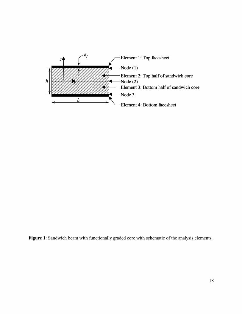
The dimensions of the sandwich beam are shown in Figure 1.The length of the beam is L,
the core thickness is h and the face sheet thicknesses are hf. The beam is divided into 4 parts or
elements: the top face sheet, top half of the core, bottom half of the core and the bottom face
sheet.
The governing equations are formulated separately for each element, and compatibility of
displacements and continuity of tractions are enforced at each interface (node) to obtain the
displacement and stress field in the sandwich beam. This procedure is analogous to assembling
element stiffness matrices to obtain global stiffness matrix in finite element analysis.
The face sheets are assumed to be homogeneous and isotropic. The core is functionally
graded but symmetric about the mid-plane given by z=0. The elastic coefficients (cij) of the top
half of the core are assumed to vary according to:
zijij ecc λ0= (1)
In the following sections, we will derive the equations for each element. The tractions
and displacements at the interface between each element are shown in Figure 2. Each element
has its own coordinate systems. The coordinate systems of each element are chosen at the

5
interface because displacements and traction compatibility between elements will have to be
enforced at these nodes. The sandwich analysis proposed here is based on the analysis methods
developed for FGM by Sankar10.
Top face sheet.
The Euler-Bernoulli beam theory is used for the analysis of face sheets. This is
admissible, if the face sheet thickness is small (compared to beam length and core thickness) and
hence the shear deformation can be neglected. The reference plane (z=0) for the top face sheet is
assumed to be along the face-sheet/core interface as shown in Figure 2.
Let t1(x) and p1(x) be the shear and normal tractions that act at the bottom surface of the
face sheet. The normal surface loads pa acting on the top surface can be combined with the
normal traction p1. Our goal is to derive expressions for the displacements u(x,0) and w(x) along
the bottom surface of the beam in terms of t1 and p1.
The equilibrium equations for the beam are expressed as
)(1 xtdxdP −= (2)
)(1 xpdxdV −= (3)
Vdx
dM = (4)
where P(x) is the axial force resultant, V(x) is the shear force and M(x) is the bending moment
along the length of the beam. Combining Eqs. (3) and (4) we obtain,
12
2
pdxdV
dxMd −== (5)
6
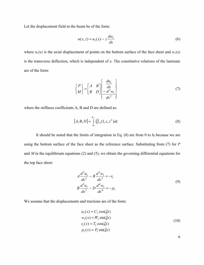
Let the displacement field in the beam be of the form:
dx
dwzxuzxu 11 )(),( −= (6)
where u1(x) is the axial displacement of points on the bottom surface of the face sheet and w1(x)
is the transverse deflection, which is independent of z. The constitutive relations of the laminate
are of the form:
���
���
�
���
���
�
−�
��
=���
���
21
2
1
dxwd
dxdu
DBBA
MP
(7)
where the stiffness coefficients A, B and D are defined as:
[ ] �=fh
dzzzQDBA0
211 ),,1(,, (8)
It should be noted that the limits of integration in Eq. (8) are from 0 to hf because we are
using the bottom surface of the face sheet as the reference surface. Substituting from (7) for P
and M in the equilibrium equations (2) and (5), we obtain the governing differential equations for
the top face sheet:
141
4
31
3
131
3
21
2
pdx
wdDdx
udB
tdx
wdBdx
udA
−=−
−=− (9)
We assume that the displacements and tractions are of the form:
)sin()()cos()()sin()()cos()(
11
11
11
11
xPxpxTxtxWxwxUxu
ξξξξ
====
(10)

7
where, U1, W1, T1, and P1 are constants to be determined.
The top face sheet is subjected to normal tractions such that,
)sin()0,( xPx azz ξσ = (11)
where
,....5,3,1 , == nL
nπξ (12)
Since n is assumed odd-valued, the loading is symmetric about the center of the beam.
The loading given by Eq. (11) is of practical significance because any arbitrary loading can be
expressed as a Fourier series involving terms of the type )sin( xPa ξ .
Substituting from Eq. (10) and (11) into (9) we obtain a relation between the interface
displacements U1, W1 and the tractions T1 and P1:
)1(
1
1
1
143
32
���
���
+=
���
����
��
−−
aPPT
WU
DBBA
ξξξξ (13)
The above equation can be written in a compact notation as:
[ ])1(
1
1
1
1)1(
���
���
+=
���
���
aPPT
WU
K (14)
where K(1) can be considered as the stiffness matrix of Element 1, i.e., the top face sheet. The
superscripts on the right hand side indicate that the tractions act on Element 1.
Bottom face sheet.
The equations of the bottom face sheet can be derived in a similar manner as the top face
sheet. Following the procedures described in the previous section, we obtain a relation for
bottom face sheet as

8
[ ])4(
3
3
3
3)4(
���
���
=���
���
PT
WU
K (15)
where
[ ] ��
���
�
−−=
DBBAK 43
32)4(
ξξξξ (16)
However, the definitions of A, B and D are different from those used for the top face
sheet because the reference surface for the bottom face sheet in at the top surface. The choice of
reference surface results in the integration limits ranging from –hf to 0, thereby resulting in
different values for the stiffness terms which are given by,
[ ] �=−
02
11 ),,1(,,fh
dzzzQDBA (17)
Top half of the core.
The functionally graded core is analyzed using the plane elasticity equations. The
procedure used is similar to that developed in Ref. [10]. In this paper, we will provide a brief
description of the procedures. The differential equations of equilibrium are:
0
0
=∂
∂+∂
∂
=∂
∂+∂
∂
zx
zxzzxz
xzxx
στ
τσ
(18)
If the material is orthotropic at every point and the principal material directions coincide
with the x and z-axes, the constitutive relations are:
{ } [ ]{ }��
��
�
��
��
�
���
���
�
=��
��
�
��
��
�
�=
xz
xx
xx
xz
xx
xx
ccccc
zcγεε
τσσ
εσ
55
3313
1311
0000
)( (19)
9
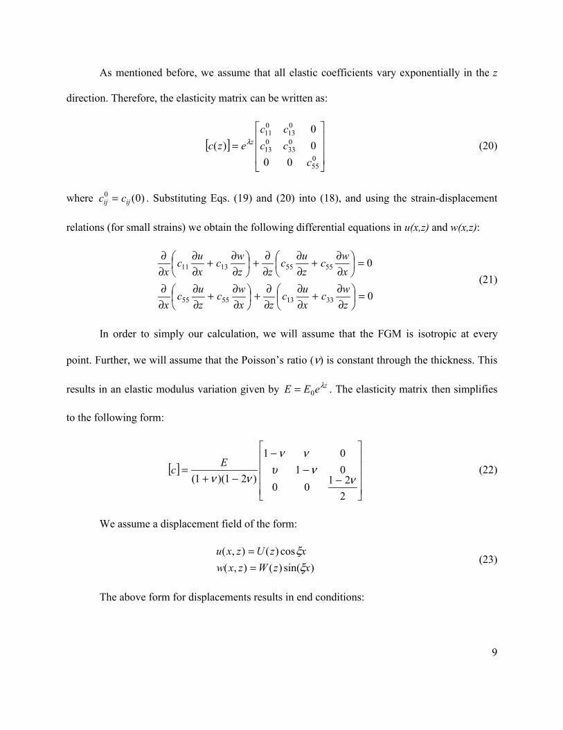
As mentioned before, we assume that all elastic coefficients vary exponentially in the z
direction. Therefore, the elasticity matrix can be written as:
[ ]���
�
�
���
�
�
=055
033
013
013
011
0000
)(c
cccc
ezc zλ (20)
where )0(0ijij cc = . Substituting Eqs. (19) and (20) into (18), and using the strain-displacement
relations (for small strains) we obtain the following differential equations in u(x,z) and w(x,z):
0
0
33135555
55551311
=��
���
�
∂∂+
∂∂
∂∂+�
�
���
�
∂∂+
∂∂
∂∂
=��
���
�
∂∂+
∂∂
∂∂+�
�
���
�
∂∂+
∂∂
∂∂
zwc
xuc
zxwc
zuc
x
xwc
zuc
zzwc
xuc
x (21)
In order to simply our calculation, we will assume that the FGM is isotropic at every
point. Further, we will assume that the Poisson’s ratio (ν) is constant through the thickness. This
results in an elastic modulus variation given by zeEE λ0= . The elasticity matrix then simplifies
to the following form:
[ ]����
�
�
����
�
�
−−
−
−+=
22100
0101
)21)(1( ννυ
νν
ννEc (22)
We assume a displacement field of the form:
)sin()(),(
cos)(),(xzWzxw
xzUzxuξ
ξ==
(23)
The above form for displacements results in end conditions:

10
0),(),0(
0),(),0(==
==zLz
zLwzw
xxxx σσ (24)
which are typical boundary conditions of a simply supported beam. Substitution of Eqs. (20) and
(23) into (21) results in a pair of ordinary differential equations for U(z) and W(z).
0
0033
033
013
013
2055
055
055
055
055
055
013
2011
=′+′′+−′−−′
=+′+′+′′+′+−
WcWcUcUcWcUc
WcWcUcUcWcUc
λλξξξξ
λξξλξξ (25)
where dz
d (.))(. ≡′ .
In order to solve Eq. (25) we assume U(z) and W(z) to be of the form:
�=
�=
=
=4
1
4
1
)(
)(
i
Zi
i
Zi
i
i
ebzW
eazU
α
α
(26)
where ai and bi are arbitrary constants to be determined from the traction boundary conditions on
the top and bottom surfaces. The terms in the exponents, αi are the roots of the characteristic
equation for α, given by:
02221
1211 =AAAA
(27)
where
( )
( ) ( ) 2222
21
12
2211
22111
2
221
2
1221
221
ξνλαναν
νλξξα
λξνξα
ξνλαναν
��
���
� −−−+−=
−−=
��
���
� −+=
−−��
���
� −+��
���
� −=
A
A
A
A
(28)
11
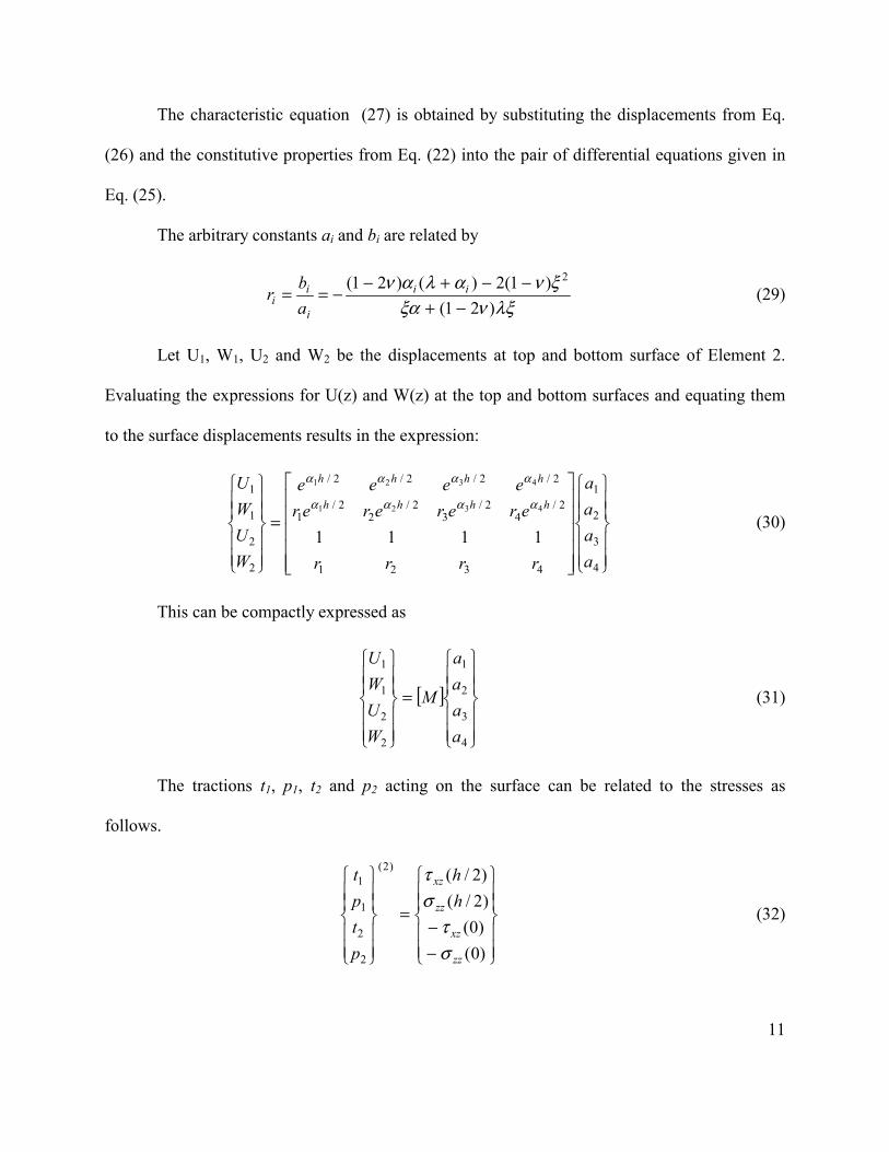
The characteristic equation (27) is obtained by substituting the displacements from Eq.
(26) and the constitutive properties from Eq. (22) into the pair of differential equations given in
Eq. (25).
The arbitrary constants ai and bi are related by
λξνξα
ξναλαν)21(
)1(2)()21( 2
−+−−+−
−== ii
i
ii a
br (29)
Let U1, W1, U2 and W2 be the displacements at top and bottom surface of Element 2.
Evaluating the expressions for U(z) and W(z) at the top and bottom surfaces and equating them
to the surface displacements results in the expression:
��
�
��
�
�
��
�
��
�
�
�����
�����
�
=
��
�
��
�
�
��
�
��
�
�
4
3
2
1
4321
2/4
2/3
2/2
2/1
2/2/2/2/
2
2
1
1
1111
4321
4321
aaaa
rrrr
erererereeee
WUWU
hhhh
hhhh
αααα
αααα
(30)
This can be compactly expressed as
[ ]��
�
��
�
�
��
�
��
�
�
=
��
�
��
�
�
��
�
��
�
�
4
3
2
1
2
2
1
1
aaaa
M
WUWU
(31)
The tractions t1, p1, t2 and p2 acting on the surface can be related to the stresses as
follows.
��
�
��
�
�
��
�
��
�
�
−−
=
��
�
��
�
�
��
�
��
�
�
)0()0()2/()2/()2(
2
2
1
1
zz
xz
zz
xz
hh
ptpt
στ
στ
(32)

12
Substituting the stress-strain, strain-displacement and constitutive relations from Eqs.
(19), (21), (22) into (32) results in an expression that relates the arbitrary coefficients ai to the
surface tractions and is given as
[ ]��
�
��
�
�
��
�
��
�
�
=
��
�
��
�
�
��
�
��
�
�
4
3
2
1)2(
2
2
1
1
aaaa
S
PTPT
(33)
where,
( )
( )( )
4,1
)(
033
0114
0553
033
011
2/2
2/0551
=
+−−=+−=
+−=+=
j
rccSrcS
rcceSrecS
jjj
jjj
jjh
j
jjh
ji
i
αξξα
αξξα
α
α
(34)
The stiffness matrix of the top half of the FGM core [K(2)] that relates the surface
tractions to the surface displacements is obtained by combining Eqs. (33) and (31) and
eliminating the coefficients ai and is expressed as follows:
[ ])2(
2
2
1
1
2
2
1
1
)2(
��
�
��
�
�
��
�
��
�
�
=
��
�
��
�
�
��
�
��
�
�
PTPT
WUWU
K (35)
where
[ ] [ ][ ] 1)2( −= MSK (36)

13
Bottom half of the core
The differential equilibrium and stress strain relations are identical to those defined for
the top half of the core, Eqs (18) and (19). The reference surface for the z-coordinate in the
bottom half of the core is chosen at its top surface (mid-plane of the sandwich) and hence z-
values are negative. The elastic modulus variation in the bottom core is hence given by
zeEE λ−= 0 (37)
Repeating the same procedure outlined for the top half of the core will provide the
stiffness matrix of the bottom core. An alternate way to obtain the same is to use a geometric
transformation derived based on the similarities in geometry, loading and of the material
property variations between the top and bottom half of the sandwich core. The stiffness matrix of
the bottom core is therefore obtained by a simple transformation of the stiffness matrix of the top
half of the core that is given by
[ ] [ ] [ ][ ]TKTK )2(1)3( −= (38)
Where the transformation matrix (T) is of the form,
����
�
�
����
�
�
−
−=
001000011000
0100
T (39)
Assembling the elements
In order to satisfy equilibrium the contributions of tractions from different elements at
each interface should sum to zero. Enforcing the compatibility of displacements at the interfaces
enables us to assemble the stiffness matrices of the four elements to obtain a global stiffness
matrix K, shown in Eq. (40).

14
���
�
���
�
�
���
�
���
�
�
=
���
�
���
�
�
���
�
���
�
�
���
���
�
0000
0
3
3
2
2
1
1
aP
WUWUWU
K (40)
The displacements U1, W1…W3, are obtained by solving Eq (51). The obtained
displacement filed along with the constitutive relations are used to obtain the stress field in each
element.
Results and Discussion
The inplane displacement U(z) and transverse W(z) deflections through the thickness of
the sandwich core calculated using the elasticity analysis described in the previous section are
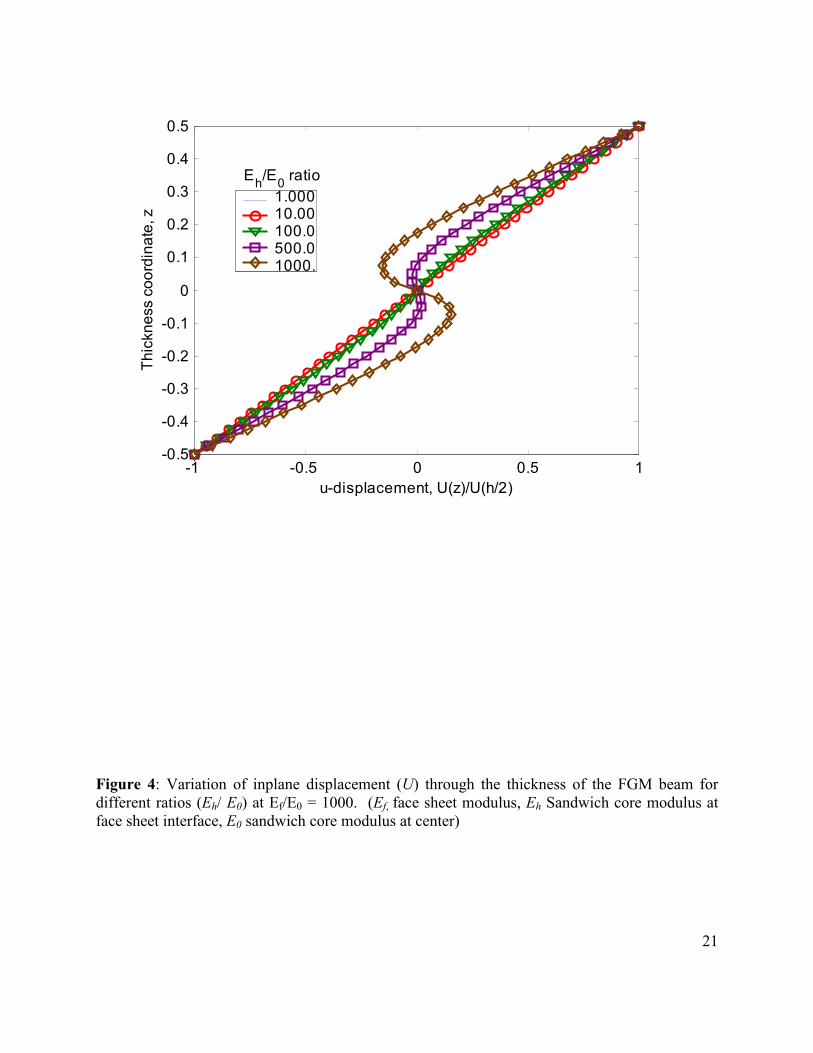
plotted in Figures 4 and 5, respectively. The inplane displacements exhibit highly non-linear
variation through the thickness of the core for the functionally graded core sandwich in
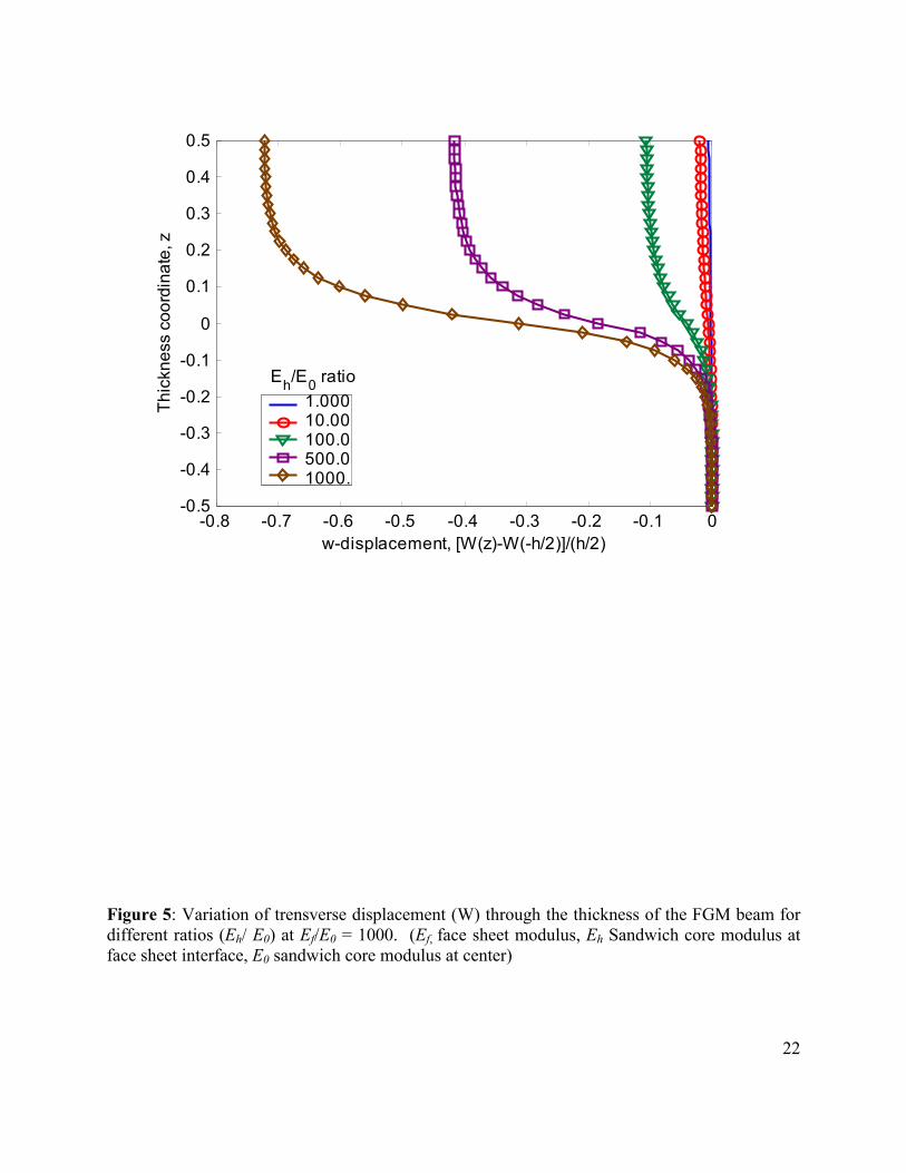
comparison to the uniform core sandwich. A very attractive feature of the elasticity solutions is
that it can provide the through the thickness compressions of the beam which is often neglected
or ignored in beam models. The through the thickness variations of the transverse deflection
(Fig. 5) indicates that maximum core compression occurs at the mid-plane of the core where the
elastic modulus is least. The core compression (difference in the transverse displacements (w)
between sandwich top and bottom facesheet/core interfaces) increases as the Eh/E0 ratio is
increased.
The displacements were verified using a NASTRAN finite element (FE) analysis model
with a very refined mesh for a beam of dimensions L/h=20 and loading p0/Ef=10-6. The beam was
modeled using four-node plane strain elements. Due to symmetry, only one half of the beam was

15
modeled. The mesh used for the analysis had 50 elements along the half-length of the beam and
108 elements along the thickness direction, 4 elements spanning the thickness of each facesheet
and 100 elements to spanning the sandwich core. The elastic modulus of each element is
calculated at its centroid. The in-plane displacements obtained from the FE model are plotted
together with the displacements calculated using the elasticity model in Figure 6. The finite
element analysis results matched the elasticity analysis results very well, thereby validating the
accuracy of the analysis for further calculations of strains and stresses.
An interesting result from analysis of the FGM sandwich beam is the transverse shear
stress in the sandwich core at the face sheet interface. Conventional design of sandwich
laminates restrict the shear stress at the core/ face sheet interface to the bond (adhesive) shear
strength, which is typically lower than the shear strength of the core material. Therefore, the core
material is not fully utilized. It is hence desirable to reduce the interfacial shear stress while
carrying a high shear stress in the core. It appears that this is possible with a functionally graded
core. The shear stress variations in the core are plotted in Figure 7 for h/hf=10. The interface
shear stress reduces as Eh/E0 ratio is increased. The maximum reduction of 20% occurs for the
case Eh/E0 =1, for which the core elastic modulus varies exponentially from E0 = Ef/1000 at the
center to Eh=Ef at the core/ face sheet interface. Figure 8 shows the ratio of shear stress at
interface for different values of Eh/E0 ratio and h/hf ratio. The reduction in shear stress at the
interface increases with increase in h/hf ratio (or for beams when the face sheet is significantly
thinner than the core). For the example problem the reduction in interface shear stress is 42% and
63% for h/hf values of 20 and 40, respectively.
The normal stress zzσ in the core (Figure 9) varies linearly and is independent of the
variation in core properties. The value of normal stress varies linearly (approximately) from the
16
applied surface load to zero at the bottom of the core. This is an interesting result, because it
simplifies the calculations required in order to account for core crushing problem. It must be
noted that the example considered here, used a smoothly varying (sinusoidal) surface pressure
load. The results will need to be verified for other concentrated loads.
The bending stress variations (Figure 10) in the core are as expected. The linear variation
in strains results in small levels of bending stress in the core near the mid-plane. The stress
increases near the face sheet. This is particularly pronounced as the value of the core modulus is
increased to match the value of the face sheet thickness.
Conclusions
An elasticity solution was derived for a sandwich beam with a functionally graded core.
Exponential variations of the elastic coefficients in the sandwich core simplify the calculations.
Solutions are presented for displacements and stresses in the core. The elasticity solution was
verified using a finite element analysis. Varying core properties through the thickness shows
promise for reducing core/face-sheet interface shear stresses. The developed method can be
extended to any general variation of elastic modulus by using multiple elements of the core to
approximate the required elastic modulus.
Acknowledgements
This research was supported by the NASA Langley Research Center Grant NAG-1-1887.
The authors are thankful to Dr. D.R. Ambur, Head, Mechanics and Durability Branch for his
support and encouragement.

17
References
1. Suresh, S. and Mortensen, A., 1998, Fundamentals of Functionally Graded Materials, IOM Communications Limited, London, United Kingdom.
2. Aboudi, J., Pindera, M-J., and Arnold, S.M., 1993, “Thermoelastic Response of Metal Matrix Composites with Large-Diameter Fibers Subjected to Thermal Gradients,” NASA TM 106344, Lewis Research Center, Cleveland, OH.
3. Aboudi, J., Arnold, S.M. and Pindera, M-J., 1994a, “Response of Functionally Graded Composites to Thermal Gradients,” Composites Engineering, 4, pp. 1-18.
4. Aboudi, J., Pindera, M-J. And Arnold, S.M., 1994b, “Elastic Response of Metal matrix Composites with tailored Microstructures to Thermal Gradients,” Int. J. Solids Structures, 31, pp. 1393-1428.
5. Aboudi, J. and Pindera, M-J., 1995, “Thermoelastic Theory for the response of Materials Functionally Graded in Two Directions with Applications to the Free-Edge Problem,”. NASA TM 106882, Lewis Research Center, Cleveland, OH.
6. Pindera, M-J. And Dunn, P., 1995, “An Evaluation of Coupled Microstructural Approach for the Analysis of Functionally Graded Composites via the Finite Element Method,” NASA CR 195455. Lewis Research Center, Cleveland, OH.
7. Marrey, R.V. and Sankar, B.V., 1993, “Stress Gradient Effects on Stiffness and Strength of Textile Composites,” Composite Materials and Structures, AD-Vol. 37/AMD-Vol. 179, ASME Winter Annual Meeting, C.W. Bert, V. Birman, and D. Hui, eds., pp. 133-148.
8. Marrey, R.V. and Sankar, B.V., 1995, “Micromechanical Models for Textile Structural Composites,” NASA CR 198229, Langley Research Center, Hampton, VA.
9. Delale, F. and Erdogan, F., 1983, “The Crack Problem for a Nonhomogeneous Plane”, ASME Journal of Applied Mechanics, 50, pp. 609-614.
10. Sankar, B. V., “An elasticity solution for functionally graded beams,” Composites Science and Technology, Volume 61, Issue 5, pp. 689-696.
11. Lee J. M., MSC NASTRAN Version 69+: Linear Static Analysis User’s Guide, MSC Software Inc, Los Angeles, California 1997.
18
Element 3: Bottom half of sandwich core
Element 1: Top facesheet
Element 4: Bottom facesheet
Element 2: Top half of sandwich corex
z
Node (1)
Node 3
Node (2)
hf
L
hElement 3: Bottom half of sandwich core
Element 1: Top facesheet
Element 4: Bottom facesheet
Element 2: Top half of sandwich corex
z
x
z
Node (1)
Node 3
Node (2)
hf
L
h
Figure 1: Sandwich beam with functionally graded core with schematic of the analysis elements.

19
x
z Top facesheetpa
t1 ,U1
p1 , W1p1 , W1
t1 , U1
t2 , U2
p2 ,W2
x
zTop half of sandwich core
t3 , U3
t2 , U2
p2 , W2
p3 , W3
x
z
Bottom half of sandwich core
t3 , U3
p3 , W3
x
zBottom facesheet
x
z Top facesheetpa
t1 ,U1
p1 , W1
x
z
x
z Top facesheetpa
t1 ,U1
p1 , W1
Top facesheetpa
t1 ,U1
p1 , W1p1 , W1
t1 , U1
t2 , U2
p2 ,W2
x
zTop half of sandwich core
p1 , W1
t1 , U1
t2 , U2
p2 ,W2
p1 , W1
t1 , U1
t2 , U2
p2 ,W2
x
z
x
zTop half of sandwich core
t3 , U3
t2 , U2
p2 , W2
p3 , W3
x
z
Bottom half of sandwich core
t3 , U3
t2 , U2
p2 , W2
p3 , W3
t3 , U3
t2 , U2
p2 , W2
p3 , W3
x
z
x
z
Bottom half of sandwich core
t3 , U3
p3 , W3
x
zBottom facesheet
t3 , U3
p3 , W3
t3 , U3
p3 , W3
x
z
x
zBottom facesheet
Figure 2: Traction forces and displacements at the interfaces of each element in the FGM sandwich beam

20
0 0.2 0.4 0.6 0.8 1-0.5
-0.4
-0.3
-0.2
-0.1
0
0.1
0.2
0.3
0.4
0.5
Eh/E0 ratio
Elastic Modulus of Sandwich Core, Ec
Thic
knes
s co
ordi
nate
, z
1.000 10.00 100.00 500.00 1000.00
Figure 3: Through the thickness variations of core modulus considered for the functionally graded sandwich beam, (Eh is the sandwich core modulus at face sheet interface and, E0 the sandwich core modulus at center)
21
-1 -0.5 0 0.5 1-0.5
-0.4
-0.3
-0.2
-0.1
0
0.1
0.2
0.3
0.4
0.5
u-displacement, U(z)/U(h/2)
Thic
knes
s co
ordi
nate
, z
Eh/E0 ratio1.00010.00100.0500.01000.
Figure 4: Variation of inplane displacement (U) through the thickness of the FGM beam for different ratios (Eh/ E0) at Ef/E0 = 1000. (Ef, face sheet modulus, Eh Sandwich core modulus at face sheet interface, E0 sandwich core modulus at center)
22
-0.8 -0.7 -0.6 -0.5 -0.4 -0.3 -0.2 -0.1 0-0.5
-0.4
-0.3
-0.2
-0.1
0
0.1
0.2
0.3
0.4
0.5
w-displacement, [W(z)-W(-h/2)]/(h/2)
Thic
knes
s co
ordi
nate
, z
Eh/E0 ratio1.00010.00100.0500.01000.
Figure 5: Variation of trensverse displacement (W) through the thickness of the FGM beam for different ratios (Eh/ E0) at Ef/E0 = 1000. (Ef, face sheet modulus, Eh Sandwich core modulus at face sheet interface, E0 sandwich core modulus at center)

23
-1.5 -1 -0.5 0 0.5 1-0.5
-0.4
-0.3
-0.2
-0.1
0
0.1
0.2
0.3
0.4
0.5
u-displacement, U(z)/U(h/2)
Thic
knes
s co
ordi
nate
, zEh/E0=1000: Exact Eh/E0= 100: Exact Eh/E0= 10: Exact Eh/E0= 1: Exact Eh/E0=1000: FE Model Eh/E0= 100: FE ModelEh/E0= 10: FE Model Eh/E0= 1: FE Model
Figure 6: Comparison of inplane displacements obtained using proposed elasticity solution (“exact”) and finite element analysis through the thickness of the FGM beam for different ratios (Eh/ E0) at Ef/E0 = 1000. (Ef, face sheet modulus, Eh Sandwich core modulus at face sheet interface, E0 sandwich core modulus at center)

24
-0.031 -0.03 -0.029 -0.028 -0.027 -0.026 -0.025 -0.024 -0.023-0.5
-0.4
-0.3
-0.2
-0.1
0
0.1
0.2
0.3
0.4
0.5
Shear stress through the thickness, τxz
Thic
knes
s co
ordi
nate
, z
Eh/E0 ratio1.00010.00100.0500 1000.
Figure 7: Variation of the through the thickness shear stress in the FGM beam for different ratios (Eh/ E0) at Ef/E0 = 1000. (Ef, face sheet modulus, Eh Sandwich core modulus at face sheet interface, E0 sandwich core modulus at center)

25
100
101
102
103
0.3
0.4
0.5
0.6
0.7
0.8
0.9
1
1.1
Eh/E0 ratioRat
io o
f int
erfa
ce s
hear
stre
ss o
f FG
M s
andw
ich
beam
to
inte
rface
stre
ss o
f reg
ular
san
dwic
h be
am
Ratio of core thicknessto facesheet thickness
10.020.040.0
Figure 8: Reduction in interfacial shear stresses for varying ratios of extreme values of core modulii (Eh/E0) and ratios of core thickness to face sheet thickness h/hf.

26
-0.01 -0.008 -0.006 -0.004 -0.002 0-0.5
-0.4
-0.3
-0.2
-0.1
0
0.1
0.2
0.3
0.4
0.5
Normal stress through the thickness, σzz
Thic
knes
s co
ordi
nate
, z
Eh/E0 ratio1.00010.00100.0500 1000.
Figure 9 Variation of the through the thickness normal (compressive) stress in the FGM beam for different ratios (Eh/ E0) at Ef/E0 = 1000. (Ef is the face sheet modulus, Eh the sandwich core modulus at face sheet interface and , E0 the sandwich core modulus at center)

27
-0.8 -0.6 -0.4 -0.2 0 0.2 0.4 0.6-0.5
-0.4
-0.3
-0.2
-0.1
0
0.1
0.2
0.3
0.4
0.5
Bending stress through the thickness, σxx
Thic
knes
s co
ordi
nate
, z
Eh/E0 ratio1.00010.00100.0500 1000.
Figure 10 Variation of the through the thickness bending stress in the FGM beam for different ratios (Eh/ E0) at Ef/E0 = 1000. (Ef, is the face sheet modulus, Eh the sandwich core modulus at face sheet interface and, E0 the sandwich core modulus at center).
Copyright © 2022 FDOKUMEN