Sustainable Sandwich Composites Manufactured from ... - MDPI
12
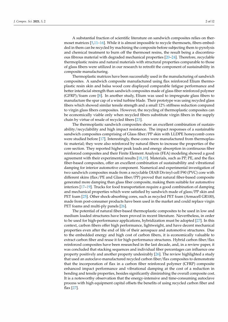
Article Sustainable Sandwich Composites Manufactured from Recycled Carbon Fibers, Flax Fibers/PP Skins, and Recycled PET Core Qihong Jiang 1 , Guiyong Chen 1 , Abhideep Kumar 1 , Andrew Mills 1 , Krutarth Jani 1 , Vasudevan Rajamohan 2 , Barathan Venugopal 2 and Sameer Rahatekar 1, * Citation: Jiang, Q.; Chen, G.; Kumar, A.; Mills, A.; Jani, K.; Rajamohan, V.; Venugopal, B.; Rahatekar, S. Sustain- able Sandwich Composites Manufac- tured from Recycled Carbon Fibers, Flax Fibers/PP Skins, and Recycled PET Core. J. Compos. Sci. 2021, 5, 2. https://dx.doi. org/10.3390/jcs5010002 Received: 10 October 2020 Accepted: 20 December 2020 Published: 23 December 2020 Publisher’s Note: MDPI stays neu- tral with regard to jurisdictional claims in published maps and institutional affiliations. Copyright: © 2020 by the authors. Li- censee MDPI, Basel, Switzerland. This article is an open access article distributed under the terms and conditions of the Creative Commons Attribution (CC BY) license (https://creativecommons.org/ licenses/by/4.0/). 1 Enhanced Composites and Structures Centre, School of Aerospace, Transport and Manufacturing, Cranfield University, Bedfordshire MK43 0AL, UK; qihong.jiang@cranfield.ac.uk (Q.J.); [email protected] (G.C.); [email protected] (A.K.); A.R.Mills@cranfield.ac.uk (A.M.); Krutarth.Jani@cranfield.ac.uk (K.J.) 2 School of Mechanical Engineering, Vellore Institute of Technology, Vellore Campus, Tiruvalam Rd, Katpadi, Vellore, Tamil Nadu 632014, India; [email protected] (V.R.); [email protected] (B.V.) * Correspondence: S.S.Rahatekar@cranfield.ac.uk Abstract: European union end of life vehicle directive mandates the use of more sustainable/recyclable materials in automotive industries. Thermoplastics matrix-based composites allow recyclability of composites at the end of life; however, their processing technology is more challenging than ther- moset composites. Manufacturing process and mechanical testing of sustainable sandwich composite made from sustainable materials: flax, recycled carbon fiber, polypropylene, and recycled PET foam are presented in this article. High pressure compression molding with adhesive thermoplastic poly- mer film was used for manufacturing sandwich composite skin. The recycled PET foam core was integrated/joined with the skin using a thermoplastics adhesive film. A three-point bending test was conducted to compare the flexural properties. The results show that such sustainable sandwich composites will be an excellent material for truck side panel to operate in adverse wind/storm conditions. The sustainable sandwich composite can potentially be an excellent candidate for the fabrication of light-duty, lightweight, and low-cost engineering structures in automotive industry to meet the EU end of life requirements. Keywords: polypropylene; recycled carbon fiber; flax; sustainable; mechanical property; sand- wich composite 1. Introduction In the transportation sector, since the number of fossil fuel-powered vehicles projected in this decade is environmentally unsustainable, there is a rapid movement of automotive manufacturers towards hybrid propulsion and electrification to substitute non-renewable sources of energy, that account for approximately 96% of the fuel used for propulsion. The electric vehicles have battery limitations to achieve a long range. Hence, the electric vehicle manufacturers are exploring strategies to increase the driving range of the electric vehicles. One such strategy is to design and develop lightweight sandwich composites made of green alternatives: low-cost natural materials which are promising candidates that could rope in recyclability and sustainability in tandem to the enhancement of perfor- mance [1–4]. Recently, several researchers have reported sandwich composites manufactured from natural, renewable or recycled materials [5–19]. These include balsa wood [5–8], hard- wood [9], bamboo [10], rubber from waste tires, foams of mushroom, PET, and PVC, and honeycombs of flax/LLDPE and PP. The face skins used in these studies encompassed a combination of synthetic fiber (glass fiber) and natural fiber (jute and flax) reinforced thermoplastics and thermosets. J. Compos. Sci. 2021, 5, 2. https://dx.doi.org/10.3390/jcs5010002 https://www.mdpi.com/journal/jcs
-
Upload
khangminh22 -
Category
Documents
-
view
0 -
download
0
Transcript of Sustainable Sandwich Composites Manufactured from ... - MDPI
Article
Sustainable Sandwich Composites Manufactured fromRecycled Carbon Fibers, Flax Fibers/PP Skins, and RecycledPET Core
Qihong Jiang 1, Guiyong Chen 1, Abhideep Kumar 1 , Andrew Mills 1, Krutarth Jani 1, Vasudevan Rajamohan 2,Barathan Venugopal 2 and Sameer Rahatekar 1,*
�����������������
Citation: Jiang, Q.; Chen, G.; Kumar,
A.; Mills, A.; Jani, K.; Rajamohan, V.;
Venugopal, B.; Rahatekar, S. Sustain-
able Sandwich Composites Manufac-
tured from Recycled Carbon Fibers, Flax
Fibers/PP Skins, and Recycled PET Core.
J. Compos. Sci. 2021, 5, 2. https://dx.doi.
org/10.3390/jcs5010002
Received: 10 October 2020
Accepted: 20 December 2020
Published: 23 December 2020
Publisher’s Note: MDPI stays neu-
tral with regard to jurisdictional claims
in published maps and institutional
affiliations.
Copyright: © 2020 by the authors. Li-
censee MDPI, Basel, Switzerland. This
article is an open access article distributed
under the terms and conditions of the
Creative Commons Attribution (CC BY)
license (https://creativecommons.org/
licenses/by/4.0/).
1 Enhanced Composites and Structures Centre, School of Aerospace, Transport and Manufacturing,Cranfield University, Bedfordshire MK43 0AL, UK; [email protected] (Q.J.);[email protected] (G.C.); [email protected] (A.K.); [email protected] (A.M.);[email protected] (K.J.)
2 School of Mechanical Engineering, Vellore Institute of Technology, Vellore Campus, Tiruvalam Rd, Katpadi,Vellore, Tamil Nadu 632014, India; [email protected] (V.R.); [email protected] (B.V.)
* Correspondence: [email protected]
Abstract: European union end of life vehicle directive mandates the use of more sustainable/recyclablematerials in automotive industries. Thermoplastics matrix-based composites allow recyclability ofcomposites at the end of life; however, their processing technology is more challenging than ther-moset composites. Manufacturing process and mechanical testing of sustainable sandwich compositemade from sustainable materials: flax, recycled carbon fiber, polypropylene, and recycled PET foamare presented in this article. High pressure compression molding with adhesive thermoplastic poly-mer film was used for manufacturing sandwich composite skin. The recycled PET foam core wasintegrated/joined with the skin using a thermoplastics adhesive film. A three-point bending testwas conducted to compare the flexural properties. The results show that such sustainable sandwichcomposites will be an excellent material for truck side panel to operate in adverse wind/stormconditions. The sustainable sandwich composite can potentially be an excellent candidate for thefabrication of light-duty, lightweight, and low-cost engineering structures in automotive industry tomeet the EU end of life requirements.
Keywords: polypropylene; recycled carbon fiber; flax; sustainable; mechanical property; sand-wich composite
1. Introduction
In the transportation sector, since the number of fossil fuel-powered vehicles projectedin this decade is environmentally unsustainable, there is a rapid movement of automotivemanufacturers towards hybrid propulsion and electrification to substitute non-renewablesources of energy, that account for approximately 96% of the fuel used for propulsion.The electric vehicles have battery limitations to achieve a long range. Hence, the electricvehicle manufacturers are exploring strategies to increase the driving range of the electricvehicles. One such strategy is to design and develop lightweight sandwich compositesmade of green alternatives: low-cost natural materials which are promising candidatesthat could rope in recyclability and sustainability in tandem to the enhancement of perfor-mance [1–4].
Recently, several researchers have reported sandwich composites manufactured fromnatural, renewable or recycled materials [5–19]. These include balsa wood [5–8], hard-wood [9], bamboo [10], rubber from waste tires, foams of mushroom, PET, and PVC,and honeycombs of flax/LLDPE and PP. The face skins used in these studies encompasseda combination of synthetic fiber (glass fiber) and natural fiber (jute and flax) reinforcedthermoplastics and thermosets.
J. Compos. Sci. 2021, 5, 2. https://dx.doi.org/10.3390/jcs5010002 https://www.mdpi.com/journal/jcs
J. Compos. Sci. 2021, 5, 2 2 of 12
A substantial fraction of scientific literature on sandwich composites relies on ther-moset matrices [5,11–16]. While it is almost impossible to recycle thermosets, fibers embed-ded in them can be recycled by machining the composite before subjecting them to pyrolysisand chemical treatment to burn off the thermoset resins, the result being a discontinu-ous fibrous material with degraded mechanical properties [20–24]. Therefore, recyclablethermoplastic resins and natural materials with structural properties comparable to thoseof glass fibers were utilized in our research to retrofit the component of sustainability incomposite manufacturing.
Thermoplastic matrices have been successfully used in the manufacturing of sandwichcomposites. A sandwich composite manufactured using flax reinforced Elium thermo-plastic resin skin and balsa wood core displayed comparable fatigue performance andbetter interfacial strength than sandwich composites made of glass fiber reinforced polymer(GFRP)/foam core [8]. In another study, Elium was used to impregnate glass fibers tomanufacture the spar cap of a wind turbine blade. Their prototype was using recycled glassfibers which showed similar tensile strength and a small 12% stiffness reduction comparedto virgin glass fibers composites. However, the recycling of thermoplastic composites canbe economically viable only when recycled fibers substitute virgin fibers in the supplychain by virtue of resale of recycled fibers [23].
The thermoplastic sandwich composites show an excellent combination of sustain-ability/recyclability and high impact resistance. The impact responses of a sustainablesandwich composites comprising of Glass fiber/PP skin with LLDPE honeycomb coreswere studied before [17]. Interestingly, these cores were manufactured from thermoplas-tic material; they were also reinforced by natural fibers to increase the properties of thecore section. They reported higher peak loads and energy absorption in continuous fiberreinforced composites and their Finite Element Analysis (FEA) modeling showed a goodagreement with their experimental results [18,19]. Materials, such as PP, PE, and the flaxfiber-based composites, offer an excellent combination of sustainability and vibrationaldamping for interior automotive component. Numerical and experimental investigation oftwo sandwich composites made from a recyclable DIAB Divinyl-cell F90 (PVC) core withdifferent skins (flax/PE and Glass fiber/PP) proved that natural fiber-based compositegenerated more damping than glass fiber composite, making them suitable for automotiveinteriors [17–19]. Trucks for food transportation require a good combination of dampingand mechanical properties which were satisfied by sandwich made of glass/PP skin andPET foam [25]. Other shock-absorbing cores, such as recycled PET foam (Armacell GR100),made from post-consumer products have been used in the market and could replace virginPET foams and multi-ply panels [26].
The potential of natural fiber-based thermoplastic composites to be used in low andmedium loaded structures have been proved in recent literature. Nevertheless, in orderto be used for high-performance applications, hybridization must be adopted [27]. In thiscontext, carbon fibers offer high performance, lightweight, and have decent mechanicalproperties even after the end of life of their aerospace and automotive structures. Dueto the embedded energy and high cost of carbon fibers, it is economically valuable toextract carbon fiber and reuse it for high-performance structures. Hybrid carbon fiber/flaxreinforced composites have been researched in the last decade, and, in a review paper, itwas concluded that stacking sequences and individual fiber percentages can influence oneproperty positively and another property undesirably [26]. The review highlighted a studythat used an autoclave-manufactured recycled carbon fiber/flax composites to demonstratethat the incorporation of flax in a carbon fiber reinforced polymer (CFRP) compositeenhanced impact performance and vibrational damping at the cost of a reduction inbending and tensile properties, besides significantly diminishing the overall composite cost.It is a noteworthy observation that the energy-intensive and time-consuming autoclaveprocess with high equipment capital offsets the benefits of using recycled carbon fiber andflax [27].
J. Compos. Sci. 2021, 5, 2 3 of 12
Therefore, to ameliorate the reduction of bending and tensile properties observed inprevious research, fully recyclable sandwich composites from recycled carbon fiber-basedthermoplastic (polypropylene) skin and recycled thermoplastic foam core (PET foam) havebeen formulated in this study. The material combination was aimed at offering excellentmechanical properties, economic viability, light-weighting, lower environmental footprint,and 100% recyclability by virtue of thermoplastic resin and core. Furthermore, skins arehybrid in nature, comprised of external layers of recycled carbon fibers and internal layersof flax fibers. Such carbon-flax-carbon configuration provides better flexural propertiesthan the flax-carbon-flax combination [27]. It will also offer reduced moisture absorptionby shielding the flax from moisture ingress. Additionally, a case study has been doneregarding the use of such composites as a truck side panel as a potential applicationin the transport sector. These fully recyclable sandwich composites will find excellentapplication in automotive truck panels and potentially in the mass transport (railways andbus transport) industries.
2. Materials and Methods2.1. Materials and Panel Design
A non-woven mat of recycled carbon fiber was supplied by ELG Carbon Fiber Ltd.(ELG Carbon Fiber Ltd., Coseley, West Midlands WV14 8XR, UK; density 1370 kg/m3)The recyclable fiber was obtained by chopping carbon fiber components end of their life.The pyrolysis process was used to remove the thermoset resin. After pyrolysis, the recycledcarbon fibers were compressed into randomly oriented fiber mat. Flax fiber (unidirec-tional fabric; density 1320 kg/m3) were utilized as reinforcements for the composite skin.Polypropylene (1 mm PP sheet; source: SIMONA PP-H natural) with a melting pointof 161 ◦C and recrystallization temperature around 122 ◦C, elastic modulus of 1.2 GPa,and density of 950 kg/m3 served as the matrix. A recycled 10-mm thick PET foam man-ufactured from recycled plastic bottles (Armacell Company, Mars St, Oldham OL9 6LY,UK) with a shear modulus of 18 MPa and a density of 100 kg/m3 was used as the core.A polyester-based copolymer adhesive film BEMIS-5256 (Bemis Associates, Units 3, 5Turnpike Cl, Grantham, UK)with a low glue line temperature (148 ◦C to 181 ◦C) was usedto enhance the bonding of the sandwich structure.
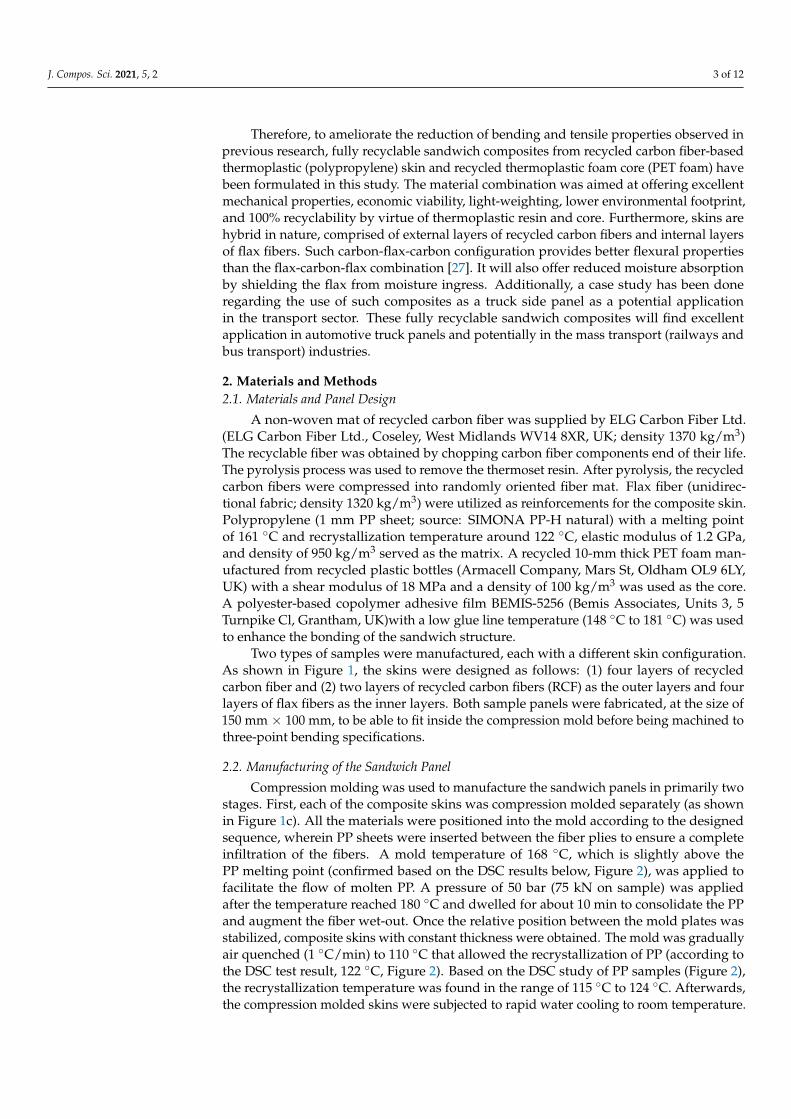
Two types of samples were manufactured, each with a different skin configuration.As shown in Figure 1, the skins were designed as follows: (1) four layers of recycledcarbon fiber and (2) two layers of recycled carbon fibers (RCF) as the outer layers and fourlayers of flax fibers as the inner layers. Both sample panels were fabricated, at the size of150 mm × 100 mm, to be able to fit inside the compression mold before being machined tothree-point bending specifications.
2.2. Manufacturing of the Sandwich Panel
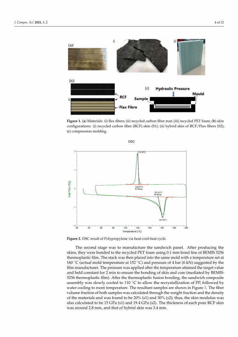
Compression molding was used to manufacture the sandwich panels in primarily twostages. First, each of the composite skins was compression molded separately (as shownin Figure 1c). All the materials were positioned into the mold according to the designedsequence, wherein PP sheets were inserted between the fiber plies to ensure a completeinfiltration of the fibers. A mold temperature of 168 ◦C, which is slightly above thePP melting point (confirmed based on the DSC results below, Figure 2), was applied tofacilitate the flow of molten PP. A pressure of 50 bar (75 kN on sample) was appliedafter the temperature reached 180 ◦C and dwelled for about 10 min to consolidate the PPand augment the fiber wet-out. Once the relative position between the mold plates wasstabilized, composite skins with constant thickness were obtained. The mold was graduallyair quenched (1 ◦C/min) to 110 ◦C that allowed the recrystallization of PP (according tothe DSC test result, 122 ◦C, Figure 2). Based on the DSC study of PP samples (Figure 2),the recrystallization temperature was found in the range of 115 ◦C to 124 ◦C. Afterwards,the compression molded skins were subjected to rapid water cooling to room temperature.
J. Compos. Sci. 2021, 5, 2 4 of 12J. Compos. Sci. 2020, 17, x 4 of 13
Figure 1. (a) Materials: (i) flax fibers; (ii) recycled carbon fiber mat; (iii) recycled PET foam; (b) skin configurations: (i) recycled carbon fiber (RCF) skin (S1); (ii) hybrid skin of RCF/Flax fibers (S2); (c) compression molding.
2.2. Manufacturing of the Sandwich Panel Compression molding was used to manufacture the sandwich panels in primarily
two stages. First, each of the composite skins was compression molded separately (as shown in Figure 1c). All the materials were positioned into the mold according to the designed sequence, wherein PP sheets were inserted between the fiber plies to ensure a complete infiltration of the fibers. A mold temperature of 168 °C, which is slightly above the PP melting point (confirmed based on the DSC results below, Figure 2), was applied to facilitate the flow of molten PP. A pressure of 50 bar (75 kN on sample) was applied after the temperature reached 180 °C and dwelled for about 10 min to consolidate the PP and augment the fiber wet-out. Once the relative position between the mold plates was stabilized, composite skins with constant thickness were obtained. The mold was gradually air quenched (1 °C/min) to 110 °C that allowed the recrystallization of PP (according to the DSC test result, 122 °C, Figure 2). Based on the DSC study of PP samples (Figure 2), the recrystallization temperature was found in the range of 115 °C to 124 °C. Afterwards, the compression molded skins were subjected to rapid water cooling to room temperature.
Figure 1. (a) Materials: (i) flax fibers; (ii) recycled carbon fiber mat; (iii) recycled PET foam; (b) skinconfigurations: (i) recycled carbon fiber (RCF) skin (S1); (ii) hybrid skin of RCF/Flax fibers (S2);(c) compression molding.
J. Compos. Sci. 2020, 17, x 5 of 13
Figure 2. DSC result of Polypropylene via heat-cool-heat cycle.
The second stage was to manufacture the sandwich panel. After producing the skins, they were bonded to the recycled PET foam using 0.1 mm bond line of BEMIS 5256 thermoplastic film. The stack was then placed into the same mold with a temperature set at 160 °C (actual mold temperature at 152 °C) and pressure of 4 bar (6 kN) suggested by the film manufacturer. The pressure was applied after the temperature attained the target value and held constant for 2 min to ensure the bonding of skin and core (mediated by BEMIS-5256 thermoplastic film). After the thermoplastic fusion bonding, the sandwich composite assembly was slowly cooled to 110 °C to allow the recrystallization of PP, followed by water cooling to room temperature. The resultant samples are shown in Figure 3. The fiber volume fraction of both samples was calculated through the weight fraction and the density of the materials and was found to be 20% (s1) and 30% (s2); thus, the skin modulus was also calculated to be 15 GPa (s1) and 19.4 GPa (s2). The thickness of each pure RCF skin was around 2.8 mm, and that of hybrid skin was 3.4 mm.
Figure 3. (a) Pure RCF skin sample 1; (b) hybrid skin sample 2; (c) three-point bending test of samples.
2.3. Mechanical Characterization The sample was machined to three-point bending test specifications. The width was
twice the thickness as per ASTM D7249/7250 and ASTM C393) [28–30]. The test was conducted in Instron 5500R machine (Instron, Norwood, MA, USA) with a 5 kN load cell at a speed of 1 mm/min. The sample was placed on a roller support having a span of 100 mm and the load head located in the middle of the sample. A laser extensometer with
Figure 2. DSC result of Polypropylene via heat-cool-heat cycle.
The second stage was to manufacture the sandwich panel. After producing theskins, they were bonded to the recycled PET foam using 0.1 mm bond line of BEMIS 5256thermoplastic film. The stack was then placed into the same mold with a temperature set at160 ◦C (actual mold temperature at 152 ◦C) and pressure of 4 bar (6 kN) suggested by thefilm manufacturer. The pressure was applied after the temperature attained the target valueand held constant for 2 min to ensure the bonding of skin and core (mediated by BEMIS-5256 thermoplastic film). After the thermoplastic fusion bonding, the sandwich compositeassembly was slowly cooled to 110 ◦C to allow the recrystallization of PP, followed bywater cooling to room temperature. The resultant samples are shown in Figure 3. The fibervolume fraction of both samples was calculated through the weight fraction and the densityof the materials and was found to be 20% (s1) and 30% (s2); thus, the skin modulus wasalso calculated to be 15 GPa (s1) and 19.4 GPa (s2). The thickness of each pure RCF skinwas around 2.8 mm, and that of hybrid skin was 3.4 mm.

J. Compos. Sci. 2021, 5, 2 5 of 12
J. Compos. Sci. 2020, 17, x 5 of 13
Figure 2. DSC result of Polypropylene via heat-cool-heat cycle.
The second stage was to manufacture the sandwich panel. After producing the skins, they were bonded to the recycled PET foam using 0.1 mm bond line of BEMIS 5256 thermoplastic film. The stack was then placed into the same mold with a temperature set at 160 °C (actual mold temperature at 152 °C) and pressure of 4 bar (6 kN) suggested by the film manufacturer. The pressure was applied after the temperature attained the target value and held constant for 2 min to ensure the bonding of skin and core (mediated by BEMIS-5256 thermoplastic film). After the thermoplastic fusion bonding, the sandwich composite assembly was slowly cooled to 110 °C to allow the recrystallization of PP, followed by water cooling to room temperature. The resultant samples are shown in Figure 3. The fiber volume fraction of both samples was calculated through the weight fraction and the density of the materials and was found to be 20% (s1) and 30% (s2); thus, the skin modulus was also calculated to be 15 GPa (s1) and 19.4 GPa (s2). The thickness of each pure RCF skin was around 2.8 mm, and that of hybrid skin was 3.4 mm.
Figure 3. (a) Pure RCF skin sample 1; (b) hybrid skin sample 2; (c) three-point bending test of samples.
2.3. Mechanical Characterization The sample was machined to three-point bending test specifications. The width was
twice the thickness as per ASTM D7249/7250 and ASTM C393) [28–30]. The test was conducted in Instron 5500R machine (Instron, Norwood, MA, USA) with a 5 kN load cell at a speed of 1 mm/min. The sample was placed on a roller support having a span of 100 mm and the load head located in the middle of the sample. A laser extensometer with
Figure 3. (a) Pure RCF skin sample 1; (b) hybrid skin sample 2; (c) three-point bending test of samples.
2.3. Mechanical Characterization
The sample was machined to three-point bending test specifications. The width wastwice the thickness as per ASTM D7249/7250 and ASTM C393) [28–30]. The test wasconducted in Instron 5500R machine (Instron, Norwood, MA, USA) with a 5 kN load cellat a speed of 1 mm/min. The sample was placed on a roller support having a span of100 mm and the load head located in the middle of the sample. A laser extensometer withreflective tapes was used to measure the maximum deflection. In total, six samples weretested, with three samples from each configuration, as shown in Figure 3. The deforma-tion behavior of the sandwich composites was predicted by employing Equations (1)–(3)given below:
D = ksPS3
EI+ kc
PScbGh2 , (1)
EI =(
bt3
6+
bth2
2
)Es +
bc3
12Ec, (2)
σ =3PdS
b(a3 − c3), (3)
where, D is the deflection under load, b is the sample width, t is the face layer thickness, h isthe distance between center lines of the upper and lower face skins, c is the core thickness,d is the sample thickness, S is the supporting span, σ is the flexural strength, P is themaximum load applied, EI is the flexural stiffness (rigidity), Es and Ec are the Young’smodulus of skin and core, respectively, ks and kc are coefficients of bending and shear,respectively, and G is the core shear modulus [31,32].
These equations were used to calculate the deflection, flexural rigidity, and flexuralstrength based on suitable assumptions and material properties [31,32], followed by ex-perimentation. The experimental test results were fed into Equation (3) to evaluate theflexural strength. Usually, the modulus of the recycled carbon fiber is considered as 1/4 ofthe properties of virgin carbon fiber. Hence, it was taken as the same value as flax fiberat 50 GPa. The skin modulus was calculated through the rule of mixtures using the fibervolume fraction. The Young’s Modulus of the core was quite small and was neglectedduring the computation. Thus, the deflection was related to skin flexural rigidity and coreshear effect only. The bending factor Ks was 1/48, and shear factor Kc was 1/4, which wassuitable for three-point bending criteria (middle load condition) [31,32]. The predicteddeflection and the experimental deflection are displayed in the following section. The sand-wich modulus was calculated from Equation (4) (same technique as that of the flexuralmodulus) using the maximum slope of the load versus deflection plot:
Esandwich =PS3
4Db(d3 − c3)(4)

J. Compos. Sci. 2021, 5, 2 6 of 12
The composite design module of Ansys was also used to model different configura-tions of sandwich beams: RCF/PET foam and hybrid/PET foam. For the sake of numericalefficiency and having reasonable computation time, the following assumptions were made:(1) Core is homogeneous and isotropic. This allowed applying shell elements to the model.(2) Perfect bonding is present between core and skins. (3) Skins are stiff enough so that thedistortion of cells of the core does not disrupt the skin’s in-plane deformation. The stackingsequence of skins used is illustrated in Figure 1b. Properties of skins and cores used in theFEA models can be found in Table 1.
Table 1. Materials properties used for Finite Element Analysis (FEA).
Type ofMaterial E1 (GPa) E2 (GPa) G12
(GPa)G13
(GPa)G23
(GPa) µ12 Density(kg/m3)
RCF skin 14.96 1.49 0.52 5.72 0.50 0.4 1034Hybrid skin 21.84 1.70 0.6 8.07 0.61 0.41 1085
PET foam 2.5 2.5 0.018 0.018 0.018 0.43 1380
The models were subjected to two boundary conditions: Simple support at the endsand force at the center of the beams. Three-point bending analysis was performed toobtain deformation responses at different load levels and recorded together for load-displacement plots.
3. Results and Discussion3.1. SEM Characterization of Bonding Region
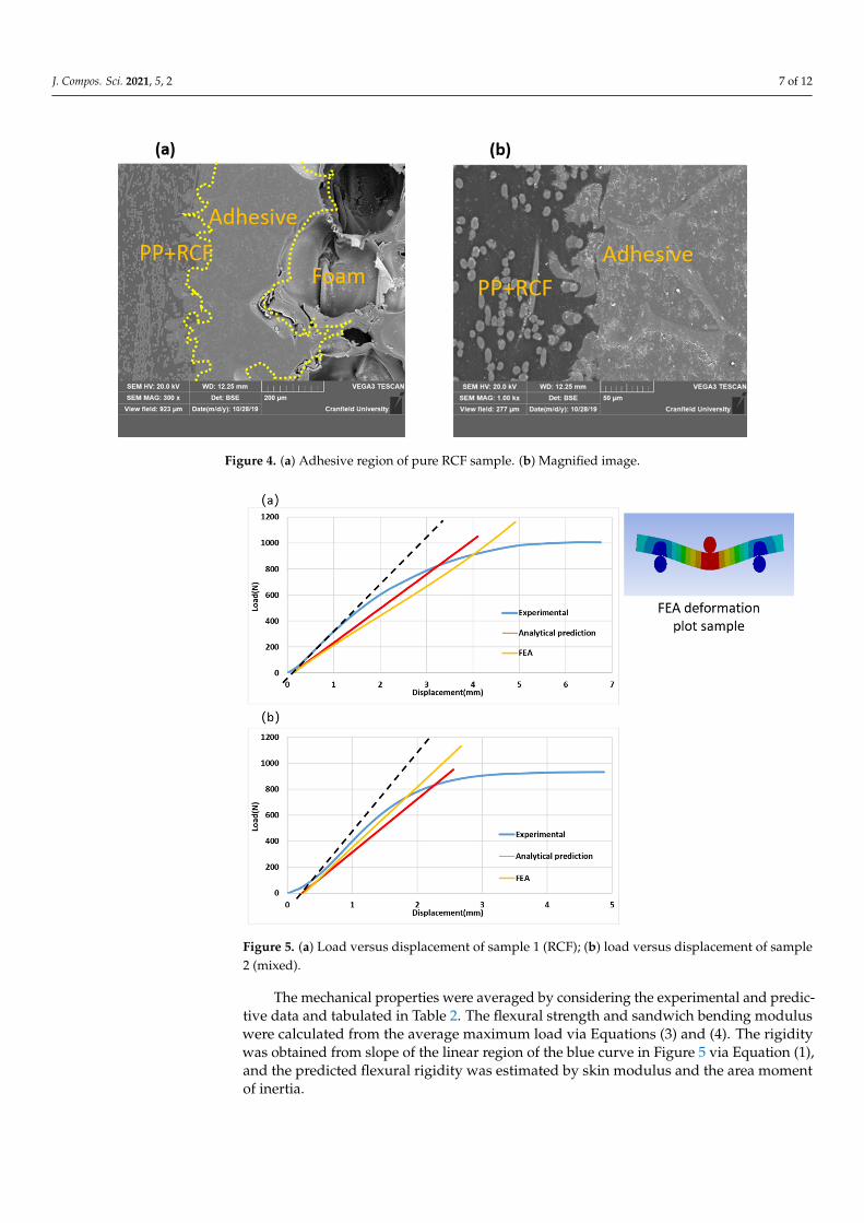
The bonding between the skin and the foam core in the sandwich composites is acritical issue in manufacturing. In this study, thermoplastic copolymer film was used toenable fusion bonding between the skin and the core. Figure 4a clearly illustrates threedistinct regions: skin (left), adhesive fusion-bonded layer (middle), and the foam core(right), which appear to be bonded seamlessly without any void formation.
Figure 4b illustrates a high resolution and magnified image of the bonding of skin andthe thermoplastic film. This image also does not show any indication of finer voids/gaps.Hence, it was inferred that the thermoplastic film is an excellent candidate for thermoplasticfusion bonding the skin and core in a sandwich composite.
3.2. Three-Point Bending Test Results
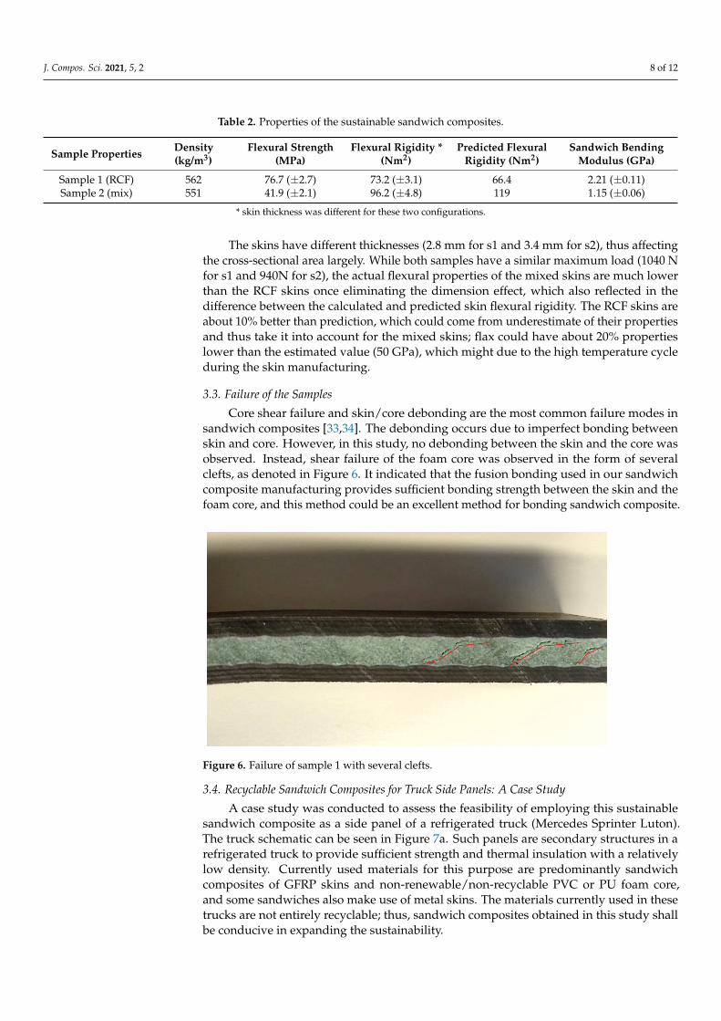
The load versus displacement plot is illustrated in Figure 5. The blue curve illustratesthe experimental data obtained during the three-point bend test (row test data could befound through the link in Supplementary Materials). The red line is indicative the predictedresults from Equations (1) and (2). The grey line with green dots for each data point is FEAanalysis result that predicted the deflection with changing load. The experimental results(blue) of both sample 1 and 2 show a small toe region before the curve increases linearly.This is mentioned in ASTM D7250, and the effect is attributed to the samples ‘adjusting’themselves to fit into the load condition. A correction was made on the load versusdisplacement plot to eliminate this effect by inserting the black dotted line. The intersectionof this correction and the x-axis was considered as the point of zero deflection. Equation(1) is the Timoshenko beam model that was utilized to predict the deflection within the‘elastic region’ before the prediction had intersected with the results at such a point couldbe considered as where plastic deformation initiated. It provides an ideally prediction veryclose to the static FEA results with slightly lower gradient than actual results but withoutattenuation when approaching the intersection point (where failure initiate) that can usedto predict the mechanical property (via maximum load taken) of the sandwich compositeswhen a good deflection (estimation of the intersection) assumption is made.
J. Compos. Sci. 2021, 5, 2 7 of 12
J. Compos. Sci. 2020, 17, x 7 of 13
3. Results and Discussion 3.1. SEM Characterization of Bonding Region
The bonding between the skin and the foam core in the sandwich composites is a critical issue in manufacturing. In this study, thermoplastic copolymer film was used to enable fusion bonding between the skin and the core. Figure 4a clearly illustrates three distinct regions: skin (left), adhesive fusion-bonded layer (middle), and the foam core (right), which appear to be bonded seamlessly without any void formation.
Figure 4. (a) Adhesive region of pure RCF sample. (b) Magnified image.
Figure 4b illustrates a high resolution and magnified image of the bonding of skin and the thermoplastic film. This image also does not show any indication of finer voids/gaps. Hence, it was inferred that the thermoplastic film is an excellent candidate for thermoplastic fusion bonding the skin and core in a sandwich composite.
3.2. Three-Point Bending Test Results The load versus displacement plot is illustrated in Figure 5. The blue curve illustrates
the experimental data obtained during the three-point bend test (row test data could be found through the link in supplementary materials). The red line is indicative the predicted results from Equations (1) and (2). The grey line with green dots for each data point is FEA analysis result that predicted the deflection with changing load. The experimental results (blue) of both sample 1 and 2 show a small toe region before the curve increases linearly. This is mentioned in ASTM D7250, and the effect is attributed to the samples ‘adjusting’ themselves to fit into the load condition. A correction was made on the load versus displacement plot to eliminate this effect by inserting the black dotted line. The intersection of this correction and the x-axis was considered as the point of zero deflection. Equation (1) is the Timoshenko beam model that was utilized to predict the deflection within the ‘elastic region’ before the prediction had intersected with the results at such a point could be considered as where plastic deformation initiated. It provides an ideally prediction very close to the static FEA results with slightly lower gradient than actual results but without attenuation when approaching the intersection point (where failure initiate) that can used to predict the mechanical property (via maximum load taken) of the sandwich composites when a good deflection (estimation of the intersection) assumption is made.
Figure 4. (a) Adhesive region of pure RCF sample. (b) Magnified image.
J. Compos. Sci. 2020, 17, x 8 of 13
Figure 5. (a) Load versus displacement of sample 1 (RCF); (b) load versus displacement of sample 2 (mixed).
The mechanical properties were averaged by considering the experimental and predictive data and tabulated in Table 2. The flexural strength and sandwich bending modulus were calculated from the average maximum load via Equations (3) and (4). The rigidity was obtained from slope of the linear region of the blue curve in Figure 5 via Equation (1), and the predicted flexural rigidity was estimated by skin modulus and the area moment of inertia.
Table 2. Properties of the sustainable sandwich composites
Sample Properties
Density (kg/m3)
Flexural Strength (MPa)
Flexural Rigidity * (Nm2)
Predicted Flexural Rigidity (Nm2)
Sandwich Bending Modulus (GPa)
Sample 1 (RCF) 562 76.7 (±2.7) 73.2 (±3.1) 66.4 2.21 (±0.11) Sample 2 (mix) 551 41.9 (±2.1) 96.2 (±4.8) 119 1.15 (±0.06)
* skin thickness was different for these two configurations.
The skins have different thicknesses (2.8 mm for s1 and 3.4 mm for s2), thus affecting the cross-sectional area largely. While both samples have a similar maximum load (1040 N for s1 and 940N for s2), the actual flexural properties of the mixed skins are much lower than the RCF skins once eliminating the dimension effect, which also reflected in the difference between the calculated and predicted skin flexural rigidity. The RCF skins are about 10% better than prediction, which could come from underestimate of their properties and thus take it into account for the mixed skins; flax could have about 20% properties lower than the estimated value (50 GPa), which might due to the high temperature cycle during the skin manufacturing.
3.3. Failure of the Samples Core shear failure and skin/core debonding are the most common failure modes in
sandwich composites [33,34]. The debonding occurs due to imperfect bonding between
Figure 5. (a) Load versus displacement of sample 1 (RCF); (b) load versus displacement of sample2 (mixed).
The mechanical properties were averaged by considering the experimental and predic-tive data and tabulated in Table 2. The flexural strength and sandwich bending moduluswere calculated from the average maximum load via Equations (3) and (4). The rigiditywas obtained from slope of the linear region of the blue curve in Figure 5 via Equation (1),and the predicted flexural rigidity was estimated by skin modulus and the area momentof inertia.
J. Compos. Sci. 2021, 5, 2 8 of 12
Table 2. Properties of the sustainable sandwich composites.
Sample Properties Density(kg/m3)
Flexural Strength(MPa)
Flexural Rigidity *(Nm2)
Predicted FlexuralRigidity (Nm2)
Sandwich BendingModulus (GPa)
Sample 1 (RCF) 562 76.7 (±2.7) 73.2 (±3.1) 66.4 2.21 (±0.11)Sample 2 (mix) 551 41.9 (±2.1) 96.2 (±4.8) 119 1.15 (±0.06)
* skin thickness was different for these two configurations.
The skins have different thicknesses (2.8 mm for s1 and 3.4 mm for s2), thus affectingthe cross-sectional area largely. While both samples have a similar maximum load (1040 Nfor s1 and 940N for s2), the actual flexural properties of the mixed skins are much lowerthan the RCF skins once eliminating the dimension effect, which also reflected in thedifference between the calculated and predicted skin flexural rigidity. The RCF skins areabout 10% better than prediction, which could come from underestimate of their propertiesand thus take it into account for the mixed skins; flax could have about 20% propertieslower than the estimated value (50 GPa), which might due to the high temperature cycleduring the skin manufacturing.
3.3. Failure of the Samples
Core shear failure and skin/core debonding are the most common failure modes insandwich composites [33,34]. The debonding occurs due to imperfect bonding betweenskin and core. However, in this study, no debonding between the skin and the core wasobserved. Instead, shear failure of the foam core was observed in the form of severalclefts, as denoted in Figure 6. It indicated that the fusion bonding used in our sandwichcomposite manufacturing provides sufficient bonding strength between the skin and thefoam core, and this method could be an excellent method for bonding sandwich composite.
J. Compos. Sci. 2020, 17, x 9 of 13
skin and core. However, in this study, no debonding between the skin and the core was observed. Instead, shear failure of the foam core was observed in the form of several clefts, as denoted in Figure 6. It indicated that the fusion bonding used in our sandwich composite manufacturing provides sufficient bonding strength between the skin and the foam core, and this method could be an excellent method for bonding sandwich composite.
Figure 6. Failure of sample 1 with several clefts.
3.4. Recyclable Sandwich Composites for Truck Side Panels: A Case Study A case study was conducted to assess the feasibility of employing this sustainable
sandwich composite as a side panel of a refrigerated truck (Mercedes Sprinter Luton). The truck schematic can be seen in Figure 7a. Such panels are secondary structures in a refrigerated truck to provide sufficient strength and thermal insulation with a relatively low density. Currently used materials for this purpose are predominantly sandwich composites of GFRP skins and non-renewable/non-recyclable PVC or PU foam core, and some sandwiches also make use of metal skins. The materials currently used in these trucks are not entirely recyclable; thus, sandwich composites obtained in this study shall be conducive in expanding the sustainability.
Figure 6. Failure of sample 1 with several clefts.
3.4. Recyclable Sandwich Composites for Truck Side Panels: A Case Study
A case study was conducted to assess the feasibility of employing this sustainablesandwich composite as a side panel of a refrigerated truck (Mercedes Sprinter Luton).The truck schematic can be seen in Figure 7a. Such panels are secondary structures in arefrigerated truck to provide sufficient strength and thermal insulation with a relativelylow density. Currently used materials for this purpose are predominantly sandwichcomposites of GFRP skins and non-renewable/non-recyclable PVC or PU foam core,and some sandwiches also make use of metal skins. The materials currently used in thesetrucks are not entirely recyclable; thus, sandwich composites obtained in this study shallbe conducive in expanding the sustainability.
J. Compos. Sci. 2021, 5, 2 9 of 12J. Compos. Sci. 2020, 17, x 10 of 13
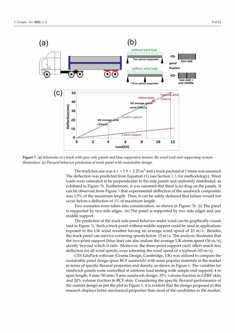
Figure 7. (a) Schematic of a truck with grey side panels and blue supportive frames; (b) wind load and supporting system illustration. (c) Flexural behavior prediction of truck panel with sustainable design.
The truck box size was 4.1 × 1.9 × 2.25 m3 and a truck payload of 1 tonne was assumed. The deflection was predicted from Equation (1) (see Section 2.3, for methodology). Wind loads were estimated to be perpendicular to the side panels and uniformly distributed, as exhibited in Figure 7b. Furthermore, it was assumed that there is no drag on the panels. It can be observed from Figure 5 that experimental deflection of the sandwich composites was 1.5% of the maximum length. Thus, it can be safely deduced that failure would not occur before a deflection of 1% of maximum length.
Two scenarios were taken into consideration, as shown in Figure 7b: (i) The panel is supported by two side edges. (ii) The panel is supported by two side edges and one middle support.
The prediction of the truck side panel behavior under wind can be graphically visualized in Figure 7c. Such a truck panel without middle support could be used in applications exposed to the UK wind weather having an average wind speed of 23 m/s. Besides, the truck panel can survive cornering speeds below 15 m/s. The analysis illustrates that the two-point support (blue line) can also endure the average UK storm speed (36 m/s), shortly beyond which it fails. Moreover, the three-point support (red) offers much less deflection for all wind speeds, even tolerating the wind speed of a typhoon (43 m/s).
CES EduPack software (Granta Design, Cambridge, UK) was utilized to compare the sustainable panel design (pure RCF sandwich) with some popular materials in the market in terms of specific flexural properties and density, as shown in Figure 8. The variables for sandwich panels were controlled at uniform load testing with simple end support; 4 m span length; 5 mm/50 mm/5 mm sandwich design; 35% volume fraction in GFRP skin; and 20% volume fraction in RCF skin. Considering the specific flexural performance of the current design as per the plot in Figure 8, it is evident that the design proposed in this research displays better mechanical properties than most of the candidates in the market.
Figure 7. (a) Schematic of a truck with grey side panels and blue supportive frames; (b) wind load and supporting systemillustration. (c) Flexural behavior prediction of truck panel with sustainable design.
The truck box size was 4.1 × 1.9 × 2.25 m3 and a truck payload of 1 tonne was assumed.The deflection was predicted from Equation (1) (see Section 2.3, for methodology). Windloads were estimated to be perpendicular to the side panels and uniformly distributed, asexhibited in Figure 7b. Furthermore, it was assumed that there is no drag on the panels. Itcan be observed from Figure 5 that experimental deflection of the sandwich compositeswas 1.5% of the maximum length. Thus, it can be safely deduced that failure would notoccur before a deflection of 1% of maximum length.
Two scenarios were taken into consideration, as shown in Figure 7b: (i) The panelis supported by two side edges. (ii) The panel is supported by two side edges and onemiddle support.
The prediction of the truck side panel behavior under wind can be graphically visual-ized in Figure 7c. Such a truck panel without middle support could be used in applicationsexposed to the UK wind weather having an average wind speed of 23 m/s. Besides,the truck panel can survive cornering speeds below 15 m/s. The analysis illustrates thatthe two-point support (blue line) can also endure the average UK storm speed (36 m/s),shortly beyond which it fails. Moreover, the three-point support (red) offers much lessdeflection for all wind speeds, even tolerating the wind speed of a typhoon (43 m/s).
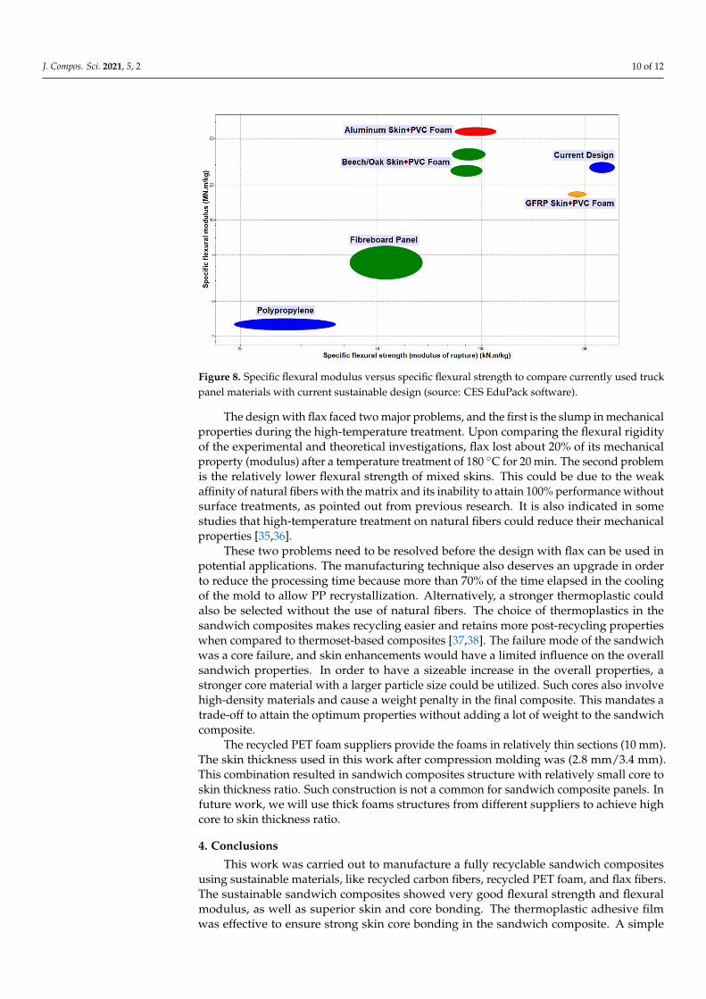
CES EduPack software (Granta Design, Cambridge, UK) was utilized to compare thesustainable panel design (pure RCF sandwich) with some popular materials in the marketin terms of specific flexural properties and density, as shown in Figure 8. The variables forsandwich panels were controlled at uniform load testing with simple end support; 4 mspan length; 5 mm/50 mm/5 mm sandwich design; 35% volume fraction in GFRP skin;and 20% volume fraction in RCF skin. Considering the specific flexural performance ofthe current design as per the plot in Figure 8, it is evident that the design proposed in thisresearch displays better mechanical properties than most of the candidates in the market.
J. Compos. Sci. 2021, 5, 2 10 of 12J. Compos. Sci. 2020, 17, x 11 of 13
Figure 8. Specific flexural modulus versus specific flexural strength to compare currently used truck panel materials with current sustainable design (source: CES EduPack software).
The design with flax faced two major problems, and the first is the slump in mechanical properties during the high-temperature treatment. Upon comparing the flexural rigidity of the experimental and theoretical investigations, flax lost about 20% of its mechanical property (modulus) after a temperature treatment of 180 °C for 20 min. The second problem is the relatively lower flexural strength of mixed skins. This could be due to the weak affinity of natural fibers with the matrix and its inability to attain 100% performance without surface treatments, as pointed out from previous research. It is also indicated in some studies that high-temperature treatment on natural fibers could reduce their mechanical properties [35,36].
These two problems need to be resolved before the design with flax can be used in potential applications. The manufacturing technique also deserves an upgrade in order to reduce the processing time because more than 70% of the time elapsed in the cooling of the mold to allow PP recrystallization. Alternatively, a stronger thermoplastic could also be selected without the use of natural fibers. The choice of thermoplastics in the sandwich composites makes recycling easier and retains more post-recycling properties when compared to thermoset-based composites [37,38]. The failure mode of the sandwich was a core failure, and skin enhancements would have a limited influence on the overall sandwich properties. In order to have a sizeable increase in the overall properties, a stronger core material with a larger particle size could be utilized. Such cores also involve high-density materials and cause a weight penalty in the final composite. This mandates a trade-off to attain the optimum properties without adding a lot of weight to the sandwich composite.
The recycled PET foam suppliers provide the foams in relatively thin sections (10 mm). The skin thickness used in this work after compression molding was (2.8 mm/3.4 mm). This combination resulted in sandwich composites structure with relatively small core to skin thickness ratio. Such construction is not a common for sandwich composite panels. In future work, we will use thick foams structures from different suppliers to achieve high core to skin thickness ratio.
4. Conclusions This work was carried out to manufacture a fully recyclable sandwich composites
using sustainable materials, like recycled carbon fibers, recycled PET foam, and flax fibers. The sustainable sandwich composites showed very good flexural strength and flexural modulus, as well as superior skin and core bonding. The thermoplastic adhesive film was
Figure 8. Specific flexural modulus versus specific flexural strength to compare currently used truckpanel materials with current sustainable design (source: CES EduPack software).
The design with flax faced two major problems, and the first is the slump in mechanicalproperties during the high-temperature treatment. Upon comparing the flexural rigidityof the experimental and theoretical investigations, flax lost about 20% of its mechanicalproperty (modulus) after a temperature treatment of 180 ◦C for 20 min. The second problemis the relatively lower flexural strength of mixed skins. This could be due to the weakaffinity of natural fibers with the matrix and its inability to attain 100% performance withoutsurface treatments, as pointed out from previous research. It is also indicated in somestudies that high-temperature treatment on natural fibers could reduce their mechanicalproperties [35,36].
These two problems need to be resolved before the design with flax can be used inpotential applications. The manufacturing technique also deserves an upgrade in orderto reduce the processing time because more than 70% of the time elapsed in the coolingof the mold to allow PP recrystallization. Alternatively, a stronger thermoplastic couldalso be selected without the use of natural fibers. The choice of thermoplastics in thesandwich composites makes recycling easier and retains more post-recycling propertieswhen compared to thermoset-based composites [37,38]. The failure mode of the sandwichwas a core failure, and skin enhancements would have a limited influence on the overallsandwich properties. In order to have a sizeable increase in the overall properties, astronger core material with a larger particle size could be utilized. Such cores also involvehigh-density materials and cause a weight penalty in the final composite. This mandates atrade-off to attain the optimum properties without adding a lot of weight to the sandwichcomposite.
The recycled PET foam suppliers provide the foams in relatively thin sections (10 mm).The skin thickness used in this work after compression molding was (2.8 mm/3.4 mm).This combination resulted in sandwich composites structure with relatively small core toskin thickness ratio. Such construction is not a common for sandwich composite panels. Infuture work, we will use thick foams structures from different suppliers to achieve highcore to skin thickness ratio.
4. Conclusions
This work was carried out to manufacture a fully recyclable sandwich compositesusing sustainable materials, like recycled carbon fibers, recycled PET foam, and flax fibers.The sustainable sandwich composites showed very good flexural strength and flexuralmodulus, as well as superior skin and core bonding. The thermoplastic adhesive filmwas effective to ensure strong skin core bonding in the sandwich composite. A simple
J. Compos. Sci. 2021, 5, 2 11 of 12
case study was carried out to show potential use of the composites in truck side panel.The flax fibers showed about 20% reduction in the mechanical properties, potentially due tohigh-processing temperature required to process high melting point polypropylene matrix.Therefore, future sustainable sandwich designs must compensate for the degradation in themechanical properties of the sandwich composites. Our sustainable sandwich compositescan meet the requirement for secondary structures in engineering applications; furtherimprovements will be needed for its use in high-performance applications.
Supplementary Materials: The Supplementary Materials are available online at https://www.mdpi.com/2504-477X/5/1/2/s1.
Author Contributions: Conceptualization, Q.J. and S.R.; Data curation, Q.J. and G.C.; Formal anal-ysis, Q.J. and G.C.; Investigation, Q.J. and G.C.; Methodology, Q.J., G.C., and S.R.; Software, V.R.,B.V. and K.J.; Project administration, A.M. and S.R.; Resources, Q.J., G.C., A.K., A.M., K.J., and S.R.;Supervision, A.M. and S.R.; Validation, Q.J. and G.C.; Visualization, Q.J.; Writing—original draft, Q.J.and A.K.; Writing—review & editing, Q.J., A.K., K.J., and S.R. All authors have read and agreed tothe published version of the manuscript.
Funding: This research was partial funding by Royal Academy of Engineering, Industrial AcademiaPartnership Program.
Institutional Review Board Statement: Not applicable, studies not involving human or animals.
Informed Consent Statement: Not applicable, studies not involving human.
Data Availability Statement: Row bending data and one processed file with predictions are availableat: https://data.mendeley.com/datasets/f9vgtm95yb/draft?a=949f5a66-438b-4129-9695-b587dfd28982.
Acknowledgments: This work is supported by Cranfield University Enhanced Composites andStructures Centre in the UK. Thanks to David Ayre for his help in the DSC testing. The author wouldlike to thank Thibault Hernandez, Jim Hurley, and Ben Hopper for their instruction and help duringsample manufacturing and mechanical testing. We would like to acknowledge partial funding fromthe Royal Academy of Engineering, Industry-Academia Partnership Program for supporting thisresearch work.
Conflicts of Interest: The authors declare no conflict of interest.
References1. Mishnaevsky, L.; Branner, K.; Petersen, H.N.; Beauson, J.; McGugan, M.; Sørensen, B.F. Materials for wind turbine blades:
An overview. Materials 2017, 10, 1285. [CrossRef]2. Lakreb, N.; Bezzazi, B.; Pereira, H. Mechanical strength properties of innovative sandwich panels with expanded cork agglomer-
ates. Eur. J. Wood Wood Prod. 2015, 73, 465–473. [CrossRef]3. Poullikkas, A. Sustainable options for electric vehicle technologies. Renew. Sustain. Energy Rev. 2015, 41, 1277–1287. [CrossRef]4. Mayyas, A.; Omar, M.; Hayajneh, M.; Mayyas, A.R. Vehicle’s lightweight design vs. electrification from life cycle assessment
perspective. J. Clean. Prod. 2018, 167, 687–701. [CrossRef]5. Yaman, M.; Önal, T. Investigation of dynamic properties of natural material-based sandwich composites: Experimental test and
numerical simulation. J. Sandw. Struct. Mater. 2016, 18, 397–414. [CrossRef]6. Sargianis, J.J.; Kim, H.I.; Andres, E.; Suhr, J. Sound and vibration damping characteristics in natural material based sandwich
composites. Compos. Struct. 2013, 96, 538–544. [CrossRef]7. Kandare, E.; Luangtriratana, P.; Kandola, B.K. Fire reaction properties of flax/epoxy laminates and their balsa-core sandwich
composites with or without fire protection. Compos. Part B Eng. 2014, 56, 602–610. [CrossRef]8. Monti, A.; Mahi, A.E.L.; Jendli, Z.; Guillaumat, L. Quasi-static and fatigue properties of a balsa cored sandwich structure with
thermoplastic skins reinforced by flax fibres. J. Sandw. Struct. Mater. 2019, 21, 2358–2381. [CrossRef]9. Bach, M.R.; Chalivendra, V.B.; Alves, C.; Depina, E. Mechanical characterization of natural biodegradable sandwich materials.
J. Sandw. Struct. Mater. 2017, 19, 482–496. [CrossRef]10. Osman, S.; Ahmad, M. Flexural and impact properties of bamboo-aluminum sandwich composites. Adv. Mater. Res. 2013, 608–609,
1728–1731. [CrossRef]11. Kabir, M.M.; Wang, H.; Cardona, F.; Aravinthan, T. Effect of chemical treatment on the mechanical and thermal properties of
hemp fibre reinforced thermoset sandwich composites. In Incorporating Sustainable Practice in Mechanics of Structures and Materials,Proceedings of the 21st Australian Conference on the Mechanics of Structures and Materials, Melbourne, Australia, 7–10 December 2010;University of Southern Queensland: Toowoomba, Australia, 2011.

J. Compos. Sci. 2021, 5, 2 12 of 12
12. Dweib, M.A.; Hu, B.; O’Donnell, A.; Shenton, H.W.; Wool, R.P. All natural composite sandwich beams for structural applications.Compos. Struct. 2004, 63, 147–157. [CrossRef]
13. Azmi, M.A.; Abdullah, H.Z.; Idris, M.I. Properties of polyurethane foam/coconut coir fiber as a core material and as a sandwichcomposites component. IOP Conf. Ser. Mater. Sci. Eng. 2013, 50. [CrossRef]
14. Hoto, R.; Furundarena, G.; Torres, J.P.; Muñoz, E.; Andrés, J.; García, J.A. Flexural behavior and water absorption of asymmetricalsandwich composites from natural fibers and cork agglomerate core. Mater. Lett. 2014, 127, 48–52. [CrossRef]
15. Oliveira, P.R.; Bonaccorsi, A.M.S.; Panzera, T.H.; Christoforo, A.L.; Scarpa, F. Sustainable sandwich composite structures madefrom aluminium sheets and disposed bottle caps. Thin-Walled Struct. 2017, 120, 38–45. [CrossRef]
16. Balcıoglu, H.E. Flexural Behaviors of Sandwich Composites Produced Using Recycled and Natural Material. Mugla J. Sci. Technol.2018, 64–73. [CrossRef]
17. Petrone, G.; Rao, S.; de Rosa, S.; Mace, B.R.; Franco, F.; Bhattacharyya, D. Behaviour of fibre-reinforced honeycomb core underlow velocity impact loading. Compos. Struct. 2013, 100, 356–362. [CrossRef]
18. Petrone, G.; Rao, S.; de Rosa, S.; Mace, B.R.; Franco, F.; Bhattacharyya, D. Initial experimental investigations on natural fibrereinforced honeycomb core panels. Compos. Part B Eng. 2013, 55, 400–406. [CrossRef]
19. Petrone, G.; D’Alessandro, V.; Franco, F.; Mace, B.; de Rosa, S. Modal characterisation of recyclable foam sandwich panels.Compos. Struct. 2014, 113, 362–368. [CrossRef]
20. Maia, B.S.; Tjong, J.; Sain, M. Material characterization of recycled and virgin carbon fibers for transportation compositeslightweighting. Mater. Today Sustain. 2019, 5, 100011. [CrossRef]
21. van de Werken, N.; Reese, M.S.; Taha, M.R.; Tehrani, M. Investigating the effects of fiber surface treatment and alignment onmechanical properties of recycled carbon fiber composites. Compos. Part A Appl. Sci. Manuf. 2019, 119, 38–47. [CrossRef]
22. Rahimizadeh, A.; Kalman, J.; Fayazbakhsh, K.; Lessard, L. Recycling of fiberglass wind turbine blades into reinforced filamentsfor use in Additive Manufacturing. Compos. Part B Eng. 2019, 175, 107101. [CrossRef]
23. Cousins, D.S.; Suzuki, Y.; Murray, R.E.; Samaniuk, J.R.; Stebner, A.P. Recycling glass fiber thermoplastic composites from windturbine blades. J. Clean. Prod. 2019, 209, 1252–1263. [CrossRef]
24. Yamamoto, T.; Yabushita, S.; Irisawa, T.; Tanabe, Y. Enhancement of bending strength, thermal stability and recyclability ofcarbon-fiber-reinforced thermoplastics by using silica colloids. Compos. Sci. Technol. 2019, 181, 107665. [CrossRef]
25. Shamsuyeva, M.; Hansen, O.; Endres, H.J.; Abu-Jdayil, B. Review on Hybrid Carbon/Flax Composites and Their Properties. Int.J. Polym. Sci. 2019, 2019, 9624670. [CrossRef]
26. Armacell Launches Recycled Foam Core. Available online: https://www.materialstoday.com/composite-processing/products/armacell-launches-recycled-foam-core-/ (accessed on 21 December 2020).
27. Longana, M.L.; Ondra, V.; Yu, H.; Potter, K.D.; Hamerton, I. Reclaimed carbon and flax fibre composites: Manufacturing andmechanical properties. Recycling 2018, 3, 52. [CrossRef]
28. ASTM International. ASTM D7249/D 7249M—06 Standard Test Method for Facing Properties of Sandwich Constructions byLong Beam Flexure. In Annual Book of ASTM Standards; ASTM International: West Conshohocken, PA, USA, 2009.
29. ASTM International. ASTM D 7250/D 7250M Standard Practice for Determining Sandwich Beam Flexural and Shear Stiffness.In Annual Book of ASTM Standards; ASTM International: West Conshohocken, PA, USA, 2009.
30. ASTM International. ASTM C393/C 393 M—06 Standard Test Method for Core Shear Properties of Sandwich Constructions byBeam. In Annual Book of ASTM Standards; ASTM International: West Conshohocken, PA, USA, 2009.
31. Pronk, A.C. Calibration of 4pb tests taking into account shear forces and other equipment factors. Road Mater. Pavement Des. 2009,10, 373–386. [CrossRef]
32. Pronk, A.C. Theory of the Four Point Dynamic Bending Test; Ministry of Transport, Public Works and Water Management: The Nether-lands, 1996.
33. Imielinska, K.; Guillaumat, L.; Wojtyra, R.; Castaings, M. Effects of manufacturing and face/core bonding on impact damage inglass/polyester-PVC foam core sandwich panels. Compos. Part B Eng. 2008, 39, 1034–1041. [CrossRef]
34. Kim, C.G.; Hong, C.S. Buckling of unbalanced anisotropic sandwich plates with finite bonding stiffness. AIAA J. 1988, 26, 982–988.[CrossRef]
35. Singh, J.I.P.; Singh, S.; Dhawan, V. Effect of Curing Temperature on Mechanical Properties of Natural Fiber Reinforced PolymerComposites. J. Nat. Fibers 2018, 15, 687–696. [CrossRef]
36. Bourmaud, A.; Baley, C. Effects of thermo mechanical processing on the mechanical properties of biocomposite flax fibersevaluated by nanoindentation. Polym. Degrad. Stab. 2010, 95, 1488–1494. [CrossRef]
37. Corvaglia, P.; Passaro, A.; Manni, O.; Barone, L.; Maffezzoli, A. Recycling of PP-based sandwich panels with continuous fibercomposite skins. J. Thermoplast. Compos. Mater. 2006, 19, 731–745. [CrossRef]
38. Poulakis, J.G.; Varelidis, P.C.; Papaspyrides, C.D. Recycling of Polypropylene-Based Composites. Wiley 1997, 16, 313–322.[CrossRef]