A new hybrid concept for sandwich structures
6
A new hybrid concept for sandwich structures A.G. Mamalis a, * , K.N. Spentzas b , N.G. Pantelelis b , D.E. Manolakos a , M.B. Ioannidis a a Laboratory of Manufacturing Technology, National Technical University of Athens, 9, Iroon Polytechniou Avenue, 15780 Athens, Greece b Vehicles’ Laboratory, National Technical University of Athens, 9, Iroon Polytechniou Avenue, 15780 Athens, Greece Available online 17 May 2007 Abstract Sandwich structures are considered as optimal designs for carrying bending loads and can be either metal (aluminium faces and hon- eycomb or metal foam cores) or polymer structures (composite faces with polymer foam cores). In this paper, a new hybrid sandwich structure has been developed by combining most of the advantages of metallic and polymeric materials while avoiding some of their main disadvantages. For this new concept metal sheets are used at the outer surfaces to maximize rigidity while introducing in between light- weight cores adhesively bonded to keep the whole structure together. Furthermore, composite or wood layers may be used as interme- diate layers to improve impact resistance. Potential methods for the manufacturing of this new structure are based on compression under vacuum. The results include the study of several panel configurations theoretically based on Finite element analysis and on the modified simplified equations and experimental results in the most representative cases of the study. Ó 2007 Elsevier Ltd. All rights reserved. Keywords: Sandwich structure; Finite element analysis; Three-point bending; Metal skins; Foam core 1. Introduction Although sandwich structures are considered as optimal set-ups for carrying bending loads, their structural design and manufacturing entail knowledge and experience [1]. Many researchers have studied the variety of the failure mechanisms of the sandwich structures either under static loads, e.g. [1,3,6,7], or under dynamic loads, e.g. impact [7,8], where the importance of the materials’ choice is prevailing. In order to tackle some of the weaknesses of the existing materials for sandwich structures some researchers have stud- ied successfully certain material combinations either in the core [8–10] or introducing internal layers [11] or even by mix- ing of completely different materials such as metals and poly- mers with applications that may be found in the building sector [12] (wall and roof panels) and in the automotive sector (thin steel or aluminium face sheets and polymer cores) [13]. These hybrid sandwich structures although improving consid- erably the structural performance of either of their materials can not be used as primary structures. In this paper, a new hybrid sandwich structure has been developed by combining most of the advantages of metallic and polymeric materials while avoiding some of their major disadvantages. The design concept is to use metals at the face sheets in order to maximize rigidity and extremely lightweight cores while introducing an intermediate layer from composite materials or wood between the face sheets and the core appropriately bonded to keep the whole struc- ture together [14,15]. The rest of the paper is organised as follows: in Section 2 the classic sandwich theory is analysed and in Section 3 the new hybrid sandwich concept is analysed while in Section 4 other structural issues such as impact behaviour are addressed. In Section 5 theoretical and experimental results are presented for the proof of concept and in Section 6 con- clusions are drawn. 2. Classic sandwich theory In general, to study and optimise a structure its basic features need to be modelled and analysed. For this reason, 0263-8223/$ - see front matter Ó 2007 Elsevier Ltd. All rights reserved. doi:10.1016/j.compstruct.2007.05.002 * Corresponding author. Tel.: +30 210 7723688. E-mail address: [email protected] (A.G. Mamalis). www.elsevier.com/locate/compstruct Available online at www.sciencedirect.com Composite Structures 83 (2008) 335–340
Transcript of A new hybrid concept for sandwich structures
Available online at www.sciencedirect.com
www.elsevier.com/locate/compstruct
Composite Structures 83 (2008) 335–340
A new hybrid concept for sandwich structures
A.G. Mamalis a,*, K.N. Spentzas b, N.G. Pantelelis b, D.E. Manolakos a, M.B. Ioannidis a
a Laboratory of Manufacturing Technology, National Technical University of Athens, 9, Iroon Polytechniou Avenue, 15780 Athens, Greeceb Vehicles’ Laboratory, National Technical University of Athens, 9, Iroon Polytechniou Avenue, 15780 Athens, Greece
Available online 17 May 2007
Abstract
Sandwich structures are considered as optimal designs for carrying bending loads and can be either metal (aluminium faces and hon-eycomb or metal foam cores) or polymer structures (composite faces with polymer foam cores). In this paper, a new hybrid sandwichstructure has been developed by combining most of the advantages of metallic and polymeric materials while avoiding some of their maindisadvantages. For this new concept metal sheets are used at the outer surfaces to maximize rigidity while introducing in between light-weight cores adhesively bonded to keep the whole structure together. Furthermore, composite or wood layers may be used as interme-diate layers to improve impact resistance. Potential methods for the manufacturing of this new structure are based on compression undervacuum. The results include the study of several panel configurations theoretically based on Finite element analysis and on the modifiedsimplified equations and experimental results in the most representative cases of the study.� 2007 Elsevier Ltd. All rights reserved.
Keywords: Sandwich structure; Finite element analysis; Three-point bending; Metal skins; Foam core
1. Introduction
Although sandwich structures are considered as optimalset-ups for carrying bending loads, their structural designand manufacturing entail knowledge and experience [1].Many researchers have studied the variety of the failuremechanisms of the sandwich structures either under staticloads, e.g. [1,3,6,7], or under dynamic loads, e.g. impact[7,8], where the importance of the materials’ choice isprevailing.
In order to tackle some of the weaknesses of the existingmaterials for sandwich structures some researchers have stud-ied successfully certain material combinations either in thecore [8–10] or introducing internal layers [11] or even by mix-ing of completely different materials such as metals and poly-mers with applications that may be found in the buildingsector [12] (wall and roof panels) and in the automotive sector(thin steel or aluminium face sheets and polymer cores) [13].These hybrid sandwich structures although improving consid-
0263-8223/$ - see front matter � 2007 Elsevier Ltd. All rights reserved.
doi:10.1016/j.compstruct.2007.05.002
* Corresponding author. Tel.: +30 210 7723688.E-mail address: [email protected] (A.G. Mamalis).
erably the structural performance of either of their materialscan not be used as primary structures.
In this paper, a new hybrid sandwich structure has beendeveloped by combining most of the advantages of metallicand polymeric materials while avoiding some of their majordisadvantages. The design concept is to use metals at theface sheets in order to maximize rigidity and extremelylightweight cores while introducing an intermediate layerfrom composite materials or wood between the face sheetsand the core appropriately bonded to keep the whole struc-ture together [14,15].
The rest of the paper is organised as follows: in Section 2the classic sandwich theory is analysed and in Section 3 thenew hybrid sandwich concept is analysed while in Section 4other structural issues such as impact behaviour areaddressed. In Section 5 theoretical and experimental resultsare presented for the proof of concept and in Section 6 con-clusions are drawn.
2. Classic sandwich theory
In general, to study and optimise a structure its basicfeatures need to be modelled and analysed. For this reason,

336 A.G. Mamalis et al. / Composite Structures 83 (2008) 335–340
a narrower version of a panel (Fig. 1a) with equivalentloads and conditions will be studied extensively in theoret-ical simulations and experimental tests.
Considering the basic beam theory in a typical three-point bending situation the mid-point deflection is given as
d ¼ PL3
48ðEIÞeq
þ PL4ðAGÞeq
ð1Þ
where P is the load, L and b are the beam’s span and width,E and G are the materials’ Young’s and shear modulus. Inthe conventional sandwich structure there are two materi-als composing the structure: the faces and the core so thecontribution of each material can be analysed straightfor-ward. As in the present case we will study sandwich struc-tures with
(a) face thickness considerably smaller than the corethickness (tf� tc)(b) core stiffness significantly smaller than the faces stiff-ness (Ef� Ec)(c) length considerably larger than thickness (L� tc)
the mid-point deflection for long beams in three-pointbending (Eq. (1)) becomes:
d ¼ PL3
24Ef tf t2cb
ð2Þ
The failure of a sandwich structure is a very complicatedphenomenon and may be due to various failure mecha-nisms in one of the materials that composes the structure.These mechanisms have been analysed and tested by vari-ous researchers [1,2,12] and the allowable mid-point load-ings in a three-point test with respect to each failuremode can be summarised as [2]:
Fig. 1. Sandwich structure section showing the thin outer faces (top andbottom) and the inner thick core. (a) Classic concept. (b) Hybrid conceptshowing also the intermediate layers.
Face microbuckling ðFMBÞ :Pb¼ 4tf tcrf
Lð3Þ
Face wrinkling ðFWÞ :Pb¼ 2tf tc
L
ffiffiffiffiffiffiffiffiffiffiffiffiffiffiffiEf EcGc
3p
ð4Þ
Core shear ðCSÞ :Pb¼ 2tcsc ð5Þ
IndentationðIndÞ :Pb¼
ffiffiffiffiffiffiffiffiffiffiffiffiffiffiffiffiffiffiffiffip2Efr2
c t3f tc
L3
ror
Pb¼
ffiffiffiffiffiffiffiffiffiffiffiffiffiffiffiffiffiffiffiffiffi16EfEct3
f tc
3L2
s
ð6Þ
where b; L; tf ; tc; P ;Ef ;Ec;Gc; rf ; rc; sc are, respectively, thewidth and length of the beam, the face sheets’ and core’sthicknesses, the maximum point load the Young’s modulusfor the skins and the core, the core shear modulus, the max-imum stress for the face sheets and the maximum compres-sion and shear stresses for the core.
Eqs. (3)–(6) give a rough idea of how each material con-tributes to the failure of the whole structure. For example ifa low cost foam core is used it is very likely that the beamswill fail either due to core shear or due to indentation espe-cially in three-point loading.
However, this theoretical analysis does not considerthree basic issues: the interaction between failure mecha-nisms, the role of the adhesion between the materials andthe contribution of a third material, between the face sheetand the core. The first two issues are very complicated andneed separate studies but at the present paper the role ofthe third intermediate material will be addressed.
3. The hybrid sandwich concept
The classic sandwich structure consists of two thin andstiff face sheets and a thick, lightweight and stiff enoughmaterial in between. Although this structure seems optimalin practice the large differences between the structural prop-erties of the materials in contact create many problems.Moreover the cost of the existing core materials is very highpushing towards the selection of the lowest possible perfor-mance cores. Of course the final selection of the core mate-rial is a compromise between these limits, the cost, theweigh but also other characteristics of the core such asthe impact resistance, fatigue, moisture, etc. Because thehomogeneity of the core materials makes this compromisevery tough, some attempts to develop either graded coresor two stacked foam cores [4,9–11] have been presented.
A compromise between the homogeneous and gradedcores is the introduction of an intermediate layer as canbe seen in Fig. 1b. This layer of thickness ti should be muchstiffer than the core material, lightweight enough and pref-erably much thicker than the face sheet. This intermediatelayer will allow the use of very thin face sheets, e.g. metals,and very cheap cores, e.g. XPS or PUR, at the expense of aslightly higher weight. Furthermore, if a common materialis chosen, e.g. wood, this intermediate layer will alsodecrease the cost considerably. However, a very good adhe-sion between all these three materials has to be ensured.
A.G. Mamalis et al. / Composite Structures 83 (2008) 335–340 337
The advantage of this intermediate layer may not beseen in face microbuckling or core shear which are practi-cally properties that do not include interaction with othermaterials but it will improve face wrinkling and indenta-tion which are of equal importance especially in the caseof cheap foam cores. In order to quantify this improvementEqs. (4) and (6) can still hold if the mechanical propertiesof the foam are substituted by the corresponding propertiesof the intermediate layer so Eqs. (4) and (6) are trans-formed to
Face wrinkling :Pb¼ 2tf tc
L
ffiffiffiffiffiffiffiffiffiffiffiffiffiffiEfEiGi
3p
ð7Þ
Indentation :Pb¼
ffiffiffiffiffiffiffiffiffiffiffiffiffiffiffiffiffiffiffiffip2Efr2
i t3f tc
L3
rð8Þ
4. Other design issues
Besides the rigidity of the panel other issues such as theimpact and fatigue resistance should also be taken intoconsideration. The sandwich structure, as such, is vulnera-ble to impact, so special consideration for these loads isrequired. The impact vulnerability of the sandwich panelis due mainly to the debonding between the skins and thecore. This debonding is due to the large deformationsbetween the flexible foam core and the skin leading at leastto the destruction of the adhesive layer and most of thetimes the internal failure of the outer surface of the core.In order to moderate this difference at the present designan intermediate layer has been introduced. Initially, a thinglassfibre/epoxy layer was used, but after several impacttests, a thicker but lighter plywood layer was chosen.
Fatigue is also an important issue when designing forthe transportation sector. The most vulnerable materialwith the most critical role is the adhesive which for thepresent study was an ordinary epoxy resin and not a specialadhesive. However, the foam core is also very vulnerable tofatigue and its characteristics may fall by 50% after hun-dreds of thousand cycles. So it is very important to
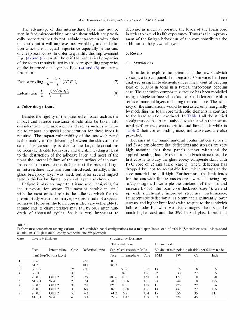
Table 1Performance comparison among various 1 · 0.5 sandwich panel configuratioaluminium, GE: glass (0/90) epoxy composite and W: plywood)
Case Layers + thickness Structural p
FEA simul
Face Intermediate Core Deflection (mm) Von Mises
(mm) (top/bottom faces) Face Int
1 St: 6 67.8 5032 Al: 8 80.1 283.33 GE:1.2 25 57.0 97.4 GE:3.6 38 11.5 345 St: 0.5 GE:1.2 25 12.9 183.6 18.6 Al: 2/1 W:4 25 7.4 44.1 0.7 St: 0.5 GE:1.2 38 7.8 126 12.8 St: 0.8 GE:1.2 38 6.8 82 8.9 St: 0.5 GE:1.2 50 4.3 61.2 6.
10 Al: 2/1 W:4 60 3.3 29.5 1.
decrease as much as possible the loads of the foam corein order to extend its life expectancy. Towards the improve-ment of the fatigue behaviour of the core contributes theaddition of the plywood layer.
5. Results
5.1. Simulations
In order to explore the potential of the new sandwichconcept, a typical panel, 1 m long and 0.5 m wide, has beenanalysed using finite elements under linear central bendingload of 6000 N in total in a typical three-point bendingcase. The sandwich composite structure has been modelledusing a single surface with classical shell elements with aseries of material layers including the foam core. The accu-racy of the simulations would be increased only marginallyby modelling the foam core with solid elements in contrastto the large solution overhead. In Table 1 all the studiedconfigurations has been analysed together with their struc-tural performance characteristics and limit loads while inTable 2 their corresponding mass, indicative cost are alsoprovided.
Looking at the single material configurations (cases 1and 2) we can observe that deflections and stresses are veryhigh meaning that these panels cannot withstand theapplied bending load. Moving to sandwich structures, thefirst case is to study the glass epoxy composite skins withPVC core of 25 mm thick (case 3) where deflection hasdropped but not to acceptable level while stresses at thecore material are still high. Furthermore, the limit loadsfor the sandwich failure modes are low not allowing anysafety margins. If we triple the thickness of the skin andincrease by 50% the foam core thickness (case 4), we endup with significantly improved structural performance,i.e. acceptable deflection at 11.5 mm and significantly lowerstresses and higher limit loads with respect to the sandwichfailure modes but with two disadvantages: the first is themuch higher cost and the 0/90 biaxial glass fabric that
ns for a mid span linear load of 6000 N (St: stainless steel, Al: standard
erformance
ations Failure modes
stresses in MPa Maximum mid-point loads (kN) per failure mode
ermediate Core FMB FW CS Inde
– – – –– – – –
2 1.22 18 6 18 50.26 82 30 27 35
6 0.52 8 178 18 7856 0.35 23 244 18 1259 0.27 11 270 27 9638 0.26 18 432 27 1952 0.14 15 356 35 11147 0.19 58 624 45 201
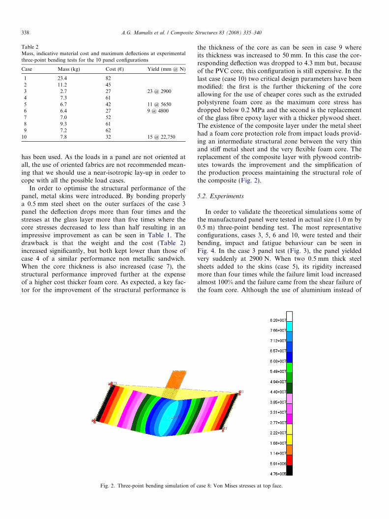
Table 2Mass, indicative material cost and maximum deflections at experimentalthree-point bending tests for the 10 panel configurations
Case Mass (kg) Cost (€) Yield (mm @ N)
1 23.4 822 11.2 453 2.7 27 23 @ 29004 7.3 615 6.7 42 11 @ 56506 6.4 27 9 @ 48007 7.0 528 9.3 619 7.2 62
10 7.8 32 15 @ 22,750
338 A.G. Mamalis et al. / Composite Structures 83 (2008) 335–340
has been used. As the loads in a panel are not oriented atall, the use of oriented fabrics are not recommended mean-ing that we should use a near-isotropic lay-up in order tocope with all the possible load cases.
In order to optimise the structural performance of thepanel, metal skins were introduced. By bonding properlya 0.5 mm steel sheet on the outer surfaces of the case 3panel the deflection drops more than four times and thestresses at the glass layer more than five times where thecore stresses decreased to less than half resulting in animpressive improvement as can be seen in Table 1. Thedrawback is that the weight and the cost (Table 2)increased significantly, but both kept lower than those ofcase 4 of a similar performance non metallic sandwich.When the core thickness is also increased (case 7), thestructural performance improved further at the expenseof a higher cost thicker foam core. As expected, a key fac-tor for the improvement of the structural performance is
Fig. 2. Three-point bending simulation of
the thickness of the core as can be seen in case 9 whereits thickness was increased to 50 mm. In this case the cor-responding deflection was dropped to 4.3 mm but, becauseof the PVC core, this configuration is still expensive. In thelast case (case 10) two critical design parameters have beenmodified: the first is the further thickening of the coreallowing for the use of cheaper cores such as the extrudedpolystyrene foam core as the maximum core stress hasdropped below 0.2 MPa and the second is the replacementof the glass fibre epoxy layer with a thicker plywood sheet.The existence of the composite layer under the metal sheethad a foam core protection role from impact loads provid-ing an intermediate structural zone between the very thinand stiff metal sheet and the very flexible foam core. Thereplacement of the composite layer with plywood contrib-utes towards the improvement and the simplification ofthe production process maintaining the structural role ofthe composite (Fig. 2).
5.2. Experiments
In order to validate the theoretical simulations some ofthe manufactured panel were tested in actual size (1.0 m by0.5 m) three-point bending test. The most representativeconfigurations, cases 3, 5, 6 and 10, were tested and theirbending, impact and fatigue behaviour can be seen inFig. 4. In the case 3 panel test (Fig. 3), the panel yieldedvery suddenly at 2900 N. When two 0.5 mm thick steelsheets added to the skins (case 5), its rigidity increasedmore than four times while the failure limit load increasedalmost 100% and the failure came from the shear failure ofthe foam core. Although the use of aluminium instead of
case 8: Von Mises stresses at top face.
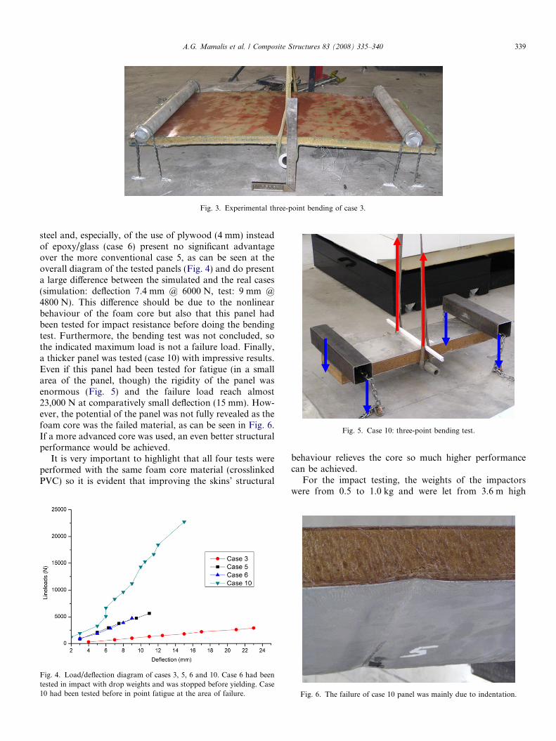
Fig. 3. Experimental three-point bending of case 3.
Fig. 5. Case 10: three-point bending test.
A.G. Mamalis et al. / Composite Structures 83 (2008) 335–340 339
steel and, especially, of the use of plywood (4 mm) insteadof epoxy/glass (case 6) present no significant advantageover the more conventional case 5, as can be seen at theoverall diagram of the tested panels (Fig. 4) and do presenta large difference between the simulated and the real cases(simulation: deflection 7.4 mm @ 6000 N, test: 9 mm @4800 N). This difference should be due to the nonlinearbehaviour of the foam core but also that this panel hadbeen tested for impact resistance before doing the bendingtest. Furthermore, the bending test was not concluded, sothe indicated maximum load is not a failure load. Finally,a thicker panel was tested (case 10) with impressive results.Even if this panel had been tested for fatigue (in a smallarea of the panel, though) the rigidity of the panel wasenormous (Fig. 5) and the failure load reach almost23,000 N at comparatively small deflection (15 mm). How-ever, the potential of the panel was not fully revealed as thefoam core was the failed material, as can be seen in Fig. 6.If a more advanced core was used, an even better structuralperformance would be achieved.
It is very important to highlight that all four tests wereperformed with the same foam core material (crosslinkedPVC) so it is evident that improving the skins’ structural
Fig. 4. Load/deflection diagram of cases 3, 5, 6 and 10. Case 6 had beentested in impact with drop weights and was stopped before yielding. Case10 had been tested before in point fatigue at the area of failure.
behaviour relieves the core so much higher performancecan be achieved.
For the impact testing, the weights of the impactorswere from 0.5 to 1.0 kg and were let from 3.6 m high
Fig. 6. The failure of case 10 panel was mainly due to indentation.

340 A.G. Mamalis et al. / Composite Structures 83 (2008) 335–340
resulting in impact energy from 18 J to 36 J. These testsindicated that cases 3 (only glassfibre/epoxy skin) and 6(aluminium and plywood skins) presented acceptableimpact resistance whereas case 5 (steel on top with glassfi-bre/epoxy intermediate layer) presented large debondingareas. This behaviour can be easily explained as the ply-wood layer is much thicker than the composite layer andbecause of its lower modulus of elasticity provides animproved behaviour to low energy impact loads.
The fatigue resistance was studied again in actual sizepanels using a cam mechanism for a large number of cycles(up to 2.5 million cycles). Although this measurement facil-ity was not standardized by any means, it did reveal thebasic phenomena of the fatigue of the panels. As expectedthe more vulnerable material in the present design was thePVC core and especially the thinner cores. This is not a sur-prise as based on the simulation results presented in Table1 the core stresses are much closer to the yield stress of thePVC foam core which is 0.6 MPa resulting in core failure incases 3 and 5. However, the reinforcement of the core withthe plywood reduces the maximum stress as can be seen incase 6 making the panel much more resistant to cyclic fati-gue. The fatigue resistance is further improved with thethickening of the foam core as the maximum load is line-arly proportional to this thickness as can be seen fromEq. (5). Thus if the thickness of the core is furtherincreased, the maximum Von Mises stresses drop below0.2 MPa (case 10) improving considerably the fatiguebehaviour of the panel even if a cheaper/lower performancefoam core is used.
With respect to the weight and cost of the panels,some very interesting observations can be extracted fromTable 2. For the fair comparison of the polymer compos-ite sandwich with the other panels the case 4 panel isused as the case 3 panel is very flexible and of low per-formance. So comparing the case 4 panel to the case 5panel we can observe that the former is heavier andmuch more expensive for comparable performance. Ifwe substitute the glass/epoxy layer with plywood (case6) the panel is even lighter and the cost drops dramati-cally to more than half of the polymer composite panel(case 4). For case 10 which is the best panel configura-tion achieved, the cost and weight increased marginallyas for foam core in real applications common extrudedEPS can be also used instead of the much more expen-sive xPVC.
6. Conclusions
A new concept of a lightweight sandwich structure forhigh performance and reasonable cost has been presented.The new concept employs thin metallic skins, low densityfoams and intermediate layers to improve impact andbonding behaviour. Finite element simulation and otherstructural analysis tools were used for the optimal sand-wich design and for the optimization of the materials’topology of the hybrid structure. The new concept was alsoproved in laboratory scale testing and further tests in fati-gue and impact resistance are inline.
References
[1] Zenkert D. An introduction to sandwich construction. London,UK: Chameleon Press Ltd.; 1995.
[2] Steeves CA, Fleck NA. Collapse mechanisms of sandwich beams withcomposite faces and a foam core, loaded in three-point bending. PartI: analytical models and minimum weight design. Int J Mech Sci2004;46:561–83.
[3] Rizov V, Shipsha A, Zenkert D. Indentation study of foam coresandwich composite panels. Compos Struct 2005;69:95–102.
[4] Borsellino C, Calabrese L, Valenza A. Experimental and numericalevaluation of sandwich composite structures. Compos Sci Technol2004;64(10–11):1709–15.
[6] Abrate S. Impact on composite structures. Cambridge, UK: Cam-bridge University Press; 1998.
[7] Mamalis AG, Manolakos DE, Ioannidis MB, Papapostolou DP. Onthe crushing response of composite sandwich panels subjected toedgewise compression: experimental. Compos Struct 2005;71:246–57.
[8] Pitarresi G, Carruthers JJ, Robinson AM, Torre G, Kenny JM,Ingleton S, et al. A comparative evaluation of crashworthy compos-ite sandwich structures. Compos Struct 2007;78:34–44.
[9] Zhu H, Sankar BV. Analysis of sandwich TPS panel with functionallygraded foam core by Galerkin method. Compos Struct 2007;77:280–7.
[10] Hosur MV, Abdullah M, Jeelani S. Manufacturing and low-velocityimpact characterization of foam filled 3-D integrated core sandwichcomposites with hybrid face sheets. Compos Struct 2005;69:167–81.
[11] Jiang D, Shu D. Local displacement of core in two-layer sandwichcomposite structures subjected to low velocity impact. Compos Struct2005;71:53–60.
[12] Davies JM. Lightweight sandwich construction. Oxford, UK: Black-well Science, Ltd.; 2001.
[13] Gresham J, Cantwell W, Cardew-Hall MJ, Compston P, Kalyanas-undaram S. Drawing behaviour of metal–composite sandwich struc-tures. Compos Struct 2006;75:305–12.
[14] Pantelelis NG, European Patent No EP1770227 (4/2007).[15] Pantelelis NG, Vrouvakis T, Spentzas K. A new concept for low cost
composite trailer. In: Proceedings of the 12th international conferencein composites engineering, Tenerife, August, 2005.