and Materials Journal of Sandwich Structures - CiteSeerX
27
http://jsm.sagepub.com/ and Materials Journal of Sandwich Structures http://jsm.sagepub.com/content/9/6/571 The online version of this article can be found at: DOI: 10.1177/1099636207070853 2007 9: 571 Journal of Sandwich Structures and Materials Brian Hayman Sandwich Structures Approaches to Damage Assessment and Damage Tolerance for FRP Published by: http://www.sagepublications.com at: can be found Journal of Sandwich Structures and Materials Additional services and information for http://jsm.sagepub.com/cgi/alerts Email Alerts: http://jsm.sagepub.com/subscriptions Subscriptions: http://www.sagepub.com/journalsReprints.nav Reprints: http://www.sagepub.com/journalsPermissions.nav Permissions: http://jsm.sagepub.com/content/9/6/571.refs.html Citations: What is This? - Nov 5, 2007 Version of Record >> at PENNSYLVANIA STATE UNIV on March 5, 2014 jsm.sagepub.com Downloaded from at PENNSYLVANIA STATE UNIV on March 5, 2014 jsm.sagepub.com Downloaded from
-
Upload
khangminh22 -
Category
Documents
-
view
0 -
download
0
Transcript of and Materials Journal of Sandwich Structures - CiteSeerX
http://jsm.sagepub.com/and Materials
Journal of Sandwich Structures
http://jsm.sagepub.com/content/9/6/571The online version of this article can be found at:
DOI: 10.1177/1099636207070853
2007 9: 571Journal of Sandwich Structures and MaterialsBrian Hayman
Sandwich StructuresApproaches to Damage Assessment and Damage Tolerance for FRP
Published by:
http://www.sagepublications.com
at: can be foundJournal of Sandwich Structures and MaterialsAdditional services and information for
http://jsm.sagepub.com/cgi/alertsEmail Alerts:
http://jsm.sagepub.com/subscriptionsSubscriptions:
http://www.sagepub.com/journalsReprints.navReprints:
http://www.sagepub.com/journalsPermissions.navPermissions:
http://jsm.sagepub.com/content/9/6/571.refs.htmlCitations:
What is This?
- Nov 5, 2007Version of Record >>
at PENNSYLVANIA STATE UNIV on March 5, 2014jsm.sagepub.comDownloaded from at PENNSYLVANIA STATE UNIV on March 5, 2014jsm.sagepub.comDownloaded from

Approaches to Damage Assessmentand Damage Tolerance for FRP
Sandwich Structures
BRIAN HAYMAN1,2,*
1Section for Structural Integrity and LaboratoriesDet Norske Veritas AS, N-1322 Høvik, Norway
2Department of Mathematics, University of Oslo, Norway
ABSTRACT: A review is made of production defects and in-service damage typesthat arise in sandwich structures having fiber reinforced plastic (FRP) face sheets.A brief overview is given of relevant defect and damage models and how thesemodels can be used in an assessment of criticality with regard to local and globalstructure, as a basis for deciding on corrective measures, for the case of a navalship. Challenges resulting from limitations in inspection techniques are discussed.The concept of damage tolerance is discussed in the light of the above. It is arguedthat the most suitable and economical approach to achieving damage toleranceis dependent on the application.
KEY WORDS: FRP sandwich structures, defects, damage, damage assessment,damage tolerance.
INTRODUCTION
COMPOSITE STRUCTURES CONSISTING of fiber reinforced plastics (FRP)contain imperfections resulting from either the production processes
or subsequent handling and use. This applies also to sandwich structuresin which the face sheets are made of FRP. Many FRP structures, such asthose used in marine applications, have traditionally been designed withoutexplicitly addressing such defects and damage; production defects have beenallowed for implicitly by applying sufficiently high factors of safety, anda certain robustness in relation to accidental events has been built-in by such
Journal of SANDWICH STRUCTURES AND MATERIALS, Vol. 9—November 2007 571
1099-6362/07/06 0571–26 $10.00/0 DOI: 10.1177/1099636207070853� SAGE Publications 2007
Los Angeles, London, New Delhi and Singapore
*E-mail: [email protected]
at PENNSYLVANIA STATE UNIV on March 5, 2014jsm.sagepub.comDownloaded from
means as the minimum thickness or minimum reinforcement requirementsin classification society rules.
In contrast, the aircraft industry has focused more explicitly on defectsand damage by requiring fail-safe or damage tolerant design. As moreoptimized, lightweight composite designs are finding their way into marineapplications, particularly for naval and high-speed vessels, the need forintroducing damage tolerance principles in these applications is increasing.However, because the in-service inspection regimes and safety considera-tions are different from those for aircraft, there must be differences in theway a damage tolerance approach is implemented.
A start has been made in the recently completed international projectTHALES JP3.23: Inspection and Repair of Sandwich Structures in NavalShips (SaNDI) [1]. In this project attention has been focused on the typesof defects and damage that need to be taken into account when navalships built in FRP sandwich are designed, built, maintained and operated,on the methods available to detect such defects and damage, on the waysin which their influence on structural performance may be assessed, andon the methods available for their repair. The project has developed anintegrated methodology [2,3] for the inspection, assessment, and repairof defects and damage, with attention to the important questions of whether,when, where, and how defects and damage should be repaired and, in thecase of in-service damage, whether measures should be taken to imposeoperational restrictions in the interim period while a repair is pending.An overview of some of the main results is presented here, with discussionof the implications for introducing more damage tolerant design in FRPstructures in ships and other applications.
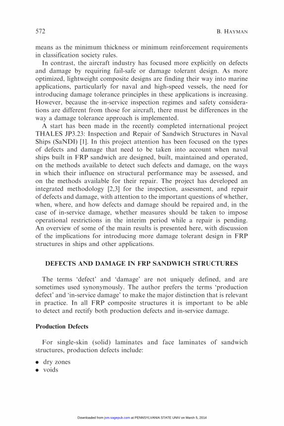
DEFECTS AND DAMAGE IN FRP SANDWICH STRUCTURES
The terms ‘defect’ and ‘damage’ are not uniquely defined, and aresometimes used synonymously. The author prefers the terms ‘productiondefect’ and ‘in-service damage’ to make the major distinction that is relevantin practice. In all FRP composite structures it is important to be ableto detect and rectify both production defects and in-service damage.
Production Defects
For single-skin (solid) laminates and face laminates of sandwichstructures, production defects include:
. dry zones
. voids
572 B. HAYMAN
at PENNSYLVANIA STATE UNIV on March 5, 2014jsm.sagepub.comDownloaded from

. delaminations
. wrinkles
. misalignment of fibers
. poor curing (giving reduced physical properties).
For sandwich structures, the following types of production defects mustalso be considered:. face–core debonds. voids and inclusions in the core. lack of bond (edge-to-edge and face-to-face) between core sheets.
In-service Damage
In aircraft structures the main type of in-service damage is impact damage,typically from bird strikes, hail, and objects thrown up from the runwayduring landing and takeoff. Ship structures, however, may encounter a widerrange of contact damage (quasi-static contact, e.g., during berthing, as wellas impact), incidences of heat damage, and numerous types of damageresulting from overloading. This last category includes core fracture orcrushing, face–core debonds, laminate rupture, delamination either within alaminate or at a joint made by secondary lamination, and failure atequipment fastenings. Impact damage may be confined to the impacted facelaminate (with or without penetration of the laminate), or may involvecrushing and/or cracking of the core. In extreme cases, penetration of theentire sandwich may occur. More substantial damage cases include theremoval of whole panels or assemblies by fire or collision. For naval vessels,some types of damage may be caused by weapon effects, such as air blast,underwater explosions, and fragment or missile hits.
INSPECTION AND DETECTION
Non-destructive Inspection: Choice of Technique
Numerous non-destructive inspection (NDI) methods are availablefor FRP sandwich structures. A comprehensive overview is provided byHayman [4]. Selection of an NDI method for a particular applicationdepends on many parameters, including the following:
. The environment in which the inspection has to be carried out
. The purpose of inspection – whether it is an initial scan or a detailedinspection, or an inspection of a repair
. The extent of the area to be inspected
Damage Assessment and Damage Tolerance for FRP Sandwich Structures 573
at PENNSYLVANIA STATE UNIV on March 5, 2014jsm.sagepub.comDownloaded from
. The accessibility of the region to be inspected (including whether accessis possible to both sides of the sandwich or only one side)
. The type of defect or damage that is suspected
. The sandwich lay-up in the area to be inspected
. The size of the damage that must be detected (e.g., the size that isconsidered critical)
. The nature of the sandwich surface to be inspected, e.g., whether it is flator curved, even or uneven, and what surface preparation is feasible
. The available supporting facilities like electrical power, compressed air,water, etc.
. Whether equipment of a given type, and the necessary personnel, areavailable, and at what cost.
Two of the most important parameters are the type and thickness ofthe material to be inspected. Thus techniques developed for lightweightaerospace structures can rarely be applied directly on ship structureswithout modification. Rigorous benchmarking of a limited number of NDImethods for application to FRP structures in naval ships was carried outin the EUCLID RTP3.8 Project [5–7]. In the SaNDI Project attentionwas confined to sandwich structures, but a wider range of techniques wasconsidered:
. Ultrasound (pulse-echo and through-transmission modes, water- andair-coupled, hand-held and automated scanning)
. Mechanical impedance
. Microwave
. Laser shearography with vacuum, heat, and vibration loadings
. Thermography (static and pulsed)
. X-ray real-time imaging and backscatter scanning
. An acoustic transmission technique.
Some evaluation was also made of visual inspection techniques andof manual coin-tapping. Tables and charts were compiled to assist in theselection of appropriate methods for a given application. Some of the resultson specific methods are presented in [8–10]. The following section gives someselected conclusions from this and the earlier work, but a comprehensiveoverview of the techniques and their capabilities has yet to be published.
Progress Made with Development of NDI Techniques
In recent years there have been numerous developments in relation tonew NDI techniques for composites. However, these developments havelargely taken place in the laboratory, with some practical applications in
574 B. HAYMAN
at PENNSYLVANIA STATE UNIV on March 5, 2014jsm.sagepub.comDownloaded from
a factory environment. A major challenge to be faced in the applicationof sandwich composites in ships (or other large structures) is the need forNDI techniques that can be used in a shipyard or dry dock environmentfor inspection of vessels that have been in operation. This may concerneither limited areas of a ship that has been damaged or very large areasduring routine, periodical inspections. Such applications require relativelyrobust equipment with at least some degree of portability. In the caseof periodical inspection, the need for equipment that can inspect largeareas in a short time is critical. There is also a need for portable equipmentthat can be used on board a ship.
The techniques for which the most promising developments have beenmade in the SaNDI Project are those based on ultrasound, shearography,and X-ray principles. An air-coupled, low-frequency, through-transmissionultrasound technique has been developed that is capable of detectingdefects inside very thick FRP sandwich lay-ups [8,9]. This requires accessfrom both sides but provides a powerful tool for production control. Rapidsingle- and multi-head scanning devices using water-coupled, pulse-echoultrasound have also been developed and demonstrated for in-serviceinspection of a ship hull [10]. A prototype, flexible shearography setup usingthermal loading was also developed and demonstrated on a ship hull.A shearography system based on vibration loading was also demonstratedon a large, damaged sandwich panel at a shipyard. Both of theseshearography systems are potentially capable of inspecting larger areas ina single scan than are possible using existing commercially available vacuumhood systems. A scanning system based on X-ray backscatter principleswas also built and demonstrated on a ship hull.
Some Conclusions Regarding NDI Techniques
Some challenges remain if a fully integrated system for defect/damageinspection, assessment, and repair is to be implemented in practice:
. The ability to detect deep defects/damage in thick sandwich structuresremains limited, especially for methods that can readily be used on boardor around a ship.
. Sandwich structures with cores of end-grain balsa are especially difficultto inspect because the defects are masked by the many joints between coreblocks and by natural features in the core material leading to large localdensity variations.
. It is generally not possible to detect far-side defects in thick sandwichstructures with one-sided inspection methods, though this has nowbeen achieved in isolated cases.
Damage Assessment and Damage Tolerance for FRP Sandwich Structures 575
at PENNSYLVANIA STATE UNIV on March 5, 2014jsm.sagepub.comDownloaded from

. Thick coatings may have to be removed from bottom structures whenships are inspected in service.
. Although there have been considerable improvements recently inautomated scanning techniques [10], there is still a need for more rapidscanning methods for large areas.
. At present there is insufficient knowledge about the sensitivity andreliability of many NDI systems when applied to composites to enabledetectability limits and probabilities of detection to be quantified.These are essential for implementation of a comprehensive damagetolerance approach to design, inspection, and maintenance.
. Standardized procedures are needed for the application of NDItechniques to FRP composites, so that they can be applied in a consistentway. These do not yet exist for some of the newer techniques.
. During inspection of ships that have been in service it may be difficultto distinguish between damage and hidden features of the structure, suchas stiffeners and joints. This problem may be avoided, or at least reduced,if a complete initial signature or map of the ship is made when the vesselis new. Damage is then identifiable as changes in the signature.
. Non-destructive testing standards are not yet well developed forapplication on sandwich composites. For some of the newer NDItechniques they do not exist at all.
Structural Health Monitoring
Improved sensor techniques using, for example, fiber optic technology,combined with specially developed data recording and processing systems,now permit continuous monitoring of ship structural responses. Suchsystems have been used to monitor the global responses of merchant shipsand of naval vessels built in sandwich composite materials [11]. Responsemonitoring systems can be used to indicate when the loads on the structurehave exceeded a level that is likely to have caused damage. They can also beused together with statistical processing techniques and/or ship responsesoftware to predict the likelihood of future exceedance of a specified limit.
It is more difficult to devise systems that can effectively monitor structuralhealth directly by indicating that damage has actually occurred, thoughthe availability of such a structural health monitoring system could havea major influence on future inspection and repair strategies. To detectreliably the appearance of small cases of damage requires an extremely highdensity of sensors since the changes in response at this stage are usuallyconfined to an area close to the damage. The damage has to involvea significant volume of material in order to change the response
576 B. HAYMAN
at PENNSYLVANIA STATE UNIV on March 5, 2014jsm.sagepub.comDownloaded from
characteristics significantly at a more global level. Methods of excitationand signal processing have recently been developed that show somepotential for reducing the density of sensors, such as the broadbandgapped smoothing method (BGSM) described by Ratcliffe and Crane [12],but as far as the author is aware such systems for damage detection are notyet implemented on ships in service.
A DAMAGE ASSESSMENT SCHEME FOR A SHIP STRUCTURE
In the SaNDI Project a comprehensive damage assessment schemehas been developed for naval ships that has the potential for including allpossible threats and evaluating the influence of the damage on the structuralperformance and functionality of the separate parts and of the ship asa whole. The damage assessment procedure for cases where strength is themain consideration is basically as follows [2,3]:
. Estimate the strength reduction caused by the damage or defect.
. Determine the allowable strength reduction based on the original designassumptions, operational envelope, etc.
. Compare these. If the residual strength is smaller than the allowablevalue, consider the possibilities for restricting the operational envelopeand/or accepting a lower safety factor until repair can be effected.
. If this is not sufficient, carry out an emergency repair or take otheremergency measures as necessary.
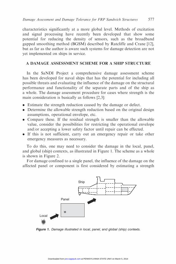
To do this, one may need to consider the damage in the local, panel,and global (ship) contexts, as illustrated in Figure 1. The scheme as a wholeis shown in Figure 2.
For damage confined to a single panel, the influence of the damage on theaffected panel or component is first considered by estimating a strength
Local
Panel
Ship
Figure 1. Damage illustrated in local, panel, and global (ship) contexts.
Damage Assessment and Damage Tolerance for FRP Sandwich Structures 577
at PENNSYLVANIA STATE UNIV on March 5, 2014jsm.sagepub.comDownloaded from
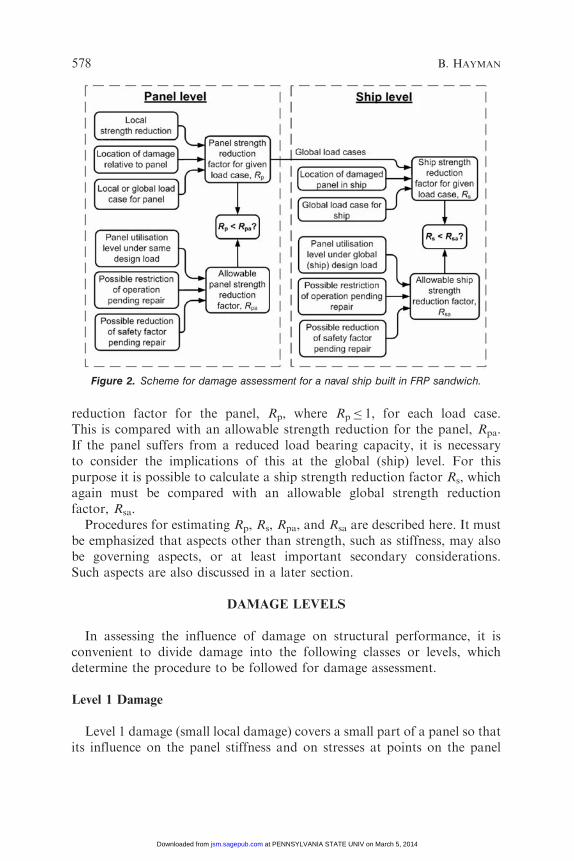
reduction factor for the panel, Rp, where Rp� 1, for each load case.This is compared with an allowable strength reduction for the panel, Rpa.If the panel suffers from a reduced load bearing capacity, it is necessaryto consider the implications of this at the global (ship) level. For thispurpose it is possible to calculate a ship strength reduction factor Rs, whichagain must be compared with an allowable global strength reductionfactor, Rsa.
Procedures for estimating Rp, Rs, Rpa, and Rsa are described here. It mustbe emphasized that aspects other than strength, such as stiffness, may alsobe governing aspects, or at least important secondary considerations.Such aspects are also discussed in a later section.
DAMAGE LEVELS
In assessing the influence of damage on structural performance, it isconvenient to divide damage into the following classes or levels, whichdetermine the procedure to be followed for damage assessment.
Level 1 Damage
Level 1 damage (small local damage) covers a small part of a panel so thatits influence on the panel stiffness and on stresses at points on the panel
Figure 2. Scheme for damage assessment for a naval ship built in FRP sandwich.
578 B. HAYMAN
at PENNSYLVANIA STATE UNIV on March 5, 2014jsm.sagepub.comDownloaded from

some way from the damage can be neglected. When considering uniform,in-plane loading (e.g., in-plane compression) it is possible to find a valueof the far-field stress or strain at which failure occurs. Its value depends onthe damage size but not on the width or length of the panel. Examplesare small impact damages. Small face–core debonds may also lie in thiscategory. The influence of Level 1 damage on panel strength can be assessedin three steps:
1. Determine a local strength reduction factor Rl in terms of the reductionin the far-field stress or strain at failure (for a given in-plane loading).
2. Determine a sensitivity factor Sp that accounts for the location of thedamage in relation to the stress field in the panel for the real loading case.
3. Combine these to give the panel strength reduction factor Rp¼Rl Sp.
Examples of local strength reduction factors for cases of face–coredebonds and face sheet impact damage are shown in the section on specificdamage models. In each of these cases the local strength reduction factor Rl
is plotted as a function of damage size.The factor Sp is referred to as the local location and load case factor.
It is defined as follows:
Sp ¼Pac
Paið1Þ
where Pac is the value of the load that causes the critical stress or straincomponent at the damage location to reach its maximum allowable value,ignoring the damage, and Pai is the maximum allowable value of load on theintact panel (i.e., the load that causes the critical stress or strain componentto reach its maximum allowable value at the most highly stressed or strainedlocation).
For face sheet damage, the critical stress or strain component is usuallytaken to be the in-plane compressive stress or strain at the point in question.The factor Sp can never be smaller than unity. Note that it is calculated fromthe properties of the intact panel: it is not directly a function of the damage,but it is a function of the damage location and of the stress componentor components that are critical for the damage type in question. Maps of Sp
values can readily be drawn for panels with given dimensions and lay-upsfor simple load configurations like uniform lateral pressure. Such mapsshow the extent to which a given panel is sensitive to Level 1 damage at eachpotential damage location.
Such a map for the specific case of a simply supported 3� 2mpanel with 1.8mm quasi-isotropic CFRP face laminates and 60mmDivinycell H80 PVC foam core under uniform lateral pressure loading
Damage Assessment and Damage Tolerance for FRP Sandwich Structures 579
at PENNSYLVANIA STATE UNIV on March 5, 2014jsm.sagepub.comDownloaded from
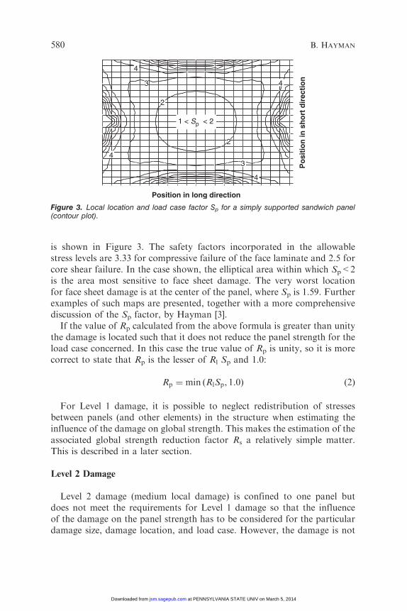
is shown in Figure 3. The safety factors incorporated in the allowablestress levels are 3.33 for compressive failure of the face laminate and 2.5 forcore shear failure. In the case shown, the elliptical area within which Sp<2is the area most sensitive to face sheet damage. The very worst locationfor face sheet damage is at the center of the panel, where Sp is 1.59. Furtherexamples of such maps are presented, together with a more comprehensivediscussion of the Sp factor, by Hayman [3].
If the value of Rp calculated from the above formula is greater than unitythe damage is located such that it does not reduce the panel strength for theload case concerned. In this case the true value of Rp is unity, so it is morecorrect to state that Rp is the lesser of Rl Sp and 1.0:
Rp ¼ min ðRlSp, 1:0Þ ð2Þ
For Level 1 damage, it is possible to neglect redistribution of stressesbetween panels (and other elements) in the structure when estimating theinfluence of the damage on global strength. This makes the estimation of theassociated global strength reduction factor Rs a relatively simple matter.This is described in a later section.
Level 2 Damage
Level 2 damage (medium local damage) is confined to one panel butdoes not meet the requirements for Level 1 damage so that the influenceof the damage on the panel strength has to be considered for the particulardamage size, damage location, and load case. However, the damage is not
1 < Sp < 2
43
2
4
4
3
2
4
Position in long direction
Po
siti
on
in s
ho
rt d
irec
tio
n
Figure 3. Local location and load case factor Sp for a simply supported sandwich panel(contour plot).
580 B. HAYMAN
at PENNSYLVANIA STATE UNIV on March 5, 2014jsm.sagepub.comDownloaded from
so severe that it influences the stiffness of the panel significantly, so thatredistribution of stresses in the global structure can be neglected in assessingthe reduction of global ship strength. Examples include moderatelylarge impact damage, moderately large debonds, and moderate core shearcracking.
As in the case of Level 1 damage, the global strength reduction factor Rs
for Level 2 damage can be estimated by relatively simple means, as describedin a later section.
Level 3 Damage
Level 3 damage (large local damage) is confined to one panel but isso severe that it significantly influences the stiffness of the panel.Redistribution of stresses cannot be neglected in assessing the reductionof global ship strength. Examples include large impact damage, largedebonds, and developed core shear cracking with debonding. The influenceof the damage on both the panel strength and the global ship strength hasto be considered for the particular damage size, damage location, and loadcase. In extreme cases it may be appropriate to assume that the panel’scontributions to the global strength and stiffness have been completelydestroyed. In this case the panel is removed from the global analysis modelof the ship and the loads adjusted accordingly. This is discussed in a latersection.
Level 4 Damage
Level 4 damage (extensive damage) affects two or more panels and/orsupporting structure. Each case must be considered individually. Generallythis type of damage leads to redistribution of stresses in the remainingstructure. It may or may not be relevant to consider the damaged panels asfully removed for the purpose of the analysis, as was the case for Level 3damage.
GLOBAL STRENGTH REDUCTION FOR A SHIP STRUCTURE
Definition
The ship strength reduction factor Rs is the proportion of the ship’s globalstrength that remains when the damage is taken into account. It can bedefined in a way that is analogous to the panel strength reduction factor Rp.The method of estimating Rs depends on the type and size of damage,as described here.
Damage Assessment and Damage Tolerance for FRP Sandwich Structures 581
at PENNSYLVANIA STATE UNIV on March 5, 2014jsm.sagepub.comDownloaded from
Estimating Rs for Level 1 or Level 2 Damage
For cases of small and medium local damage (Level 1 and Level 2damage) the change in panel stiffness due to the damage can be neglected.
A global panel location and load case factor Ss can be defined that isanalogous to the local location factor Sp. Maps of Ss can be drawn for theship; these show to what extent different parts of the ship are sensitiveto damage. The global strength reduction factor Rs is then given by
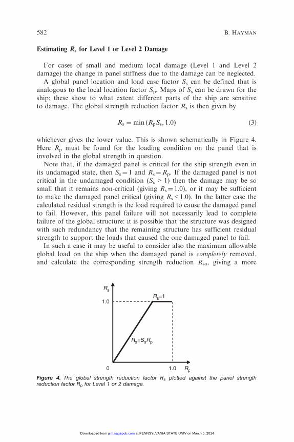
Rs ¼ min ðRpSs, 1:0Þ ð3Þ
whichever gives the lower value. This is shown schematically in Figure 4.Here Rp must be found for the loading condition on the panel that isinvolved in the global strength in question.
Note that, if the damaged panel is critical for the ship strength even inits undamaged state, then Ss¼ 1 and Rs¼Rp. If the damaged panel is notcritical in the undamaged condition (Ss>1) then the damage may be sosmall that it remains non-critical (giving Rs¼ 1.0), or it may be sufficientto make the damaged panel critical (giving Rs<1.0). In the latter case thecalculated residual strength is the load required to cause the damaged panelto fail. However, this panel failure will not necessarily lead to completefailure of the global structure: it is possible that the structure was designedwith such redundancy that the remaining structure has sufficient residualstrength to support the loads that caused the one damaged panel to fail.
In such a case it may be useful to consider also the maximum allowableglobal load on the ship when the damaged panel is completely removed,and calculate the corresponding strength reduction Rso, giving a more
Rp
Rs
1.0
1.0
Rs=SsRp
Rs=1
0
Figure 4. The global strength reduction factor Rs plotted against the panel strengthreduction factor Rp for Level 1 or 2 damage.
582 B. HAYMAN
at PENNSYLVANIA STATE UNIV on March 5, 2014jsm.sagepub.comDownloaded from

favorable value than Rs as determined by Equation (3). However, loadingthe ship to the corresponding load level may cause further damage to thepanel in question, so the consequences of such an event for the ship’sfunctionality must be checked if the global strength assessment is basedon Rso instead of Rs. Note that removal of the entire damaged panelwill cause significant redistribution of stresses in the adjoining structure,so a separate global analysis is required for this case.
Estimating Rs for Level 3 or Level 4 Damage
For cases of large local damage and extensive damage (Level 3 andLevel 4 damage) the change in panel stiffness due to the damage cannot beneglected if an accurate assessment of the global strength is required.
In cases of Level 4 damage it is normally necessary to perform a fullydetailed analysis of the ship with the damaged panels removed or havingappropriately reduced stiffnesses. This is also the case for Level 3 damage,especially if the structure is a complex, three-dimensional one and theinfluence of the damage on global behavior is unclear. If entire panelsare removed it may be necessary to modify the stress calculation forthe immediately adjoining structure so as to avoid unrealistic stressconcentrations, especially near the corners of the removed parts.
However, for many cases of Level 3 damage it appears to be possibleto estimate the residual strength using approaches based on pre-calculationof standard cases and simplified treatment of stress redistribution.For example, if it is assumed that the influence of the damage on panelstiffness does not exceed that on panel strength (which is usually the case),it appears that a conservative estimate of the global strength reductionfactor Rs can be found by taking the smaller of
Rs ¼ RpSs ð4aÞ
and
Rs ¼ Rso þ 1� Rsoð ÞRp ð4bÞ
These relations are shown in Figure 5. The first relation refers to thecase where the damaged panel is itself critical for the global ship strength. Thesecond refers to the case where the damaged panel is not critical for the shipstrength but the damage results in transfer of load into a neighboring panelthat is critical and thereby reduces the global strength. If the damaged panelis critical for the global ship strength even in its undamaged condition thenSs¼ 1 and the first relation reduces again to Rs¼Rp. In this case the secondrelation does not come into play in this conservative estimation method.
Damage Assessment and Damage Tolerance for FRP Sandwich Structures 583
at PENNSYLVANIA STATE UNIV on March 5, 2014jsm.sagepub.comDownloaded from

It should be noted that the validity of this estimation method has not beenproved rigorously but is based on consideration of some simplified models ofa group of panels adjacent to each other. This requires further evaluation andthe proposed method should be used with caution until it is fully validated.
CHECKS ON LOCAL AND GLOBAL STRENGTH REDUCTIONS
There is normally no need to consider an allowable strength reductionif Rp¼ 1. If Rp<1 the possibility of accepting a reduction of panel strengthmust be considered unless the damage can be fully repaired immediately.If Rp<1, the global strength reduction Rs must be calculated or estimatedas described in the previous section.
In some cases it is not possible to accept any reduction in the globalor local strength of the structure. However, not all parts of the structureof a ship are highly stressed. In many cases a given panel may be exposedto a maximum loading that is lower than the allowable value because thedesign gave more than the minimum required reserve of strength, i.e., thereis a lower utilization of the panel than the maximum that is allowed. Thisis often due to the fact that a limited number of standard sandwich lay-upsare used in a given vessel. In such cases it will normally be acceptableto reduce the panel strength by an amount that reflects this extra reserveof strength in the intact structure. The same may apply at the global shiplevel if the ship has been generally overdesigned against the global loads(e.g., because the local load requirements were more severe). These aspectsare dealt with here by using utilization factors Up and Us at the paneland ship levels. The panel utilization factor Up for a given load case is heredefined as the ratio of the maximum load applied to the damage panel underthe extreme design loading (for the load case in question) to the maximumallowable value of that load when the panel is undamaged. The ship
Rp
Rs
1.0
Rso
Rs=SsRp
Rs=Rso+(1−Rso)Rp
1.00
Figure 5. Lower bound estimate of global strength reduction factor Rs plotted against panelstrength reduction factor Rp for Level 3 damage.
584 B. HAYMAN
at PENNSYLVANIA STATE UNIV on March 5, 2014jsm.sagepub.comDownloaded from

utilization factor Us is defined in a similar way at the ship level. Normallythe allowable strength reductions Rpa and Rsa for panel and global strengthwill be set equal to the respective utilization factors.
There are two main additional considerations that may make a strengthreduction acceptable:
. Reducing the loads (relative to original design) by restricting theoperation in some way.
. Accepting a reduced factor of safety in the interim period until a repairis effected.
The first of these leads in effect to a lowering of the utilization level in thatthe extreme design loads are now decreased. The second leads to a loweringof the utilization level in that the allowable loads are increased. There areseveral justifications for accepting lower factors of safety than those usedin the original design:
. The remaining period of operation (either to the end of the ship’s life orto the time when a permanent repair will be effected) is shorter than theoriginally assumed life. Thus the period of exposure to environmentalloads is shorter and maximum expected values will be lower. (This aspectcould in fact be taken into account either by reducing the consideredloads or by reducing the safety factors.)
. The structure as it exists at the time damage is encountered may well bebetter known and characterized than it was at the time the original designcalculations were performed; thus some of the uncertainties that weretaken account of by the use of safety factors in the original design arenow removed or reduced.
. At the design stage a significant part of the applied safety factor isintended to take account of potential production defects and minordamage in service. Consideration of many of these defect and damagecases will be irrelevant because they only affect locations or load casesthat are not critical for the ship with the particular observed damage.
These aspects all require further investigation using probabilisticapproaches, not only for ships built in FRP composites but for ships andother large-scale structures in general.
ASPECTS OTHER THAN STRENGTH: FUNCTIONALITY
The procedure described so far deals only with strength considerations.Considerations of functionality (which may include that of stiffness asembodied in deflection criteria) must be made separately. Functionality
Damage Assessment and Damage Tolerance for FRP Sandwich Structures 585
at PENNSYLVANIA STATE UNIV on March 5, 2014jsm.sagepub.comDownloaded from
requirements may override repair decisions based on load carrying capacity.For a ship they include aspects such as
. watertightness
. weathertightness
. smoke-tightness
. fire division effectiveness
. equipment functioning (machinery, instrumentation)
. signatures and shielding.
For naval ships the functioning of weapon systems may be a majorconsideration.
SPECIFIC DAMAGE MODELS
Models have been developed with which it is possible to estimate theinfluence of individual defects and damage on structural performance.In the SaNDI Project attention was focused mainly on the estimationof residual strength under single, quasi-static loading, rather than ondamage growth and fatigue under repeated loading. The following modelsare now available, though their accuracy in some cases is not fullyestablished.
Face–Core Debonds
A face–core debond reduces the strength of a sandwich panel subjectedto in-plane compression. A debond may also reduce the capacity of apanel with lateral loading if the face laminate at the debond is incompression, though the behavior may also be influenced by out-of-planeshear stresses.
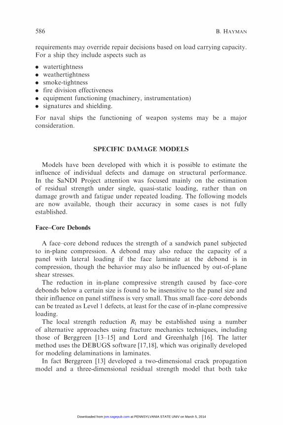
The reduction in in-plane compressive strength caused by face–coredebonds below a certain size is found to be insensitive to the panel size andtheir influence on panel stiffness is very small. Thus small face–core debondscan be treated as Level 1 defects, at least for the case of in-plane compressiveloading.
The local strength reduction Rl may be established using a numberof alternative approaches using fracture mechanics techniques, includingthose of Berggreen [13–15] and Lord and Greenhalgh [16]. The lattermethod uses the DEBUGS software [17,18], which was originally developedfor modeling delaminations in laminates.
In fact Berggreen [13] developed a two-dimensional crack propagationmodel and a three-dimensional residual strength model that both take
586 B. HAYMAN
at PENNSYLVANIA STATE UNIV on March 5, 2014jsm.sagepub.comDownloaded from
full account of mode mixity, which is often significant in sandwich interfaceproblems because of the large difference in properties between the facesand the core. The models are both based on the crack surface displacementextrapolation (CSDE) approach and have been implemented using thecommercial FE software ANSYS.
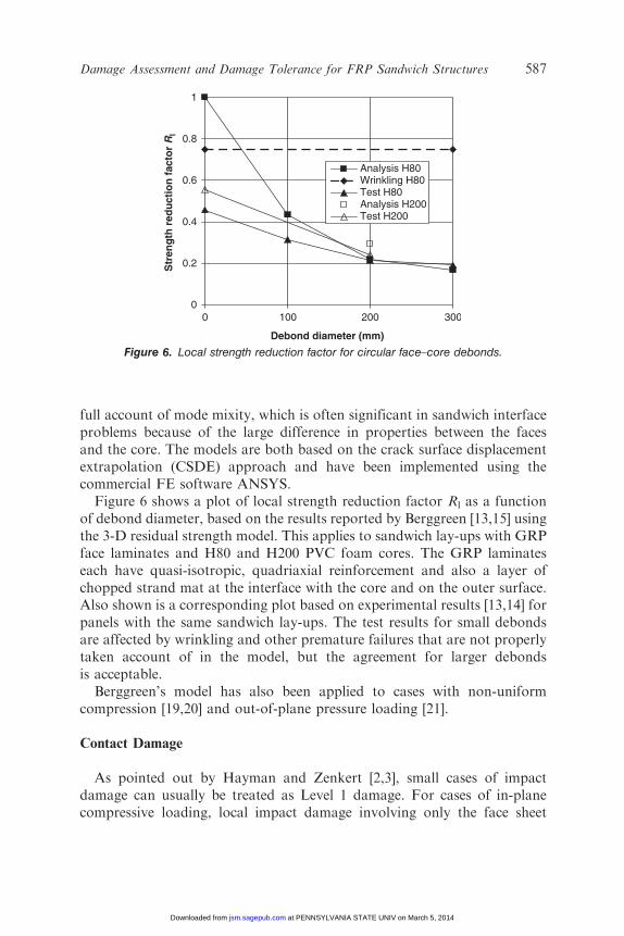
Figure 6 shows a plot of local strength reduction factor Rl as a functionof debond diameter, based on the results reported by Berggreen [13,15] usingthe 3-D residual strength model. This applies to sandwich lay-ups with GRPface laminates and H80 and H200 PVC foam cores. The GRP laminateseach have quasi-isotropic, quadriaxial reinforcement and also a layer ofchopped strand mat at the interface with the core and on the outer surface.Also shown is a corresponding plot based on experimental results [13,14] forpanels with the same sandwich lay-ups. The test results for small debondsare affected by wrinkling and other premature failures that are not properlytaken account of in the model, but the agreement for larger debondsis acceptable.
Berggreen’s model has also been applied to cases with non-uniformcompression [19,20] and out-of-plane pressure loading [21].
Contact Damage
As pointed out by Hayman and Zenkert [2,3], small cases of impactdamage can usually be treated as Level 1 damage. For cases of in-planecompressive loading, local impact damage involving only the face sheet
0
0.2
0.4
0.6
0.8
1
0 100 200 300
Debond diameter (mm)
Str
eng
th r
edu
ctio
n f
acto
r R
lAnalysis H80Wrinkling H80Test H80Analysis H200Test H200
Figure 6. Local strength reduction factor for circular face–core debonds.
Damage Assessment and Damage Tolerance for FRP Sandwich Structures 587
at PENNSYLVANIA STATE UNIV on March 5, 2014jsm.sagepub.comDownloaded from
can be analyzed using equivalent hole and equivalent crack models asdescribed by Bull, Edgren and co-workers [22–26]. For damage involvingfiber fracture it may be appropriate to use either of these models; Bull andEdgren [25] provide guidance on how to determine the equivalent holediameter or equivalent crack length.
For less severe cases where the damage does not involve fractureof the fibers, it may still be possible to apply the equivalent hole model,but if there is permanent damage to the underlying core it may be necessaryto consider an alternative residual dent model [22,27,28], and also to checkfor delamination buckling.
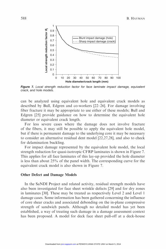
For impact damage represented by the equivalent hole model, the localstrength reduction for quasi-isotropic CFRP laminates is shown in Figure 7.This applies for all face laminates of this lay-up provided the hole diameteris less than about 25% of the panel width. The corresponding curve for theequivalent crack model is also shown in Figure 7.
Other Defect and Damage Models
In the SaNDI Project and related activity, residual strength models havealso been investigated for face sheet wrinkle defects [29] and for dry zonesin laminates [30]. These may be treated as respectively Level 2 and Level 1damage cases. Some information has been gathered concerning the influenceof core shear cracks and associated debonding on the in-plane compressivestrength of sandwich panels. Although no detailed model has yet beenestablished, a way of treating such damage in a damage assessment contexthas been proposed. A model for deck face sheet pull-off at a deck-house
0
0.1
0.2
0.3
0.4
0.5
0.6
0.7
0.8
0.9
1
0 10 20 30 40 50 60 70 80 90 100Hole diameter/crack length (mm)
Lo
cal s
tren
gth
red
uct
ion
fac
tor
Rl
Blunt impact damage (hole)Sharp impact damage (crack)
Figure 7. Local strength reduction factor for face laminate impact damage, equivalentcrack, and hole models.
588 B. HAYMAN
at PENNSYLVANIA STATE UNIV on March 5, 2014jsm.sagepub.comDownloaded from

corner in a ship undergoing global hull girder bending has also beendeveloped using Berggreen’s 2D delamination model [13,31,32]. A seriesof more severe Level 3 and Level 4 damage cases has also been investigatedfor some twin-hull vessels.
DAMAGE TOLERANCE
Basic Concept
In its simplest form, damage tolerance may be defined as the ability ofa structure to accommodate damage without an unacceptable deteriorationin its performance. Here the term ‘damage’ is usually considered to includemanufacturing defects as well as in-service damage. In practice, this impliesthat the residual strength and/or the residual life following the incidenceof damage are sufficient to meet a prescribed set of structural performancecriteria.
Damage Tolerance in Aircraft Structures
Certification of metal aircraft structures has generally been based onone or more of the following three principles as set out in the rules of theFederal Aviation Authority [33,34]:
Safe-life: It is shown by means of a fatigue strength investigation that thestructure is able to withstand the repeated loads expected in service.
Fail-safe: It is shown that catastrophic failure of the structure is notprobable after fatigue failure, or obvious partial failure, of a principalstructural element, and that the remaining structure is able to withstand themaximum design loads (with a specified reduced factor of safety).
Damage tolerant: The probable locations and modes of damage dueto fatigue, corrosion, or accidental damage are determined and a damageextent consistent with the initial detectability and subsequent growth underrepeated loads is established. The evaluation consists of repeated load andstatic analyses. The residual strength evaluation must show that theremaining structure is able to withstand the design loads.
The damage tolerant design philosophy leads to two damage limits:
. Allowable damage limit (ADL), which is the maximum extent of defector damage that the aircraft must survive while maintaining the originaldesign factor of safety.
. Critical damage threshold (CDT), which is the maximum extent ofdamage that the aircraft must survive when subjected to the maximumload expected during its lifetime.
Damage Assessment and Damage Tolerance for FRP Sandwich Structures 589
at PENNSYLVANIA STATE UNIV on March 5, 2014jsm.sagepub.comDownloaded from

Note that the safety philosophy for metal aircraft structures isheavily focused on fatigue under repeated loads as the potential causeof failure.
For composite aircraft structures only the damage tolerant option isallowed by the current Federal Aviation Regulations. The threshold levelfor growth and the subsequent growth rate for damage that may occurfrom fatigue, corrosion, manufacturing flaws, or impact damage, underrepeated loads expected in service, are established. A damage level isestablished at which it is demonstrated that the structure will still haveadequate residual strength (e.g., an ADL or CDT). It must be possibleto develop an inspection programme, for application by operation andmaintenance personnel, that will ensure that damage cannot grow from theinitial detectability limit to this residual strength limit without beingdetected.
Structural components for which the damage tolerance method is shownto be impractical must be shown to be able to withstand the repeated loadsof variable magnitude expected in service. Damage up to the thresholdof detectability must be considered.
The essential element of the damage tolerance approach is thus that anydefect or damage that cannot be detected by the anticipated inspectionprocedures must be able to exist at a given inspection without causingfailure by the time of the next scheduled inspection. Thus the initialdesign is inseparably linked to the regimes for both initial (production) andperiodical (in-service) inspection.
In the aircraft industry, damage tolerance considerations for FRPcomponents have been mainly focused on delaminations as productiondefects and impact damage, with multiple delaminations, as in-servicedamage. So far the application of sandwich structures in civil aviationhas been limited because combinations of appropriate damage models andinspection techniques have not been well enough established.
Note that the focus on the threshold level for growth initiation in adamaged composite component represents a difference between the damagetolerance approaches for metal and composite structures in aircraft.This is quite important because, for many cases of damage to composites,damage growth, once started, occurs rapidly. In such cases the thresholdlevel may be used in a defect/damage assessment scheme in much thesame way as the residual static strength with the initial defect or damage.The difference is that the residual static strength refers to a singleloading with the defect or damage, whereas the threshold level refers toany number of subsequent loading cycles. This implies that it may beappropriate to apply different safety factors in the associated acceptancecriteria.
590 B. HAYMAN
at PENNSYLVANIA STATE UNIV on March 5, 2014jsm.sagepub.comDownloaded from

Damage Tolerance Approach to Ship Design and Maintenance
The damage tolerance philosophy described in the previous sectionis made possible by the strict inspection and maintenance regimes that existin the aircraft industry. Other decisive features are the mass productionof most aircraft types in combination with a stringent safety regime. Thesejustify high development and qualification costs and the establishmentof rigorous production quality assurance regimes with associated inspectionsystems. Combined with high aircraft utilization levels, they also justify highin-service inspection and maintenance costs. The difficulty of access to largeparts of a ship’s structure at all times except for periodic dockings (whichare typically at intervals from one year upward) make it more difficult toapply such a philosophy in its entirety to ships, so some modification seemsnecessary. Furthermore, ships are generally produced in shorter seriesso that lower development and qualification costs for a series are essential,and the investment in production control must be in proportion to theproduction volume. The fact that ships are less safety-critical, owing to theiroperation on the sea surface and the existence of effective life-savingsystems, makes it possible to balance the rigor of the damage tolerantdesign, production, and maintenance regime against cost to a greater extentthan with aircraft.
Thus for ships a fully damage tolerant design, inspection, andmaintenance regime may not be justified on economical grounds. It isprobably more cost effective to use defect and damage models at the designstage to provide damage tolerance at an appropriate, more modest level andaccept some uncertainty in the initial detection of production defects.The damage models and associated methodologies can then be used in theoperational phase to compensate for the less rigorous built-in damagetolerance by ensuring that, if damage does occur, it can be assessed rapidlyand appropriate corrective actions can be taken so that overall safetyand survivability are not compromised. In this context the availability ofa well-defined damage assessment scheme of the type described earlier,making extensive use of pre-calculated data, is an essential element.
A limitation of the defect/damage models and assessment schemedeveloped in the SaNDI Project for sandwich structures in naval shipsis that attention has been focused almost entirely on the residual staticstrength of the structure with a defect or damage, estimated using a mixtureof simple strength approaches and fracture mechanics methods. To increasetheir validity it is necessary to extend the models and assessment schemeto include damage growth under repeated loadings and the associatedthreshold levels for growth. There is also a need to develop and documentfurther the capabilities of the relevant NDI techniques and to standardize
Damage Assessment and Damage Tolerance for FRP Sandwich Structures 591
at PENNSYLVANIA STATE UNIV on March 5, 2014jsm.sagepub.comDownloaded from

their application so that the probability of detection of a defect or damageof a given size is better known.
Damage Tolerance Approach to Wind Turbine Blade
Design and Maintenance
In contrast to an aircraft or a ship, a wind turbine can be taken outof service relatively quickly without having to land or seek refuge ina harbor. Thus wind turbines are generally much less safety-critical thanaircraft or ships, and losses due to blade failures are mainly economic ones.
However, wind turbine blades present a special challenge in that they areproduced in large numbers, similar to aircraft, but the possibilities forregular in-service inspection are much more limited or even non-existent,because of accessibility problems. For these structures an ideal approachwould be safe-life design accounting for the worst combination ofproduction defects that is likely to go undetected during production,and the worst in-service damage that is likely to occur without beingnoticed. To implement such an approach in a systematic way requiresa comprehensive and reliable overview of both in-service damage eventsand the defects that may occur in practical production, including thestatistics of their incidence. This presents a major challenge for the industrysince competition between manufacturers limits the amount of informationthey are able to share while differences in production techniques makethe production defects more manufacturer-dependent than in many otherindustries. With high production volumes, improvement of all aspectsof production control, including NDI capabilities, should be a cost-effectivemeans of reducing the incidence of such defects and of the uncertaintiesassociated with them.
A development that is likely to improve the situation for wind turbinesis the widespread use of structural health monitoring of blades using,for example, fiber optic sensors. These may be used both to detect abnormalevents and to detect changes in dynamic response associated with theincidence of damage or major growth of a defect. This is already doneto some extent by detecting out-of-balance conditions in the machinery.
Summary of Differences between Aircraft, Ship, and
Wind Turbine Regimes
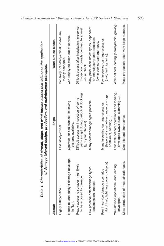
As seen in the previous sections, in order to provide safe and cost-effectiveregimes for ensuring adequate damage tolerance in different applicationsit is necessary to recognize important differences between the industriesconcerned. The main differences are summarized in Table 1.
592 B. HAYMAN
at PENNSYLVANIA STATE UNIV on March 5, 2014jsm.sagepub.comDownloaded from
Table
1.Characteristicsofaircraft,sh
ips,
andwindturbinebladesthatinfluencetheapplication
ofdamagetolerantdesign,production,andmaintenanceprinciples.
Aircraft
Ships
Windturbineblades
Highly
safety-critic
al.
Less
safety-critic
al.
Generally
notsa
fety-critic
al;loss
esare
mainly
eco
nomic.
Needsto
landsa
fely
ifdamagedeve
lops
inflight.
Operatesonse
asu
rface
;life-saving
systemsava
ilable.
Canreadily
betake
noutofse
rvice.
Readyacc
ess
tosu
rface
smost
likely
tobeexp
ose
dto
damage.
Difficultacc
ess
forinsp
ectionofso
me
partsexceptduringperiodicaldock
ings
(�1ye
arintervals).
Difficultacc
ess
afterinstallatio
n;in-service
insp
ectionnorm
ally
confin
edto
annual
visu
alch
eck
.
Few
potentia
ldefect/damagetypes
(delaminatio
n,im
pact).
Manydefect/damagetypesposs
ible.
Manyproductiondefect
types,
dependent
onmanufacturerandproce
sses;
few
in-servicedamagetypes.
Few
in-servicedamagesc
enarios
(bird,hail,
lightning,groundobjects).
Manyin-servicedamagesc
enarios
(largeandsm
allobject
impacts–logs,
containers,berthing,...).
Few
in-servicedamagesc
enarios
(bird,hail,
lightning).
Well-defin
edoperatio
nalandloading
enve
lopes.
Less
well-defin
edoperatio
nalandloading
enve
lopes(w
ave
loads,
slamming,...).
Well-defin
edloading(aerodyn
amic,gravity).
Mass
-productionofmost
aircrafttypes.
One-offs
andsh
ortse
ries.
Mass
-production,oftenve
rylargenumbers.
Damage Assessment and Damage Tolerance for FRP Sandwich Structures 593
at PENNSYLVANIA STATE UNIV on March 5, 2014jsm.sagepub.comDownloaded from

CONCLUSIONS
A methodology for assessing the influence of production defects andin-service damage on the performance of FRP sandwich structures in navalships has been presented as a basis for deciding on corrective measures.This incorporates models for a range of specific types of defects and damage.For a given ship, most of the required data for defect/damage assessment canbe readily assembled during the design calculation stage, making it possibleto provide decision support tools for both production control and in-servicedamage assessment. However, the existing models and procedures need to beextended to cover damage growth under repeated loading.
Limitations in inspection techniques, combined with less rigorous andless frequent inspection and maintenance regimes associated with the lowersafety risk, make a full damage tolerance philosophy similar to that inthe aircraft industry both impractical and uneconomic for FRP sandwichstructures in ships, as for many other large FRP structures, such as windturbine blades. The most suitable and economical approach to achievingdamage tolerance is thus dependent on the application.
ACKNOWLEDGMENTS
This study is based largely on experience from the recently completedSaNDI (THALES JP3.23) Project ‘Inspection and Repair of SandwichStructures in Naval Ships’, with participants from Norway, Denmark,Sweden, Finland, and the United Kingdom. The support of the Ministriesof Defence of the five participating nations is gratefully acknowledged.
REFERENCES
1. Hayman, B. (2003). Inspection and Repair of Sandwich Structures Based on DamageTolerance Principles, In: Vinson, J.R., Rajapakse, Y.D.S. and Carlsson, L.A. (eds), 6th Int.Conf. on Sandwich Structures, Fort Lauderdale, Florida, USA, pp. 955–963.
2. Hayman, B. and Zenkert, D. (2004). The Influence of Defects and Damage on the Strengthof FRP Sandwich Panels for Naval Ships, In: Keil, H. and Lehmann, E. (eds), 9th Int. Symp.on Practical Design of Ships and Other Floating Structures (PRADS 2004), Seehafen VerlagGmbH, Germany, pp. 719–726.
3. Hayman, B. (2004). Defect and Damage Assessment for Ships Built in FRP Sandwich,RINA Conference on High Speed Craft, London, England.
4. Hayman, B. (2005). Non-destructive Evaluation and Quality Assurance. In: Shenoi, R.A.,Groves, A. and Rajapakse, Y.D.S. (eds), Theory and Applications of Sandwich Structures,University of Southampton, UK, pp. 351–381.
5. Weitzenbock, J.R., Echtermeyer, A.T., Artiga-Dubois, F. and Parmar, M. (1998).Nondestructive Inspection and Evaluation Methods for Sandwich Panels, 4th Int. Conf.on Sandwich Construction, Stockholm, Sweden.
594 B. HAYMAN
at PENNSYLVANIA STATE UNIV on March 5, 2014jsm.sagepub.comDownloaded from
6. Weitzenbock, J.R., Echtermeyer, A.T., Grønlund, P.K., Artiga-Dubois, F. andParmar, M. (1999). Nondestructive Inspection and Evaluation Methods forComposites Used in the Marine Industry, 12th Int. Conf. on Composite Materials(ICCM-12), Paris, France.
7. Artiga-Dubois, F., Parmar, M., Echtermeyer, A.T. and Weitzenbock, J.R. (1999).Nondestructive Testing of Composites for Naval Applications, 20th Int. SAMPE EuropeConf., Paris, France.
8. Borum, K.K. and Berggreen, C. (2004). Examination of Sandwich Materials UsingAir-Coupled Ultrasonics, In: Proc. 16th World Conf. on Non Destructive Testing, Montreal,Canada.
9. Borum, K. (2005). Evaluation of Sandwich Materials Using Ultrasonic Air-CoupledScanning Technique, In: Thomsen, O.T., Bozhevolnaya, E. and Lyckegaard, A. (eds),Sandwich Structures 7: Advancing with Sandwich Structures and Materials, Springer,Dordrecht, The Netherlands, pp. 805–813.
10. Wulf, T.M. (2005). Automated Ultrasonic Inspection of Large-Scale Sandwich Structures,In: Thomsen, O.T., Bozhevolnaya, E. and Lyckegaard, A. (eds), Sandwich Structures 7:Advancing with Sandwich Structures and Materials, Springer, Dordrecht, The Netherlands,pp. 795–804.
11. Jensen, A.E., Taby, J., Pran, K., Sagvolden, G. and Wang, G. (2000). Global LoadMeasurement on a Surface Effect Ship using a Network of Fibre Optic Strain Sensorsand Detailed FE Analysis, In: Proc. 7th Int. Conf. on Composites Engineering (ICCE/7),Denver, Colorado, USA.
12. Ratcliffe, C. and Crane, R.M. (2003). Locating Manufacturing and Structural Irregularitiesin Large Composite Sandwich Structures, In: Vinson, J.R., Rajapakse, Y.D.S. andCarlsson, L.A. (eds), 6th Int. Conf. on Sandwich Structures, Fort Lauderdale, Florida,USA, pp. 935–942.
13. Berggreen, C. (2004). Damage Tolerance of Debonded Sandwich Structures, PhD Thesis,Department of Mechanical Engineering, Technical University of Denmark.
14. Lundsgaard-Larsen, C., Berggreen, C. and Nøkkentved, A. (2005). Residual Strengthof In-plane Loaded Debonded Sandwich Panels – Experimental Investigation, 7th Int.Conf. on Sandwich Structures, Aalborg, Denmark.
15. Berggreen, C. and Simonsen, B.C. (2005). Residual Strength of In-plane Loaded DebondedSandwich Panels – Fracture Mechanical Modelling, 7th Int. Conf. on Sandwich Structures,Aalborg, Denmark.
16. Lord, S.J. and Greenhalgh, E.S. (2004). Modelling of Delamination and Debondingin Laminated Composites using a Moving Mesh Approach, 11th European Conference onComposite Materials, Rhodes, Greece.
17. Nilsson, K-F., Asp, L. and Alpman, J. (1997). Delamination Buckling and Growthat Global Buckling, In: Rossmanith, H.-P. (ed.), First Int. Conf. on Damage and Failure ofInterfaces, Vienna, pp. 193–202.
18. Nilsson, K-F., Asp, L.E., Alpman, J.E. and Nystedt, L. (1999). Delamination Bucklingand Growth for Delaminations at Different Depths in a Slender Composite Panel,FFA TN-1999-09, Aeronautical Research Institute of Sweden, Bromma, Sweden.
19. Nøkkentved, A., Lundsgaard-Larsen, C. and Berggreen, C. (2005). Non-UniformCompressive Strength of Debonded Sandwich Panels – I. Experimental Investigation,Jnl. of Sandwich Structures and Materials, 7(6): 461–482.
20. Berggreen, C. and Simonsen, B.C. (2005). Non-Uniform Compressive Strength ofDebonded Sandwich Panels – II. Fracture Mechanics Investigation, Jnl. of SandwichStructures and Materials, 7(6): 483–517.
21. Jolma, P., Segercrantz, S. and Berggreen, C. (2006). Ultimate Failure of Debond DamagedSandwich Panels Loaded with Lateral Pressure – An Experimental and FractureMechanical Study, Jnl. of Sandwich Structures and Materials, in press.
Damage Assessment and Damage Tolerance for FRP Sandwich Structures 595
at PENNSYLVANIA STATE UNIV on March 5, 2014jsm.sagepub.comDownloaded from

22. Zenkert, D., Shipsha, A., Bull, P. and Hayman, B. (2005). Damage Tolerance Assessmentof Composite Sandwich Panels with Localised Damage, Composites Science andTechnology, 65(15–16): 2597–2611.
23. Bull, P.H. (2004). Damage Tolerance and Residual Strength of CompositeSandwich Structures, PhD Thesis, Department of Aeronautical and Vehicle Engineering,Kungliga Tekniska Hogskolan, Stockholm, Sweden TRITA-AVE.2004:16.
24. Bull, P.H. and Edgren, F. (2003). Residual Strength of Impact Damaged CFRP-FoamCore Sandwich Panels, In: Vinson, J.R., Rajapakse, Y.D.S. and Carlsson, L.A. (eds), Proc.6th Int. Conf. on Sandwich Construction, Fort Lauderdale, USA, pp. 363–372.
25. Bull, P.H. and Edgren, F. (2004). Compressive Strength after Impact of CFRP-Foam CoreSandwich Panels, Composites Part B: Engineering, 35(6–8): 535–541.
26. Edgren, F., Asp, L.E. and Bull, P.H. (2004). Compressive Failure of ImpactedNCF Composite Sandwich Panels – Characterisation of the Failure Process, Journal ofComposite Materials, 38(6): 495–514.
27. Zenkert, D., Shipsha, A. and Persson, K. (2004). Static Indentation and UnloadingResponse of Sandwich Beams, Composites Part B, 35(6–8): 511–522.
28. Shipsha, A., Hallstrom, S. and Zenkert, D. (2004). Failure Mechanisms and Modellingof Impact Damage in Sandwich Beams – A 2D approach: Part I – ExperimentalInvestigation, Journal of Sandwich Structures and Materials, 5(1): 7–32.
29. Hayman, B., Berggreen, C. and Pettersson, R. (2006). The Effect of Face Sheet WrinkleDefects on the Strength of FRP Sandwich Structures, Journal of Sandwich Structures andMaterials, in press.
30. Johansson, A. (2005). Dry-zones in Sandwich Panels, MSc Thesis, Royal Instituteof Technology, Stockholm, Sweden.
31. Berggreen, C., Simonsen, B.C. and Tornqvist, R. (2003). Modelling of Debond andCrack Propagation in Sandwich Structures Using Fracture and Damage Mechanics,In: Vinson, J.R., Rajapakse, Y.D.S. and Carlsson, L.A. (eds), 6th Int. Conf. on SandwichStructures, Ft. Lauderdale, Florida, USA, CRC Press, Boca Raton, pp. 682–693.
32. Berggreen, C., Simonsen, B.C. and Borum, K.K. (2006). Experimental and NumericalStudy of Interface Crack Propagation in Foam Cored Sandwich Beams, Jnl. of CompositeMaterials, in press.
33. Tomblin, J. Lacy, T., Smith, B,. Hooper, S, Vizzini, A. and Lee, S. (1999). Reviewof Damage Tolerance for Composite Sandwich Airframe Structures, Office of AviationResearch Report DOT/FAA/AR-99/49.
34. Federal Aviation Authority (FAA). Federal Aviation Regulations Part 23 AirworthinessStandards: Normal, Utility, Acrobatic and Commuter Category Airplanes. ReferEspecially to Sections 23.571, 23.572 and 23.573.
596 B. HAYMAN
at PENNSYLVANIA STATE UNIV on March 5, 2014jsm.sagepub.comDownloaded from