Materials and Structures
17
ORIGINAL ARTICLE Durability of strain-hardening cement-based composites (SHCC) Gideon P. A. G. van Zijl • Folker H. Wittmann • Byung H. Oh • Petr Kabele • Romildo D. Toledo Filho • Eduardo M. R. Fairbairn • Volker Slowik • Atsuhisa Ogawa • Hideki Hoshiro • Viktor Mechtcherine • Frank Altmann • Michael D. Lepech Received: 5 March 2010 / Accepted: 13 February 2012 / Published online: 28 February 2012 Ó RILEM 2012 Abstract Strain-hardening cement-based compos- ites were named after their ability to resist increased tensile force after crack formation, over a significant tensile deformation range. The increased resistance is achieved through effective crack bridging by fibres, across multiple cracks of widths in the micro-range. Whether these small crack widths are maintained under sustained, cyclic or other load paths, and whether the crack width limitation translates into durability through retardation of moisture, gas and other deleterious matter ingress, are scrutinised in this paper by evaluation of test results from several laboratories internationally. This contribution is a short version of the State-of-the-Art report by RILEM TC 208-HFC, Subcommittee 2: Durability, developed during the committee life 2005–2009. Keywords Durability Á Strain-hardening Á Fibre-reinforced Á Cracking 1 Introduction It has become possible to design fibre reinforced cement-based composites (FRC) to desired mechan- ical and non-mechanical performances. Among the various classes of high performance fibre-reinforced cement-based composites (HPFRCC) that have been G. P. A. G. van Zijl (&) Department of Civil Engineering, Stellenbosch University, Private Bag X1, 7602 Matieland, Stellenbosch, South Africa e-mail: [email protected] URL: www.civeng.sun.ac.za F. H. Wittmann Aedificat Institute Freiburg, Freiburg, Germany B. H. Oh Seoul National University, Seoul, Korea P. Kabele Czech Technical University, Prague, Czech Republic R. D. Toledo Filho Á E. M. R. Fairbairn Universidade Federal do Rio de Janeiro, Rio de Janeiro, Brazil V. Slowik Leipzig University of Applied Sciences, Leipzig, Germany A. Ogawa Á H. Hoshiro Kuraray Co. Ltd, Osaka, Japan V. Mechtcherine Á F. Altmann Technical University, Dresden, Germany M. D. Lepech Stanford University, Palo Alto, USA Materials and Structures (2012) 45:1447–1463 DOI 10.1617/s11527-012-9845-y
Transcript of Materials and Structures

ORIGINAL ARTICLE
Durability of strain-hardening cement-based composites
(SHCC)
Gideon P. A. G. van Zijl • Folker H. Wittmann • Byung H. Oh • Petr Kabele •
Romildo D. Toledo Filho • Eduardo M. R. Fairbairn • Volker Slowik •
Atsuhisa Ogawa • Hideki Hoshiro • Viktor Mechtcherine • Frank Altmann •
Michael D. Lepech
Received: 5 March 2010 / Accepted: 13 February 2012 / Published online: 28 February 2012
� RILEM 2012
Abstract Strain-hardening cement-based compos-
ites were named after their ability to resist increased
tensile force after crack formation, over a significant
tensile deformation range. The increased resistance is
achieved through effective crack bridging by fibres,
across multiple cracks of widths in the micro-range.
Whether these small crack widths are maintained
under sustained, cyclic or other load paths, and
whether the crack width limitation translates into
durability through retardation of moisture, gas and
other deleterious matter ingress, are scrutinised in this
paper by evaluation of test results from several
laboratories internationally. This contribution is a
short version of the State-of-the-Art report by RILEM
TC 208-HFC, Subcommittee 2: Durability, developed
during the committee life 2005–2009.
Keywords Durability � Strain-hardening �
Fibre-reinforced � Cracking
1 Introduction
It has become possible to design fibre reinforced
cement-based composites (FRC) to desired mechan-
ical and non-mechanical performances. Among the
various classes of high performance fibre-reinforced
cement-based composites (HPFRCC) that have been
G. P. A. G. van Zijl (&)
Department of Civil Engineering, Stellenbosch
University, Private Bag X1, 7602 Matieland,
Stellenbosch, South Africa
e-mail: [email protected]
URL: www.civeng.sun.ac.za
F. H. Wittmann
Aedificat Institute Freiburg, Freiburg, Germany
B. H. Oh
Seoul National University, Seoul, Korea
P. Kabele
Czech Technical University, Prague, Czech Republic
R. D. Toledo Filho � E. M. R. Fairbairn
Universidade Federal do Rio de Janeiro, Rio de Janeiro,
Brazil
V. Slowik
Leipzig University of Applied Sciences, Leipzig,
Germany
A. Ogawa � H. Hoshiro
Kuraray Co. Ltd, Osaka, Japan
V. Mechtcherine � F. Altmann
Technical University, Dresden, Germany
M. D. Lepech
Stanford University, Palo Alto, USA
Materials and Structures (2012) 45:1447–1463
DOI 10.1617/s11527-012-9845-y

developed, a particular class of generally moderate
tensile strength (3–8 MPa), but with pseudo strain-
hardening tensile behaviour of ultra ductility is of
interest here. Fibre-reinforced strain-hardening
cement-based composites (SHCC) exhibit superior
crack width and spacing control in the pseudo strain-
hardening phase, as depicted in Fig. 1. Composites
with such superior tensile response, yet low volumes
of short fibre, can be engineered by tailoring the
composite ingredients with the aid of micromechan-
ically based formulations (e.g. [1]). This has led to the
terminology ‘Engineered Cementitious Composites’,
or ECC by Li and co-workers for such SHCC
materials. In this document the focus is on SHCC,
distinguished by its ability to develop multiple, finely
spaced cracks of tight crack widths, generally below
100 lm. This crack control may be exploited for its
potential inherent durability and the durability it may
afford structures [2].
1.1 Classification
Categorization of HPFRCC may be based on tensile
strength and ductility. Two classes define the extrem-
ities of tensile ductility and strength inHPFRCC. SHCC
has moderate tensile strength but significant ductility
(up to and beyond 3% of tensile strain). Ultra-high
performance fibre-reinforced concretes (UHPFRC)
may have high tensile strength, flexural strength
(25–60 MPa), as well as extremely high compressive
strength (180–240 MPa), but reach these strengths at
low to moderate strain levels. Examples of tensile
responses of SHCC and UHPFRC are shown in Fig. 2.
Note that it has recently become possible to design these
advanced composites with low to moderate fibre
volumes (1% B Vf B 3%).
In SHCC cracks of small, controlled width arise
over a wide range in strain. Fine cracks also arise in the
pre-peak region of UHPFRC. In UHPFRC, the cracks
are generally localised in areas of weakness or
positions of maximum internal forces in structural
elements, unlike in SHCC where the extreme ductility
leads to large pseudo-plastic zones, containing multi-
ple cracks. Degradation processes through a single, or
a small number of fine cracks may equally apply to
UHPFRC and SHCC in their respective regions of fine
crack widths. However, generally these classes of
HPFRCC have different mechanisms of resistance to
degradation processes. For instance, UHPFRC usually
has a dense matrix, which is highly resistant to
capillary suction, whereas SHCC resists long term
moisture and chloride diffusion through crack control
to fine widths.
A traditional distinction is made between fibre-
reinforced cement paste and mortars or renderings and
fibre-reinforced concretes, based on the grain size of
the matrix. Whereas large aggregate is desirable in
several applications of FRC, fine grained matrices,
which include only fine aggregates, may be required
by the application, manufacturing method, or the
required mechanical behaviour of the hardenedFig. 1 Direct tensile stress–strain response of SHCC showing
crack control to less than 65 lm [3]
Fig. 2 Uniaxial tensile behaviour of classes of HPFRCC [4]
1448 Materials and Structures (2012) 45:1447–1463

material. For instance, the manufacturing method of
SIMCON and SIFCON entails forcing the fresh
cement-based slurry into pre-arranged, dense fibres
or fibre mats. This requires a fine aggregate. Ductility,
and especially inherent crack control to fine widths
and spacing also requires a fine-grained matrix. This
categorization in terms of grain size would group
UHPFRC together with ultra ductile SHCC’s, which
have inherent crack control. Ductal� [5] and other
UHPFRC based on reactive powder concrete (RPC)
technology [6] or multi-scale cement composites
(MSCC) and fibre-reinforcement for ductility, such
as CEMTEC� [7], are fine-grained.
In this paper, fine grained SHCC is discussed.
1.2 Fundamentals of durability design for SHCC
Tight crack-control by SHCC has the potential of
addressing an increasing trend in infrastructure inter-
nationally, namely that the portion of total expenditure
for maintenance and rehabilitation is growing at an
alarming rate. Roughly fifty percent of the total
expenditure for construction is needed for mainte-
nance and repair in many countries [8]. The largest
source of damage may be attributed to moisture, gas
and salts ingress in cement-based composites like
concrete, whereby steel reinforcement is subjected to
degradation processes.
This situation motivates great care when develop-
ing new construction materials, such as SHCC. In the
first place such materials should inherently be durable,
and in addition contribute to more durable structures.
In this regard SHCC in particular presents a strong
potential, by the very nature of pseudo strain-harden-
ing, physically attributed to increasing load capacity
during multiple micro-crack formation. It is argued
that this potential of SHCC is put under the spotlight in
the research efforts towards characterizing and
improving the durability of these materials. Thus, this
document gathers and presents the state-of-the-art
regarding the inherent durability of the SHCC itself,
but to a large degree, the durability afforded to
structures by crack width limitation whereby ingress
of moisture, gas and salts is limited.
Since a combination of steel reinforcement and
SHCC seems to be most promising for most structural
applications, the following requirements arise with
regard to the durability of individual system compo-
nents and consequently of the system as a whole:
Protection of steel reinforcement from corrosion,
Durability of the SHCC matrix,
Fibre durability,
Durability of fibre-matrix bond properties.
2 Durability under mechanical load: micro-crack
formation
Crack width control is a well established concept in
reinforced concrete (RC) design. Design standards for
concrete suggest limiting values for crack widths for
different environments to assure durability of struc-
tures built of RC in these environments. The pseudo
strain-hardening in SHCC involves multiple cracks.
Thereby individual crack widths are arrested and new
cracks arise, which is a form of crack control. This is
true for SHCC on the material level (Fig. 1) and also
on the structural scale as demonstrated by Fischer and
Li [9] for steel reinforced SHCC (R/SHCC) elements.
This phenomenon may be regarded as an extension of
the well-known phenomenon of crack width reduction
in RC through rebar size reduction, but increased
number of bars to maintain the reinforcement level. In
this section, crack width control in SHCC under
mechanical load is discussed. Evidence of the limita-
tion of ingress of deleterious gases and fluids by crack
control in SHCC is also reported.
2.1 Crack width development under mechanical
load
The multiple crack formation, accompanied by tensile
pseudo strain-hardening is illustrated in Fig. 1 in terms
of a uniaxial tension test force–displacement result,
translated to stress and strain. The notions of stresses
and strains are reserved for continua, but are com-
monly used for the macroscopical description of
cement-based materials, despite their heterogeneous
nature, containing various phases like stone, hardened
cement paste and, in the case of SHCC, fibres.
Nevertheless, the SHCC with finely spaced, spread-
out, fine cracks beyond the elastic range can be treated
as a continuum when the stresses and strains in the
constitutive description of SHCC denote averages of
forces and deformation over a representative volume
containing many microcracks. This is particularly
justifiable when the microcrack spacings are on the
Materials and Structures (2012) 45:1447–1463 1449

mm scale, and the constitutive laws are used to
describe material behaviour in structures on the cm or
m scale. The artificial notion of ‘‘smeared cracking’’,
which is conveniently used for describing localized
cracking in concrete, is in fact an actual, physical
phenomenon in SHCC, justifying the expression of
strain in these materials.
Crack widths have been monitored in several
experimental studies. Crack width measurements by
Li et al. [10] formed part of a SHCC sensitivity study
to the parameters fibre bond (varied by surface oiling),
matrix toughness (varied by aggregate content varia-
tion) and, to a limited degree, fibre volume
(Vf = 2.0% or 2.5%). The study used Polyvinyl
Alcohol (PVA) fibres. Other studies that included
crack width measurement were reported by Weimann
and Li [11] andWang and Li [3]. In all of these studies
PVA fibre was used, although SHCC can be made also
with other fibre types. Nevertheless, the other ingre-
dient and proportioning differences, which are sum-
marized in Table 1, allow some conclusions on the
crack width in SHCC as influenced by the main
governing parameters. This will be discussed in the
following sections.
2.1.1 Crack width evolution with tensile strain
The crack width evolution with tensile strain is shown
for a particular SHCC in Fig. 1. It should be noted that
the crack width in that figure is that of a single crack,
which was monitored throughout a uniaxial tensile
test. This was done on a small rectangular tensile
specimen, of dimension given in Table 1, as tested by
Wang and Li [3]. Similar observations were done by
Li et al. [10] and Weimann and Li [11]. Note that due
to fibre dispersion non-uniformity, it may be expected
that crack width may vary from one crack plan to
another, so that crack width on a given specimen is not
a single number, but shows a statistical distribution.
It appears that, for the particular types of SHCC
tested thus far, all containing PVA fibres in the range
2.0% B Vf B 2.5% and similar matrices as indicated
in Table 1, the crack width is arrested at a strain level
of less than 1% at an average value in the range of
50–60 lm. Subsequently, more cracks arise in the
specimen upon increased tensile straining, while
widening of the existing cracks is negligible. It is
postulated that a crack width increase must take place
to develop the higher crack bridging resistance
demanded at increased tensile strain, to realise the
pseudo strain-hardening behaviour. Either fibre slip or
fibre stretching or both can lead to such increased
resistance. From the shown crack measurements this
effect appears to be insignificant.
2.1.2 Fibre volume
The only direct comparison is possible from the
research results of Li et al. [10], who tested similar
PVA-SHCC specimens with Vf = 2% and Vf = 2.5%,
as listed in Table 1 under reference numbers 5 and 6.
Whereas the fibre volume increase led to increases in
both the ductility, in terms of the ultimate tensile
strain, and the ultimate tensile strength, the crack
width changed insignificantly. Note that these crack
widths were measured on specimens in the unloaded
state, after a monotonic tensile test up to and beyond
the ultimate strength. This means that the crack widths
on the lower fibre volume specimens occurred at a
significantly lower residual tensile strain level, in the
region of 2%, than the higher fibre volume specimens
(in the region of 4%).
This result agrees with the concept of crack width
arrest in SHCC, after which more cracks arise, rather
thanwideningof individual cracks.Arguably, at a higher
fibre volume the crack opening displacement to achieve
the required crack bridging strength for subsequent
cracks to form will be lower, due to a larger number of
fibres bridging the crack in a matrix otherwise identical.
If fibre interaction is ignored, the crack width reduction
should be proportional to ratio of the fibre volumes, i.e.
the crack width for Vf = 2.5% should reduce to 80% of
that forVf = 2.0% at the same stress level. This remains
to be confirmed in future test programs.
2.1.3 Matrix composition
2.1.3.1 Aggregate content Whereas the role of
aggregate in the tensile mechanical behaviour of
certain types of SHCC has been studied intensely
[10, 12, 13], sufficient crack measurements are not
available to draw conclusions on its influence on crack
width evolution. It has been clearly demonstrated that
the matrix strength, expressed by the first cracking
strength (rfc), and toughness, expressed by the crack
tip toughness (Jtip), are increased with increased sand
content. Thereby tensile ductility is reduced. It has
been demonstrated theoretically that the ratio between
1450 Materials and Structures (2012) 45:1447–1463

Table 1 Crack width measurements in SHCC, specimen composition, size and test setup
Li et al. [10]a Wang and Li [3]b
Ref. nr. 1 2 3 4 5 6 7
Cement 1.0 1.0 1.0 1.0 1.0 1.0 1.0
Water 0.45 0.45 0.45 0.45 0.45 0.45 0.51
Sand 1.0 1.0 1.0 1.2 1.2 1.2 0.8
Sand grading F110 F110 F110
Fly Ash – – – – – – 1.2
Vf (%) 2.0 2.0 2.0 2.0 2.0 2.5 2.0
Fibre:
type
PVA
Length Lf (mm) 12 12
Diameter df (lm) 39 39
E-mod Ef (GPa) 42.5 25.8
Oiling agent % 0.3 0.5 0.8 0.5 0.8 0.8 1.2
Frictional bond
s0 (MPa)
3.5 2.5 2.0
Chemical bond
Gd (J/m2)
3.0 2.5 2.0
Crack tip toughness
Jb0 (J/m2)
9.6 10.7 16.5
Ultimate tensile strength rtu
(MPa)
4.60
(±0.23)
4.02
(±0.40)
4.58
(±0.38)
3.92
(±0.15)
4.28
(±0.17)
5.00
(±0.52)
First crack stress
rfc (MPa)
3.97
(±0.28)
2.66
(±0.11)
3.11
(±0.14)
3.45
(±0.14)
2.63
(±0.32)
3.39
(±0.09)
Ultimate tensile strain etu (%) 1.59
(±0.35)
3.62
(±0.56)
3.68
(±1.16)
1.64
(±0.60)
2.48
(±1.04)
4.59
(±0.36)
Crack width
w (lm)
44 (±7) 52 (±10) 71 (±9) 45 (±19) 50 (±9) 58 (±10) Fig. 1
Crack spacing
s (mm)
7.5 (±2.8) 3.5 (±2.0) 2.5 (±0.3) 6.4 (±1.0) 3.9 (±2.4) 1.8 (±0.3)
Specimen size (mm)
Length 304 304
Width 76.2 76.2
Thickness 12.7 12.7
Gauge length 180 180
Test age (days) 30 28
Curing 24 h in mould, 28 d in water, 1 day air dry
Test speed 0.15 mm/min 0.3 mm/
min
Crack measurement 509 magnifier, after unloadinga Single crack
continuousb
a The reported crack widths were measured after unloading, in the residual stateb Individual cracks were monitored by video microscope during loading, at various strain levels
Materials and Structures (2012) 45:1447–1463 1451
the complementary energy (Jb0) of the fibre bridging
stress-crack opening, to the matrix crack tip toughness
must be larger than one for strain hardening, i.e. Jb0/
Jtip[ 1. However, the requirement for this ratio has
been measured to be Jb0/Jtip C 3 [14] for multiple
cracking saturation, reflecting material variability not
accounted for in theoretical models.
From the available data in Table 1, in particular
specimens nr 2 and 4, the reduced tensile ductility is
confirmed with even a slight increase in aggregate to
cement proportion from 1.0 to 1.2. Nevertheless, the
average crack width is insignificantly changed,
keeping in mind the different residual strain levels
at which they were measured. However, the crack
spacing is nearly doubled with this increase in
aggregate content.
2.1.3.2 Cement replacement by fly ash (FA) and
slagment The role of FA in the mechanical
behaviour of certain classes of SHCC has been
studied by several research groups (e.g. [3, 15, 16].
Cement replacement with FA has been shown to
reduce the matrix strength. It has been postulated that
the fibre-matrix interfacial zone is modified, leading to
improved fibre slip from the matrix instead of fibre
breakage. Measurements show reduced chemical bond
(Gd) but higher frictional bond with increase of fly ash.
Thus both matrix and interface properties are modified
by the increased ratio Jb0/Jtip [3]. Consider the crack
width measurements for the specimens with ref. nr. 7
in Table 1. These specimens contain large quantities
of FA and show comparable crack widths with those of
specimens without FA.
In contrast, cement replacement with large quanti-
ties (up to 50% by mass) of ground granulate Corex
slagment (GGCS), led to a strong matrix, which in turn
led to higher SHCC tensile strength, but slightly larger
crack spacing and crack widths [16].
2.1.4 Fibre-matrix interface: fibre bond strength
Evaluation of this influence is possible by comparison
of the results for specimens with ref. nr. 1–3 in
Table 1. For these specimens, the frictional fibre bond
(s0) was reduced from s0 = 3.5 MPa (0.3% coating)
to s0 = 2.0 MPa (0.8% coating), while the chemical
bond (Gd) was reduced from 5.0 to 2.5 J/m2. These
results were established by single fibre pull-out
tests [10].
From the resulting crack width and spacing mea-
surements in Table 1 for these specimen types it is
clear that the reduced fibre bond leads to a reduced
crack spacing (from 7.5 to 2.5 mm), although the
average crack width is increased from 44 to 71 lm. It
must be noted once again that the crack widths were
measured after removal of the load, which means that
the residual tensile strain level was significantly lower
(etu = 1.6%) for specimens with the high fibre bond
than for those with weaker fibre bond (etu = 3.7%).
It is postulated that the fibre bond strength governs
the SHCC ductility, rather than the crack width in the
strain-hardening phase. Thus, for objective character-
isation of the influence of the fibre bond strength on the
crack width evolution in SHCC, crack width mea-
surements should be done at the same strain levels.
2.2 Crack width under non-monotonic loads
It is essential that crack control is maintained in
service conditions. For structures subjected to cyclic
loads, or relatively high permanent/sustained loads,
cracks must remain restricted to below the threshold
width beyond which highly increased moisture, gas
and chlorides ingress occurs.
Figure 3 schematises examples of cyclic and sus-
tained tensile loading conditions, showing also the
typical response to monotonic tensile load. Jun and
Mechtcherine [17] performed such tests on SHCC
under creep, as well as force and displacement-
controlled cyclic loads. The number of tests under
each loading condition was limited, not sufficient to
give a sound statistical base. Nevertheless, their results
indicate limited sensitivity to such loading conditions
of the total number of cracks that arose at the same
level of total deformation. The most significant
deviation was a roughly 20% lower average number
of cracks under deformation controlled cyclic loading.
Note that the sustained stress level and the upper
tensile stress levels in the cyclic tests are close to and
above the stress at first crack.
Boshoff [18] performed tensile creep tests on pre-
cracked SHCC specimens. The specimens were sub-
jected to a tensile deformation causing average strain
of 1%. This is shown schematically in Fig. 3b.
Subsequently, tensile creep loads of 30, 50, 70 and
80% of the ultimate tensile strength were applied. This
simulates a large live load which causes the SHCC
member to enter the strain-hardening region, after
1452 Materials and Structures (2012) 45:1447–1463

which the live load is removed and the load drops to
the respective sustained load levels. In these experi-
ments, the initiation of new cracks during the
sustained load phase was observed. Under these
loading conditions, fewer cracks formed under the
creep loads than under monotonic deformation-con-
trolled tensile loading to the same level of deforma-
tion. Specifically for the high sustained load (80%),
larger crack spacing and associated wider cracks were
observed. Accurate measurement of time-dependent
crack width under sustained tensile load remains to be
performed, and is a current research focus.
From the creep results it appears that crack
initiation (see for example Fig. 4), width evolution
as well as matrix creep contribute to creep deforma-
tion. In studying a mechanism of crack width increase
under creep load, Boshoff et al. [19, 20] performed
single fibre pull-out tests under monotonically increas-
ing pull-out displacement, as well as under tensile
creep load. In all single fibre creep tests complete pull-
out occurred, albeit delayed with up to 70 h under a
load of half the peak bond resistance. This indicates
that time-dependent fibre slip is a mechanism of
tensile creep deformation and time-dependent crack
width increase.
An important further phenomenon is creep fracture,
or delayed fracture of the tensile specimen subjected to
sustained load. In the tests by Jun and Mechtcherine
[17], where the tensile resistance at a strain of 1 and
2% respectively was sustained, the specimens failed
after 5 and 16 h respectively. In the tests by Boshoff
[18], creep fracture did not occur under sustained load
after 1.5 years, although significant deformation,
beyond the monotonic tensile deformation capacity
at that load, was recorded for the high sustained load
cases (80% of ultimate monotonic tensile resistance).
Much work still needs to be done in this area. At lower
sustained load levels, it appears that creep deformation
was arrested, in agreement with the so-called creep
limit concept, i.e. the stress–strain response under
monotonic load at infinitely slow loading rate.
2.3 Resistance to ingress of deleterious gases
and fluids
Resistance to moisture, gas and salt penetration is an
important mechanism of cement-based materials dura-
bility. Matrix degradation and/or reinforcing steel
corrosion may be consequents of such ingress. Resis-
tance to moisture, gas and chloride ingress is a measure
of the susceptibility of SHCC to such degradation
processes. General consensus exists that capillary
sorption and moisture diffusion are models describing
the most important mechanisms ofmoisture ingress and
migration. In the near surface zone capillary sorption
dominatesmoisture intake [21]whilemoisture diffusion
governs the longer term migration of water in the
material through the micro-pores [21, 22]. By matrix
densification the capillary absorption is significantly
reduced in UHPFRC [23]. In SHCC, diffusivity is
reduced by inherent crack control [24, 25].
In Fig. 5 the total permeability and the permeability
normalised by the number of cracks in the specimen
are compared for SHCC ref. nr. 7 in Table 1 and
reinforced mortar at various crack width levels. Note
that all these permeability tests were performed on
specimens after unloading of the mechanical load,
with which the cracking was imposed.
The flow rate was found to be lower in FRC than in
plain concrete by Tsukamoto [26], ascribing it to the
increased tortuosity of the cracks in the presence of
Fig. 3 Tensile load cases applied by (a) Jun and Mechtcherine
[17] and (b) Boshoff [18]
Materials and Structures (2012) 45:1447–1463 1453

fibres. However, the difference in flow rate becomes
negligible when the crack width is below 100 lm.
This threshold value is in agreement with results of
permeability tests by Rapoport et al. [27] on steel fibre
reinforced concrete (SFRC). The steady state perme-
ability of SFRC specimens, cracked by Brazilian split
test to different levels of crack width, was insensitive
to the fibre volume content level, for crack widths up
to 100 lm. In Fig. 5, the crack width in the SHCC,
denoted by ECC in the figure, is 60 lm. The water
permeability of SHCC at this crack width appears to be
in agreement with the trend in water permeability of
SFRC.
Increased crack width can be related to higher
chloride penetration rate in cement composites. Chlo-
ride ingress and migration in cement composites is
predominantly as solvent in moisture, thus sharing the
driving mechanisms of absorption and diffusion.
Sahmaran et al. [25] studied chloride penetration and
permeability of SHCC in comparison to mortar. Based
on results of immersion tests, chloride penetration
depth was found to be reduced in uncracked SHCC
specimens compared to uncracked mortar. Based on
ponding tests of pre-cracked specimens, the effective
chloride diffusion coefficient was found to be strongly
dependent on crack width in mortar (Fig. 6a).
Fig. 4 Representative
(a) stress–strain and time–
strain curves under
sustained load, and
(b) cyclic loading acc. to Jun
and Mechtcherine [17]
Fig. 5 SHCC (ECC) and
steel mesh reinforced mortar
water permeability
normalised by the number of
cracks [24]
1454 Materials and Structures (2012) 45:1447–1463

The diffusion coefficient in SHCC was found to be
comparative for equal crack widths in SHCC and
mortar. However, the crack width in SHCC was found
to be insensitive to the deformation level, which in this
case was induced by four point bending. This explains
the diversion of chloride diffusivity of mortar speci-
mens from that of SHCC with increased deformation
level (Fig. 6b).
The reduced penetration depth in SHCC versus
reinforced mortar/concrete is confirmed by observa-
tions of Maalej et al. [28] and Miyazato and Hiraishi
[29] in comparative SHCC and concrete beams loaded
in flexure to the same deflection. From the results of
these studies it is concluded that SHCC is effective in
slowing down the diffusion of chloride ion under
combined mechanical and environmental (chloride
exposure) loading, by virtue of its ability to achieve
self-controlled tight crack width.
3 Durability under chemical loads
The most important advantage of SHCC is the
capability of maintaining very narrow crack widths
under applied loads [30–32]. These reduced, finely-
distributed cracks may provide good resistance to
penetration of deleterious substances from the envi-
ronment even under extensive straining, as discussed
in the previous section. This section reports the effects
of chemical agents on SHCC composite, as well as on
individual components namely the fibres, the fibre-
matrix interface and the matrix. Since these effects are
Fig. 6 Chloride diffusion
coefficient versus (a) crack
width for mortar deformed
under bending load,
(b) deflection of SHCC
and steel mesh reinforced
mortar [25]
Materials and Structures (2012) 45:1447–1463 1455

usually very slow in natural conditions, various
accelerated methods are used.
3.1 Chloride environment
The ability to protect reinforcement from corrosion
greatly affects the durability of RC members [33–36].
The finely-distributed cracks of small width that arise
in SHCC provide good resistance to chloride penetra-
tion (see Sect. 2), whereby corrosion-inducive condi-
tions in structures may be delayed or prevented.
3.1.1 Effects on composite behaviour
Chloride-induced reinforcement corrosion progresses
through stages of depassivation of the protecting layer,
oxidation of the reinforcement which ultimately
cracks the cover through expansion of corrosion
products, and subsequent faster corrosion due to the
increased exposure, until the concrete eventually
spalls off. The exposed reinforcement then corrodes
rapidly. Results of comparative tests on pre-loaded
steel reinforced mortar (R/mortar) and steel reinforced
SHCC (R/SHCC) beams performed by Miyazato and
Hiraishi [29] indicate significantly reduced chloride
penetration depth as well as reduced corrosion rate in
R/SHCC compared to R/mortar. While kept under
load, the beams were subjected to accelerated chloride
exposure conditions, with alternating wet and dry
cycles. The load caused a single crack of 0.3 mm in
R/mortar, and several cracks of 0.1 mm wide in the
R/SHCC. The influence of the matrix type and crack
width on the chloride penetration speed and depth
remains to be verified.
Spalling, the late stage of the corrosion process, is
highly unlikely to occur in R/SHCC [2, 37, 38], due to
the reduced chloride transport rate after cracking and
the ductility of SHCC. This is supported by the results
of Miyazato and Hiraishi [29] in which SHCC was
effective in reducing the rate of corrosion of steel
embedded in SHCC after cracking when compared to
concrete. Sahmaran et al. [39] performed accelerated
corrosion on R/mortar and R/SHCC beams by an
electrochemical method. By testing residual flexural
load capacity of the test specimens and measuring the
mass loss of reinforcing bars embedded in specimens,
it was concluded that due to its high tensile strain
capacity and microcracking, SHCC significantly
prolonged the corrosion propagation period while
enhancing the ability to maintain the load capacity of
the beam.
3.1.2 Effects on matrix, fibre and matrix-fibre
properties
Single fibre pull-out and nano-indentation after expo-
sure to chloride environments were performed by
Kabele et al. [40, 41]. Natural chloride attack was
simulated in an accelerated manner by 10 cycles of
5 days immersion in a saturated solution of NaCl at
20�C and 2 days drying in an oven at 50�C. Reference
samples were kept in room conditions. The single fibre
pull-out test results indicate significantly reduced
chemical bond, and slightly increased frictional bond
in specimens subjected to accelerated chloride attach,
compared with reference specimens.
Nano-indentation tests by Nemecek et al. [42]
indicated unaffected properties of the SHCCmatrix by
the accelerated chloride attack method described
above.
Results of a test series on small notchedSHCCbeams
by Kabele et al. [41] show that the matrix fracture
toughness is also virtually unaffected by the above
described accelerated chloride attack, but that a reduced
modulus of rupture is affected, most likely through the
decrease in the fibre-bridging effectiveness.
3.2 Hydrolysis and leaching
Calcium leaching caused by soft water (low ion
concentrations) or by water containing sulphur or
ammonium ions, decalcifies the matrix and degrades
mechanical properties of cement-based composites
[43, 44]. The degradation processes caused by the
calcium leaching on SHCC were studied by Nemecek
et al. [45]. An accelerated leaching process was
induced by exposure of SHCC specimens to 1.4 mol/L
KNO3 for 16 days. Nano-indentation on these spec-
imens and control specimens indicate significant
reduction in Modulus of Elasticity in the leached
specimens. In a subsequent study [42], the nano-
indentation technique was used on a composite with
matrix of lower w/c ratio. The accelerated leaching
was induced by immersing samples for 70 days into
3 mol/L (N3-series) or 6 mol/L (N6-series) water
solution of NH4NO3 at room temperature. This study
qualitatively confirmed the earlier results of Nemecek
et al. [45].
1456 Materials and Structures (2012) 45:1447–1463

Single fibre pull-out tests by Kabele et al. [40, 41]
on SHCC specimens subjected to the accelerated
leaching conditions of 3 and 6 mol/L NH4NO3 at room
temperature resulted in significantly reduced pull-out
forces compared with reference specimens. This,
together with the nano-indentation results indicates
that leaching severely damages the matrix. Results
from small-scale fracture tests, similar to those in
Sect. 3.1.2, resulted in almost 50% decrease of both
matrix fracture toughness andMOR by the accelerated
leaching.
3.3 Hot and humid environments
Accelerated tests to simulate hot and humid environ-
ments performed by Li et al. [31] comprised hot water
immersion for 26 weeks of individual fibres, but also
single fibres embedded in SHCCmatrix and composite
SHCC specimens which had been cured 28 days at
60�C. Little change was seen in fibre properties such as
strength, modulus, and elongation. Interfacial proper-
ties characterized by single fibre pull-out tests indicate
insignificant change in frictional bond and apparent
fibre strength, but average chemical bond increased by
roughly 50%.These interfacial results are in agreement
with results of uniaxial tensile tests on the SHCC
composite specimens, which showed increased tensile
strength but reduced tensile ductility (from an average
strain capacity of roughly 4.5 to 2.75%) with acceler-
ated aging under these conditions. While accelerated
hot weather testing results in lower strain capacity, the
2.75% capacity, over 250 times greater than concrete,
seen after 26 weeks of accelerated conditioning
(equivalent to 70? years of hot and humid exposure)
is acceptable for nearly any application. In bending
tests performed by Horikoshi et al. [46], MOR was
found to be insignificantly reduced after 4 weeks of
immersion of PVA-SHCC inwater of 60�C, as opposed
to significant loss of roughly 30% inMORof glass fibre
reinforced cement-based composite.
3.4 Alkaline and other chemical environments
While several fibre types can be used to manufacture
SHCC, tests results of fibre durability of a limited
sample of types (PVA, polyester, alkali resistant AR
glass and E glass) was investigated under accelerated
aging tests of immersion in high alkaline hot water
(80�C) for 14 days. PVA fibres retained near full
tensile strength. Accelerated tests of immersion in
diluted sulfuric acid, hydrochloric acid and nitric acid
solutions in water for more than 1 year led to reduction
in tensile strength of at most 5% in the extreme.
For structures contacting soil, specifically founda-
tions and concrete piles, resistance to sulphate attack is
essential [33]. While this has not specifically studied
experimentally for SHCC, it is postulated that the use
of fly ash SHCC, as is often the case (see Table 1),
may be successful in preventing deterioration due to
sulphate attack.
In terms of alkali aggregate reaction (AAR), no
tests on SHCC containing reactive aggregates have
been performed to date. Sahmaran and Li [47] tested
the performance of SHCC similar to nr 7 in Table 1
under high alkaline medium according to ASTM
C1260. SHCC did not show any expansion at the end
of 30 days soaking period probably due to non-
reactive silica sand. However, even if reactive silica
sand and alkalis are present in SHCC, expansion due to
alkali-silica reaction (ASR) is unlikely if high volume
of fly ash is used (see Table 1).
4 Durability under thermal loads
Structures manufactured of cement-based materials
are vulnerable to large thermal gradients and extreme
temperatures like exposure to fire and freeze–thaw
cycles. From a structural durability perspective, it is
essential to have design guidance to consider the
impact of such events.
4.1 SHCC behaviour at high temperatures
Distinction is made between relative constant extreme
temperature, for instance in chimney structures and
industrial vats, and strong variation of high tempera-
tures within a short time, for example during a fire and
thermal shocks of cooling when the fire is extin-
guished. It is known that concrete undergoes signif-
icant chemical and micro-structural changes at
temperatures beyond 105�C [48], leading to loss of
stiffness and strength due to dehydration. In the event
of rapid heating, high pore pressure may arise and lead
to spalling.
It has been reported that polypropylene fibres have
a twofold effect regarding thermal loadings to fibre-
reinforced cement composites (FRCC). On one hand,
Materials and Structures (2012) 45:1447–1463 1457

they can reduce the effects of spalling [49–52] because
when the polypropylene fibres are melted at about
170�C they create relief channels and also micro-
cracks that allow vapour to escape avoiding the
spalling phenomenon that occurs between 190 and
250�C. On the other hand, polypropylene fibres have a
negative effect on the residual performance of heated
FRCC [53–55], attributed to fibre melting or softening,
dehydration of cement hydrates, and increased poros-
ity [54].
In studying fire resistance, Yoshitake et al. [56]
compared the response of plain concrete with those of
three types of FRCC’s with medium fibre content
(Vf = 0.5–0.75%) of steel, polypropylene and PVA
fibre respectively, when exposed to a temperature
history simulating a fire. While it should be noted that
these composites are unlikely to exhibit strain hard-
ening tensile behaviour, an indication of fire heat
resistance of SHCC is given, in terms of a delayed
internal heating of the FRCC’s containing polymeric
fibres compared with the plain concrete and SFRC. In
all three FRCC’s and the reference concrete, the
surface temperature nearly instantly followed the
applied heating evolution, but the heating was delayed
with increasing depths. For polymeric FRCC the delay
was stronger than for concrete, while the internal
heating was quicker in SFRC than in plain concrete.
The duration under fire loading before structural
collapse may be estimated from such test results. An
extreme situation will occur when the thermal decom-
position temperature (for polypropylene 271�C and for
PVA 263�C) of the fibre materials is reached at a
significant depth in the structural element. Elaborate
testing is required to confirm the retardation of heat
evolution in the case of SHCC containing polymeric
fibres.
4.2 Frost resistance and action of de-icing salts
Cyclic freezing and thawing is one of the most
damaging environmental conditions for concrete.
There are indications that the stiffness (dynamic
modulus of elasticity) and tensile ductility of SHCC
are not significantly degraded by this mechanism [30,
57]. This may be due to the relatively high air content
of the SHCC because of fibre addition, which should
be confirmed in systematic testing and characteriza-
tion of the SHCC resistance to this potential degrada-
tion mechanism.
4.2.1 SHCC freeze–thaw and de-icing resistance
as tested according to ASTM
Li et al. [30] performed freeze–thaw testing in
accordance with ASTM C666A on SHCC and normal
concrete specimens, both without deliberate air
entrainment. In addition to typical dynamic modulus
testing of prism specimens outlined in C666A, a series
of SHCC tensile specimens was also subjected to
freeze–thaw cycles. The results of the tensile tests were
compared to those with reference samples of identical
age cured in water at 22�C. These tests allowed
evaluation of freeze–thaw effect on SHCC tensile
strain capacity. Testing of SHCC and concrete prisms
was conducted concurrently over 14 weeks. After
5 weeks (110 cycles), the concrete specimens had
severely deteriorated, requiring removal from the test.
However, all SHCC specimens survived 300 cycles
with no degradation of dynamic modulus. This
performance results in a durability factor of 10 for
concrete compared to 100 for SHCC, as computed
according to ASTM C666. In the uniaxial tension tests
performed on wet cured and freeze–thaw exposed
SHCC specimens, no significant drop in strain capacity
was experienced after 300 cycles. Both sets of spec-
imens exhibited a tensile strain capacity of roughly 3%,
well above the capacity needed for most applications.
Salt scaling resistance of uncracked and mechan-
ically pre-loaded (cracked) SHCC specimens was
evaluated in accordance with ASTM C672 by Sahm-
aran and Li [58]. Mortar specimens with and without
fly ash were also tested as reference specimens. After
50 freezing and thawing cycles in the presence of
de-icing salt, the surface condition, visual rating and
total mass of the scaling residue for SHCC specimens,
even for those with high volume fly ash content (FA/C
ratio of up to 2.2), remained within acceptable limits
according to ASTM C 672. This level of durability
holds true even for SHCC specimens pre-loaded to
high deformation levels and exhibiting extensive
microcracking. In comparison, reference mortar spec-
imens under identical testing conditions deteriorated
severely.
4.2.2 SHCC freeze–thaw and de-icing resistance
as tested with the RILEM TC-117 procedure
The freeze–thaw and de-icing resistance of SHCC and
a reference mortar was also assessed by using the test
1458 Materials and Structures (2012) 45:1447–1463

method proposed by RILEM TC 117-FDC [59]. This
so-called CDF test procedure (capillary suction of de-
icing solution and freeze–thaw test) allows the deter-
mination of the material loss per unit surface area due
to repeated well-defined freeze–thaw cycles in the
presence of de-icing salt. The SHCC had a signifi-
cantly reduced mass loss per unit surface area
compared with the mortar, suggesting that SHCC has
a significantly higher freeze–thaw and de-icing resis-
tance than the reference mortar. However, the mass
loss of 2.2 kg/m2 after 28 freeze–thaw cycles mea-
sured for the SHCC exceeds the generally accepted
limit value of 1.5 kg/m2 [60]. Accordingly, the freeze–
thaw and de-icing resistance appears to be insufficient
when determined by this method.
4.3 SHCC cracking at early age
Cracking at early age is a problem that involves strains
imposed by both thermal gradients and autogenous
shrinkage. Both phenomena originate from the hydra-
tion reaction of the cement. This reaction is exother-
mic as well as thermally activated and the properties of
the material like strength, Modulus of Elasticity,
autogenous shrinkage and creep are dependent on its
extent. Suchmeasurements remain to be performed for
SHCC. Wang and Li [3] measured autogenous
shrinkage of SHCC nr 7 in Table 1 from the moment
of setting, which occurred about 11 h after casting, up
to an age of 47 days. Rapid autogenous shrinkage was
recorded within the first 2 days to a level of 0.033%,
with subsequent increasingly reduced rate, reaching
0.072% after 47 days.
5 Durability under combined loads
Materials are usually not exposed to a single deteri-
orating process, but a combination of mechanical and
environmental loads and hence durability of a struc-
tural member depends essentially on the specific
combination of loads in its environment. It has been
shown, that service life of concrete structures under
the influence of combined loads can be considerably
shorter than under the influence of individual loads
[61, 62].
The response of SHCC to combined actions has
been presented in Sect. 2.3 (imposed strain and the
simultaneous penetration of an aggressive agent such
as chloride), Sects. 3.2 (hydrolysis and leaching) and
3.3 (hot and humid environments), and in Sect. 4.2
(frost action and de-icing salts). In Sect. 2.3 it was
shown that the permeability of SHCC with respect to
chloride penetration is not increased by crack forma-
tion if the maximum crack width remains below a
critical value—see Fig. 6a. In Sects. 3.2 and 3.3
leaching and exposure to hot and humid conditions
were shown to lead to reduced capacity for mechanical
load. The contradicting results of the two test methods
in Sect. 4.2, and the necessity of exact limits of the
safe region of combined frost action and chloride
penetration in SHCC, call for further investigation. It
is known that damage induced by frost action coarsens
the pore structure and thereby can accelerate rates of
carbonation and of chloride penetration [62]. It has
become obvious that service life of a reinforced
concrete structure can be considerably shortened by
combined frost action and chloride attack.
Some synergetic effects of combined actions are
obvious, others are not. In Table 2 some examples for
actions, which may damage the composite structure of
cement-based materials are compiled. If a compres-
sive load higher than 60% of the ultimate load is
applied, additional micro-cracks are formed and the
bulk volume increases. Under tensile stress the same
happens at even lower stress levels. Damage can also
be induced by frost action. In this case the pore space is
increased. Ca(OH)2 in the concrete structure can be
dissolved if the surface of concrete is in contact with
pure water or carbonic acid. Again new pore space is
created.
We can expect that these actions will accelerate all
deteriorating processes, which depend on diffusion or
migration, such as carbonation or chloride penetration.
In reality the interactions are more complex, however.
Each of the three actions mentioned in Table 2 has an
influence on the other two. That means it will take us
some time to find out what are the most critical load
combinations.
6 Structural durability: life cycle considerations
It has been argued and to a large extent verified in the
foregoing sections that the inherent crack control in
SHCC underlies its potential of affording protection to
construction materials, and thus structures, against
degradation by deleterious processes and agents.
Materials and Structures (2012) 45:1447–1463 1459
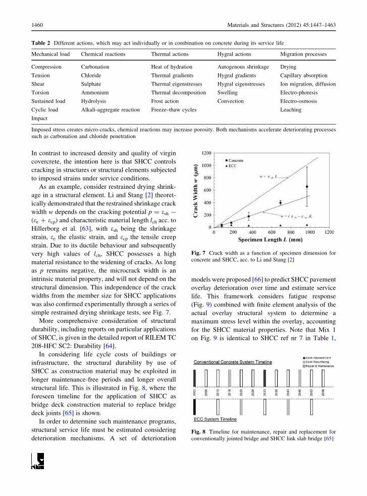
In contrast to increased density and quality of virgin
covercrete, the intention here is that SHCC controls
cracking in structures or structural elements subjected
to imposed strains under service conditions.
As an example, consider restrained drying shrink-
age in a structural element. Li and Stang [2] theoret-
ically demonstrated that the restrained shrinkage crack
width w depends on the cracking potential p = esh -
(ee ? ecp) and characteristic material length lch acc. to
Hillerborg et al. [63], with esh being the shrinkage
strain, ee the elastic strain, and ecp the tensile creep
strain. Due to its ductile behaviour and subsequently
very high values of lch, SHCC possesses a high
material resistance to the widening of cracks. As long
as p remains negative, the microcrack width is an
intrinsic material property, and will not depend on the
structural dimension. This independence of the crack
widths from the member size for SHCC applications
was also confirmed experimentally through a series of
simple restrained drying shrinkage tests, see Fig. 7.
More comprehensive consideration of structural
durability, including reports on particular applications
of SHCC, is given in the detailed report of RILEM TC
208-HFC SC2: Durability [64].
In considering life cycle costs of buildings or
infrastructure, the structural durability by use of
SHCC as construction material may be exploited in
longer maintenance-free periods and longer overall
structural life. This is illustrated in Fig. 8, where the
foreseen timeline for the application of SHCC as
bridge deck construction material to replace bridge
deck joints [65] is shown.
In order to determine such maintenance programs,
structural service life must be estimated considering
deterioration mechanisms. A set of deterioration
models were proposed [66] to predict SHCC pavement
overlay deterioration over time and estimate service
life. This framework considers fatigue response
(Fig. 9) combined with finite element analysis of the
actual overlay structural system to determine a
maximum stress level within the overlay, accounting
for the SHCC material properties. Note that Mix 1
on Fig. 9 is identical to SHCC ref nr 7 in Table 1,
Table 2 Different actions, which may act individually or in combination on concrete during its service life
Mechanical load Chemical reactions Thermal actions Hygral actions Migration processes
Compression Carbonation Heat of hydration Autogenous shrinkage Drying
Tension Chloride Thermal gradients Hygral gradients Capillary absorption
Shear Sulphate Thermal eigenstresses Hygral eigenstresses Ion migration, diffusion
Torsion Ammonium Thermal decomposition Swelling Electro-phoresis
Sustained load Hydrolysis Frost action Convection Electro-osmosis
Cyclic load Alkali-aggregate reaction Freeze–thaw cycles Leaching
Impact
Imposed stress creates micro-cracks, chemical reactions may increase porosity. Both mechanisms accelerate deteriorating processes
such as carbonation and chloride penetration
Fig. 7 Crack width as a function of specimen dimension for
concrete and SHCC, acc. to Li and Stang [2]
Fig. 8 Timeline for maintenance, repair and replacement for
conventionally jointed bridge and SHCC link slab bridge [65]
1460 Materials and Structures (2012) 45:1447–1463

with the exception of a slightly adjusted water content
(W/C = 0.55). Mixes 2 and 3 contain progressively
more FA [66].
These service life models remain to be tested in
practice, as SHCC applications are young. The first
link slab retrofit, i.e. replacement of a conventional
joint with an SHCC link slab, was performed in
Michigan in 2005, and the earliest large scale appli-
cations of SHCC started in 2002 [64].
7 Conclusion
An overview of existing research results on durability
of SHCC has been presented, based on the work of
RILEM TC 208 HFC SC2 [64]. While SHCC forms a
young class of construction materials, insight and
research results on several aspects that need to be
considered in durability design have been developed
over the past one-two decades. At the basis of
durability of SHCC lies its intrinsic crack control,
whereby ingress of deleterious gases and liquids is
deterred, offering protection to underlying structural
parts like steel rebar, substrate concrete or other
construction materials. Importantly, evidence has
been presented that crack control is maintained up to
large strain levels. It remains to be proven to what
extent this crack control is valid for different loading
histories and paths, as some evidence exists of altered
crack patterns in terms of spacing and width under
cyclic and sustained tensile loading.
While durability behaviour under various condi-
tions of mechanical, chemical, thermal and combined
actions have been tested and reported here, and
reference has been made to a preliminary service life
prediction model, a current focus is to formulate a
framework for durability design based on this knowl-
edge of deterioration mechanisms and resistance.
Key to such framework is a systematic characterisa-
tion of cracking and crack distributions in SHCC, and
the link between crack distribution and deterioration
mechanisms.
References
1. Li VC (1998) Engineered cementitious composite (ECC)-
tailored composites through micromechanical modelling.
In: Banthia N, Bentur A, Mufti A (eds) Fiber Reinforced
Concrete: Present and the Future, Canadian Society for
Civil Engineering, Montreal, pp 64–97
2. Li VC, Stang H (2004) Elevating FRC material ductility to
infrastructure durability. In: Proceedings of RILEM PRO
39, BEFIB 6, pp 171–186
3. Wang S, Li VC (2006) Polyvinyl alcohol fiber reinforced
engineered cementitious composites: material design and
performances. RILEM PRO 49. Honolulu, Hawaii
4. Van Zijl GPAG (2008) Mechanisms of creep in fibre-rein-
forced strain-hardening cement composites (SHCC),
CONCREEP8, Ise-Shima, Japan, pp 753–760
5. Ductal� http://www.ductal-lafarge.com, Accessed 2007
6. Richard P, Cheyrezy M (1995) Composition of reactive
powder concretes. Cem Concr Res 25(7):1501–1511
7. Rossi P (2000) Ultra-high performance fiber reinforced
concrete (UHPFRC): an overview, RILEM PRO 15,
BEFIB5, pp 87–100
8. Wittmann FH, Van Zijl GPAG (2006) Task group B:
durability of SHCC conclusions, RILEM PRO 49. Hono-
lulu, Hawaii, pp 109–114
9. Fischer G, Li VC (2004) Effect of fiber reinforcement on the
response of structural members, FRAMCOS5, Vail, Colo-
rado, USA:831–838
10. Li VC, Wang S, Wu C (2001) Tensile strain-hardening
behaviour of polyvinyl alcohol engineered cementitious
composites (PVA-ECC). ACI Mater J 98:483–492
11. WeimannMB, Li VC (2003) Hygral behavior of engineered
cementitious composites (ECC). Int J Restor Build Monum
9(5):513–534
12. Li VC,Mishra DK,WuHC (1995)Matrix design for pseudo
strain-hardening FRCC. Mater Struct 28:586–595
13. Van Zijl GPAG (2005) The role of aggregate in HPFRCC.
Concrete/Beton 110:7–13
14. Kanda T, Li VC (1999) A new micromechanics design
theory for pseudo strain-hardening cementitious composite.
ASCE J Eng Mech 124(4):373–381
Fig. 9 Fatigue performance of three SHCC mixes in flexure
[66]
Materials and Structures (2012) 45:1447–1463 1461

15. Peled A, Shah SP (2003) Processing effect in cementitious
composites: extrusion and casting. J Mater Civil Eng 34:
107–118
16. Song Gao, van Zijl GPAG (2004) Tailoring ECC for com-
mercial application.In: Proceedings 6th Rilem Symposium
on Fibre reinforced Concrete (FRC), Varenna, Italy,
1391–1400
17. Jun P, Mechtcherine V (2007) Behaviour of SHCC under
repeated tensile loading, RILEM PRO 53, HPFRCC5.
Mainz, Germany, pp 97–104
18. Boshoff WP (2007) Time-dependent behaviour of ECC.
Dissertation, Stellenbosch University
19. Boshoff WP, Mechtcherine V, van Zijl GPAG (2009)
Characterising the time-dependent behaviour on the single
fibre level of SHCC: Part 1: Mechanism of fibre pull-out
creep. Cem Concr Res 39:779–786
20. Boshoff WP, Mechtcherine V, van Zijl GPAG (2009)
Characterising the time-dependent behaviour on the single
fibre level of SHCC: Part 2: Rate effects in fibre pull-out
tests. Cem Concr Res 39:787–797
21. Neithalath N (2006) Analysis of moisture transport in
mortars and concrete using sorption-diffusion approach.
ACI Mater J 103(3):209–217
22. Bazant ZP, Najjar LJ (1971) Drying of concrete as a non-
linear diffusion problem. Cem Concr Res 1:461–473
23. Kunieda M, Denarie E, Bruhwiler E, Nakamura H (2007)
Challenges for SHCC: deformability versus matrix density,
RILEM PRO 53, HPFRCC5, Mainz, Germany:31–38
24. Lepech M, Li VC (2005) Water permeability of cracked
cementitious composites. In: Proceedings of ICF11, Turin,
Italy, Mar. 2005, pp 113–130
25. Sahmaran M, Li M, Li VC (2007) Transport properties of
engineered cementitious composites under chloride expo-
sure. ACI Mater J 104(6):604–611
26. TsukamotoM (1990) Tightness of fiber concrete. Darmstadt
Concrete 5:215–225
27. Rapoport J, Aldea C, Shah SP, Ankenman B, Karr AF
(2001) Permeability of cracked steel fiber-reinforced con-
crete. Technical Report Number 115, January, 2001,
National Institute of Statistical Sciences
28. Maalej M, Ahmed SFU, Paramasivam P (2002) Corrosion
durability and structural response of functionally-graded
concrete beams. J Adv Concr Technol 1(3):307–316
29. Miyazato S, Hiraishi Y (2005) Transport properties and
steel corrosion in ductile fiber reinforced cement compos-
ites. In: Proceedings of ICF11, Turin, Italy, Mar. 2005
30. Li VC, Fischer G, KimYY, LepechM, Qian S,WeimannM,
Wang S (2003) Durable link slabs for jointless bridge decks
based on strain-hardening cementitious composites, Report
for Michigan Department of Transportation RC-1438,
November 2003
31. Li VC, Horikoshi T, Ogawa A, Torigoe S, Saito T (2004)
Micromechanics-based durability study of polyvinyl alco-
hol-engineered cementitious composite. ACI Mater J
101:242–248
32. Oh BH, Shin KJ (2006) Cracking, ductility and durability
characteristics of HPFRCC with various mixture propor-
tions and fibers, RILEM PRO 49. Honolulu, Hawaii
33. Lepech M, Li VC (2006) Durability and long term perfor-
mance of engineered cementitious composites, RILEM
PRO 49. Honolulu, Hawaii
34. Oh BH, Jang BS (2003) Chloride diffusion analysis of
concrete structures considering the effects of reinforce-
ments. ACI Mater J 100(2):143–149
35. Oh BH, Jang SY (2003) Experimental investigation of the
threshold chloride concentration for corrosion initiation in
reinforced concrete structures. Mag Concr Res 55(2):
117–124
36. Oh BH, Jang SY (2004) Prediction of diffusivity of concrete
based on simple analytic equations. Cem Concr Res 34(3):
463–480
37. Kabele P, Takeuchi S, Inaba K, Horii H (1999) Performance
of engineered cementitious composites in repair and retrofit:
Analytical Estimates, RILEM PRO 6, HPFRCC 3:617–627
38. Lim YM (1996) Interface fracture behavior of rehabilitated
concrete infrastructures using engineered cementitious
composites. Dissertation, Michigan University
39. Sahmaran M, Li VC, Andrade C (2008) Corrosion resis-
tance performance of steel-reinforced engineered cementi-
tious composite beams. ACI Mater J 105(3):243–250
40. Kabele P, Novak L, Nemecek J, Kopecky L (2006) Effects
of chemical exposure on bond between synthetic fiber and
cementitious matrix, Proc ICTRC’2006. 1st International
RILEM Conference on Textile Reinforced Concrete, 6–7
September 2006, Aachen, Germany, RILEM Publications
S.A.R.L, pp 91–100
41. Kabele P, Novak L, Nemecek J, Pekar J (2007) Multiscale
experimental investigation of deterioration of fiber-cemen-
titious composites in aggressive environment, Proceedings
of MHM 2007: Modeling of heterogeneous materials with
applications in construction and biomedical engineering,
25–27 June 2007, Prague, Czech Republic, pp 270–271
42. Nemecek J, Kabele P, Kopecky L, Bittnar Z (2007) Effect of
chemical exposure on fiber reinforced cementitious matrix.
In: Proceedings of SEMC 2007 The Third International
Conference on Structural Engineering, Mechanics and
Computation, 10–12 September 2007, Cape Town, South
Africa
43. Constantinides G, Ulm FJ (2004) The effect of two types of
C-S-H on the elasticity of cement based materials: results
from nanoindentation and micromechanical modelling.
Cem Concr Res 34(1):67–80
44. Kamali S, Garbozzi E, Prene S, Gerard B (2004) Hydrate
dissolution influence on the Young’s modulus of cement
pastes, FRAMCOS5. Vail, Colorado
45. Nemecek J, Kabele P, Kopecky L, Bittnar Z (2006)
Micromechanical properties of calcium leached engineered
cementitious composites, RILEM PRO 49, Honolulu,
Hawaii, USA, pp 205–211
46. Horikoshi T, Ogawa A, Saito T, Hoshiro H (2006) Proper-
ties of poly vinyl alcohol fiber as reinforcing materials for
cementitious composites, RILEM PRO 49. Honolulu,
Hawaii
47. Sahmaran M, Li VC (2008) Durability of mechanically
loaded engineered cementitious composites under high
alkaline environment. Cem Concr Compos 30(2):72–81
48. Bazant ZP, Kaplan MF (1996) Concrete at high tempera-
tures, Material properties and mathematical models, Long-
man, Essex
49. Kalifa P, Chene G, Galle Ch (2001) High-temperature
behavior of HPC with polypropylene fibers from spalling to
microstructure. Cem Concr Res 31:1487–1499
1462 Materials and Structures (2012) 45:1447–1463

50. Kalifa P, Menneteau FD, Quenard D (2000) Spalling and
pore pressure in HPC at high temperatures. Cem Concr Res
30:1–13
51. Nishida A, Yamazaki N (1995) Study on the properties of
high strength concrete with short polypropylene fiber for
spalling resistance. In: Proceedings of International Con-
ference on Concrete under Severe Conditions, CON-
SEC’95, Sapporo, Japan, August, E&FN Spon, London,
pp 1141–1150
52. Velasco RV, Toledo Filho RD, Fairbairn EMR, Lima PRL,
Neumann R (2004) Spalling and stress-strain behaviour of
polypropylene fibre reinforced HPC after exposure to high
temperatures. RILEM PRO 39, BEFIB6, pp 699–708
53. Chan YN, Luo X, Sun W (2000) Compressive strength and
pore structure of high-performance concrete after exposure
to high temperature up to 800�C. Cem Concr Res 30:
247–251
54. Li Z, Zhou X, Shen B (2004) Fiber-cement extrudates with
perlite subjected to high temperatures. J Mater Civil Eng
16(3):221–229
55. Poon CS, Shui ZH, Lam L (2004) Compressive behavior of
fiber reinforced high-performance concrete subjected to
elevated temperatures. Cem Concr Res 34:2215–2222
56. Yoshitake I, Baba K, Ito T, Nakagawa K (2006) Behavior of
fiber reinforced concrete under fire temperature, RILEM
PRO 49. Honolulu, Hawaii
57. Ogawa A, Hitomi Y, Hoshiro H (2006) PVA-fibre rein-
forced high performance cement board, RILEM PRO 49.
Honolulu, Hawaii
58. Sahmaran M, Li VC (2007) De-icing salt scaling resistance
of mechanically loaded engineered cementitious compos-
ites. Cem Concr Res 37(7):1035–1046
59. Setzer MJ, Fagerlund G, Jansen DJ (1996) CDF test: test
method for the freeze-thaw resistance of concrete: tests with
sodium chloride (CDF), RILEM Recommendation, TC
117-FDC: freeze-thaw and deicing resistance of concrete.
Mater Struct 29(193):523–528
60. Setzer MJ, Auberg R (1995) Freeze-thaw and deicing salt
resistance of concrete testing by the CDF method: CDF
resistance limit and evaluation of precision. Mater Struct
28(175):16–31
61. Zhao T, Wittmann F, Ueda T (eds) (2005) Durability of
reinforced concrete under combined mechanical and cli-
matic loads. Aedificatio Publishers, Freiburg
62. Wittmann FH, Zhang P, Zhao T (2006) Influence of com-
bined environmental loads on durability of reinforced con-
crete structures. Int J Restor Buildings Monum 12(4):
349–361
63. Hillerborg A, Modeer M, Petersson P-E (1976) Analysis of
crack formation and crack growth in concrete by means of
fracture mechanics and finite elements. Cem Concr Res
6:773–781
64. Van Zijl GPAG, Wittmann FH (eds, 2009) Durability of
strain-hardening fibre-reinforced cement-based composites
(SHCC): State-of-the-art. RILEM TC 208-HFC Subcom-
mittee 2 Report, Springer, submitted for publication
65. Lepech MD, Li VC (2009) Application of ECC for bridge
deck link slabs. Mater Struct 42:1185–1195
66. Qian S, Li VC, Han Zhang, Keolaian GA (2008) Durable
and sustainable overlay with ECC. In: Proceedings of 9th
International Conferance Concrete Pavements, San Fran-
cisco, California, August 17–21, 2008
Materials and Structures (2012) 45:1447–1463 1463