Materials and mapping - Elsevier
32
70 70 Textures modified from photographs coupled with mapping to match the object’s shape make the best renderings.
-
Upload
khangminh22 -
Category
Documents
-
view
0 -
download
0
Transcript of Materials and mapping - Elsevier

7070
Textures modified from photographs coupled with mapping to match the object’s shape make the best renderings.

Materials and mappingHAVING GOOD TEXTURES is half the battle in making realistic materials. The other half is knowing how to create materials with the textures, and how to get them onto objects with the right orientation and size.
While a map is 2D and provides color information only, a material has a 3D aspect to it. Shininess, bumpiness, and transparency are all set within the material. You define a material with one or more maps, and then assign the material to a 3D object.
In this chapter, you’ll learn how to create materials and apply mapping to suit your scene.
71© 2011 Elsevier, Inc. All rights reserved. 10.1016/B978-0-240-81433-9.50004-0

MMMaaattteeeriaaals aannd mappppingggMaterials andd mappppingMMMaaatttteeeerrrriiiaaaallllsss aaaannndddd mmmmaaaappppppppppiiinnnnngggggMatteriia s an mappp ng
72
THE MATERIAL EDITOR is the heart of all
materials and mapping. Here is where
you specify the maps that will be applied to
the object. This topic is a quick guide to the
Material Editor tools you’ll use the most often.
As of version 2011, 3ds Max has two different
material editors: the compact Material
Editor (the only version before 2011) and the
Slate Material Editor. This topic covers the
Slate version, which gives you a graphical
representation of the material.
Material Editor basics
4 To assign a bitmap as the material color, scroll down the Material/Map browser display to find the Maps listing.
Drag a bitmap node into the Active View, and choose a bitmap with the Select Bitmap Image File dialog.
7 To make the material shinier, scroll down the Parameter Editor to locate the Specular Highlights parameters.
Adjust the Specular Level and Glossiness parameters to change the material’s shininess. The shininess changes in both the viewport and renderings.
6 To show the map on the object in viewports, select the Bitmap node and click the Show Standard Map in
Viewport button on the toolbar. The color on the Bitmap node changes to a two-color display to indicate the map is being shown in shaded viewports.
4 To assign a bitmap as the material color scroll down the
6 To show the map on the object in viewports, select 7 To make the material shinier, scroll down the Parameter 7
443 To assign the material to an object in the scene, first select the object, then right-click the Material header
and choose Assign Material to Selection from the pop-up menu.

2 To change the material color, double-click the Material node header to make the material parameters appear in
the Parameter Editor. Click the Diffuse color, and change the color in the Color Selector.
1Open the Slate Material Editor by pressing the m key or clicking the Material Editor button on the toolbar.
To start a new material, locate the Standard material in the Material/Map Browser under Materials > Standard. Drag the Standard material type to the right side of the Active View to create a Material node and start a new Standard material.
73
8 To make the material bumpy, create a Noise map node and attach it to the Bump node of the material.
Another Controller Bezier Float node appears. To make sure you know which one goes with which map, expand the Additional Params and Maps rollouts on the Material node.
5 Connect the new bitmap node to the Diffuse Color slot on the Material node. When you do so, a new parameter will appear, Controller Bezier Float. This value represents the Diffuse color amount. A value of 1.0 means the bitmap will be
used for the full color. A value of 0.0 will use the plain Diffuse color, and values in between will mix the two.
HOT TIPTo switch between the Slate and Compact Material Editors, use the Modes menu on either one.
9 Double-click the Noise map node to see its parameters in the Parameter Editor. Click Show Standard Map in
Viewport to see the Noise map on the object, and increase the Tiling parameters. You’ll need to render the viewport to see the Diffuse and Bump maps working together.
1Open the Slate Material Editor by pressing the mm key
5 Connect the new bitmap node to the Diffuse Color slot on thhe Material node. When you do so a new parameter will
HTobeSlCoMusmon
he
8 To make the material bumpy, create a Noise map 9 Double-click the Noise map node to see its parameters 9
2 To change the material color, double-click the Material2

MMMaattteeeriaaallss aaannndd mmaappppppiinnggggMMMaattteeeriaaallls aaannnddd mmapppppinnggMMMaaatttteeeerrrriiiaaaalllsss aaaannndddd mmmmaaaappppppppppiiiiinnnnngggggMatteerriia ss ann mapppp ng
MAPPING IS A METHOD of specifying the
orientation and size of maps on an object.
For mapping, 3ds Max uses a special coordinate
system that works with both flat and curved
sections of objects. When you apply a material to
an object, the object’s own mapping coordinates
determine the textures’ orientation and size.
Every primitive, and just about every other kind
of object you can create in 3ds Max, has mapping
coordinates assigned to it by default. You can
change the default coordinates by applying a UVW
Map modifier to the object, where you’ll have a
selection of mapping types to choose from. In
practice, you’ll use just two or three of them for the
majority of your work.
74
Mapping coordinates
1Every primitive in 3ds Max, and most other objects, have default mapping coordinates applied. As you’d
imagine, the default mapping coordinates correspond to the general shape of the primitive.
4 Box, Spherical, and Shrink-Wrap
have specialty uses for certain types of objects. You will rarely use the other types available with the UVW Map modifier.

HHHooowww ttooo CCChhheeaatt iinn 3ds Max
HOT TIP3ds Max uses UVW as the letters for its coordinate system to avoid confusion with the XYZ coordinate system used to designate 3D space.
75
2 To change the mapping coordinates, apply a UVW Map modifier. The default setting for this modifier,
Planar, projects the map onto the surface. This is the mapping type you’ll use most often.
3 Cylindrical mapping looks good on curved surfaces, but warps at the edges of flat surfaces. This is the
mapping type you’ll use occasionally, mostly for round surfaces.
5 On a lofted object, you can use the Apply Mapping option to apply custom mapping coordinates that
follow the loft path. For objects that follow a spline but aren’t created with lofting, you can use the Unwrap UVW modifier’s Spline Mapping feature.
6 When mapping coordinates from the UVW Map modifier don’t give you exactly what you need,
you can use the Unwrap UVW modifier to fine-tune the mapping. See the Unwrapping the Mapping topic for details on this feature.
2 To change the mappin 3 Cylindrical mapping lo

MMaaattteeeriaaals aannd mappppiinngggMaterials andd mappppingMMMaaatttteeeerrrriiiaaaallllsss aaaannnndddd mmmmaaaappppppppppiiinnnnngggggMMaatttterriiiaa s aan mapppp nng
2 If the map doesn’t match the object exactly, the background
color will “bleed” onto the object. Use Photoshop’s Smudge tool to push the edges of the image and make it larger.
76
he map doesn’t match the1A straight-on photograph of an object makes an excellent basis for
a texture map. In Photoshop, remove perspective with the Warp and Distort tools and clean up the image.
GOOD TEXTURE MAPS are the key to
believability in your renderings. Realistic
textures can bring a crude model to life, but
it doesn’t work the other way around. If your
textures aren’t up to par, your rendering will
suffer accordingly.
Rather than paint your own textures, start
with photographs as a base and do a bit of
cleanup in Photoshop.
Preparing textures
6 Tiny shadows in crevices can be hard to produce with lighting and
shadows alone. Build these shadows into the texture itself for a more realistic rendering.
2n photograph of an
65 If you need a Bump map, make a grayscale version of your texture
map and increase the contrast so you have a range from black to white.
7 To create interesting shadows without having to model the
objects, create a Projector map from a photo. See the Shadows chapter to find out how to use this type of map.
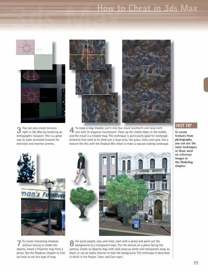
8 For quick people, cars, and trees, start with a photo and paint out the background to a transparent layer. Put the texture on a plane facing the
camera. Create an Opacity map with solid areas as white and transparent areas as black, or use an alpha channel to hide the background. This technique is described in detail in the People, Trees, and Cars topic.
HHHHHooooowwwww tttttooooo CCCCChhhheeeaaattt iiinnn 3333dddss MMMaaaxx
77
4 To make a map tileable, cut it into four equal quadrants and swap each one with its diagonal counterpart. Clean up the visible edges in the middle,
and the result is a tileable map. This technique is particularly good for landscape elements that need to be tiled over a large area, like grass, rocks, and sand. Use a texture like this with the Gradual Mix cheat to make a natural-looking landscape.
3 You can also create textures right in 3ds Max by rendering an
orthographic viewport. This is a great way to make animated textures for television and monitor screens.
r equal quadrants and swap eachHOT TIP
To create textures from photographs, you can use the same techniques as those used on reference images in the Modeling chapter.
ake a map tileable, cut it into fourr e

MMMaaattteeeriaaals aannd mappppingggMaterials andd mappppingMMMaaattteeeerrrriiiaaaallllsss aaaannndddd mmmaaappppppppppiiinnnnggggMMaattteerriiiaa s aann mmaappp nng
APPLYING A MAP in a single spot on
the model is a common need in 3D
presentation. Instead of applying multiple
materials, you can create a decal by using a PSD
texture map with a transparent background.
78
Applying a decal
1Prepare the decal bitmap in Photoshop with a transparent background, and save it as a PSD file. This
automatically stores the transparency information as an alpha channel that you can use in 3ds Max.
4 Assign the material to the object, and turn on Show Standard Map in Viewport. The decal appears all over
the object. In the Coordinates rollout, turn off the Tile option for both U and V to remove the decal from all parts of the object except the area designated by the UVW Map gizmo.
1Prepare the decal bitmap in Photoshop with a
HHHHHooooowwwww tttttttoooooo CCCCChhhhheeeeaaaatttt iiiinnn 333333ddddsss MMMMaaaxxxx
79
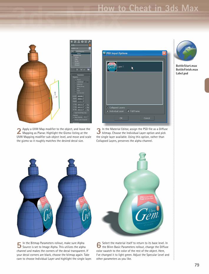
2 Apply a UVW Map modifier to the object, and leave the Mapping as Planar. Highlight the Gizmo listing at the
UVW Mapping modifier sub-object level, and move and scale the gizmo so it roughly matches the desired decal size.
3 In the Material Editor, assign the PSD file as a Diffuse bitmap. Choose the Individual Layer option and pick
the single layer available. Using this option, rather than Collapsed Layers, preserves the alpha channel.
5 In the Bitmap Parameters rollout, make sure Alpha Source is set to Image Alpha. This utilizes the alpha
channel and makes the corners of the decal transparent. If your decal corners are black, choose the bitmap again. Take care to choose Individual Layer and highlight the single layer.
6 Select the material itself to return to its base level. In the Blinn Basic Parameters rollout, change the Diffuse
color swatch to the color of the rest of the object. Here, I’ve changed it to light green. Adjust the Specular Level and other parameters as you like.
BottleStart.max BottleFinish.max Label.psd

MMMaaattteeeriaaals aannd mappppingggMaterials andd mappppingMMMaaattteeeerrrriiiiaaaallllsss aaaannndddd mmmaaappppppppppiiiinnnnggggMMatteriia ss an mappp ng
80
7 The same can be done with trees. The base of the tree will give away the fact that it’s on a plane unless you
hide it behind something, such as a mailbox.
EXTRA SCENE ELEMENTS like people, trees,
and cars are time-consuming to create as
models.
You can save a lot of time by creating these
extra elements as textures and mapping each
one onto a plane. For a more three-dimensional
look, you can also model a simple low-polygon
object, and let the textures do most of the
work.
People, trees, and cars
3 In 3ds Max, create a material with the PSD
file as the Diffuse map. In the PSD Input Options dialog, choose the Individual Layer option and select the single layer. This ensures that the background area will be transparent. In the Bitmap Parameters rollout, make sure Alpha Source is set to None.
6 Place a shadow-casting light in the scene with Ray Traced Shadows. This will render shadows cast by
transparent objects correctly, while a Shadow Map won’t.

1Get together a few pictures of elements you want to use in the scene. Action poses work best for people, such as
walking or sitting, rather than just standing there. For cars, get side and top photos, and back or front views as needed.
4 In the Compact Material Editor,
pick the material from the scene. Expand the Maps rollout, and drag the map from the Diffuse slot to Opacity slot as a Copy. Click the map in the Opacity slot, and set Mono Channel Output to Alpha. This will enable the renderer to generate shadows for the object. Change the Sample Type to a cube and turn on the Background option to check that the map background is transparent.
HHHHooooowww ttttttooooo CCCChhhheeeeaaaatttt iiinn 33333dddsss MMaaaxxx
81
2 In Photoshop, paste the image onto a transparent layer, and erase the background. The Quick Selection tool can
help with large areas, but you’ll need to do some custom cleanup around the edges. Save each image as a PSD file.
8 To darken the shadowy area of the tree, use a Mix map and mix the tree with black, with a black-to-white
Gradient map to determine the Mix Amount.
5 Create a plane in the scene and assign the material to it. Turn on Show Standard Map in Viewport to see
the image in the scene. Assign a UVW Map modifier to the plane, and use View Align, Fit, and Bitmap Fit to ensure the mapping matches the PSD file’s aspect ratio.
HOT TIPIf there are no shadows cast upon the plane in the scene, you can set the Self-Illumination value in the Blinn Basic Parameters rollout to 100 to get the full range of color in the image regardless of the scene lighting. However, self-illumination will also prevent the plane from receiving shadows from other scene elements.
11Get together a few pictures of elements you want to use 2
9 A car can also be mapped onto a plane or created as a low-polygon object. Although it won’t hold up to close
scrutiny, it’s fine as an auxiliary element.
thfrshotel
ar can also be mapped onto a plane or created as a w-polygon object Although it won’t hold up to close
PeopleTrees.max

MMMaaattteeeriaaals aannd mappppingggMaterials andd mappppingMMMaaattteeeerrrriiiaaaallllsss aaaannndddd mmmaaappppppppppiiinnnnggggMMaattteerriiiaa s aann mmaappp nng
82
1In the Compact Material Editor, select a material slot, click the Diffuse color for a new material, and change
the color to the general color of the object. Assign the material to the object. Drag the material to another slot to make a copy, and give it a different name. In this second material, assign the texture map you want to use on just one part of the object.
7 Access the main level of the UVW Mapping modifier, and right-click it. Choose Collapse All to collapse the
modifier stack. This embeds the mapping in the selected polygons.
4 Choose the Bitmap Fit option on the UVW Mapping modifier, and pick the texture map. This will resize the
gizmo to the same aspect ratio as the bitmap.
YOU WILL OFTEN NEED to map several
different textures onto one object. There
are many ways to do this, but the one shown
here is the quickest.
The key is to assign each material to an
appropriate selection of polygons. The result is
an automatic Multi/Sub-Object material with
exactly the right materials in the right places.
This technique uses the Compact Material
Editor, where it’s easier to copy materials than
in the Slate Material Editor.
Multiple maps
A th i l l f th UVW M i difi

HHHHHooooowwwww tttttttoooooo CCCCChhhhheeeeaaaatttt iiiinnn 333333ddddsss MMMMaaaxxxx
83
2 At the Polygon sub-object level, select the polygons to which you want to apply the texture map. Assign the
material to the object while still at the Polygon sub-object level. This assigns the material to the selected polygons only.
3 With the polygons still selected, apply a UVW Map modifier to the object. Use the View Align and Fit
options to line up the gizmo with the approximate size and orientation.
8 Select another set of polygons and repeat the process: Assign a material, apply a UVW Map modifier, adjust
the gizmo, collapse the stack. Repeat this as many times as needed to map the entire object.
9 After assigning multiple materials, click an empty sample slot in the Material Editor and use the eyedropper to pick
the material from the object. The material is a Multi/Sub-Object material with all sub-materials assigned appropriately.
5 If the texture needs to be moved or scaled, access the Gizmo sub-object level of the UVW Mapping modifier,
and move or scale the gizmo.6 If the map is a decal (meaning it’s not meant to be
tiled), turn off the Tile checkbox for both U and V in the bitmap’s Coordinates rollout in the Material Editor.
HOT TIPTo see the bitmap on the object after assigning the material, turn on the Show Standard Map in Viewport option on the Material Editor toolbar.
MailStart.max MailFinish.max USPS_Logo.psd USMail.jpg

MMMaaattteeeriaaals aannd mappppingggMaterials andd mappppingMMMaaattteeeerrrriiiaaaallllsss aaaannndddd mmmaaappppppppppiiinnnnggggMMaattteerriiiaa s aann mmaappp nng
YOUR RENDERINGS can get a lot of
mileage out of a photograph used as
a background. The bitmap can be shifted or
tiled within 3ds Max to match your camera’s
perspective.
84
PHOT
O B
Y FR
AN G
ARDI
NO
Background maps
4 Select the background image slot in the Material Editor. Experiment
with the Offset and Tiling values to eliminate stretching, or to make the parts you want to see show up in the viewport and rendering. You can also change the Mapping to Cylindrical or Spherical Environment, or use the Mirror option to get more sky at the top and trees at the sides.
3 Open the Material Editor. Drag from the Environment Map button
in the Environment and Effects dialog to an empty material slot. When asked to choose the copy method, choose Instance. This will enable you to change the background map from within the Material Editor.

1To set up the background for the rendering, choose Rendering > Environment, click the blank Environment
Map button, and choose a Bitmap. You won’t see the bitmap in viewports; you need to render to see the background.
HHHHHooooowwwww tttttttoooooo CCCCChhhhheeeeaaaatttt iiiinnn 333333ddddsss MMMMaaaxxxx
HOT TIPWhen choosing a background map, look for images with landscape elements far from the camera.
85
2 To display the background in a viewport, activate a camera or Perspective viewport and choose Views
> Viewport Background > Viewport Background (hotkey Ab). Turn on the Use Environment Background and Display Background options and click OK. If the image’s aspect ratio differs from the viewport’s, the image will appear squashed.
5 In the Coordinates rollout, the mapping type is set to Environ by default. This means the background will stay still even if the camera moves. If the camera is animated, you’ll need to put the background texture on an actual 3D object in the
scene. Create a giant sphere or cylinder around the scene, and apply a material to it that uses the background image as a Diffuse map. Turn on the 2-Sided option and set Self-Illumination to 100. With this type of setup, the background will pan appropriately when the camera moves.
Background.jpg
MMMaaattteeeriaaals aannd mappppingggMaterials andd mappppingMMMaaattteeeerrrriiiaaaallllsss aaaannndddd mmmaaappppppppppiiinnnnggggMMaattteerriiiaa s aann mmaappp nng
86
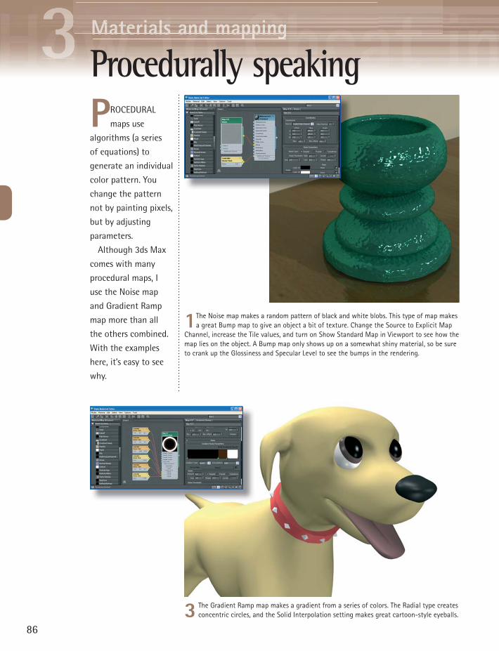
1The Noise map makes a random pattern of black and white blobs. This type of map makes a great Bump map to give an object a bit of texture. Change the Source to Explicit Map
Channel, increase the Tile values, and turn on Show Standard Map in Viewport to see how the map lies on the object. A Bump map only shows up on a somewhat shiny material, so be sure to crank up the Glossiness and Specular Level to see the bumps in the rendering.
3 The Gradient Ramp map makes a gradient from a series of colors. The Radial type creates concentric circles, and the Solid Interpolation setting makes great cartoon-style eyeballs.
PROCEDURAL
maps use
algorithms (a series
of equations) to
generate an individual
color pattern. You
change the pattern
not by painting pixels,
but by adjusting
parameters.
Although 3ds Max
comes with many
procedural maps, I
use the Noise map
and Gradient Ramp
map more than all
the others combined.
With the examples
here, it’s easy to see
why.
Procedurally speaking
HHHHHooooowwwww tttttttoooooo CCCCChhhhheeeeaaaatttt iiiinnn 333333ddddsss MMMMaaaxxxx
87
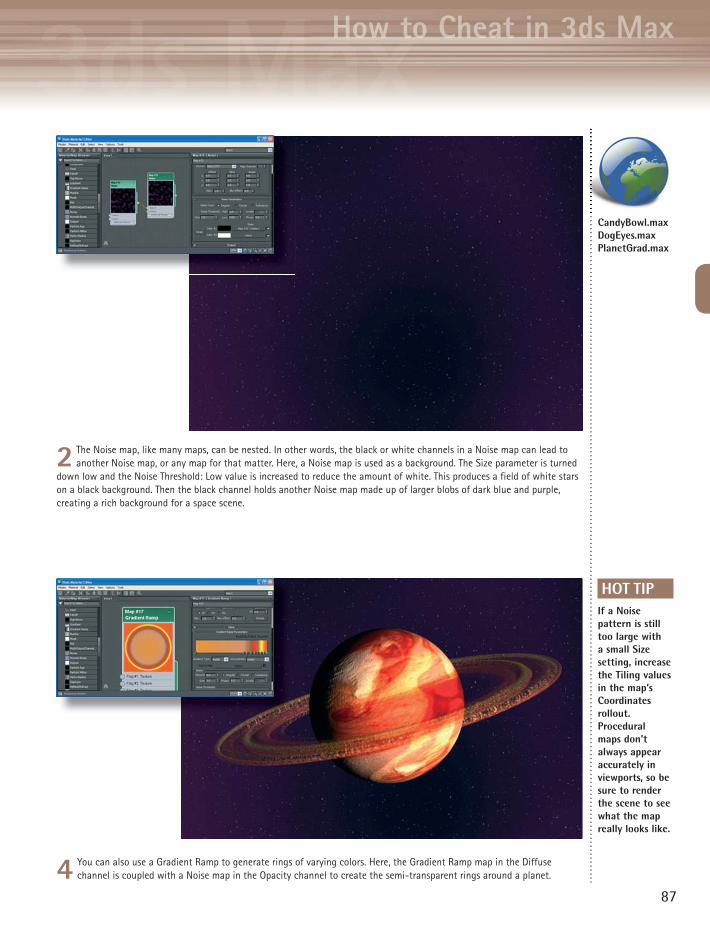
2 The Noise map, like many maps, can be nested. In other words, the black or white channels in a Noise map can lead to another Noise map, or any map for that matter. Here, a Noise map is used as a background. The Size parameter is turned
down low and the Noise Threshold: Low value is increased to reduce the amount of white. This produces a field of white stars on a black background. Then the black channel holds another Noise map made up of larger blobs of dark blue and purple, creating a rich background for a space scene.
4 You can also use a Gradient Ramp to generate rings of varying colors. Here, the Gradient Ramp map in the Diffuse channel is coupled with a Noise map in the Opacity channel to create the semi-transparent rings around a planet.
HOT TIPIf a Noise pattern is still too large with a small Size setting, increase the Tiling values in the map’s Coordinates rollout. Procedural maps don’t always appear accurately in viewports, so be sure to render the scene to see what the map really looks like.
CandyBowl.max DogEyes.max PlanetGrad.max

MMMaaattteeeriaaals aannd mappppingggMaterials andd mappppingMMMaaattteeeerrrriiiaaaallllsss aaaannndddd mmmaaappppppppppiiinnnnggggMMaattteerriiiaa s aann mmaappp nng
3 In the Material Editor, create a Standard material with a Mix map in the Diffuse map slot, and assign it to the terrain. Select a Color 1 map for the
black areas and a Color 2 map for the white areas. As you assign each map, display it in the viewport with the Show Standard Map in Viewport option so you can adjust tiling appropriately.
1Create a terrain object with any method and apply a VertexPaint modifier to it. In the VertexPaint dialog, turn on Vertex Color Display - Unshaded. By default,
all vertex colors are white. You’ll use the VertexPaint tool to paint some of the vertices black.
ALARGE LANDSCAPE might call for
gradual changes from one kind
of ground cover to another. Examples
are grass and dirt on a forest floor and
rocks and snow on a mountaintop.
There are a number of ways you
could create the texture map for such
a landscape, such as mixing two maps
using a Noise map to vary it across the
surface. But with that type of setup,
it’s hard to control where each map
appears on the terrain.
Instead, you can use vertex painting
to put different maps on specific areas.
This technique gives you fine control
over the final look of the landscape
while retaining natural-looking
variations from one map to another.
Gradual mix
88

HHHHHooooowwwww tttttttoooooo CCCCChhhhheeeeaaaatttt iiiinnn 333333ddddsss MMMMaaaxxxx
HOT TIPTo see the ground cover bitmap on the object without the vertex colors, turn on the Disable vertex color display option in the VertexPaint dialog.
4 For the Mix Amount map, choose a Vertex Color map. This will use the vertex colors to determine the amount by which the two maps are mixed. Since
you can see only one map at a time in viewports, you’ll need to render the image to see the result. You can also paint some of the black vertices back to white to change the effect.
2 Make sure the color swatch in the Paintbox is black. Click the Paint tool and move the cursor over the object to see the disk-shaped Paintbrush tool. Drag
the cursor over the object to paint areas black. Here, I’ve painted the peaks black and left the valleys white.
89
TerrainStart.max TerrainMix.max

MMMaaattteeeriaaals aannd mappppingggMaterials andd mappppingMMMaaattteeeerrrriiiaaaallllsss aaaannndddd mmmaaappppppppppiiinnnnggggMMaattteerriiiaa s aann mmaappp nng
1Planar mapping works fine for the top of the mountain, but you’ll get stripes on the sides due to the map pixels going straight down. To visualize the problem clearly, you can apply a Checker map to
the object and see where the checkers stretch.
MAPPING A VERTICAL
surface like a
mountain presents specific
difficulties that can be solved
only with the Unwrap UVW
modifier.
This powerful tool can be
used in a variety of situations.
Here it’s used to clean up
mapping artifacts on a vertical
surface.
Learning to visualize how
the Edit UVWs dialog relates to
the object takes some practice,
but it’s well worth the time
spent. Once you know how
to unwrap your UVs, you’ll be
able to map any object with
ease regardless of its size or
shape.
Unwrapping the mapping
4 For extreme vertical areas, you can also reduce the striping further by scaling selected vertices so they use more of the map. Turn on Soft Selection in the Options panel, and move and scale vertices.
Vertices selected in the viewport are automatically selected in the Edit UVWs dialog, and vice versa.
90
HHHHHooooowwwww tttttttoooooo CCCCChhhhheeeeaaaatttt iiiinnn 333333ddddsss MMMMaaaxxxx
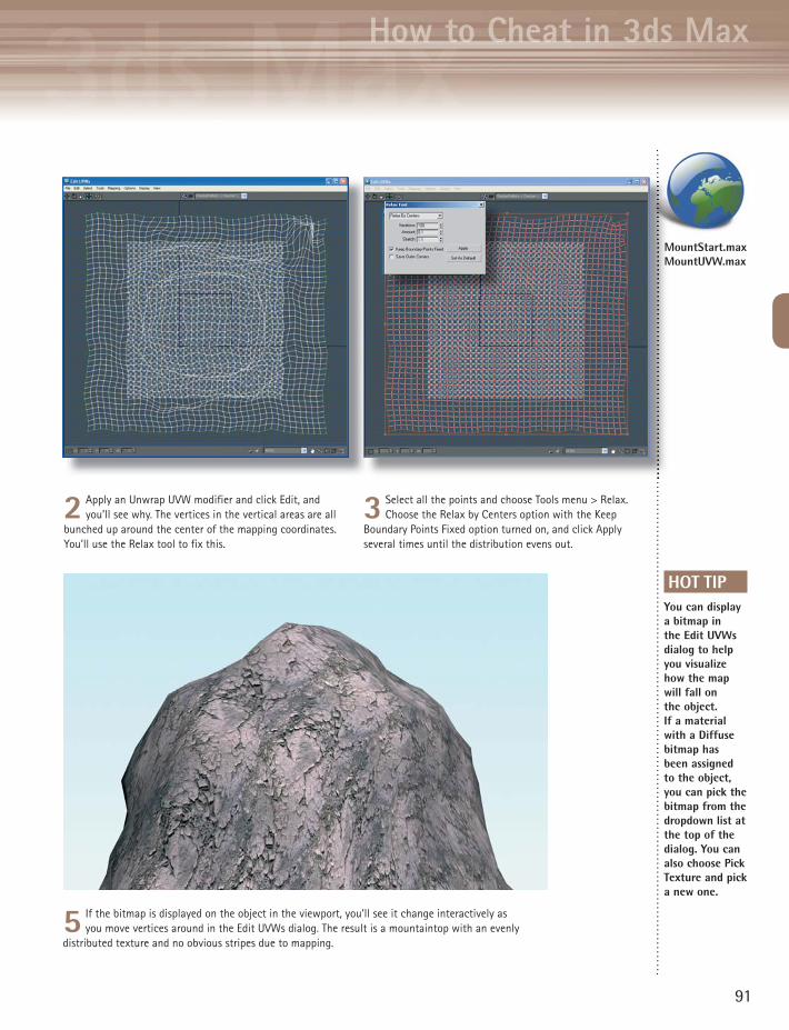
HOT TIPYou can display a bitmap in the Edit UVWs dialog to help you visualize how the map will fall on the object. If a material with a Diffuse bitmap has been assigned to the object, you can pick the bitmap from the dropdown list at the top of the dialog. You can also choose Pick Texture and pick a new one.
2 Apply an Unwrap UVW modifier and click Edit, and you’ll see why. The vertices in the vertical areas are all
bunched up around the center of the mapping coordinates. You’ll use the Relax tool to fix this.
3 Select all the points and choose Tools menu > Relax. Choose the Relax by Centers option with the Keep
Boundary Points Fixed option turned on, and click Apply several times until the distribution evens out.
91
5 If the bitmap is displayed on the object in the viewport, you’ll see it change interactively as you move vertices around in the Edit UVWs dialog. The result is a mountaintop with an evenly
distributed texture and no obvious stripes due to mapping.
MountStart.max MountUVW.max

8 In the Baked Material rollout, choose Output Into Source and Keep Source Materials. This will cause the
Render to Texture operation to automatically assign the new maps to the low-res object’s material in their appropriate slots.
MMMaaattteeeriaaals aannd mappppingggMaterials andd mappppingMMMaaattteeeerrrriiiaaaallllsss aaaannndddd mmmaaappppppppppiiinnnnggggMMaattteerriiiaa s aann mmaappp nng
92
NORMAL MAPPING is a type of bump mapping that produces realistic, detailed bumps.
Normal mapping is particularly useful for replacing a high-resolution object with a low-
resolution version for medium shots and animation.
While bump mapping uses a grayscale image and distorts normals at render time, normal
mapping uses a range of colors to indicate normals pointing in all directions, and replaces the
normals entirely at render time.
Drawing a normal map from scratch is a complicated business, so 3ds Max provides tools to
create them for you. The Render to Texture tool projects the faces of a high-resolution object onto
a low-resolution version to produce the normal map.
Normal mapping works best on curved surfaces, where none of the hi-res object’s faces are at
right angles to one another. With the right kind of hi-res object, you can instantly get a fabulous-
looking low-res object without the overhead of hi-res polygons.
Normal mapping
5 In the Render to Texture dialog, in the Mapping Coordinates group, choose Use Automatic Unwrap for
the Object setting. Having the Render to Texture operation unwrap the mapping for you usually yields better results than using the existing mapping.
6 In the Output rollout, click Add and choose NormalsMap, and click Add Elements to add it to the
output queue. Make sure the Target Map Slot is set to Bump. Set the map size to 2048x2048, and turn on Output into Normal Bump.
7 As long as we’re rendering a normal bump map, we may as well grab the hi-res object’s texture too. Click
the Add button again, and choose DiffuseMap. Set the Target Map Slot to Diffuse Color, and set the map size to 2048x2048.
How to Cheat in 3ds Max
93
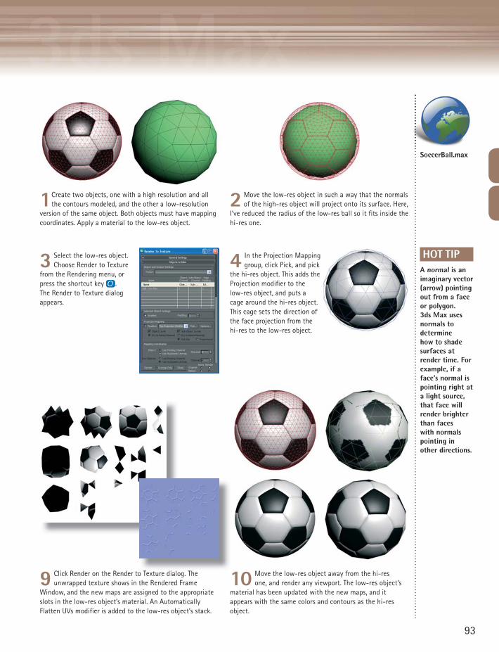
2 Move the low-res object in such a way that the normals of the high-res object will project onto its surface. Here,
I’ve reduced the radius of the low-res ball so it fits inside the hi-res one.
3 Select the low-res object. Choose Render to Texture
from the Rendering menu, or press the shortcut key o. The Render to Texture dialog appears.
9 Click Render on the Render to Texture dialog. The unwrapped texture shows in the Rendered Frame
Window, and the new maps are assigned to the appropriate slots in the low-res object’s material. An Automatically Flatten UVs modifier is added to the low-res object’s stack.
HOT TIPA normal is an imaginary vector (arrow) pointing out from a face or polygon. 3ds Max uses normals to determine how to shade surfaces at render time. For example, if a face’s normal is pointing right at a light source, that face will render brighter than faces with normals pointing in other directions.
1Create two objects, one with a high resolution and all the contours modeled, and the other a low-resolution
version of the same object. Both objects must have mapping coordinates. Apply a material to the low-res object.
10 Move the low-res object away from the hi-res one, and render any viewport. The low-res object’s
material has been updated with the new maps, and it appears with the same colors and contours as the hi-res object.
o Texture dialog The 1
SoccerBall.max
4 In the Projection Mapping group, click Pick, and pick
the hi-res object. This adds the Projection modifier to the low-res object, and puts a cage around the hi-res object. This cage sets the direction of the face projection from the hi-res to the low-res object.

MMMaaattteeeriaaals aannd mappppingggMaterials andd mappppingMMMaaattteeeerrrriiiaaaallllsss aaaannndddd mmmaaappppppppppiiinnnnggggMMaattteerriiiaa s aann mmaappp nng
94
7 Select all the vertices in the window. Using the transform tools at the upper left of the dialog, move
and scale the vertices to fit the part of the texture they correspond to. In this case, it’s the rectangular patch of green at the upper right of the texture image.
Mapping a characterM
ODE
L AN
D TE
XTU
RE B
Y TA
N T
ECK
WEN
G
7 Select all the vertices in the window. Using the
1Put all the various textures for the character in one square image. Create a material with this image as the
Diffuse map.
7
MAPPING A CHARACTER requires a few
special techniques. The use of the
Unwrap UVW modifier makes it possible to put
all the textures into one image, making a game-
ready character that uses as little memory as
possible.
Wrapping your head around the Unwrap UVW
modifier takes a little practice, but it will open
up a new world of texturing to you.
6 Apply the Unwrap UVW modifier, and click Edit. The mesh displayed in the Edit UVWs dialog represents
the skirt flattened out. Choose the texture map from the dropdown at the top of the dialog to display it in the window.

2 Select a body part to
start mapping. In this case we’ll start with the skirt. Select the polygons that make up the skirt, making sure you get all the ones around the back.
HHHHHooooowwwww tttttttoooooo CCCCChhhhheeeeaaaatttt iiiinnn 333333ddddsss MMMMaaaxxxx
95
4 With the polygons still
selected, apply the UVW Map modifier. Choose an appropriate map type, in this case Cylinder. Use View Align and Fit to fit the gizmo.
3 Apply the material
to the selected polygons. The material won’t look right, but that’s okay at this stage.
8 Collapse the modifier stack to set the mapping. Repeat the process for each part of the body, selecting polygons, choosing an appropriate UVW Map type for that section, and applying an Unwrap UVW modifier to align the mesh with
the texture in the Edit UVWs dialog. When you select a vertex in the Edit UVWs dialog, it turns yellow on the mesh. You will see the mapping change on the character in the viewport as you move and scale vertices in the Edit UVWs dialog. Collapse the stack after aligning each part of the mesh in the Edit UVWs dialog.
5 Choose Thick Seam Display
in the UVW Map modifier panel to see where the gizmo’s seam is. At the Gizmo sub-object level, rotate the gizmo to put the seam at the back.
HOT TIPTo make the map easier to see and work with in the Edit UVWs dialog, choose Options > Preferences, turn off Tile Bitmap, and use View > Show Grid to turn off the grid display.
8 Collapse the modifier stack to set the mapping. Repeat the pro
GreenGirl.max

MMMaaattteeeerrrriiiaaaallllsss aaaannndddd mmmaaappppppppppiiinnnnggggMMMaattteeeerrriiiaaaalllss aaaannndddd mmm pppppppppiiinnnngggg
MENTAL RAY comes with a
number of preset materials
that work “as is” in your scene.
Materials that are difficult to create
with the Standard type take just
minutes when you use the Arch &
Design material’s presets.
Mental Ray materials are available
only when Mental Ray is selected as the
renderer. These materials are designated
in the Material/Map Browser by a
yellow sphere icon.
Note that if you switch back to the
default renderer after you assign Mental
Ray materials, you will need to reassign
non-Mental Ray materials to make the
scene render properly.
96
Basic mental ray materials
1In the Render Setup dialog > Common tab, change the renderer to Mental Ray. Open the Slate Material Editor, where the Mental
Ray materials will now be available. Drag an Arch & Design material into the Active View.
1In the Render Setup dialog > Common tab change the renderer
3 Experiment with more templates, and note how they change the Diffuse, Reflectivity, and Transparency settings. Also, look for the
Bump and Displacement settings in the Special Purpose Maps rollout. Many templates automatically assign textures to these parameters.
3 Experiment with more templates, and note how they change the

HHHHHooooowwwww tttttttoooooo CCCCChhhhheeeeaaaatttt iiiinnn 333333ddddsss MMMMaaaxxxx
HOT TIPTo keep the rendering time to a reasonable length while getting the benefits of Mental Ray, turn on Enable Final Gather in the Indirect Illumination tab of the Render Setup dialog, and set the Preset to Draft.
97
2 Double-click the material node to see the material parameters. To get started, choose a template from the Select a Template dropdown and assign the material to an object in the scene. Choosing a template sets the material parameters
to appropriate values, but the preset name doesn’t stay with the material. Try a new template, change the Diffuse color swatch, apply it to an object, and render. Set the output resolution low to keep the rendering time reasonable.
4 Where Mental Ray really shines is with hard-to-get-right materials like glass. Here, I’ve applied the Glass
(Physical) template to the bottle. At any time, you can change the parameters on any rollout to change the object’s color or appearance.
5 The Water, Reflective Surface template gives you instantly believable water. With just a quick change of
the Diffuse color, you can make it match your scene. In the next topic, Custom Mental Ray Materials, you’ll learn how to use your own maps with these templates.
MRTable.max

MMaaattteeeriaaals aannd mappppiinngggMaterials andd mappppingMMMaaatttteeeerrrriiiaaaallllsss aaaannnndddd mmmmaaaappppppppppiiinnnnngggggMMaatttterriiiaa s aan mapppp nng
WHILE PRESET MATERIALS can get you through some
of your projects, to really make use of Mental Ray
you’ll need to use your own bitmaps and textures. To create
a 3D version of this 17th-century ornamental carving, I used
Mental Ray to make all those nooks and crannies really pop.
98
PHOT
O B
Y W
ARRE
N A
PEL
Custom mental ray materials
1Before you start using Mental Ray, create Standard materials for the
object as usual.
5 Replace the Reflection Color map with the same map as the Diffuse map. In the case of Masonry, this will
put soft reflections on the object. Replace the Bump map with your original material’s bump map. For my model, the bumpiness was a bit high for the leaves, so I reduced the Bump value from 1.0 to 0.6.
4 Remove the default map assigned to the Arch & Design material by selecting and deleting it. Connect the
Diffuse Color map from the original material to the Diffuse Color map for the Arch & Design material. Render the scene to see how the material is coming along. Here I’ve assigned the material to the leaves only.

3 In the same Material Editor view, create a new Arch & Design material. This type of material, which is
available only after you have set the renderer to Mental Ray, comes with a number of presets that make it easy to get a particular look for your materials. Click the Templates dropdown menu and choose a template. For my carving, I chose Masonry. Choosing a template changes the material parameters and assigns default maps automatically. You will make your custom material by replacing the default maps.
HHHHHooooowwwww tttttooooo CCCCChhhheeeaaattt iiinnn 3333dddss MMMaaaxx
HOT TIPIf a bump map creates too hard a line between black and white areas in the rendering, increase the Blur value on the bitmap’s Coordinates rollout.
99
2 Get the maps and materials to the point
where the rendering looks pretty good with the default renderer, then assign Mental Ray as the current renderer (Render Setup dialog > Assign Renderer rollout). In the Indirect Illumination tab, turn on Enable Final Gather and choose the Draft preset. Render the scene to see if it looks any different. Shown here are renderings with the default renderer (top) and Mental Ray renderer (bottom). Aside from slight differences in shadows, you won’t see much of a change until you assign Mental Ray materials.
6 Use the same method to create Mental Ray materials for all other parts of the model. Use an appropriate
preset as a base for each material, and replace the maps with your Standard material maps as necessary. Assign each material to a Polygon sub-object selection to automatically create a Multi/Sub-Object material made up of Mental Ray materials. Here, I’ve used the Vertex Paint method to make a messy wall with the Gradual Mix technique.
7 You can also use the bump map as a Displacement map. This causes the bumps to look as though they are
physically modeled, so they show in profile in the rendering. Note the difference in the circular center of this model, where the ridges stand out and prevent it from looking perfectly round. I also made it look like an old relic by mixing a bit of the Speckle map with the original bump map and by applying a Noise modifier to the model itself.
Carving.max CarvingMR.max
33 In the same Material Editor view, create a new Arch
CaCa

MMMaaattteeeriaaals aannd mappppingggMaterials andd mappppingMMMaaattteeeerrrriiiaaaallllsss aaaannndddd mmmaaappppppppppiiinnnnggggMMaattteerriiiaa s aann mmaappp nng
100
WHEN YOU’RE MODELING an object that has lots of creases, crevices, and
curlicues, a question arises: what parts do you model with polygons, and what
parts do you represent with maps?
To answer this question, we’ll look at an ornate mirror that I photographed
at my friend’s house. (Yep, that’s me in the mirror with the camera.) My friend
has a lot of cool antique stuff, and when I saw this mirror I knew I had to
model it in 3ds Max.
The first step, of course, was to remove the background (and my face) and
make a nice, clean texture map. Since the mirror frame is white, the image can
work as both a texture map and a bump map. Then I painted over the frame
with white to create an opacity map.
Rather than model each curlicue in the mirror frame, the texture/bump map
can provide this detail. But what about the outer edges? The easiest approach
is to map the image onto a box using the opacity map. However, the result is a
flat-looking object. While the curlicues themselves look fine, you can tell from
the edge of the object that it’s flat.
I N T E R L U D E
Lumps, bumps, and dainty curly stuff

HHHHHooooowwwww tttttttoooooo CCCCChhhhheeeeaaaatttt iiiinnn 333333ddddsss MMMMaaaxxxx
101
To get some thickness around the edges, I took a plane with 20x20 segments and pushed
and pulled the vertices to make the mirror frame outline, then applied the Shell modifier to
make it a 3D object. The TurboSmooth modifier with Iterations of 2 smoothed out the mirror
frame nicely. (To understand why I didn’t just draw a spline and extrude it, see How to Make
a Mess with Modeling in the Modeling chapter.)
I also modified the opacity map to be solid (white) around the edges of the mirror frame.
With this setup, the model has a bit of thickness around the edges, and all the curlicue detail
is still provided by maps.
The same rules can be applied to any object. Interior detail: use maps. Exterior edges: use
modeling.
MirrorThick.max