CIVIL ENGINEERING MATERIALS and CONSTRUCTION
272
LECTURE NOTE On CIVIL ENGINEERING MATERIALS and CONSTRUCTION COURSE CODE: BCE03002: 3.0.0 (CR 03) Third Semester, B Tech, Civil Engineering Dr. S K Panigrahi Associate Professor Deptt. of Civil Engg VSSUT BURLA
-
Upload
khangminh22 -
Category
Documents
-
view
0 -
download
0
Transcript of CIVIL ENGINEERING MATERIALS and CONSTRUCTION

LECTURE NOTE
On
CIVIL ENGINEERING MATERIALS
and
CONSTRUCTION
COURSE CODE: BCE03002: 3.0.0 (CR 03) Third Semester, B Tech, Civil Engineering
Dr. S K Panigrahi
Associate Professor
Deptt. of Civil Engg
VSSUT BURLA
SYLLABUS
Civil Engineering Materials and Constructions (BCE03002) Module-I
Basic Building Materials I Aggregate: Classification, Physical and mechanical properties, soundness, alkali-aggregate reaction,
thermal properties of aggregate Bricks and Masonry Blocks: Types, properties and field and
laboratory tests to evaluate quality Lime: classification, properties Cement: types, Portland cement:
chemical composition of raw material, bogue compounds, hydration of cement, role of water in
hydration, testing of cements, fly ash: properties and use in manufacturing of bricks and cement.
Module-II Mortar: Types and tests on mortars. Concrete: Production, mix proportions and grades of concrete,
fresh, mechanical and durability properties of concrete, factors affecting properties of concrete, tests
on concrete, admixtures, Special concrete: light weight concrete, high density concrete, vacuum
concrete, shotcrete, steel fiber reinforced concrete, polymer concrete, Ferro cement, high performance
concrete, self-compacting concrete.
Module-III
Basic Building Materials II Building stone: classifications, properties and structural requirements; Wood and Wood products:
Introduction to wood macrostructure, sap wood and heart wood, defects and decay of timber,
seasoning and preservation of timber, fire resisting treatment, introduction to wood products- veneers,
plywoods, fibre board, particle board, block board, batten boards. Metals: Steel: Important properties
and uses of Iron (Cast iron, wroght iron and steel), Important tests on steel rebar, aluminum and
copper. Glass: types and uses, gypsum: source, properties, uses; plastic: properties and uses, paint:
types, distemper, varnish, Adhesive: Types, Bitumen: types, properties and tests.
Module-IV
Basic Building Constructions Foundation: purpose, types of foundation- shallow, deep, pile, raft, grillage foundation. Masonry:
Brick Masonry: types of bonds, relative merits and demerits of English, Single Flemish and Double
Flemish bond. Stone Masonry: General principles, classification of stone masonry and their relative
merits and demerits, Cavity wall: components and construction, Arches: Terminology and
classifications Doors and Windows: Types, materials used
Module-V
Finishing, Services and Special constructions Wall Finishes: Plastering, pointing, distempering and painting: Purpose, methods, defects and their
solutions. Vertical communication: Stairs: Terminology, requirements of good staircase,
classification; ramps, lifts and escalators. Damp proofing: causes, effects, prevention and treatments,
Fire resistant construction: Fire resistant properties of common building materials, requirements for
various building components.
Reference Books:
1. A Text-Book of Building Construction, S.P.Bindra and S.P.Arora, Dhanpat Rai Publications
2. Building Materials and Construction, Jena and Sahu, Mc. Graw Hill.
3. Materials for Civil and Construction Engineers, Mamlouk and Zaniewski, Pearson
4. Building Materials and Building Construction, by P C Verghese
5. Building Construction, by B. C. Punmia, , Laxmi Publicaton
Civil Engineering Materials and Constructions (BCE03002)
Module-I
Basic Building Materials I
Module I Syllabus
Aggregate: Classification, Physical and mechanical properties, soundness, alkali-aggregate
reaction, thermal properties of aggregate Bricks and Masonry Blocks: Types, properties and
field and laboratory tests to evaluate quality Lime: classification, properties Cement: types,
Portland cement: chemical composition of raw material, bogue compounds, hydration of
cement, role of water in hydration, testing of cements, Fly ash: properties and use in
manufacturing of bricks and cement.
Subject to Revision
1. AGGREGATE:
Classification, Physical and mechanical properties, soundness, alkali-aggregate reaction,
thermal properties of aggregate Aggregates are the important constituents of the concrete which give body to the concrete and
also reduce shrinkage. Aggregates occupy 70 to 80 % of total volume of concrete. So, we can
say that one should know definitely about the aggregates in depth to study more about concrete.
Classification of Aggregates as per Shape and Size:
Aggregates are classified based on so many considerations, but here we are going to discuss
about their shape and size classifications in detail.
i) Classification of Aggregates Based on Shape:
We know that aggregate is derived from naturally occurring rocks by blasting or crushing etc.,
so, it is difficult to attain required shape of aggregate. But, the shape of aggregate will affect
the workability of concrete. So, we should take care about the shape of aggregate. This care is
not only applicable to parent rock but also to the crushing machine used.
Aggregates are classified according to shape into the following types
Rounded aggregates
Irregular or partly rounded aggregates
Angular aggregates
Flaky aggregates
Elongated aggregates
Flaky and elongated aggregates
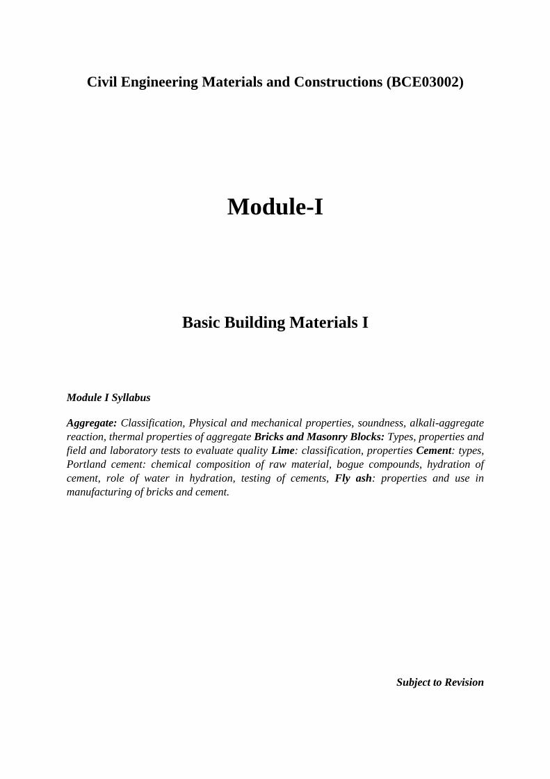
Rounded Aggregate:
The rounded aggregates are completely shaped by attrition (the resistance of a granular
material to wear) and available in the form of seashore gravel. Rounded aggregates result in
the minimum percentage of voids (32 – 33%) hence gives more workability. They require a
lesser amount of water-cement ratio. They are not considered for high-strength concrete
because of poor interlocking behavior and weak bond strength.
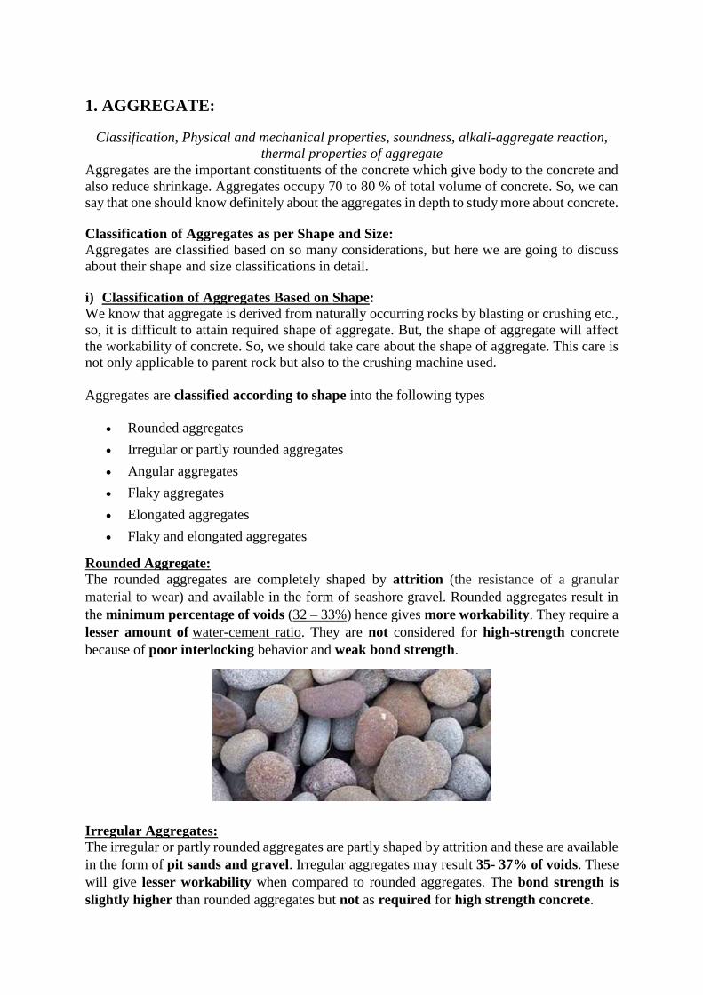
Irregular Aggregates:
The irregular or partly rounded aggregates are partly shaped by attrition and these are available
in the form of pit sands and gravel. Irregular aggregates may result 35- 37% of voids. These
will give lesser workability when compared to rounded aggregates. The bond strength is
slightly higher than rounded aggregates but not as required for high strength concrete.
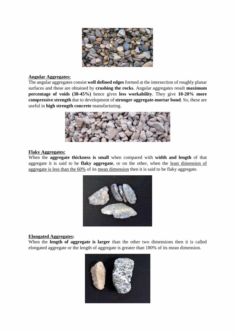
Angular Aggregates:
The angular aggregates consist well defined edges formed at the intersection of roughly planar
surfaces and these are obtained by crushing the rocks. Angular aggregates result maximum
percentage of voids (38-45%) hence gives less workability. They give 10-20% more
compressive strength due to development of stronger aggregate-mortar bond. So, these are
useful in high strength concrete manufacturing.
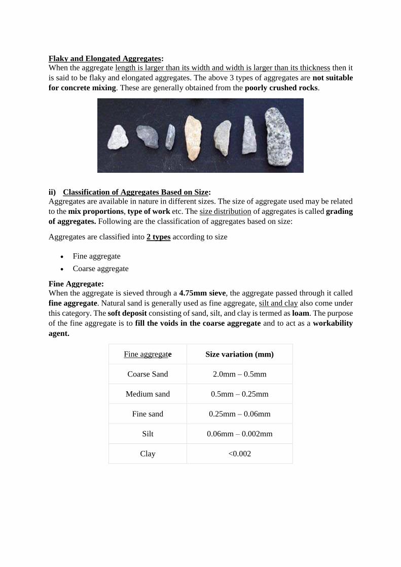
Flaky Aggregates:
When the aggregate thickness is small when compared with width and length of that
aggregate it is said to be flaky aggregate, or on the other, when the least dimension of
aggregate is less than the 60% of its mean dimension then it is said to be flaky aggregate.
Elongated Aggregates:
When the length of aggregate is larger than the other two dimensions then it is called
elongated aggregate or the length of aggregate is greater than 180% of its mean dimension.
Flaky and Elongated Aggregates:
When the aggregate length is larger than its width and width is larger than its thickness then it
is said to be flaky and elongated aggregates. The above 3 types of aggregates are not suitable
for concrete mixing. These are generally obtained from the poorly crushed rocks.
ii) Classification of Aggregates Based on Size:
Aggregates are available in nature in different sizes. The size of aggregate used may be related
to the mix proportions, type of work etc. The size distribution of aggregates is called grading
of aggregates. Following are the classification of aggregates based on size:
Aggregates are classified into 2 types according to size
Fine aggregate
Coarse aggregate
Fine Aggregate:
When the aggregate is sieved through a 4.75mm sieve, the aggregate passed through it called
fine aggregate. Natural sand is generally used as fine aggregate, silt and clay also come under
this category. The soft deposit consisting of sand, silt, and clay is termed as loam. The purpose
of the fine aggregate is to fill the voids in the coarse aggregate and to act as a workability
agent.
Fine aggregate Size variation (mm)
Coarse Sand 2.0mm – 0.5mm
Medium sand 0.5mm – 0.25mm
Fine sand 0.25mm – 0.06mm
Silt 0.06mm – 0.002mm
Clay <0.002

Coarse Aggregate:
When the aggregate is sieved through 4.75mm sieve, the aggregate retained is called coarse
aggregate. Gravel, cobble and boulders come under this category. The maximum size
aggregate used may be dependent upon some conditions. In general, 40mm size aggregate
used for normal strengths, and 20mm size is used for high strength concrete. The size range
of various coarse aggregates given below.
Coarse aggregate Size variation (mm)
Fine gravel 4mm – 8mm
Medium gravel 8mm – 16mm
Coarse gravel 16mm – 64mm
Cobbles 64mm – 256mm
Boulders >256mm
1.1 Physical Prosperities of Aggregate:
1.1.1 Grading:
Grading is the particle-size distribution of an aggregate as determined by a sieve
analysis using wire mesh sieves with square openings.
As per IS:2386(Part-1):
Fine aggregate: 6 standard sieves with openings from 150 μm to 4.75 mm. (150 μm,
300 μm, 600 μm, 1.18mm, 2.36mm, 4.75mm)
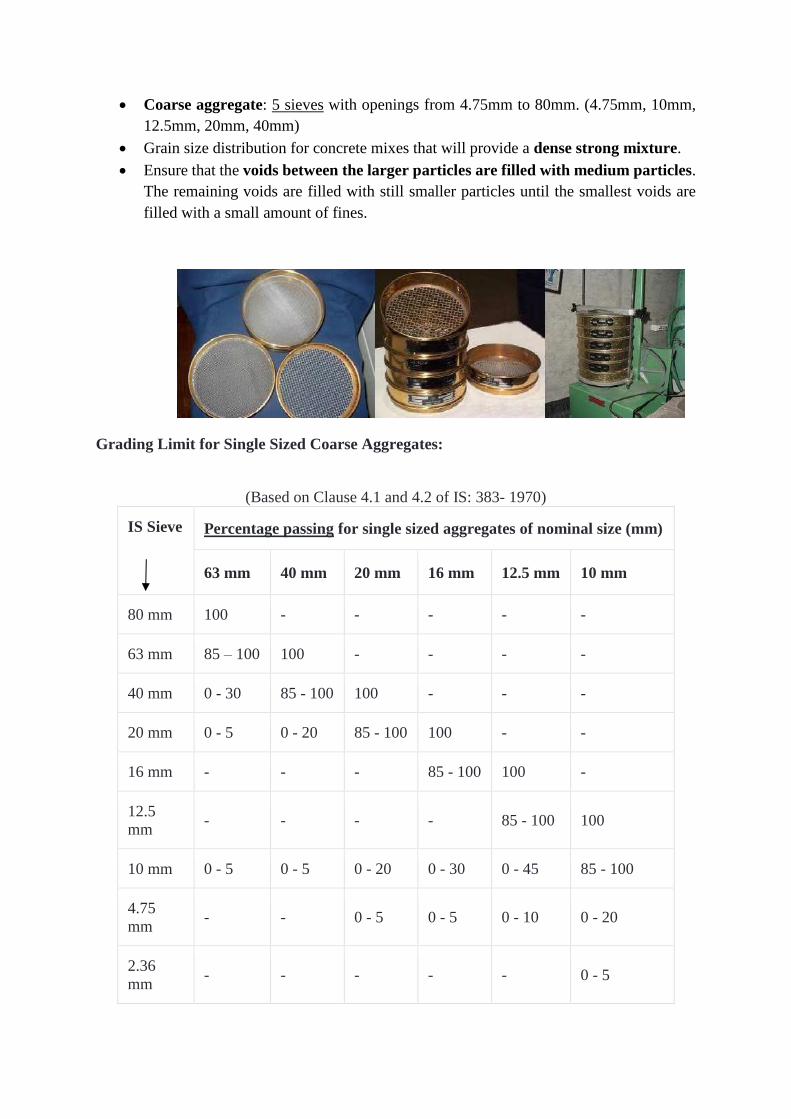
Coarse aggregate: 5 sieves with openings from 4.75mm to 80mm. (4.75mm, 10mm,
12.5mm, 20mm, 40mm)
Grain size distribution for concrete mixes that will provide a dense strong mixture.
Ensure that the voids between the larger particles are filled with medium particles.
The remaining voids are filled with still smaller particles until the smallest voids are
filled with a small amount of fines.
Grading Limit for Single Sized Coarse Aggregates:
(Based on Clause 4.1 and 4.2 of IS: 383- 1970)
IS Sieve Percentage passing for single sized aggregates of nominal size (mm)
63 mm 40 mm 20 mm 16 mm 12.5 mm 10 mm
80 mm 100 - - - - -
63 mm 85 – 100 100 - - - -
40 mm 0 - 30 85 - 100 100 - - -
20 mm 0 - 5 0 - 20 85 - 100 100 - -
16 mm - - - 85 - 100 100 -
12.5
mm - - - - 85 - 100 100
10 mm 0 - 5 0 - 5 0 - 20 0 - 30 0 - 45 85 - 100
4.75
mm - - 0 - 5 0 - 5 0 - 10 0 - 20
2.36
mm - - - - - 0 - 5
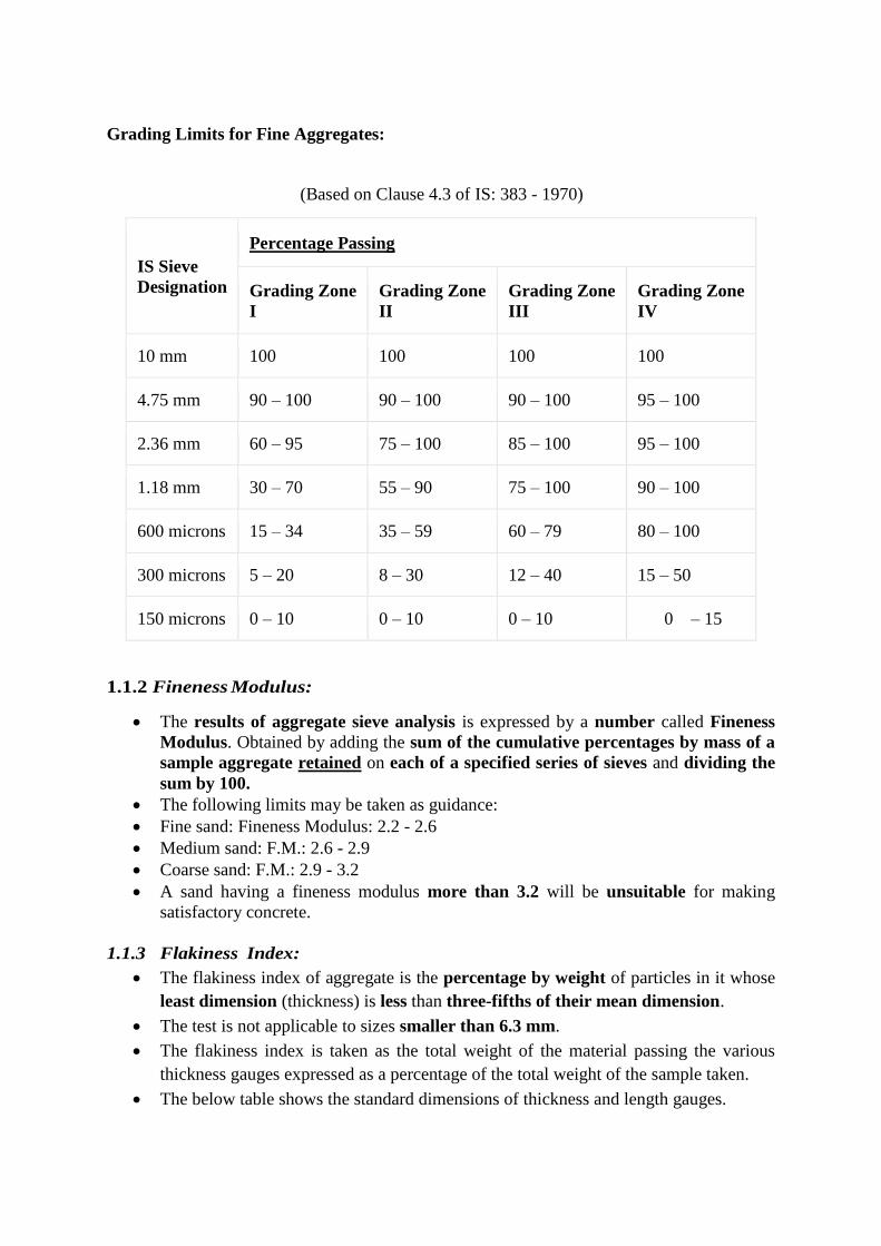
Grading Limits for Fine Aggregates:
(Based on Clause 4.3 of IS: 383 - 1970)
IS Sieve
Designation
Percentage Passing
Grading Zone
I
Grading Zone
II
Grading Zone
III
Grading Zone
IV
10 mm 100 100 100 100
4.75 mm 90 – 100 90 – 100 90 – 100 95 – 100
2.36 mm 60 – 95 75 – 100 85 – 100 95 – 100
1.18 mm 30 – 70 55 – 90 75 – 100 90 – 100
600 microns 15 – 34 35 – 59 60 – 79 80 – 100
300 microns 5 – 20 8 – 30 12 – 40 15 – 50
150 microns 0 – 10 0 – 10 0 – 10 0 – 15
1.1.2 Fineness Modulus:
The results of aggregate sieve analysis is expressed by a number called Fineness
Modulus. Obtained by adding the sum of the cumulative percentages by mass of a
sample aggregate retained on each of a specified series of sieves and dividing the
sum by 100.
The following limits may be taken as guidance:
Fine sand: Fineness Modulus: 2.2 - 2.6
Medium sand: F.M.: 2.6 - 2.9
Coarse sand: F.M.: 2.9 - 3.2
A sand having a fineness modulus more than 3.2 will be unsuitable for making
satisfactory concrete.
1.1.3 Flakiness Index:
The flakiness index of aggregate is the percentage by weight of particles in it whose
least dimension (thickness) is less than three-fifths of their mean dimension.
The test is not applicable to sizes smaller than 6.3 mm.
The flakiness index is taken as the total weight of the material passing the various
thickness gauges expressed as a percentage of the total weight of the sample taken.
The below table shows the standard dimensions of thickness and length gauges.
The flakiness index of aggregate is the percentage by weight of particles in it whose
least dimension (thickness) is less than three-fifths of their mean dimension.
1.1.4 Elongation Index:
The elongation index on an aggregate is the percentage by weight of particles whose
greatest dimension (length) is greater than 1.8 times their mean dimension.
The elongation index is not applicable to sizes smaller than 6.3 mm.
The elongation index is the total weight of the material retained on the various length
gauges expressed as a percentage of the total weight of the sample gauged. The presence
of elongated particles in excess of 10 to 15 per cent is generally considered undesirable,
but no recognized limits are laid down.
1.2 Mechanical Properties of Aggregate
Property # 1. Toughness:
Property # 2. Hardness:
Property # 3. Specific Gravity:
Property # 4. Porosity and Absorption of Water by Aggregate:
Property # 5. Bulking of Sand:
1.2.1 Toughness: It is defined as the resistance of aggregate to failure by impact. The impact
value of bulk aggregate can be determined as per I.S. 2386, 1963.
Procedure: The aggregate shall be taken as in the case of crushing strength value test i.e., the
aggregate should pass through 12.5 mm I.S. sieve and retained on 10 mm I.S. sieve. It should
be oven dried at 100°C to 110°C for four hours and then air cooled before test.
Now the prepared aggregate is filled upto 1/3rd height of the cylindrical cup of the equipment.
The diameter and depth of the cup are 102 mm and 50 mm respectively. After filling the cup
upto 1/3rd of its height, the aggregate is tamped with 25 strokes of the rounded end of the
tamping rod.
After this operation the cup shall be further filled upto 2/3rd of its height and a further tamping
of 25 strokes given. The cup finally shall be filled to over flowing and tamped with 25 strokes
and surplus aggregate removed and the weight of aggregate noted. The value of weight will be
useful to repeat the experiment.
Now the hammer of the equipment weighting 14.0 kg or 13.5 kg is raised till its lower face is
380 mm above the upper surface of the aggregate and., allowed to fall freely on the aggregate
and the process is repeated for 15 times.
The crushed aggregate is now removed from the cup and sieved through 2.36 mm I.S. sieve.
The fraction passing through the sieve is weighed accurately.
Let the weight of oven dry sample in the cup = W kg.
Weight of aggregate passing 2.36 mm sieve = W1 kg.
Then impact value = [(W1/W) x 100]
1.2.2 Hardness:
It is defined as the resistance to wear by abrasion, and the aggregate abrasion value is
defined as the percentage loss in weight on abrasion.
Deval Attrition Test:
This test has been covered by IS 2386 Part (IV)-1963. In this test particles of known weight
are subjected to wear in an iron cylinder rotated 10,000 (ten thousand) times at the rate of 30
to 33 revolutions per minute. After the specified revolution of the cylinder the material is taken
out and sieved on 1.7 mm sieve and the percentage of material finer than 1.7mm is determined.
This percentage is taken as the attrition value of the aggregate. The attrition value of about 7
to 8 usually is considered as permissible.
Dorry Abrasion Test:
This test has not been covered by Indian standard specifications. In this test a cylindrical
specimen having its diameter and height of 25 cm is subjected to abrasion against a rotating
metal disk sprinkled with quartz sand. The loss in weight of the cylinder after 1000 (one
thousand) revolutions is determined.
Then the hardness of rock sample is expressed by an empirical relation as follows:
Hardness or sample = 20 – Loss in weight in grams/3
For good rock this value should not be less the 17. The rock having this value of 14 is
considered poor.
Los-Angeles Test:
This test has been covered by IS 2386 (Part-IV) 1963. In this test, aggregate of the specified
grading is placed in a cylindrical drum of inside length and diameter of 500 mm and 700 mm
respectively. This cylinder is mounted horizontally on stub shafts. For abrasive charge, steel
balls or cast-iron balls of approximately 48 mm diameter and each weighting 390 grams to
445 gram are used. The numbers of balls used vary from 6 to 12 depending upon the grading
of the aggregate. For 10 mm size aggregate 6 balls are used and for aggregates bigger than
20 mm size usually 12 balls are used.

PROCEDURE: For the conduct of test, the sample and the abrasive charge are placed in the
Los-Angeles testing machine and it is rotated at a speed of 20 to 33 revolutions per minute. For
aggregates up to 40 mm size the machine is rotated for 500 revolutions and for bigger size
aggregate 1000 revolutions. The charge is taken out from the machine and sieved on 1.7 mm
sieve.
Let the weight of oven dry sample put in the drum = W Kg.
Weight of aggregate passing through 1.7 sieve = W1 Kg.
Then abrasion value = [(W1/W) x 100]
The abrasion value should not be more than 30% for wearing surfaces and not more than
50% for concrete used for other than wearing surface. The results of Los Angeles test show
good correlation not only the actual wear of aggregate when used in concrete, but also with the
compression and flexural strength of concrete made with the given aggregate.
1.2.3 Specific Gravity and Water Absorption:
The specific gravity of a substance is the ratio of the weight of unit volume of the substance
to the unit volume of water at the stated temperature. In concrete making, aggregates generally
contain pores both permeable and impermeable hence the term specific gravity has to be
defined carefully. Actually, there are several types of specific gravity. In concrete technology
specific gravity is used for the calculation of quantities of ingredients. Usually, the specific
gravity of most aggregates varies between 2.6 and 2.8.
Specific gravity of certain materials as per concrete hand book CA-1 Bombay may be assumed
as shown in Table 4.9.
Absolute Specific Gravity:
It can be defined as the ratio of the weight of the solid, referred to vacuum, to the weight of
an equal volume of gas free distilled water both taken at the standard or a stated temperature,
usually it is not required in concrete technology. Actually, the absolute specific gravity and
particle density refer to the volume of solid material excluding all pores, while apparent
specific gravity and apparent particle density refer to the volume of solid material including
impermeable pores, but not the capillary pores. In concrete technology apparent specific
gravity is required.
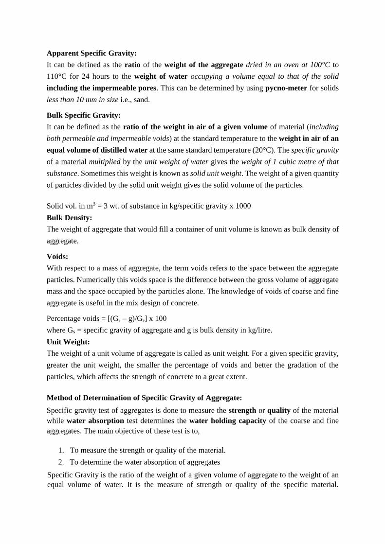
Apparent Specific Gravity:
It can be defined as the ratio of the weight of the aggregate dried in an oven at 100°C to
110°C for 24 hours to the weight of water occupying a volume equal to that of the solid
including the impermeable pores. This can be determined by using pycno-meter for solids
less than 10 mm in size i.e., sand.
Bulk Specific Gravity:
It can be defined as the ratio of the weight in air of a given volume of material (including
both permeable and impermeable voids) at the standard temperature to the weight in air of an
equal volume of distilled water at the same standard temperature (20°C). The specific gravity
of a material multiplied by the unit weight of water gives the weight of 1 cubic metre of that
substance. Sometimes this weight is known as solid unit weight. The weight of a given quantity
of particles divided by the solid unit weight gives the solid volume of the particles.
Solid vol. in m3 = 3 wt. of substance in kg/specific gravity x 1000
Bulk Density:
The weight of aggregate that would fill a container of unit volume is known as bulk density of
aggregate.
Voids:
With respect to a mass of aggregate, the term voids refers to the space between the aggregate
particles. Numerically this voids space is the difference between the gross volume of aggregate
mass and the space occupied by the particles alone. The knowledge of voids of coarse and fine
aggregate is useful in the mix design of concrete.
Percentage voids = [(Gs – g)/Gs] x 100
where Gs = specific gravity of aggregate and g is bulk density in kg/litre.
Unit Weight:
The weight of a unit volume of aggregate is called as unit weight. For a given specific gravity,
greater the unit weight, the smaller the percentage of voids and better the gradation of the
particles, which affects the strength of concrete to a great extent.
Method of Determination of Specific Gravity of Aggregate:
Specific gravity test of aggregates is done to measure the strength or quality of the material
while water absorption test determines the water holding capacity of the coarse and fine
aggregates. The main objective of these test is to,
1. To measure the strength or quality of the material.
2. To determine the water absorption of aggregates
Specific Gravity is the ratio of the weight of a given volume of aggregate to the weight of an
equal volume of water. It is the measure of strength or quality of the specific material.
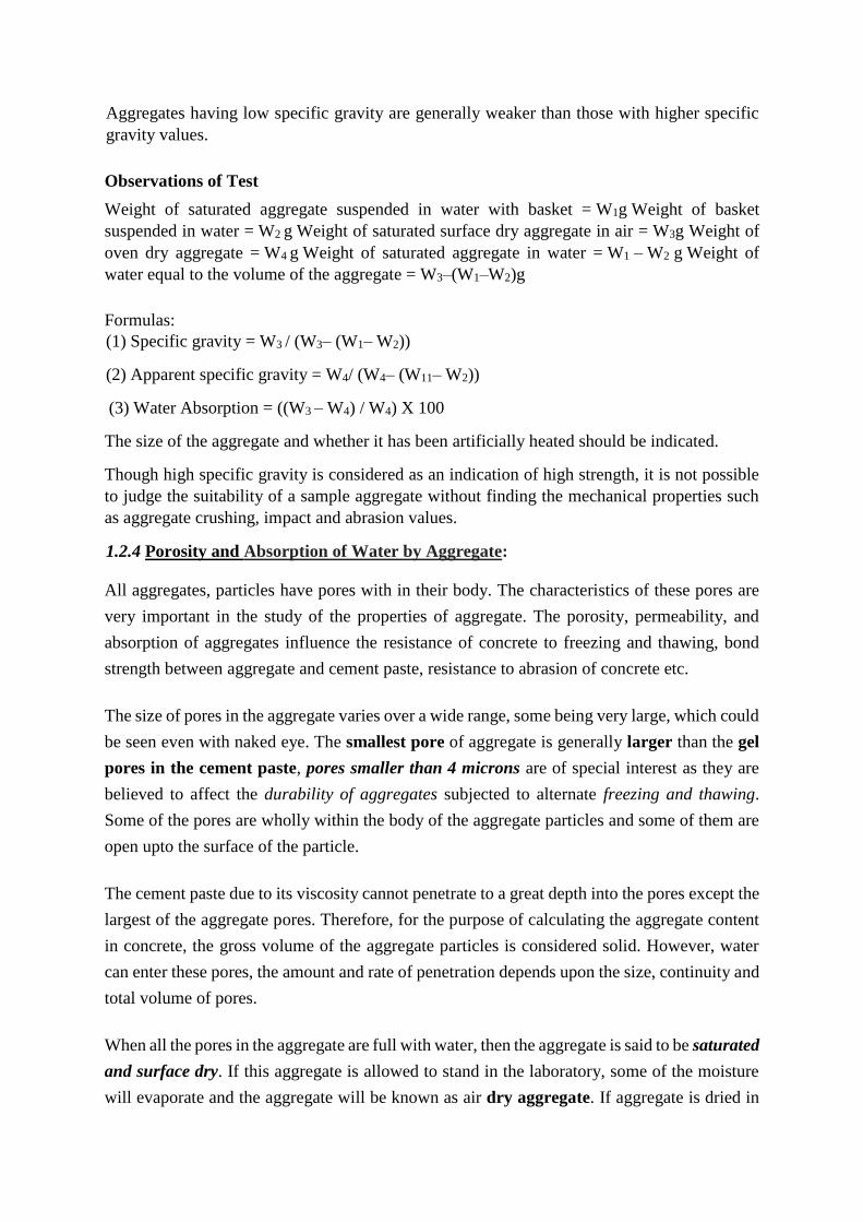
Aggregates having low specific gravity are generally weaker than those with higher specific
gravity values.
Observations of Test
Weight of saturated aggregate suspended in water with basket = W1g Weight of basket
suspended in water = W2 g Weight of saturated surface dry aggregate in air = W3g Weight of
oven dry aggregate = W4 g Weight of saturated aggregate in water = W1 – W2 g Weight of
water equal to the volume of the aggregate = W3–(W1–W2)g
Formulas:
(1) Specific gravity = W3 / (W3– (W1– W2))
(2) Apparent specific gravity = W4/ (W4– (W11– W2))
(3) Water Absorption = ((W3 – W4) / W4) X 100
The size of the aggregate and whether it has been artificially heated should be indicated.
Though high specific gravity is considered as an indication of high strength, it is not possible
to judge the suitability of a sample aggregate without finding the mechanical properties such
as aggregate crushing, impact and abrasion values.
1.2.4 Porosity and Absorption of Water by Aggregate:
All aggregates, particles have pores with in their body. The characteristics of these pores are
very important in the study of the properties of aggregate. The porosity, permeability, and
absorption of aggregates influence the resistance of concrete to freezing and thawing, bond
strength between aggregate and cement paste, resistance to abrasion of concrete etc.
The size of pores in the aggregate varies over a wide range, some being very large, which could
be seen even with naked eye. The smallest pore of aggregate is generally larger than the gel
pores in the cement paste, pores smaller than 4 microns are of special interest as they are
believed to affect the durability of aggregates subjected to alternate freezing and thawing.
Some of the pores are wholly within the body of the aggregate particles and some of them are
open upto the surface of the particle.
The cement paste due to its viscosity cannot penetrate to a great depth into the pores except the
largest of the aggregate pores. Therefore, for the purpose of calculating the aggregate content
in concrete, the gross volume of the aggregate particles is considered solid. However, water
can enter these pores, the amount and rate of penetration depends upon the size, continuity and
total volume of pores.
When all the pores in the aggregate are full with water, then the aggregate is said to be saturated
and surface dry. If this aggregate is allowed to stand in the laboratory, some of the moisture
will evaporate and the aggregate will be known as air dry aggregate. If aggregate is dried in

oven and no moisture is left in it, then it is known as bone dry aggregate. Thus the ratio of the
increase in weight to the dry weight of the sample, expressed as a percentage is known as
absorption.
The knowledge of absorption of aggregate is important in adjusting water-cement ratio of the
concrete. If water available in the aggregate is such that it contributes some water to the dilution
of cement paste, in that case the water-cement ratio will be more than the required and the
strength will go down.
On the other hand, if the aggregate is so dry that it will absorb some of the mixing water, in
that case the mix will have lower water-cement ratio and the mix may become unworkable.
Hence, while deciding the water-cement ratio, it is assumed that the aggregate is in saturated
but surface dry condition, i.e. neither it will add water to cement paste, nor it will absorb water
from the mix.
Surface Water:
While using aggregate in the concrete, water on the surface of the aggregate should be taken
into account, as it will contribute to the water in the mix and will affect the water-cement
ratio of the mix, causing lower strength of the concrete. It is difficult to measure surface
water of the aggregate.
1.2.5 Bulking of Sand:
The moisture present in fine aggregate causes increase in its volume, known as bulking of
sand. The moisture in the fine aggregate develops a film of moisture around the particles of
sand and due to surface tension pushes apart the sand particles, occupying greater volume.
The bulking of the sand affects the mix proportion, if mix is designed by volume batching.
Bulking results in smaller weight of sand occupying the fixed volume of the measuring box,
and the mix becomes deficient in sand and the resulting concrete becomes honeycombed and
its yield is also reduced.
The extent of bulking depends upon the percentage of moisture present in sand and its fineness.
The increase in volume relative to that occupied by a saturated and surface dry sand increases
with an increase in the moisture content of the sand upto a value of 5 to 8%, causing bulking
ranging from 20 to 40%.
As the moisture content increases, the film of water formed around the sand particles merge
and the water moves into the voids between the particles so that the total volume of sand
decreases, till the sand is fully saturated. The volume of fully saturated sand is same as that
of the dry sand for the same method of filling the container.
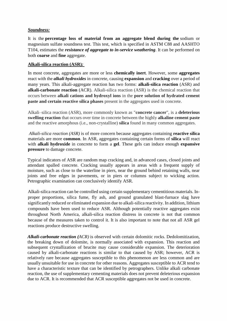
Soundness:
It is the percentage loss of material from an aggregate blend during the sodium or
magnesium sulfate soundness test. This test, which is specified in ASTM C88 and AASHTO
T104, estimates the resistance of aggregate to in-service weathering. It can be performed on
both coarse and fine aggregate.
Alkali-silica reaction (ASR):
In most concrete, aggregates are more or less chemically inert. However, some aggregates
react with the alkali hydroxides in concrete, causing expansion and cracking over a period of
many years. This alkali-aggregate reaction has two forms: alkali-silica reaction (ASR) and
alkali-carbonate reaction (ACR). Alkali-silica reaction (ASR) is the chemical reaction that
occurs between alkali cations and hydroxyl ions in the pore solution of hydrated cement
paste and certain reactive silica phases present in the aggregates used in concrete.
Alkali–silica reaction (ASR), more commonly known as "concrete cancer", is a deleterious
swelling reaction that occurs over time in concrete between the highly alkaline cement paste
and the reactive amorphous (i.e., non-crystalline) silica found in many common aggregates.
Alkali-silica reaction (ASR) is of more concern because aggregates containing reactive silica
materials are more common. In ASR, aggregates containing certain forms of silica will react
with alkali hydroxide in concrete to form a gel. These gels can induce enough expansive
pressure to damage concrete.
Typical indicators of ASR are random map cracking and, in advanced cases, closed joints and
attendant spalled concrete. Cracking usually appears in areas with a frequent supply of
moisture, such as close to the waterline in piers, near the ground behind retaining walls, near
joints and free edges in pavements, or in piers or columns subject to wicking action.
Petrographic examination can conclusively identify ASR.
Alkali-silica reaction can be controlled using certain supplementary cementitious materials. In-
proper proportions, silica fume, fly ash, and ground granulated blast-furnace slag have
significantly reduced or eliminated expansion due to alkali-silica reactivity. In addition, lithium
compounds have been used to reduce ASR. Although potentially reactive aggregates exist
throughout North America, alkali-silica reaction distress in concrete is not that common
because of the measures taken to control it. It is also important to note that not all ASR gel
reactions produce destructive swelling.
Alkali-carbonate reaction (ACR) is observed with certain dolomitic rocks. Dedolomitization,
the breaking down of dolomite, is normally associated with expansion. This reaction and
subsequent crystallization of brucite may cause considerable expansion. The deterioration
caused by alkali-carbonate reactions is similar to that caused by ASR; however, ACR is
relatively rare because aggregates susceptible to this phenomenon are less common and are
usually unsuitable for use in concrete for other reasons. Aggregates susceptible to ACR tend to
have a characteristic texture that can be identified by petrographers. Unlike alkali carbonate
reaction, the use of supplementary cementing materials does not prevent deleterious expansion
due to ACR. It is recommended that ACR susceptible aggregates not be used in concrete.
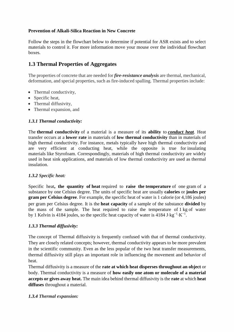
Prevention of Alkali-Silica Reaction in New Concrete
Follow the steps in the flowchart below to determine if potential for ASR exists and to select
materials to control it. For more information move your mouse over the individual flowchart
boxes.
1.3 Thermal Properties of Aggregates
The properties of concrete that are needed for fire-resistance analysis are thermal, mechanical,
deformation, and special properties, such as fire-induced spalling. Thermal properties include:
Thermal conductivity,
Specific heat,
Thermal diffusivity,
Thermal expansion, and
1.3.1 Thermal conductivity:
The thermal conductivity of a material is a measure of its ability to conduct heat. Heat
transfer occurs at a lower rate in materials of low thermal conductivity than in materials of
high thermal conductivity. For instance, metals typically have high thermal conductivity and
are very efficient at conducting heat, while the opposite is true for insulating
materials like Styrofoam. Correspondingly, materials of high thermal conductivity are widely
used in heat sink applications, and materials of low thermal conductivity are used as thermal
insulation.
1.3.2 Specific heat:
Specific heat, the quantity of heat required to raise the temperature of one gram of a
substance by one Celsius degree. The units of specific heat are usually calories or joules per
gram per Celsius degree. For example, the specific heat of water is 1 calorie (or 4,186 joules)
per gram per Celsius degree. It is the heat capacity of a sample of the substance divided by
the mass of the sample. The heat required to raise the temperature of 1 kg of water
by 1 Kelvin is 4184 joules, so the specific heat capacity of water is 4184 J⋅kg−1⋅K−1.
1.3.3 Thermal diffusivity:
The concept of Thermal diffusivity is frequently confused with that of thermal conductivity.
They are closely related concepts; however, thermal conductivity appears to be more prevalent
in the scientific community. Even as the less popular of the two heat transfer measurements,
thermal diffusivity still plays an important role in influencing the movement and behavior of
heat.
Thermal diffusivity is a measure of the rate at which heat disperses throughout an object or
body. Thermal conductivity is a measure of how easily one atom or molecule of a material
accepts or gives away heat. The main idea behind thermal diffusivity is the rate at which heat
diffuses throughout a material.
1.3.4 Thermal expansion:
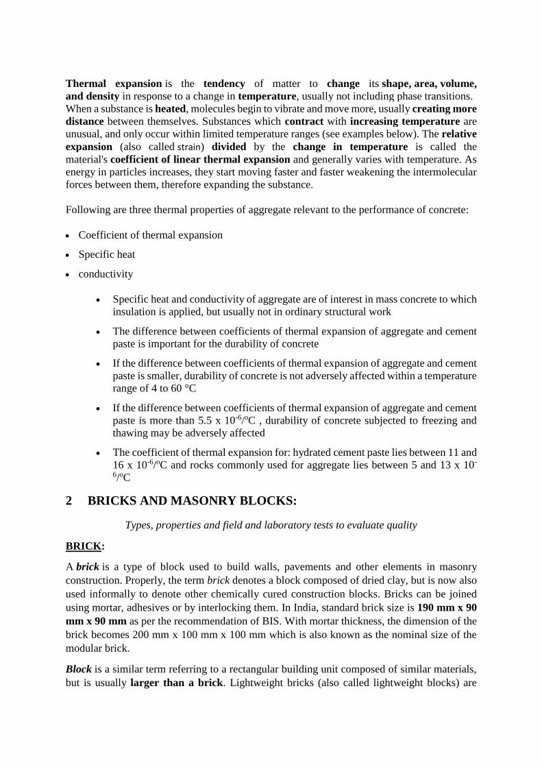
Thermal expansion is the tendency of matter to change its shape, area, volume,
and density in response to a change in temperature, usually not including phase transitions.
When a substance is heated, molecules begin to vibrate and move more, usually creating more
distance between themselves. Substances which contract with increasing temperature are
unusual, and only occur within limited temperature ranges (see examples below). The relative
expansion (also called strain) divided by the change in temperature is called the
material's coefficient of linear thermal expansion and generally varies with temperature. As
energy in particles increases, they start moving faster and faster weakening the intermolecular
forces between them, therefore expanding the substance.
Following are three thermal properties of aggregate relevant to the performance of concrete:
Coefficient of thermal expansion
Specific heat
conductivity
Specific heat and conductivity of aggregate are of interest in mass concrete to which
insulation is applied, but usually not in ordinary structural work
The difference between coefficients of thermal expansion of aggregate and cement
paste is important for the durability of concrete
If the difference between coefficients of thermal expansion of aggregate and cement
paste is smaller, durability of concrete is not adversely affected within a temperature
range of 4 to 60 °C
If the difference between coefficients of thermal expansion of aggregate and cement
paste is more than 5.5 x 10⁻⁶/oC , durability of concrete subjected to freezing and
thawing may be adversely affected
The coefficient of thermal expansion for: hydrated cement paste lies between 11 and
16 x 10-6/oC and rocks commonly used for aggregate lies between 5 and 13 x 10-
6/oC
2 BRICKS AND MASONRY BLOCKS:
Types, properties and field and laboratory tests to evaluate quality
BRICK:
A brick is a type of block used to build walls, pavements and other elements in masonry
construction. Properly, the term brick denotes a block composed of dried clay, but is now also
used informally to denote other chemically cured construction blocks. Bricks can be joined
using mortar, adhesives or by interlocking them. In India, standard brick size is 190 mm x 90
mm x 90 mm as per the recommendation of BIS. With mortar thickness, the dimension of the
brick becomes 200 mm x 100 mm x 100 mm which is also known as the nominal size of the
modular brick.
Block is a similar term referring to a rectangular building unit composed of similar materials,
but is usually larger than a brick. Lightweight bricks (also called lightweight blocks) are
made from expanded clay aggregate. In India, most commonly used, rectangular, standard size
of solid concrete block is 4″(100 mm), 6″(150 mm) and 8″ (200 mm) thick CMU.
2.1 Types of Bricks:
a) Classification of Bricks Based on Quality:
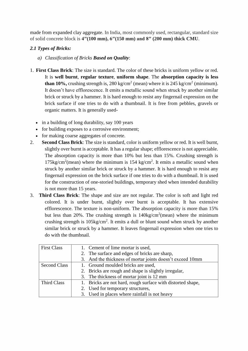
1. First Class Brick: The size is standard. The color of these bricks is uniform yellow or red.
It is well burnt, regular texture, uniform shape. The absorption capacity is less
than 10%, crushing strength is, 280 kg/cm2 (mean) where it is 245 kg/cm2 (minimum).
It doesn’t have efflorescence. It emits a metallic sound when struck by another similar
brick or struck by a hammer. It is hard enough to resist any fingernail expression on the
brick surface if one tries to do with a thumbnail. It is free from pebbles, gravels or
organic matters. It is generally used-
in a building of long durability, say 100 years
for building exposes to a corrosive environment;
for making coarse aggregates of concrete.
2. Second Class Brick: The size is standard, color is uniform yellow or red. It is well burnt,
slightly over burnt is acceptable. It has a regular shape; efflorescence is not appreciable.
The absorption capacity is more than 10% but less than 15%. Crushing strength is
175kg/cm2(mean) where the minimum is 154 kg/cm2. It emits a metallic sound when
struck by another similar brick or struck by a hammer. It is hard enough to resist any
fingernail expression on the brick surface if one tries to do with a thumbnail. It is used
for the construction of one-storied buildings, temporary shed when intended durability
is not more than 15 years.
3. Third Class Brick: The shape and size are not regular. The color is soft and light red
colored. It is under burnt, slightly over burnt is acceptable. It has extensive
efflorescence. The texture is non-uniform. The absorption capacity is more than 15%
but less than 20%. The crushing strength is 140kg/cm2(mean) where the minimum
crushing strength is 105kg/cm2. It emits a dull or blunt sound when struck by another
similar brick or struck by a hammer. It leaves fingernail expression when one tries to
do with the thumbnail.
First Class 1. Cement of lime mortar is used,
2. The surface and edges of bricks are sharp,
3. And the thickness of mortar joints doesn’t exceed 10mm
Second Class 1. Ground moulded bricks are used,
2. Bricks are rough and shape is slightly irregular,
3. The thickness of mortar joint is 12 mm
Third Class 1. Bricks are not hard, rough surface with distorted shape,
2. Used for temporary structures,
3. Used in places where rainfall is not heavy
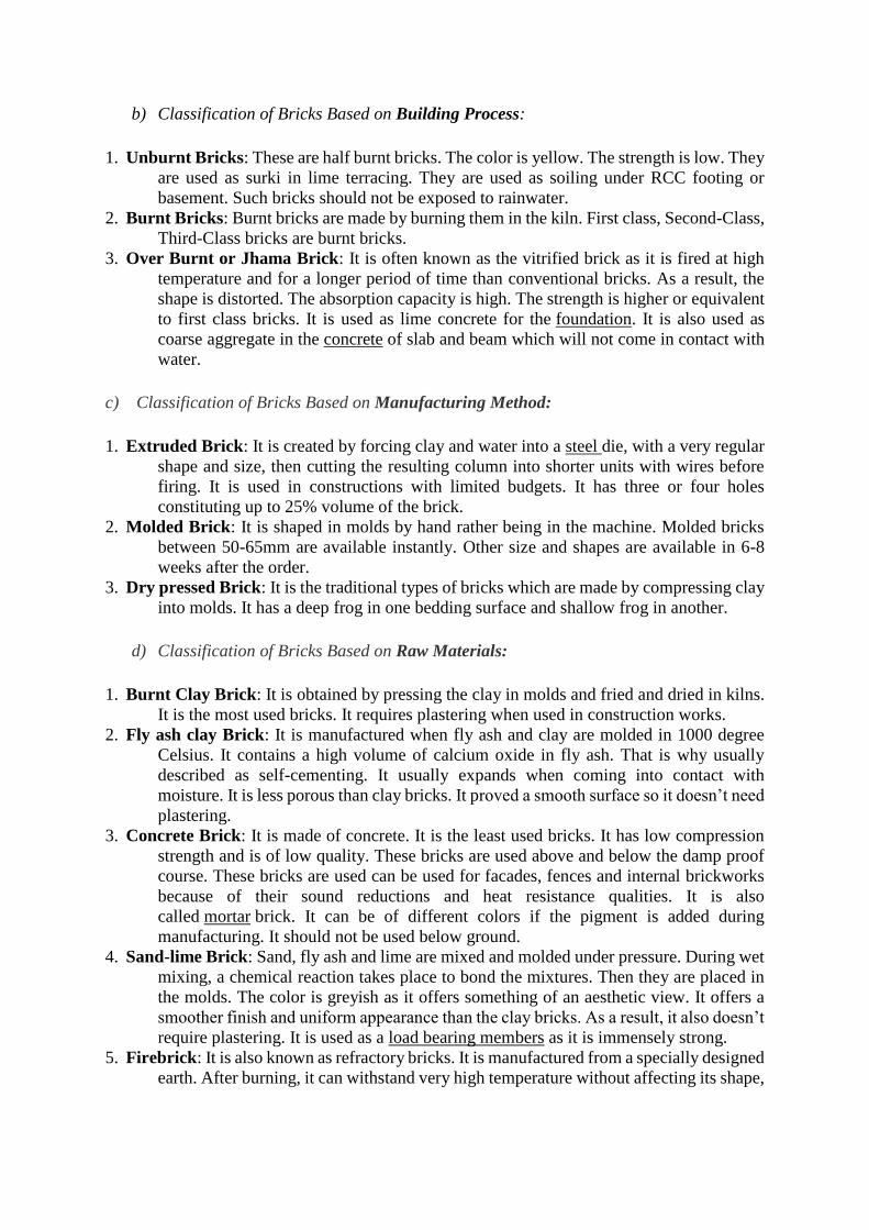
b) Classification of Bricks Based on Building Process:
1. Unburnt Bricks: These are half burnt bricks. The color is yellow. The strength is low. They
are used as surki in lime terracing. They are used as soiling under RCC footing or
basement. Such bricks should not be exposed to rainwater.
2. Burnt Bricks: Burnt bricks are made by burning them in the kiln. First class, Second-Class,
Third-Class bricks are burnt bricks.
3. Over Burnt or Jhama Brick: It is often known as the vitrified brick as it is fired at high
temperature and for a longer period of time than conventional bricks. As a result, the
shape is distorted. The absorption capacity is high. The strength is higher or equivalent
to first class bricks. It is used as lime concrete for the foundation. It is also used as
coarse aggregate in the concrete of slab and beam which will not come in contact with
water.
c) Classification of Bricks Based on Manufacturing Method:
1. Extruded Brick: It is created by forcing clay and water into a steel die, with a very regular
shape and size, then cutting the resulting column into shorter units with wires before
firing. It is used in constructions with limited budgets. It has three or four holes
constituting up to 25% volume of the brick.
2. Molded Brick: It is shaped in molds by hand rather being in the machine. Molded bricks
between 50-65mm are available instantly. Other size and shapes are available in 6-8
weeks after the order.
3. Dry pressed Brick: It is the traditional types of bricks which are made by compressing clay
into molds. It has a deep frog in one bedding surface and shallow frog in another.
d) Classification of Bricks Based on Raw Materials:
1. Burnt Clay Brick: It is obtained by pressing the clay in molds and fried and dried in kilns.
It is the most used bricks. It requires plastering when used in construction works.
2. Fly ash clay Brick: It is manufactured when fly ash and clay are molded in 1000 degree
Celsius. It contains a high volume of calcium oxide in fly ash. That is why usually
described as self-cementing. It usually expands when coming into contact with
moisture. It is less porous than clay bricks. It proved a smooth surface so it doesn’t need
plastering.
3. Concrete Brick: It is made of concrete. It is the least used bricks. It has low compression
strength and is of low quality. These bricks are used above and below the damp proof
course. These bricks are used can be used for facades, fences and internal brickworks
because of their sound reductions and heat resistance qualities. It is also
called mortar brick. It can be of different colors if the pigment is added during
manufacturing. It should not be used below ground.
4. Sand-lime Brick: Sand, fly ash and lime are mixed and molded under pressure. During wet
mixing, a chemical reaction takes place to bond the mixtures. Then they are placed in
the molds. The color is greyish as it offers something of an aesthetic view. It offers a
smoother finish and uniform appearance than the clay bricks. As a result, it also doesn’t
require plastering. It is used as a load bearing members as it is immensely strong.
5. Firebrick: It is also known as refractory bricks. It is manufactured from a specially designed
earth. After burning, it can withstand very high temperature without affecting its shape,
size, and strength. It is used for the lining of chimney and furnaces where the usual
temperature is expected to be very high.
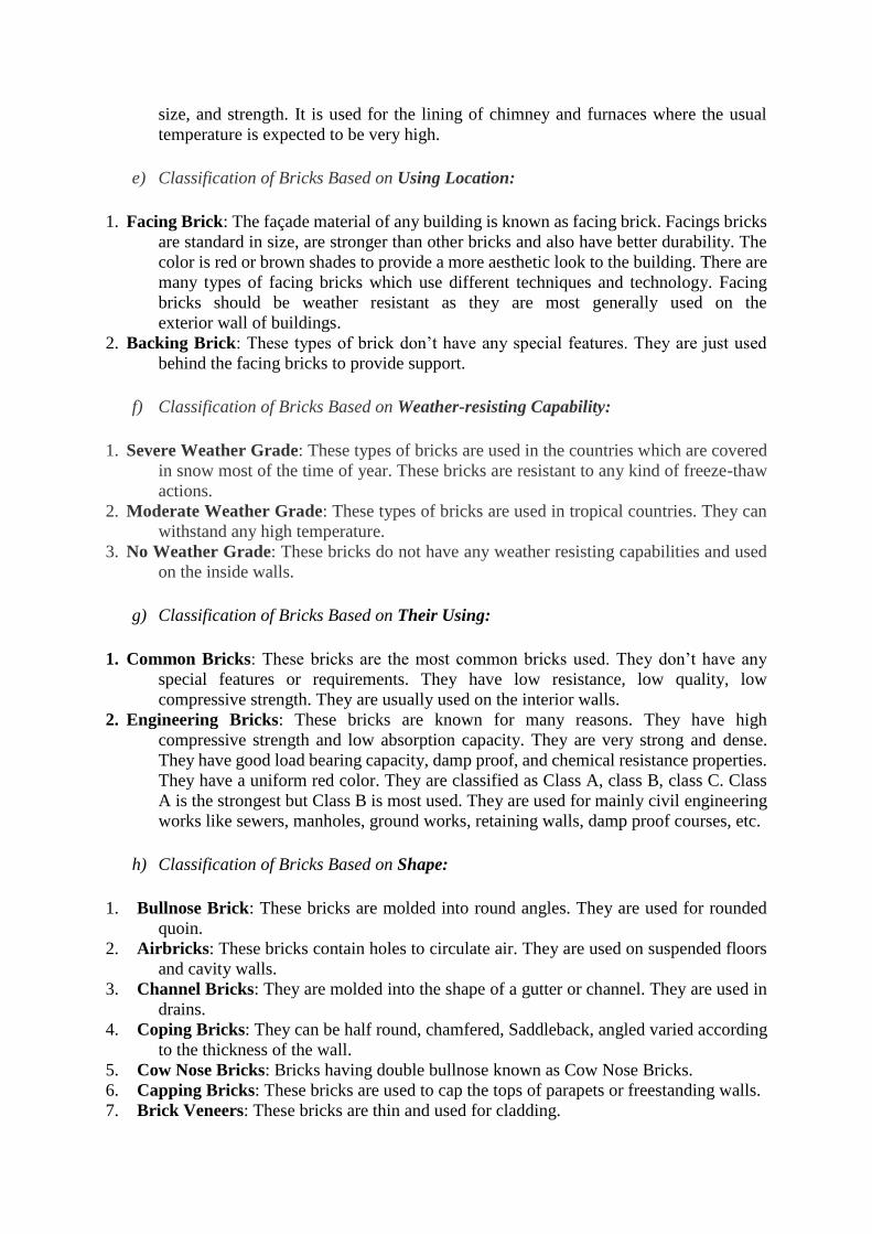
e) Classification of Bricks Based on Using Location:
1. Facing Brick: The façade material of any building is known as facing brick. Facings bricks
are standard in size, are stronger than other bricks and also have better durability. The
color is red or brown shades to provide a more aesthetic look to the building. There are
many types of facing bricks which use different techniques and technology. Facing
bricks should be weather resistant as they are most generally used on the
exterior wall of buildings.
2. Backing Brick: These types of brick don’t have any special features. They are just used
behind the facing bricks to provide support.
f) Classification of Bricks Based on Weather-resisting Capability:
1. Severe Weather Grade: These types of bricks are used in the countries which are covered
in snow most of the time of year. These bricks are resistant to any kind of freeze-thaw
actions.
2. Moderate Weather Grade: These types of bricks are used in tropical countries. They can
withstand any high temperature.
3. No Weather Grade: These bricks do not have any weather resisting capabilities and used
on the inside walls.
g) Classification of Bricks Based on Their Using:
1. Common Bricks: These bricks are the most common bricks used. They don’t have any
special features or requirements. They have low resistance, low quality, low
compressive strength. They are usually used on the interior walls.
2. Engineering Bricks: These bricks are known for many reasons. They have high
compressive strength and low absorption capacity. They are very strong and dense.
They have good load bearing capacity, damp proof, and chemical resistance properties.
They have a uniform red color. They are classified as Class A, class B, class C. Class
A is the strongest but Class B is most used. They are used for mainly civil engineering
works like sewers, manholes, ground works, retaining walls, damp proof courses, etc.
h) Classification of Bricks Based on Shape:
1. Bullnose Brick: These bricks are molded into round angles. They are used for rounded
quoin.
2. Airbricks: These bricks contain holes to circulate air. They are used on suspended floors
and cavity walls.
3. Channel Bricks: They are molded into the shape of a gutter or channel. They are used in
drains.
4. Coping Bricks: They can be half round, chamfered, Saddleback, angled varied according
to the thickness of the wall.
5. Cow Nose Bricks: Bricks having double bullnose known as Cow Nose Bricks.
6. Capping Bricks: These bricks are used to cap the tops of parapets or freestanding walls.
7. Brick Veneers: These bricks are thin and used for cladding.
8. Curved Sector Bricks: These are curved in shape. They are used in arcs, pavements, etc.
9. Hollow Bricks: These bricks are around one-third of the weight of the normal bricks. They
are also called cellular or cavity bricks. Their thickness is from 20-25mm. These bricks
pave the way to quicker construction as they can be laid quickly compared to the normal
bricks. They are used in partitioning.
10. Paving Bricks: These bricks contain a good amount of iron. Iron vitrifies bricks at low
temperature. They are used in garden park floors, pavements. These bricks withstand
the abrasive action of traffic thus making the floor less slippery.
11. Perforated Bricks: These bricks contain cylindrical holes. They are very light in weight.
Their preparation method is also easy. They consume less clay than the other bricks.
They can be of different shapes like round, square, rectangular. They are used in the
construction of the panels for lightweight, structures, and multistoried frame structures.
12. Purpose Made Bricks: For specific purposes, these bricks are made. Splay and can’t
bricks are made for doors and window jambs. Engineering bricks are made for civil
engineering constructions such as sewers, manholes, retaining walls. Fire bricks are
made for chimneys and fireworks. Ornamental bricks are made to use for cornices,
corbels. Arch bricks are used in arcs.
i) Classification of Bricks Based on Region:
1. Cream City Bricks: These bricks are from Milwaukee, Wisconsin.
2. London Stock: These bricks are used in London.
3. Dutch: These are from the Netherlands.
4. Nanak Shahi Bricks: These are from India.
5. Roman: These are used in Roman constructions,
6. Staffordshire Blue Brick: These are from England.
MASONRY BLOCKS:
Masonry block is an important component in construction and building materials in many parts
of the world. Concrete block is made from Portland Cement, aggregates and water. It is also
known as a concrete masonry unit (CMU). As a building material, concrete offers several
attractive characteristics to designers and builders. Standard size of
Brick—A solid or hollow manufactured masonry unit of either concrete, clay or stone.
Concrete brick—A concrete hollow or solid unit smaller in size than a concrete block
Concrete block—A hollow or solid concrete masonry unit. Larger in size than a concrete brick.
Block walls have higher density as compared to brick constructions and hence they offer more
soundproofing. Their efficient acoustic insulation is a big help if your home is constantly
surrounded by noise that could keep you from getting a sound sleep.
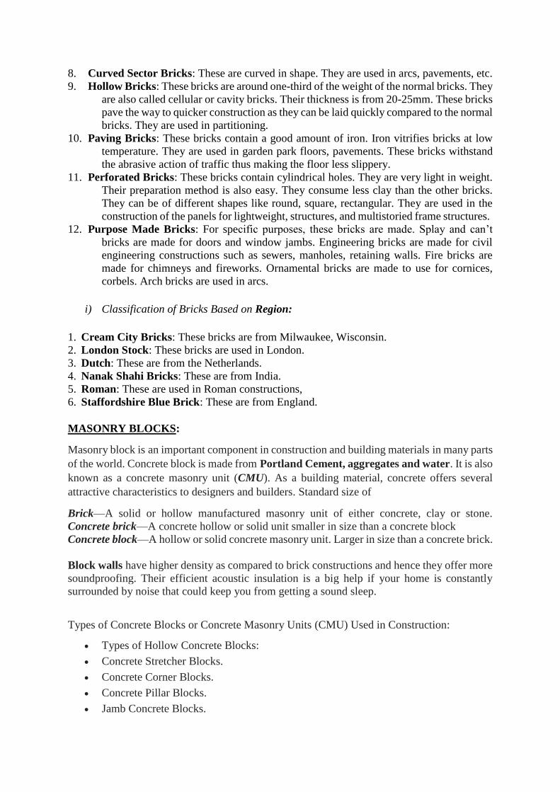
Types of Concrete Blocks or Concrete Masonry Units (CMU) Used in Construction:
Types of Hollow Concrete Blocks:
Concrete Stretcher Blocks.
Concrete Corner Blocks.
Concrete Pillar Blocks.
Jamb Concrete Blocks.
Partition Concrete Block.
Lintel Blocks.
Frogged Brick Blocks.
2.2 Field Tests on Brick:
A field test on bricks gives the idea about its basic quality based on its shape, size and colour
at first observation without any big appliances. They are the very common and easiest way to
check the quality of brick. Field tests of brick are very helpful on the site. Some very common
tests of brick that is followed to find if brick is good at first observation are as follows:
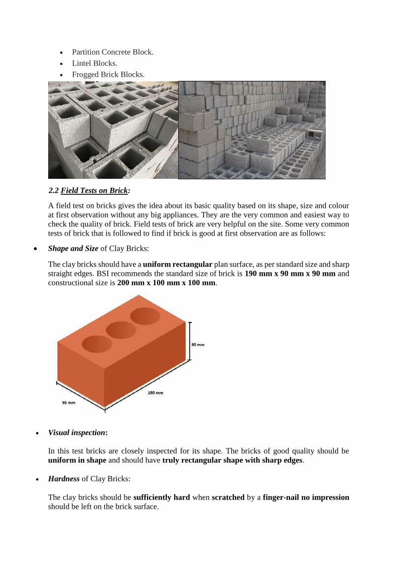
Shape and Size of Clay Bricks:
The clay bricks should have a uniform rectangular plan surface, as per standard size and sharp
straight edges. BSI recommends the standard size of brick is 190 mm x 90 mm x 90 mm and
constructional size is 200 mm x 100 mm x 100 mm.
Visual inspection:
In this test bricks are closely inspected for its shape. The bricks of good quality should be
uniform in shape and should have truly rectangular shape with sharp edges.
Hardness of Clay Bricks:
The clay bricks should be sufficiently hard when scratched by a finger-nail no impression
should be left on the brick surface.
Colour of Clay Bricks:
The clay bricks should have a uniform deep red colour throughout. It indicates the uniformity
of chemical composition and the quality of burning of the bricks.
Texture and compactness of Clay Bricks:
The surfaces should not be so smooth to cause skidding of mortar. The clay brick should have
a pre-compact, homogeneous and uniform texture. A broken surface should be free form
cracks, holes grits or lumps of lime.
Soundness of Clay Bricks: When two clay bricks are stuck together, a metallic ringing sound
should come.
Structure:
A brick is broken and its structure is examined. It should be homogeneous, compact and
free from any defects such as holes, lumps etc.
Thermal Conductivity of Clay Bricks:
Generally, we are not conducting any test for thermal conductivity because the thermal
conductivity of clay brick is low, i.e., it protects from heat.
Basic Strength of Clay Bricks:
When dropped flat on the hard ground from a height of about one meter, clay bricks should
not break.
2.3 Laboratory Tests on Brick:
Laboratory tests on brick determine the mechanical properties of brick and give a scientific
approach to ensure the quality of bricks. It is essential while purchasing the brick and examine
the properties for the quality of construction.
Followings brick tests are performed in the laboratory to determine the quality of brick.
1. Water Absorption of Bricks:
The brick is porous by nature and Porosity is the ability to release and absorb moisture.
Therefore, it tends to absorb the water or moisture. It’s an important and useful property of
brick. But if brick absorbs more water than the recommended result, than it affects the strength
of brick as well as durability of the structure and of course will damage plaster and paint over
walls.
(a) Use of Water Absorption of Bricks:
Water absorption test is performed to know the percentage of water absorption of bricks.
(b) Recommended Result of Water Absorption of Bricks:
Water absorption of bricks should not more than 20 % by its dry weight.
(c) Why Bricks Fails in Water Absorption? & What if Test Fails?
If brick fails in the water absorption test, possible reasons are like manufacturing error,
insufficient burning, error in clay composition etc. and If brick fails in water absorption as well
as efflorescence than never never never use those bricks because you will land in permanent
problems and it will be very difficult to solve them.
(d) Standard Guidelines for Water Absorption Test of Bricks:
There various standard guidelines available for water absorption test of bricks such as IS 3495
(Part 2) 1992, ASTM C 67, BS 3921:1985.
(e) Apparatus of Water Absorption Test of Brick:
Water bath, weight balance, and oven are required for performing this test
2. Compressive Strength of Brick:
The compressive strength of the brick is the most essential property of the bricks because in
the construction, bricks are widely used in masonry and it also plays a significant role as a load
bearing component.
When bricks are used in any structure, the bottom-most layer of the brick will be subjected to
the highest compressive stress. Therefore, it is essential to know that any particular brick will
be able to withstand that load or not.
(a) Use of Compressive Strength of Brick:
This test is performed to know the strength of bricksbecause it affects the overall structure in
the way of quality, durability and serviceability.
(b) Recommended Result of Compressive Strength Test of Brick:
Test result recommendations are as follows:
For first class bricks, it should not less than 10 N/mm2 (102 kg/cm2).
For second class bricks, it should not less than 7 N/mm2 (71 kg/cm2).
For third class bricks, it should not less than 3.5 N/mm2 (36 kg/cm2).
In India, the northern and the eastern region produce bricks having good compressive strength
than the western region because the western region has black cotton soil, while the soil is good
in Gangetic region.
Why Compressive Strength Test Fails? & What if Test Fails?
If the test result is not as per recommendation, there are many reasons behind it such as the
clay composition, degree of burning like over burning or insufficient burning, error in the
testing appliance or testing procedure etc.
If bricks fail in strength as well as water absorption test than do not use it.If bricks are irregular
in some minor shape/size than it can be corrected with mortar. If not then you can consult your
brick supplier or brick manufacturer for replacing it.
3. Efflorescence:
This test should be conducted in a well-ventilated room. The brick is placed vertically in a dish
30 cm x 20 cm approximately in size with 2.5 cm immersed in distilled water. The whole water
is allowed to be absorbed by the brick and evaporated through it. After the bricks appear dry,
a similar quantity of water is placed in the dish, and the water is allowed to evaporate as
before. The brick is to be examined after the second evaporation and reported as follows:
Nil: When there is no perceptible deposit of salt
Slight: When not more than 10% of the area of brick is covered with salt
Moderate: When there is heavy deposit covering 50% of the area of the brick but
unaccompanied by powdering or flaking of the surface.
Heavy: When there is heavy deposit covering more than 50% of the area of the brick
accompanied by powdering or flaking of the surface.
Serious: When there is heavy deposit of salts accompanied by powdering and/or flaking
of the surface and this deposition tends to increase in the repeated wetting of the specimen.
Bricks for general construction should not have more than slight to moderate efflorescence.
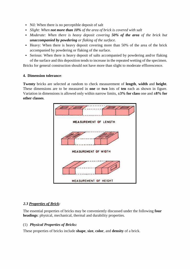
4. Dimension tolerance:
Twenty bricks are selected at random to check measurement of length, width and height.
These dimensions are to be measured in one or two lots of ten each as shown in figure.
Variation in dimensions is allowed only within narrow limits, ±3% for class one and ±8% for
other classes.
2.3 Properties of Brick:
The essential properties of bricks may be conveniently discussed under the following four
headings: physical, mechanical, thermal and durability properties.
(1) Physical Properties of Bricks:
These properties of bricks include shape, size, color, and density of a brick.
(i) Shape:
The standard shape of an ideal brick is truly rectangular. It has Well defined and sharp edges.
The surface of the bricks is regular and even.
(ii) Size:
The size of brick used in construction varies from country to country and from place to place
in the same country.
In India, the recommended standard size of an ideal brick is 19 x 9 x 9 cm which with mortar
joint gives net dimensions of 20 x 10 x 10 cm.
These dimensions have been found very convenient in handling and making quantity
estimates. Five hundred such bricks will be required for completing 1 m3 brick masonry.
(iii) Color.
The most common color of building bricks falls under the class RED. It may vary from deep
red to light red to buff and purple.
Very dark shades of red indicate over burnt bricks whereas yellow color is often indicative
of under-burning.
(iv) Density.
The density of bricks or weight per unit volume depends mostly on the type of clay used and
the method of brick molding (soft-mud, Stiff-mud, hard-pressed etc.).
In the case of standard bricks, density varies from 1600 kg/m3 to 1900 kg/m3. A single brick
(19 x 9 x 9 cm) will weigh between 3.2 to 3.5 kg. depending upon its density.
(2) Mechanical Brick Properties.
(i) Compressive Strength of Bricks:
It is the most important property of bricks especially when they are used in load-bearing walls.
The compressive strength of a brick depends on the composition of the clay and degree of
burning. It may vary from 3.5 N/mm2 to more than 20 N/mm2 in India.
It is specified under the I.S. codes that an ordinary type building brick must possess a minimum
compressive strength of 3.5 N/mm2.
The first and 2nd class bricks shall have a compressive strength not less than 7 N/mm2 and 14
N/mm2 respectively.
(ii) Flexure Strength:
Bricks are often used in situations where bending loads are possible in a building. As such,
they should possess sufficient strength against transverse loads.
It is specified that the flexural strength of a common building brick shall not be less than 1
N/mm2. Best grade bricks often possess flexural strength over 2 N/mm2.
Similarly, it is required that a good building brick shall possess a shearing strength of 5-7
N/mm2.
(3) Thermal Properties of Building Bricks:
Besides being hard and strong, ideal bricks should also provide an adequate insulation against
heat, cold and noise.
The heat and sound conductivity of bricks vary greatly with their density and porosity.
Very dense and heavy bricks conduct heat and sound at a greater rate. They have,
therefore, poor thermal and acoustic (sound) insulation qualities.
For this reason, bricks should be so designed that they are light and strong and give adequate
insulation.
(4) Durability:
By durability of bricks, it is understood that the maximum time for which they remain
unaltered and strong when used in construction.
Experience has shown that properly manufactured bricks are among the most durable of
man-made materials of construction. Their life can be counted in hundreds of years.
The durability of bricks depends on some factors such as: absorption value, frost resistance,
and efflorescence.
(i) Absorption Value.
This property is related to the porosity of the brick.
True Porosity is defined as the ratio of the volume of pores to the gross volume of the sample
of the substance.
Apparent porosity, more often called Absorption value or simply absorption, is the quantity
of water absorbed by the (brick) sample. This is expressed in percentage terms of the dry
weight of the sample: Absorption=W2 – W1 / W1 x 100.
Where W2 is weight after 24 hours of immersion in water and W1 is the oven dry weight of
the sample.
The absorption values of bricks vary greatly.It is, however, recommended that for first class
bricks, they shall not be greater than 20 percent and for ordinary building bricks, not
greater than 25 percent.
The absorption characteristic of bricks effects their quality in many ways:
Firstly: higher porosity means fewer solid materials; hence, strength is reduced.
Secondly: higher absorption will lead to other water-related defects such as frost-action and
efflorescence.
Thirdly: higher absorption results in deeper penetration of water which becomes a source
of dampness.
(ii) Frost Resistance:
Water on freezing expands by about 10% in volume and exerts a pressure on the order of 14
N/mm2. When bricks are used in cold climates, their decay due to this phenomenon of “frost
action” may be a common process.
This is especially so because bricks are quite porous materials (apparent porosity = 20-25%).
It is, therefore, essential that bricks in these areas should be properly protected from rain to
minimize absorption.
(iii) Efflorescence:
It is a common disfiguring and deteriorating process of bricks in hot and humid climates. Brick
surface gets covered with white or grey coloured patches of salts. These salts are present in
the original brick clay.
When rain water penetrates into the bricks, the salts get easily dissolved. After the rains,
evaporation starts.
The salts move out along with the water and form thin encrustations on the surface of the
bricks.
Salts which are commonly precipitated during efflorescence are: sulphates of calcium,
magnesium, sodium and potassium.
It is why great emphasis should be laid while testing the chemical composition of the clay for
brick manufacturing.
SUMMARY (Properties of Bricks).
1. It should have a rectangular shape, regular surface and red colored appearance.
2. It should confirm in size to the specified dimensions (19 x 9 x 9 cm).
3. It should be properly burnt. This can be ascertained by holding two bricks freely, one in
each hand, and striking them. A sharp metallic sound indicates good burning whereas a dull
thud would indicate incomplete burning.
4. A good building brick should not absorb water more than 20 percent of its dry weight.
Absorption should not exceed 25 percent in any case.
5. A good building brick should possess requisite compressive strength, which in no case
should be less than 3.5 N/mm2. A rough test for the strength of the brick is to let it fall freely
from a height of about one meter on to a hard floor. It should not break.
6. Brick should be hard enough so that it is not scratched by a finger nail.
7. A good brick has a uniform colour and structure through its body. This can be checked by
taking a brick from the lot and breaking it into two parts. The broken surface in both the
halves should have same appearance and structure.
3. LIME: (A Building Material for use in Construction)
Classification, Properties
3.1 Classification:
Lime is the versatile mineral. Various forms of lime are used in environmental, metallurgical,
construction, and chemical/industrial applications, etc. Lime, or calcium oxide (CaO), is
derived from high quality natural deposits of limestone, or calcium carbonate (CaCO3).
Limestone is a sedimentary rock that formed millions of years ago as the result of the
accumulation of shell, coral, algal, and other ocean debris. Lime is produced when limestone
is subjected to extreme heat, changing calcium carbonate to calcium oxide.
Lime is commonly referred to by a number of terms including quicklime, calcium oxide, high
calcium lime, or dolomitic lime. All refer to the same material, lime. Dolomitic lime contains
magnesium oxide (MgO) derived from the presence of magnesium carbonate (MgCO3) in the
initial stone referred to as dolomitic limestone. Dolomitic limestone contains two forms of
carbonate, calcium carbonate and magnesium carbonate. High calcium lime is almost pure
calcium carbonate. The use of lime surrounds our everyday life making the water we drink
safe, the air we breathe cleaner, our steel purer and construction projects more stable. It goes
into glass production, paper manufacturing, agricultural practices, chemical processes,
plaster, mortar and other building materials, to name a few.
In construction applications, lime and lime-based reagents can dry wet soils to eliminate
downtime, increase productivity and keep projects moving. They quickly modify weak soils to
make work cleaner, safer, faster and easier. Soil modification provides an improved working
platform that keeps materials coming to the job site. Lime derived products can also be used to
stabilize soils providing long term, permanent strength gains.
Lime is one of the basic building materials used mainly as lime mortar in construction. The
broad category of lime is non-hydraulic (quick lime, fat lime or white lime or as lump lime)
and hydraulic lime. Hydraulic lime sets under water and non-hydraulic lime do not set under
water. Quick Lime is a form of lime is manufactured by the burning of stone that has calcium
carbonate within it. The burning temperature varies, say 900 degrees Celsius and above for
several hours. This process is called as calcination. The solid product that remains after the
removal of carbon dioxide in the calcium carbonate is called as the quicklime.
CaCO3 (Calcium carbonate) --> CaO (Calcium Oxide – Quick Lime) + CO2
The quick lime is used as hydrated lime (quick lime with water). This is because it is unstable
and hazardous in nature. There is heat liberated when a small quantity of water is added to the
quicklime. After this hydration product, a fine dry white powder is obtained, which is called as
calcium hydroxide or slake lime. Now this process is defined as the slaking of lime. The
slaking of lime is a process that varies depending upon the extent and type of use. For example,
the use of lime in plasters or in mortars, make use of lime in dry or putty form.
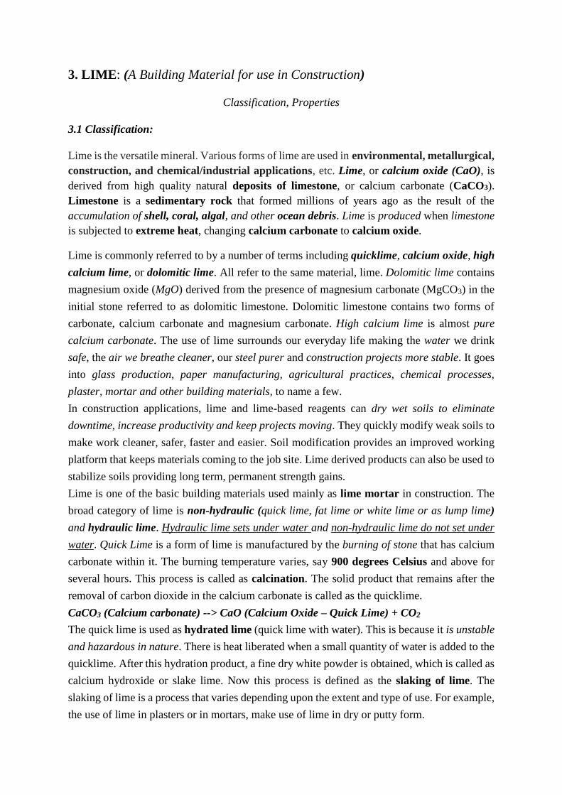
Putty is formed by the addition of a large quantity of water (two to three times its weight). This
process promotes a chemical reaction that makes the whole system to boil. A semi-fluid mass
is obtained as a stiffened mass on cooling, which is called as the putty. This material after
proper screening is used as the material for construction.
Hydraulic lime is a factor-based product. These have natural pozzolana or added Pozzolana
in it that sets under water. The raw material for hydraulic lime is limestone which is impure,
that contains calcium carbonate and impurities of clay. These are also calcinated at 900 to
1000 degree Celsius. The reaction is as follows Calcium carbonate + clay impurities (Al2O3 +
Si2O3) --> CaO (calcium oxide) + carbon dioxide + Monocalcium silicate (CA), Monocalcium
aluminates dicalcium silicate (C2S), dicalcium alumino-ferrite (C2AF)
Products:
Lime can be manufactured in a number of different end products.
Pebble Lime, with sizes ranging from 2-inch down to ¼-inch, is used in many
applications including steel manufacturers and other industrial areas as a fluxing agent
or slaked as part of a larger process.
Pulverized Lime is a graded material with a controlled particle size distribution formed
from crushed pebble lime.
Lime Fines, generally less than ¼-inch in size, are often used in construction markets.
The small particle size of this quicklime product helps to increase the speed at which it
can dry, modify and stabilize soils.
Lime kiln dust, a co-product of lime manufacturing, is a mix of calcium and
magnesium oxides and pozzolans.
Hydrated Lime is produced when quicklime is carefully mixed with water to yielding
hydrated lime (Ca(OH)2), also known as slaked lime or calcium hydroxide. This
process forms a very fine white powder that is very useful in a number of applications,
especially asphalt.
Quicklime slurry is a suspension of calcium hydroxide in water. This free-flowing
product offers a solution for customers requiring a liquid or if they are particularly
concerned with dusting.
Precautions:
If handled properly lime is a very safe product. There are several precautions working with
lime.
Eye irritation: Safety glasses should be worn when working with lime-based products.
In dusty and/or windy conditions gasketed safety glasses or goggles should be worn.
Skin irritation: When lime is exposed to moisture, or sweat, a very hot chemical
reaction take place that could cause chemical burns. Appropriate clothing covering
exposed skin is recommended.
Respiratory Irritation: The use of a respirator can minimize breathing dust.
3.1.1 Four Different Types of Limes Used in Construction:
Different types of limes are used for building construction. It is not generally found in the free
state. Lime is a product which is obtained by burning lime stone, a raw material, found in lime
stone hills or lime stone boulders in the beds of old river, kankar found below ground level,
or shells of sea animals.
1. QUICK LIME
It is also known as caustic lime. It is obtained by calcination (i.e. heating to redness) of
comparatively pure lime stone. It is amorphous in nature, highly caustic and possesses great
affinity to moisture.
2. SLAKED LIME
It is also known as hydrate of lime. It is obtained by slaking (i.e. chemical combination of
quick lime with water) of quick lime. It is ordinary pure lime, in white powder form, available
in market. It has got the tendency of absorbing carbonic acid from the atmosphere in presence
of water.
3. FAT LIME
It is also known as high calcium lime or pure lime or rich lime or white lime. It is popularly
known as fat lime as it slakes vigorously and its volume is increased to about 2 to 2.5 times
that of quick lime. This lime is used for various purposes as white washing, plastering of
walls, as lime mortar with sand for pointing in masonry work, as a lime mortar with surkhi
for thick masonry walls, foundations, etc.
4. HYDRAULIC LIME

It is also known as water lime. This lime contains clay and some amount of ferrous oxide. It
sets under water and hence also known as water lime. Depending upon the percentage of
clay, IS has divided hydraulic lime in three classes namely:
Class A – Eminently hydraulic
Class B – Semi Hydraulic
Class C – Non-hydraulic (or Fat lime)
CLASS A – EMINENTLY HYDRAULIC
This lime contains about 25% clay content and sets readily under water within a day or so.
This lime slakes with difficulty. The mortar and lime concrete prepared from this lime is very
useful for construction under water or in damp places.
CLASS B – SEMI HYDRAULIC
Semi-hydraulic lime contains about 15% clay content and sets under water at a slower rate
within a week or so. The mortar and concrete prepared from this lime is strong and used for
superior type of masonry work.
CLASS C – NON-HYDRAULIC (OR FAT LIME)
This lime contains about 7.5% of clay content and is prepared from pure lime stone. This
slakes vigorously within few minutes but does not set under water. This is used for white
washing and colour washing.
USES OF BUILDING LIME:
Lime in building industry is used for various purposes such as
A matrix for lime concrete used in building foundations and filling where early setting is
not required
For preparing mortar for bedding bricks and stones in masonry works
As a cementing material in plaster for covering walls and pointing in preserving joints
For white washing and colour washing
PREPARATION OF SLAKED LIME:
The procedure behind the making of slaked lime is described in the following steps:
The required quantity of fat lime or quicklime is placed over a platform which is wooden
or masonry, free of moisture. The quicklime is produced by the burning of limestone and
shells.
Water is then sprinkled over this heap of quick lime, till it gets reduced to powder form.
During the addition water, thorough mixing is done along with this, until no more water is
required to completely reduce the quicklime to the powdered form.
The final mixture is allowed to pass through the sieve of 3.35mm dimension. The residue
is rejected. The final product is called the slaked lime.
Preparation of Lime Putty Before the use of quicklime in lime mortar, it is made into lime
putty. The procedure of lime putty preparation is explained in the following procedures:
Initially, two tanks are made of 50 and 80 cm deep (Tank 1 and Tank 2 respectively). The
former tank is constructed at a higher level compared to the latter, to ensure proper flow of
fluid from tank 1 to tank 2.
Initially, the tank 1 is filled with water to its half. Quick lime is then added to this, till the
half depth of the tank 1 is filled. It is kept in mind to add lime to the water and not water to
lime.
Proper stirring is carried out, keeping in mind that no exposure to the air above the water
level is carried out. The mixing will be continued for few minutes (around 5 minutes), till
the moment the boiling ends and the whole mixture starts to thicken.
The mixture is den allowed to flow to the tank 2, located at the lower height. For this to
happen with ease, more water can be added.
The tank 2 takes this mixture for a minimum time of 72 hours. The lower tank (tank 2) is
made up of dry brick masonry, whose joints are filled with sand alone. This would facilitate
the absorption of water from the slurry. This is the way, how the excess water is removed
and lime putty is obtained in the paste form.
If the exposure to the atmosphere is avoided, it can be stored for a period of say 2 weeks.
The addition of water in a gradual means will make the hydraulic lime slaked. When compared
to quicklime, the hydraulic lime requires lesser water. The fat quick lime is said to slake by an
amount of twice, in the powder form and by one and a half parts of paste. The hydraulic lime
slakes by an amount of one and half in the powder form and by the same quantity in the paste
form.
3.2 Properties of Lime for Use in Construction:
The white powdered slaked lime has a wide range of applications in construction. The
properties of lime are:
1. Cementing capability- This is obtained by their carbonation with carbon dioxide. Lime
is used as lime mortar for brick masonry construction.
2. Have a higher acid resistance- due to its alkaline nature
3. Gain Pozzolanic activity- this gives cementitious products
4. Sealing of micro cracks- This is done by the precipitation made by the calcium
carbonate when carbon dioxide passes through the lime mortar mix.
Properties of Lime
It should possess good plasticity.
It should be flexible and easily workable.
When used in mortar, it should provide greater strength to the masonry.
It should solidify in less time and become hard
Factors affecting Properties of Lime Mortar:
1. The free calcium amount present in the lime mortar
2. The free lime content and porosity are directly proportional
3. The fat lime or nonhydraulic lime does not set under water, it sets with time
4. The hydraulic lime sets after the addition of water. This rate depends on the type as well as
the characteristic composition of hydraulic lime.
Advantages of Lime in Construction:
1. Provides building breathing property- the lime was regarded as a material by the society
for protection against the depletion of ancient buildings. This material let the building to
be vapor permeable, thus allowing to breathe. This reduces the chances of trapped moisture
and the damage of the building.
2. Renders Comfortable Environment- Absorbing moisture by the lime, stabilize internal
humidity
3. Ecological Benefits- energy conservation than cement, small scale production of lime is
possible
4. Protection of adjacent materials- Porous texture of lime handle the moisture movement,
without affecting the adjacent materials
5. Provides good workability
6. Durability is high
7. Beautiful finish for the building
8. Self-healing properties- Any movement of the building made of lime, creates micro-
cracks. Presence of moisture make the free lime active to precipitate and heal these micro
cracks
4. CEMENT:
Types, Portland cement: Chemical composition of raw material, Bogue Compounds,
Hydration of cement, Role of water in hydration, Testing of cements
4.1 CEMENT:
A cement is a binder, a substance used for construction that sets, hardens, and adheres to
other materials to bind them together. Cement is seldom used on its own, but rather to bind fine
aggregate (sand) and coarse aggregate (gravel) together. Cement mixed with fine aggregate
produces mortar for masonry, or with fine aggregate and coarse aggregate, produces concrete.
Concrete is the most widely used material in existence and is behind only water as the planet's
most-consumed resource.
Cements used in construction are usually inorganic, often lime or calcium silicate based,
which can be characterized as non-hydraulic or hydraulic respectively, depending on the
ability of the cement to set in the presence of water.
Non-hydraulic cement does not set in wet conditions or under water. Rather, it sets as it dries
and reacts with carbon dioxide in the air. It is resistant to attack by chemicals after setting.
Hydraulic cements (e.g., Portland cement) set and become adhesive due to a chemical
reaction between the dry ingredients and water. The chemical reaction results in
mineral hydrates that are not very water-soluble and so are quite durable in water and safe
from chemical attack. This allows setting in wet conditions or under water and further protects
the hardened material from chemical attack. The chemical process for hydraulic cement was
found by ancient Romans who used volcanic ash (pozzolana) with added lime (calcium oxide).
The word "cement" can be traced back to the Ancient Roman term opus caementicium (Roman
concrete, also called opus caementicium, was a material used in construction in Ancient Rome.
Roman concrete was based on a hydraulic-setting cement. It is durable due to its incorporation
of pozzolanic ash, which prevents cracks from spreading), used to describe masonry
resembling modern concrete that was made from crushed rock with burnt lime as binder. The
volcanic ash and pulverized (reduce to fine particles) brick supplements that were added to the
burnt lime, to obtain a hydraulic binder, were later referred to as cementum, cimentum, cäment,
and cement. In modern times, organic polymers are sometimes used as cements in concrete.
World production is about four billion tonnes per year, of which about half is made in China. If
the cement industry were a country, it would be the third largest carbon dioxide emitter in the
world with up to 2.8 billion tonnes, surpassed only by China and the United States. The
initial calcination reaction (at or above the thermal decomposition temperature) in the
production of cement is responsible for about 4% of global CO2 emissions. The overall process
is responsible for about 8% of global CO2 emissions, as the cement kiln in which the reaction
occurs is typically fired by coal or petroleum coke due to the luminous flame required to heat
the kiln by radiant heat transfer. As a result, the production of cement is a major contributor
to climate change.
HYDRAULIC CEMENT:
By far the most common type of cement is hydraulic cement, which hardens by hydration
of the clinker minerals when water is added. Hydraulic cements (such as Portland cement)
are made of a mixture of silicates and oxides. The four main mineral phases of the clinker,
abbreviated in the cement chemist notation, being:
C3S: Tri Calcium Silicate (Alite) (3CaO·SiO2);
C2S: Di Calcium Silicate (Belite) (2CaO·SiO2);
C3A: Tri Calcium Aluminate (celite) (3CaO·Al2O3);
C4AF: Tetra Calcium Alumino Ferrite (Brownmillerite) (4CaO·Al2O3·Fe2O3).
The silicates are responsible for the cement's mechanical properties — the tricalcium
aluminate and Tetra Calcium Alumino Ferrite are essential for the formation of the liquid
phase during the sintering (firing) process of clinker at high temperature in the kiln. The
chemistry of these reactions is not completely clear and is still the object of research.
First, the limestone (calcium carbonate) is burned to remove its carbon,
producing lime (calcium oxide) in what is known as a calcination reaction. This single
chemical reaction is a major emitter of global carbon dioxide emissions.
CaCO3 → CaO + CO2
The lime reacts with silicon dioxide to produce dicalcium silicate and tricalcium silicate.
2CaO + SiO2 → 2CaO·SiO2
3CaO + SiO2 → 3CaO·SiO2
The lime also reacts with aluminum oxide to form tricalcium aluminate.
3CaO + Al2O3 → 3CaO·Al2O3
The lime also reacts together with aluminum oxide, and ferric oxide to form cement.
4CaO + Al2O3 + Fe2O3 → 4CaO·Al2O3·Fe2O3 (cement)
NON-HYDRAULIC CEMENT:
A less common form of cement is non-hydraulic cement, such as slaked lime (calcium
oxide mixed with water), hardens by carbonation in contact with carbon dioxide, which is
present in the air (~ 412 vol. ppm ≃ 0.04 vol. %). First calcium oxide (lime) is produced
from calcium carbonate (limestone or chalk) by calcination at temperatures above 825 °C
(1,517 °F) for about 10 hours at atmospheric pressure:
CaCO3 → CaO + CO2
The calcium oxide is then spent (slaked) mixing it with water to make slaked lime (calcium
hydroxide):
CaO + H2O → Ca(OH)2
Once the excess water is completely evaporated (this process is technically called setting), the
carbonation starts:
Ca(OH)2 + CO2 → CaCO3 + H2O
This reaction is slow, because the partial pressure of carbon dioxide in the air is low
(~ 0.4 millibar). The carbonation reaction requires that the dry cement be exposed to air, so the
slaked lime is a non-hydraulic cement and cannot be used under water. This process is
called the lime cycle.
4.2 PORTLAND CEMENT:
Portland cement, a form of hydraulic cement, is by far the most common type of cement in
general use around the world. This cement is made by heating limestone (calcium carbonate)
with other materials (such as clay) to 1,450 °C (2,640 °F) in a KILN, in a process known
as calcination that liberates a molecule of carbon dioxide from the calcium carbonate to
form calcium oxide, or quicklime, which then chemically combines with the other materials
in the mix to form calcium silicates and other cementitious compounds. The resulting hard
substance, called 'clinker', is then ground with a small amount of gypsum into a powder to
make ordinary Portland cement, the most commonly used type of cement (often referred to as
OPC). Portland cement is a basic ingredient of concrete, mortar, and most non-
specialty grout. The most common use for Portland cement is to make concrete. Concrete is a
composite material made of cement, aggregate (gravel and sand), and water. As a construction
material, concrete can be cast in almost any shape, and once it hardens, can be a structural (load
bearing) element. Portland cement may be grey or white.
PORTLAND CEMENT BLEND:
Portland cement blends are often available as inter-ground mixtures from cement producers,
but similar formulations are often also mixed from the ground components at the concrete
mixing plant.
Portland blast-furnace slag cement, or blast furnace cement (ASTM C595 and EN 197-1
nomenclature respectively), contains up to 95% ground granulated blast furnace slag, with
the rest Portland clinker and a little gypsum. All compositions produce high ultimate strength,
but as slag content is increased, early strength is reduced, while sulfate resistance increases
and heat evolution diminishes. Used as an economic alternative to Portland sulfate-resisting
and low-heat cements.
Portland-fly ash cement contains up to 40% fly ash under ASTM standards (ASTM C595),
or 35% under EN standards (EN 197–1). The fly ash is pozzolanic, [Pozzolans are a broad
class of siliceous and aluminous materials which, in themselves, possess little or
no cementitious value but which will, in finely divided form and in the presence of water, react
chemically with calcium hydroxide (Ca(OH)2) at ordinary temperature to form compounds
possessing cementitious properties. The quantification of the capacity of a pozzolan to react
with calcium hydroxide and water is given by measuring its pozzolanic activity. Pozzolana are
naturally occurring pozzolans of volcanic origin. A siliceous volcanic ash used to produce
hydraulic cement / Any of various powdered substances that react with lime to form
strengthening or enhancing compounds in cement. Both natural (Volcanic ashes and pumices)
and artificial (man-made, eg. metakaolin, fly ash, silica fume, rice husk ash, etc) materials
show pozzolanic activity and are used as supplementary cementitious materials (SCM)], so
that ultimate strength is maintained. Because fly ash addition allows a lower concrete water
content, early strength can also be maintained. Where good quality cheap fly ash is available,
this can be an economic alternative to ordinary Portland cement.
Portland pozzolan cement includes fly ash cement, since fly ash is a pozzolan, but also
includes cements made from other natural or artificial pozzolans. In countries where volcanic
ashes are available (e.g., Italy, Chile, Mexico, the Philippines), these cements are often the
most common form in use. The maximum replacement ratios are generally defined as for
Portland-fly ash cement.
Portland silica fume cement. Addition of silica fume can yield exceptionally high strengths,
and cements containing 5–20% silica fume are occasionally produced, with 10% being the
maximum allowed addition under EN 197–1. However, silica fume is more usually added to
Portland cement at the concrete mixer.[45]
Masonry cements are used for preparing brick laying mortars and stuccos (decorative coating
for walls and ceilings, exterior walls), and must not be used in concrete. They are usually
complex proprietary formulations containing Portland clinker and a number of other
ingredients that may include limestone, hydrated lime, air entrainers, retarders, water proofers,
and coloring agents. They are formulated to yield workable mortars that allow rapid and
consistent masonry work. Subtle variations of masonry cement in North America are plastic
cements and stucco cements. These are designed to produce a controlled bond with masonry
blocks.
Expansive cements contain, in addition to Portland clinker, expansive clinkers (usually sulfo-
aluminate clinkers), and are designed to offset the effects of drying shrinkage normally
encountered in hydraulic cements. This cement can make concrete for floor slabs (up to 60 m
square) without contraction joints.
White blended cements may be made using white clinker (containing little or no iron) and
white supplementary materials such as high-purity metakaolin.
Colored cements serve decorative purposes. Some standards allow the addition of pigments
to produce colored Portland cement. Other standards (e.g., ASTM) do not allow pigments in
Portland cement, and colored cements are sold as blended hydraulic cements.
Very finely ground cements are cement mixed with sand or with slag or other pozzolan type
minerals that are extremely finely ground together. Such cements can have the same physical
characteristics as normal cement but with 50% less cement, particularly due to their increased
surface area for the chemical reaction. Even with intensive grinding they can use up to 50%
less energy (and thus less carbon emissions) to fabricate than ordinary Portland cements.[
4.3 TYPES OF CEMENT (Other cements)
1. Ordinary Portland Cement (OPC)
2. Portland Pozzolana Cement (PPC)
3. Rapid Hardening Cement
4. Quick setting cement
5. Low Heat Cement
6. Sulfates resisting cement
7. Blast Furnace Slag Cement
8. High Alumina Cement
9. White Cement
10. Colored cement
11. Air Entraining Cement
12. Expansive cement
13. Hydrographic cement
Ordinary Portland Cement (OPC)
The principal raw materials used in the manufacture of Ordinary Portland Cement are:
1. Argillaceous or silicates of alumina in the form of clays and shales.
2. Calcareous or calcium carbonate, in the form of limestone, chalk and marl which is a
mixture of clay and calcium carbonate.
The ingredients are mixed in the proportion of about two parts of calcareous materials to one
part of argillaceous materials and then crushed and ground in ball mills in a dry state or mixed
in wet state. The dry powder or the wet slurry is then burnt in a rotary kiln at a temperature
between 1400 degree C to 1500-degree C. the clinker obtained from the kiln is first cooled and
then passed on to ball mills where gypsum is added and it is ground to the requisite fineness
according to the class of product.

Portland Pozzolana Cement (PPC):
Portland Pozzolana cement is integrated cement which is formed by synthesising
(combining) OPC cement with pozzolanic materials in a certain proportion. It is commonly
known as PPC cement. In this article we discuss about the properties, manufacture,
characteristics, advantages and disadvantages of Portland Pozzolana cement.
Rapid Hardening Cement:
Rapid hardening cement is a particular type of cement that is used in exceptional cases of
concrete pouring. As the name implies, rapid hardening cement needs the shortest time
to set up and consolidate. It achieves higher strength on lesser days. With such, it can attain
seven days strength in only three days.
Quick setting cement:
Quick Setting Cement (QSC) is a special cement formulation that develops a rapid
compressive strength and significantly reduces the waiting on cement (WOC)
time compared to traditional cement systems. This cement loses its plasticity quicker than
ordinary Portland cement, but does not achieve a higher rate of strength.
Low Heat Cement:
Low heat cement is a special tailored cement which generates low heat of hydration
during setting. It is manufactured by modifying the chemical composition of normal
Portland cement. In this article we discuss about the composition, properties,
characteristics, uses and advantages of low heat cement.
Sulphate resisting cement:
The sulphate resisting cement is the cement which has the capability to resist against
sulphate attack by introducing low C3A and relatively low C4AF content in the
cement. The specification for sulphate cement content should not allow C3A content more
than 5 percent.
Blast Furnace Slag Cement:
Blast furnace slag cement is the mixture of ordinary Portland cement and fine
granulated blast furnace slag obtained as a by-product in the manufacture of steel with
percent under 70% to that of cement. Ground granulated blast furnace slag cement
(GGBFS) is a fine glassy granule which contain cementitious properties.
High Alumina Cement:
High alumina cement refers to a fast-hardening, high-strength, heat-resistant and
corrosion-resistant cementitious material. All clinker based on calcium aluminate and
alumina content of about 50% and ground hydraulic cementitious material are called high
alumina cement.
White Cement:
The manufacturing process of white cement is same as that of grey cement, but the
selection of raw material is an important part in the manufacturing process. The oxides
of chromium, manganese, iron, copper, vanadium, nickel and titanium imparts the grey
colour to the cement. In white cement manufacture, these raw materials are kept to least
percentage. Limestone and clay are used as a prominent raw material for the manufacture
of white cement. The manufacture process is same as that of OPC cement, the only
differences are the heat required for the burning of raw material is more and fineness is
more.
Coloured cement:
Coloured Cement may be obtained by intimately mixing mineral pigments with
ordinary cement. The amount of colouring material may vary from 5 to 10 per cent. If this
percentage exceeds 10 per cent, the strength of cement is affected.
1. The chromium oxide gives green colour.
2. The cobalt imparts blue colour.
3. The ton oxide in different proportions gives brown, red or yellow colour
4. The manganese oxide is used to produce black brown coloured cement
The coloured cements are widely used for finishing of floors, external surfaces. artificial
marble, window sill slabs, textured panel faces, stair treads, etc.
Air Entraining Cement:
Air-entrained portland cement is a special cement which has air bubbles introduced in the
cement or concrete that provides the space for expansion of minute droplets of waters in
the concrete due to freezing and thawing and protects from cracks and damage of concrete.
In this article we discuss about manufacture, air entraining agents, properties, advantages
and disadvantages.
Advantages of Air-Entrained Cement
Workability of concrete increases.
Use of air entraining agent reduces the effect of freezing and thawing.
Bleeding, segregation and laitance in concrete reduces.
Entrained air improves the sulphate resisting capacity of concrete.
Reduces the possibility of shrinkage and crack formation in the concrete surface.
Expansive cement:
Expansive cement is special type of cement when mixed with water, which forms a paste
that tends to increase in volume to a significantly greater degree than Portland cement
paste after setting. The expansion of the cement mortar or concrete is compensated for the
shrinkage losses. In this article we study about the manufacture, properties, types and uses
of expansive cement.
Hydrographic cement:
Hydrographic cement Hydrographic cement prepares by mixing water-repelling
chemicals and has high workability and strength. It has the property of repelling water
and unaffected during monsoon or rains. Hydrophobic cement mainly uses for the
construction of water structures such as dams, water tanks, spillways, water retaining
structures, etc.
4.4 CHEMICAL PROPERTIES OF PORTLAND CEMENT ARE AS FOLLOWS:
Lime (CaO) 60 to 67%
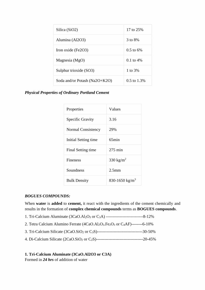
Silica (SiO2) 17 to 25%
Alumina (Al2O3) 3 to 8%
Iron oxide (Fe2O3) 0.5 to 6%
Magnesia (MgO) 0.1 to 4%
Sulphur trioxide (SO3) 1 to 3%
Soda and/or Potash (Na2O+K2O) 0.5 to 1.3%
Physical Properties of Ordinary Portland Cement
Properties Values
Specific Gravity 3.16
Normal Consistency 29%
Initial Setting time 65min
Final Setting time 275 min
Fineness 330 kg/m2
Soundness 2.5mm
Bulk Density 830-1650 kg/m3
BOGUES COMPOUNDS:
When water is added to cement, it react with the ingredients of the cement chemically and
results in the formation of complex chemical compounds terms as BOGUES compounds.
1. Tri-Calcium Aluminate (3CaO.Al2O3 or C3A) ---------------------------8-12%
2. Tetra Calcium Alumino Ferrate (4CaO.Al2O3.Fe2O3 or C4AF)--------6-10%
3. Tri-Calcium Silicate (3CaO.SiO2 or C3S)---------------------------------30-50%
4. Di-Calcium Silicate (2CaO.SiO2 or C2S)----------------------------------20-45%
1. Tri-Calcium Aluminate (3CaO.Al2O3 or C3A)
Formed in 24 hrs of addition of water
Maximum evolution of heat of hydration
Check setting time of cement
2. Tetra Calcium Alumino Ferrate (4CaO.Al2O3.Fe2O3 or C4AF)
Formed within 24 hrs of addition of water
High heat of hydration in initial periods
3. Tri-Calcium Silicate (3CaO.SiO2 or C3S)
Formed within week
Responsible for initial strength of cement
Contribute about 50-60% of strength
Content increase for the pre-fabricated concrete construction, Cold weathering construction.
4. Di-Calcium Silicate (2CaO.SiO2 or C2S)
Last compound formed during hydration of cement
Responsible for progressive later stage strength
Structure requires later stages strength proportion of this component increase
e.g. hydraulic structures, bridges.
HYDRATION OF CEMENT:
When cement, water, aggregate, and additives are mixed together, a significant heat increase
occurs. This is due to the exothermic process in the reaction between cement and water (called
hydration).
Measuring the concrete temperature over time enables you to know how far the concrete is in
the hydration process (Concrete Maturity) and thereby also an estimated concrete strength. The
hydration process is divided into five phases:
Phase 1: Initial Mixing Reaction
Initial after mixing the cement and water comes into contact with each other, a peak in
temperature happens. The aluminate (C3A) reacts with H2O (Calcium and sulfate ions) to form
ettringite (aluminate hydrate). The release of the energy from these reactions causes the initial
peak.
Phase 2: Dormancy
A result of the reaction described in phase 1 is a surface coating of the cement particles. This
coating keeps increases, but also slows down the reaction (hydration) as the access to H2O isn’t
as good as when the concrete was mixed. The amount of hydrated concrete keeps increasing
on a steady level while the surface of the concrete keeps fluid.
This is why this phase is used for transporting and pouring the concrete, as the concrete stays
on a fluid level. The length of this period depends on each individual concrete mix and can,
therefore, be optimized depending on the application like winter concreting, length of transport,
etc.
This phase ends with an initial set of the concrete.
Phase 3: Strength Acceleration
A heat increase happens due to the reaction between calcium silicate (C3S and C2S) which
creates the silicate hydrate CSH (heat increase also caused by other minor reactions). The
creation of CSH also has a major impact on the concrete strength during this phase.
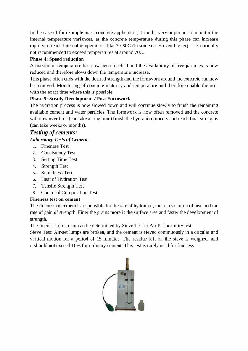
In the case of for example mass concrete application, it can be very important to monitor the
internal temperature variances, as the concrete temperature during this phase can increase
rapidly to reach internal temperatures like 70-80C (in some cases even higher). It is normally
not recommended to exceed temperatures at around 70C.
Phase 4: Speed reduction
A maximum temperature has now been reached and the availability of free particles is now
reduced and therefore slows down the temperature increase.
This phase often ends with the desired strength and the formwork around the concrete can now
be removed. Monitoring of concrete maturity and temperature and therefore enable the user
with the exact time where this is possible.
Phase 5: Steady Development / Post Formwork
The hydration process is now slowed down and will continue slowly to finish the remaining
available cement and water particles. The formwork is now often removed and the concrete
will now over time (can take a long time) finish the hydration process and reach final strengths
(can take weeks or months).
Testing of cements:
Laboratory Tests of Cement:
1. Fineness Test
2. Consistency Test
3. Setting Time Test
4. Strength Test
5. Soundness Test
6. Heat of Hydration Test
7. Tensile Strength Test
8. Chemical Composition Test
Fineness test on cement
The fineness of cement is responsible for the rate of hydration, rate of evolution of heat and the
rate of gain of strength. Finer the grains more is the surface area and faster the development of
strength.
The fineness of cement can be determined by Sieve Test or Air Permeability test.
Sieve Test: Air-set lumps are broken, and the cement is sieved continuously in a circular and
vertical motion for a period of 15 minutes. The residue left on the sieve is weighed, and
it should not exceed 10% for ordinary cement. This test is rarely used for fineness.
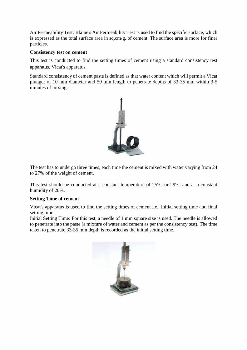
Air Permeability Test: Blaine's Air Permeability Test is used to find the specific surface, which
is expressed as the total surface area in sq.cm/g. of cement. The surface area is more for finer
particles.
Consistency test on cement
This test is conducted to find the setting times of cement using a standard consistency test
apparatus, Vicat's apparatus.
Standard consistency of cement paste is defined as that water content which will permit a Vicat
plunger of 10 mm diameter and 50 mm length to penetrate depths of 33-35 mm within 3-5
minutes of mixing.
The test has to undergo three times, each time the cement is mixed with water varying from 24
to 27% of the weight of cement.
This test should be conducted at a constant temperature of 25°C or 29°C and at a constant
humidity of 20%.
Setting Time of cement
Vicat's apparatus is used to find the setting times of cement i.e., initial setting time and final
setting time.
Initial Setting Time: For this test, a needle of 1 mm square size is used. The needle is allowed
to penetrate into the paste (a mixture of water and cement as per the consistency test). The time
taken to penetrate 33-35 mm depth is recorded as the initial setting time.
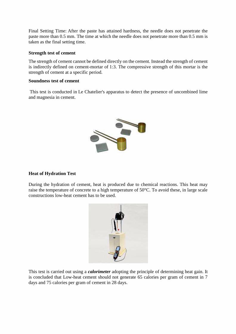
Final Setting Time: After the paste has attained hardness, the needle does not penetrate the
paste more than 0.5 mm. The time at which the needle does not penetrate more than 0.5 mm is
taken as the final setting time.
Strength test of cement
The strength of cement cannot be defined directly on the cement. Instead the strength of cement
is indirectly defined on cement-mortar of 1:3. The compressive strength of this mortar is the
strength of cement at a specific period.
Soundness test of cement
This test is conducted in Le Chatelier's apparatus to detect the presence of uncombined lime
and magnesia in cement.
Heat of Hydration Test
During the hydration of cement, heat is produced due to chemical reactions. This heat may
raise the temperature of concrete to a high temperature of 50°C. To avoid these, in large scale
constructions low-heat cement has to be used.
This test is carried out using a calorimeter adopting the principle of determining heat gain. It
is concluded that Low-heat cement should not generate 65 calories per gram of cement in 7
days and 75 calories per gram of cement in 28 days.
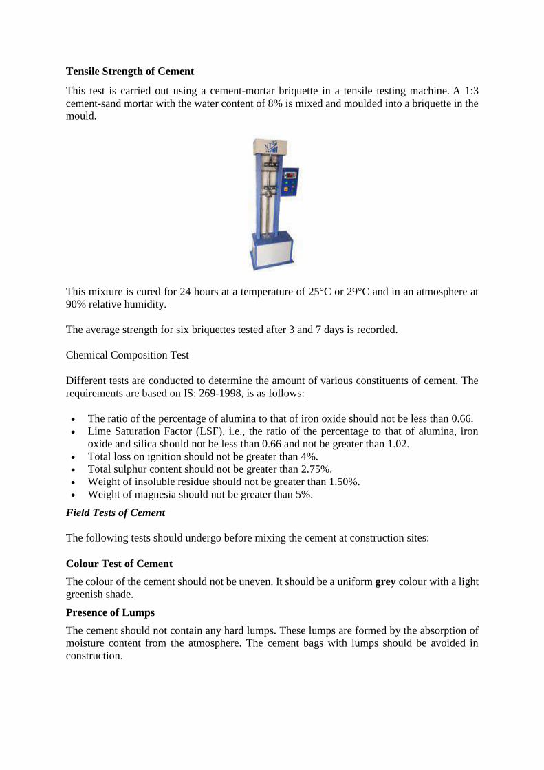
Tensile Strength of Cement
This test is carried out using a cement-mortar briquette in a tensile testing machine. A 1:3
cement-sand mortar with the water content of 8% is mixed and moulded into a briquette in the
mould.
This mixture is cured for 24 hours at a temperature of 25°C or 29°C and in an atmosphere at
90% relative humidity.
The average strength for six briquettes tested after 3 and 7 days is recorded.
Chemical Composition Test
Different tests are conducted to determine the amount of various constituents of cement. The
requirements are based on IS: 269-1998, is as follows:
The ratio of the percentage of alumina to that of iron oxide should not be less than 0.66.
Lime Saturation Factor (LSF), i.e., the ratio of the percentage to that of alumina, iron
oxide and silica should not be less than 0.66 and not be greater than 1.02.
Total loss on ignition should not be greater than 4%.
Total sulphur content should not be greater than 2.75%.
Weight of insoluble residue should not be greater than 1.50%.
Weight of magnesia should not be greater than 5%.
Field Tests of Cement
The following tests should undergo before mixing the cement at construction sites:
Colour Test of Cement
The colour of the cement should not be uneven. It should be a uniform grey colour with a light
greenish shade.
Presence of Lumps
The cement should not contain any hard lumps. These lumps are formed by the absorption of
moisture content from the atmosphere. The cement bags with lumps should be avoided in
construction.
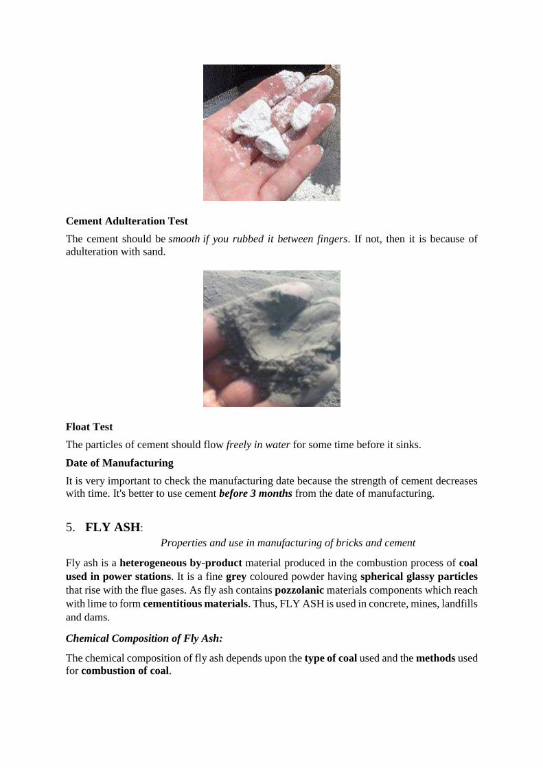
Cement Adulteration Test
The cement should be smooth if you rubbed it between fingers. If not, then it is because of
adulteration with sand.
Float Test
The particles of cement should flow freely in water for some time before it sinks.
Date of Manufacturing
It is very important to check the manufacturing date because the strength of cement decreases
with time. It's better to use cement before 3 months from the date of manufacturing.
5. FLY ASH:
Properties and use in manufacturing of bricks and cement
Fly ash is a heterogeneous by-product material produced in the combustion process of coal
used in power stations. It is a fine grey coloured powder having spherical glassy particles
that rise with the flue gases. As fly ash contains pozzolanic materials components which reach
with lime to form cementitious materials. Thus, FLY ASH is used in concrete, mines, landfills
and dams.
Chemical Composition of Fly Ash:
The chemical composition of fly ash depends upon the type of coal used and the methods used
for combustion of coal.

Chemical composition of fly ash of different coals
Component Bituminous Coal Sub bituminous Coal Lignite Coal
SiO2 (%) 20-60 40-60 15-45
Al2O3 (%) 5-35 20-30 20-25
Fe2O3 (%) 10-40 4-10 4-15
CaO (%) 1-12 5-30 15-40
LOI (%) 0-15 0-3 0-5
5.1 Physical Properties of Fly Ash:
Fineness of Fly Ash
As per ASTM, the fineness of the fly ash is to be checked in both dry and wet sieving. The fly
ash sample is sieved in 45 micron sieve and the percentage of retained on the 45 micron sieve
is calculated. Further fineness is also measured by LeChatelier method and Blaine Specific
Surface method.
Specific Gravity of Fly Ash
The specific gravity of fly ash ranges from a low value of 1.90 for a sub-bituminous ash to a
high value of 2.96 for an iron-rich bituminous ash.
Size and Shape of Fly Ash
As the flyash is a very fine material, the particle size ranges in between 10 to 100 micron. The
shape of the fly ash is usually spherical glassy shaped.
Color
The color of the fly ash depends upon the chemical and mineral constituents. Lime content in
the fly ash gives tan and light colors whereas brownish color is imparted by the presence of
iron content. A dark grey to black color is typically attributed to an elevated un-burned content.
5.2 Fly ash Bricks:
Fly Ash Bricks are manufactured using Major percentage of fly ash generated from Thermal
Power stations. Other raw materials used along with Fly Ash are lime and calcined gypsum.
Fly ash is a fine, glass-like powder recovered from coal-fired electric power generation.
They consist mostly of silicon dioxide (SiO2), aluminum oxide (Al2O3) and iron oxide (Fe2O3).
Products and Its Application
Fly ash lime bricks are chemically bonded bricks manufactured by utilizing 80- 82% of fly ash,
which is a major waste bye-product of pulverized coal fired in Thermal Power Stations, 9-10%
of lime, 9-10% of sand and accelerator. The process know-how has been developed by
Central Fuel Research Institute.
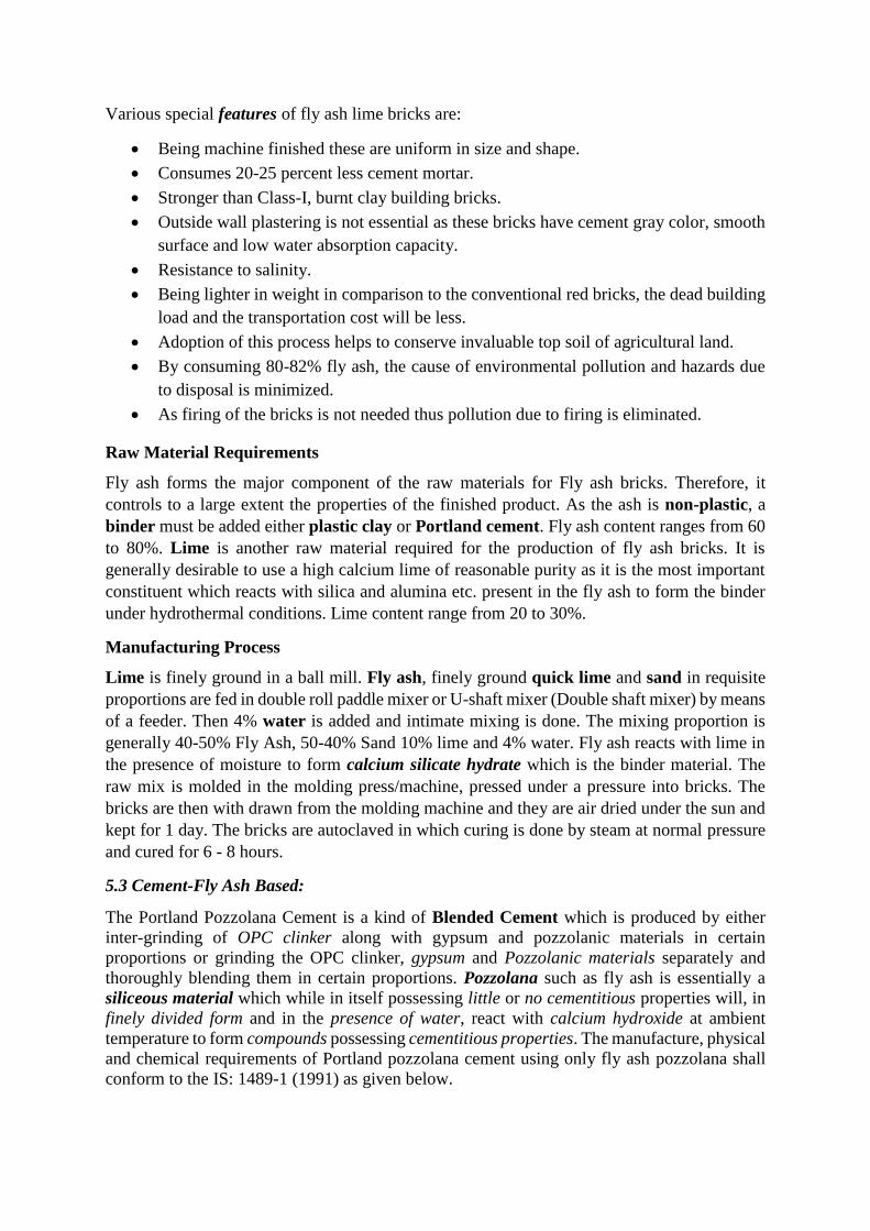
Various special features of fly ash lime bricks are:
Being machine finished these are uniform in size and shape.
Consumes 20-25 percent less cement mortar.
Stronger than Class-I, burnt clay building bricks.
Outside wall plastering is not essential as these bricks have cement gray color, smooth
surface and low water absorption capacity.
Resistance to salinity.
Being lighter in weight in comparison to the conventional red bricks, the dead building
load and the transportation cost will be less.
Adoption of this process helps to conserve invaluable top soil of agricultural land.
By consuming 80-82% fly ash, the cause of environmental pollution and hazards due
to disposal is minimized.
As firing of the bricks is not needed thus pollution due to firing is eliminated.
Raw Material Requirements
Fly ash forms the major component of the raw materials for Fly ash bricks. Therefore, it
controls to a large extent the properties of the finished product. As the ash is non-plastic, a
binder must be added either plastic clay or Portland cement. Fly ash content ranges from 60
to 80%. Lime is another raw material required for the production of fly ash bricks. It is
generally desirable to use a high calcium lime of reasonable purity as it is the most important
constituent which reacts with silica and alumina etc. present in the fly ash to form the binder
under hydrothermal conditions. Lime content range from 20 to 30%.
Manufacturing Process
Lime is finely ground in a ball mill. Fly ash, finely ground quick lime and sand in requisite
proportions are fed in double roll paddle mixer or U-shaft mixer (Double shaft mixer) by means
of a feeder. Then 4% water is added and intimate mixing is done. The mixing proportion is
generally 40-50% Fly Ash, 50-40% Sand 10% lime and 4% water. Fly ash reacts with lime in
the presence of moisture to form calcium silicate hydrate which is the binder material. The
raw mix is molded in the molding press/machine, pressed under a pressure into bricks. The
bricks are then with drawn from the molding machine and they are air dried under the sun and
kept for 1 day. The bricks are autoclaved in which curing is done by steam at normal pressure
and cured for 6 - 8 hours.
5.3 Cement-Fly Ash Based:
The Portland Pozzolana Cement is a kind of Blended Cement which is produced by either
inter-grinding of OPC clinker along with gypsum and pozzolanic materials in certain
proportions or grinding the OPC clinker, gypsum and Pozzolanic materials separately and
thoroughly blending them in certain proportions. Pozzolana such as fly ash is essentially a
siliceous material which while in itself possessing little or no cementitious properties will, in
finely divided form and in the presence of water, react with calcium hydroxide at ambient
temperature to form compounds possessing cementitious properties. The manufacture, physical
and chemical requirements of Portland pozzolana cement using only fly ash pozzolana shall
conform to the IS: 1489-1 (1991) as given below.
1. Raw Materials:
Pozzolana: Fly ash used in the manufacture of Portland-pozzolana cement shall
conform to IS 3812: 1981
Portland Cement Clinker: The Portland cement clinker used in the manufacture of
Portland-pozzolana cement shall comply in all respects with the chemical requirements
of IS 269: 1989
Portland Cement: Portland cement for blending with fly ash shall conform to IS 269:
1989
Other admixtures: Not more than 1 percent may be added
2. Manufacture:
Portland-pozzolana cement shall be manufactured either by intimately inter-grinding
Portland cement clinker and fly ash or by intimately and uniformly blending Portland
cement and fine fly ash. The fly ash constituent shall not be less than 10 percent and not
more than 25 percent by mass of Portland-pozzolana cement.
3. Chemical Requirements:
Portland-pozzolana cement, shall comply with the chemical requirements given below.
Chemical requirement as per IS: 1489-1 (1991)
4. Physical Requirements:
a. Fineness: When tested by the air permeability method described in IS 4031 (Part 2):
1988, the specific surface of Portland-pozzolana cement shall be not less than 300
m2/kg.
b. Soundness: When tested by ‘Le Chatelier’ method and autoclave test described in IS
4031 (Part 3): 1988, unaerated Portland-pozzolana cement The average drying
shrinkage of mortar bars shall not have an expansion of more than 10 mm and 0.8
percent respectively.
c. Setting Time: The setting time of Portland-pozzolana cement, when tested by the Vicat
apparatus method described in IS 4031 (Part 5): 1988, shall be 30min (Minimum) for
initial setting time and 600min (Maximum) for final setting time
d. Compressive strength: The average compressive strength tested in the manner as
described in IS 4031 (Part 6): 1988 shall be as follows:
At 72 ±1hr 16 MPa, Min
At 168 ± 2hrs 22 MPa, Min
At 672 ±4hrs 33 MPa, Min

e. Drying shrinkage: The average drying shrinkage of mortar bars prepared and tested in
accordance with IS 4031 (Part 10): 1988 shall not be more than 0.15 percent.
############################
Civil Engineering Materials and Constructions (BCE03002)
Module-II
Basic Building Materials I
Module II Syllabus
Syllabus: Mortar: Types and tests on mortars. Concrete: Production, mix proportions and
grades of concrete, fresh, mechanical and durability properties of concrete, factors affecting
properties of concrete, tests on concrete, Admixtures, Special concrete: light weight concrete,
high density concrete, vacuum concrete, shotcrete, steel fiber reinforced concrete, polymer
concrete, Ferro cement, high performance concrete, self-compacting concrete.
Subject to Revision
1. MORTAR
(Types and tests on mortars)
Several different tests are needed to estimate the stability and strength of a structure, from the
soil it will stand on to the bricks or concrete that will form it. But what about mortar, the material
that binds it all together? There are a variety of ways to perform mortar testing, many of which
are similar to how you would test aggregates, concrete or cement.
1.1 Types of Mortar:
1. Cement Mortar
2. Lime Mortar
3. Surki Mortar
4. Gauged Mortar
5. Mud Mortar
Cement Mortar
Cement mortar is a type of mortar where cement is used as binding material and sand is used as
fine aggregate. Depending upon the desired strength, the cement to the sand proportion of
cement mortar varies from 1:2 to 1:6.
Lime Mortar
Lime mortar is a type of mortar where lime (fat lime or hydraulic lime) is used as binding
material and sand is used as fine aggregate. The lime to the sand proportion of cement mortar is
kept 1:2. The pyramids at Giza are plastered with lime mortar.
Gauged Mortar
Gauged mortar is a type of mortar where cement and lime both are used as binding material and
sand is used as fine aggregate. Basically, it is a lime mortar where cement is added to gain
higher strength. The process is known as gauging. The cement to the lime proportion varies
from 1:6 to 1:9. Gauged mortar is economical than cement concrete and also possess higher
strength than lime mortar.
Surki Mortar
Surkhi is an artificial pozzolanic material (i.e. Pozzolans are a broad class of siliceous or
siliceous and aluminous materials which, in themselves, possess little or no cementitious value
but which will, in finely divided form and in the presence of water, react chemically
with calcium hydroxide at ordinary temperature to form compounds possessing cementitious
properties (The pozzolanic reaction is the chemical reaction that occurs in portland cement upon
the addition of pozzolans) made by powdering bricks or burnt clay balls. Surkhi is used for
making waterproof cement mortars and concrete. They also make the concrete more resistant
to alkalis and salt solutions. Surkhi is used as a substitute for sand for concrete and mortar, and
has almost the same function as of sand but it also imparts some strength and hydraulicity.
Surkhi is made by grinding to powder burnt bricks, brick-bats or burnt clay; under-burnt or over-
burnt bricks should not be used, nor bricks containing high proportion of sand. When clay is
especially burnt for making into surkhi, an addition of 10 to 20 per cent of quick lime will
improve its quality; small clay balls are made for burning.
Surki mortar is a type of mortar where lime is used as binding material and surki is used as fine
aggregate. Surki mortar is economic.
Mud Mortar
Mud mortar is a type of mortar where mud is used as binding material and sawdust, rice husk
or cow-dung is used as fine aggregate. Mud mortar is useful where lime or cement is not
available.
Is Mortar Testing Necessary?
While there are ASTM methods specifically designed for masonry mortar testing, there is not a
code requirement for testing mortar. Neither the International Building Code (IBC) nor the
Masonry Building Code call for mortar testing on job sites or in labs. Some specifiers will still
call for mortar strength testing, so it can be performed on a case-by-case basis. Mortar may only
play a small part in contributing to structural capacity, but it's still important to determine
whether it meets the physical property requirements of a project, including strength.
1.2 Types of Mortar Testing
There are several tests that can be performed on both plastic and hardened mortar to determine
ideal mix ratios and strength. The tests listed below are a high-level overview, so be sure to
consult ASTM C 780, which outlines the specifics of each, to help you learn more about a mortar
sample's physical properties.
1. Air Content
Air content tests are commonly specified for concrete and cement in areas that are prone to frost
they can also be specified for mortar. Repetitive tests using pressure meters or "roll-o-meters"
help determine if air content levels change due to mixing consistency and mixing time in order to
find the ideal level of air content both in the field and in the lab.
2. Board Life
Board life is an especially crucial form of mortar testing because it describes the time frame of
usability for mortar after it's removed from a mixer and placed on a mortarboard. Mortar begins
to lose moisture and stiffen once it's in open air, so it needs to be placed quickly to ensure it
bonds properly. While time frame determination is important, this test also reveals whether
mortar will be acceptable for use once completely hardened — if it's too stiff, it won't work.
3. Compressive Strength
Compressive strength tests are performed on mortar once it has hardened, and can help
determine the load a sample will be able to bear. These tests are better suited to a laboratory
since field testing may indicate less approximate mortar strengths.
4. Consistency
Consistency testing helps identify variations between batches of mortar mix, both in mix
materials and mix time. Mortar testing equipment, like a mortar penetrometer, is generally used
to determine consistency based on the depth it can penetrate into the mortar sample. While
inconsistent batches don't indicate that the materials used are improper, they can suggest that
poor control was exercised during mortar batching and mixing.
5. Mortar-Aggregate Ratio
This test helps determine whether cement, sand and water are added properly and consistently to
each batch of mortar, a bit like the consistency test. But, while the tests might be similar, mortar-
aggregate ratio testing is performed solely in a laboratory, after mortar mix samples are obtained
from a job site and sent in to be measured.
6. Water Retention
Water retention tests measure the plastic life of mortar. The longer the plastic life, the greater the
amount of time a mason has to lay and adjust the mortar/masonry unit before the mortar hardens.
These tests are performed in a laboratory.
2. CONCRETE
(Production, mix proportions and grades of concrete, fresh, mechanical and durability
properties of concrete, factors affecting properties of concrete, tests on concrete)
Concrete, in construction, structural material consisting of a hard, chemically inert particulate
substance, known as aggregate (usually sand and gravel), that is bonded together
by cement and water.
2.1 Production Process of Concrete:
A good quality concrete is essentially a heterogeneous mixture of cement, coarse and fine
aggregates and water which consolidates into a hard mass due to chemical action between the
cement and water. Each of the four constituents has a specific function. The coarser aggregate
acts as a filler. The fine aggregate fills up the voids between the paste and the coarse aggregate.
The cement in conjunction with water acts as a binder. The mobility of the mixture is aided by
the cement paste, fines and nowadays, increasingly by the use of admixtures.
Most of the properties of the hardened concrete depend on the care exercised at every stage of
the manufacture of concrete. A rational proportioning of the ingredients of concrete is the
essence of the mix design. However, it may not guarantee of having achieved the objective of th
e quality concrete work. The aim of quality control is to ensure the production of con crete of
uniform strength from batch to batch. This requires some rules to be followed in the various
stages of concrete production and are discussed as follows. The stages of concrete production
are:
1. Batching or measurement of materials
2. Mixing
3. Transporting
4. Placing
5. Compacting
6. Curing
7. Finishing
1. Batching of Materials
For good quality concrete a proper and accurate quantity of all the ingredients should be used.
The aggregates, cement and water should be measured with an accuracy of 3 percent of batch
quantity and the admixtures by 5 per cent of the batch quantity. There are two prevalent methods
of batching materials, the volume batching and the weigh batching. The factors affecting the
choice of batching method are the size of job, required production rate, and required standards
of batching performance. For most important works weigh batching is recommended.
a) Volume Batching
b) Weigh Batching
2. Mixing
Hand Mixing
Machine Mixing
Tilting Mixers
Non-tilting Mixer
Reversing Drum Mixer
Pan-type or Stirring Mixer
Transit Mixer
3. Transporting
Concrete should be transported to the place of deposition at the earliest without the loss of
homogeneity obtained at the time of mixing. A maximum of 2 hours from the time of mixing is
permitted if trucks with agitator and 1 hour if trucks without agitators are used for
transporting concrete. Also it should be ensured that segregation does not take place during
transportation and placement. The methods adopted for transporting concrete depend upon the
size and importance of the job, the distance of the deposition place from the mixing place,
and the nature of the terrain. Some of the methods of transporting concrete are as below:
Mortar Pan
Wheel Barrow
Chutes
Dumper
Bucket and Ropeway
Belt conveyor
Skip and Hoist
Pumping
4. Placing
To achieve quality concrete, it should be placed with utmost care securing the uniformity
achieved during mixing and the avoidance of segregation in transporting. Research has shown
that a delayed placing of concrete results in a gain in ultimate compressive strength provided the
concrete can be adequately compacted. For dry mixes in hot weather delay of half to one hour
is allowed whereas for wet mixes in cold weather it may be several hours. The various
situations in which concrete is placed are discussed below.
Foundations (Sub Structure) Concrete foundations for walls and columns are provided below the ground surface.
Before placing the concrete in the foundation all the loose earth, roots of trees etc., are removed.
If the surface is found dry it is made wet so that earth does not absorb water from concrete. On
the other hand if the foundation bed is wet the water and mud is removed and cement is sprinkled
before placing concrete.
Beams, Columns, and Slabs (Super Structure) Before placing the concrete, the forms must be examined for correct alignment. They should
be adequately rigid to withstand the weight of concrete and construction loads without undue
deformation. Forms should be light enough to avoid any loss of mortar resulting in honeycombed
concrete. The insides of the forms should be cleaned and lubricated (oiled) before use to avoid
any sticking of concrete with the forms and making their stripping off difficult.
Concrete should not be dropped but placed in position to prevent segregation. It should be
dropped vertically from as small height as possible. It should be placed at one point in the
formwork and allowed to flow side ways to take care of honeycombing.
Laitance formation should be avoided. It can be checked by restricting thickness of layer of
concrete by 150-300 mm for R.C.C work. Laitance, however, if formed must be removed before
placing the next layer of concrete. Several such layers form a lift, provided they follow one
another quickly enough to avoid cold joints. The surface of the previous lift is kept rough and all
the laitance removed before placing the next lift.
The reinforcement should be checked for tightness and clean surface. The loose rust or scales
if any, are removed by wire brush. Paint, oil or grease if found should be removed. The
minimum cover for reinforcement should be checked before concreting.
Mass Concreting When the concrete is to be laid in mass as for raft foundation, dam, bridge, pier etc., concrete is
placed in layers of 350-450 mm thickness. Several such layers placed in quick succession form
a lift. Before placing the concrete in the next lift, the surface of the previous lift is cleaned
thoroughly with water jets and scrubbing by wire brush. In case of dams, sand blasting is done.
The laitance and loose materials are removed and cement slurry is applied. When the concrete is
subjected to lateral thrust, bond bars or bond stones are provided to form a key between different
layers.
Concreting Highways and Runways Concrete is laid in bays for highway, runway, or floor slabs. First the ground on which
concrete is to be laid is prepared and all the loose materials and grass etc., are removed. The
earth is wetted and compacted. The subgrades over which concrete is to be laid should be
properly compacted and damped to avoid any loss of moisture from concrete. Concrete is then
laid in alternate bays. This allows the concrete to undergo sufficient shrinkage and cracks do not
develop afterwards. Concrete is not placed in heap at one place and then dragged, instead it is
placed in uniform thickness.
Concreting Underwater Concrete may be placed underwater with the help of bottom dump buckets. The concrete is taken
through the water in water- tight bucket. On reaching the place of deposition the bottom of the
bucket is made to open and the concrete is dumped. In this process certain amount of cement is
washed away causing a reduction in strength of concrete. Another way of concreting underwater
is by filling cement bag with dry or semi-dry mix of cement and aggregates and lowering them to
the place of deposition. The drawback of this method is that the concrete will be full of voids
interspersed with participle gunny bags.
The best method of placing concrete underwater is by the use of termite pipe. The
concrete is poured into it through funnel. The bottom end of the pipe is closed with a thick
ploythene sheet, with the bottom end of the pipe at the place of deposition. The concrete (slump
150-200 mm) is poured into funnel till the whole pipe is filled with concrete. The pipe is slightly
lifted and given a jerk, the polythene sheet cover falls and concrete discharged. It should be
ensured that the end of pipe remains inside the concrete so that water does not enter the pipe. The
pipe is again filled with concrete through funnel and the process repeated till the concrete level
comes above the water level. No compaction is required for underwater concrete as it gets
compacted by the hydrostatic pressure of water. Concrete can also be placed underwater with the
help of pipes and pumps.
5. Compacting
After concrete is placed at the desired location, the next step in the process of concrete
production is its compaction. Compaction consolidates fresh concrete within the moulds or
frameworks and around embedded parts and reinforcement steel. Considerable quantity of air is
entrapped in concrete during its production and there is possible partial segregation also. Both
of these adversely affect the quality of concrete. Compaction of the concrete is the process to get
rid of the entrapped air and voids, elimination of segregation occurred and to form a uniform
dense mass. It has been found that 5 per cent voids in hardened concrete reduce the strength by
over 30 per cent and 10 per cent voids reduce the strength by over 50 per cent. Therefore, the
density and consequently the strength and durability of concrete largely depend upon the
degree of compaction. For maximum strength driest possible concrete should be compacted 100
per cent.
The voids increase the permeability of concrete. Loss of impermeability creates easy
passage of moisture, oxygen, chlorides, and other aggressive chemicals into the concrete. This
causes rusting of steel and spalling (disintegration) of concrete i.e., loss of durability. Easy
entry of sulphates from the environment causes expansive reaction with the tricalcium
aluminate (C3A) present in cement. This causes disintegration of concrete and loss of
durability. Entry of carbon dioxide causes carbonation of concrete i.e., loss of alkalinity of
concrete or loss of the protective power that concrete gives to the reinforcement or other steel
embedded in it. Once the carbonation depth exceeds the thickness of concrete cover to the
embedded steel, steel becomes vulnerable to the attack of moisture. This expedites rusting of
steel as the protective concrete cover remains no longer alkaline in nature.
Voids also reduce the contact between embedded steel and concrete. This results in loss of
bond strength of reinforced concrete member and thus the member loses strength. Voids such
as honeycombs and blowholes on the exposed surface produce visual blemish. Concrete surface
is not good to look with all such blemishes. Concrete with smooth and perfect, surface finish not
only looks good but is also stronger and more durable.
Compaction is achieved by imparting external work over the concrete to overcome the internal
friction between the particles forming the concrete, between concrete and reinforcement and
between concrete and forms and by reducing the air voids to a minimum. The compaction of
concrete can be achieved by the following methods.
1. Hand Compaction
2. Compaction by Vibration
a. Needle Vibrator:
b. Formwork Vibrator
3. Compaction by Spinning
4. Compaction by Jolting
5. Compaction by Rolling
6. Curing
Cement gains strength and hardness because of the chemical action between cement and
water. This chemical reaction requires moisture, favorable temperature and time referred to as
the curing period. The variation of compressive strength with curing period is shown in Fig.
10.11 (a, b). Curing of freshly placed concrete is very important for optimum strength and
durability. The major part of the strength in the initial period is contributed by the clinker
compound C3S and partly by C2S, and is completed in about three weeks. The later strength
contributed by C2S is gradual and takes long time. As such sufficient water should be made
available to concrete to allow it to gain full strength. The process of keeping concrete damp
for this purpose is known as curing. The object is to prevent the loss of moisture from
concrete due to evaporation or any other reason, supply additional moisture or heat and moisture
to accelerate the gain of strength. Curing must be done for at least three weeks and in no case
for less than ten days.
Approximately 14 liters of water is required to hydrate each bag of cement. Soon after the
concrete is placed, the increase in strength is very rapid (3 to 7 days) and continues slowly
thereafter for an indefinite period. Concrete moist cured for 7 days is about 50 per cent stronger
than that which is exposed to dry air for the entire period. If the concrete is kept damp for one
month, the strength is about double than that of concrete exposed only to dry air.
Methods of Curing
Concrete may be kept moist by a number of ways. The methods consist in either supplying
additional moisture to concrete during early hardening period by ponding, spraying, sprinkling,
etc. or by preventing loss of moisture from concrete by sealing the surface of concrete by
membrane formed by curing compounds. Following are some of the prevalent methods of
curing.
Water Curing
Steam Curing
Curing by Infra-Red Radiation
Electrical Curing
Chemical Curing
7. Finishing
Concrete is basically used because of its high compressive strength. However, the finish of the
ultimate product is not that pleasant. In past couple of decades efforts have been made to develop
surface finishes to give a better appearance to concrete surfaces and are as follows.
Formwork Finishes
Surface Treatments
Applied Finishes
2.2 Mix Proportions and Grades of Concrete
Nominal Concrete Mix Ratios
In the past the specifications for concrete prescribed the proportions of cement, fine and coarse
aggregates. These mixes of fixed cement-aggregate ratio which ensures adequate strength are
termed nominal mixes. Nominal mixes offer simplicity and under normal circumstances, have a
margin of strength above that specified. However, due to the variability of mix ingredients the
nominal concrete for a given workability varies widely in strength. Nominal mix ratios for
concrete are 1:2:4 for M15, 1:1.5:3 for M20 etc.
Standard Mixes or Ratio
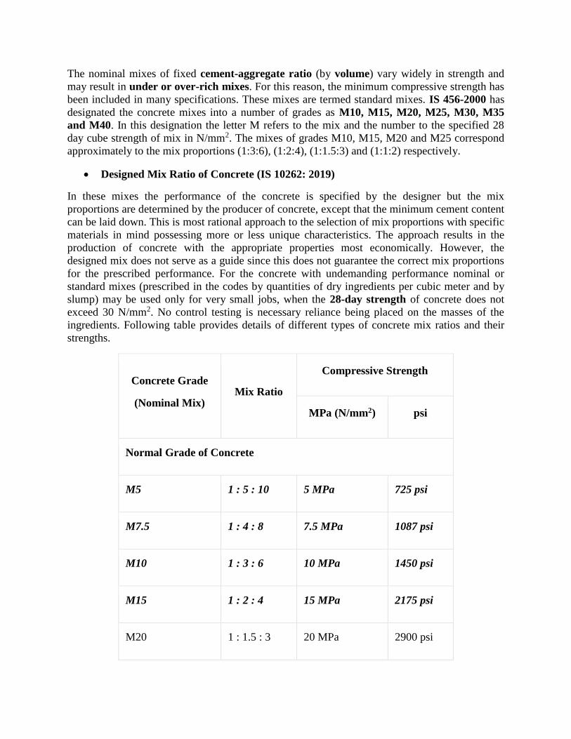
The nominal mixes of fixed cement-aggregate ratio (by volume) vary widely in strength and
may result in under or over-rich mixes. For this reason, the minimum compressive strength has
been included in many specifications. These mixes are termed standard mixes. IS 456-2000 has
designated the concrete mixes into a number of grades as M10, M15, M20, M25, M30, M35
and M40. In this designation the letter M refers to the mix and the number to the specified 28
day cube strength of mix in N/mm2. The mixes of grades M10, M15, M20 and M25 correspond
approximately to the mix proportions (1:3:6), (1:2:4), (1:1.5:3) and (1:1:2) respectively.
Designed Mix Ratio of Concrete (IS 10262: 2019)
In these mixes the performance of the concrete is specified by the designer but the mix
proportions are determined by the producer of concrete, except that the minimum cement content
can be laid down. This is most rational approach to the selection of mix proportions with specific
materials in mind possessing more or less unique characteristics. The approach results in the
production of concrete with the appropriate properties most economically. However, the
designed mix does not serve as a guide since this does not guarantee the correct mix proportions
for the prescribed performance. For the concrete with undemanding performance nominal or
standard mixes (prescribed in the codes by quantities of dry ingredients per cubic meter and by
slump) may be used only for very small jobs, when the 28-day strength of concrete does not
exceed 30 N/mm2. No control testing is necessary reliance being placed on the masses of the
ingredients. Following table provides details of different types of concrete mix ratios and their
strengths.
Concrete Grade
(Nominal Mix) Mix Ratio
Compressive Strength
MPa (N/mm2) psi
Normal Grade of Concrete
M5 1 : 5 : 10 5 MPa 725 psi
M7.5 1 : 4 : 8 7.5 MPa 1087 psi
M10 1 : 3 : 6 10 MPa 1450 psi
M15 1 : 2 : 4 15 MPa 2175 psi
M20 1 : 1.5 : 3 20 MPa 2900 psi
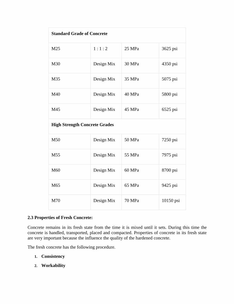
Standard Grade of Concrete
M25 1 : 1 : 2 25 MPa 3625 psi
M30 Design Mix 30 MPa 4350 psi
M35 Design Mix 35 MPa 5075 psi
M40 Design Mix 40 MPa 5800 psi
M45 Design Mix 45 MPa 6525 psi
High Strength Concrete Grades
M50 Design Mix 50 MPa 7250 psi
M55 Design Mix 55 MPa 7975 psi
M60 Design Mix 60 MPa 8700 psi
M65 Design Mix 65 MPa 9425 psi
M70 Design Mix 70 MPa 10150 psi
2.3 Properties of Fresh Concrete:
Concrete remains in its fresh state from the time it is mixed until it sets. During this time the
concrete is handled, transported, placed and compacted. Properties of concrete in its fresh state
are very important because the influence the quality of the hardened concrete.
The fresh concrete has the following procedure.
1. Consistency
2. Workability
3. Settlement & Bleeding
4. Plastic shrinkage
5. Loss of consistency
1. Consistency
Consistency of a concrete mix is a measure of the stiffness or sloppiness or fluidity of the mix.
For effective handling, placing and compacting the concrete, consistency must be the same for
each batch. It is therefore necessary to measure consistency of concrete at regular
intervals. Slump test is commonly used to measure consistency of concrete.
2. Workability
The workability of a concrete mix is the relative ease with which concrete can be placed,
compacted and finished without separation or segregation of the individual materials.
Workability is not the same thing as consistency. Mixes with the same consistency can have
different workabilities, if they are made with different sizes of stone – the smaller the stone the
more workable the concrete.
It is not possible to measure workability but the slump test, together with an assessment of
properties like stone content, cohesiveness and plasticity, gives a useful indication.
3. Settlement and Bleeding
Cement and aggregate particles have densities about three times that of water. In fresh concrete
they consequently tend to settle and displace mixing water which migrates upward and may
collect on the top surface of the concrete. This upward movement of mixing water is known as
bleeding; water that separates from the rest of the concrete is called bleed water.
4. Plastic Shrinkage
If water is removed from the compacted concrete before it sets, the volume of the concrete is
reduced by the amount of water removed. This volume reduction is called plastic shrinkage.
Water may be removed from the plastic concrete by evaporation or by being absorbed by dry
surfaces such as soil or old concrete or by the dry wooden form work.
5. Slump Loss
From the time of mixing, fresh concrete gradually loses consistency. This gives rise to the
problems only if the concrete becomes too stiff to handle, place and compact properly.
Slump loss in concrete is caused due to the following reasons.
Hydration of cement (generating more heat)
Loss of water by evaporation
Absorption of water by dry aggregates
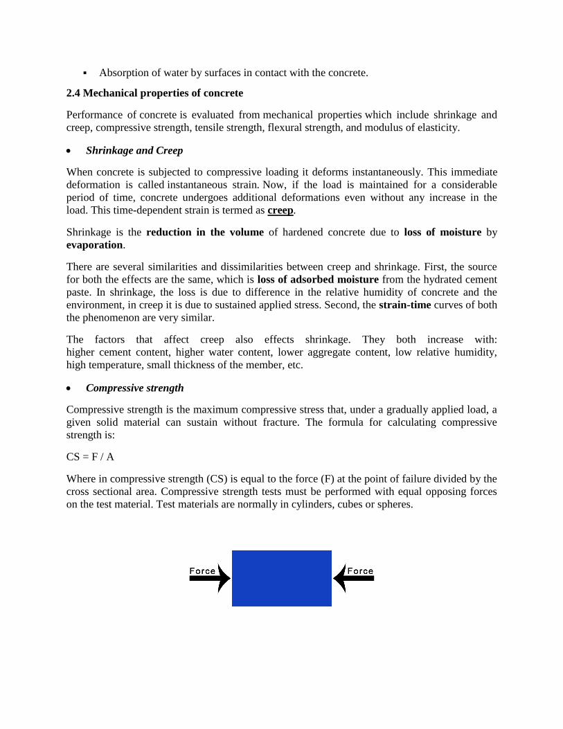
Absorption of water by surfaces in contact with the concrete.
2.4 Mechanical properties of concrete
Performance of concrete is evaluated from mechanical properties which include shrinkage and
creep, compressive strength, tensile strength, flexural strength, and modulus of elasticity.
Shrinkage and Creep
When concrete is subjected to compressive loading it deforms instantaneously. This immediate
deformation is called instantaneous strain. Now, if the load is maintained for a considerable
period of time, concrete undergoes additional deformations even without any increase in the
load. This time-dependent strain is termed as creep.
Shrinkage is the reduction in the volume of hardened concrete due to loss of moisture by
evaporation.
There are several similarities and dissimilarities between creep and shrinkage. First, the source
for both the effects are the same, which is loss of adsorbed moisture from the hydrated cement
paste. In shrinkage, the loss is due to difference in the relative humidity of concrete and the
environment, in creep it is due to sustained applied stress. Second, the strain-time curves of both
the phenomenon are very similar.
The factors that affect creep also effects shrinkage. They both increase with:
higher cement content, higher water content, lower aggregate content, low relative humidity,
high temperature, small thickness of the member, etc.
Compressive strength
Compressive strength is the maximum compressive stress that, under a gradually applied load, a
given solid material can sustain without fracture. The formula for calculating compressive
strength is:
CS = F / A
Where in compressive strength (CS) is equal to the force (F) at the point of failure divided by the
cross sectional area. Compressive strength tests must be performed with equal opposing forces
on the test material. Test materials are normally in cylinders, cubes or spheres.
Tensile strength
Tensile strength, maximum load that a material can support without fracture when being
stretched, divided by the original cross-sectional area of the material. Tensile strengths have
dimensions of force per unit area and in the English system of measurement are commonly
expressed in units of pounds per square inch, often abbreviated to psi. When stresses less than
the tensile strength are removed, a material returns either completely or partially to its original
shape and size. As the stress reaches the value of the tensile strength, however, a material, if
ductile, that has already begun to flow plastically rapidly forms a constricted region called a
neck, where it then fractures.
Flexural strength
The flexural strength of a material is defined as the maximum bending stress that can be applied
to that material before it yields. The most common way of obtaining the flexural strength of a
material is by employing a transverse bending test using a three-point flexural test technique.
Flexural strength is also known as bending strength, modulus of rupture or transverse rupture
strength.
Modulus of elasticity
The ratio of the stress in a body to the corresponding strain.
Quality Tests on concrete
Each quality test conducted on concrete determines their respective quality result of concrete.
Hence, it is not possible to conduct all the test to determine the quality of concrete. We have to
choose the best tests that can give good judgment of the concrete quality. The primary quality
test determines the variation of the concrete specification from the required and standard
concrete specification. The quality tests ensure that the best quality concrete is placed at the
site so that concrete structural members of desired strength are obtained. Below mentioned are
the quality tests conducted on fresh and hardened concretes.
Fresh Concrete
Most Common Quality Tests on Fresh concrete are:
1. Workability Tests
Workability of concrete mixture is measured by, Vee-bee consistometer test, Compaction factor
Test, and Slump test.
2. Air content
Air content measures the total air content in a sample of fresh concrete but does not indicate
what the final in-place air content is, because a certain amount of air is lost in transportation
Consolidating, placement, and finishing.
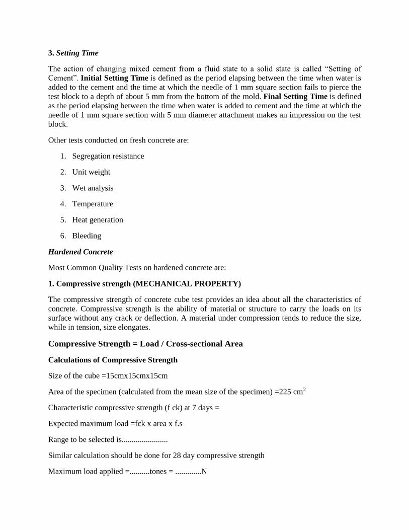
3. Setting Time
The action of changing mixed cement from a fluid state to a solid state is called “Setting of
Cement”. Initial Setting Time is defined as the period elapsing between the time when water is
added to the cement and the time at which the needle of 1 mm square section fails to pierce the
test block to a depth of about 5 mm from the bottom of the mold. Final Setting Time is defined
as the period elapsing between the time when water is added to cement and the time at which the
needle of 1 mm square section with 5 mm diameter attachment makes an impression on the test
block.
Other tests conducted on fresh concrete are:
1. Segregation resistance
2. Unit weight
3. Wet analysis
4. Temperature
5. Heat generation
6. Bleeding
Hardened Concrete
Most Common Quality Tests on hardened concrete are:
1. Compressive strength (MECHANICAL PROPERTY)
The compressive strength of concrete cube test provides an idea about all the characteristics of
concrete. Compressive strength is the ability of material or structure to carry the loads on its
surface without any crack or deflection. A material under compression tends to reduce the size,
while in tension, size elongates.
Compressive Strength = Load / Cross-sectional Area
Calculations of Compressive Strength
Size of the cube =15cmx15cmx15cm
Area of the specimen (calculated from the mean size of the specimen) =225 cm2
Characteristic compressive strength (f ck) at 7 days =
Expected maximum load =fck x area x f.s
Range to be selected is.......................
Similar calculation should be done for 28 day compressive strength
Maximum load applied =..........tones = .............N
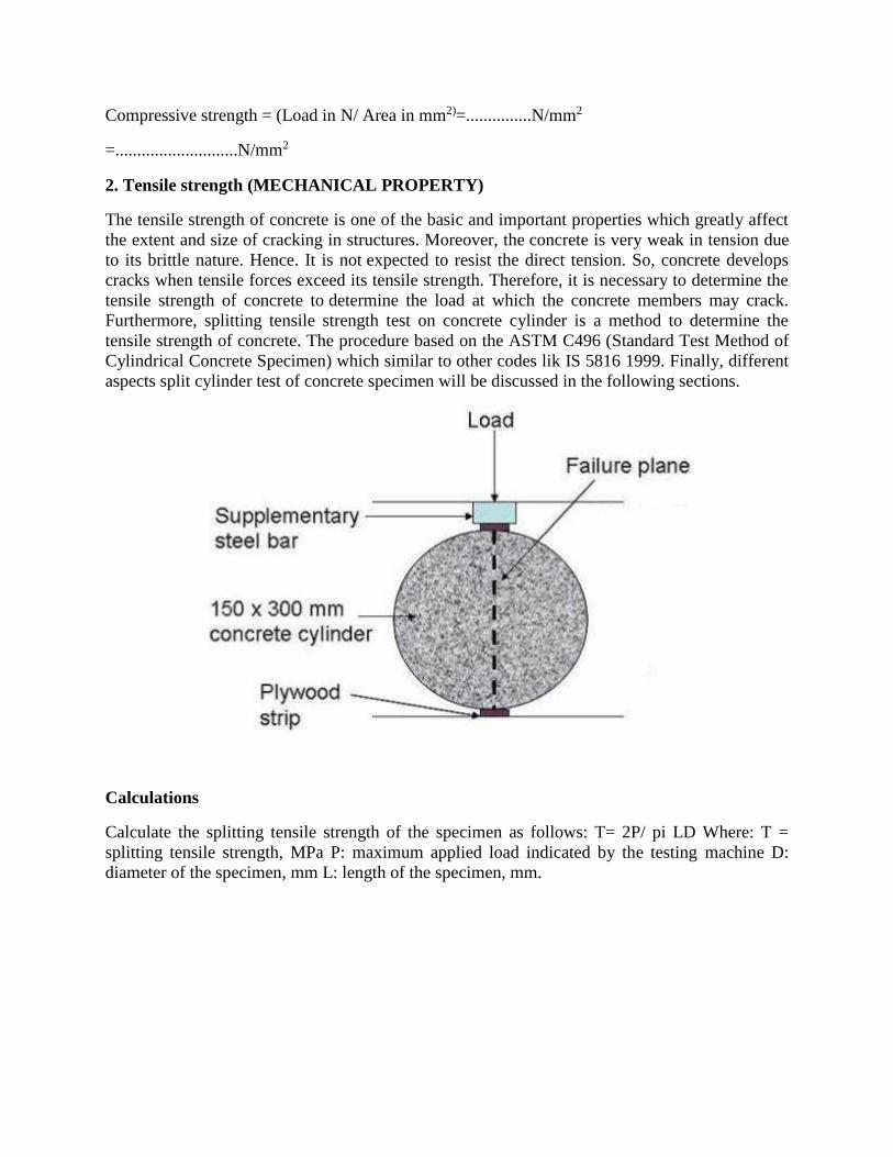
Compressive strength = (Load in N/ Area in mm2)=...............N/mm2
=............................N/mm2
2. Tensile strength (MECHANICAL PROPERTY)
The tensile strength of concrete is one of the basic and important properties which greatly affect
the extent and size of cracking in structures. Moreover, the concrete is very weak in tension due
to its brittle nature. Hence. It is not expected to resist the direct tension. So, concrete develops
cracks when tensile forces exceed its tensile strength. Therefore, it is necessary to determine the
tensile strength of concrete to determine the load at which the concrete members may crack.
Furthermore, splitting tensile strength test on concrete cylinder is a method to determine the
tensile strength of concrete. The procedure based on the ASTM C496 (Standard Test Method of
Cylindrical Concrete Specimen) which similar to other codes lik IS 5816 1999. Finally, different
aspects split cylinder test of concrete specimen will be discussed in the following sections.
Calculations
Calculate the splitting tensile strength of the specimen as follows: T= 2P/ pi LD Where: T =
splitting tensile strength, MPa P: maximum applied load indicated by the testing machine D:
diameter of the specimen, mm L: length of the specimen, mm.
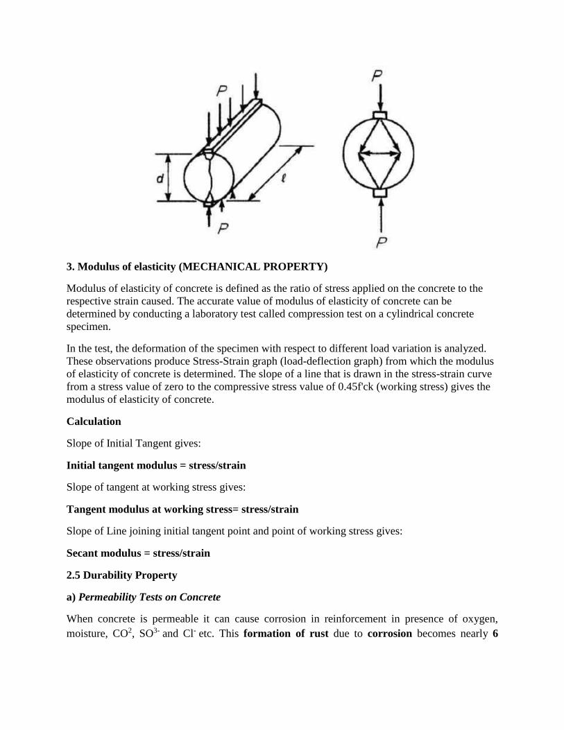
3. Modulus of elasticity (MECHANICAL PROPERTY)
Modulus of elasticity of concrete is defined as the ratio of stress applied on the concrete to the
respective strain caused. The accurate value of modulus of elasticity of concrete can be
determined by conducting a laboratory test called compression test on a cylindrical concrete
specimen.
In the test, the deformation of the specimen with respect to different load variation is analyzed.
These observations produce Stress-Strain graph (load-deflection graph) from which the modulus
of elasticity of concrete is determined. The slope of a line that is drawn in the stress-strain curve
from a stress value of zero to the compressive stress value of 0.45f'ck (working stress) gives the
modulus of elasticity of concrete.
Calculation
Slope of Initial Tangent gives:
Initial tangent modulus = stress/strain
Slope of tangent at working stress gives:
Tangent modulus at working stress= stress/strain
Slope of Line joining initial tangent point and point of working stress gives:
Secant modulus = stress/strain
2.5 Durability Property
a) Permeability Tests on Concrete
When concrete is permeable it can cause corrosion in reinforcement in presence of oxygen,
moisture, CO2, SO3- and Cl- etc. This formation of rust due to corrosion becomes nearly 6
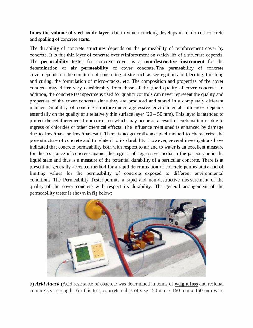
times the volume of steel oxide layer, due to which cracking develops in reinforced concrete
and spalling of concrete starts.
The durability of concrete structures depends on the permeability of reinforcement cover by
concrete. It is this thin layer of concrete over reinforcement on which life of a structure depends.
The permeability tester for concrete cover is a non-destructive instrument for the
determination of air permeability of cover concrete. The permeability of concrete
cover depends on the condition of concreting at site such as segregation and bleeding, finishing
and curing, the formulation of micro-cracks, etc. The composition and properties of the cover
concrete may differ very considerably from those of the good quality of cover concrete. In
addition, the concrete test specimens used for quality controls can never represent the quality and
properties of the cover concrete since they are produced and stored in a completely different
manner. Durability of concrete structure under aggressive environmental influences depends
essentially on the quality of a relatively thin surface layer (20 – 50 mm). This layer is intended to
protect the reinforcement from corrosion which may occur as a result of carbonation or due to
ingress of chlorides or other chemical effects. The influence mentioned is enhanced by damage
due to frost/thaw or frost/thaw/salt. There is no generally accepted method to characterize the
pore structure of concrete and to relate it to its durability. However, several investigations have
indicated that concrete permeability both with respect to air and to water is an excellent measure
for the resistance of concrete against the ingress of aggressive media in the gaseous or in the
liquid state and thus is a measure of the potential durability of a particular concrete. There is at
present no generally accepted method for a rapid determination of concrete permeability and of
limiting values for the permeability of concrete exposed to different environmental
conditions. The Permeability Tester permits a rapid and non-destructive measurement of the
quality of the cover concrete with respect its durability. The general arrangement of the
permeability tester is shown in fig below:
b) Acid Attack (Acid resistance of concrete was determined in terms of weight loss and residual
compressive strength. For this test, concrete cubes of size 150 mm x 150 mm x 150 mm were
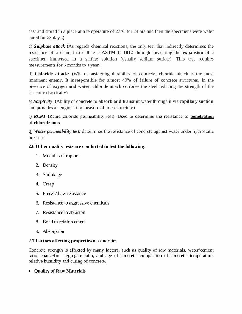
cast and stored in a place at a temperature of 27°C for 24 hrs and then the specimens were water
cured for 28 days.)
c) Sulphate attack (As regards chemical reactions, the only test that indirectly determines the
resistance of a cement to sulfate is ASTM C 1012 through measuring the expansion of a
specimen immersed in a sulfate solution (usually sodium sulfate). This test requires
measurements for 6 months to a year.)
d) Chloride attack: (When considering durability of concrete, chloride attack is the most
imminent enemy. It is responsible for almost 40% of failure of concrete structures. In the
presence of oxygen and water, chloride attack corrodes the steel reducing the strength of the
structure drastically)
e) Sorptivity: (Ability of concrete to absorb and transmit water through it via capillary suction
and provides an engineering measure of microstructure)
f) RCPT (Rapid chloride permeability test): Used to determine the resistance to penetration
of chloride ions
g) Water permeability test: determines the resistance of concrete against water under hydrostatic
pressure
2.6 Other quality tests are conducted to test the following:
1. Modulus of rupture
2. Density
3. Shrinkage
4. Creep
5. Freeze/thaw resistance
6. Resistance to aggressive chemicals
7. Resistance to abrasion
8. Bond to reinforcement
9. Absorption
2.7 Factors affecting properties of concrete:
Concrete strength is affected by many factors, such as quality of raw materials, water/cement
ratio, coarse/fine aggregate ratio, and age of concrete, compaction of concrete, temperature,
relative humidity and curing of concrete.
Quality of Raw Materials
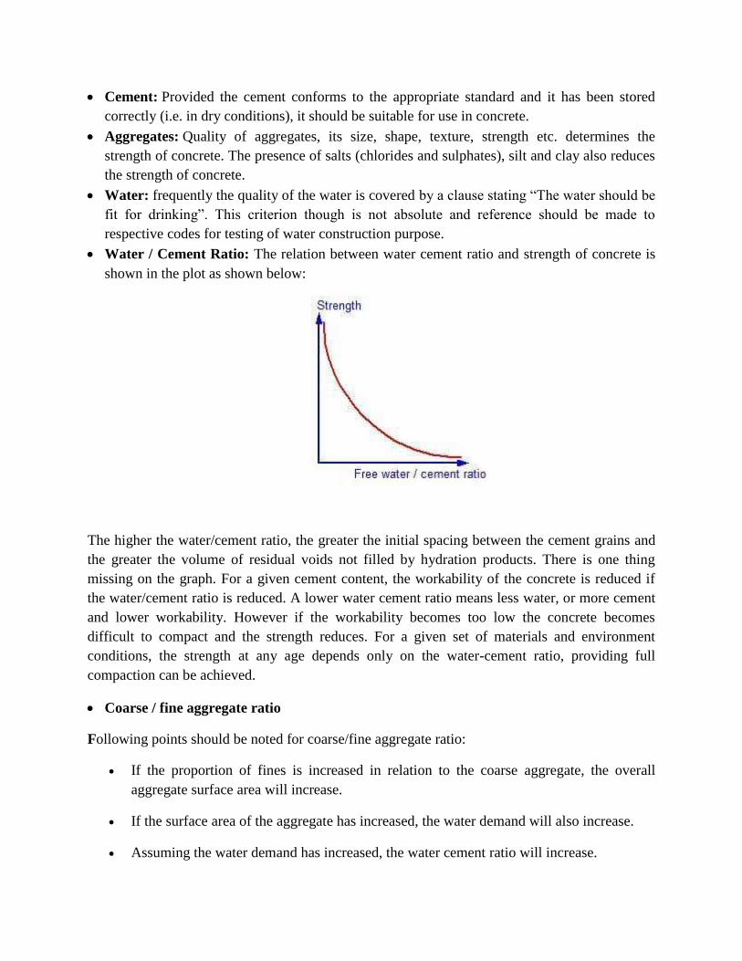
Cement: Provided the cement conforms to the appropriate standard and it has been stored
correctly (i.e. in dry conditions), it should be suitable for use in concrete.
Aggregates: Quality of aggregates, its size, shape, texture, strength etc. determines the
strength of concrete. The presence of salts (chlorides and sulphates), silt and clay also reduces
the strength of concrete.
Water: frequently the quality of the water is covered by a clause stating “The water should be
fit for drinking”. This criterion though is not absolute and reference should be made to
respective codes for testing of water construction purpose.
Water / Cement Ratio: The relation between water cement ratio and strength of concrete is
shown in the plot as shown below:
The higher the water/cement ratio, the greater the initial spacing between the cement grains and
the greater the volume of residual voids not filled by hydration products. There is one thing
missing on the graph. For a given cement content, the workability of the concrete is reduced if
the water/cement ratio is reduced. A lower water cement ratio means less water, or more cement
and lower workability. However if the workability becomes too low the concrete becomes
difficult to compact and the strength reduces. For a given set of materials and environment
conditions, the strength at any age depends only on the water-cement ratio, providing full
compaction can be achieved.
Coarse / fine aggregate ratio
Following points should be noted for coarse/fine aggregate ratio:
If the proportion of fines is increased in relation to the coarse aggregate, the overall
aggregate surface area will increase.
If the surface area of the aggregate has increased, the water demand will also increase.
Assuming the water demand has increased, the water cement ratio will increase.
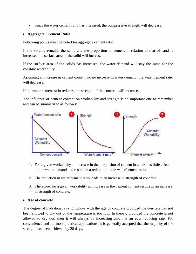
Since the water cement ratio has increased, the compressive strength will decrease.
Aggregate / Cement Ratio
Following points must be noted for aggregate cement ratio:
If the volume remains the same and the proportion of cement in relation to that of sand is
increased the surface area of the solid will increase.
If the surface area of the solids has increased, the water demand will stay the same for the
constant workability.
Assuming an increase in cement content for no increase in water demand, the water cement ratio
will decrease.
If the water cement ratio reduces, the strength of the concrete will increase.
The influence of cement content on workability and strength is an important one to remember
and can be summarized as follows:
1. For a given workability an increase in the proportion of cement in a mix has little effect
on the water demand and results in a reduction in the water/cement ratio.
2. The reduction in water/cement ratio leads to an increase in strength of concrete.
3. Therefore, for a given workability an increase in the cement content results in an increase
in strength of concrete.
Age of concrete
The degree of hydration is synonymous with the age of concrete provided the concrete has not
been allowed to dry out or the temperature is too low. In theory, provided the concrete is not
allowed to dry out, then it will always be increasing albeit at an ever reducing rate. For
convenience and for most practical applications, it is generally accepted that the majority of the
strength has been achieved by 28 days.

Compaction of concrete
Any entrapped air resulting from inadequate compaction of the plastic concrete will lead to a
reduction in strength. If there was 10% trapped air in the concrete, the strength will fall down in
the range of 30 to 40%.
Temperature
The rate of hydration reaction is temperature dependent. If the temperature increases the reaction
also increases. This means that the concrete kept at higher temperature will gain strength more
quickly than a similar concrete kept at a lower temperature. However, the final strength of the
concrete kept at the higher temperature will be lower. This is because the physical form of the
hardened cement paste is less well-structured and more porous when hydration proceeds at faster
rate. This is an important point to remember because temperature has a similar but more
pronounced detrimental effect on permeability of the concrete.
Relative humidity
If the concrete is allowed to dry out, the hydration reaction will stop. The hydration reaction
cannot proceed without moisture. The three curves shows the strength development of similar
concretes exposed to different conditions.
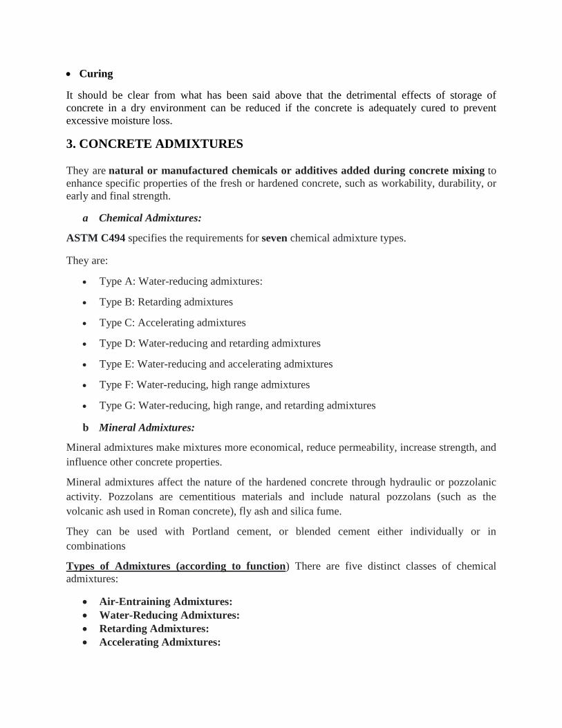
Curing
It should be clear from what has been said above that the detrimental effects of storage of
concrete in a dry environment can be reduced if the concrete is adequately cured to prevent
excessive moisture loss.
3. CONCRETE ADMIXTURES
They are natural or manufactured chemicals or additives added during concrete mixing to
enhance specific properties of the fresh or hardened concrete, such as workability, durability, or
early and final strength.
a Chemical Admixtures:
ASTM C494 specifies the requirements for seven chemical admixture types.
They are:
Type A: Water-reducing admixtures:
Type B: Retarding admixtures
Type C: Accelerating admixtures
Type D: Water-reducing and retarding admixtures
Type E: Water-reducing and accelerating admixtures
Type F: Water-reducing, high range admixtures
Type G: Water-reducing, high range, and retarding admixtures
b Mineral Admixtures:
Mineral admixtures make mixtures more economical, reduce permeability, increase strength, and
influence other concrete properties.
Mineral admixtures affect the nature of the hardened concrete through hydraulic or pozzolanic
activity. Pozzolans are cementitious materials and include natural pozzolans (such as the
volcanic ash used in Roman concrete), fly ash and silica fume.
They can be used with Portland cement, or blended cement either individually or in
combinations
Types of Admixtures (according to function) There are five distinct classes of chemical
admixtures:
Air-Entraining Admixtures:
Water-Reducing Admixtures:
Retarding Admixtures:
Accelerating Admixtures:
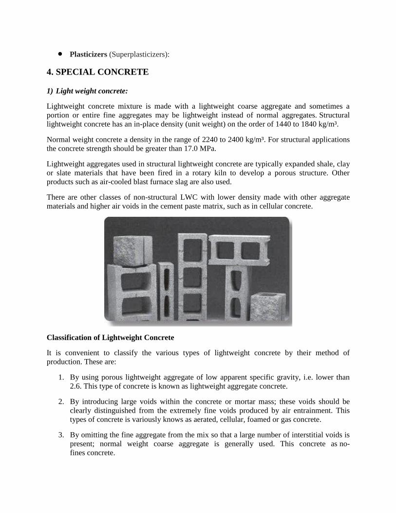
Plasticizers (Superplasticizers):
4. SPECIAL CONCRETE
1) Light weight concrete:
Lightweight concrete mixture is made with a lightweight coarse aggregate and sometimes a
portion or entire fine aggregates may be lightweight instead of normal aggregates. Structural
lightweight concrete has an in-place density (unit weight) on the order of 1440 to 1840 kg/m³.
Normal weight concrete a density in the range of 2240 to 2400 kg/m³. For structural applications
the concrete strength should be greater than 17.0 MPa.
Lightweight aggregates used in structural lightweight concrete are typically expanded shale, clay
or slate materials that have been fired in a rotary kiln to develop a porous structure. Other
products such as air-cooled blast furnace slag are also used.
There are other classes of non-structural LWC with lower density made with other aggregate
materials and higher air voids in the cement paste matrix, such as in cellular concrete.
Classification of Lightweight Concrete
It is convenient to classify the various types of lightweight concrete by their method of
production. These are:
1. By using porous lightweight aggregate of low apparent specific gravity, i.e. lower than
2.6. This type of concrete is known as lightweight aggregate concrete.
2. By introducing large voids within the concrete or mortar mass; these voids should be
clearly distinguished from the extremely fine voids produced by air entrainment. This
types of concrete is variously knows as aerated, cellular, foamed or gas concrete.
3. By omitting the fine aggregate from the mix so that a large number of interstitial voids is
present; normal weight coarse aggregate is generally used. This concrete as no-
fines concrete.
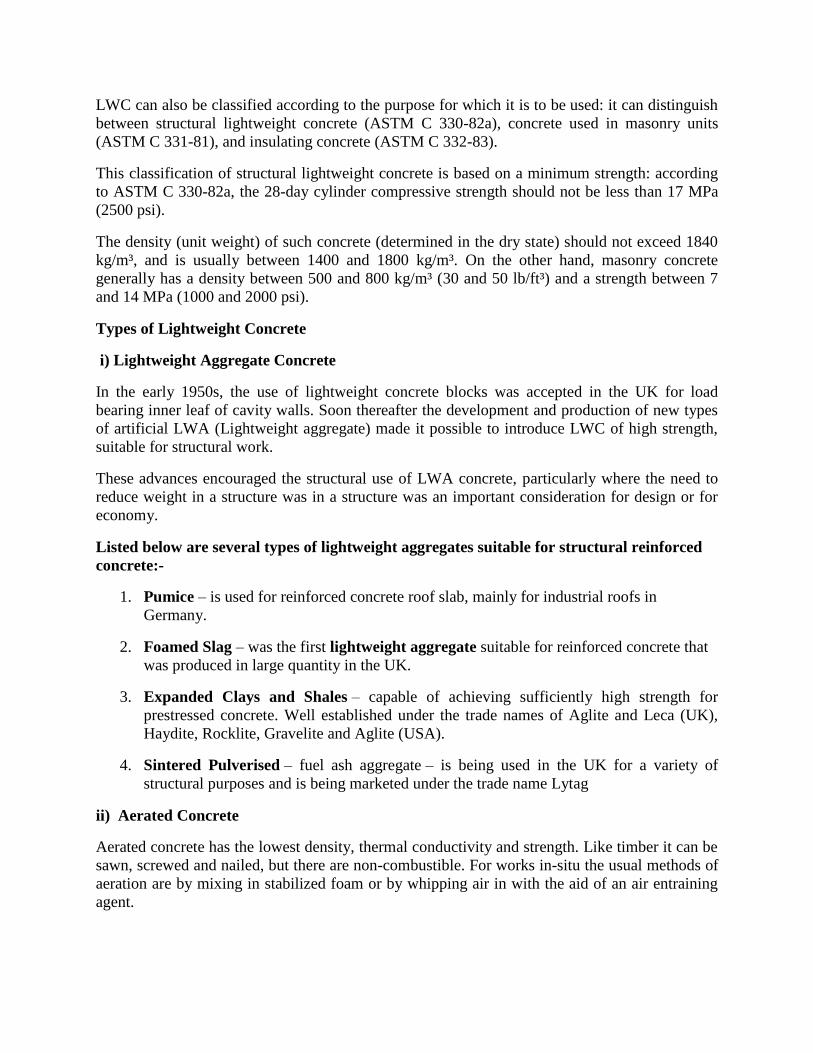
LWC can also be classified according to the purpose for which it is to be used: it can distinguish
between structural lightweight concrete (ASTM C 330-82a), concrete used in masonry units
(ASTM C 331-81), and insulating concrete (ASTM C 332-83).
This classification of structural lightweight concrete is based on a minimum strength: according
to ASTM C 330-82a, the 28-day cylinder compressive strength should not be less than 17 MPa
(2500 psi).
The density (unit weight) of such concrete (determined in the dry state) should not exceed 1840
kg/m³, and is usually between 1400 and 1800 kg/m³. On the other hand, masonry concrete
generally has a density between 500 and 800 kg/m³ (30 and 50 lb/ft³) and a strength between 7
and 14 MPa (1000 and 2000 psi).
Types of Lightweight Concrete
i) Lightweight Aggregate Concrete
In the early 1950s, the use of lightweight concrete blocks was accepted in the UK for load
bearing inner leaf of cavity walls. Soon thereafter the development and production of new types
of artificial LWA (Lightweight aggregate) made it possible to introduce LWC of high strength,
suitable for structural work.
These advances encouraged the structural use of LWA concrete, particularly where the need to
reduce weight in a structure was in a structure was an important consideration for design or for
economy.
Listed below are several types of lightweight aggregates suitable for structural reinforced
concrete:-
1. Pumice – is used for reinforced concrete roof slab, mainly for industrial roofs in
Germany.
2. Foamed Slag – was the first lightweight aggregate suitable for reinforced concrete that
was produced in large quantity in the UK.
3. Expanded Clays and Shales – capable of achieving sufficiently high strength for
prestressed concrete. Well established under the trade names of Aglite and Leca (UK),
Haydite, Rocklite, Gravelite and Aglite (USA).
4. Sintered Pulverised – fuel ash aggregate – is being used in the UK for a variety of
structural purposes and is being marketed under the trade name Lytag
ii) Aerated Concrete
Aerated concrete has the lowest density, thermal conductivity and strength. Like timber it can be
sawn, screwed and nailed, but there are non-combustible. For works in-situ the usual methods of
aeration are by mixing in stabilized foam or by whipping air in with the aid of an air entraining
agent.
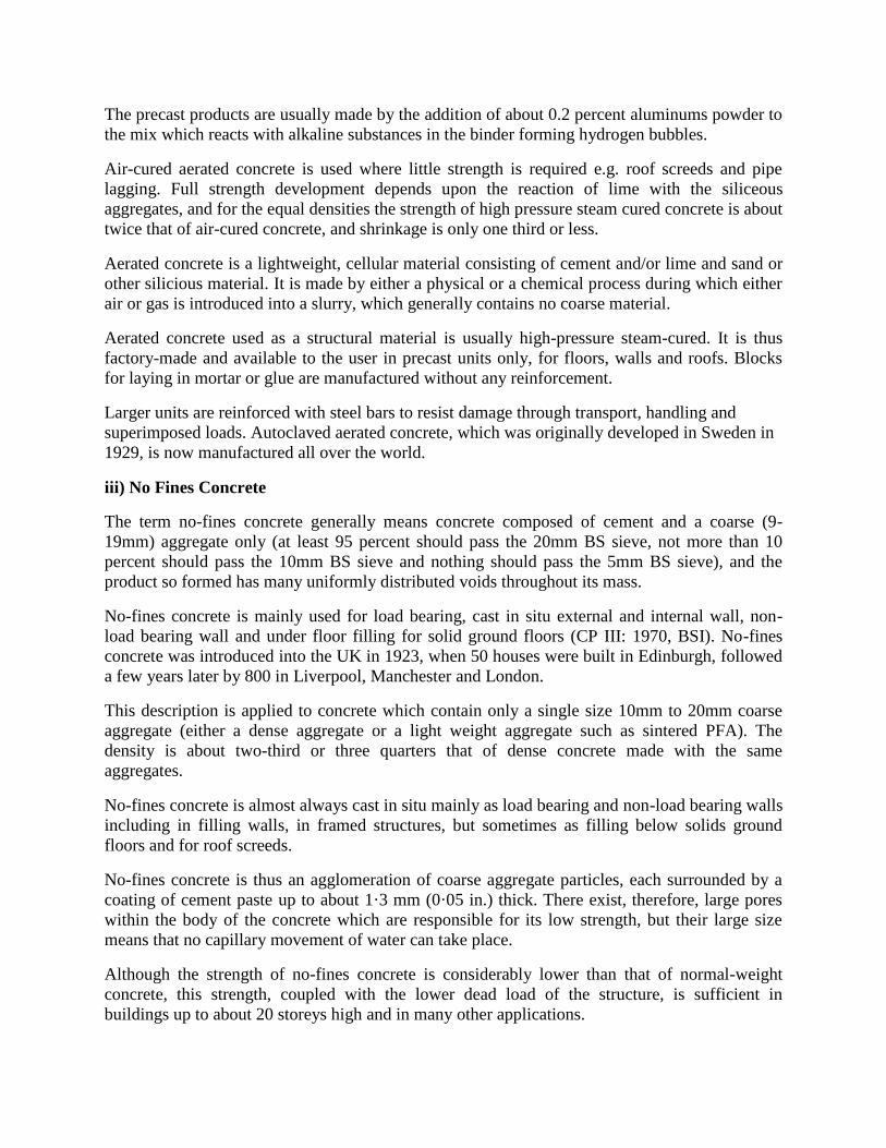
The precast products are usually made by the addition of about 0.2 percent aluminums powder to
the mix which reacts with alkaline substances in the binder forming hydrogen bubbles.
Air-cured aerated concrete is used where little strength is required e.g. roof screeds and pipe
lagging. Full strength development depends upon the reaction of lime with the siliceous
aggregates, and for the equal densities the strength of high pressure steam cured concrete is about
twice that of air-cured concrete, and shrinkage is only one third or less.
Aerated concrete is a lightweight, cellular material consisting of cement and/or lime and sand or
other silicious material. It is made by either a physical or a chemical process during which either
air or gas is introduced into a slurry, which generally contains no coarse material.
Aerated concrete used as a structural material is usually high-pressure steam-cured. It is thus
factory-made and available to the user in precast units only, for floors, walls and roofs. Blocks
for laying in mortar or glue are manufactured without any reinforcement.
Larger units are reinforced with steel bars to resist damage through transport, handling and
superimposed loads. Autoclaved aerated concrete, which was originally developed in Sweden in
1929, is now manufactured all over the world.
iii) No Fines Concrete
The term no-fines concrete generally means concrete composed of cement and a coarse (9-
19mm) aggregate only (at least 95 percent should pass the 20mm BS sieve, not more than 10
percent should pass the 10mm BS sieve and nothing should pass the 5mm BS sieve), and the
product so formed has many uniformly distributed voids throughout its mass.
No-fines concrete is mainly used for load bearing, cast in situ external and internal wall, non-
load bearing wall and under floor filling for solid ground floors (CP III: 1970, BSI). No-fines
concrete was introduced into the UK in 1923, when 50 houses were built in Edinburgh, followed
a few years later by 800 in Liverpool, Manchester and London.
This description is applied to concrete which contain only a single size 10mm to 20mm coarse
aggregate (either a dense aggregate or a light weight aggregate such as sintered PFA). The
density is about two-third or three quarters that of dense concrete made with the same
aggregates.
No-fines concrete is almost always cast in situ mainly as load bearing and non-load bearing walls
including in filling walls, in framed structures, but sometimes as filling below solids ground
floors and for roof screeds.
No-fines concrete is thus an agglomeration of coarse aggregate particles, each surrounded by a
coating of cement paste up to about 1·3 mm (0·05 in.) thick. There exist, therefore, large pores
within the body of the concrete which are responsible for its low strength, but their large size
means that no capillary movement of water can take place.
Although the strength of no-fines concrete is considerably lower than that of normal-weight
concrete, this strength, coupled with the lower dead load of the structure, is sufficient in
buildings up to about 20 storeys high and in many other applications.
Types of Lightweight Concrete Based on Density and Strength
LWC can be classified as:-
a Low density concrete
b Moderate strength concrete
c Structural concrete
a. Low Density Concrete
These are employing chiefly for insulation purposes. With low unit weight, seldom exceeding
800 kg/m³, heat insulation value are high. Compressive strength are low, regarding from about
0.69 to 6.89 N/mm2.
b. Moderate Density Concrete
The use of these concrete requires a fair degree of compressive strength, and thus they fall about
midway between the structural and low density concrete. These are sometimes designed as ‘fill’
concrete. Compressive strength are approximately 6.89 to 17.24 N/mm² and insulation values are
intermediate.
c. Structural Concrete
Concrete with full structural efficiency contain aggregates which fall on the other end of the
scale and which are generally made with expanded shale, clay, slates, slag, and fly-ash.
Minimum compressive strength is 17.24 N/mm².
Most structural LWC are capable of producing concrete with compressive strength in excess of
34.47 N/mm².
Since the unit weight of structural LWC are considerably greater than those of low density
concrete, insulation efficiency is lower. However, thermal insulation values for structural LWC
are substantially better than NWC.
Uses of Lightweight Concrete
1. Screeds and thickening for general purposes especially when such screeds or thickening
and weight to floors roofs and other structural members.
2. Screeds and walls where timber has to be attached by nailing.
3. Casting structural steel to protect it against fire and corrosion or as a covering for
architectural purposes.
4. Heat insulation on roofs.
5. Insulating water pipes.
6. Construction of partition walls and panel walls in frame structures.
7. Fixing bricks to receive nails from joinery, principally in domestic or domestic type
construction.
8. General insulation of walls.
9. Surface rendered for external walls of small houses.
10. It is also being used for reinforced concrete.
Advantages of Lightweight Concrete
1. Reduced dead load of wet concrete allows longer span to be poured un-propped. This
save both labor and circle time for each floor.
2. Reduction of dead load, faster building rates and lower haulage and handling costs. The
eight of the building in term of the loads transmitted by the foundations is an important
factor in design, particular for the case of tall buildings.
3. The use of LWC has sometimes made it possible to proceed with the design which
otherwise would have been abandoned because of excessive weight. In frame structures,
considerable savings in cost can be brought about by using LWC for the construction
floors, partition and external cladding.
4. Most building materials such as clay bricks the haulage load is limited not by volume but
by weight. With suitable design containers much larger volumes of LWC can haul
economically.
5. A less obvious but nonetheless important characteristics of LWC is its relatively low
thermal conductivity, a property which improves with decreasing density in recent years,
with the increasing cost and scarcity of energy sources, more attention has been given the
formerly to the need for reducing fuel consumption while maintaining, and indeed
improving, comfort conditions buildings. The point is illustrated by fact that a 125 mm
thick solid wall of aerated concrete will give thermal insulation about four times greater
than that of a 230 mm clay brick wall.
Durability of Lightweight Concrete
Durability is defined as the ability of a material to withstand the effect of its environment. In a
building material as chemical attack, physical stress, and mechanical assault:-
Chemical attack is as aggregate ground-water particularly sulfate, polluted air, and spillage of
reactive liquids LWC has no special resistant to these agencies: indeed, it is generally move
porous than the ordinary Portland cement. It is not recommended for use below damp-course. A
chemical aspects of durability is the stability of the material itself, particularly at the presence of
moisture.
Physical stresses to which LWC is exposed are principally frost action and shrinkage and
temperature stresses. Stressing may be due to the drying shrinkage of the concrete or to
differential thermal movements between dissimilar materials or to other phenomena of a similar
nature. Drying shrinkage commonly causes cracking of LWC if suitable precautions are not
taken.
Mechanical damage can result from abrasion or impact excessive loading of flexural members.
The lightest grades of LWC are relatively soft so that they subject to some abrasion were they
not for other reasons protected by rendering.
2) High density of concrete
As the name suggests, the density of this concrete varies from 3360 kg/m3 to 3840 kg/m3,
whereas the density of normal concrete is of the order of 2400 kg/m3. The density of light weight
concrete is about 1900 kg/m3 . Thus the density of high density concrete is about 50% more than
the density of conventional concrete. However this concrete can be produced of density up to
5200 kg/m3 using iron as both fine and coarse aggregate.
With the advent of the nuclear energy, there is a considerable demand of the concrete
technologists in the market. Due to the use of nuclear energy producing reactors, large scale
production of penetrating radiation and radioactive materials also has taken place.
Thus all nuclear energy producing units such as nuclear reactors, particle accelerator,
industrial radiography, x-ray and gamma ray therapy units require nuclear shielding material
for the protection of the operating personnel against the biological hazards such as radiation. The
normal as well as high density concrete is effective and economical for the construction of
permanent shield against radiation.
Types of Radiation in High Density Concrete:
The radiation can be classified into two groups as follows:
These radiations are considered in the design of biological shields.
a. Electro-Magnetic Waves:
These waves are of high frequency and have high energy. These waves are known as X and
gamma rays. These are the only electro-magnetic waves which need shields for the protection of
personnel. Though they are similar to high rays, but possess higher energy and greater
penetrating power. X and gamma rays are identical, but their sources of production are different.
Both these rays have high penetration power, but they can be adequately absorbed by an
appropriate thickness of concrete shield.
b. Nuclear Particles:
Nuclear particles consist of nuclei of atoms or their fragments. These fragments are known as
neutrons, protons, alpha and beta particles. Except neutrons all the other particles possess an
electric charge. On the other hand neutrons are un-charged and remain un-affected by electric
field, until they interact by collision with a nucleus. They have no definite range and some of
them may penetrate any shield.
Alpha, beta and proton particles carry electrical charge, which interact with electric field,
surrounding the atom of the shielding material and lose their energy considerably. Generally
these particles do not create a separate shielding problem, though accelerated protons at high
energy levels may require heavy shielding comparable to that required for neutrons.
Thus X and gamma rays, and neutrons need protection shield. As stated above X and gamma
rays are similar except in energy and origin. The biological hazards of radiation arise from the
fact that the radiation interact with human tissues. In the process of interaction some of the
energy of the human tissues is lost.
The energy loss is sufficient to ionize the atoms of the cells, upsetting the delicate chemical
balance and causing the death of cells. If enough cells are affected, the organism dies. Thus the
radiation must be reduced or weekend sufficiently, so that the remainder or left out radiation may
not cause permanent damage to the persons exposed to it.
Apart from biological hazards, a very high temperature is also generated by the nuclear reaction.
Thus the shielding is necessary to protect the electronic and other sensitive equipment in the
vicinity.
Shielding Ability of High Density Concrete:
Due to the following characteristics, concrete has been found an excellent shielding
material:
1. It has sufficient capacity to absorb the radiation both of neutron and gamma rays, reducing the
radiation to a very weak state.
2. It has good mechanical properties as strength and durability.
3. When green, it can be moulded into any shape. Thus the ease of construction makes concrete a
specially suitable material for radiation shielding.
4. Its initial and maintenance cost is also relatively low.
Disadvantages:
Its disadvantages are as follows:
1. As the sections of the structure are heavy, they need more space. Thus the use of concrete as
shielding against radiation needs more space.
2. The weight of shielding concrete is very high in the range of 3360 to 3840 kg/m3.
Aggregates to be used in Shielding High Density Concrete:
For making shielding concrete heavy weight aggregate having a specific gravity between 3.5 to
4.0 is needed. There are many aggregates whose specific gravity is more than 3.5 for making a
heavy weight concrete.
Some of natural commercially used aggregates are as follows:
1. Barite
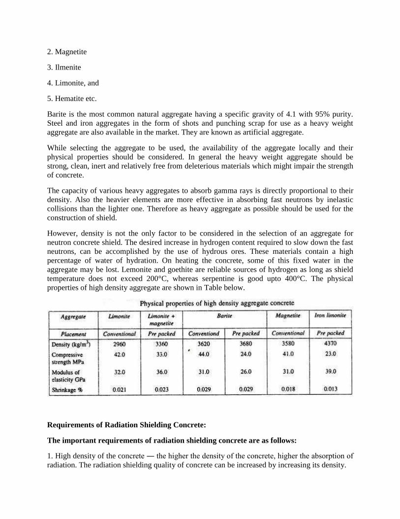
2. Magnetite
3. Ilmenite
4. Limonite, and
5. Hematite etc.
Barite is the most common natural aggregate having a specific gravity of 4.1 with 95% purity.
Steel and iron aggregates in the form of shots and punching scrap for use as a heavy weight
aggregate are also available in the market. They are known as artificial aggregate.
While selecting the aggregate to be used, the availability of the aggregate locally and their
physical properties should be considered. In general the heavy weight aggregate should be
strong, clean, inert and relatively free from deleterious materials which might impair the strength
of concrete.
The capacity of various heavy aggregates to absorb gamma rays is directly proportional to their
density. Also the heavier elements are more effective in absorbing fast neutrons by inelastic
collisions than the lighter one. Therefore as heavy aggregate as possible should be used for the
construction of shield.
However, density is not the only factor to be considered in the selection of an aggregate for
neutron concrete shield. The desired increase in hydrogen content required to slow down the fast
neutrons, can be accomplished by the use of hydrous ores. These materials contain a high
percentage of water of hydration. On heating the concrete, some of this fixed water in the
aggregate may be lost. Lemonite and goethite are reliable sources of hydrogen as long as shield
temperature does not exceed 200°C, whereas serpentine is good upto 400°C. The physical
properties of high density aggregate are shown in Table below.
Requirements of Radiation Shielding Concrete:
The important requirements of radiation shielding concrete are as follows:
1. High density of the concrete ― the higher the density of the concrete, higher the absorption of
radiation. The radiation shielding quality of concrete can be increased by increasing its density.
2. The other important requirement of radiation shielding concrete is its structural strength even
at high temperature.
Thus to produce high density and high strength concrete, it is necessary to control the
water/cement ratio very strictly. Appropriate admixture and proper vibrators for good
compaction should be employed, after that good quality control should be followed.
High density concrete used for shielding differs from normal weight concrete in the following
respects.
High density concrete should contain sufficient material of light atomic weight, which produces
hydrogen. Sometimes in high density concrete serpentine aggregates are used due to their ability
to retain water of crystallisation at high temperatures which assure a source of hydrogen. The
availability of water of crystallisation in all heavy weight aggregate is not necessary.
High density concrete may contain high content of cement-and may exhibit increased creep and
shrinkage. Due to the high density of aggregate, it has a tendency of segregation. Coarse
aggregate used may be of only high density mineral aggregate, or a mixture of mineral aggregate
and steel particles or only steel particles, Experiments have shown that if only smooth cubical
pieces of steel or iron ore are used as coarse aggregate, the compressive strength will not be more
than 21 MPa, regardless of the water/cement ratio or grout mixture ratio.
If sheared reinforcing bars are used as aggregate along with good grout, normal strength will be
obtained. The grout used in high density pre placed aggregate concrete should be somewhat
richer than that used in normal density pre placed concrete. High modulus of elasticity, low
thermal expansion, and low elastic and creep deformation are the ideal properties for both high
density and normal concrete.
Properties of High Density Concrete:
Following properties of high density concrete have been observed:
1. The strength of this concrete measured on standard cylinders has been found 42 MPa at 28
days for a water/cement ratio 0.58 and 24 MPa at water/cement ratio 0.9.
2. The density of this concrete for a mix of 1:4.6:6.4 with water/cement ratio of 0.58 has been
found as 3700 kg/m3.
3. The coefficient of thermal expansion of barite concrete measured in the range of temperature
of 4°C to 38°C is found about twice that of normal concrete.
4. The modulus of elasticity and poisson’s ratio of high density concrete and normal concrete are
approximately the same.
5. Shrinkage of high density concrete is about 1/4 to 1/3 of the normal concrete.
6. Thermal conductivity, diffusivity etc. of high strength concrete is considerably lower than
corresponding values for normal aggregate concrete.
7. Concrete made with barite aggregate does not stand well to weathering.
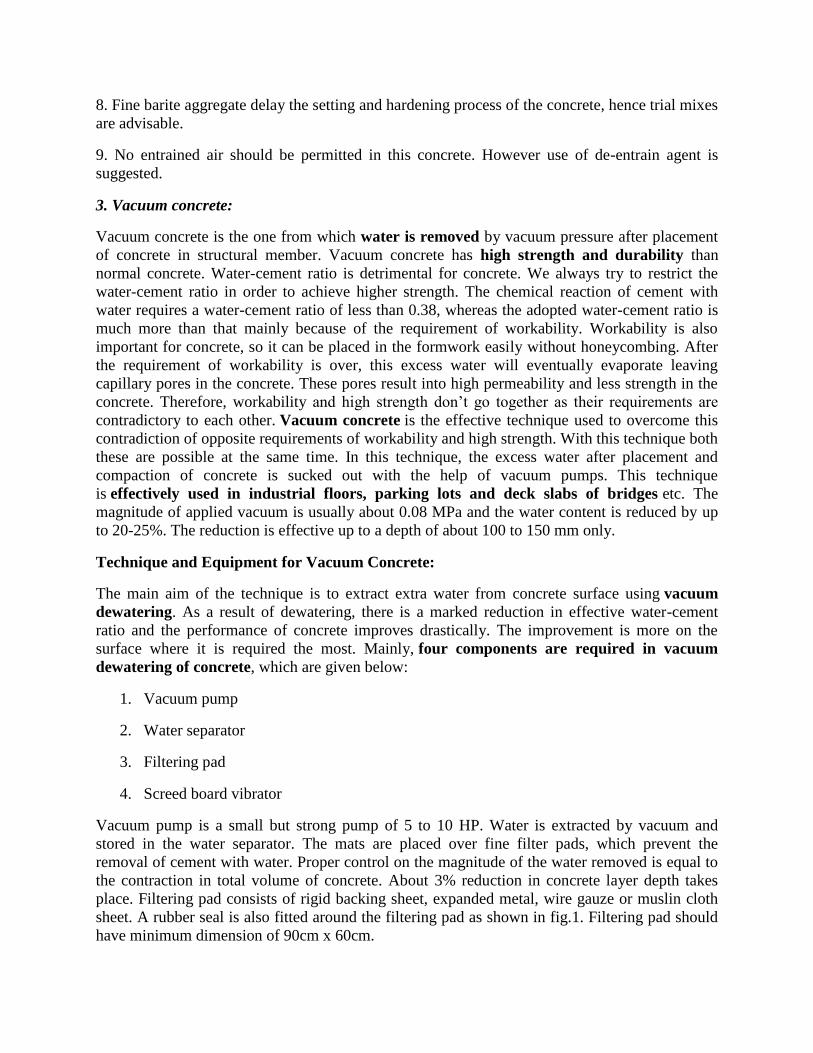
8. Fine barite aggregate delay the setting and hardening process of the concrete, hence trial mixes
are advisable.
9. No entrained air should be permitted in this concrete. However use of de-entrain agent is
suggested.
3. Vacuum concrete:
Vacuum concrete is the one from which water is removed by vacuum pressure after placement
of concrete in structural member. Vacuum concrete has high strength and durability than
normal concrete. Water-cement ratio is detrimental for concrete. We always try to restrict the
water-cement ratio in order to achieve higher strength. The chemical reaction of cement with
water requires a water-cement ratio of less than 0.38, whereas the adopted water-cement ratio is
much more than that mainly because of the requirement of workability. Workability is also
important for concrete, so it can be placed in the formwork easily without honeycombing. After
the requirement of workability is over, this excess water will eventually evaporate leaving
capillary pores in the concrete. These pores result into high permeability and less strength in the
concrete. Therefore, workability and high strength don’t go together as their requirements are
contradictory to each other. Vacuum concrete is the effective technique used to overcome this
contradiction of opposite requirements of workability and high strength. With this technique both
these are possible at the same time. In this technique, the excess water after placement and
compaction of concrete is sucked out with the help of vacuum pumps. This technique
is effectively used in industrial floors, parking lots and deck slabs of bridges etc. The
magnitude of applied vacuum is usually about 0.08 MPa and the water content is reduced by up
to 20-25%. The reduction is effective up to a depth of about 100 to 150 mm only.
Technique and Equipment for Vacuum Concrete:
The main aim of the technique is to extract extra water from concrete surface using vacuum
dewatering. As a result of dewatering, there is a marked reduction in effective water-cement
ratio and the performance of concrete improves drastically. The improvement is more on the
surface where it is required the most. Mainly, four components are required in vacuum
dewatering of concrete, which are given below:
1. Vacuum pump
2. Water separator
3. Filtering pad
4. Screed board vibrator
Vacuum pump is a small but strong pump of 5 to 10 HP. Water is extracted by vacuum and
stored in the water separator. The mats are placed over fine filter pads, which prevent the
removal of cement with water. Proper control on the magnitude of the water removed is equal to
the contraction in total volume of concrete. About 3% reduction in concrete layer depth takes
place. Filtering pad consists of rigid backing sheet, expanded metal, wire gauze or muslin cloth
sheet. A rubber seal is also fitted around the filtering pad as shown in fig.1. Filtering pad should
have minimum dimension of 90cm x 60cm.
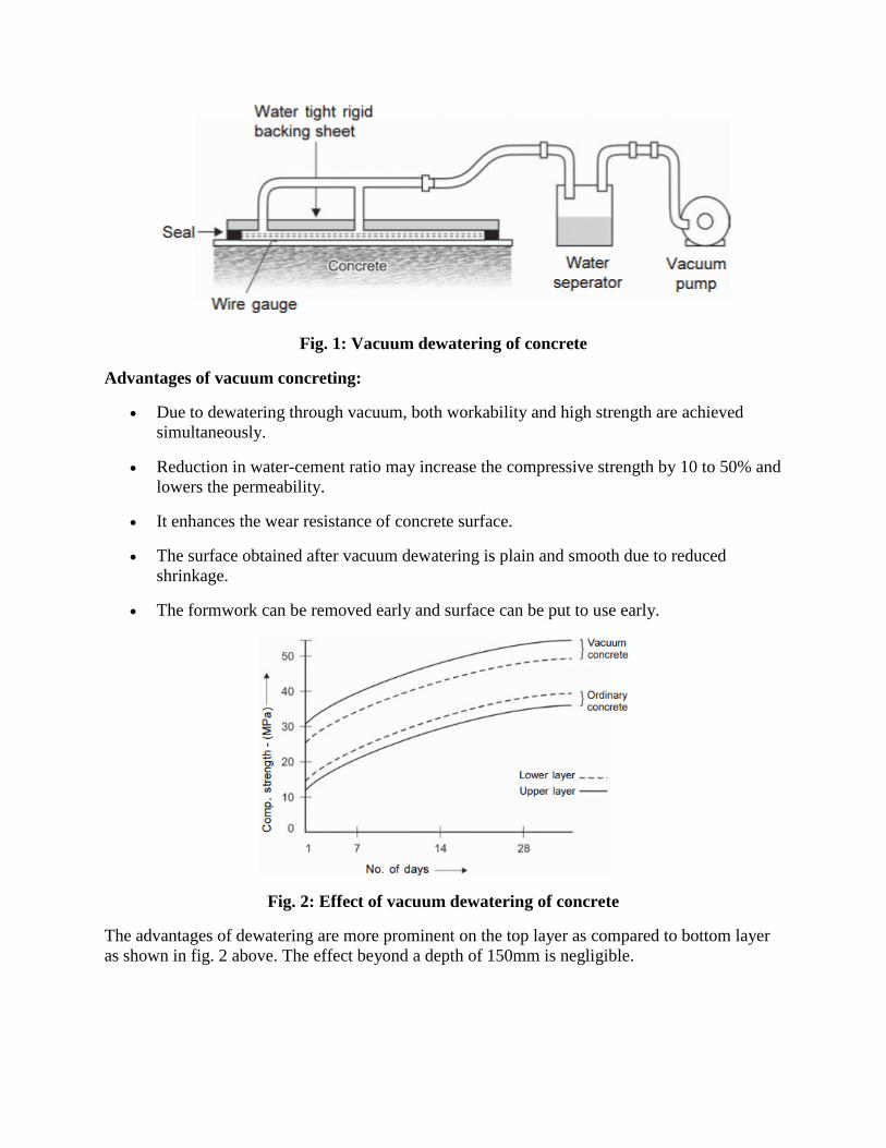
Fig. 1: Vacuum dewatering of concrete
Advantages of vacuum concreting:
Due to dewatering through vacuum, both workability and high strength are achieved
simultaneously.
Reduction in water-cement ratio may increase the compressive strength by 10 to 50% and
lowers the permeability.
It enhances the wear resistance of concrete surface.
The surface obtained after vacuum dewatering is plain and smooth due to reduced
shrinkage.
The formwork can be removed early and surface can be put to use early.
Fig. 2: Effect of vacuum dewatering of concrete
The advantages of dewatering are more prominent on the top layer as compared to bottom layer
as shown in fig. 2 above. The effect beyond a depth of 150mm is negligible.
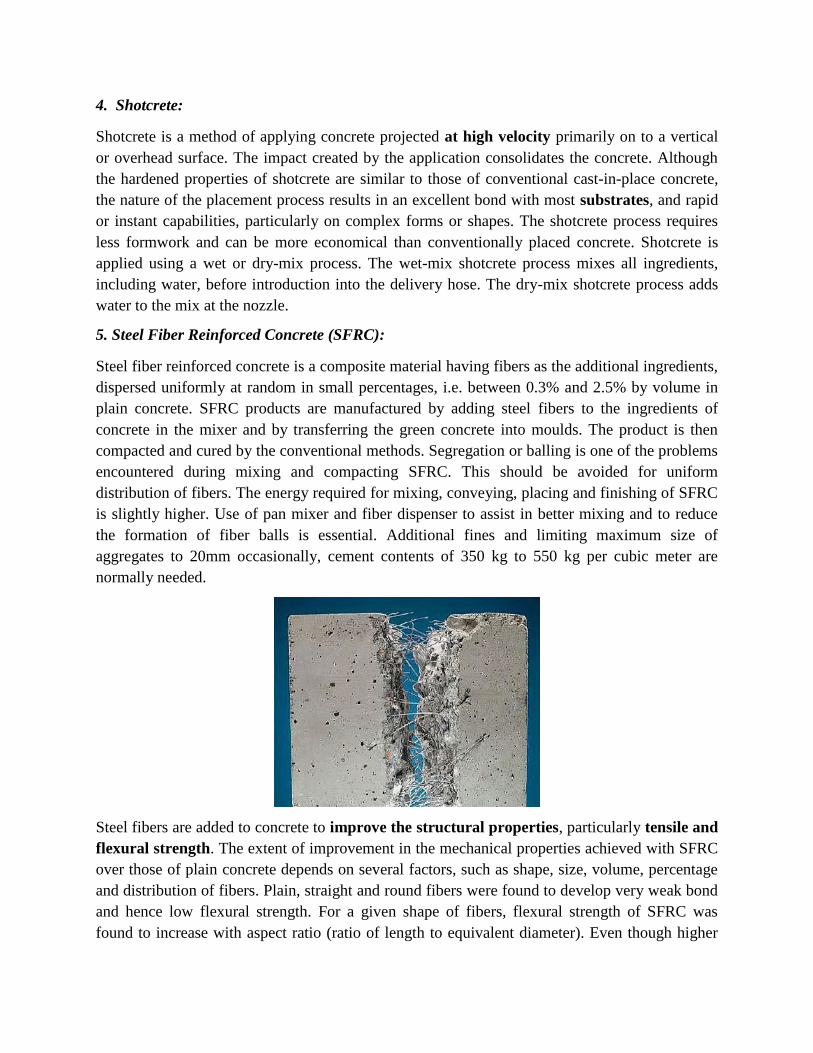
4. Shotcrete:
Shotcrete is a method of applying concrete projected at high velocity primarily on to a vertical
or overhead surface. The impact created by the application consolidates the concrete. Although
the hardened properties of shotcrete are similar to those of conventional cast-in-place concrete,
the nature of the placement process results in an excellent bond with most substrates, and rapid
or instant capabilities, particularly on complex forms or shapes. The shotcrete process requires
less formwork and can be more economical than conventionally placed concrete. Shotcrete is
applied using a wet or dry-mix process. The wet-mix shotcrete process mixes all ingredients,
including water, before introduction into the delivery hose. The dry-mix shotcrete process adds
water to the mix at the nozzle.
5. Steel Fiber Reinforced Concrete (SFRC):
Steel fiber reinforced concrete is a composite material having fibers as the additional ingredients,
dispersed uniformly at random in small percentages, i.e. between 0.3% and 2.5% by volume in
plain concrete. SFRC products are manufactured by adding steel fibers to the ingredients of
concrete in the mixer and by transferring the green concrete into moulds. The product is then
compacted and cured by the conventional methods. Segregation or balling is one of the problems
encountered during mixing and compacting SFRC. This should be avoided for uniform
distribution of fibers. The energy required for mixing, conveying, placing and finishing of SFRC
is slightly higher. Use of pan mixer and fiber dispenser to assist in better mixing and to reduce
the formation of fiber balls is essential. Additional fines and limiting maximum size of
aggregates to 20mm occasionally, cement contents of 350 kg to 550 kg per cubic meter are
normally needed.
Steel fibers are added to concrete to improve the structural properties, particularly tensile and
flexural strength. The extent of improvement in the mechanical properties achieved with SFRC
over those of plain concrete depends on several factors, such as shape, size, volume, percentage
and distribution of fibers. Plain, straight and round fibers were found to develop very weak bond
and hence low flexural strength. For a given shape of fibers, flexural strength of SFRC was
found to increase with aspect ratio (ratio of length to equivalent diameter). Even though higher
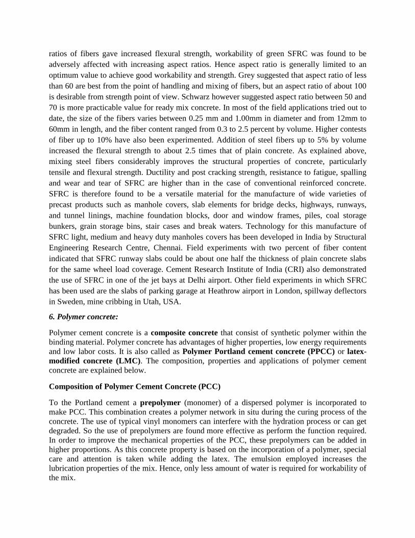
ratios of fibers gave increased flexural strength, workability of green SFRC was found to be
adversely affected with increasing aspect ratios. Hence aspect ratio is generally limited to an
optimum value to achieve good workability and strength. Grey suggested that aspect ratio of less
than 60 are best from the point of handling and mixing of fibers, but an aspect ratio of about 100
is desirable from strength point of view. Schwarz however suggested aspect ratio between 50 and
70 is more practicable value for ready mix concrete. In most of the field applications tried out to
date, the size of the fibers varies between 0.25 mm and 1.00mm in diameter and from 12mm to
60mm in length, and the fiber content ranged from 0.3 to 2.5 percent by volume. Higher contests
of fiber up to 10% have also been experimented. Addition of steel fibers up to 5% by volume
increased the flexural strength to about 2.5 times that of plain concrete. As explained above,
mixing steel fibers considerably improves the structural properties of concrete, particularly
tensile and flexural strength. Ductility and post cracking strength, resistance to fatigue, spalling
and wear and tear of SFRC are higher than in the case of conventional reinforced concrete.
SFRC is therefore found to be a versatile material for the manufacture of wide varieties of
precast products such as manhole covers, slab elements for bridge decks, highways, runways,
and tunnel linings, machine foundation blocks, door and window frames, piles, coal storage
bunkers, grain storage bins, stair cases and break waters. Technology for this manufacture of
SFRC light, medium and heavy duty manholes covers has been developed in India by Structural
Engineering Research Centre, Chennai. Field experiments with two percent of fiber content
indicated that SFRC runway slabs could be about one half the thickness of plain concrete slabs
for the same wheel load coverage. Cement Research Institute of India (CRI) also demonstrated
the use of SFRC in one of the jet bays at Delhi airport. Other field experiments in which SFRC
has been used are the slabs of parking garage at Heathrow airport in London, spillway deflectors
in Sweden, mine cribbing in Utah, USA.
6. Polymer concrete:
Polymer cement concrete is a composite concrete that consist of synthetic polymer within the
binding material. Polymer concrete has advantages of higher properties, low energy requirements
and low labor costs. It is also called as Polymer Portland cement concrete (PPCC) or latex-
modified concrete (LMC). The composition, properties and applications of polymer cement
concrete are explained below.
Composition of Polymer Cement Concrete (PCC)
To the Portland cement a prepolymer (monomer) of a dispersed polymer is incorporated to
make PCC. This combination creates a polymer network in situ during the curing process of the
concrete. The use of typical vinyl monomers can interfere with the hydration process or can get
degraded. So the use of prepolymers are found more effective as perform the function required.
In order to improve the mechanical properties of the PCC, these prepolymers can be added in
higher proportions. As this concrete property is based on the incorporation of a polymer, special
care and attention is taken while adding the latex. The emulsion employed increases the
lubrication properties of the mix. Hence, only less amount of water is required for workability of
the mix.
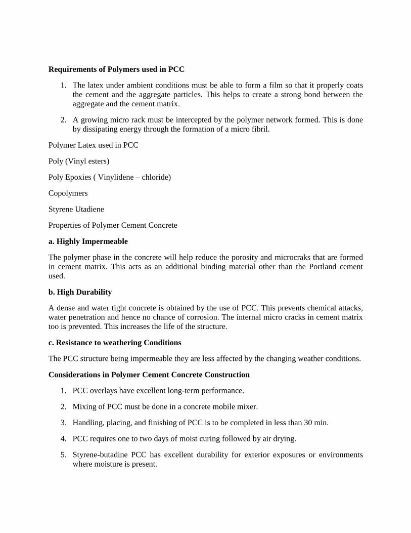
Requirements of Polymers used in PCC
1. The latex under ambient conditions must be able to form a film so that it properly coats
the cement and the aggregate particles. This helps to create a strong bond between the
aggregate and the cement matrix.
2. A growing micro rack must be intercepted by the polymer network formed. This is done
by dissipating energy through the formation of a micro fibril.
Polymer Latex used in PCC
Poly (Vinyl esters)
Poly Epoxies ( Vinylidene – chloride)
Copolymers
Styrene Utadiene
Properties of Polymer Cement Concrete
a. Highly Impermeable
The polymer phase in the concrete will help reduce the porosity and microcraks that are formed
in cement matrix. This acts as an additional binding material other than the Portland cement
used.
b. High Durability
A dense and water tight concrete is obtained by the use of PCC. This prevents chemical attacks,
water penetration and hence no chance of corrosion. The internal micro cracks in cement matrix
too is prevented. This increases the life of the structure.
c. Resistance to weathering Conditions
The PCC structure being impermeable they are less affected by the changing weather conditions.
Considerations in Polymer Cement Concrete Construction
1. PCC overlays have excellent long-term performance.
2. Mixing of PCC must be done in a concrete mobile mixer.
3. Handling, placing, and finishing of PCC is to be completed in less than 30 min.
4. PCC requires one to two days of moist curing followed by air drying.
5. Styrene-butadine PCC has excellent durability for exterior exposures or environments
where moisture is present.
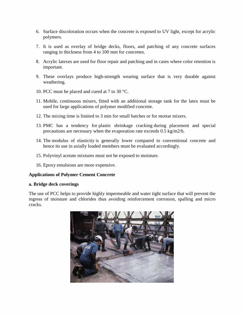
6. Surface discoloration occurs when the concrete is exposed to UV light, except for acrylic
polymers.
7. It is used as overlay of bridge decks, floors, and patching of any concrete surfaces
ranging in thickness from 4 to 100 mm for concretes.
8. Acrylic latexes are used for floor repair and patching and in cases where color retention is
important.
9. These overlays produce high-strength wearing surface that is very durable against
weathering.
10. PCC must be placed and cured at 7 to 30 °C.
11. Mobile, continuous mixers, fitted with an additional storage tank for the latex must be
used for large applications of polymer modified concrete.
12. The mixing time is limited to 3 min for small batches or for mortar mixers.
13. PMC has a tendency for plastic shrinkage cracking during placement and special
precautions are necessary when the evaporation rate exceeds 0.5 kg/m2/h.
14. The modulus of elasticity is generally lower compared to conventional concrete and
hence its use in axially loaded members must be evaluated accordingly.
15. Polyvinyl acetate mixtures must not be exposed to moisture.
16. Epoxy emulsions are more expensive.
Applications of Polymer Cement Concrete
a. Bridge deck coverings
The use of PCC helps to provide highly impermeable and water tight surface that will prevent the
ingress of moisture and chlorides thus avoiding reinforcement corrosion, spalling and micro
cracks.
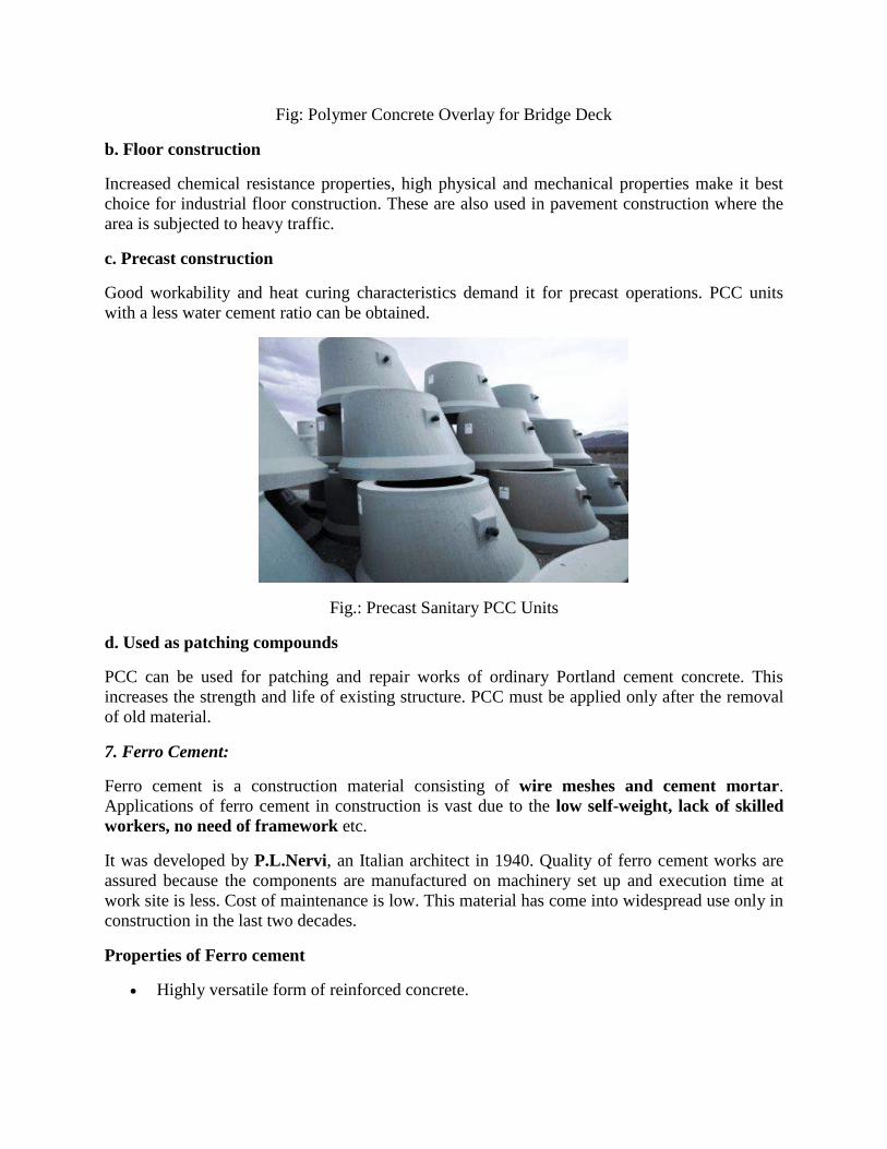
Fig: Polymer Concrete Overlay for Bridge Deck
b. Floor construction
Increased chemical resistance properties, high physical and mechanical properties make it best
choice for industrial floor construction. These are also used in pavement construction where the
area is subjected to heavy traffic.
c. Precast construction
Good workability and heat curing characteristics demand it for precast operations. PCC units
with a less water cement ratio can be obtained.
Fig.: Precast Sanitary PCC Units
d. Used as patching compounds
PCC can be used for patching and repair works of ordinary Portland cement concrete. This
increases the strength and life of existing structure. PCC must be applied only after the removal
of old material.
7. Ferro Cement:
Ferro cement is a construction material consisting of wire meshes and cement mortar.
Applications of ferro cement in construction is vast due to the low self-weight, lack of skilled
workers, no need of framework etc.
It was developed by P.L.Nervi, an Italian architect in 1940. Quality of ferro cement works are
assured because the components are manufactured on machinery set up and execution time at
work site is less. Cost of maintenance is low. This material has come into widespread use only in
construction in the last two decades.
Properties of Ferro cement
Highly versatile form of reinforced concrete.
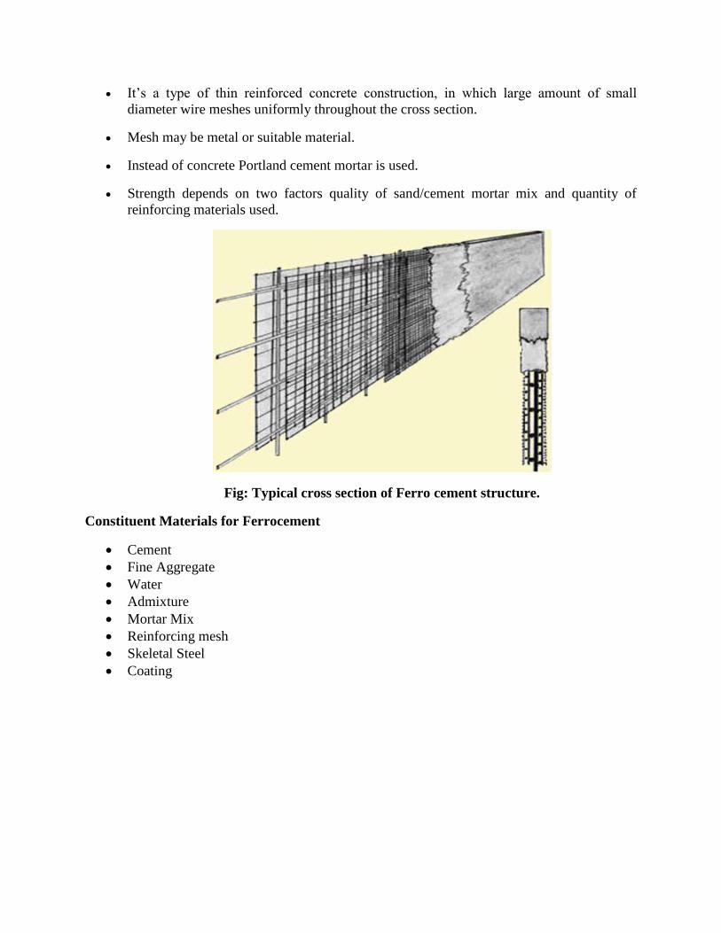
It’s a type of thin reinforced concrete construction, in which large amount of small
diameter wire meshes uniformly throughout the cross section.
Mesh may be metal or suitable material.
Instead of concrete Portland cement mortar is used.
Strength depends on two factors quality of sand/cement mortar mix and quantity of
reinforcing materials used.
Fig: Typical cross section of Ferro cement structure.
Constituent Materials for Ferrocement
Cement
Fine Aggregate
Water
Admixture
Mortar Mix
Reinforcing mesh
Skeletal Steel
Coating
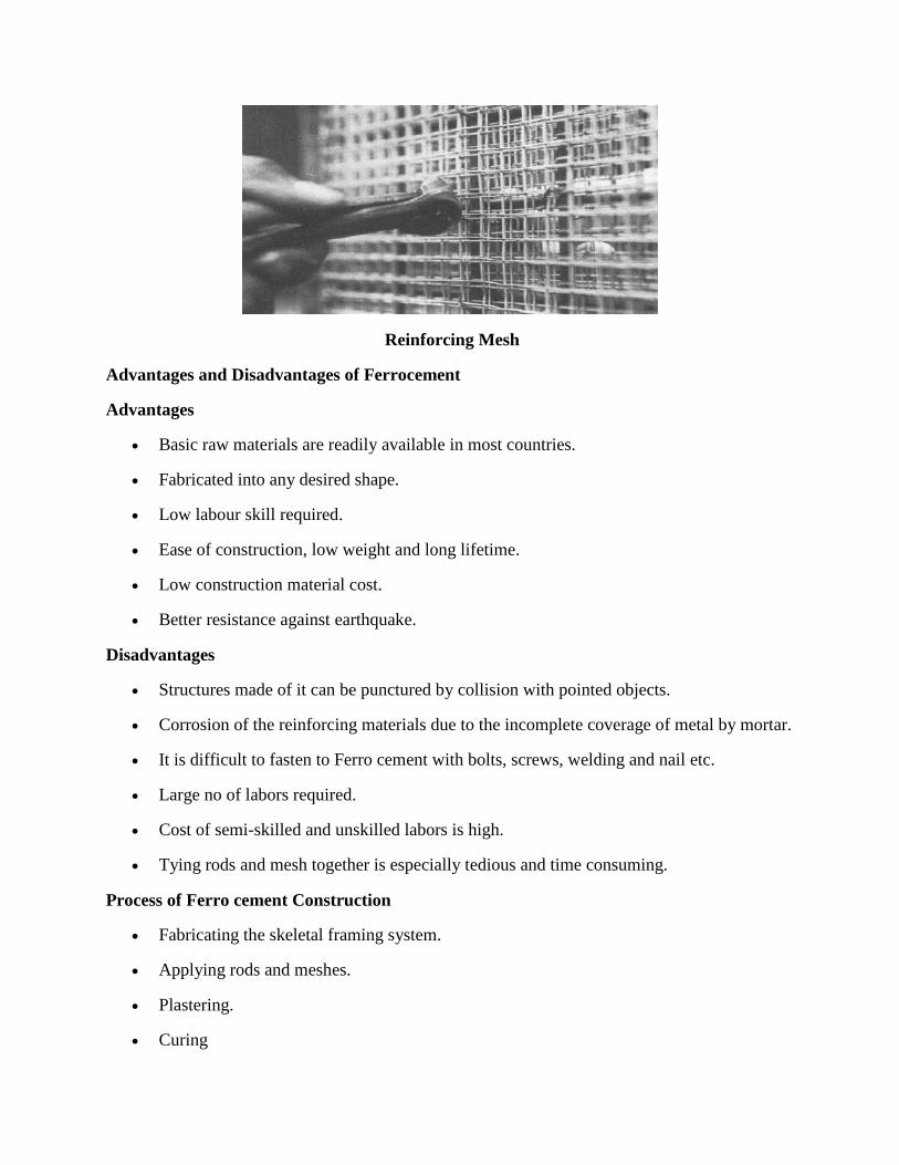
Reinforcing Mesh
Advantages and Disadvantages of Ferrocement
Advantages
Basic raw materials are readily available in most countries.
Fabricated into any desired shape.
Low labour skill required.
Ease of construction, low weight and long lifetime.
Low construction material cost.
Better resistance against earthquake.
Disadvantages
Structures made of it can be punctured by collision with pointed objects.
Corrosion of the reinforcing materials due to the incomplete coverage of metal by mortar.
It is difficult to fasten to Ferro cement with bolts, screws, welding and nail etc.
Large no of labors required.
Cost of semi-skilled and unskilled labors is high.
Tying rods and mesh together is especially tedious and time consuming.
Process of Ferro cement Construction
Fabricating the skeletal framing system.
Applying rods and meshes.
Plastering.
Curing
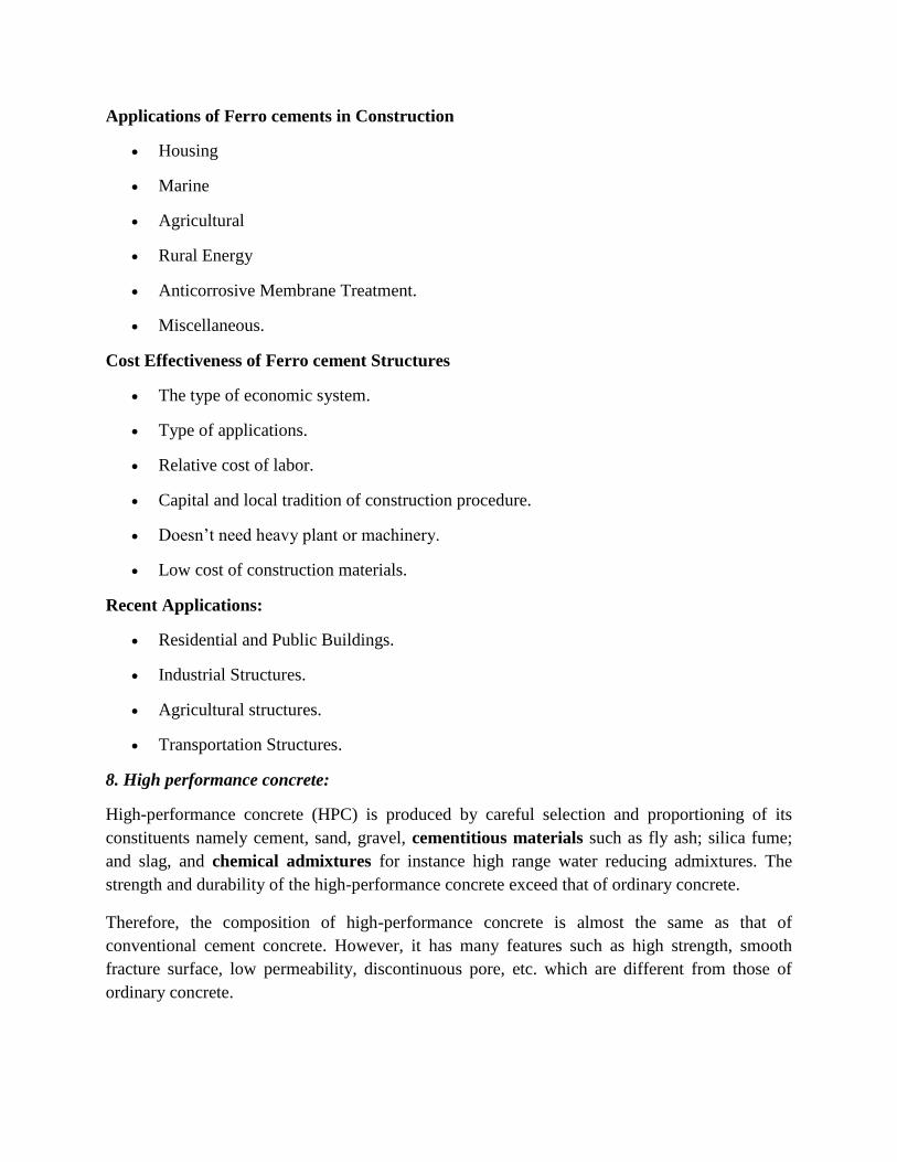
Applications of Ferro cements in Construction
Housing
Marine
Agricultural
Rural Energy
Anticorrosive Membrane Treatment.
Miscellaneous.
Cost Effectiveness of Ferro cement Structures
The type of economic system.
Type of applications.
Relative cost of labor.
Capital and local tradition of construction procedure.
Doesn’t need heavy plant or machinery.
Low cost of construction materials.
Recent Applications:
Residential and Public Buildings.
Industrial Structures.
Agricultural structures.
Transportation Structures.
8. High performance concrete:
High-performance concrete (HPC) is produced by careful selection and proportioning of its
constituents namely cement, sand, gravel, cementitious materials such as fly ash; silica fume;
and slag, and chemical admixtures for instance high range water reducing admixtures. The
strength and durability of the high-performance concrete exceed that of ordinary concrete.
Therefore, the composition of high-performance concrete is almost the same as that of
conventional cement concrete. However, it has many features such as high strength, smooth
fracture surface, low permeability, discontinuous pore, etc. which are different from those of
ordinary concrete.
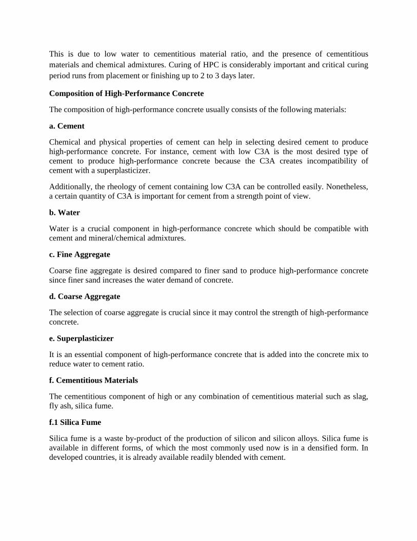
This is due to low water to cementitious material ratio, and the presence of cementitious
materials and chemical admixtures. Curing of HPC is considerably important and critical curing
period runs from placement or finishing up to 2 to 3 days later.
Composition of High-Performance Concrete
The composition of high-performance concrete usually consists of the following materials:
a. Cement
Chemical and physical properties of cement can help in selecting desired cement to produce
high-performance concrete. For instance, cement with low C3A is the most desired type of
cement to produce high-performance concrete because the C3A creates incompatibility of
cement with a superplasticizer.
Additionally, the rheology of cement containing low C3A can be controlled easily. Nonetheless,
a certain quantity of C3A is important for cement from a strength point of view.
b. Water
Water is a crucial component in high-performance concrete which should be compatible with
cement and mineral/chemical admixtures.
c. Fine Aggregate
Coarse fine aggregate is desired compared to finer sand to produce high-performance concrete
since finer sand increases the water demand of concrete.
d. Coarse Aggregate
The selection of coarse aggregate is crucial since it may control the strength of high-performance
concrete.
e. Superplasticizer
It is an essential component of high-performance concrete that is added into the concrete mix to
reduce water to cement ratio.
f. Cementitious Materials
The cementitious component of high or any combination of cementitious material such as slag,
fly ash, silica fume.
f.1 Silica Fume
Silica fume is a waste by-product of the production of silicon and silicon alloys. Silica fume is
available in different forms, of which the most commonly used now is in a densified form. In
developed countries, it is already available readily blended with cement.
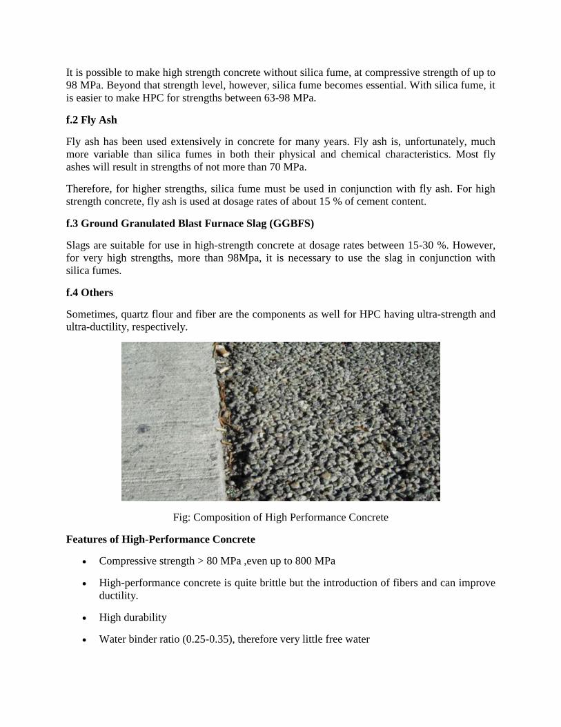
It is possible to make high strength concrete without silica fume, at compressive strength of up to
98 MPa. Beyond that strength level, however, silica fume becomes essential. With silica fume, it
is easier to make HPC for strengths between 63-98 MPa.
f.2 Fly Ash
Fly ash has been used extensively in concrete for many years. Fly ash is, unfortunately, much
more variable than silica fumes in both their physical and chemical characteristics. Most fly
ashes will result in strengths of not more than 70 MPa.
Therefore, for higher strengths, silica fume must be used in conjunction with fly ash. For high
strength concrete, fly ash is used at dosage rates of about 15 % of cement content.
f.3 Ground Granulated Blast Furnace Slag (GGBFS)
Slags are suitable for use in high-strength concrete at dosage rates between 15-30 %. However,
for very high strengths, more than 98Mpa, it is necessary to use the slag in conjunction with
silica fumes.
f.4 Others
Sometimes, quartz flour and fiber are the components as well for HPC having ultra-strength and
ultra-ductility, respectively.
Fig: Composition of High Performance Concrete
Features of High-Performance Concrete
Compressive strength > 80 MPa ,even up to 800 MPa
High-performance concrete is quite brittle but the introduction of fibers and can improve
ductility.
High durability
Water binder ratio (0.25-0.35), therefore very little free water
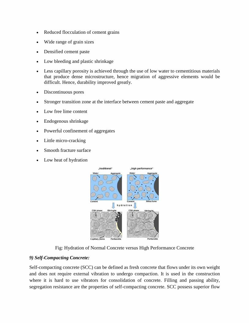
Reduced flocculation of cement grains
Wide range of grain sizes
Densified cement paste
Low bleeding and plastic shrinkage
Less capillary porosity is achieved through the use of low water to cementitious materials
that produce dense microstructure, hence migration of aggressive elements would be
difficult. Hence, durability improved greatly.
Discontinuous pores
Stronger transition zone at the interface between cement paste and aggregate
Low free lime content
Endogenous shrinkage
Powerful confinement of aggregates
Little micro-cracking
Smooth fracture surface
Low heat of hydration
Fig: Hydration of Normal Concrete versus High Performance Concrete
9) Self-Compacting Concrete:
Self-compacting concrete (SCC) can be defined as fresh concrete that flows under its own weight
and does not require external vibration to undergo compaction. It is used in the construction
where it is hard to use vibrators for consolidation of concrete. Filling and passing ability,
segregation resistance are the properties of self-compacting concrete. SCC possess superior flow
ability in its fresh state that performs self-compaction and material consolidation without
segregation issues. The materials, tests and properties of self-compacting concrete are explained
in the below sections.
Fig: Self Compacting Concrete (SCC)
Composition of Self-Compacting Concrete (SCC) are:
a. Cement
Ordinary Portland cement either 43 or 53 grade cement can be used.
b. Aggregates
The size of the aggregates used for SCC design is limited to 20mm. If the reinforcement
employed for the structure is congested, the aggregate size used can be in the range 10 to 12mm.
Well graded aggregates either round or cubical shape are a best choice. The fine aggregates used
in SCC can be either natural aggregates or manufactured aggregates (M- Sand) with a uniform
grade. The fine aggregates with particle size less than 0.125mm are generally employed.
c. Water
The quality of water used is same that followed for reinforced concrete and prestressed concrete
construction.
d. Mineral Admixtures
The mineral admixtures used can vary based on the mix design and properties required.
Mentioned below are the different mineral admixtures that can be used and their respective
properties they provide. Ground Granulated Blast Furnace Slag (GGBS): The use of GGBS helps
to improve the rheological properties of the self-compacting concrete. Fly ash: The fine fly ash
particles help to improve the filling of the internal concrete matrix with fewer pores. This
improves the quality and durability of the SCC structures. Silica Fumes: The use of silica fumes
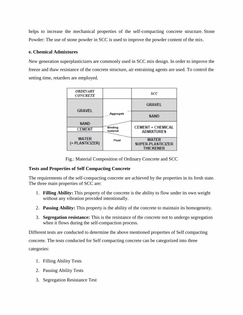
helps to increase the mechanical properties of the self-compacting concrete structure. Stone
Powder: The use of stone powder in SCC is used to improve the powder content of the mix.
e. Chemical Admixtures
New generation superplasticizers are commonly used in SCC mix design. In order to improve the
freeze and thaw resistance of the concrete structure, air entraining agents are used. To control the
setting time, retarders are employed.
Fig.: Material Composition of Ordinary Concrete and SCC
Tests and Properties of Self Compacting Concrete
The requirements of the self-compacting concrete are achieved by the properties in its fresh state.
The three main properties of SCC are:
1. Filling Ability: This property of the concrete is the ability to flow under its own weight
without any vibration provided intentionally.
2. Passing Ability: This property is the ability of the concrete to maintain its homogeneity.
3. Segregation resistance: This is the resistance of the concrete not to undergo segregation
when it flows during the self-compaction process.
Different tests are conducted to determine the above mentioned properties of Self compacting
concrete. The tests conducted for Self compacting concrete can be categorized into three
categories:
1. Filling Ability Tests
2. Passing Ability Tests
3. Segregation Resistance Test
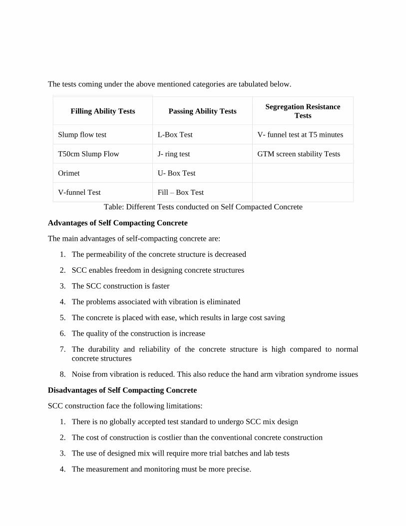
The tests coming under the above mentioned categories are tabulated below.
Filling Ability Tests Passing Ability Tests Segregation Resistance
Tests
Slump flow test L-Box Test V- funnel test at T5 minutes
T50cm Slump Flow J- ring test GTM screen stability Tests
Orimet U- Box Test
V-funnel Test Fill – Box Test
Table: Different Tests conducted on Self Compacted Concrete
Advantages of Self Compacting Concrete
The main advantages of self-compacting concrete are:
1. The permeability of the concrete structure is decreased
2. SCC enables freedom in designing concrete structures
3. The SCC construction is faster
4. The problems associated with vibration is eliminated
5. The concrete is placed with ease, which results in large cost saving
6. The quality of the construction is increase
7. The durability and reliability of the concrete structure is high compared to normal
concrete structures
8. Noise from vibration is reduced. This also reduce the hand arm vibration syndrome issues
Disadvantages of Self Compacting Concrete
SCC construction face the following limitations:
1. There is no globally accepted test standard to undergo SCC mix design
2. The cost of construction is costlier than the conventional concrete construction
3. The use of designed mix will require more trial batches and lab tests
4. The measurement and monitoring must be more precise.

5. The material selection for SCC is more stringent
Applications of Self Compacting Concrete
The major applications of self-compacting concrete are:
1. Construction of structures with complicated reinforcement
2. SCC is used for repairs, restoration and renewal construction
3. Highly stable and durable retaining walls are constructed with the help of SCC
4. SCC is employed in the construction of raft and pile foundations
############################
Civil Engineering Materials and Constructions (BCE03002)
Module-III
Basic Building Materials II
Module III Syllabus
Building stone: classifications, properties and structural requirements; Wood and Wood
products: Introduction to wood macrostructure, sap wood and heart wood, defects and
decay of timber, seasoning and preservation of timber, fire resisting treatment, introduction
to wood products- veneers, plywoods, fibre board, particle board, block board, batten
boards. Metals: Steel: Important properties and uses of Iron (Cast iron, wroght iron and
steel), Important tests on steel rebar, aluminum and copper. Glass: types and uses, Gypsum:
source, properties, uses; Plastic: properties and uses, Paint: types, distemper, varnish,
Adhesive: Types, Bitumen: types, properties and tests
Subject to Revision
1. BUILDING STONES:
(Classifications, properties and structural requirements)
A building stone is a piece of rock quarried and worked into a required size and shape for a
particular purpose. A building stone may be defined as a sound rock that can be safely used in
some situation in the construction as a massive dressed or undressed unit. Granites and marbles
used in the form of finely dressed blocks or slabs or columns in monumental and costly
buildings, are good building stones.
Similarly, sandstones and limestones used in forts, retaining walls and boundary walls and also
as blocks in stone houses and bungalows are typical building stones. Slates used in many areas
as roofing material for ordinary constructions and in pavements also fall in the category of
building stones.
Stone masonry is an engineering art that is preserved in many historical buildings in all
parts of the world. This skill is still used, though on a lesser scale (because of the advent of
concrete) in the construction of common residential houses and palatial buildings in many
places. The Taj Mahal at Agra, the Red Fort in Delhi and temples of Lord Jagannath puri
are some of the best known stone marvels of India. Such examples may be compiled from
all countries of the world and the number may run into many hundreds.
1.1 Classification of Building Stone:
Physical classification
o Stratified stone
o Unstratified stone
Geological classification
o Igneous Rocks
o Sedimentary Rocks
o Metamorphic Rocks
Scientific or engineering classification
o Silicious Rocks
o Argillaceous Rocks
o Calcareous Rocks
A particle of stone Classification
o Granite
o Sandstone
o Limestone
o Slate
Physical classification:
Stratified Stones
These stones are derived from sedimentary rocks. These stones are found in layers, one above
another Limestone and sandstones are the stratified stone.
Unstratified Stones
These stones do not show any types of layers. Granite, marble, trap, etc. are the unstratified
stones.
Geological classification:
Igneous Rocks
These are formed by the cooling of molten lava. The structure of stone depends upon the rate
of cooling of lava. This lava becomes hard on cooling and formed igneous rocks. These rocks
are durable, hard, massive and stronger than other stones. Example: Basalt, Trap, Andesite,
Rhyolite, Diorite, Granite.
Sedimentary Rocks
These are formed by the deposition of sediments due to the action of air and water. Due to
the action of high-speed wind and heavy rain, igneous rocks are disintegrated and deposited in
layers, one the earth crust and formed sedimentary rocks. Example: Limestone, Sandstone,
Dolomite and Slate are the sedimentary rocks.
Metamorphic rocks
These rocks are either the sedimentary rocks or the igneous rocks whose physical and chemical
properties are changed due to the action of high temperature and pressure. Dolomite, slate,
marble, gneiss are the metamorphic rocks. Example: Gneiss, Quartzite, Marble, Slate.
Scientific or engineering classification:
Silicious Rocks
These have silica as the principal constituent. These rocks are hardly affected by weathering
action. These are very hard and also durable. Granite, sandstone, gneiss, basalt, trap syenite
are the siliceous rocks.
Argillaceous rocks
These have clay as the principal constituent. These stones are hard and durable but brittle in
nature. Slate and laterite are the argillaceous rocks.
Calcareous Rocks
These have carbonate of lime as the principal constituent. Limestone, marble, kankar, dolomite,
and gravel are the calcareous rocks.
A particle of stone Classification:
Granite
The formation of minerals of granite is quartz, feldspar, and mica. It’s also having specific
gravity 2.63 to 2.75. They also having light or dark grey, pink or reddish color. It’s also having
a crushing strength of 1000 to 1400 kg/m2.
It also having light or dark grey, pink or reddish color. They also have a crushing strength of
1000 to 1400 kg/m2. It is very strong heavy, hard durable. It contains silica 60 to 80%.
Sandstone
Sandstone is composed of sand grains, cemented together by calcium or magnesium carbonate
or silicic acid, alumina, and also oxide of iron. It also has a specific gravity 2.25. They are also
white, grey, brown, or red in color. It’s having a crushing strength of 400 to 800 kg/m2.
These strong under pressure, but it is flaky when it contains mica. These are hard, non-
absorbent, strong, and heavy. They are easily workable and also resists the weathering in a
better way. They use to face work and ornamental work.
Limestone
These are carbonate of lime intermixed with other minerals and impurities such as silica,
magnesium carbonate, aluminum, and iron. It’s also having yellow, brown, grey or violet color.
It’s also having specific gravity 2.56. They having crushing strength 300 to 500 kg/m2.
These are soft and absorbent and so they do not resist the weathering action well. Chalk,
marbles are examples of limestone.
Slate
These are also composed of silica and alumina. These are also usually grey-black or dark blue.
It’s also having specific gravity 2.8. It’s also having crushing strength 700 to 2100 kg/m2.
When these are hard and tough, laminar in nature. It’s useful for roofing as well as flooring.
Some of the common building stones which are used for different purposes in India.
1. Granite
It is a deep-seated igneous rock, which is hard, durable and available in various
colours.
It has a high value of crushing strength and is capable of bearing high weathering.
Granite is used for bridge components, retaining walls, stone columns, road
metal, and ballast for railways, foundation, stone work and for coarse aggregates
in concrete. These stones can also be cut into slabs and polished to be used as
floor slabs and stone facing slabs.
Granite is found in Maharashtra, Rajasthan, Uttar Pradesh, Madhya Pradesh,
Punjab, Assam, Tamil Nadu, Karnataka and Kerala.
2. Basalt and Trap
They are originated from igneous rocks in the absence of pressure by the rapid
cooling of the magma.

They have the same uses as granite. Deccan trap is a popular stone of this group
in South India.
3. Limestone
It is a sedimentary rock formed by remnants of seaweeds and living organisms
consolidated and cemented together.
It contains a high percentage of calcium carbonate.
Limestone is used for flooring, roofing, and pavements and as a base material
for cement.
It is found in Maharashtra, Andhra Pradesh, Punjab, Himachal Pradesh and
Tamil Nadu.
4. Sandstone
This stone is another form of sedimentary rock formed by the action of mechanical
sediments.
It has a sandy structure which is low in strength and easy to dress.
They are used for ornamental works, paving and as road metal. It is available in
Madhya Pradesh, Rajasthan, Uttar Pradesh, Himachal Pradesh and Tamil Nadu.
5. Gneiss
It can be recognised by its elongated platy minerals usually mixed with mica and used
in the same way as granite.
They can be used for flooring, pavement and not for major purposes because of its
weakness.
It is found in Karnataka, Andhra Pradesh, Tamil Nadu and Gujarat.
6. Marble
It is a metamorphic rock which can be easily cut and carved into different shapes.
It is used for ornamental purposes, stone facing slabs, flooring, facing works etc.
It is found in Rajasthan, Gujarat and Andhra Pradesh.
7. Slate
It is a metamorphic rock which can be split easily and available in black colour.
It is used for damp-proofing flooring and roofing.
8. Quartzite
It is a metamorphic rock which is hard, brittle, crystalline and durable.
It is difficult to work with and used in the same way as granite but not recommended
for ornamental works as it is brittle.
9. Laterite
It is decomposed from igneous rocks; occur in soft and hard varieties.
It contains a high percentage of iron oxide and can be easily cut into blocks.
The soft variety is used for walls after curing while the hard blocks are used for
paving the pathways.
1.2 Properties and Structural requirements of building stone:
The following properties of the stones should be looked into before selecting them for
engineering works:
i. Strength
ii. Hardness
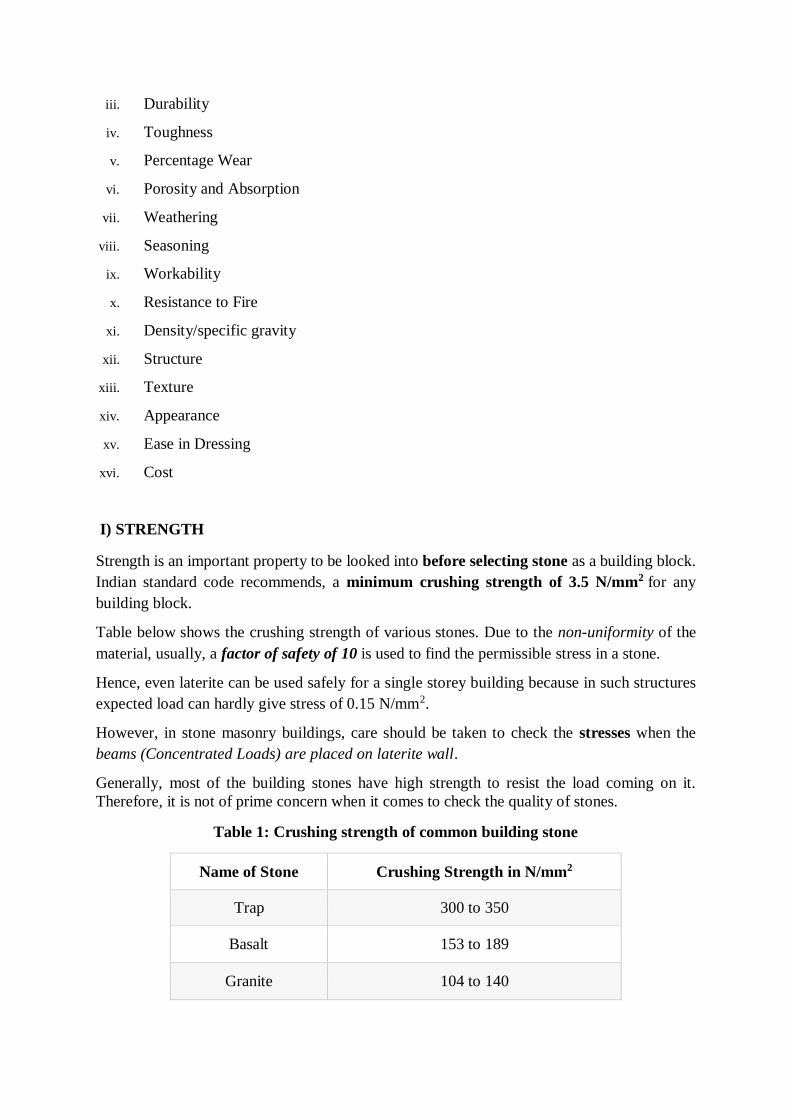
iii. Durability
iv. Toughness
v. Percentage Wear
vi. Porosity and Absorption
vii. Weathering
viii. Seasoning
ix. Workability
x. Resistance to Fire
xi. Density/specific gravity
xii. Structure
xiii. Texture
xiv. Appearance
xv. Ease in Dressing
xvi. Cost
I) STRENGTH
Strength is an important property to be looked into before selecting stone as a building block.
Indian standard code recommends, a minimum crushing strength of 3.5 N/mm2 for any
building block.
Table below shows the crushing strength of various stones. Due to the non-uniformity of the
material, usually, a factor of safety of 10 is used to find the permissible stress in a stone.
Hence, even laterite can be used safely for a single storey building because in such structures
expected load can hardly give stress of 0.15 N/mm2.
However, in stone masonry buildings, care should be taken to check the stresses when the
beams (Concentrated Loads) are placed on laterite wall.
Generally, most of the building stones have high strength to resist the load coming on it.
Therefore, it is not of prime concern when it comes to check the quality of stones.
Table 1: Crushing strength of common building stone
Name of Stone Crushing Strength in N/mm2
Trap 300 to 350
Basalt 153 to 189
Granite 104 to 140
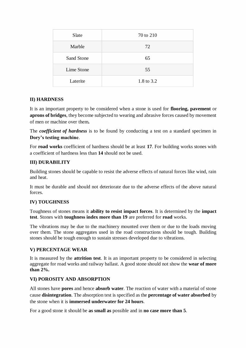
Slate 70 to 210
Marble 72
Sand Stone 65
Lime Stone 55
Laterite 1.8 to 3.2
II) HARDNESS
It is an important property to be considered when a stone is used for flooring, pavement or
aprons of bridges, they become subjected to wearing and abrasive forces caused by movement
of men or machine over them.
The coefficient of hardness is to be found by conducting a test on a standard specimen in
Dory’s testing machine.
For road works coefficient of hardness should be at least 17. For building works stones with
a coefficient of hardness less than 14 should not be used.
III) DURABILITY
Building stones should be capable to resist the adverse effects of natural forces like wind, rain
and heat.
It must be durable and should not deteriorate due to the adverse effects of the above natural
forces.
IV) TOUGHNESS
Toughness of stones means it ability to resist impact forces. It is determined by the impact
test. Stones with toughness index more than 19 are preferred for road works.
The vibrations may be due to the machinery mounted over them or due to the loads moving
over them. The stone aggregates used in the road constructions should be tough. Building
stones should be tough enough to sustain stresses developed due to vibrations.
V) PERCENTAGE WEAR
It is measured by the attrition test. It is an important property to be considered in selecting
aggregate for road works and railway ballast. A good stone should not show the wear of more
than 2%.
VI) POROSITY AND ABSORPTION
All stones have pores and hence absorb water. The reaction of water with a material of stone
cause disintegration. The absorption test is specified as the percentage of water absorbed by
the stone when it is immersed underwater for 24 hours.
For a good stone it should be as small as possible and in no case more than 5.
Porosity of building stones depend upon the mineral constituent and structural formation
of the parent rock.
If stones used in building construction are porous then rain water can easily enter into the
pore spaces and cause damage to the stones. Therefore, building stone should not be porous.
Water absorption of stone is directly proportional to the porosity of rock. If a stone is more
porous then it will absorb more water and cause more damage to stone.
In higher altitudes, the freezing of water in pores takes place and it results into the
disintegration of the stone.
VII) WEATHERING
Rain and wind cause loss of the good appearance of stones. Hence stones with good weather
resistance should be used for face works.
VIII) SEASONING
The stones obtained from the quarry contain moisture in the pores. The strength of the stone
improves if this moisture is removed before using the stone.
The process of removing moisture from pores is called seasoning. The best way
of seasoning is to allow it to the action of nature for 6 to 12 months. This is very much
required in the case of laterite stones.
Good stones should be free from the quarry sap. Lateritic stones should not be used for 6 to 12
months after quarrying. They are allowed to get rid of quarry sap by the action of nature. This
process of removing quarry sap is called seasoning.
IX) WORKABILITY
Stone is said to be workable when the work involved in stone working (such as cutting, dressing
& shaping) is economical and easy to conduct.
X) FIRE RESISTANCE
Stones should be free from calcium carbonate, oxides of iron, and minerals having different
coefficients of thermal expansion.
Igneous rock show marked disintegration principally because of quartz which disintegrates
into small particles at a temperature of about 575°C.
Limestone, however, can withstand a little higher temperature; i.e. up to 800°C after which
they disintegrate.
Sand-stones resist fire better. Argillaceous materials, though poor in strength, are good in
resisting fire.
XI) DENSITY / SPECIFIC GRAVITY
Denser stones are stronger. Light-weight stones are weak. Hence stones with a specific gravity
less than 2.4 are considered unsuitable for buildings.
The more the specific gravity of stone, the heavier and stronger the stone.

Therefore, stones having higher specific gravity values should be used for the construction
of dams, retaining walls, docks and harbours.
The specific gravity of good building stone is between 2.4 and 2.8.
XII) STRUCTURE
The structure of the stone may be stratified (layered) or unstratified. Structured stones should
be easily dressed and suitable for super-structure. Unstratified stones are hard and difficult
to dress. They are preferred for the foundation works.
XIII) TEXTURE
Fine grained stones with homogeneous distribution look attractive and hence they are used
for carving. Such stones are usually strong and durable.
XIV) APPEARANCE
A stone with uniform and attractive colour is durable if grains are compact. Marble and
granite get a very good appearance, when polished. Hence, they are used for face works in
buildings.
In case of the stones to be used for face works, where appearance is a primary requirement, its
colour and ability to receive polish is an important factor.
Light colour stones are more preferred than dark colour stones as the colour are likely to
fade out with time.
XV) EASE IN DRESSING
Giving required shape to the stone is called dressing.
The cost of dressing contributes to cost of stone masonry to a great extent. The dressing is easy
in stones with lesser strength.
Hence an engineer should look into sufficient strength rather than high strength while selecting
stones for building works.
XVI) COST
Cost is an important consideration in selecting a building material. The proximity of the
quarry to the building site brings down the cost of transportation and hence the cost of stones
comes down.
2. WOOD AND WOOD PRODUCTS
(Introduction to wood macrostructure, sap wood and heart wood, defects and decay of
timber, seasoning and preservation of timber, fire resisting treatment, introduction to wood
products- veneers, plywoods, fibre board, particle board, block board, batten boards)
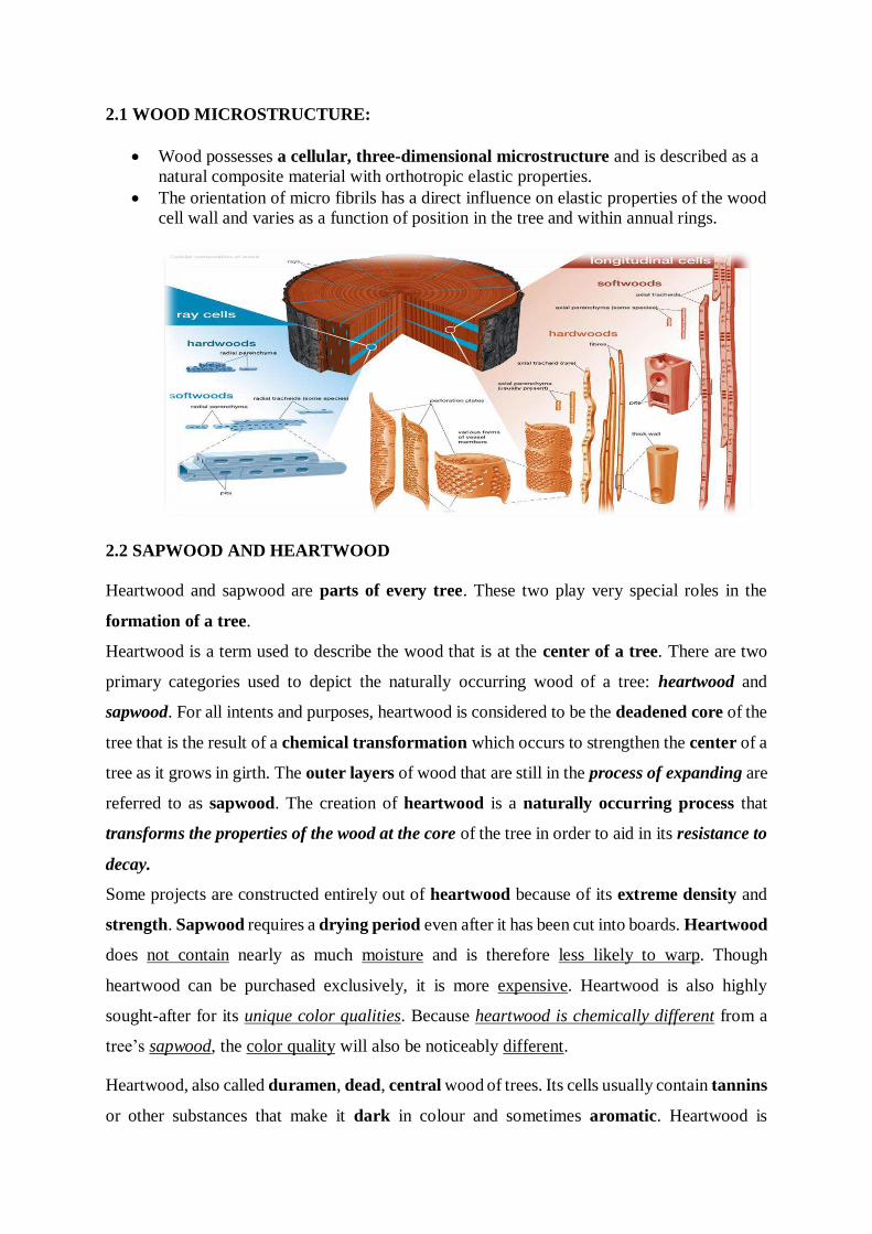
2.1 WOOD MICROSTRUCTURE:
Wood possesses a cellular, three-dimensional microstructure and is described as a
natural composite material with orthotropic elastic properties.
The orientation of micro fibrils has a direct influence on elastic properties of the wood
cell wall and varies as a function of position in the tree and within annual rings.
2.2 SAPWOOD AND HEARTWOOD
Heartwood and sapwood are parts of every tree. These two play very special roles in the
formation of a tree.
Heartwood is a term used to describe the wood that is at the center of a tree. There are two
primary categories used to depict the naturally occurring wood of a tree: heartwood and
sapwood. For all intents and purposes, heartwood is considered to be the deadened core of the
tree that is the result of a chemical transformation which occurs to strengthen the center of a
tree as it grows in girth. The outer layers of wood that are still in the process of expanding are
referred to as sapwood. The creation of heartwood is a naturally occurring process that
transforms the properties of the wood at the core of the tree in order to aid in its resistance to
decay.
Some projects are constructed entirely out of heartwood because of its extreme density and
strength. Sapwood requires a drying period even after it has been cut into boards. Heartwood
does not contain nearly as much moisture and is therefore less likely to warp. Though
heartwood can be purchased exclusively, it is more expensive. Heartwood is also highly
sought-after for its unique color qualities. Because heartwood is chemically different from a
tree’s sapwood, the color quality will also be noticeably different.
Heartwood, also called duramen, dead, central wood of trees. Its cells usually contain tannins
or other substances that make it dark in colour and sometimes aromatic. Heartwood is
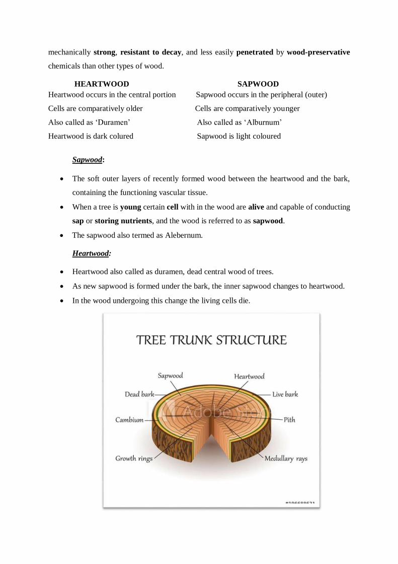
mechanically strong, resistant to decay, and less easily penetrated by wood-preservative
chemicals than other types of wood.
HEARTWOOD SAPWOOD
Heartwood occurs in the central portion Sapwood occurs in the peripheral (outer)
Cells are comparatively older Cells are comparatively younger
Also called as ‘Duramen’ Also called as ‘Alburnum’
Heartwood is dark colured Sapwood is light coloured
Sapwood:
The soft outer layers of recently formed wood between the heartwood and the bark,
containing the functioning vascular tissue.
When a tree is young certain cell with in the wood are alive and capable of conducting
sap or storing nutrients, and the wood is referred to as sapwood.
The sapwood also termed as Alebernum.
Heartwood:
Heartwood also called as duramen, dead central wood of trees.
As new sapwood is formed under the bark, the inner sapwood changes to heartwood.
In the wood undergoing this change the living cells die.
2.3 DEFECTS AND DECAY OF TIMBER:
Timber is a natural product and every natural product has some imperfections.
Most of the defects in timber cause weakness or others sorts of difficulties. However, some
defects can be beneficial for a specific type of work.
The followings are the five main types of defects in timber:
1. Defects due to Natural Forces
2. Defects due to Attack by Insects
3. Defects due to Fungi
4. Defects due to Defective Seasoning
5. Defects due to Defective Conversion
1) Defects in timber due to Natural Forces
Following defects are caused by natural forces:
Burls
Callus
Chemical stain
Coarse Grain
Deadwood
Druxiness
Foxiness
Knots
Rind galls
Shakes
Burls:
These formed when a tree has received shock or injury, the growth of the tree is completely
upset and irregular projections appear on the body of timber.
Callus: It indicates soft tissue or skin which covers the wound of a tree.
Chemical strain: The wood is sometimes discolored by the chemical action caused by some external agency.
This is known as the chemical strain.
Coarse grain:
If a tree grows rapidly, the annual rings are widened. It is known as coarse-grained timber and
such timber possesses less strength.
Deadwood: The timber which is obtained from dead standing trees contains dead wood. It is indicated by
lightweight and reddish color.
Druxiness:
This defect is indicated by white decayed spots that are concealed by healthy wood. They are
probably formed for the access of fungi.
Foxiness: This defect is indicated by red or yellow tinge (a colour) in wood or reddish-brown strain or
spots round the pith of tree discoloring the timber. It is caused either due to poor ventilation
during storage or by the commencement of decay due to over-maturity or due to the growth
of the tree in marshy soil.
Knots
These are the bases of branches or limbs which are broken or cut off from the tree. The portion
from which the branch is removed receives nourishment from the stem for a pretty long time
and it ultimately results in the formation of dark hard rings which are known as the knots. As
continuity of wood fibers is broken by knots, they form a source of weakness.
Rind galls: The rind means bark and gall indicates abnormal growth. It is an irregular growth cause the
fibers on wound fell after the branches have been cut off in an irregular manner.
Shakes: These are cracks that partly or completely separate the fibers of the wood. The following are
the different varieties of shakes.
Cup shakes
Heart shake
Ring shake
Star shake
Radial shake
2) Defects of timber due to insects:
Following are the insects which cause the decay of timber:
Termites.
Beetles.
Marine Borers
Termites:
These are popularly known as the white ants and they are found in abundance in tropical and
sub-tropical countries. These insects live in a colony and they are very fast in eating away the
wood from the core of the cross-section.
They make tunnels inside the timber in different directions and usually do not disturb the
outer shell or cover.
Beetles:
These are small insects and they cause rapid decay of timber. They form pin-holes of size
about 2mm diameter in wood. They attack the sapwood of all species of hardwoods.
Marine borers: These are generally found in salty water. Most of the varieties of marine borers do not feed
on wood. But they make holes or bore tunnels in wood for taking shelter.
3) Defects of timber due to Fungi:
The fungi are minute microscopic plane organisms.
Following defects of timber are caused in the timber by the fungi:
Dry rot
Wet Rot
Brown rot
White rot
Heart Rot
Sap strain
Blue stain
Dry rot:
The term rot is used to indicate the decay or disease of timber. The fungi of certain types feed
on Wood and during feeding, they attack on wood and convert it into dry powder form. This is
known as dry rot.
The dry rot occurs at places where there is no free circulation of air. The fungus rapidly dies
on exposure to air or sunlight. The unseasoned softwoods and sapwood are easily attacked by
dry rot.
When part of the timber is seriously affected by dry rot, the damaged portion may be
completely Removed and the remaining unaffected portion should be painted with a solution
of copper sulphate.
Wet rot:
When timber is subjected to alternate wet and dry conditions, decomposition of its tissue Takes
place and the timber is said to have been attacked by wet rot. The attacked part of timber gets
Reduced to a grayish brown powder Standing tree or timber exposed to rain is subjected to
attack
Wet rot can be avoided by the use of well-seasoned timber treated with preservatives.
Brown rot:
The fungi of certain types remove cellulose compounds from wood and hence the wood comes
brown in color. This is known as brown rot.
White rot:
The fungi of certain types of attack wood and the wood become a white mass consisting of
cellulose compounds.
Heart rot:
This is formed when the heartwood is exposed to the attack of atmospheric agents. Due to this,
the tree becomes weak and it gives out a hollow sound when struck with a hammer.
Sap stain:
The fungi of certain types do not bring about the complete decay of timber. But they feed on
cell contents of sapwood and the sapwood loses its color. This is known as the sap stain and it
generally occurs when moisture content goes beyond 25 percent or so.
Blue stain:
The sap of wood is stained to bluish color by the action of certain types of fungi.
4) Defects of timber due to seasoning:
Seasoning of Timber is a hydrothermal treatment of Timber, involving evaporation of
moisture content in required proportion i.e. controlled reduction of moisture from the wood.
Timber Seasoning increases the strength of timber, eliminates wood rot, prevents changes in
the dimensions and shape of the articles made of timber, and ultimately improves the quality
of finishing of timber.
This is necessary for reducing the unnecessary weight of timber, for effecting an increase in its
strength, to improve its workability, to reduce the possibility of development of shrinkage
defects and to ensure durability or long life of timber. The moisture content of standing trees
may be as high as 40-60 percent or even more.
After careful seasoning, it could be brought down to 4-6 percent by (kiln seasoning) or 14-16
percent by (air seasoning).
Methods of Seasoning of Timber
There are two methods of Seasoning of timber which are explained below
1. Natural seasoning (Air/water seasoning)
2. Artificial seasoning (Kiln seasoning)
Both methods require the timber be stacked and separated to allow the full circulation flow of
air, etc. around the stack.
Natural Seasoning of Timber
Natural seasoning is the process in which timber is seasoned by subjecting it to the natural
elements such as air or water. Natural seasoning may be water seasoning or air seasoning.
Water Seasoning
Water seasoning is the process in which timber is immersed in water flow which helps to
remove the sap present in the timber. It will take 2 to 4 weeks of time and after that the timber
is allowed to dry. Well-seasoned timber is ready to use. Sometimes logs are placed in running
water before subjecting to air seasoning. This helps in replacement of “sap” from wood cells
by water. The water-saturated wood dried quicker as compared to sap-rich wood. The process
of placing timber logs in water is sometimes referred to water-seasoning.
As already said trees contain a lot of moisture in the standing condition. The mode of
occurrence of water in wood issue is rather complex and must be understood thoroughly.
It is because a number of important properties of wood and timber depend on its moisture
content and the way in which it is present in the wood.
The wood tissue stores water in cell walls and the cell cavities.
(a) The water present in the cell walls is called the bound water, the hygroscopic water or the
imbibed water. It is this water, loss or gain of which will affect the dimensional stability of the
timber. It makes 25-30 percent of the dry weight of the wood tissue when all the cell walls are
fully saturated with water. This situation, in which all the cell walls of wood are fully saturated
with water (and the cavities are empty) is termed as fiber saturation point.
(b) The water present in the cell cavities of the wood tissue is called the free water. Its presence
effects the mechanical properties of the timber.
If the total moisture content in a species of timber is 75 percent, and its fiber saturation point
is 30 percent, then, the free water is 45 percent. Whenever a freshly cut wood log is laid for
drying, it is the free water (from the cell cavities) that is lost first. Once cell cavities are empty,
and drying is continued, then the water from the cell walls will start moving out due to drying
effect. And it is only the loss of water from the cell walls that will cause shrinkage in the wood.
Similarly, if a dry piece of wood is left out in a humid atmosphere, wood will start absorbing
moisture. (Because, as already said, wood is a hygroscopic material). Supposing the original
moisture content of the dry wood is only 6 percent and the humidity of the atmosphere is 40
percent, then the wood will go on absorbing moisture till its moisture content is the same as
that of the atmosphere in which it is exposed. This is called the “equilibrium moisture content”
of the wood.
When water is absorbed by the wood, it is the cell walls that must be saturated before the cell
cavities are allowed to get any water.
This is the reason doors and windows made of wood show swelling effect during rainy seasons
immediately after a few days of rains, especially when they are located where rain water can
fall directly on them.
Air Seasoning
In the process of air seasoning timber logs are arranged in layers in a shed. The arrangement is
done by maintaining some gap with the ground. So, platform is built on ground at 300mm
height from ground. In air seasoning, timber in properly cut forms is stacked in a proper
manner in the open air for losing moisture by process of evaporation.
The Stacks are so constructed to allow free circulation of air around each part as far as possible.
The stacks are properly sheltered from direct sun and winds and rain. It may take 6 months to
4 years for bringing down the original moisture content to allowable limits of 14-16 percent by
this method.
Artificial Seasoning of Timber
Natural seasoning gives good results but takes more time. So, artificial seasoning of timber is
developed nowadays. By artificial seasoning, timber is seasoned with in 4-5 days. Here also
different methods of artificial seasoning are there and they are as follows.
Seasoning by Boiling
Seasoning by boiling wood logs in hot water is called seasoning by boiling. Drying is
done after proper boiling. For a large amount of wood, it is done in an enclosed place
where hot steam is passed.
Chemical seasoning
In case of chemical seasoning, timber is stored in suitable salt solution for some time.
The salt solution used has the tendency to absorb water from the timber. So, the
moisture content is removed and then timber is allowed to drying. It affects the strength
of the timber.
Disadvantages:
Chemical seasoning agents can reduce the strength of wood and sometimes cause
problems in gluing and finishing or corrosion during use. Although large quantities
of wood treated with such chemicals have been used suc- cessfully for a variety of
purposes, some consideration should be given to these disadvantages
Kiln seasoning
In kiln seasoning, timber is dried for specific periods and under very controlled
conditions of temperature and humidity in specially designed kilns. Tunnel type kilns
can also be used for this purpose. Among the other methods of seasoning of timber and
wood, the chemical seasoning and electric seasoning are of some importance. Timber
can also be made fire proof to some extent by giving external coats and treatment of
fire retarding chemicals like sodium silicate, sodium arsenate or borax.
Electrical seasoning
The resistance of timber against electricity is measured at every interval of time. When
the required resistance is reached seasoning, process is stopped because resistance of
timber increases by reducing moisture content in it. It is also called as rapid
seasoning and it is uneconomical.
Objectives of Seasoning of Timber:
We may Summarize the objectives of seasoning of timber in five sentences:
1. Reduces much of the useless weight of timber;
2. Increases its strength considerably;
3. Improves the workability of the timber;
4.Decreases the chances of development of shrinkage defects, and,
5. Increases the life of timber, i.e. makes it more durable.
Following defects occur in the seasoning process of wood:
Cup
Case-hardening
Check
Collapse
Honey-combing
Radial slakes
Split
Twist
Warp
Cup:
This defect is indicated by the curvature formed in the transverse direction of timber.
Case-hardening:
The exposed surface of timber dries very rapidly. It therefore shrinks. The interior surface
which has not completely dried is under tension case-hardening and it usually occurs in timbers
which are placed at the bottom during seasoning.
Check:
A check is a crack that separates fibers of the wood. It does not extend from one end to the
Checks Surface checks: Shallow cracks extending along the grain on the face or cage.
Collapse: Due to uneven shrinkage, the wood sometimes flatters during drying. This is known as the
collapse
Honey-combing:
Due to stresses developed during drying, the various radial and circular cracks developed in
the interior portion of timber. The timber thus assumes the honey-comb texture and the defect
so developed is known as the honey-combing.
Radial shakes:
These are radial cracks.
Split:
When a check extends from one end to the other, it is known as a split.
Twist:
When a piece of timber has spirally distorted along its length, it is known as a twist.
Warp:
When a piece of timber has twisted out of shape, it is said to be warped
Defect in Timber due to Defective Seasoning
During seasoning of timber, exterior or surface layer of the timber dries before the interior
surface. So, stress is developed due to the difference in shrinkage.
a. Bow: Curvature formed in direction of the length of the timber is called bow.
b. Cup: Curvature formed in the transverse direction of the timber is called a cup.
c. Check: Check is a kind of crack that separates fibers, but it doesn’t extend from one
end to another.
d. Split: Split is a special type of check that extends from one end to another.
e. Honey Combing: Stress is developed in the heartwood during the drying process or
seasoning. For these stresses, cracks are created in the form of honeycomb texture.
5) Defects due to Defective Conversion:
During the process of converting timber to the commercial form, the following defects may
occur:
(i) Chip mark
(ii) Diagonal grain
(iii) Torn grain
(iv) Wane
(i) Chip Mark:
This defect is indicated by the marks or signs placed by chips on the finished surface of timber.
They may also be formed by the parts of a planning machine.
(ii) Diagonal Grain:
This defect is formed due to improper sawing of timber. It is indicated by diagonal mark on
straight grained surface of timber.
(iii) Torn Grain:
This defect is caused when a small depression is formed on the finished surface of timber by
falling of a tool or so.
(iv) Wane:
This defect is denoted by the presence of original rounded surface on the manufactured piece
of timber.
Defects of Timber due to Defective Conversion
a. Boxed Heart: This term is applied to the timber, which is sawn in a way that the pith
or the centre heart falls entirely within the surface throughout its length.
b. Machine Burnt: Overheating is the main reason for this defect.
c. Machine Notches: defective holding and pulling causes this defect.
d. Miscut: erroneous cutting or sawing of wood causes this defect. Lack of experience
in sawing and carelessness is the main reason for erroneous cutting.
e. Imperfect Grain: Mismatch in grain alignment.
2.4 PRESERVATION OF TIMBER
Preservation of timber is carried out to increase the life of timber. Preservation is done using
different types of preservatives. Methods and different materials used for preservation of
timber is discussed. Increasing life makes timber more durable and it can be used for longer
periods. Preservation also helps the timber to get rid of insects and fungi etc. If preservation is
not done, then wood will be diseased and damaged badly.
Properties of Good Preservative for Timber
The preservative used to protect the timber should contain following requirements or
properties.
It should be effortlessly and cheaply available.
It should not contain any harmful substances, gases etc.
It should cover larger area with small quantity. Hence, it should be economical.
Decorative treatment or any surface treatment should be allowed on timber after the
application of preservative.
Strength of timber should not be affected by the preservative.
It should not contain any unpleasant smell.
It should not get affected by light, heat, water etc.
It should not get affected by fungi, insects etc. and should also efficient to kill them.
It should not generate flame when contacts with fire.
It should not corrode metals when it makes a contact with them.
The depth of penetration of preservative in wood fibers should be minimum 6mm to
25mm
Different Types of Preservatives for Timber
Coal tar
ASCU
Chemical slats
Oil paints
Solignum paints
Creosote oil
Coal Tar for Preservation of Timber
Coal tar is heated and obtained liquid hot tar is applied on timber surface using brush. Coal tar
contains unpleasant smell and does not allow paint on it. So, it is used for door frames, window
frames etc. It is very cheap and has good fire resistance.
ASCU Preservative for Timber
ASCU is a special preservative which is available in powder form. It is dissolved in water to
get preservative solution. It should be added 6 parts by weight of ASCU in 100 parts by weight
of water. The final solution is applied on timber by spraying. This solution does not contain
any odor. It is useful mainly to get rid of from white ants. ASCU contains hydrated arsenic
pent oxide, copper sulphate or blue vitriol and sodium dichromate or potassium dichromate in
it. After applying ASCU, the timber can be coated with paint, varnished etc.
Chemical Slats for Preservation of Timber
Chemical salts like copper sulphate, mercury chloride and zinc chloride are used as
preservative which can be dissolved in water to get liquid solution. They are odorless and do
not generate flames when contact with fire.
Oil Paints Preservatives for Timber
Oil paints are suitable for well-seasoned wood. They are generally applied in 2 or 3 coats. Oil
paints prevents timber from moisture. If timber is not seasoned, then oil paints may lead to
decay of timber by confining sap.
Solignum Paints for Preservation of Timber
Solignum paints are applied in hot condition using brush. They are well suitable for preserving
timber from white ants. Solignum paints can be used by adding color pigments so, the timber
has good appearance.
Creosote Oil for Preservation of Timber
Creosote oil is prepared by the distillation of tar. It is black or brown in color. It contains
unpleasant smell. It is applied in a special manner. Firstly, the timber is well seasoned and
dried. Then, it is placed in airtight chamber and inside air is pumped out. Finally creosote oil
is pumped into the chamber with high pressure about 0.7 to 1 N/mm2 at a temperature of 50oC.
After allowing it for 2 hours, the timber absorbs creosote oil sufficiently and taken out from
the chamber. Creosote oil is flammable so, it is not used for timber works in fireplaces. It is
generally used for wood piles, poles, railway sleepers etc.
Methods of Timber Preservation
Brushing
Spraying
Injecting under pressure
Dipping and stepping
Charring
Hot and cold open tank treatment
Brushing of Timber Preservatives
Brushings the simplest method of applying preservatives. For well-seasoned timber, oil type
preservatives are applied with good quality brushes. For better results, the applied preservative
should in hot condition. Multiple coats should be applied and certain time interval should be
maintained between successive coats.
Spraying of Timber Preservatives
Spraying is an effective technique than brushing. In this case, preservative solution is sprayed
on to the surface using spray gun. It is time saving and quite effective.
Preservative Injecting Under Pressure
The preservative is injected into the timber under high pressure conditions. Generally, creosote
oil is applied in this manner which is already discussed above. It is costly treatment process
and required special treatment plant.
Dipping and Stepping Method of Timber Preservation
Dipping is another type of preserving in which, timber is dipped directly in the preservative
solution. Hence, the solution penetrates the timber better than the case of brushing or spraying.
In Some case, the stepping or wetting of timber with preservative solution is allowed for few
days or weeks which is also quite effective process.
Charring Method of Timber Preservation
Charring is nothing but burning of timber surface, which is quite an old method of preservation
of timber. In this method, the timber surface is wetted for 30 minutes and burnt up to a depth
of 15mm from top surface. The burnt surface protects the inner timber from white ants, fungi,
etc. This method is not suitable for exterior wood works so, it is applied for wood fencing poles,
telephone pole bottoms etc.
Hot and Cold Open Tank Treatment of Timber
In this method, the timber is placed in an open tank which contains preservative solution. This
solution is then heated for few hours at 85 to 95 degree Celsius. Then, the solution is allowed
to cool and timber gets submerged with this gradual cooling. This type of treatment is generally
done for sap wood.
2.5 FIRE RESISTING TREATMENT OF WOOD
Flame retardant treatment used to coat a wood surface or penetrate it into the wood to achieve
specific properties mainly include dipping, coating, spray, cover, hot pressing, ultrasonic wave
assistance and a high energy injection method.
As a general rule, the structural elements made of timber ignite and get rapidly destroyed in
case of a fire. Further, they add to the intensity of a fire. But the timber used in heavy sections
may attain high degree of fire-resistance because the timber is a very bad conductor of heat.
This is the reason why time is required to build up sufficient heat so as to cause a flame in the
timber.
With respect to the fire-resistance, the timber is classified as
1. Refractory Timber
2. Non-refractory Timber
Refractory Timber
The refractory timber is non-resinous and it does not catch fire easily. The examples of
refractory timbers are sal, teak, etc.
Non-refractory Timber
The non-refractory timber is resinous and it catches fire easily. The examples of non-
refractory timbers are chir, deodar, fir, etc.
To make timber more fire-resistant, the following methods are adopted:
A. Application of Special Chemicals:
The timber surface is coated with the solution of certain chemicals. The fire resistance
of timber can be enhanced by phosphates of ammonia, a mixture of ammonium
phosphates and ammonium sulphate, borax and boric acid, sodium arsenate etc. It is
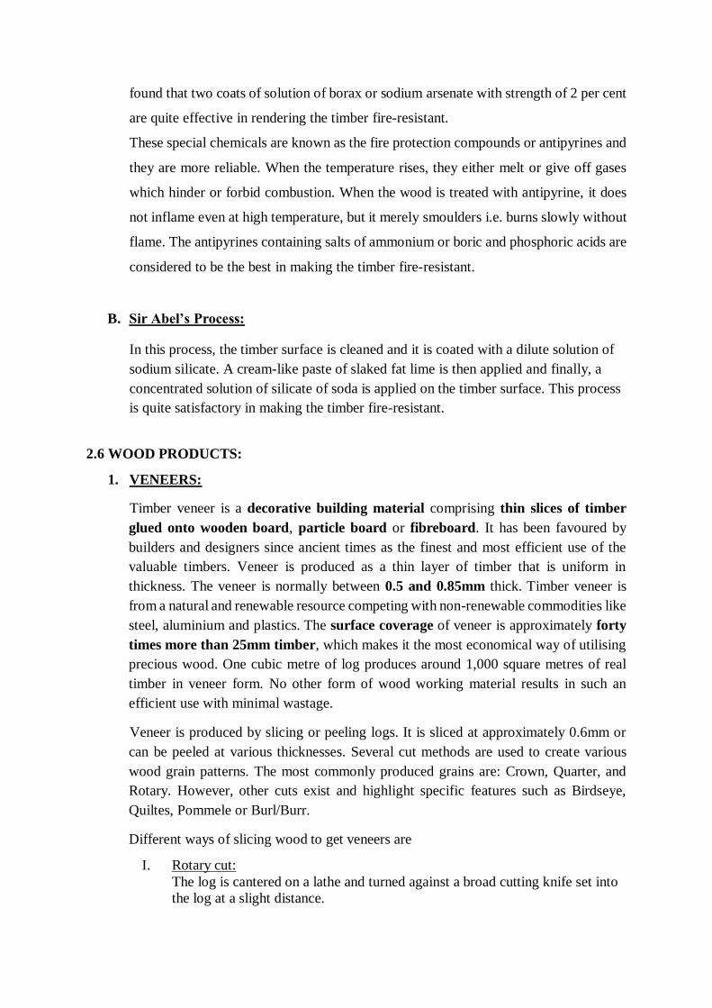
found that two coats of solution of borax or sodium arsenate with strength of 2 per cent
are quite effective in rendering the timber fire-resistant.
These special chemicals are known as the fire protection compounds or antipyrines and
they are more reliable. When the temperature rises, they either melt or give off gases
which hinder or forbid combustion. When the wood is treated with antipyrine, it does
not inflame even at high temperature, but it merely smoulders i.e. burns slowly without
flame. The antipyrines containing salts of ammonium or boric and phosphoric acids are
considered to be the best in making the timber fire-resistant.
B. Sir Abel’s Process:
In this process, the timber surface is cleaned and it is coated with a dilute solution of
sodium silicate. A cream-like paste of slaked fat lime is then applied and finally, a
concentrated solution of silicate of soda is applied on the timber surface. This process
is quite satisfactory in making the timber fire-resistant.
2.6 WOOD PRODUCTS:
1. VENEERS:
Timber veneer is a decorative building material comprising thin slices of timber
glued onto wooden board, particle board or fibreboard. It has been favoured by
builders and designers since ancient times as the finest and most efficient use of the
valuable timbers. Veneer is produced as a thin layer of timber that is uniform in
thickness. The veneer is normally between 0.5 and 0.85mm thick. Timber veneer is
from a natural and renewable resource competing with non-renewable commodities like
steel, aluminium and plastics. The surface coverage of veneer is approximately forty
times more than 25mm timber, which makes it the most economical way of utilising
precious wood. One cubic metre of log produces around 1,000 square metres of real
timber in veneer form. No other form of wood working material results in such an
efficient use with minimal wastage.
Veneer is produced by slicing or peeling logs. It is sliced at approximately 0.6mm or
can be peeled at various thicknesses. Several cut methods are used to create various
wood grain patterns. The most commonly produced grains are: Crown, Quarter, and
Rotary. However, other cuts exist and highlight specific features such as Birdseye,
Quiltes, Pommele or Burl/Burr.
Different ways of slicing wood to get veneers are
I. Rotary cut:
The log is cantered on a lathe and turned against a broad cutting knife set into
the log at a slight distance.

II. Quarter slicing:
The slicing is made perpendicular to the annual growth rings of the tree. This
creates a straight grain appearance.
III. Lengthwise slicing:
This is done from a board of flat sawn lumber rather than from a log. A
variegated figure is created with this slice.
IV. Plain slicing:
By slicing parallel to the centre of the log, a raised “cathedral effect” is formed
by the innermost growth rings.
V. Half round slicing:
Sliced on an arc parallel to the centre of the log, this cut achieves a flat-cut
veneer appearance.
VI. Rift cut:
This straight grain cut is derived by slicing red and white oak at a slight angle
to minimize the irregularities in the wood.

2. PLYWOODS:
Plywood is an engineered wood sheet material made up of fine layers or flimsy
strands of wood veneers attached together placing wood grains 90 degrees to one
another. It is one type of manufactured board which can be described as a mixture
of Medium Density Fibreboard (MDF) and Chip Board (Particle Board). It is a complex
material and attaches resin and fibre sheets of wood.
Plywood has become popular through this decade because it’s relatively low moisture
content which makes various tasks easy to perform with this. Mostly for outdoor uses
plywood has become very important to use.
Following are the different types of Plywood.
Softwood Plywood
Hardwood Plywood
Tropical Plywood
Aircraft Plywood
Decorative Plywood
Flexible Plywood
Marine Plywood
Softwood Plywood
Softwood Plywood which is also known as spruce-pine-fir or SPF because it’s from
spruce, pines, and fir. Though it can be made from cedar, douglas fir. If made from
spruce the prominent grains are coated by a system so that this kind of plywood
becomes more effective as hard as concrete and used for shuttering strands and
construction.
Hardwood Plywood
Hardwood Plywood is made from angiosperms. This type of plywood is identified by
its firmness, hardness on surface, inflexibility, resistance quality. This can be used to
bear heavy weight.
Tropical Plywood
Different types of timbers of tropical area are mixed to make this type of plywood.
Though previously it was only collected from the Asian region, now also from Africa
and America it is collected. Tropical plywood popular for some special qualities like
Strength
Density
Evenness
Inflexibility
Resistance quality
Thickness
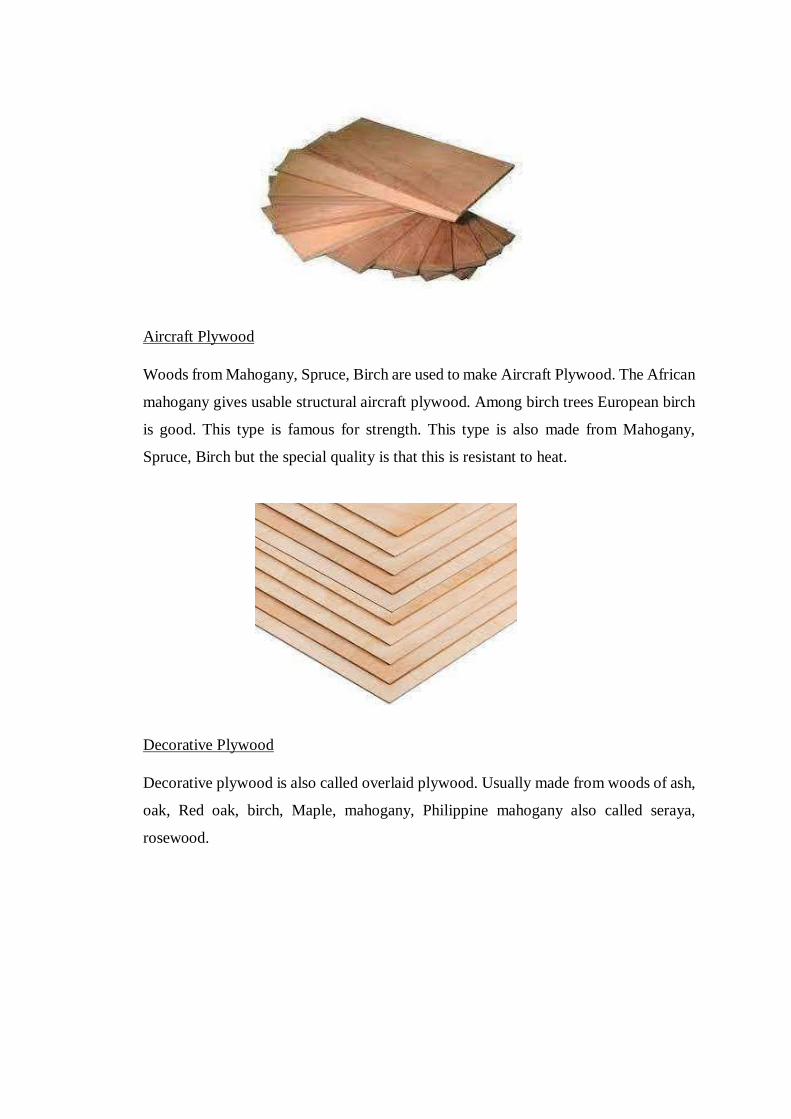
Aircraft Plywood
Woods from Mahogany, Spruce, Birch are used to make Aircraft Plywood. The African
mahogany gives usable structural aircraft plywood. Among birch trees European birch
is good. This type is famous for strength. This type is also made from Mahogany,
Spruce, Birch but the special quality is that this is resistant to heat.
Decorative Plywood
Decorative plywood is also called overlaid plywood. Usually made from woods of ash,
oak, Red oak, birch, Maple, mahogany, Philippine mahogany also called seraya,
rosewood.
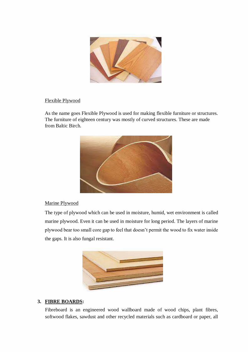
Flexible Plywood
As the name goes Flexible Plywood is used for making flexible furniture or structures.
The furniture of eighteen century was mostly of curved structures. These are made
from Baltic Birch.
Marine Plywood
The type of plywood which can be used in moisture, humid, wet environment is called
marine plywood. Even it can be used in moisture for long period. The layers of marine
plywood bear too small core gap to feel that doesn’t permit the wood to fix water inside
the gaps. It is also fungal resistant.
3. FIBRE BOARDS:
Fibreboard is an engineered wood wallboard made of wood chips, plant fibres,
softwood flakes, sawdust and other recycled materials such as cardboard or paper, all
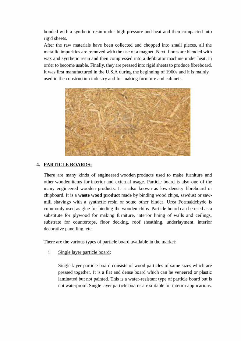
bonded with a synthetic resin under high pressure and heat and then compacted into
rigid sheets.
After the raw materials have been collected and chopped into small pieces, all the
metallic impurities are removed with the use of a magnet. Next, fibres are blended with
wax and synthetic resin and then compressed into a defibrator machine under heat, in
order to become usable. Finally, they are pressed into rigid sheets to produce fibreboard.
It was first manufactured in the U.S.A during the beginning of 1960s and it is mainly
used in the construction industry and for making furniture and cabinets.
4. PARTICLE BOARDS:
There are many kinds of engineered wooden products used to make furniture and
other wooden items for interior and external usage. Particle board is also one of the
many engineered wooden products. It is also known as low-density fibreboard or
chipboard. It is a waste wood product made by binding wood chips, sawdust or saw-
mill shavings with a synthetic resin or some other binder. Urea Formaldehyde is
commonly used as glue for binding the wooden chips. Particle board can be used as a
substitute for plywood for making furniture, interior lining of walls and ceilings,
substrate for countertops, floor decking, roof sheathing, underlayment, interior
decorative panelling, etc.
There are the various types of particle board available in the market:
i. Single layer particle board:
Single layer particle board consists of wood particles of same sizes which are
pressed together. It is a flat and dense board which can be veneered or plastic
laminated but not painted. This is a water-resistant type of particle board but is
not waterproof. Single layer particle boards are suitable for interior applications.
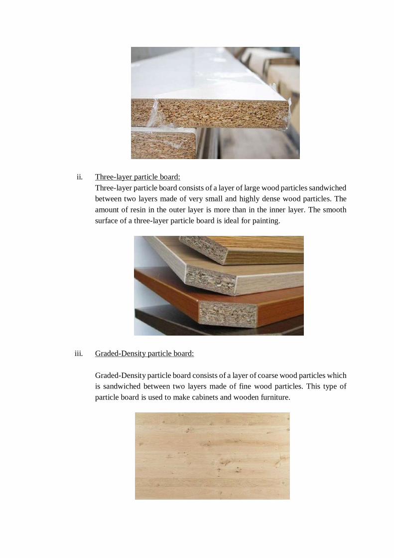
ii. Three-layer particle board:
Three-layer particle board consists of a layer of large wood particles sandwiched
between two layers made of very small and highly dense wood particles. The
amount of resin in the outer layer is more than in the inner layer. The smooth
surface of a three-layer particle board is ideal for painting.
iii. Graded-Density particle board:
Graded-Density particle board consists of a layer of coarse wood particles which
is sandwiched between two layers made of fine wood particles. This type of
particle board is used to make cabinets and wooden furniture.
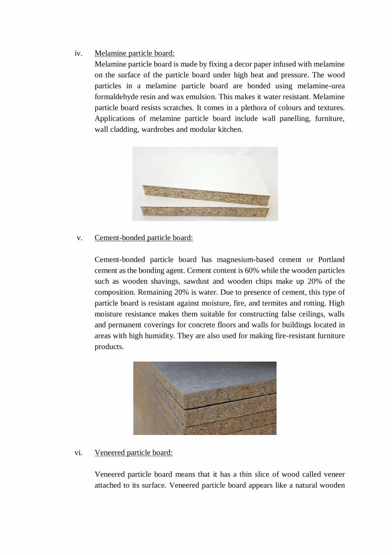
iv. Melamine particle board:
Melamine particle board is made by fixing a decor paper infused with melamine
on the surface of the particle board under high heat and pressure. The wood
particles in a melamine particle board are bonded using melamine-urea
formaldehyde resin and wax emulsion. This makes it water resistant. Melamine
particle board resists scratches. It comes in a plethora of colours and textures.
Applications of melamine particle board include wall panelling, furniture,
wall cladding, wardrobes and modular kitchen.
v. Cement-bonded particle board:
Cement-bonded particle board has magnesium-based cement or Portland
cement as the bonding agent. Cement content is 60% while the wooden particles
such as wooden shavings, sawdust and wooden chips make up 20% of the
composition. Remaining 20% is water. Due to presence of cement, this type of
particle board is resistant against moisture, fire, and termites and rotting. High
moisture resistance makes them suitable for constructing false ceilings, walls
and permanent coverings for concrete floors and walls for buildings located in
areas with high humidity. They are also used for making fire-resistant furniture
products.
vi. Veneered particle board:
Veneered particle board means that it has a thin slice of wood called veneer
attached to its surface. Veneered particle board appears like a natural wooden

board. Furthermore, a veneered particle board is also more resistant against
warping as compared to a conventional particle board.
vii. Laminated particle board:
When a thin laminate sheet is attached to the surface of a plain particle board, it
becomes a laminated particle board. Laminate sheet not only improves the
aesthetics of the particle board but also increases its durability.
5. BLOCK BOARD:
Block board is a type of plywood that is engineered in a special way. It is pressured in
such a way that the softwood strips are found between two layers of the wood veneers
in the core of the sheet. This contributes to the dimensional stability of the board. The
presence of softwood strips ensures that the board is able to hold nails
and screws better than the other engineered boards. Though it is lighter than plywood,
it does not split or splinter while cutting because of the presence of softwood in its
core.
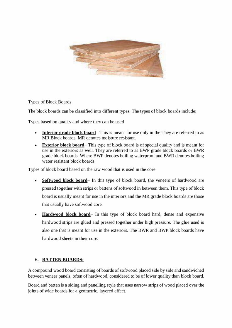
Types of Block Boards
The block boards can be classified into different types. The types of block boards include:
Types based on quality and where they can be used
Interior grade block board– This is meant for use only in the They are referred to as
MR Block boards. MR denotes moisture resistant.
Exterior block board– This type of block board is of special quality and is meant for
use in the exteriors as well. They are referred to as BWP grade block boards or BWR
grade block boards. Where BWP denotes boiling waterproof and BWR denotes boiling
water resistant block boards.
Types of block board based on the raw wood that is used in the core
Softwood block board– In this type of block board, the veneers of hardwood are
pressed together with strips or battens of softwood in between them. This type of block
board is usually meant for use in the interiors and the MR grade block boards are those
that usually have softwood core.
Hardwood block board– In this type of block board hard, dense and expensive
hardwood strips are glued and pressed together under high pressure. The glue used is
also one that is meant for use in the exteriors. The BWR and BWP block boards have
hardwood sheets in their core.
6. BATTEN BOARDS:
A compound wood board consisting of boards of softwood placed side by side and sandwiched
between veneer panels, often of hardwood, considered to be of lower quality than block board.
Board and batten is a siding and panelling style that uses narrow strips of wood placed over the
joints of wide boards for a geometric, layered effect.
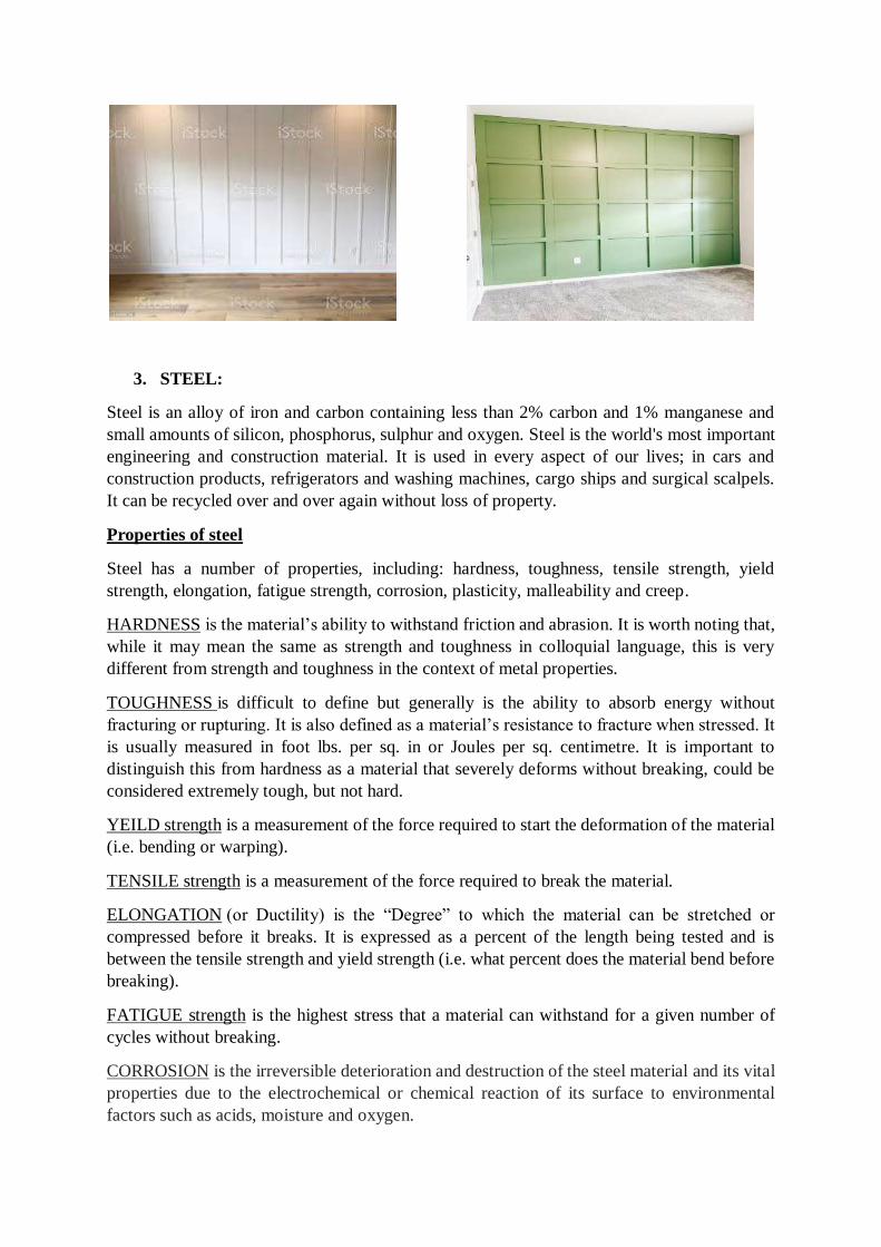
3. STEEL:
Steel is an alloy of iron and carbon containing less than 2% carbon and 1% manganese and
small amounts of silicon, phosphorus, sulphur and oxygen. Steel is the world's most important
engineering and construction material. It is used in every aspect of our lives; in cars and
construction products, refrigerators and washing machines, cargo ships and surgical scalpels.
It can be recycled over and over again without loss of property.
Properties of steel
Steel has a number of properties, including: hardness, toughness, tensile strength, yield
strength, elongation, fatigue strength, corrosion, plasticity, malleability and creep.
HARDNESS is the material’s ability to withstand friction and abrasion. It is worth noting that,
while it may mean the same as strength and toughness in colloquial language, this is very
different from strength and toughness in the context of metal properties.
TOUGHNESS is difficult to define but generally is the ability to absorb energy without
fracturing or rupturing. It is also defined as a material’s resistance to fracture when stressed. It
is usually measured in foot lbs. per sq. in or Joules per sq. centimetre. It is important to
distinguish this from hardness as a material that severely deforms without breaking, could be
considered extremely tough, but not hard.
YEILD strength is a measurement of the force required to start the deformation of the material
(i.e. bending or warping).
TENSILE strength is a measurement of the force required to break the material.
ELONGATION (or Ductility) is the “Degree” to which the material can be stretched or
compressed before it breaks. It is expressed as a percent of the length being tested and is
between the tensile strength and yield strength (i.e. what percent does the material bend before
breaking).
FATIGUE strength is the highest stress that a material can withstand for a given number of
cycles without breaking.
CORROSION is the irreversible deterioration and destruction of the steel material and its vital
properties due to the electrochemical or chemical reaction of its surface to environmental
factors such as acids, moisture and oxygen.
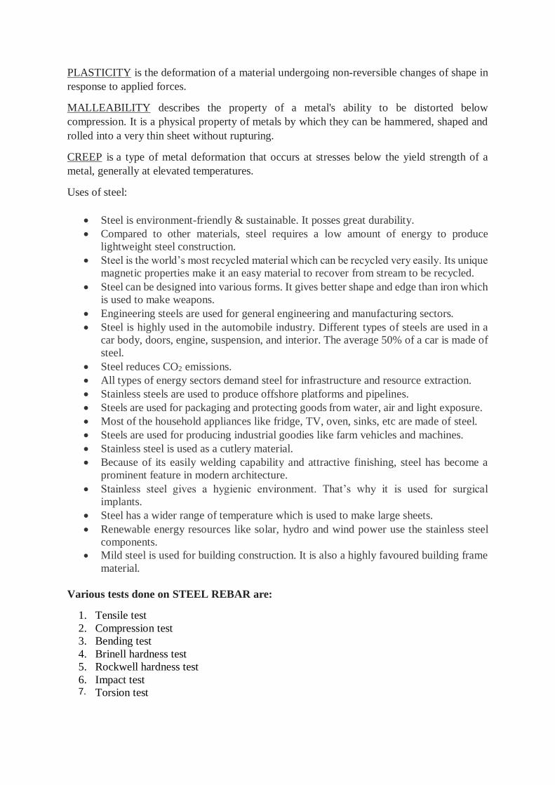
PLASTICITY is the deformation of a material undergoing non-reversible changes of shape in
response to applied forces.
MALLEABILITY describes the property of a metal's ability to be distorted below
compression. It is a physical property of metals by which they can be hammered, shaped and
rolled into a very thin sheet without rupturing.
CREEP is a type of metal deformation that occurs at stresses below the yield strength of a
metal, generally at elevated temperatures.
Uses of steel:
Steel is environment-friendly & sustainable. It posses great durability.
Compared to other materials, steel requires a low amount of energy to produce
lightweight steel construction.
Steel is the world’s most recycled material which can be recycled very easily. Its unique
magnetic properties make it an easy material to recover from stream to be recycled.
Steel can be designed into various forms. It gives better shape and edge than iron which
is used to make weapons.
Engineering steels are used for general engineering and manufacturing sectors.
Steel is highly used in the automobile industry. Different types of steels are used in a
car body, doors, engine, suspension, and interior. The average 50% of a car is made of
steel.
Steel reduces CO2 emissions.
All types of energy sectors demand steel for infrastructure and resource extraction.
Stainless steels are used to produce offshore platforms and pipelines.
Steels are used for packaging and protecting goods from water, air and light exposure.
Most of the household appliances like fridge, TV, oven, sinks, etc are made of steel.
Steels are used for producing industrial goodies like farm vehicles and machines.
Stainless steel is used as a cutlery material.
Because of its easily welding capability and attractive finishing, steel has become a
prominent feature in modern architecture.
Stainless steel gives a hygienic environment. That’s why it is used for surgical
implants.
Steel has a wider range of temperature which is used to make large sheets.
Renewable energy resources like solar, hydro and wind power use the stainless steel
components.
Mild steel is used for building construction. It is also a highly favoured building frame
material.
Various tests done on STEEL REBAR are:
1. Tensile test
2. Compression test
3. Bending test
4. Brinell hardness test
5. Rockwell hardness test
6. Impact test 7. Torsion test
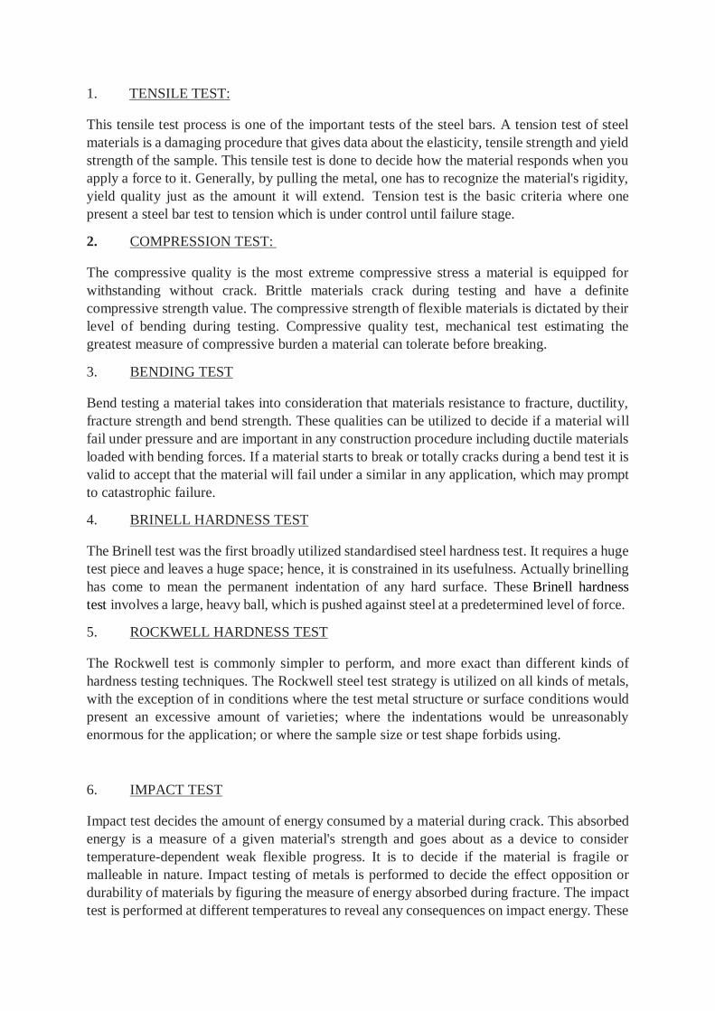
1. TENSILE TEST:
This tensile test process is one of the important tests of the steel bars. A tension test of steel
materials is a damaging procedure that gives data about the elasticity, tensile strength and yield
strength of the sample. This tensile test is done to decide how the material responds when you
apply a force to it. Generally, by pulling the metal, one has to recognize the material's rigidity,
yield quality just as the amount it will extend. Tension test is the basic criteria where one
present a steel bar test to tension which is under control until failure stage.
2. COMPRESSION TEST:
The compressive quality is the most extreme compressive stress a material is equipped for
withstanding without crack. Brittle materials crack during testing and have a definite
compressive strength value. The compressive strength of flexible materials is dictated by their
level of bending during testing. Compressive quality test, mechanical test estimating the
greatest measure of compressive burden a material can tolerate before breaking.
3. BENDING TEST
Bend testing a material takes into consideration that materials resistance to fracture, ductility,
fracture strength and bend strength. These qualities can be utilized to decide if a material will
fail under pressure and are important in any construction procedure including ductile materials
loaded with bending forces. If a material starts to break or totally cracks during a bend test it is
valid to accept that the material will fail under a similar in any application, which may prompt
to catastrophic failure.
4. BRINELL HARDNESS TEST
The Brinell test was the first broadly utilized standardised steel hardness test. It requires a huge
test piece and leaves a huge space; hence, it is constrained in its usefulness. Actually brinelling
has come to mean the permanent indentation of any hard surface. These Brinell hardness
test involves a large, heavy ball, which is pushed against steel at a predetermined level of force.
5. ROCKWELL HARDNESS TEST
The Rockwell test is commonly simpler to perform, and more exact than different kinds of
hardness testing techniques. The Rockwell steel test strategy is utilized on all kinds of metals,
with the exception of in conditions where the test metal structure or surface conditions would
present an excessive amount of varieties; where the indentations would be unreasonably
enormous for the application; or where the sample size or test shape forbids using.
6. IMPACT TEST
Impact test decides the amount of energy consumed by a material during crack. This absorbed
energy is a measure of a given material's strength and goes about as a device to consider
temperature-dependent weak flexible progress. It is to decide if the material is fragile or
malleable in nature. Impact testing of metals is performed to decide the effect opposition or
durability of materials by figuring the measure of energy absorbed during fracture. The impact
test is performed at different temperatures to reveal any consequences on impact energy. These

services give test results that can be helpful in evaluating the suitability of a material for a
specific application and in predicting its expected service life.
7. TORSION TEST
The reason for a torsion test is to decide the behaviour a material or test shows when turned or
under torsional forces because of applied moments that cause shear stress about the axis.
Measurable values include: the modulus of ductility, ultimate shear strength, elasticity in shear
modulus of rupture in shear, yield shear strength and torsional fatigue life. These values are
similar but not the same as those measured by a tensile test and are significant in assembling
as they might be utilized to simulate the service conditions, check the item's quality and
structure, and guarantee that it was made effectively.
4. CAST IRON:
Cast iron is a group of iron-carbon alloys with a carbon content of more than 2%. Its usefulness
derives from its relatively low melting temperature. Iron alloys with lower carbon content are
known as steel. Cast iron tends to be brittle, except for malleable cast irons.
Use of cast iron:
It is used in making pipes, to carry suitable fluids.
It is used in making different machines.
It is used in making automotive parts.
It is used in making pots pans and utensils.
It is used in making anchor for ships.
5. WROUGHT IRON
Wrought iron is a soft, ductile, fibrous variety that is produced from a semi-fused mass of
relatively pure iron globules partially surrounded by slag. It usually contains less than 0.1
percent carbon and 1 or 2 percent slag. It is superior for most purposes to cast iron, which is
overly hard and brittle owing to its high carbon content.
Use of wrought iron:
It is used to make decor items like table base, candle holder, curtain rods etc.
It is used in making pipes.
It is used in making fences and gates.
It is used in making nuts, bolts, rivets etc.
It is used in making chains.
It is used in making crane hooks.
It is used in making plates.
It is used in making handrails.
It is used in making carpenter tools.
It is used in general forging applications.
It is used in making railway couplings.
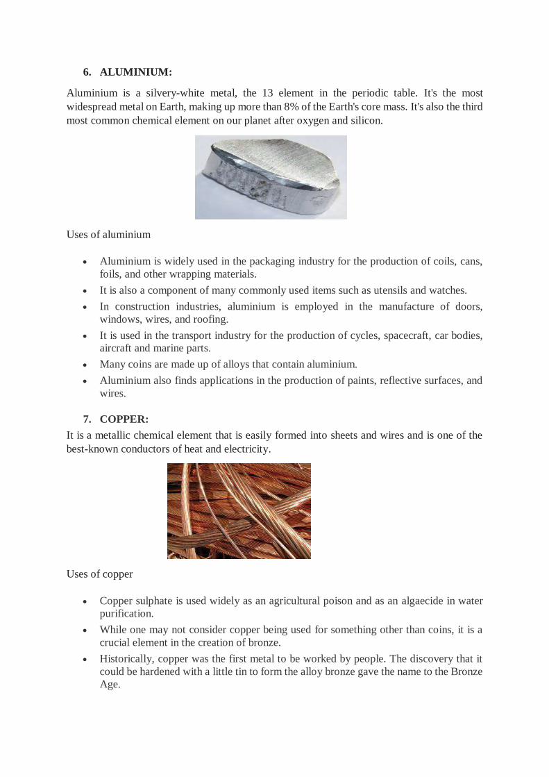
6. ALUMINIUM:
Aluminium is a silvery-white metal, the 13 element in the periodic table. It's the most
widespread metal on Earth, making up more than 8% of the Earth's core mass. It's also the third
most common chemical element on our planet after oxygen and silicon.
Uses of aluminium
Aluminium is widely used in the packaging industry for the production of coils, cans,
foils, and other wrapping materials.
It is also a component of many commonly used items such as utensils and watches.
In construction industries, aluminium is employed in the manufacture of doors,
windows, wires, and roofing.
It is used in the transport industry for the production of cycles, spacecraft, car bodies,
aircraft and marine parts.
Many coins are made up of alloys that contain aluminium.
Aluminium also finds applications in the production of paints, reflective surfaces, and
wires.
7. COPPER:
It is a metallic chemical element that is easily formed into sheets and wires and is one of the
best-known conductors of heat and electricity.
Uses of copper
Copper sulphate is used widely as an agricultural poison and as an algaecide in water
purification.
While one may not consider copper being used for something other than coins, it is a
crucial element in the creation of bronze.
Historically, copper was the first metal to be worked by people. The discovery that it
could be hardened with a little tin to form the alloy bronze gave the name to the Bronze
Age.
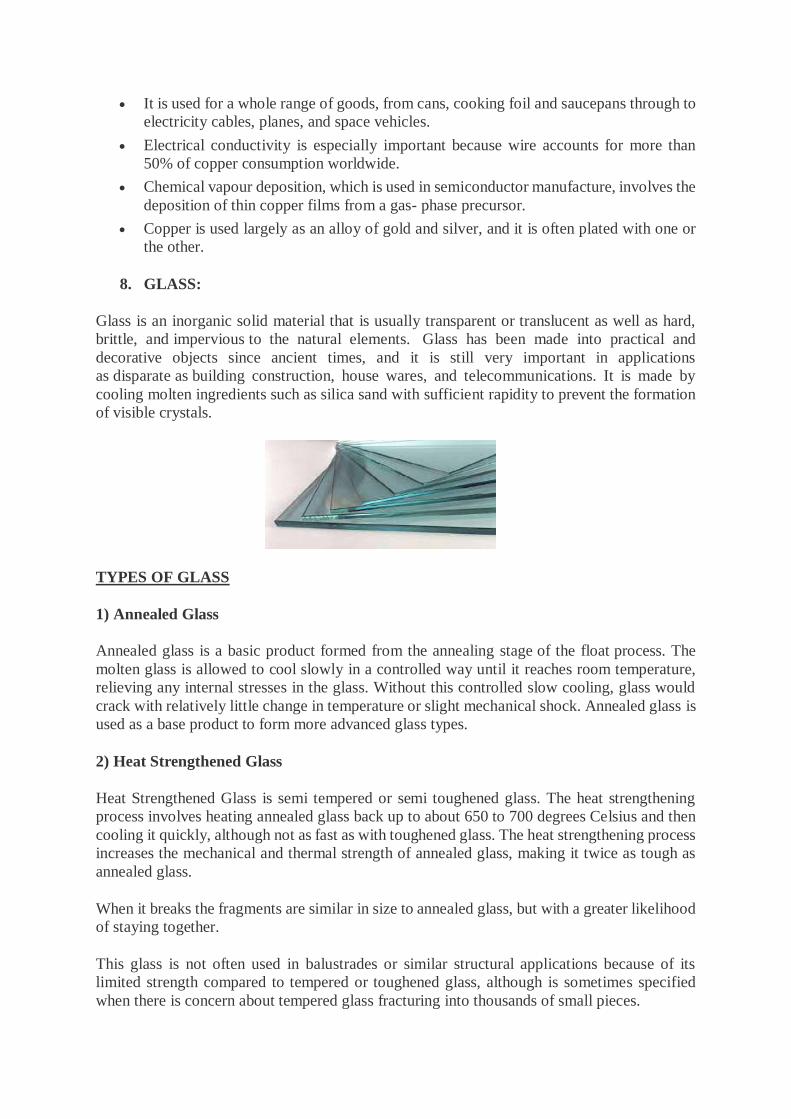
It is used for a whole range of goods, from cans, cooking foil and saucepans through to
electricity cables, planes, and space vehicles.
Electrical conductivity is especially important because wire accounts for more than
50% of copper consumption worldwide.
Chemical vapour deposition, which is used in semiconductor manufacture, involves the
deposition of thin copper films from a gas- phase precursor.
Copper is used largely as an alloy of gold and silver, and it is often plated with one or
the other.
8. GLASS:
Glass is an inorganic solid material that is usually transparent or translucent as well as hard,
brittle, and impervious to the natural elements. Glass has been made into practical and
decorative objects since ancient times, and it is still very important in applications
as disparate as building construction, house wares, and telecommunications. It is made by
cooling molten ingredients such as silica sand with sufficient rapidity to prevent the formation
of visible crystals.
TYPES OF GLASS
1) Annealed Glass
Annealed glass is a basic product formed from the annealing stage of the float process. The
molten glass is allowed to cool slowly in a controlled way until it reaches room temperature,
relieving any internal stresses in the glass. Without this controlled slow cooling, glass would
crack with relatively little change in temperature or slight mechanical shock. Annealed glass is
used as a base product to form more advanced glass types.
2) Heat Strengthened Glass
Heat Strengthened Glass is semi tempered or semi toughened glass. The heat strengthening
process involves heating annealed glass back up to about 650 to 700 degrees Celsius and then
cooling it quickly, although not as fast as with toughened glass. The heat strengthening process
increases the mechanical and thermal strength of annealed glass, making it twice as tough as
annealed glass.
When it breaks the fragments are similar in size to annealed glass, but with a greater likelihood
of staying together.
This glass is not often used in balustrades or similar structural applications because of its
limited strength compared to tempered or toughened glass, although is sometimes specified
when there is concern about tempered glass fracturing into thousands of small pieces.

3) Tempered or Toughened Glass
This is the most common type of glass used in balustrades or similar structural applications.
Annealed glass is heated to about 700 degrees Celsius by conduction, convection and
radiation. The cooling process is accelerated by a uniform and simultaneous blast of air on
both surfaces. The different cooling rates between the surface and the inside of the glass
produces different physical properties, resulting in compressive stresses in the surface balanced
by tensile stresses in the body of the glass.
This process makes the glass four to five times stronger and safer than annealed or untreated
glass.
The counteracting stresses or surface compression gives toughened glass its increased
mechanical resistance to breakage, and when it does break, causes it to produce small, regular,
typically square fragments rather than long, dangerous shards that are far more likely to lead
to injuries.
4) Laminated Glass
Any one of the above types of glass can be laminated. The most commonly used finished
product is two sheets of toughened glass, laminated together with a 1.52mm thick Polyiynil
Butyral (PVB) interlayer.
Laminated glass offers many advantages. Safety and security are the best known of these, so
rather than shattering on impact, laminated glass is held together by the interlayer. This reduces
the safety hazard associated with shattered glass fragments, as well as, to some degree, the
security risks associated with easy penetration.
Glass is used for following
Packaging (jars for food, bottles for drinks, flacon for cosmetics and pharmaceuticals)
Tableware (drinking glasses, plate, cups, bowls)
Housing and buildings (windows, facades, conservatory, insulation, reinforcement
structures)
Interior design and furniture (mirrors, partitions, balustrades, tables, shelves, lighting)
Appliances and Electronics (oven doors, cook top, TV, computer screens, smart-
phones)
Automotive and transport (windscreens, backlights, light weight but reinforced
structural components of cars, aircrafts, ships, etc.)
Medical technology, biotechnology, life science engineering, optical glass
Radiation protection from X-Rays (radiology) and gamma-rays (nuclear)
Fibre optic cables (phones, TV, computer: to carry information)
Renewable energy (solar-energy glass, wind turbines)
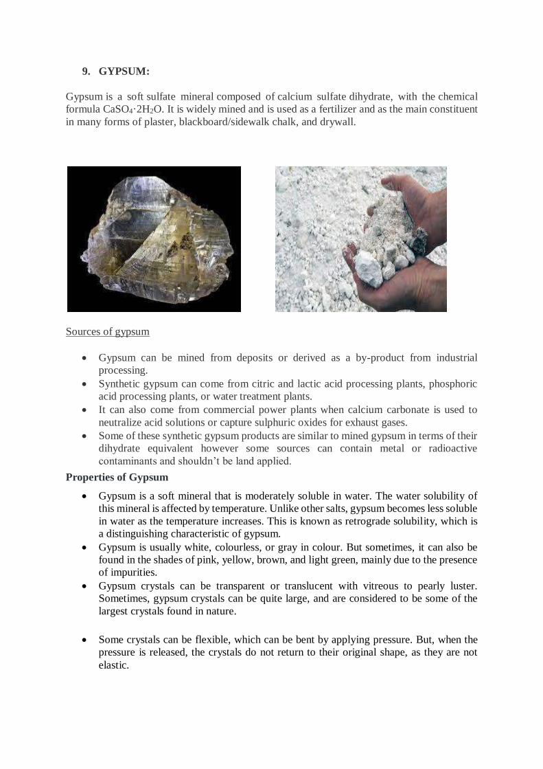
9. GYPSUM:
Gypsum is a soft sulfate mineral composed of calcium sulfate dihydrate, with the chemical
formula CaSO4·2H2O. It is widely mined and is used as a fertilizer and as the main constituent
in many forms of plaster, blackboard/sidewalk chalk, and drywall.
Sources of gypsum
Gypsum can be mined from deposits or derived as a by-product from industrial
processing.
Synthetic gypsum can come from citric and lactic acid processing plants, phosphoric
acid processing plants, or water treatment plants.
It can also come from commercial power plants when calcium carbonate is used to
neutralize acid solutions or capture sulphuric oxides for exhaust gases.
Some of these synthetic gypsum products are similar to mined gypsum in terms of their
dihydrate equivalent however some sources can contain metal or radioactive
contaminants and shouldn’t be land applied.
Properties of Gypsum
Gypsum is a soft mineral that is moderately soluble in water. The water solubility of
this mineral is affected by temperature. Unlike other salts, gypsum becomes less soluble
in water as the temperature increases. This is known as retrograde solubility, which is
a distinguishing characteristic of gypsum.
Gypsum is usually white, colourless, or gray in colour. But sometimes, it can also be
found in the shades of pink, yellow, brown, and light green, mainly due to the presence
of impurities.
Gypsum crystals can be transparent or translucent with vitreous to pearly luster.
Sometimes, gypsum crystals can be quite large, and are considered to be some of the
largest crystals found in nature.
Some crystals can be flexible, which can be bent by applying pressure. But, when the
pressure is released, the crystals do not return to their original shape, as they are not
elastic.
Gypsum crystals are sometimes found to occur in a form that resembles the petals of a
flower. This type of formation is referred to as ‘desert rose’, as they mostly occur in
arid areas or desert terrains.
Uses of Gypsums – Some of the Important Uses of Gypsums Include:
1. Building materials industry:
The largest user of gypsums is the building materials industry, which is used to produce all
kinds of building materials and as raw materials for cement and cementing materials.
The production of gypsum partition board, load-bearing inner wallboard, external wall block,
wall covering board, ceiling and so on.
2. Model plaster:
Model gypsum can be used in foundry, art, ceramics and other industries.
3. Agriculture:
It can be used to produce sulphuric acid and ammonium sulfate fertilizer.
Anhydrite can adjust soil pH, improve the soil environment, and provide calcium, sulfur and
other nutrients for various fertilizers.
4. Food industry:
In terms of food, gypsum can coagulate soybean milk into tofu, and it can also be used as a
coagulant in canned tomatoes.
5. Pharmaceutical industry:
Plaster external fixation is still the basic method for clinical treatment of fractures and various
orthopaedic diseases.
It has the functions of maintaining, fixing and maintaining the special posture of the affected
limb, reducing or eliminating the weight-bearing of the affected area, and so on.
6. Fillers for plastics and rubber:
After processing, anhydrite can be used as a filler for plastics and rubber.
The modified anhydrite filler can improve the mechanical strength, heat resistance and
dimensional stability of the polymer.
7. Production of calcium sulfate whisker:
Gypsum can be transformed into a calcium sulfate whisker in an aqueous medium under the
conditions of high temperature and high pressure.
Calcium sulfate whisker can be used as reinforced filler in resin matrix composites, friction
materials, binders and other industries.
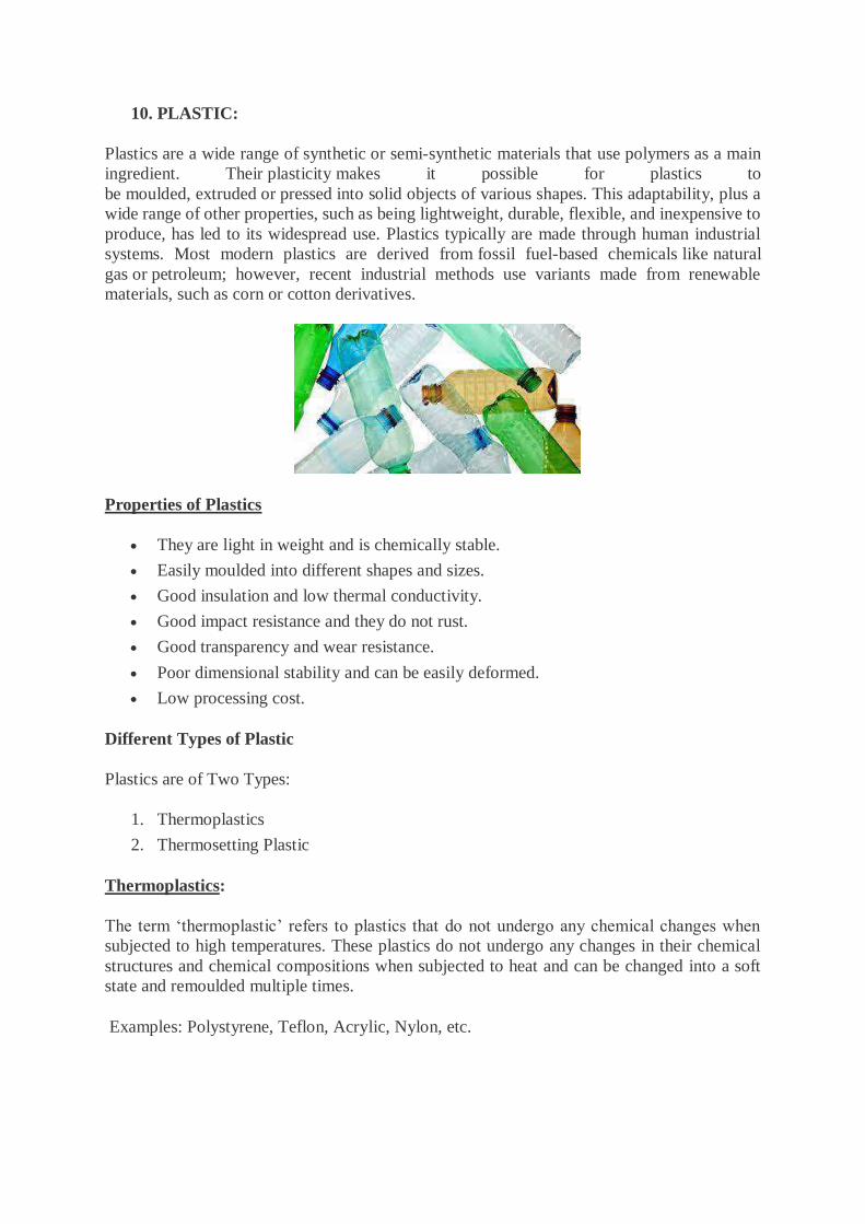
10. PLASTIC:
Plastics are a wide range of synthetic or semi-synthetic materials that use polymers as a main
ingredient. Their plasticity makes it possible for plastics to
be moulded, extruded or pressed into solid objects of various shapes. This adaptability, plus a
wide range of other properties, such as being lightweight, durable, flexible, and inexpensive to
produce, has led to its widespread use. Plastics typically are made through human industrial
systems. Most modern plastics are derived from fossil fuel-based chemicals like natural
gas or petroleum; however, recent industrial methods use variants made from renewable
materials, such as corn or cotton derivatives.
Properties of Plastics
They are light in weight and is chemically stable.
Easily moulded into different shapes and sizes.
Good insulation and low thermal conductivity.
Good impact resistance and they do not rust.
Good transparency and wear resistance.
Poor dimensional stability and can be easily deformed.
Low processing cost.
Different Types of Plastic
Plastics are of Two Types:
1. Thermoplastics
2. Thermosetting Plastic
Thermoplastics:
The term ‘thermoplastic’ refers to plastics that do not undergo any chemical changes when
subjected to high temperatures. These plastics do not undergo any changes in their chemical
structures and chemical compositions when subjected to heat and can be changed into a soft
state and remoulded multiple times.
Examples: Polystyrene, Teflon, Acrylic, Nylon, etc.
Thermosetting Plastics:
They are also known as thermosets, and are plastics that can be moulded only once and do not
change shape on applying heat. These plastics can only be moulded once and they cannot be
softened on further heating. These plastics undergo degradation and become damaged when
exposed to a large amount of heat.
Examples: Vulcanized rubber, Bakelite, Polyurethane, Epoxy resin, Vinyl ester resin, etc.
Uses of Plastics
Plastics are highly durable, lightweight and most importantly can be moulded into any form or
shape. These properties account for the largest usage of plastics. plastics are extremely versatile
materials and can be used for a wide variety of purposes. Some usage of plastics are given
below:
1. The ability to be moulded makes plastic an ideal packaging material. Plastics in
packaging help to keep foods safe and fresh.
2. Being durable and lightweight, plastics have helped in the electronic field. From
computers and cell phones to television and microwave, almost all appliances around
us make some use of plastic.
3. Plastics are used to make safety gear like helmets, goggles etc. Plastics are used in the
construction industry due to their low maintenance and high durability.
4. Plastic is strong and lightweight, that is why it is useful in making toys, electrical
switches and other household products.
5. Being non-reactive with air and water, plastic is used to store water in plastic bottles
and other chemicals in chemical laboratories.
6. Plastic is a poor conductor of electricity and heat. Its insulation property is used for
coating the electric wire and to make handles of cooking utensils and various household
products.
11. PAINTS:
Paint is a substance used as the final finish to all surfaces and as a coating to protect or decorate
the surface. Paint is a pigmented opaque material that completely covers and hides the surface
to which it is applied. Paint is available in oil-based and water-based formulae. It is used as a
protective coating and is normally sprayed or brushed on. Paint prevents corrosion. It is a
combination of pigments with suitable thinners or oils to provide decorative and protective
coatings. Painting protects a surface from weathering effects and also prevents corrosion of
metals.
Constituents of Paint:
The essential constituents of paints are:
1. Base
2. A vehicle
3. A pigment
4. A drier
5. A thinner
1. Bases: It is a principal constituent of paint. It also possesses the binding properties. It forms
an opaque coating. Commonly used bases for paints are white lead, red lead, zinc oxide, iron
oxide, titanium white, aluminium powder and lithophone. A lead paint is suitable for painting
iron and steel works, as it sticks to them well. However it is affected by atmosphere action and
hence should not be used as final coat. While zinc forms good base but is costly. Lithophone,
which is a mixture of zinc sulphate and barytes, is cheap. It gives good appearance but is
affected by day light. Hence it is used for interior works only.
2. Vehicles: The vehicles are the liquid substances which hold the ingredients of paint in liquid
suspension and allow them to be applied on the surface to be painted. Linseed oil, Tung oil and
Nut oil are used as vehicles in paints. Of the above four oils, linseed oil is very
commonly used vehicles. Boiling makes the oil thicker and darker. Linseed oil reacts with
oxygen and hardens by forming a thin film.
3. Pigment: Pigments give required colour for paints. They are fine particles and have a
reinforcing effect on thin film of the paint. The common pigments for different colours are:
Black—Lamp black, suit and charcoal black.
Red—venedion red, red lead and Indian red.
Brown—burned timber, raw and burned sienna.
Green—chrome green, copper sulphate.
Blue—Prussian blue and ultra marine.
Yellow—ochre and chrome yellow.
4. The Drier: These are the compounds of metal like lead, manganese, cobalt. The function of
a drier is to absorb oxygen from the air and supply it to the vehicle for hardening. The drier
should not be added until the paint is about to be used. The excess drier is harmful because it
destroys elasticity and causes flaking.
5. The Thinner: It is known as solvent also. It makes paint thinner and hence increases the
coverage. It helps in spreading paint uniformly over the surface. Turpentine and naphtha is
commonly used thinners. After paint applied, thinner evaporates and paint dries.
Properties of an Ideal Paint
1. It should be possible to apply easily and freely.
2. It should dry in reasonable time.
3. It should form hard and durable surface.
4. It should not be harmful to the health of workers.
5. It should not be easily affected by atmosphere.
6. It should possess attractive and pleasing appearance.
7. It should form a thin film of uniform nature i.e., it should not crack.
8. It should possess good spreading power.
9. It should be cheap.
Types of Paints:
Depending upon their constituents there are various types of paints. A brief description of some
of them which are commonly used are given below:
1. Oil Paint: These paints are applied in three coats-primer, undercoat and finishing coat. The
presence of dampness while applying the primer adversely affects the life of oil paint. This
paint is cheap and easy to apply.
2. Enamel Paint: It contains white lead, oil, petroleum spirit and resinous material. The surface
provided by it resists acids, alkalis and water very well. It is desirable to apply a coat of titanium
white before the coat of enamel is applied. It can be used both for external and internal walls.
3. Emulsion Paint: It contains binding materials such as polyvinyl acetate, synthetic resins etc.
It dries in 1,5 to 2 hours and it is easy to apply. It is more durable and can be cleaned with
water. For plastered surfaces, first a coat of cement paint should be applied and then the
emulsion point. Emulsion paint needs sound surfaces.
4. Cement Paint: It is available in powder form. It consists of white cement, pigment and other
additives. It is durable and exhibits excellent decorative appearance. It should be applied on
rough surfaces rather than on smooth surfaces. It is applied in two coats. First coat is applied on
wet surface but free from excess water and allowed to dry for 24 hours. The second coat is then
applied which gives good appearance.
5. Bituminous Paints: This type of paint is manufactured by dissolving asphalt or
vegetable bitumen in oil or petroleum. It is black in colour. It is used for painting iron works
under water.
6. Synthetic Rubber Paint: This paint is prepared from resins. It dries quickly and is little
affected by weather and sunlight. It resists chemical attack well. This paint may be applied
even on fresh concrete. Its cost is moderate and it can be applied easily.
7. Aluminium Paint: It contains finely ground aluminium in spirit or oil varnish. It is visible
in darkness also. The surfaces of iron and steel are protected well with this paint. It is widely
used for painting gas tanks, water pipes and oil tanks.
8. Anti-corrosive Paint: It consists essentially of oil, a strong dyer, lead or zinc chrome and
finely ground sand. It is cheap and resists corrosion well. It is black in colour.
Application of Paint
Preparation of surface for application of paint is the most important part in painting. The surface
to be painted should not be oily and it should be from flakes of the old paint. Cracks in the
surface should be filled with putty and then with sand paper. Then primer is applied. Painting
work should be carried out in dry weather. The under coats and first coats must be allowed to
dry before final coat is applied.
12. DISTEMPER:
Distemper is a water based paint in which the binding medium consists essentially of either
glue or casein, or similar sizing material. The major constituents of distemper are chalk, lime,
water and some colouring agents if necessary. They are also known as cement paint. This is
called so because such kind of paint can be applied directly on cement walls without any other
coating on them. They are a cheaper option and they stay good for more than 5 years.
Distempers are used for both interior and exterior walls usually needing two coatings.
Properties of Distemper
8. They are generally light in colour.
2. The coatings are generally thick.
3. They give reflective coating.
4. They are less durable than oil paints but are cheaper.

13. VARNISH:
Varnishes are more or less transparent liquids which are used to provide a protective surface
coating in much the same way as paints do. At the same time they allow the original surface to
show but add a lustrous and glossy finish to it. All varnishes have basically the
same components as paints. Varnish is a transparent, hard, protective finish or film primarily
used in wood finishing but also for other materials. Varnish is traditionally a combination of a
drying oil, a resin, and a thinner or solvent. Varnish finishes are usually glossy but may be
designed to produce satin or semi-gloss sheens by the addition of "flatting" agents.
Based on the different solvents used, varnishes are classified under the following categories:
(1) Water Varnish
They consists of lac dissolved in hot water with borax, ammonia, potash or soda just enough
to dissolve the lac. Varnish so made withstands washing. It is used for painting wall paper and
for delicate work.
They are used for varnishing wall paper, maps, pictures, book jackets for delicate work.
(2) Polyurethane Varnish
These varnishes are typically hard, Absorption resistant and durable coating.
They are popular for hardwood floors but are considered by some wood finishers to be difficult
or unsuitable for finishing furniture or other detailed pieces.
(3) Oil Varnish
These are made by dissolving hard resins like amber or copal in oil. They are slow to dry but
are hardest and most durable of all varnishes. There are suited for being used on exposed
surfaces requiring polishing or frequent cleaning and for superior works.
(4) Turpentine Varnish
These are made from soft resins like mastic, common resin is dissolved in turpentine oil.
These varnishes used as solvent in which soft resign such as Gun dammar, mastic and
Rosin are dissolved.
They dry quickly but not so durable.
These are cheaper than oil varnishes.
(5) Spirit Varnish
Varnishes in which spirit is used as a solvent as known as spirited varnish or French Polish.
Shellac is dissolved in spirit and the product is applied in a thin layer. This varnish gives a
transparent finish thus showing the grains of the timber. These however, do not weather well
and as such are used for polishing wood work not exposed to weather.
(6) Acrylic varnish or Gloss Varnish
Acrylic Varnishes, made from 100% acrylic polymer emulsions, form durable films when dry.
They have excellent flexibility and resistance to chemicals, water, abrasion and ultraviolet
radiation. Use them to provide lasting protection for artwork.
14. ADHESIVE:
An adhesive may be defined as a material which can join the surfaces together and resist their
separation. Adhesives can be defined as non-metallic materials capable of joining permanently
to surfaces by an adhesive process. The use of adhesives in construction offers certain
advantages over other binding techniques. These include the ability to bind different materials
together, the more efficient distribution of stress across a joint, the cost-effectiveness of an
easily mechanized process, and greater flexibility in design.
There are different kinds of adhesives used in construction; some of them are given below.
Polymer adhesives
A polymer adhesive is a synthetic bonding substance made from polymers and is considered
to be stronger, more flexible, and has greater impact resistance than other forms of adhesives.
These bonding products are used in multiple industries including automotive, aerospace,
aviation, construction, electronics, and electrical. Polymer adhesives are broadly classified as
thermoplastic, or thermosetting, depending on the molecular structure. Many polymer
adhesives are dispersed in water and are suitable for use with both solid and engineered wood
flooring.

Hot melt adhesives
Hot melt adhesive (HMA), is a form of thermoplastic adhesive that is commonly sold as solid
cylindrical sticks of various diameters designed to be applied using a hot glue gun. The gun
uses a continuous-duty heating element to melt the plastic glue, which the user pushes through
the gun either with a mechanical trigger mechanism on the gun or with direct finger pressure.
In industrial use, hot melt adhesives provide several advantages over solvent-based adhesives.
Volatile organic compounds are reduced or eliminated, and the drying or curing step is
eliminated. Hot melt adhesives have a long shelf life and usually can be disposed of without
special precautions. Some of the disadvantages involve a thermal load of the substrate, limiting
use to substrates not sensitive to higher temperatures, and loss of bond strength at higher
temperatures, up to complete melting of the adhesive. Hot melt adhesives can also be applied
by dipping or spraying, and are popular with hobbyists and crafters both for affixing and as an
inexpensive alternative to resin casting.
Acrylic adhesives
Acrylic adhesives are key to large sections of modern industry, providing high strength bonds
that work well as an alternative to rivets or other more mechanical joining techniques. Acrylic
adhesives are useful for a wide range of surfaces; they can also be used to join acrylics. Acrylic
adhesives are either thermoplastics, which can be moulded above a certain temperature or
thermosetting polymer, which ‘cure’ once and cannot be remoulded. Acrylic adhesives have
traditionally been used for their strong structural adhesive properties. As a good structural
adhesive, acrylic adhesives are naturally in high demand. As an inexpensive structural
adhesive, they can be very useful to very many projects! Acrylic adhesives also look good and
bond easily to several different materials. This gives them great flexibility in terms of
applications.
Resin adhesives
Resin adhesive provides superior bonding capabilities. It is manufactured in powdered, spray,
emulsion, and liquid forms. Resin adhesives are used to enhance the retention of both
composites and compomers and hence prevent bacterial micro leakage. It can be used with
various materials, including, wood, fabric, glass, china or metal. It’s important to note,
however; the epoxy resin is not considered to be water-resistant. Repeated moist or wet
conditions can cause deterioration over time which will affect durability.
Anaerobic adhesives
Anaerobic adhesives are one-part adhesives composed of dimethacrylate monomers that cure
only in the absence of air. They are less toxic than other acrylics, have a mild, inoffensive
odour, and are not corrosive to metals. Anaerobic adhesives are stored in partially filled
polyethylene containers, in which the ratio of air-exposed surface to volume is high. Anaerobic
adhesives are used for structural bonds, primarily with materials such as metals and glass and
to a lesser extent, wood and plastic (thermosets and some thermoplastics). An activator is
applied to one or both joint surfaces; adhesive is then applied to one surface to begin curing.
Joints produced using anaerobic adhesives can withstand exposure to organic solvents and
water, weathering, and temperatures of up to about 200°C.
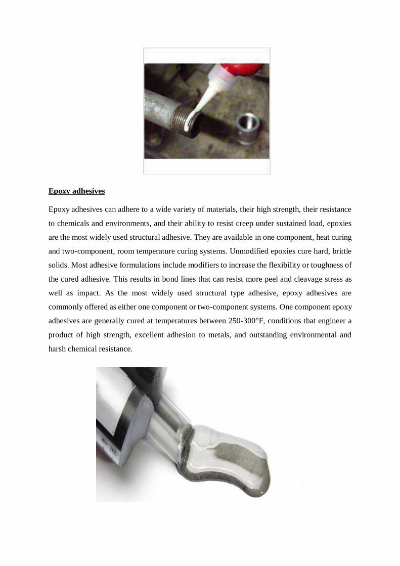
Epoxy adhesives
Epoxy adhesives can adhere to a wide variety of materials, their high strength, their resistance
to chemicals and environments, and their ability to resist creep under sustained load, epoxies
are the most widely used structural adhesive. They are available in one component, heat curing
and two-component, room temperature curing systems. Unmodified epoxies cure hard, brittle
solids. Most adhesive formulations include modifiers to increase the flexibility or toughness of
the cured adhesive. This results in bond lines that can resist more peel and cleavage stress as
well as impact. As the most widely used structural type adhesive, epoxy adhesives are
commonly offered as either one component or two-component systems. One component epoxy
adhesives are generally cured at temperatures between 250-300°F, conditions that engineer a
product of high strength, excellent adhesion to metals, and outstanding environmental and
harsh chemical resistance.
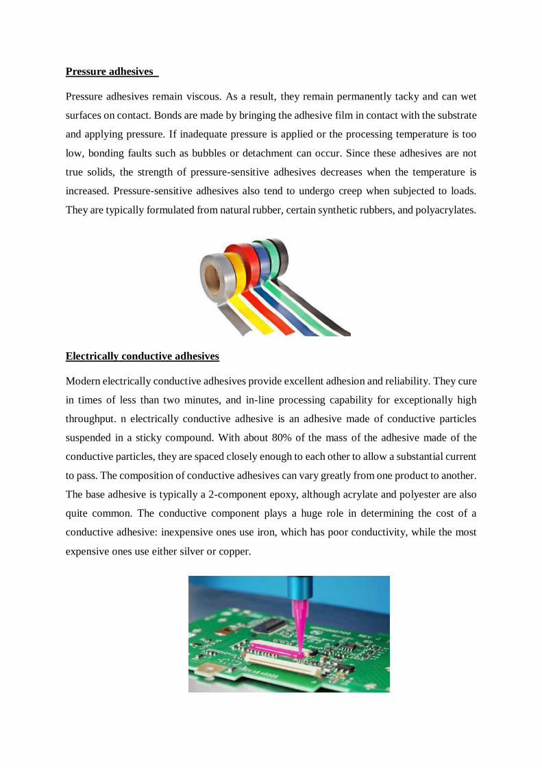
Pressure adhesives
Pressure adhesives remain viscous. As a result, they remain permanently tacky and can wet
surfaces on contact. Bonds are made by bringing the adhesive film in contact with the substrate
and applying pressure. If inadequate pressure is applied or the processing temperature is too
low, bonding faults such as bubbles or detachment can occur. Since these adhesives are not
true solids, the strength of pressure-sensitive adhesives decreases when the temperature is
increased. Pressure-sensitive adhesives also tend to undergo creep when subjected to loads.
They are typically formulated from natural rubber, certain synthetic rubbers, and polyacrylates.
Electrically conductive adhesives
Modern electrically conductive adhesives provide excellent adhesion and reliability. They cure
in times of less than two minutes, and in-line processing capability for exceptionally high
throughput. n electrically conductive adhesive is an adhesive made of conductive particles
suspended in a sticky compound. With about 80% of the mass of the adhesive made of the
conductive particles, they are spaced closely enough to each other to allow a substantial current
to pass. The composition of conductive adhesives can vary greatly from one product to another.
The base adhesive is typically a 2-component epoxy, although acrylate and polyester are also
quite common. The conductive component plays a huge role in determining the cost of a
conductive adhesive: inexpensive ones use iron, which has poor conductivity, while the most
expensive ones use either silver or copper.
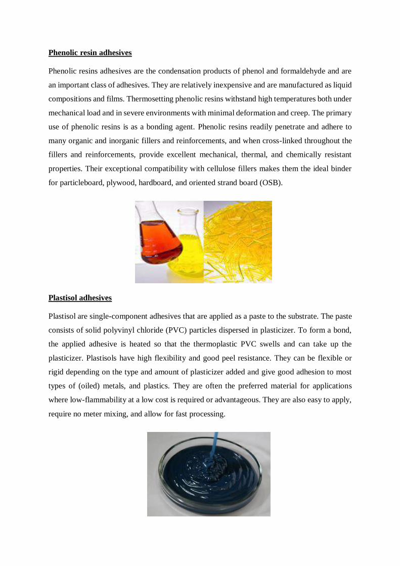
Phenolic resin adhesives
Phenolic resins adhesives are the condensation products of phenol and formaldehyde and are
an important class of adhesives. They are relatively inexpensive and are manufactured as liquid
compositions and films. Thermosetting phenolic resins withstand high temperatures both under
mechanical load and in severe environments with minimal deformation and creep. The primary
use of phenolic resins is as a bonding agent. Phenolic resins readily penetrate and adhere to
many organic and inorganic fillers and reinforcements, and when cross-linked throughout the
fillers and reinforcements, provide excellent mechanical, thermal, and chemically resistant
properties. Their exceptional compatibility with cellulose fillers makes them the ideal binder
for particleboard, plywood, hardboard, and oriented strand board (OSB).
Plastisol adhesives
Plastisol are single-component adhesives that are applied as a paste to the substrate. The paste
consists of solid polyvinyl chloride (PVC) particles dispersed in plasticizer. To form a bond,
the applied adhesive is heated so that the thermoplastic PVC swells and can take up the
plasticizer. Plastisols have high flexibility and good peel resistance. They can be flexible or
rigid depending on the type and amount of plasticizer added and give good adhesion to most
types of (oiled) metals, and plastics. They are often the preferred material for applications
where low-flammability at a low cost is required or advantageous. They are also easy to apply,
require no meter mixing, and allow for fast processing.
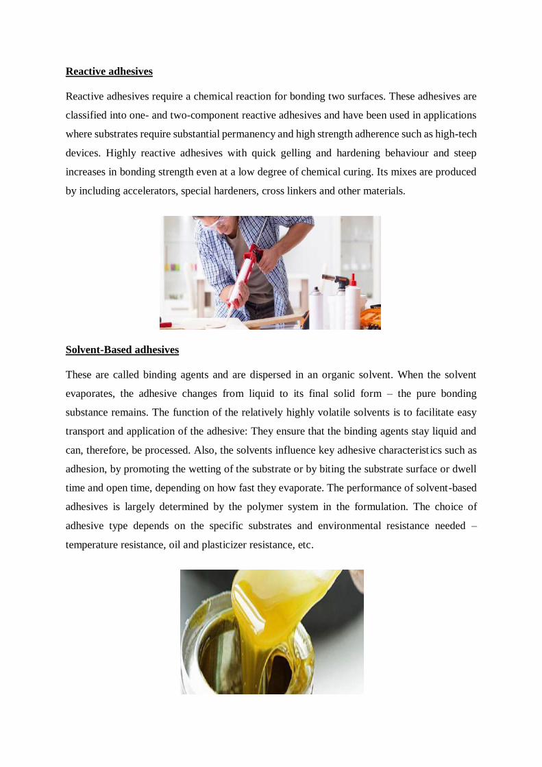
Reactive adhesives
Reactive adhesives require a chemical reaction for bonding two surfaces. These adhesives are
classified into one- and two-component reactive adhesives and have been used in applications
where substrates require substantial permanency and high strength adherence such as high-tech
devices. Highly reactive adhesives with quick gelling and hardening behaviour and steep
increases in bonding strength even at a low degree of chemical curing. Its mixes are produced
by including accelerators, special hardeners, cross linkers and other materials.
Solvent-Based adhesives
These are called binding agents and are dispersed in an organic solvent. When the solvent
evaporates, the adhesive changes from liquid to its final solid form – the pure bonding
substance remains. The function of the relatively highly volatile solvents is to facilitate easy
transport and application of the adhesive: They ensure that the binding agents stay liquid and
can, therefore, be processed. Also, the solvents influence key adhesive characterist ics such as
adhesion, by promoting the wetting of the substrate or by biting the substrate surface or dwell
time and open time, depending on how fast they evaporate. The performance of solvent-based
adhesives is largely determined by the polymer system in the formulation. The choice of
adhesive type depends on the specific substrates and environmental resistance needed –
temperature resistance, oil and plasticizer resistance, etc.

Thermoset adhesives
Thermoset adhesives are cross linked polymeric resins that are cured using heat and/or heat
and pressure. Due to their superior strength and resistance, thermosets are widely used for
structural load-bearing applications. Thermoset adhesives have very high strength, excellent
gap filling ability, and resistance to moisture and heat. Most thermoset adhesives are supplied
as a two-component system although one-part adhesives are used as well. Two-component
adhesives are typically made up of a resin and a hardener, in liquid or gel form, which are
mixed to initiate the curing process.
UV Curing adhesives
UV glue curing is gaining popularity over other methods of bonding such as drying or exposure
to chemicals. Bonding with heat or drying works by evaporation, this can be inconsistent and
can also take time for the inks to dry. Chemical treatment can be costly to purchase materials
and may expose employees to harmful inhalants or respiratory contaminants. UV glue curing
is quick and consistent, providing and instantly hardened surface with no harmful chemical
exposure. One big advantage to the finishes with UV curing is that it dries clear, allowing
multiple layers if need be while sanding down the finish will provide an invisible ‘liquid
plastic’ unbreakable bond. Paint or stain can be applied to the finish, giving endless options for
applications with various products.
Water-based adhesives
Water-based (or more commonly referred to as waterborne) adhesives are typically formulated
from natural polymers and soluble synthetic polymers. These adhesives may be supplied as
solutions or formulated as dry powders which must be mixed with water before application.
The strength of the adhesive is attained when water is lost from the glue line by evaporation or
absorption by the substrate. Because of this requirement, the use of these adhesives requires
that at least one substrate is permeable. Where neither substrate is permeable, it is possible to
apply a thin coat of adhesive, allow it to dry, and then activate the adhesive by lightly wiping
with a wet brush or roller or spraying with water.
13. BITUMEN:
Bitumen, also known as asphalt, is a substance produced through the distillation of crude
oil that is known for its waterproofing and adhesive properties. Bitumen production through
distillation removes lighter crude oil components, such as gasoline and diesel, leaving the
“heavier” bitumen behind. Bitumen is a petroleum based material, used for binding stones and
sands and producing asphalt for road construction.
In the normal process of an oil refinery, crude oil is heated in an atmospheric distillation
column. This will lead to the separation of various parts of crude oil according to their
molecular weight. The heaviest part of the oil that remains at the bottom of the distillation
column is called Vacuum Bottom and forms the raw material for producing refined bitumen.
The bitumen can be classified into the following grade types:
Penetration Grade Bitumen
Oxidized Bitumen Grades
Cut Back Bitumen
Bitumen Emulsion
Polymer Modified Bitumen
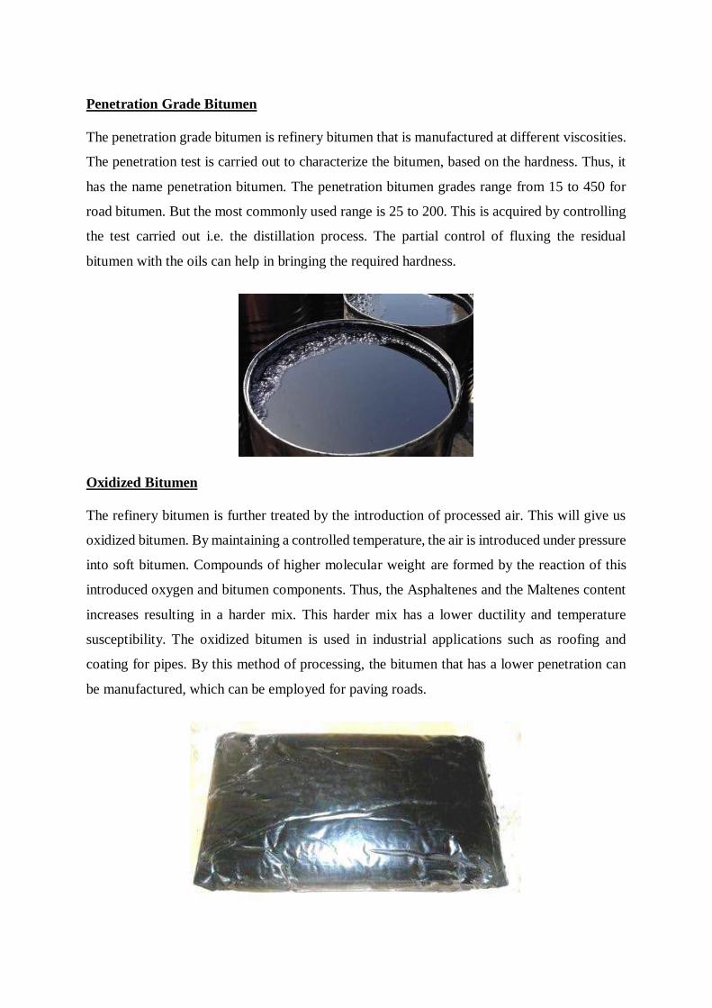
Penetration Grade Bitumen
The penetration grade bitumen is refinery bitumen that is manufactured at different viscosities.
The penetration test is carried out to characterize the bitumen, based on the hardness. Thus, it
has the name penetration bitumen. The penetration bitumen grades range from 15 to 450 for
road bitumen. But the most commonly used range is 25 to 200. This is acquired by controlling
the test carried out i.e. the distillation process. The partial control of fluxing the residual
bitumen with the oils can help in bringing the required hardness.
Oxidized Bitumen
The refinery bitumen is further treated by the introduction of processed air. This will give us
oxidized bitumen. By maintaining a controlled temperature, the air is introduced under pressure
into soft bitumen. Compounds of higher molecular weight are formed by the reaction of this
introduced oxygen and bitumen components. Thus, the Asphaltenes and the Maltenes content
increases resulting in a harder mix. This harder mix has a lower ductility and temperature
susceptibility. The oxidized bitumen is used in industrial applications such as roofing and
coating for pipes. By this method of processing, the bitumen that has a lower penetration can
be manufactured, which can be employed for paving roads.
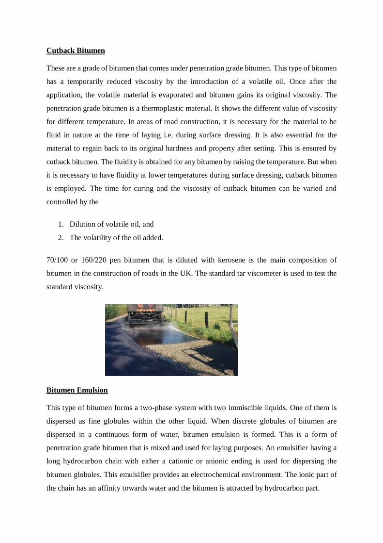
Cutback Bitumen
These are a grade of bitumen that comes under penetration grade bitumen. This type of bitumen
has a temporarily reduced viscosity by the introduction of a volatile oil. Once after the
application, the volatile material is evaporated and bitumen gains its original viscosity. The
penetration grade bitumen is a thermoplastic material. It shows the different value of viscosity
for different temperature. In areas of road construction, it is necessary for the material to be
fluid in nature at the time of laying i.e. during surface dressing. It is also essential for the
material to regain back to its original hardness and property after setting. This is ensured by
cutback bitumen. The fluidity is obtained for any bitumen by raising the temperature. But when
it is necessary to have fluidity at lower temperatures during surface dressing, cutback bitumen
is employed. The time for curing and the viscosity of cutback bitumen can be varied and
controlled by the
1. Dilution of volatile oil, and
2. The volatility of the oil added.
70/100 or 160/220 pen bitumen that is diluted with kerosene is the main composition of
bitumen in the construction of roads in the UK. The standard tar viscometer is used to test the
standard viscosity.
Bitumen Emulsion
This type of bitumen forms a two-phase system with two immiscible liquids. One of them is
dispersed as fine globules within the other liquid. When discrete globules of bitumen are
dispersed in a continuous form of water, bitumen emulsion is formed. This is a form of
penetration grade bitumen that is mixed and used for laying purposes. An emulsifier having a
long hydrocarbon chain with either a cationic or anionic ending is used for dispersing the
bitumen globules. This emulsifier provides an electrochemical environment. The ionic part of
the chain has an affinity towards water and the bitumen is attracted by hydrocarbon part.
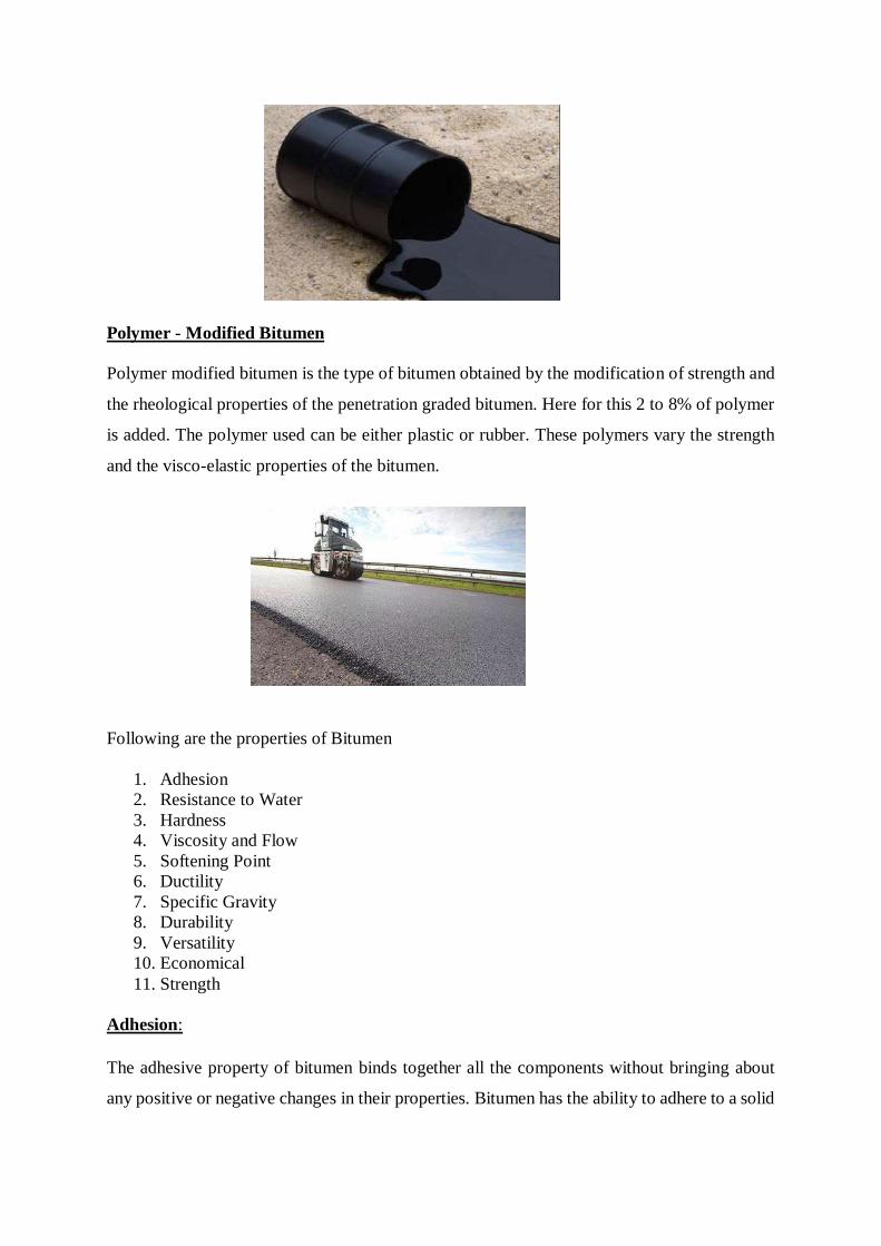
Polymer - Modified Bitumen
Polymer modified bitumen is the type of bitumen obtained by the modification of strength and
the rheological properties of the penetration graded bitumen. Here for this 2 to 8% of polymer
is added. The polymer used can be either plastic or rubber. These polymers vary the strength
and the visco-elastic properties of the bitumen.
Following are the properties of Bitumen
1. Adhesion
2. Resistance to Water
3. Hardness
4. Viscosity and Flow
5. Softening Point
6. Ductility
7. Specific Gravity
8. Durability
9. Versatility
10. Economical
11. Strength
Adhesion:
The adhesive property of bitumen binds together all the components without bringing about
any positive or negative changes in their properties. Bitumen has the ability to adhere to a solid

surface in a fluid state depending on the nature of the surface. The presence of water on the
surface will prevent adhesion.
Resistance to Water:
Bitumen is insoluble in water and can serve as an effective sealant Bitumen is water resistant.
Under some conditions water may be absorbed by minute quantities of inorganic salts in the
bitumen or filler in it.
Hardness:
To measure the hardness of bitumen, the penetration test is conducted, which measures the
depth of penetration in tenths of mm. of a weighted needle in bitumen after a given time, at a
known temperature. Commonly a weight of 100 gm is applied for 5 sec at a temperature of 77
°F. The penetration is a measure of hardness. Typical results are 10 for hard coating asphalt,
15 to 40 for roofing asphalt and up to 100 or more for water proofing bitumen.
Viscosity and Flow:
The viscous or flow properties of bitumen are of importance both at high temperature during
processing and application and at low temperature to which bitumen is subjected during
service. The flow properties of bitumen vary considerably with temperature and stress
conditions. Deterioration, or loss of the desirable properties of bitumen, takes the form of
hardening. Resultantly, decrease in adhesive and flow properties and an increase in the
softening point temperature and coefficient of thermal expansion.
Softening point:
This property make us to know whether given bitumen can be used at the particular place i.e.
softening point value should be higher than pavement temperature otherwise bitumen present
in the layer get soften and come out.
Softening point is the temperature at which a steel ball falls a known distance through the
bitumen when the test assembly is heated at a known rate. Usually the test consist of a (3/8) in
dia. steel ball, weight 3.5 gm, which is allowed to sink through a (5/8) in dia, (1/4) in thick disk
of bitumen in a brass ring. The whole assembly is heated at a rate of 9 °F per min. Typical
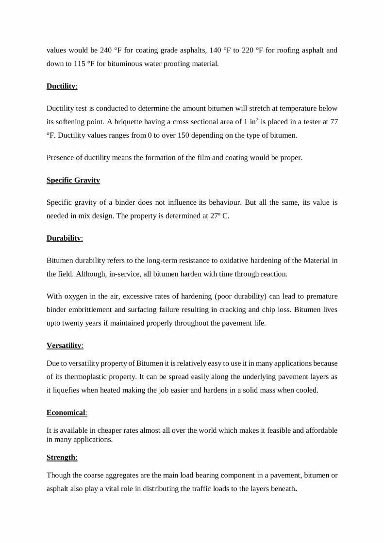
values would be 240 °F for coating grade asphalts, 140 °F to 220 °F for roofing asphalt and
down to 115 °F for bituminous water proofing material.
Ductility:
Ductility test is conducted to determine the amount bitumen will stretch at temperature below
its softening point. A briquette having a cross sectional area of 1 in2 is placed in a tester at 77
°F. Ductility values ranges from 0 to over 150 depending on the type of bitumen.
Presence of ductility means the formation of the film and coating would be proper.
Specific Gravity
Specific gravity of a binder does not influence its behaviour. But all the same, its value is
needed in mix design. The property is determined at 27º C.
Durability:
Bitumen durability refers to the long-term resistance to oxidative hardening of the Material in
the field. Although, in-service, all bitumen harden with time through reaction.
With oxygen in the air, excessive rates of hardening (poor durability) can lead to premature
binder embrittlement and surfacing failure resulting in cracking and chip loss. Bitumen lives
upto twenty years if maintained properly throughout the pavement life.
Versatility:
Due to versatility property of Bitumen it is relatively easy to use it in many applications because
of its thermoplastic property. It can be spread easily along the underlying pavement layers as
it liquefies when heated making the job easier and hardens in a solid mass when cooled.
Economical:
It is available in cheaper rates almost all over the world which makes it feasible and affordable
in many applications.
Strength:
Though the coarse aggregates are the main load bearing component in a pavement, bitumen or
asphalt also play a vital role in distributing the traffic loads to the layers beneath.
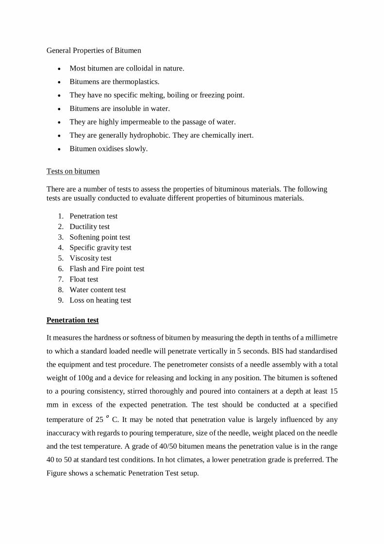
General Properties of Bitumen
Most bitumen are colloidal in nature.
Bitumens are thermoplastics.
They have no specific melting, boiling or freezing point.
Bitumens are insoluble in water.
They are highly impermeable to the passage of water.
They are generally hydrophobic. They are chemically inert.
Bitumen oxidises slowly.
Tests on bitumen
There are a number of tests to assess the properties of bituminous materials. The following
tests are usually conducted to evaluate different properties of bituminous materials.
1. Penetration test
2. Ductility test
3. Softening point test
4. Specific gravity test
5. Viscosity test
6. Flash and Fire point test
7. Float test
8. Water content test
9. Loss on heating test
Penetration test
It measures the hardness or softness of bitumen by measuring the depth in tenths of a millimetre
to which a standard loaded needle will penetrate vertically in 5 seconds. BIS had standardised
the equipment and test procedure. The penetrometer consists of a needle assembly with a total
weight of 100g and a device for releasing and locking in any position. The bitumen is softened
to a pouring consistency, stirred thoroughly and poured into containers at a depth at least 15
mm in excess of the expected penetration. The test should be conducted at a specified
temperature of 25 C. It may be noted that penetration value is largely influenced by any
inaccuracy with regards to pouring temperature, size of the needle, weight placed on the needle
and the test temperature. A grade of 40/50 bitumen means the penetration value is in the range
40 to 50 at standard test conditions. In hot climates, a lower penetration grade is preferred. The
Figure shows a schematic Penetration Test setup.
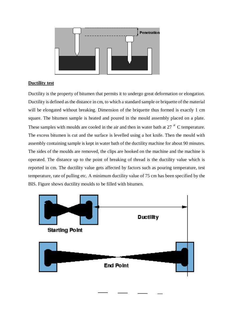
Ductility test
Ductility is the property of bitumen that permits it to undergo great deformation or elongation.
Ductility is defined as the distance in cm, to which a standard sample or briquette of the material
will be elongated without breaking. Dimension of the briquette thus formed is exactly 1 cm
square. The bitumen sample is heated and poured in the mould assembly placed on a plate.
These samples with moulds are cooled in the air and then in water bath at 27 C temperature.
The excess bitumen is cut and the surface is levelled using a hot knife. Then the mould with
assembly containing sample is kept in water bath of the ductility machine for about 90 minutes.
The sides of the moulds are removed, the clips are hooked on the machine and the machine is
operated. The distance up to the point of breaking of thread is the ductility value which is
reported in cm. The ductility value gets affected by factors such as pouring temperature, test
temperature, rate of pulling etc. A minimum ductility value of 75 cm has been specified by the
BIS. Figure shows ductility moulds to be filled with bitumen.
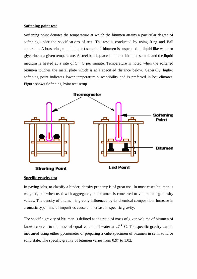
Softening point test
Softening point denotes the temperature at which the bitumen attains a particular degree of
softening under the specifications of test. The test is conducted by using Ring and Ball
apparatus. A brass ring containing test sample of bitumen is suspended in liquid like water or
glycerine at a given temperature. A steel ball is placed upon the bitumen sample and the liquid
medium is heated at a rate of 5 C per minute. Temperature is noted when the softened
bitumen touches the metal plate which is at a specified distance below. Generally, higher
softening point indicates lower temperature susceptibility and is preferred in hot climates.
Figure shows Softening Point test setup.
Specific gravity test
In paving jobs, to classify a binder, density property is of great use. In most cases bitumen is
weighed, but when used with aggregates, the bitumen is converted to volume using density
values. The density of bitumen is greatly influenced by its chemical composition. Increase in
aromatic type mineral impurities cause an increase in specific gravity.
The specific gravity of bitumen is defined as the ratio of mass of given volume of bitumen of
known content to the mass of equal volume of water at 27 C. The specific gravity can be
measured using either pycnometer or preparing a cube specimen of bitumen in semi solid or
solid state. The specific gravity of bitumen varies from 0.97 to 1.02.
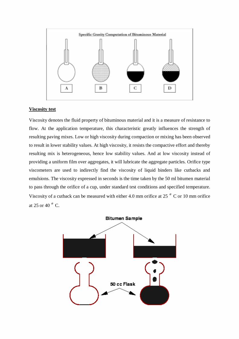
Viscosity test
Viscosity denotes the fluid property of bituminous material and it is a measure of resistance to
flow. At the application temperature, this characteristic greatly influences the strength of
resulting paving mixes. Low or high viscosity during compaction or mixing has been observed
to result in lower stability values. At high viscosity, it resists the compactive effort and thereby
resulting mix is heterogeneous, hence low stability values. And at low viscosity instead of
providing a uniform film over aggregates, it will lubricate the aggregate particles. Orifice type
viscometers are used to indirectly find the viscosity of liquid binders like cutbacks and
emulsions. The viscosity expressed in seconds is the time taken by the 50 ml bitumen material
to pass through the orifice of a cup, under standard test conditions and specified temperature.
Viscosity of a cutback can be measured with either 4.0 mm orifice at 25 C or 10 mm orifice
at 25 or 40 C.
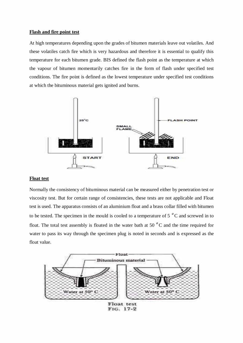
Flash and fire point test
At high temperatures depending upon the grades of bitumen materials leave out volatiles. And
these volatiles catch fire which is very hazardous and therefore it is essential to qualify this
temperature for each bitumen grade. BIS defined the flash point as the temperature at which
the vapour of bitumen momentarily catches fire in the form of flash under specified test
conditions. The fire point is defined as the lowest temperature under specified test conditions
at which the bituminous material gets ignited and burns.
Float test
Normally the consistency of bituminous material can be measured either by penetration test or
viscosity test. But for certain range of consistencies, these tests are not applicable and Float
test is used. The apparatus consists of an aluminium float and a brass collar filled with bitumen
to be tested. The specimen in the mould is cooled to a temperature of 5 C and screwed in to
float. The total test assembly is floated in the water bath at 50 C and the time required for
water to pass its way through the specimen plug is noted in seconds and is expressed as the
float value.
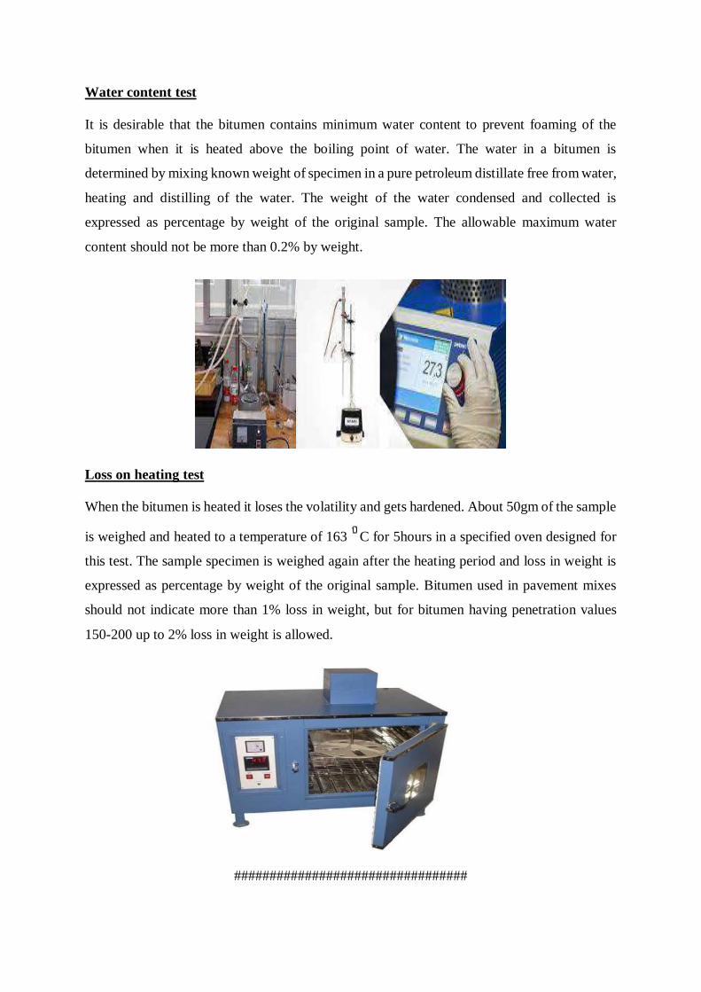
Water content test
It is desirable that the bitumen contains minimum water content to prevent foaming of the
bitumen when it is heated above the boiling point of water. The water in a bitumen is
determined by mixing known weight of specimen in a pure petroleum distillate free from water,
heating and distilling of the water. The weight of the water condensed and collected is
expressed as percentage by weight of the original sample. The allowable maximum water
content should not be more than 0.2% by weight.
Loss on heating test
When the bitumen is heated it loses the volatility and gets hardened. About 50gm of the sample
is weighed and heated to a temperature of 163 C for 5hours in a specified oven designed for
this test. The sample specimen is weighed again after the heating period and loss in weight is
expressed as percentage by weight of the original sample. Bitumen used in pavement mixes
should not indicate more than 1% loss in weight, but for bitumen having penetration values
150-200 up to 2% loss in weight is allowed.
#################################
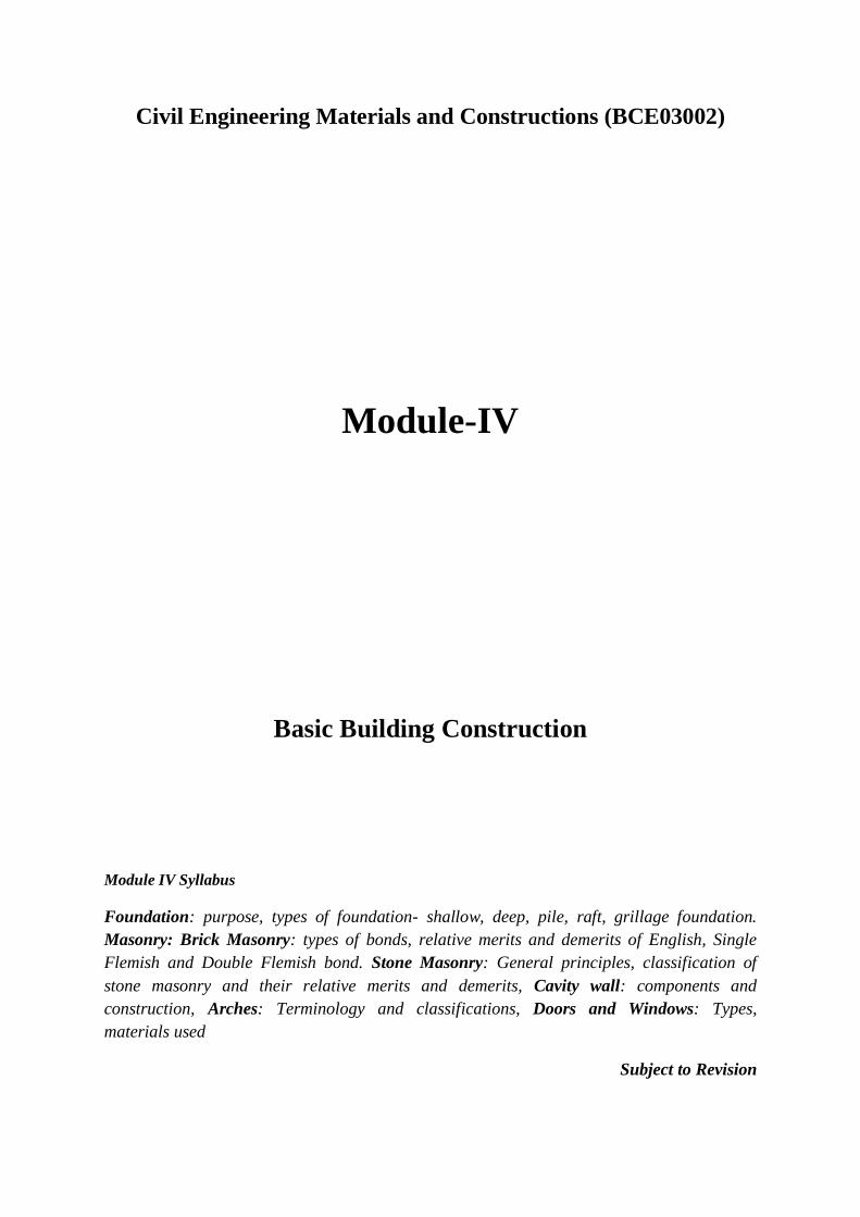
Civil Engineering Materials and Constructions (BCE03002)
Module-IV
Basic Building Construction
Module IV Syllabus
Foundation: purpose, types of foundation- shallow, deep, pile, raft, grillage foundation.
Masonry: Brick Masonry: types of bonds, relative merits and demerits of English, Single
Flemish and Double Flemish bond. Stone Masonry: General principles, classification of
stone masonry and their relative merits and demerits, Cavity wall: components and
construction, Arches: Terminology and classifications, Doors and Windows: Types,
materials used
Subject to Revision
1. FOUNDATION: -
It is a part of structural system that supports and anchors the superstructure of a building
and transmits its loads directly to the earth. Foundation of a building as the name implies is
the starting of a building construction on site really. Types of building, nature of soil and
environmental conditions are the major determinant of type of foundation. Choosing a kind of
foundation depends on, ground conditions, groundwater conditions, site – the environment
(the buildings nearby) and structure of our building.
Purpose:-
There are numerous reasons a foundation is provided, some of which are:
The most crucial purpose of providing Foundation is Structural Stability. Strength of
the foundation determines the stability of the structure to be constructed.
A properly designed and the constructed foundation provide an even surface for the
development of superstructure at a proper level at over a firm bed.
A well-designed foundation prevents the lateral movement of the supporting material
(which is the soil in this case) and thus ensuring the safety of the superstructure from
the detrimental effects of the lateral movements of soil.
The foundation serves the purpose of completely distributing the loads from the
structure to a large base area, and then the soil underneath. This uniform transfer of
loads helps in avoiding unequal settlement of the building, which is one of the
detrimental defects in building construction.
Types of Foundation:-
1. Shallow foundation: If the depth of foundation is less than the width of foundation
then it is known as Shallow or stepped Foundation. It can be used where the bearing
capacity of soil on which the structure is to be constructed is maximum. Minimum
depth of this Foundation is 800mm and maximum depth not to be taken more than 4
meters.
2. Deep foundation: If the depth of footing greater or equal to the Width of footing, it is
known as the deep Foundation. Deep Foundation is used where the bearing capacity
of the soil is very low. The load coming from the superstructure is further transmitted
vertically to the soil.
Difference between Foundation and Footing:
Foundation is a structure which transfers the loads from the superstructure to the ground,
while footing is the foundation which is in contact with the earth. A foundation can be shallow and deep, while a footing is a type of a shallow
foundation. so, all footings are foundations but all foundations cannot be footings.
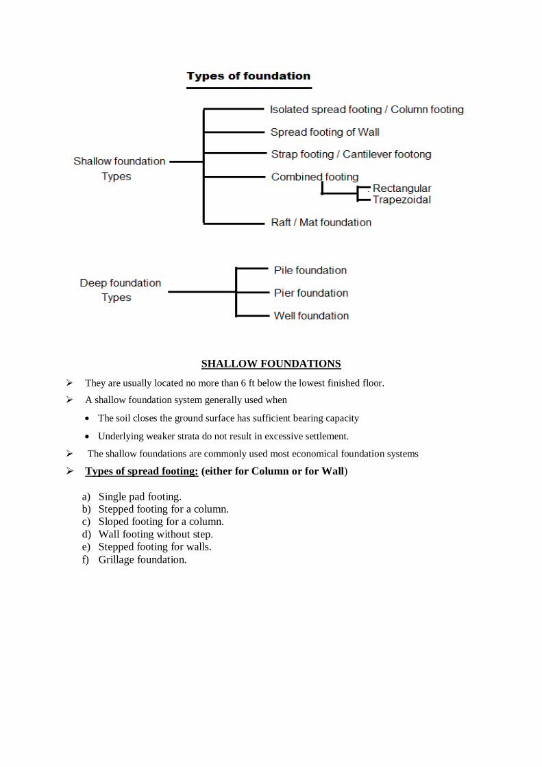
SHALLOW FOUNDATIONS
They are usually located no more than 6 ft below the lowest finished floor.
A shallow foundation system generally used when
The soil closes the ground surface has sufficient bearing capacity
Underlying weaker strata do not result in excessive settlement.
The shallow foundations are commonly used most economical foundation systems
Types of spread footing: (either for Column or for Wall)
a) Single pad footing.
b) Stepped footing for a column.
c) Sloped footing for a column.
d) Wall footing without step.
e) Stepped footing for walls.
f) Grillage foundation.
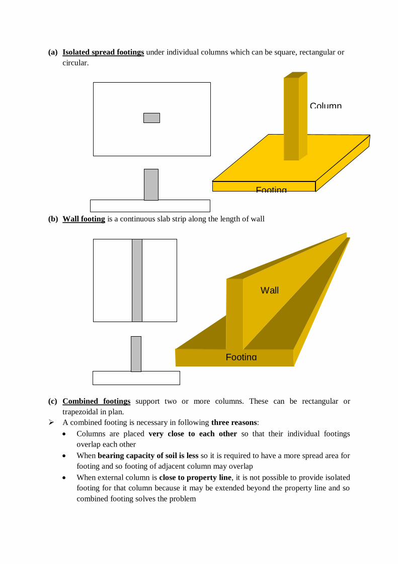
(a) Isolated spread footings under individual columns which can be square, rectangular or
circular.
(b) Wall footing is a continuous slab strip along the length of wall
(c) Combined footings support two or more columns. These can be rectangular or
trapezoidal in plan.
A combined footing is necessary in following three reasons:
Columns are placed very close to each other so that their individual footings
overlap each other
When bearing capacity of soil is less so it is required to have a more spread area for
footing and so footing of adjacent column may overlap
When external column is close to property line, it is not possible to provide isolated
footing for that column because it may be extended beyond the property line and so
combined footing solves the problem
Footing
Wall
Footing
Column
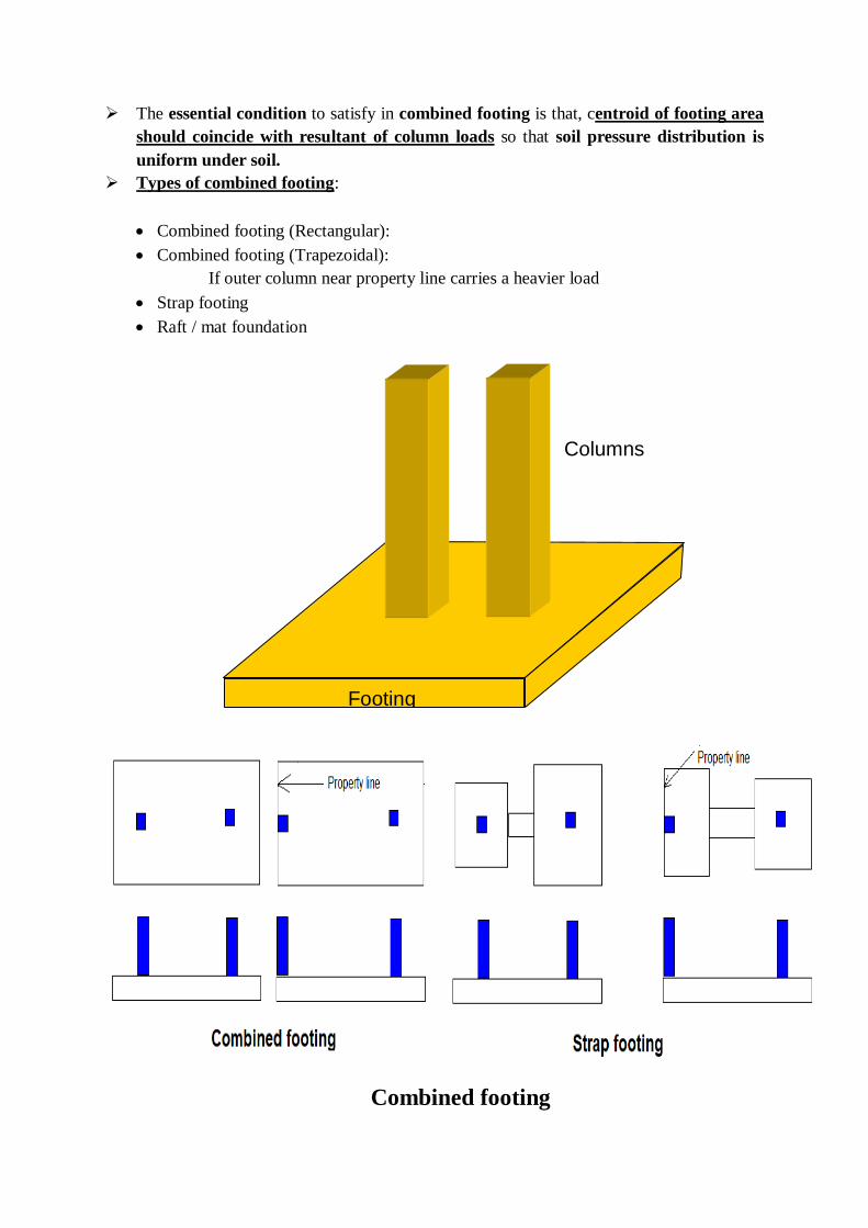
The essential condition to satisfy in combined footing is that, centroid of footing area
should coincide with resultant of column loads so that soil pressure distribution is
uniform under soil.
Types of combined footing:
Combined footing (Rectangular):
Combined footing (Trapezoidal):
If outer column near property line carries a heavier load
Strap footing
Raft / mat foundation
Combined footing
Footing
Columns

(d) Strap or Cantilever Footing
Strap footings are similar to combined footings.
Reasons for considering or choosing strap footing are identical to the combined one.
In strap footing, the foundation under the columns is built individually and connected by
a strap beam.
Generally, when the edge of the footing cannot be extended beyond the property line,
the exterior footing is connected by a strap beam with interior footing.
(e) Raft / mat foundation:
This is a large continuous footing supporting all the columns of the structure.
This is used when soil conditions are poor but piles are not used.
Raft foundation is provided
When load transmitted by columns are so heavy or allowable soil pressure are so
small that individual footings if provided would cover more than about half of the
area, then it is better to provide a continuous footing called raft foundation under all
columns and walls
Raft foundations are used to reduce settlement of structure located above heavy
compressible deposits i.e. they control differential settlement
Types of raft foundation:
Solid raft (A continuous slab covering all the columns)
Ribbed raft (mat with a central hollow region when all the columns are connected by
a continuous beam which gets supported on the raft slab
Raft foundation
Footing
Columns
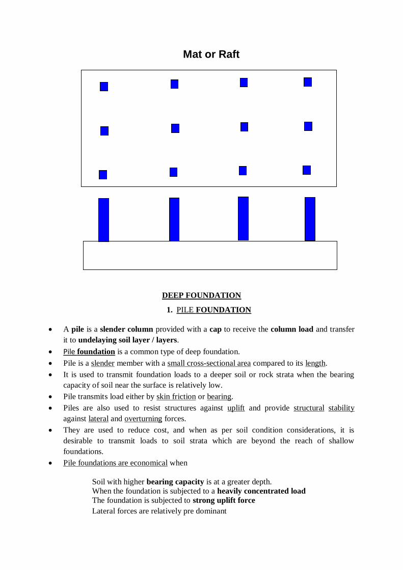
DEEP FOUNDATION
1. PILE FOUNDATION
A pile is a slender column provided with a cap to receive the column load and transfer
it to undelaying soil layer / layers.
Pile foundation is a common type of deep foundation.
Pile is a slender member with a small cross-sectional area compared to its length.
It is used to transmit foundation loads to a deeper soil or rock strata when the bearing
capacity of soil near the surface is relatively low.
Pile transmits load either by skin friction or bearing.
Piles are also used to resist structures against uplift and provide structural stability
against lateral and overturning forces.
They are used to reduce cost, and when as per soil condition considerations, it is
desirable to transmit loads to soil strata which are beyond the reach of shallow
foundations.
Pile foundations are economical when
Soil with higher bearing capacity is at a greater depth.
When the foundation is subjected to a heavily concentrated load
The foundation is subjected to strong uplift force
Lateral forces are relatively pre dominant
Mat or Raft
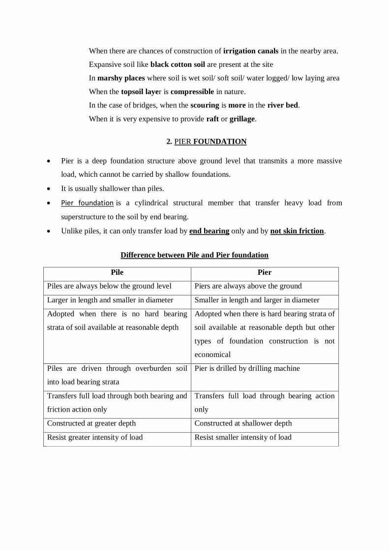
When there are chances of construction of irrigation canals in the nearby area.
Expansive soil like black cotton soil are present at the site
In marshy places where soil is wet soil/ soft soil/ water logged/ low laying area
When the topsoil layer is compressible in nature.
In the case of bridges, when the scouring is more in the river bed.
When it is very expensive to provide raft or grillage.
2. PIER FOUNDATION
Pier is a deep foundation structure above ground level that transmits a more massive
load, which cannot be carried by shallow foundations.
It is usually shallower than piles.
Pier foundation is a cylindrical structural member that transfer heavy load from
superstructure to the soil by end bearing.
Unlike piles, it can only transfer load by end bearing only and by not skin friction.
Difference between Pile and Pier foundation
Pile Pier
Piles are always below the ground level Piers are always above the ground
Larger in length and smaller in diameter Smaller in length and larger in diameter
Adopted when there is no hard bearing
strata of soil available at reasonable depth
Adopted when there is hard bearing strata of
soil available at reasonable depth but other
types of foundation construction is not
economical
Piles are driven through overburden soil
into load bearing strata
Pier is drilled by drilling machine
Transfers full load through both bearing and
friction action only
Transfers full load through bearing action
only
Constructed at greater depth Constructed at shallower depth
Resist greater intensity of load Resist smaller intensity of load
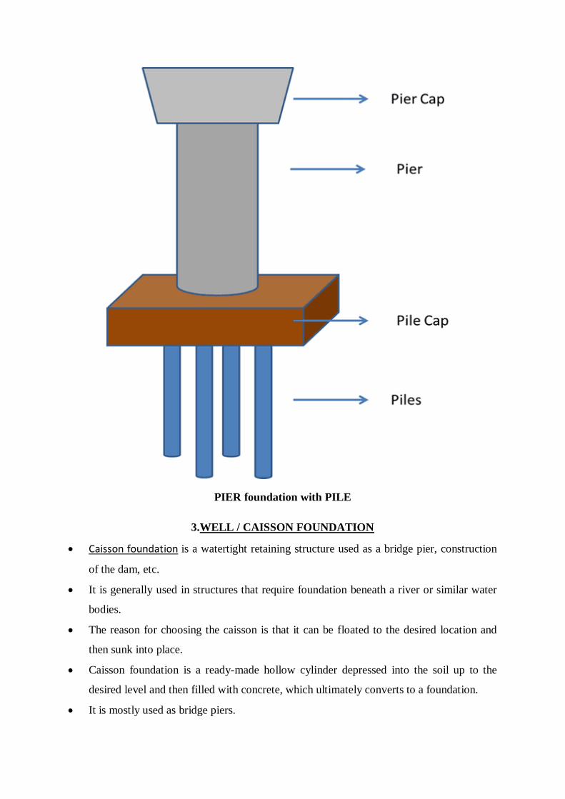
PIER foundation with PILE
3.WELL / CAISSON FOUNDATION
Caisson foundation is a watertight retaining structure used as a bridge pier, construction
of the dam, etc.
It is generally used in structures that require foundation beneath a river or similar water
bodies.
The reason for choosing the caisson is that it can be floated to the desired location and
then sunk into place.
Caisson foundation is a ready-made hollow cylinder depressed into the soil up to the
desired level and then filled with concrete, which ultimately converts to a foundation.
It is mostly used as bridge piers.
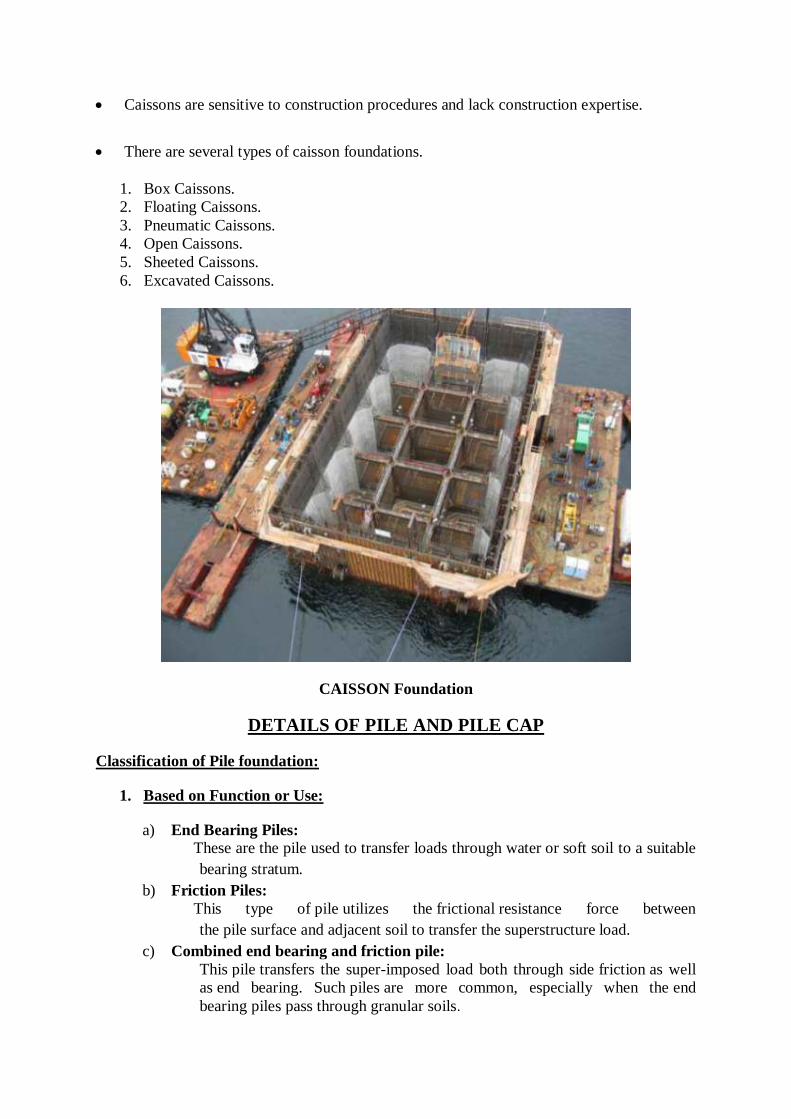
Caissons are sensitive to construction procedures and lack construction expertise.
There are several types of caisson foundations.
1. Box Caissons.
2. Floating Caissons.
3. Pneumatic Caissons.
4. Open Caissons.
5. Sheeted Caissons.
6. Excavated Caissons.
CAISSON Foundation
DETAILS OF PILE AND PILE CAP
Classification of Pile foundation:
1. Based on Function or Use:
a) End Bearing Piles: These are the pile used to transfer loads through water or soft soil to a suitable
bearing stratum.
b) Friction Piles:
This type of pile utilizes the frictional resistance force between
the pile surface and adjacent soil to transfer the superstructure load.
c) Combined end bearing and friction pile:
This pile transfers the super-imposed load both through side friction as well
as end bearing. Such piles are more common, especially when the end
bearing piles pass through granular soils.

d) Compactor Piles:
These are used to compact loose granular soil thus increasing their bearing
capacity.
e) Batter pile:
A pile driven at an angle with the vertical to resist a lateral force
f) Sheet Piles:
Used as impervious cut-off to reduce seepage and uplift under hydraulic
structures.
They are rarely used to furnish vertical support but are used to function as
retaining wall g) Anchor pile:
It provides anchorage against horizontal pull from sheet piling
Anchor piles can transfer both compressive and tensile forces as well as
bending moments to the ground, making them ideal as anchors for offshore
moorings, basements, and tunnels, etc. Moored floating offshore structures
impose a variety of load conditions on the anchor system.
h) Tension/uplift pile:
It anchors down the structures subjected to uplift due to hydro static pressure,
seismic activity or due to overturning moment
2. Based on Materials:
a) Timber Piles
b) Concrete Piles
c) Steel Piles
d) Composite Piles
3. Based on construction process:
a) Bored Piling:
Bored piles are installed by auguring into the ground forming a hole into
which concrete can be poured, thereby casting the pile in position.
b) Driven Piling:
Driven piles are driven or hammered into the ground with the use of
vibration
c) Screw Piling
Screw piles are wound into the ground, much like a screw is wound into
wood. This is an efficient means of installation and coupled with their
mechanism of dispersing load, provides effective in-ground performance in a
range of soils, including earthquake zones with liquefaction potential
d) Mini Piling
Mini piling is a variation on piling that uses a narrower diameter. This makes
them light and inexpensive whilst still being able to support considerably
heavy loads. For the most common type of mini piling a hollow steel shaft is
screwed or drilled into the ground
e) Sheet Piling
Sheet pile walls are retaining walls constructed to retain earth, water or any
other filling materials. These walls are thinner in section compared to
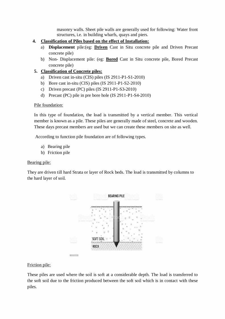
masonry walls. Sheet pile walls are generally used for following: Water front
structures, i.e. in building wharfs, quays and piers.
4. Classification of Piles based on the effect of Installation:
a) Displacement pile:(eg: Driven Cast in Situ concrete pile and Driven Precast
concrete pile)
b) Non- Displacement pile: (eg: Bored Cast in Situ concrete pile, Bored Precast
concrete pile)
5. Classification of Concrete piles:
a) Driven cast in-situ (CIS) piles (IS 2911-P1-S1-2010)
b) Bore cast in-situ (CIS) piles (IS 2911-P1-S2-2010)
c) Driven precast (PC) piles (IS 2911-P1-S3-2010)
d) Precast (PC) pile in pre bore hole (IS 2911-P1-S4-2010)
Pile foundation:
In this type of foundation, the load is transmitted by a vertical member. This vertical
member is known as a pile. These piles are generally made of steel, concrete and wooden.
These days precast members are used but we can create these members on site as well.
According to function pile foundation are of following types.
a) Bearing pile
b) Friction pile
Bearing pile:
They are driven till hard Strata or layer of Rock beds. The load is transmitted by columns to
the hard layer of soil.
Friction pile:
These piles are used where the soil is soft at a considerable depth. The load is transferred to
the soft soil due to the friction produced between the soft soil which is in contact with these
piles.
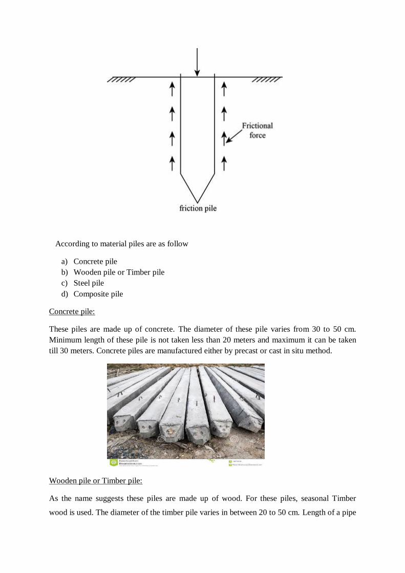
According to material piles are as follow
a) Concrete pile
b) Wooden pile or Timber pile
c) Steel pile
d) Composite pile
Concrete pile:
These piles are made up of concrete. The diameter of these pile varies from 30 to 50 cm.
Minimum length of these pile is not taken less than 20 meters and maximum it can be taken
till 30 meters. Concrete piles are manufactured either by precast or cast in situ method.
Wooden pile or Timber pile:
As the name suggests these piles are made up of wood. For these piles, seasonal Timber
wood is used. The diameter of the timber pile varies in between 20 to 50 cm. Length of a pipe
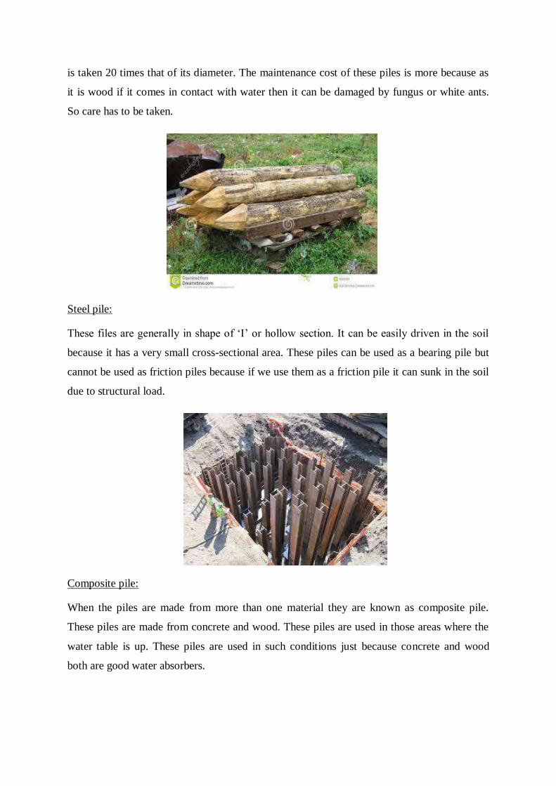
is taken 20 times that of its diameter. The maintenance cost of these piles is more because as
it is wood if it comes in contact with water then it can be damaged by fungus or white ants.
So care has to be taken.
Steel pile:
These files are generally in shape of ‘I’ or hollow section. It can be easily driven in the soil
because it has a very small cross-sectional area. These piles can be used as a bearing pile but
cannot be used as friction piles because if we use them as a friction pile it can sunk in the soil
due to structural load.
Composite pile:
When the piles are made from more than one material they are known as composite pile.
These piles are made from concrete and wood. These piles are used in those areas where the
water table is up. These piles are used in such conditions just because concrete and wood
both are good water absorbers.
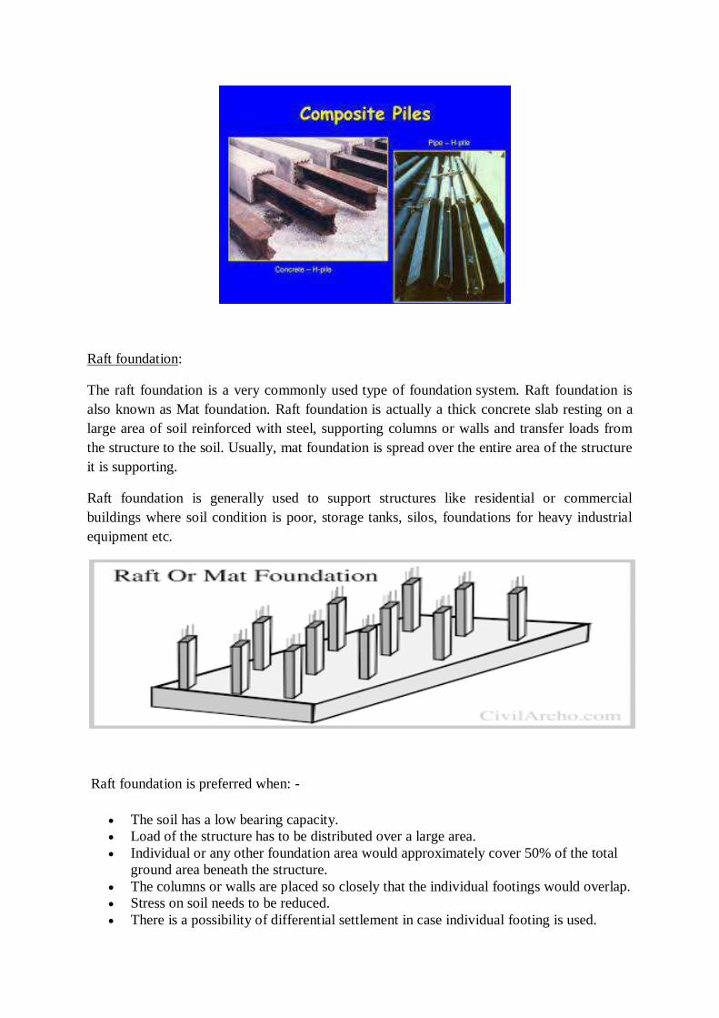
Raft foundation:
The raft foundation is a very commonly used type of foundation system. Raft foundation is
also known as Mat foundation. Raft foundation is actually a thick concrete slab resting on a
large area of soil reinforced with steel, supporting columns or walls and transfer loads from
the structure to the soil. Usually, mat foundation is spread over the entire area of the structure
it is supporting.
Raft foundation is generally used to support structures like residential or commercial
buildings where soil condition is poor, storage tanks, silos, foundations for heavy industrial
equipment etc.
Raft foundation is preferred when: -
The soil has a low bearing capacity.
Load of the structure has to be distributed over a large area.
Individual or any other foundation area would approximately cover 50% of the total
ground area beneath the structure.
The columns or walls are placed so closely that the individual footings would overlap.
Stress on soil needs to be reduced.
There is a possibility of differential settlement in case individual footing is used.
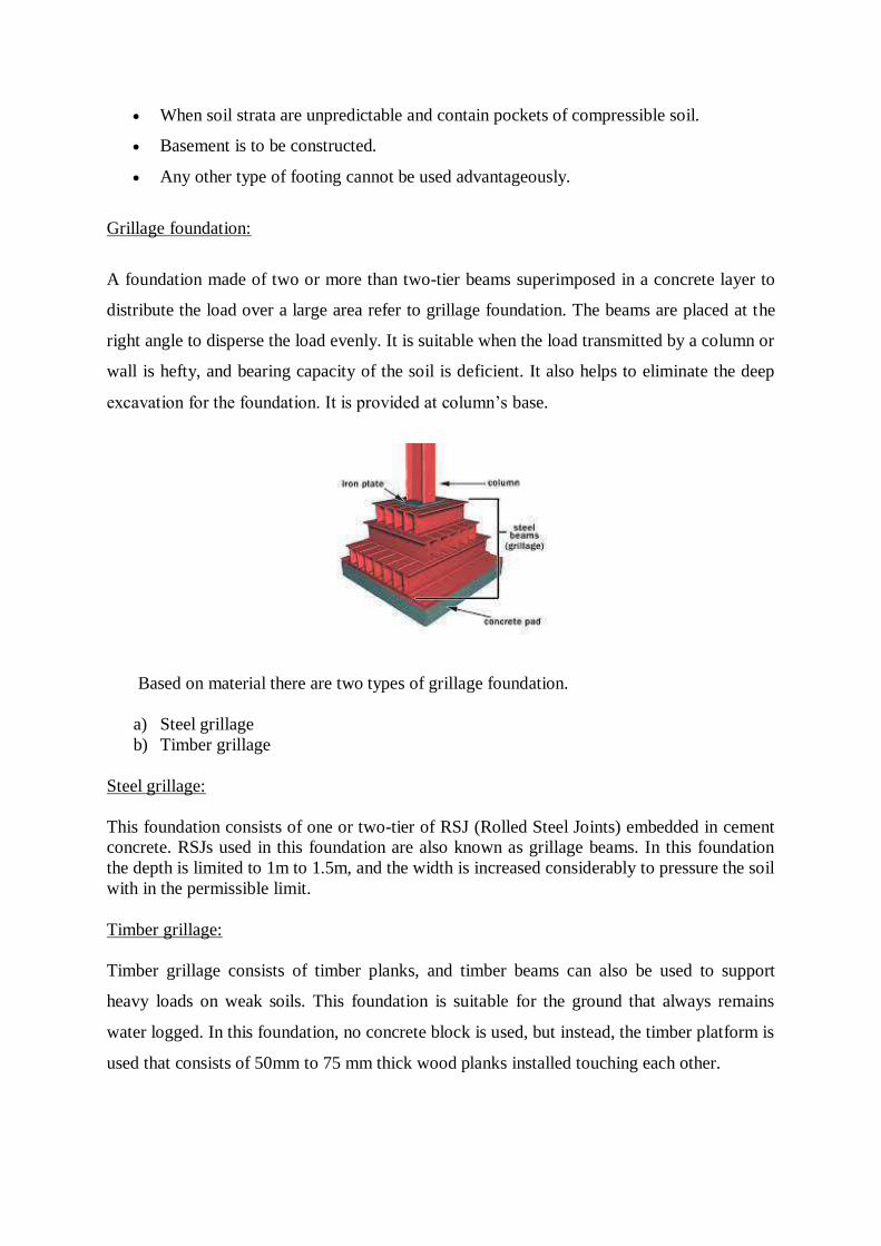
When soil strata are unpredictable and contain pockets of compressible soil.
Basement is to be constructed.
Any other type of footing cannot be used advantageously.
Grillage foundation:
A foundation made of two or more than two-tier beams superimposed in a concrete layer to
distribute the load over a large area refer to grillage foundation. The beams are placed at the
right angle to disperse the load evenly. It is suitable when the load transmitted by a column or
wall is hefty, and bearing capacity of the soil is deficient. It also helps to eliminate the deep
excavation for the foundation. It is provided at column’s base.
Based on material there are two types of grillage foundation.
a) Steel grillage
b) Timber grillage
Steel grillage:
This foundation consists of one or two-tier of RSJ (Rolled Steel Joints) embedded in cement
concrete. RSJs used in this foundation are also known as grillage beams. In this foundation
the depth is limited to 1m to 1.5m, and the width is increased considerably to pressure the soil
with in the permissible limit.
Timber grillage:
Timber grillage consists of timber planks, and timber beams can also be used to support
heavy loads on weak soils. This foundation is suitable for the ground that always remains
water logged. In this foundation, no concrete block is used, but instead, the timber platform is
used that consists of 50mm to 75 mm thick wood planks installed touching each other.
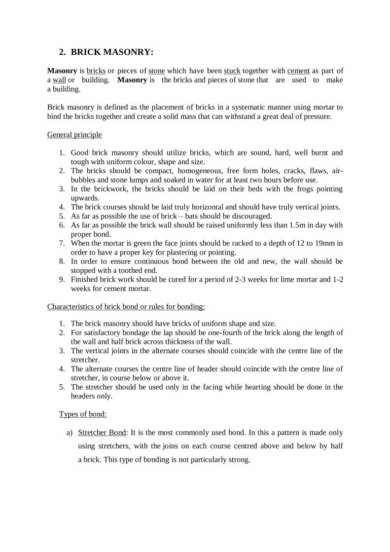
2. BRICK MASONRY:
Masonry is bricks or pieces of stone which have been stuck together with cement as part of
a wall or building. Masonry is the bricks and pieces of stone that are used to make
a building.
Brick masonry is defined as the placement of bricks in a systematic manner using mortar to
bind the bricks together and create a solid mass that can withstand a great deal of pressure.
General principle
1. Good brick masonry should utilize bricks, which are sound, hard, well burnt and
tough with uniform colour, shape and size.
2. The bricks should be compact, homogeneous, free form holes, cracks, flaws, air-
bubbles and stone lumps and soaked in water for at least two hours before use.
3. In the brickwork, the bricks should be laid on their beds with the frogs pointing
upwards.
4. The brick courses should be laid truly horizontal and should have truly vertical joints.
5. As far as possible the use of brick – bats should be discouraged.
6. As far as possible the brick wall should be raised uniformly less than 1.5m in day with
proper bond.
7. When the mortar is green the face joints should be racked to a depth of 12 to 19mm in
order to have a proper key for plastering or pointing.
8. In order to ensure continuous bond between the old and new, the wall should be
stopped with a toothed end.
9. Finished brick work should be cured for a period of 2-3 weeks for lime mortar and 1-2
weeks for cement mortar.
Characteristics of brick bond or rules for bonding:
1. The brick masonry should have bricks of uniform shape and size.
2. For satisfactory bondage the lap should be one-fourth of the brick along the length of
the wall and half brick across thickness of the wall.
3. The vertical joints in the alternate courses should coincide with the centre line of the
stretcher.
4. The alternate courses the centre line of header should coincide with the centre line of
stretcher, in course below or above it.
5. The stretcher should be used only in the facing while hearting should be done in the
headers only.
Types of bond:
a) Stretcher Bond: It is the most commonly used bond. In this a pattern is made only
using stretchers, with the joins on each course centred above and below by half
a brick. This type of bonding is not particularly strong.
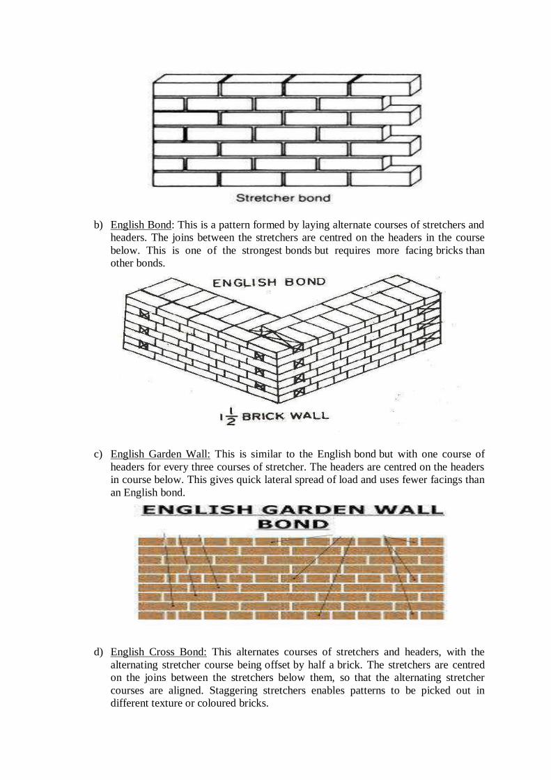
b) English Bond: This is a pattern formed by laying alternate courses of stretchers and
headers. The joins between the stretchers are centred on the headers in the course
below. This is one of the strongest bonds but requires more facing bricks than
other bonds.
c) English Garden Wall: This is similar to the English bond but with one course of
headers for every three courses of stretcher. The headers are centred on the headers
in course below. This gives quick lateral spread of load and uses fewer facings than
an English bond.
d) English Cross Bond: This alternates courses of stretchers and headers, with the
alternating stretcher course being offset by half a brick. The stretchers are centred
on the joins between the stretchers below them, so that the alternating stretcher
courses are aligned. Staggering stretchers enables patterns to be picked out in
different texture or coloured bricks.
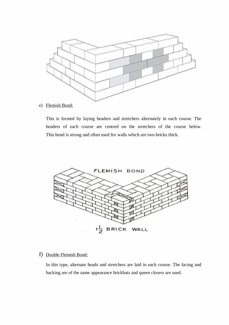
e) Flemish Bond:
This is formed by laying headers and stretchers alternately in each course. The
headers of each course are centred on the stretchers of the course below.
This bond is strong and often used for walls which are two-bricks thick.
f) Double Flemish Bond:
In this type, alternate heads and stretchers are laid in each course. The facing and
backing are of the same appearance brickbats and queen closers are used.
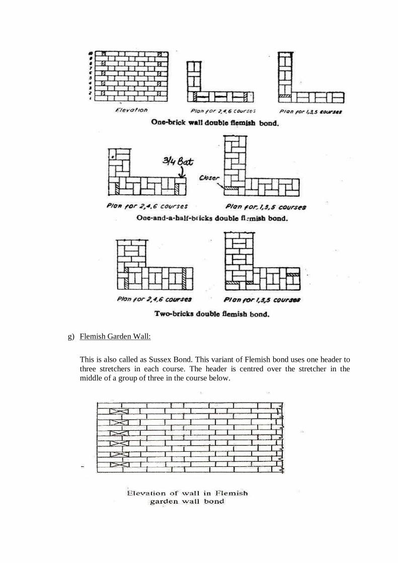
g) Flemish Garden Wall:
This is also called as Sussex Bond. This variant of Flemish bond uses one header to
three stretchers in each course. The header is centred over the stretcher in the
middle of a group of three in the course below.
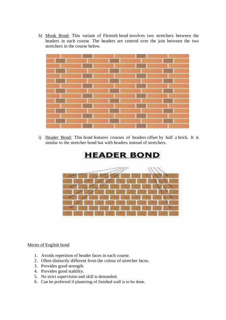
h) Monk Bond: This variant of Flemish bond involves two stretchers between the
headers in each course. The headers are centred over the join between the two
stretchers in the course below.
i) Header Bond: This bond features courses of headers offset by half a brick. It is
similar to the stretcher bond but with headers instead of stretchers.
Merits of English bond
1. Avoids repetition of header faces in each course.
2. Often distinctly different from the colour of stretcher faces.
3. Provides good strength.
4. Provides good stability.
5. No strict supervision and skill is demanded.
6. Can be preferred if plastering of finished wall is to be done.
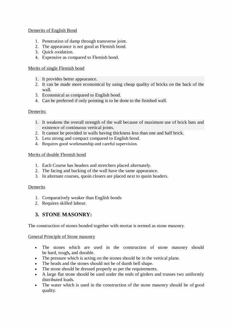
Demerits of English Bond
1. Penetration of damp through transverse joint.
2. The appearance is not good as Flemish bond.
3. Quick oxidation.
4. Expensive as compared to Flemish bond.
Merits of single Flemish bond
1. It provides better appearance.
2. It can be made more economical by using cheap quality of bricks on the back of the
wall.
3. Economical as compared to English bond.
4. Can be preferred if only pointing is to be done to the finished wall.
Demerits:
1. It weakens the overall strength of the wall because of maximum use of brick bats and
existence of continuous vertical joints.
2. It cannot be provided in walls having thickness less than one and half brick.
3. Less strong and compact compared to English bond.
4. Requires good workmanship and careful supervision.
Merits of double Flemish bond
1. Each Course has headers and stretchers placed alternately.
2. The facing and backing of the wall have the same appearance.
3. In alternate courses, quoin closers are placed next to quoin headers.
Demerits
1. Comparatively weaker than English bonds
2. Requires skilled labour.
3. STONE MASONRY:
The construction of stones bonded together with mortar is termed as stone masonry.
General Principle of Stone masonry
The stones which are used in the construction of stone masonry should
be hard, tough, and durable.
The pressure which is acting on the stones should be in the vertical plane.
The heads and the stones should not be of dumb bell shape.
The stone should be dressed properly as per the requirements.
A large flat stone should be used under the ends of girders and trusses two uniformly
distributed loads.
The water which is used in the construction of the stone masonry should be of good
quality.
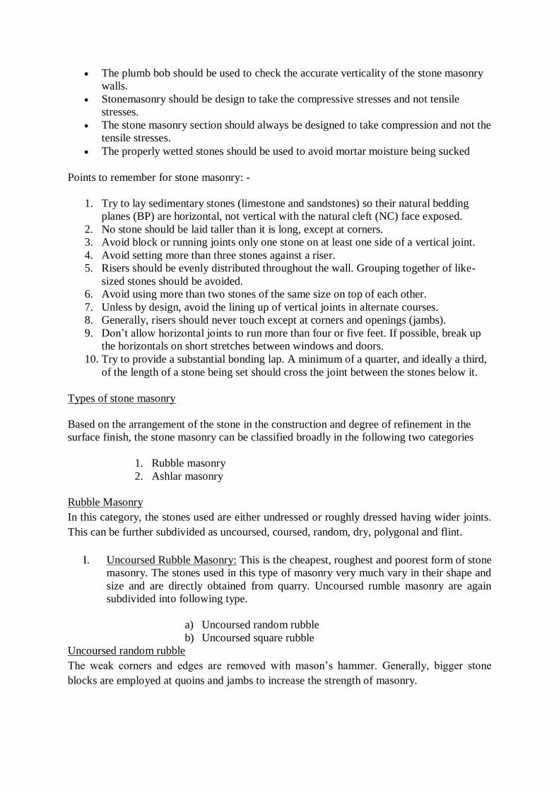
The plumb bob should be used to check the accurate verticality of the stone masonry
walls.
Stonemasonry should be design to take the compressive stresses and not tensile
stresses.
The stone masonry section should always be designed to take compression and not the
tensile stresses.
The properly wetted stones should be used to avoid mortar moisture being sucked
Points to remember for stone masonry: -
1. Try to lay sedimentary stones (limestone and sandstones) so their natural bedding
planes (BP) are horizontal, not vertical with the natural cleft (NC) face exposed.
2. No stone should be laid taller than it is long, except at corners.
3. Avoid block or running joints only one stone on at least one side of a vertical joint.
4. Avoid setting more than three stones against a riser.
5. Risers should be evenly distributed throughout the wall. Grouping together of like-
sized stones should be avoided.
6. Avoid using more than two stones of the same size on top of each other.
7. Unless by design, avoid the lining up of vertical joints in alternate courses.
8. Generally, risers should never touch except at corners and openings (jambs).
9. Don’t allow horizontal joints to run more than four or five feet. If possible, break up
the horizontals on short stretches between windows and doors.
10. Try to provide a substantial bonding lap. A minimum of a quarter, and ideally a third,
of the length of a stone being set should cross the joint between the stones below it.
Types of stone masonry
Based on the arrangement of the stone in the construction and degree of refinement in the
surface finish, the stone masonry can be classified broadly in the following two categories
1. Rubble masonry
2. Ashlar masonry
Rubble Masonry
In this category, the stones used are either undressed or roughly dressed having wider joints.
This can be further subdivided as uncoursed, coursed, random, dry, polygonal and flint.
I. Uncoursed Rubble Masonry: This is the cheapest, roughest and poorest form of stone
masonry. The stones used in this type of masonry very much vary in their shape and
size and are directly obtained from quarry. Uncoursed rumble masonry are again
subdivided into following type.
a) Uncoursed random rubble
b) Uncoursed square rubble
Uncoursed random rubble
The weak corners and edges are removed with mason’s hammer. Generally, bigger stone
blocks are employed at quoins and jambs to increase the strength of masonry.
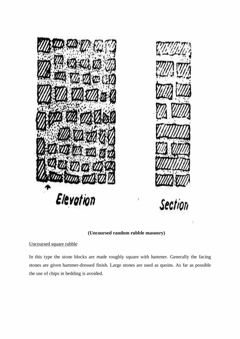
(Uncoursed random rubble masonry)
Uncoursed square rubble
In this type the stone blocks are made roughly square with hammer. Generally the facing
stones are given hammer-dressed finish. Large stones are used as quoins. As far as possible
the use of chips in bedding is avoided.
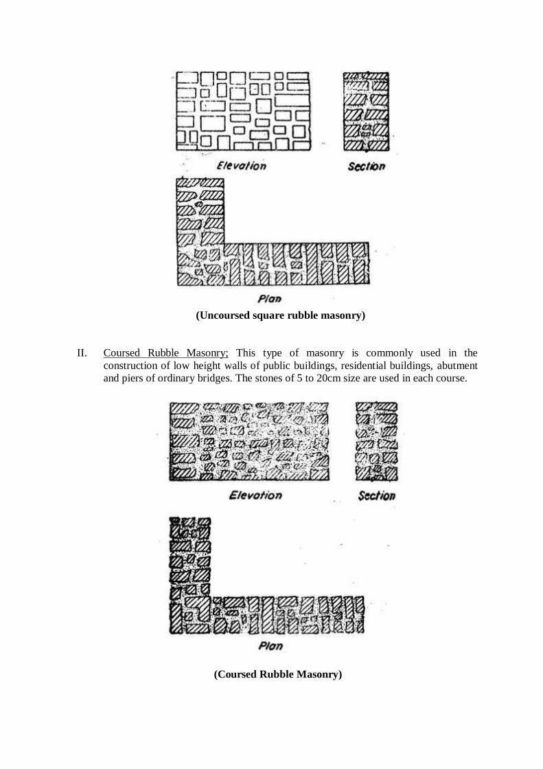
(Uncoursed square rubble masonry)
II. Coursed Rubble Masonry; This type of masonry is commonly used in the
construction of low height walls of public buildings, residential buildings, abutment
and piers of ordinary bridges. The stones of 5 to 20cm size are used in each course.
(Coursed Rubble Masonry)

III. Coursed Square Rubble: This type of masonry is made up of hammer squared stones
facing with bonded backing of uncoursed random rubble masonry. The stones
employed in each course are of equal height. The backing and facing construction
should be carried simultaneously. In order to avoid thick mortar joints, small chips
may be used.
(Coursed Square Rubble)
IV. Built to regular course: In this type of stone masonry the uniform height stones are
used in horizontal layers not less than 13cm in height. Generally, the stone beds are
hammered or chisel dressed to a depth of at least 10cm from the face. The stones are
arranged in such a manner so that the vertical joints of two consecutive curse do not
coincide with each other.
(Built to regular course)
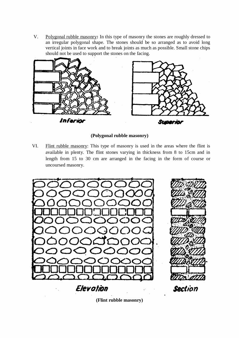
V. Polygonal rubble masonry: In this type of masonry the stones are roughly dressed to
an irregular polygonal shape. The stones should be so arranged as to avoid long
vertical joints in face work and to break joints as much as possible. Small stone chips
should not be used to support the stones on the facing.
(Polygonal rubble masonry)
VI. Flint rubble masonry: This type of masonry is used in the areas where the flint is
available in plenty. The flint stones varying in thickness from 8 to 15cm and in
length from 15 to 30 cm are arranged in the facing in the form of course or
uncoursed masonry.
(Flint rubble masonry)
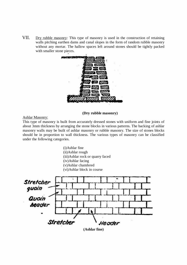
VII. Dry rubble masonry: This type of masonry is used in the construction of retaining
walls pitching earthen dams and canal slopes in the form of random rubble masonry
without any mortar. The hallow spaces left around stones should be tightly packed
with smaller stone pieces.
(Dry rubble masonry)
Ashlar Masonry:
This type of masonry is built from accurately dressed stones with uniform and fine joints of
about 3mm thickness by arranging the stone blocks in various patterns. The backing of ashlar
masonry walls may be built of ashlar masonry or rubble masonry. The size of stones blocks
should be in proportion to wall thickness. The various types of masonry can be classified
under the following categories.
(i)Ashlar fine
(ii)Ashlar rough
(iii)Ashlar rock or quarry faced
(iv)Ashlar facing
(v)Ashlar chamfered
(vi)Ashlar block in course
(Ashlar fine)
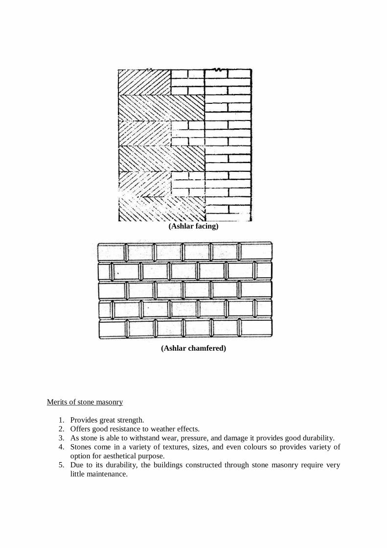
(Ashlar facing)
(Ashlar chamfered)
Merits of stone masonry
1. Provides great strength.
2. Offers good resistance to weather effects.
3. As stone is able to withstand wear, pressure, and damage it provides good durability.
4. Stones come in a variety of textures, sizes, and even colours so provides variety of
option for aesthetical purpose.
5. Due to its durability, the buildings constructed through stone masonry require very
little maintenance.

Demerits:
1. The stones used are heavy and produce thick walls. 2. It requires skilled worker.
3. Due to the thickness and heavyweight of the stones, handling these aspects can be
challenging and accidents can easily happen.
4. The construction cost of stone masonry is a bit on the higher side because of the
skilled labour required, the expensive equipment to be used and many other costs
incurred.
5. Stones are mostly found in designated areas such as quarries and therefore,
transportation of these stones to the sites is necessary. This is then more costly
because of the weight of the stones.
6. The total construction period takes a lot of time.
4. CAVITY WALL:
Cavity walls are constructed with two separate walls for single wall purpose with some space
or cavity between them. These two separate walls are called as leaves of cavity wall. The
inner wall is called as internal leaf and outer wall is called as external leaf. Cavity wall is also
called as Hollow wall.
For non-load bearing cavity wall, two leaves are of equal thickness or sometimes
internal leaf with more thickness is provided. The cavity size should be in between 4 to 10cm.
The internal and external leaves should have at least 10mm thickness. The two leaves are
interconnected by metal ties or links
Construction of cavity wall
In general, cavity wall doesn’t require any footings under it, just a strong concrete base is
provided on which cavity wall is constructed centrally. Two leaves are constructed like
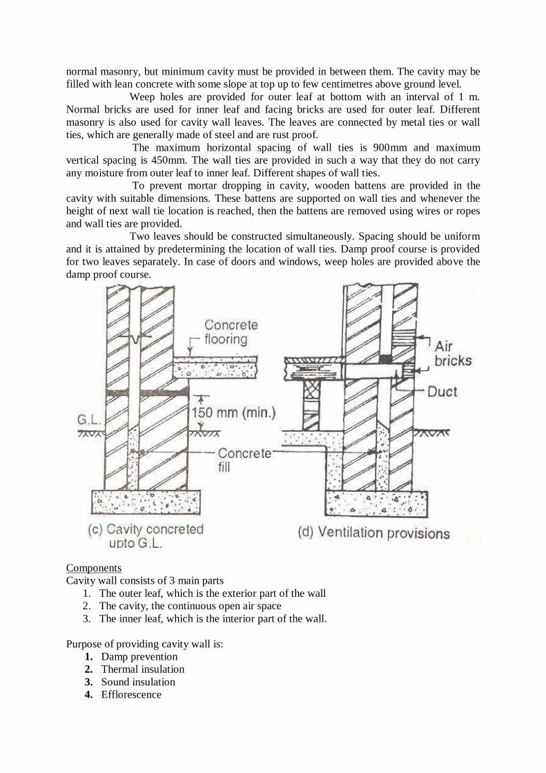
normal masonry, but minimum cavity must be provided in between them. The cavity may be
filled with lean concrete with some slope at top up to few centimetres above ground level.
Weep holes are provided for outer leaf at bottom with an interval of 1 m.
Normal bricks are used for inner leaf and facing bricks are used for outer leaf. Different
masonry is also used for cavity wall leaves. The leaves are connected by metal ties or wall
ties, which are generally made of steel and are rust proof.
The maximum horizontal spacing of wall ties is 900mm and maximum
vertical spacing is 450mm. The wall ties are provided in such a way that they do not carry
any moisture from outer leaf to inner leaf. Different shapes of wall ties.
To prevent mortar dropping in cavity, wooden battens are provided in the
cavity with suitable dimensions. These battens are supported on wall ties and whenever the
height of next wall tie location is reached, then the battens are removed using wires or ropes
and wall ties are provided.
Two leaves should be constructed simultaneously. Spacing should be uniform
and it is attained by predetermining the location of wall ties. Damp proof course is provided
for two leaves separately. In case of doors and windows, weep holes are provided above the
damp proof course.
Components
Cavity wall consists of 3 main parts
1. The outer leaf, which is the exterior part of the wall
2. The cavity, the continuous open air space
3. The inner leaf, which is the interior part of the wall.
Purpose of providing cavity wall is:
1. Damp prevention
2. Thermal insulation
3. Sound insulation
4. Efflorescence

5. ARCH:
An arch is a vertical curved structure that spans an elevated space and may or may not
support the weight above it, or in case of a horizontal arch like an arch dam, the hydrostatic
pressure against it.
Terminologies
1. Intradose: This is the inner curve of arch.
2. Soffit: This is the inner surface of the arch.
3. Extrados or Back: This is the external curve of an arch.
4. Voussoirs: These are the wedge-shaped units forming the courses of an arch.
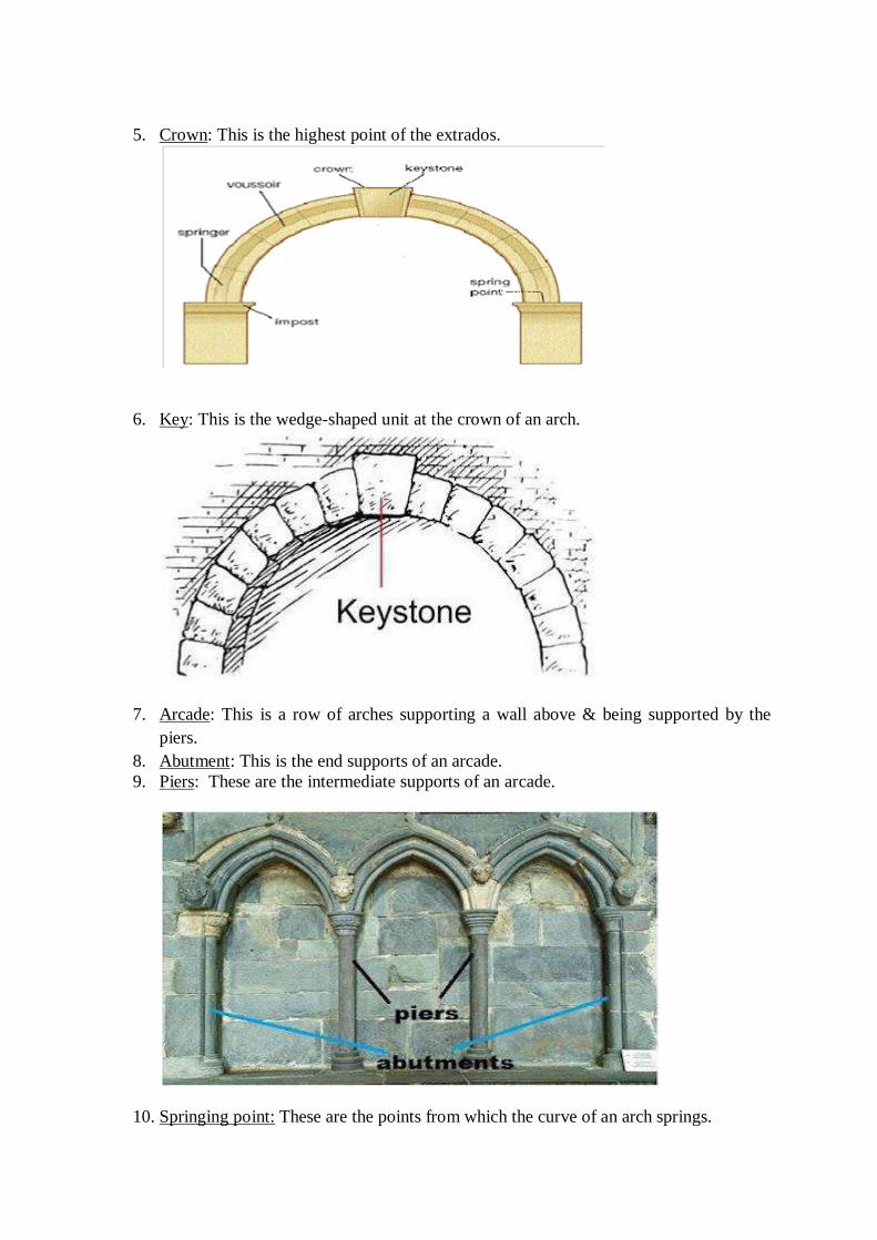
5. Crown: This is the highest point of the extrados.
6. Key: This is the wedge-shaped unit at the crown of an arch.
7. Arcade: This is a row of arches supporting a wall above & being supported by the
piers.
8. Abutment: This is the end supports of an arcade.
9. Piers: These are the intermediate supports of an arcade.
10. Springing point: These are the points from which the curve of an arch springs.
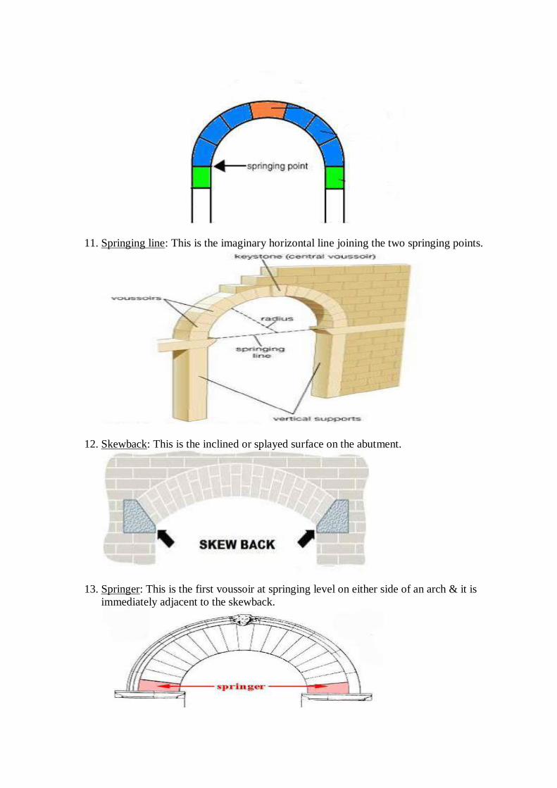
11. Springing line: This is the imaginary horizontal line joining the two springing points.
12. Skewback: This is the inclined or splayed surface on the abutment.
13. Springer: This is the first voussoir at springing level on either side of an arch & it is
immediately adjacent to the skewback.
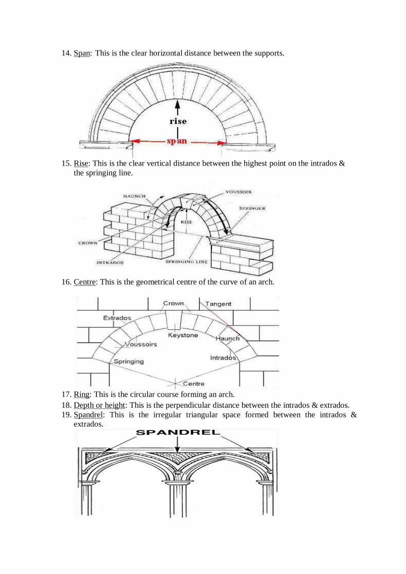
14. Span: This is the clear horizontal distance between the supports.
15. Rise: This is the clear vertical distance between the highest point on the intrados &
the springing line.
16. Centre: This is the geometrical centre of the curve of an arch.
17. Ring: This is the circular course forming an arch.
18. Depth or height: This is the perpendicular distance between the intrados & extrados.
19. Spandrel: This is the irregular triangular space formed between the intrados &
extrados.
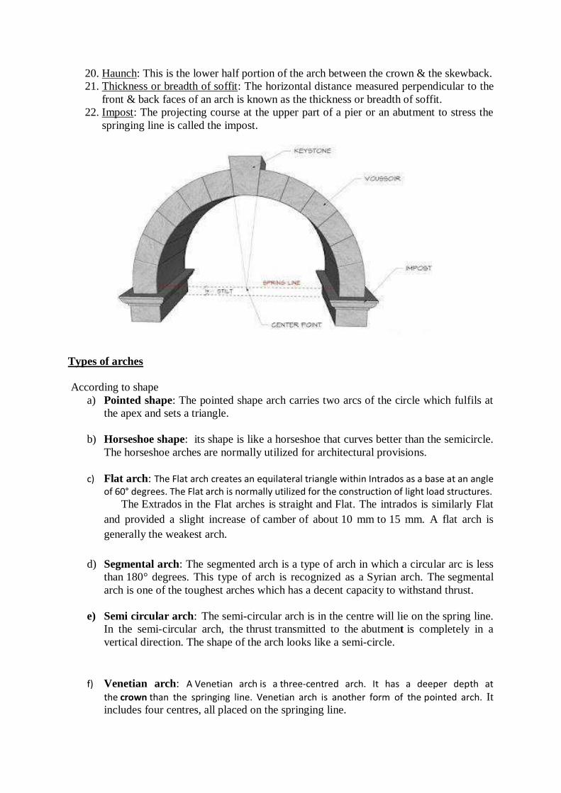
20. Haunch: This is the lower half portion of the arch between the crown & the skewback.
21. Thickness or breadth of soffit: The horizontal distance measured perpendicular to the
front & back faces of an arch is known as the thickness or breadth of soffit.
22. Impost: The projecting course at the upper part of a pier or an abutment to stress the
springing line is called the impost.
Types of arches
According to shape
a) Pointed shape: The pointed shape arch carries two arcs of the circle which fulfils at
the apex and sets a triangle.
b) Horseshoe shape: its shape is like a horseshoe that curves better than the semicircle.
The horseshoe arches are normally utilized for architectural provisions.
c) Flat arch: The Flat arch creates an equilateral triangle within Intrados as a base at an angle of 60° degrees. The Flat arch is normally utilized for the construction of light load structures. The Extrados in the Flat arches is straight and Flat. The intrados is similarly Flat
and provided a slight increase of camber of about 10 mm to 15 mm. A flat arch is
generally the weakest arch.
d) Segmental arch: The segmented arch is a type of arch in which a circular arc is less
than 180° degrees. This type of arch is recognized as a Syrian arch. The segmental
arch is one of the toughest arches which has a decent capacity to withstand thrust.
e) Semi circular arch: The semi-circular arch is in the centre will lie on the spring line.
In the semi-circular arch, the thrust transmitted to the abutment is completely in a
vertical direction. The shape of the arch looks like a semi-circle.
f) Venetian arch: A Venetian arch is a three-centred arch. It has a deeper depth at
the crown than the springing line. Venetian arch is another form of the pointed arch. It includes four centres, all placed on the springing line.
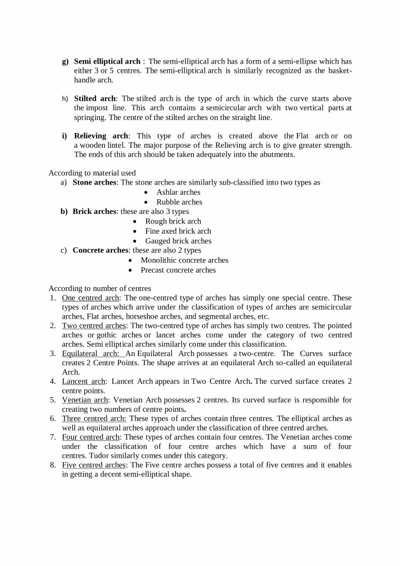
g) Semi elliptical arch : The semi-elliptical arch has a form of a semi-ellipse which has
either 3 or 5 centres. The semi-elliptical arch is similarly recognized as the basket-
handle arch.
h) Stilted arch: The stilted arch is the type of arch in which the curve starts above
the impost line. This arch contains a semicircular arch with two vertical parts at
springing. The centre of the stilted arches on the straight line.
i) Relieving arch: This type of arches is created above the Flat arch or on
a wooden lintel. The major purpose of the Relieving arch is to give greater strength.
The ends of this arch should be taken adequately into the abutments.
According to material used
a) Stone arches: The stone arches are similarly sub-classified into two types as
Ashlar arches
Rubble arches
b) Brick arches: these are also 3 types
Rough brick arch
Fine axed brick arch
Gauged brick arches
c) Concrete arches: these are also 2 types
Monolithic concrete arches
Precast concrete arches
According to number of centres
1. One centred arch: The one-centred type of arches has simply one special centre. These
types of arches which arrive under the classification of types of arches are semicircular
arches, Flat arches, horseshoe arches, and segmental arches, etc.
2. Two centred arches: The two-centred type of arches has simply two centres. The pointed
arches or gothic arches or lancet arches come under the category of two centred
arches. Semi elliptical arches similarly come under this classification.
3. Equilateral arch: An Equilateral Arch possesses a two-centre. The Curves surface
creates 2 Centre Points. The shape arrives at an equilateral Arch so-called an equilateral
Arch.
4. Lancent arch: Lancet Arch appears in Two Centre Arch. The curved surface creates 2
centre points.
5. Venetian arch: Venetian Arch possesses 2 centres. Its curved surface is responsible for
creating two numbers of centre points.
6. Three centred arch: These types of arches contain three centres. The elliptical arches as
well as equilateral arches approach under the classification of three centred arches.
7. Four centred arch: These types of arches contain four centres. The Venetian arches come
under the classification of four centre arches which have a sum of four
centres. Tudor similarly comes under this category.
8. Five centred arches: The Five centre arches possess a total of five centres and it enables
in getting a decent semi-elliptical shape.
6. DOORS:
A door is a movable barrier secured in an opening, known as the doorway, through a
building wall or partition for the purpose of providing access to the inside of a building or
rooms of a building. A door is held in position by doorframes, the members of which are
located at the sides and top of the opening or doorway.
TYPES OF DOORS BASED ON PLACING OF COMPONENTS
1. Battened and legged doors
Battens are vertical bonds which are having grooves are attached together by horizontal
supports called ledges as shown in below figure.
General Dimensions of batten are 100-150mm width and 20-30mm thick.
General dimension of ledges are 100-200mm width and 25-30mm thick.
This type of battened and ledged doors suitable for narrow openings.
2. Battened, legged and braced doors
To make more rigid, braces are provided diagonally in additional to battens and ledges as
shown in figure.
Braces are having 100-150mm width and 25-30mm thickness are preferable.
Braces should place upwards from handing side, then they acts as struts and take
compression.
These types of doors can be used for wider openings.
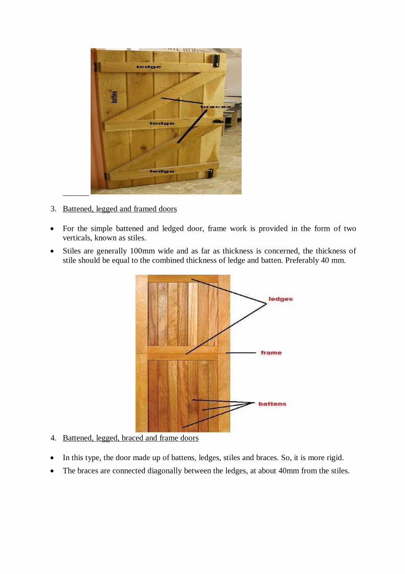
3. Battened, legged and framed doors
For the simple battened and ledged door, frame work is provided in the form of two
verticals, known as stiles.
Stiles are generally 100mm wide and as far as thickness is concerned, the thickness of
stile should be equal to the combined thickness of ledge and batten. Preferably 40 mm.
4. Battened, legged, braced and frame doors
In this type, the door made up of battens, ledges, stiles and braces. So, it is more rigid.
The braces are connected diagonally between the ledges, at about 40mm from the stiles.
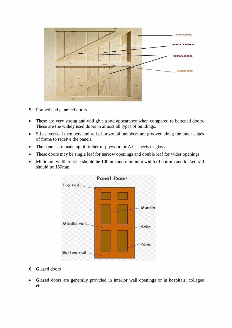
5. Framed and panelled doors
These are very strong and will give good appearance when compared to battened doors.
These are the widely used doors in almost all types of buildings.
Stiles, vertical members and rails, horizontal members are grooved along the inner edges
of frame to receive the panels.
The panels are made up of timber or plywood or A.C. sheets or glass.
These doors may be single leaf for narrow openings and double leaf for wider openings.
Minimum width of stile should be 100mm and minimum width of bottom and locked rail
should be 150mm.
6. Glazed doors
Glazed doors are generally provided in interior wall openings or in hospitals, colleges
etc.
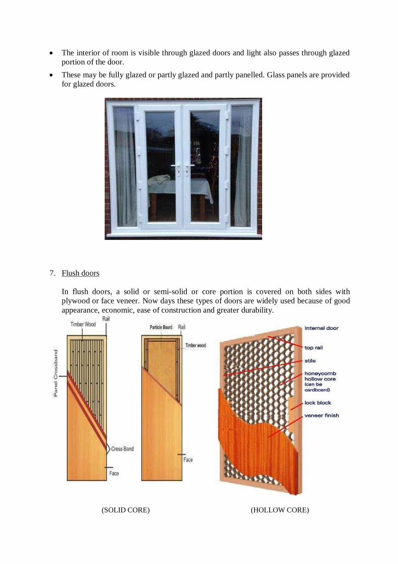
The interior of room is visible through glazed doors and light also passes through glazed
portion of the door.
These may be fully glazed or partly glazed and partly panelled. Glass panels are provided
for glazed doors.
7. Flush doors
In flush doors, a solid or semi-solid or core portion is covered on both sides with
plywood or face veneer. Now days these types of doors are widely used because of good
appearance, economic, ease of construction and greater durability.
(SOLID CORE) (HOLLOW CORE)
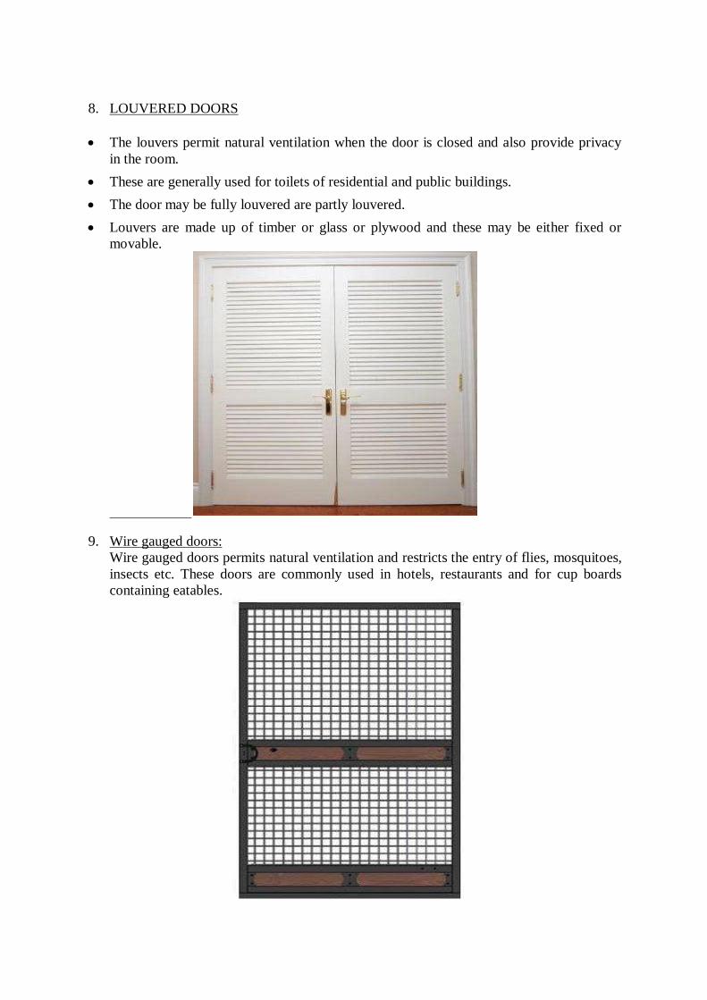
8. LOUVERED DOORS
The louvers permit natural ventilation when the door is closed and also provide privacy
in the room.
These are generally used for toilets of residential and public buildings.
The door may be fully louvered are partly louvered.
Louvers are made up of timber or glass or plywood and these may be either fixed or
movable.
9. Wire gauged doors:
Wire gauged doors permits natural ventilation and restricts the entry of flies, mosquitoes,
insects etc. These doors are commonly used in hotels, restaurants and for cup boards
containing eatables.
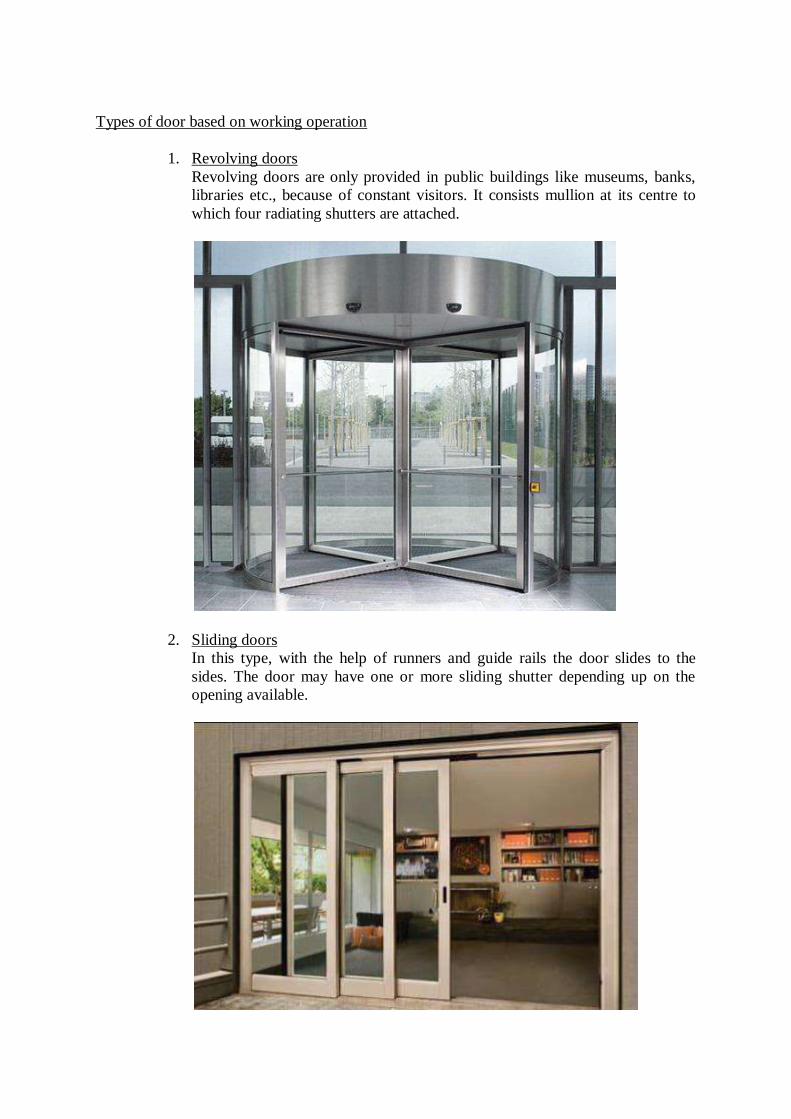
Types of door based on working operation
1. Revolving doors
Revolving doors are only provided in public buildings like museums, banks,
libraries etc., because of constant visitors. It consists mullion at its centre to
which four radiating shutters are attached.
2. Sliding doors
In this type, with the help of runners and guide rails the door slides to the
sides. The door may have one or more sliding shutter depending up on the
opening available.
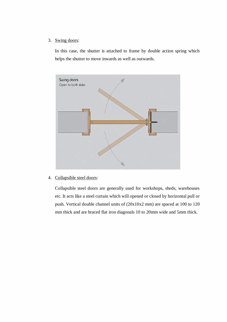
3. Swing doors:
In this case, the shutter is attached to frame by double action spring which
helps the shutter to move inwards as well as outwards.
4. Collapsible steel doors:
Collapsible steel doors are generally used for workshops, sheds, warehouses
etc. It acts like a steel curtain which will opened or closed by horizontal pull or
push. Vertical double channel units of (20x10x2 mm) are spaced at 100 to 120
mm thick and are braced flat iron diagonals 10 to 20mm wide and 5mm thick.
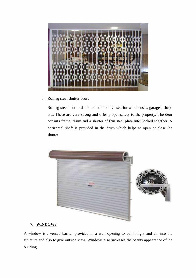
5. Rolling steel shutter doors
Rolling steel shutter doors are commonly used for warehouses, garages, shops
etc.. These are very strong and offer proper safety to the property. The door
consists frame, drum and a shutter of thin steel plate inter locked together. A
horizontal shaft is provided in the drum which helps to open or close the
shutter.
7. WINDOWS
A window is a vented barrier provided in a wall opening to admit light and air into the
structure and also to give outside view. Windows also increases the beauty appearance of the
building.

TYPES OF WINDOWS
1. Fixed windows;
Fixed windows are fixed to the wall without any closing or opening operation. In
general, they are provided to transmit the light into the room. Fully glazed shutters are
fixed to the window frame. The shutters provided are generally weatherproof.
2. Sliding windows:
In this case, window shutters are movable in the frame. The movement may be
horizontal or vertical based on our requirements. The movement of shutters is done by
the provision of roller bearings. Generally, this type of window is provided in buses,
bank counters, shops, etc.
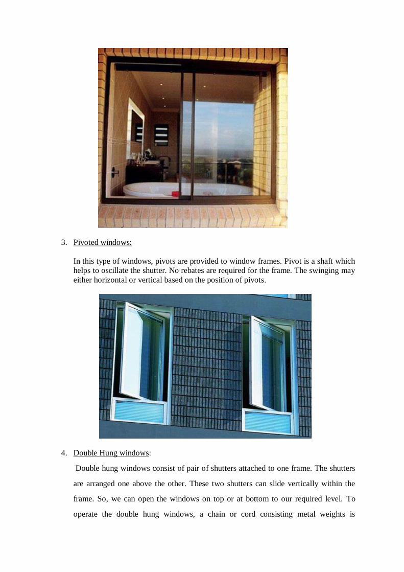
3. Pivoted windows:
In this type of windows, pivots are provided to window frames. Pivot is a shaft which
helps to oscillate the shutter. No rebates are required for the frame. The swinging may
either horizontal or vertical based on the position of pivots.
4. Double Hung windows:
Double hung windows consist of pair of shutters attached to one frame. The shutters
are arranged one above the other. These two shutters can slide vertically within the
frame. So, we can open the windows on top or at bottom to our required level. To
operate the double hung windows, a chain or cord consisting metal weights is
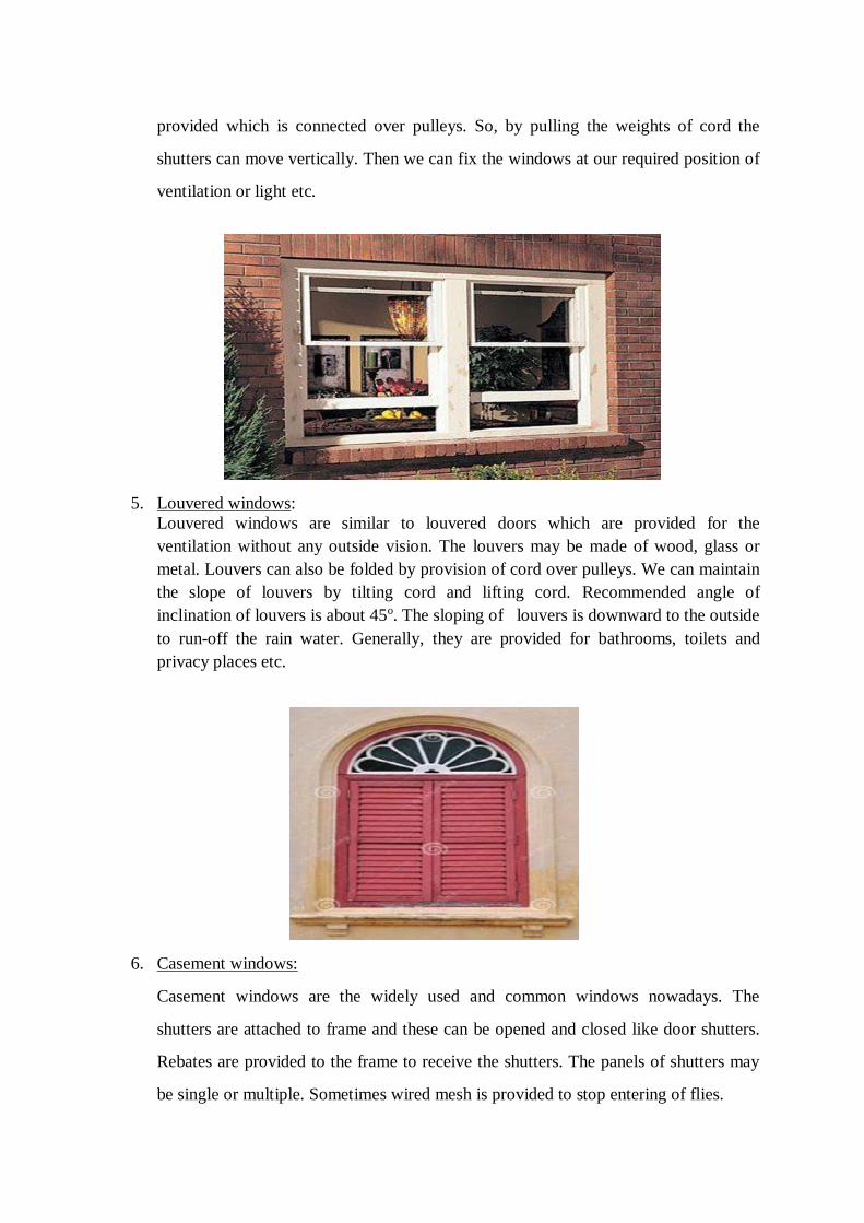
provided which is connected over pulleys. So, by pulling the weights of cord the
shutters can move vertically. Then we can fix the windows at our required position of
ventilation or light etc.
5. Louvered windows:
Louvered windows are similar to louvered doors which are provided for the
ventilation without any outside vision. The louvers may be made of wood, glass or
metal. Louvers can also be folded by provision of cord over pulleys. We can maintain
the slope of louvers by tilting cord and lifting cord. Recommended angle of
inclination of louvers is about 45o. The sloping of louvers is downward to the outside
to run-off the rain water. Generally, they are provided for bathrooms, toilets and
privacy places etc.
6. Casement windows:
Casement windows are the widely used and common windows nowadays. The
shutters are attached to frame and these can be opened and closed like door shutters.
Rebates are provided to the frame to receive the shutters. The panels of shutters may
be single or multiple. Sometimes wired mesh is provided to stop entering of flies.
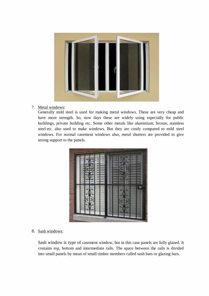
7. Metal windows:
Generally mild steel is used for making metal windows. These are very cheap and
have more strength. So, now days these are widely using especially for public
buildings, private building etc. Some other metals like aluminium, bronze, stainless
steel etc. also used to make windows. But they are costly compared to mild steel
windows. For normal casement windows also, metal shutters are provided to give
strong support to the panels.
8. Sash windows:
Sash window is type of casement window, but in this case panels are fully glazed. It
contains top, bottom and intermediate rails. The space between the rails is divided
into small panels by mean of small timber members called sash bars or glazing bars.
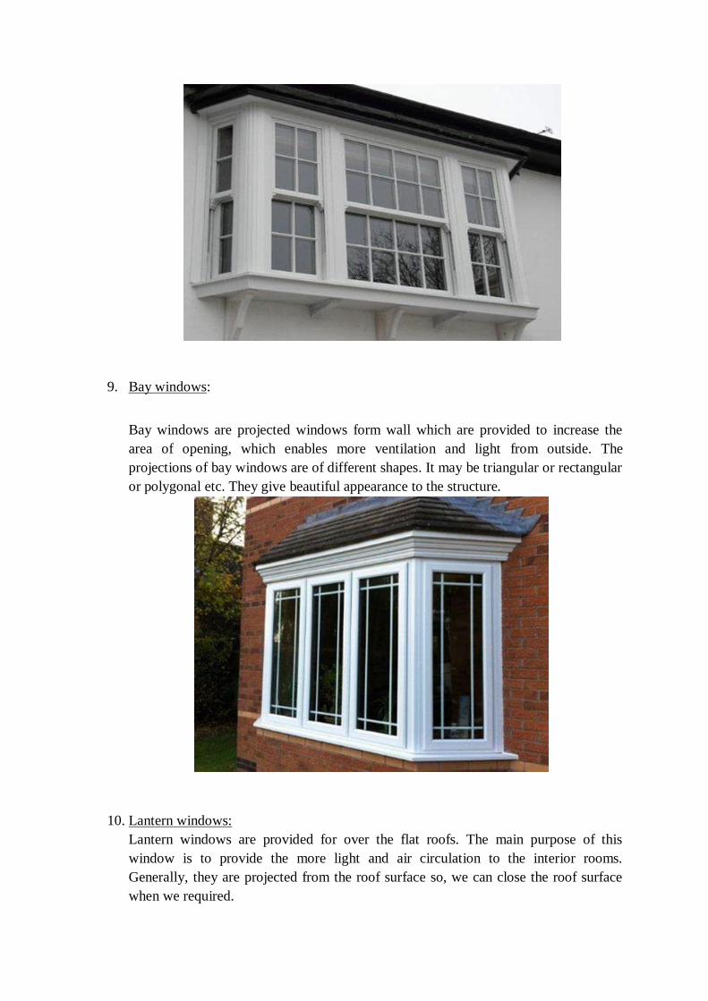
9. Bay windows:
Bay windows are projected windows form wall which are provided to increase the
area of opening, which enables more ventilation and light from outside. The
projections of bay windows are of different shapes. It may be triangular or rectangular
or polygonal etc. They give beautiful appearance to the structure.
10. Lantern windows:
Lantern windows are provided for over the flat roofs. The main purpose of this
window is to provide the more light and air circulation to the interior rooms.
Generally, they are projected from the roof surface so, we can close the roof surface
when we required.
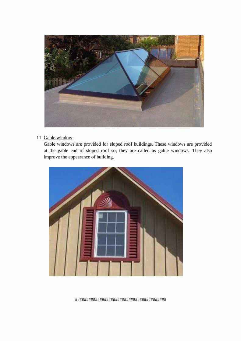
11. Gable window:
Gable windows are provided for sloped roof buildings. These windows are provided
at the gable end of sloped roof so; they are called as gable windows. They also
improve the appearance of building.
#########################################
Civil Engineering Materials and Constructions (BCE03002)
Module-V
Basic Building Construction
Module V Syllabus
Finishing, Services and Special constructions
Wall Finishes: Plastering, pointing, distempering and painting: Purpose, methods, defects and
their solutions. Vertical communication: Stairs: Terminology, requirements of good staircase,
classification; ramps, lifts and escalators. Damp proofing: causes, effects, prevention and
treatments, Fire resistant construction: Fire resistant properties of common building materials,
requirements for various building components.
Subject to Revision
1. WALL FINISHES:
1.1 PLASTERING:
Definition of Plastering:
plastering is a layer provide over masonry or concrete surface for the purpose of protect wall and
other concrete element against the atmospheric effect, and also provide finishing surface.
Purpose of Plastering
1)Plastering is a method that is used to increase the durability of the wall. The purpose of plastering
is to decorate the structures of the walls. Plastering of external walls refers to the process of
covering the uneven surface and rough walls with the help of a plastic material named as plaster.
2)The plaster is prepared by mixing sand and lime or cement concrete along with water. There are
various requirements of a plaster that must be fulfilled while doing plastering of external walls.
3)To prevent water ingress into brickwork / blockwork, since both bricks and blocks absorb water
from outside. This is the reason why most stoneworks are left un-plastered.
4)In case of walls - to make up the issues in underlying brickwork / blockwork - like plumb-outs,
diagonal-outs, etc.
5)To prepare a proper base for further painting works (Putty application, paint application, wall
paper application, etc.)
Requirement of Good Plaster
-The surface of plaster should be smooth
-The surface of plaster should be non-absorbent
-The plaster surface should not wash by water
-Plaster should not shrink when it dries or freezes
-The shrinkage cracks is not developed in plaster
-The plaster should be firmly attached to the masonry surface
-The fire resistance of plaster should be good
-The plaster should be sound insulated
-The surface of the plaster should be paintable
Methods of Plastering
Plater is applied in the manner mention below. To get uniform 150 x 150 mm and 10 mm thick
dots are prepared on the surface at a lower level.
Those dots are transferred on the upper level with a plumb bob, so the dots of the upper level and
lower come in one and vertical surface.
In this, any dots are applied on all the surface of the wall at 1500 to 2000 mm. Four dots are
covered masonry with the help or screed, and plaster is applied properly. Lime plaster is applied
in these coats or in three coats or in two cots. The background is prepared before applying plaster.
Different Layers of plaster:
1) Three Coat Plaster
● Application of Rendering Coat
● Application of Floating Coat
● Application of Finishing Coat
2) Two Coat Plaster
3) Cement Plaster and Cement Lime Plaster
4) Single Coat Plaster
5) Plaster on Lath
● Wooden Laths
● Metal Lath
1) Three Coat Plaster
The procedure of applying three-coat plaster is similar to two-coat plaster only difference is that
an intermediate coat is known as a floating coat. The purpose of this coat is to bring the plaster to
an even surface. In the case of 3-coat plaster, the first coat is known id rendering coat, the second
coat is known as a floating coat, and third coat is known as setting coat or finishing coat. The
rendering coat is applied, and scratches are made. The floating coat is applied, and after seven days
finished coat is applied, after 6 hours of applying a floating coat.
-Application of Rendering Coat
The mortar is applied forcibly on the surface of wall. With masons trowel and pressed well into
joints and over the surface. The thickness of the coat should be such as to cover all inequalities of
the surface normally this thickness is 12mm.
This coat is allowed to harden slightly a then scratch marks are made on the surface with the help
of trowel ledge. During this period, the surface is curved and then allowed to dry completely
-Application of Floating Coat
The first coat is prepared properly to apply the second coat, i.e., a floating coat. All dirt and dust
are cleared. It is wetted properly. 10 cm wide strips or 15 cm x 15 cm patches are applied at a
suitable distance. These patches or strips act as a gauge for thickness or floating coat. The mortar
is dashed with mason’s trowel, spread, and rubbed to the required plain surface with a wooden
float. The floating coat is beaten with floats edge at the close spacing of cm. Then it is allowed to
dry completely. The thickness or floating coat is 6 to 9 mm.
-Application of Finishing Coat
The third coat is called a finishing coat. In the Case of lime-sand mortar, the finishing coat is
applied immediately after the floating coat cream of lime and sand in 4:1 are applied with a steel
trowel and rubbed and finished smooth.
2) Two Coat Plaster
The joints are ranked at a depth of 20 mm. The surface is cleaned, and water is sprinkled property
on it.Before the first coat is applied preliminary coat is applied to make an uneven surface in le.
Then, the first coat is applied. The first coat is racked as a rendering coat. The thickness first coat
is kept 2 to 3 mm less than a total thickness of plaster. To maintain interim thickness and vertically
of plaster 15 cm * 15 cm dots or are provided, Then a vertical strip of mortar known as the spread
is formed at a distance of 2 m. spacing.Then the spaces between screeds are filled with mortar and
properly finished.Scratches are made on rendering coat to provide mechanical key before it
hardens. The rendering coat is watered for 2 days and then dried.
Before applying the final/coat, the rendering coat is damped well. The final coat is applied with
wooden floats to a true even surface with steel trowels. The thickness of the final coat may vary
from 2 to 3 mm.
3) Single Coat Plaster
This is used only in interior quality work. It is applied similar to two coat plaster except that the
rendering coat as applied fro two-coat plaster is finishing off immediately after it has sufficiently
hardened
4) Cement Plaster and Cement Lime Plaster
For interior work single coat plaster is applied. For good quality works, either two coat or three
coat plaster is applied. But two coat plaster is more common sow shall discuss it first.
5) Plaster on Lath
Thin partition walls and ceilings are plastered using laths. Laths are provided as a foundation to
receive plasterwork. Laths may be.
-Wooden laths
-Metal laths
Wooden laths are well seasonal wooden strips 25 mm wide and 1 to 1.2 m long. Wooden laths are
used and ceilings.Laths are fixed in a parallel line with a clear spacing of 10 mm and secured to
the surface with galvanized iron nails.
Metal laths are available under various patent names. The plain expanded metal lath(exam) is
commonly metal laths are fixed to the surface by G.I Staples.In the case of concrete or masonry
surfaces, wooden plugs have to be embedded for fixing the lath. After fixing the lath, the surface
is plastered, usually, in there coats, cement mortar is usually used.
Plaster Defects and their Solution:
Plaster is a common material used in construction all around the world. Easy to work with and also
easier to repair. However, there will be times when your plaster starts to show signs of wear and
tear or other problems.If the plaster quality is not good enough it can cause many problems later.
1). Blistering of Plastered Surface
Blistering is the formation of small patches of plaster, swelling out beyond the plastered surface,
arising due to late slaking (addition of water to lime) of lime particles in the plaster. This defect is
usually caused due to the uneven mixing of plaster.
How to prevent it: This can be prevented by ensuring appropriate mixing between cement and
its components used to form plaster.
2) Plaster De-bonding
De-bonding occurs when a plaster is separated from the wall. It can be caused by an excessively
thick plaster layer, inadequate substrate preparation or may be due to a dusty, oily or dry substrate.
How to prevent it: To prevent de-bonding of plaster, we need to take care of the following things
during plastering.
● Remove dust & oil from the substrate before plastering.
● Allow substrate to reach correct moisture content.
● If necessary, you should use bonding chemical.
3) Cracks on Plastered Surface
One of the most common problems you would have observed in plastering is the crack. Cracks on
the plastered surface can be in different forms:
Crazing – It is a network of fine cracks like spider web. They are usually very fine and do not
extend through the whole depth of the plaster. It occurs due to presence of excess fine content in
the sand or due to dry base on which plaster is applied – when base absorbs the water and fines
accumulate on the surface, it leads to crazing.
Separation crack at joints – It usually occurs at joints of two different materials for example at
junction of RCC & Brick work. It occurs due to differential thermal movement.
Crack with Hollowness – This crack occurs due to hollowness in plaster. Other reasons could be
extra water in the plaster mix or due to poor workmanship.
How to prevent it: Mainly cracks occur due to bad workmanship or expansion and shrinkage in
the plaster during drying. Below are few tips to prevent cracks:
● Ensure the addition of water in mortar done is by skilled mason and not by unskilled labour
to ensure desired workability in terms of handling and application.
● It can be avoided by proper curing of the plaster in order to slow down any rapid drying.
● Taking care of workmanship and material quality issues will help in preventing cracks.
4) Efflorescence on Plastered Surface
When a newly constructed wall dries out, the soluble salts are brought to the surface and they
appear in the form of a whitish crystalline substance. This is called efflorescence. Efflorescence is
formed on plasters when soluble salts are present in plaster making materials as well as building
materials such as bricks, sand, cement etc. Even water used in the construction work may contain
soluble salts. It seriously affects the adhesion of paint with the wall surface and causes further
problems.
How to prevent it:
All Construction materials used for wall should be free from salt.
Ensuring that the surface is moisture-free.
5). Falling Out of Plaster
This defect can happen in two forms – Flaking of plaster and peeling off plaster.
● Flaking of plaster: The formation of a small loose mass on the plastered surface is known
as flaking. It is mainly due to bond failure between successive coats of plaster.
● Peeling off plaster: The plaster from some portion of the surface comes off and a patch is
formed. This is termed as peeling. It is also mainly due to bond failure between successive
coats of plaster.
How to prevent it: Both defects can be prevented with proper material selection and surface
preparation. Imperfect adhesion can be minimized by good workmanship.
6) Popping of Plaster
Popping is the formations of conical like holes that break out of the plaster. It is caused due to the
presence of contaminant particles such as burnt lime or other organic materials in the mix of
mortar.
How to prevent it: To prevent popping in plastering, you need to ensure that no contaminant
particles are present in the mortar mix.
7) Loose Plaster
When the plaster gets displaced on external impacts like application of material or tapping, etc, it
is termed as loose plaster. This is caused mainly due to improper mixture and inadequate curing.
How to prevent it: Good workmanship will help in avoiding this problem.
Apart from the above defects, Uneven or undulation also occurs at plastered surface. The plastered
surface should be in perfect plumb and without any undulations. Unevenly plastered surface
happens due to poor workmanship2 of the plastering work.
1.2 POINTING:
Definition of pointing: Pointing is the finishing of mortar joints in brick or stone masonry
construction. Pointing is the implementing of joints to a depth of 10 mm to 20 mm and filling it
with better quality mortar in desired shape. It is done for cement mortar and lime mortar joints.
Purpose of pointing:
Pointing is adopted due to the following purposes.
* For the protection of exposed surface from adverse effects due to atmospheric action like rain,
sun, wind, snow etc.
* To hide the interior mortar and inferior quality.
* To develop a decorative impact or to enhance the appearance.
Methods of pointing:
*Mortar joints of the surface (Brick Masonry or Stone Masonry) to be pointed are raked out to a
depth of about 13 to 20 mm.
*The raked joints are cleaned from loose mortar and completely wetted. Mortar is taken in small
flat rectangular plates made of iron.
*Pointing should be finished as per the expected finishing with the help of the particular tool.
*Curing should be done on the pointed surface for at least three days in case of lime mortar and
ten days in case of cement mortar.
Types of pointing:
1. Flush Pointing
Flush pointing is the most accessible type of pointing and is generally utilised in brick masonry
and stone masonry. In flush pointing, mortar is pushed into the raked joints and joints are made
flush with the edge of the stone or brick to provide a uniform appearance.
After that, with the help of a trowel and straight edge, edges are precisely trimmed. This type of
pointing doesn’t have a good appearance, but it doesn’t have any space for dust and water which
make it long-lasting.
2. Recessed Pointing
Recessed pointing has a vertical pointing face and provides a better appearance. A recessed
pointing mortar is pushed back inside the surface of the wall with a vertical pointing face with the
help of a suitable pointing tool.
3. Beaded Pointing
Beaded pointing is made with the help of a steel or iron rod having a concave edge. Beaded
pointing provides a better appearance, but it is susceptible to damage and maintenance is difficult.
4. Struck Pointing
In struck pointing, have inclined or sloping pointing face as shown in the image. The upper edge
of the joint is about 3 to 6 mm pushed back inside from the face of the brick.This joint helps to
dispose of water quickly. When the lower edge of the joint is kept inside from the face of brick or
stone, it is called overhand struck pointing. But it will not make an adequate joint because water
may collect in the joint.
5. Rubbed, Keyed or Grooved Pointing
In tuck pointing, a channel or groove of 5mm width and 3 mm depth is created at the middle of
the mortar joint. Then the groove or track is packed up by white cement putty having a projection
of 3 mm. If the node is made in the mortar, it is known as bastard pointing or half – tuckpointing.
6. Tuck Pointing
In this case mortar is pressed in the raked joint first and finishing flush with the face.While the
pressed mortar is green, groove or narrow channel is cut in the center of groove which is having
5mm width and 3mm depth. This groove is then filled with white cement putty, kept projecting
beyond the face of the joint by 3 mm. if projection is done in mortar, it is called bastard pointing
or half tuck pointing.
7. V- Grooved Pointing
This type of point is similar to keyed or grooved pointing except that instead of a normal groove,
v groove is formed using a suitable shaped steel rod.
1.3 DISTEMPERING:
Distemper: Distemper is a water based paint in which the binding medium consists essentially of
either glue or casein, or similar sizing material. The major constituents of distemper are chalk,
lime, water and some coloring agents if necessary. They are also known as cement paint. This is
called so because such kind of paint can be applied directly on cement walls without any other
coating on them. They are a cheaper option and they stay good for more than 5 years. Distempers
are used for both interior and exterior walls usually needing two coatings.
Ingredients of Distemper:
Distemper is composed of base, carrier, colouring pigments and size. For base, the whiting or chalk
is used and for carrier, the water is used. Thus it is more or less a paint in which whiting or chalk
is used as base instead of white lead and the water is used as carrier instead of linseed oil.
The distempers are available in powder form or paste form. They are to be mixed with hot water
before use. The oil-bound distempers are a variety of an oil paint in which the drying oil is so
treated that it mixes with water. The emulsifying agent which is commonly used is glue or casein.
As the water dries, the oil makes a hard surface which is washable.
It should be remembered that most of the manufacturers of ready-made distempers supply
complete directions for use of their products. These directions are to be strictly followed to achieve
good results.
Properties of Distempers:
(i) On drying, the film of distemper shrink. Hence it leads to cracking and flaking, if the surface to
receive distemper is weak.
(ii) The coatings of distemper are usually thick and they are more brittle than other types of water
paints.
(iii) The film developed by distemper is porous in character and it allows water vapour to pass
through it. Hence it permits new walls to dry out without damaging the distemper film.
(iv) They are generally light in colour and they provide a good reflective coating.
(v) They are less durable than oil paints.
(vi) They are treated as water paints and they are easy to apply.
(vii) They can be applied on brickwork, cement plastered surface, lime plastered surface, insulating
boards, etc.
(viii) They exhibit poor workability.
(ix) They prove to be unsatisfactory in damp locations such as kitchen, bathroom, etc.
Process of Distempering:
The application of distemper is carried out in the following way:
(1) Preparation of Surface:
The surface to receive the distemper is thoroughly rubbed and cleaned.
The important facts to be kept in mind are:
(i) The new plastered surfaces should be kept exposed for a period of two months or so to dry out
before distemper is applied on them. The presence of dampness on the surface results in failure of
distemper coating.
(ii) The surface to receive distemper should be free from any efflorescence patches. These are to
be wiped out by clean cloth.
(iii) The irregularities such as cracks, holes, etc. of the surface are to be filled by lime putty or
gypsum and allowed to become hard before distemper is applied on the surface.
(iv) If distemper is to be applied on the existing distempered surfaces, the old distemper should be
removed by profuse watering.
(2) Priming Coat:
After preparing the surface to receive the coats of distemper, a priming coat is applied and it is
allowed to become dry. For ready-made distempers, the priming coat should be composed of
materials as recommended by the makers of distempers. For local made distempers, the milk is
used for priming coat. One litre of milk will cover about 10 m2 of the surface.
(3) Coats of Distemper:
The first coat of distemper is then applied on the surface. It should be of a light tint and applied
with great care. The second coat of distemper is applied after the first coat has dried and become
hard.
Following facts are to be remembered:
(i) The distempering should be done in dry weather to achieve better results.
(ii) The oil-bound distemper or washable distemper adheres well to oil- painted walls, wood,
corrugated iron, etc. But a priming coat of pure milk should be applied before distempering is done
on such surfaces.
(iii) The application of distemper by a spraying pistol is superior to that by brushes. The spraying
affords smooth and durable film of distemper.
Defects in Distempering:
The following are the defects which may occur in distempering work.
1. Blistering: It is the defect caused due to the formation of bubbles under the distempering film.
The bubbles are formed by water vapours trapped behind the surface.
2. Bloom: In this defect, dull patches are formed on the finished surface. This may be due to the
defect in distempering material or bad ventilation.
3. Crawling or sagging: This defect occurs due to the application of too thick a distempering coat.
4. Flaking: Flaking is the loosening of some portion of the distempered surface.
5. Fading: This is the gradual loss of colour of distemper, due to the effect of sunlight.
6. Flashing: It is the formation of glossy patches on the surface, resulting from bad workmanship.
7. Grinning: This defect is caused when the final coat does not have sufficient opacity so that
background is clearly seen.
1.4 PAINTING:
Paints are coatings of fluid materials which are applied as a final finish to surfaces like walls,
ceiling, wood and metal works.
Painting is done to protect the surface from the effects of weathering, to prevent wood from decay
and metal from corrosion, to provide a decorative finish and to obtain a clean, hygienic and healthy
living atmosphere.
Purpose of painting:
1. Decoration to Interiors and Exteriors of a Building
2. They are used to enhance the interior and exterior of a building by adding pigments,
lightness or darkness
3. Reflective surfaces can be also be obtained
4. Now a days textures are also added for different designs Protective Layer
5. Paint are used to protect the outer surfaces of a building or metals to protect them against:
○ Sunlight
○ Dampness
○ Dust
○ Abrasion
○ Weathering
○ Ease of Cleaning
○ To provide easily cleanable surfaces
○ To keep the substrates clean and tidy
Methods and Process of Painting on Different Surfaces
● New wood work
● Repainting Old wood surface
● New iron and steel surfaces
● Repainting of old steel and iron surfaces
● Galvanized iron surface
● Metals
● Plastered surfaces
● Painting on New Wood Work
Following are the steps for painting new wooden surfaces:
● Surface preparation
● Knotting
● Priming
● Stopping
● Under coating
● Finishing
1. Surface Preparation of Wooden Works
The surface should be well cleaned without any dust, spots, greasy matter etc. The nails used in
the wood work should be punched up to 3mm below the surface. The wood in wood work should
be well seasoned and should not contain more than 15% of moisture content. The surface should
be dry.
2. Knotting
Knots present in the wood may eject resins from wood. So, knots are killed or covered in this
knotting process. Knotting can be done by two ways as follows: 1. In this first method, two coats
of solutions are applied on surface. First coat consists 15g of red lead, 2 liters of water and 225
grams of glue. After adding these three, mixture is heated and applied and left for 10 minutes.
After that second coat is applied which consists red lead ground in boiled linseed oil and thinned
with turpentine oil. 2. In this method, hot lime coat is applied on surface and left it for 24 hours.
After that the layer is scrapped off from the surface.
3. Priming of New Wooden Surface
Priming is nothing but applying prime coat or first coat on surface. In this case, the surface is
smoothened with abrasive paper and then first coat of paint is applied to fill all the pores in the
surface. The ingredients used in this prime coat is same as subsequent coats but the quantity or
composition ratio may vary.
4. Stopping
After filling all the pores of wooden surface in priming, it’s time to fill up nail holes, dents, cracks,
etc. Putty is used as the fill material. When putty is dried, then the whole surface is rubbed with
glass paper or pumice stone. This process of rubbing sown the wooden surface is called stopping.
5. Under Coating of New Wooden Surface
In general, for good quality works, 4 coats of paints are applied (prime + under coatings +
finishing). For inferior quality works 2 to 3 coats can be used. So, under coatings are nothing but
second and third coats of good quality works which provides same look or shade as finishing coat.
For better results, enough time should be allowed for each coat.
6. Finishing of New Wooden Surface
Finishing is the last coat applied on surface which is generally applied on the under coatings. It
should be applied in smooth, uniform manner. It decides the whole final look of surface, so, skilled
workers is required for better results.
Repainting of Old Wooden Surface
Old wood work can be repainted but the previous paint work should be removed. The removal is
more important which can be done by many ways as follows:
Prepare a solution of 1 kg caustic soda in 5 liters of water and apply on the old painted surface.
When this solution is applied on the surface, the old paint gets dissolved and removed easily.
Another method is, prepare a hot solution consisting of soft soap, potash, quicklime in the ratio
1:2:1. This solution is applied on old surface and washed with hot water.
1:1 mixture of washing soda and quick lime is prepared and applied on old paint surface and then
washed with water.
After applying any of the three methods described above, the surface is ready for fresh painting.
Before that the surface is rubbed with pumice stone or glass paper and then 2 to 3 coats of paints
are applied.
Painting of New Iron and Steel Surfaces
Painting of iron and steel surfaces will resist the rust formation due to weathering. Before painting
the surface must be cleaned. If there is any rust or scales, should be wiped off using steel brushes
etc. stains on surface can be washed with benzene or lime water. Before applying prime coat, the
surface should be treated with phosphoric acid to get better adhesive nature. Now prime coat is
applied which consists 3kg of red lead in 1 liter of boiled linseed oil. This should be applied using
brush. After that, two or more under coats are applied which consist 3 kg of red lead in 5 liters of
boiled linseed oil. After drying up, smooth finishing coat of desired paint is applied.
Repainting of Old Steel and Iron Surfaces
Repainting of steel and iron surfaces is as same as new surfaces but cleaning of old paint is most
important. Oxy acetylene flame is used to burn off the paint surface and then it is scrapped with
brushes.
Painting of Galvanized Iron Surface
In general, Galvanized iron surface does not contain adhesive nature with paint. So, it is difficult
to apply paint on it without any special action. That special treatment may be applying different
solutions on surface. The solutions are 40 grams of copper acetate in one liter of water or 13 grams
each of copper chloride, copper nitrate, muriatic acid and ammonium chloride in 1 liter of water.
Any one of these two solutions are mixed in earthen vessel and applied on surface. When the
surface turns into black, then prime coat is applied after it dries, finishing coat is applied.
Painting of Plastered Surfaces
Painting of newly plastered surfaces is difficult because of moisture content present in the plaster
material. Heat of hydration of cement also causes severe problems for paints especially oil based
paints and distempers are liable to alkali attack. To overcome this, alkali resistant primer is used
in prime coat. The plastered surface contains pores in it, and whenever the paint is applied, liquid
from the paint is absorbed by these pores which is called as suction. The suction of surface depends
upon type of paint, prime coat composition, etc. Suction should be uniform throughout the surface.
So, the preparation of surface depends upon the type of paint used on the surface. For different
paints, different types of pretreatments are adopted on the surface which is described below.
Type of paint Preparation of surface
Oil paint A coat of thin primer or prime sealer
Emulsion paint A coat of paint thinned with water
Dry distemper Same distemper thinned with water
Size bound distemper A Coat of clearcole
Cement paint and lime wash Just wet the surface before applying.
DEFECTS:
The common defects that should be avoided in painting are:
Blistering: These are formed by water vapour trapped inside non-breathing types of paints.
Bloom or Flashing: These are formation of dull patches usually due to the defect in paint or bad
ventilation.
Brush marks: These occur due to defective work.
Cracking: It occurs due to the defect of paint and fast drying.
Crawling or sagging: It occurs due to application of too thick a paint.
Flaking: It occurs due to poor adhesion of paint to the surface.
Lack of opacity or body: It happens due to overthinning of paint or inadequate stirring of paint
during its application.
Pin holes: These are formed when there are small holes present in the surfaces such as walls even
before painting. The air from these holes can burst forth and create holes . Surface should be
levelled with putty before painting.
Slow Drying: It can occur due to a moist unhardened undercoat ,bad quality of paint or painting
in damp weather on a greasy surface.
Its solutions:
● Employ good surface preparation before the application of paint. Ensure that substrate
should be free from sand, dirt or any dust.
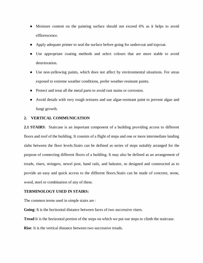
● Moisture content on the painting surface should not exceed 6% as it helps to avoid
efflorescence.
● Apply adequate primer to seal the surface before going for undercoat and topcoat.
● Use appropriate coating methods and select colours that are more stable to avoid
deterioration.
● Use non-yellowing paints, which does not affect by environmental situations. For areas
exposed to extreme weather conditions, prefer weather-resistant paints.
● Protect and treat all the metal parts to avoid rust stains or corrosion.
● Avoid details with very rough textures and use algae-resistant paint to prevent algae and
fungi growth.
2. VERTICAL COMMUNICATION
2.1 STAIRS: Staircase is an important component of a building providing access to different
floors and roof of the building. It consists of a flight of steps and one or more intermediate landing
slabs between the floor levels.Stairs can be defined as series of steps suitably arranged for the
purpose of connecting different floors of a building. It may also be defined as an arrangement of
treads, risers, stringers, newel post, hand rails, and baluster, so designed and constructed as to
provide an easy and quick access to the different floors.Stairs can be made of concrete, stone,
wood, steel or combination of any of these.
TERMINOLOGY USED IN STAIRS:
The common terms used in simple stairs are :
Going: It is the horizontal distance between faces of two successive risers.
Tread:It is the horizontal portion of the steps on which we put our steps to climb the staircase.
Rise: It is the vertical distance between two successive treads.
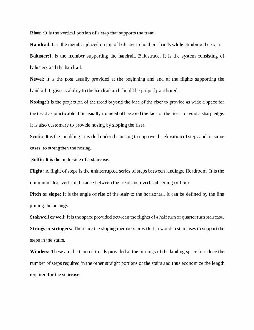
Riser.:It is the vertical portion of a step that supports the tread.
Handrail: It is the member placed on top of baluster to hold our hands while climbing the stairs.
Baluster:It is the member supporting the handrail. Balustrade. It is the system consisting of
balusters and the handrail.
Newel: It is the post usually provided at the beginning and end of the flights supporting the
handrail. It gives stability to the handrail and should be properly anchored.
Nosing:It is the projection of the tread beyond the face of the riser to provide as wide a space for
the tread as practicable. It is usually rounded off beyond the face of the riser to avoid a sharp edge.
It is also customary to provide nosing by sloping the riser.
Scotia: It is the moulding provided under the nosing to improve the elevation of steps and, in some
cases, to strengthen the nosing.
Soffit: It is the underside of a staircase.
Flight: A flight of steps is the uninterrupted series of steps between landings. Headroom: It is the
minimum clear vertical distance between the tread and overhead ceiling or floor.
Pitch or slope: It is the angle of rise of the stair to the horizontal. It can be defined by the line
joining the nosings.
Stairwell or well: It is the space provided between the flights of a half turn or quarter turn staircase.
Strings or stringers: These are the sloping members provided in wooden staircases to support the
steps in the stairs.
Winders: These are the tapered treads provided at the turnings of the landing space to reduce the
number of steps required in the other straight portions of the stairs and thus economize the length
required for the staircase.
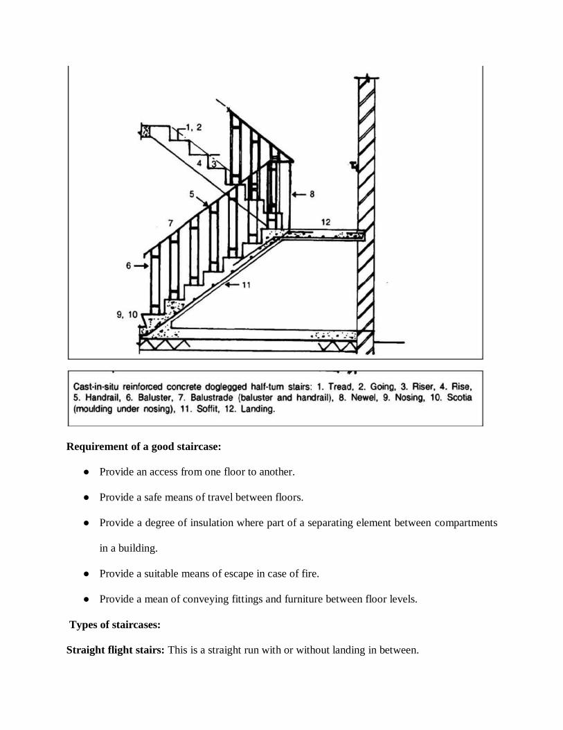
Requirement of a good staircase:
● Provide an access from one floor to another.
● Provide a safe means of travel between floors.
● Provide a degree of insulation where part of a separating element between compartments
in a building.
● Provide a suitable means of escape in case of fire.
● Provide a mean of conveying fittings and furniture between floor levels.
Types of staircases:
Straight flight stairs: This is a straight run with or without landing in between.
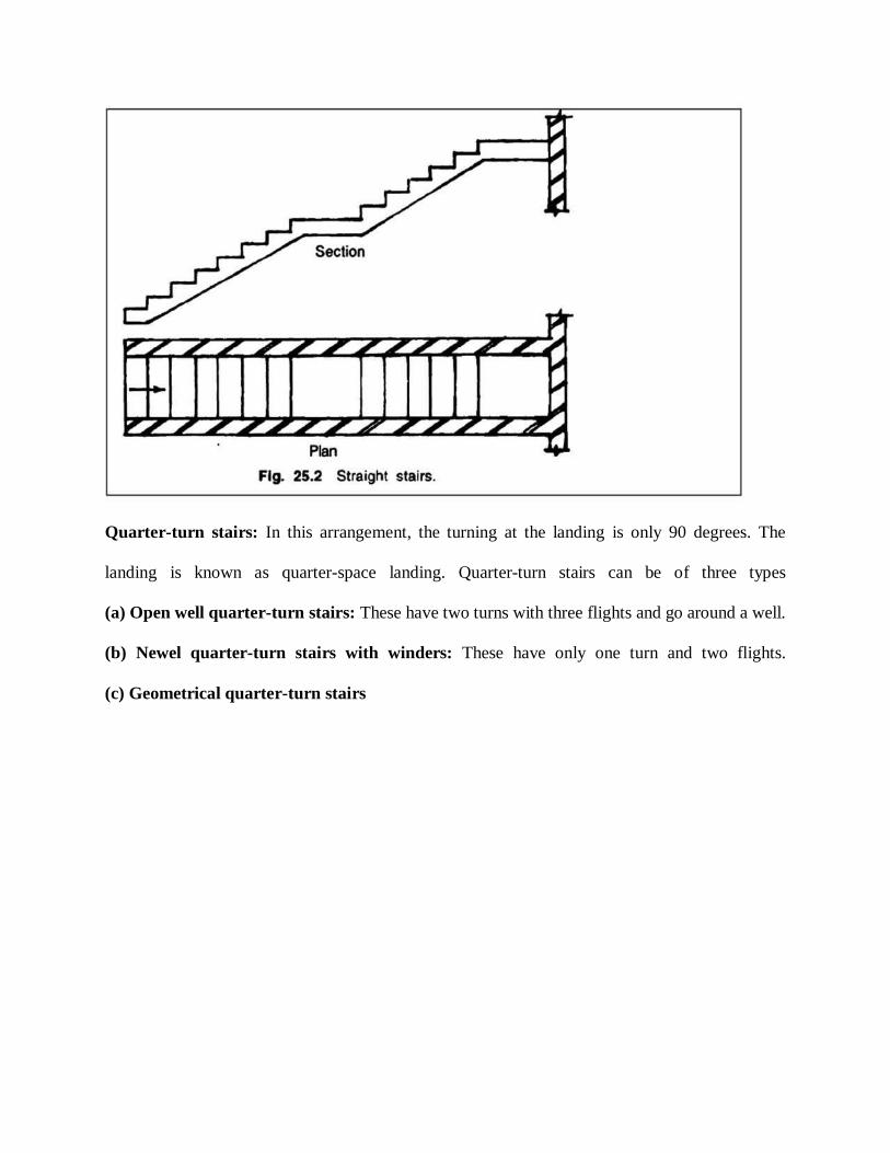
Quarter-turn stairs: In this arrangement, the turning at the landing is only 90 degrees. The
landing is known as quarter-space landing. Quarter-turn stairs can be of three types
(a) Open well quarter-turn stairs: These have two turns with three flights and go around a well.
(b) Newel quarter-turn stairs with winders: These have only one turn and two flights.
(c) Geometrical quarter-turn stairs

Half-turn stairs: In this system, the direction of climbing at the landing is reversed through 180°.
This type of landing is called half-space landing. There can be three types of such stairs:
(a) Doglegged (or newel) half-turn stairs with no well
(b) Open well half-turn stairs with a well
(c) Geometrical half-turn stairs
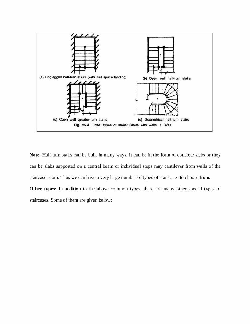
Note: Half-turn stairs can be built in many ways. It can be in the form of concrete slabs or they
can be slabs supported on a central beam or individual steps may cantilever from walls of the
staircase room. Thus we can have a very large number of types of staircases to choose from.
Other types: In addition to the above common types, there are many other special types of
staircases. Some of them are given below:
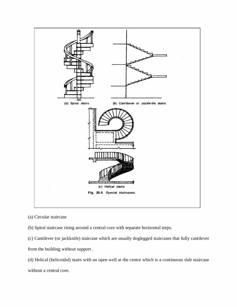
(a) Circular staircase
(b) Spiral staircase rising around a central core with separate horizontal steps.
(c) Cantilever (or jackknife) staircase which are usually doglegged staircases that fully cantilever
from the building without support .
(d) Helical (helicoidal) stairs with an open well at the centre which is a continuous slab staircase
without a central core.
Spiral stairs have separate steps describing a helix around a central column whereas a helical stair
has an open well. A helicoid is a warped surface generated by a line wrapped around a central
imaginary core. It will be like the curve of a screw. The slab is like an inclined plane. It can be
circular or elliptical (it has no central structure). Spiral stairs are generally provided at the back of
buildings as emergency exit and as access to working people to the various floors. Helical
staircases are very aesthetic, more difficult to design and are generally provided as an ornamental
feature in libraries, assembly halls and also in very luxury buildings.
REINFORCED CONCRETE (RC) STAIRS:
Nowadays reinforced concrete is the preferred material for stairs in residential as well as in office
and other public buildings. For ornamentation, the concrete structures are sometimes covered with
wood. Steel staircases are common in factories especially in chemical plants. We will study in a
little more detail the simple doglegged reinforced concrete stairs, which are used in most
residential buildings.
● Layout Requirements of RC Stairs: The following are the general requirements to be
met when we plan the layout of a staircase.
● Width of stair: It depends on its use. The recommended values are a minimum of 90 cm
(3 ft) in residences and 1.5 to 2 m in public buildings. Length of
flight:Generally the number of steps in one flight (to the landing) should not exceed 12 to
16 and not be less than 3.
● Pitch of stair: The pitch or slope of the stair depends on the rise and tread adopted. They
should depend on the use of the building. Public buildings should have larger treads or
going and smaller rise than in dwelling houses.
The values usually recommended for tread and rise are as follows:
(a) In residences, we give a tread or going of 250 mm (9 to 10 inches) and a rise of 160 to
175 mm (6½ to 7 inch) approximately.
(b) Public buildings should have longer treads and smaller rise. Treads of 270 mm to 300
mm and rises of 100 to 150 mm are usually given.
(c) Rises and treads of all the steps should be the same. It is very important that we should
not change the dimensions of tread and rises from the start to the finish of the stairs. Sudden
changes in dimensions can lead to accidents.
The following empirical formula between going and rise is usually used:
(2R + G) > 550 mm but < 700 to 600 mm (approximately)
Head room: The clear distance between the tread and the soffit of a flight immediately
above or between the tread and floor above should not be less than 2.1 to 2.3 m (say 7 feet
4 inch) so that a person can use the stairs with a luggage on his head. This provision of
head room is very important.
Height of handrail: The height of the top of the handrail from the tread should be between
850 to 900 mm (about 3 ft) to make it easy for a person of average height to hold on to it
by hand.
Stairs to open terrace: Where the staircase leads to an open terrace, the level of the upper
landing slab should be 30 cm (1 ft) higher than top of roof slab so that there will be a clear
difference in height of about 15 cm after the weathering course is laid. (This need not be
so if another storey is envisaged in future.)
Staircase room dimension: The minimum clear width of staircase room in residential
buildings should be 2.1 m (7 ft) so that there will be a clear width of staircase of 90 cm
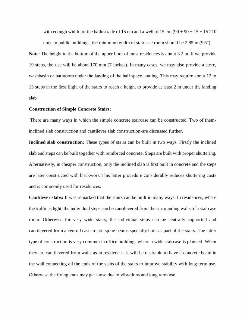
with enough width for the ballustrade of 15 cm and a well of 15 cm (90 + 90 + 15 + 15 210
cm). In public buildings, the minimum width of staircase room should be 2.85 m (9'6").
Note: The height to the bottom of the upper floor of most residences is about 3.2 m. If we provide
19 steps, the rise will be about 170 mm (7 inches). In many cases, we may also provide a store,
washbasin or bathroom under the landing of the half space landing. This may require about 12 to
13 steps in the first flight of the stairs to reach a height to provide at least 2 m under the landing
slab.
Construction of Simple Concrete Stairs:
There are many ways in which the simple concrete staircase can be constructed. Two of them-
inclined slab construction and cantilever slab construction-are discussed further.
Inclined slab construction: These types of stairs can be built in two ways. Firstly the inclined
slab and steps can be built together with reinforced concrete. Steps are built with proper shuttering.
Alternatively, in cheaper construction, only the inclined slab is first built in concrete and the steps
are later constructed with brickwork This latter procedure considerably reduces shuttering costs
and is commonly used for residences.
Cantilever slabs: It was remarked that the stairs can be built in many ways. In residences, where
the traffic is light, the individual steps can be cantilevered from the surrounding walls of a staircase
room. Otherwise for very wide stairs, the individual steps can be centrally supported and
cantilevered from a central cast-in-situ spine beams specially built as part of the stairs. The latter
type of construction is very common in office buildings where a wide staircase is planned. When
they are cantilevered from walls as in residences, it will be desirable to have a concrete beam in
the wall connecting all the ends of the slabs of the stairs to improve stability with long term use.
Otherwise the fixing ends may get loose due to vibrations and long term use.
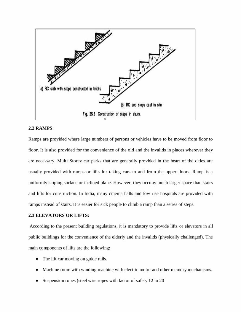
2.2 RAMPS:
Ramps are provided where large numbers of persons or vehicles have to be moved from floor to
floor. It is also provided for the convenience of the old and the invalids in places wherever they
are necessary. Multi Storey car parks that are generally provided in the heart of the cities are
usually provided with ramps or lifts for taking cars to and from the upper floors. Ramp is a
uniformly sloping surface or inclined plane. However, they occupy much larger space than stairs
and lifts for construction. In India, many cinema halls and low rise hospitals are provided with
ramps instead of stairs. It is easier for sick people to climb a ramp than a series of steps.
2.3 ELEVATORS OR LIFTS:
According to the present building regulations, it is mandatory to provide lifts or elevators in all
public buildings for the convenience of the elderly and the invalids (physically challenged). The
main components of lifts are the following:
● The lift car moving on guide rails.
● Machine room with winding machine with electric motor and other memory mechanisms.
● Suspension ropes (steel wire ropes with factor of safety 12 to 20
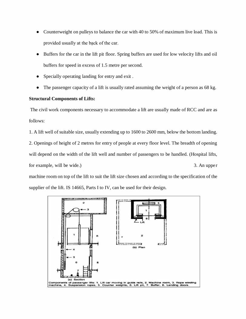
● Counterweight on pulleys to balance the car with 40 to 50% of maximum live load. This is
provided usually at the bạck of the car.
● Buffers for the car in the lift pit floor. Spring buffers are used for low velocity lifts and oil
buffers for speed in excess of 1.5 metre per second.
● Specially operating landing for entry and exit .
● The passenger capacity of a lift is usually rated assuming the weight of a person as 68 kg.
Structural Components of Lifts:
The civil work components necessary to accommodate a lift are usually made of RCC and are as
follows:
1. A lift well of suitable size, usually extending up to 1600 to 2600 mm, below the bottom landing.
2. Openings of height of 2 metres for entry of people at every floor level. The breadth of opening
will depend on the width of the lift well and number of passengers to be handled. (Hospital lifts,
for example, will be wide.) 3. An upper
machine room on top of the lift to suit the lift size chosen and according to the specification of the
supplier of the lift. IS 14665, Parts I to IV, can be used for their design.
Elevators are used in buildings having more than four storeys. They are used for providing vertical
transportation of passengers or freight. They can be either electric traction elevators or hydraulic
elevators. Electric traction elevators are used exclusively in tall buildings. Hydraulic elevators are
generally used for low-rise freight service which rise up to about six storeys. Hydraulic elevators
may also be used for low-rise passenger service. The different components of an electric traction
elevator are the car or cab, hoist wire ropes, driving machine, control equipment, counter weight,
hoistway rails, penthouse, and pit. The car is a cage of light metal supported on a structural frame,
to the top of which the wire ropes are attached. The ropes raise and lower the car in the shaft. They
pass over a grooved motor-driven sheave and are fastened to the counter weights. The paths of
both the counterweights and the car are controlled by separate sets of T-shaped guide rails. The
control and operating machinery may be located in a penthouse above the shaft or in the basement.
Safety springs or buffers are placed in the pit, to bring the car or counterweight to a safe stop.
Elevators, serving more than three floors, should be provided with means for venting smoke and
hot gases from the hoistways to the outer air in case of fire. Vents may be located in the enclosure
just below the uppermost floor, with direct openings to the outside or with non-combustible duct
connections to the outside.
Vent area should be at least 3.5% of the hoistway cross sectional area.
A few important terms, generally, used in ELEVATOR description, are defined below:
1. Annunciator. This is an electrical device which indicates, usually by lights, the floors at which
an elevator landing signal has been registered.
2. Buffer. This is a device for stopping a desce- nding car or counterweight beyond its bottom
terminal by absorbing and dissipating the kinetic energy of the car or counterweight. The absorbing
medium may be oil, in which case the buffer may be called an oil buffer, or a spring, in which case
the buffer may be referred to as a spring buffer.
3. Bumper. This is a device other than a buffer stopping a descending car or counterweight beyond
its bottom terminal by absorbing the impact.
4. Car. This is the load carrying element of an elevator, including car platform, car frame, enclosure
and car door or gate.
5. Car-door Electric Contact. This is an electrical device for preventing normal operation of the
driving machine unless the car door or gate is closed.
6. Car Frame. This is the supporting frame to which the car platform guide shoes, car
safety,hoisting ropes or hoisting rope sheaves, or the plunger of a hydraulic elevator are attached
in a car by which an operator actuates the control.
7. Control. This is the system governing the starting, stopping, direction of motion, acceleration,
speed and retardation of the car.
8. Generator Field Control. This employs indivi dual generator for each elevator, with voltage
applied to the driving machine motor adjusted by varying the strength and direction of the
generator field.
9. Multi Voltage Control. This impresses successively on the armature of the driving machine
motor at various fixed voltages, such as those that might be obtained from multi-commutator
generators common to a group of elevators.
10. Rheostatic Control. This varies the resistanceor reactance of the armature or the field circuit of
the driving machine motor.
12. Single Speed Alternating Current Control.This governs a two-speed driving machine induc
13. Dispatching Device. This is a device which operates a signal in a car to indicate when the car
should leave a designated floor or to actuate the car's starting mechanism when the car is at a
designated floor.
14. Emergency Stop Switch. This is a car-located device that, when operated manually, causes the
car to be stopped by disconnecting electric power from the driving machine motor.
15. Hoistway. This is a shaft for travel of one or more elevators. It extends from the bottom of the
pit to the underside of the overhead machine room or the roof. A blind hoistway is the portion of
the shaft that passes floors or other loadings without providing a normal entrance.
16. Hoistway Access Switch. This is a switch placed at a landing to permit car operation with both
the hoistway door at the landing and the car door open.
17. Hoistway-door Electric Contact. This is an electrical device for preventing normal operation
of the driving machine unless the hoistway door is closed.
18. Hoistway-door Locking Device. This is a device for preventing the hoistway door or gate from
being opened from the landing side unless the car has stopped within the landing zone.
19. Levelling Device. This is a mechanism for moving a car that is within a short distance of a
landing towards the landing and stopping the car there. An maintaining two-way levelling device
will keep the car floor level with the landing during loading and unloading.
20. Machine. This is the power unit for raising and lowering an elevator car.
21. Non-stop Switch. This is a device for preventing a car from making registered sanding stops.
22. Operating Device. This is the car switch, push button level, or other manual device used to act
uate the control.
23. Operation. The method of actuating the control.
24. Car-Switch Operation. This starts and stops a car in response to a manually operated car switch
or continuous pressure buttons in a car.
25. Pre-register Operation. This is one in which signals to stop are registered in advance by buttons
in a car or loadings and then at the proper points as a car, travel are given to an operator in the car
who initiates the stop, which is completely automatic.
26. Signal Operation. This starts and stops a car automatically as landings are reached, in response
to actuation of buttons in cars or at landings, irre- spective of direction of car travel or sequence in
which buttons are actuated, but the car can be started only by a button or starting switch in the car.
27. Parking Device. This is a device for opening from the landing side the hoistway door at any
landing when the car is within the landing zone.
28. Pit. This is a portion of a hoistway below the lowest landing.
29. Position Indicator. This is a device for showing the location of a car in the hoistway.
30. Rope Equalizer. This is a device installed on a car or counterweight to equalize automatically
the tensions in the hoisting ropes.
31. Runby. This is the distance a car can travel beyond a terminal landing without striking a stop.
32. Safety. This is a mechanical device attached to the counterweight or to the car frame or an
auxiliary frame to stop or hold the counterweight or the car, whichever undergoes a free fall, or if
the hoisting ropes should slacken.
33. Safety Bulkhead. This is in a cylinder of a hydraulic elevator, a closure, at the bottom of the
cylinder but above the cylinder head, with an orifice for controlling fluid loss in case of cylinder-
head failure.
34. Signal Registering Device. This is a button or other device in a car or at a landing that causes
a stop signal to be registered in a car.

35. Signal Transfer Device. This is a manually operated switch for accomplishing the same
function as a signal transfer device.
36. Slack Rope Switch. This is a device that automatically disconnects electric power from the
driving machine when the hoisting ropes of a winding drum machine become slack.
37. Starter's Control Panel. This is an assembly of devices with which an elevator starter can
control the way in which one or more elevators function.
38. Terminal Speed-Limiting Device (Emergency). This is a device for automatically reducing the
speed of a car approaching a terminal landing, independently of the car operating device and the
normal terminal stopping device if the latter fails to slow the car as intended.
39. Terminal Stopping Device. This is a device for slowing or stopping a car automatically at or
near a terminal landing, independently or the car operating device. A final terminal stopping device
after a car passes a terminal landing, disconnects power from the driving apparatus, independently
of the operating device, normal terminal stopping device or emergency terminal speed limiting
device. A stop motion switch, or machine final terminal stopping device, is a final terminal
stopping device operated directly by the driving machine.
40. Transom. This comprises one or more panels that close the opening above the hoistway
entrance.
41. Travel (Rise). This is the vertical distance between top and bottom terminal landings.
42. Travelling Cable. This is a cable containing electrical conductors for providing electrical
connections between a car and a fixed outlet in a hoistway.
43. Truck Zone. This is a limited distance above a landing within which the truck zoning device
permits movement of a freight elevator car with its door or the hoistway door open.
44. Truck Zoning Device. This is a device that permits a car operator on move, within a specified
distance above a landing, a freight-elevator car with its door or the hoistway door open.
2.4 ESCALATORS:
These are powered stairs. They are used when it is necessary to move a large number of people
from floor to floor. These stairs have continuous operation without the need for operators. They
have large capacity with low power consumption. These escalators are in the form of an inclined
bridge spanning between floors. The components of an escalator consist of a steel trussed
framework, handrails and an endless belt with steps. At the upper ends of an escalator there is a
pair of motor-driven sprocket wheels and a worm-gear driving machine. At the lower end is a
matching pair of sprocket wheels. Two precision made roller chains travel over the sprockets
pulling the endless belt of steps around the steps which move on an accurately made set of tracks
attached to the trusses with each step supported on four resilient rollers. Escalators are reversible
in direction. They are generally operated at a speed of 30 or 40 m/min. Slope of the stairs is
standardized at 30°. For a given speed of travel, the width of step determines the capacity of the
powered stairs.
Escalators should be installed where traffic is heaviest and convenient for passengers. In the design
of a new building, adequate space should be allotted for powered stairs. Structural framing should
be made adequately to support them.
Escalators are generally installed in pairs. One of them is used for carrying up-going traffic and
the other for traffic moving down. The arrangement of escalators in each storey can be either
parallel or criss-cross. Criss-cross arrangement is more compact. It reduces walking distance
between stairs at various floors to a minimum. That is why a criss-cross arrangement is preferred
over parallel arrangement. The floor openings of an escalator not serving as required if exist must
be protected. The following protection methods are generally used in buildings pac completely
protected by a standard supervised sprinkler system.
Sprinkler-vent method. This is a combination of an automatic fire or smoke detection system,
automatic air-exhaust system and an automatic water curtain.
Spray-nozzle method. This is a combination of an automatic fire or smoke detection system and a
system of high velocity water-spray nozzles.
Rolling shutter method. In this an automatic, self-closing, rolling shutter is used to enclose
completely the top of each escalator.
Partial enclosure method. In these kiosks, with self-closing, fire-doors, provide an effective barrier
to the spread of smoke between floors.
3. DAMP-PROOFING (i.e., D.P.C.) TREATMENTS IN BUILDINGS
The use of damp-proofing courses (D.P.C.), for the treatment of buildings, against dampness, can
be grouped into the following categories:
1. Treatment of foundations' dampness from adjacent ground.
2. Treatment of foundations on bad (poor) soils.
3. Treatment of basements.
4. Treatment of floors.
5. Treatment of walls.
6. Treatment of flat roofs, parapets and copings.
7. Treatment of pitched roofs
1. Treatment of Foundations' Dampness from Adjacent Ground. In case the moisture rises up
the walls through the foundations where water is percolating from the adjacent ground, this may
be treated by providing air drains and damp-proof course or by D.P.C. alone. Sub-soil drainage

may also be provided to solve this problem. An air drain is a narrow dry space (20 to 30 cm width)
which is provided on the outer face of the wall below the ground level. It is formed by a thin outer
wall resting on the base slab of foundation and carried little above the ground level (usually by 15
cm) to prevent water entering the drain. Openings with gratings are provided at e regular spacing
for the passage of air. The top of the air e drain is covered either with R.C.C. slab or stone slab and
due provisions for examination and clearing this drain are made. Damp-proof courses (D.P.C.) are
also provided horizontally and vertically as shown in Fig. 10.4. An air drain with wall ties may
also be used.
2. Treatment of Foundations on Bad (Poor) Soils. Where the foundations of basements are not
properly drained (in dry or peat soil) and hence subjected to great hydrostatic pressure, then in
such cases the structure should be disconnected from the face of the ground excavation and a trench
made all around for width of about 30 cm taken down to a point as low as under side of the concrete
footings This becomes essential, because the more provision of continuous D.P.C. may not give
satisfactory results. The bed of the trench should be provided with a good slope at each end and
the trench filled with coke, gravel, or stone, graded with fines to fill the voids. Moreover, in such
cases the basement is relieved of hydrostatic pressure by suitably draining the sub-soil water. Sub-
soil water may be drained by providing open jointed land drain at the bottom of trench and also
drainage-pipes below the concrete base The open jointed pipes or drains are given a bed slope so
that the water is discharged in an outlet outside the building from where the collected water is
allowed to flow away in some natural drain. The gravel bed helps to accumulate the sub-soil water
seepage and percolate the same in the pipes. The details of horizontal and vertical D.P.C. (either
mastic asphalt or bituminous felt) under the floors and through the external walls,
3. Treatment of Basements. To ensure the dryness, the whole of the structure below ground level
should be provided with a continuous membrane of asphalt (t.e., D.P.C.) either mastic asphalt or
bituminous felt supported on the inside. This is achieved by spreading a layer of an impervious
material (i.e., D.P.C.) over the whole area of the floor and continuing the same (i.e., Horizontal
D.P.C.) through the external walls extending vertically up, forming a sort of water-proof tank .
The details of asphalt tanking or waterproof or D.P.C. tank and sequence of operations in providing
D.P.C. for basements in buildings, have been shown in Figs. 10.6 and 10.7 but the following points
require due consideration in asphalt tanking.
(i) D.P.C. basement buildings should be provided in the dry season when sub-soil water is at its
lowest level.
(ii) D.P.C. is provided on the outside of walls and under floors of basements and underground
structures, in such a way that the latter may provide support necessary to withstand such water
pressure as may be exerted on the outer faces of the structures.
(iii) Horizontal D.P.C. is laid continuous and extended vertically up through the walls. This vertical
D.P.C. should either be taken to the ground for a minimum distance of 15 cm or may end in a
horizontal D.P.C. if necessary.
(iv) An adequate dewatering arrangement for pumping out sub-soil water should be installed in
order to keep water level below the operating level or working level.
(v) Suitable shuttering should be provided to prevent the excavation from collapsing.
(vi) D.P.C. is laid over the entire base slab of concrete including the projection of 15 cm.
(vii) A protective flooring of brick flat on cement concrete (1: 3: 6) is laid to protect D.P.C. from
damage during the construction of the floor. The structural walls and floors are then constructed
to withstand the anticipated water pressure.
(viii) Sufficient care should be exercised to ensure a perfect bond between the D.P.C. on the base
slab and that on the outside of walls.
(ix) The gap between thin protective brick wall (half-brick) and structural wall should be grouted
so as to ensure that no air is trapped between the D.P.C. and the walls.
N.B. 1. In case of deep basements, the D.P.C. should be applied on the outside of walls (rather
than through the walls) in stages of convenient heights and the construction of the protective wall
as well as back filling the earth is completed progressively.
2. Types of damp-proofing treatments above and below the ground level have been recommended
as below:
A. D.P.C. above ground level shall be according to either (a) or (b), below:
(a)
● (i) Hot applied blown bitumen @ 1.5kg/sq.m.
● (ii) Hessian base self-finished felt type 3, grade 2.
● (iii) Hot applied blown bitumen @ 1.5 kg/sq.m.
(b)
● (i) Hot applied blown bitumen @ 1.5kg/sq.m.
● (ii) Fibre base self-finished felt type 2, grade 3. (iii) Hot applied blown bitumen @ 1.5
kg/sq.m.
B. D.P.C. for basements and structures below ground level: The multiple layer D.P.C. shall be
according to either (a) Two layers of felt (for light treatments), or (b) Three layers of felt (for
heavier treatments) as given below:
(a) (i) Primer.
(ii) Hot applied blown bitumen @ 1.5 kg/sq.m.
(iii) Fibre base self-finished felt type 2, grade 3.
(iv) Hot blown bitumen @ 1.5 kg/sq.m..
(v) Fibre base self-finished felt type 2, grade 3. (vi) Hot applied blown bitumen @ 1.5 kg/sq.m.
(b) (i) Primer.
(ii) Hot applied blown bitumen @ 1.5 kg/sq m.
(iii) Fibre base self-finished felt type 2, grade 3,
(iv) Hot applied blown bitumen @ 1.5 kg/sq m.
(v) Fibre base self-finished felt type 2, grade 3,
(vi) Hot applied blown bitumen @ 1.5 kg/sq m.
(vii) Fibre base self-finished felt type 2, grade 3,
(viii) Hot applied blown bitumen @ 1.5 kg/sq m.
4. Treatment of Floors. For dry locations, generally, a filling of 7.5 cm to 15 cm of dry coarse
sand under the floor masonry is specified. A hardcore filling of stones with smaller stones to fill
in voids is also quite suitable. The filling should be well rammed but not unduly consolidated. It
is observed that a thin layer of cinders and coal tar under a tiled floor acts as a good D.P.C. to
prevent the moisture as well as efflorescence.
In case, there is a possibility of moisture penetrating the floor, it will be necessary to lay a
waterproofing membrane of mastic asphalt or fibrous asphalt felt, before a concrete floor is laid.
It happens, because porous concrete attracts moisture from the wet soil and is also aided by
capillary action. Even a dense concrete with waterproofing compound is not found to be a perfect
barrier to moisture. Hence, generally, over a dry concrete bedding, a priming coat of hot liquid
asphalt is first given and then mastic asphalt is applied in two coats.
In case, there is a possibility of the floor being subjected to excessive uplift pressures due to soil
and water table characteristics, then concrete floor should be reinforced. The D.P.C. of mastic
asphalt or felt laid over the slab should be covered with a concrete wearing coat.
5. Treatment of Walls. In case of basements, the outer face of the wall is well grouted with a
water-proofed cement plaster. This forms the base for the asphalt layer (i.e., vertical D.P.C.) which
is continued from the basement floor and extended vertically up covering the whole area of the
external wall face. This vertical D.P.C. is further protected by a thin skin wall or protective wall.
The horizontal D.P.C. in external walls is generally provided at least 15 cm above the ground level.
It is further essential to provide a vertical D.P.C. between the floor level and the D.P.C. level on
the inside of external walls. In internal walls, the D.P.C. is provided in level with the upper surface
of the concrete floor. The continuity of D.P.C. between the internal and external walls is attained
by way of cement concrete blocks on bituminised bricks.
If the D.P.C. is to be provided in an existing wall, then a cut about 15 cm or more above the ground
is made at the corner of the wall: loose bricks on materials above the cut are removed; and a damp
proof membrane of bituminous felt is inserted inside the cut. This process of cutting the slots and
inserting the damp-proof membrane is continued, till the entire length of wall is completed. The
removed materials like bricks are relaid and the wall surface is plastered or pointed. D.P.C. details
in cavity walls have already been shown in Figs. 10.2 and 10.3. In this, a horizontal D.P.C. is laid
at least 15 cm above the ground. A layer of lead sheet, copper sheet or asphalt felt is brought down
from the inner wall to the head of the floor or window, to protect the openings. To protect the
window sills, D.P.C. of bituminous felt or lead sheet can be inserted between the inner wall
covering and the sill. Generally, a porous external treatment of plaster, having proportions (1
cement: 1 lime: 6 sand) to the walls is recommended to safeguard against dampness.
6. Treatment of Flat Roofs, Parapets and Copings. In case of flat roofs, the rain water enters
either through the defective parapet wall, or crac- ked roofing tiles or broken pointing, etc. The
water proofing treatment given to flat roofs in the various regions of the country (India) is of three
types, namely; (i) Lime concrete terracing, (ii) Lime concrete terracing with flat tiles, and (iii) Mud
phuska terracing with tiles.
Ist method of waterproofing, i.e., lime concrete terracing has been recommended for 'Hot and
Humid Regions' in India, viz., Kolkata, Mumbai, Chennai, etc. The process consists of laying the
lime concrete at an adequate slope; application of hot prime coat of bitumen over dried lime
concrete and finally laying sheet of bitumen over the primed surface.
the 2nd method of waterproofing, i.e., lime concrete terracing with flat tiles has also been
recommended for hot and humid regions mentioned above, where the roof is to be used for sleeping
or such other purposes. In such cases, the roof is strengthened by covering the lime concrete with
two courses of brick tiles laid in cement mortar to withstand the wear and tear effects due to traffic.
The process of lying consists of various operations (See Fig. 10.8): Laying the D.P.C. of hot
bitumen @ 1.70 kg/m² roof surfaces; spreading over the hot bitumen a layer of coarse sand @0.6
m³ of sand per 100 m² of roof surface; laying lime concrete proper slope in average thickness of
10 cm and, finally, laying two courses of flat tiles (each course having thickness from 13 to 20
mm) in cement mortar (1 cement: 3 sand). The joints of the top course of the tile are pointed with
cement mortar having mix proportions 1 : 3 and 5% of crude oil, based on the weight of cement.
Instead of flat tiles, pressed tiles or precast cement concrete tiles or 25 mm thick Shahabad stone
can also be used based on availability.
3rd method of waterproofing, i.e., Mud phuska terracing with tiles has been recommended for 'Hot
and Arid Regions' in India, e.g., Delhi, Punjab, Rajasthan, U.P., etc. The process of laying consists

of various operations (See Fig. 10.9), viz., laying the D.P.C. of hot bitumen @1.70 kg/m² of roof
surface; spreading over the hot bitumen, a layer of coarse sand @ 0.6 m³ per 100 m² of roof surface;
laying a layer of mud phuska prepared from puddled clay or lime concrete if locally available;
covering the mud phuska layer with mud-gobar mortar (3 mud : 1 cow dung) and finally the flat
tiles are laid with cement mortar (1 cement: 3 sand) and the joints grouted.
N.B. 1. The following requirements in water proofing of roofs should be ensured:
(i) Shuttering should be either of steel or of strong wood with the joints made water-tight. R.C.C.
slabs should be made as dense as possible by the use of vibrators.
(ii) Top surface of R.C.C. slab should be finished with cement mortar (1:3) immediately after
laying the cement concrete.
(iii) Before laying terracing, the surface of the seals should be cleaned with a rag soaked in
kerosene oil and treated with two coats of hot bitumen.
(iv) Bitumen pads should be used between the slabs and junctions of slabs with walls.
(v) Finished surface of the roof should have a slope of 1 in 50 to ensure good drainage.
(vi) Junctions of roofs and parapets should be paid special attention.
2. Lime concrete specifications adopted for water proofing of Roofs: (7.5 cm to 12 cm thick,
average thickness= 10 cm).
(1) 2 lime: 2 surkhi: 7 brick ballast 25 mm gauge (Mumbai and Kolkata regions). 1 lime with 21/2
brick ballast 20 mm gauge
(ii)(Madras region). br
(iii) 25 mm gauge brick ballast with 50% lime ac mortar consisting of 1 lime: 2 surkhi (Delhi,U.P.,
Punjab and Rajasthan regions).
To check the penetration through the parapets and copings, they should be protected from the
weather by providing D.P.C. at various locations. such as: (i) A D.P.C. (asphalt layer) covering
the whole of the roof and then extending up the junction against the parapet wall at least upto 15
cm height; (ii) A D.P.C. for parapet wall at this height (i.e. above junction at least 15 cm) is laid
for
7. Treatment of Pitched Roofs. In case of pitched roofs or sloping roofs, the main causes, in
general, of water penetration are: (i) In sufficient lap of tiles or roofing sheets; (ii) Insufficient roof
slopes or flat pitches; and (iii) Inadequacy of rainwater gutters. First two causes are taken care of
by proper design and construction as per recommendations. For treating rainwater gutters, they
should be of sufficient capacity, water-tight and capable of accommodating variations due to
temperature changes without leakage. There should not be any over-flowing of the rain water or
leakage through the walls. The tiles should project beyond the edge of the gutter. Lead flashing
(D.P.C.) provided in the gutter should be extended up the surface of the parapet wall and should
be taken inside partly the body of the wall Like flat roofs, the parapet wall should itself be protected
by means of a coping of stone or well burnt bricks with a D.P.C. under neath.
TREATMENT OF DAMPNESS
Before applying any remedial measures to the dampness problems at any point in a building, the
real cause of dampness should be identified. It is essential, because a cause should be cured rather
than the effect.
Method for Laying Damp-proof Course in Existing Buildings.
● Generally the need for laying damp-proof course in existing buildings arises because of the
fact that they have been constructed without damp-proof course and the rise of moisture
through their walls, calls for remedial measures. The method usually adopted is to insert
the damp-proof course after underpinning the walls. This method is not only expensive but
also time-consuming. CBRI, Roorkee, has developed a quicker and more satisfactory
method which consists of cutting through a selected course in the brickwork and inserting
bitumen felt immediately after the cut is completed.
● To cut or saw through the brick walls, masonry saws have been developed in two sizes, the
smaller saw is 35 cm x 8 cm x 3 mm (thick) used for starting the cut initially and the bigger
one is 120 cm x 10 cm x 3 mm (thick) operated by two persons for regular cutting. The
saw is made of steel blade, with inserts of satellite (4 mm x 4 mm) in the slots made on one
of the edges of the blades are brazed with latter so as to remain fixed in position.
● The cut is started at a corner of the wall at the bed joint about 15 cm above the floor or the
ground whichever is higher. The sawing is done in lengths of 60 cm or so at a time and
fibre based bitumen felts conforming to Indian Standards cut in lengths of the slot cut and
width equal to the wall thickness + 5 mm projection on each side of the wall is inserted
immediately after the cut is completed. The successive pieces of felt overlap by 10 cm
thereby providing an effective barrier to the rising dampness. The little gap between the
opened cut joint and the felt is filled with 1:3 (cement : sand) mortar grout and finally
finished flush on both sides of the wall. This is simple in operation and carried out even
when buildings remain occupied and in use. Apart from saving time, it saves 40 percent in
cost as compared to underpinning method. Asbestos cement offer great resistance to
cracking, swelling or disintegration when subjected to fire. 11. Plaster or Mortar. It is an
incombustible material and hence used for protecting the walls and ceilings of buildings
from fire-risks. Cement plaster is better than lime plaster as the latter is likely to be
calcined. The fire resistance of the plaster to fire hazards can be increased by using it in a
thicker layer or reinforcing the plaster with metal lathes. Gypsum plaster is also applied on
steel columns and other steel members to increase their fire-resistive qualities. The use of
cement mortar with surkhi or pozzolana is preferred from the viewpoint of fire-resistance
4. FIRE-RESISTANT CONSTRUCTION
Every region develops its own standards for fire-resistance of buildings based on fire tests. In
India, National Building Code classifies the construction into four classes, namely, type 1, type 2,
type 3 and type 4 on the basis of fire-resistance offered by building components for 4-hours, 3-
hours, 2-hours, and 1-hour respectively. All the structural components of a building should be
constructed in such a way and of such materials that they withstand as an integral member of the
structure, for the period desired according to the type of construction, in the event of fire. To
achieve this objective, due considerations should be made in design and construction of the
following structural elements of a structure, and use of combustible material should be avoided as
far as possible in the construction.
1. Wall and columns;
2. Floor and roofs;
3. Wall openings; and
4. Building fire escape elements, e.g., stair, stair cases, corridors, entrances, etc.
The fire resistant or fire-proof construction of these above elements will now be discussed in the
following pages.
1. Walls and Columns. The load bearing walls or columns of masonry should be thicker in section
so that they can resist fire for a longer time and act as vertical barriers to the passage of heat and
fire.
If the construction is of solid bearing walls, bricks should be preferred to stones. If it happens to
be a framed structure then R.C.C. frames are preferred to those of steel frames. If the use of steel
only is to be made due to specific reasons then it should be protected by embedding it in concrete
or by covering it with some other fire-insulating material, such as burnt clay blocks or terra-cotta.
Walls of light-weight concrete are preferred to dense concrete as far as fire-resisting qualities are
concerned. Both load-bearing and non-load bearing walls should be plastered with fire-resistive
mortar to improve fire resistance. Normally, 20 cm thickness of common wall (i.e., wall separating
two buildings) is sufficient from a fire-resistance point of view but it should be raised above the
roof level by at least 90 cm. This is necessary to protect the adjacent building from fire-hazards.
The partition walls should similarly be of fire resistant materials such as, R.C.C. or reinforced
brickwork, or hollow concrete, or burnt clay tiles, or reinforced glass, or asbestos cement board,
or metals lath covered over with cement plaster. In case the wooden partitions are employed, they
should be covered with metal lath and plaster. Cavity wall construction also offers good resistance
against fire and has already been illustrated in Figs. 10.3 and 10.4. For columns and girders,
the desirable fire grading is of 4-hours whereas for beams it is of 3-hours. Therefore, as already
mentioned,
R.C.C. framed structures are preferred to steel structures for this purpose. As steel columns are
liable to twist or distort under intense fire and hence should be protected by way of insulating
materials like concrete, hollow clay tiles, bricks, metal lath followed by plaster, etc. In modern
buildings, the columns are made fire-proof with concrete and then encased in masonry. The
combination of terra-cotta and concrete is most suitable for fire-proofing of steel columns. The
sufficient cover to R.C.C. members like beams or columns, should be provided to enable them to
function satisfactorily, under fire for a maximum time. It has been recommended that a cover of at
least 50 mm. outside the main reinforcement of structural members, like columns, girders, trusses,
etc. of 38 mm for ordinary beam, long span slabs, arches, etc. and 25 mm for partition walls, short

span slabs, etc. should be provided. The fire-proofing treatments, which can possibly be given to
concrete and steel columns construction, are illustrated in Fig. 10.13.
2. Floors and Roofs. The floors and roofs should be made of fire-resisting materials as they act as
horizontal barriers to spread heat and fire in a vertical direction. For fire-resistant construction, the
floor such as concrete Jack Arch floors with steel joists embedded in concrete (See Fig. 10.14),
hollow tiled ribbed floor (See Fig. 10.15), R.C.C. floors, etc. should be used.
Flooring of material, like concrete, ceramic tiles and brick, is regarded to be most suitable from
the viewpoint of fire-resisting qualities. The use of terrazzo, marble and slate as floor surfaces is
also. quite satisfactory. In case usage of combustible materials, like wood, cast-iron, rubber,
linoleum, cork, carpet, etc. in flooring, becomes unavoidable due to financial or practical
considerations, then the following points should be given due consideration:
(i) In case of wooden joist floors, joists at a greater spacing should be used to limit the deflection
within allowable limits in the event of fire.
(ii) Fire stops or barriers in wooden floors should be provided at suitable intervals.
(iii) While using combustible materials, like cast iron, wrought iron, cork, carpet, etc They should
be protected by a covering of insulating material like ceramic tiles, plaster, terra-cotta, bricks, etc.
3. Wall Openings. From a fire-resistant construction point of view, firstly the openings in the
walls should be restricted to a minimum and secondly they should be protected by suitable
arrangements in case of fire. These openings serve as means of escape in fire if properly protected,
otherwise, they provide the passage for the spread of fire in the horizontal direction. Doors and
windows should be made of steel. These days wire glass panels are preferred for windows, whereas
steel rolling shutters are becoming popular for doorways and window openings in garages,
godowns, shops, etc. due to their ability in preventing the spread of fire.
The following points should be given due consideration for protecting the openings:
(i) Solid timber doors having a minimum thickness of 4 cm should be used where some degree of
fire resistance is desired.
(ii) All those openings which are used for communication, should have double fire-proof doors
and other openings may have single fire-proof doors. (Fire-proof doors are considered to be of
superior type when made of steel plate with a minimum thickness of 6 mm and of inferior type
when made of composite material, i.e., 4 cm thick timber panel sandwiched by iron sheets of 3
mm on either side.
(iii) Any window exposed to the roof of the structure should be protected by fire-proof shutters.
(iv) If any structure has a separation less than 6 metres from the adjoining structure, then all doors,
windows or exposed sides should be made of fire-proof construction.
(v) All escape doors should be such as to provide free circulation to the persons in passages,
lobbies, corridors, stairs, entrances, etc. and be made of fire-proof materials.
(vi) Windows, if carried down the floor, should have suitable barrier, like projecting slab beyond
the outer face of the building.
##########################################