Introduction to Aerospace Structures and Materials Dr. ir. R.C. (R
27
Introduction to Aerospace Structures and Materials Dr. ir. R.C. (René) Alderliesten
-
Upload
khangminh22 -
Category
Documents
-
view
0 -
download
0
Transcript of Introduction to Aerospace Structures and Materials Dr. ir. R.C. (R
Intr
oduc
tion
to A
eros
pace
S
truc
ture
s an
d M
ater
ials
Dr.
ir. R
.C. (
Ren
é) A
lder
liest
en
Introduction to Aerospace Structuresand Materials


Introduction to Aerospace Structuresand Materials
R.C. Alderliesten
Delft University of TechnologyDelft, The Netherlands
Introduction to Aerospace Structures and Materials by R.C. Alderliesten, Delft University of Technology islicensed under a Creative Commons Attribution-NonCommercial-ShareAlike 4.0 International License,except where otherwise noted.
Cover image CC-BY TU Delft is a derivation of two images by: Christopher Boffoli, Big Appetites Studio, Seattle,Washington, USA, (http://bigappetites.net), who graciously agreed for us to use his Public Domain photographof the Boeing 787 fuselage in high resolution, and by Gillian Saunders-Smits, Delft University of Technology withher photograph of a Fokker F100 Cockpit Structure (CC-BY-SA 4.0). The final cover design was made by MarcoNeeleman, Delft University of Technology Library.
Every attempt has been made to ensure the correct source of images and other potentially copyrighted materialwas ascertained, and that all materials included in this book has been attributed and used according to itslicense. If you believe that a portion of the material infringes someone else’s copyright, please the authordirectly on: [email protected]
Partly funded by the TU Delft Extension School (online-learning.tudelft.nl) as part of the development of aMassive Open Online Course in Introduction to Aerospace Structures and Materials.ISBN E-Pub: 978-94-6366-077-8ISBN hardcopy: 978-94-6366-074-7ISBN PDF: 978-94-6366-075-4

7. Translating loads to stresses
7.1 Introduction
In the previous chapter, the loads acting on an aircraft or spacecraft structure have
been discussed. These loads are generally considered to act at certain locations
on the structure either by concentrated loads or by distributed loads. These loads
induce deformations in the structure that correlate to stresses within the structure.
To understand this, one should reconsider the example of the tensile test in chapter
1, where the load acting on the specimen induces an elongation (deformation) of the
specimen, which corresponds to the stress in the specimen, calculated with the load
divided by the cross section.
In this chapter, some cases are dealt with to explain how loads acting on an aircraft
or spacecraft structure will induce deformation, but also lead to stresses within the
structure. These stresses must be known, to be able to assess whether the materials
used in the structure are capable to sustain the loads. Here, the stresses calculated
from the loads acting on the structure should be compared with the stress-strain
response of the materials to identify whether sufficient strain is present, and whether
the material’s stiffness will be sufficient to limit deformations to acceptable levels.
7.2 Pressurization of a fuselage structure
As commercial aircraft commonly operate at altitudes of 10000 meters, aircraft
fuselages are pressurised to ensure that crew and passengers can breath normally. In
this section the stresses induced into the structure as a result are explained.
131

7.2.1 Stresses in cylindrical pressure vessel
The circumferential and longitudinal stresses in a pressure vessel can be derived
from equilibrium within the vessel. To calculate the circumferential stress, one first
considers the upper half of a pressure vessel with unit length as illustrated in Figure
7.1.
Figure 7.1
Equilibrium between radial pressure distribution and circumferential stress per unit vessel length. (TU Delft, n.d.,
7-1.jpg. Own Work.)
There should be equilibrium in vertical direction between the circumferential stress
and the vertical component of the pressure p acting at the inner surface of the
vessel. Per unit length1
of the vessel, this equilibrium can be described with
(7.1)
Goniometric analysis of the pressure difference (i.e. inside – outside) acting on an
element implies that the vertical components of the radial pressure per unit length
is given by
(7.2)
1. Per unit length means that the parameter L describing the length of the pressure vessel is set equal to 1. Ittherefore can be neglected in equations (7.1) and (7.2). One should be aware however, that the correct relationbetween load and stress is given by a cross sectional area (length x thickness) rather than just thickness.
132 R.C. Alderliesten
Combining equation (7.1) and equation (7.2) then implies that:
(7.3)
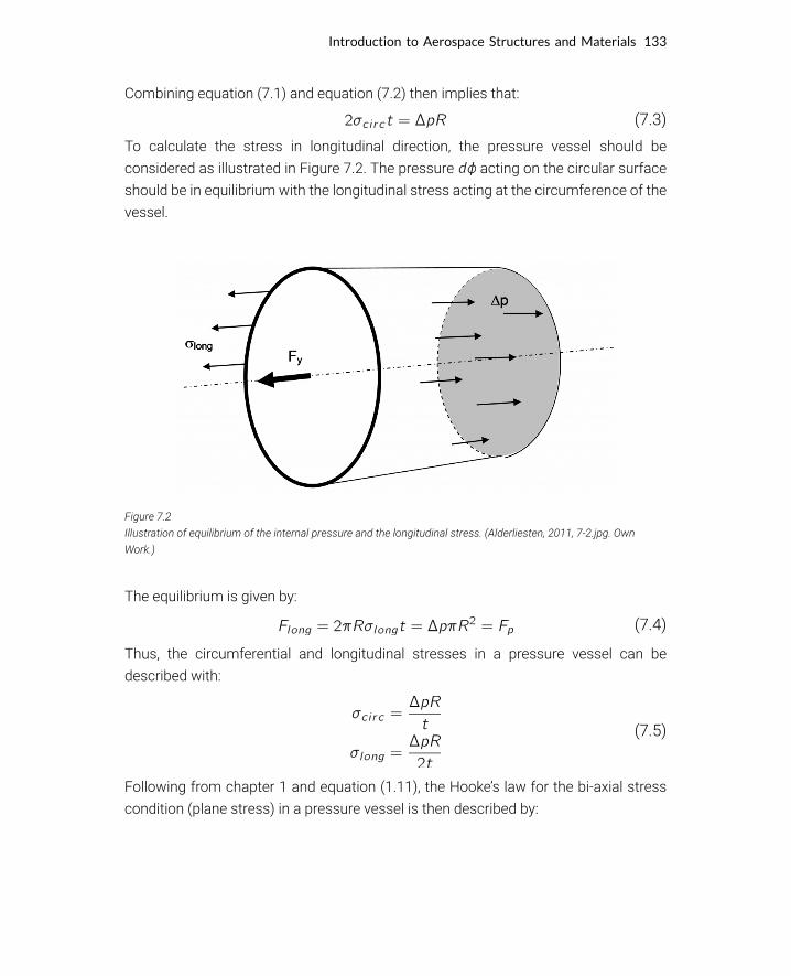
To calculate the stress in longitudinal direction, the pressure vessel should be
considered as illustrated in Figure 7.2. The pressure acting on the circular surface
should be in equilibrium with the longitudinal stress acting at the circumference of the
vessel.
Figure 7.2
Illustration of equilibrium of the internal pressure and the longitudinal stress. (Alderliesten, 2011, 7-2.jpg. Own
Work.)
The equilibrium is given by:
(7.4)
Thus, the circumferential and longitudinal stresses in a pressure vessel can be
described with:
(7.5)
Following from chapter 1 and equation (1.11), the Hooke’s law for the bi-axial stress
condition (plane stress) in a pressure vessel is then described by:
Introduction to Aerospace Structures and Materials 133

(7.6)
Equation (7.5) implies that the circumferential stress is twice the longitudinal stress.
Combining equation (7.5) and equation (7.6) this results in:
(7.7)
For a metallic pressure vessel the Poisson’s ratio is about 0.3, which means that
with equation (7.7) the circumferential strain is about 4.25 times larger than the
longitudinal strain.
7.2.2 Connection between cylinder and spherical end sections
Consider a metallic pressure vessel as indicated in Figure 7.3. In this figure several
locations of interest can be identified: the weld lines between the individual metal
plates and the transition from a tubular shape to the spherical end sections.
Figure 7.3
Illustration of a pressure vessel containing weld lines. (TU Delft, n.d., 7-3.jpg. Own Work.)
To address the strength of the weld lines in the tubular section, the longitudinal
stress should be considered, because that is the stress perpendicular to the weld
line pulling the welded components apart. Because the circumferential stress is twice
the longitudinal stress, the weld lines should be oriented in circumferential direction,
rather than longitudinal direction. Otherwise, the stress loading of the weld would be
twice the stress loading of the weld in Figure 7.3 under the same pressurization.
134 R.C. Alderliesten

Figure 7.4
Illustration of a spherical pressure vessel. (TU Delft, n.d., 7-4.jpg. Own Work.)
To calculate the stress in the spherical end sections, first a pressurized sphere is
considered, see Figure 7.4. In this vessel the stresses in both directions are equal to2:
(7.8)
With the Hooke’s law for bi-axial loaded plates, see equation (1.11), this implies for the
strains in both directions:
(7.9)
To create the welded connection between the tubular section and the spherical
sections in Figure 7.3, one should consider the question whether the thickness of both
sections should be equal or not. In general, discontinuities in circumferential strain
as illustrated in Figure 7.5 should be avoided, because they would lead to unwanted
deformations, or even damage and/or failure. With the equations for strain given for
both sections with respectively equation (7.7) and equation (7.9) , potential strain
discontinuities can be assessed.
Figure 7.5
Illustration of the transition between tubular and spherical section without strain discontinuity (left) and with strain
discontinuities (centre and right). (TU Delft, n.d., 7-5.jpg. Own Work.)
2. A similar derivation as presented in section 7.2.1 can be given for this case, except that it will be somewhat morecomplex. The analysis should be 3D instead of the 2D in Figure 7.1.
Introduction to Aerospace Structures and Materials 135

To derive the ratio between the thicknesses of both sections the circumferential strain
should be equal to the strain in the spherical section, thus :
(7.10)
This results in the following relation:
(7.11)
In case the radii of both sections are identical this means that the thickness of the
cylindrical section is 2.5 times the thickness of the spherical section.
7.2.3 Pressurization of an aircraft cabin structure
Of course, the example of a pressure vessel analyzed in the previous section is
a simplified case compared to an aircraft fuselage structure under pressurization.
Therefore, some remarks have to be made in addition to the previous analysis.
First of all, the thickness of the fuselage shells is not constant throughout the
fuselage. Local reinforcement, especially near cut-outs such as doors and windows,
will locally redistribute the stresses and change the deformation of the pressured shell
structure.
In addition, it was already discussed in chapter 5 and 6 that the fuselage shell
is reinforced by stringers and frames to maintain the aerodynamic shape under
all operating conditions. Especially the frames have a significant impact on the
deformation of the pressurized fuselage and as a consequence on the circumferential
stresses. The contribution of the frames to the response of the fuselage to
pressurization is illustrated in Figure 7.6.
136 R.C. Alderliesten

Figure 7.6
Illustration of frame contribution to the fuselage response to pressurization; a pillowing effect occurs due to limited
deformation near the frames. (TU Delft, n.d., 7-6.jpg. Own Work.)
Because failure of the fuselage shell structure under pressurization may imply a
disastrous occurrence similar to an exploding balloon, this type of fracture should be
avoided at all times. First, the maximum pressurization load is defined to limit the
static load that may occur, while secondly, damage retardant features are applied in
the fuselage to stop cracks that may occur during over-pressurization.
Limit load cannot be defined for fuselage pressurization according to the formal
definition, i.e. once in the lifetime of the aircraft, because the pressurization occurs
every flight. For that reason, a larger safety factor is applied to the maximum
pressurization load, often a factor 2 is applied.
In case of pressurization loads, the pressure differential is considered to induce the
longitudinal and circumferential stress in the fuselage. This pressure differential is the
difference between the inside pressure of the aircraft and the outside pressure. The
design pressure differential is thus defined as:
(7.12)
where is the pressure inside the fuselage and the pressure at an altitude
h. For the cabin pressure often a pressure is taken at an altitude between 2400 and
3000 m, rather than the pressure at sea level. This pressure is considered to be still
comfortable for the passengers, while it reduces the design pressure differential for a
cruise altitude h.
This can be illustrated as follows. If a safety factor of 2 is applied, the maximum
pressure differential is equal to 2 . Assume that this maximum pressure differential
is equal to 45 kPa. In case the maximum cruise altitude is set to be 9050 m, then a
Introduction to Aerospace Structures and Materials 137
cabin altitude of 2440 m could be used. However, if an aircraft altitude of 10350 m is
required; this implies a cabin altitude of 3050 m, thus a lower cabin pressure.
7.3 Torsional loading of a fuselage structure
Another load case that may act on an aircraft fuselage is torsional loading. As
explained in chapter 6, this may occur if the vertical tail of an aircraft is laterally loaded
by gust wind, or by forces induced by the rudder. Aside from bending of the vertical
tail, this load case will induce rotation of the rear fuselage section.
This section will discuss in more detail the torsional loading of a cylindrical fuselage
section and the implications of such load case to the stresses within that structure.
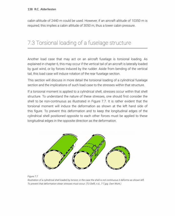
If a torsional moment is applied to a cylindrical shell, stresses occur within that shell
structure. To understand the nature of these stresses, one should first consider the
shell to be non-continuous as illustrated in Figure 7.7. It is rather evident that the
torsional moment will induce the deformation as shown at the left hand side of
this figure. To prevent this deformation and to keep the longitudinal edges of the
cylindrical shell positioned opposite to each other forces must be applied to these
longitudinal edges in the opposite direction as the deformation.
Figure 7.7
Illustration of a cylindrical shell loaded by torsion; in the case the shell is not continuous it deforms as shown left.
To prevent that deformation shear stresses must occur. (TU Delft, n.d., 7-7.jpg. Own Work.)
138 R.C. Alderliesten

These forces must be in equilibrium within the shell structures, which implies a shear
stress acting in opposite direction as the applied moment, because these shear
stresses should create equilibrium with the applied moment.
Figure 7.8
Illustration of the force-couple systems and torsional moments acting on a cylindrical shell. (Alderliesten, 2011,
7-8.jpg. Own Work.)
To identify these shear stresses and their direction, one may also look at the
deformation of a cylinder deformed under a torsional moment. A rectangular section
on such cylinder will deform into a parallelogram, as illustrated in Figure 7.8.
If equilibrium is satisfied in the example shown in Figure 7.8 this means that
(7.13)
Figure 7.9
Illustration of the resulting shear stresses as a result of the torsional moments acting on a cylindrical shell. .
(Alderliesten, 2011, 7-9.jpg. Own Work.)
Introduction to Aerospace Structures and Materials 139

Thus a torsional deformation induces shear stress according to equation (1.7), see
Figure 7.9
(7.14)
If the shear stress acting in the shell with thickness t at a distance r from the centre of
the cylinder over the complete circumference of the cylinder is in equilibrium with the
torsional moment (see right hand side of Figure 7.9), this means that
(7.15)
Defining the shear flow q as , this equation can be written as
(7.16)
In other words, in case a thin walled structure like the fuselage shell structure is
loaded by a torsional moment then the shear flow in that shell is solely
determined by the enclosed area A. This relationship appears to be independent of the
shape of the enclosed area. Thus whether the area is a cylinder as in the example of a
fuselage, or a wing box structure, as long as the area is equal, the shear flow q will be
the same according to
(7.17)
This can be illustrated with a wing box as illustrated in Figure 7.10. Dividing the
contour of the wing box structure in small elements, then for each element the
fractional moment is given by
(7.18)
Superimposing all fractions together, one evidently gets equation (7.17).
Figure 7.10
Illustration of a torsional moment MT acting on a wing box structure causing shear flow q. (TU Delft, n.d., 7-10.jpg.
Own Work.)
140 R.C. Alderliesten

Figure 7.11
Arbitrary enclosed areas for thin walled structures under torsional moment MT. (TU Delft, n.d., 7-11.jpg. Own Work.)
Thus all structures illustrated in Figure 7.11 have the same shear flow under torsional
moment independent of the cross sectional shape. This closed section is
therefore often called a torsion box, because it resists torsional deformation
efficiently.With the above discussion, it can be concluded that a torsional moment is
resisted by shear stresses within the thin walled shell structure. However, in case a
cut-out is created within such structure, for example a door or window in an aircraft
fuselage, the torsional box will not function well at the location of the cut-out. This is
illustrated in Figure 7.12. For this reason cut-outs must be reinforced locally around
the cut-out to provide the resistance against shear deformation that was provided by
the removed shell structure. This is often created by locally increasing the thickness
with doublers and stiff frames and stringers providing rigid corners.
Figure 7.12
Cut-out in cylindrical shell under torsion must be reinforced to provide resistance against shear deformation. (TU
Delft, n.d., 7-12.jpg. Own Work.)
Introduction to Aerospace Structures and Materials 141
7.4 Bending of a wing structure
It was explained in chapter 5 that wing bending is taken up primarily by the spars in
that wing structure. In this section the function of the spar and its structural elements
is explained in more detail and a structural analysis is performed
7.4.1 Shear deformation
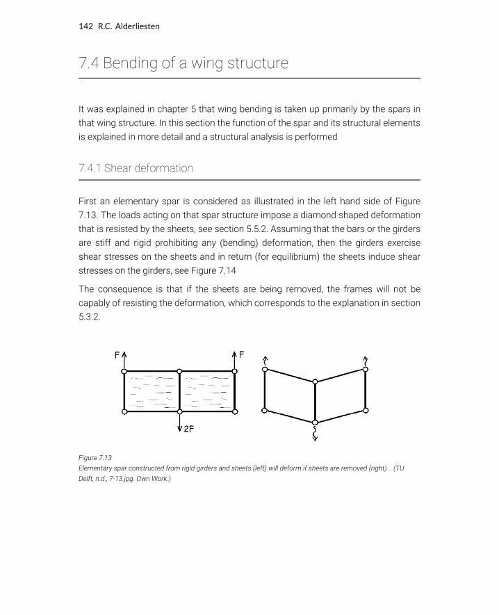
First an elementary spar is considered as illustrated in the left hand side of Figure
7.13. The loads acting on that spar structure impose a diamond shaped deformation
that is resisted by the sheets, see section 5.5.2. Assuming that the bars or the girders
are stiff and rigid prohibiting any (bending) deformation, then the girders exercise
shear stresses on the sheets and in return (for equilibrium) the sheets induce shear
stresses on the girders, see Figure 7.14
The consequence is that if the sheets are being removed, the frames will not be
capably of resisting the deformation, which corresponds to the explanation in section
5.3.2.
Figure 7.13
Elementary spar constructed from rigid girders and sheets (left) will deform if sheets are removed (right). . (TU
Delft, n.d., 7-13.jpg. Own Work.)
142 R.C. Alderliesten
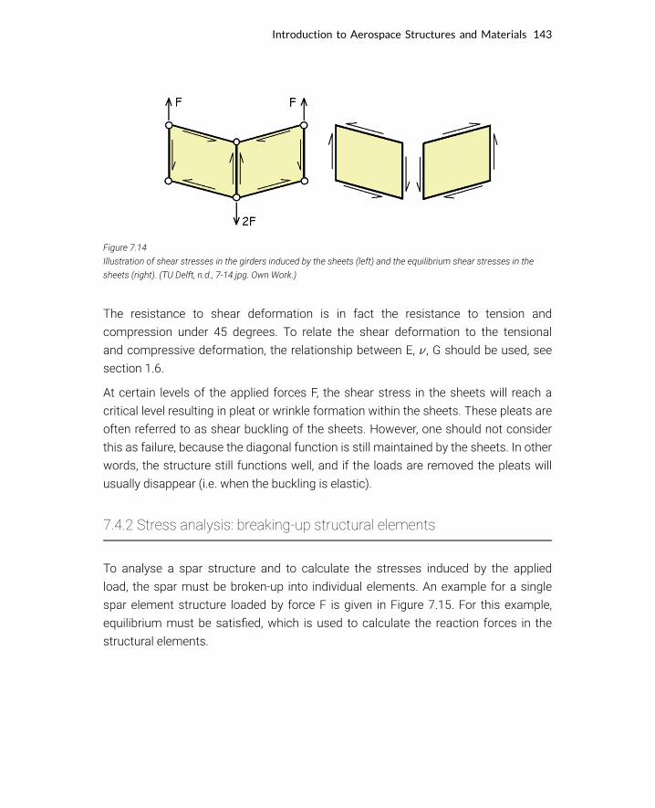
Figure 7.14
Illustration of shear stresses in the girders induced by the sheets (left) and the equilibrium shear stresses in the
sheets (right). (TU Delft, n.d., 7-14.jpg. Own Work.)
The resistance to shear deformation is in fact the resistance to tension and
compression under 45 degrees. To relate the shear deformation to the tensional
and compressive deformation, the relationship between E, , G should be used, see
section 1.6.
At certain levels of the applied forces F, the shear stress in the sheets will reach a
critical level resulting in pleat or wrinkle formation within the sheets. These pleats are
often referred to as shear buckling of the sheets. However, one should not consider
this as failure, because the diagonal function is still maintained by the sheets. In other
words, the structure still functions well, and if the loads are removed the pleats will
usually disappear (i.e. when the buckling is elastic).
7.4.2 Stress analysis: breaking-up structural elements
To analyse a spar structure and to calculate the stresses induced by the applied
load, the spar must be broken-up into individual elements. An example for a single
spar element structure loaded by force F is given in Figure 7.15. For this example,
equilibrium must be satisfied, which is used to calculate the reaction forces in the
structural elements.
Introduction to Aerospace Structures and Materials 143
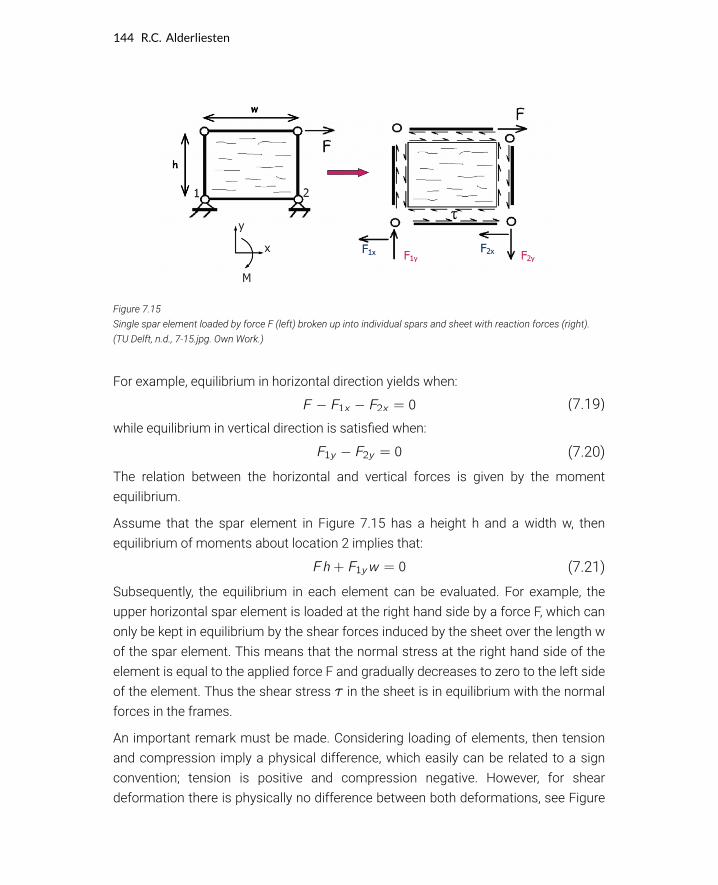
Figure 7.15
Single spar element loaded by force F (left) broken up into individual spars and sheet with reaction forces (right).
(TU Delft, n.d., 7-15.jpg. Own Work.)
For example, equilibrium in horizontal direction yields when:
(7.19)
while equilibrium in vertical direction is satisfied when:
(7.20)
The relation between the horizontal and vertical forces is given by the moment
equilibrium.
Assume that the spar element in Figure 7.15 has a height h and a width w, then
equilibrium of moments about location 2 implies that:
(7.21)
Subsequently, the equilibrium in each element can be evaluated. For example, the
upper horizontal spar element is loaded at the right hand side by a force F, which can
only be kept in equilibrium by the shear forces induced by the sheet over the length w
of the spar element. This means that the normal stress at the right hand side of the
element is equal to the applied force F and gradually decreases to zero to the left side
of the element. Thus the shear stress in the sheet is in equilibrium with the normal
forces in the frames.
An important remark must be made. Considering loading of elements, then tension
and compression imply a physical difference, which easily can be related to a sign
convention; tension is positive and compression negative. However, for shear
deformation there is physically no difference between both deformations, see Figure
144 R.C. Alderliesten

7.16. This means that for the analysis of spar bending a sign convention must be
agreed upon like for instance illustrated in Figure 7.16.
Be aware however, that despite tension and compression are easily captured by
respectively a positive and a negative sign, this assumes that both cases are identical
but opposite of sign. However, physically tension may be considered being different
from compression. Consider for example the presence of a crack. Under tension the
crack would open and all load has to bypass the crack, while in compression the crack
closes, enabling the load to be transferred through the crack.
Figure 7.16
A sign convention for shear is needed to analyse the spar deformation. (TU Delft, n.d., 7-16.jpg. Own Work.)
From the above explanation it is evident that the in case of bending, the shear function
of spar webs is essential. However, the webs have to be supported on the upper and
lower side by caps or girders in order to realize equilibrium. In this configuration, the
webs transfer (external) transverse forces into shear-flows, while the caps transfer
shear-flows in normal forces.
7.5 Case study: bending of wing spar
To illustrate the previous explanation, this section discusses the approach for a
simplified wing spar loaded in bending, illustrated in Figure 7.17.
Introduction to Aerospace Structures and Materials 145

7.5.1 Normal and shear forces
The general approach to this problem is to first check the global equilibrium of the
problem. This means that the reaction forces at the spar root, i.e. at the clamping area
(see Figure 7.18), should provide equilibrium with the external forces .
Figure 7.17
Simplified wing spar loaded by forces F1 to F3.. (TU Delft, n.d., 7-17.jpg. Own Work.)
Global equilibrium implies in (horizontal) x-direction that
(7.22)
And in y-direction
(7.23)
Equilibrium of moments results in point A
(7.24)
146 R.C. Alderliesten
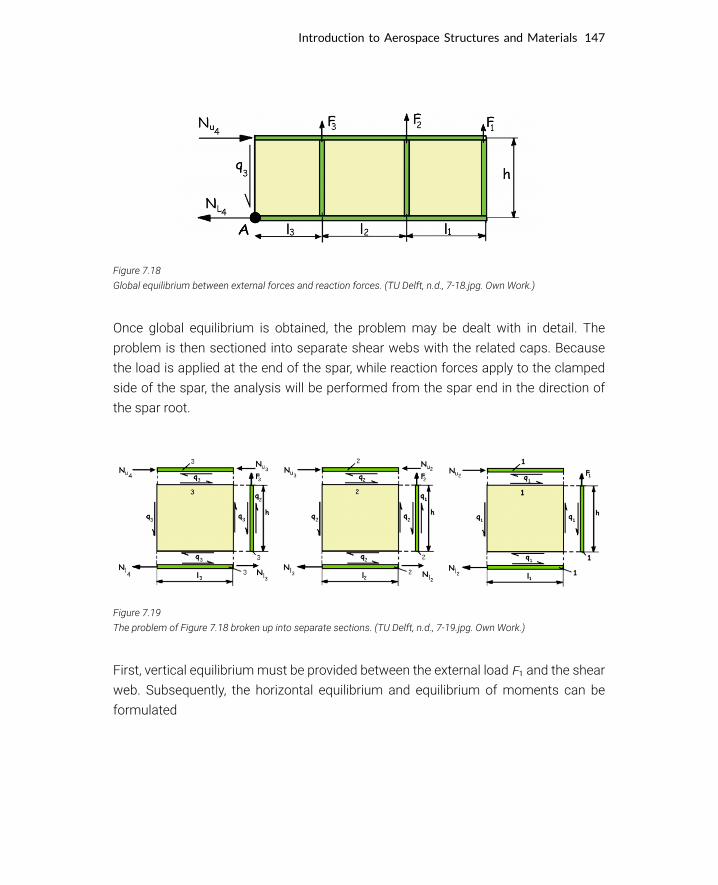
Figure 7.18
Global equilibrium between external forces and reaction forces. (TU Delft, n.d., 7-18.jpg. Own Work.)
Once global equilibrium is obtained, the problem may be dealt with in detail. The
problem is then sectioned into separate shear webs with the related caps. Because
the load is applied at the end of the spar, while reaction forces apply to the clamped
side of the spar, the analysis will be performed from the spar end in the direction of
the spar root.
Figure 7.19
The problem of Figure 7.18 broken up into separate sections. (TU Delft, n.d., 7-19.jpg. Own Work.)
First, vertical equilibrium must be provided between the external load and the shear
web. Subsequently, the horizontal equilibrium and equilibrium of moments can be
formulated
Introduction to Aerospace Structures and Materials 147
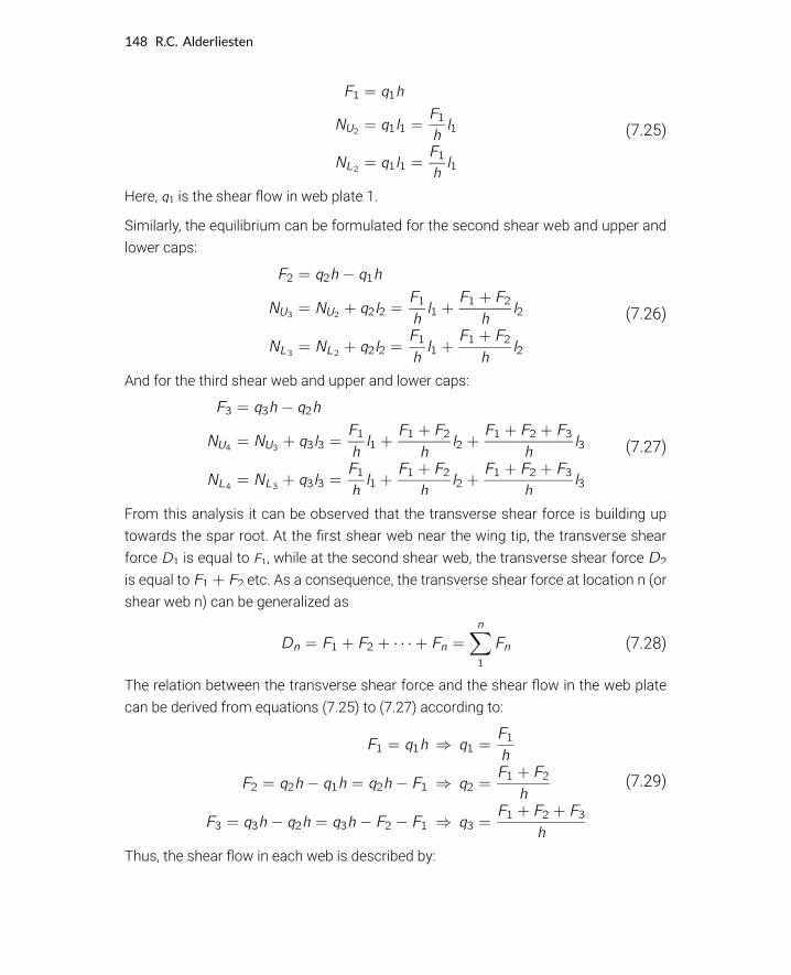
(7.25)
Here, is the shear flow in web plate 1.
Similarly, the equilibrium can be formulated for the second shear web and upper and
lower caps:
(7.26)
And for the third shear web and upper and lower caps:
(7.27)
From this analysis it can be observed that the transverse shear force is building up
towards the spar root. At the first shear web near the wing tip, the transverse shear
force is equal to , while at the second shear web, the transverse shear force
is equal to etc. As a consequence, the transverse shear force at location n (or
shear web n) can be generalized as
(7.28)
The relation between the transverse shear force and the shear flow in the web plate
can be derived from equations (7.25) to (7.27) according to:
(7.29)
Thus, the shear flow in each web is described by:
148 R.C. Alderliesten
(7.30)
Similarly, it follows that the normal forces in the upper and lower caps at the location
of the vertical stiffener is given by
(7.31)
As explained in section 6.3.2, the constant shear flow in the shear webs results in
an increase in normal forces in the spar caps, because the caps transfer the shear
flow into normal forces. Thus equation (7.31) describes the normal forces at the
location of the vertical stiffener, the normal forces in-between the stringers require
some additional analysis.
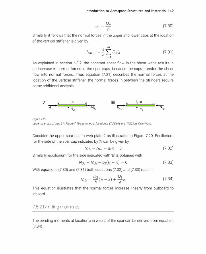
Figure 7.20
Upper spar cap of web 2 in Figure 7.19 sectioned at location x. (TU Delft, n.d., 7-20.jpg. Own Work.)
Consider the upper spar cap in web plate 2 as illustrated in Figure 7.20. Equilibrium
for the side of the spar cap indicated by ‘A’ can be given by
(7.32)
Similarly, equilibrium for the side indicated with ‘B’ is obtained with
(7.33)
With equations (7.30) and (7.31) both equations (7.32) and (7.33) result in
(7.34)
This equation illustrates that the normal forces increase linearly from outboard to
inboard.
7.5.2 Bending moments
The bending moments at location x in web 2 of the spar can be derived from equation
(7.34)
Introduction to Aerospace Structures and Materials 149

(7.35)
For web 2 in the spar one can thus obtain that
(7.36)
Which is valid on every location x on the spar. Thus equation (7.36) can be generalized
as
(7.37)
7.5.3 Bending of wing spar
Thus once a spar is loaded in bending by external forces the transverse shear
forces are known with equation (7.30) and the normal forces in the spar caps are
known as
(7.38)
This enables the determination of the transverse shear force and moment diagram as
illustrated in Figure 7.21.
Figure 7.21
Bending of wing spar; transverse shear force and moment diagram. (TU Delft, n.d., 7-21.jpg. Own Work.)
150 R.C. Alderliesten

In case of a wing structure, where not only the lift is considered as distributed forces
rather than concentrated forces, but in addition also the weight of fuselage and
engines is considered, the transverse shear and moment diagrams will look similar to
Figure 7.22.
Figure 7.22
Transverse shear force and moment diagram of aircraft wing. (TU Delft, n.d., 7-22.jpg. Own Work.)
It should be noted, that the transverse shear line linearly increases or decreases due
to the distributed forces, which implies for the moment line a non-linear increase or
decrease.
The shear stress in the webs is given by
(7.39)
While the normal stress in the spar caps is given by
(7.40)
Here, the parameters are called the moment of resistance W in a spar.
Introduction to Aerospace Structures and Materials 151
This book provides an introduction to the discipline of aerospace structures and materials. It is the first book to date that includes all relevant aspects of this discipline within a single monologue. These aspects range from materials, manufacturing and processing techniques, to structures, design principles and structural performance, including aspects like durability and safety. With the purpose of introducing students into the basics of the entire discipline, the book presents the subjects broadly and loosely connected, adopting either a formal description or an informal walk around type of presentation. A key lessons conveyed within this book is the interplay between the exact science and engineering topics, like solid material physics and structural analysis, and the soft topics that are not easily captured by equations and formulas. Safety, manufacturability, availability and costing are some of these topics that are presented in this book to explain decisions and design solutions within this discipline.
Dr.ir. R.C. (René) AlderliestenTU Delft | Faculty of Aerospace Engeneering
Dr. Alderliesten obtained his MSc and PhD degree both at TU Delft, and holds since 2012 the position of associated professor within the department of Aerospace Structures and Materials at the faculty of Aerospace Engineering, TU Delft. His expertise is fatigue and damage tolerance of metals, composites and hybrid materials, with the emphasis on proper understanding the physics of damage growth. Dr. Alderliesten introduces Aerospace Structures & Materials in the first semester of the BSc curriculum, while teaching Fatigue of Structures & Materials in the first semester of the MSc both at TU Delft and at the University di Bologna.
© 2018 TU Delft OpenISBN 978-94-6366-075-4DOI https://doi.org/10.5074/t.2018.003
textbooks.open.tudelft.nl
Cover image is licensed under CC-BY TU Delft is a derivative of images by: Christopher Boffoli, USA, of the 787 fuselage (CC-BY-SA 3.0), and Gillian Saunders-Smits, TU Delft of a Fokker F100 cockpit (CC-BY-SA 3.0).
Introduction to Aerospace Structures and Materials
Dr.ir. R.C. (René) Alderliesten