MARTIN MARIETTA DENVER AEROSPACE CO - Records ...
162
EPA Region 5 Records Ctr. Ill) 205278 ATTACHMENT 12 Superfund Record of Decision: Martin Marietta, Denver Aerospace, CO (EPA/ROD/R08-90/035) September 1990
-
Upload
khangminh22 -
Category
Documents
-
view
4 -
download
0
Transcript of MARTIN MARIETTA DENVER AEROSPACE CO - Records ...

EPA Region 5 Records Ctr.
Ill)205278
ATTACHMENT 12
Superfund Record of Decision:Martin Marietta, Denver Aerospace, CO
(EPA/ROD/R08-90/035)September 1990

United States Office ofEnvironmental Protection Emergency andAgency Remedial Response
EPA/ROD/R08-90/035September 1990
& ERA Superf undRecord of Decision:
PB91-921483
Martin Marietta, DenverAerospace, CO

50272-101
REPORT DOCUMENTATIONPAGE
1. REPORT NO.EPA/RGD/R08-90/035
3. Recipient' Acceeajon No.
4. Tin* and SubtitleSUPERFUND RECORD OF DECISIONMartin Marietta, Denver Aerospace, COFirst Remedial Action
5. Report Dtlt
0 9 / 2 4 / 9 0
7. Author(e) a. Performing Organization Rcpt No.
>. Performing Orgalnlation Hunt end Addreu 10. ProjecVTaak/Work Unit No.
11. ContracKC) or Grant(G) No.
(C)
(O)
12. Sponeoring Organization Hunt end Addrtu
U.S. Environmental Protection Agency401 M Street, S.W.Washington, D.C. 20460
13. Type of Report 1 Period Covered
800/000
15. Supplementary Nolee
16. Abetrtct (Unit: 200 worde)
The 5,200-acre Martin Marietta, Denver Aerospace site is in Waterton, Jefferson County,Colorado. The site completely surrounds 464 acres of contaminated Air Force property,which is being addressed as a separate Superfund site. Since 1950, the Martin MariettaAeronautics Group (MMAG) has been conducting high technology engineering, design,development, and manufacturing operations for the space industry onsite. Types ofwastes generated during onsite activities include oils, metals, organic solvents,wastewater, chemical process sludges, and VOCs. From 1959 to 1980, untreated, highlyconcentrated waste from onsite activities was disposed of in five onsite ponds, referredto as the Inactive Site Ponds Area. An estimated 2,100 cubic yards of waste and 24,000cubic yards of contaminated soil are contained in the Inactive Site Ponds Area. From1957 to 1969, solid wastes and construction debris generated at the site were disposedof in an 11-acre landfill known as the Rifle Range Landfill. In addition, waste wasstored in underground storage tanks in an area referred to as the Chemical StorgageArea. Previous site remediations by MMAG from 1969 to 1985 did not address contaminantsources or migration, but included backfilling and regrading of the Rifle RangeLandfill; consolidation of soil and wastes from two onsite disposal ponds into one pond
(See Attached Page)
CO17. Document Analysis a. Deecrlptora
Record of Decision - Martin Marietta, Denver Aerospace,First Remedial ActionContaminated Media: soil, debris, gwKey Contaminants: VOCs (TCE, toluene, xylenes), other organics (PCBs, pesticides,
phenols), metals (chromium, lead)b. Identitiere/Open-Ended Terme
c. COSATI Raid/Group11. Avellabiity Statement 9. Sacurily Claaa (Thia Report)
None20. Security Claaa (Thie Page)_____None_____
21. No. ol Pagea
16222. Price
(See ANSI-Z39.18) See instructions on fleverae OPTIONAL FORM 272 (4*77)(Formerly NTIS-M)Department of Commerce

EPA/ROD/R08-90/035Martin Marietta, Denver Aerospace, COFirst Remedial Action
Abstract (Continued)
and covering of the ponds with soil; and operation of a ground water recovery system.EPA investigations have identified the Inactive Site Ponds and the Chemical Storageareas, both located to the north of the main facility, as the two major sources ofonsite soil and ground water contamination. This Record of Decision (ROD) addressesremediation of onsite contaminated soil, waste/debris, and ground water. The primarycontaminants of concern affecting the soil, debris, and ground water are VOCs includingTCE; toluene, and xylenes; other organics including PCBs, pesticides, and phenols; andmetals including chromium and lead.
The selected remedial action for this site has been divided into three separate areas:the Inactive Site Ponds Area, the Chemical Storage Area, and the ground water in thesouth central portion of the site. Remediation of the Inactive Site Ponds Area includesdewatering 1.3 million gallons of water from perched water zones; excavating andincinerating offsite 2,100 cubic yards of organic waste/soil material from in and aroundthe ponds; thermally treating onsite 24,000 cubic yards of organic-contaminated soil;solidifying and stabilizing remaining soil contaminated with inorganics; backfillingexcavated areas with the treated soil, and covering the ponds area with aRCRA-multilayer cap. Remediation of the Chemical Storage Area includes treatingVOC-contaminated soil using in-situ soil vapor extraction, incinerating, and disposingof offsite any residual organic-laden sludge from the thermal extraction treatmentsystem at the ponds area along with any spent carbon from the in-situ soil vaporextraction process. Contaminated ground water remediation includes onsite pumping andtreatment using air stripping, carbon adsorption, ion exchange, UV photolysis/oxidation,chemical reduction, and precipitation, followed by onsite discharge to surface water;and ground water monitoring. The present worth cost for this remedial action is$58,240,000, which includes an annual O&M cost of $1,231,500 for 30 years.
PERFORMANCE STANDARDS OR GOALS: Both onsite and offsite ground water will be treated tomeet SDWA MCLs or MCLGs. Chemical-specific ground water cleanup standards includebenzene 5 ug/1 (MCL), arsenic 50 ug/1 (MCL), chromium 50 ug/1 (MCL), lead 5 ug/1 (MCL),and TCE 5 ug/1 (MCL). Chemical-specific soil cleanup levels are based on soil actionlevels and TCLP treatment standards including toluene 28 mg/kg (TCLP), PCB 1.0 mg/kg(TCLP), and TCE 0.09 mg/kg (TCLP).

RECORD OF DECISIONFOR
Martin Marietta Astronautics Group SiteWaterloo, Colorado
FINALSeptember 19,1990
KE.-OI2-COI002\nnia\m2-<ad.loc

UNITED STATES ENVIRONMENTAL PROTECTION AGENCYREGION Vfl
999 18th STREET - SUITE 500DENVER, COLORADO 80202-2405
Ref: 8HWM-SR SEP 2 A I990
MEMORANDUM
TO: James J. SchererRegional Administrator
FROM: Robert L. Duprey,Hazardous Waste Management Divisio
SUBJECT: Recommendation to Approve the Record of Decision forthe Martin Marietta Astronautics Group (MMAG) Site
I am recommending that you sign the attached Record ofDecision (ROD) for the MMAG Site.
The selected remedy calls for the Inactive Site Ponds soilsto be treated using the following steps: de-watering;excavation; off-site treatment and disposal of waste; thermalextraction of backfill and alluvium; above ground stabilizationof backfill and alluvium, and cap. For the Chemical StorageTanks in the M3 Manufacturing Area, the selected remedy calls forthe soil to be treated using vapor extraction. For the groundwater, site-wide, the selected remedy calls for interception andtreatment using five recovery well systems across the Site. Theground water will be treated on-site to remove organic andinorganic contaminants.
The remedy will be protective of human health and theenvironment because it will address the principal threat, theInactive Site area, which is a major source of ground watercontamination. The remedy will restore ground water to a qualitythat will allow for its beneficial use as a drinking watersupply.
The remedy will accomplish this level of protection bymeeting the following remediation goals:
1. Waste (approximately 2,100 cubic yards) in the InactiveSite Ponds will be transported to an off-site facilityfor treatment and disposal as Resource Conservation andRecovery Act (RCRA) hazardous waste.

2. Contand nat«H soil (approximately 24,400 cubic yards)will be treated by removing organic contaminants andstabilizing inorganics to prevent future impacts toground water quality and minimize the potential forcontact with contaminants in the soil.
3. Ground water will be treated to meet drinking waterstandards both on and off Site. (Restoration may takeas long as 45 years before alluvial ground water meetsdrinking water standards on Site.)
Two sets of comments were received on the preferredalternative. The National Toxics Campaign recommended emissioncontrols for the on-site air stripper and was interested inoverseeing the work as a third party. MMAG requested flexibilityin implementing any decision made and expressed the concern thatthe Environmental Protection Agency was being overly restrictiveon cleanup levels by projecting residential use in the future.MMAG recommended another alternative be left in the ROD tosupplement the selected remedy. These comments have beenaddressed in the responsiveness summary and in the ROD itself.
The State has concurred with the remedy and has beenrequested to jointly sign the ROD because the Colorado Departmentof Health will be overseeing the remedy implementation under RCRACorrective Action authority.
Attachment

September 19, 1990
Martin Marietta Astronautics Group SiteDeclaration for the Record of Decision
SITE NAME AND LOCATION
Martin Marietta Astronautics GroupWaterton, Colorado
STATEMENT OF BASIS AND PURPOSE
This decision document presents the selected remedial action for the Martin Marietta AstronauticsGroup (MMAG) site in Waterton, Colorado. The remedy includes remediation of contaminated soilin and around the Inactive Site Ponds and the Chemical Storage Tank area to the north of the mainmanufacturing building. Additionally, the remedy includes remediation of contaminated groundwater hi the south central portion of the Site (including die M3 area, branches of Brush Creek, DryGulch, and Filter Gulch). This remedy was developed in accordance with the ComprehensiveEnvironmental Response, Compensation, and Liability Act of 1980 (CERCLA), as amended by theSuperfund Amendments and Reautborization Act (SARA), and the National Oil and HazardousSubstances Pollution Contingency Plan (NCP). The decision is based upon the AdministrativeRecord for this site.
The State of Colorado concurs with the selected remedy.
ASSESSMENT OF THE SITE
The actual or threatened releases of hazardous substances and hazardous constituents from the site, ifnot addressed by implementing the response action selected in this record of decision (ROD), maypresent an imminent and substantial endangerment to public health, welfare, or the environment.
DESCRIPTION OF THE SELECTED REMEDY
The selected remedy for the Martin Marietta Astronautics Group she addresses the Inactive SitePonds, die Chemical Storage Tank area and ground water in me south central portion of die Site.The objective of die remedy is to mitigate continued release of hazardous substances to die groundwater and to prevent further degradation of die aquifer both on-site and off-site. The remedy willalso prevent contaminant loading in me South Platte River which supports both domestic andrecreational uses. Additionally by removing the majority of the contamination from the Inactive Site
RE:012-CO«0<n\iMrtin\m2-nxi.toc

September 19, 1990
Ponds, the remedy will mini"^?* the potential for future human exposure to contaminants on or off-site. The major components of the remedy include:
Inactive Site Ponds
Dewatering the perched zones and contaminated alluvium and treating the water on-site(approximately 1 million gallons).Excavating waste ?"d contaminated soil in t*u} around the ponds for treatment.Approximately 2,100 cubic yards of waste will be treated and disposed of off-site inaccordance with the Land Disposal Restrictions (LDRs).Treating contaminated soil (approximately 24,400 cubic yards) on-site using thermalextraction for organic chemicals and solidification/stabilization for inorganic chemicals. Soilwhich is contaminated with RCRA listed hazardous wastes will be treated to meet either theLDR treatment standards or the soil and debris treatability variance standards.Backfilling treated soil into the area of contamination and covering with a multi-layered cap.
Chemical Storage Tank Area
Using soil vapor extraction tn-situ around the Chemical Storage Tanks to remove and capturehalogenated organic ^gmicals
Ground Water
Installing additional extraction systems on-site hi Dry Gulch, Filter Gulch, the Chemical MillSumps, Hydrostatic Test Tank area, and possibly in the East Branch of Brush Creek (northof the Inactive Site).Treating the recovered ground water for volatile organic compounds (VOCs) and inorganiccontaminants including heavy metals. Additionally, a process for treating N-nitrosodimethylamine (MDMA) will be installed.Treating the water to meet parameters established in the Colorado Pollutant DischargeElimination System (COPDES) permit for the MMAG facility. Clean-up targets for theground water are based on federal and state drinking water standards.
Implementation of this remedy is expected to take 4 to 5 years for the Inactive She Ponds.Approximately 45 years may be needed to remove contaminants in the ground water in order to meetthe remediation goals.
REXI12-COS002 \mtrun\ia2-rod.iac
\

September 19, 1990
The selected remedy is protective of human health and the environment, complies with Federal andState requirements legally applicable or relevant and appropriate to the remedial action, and is cost-effective. The remedy uses permanent solutions and alternative treatment technologies to themaximum extent practicable and satisfies the statutory preference for remedies that employ treatmentsthat reduce toxicity, mobility or volume as a principal element. Because this remedy will result inhazardous substances remaining on-site above levels that allow for unlimited use and unrestrictedexposure, a review will be conducted no less often man every five years after remediation is initiatedto ensure the remedy continues to provide protection of human health and the environment.
. ScheteVRegional AdministratorEPA Region
Thomas P. Looby £/ DateAssistant DirectorOffice of Health and Environmental ProtectionColorado Department of Health
KE4>12-CM002\autin\m2-nd.ioc

September 19, 1990
TABLE OF CONTENTSSECTION EAfiE
1.0 SITE NAME, LOCATION, AND DESCRIPTION . . . . . . . . . . . . . . . . . . . . . . . . . 1
1.1 PHYSIOGRAPHY AND MAJOR SITE FEATURES . . . . . . . . . . . . . . . . . 1
1.2 SURROUNDING LAND USE . . . . . . . . . . . . . . . . . . . . . . . . . . . . . . . 4
1.3 METEOROLOGY . . . . . . . . . . . . . . . . . . . . . . . . . . . . . . . . . . . . . . 5
1.4 GEOLOGY . . . . . . . . . . . . . . . . . . . . . . . . . . . . . . . . . . . . . . . . . . 6
1.5 HYDROLOGY . . . . . . . . . . . . . . . . . . . . . . . . . . . . . . . . . . . . . . . . 7
2.0 SITE HISTORY . . . . . . . . . . . . . . . . . . . . . . . . . . . . . . . . . . . . . . . . . . . . . . 8
2.1 WASTE GENERATION AND DISPOSAL . . . . . . . . . . . . . . . . . . . . . . 8
2.2 ENFORCEMENT HISTORY . . . . . . . . . . . . . . . . . . . . . . . . . . . . . . . . 9
2.3 PREVIOUS STUDIES . . . . . . . . . . . . . . . . . . . . . . . . . . . . . . . . . . . . 10
2.4 REMEDIAL ACllVliltS . . . . . . . . . . . . . . . . . . . . . . . . . . . . . . . . . 11
25 U.S. AIR FORCE (PJKS) PROPERTY . . . . . . . . . . . . . . . . . . . . . . . . . 11
3.0 COMMUNITY PARTICIPATION . . . . . . . . . . . . . . . . . . . . . . . . . . . . . . . . . . . 11
3.1 CHRONOLOGY OF COMMUNITY PARTICIPATION ALTIV1T1HS . . . . . . 13
3.2 LOCATION OF INFORMATION CENTERS . . . . . . . . . . . . . . . . . . . . . 14
4.0 SITE CHARACTERIZATION . . . . . . . . . . . . . . . . . . . . . . . . . . . . . . . . . . . . . 15
4.1 SOURCES OF CONTAMINATION . . . . . . . . . . . . . . . . . . . . . . . . . . . 15
4.2 AFFECTED MEDIA AND EVALUATION OF CONTAMINATION . . . . . . . 16
4.3 MOBILITY OF CONTAMINANTS . . . . . . . . . . . . . . . . . . . . . . . . . . . 21
4.3.1 Ground Water . . . . . . . . . . . . . . . . . . . . . . . . . . . . . . . . . . . . 214.3.2 Surface Water and Sediments . . . . . . . . . . . . . . . . . . . . . . . . . . . 22
4.4 MODELLING OF CONTAMINANT MIGRATION . . . . . . . . . . . . . . . . . . 25
KE.-OU-COt002VBMlia\m2-fod.ioc

September 19, 1990
TABLE OF CONTENTS(Continued)
SECTION PAGE
5.0 SUMMARY OF SITE RISK . . . . . . . . . . . . . . . . . . . . . . . . . . . . . . . . . . . . . . . 28
5.1 CONTAMINANT IDENTIFICATION INFORMATION . . . . . . . . . . . . . . . 28
5.1.1 Media of Concern . . . . . . . . . . . . . . . . . . . . . . . . . . . . . . . . . . 285.1.2 Contaminants of Concern in Each Media . . . . . . . . . . . . . . . . . . . . 295.1.3 Concentrations of Chemicals . . . . . . . . . . . . . . . . . . . . . . . . . . . 30
5.2 EXPOSURE ASSESSMENT INFORMATION . . . . . . . . . . . . . . . . . . . . . 32
5.2.1 Exposure Pathways . . . . . . . . . . . . . . . . . . . . . . . . . . . . . . . . . 325.2.2 Potential Exposed Populations . . . . . . . . . . . . . . . . . . . . . . . . . . 335.2.3 Monitoring or Modelling Data and Assumptions Used to Characterize
Exposure Point Concentrations . . . . . . . . . . . . . . . . . . . . . . . . . . 335.2.4 Assumptions of Exposure Frequency and Duration . . . . . . . . . . . . . . 34
5.3 CURRENT AND FUTURE USE SCENARIOS . . . . . . . . . . . . . . . . . . . . 34
5.3.1 Assumptions . . . . . . . . . . . . . . . . . . . . . . . . . . . . . . . . . . . . . 34- 5.3.2 Current Use Scenario . . . . . . . . . . . . . . . . . . . . . . . . . . . . . . . . 37
5.3.3 Future Use Scenario . . . . . . . . . . . . . . . . . . . . . . . . . . . . . . . . 37
5.4 TOXICITY ASSESSMENT INFORMATION . . . . . . . . . . . . . . . . . . . . . . 37
5.4.1 Slope Factors . . . . . . . . . . . . . . . . . . . . . . . . . . . . . . . . . . . . 375.4.2 Reference Dose . . . . . . . . . . . . . . . . . . . . . . . . . . . . . . . . . . . 395.4.3 Explanation of Toxicity Information . . . . . . . . . . . . . . . . . . . . . . . 39
5.5 RISK CHARACTERIZATION INFORMATION . . . . . . . . . . . . . . . . . . . . 39
5.5.1 Quantified Carcinogenic Risks for Each Contaminant of Concern inEach Pathway . . . . . . . . . . . . . . . . . . . . . . . . . . . . . . . . . . . . 41
5.5.2 Combined Carcinogenic Effects . . . . . . . . . . . . . . . . . . . . . . . . . 415.5.3 Noncarcinogenic Effects for Each Contaminant in Each Pathway . . . . . 455.5.4 Combined Noncarcinogenic Effects . . . . . . . . . . . . . . . . . . . . . . . 455.5.5 Sources of Uncertainty . . . . . . . . . . . . . . . . . . . . . . . . . . . . . . . 485.5.6 Risk Assessment Conclusions . . . . . . . . . . . . . . . . . . . . . . . . . . . 49
5.6 ENVIRONMENTAL RISKS . . . . . . . . . . . . . . . . . . . . . . . . . . . . . . . . 49
5.6.1 Critical Habitats . . . . . . . . . . . . . . . . . . . . . . . . . . . . . . . . . . . 505.6.2 Endangered or Threatened Species . . . . . . . . . . . . . . . . . . . . . . . . 50
6.0 DESCRIPTION OF ALTERNATIVES . . . . . . . . . . . . . . . . . . . . . . . . . . . . . . . . 50
6.1 ALTERNATIVE S-l: NO ACTION . . . . . . . . . . . . . . . . . . . . . . . . . . . 52
RE.-012-C08002\minin\in2-nxl.u>c11

September 19, 1990
TABLE OF CONTENTS(Continued)
SECTION PAGE
6.2 ALTERNATIVES-2: DEWATER/RCRA CAP/IN-SITU SOIL VAPOREXTRACTION . . . . . . . . . . . . . . . . . . . . . . . . . . . . . . . . . . . . . . . . 52
6.3 ALTERNATIVES-3: DEWATER/OFF-SITE INCINERATION ANDDISPOSAL OF WASTE/EX-SITU STABILIZATION OF BACKFILL ANDALLUVIUM/RCRA CAP/IN-SITU SOIL VAPOR EXTRACTION . . . . . . . . . 54
6.4 ALTERNATIVES-4: DEWATER/ON-SrEEINCINERATION OFBACKFILL, ALLUVIUM, AND WASTE/OFF-SITE DISPOSAL OFINCINERATED RESIDUES/EX-SITU STABILIZATION OFINCINERATED BACKFILL AND ALLUVIUM/RCRA CAP/IN-SITU SOILVAPOR EXTRACTION . . . . . . . . . . . . . . . . . . . . . . . . . . . . . . . . . . . . 57
6.5 ALTERNATIVES-5: DEWATER/OFF-SITE INCINERATION ANDDISPOSAL OF WASTE/THERMAL EXTRACTION OF BACKFILL ANDALLUVIUM/EX-SITU STABILIZATION OF BACKFILL ANDALLUVIUM/RCRA CAP/VAPOR IN-SITU SOIL VAPOR EXTRACTION ... 60
6.6 ALTERNATIVE GW-1: NO ACTION . . . . . . . . . . . . . . . . . . . . . . . . . 62
6.7 ALTERNATIVE GW-2: CONTINUED OPERATION OF THE EXIS' NGRECOVERY WELL SYSTEMS/TREATMENT BY AIR STRIPPING,CARBON ADSORPTION, AND ION EXCHANGE/DISCHARGE TOBRUSH CREEK . . . . . . . . . . . . . . . . . . . . . . . . . . . . . . . . . . . . . . . 63
6.8 ALTERNATIVE GW-3: CONTINUED OPERATION OF THE EXISTINGRECOVERY WELL SYSTEMS/INSTALLATION OF ADDITIONALRECOVERY WELL SYSTEMS IN FILTER GULCH AND DRY GULCHUPGRADIENT FROM THE EXISTING RECOVERY WELLSYSTEMS/TREATMENT BY AIR STRIPPING, CARBON ADSORPTION,ION EXCHANGE, AND/OR UV PHOTOLYSIS-OXIDATION/DISCHARGE TO BRUSH CREEK . . . . . . . . . . . . . . . . . . . . . . . . . . . . 65
6.9 ALTERNATIVE GW-4: CONTINUED OPERATION OF EXISTINGRECOVERY WELL SYSTEMS/INSTALLATION OF ADDITIONALRECOVERY WELL SYSTEMS IN FILTER GULCH AND DRY GULCHUPGRADIENT FROM THE EXISTING RECOVERY WELLSYSTEMS/ADDITION OF A RECOVERY WELL SYSTEM IN THE M3AREA/TREATMENT BY CHEMICAL REDUCTION, PRECIPITATION,CLARIFICATION, AIR STRIPPING, CARBON ADSORPTION, IONEXCHANGE, AND/OR UV PHOTOLYSIS-OXIDATION/DISCHARGE TOBRUSH CREEK . . . . . . . . . . . . . . . . . . . . . . . . . . . . . . . . . . . . . . . 66
7.0 SUMMARY OF COMPARATIVE ANALYSIS OF ALTERNATIVES . . . . . . . . . . . . 67
7.1 INTRODUCTION . . . . . . . . . . . . . . . . . . . . . . . . . . . . . . . . . . . . . . 67
KEK)12-COtOaZ\mutin\m2-ndJoc111

September 19, 1990
TABLE OF CONTENTS(Continued)
SECTION PAGE
7.2 COMPARATIVE ANALYSIS OF SOIL ALTERNATIVES . . . . . . . . . . . . . 68
7.2.1 Overall Protection of Human Health and the Environment . . . . . . . . . 687.2.2 Compliance with ARARs . . . . . . . . . . . . . . . . . . . . . . . . . . . . . 727.2.3 Long-term Effectiveness and Permanence . . . . . . . . . . . . . . . . . . . . 727.2.4 Reduction of Toxicity, Mobility, or Volume Through Treatment . . . . . . 737.2.5 Short-term Effectiveness . . . . . . . . . . . . . . . . . . . . . . . . . . . . . . 747.2.6 Implementability . . . . . . . . . . . . . . . . . . . . . . . . . . . . . . . . . . . 757.2.7 Cost . . . . . . . . . . . . . . . . . . . . . . . . . . . . . . . . . . . . . . . . . . 767.2.8 State Acceptance . . . . . . . . . . . . . . . . . . . . . . . . . . . . . . . . . . 777.2.9 Community Acceptance . . . . . . . . . . . . . . . . . . . . . . . . . . . . . . 78
7.3 COMPARATIVE ANALYSIS OF GROUND WATER ALTERNATIVES . . . . 78
7.3.1 Overall Protection of Human Health and the Environment . . . . . . . . . 787.3.2 Compliance with ARARs . . . . . . . . . . . . . . . . . . . . . . . . . . . . . 817.3.3 Long-term Effectiveness and Permanence . . . . . . . . . . . . . . . . . . . . 817.3.4 Reduction of Toxichy, Mobility, or Volume Through Treatment . . . . . . 827.3.5 Short-term Effectiveness . . . . . . . . . . . . . . . . . . . . . . . . . . . . . . 827.3.6 I m p l e m e n t a b i l i t y . . . . . . . . . . . . . . . . . . . . . . . . . . . . . . . . . . . 827.3.7 Cost . . . . . . . . . . . . . . . . . . . . . . . . . . . . . . . . . . . . . . . . . . 837.3.8 State Acceptance . . . . . . . . . . . . . . . . . . . . . . . . . . . . . . . . . . 837.3.9 Community Acceptance . . . . . . . . . . . . . . . . . . . . . . . . . . . . . . 84
8.0 SELECTED REMEDY . . . . . . . . . . . . . . . . . . . . . . . . . . . . . . . . . . . . . . . . . . 84
8.1 DESCRIPTION . . . . . . . . . . . . . . . . . . . . . . . . . . . . . . . . . . . . . . . . 85
8.1.1 Alternative S-5: Dewater/Off-site Incineration and Disposal ofWaste/Thermal Extraction of Backfill and Alluvium/Ex-SituStabilization of Backfill and Alluvium/RCRA Cap/Vapor In-Situ SoilVapor Extraction . . . . . . . . . . . . . . . . . . . . . . . . . . . . . . . . . . 85
8.1.2 Alternative GW-4: Continued Operation of Existing Recovery WellSystems/Installation of Additional Recovery Well Systems In FilterGulch and Dry Gulch Upgradient From the Existing Recovery WellSystems/Addition of a Recovery Well System in the M3 Ar-ea/Treatment By Chemical Reduction, Precipitation, Clarification, AirStripping, Carbon Adsorption, Ion Exchange, and/or UV Photolysis-Oxidation/Discharge to Brush Creek . . . . . . . . . . . . . . . . . . . . . . . 95
8.2 REMEDIATION GOALS . . . . . . . . . . . . . . . . . . . . . . . . . . . . . . . . . 103
8.2.1 Soil Remediation Goals (Inactive Site and Chemical Storage TankAreas) . . . . . . . . . . . . . . . . . . . . . . . . . . . . . . . . . . . . . . . . . 104
8.2.2 Ground Water Remediation Goals . . . . . . . . . . . . . . . . . . . . . . . . 105
RE.-012-COS002\uutiB\n2'«>d.iocIV

September 19, 1990
TABLE OF CONTENTS(Continued)
SECTION EASE
8.3 REVISED COST ESTIMATE . . . . . . . . . . . . . . . . . . . . . . . . . . . . . . 107
9.0 STATUTORY DETERMINATIONS . . . . . . . . . . . . . . . . . . . . . . . . . . . . . . . . . . 107
9.1 PROTECTION OF HUMAN HEALTH AND THE ENVIRONMENT . . . . . . 107
9.2 COMPLIANCE WITH APPLICABLE OR RELEVANT ANDAPPROPRIATE REQUIREMENTS (ARARs) OF ENVIRONMENTALLAWS . . . . . . . . . . . . . . . . . . . . . . . . . . . . . . . . . . . . . . . . . . . . . 112
9.2.1 Resource Conservation & Recovery Act (RCRA) andToxic Substance Control Act (TSCA) . . . . . . . . . . . . . . . . . . . . . 113
9.2.2 Clean Water Act (CWA) & Safe Drinking Water Act (SDWA) . . . . . 1259.2.3 dean Air Act (CAA) . . . . . . . . . . . . . . . . . . . . . . . . . . . . . . 125
9.3 COST-EFFECTIVENESS . . . . . . . . . . . . . . . . . . . . . . . . . . . . . . . . . . 125
9.4 USE OF PERMANENT SOLUTIONS AND ALTERNATIVE TREATMENTTECHNOLOGIES OR RESOURCE RECOVERY TECHNOLOGIES TOTHE MAXIMUM EXTENT PRACTICABLE . . . . . . . . . . . . . . . . . . . . . 126
9.5 PREFERENCE FOR TREATMENT AS PRINCIPAL ELEMENT . . . . . . . . . 126
9.6 CONCLUSIONS . . . . . . . . . . . . . . . . . . . . . . . . . . . . . . . . . . . . . . . 127
10.0 REFERENCES . . . . . . . . . . . . . . . . . . . . . . . . . . . . . . . . . . . . . . . . . . . . . . 127
APPENDIX A - RESPONSTVENESS SUMMARY
APPENDIX B - INACTIVE SITE PONDS CROSS SECTIONS
RE.-OI2-CO$002\m«nin\ni2fodJoe
\

September 19, 1990
TABLE OF CONTENTS(Continued)
LIST OF TABLES
Table 4-1 . . . . . . . . . . . . . . . . . . . . . . . . . . . . . . . . . . . . . . . . . . . . . . . . . . . . . 19Table 5-1 . . . . . . . . . . . . . . . . . . . . . . . . . . . . . . . . . . . . . . . . . . . . . . . . . . . . . 35Table 5-2 . . . . . . . . . . . . . . . . . . . . . . . . . . . . . . . . . . . . . . . . . . . . . . . . . . . . . 38Table 5-3 . . . . . . . . . . . . . . . . . . . . . . . . . . . . . . . . . . . . . . . . . . . . . . . . . . . . . 40Table 5-4 . . . . . . . . . . . . . . . . . . . . . . . . . . . . . . . . . . . . . . . . . . . . . . . . . . . . . 42Table 5-5 . . . . . . . . . . . . . . . . . . . . . . . . . . . . . . . . . . . . . . . . . . . . . . . . . . . . . 46Table 7-1 . . . . . . . . . . . . . . . . . . . . . . . . . . . . . . . . . . . . . . . . . . . . . . . . . . . . . 68Table 7-2 . . . . . . . . . . . . . . . . . . . . . . . . . . . . . . . . . . . . . . . . . . . . . . . . . . . . . 79Table 8-1 . . . . . . . . . . . . . . . . . . . . . . . . . . . . . . . . . . . . . . . . . . . . . . . . . . . . . 88Table 8-2 . . . . . . . . . . . . . . . . . . . . . . . . . . . . . . . . . . . . . . . . . . . . . . . . . . . . . 106Table 8-3 . . . . . . . . . . . . . . . . . . . . . . . . . . . . . . . . . . . . . . . . . . . . . . . . . . . . . 108Table 9-1 . . . . . . . . . . . . . . . . . . . . . . . . . . . . . . . . . . . . . . . . . . . . . . . . . . . . . 114
LIST OF FIGURES
Figure 1-1 . . . . . . . . . . . . . . . . . . . . . . . . . . . . . . . . . . . . . . . . . . . . . . . . . . . . . 2Figure 1-2 . . . . . . . . . . . . . . . . . . . . . . . . . . . . . . . . . . . . . . . . . . . . . . . . . . . . . 3Figure 8-1 . . . . . . . . . . . . . . . . . . . . . . . . . . . . . . . . . . . . . . . . . . . . . . . . . . . . . 86Figure 8-2 . . . . . . . . . . . . . . . . . . . . . . . . . . . . . . . . . . . . . . . . . . . . . . . . . . . . . 92Figure 8-3 . . . . . . . . . . . . . . . . . . . . . . . . . . . . . . . . . . . . . . . . . . . . . . . . . . . . . 94Figure 8-4 . . . . . . . . . . . . . . . . . . . . . . . . . . . . . . . . . . . . . . . . . . . . . . . . . . . . . 97Figure 8-5 . . . . . . . . . . . . . . . . . . . . . . . . . . . . . . . . . . . . . . . . . . . . . . . . . . . . . 101
RE4)12-GM002Vn>nia\m2-n>d.locVI

September 19, 1990
Martin Marietta Astronautics Group SiteDecision Summary of the Record of Decision
1.0 SITE NAME, LOCATION, AND DESCRIPTION
This record of decision (ROD) describes the remedial cleanup of the Martin MariettaAstronautics Group (MMAG) site.
The site is located in Jefferson County near the mouth of Waterton Canyon approximately 25miles southwest of Denver (see Figure 1-1). The site occupies approximately 5,200 acres, andcompletely surrounds 464 acres of U.S. Air Force property (PJKS). The site is the location ofMMAG high technology engineering, design, development, and manufacturing operations primarilyfor the space industry. MMAG has produced the Titan 34D7 space launch vehicle, the MXemplacer, and various space shuttle subsystems at the site.
1.1 PHYSIOGRAPHY AND MAJOR SITE FEATURES
The west side of the site is located in the foothills of the Rocky Mountains with elevationsranging from 5,800 to 8,000 feet above mean sea level. The east side of toe site is divided by theDakota Hogback into a central valley between the hogback and the foothills and the plains east of thehogback. The elevation of the eastern areas ranges from 5,500 to 6,000 feet above mean sea level.The site has been subdivided into four major study areas. The first area contains plains stretchingfrom the eastern boundary of the site to the Dakota Hogback. The second and third areas liebetween the Dakota Hogback and the foothills. The Norm Central Valley area is norm of the LariatGulch/Brush Creek divide, while the South Central Valley area is south of the divide. ThePrecambrian Bedrock area spreads from the western edge of the central valley to the westernboundary of the she.
A majority of the development on the site is confined to the South Central Valley. The siteis further subdivided into nine separate areas (Figure 1-2). These areas include:
Kassler Area
FQter Gulch AreaLower Brush Creek Area
M3 Area
Space Support Building (SSB) Area
RE.-012-COSOQ2\mulinVfDd-M9

Martin MariettaAstronautics
U.S. Air ForcePJKS Facility
FIGURE 1-1 - LOCATION OF MARTIN MARIETTA ASTRONAUTICS GROUPSITE

Area But of theDakota Hogback
T-_ I
Pre-Cambmn Area
0' SOO'
FIGURE 1-2 - MARTIN MARIETTA ASTRONAUTICS GROUPSITE
September 19, 1990
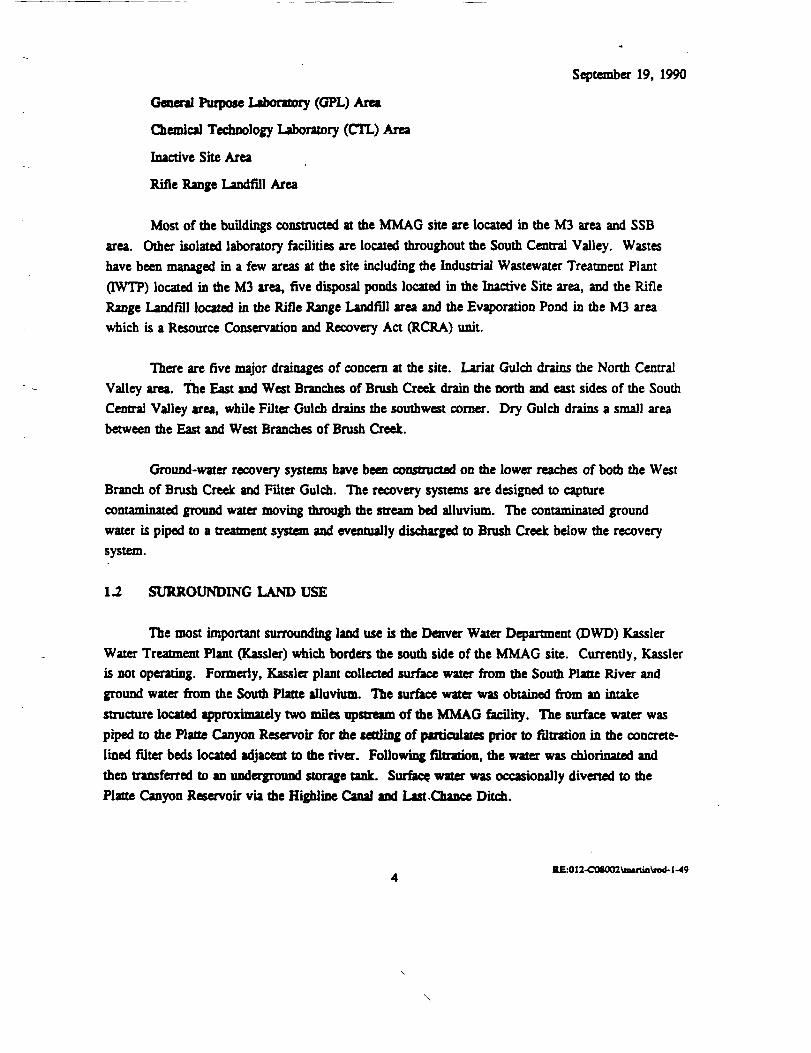
General Purpose Laboratory (GPL) AreaChemical Technology Laboratory (CTL) Area
Inactive Site AreaRifle Range Landfill Area
Most of die buildings constructed at the MMAG site are located in the M3 area and SSBarea. Other isolated laboratory facilities are located throughout the South Central Valley. Wasteshave been managed in a few areas at the site including the Industrial Wastewater Treatment Plant(IWTP) located in the M3 area, five disposal ponds located in the Inactive Site area, and the RifleRange Landfill located in the Rifle Range Landfill area and the Evaporation Pond in the M3 areawhich is a Resource Conservation and Recovery Act (RCRA) unit.
There are five major drainages of concern at the site. Lariat Gulch drains the North CentralValley area. The East and West Branches of Brush Creek drain the norm and east sides of the SouthCentral Valley area, while Filter Gulch drains the southwest corner. Dry Gulch drains a small areabetween the East and West Branches of Brush Creek.
Ground-water recovery systems have been constructed on the lower reaches of both the WestBranch of Brush Creek and Filter Gulch. The recovery systems are designed to capturecontaminated ground water moving through the stream bed alluvium. The contaminated groundwater is piped to a treatment system and eventually discharged to Brush Creek below the recoverysystem.
1.2 SURROUNDING LAND USE
The most important surrounding land use is the Denver Water Department (DWD) KasslerWater Treatment Plant (Kassler) which borders the south side of the MMAG site. Currently, Kassleris not operating. Formerly, Kassler plant collected surface water from the South Plane River andground water from the South Plane alluvium. The surface water was obtained from an intakestructure located approximately two miles upstream of the MMAG facility. The surface water waspiped to the Platte Canyon Reservoir for the settling of particulates prior to filtration in the concrete-lined filter beds located adjacent to the river. Following filtration, the water was chlorinated andthen transferred to an underground storage tank. Surface water was occasionally diverted to thePlatte Canyon Reservoir via the Highline Canal and Last .Chance Ditch.
RE:OI2-C08002Vm.runWwi-M9

September 19, 1990
Ground witer was collected using a series of infiltration galleries constructed in the saturatedalluvium along the South Platte River. Ground water was withdrawn from the infiltration galleriesafter collecting at the 5-sided well. The water was chlorinated and then blended with surface waterin the underground storage tank. The 5-sided well was shut down in December 1984 following thedetection of low levels of TCE in the South Platte alluvium. Last Chance Ditch may also have beenimpacted by contaminated water coming from seeps in the Filter Gulch area. In December 1985, allwater treatment operations were discontinued at the Kassler plant. The plant is maintained go that itmay be brought back on-line in the future.
The Chatfield Reservoir State Recreation area is located northeast of the MMAG site.Chatfield Reservoir is extensively used for boating, hiking, and many other recreational activities.The area outside the recreational area is zoned A-1 and A-2, meaning that development plots must beat least 10 acres. There are scattered residences throughout this area.
Two miles north/northeast of the site is the planned development, Chatfield Green ActivityCenter. It wfll cover 346 acres and contain office, research, and industrial facilities as well as 600dwelling units. Two miles northwest of the site is the Red Mesa Quarry. The area has been zonedfor industrial use only. To the west, the land is zored A-1 restricting development plots to greaterman 35 acres. Only scattered residences exist in mis area.
An inventory of ground water wells in the area surrounding the site shows that mere arecurrently no wells with a domestic-use permit Previously, five domestic-use wells were permitted inthe immediate vicinity. Four wells permitted to the DWD in 1954 and 1956 were abandoned in1971. A fifth well permitted in 1956 no longer exists.
Water in the South Platte River is used as a source for drinking water by the city ofEnglewood. The water intake is 3 miles south of Chatfield Reservoir.
1J METEOROLOGY
The weather at the she is typical for the east flank of the front range of the Colorado RockyMountains. It is temperate with avenge high temperatures of 70 degrees O Fahrenheit (F) in Julyand 29T in January. It is semi-arid with an average of 17.75 inches of rainfall per year.Atmospheric pressure is approximately 83 percent of mat at sea level because of the elevation.Humidity averages 50 percent and the mean average evaporation is between 50 inches and 60 inchesper year. Eighty percent of the precipitation falls between April 1 and September 30. Snow is
K£.-012-COI003\mutin\nd.1 -49
\

September 19, 1990
possible year round, but the heaviest snow falls are in March. Prevailing winds are from the southand southwest at 9 miles per hour, with the strongest winds in March and April.
1.4 GEOLOGY
The oldest rock type occurring at the MMAG site is Precambrian age granite andmetamorphic rocks. These rocks make up the mountainous terrain on the west side of the site. ThePennsylvanian age Fountain Formation nonconfbrmably overlies the igneous and metamorphic rocks.The Fountain Formation is 2,200 feet thick and outcrops or subcrops below most of the Inactive Sitearea, M3 area, GPL area, and Filter Gulch area. The Fountain Formation and the overlyingsediments units have been tectonically uplifted and now strike to the northwest and dip to thenortheast.
The Fountain Formation consists primarily of laterally discontinuous layers of poorly sortedconglomeratic sandstone, sandstone, and sandy and silty claystone.
The Permian age Lyons Sandstone conformably overlies the Fountain Formation. The LyonsSandstone is approximately 235 feet thick and consists primarily of fine-to-coarse-grained quartzsandstone. It is moderately resistant and forms a small hogback through the South Central Valleyarea.
The Permian to Triassic age Lykins Formation conformably overlies the Lyons Sandstone.The Lykins Formation includes three members: Bergen/Harriman Shale, Glennon Limestone, andStrain Shale. The basal 112 feet thick Bergen/Harriman Shale consists primarily of reddish-brownsilty shale. The 15-foot thick Glennon Limestone is a pink and gray, thinly laminated limestone withlocally well developed secondary porosity. The 250-foot thick Strain Shale consists primarily ofyellow-brown shale.
The Jurassic age Ralston Creek Formation disconfbrmably overlies the Lykins Formation.The Ralston Creek Formation is 50 feet thick and consists of imerbedded, fine-grained sandstone,limestone, and shale. The Ralston Creek Formation is overlain by the Jurassic age MorrisonFormation. The Morrison Formation is approximately 360 feet thick and consists primarily ofmulticolored shale with thin, interbedded sandstones and limestones. The Lykins, Ralston Creek,and Morrison Formations are all non-resistant valley forming formations.
The Cretaceous age Dakota Group unconfbrmably overlies the Morrison Formation. The320-foot thick Dakota Group includes the South Plane and Lytle Formations. Both formations

September 19, 1990
consist primarily of massive, crossbedded sandstone with conglomeratic rone* interbedded with lesseramounts of shale, sfltstone, and daystone. The Dakota Group is very resistant and forms theprominent hogback which separates the Central Valley area from the area east of the DakotaHogback.
The Dakota Group is overlain by the Cretaceous age Graneros Shale, Greenhorn Limestone,Carlisle Shale, Niobrara Formation, and Pierre Shale. These formations consist primarily of shalewith thin limestone beds and cumulatively are more man 6V300 feet thick. They are non-resistantand form the plains extending east of the Dakota Hogback.
The youngest geologic materials at the she include unconsolidated soil and alluvium. Thesoils are loams containing differing amounts of clay, sand, and gravel. They tend to be well drainedand have moderate to low permeability. The alluvium is thickest in the stream drainage and is onlya thin veneer or is completely absent over the topographic high. In me Central Valley area, thealluvium reaches a maximum thickness of 35 feet and consists primarily of silts or clayey sand withlocal accumulations of clay, silt, gravel and boulders In the Kassler area, the alluvium may reach athickness of 50 feet and is dominated by gravel and boulders.
1.5 HYDROLOGY
There are two major components to the MMAG site hydrologic system: alluvial groundwater and bedrock ground water. The interconnection between the two systems has not beencompletely defined. The alluvial ground water occurs in narrow bands of alluvium along the majorstream drainage of Filter Gulch, the East and West Branches of Brush Creek, Dry Gulch, and theSouth Plane River. The alluvium is generally thin throughout me MMAG she but reaches athickness of approximately 50 fleet along the South Plane River.
The alluvial aquifer is recharged by rainfall, surface water, and discharge from the bedrockaquifer. The alluvial ground water tends to flow downgradient, parallel to the stream drair ;,eventually discharging to the South Plane River alluvium. The alluvial ground water may alsodischarge to seeps, directly to surface water, or to the underlying bedrock. The hydraulicconductivity of the alluvial aquifer varies firom 0.032 feet per day to 212 feet per day throughout theMMAG site.
Ground water also occurs in the bedrock formations underlying the MMAG she. Bedrockground water flow is best characterized in the Fountain Formation underlying the Central Valleyarea. Water table, semi-confined, and confined conditions exist in different areas and at different
KE.-012-COS002ViMftiaVn>d-l-49

September 19, 1990
depths in the Fountain Formation. Recharge may be from direct infiltration of precipitation or fromdischarge from the alluvial aquifer. Ground water flow pans are variable due to Ihhologicinhomogeneities but, in general, flow is greatest parallel to strike and down dip. Overall, the groundwater flow gradient hi the Fountain Formation is southeast toward the South Platte River. Onaverage, the hydraulic conductivity is an order of magnitude less than in the alluvial aquifer.
Bedrock ground water flow is not as well understood as in other bedrock formations;however, some characterization has been completed. Characterization of the hydrologic properties ofthe Precambrian age igneous and metamorphic rocks indicate mat ground water flow is dominated byfracture flow and is under artesian conditions in most areas. In addition, the development ofsecondary porosity has been observed hi the Glennon Limestone and Morrison Formation whichresults in ground water flow rates similar to the rates observed in the alluvial aquifer. Finally, thethick, Cretaceous age, shale dominated formations east of the Dakota Hogback are believed to form ahydrologic confining layer preventing ground water migration to the important aquifer formations inthe Denver Basin.
The surface flow in the major drainage has been measured using a flume at regular intervalsalong all the creeks. The branches of Brush Creek have a combined flow rate ranging from 0gallons per minute (gpm) to 80 gpm in the upper reaches. In the lower reaches, Brush Creek'sflowrate gains considerably due to effluent discharge from the MMAG wastewater treatment plant.At its mouth in the Kassler area, it has a flow rate of 300 gpm to 1,000 gpm. Both Filter Gulch andLariat Gulch have flow rates ranging from 0 gpm to 20 gpm. The South Platte River has flow ratesranging from 0.1 cubic feet per second (cfs) to 5,700 cfs. The DWD is required to maintain a flowrate of 30 cfs. The infiltration galleries at Kassler allow surface water to be diverted into the SouthPlatte alluvium near the 5-sided well.
2.0 SITE HISTORY
MMAG purchased the site in the mid-1950s and subsequently built the manufacturingfacilities in what is known as the M3 area. In the mid-1960s, the space park facilities were built inthe Space Support Building (SSB) area. Isolated laboratories have been built at the she periodicallysince the 1960s.
2.1 WASTE GENERATION AND DISPOSAL
The mam waste types generated by on-she activities are various oils, fluoride, aluminum,chromium, titanium, nitrate, cyanide, organic solvents, acid etching sludges, chemical treatment
RE.-012-COU02\ButiD\fod-M9

September 19, 1990
sludges, and propellants. From 19S9 to September 1980, all the waste that could not be treated on-site was disposed of in the five Inactive Site Ponds. Two of the ponds were used on a regular basis,while the other three were used sporadically. The ponds cover approximately 4.1 acres. Ponds 1and 4 may have bad day liners at one time. However, site investigations indicate that no pond iscompletely lined with clay.
The one on-site landfill, Rifle Range Landfill, was active from 1957 to 1969. From 1957 tothe early 1960s, it was used as a source for sand and gravel. From the early 1960s to 1968, it wasused for the disposal of refuse, construction debris, and other solid wastes generated on-site. In1969, it was backfilled and regraded. It covers approximately 11 acres, is 1,200 feet long andbetween 100 feet and 500 feet wide.
MMAG built a wastewater treatment plant in the M3 area during initial development. Thewastewater treatment plant was designed to handle the septic and industrial waste generated on-site.The current treatment process includes chemical treatment, precipitation, filtration, and sludgeseparation. Industrial waste is stored in tanks and sumps before transportation to the wastewatertreatment plant Ground water from the extraction well systems is also piped to the treatment plantand stored in a tank prior to treatment. All the wastewater is stored in a tank after treatment duringchemical analysis to determine compliance with standards of the discharge permit. The effluent isfinally discharged to Brush Creek under permit number COPDES f CO-001511.
The current container storage area has been in operation since RCRA requirements went ineffect in 1981. All waste that cannot be treated on-site is containerized and shipped to the containerstorage facility. MMAG is presently seeking a RCRA operating permit.
2.2 ENFORCEMENT HISTORY
On November 17, 1980, pursuant to section 3005 of RCRA, MMAG filed a RCRA Pan Aapplication for the treatment, storage, and disposal of hazardous waste at the facility. Revised PanA applications were submitted in 1985, and a Part B was submitted in November 1985. In August1990, MMAG submitted a revised Pan B application which is under review at the ColoradoDepartment of Health (CDH).
On February 27 and March 14, 1985, CDH and EPA, respectively, issued AdministrativeOrders requiring M7 'AG to address contaminant releases mat were detected in the Kassler areasoutheast of the MN^-wG property. The MMAG site was propos ' for listing on the NationalPriorities List (NPL) on September 5, 1985 based upon the findu.^ of a site inspection and evaluation
-1-49

September 19, 1990
of the she risks using the hazard ranking system. On February 7, 1986, EPA and MMAG signedthe Administrative Order on Consent pursuant to section 106(a) of CERCLA and section 3008(h) ofRCRA. Under this agreement, MMAG conducted a remedial investigation and feasibility study(RI/FS) in accordance with provisions of the NCP. The remedy is being selected under the NCP andCERCLA. However, EPA anticipates this remedy wfll be implemented under the RCRA authority.
Hazardous waste management units at the MMAG facility are undergoing closure incompliance with an Administrative Order with CDH. CDH was authorized to implement the RCRAprogram in 1984 and is responsible for regulating the MMAG facility.
The Hazardous and Solid Waste Amendments (HSWA) of 1984 expanded the scope of theRCRA program to include provisions mat allow EPA to require corrective action when there is arelease of hazardous waste or constituents from any solid waste management unit at an interim statusor permitted facility. CDH now has the authority to require corrective action at facilities operatingunder interim status or a permit, including the MMAG Facility. It is EPA policy to defer placingsites on the NPL that can be addressed by RCRA corrective action authorities. Since the MMAGfacility satisfies this policy, EPA has dropped the MMAG site from the proposed NPL. Because theremedy selected in this ROD is consistent with both CERCLA and RCRA, the remedy will beimplemented using the corrective action authority under RCRA.
MMAG operates a wastewater treatment plant for which CDH has issued a COPDES permit.Additionally, the facility has an air emissions permit from CDH.
2.3 PREVIOUS STUDIES
In 1961, MMAG began sampling selected monitoring wells for inorganic contamination. In1981 in compliance with RCRA regulations, ground water monitoring of all RCRA and non-RCRAfacilities began. In February 1986, large scale site investigations began. A complete listing of allthe reports generated can be found in Tables 2, 3, and 4 of the RI report (Geraghty & Miller,1990a). A brief description of the activities and results of each report can be found on pages 6through 19 of the final RI report. The RI was finalized in March 1990 and the FS was finalized inJune 1990.
d-1 -4910
\

September 19, 1990
2.4 REMEDIAL ACTIVITIES
Besides die cleanup of some small spDls and RCRA unit closures, mere have been fourremediation efforts undertaken at the site. The first was the backfilling and regrading of the RifleRange Landfill in 1969. This effort did not address any of the contaminant sources or the migrationof contaminants. The second remediation effort occurred when the contents of Pond 2 werebulldozed into Pond 1 and all the ponds were covered with soil fill in 1980. This effort did little tocontain contaminant sources or to prevent contaminant migration. The third effort became necessarywhen contamination in the ground water was detected off-site. In September 1985, MMAG beganoperation of a ground water recovery system across Filter Gulch. Between 6,500 gallons and 10,000gallons of contaminated ground water are recovered each day and sent to the wastewater treatmentplant. In April 1987, MMAG began operation of the West Branch of Brush Creek recovery wellsystem. The 3 24-inch recovery wells in a gravel backfilled trench recover between 18,000 gallonsand 28,000 gallons of contaminated water per day. The water is piped to the MMAG IndustrialWastewater Treatment Plant (IWTP) for treatment.
2.5 U.S. AIR FORCE (PJKS) PROPERTY
The U.S. Air Force owns approximately 464 acres within the MMAG property. It is anNPL site, and it is being addressed separately from the MMAG site.
Portions of an RI/FS have been conducted by the Air Force, and an Interagency Agreementis being negotiated with EPA, CDH and the Air Force to complete work at the site.
Contamination from the Ah- Force property has migrated onto MMAG property. There aretwo locations, upper reaches of Brush Creek and Lariat Gulch, where contaminants emanate fromAir Force property. EPA anticipates that source controls will be addressed by the Air Force, butground water may be addressed by both MMAG and the Air Force.
3.0 COMMUNITY PARTICIPATION
Community relations activities for the MMAG site began in February 1986 when EPAinterviewed local officials, area residents, various group representatives, CDH personnel, and otherEPA personnel. The individuals represented a cross-section of diverse interests, including state andlocal government, environmental groups, peace and anti-nuclear groups, homeowner groups, and areabusiness and civic groups.
BE.-OI2-COS002\mutio\rad-l-49
\

September 19, 1990
The interviews were based on questions recommended fat on-site discussion as outlined indie "Interim Community Relations in Superfund Handbook," dated 1983. Hie interviews wereconducted informally and interviewees were encouraged to expand on comments according to theirinterests. EPA also maintained regular contact with interested groups and individuals, congressionaloffices, the governor's office of Colorado, and the mayor's office of Denver.
On March 24, 1986, EPA held a public meeting at Columbine High School to explain theSuperfund process and the Administrative Consent Order issued by EPA in February 1986 to MartinMarietta.
On March 24, 1986, EPA also produced an initial fact sheet. This fact sheet providedbackground information on the MMAG site, information on studies to occur at the site, andcommunity relations information. The fact sheet also requested comments on the RI/FS work planand address information.
On May 29, 1986, interested groups, members of Governor Richard Lamm's staff, EPA,CDH, and MMAG officials met to discuss the possible formation of a governor's monitoringcommittee for the MMAG she. It was decided that a monitoring committee was not necessary.However, it was agreed that to maintain community involvement, EPA would produce a series ofinformation updates and schedule quarterly public meetings.
As a result, EPA produced eleven information updates from June 1986 through November1989; scheduled quarterly public meetings as agreed to by Governor Richard Lamm, interestedcitizens, EPA, and CDH; and held a site tour on June 8, 1986. EPA held the first quarterly publicmeeting for the site on July 17, 1986.
In June 1986, EPA finalized the community relations plan (CRP). EPA based the CRP oninformation gathered through interviews and meetings. The resulting CRP outlined citizen concernsand identified the methods by which EPA would keep citizens informed and involved in decisionsabout studies at the site.
On September 11, 1986, EPA attended a meeting of the Deer Creek Mesa Homeowner'sAssociation to discuss the area geology, hydrology, and the studies at the she in relation tohomeowner wells. EPA subsequently sampled 10 wells in the area to determine if contamination hadreached any potable wells in the Deer Creek Mesa area.
REK)12-C08002\m«run\rod-l-4912

September 19, 1990
JEPA also compiled f^ maintained a n**nhig list of approximately 300 names and addresses.Announcements and updates were regularly sent to this mafling list. Public meetings were regularlyannounced in the information updates and in local newspapers. EPA also produced a number ofpress releases during the early stages of activity at the site announcing the Administrative Order onConsent, site activities, and public meetings.
By September 1987, EPA had held five public meetings. Less than 10 community membersattended the last three meetings. Due to this low attendance, EPA issued a letter on August 24,1987 to everyone on the mailing list stating that unless there was significant community opposition,EPA would discontinue the quarterly public meetings. Only one letter was received opposingdiscontinuation of these meetings. EPA continued holding public meetings at key points during theremaining stages of the Superfund studies at the she.
3.1 CHRONOLOGY OF COMMUNITY PARTICIPATION ACTIVITIES
RI Documents
EPA obtained public comment on the RI documents produced for the site as outlined hi theCRP. Initially, MMAG submitted a draft work plan for the entire RI/FS to EPA on March 10,1986. On March 11, 1986, EPA published a press release announcing the beginning of the publiccomment period on the work plan and to announce the March 24 public meeting. The publiccomment period was scheduled to continue through March 28, 1986.
EPA obtained public comment on this document at the public meeting held at ColumbineHigh School. EPA also accepted public comments in writing, by mail, and over the phone. Alongwith the public comments received, EPA provided technical comments to MAG on the work plandocument. The work plan established mat the RI would be performed in tnree phases and that areport would be completed and public comment received after each phase.
In June 1987, EPA announced a regular quarterly meeting. EPA also announced that publiccomments would be accepted on the Phase 1 report, which detailed the studies conducted since thebeginning of the project. The report also incorporated the results of bydrogeologic, soils, and waterquality investigations at the facility since October 1985. The meeting was held on June 23 and thepublic comment period ended on July 10,1987. No public comments were received during that timeperiod.
REK>l2-COI002\niMtia\R>d.t-49

September 19, 1990
Once Phase 1 was completed, work began on Phase 2. Phase 2 was designed to conductadditional investigations at sites within the MMAG facility which were identified hi Phase 1 aspotential sources of contamination. Phase 2 identified four sites that required farther study.
1) The Vertical Test Facility/General Purpose Lab Ditch fin the Brush Creek vicinity)
2) The abandoned waste lines from the Chem Mill to the IWTP3) The west side of the factory acid and alkaline solution spills4) The Chemical Storage Tanks between the north door of the factory and the Hydrostat
Test Facility
On November 1, 1988, EPA held a public meeting to discuss the results of the Phase 2investigations. Subsequently, Phase 3 began an effort to better determine the extent of contaminationat the four locations identified in Phase 2.
Feasibility Study
After completion of the three-phased RI, EPA and MMAG completed an FS describingvarious alternatives for site cleanup based on contaminants identified in the RI. The FS was finalizedin June 1990.
The public comment period for the FS and proposed plan began June 28, 1990 and ended onAugust 27, 1990. A public meeting to provide information on the preferred alternative and to collectcomments was held on July 26, 1990 at Deer Creek Junior High School. The proposed plan, whichincluded an announcement of the public comment period and meeting, was sent to all individuals onthe mailing list. The meeting was also announced in display ads in the Denver Post. RockyMountain News, and the Lakewood and Lhtleton Sentinels. These were also the official notices ofavailability of the proposed plan for review and comment. The FS and proposed plan were added tothe information centers for public comment.
3.2 LOCATION OF INFORMATION CENTERS
EPA identified five information centers for availability of she documents for public review.The RI/FS, proposed plan, and other related documents are available for review at these fivelocations. Other related documents available at the centers include the 1986 Administrative Order onConsent, public health evaluation and environmental assessment, various ground water reports,updates, the CRP, and work plans. The locations are as follows:
K£4>12-OOI002VnttiaVrad-l-49

September 19, 1990
• Lakewood Public Library10200 W. 20th AvenueLakewood, CO 80215
• Denver Public Library1357 BroadwayDenver, CO 80203 <
• Colorado Department of HealthRoom 3514210 E. llth AvenueDenver, CO 80220
• Columbine Public Library7706 W. Bowles AvenueLhtleton, CO 80123
• EPA LibraryU.S. Environmental Protection Agency999 18th Street, Suite 215Denver, CO 80202-2413
The administrative record is also available for public review at the Superfund Records Centeron die fifth floor of the EPA building, located at 999 18th Street in Denver, Colorado.
4.0 SITE CHARACTERIZATION
4.1 SOURCES OF CONTAMINATION
During me course of 30 years of operations at the facility, contamination of die soil andwater on-site has occurred and is attributable to several sou: vs. The objective of die RI was toidentify those sources and define die nature and extent of die contamination from those sources. Thescope of die RI was limhed to areas not already addressed under die RCRA program implemented bydie State of Colorado since 1984. Additionally, die study did not include die U.S. Air Force (PJKS)property because there is a separate RI/FS being conducted for die Air Force property which is anNPLshe.
The RI was conducted in several phases and die results of each phase are described in die RIreport (Geraghry & Miller, March 1990). The final RI had identified die Inactive She Ponds as diemajor source of soil and ground-water contamination at the site. Additional areas of contaminationthat were evaluated in die last phase of me RI, Phase 2, included die Chemical Storage Tank area,Abandon Waste Line, me Vertical Test Facility/General Purpose Lab Ditch and die West Side of
KE.4l2-COI002\mtnia\K>d-l-49

September 19, 1990
Factory spills. Of these additional locations, the Chemical Storage Tank area near the north door ofthe factory is the only location where significant levels of contamination were found in the soil.
The Rifle Range Landfill was also investigated and the results showed no contaminant levelsof concern in the landfill. There are low levels of ground water contamination below the landfill thatmay emanate from areas upgradient.
42 AFFECTED MEDIA AND EVALUATION OF CONTAMINATION
The Inactive Site area, the principal threat at the site, contains highly concentrated wastefrom the manufacturing operations. The wastes types include waste oil, wastewater treatment andchemical processes sludges containing fluoride, aluminum, chromium, titanium, nitrate and cyanide,and halogenated solvents. These sludges include wastes classified as F001, F002, F005 and F019RCRA listed waste. There are five ponds mat were originally used for waste disposal.Contamination has since migrated into the soil and bedrock surrounding the ponds. An estimated2,100 cubic yards (cy) of waste and 24,000 cy of contaminated soils are contained in the area.Because the ground water intersects portions of the Inactive Site area and infiltration has carriedcontaminants into the ground water, extensive ground water contamination has also resulted.
Bedrock and alluvium have been highly contaminated by chemicals leaching from the ponds.Below Pond 1, waste has infiltrated directly into the bedrock in the northeastern edge of the pondand contaminated saturated and unsaturated alluvium under the south central area of the pond.Concentrations in the alluvial ground water are approximately an order of magnitude higher than inperched water found in the Inactive Site pond area. This indicates that contaminant levels are likelyhigher in the alluvium than in the ponds.
The soil contamination below Pond 1 (alluvium) is not uniform according to the soil coresamples. This suggests that there is a discrete nonaqueous phase liquid (DNAPL) phase present.Mackay and others (Mackey, 1985) maintain mat due to difnisional limitations and dilution bydispersion, the water in contact with organic liquid phases generally has contaminant concentrationlevels that rarely exceed 10 percent of the saturation limit. The ground water in the alluvium belowPond 1 has TCE in concentrations exceeding 19 percent of TCE saturation limit If the direction ofalluvial ground water flow follows the slope of the bedrock surface, the alluvial ground water ismoving to the south. There is the possibility mat the bedrock discharges ground water to thealluvium underneath or upgradient of Pond 1. The RI determined that bedrock ground water flow isgreatest parallel to strike. An examination of the water level data upgradient and parallel to thestrike of the Fountain Formation indicates that the water table must dip steeply ID prevent bedrock
K£.OllCOIOQZ\BMitin\fQd-l-4916
\

September 19, 1990
ground water from discharging into the alluvium. It is more likely mat the water table observed inthe bedrock npgndient is hydrologically connected to the water table present in the alluvium underPond 1.
The material contained within Pond 2 was moved into Pond 1 in 1980. The core logs of thesoil borings hi Pond 2 indicate that there is no waste material left. Chemical analysis of samplestaken from within the ponds have low levels of VOCs (less man 100 micrograms per kilogram(ug/kg» and moderate levels of chromium (up to 464 milligrams per kilogram (mg/kg)). Pond 2 islocated directly above the bedrock and there is no alluvium or alluvial ground water below the pond.
Pond 3 is also located directly above the bedrock. It contains up to 5 feet of mixed wasteand clay. Detectable VOC concentration levels in the waste material range from 136 ug/kg u 9,120ug/kg and the chromium concentration ranges from 9.6 mg/kg to 44 mg/kg. No piezometers havebeen installed in Pond 3; therefore the best available evidence in the core logs suggests that the wastematerial in the pond and the alluvium around the pond is saturated. The level of contamination inthe ground water and the lateral extent of ground-water contamination are unknown.
Soil and ground water in and under Pond 4 are highly contaminated. Core samples takenfrom the waste material have TCE concentrations as great as 74,000 ug/kg and chromiumconcentrations as great as 42,500 mg/kg. The alluvium below the ponds has TCE concentrations asgreat as 6,500,000 ug/kg (0.65 wt%) and chromium concentrations as great as 5,360 mg/kg. Moresignificant than mis is the distribution of the TCE with depth. A concentration of 6,500,000 ug/kgof TCE was detected in a three foot core sample (SCB-28; 20 feet to 23 feet) taken from thealluvium in a low point in the bedrock. There is no discrete waste found directly above where thesample was taken. Since 6,500,000 ug/kg is substantially higher man the solubility of TCE in water(1,100,000 ug/1) and since the amount of organic carbon needed to completely adsorb the excessTCE is approximately an order of magnitude higher than expected, ft is very likely that the TCEexists as a discrete phase.
Like Pond 1, mere are two distinct layers of ground water in Pond 4. The upper layeroccurs as perched water within the pond. Water level measurements in well GM-142 indicate thatthe upper layer is not permanent. It ranges in thickness from near 0 feet to over 6 feet The lowerbydrologic layer occurs in the alluvium approximately 7 feet below the upper laver. It is more than4-feet thick. The upper layer has VOC concentrations as high as 13,200 ug/1 and the lower layer hasVOC concentrations as high as 596,000 ug/1. Thus, the trend in TCE concentration observed in thesofl borings is mimicked by the ground water. The direction of alluvial ground water flow followsthe slope of the bedrock surface; the alluvial ground water is moving to the southeast.
KE.-0!2-COSOa2Himnin\n>d-l-49
\

September 19, 1990
The levels of contamination present in and under Pond 5 are the highest measured at the site.There are only four borings within the pond area and only one of these was sampled for chemicalcharacterization. The highest measured TCE concentration is 7,100,000 ug/kg for the wastematerials and 3,300,000 ug/kg for the alluvium. Both are significantly higher man the solubility ofTCE in water. Unlike Ponds 1 and 4, both the waste material and the alluvium are contained withinone hydrologic layer. Pond 5 shs in a depression in the bedrock that is lined with approximately 3feet of alluvium. The thickness of the saturated zone above the bedrock is estimated to be 7 feet andit is flowing to the southeast.
The highest observed contaminant concentrations in Ponds 1, 4, and 5 are all located at lowspots in the waste mix/alluvium interface or alluvium/bedrock interface. The similar trend in all theponds suggests that a dense phase has migrated into depressions.
A summary of the chemicals of potential concern in the Inactive Site soils and the detectedconcentration range is given in Table 4-1. A cross section of the ponds showing contaminantprofiles is presented in Appendix B.
Contamination from the ponds has migrated with the bedrock and alluvial ground water.Contamination in the bedrock has migrated at least 800 feet down dip in the Fountain Formation.Most of the contamination detected north of the ponds can be attributed to down dip migration.Ultimately, the contamination migrating down dip will move to depths of over 6,000 feet under theDenver Basin. As described in Section 1.4, the formations which subcrop under the MMAG facilityare overlain by approximately 5,000 feet of shale which should prevent contamination from movinginto utilized aquifers. Contamination is also migrating along strike to the southeast. Bom migrationparallel to strike and recharge from the contaminated alluvial aquifer can explain the distribution ofcontaminants in the bedrock south of the ponds using the data on hand. It is impossible todistinguish how the contamination migrated to its present position. The bedrock shows high levels ofcontamination over 2,000 feet south along strike. A ridge of resistant bedrock is preventing largeamounts of contamination from entering the upper reaches of the West Branch of Brush Creek.Similarly, the Lyons sandstone is preventing large amounts of contamination from entering the SSBarea. The amount of contaminant migration across strike is unknown. The distribution ofcontamination in tL^ Rifle Range Landfill area suggests that mere is another TCE source besides thelandfill. The most obvious source is the Inactive Site; however the evidence is not conclusive.
The other contaminant source area identified by the RI is the soil contamination around theChemical Storage Tanks. The four contaminants detected in the soil at the Chemical Storage Tankarea are TCE, 1,1,1-trichloroethane (TCA), 1,1-dichloroethene (DCE), and total nitrogen. The
KE.-OI2-COt002\mutia\rod-1 -49

September 19, 1990
__ TABLE 4-1MARTIN MARIETTA ASTRONAUTICS GROUP SITE
CONCENTRATION RANGE FOR CHEMICALS OF CONCERN
INACTIVE SITE POND AREA
Total ConcentrationRange
Chemicals of Concern low high
VOLATILE ORGANIC COMPOUNDS, ug/kg
Acetone 113 8,4802-Butanone 374 23,5001,1-Dichloroethane 57 2,860cis-l,2-Dichloroethylene 51 126,000trans-l,2-Dichloroethylene . 63 63Ethylbenzene 35 105,000Methylene chloride 1,260 179,0004-Methyl-2-pentanone 244 4,750Tetrachloroethylene 41 1,100,000Toluene 86 607,0001,1,1-Trichloroethane 41 163,000Trichloroethene 43 7,100,000m-Xylenes 68 232,000o+p-Xylenes 108 238,000
SEMI-VOLATILE ORGANIC COMPOUNDS, ug/kg
Anthracene 2,740 2,740Benzo(a)anthracene 2,090 4,300Benzo(a)pyrene 3,120 3,600Benzo(ghi)perylene 3,500 3,500Benzo(b+k)fluoranthenes 3,180 6 .r<50Bis(2-ethylhexyl)phthalate 2,060 9...0Chrysene 2,160 4,730Di-n-butylphthalate 1,710 2,980Fluoranthene 1,880 14,700Indeno(l,2,3<d)pyrene 1,740 1,890Phenanthrene 2,000 14,100Pyrene 1,770 8,7601,2,4-Trichlorobenzene 2,480 4,930Phenol od ndPCB - 1242 371 79,800PCB - 1248 1,310 12,800PCB - 1254 177 5,600PCB - 1260 1,060 14,400
19 RE:012-COS002\Mi(tinMlodlbl.4-l\«lc

September 19, 1990
TABLE 4-1 (continued)MARTIN MARIETTA ASTRONAUTICS GROUP SITE
CONCENTRATION RANGE FOR CHEMICALS OF CONCERN
INACTIVE SITE POND AREA
Total ConcentrationRange
Chemicals of Concern low high
INORGANIC COMPOUNDS
Aluminum, mg/kg 1,640 158,000Antimony, mg/kg 11.5 461Barium, mg/kg 22 1,820Beryllium, mg/kg 1 5.5Cadmium, ug/kg 1.6 159,000Chromium mg/kg 2 42,500Chromium (hexavalent), mg/kg 0.79 9.3Copper, mg/kg 4.7 28,600Lead, mg/kg 3 858Mercury, ug/kg 0.07 2,400Nickel, mg/kg 4.7 179Silver, ug/kg 24 28,100Fluoride, mg/kg 9.2 253Nitrate + Nitrite, mg/kg 0.4 71Cyanide (total), mg/kg 1 34
20 K£.-012-COS002\MutiaMlodtbl.4-l<alc

September 19, 1990
extent of contamination appears to be limited to a small area under «u* around the tanks.
Additional source areas for ground water contamination exist in the M3 area, SSB area andthe Chemical Technology Lab area. These are RCRA regulated areas not investigated as pan of theRI. Large amounts of TCA, TCE, DCE, acetone, chromium, and other chemicals have beenreleased to the ground water. In the M3 area, the ground water has been severely contaminated inthree areas. The most contaminated area is at the norm end of the manufacturing building.Concentrations of TCA up to 2,600,000 ug/1 have been detected. Other contaminants present includeTCE, DOE, acetone, methylene chloride, and chromium. In mis area there is no alluvial groundwater, therefore, all the contamination is located in the bedrock and the bedrock ground water.
The second contaminated area is down gradient of the Evaporation Pond, where levels ofTCA up to 110,000 ug/1 have been detected. Other chemicals that have been detected include DCEand chromium. Both bedrock and alluvial ground water have been contaminated. The EvaporationPond is now undergoing RCRA closure under the supervision of CDH.
The third area of contamination is directly down gradient of the Evaporation Pond near thesouth end of the manufacturing building. TCE has been detected at concentrations of 150,000 ug/1.TCA and DCE also occur at high levels. There is a source for contamination in mis area, but someof the TCA and DCE may have migrated from the Evaporation Pond. Both alluvial and bedrockground water are highly contaminated in this area. The ground water contamination from these threesource areas is migrating down Filter Gulch towards the Kassler facility. The contaminated alluvialground water is intercepted by the Filter Gulch recovery well system. The contaminated bedrockground water is migrating off-she near Filter Gulch. Before the recovery well system was installed,TCE from these sources was detected in the Kassler area.
4 .3 MOBILITY OF CONTAMINANTS
4.3.1 Ground Water
The migration of contaminants in the alluvial ground water is the dominant contaminanttransport process active at the site. High levels of contamination have migrated into the upperreaches of Dry Gulch. Lesser amounts of contamination continue to migrate downstream into theBrush Creek drainage and along the West Branch of Brush C ?ek into the South Plane alluviumaround the Kassler facility. The concentration of TCE in the headwaters of Dry Gulch is as high as67,400 ug/1 in well GM-11. About half way down the gulch at well GM-80, the concentration ofTCE drops an order of magnitude to 5,680 ug/1. At the point where Dry Gulch intercepts the West
RE.-012-C08002\m«tin\rod-l-49

September 19, 1990
Branch of Brush Creek, the concentration of TCE is about 1,800 ug/1. Above the West Branch ofBrush Creek recovery well system, the concentration of TCE ranges from 36 ug/1 to 260 ug/1.
Below the Brush Creek ground water recovery well system, me TCE concentration in theground water has dropped with time. Before operation of the recovery well system, GM-69 hadTCE concentrations as high as 71 ugA. After nearly 1.S years of operation, the concentration in theground water had dropped below the detection limit. All the other wells down gradient of the WestBranch of Brush Creek recovery well system have also shown decreases in the level of TCEcontamination.
NDMA and chromium are two contaminants of concern mat have migration characteristicsdifferent from TCE. NDMA is very soluble in water; therefore the speed at which it will movethrough the system is dependent upon the ground water velocity. The behavior of chromium is mademore complicated by the different solubilities of trivalent chromium (Cr*J) and hexavalent chromium(Cr**). Cr** is much more soluble in water therefore it is much more mobile. Cr*1 is not verysoluble, therefore it is not very mobile. Most of the chromium detected at tbe Inactive Site is Cr*'.
Although there is contamination in the bedrock, the Cretaceous age Grancros Shale,Greenhorn Limestone, Carlisle Shale, Niobrara Formation and Pierre Shale form a layer of very lowhydraulic conductivity over 6,300 feet thick. The thickness and impermeability of this sequence willprevent any contaminated ground water in tbe bedrock formations mat subcrop under the MMAG sitefrom impacting the utilized aquifers in the Denver Basin.
4 J J Surface Water and Sediments
Samples have been collected for chemical analysis during the RI from the following surfacewater bodies:
Brush Creek (both branches and Lower Brush Creek)Filter GulchLast Chance DitchSouth Plane RiverLariat Gulch
Surface-water contamination has been directed in both branches of Brush Creek. On the EastBranch of Brush Creek, the majority of the contamination appears to be limited to two reaches. Thefirst is from the U.S. Air Force property boundary to directly upstream of the Rifle Range Landfillwhere TCE, cis-l,2-DCE, trans-l,2-DCE and TCA have been detected at maximum concentrations
-, RE.-012-COS002\iautin\iod->-4»22
\

September 19, 1990
of 57 ug/1, 5.2 ug/I, 9.7 ug/1 and 5.1 ug/1, respectively. The second is located directly east of theSSB facility. TCE is the only organic contaminant found in mis portion of Brush Creek withconcentrations ranging from 14 ug/1 to 31 ug/1 (Geraghty & Miller, 1990).
Stream-flow rates and ground water flow directions indicated mat both these reachesconsistently exhibit gaining conditions and mat contaminated ground water is discharging to thestream. In addition, the presence of these contaminants upstream of the property boundary indicate asource is also located on the U.S. Air Force property (Geraghty & Miller, 1990).
On the West Branch of Brush Creek mere are three areas of surface-water contamination.Surface water quality has been impacted near the confluence of the West Branch of Brush Creek andthe dry gulch that trends southeast from the Inactive Site area. Ground water migrating down thedry gulch, through alluvium overlying the Fountain Formation, surfaces at seeps approximately 50feet above the confluence. Samples collected at the seeps exhibited cis-l,2-DCE and vinyl chlorideconcentrations ranging from 5.5 ug/1 to 27 ug/1, and from 3.4 ug/1 to 34 ug/1, respectively.
Low levels of TCE have also been detected adjacent to the Lower Brush Creek Recoverysystem and approximately 500 feet upstream of the property boundary. No organic contaminantshave been detected at stations located downstream of the confluence on Lower Brush Creek.
Stream sediments were sampled on bom the West and East Branches of Brush Creek andonly toluene was detected at one location near the Inertia! Guidance Lab at a concentration of 595ug/1.
The relatively low concentrations of inorganic compounds in ground water between theInactive She and the upper West Branch of Brush Creek, and the evidence that Brush Creek is alosing stream along this reach suggest that previous activities at the Inactive She have not impactedthe inorganic chemical quality of the stream sediments of the West Branch of Brush Creek.
Along the East Branch of Brush Creek, bis (2-cthylhexyl) phthalate was detected (2,750 ug/1)in the stream sediments adjacent to the Rifle Range Landfill (Geraghty & Miller, 1987e). Anincrease in the concentrations of inorganic chemicals such as chromium (total and hexavalent), iron,lead, fluoride, total kjeldahl nitrogen (TKN), sulfate, copper, nitrate/nitrite, phosphorus, aluminum,and zinc in sediment samples collected at surface water stations adjacent to and just downstream ofthe Rifle Range Landfill appears to reflect an impact to stream sediment quality from the Rifle RangeLandfill (Geraghty & Miller. 1990).
KE.-012-COf002\aMnia\rod-M9
\

September 19, 1990
Sediment samples were collected in the lower portion of the West Branch of Brush Creek andalong Lower Brush Creek, and d-C, petroleum hydrocarbons (26.0 mg/I) were detected in onesample. Fluoranthene (2,390 ug/I) and pyrene (2,430 ug/I) were also detected in one sample andmay reflect the impact on the creek from storm drains which divert runoff from a nearby parking lot(Geraghty & Miller, 1990).
TCE is the primary organic contaminant detected in Filter Gulch surface water. Otherorganic contaminants which have also been detected in Filter Gulch are:
Parameter Range of Concentration (uy/11
1,1,1-trichloroethane ND-68cis-1,2-dichloroethene ND-1161,1-dichloroethane ND-2731,1-dichloroethene ND-7.1bromofonn ND-STCE ND-135vinyl chloride ND-2.7
Five sediment samples were collected in Filter Gulch. VOCs were not detected in any of thesediment samples nor were mere any inorganic constituents above the established background range.
No organic compounds have been detected in samples from Last Chance Ditch during the RI.However, ground water seeps in Last Chance Ditch show low level organic contaminants.
Surface water quality samples collected from the South Plane River at the intake of DWDconduit i 20, located approximately three miles upstream of the Kassler Treatment Plant, were onlyfound to contain the common laboratory contaminant bis (2-ethylhexyl) phthalate (24 ug/1). Thereported presence of this chemical is attributable to a laboratory bias. Additional samples collectedfrom the South Plane River at various locations in the Kassler area by MMAG, EPA and DWDduring 1983 and 1985 were free of detectable organic compounds.
No organic compounds have been detected in surface water samples collected from LariatGulch. Cr** was detected during a March 1987 sampling round at the method detection limit (0.01mg/1) from a sample collected approximately 5,000 feet downstream of the northern boundary of theU.S. Air Force property.
Organic compounds have been detected at a seep on the hillside approximately 300 feet northof the Propulsion Research Lab (PRL). TCE and cis-l^-DCE were detected at concentrations of338 ug/1 and 16 ug/1, respectively. Data developed during the ongoing IRP at the U.S. Air Force
XE.-Ol2-COt002Vnutio\nxl-l-<9

September 19, 1990
facility indicate mat mis seep is fed by ground water in me bedrock (Foundation Formation) and isnot directly related to conditions in me saturated alluvium at the PRL (Geraghty & Miller, 1990).
4.4 MODELLING OF CONTAMINANT MIGRATION
A ground-water contaminant transport model was developed for the MMAG site to predictthe concentration of the major contaminants of concern at several exposure points for which a riskassessment was performed (see Section 5.0). Exposure point concentrations were predicted for asmuch as 100 years into the future (1989 to 2089). First, the ground water flow model was calibratedto the water levels and volumetric flow rates at the she. Output from the flow model was then usedas input to a chemical transport model which predicted the migration of contaminants at the MMAGfacility between bedrock, alluvium, and surface waters. As an approximation of the uncertaintyassociated with the model predictions, simulations were run which used "upper bound" chemicalconcentrations at the contaminant sources to predict maximum plausible exposure point concentra-tions.
The ground water flow model of the MMAG facility is based upon the U.S. GeologicalSurvey (USGS) computer program for the simulation of three-dimensional ground water flow(Trescott and Larson, 1976). The chemical transport model was prepared by S.S. Papadopulos &Associates (SSP&A, 1989).
Eight source areas were considered in the contaminant transport modeling: the EvaporationPond; the Manufacturing Building and associated facilities in the M3 area; the Space SupportBuilding area; the Inactive She; the Rifle Range Landfill; the General Purpose Lab (GPL); theChemical Technologies Lab (CTL); the U.S. Air Force properties upgradient of the CTL; and theU.S. Air Force properties upgradient of the MMAG facility along the East Branch of Brush Creek.
Results of the contaminant transport modelling indicated that most of the TCE observed inthe alluvial and bedrock ground water and the surface streams can be explained by migration fromthe Inactive She and the M3 areas at a constant rate. In Filter Gulch the TCE distribution was bestmatched when a constant TCE concentration of 1,200 parts per billion (ppb) was assumed at the M3area. This is somewhat lower than the estimated average source concentration of 1,800 ppb. In DryGulch, West Branch of Brush Creek, and Brush Creek, the TCE distribution was almost completelyexplained by migration from the Inactive Site.
There was considerable debate over developing estimates of me uncertainty associated withthe model results. EPA determined mat developing an accurate probability distribution for ,xposure
XE.-012-CM001\autiii\nNl-M9

September 19, 1990
point concentrationl was not possible given the large number of parameters involved in the model.Instead, it was agreed mat •frimat«« would be made for the "upper bound" exposure point concentra-tions. These upper bound values were considered the plausible maximum aqueous concentrations atthe exposure points. The upper bound concentration at a well was defined as the mean concentrationplus two standard deviations.
Exposure points for which the upper bound concentrations were evaluated included groundwater wells on- and off-site, surface water in Brush Creek, the South Platte and soils on-siteassuming residential and industrial exposure scenarios. The results of the risk assessment describethe risk associated with these points of exposure.
Evaluation of Ground Water Remedial Alternatives
The four ground water alternatives presented hi Sections 6.6 through 6.9 were evaluatedusing the model to determine the amount of time required for ground water restoration. The modelassumed mat all sources were removed or remediated. The remedial time frames for ground waterrestoration for each alternative are as follows:
Alternative Restoration Time
GW-1 More than 130 years off-site/70 years on-siteGW-2 130 years on-site/more than 5 years off-siteGW-3 45 years on-site/more than 5 years off-she
GW-4 45 years on-site/more man 5 years off-site
In simulating these remedial alternatives, me calibrated model was modified so that thealluvial ground water was completely removed at these points. The water was then reinjected intothe surface water model segments corresponding to the location where outflow from the treatmentsystem enters Brush Creek.
Contaminant Transport Modelling at the Chetn Mill, SSB, and Evaporation Pood
Source areas affecting ground water which were not pan of the RI/FS but are currentlymanaged under RCRA authority, were evaluated as part of a site-wide ground water remediationplan. Modelling was used to assist in the selection of appropriate systems which were added to theground water alternatives in the FS.
RE.-012-COKXa\aMnia\rad-l-4926

September 19, 1990
Corrective action measures at the Chem Mill, SSB, and Evaporation Pond areas wereevaluated using coupled ground water flow and contaminant transport models as described for the sitewide model. In the Evaporation Pond area the same she wide models described previously wereused to evaluate contaminant transport. At the Chem Mill and SSB area, additional localized modelswere developed in a manner analogous to the overall site model. Ground water transport wasestimated by calibrating the USGS's three-dimensional modular flow program developed byMcDonald and Harbaugh (1988) and contaminant transport was determined with a three-dimensionaltransport code developed by SSP&A.
Contaminants simulated hi the Chem Mill area include TCE, TCA, and hexavalentchromium. Contaminant transport modeling of the Chem Mill area simulated potential correctivemeasures. These included (1) perforation and withdrawal of ground water from all four sumps in theChem Mill basement and (2) perforation and ground water withdrawal from all four sumps (as in 1)and pumpage of ground water from 9 wells located in areas of ground .water contamination.
Model simulations indicated mat pumping water from the sumps is an effective method ofremoving TCE and TCA from the ground water. If a pumping alternative is used, TCA is predictedto decrease below the Tr>?*i"«m» contaminant level (MCL) in less than 8 years. Additional wells arerequired to achieve comparable removal of chromium from the vicinity of the Hydrostatic Test Tank.Hexavalent chromium is not easily removed due to its limited mobility in the ground water ascompared to the VOCs.
Modelling at the SSB simulated a scenario involving pumping of ground water from sevenwells in the area all of which show signs of ground water contamination. The total flow to the sevenwells in the remedial alternative was less man 0.1 gpm. Furthermore, based upon monitoring data,the model predicted the acetone concentrations would drop below 2,400 ppb (the 10* risk level) in10 years. Addition of extraction wells would not appreciably alter mis outcome with respect to thetime required to achieve the cleanup level.
Simulations of remedial alternatives in the Evaporation Pond area considered the transport ofTCA. Modelling results indicated that TCA concentrations in the alluvial ground water would bedecreased significantly in 10 years under a scenario of source control by fixation and capping.Source control does not have a significant impact on bedrock TCA concentrations in this same timeframe due to the lower ground water velocity.
KE.-012-COKX)2VaM(tia\fad-l-49

September 19, 1990
5.0 SUMMARY OF SITE RISK
A Public Health Evaluation (PHE) and Ecological Assessment (EA) were performed for theMMAG site by Clement Associates, Inc. (CAI, 1990). The information presented in mis section issummarized from that report. The purpose of the PHE and EA was to evaluate the risk to humanhealth and the environmental impacts which might be associated with the MMAG site under currentor potential future conditions of land use. The PHE and EA constitute a baseline risk assessment.They are based on the assumption mat no remedial action or mitigation procedures are instituted orin place that might lower the concentrations or reduce the effects of contamination identified invarious media on the site. The risks associated with the site were evaluated to facilitate selection ofremedial actions at the site.
5.1 CONTAMINANT IDENTIFICATION INFORMATION
Contaminant concentrations used in the risk assessment were of two types:
1. Validated sampling data2. Data generated by computer modelling mat resulted in estimated chemical
concentrations at locations downstream from known sources for future and presentconditions
These data were used to identify the media and contaminant* Of concern, to calculate the associatedhealth risks, and to evaluate potential environmental effects.
5.1.1 Media of Concern
Three media of concern were identified because they could be pathways of exposure tocontaminants originating on the MMAG she: soil, surface water, and ground water. The basis forselection of these media was the presence of significant concentrations of contaminants and thepotential for human exposure and environmental effects associated with these concentrations.
Air was not selected as a media of concern because air monitoring data showed no inorganiccontamination and insignificant contamination (low concentrations detected only once) of VOCs,Transport of non-volatile compounds by airborne dusts was not considered in the risk assessmentexcept for the case of on-site construction workers involved in activities mat disturb subsurface soilfor limited periods of time.
RE.-012-COt002\nutiaVnxl-l-4928
\

September 19,1990
Sediment was not considered a medium of concern because sampling data indicated nosignificant contamination within that medium.
5.1.2 Contaminants of Concern in Each Medium
Chemicals of potential concern for the risk assessment were selected by a process ofelimination. Sampling data for each chemical were scrutinized and compared to selection criteria.The following criteria were used to eliminate a detected contaminant from further consideration:
• The contaminant was not specifically identified in the sampling results but wasreported only as a chemical class.
• No toxicity criteria exist with which to evaluate the health or environmental effects ofthe identified chemical.
• The chemical concentration was not above local or regional backgroundconcentrations.
• The chemical was detected with a frequency of less than 5 percent or only once, andwas not detected frequently above background in related media.
• The sampling data did not meet Level 4 criteria for Data Quality Objectives (DQOs)as defined by EPA (EPA, 1987) and the chemical was not detected above backgroundlevels in related media.
In addition, only dissolved metals were considered in ground water (mat is only the metalsdetected in filtered ground water samples) with the exception of hexavalent chromium. Total metals(metals detected in unfiltered samples) were considered in selection of chemicals of concern forsurface water. Radioactive parameters were not considered because of the proximity of uranium-bearing geological zones and minimal historic use of radioactive compounds on the she.
Chemicals of potential concern were identified separately in each of 11 different geographicareas for ground water, 9 different areas of surface flow for surface water, and 9 geographic areasfor soil contamination. Up to S3 chemicals were determined to be of potential concern in each ofthese areas, with the largest number being present in the soils and ground water in the Inactive Sitearea. Classes of chemicals designated to be of concern included:
• Chlorinated aliphatic organic compounds accounted for most of the ghen»cais ofconcern considered and includedTCE, tetracbJoroethyiene, 1,1,1-TCA and a suite oftransformation products including vinyl chloride
• Aromatic compounds including benzene, toluene, phenols, and xylenes• Hydrazines and the transformation product MDMA
KE.-012-CM002VMitin\nMM-49
\

September 19, 1990
• Polycyclic aromatic hydrocarbons (PAH) including benzol(a)pyrene• Polychlorinated bipbeoyls (PCBs)• Inorganic compounds including fluoride, nitrates and nitrites, cyanide, and at least 16
metals including hexavalent chromium, arsenic, lead, cadmium, anf* beryllium
The complete listing of chemicals of concern for each media in each geographic area is provided inTables 2-5 through 2-8 in the PHE (CAI, 1990).
5.1.3 Concentrations of Chemicals
In general, concentrations of chemicals are highest in ground water and soil and lowest insurface water on the site. Of the 11 geographic areas on the site mat were investigated, the mostcontaminated areas both in numbers of contaminants and concentrations of contaminants are theInactive Site and the M3 area. The Filter Gulch area is also associated with relatively morecontaminants or higher concentrations of contaminants man other site areas.
Concentrations of organic contaminants in ground water were generally in the ppb range buta large number of organic and inorganic contaminants were found in parts per million (ppm)concentrations in at least one geographic area including:
• The ketones acetone and 2-butanone• The chlorinated aliphatic compounds methylene chloride, TCE, tetrachloroethylene,
1,1,1-TCA and the transformation products cis- and trans-l,2-DCE, 1,1-DCE, and1,1-DCA
• The aromatic compounds toluene and total xylenes
• The nitrogen-containing organic compound monomethyl hydrazine
• Inorganic compounds including the metals hexavalent chromium, total chromium,arsenic, iron, manganese, mercury, silver, copper, aluminum, the halogen fluoride,the nitrogen-containing inorganic compounds nitrate and nitrite, and ammonia
Of the organic contaminants, TCE contamination of ground water was the highest and mostwidespread: TCE was detected in nine ground water study areas and was found in ppmconcentrations in five ground water study areas on-she. Related chlorinated compounds andtransformation products were also widespread, although not generally in such relatively highconcentrations.
EE.-011-C08002\iMitiB\rod-l-49

September 19, 1990
Hexavalent chromium was detected in six study areas although it was eliminated as achemical of potential concern for the risk assessment in three study areas. It was found in ppmconcentrations in two areas; the M3 area and the Inactive Site.
The important transformation products vinyl chloride and NDMA were each found inconcentrations greater than 100 ppb in the Filter Gulch area and the Inactive Site area, respectively.Vinyl chloride was also detected in one other ground water study area.
The contaminant concentrations in ground water used in the risk assessment are tabulated inTables A-l through A-ll in the PHE (CAI, 1990).
The number and concentration of soil contaminants was highest hi the Inactive Site and M3areas where a total of 44 chemicals were detected in ppm concentrations including:
• TCE, tetrachloroemylene, and related compounds
• five benzene-related compounds
• eleven PAHs
• four PCBs• eight metals including hexavalent chromium• Other inorganic compounds including cyanide
Additionally, in these two areas the metals aluminum, barium, .copper, and total chromium (includinghexavalent) were measured in parts per thousand concentrations (that is for every kilogram of soilmere was one gram of these metals at the sampled location). Vinyl chloride was also detected inthese two areas at a concentration greater man 100 ppb.
Sofl concentrations of contaminants detected in all study areas are tabulated in Tables A-23through A-31 of the PHE (CAI, 1990).
Surface water on-she was associated whl concentrations of chemicals in the ppb range andwim fewer detected compounds, primarily metals and a few organic chemicals, most notably TCE.Iron and nitrate were detected at least once in on-she surface water in the ppm range. The aliphaticcompound TCE was detected at a maximum concentration of greater than 100 ppb in Lariat Gulchsurface water. Vinyl chloride was detected in the Filter Gulch surface water at approximately 3 ppb.
RE--012-CO«OQ2\iMrtin\nx>-M9

September 19, 1990
Tables A-12 through A-22 of the PHE present die complete results of contaminant concentrationsdetected in surface water including the Sooth Plane River sampling results (CAI, 1990).
5-2 EXPOSURE ASSESSMENT INFORMATION
Human exposure to contaminants of concern identified on the MMAG site were assessedbased on the presence of contaminants in the three primary media of concern (soil, ground water,and surface water) and the likelihood of human contact with those media by inhalation, ingestion,and dermal contact. Exposures to non-human species were evaluated based on chemicalconcentrations in soil and surface water and the likelihood of direct contact with these contaminantsby wildlife or plant species. EPA required the evaluation of domestic use of ground water on-site asa reasonable maximum exposure scenario.
5.2.1 Exposure Pathways
For humans, the following major pathways were evaluated:
• Ingestion of venison or fish that had contacted site contaminants in soils and surfacewater on or proximate to the MMAG site
. contact with contaminated soils in different geographic areas on-site byincidental ingestion, inhalation, and dermal absorption
• Domestic use of surface or ground water at various sampled exposure points resultingin exposure by ingestion and inhalation of contaminants volatilizing from waterduring use
Nineteen potential pathways were initially considered but only 1 1 were evaluated as likely to becomplete. All pathways considered are tabulated in Tables 4-2 and 4-6 of the PHE (CAI, 1990).
For wildlife and plants the following exposure pathways were identified:
• Direct contact with contaminants in soil by inhalation, ingestion, aerial deposition andabsorption (such as deposition on plants), or dermal exposure (such as duringburrowing behavior)
• Direct contact with contaminants in surface water by ingestion, by dermal absorptionduring bathing or swimming, or for fish during respiration through gills
• Direct contact with contaminated sediments by wading animals or birds, or byingestion by bottom-feeding invertebrates or fish
• Indirect contact with contaminants originating on the MMAG she by ingestion ofcontaminated prey or vegetation
KE.-OU-COtOOI\awtia\rad-1-4932

September 19, 1990
Most of these pathways were considered only qualitatively in the assessment because data are lackingfor quantitative evaluation.
522 Potential Exposed Populations
Potentially exposed human populations were identified to include die following:
• Deer hunters on the site and persons fishing in the nearby South Platte River or theDivision of Wildlife ponds
• Workers at the MMAG she working at specific outdoor locations• Domestic users of water from the Outfield Reservoir downstream from the site• Hypothetical residents living on-site
Animal and plant populations potentially exposed include:
• Rare, threatened, or endangered species including a plant rare only in Colorado, theannual threeawn, and two Federally-listed endangered species: the bald eagle and theperegrine falcon
• Plant, terrestrial animal, and bird species associated with the variety of habitats on orproximate to the site that range from grasslands to mountain habitats and includeriparian habitats along the South Platte River and the Outfield Reservoir
• Aquatic species in the South Platte River and the Outfield Reservoir including gamefish and the populations of species that support mem
• The populations of fish, invertebrate, and plant species mat may live or range intothe on-site streams of Brush Creek, Dry Creek, Filter Gulch, and Lariat Gulch someof which have perennial flow in certain portions of their courses through and off thesite
5.2.3 Monitoring or Modelling Data and Assumptions Used to Characterize Exposure PointConcentrations
Both monitoring and modelling data were used to estimate exposure concentrations.Monitoring data from on-site soil, surface water, ground water sampling, and air monitoring datawere used for most on-site exposure points. Off-site sampling data that was collected includedsurface water samples collected from the Kassler area, the South Platte River, and me Last ChanceDitch. Geometric mean and marhmim values were used to evaluate the average and plausiblemaximum exposures, respectively.
KE.-OU-CMOa2\MftiB\n>4-l-49

September 19, 1990
The migration of contaminants in ground water was modelled from seven major source areaslinear adsorption. Contaminant concentrations were estimated by modelling for off-site
exposure points and for some ground water points on-site. For modelling purposes, me two groundwater extraction and treatment systems currently operating were assumed to not be in operation.Organic compounds were primarily assumed to move at the linear velocity of water while retardationcoefficients were used to model the movement of inorganic compounds and metals.
The volatilization of chemicals from surface water was modelled assuming exponential decayof concentrations. The volatile organic transfer coefficient was estimated to be 0.4 based on-site-specific data. Volatilization of contaminants from soil was predicted based on chemical-specificvapor pressure and/or Henry's Law constants. Emissions factors and a simple box model were usedto estimate contaminant concentrations in air as a result of soil-disturbing activities such asconstruction.
Concentrations of chemicals in the Chatfield Reservoir were estimated based on predictedconcentrations in the South Platte River multiplied by 0.85 to account for the contribution of othersources to the reservoir. River concentrations were based on the estimated location where allchemical contaminants from the she would have discharged.
Contaminant concentrations in venison were estimated using modified transfer coefficients foruptake of chemicals in beef cattle. Bioconcentration factors in fish were based on literature values orwere estimated if not in the published literature.
For a complete account of data and assumptions used, the PHE should be consulted (CAI,1990).
5.2.4 Assumptions of Exposure Frequency and Duration
The assumptions regarding exposure frequency and duration for the various pathwaysevaluated are presented in Table 5-1 of mis report
5.3 CURRENT AND FUTURE USE SCENARIOS
5J.1 Assumptions
The baseline risk assessment relied primarily on standard assumptions of exposure availablein the Exposure Factors Handbook (1988). Assumptions concerning average body weight,
B£.-012-COIOa2\nutin\KMl-l-49

TABLES-1
Assumptions of Exposure Frequency and Duration Usedfor Baseline Risk Assessment of MMAG Site Contaminants
September 19,1990
Exposed Population
Current Conditions
Deer hunters
Persons fishing inriver or ponds nearby
Domestic water users
Future cond: -jg
On-site MMAGworkers
On-site constructionworkers
Future residents
Routes of Exposure
Ingestion of venison
Ingestion of fish
Ingestion of water
Inhalation during showering
Dermal contact with soil
Incidental ingestion of soil
Inhalation of contaminantsin soil**
Dermal contact with soil
Incidental ingestion of soilInhalation of contan"nan*s
in soilDermal contact with soil
Incidental ingestion of soflDermal contact with surface
water
Use of on-she ground water(ingestion an^ inhalation)
Use of on-she surface water
Exposure Frequency
PlausibleAverage Maximum
3times/wk
Daily"
DailyDaily
180d/yr
l&Od/yr
180 d/yr
30 d
30 d
30 d
80 d/yr80d/yr7 d/yr*
Daily
Daily
4times/wk
Daily
Daily
Daily
180 d/yrl&Od/yr
180 d/yr
30 d
30 d
30 d
200 d/yr200 d/yr7 d/yr
Daily
Daily
Exposure Duration
PlausibleAverage Maximum
9yr
9yr
9yr»
9yr
ly r
lyrl y r
6wk
6wk
6wk
9yr
9yr
9yr
9yr
9yr
30 yr
30 yr
30 yr
30 yr
3yr
3yr
Syr
6wk
6wk
6wk
30 yr
30 yr
15 yr
30 yr
30 yr(ingestion and inhalation)
35
\

TABLE 5-1.September 19, 1990
Assumptions of Exposure Frequency uid Duration Used forBaseline Risk Assessment of MMAG Site Contaminants (Concluded)
Exposed Population Routes of Exposure
Exposure Frequency Exposure Duration
Plausible PlausibleAverage Maximum Average Maximum
Future residents (cont.) Use of off-site ground water(ingestion and inhalation)
Use of off-site surface water(ingestion and inhalation)
Use of Kassler undergroundstorage tank water
Ingestion of fish with
Daily
Daily
Daily
Daily"
Daily
Daily
Daily
Daily
9yr
9yr
9yr
9yr
30 yr
30 yr
30 yr
30 yrKassler system operating
w Daily consumption of fish was assumed because the consumption rate was based on an annual averagedivided by the number of days in a year..
*' For non-carcinogens only the 9 year case resulted in the greatest calculated exposure, so it wasconsidered the plausible maximum case and the 30 year case was considered the average case.
w For inhalation, exposure was assumed to occur for 4 hours per day for each of the 180 days per yearw For children wading in on-she streams, exposure was assumed to last for 2.6 hours per day from ages 3
through 12 or 3 through 18.
36 KE.-012-COIOQ2\mutia\n>dibl^-]Wlc

September 19, 1990
consumption rates for water and fish, showering times, inhalation rates, rates of incidental ingestionof soil, body surface area, average lifetime, time spent swimming or wading, and residence durationwere all based on data from the handbook. Other published literature or professional judgementwere used when data were not available in the handbook. The PHE presents the assumptions usedfor exposure in Chapter 5 and in Appendix C (CAI, 1990).
5.3.2 Current Use Scenario
The exposed populations considered in the current use scenario are listed in Table 5-1.Access to the site is restricted under current conditions.
5.3.3 Future Use Scenario
The exposed populations considered in the future use scenario are listed in Table 5-1.Currently unused portions of the site are assumed to be storage areas resulting in employee exposureto high contamination. An alternative assumption included the she being developed for residentialuse, exposing construction workers to subsurface soils and residents to contaminated media. TheKassler system was assumed to resume operation in order to evaluate its effect on contaminantsreaching the South Plane River.
5.4 TOXKHTY ASSESSMENT INFORMATION
5.4.1 Slope Factors
Slope factors (SF) have been developed by the EPA Carcinogenic Assessment Group (CAG)for estimating excess lifetime cancer risks associated with exposure to potentially carcinogenicchemicals. SFs, which are expressed in units of (mg/kg/day)*1, are multiplied by the estimated intakeof a potential carcinogen, in mg/kg/day, to provide an upper bound estimate of the excess lifetimecancer risk associated with exposure at mat intake level. The term "upper bound" reflects theconservative estimate of risks calculated from the SF. Use of this approach makes underestimatingthe actual cancer risk highly unlikely. SFs are derived from the results of human epidemiologicalstudies or chronic animal bioassays to which animal-to-4iuman extrapolation and uncertainty factorshave been applied. SFs for the major contaminants at the MMAG site are presented in Table 5-2.
KE.-012-COUQ2\a»ftia\fad-l-4937

September 19,1990TABLE 5-2.
SLOPE FACTORS'* USED IN THE BASELINE RISK ASSESSMENT FOR MMAG SITE
Weight-of-EvidenceChemical Slope Factor (mg/kg/day)'1 Classification*'
Benzene
1,1 - Dichloroethane
1,1 - Dichloroethylene
Methylene chloride
N - nitrosodimethylamine
Polychlorinated bipheylsPolycydic aromatic hydrocarbonsTetrachloroethylene
Trichloroethylene
Unsymmetrical dimethylhydrazineVinyl chloride
Cadmium
Chromium, hexavalentLead
Oral
0.029
0.091
0.6
0.0075
51
7.7
11.5
0.051
0.011
1.88
2.3
—
-_
Inhalation
0.029
-
1.2
0.014
51
7.7
6.1
0.0033
0.0046
—
0.295
6.1
41_
A
B2
C
B2
B2
B2
B2
B2
B2
B2
A
Bl
A
B2
*' Slope factors are only presented for contaminants classified as to carcinogenicity, and thatcontributed significantly to MMAG she contamination as determined by the following criteria:concentration exceeded a Federal Standard and/or the contaminant contributed to a cancer risk of> 1 x 10"* or hazard index > 1 in the MMAG baseline risk assessment. The complete list ofslope factors for chemicals of potential concern can be found in Tables 3-1 and 3-2 in the PHE(CAI, 1990).
*' Weight-of-Evidence Classes are as follow:A B Human Carcinogen, sufficient evidence from human epidemiologic studiesBl = Probable Human Carcinogen, limited human evidence and adequate animal evidenceB2 = Probable Human Carcinogen, inadequate human evidence and adequate ai'mal evidenceC * Possible Human Carcinogen, limited animal evidence in the absence of human evidenceD - Not classified as to human carcinogenicityE = Evidence of noncarcinogenictty
RE.-Ol2-CO*002/m«itio/ro<ftbl.5-2

September 19, 1990
5.4.2 Reference Dose
Reference doses (RfDs) have been developed by EPA to indicate the potential for adversehealth effects from exposure to chemicals exhibiting noncarcinogenic effects. RfDs, which areexpressed in units of mg/kg/day, are estimates of lifetime daily exposure levels for humans,including sensitive individuals. Estimated intakes of chemicals from environmental media (such asthe amount of a chemical ingested from contaminated drinking water) can be compared to the RfD.RfDs are derived from human epidemiological studies or animal studies to which uncertainty factorshave been applied (that is, to account for the use of animal data to predict effects on humans).These uncertainty factors help ensure mat the RfDs will not underestimate the potential for adversenoncarcinogenic effects to occur. RfDs for the major contaminants at the MMAG site are presentedin Table 5-3.
5.4J Explanation of Toricity Informationi
The SFs and RfDs were used to quantitatively characterize the health risk associated with thecontaminants of concern. Examination of Tables 5-2 and 5-3 reveals that SFs vary by up to 4 ordersof magnitude (a factor of 10,000) and that RfDs also vary substantially. A large SF indicates that alow exposure or intake produced carcinogenic effects in the study or studies used to determine the SFand/or that the uncertainty associated with the carcinogenicity of the chemical is high. A small SFindicates that at low exposures or intakes the carcinogenic effects were low and/or that theuncertainty is low. For RfDs, the lower the RfD the greater the potential for adverse effects at lowintakes and/or the higher the uncertainty associated with the RfD. Generally, high SFs and lowRfDs are associated with chemicals mat have shown a high potential for carcinogenic or otheradverse effects, at least in animal studies. As an example, the RfD for TCE is relatively lowindicating a high potential for adverse effects to be associated with exposure to mis contaminant.However, the SF for vinyl chloride, a transformation product of TCE, is much higher man the SFfor TCE, indicating mat at similar exposures mere may be a higher potential for carcinogenic effectsto occur from vinyl chloride than from TCE.
Qualitative information regarding the types of toxichy or carcinogenicity of the S3compounds of concern were provided in toxichy profiles presented in Appendix B of the PHE.
5.5 RISK CHARACTERIZATION INFORMATION
Risk was characterized for carcinogenic and noncarcinogenic effects mat could potentiallyresult from exposure to chemical contaminants detected on the MMAG she.
KE.-012-CM002\a»itin\KNl-l-49

September 19, 1990TABLE 5-3.
REFERENCE DOSES'" USED IN THE BASELINE RISK ASSESSMENT FOR MMAG SITE
Chemical Reference Dose (mg/kg/day)
1,1 - Dichloroethane
1,1 - Dichloroethylene
Metbylene chloridePolycyclic aromatic hydrocarbons
Tetrachloroethylene1,2,4 - Trichlorobenzene
1,1,1 - Trichloroethane
TrichloroethyleneAmmonia
Cadmium
Chromium, hexavalent
Chromium, trivalent
Copper
Lead
Oral
0.1
0.009
0.06
0.4
0.01
0.02
0.09
0.00735
0.97
0.001
0.005
1
0.037
0.0006
Inhalation
0.1
—
-
-
—
0.003
0.3
—
0.36
—
—
—
0.01—
Only chemicals with established reference doses and which meet the following criteria arepresented: concentration on MMAG she exceeded a Federal Standard or the contaminantcontributed to a cancer risk of > 1 x HT* or a hazard index > 1 in the MMAG baseline riskassessment.
40 K£K)t2-OM002/autia/ndiblJ-3
\

September 19, 1990
5 J.I Quantified Carcinogenic Risks for Each Contaminant of Concern in Each Pathway
Excess lifetime cancer risks are determined by multiplying the intake level with the cancerslope factor. These risks are probabilities mat are generally expressed in scientific notation (that is,1 x 10*). An excess lifetime cancer risk of 1 x 10* indicates that, as a plausible upper bound, anindividual has a one in one million chance of developing cancer as a result of site-related exposure toa carcinogen over a 70-year lifetime under the specific exposure conditions at a she.
The carcinogenic risk associated with each of the S3 chemical contaminants of concern foreach pathway and exposure point is presented in Tables E-l through E-66 of the PHE (CAI, 1990).Table 5-4 presents a summary of risk information for 14 of the chemicals of concern. Each of thechemicals in Table 5-4 meets the following criteria for inclusion:
• The chemical has been classified by EPA as a known or suspected carcinogen• The chemical was described in the PHE as contributing to a cancer risk of greater
man or equal to 1 x 10* for at least one exposure pathway.
• The concentration of the chemical exceeded a Federal standard (such as a the MCLfor drinking water) in at least one sampling location at the MMAG
5.5.2 Combined Carcinogenic Effects
The combined risk for exposure to all of the chemicals of concern for a particular pathwayand exposure point are given in Tables 8-1 to 8-4 of the PHE (pp. 8-6 to 8-17, CAI, 1990).
The only exposure pathway considered for current land use conditions mat is associated witha risk greater man 1 x 10"* according to the assumptions used in the PHE is domestic use of waterfrom the Chatfidd Reservoir, but only for the plausible maximum intake case. The estimatedaverage intake results in a risk of 5 x Iff7. Modelling estimates rather than measured data were usedfor calculating these risks. No direct on-she exposures were considered probable.
When future land use conditions were considered, however, on-site exposures through directcontact with or inhalation of contaminants in soil resulted in die plausible tn»Ttmnm intake producinga cancer risk of greater than 1 x 10* in 4 out of 6 scenarios. In only one of these scenarios did therisk associated with the estimated average intake also exceed 1 x 10*. In all 5 cases the risk waswithin the range of 1 x 10* and 7 x 10"5, or one in one million to seven in one hundred thousand.Direct contact with surface water was not associated with a risk greater man 7 x 10* for even themaximum detected concentrations of chemicals in surface water on-she. Except for the inhalation
tE.-OU-COM02\«i«rtiBtoH.49
\
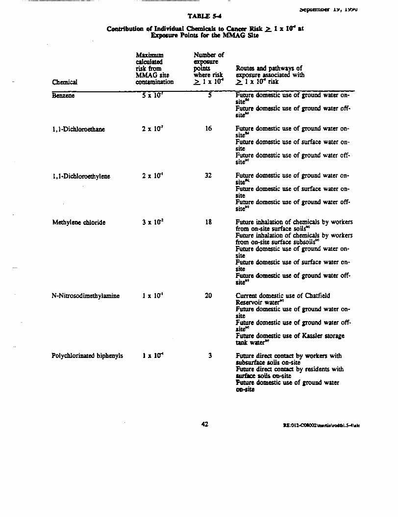
TABLES-4
Contribution of Individual Chemicals to Cancer RiskExposure Points for the MMAG Site
aeptemoer
I x Iff* at
Chemical
Maximumcalculatedrisk fromMMAG shecontamination
Number ofexposurepointswhere risk>_1 x 104
Routes and pathways ofexposure associated with.£. 1 x Iff4 risk
Benzene
1,1-Dichloroethane
1,1 -Dichloroethylene
Methylene chloride
N-Nitrosodimethylamine
5x 1(T
2x la1
2x Iff1
3x Iff2
1 x Iff1
Polychlorinated biphenyls 1 x Iff*
16
32
20
Future domestic use of ground water on-site*'Future domestic use of ground water off-,wsite'
Future domestic use of ground water on-site*'Future domestic use of surface water on-siteFuture domestic use of ground water off-site"'
Future domestic use of ground water on-site*1
Future domestic use of surface water on-siteFuture domestic use of ground water off-site"'
Future inhalation of chemicals by workersfrom on-site surface soils"'Future inhalation of chemicals by workersfrom on-site surface subsoils'"Future domestic use of ground water on-siteFuture domestic use of surface water on-siteFuture domestic use of ground water off-site"'Current domestic use of ChatfieldReservoir water"1
Future domestic use of ground water on-siteFuture domestic use of ground water off-site"1
Future domestic use of Kassler storagetank water1"Future direct contact by workers withsubsurface soils on-siteFuture direct contact by residents withsurface soils op-siteFuture domestic use of ground wateron-site
42 *E:OI2-COSO<n\Jiilirun\rodlbl.S-4\»lc

TABLE 5-4September 19,1990
Contribution of IndiTidual Chemicals to Cancer Risk £. 1 x Iff* atExposure Points for the MMAG Site (Concluded)
Chemical
calculatedrisk fromMMAG Shecontamination
Number ofexposurepointswhere risk£.1* 10*
Routes and pathways ofexposure associated with.£. 1 x 1C* risk
Polycydic AromaticHydrocarbons
Tetrachloroethylene
Trichloroethylene
UnsymmetricalDimethyl hydrazine
Vinyl chloride
CadmiumChromium, hexavalentLead
2x l< r J
7x Iff*
I x H T 1
4x 10*
8x10"
NoneNoneNone
40
8
10
NoneNoneNone
Future direct contact by workers withsubsurface soils on-site
Future inhalation of chemicals fromsubsurface soils by workers on-site*'Future direct contact with subsurface soilsby workers on-siteFuture inhalation of chemicals insubsurface soils by workers on-site"'Future domestic use of ground water on-sitew-Future domestic use of ground water off-site1",w
Future direct contact with subsurface soilsby workers on-siteFuture inhalation of chemicals insubsurface soils by workers on-siteM
Future domestic use of ground water on-site*Future domestic use of surface water on-siteFuture domestic use of ground water off-site**
Future domestic use of ground water on-site*1
Future domestic use of ground water en-sile**Future domestic use of surface water on-siteFuture domestic use of ground water off-site**None reported40
None reported40
None reported40
wIN
MW
cikutoc riik, wail* iB*i*d eonodiTb* iaotftatc i
tmnA r t»t»uuitiutf of Mwrtminnnt vtn »g»d le imlmihtt ML.i nd b»drock »•« eclcuUud. Mcuurtd eoacMlnlion of
fcr te ii«k fn« bedrock ground WMCT.Mi to
»Hd iMd WMI npoittd to ncwd Fwiml MKOOMB <AptMduEof*cPHE(CAI, 1990).
tdwtur,
43 «E--012-COI002\imnin\iwhbl3-4Wk

September 19, 1990
pathway, these risks were calculated using measured concentrations of contaminants. Concentrationsof soil contaminants in air were estimated by computer modelling as described previously.
The use of ground water on-she for domestic purposes including ingestion and showeringwould be associated with relatively high cancer risks depending on the exposure point. At 11 out of14 on-site exposure points (80 percent), domestic use of the ground water would be associated withan upper-bound cancer risk greater man 1 x 10" (greater than 1 in 10,000) for both the estimatedaverage intake and plausible maximum intake. Five of the exposure points where the calculated riskwas greater than or equal to 1 x 10" were alluvial ground water; 6 were ground water pointsassociated with bedrock formations. Concentrations in alluvial ground water were measured, whilecontaminant concentrations in ground water associated with bedrock formations were based onmodelling estimates. The upperbound cancer risk associated with domestic use of ground waterranged from a low of 1 in 100,000 (1 x Id') to a high of 1 in 10 (1 x Iff1). At 5 of the 14exposure points (36 percent), the upper-bound cancer risk associated with domestic use of groundwater was estimated to be greater than 1 in 1,000 (1 x 10"*); 3 of these points were alluvial groundwater points and 2 were ground water points associated with bedrock formations.
The domestic use of surface water on-site was associated with a lower cancer risk that rangedfrom a low of 3 x 10" for me average intake at one surface water exposure point to 7 x 10s for theplausible maximum at another surface water location based on measured data.
Domestic use of ground water off-she, was calculated using modelling estimates of site-boundary concentrations. Off-she ground water use was associated with an upper-bound cancer riskthat ranged from 9 in 100,000 for the average case from a Brush Creek well to 8 in 1,000 for theplausible maximum case from a Filter Gulch well. The average and plausible maximum casesdiffered by about one order of magnitude (a factor of 10). Off-she surface water taken from BrushCreek, if used domestically, would be associated with a 3 in 100,000 (average case) to 1 in 10,000(plausible maximum case) upper bound-cancer risk based on modelling estimates of contaminantconcentrations.
If the Kassler system were to be put back in operation and water were supplied from theKassler underground storage tank without being treated, the risk would be similar to current use ofthe Chatfield Reservoir for both the average and plausible maximum intakes (6 x 10"7 to 3 x 10*)according to modelling estimates.
REK>12-COS002\autin\n>d-l-49

September 19, 1990
5.5.3 Noncardnogenic Effects for Each Contaminant In Each Pathway
The relative potential for noncarcinogenic effects to result from exposure to a singlecontaminant in a single medium is expressed as the hazard quotient (HQ) (that is, the ratio of theestimated intake derived from die contaminant concentration in a given medium to the contaminant'sRfD). When the HQ exceeds 1, the estimated intake exceeds the RfD. The potential for adverseeffects to occur increases as the HQ increases above 1. By adding the HQ's for all contaminantswithin a medium or across all media to which a given population may reasonably be exposed, theHazard Index (HI) can be generated. The HI provides a useful reference point for gauging thepotential significance of multiple contaminant exposures within a single medium or across media.
The HQs for all contaminants of concern for each pathway and exposure point are presentedin Tables E-l through E-66 of the PHE (CAI, 1990). In Table 5-5 that follows, the noncarcinogenichazard information is briefly summarized for 12 contaminants of concern that were described in thePHE as contributing to an HI of greater man 1 for at least one pathway and location.
5.5.4 Combined Noncarcinogenic Effects
The His for the combined exposure to the contaminants of concern for each exposurepathway and exposure point are presented in Tables 8-1 through 8-4 of the PHE (pp. 8-6 through e>-17, CAI, 1990). No current exposures are estimated to result in an HI that exceeds 1. No directon-site exposures were considered probable under current conditions.
Direct contact with or inhalation of contaminants from subsurface soils on-she in the futurewere predicted to result in an HI of approximately 6. No other direct contact or inhalation exposureswere predicted to be associated with an HI greater than 1. The inhalation pathway was evaluatedusing modelling estimates, rather than measured
The domestic use of ground water on-she was associated with an HI greater than or equal to1 at 13 out of 14 exposure points (93 percent) for the average case. The average intake resulted inan HI that ranged from 0.5 to 400 and the His for the plausible n*»*?ippm intake ranged from 2 to800 for all 14 exposure points. The exposure points were divided between 8 alluvial ground waterpoints, which were actually sampled, and 6 bedrock ground water points were contaminantconcentrations were based on modelling ««rimat»» Two out of seven on-she exposure points wheresurface water was sampled would be associated with an HI greater than 1 but less than 5, if thewater was used domestically.
KE.-012-a»002\mtiBVrad.l-49

TABLES-5Contribution of Individual Chemicals to Hazard Index (HI) > 1 at
Exposure Points for the MMAG Site
Chemical
1,1-Dichloroethane
1 , 1 -Dichloroethylene
calculatedhazardquotient fromMMAG sitecontamination
4
180
Number ofexposurepointswhere HIexceeds 1
2
5
Routes and pathways ofexposure associatedwith ffl > 1"
Future domestic use of groundsite*1
Future domestic use of ground
water on-
water on-
Methylene chloride 87
site™Future domestic use of ground water off-site*1
Future domestic use of ground water on-site*'
Tetrachloroediylene
1,2,4-Trichlorobenzene
Trichloroethane
Trichloroethylene
Ammonia
210
15
95
6300
2
3
11
18
Future domestic use of ground water on-
1.2
site*'
Future inhalation by workers of chemicalsin subsurface soils on-site"'Future domestic use of ground water on-site*'Future domestic use of ground water on-•fte**Future domestic use of ground water off-site*Future direct contact with subsurface soilsby workers on-site*'Future use of ground water on-siteFuture domestic use of surface water on-site*'Future use of ground water off-site1"Future domestic use of ground water on-ine*>Future domestic use of surface water on-siteFuture domestic use of ground water on-»he*»
46 K£.-012-COS002\mulia\fQdtbl5-5\>k
\

TABLES-5
Contribution of Individual Chemicals to Hazard Index (HI) > 1 atExposure Points for the MMAG Site (Concluded)
Chemical
Maximumcalculatedhazardquotient fromMMAG sitecontamination
Number ofexposurepointswhere HIexceeds 1
Routes and pathways ofexposure associatedwith HI > 1
Chromium
Copper
Lead
250*
3
110
1
5
Future domestic use of ground water en-sile*Future domestic use of surface water on-site
Future domestic use of ground water off-site'*'
Future domestic use of ground water on-
Future direct contact with subsurface soilsby workers on-siteFuture domestic use of ground water on-site*Future domestic use of surface water on-site
W
w
Unless otherwise noted, measured concentrations of contaminant were used to calculate the HI.
Ground water from all alluvia and bedrock formations was evaluated. Measured concentrations ofcontaminants in alluvial ground water were used to calculate the HI, while modelling estimates ofcontaminant concentrations were used to calculate the HI associated with water in bedrock.Based on modelling estimates rather than measured data.
The HI reported were listed only as "chromium" but the reference dose used was for hexavalentchromium.
47 RE.-012-a»«a\in.itin\n>*bl5-S\«k

September 19, 1990
Based on modelling results for off-site ground water exposure points, two out of threelocations would be associated with an HI ranging from 10 (average case) to 70 (plausible maximumcase). The third point would be associated with and HI of 0.8 to 3. Off-she surface water locationsand the Kassler underground storage tank water were associated with His less than 1 according tomodelling estimates.
5.5.5 Sources of Uncertainty
Significant sources of uncertainty for any risk assessment include the following:
• Sampling data may be biased by technical or analytical limitations and models used toestimate concentrations at unsampled locations require many assumptions that may notexactly represent site characteristics.
• Toxicity values such as SFs and RfDs may be based on studies that requireextrapolation from results of animal studies to effects in humans, extrapolation ofhigh-dose exposures to much lower environmental exposures, and results fromhomogenous animal populations to variable human populations with a wide range ofsensitivities.
• Exposure assumptions used to calculate intakes may over- or underestimate actualexposures for any one individual.
Therefore, conservative assumptions are used in risk assessment so mat the calculated risk will morelikely overestimate the risk than under estimate the risk.
Uncertainties mat are specific to this risk assessment include the following:
• All off-site and some on-site concentrations were based on modelled rather thanmeasured data
• No decay or transformation of contaminants with time and transport were included inmodelling assumptions.
The last point may be particularly important at the MMAG she because concentrations of twocontaminants, vinyl chloride and NDMA, are not known to have been used on the site but that areknown to be transformation products of she contaminants shown in the risk assessment to contributesignificantly to the calculated cancer risks.
REK>12-CO*OOI\m«nin\fod-l-49
September 19, 1990
5.5.6 Risk Atsemnent Conclusions
Chemical contamination at the MMAG she is widespread in soil: and ground water. Fifty-three contaminants of concern were identified in site soils, ground water, and surface water.
EPA has established a risk range of 1 x KT4 to 1 x KT* as generally acceptable exposurelevels for hazardous waste sites. Calculated cancer risks for the MMAG site exceeded the targetrange by 1 to 3 orders of magnitude (mat is, 10 to 100 times) at between 40 percent and 70 percentof ground water exposure points located bom on- and off-site, depending on whether average intakeor plausible maximum intake assumptions were used, respectively. A hazard index of 1 wasexceeded at 90 percent of ground water locations for the average case, indicating the need forconcern regarding the potential for noncarcinogenic adverse health effects to occur if ground waterwere to be used domestically. Risks calculated from estimated exposures to ground water on-sitewere similar whether contaminant concentrations were directly measured or based on modellingestimates. The primary risk is associated whit the chemicals listed in Tables 5-4 and 5-5.
Based upon modeling date, the plausible maximum intake estimated for the current use ofOutfield Reservoir water results in an upper bound cancer risk slightly greater man 1 x Iff4 as aresult of MDMA contamination. This estimate of risk is based upon modeled or predictedconcentrations, not measured values. This contaminant is a stable transformation product ofunsymmetrical dimethyl hydrazine that was a chemical of concern in ground water on-site.Concentrations of vinyl chloride may increase significantly with time because it is a transformationproduct of various chlorinated solvents including TCE and tetrachloroethylene that are the majorcontaminants on the she. Risks associated with these compounds will also increase with time, ifconcentrations increase. Both vinyl chloride and NDMA are associated with SFs at least 10 timeshigher than the compounds from which they are formed.
5.6 ENVIRONMENTAL RISKS
Risks to aquatic life were partially evaluated by comparing contaminant concentrations withFederal and State of Colorado standards. Concentrations of silver, chromium, cyanide, aluminum,and fluoride exceed either Federal Ambient Water Quality Criteria or a Colorado standard for surfacewater hi Brush Creek on the site. The locations are primarily intermittent streams. Chemicalconcentrations hi the South Plane River are not estimated to exceed any Federal or State criteria.Sediments and surface water sampling indicated mat contaminants are not being transported off site atsignificant concentrations and are not expected to impact aquatic life in the South Plane River.
RE.-012-COS002Vimitiii\R>d-l-4949

September 19, 1990
5.6.1 Critical Habitats
The brief qualitative evaluation performed did not identify any critical habitats or effects oncritical habitats either on- or off-she.
5.6.2 Endangered or Threatened Spcries
The brief qualitative evaluation performed identified one bald eagle nesting within a 3-mileradius and one rare plant that may occur on-site. No effects of site contamination on either specieswas projected.
6.0 DESCRIPTION OF ALTERNATIVES
Remedial action alternatives in the feasibility study (FS) report were evaluated in accordancewith the Comprehensive Environmental Response, Compensation, and Liability Act, as amended bythe Superfund Amendments and Reauthorization Act, and the National Contingency Plan. Prior toevaluating remedial action alternatives, several preliminary evaluations occurred. Remedial actionobjectives were identified on the basis of the site characterization results. Response actions andassociated technologies were considered and screened. The technology screening activities werebased on relative effectiveness, implementabilhy, and cost
Preliminary remedial action alternatives were developed from the remaining technologyprocess options. Alternatives were developed ranging from those eliminating the need for long-termmanagement, to alternatives involving treatment mat would permanently reduce the mobility, toxicity,or volume of the hazardous substances as their principal element. Containment options were alsodeveloped. During the preliminary remedial action alternatives analysis, several potential optionswere dropped.
Eight alternatives for soil remediation and four alternatives for ground water were developedin the FS (Eder, 1990). Upon completion of the initial screening phase of the FS, the number ofsoil alternatives was reduced to six for detailed analysis. The four ground water alternatives werealso retained in the detailed analysis. Each of the retained alternatives is described in this section.
Remedial action objectives developed for the site are designed to address die principal threatand reduce the risks posed by potential health threats associated with the ground water. Theremedial action objectives are as follows (clean up goals are described more fully La Section 8.0):
RE.-012-COS002\BMia\n>d45-99
SO

September 19, 1990
1. Reduce the threat posed by the Inactive Site contamination releases to theenvironment which impact ground water and surrounding soil and soil contaminationassociated with the O'fniical Storage Tanks.
2. Restore the ground water to its beneficial uses by reducing contaminant levels towithin acceptable standards for drinking water.
There are five soQ alternatives from S-l through S-5, and four ground-water alternativesGW-1 to GW-4, presented below. In-shu soil vapor extraction will not be discussed as a separatealternative because h was developed solely to address contamination in the Chemical Storage Tanksarea. It is a component of all the soil alternatives, excluding no action.
SOIL ALTERNATIVES:
S-l: No ActionS-2: Dewater/RCRA Cap/In-shu Soil Vapor ExtractionS-3: Dewater /Off-site Incineration and Disposal of Waste/Ex -situ
Stabilization of Backfill and Alluvium/RCRA Cap/In-situ Soil VaporExtraction
S-4: Dewater/On-site Incineration of Backfill, Alluvium, and Waste/Off-site Disposal of Incinerated Waste/Ex-shu Stabilization of IncineratedBackfill and Alluvium/RCRA Cap/In-shu Soil Vapor Extraction
S-5: Dewater/Off-site Incineration and Disposal of Waste/ThermalExtraction of Backfill and Alluvtum/Ex-situ Stabilization of Backfilland Alluvium/RCRA Cap/In-shu Soil Vapor Extraction
GROUND WATER ALTERNATIVES:
GW-1 No Action
GW-2 Continued Operation of the Existing Recovery Well System/Treatmentby Air Stripping, Carbon Adsorption, and Ion Exchange/Discharge toBrush Creek
GW-3 Contmued Operation of the Existing Recovery Well System/Insta. ation of Additional Recovery Well System in Filter Gulch andDry Gulch Upgradient from the Existing Recovery Well Systems/Treatment by Air Stripping, Carbon Adsorption, Ion Exchange,and/or UV Photolysis-Oxidation/Discharge to Brush Creek
GW-4 Continued Operation of the Existing Recovery Well Systems/Installation of Additional Recovery Well Systems in Filter Gulch andDry Gulch Upgradient from the Existing Recovery Well Systems/Addition of a Recovery Well System in the M3 Area/Treatment byChemical Reduction, Precipitation, Clarification, Air Stripping,Carbon Adsorption, Ion Exchange, and/or UV Photolysis-Oxidation/Discharge to Brush Creek
KE.-012-COS002\nuiin\nx!45'99
51
September 19, 1990
6.1 ALTERNATIVE S-l: NO ACTION
In accordance with Section 300.430(e) (6) of the NCP, the no action alternative must beconsidered in the FS. No action also serves as a baseline for comparison of other soil alternatives.No contaminants or contaminated media are removed or treated by the no action alternative, althoughnatural attenuation processes are likely to occur.
No action, as it pertains to the Inactive Site and the Chemical Storage Tank areas, means matno activities intended to protect human health and the environment, including any remediation, wouldbe taken. Contaminant migration from the Inactive Site and the Chemical Storage Tank areas wouldcontinue unrestricted.
Ground water monitoring would be conducted to track contaminant migration. No soilsamples would be collected from either area. There would be no measures to prevent humanexposure to contamination. A review of the threat to public health and the environment would beconducted at least every 5 years.
6.2 ALTERNATIVE S-2: DEWATER/RCRA CAP/IN-STTU SOIL VAPOR EXTRACTION
The objectives of Alternative S-2 would be to reduce the potential for direct human contactwith the Inactive Site soils, reduce infiltration of precipitation through the Inactive site ponds,remove perched water from the ponds, and remove volatile organic contaminants (VOCs) from theChemical Storage Tank area. No treatment of waste, backfill, or contaminated alluvium would occurat the Inactive Site.
The area covering the Inactive Site and the area adjacent to it would be regraded to divertstorm water run-on and enhance storm water run-off. The Inactive Site ponds are located on atopographic high; therefore, storm water flow would be diverted into the East Branch of Brush Creekdrainage for flow to the north and the West Branch of Brush Creek/Dry Gulch drainage for flow tothe south.
RE:012-COS002\mutiii\nxUS-99
52

September 19, 1990
A series of weltpoints would be installed in the perched zones of me Inactive Site to extractwater. The water would be temporarily stored in holding tanks and either trucked, pumped, orgravity fled to the MMAG's IWTP. The treated water would be discharged in accordance withMMAG's COPDES permit. The dewatering process would take approximately 2 to 3 months tocomplete.
A multi-layered cap is proposed for covering me Inactive Site area, which includes the fiveponds and the area adjacent to the ponds. The cap would be sloped to divert surface flow awayfrom the ponds.
Ground water monitoring would be conducted to monitor contaminant migration.
The cap would be maintained and no construction would occur on or near the cap. Sincecontaminants would remain at the Inactive Site, the site would be monitored and every five yearsEPA would review the remediation to assure that human health and the environment are protected.
In-situ soil vapor extraction would be used to remove VOCs from the Chemical Storage Tankarea subsurface soil. A series of extraction wells connected to a vacuum pump would be installed inand around the Chemical Storage Tank area such that the cones of influence would extend over theentire contaminated area. A series of injection wells connected to a blower or vacuum pump wouldbe placed in and around the Chemical Storage Tank area and used to induce air flow through the soilto strip and volatilize the VOCs into the air stream. Subsurface air, VOC vapors, and water vaporswould migrate toward the vacuum extraction wells and be removed for collection and treatment.
Approximately 1.3 million gallons of perched water within the ponds would be removed,treated, and discharged to Brush Creek. Approximately 2,100 cy of waste, 9,700 cy of contaminatedbackfill, and 14,700 cy of contaminated alluvium would be left in-place.
Because both the Inactive She and Chemical Storage Tank areas are covered, the InactiveSite by soO and the Chemical Storage Tank area by asphalt, the potential for direct contact exposureto contaminants is low. The installation of a cap at the Inactive Site would provide added insurancemat the potential for direct human contact would be mi«imi«a^ In-situ sofl vapor extraction wouldeffectively remove contaminants from the Chemical Storage Tank area so mere would be no concernfor exposure. Contaminants in the soil may continue to migrate from the Inactive Site and enter theground water. However, infiltration is greatly reduced and contaminant migration is then reduced.
KE.-012-CO*002\Btnia\iwM5-9953

September 19. 1990
The uncertainty associated with Alternative S-2 are the ability to lower the ground watertable enough to avoid intersecting the contamination below the ponds.
Alternative S-2 would comply with RCRA closure and RCRA cap requirements for surfaceimpoundments and landfills. Air emissions from the in-shu soil vapor extraction process would meetambient air quality standards. Perched water would be treated to permit discharge limits beforebeing discharged to Brush Creek.
Alternative S-2 would be implemented in four months.
d3 ALTERNATIVE S-3: DEWATER/OFF-STTE INCINERATION AND DISPOSAL OFWASTE/EX-SITU STABILIZATION OF BACKFILL AND ALLUVIUM/RCRACAP/iN-srru SOIL VAPOR EXTRACTION
Alternative S-3 would be used to reduce contaminant migration from the Inactive Site into theground water via removal and/or treatment of both organic and inorganic contaminants. In addition,the potential for direct human contact would be minimized by the placement of a cap. The RCRAcap would also reduce infiltration, which would enhance the long-term effectiveness of treatment. Atthe Chemical Storage Tank area, 99% removal of the organic contaminants would be anticipated,thereby eliminating the Chemical Storage Tank area as a potential source for ground watercontamination.
This alternative would begin with the dewatering of the Inactive Site Ponds. After which,the contaminated areas would be excavated and material separated into waste, contaminated soil anduncontaminated backfill. Additionally, in-situ soil vapor extraction would be employed at theChemical Storage Tank area to remove organic chemicals.
A series of wellpoints would be installed hi the perched zones of the Inactive Site to extractwater. The water would be temporarily stored in holding tanks and either trucked, pumped, orgravity fed to MMAG's IWTP. The treated water would be discharged in accordance with MMAG'sCOPDES permit. The dewatering process would take approximately 2 to 3 months to complete.
Excavation and material segregation would require mat three stockpile or staging areas beused: one for the cover material, one far the waste, and one for the backfill and alluvium. Thewaste material would be loaded onto plastic-lined trucks and transported off-site to a permittedincineration and landfill facility. The backfill and alluvium would undergo stabilization. The covermaterial would be replaced back into the excavation once the stabilization process is complete and all
KE.412.COSOa2\B*rtio\fod4$-9954

September 19, 1990
stabilized t"*«»"»Jf have been returned to the excavation. (The cover material would be\iiyopTyn*Tiat*f* or contains <*f"tatninant< jt levels below the action level.)
The area covering and adjacent to the Inactive Site would be regraded to divert storm waterrun-on and enhance storm water run-off. The Inactive Site ponds are located on a topographic high;therefore, flow would be diverted into the East Branch of Brush Creek drainage for flow to the northand into the West Branch of Brush Creek/Dry Gulch drainage for flow to the south.
A multi-layered cap is proposed for covering the Inactive She area, which includes the fiveponds and the area adjacent to the ponds. The cap would be sloped to divert surface flow awayfrom the ponds.
Ground water monitoring would be conducted to monitor contaminant migration.
The cap would be maintained and no construction would occur on or near the cap. Sincecontaminants would remain at the Inactive Site, the she would be reviewed at least every 5 years bythe EPA to assure that human health and the environment are protected. Periodic 5 year reviews atthe Chemical Storage Tank area would not be required since the organic contaminants would beremoved from the sofl.
In-shu soil vapor extraction used to remove VOCs from the Chemical Storage Tank areasubsurface soD requires a series of extraction wells connected to a vacuum pump be installed in andaround the Chemical Storage Tank area. A series of injection wells connected to a blower orvacuum pump would be placed in and around the Chemical Storage Tank area and used to induce airflow through the soil to strip and volatilize the VOCs into the air stream. Subsurface air, VOCvapors, and water vapors would migrate toward the vacuum extraction wells and be recovered forcollection and treatment Air emissions would be monitored, and additional controls would beincorporated as necessary.
Approximately, 2,100 cy of waste would be transported off-she. Approximately 24,400 cyof contaminated backfill and alluvium would be treated by ex-shu stabilization. The stabilizationprocess incorporates the contaminated soil into a matrix with additives such as Portland cgmpnt,water, and proprietary compounds to immobilize the contaminants by chemically and physicallybinding mem in-place. Stabilization is a process mat can be performed hi an open pit, in concretetrucks, and in fabricated systems designed specifically for stabilization. Bom stationary and mobile
B£--012-CO«002\iMutm\rod4i-9955

September 19, 1990
(skid-mounted) systems are available. The specific system and additives would be chosen during thedesign phase.
MMAG performed bench-scale stabilization and thermal process treatability studies onInactive Site pond materials. The treatability studies are discussed hi Section 8.0.
The removal of the waste from the ponds and stabilization of the contaminated backfill andalluvium would significantly reduce the impact of the Inactive Site on ground water contamination.The installation of a RCRA cap at the Inactive Site would provide added insurance that the potentialfor direct human contact would be minimi™d In-situ soil vapor extraction would effectively removecontaminants from the Chemical Storage Tank area. Contaminated soil materials would remain on-site but the constituents would be less mobile.
The uncertainties associated with Alternative S-3 are the ability, to lower the ground watertable enough to avoid intersecting the ponds. However, reducing infiltration via a cap and in turnlowering the ground water table will be effective to some extent. Another uncertainty is the abilityto stabilize organic contaminant* During the stabilization operation, die contaminated soils would behandled several times. First the soil would be excavated, and men stockpiled. It would thenundergo size reduction, and men proceed through the stabilization process, which often undergoesseveral temperature fluctuations due to ambient air temperatures, process water temperatures, andchemical reactions. With each of these activities, some volatilization is likely to occur.
The transport of waste would comply with RCRA, Department of Transportation, and Stateregulations. Incineration of the waste would be performed at a RCRA-permitted incineration facilityand would meet all requirements including at least a 99.99 percent destruction of organiccontaminants. Disposal of the treated waste would comply with RCRA standards, including theLDRs. Stabilization treatment goals would be based upon LDR standards using the ToxicityCharacteristic Leaching Procedure (TCLP). Perched water and wastewaters generated from thetreatment processes on-site would be treated and discharged according to MMAG's COPDES permitrequirements. All activities, including in-shu sofl vapor extraction, would comply with ambient airquality standards.
Implementation of the Alternative S-3 is estimated to take 18 months.
K£K)12-COI002\n»itin\RMl45-99
56

September 19,19906.4 ALTERNATIVE S-4: DEWATER/ON-STTE INCINERATION OF BACKFILL,
ALLUVIUM, AND WASTE/OFF-SITE DISPOSAL OF INCINERATED RESIDUES/EX-SITU STABILIZATION OF INCINERATED BACKFILL AND ALLUVIUM/RCRACAP/IN-SITU SOIL VAPOR EXTRACTION
The objective of mis alternative is to provide long term protection of the ground water andhuman health by removing and treating waste at the Inactive Site Ponds. By destroying the organiccontaminants and stabilizing the inorganic contaminants, additional contaminant loading on theground water is precluded and potential human exposure is effectively eliminated.
Alternative S-4 incorporates dewatering of the Inactive ponds, excavation and on-siteincineration of waste, backfill, and alluvium from the Inactive Site ponds, off-site disposal of theincinerated waste in accordance with LDRs, ex-shu stabilization of the backfill and alluvium,replacement of waste into the excavation, placement of cover material into the excavation, andplacement of a cap over the Inactive Site. In-situ soil vapor extraction would be used forcontaminated soil it the Chemical Storage Tank area.
Alternative S-4 would be implemented in 3.5 to 4 years.
Dewatering would be implemented as described previously. Controls to collect vapors withintegrated vacuum systems during excavation wfll be evaluated during the design phase.
Since excavation would be required for this alternative and the waste would be disposed ofseparately at an off-she RCRA landfill, material segregation would be necessary at the Inactive Site.It is anticipated that three stockpile or staging areas would be necessary. The waste material wouldbe incinerated in the on-site incinerator, allowed to cool, then loaded onto plastic-lined trucks andtransported to an off-site landfill. The backfill and alluvium would then be incinerated afterexcavation, processed through stabilization and returned to the excavation. The cover material wouldbe replaced back into the excavation once the stabilization process was complete and all stabilizedmaterials would be returned to the excavation.
The area covering and adjacent to the Inactive Site would be regraded and capped asdescribed previously in the other alternatives.
Ground water monitoring would be conducted to monitor contaminant migration.
K&012-COU02ViHnia\KMi45-9957

September 19, 1990
Hie cap would be maintained and construction restricted on or near the cap. Sincecontaminants would remain at the Inactive She, the cite would be monitored and every five yean areview would be conducted to assure mat human health and the environment are protected.
As described earlier, in-situ sofl vapor extraction would be used to remove VOCs from theChemical Storage Tank area subsurface soil.
Because the waste in the Inactive Site ponds is considered a RCRA Listed Hazardous Waste,the waste must be treated to meet the treatment standards established for RCRA Listed Waste,particularly F001, F005, and F019. The best demonstrated available technology (BDAT) for theF001 and F005 waste is incineration. The BDAT for F019 waste is stabilization. The waste,approximately 2,100 cy, would be incinerated on-site. The residues would be allowed to cool, loadedonto lined trucks and transported to an off-site landfill. The Inactive Site contains low levels of theF019 or inorganic contaminants. If the incinerated waste residues did not satisfy the LDR treatmentstandards for F019 (inorganic) wastes, they would be stabilized prior to land disposal hi a RCRALandfill. The incineration residue would be transported to a landfill for stabilization to avoidtransporting the additional 10 to 40 percent volume that would be generated if stabilization wasperformed on-she.
The contaminated backfill and alluvium would be incinerated on-she after all waste wasremoved and treated. A rotary kiln process is proposed for incineration. Rotary kiln incineratorsare the most widespread, most proven, and most readily available of the incineration processes;however, other types of incinerators would be considered during the design phase.
Following on-she incineration, approximately 24,400 cy of backfill and alluvium would betreated by ex-situ stabilization in order to immobilize inorganic contaminants. The stabilizationprocess incorporates the contaminated soil into a matrix with additives such as Portland cement,water, and proprietary compounds to immobilize the contaminants by chemically and physicallybinding them in-place.
Stabilization can be performed in an open pit, in concrete trucks, and hi fabricated systemsdesigned specifically for stabilization. Both stationary and mobile systems are available. Thespecific system and additives to be used wfll be determined during the design phase. The stabilizedproduct would either be replaced directly back into the excavation or placed in forms and allowed tocure before being place into the excavation.
KE.-OI3-COI002\«itio\fDd45-9958
September 19, 1990
MMAG conducted bench-scale treatabflhy studies on thermal treatment and stabilization ofInactive She Pond fr^T*"y|g The results of the treatabiltty studies are d't'im"^ in Section 8.0.
The removal of me waste from the ponds and incineration and stabilization of thecontaminated backfill and alluvium would significantly reduce the impact that the Inactive Site has onground water contamination. The installation of a cap at the Inactive Site would provide addedassurance mat the potential for direct human contact would be minimi*^ In-situ soil vaporextraction would effectively remove contaminants from the Chemical Storage Tank area, so therewould be no concern for exposure. Contaminated materials would remain on-site but the constituentswould be immobilized.
Incineration of the waste, backfill, and alluvium would comply with or exceed the technicalrequirements of RCRA and the Toxic Substances Control Act (TSCA). The hazardous wasteincineration standards set forth in 40 CFR Parts 264 and 270 specify three major requirementsregarding incinerator performance:
1. Principal organic hazardous constituents (POHCs) designated in each waste feed mustbe destroyed and/or removed to an efficiency (DRE) of 99.99 percent or better; theORE for dioxins and PCBs must be 99.9999 percent.
2. Paniculate emissions must not exceed 180 milligrams per dry standard cubic meter(dscm) corrected to 7 percent oxygen in the stack gas.
3. Gaseous hydrogen chloride (HQ) emissions must either be controlled to 4 pounds/hour or less, or be removed with 99 percent efficiency.
The transport of Inactive Site pond waste would comply with RCRA, Department ofTransportation, and State regulations. Disposal of the treated waste would comply with RCRAstandards, including LDRs. Stabilization would achieve immobilization such that contaminants meetthe treatment standards. Perched water and wastewaters generated from the treatment processes on-site would be treated to meet COPDES permit requirements. All activities, including in-situ soilvapor extraction, would comply with ambient air quality standards. This alternative satisfies theSARA preference for treatment.
KE.-012-COSOQ2\aulia\n>d4S-99
59

September 19, 1990
6.5 ALTERNATIVE S-5: DEWATER/OFF-SITE INCINERATION AND DISPOSAL OFWASTE/THERMAL EXTRACTION OF BACKFILL AND ALLUVIUM/EX-SITUSTABILIZATION OF BACKFILL AND ALLUVIUM/RCRA CAP/VAPOR IN-STTUSOIL VAPOR EXTRACTION
The objectives of Alternative S-5 are to prevent the further impact from the Inactive Site areaon ground water and minimize the potential for direct human contact with, inhalation of, andingestion of contaminants at bom areas. This alternative is designed to remove organic contaminantsand immobilize inorganic contaminants at the Inactive Site, reduce infiltration of precipitation throughthe Inactive She pond, and remove organic contaminants from the Chemical Storage Tank area.
Alternative S-5 incorporates dewatering of the Inactive Site ponds; excavation, off-siteincineration and disposal of waste in accordance with LDRs; excavation, thermal extraction and,stabilization of contaminated backfill and alluvium; replacement of treated backfill and alluvium intothe excavation; and capping over the Inactive Site. In-situ soil vapor extraction would be used totreat the soil at the Chemical Storage Tank area. In addition, this alternative includes the off-siteincineration and disposal of the residual organic laden sludge from the thermal extraction process andthe off-site incineration and disposal of regeneration of the carbon from the in-situ soil vaporextraction process and the thermal extraction air treatment system.
Alternative S-5 would be implemented in 4 years.
The area covering and adjacent to the Inactive She would be regraded to divert storm waterrun-on and enhance storm water run-off. Grading would be accomplished using conventionalconstruction equipment such as front-end loaders and grade-alls. Water trucks would be used tominimize dust generation. The Inactive She ponds are located on a topographic high; therefore, flowwould be diverted into the East Branch of Brush Creek drainage for flow to the north and into theWest Branch of Brush Creek/Dry Gulch drainage for flow to the south.
Ground water monitoring would be conducted at both the Inactive Site and the ChemicalStorage Tank area to monitor contaminant migration from both areas. Monitoring wells would beplaced within the perched zones to verify mat infiltration was the source of the perched water andthat the perched zones were not being recharged. The monitoring wells in the Chemical StorageTank area would be placed such mat the effectiveness of in-situ soil vapor extraction could bemonitored.
KE.-012-COt002\mutin\ml4S-99
60

September 19, 1990
The cap would be maintained and no construction would occur on or near the cap. Sincelow levels of contaminants would remain at the Inactive She, the site would be monitored and every5 years a review would be conducted to assure human health and the environment are protected.
In-situ soil vapor extraction would be used to remove VOCs from the Chemical Storage Tankarea subsurface soil. A series of extraction wells connected to a vacuum pump would be installed inand around the Chemical Storage Tank area such mat the cones of influence would extend over theentire contaminated area. A series of injection wells connected to a blower or vacuum pump wouldbe placed in and around the Chemical Storage Tank area and used to induce air flow through the soilto strip and volatilize the VOCs into the air stream. Subsurface air, VOC vapors, and water vaporswould migrate toward the vacuum extraction wells hi response to the negative pressure gradientaround the well.
The contaminated air and vapor would flow to a vapor/liquid separator where contaminatedwater would be removed. The contaminated water would be treated to meet COPDES limits inMMAG's IWTP. The contaminated air stream would be treated to remove VOC concentrations toair quality standards. The carbon would be either regenerated or disposed of accordingly. Airemissions would be monitored and additional controls would be incorporated as necessary.
The waste in the Inactive She ponds is considered a RCRA Listed Hazardous Waste. Thewaste, approximately 2,100 cy, would be loaded onto lined tr-cks and transported to an off-siteincinerator permitted to accept F001, F005, and F019 listed wastes. The waste would be incineratedto comply with the F001 and F005 LDR treatment standards. If the incinerated waste residues didnot satisfy the LDR treatment standards for F019 (inorganic) wastes, they would be stabilized priorto land disposal in a RCRA Landfill.
Approximately 24,400 cy of contaminated backfill and alluvium would be treated by thermalextraction to remove organic contaminants. Thermal extraction is a low temperature thermaltreatment process which volatilizes organic contaminants from the sou* matrix. Operatingtemperatures are low, preventing combustion of the organic contaminants and oxidation of theinorganic contaminants. The process produces an organic-free soO and an off-gas tiiat, when treated,generates waste water, clean air, and an organically contaminated sludge.
Following the thermal treatment, approximately 24,400 cy of backfill and alluvium would betreated by ex-shu stabilization. The stabilization process incorporates the contaminated soil into a
KE.-On-COt002\mtio\RMl45-9961
September 19, 1990
matrix with additives such as Portland cement, water, and proprietary compounds to immobilize theinorganic contain*1*811*? by chemically an^ physically binding them in-place.
Treatability studies on thermal extraction and stabilization were performed previously byMMAG. The results are discussed in Section 8.0.
The removal and incineration of the waste from the ponds and thermal extraction andstabilization of the contaminated backfill and alluvium would significantly reduce the impact that theInactive Site has on ground water contamination. The installation of a multi-layered cap at theInactive Site would provide added assurance mat me potential for direct human contact would beininimiTxj In-situ soil vapor extraction would effectively remove contaminants from the ChemicalStorage Tank area so mere would be no concern for exposure. Contaminated materials wouldremain on-site would be treated to immobilize hazardous constituents.
The uncertainty associated with Alternative S-5 is the ability to remove organic contaminantsand stabilize inorganic compounds to meet LDR treatment standards.
The transport of Inactive Site pond waste and thermal extraction residues would comply withRCRA, Department of Transportation, and State regulations. Incineration of the waste would beperformed at a RCRA approved incineration facility and would meet all pertinent requirementsincluding at least a 99.99 percent destruction of organic contaminants. Disposal of the treated wastewould comply with RCRA standards, including the LDRs. Thermal extraction would removeorganic contaminants, and stabilization would achieve immobilization to prevent contaminants fromleaching to the ground water. Perched water and wastewaters generated from the treatment processeson-site would be treated to meet MMAG's COPDES permit requirements. All activities, includingthermal extraction and in-situ soil vapor extraction, would comply with ambient air quality standards.
6.6 ALTERNATIVE GW-1: NO ACTION
In accordance with Section 300.430(eX6) of the NCP, the no action alternative must beconsidered in the FS. The no action alternative also serves as a baseline for comparison of otherground water alternatives. No contaminants are removed or treated by the no action alternative,although natural attenuation processes are likely to occur. Predicting natural attenuation processes isnot technologically possible for most of the contaminants present in the ground water.
KE.-012-COt002VnMia\ro<M5-9962

September 19. 1990
No action, as ft pertains to ground water contamination, means that no activities intended toprotect human health and the environment, including any remediation, would be taken. The existingBrush Creek and Filter Gulch ground water extraction and treatment systems would be shut down.The existing water supply provided by the Denver Water Department could be used to meet currentwater demands and future demands from development. Contaminated ground water would beallowed to migrate off-site.
Ground water monitoring would be conducted to track contaminant migration from the siteand to continually assess the resulting risks.
Ground water modeling, assuming the source is removed and natural attenuation processesoccur, predicts mat ground water restoration time frames required to attain clean up goals are inexcess of 130 years for on-site ground water and in excess of 70 years for off-she ground water.
This alternative does not provide protection against threats to human health or theenvironment. The immediate concern with the no action alternative is that environmental degradationwould continue to occur and that the remedial action objective to restore ground water to itsbeneficial use in a reasonable time frame is not achieved.
The ground water, which is a past and a potential source of drinking water, does not meetthe dean up goals at the present time.
6.7 ALTERNATIVE GW-2: CONTINUED OPERATION OF THE EXISTINGRECOVERY WELL SYSTEMS/TREATMENT BY AIR STRIPPING, CARBONADSORPTION, AND ION EXCHANGE/DISCHARGE TO BRUSH CREEK
The objectives of Alternative GW-2 would be to preclude ground water migration off-siteinto the South Platte River Basin and remove organic and inorganic contaminants from the recoveredground water.
Alternative GW-2 is presently in operation. The Filter Gulch recovery well system wasinstalled in 1985, and the Lower Brush Creek recovery system was installed in 1987. The FilterGulch recovery system consists of 14 recovery wells located approximately 800 feet southeast of theM3 area on Denver Water Department property. The Brush Creek recovery system consists of three24-inch diameter recovery wells installed in a gravel backfilled trench located approximately 2,000feet east of the M3 area.
KE.-01KS»002\s»niii\n>d4S-9963

September 19, 1990
The recovered water is pumped along with MMAG's industrial process waste waters to theIWTP in the M3 area where organic and inorganic contaminants are removed. Currently, the IWTPtreats wastewater by air stripping, carbon adsorption, and a ferrous sultate reduction processes. Thetreated effluent is discharged to Brush Creek MMAG waste water outfall (COPDES Permit#0001511), located approximately 100 feet downstream of the Brush Creek recovery system.
Ground water monitoring would be conducted semiannually to track contaminant migrationfrom the site and to assess the resulting risks.
An alternative water supply would be provided should the need arise during theimplementation of alternative GW-2.
MMAG has demonstrated mat the Filter Gulch and Brush Creek recovery systems provideeffective containment of contaminants by minimizing off-site migration-of alluvial ground water.
The principal environmental concern associated with air stripping is the generation of volatileorganic air emissions. The MMAG IWTP is presently operating within its air permit limitations,which do not require additional treatment of the exhaust air stream. If ah* emission levels are foundto exceed ambient ah- quality standards or risk-based levels, the air would require further treatment.Treatment of the exhaust air would be accomplished by capturing organic constituents using vaporphase carbon adsorption or by destruction in an incinerator. The need for emission controls wouldbe assessed during the design phase.
All the residues of ground water treatment would be analyzed for contaminant content anddisposed of accordingly. Sludges would most likely be incinerated at an off-site facility prior todisposal. Spent carbon and ion exchange resins would either be recycled (regenerated), incinerated,and/or disposed of directly.
The treated effluent exiting the MMAG IWTP would meet the required treatment standardsof MMAG's COPDES permit before being discharged to Brush Creek via the existing outfall.
Ground water modeling indicates mat ground water restoration time frames required to attainclean up goals are approximately 130 years for on-site ground water and in excess of 5 years for off-site ground water. However, there is some uncertainty in the estimate of ground water restorationtime. The ground water modeling was conducted using available data on subsurface conditions, andassumptions were made regarding all the variables. In addition, the model assume that sources of
XE.-012-CM002\B*itia\rad45-9964

September 19, 1990
contamination are completely removed. Effectively, mis means little if any remediation occurs on-site in the highly contaminated areas for an extensive period.
The untreated ground water does not meet the clean up goals at me present time. With dieimplementation of alternative GW-2, however, dean up goals would be achieved off-site in areasonable time frame. However, contaminant levels in ground water on-site would remain aboveMCLs for over 100 years.
6.8 ALTERNATIVE GW-3: CONTINUED OPERATION OF THE EXISTINGRECOVERY WELL SYSTEMS/INSTALLATION OF ADDITIONAL RECOVERYWELL SYSTEMS IN FILTER GULCH AND DRY GULCH UPGRADIENT FROMTHE EXISTING RECOVERY WELL SYSTEMS/TREATMENT BY AIR STRIPPING,CARBON ADSORPTION, ION EXCHANGE, AND/OR UV PHOTOLYSIS-OXIDATION/DISCHARGE TO BRUSH CREEK
The objectives of Alternative GW-3 would be to preclude contaminant migration off-site andrestore the ground water to beneficial uses by recovering ground water and removing organic andinorganic contaminants.
Alternative GW-3 is a modification to Alternative GW-2 mat incorporates two additionalextraction systems coupled with recharge or infiltration trenches to enhance the rate of ground waterextraction. One of the two new recovery systems would be installed in Dry Gulch, approximately3,500 feet southeast of the Inactive Site, and the other would be installed in Filter Gulch southeast ofthe M3 area, approximately 200 feet norm of me MMAG property boundary. The new recoverysystem in Dry Gulch would probably consist of a trench and well system similar to the existingBrush Creek system and would recover 5-10 gpm. The new system in Filter Gulch would probablyconsist of a line of recovery wells similar to the existing Filter Gulch system. Additionally atreatment step to remove MDMA and UDMH contamination is included. The additional treatmentstep associated with this alternative is ultraviolet light (UV) photolysis used in combination withoxidation to treat NDMA and UDMH.
The ground water would be pumped from the four recovery systems and treated at theIWTP. Organic and inorganic contaminants would be removed. The IWTP would include airstripping, carbon adsorption, ion exchange, and the UV photolysis/oxidation process. The treatedeffluent would be discharged to the Brush Creek MMAG waste water outfall (COPDES Permit#0001511), located approximately 100 feet downstream of the Brush Creek recovery system.
*E.-012-CO«002\a«ti0\n»d45-99
65

September 19, 1990
Ground water monitoring would be conducted to track contaminant migration from me siteand to assess the resulting risks. An alternate water supply would be provided should the need ariseduring the implementation of alternative GW-3.
Water purchased from the Denver Water Department would be recharged into the alluvium atDry Gulch and the M3 area to enhance extraction rates and flushing of the alluvium for more rapidrestoration.
It could also be necessary to install a small extraction system upgradient of the Inactive Siterecharge system to collect ground water located between the ponds and the recharge system. Theneed for such a system would be evaluated during the design phase.
Ground water modeling indicates that ground water restoration time frames required to attaindean up goals are approximately 45 years for on-stte ground water and approximately 5 years foroff-site ground water.
The untreated ground water does not meet the clean up goals at the present time. With theimplementation of alternative GW-3, however, clean up goals would be achieved more rapidly bothoff-site and on-site.
6.9 ALTERNATIVE GW-4: CONTINUED OPERATION OF EXISTING RECOVERYWELL SYSTEMS/INSTALLATION OF ADDITIONAL RECOVERY WELL SYSTEMSIN FILTER GULCH AND DRY GULCH UPGRADIENT FROM THE EXISTINGRECOVERY WELL SYSTEMS/ADDITION OF A RECOVERY WELL SYSTEM INTHE M3 AREA/TREATMENT BY CHEMICAL REDUCTION, PRECIPITATION,CLARIFICATION, AIR STRIPPING, CARBON ADSORPTION, ION EXCHANGE,AND/OR UV PHOTOLYSIS-OXIDATION/DISCHARGE TO BRUSH CREEK
The objectives of Alternative GW-4 are to preclude contaminant migration off-site and restorethe ground water to beneficial uses by recovering ground water and removing organic and inorganiccontaminants from the ground water. Additionally, this includes systems to collect and treat theground water in the Fountain Formation in the vicinity of the Chem Mill and Hydrostat Tank areas.
This alternative provides protection to human health and the environment by removingcontaminants in the ground water and by reducing contaminant migration off-site.
Alternative GW-4 is a modification of alternative GW-3. It incorporates all the aspects ofGW-4 and in addition includes one more extraction system. The water extracted by the additional
RE:012-COI001\inMtin\fiMi45-99
66

September 19, 1990
system would be treated to remove chromium and chlorinated organic compounds. The water wouldbe recovered from die five systems and pumped to the IWTP where organic and inorganiccontaminants would be removed. The IWTP would include air stripping, carbon adsorption, ionexchange, and the addition of the UV photolysis/oxidation and chemical reduction, precipitation, andclarification processes. The treated effluent would be discharged to the Brush Creek MMAG wastewater outfall (COPDES Permit #0001511), located approximately 100 feet downstream of the BrushCreek recovery system.
Ground water monitoring would be conducted to track contaminant migration from the siteand to assess the resulting risks. An alternate water supply would be provided should the need ariseduring die implementation of alternative GW-3.
Ground water modelling indicates mat ground water restoration tune frames required to attainclean up goals are approximately 45 years for on-site ground water and in excess of 5 years for off-site ground water. However, mere is some uncertainty associated with the ground water restorationtime. The ground water modeling was conducted using available data on subsurface conditions, andassumptions were made regarding all the variables. In addition, the model assumes that sources of
are completely removed.
The untreated ground water does not meet the clean up goals at the present time. With theimplementation of Alternative GW-4, however, these goals would be achieved on-site and off-sitewithin reasonable time frames. In addition, an area of high contamination in the M3 area would beremediated preventing further migration of contaminants off-site.
7.0 SUMMARY OF COMPARATIVE ANALYSIS OF ALTERNATIVES
7.1 INTRODUCTION
In accordance with the NCP, Section 300.430(e), each of the alternatives passing the initialscreening phase of die feasibility study underwent the detailed analysis which specifically addressesthe nine evaluation criteria listed below:
Threshold Criteria
1. Overall protection of human health and die environment
2. Compliance whh applicable or relevant and appropriate requirements (ARARs)
KE.-012-COS002\mitia\rad45-9967

September 19, 1990
Primary Balancing Criteria
3. Long-term effectiveness and permanence4. Reduction of toxicity, mobility, or volume through treatment
5. Short-term effectiveness6. Implementability
7. Cost
Modifying Criteria
8. State acceptance
9. Community acceptance
The NCP indicates that a remedy must satisfy the threshold criteria to be eligible forselection.
7.2 COMPARATIVE ANALYSIS OF SOIL ALTERNATIVES
This section provides a comparison of each of the soil alternatives with respect to the nineevaluation criteria described above. The results of the comparative analysis are summarized in Table7-1.
7.2.1 Overall Protection of Human Health and the Environment
All of the alternative, except no action, would provide some degree of protection to humanhealth and the environment.
Protectiveness is in pan related to the final disposition of contaminants, and alternatives S-4and S-5 employ proven processes to treat all waste and provide for the destruction of organiccompounds with treatment i*nd containment of inorganic fy>"t?TT"nantt Both alternatives areconsidered pennants remedies and, therefore provide long-term effectiveness and protection.Alternative S-3 is protective and ft includes treatment of all waste, although the organic compoundswould not be removed or destroyed and would potentially be able to leach from the stabilizedproduct. Alternative S-2 is protective from the standpoint that the potential for direct human contactis reduced and that infiltration is reduced, thereby reducing the potential for contaminant migration
K£K)12-COI002\iMflin\RMl4S-99
68

TABLE 7-1 SUMMARY OF COMPARATIVE ANALYSIS FOR SOIL ALTERNATIVESALTERNATIVE
EVALUATIHM
OvOfM PfOtOcttOft Of HUj»IHOfl MOtnll MIQ BIO BfWfr
fOfMIMfll
«„**.»*«,««.
And rVffllMVOflOO
S-1
Mot protecftw.
NrtappBcatta.
DOM fiot OWOT ony ton0-tonn
S-2
no4 krvorv* any *Mbn*nl orrwnov* of contammatol totor wuto M kMcHva SNa.
human axpoaur* poariMa flcap to not maMMnad.
CompHM wWl •• ARAM
Dw RCRA eip would pnwM*• tone-Mrm loMion (W mW-mildly WM MiobMly of oon-••rnlnAnlB. ConlMiilrMnliwould ranMhi ki-pMo*. in-IrMtad. «nd eonHniM to eon-tMnlmto Qround wttof .
nowd froni ttiv CfMfflicflfStorao* Tank «nw. Oound
wd.
S-3
ProwMM protection, but un-
«bmyto»l«W«i»oro^nlc
Wn.
ComolM w«h * ARAM
rani ilabMzillon to unoorWrt.
MA ww HiooMly of oonMnif-
ration ki tw CtMmlcal 8tor-•0* T«* «r*« would b*pMiMMnHV rwnov*d. lora>ante and organle oontaml-ranM would nmaM fevplM*al ttM kwcM* SO*, but would
S-4
conuvfilnonlv would bo vo-movwl ond dmfcoyod. Inor-
CornpKM wlh al ARAM.
ProvUM iha moal •flactki*and parmananl ranMdy.
ba lamovad from ttw Mto anddailioyad. Inorojanlc oon-
Mnd. Pvrctwd wilaf would
vWlWi . TfW nCnA CflpwouW niwwiilzv wit MoMMy
8-5
Organic ooKammarti would
morganie coolamnanuwould b9 wDfnoMRxML Do-
wtwA tow ttim AHomottvo8-4.
Comp*** w«i al ARAM.
ProvMaa • Nghfy altodrMand parmanant ramady.
ba ramovad from Via aVa
oonlamkwnli would b* kn-
fnov9d ond Iraotod. TTwRCflA cop would tnlnftfilMffio mooMly of oontojirinonkt.

TABLE 7-1 (Continued)
ALTERNATIVEEVALUATION
CRITERIAReduction ol Toxtcflty, Mo*Mnty, Of VONJflM TnfOUfplTraalmant
f horMarm eftacWvanaaa
S-1
Nona
No actton WOUM oa takanIharatora, natural altanuattonpiocaua» would taka to ax-eaai of 200 yaan to maatcleanup goafc. AMamallM8-1 to not aHacaVa to theahort'lann. Contaminant irt-giatkjn would conttnua un-raatrtctad. Howavar, no ax-pottjra lo hurnant occun
S-2
Removal and dathoyi 95-Mparcanl of the VDCi (ram lhaChemical Storage Tank araa.Cap would raduoa moMMy ofcontammanti al fha InactiveSHe.
Thh aRamallva * lor lhaihorl4ann bacauta rarneol-otton ojtfMMOai raojUato noOOnlaMl WMfl OOTllOIHlnontl ollha toactlva Sfta and toa
od in rotation lo ottwn. Po-lonttal lot inhoMatton of voponWOUM DO IOW. MNWIIM fUK
asaocWad wftti wal toMafla-Iton* and oparallon of vapor
RaqtikM Ite thOfHit fenpla-nMfHallon Hma (4 monttw) ofall aMamaHvai, axdudtog noaction.
S-3
Manually tomoMHzai (nor-panic and onjante conlaml-nanta at tha toadlva SKa(24.400 cy) Mmovatanddaitroyi ag.99 pareanl of lhaorganic cootamtnanto to ttiawasla. flaniowt and daa*Iroya OS-m pareanl of toaVOCa from lha ChamtealSloraga Tank araa. Traatad•ol would ba eappad to ra-duoa mobMy of rasktual con-taminants at lha toatflva Sfla.Vokima tocnaiat ara poaeVbkt wRh KabWiatlon.
toykMnantallon tovoha* ofl-•Ka toctoarallon and on-aHa•tabMzatton, both of wMLb
Hona that mua] ba oontreaad.Thara would ba a potential
laHon of, and toQastlon of
•va would ba lha tacond
Vio short l»xm OOC.KIM on-•No iraoliMnl would bo MUM*ad to MabMzatton and vapor•MfTBCtton.
S-4
nwnova* and dvslroyi up to89.99 percent of lha organic
and to Iw aod at tha toacttvaSNa (2,100 cy of waita and24,400 cy of baddM andaHuvtom. knmobMzaf toor-
mocKvo SHo (24.400 cy). Ro-movM and dosfroys 95-99poiront of IHo VOC* ftuni 9toChamteal Storaga Tank araa.Traatad wacla would ba tond-Mad. Traatad «* would bacoppod to radtico tnobMiy ofratktual contamtoant* at fhatoadlva Saa. RatlduMof
furlhar traatmant
Tha laaal affactlva aRamatlvafor tha ahort-tarm oaeauat oftoa ma of on-Ma toctoarattonfor lha dartnicflon of organic
andaol. Air amtatont fromtoa toetoarator would raquka•IftnQont *lr poNirilon oon-tronx AlrtolbumwouUbo
•fnteslons would bo offocttvctf conffDNod. OW>*f piocoM-M would praianl minimalitak*. Slabmtallon wouldposa no itgnMcant risk itocaVOCt would hava baan ra-movad by Incineration, tocto-•f»Won would nquln tongarImpiainanlanon than olhar•Rematlv**.
W
Awnovoai ond doftfcys up to99.99 parcant of toa organicconUafittnonte (n ttio VMotoand f» pareanl of tha organ-ic eonlanitoanti to ttw tol alIta toaclNa Saa (2,100 cy ofwa»ta and 24.400 cy ofbackfM and aBuvtum). tovtoobMiat toorgante eontamt-nantt at »a toaclKw S*a(24.400 cy). Radueaalwvoluma of waria to ba Iraal-ad ofMta. ftawovaa and da*ahoy* 95-99 parcant of tiavod ftom tw ChamfcalStoraga Tank araa Traatadwaala woutd ba tandMad.T vooJod oov wouM boeappad to raduca tht moMR-tAI fj ' " - * i I •••!*•• ii la
at toa toacttva Ma. Ratf-duos of afiomioj oxtfocoonloojuMo wnnof WOOJHM|B| by
foJktfl ftioji AMoffMPVv S-4^
ONWVMOfW WOtlld bO OOlalTO-•tod moro oos*?y ation fetdn*
plOOOMM WOUU DfOaWntfntofenaf itata. StabMzaltonwoukt poM m tkjnMcantrb* itoca tha VOCa wouldhava bam ramovad by ttMr-mal extraction. ShortarMmawould bo toojutrod to tvnplo-monf ttatt oNwnflilM oont*paradtoS-4. Haajntwaahto lha public ara not axpact-ad. however, for afther S-4orS-S.

••MUfeoM *q oi pwiraf -DMlnW HUMUUI09 ON •DM|*3«l tmWUUMO ON
JO|UMJ|3U|M«U00U|MMd*P
-tv p*A4*3*i nuwuuno ON
•i-s
•*Hmd*30» *q oi p*umtp»y»J«J nmuiuioj ON
Buipnpx* ttmtoxm i»*i
••V p«N»3«J WMMU09 ON
ooo'ora'ir*OOS'Wltowcortct
OOO'OM'JttOOS'ltltooo'cze'sH
DOS' 1C ItOOO'GU'lSt
OOO'OW'rtOOS'ICI*ooo'cza'zt
OOO'OOMooo'octot
NtO
MHO MM* (HUP**
•MPUUMU
•«nnbw •*oui*Muip« «u!UMiM|dwi o| pmnbM «q
PPWM MWA fr JU>BMIHMfflMlltyMHU|(MIU|» MU
••Dhui o| DMintMi «q PUMM- S'C A)»(KU|XOJdilv
lignum nq iMiAvMiOutmowMuMid
-UK «q pmoM MOM
••MW 3M A«m* «q pmoMHMMKn1
AIPMJ Bum p*iiMUM|d •Ul
IM11MMI PHKHKm (HI-UOjo p*»ddni joptiM • MM**
IB MR wi MpbM PPOM s-8oHnuwMidwi
-oidiMao TM» *HH» P»|W•uq*l jo gun •MOW p«*ddn*jopuM • MMN* Buim pMimd
ft U| JOOA DUB tUMIMlinlM(MMWMMlOa 1MMIMI •*)•«MI AVMI Bonn IMMMM
•JCXM pu« luwudmb* |MJO«•iMMIOl IptMIWI (NmiMi
/IIVOM Mjim pMimduioa•«• «q pjnoM uoimu«iM|du4
•4UO30B M| PVMM UO||M OHft UOHmMUMUlUJI
ou Mod PWWM MNBI
AWKMIUHUMduil•Hlli f • l" """ ""
fi-S z-s i-s NouvmvAa3AI1VNU311V
(P«HJ»uoo)

September 19, 1990
into the ground water. Alternative S-2, however, does not address the existing contaminatedalluvium which is and will continue to be intersected by ground water and it is not necessarily apermanent solution. Fa?b of these alternatives also reduce mobility of contaminant^ remaining hi thesoils due to the placement of a RCRA cap over contaminated or treated areas to minimiM infiltrationof precipitation.
Alternative S-l does not provide any protection to human health and the environment. Atpresent, neither the Inactive Site soils nor the Chemical Storage Tank area soils present a threat tothe MMAG employees or trespassers because both areas are covered. The Inactive Site is coveredby soil and the Chemical Storage Tank area by asphalt. However, contaminants in the soil matmigrate from both areas and enter the ground water could result in exposure to contaminants causingthreats to human health and the environment.
7.2.2 Compliance with ARARs
Chemical-, location-, and action-specific ARARs were identified for the MMAG site and thealternatives developed. The full ARARs analysis is presented in Appendix A of the feasibility study(Geraghty & Miller, 1990b). Each alternative would comply with ARARs. The number of ARARsthat apply to an alternative increases with the amount of treatment involved.
7.2.3 Long-term Effectiveness and Permanence
Alternatives S-4 and S-5 would provide the highest degree of long-term effectiveness andwould also be the most permanent remedies primarily because both alternatives would use treatmentto remove and destroy organic contaminants at the Inactive Site. Alternative S-4 would use directdestruction via incineration, whereas Alternative S-5 would use removal via thermal extractionfollowed by destruction via incineration off-site. For Alternatives S-3, S-4, and S-5, the inorganiccontaminants would be immobilized by stabilization. The long-term effectiveness of stabilizationwould, in part, depend on the ability of the RCRA cap to minimize infiltration through the solidifiedmass. RCRA caps have been used extensively and have been shown to be effective, long-termsolutions for reducing infiltration. The RCRA cap would require periodic maintenance that consistsof sealing cracks, adjusting for settlement, and revegetating. With proper maintenance and design,the cap would function effectively and last indefinitely.
Alternative S-3 would be the next most effective and permanent alternative, but becauseorganic contaminants remain in place using a technology that has not been proven for organic
R£.0124SS002\autiii\rad45-9972
September 19, 1990
contaminants, some questions remain regarding long-term effectiveness. Alternative S-2 would bethe next most effective and permanent alternative. However, contamination would remain in theground untreated and continue to migrate in the environment. Alternative S-l does not offer anylong-term effectiveness or permanence.
Alternatives S-3, S-4, and S-5 would enhance ground water restoration because contaminationpresently in the saturated alluvium would be treated, and the organic constituents would be removedas part of Alternatives S-4 and S-5.
Alternatives S-2 through S-5 apply in-shu soil vapor extraction at the Chemical Storage Tankarea to remove most of the organic contaminants from the soil, thus providing for long-termeffectiveness and permanence. (Although capping is not planned for this area, a cap to preventinfiltration would be effective at protecting the environment and preventing human exposure.)
7.2.4 Reduction of Toxicity, Mobility, or Volume Through Treatment
Alternatives S-l does not involve any treatment of the waste, contaminated backfill,contaminated alluvium at the Inactive Site, or contaminated soil at the Chemical ntorage Tank areaand therefore does not meet mis criterion.
Alternatives S-2 through S-5 all provide some level of reduction in toxichy, mobility, andvolume of contaminants. In all of these alternatives, contaminants in the Chemical storage Tank areaare removed from the soils thereby reducing the toxicity of the soils and eliminating the potential forfurther migration of contaminants to the ground water.
This criterion is addressed to the highest degree by alternatives S-3, S-4, and S-5 becausethese alternatives involve a high level of treatment for contaminants at the Inactive Site area.Incineration of waste materials in alternatives S-3, S-4, and S-5 effectively reduces toxicity, mobility,and volume of contaminants by permanent destruction. Thermal extraction in alternative s-5accomplishes the same result but by a different mechanism. Volume reduction is a key aspect of S-5 because the thermal extraction process concentrates organic contaminants in a sludge and reducesthe volume of material mat must be incinerated. A major difference between S-3, S-4 and S-5 is thequantity and type of material which would be thermally treated under each alternative.
The thermal treatment aspect of alternatives S-3, S-4 and S-5 all result in the generation ofsmall quantities of residues. These residual waste streams are the result of air "-llution control
RE.-012-COI002\nutiii\rod45-99
73
\

September 19, 1990
devices and may be liquid or solid in form. These residues constitute of small volume of wasteswhich must be disposed or further treated. Examples of these waste materials are scrubbing liquids(waste water), spent activated carbon, dry scrubbing residues (salts) and ash.
The stabilization treatment portion of alternatives S-3, S-4, and S-S will reduce mobility ofcontaminants in the soils. The effectiveness of stabilization varies with the type of contaminant beingtreated. Only inorganic constituents would be treated by stabilization with S-4 and S-5. However,alternative S-3 would utilize stabilization for immobilizing bom inorganic and organic constituents.The use of stabilization to treat organic contaminants is not as well accepted as for inorganiccontaminants.
Stabilization treatment would probably result in a volume increase of treated materials due tothe addition of stabilizing or solidifying agents. However, depending on the nature of the materialbeing treated and the additives used, volume reduction is also a possibility.
In summary, the treatment aspects of S-4 and S-5 alternatives would provide the highestreductions in toxicity and mobility. Alternative S-l provides no reductions and S-2 provides lessreduction in toxicity and mobility than S-4 and S-5. This is because thermal treatment is proposedfor only the discrete waste materials which comprise a small fraction of the contaminated materials atthe Inactive Site.
7.2.5 Short-term Effectiveness
The short-term effectiveness of Alternative S-l with respect to protecting the environmentwould be very low, primarily because contaminants would continue to migrate into the ground waterand significantly increase the time required for ground water restoration. However, there would notbe an immediate threat to human health due to the lack of current exposure to contaminants in theground water and at the Inactive Site.
Alternative S-2 would be most effective for the short-term because implementation of thealternative would take four months and no excavation of contaminated soil or waste would berequired. Therefore, risk from inhalation of vapors, inadvertent ingestion of soil, and dermal contactassociated with the Inactive Site would be insignificant The cap would immediately stop infiltrationof precipitative and reduce contaminant migration to the ground water and slow subsequent off-sitemigration.
RE.-012-CO»002\m«nin\rod45-99
74
September 19, 1990
Alternative S-3 would be a somewhat less alternative for the short-term. Alternative S-5would follow Alternative S-3 and Alternative S-4 would be the least effective alternative in the short-term with respect to protecting the environment. All three alternatives have similar components withcorresponding short term risks. The risks associated with dewatering and in-situ soil vaporextraction would be the same as described for Alternative S-2. In addition, because excavation ofcontaminated waste, backfill, and alluvium would be required, mere are short term risks associatedwith inhalation of, ingestion of, and dermal contact with contaminants for on-site workers. Theserisks can be controlled by the use of safe working practices and engineering controls duringimplementation.
Off-site incineration of the waste (Alternatives S-3 and S-5 only) would pose some risk to thecommunity as a result of the transport of hazardous waste on public roads and highways. Theloading and unloading procedure may expose workers to contaminants. These risks would becontrolled by establishing procedures for safe transfer of waste materials and careful planning oftransportation. In the event of an accident, waste material would be cleaned up in a relatively shorttime (several hours) and community exposure is unlikely.
The transport of treated waste residuals would be required for Alternative S-4 and S-S.However, the risks would be significantly less with S-4 because the materials being transportedwould be free of organic contaminants.
During S-3 stabilization treatment would result hi a risk to workers from inhalation ofvapors. Inadvertent ingestion or dermal contact with soil is a risk for all three alternatives S-3, S-4,and S-5. This risk would be greater for Alternative S-3 because organic contaminants would still bepresent during stabilization.
In summary, the short term effectiveness of alternative S-2 is the greatest because it providesa relatively quick solution for remediation and the human health risks associated with implementingthe remedy are less than S-3, S-4 and S-S. Alternative S-l provides no short term protection to theenvironment, however, S-l poses no threat to human health associated with implementation.
7.2.6 Imptanentabi&tj
Implementabflhy refers to the technical and administrative feasibility of implementing analternative and the availability of service and material. All the alternatives would be technicallyimplementable. Conventional construction equipment would be used for excavation, transport, and
RE.-On-COM02\aulin\n>d45-9975

September 19, 1990
replacement. On-site treatment processes would be vendor supplied or designed and fabricated byMMAG. Off-site incineration and disposal would be performed at permitted facilities. All thetechnologies involved in the alternatives are reliable. Incineration and stabilization have been usedextensively to treat hazardous waste and are considered the BDATs for organic and inorganiccontaminants, respectively. Thermal extraction is a relatively innovative technology that operates onproven thermodynamic properties. A RCRA cap is considered the best demonstrated availabletechnology (BOAT) for cover types and has been used extensively and successfully at hazardouswaste sites and landfills. In-situ soil vapor extraction is a relatively new technology adapted from theproven air stripping technology for removing VOCs from aqueous streams. Carbon adsorption isproven technology widely used in waste water and water treatment plants as well as hazardous wastesites for removing organic contaminants from aqueous waste streams.
Alternative S-5 has the disadvantage of utilizing a thermal treatment technology that is not asreadily available as conventional incineration. Thermal extraction is relatively new technology andalthough there are several companies offering the technology, they are fewer in number thanincineration vendors.
The administrative feasibility of alternatives varies from alternative to alternative. AlternativeS-2 could be implemented with little administrative or technical difficulty. The only administrativerequirements to be achieved would be to meet ambient air quality standards for the in-situ vaporextraction process. Alternative S-2 would be readily adaptable if additional remedial actions werenecessary at a later date. Alternatives S-3 and S-S would be relatively simple to implement from aregulatory stand point. The regulatory requirements for on-site treatment are easily implementable.The off-site treatment and disposal requires very little administrative efforts because the materialswould be treated at permitted hazardous waste TSD facilities.
Alternative S-4 would meet with the most difficult alternative to implement on-site due to theregulatory requirements for incineration, such as trial burns.
7.2.7 Cost
MMAG estimated capital, O&M, and present worm costs for each alternative. The costs arepresented below:
R£K)I2-COIOOZVai*iunVnd45-9976

Alternative
S-l
S-2
S-3
S-4
S-5
Capital
$0
$ 2,923,000
$21,723,000
$45,923,000
$39,023,000
Q&M
$39,000
$131,500
$131 ,500
$131,500
$131400
September 19, 1990
Present Worth
$ 600,000
$ 4,940,000
$23,740,000
$47,940,000
$40,040,000
MMAG also conducted a cost sensitivity analysis to evaluate how the costs respond tofluctuations in various factors such as volumes, interest rates, and unit costs. The results of thesensitivity analysis are summarized below.
SENSITIVITY ANALYSIS OF PRESENT WORTH COSTS
Alternative Low Cost High Cost
S-l $ 260,000 $ 980,000
S-2 3 2,950,000 $ 7,180,000
S-3 $10,150,000 $ 40,380,000
S-4 $16,650,000 $107,480,000
S-5 $17,150,000 $ 69,080,000
As indicated in the table above, significant uncertainty exists regarding the cost of AlternativeS-4. The low end cost is 35 percent of the estimated present worth cost and the high end cost is 224percent more than the estimated present worth cost. The uncertainty associated with costs for theother alternatives is not as great.
7.2.8 State Acceptance
The no action alternative is not acceptable to the State of Colorado (CDH). CDH prefersalternatives requiring treatment over alternative S-2 and has indicated concurrence with EPA on theselected remedy.
RE.-012-COIdaZ\MitinVn>d45-9977

September 19, 1990
7.2.9 Community Acceptance
Community acceptance of the soil alternatives is assumed to be in concurrence with the Stateand EPA. No significant comment regarding the soil alternatives was received during the publicmeeting or during comment period on the proposed plan.
73 COMPARATIVE ANALYSIS OF GROUND WATER ALTERNATIVES
This section provides a comparison of each of the ground water alternatives with respect tothe nine evaluation criteria described in Section 7.1. The results of the comparative analysis aresummarized in Table 7-2.
7 J.I Overall Protection of Human Health and the Environment
Earh alternative except no action provides some protection of human health and theenvironment. The ground water alternatives were developed and evaluated based on the assumptionmat the two major source areas of contamination would be removed. These sources are thecontaminants at the Inactive She and Chemical Storage Tank areas.
Alternative GW-1 would be a step backwards if it were to be implemented. The existingrecovery well systems would be shut down and contamination would migrate unrestricted off-site.The long-term impacts would be considerable as the contaminated ground water would contaminateclean ground water and water users distant from the she could be affected. Alternative GW-1 is notprotective of either human health or the environment.
MMAG is presently implementing Alternative GW-2. MMAG has been able to demonstratethat this recovery well systems is effective at collecting and treating alluvial ground water. Therecovery well systems used to extract ground water are conventional and proven. The treatmentprocesses used are also conventional and widely used to treat municipal water supplies. (The currenttreatment process for ground water includes only air stripping.)
Alternative GW-3 is protective for the same reasons as GW-2 and is possibly more protectivebecause h reduces the restoration time frame and provides for the treatment of two importantcontaminants, NDMA and UDMH.
IE.-012-OOt002\awlia\fDd45-99
78

TABLE 7-2. SUMMARY OF COMPARATIVE ANALYSIS FOR GROUND WATER ALTERNATIVES
ALTERNATIVES
EVALUATIONCRITERIA
••M^MMMMtMtrf•nvwwwiMffii
CompNanea wMl MUM
MadllCtlOft Ol T0K9Cn]fi PJO»MHy, or Votuma TnrougtiTrMftlMfW
GW-1
Qoo no! pravMt ttiy pfotodton to
Hoi •ppNcaM*.
QOMI wouM •>• tlWfwd * torn* poMIn tw Mur* fMMMtod to tttt InMOM 01*130 yMn). MM point,MMnnnQ *v^f uvwtnowffi BOUPOW, AHOF •IWMM QW-1 WOUM b9 OOncMMVd•k aBB^HB^M^ «MuA arflW«4Bta* IM Ml* bMMK.pwimnOTV •w wwwww wi ww vunv*lamkWfnL
DOM ncrt kwolw "V VMnVMni flnd
AicMont to toidcffyt fnoMNy, of vol*INIW.
GW2
Th» NfiMtfy to pratodK*. ^Mtnlfy
ofl-Hto ndgMHon o» grouwt iMtor tn•MMkMum.
CompIlM MM) M ARM* «xl nw«MMMAQ-I COCOES pMIMI ntftn-KMrtS.
ki 130 yMn tor on-*» ground MMtor•nd ki mtoM* ol S yMn lor off -*M
tfgmncwtf Ma CMOtMcd wwi tone-
M PMMM o« «r* VOOi. Carbon•dtorplon «nuM •ffMHMly rwnov*up to 99.99 p*rc«nl of t» nmaHngorganle oontamlMnti. ton •xctwm*
99 iwmnt of ttw morgvie oontomf-
TO4V. SfltraniM SAflA pfVWfVOCC fOftmaHranl
GW^JThe iwnwly to pratoctttw. Mof»> PWKwdfw to nunMfi nMMti MM Inv ^nw~ronnwnl fMn GW 2 teowM I wnuM
lyUMn Md UV prtokrtytli/oxkMItonto captur* ind kMl NOMA andl DMH ooivMfilnflflon, fvipvcwM f .
ComtMM M«h Ml ARAm «nd MUMnw* MMAG-t COPOES p«n« l%q-ukMMnH.
ftwnwJtallon Qottt nrouM ba •cMcvtdhi 4S y*m for on-iM ground water•mt mort than S yean for off-atlaQfOWMf WMNf . n>MVIOV8l WIQ tVMbnf9tH Of COi MfTllnBlftO jJIWllWl WMNTwould Da aflactNa and parmananl
ba no algnMIcanl rlak aaaocMad vMfi
99 pareant of lha voct. Carbonadsorption vvould aflacltwaly ramoMup to 99.99 parcaiil of lha rarnaMnQ
would affadVaty ramova ki aMoass ol
nants. UV photofytls/oiddaMon would
axcan of 99 parcanl of Iw NOMAand UOMH contomtnaflon. Ramadto-Ron goals and rtsk-basad mncanlia-Don lc H would ba mat. Sattsffattia SARA orefaranca for fraatmanl.
QW-4
ttia rarnady b protadlva. ModpfOtoCHW •MOflMittVV tMOaWM 1i i 9M iiB i •ili'liBl~-~ ** Wln^ai
•MMMMi to coWttliini flnd kwdn0NDMA/UOMH OontanliNilloiv Clwo*
wouM bo ooHtctod and feMtod byAftbMMl* j__ffcij ULnm AijLi_iilhi-lljMiLii fCfWmVCBI rVwllcaon |MvGa|IP*MIOn/
daWfflcollon.
CotnpHM wWi ••) ARARi md wouhjmaat MMAffi COPDES parml ra-ojutfamanls.
achl»vad ki 45 yaan for on-aHaground wwar and fliioiv wian s yaaftfor ofi-ttto ground VMMT. RMHOMIand IraaRmanf of conlafflftMiadground watar would ba affacMua. and
ITiara woufd ba no algnMoHt itak
akwa oontammani kwaft would maat
Air atfpplng would affaolMly n>mow 99 parcanl of tnaVOC*. Cw-bon adsorption would affadtM*/ramovi up to 99.99 pareant of lharamatnaiq organic cortammanbxton axchanga would affadftMy nvmova ki axeaii of 99 pareant of IM
yswyoKKtonon woolo •HvdiVMy w-fnQW WM vMmOy fel •XCWA Ol VPpareanl of fna NOMA and UOMHeontammatlon. Chamtcal ndudtonwould •ftodtwly (wnov*) ki oncmoC 09 pcfnnl of HM chfOfnluni cool*•mlnallon. Sottefln lh« SARA praf-•fii)0C4 fOf ItVilnlMfli,

pMUnmV p*N*3«J IMMUIUM9 ON
•IP*HUM P*P*MM Ma M t-HO MM* •«>-uoo*WS *PIS»ao|t(qtid«TV
OOO'OOZtltooo'ooi'itowooc'it
•JMVI MM uMa n*i nm PIOOM
•Ml PUB MiMiAi BOM AMAOMJ nurtu1PP« MB » IKHPIUHU03 1UMU|IMNM MJMHIpUl 4MM U»M *m JO)
UTVWV ^ ^k^pi u) fiffw*^ V| ••v>«um
BUMX* •AVWn M UM M PMUMII
•4 pmOM UM»tX« UO||Bp|XO/8|BA|0|
" •• •MW ^Mi •!••* I P^ "
TtouraiauiBufciB
•OMj* Ml MU PPOM »-MO WfM»W
1TMO
pcumray p*N«J»i iiUMuuion ON
••(•IS MM o» *|cptilmy
OOOOOO'iUooo'oontOOOOOl'H
•jmA MM UMM tt*| nm pinoMtMXud MMUUMD HWOn/VWON «a
MM M UOffMUKUOO ULMlBuimX*
jopuM • UM4 pMimqo *q PinoM UMI
UM|iAi AMMXWJ IBUOMPP* Ma lanj
p«*W*B|UIB^ Mlf |«pil M b IffWJ ^^ '•••m
'UflUBIIIMIIMlfcuiOumo D*r»v>td •• KWUMIOVMW
•MMIIMtfUUUII 1UMI UCHM MM !M MM
•3»u» «l |ou pinoM c MO «<||MU*|nr
e-wo
•p*A|KMJ HUMUUM3 ON
OOO'OOB'Uooo>»»0*
•AMIQB|lfT"*firtlll| M i^gfjuj tlBM fflMIBf
l* * *!1* "HI •*•* •BMfMBiMiiaj B«HM •M l
•*•*•"* * I Bl «»««»i B| f fMU >H fPUIVp>f
-flnrf 'MAMMMI 'IIIIM imm MH in MM-9m* M) |OU PinOM Z MO fMHMIWIH/
Z-M9
S3AliVNd3ilV
pwunny 'p»mo*i IMJMIMMO ON
000'00»Z$OOO'OSItOt
111 mHhMiiMfliiH HI nnnu iiiithi/fiHM AMAOOBJ Ouuw* Bu|uoimui09B0
^^ IBWHAnif •N^PHMNf t
1-M9
^uwto^AaunumMo
NtO|*||d*3 |BOO
••HHf •• •• • •• * • 1 • "^
.MM^MMUU^MOMS
vidanuoNCNlvniVA3
(P«iunuoo) z-l 318V1

September 19, 1990
Alternative GW-4 again is protective and reduces uncertainty associated with AlternativeGW-3 by including an additional recovery well system in the M3 area to collect a chromium plumemat originates in the M3 area. In addition, a chemical reduction/precipitation/clarification processwould be used to remove the chromium and any other metals as well as other inorganic contaminantsfrom the ground water. Alternative GW-4 does not result in any reduction to the ground waterrestoration time frame when compared to alternative GW-3, but it does address a knowncontaminated plume.
7.3.2 Compliance with ARARs
Chemical-, location-, and action-specific ARARs were identified for the MMAG site andground water alternatives developed. The full ARARs analysis is presented in Appendix A of thefeasibility study (Geraghty & Miller, 1990b).
Alternative GW-1 may attain, in 200 years, the chemical-specific ARARs. Alternatives GW-2, GW-3, and GW-4 would comply with all ARARs. Since Alternatives GW-2, GW-3, and GV-Mwould all collect and treat for detectable contaminants, each would equally comply with ARAR
73 J Long-term Effectiveness and Permanence
Long-term effectiveness and permanence are the measure of how long into the future theremedy will last and how protective it is during mat time. Considering mat the ground water wouldeventually be restored (by natural attenuation in the case of GW-1 or by active treatment in the caseof Alternatives GW-2, GW-3, and GW-4), all the alternatives would provide adequate long-termeffectiveness and all would be permanent assuming that there are no unknown sources that wouldprevent restoration. However, alternatives GW-2, GW-3 and GW-4 assure long term effectivenessby using active treatment.
7.3.4 Reduction of Toricity, Mobility, or Volume Through Treatment
Alternative GW-1 does not involve treatment of contaminants. However, the naturalattenuation processes that occur would reduce the toxichy and volume of contaminated ground water.
Alternatives GW-2, GW-3, and GW-4 would effectively use the recovery well systems toreduce the mobility of contaminants. Alternative GW-4 would provide the greatest reduction incontaminant mobility for the short-term followed by GW-3 then by GW-2, predominantly because of
81

September 19, 1990
the number of recovery systems employed. Residuals such as sludge from treatment processes wouldbe treated and disposed of off-she to ensure meeting this criteria for each alternative.
Alternatives GW-2, GW-3, and GW-4 would also reduce the toxicity of contaminants throughtreatment that removes contaminants from the ground water. Alternative GW-4 would achieve thehighest reductions, followed by GW-3 and GW-2 primarily because it addresses all contaminants ofconcern including chromium and MDMA and UDMH.
7.3.5 Short-term Effectiveness
None of the alternatives will reduce the threat in the short-term because it may require 45years or more to attain remediation goals. However, GW-2, GW-3, and GW-4 are protectivebecause ground water is not currently used for human consumption and an alternative water supplywill be provided during implementation of the remedy should the need arise.
The ground water treatment process, air stripping, releases low levels of volatile organicchemicals into the air. However, the release will be subject to air pollution controls which willprotect human health and the environment.
Environmental degradation would be reduced by Alternatives GW-2, GW-3, or GW-4.GW-4 would be most beneficial to reducing environmental degradation in the short-term followed byGW-3.
7.3.6 Implementability
Alternative GW-2 ranks the highest with respect to implementability, because it is already inoperation. Alternative GW-1 would be easily implemented by shut down of present operation.
Implementation of Alternatives GW-3 and GW-4 would require installation of wells ortrenches, construction of small diameter pipelines, and process modifications to MMAG's IWTP.This makes GW-3 and GW-4 the most technically difficult to implement.
REK>12-COS002Wunui\rod45-99
82

September 19, 1990
7.3.7 Cost
MMAG estimated capital, operation and maintenance (O&M), and present worth costs foreach alternative. The costs are presented below:
Alternative
GW-1
GW-2
GW-3
Capital
$0
$0
$1,100,000
AnnualO&M
$180,000
$514,000
$1,100,000
Present Worth
$2,800,000
$7,900,000
$18,000,000
GW-4 $1,300,000 $1,100,000 $18,200,000
MMAG also conducted a cost sensitivity analysis to evaluate how the costs respond tofluctuations in various factors such as volumes, interest rates, and unit costs. The results of thesensitivity analysis are summarized below.
SENSITIVITY ANALYSIS OF PRESENT WORTH COSTS
Alternative Low Cost High Cost
GW-1 $1,400,000 $4,300,000
GW-2 $3,400,000 $13,100,000
GW-3 $7,500,000 $30,600,000
GW^ $7,700,000 $32,800,000
The sensitivity analysis indicates that approximately the same level of uncertainty exists foreach alternative. This is reasonable since Alternatives GW-2, GW-3, and GW-4 all employ similarprocesses and operate under similar conditions.
7.3.8 State Acceptance
The no action alternative is not acceptable to the State of Colorado (CDH). CDH supportsEPAs selection of Alternative GW-4 for ground water remediation.
RE.Ol2-COM02\mtnia\nxMJ-9983
September 19, 1990
7.3.9 Community Acceptance
Community acceptance of die ground water alternatives is assumed to be in concurrence withthe State and EPA. No significant comment regarding the ground water alternatives was receivedduring the public comment period on the proposed plan.
8.0 SELECTED REMEDY
The selected remedy combines two alternatives: S-5 for treatment of contaminated soil andwaste from the Inactive Site Ponds and the soil in Chemical Storage Tank area, and GW-4 forcontaminated ground water treatment.
The selected remedy addresses the remedial action objectives by including remediation of theprincipal threat at the site, the Inactive Site area, which contains highly concentrated and mobilecontaminants and the soil in the Chemical Storage Tank area. Remediation of ground water is alsopart of this remedy. As a result of these actions, surface water on-site is expected to be remediatedalso.
Both EPA and CDH have evaluated the alternatives and agree that this remedy will providethe most effective measures to ensure long term protection of human health and the environmentsatisfying requirements under CERCLA and attain the ARARs from other Federal and Stateregulations. In particular, the remedy is consistent with anticipated elements of RCRA correctiveaction as well as closure standards for RCRA hazardous waste units. These considerations areparticularly important because it is anticipated that the remedy will be implemented under the RCRAcorrective action authority.
The remedy does not specifically address contamination which originates from Air Force(PJKS) property. However, because ground water in Brush Creek and Dry Gulch will beintercepted, contaminants from Air Force property will be treated also. At this time, contaminationin Lariat Gulch will not be addressed by mis remedy, except that monitoring will be conducted. TheU.S. Air Force and EPA are expected to address Lariat Gulch as part of the Interagency Agreementfor that site.
KEK>t2<XM002\nutia\rad45-99
84

September 19, 1990
8.1 DESCRIPTION
8.1.1 Alternative S-5: Dewatcr/Off-Site Incineration and Disposal of Waste/ThermalExtraction of Backfill and Alluvium/Ex-Situ Stabilization of Backfill andAHurium/RCRA Cap/In-Situ Soil Vapor Extraction
Specifically, the objectives of this portion of the selected remedy are to mitigate the impactmat the Inactive Site Pond area contamination is having on ground water and to reduce the potentialfor further migration of chlorinated organic chemicals from the Chemical Storage Tank area. Theremedy is designed to address both the immediate need to control the source of contamination toanother media (ground water) and prevent the potential for future exposure of humans tocontaminants at both areas. In order to provide a permanent solution, organic contaminants will beremoved and inorganic contaminants will be immobilized at the Inactive Site, infiltration ofprecipitation through the Inactive Site will be reduced, and organic contaminants from the ChemicalStorage Tank area will be removed.
Alternative S-5 incorporates the following components for the Inactive Site area: dewateringof the perched water; excavation, off-site incineration, and off-site disposal of the waste inaccordance with LDRs; and excavation, thennal extraction and stabilization of contaminated backfilland alluvium. The treated backfill and alluvium wQl be placed back into me excavation, and coveredwith a multi-layered cap over the Inactive She area. In-sttu sofl vapor extraction will be used toremove VOCs at the Chemical Storage Tank area. In addition, mis alternative includes the off-siteincineration and disposal of the residual organic laden sludge from the thennal extraction process andthe off-site incineration and disposal or regeneration of the carbon from the in-situ soil vaporextraction process and the thennal extraction air treatment system. This portion of the remedy willbe implemented within approximately 4 years. Figure 8-1 depiects the selected remedy for theInactive Site.
Approximately 1.3 million gallons of perched water will be extracted and treated along withthe contaminated ground water. The waste material, approximately 2,100 cy, will be excavated, andtransported, and incinerated off-she. The proposed facility is Rollins in Deerpark, Texas. However,any off-she facility used as pan of this remedy must satisfy the requirement in section 121(d)(3) ofCERCLA.
RE.-012-COt002Vnwnio\n>d45-9985
\

VeWATEMNQEXCAVATION
MATERIAL SEGREGATION
0-THERMAL EXTRACTION
STABIUZATION/SOUDmCATION
TUATED SOIL UTLACZDSACK INTO EXCAVATION
f\
FIGURE 8- I.MARTIN MARIETTA ASTRONAUTICS GROUPSELECTED REMEDY FOR THE INACTIVE SITE
September 19, 1990
The contaminated backfill and alluvium would be excavated down to action levels, undergothermal extraction to remove organic contaminants, and be stabilized to immobilize inorganiccontaminants. The organic contaminants in the Chemical Storage Tank area would be permanentlyremoved.
A series of wellpoints will be installed in the perched zones of the Inactive Site to extractwater. The water will be temporarily stored in holding tanks and either trucked, pumped, or gravityfed to the IWTP to be treated by the processes discussed in GW-4. The treated water would bedischarged in accordance with MMAG's COPDES permit. The dewatering process would takeapproximately 2 to 3 months to complete.
Excavation of the waste, contaminated backfill, and contaminated alluvium at the InactiveSite wfll be necessary in order to treat the materials. (No excavation will be required at theChemical Storage Tank area.) Excavation would be achieved utilizing conventional constructionequipment such as backhoes and front-end loaders. Controls for VOC emissions during excavationactivities will be evaluated during the design phase.
Material segregation by conventional mechanic equipment will be necessary at the InactiveSite. It is anticipated that three stockpile or staging areas wfll be necessary: one for theuncontaminated cover material, one for the waste, and one for the contaminated backfill andalluvium. The waste material will be loaded onto plastic-lined trucks and transported off-site to anincinerator and landfill. The backfill and alluvium will men be treated by thermal extraction andstabilization. The cover material will be placed back into the excavation once the excavation andtreatment processes are complete. (Cover material is that soil which is uncontaminated or containsconstituents below the action levels specified in Table 8-1.) Materials will be stockpiled only to theextent that the site remediation is run in an efficient, cost effective manner.
The waste in the Inactive Site ponds is considered a RCRA Listed Hazardous Waste. Thewaste, approximately 2,100 cy, wfll be loaded onto lined trucks and transported to an off-siteincinerator permitted to accept F001, F005, and F019 listed wastes. The waste will be treated tocomply with the F001 and F005 LDR treatment standards. If incineration is used and residues donot satisfy the LDR treatment standards for F019 (inorganic) wastes, they wfll be stabilized prior toland disposal in a RCRA Landfill. These activities wfll be consistent with Section 121(d)(3) ofCERCLA.
KE.-012-CM002\n«tii!\f«M5-9987

September 19, 1990
TABLE 8-1
MARTIN MARIETTA ASTRONAUTICS GROUP SITESOIL ACTION LEVELS AND TREATMENT STANDARDS
ORGANICCONTAMINANTSOF CONCERN ACTION LEVELS
TREATMENTSTANDARDS
VOLATILE ORGANIC COMPOUNDS
Acetone1,1-Dichloroethenetram 1,2-DichloroetbeneTetrachloroethyleneToluene1,1,1-TrichloroethaneTrichloroetheneXylenes (total)
TCLP, rng/1"'0.59
0-7
0.5
TCLP, mg/lro
1607.233
0.050.330.41
0.09128
SEMI-VOLATILE ORGANIC COMPOUNDS
AnthraceneBenzo(a)anthraceneBenzo(a)pyreneBenzo(ghi)peryleneBenzo(b+k)fluoranthenesBis(2-ethylhexyl)pathlateChryseneDi-n-butylphthalateFluorantheneIndeno(l ,2,3-cd)pyrenePhenanthrenePyrene1,2,4-TrichlorobenzenePhenolPCB - 1242PCB - 1248PCB-1254PCB - 1260
25.025.025.025.0
Total Cone, mg/kg
4.08.28.21.53.428
8.2283.18.23.18.2
1.01.01.01.0
0)
88 RE.-012-C(M002\Mulin\Ilodtbl.S-l\ak

September 12, 1990TABLE 8-1 (continued)
MARTIN MARIETTA ASTRONAUTICS GROUP SITESOIL ACTION LEVELS AND TREATMENT STANDARDS
ORGANICCONTAMINANTSOF CONCERN
INORGANIC COMPOUNDS
AcetoneAluminumAntimonyBariumBerylliumCadmiumChromium (Total)ConnerSrMercuryNickelSilverFluorideNitrate + NitrateCyanide (total)Cyanide (amenable)
TREATMENTACTION LEVELS STANDARDS
TOTAL CONC, mg/kgw
0.59
116000
1.563.260
434331
3.7
525
TCLP, rag/I"
100
15
50.2
5
590 rag/kg®30 mg/kg01
NOTE: LDR treatment standards are not ARARs for contaminated soil and debris. However, thetreatment standards are being used as target cleanup levels. Treatability variances for soiland debris are available. 55 Federal Register. 8760 (March 8, 1990).
1. Regulatory levels for toxicitv characteristic constituents as published at 55 Federal Register.(March 29, 1990).
2. Treatment standards published in die at the 55 Federal Register. (June 1, 1990).
3. Treatment standards published at 55 Federal Register. (June 1, 1990)
4. Background levels from the remedial investigation report (Geraghty &. Miller, 1990a)
5. Treatment standards for F019 wastes as published, at 55 Federal Register. (June 1, 1990).
89 RE--012-CO»002\M»flia\ao*bl.M\*lc

September 19, 1990
On-she, approximately 24,400 cy of contaminated backfill and alluvium will be treated bythermal extraction to remove volatile and semivolatile organic contaminants. Thermal extraction is alow temperature thermal treatment process which volatilizes organic contaminants from the soilmatrix. Operating temperatures are low, preventing combustion of the organic contaminants andoxidation of the inorganic contaminants. The process produces an organic-free soil and an off-gasthat, when treated, generates waste water, clean air, and an organically contaminated sludge.
A typical thermal extraction system would consist of an extraction vessel and gas treatmentsystem. Material to be thermally treated would be screened and/or undergo size reduction to removelarge particles. Several types of thermal extraction processes are available. Selection of theequipment will be performed during the design phase. The off gas treatment system removescontaminants from the gas stream usually with a condenser and paniculate collection equipment.
Thermal extraction differs from incineration in several ways. One of the major differences isthat thermal extraction is not a combustion process and, therefore, does not have stringent permitrequirements. The thermal extraction process operates at significantly lower temperatures comparedto incineration. Thermal extraction is accomplished at 300-600°F while incineration requires aminimum temperature of 1,200°F. Thermal extraction contributes less to thermal pollution thenincineration because gas exiting the stack is usually within 10°F of ambient air temperatures.Thermal extraction is best suited for low level organic contamination whereas incineration is best forhigh organic materials with significant heat value.
One of the major differences between thermal extraction and incineration is that thermalextraction is a removal technology and incineration is a destruction technology. As a result, theorganic-laden sludge residue generated from thermal extraction, which is on the order of 0.5 to 10percent of the feed volume, requires additional treatment via incineration to achieve destruction tolevels acceptable for land disposal. Incineration is more efficient than thermal extraction at removingorganic contaminants. Incineration has a destruction and removal efficiency (DRE) of 99.99 percentcompared to a removal efficiency for thermal extraction of up to 99 percent. Mobile or transportableunits are available for both technologies.
Following thermal treatment, approximately 24,400 cy of backfill and alluvium would betreated by ex-situ stabilization. The stabilization process incorporates the contaminated soil into amatrix additives such as Portland cement, water, and proprietary compounds to immobilize thecontaminants by chemically and physically binding them in-place.
RE:012-COa002\imniiiVKNM5-99
90

September 19, 1990
Stabilization processes employ ion exchange, nucleation, chemical bonding, and otherchemical reactions to treat fpirtimrn>t*d materials. Removing the organic contaminants by thermalextraction will increase the effectiveness of stabilization.
Stabilization can be performed in an open pit, in concrete trucks, and in fabricated systemsdesigned specifically for stabilization. Both stationary and mobile systems, are available. Thebackfill and alluvium would be mixed with additives in a manner to be determined during the designphase. The mixed product will be placed back into the excavation and capped.
The remediation goal for treatment of the contaminated soil is to meet LDR treatmentstandards for the waste types identified above. If pilot scale treatability studies demonstrate thattreatment levels specified by LDR standards cannot be achieved, a treatment level based upon soiland debris variances will be established. The combination of removing organic contamination andimmobilizing inorganic contamination wfll protect ground water from contaminant leaching andreduce the potential for direct contact with contaminated soil.
A multi-layered, engineered cap will be installed to cover any area where treated soil isreturned to the Inactive She. The cap wfll be consistent with RCRA capping design standards forland disposal units.
A RCRA cap is proposed for covering the Inactive Site area, following replacement oftreated materials. This may include the five ponds and the area adjacent to the ponds as depicted inFigure 8-2. The extent of capping will be determined during the design phase. A RCRA cap wasselected because h is the best demonstrated available technology. It provides a high degree ofeffectiveness at a reasonable cost and is easily maintained.
The RCRA cap would consist of an upper vegetated layer underlain by a drainage layer overa low permeability layer as shown in Figure 8-2. The low penr.^bilhy layer can be composed ofnatural soil, admixed soil, a synthetic liner, or any combination of these materials. A synthetic linerwould overlay the low permeability natural soil or soil admix. The synthetic liner allows minimalliquid penetration for a minimum of 20 years as long as h is properly installed and maintained inaccordance with the manufacturer's instructions. The low pe-meability soO layer provides additionalprotection in the event the synthetic liner fails.
Relative to other capping options, the RCRA cap requires little maintenance. Since most ofthe cap is composed of natural materials, erosion and settlement are the major concerns. Both
KE.-012-COIOa2\muiia\ra<M5-9991
\

Treated Soil Cow Matt rial
RCRA Cap (saeDetail on Right)
RCRA Cap
VagatationFlttar Fabric*
PVC or HOPE Unar
FIGURE 8-2 - MARTIN MARIETTA ASTRONAUTICS GROUPRCRA CAPPING PROCESS

September 19, 1990
concerns would be rnininMy*** by establishing and maintaining a. healthy vegetative cover. The capwould be inspected regularly for the design life of the cap.
Ground water monitoring will be conducted around the Inactive Site to monitor potentialcontaminant migration from the area. Soil samples will be collected from the Chemical StorageTank area to evaluate the treatment effectiveness.
The Site will be monitored on a routine basis consistent with RCRA requirements todetermine if the remedy is effectively reducing contaminant levels in the ground water and if thesource control measures effectively preclude contaminant loading on the ground water. Post-closuremonitoring is required and will be performed annually or more frequently.
During the RI/FS process, bench scale treatability tests were performed on Inactive Sitematerials to study thermal and stabilization treatment. The analysis of Jhe treatability test results isreported in the test report (Geraghty & Miller, 1987b). In general, the test results were supportiveof the selected remedy. The thermal treatment testing demonstrated mat both semi-volatile andvolatile organic compounds are removed from pond samples at a treatment temperature of 1022 T(5SO*C) but not at 220*F (104'Q., The test results report concluded mat removal efficiencies ofgreater than 99% were achieved. The stabilization testing results concluded that cement basedtreatment will reduce mobility of contaminants and proposed treatment additive ratios. However, thetest results cannot be used for the purpose of remedial design.
Additional treatability testing of thermal vapor extraction and stabilization/solidification mustbe performed to support the design phase activities. This treatability testing will be used to verifythe effectiveness of the treatment processes and establish operating parameters for design of full scaleequipment.
In-situ soil vapor extraction would be used to remove TCE and 1,1,1,-TCA from theChemical Storage Tank area subsurface soil. The in-situ soil vapor extraction process is depicted inFigure 8-3. A series of extraction wells connected to a vacuum pump would be installed in andaround the Chemical Storage Tank area such that the cones of influence would extend over the entirecontaminated area. A senes of injection wells connected to a blower or vacuum pump would beplaced in and around the Chemical Storage Tank area and used to induce air flow through the soil tostrip and volatilize the VOCs into the air stream. Subsurface air, VOC vapors, and water vaporswould migrate toward the vacuum extraction wells in response to the negative pressure gradientaround the well.
R£.-OI2-CM002\a»rtia\rod4S-99
93

SyM*m (opiieral), Vacuum
Vapor toGabon ArtMfpUon
FIGURE 8-3 • MARTIN MARIETTA ASTRONAUTICS GROUPSELECTED REMEDY FOR CHEMICAL STORAGE AREAIN-SITU VAPOR EXTRACTION

September 19, 1990
The contaminated air and vapor would flow to a vapor/liquid separator where contaminatedwater would be removed. The contaminated water would be treated to meet COPDES limits inMMAG's industrial waste water treatment plant. The contaminated air stream would be treated toreduce VOC concentrations to air quality standards. Air emissions would be monitored andadditional controls would be incorporated as necessary.
Soil vapor extraction is expected to achieve an estimated 99% removal of VOCs which willprovide long term protection of the ground water by further reducing the potential for contaminantleaching into the saturated zone.
8.1 J Alternative GW-4: Continued Operation of Existing Recovery Well Systems/Installationof Additional Recovery Well Systems In Filter Gulch and Dry Gulch Upgradient Fromthe Existing Recovery Well Systems/Addition of a Recovery Well System in the M3Area/Treatment By Chemical Reduction, Precipitation, Clarification, Air Stripping,Carbon Adsorption, Ion Exchange, and/or UV Photolysis-Oxidation/Discharge to BrushCreek
Because the ground water supplied both domestic and agricultural water, and there is apotential for the ground water to be used for these purposes in the future, alternative GW-4 isselected to restore ground water to its beneficial uses. Presently, the ground water is contaminatedwith VOCs, semi-volatiles and chromium at levels that pose significant health mreats were the waterused is for domestic purposes.
Ground water Alternative GW-4 will preclude contaminated migration off-she in the alluvialground water by removing organic and inorganic contaminants from the alluvial ground water tomeet remediation goals. Additionally, ground water in the Fountain Formation in the vicinity of theChem Mill and Hydrostat Tank areas highly contaminated with VOCs and chromium will becollected and treated.
The ground water response action is generally limited to the alluvial system, except forground water in the NO area. Hie basis for mis decision is the fact mat bedrock flow is extremelylow relative to the alluvial flow, contaminant migration is primarily directed down-dip andsubsequently confined by a shale formation as described in section 4.3.1. Additionally, bedrockwould not yield sufficient water to be used for domestic or agricultural purposes. However,monitoring of bedrock and alluvium will be conducted to evaluate migration of contaminants in thebedrock, and remediation goals are likely to be met at some point hi the future as a result of naturalattenuation and the other response actions.
KE.-012'CMOa2\MitiaVratf45-9995

September 19, 1990
The ground water will be recovered from the five systems and pumped to the IWTP in theM3 area where organic and inorganic contaminants will be removed. The IWTP would include airstripping, carbon adsorption, ion exchange, UV photolysis/oxidation, chemical reduction, precipita-tion, and clarification processes. Ground water may be treated separately through some of theprocesses. Only, chromium contaminated water would proceed through the chromium removal step.The treated effluent would be discharged to the Brush Creek MMAG waste water outfall (COPDESPermit #0001511), located approximately 100 feet downstream of the Brush Creek recovery system,as shown in Figure 8-4.
Ground water modeling indicates that ground water restoration time frames required to attainrestoration goals are approximately 45 years for on-site ground water and in excess of 5 years foroff-site ground water. The model assumes that sources of contamination are completely removed.Given this assumptions and others, the length of time required for ground water restoration is onlyan estimate.
Ground water monitoring will be conducted semiannually, at a minimum, through sufficientnumber of wells to track contaminant migration from the site to assess potential risks. Exact welllocations will be determined during the design phase. The monitoring would be done in thefollowing areas:
M3, Filter Gulch, and Kassler:
Alluvium
• Up and down-gradient of the Evaporation Pond
• In the central M3 area near Mod C along Filter Gulch, both above and below theFilter Gulch recovery system
• At the mouth of Filter Gulch in the Kassler area
Bedrock
• Downgradient from the Chemical Tanks at the north door of the factory
• Downgradient from the evaporation pond
• In the central M3 area near Mod C
• Downgradient from the former location of the EHT
• On the south side of Filter Gulch, southeast of the Evaporation Pond
REK>12-COS002\m»ttio\nd45-99

FIGURE M - MARTIN MARIETTA ASTRONAUTICS GROUPPROPOSED GROUND WATER RECOVERY SYSTEMS
i I I \ ' J

September 19, 1990
• Along Filter Gulch, both above and below die existing Filter Gulch recovery system• At die mouth of Filter Gulch in the Kassler area
Inactive Site Area:
Alluvium
• Along alluvial ground water pathways directly north of the ponds approximately 400feet downgradient (south) of Pond 1
• Along Dry Gulch at locations approximately 1,000 feet, 2,100 feet, and 4,000 feetdowngradient of the ponds
• Along the West Branch of Brush Creek approximately 300 feet south-southeast ofPond 1
Bedrock
• Approximately 180 feet norm of Pond 4
• Along the West Branch of Brush Creek, 300 feet south-southeast of Pond 1
• Approximately 400 feet south-southeast of Pond 1
• Along Dry Gulch at locations 1,000 feet, 2,100 feet, 2,700 feet, and 4,000 feetsouth-southeast of the ponds
• In the Lyons Sandstone 1,000 feet east-northeast of the ponds
Brush Creek (East and West Branches) and Kassler:
Alluvium
• Along the West Branch at the confluence with Dry Gulch
• Above and below the Lower Brush Creek recovery system• Along the East Branch, downgradient from the Rifle Range Landfill
• Along the East Branch above the confluence with the West Branch
• In the South Plane alluvium along Brush Creek, near the 5-sided well and upgradientfrom the Department of Wildlife ponds
Bedrock
• Along the West Branch at the confluence with Dry Gulch
KEK>12-COI002\aMitin\rod4S'99
98

September 19, 1990
• In die Glenaon Limestone near the West Branch• In the South Platte/Lytle Formation below the Lower Brush Creek recovery system
• Downgradient from the Rifle Range Landfill
North Central Valley:
Alluvium
• Along the southern extension of Lariat Gulch, 800 feet norm of the Air Forceproperty boundary and 1,600 feet north of the boundary at the confluence of thesouthern extension with the main branch of Lariat Gulch
Bedrock
• Along the southern extension of Lariat Gulch 800 feet norm of the Air Forceproperty boundary
The RCRA Part B and Post-closure permits will place restrictions on the installation of newgrc jad water supply wells and provisions for MMAG to provide an alternate water supply should theneed arise during the implementation of alternative GW-4.
One of the new recovery systems will be installed hi Dry Gulch in a more highlycontaminated area, approximately 3,500 feet southeast of the Inactive She, and another will beinstalled in Filter Gulch southeast of the M3 area, approximately 200 feet north of the MMAGproperty boundary. The new recovery system in Dry Gulch will probably consist of a trench andwell system similar to die existing Brush Creek system. The new system in Filter Gulch wouldprobably consist of a line of recovery wells similar to the existing Filter Gulch system. Waterpurchased from the Denver Water Department would be recharged into the alluvium at Dry Gulchand the M3 area to enhance extraction rates and flushing of the alluvium for more rapid restoration.Additionally, a recovery system will be installed in the dean Mill Sumps and extraction wells willbe placed near the HTT area.
It may also be necessary to install an extraction system upgradient of the Inactive Siterecharge system to collect ground water located between the ponds and the recharge system. Theneed for such a system would be evaluated during the design phase. Figure 8-4 provides a summaryof all the ground water recovery system locations.
Extracted ground water will be treated by chemical reduction, precipitation, air stripping,carbon adsorption, ion exchange, and UV photolysis/oxidation, chemical reduction, and chemical
KE.-012-COM02\mtia\rad45-9999

September 19, 1990
precipitation (See Figure 8-5). The process design and final methods of treatment will be determinedduring design phase.
Air stripping is a widely used process for removing VOCs from aqueous streams. The degreeto which the contaminant enters the gaseous phase depends on a combination of physical andchemical characteristics of the contaminant such as the diffusivity, molecular weight, solubility, andvapor pressure, as well as the design of the aeration system employed. One of the more importantcharacteristics of a volatile organic compound is its Henry's Law constant. The greater the Henry'sLaw constant for a particular VOC, the easier a VOC is removed from water by aeration. TheHenry's Law constant is a function of temperature, therefore, the water temperature will also affectthe amenability of a contaminant to removal by aeration.
Air stripping is generally used to remove VOCs mat have a Henry's Law constant greaterthan 3.0 x 10° atm-m'/mole from aqueous liquids and would effectively remove ground watercontaminants such as TCE, DCE, and toluene found at the MMAG site.
The air stripping system in use at MMAG is a counter-current packed tower. Water isintroduced at the top of the tower and flows by gravity through packing media, which serves as themass transfer surface area. At .the same time, air is blown upward through the tower in a counter-current flow. The ah* is exhausted through the top of the tower. The process transfers organiccontaminants from the wastewater to the air stream. The treated effluent is removed from thebottom of the tower, collected in a sump, and pumped to the carbon adsorption unit.
The principal environmental concern associated with air stripping is the generation of volatileorganic air emissions. As part of the final remedy, EPA and CDH have decided to include, as panof the air stripping process, an activated carbon adsorption emission control system. The emissioncontrol system is added to comply with the national policy (OSWER Dir. 9355.0-28) calling foremission controls for air stripping in areas of non-attainment with respect to ambient air qualitystandards. Additionally, the response actions are intended to reduce contaminant toxicity, mobility orvolume in the environment and not cause cross-media contamination. This decision is not basedsolely on cancer risk considerations. The justifications for mis decision include communityacceptance and the need to control VOC emissions to reduce atmospheric impacts on ozone.
Liquid effluent from the air stripper will be sent to the carbon adsorber. Carbon adsorptionremoves the organic contaminants from the liquid stream by absorbing mem onto a high surface areaactivated carbon bed comprised of either granular or powdered carbon. Activated carbon will also
lt£.-012-COI002\m(tu\rad45-99100

AIRSTVPPERCARBON
ADSOBBESUV PHOTOLYSIS/
OXIDATION ION EXCHANGE
Note: Process flow scheme is ttpracoatlve of ttmedy but i»ffl besubjeci to tbe lecultt of pre*daigD ttxUet.
FIGURE 8-5 - MARTIN MARIETTA ASTRONAUTICS GROUPSELECTED REMEDY FOR GROUND WATER CONTAMINANTTREATMENT PROCESS

September 19, 1990
adsorb most metals cbelated with organic compounds. Factors affecting the adsorption processinclude the carbon pore structure, carbon contact time, temperature, and pH. Treated effluent fromthe carbon adsorber would be next processed in the UV photolysis system. Used carbon materialwould be periodically regenerated or disposed off-site.
Ultra-violet (UV) photolysis is a process that uses UV radiation to destroy or detoxifyorganic contaminants in aqueous solutions. Oxidation is combined with UV photolysis to enhancethe efficiency and rate of the reactions for compounds mat are difficult to oxidize. UV photolysiswill be used at MMAG to remove MDMA and UDMH from the ground water.
Treatability studies will be required to select the appropriate design for the UV/Oxidationprocess. Several options exist which include using solar and lamp generated UV light.
The ion exchange process equipment consists of columns containing solid ion exchangeresins. These resins contain charged surface sites mat are initially occupied by weakly heldmonovalent anions or cations such as chloride, hydroxyl, sodium, or hydrogen ions. Thecontaminant ions displace the original ions from the exchange shes and are removed from thewastewater stream as a result of high affinity for the charged sites on the surface of the resins.
Exchange resins are reversible, and are periodically regenerated for reuse. Both anions andcations can be removed from the ground water stream by placing a cation exchange column andanion exchange column in series. This type of system would have the capability to remove a widerange of inorganic dissolved contaminants such as metallic anions and cations, halides, sulfates, andorganic acids and bases. The exact configuration of the ion exchange process will be determinedduring design.
Regeneration of ion exchange resins produces a concentrated solution of contaminants thatmay require treatment prior to disposal.
Reduction/oxidation may be used to treat hexavalent chromium in the ground water. In thisprocess the oxidation state of one reactant is raised while the other is lowered. This process is usedto reduce the toxichy of hexavalent chromium by converting h to the trivalent state. Typicalreducing agents used in the process are ferrous sulfate, sulfur dioxide, and sodium chlorohydride.
The chemical precipitation step is a physicochemical process through which some or all of asubstance in solution is transformed into a solid phase. Precipitation would follow the chemicalreduction phase to separate the solid metals from the liquid phase. The process is based on altering
... *E.-012-CO«002\n«nin\rod9»-.end
September 19, 1990
the chemical equilibrium relationships affecting the solubfltty of inorganic species. Precipitationwould be used to remove the chromium and other metals from solution. Other inorganiccontaminants such as phosphate, sulfate, and fluoride would be removed as necessary.
The removal of metals would be accomplished through the addition of lime, sodiumhydroxide, or sodium sulfide to the water in a rapid mixing tank along with flocculating agents. Thewater would be introduced to a flocculation tank where ft would be mixed and retained to allow foragglomeration of precipitate particles. Sedimentation or clarification would be used to settle out thesludge. Precipitation is nondestructive and generates a large volume of sludge mat must be disposed.
Sludges, waste residues, and spent carbon resulting from the treatment of the ground waterwould be analyzed for contaminant content and disposed of accordingly. Sludges will be disposed atan off-site permitted hazardous waste TSD facility. Spent carbon and ion exchange resins wouldeither be recycled (regenerated), and/or disposed off-site.
The treated effluent discharged from the MMAG IWTP will meet the required treatmentstandards, specified in MMAG's COPDES permit. Modifications to the permit resulting fromimplementation of mis remedy are not expected with the exception of the limit for MDMA whichmay be lowered.
8-2 REMEDIATION GOALS
The selected remedy includes: (1) removal and treatment of waste and contaminated soil inand around the Inactive Site Ponds which act as the contamination source to the ground water; (2) in-situ removal of chlorinated hydrocarbons from the soil in the Chemical Storage Tank area; (3) andrecovery and treatment of contaminated ground water on a site-wide basis (excluding Lariat Gulch).The remediation goals are set at concentrations based upon chemical-specific ARARs which willachieve drinking water standards and provide long term protection of the ground water throughsource control measures. Additionally, the removal and containment of contaminants in soil on-sitewill prevent future uncontrolled exposure to humans and wildlife. Finally, the remedy wfll protectthe recreational uses of adjacent areas by preventing contaminant loading on the down gradientenvironment both in the short term during implementation and in the long term after remediationgoals are achieved.
The remediation goals are set at levels necessary to provide long-term protection of humanhealth and the environment with, to the extent possible, unrestricted use of the site and adjacent areasand water migrating from the she.

September 19, 1990
8.2.1 Soil Remediation Goals (Inactive Site and Chemical Storage Tank Areas)
The remediation goals for the Inactive Site Pond area are as follows:
1. Dewatering of the Inactive Site Pond area to remove contaminated perched andalluvial ground water to allow for the subsequent removal and treatment of waste andcontaminated soil (alluvium and backfill), This water will be treated to meet theCOPDES permit standards before discharge. The limits set in the COPDES permit(No. C000001511) are protective of human health and the environment.
2. The waste sludge that is readily differentiated from soil (i-e., based upon visualinspection) will be separated from the contaminated soil (backfill and alluvium) andtransported off-site for treatment and disposal at a permitted hazardous waste TSDF.The waste will be identified as restricted waste subject to all RCRA LDRs standardsfor treatment and disposal (40 CFR Parts 264 and 268). The off-site facility mustcomply with section 121(d)(3) of CERCLA.
3. The soil mat is contaminated with the hazardous substances/constituents from thewastes will be treated to meet the standards, as described below, and replaced in thearea of contamination.
Soil in the Inactive She area will be analyzed to determine if it meets action levels. Theaction levels for contaminated soil are based upon bom the RCRA Toxicity Characteristics (TC)determination established in 40 CFR Part 261 and background concentrations. The numericalstandards for each hazardous substance/constituent are determined by the application of the ToxicityCharacteristic Leaching Procedure (TCLP). These action levels are selected as being protective ofthe water resources on- and off-site and reducing the potential for exposure through other pathways.
The TC-based action levels were developed using health-based concentration thresholdsincluding MCLs, RfDs and Risk-Specific Doses (RSDs) for drinking water (FR 55 March 29, 1990at 11798 to 11877). The limits for individual contaminant concentrations in the leachate are intendedto be protective of humans and the environment ytpiming ground water is a drinking water source.
Soil that is contaminated in excess of the action level will be treated to meet the treatmentstandards promulgated for the RCRA hazardous waste under the LDRs (Table 8-1). In practice thiswill mean mat soil, including alluvium and weamered bedrock, will be excavated and treated if it iscontaminated above action levels. (The ability to excavate weamered bedrock is uncertain and willrequire evaluation at the time of implementation.)
The treatment standards for restricted RCRA listed hazardous waste, as defined by LDRs,were established based upon BDAT for discrete industrial waste streams, not soil and debris, andthese standards are generally not appropriate for soil (FR 55 p. 8760, March 8, 1990). If the pilot
KE.-012-CO«002Vnutin\i«l99- nd
September 19, 1990
scale treatability studies conducted during the remedy design phase demonstrate that it is not possibleor cost-effective to achieve the LDR treatment standards for listed waste, a new treatment standardwill be established base upon the soil and debris treatability variance process for CERCLA responseand RCRA corrective actions (OSWER Directive 9347.3-O6FS, July 1989).
The soils in the Chemical Storage Tank area will be treated in-shu removing VOCs toapproximately 99% removal. The target clean up level will be the LDR treatment standards or anappropriate level based upon soil and debris treatability variance guidelines.
8.2.2 Ground Water Remediation Goals
The remedy selected for the ground water is designed to address contaminated ground waterfrom both source areas identified during the RI/FS and units regulated under RCRA
program. In mis way, the remedy is a she-wide -rogram to address the most significant groundwater contamination in the alluvium and a portion of the bedrock in the M3 area.
Because ground water at and near the site is a potential source of drinking water, theremediation goal for both on- and off-she is set to allow use of the ground water as drinking water.The chemical-specific levels are based upon MCLs and MCLGs under the Safe Drinking Water Act,Colorado Secondary Drinking Water Standards, Colorado ground water standards, and health basedconcentrations (for NDMAXsee Table 8-2). Where a contaminant has more man one standard themost stringent applies. (Only MCLGs greater man zero are relevant and appropriate.)
The selected remedy including treatment of contaminated soil and ground water is intended torestore ground water to its beneficial uses which included drinking water and agricultural supply.The data obtained during the RI and evaluation of the remedial alternatives support the conclusionmat it is possible to achieve the remedial goal. The remedy wOl be implemented with the intent ofachieving mis goal. However, it may become apparent during the operation of the remedy thatcontaminant levels have ce^ sd to decline and are renaming constant at levels higher than theremediation goals. In such a case, the system performance standards and/or the remedy may bereevaluated based upon the data collected during me regular monitoring program established as partof the remedy.
A potential technical limitation may prevent the remedy from achieving the remediation goalfor MDMA in the ground water. The 10E-6 cancer risk from MDMA ingestion assuming exposurein drinking water is estimated at 0.0007 ug/1. Using the best available analytical procedures, theexisting reliable quantification limit for compliance monitoring is approximately 0.07 ug/1 NDMA in
lft_ KE.-012-COt002VaMiaVrod99-.rad105

September 19, 1990
TABLES-2
MARTIN MARIETTA ASTRONAUTICS GROUP SITEGROUND WATER CLEAN-UP STANDARDS
Contaminant Ground Water"' MCLGsw
Of Concern Concentration fug/1) (up/I)
ORGANIC CHEMICALS
Benzene 5 01,2-Dichloroethane 5 01,1-Dichloroetbylene 7 7N-Nitrosodimethylamine O.OOOT*' . -*1,1,1-Trichloroethane 200 200Tricfaloroethylene 5 0Vinyl chloride 2 0
INORGANIC CHEMICALS
Arsenic 50® 0Barium l,000n> 5000Cadmium 5 5Chromium 50°' 100Copper l.OOO* 1300Cyanide (free) 200 200Fluoride 4,000 4000Iron 3000) -*Lead (MCL = 5 © source) 5 0Manganese SO*" -*Mercury 2 2Nitrate 10,000 10,000Nitrite 1,000 1,000Silver 50* -*Zinc 5,000°' -*
References
1. Standards taken from (unless otherwise noted) Safe Drinking Water Act MaximumContaminant Level (MCL), Drinking Water Regulations and Health Advisories, EPA Officeof Drinking Water, Washington, D.C., April 1990.
2. Colorado Human Health Standards for Ground Water, Colorado Water Quality Commission,The Basic Standards for Ground Water, Section 3.11.0, January 15, 1987.
3. Colorado Secondary Drinking Water Standards, Colorado Water Quality Commission, BasicStandards for Ground Water, Section 3.11.0, January 15, 1987.
4. Based on the Integrated Risk Information System (IRIS). (Also equivalent to the cancer risklevel of 10E-6 for drinking water).
5. Standards taken from the Drinking Water Act Maximum Contaminant Level Goal (MCLG),Drinking Water, Regulations and Health Advisories, EPA Office of Drinking Water,Washington, D.C., April 1990.
6. MCLG standards not set for these constituents.
106 REK)12-C08002\M*rtin\rodibl.»-2\ilc

September 19, 1990
water. This corresponds to a 10E-4 cancer risk. The ability to treat ground water to removeNDMA to a concentration equal to or less man 0.07 ug/1 has yet to be demonstrated.
Changes or adjustment to the design or operation of the ground water recovery and treatmentsystems may be necessary to achieve the remediation goals. This will be determined aftaerimplementation and subsequent evaluation of remedy performance.
g J REVISED COST ESTIMATE
Table 8-3 is a summary of the total estimated cost for the selected remedy.
9.0 STATUTORY DETERMINATIONS
The selected remedy will comply with all applicable action-specific, chemical-specific andlocation-specific ARARs.
The selected remedy is consistent with requirements of CERCLA (as amended by SARA) andthe NCP. Under Section 12l(b) of SARA tfae selected remedy must satisfy the followingfundamental criteria:
1. Protection of human health and the environment2. Compliance with ARARs or justify a waiver
3. Cost-effectiveness4. Use permanent solutions and alternative technologies or resource recovery
technologies to the maTiimim extent practicable
5. Satisfy the preference for treatment to reduce toxichy, mobility, or volume as aprincipal element, or provide an explanation as to why mis preference is not satisfied
9.1 PROTECTION OF HUMAN HEALTH AND THE ENVIRONMENT
If EPA were to select the No Action alternative as the remedy, the contaminants on-sitewould continue to be released to ground water and contaminant migration would result in furtherdegradation of water resources on-site and off-she. Ecological impacts could result in the SouthPlane River and the Chatfidd Reservoir. The potential for human exposure to the contaminantswould increase and the ground water would remain useable in the future. If ground water were usedfor domestic purposes, the health risks would exceed acceptable levels for cancer and noncancerous
KE:012-COSOa2\BiitinVn<!99-.md

TABLE 8-3 September 19, 199O
MARTIN MARIETTA ASTRONAUTICS GROUP SITETOTAL ESTIMATED COSTS FOR SELECTED REMEDY
CAPITAL COSTS
ALTERNATIVE 35: DEWATER/EXCAVATE/INCINERATE AND DISPOSE OF WASTE OFF-SITE/THERMALLY EXTRACT CONTAMINATED BACKFILL & ALLUVIUM/EX-SITUSTABILIZE CONTAMINATED BACKFILL ft ALLUVIUM/RCRA CAP/IN SITU SOIL VAPOR EXTRACTION
1.2.
3.
4.
5.
6.
7.
8.
t.
10.
ITEM
Extraction Weft*
Excavation
Tranaportatlon of Waata
Incinerate and Dlapoaa ofWatt* Off-Site
Thermal Extraction•1 contaminated backfMb| afluvhim
StablHzatlon•1 contMnlnttftQ DMofcfWbl alluvium
RCRA Capping
Tranaportatlon ofSludge RaaMua
Incinerate and Dlapoaa ofRaaMua Off-Site
Fence
ESTIMATEDQUANTITY
SO wed point*
47.500 cy
2.200 cy165 trip*
2,100oy
9.700 cy14.7000V
9.700 cy14.700 cy
45,000 *q yd
750 ey60 tripe
750 cy
3.500ft
UNIT PRICE
1830
40/cy
3.40O/trip
1.800/cy
425/cv"
275/cy"
40/cqyd
3.400 /trip
1,800/cy
10/ft
11. So* Vapor Extraction (material* and Int taHationcottt for vacuum weRe end pumpi)
SUBTOTAL
12. Contingency (9 20%)
ALTERNATIVECOST TOTAL COST
tso.ooo» 1,900.000
» 600,000
3.800.000
4.100.0006,200.000
2.700.0004.000.000
1 .800.000
2OO.OOO
1.400.000
35.000
85.000
126.885.000
5,377.000
13. Engineering, Legal,Administration (9 25%l 6,721.000
ALTERNATIVE 8-6 TOTAL «38.9B3.OOO (38.983.000
108

TABLE S-3 <conttnu*d|
MARTIN MARIETTA ASTRONAUTICS OROUf* SITETOTAL ESTIMATED COSTS FOR SELECTED REMEDY
September 19. 1990
CAPITAL COSTS
ITEMESTIMATEDQUANTITY UNIT fWCE COST TOTAL can
ALTERNATIVE OW-4: PUMPINQ/EXTRACTION/TREATMENT SYSTEM
14.
1 5*
16.
17.
IS.
19.
20.
21.
22.
23.
Extraction Syctwiw
AfAr««|
Pip* TranehAir Stripper Sytttm
AoHvit J Cwbon FtH«r Sy*t«m
UV/OtoMtlen Syitcm
BuMng Enotowra
UtMrtM
ContlnacnolM (9 20%|
EngliM«rino. Ufld *Admlnlitr«tlen (9 25%)
1.000ft7.000ft
5.700ft
II. SO/ft«3.SO/tt
11.50/ft
SUBTOTAL
1560.000
1.50024.500
7.600
39.000
27.500
164.000
60.000
30.000
1905.666
11I.OOO
226.000
ALTERNATIVE OW-4 TOTAL M.3OO.OOO 1.300.000
SELECTED REMEDY TOTAL CAHTAL COST I40.2S3.000
109

TABLE 8-3 IconlbitMdl September 19. 1990
MARTIN MARIETTA ASTRONAUTICS GROUP SITETOTAL ESTIMATED COSTS FOR SELECTED REMEDY
OPERATION AND MAINTENANCE COSTS
ALTERNATIVE S-S: DEWATER/EXCAVATE/INCINERATE AND DISPOSE OF WASTE OFF-SITE/THERMALLY EXTRACT CONTAMINATED BACKFILL * ALLUVIUM/EX-SITU STABILIZECONTAMINATED BACKFILL ft ALLUVIUM/RCRA CAP/IN SITU SOIL VAPOR EXTRACTION
1.2.
3.
4.
5.
B.
7.
8.
9.
10.
ITEM
Ground Water Sampling ft Analyel*
Cap Maintenance
Report Preparation
Fence Repair*
Ground Water Sampling ft Analyel*
Equipment Repatre
Elaetrldty
Report Preparation
Contingency (f> 20%)
Engineering, Legal. Administration
ANNUAL COST
117,000
50.000
10.000
4,000
5.000
1.000
1.000
3.000
18.0OO
TOTAL ANNUALOftM COST
25%) * 23.000
ALTERNATIVE SB TOTAL • 132.000 * 132.000
110

TABLE S-3 Icentbwedl
MARTIN MARIETTA ASTRONAUTICS GROUP SITETOTAL ESTIMATED COSTS FOR SELECTED REMEDY
OPERATION AND MAMTENANCE COSTS
September 19. 1*90
ALTERNATIVE GW-4: PUMPING EXTRACTION/TREATMENT SYSTEM
_____ITEM________________________ANNUAL COSTTOTAL ANNUALOAM COST
11.12.
13.
14.
Extraction Systems
Piping. Inspection, Testingarid Maintenance
Treatment Systeme
Ground Weter Monitoring
167,000
SUBTOTAL
15. Contingency 19 20%)
16. Engineering, Legal d10 25X1
1790,000
1158,000
1198.000
ALTERNATIVE OW-4 TOTAL
SELECTED REMEDY TOTAL O*M COSTS
SUMMARY OP SELECTED REMEDY
TOTAL CAPITAL COSTS
TOTAL OPERATION ANDMAINTENANCE COSTS
TOTAL COST • Net Preeent Velue
11.100.000
«1.232.000
$40,283.000
11,232.000/YR
t69.222.000
41.100.000
11.232,000
(Net precent vetue eeleuleted utlng 8% dlecount vriue end e 30 yeerproject Nfe. present worth factor - 15.37251
111
September 19, 1990
threats (in other words cancer risks above 1 x.The selected remedy will substantially decrease the release and threat of release of hazardous
substances, pollutants and contaminants from the soil and ground water at the Site. The currentthreats and any potential future threats associated with domestic use of the ground water will beaddressed by treating and removing the sources of ground water contamination and treating theground water to meet drinking water standards. In terms of short term effectiveness, the remedy isadequate as mere are no current users of the ground water, an alternate water supply will beprovided if needed, and contaminant migration and release will be reduced with the implementationof the remedy. Threats to the environment or human health on and around the site are not expectedduring the implementation of the remedy because the emissions and discharges will meet health basedand regulatory standards.
Achieving the goals of remediation for the ground water remediation is estimated to require45 years. However, the source control measures at the Inactive Site Ponds will be completed inapproximately 4 years. The combination of two alternatives will provide short-term and long-termprotection of the environment and human health.
As an additional measure, because the selected remedial action results in hazardoussubstance, pollutants or contaminants remaining at the she, the remediation will be reviewed at leastevery 5 years after the initiation of the remedy to assure human health and the environment are beingprotected.
92 COMPLIANCE WITH APPLICABLE OR RELEVANT AND APPROPRIATEREQUIREMENTS (ARARs) OF ENVIRONMENTAL LAWS
Under Section 121(d)(l) of the CERCLA, remedial actions that leave any hazardoussubstance, pollutant or contaminant on site must attain a level of control mat at least attainsstandards, requirements, limitations, or criteria mat are "applicable or relevant and appropriate"under the circumstances of the release. A remedial action that does not attain ARARs may beselected only if a statutory waiver is available and determined to be appropriate.
"Applicable" requirements are those clean-up standards, standards of control and othersubstantive environmental protection requirements, criteria, or limitations promulgated under Federalor State law that specifically address a hazardous substance, pollutant or contaminant, remedialaction, location, or other circumstance at a remedial action she. "Relevant and appropriate"requirements are clean-up standards of control and other substantive environmental protectionrequirements, criteria, or limitations promulgated under Federal or State law that, while not
. _ RE.-OI2-COS002\m»rtin\«)d99-.end

September 19,. 1990
"applicable" to a hazardous substance, pollutant, contaminant, remedial action, location, or othercircumstance at a remedial action site, address problems or situations sufficiently similar to thoseencountered at the she mat their use is well-suited to the particular she. See the NCP (40 CFRSection 300.430) for further information.
The selected remedy will comply with all applicable or relevant and appropriate action-specific, chemical-specific and location-specific ARARs (Table 9-1). The action-specific ARARsapply to operating specific technologies such as incineration or landfilling of hazardous waste.Chemical-specific ARARs are those which set limits on concentrations for individual chemicals suchas MCLs for drinking water. Finally, me location-specific ARARs relate to activities mat arerestricted from occurring based upon site conditions such as flood plains or wetlands.
9.2.1 Resource Conservation and Recovery Act (RCRA) and Toxic Substance Control Act(TSCA)
Off-site transportation, treatment, storage and disposal of listed hazardous waste and PCBs issubject to RCRA, TSCA and CHWA and applicable regulations, as well as Section 121(d)(3) ofCERCLA.
On-she treatment of soil containing RCRA hazardous waste and other contaminants, and theredepositing of the treated soil in the area of contamination, wfll attain ARARs under RCRA. Thewaste removed from the area of contamination will be treated and disposed off-site. The soil will betreated to meet LDR standards (for the listed waste type) or protective standards based on a soil anddebris treatabilhy variance.
RCRA requirements are applicable because soil excavated and treated (by stabilization) willcontain a hazardous waste and wfll be redeposhed in the area of contamination. (CERCLACompliance with Other Laws, Draft, U.S. EPA OSWER Directive 9234.1-01, August 1988).Qosure standards for landfills and surface impoundments are applicable. However, redepositing thetreated soil in the area of contamination does not trigger miniimirn technology requirements becauseh is not a replacementunit and no additional waste from outside the unit is added (SuperfundRecords of Decision Update, U.S. EPA Publication 9200.5-2161, June 1990). Therefore, the designand operating requirements for Subtitle C landfills (40 CFR Section 301) are not applicable. Also,the RCRA storage unit requirements are no: applicable for the purposes of accumulating sufficientwaste prior to treatment (U.S. EPA, OSWER Directive 9234.1-01 August 1988, p. 2-12).Furthermore, the material mat is identified as waste and the organic contamination extracted from thesoil will be shipped off-site for treatment and disposal in accordance with RCRA land disposal
... B£.-012-COM02\Mutiii\nid99-.*pd

Standard, RequirementCriteria, or Limitation
TABLE 9-1
MARTIN MARIETTA ASTRONAUTICS GROUP SITEAPPLICABLE OR RELEVANT AND APPROPRIATE REQUIREMENTS
FEDERAL AND STATEApplicable/Relevant and
Citation_______Description________
September 19, 1990
Comment
A. Federal Contaminant Specific ARAR'sSafe Drinking Water Act
National Primary Drinking WaterStandards
National Secondary DrinkingWater Standards
Maximum Contaminant Level Goals
42 U.S.C. 55 300f-300J-26
40 C.F.R.Part 141
40 C.F.R.Part 143
Establishes standards for NO/YESdrinking water
Establishes standards NO/YESfor public water supplysystems (maximum con-taminant levels).
Establishes welfare-based NO/YESstandards for public watersupply systems (secondarymaximum contaminant levels).
Clean Water Act
Pub. I. No. 99-339,100 Stat, 642 (1986)
33 U.S.C.55 1251-1376
Establishes drinking water NO/YESquality goals set at levels'of no known or anticipatedadverse health effects, withan adequate margin of safety.
Relevant and appropriate forground water that is current orpotential source of drinkingwater.
MCLs are relevant and appro-priate for ground water that iscurrent or potential source ofdrinking water.
SMCLs are relevant andappropriate for ground waterthat is a current or potentialsource of drinking water. Forstates that have adoptedSMCLs as additional drinkingwater standards, SMCLs arepotential state ARARs.
MCLGs above zero are rele-vant and appropriate forground water that is or may beused for drinking. MCLGs =zero are TBC.
114 RE:Oll-CO*OQZViMrtfaiVradlbl.*-l

Standard, RequirementCriteria, or Limitation
TABLE 9-1
MARTIN MARIETTA ASTRONAUTICS GROUP SITEAPPLICABLE OR RELEVANT AND APPROPRIATE REQUIREMENTS
FEDERAL AND STATEApplicable/Relevant and
___Citation___ Description AooroDriate
September 19, 1990
CommentWater Quality Criteria
Clean Air Act
National Ambient Air QualityStandards (NAAQS)
40 C.F.R.Part 131
42 U.S.C.(ft 7401-7642
40 C.F.R. Part 50
Provides for establishment NO/YESof water quality based ontoxicity to aquatic organismsand human health.
Establishes standards forambient air quality applic-applicable to air emissionsfrom cleanup operations.
VESA-
National Emissions Standardsfor Hazardous Air Pollutants(NESHAPs)
40 CFR Part 61 Sets emission standards fordesignated hazardous pollu-tants.
YES/-
FWQC for human health arerelevant and appropriate for acurrent or potential drinkingwater supply . j prom-ulgated MCL exists.
Requirements related to attain-ment of NAAQS are applic-able when the remedialactivity at a CERCLA she(e.g. air stripping is a majorsource of emissions, consider-ing the aggregrate of allsource emissions at the site.There exists proposed sourcesat the site which will emithazardous air pollutants.
B. Federal Location Specific ARAR's
NONE
C. Federal Action Specific ARAR's
Solid Waste Disposal Act ("SWDA") 40 U.S.C.fifi 6901-6987
US KEK)12-COMI02\iMitla\RMMM.9-l
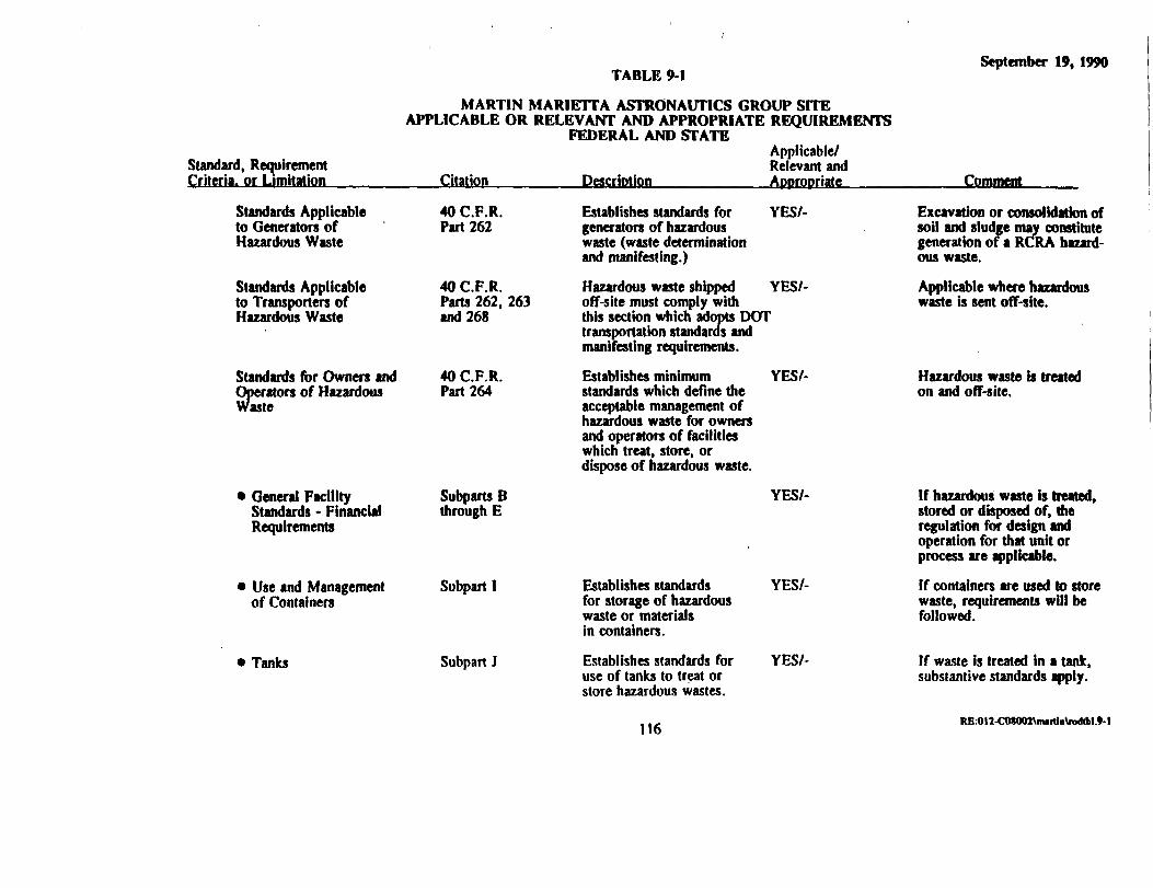
Standard, RequirementCriteria, or Limitation
TABLE 9-1
MARTIN MARIETTA ASTRONAUTICS GROUP SITEAPPLICABLE OR RELEVANT AND APPROPRIATE REQUIREMENTS
FEDERAL AND STATEApplicable/Relevant and
___Citation_______Description________ Appropriate _^_
September 19, 1990
Comment
Standards Applicableto Generators ofHazardous Waste
Standards Applicableto Transporters ofHazardous Waste
Standards for Owners andOperators of HazardousWaste
40 C.F.R.Part 262
40 C.F.R.Parts 262, 263and 268
40 C.F.R.Part 264
General FacilityStandards • FinancialRequirements
• Use and Managementof Containers
Tanks
Subparts Bthrough E
Subpart I
Subpart J
Establishes standards forgenerators of hazardouswaste (waste determinationand manifesting.)
YES/-
Hazardous waste shipped YES/-off-site must comply withthis section which adopts DOTtransportation standards andmanifesting requirements.
Establishes minimum YESA-standards which define theacceptable management ofhazardous waste for ownersand operators of facilitieswhich treat, store, ordispose of hazardous waste.
YES/-
Establishes standardsfor storage of hazardouswaste or materialsin containers.
Establishes standards foruse of tanks to treat orstore hazardous wastes.
YES/-
YES/-
Excavation or consolidation ofsoil and sludge may constitutegeneration of a RCRA hazard-ous waste.
Applicable where hazardouswaste is sent off-site.
Hazardous waste is treatedon and off-site.
If hazardous waste is treated,stored or disposed of, theregulation for design andoperation for that unit orprocess are applicable.If containers are used to storewaste, requirements will befollowed.
If waste is treated in a tank,substantive standards apply.
116 RE:OI2-COSOOZ\miiliii\K>dlbl.*-1

Standard, RequirementCriteria, or Limitation
TABLE 9-1
MARTIN MARIETTA ASTRONAUTICS GROUP SITEAPPLICABLE OR RELEVANT AND APPROPRIATE REQUIREMENTS
FEDERAL AND STATEApplicable/Relevant and
___Citation_______Description_________Appropriate____
September 19,1990
• Surface Impoundments Subpart K
• Waste Piles Subpart L
Landfills Subpart N
Incinerators Subpart O
Land Disposal Subpart CRestrictions
Hazardous Waste TSDF - Organic 40 CFRAir Emission Standards for Parts 264Process Vents, Equipment Leaks Subpart AA
Toxic Substances Control IS U.S.C.Act fi§ 2601-2629
Establishes standards to YES/-treat, store, or disposeof hazardous wastes.
Establishes standards for YES/-storage or treatment ofhazardous waste in piles.
Establishes standards for NO/NOdisposal of hazardous wastesin a landfill.
Establishes standards for NO/NOincinerators.
Identifies hazardous wastes YES/-restricted from land disposaland circumstances underwhich waste may be landdisposed.
Standards for emissions .from air stripping of VOCs.
YES/-
TBC
CpmmenL
If waste is treated hi a tank,substantive standards apply.
Temporary storage prior totreatment is not subject tostandards.
Off-site disposal is planned.
Off-site incineration is plan-ned. Applies to TSD ofwastes.
Applies to TSD of waste andsoil containing waste.
Air stripping and thermal ex-traction are employed by theremedy.
For soil containing waste,LDR levels are target forclean-up.
117 RfiK>l2-CO*OQ2\mntbi\ra«M.*-l

Standard, RequirementCriteria, or Limitation
TABLE 9-1
MARTIN MARIETTA ASTRONAUTICS GROUP SITEAPPLICABLE OR RELEVANT AND APPROPRIATE REQUIREMENTS
FEDERAL AND STATEApplicable/Relevant and
___Citation_______Description_______ ADDrooriate _____
September 19, 1990
Comment
PCB Requirements
Clean Air Act
National EmissionStandards forHazardous Air Pollutants
National Ambient AirQuality Standards (NAAQS)
Occupational Safetyand Health Act
Hazardous MaterialsTransportation Act
Hazardous MaterialsTransportationRegulations
40 C.F.R.Part 761
42 U.S.CC.fifi 7401-7642
40 C.F.R.Part 61
40CFRPart 50
29 U.S.C.fit 651-678
49 U.S.C.6§ 1801-1813
49 C.F.R. Parts107, 171-177
Establishes storage and NO/YESdisposal requirements forPCB's. PCB'sarenotpresent in significantquantities at the site.
Sets emission standards for YES/-designated hazardous pollu-tants
Sets emission standards forcarbon monoxide, lead,nitrogen, dioxide, pani-culate matter, ozone, andsulfur oxides.Regulates worker healthand safety.
YES/-
YES/-
Regulates transportationof hazardous materials.
YES/-
If PCBs are found it concen-trations above 50 ppm, thesewill be applicable.
There exists proposed sourcesat the site which will emithazardous air pollutants.Applicable to TSD facilitiesandMMAG. MMAG is is «non-attainment area.
Hazardous waste she activitiesworker protection will apply.(40 CFR 300.38)
These standards are applicableto off-site transportation ofwaste.
118 REK)ll-COM07\muthi\rodlM.9-l
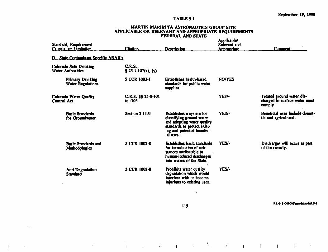
Standard, RequirementCriteria, or Limitation
TABLE 9-1
MARTIN MARIETTA ASTRONAUTICS GROUP SITEAPPLICABLE OR RELEVANT AND APPROPRIATE REQUIREMENTS
FEDERAL AND STATEApplicable/Relevant and
___Citation_______Description_________Appropriate_____
September 19, 1990
Comment
D. State Contaminant Specific ARAR's
Colorado Safe DrinkingWater Authorities
Primary DrinkingWater Regulations
Colorado Water QualityControl Act
Basic Standardsfor Groundwater
Basic Standards andMethodologies
Anti DegradationStandard
C R Ss25-l-107(x),(y)
5 CCR 1003-1
C.R.S. SS 25-8-101to -703
Section 3.11.0
5 CCR 1002-8
5 CCR 1002-8
Establishes health-basedstandards for public watersupplies.
Establishes a system forclassifying ground waterand adopting water qualitystandards to protect exist-ing and potential benefic-ial uses.
Establishes basic standardsfor introduction of sub-stances attributable tohuman-induced dischargesinto waters of the State.
i
Prohibits water qualitydegradation which wouldinterfere with or becomeinjurious to existing uses.
NO/YES
YES/-
YES/-
YES/-
YES/-
Treated ground water dis-charged to surface water mustcomply
Beneficial uses include domes-tic and agricultural.
Discharges will occur as partof the remedy.
119 RE:OI2-CO<Q<n\iMittaWM.9-t

Standard, RequirementCriteria, or Limitation
TABLE 9-1
MARTIN MARIETTA ASTRONAUTICS GROUP SITEAPPLICABLE OR RELEVANT AND APPROPRIATE REQUIREMENTS
FEDERAL AND STATEApplicable/Relevant and
___Citation_______Description_________AoDronriate _____
September 19, 1990
Comment
Ambient Air Quality Standards 5 CCR 1001-14 Sets ambient standards for YES/-total suspended particulates,sulfur dioxide, oxidates,carbon monoxide, and nitro-gen dioxide.
MMAG is in a non-attainmentarea.
E. State Location Specific ARAR's
NONE
F. State Action Specific ARAR'sColorado Hazardous Waste Act(HWA)
Rules & RegulationsPertaining toHazardous Waste• Standards Applicable
to Generators ofHazardous Waste
Standards Applicableto Transporters ofHazardous Waste
C.R.S. 8 25-15-101to -313
6 CCR 1007-3
Part 262
Part 99, 262,263 and 268
YES/-
YES/-
These requirements will applyto waste excavated and gener-ated during the responseaction.
Off-site shipments of wastemust be manifested as hazard-dous waste and comply withall transportation standards.
120 RE:OI2-COt002\imitia\R>dtbl.9-l

Standard, RequirementCriteria, or Limitation
TABLE 9-1
MARTIN MARIETTA ASTRONAUTICS GROUP SITEAPPLICABLE OR RELEVANT AND APPROPRIATE REQUIREMENTS
FEDERAL AND STATEApplicable/Relevant and
___Citation_______Description_________APDrooriate____
September 19, 1990
Comment
• Standards for Owners Part 264and Operators ofHazardous Waste Treat-ment, Storage andDisposal Facilities
• General Facility Subparts BStandards - Financial through ERequirements
• Release from Solid Subpart FWaste Management Units
• Closure and Post-Closure Subpart G
Use and Management Subpart Iof Containers
Tanks Subpart J
See standards below
Standards applying tounits which store wastefrom which a release hasoccurred (includingground water monitoringand protection standards).
Standards that apply tothe controls and monitor-ing of waste in a unitthat is no longer operational.
Establishes standardsfor storage of hazardouswaste or materials incontainers.
Establishes standards foruse of tanks to treat orstore hazardous wastes.
NO/YES
YES/- The Inactive Site Ponds areSWMUs.
YES/-
YES/-
YES/-
Treated soil containing wastereturned to the area of con-tamination is subject to thesestandards.
If containers are used to storewaste, requirements will befollowed.
If waste is treated in a tank,substantive standards apply.
121 RE:OI2-COtOOZ\mMlln\K>M»l.9-l

Standard, RequirementCriteria, or Limitation
TABLE 9-1
MARTIN MARIETTA ASTRONAUTICS GROUP SITEAPPLICABLE OR RELEVANT AND APPROPRIATE REQUIREMENTS
FEDERAL AND STATEApplicable/Relevant and
Citation Description AoDrooriate
September 19, 1990
Comment
• Surface Impoundments Subpatt K
Waste Piles
Landfills
Incinerators
• Colorado FinancialRequirements
Colorado Water Quality ControlAct
State DischargePermit Regulations
Colorado Air Quality ControlAct
Subpart L
Subpart N
Subpart O
Pan 266
C.R.S. 88 25-8-101to -703
5 CCR 1002-2
C.R.S. §§ 25-7-101to -505
Establishes standards to YES/-treat, store, or disposeof hazardous wastes.
Establishes standards for NO/YESstorage or treatment ofhazardous waste in piles.
Establishes standards for YES/-disposal of hazardous wastesin a landfill.
Establishes standards forincinerators.
NO/NO
YES/-
Point source dischargesof wastewater require apermit which establishesstandards for specificparameters.
YES/-
If waste is treated in a tank,substantive standards apply.
Temporary storage prior totreatment is not subject tostandards.
The existing area of contamin-ation will be closed as a land-fill following treatment and re-depositing of the soil(5 265.310).
Off-site treatment of waste isplanned.
Treated ground water dis-charge limits will comply withthe COPDES permit limits orbe more stringent.
122 RE:OI2-COS002\m.rtlnWdtbl.9-l

TABLE 9-1September 19, 1990
Standard, RequirementCriteria, or Limitation
MARTIN MARIETTA ASTRONAUTICS GROUP SITEAPPLICABLE OR RELEVANT AND APPROPRIATE REQUIREMENTS
FEDERAL AND STATEApplicable/Relevant and
___Citation_____ DescriotioiL ADorooriate____ -Comment
Regulation No. I
Regulation No. 2
Regulation No. 3
Regulation No. 6
Regulation No. 7
Regulation No. 8
5 CCR 1001-3
5 CCR 1001-4
5 CCR 1001-5
5 CCR 1001-8
5 CCR 1001-9
5CCR 1001-10
Establishes emission control YES/-regulations for partlculates,smokes, carbon monoxide,sulfur oxides, and fugitivepaniculate emissions.
Establishes odor emission YES/-regulations.
Establishes permit require- YES/-ments for construction ormodification of stationarysources and regulations torprevention of significantdeterioration.
Establishes new source per- YES/-formance standards for In-cinerators, storage vesselsfor petroleum liquids, sewagetreatment plants, new fuel-burning equipment, and newsources of sulfur dioxide.
Thermal extraction of organlcswill meet these standards.
Air stripping and thermal ex-traction employ sourceemission.
Regulations to controlemissions of volatile,organic compounds.
YES/-
Sets forth emission control YES/-requirements for hazardousair pollutants, includingberyllium, mercury and lead.
VOCs are being treated on-site.
These contaminants arepresent on-site.
123 RE:011-CM001\imrtte\n>M>t.9-l

Standard, RequirementCriteria, or Limitation
TABLE 9-1
MARTIN MARIETTA ASTRONAUTICS GROUP SITEAPPLICABLE OR RELEVANT AND APPROPRIATE REQUIREMENTS
FEDERAL AND STATEApplicable/Relevant and
___Citation_______Description_________Appropriate____
September 19, 1990
Comment
Colorado Noise Abatement
Water Well and Pump
C.R.S. 58 25-12-101to -108
C.R.S. 6$ 37-91-101
Water Well md PumpInstallation ContractorsRegulations
Well Permit Regulation
2 CCR 402-2
2 CCR 402-4
Establishes maximum YES/-permissible noise levelsfor particular time periodsand land use zone.
Establishes license require- YES/-ments for well constructionand pump installation con-tractors and minimum stan-dards for well constructionand abandonment to protectagainst pollution.
Establishes regulations for YES/-constructton and abandonmentof wells.
YES/-
If the remedy causes noise.
Applies to recovery and moni-toring wells for ground water.
Applies to recovery and moni-toring wells for ground water.
Applies to recovery and moni-toring wells for ground water.
124 RE:OI2-COt002Vimrth\rodiM.M

September 19, 1990
restrictions.
LDRs are applicable to die remedy because die action requires treating waste listed in 40CFR Pan 261. The soil contains listed waste and will be treated in accordance with LDR standardsapplicable to soil and debris. Presently, the remedy sets the treatment goal at the levels establishedby EPA in the OSWER Directive: 9347.3-06FS may be used if during the design phase it isdetermined necessary in order to implement mis remedy. The hazardous waste storage standards arenot applicable to accumulation of waste prior to treatment, me remedy will meet relevant andappropriate requirements to ensure protection of human health and the environment.
There are no action-specific ARARs addressing the stabilization process. ARARs pertainingto air emissions and noise generation will be complied with. OSHA requirements will also be met.
923 Clean Water Act (CWA) and Safe Drinking Water Act (SDWA)
Discharges from the treatment of water from the Inactive Site or ground water contaminatedwith RCRA hazardous waste, will meet limits established under the State and Federal Clean WaterActs. Discharge limits for each chemical parameter are established in the COPDES permit.Additionally, the discharge will be required to comply with water quality criteria for protection ofhuman health.
Ground water will be treated to meet chemical-specific standards specified by the SafeDrinking Water Act (these being, MCLGs, MCLs) and a health-based concentration threshold forMDMA and State Standards, whichever are more stringent. (Only MCLGs which are above zero arerelevant and appropriate.)
9.2.3 Clean Air Act (CAA)
Air emissions from the thermal extraction system, the air stripper for ground water and thesoil vapor extraction system will comply with requirements specified in Table 9-1. Spent carbonfrom the granular activated carbon treatment of vapors will either be disposed of via incineration anddisposal (landfill) or regenerated at an off-site location.
93 COST-EFFECTIVENESSThe selected remedy offers the best combination of effectiveness, implementability and cost
in comparison with the alternatives evaluated. The remedy mitigates and minimi?^ threats to and isprotective of public health and the environment.
... R£.-OI2-COia02\miniii\iad99-.cnd

September 19, 1990
Alternatives S-5 and GW-4 provide a high degree of overall effectiveness based upon thecriteria of long-term effectiveness and permanence, reduction in toxicity, mobility and volumethrough treatment of the contaminants on-site, and achievement of short-term effectiveness duringimplementation.
Compared with alternative S-4 which would be equally as effective, S-5 is less costly.Alternative S-5 is nearly equivalent in cost to S-3 and provides better long-term effectiveness.Alternative GW-4 provides the most extensive cleanup of ground water of any alternative and hasone of the shortest restoration timeframes. Alternative GW-3 is the only alternative with comparableeffectiveness; however, it does not address an area of highly contaminated bedrock ground waterwhich is addressed in GW-4.
9.4 USE OF PERMANENT SOLUTIONS AND ALTERNATIVE TREATMENTTECHNOLOGIES OR RESOURCE RECOVERY TECHNOLOGIES TO THEMAXIMUM EXTENT PRACTICABLE
The selected remedy uses treatment and alternative technologies to the maximum extentpracticable to achieve a permanent solution which is cost-effective. The treatment processesemployed by this remedy will remove organic contamination from the soil up to an estimated 99%removal efficiency and immobilize the remaining contaminants both inorganic (metals) and organicwith chemical and physical stabilizing processes. Removal and destruction of waste and the reducedmobility of contaminants both from the soil and ground water will provide a permanent solution tothe maximum extent possible.
Although other alternatives would provide a protective remedy by reducing mobility ofcontaminants, no other remedy was as cost-effective in providing permanence through reduction intoxicity and volume Of contaminants
9.5 PREFERENCE FOR TREATMENT AS PRINCIPAL ELEMENT
As describe above, the selected remedy includes extensive treatment of both soil and groundwater to reduce the toxicity, mobility and volume of contaminants at the she. The remedy includesthe use of thermal extraction for organic contaminant^ cod cement-based stabilization for inorganiccontaminants in the Inactive Site soil. Chlorinated organic contaminants (TCE and 1,1,1-TCA) willbe removed and contained from the Chemical Storage Tank area using in-situ soil vapor extraction.The ground water will be treated for VOCs, semi-volatiles and inorganic contaminants with aspecialized process using UV photolysis and oxidation to treat NDMA.
,_, KEK>l2-COS002\Mftin\iod99-.eod12O

September 19, 1990
The remedy mat satisfies the preference for treatment as a prnciple dement by requiring thetreatment of ficfa contaminant to the «tpTtmutn extent practicable
9.6 CONCLUSION
The selected remedy will meet the statutory requirements as specified in Section 121 ofCERCLA by satisfying the threshold and balancing criteria for remedy selection as required bysection 300.430(e) of the NCP. The State of Colorado has also accepted mis remedy and hasparticipated in its selection.
10.0 REFERENCES
CAI, 1990. Public Health Evaluation and Ecological Assessment, Martin Marietta AstronauticsGroup, Waterton Facility, Revised. Clement Associates, Incorporated. Fairfax, Virginia.March 29, 1990.
Eder, 1990. Final Feasibility Study, Martin Marietta Astronautics Group. Denver, Colorado. June27, 1990.
EPA, 1987. Data Quality Objectives for Remedial Response Activities. U. S. EnvironmentalProtection Agency. EPA/540/G-87/003. March 1987.
EPA, 1990. National Oil and Hazardous Substance Pollution Contingency Plan. U. S.Environmental Protection Agency. 40 CFR 300. Updated March 1990.
Geraghty &. Miller, Inc., 1987a. Results of Phase 1 Investigation, Martin Marietta AstronauticsGroup. Denver, Colorado. June 10, 1987.
Geraghty & Miller, Inc., 1987b. Results of the Inactive Site Source Characterization Study andBench Scale Treatability Testing. Denver, Colorado. October 14, 1987.
Geraghty & Miller, Inc., 1990. Final Remedial Investigation Report, Martin Marietta AstronauticsGroup. Denver, Colorado. March 29, 1990.
Mackay, D.M., P.V. Roberts, and J.A. Cherry, 1985. Transport of Organic Contaminants inGround Water. Environmental Science and Technology 19:364-392.
McDonald and Harbaugh, 1988. A Modular Three-Dimensional Finite-Difference Ground-WaterFlow Model, Techniques of Water-Resources Investigations of the United States GeologicalSurvey, Book 6, Chicago Al.
SSPA, 1989. Modeled Estimates of Ground-water Cleanup Times for Martin Marietta, S.S.Papadopulos and Associates, Inc. September 1, 1989 (Revised September 8 and December 7,1989).
Trescott, P.C., and S.P. Larson, 1976. Documentation of Finite-Difference Model for Simulation ofThree-Dimensional Ground-Water Flow. U.S. Geological Survey Open-File Report 76-591.August
APPENDIX A
MARTIN MARIETTA ASTRONAUTICS GROUP SITERESPONSIVENESS SUMMARY

September 19, 1990
APPENDIX A
Martin Marietta Astronautics Group SiteResponsiveness Summary
The community relations responshreness summary for the she is divided into two sections;1. a brief description of the site and the selected remedy, and 2. a summary of the oral and writtencomments received during the public comment period concerning the Proposed Plan prepared byEPA.
1. Overview
The Martin Marietta Astronautics Group (MMAG) site is located in Jefferson County nearthe mouth of Waterton Canyon on Highway 121 approximately 25 miles southwest of Denver. Thesite occupies approximately 5200 acres and has operated since the 1950s. Operations have includedthe manufacturing of rockets for the U.S. Air Force and research and development associated withaerospace equipment and fuels.
The facility is regulated under the Resource Conservation and Recovery Act (RCRA) as atreatment, storage and disposal facility. During the operating period prior to RCRA, the wastewhich could not be treated in the wastewater treatment plant on site was disposed of in five pondslocated on site. The area is now called the Inactive She Ponds and is a major source of groundwater and soil contamination. There are several other sources of contamination on site which wereinvestigated during the remedial investigation or area being investigated under closure requirementsof the RCRA program.
The primary contaminants found at the site are volatile organic compounds (VOCs) includingtrichloroethene (TCE), 1,1,1-trichlorothane (TCA) and the degradation compounds from thesechemicals; semi-volatile chemicals including N-nhrosodimethylamine (NDMA) which is a chemicalassociated with hydrazine fuels, and inorganic chemicals such as hexavalent chromium. Thecontamination is highly concentrated in the Inactive She area soil and ground water. Another areawith high levels of contamination in the ground water is the Manufacturing (M3) area. There arelow levels of contamination found off she in the Denver Water Department (DWD) Kassler property.
There is a separate she located within the MMAG property which is federal facility and is onthe National Priorities List. The site is approximately 464 acres and is owned by the U.S. Air
A-l R£.-012-C08002\m«miiV.Pp<n-«.rod

September 19, 1990
Force. A separate program is in place to require the investigation of the site and select a remedy forthe remediation of the site.
On June 28, 1990 EPA proposed the preferred alternative for remediating the site. Theproposed remedy included Alternative S-5 for the Inactive Site and Chemical Storage Tank areas andAlternative GW-4 to address ground water. Bom alternatives include extensive treatment of
Alternative S-S requires that contaminated soils in the Inactive She area be excavated and thatwaste be separated for treatment and disposal off she. The contaminated soil mat remains on sitewill be treated by thermal extraction to remove organic chemicals and solidified to immobilizeinorganic contaminants. The treated soil will be returned to the area of contamination and cappedwith a multi-layered cap. Residues from the treatment process wr! be. transported off site fortreatment and disposal.
Alternative GW-4 for the ground water is a she-wide remedy addressingcontamination which originates from sources investigated during the remedial investigation andhazardous waste management units subject to RCRA regulations.
EPA solicited written and oral comment from the public during the comment period whichbegan on June 28, 1990 and closed August 27, 1990. Comments were received during the publicmeeting, held July 26, 1990, from the National Toxics Campaign (NTQ representative. Writtencomments were submitted by MMAG.
2. Public Comments and Response
Comment: First of all, we feel that it is important mat no additional air emissions be factored into aclean-up she, that we would be working as diligently as possible to reduce air emissions in theDenver metropolitan area. So mat is something that is extremely important and needs to beaddressed.
EPA Response: EPA agrees with the concern over introducing additional sources of air emissions aspart of the remedy. After further consideration of the proposed alternative for ground waterinvolving air stripping, EPA has decided to include emission controls as part of the final remedy forthis process. This decision is based upon several factors including the EPA policy (OSWER Dir.9355.0-28) applicable to areas of non-attainment for ambient air quality and the fact mat MMAG is
A-2

September 19, 1990
within an area of non-attainment, and the requirement in the NCP to reduce the toxicity, mobility orvolume of contaminants through treatment. During the design phase, the specific type of control willbe determined.
Comment: We also call for independent monitoring. We feel that mis is extremely important aswell, given the history of monitoring of different toxic contamination sites in Colorado.
EPA Response: As pan of the regulatory responsibilities of EPA and the Colorado Department ofHealth (CDH) the authority to enter facilities and collect samples and conduct inspections is providedby law. However, neither EPA or CDH have the authority to require MMAG or any facility toallow a third party which does not represent the agencies to enter a facility to collect samples.
Specifically, pursuant to the Hazardous and Solid Waste Amendments (HSWA) Section 3007and CERCLA Section 104(e), EPA is provided the authority to enter, inspect and collect samplesfrom facilities treating, storing or disposing of hazardous waste or facility, vessel, location withhazardous substances. Pan 3 of the Colorado Hazardous Waste Act (Section 25-15-301 (3))authorizes CDH to enter and inspect hazardous waste facilities.
If any party desires samples from facility, then mat party may contact the owner/operator ofmat facility and request permission to obtain samples directly from that facility.
Comment: MMAG believes that flexibility must be maintain^ throughout mis cleanup process toallow the work to proceed in an effective and economical manner. This will allow the procedure tobe updated as the knowledge of the she increases through time. A Record of Decision (ROD) thatallows for this kind of continual feedback will result in an accelerated achievement of our goals withimproved results.
EPA Response: EPA agrees that flexibility must be built into the ROD to allow for the developmentof the most cost-effective design of the remedy specified in the ROD. However, the ROD mustspecify the processes selected to remediate the contaminant conditions at the site. The ROD willretain flexibility accounting for the results of treatabflity studies which will be conducted during thedesign phase. Soil treatment standards are specified with provisions for a variance. In addition, theROD acknowledges the potential difficulties with achieving the cleanup goals for ground water asspecified in the ROD and includes provisions to evaluate the response action and treatment standardsafter a period of operation.
A-3 REH)12-COS002\inutm\>pp«a-t.rod

September 19, 1990
Comment: Hie Endangerment Assessment (EA) mat evaluates the risk to human health and theenvironment has used residential use scenario for the basis of evaluation. These requirements shouldbe reconsidered in light of Jefferson County's recent request to further review zoning at the MMAGand the county desires mat "visually sensitive areas (hogback, mountain front) be protected as zonedopen space." These changes would reduce the health risk concerns, drinking water and showeringwith water from ground water source, and therefore affea die final cleanup requirements as specifiedin die Record of Decision.
EPA Response: The use of die residential scenario in die EA was done to evaluate die reasonableexposure scenario for die site as required by EPA policy for conducting risk assessments.
In doing so die EPA has a better understanding of die risk mat may be posed to human health underconditions of maximum exposure and be able to communicate diat information to die public. Thefact mat die zoning changes are being considered for the area does not change need to assess whatEPA considers to be a potential reasonable maximum exposure scenario.
The final cleanup requirements specified in the ROD are based upon several requirements inthe NCP and CERCLA. Specifically, with respect to ground water remediation, EPA is to considerrestoring ground water to its beneficial use based upon previous uses and potential uses. The groundwater from me site was used as a drinking water supply and the potential for diat demand in thefuture exists. Furthermore, die EPA is to select remedies that attain permanent solutions dirough useof treatment whenever practicable and remedies must attain applicable or relevant and appropriaterequirements (ARARs) or attain a waiver. Based upon mese site conditions and requirements, theremedy selected is the most appropriate for the site and reconsideration of die standards set forth indie ROD based upon zoning which is subject to change would be inappropriate.
Comment: The soils alternatives evaluated in die presentation of die Proposed Plan did not considertwo of die alternatives set forth in die Feasibility Study (FS), limited action and in-shu stabilization.The limited action alternative relies on isolating die property to prevent exposure while die in-situstabQization depends on adding Pttfnals to die sofl diat decreases die transport rate of contaminantswhile they decompose naturally. These alternatives do not appear to completely meet dierequirements for tiiis cleanup but could compliment me odier technologies. Again, tiiey add to dieflexibility diat we believe is needed in mis ROD.
EPA Response: The limited action alternative and me in-situ stabQization alternative are notsupported in die FS as beneficial over die conmarable alternatives, no action and ex-situ stabQization,respectively. The limited action alternative does not provide any significant increase in protection to
A-4

September 19, 1990
human health or the environment when compared to the no action alternative. Most of thecomponents (e.g., restrictions) associated with the limited action are inherent with (or will beincorporated into) the selected alternative during the design phase, thus addressing the MartinMarietta comment that limited action could compliment the other technologies. The FS demonstratedmat the in-situ stabilization process is inferior to the ex-shu stabilization process with respect toeffectiveness and implementability. The costs were near equivalent. As such, the EPA does notbelieve mat in-situ stabilization warrants any further consideration. It should be noted that the FS isthe mechanism used to reduce the range of alternatives to a manageable number of the most feasiblealternatives.
Comment: The request that the ROD remain flexible should be especially exercised in the soil vaporextraction technology, suggested in all alternatives, for cleanup of soil contamination at the chemicalstorage tanks. The site compatibility for this removal method must be evaluated before specifyingthe technique. We suggest that a pilot test of the technology be incorporated.
EPA Response: EPA agrees that a pilot study should be conducted during the design phase todetermine the feasibility of in-situ soil vapor extraction. EPA, however, believes that in-situ soilvapor extraction will work in this particular application and will specify in-situ soil vapor extractionin the ROD. Should the process fail during the design phase, another process would be identified.
Comment: The on-site treatment and excavation called for in alternatives S-3 through S-5 in theproposed plan are based on handling the cover material, waste sludge, contaminated alluvium andcontaminated backfill. The contaminated backfill, which was not included in the proposed plan,should be combined with the contaminated alluvium and termed contaminated soil to be compatiblewith the FS report.
EPA Response: While it may not have been clearly stated in the Proposed Plan, references made tobackfill and/or contaminated soil were intended to refer to both contaminated backfill
and alluvium mat corresponds to a volume of 24,400 cubic yards. This will be clearly stated in theROD and the term "contaminated sou" will be used when referring to contaminated backfill andalluvium.
Comment: Based on the current information available, the region where Pond *2 was locatedappears to be uncontaminated. If additional data garnered during the design phase verifies this fact,h seems unnecessary to remediate that area. This also seems like a reason to minta»" flexibility in
A-5 KE.-012-COS002\a»i1ia\q>fM»«.K>d

September 19, 1990
the discussion on the area that needs to be covered by the cap. The extent and nature of the capshould be called out in the design report which will reflect the results of the additional study needed.
EPA Response: During the design phase, additional field sampling will be required to moreaccurately determine the extent of contamination. From mis information, the cap will be designed tocover the contaminated area. A RCRA cap, however, will be specified in the ROD to the extentshown in the FS which coven all five ponds. The extent of the cap may increase, decrease, orremain the same depending on the results of the field sampling program conducted during the designphase.
Comment: Alternative S-5 should state clearly mat the collected volatile residue from the thermalextraction process and the excavated waste must be treated and disposed of off-site while theremainder of the material can be handled on-site. The ROD should clarify the target remedial actionlevel and target treatment level with the flexibility to accommodate the results of the design and pilotresults.
EPA Response: The ROD will be written to clearly state mat the waste and thermal extractionresidues will be treated and disposed of off-she and the remainder of the material can be treated anddisposed of en-site. Target remedial action levels and treatment levels will be presented hi the RODand clarified as necessary to account for the analytical method detection limits and attainabletreatment technology levels.
Comment: The ground water treatment system described in alternative GW-4 should leave the natureand order of the process step open so an economical design can be developed to best protect theenvironment. This may leave the operations in the current MMAG wastewater treatment plantavailable for final polishing.
EPA Response: EPA agrees with this comment, however, the process order presented in theProposed Plan was taken from the FS and wQl be used in the ROD for the purpose of presenting theselected remedy. The design will dictate the order of the unit processes.
A-6

September 19, 1990
APPENDIX B
MARTIN MARIETTA ASTRONAUTICS GROUP SITEINACTIVE SITE PONDS
CROSS SECTIONS
\

B12
Pond 1 GMI9•GMI9B
B14
SPB40 \GJH140 "SCB6°5U5»!H____SCB38_V»GM 141
GM14
50Feel
100
Pond 5SCB2
SCB2
IUMTW ASTMNAUUCS «wuf i
FIGURE B-1INACTIVE SITE PONDS
CROSS SECTION LOCATIONSDATE CREATED: S/14/»0

Pond 1
JM
10
SCB49CrTCETCACIs-DCE
All~BR~ ~~
2ft 8ft595 mg/kgND ug/kgND ug/kgND ug/fcg
Cross-Section KeyCo • Cover MaterialAH - AlluviumWA • Asphalt Rich WasteWC • City Rich WaileBR « Bed Rock0 • Interval Sampled19 - Infiltrating Sludge
Horizontal Scale - 1:300Vertical Scale - 1:60
Contaminant Concentration Key
SCBSOCr 34 mg/kgTCE 530 ug/kgTCA 1710 ug/kgCIvDCE ND ug/kg
SCB5ICrTCETCA
UiJft34 ing/kgND ug/kg57 uf/fcc
CliDCE NDu|/k|
SCB492fiRfiCrTCETCACii-DCEND
Soil Boring IdentificationInterval SampledTotal. ChromiumTrlchioroethene1,1.1 TttchlotoethaneCh-1,2 DichloroetheneNot Detected
HMTM MAMenA AtnWMAUIKS tMUT OTI•AKMTOH. COLOMM
nGURE B-2 .POND 1
CROSS SECTION A-A*DATE CREATED: S/U/M

f •t,IIr
BW
SCB44 SCB45
Pond 1
SCB46 SCB47
B'E
SCB54Cross-Seclion KeyCO - Cover MaterialAll • AlluviumWA - Asphalt Rich WasteWC - Clay Rich WasteBS - Black SludgeBR - Bed Rock£3 * Interval Sampledgj - Infiltrating Sludge
BR
Horizontal ScaleVertical Scale
- 1:300- 1:60
Conlnminant Concentration Key
SCB44 Sft-lJftCr 20 ing/kgTCE ND ug/kgTCA 351 ug/kgCliDCE 647 ug/kg
SCB45CrTCETCA
5ft-18fl9J mg/kg646 ug/kgND ug/kg
CIs-DCE 57 ug/kg"
SCB46CrTCETCACIs-DCE
6fl-l4ft5 mg/kgND ug/kgND ug/kgND ug/kg
SCB47 lOfl 19ftCr 72 mg/kgTCE ND ug/kgTCA ND ug/kgCisDCE 92 ug/kg
SCB54CrTCETCA
9fl 12ft12 mg/kgND ug/kgND ug/kg
CisDCE ND ug/kg
SCB445fl-l3flCrTCETCACisDCEND
Soil Boring IdentificationInterval SampledTotal ChromiumTrichloroelheneI.l.l-TrichlnroethaneCis-1,2-DichloroelheneNot Detected
At IMNAUTICS amir <mWAtWTOM. COLOKADe
FIGURE 8-3POND 1
CROSS SECTION B-tfDATE CREATED: 5/14/M

cwSCB42 SCB4I SCB58
Pond 1SCBI3 SCDI2
CE
SCB43 SCB37
10
15
20
30
35
40
BR
\\\\
11(1-19(1 \SM mg/kg \ND ug/kg \ND u|/k(
Cr mg/kg,TCE ug/kgTCA ug/kg
12(1 19(1125 mg/kg19600 ug/kgND ug/kg
Ch-DCE IHOOug/kj
SCB37 9fl-13flCr 195 ing/kgTCE 35400 ug/kgTCA 1230 u|/k|CilDCE »ROOut/k|
Cross-Section KeyCo - Cover MmtrMAll - AlluviumWA - Atph«ll Rich WuieWC - Oir Rich WuieBS - Blick Slud|CLn - Uner MllerUIBR - Bed Rock0 • Inlervil SampledQ] - Infiluilini Sludge
Horlzontil Sale - 1:300Verticil Sale - 1:60
Contaminant Concentration KeySCB42 Son Boring IdentinaUMlift Wi Imecvd StmpledCc Toul ChrotnhimTCE TrichloroelheneTCA 1.1.1 TrlchlofoethineCiiDCE Cts l.J DkMofoelberwND Not Detected
Ch-DCE ND ug/kg
XSCB58 9(1-25(1O /ND mg/kgTCE/ 1590 ug/kg
, TCA ND ug/kg2 /Ch DCE 321 ug/kg
SCB4I
Cr mg/kgTCE ug/kgTCA ug/kgCh-DCE ug/kg
(eel4.6NDND 'ND
4 8(eet14NDNDSO
110(eel237012500ND17400
10-H(eet197NDND14SO
14 11(eet197102ND2380
1822leet7.1NDND1130
22-26(eel2370NDND3800
2630(eel79S6120ND2180
30^34(eel6.7NDNDND
34 39(eel135160NDND
MAMTM MANETTA AIlMMMfllCt «MVF «tl
FIGURE 8-4PONO 1
CROSS SECTION C-C'DATE CREATED: S/I4/M

Pond 1
10-
1 5 -
30-
35
40-
SCBJ6 10ft. 17hCr ISO m|/k|TCE 6020 u|/k|TCA ND u|/k|CiiDCE S440u|/k|
SCB40 MI-2MICf 1080 m|/k|TCE 321000 u|/k|TCA Nt3 U|/k|CiiDCE l2COOOu|/k|
scat 20fi-22ftCr 10 mg/k|TCE ND u(/kiTCA NDu|/k|Cil DCE 51 u|/k|
SCB5» 20-26 37-41feel (eel
Cr mf/k| 2790 ItTCE ug/k| 995000 2790TCA u|/k| ND NDCii-DCEufAl 35000 ND
Cross-Section KeyCo • Cover MaterialAll - AlluviumWA - Asphalt Rich WasteWC - Oar Rich WaneBS • Black SludgeBR - Bed Rock^ - Interval Sampled
Horizontal Scale - 1:300Vertical Scale • 1:60
Contaminant Concenlmtion KeySCB40 - Soil Borln| Identification8fl 25fl - Interval SampledCr - Total ChromiumTCE - TrichlotnelheneTCA - I.l.l-TrichloroeihaneCit-DCE - Ch-1,2 DichloroeihencND - Not DeiecteJ
UAMCUA ASTMHMmet (MOUP I•AfCHION. COLOMAM
FIGUREPOND 1
CROSS SECTION D-D'DATE CREATED: S/I4/>0

15
I3(1 liftJ4mg/kg530 u|/k|1710 u(/k|
IWi Mil19 mg/kgND ug/kgND ug/kg
30
SCB53 «(t-«ftCr 21 mg/kgTCE ND ug/kgTCA ill ug/kgCtaDCB ND ug/kg
SCB52Cr 54 mj/kgTCE ND ug/kgTCA 67 ug/kgCilDCE ND ug/kg
Contnmlnnnt Concentration KeySCBS)Mi-9ftCrTCETCACilDCEND
Soil Boring IdemlficitionInterval SampledTout ChromiumTrlchloroelhencI.l.l-TrkhloroclhaneCi» 1.2-DichloroeihcneNot Detected
SCB45CrTCETCA
Stt-lth»S mg/kg646 ug/kgND ug/kg
Cross-Section KeyCo • Cover MaterialAll - AlluviumWA - Ajphalt Mick WarnWC -day Rick WatwBS - Black StudftBR - Bed Rock0 - Inlervai Sampled
1300Horlzomal ScaleVenical Scale
20fl-22hI0m|/k|NDu|/k|NDu|/k|
Cil-DCE 51 ug/kg
CilDCE 57 ug/kg
40J
SCB5SCrTCETCACilDCE
9li23fiND mg/k|1590 ug/kfND ug/k|321 u|/k|
SCD59
Cr mg/kgTCE ug/kgTCA ug/kg
2026 37-41leci feei2790 II995000 2790ND ND
Cis DCE ug/kg 35000 ND
•Mum AsnwNMnm MWUP tm•ATCKTOM. COLOJuUM
FIGURE B-6POND 1
CROSS SECTION E-C*DATE CREATED: 5,

Pond 3
10 J
aN
O'S
SCB3S SCB14 SCB33
SCB35CrTCETCACliDCE
2ft-5ft44 mg/kg2020 ug/kgND ug/kgND U|/kg
JO
All
Cross-Section KeyCo • Cover MaterialAll - AlluviumWM - Waste MilBR - Bed Rock£2 - Interval Sampled
SCB35
JTCETCACliDCE
2fl5fl44 m|/k|2020 tig/kg TCEND ug/kgND ug/kg
TCACli-DCE
OTMft12 pig/kg202 ug/kgND ug/kgND ug/kg
All
SCB33CrTCETCACij-bCE
Horizontal ScaleVertical Scale
1:3001:60
4tl-7fiII mg/kg9120 ug/kgND ug/kgND ug/kg
Contaminant Concentration KeySCB3S2fl-5flCrTCETCACIs-DCEND
Soil Boring IdenllflcalionInterval SampledTotal ChromiumTrichloroeiheneI.l.l-TrichloroelhaneCit-l.2-DichloroeiheneNot Detected
H**TM HAMCTTA AtTMMAUTIC* OHOOf «tTl•ATINTON. COLORADO
FIGURE B-7POND 3
CROSS SECTION F-F* <t Q-CDATE CREATED: 5/14/»0 ___

Hsw
SCB29 SCB40. —————————————————————————————————————
3-
I10'
IS
20'
\ 1 1 ^x*' v\K| ^° ^x^ *\Kl *^x*'x ' V -
.„ 'AJI
^ 'V
^
iSCB29 IMft SCB4 6fCr Umg/kg Ct 11TCE 4640 tig/kg TCB NTCA NDug/kg TCA NOs-DCE NDug/kl Cis DCE N
\ LnoDK
Pond 4H> iNE sw
rNE
SCB3I SCB9 SC825 SCB6 SCB27 OM14
CO
' — — 7/
° ^, _ _ ^\ ^\ BS ^' V.\- -
/
/
/ All
/-~7
/' ^- /BR
/
l-IOft SCB3I 3ft- 10ftmg/kg Cr ND mg/kgng/kg TCE 216 ug/kg
D ug/kg TCA ND ug/kgDug/kg Cis-DCE NDug/kg
//
$
i»15
20
ABR
^
Co
•
\\
^£
\t.rj
\
x~ "=-— _
we
u
, All
SCB2S SftSfl \Cr 502 mg/kg \TCE 16900 ug/kg \TCA ND ug/kg \ChDCE NDug/kg \
SCB6 0-4 4-g !(eel feel (
Ji
I
;c:r
Co y UToss-aeciton t\ey7 Co » Cover Material
_J^A / All • AUuvlura•^ "/ WA - Aiphalt Rick Wane
/ WC - Oay Rich Waste/ BS • Black Sludge
7-/ — -J Ln - Uner Material
BR - Bed Rock£3 - Interval Sampled
Horltomat Scale - 1300Vertical Scale - 1*0
ConiHminant Concentration KeyB27 I6fl-I8fl SCD29 Soil Boring IdenllOcallon
5360 ma/kg Ifi 4fi Interval SampledCr mg/kg 506 265 TCE 280000 ug/kg Cr Total ChromiumTCE ug/kg 5450 39900 TCA NDug/kg TCE TrichloroelheneTCA ug/kg ND 23700 Cis-DCE NDug/kg TCA l.l.l-TrichloroethaneCis DCE ug/kg ND ND Cis DCE Cii-1,2 DicMoroelbene
ND Not Detected
WAKTM HAMEnA ASTMMMItttt eaoU? (TitWATCRTON. COLOMArM
FIGURE B-8POND 4
CROSS SECTION H-H' It M*DATE CREATED: B/U/M

LSW
Pond 5
L' MNB N
SCB1 SCB21 SCB22 m SCB2 SCB23 SCB21™
I"
10-
SCB21
1A•«
0-2feel
Omg/kl 54TCBug/kg 706TCAii|/k| NDCb-DCE ug/kg ND
'j%'i
j
J?i
/" y \ /i
M Co iwe; ZAII» ^/ , M *c // " |S \»- i//BR V--/ BR X. ?
/ 10- X. ^^ / _
2-4 44 <4 8-10 10-11 SCB2 Oft 5ft
M'S
SCB201 I Cross-Section Key ,
„ If Co - Cover Material^_ 1 / All - Alluvium^\ 1 / WC - City Rich Waite
Xs* 1 / nc DI A ci A
S V BR - Bed Rock——— -*— -J 0 • Interval Sampled
All_ _ _ _ _ Horizontal Scale - 1.300
Vertical Scale - 1:60feel feel feel feel feel Cr 98 m»/kf267 856 28900 38 38 TCE 36600 ug/kg2590 1100000 4700000 260000 330000 TCA 3690 ug/kgND ND 163000 ND 130000 di DCE ND ug/k|161 ND ND ND ND s(X2l ^ 2<
feet feelCr mg/kl 54 267TCE ug/kg 706 2590
Contaminant Concentration Key TCA ug/kg ND NDSCB2 Soil Boring Identification Ch-DCE ug/kg ND 161OflSftCrTCETCACit-DCEND
4-6 6-8 8-10 1011feel feel feet feel856 28900 38 381 100000 4700000 260000 330000ND 163000 ND 130000ND ND • ND ND
Interval SarnokdTotal ChromiumTrichloroelhene1,1,1-TrichloroethaneOi- U-DichloroelheneNot Detected
UAftlM MAaKTTA ASTMNAUTICS MOUP tOl•ATtarON. COLONMW
FIGURE B-10POND 5
CROSS SECTION L-L' ft M-M*DATE CREATED: 5/l4/*O

JN
JPond 4
KS N
•
K'S
SCBJO SCB4 SCUM SCB25 SCB7 SCB32 SCB3I SCB3 SCB27 SCB24§• ————————————————————————————————————— - — "- ——— - — — ——— ___ — ——————— -
5-
J 10 '
15
\
V \\v \f\ \ \
Co /
All
?/.Y,i
\
\SCBJO l((7fiCr 1990 mg/kgTCE 74000 ug/kgTCA ND ug/kgCUDCE NDug/kg.
SCB4 6ft-10nCr 12 mg/kg
20- TCE 90 ug/kgTCA ND ug/kgxCiiDCE ND ug/kg x
SCD28 <Mfeel
Cr mg/kg 49TCE ug/kg' 1050TCA ug/kg NDOt-DCE ug kg ND
f
X|^
\
',
\£y
\
^^L-?/A.^^^^»_ Vkff* r /
yf'^V
All / ^N_
/
/ SCB25 Sll-Sft/ O 507 mg/kg
/ TCE 16900 ug/kg/ TCA ND ug/kg/ Cil DCE ND ug/kg
//
w -
5
i 10
15
^P \
\^W>Xvc
\\
Nx *• \ «SXN \ S
\ \\
BR X N
S
\
\*/*/£
/ 20
' SCB32 OflJfl SCB31 3fi lOflO IS mg/kg Cr NO mg/kg
4-S 812 12-16 16-20 2fr23 JCE 470 ug/kg TCE 216 ug/kgf«i r»i fe<i feel (MI TCA ND ug/kg TCA ND ug/kg12 29 22 55 ' 43 ch D" ND ug/kj CiiDCE ND ug/kj3720 172 13300 1400000 6500000
\
\>
«
_ _ _ —
NX
N
SCB3Cr
\
Co /
^-^
^All
TCETCACiiDCE
Co I Cross-Section KeyWA ^^____ 2J Co - Cover Material
u~"~" --""" ^ / / All • Alluvium^ ' WA - Aipball Rick Walk
WC -S^^ WC - Qay Rh* Wait*^^ BS - Black Shidga
' ^ Ln - Uner MaterialAll
BR - Bed Rock0 - Interval Sampled
s'/ Horizontal Seal* - I JOO
/ Vertical Scale - 140S BR
x'/
8fl I2fl SCB27 I6fl-I8fl SCB24 Ifl-Sfl1090 mg/kg Cr 5360 mg/kg Cr 448 mg/kgII 200 ug/kg TCE 280000 ug/kg TCE 4480 ug/kg '-NDug/kg TCA NDug/kg TCA NDug/kgNDug/kg rii-DCE NDug/kg Ch-DCE NDug/kg
ND ND ND ND NDND ND ND ND ND
ConiaminRnt Concenlralion Key
-
SCBJOlfl-7ftCrTCETCACUDCEND
Soil Boring IdentificationInterval SampledTotal ChromiumTrichloroclheneI,l.l-Trichk>roeihaneCb-1.2-DichloroelheneNot Detected
UAftTM MAMETTA AStlMNAUIKI QWUf WlWAKKTOM. COLORADO
FIGURE B-9POND 4
CROSS SECTION J-J* * K-K*DATE CREATED: S/I4/BO
U.S. DEPARTMENT OP COMMERCENational Technical Information ServiceSpringfield. Va 22161
AN EQUAL OPPORTUNITY EMPLOYER
OFFICIAL BUSINESSPenalty for Private Use. $300
POSTAGE AND FEES PAIDUS. DEPARTMENT OF COMMERCE
COM-21 1
SPECIAL FOURTH-CLASS RATEBOOK