
, 19th Aerospace Mechani Symposium - NASA Technical ...
389
t J i.!! __ 22 SEP1619B5 _ NASA Conference Publication 2371 /, 19th Aerospace Mechani _ SiS Symposium
-
Upload
khangminh22 -
Category
Documents
-
view
1 -
download
0
Transcript of , 19th Aerospace Mechani Symposium - NASA Technical ...
t
J
i.!! __ 2 2SEP1619B5_ NASA Conference Publication 2371
/, 19th AerospaceMechani_ SiS
Symposium

E
NASA Con[erence Publication 2371
19th AerospaceMechanisr.nsSymposium
; Proceedings of a symposmm sponsored by theNational Aeronautics and Space Admimstration,
• Washington, D.C., the California I lstitute ofTechnology, Pasadena, Californ,a, and the
Lockheed Missiles and Space Comoan3, Inc.,Sunnyvale, Cahforma, and held at
NASA Ames Research CenterMoffetl Field, California
May 1-3, 1985
N/_ANational Aeronautics
and Space Administrationm
Scientific and TechnicalInformation Branch
1985
1985025199-002
PREFACE
The proceedings of the 19th Aerospace Mechanisms Symposium held at theNASA Ames Research Center on May !-3, 1985, are in this NASA Conferencei
Publication. The symposium was sponsored by the National Aeronautics andSpace Administration, the California Institute of Technology, and Lockheed
: Misslles and Space Company, Inc.
The purpose of the symposium was to provide a forum for the interchange ofinformation among those active in the field of _aechanismstechnology. To thatend, 25 papers were presented on aeronautics and space flight, with specialemphasis on actuators aerospace mechanism applicatiens for ground supportequipment, lubricants, latches, connectors, and other mechanisms for largespace structures. The papers were prepared by engineers from a broadaerospace background, including the U.S aerospace industry, NASA, andEuropear and Asian parCicipants.
The efforts of the r_view committee, session chairmen, and speakers con-z tributing to the technical excellence and professional character of the •.: conference are especially appreciated.
The use of trade names or names of manufacturers in this publication doesnot constitute an official endorsement of such ploducts or manufacturers,either expressed or implied, by the National Aeronautics and SpaceAdministration.
I'kl]..!LI.)INC i',",Gi,i i;I,AI<iC NOT I:ILMED
lil
J
1985025199-003
CONTENTS
Preface .......................................................................... lll
The Organizing Committee ......................................................... vii
Program .......................................................................... _x
THE GALILEO SPACECRAFT MAGNETOMETER BOOM ...........................................
Douglas T. Packard and Max D. Benton
HOOP/COLUMN ANTENNA DEFLOYMENT MECHANISM OVERVIEW ................................. 23B. B. Allen and D. H. Butler
DEVELOPMENT OF AN ENERGY-ABSORBING PASSENGER SEAT FOR A TRANSPOrt _IRCRAFT ........ 39
Charles P. Eichelberger and Emilio Alfaro-Bou
_: A MODULAR DOCKING MECHANISM FOR IN-ORBIT ASSEMBLY AND SPACECRAFT SEi_iCING ........ 59
F. Gampe, K. Priesett, and R. H. Bentall
DRAG-COMPENSATED, PRECISION-POWERED HINGE SYSTEM .................................. 75
G. G. Jacquemin and S. J. Rusk
DESIGN AND DEVELOPMENT OF A LINEAR THERMAL ACTUATOR ............................... 87
Gerry Bush and Don Osborne
THE DESIGN AND DEVELOPMENT OF A CONSTANT-SPEED SOLAR ARRAY DRIVE ................. 103
Howard M. Jones and Neil Roger
APPLICATION OF TRACTION DRIVES AS SERVO MECHANISMS ............................... 119
Stuart H. Loewenthal, Douglas A. Rohn, and Bruce M. Steinetz
THE PROPERTIES OF THIN-SECTION, FOUR-POINT-CONTACT BALL BEARINGS IN SPACE ........ 141Robert A. Rowntree
THE DESIGN AND DEVFLOPMENT OF A SPACECRAFT APPENDAGE TIE DOWN MECHANISM .......... 167
William D. Nygren and Raymond Head
THE USE OF PERFLUOROETHER LUBRICANTS IN UNPROTECTED SPACF ENVIRONMENTS ........... 179
Bryan H. Baxter and Barry P. Hall
ADVANCES IN SPUTTERED AND ION PLATED SOLID FILM LUBRICATION ...................... 209
T. Spalvins
TELEPRESENCE WORK SYSTEM CONCEPTS................................................ 225: [.yle M. Jenkins
DUAL ARM MASTER CONTROLLER DEVELOPMENT........................................... 235D. P. Kuban and G. S. Perkins
MAN-VEHICLE SYSTEMS RESEARCH FACILITY ADVANCED AIRCRAFT FLIGHT SIMULATOR
THROTTLE MECHANISM .............................................................. 251
Seth S. Kurasaki and Wilbur C. gallotton
v
t
1985025199-004
THE DEVELo?MENT OF STAGING MECHANISMS FOR THE JAPANESE SATELLITE
LAUNCHER MU-3S!I ................................................................. 2_9
JunJiro Onoda
A ROTATING ELECTRICAL TRANSFER DEVICE ........................................... 277
Ryan S. Porter
A DUAL, FAULT-TOLERANT AEROSPACE ACTUATOR ........................................ 293Clete J. Siebert
DESIGN OF A DbAL FAULT TOLERANT SPACE SHUTTLE PAYLOAD DEPLOYMENT ACTUATOR ........ 305Duane R. Teske
FEATURES OF THE SOLAR ARRAY DRIVE MECHANISM FOR THE SPACE TELESCOPE .............. 315
Raimund G. Hostenkamp
APPENDAGE DEPLOYMENT MECHANISM FOR THE HUBBLE SPACE TELESCOPE PROGRAM ............ 329Herbert T. Greenfield
SIX MECHANISMS USED ON THE SSM/I RADIOMETER ...................................... 347
Howard R. Ludwig
CIRCULATION CONTROL LIFT CENERATION EXPERIMENT: HARDWARE DEVELOPMENT ............ 363Tina L. Panontin
TWO-PLANE BALANCE AND SLIP-RING DESIGN ........................................... 379
Phil M. Luna
vi
1985025199-005

THE ORGANIZING COMMITTEE
The papers presented at the Symposium were selected andreviewed by the Organizing Committee. Authors are responsiblefor the content and the technical accuracy of their respectivepapers. The committee was composed of the following personnel:
General Chairman Charles W. Coale
Lockheed Missiles & Space Co.
Administrative Chairman David P. Welch
California Institute of Technology
Operations Chairman Joseph F. WilsonLockheed Missiles & Space Co.
Host Chairmen David F. EngelbertRonald E. Mancini
NASA Ames Research Center
Committee Members
Richard H. Bentall European Space Research & TechnologyCentre
Thomas F. Bonnet, Jr. NASA Johnson Space Center
Kenneth C. Curry Jet Propulsion Laboratory
Charles R. Darwin NASA Marshall Space Flight Center
Harvey H. Horluchl Jet Propulsion Laboratory
Stuart H. Loewenthal NASA Lewis Research Center
Allen J. Louviere NASA Johnson Space Center
Frank T. Martin NASA Goddard Space Plight Center
Peter A Minderman NASA Kennedy Space Center
Bowden W. Ward. Jr. NASA Goddard Space Flight Center
Nathan D. Watson NASA Langley Research Center
vli
1985025199-006
PROGRAM)
WEDNESDAY, I MAY 1985
10:00-12:00 REGISTRATION AND COFFEE SOCIAL
Auditorium, Bldg N201, NASA Ames Researeh Center
12:00 LUNCH
1:00 AFTERNOON SESSIONS
INTRODUCTORY REMARKS
Mr. David F. Engelbert, Host ChairmanNASA Ames Research Centerb
j Dr. Charles W. Coale, General Chairman,{
I Lockheed Missiles & Spaee Co, Sunnyvale,CA
!I WELCOMEi Dr. William F. Ballhaus Jr, Center Director
NASA Ames Researeh Center
SESSION I
Frofessor Riehard K. Pefley, Session ChairmanUniversity of Santa Clara, Santa Clara, CA
-The Galileo Spaeeeraft Magnetometer BoomDouglas T. Packard and Max D. Benton
Jet Propulsion Laboratory, Pasadena, CA
-Hoop/Column Antenna Deployment Meehanism OverviewB.B. Allen, Harris Corp, Melbourne, FLD.B. Butler, NASA Langley Researeh Center, Hampton, VA
-Development of an Energy AbsoPbing Passenger Seat for aTransport Aireraft
Charles P. Eiehelberger and Emilio Alfano-BouNASA Langley Research Center, Hampton, VA
Edwin L. Fasanella, Kenton Intl, Hampton, VA
-A Modular Docking Mechanism for In-Orbit Assembly andSpaeeoraft Servicing
F. Gampe & K. Priesett, Dornier System GmbH: Friedriehshafen, West Germany
R. H. Bentall, European Spaee Research & TechnologyCentre, NoordwiJk, The Netherlands
COFFEE BREAK
........ " _ I ........ t',i[ ":O'r lqL:,IED
iX
&
1985025199-007

SESSION II
Mr. Lester D. Nichols, Session ChairmanNASA Lewis Research Center,Cleveland, OH
-Drag Compensated, Precision-_wered Hinge System, Georges G. Jacquemip _nd Stanley J. Rusk
Lockheed Missiles & Space Co, Sunnyvale, CA
-Design and Development of a Linear Thermal ActuatorGerry Bush and Don Osborne
Spar Aerospace Ltd, Ste Anne de Bellevue,Quebec, Canada
-The Design and Development of a Constant Speed SolarArray Drive
Howard M. Jones and Neil RogerSpar Aerospace Lid, Toronto, Ontario, Canada
-Application of Traction Drives as Servo MechanismsStuart H. Loewenthal, Douglas A. Rohn,and Bruce M. Steinetz
NASA Lewis Research Center, Cleveiand, OH
7:30-9:30 EVENING SOCIAL GATHERINGPiazza Room, Holiday Inn, Pale Alto
THURSDAY, 2 MAY 1985
8:30 MORNING SESSIONSAuditorium, Bldg N201, NASA Ames Research Center
SESSION IiI
Dr. Horst Klages, Session ChairmanDornier System GmbH, Frledrlchshafen, _est Germany
-The Properties of Thin-Section Four-Point-Contact BallBearings in Space
Robert A. Rowntree
European Space Tribology Laboratory, Rlsley, England
-The Design and Development of a Spacecraft Appendage TieDown Mechanism
William D. Nygren ond Raymond HeadMartin Marietta Aerospace, Denver, CO
-The Use of Perfluorether Lubricants tn Unprotected SpaceEnvironments
Bryan H. Baxter and Barry P. Hall, British AerospacePrecision Products Group, Stevenage, England
I -Advances in Sputtered and Ion Plated Solid Film Lubrication
| Talivaldis Sp_lvlnsNAbA Lewis Research Center, Cleveland, OH
COFFEE BREAK
1985025199-008

SESSION IV
Professor Erik Z. Antonsson, Session ChairmanCalifornia Institute of Technology, Pasadena, CA
-Telepresenee Work System ConceptsLyle M. Jenkins, NASA Johnson Space Center, Houston, TX
-Dual Arm Master Controller Development(Consolidated Fuel Reprocessing Program)
Daniel P.Kuban, Oak Ridge Nail Laboratory, Oak Rid_ TNGerald S. Perkins, Jet Propulsion Laboratory, Pasadena, CA
-Smart Mechanical Hands for TeleoperatlonAntal K. BeJczy and Bruno M. Jau
Jet Propulsion Laboratory, Pa:_adena, CA
-Man-Vehicle Systems Research FacilityAdvanced Aircraft Flight Simulator Throttle Mechanism
Seth S. Kurasaki and Wilbur Co VallottonNASA Ames Research Center
12:00 LUNCH
1:00 AFTERNOON SESSIONS
SESSION V
Mr. Theron H. Haynie, Session ChairmanBoeing Aircraft Co., Seattle, WA
-The Development of Staging Mechanisms for ths JapaneseSatellite Launcher Mu-3SII
JunJlro Onoda, The Institute of Space AstronautlealScience, Tokyo, Japan
-A Rotating Electrical Transfer Devle_Ryan S. Porter, Sperry Flight Systems, Phoenix, AZ
TOUR OF SAN FRANCISCO CABLE CAR BAHt/ FACILITY
! PREVIEW"The San Francisco Cable Car System"
Angelo GiovannettlNASA Ames Research Center (Ret)
TOURMr Ron Mancinl, Tour Chairman
NASA Ames Research Center
xl
1985025199-009

EVENING SOCIAL ACTIVITIES
Empress of China Roof Garden ResturantChinatown, San Francisco
7:15 Social Hour
8:15 Symposium Banquet9:00 Awards
9:15 Introduction of Banquet SpeakerMr. David F. Engelbert
NASA Ames Research Center
BANQUET PRESENTATION
"Space Station - NASA and Industry's Latest Challenge"Mr. Angelo Guastaferro
Lockheed Missiles & Space Co, Sunnyvale, CA
FRIDAY, 3 MAY 1985
8:30 MORNING SESSIONS
Auditorium, B!dg 201, NASA Ames Research Center
SESSION VI
Mr. William G. Smith, Session ChairmanAerospace Corp, Los Angeles, CA
-A Dual Fault Tolerant Aerospace Actuator
Clete J. Siebert, Martin Marietta Aerospace,Denver, CO
-Design of a Dual FRuit Tolerant Space Shuttle PayloadDeployment Actuator
Duane R. Teske, 3undstrand Energy Systems, Rockford,IL
. -Features of the Solar Array Drive Mechanism for the SpaceTelescope
Ralmund G. Hosten_ampDornler System GmbH, Friedrichshafen_ West Germany
-Appendage Deployment Mechanism for the Hubble SpaceTelescope Program
Herbert T. Greenfield, Lockheed Missiles & Space CoSunnyvale, CA
-Six Mechanisms Used On the SSM/I Radiometer
., Howard R. Ludwig, Hughes Aircraft Co, E1 Segundo, CA
COFFEE BREAK
xii
{
1985025199-010
SESSION VII
Hr. Otto Fedor, Session ChairmanLockheed Space Operatie,_s Co, Titu_ville, FL
-Circulation Control Lift Generation Experiment= HardwareDevelopment
Tina L. Pancntin, NASA Ames Research Center
-Two-Plane Balance and Slip-Ring DesignPhil Mo Luna, NASA Ames Research Center
-NASA Ames---A Center Overview
John W. Boyd, Associate DirectorNASA Ames Research Center
HERZL AWARD
Presentation of the Dr. George Herzl Award for the bestsymposium paper
Mr. Alfred L. Rinaldo
Lockheed Missiles & Space Co (Ret)
CLOSING REMARKS
Mr. David F. Engelbert, NASA Ames Research CenterMr. Joseph F. Wilson, Lockheed Missiles & Spaee Co
12:00 LUNCH
I:00 TOUR OF NASA AMES FACILITIESTOUR CHAIRMANMr Salvador A. Ros!tano
Chief, Electrical S_qtems BranchNASA Ames Research Cen_er
xttt
1985025199-011
N85-33513!
THE GALILEO SPACECRAFT
MAGNETOMETER BOOM
Doug._as T. Packard and Fax D. Benton*
ABSTRACT
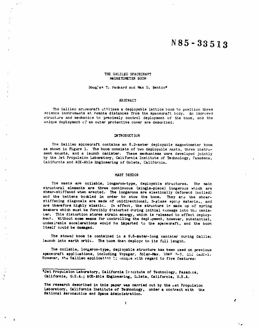
The Galileo sr-_cecraft utllizes a deployable lattice boom to position threescience instruments at remote distances from the spacecraft body. An improved
structdre and mechani'cm to precisely control deployment of the boom, and theunique deployment cf an outer protective cover are described.
INTRODUCTION
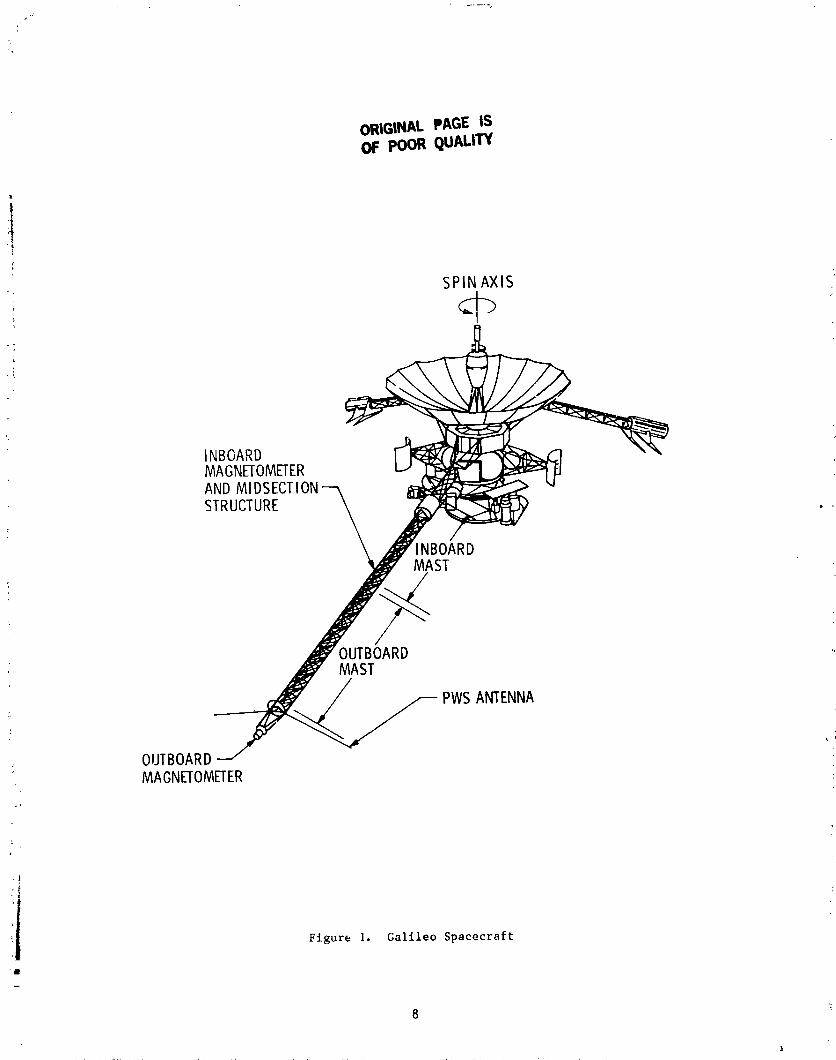
The Galileo spacecraft contains an 8.2-meter deployable magnetometer boom
as shown in Figure i. The boom consists of two deployable ,masts, three instru-ment mounts, and a launch canister. These mechanisms were developed Jointly
by the Jet Propulsion Laboratory, California Institute of Technology, Pasadena,
California and ACE-Able Engineering of Goleta, California.
MAST DESIGN
The masts are coilable, longaron-type, deployable structures. The main
structural elements are three continuous (single-piece) longeroas which areshear-stlffened when erected. The longerons are elastically deformed (coiled)
and the battens buckled in order to stow the boom. They ano the shear-
stiffening diagonals are made of unidirectional, S-glass epo:.y materia,, and
are therefore hilly elastic. In effect, the structure i.* made up of springmembers which must be forcibly dtstorted during initial -.towage into th_ canis-
ter. This distortion stores strain energy, which is released to effect Oeploy-
merit. Without some means for controlling the deployment, however, substantial,undesL-able accelerations would he imparted to the spacecraft, and the boomitself could be damaged.
The stowed boom is contained in a 0.6-meter-long canister during Galileolaunch Into earth orbit. The boom then deploy_ to its full length.
The collable, lor_eron-type, de_lo)lble structure has been used on previousspacecraft app)ications, including Voyager, _._c!ar-Max: U,_aF'g-_, a..d Oao_-l.However, the C,altleo applicat4o_ '_= ,tntq_e ;Ith regard to five featuces:
: _Jet Propulsion Laboratory, California Iratltute of Technology, Pasadena,California, U.S.A.; A(_Able EnElneerir_, G_leta, California, U.S.A.c_
The research described in this paper was carried out by the oct Propulsion
Laboratory, California Institute of Technology, under a contract with theNational Aeronautics and Space Administration.
rI
ki
1985025199-012

o The Galileo boom consists of t'_o independent, d_ployable sections, aninboard mast and an outboard mast, as shown in Figu. e 2.
o As it deploys, the boom is attached to a highly maneuverable, spinning
spacecraft, and thus experiences loading due to vehicle spin dynamics suchas nutation, wobble, and translational acceleratigns.
o Achievement of a stable, spinning-spacecraft attitude requires predict-
able boom deployment in order to minimize the amount oe undesired accelera-
tion to the spacecraft and boom structure during deployment.
o The Jovian environment requires that the mast structure and electrical
cables be protected from electrostatic build-up and micrometeoroids. Pro-
tection is provided by the use of a stowable, pop-out cover which totally
encloses each mast and provides "first surface" micrometeoroid protection.
o The protective cover over the masts requires that the launch/stowagecanister be mounted around the masts after the masts are stowed.
DEPLOYMENT SEQUENCE CONTROL
The Galileo magnetometer boom contains a deployment-control system which
] [rovides a precisely controlled deployment rate and sequence without the useof active or commandable elements. Once re_ _a_ed from its canister, the boom
I automatically deploys in a controlled manner wzth the erecting sequence pro-ceeding as described Delow.
J The deplayment rate is controlled by a rotary, viscous damper located at
the base of the inboard mast, as indicated in Figures 2 and 4. A metallic lan-yard connects the storage reel to the deployable structure. This arrangementis similar to that of previous applications. However, the method used to
attach the end of the lanyard to the deployable structure is unique. The lan-
yard passes through the center of the mast, 2tom the base of the inboard mast
to the outer end of the outboard mast. On previous applications, the lanyard
was attached at the outboard support plate, but in this application the lanyard
is looped over a pulley at the outboard end and routed back upon itself to the
midsection structure, where it is secured. This arrangement produces a mechan-
ical advantage between the lanyard forces produced by the inboard mast on theoutboard mast.
As the inboard mast deploys, the elastic energy stored in the erectionsprings and the masts produces a force of 89 newtons (20 pounds) on the l_n-yard. That force is transmitted to the rotary damper (rate limiter) as the
lanyard pays out in a controlled manner. The 89-newton lanyard force acts
around the outboard pulley and back to the midsection structure, thereby pro-ducing a force of 178 newtons (40 pounds) across the coiled outboard mast. The
178-newton load holds the outboard mast closed even though it has an 89-newtondeployment force of its own.
2
1985025199-013

Once deployed, the inboard mast can no longer tension the lanyard. At thistime the 89-newton force of the outboard mast and outboard erection springs
tensions the lanyard to 44.5 newtons (i0 pounds). Now, the outboard mast de-ploys at a much slower rate than the inboard mast. The rate is slower because
the tension in the lanyard is now only half of what it was during inboard-mast
deployment, and twice as much lanyard must be deployed for each unit length ofmast deployed.
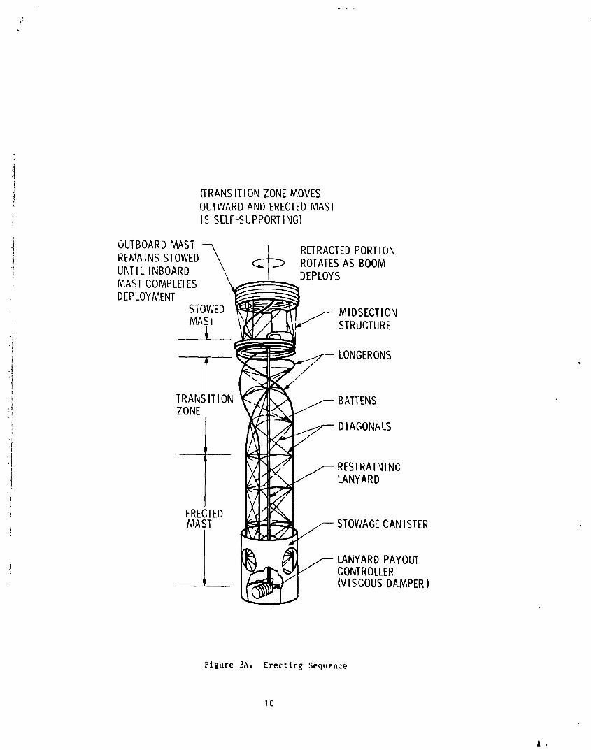
Figure 3 shows that the inboard mast first erects into a rigid structureat its base, and then continues to deploy outward. This controlled erecting
sequence minimizes the dynamzc loading produced by Coriolis and otl%er forces
during deployment.
The inboard end of each mast is caused to erect first by means of a base
erecting spring (see Figure 4) at the inboard end of each of the mast longer-
ons. The springs produce a relatively uniform torque through the first 45 ° of
longerons rotation and guarantee that the erecting sequence will begin as shown
in Figure 3.
Full deployment of the base of the mast is guaranteed _i uslng batten mem-
bers with 14% smaller diamcters in the first and second batten frames or the
inboard end of each mast. This assures that the base of the mast will lock-upinto a fully erect structure before the remaining stowes portions of that mast
begin to deploy.
Completion of the deployment of a coilab!e, longeron-type mast results in
a large transient load condition resulting from the final release of storedenergy as the longerons rapidly rotate into their fully deployed state. This
peak load is as much as 20 times greater than the 89-newton deployment force.It is necessary to provide a method for relieving the peak load in order to
prevent failure of the lanyard.
Figure 5 shows the method employed for this purpose. The body of the rate
itmiter is spring-loaded with a negator spring to the base plate of the canis-
ter. When the spring preload is exceeded by the peak deployment force, the
body of the rate l_miter rotates, allowing sufficient additional lanyard to payout, thereby reducing peak lanyard loads. By using this method, the peak lan-
yard loads are limited to approximately 200 newtons (45 pounds).
DEPLOI_4ENT RATE CONTROL
The mechanism to control the magnetometer deployment rate is a "shear-type"
rotary damper. The damping force is produced by the fluidshearlng action
across a gap between the stationary damper housing and the rotor containedwithin the housing. Figure 5 shows the construction details of that unit.
A similar damper configuration was previously used for boom deployment con-
trol on the 3-axls-stabilized Voyager spacecraft (Ref. i). However, the Voy-ager boom was smaller in cross section, and the required damping was corres-
pondingly less. Also, deployment _rom a 3-axis-stabilized platform ellmlnated
much of the need for precise control of the deployment rate.
3
1985025199-014

Three specific characteristics of the Voyager damper were unacceptable forthe Galileo application:
o The Voyager deployment for_e was 38 newtons (8.5 pounds) versus 89newtons (20 pounds) for Galileo. Therefore, more damping was required.
o The ambient temperature deployment rate for the Voyager boom variedfrom 0.26 m/s (10.2 in/s) at the start of deployment to 0.006 m/s(0.25 in/s) at completion of deployment. This large variation in thedeployment Pate was not aoc_.ptable fop Galileo applioatioP-_.
o Because of the hiah Iluid-shear rate associated with the 0.26-m/s Voy-ager deployment, a thixotropio loop (._e Figure 6) o_casionally formed inthe damping fluid and this occurrence caused less than expected damping.
DAMPERPERFORMANCE
The performance of the shear_type damper is given by the approximate (butacceptably acommte) equation
hD3
eC 1
T = Torque
h = Rotor width
• Dynamic visooslty
• Rotor speed
D • Mean diameter of the fluid gap
; O • Fluid &ap width
CI It Numerical constant depending on system of units used
This equation o.__.be simplified using the following factors:
h • 1.11 om (same as Voya&or)
• Kinenmtio visooslty • 32.11 (V/C) 0"51b's/ft 2 (measured valuefor 500,000 oSt fluid; see Ref. 2)
o • 0.128 mm (same as Voyager)
V • Velootty aoross the l'lutd Eap
VD • Deployment velocity
J
1985025199-015

R = Pulley radius
C2 = Numerical constant depending on system of units used
The damping equation then simplifies to the form:
2 R3FD
VD - C2D5
This equation identifies the sensitivities of the controlling damping param-
eters, and shows that D and R greatly affect performance.
This analysis also clearly indicates that the increased deployment force
: associated with the Galileo boom would result in excessively rapid deployment
unless the Voyager damper were redesigned to provide increased damping control.
This was accomplished by increasing the mean rotor diameter (D) from the
3.20-cm diameter for Voyager to 7.62 cm for the Galileo damper. Also, the
Voyager lanyard pulley allowed a pulley-radium decrease, as the lanyard paidout, from 3.56 cm at deployment initiation to 1.02 cm at deployment completion.
This difference of radius (R) allowed the excessive deployment rate variation
as previously discussed. For Galileo, the variation of R is minimized by usinga larger pulley and a thinner, metallic lanyard with R varying from 3.81 cm at
the start of deployment to 3.30 cm at the completion of deployment.
These damper modifications result in the performance indicated in F±gures 7: and 8. A fluid viscosity of 50,000 cSt was selected for the Galileo damper,
and this resulted in deployment characteristics as shown in Figure 9. The max-imum fluld-shear rate which occurred in the Voyager damper was 411/s. But,
for Galileo, this maximum value was reduced to 178/s, and, can be seen from
the slopes of the damping curves in Figures 7 and 8, the possibility of the
formal!on of a significant thixotropic loop is eliminated.
PROTECTIVE COVER
• The magnetometer boom cover provides: (i) a bla_, nonspecular surface to
minimize reflections from the spinning boom back to the science instruments
: located on the despun section of the spacecraft; (2) a conductive outer surface
to prevent build-up of electrostatic charges; and (3) a "first surface" againstmicrometeorolds in the Jovian environment for protection of the mast structurean_ the instrument's electrical cables.
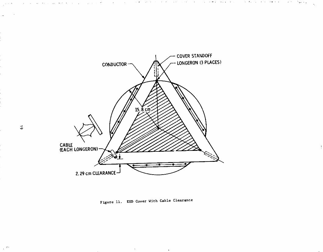
The "pop-out" covers (Figure i0) are fabricated from a graphite-coated,
Kapton _hermal-blanket material. Each cover is spaced from the coilable struc-
tures by fiberglass, lenticular-shaped springs (standoffs) (Figure II) whichare attached to the mast at each batten frame. The cover and lattice masts are
folded together by manually collapsing all standoffs (Figure 12), and thenfolding the colla_eed cover into the stowed masts (Figure 13).
5
L
1985025199-016

Figures 3B, lO, and 13 show the cover as being loosely formed and not in
the triangular shape shown in Figure ii° The extra material in the cover isto allow for differential thermal shrinkage between the boom and cover. It is
desired that the cover be untensioned when cold (approximately -223°C) to pre-
vent it from affecting the mast shape and thus changing the alignment of theins truments.
LAUNCH CANISTER AND RELEASE MECHANISM
The magnetometer outboard support plate and canister are shown in Figure
14. The canister consists of three curved, honeycomb panels joined at three
longitudinal joints along the panel edges, and attached to the magnetometer
boom base plate by a circumferential bolt pattern on the inboard end of the
canister. This structural arrangement is necessary to allow access to the
sides of the mast while it is being sto_:ed. Access is required to align theprotective cover's "pop-out" brackets and to fold in the deployable protective
cover. Once the masts are fully stowed, the canister segments are assembledaround them and secured to each other and to the base plate.
Spring-loaded latch pins are located at six places on the canister. These
pins en_age a set of three slots in the magnetometer boom cuter plate and three_dditional slots in the magnetometer boom midsection structure. Three wire-
rope cables (Figure 14) are tensioned to push the spring-loaded pins into the
appropriate slots in the magnetometer boom. A single pyrotechnic pin-puller
mounted to the side of the canister (Figure 14) releases all of the cables and
allows deployment to start.
SUMMARY
The Galileo magnetometer boom development program began in late 1978 and
, .._flight boom was delivered to the Galileo space,raft in May 1984. Magneto-meter boom formal testing included: sine and random vibration, hot and cold
deployments, magnetic cleanliness checks, and electrical bonding/groundingchecks.
The Galileo magnetometer boom design relied heavily upon the experience
gained during the earlier Voyager program. Many potential problems wereavoided and the Galileo development effort was mainly problem-free.
For the Galileo magnetometer boom, the use of a larger, less delicate,
coilable-mast structure than the one used for Voyager grea'ly reduced the hand-
ling damage which was a contir:uing problem during the Voyager program. The
only significant, unresolved Galileo magnetometer boom problem relates to thecomplexity of the boom-cover degign. Each cycle of operation (deployment/
stowage) causes some damage to the cover surface. This damage is repairable
< after each deployment; however, the cover is definitely life-limited. A totalof six deployments is considered to be a reasonable llfe limit. With the
exception of the cover design, and given the same set of design requirements,
no design change would be recommended for similar boom applications.
A
1985025199-017

REFERENCES
(i) "The Voyager Ma_etometer Boom," David C. Miller, 12th Aerospace Mechanisms: Symposium, April 27-28, 1978, Moffett Field, California.
(2) "Mariner-IV Structural Dampers," Peter T. Lyman, Ist Aerospace Mechanisms
Symposium, May 19-20, 1966, Santa Clara, California, pp. 37-50.
7• }
[ ..... A_.
"i
1985025199-018
ORiGiNAL PAGE ISOF pOOR QUALITY
i!
it
SPIN AXIS
INBOARDMAGNETOMETERANDMIDSECTIONSTRUCTURE
INBOARDMAST
OUTBOARDMAST
PWSANTENNA
OUTBOARDMAGNETOM_ER
ii Figure I. GalileoSpacecrafti
8
1
1985025199-019

r
/---BATTENFRAMESBASEERECTING; /-- _ /,--MIDSECTIONSTRUCTURE
/ SPRINuS(3) ,//_ BASEERECTING
/ /--CANISTER ///SPRING (3) PULLEY-7
,_---_ INBOARDMAST / i_,_x OUTBOARDMASTi/-- # __ ,xy _/ _/ \,'\/ \/ \v_/_ -_V _C,"XV \/N/_/_C,"xE_..fF___'--RATELIMITER LANYARD OUTBOARDSUPPORT_
THEBOOMDEPLOYMENTCONTROLSYSTEMCONSISTSOFTHREEFUNCTIONALELENIENTS:
1. THEDEPLOYMENTLANYARD.
2. THEDEPLOYMENTRATELIMITER.
3. THEBASEERECTINGSPRINGS.
Figure 2. Galileo Magnetometer Boom
9
i
1985025199-020
,.3
i (TRANSITIONZONEMOVES' OUTWARDANDERECTEDMAST• IS SELF-SUPPORTING)
OUTBOARDMAST
REMAINSSTOWED \ _ RETRACTEDPORTIONROTATESAS BOOMUNTIL INBOARD "" J-J DEPLOYSMASTCOMPLETESDEPLOYMENT m
.. STOWED _. MIDSECTIONMASI
j. / _, STRUCTUREl m
f 2-" LONGERONS 4,
]
.!' TRANSITION ,_; BATTENS:_ ZONE _
, \ _ DIAGONAI_S
RESTRAININC, _ LANYARD
'if ,_f
-i ERECTED " _
1 [ _ 0 f- ,.,.NY._,_,__,,¥o,.,,
Figure 3A. Erecting Sequence
I0
1985025199-021

pr
ORIGINALPAGE ISOF POOR QUALITY
Figure 3B. Galileo Magnetometer Boom at Deployment Midpoint
ORIGINALPAGE ISOF POOR QUALITY
i
i Figure 4. Hagnetometer Boom Base Plate
, 12
A
1985025199-023

ORIGINAL P/_C,FISOF POOR QUALITY
TEMPERATURE/VOLUM LANYARB/I_EELCOMPENSATION
J
Flgure 5. Hagnetometer Boom Rate L/_iter
73
1985025199-024

Figure 6. The Thlxotropic Loop
,t14
1985025199-025
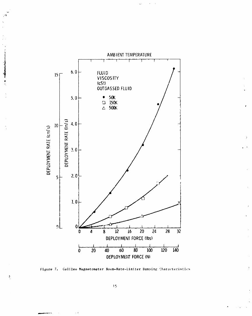
AMBlENTTEMPERATUREI I I l 1 1 1
15 - 6.0 - FLUIDVISCOSITYIcSt)OUTGASSEDFLUID
5.0- • 50K[] 150K
500K
,.°I0 4 8 12 16 20 24 28 32
DEPLOYMENTFORCE{Ibs)
L ..1 1 I I 1 1 I0 20 40 60 80 100 120 140
DEPLOYMENTFORCE(N)
Figure 7. Galileo Magnetometer Boom-Rate-.Limtter Damping qharacteristtcs
15
1985025199-026

I I I I I I+65°C
STD50,000cSt(OUTGASSED)
. A 15- +40°C
E_ CI,.MI..--< +22°C
_ 10+lO°C "
O....1
" 5 C
0 _.I._I_.L_L_0 20 40 60 80 100 120
MASTDEPLOYMENTFORCE(N)
Figure 8. Galileo Hagnetometer Boom Rate Limlter Performance at Temperature
i
16
|
1985025199-027
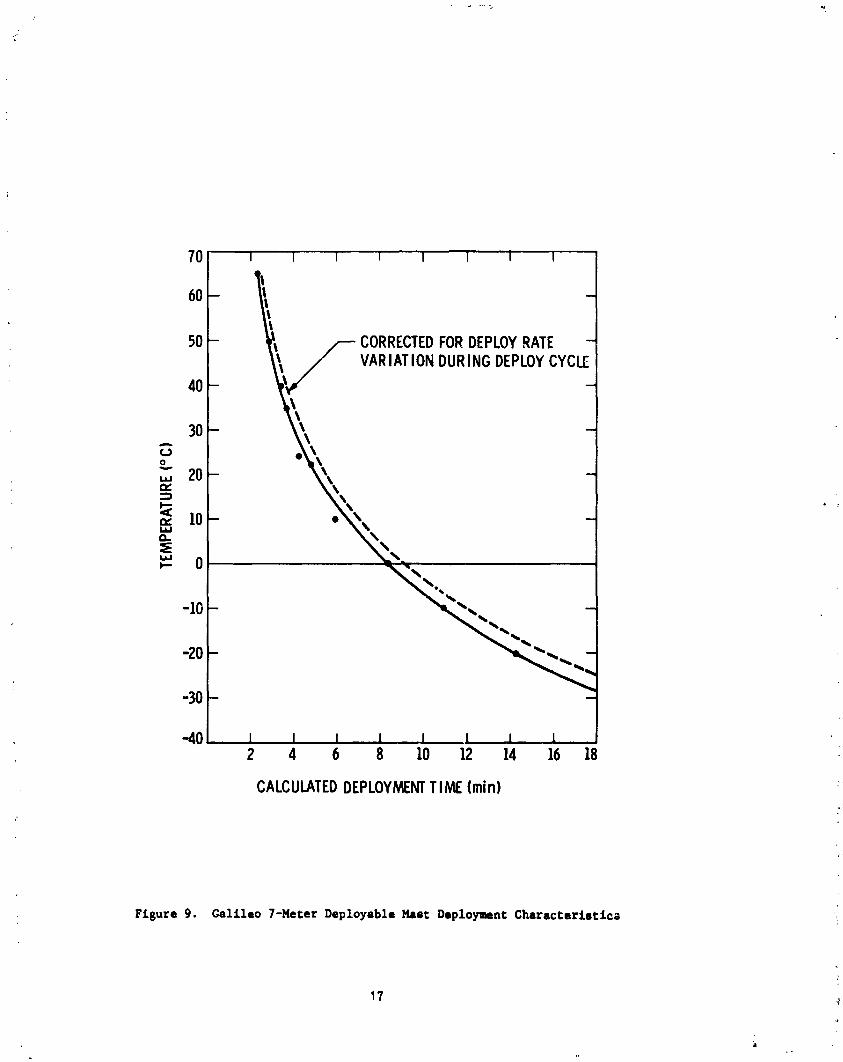
70 I I I I I I i I
50 - CORRECTEDFORDEPLOYRATE -VARIATIONDURINGDEPLOYCYCLE
40-
-40 I I I I I I I I2 4 6 8 I0 12 14 16 18
CALCULATEDDEPLOYMENTTIME{min)
Figure 9. Galileo 7-bleter Deploysble Mast Deployment Characteristic_ -,
17 ,_
,.
1985025199-028

ORIGINAL PAGE ISOF POOR QUALITY
Figure I0. Galileo Magnetometer Boom (Fully Deployed) i
18
i
1985025199-029
I
19
1985025199-030

i
; ORiGiNAL PAGE iSOF pOOR QUALITY
Figure 12. Magnetometer Boom Cover Stowing Procedure
2O
?
i "
1985025199-031

ORIGINAl..PAGE ISOF POOR QUALITY

ORIGINAL PAGE 1'.3OF POOR QUALITY
Figure ]4. Stowed Magnetometer Boom
22
1985025199-033

N85-33514
HCOP/COLUMN ANTENNA DEPLOYMENT MECHANISM OVERVIEW
B. B. Allen* and D. H. Butler**
ABSTRACT
The hoop/column antenna program is directed toward the development of a
cost-effective, large-area, self-deploying reflector antenna system.
Large-surface-area antenna systems (50-300 meters in diameter) are required in
future space missions involving improved land communications, Earth resourcesobservation, and the study of intergalactic energy sources• The hocp/column
antenna is a concept where a large antenna system can be packaged within the
Space Transportation System (Shuttle) payload bay, launched into Earth orbitwhere it is released either for deployment as an Earth observation or
communications antenna, or boosted into deep space as an intergalactic energyprobe. Currently, seif-deployable antenna concepts are competing with
astronaut-erectable concepts as the most efficient means of deploying
large-surface-area antenna systems in space•
This paper describes various mechanisms and support structures that are
required to deploy the hoop, which is used to support the antenna reflectivesurface, and the column that is used to positron the antenna feeds and the
reflector. It also describes a proof-of-concept model (15 meters in diameter)
that is currently being ground-tested to determine the adequacy of theceployment mechanisms.
INTRODUCTION
Intergalactic energy probes, land mobile communications, Earth resources
observation--these are mission scenarios projected by NASA and the scientific
community of the year 2000 and beyond. Large-scale, self-deployable space
antennas of diameters ranging from 50 to 300 meters will play an important
role in these missions. Large reflectors will one day allow national landmobile communications with transmitter/receiver power levels comparable to
today's citizens band radios• Large-aperture radiometers can be used for
monitoring global hydrology on a weekly basis to aid agricultural and climateresearchers.
The self-deployable hoop/column antenna concept h_s been under study for
several years. The study program is at the proof-of-concept stage where
scale-model hardware of the deployment mechanisms and support structure havebeen built and tested. This paper describes the deployment mechanisms and
support structure necessary to launch and deploy an entire large-surface-antenna system with one Shuttle flight. It also describes the scale-model
hardware that is currently being ground-tested to determine the deployment
characteristics of the hoop/_olumn concept.
mHarrls Corporation, Melbourne, Florida
*mNASA Langley Research Center, Hampton, Virginia
23
A
i
1985025199-034
HOOP/COLUMN DESIGN FEATURES
The elements of the antenna are labeled in Fig. 1-3. Primary structural
elements of the hoop/column antenna concept are an extendable column, which
deploys from a central hub, and a hoop mad_ of articulating segments that isused as a frame for attaching the peripnery of the reflector surface. The
column consists of telescoping segments made of a triangular truss network of
structural elements. Hoop position is controlled by a series of cables,_ emanating from both the lower and upper column extremitles and attached to
each hoop joint. These cables serve to support and locate the hoop. Thereflector surface, which is attached to both the hoop and lower hub section,
is shaped by a serie_ of catenary cord elements which support and contour thereflective mesh surface. The cord elements are high stiffness/low coefficient
of thermal expansion quartz and graphite material which provide a very stable
structure to which a gold-plated molybedenum reflective mesh is attached.
The remainder of the paper addresses major festures of the 15-meter-
diameter scale model of the hoop/column antenna. These features are the same
as those of a iO0-meter-diameter flight mode. The 15-meter-diameter size forthe scale model was chosen so that the model could be tested in existing RF
and thermal-vacuum ground test facilities and to minimize the effects of
scaling on the deployment characteristics of the antenna.
ANTENNA DEPLOYMENT
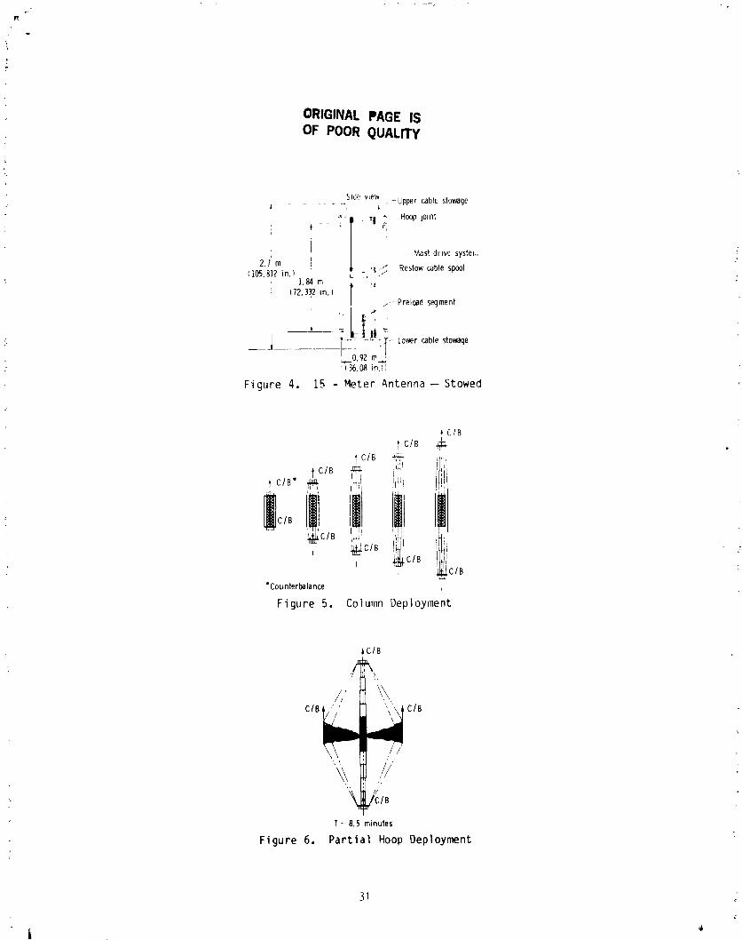
Prior to deployment, the scale model antenna is stowed in a package 2.7 m
long and 0.9 m in diameter as shown on Fig. 4. Approximately 30 minutes is
required for deployment, with the time being divided between visual inspection
and mechanism operation. Deployment is accomplished in three basic steps:
column extension, hoop/surface deployment, and system preloading, which shapes
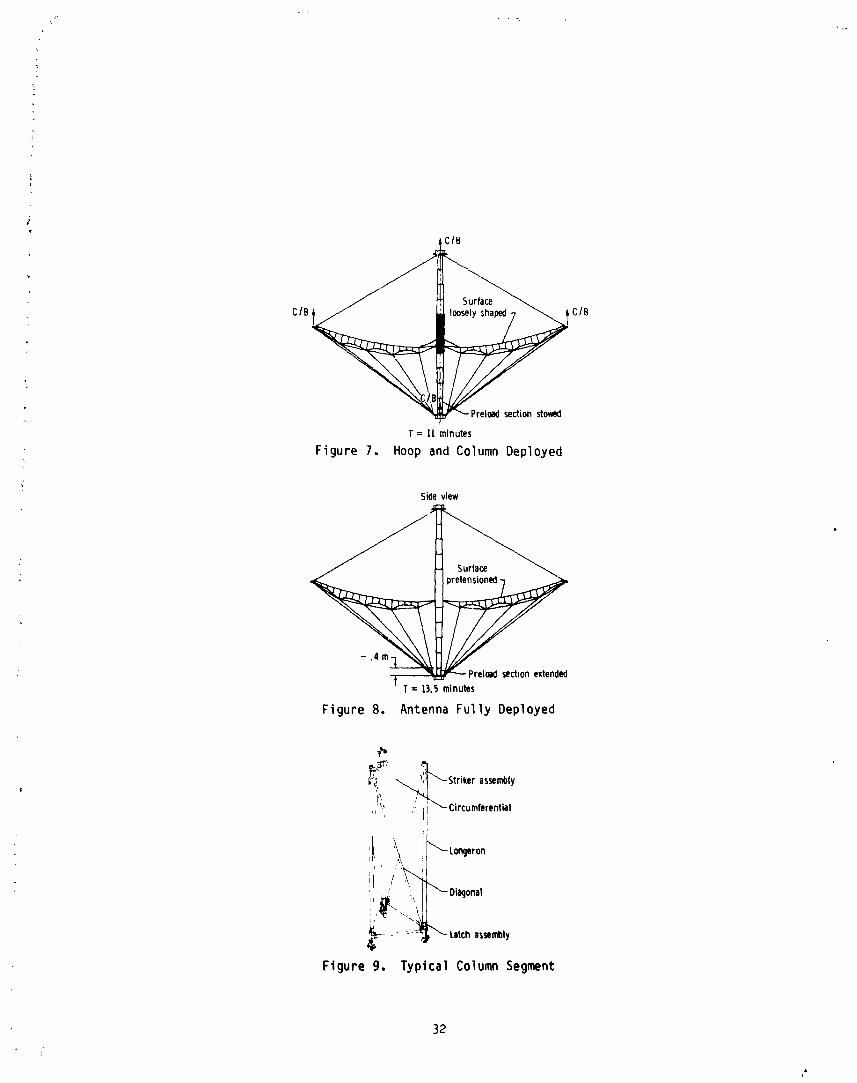
the surface. Deployment begins with column extension (Fig. 5). The
telescoping column is deployed by a cable-driven system that tension_ the
column during the final phase of deployment. This tensioning process is to
allow the column cam lock latches to properly actuate. A feature of the
column is the ability to deploy the telescoping sections sequentially, with
:i the sequence being passively controlled by the latches themselves.
The next step is to deploy the hoop and surface (Figs. 6 and 7). The hoopconsist3 of 24 tubular segments that contain double hinge Joints at each end
which permit rotation but do not allow torsional wrap-up. During deployment,th_ hoop segments simply rotate from vertical to horizontal orientation about
an axis through the center of each member. Eight electrical motors, located
i at eight different hinge Joints, drive wor.,,gears that transmit torque through
four bar mechanisms to passive Joints. The surface is deployed with the hoop,
but not shaped Shaping of the surface is accomplished by the extension of
the lower extremity of the column called the preload segment. Preloadingconsists of extending the column an additional 0.4 meter by means of a screw
to properly pretension the structure and the surface (Fig. 8).
24
A
1985025199-035
?
ORIGINAL pAOE 15OF poOR QUALITY
COLUMN DEPLOYMENT
The column is a sequentially deployed, cable-driven, telescoping,
triangular truss unit with diagonals that resist compressive loads. The
column, which is symmetrical about the center hub, extends in both directionsfrom the hub. LonEerons, circumferentials, at_d diagonals are all tubular
members laminated from graphite epoxy material. A typical column segment is
shown in Fig. 9. Diagonal direction is reversed from bay to bay to minimize
column "wind-up" or a rotation relative to the hoop.
COLUMN DRIVE SYSTP_ (CDS)
The following is a list of the major CD_ requirements:
o Must be located at t,,e stowed column center
o Must deploy and stow each column end simultaneously at a uniform rate
o Must be remotely controlled
o bust place column in tension during final phase of column deployment.
The column drive system (Figs. i0-i3), located at the geometrical center
of the column, is responsible for providing the forces necessary to deploy and
stow the counterbalanced column system during testln_. A tensile load is
applied to the column by the CDS at the final stage of deployment to allow
proper latching of the telescoping column sections. This tension is relieved
upon completion of column deployment The CDS does not pretension the
antenna. The structural design foe the CDS consists of two large triangular
plates separated by bea_-_olumn spacer brackets located directly in llne withthe column longeron-..
Deployment of the column is accon'plished by retrieving the deployment
cables onto a drum (Fig. ll). There are six deployment cable which arethreaded through each of the three longerons on each column half. The drum is
threaded to ensure that the cables remain _n a selected area. Lonseron cablesa,e routed from the drum to a sinsle pulley on the spacer brackets which in
turn directs the cable through the lonEerons. When the cable reaches the top
of the longeron, a pulley in _he striker housing turns the cable 180 ° and it
proceeds (between the longerons) to the bottom of the second lonEeron. Then
it is intercepted by another pulley located in the latch housing of theadjacent telescoping section and turns 180 ° to proceed up the inside of this
lonseron to the second striker housing. This path is repeated until the cablehas been threaded thoush all four lonserons.
Tne stow cables are attached to the latch actuation arms on the end
telescopin8 section through a bridle unit. This cable is routed down along
the column centerline and throush the drum to a pulley attached to theopposite triansular plate. This pulley directs the cable to the beam spacer
bracket containir_ dual pulleys, each turning the cable 90o. This brinss thecables to the threaded drum and cam portion of the mechanism. Both stow
cables have a small residual tehsile load applied durin8 the deployment andstow phases. Hi-lift cams (Fig. 12) relieve the residual tension loads in the
stow cables, thereby allowing them to go slack. This feature is necessary for
25J
•-j , j
1985025199-036

i
proper latching of the end see_ior_ because the stow cables are attached to
the latch pawl (of the s,=o _esocD::_g sections) and latching can't occur
while the cables are iN ;_nslon. The cable drum is suspended between ball
bearings attached to the triangular base plates (Fig. 13). Drum rotation is
accomplished by a 28-VDC gear motor" connecte_ to a pinion and gear system.
Drum back-driving is resisted by the gear motor. The motor and pinion
assembly is mounted on the upper triangular plate.
The materials used for construction are primarily 6061-T6 aluminum, with
300 and 400 series stalnless steel components and cables.
I COLUMN LATCH
i
! Primary latin requirements are
o latch the column sections into a rigid, predictable structure
o Withstand a preloa_ o, 4000 N
o Latch and unlatch the column sections remotely
o Passively provide sequential deployment and stow
o Provide adjustment capability.
The latch design provides positive latching, passively actuated sequentialdeployment, reasonably direct load path from longeron to longeron, and a high
tolerance for error through adjustment capability. A depiction of the latch
delineating the major components is shown in Fig. 14.
The latch is comprised of two assemblies located on the ends of the column
longerons. The assembly loaded on the top of the longeron o£ each telescopingassembly is called the striker housing and contains the oawl striker plate.
Active latching elements are contained in a latch housing located on the
bottom of the telescoping column sections. The latch provides a continuous
1 load path along the lo_erons without introducing excessive bending momentsinto the lon_erons. Both la'ch housings contain rollers that guide the
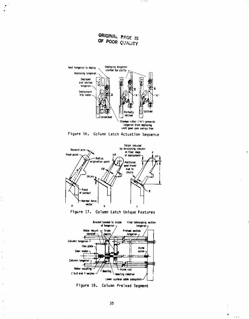
deploying sections along the longerons of the previously latched telescopingsection. When the column is in the stowed configuration, the latches are all
positioned as shown in Fig. 15. When deployment is iDitiated, the motor,pinion, and gear arrangement rotates the CDS cable drum such that the
deployment cable threaded throu_ the longerons are collected on the drum.
This in turn translates the ±nboard column segments upward (Fig. 16), thereby
allowing the latching actuation gear to come into contact with the deploymenttrip roller. All telescoping sections deploy as a unit because the pawl cam
does not allow the stowage rollers to advance. The pewl and lever
arrangements are overcenter devices and are held in place by the spring/
plunger assembly. Deployment continues unchanged until the latch actuation
lever contacts the trip roller attached to the str'ker upward (FIF. 16),
thereby allowing the latching actuation gear to come into contact with the
deployment housing. The lever tip cannot traverse past the rollers, so the
bottom of the pawl begins to move h_ward the striker housing. Binding is
prevented because the spring/plunger assembly allows for length adjustments.
Adjacent section release begins when the pawl cam eotates away from the
stowage roller. It can be seen that the pawl has total control over the
deployment sequence and, also, that no additional mechanisms are required tomaintain that control.
26
A
1985025199-037
] A unique feature of the pawl is the cam profile (Fig. iTa) on the surfacethat contacts the striker plate. This feature allows the pawl to seat itself
against the striker plate so that the normal force vector at the point of
contact results in an opening moment, preventing binding. The cam profile
also compensates for possible errors in the striker plate location (Fig.17b). This design incorporates s_'ims under the striker pIate so that the
deployed pawl angle can be adJuste prior to final column assembly. The cam
feature allows the pawl to be prestressed to reduce the Joint nonllnear
motion. Prestressing is accomplished by applying a large tensile force to the
deployment cabIes located inside each longeron (Fig. l?c). The cable tension
strains the latch housing and the pawl pivot to increase the distance between
the Iatch/striker housing interface and the pawl pivot. Fawl rotation will
continue because the spring/plunger assembly pushes it clockwise. When thecable tension is relieved, friction prevents pawl release (counterclockwiserotation).
Latch housings are plaster mold A355 aluminum castings and the latchlr_component_ are i7-4 PH stainless steel.
The coiumn latch has demonstrated conformance to the requirements throughcomponent and system-level testing.
PRELOAD SE(_ENT
Peeload segment design requirements are
o Extend against a load of 3560 N
o Deploy against rigid stops
o Be remotely controlled
o Have a redur]Jnt stop mechanl_m
The preload segment (Figs. 18 and 19) attaches to the lower end of thecolumn (Fig. 8). The purpose of the preload segment is to extend the column
to its design length in order to pretension the hoop and surface controlcords. The preload segment travels approximately 0.4 m from its stowed to
deployed state.
An axial, motor-driven screw was selected to drive the preload segmentfrom the stowed to tha deployed position. Screw loads are carried to the
longer,on through a triple beam arrangement. The beam brackets are bonded to
the inside of the longerons as shown in Fig. 18. This bracket design is notthe _ost desirable, but the outer portions of the longerons were reserved for
rollers and guides located on other deployable sections (Fig. 14). Power to
drive the screw is provided by a 28-VDC gear motor. Motor torque istransferred to the column nodes through a thin flex plate. The plate is
essentially rigid in torsion, but can allow axial dlsp]acement to account formanufacturing errors. The screw is 16-mm steel with acme threads. Ball
screws were considered and rejected because the coefficient of friction is not
adequate to prevent back driving under load without a brake. Preloa_ segmentextenslot, is terminated by limited switches ana redundant current sensor_.
The preload segment is manufactured from the same structural material_ asthe column.
27
i L
1985025199-038
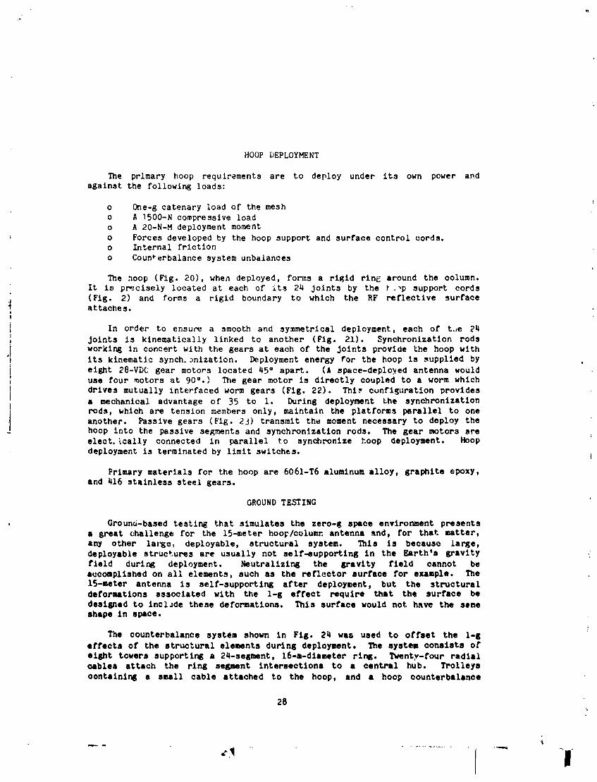
HOOP DEPLOYMENT
The primary hoop requirements are to deploy under its own power and
against the followlng loads:
o One-g catenary load of the mesh
o A ]500-N compressive loado A 20-N-M deployment moment
, o Forces developed by the hoop support and surface control cords.o Internal friction
o Counterbalance system unbalances
The hoop (Fig. 20), when deployed, forms a rigid rinc around the column.
It is precisely located at each of its 24 Joints by the _ ._p support cords(Fig. 2) and forms a rigid boundary to which the RF reflective surfaceattaches.I
!
i In order to ensure a smooth and symmetrical deployment, each of t_Je 24
i joints is kinematically linked to another (Fig. 21). Synchronization rodsI working in concert with the gears at each of the Joints provide the hoop with
:i its kinematic synch._nization. Deployment energy for the hoop is supplied by o
L eight 28-VDC gear motors located 45 ° apart. (A space-deployed antenna wouldt
i use four motors at 90°.) The gear motor is directly coupled to a worm whichI drives mutually interfaced worm gears (Fig. 22). Thi_ cunfi_uration provides
a mechanical advantage of 35 to i. During deployment the synchronizationirods, which are tension members only, maintain the platforms parallel to one
another. Passive (Fig. 23) transmit the moment necessary to deploy thegears
hoop into the passive segments and synchronization rods. The gear motors are
elect. _cally connected in parallel to synchronize hoop deployment. Hoop
deployment is terminated by limit switches.
Primary materials for the hoop are 6061-T6 aluminum alloy, graphite epoxy,
and 416 stainless steel gears.
GROUND TESTING
Orouno-based testing that simulates the zero-g space environment presentsa great challenge for the 15-meter hoo_/column antenna and, for that matter,
any other largc_ deployable, structural system. This is because larse,
deployable structures are usually not self-eupportlng in the garth's gravity
field during deployment. Neutrallzing the gravity field cannot beaccomplished on all elements, such as the reflector surface for example. The
15-meter antenna is self-supporting after deployment, but the structural
deformations associated with the l-g effect require that the surface bedeslgnad to InclJde these deformations. This surface would not _ave the sBme
shape in space.
The counterbalance system shown in Fig. 24 was used to offset the l-g
effects of the structural elements during deployment. The system consists or
elECt towers supporting a 24-segment, 16-m-dlameter ring. Twenty-four radialcables attach the ring segment interaectlona to a central hub. Trolleys
contalnln_ a small cable attached to the hoop, and a hoop counterbalance
28
1985025199-039

weight, traverse the radial cables during deployment. The counterbalancesystem central hub is raised or lowered to attempt to cancel the drag induced
by friction in the hoop joint worm gears and counterbalance system cable sag.The dra_ increased near full deployment, requiring full capacity off our four28-VDC electrical motors. Radial cable tracks were used because of
installation/removal requirements for the counterbalance system in variousfacilities.
The mechanisms utilizing electric gear motors were controlled by a remoteconsole during ground testing. The console contained current sensors that
terminated deployment approximately one second after a system current levelexceeded predetermined values. This remote console would be replaced with a
on-board computer system for a flight antenna.
Test observations were conducted during and after deployment. Gear motor
current levels and hoop synchronization sensors were monitored duringdeployment. After pretensionlng, structural element positions and loads were
measured and correlated with required values. The antenna mechanisms performedas designed, but the couterbalance system drag on the hoop require' the
addition of four active joints (for a total of eight) so that hoop deploymentcan be implemented when the surface is installed. There was a 3 second delay
between deployment termination of the first hoop active joint and the finalactive joint. This time delay did not appear to affect the hoop geometry.
The geometry of the structural system was within the error budget exceptfor the hoop radial component. The allowable radial deviatlonwas 1.27 mm rms
7
as compared to the measured value of 4 mm rms. Adjustments will be
implemented to attempt to obtain the error budget when the surface isinstalled.
TF_T CONCLUSIONS
All mechanisms performed as designed. The hoop drive system needs to be
reevaluated with respect to the friction associated with worm gears in the 4
hoop Joints. Ground-test results indicate structural elements of a 15-meter
hoop/column antenna can be fabricated and adjusted so that when the reflector
is installed a 1.75 mm rms deviation from a true parabola, when referenced tosurface nodes, can be _xpected. Precision measurements of all structural
components are needed before assembly to assure compliance with error budgets.
The structural deployment program is considered to have been successful.
This leads to the conclusion that large, deployable antennas can be
fabricated, ground-tested, and placed in orbit with the expectation of success.
If future programs require a hlgh-quality zero-gravity simulation, designand development of such a facility would be comparable to the antenna orstructural system itself.
29
| f
1985025199-040

7- 3-axispositioner
U_?eL /f-- , _feeds_ruc_ure/ I ,\ !interface-/ 3.3m
21_,
Antenna-mes_iT____;_-interfaceJ/ - ' g3m
I ._ 0.53m _ = 14mI I-- _-
Figure 1. 15-Meter Hoop/Column Ar.tenna
_...- UppercablestageColumn,atc,-__
/_ _ ./-Quartz hoop"_ _ supportcords
_\ \ \11 /// / ///'_-Graphitehoop_'_ 71 i__ supportcords
__J]\ /IYl_ _"- GraphitesurfaceLowerc_o|esto.ge-_ J_F shapingcord_
Supportpedestal-----Jl_ _ ....•_ .u. ..u.--_Preloadsegment
Figure2. 15-MeterAntennaStructure
_s_rn%'__m",n'_--_'_'__-_----/_-_--- 15"meter
_ diameter
Figure3. 15-MeterAntenna- Top View
30
1985025199-041
ORIGINAL PAGE ISOF POOR QUALITY
Sidewew .-Upper cablestowage[ ........ , b.
i _ I ' 'I _ Hoop]omtiI -- Mastdrive syster,,
2.1'm i . ,/,._ Restowcablespool}05.8]2 in.)1.84m ;t
i (72.332m.)' ] _,- Preloadsegment
___I :i 92m'-_'Lo_r cablestowage
_ 36.0_ )n ,'
Figure 4. 15 - Meter Antenna-- Stowed
I CIBf C/B ._
fC/B _ if't ClB _ '_;:!
fi
,' , , ,_cIB ....
l!ii!llii, _Ja_clB
_LC IB"Counterbalance I
Figure 5, Column Deployment
,_/B/' \
C/B ClB
T_ 8.5 minutes
Figure 6. Partial Hoop Deployment
31
1985025199-042
C/Bl CIB
f = II minutes
Figure 7, Hoop and Column Deployed
Side view
-.4m
3--T = 13.5 minutes
Figure 8. Antenna Fully Deployed
_,_. Striker assembly
' ,='I_, / _i "-Circumferential
' , _- Longeron
I , \ '
Figure 9, Typical Column Segment
_2
4
1985025199-043

ORIGINAL PAGE IS
OF POOR QUALITY
Double
- i- 2 Iongeron pulleybracket_1 _- Triangular
2--._,
/_,__.:_ plate-
20 cm
l- _ PulleYt_"1 - Longeroncable Beam-column2 - Stowcable spacer
Figure 10. ColumnDrive System
Fully stowed Mast fully deployed
Pulleys_
Cabledrum7 Lor_erons-_ /, Pulleys7 / f Longerons .
/ / / /- Excesscable
L°ncjer°nA" /
_when stowed cable'J/_ _I_-1 _ _/- LorKjeron
Stowc_le -J LStow bridle w_e_l_eplcab_l_JLA
st=,_,.-_/_/,StowbridieJ
Figure 11, Column Drive System Principle
Cabledrum _=___.-_._.. _.- Externalspurgear
,/_ Hi-lift cam
_ Plnion gear
Figure 12. CDS Hi-LiftCam
)3
6 f, .
1985025199-044

ORIGINAL PAGE IS
OF POOR QUALITY
28 VDC I--1/_ I Bearing/ /-Triangular plateI assemblyT" H /
P'n'_°;-I r
Hi-lift cam_r_lley cablepulley
Figure 13. CDSCross Section
SA_tiA°_- Columncircumferential
Section '_ee_ Sprlnglplunger
"_. F"ASection
-- F-F
Striker Section': C'C
;ukle rollersSection
B-B
Figure 14. Column Latch Assembly
,_,,,_ I._1___'_'_',__'-
4
striker housing_ ._
Stomgoroller _ _ Pewl cam• Circumferentialbracket-.,, ""
TrlPlon_ronrOller_/-,,I __ roller
Latchingactuationlevers-._
Hub motion
HUO _ UltCh II¢)USlllgShim gllhtllCMto hm striker housing
Ftgure 15. Stowed ColumnLatches
3_
1985025199-045
ORIGINAL PA.GE ISOF POOR QU_,LiTY
DeployingIongeron
NextIongeronto deploy_ omittedfor clarity_DeployingIongeron-_ \ /
and latched IIongeron-_ -_ (
Deployment _ I "A.... A"trip roller-_ __\
_. _ \ IPIIIPar ly _] Latched
_-Stovage rotter I"A") preventsIongeronfromdeploying
until pawicam swingsfree
Figure 16. ColumnLatch Actuation Sequence
Strain inducedbytensioningcolumnMomentarm_ •
Pivotpoint--_7//'_" d8 at final stage pOfdeploymentL ,._A L-_Additional "
I ¢I origination point ,/_ ) T
b ,,.a t"'
R
1'- Normalforce /a vector b ¢
Figure 17. ColumnLatch Unique Features
Bracketbondedto inside Final telescoping_ection
of longeron7 lor_rm-,MotOrmount pie/ Pretold soctlon /
_ndaff-_ _ ,ms/ longeron-____ I
Flexplm _ == i
:2_= coup,r_-/ /z
L'nul |rd t'msher -J rln9 _--BMrln9 retainer
L_r surflce cableSubsystettJ .__J
Figure 18. Column Preload Segment
35
1985025199-046

°""_/d/_';'<'a n':_I_//_L'-.II_L '='''oo-
._ _- _ Teflon
Figure 19. Preload Segment.- Top View
•15m
Figure 20, Hoop Dep]oyn_ntSequence
,i
Hingeplatform
._v_ pelnt
Ftgure 21. HoopSynchronization Approach
36
1985025199-047

', r
ORIGI_,_AI. ?AGE iSOF POOR C_UALIT¥
/- Hinge platform/ supportcone
,- Drive motorSynchrorod - "
clevis _-Synchro rod _' F Coneattachmentshaft
Synchro-_ _ _ /_ /Synchro rod
rnd__r_ _m_lJ_,---="r-I ___ -- / clevis, r SYrn:::o
__tm( l'___raph.e]
____=_ __ _-_,,_armHingeplatform-/ _m k-Worm gear and shims
Figure 22, Active Hoop Hinge
Synchrorod clevis--x .Hingeplatform/-Bevelgearand shim\ ,_
.... ; I
.• "_-Gear adjustment
Gear shim-/ --. _ bracket;_ _el-'\-Gear adjustment
washer hardlre
1,Figure23. PassiveHoopHinge
16.1m diameter----------.- /r HOOpsuNort _rolley
• _Pulley---N,,/--Hub ,/-Cable / /-Pulley
(8)-x _ -Stov_l
16.! m r Cable rl / . shape terv_lghts
__ . (24)
, ----nn nn-,,,_
_ _ \,n,,nn,_o,umn, , _ =::= _: .- -- countortight s
........ (2)
__- P_s_I legs (3)
Figure 24. AntennaCounterba]anceSystem
37
1985025199-048

N85-33515
DEVELOPMENT OF AN ENERGY-ABSORBINGPASSENGER SEAT FOR A TRANSPORT AIRCRAFT
Charles P. Eichelberger and Emilio Alfaro-Bou*Edwin L. Fasanella**
INTRODUCTION
Commercial air transport passenger safety and survivability, ir_ the eventof an impact-survivable crash, are subjects receiving increased technical
focus/study by the aviation community. One such study was recently initiatedby a Joint understanding of the Federal Aviation Administration (FAA) and the
National Aeronautics and Space Administration (NASA). A B-720 aircraft,
highly instrumented, and remotely controlled from the ground by a pilot in a
simulated cockpit, was crashed on a specially prepared gravel-covered impact
site. The aircraft was impacted under controlled conditions in an
air-to-ground gear-up mode, at a nominal speed of 150 knots and 4-i/2 ° glide
slope. The flight test was performed at the NASA Ames Dryden Flight ResearchFacility at Edwards Air Force Base, California.
Data from a number of on-board, crash-worthiness experiments provided
valuable information related to structural loads/failure modes, artimistingkerosene fuel, passenger and attendant restraint systems and energy-absorbing
seats. This paper describes the development of an energy-absorbing (EA) seat
accomplished through innovative modification of a typical modern-standard,
commercial aviation transport, three-passenger seat. Values are given in both
S.I. and U.S. Customary units. The EA seat development effort was carried out
at the NASA Langley Research Center and tested on the B-720 aircraft used forthe FAA/NASA Controlled Impact Demonstration Test.
SEAT SELECTION
The commercial transport passenger seat selected by NASA Langley for
modification to an energy-absorbing collapsible seat was a triple passenger
seat manufactured by the Fairchild Burns Company, Winston Salem, NorthCarolina.
The seat (trade name Airest 2000 m) was deemed typical of the designs now
employed by commercial airlines on modern air transports. The seat's basic
structure consists of a rectangular shaped frame fashioned from nominal
*NASA Langley Research Center, Hampton, VA
a*Kentron international, _mpton, VA
*Identification of commercial pr.ducts and companies in this paper is used to
describe adequately the EA seat development. The identification of these
commercial products does not constitute endorsement, expressed or implied,of such products by the National Aeronautics and Space Admlnstration or the
publishers of this paper.
39 PRECEDING PAGE BLANK NOT F_MEDL
L i
1985025199-049

4.45-cm (1 _/4-in.) outside diameter aluminum tubes. Four forged aluminum
legs, bolted to the frame and stabilized by two aluminum diagonal- and
_a:e-r_ _ r_t_,ch r:e<:_-s, _upport the seat and its occurants. Plastics plusllght_e:gnt c_a ions and covers complete the outer appearance. Weighing about
25 kg '_,c_lb,,the seat possesses exce]lent strength-versus-weight qualities.
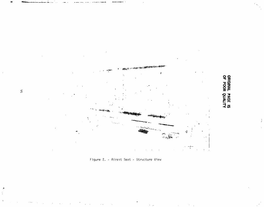
Figure i l!iJ*_t:_,e_-,_ Fronta] view of the Airest 2000, while Fig. 2 displaysthe structu,__ :e',tu_es.
DESIGN GOAL
_he deszgn goal in the development of an energy-absorblng passenger seatfor a transport alrcraft was to protect the passengers, simulated by three
75-kg (165 ib) anthropomorphic dummies, against both a vertical and
longitudlnel velocity change of 6.40 m/sec. (21 ft/sec). Each of the threedummies represents a 50th percentile passenger, defined in reference i.
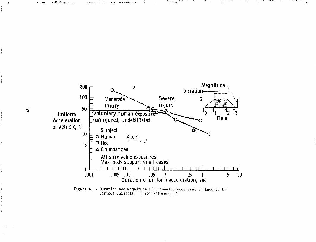
Figures 3 and 4 present graphic data pertaining to human tolerance
acceleration limits for vertical and horizontal motion (reference 2).
SEAT MODIFICATION DESIGN
Several innovative design changes were featured in converting the standard
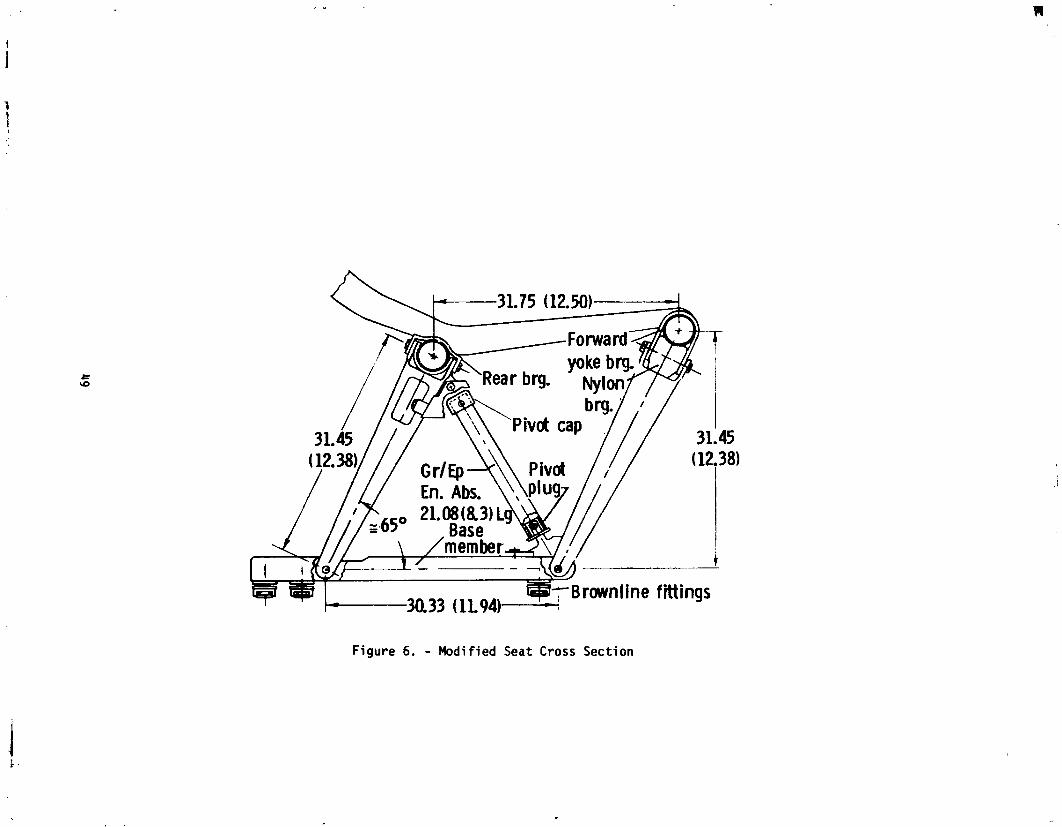
triple passenger seat (Fig. 5) to an EA unit. To limit acceleration the seat
was rectified (Fig. 6) so that it would rotate forward under high load. Toallow seat rotatlon, split-sleeve-type bearings were affixed to the upper ends
or the rear legs and a combination nylon bearing, block-steel yoke unit was
installed on the upper ends of the forward legs. All bearings sufficiently
! encircled the seat Frame tubes to allow rotation and yet withstand the impactloads. Conventional aircraft bolts were employed as hingeplns to permit pivot
: rotation of both the forward and rear legs at their lower seat rail
attachment. These changes effectively converted the standard seat to afour-bar linkage system. The original flexible membrane seat pan was replaced
: with a O.079-mm (1/32-i[,.) thick aluminum sheet. Both forward and rear legs
were ir_cllned parallel to each other at an angle approximately 65° with the
ho_ Jzontal. Two graphite-epoxy, energy-absorblng tubes, installed diagonally
between the forward and rear seat legs (Fig. 6), ceplaced in the originaldiagonal members to stabilize the seat under normal flight conditions. The
tubes _rogre_sively crush as axial columns during the aircraft impact. Figure
5 di_pl_tys a Araphic cross section of the unaltered standard seat. Figure 6
depicts the same cross section of the modified seat for comparison. The
energy-absorbing, graphite/epoxy tubes, associated tube attachment hardware,
and overall seat dimensiol_s are shown. Note that the passenger seat panheight above the aircraft floor level and buuy posture angle are the same in
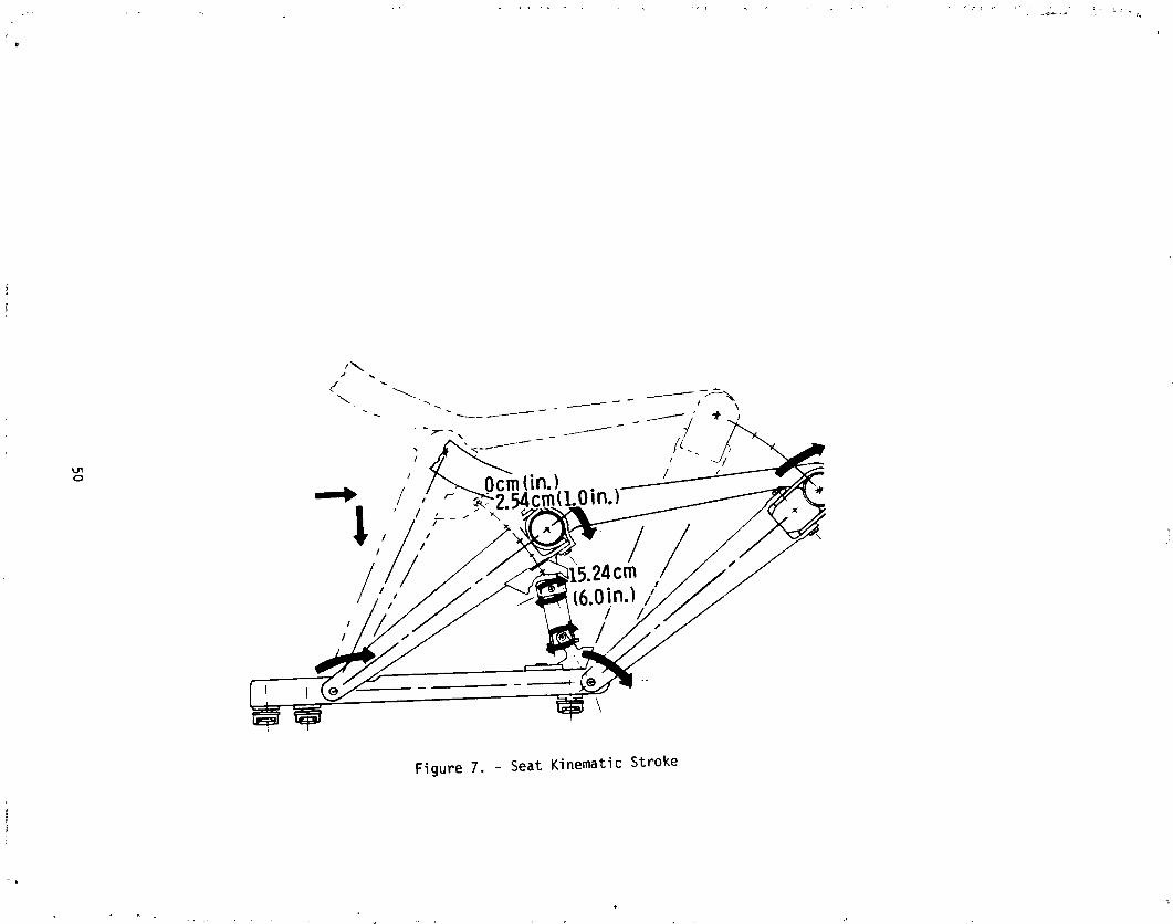
both standard and moOified designs. Figure 7 graphically traces the kinematic
stroke of the seat during the energy-absorbing process. The stroke is limitedby hardware constraints to a maximum distance of about 16.5 cm (6.5 in.).
ENERGY-ABSORBING TUBE DESIGN
Various design characteristics were considered when selecting theenergy-absorber device. The energy absorber should be lightweight, small, and
as simple as possiote to oe cost effective. It should possess long-term
4O
Rmw _w m. .......,....
1985025199-050

reliability, require minimum maintenance, and be corrosive/envlronmenta t
resistant, and unaffected by vibration. D_ost importantly, the Qevlce must
decelerate the pa._sengers while not exceeding the load limits of humantolerance.
Graphite epoxy crushab'e tubes were chosen to meet the requirements for
the energy-absorbing process. Since the energy absorption is a function of
the materials (fiber and matrix) and ply orientation, the tubes could bereadily tailored to absorb the dummies' kinetic energy. A series of
developmental tests plus the knowledge gaiped from a recent study (reference
3) resuited in the selection of i0- and 12-ply graphlte-epoxy tubes 21.08 cm
{8.30 in.) in length to balance the uneven seat weight distribution caused by
lack of symmetry between the seat legs and the occupant se_ting positions.
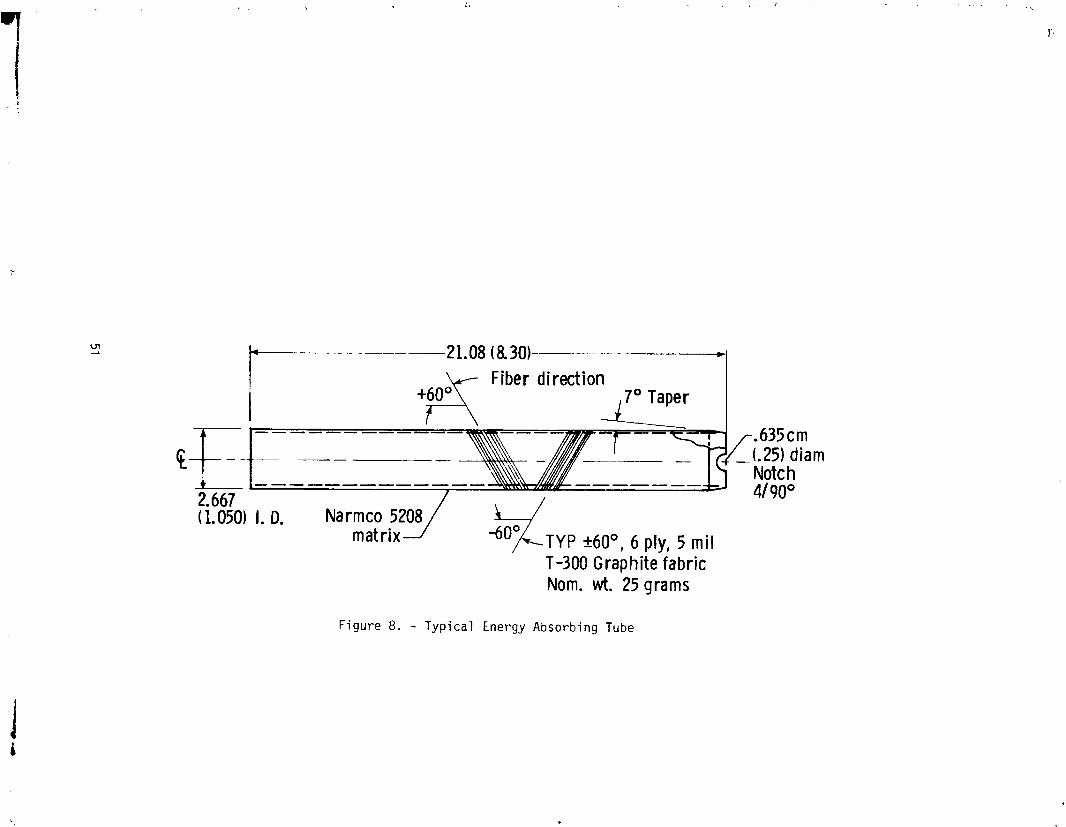
The tubes were fabricated from the prepreg materlal of Thornel 300 graphitefibers and Narmco 5208 matrix composed of an MY720 epoxide base. F_ch ply had
a nominal O.Ol40-cm (0.0055-in.) thickness and a ply orientation of +60 °.
Data from investigations (refernce _) indicated changes in energy-absorblng
values from 90° to 45° ply orientation; thus, 60 o was selected for size andstrength considerations. A taper and circJiar notches (Fig. 8) were machined
on one end of the tubes to reduce an initial high load spike without affecting
the sustained crushing load.
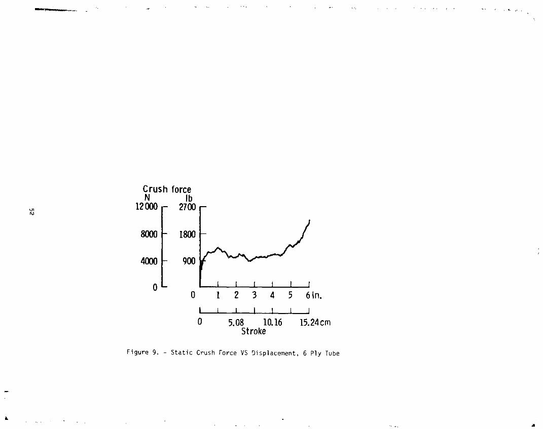
During the development phase of the composite tubes, static and dynamic_ests were conducted to determine the crush load-dlsplacement characteristics
and the deceleration-time response of the tube. The static tests wer_conducted on a 533,786-N (120,OO0-ib) capacit, compresslon-testlng machine.
E_ring the static tests, a cap was placed on the tapered end of the tube and a
plug was inserted in the flat end to simulate the effect of the cap and plug
used in th seat mechanism that holds the tube in place. The crush force-
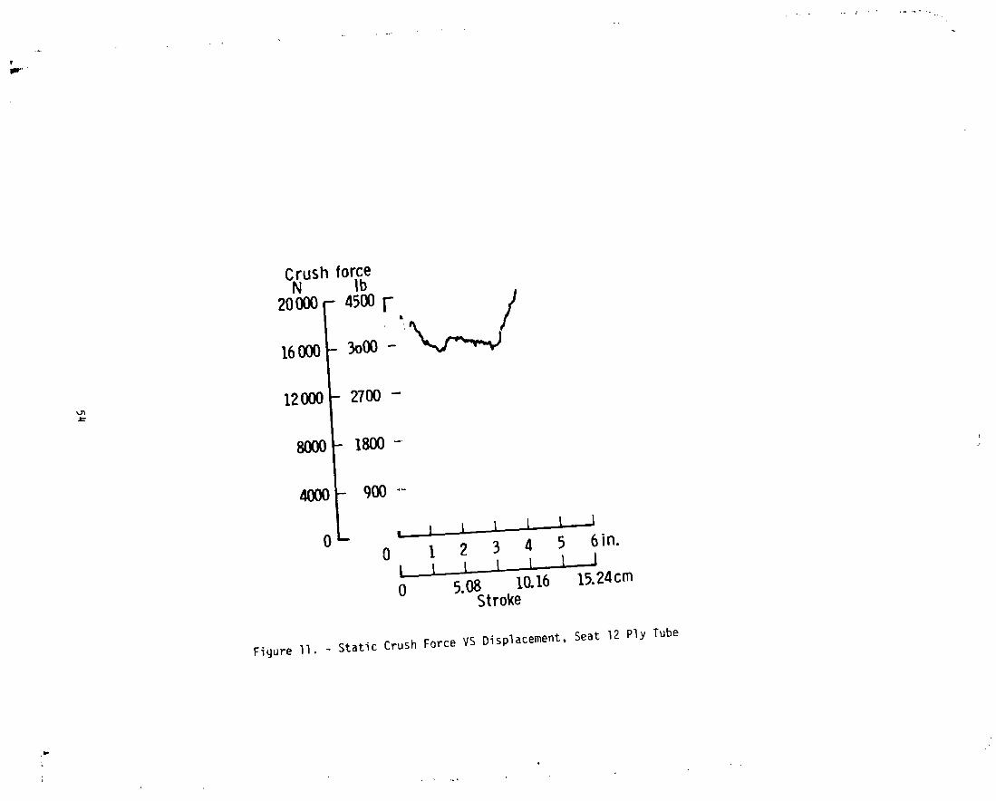
displacement curve for a 6-ply composite tube is sDown in Fig. 9. Figures I0
and II display the static tests results for the iO- and 12-ply tubes used inthe seat. Although the proper initial force Ievel was achieved, the 12-ply
tube crushing load was found to inc,'ease at a high rate after _ in. of crush
{Fig. ii) because the crushed material filled the remaining volume of thetube. A larKer-diameter tube with Iess plies wouid have been more deslrabIe
but would have required making new end caps.
The dynamic tests on the tube were performed ,n a drop-tower impact-testmachine. A weighted head of approximately 77 kg (170 lb), guided by two
rails, was dropped vertically on the tube. D_celeration of the head wasmeasured using accelerometers _,nd was recorded on a strip-chart recorder. A
typical deceleration-tlme curve for a 6-ply-tube dynamic test is displayed in
Fig. 12. Head-impact velocity was 4.52 m/sec (I_.83 ft/sec), resulting from a
drop height of 1.04 m .3.42 ft). Pulse time was about 70 ms. Deceleration
ranged between 6 and 12 g. Compacted crushed material, filling the remaining
volume of the tube during the tube-crushing energy-absorbing process,
accounted for the deceleration g buildup. About 21-era (6.4-in.) length of
tube crushed in absorbing the bead's kinetic energy.
4]
| t
1985025199-051

STATIC AND DYNAMIC SEAT TESTS
Static Seat Test
With the graphite-epoxy tubes in place on the assembled seat, a problem
arose during static loading tests conducted to determine maximu, stroke
di3tance. A local bending condition at the ends of the graphite-epox:, tubesprevented uniform axial crushlng and resulted in tube failure. 1_e problem
was :_olw;d by the installation of an axial alining pivot cap and plugattachment at each end of the tube. As the seat stroked do_mward and forward,
t_ pivot attachment mechanisms caused the tubes to crush uniformly in anaxial compressive mode.
lhe utilization of this mechanism has several possibllities. The
energy-absorbing device aligns only in one direction, _ince the seat had a
misalignment problem in only one plane of rotation. A bali Joint could be
used for multldirectlon misalignment if necessary. It should provide a useful
tool to other designers working with compressively loaded energy absorbers
thac require the dual characteristics of movable Joints and fixed axialaJignment conditions. This application is ideal for composite tubes whichcrush in a brittle mode and are thus difficult to control.
In actual use, the seat is unevenly loaded because of lack of symmetry
between t_, seat legs location and the occupant seating posltlons. The
outboard legs sustain twice the laod of the inboard legs because cf the
offset. However, this effect was nullified during static seat test by
locating the hydraulic ram symmetrically between the seat legs. For this
symmetricall} loaded seat, both composite tubes were 6 ply. Four static tests
were ;erformed to check the operation of the seat mechanism. The applied
vertical load (hydraulic ram), and the vertical (Z) and horizontal (X) floorreaction forces for a typical test are shown in Fig. 13.
_Dynamic Seat Tests
fhe assembled seat, with installed I0- and 12-ply EA tubes, was
dynamically tested at the Langley Research Center's D?namic Impact Test
Facility. A series of dynamic drop tests were conducted to simulate thevertical and forward expected shock pulse charaet-.ristics. The drop tests
were accomplished by mounting the seat at a 45" tilt angle to the horizontal
flat surface of a steel carriage. The carriage structure basic%fly consisted
of t_o horizontally positioned, built-up beam units, connect..d by _teel pldce
members. The carriage, with the 45" tilted seat containing the three
anthropomorphic dummies, was then raised and dropped vertically. Impact pulse
was controlled by permitting the falling carriage to strike and deform a
series of steel bars at ground level. The dummies were restrained by lapbelts and were positioned leaning forward with their head between their legs
in a crash preparation body posture,. Data acquisition consisted of
accelerometers, load cells extensiomet_rs, and nigh-speed motion picture
cameras. This method of dynamic impact testing was based on knowledge and
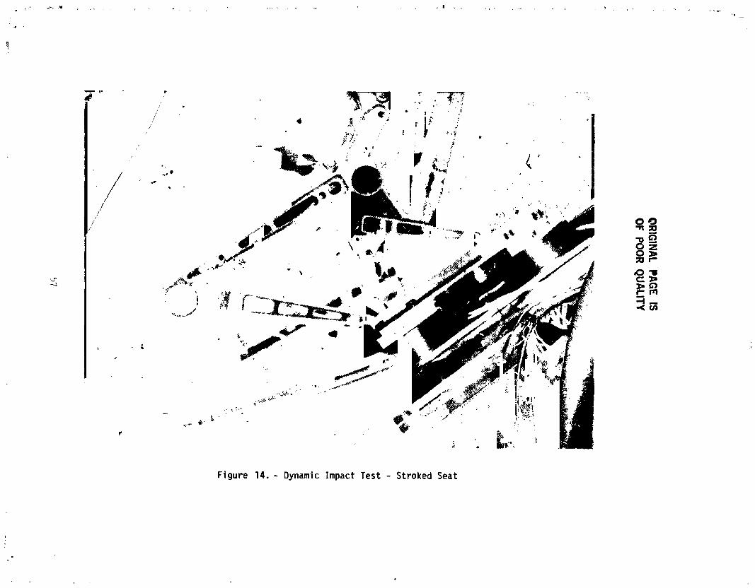
techniques established by many previous experiments performed at the LangleyResearch Center (see reference #). Figure I_ illustrabes an actual stroked
_2
1985025199-052
seat which resulted from these shock tests. About 12.7 cm (5 in.) of each
composite tube crushed from the 4.27-m (14-ft) drop height, in absorbing the
dummy passenger kinetic energy. Carriage input pulse plotted with theresulting pulse on the seat pan is shown in Fig. 15. Accelerat'on levels
remained within the range of human tolerance levels (see Fig. 1 and 2). Data
analysis of the seat from the Boeing 720 crash had not been completed at the
time this paper was prepared.
CONCLUSIONS
This investigation applies the concept of an energy-absorbing, axial,
tube-crushing unit to commerlcal aviation passenger transport seats. Theinvestigative effort was limited by the primary schedule of the Controlled
Impact Demonstration Project which prevented optimizing the energy absorbers.
For optimum seat performance, further development of the energy absorbers isrecommended.
Such parameters as belt restraihts, varying passenger seat weight loads
and their distribution, seat rebound, and economic aspects must be examined.
Preliminary results from the work conducted so far are encouraging. The
desired objective of demonstrating the concept/feasibility of converting a
standard commercial passenger seat to a axial, tube-crushing, energy-absorbing
unit as an additional crash safety feature has been attained.
REFERENCES
i. U.S. Code of Federal Regulations, Title 49, Chapter 5, P_rt 572:Anthropomorphic Test Dummy, U.S. Government Printing Office, Wacnington,
D.C., (Rev.) 1978.
2. Eiband, A. M.; Human Tolerance to Rapidly Applied Accelerations: NASA
Memorandum 5-19-59E, June 1959. Data curves as published in Aircraft
Crash Survival Design Guide, Volume II, USARTL-TR-79-22B, January 1980.
3. Farley, Gary L.: Energy Absorption of Composite Materials. NASA
TM-84638, March 1983. Also, Journal of Composite Materials, vol. 17, May1983, pp. 267-279.
4. Alfaro-Bou, Emilio; Williams, M.S.; and Fasanella, E. L.: Determinationof Crash Test Pulses and Their Application to Aircraft Seat Analysis: SAE
Paper 81061, Business Aircraft eeting and Exposition (Wichita, Kansas),i April 7-10, 1981.
I
43
1985025199-053

OR
IGIN
AL
PA
GE
IS
tO
FP
OO
RQ
UA
LIT
Y
44
1985025199-054
OR
IGIN
AL
PA
GE
ISO
FP
OO
RQ
UA
LIT
Y
45
a
1985025199-055

46
1985025199-056
47
i
1985025199-057

48
1985025199-058
49
1985025199-059
50
1985025199-060
m
51
1985025199-061
52
1985025199-062

F
53
1985025199-063
54
l
1985025199-064


J,
56
,i,
1985025199-066
t
OR
IGIN
AL
PA
GE
ISO
FP
OO
RQ
UA
LIT
Y
1985025199-067

58
,A
1985025199-068

N85-SS516
A MODULAR DOCKING MECHANISM
FOR
IN-ORBIT ASSF_4BLY AND SPACECRAFT SERVICING
By: Dipl.-Ing. F. Campe*,
Dipl.-Ing. K. Priesett*, and Dr. R. H. Bentall+
INTRODUCTION
As space operations become accepted as "normal" business enterprises, two
requirements tend to dominate any future technological developments:
o systems are required to be reliable over a long period of time,
either by their inherent reliability, or by means of scheduledmaintenance.
and
o future space technology developments need to be cost-effective to
warrant their incorporation.
Rendezvous and Docking (RVD) technology, being a prerequisite for
advanced space operations, is a typical example of this technology
development. Since the RVD process is not only mission critica± but also
contains the risk of damage to the in-situ space investment, its technologyhas to be highly reliable. But it must also sat_ °v _he other criterion, of
being vailable at reasonable cost, so that the t ts of in-o_bit assemblyand s( vicing can be realized.
The above requirements are passed on to the subsystems comprising the RVD
system. This paper is about one of them, the Docking Mechanism Subsystem(DMS) dev_ioped during an ESA sponsored contract.
DOCKING ,MECHANISM CONCEPTS
The various docking mechanism concepts which have flown (e.g., Gemini,
Apollo, Soyus/Saljut) were of the "impulse", or "impact:', type where thekinetic energy of the active chaser spacecraft was used to trigger, oractuate, the docking mechanism. This was possible because the spacecraftinvolved were (more or less) rigid and rugged bodies and because their
centres of gravity were aligned.
* Dornier System, Friedrichshafen, West Germany
+ ESA, ESTEC, NoordwiJk, The Netherlands
59
1985025199-069

For future space missions, however, such as large, flexible, and locally
fragile platforms, it is very desirable to adopt non-impact docking
techniques to avoid the risk of damage, and to make use of self-actuated, and
re-usable, docking mechanisms.
Non-lmpact docking systems can be sub-divided into two categories where,
following the close rendezvous of the two satellites, they are brought
together into intimate contact either by means of the Docking Mechanism viaan extended probe, or by active control of the AOCS of one of the
spacecraft. This bringing together is known as "Closure", and the two meansof achieving it are referred to in the following as "DMS controlled closure"
(DMS-CC) and "AOCS controlled closure" (AOCS-CC). These two closure
techniques differ in the _perations which are needed, and in the make-up of
their constituent components. Table 1 gives an overview of the operations
associated with each category. Figure 1 illustrates the two different
docking mechanisms implied.
It is clear that, in principle, AOCS controlled closure can result in a
simpler mechanism, in that the boom is not needed, nor are the necessarily
complex grapple and actuator mechanisms. However, this is at the expense ofa greater demand on the AOCS and the need for short range docking sensors. A
very major advantage accrues, however: that is the possibility ot using a
very simple structural docking interface which is compatible with adoption asa "standard" interface.
REQUIREMENTS
The general requirements for the DMS are based on typical Europeanscenarios for automated RVD missions, where the spacecraft are unmanned and
3-axls-stabilized. These missions require a high flexibility and modularity
in the DMS concept. Further, to protect the higher investment in orbit it is
desirable to ensure that only passive parts of the DMS are located on themore "permanent" spacecraft.
Safety requirements become, in fact, design drivers, and Table 2 glves
typical requirements with which the DMS must comply. Latch performance
requirements derived to contain a number of alternative missions are given inTable 3, and the range of satellite parameters is given in Table 4. Finally
the DMS is required to support certain operational strategies; these areshown in Table 5.
Notable among these requirements is the requirement that, regardless of
the failure, it should be possible to separate the two spacecraft in order
not to prejudice a further attempt at RVD. The DMS therefore not only needs
to be reversible, it must have back-up systems which ensure complete release.
I 60
1985025199-070
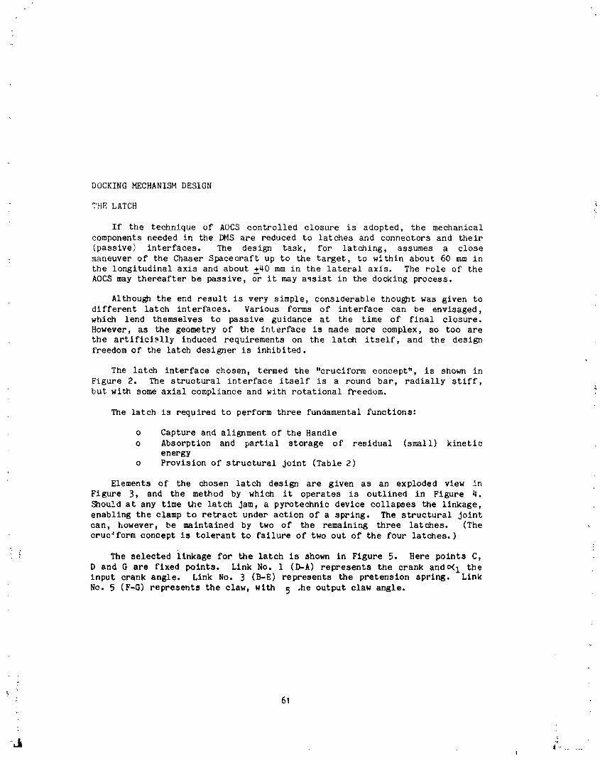
DOCKING MECHANISM DESIGN
THE LATCH <
If the technique of AOCS controlled closure is adopted, the mechanicalcomponents needed in the DMS are reduced to latches and connectors and their
(passive) interfaces. The design task, for latching, assumes a closemaneuver of the Chaser Spacecraft up to the target, to within about 60 mm in
the longitudinal axis and about +40 mm in the lateral axis. The role of the
AOCS may thereafter be passive, or it may assist in the docking process.
Althou_h the end result is very simple, conslderable thought was given todifferent latch interfaces. Various forms of interface can be envisaged,
which lend themselves to passive guidance at the time of final closure.
However, as the geometry of the interface is made more complex, so too arethe artificimlly induced requirements on the latch itself, and the design
freedom of the latch designer is inhibited.
The latch interface chosen, termed the "cruciform concept", is shown inFigure 2. The structural interface itself is a round bar, radially stiff,
but with some axial compliance and with rotational freedom.
The latch is required to perform three fundamental functions:
o Capture and alignment of the Handle
o Absorption and partial storage of residual (small) kineticenergy
o Provision of structural joint (Table 2)
Elements of the chosen latch design are given as an exploded view in
Figure 3, and the method by which it operates is outlined in Figure 4.
Should at any time the latch Jam, a pyrotechnic device collapses the linkage,
enabling the clamp to retract under action of a spring. The structural joint
can, however, be maintained by two of the remaining three latches. (Thecruc_form concept is tolerant to failure of two out of the four latches.)
The selected linkage for the latch is shown in Figure 5. Here points C,
D and G are fixed points. Link No. 1 (D-A) represents the crank ando< 1 theinput crank angle. Link No. 3 (B-E) represents the pretension spring. Link
No. 5 (F-G) represents the claw, with 5 .he output claw angle.
; 61
I
1985025199-071

Based on this layout, with the following dimensions, Figures 6 to 8 give
the latch performance parameters, based on the following dimensions:
D-A : 31.50 mm 1 START = 130°
A-B : 32.48 mm 1 END : 76"9o
C-E = 82.10 mm 5 START = 186°
F-G = 30.00 mm 5 END = 60o
LATCH DESIGN TESTING
In order to gain some insight into the latch performance, testing has: been performed on a single latch, and Figure 9 shows the test setup used.
Two massive blocks (160 kg each) onto which the handle and latch assemblies
were mounted, were supported on air bearings and made to approach each other
at varying rates and alignments, simulating a constant AOCS thrust.Interactive forces were measured using a piezoelectric transducer mountedbetween the latch and the base. Figure lOa shows a typical behaviour during
such a test with an initial lateral misalignment of 60 mm. Several bouncesagainst the reception element are shown prior to claw engagement. Figure lob
shows a capture with the same approach velocity (15 mm/sec), but with no
misalignment.
The results of the testing confirmed in general the performance of the
latch, and gave valuable guidance to the modelling of the latch for RVDsimulation purposes. Testing also indicated that some detailed improvements
were necessary in the configuration of the spring energy absorber - for
example, the addition of a damper. This damper could either be a
conventional passive damper (velocity proportional), or an active damperwhere the interactive forces are measured and the claw is controlled
,. appropriately.
THE CONNECTOR MECHANISM
It soon became apparent that the requirement for achieving electrical and
fluid connection within the DMS could become a design driver on the latches,
not just with the precision of latching required, but also with the forceswhich the latches should withstand. The forces required to mate and de-mate
connectors, particularly for the fluid connectors, were relatively high, and
in order to maintain modularity of design, keeping the latch development
independent of connector development, it was decided to provide a
self-powered, self-reacting mechanism to achieve connection. This mechanism
is still undergoing development, and will not be reported here. However
Table 6 shows typical connector mechanism requirements.
62
1985025199-072

STANDARD DOCKING INTERFACE
With a growing number of satellites in orbit, and a gro_ng capability of
direct intervention by means of vehicles designed to dock with them, it is
particularly interesting to develop usable and commercially viable standard
docking interfaces.
The latch design described has certainly some attributes to its credit,but it is nJt the only latch design _hat can be found which interfaces with
the simple handle. Indeed this latch has co-existed wlth a latch of totally
different concept which is also being considered as an alternative design.This possibility arises from the classic simplicity of the handle. The
handle is light (0.4 kg) and the design freedom offered to the latch means
that it is not therefore necessary to _urchase the latch always from the samesupplier.
The handle may be in a number of alternative configurations, e.g., 3
instead of 4, and located at different diameters without invalidating the
essential of the _tandat_, oe the principles of operation of the DMS. Four
such "handles" were chosen as the interface for the design presented in this
paper, over the more conventional alternative of a 3-handle configuration for
kinematic reasons because of the added security against failu,,e during
latching. In addition, aided by the inherent self-centering capability ofthe latch/handle combination, the concept is also suitab] for the so-called
androgenous DMS, where active parts are placed on both sides of the lr.terface
to allow initiation of separation by either satellite. In this configurationthe location of the latches is alternated between the spacecraft, i.e.,
latches I and 3 on spacecraft i and latches 2 and 4 on spacecraft 2 (see fig.
ii). However in this concept the release security is compromised if thecommand llnk fails.
CONCLUSION
A Docking Mechanism concept has been described which is suitable for use
with autonomous docking systems. The central feature of using simplecylindrical handles on one side and a type of prism seating on the other is
offered a:3 a practical method of achieving a standardized structuralinterface without freezing continued development of the latches, either
technically or commercially.
The main emphasis in future Docking Mechanism concepts will probably bein two directions:
o The first is towards a very simple Docking Mechanism, involving
mainly the latch mechanism to achieve a structural linko the second is towards a sophisticated Docking Mechanism, where the
latch mechanism is designed for non-rlgid spacecraft and the
achievement of very low dynamic interactions between spacecraft
during the docking process.
63
1985025199-073

ORIGINAL PAGE IS
OF POOR QUALITY
Electrical Connector Electrical andMechanism Llquld/Ges Connector
Liquid/Gas Connector Mechanism LatchMechanizm _ Mechenllm ....
Handle _ UlOSe-Up_ensor
I
! i !
-- ElectronicDocking Mechanism Chasor
for _Sid0 )ide) AOCS Controlled Closure
I
Latch Camera
Electrical, Connection
Mechanism
GrappleMechanism Boom
Extension/Boom Retraction
Mechanism
LiquidConnectionMechanism
\ Power end Date_ Electronics
Camera _, i x-- -- /
Docking " Mechanism _v/__ _ j/
forDMSControlledClosure
FIGUREi: DHS AND AOCS CONTROLLEDCLOSURECONCEPTS
64
'-Jr _.......
1985025199-074
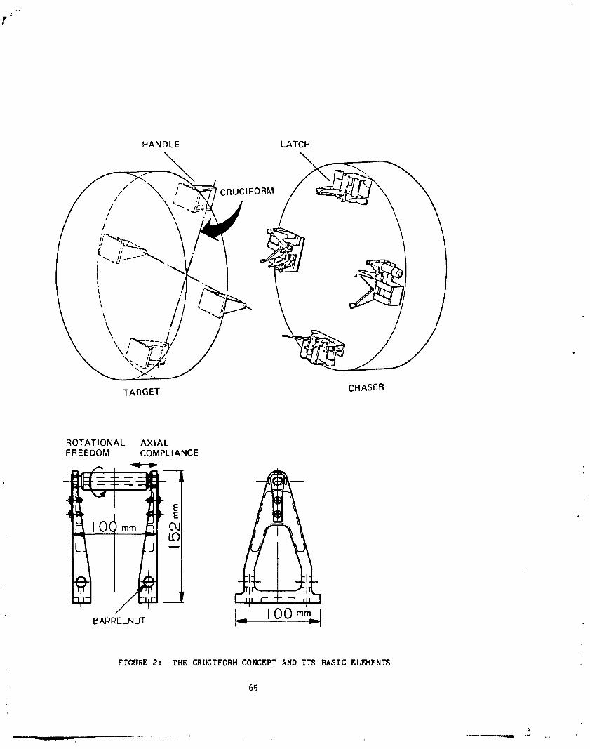
t"
HANDLE LATCH
\
ROTATIONAL AXIALFR EEDOM COMPLIANCE
%-
0(, mm""-, _1
BA_L.uT L. I00 _%[
FIGURE 2: THE CRUCIFORM CONCEPT AND ITS BASIC EL_4ENTS
65
1985025199-075

HANDLESUPPORT
BAR
RECEPTIONELEMENTOFCLAW VARIOUSSHAPES
EMERGENCY
SPRINGSOF VARIOUSLINKA( STIFFNES_CHARACTEh ISTIC_
PRETENSI(SPRING .;EAT
MOTOR
FORCE/TORQUESENSO_GEAR
DAMPER"_
ENDSWITCH
BASEPLATE EMERGENCYSPRING
FIGUR_ J: BASIC ELB_ENTS AND POSSIBLE ADDITIONAL EL_ENTSt OF THELATCHING MECHANISM
66
a
1985025199-076

ORIGINAl. PAGE IIOF POOR QUALITY
FIGURE qa shows the reception positons of latch \\\ _ELEMENT/ /and handle, which do not hecessarily involve \_ \7immediately a real mechanical contact, but _ \\\\_____.,x'x_ /_ /which give the final initiation command for ,i ,_. , \ _,_,'1_ r_fi_t �˜�the latch actuator. _ _,-_-'_':"_ \J_-] _:_[ l_
' _=--4_1--_v-- t --I
The handle runs against the reception element, ,,,which, fixed to the springs, limits the inter-active forces by compliance in the cxes. 'The claw is rotated by the actuator for engage--ment with the handle. ______!F_ f o .
FIGURE qc shows the handle captured by the claw. % _L_/--_ _'/
The docking process may now be controlled for the ___
minimum dynamic interaction between Chaserand Target. The actuator has to overcome thereaction forces, the spring force and the emergencyspring force.
FIGU RE _d shows the final la_chirlg position whlEn -___'_/__ /
the handle is forced into the prism seating by the
overcenter linkage and loaded pretension ._pring. i _i-___ _[_ __ _ ,t_, ,_t..
FIGURE _e shows the emergency undocking _*"/
when, after disabling a linkage hinge, the _!!
chaser i,_ undocked by the spring element.
t ,'1
FIGURI_ _. OPERATIONAL SEQUENCE OF LATCH FOR DOCKING AND
F_,E_G_.H_Y UNDOCKING
67
_I V P
1985025199-077
/ CSAW
I F \\
FOUR-BAR LINKAGE I ABCOFOUR-BAR LINKAGE II CE F G
D.C,G . FIXEOPOtN',$
FIGURE 5: LATCH LINKAGE IN 2x4-BAE LINKAGE LAYOUT
e2,3,4J
IDEOJ / 45
100- /
//
1BO- /
/120- /
/w. /
I /i-".\.
i1 "+" I / "+I /
/0"t, "-.-._.- i "" i ' , " , "' i --
FIGURE 6: INPUT LIHAGE ANGLE _C l) VF._3US OUTPUT LINKAGE ANGLE _(5 )
68
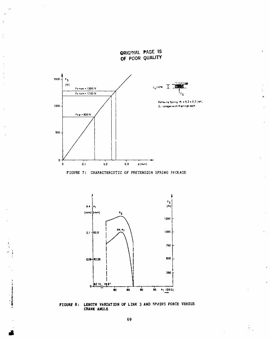
ORIG'NAL PAGE ISOF POOR QUALITY
,,00-'Fs / ......Fsmol= 13OON Lo'4_, T
Fs nora- 1200 N / r S
A Bell_dle Spring 15 w 5,2 X 0,7 (rI1_)
1000 / I 2 ; ICklgelJ w_th 4 tkorm_1 elch
/ I
Fs,o - 800 N II
° ii
1I
0 ' i A mc[
0 0.l 0.2 0.3 d [mrnJ
FIGURE 7: CHARACTERISTIC OF PRETENSION SPRING P_CKAGE
r S
_e o1 INI
[mini [ram) F S
1250
0,l B2.0 i j,/_ _j / 1000
L _"_r /I 750
°'_"" I JI I •I 2r,o
, I
i ! _ ., |
-|
"_! FIGURE 8: LENGTH V,RXATTON OF LINK 3 AND _PdlNG FORCE VF._SUSCRANK ANGLE
69
41
1985025199-079
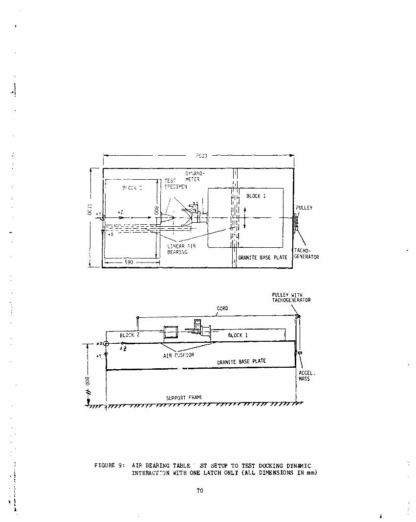
"q 2000 w.
F 17 TEST METER
I ! BLOCKI
_'=- _-'_ --4J-_:n-. 1---- _ --## LINE#R ,_[q L
L _ _90_ _,_ITEBASEPLATE'GE,ERATORi i
PULLEYWITH", TACHOGENERATOR
i CORD \_ .z
+xq+_ '_
AIR CUSHIONGRANITEBASEPLATE
i i , , _ mc_ ACCEL.o MASS0
'f/'lft rffY// _')-/f/i-if /W,,'/ f.f#11/ rl,,"JfJ /f/_f,_ i
FIGURE 9: AIR BEARING TABLE' ST SETUP TO TEST DOCKING DYNAMIC
INTERACYTgN WITH ONE LATCH ONLY (ALL DIMENSIONS IN ram)[
70
L
1985025199-080
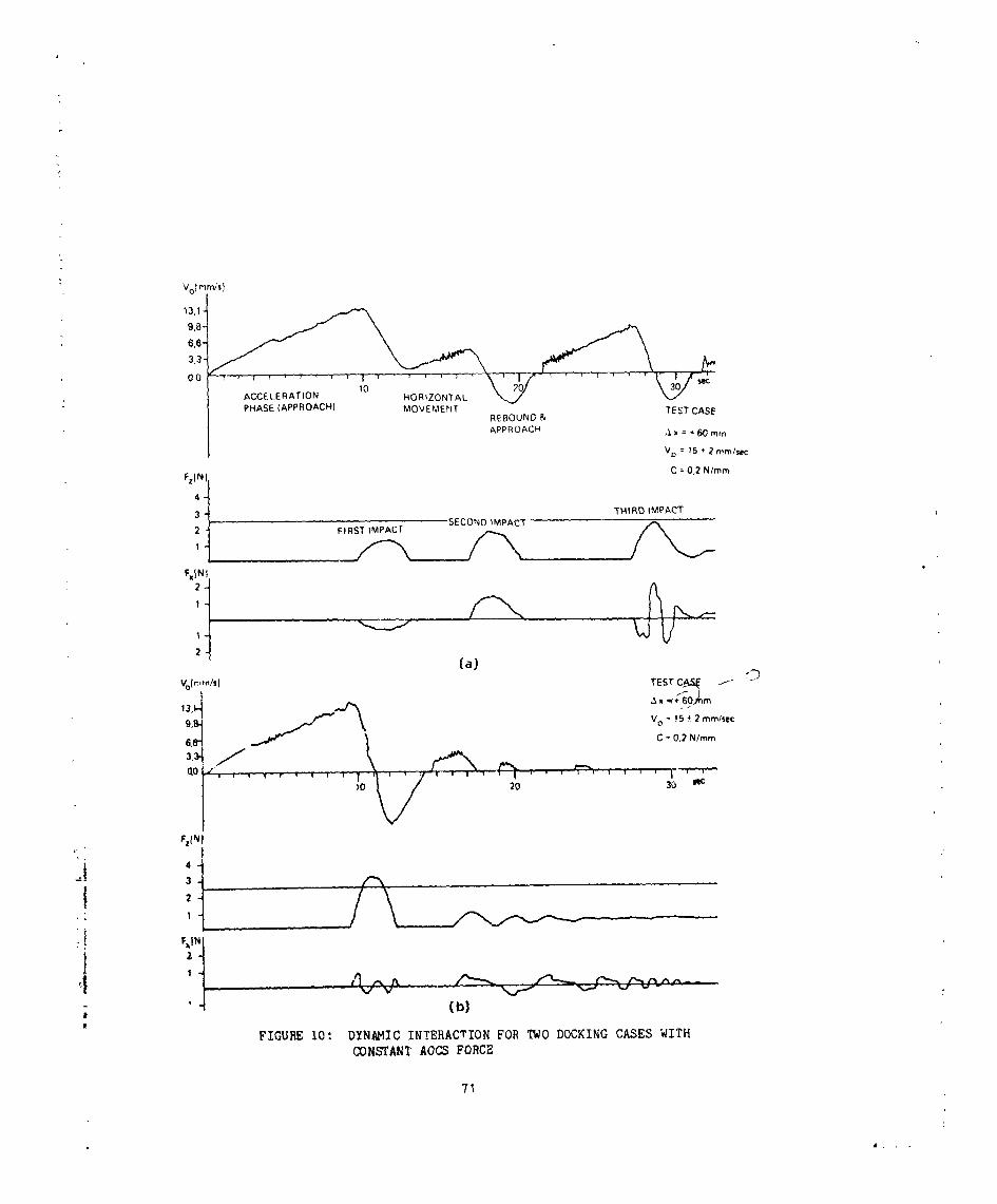
Volram/s)
O0 r , _ , _ i "_ "_ r I ,"' , , I r "T"--_ \ , I T
ACCELERAT,ON I0 HOR$ZONTAL _ _ sec
PHASE (APPROACH) MOVEMENT TEST CASEREBOUNO &
APPROACH ,._x = + 60 mm
Vo = 15 + 2 n!m/$c_:
FzlNJl C = 0,2 N/ram#
SECOND IMPACTFIRST IMPACT
(a)Vofmm/,) rESt .f _
9 VO = 15 _ 2 ram/see
6ii _ C = 0.2 N/ram
10 20 30 N¢
F,I.I
" j-.! 1
! , I
i
, (b]l
FIGURE i0: DYNAMIC INTERACTION FOR TWO DOCKING CASES WITH
CONSTANT AOCS FORCE
71
# ,
1985025199-081

DMS CONCEPTS 1
!__[ ;
IMPACT DOCKING DOCKING
i.
ICONTROLLED CONTROL& EO
CLOSURE CLOSURE
, _ , , z | 1..__
D,STANCE CLOSURE LATCHING CONNECTION DISTANCE LATCHING CONNECTJC, N< = lm <=01m
1
-- Vet ,fv reed¢ - Reduce - F ,he IL._:trlcal -Vetlfy reedl. -F =re I" E le_ztrJca_
hess for kmtfftlC alignment connect_or,s ne_ for alKjnment / connections
gr_lpphng energy of rela latch,ngtire mot on
- Move grapple -Ahgn -R_yd rnecha - hgutCl/ .Capture "R,gsd mec_l L_Iw_,'__echanll_n '_d_lCle nical connec'=lon Ga_ nicaf con":._t_o_ G_'-into po%,tton of veh_le$ connections of wh,cle_ ¢( nn.c_ ,ons
CIo..e _ffappte -Drawrne¢hani.,r.."n vehicles
I_ogelher
TABLE I: DOCKING CONCEPTS AND RELATED qOCKING OPERATIONS
Gene_l • The DMS shall not hazard to other equ,pment or perso_mel during ground ,est,n9.
• The DMS shalI have no credlblesinglepoint failurewhich re_its in an unsafe condlt_on for eltherveh,cie
• The DMS shall make ava,L'ble provismns for dock,r.g abort=on at any t,me a. d satelhte rlease w_thouI
damage to either 3atelhte.
• • The DMS shall be protected against fal._e commands.
i • The OMS shall be designed to fad-safe, fad-safe standarda
• The first point of contact shall be grounded.
i During Docking • No damage shall occur to eether satelhte dur,ng docking, nor shall the,r ol;:eratmnal peffnrmancL be' isolated.
• It shall be poss=ble to abort docking at any point =n rhe sequence.
• The dock=ng operat,on shall be man supervised.
• ; During Contingency • it shall be possible, following contingency upefatgons, to re-dock wrth the same two spac_c='attJ
"1 OperatiOns • The DMS shall prov=de fad_fe means for Contingency o_}erat=ons.
During Emergency • Emergency Operatfons shah not impa=r the docking capabdtty of the Target Satelhte.
I Operatmns • There ,s no necessrty for dock,ng w,th the same Chaser Satelhte following Emergency Cpe_atv)n_
TABLE 2: SAFETY REQUIREMENTS
72
1985025199-082

INITIAL SEPARATION CONDITIONS LATCHING CHARACTERISTIC8
Parameter AOCS ControLled Closure Parameter Final Conditione at End of Latching
displacement (mm) -55 _ dx,s, dys_; +55 dlsplaceme_t (mm) --1.0 • dxl,dye,dze • +1.0between both
0 _ dzs _ +30 satelhtes
approach -2.0_ Vxs.vys • +2.0 misallgnment --0.2 • ee,0e._k e • 0.2velocity (mm/sec) between both
5 _; Vzs_; 15 satelhtes (deg)
angular --0.5 _ (_xs.0ys,_zs_ +0.5 Stiffness Kx " Ky ', Kz ;) 2.2.106 N/mmisaliQnment {de9) axial, lateral forces
bending, torsional Cx " CV = Cz ;= 12 '103 Nm/degrotational speed -005 _ _xs,_ys,_zs _ +0.05{deg/sec) The DMS shall maintain there characteristics while transmitting
the following loadsacrot= the docking interfece:
- axial, lateral forces Fx ', FV '. Fz • 220 N
- bending, torsional M x • My • Mz • 200 Nmmoments
"' TABLE 3: FUNCTIONAL PERFORMANCE REQUIREMENTS
'lPARAMETER CHASER TARGET
Mass(k9) 200 _ m ,_ 4000 1200 _ mD _ 15000
Moment of inertia (kg-m 2) 100 _ JXA _ 11000 5000 • Jxp _ 260000
100 _ JYA _ 11000 9000 • Jyp _ 520000
100 < JZA < 8000 12000 • JZp • 600000
-1 Centre ofgravqty _m) 0.05 < XCGA < 0.25 0.2 '; XCG P < 10.0
i (relatweto DMS) 005 < YCGA • 025 0.2 _ YCPG • 4.8
0,75 < ZCGA • 2.00 0.2 • Zcp G I; 2.5e
Eigenfrequencnes (Hz) fl _ 10 Hz 0.9 < fTp =; 2.0
f2 _ 35 Hz 1.20 q; fup • 2.0
1_ K; f99 ( 2.0
Flexible appendages TBS I'P_
, end moving parts
TABLE 4: PHYSICAL PROPERTI_S OF CHASE AND TARGET
73
1985025199-083

Operational Principles: man involvement shall be limited to:
- Supervision of DMS operation
- Interpretation of housekeeping data
- Specially assigned stop/go commands
- Contingency and Emergency control
Operational Modes :
- Permanent docking
- Episodical docking
Nominal Operations Task Structure;
- The DMS shall be checked for docking readiness prior to the initiation of docking
- Nominal operations shall be based on a predetermined operational sequence
- Prior to each sequence and after each sequence go-ahead checks shallassess the status of the docking process and the DMS itself
- The DMS shall provide automatic correction and switch-over commands and/or "control of those functions from the ground, according to the missionreq uirements.
Contin9ency Operations Task Structure;
- Contingency and Emergency operations shall be initiated when any systemof either spacecraft is endangercd and safety is b,o longer guaranteed
- Contingency and Emergency operation shall be initiated by the DMS and/orfrom the ground, according to the mission requirements
TABLE 5: OPERATIONAL REQUIREMENTS
TRANSFER CAPA81LITIES
ELECTRIC LIQUID/GAS
• High PressureGas - 80 kg total at 100 3M3/H• 2 kW at 50 V
• 1 kWat 28 V - 280 bar initial pres_,re
• Low Rate Signal: 100 lines • Low PressureGas: - 100 DM3 total at 100 D[d3/H• High Rate Signal: 100 rob/mr
- 1 bar• Only Parasitic Loads to DMS latches
• Plate Travel < 30ram • Liquid Connectors:
• Emergency Separation Capability - 100 kg of fre_m 21,45 bar, 350 K.
• Separation of Electrical from Liquid/Gas 360 kg/h, &p = 6 bar
- 500 kg bipropellant, 20 kg/h
TABLE6: REQUIRE_NTSFOR CONNECTINGMECHANISM(TYPICAL)
?4
A
1985025199-084

DRAG-COMPENSATED, PRECISION-POWERED HINGE SYSTEM
By G. G. daoquemin m and S. O. Rusk m
SL_MARY
The design of a high-precision powered hinge is complicated by theunavoidable presence of parasitic drag torque resulting mainly from friction
and transfer of power, signals, and fluids across the hinge. Regardless ofthe type of drive system selected, it is impossible to completely eliminate
all parasitic drag. However, the mechanism described here comes very closeto pro%id_ng a drag-free system. All sources of parasitic drag torque are
collected on a shaft which is powered by an electric motor independent of the
main hinge drive. Under control of a sensor, the electric motor applies a
compensating torque equal to that of the parasitic drag torque, allowing the
main hinge drive to operate in a practically drag-free environment with veryhigh positioning precision.
INTRODUCT ION
In the design of robotic arm_, precision pointing systems and other
mechanisms which require very accurate angular positioning, it is necessaryto find methods for minimizing or eliminating the parasitic drag torque. The
presence of parasitic drag torque introduces step functions into the torque-
vs.-displacement curve, the nonllnearity of which is further aggravated by
the effect of static friction. The parasitic drag is difficult to predict.
It is known to vary with angular position_ velocity, load, temperature, andother variables, especially if wire bundles and flex hoses are routed around
the hinge. If the hinge drive mechanism design includes a gearboy gear
backlash introduces deadbands in _..ich positioning cannot be controlled.
The powered hinge mechanism presented in this paper eliminates gearing and
its associated problems by using dlrect-drive motors, and reduces parasiticdrag torque to that of one lightly loaded ball bearing.
POWERED HINGES - GENERALITIES
Powered hinges can be classed into two broad categories:
i. Deployables (nonretractable)
: 2. Remotely controlled c_inuously adjustable
The deployable systems of category 1 are usually spring-driven with
deployment rates control]ed by adjustable damp_s. Precision positioning in
the deployed position is provided by the lockup mechanism. This type of
powered hinge is of no interest in the following discussion.
The remotely controlled systems of category 2 cover an array of devices
adapted to various degrees of positioning precision, ranging from simplepowered door actuators to robotic arm hinges and high-precision pointingsystems. If high-precision pointing is not a requirement, relatively simple
*Lockheed Missiles & Space Company, _nnyvale, California
75
1985025199-085

devices can be designed using gear-train reduction drives. Such mechanisms
can sometimes be tolerant of significant parasitic drag torque so that
transfer of power and electric signals can be performed externally by means
of wire bundles or sllp rings and fluids via flexhoses. However, the design
of a hinge system with the high pointing precision of a fraction of an arcsec. presents difficult problems which cannot be resolved by simple
conventional mechanisms. To meet such requirements, it is necessary to use
more complex electromechanisms.
GENERAL REQUIREMENTS
The hlgh-preclsion powered hinge system discussed in this paper was designedto meet the following specifications:
1. Maneuver an 8000-1b payload at the end of a 75-in. arm in a vacuum/zero-g environment.
2. Achieve fine pointing with a 0.50 arc sec. resolution and within
+--2arc sec. of the specified value.3. Ensure that the Jitter does not exceed:
Freq., Hz. Max. Jitter, arc sec.0 to 5 0.605 to 20 0.50
20 0.20
4. Provide fcr electrical power transfer across the hinge(two lines).
5. Provide for signal transfer across the hinge (40 channels).
6. Provide for fluid llne transfer across the hinge (four lines)
or Into the hinge systems, if cooling is required.
The pointing precision requirements are not too meaningful when expressed interms of arc sac. In order to give a better appreciation of their severity,
they are expressed below in inches at 1 mile from the hinge point.
pointing: +_2 arc sac. = _ 0.62 in. at 1 mileresolution: 0.50 arc sec. = 0.16 in. at 1 mile
Jitter: 0.60 arc sec. = 0.19 in. at 1 mile0.50 arc sec. = 0.18 in. at 1 mile
0.20 arc sec. : 0.06 in. at 1 mile
BASIC CONCEPT
To provide a mechanism which will perform with the high precision cor,sistent
with the above specifications, it is necessary to neutralize the parasitica.ig torque such that the drive motor effectively operates a drag-free
system. It is also necessary to use DC torque motors in direct drive to
eliminate difficulties inherent with reduction drives and/or stepper motors.
The neutralization of the parasitic torque drag is provided by means of a
drag torque eliminator system (DTES). The DTES senses the presence of dragtorque and applies additional power independently from the main drive motor
in such a manner that the drag torque is balanced out without disturbing themain drive.
76
1985025199-086

lhe _in _]rive is provided by a DC torque motor controlled by an electronic
feedback control system which ensures the appropriate pointing precision.
Sne transfer of electric power Is performed by means of rotary transforme
,]_ng _C current $imJ!arly, the transfer of all electrical slgrals is
_rovided via rotary capacitive couplers. Advantage is therefore taken or the
property of both rotary transJrrmers and capacitive couplers which perform
their functions through air (or vacuum) gaps without physical contact, i.e.,
wlthout parasitic drag torque.
_ASIC HINGE MECHANISM
Figure 1 shows the hinge mechanism'J major components as designed for a
developmer_t prototype. To clarify the basic components of the system, Fig. 2presents a schematic of the mechanism. It s _uld be noted that since this
d_vice was p_imarily intended for space use, all electric motors are provided
with identical backups for use in case of primary motor failure.
The syste_ is supported by two large self-aligning spherical roller bearingsinserted _n two pillow blocks. These roller bearings are mounted on stub
shafts over conic sleeves which are forced under the inner races. This
e×Fands the inner races radially to eliminate all interna] clearance and
apply controlled radial preloads needed to meet launch reqdlrements. As a_esult of the preloads, these bearings exhibit a slgniflc_nt drag torque
_h_eh, together with the fluid coupler O-ring friction, prcvide the majorcontributions to the system parasitic drag torque. The twc stub shafts are
connected through a large c_.indrical shell as shown in Fig. 1. Supported by
flexure bearings, the stub shaft assembly can rotate through small angles
with respect to the main hinge shaft. These flexures allow a total
diff_rentlal displacement of only +2° with a stiffness of 100-400 in-lb/rad
depending on the thickness of the flexure blades.
]he differential angular displacement between the stub shaft assembly and the
hinge shaft is detected and measured by a sensor as shown in Fig. 2. This
sensor controls the operation of a twist motor which adds sufficient torque
to the stub shaft assembly to counteract all parasitic torque drag collectedby the _tub shafts. Thus, the primary hinge drive motor operates in a
torque-free environment, thereby ensuring the desired hinge positioning
accuracy.
: The misalignment coupling in Fig. 2 is intended to provide enough compliance
to accommodate manufacturing tolerances in shaft alignment at that point.T_is coupling allows for bending and for a_lal and lateral mismatching.
However, itJ torsional compliance is not significant.
PARTIAL ANALYTICAL MODEL
In order to more clearly describe the operation of the powered hinge, it was
found convenient to develop a simplified analytical model in which the
masses, inertias, and details of the electronic loops were left out. Thismodel is shown in Fig. 3.
It is shown in thls system that a displacement provided by the drive motor
acts directly upon the output branch and indirectly upon a parallel branch
77
1985025199-087

which, by means of a detector and a feedback control system, provides power
to cancel out all parasitic drag torque.
An examination of the mechanism in Fig. i shows that some parasitic torque
drag must necessarily exist in both branches of the system. However, bycareful design, only one small ball bea_ing is left in the output branch to
ensure proper alignment of the encoder wheel. In zero gravity, the torque
drag of this bearing is expected to be at or near the noise level of thebranch. All ether sources of parasitic drag torque are collected on the
other branch to be sensed by the drag torque eliminator system. These
sources of parasitic torque incl,_de that of the main roller bearings, thesmaller ball bearir_s, and any external torque drag (such a_ that of the
rotating fluid coupl_ngs).
In operation, the position sensor detects an angular displacement _6 and
sends a signal to the twist motor. This signal closes tne loop mechanically
by rotating the stub shafts to cancel the displacement, thereby eliminating
the drag torque.
The response characteristics of this control system are not addressed in this
paper; however, the system is designed to function much faster than the
primary drive system to ensure a very small lag angle _6 and the intended
drag-free operation of the powered hinge.
ACTIVE FLEXURE
The operation of the flexure is shown in Fig. 4, which {llustrates one cycleof motion. The flexure consists of two concentric hollow shafts held
together by thin flexible blades mounted as shown in _ig. 4-1. The tw_
shafts have a small radial clearance such that large lift-off and landingradial and axial loads transmitted from the inner main shaft to the outer
stub shaft can be taken by direct contact of the two shafts. The radial
clearance between the two shafts is small enough that the flexure blades are
not unduly stressed during static load. This clearance is also selected to
ensure that no contact is made between shafts in the normal zero-g operation.
As can be seen in Fig. 4-1, the main shaft (output) is inside the stub shaft
(drag eliminator system). Tne main shaft is eonnecte_ to the main motor; thestub shaft is connected to the twist motor and runs with the drag-producing
roller bearing.
When the main motor is activated, the main shaft rotates. Fig. 4-2 shows the
small rotation _ , which brings the flexures almost in contact with the edges
of the main shaft windows. Th_ sensor, upon detecting this misalignment,
energizes the twist motor, which rotates the stub shaft and restores a n_ll
position at the displacement angle _ , thereby driving the roller bearing and
any other drag-producing components which may be connected to the stub shaft.
In a practical application, the angl, _ is made as small as possible; inthis instance, 1 are sac The lag of the stub shaft over the main shaft is
not perceptible, i
1985025199-088

EFFECT OF PARASITIC DRAG TORQUE ON SYST_ RESPONSE
In order for this system to perform with the expected efficiency, the torque
required to deflect the flexures : _st be as low as possible. Thisrequirement implies a combination of low spring rate and small angulardisplacement. Bottoming out of the flexure is highly undesirable. Figure 5
shows a representation of a typical torque-vs.-displacement curve for a
flexure where the bottoming angle is +2 °. In a well-designed system, thesensor must be capable of detecting a displacement of i arc sec. so that the
flexures remain virtually undeflected with no parasitic torque being prodoced.
The residual torque along the output branch (see Fig. 3) must be very small,slnce it will not be eliminated.
All other sources of internal and external drag torque are applied to the
"Eliminating" branch (Fig. 3) to avoid disturbing the output branch. The
disturbance introduced by parasitic drag torque is shown in Fig. 6, which
compares the displacement under the same torque of a one-degree-of-freedom
system with and without friction drag. This plot shows how troublesome theeffect of static friction is. In order to obtain a displacement, it is
necessary to apply a torque at least equal to that produced by the static
friction. However, as soon as the torque corresponding to the staticfriction is reached, the motion starts and the friction coefficient drops to
the lower value corresponding to the dynamic condition. The system then
jumps to a position of equilibrium, such as 61 . By comparison, afriction-free linear system with the same stiffness and under the same torque
would reach its equilibrium position at 02, going in a controlled manner
through all intermediat_ angles as shown by the straight line passing through
the origin.
Since friction is the major contributor to the paraz[tic torque drag, it is
clear that a high-precision hinge cannot be designed unless it can beoperated in a friction-free manner.
SOURCES OF PARASITIC DRAG TORQUE
In the general hinge system, sources of parasitic drag torque are to be found
in the following components:
i. Main bearings (rollers or ball bearings)
2. Auxiliary motors bearings (ball bearings)
3. Encoder bearing (ball bearing)
4. Power line transfer system
5. Sisals transfer system6. Fluid lines transfer system
In the powered hinge discussed here, only Item 3, the encoder bearing,remains effective as a minor source of parasitic drag torque. Item_ 4 and 5
are transmitted by induction and capacitive coupling through r gaps (or
vacdum gaps) while the remaining three, Items i, 2, and 6, elJminatea bythe twist motor feedback loop.
79
1985025199-089

i
!
i
r
' CONCLUDING RF_ARKS
A full-s_ze model of this powered hinge has been designed and built for test
purposes. This model (Fig. ?) meets the requirements specified in thispaper. It has been successfully subjected to qualitative running tests of
the main drive motors without any drag relief.
Precision pointing tests have not been carried out at this stage because of
delays in the design of the electronic feedback systems. However, analytical
simulation techniques have shown that excellent controlled performance could
be achieved at any selected angle. It should be noted that the hinge
rotation angle is not limited, it can be a fraction or any number ofrevolutions.
In its _-esent configuration, this precision powered hinge is a large device
adapted to 2erform the functlon_ represented by its specifications. Its
large size wa_ convenient for prototype fabrication, development, and
testing. Application to smaller devices will require changes in itsconfiguration to accommodate more severe space restrictions.
In addition to obvious aorospace applications, the principles of this
mechanism should be adaptable in miniaturized form to robotics systems andother devices.
8O
1985025199-090

81
1985025199-091

.L
1985025199-092
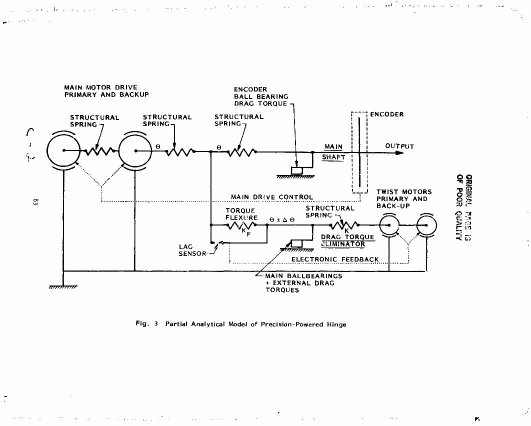
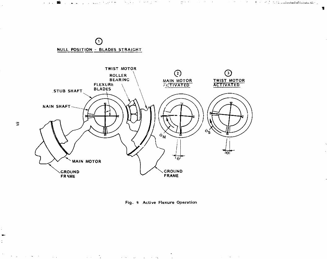
F
zl
:!\
84
"1985025"199-094

c
o
,,,_|!
ma)
<n,
_cn'u
z>
_"
,.
_I--"
+w
_U
$_.o,_
_0
m_ELU
10nE>
..--I--'11
85
1985025199-095

OR
IGIN
AL
PA
GE
|2
OF
PO
OR
QU
AL
ITY
I"q
"_
al

N85-33518
DESIGN AND DEVELOPMENT OF A
LINEAR THERMAL ACTUATOR
Gerry Bush and Don Osborne*
ABSTRACT
The design and development of a Linear Thermal Actuator (LTA) for space
; applications is described. The actuator is driven by thermal energy anautilizes the property of thermal expansion to do work. Equations to predict
performance are developed and used to optimize the design of the Development
Model LTA. Design details and test results are presented and discussed.
INTRODUCTION
Concept
An LTA is a device which, when subjected to a change in temperature by theaddition or extraction of thermal energy, causes work to be done by the
movement of an actuator rod against some external resisting force (Figure 1).The principle of operation through which the actuation is achieved is based on
the expansion or contraction of a large number of plates, packaged in such a
manner that variations in lengths _e to temperature changes are combined.
Applications
The LTA is inherently a high force/low displacement type mechanism,
although larger displacements can be obtained by using the LTA with theapproprigte linkages. Applications under consideration are:
i. Antenna Pointing Mechanism
, A number of spacecraft require active antenna positioning. Dependingon required response time and positioning accuracy the LTA is aviable candidate.
2. Deployment Mechanism
As a high force mechanism the LTA is well suited for use in deployingstructures. It also has a retraction capability which is attractive
in light of recent Space Shuttle missions which have demonstrated the
capability to retrieve satellites.
3. Thermal Control System
The LTA can generate sufficient force to make conductive couplings to
radiator panels• As spacecraft temperature increases, the LTA
actuator move3 making conductive couplings to a radiator plate. Theresult is a simple thermal control system.
* Spar Aerospace Limited, Ste. Anne de Bellevue, Quebec, Canada
87
A
1985025199-097

" Ob_eetives
The project goal was to design, manufacture and test a product for space
applications based on the above concept. It was to be compact, highlyreliable and have desirable performance characteristics. Performance
objectives and test results for the Development Model LTA are given in
Table i. Where test results are not yet available, calculated values arepresented.
• TABLE i: LTA PERFORMANCE SPECIFICATIONS
ICHARACTERISTIC OBJECTIVE
i TEST RESULTS
Displacement Range 8.5 mm 12.0 _L_
Maximum Applied Load Z 50 N Z 100N
Repeatability Z 2.5 ± 1.0(% of peak to peak displ.)
Non Linearity Minimize
(% of peak to peak displ.)
Due to Friction + 2.5m
Due to Backlash + 9.0
Response Time
(End to End)
Heating 5 min i0 min**
Cooling 5 min 180 min**
Power Consumption
Heating - 150 W max
Cooling - 0 WPosition Maintenance I0 W max i0 W max**
**Calculated values - test results not yet available.
i
A
1985025199-098

Confisurations
Three configurations were proposed at the start of the project. Two of
the arrangements were based on planar components. In the symmetrically loadedplanar arrangement, the actuator rod was located in the center of the plate
assembly. In the unsymmetrically loaded planar arrangement, the actuator rod
was located on one end of the plate assembly as shown in Figure i. The third
arrangement was based on cylindrical elements which assemble one inside theother.
I A trade-off analysis was performed to determine which configuration wasbest. The trade-off study gave high weighting to reliability, a large
displacement range against design external loads, repeatablet
temperature/posit_on actuation with minimum nonlinearity, quick response,
compactness, low weight, and minimal power consumption during rosition
i maintenance.
The unsymmetrically loaded planar arrangement was chosen because of its
ability to be manufactured to analytic predictions for a weight optimal designwith no significan' penalty to other criteria.
: Plate Joinin_ Techniques
A major task in the development of the LTA was to determine a suitable
method of joining the ends of th_ high and low expansion materials. A
mechanical joint was selected to avoid high temperature fatigue and strength
problems associated with adhesives and sotders. Interlocking tabs weredeveloped which are capable of two way operatlon_ do not degrade at elevated
temperatures, and can be manufactured to strict tolerances.
Plate Materials
Ideally, a plate material has a high modulus of elasticity, low density,very high or very low coef_iclent of thermal expansion and a high strength. A
high thermal conductivity and low thermal capacitance is desirable for the
i high expansion plate.I
Invar and Graphite Fiber Epoxy Composite (GFEC) were found to be most
suitable for use as low expansion materials. Aluminum and Magnesium were
found to be best for use as high expansion materials. Invar was selected over
GFEC for the low expansion material as it has a much higher shear strengthwhich is required by the interlocking tab joining technique. Aluminum was
chosen over magnesium because it behaves more predictably and has a higheryield strength.
89
] 985025 ] 99-099
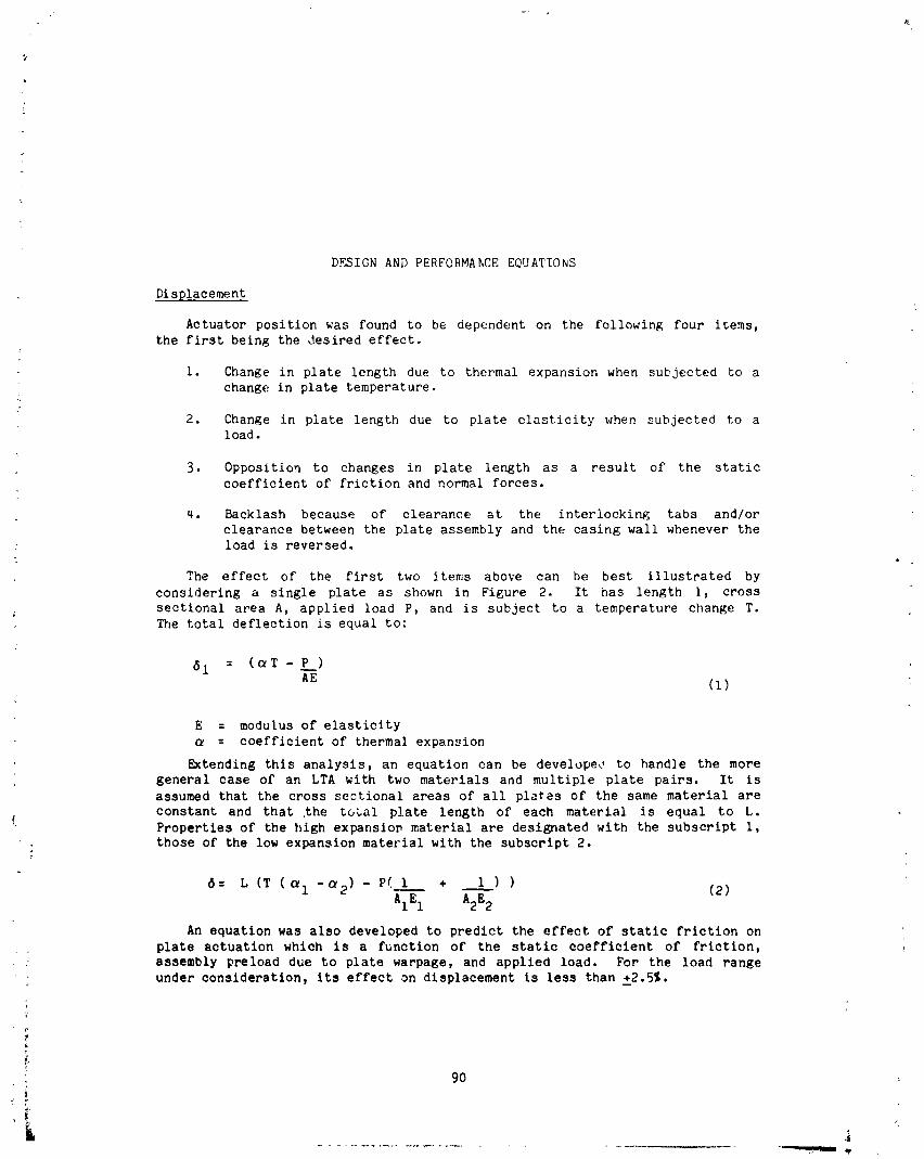
DF_IGN AND PERFORMANCE EQUATIONS
Displacement
Actuator position was found to be dependent on the following four items,the first being the desired effect.
i. Change in plate length due to thermal expansion when subjected to achange in plate temperature.
f,
2. Change in plate length due to plate elasticity when subjected to aload.
3. Opposition to changes in plate length as a result of the staticcoefficient of friction and normal forces.
4. Backlash because of clearance at the interlocking tabs and/or
clearance between the plate assembly and the casing wall whenever theload is reversed.
The effect of the first two items above can be best illustrated by
considering a single plate as shown in Figure 2. It has length i, cross
sectional area A, applied load P, and is subject to a temperature change T.
The total deflection is equal to:
61 : (sT - P__)
AE (i) "
E = modulus of elasticity
= coefficient of thermal expansion
Extending this analysis, an equation can be develope_ I to handle the more
general case of an LTA with two materials and multiple plate pairs. It is
assumed that the cross sectional areas of all plates of the same material are
constant and that the to_al plate length of each material is equal to L.
i Properties of the high expansion material are designated with the subscript I,
; those of the low expansion material with the subscript 2.
6: L (T (_i -_2 ) - P(I + 1) ) (2)
AIE 1 A2E 2
An equation was also developed to predict the effect of static friction on
plate actuation which is a function of the static coefficient of friction,
assembly preload due to plate warpage, and applied load. For the load range
under consideration, its effect on displacement is less than +2,5%.
; 90
1985025199-100

Weight and Volume Minimization
An ana]ysis was performed to determine t_e values of the design parameters
which minimized weight and volume for a given load and displacement. 1]_is
was accomplished by specifyir_ the weight of the LTA plate assembly as
follows; where{) represents the material density:
: Wt : AILPl + A2LP2 (3)
Equation (2) can be rearranged to solve for L and substituted into
Equation (3). The resulting equation has only two variables A1 and A2.Taking derivatives and setting them equal to zero yields equations for thecross sectional areas which minimize weight.
Calculations were also performed to find the plate width and number of
plates which minimize LTA vo]ume. The smallest volume occurs when the plate
assembly, including space for actuation, takes the shape of a cube. While
this shape is not normally ideal, it does provide a useful baseline to whichmore desireable shapes can be compared.
Response Time
One of the design objectives for the Development Model LTA was to limit
power consumptions during position maintenance to a maximum of lOW. To
_ccomplish this it was necessary to isolate the LTA from the environment using
multilayer thermal blankets and nonconductlve mounting shims. Beeause the
los=eL are so limited, the [TA can be treated as an isothermal block for thepus,poses of analysis.
During heating the response time is limited by available spacecraft power
or heater capacity and the unit thermal capacitance. During cooling the
response time is limited by the ability of the radiator plate to dump power to
space and the unit thermal capacitance. The thermal capacitance of theDevelopment Model LTA is calculated to be 491 Jl°C.
DESIGN AND MANUFACTURING
The Development Model LTA consists of a number of components andassemblies. A sample of each of the components is shown in Figure 3.
The casing, shown in Figure 3 and Figure 4, is used to hold the plates in
position and constrain the motion of the actuator rod. The interior of the
casing is coated with dry film lubricant to reduce friction and wear betweenthe plates and the easing. One side of the casing is coated with white paint
to act as a radiator plate and dissipate heat to space. Thermistors are
mounted on the ends of the casing to monitor temperature. The casing is shownresting on thermal shims which are made of polyimlde.
91
1985025199-101

\
The LTA was covered by the multilayer thermal blanket shown in Figure 3.
Phe large rectangular cutout allows the white painted radiator surface to viewspace.
Plate Assembly
The plate assembly is made up of 33 aluminum plates and 32 Invar plates.
A set of aluminum plates consist of 1 actuator end plate, i0 heater plate
assemblies, 18 high expansion plates, 3 thermistor plates and a fixed end
: plate assembly. One of each of these i._ shown in Figure 3. The plate in theforeground is a thermistor plate. The remaining al,_minum plates are shown in
the order mentioned, separated by Invar plates, from left to right. Allplates are coated with dry film lubricant.
Details of a high exparsion plate and a low expansion plate are shown in
Figure 5. The Invar plate has a thickness o_ .64 ms. The aluminum plate is
.94 mm thick and has a pocket .47 mm deep. Both plates have weight optimalcross sectional areas. The slot and the hole in the aluminum plate are us_ a
to pass wires for heaters and thermistors through the plate assembly. The
tabs on the aluminum plates are 12.5 mm long as compated to 2.5 mm long for
the Invar plates. The tabs were lengthened to reduce berding stresses andplate assembly elasticity as a result of any clearance between tabs. It is
plarned to increase the length of the tabs on the Invar plates for all futureLTAs.
Figure 6 shows details of the fixed end plate. The right end of tl_e plate
has a single tab on the back which fits into a slot in the casing. Athermistor is mounted in the pocket to monitor plate temperature. The tabs at
the left end are similar for all aluminum p]ates. Figure 7 shows details of
the heater plate assembly. It has tabs on both ends and a Kapton film heater
bonded into the pocket.
TEST RESULTS
Vigure_ 8 through 15 show test results for the Development Model LTA. Thefirst six curves show actuator displacement as a function of temperature under
different loading conditions. The remaining curves give the transient heating
and cooling response for two different power inputs. In general, results
match theoretical predictJons well. Variations occur as a result of backlashand increased elasticity of the plate assembly. Theoretical c,lrves neglectthe effect of backlash and frictlon.
The backlash is apparent only under no load conditions and is of the order
of 2.1 mm. It can be viewed in Figure 8. Friction effects can be considered
negligible since the normal force is small under these conditions.
_'.+gure8 also demonstrates the high repeatability of the LTA by actuating
throu h two complete cycles. For both the heating and cooling curve, theactun'+on follows the same path within _+1%.
92
1985025199-102

Figures 9 through 12 demonstrate performance under both compressive and
tensile loading. In all cases the effect of p._te elasticity is larger than
that predicted by theory• This is apparent by the offset between theoreticaland experimental results. The nonlinear effect of friction forces is also
visible and can be seen to increase with increasing load as expected.
The heating portion of each of t_e displacement versus temperature curves
is shown on one graph in Figure 13. The slope is the same for all curves.
The effect of plate elasticity can also be seen by the separation betweencurves.
Figures 14 and 15 are heating and cooling curves for the Development Model
LTA at room temperature and pressure. Under thermal vacuum condltion_ theheating portion of the curve will be sharper, as losses are limited to a
maximum of i0 W. A longer cooling response time is also anticipated.
_i DEVELOPMENT PROBLEMS AND SOLUTIONSA number of problems became apparent during testing at different stages.
The most obvious are the nonlinearities as a result of backlash and friction.
Backlash was caused prlmarily by clearance at the tab joints and is seen
as a manufacturing problem. It was first noted during breadboard testing: where more than .04 _ clearance per joint was evident. With 65 Joints in the
Development Model LTA even a s_ll clearance is excessive. The proposed
solution was to dimension the plates to obtain a light interference fit. This
fit was clearly not achieved during _anufacturing with the techniques used,
however', the solution is still seen as viable.
The static coefficient of friction between the plates coated with dry filmlubricant was found to be in the order of 0.35. When first assembled this
high coefficient of friction, when combined with preload caused by platewarpage, causes significant binding of the actuator. The problem was reduced
by increasing the clearance between the casing and the plate assembly _reduce preload. Decreasing preload by this method resulted in increased!
:I backlash and increased plate assembly elasticity.I
As noted above, there was more plate elasticity than that predicted by
theory. Clearance between the plat _ assembly and the casing wall allowed the
tabs to rotate which induced the plates to assume buckling shapes in the spaceavailable. These actions led to increased elasticity. The tabs on the
aluminum plates were therefore increased in length to reduce the amount of
rotation posbible f_Jr a given clearance, the ideal solution t_ this problem
is to reduce the stetic coefficient of friction, wl_.tchwould allow tighterpackaging of the plate,,.
93
,i
1985025199-103

CONCLUSIONS
The Development Model LTA has demonstrated the performance characteristics
required for the target applications• It has responded in a predictable,repeatable fashion which has been successfully characterized• Both load and
displacement obtained by the Development Model LTA have exceeded initial goals.
Future work will be directed towards developing a deployment/retractionmechanism for a fliEht project.
ACKNOWLEDGEMENT
The authors wish to thank the Department of Communications of Canada and
Spar Aerospace Limited for their permission to publis this paper and would
like to acknowledge the ccntributions of engineers and technicians at Spar whocontributed to this project.
94
i
1985025199-104
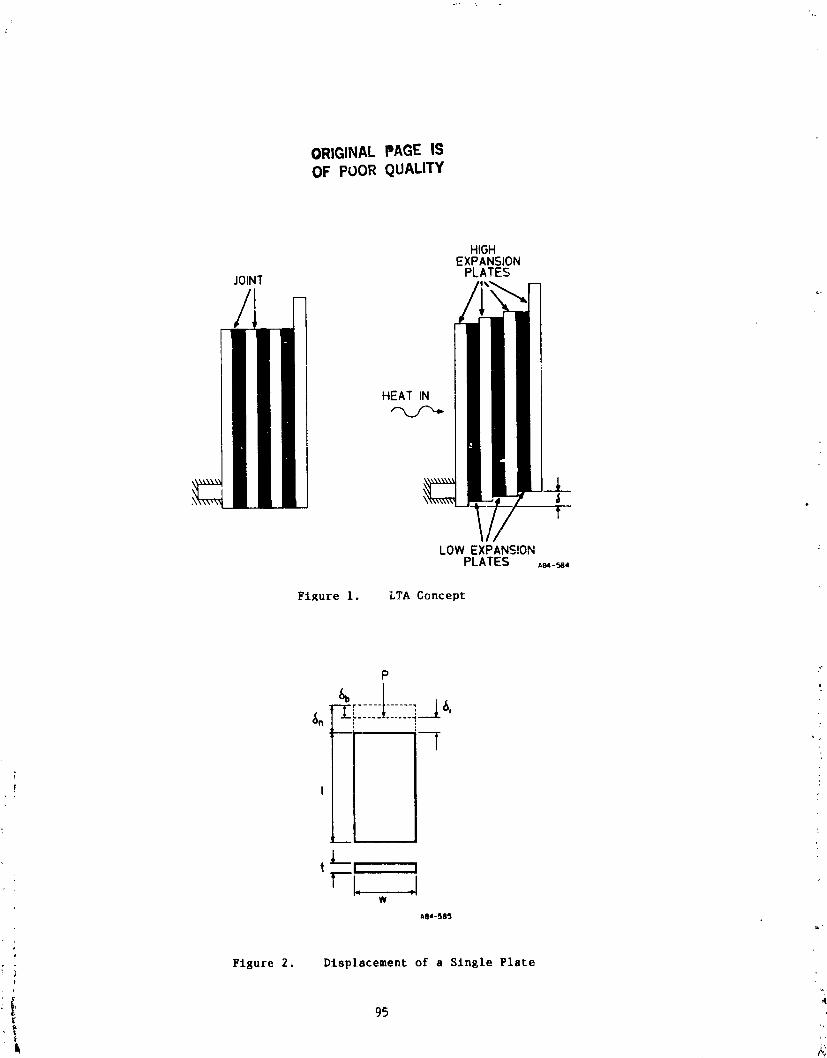
ORIGINALPAGE ISOF POOR QUALITY
HIGHEXPANSION
JOIN]' PLATES
HEAT IN
_L_
LOW EXPANSIONPLATES Aw-_,
Figure 1. LTA Concept
p ?-
i TII
I
_1I___ i
t r__i _1w
Aoa-s85
. Figure 2. Displacement of a Single Platei
i, v,.,
4
95[
1985025199-105

{_O
RIG
INA
LP
AG
EIS
OF
PO
OR
QU
AL
ITY
96
,it
1985025199-106

ORIGINALPAGE ISOF POOR QUALITY
; Figure 4. Casin8 A embl)
• Figure 5. Sample High & Low Expanslon PlateJ
97
A
1985025199-107
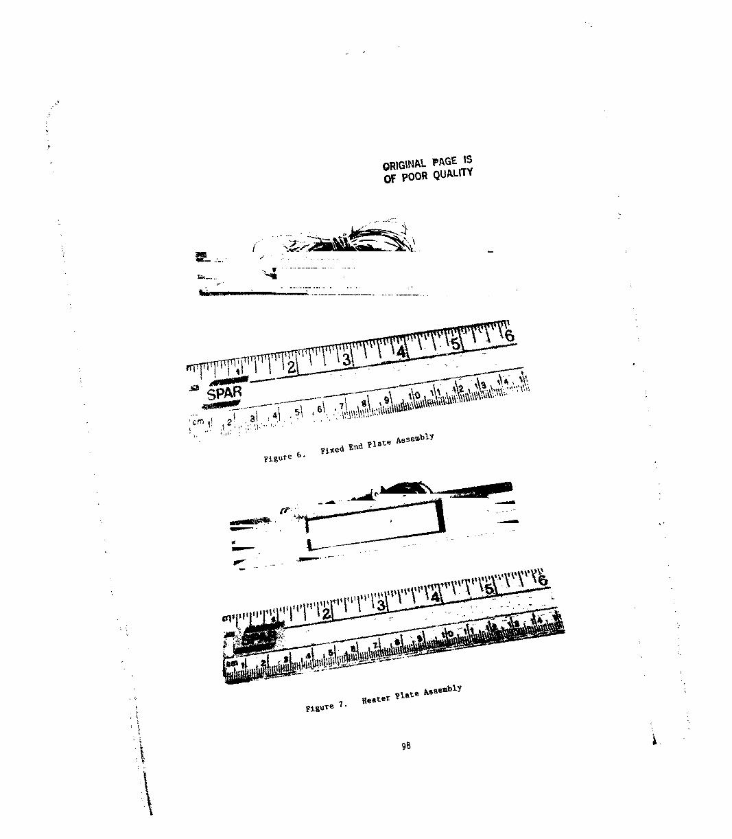
• ORIGINAL PAGE ISOF POOR QUALITY
_, I J2 i 1 1 t 1 I I | I_ I I x6
Figure 6. Fixed End Plate Assembly
,,, ',,
'. ") Ftsure ?. HesPer Plate Assembly '.
t :: 98
1,
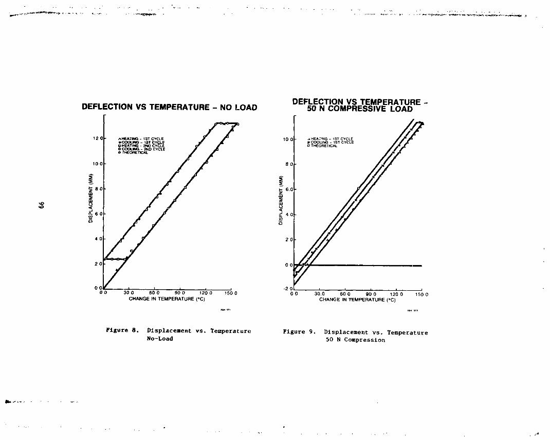
!
Io
s
zIE
._=-
_08:
""
oo
oo
O0
C_
O
oco
_,_
_o
e_
"4
(ININ
)1N::]IN
3OV
7dSIO
_o
Q_!t
...._
,_I
,.I
ii
i,
I_lll
0I_
";
I11(IN
IN)IN
qlN=]O
VT
_$100
e;{99
]985025]99-]
09
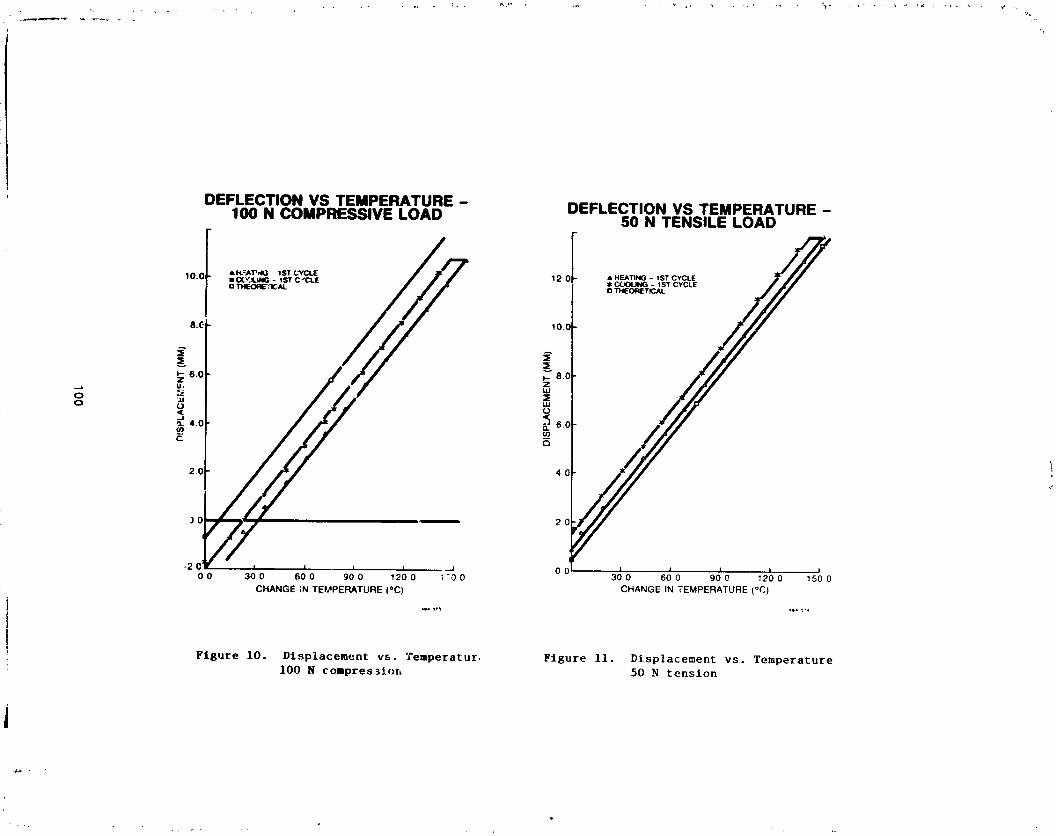
1°I
_
1
OZ
_<
z._
o
C3
00
00
0"
--0
:3
(IAIIA
I)1N::II_I30Y
7d810
'L
4_I
°"=
i__
7_m
IZ
O_._
=i-I
ii
ii
i._
,--o
o.
_.o
oo
o-
%0
(Iqlq)IN
"_;'_.:IOy'IO
SM
100
1985025199-110

P,f
oG
,-,_v
o
Z_
1,0
g_4,i.1
•
I
__
(INI_)
1N31/_F
:IOV
7dS
_3'
I:ELI/
_=
.4w
___
|
!i!0z
°'°0
,.4;
_iI
Ii
I*
_"'
__
l(_l
1,4
oo
oo
oo
o_
__
(ININ
)1N
31fi::]OY
"ldS
IO
i101
1985025199-111
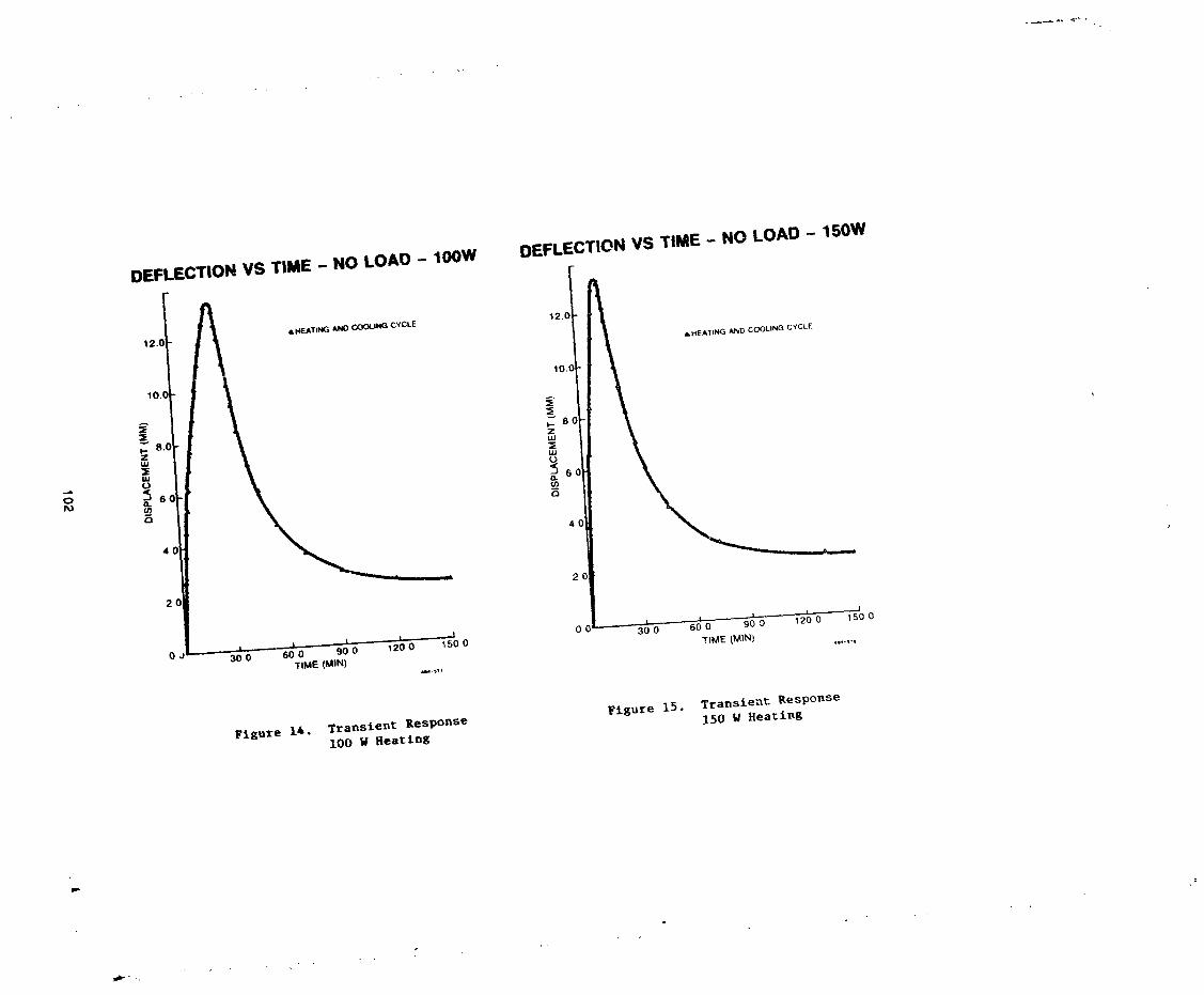
I
102
1985025199-112
N85-33519
THE DESIGN AND DEVELOPMENT OF A CONSTANT-SPEED SOLAR ARRAY DRIVE
Howard M. Jones and Nell Roger*
ABSTRACT
This paper describes the design and development of a constant-speed solar
array drive system for use in high-power communications satellites. Therelationship between continuity of motion in the solar array drive and
spacecraft attitude disturbance is investigated. The selection of the system
aesign based on the design requirements including spacecraft disturbance isdiscussed. The system comprises two main parts: the drive mechanism
including small-angle stepper motor and reduction gearing and the control
electronics including ministepping drive circuits, such that a very smalloutput step size is achieved. Factors contributing to discontinuities in
motion are identified and discussed. Test methods for measurement of very
small amplitudes of d_scontinuity at low rotational rates are described toa_sist in the testing of similar mechanisms.
INTRODUCTION
The use of sun-pointing deployable solar arrays of increasing power levels
on spacecraft for various applications has placed increased emphasis on thedesign and operational strategies of the solar array drives which maintain the
sun-pointlng attitude of the solar array while the spacecraft typically
remains earth-pointing. As a result of increased solar array size and: flexibility the potential to disturb spacecraft has increased dramatically.
The use of a constant-speed drive as opposed to the more traditional
intermittent or pulsed drive can improve this situation in two ways:
(a) The elimination of discontinuities in angular momentum between the solar
array and the spacecraft results in reduced disturbance levels. This
permits the use of smaller size or lower power consumption in the
reaction or momentum wheels of the spacecraft pitch axis control loop,
and/or less frequent momentum-dumping operations of the thrusters.
4
(b) The reduced energy levels in the dynamic coupling between the solar array
and drive system leads to improved operating torque margins and
_ eliminates potential problems of stalling and backdriving due to resonantarray dynamics. This phenomenon occurred on-orblt in a largecommunications satellite recently, resulting in forcible back-stepping ofthe system while a step forward had been commanded.
However, because the required rate of rotation is very low (i.e., lrevolution per day for geosynchronous spacecraft), the maintenance of
constant speed within limits, expressed as a proportion of the nominalspeed, is a difficult proposition. The fundamer_l problem is therefore
one of achieving the necessary continuity of motion in the solar array
drive system without leading to excessive mechanical and electrical
complexity with the resulting penalties in reliability, cost and mass.
°i *Spar Aerospace Limited, Toronto, Canada
103
I
1985025199-113
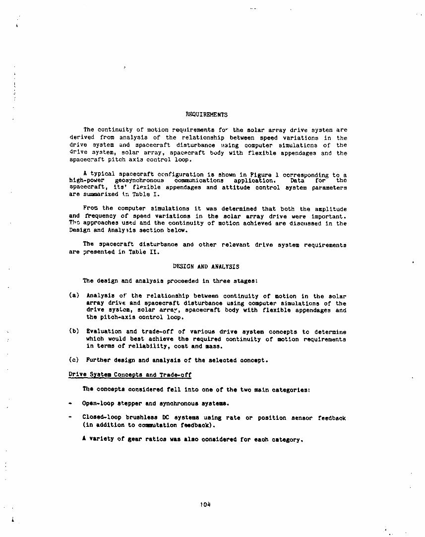
REQUIREMENTS
The continuity of motion requirements fo _ the solar array drive system arederived from analysis of the relationship between speed variations in the
drive system and spacecraft disturbance u3ing computer simulaticns of the
drive system, solar array, spacecraft body with flexible appendages and thespacecraft pitch axis control loop.
A typical spacecraft configuration is shown in Figure 1 corresponding to ahlgh-power geosynchronous communloations application. Data for the
spacecraft, its' fle_lble appendages and attitude control system parametersare summarized In Table I.
Fro_ the computer simulations it was determined that both the amplitude
and frequency of speed variations in the solar array drive were important.Tb_ approaches used and the continuity of motion achieved are discussed in the
Design and Analysis section below.
The spacecraft disturbance and other relevant drive system requirementsare presented in Table II.
DESIGN AND ANALYSIS
The design and analysis proceeded in three stages:
(a) Analysis of the relatiooship between continuity of motion in the solar
array drive and spacecraft disturbance using computer simulations of the
drive system, solar array, spacecraft body with flexible appendages andthe pitch-axls control loop.
(b) Evaluation and trade-off of various drive system concepts to determine
: which would beat achieve the required continuity of motion requirementsin terms of reliability, cost and mass.
(c) Further design and analysis of the selected concept.
Drive System Concepts and Trade-off
The concepts considered fell into one of the two main categories:
- Open-loop stepper and synchronous systems.
- Closed-loop brushless DC systems using rate or position sensor feedback(in addition to commutation feedback),
£ variety of gear ratios was also considered for eaoh category.
/,.
i1-
1985025199-114

It was found that because the nominal rotation rate _s very low (i
revolution per day) the fluctuations in rate, expressed as a proportion nf the
nomipal, are very small and hence difficult to detect and to control for the
closed-loop systems. Therefore the open-loop stepper or synchronous approach
was selected due to its simplicity. The system block diagram for the
open-loop geared stepper concept is illustrated in Figure 2.
The other major trade-off area involved selection of the optimum
combination of techniques for reducing output step size for the stepper orsynchronous concepts. The following methods are available:
(a) Motor with small prime step angle.
(b) Electronic step division (mini-stepping).
(c) Reduction gearing.
Gear reductions are selected for other reasons including motor torque
amplification (reduces system size and weight) and baekdrive characteristics(e.g., low backdrive efficiency reduces susceptibility to solar array dynamic
torques). The selected concept uses a conventional 1.8° stepper motor with
64-1evel minl-stepplng and 288:1 reduction gearing to achieve a theoretical
output step size of 0.0001 °. This step size is so low and the associated
stepping frequency of 42 Hz so h_gh, that significant interaction with the
solar array and the opacecraft p_tch axis control loop are avoided. The
lamination shapes for a hybrid stepper motor with 1.8" prime step _ngle areillustrated in Figure 3, with the associated electrfeal schematic and
sinusoidal minlstep drive sequence. The schematic of the ministep electronics
is shown in Figure 4. A cutaway illustration of the 288:1 reduction gearingis presented in Figure 5. The second stage of the reduction gearing is a
regenerative planetary set which is non-backdrlveable. This set functions in
a slmilar fashion to the harmonic drive except that the nutating flexible
spline of the later has been replaced by the more robust planet gears, which
can withstand much higher backdrive loads. More detailed information on thegears is presented in Table III.
Factors Affectin 6 Continuity of Motion
As described above the selected drive system provides a theoretical output
step size of 0.0001 e and a stepping frequency of 42 Hz. In practice the drive
mechanism will be part of a solar array drive assembly which includes be&rings
i and slip rings mounted on the main shaft. It has been predicted that _heachievable continuity of motion at the output is limited by stlck-sllp effects
in the system.
Due to the compliance of the drive train and the slow, synchronous speed
of the motor there is a finite rate of drive torque build-up in the mainshaft. Therefore when the system is started from zero rate it takes a finite
time for the drive torque in the shaft to exceed the static friction due tothe slip rings and bearings. Let this time be called T 1. When the breakouttorque is exceeded the shaft accelerates to a speed higher than the nominalrate under the action of the "wind-up" torque in the drive train. As the
i I05
JL .,
1985025199-115

J
f
"wind-up" torque falls below the friction torque the shaft speed decreases
until it is caught by static friction. Let this time interval (of relative
motlcn at the sllp rings) be called T2. The process is then repeated and isillustrated in Figure 6A.
The phenomenon could only be completely eliminated by the totalelimination of friction or by the addition of viscous or damping friction into
the system. However, the problems associated with the stick slip effects can
be alleviat_d by controlling the times T1 and T2 and hence the amplitudesof disconti_ulties in the main shaft rotation. The following parameters were
found to a,f_ct TI and T2:
(a) Drive system stiffness.
(b) Absolute levels of static and dynamic friction.
(c) Relative levels of static and dynamic friction.(d) Level of viscous friction in the system.
(e) Solar array dynamics.
The ratio of static to dynamic friction in tne slip rings is determined by
the properties of the materials used and is not amenable to manipulation. The
solar array dynamics are not generally subject to alteration for this purposewhile the addition of sufficient viscous friction into the system at these low
rates would not be practical. This generally leaves the drive systemstiffness and the absolute friction levels under the control of the solar
array dri-e designvr. Increasing the drive system stiffness and reducing the
slip ring friction levels will decrease the period (T1 2) and hence theamplitude of the rate discontinuities. A parametric analysis using the
computer simulations mentioned earlier was conducted to determine acceptablecombinations of stiffness and friction. The predicted effects of various
combinations of sllp ring friction and drive system stiffness on continuity ofmotion are illustrated in Figure 6B. This indicates that to maintain an
output step size in the same range as the theoretical value, say 0.0003 °
maximum, the sllp ring dynamic friction should be limited to 1.3 Nm and the
drive system stiffness at the main shaft should be above 150,000 Nm/radian.
While this stiffness is not generally difficult to achieve in a solar array
drive mechani_m, the limit of 1.3 Km sliding friction presents a challenge forthe larger sllp ring assemblies, particularly those of the disc configuration
due to the larger diameter of the rings.
TESTING
An engineering model drive system has been built including the
mlnistepplng electronics. Tne test program in progress includes:
(a) Ambient performance testa (torque-speed, etc.).
(b) Environmental testing (vibration and thermal vacuum).
(c) Continuity of motion (systems dynamics).
106
1985025199-116

!The ambient performance and environmental tesZlng involve conventional
v
: procedures and techniques and need not be discussed further. However, thesystem dynamics test includes a novel approach for measuring continuity of
motion at the output under various operating conditions and is descl oed below.
The purpose of the System Dynamics test is to determine the dynamic
characteristics of the Solar Array Drive Assembly (SADA) under various
operational conditions. The operational conditions to be represented _oraccounted for) are:
(_) Solar array dynamics.
(b) Slip ring friction.
(c) Rotational rates (for sun acquisition and sun-tracking modes).
The system dynamics test rig illustrated in Figure ? was designed andfabricated to represent t_e appropriate solar array torsional modes and the
sllp ring friction. The ir_rtis and stiffness of the simulated solar array
and the friction of the simulated slip ring can be adjusted to representvarious operational conditions of interest. The drive system can be commanded
to run at a variety of rotational rates including those correspondirg to
typical sun-acquisltion and sun-tracking modes for geosynchronous andlow-earth orbits.
The main indicator of system performance is the continuity of motion
achieved at th_ SADA output. This parameter readily indicates any problems in
the system _uch as temporary stalling, excessive stick-sllp effects or solar
array excitation. The relationship between continuity of motion and levels ofspacecraft disturbance and solar array excitation was discussed above. _ince
the predicted discontinuities in the SADA output motion are low, the questionof measurement techniques is important.
Dynamics analyses discussed above indicated that the e_lecteddiscontinuities in rotational rate have amplitudes of 0.0001 to O.0OO? degree
and periods of 23 to 170 milliseconds (frequencies of q-60 Hz approximately).
Two alternatives were considared for determining these discontinuities:
(a) Position or rate sensing.
(b) Acceleration sensing.
Position or Rate SensinB
The predicted amplitudes of the discontinuities are so low that extremely
hlSh resolution position sensing is required to measure them to, say, 0.00005
degree. The only feasible techniques identified were either an inducto_yn :resolver or an optical encoder-reeolver, both with digital interpolationelectronics. The required resolution Is equivalent to a 23-blt encoder. The
J__°
107 _"
4
,I J
1985025199-117
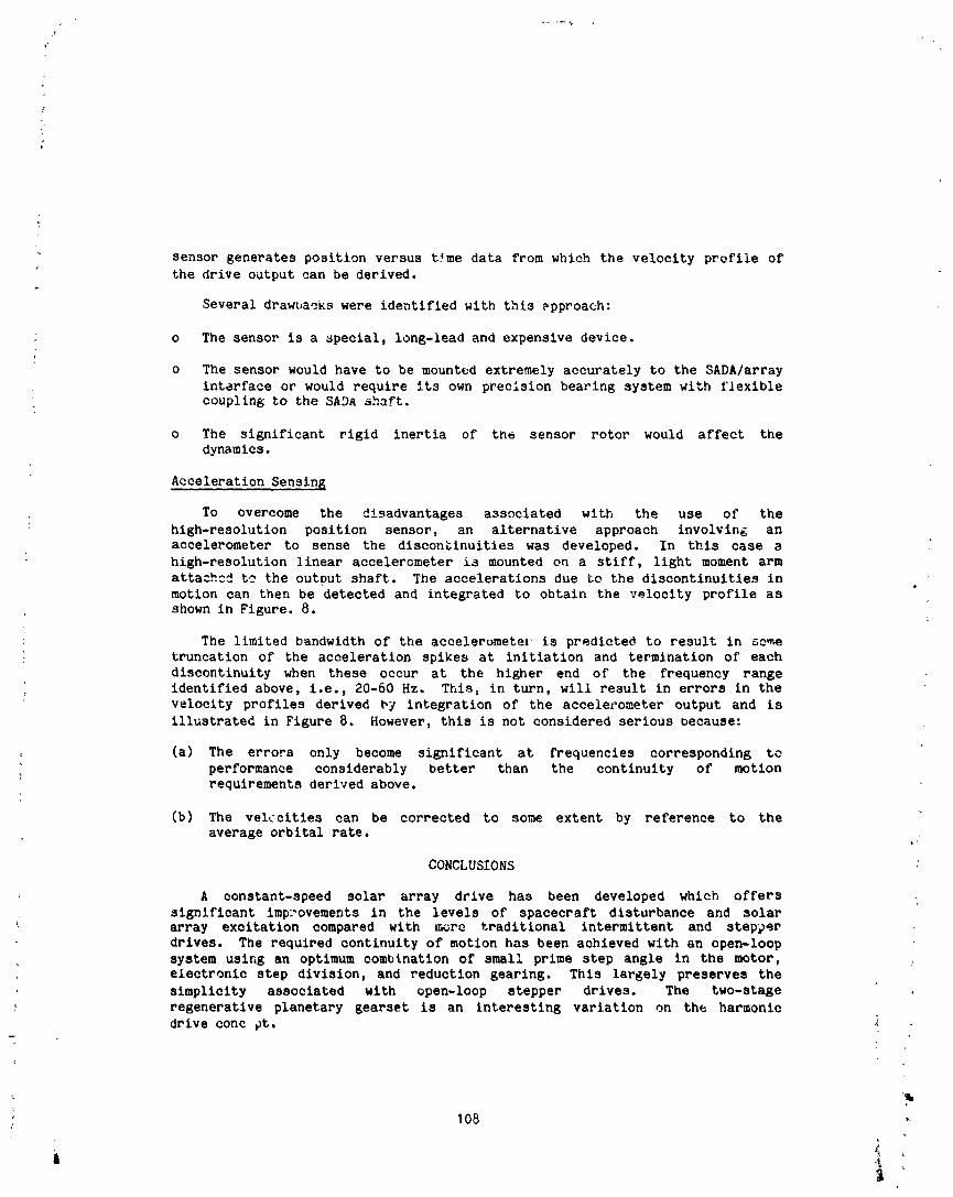
sensor generates position versus t_me data from which the velocity profile of
the drive output can be derived.
Several drawbacks were identified with this _pproach:
; o The sensor is a special, long-lead and expensive device•
o The sensor would have to be mounted extremely accurately to the SADA/array
interface or would require its own precision bearing system with flexible; coupling to the SADa abaft.
o The significant rigid inertia of the sensor rotor would affect the
dynamics.
Acceleration Sensin 5
To overcome the disadvantages associated with the use of the
high-resolution position sensor, an alternative approach involving an
accelerometer to sense the disconblnuitles was developed. In this case a
high-resolution linear accelerometer is mounted on a stiff, light moment arm
attached to the output shaft. The accelerations due to the discontinuities in
motion can then be detected and integrated to obtain the velocity profile asshown in Figure• 8.
: The limited bandwidth of the accelerumeter is predicted to result in some
truncation of the acceleration spikes at initiation and termination of each
discontinuity when these occur at the higher end of the frequency rangeidentified above, i.e., 20-60 Hz. This, in turn, will result in errors in the
velocity profiles derived by integration of the accelerometer output and is
illustrated in Figure 8. However, this is not considered serious because:
(a) The errors only become significant at frequencies corresponding to
performance considerably better than the continuity of motionrequirements derived above.
(b) The velcclties can be corrected to some extent by reference to the
average orbital rate. ,
CONCLUSIONS
A constant-speed solar array drive has been developed which offers
significant improvements in the levels of spacecraft disturbance and solararray excitation compared with more traditional intermittent and stepper
drives. The required continuity of motion has been achieved with an open-loopsystem using an optimum combination of small prime step angle in the motor,
; electronic step division, and reduction gearing. This largely preserves the
simplicity associated with open-loop stepper drives. The two-stage
regenerative planetary gearset is an interesting variation on the harmonic
drive conc pt.
q
q
108
1985025199-118
An engineering model drive system including the minlstepping electronics
has been fabricated and is currently undergoing a series of tests. Of
particular interest is the method of measuring the achieved continuity ofmotion at the output under various operating conditions. A novel approach was
; adopted involving a sensitive linear acoelerometer mounted on a stiff, light
moment arm attached to the output shaft of the drive system. The
accelerometer signal can be processed in a variety of ways to derive the
angul_." velocity pro'ile, frequency spectrum, etc.
The design and test techniques described in this paper are applicable to
other low-speed mechanisms such as robot arm joints and pointing drives for
iar_e antennae.
ACKNOWLEDGEMENTS
This paper describes work performed under the sponsorship and technical
direction of the Internatlonal Telecommunications Satellite Ocganlzation
(INTELSAT). Any views expressed are not necessarily those of INTELSAT. Theauthors would like to thank Mr. W. Alsbach of INTELSAT for his valuable
support and advice.
: The prior support of the Canadian Government Department of
Communications/CRC for developing various aspects of solar array drive
technology is also gratefully acknowledged.
139
1985025199-119
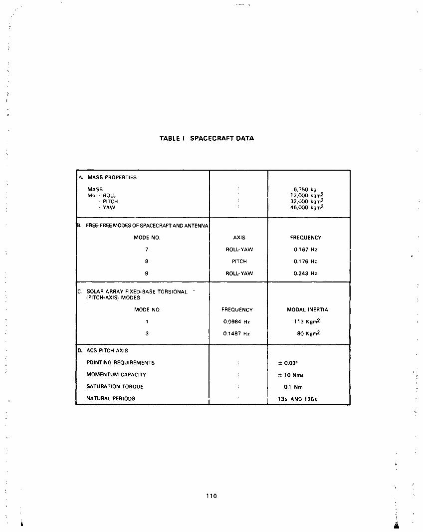
TABLE I SPACECRAFT DATA
A. MASS PROPERTIES
MASS : 6,':50 kgMol- ROLL F2,OOO kgm2
- PITCH : 32,000 kgm2 :- YAW : 46,000 kgm2
B. FREE-FREEMODES OF SPACECRAFT AND ANTENNA
MODE NO. AXIS FREQUENCY
7 ROLL-YAW O.167 Hz
8 PITCH 0.176 Hz
9 ROLL-YAW 0.243 Hz
C. SOLAR ARRAY FIXED-BASE TORSIONAL °(PITCH-AXIS) MODES
MODE NO. FREQUENCY MODAL INERTIA
1 0.0984 Hz 113 Kgm 2 _"
3 0.1487 Hz 80 Kgm 2
D. ACS PITCH AXIS
POINTING REQUIREMENTS : ± 0.03 °
"; MOMENTUM CAPACITY : ± 10 Nms '
SATURATION TORQUE : 0.1 Nm
: NATURAL,, PERIODS I I 135 AND 125s
7
110
1985025199-120

TABLE II DRIVE SYSTEM DESIGN REQUIREMEI_TS
DRIVE TORQUE- (3 cx WORST-CASE RESIST=NGTORQUES) 16 Nr_, MINIMUM
SOLARARRAY ORIENTATION ± 2.0=_- - POINTING ACCURACY
- DEVIATIDN BETWEENNAND S WINGS O'2=- SUN-TRACKING RATE 1 REVOLUTIONPER DAY- SUN-ACQUISITION RATE 0.27 ° PER SECOND
INDUCED SPACECRAFTDISTURBANCE!PITCH-AXIS)- POINTING ERROR 0.03 °, MAXIMUM- REACTIONWHEELTORQUE 0.1 Nm, MAXIMJM- REACTIONWHEEL MOMENTUM CHANGE 1.0 Nms, M/'_,IMUM"
' 10% OF TOTAL REACTIONWHEEL CAPACITYFROM TABLE
TABLE III GEAR DATA
: A. FIRST STAGE : EXTERNALS?UR SET
NUMBER OF TEETH ON PINION : 34NUMBER OFTEETH ON GEAR : 200RATIO=200 / 34 = 5.88
MODULE(DIAMETI _L PITCH) : 1.O6mm (24)PRESSUREANGLE : 20_EFFICIENCY.NOMINAL : 98%
B. SECOND STAGE: REGENERATIVEPLANETARYSET
NUMBER OF TEETH ON PLANET : 27NUMBER OF TEETH ON FIXED RING : 98NUMBER OF TEETH ON ROTATING RING : 98RATIO= 98 x 27 =49
(98 x 27) - (98 x 27)
MODULE (DIAMENTRAL PITCH) : 0.94 mm (28.889): PRESSUREANGLE : 22.5°
EFFICIENCY,NOMINAL : 30%
111
1985025199-121
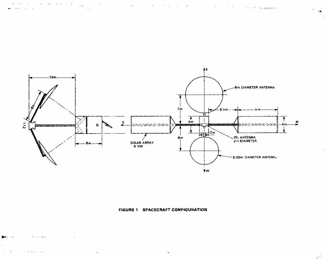
--_E
'1
?\
/"\
_/112
1985025199-122
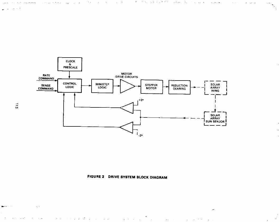
1985025199-123
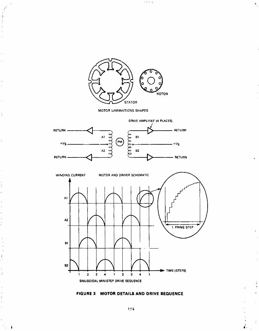
oGROTOR
R
MOTOR LAMINATIONS SHAPES
DRIVE AMPLIFIEP (4 PLACES)
RETURN _ _ RETURN
A1 !<- Q __ B1
+Vs e_ • 4V SA2 B2
RETURN _ _ RETURN
WINDING CURRENT MOTOR AND DRIVER SCHEMATIC
IA1
1 PRIME STEP
='- TIME (STEPS)1 2 3 4 1 2 3 4 1
SINUSOIDAL MINISTEP DRIVE SEQUENCE ,
FIGURE 3 MOTOR DETAILS AND DRIVE SEQUENCE
114
1985025199-124

,}f
-t-!
z
+or
_,
_cr
oi-_
\f,
V'V
V'---_
•,.u
+!
mt_
"Z
o,_
I-_Jwa.
-_
_7_
"'-
"-'I-
:�:_
0
55
r-
_W
1°
:u,I
©o
-r3
__
_8
-
JU
zo(J
115
Li
1985025199-125

MOTOR-ENCODER; (2-PLACES)
1ST STAGE_; -"_" GEARSET
(5.88:1)
MAIN BEARING
(1 OF 2)
OUTPU]
2ND STAGEPLANETARY
GEARSET
(49:1)
!
1
Ji
FIGURE 5 CUTAWAY ILLUSTRATION OF REDUCTION GEARING
116
1985025199-126

Tk#
AVERAGEORWTAL.RATE _ ___' _
.--_-- _ OUTPUT STEP SIZE
(A)
SHAFTSTIFFNESS
10-4 (KNnV_Ot
I O0 200 300
(B)
FIGURE 8 8TICK-SLIP MOTION AND EFFECT8 OF FRICTION AND 8TIFFNE$$
1985025199-127

E
CONTROL AND t
DRIVEELECTRONICS
,RIVE MECHANISM
SIMULATEO SOLAR ARRAY
SIMULATED S COMPRISING TORSION ROD.INERTIA DISC.AND WEIGHTS
SUPPORT STRUCTURE ACCICLEROMET[ R
FIGURE 7 SYSTEM DYNAMICS TEST RIG
ACCELERATION
/ / ,
EFFECTS OF ACCELEROMETER.-_
TIME-CONSTANT
VIELOClTY
__ PROFo_ Ol[no_[o BY
,, INTIGRATION OF ACC|LEROMIT|R l f
FIGURE 8 DETERMINATION OF CONTINUITY OF MOTION
118
1985025199-128

,, N85-33520
APPLICATION OF TRACTION DRIVES AS SERVC MECHANISMS
by
Stuart H. Loewenthal, Douglas A. Bohn, and Bruce M. Steinetz*
ABSTRACT
The suitability of traction drives for a wide class of aerospace control
mechanisms is examined. Potential applications include antenna or solar array
drive positioners, robotic Joints, control moment gyro (CMG) actuators andpropeller pitch change mechanisms. In these and similar applications the zero
backlash, high torsional stiffness, low hyste_.esis and torque ripple
characteristics of traction drives are of particular interest, as is the
ability to run without liquid lubrication in certain cases. Wear and fatigue
considerations for wet and dry operation are examined along with the
tribological performance of several promising self-lubricating polymers fortraction contracts. The speed regulation capabilities of variable ratio
traction drives are reviewed. A torsional stiffness analysis described in
this study suggests that traction contacts are relatively stiff compared to
gears and are si_ificantly stiffer than the other structural elements in the
prototype CMG traction drive analyzed. Discussion is also given of an
advanced turboprop propeller pitch change mechanism that incorporates atraction drive.
INTRODUCTION
An interesting but not particul_rl) well known class of speed changing
mechanisms utilize traction as the means to transfer torque. Applications
range _,_m dry contacts such as the locomotive wheel against the rail and
elastomer coated rollers in paper handling equipment to lubricated contacts in
industrial adjustable speed traction drives.
As power transmissions, few mechanical drives match their low noise,
smooth torque transfer characteristics and speed regulating accuracy.
However, their suitability as servo drive mechanisms has not been given wide
attention. For some control system applications, their ability to provide a
smooth transfer of motion with relatively low hysteresis losses and hightorsional stiffness while producing no detectable "backlash" upon direction
reversal are obviously beneficial qualities. On the other hand, traction
drives are unsuitable for polnt-to-polnt (PTP) positioning applications whereit is impractical to feedback output position.
The discussion which follows is intended to provide greater insight into
some of the performance characteristics of traction drives which may lend
themselves to certain servo mechanism applications. A number of examples will
be cited, as known to the authors, to help illustrate some of the prior art
along with a few applications presently under consideration. Due to the broad
eNASA Lewis Research Center, Cleveland, Ohio
119
i
1985025199-129

i
h
i
!
nature of this technology and the space limitations set forth here, this
: review can only hope to _ouch upon some of the more relevant designconsiderations. While published inform_tlon on traction drives isconsiderably more limited than other types of transmissions, particularly in
terms of servo mechanism applications, a significant design data base does
exist, as can be found in references 1 to 3.
BACKGROUND
The earl.lest of speed changing mechanisms us,:d smooth wheels of unequal
size in frictional contact. According to his writings, Leonardo De Vinci
devised and experimented with several machines which incorporated frictional
wheels. One such machine was for the grinding of lenses or polishing of
mirrors where the repetitive toothing errors f:-omgearing would produce
imperfect surfaces.
Because of their simplicity and their unique ability to smoothly and _continuously regulat_ speed, friction crive3 or traction drives, as they are
now known, found use in a host of applications. Some early examples include
wood working machines (circa 1870) in which the wood feed rate was regulated
with friction drive roller-- and turn-of-the-century motor cars equipped wiLhcontinuously variable, friction disk transmissions (ref. I). MoL'e modern
examples nf feed regulating and loading applications can be found in paper and
film handling equipment including printing and copying machines and computer
plotting devices. In these applications, 'he processed material is normally
"pinched" between an elastomer-ccated drive roller and another that
freewheels, such as that used in multlcolor printing operations to reglste,the paper. Analogous space vehicle applications include a pinch roller drive
mechanism for deploying a spool-wrapped antenna for the Helios B satellite
(ref. 4) and one that dispenses and store_ _ transfer boom for Skylab (ref. _).
Philosop_ically, "linear" traction drives include a wide class of vehicles
ranging from bicycles to locomotives. This later example of the wheel/rail
contact vividly illustrates that traction power transfer need not be limited
to trivial load levels. In fact, advanced, .'ight-weight helicopter
transmissions (Fig. i) which inco,'porate stee _ traction rollers lubricated
wlth synthetic traction fluids have been tested at the authors' laboratory atpower levels to 370 kW (ref. I).
Although not a mature discipline, desi_n techniques for traction drives
i have made good progress in recent years. Based on lubricaU_n, fatigue and
performance models developed originally for rolling-element bearings,analytical methods are now available to size traction drive contacts for a
specified reliability level end to make reasonable estimates of power loss and
traction capacity limits. Metallurgical Im_ovement_ in the fatigue
resistance of bearing steels coupled with the commercial introduction of hi_traction fluids have increased _e power capacity of traction drive contactsby several fold. While an extende3 discussion of these technical aavancements
is not central _ this review, helpful design information can be found from3everal source_ _refs. I to 3). _
120
1985025199-130

TRACTION DRIVES AS SPEED REGULATORS
Apart from their basic mechanical simpli'±ty, the most sou&ht after
_haracteristic of traction drives is their ability to prcvide nechanical
stepless speed control over wide ratio ranges, with some unit_ being
infinitely variable. In this regara, traction drives have been performing
light to medium duty (up to 75 kW) speed matching for industrial machinery for
more than 50 years (refs. i and 2). Applications range from knitting and
fiber-spinning equipment to milling machines and high-speed grinders(ref. 2). There are more than 2 doze_ commercial manufacturers of variable
ratio traction drives, with some designs dating back to the 1920s. Operatinglives of 2C years or more are not uncommon in factory environments.
A sample of commercially available, adjustable speed traction drive
geometries appears in Fig° 2. Speed regulation is achieved by altering therolling radii r_tio between input and output member. This is accomplished by
either tilting or translatlng an intermeazate transfer element or through
direct translation of input or output members. Normally a manu_± vernier
control element is ,,_d £nr this positioning, although feedback control hasbeen used on some aerospace applications. With manual control, output speed
regulation and repeatability is often with +0.1 percent under uniform
loading. Under extreme no-load-to-full-load fluctuations, maximum output
speed variations are typically i to 2 percent. However, with suitable servo
controls, accuracy can be restored back to the O.1 percent level (ref. 6).
TRACTION CURVE
_e speed variation between traction rollers due tc torque transfer is
generally referred to as "creep" (ref. 3). Traction drives are designed to
operate along the linear ascending portion of the traction curve (Fig. 3) at
some point below the peak. A ball or roller-ramp loading mechanism (Fig. 4)
is commonly used to increase the clamping force between roller elements in
proportion to t_e transmitted torque. The angle of the ball ramp is tailoredto the lubricant-contact condition. It ie selected so that the ratio of the
applied tangential to normal force, or traction coefficient, is about 20 to 30
percent less than the maximum available traction coefficient under the least
favorable operating condition. This provides some margin against slip. With
a torque sensitive loading mechanism, gross slip will not occur, even at
torque levels which exceed the elastic limit of the rollers or structural
material. This loading action is not unlike the behavior of a roller ramp or
sprag-type clutch. Improved part load efficiency and extended service life
are additional benefits from modulating the clamping force with the demandload. Maximum officiencies of adjustable speed traction drives typically
range from 85 to 93 percent. However, multiple contact fixed ratio traction
drives have efficiencies of about 96 to 97 percent, with single contactsystems being as high as 99 percent.
Operating creep rates of traction contacts are relatively small. Theyrange from 0.i to 0.2 percent for dry contacts or those lubricated with
traction fluids at low speeds (Fig. 3), to 3 or 4 percent for lightly loaded,
high speed contacts lubricated with mineral oils. This speed difference is
.4
121
1985025199-131

1
f
not due to slip between driver and driven roller but is, in fact, the
accumulated lost motion due to the tangential stretching and compressing
motion or compliance occurring at the roller contact interface. It is well
known that a "locked" or "zero slip" region exists at the leading edge of thecontact and only at the peak traction point, i.e., point of impending slip,
will this region completely disappear. Nevertheless, this lost motion due to
creep precludes the use of traction drives for open-looped positioning
devices. However, open-looped speed regulation accuracies of +0.5 percent or
better are achievable with an automatic loading mechanism over a wide range ofspeeds and torques based on test data for a 14:1 fixed rati_ traction drive
reported in reference 7.
It is instructive to note that the creep or s±_de-to-ro_l _ates associated
with traction drives are generally one to two orders o_ magnitude smaller than
those associated with gear teeth as they enter and leave mesh. Under
difficult to lubricate 6onditions, such as those that exist for most space
mechanisms, the fundamental rolling nature of a traction contact is a decided
benefit in terms cf reduced wear and heat gen_'_tion. This was clearly
demonstrated at the authors' laboratory where a ±C.g:l ratio planetarytraction drive (Fig. 5) survived 1 hour of repeated _iI oower acceleration
(Ii kW at 9xlO 4 rad/sec 2) tests from 0 to 70,00_ rpm whz±e submerged inLOX (ret. ]). Test life was equivalent to 2x10 revolutions of the
high-speed shaft. Expected gear life under comparable conditions would be amaximum of about 15 or 20 minutes du_ to excessive wee _ under this hostile
lubrication condition. Furthermore, a similar but 120:1 ratio traction drive
was tested fully preloaded for 43 hours at 360,000 rpm without failure using
no liquid lubrication whatsoever (ref. 1). Such speeds are, in alllikelihood, beyond the realm of even oil lubricated gears.
DURABILITY
Fatigue
The falure modes of traction drive contacts are very similar to those of
ball and roller bearings. This is not surprising since the operating
stresses, materials (normally hardened bearing steels), contact geometries andsurface finishes as well as lubrication conditions are also very similar. As
with rolling-element bearings, fatigue or pitting is the likely failure mode
when the quality of lubrication is good, that is when the ratio of lubricantfilm thickness to composite surface roughness or lambda ratio is above about
1.5. Statistical fatigue life can then be predicted from a modified form of
the Lundberg and Palmgren theory that is traditionally used to determine
service llfe ratings of commercially available ball and roller bearings.
Details of this method can be found in reference 3. In general, fatigue life
L is related to size, torque T and available traction coefficient_ as follows:
LIW size 8"4 at constant T andS4
Lo( T-3 at constant size and_
Le(_ 3 at constant size and T
122
1985025199-132

Thus a 9 percent increase in size or a 26 percent increase !m_ will double> the fatigu_ izfe at constant torque capacity or, in turn, cause a 26 percent
increase in torque capacity at constant fatigue life.r
?!ear
As the quality of lubrication or iambda ratLo diminishes, the degree of
asperity cu_tact and surface distress increases and the failure mode shifts
from predominantly fatigue to one +hat is predominantely wear. It is this
' mixed or boundary lubrication regime _here most low speed space mechanism •
contacts must operate.
Solid lubricant films formea _ ..... om graphite. YOS2_ pT_ or those from• soft metals such as lead, gold or silvtr are potent±el substitutes for liquid
lubrluants and greases in the low lambda regime. The geheral increase in
: friction coefficient attendant with some dry film lubricants is obviously
beneficial for traction drive _o_tacts, allowing some reauction in the
requ1£od clamping loads. However, the normal concerns of using dry film
lubrican_ still remain, namely their non-renewable nature, the integrity ofthe film/subctrate bond and the detrimental accumulation of wear debris.
Also, the somewz,:,terratic nature of a dry film's friction coefficient may °preclude their use fcr certain torque-sensitive mechanisms. In such cases,
low vapor pressure greases, such as the perfluoroether type, are normally
preferred provided that potent1_l contamination of optical surfaces are not a
factor and evaporation rates are witnlr operational life requirements.
hard-faced, ion-sputtered or vapor-deposited coatings such as TiN and TiC
avoid some of these problems (ref. 3), but their long-term fatigue resistancestill requires better definition.
Polymers/elasto_ers. - Perhaps the most promising self-_ubricatingmaterials for traction drive actuators are some of the polymers and elastomers
that have been successfully used for a variety of industrial roller type
components. These range from molded polyurethane casters and wheels to
polyamide (nylon), acetal and polyamide-imide (Torlon) thermoplastic bearings
and gears. Many of _hese materials can be reinforced with glass fibers for
strength and filled with graphite or PTFE for reduced friction. In additionto their self-luricating _'ilities, these maintenance-_,ee materials offer
significant vibration damping, quietness of operation, low weight and
corrosion resistance. The general tribological propertJcs of a large number
of these polymers is relatively well defined (re'. 9), but the_. specificperformance as traction drive materials for use in space mechanisms is not as
"i w_ll understood. Specifically, their cold temperature and vacuum, tractionand wear cDaracteristics need better definition as does their stress
relaxation (cold flow), radiation resistance, and outgassing behavior.Because contamination by liquid lubricants can markedly reduce their traction
:, capability, use of these materials must be restricted to relatively cleanenvironments, not unlike those required for other types of precision
mechanisms. Despite these concerns, a surprisingly large class of polymeric
materials have been applied successfully as structural, protective, dielectric
L
: 123
1985025199-133

and sealing materials on spacecraft (ref. 10). Furthermore, because of theirability to self-lubricate _nd to resist cold welding even in a hard vacuum,
they have also been used in mechanisms at points of sliding. Typical examc!es
i include phenolic ball bearing cages impregnated with dry or liquid lubricantsand fine-pitched gears made from polyamide or acetal resin.
I
.I The load capacity of some commercially available polymers in
sliding/rolling contact is surprisingly large. For example, table I listsf some of the results of test programs sponsored by the authors' laboratory to
t define the traction capacity limits of several engineering thermoplastics. In
i these tests, the rolling failure load limits o_ six different thermoplasticrollers 50 mm in diameter in contact with equJ sized steel rollers were
determined in air at ambient temperature and pressure. From the rolling
tests, two of these materials, an unfilled polyamid_-imide and a cotton fiber
phenolic, were selected for torque transfer testing near their peak traction
capacity limits. The polyamide-imide resin withstood a remarkable 220 N/mm
(1250 Ib/in) of unit normal loading at a rolling speed of i0 m/s with 2
percent sliding for 30 minutes of testing without da_ge. A narrow roller,
just 5 mm wide, of this material transmitted 4.8 kW of power continuously for
10 minutes at 20 m/s without fai3ure. W_ile the perfor,aance of some of these
commercially available thermoplastics clearly exceeds any of those anticipated
for servo mechanisms applications, these result- do suggest that plastics
could be used in place of steel for certain low-cost, moderate power, tractionspeed regulators.
Polyimides are another class of polymer which offers promise as a
low-wear, high-traction material. Polyimide films have excellent UV radiationresistance and vacuum stability, being used extensively on spacecraft for
thermal blanket insulation and a variety of external semistructural
applications (ref. lO). In addition, some polyimides have unusually
high-sliding wear resistance. For example, ambient pin-on-disk experiments
with an experimental, partially fluorinated polyimide pin sliding against a
"_ steel disk showed it to have an average friction coefficient of 0.8 and an
average wear rate of 5x10 -15 m3 per meter of sliding at sliding speeds of
I! 2.7 to 3.1 m/s (ref. ii). At this wear rate, it would take ix109
"l' re_olutions for a l0 mm wide, relatively heavily loaded traction roller madeof this polymer to wear off a i m thick layer of material, assuming a
relatively high 1 percent slide-to-roll ratio. _
Another potentially useful class of materials for traction rollers are
vulcanized natural and synthetic ruboers. Some guidelines for the speed/loadlimits of these elastomers for general traction drive service can be found in
reference 3. Polyurethene rubbers are particularly durable, having been usedin difficult service conditions such as when molded to forklift truck wheels
and subway train tires. Furthermore, polyurethane molded rollers have already
been used without failure for one type of traction drive, space qualified,
rotary actuator known to the authors. Its traction capacity in a vacuum is
high. Sliding friction tests of a molded polyurethane wheel, meetingMIL-R-3065 specifications, exhibited a friction coefficient from 0.7 to 1.3
against an aluminum or magnesium concave slider in a vacuum of 10-5 torr atroom temperature (ref. 12). Since all elastomers stiffen to some extent at
124
1985025199-134
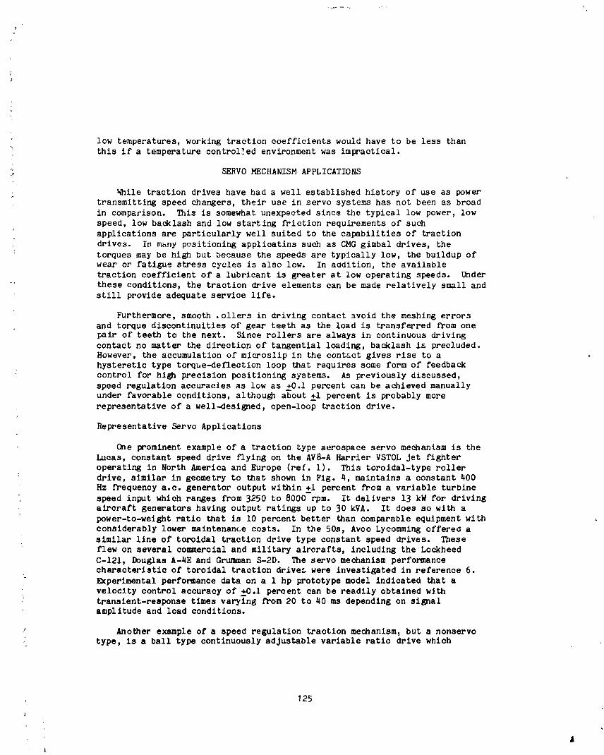
low temperatures, working traction coefficients would have to be less than
this if a temperature controlled environment was impractical.
"; SERVO MECHANISM APPLICATIONS%
While traction drives have had a well established history of use as powertransmitting speed changers, their use in servo systems has not been as broad
in comparison. This is somewhat unexpected since the typical low power, low
speed, low backlash and low starting friction requirements of such
applications are particularly well suited to the capabilities of traction
drives. In many positionir_ applicatins such as CMG gimbal drives, the
torques may be high but because the speeds are typically low, the buildup of
wear or fatigue stress cycles is also low. In aodition, the available
traction coefficient of a lubricant is greater at low operating speeds. Under
these conditions, the traction drive elements can be made relatively small and
still provide adequate service life.
Furthermore, smooth .ollers in driving contact avoid the meshing errors
: and torque discontinuities of gear teeth as the load is transferred from onepair of' teeth to the next. Since rollers are always in continuous driving
contact no matter the direction of tangential loading, backlash is precluded.
However, the accumulation of microsllp in the contact gives rise to ahysteretic type torque-deflection loop that requires some form of feedback
control for high precision positioning systems. As previously discussed,
speed regulation accuracies as low as +0.I percent can be achieved manuallyunder favorable conditions, although a_out +i percent is probably more
representative of a well-designed, open-loop traction drive.
Representative Servo Applications
One prominent example of a traction type aerospace servo mechanism is the
Lucas, constant speed drive flying on the AVS-A Harrier VSTOL Jet fighter
operating in North America and Europe (ref. i). This toroidal-type roller: drive, similar in geometry to that shown in Fig. 4, maintains a constant 400
Hz frequency a.c. generator output within +i percent from a variable turbinespeed input which ranges from 3250 to 8000 rpm. It delivers 13 kW for driving
aircraft generators having output ratings up to 30 kVA. It does so with a
power-to-weight ratio that is I0 percent better than comparable equipment with
considerably lower maintenance costs. In the 50s, Avco Lycomming offered a
similar line of toroidal traction drive type constant speed drives. These
flew on several commercial and military aircrafts, including the Lockheed
C-121, Douglas A-4E and Grumman S-2D. The servo mechanism performance
characteristic of toroldal traction driver were investigated in reference 6.L
Experimental performance data on a 1 hp prototype model indicated that a
velocity control accuracy of \�€can be readily obtained with
transient-response times varying from 20 to 40 ms depending on signalamplitude and load conditions.
." Another example of a speed regulation traction mechanism, but a nonservo
• type, is a ball type continuously adjustable variable ratio drive which
: 125
Ai
1985025199-135

synchronizes the digital counter readout of a commercially available liquid
flow volume meter. The drive couples the positive displacement fluid rotor to
the meter's counter. A vernier adjustment screw is used to vary the speed
ratio in 0.02 percent increments between the metering rotor and the counter so
that accurate readings are obtained when the meter is calibrated against some
"master" meter or other liquid volume test standard.
Traction type linear actuators are also commercially available. These
units are useful for a wide range of positioning and motion applicationsparticularly where jamming and overload protection are req,_ired. In one
design, three equally spaced, skewed rollers located on each end of a twopiece, spring-loaded, clamping block are loaded against the surface of the
smooth, rotating drive shaft. The angle of roller skew relative to the driveshaft axis is directly related to the amount of linear travel of the block per
drive shaft revolution or "lead." The thrust capacity at slip can be easily
varied by adjusting the screws which vary the spring clamping load. If the
linear element would hit its stop or jam, the rollers would automatically slip
at the set thrust level and be automatically reset for operation when the jamwas relieved.
OPERA TING CHARACTERISTICS
In comparison with gear type servo mechanisms, traction drives possessseveral desirable operating characteristics. These can be summarized asfollows:
(i) Zero backlash
(2) High torsional stiffness
(3) Low starting friction or breakaway torque
(4) Low torque ripple
(5) Low velocity errors
(6) High torque density and compactness
(7) Infinite resolution of speed or ratio adjustment
In addition to these features, the roller contact due to its low sliding
nature can be designed to operate for extended periods of time without liquid
or grease lubrication. As previously discussed, this can be accomplished by
either using high traction solid film coatings such as ion-plated gold or
silver or using advanced, low-wear polymers such as partially fluorinated
polyimides or polyamide-imides. The elimination of a depletable liquidlubrication is a decided benefit for spacecraft mechanism applications.
Furthermore, rollers, unlike gears, have th3 ability to harmlessly sllp at
predetermined traction limits. The over torque, release-clutch-tendency can
prevent catastrophic da_mge if jamming should occur at some point in themechanism drive train.
Finally, in the case of dual fault or multiply redundant servo drive
mechanisms, such as those for some spacecraft applications, independent,
multiple drive rollers can be readily engaged and disengaged from drive
126
J
1985025199-136

o;'
4
systems with conventional linear actuators wihou_ the need to stop the systemfrom rotating or the need to provide proper tooth mesh phasing.
Stiffness
To achieve minimum response time for a point-to-point motion control or toincrease responsiveness of a servo controller in general, it is necessary tomaximize drive system torque-to-inertia ratio and stiffness. In reference 13a method was presented for analyzing the torsional stiffness and hysteresiseffects of a traction drive contact of arbitrary geometry under a wide variety
of loading conditions.
Torsional stiffness KT was found to increase with an increase in normal loadN, available traction coefficient , shear modulus of the material G androller radius R while decreasing with an increase in transmitted torque T.The exact expression for the stiffness of a crowned roller pair of equal sizewas given as:
( T I13KT - 7- I ---_'] (I)
where a is the semiwid_5 of the elliptical contact and is a contact geometryparameter.
Another finding of the study performed in reference 13 was that the
traction contacts themselves are considerably stiffer than the bearings andother structural elements in a complete traction drive system, typically
accounting for only several percent of the drive's tottl compliance.
A comparison of the theoretical stiffness of equally sized gear andtraction roller pairs made of steel showed that traction contracts were
; typically two or three times stiffer than gears under comparable loads. Thisis illustrated in Fig. 6 where the stiffness of traction contacts relative to
: _ mparably sized and loaded gears is plotted as a function of gear tooth sizediametral pitch). The method used to analyze gear stiffness considers the
-' local Hertzlan normal compliance and tooth beam bending. It also considersstandard undercut and fillet bending and shear as well as foundation
i flexibility (ref. 13).
It is apparent from Fig. 6, that gear mesh stiffness is relativelyinsensitive to the number of teeth or the torque level and fluctuates betweentwo relatively discrete levels as the load is transferred between single toothand double tooth contact. Apart from the kinematic (unloaded) errors, this
stiffness fluctuation contributes to velocity fluctuations in a loaded geartrain. In contrast, the stiffness of a traction drive contact is essentiallyconstant for a given load, although some de_adation with increasedtransmitted torque will occur as shown.
. ' 12"/'.am,
i
1985025199-137
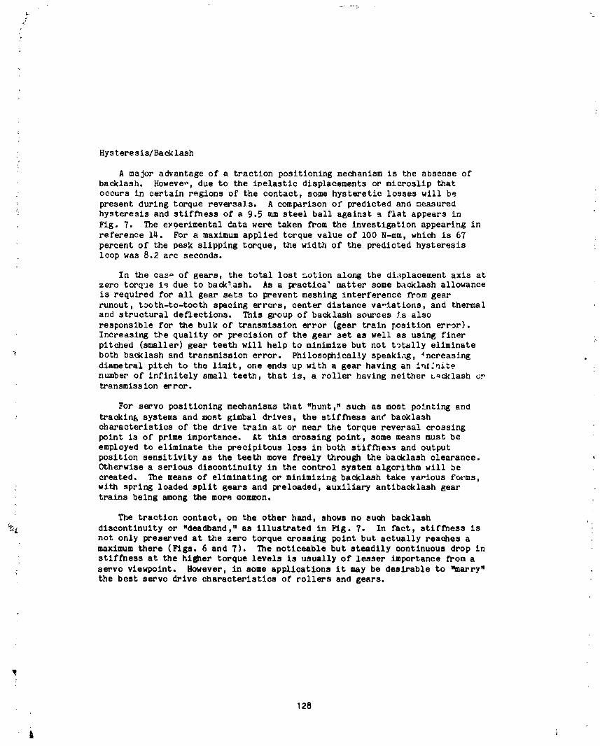
Hysteresis/Backlash
A major advantage of a traction positioning mechanism is the absense ofbacklash. Howeve,., due to the inelastic displacements or microslip that
occurs in certain regions of the contact, some hysteretic losses will be
present during torque reversals. A comparison of predicted and measured
hysteresis and stiffness of a 9.5 mm steel ball against a flat appears in
Fig. 7. The eyoerimental data were taken from the investigation appearing in
reference 14. For a maximum applied torque value of i00 N-ram, which is 67
: percent of the peak slipping torque, the width of the predicted hysteresis :loop was 8.2 arc seconds.
In the cas_ of gears, the total lost motion along the displacement axis atzero torque is due to back_ash. As a practica" matter some backlash allowance
is required for all gear sets to prevent meshing interference from gear
runout, tooth-to-tooth spacing errors, center distance va-iations, and thermaland structural deflections. This group of backlash sources is also
responsible for the bulk of transmission error (gear train T_)sition error).
Increasing the quality or precision of the gear set as well as using finer i.pitched (smaller) gear teeth will help to minimize but not t_tally eliminate
•_ both backlash and transmission error. Philosophically speakiag, _ncreasing .
diametral pitch to the limit, one ends up with a gear having an intlnite
number of infinitely small teeth, that is, a roller having neither u_cklash ortransmission error.
For servo positioning mechanisms that "hunt," such as most pointing and
trackin_ systems and most gimbal drives, the stiffness an¢ backlash
characteristics of the drive train at or near the torque reversal crossing
point is of prime importance. At this crossing point, some means must be
employed to eliminate the precipitous loss in both stiffness and output
position sensitivity as the teeth move freely through the backlash clearance.Otherwise a serious discontinuity in the control system algorithm will be
created. The means of eliminating or minimizing backlash take various forms,
with spring loaded split gears and preloaded, auxiliary antibacklash gear
trains being among the more common.
: The traction contact, on the other hand, shows no such backlash ,_L discontinuity or "deadband," as illustrated in Fig. 7. In fact, stiffness is
not only preserved at the zero torque crossing point but actually reaches a
maximum there (Figs. 6 and 7). The noticeable but steadily continuous drop in
stiffness at the higher torque levels is usually of lesser importance from a
; serve viewpoint. However, in some applications it may be desirable to "marry",+ the best serve drive characteristics of rollers and gears.
128
1985025199-138
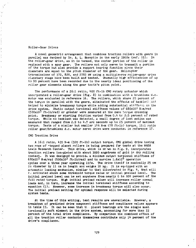
Roller-Gear Drives
A novel geometric arrangement that combines traction rollers with gears in
parallel was devised by Dr. A. L. Nasvytis in the early 1960s (ref. 15). In
the roller-gear drive, as it is termed, the center portion of the roller is
replaced with a spur gear. The rollers not only serve to transmit a portionof the torque but also provide a support bearing function since their
diameters are equal to the pitch diameter of the gear. Helicopter
transmissions of 370, 820, and 2760 kW using a multiple-row roller-gear drivep!dnetary stage have been built and tested. Unusually high efficiencies of up
to 99 percent have been recorded due to the nearly ideal positioning of the
roller gear elements along the gear tooth's pitcn point.
The performance of a 26:1 ratio, 400 ft-lb CMG rotary actuator which
inco-porated a roller-gear drive (Fig. 8) in combination with a brushless d.c.
motor was evaluated in reference 16. The rollers, which share 25 percent of
the torque in parallel with the gears, eliminated the effects of backlac:, and
helped to minimize breakaway torque while adding substantial stiffness co the
drive s_stem. Static output torsional stiffness values of 680xI0 _ N-m/rad(500xlO _ ft-lb/rad) or greater were measured at the zero torque crossing
point. 8reakaway or starting friction varied from 0.4 tc 2.5 percent of rated
torque. While no backlash was detected, a small degree of lost motion wasmeasured that ranged from 2.9 to 4.7 arc seconds up to 25 percent of maximum
torque. Tests of a similar but smaller i_6 N-m (78 ft-lb) torque, 15:1 ratio
roller gear/brushless d.c. motor servo drive were conductea in reference 17.
CMG Traction Drive
: A 16:1 ratio, 435 N-m (320 ft-lb) output torque, CMG gimbal drive having
two rows of otepped planet rollers is being prepared for tests at the NASA
Lewis Research Center. This drive, which is sh,wn in Fig. 9, incorporates
traction rollers ion-plated with about 3000 angstroms of gold in dry rolling
contact. It was designed to provid_ a minimum output torsional stif_ess of
680xi03 N-m/rad (500xlO 3 ft-lb/rad) and to survive 1.6x10⁶ operation
cycles over a three year operating life. The drive itself is nominally 25 cm
Jn diameter by ll cm in length and weighs i0 kg. It is eq_ipped with an
at,tomatic loading mechanism, similar to that illustrated in Fig. 4, that willt._ activated above some threshold torque value or initial preload level. The
initial preload level can be set anywhere from nearly 6 to i00 percent of thefull rated torque. High initial preload values will increase roller normal
loads and, in turn, increase the initial torsional stiffness according to
equation (i). However, some increase in breakaway torque will also occur.
The initial preloac setting for optimal response will be selected duringsystem tests.
At the time of this writing, test results are unavailable. However, a
breakdown of predicted drive component stiffness and compliance values appears
in table II. It can be seen that tL planet bearings are the single most
torsionally soft element in the drive system, accounting for more than 33
percent of the total drive compliance. By comparison the combined effect of
all the traction roller contacts themselves contribute only 14 percent of the
drive's compliance.
129
1985025199-139

!
|
_RACTION DRIVE PITCH CHANGE MECHANISM
A NASA program wa_ qtarted in the early 1970s to develop technology for an
advanced turboprop (ATP) commercial aircraft capable of accommodating up to
' 150 passcrg_,_ a_ a cruise Mach number between 0.7 and 0.8. Fuel savings for
an ATP aircraft are projected to be on the order of 20 percent for singlerotation (SR) and 30 percent for counter rotation (CR) propeller systems
relative to comparable state-of-the-art turbofan engines without a significant
compromise in engine noise or emissions. A technology area that has beenidentified as being critical to the successful development of an ATP aircraft
is a highly reliable, efficient gearbox/pitch change mechanism (P(IM) propellerdrive system (ref. 18).
Due to the unusually high power levels (on the order of i0,000 kW) and
large size propellers (on the order of 4 m in diameter) the blade reaction
torque which must be carried b# the PC_ is more than an order magnitude larger
than previoas turboprop PCM systems. In addition, a goal has been e_tablishedto increase the operating reliability of the drive system from today's 4000 to8000 hour mean time between unscheduled removal (MTBUR) to greater than 20,000
hour MTBUR. Furthermore, the propeller blade angle control system must be
sufficiently precise to synchro_hase the clock position of multiple engine
propellers _rd thus minimize _he "beating" noise hitting the fuselage. In
view of these new and challenging requirements, PCMs which embody advanced
teo]qnology features are currently being investigated.
One premising approach being studied is the electromechanical PCM
illustrate in Fig. i0. This system incorporates a compact, high-reductlon
ratio (210:1) hybrid traction drive, powered by an advanced technology,electronically commutated, porto&rent magnet (PM) synchronous motor. A
similarly constructed PM synchronous alternator which is colocated with themotor inside the rotating spinner provides the electrical power. This
alternator receives mechanical power across the rotating interface through a
power takeoff shaft extending from the main propeller gearbox. Thus, highmaintenance, rotating power transfer devices such as electrical sllp rings orhydraulic fluid transfer seals, in the case of hydraulic actuators, areellmina ted.
The hybrid traction drive (Fig. ii) couples the high-speed servo motor
(nominally 20,000 rpm at maximum blade slew rates) to the ball screw. The
ball screw, in turn, articulates the individual blades through stiff links,
connected at one end to an eccentric pin at the blade root and st the other
end to the translating ball screw nut. The motor input to the hybrid drive
occurs at the sun roller while the output to the ball screw Is taken from the
toolhed output ring gear. The planet carrier frame is grounded to the casing
while the outer ring roller is allowed to freely rotate, serving as a"containment" ring to react the traction drive rollers, clamping loads.
130
1985025199-140

ilIL
I Blade Angle Control|
ii An autonomous digital electronic control module, located in the nose of
the spinner for ease of maintenance, commands blade angle position based on
control signal information from the cockpit. This control signal data passes
across the rotating interface through a novel fiber optic coupling with
superior noise rejection and data bandwidth characteristics. The drive
• mechanisms is actuated only when a change in blade positior is commanded and
then only in a low speed, hunting mode to achieve synchrophasing. Since the
' cruise condition occupies the bulk of the mission, the drive system
experiences only intermittent periods of high slew rate when either reverue
pitch or emergency feather operations are commanded. However, the drivemechanism carries nearly full torque under practically all operating
conditions since it must always react the blades' centrifugal force twisting
moment. In the event of PCM failure this twisting moment would back drive the
blades toward a flat pitch position which, if left unchecked, could lead to a
potentially dangerous overspeed condition. To prevent this situation from
occurring, an independently driven pitchlock screw mechanism which tracks theposition of the ball screw nut has been incorporated into the system• In the
event of any mechanical or electrical component failure downstream of the hall
screw, the pitchlock will lock the propeller blades within 1° to 2° oftheir last position and allow engine operation in a "fixed prop" mode without
any danger of overspeeding.
Hybrid Traction Drive
The traction drive was selected for this application fcr several reasons.
Its high ratio capabilities in a compact "pancake" package enables it to beconveniently installed as a module near the nose of the spinner for ease of
maintenance and/or replacement with the engine still on the wing. Because ofits rolling nature, the roller drive has the ability to handle intermittent
bursts of input speeds to 20,000 rpm without the need for liquid lubrication
cooling. The unit can be conveniently packed with synthetic "traction" grease
(formulated grease with a high coefficient of friction) and then "sealed forlife."
The traction drive's low mechanical hysteresis and hiSh torsional
stiffness increases blade positioning resolution. _ile gear type
differential speed reducers can be designed to achieve the same 210:i ratio in
a single stage, their expected efficiencies in the neighborhood of 80 percentare decidedly inferior to the told-90 percent range expected for the hybrid
traction drive. With the proposed friction, low inertia mechanism coupled to
a high resolution digital controller, blade position accuracies of better than3 arc rain of a degree are projected for the system (ref. 18). Although the
level of precision necessary to achieve multiengine synchrophaslng has yet to
be established, the PCM described here should be significantly more accurate
than the current industry standard of about +_5° on blade clock position.
131
_ ,_- t
&
1985025199-141

SUMMARY
Adjustable speed traction drives have been in commercial service for _ore
than 50 years, performing a speed regulation function for a wide range of
industrial machinery. Speed regulation accuracies typically range from _i
percent with open loop control to about +0.i percent with feedback control or
wlth oven loop control when the loads are relatively constant.
Despite their smooth torque transfer characteristics, low rolling friction
and undetectable backlash, traction actuators have noc been widely applied to
aerospace servomechanisms. One notable exception are the constant speed
generator, drives that have been in service on several commercial and militaryaircraft. Also "pinched" roller drive systems similar to those commonly used
in printing and paper handling machinery have been incorporated in some
spacecraft deployment mechanisms.
In this paper, reference is made to the traction-creep characteristics,
lubrication principles, material considerations and fatigue llfe sizing
relationships associated with traction drives. The low sliding nature of utraction contact lends itself to the application of solid film lubricants and
to the use of soft metal coatings and self-lubrlcati-_ polymers. Certain
classes of thermoplastics, such as polyimldes and polyamide-lmides have lowwear, high traction characteristics and can sustain very high loads without
failure. Although several of _hese polymers have been used as structural and
sliding Joint materials on spacecraft, their long term trlbologlcal
performance in a space environment needs greater definition.
_hc torsional stiffness characteristics of a traction contact were found,
:'rom the method presented, to compare favorably with those of gears,
_,'_Icularly at the zero torque crossing point. The typical torque-angulardisplacement loop of a statically strained traction contacts revealed no
backlash, although a small hysteresis displacement, on the order of arc
seconds, was observed. High stiffness and the absence of backlash are
important to certain "hunting" type positioning mechanisms, such as CMG
actuators. In this regard, "roller-gear" CMG drives where traction rollers
share the load in parallel with gears have shown excellent performance. Acurrent investigation with a pure traction roller CMG drive suggests that
overall system stiffness is primarily dictated by the planet support bearings
and structure. The traction contacts themselves have a relatively minorcontribution.
Finally, i conceptual design is provided of an electromechanical propeller
pitch char4u mechanism which incor_ol.ates a hybrid traction drive. This
system, proposed for an advanced turboprop commercial aircraft, contains
advanced electric motor and fiber optic control technology. Projected blade
positioning accuracies of three _rc minutes of a degree should be sufficientlyprecise to achieve low noise synchroDhaslng of multiengine propeller blades.
132
iI
1985025199-142

REFERENCES
I. Loewenthal, S. H., Rohn, D. A., and Anderson N. E.: "Advances in r'-action
Drive Technology." SAE Trans., Vol. 92, sec. 3, 1983.
2. Helich, F. W. and Shube, E. E.: Traction Drives: Selection and
Application, Marcel Dekker, Inc., New York, 1983.
3. Loewenthal, S. H. and Zaretsky, E. V.: Traction Drives, Section 34,
Mechanical De.slsn and Systems Handbook, H. Rothbart, ed., McGraw Hill BookCo., New Yock, 1985.
4. Muller, E.J.W.: "The Helios _xperiment 5 Antenna Mechanism," NASA
,{ TM-33-777, lOth ASM Symposium, July i, 1976, pp. 133-142.
5. Smith, G. A.: ':Metal with a Memory Prevides Useful Tool for Skylab
Astronauts," NASA TMX-3274, 9th ASM Symposium, Aug. 1975, pp. 81-97.
6. Harned, J. L., Miller, K. M., Szlaga, E. V., and Sudhindranath, P.:"Precise Power Control Utilizing a New Actuator Concept Embodying
All-Mechanical Power Flow," ASME Trans., J. of Bsslc Eng., Vol. @6, No. i,
Mar. 1964, pp. 121-131.
7. Loewenthal, S. H., Anderson, N. E., and Rohn, D. A.: "Evaluation of a
I High Performance Fixed-Ratio Traction Drive," ASM£ Trans.. J. cf Mech.
Des., Vol. 103, No. 23, Apr. 1981, pp. 410-422.
8. Bovine H. J., Hintermann, H. E., and Stehle, G.: "TIC-Coated Ball
i for Applicasior," ASLE Lubr. Eng., Vol. 37, NO. 9,Bearings Spin-Axis Oyro
.| Sept. 1981, pp. 534-537.W
9. Physiochemlcal Aspects of Polymer Surfaces_ Vol. I, K. L. Mittal, edit.,Am. Chem. Sot., Pro. Int'l. Syrup. cn PnysloQhemical Aspects of PolymerSurfaces, Plenum Press, New York, 1983.
iO. Rittenhouse, J. B., and Singletary, J. B.: S_ce Miterlals Handbook, 3rdedition, NASA SP-3051, 1969.
II. Fusaro, R. L., and Hady, W. F.: "Low Wear Partially Fluorinated
Polyimldes," NASA TM-83_29, _ct. 1984.
12. Engineering Test Report for the Eval_,atlon Test for the Coefficient of
Ji Friction of a Urethane Klastomer, hMSC Report No. TA 2388, Apr. 1968.
13. Bohn, D. A. and Loewenthal, S. H.: "An Analysis of Traction DriveTm-slonal Stiffness," AS_ Paper No. 84-D_T-IO0, Oct 1984.
14. Johnson, K. L.: "Surface Interaction Between Elastically Loaded Bodies
Under Tangential Forces," Proc. Royal Soc., Set. A, Vol. 230, 1955, pp.531-5_9.
133
4
1985025199-143

15. Nasvytls, A. L.: "MulE|roller Planetary Friction Drives," SAE paper
660763 Oct. 1966.
16. High Torque CMG Rotary Actuator, General Electric Co., Aircraft Equipment
Div., Final Rept. ACSI0357 for NASA Goddard Space Fligh_ Center, June
1972.
17. Roller.Gear P_ive Development, Ceneral Electric Co., Avionics Controls
Dept., F1ndl Report ACDIOI04, for NASA Marshall Spa.-e Flight Center, Feb.1971.
1$. Steinetz, B. M., Sargisson, D. F., White, G., and Loewenthal, S. H.: "An
Advanced Pitch Change Mechanism Incorporating a Hybrid Traction Drive,"
AIAA Paper number AIAA-84-1383, June 1984.
TA|L[ I. - [XPEX[HERTALTRACT:ONCAPACITYL|R|T$ OF TM[R_)P_AS]|C_OLLER$
AGAINSTST|EL ROLLERSAT A/qBZ(NTCOIiDZTIONS(SO aimdtamter
cyl,ndrlcel rollers from 3 to 20 mm)
S_,ady state atherma| _411ure load
Italt.n/gm
Iqater141 descrlptlon Rolltnq I 2 to 3 Steady st:re b Typlcel rangepercent peek trans of tractto.s11dlng mltte4 pOWer, coefficient
kW at sttp
Poly_alde-lmlde resl. 21_ Z20 4.l 0.25-0.3S(unfilled Teflon)
Phenollc w/cotton ftbers 11S 8S _.2 .3- ._
Folyamlde-lmtde w/graphite 14§ ....... IS- .2§an4 PTF( (filled Tor|on)
[l_ruded Polyomlde _/t 3g ....... 15- .4(Nylon t/t)
Ilold-Polyteerlzed Polys_lde 38 ....... _S- .25(Renocist Ny1On)
Acetel Copelymer 32 ....... I- .2 J
elk, fatlure ob:er, e4 dur1_ 30 minute test perled at 10 s_S rolling speed.Cepectty limits ere greeter it rolling speeds _ess then 10 m/s.
PPover trenslttted by S im wide rollers for | mlnllum of 10 etnvtes at 20 aWsrolllng Speed,
i
1985025199-144
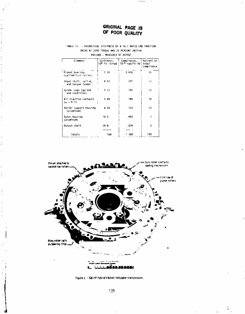
ORIGINAL PAGE ISOF POOR QUALITY
: TABLE IT, - THEORETICAL STIFFNESS OF A 16:l RATIO CMG TRACTION
DRIVE A1 ZERO TORQUE AND 25 PERCENT INITIAL
PRELOAD - MEASURED AT OUTPUT
• Element, IT1sttffness, Compliance, Percent of06 ft-_b/rad 10 -6 rad/ft-lb total
:+ , compliance
Planet bearings 2 35 0.426 33
(cyl+ndrlca] roller)
Input sh_ft, spIl_e, 4.52 221 17
and torque loader
Spldet cage (guided 5 12 Ig5 15
; end condition)
A11 traction contacts 5 44 184 14
(_ = 0.I)
Roller support housing 6.54 IS3 12
(alumlnum)
' Outer houslng I0.5 .og5 7
(alumlnum)
i
Output shaft 29.8 .034 Z
ITotals 760 1 308 TO0
FigureL - 5_0PIPhybridtrachonhelicoptertransmission.
135
1985025199-145
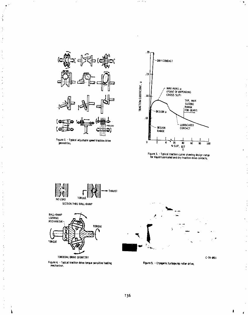
_,_ .20
r MAXAVAILp/ (POINTOFIMPENDING
// CROSSSUP_10
SLIDINGI=: _ .RANGE
'C_ ^ - '-"LUBRICATED
Ao CON]ACTR_N_
Figure2. - Typicaladjustablespeedtractiondrive 0 2 4 20 40 60 80 ]00geometries. % SLIP,A U_
U
Figure3. - Typicaltractioncurveshowingdesigprangefor liquidlubricatedenddrytractiondrivecontacts.
"_e: _ THRUSI
NOLOAD TORQUE
SEC_I_THRUBALL-fl_P
BA_-R_P _ ' _LOADING
"tORQUE --_
C-16-480!TOROIDALDRIVEGECM£TRY
Figure4. - Typicalfrictiondrivetorquesensitiveloading Figure5. - Cryo9_icturlx_pumprollerdrive.mechanism.
136
1985025199-146
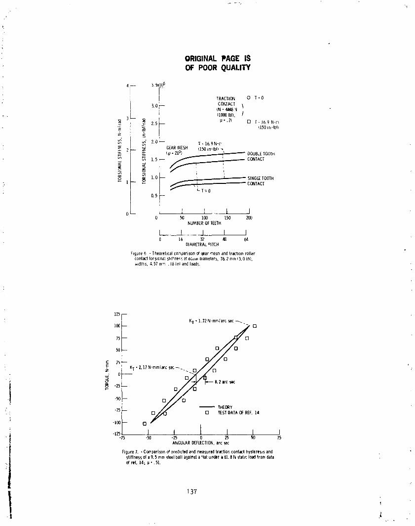
ORIGINALPAGE ISOF POOR QUALITY
3.5xlO6
"r- r[ | TRACTION O T- 0
3.0 CoNqACT 1
(N- 4448N(1000Ibf), /
3 _ 7.5-- p-.7) [] _-16.9N-m
z' I _c (150ir,-Ibf)
_ 2.0-- T -16.9 N-rnu.n
_ GEARMESH (150m-lbfl
_ DOUBLETOOTH
_' _ 1.5 -- CONTACT
_. I.0 -- ' - SINGLETOOTHj. _ 1 _ _ ,i --CONTACT
L LT:O; 0.5 F
o / I ', I I0 _ lOO 150 200
NUMBEROFTEETH
[ _ I I I0 16 32 48 64
DIAMETRAL°ITCH
Fmgure6 - lheorebcalcomparisonof qearmesnandtracbonrollercontacttorsionalstiffness_t equd_olameters.76.2 mm(3.0 in),
,._._,,u, _, 4.57mm. 18in) andloads.
KT •I.72N-mm/arc sec
75 Or__
.50 [] []
75-- O OKl • 7.11 N-mmlarcsec
' _ -75-- /_'¢" F"_8"Tarc_
°X°Q_ _ THEORY
: -15_ 0 TESTDATAOfREF.14
-100 -- 0 I
-17: 1 I J ] I I-15 -50 -25 0 25 50 15
ANGULARDEFLECTION,arc _c
FigureI.-Comparisono_predictedan(lmeasuretitractioncontacthysteresisantlstiffnessofa g.5 mmsteelballagainsta fiat un_r a 61.8N stattcloadfromdataof ref. 14;p•. 51.
137
t
. lil
1985025199-147
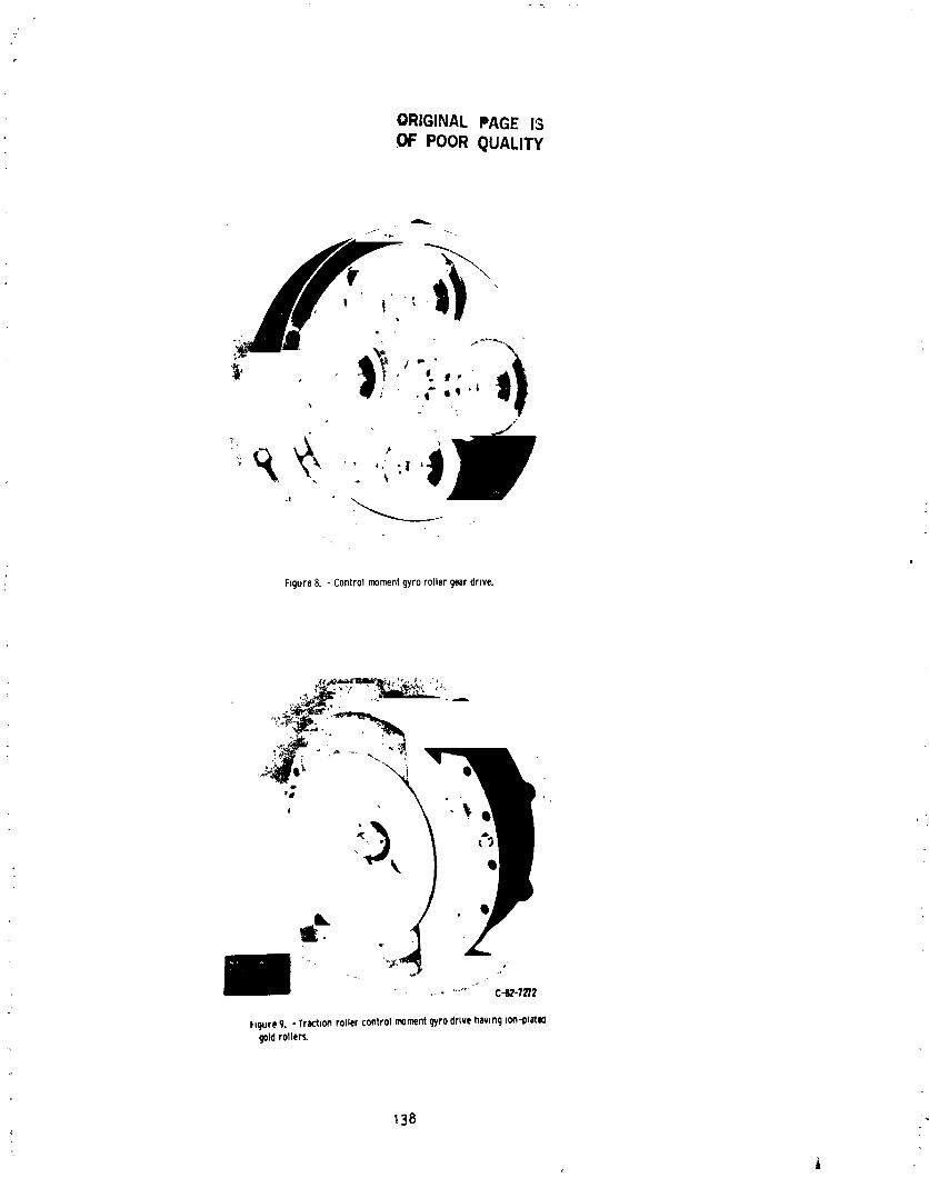
ORIGINAL PAGE IS.OF POOR QUALITY
°_
J
F;gure8. - Controlmomentgyrorollergeardrive.
• 4
Q
i
..... C-82-7_
hgureg. - Tract,onrollercontrolmomentgyrodrivehawngDon-plateogoldrollers,
138
1985025199-148

r"
.=
ORIGINAL PAGE ISOF POOR QUALITY
HIGHRATIO(210:1)TRACTIONDRIVE-,,,, BALLSCREW-_
I
ROTATING "\ELECT_,ONICPO,_ROL
MOTOR-
PITCHLOCK
OPTICDATALINK
ALTERNATOR (OPTICALSUPRING)
_INPUTPOWER
_ TAKEOFFSHAFT
Figure!_ - Conceptualdesignufanadvancedturboproppropellerpitchchangemechanismwhichiocorperatesah_rid tractiondrive.
i
OUTER-ROW
ROLLERS_...,.,/I__ ,,,'-O_PUT$ECONO-ROW _ _ "_ _ ," TOOTHED
ROLLERS-'-../ _. 4''_'_ _ .°"'_': _"(X PINIONSAND
FRAME
\ " _.' +,,' ,, _#, 1/ "-iNPUTSUN
ROLLER
Figure[L - 210toI ratlo,h_rkl tr_:tiondrlvl glomtry.
1 39
i,li
1985025199-149
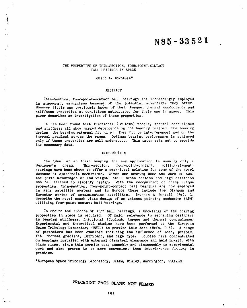
iI
N85-33521 .
THE PPOPERTTF_ OF THIN-SECTION, FOUR-POINT-CONTACTBALL BEARINGS IN SPACE
Robert A. Rowntree*
• ABSTRACT
Thln-section, four-point-contact ball bearings are increasingly employed
in spacecraft mechanisms because of the potential advantages they offer.However little was previously known of their torque, thermal conductance and
'; stiffness properties at conditions anticipated for their use it space. Thispaper describes an investigation of these properties.
It kas been found that frictional (Coulomb) torque, thermal conductance
and stiffness all show marked dependence on the bearing preload, the housing
design, the bearing external fit (i.e., free fit or interference) and on thethermal gradient across the races. Optimum bearing performance is achieved
only if these properties are well understood. This paper sets out to providethe necessary data.
INTRODUCTION
The ideal of an ideal bearing for any application is usually only a
designer's dream. Thin-section, four-point-contact, rolllng-element,
bearings have been shown to offer a near-ideal solution for some of the novel
demands of spacecraft mechanisms. Since one bearing does the work of two,
the prime advantages of low weight, small cross section and high stiffness
can be utilised to simplify design. With the recognition of these unique
properties, thin-eection, four-point-contact ball bearings are now employedin many satellite systems and in Europe these include the Olympus andEurostar series of communication satellites. Brunnen & Bentall (Ref. I)
describe the novel swash plate design of an antenna pointing mechanism (APM)
utilizing four-point-contact ball bearings.
To ensure the success of such ball bearings, a knowledge of the bearing
properties in space is required. Of major relevance to mechanism designers
is bearing stiffness, frictional (Coulomb) torque and thermal conductance.
Experimental and theoretical studies have been performed at the European
Space Tribology Laboratory (ESTL) to provide this data (Refs. 2-5). A range
of parameters has been examined including the influence of load, preload,fit, thermal gradient, lubricant, and cage type. Studies have concentrated
on bearings installed with external diametral clearance and held in-situ with
clamp rings, since this permits easy assembly and disassembly in experimentalwork and also proves to be more convenient than interference fitting in
practice.
*European Space Tribology Laboratory, UKAEA, Risley, Warrington, England
PRECEDING PAGe. BLANK NOT FILMED
141
1
1985025199-150

I
i
BEARING SPECIFICATIONS
Details of the bearings used in these tests are given in Table i.
Bearing size and ranFe oi internal diametral preloads (designated A, K or M)were chosen to be similar to those used in the Olympus APM (Ref. i).Diametral preload is defined as the sum of the interferences in the radial
direction between ball and races (i.e., the sum of the normal Hertzian
approach betwee;] ball and races). In this type of bearing, the groove ineach race has two radii whose centres are offset by equal amounts from the
plane of the ball centres. This construction gives the bearing a "GothicArch" configuration making poesible four-point contacts between a ball and
the raceways_
Table 1 Bearing details.
Kaydon Bearing No. KAOTOXP2
i External diameter 190.5mmInternal diameter 177.SmmWidth 6.35am .
iI Bearing internal fits (nominal) 0-12.7 m clearance (Brg. A)" " " " 0-12.7 m preload (Beg. K)
.| " " " " 12.7-25.4 m preload (Brg. M)
i No. of balls 87
Cage Snap over crown in brass, nylonor spring separators
Contact angle 30 degrees
Bearing steel AISI 52100
Precision Class 6 (equivalent to ABEC 7in run-out tolerances)
MEASUREMENT OF STIFFNESS AT LOW LOADS
Stiffness Rig
The ESTL stiffness rig is illustrated in cross-section in Figure i. The
bearing was located against a machined shoulder on both the inner and outer
housings and was held in place by clamp rings. The axial clamping force on
the bearing could b_ varied by the torque imparted to the 24 X M3 clamping
bolts on each clamp ring. Figure 2 shows, in more detail, the configurationof the clamp rings in relation to the bearing and housings. Bearing
deflections were measured by two, diametrically opposite, contacting
displacement transducer probes which were rigidly clamped via a support arm
to the outer housing. Bending moment was applied using the pulley and weightsystem attached to the central rod. Axial load was varied by the addition ofweights to the inner housing.
142
1985025199-151

C
Structural Deflections in the Rig
From the limited information available, very small axial and moment
deflections were to be expected. To ensure any additional deflections did
not arise from the stiffness rig itself (despite its massive structure), a
solid stainless steel ring of nominally "infinite" stiffness was manufacturedand substituted for the bearing. Only minor deflections were measured
arising from the rig; where necessary the experimental results have beencorrected.
BEARING STIFFNESS RESULTS
Effect of bearin_ Internal Fit on Moment Compliance (constant axial clamp)
The influence of bending moment on the moment deflections of the three
bearings, with differing internal fits (diametral preload), is showr in
Figure 3, at a clamp ring bolt torque of 0.8 Nm. This, arbitrarily chosen,bolt torque is equivalent (assuming dry bolt threads and standard cap head
bolts) to an axial clamping force per bearing race of approximately 48 N/mm.
The bearing movement is such that a moment load in the direction of probe A
(see Figure l) produces a negative deflection at that probe and a positivedeflection at probe B. Moment loading towards B produces the reverse
deflections. For clarity the results obtained from probe A have been omittedfrom Figure 3.
The effect of increasing the bearing internal preload is, as expected, to
decrease the moment deflection at a given moment load. By imposing higher
race deformation (at the four-point contacts) a larger bending moment is
required to produce the same moment deflection. The slopes of the lines of
Figure 3, defined as the moment compliance with units of Rad/Nm, have beencalculated by linear regression and are presented in Table 2. This table is
specific to the axial clamping force imparted by a bolt torque of 0.8 _n.
For comparison th_ moment compliance derived from information in the bearing
manufacturer's catalogue (Ref. I0) is included in Table 2. Although theinternal preload is not specified in the catalogue, there is good agreement
with the values of moment compliance.
Table 2 Moment compliance as a function of original bearing internal fit
(clamp ring bolt torque 0.8 Nm).
Bearing Moment Compliance (Rad/Nm)
Experimental _nufacturer's estimate(internal fit not specified)
A (0-12.5 m clearance) 1.62 X i0-6
K (0-12.5 m preload) 1.27 X 10⁻⁶ 2 X 10⁻⁶M (12.5-25 m preload) 0.85 X i0"6
111.3
iiL , ..
1985025199-152

The Effect of Axial Clamping Force on Moment Compliance
The pronounced effect of the bolt clamping torq,ie (which is proportionalto the axial clamping force) on the moment compliance of the three bearln&s,
is illustrated in Figure 4. Increasing the axial clamping force reduces the
moment compliance of the bearings. The range of moment compliance valuesfrom all the bearings studied can be encompassed usi6g bearing A (0-12.5 m
clearance) solely by adjusting the clamp ring bolt torque. At higher clamp
ring bolt torques ( 2 Nm), it was not possible to differentiate between the
, moment compliance of the three bearings, as the deflections were so low
( 0.i m) that experimental error predominated.
The effect of increasing the axial clamping force is to bend the
.i Gothlc-Arched-shaped races and impose additional Hert_ian deformation at theC
! four-point contacts. Thus moment compliance will be correspondinglyI reduced. This result demonstrates the sensitivity of this type of bearing to
! bending of the rings induced by clamping forces.
i A notable feature of Figure 3 is that bearing A (0-12.5 m internalclearance, prior to fitting) responds to moment loads in a similar manner to
the internally preloaded bearings; i.e., as the moment load was varied therewas no evidence of play or clearance in the resulting moment deflections.
Only when the clamp ring bolt torque was reduced to 0.2 Nm was hysteresis and
'_ non-llnearity, due to rlng movement and a highly variable ball complement,exhibited in its moment deflections (Figure 5). The implication of this
result is that poor locational accuracy and low stiffness can be avoided byJudicious use of axial ring clamping (without the need for interference
fitting).
Effect of Bearin_ Internal Fit on Axial Compliance (constant axial clam/D)
Table 3 summarises the effect of the bearing internal fit on the axial
compliance of the three bearings studied (at a clamp ring bolt torque of0.8 Nm). At axial loads of up to 200 N, there was a linear relationship
between load and axial deflection; as expected, increasing the bearingpreload reduces the bearing axial compliance. Fair correlation is obtained
wltb the axial compliance deduced from the bearing manufacturer's catalogue.
Table 3 Axial compliance as a function of original bearing internal fit
(clamp ring bolt torque 0.8 Nm).
Bearing Axial Compliance (m/N)
Experimental Manufacturer's estimate(internal fit not specified)
A (0-12.5 m clearance) 7.25 X 10⁻⁹
K (0-12.5 m preload) 5.81X 10⁻⁹ 8 X 10⁻⁹
M (12.5-25 m preload) 4.04 X 10⁻⁹
144
1985025199-153

Effect of Axial Clampir_ Forcc on Axial _1_v....r._a..eno
The marked influence of axial clamping force on the axia] compliance of
bearing A (0-12.5 m clearance) is summarised in Table 4, for three bolt
torque settings (0.2, 0.8, and 1.86 Nm). At a given axial clamping force
there was a linear relationship between axial deflection and load.
T3ble 4 Axial compliance as a function of axial clamping force (clamp ringbolt torque). Bearing A (0-12.5 m clearance).
Clamp ring
bolt torque Axial Compliance (m/N)
C.2 Nm 3.0 X 10⁻⁸
0.8 Nm 7.25 X 10⁻⁹
1.86 Nm 1.56 X 10⁻⁹
MEASUREMENT OF TOROUE AND RADIAL THERMAL CONDUCTANCE
Heat Transfer Rig
Figure 6 is a schematic drawing of the rig. Its design was based on anexisting bearing heat transfer rig at ESTL (manufactured by the Dutch
National Lucht en Ruimtervaart Laboratorium (Ref. 6)). The bearing was
mounted between the inner housing and heat flux meter (HFM), locating against
shoulders thereon. The bearing housings and seatings were manufactured to
ABEC 9 standard. The bearing was held in place by inner and outer clamp
ring,, whose clamping force could be varied by th) torque applied to the M3
clamp ring bolts (24 per clamp ring). The configuration of the clamp rings
in relation to the bearing, housing and HFM is as shown in Figure 2. Four
radial groups of copper/constantan thermocouples were located at 90-degree
intervals around the H_. Per grouping, two thermocouples measured the inner
(TI) and outer (TO) bearing race temperatures and two thermocouples
measured the temperature difference across the HFM (TI' and TO'). The
thermocouples measuring TI and TO were positioned such that they were incontact with the surfaces of the bearing races. Under isothermal conditions
and with a stationary bearing in vacuum, the thermocouples all showed the
same reading on a digital voltmeter (5_M) to within 1 V (I/40_C). Radiant
heat loss from the bearing and HFM was prevented by multiple superinsulation
shields. The inner housing, HFM and clamp rings were manufactured from
FV 520B, which has the same coefficient of thermal expansion as AISI 52100,
thus ensuring tre isoexpansive nature of the rig with respect to the bearing.
The bearing was rotated using an externally controlled motor via a
ferrofluidic vacuum feedthrough. Bearing torque was sensed by a strain gauge
torque transducer, the output of which was displayed on a potentiometric pen
recorder and on a programmable digital voltmeter.
145
1985025199-154
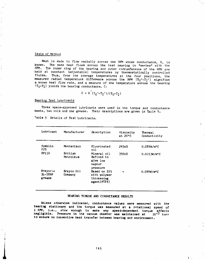
Basis of Method
Heat is made to flow radially across the HFM whose conductance, K, isknown. The same heat flows across the test bearing in "series" with the
HFM. The inner ring of the bearing and outer circumference of the HFM are
held at constant (adjustable) temperatures Dy thermostatically controlled
fluids. Thus, from the average temperatures at the four positions, the
measured radial temperature difference across the HFM (To'-TI') signifiesa known heat flow rate, and a measure of the temperature across the bearing(To-TI) yields the bearing conductance. C:
C : K (To'-TI')/(To_TI)
Bearing Test Lubricants
Three space-approved lubricants were used in the torque and conductance
tests, two oils and one grease. Their descriptions are given in Table 5.
Table 5 Details of Test Lubricants.
Lubricant Manufacturer Description Viscosity Thermal
at 20°C Conductivity
Fomblin Montedison Fluorinated 240cS O.084W/m°CZ25 oil
BPIlO British Mineral oli 350cS O.OI53W/moCPetroleum Reflned to
give low
vapour
pressure
Brayccte Brayco Oil Based on Z25 - O.084W/mOC3L-38RP Company with polymer
grease thickening
agent(PTFE)
BEARING TOROUE AND CONDUCTANCE RESULTS
Unless otherwise indicated, conductance values were measured with the
bearlng statlonar_ and the torque was measured at a rotational speed of
I RPM, i.e., slow enough to make any speed-dependent torque effectsnegligible. Pressure in the vacuum chamber was maintained at i0-3 tort
to ensure no convective heat transfer between bearing and environment.
-+
145
1985025199-155
|
Thermal Gradient
Figure 7 illustrates the marked influence of th_rm_l gradient
: (To-TI), defined as the temperature dif2 "ence between the outer andinner bearing race, on the torque and heat t nsfer of bearing A (0-12._ mclearance). The clamp ring bolts were tightened to 0.8 Nm and th_s has
resulted in preloading the bearing, despite its nomlnal internal clearance,
due to bending of the rings. Conductance is ob3erved to rise linearly with
increasing thermal preload (i.e., as TI is made hotter than TO ) whereasthe increase in torque is almost a square law relation.
The results shown in Figure 7 imply that, in this particular case, theouter race needs to be about IO°C warmer than the inner race h_fnre the
induced preload is apparently relieved, i.e., wher_ the torque and
conductance reach their minimum values. [_wever, as will be shown later,
other factors can influence the precise determination of this point.
Internal Preload and Devleopment of Internal Clearance
The influence of internal preload on the mean conductance across
degreased and unlubricated four-point-contact ball bearings is shown in
Figure 8, plotted as a function of thermal gradient. All the hearings have a
similar minimum conductance value of 0.08 W/oC; this corresponds to the
development of intprnal clearance in the bearir _ The effect of increasing
the internal preload is to raise the thermal c:,_uctanoe at a given thermal
• preload. It may be noted that at ambient conditions (To-TI:O°C) allbearings are internally preloaded at a _lamp ring bolt torque of 0._ Nm.
As the bearings were not rotated without the presence of lubricant(because of the risk of damage), torque measurements on the influence of
preload were taken with the addition of 1 1 of Z25 (Figure 9). Increasing
the internal preload causes a corresponding increase in the meah bearing
torque. Analysis of Figures 8 and 9 reveals that the frictional torque and
"dry" conductance reach a minimum (or steady value) at approximately the same
thermal gradient.
Axial Clamping Force
Figures i0 and ii summarise the influence of the axial clamping force on
the torque and conductance of bearing A (0-12.5 m clearance). Increasing
the axial force and imposing additional Hertzlan deformation at the
four-point contacts would be expected to raise bearing conuuctance andtorque, a result which is demonstrated in Figures ]0 and Ii. As in the
compliance studies, the effect of increasing the internal preload is to
reduce the sensitivity of bearing torque and conductance to the axialclamping force (Rel. 4).
147
d
1985025199-156

_,mblln i.Z5_3ii Addition
The influence of Fomblin Z25 lubricant quantity on the torque qndconductance of bearing A (0-12.5 m clearance) is illustrated In
Figures 12 and 13. There is no effect of lubricant quantity ( 1 I) on
torque at 1 HPM (eonL'irmlng the absence, under these conditions, of a
speed-dependent or viscous torque component). At higher rotatlon_l speeds( 25 RPM) the viscous torque component becomes predominant and the quantity
o_" lubricant can then influence the torque. Thermal conductance increases in
a nonlinear manner wzth oil quantity. From Figure 13 it may be concluded
that 200 I of oil i_ lubricant quantity. Smaller angular contact bearings
exhibit a similar relationship with lubrication quantity (Ref. 7).
Comparison of BPIIO Oil Wlth Fomblin Z25
As with _omblin Z25, the addition QF BPIIO lubricant had no influence on
beoring torque (at 1 RPM) and gave results identical to those for FomblinZ25. In previous work (Ref. 8) the boundary friction coefficients of BPIIOand Fomblln 225 oils between steel surfaces have been demonstrated to be
similar (0.13 and 0.12, respectively).
Table 6 shows, under isothermal conditions, the relative influence ofFomblin Z25 and DP!IO lubrication on bearing conductance (BPilO has a thermal
conductivity which is approximately twice that of Fomblin Z25). These values
have been normalised tc indicate the coptr!butlon from the oil only (i.e,minus dry component).
Table 6 Influence of oil type on oll conductance component
Oil Quantity Normalised conductance (W/°C)Z25 BPIIO
Dry 0 0
I0 1 0.3 0.3530 1 0.37 0.51
500 I 0.5 0.97
i
J_
!
i •
_! Y48i
1985025199-157
r
Inspection of Table 6 reveals that for "flooded" lubrication (500 i) the_ cnnductance wlth BPllO is indeed close to twice that shown with Fomblin Z25.
For small additicns, however, the extra conductance with BPIIO is small.Stevens and Todd (Ref. 7) have shown with smaller angular contact bearings
_ that at low lubricant additions bearing conductance is proportional to the
Hertzian contact area, while at large lubricant additions the majority of theheat flows through the oil meniscus at the ball/race contact and thus
I conductance is related to the o11 conductivity. The present results wlth
thin-section bearings are in close agreement.
Grease Lubrication
d
Figure 14 illustrates the effect of grease lubrication on bearing A
(0-12.5 m clearance). The bearing was approximately one-third filled withgrease and then rotated for several revolutions to ensure an even
distribution. As Braycote 3L-38RP grease is based on Fomblin Z25 oil,
bearing torque and conductance may be expected to correspond to the floodedFomblin 725 oil values. In fact slightly higher torque and conductance
values were obtained for grease lubrication. The small difference in torque
is attributable to grease churning losses and the action of the polymer
thickening agent, while the increased conductance probably arises from theT
grease between cage and races, i.e, bridging the conductance path of the
]_I ball/race contacts.
I Cage Type
The effect of the following cages types was studied:
(i) Standard brass formed ring, "snap-over" type
, (11) Nylon segmented "snap-over" type(iii) Helical coll springs
Only minor difference in bearing torque were found (Figure 15), where
• spring separators tended to give higher torques when the bearing was
subjected to negative temperature gradients. Whilst the insensitivity of
- mean torque to cage type implies that, at a rotational speed of 1 RPM nosignificant cage "hang up" occurs, even with the solid (loose pocketed) brass
cage, It should be noted that the precision of the bearing and housings is1 also crucial. A lower precision of bearing or housing could tend to promote
cage "hang-up". Bearing conductance was found to be independent of cage type.
149
1985025199-158
DISCUSSION
It is apparent from the results that the stiffness, radial conductance
and frictional (Coulomb) torque of large-diameter, thin-sectlon, four-point-
contact ball bearings involve the interaction of several variables and as
such a rigorous theoretical analysis is not feasible. However, the
relationships between stiffness, torque and conductance with internal preload
and thermal gradient, for pre]oaded bearings, have been shown to be in broad
agreement with those predicted with reasonable assumptions from theory
(Ref. 9). The chief uncertainty in the theory is in the number of rollingelements effectively loaded, tlearly for such large bearings with thin,
deformable rings the effective ball complement will vary greatly with the
load applied and with the probability distribution of the ball to raceinterference. In the absence of such data, theoretical predictions must be
rather imprecise.
An important practical consideration for those bearings is in the manner
of the installation employed. Provided that the "unfitted" internal preload
is accurately known and that one has a precise knowledge of the amount of
interference being applied, then it can be argued that interference fittingis desirable (assuming also that a later dismantling is not contempldced).However, in the case of the test bearings, the wide tolerance bands of
internal diametral fit (Ref. i0) mean that there would be considerable
uncertainty in the start point and, therefore, in the ball load and dry
torque after interference fitting. For example, the effect of a i0- m
diametral interference on bearing fitting was found to increase the meantorque by a factor of 4. The characteristics of thin-section bearings also
change, the bearing becoming more sensitive to thermal gradients, etc. Axial
clamping of four-point-contact bearing rings, which are clearance fits, has a
similar effect to fitting with interference, but it is possible then to vary
the ball load and torque to match the requirements more exactly.
For most uses, the optimum mounting method would combine the use of
external diametral clearance for each of bearing fitting (and removal) with
allow axial clamp. Such a value of axial clamp would minimise ring bending,
but would be sufficient to ensure that the bearlrg cannot physically move in
it3 housing. Suitable clamp ring design can reduce the dependence of the
bearing on the axial clamping force. It is recommended that the bearingtorque or deflection be measured after installation, from which the effective
i internal preload can be inferred.CONCLUS IONS
Measurements of the frictional (Coulomb) torque, radial thermal
conductance and stiffness of thin-section, four-point-contact, ball bearings
have shown the following:
a. Internal preload, housing design and external axial clamping force on the
bearing rings all have a strong influence upon torque, conductance andstiffness.
150
J _"
1985025199-159
b. The thermal conductance of a dry or marginally lubricated bearing depends
only upon the thermal strain and varies linearly with radial temperaturedifference between the rings. Additionally, conductance is a function of
type and quantity of lubricant.
c. The Coulomb torque exhibits an almost square law relation with thermalstrain.
ACK NOWL EDG EI_ENTS
The bearing stiffness rig was designed by J A Duvall, ESTL and the
theoretical bearing analysis was performed by M J Todd, ESTL. The Author is
indebted to Dr R H Bentall, ESTEC for encouragement in this work and to the
Managing Director, Northern Division, UKAEA, England for permission to
publish.
REFERENCES
i. Brunnen A J D & Bentall R H 1982, Development of a high stability
pointing mechanism for wide application, Proc. 17th Aerospace MechanismsSymposium, May 1983.
2. Rowntree R A 1982, The axial and moment compliance of thin-section
- four-point-contact ball bearings, ESTL/TM/33.
- 3. Rowntree R A !982, The moment compliance of thin-section
four-point-contact ball bearings at light axial clamping forces,ESTL/TM/35.
4. Rowntree R A & Todd M J 1983, Thermal conductance and torque ofthin-section four-point-contact ball bearings in vacuum, ESA(ESTL)54.
5. Rowntree R A 1983, The stiffness, torque and thermal conductance of
thin-section four-polnt-contact ball bearings for use in spacecraft
mechanisms, Proc First European Space Mechanisms and Tribology Symposium,Neuchatel October 1983, ESA-SP-196.
6. Heemskerk J F et al 1975, A test rig to measure the thermal conductance
and frictional torque of bearings in vacuum, Proc First European Space
Tribology Symp, Frascati April 1975, ESA SF-lll.
7. Stevens K T & Todd M J 1980, Thermal conductance across ball bearings in
vacuum, ESA TRIB i, 15-40.
8. Todd M J 1980, A method for the calculation of torque 1,_ dry lubricated
ball bearings including the influence of temperature and fit, Proc Second
Space Trlbology Workshop, Risley October 1980, ESA-SP-158.
9. Todd M J 1983, Computational methods for ball bearings in spacecraft,
Proc First European Space Mechanisms and Trlbology Symposium, NeuchatelOctober 1983, ESA-SP-196.
i0. Kaydon Corporation, Kaydon bearing division catalogue on "Reall-slim"
bearings.
151
1985025199-160
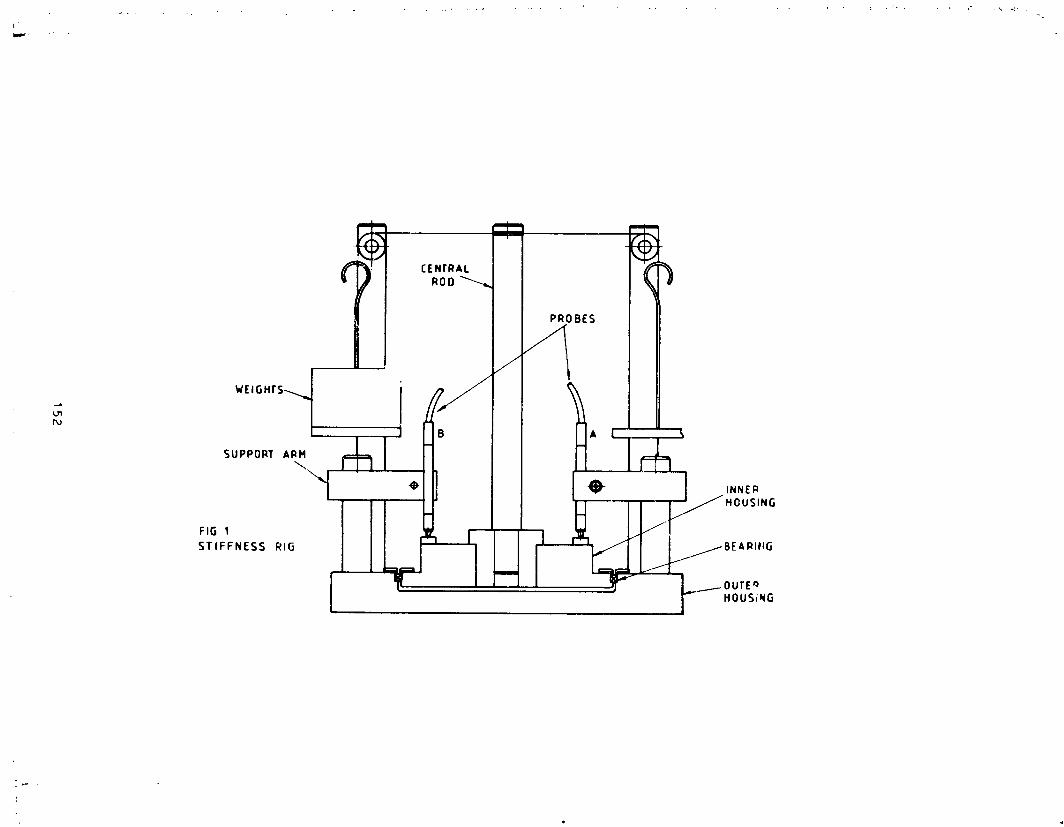
152
1985025199-161

:!
153
t4i
1985025199-162
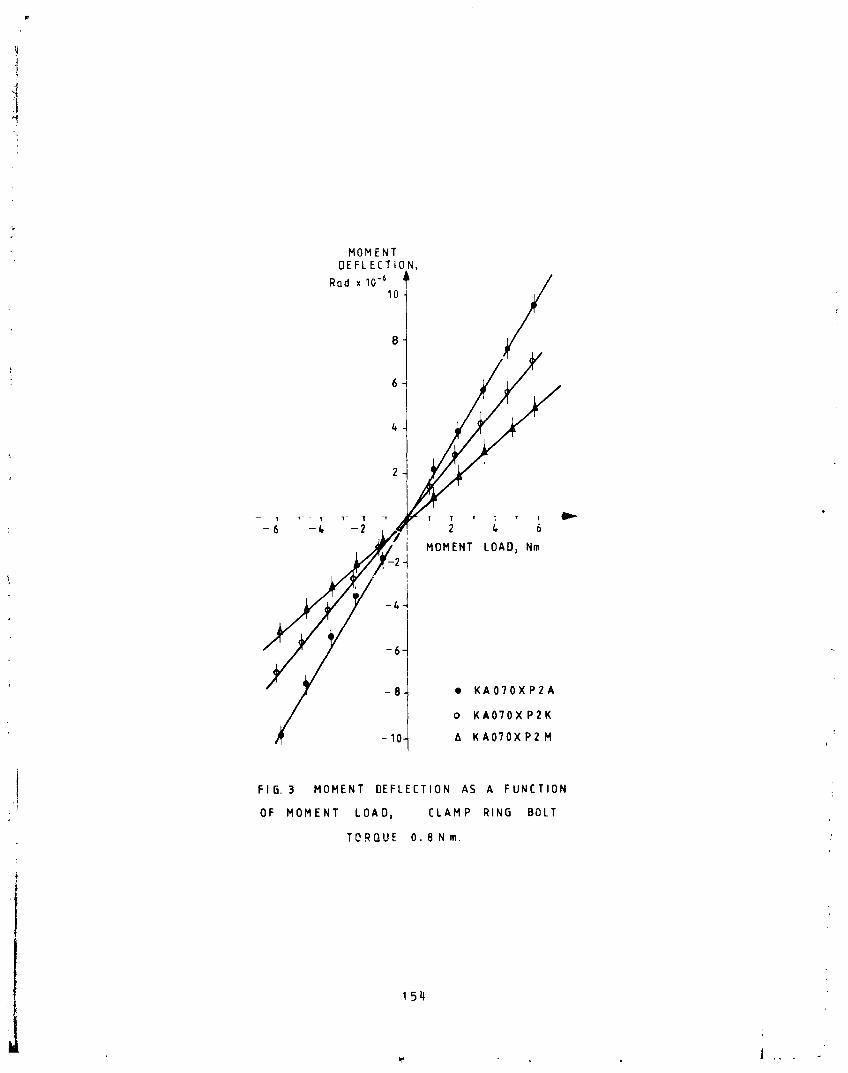
MOMENTDEFLECTION,
Rad x 10-610
-8 • KA070XP2A
o KA070X P2K
-10 A KA070XP2 M
i FIG. 3 MOMENT DEFLECTION AS A FUNCTION :,!' OF MOMENT LOAD, CLAMP RING BOLT
TORQUE O. 8 N m.
154
1985025199-163

ORIGINAL PAGE ISOF POOR QUALITY
5
• KA070XP2A
KA070XP2K
4._- A KA070XP2M
E
Z
To
x 3 '
n,.
Q_J
Z
1
L L __ _ l .... L __ _1 ....
0 0.4 0,8 1.2 1,8 2CLAMP RING BOLT TORQUE, Nm
FIG.I. EFFECT OF CLAMP RING BOLT TORQUE ON MOMENT
COMPLIANCE OF THREE KAYDON BEARINGS
" 155 '_
1985025199-164

ORIGINALPAGE ISOF POOR QUALITY
FIG 5 MOMENT DEFLECTION Vs.MOMENT LOAD,
BEARING KA0"/0XP2A, 0,2Nm CLAMP RING
BOLT TORGUE
156
1985025199-165

,.
-
1
OR
:GlO
bAL
PA
GE
ISO
FP
CO
RQ
UA
LIT
Y
157
1985025199-166

OR
IGIN
AL
PA
GE
IS
OF
PO
OR
QU
ALIT
Y
158
1985025199-167

159
iil
1985025199-168
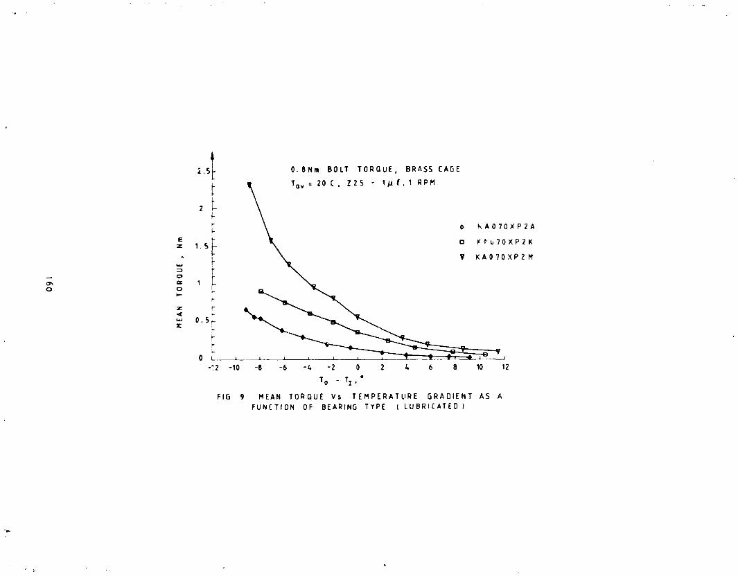
160
v,A
1985025199-169
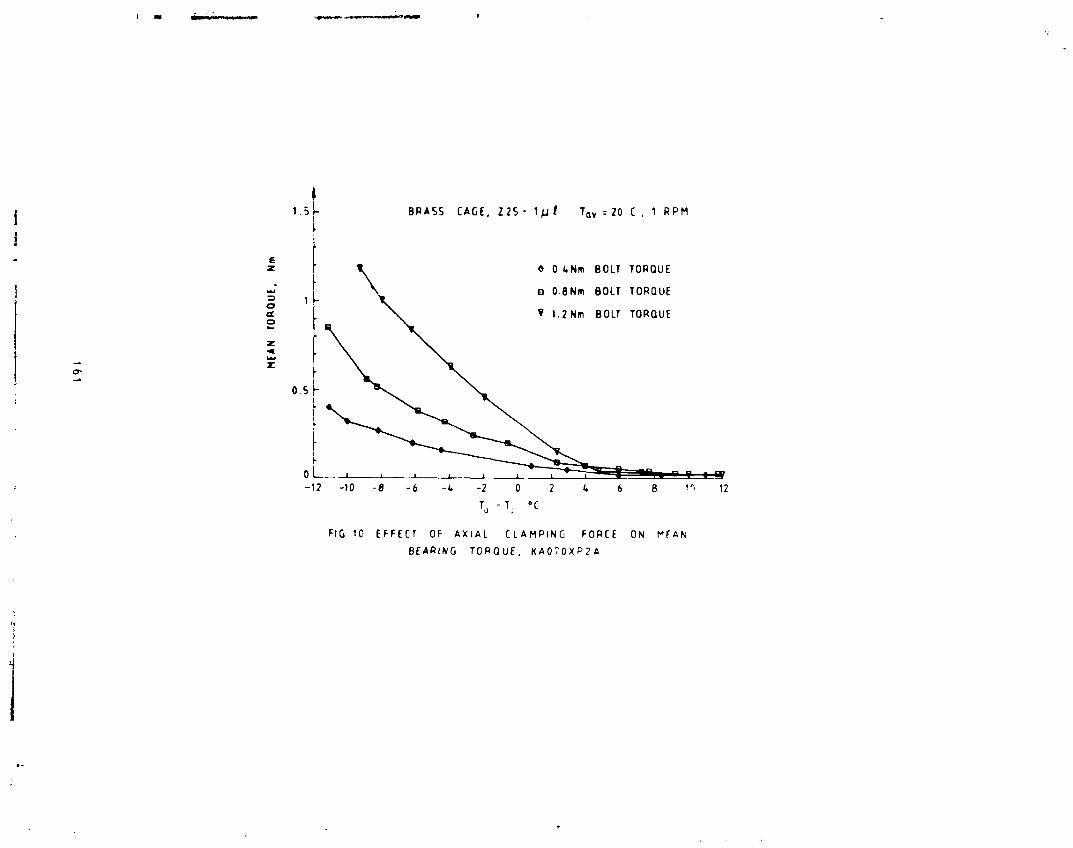
("d
161
,4
1985025199-170

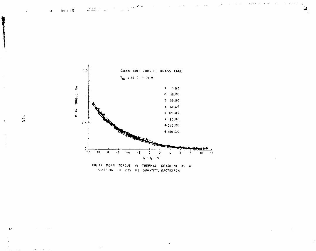
o
163
l'"
/,
i-
2.......
1985025199-172
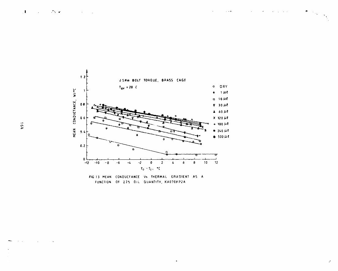
4m
164
1985025199-173

\
:165
$,
1985025199-174
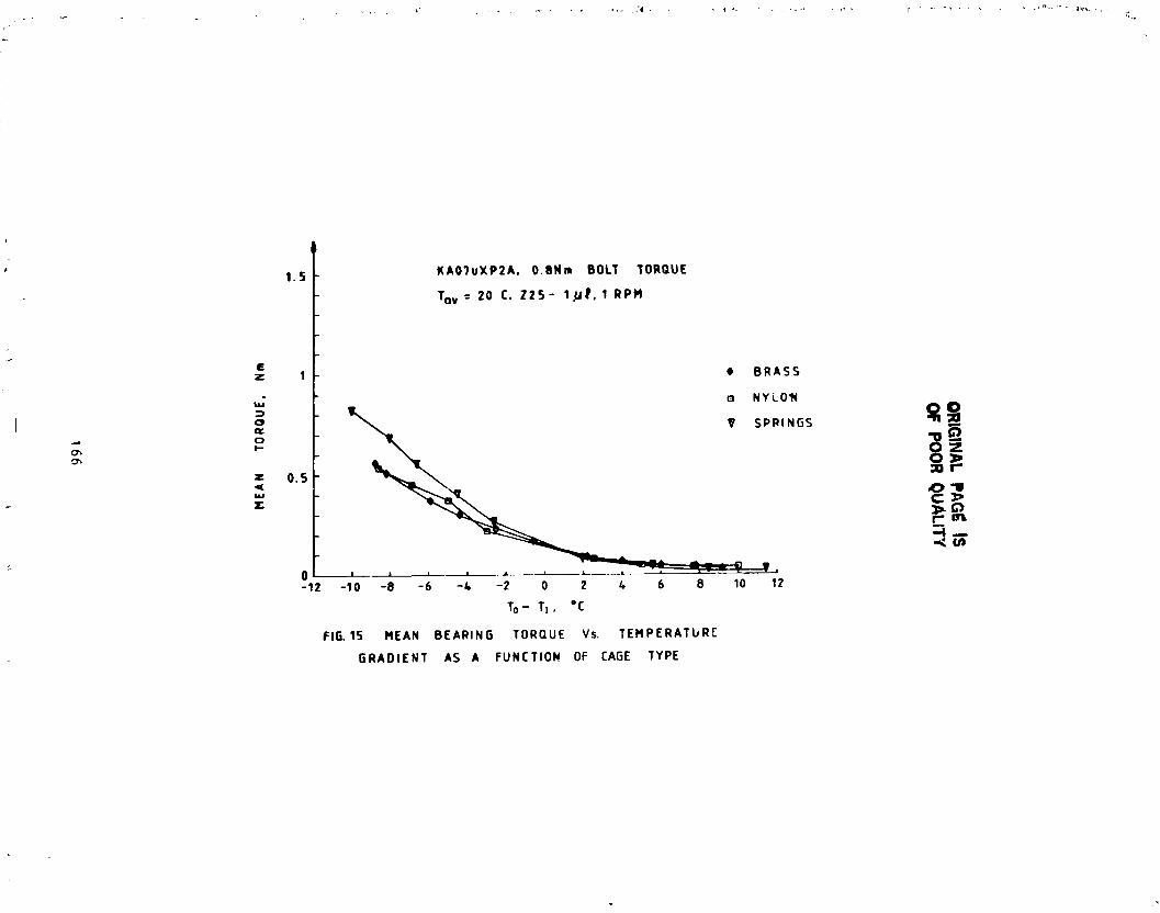
:O
RIG
INA
LP
AG
I_IS
OF
PO
OR
QU
AL
ITY
rJl
z
4,O
I,,Jn
,.
o.=,
0¢0O
.
Q.
It.Q
:0--
..4¢3_"
gO!
o,.,
o=
N
Q"
0L
OX
NZ
II_(
O>
.,co
_1¢I--
14JZM
.
--.J
JJ
[I
I_
II
I|
|I
II
_1PI_
i-U
_01,
mN
'3N
OE
l0,1.N
V]b
l
166
1985025199-175
I
N85-33522
THE DESIGN AND DEVELOPMENT OF A SPACECRAFT APPENDAGE TIE DOWN MECHANISM
William D. Nygren and Raymond Head*
ABSTRACT
This paper describes the design and evolutior_ of a spacecraft Appendage
Tie Down Mechanism (ATDM), with particular emphasis on the mechanical aspects
of usir_ dry lubricants to increase _he efficiency of a_.me threads and worm_ gearing.
ATDM- DESCRIPTION
The ATDM consists of five major components as shown in Figure 1 and i_,
cross section (Fig. 2). These are (i) a DC torque motor, (2) a worm gear
speed reducer, (3) the tension bolt (or T-bolt), (4) nut capture and centering
jaws and (5) the capture nut. In addition, there are several minor componentssuch as limit switch assemblies and an anti-backdrive mechanism which couples
the drive motor to the worm shaft.
ATDM - OPERATION
The operational sequence is as follows: First the DC torque motor drives
the T-bolt through the worm gear speed reducer with a ratio of 58 to i. ll_eworm gear hub is splined, allowing T-bolt axial ddvancement while the worm
gear rotates. The center section of the T-bolt is a ball screw which advances
the T-bolt through its fixed ball nut at a rate of u._08 _ _'n200 in.) per.
revolution. The next step is the capture and centering of the nut assembly
(see Fig. 4). As the T-bolt advances, it drives the t_so capture jaws to swing
closed. This forces the nut to the proper position to allow the acme threads
on the tip of the T-bolt to engage the nut threads.
The capture nut is free to move _xlally in its housing against two ets of
springs. The first is a "soft" stack of wave washers which allows the T-bolt
to fully engage the nut under low thread loading. The second stack is made up
of Belleville washers which start compressing only after the soft stack spring
has completed its stroke. The Pelleville springs reach an axial force of
22 678 N (5100 ib) during one revolution of the T-bolt. The mechanism is then
shut off by limit switches on the nut housing, which monitor nut spring
travel. Figure 3 shows the limlt-swltch mounting on the nut assembly.
The actual loading or tensioning of the T-bolt by t_, nut is accomplished
by the difference in the leads of the ball screw thread and the acme capturethread on the forward end of the T-bolt. The lead of the ball screw is
mMartin Marietta Aerospace, Denver, Colorado
167
1985025199-176

I
0.508 cm/rev (0.200 in/rev) while that of the 1.905 cm (0.750 in.) double-lead
| aeme screw is 0.846 cm/rev (0.333 in./rev). The T-holt always advance_ out of
the mechanism at a rate of 0.508 cm/rev (0.200 in./rev); however, after the
i acme threae engages the capture nut, the nut advances relative to the bolt at
++i a rate of 0.846 cm/rev (0.333 in./rev). Thus the net compression of the nuti springs is 0.338 cm (0.133 in.) per revolution of the T-bolt.I
I DESIGN EVOLUTION!
"1 As system requirements were refined, the preload that the ATDM was|
supposed to develop was substantially increased. The original preload was
,! defined to be 7115 N (1600 Ib) maximum. After the first development unit wasJ built, this figure was increased to approximately 13 344 N (3000 lb), and
finally to 22 678 N (5100 ib). This tripling of output force req.ired that
-_I most attention be focused on mechanical efficiency as the electrical power todrive the mechanism was "fixed" as was the time available for the entire
operation to take place. The increased capability of the mechanism was
required to take place within the original physical envelope.
To provide this increased capability, the following improvements were
made. First, the gear ratio was changed from 50-1 to its present value of
58-1. No further increase was allowable because of gear tooth strength
considerations and size and time limitations. The next step was to changefrom a V-thread to the present ball screw for the driver thread. This was a
major improvement; the apparent coefficient of friction dropped from 0.18 toO.OO7.
Although this w_s a major improvement, a i_ torque margin under
worst-case conditions of voltage, temperature, and motor Kt torque constanthad yet to be demonstrated.
The original development unlt had used wet lubricant (Braycote 3L-38RP)for surfdces, and it was calculated during testing that the efficiencies of
these two components+ were around the 30% range because or" a coefficient of
friction of approxlh,ately 0.2 at the mating surfaces. Since the mechanism
efficiency was basically the product of the gear box and acme screw
efficiencies, the overall mechanism efficiency was only about 10%. A decision
was therefore made to switch to a dry lubricant such as molydisulfide forthese sliding s -Paces of the ATDM the worm/worm gear and the acme captureth:_ads.
The dry lubricant recommended by Materials Engineering was LUBECO 905 as
Martin Maretta Co, (MMC) has previously obtained good results with it. After
successful application of LUBECO 905, the observed coefficient of friction was
•I or lower at both worm/Worm gear interface and at the acme bolt/nut
interface in a vacuum environment, this value was seen to futher decrease tothe point where efflciencies _bove 60% were obtained for the individual
_omponents, approximately a four-fold increase for the overall mech_mism.
168
l ,,,,
1985025199-177

I DRY-LUBRICANT DIFFICULTIES!!
When the mechanism was first lubricated with LUBECO 905 and reassembled,
it failed almost immediately during testing. This caused carefull reanalysis, of the use of dry-film lubricants. Based on the calculated contact stress _md
wear life required to survive testing, the lubricant should have beents_ccessful. However, upon further investigation, the following importantfacts were learned.
o No matter how well made and aligned they are, a worm and worm gear
must go through a wear-in riod before a true line contact area is
established across the face of each gear tooth.
o In a similar fashion, male and female screw threads must also be
mated together by a wear-in period before true area contact isestablished to support the load.
o All sharp corners must be removed around each worm and gear tooth,and on all corners of both the male and female acme thread. In
particul_ this must be done at any partial threads which spiral from
minor to major dia meters (or vice-versa) such as occurs at the
beginring and endin_ of both the male and the female threads.
o After the proper contact areas are established, the mating partsshould be burnished together, starting with low loads and working up
to the full flight loads in gradual steps.
LAPPING
_o facilitate a rapid wear-in of the worm/worm gear and T-bolt/nut of theATDM, the decision was made to lad the mating surfaces together with a
grinding compound. Since it is desired to force one surface to conform to theother, both the worm and the T-bolt acme thread were hardened by nltrlding
prior to starting the lapping process. These surfaces were chosen for the
following reasons. It was felt that the T-bolts contoL"_ could be more
accurately manufactured and dimensionally verified than could its mating nut.
The worm was chosen for hardenin£ because it has basically one tooth, which
must wear in each tooth of the worm gear to match it exactly. (Thus the worm
gets 58 times the wear that any particular worm gear tooth gets during
lapping).
After _litriding was completed, the worm/worm gears were serialized along
with their housing to be maintained as a matched set. The gear box was then
reassembled, the output shaft was attached to a brake which could ap_ly 1.13N-m (i0 in.-Ib) of drag. The worm and _orm gear were then coated w_th a
320-grit Clover grinding compound, and the worm was driven at 2CC rpm untilthe desired wear pattern was established across the face of each tooth.
Finally, the 320-grit compot_nd was replaced with a 600-grit compound to leavea 16-# to 32-rms surface finish for the application of the LUBECO 905.
169
1985025199-178

In a similar manner, the T-bolt and cagi_,g nut were i_- _.d together with
the same compounds under a constant axial load of 22-44 N Ib), with the
nut fully engaged with the bolt. A special fixture was cosigned for this
purpose (Fig. 5).
BURNISHING
After lapping, the ".ritical parts were relubrlcated with LUBECO g05. Thegear box was then reassembled and reattached to the braka. This time,
however, the load was gradually increased in approximately ]4 steps to an
output torque of 40 N-m (360 in-lb). At this point the input torque was
measured to be 0.15 N-m (1.3 ir-lb), giving an efficiency of 49.7% under stall
conditions. (This would furth .. improve in vacuum conditions. ) Likewise, theT-bolt and nut were burnished together at gradually increasing axial load
levels to a final load of 17 78 7 N (4000 ib). Here the torque required to
rotate the bolt was measured as 33 N-m (291 in-lb), giving an efficiency of73%. (The bolt required a torque of 12 N-m (105 in-lb) to keep it from over
hauling). A coefficient of friction of 0.06 in air can be deduced from these
values and the thread geometry.
ANTI-BACK-D RIVE MECHANISM
The success of the dry film lubricant was not completely without adrawback because it led to a luther complication.
At the 22678 N (5100-ib) preload level, it was found that the acme thread
would back-drive its low coefficient of friction and large helix angle. This
torque was about 17 N-m (150 in-lb) in air and would possibly double undervacuum conditions. The conclusion was that the acme thread could overcome the
holding torque produced by the ball nut and so deliver a back-driving torqu_to the worm gear. Here the low friction coefficient is again harmful as it
allows a normally locking gear ratio to back-drlve. This potential for
back-driving is particularly hazardous during the launch and boost phases of a
flight, because the harsh vibration environment increases the likelihood for
back-drivlrg, at a time when a loss of PTDM preload would be most dangerous.
Of the many possible solutions to this problem, most either caused an
unacceptable constant loss of motor torque or required electrical power and
control lines which were not available. The solution was to make the couplingbetween the drive motor and the worm serve as a ratchet which would allow the
motor drive the worm in eithel direction, but not allow the worm to back-drivethe motor. Tne operation of this device ia shown in Fig. 6.
The mechanism consists of' a detent disk attached to the worm shaft, and a
cam disk attached to the motor shaft. These two disks are coupled together by
a pin attached to t,,_ detent disk, which rides in a slot in the cam disk.
This arrangement allow approximately 60° of relative motion between disks.
There is also a Vlier-type plunger between the disks (not shown), which locks
the disks into the configuration shown in Fig. 6a prior to the start of
operations. The final component is the ratchet dog, which in this ca_e ha.=.aroller to minimize friction.
170
1985025199-179

!
The operation is as follows: First, as the motor starts running (see Fig.6a), the roller rides on the combined outside diameter of the two disks and is
held in this configuration by the Vlier pin between them. When the mechanismapproaches its desired preload, the transmitted torque becomes large enough to
overcome the Vlier pin, the disks shift to the configuration shown in Fig. 6b,and the dog starts ratcheting. Next, if the worm attempts to back off, it can
rotate back only until the roller comes against the now "uncovered" detent
(Fig. 6c). Finally, when the mechanism, is desired to be uncaged the reversal
of the drive motor causes the cam disk to cam the roller out of the detent,and the back-out can commence as shown in Fig. 6d.
PRESENT STATUS
A development model of the ATDM in various configurations has been under
test for some time. In its latest version, it has successfully completed
thermal vacuum testing, vibration testing, and extended-life testing.Qualification and flight units are scheduled for testing.
1711
1985025199-180

OR
IGIN
AL
PA
GE
IS
OF
PO
OR
QU
AL
ITY
i
172
"1985025"199-'18"1
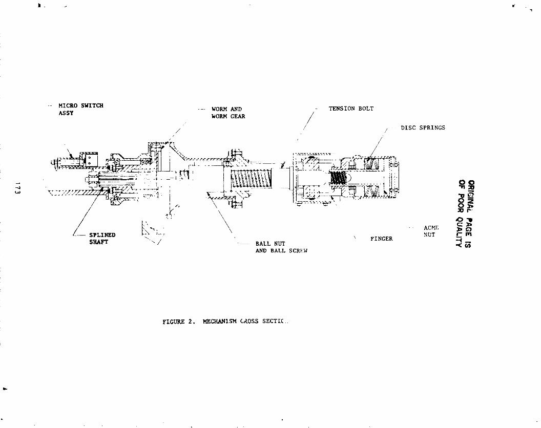
OR
IGIN
AL
PA
GE
ISO
FP
OO
RQ
UA
LITY
r__tD
_
u:
•"_-_Z
,-100_,_
i\,
L'.'_-
r.j
mu
<
%i
'IIJ
'j
."
/_
/
•._
l{'rl,',
_I*o'
,l
173
,i
1985025199-182

OR
IGIN
AL
PA
GE
ISO
FP
OO
RQ
UA
LIT
Y
_985o:_5_99-_83
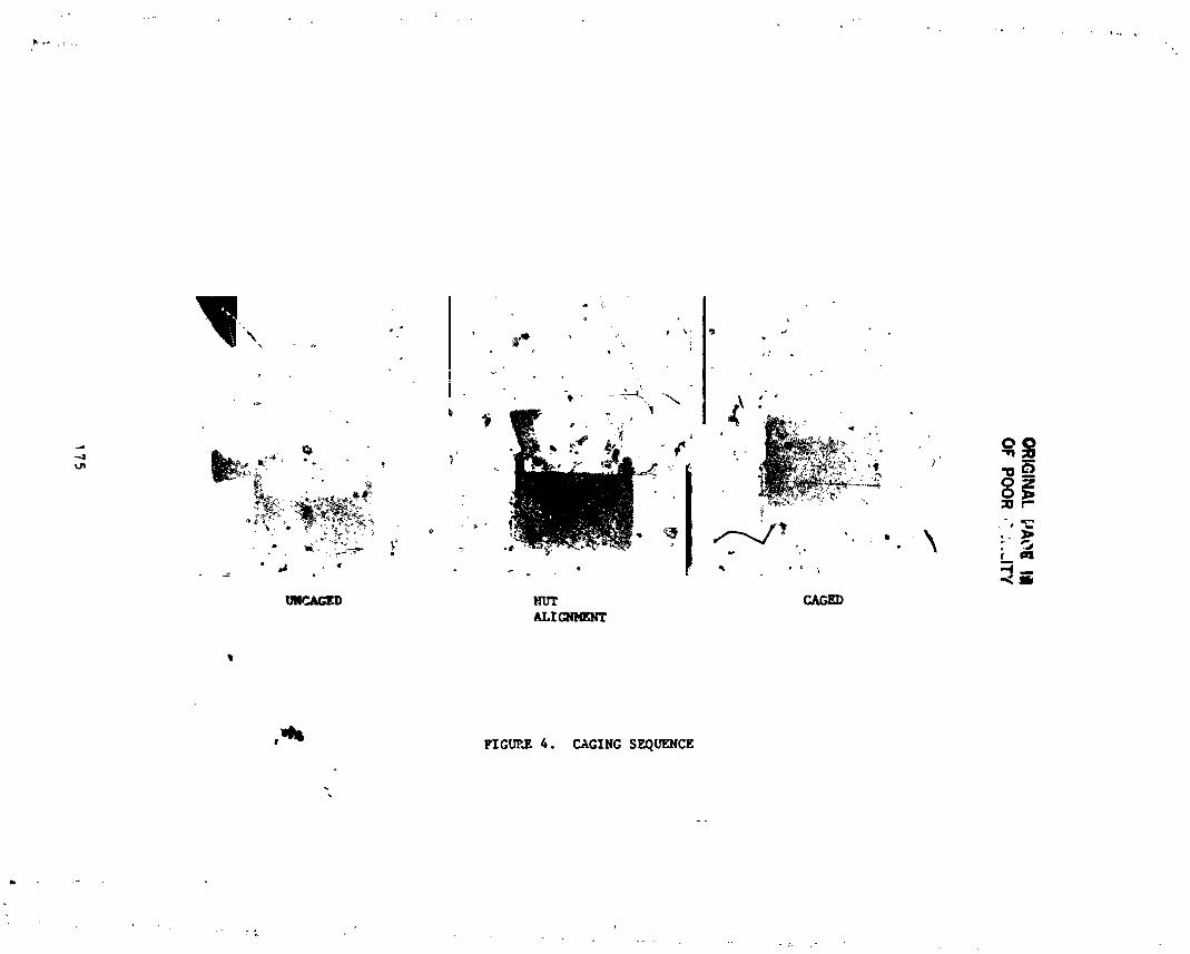
OR
IGIN
AL
PA
OE
llllO
FP
OO
R_":,..IT
Y
:175
1985025199-184
OR
IGIN
AL
PA
GE
IS
OIF
PO
OR
QU
AL
ITY
176
1
]985025]99-]
85
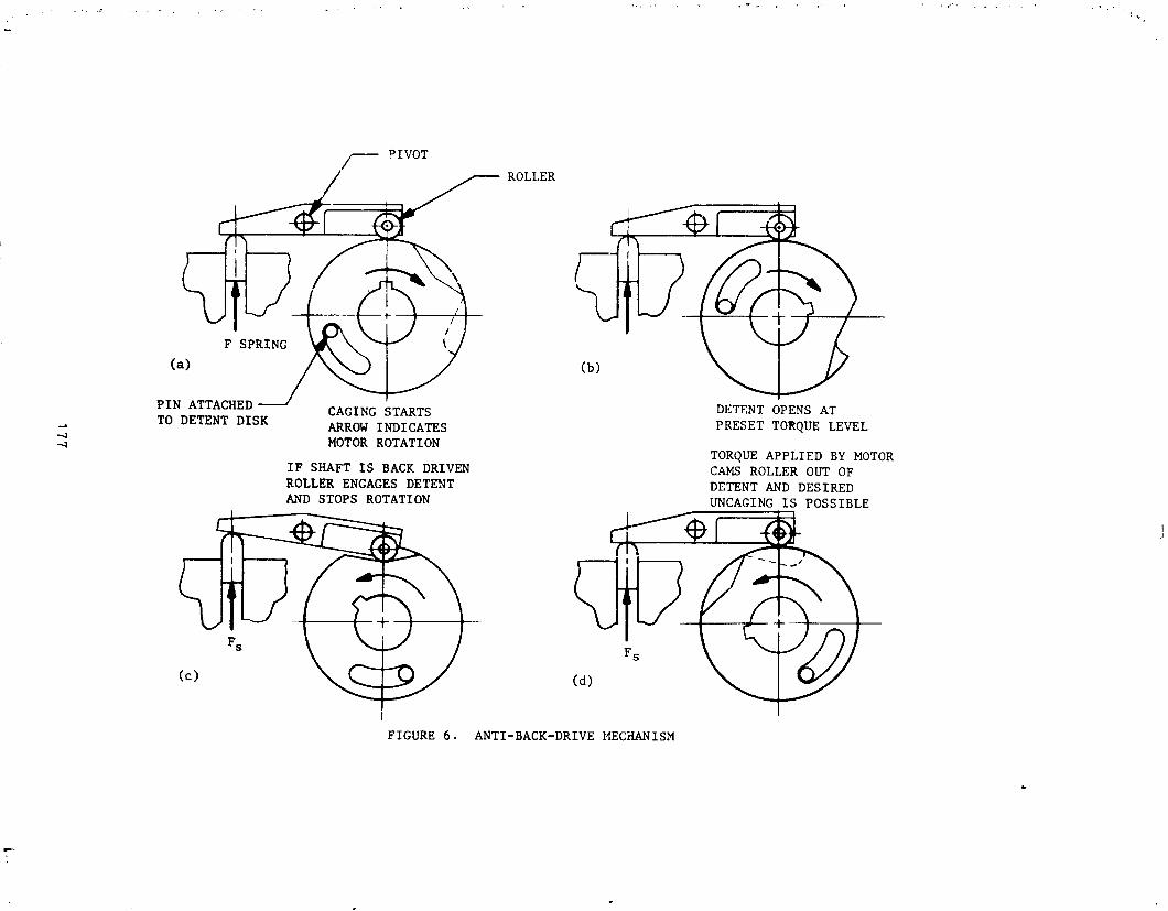
177
1985025199-186
' N85-83523
THE USE OF PERFLUOROETHEP LUERICANTS
IN UNPROTECTED SPACE ENVIRONMENTS
Bryan H. Baxter*, Barry P. Hall*
ABSTRACT
This paper describes a series of ball bearing tests in simulated space
t environment to determine durability of perfluoroether lubricants. The
results of the examination of the test bearings for each stage are describeO
and experimental techniques designed to overcome lubricant degradation areoutlined.
INTRODUCTION
The perfluoroether (PFE) group of lubricants, which is manufactured by a
variety of companies around the world, has unique physical properties
suggesting that they would be ideal for space applications.
The available range of products in this class of fluids is very large
indeed and is complicated by the fact that several different manufacturing
routes are used, resulting in different families of product.
To illustrate the physical properties which are relevant to space
component lubrication, typical data are presented in Table I for two members
of representative series, designated Z and Y.
These properties have encouraged designers to consider the use of such
lubricants in space mechanisms, and in order to establish design rules andlife data, several research programmes have been in_tzatea.
At the European Space Tribology Laboratory (ESTL) established at the
National Centre for Tribology, Risley, England, considerable research effort
has been expended on studies o_ lubrication in the space environment,supported by the European Space Agency (ESA).
Part of this ESTL research programme has involved long ter'n studies of
the PFE lubricants, running in test ball bearings under ambient pressures of10-6 tort or less.
At the Materials Science Group, in British Aerospace, Stevenage we haveestablished a small working group which has specialized for several years instudies of lubrication mechanisms. As a result of this specialization we
have been pleased to assist ESTL and ESA in the studies of test bearings with
the aim of improving the understanding of lubricant degradation studies.
Over the past two to three years, we have been closely associated with a
series of studies on the PFE lubricants and this paper describes the sequence
of tests involved, the results of examining the test bearings and theconclusions we have drawn from the data.
* British Aerospace plc. Stevenage England
179
t
• ,_' PRECEDING PAGE BLANK NOT FILMED _[
1985025199-187
P
LIFE STUDIES WITH Z25 LUBRICATED BALL BEARINGS, RUNNING IN VACUUM
z
Summary of Tests
In this work, carried out by Mr. K. Stevtns at ESTL (1,2), the testbearings were 42 mm o.d. i0 ball _ngular contact. Raceways and balls were in
44OC, and a one-piece fabric reinforced retainer was fitted.
Four bearings were used in this first test, run as preloaded pairs within
the vacuum chambers (10-6torr),^one at 200 rpm and the other at 1400 rpm,
for a total for each pair of I0_ revolutions.
> It was observed during this test that the running torque of both bearing
pairs fell steadily, reaching a minimum after i06 revolutions. If the
tests were stopped for 15 minutes, the torque on restarting was found to be
equal to tha_ at the start of the test, but this fell rapidly to the minimum• level within a short time.
Bearing noise increased with this fall in runnlng torque, and bearingsurface temperature also increased slightly as the minimum torque level wasreached.
On completion of the tests it was found that all the bearings were
contaminated with brown/black deposits along each ball track and in the ballpockets of the phenolic retainers.
Examination of Bearings
The samples submitted were as follows:
i. An inner race washed free of unchanged oil and contaminant.
2. A sample of contaminant washed free of unchanged oil usingtrichlorotrifluoroethane (FII3).
3. A complete test bearing (1400 rpm) with lubricant and lubricant-de_-adation products intact.
Preliminary compositional analysis on the contaminant, after washing free
of unchanged oil, had been carried out by ESTL, and the results are shown in_ Table II.
These indicated that the deposits from both the 200 and 1400 rpm bearings
were rich in Fe and Cr, both contained a significant level of organic
material and that no significant 'foreign' elements were present.
Microscopic examination of the ball track on the raceway of the washedinner bearing (sample i) showed a well defined wear track with surface
pitting. The surface within the wear track carried a very thin, highly
adherent film which could not be removed by repeated washing in solvent.
180
i
1985025199-188
r
The complete bearing (sample 3) was disassembled and examined
microscopically with the lubricant intact on the raceways.
Both inner and outer raceways were heavily contaminated with the black
contaminant which had spread on either side of the ball tracks. At higher
magnification this contaminant which appeared red/brown in transmitted light
was seen to be confined to an immiscible phase separated by clearly visible
boundaries from the colourless transparent Z25 film (Figure i).
Analysis of Deposits
Because of the particular che_*ical structure of the PFE lubricants, they
are totally insoluble in common flushing solvents such as toluene or benzene,chloroform, trichloroe_hane, etc, and can only be dissolved in fluorinated
solvents such as chlorotrifluoroethane (FII3). Therefore, if a sample ofmixed Z25 oil and contaminant was flushed repeatedly with FII3, it was found
that all the free Z25 could be removed, leaving dense dark solid which was
!| completely insoluble in Freon 113.
! Micro infra-red spectroscopy was used as a preliminary method of
! characterization of the sample, and the results showed that the material was• free of carbon hydrogen absorption, and had a strong carbon fluorine
absorption. This indicated that the contaminant was derived directly from "
the perfluoroether lubricant and was not a 'foreign' product, such as
phenolic polymer constituents of the retainer, or residues of cleaning agents
remaining in the bearing.
Since the contaminant was a non-volatile 'polymeric' material it wasdecided to apply pyrolysis gas chromatography mass spectrometry (PGC MS) both
to the sample and the unchanged Z25 oil in an attempt to est_bllsh thestructure of both and hence the mechanism of formation of the contaminant.
The technique of PGC MS involves the process of rapid heating of a
polymeric sample within the carrier gas stream of a gas chromatocraph. This
: heating, typically within the range 700 to 900°C, causes thermal "cracking"
of the sample to produce a series of stable compounds of lower molecular
weight and hence of much greater volatility than the parent compound. These
compounds are formed in the carrier gas stream of the chromatograph and are
carried onto the column and separated in the conventional way. By the use of
carefully controlled conditions the products of a given polymer are both
reproducible and characteristic of the parent polymer and the technique findswidespread use in polymer characterization and identification.
By combining a fast scanning mass spectrometer with the gas
chromatograph, it is possible to obtain the mass spectrum of each componentof the pyrogram as it leaves the gas chromatograph, and thus a rapididentification of each fragment can be obtained.
181
i
1985025199-189
The equipment used for this work at B.Ae Stevenage was a Finnigan 4021
: GC/MS which is coupled to a Digilab Nova 4 computer. This data processor is
used to control the operation of the equipment and also for theidentification of compounds separated chromatogra_Jcally.
In Figure 2 the PGC MS output obtained by the pyrolysis of unused Z25 isshown. It is presented in the form known as the reconstructed ion
chromatogram (RIC). This is a plot of the ion current at the mass
spectrometer detector as the vertical axis, against the time as the
holizontal axis. The form of the RIC shown in Fi_,-__._2 _=- immediately
recognizable as a typical gas chromato_ap_ _ince it is generated by usingthe mass spectrometer as a GC detector. As each component of the pyrolysisleaves the gas chz_ematograph and enters the mass spectrometer, the ion
current rises, reaching a maximum and then falls as the concentration of the
component decays, thus building up the _ype of output shown in Figure 2.
Despite the apparent simplicity of the output, each pyrogram RIC carries
an immense amount of information. Typically, using a mass spectrcmeter
scanning rate of 1 Hz, each RIC contains up to 3000 individual mass spectra,
each of which can be recalled from memory, searched against a referencelibrary of some 30,000 standard compounds and identified.
Examination of the output obtained from the pyrolysis of 225 in Figure 2,
shows that it comprises two L_ain parts, a single large component at or near
scan number 43, followed by a series of closely spaced, barely resolved peaksnumbering some 50 components.
Interpretation of the computer identification of the mass spectrum of the
component at scan 43 showed that it was a fluoroalkene, tetrafluoroethene, as
; shown by the printout in Table III.
When the computer identification was applied to each of the later
components from scan 150 to scan I000, a problem was encountered. Each
component when recalled from the computer memory was found to have the same
mass spectrum (Figure 3) such that when a computer identification was run
each gave exactly the same search. Typical printouts are shown in Table IV
from two well separated components, both of which are identified as
chloropentafluoroethane.
This apparent anomaly is resolved if the structure of the oil is
considered. Since it is a polymer, i.e., a chain of repeating identical
• units, then the pyrolytic fragments will each be very similar in structure,differing only in their chain length. In the mass spectrum each _ragment
will ionize to give a relatively small number of ions common to each fragment
and independent of the chain length of the fragment.
_" Thus in the mass spectrum in Figure 3 it is possible to identify the ions
CF2+ (50), CF3 C2F4 C2F5 C2F50 (135) and C2F5.0.CF2+
(185).
182
L -
1985025199-190

The significant information in this s&ries is the pair of ions C2F5+
at a.m.u. 119 and C2F50+ a_m.u. 135. This ind_:ates that the repeat unitin the polymer contains two carbons and _ oxygen atom, and thus the polymer
structure is:
(CF2-CF2-O)
This structure satisfies the pyrolytic fragments obtained, i.e., the
first component C2F4, followed by a series of fragments of the polymer
chain_ made up of CF2.CF2.0 units.
On applying the pyrolytic technique to the w_shed contaminant, the output
shown in Figure 4 was obtained. If this is compared with the pyrogram of theunused oil in Figure 2, it will be seen that only the early compound was
obtained; the system of multiple peaks from about scan number i00 to scannumber lO00, so characteristic of the Z25 oil was only barely detectable.
Computer searching of the early compound gave an identical output to thatobtained from the corresponding component ir the Z25 output, namelytetra fluoroe thene.
Discussion of Analytical Data
The output obtained from the washed contaminant, namely tetrafluoroethene
alone, could only be interpreted as indicating that the "oxygen component" of
the polymer had been lost in some way. In simple terms, if the product was a
perfluorohydrocarbon, i.e., CF2 - CF2 - CF2 - CF2, then pyrolysiswould give the result obtained.
As an example of this, the pyrogram of a sample of
polytetrafluoroethylene (Fluon, Teflon, etc.) prepared under identical
conditions to those used on the contaminant is shown in Figure 5. This also
consisted of a single component searching as tetrafluoroethene.
However, a simple model comprising a perfluorohydrocarbon would not
satisfy all the data. For example, the intense color and the very high
content could not be satisfactorily explained. ,
It is proposed therefore that the contaminant consisted of a product
formed by interaction between the lubricant and the wearing surface of the
bearings. It was further argued that the proposed linear structure of the
oil, i.e.,
O.CF2.CF2.0.CF2.CF 2
could render the material particularly sensitive to adsorption to a wearingsurface, owing to the unprotected nature of the oxygen atoms in thestructure. Sufficient work was not done on the product to establish whether
this was a true compound, or a complex formed by the adsorption of thelubricant onto wear debris, but it appears likely that pyrolysis of such a
183
&
1985025199-191

J
product would result in the release of the tetrafluoroethene, leaving the
oxygen component bound firmly to the inorganic residue remaining afterpyrolysis.
The formation of such a surface film would help to explain the loss of
running torque which developed during _he test. This loss of torque _ould beexplained as being due to loss of the viscous drag component of the total
running torque of the bearing pair, and the development of a surface film onthe ball track could well cause the loss of the oil film due te non-wetting
dnd retraction. On stopping the bearing, slow flow back would occur,
allowing the temporary re-establishment of the hydrodynamic condition, before
oll retraction recurred and the viscous drag component was lost again.
Thus this initial test suggested that under the conditions used, namely
low pressure (zero oxygen, moisture etc.), the Z25 tes_ lubricant was liableto form a surface 'reaction' product which would wear away sacrificially,
building up within the bearing as described.
REPEAT (F BEARING TESTS
Introduction
Following the results obtained in the first test, ESTL prepared and ran a
second bearing life test, which was identical in all respects to the firstrun, except that the bearings, to the same specification, were obtained froma different source.
The results wsre quite different. The torque level remained constantthroughout the i0Q revolutions of the test, and on disassembly of the testrig no trace of the black contaminant could be found in the bearings.
Examination of Test Bearing
As before, a single bearing was submitted for' examination and analysis. On
disassembly and microscopic examination at low power (Figure 6), the oil filmin the raceways was seen to be cloudy. No trace of the black contaminant
could be found, and the ball tracks were smooth and free of any of the
pitting wear seen previously.
At higher magnification (Figure 7) it was revealed that the cloudiness of
the oil film was due to the presence of two immiscible fluids in thebearings, one in the form of a dispersion of droplets in the second fluid,
thus causing light scattering and the cloudiness observed.
Analysis of Bearin 6 Lubricants
Without the 'target' of the insoluble contaminant found In the first test
: bearings, it was obviously necessary to change the method of analysis." Because of the presence of two mutually insoluble fluids, one of which must
| have been the test oil Z25, it was almost certain that the second fluid would
be a nonfluorinated material such as an hydrocarbon or dlester oil.
-I".t 184
1985025199-192

Therefore by flushing down the bearings with Freon I13 _n which both
components would be soluble, it was possible to concentrate the lubricant in
one region of the bearing and obtain a representative sample for PGC MS.
The output obtained is shown in Figure 8. If one compares this outputwith that from the unused Z25 standard in Figure 2, it can be seen that
although the pyrogram starts with a similar early component, identifiable astetrafluoroethene as before, the later portion was quite different. In
contrast to the close spaced components of the Z25 pyrogram, the output
obtained showed a different series of well resolved compounds. The oomputer
search data for three typical samples at scan Nos. 138, 600 and 6So, are
shown in Table V, proving unequivocally that hydrocarbon oil was present.
; The output in figure 8 also showed the typical pattern of the PFE oil lyingbeneath the strong output from the hydrocarbon.
(Due to the ease of pyrolysis and lower ionization potential of the
hydrocarbon, PGC MS of a mixture of hydrocarbon tends to result in the
exaggeration of the level of the hydrocarbon components in the mixture).
Discussion of Data from Secend Bearing Life Test
The reason for the difference in bearing performance between the first and
second test runs was obvious following the examination of the bearings. The
presence of a second hydrocarbon oil would have successfully decoupled the
Z25 from the surface and thus prevented _ny disruptzon of the PFE lubricant.
Normally when cross contamination of liquid lubricants occurs, the
effects are minimized due to the immiscibility of commonly used systems.
Because hydrocarbons and PFE systems are so completely insoluble, one with
another, each can act indepenaently when present together in a bearing.
Whichever component has the greatest tendency to wet the bearing surface
will be the dominant lubricant in the Oehaviour of the test bearing.
This result did little to resolve the problem of the apparent sensltivity
of the Z lubricant to active metal surfaces, and in fact could have been seen
as supporting the theory since decoupling by the accidental use of a second
lubricant had completely prevented a recurrence of the degradation.
EXPERIMENTAL METHODS TO VERIFY THEORY
; Introduction
Two techniques were investigated to overcome the apparent difficultiesassociated with the use of the Z series oil.
Non-metallic Coatin_ on Test _earin_ Surfaces
The first was to decouple the lubricant from the wearing metal surface by the
application of non-metallic layers to _he bearing surfaces. The system
2
185
1985025199-193

chosen by Mr. Stevens at ESTL was to use tungsten carbide balls which !_adbeen coated with titanium carbide, running against raceways which has been
coated with zirconium nitride. In all other respects the bearings were
exactly as used in the previous te_t runs
The results of running the coated bearings in preloade_ pairs at i0-8torr as before wcre excellent. A total bearing life of i0U revolutions was
achieved without any change in running torque, and on completion of the test,
no evidence of oll degradation could be found.
One of the pair of bearings was submitted for analysis as before, and
microscopic examination confirmed that no oli degradation resembling theoriginal result could be detected. The zirconium nitride layer had been worn
away from the central high load region of bearing raceways, and a low level
of solid debris had been generated as a result. The appearance of the
nitride layer and the worn track are shown in Figure 9, which shows theJunction between the bright, worn ball track and the partially worn nltride
layer. The titanium carbide surface of the balls had not been destroyed.
PGC MS of the very low level of Freon residues gave the output shown in
Figure 10. Owing to the extremely small sample size, the output was poorly
resolved with respect to the PFE fragments which appeared as the ill-defined,
broad peak with a maximum near scan number 800.
The information available from this analysis was improved by performing
ion specific searches on the data. By this means known or suspected
impurities can be identified by feeding in search ions specific to theunknown. This is demonstrated in Figures ii, and 12, in which the search for
hydrocarbons, mass numbers 41, 43 and 57, in conjunction with the RIC and a
similar search for the PFE fragments, mass numbers 119, 135 and 185, aresho,_n.
This technique showed clearly that the sample was composed of a _ery low
level of Z25 and hydrocarbon oils, at levels insignificant to the result of
the bearing test.
Test of an Oil With Different Chemical Structure
The second part of the hypothesis concerning the sensitivity of the Z type of
oil to decomposition in ball bearings was that the particular llrear
structure of the polymer could contribute to the effect.
I Other types of perfluoroether lubricant are available, one of which amember of the Y series; ¥VAC 40/11 is also recommended for instrument bearing
use. As shown in the table of comparative physical data in Table I, certain
penalties would be incurred in substitution for Z25, such as an increased
viscosity, a higher vapour pressure at a given temperature and a higher pour
point.
186
]985025]99-]94
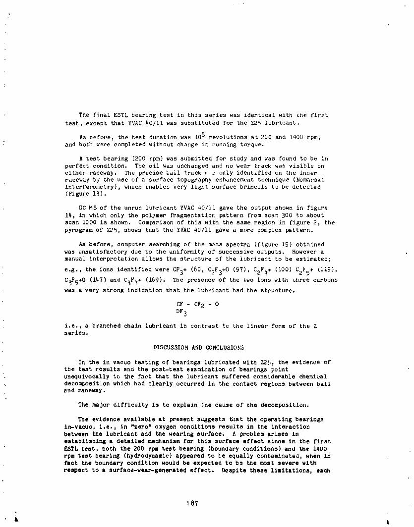
The f_nal ESTL bearing test in this series was identical with the first
test, except that YVAC 40/ii was substituted for the Z25 lubricant.
As before, the test duration was lO8 revolutions at 200 and 1400 rpm,and both were completed without change in running torque.
A test bearing (200 rpm) was submitted for study and was found to be in
perfect condition. The oil was unchanged and no wear track was visible on
either raceway. The precise ball track _ _ only ident:fied on the innerraceway by the use of a surface topography enhancem_,it technique (Nomarski
interferometry), which enables very light surface brinells to be detected
(Figure 13).
GC MS of the unrun lubricant YVAC 40/11 gave the output shown in figure
14, in which only the polymer fragmentation pattern from scan 300 to about
scan lO00 is shown. Comparison of this with the same region in figure 2, the
pyrogram of Z25, shows that the YVAC 40/11 gave a more complex pattern.
As before, computer searching of the mass spectra (figure 15) obtained
was unsatisfactory due to the uniformity of successive outputs. However amanual interpretation allows the structure of the lubricant to be estimated;
e.g., the ions identified were CF3+ (60, C2F3+O (97), C2F4+ (i00) C2_5+ (119),
C3F5+O (147) and C3F7+ (169). The presence of the two ions with _hree carbons
was a very strong indication that the lubricant had the structure.
CF - CF2 - O
DF3
i.e., a branched chain lubricant in contrast to the linear form of the Zseries.
DISCUSSION AND CONCLUSIOh'S
In the in vacuo testing of bearings lubricated with Z25, the evidence ofthe test rcsults arid the post-test examination of bearings point
unequivocally to the fact that the lubricant suffered considerable chemical
decomposition which had clearly occurred in the contact regions between balland raceway.
The major difficulty is to explain the cause of the decompositloll.
The evidence available at present suggests _mt the operating bearings
In-vacuo, i.e., in "zero" oxygen conditions results in the interaction
between the lubricant and the wearing surface. A problem arises in
establishing a detailed mechanism for this surface effect since in the first
£$TL test, both the 200 rpm test bearing (boundary conditions) and the 1400
rpm test bearing (hydrodynamic) appeared to ke equally contaminated, when in
fact the boundary condition would be expected to bs the most severe with
respect to a surface-wear-generated effect, b_splte these limitations, each
187
L l
1985025199-195
of the subsequent experiments supported the hypothesis that the lubricant was
decomposed by the wearin£ surfa , e.g., the accidental contamination of testbearings with a ceccnd oil, anu tLe use of nonmetaJlic surface coatings both
resulted in remarkable improvements in lubricant lifp.
The flnal experzment using the second, Y series, oil was also consistent
wlth the ._rface interaction theory, if the stereo chemistry of the lubricant
could k:ave the effect proposed, although in this instance the higher
viscosity lubricant could have a significant effect on film thickness and
stability and co_,id result in improved lubricant life.
Much more investigation will be necessary before a clear understanding i3available of the complex mechanisms involved ir the tribology of the
perfluoroether lubrlcants. ':'hetest described herein were carried out at low
pressure (lO -6 torr) and thus the wearing surface would be low in oxy.::n
and thus chemically active. However other work (not reported) has shown thatPFE lubricants can decompose in bearings operating in amoiei_t atmosphere.
This work is also concerned exclusively with PFE lubricants of European
origin; other sources, using different synthetic methods of manufacture,
could give different results.
At this stage of the work, it appeases that bearing surf_:ee modification
with an inert substance, resulting in "decoupling" of the lubricant from the
active wear region of the bearing surfaces, offers the best course to ensuremaximum lubricant llfe.
REFERENCES
I. The performance of Z25 oil in ball bearings operating in vacuum.
E.S.A. (ESIL) 056 January 1983. European Space Agency.
2. Some observations on the performance of Fomblin 725 oil and _-ayeo
3L-38-RP in ball bearings and gearboxes.
Proceedings of the ist European Symposium on Space Mechanisms and
Tribology.
Neuchatel 12th -14th October 1983 (E.S.A. SP196, 12/83).
AC::NO_ EDGE_E_ TS
_he authors wish to thank ESA and B"it!sh Aerospace plc, for permissionto publish this paper, and would like to acknowledge the valuable
contributions of the ,:_ny people involved directly and indirectly with thework.
188&
1985025199-196
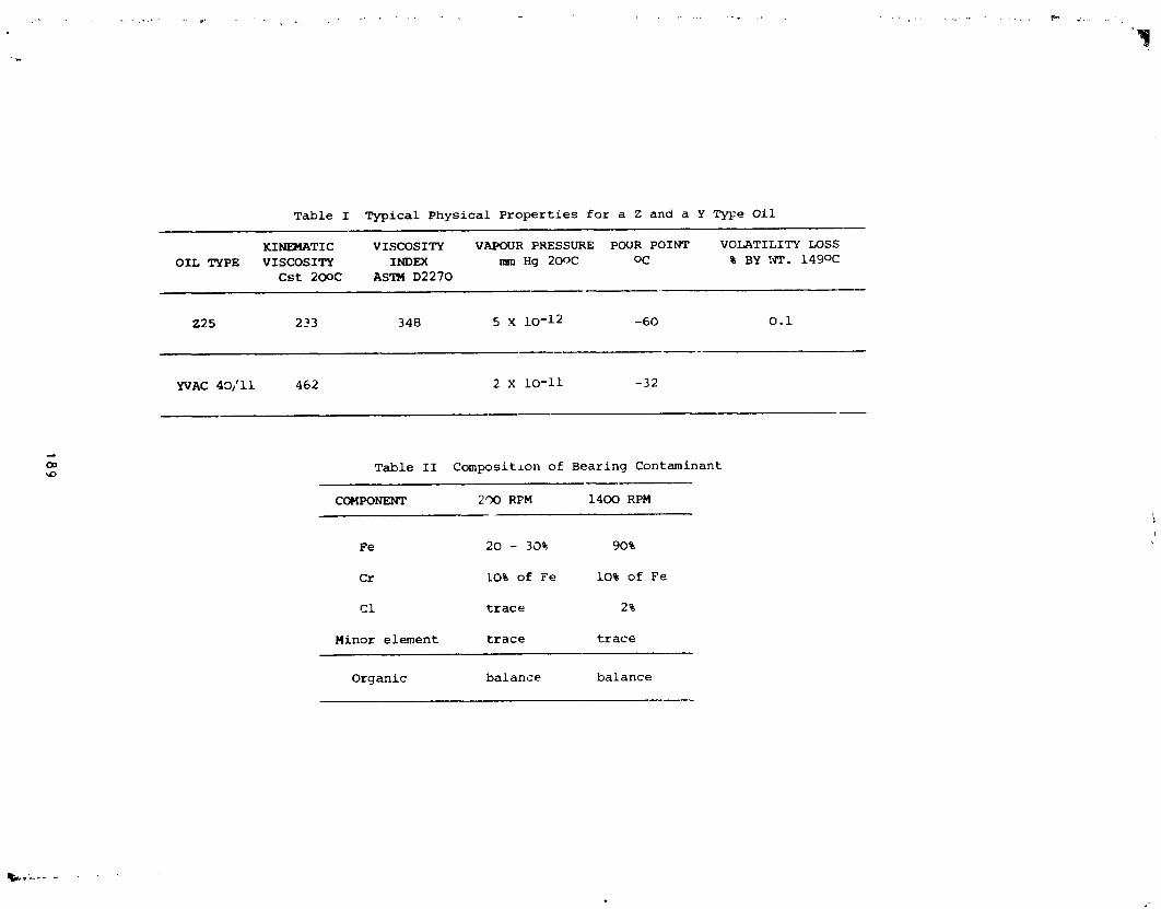
18g
1985025199-197

ORIGINAL PAGE IS
OF pOOR QUALITY
Table III C2F 4 Computer Library Search
LIIIRI:M_YI1EI_JI_H NTIts INHIEI_• 42 _ I'l,,"Et 018feJil,'lll lit2SsN 4. It_ CNLI, CI| • I RICI 413,41_.SN'IPLEs_¢Iq"PLEFROI'IIIIIIER IJtSNEDSLr_ERllTIES IN FIIEOIt113 (E$11..IOI)
• 42- • 32-o TJIXI.N
25488 g_'C'rlM IN LIIIClRM_ SE_CJ_I) FOI l_XllILql PURITY147 mTCHIEDItT I.F.MT4 OF 114EI$ _T _ 114_
Rm,Ig IN1 1415"J_ I,-P,II4PEI4E.I oI. 2.3. ]o 3_2 I_ E'n,@J@._
. $ 21n ImllmL.NBrrnFLumO-4 1411 C'fCt._,OClllFLUBIO-S 21n Iqml,mlL.l_dnm.uww-• 2131 ¢¢lVaN.,I'EmmI_.AFLI._IW-l 2114 I_11qllOII31¢II.NEP_I 2871 IUIIIE,.RCCF1.UC_I_-$ 2130 C_LOP_llIIE.IOIItFUJ_0-
J_ rI.UT IhPK PtmlXY FIT liF|T1 C.11.1_ tg Ill SlB 040 Ill2 "*.P4 IN OI I 8343 C4,H.O.IrT lSl 188 _ _4 C4.1ql _ III din Tff St|5 C].H.C.I'3 148 Ill 498 7'|4 dlEBs CI.N.0.FIS _ O 447 il_ SEtF C4.H.O2.1r/' 214 I11 _ m 4148 ¢4.FI1 N O N _5l (21.M.l_l 131 IS IS3 II1"1
>. :9o
i
1985025199-198

ORIGINAL PAGE IS
; OF POOR QUALITY
Table IV Ccmputer Library Search of Two Z25 Pyrolytic Fragments
LIBRRRY 5EI:IRCH DRTA: RE5 • 289 BRS£_H/E: 11986,/85/81 13:58:08 + 4:49 CRLh C!e • 1 RIC: 25983.5RttPLE: RESDU[ FROMZ25 SNIPL_• 289 - • 288 - • 298 _<I.(R
25418 5PEC11;_ IN LIBRRRYN8 .'.'.'.'_RRCHEDFOR I'IRX|ft.ffl PLIRITY561 tIRTCHEDRT LERST 2 OF TH£ 16 L_GEST PERKS IN THE UNKNOI.IN
RANK IN N_'IEI 332 ETHRNE,CHLOROPENTRFLUORO-
2 333 ETI._NE.HE_<RFLUORO-3 3175 BUTRNE.I. 1, 1,2o3,_,4,4,4-NONf_LOORO-2-(TRIFLUOROHE_)-4 3822 DISULFIDE,SJS(PENTRFLUOROETHYL)5 1488S 8EIqZENEPROPRHOfCRCID,.BETR.°.BETR.-DIr'E.THYL-,rIE'U_YI.ESTER6 3821 PENTRNE,DODECRFLUORO-? 2871 8UTRNE,_ECRFLUORO-5 2683 8ENZRrIIDE,2-r1ETH'tL-9 24281 8ENZRrIIDE,3-rlETI.rr'L-N-\(PHENYLAHIHO)TI.tlO_OI'IETHYL',,-
RRNK FORIIULR rl.UT B.PK PURll_ FIT RFITI C2.CL.F5 154 119 177 761 1882 C2.F6 138 119 17? 949 1813 CS.FI2 288 119 152 819 1894 C4.$2.F18 382 119 141 518 1825 C12.H16.02 192 119 135 681 :656 C5.FI2 288 119 134 ?_2 9_? C4.F 18 238 69 126 6?9 _'28 CS.HS.0.N 135 135 121 647 mO,9 CIS.H14,0.N2.5 278 119 12e 631 179
LIBRARY SEARCH DA"_: RE5 • 318 8RSE I'1._: 11906/8S/81 13:58:88 + 5:15 CRLh C18 • 1 RIC: 2'68,47.5NIPLE: RESDUEFROMZ25 SRftSl.E
ENHANCED(S 158 2N SoT)
25418 SPECTRRIN LIER_I_YNB SEARCHEDFOR ,'qqXllqJM PURIT'Y5S MRTCHEDRT LERST 3 OF THE 16 LORGESTPERKS IN TIlE UNKNOUN
RRNKIN NN'E1 332 ETHRNE,CHLOROI_NTRFLUORO-2 15372 MOLVSDF._JrI.'I_T_RCRRBON'ys,SIS(HE_IIETHYt.PHOSPHOROU_;_I_-P_ -3 19633 PYI_ROLO%Io2-B_,',I,2,4%OXRDIRZOLE-2(IH)-THIONE,TE11_RHYDRO-5,5-DIIIE_rCL-I ,4 4216 PHENOLo2-\I-(4-HVI)ROXYPHENVt.)-I-rIETHYLETHYL%-5 599 8ENZENERCE'I_M|DE,.RLPHR.-El14'fL-E 1?33 Io6,10-DODECRTPIEN-3-OL,3,?,II-TRIIIETHYL-.,,S-(Z),,-? ! 1806 MOLYBDENLk%PENTRCRRBOt4Vt.(HEXRII[THYLPHOSPHOROU,qTRINII_-P)-,(0C-6-22)-5 19634 P'fRROLO%Io2-B',%I°2,4%OXRDIRZOLE-2(IH)-THIONE.TETRRHYDRO-5,5,?°?-TEll_WI9 6526 51LRXE.(ERGOSTR-5.?°22-TRIEN-3.BETR.-'rl.0XY)llq|I'IETH'rl.o
"- RRNK FORMULA M.UT B.PK PURITY FIT RFITI C2.CL.F5 154 119 178 626 266
• 2 CIE.H36.04.HE.MO.P2 536 119 146 652 2863 CI3.HI6.0.N2.S 248 119 146 494 2?34 CI5.H16.02 22q 119 132 495 2125 CIS.fll3.0.N 163 119 117 4?4 2156 CIS.H26.0 222 119 99 364 287? CII.HIS.0S.N3.PT).P 481 119 93 426 2195 CIS.H28,O.N2,S 2?6 69 8S 312 1939 C31.HS2.0.51 460 69 ?4 289 197
191
<
*i l.....
1985025199-199
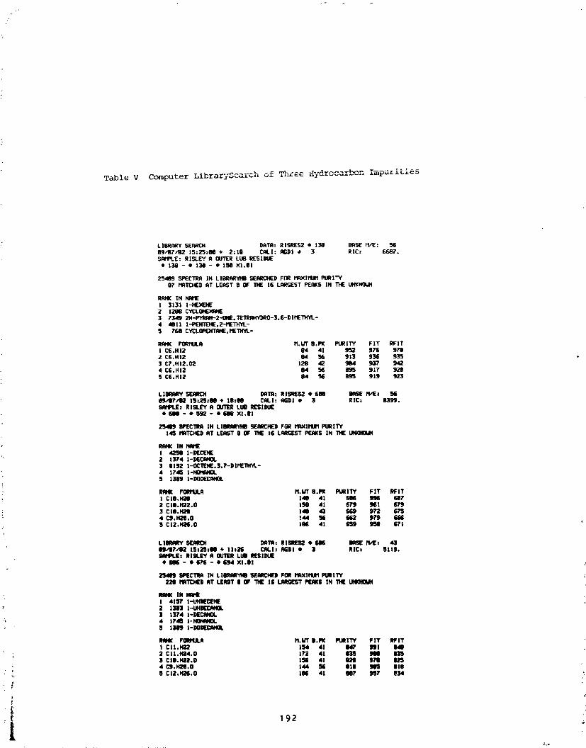
Table V Computer LibrarySc_rch _f • -
L)ORRRY SEI_L'14 i)RTA: RISRES2 • 138 eASE rt/1[:094?/82 15:2S:m + 2=19 CALl: N;DI -', 3 R]C: 5587.SN'IPLE: RISLE¥ A OUTER LU8 RI£SIDUE
• 138 - • 13e - • 158 XI.OI
25409 SPECTRA IN LIOI_R'_ID SEARCHEDFNR Mg_lrtNq PURI"YO? MnTCHEDAT LEAST 8 OF THE 16 LARGESTPEAKS IH T14EtJt_NOUH
Rm4K IH ItNIEI :3131 I-HE)_IE2 1208 C'J_'LOIF.)4qHE3 7345 21,I-PYRAII-2oOHE.TEll_HYDRO-3.6-DIf'ETHYL-4 4011 I-PEHTEHE,2-MElltYL.-5 ?58 CYCLOPEHTPMEoI'ETI4YL-
RRHK FORfSA.R M,UT B.PK PURII'Y FIT RFIT1 CS.HI2 84 41 952 976 9?tDZ C1;.H12 e4 56 913 931; 9353 C?.H12,02 120 42 904 93? 5424 C6.HI2 04 56 095 917 9205 CG.HI2 84 56 895 919 923
LIORARY SEPlR04 DRTgs RiSqES2 • 680 BASE M/Et 5(;_J/O?/O2 ISz._*OO + 18100 CALl: RGDI • 3 RIC: 83_J..qNlPt.E: RISLEY A OUTER LLI8 RESIDUE
• 600 - • 592 - • iU8 Xl,lll
25489 SPI[CTIm ;H LllIImRYXB 56NICHED FOR rltxlltJ1 PURIIY145 I'I_TCI4[D RT LEAST 0 OF TIE 16 LqRGEST PEAKS |H THE UHKHOUH
RAHK IH HRit[I 4258 I-DECEHE2 1374 I-DECN40L3 61!r4 I-OCTENE,3,?-Dlfl£TH'Yt.-4 1745 IoHOttqNOL5 1389 I-DflDECI_40L
RN4K FORMULA M.i,q"B.PK PURITY FIT RFIT1 CIO.H20 140 41 886 996 (;8?2 CIm.H22.0 150 41 $;NJ 961 6_
,_ 3 CIO.X20 idle 43 _ 9;,2 $;_J4 CJ.H20,O '.44 56 f_J2 g_J _;S5 C12.142S.0 185 41 (;$9 958 671
LIORRRY SEI_L'CH Dg'I_t RISREII2 • _ BRSE fS,_m 43OJ,'lJ?/82 ISs2S#O0 + lit;H; CALls AGDI • 3 RtCt 5119.SAI'PLEs I_IM.EY A OUIt'R LUO NESiDUE
• i;_ - • 1_76 - 4) _ Xl.OI
2549 SPI_CI'I_ IH L|iINAItYI4D'SEI_D FOR 1"1_115JI5Pt/itl'T'f_'20 MRI'CHEDAT LEAST | OF 'T14E16 LARGESTPERKS IN THE UHKH05_
I 41S_' I-Ut_E¢[H[2 13113 I-UXl)EC_I_OL] 131'4 I-DECANOL
_ 4 174B i-Nm4N40L$ 13_J i-DON(:_40L
iliflHl( FONffJLA M.UT IJ.Pi( PURITY FIT RF|TI CI 1.H22 154 41 047 _PJI 048
2 C11.H24.0 I1P2 41 83eJ NO 8353 C111.t422.0 158 41 020 9t'0 ll_4 C_.H20.O 144 5E 018 _ 818
_ 5 CI2.H2S.O IN 41 001' _1' 834 ;
t' 192 :
-| ,
1985025199-200
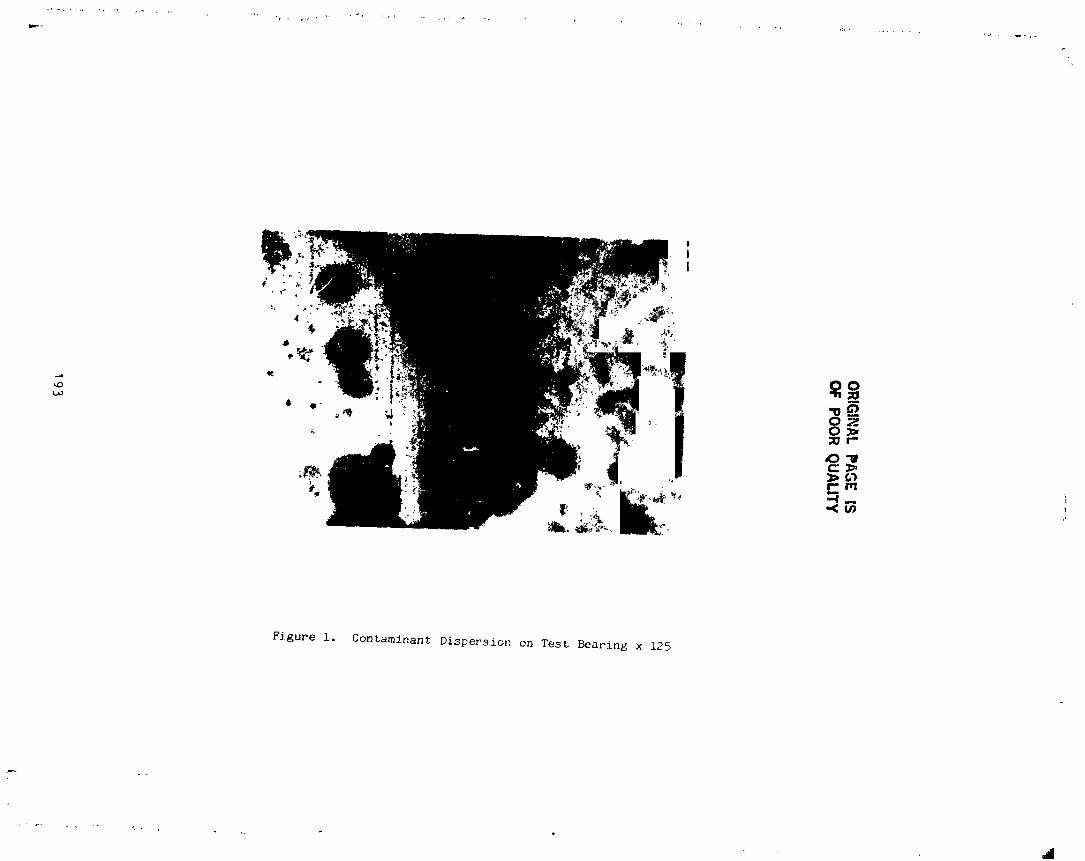
•O
RIG
INA
LP
AG
EIS
OF
PO
OR
QU
AL
ITY
:193
ii,
1985025199-201

J
1985025199-202

OR
IGIN
AL
PA
GE
ISO
FP
OO
RQ
UA
LIT
'f
|,.i
iI
"!
''
!I
oI
II
II
Ia
II
T
•"
N
iis
!__'_
_.
•ot_
•_S-
__-.
_''__
_I
••
••
!"
""
•"
195
1985025199-203

OR
IGIN
AL
PA
GE
ISO
FP
OO
RQ
UA
LIT
Y
196
1985025199-204

OR
IGIN
AL
PA
GE
iS.O
FP
OO
RQ
UA
LIT
Y
¢
197
f.
1985025199-205

:O
RIG
INA
LPA
GE
ISI,
Of
PO
OR
QU
AL
ITY
7'
TwiSt
Page
Figure
.....w
,,
'!'
'-j!
198
1985025199-206

OR
IGIN
ALP
AG
EIS
OF
PO
OR
QU
AL
ITY
199
Ji
1985025199-207

2OO
1985025199-208

OR
IGIN
AL
PA
CE
13I
OF
PO
OR
QU
AL
ITY
t,,t!f
201Ii
1985025199-209

F
'i20_.
4
1985025199-210
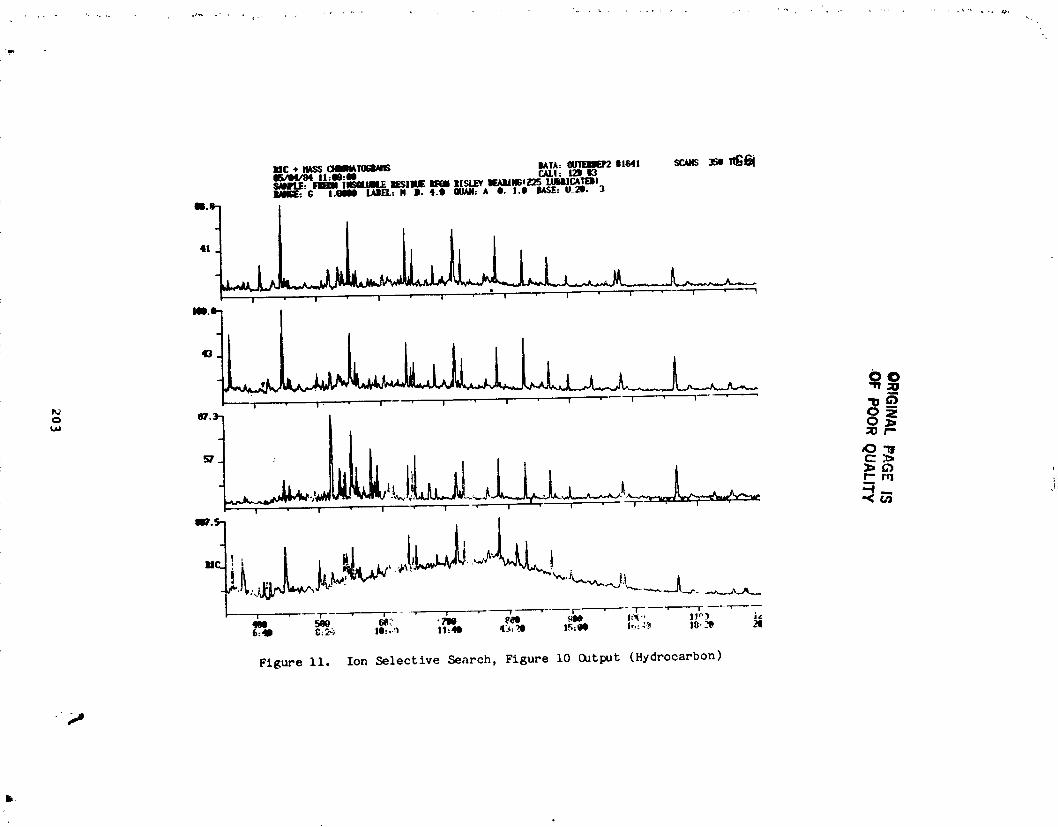
OR
IGIN
AL
PA
GE
IS.O
FP
OO
RQ
UA
LIT
Y'
203
J',Ill
1985025199-211
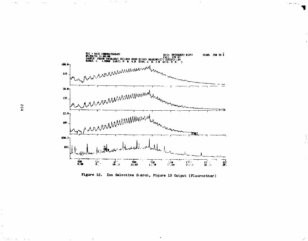
20_1
1985025199-212

OR
IGIN
AL
PA
GE
ISO
FP
OO
RO
UA
LIT
Y
|
205
1985025199-213
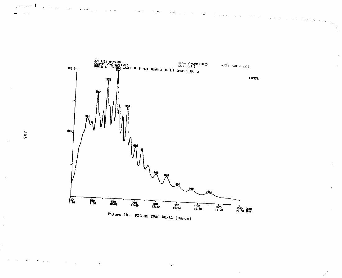
206
i
1985025199-214

OR
IGIN
AL
PA
GE
ISO
FP
OO
RQ
UA
LITY
?\
I,,,,
I•
lI
I|
II
"•
II
II
I
4.-
j_p
t-,,tm
e"tP
I
_t-°
M'
___-
v
_.r'l0o
-
:_,_.H
..,__
......I
I•
•"
'"
!I
•"
!''
"""
0•
207
1985025199-215
• N85-33524
• ADVANCES IN SPUTTERED AND ION PLATED SOLID FILM LUBRICATION
T. Spal vins*
SUMMARY
'; The glow discharge or ion assisted vacuum deposition techniques, primar-
ily sputtering and ion plating, have rapioly emerged and offer great poten-
tial to deposit solid lubricants. The increased energizing of these deposi-tion processes lead to improved adhere.ice and coherence, favorable morpho-
logical growth, higher density, and :.educed residual stresses in the film.These techniques are of invaluable importance where high precision machines
tribo-components require very thin, uniform lubricating films ( 0.2 m),which do not interface with component tolerances. The performance of sput-
tered MoS 2 films and ion plated Au and Pb films are described in terms offilm thickness, coefficient of friction, and wear lives.
INTRODUCT ION
To prevent tribological failures of contacting tribo-elenent surfaces in
sliding, rotating, rolling or oscillating motion, friction and wear has to be
minimized by application and interposition of lubricating materials. Oils
and _reases have been found to be inadequate wear preventives under severe
environmental conditions. To meet severe operational conditions such as high
vacuum, high temperature, nuclear or spacial radiation, extreme loads, and
chemically reactive or corrosive environments, it is of great importance toselect the proper solid lubricant and a suitable depositzon technique. The
selected solid lubricant and its application technique will determine the
• tribological control in terms of friction, wear, and endurance llfe and is
expected to perform over a broad spectrum of these harsh environments. Pri-
marily, thc deposition technique selected determines the mode and llfe of: wear or the type of corrosion. In recent years, the glow discharge or ion
assisted vacuum deposition techniques, primarily sputtering and ion plating
have rapidly emerged and offer a great potential to deposit solid lubricants
: such as the lamellar solids (MoS2, WS 2, NbSe2, etc.); soft metals (Au,Ag, Pb); polymers (PTFE and polyimides); and wear resistant refractor com-pounds (nitrides, carbides, borides, oxides and silicides).
The sputtering and ion pia_ing techniques are restricte +_ processes
where particle condensation on the substrate is initiated by the ions which
transfer energy, momentum, and charge to the substrate and the growing film,
and which can be beneflci_lly controlled to affect the nucleation and growth
sequence. Consequently, the increased energizing of the deposition process
leads to improved adherence and coherence, favorable morphologica] growth,
higher density, and reduced residual stresses in the films. The coatingthickness required is generally small, typically 0.2 to 0.6 m thick, and the
*Natlona Aeronautics and Space Administration, Lewis Research Center,' Cleveland, Ohio 44135
209
PRECEDING PAGE BLANX NOT FR,MEDJ
i
1985025199-216

i!! highly polished and finished components are coated aJ the final processing
step. All these foregoing coating properties beneficially affect the tri-
bologlcal, mechanical, and corrosive behavior of the contacting surfaces andare described and illustrated in this paper.
ISPUTTERING TECHNOLOGY
When energetic ions strike a surface, a number of events can occur, as
shown in Fig. i. First, the incident ion can enter the surface and becometrapped. This interaction is referred to as ion implantation. Second, the
; ion may be reflected from the surface, after being neutralized in the proc-
ess. Third, as a result of momentum transfer, an atom of the surface can beejected. This is the mechanism referred to as sputtering.
_he sputtering technology offers a great versatility and flexibility in
i coating deposition, since the sputtered coatings can be tailored in any pre-ferred chemical composition, and the coating morphologies can be modified.
i Numerous sputtering modes 9direct current-dc, radio frequency-rf, magnetron,
reactive, etc.) have emerged and have been widely described in the literature
(Refs. 1 to 3). Atypica] rf diode sputtering apparatus with dc bias capa-bility is shown schematically and photographically in Fig. 2. This sputtering
system has been extensively used for sputter-depositlon of solid luDrlcants
such as MoS2, WS2, PTFE, etc. In rf sputtering, the target (material to
be deposited) is energized by the application of rf (13.56 MHz) power.Before rf sputter deposition, the substrate surface is sputter cleaned andtextured Oy ion bombardment, thus providing excellent adherence.
Performance of Sputtered MoS 2 Films
_o achieve effective MoS 2 lubrication, two requirements have to be met:(i) strong film/substrate adherence, and (2) a low crystalline slip during
shearing. Sputtered MoS2 films generally display a strong adherence tomost metallic surfaces, with the presently known exceptions being copper and
silver and their al]oys (Ref. 4). These two metals are highly reactive with
the activated free sulphur during the sputtering process, thus forming sul-
phur compounds which have the tendency to flake off the surface.
Prior to sputter depositing MoS2, the highly polished surface isI cleaned by ion bombardment, thus providing an excellent adherence. Due to
[ the strong adherence, extremely thin films (about 0.2 m) are more effective
than thicker films applied by other techniques, as shown in Fig. 3. In thin
solid film lubrication, the film thickness has a very pronounced effect on
| the coefficient of friction. Essentially, the coefficient of friction
I reaches a minimum value at an effective or critical film thickness, as shown
in Fig. 4. The effective film thickness for sputtered MoS 2 films has been
| experimentally observed to be in the 0.2 m range (Ref. 5). Typical Scanning
i Electron Micrographs (SEM) in Fig. 5 show that a 1 m thick sputtered MoS 2film after a single pass sliding has a tendency to break within the columnar
| region of the film, thus leaving a residual or effective film on the sub-
strate. This effective lubricating film performs the actual lubrication anddisplays a low coefficient of friction (0.04) under vacuum condltion_. The
- morphological growth zones for MoS 2 eilms are schematically illustrated
210
|
1985025199-217
i after sliding in respect to film fracture in the columnar zone in Fig. 6.
This film fracture behavior clearly indicates that the adhesive forces
between the substrate and the MoS 2 film are stronger than the cohesiveforces in the film itself. It should be remarked that the displaced excess
film generates unnecessary wear debris, which has the tendency to _ncreasethe torque level and impair the lubrication cycle in precision bearings.
To strengthen the structural integrity of the MoS 2 film in the columnarzone and possibly increase the thickness of the remaining or effective film,
gold dispersion was introduced into the sputtered MoS 2 film for densifica-
cion and strengthening purposes. A compact Au-MoS 2 sputtering target pre-pared by powder metallurgy techniques with 5 to 8 wt % of gold was sputtered
to achieve the gold distribution within the MoS 2 films. Similar co-
, deposited Ni-MoS 2 films have been also reported (Ref. 6). These co-
sputtered Metallic-HoS 2 films aisplayed a lower and more stable coefficientof friction and even longer endurance lives than the pure MoS 2 films (Ref.7).
To insure consistency in performance, precise sputtering quality control
is necessary. Film morphology and chemical composition are sensitive to
sputtering parameters. The integrity of the sputtered HoS 2 films can beidentified by visual appearance prior to and after gentle rubbing or wiping
_| across the surface. An effective lubricating film has a matte-black, sootysurface appearance, whereas an unacceptable film has a highly reflective
mlrror-type surface. When the matte-black, sooty surface is slightly wiped
unidirectionally, the color changes from black to gray and is schematicallyrepresented in Fig. 7. The color change reflected from black to gray is due
to the reorientatlon of the crystallites or platelets in the fllm (Ref. 8).
Sputtered MoS 2 films are particularly indispensable for applicationswhere extremely thin films ( 0.2 m) are required for trlbological control in
high precision bearings, where tolerances are close, reliability requirementsare high and the minimization of wear debris formation is critical. MoS 2
films are directly sputtered onto hearing components (races, cage, and balls)
as shown in Fig. 8. These films have been successfully used in despin bear-ings for communications satellites, glmbal bearings of reactive motors, bear-
ings for antenna and solar array pointing mechanisms, gears and bearings of
spacecraft harmonic drive assemblies, and in numerous other aerospace and
earth satellite applications. For instance, in Fig. 9 the adjusting screw
which fits into a power nut, Is sputter coated with a 0.3 m thick MoS 2film (_ef. 9). Note, that the left hand bearing diameter is also sputtered
to prevent fretting corrosion against the inner face of a ball bearing fit.
This assembly is used in the Intelsat V Satellite to position the antennas.
The operational requirements are from one to two cycles per day for 16 years.
ION PLATING TECHNOLOGY
The ion plating technique combines the hlgh throwing power of electro-
plating, the high depositJon rates of thermal evaporation, and the hlgh
energy impingement of ions and energetic atoms of sputtering and Ion implan-
tation processes. The basic difference between sputtering and ion plating isthat the sputtered material is generated by impact evaporatior and transfer
211
i
1985025199-218

[ ,
,_ ORIGINAL PAGE ISOF POOR QUALITY
• ,, _1.,' ,.y ;. ,'.,,.,:_qt,,, 1_';:._. t'_,r _,,(.:{..,:;. il_ ion platin_ the evdrorant is gen-
, _,',:,I L/ tf_-r._-_l _.,/,,toz,,.] Jol_. 'lhe J(m [,latin_z process is more energetic
t.q,r: ._i,tllt,,, ]r_, str,_t t,n,: [,t, ee."s uses a Li_h :_peeimen bias of several
ti_.,-,l._a:,_ .,_,]t.,_ t_-, ,i tP, ,,.t l:,, ao.,.,,],_r',_t.,: the positively ionized evaporant atomslilt,, t ., ,botr._t.<. lh_: ba.-i( lrt, !,]dt]n_ syst.e[_l qonsi:_ts of a dot-diode con-
Z *F _.'it_m, ,i_,-r'uih,, l,c,_]m,:,, is made the cathode of the high voltage dc
cir:;,_]t with an evaporation soJroe as an_,de shown in Fig. !0. £he ion p]ant-
inff t_:chnique anq the process parameters are described in the literature
(Refs. lP, to, ]_').
IF,,_ irte:'ost Ir_ i ,n plattn@ ori;,inates from its two unique features:
(!) _Ih,: !,i_h erer_} t'lt'x of :r r.:-', and energetic neutrals contribute to the
c_'_,l].e:<r t_]rW._'d_rt.,-.at( :_dherence _md tht; desirable morDholo_:;ea! growth ofthe f J 1m.
(2] ']!, n_/': "} ' _,m; _,(,'q,:r' pr'ovJ':es f,Jr three-,tlmensinnal coverage to
coat _ t.[_ [1(.,4, l,,_tr _ ('_:._- cC.mF,onent _ such as t.earin_s cages arid races withoutrot -_t t o,_.
Ikhese <wr f_t_,re:" hay{: generated new potentials in coatir_F, utilization.
the soft retal]ic ior, [)tared ;'i][r.'{such as Au, P_., and Pb are primarily used
for" ] ubr] ('Ptlr_; _b._r'ei_or,, t "ibo-el_mer't ('omDonents and ion plated A] films
f-.r ,_,_rr'oslon _ro,_:. tton ,_t' ,_trcr_ft engine part2 and structural eomprments.
_q,rt'r r._.l_c(, hi' for, }'lated _'etalJJe Films
1_,,c exc._.!],., t f'-l,n adher_,n(.e oF ion _'lated t'i. ims _s attributed to the
t _rrnati, - ,,t _ _ ra,' :,I ]:,Lert._{ ,. f{ tw¢_,,n the fLlrq and the submit'ate, even
wh_.m _ !.( ", L,r, ',;,fi" .,t,rat_ P'._tt_;rials ar "_ iT,dlt uaJ]y incompatible. This gradedlr_t,_'['.'_ .,.:. r:ot , nlv i,'c,_l h,._ exu_,lLent adh(,r'('nee, hut also induces surface and
,suh.-_urfae_. sLr-_n_ chef, inK effects whic.h faw_rably affect the mechanical prop-
_,Ftie:_ s,lch .._,_ , le[d strenzth, termite r, trength, and fatigue life, as shown
in PJL'_. ]1 ar_ 12. qf the soft. metallic f_lms (AK, At], ard Fh), gold and
le._d haw, .*r,t.n<t'xttJlJsLv_;d3_.S in s_aceborn bearings of satellite mechanisml
s]en _s :-:Jar arr=_y drives, d.:apin a:.semh]ier, and gim_.ats. These ton plated
[ut_rL-at]ng thlb fii._s {_.2 m thick are w, ry er['ective in tncreasjnF the
_ndur_n,'e ]ifw, _:,.]uc'inK th.. ('_,_,ffie]ert of 1'ric'tJon, anQ eliminating instant
or c.,t mire,phi(, t';,lltn'_.'.. 1he f_vorable: eoqtinF behavior is due to the
s_rertor ,_,lb_,ren, e, _'r'3de,t int_;rfac_, very small, unifor_ crysta]lite sizewhich c !'lbutes tn hJ;h (_ens]ty pac'.kin_: (pore free) and v,'rv cnnttnuous and
unJf(,rm flil,n with a h'._h _,Kr'ee ol lattice f'_.t,. Du_ to these favorable coat-
in.< [{'zm,_t]r.n {harn_'t_,rz:'ti;:r, extremo.]y thin f_lms Jn the 0.2 m range aret'_r :,<[._.r': .',r t,_ tb] uk, r t t 1ms in t er, m:, .)f the c'r,e/'fJctent of fl'JctJon_ as
sh(wn 1l ?'i6. 1}, [',,r K{,ld _,n,l lead (£ef. lJl]. ,_or Jh.':tanc- it has been
shown (l.el'. 1' ) t.h4t th(, Pb film's superior adhesion prc)duoed stgr:iftcantty
lower torqqe _. l::e .,n(;_[,e t_.rq_,, bohavi,_r was st" _ ' the tia_.e over rst milY_on
revol itions.
The. q_h thr_ wtnw i, w,.r'and tfe e_-ell;rt adhererl"e is wld(,ty used to ton
[.14te t_lr_-_--,Jim,,r::_]c.tt,l[ e_,_,,[,!,,x r,_:,.h,_rtieal :,ur'fa,'es, :_tJch as internal and
_xt,.r:.lL sllrf.,, _-:_ ,_f' t_mlh_', [,_:-t,+n+ r.., , ',4|] t_'.trln_ts, and aear t,+eth, ,is
" i L'1?.t
.[,
1985025199-219

ORIGINALPAGE ISOF POOR QUALITY
shcwn in F];- J_ , , _ , __.,, ,,,:,,t:-'.:arecomponents
:_] ' r'_]u.,. A highly loadedion plated 1_,_ _ ,i :; ,_ , ,', .......precision t,uli _,,-,:_ , ,. ,. _, , ,- _, r p_,_t_;d _ll,n Fold (0.]2 to0.2 m) as ._lLo_.it r _. ,[ ,,_" I; u::ed Ir_ :;p-_eewhere it
tra _smits 136 ,,_ul,:,,,_ , .... , t:][ im_vents cold welding ofthe gear pitch li._.
In addltl,,, t ..... , . :, . _ :_ i J,: _l f,,v, f,,,- lubrication:in the air'c: "_ _ I l i _ % ] :'" t' r _ • ' if..: ,,+ ,._ J i,_.+'F;:-:_cale productionbasis to _,,l"<'t_;_;t, rill', ,' :: , ,_ .... ! ,,: ' . [ _ ,f .... m'c;_l,',,-,. Also, whererequired, it will [e _:_.,i ,,, ._] _ ;,t _.,: ,_ ltic_,l h,'_h strength aluminum andsteel structure_ _n.! ,,r_ t i_,r,,,_. . _,,! ,il. ,, ,,1,-_.1 fastener_ (Ref. 16). A
- typical AI itm _,i,t,:,_ _,,_, ,_,/;, .- , .. 1,,., F,,u" .-7[tnd,_'r for corrosion
• protection _, :_q ._, _ . " ',,._."h _ldr_it_um alloy bulkheadfor corroslon ,,r_,! t _; la.. _ : ., _.. t._,7. 17.
ir, I , i,!,
The plasma ,r ;.,_, ., _ ,'.. : _, .. -_ ..... t, ,.*._:q,_,+-._, ._t_ch as sputtering andion plating, ,,[i'_ ' $ g : '-- ' t [ ' ' ' . : , ' I ' r _ ' :,, ,lid t'_Im lubricants and
corrosion protect J_u ,,:,i ,i, :.... ':., ,,x,,:ll,:_,.tadh_'renee and coherence
reduces intert_.,_ ._t I ,. .... ,: : ,r,.1 ! t ,. % .I'[)q - [ _,' l,'r_ [ _,u_lwt,h to form dense,cohesive, equiaxed ,Kc;,]t_ ', _:.,. , ' _,t' _.u[ch have a tendency to lowerthe coefficiept _,_ _r]_ : i. : , ' , ",,' . .' _[, , _r'._ Lhcrease surface corrosionprotection. F_,r _:c,.q:_i:,L.-!." :., ,:. ' ,_ I' i :, ,-,_-F_nt ia} that good qualitycontrol is ma_,ta_r,,_4 ,_ :.,_ ',_. ,'." _ :, _.la_in4 proe.ess,
1. Maissel, L. : A_.t,i , -.t _. _, , . ,' ., t, , ,- '. the. ]loposition nf Films, Hand-book of Th_r, H]_,. 'P . _: .... _-. , ( ,' . _., [,._. _,,i,:.'_el and R. (;lang, eds.,McGraw-Hill, _ew Y,_.,,_, i_ • ,- ' :_ ,'., ','<,.
2. Holland, L.: A hev]ew ,.:" _1 ,:,',, , ,.,:: ._tudies, :;tu'f. Tech. ii, pp.145-169, 19_0.
3. _u_hah, H.F.: ['_t',',,',_ t. _',..h_.,l.,.',t,._ l'( z' _ilms :,nd Ccatings, Noyes
Public, 1982.
4. Spalvlns, T.: In/l l_r:._ , r ,_: ,_ ,_::',,, }r_,_I',,;_tm_ntson Adherence of
Sputtered_blytdrrmm D[:._:[r] :. t,_ ."i]v.r, _.Id, Copper and Bronze, NASA
i TND-7169, 1973.5. Spalvlns, T.: Ch,,r,_( t,r,.:,t l, I%r[ _ l=_,i<:,_l a:,d Frictional Changes in
Sputtered Mob, _]lm, , A,,[,_t }r_,,t,,:_',r:- _i,d International Conference. . on Solid Lubrication L'_,_4. ._.::,_' .'.F-i_ ,,.-,_1-207) D_,nver Col., 1984.
6. Stupp, B.,,r'.: :;yh, zg_',_ i t l*,_t _ , t _bt_l: (c-Sputtered with MoS2,• _hln Solid Film_, 84, (,',,'-''_, t_"!.
• 7. Spalvins, T.: i.'cl,,tl,,_4l ,rid P,<.rbh_ l,,v!,'._+J F.,.,,p,trties o! Au-MoS 2 FilmsSputtered From a Co_.pd,,t 'l.,r#,,t, ['hill ,;_l i,J bilms, 118, (373-384), 1984.
8. Spalvins, T.: M(,rph,,l,_glc41 ,,_i b'_'l "tl.,.,,_l t-,harlot of Sputtered MoS 2Films, Thin Sol_d _Im:;, _ (t,'-/4), !,;:_.
9. 5tupp, B.: Practical tq I-i",tt t_,tm ,r., + li:+,.+:, or Solid Lubricant Films,Tribology in the _!)':_,_A: A 'i • _>( , ,,)i. 11. 6AI-70 z, 1984.
I0. Mattox, h.H.: l"_,h,l,,_._,,,,I v _ r _'__ i_F, ,;. Vao. Sci, Technol., vol.• ,'. .I0, no l, (4(-b,), ',
1985025199-220
J
ii. Spalvins, T.: Survey of Ion Plating Sources, J. Vac. Sel. Teehnol., vol.
17, no. 1 (315-321), 1980.12. Spaivlns, T.: Ion Plating for the Future, Met. Finish., vol. 80, no. 5,
(47-50), May 1982.
13. Mattox, D.M.: Ion Plating Technology, Deposition Technologies for Thin
Films, Ch. 6, R.F. Bunshah ed., Noyes Public. 1982.14. Spalvlns, T.: Frictional and Morphological Properties of Ion Plated Soft
Metallic Films, Thin Solid Films, 84 (267-272), 1981.
15. Todd, M.J. and Bentall, R.H.: Lead Film Lubrication in Vacuum, ASLE
Conference on Solid Lubrication, Denver, ASLE SP-6, 1978.
16. Muehlberger, D.E. and Rellly, J.J.: Improved Equipment Productivity
Increases Applicatlon_ for Ion Vapor Deposition of Aluminum, SAE Reprint
P-127, Proo. of the 19th Annual Airline Plating and Metal Finishing
Forum, (McDunnel Douglas Corp. Report 830691), 1983.
t
JIi 2111
i
1985025199-221
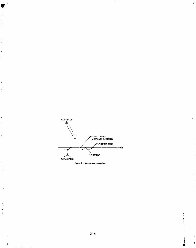
[IT' "
INCID[NTION
®
_ REFLECTEDIONS
sEcoNo,RYE_CTR_S./sPu_E_DATO_
"-I'" - ,i"-,_ _upF,cE,_ SPUTT[RING
IMP_ANTATION
FRure1. - Io_,-surfaceinteractions.
21.5_L
1985025199-222
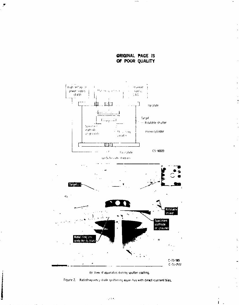
ORIGINAL PAGE IS
OF POOR QUALITY
_ ....... C-?i-_537
Ib) Viev,ot appdrdluSduring sputtercoating.
Figure 2. Radtofrequoncl du._tesp,|tterin(j al)par,tUSwith dlrect-currentbias.
l
1985025199-223

Z
r
ORIGINAL PAGE ISOF POOR OUALITY
;AIL' _'_,_Tl _10_ " _ t_,irr_ L 'r"
I
1_''_
lol_-
[I[_ ( h',v,ur?_ I:q _:, q," ,
F_qure 3. - I.n_uranco hves of MoS2 flhr, s dpphe_ by _ar oustechmques,
-pFOR B_RL SILELS
i-
• _ I FCR_I_C_LOil , _ ,
: _ Pmin
ll_bREASINGfILM THICKNESb h
F_gure4. - SchemaI_¢representation o_the effect of hlmthm_ness on the lt'lt.lion tmfhr.._e_l _( _o._shear stl'en_tl_metall_¢ films on steel,
• , 2 1'7
, i_ J
1985025199-224

ORIGINAL PAGE IS• OF POOR QUALITY
_ ': aBAI_ _W ......
iyjnn]?.,w_r_.,,,._,.,i "--_'-""- ,.v4L* -
(a)On4t_Cstainless-steelsubstrate.

i ORIGINAL PAGE ISOF POOR QUALITY
: FIBER ZONE
L
- FRACIURE
EOUIAXlD 20,N_
EF_CIIVE
RIDGE ...... xx_xxxxxxxx xx_ " THICKNESS
.... ,/// ,/_ ,/ ,
: Figure 0 Fracture durm_/shdmg _f sputtered _oS 2 him m respect 1o morphologicalzenes
/ -S[IDING _ _
WIPING _ "'"-
hqure I. - keorlentatiun _! sputtered MoS 2 plateleB,
219
i Vl,- , -,
1985025199-226

ORIGINAL PAGE IS. OF POOR QUALITY
0
"( '41-03Jl
!, jr, 4. 1,_, _*>t', N hall hParmq d%_,mbhes sputter-coaled wlth t_S 2 films.
"_'_"SD_'tt_r'_'_ %_q'2 film.
i I I k
iN,,...
_'m k- ................
//
,. _,: _77h Adlultlllt I sf'r£%_i-/lcm
_ ...... __._: wWlllllllll-
4"/
/( g4 b77t_ Piipr hill -/
|¢m
FiqHr_4. P_,'_or roll and a,llelst'q q s( re_ a_,embly sputtercoated with t',_oS2.
.i! 220
, I
1985025199-227

ORIGINAL PAGE ISOF POOR QUALITY
..............1 1H.V ...............
,.-Sgecimen
r Evap, heatSourcet+ )
F-LT_,,+oT,I......_w_-l[ o+++,,,_........

0.4 cn,
- 8.9 cm - _-t INCONELIONPLATED_ WITHCOPPER
528 -- 3.2 cm INCONEL
_ FLATTENSILESPECIMrN1/61. NICKEL0.O_cmTHICK
', Z INCONEL0.043cmTHICKI I 1 J l
.127 .254 .381 .508 .635ELONGATION,cm
} Figure11. - Loadelongationcurve',d:Jringtensiletests.
l 2.5 Y_ _ O STEEL' _ _ I-1 Au ELECTROPLATING
_ ZO--
1.5 I I 1IO lo6 lo7 lo8
CYCLESTOFAILURE,Nf
FigureIZ - Effectofionpletlr)gontM tltlgue propertyoflowcarbonsteel.
222
i
1985025199-229

ORIGINAL PAGE IS
DE. POOR QUALITY
.6
.4
.2
' _ o __l____Jla)Leadfilm.
¢,J
'='_-g.4"6_1 I L I
0 ,I I I0 I00 "
FILMTHICKNESS,pm
(b)Goldfilm.
Figure13. - Thevariationof frictioncoef-ficientwith filmthickness.
POLYMIDI-HOLLOWI_FLONHOLLOWCERAMIC CAGE
TUBING TUBING
•lU.'l(a)Co'tediosulators.
A I 8IbICoatedinternalandexternalmetallic_rfaces. i
Figure14. - Ionplatedinsulitorsandobjectswith metalliccoitin9.Cs-Tg-I_T2
223
1985025199-230


N85-33525ORIGINAL PAGE [$OF POOR OUALITY
TELEP_ESENCE WOrK SYSTEM CONCEPTS
Ly]_ :i. JerH" _,: *
A_STHA,':T
manzpulaLion where the operator is provided w_th tb_ _,,:,_,'rvfe_d_a_"_ anJ
control to perform hiFjnly dexterous tasks. The conc'eot of _ Ten-presence
Work Station for operation In space ts described. System requirements,
concepts, and a development approach are discussed. The TWS has the
potential for application on the Spare Shuttle, on the (Irbi_ Maneuver
Vehicle, on an 'Orbit "Iransfer Vehicle, and on th_ Skd_'e Stati.;n. _ _ ,function is to perform satellite s_vicinF tasks an l cnnstrqetion and
assembly operations in the buildup of large spacecraft. The basic concept _{
a pair of dexterous arms controlled from a remote station by an operator with
feedback. It may be evolved through levels of suuervisory control to a smartadaptive robotic system.
INTRODUCTION
_he ter._,"lelepresence" describes a r,em,)temanipulacion s_tuation where
the c_er'ator 18 provided with the sensnry perceptiot_._ at_d control tnIaccompitsh intrtcete tasks requir!ng Freat dexterity. An e_t_n_iorl o{ the
concept of telepresence J.s . space _Light syste_ t_'at ts a combination ofteleoperation and robotics called a q'e[e_-_nee W_rk Sy_t,',m('[WS). The IW?
is an evolutlona_'y concept that is inten,._d t_ prcwid- t.h_ ,,_,,.-at,,r with the,; capability to perform tasks in :Bpace "_3 though th_ _,p,,r_,)_' _ere at th,'
i re_'_te '" "
ol,.e, trle basic conct, pt of a TWS i_ a D,_r ,'f m:Jnir']]at"r "_rrn_controlled f,_oma remote station that provides s_ti_ory feedba('k c( the work
slte conditions. Utilization of current technology with the option of
"I including new technology as it develops is a design goal ,)f the concept. ThoI IWS mission and design requirements are poi_ted toward a _ner'al capability,i
rather than specific or unique tasks with limited applleatton. ]'hepr}ma,'y
i _unctio:_ of the TWS would be the perfor'm_mee of satellite servici_g and
repair from the Space Shuttte. lhe TWS can be uJed for assembly task_ I_ thP
bui}dup of the Space Station. On the operational S_-,_<,eStr_ti,m, the ._ ran
aid in the servtci_g of satellites ano in the c,)n,L_uctton ar _ _:_sembly <)f
new spacecraft.
TWS MISSION AND DESIGN RZQUIREM!£N'I'S
The Spare Shuttle can be expected to increase tt:_ ro], _n th_ "_ervtetn_,
repair, and recovery o/ operational satellltej, su'h a_ has b_u ',,,-wi_h
Solar Max, WES_AR, and PALAPA (Figure I). 1'he ,'u,'rent ._n(lprojected FVA(extravehlcuIar activity) capabiIlty provldes a basis fc.r ,leve[opm,,nt or the
i * NASA Lyndon B. Johnson Space Center, Houston, TPxas
2P5t
a i
1985025199-232

equipment and functions needed for working with satellites. The addition of
dexterous functions greater than the current SRMS (Shuttle Remote Manipulator
System) can supplement EVA for hazardous, tedious, or repetitious tasks.These dexterous functional requirements can be defined for satellite
servicing, assembly and construction, and Orbiter contingency situations interms of the capabllity of an EVA astronaut to perform detailed tasks.
Requirements for servicing satellites include the resupply ofexpendables, the replacement of modules, and the repair of damaged or
inoperrtive components. The transfer of fluids for a resupply mission
involves the attachment of fluid connectors, determination of integrity of
the interface, actuation of valves, release of connectors, and verification
of lack of system leakage. Resupply by tank replacement also requires themanipulation of fluid connectors as well as the handling tasks inherent in
the replacement of equipment modules. Working with modules includes a
variety of tasks such as removal of insulation, removal of access panels,
fastener disconnection, module handling, fastener insertion, electrical
connection, and verification of mechanical and electrical interfaces. Repairtasks are among the most unstructured activities that will be demanded of the
TWS. The repair functions require cutting, clamping, soldering, applyingadhesives, and other nonstandard operations.
The requirements to perform assembly and construction tasks in the
buildup of satellJL_s that are larger than the payload bay of the Orbiter or
in the reconfiguration of satellites that are already in orbit will be
similar tc the operations for satellite servicing. These operations wxll be
better defined and structured with supplemental fixtures and tooling to aidin the assembly of components into the final configuration.
Orbiter contingencies represent another area of operations that will be
well structured in some instances and very poorly defined in other cases.
The deployment and stowage of payloads involve the actuation of latches or
the movement of mechanical appendages that have not functioned properly.
With a high degree of dexterity available, the use of kits to repair da_ged
heat shield tiles becomes practical. The removal of icicles, as occurred on
one mission, could be accomplished with ease. A TWS could provide a varietyof services to aid the astronaut in EVA operations.
The design of the TWS requires certain subsystems to perform criticalfunctions in the efficient accomplishment of tasks. The work must be
stabilized relative to the TWS. The dexterous arms must have sufficient
reach and degrees of freedom to place the end effectors in proximity to thework. End effectors need to interface with the equipment being serviced.
Vision is an important sense in orienting for remote manipulation. Stereo
viewing, while not a requirement, improves the performance of the operator inmany circumstances. The interaction of the type of control system with the
layout of the control station is fundamental in the case of the Orbiter. For
example, the SRMS was driven to a resolved rate system because of the lengthof the slave arm and the uonstral_d volume of the crew station. Shorter
arms on the TW$ may allow the option of a master slave controller with the
proven force reflection technique to feed back reactions at the end of themanipulator arm.
226
1985025199-233

ORIGINAL PAGE ISOF POOR QUALITY
CONCEPT D_EC_ !PTIONS
Elements of the TWS are pointed out in Figure 2. The TWS concepts
current]y under evaluation are composed of the following subsysLems:structural base, interface to the carrier, stabilizer arm, dexterous arms,
end effectors, closed circuit television, controllers, dlsplaye, lighting,communication, and power. There are a number of options in sensors that
could be Incorporat'd to enhance the ability of the operator to perform more
effectively. Stereo vision, proximity sensing, and tactile and forcefeedback are probable additions.
Two companies, Grumman (GAC) and Martin-Marletta (MMA), have study
contracts with NASA to define concepts for the _'S. A Grumman concept, shown
in Figure 3, is based on using one of the dexterous arms as the stabilizing
device. The support structure is a simple arrangement for the three
dexterous arms and the television camera. The control station is a portable
setup in t_e aft deck of the Orbiter cabin. Another GAC version, illustrated
in Figure 4, car_,ies a stabilizer arm and movable cameras to get improved
viewing angle_. Stowage for end effectors to adapt the manipulators for
specific tasks is incorporated in the structure.
A Martin-Marietta concept, as shown in Figure 5, uses 7-degree-of-freedomarm_ for the dexterous function and an arm with limited articulation for
stabil_zation. Stereo vision simulates the operator eye location with thecamera located relative to the two dexterous arms in an anthropomorphic
representation. The initial control station concept appears in Figure 6.
The controllers shown are 6-degree-of-freedom that input motion to the arms.
The controllers are reindexed to keep the controller motion within the
available space envelope.
SYSTEM DEVELOPMENT
The concept development will be subject to a number of trade studies.Among the more important trades are: arm length, control by position or
rate, stereo or regular TV, number of arms, force reflection vs. displayed
force feedback, and stabilizer arm (number, stiffness).
The initial trade results will result in a basic configuration to beginthe development. The trades and technology projections are elements in the
definition of an evolutionary development plan. An _volutionary program is
projected that has objectives beyond the operation on the Orbiter. The OMV(Orbit Maneuver" Vehicle) requires a dexterous system to perform tasks on the
satellites. Siml¢or requirements are expected for the OTV (Orbit Transfer
Vehicle). These operatlo_s will be conducted at long distances from the
control station. Time nclay in exces_ _f aoout O._ _econd becomes a factor
in teleoperation; therefore, deeclopment of the TWS should include time delay
compensation techniques in the _eleetion of subsystems. Coping with time
delay may include predictive graphles, rate control rather than position
control, data compression and simplification tc reduce communication
requirements, and robotic phases in performance of an operation.
2_7I
1985025199-234
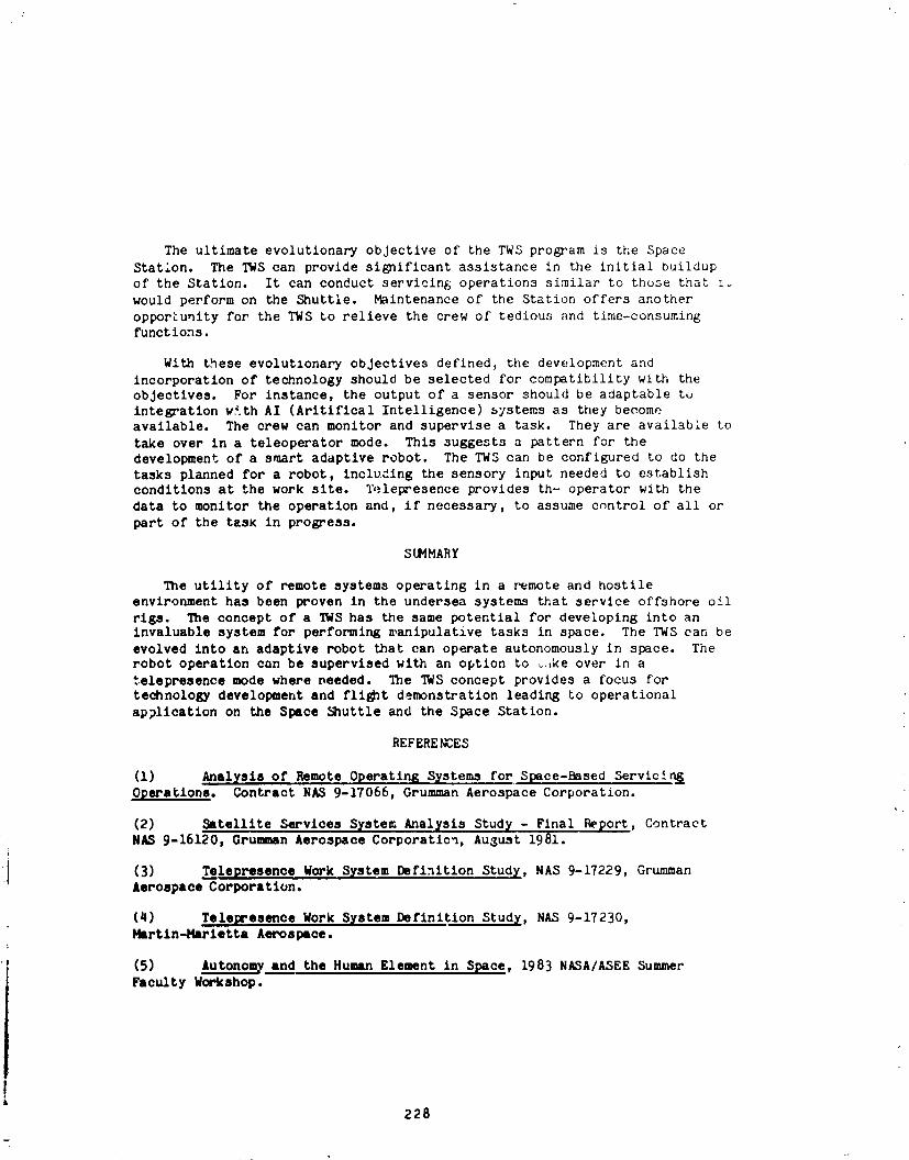
The ultimate evolutionary objective of the TWS program is the Space
Statlon. The TWS can provide significant assistance in the initial buildup
of the Station. It can conduct servicing; operations similar to those that _.,
would perform on the Shuttle. Maintenance of the Station offers another
opportunity for the TWS to relieve the crew of tedious and time-consumingfunctions.
With these evolutlonary objectives defined, the development and
incorporation of technology should be selected for compatibility with the
objectives. For instance, the output of a sensor should be adaptable to
integration w_th AI (Aritlflcal Intelligence) systems as they becomeavailable. The crew can monitor and supervise a task. They are available to
take over in a teleoperator mode. This suggests a pattern for thedevelopment of a smart adaptive robot. The TWS can be configured to do the
tasks planned for a robot, including the sensory input needed to establishconditions at the work site. Telepresence provides th- operator with the
data to monitor the operation and, if necessary, to assume control of all or
part of the task in progress.
SUMMARY
The utility of remote systems operating in a remote and hostileenvironment has been proven in the undersea systems that service offshore oil
rigs. The concept of a TWS has the same potential for developing into aninvaluable system for performing ,,anipulative tasks in space. The TWS can be
evolved into an adaptive robot that can operate autonomously in space. Therobot operation can be supervised with an option to _ke over in a
telepresence mode where needed. The TWS concept provides a focus for
technology development and fli_t demonstration leading to operational
application on the Space Shuttle and the Space Station.
REFERE _T,ES
(!) Analysis of Remote Operating S_stems for Space-Based Servlcin i
Operations. Contract NAS 9-17066, Grumman Aerospace Corporation.
(2) Satellite Services System Anal_sis Study - Final P_port, ContractN_ 9-16120, Grumman Aerospace Corporatlc_, August 1981.
} (3) Telepresence Work System Definition Study, NAS 9-17229, GrummanAerospace Corporation.
(4) Telepresence Work System Definition Study, N/LS 9-17230,Martln-Marletta Aerospace.
' (5) Autonom_ and the Human Element in Space, 1983 NASA/ASEE Summer
Faculty Workshop.
228
1985025199-235

ORIGINAL PAGE ISOF POOR QUALITY
_ ORBITER
MID-DECK
DEPLOY/RETRIEVE
RETRIEVE/RETURN TO EARTH
Figure I. Shuttle Satellite Servicing Capabilities
229
il
'- l i ' I I m
1985025199-236
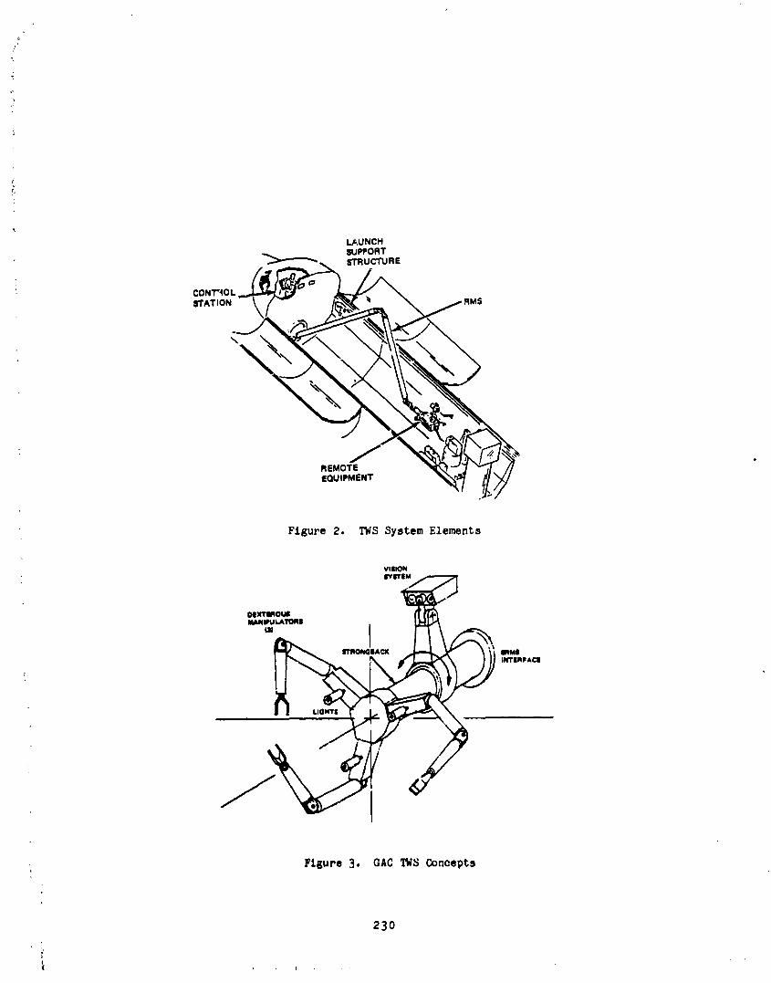
L_UNCHSUPPORTSTRUCTURE
Figure 2. TWS System Elements
VIIIONII'ITIM
Dix'reqouJ
, ,,, t" _
• Figure3. GAC TN3 Concepts
230
1985025199-237

ORIGINAL PAGE ISOF POOR QUALITY
MANIPULATORS
-_ VISION/LIGHTING CONTROL/CHECKOUT| E TRONICS
ATAt,MEN, _L. // STRUC,_'_E,_J STORAGE-1
Figure 4. Alternative GAC TWS Concepts
!!
231
1985025199-238

ORIGINAL PAGE ISDE POOR QUALITY
Figure 5. MM TWS Concept
232
I ..... i
1985025199-239

ORIGINAL PAGE ISOF POOR QUALITY
Figure 6. MM Control Station Concept
1985025199-240

N85-33526
Consolidated Fuel Reprocessing Program
[
DUAL ARM MASTER CONTROLLER DEVELOPMENT*
D. P. Kuban** and G. S. Perkins +
ABSTRACT
The advanced servomanipulator (ASM) salve was designed with an
anthropomorphic stance gear/torque tube power drives, and modularconstruction. These features resulted in increased inertia, friction, andbacklash relative to tape-driven manipulators. Studies were performed which
addressed the human factor design and performance trade-offs associated with
the corresponding master controller best suited for the ASM. The results of
these studies, as well as the conceptual design of the dual arm master
controller, are presented.
INTRODUCTION
The dual arm master controller (master) is the out-of-cell half of the
advanced servomanipulator (ASM) teleoperator system. It will be used tooperate the ASM slave from the control room, safely behind the biological
shielding a" shown in Figure I. It is primarily controlled by inputs from thehuman operator, with computer augmentation for selected features. The motions
of the master are reproduced in the cell by the slave, using bilateral
posltion-posltion servoloops. 1 The slave was designed to be remotelymaintainable in-cell with another ASM slave. 2 This was achieved by
designing the ASM slave with remotely replaceable modules and with a
gear/torque tube force transmission. These functional requirements increasemanipulator inertia, friction, and backlash in comparison to conventional
tape-driven servomanipulators. It was also felt that conventional systems
needed an improved man/machine interface.
Therefore, the development of the _ual arm master controller was intended
to optimize both the mechanical design and the human factors asp is. It was
designed to minimize ivertia, friction, and backlash to offset the increase of
these parameters in the slave. This combination will allow the entire
master/slave system to perform comparably to the conventional systems. Thehuman factors of the master were also studied to enhance the m_n/machine
interface. The kinematics, handle type, and Joint cross couplAng weredesigned to conform to these results of the studies.
*Research sponsored by the Office of Spent Fuel Management and ReprecessingSystems, U.S. Department of Energy, under contract No. DE-ACO5-840R21400
with Martin Marietta Energy Systems, Inc.
**Oak Ridge National Laboratory, Oak Ridge, Tennessee
+Jet Propulsion Laboratory, Pasadena, California
235
" '_r_"*1o D r b : .... , _"""v'r 1_1_'' _!_ ja, t
1985025199-241
CONTROL SYSTEM FEATURES
In a master/slave (M/S) teleoperator control system, a primary objectiveis to provide hlgh-quallty force-reflection. First of all, the operator mustbe able to feel the forces he is generating in-cell to operate efficiently. A"high quality" system would accurately reflect the forces being generated inthe cell, be highly responsive and stable, and have a low force reflection
threshold. The last characteristic is particularly important as it determinesthe sensitivity of the teleoperator system. Present systems' sensitivitiesare about 0.5 to I kg, but with their different capacities this ranges from1 to 10_ of maximum lift. The goal for this system is 0.5 kg (2_), which hasbeen verified on a single-degree-of-freedom test stand.
Other features of the control system are indexing, force scaling, andposition scaling. When indexing, the control system servos the slave aboutits present position and frees the master. The operator then moves the master
to any position desired and restores M/S operations. The system thencontinues as before, but with the offset between the Joints. The force
scaling feature allows the operator to select the percentage of the forcegenerated in-cell that is reflected back to him. Presently the ratios
available are I:I, 2:1, 3:1, 4:1, and 8:1. For small delicate tasks i:i wouldbe used to maximize sensitivity. For heavy tasks 8:1 would be selected tominimize fatigue. Another useful feature is position scaling. This allowsthe operator to move the slave only half the distance of the master. This isvery useful for delicate tasks and complex motions, such as aligning andinserting a multipin electrical connector. These options are selected from aCRT menu display. The cursor for the menu is controlled from the handle, andonce the choice has been selected it is executed by a push-button on thehandle.
KINEMATICS
The most basic criterion for designing a manipulator is the kinematicarrangement. The Joint relationships and the length of the links can greatlyinfluence the performance and dexterity. These factors were studied indetail,3 and master kinematics were recommended that were similar to the ASMslave. The kinematics were investigated from a variety of viewpoints, _t theoverall objective was to maximize the dexterity and transparency to theoperator. If this objective is met, it will maximize the operator'sperformance and efficiency by providing human-like flexibility and byminimizing fatigue and frustration. The master must be capable of motionscomparable to a human and should not interfere with the operator's body.Since several kinematic arrangements can achieve this objective, othercriteria were established to evaluate these arrangements more closely. Onesuch additional criterion was implementation complexity. Some of thearrangements, though geometrically similar, were not kinematlcally identical
and therefore were difficult to implement. Geometric similarity consists ofidentical link lengths and joint orientations. Kinematic similarity includesthis, but goes further than the structural linkages to include identical forceand torque transmission. This also means that the entire manner in which
forces are transmitted through the master, including Joint interrelations,must be the same as in the slave.
236
iL
1985025199-242

}
The difficulty of implementation that arises when one tries to use a
geometricvlly similarly (not kinematically identical) arrangement is in the
type of control loop that must be used. A ,osition-position control loop is
currently employed in the ASM control system. 1 This loop is very simple if
the master is a kinematic replica of the slave, but becomes very complicatedif a nonrspllca master is chosen. With identical kinematics, the positions of
the individual Joints in both the master and the slave are sensed _nd compared
directly. If a position difference (error) exists, a command is derived from
the control algorithm and is given to the master/slsve pair to eliminate thediflerence. With nonreplica kinematics the position difference must be
derived since the individual joint positions cannot be compared directly.
Such a derivation requires motor/joint transformations with significant
calculations. Once the position differences are determined, a similar
transformation procedure is necessary to obtain the command for each
corresponding Joint. Since this method is theoretically feasible, an analysis
was performed to determine if such a control loop could be closed fast enough
to De stable. The analysis indicated that the loop could be i_plemented, butwould require development of complex software. Since the nonreplica kinematic
arrangement offered little advantage over the replica arrangement and since
the nonreplica option carried with it the need for increased software
complexity, a kinematic replica master was Chosen.
HANDLES
To properly design the handle for the m_ster, the kinematic arrangement
must be consldered_ Many handle designs were conceptualized.3 Once thekinematics were chosen, several possibilities were eliminated. Four handle
types were evaluated for the replica master kinematics. The criteria for this
evaluation were primarily concerned with the human factors that affect the
performance of the operator. The handle must be comfortable and nonfatiguing,
and must provide the operator with a transparent man/machine interface to the
master. From previous studies 4 it was shown that an operator often useseither hand on either handle, so the design must be also be ambidextrous.
After a new tong-actuator contrcl concept was selected, the pistol-type handle(Figures 2, 3, and 4) looked most favorable. The initial tong control concept
was a backdrlveable electromechanical gear train the same as the rest of the
Joints. Howeverl for this application, it was decided to control the tong
with a new concept that employs a trigger with a position sensor (see section
on design concept). This control can be easily implemented with theplstol-type hand!e. This handle also provides a good location for the
operator to reach the remaining control switches. A prototype of the chosenhandle was built and the human factors were thoroughly studied to design thefinal version for the master.
CROSS COUPLING
In the slave, all the wrist motors are located above the shoulder on the
gear pod, and the forces required for the wrist a_ transmitted through theelbow, which results in elbow/wrist cross-couplin_. A cross-couple_ jcint is
one in which the torque in that Joint is a function of the load in that Joint
237
&
1985025199-243

and the load in another Joint. For example, the summation of torque_ about
the elbow Joint is equal to the torque supplied by the elbow motor, plus anamount proportional to the torques supplied by the wrist motors. Another way
to look at it is that the torque required from the elbow motor to support the
elbow depends on how the wrist is being loaded. So the force reflected to the
operator in the elbow of the master would be changed as the load in the slavewrist changed. The implications of this coupled relationship (as well as the
coupling itself) are subtle, but it results in reduced controllability and
inaccurate force re_lection unless it is properly handled. In the firstmaster design study,_ a concept was recommended for the master controller.
This design was light, with low inertia and almost no backlash, but the wrist
motors were located behind the elbow attached to the forearm. This completelyeliminated the elbow/wrlst cross-coupling in the master. In most manipulator
systems, this would be an advantageous feature, but in actuality it wasdetrimental to the performance of this master/slave system. Since the slave
would be coupled but the master would be uncoupled, this unsymmetrical
coupling would give the operator of the master a very confusing force and
positional response.
The only was to account for this coupled-uncoupled relationship would be
to employ motor/joint transformations. This would also require development of
the transformation software. Therefore, a new concept was developed based on
the knowledge that was gained through the conceptual design efforts on themaster and the slave. This new concept is coupled in an identical manner as
the slave. The coupling effects will then be reproduced in the opposite
direction and cancelled out by the position-posltion loop. This will give the
operator an accurate force and positional response because all the coupling
, effects have been effectively "eliminated." As electronic advances continue,} such motor-joint transformations that are now avoided may be come routine
_! enough to reconsider an uncoupled master. If this transformation option is
chosen, then the other kinematic arrangements should also be reconsidered.
:i MOTORSi
i The motors used on the master are the same as those used for the
slave. 2 These motors have the highest continuous-torque/friction-torquei rat_v of any available motor. This is their most important feature, since
they will obtain the lowest static friction possible for the master. This is
very desirable in order to offset the increased friction in the slave. The
gear ratio required with these motors ranges from 2:1 to 12:1.
The only disadvantage is that the weight cf the motors is approximately50_ of the estimated total master weight. This high weight contribution isbecause the master is of much lighter construction than the slave. This is anunusually high contribution, but it is warranted by the low overall frictionof the motor. A smaller motor (less weight) with a higher gear ratio was
considered in order to reduce the high weight contribution. This was not donebecause friction would actually be _noreased, since the absolute value of themotor friction torque (42 N.mm) is the same in both the smaller and the
larger _tor. Also, since the smaller motor has lower continuous torque, ityields a lower continuous-torque/friction-torque ratio, which increases the
238
1985025199-244

static friction and therefore degrades the force reflection. The presentslave motor then provide_ the minimum static friction and, therefore, the
: minimum force-reflection threshold. In essence, the motor development effortfor the slave system identified a nearly optimal servomotor in terms ofcapacity and friction characteristics. Using this motor on both the slave andthe master will assist in producing the best force reflection possible.
FORCE TRANSMISSION
A variety of techniques and hardware are available for Zransmitting forcesfrom the centralized motors to their respective Joints. The most likely
possibilities that were considered were metal tapes, cables, and polyurethanecable chains. Cable chains are relatively new compared to the metal tapes orcables. They are available coueroially and have been successfully used inman$ critical applications.5
Cable chains were initially selected because they appeared to meetperformance requirements and were very inexpensive. Testing is under way todetermine how the backdrive friction torque varies with preload. Standardaircraft cable is also being tested for comparison.
DESIGN OBJECTIVES
AS stated earlier, the objective of the master design was to provide asystem that was best suited for the gear-driven slave. Therefore, the masterwas designed to minimize f_lction and inertia with zero backlash whileenhancing the man/machine interface. All of these features can be groupedunder the single category of improving the operator's performance.Consequently, it also important to achieve a very clean and aestheticallyappealing master that is comfortable to operate. In addition, the designoptions for the master considered simplicity and low cost as high prioritiesto balance the cost of the slave.
DESIGN CONCEPT
The conceptual design for the dual arm aaster controller is shown inFigure 5. The easter has a capacity of 6 kg, approximately one-fourth thecapeoity of the ASH slave. It has 7 degrees of f_eedom and features theanthropomorphic (elbows down) stance to mimic the slave. The master will usean advanced handle developed from rigorous human factors analysis andexperimental tests of a prototype handle. The forae-refleotion threshold hasbeen analytically determined to be about 0.25 kg. A slnEle-degree of freedomtest stand that simulates the wrist roll Joint has been fabricated to verifythese analytical results.
The kinelatic arrangement of the Joints is Identical to that of theslave. All the force tranuLlsslon, the len6th of the links, and the locationand orientation of the Joints are identical, except for the wrist L-housing.Here the distance from the wrist pitch axis to the toni actuator is only200 mm 50 u less than the slavs) to allow the slave ton_s to touch without
1985025199-245

t
the master handles colliding. The master is mechanically counterbalanced to
reduce friction. This is accomplished with a _-bar linkage located inside the
support arm tube.
, The two upper degrees of freedom are all gear-drlven as in the slave.
Since the capacity of the master is much less than that of the slave, the geartrains are smaller and simpler. Precision gears, with weight and inertia
minzmized, and precision bearings are used throughout. This results in a geartrain with very low backlash and low inertia.
The elbow is partially gear-driven and ues the 4-bar counterbalance
linkage to also transmit the drive forces to the lower arm structure in the
elbow Joint. This yields a very clean, compact design which is much easier to
implement than a bevel gear/drive shaft arranKement.
The three wrist motions (pitch, yaw, ano roll) are driven by i:i ratiogears to translate s_d rotate the torque from the motor at the edge of the
gear box to the sheave assembly in the center of the gear box. From the
_heave assembly to the wrist, the forces are transmitted using commercialaircraft cable. One cable transmits forces from the sheave assembly to the
elbow, and a second cable continues the transmission from the elbow to wrist
gearing. In the wrist itself, the tradition_l differential is used to drive
pitch and yaw motions, and a partial second differential is nested inside thisto drive the roll motion. The roll forces are tran_altted from its
differential through the L-housing, with a special three-dlmensional cable
arrangement, to turn the corner and transmit the wrist roll forces to thehandle interface.
Another unique featurJ is the "unilateral loop" that is used to control
the slave tong. Traditionally, the slave tong is controlled similarly to the
other Joints, with a bilateral force-reflecting drive train. With this methodthe force-reflection threshold for the tong would be on the order of 1.0 kg.
Since this threshold level is so high, a new idea was pursued that was muchsimpler and more reliable. The new tong actuator is electromechanical, but it
is not a backdriveable gear train. Instead, it incorporates a position sensor
with a spring to give the operator an artificial force reflection. The slavetong is driven by sensing the position of the tong actuator (triuer) andusing this information to calculate a current nommand to the tong motor. The
control system then servos the tong about this resulting force. Since theposition of the tong actuator is related (through the spring constant of the
actuator spring) to the force applied by the operator to the trigger, this is
actually a force-force loop. This control method is very flexible since the
gains can be changed in the softwac_ to make the tong very sensitive to the
tong actuator force for fragile Jobs, or insensitive for heavy tasks. The
spring in the handle itself can also be changed for various tasks or for
individual operators. Overall, this method is deemed very acceptable for the
function it is to perform, but it will be thoroughly evaluated during the
testing of the master.
I
2_10
t
1985025199-246

PRELIMINARY TEST RESULTS
Much testing of this new teleoperator system has been done with one-degree
of freedom test stands: two gear-drlven stands (Figure 6), one representing
the slave and one representing the master, and one cable-drlven stand
(Figure 7) representing the master. All of the stands simulate the wrist roll
joint, which has the most gear meshes, largest length, and most friction.
This Joint was chosen because it is obviously the most difficult. Since the
most important criterion for the system is force-reflectlon threshold, the
performance of these test stands was quantified by this parameter in Table i.
241
J
198502519924Y
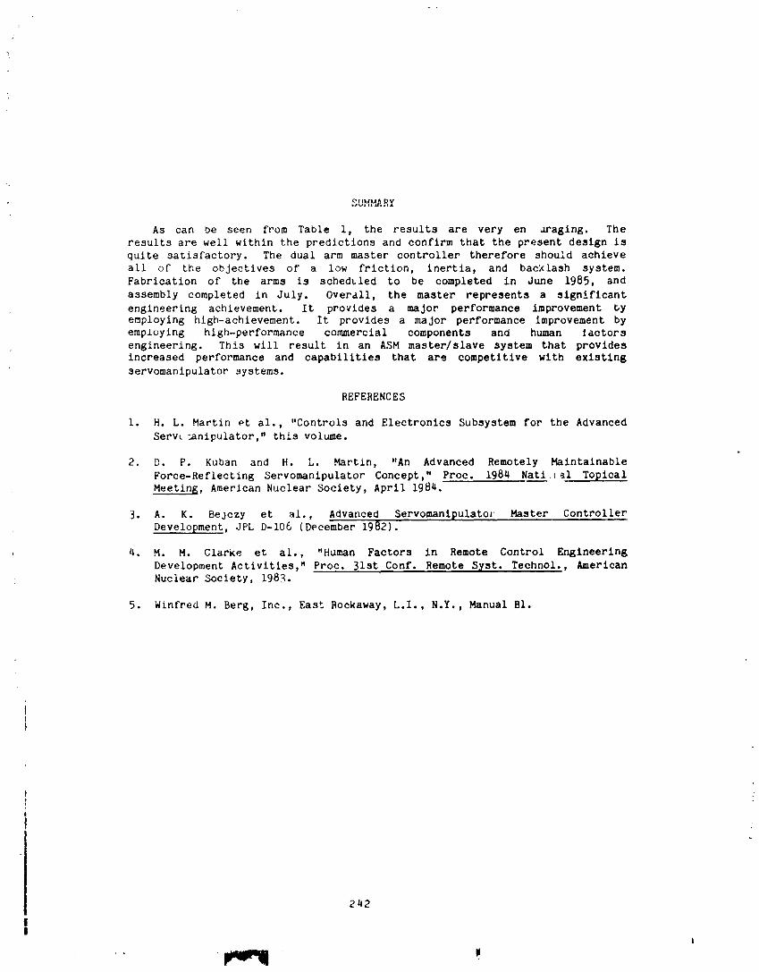
SUMMARY
As can be seen from Table I, the results are very en _raglng. The
results are well within the predictions and confirm that the present design isquite satisfactory. The dual arm master controller therefore should achieve
all of the objectives of' a low friction, inertia, and backlash system.
Fabrication of the arms is scheduled to be completed in June 1985, and
assembly completed in July. Overall, the master represents a significant
engineering achievement. It provides a major performance improvement byemploying high-achievement. It provides a major performance improvement byemploying high-performance commercial components and human _actors
engineering. This will result in an ASM master/slave system that providesincreased performance and capabilities that are competitive with existing
servomanlpulator systems.
REFERENCES
i. H. L. Martin et al., "Controls and Electronics Subsystem for the Advanced
Serw _nipulator," this volume.
2. D. P. Kuban and H. L. Martin, "An Advanced Remotely Maintainable
Force-Reflecting Servomanipulator Concept," Proc. 1984 Nati, _i Topical
Meeting, American Nuclear Society, April 1984.
3. A. K. Bejczy et al., Advanced Servomanipulatoz Master Controller
Development, JPL D-I06 (December 1982).
4. M. M. Clarke et al., "Human Factors in Remote Control Engineering
Development Activities," Proc. 31st Conf. Remote Syst. Teehnol., AmericanNuclear Society, 1983.
5. Winfred M. Berg, Inc., East Rockaway, L.I., N.Y., Manual BI.
242
II
1985025199-248

1985025199-249
;J"
244
I
1985025199-250

OR
IGIN
AL
PA
GE
IS
OF
PO
OR
QU
AL
ITY
2145
1985025199-251
If+'

1985025199-254

ORIGINALPAGE IS,OF POOR QUALITY
. f
L
: I OneDe_reeof FreedOmlestStand: Slaved
Figure 6. 2_9 "
1985025199-255
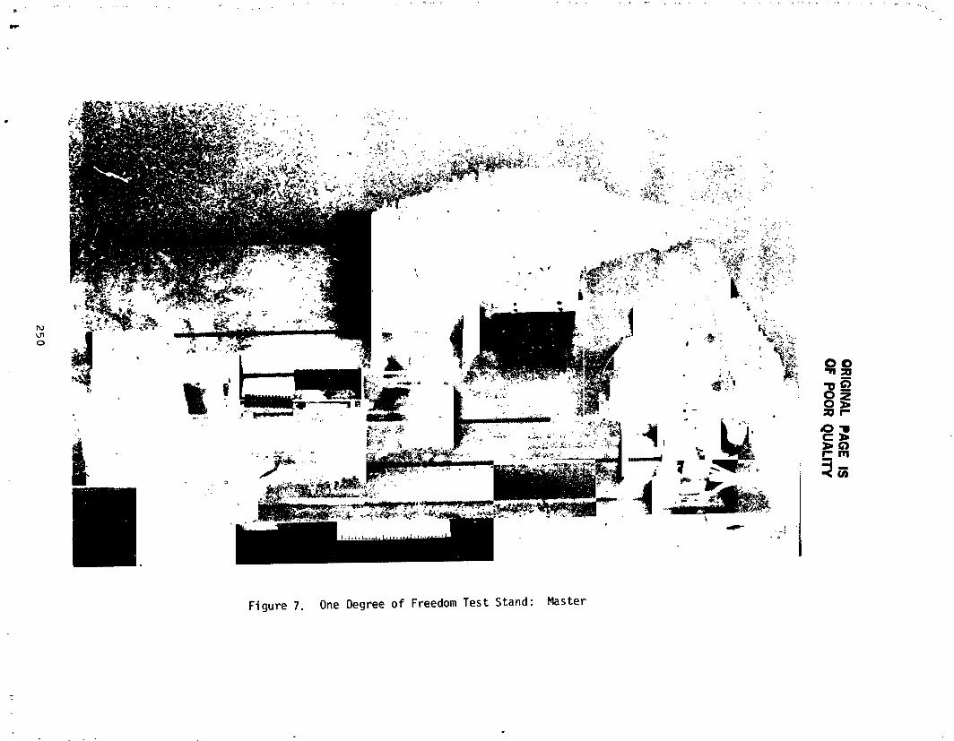
25O
1985025199-256

t......
i
N85-33527
MAN-VEHICLESYSTEMSRESEARCHFACILITYADVANCEDAIRCRAFTFLIGHT SIKULATORTHROTTLEMECHAIIISM
Seth S. Kurasaki*and Wilbur C. Vallotton**
ABSTRACT
This paper describes the conceptualand detai| design as well as somepreliminaryresults of an automaticthrottle control system for use in anAdvancedAircraftFlignt Simulatorat the Ames ResearchCenter. The mechani;msimulates an aircraft engine throttle system for a future two-enginejet-transportaircraft,
INTRODUCTION
The Man-Vehicle Systems Research Facility Advanced Aircraft F11ghtSimulatoris an importantnew facilityat the Ames ResearchCenter. This newaircraft simulator features a number of innovative aircraft controls and;play_ to study advancedcockpit concepts and to investigatepilot-vehicle
interactionsfor the next-generationcommercial-transportjet aircraft. Theresults of human factors research performedon these systems may result inimprovedsafety for futurecommercialaviation.
Includedin these control systems is a dual-throttle,jet-enginecontrolsystem that can be operated by the Pilot, First Officer, or the alrcraft'scomputer-operatedperformance-managementsystem. The throttle-controlsystemis located in the AdvancedConcepts"Flight Desk" forwardof and between thecrew seats. The Pilot operatesthe throttlecontrols_ith his right hand andthe First Officer operates then with his left hand. lh_ movement of thethrottlesis conventionalwith full forwardbeing the maximumthrust conditionand full aft being the thrust-reversecondition. A "gate" is used to preventthe accidentalmovementof the thrust levers into the thrust-reverseconditionfrom the idle position. The simulatedaircraft is powered by two advanced,hlgh by pass turbofan engineswhich contain full-authorityelectronicenginecontrol both for manual operation and for interface with the aircraftcomputer-drivenperformance-m_nagementsystem.
DESIGNREQUIREMENTS
Since existing aircraft simulator throttle systems either could notperfom to meet the needed requirements,or be configured for all of theoperations necessary for the Advanced Aircraft Flight Simulator, a newthrottlecontrolsystemspecificto the simulatorwas created.
The effortdirectedto the design of the mechanismwas to provideseparateengine controls for both pilots within the constraints of the advancedaircraft shell enclosure _d crew seating, provide features identified asbeing critical to aircraft operation, and complete the effort within theproject'sscheduleand cost constraints.
*Research Engineer, NASAAmesResearch Center**Mechanical Engineering Technician, NASAAmesResearch Center
251
, m t '
1985025199-257

In the AdvancedAircraft S1mulatoroeach f11ghtcrewmember Is 21 Inchesoff the alrcraft centerllne to provlde the correct posltlon for thecomputer-generated"out-the-wlndow"Imagery. The placement of the crew,because of the vlsual systems and the ergonomlc requlrements for a95-percentllepl]ot, necessltatedthe Insta]latlonof dual throttle-controlhandles so that the p11ots could ju;,,tlyor Indlvldually manage theenglne-controlsystems.
The proper arc travels, placements,and helghts of the throttle controlhandles were detemlned before any deslgn work commenced. The system wasconflguredto conform to the "Flight Desk_ Cockplt concept of the AdvancedA]rcraft.
DESIGN
Vartous destgn approaches for the throttle system were consfdered. Ofthese, the most promising vms a mechanism that combtned a mechanical linkagedestgn and separate motor drtve systems destgn. In thts manner, separate andsimultaneous destgns could be worked on _thout the necessity for constantInterfacing to assure that parts would match. The Interfacing requirementwould be a chatn drlve _here the drive system coupled to the machantcal torquetube. Thts orlgtnal design did not work as expected and was replaced laterwith a mechanical ltnkage. The new design _hown In ftgure 1 ls the syste_a nowInstalled In the simulator.
Figure 1 shows the concept of the throttle system and the relattveplacenmnt of the components. The system Is primarily composedof two sets ofTour-bar linkages. These four-bar ltnkages are coupled tn sets of two bytorque tubes so that operation of one linkage causes the other appropriateltnkege to move. In thts manner, the throttle system has left and rightengine controls that either pilot can operate. All torque tubes are supported
, on needle bearings, and the pushrods have atrcraft spherical rod-ends wtthboth left-and right-hand Lnread. Alignment of torque tubes and bellcrankswith each other durtng assembly |s not critical, and the use of the rod-endseltm|nates the requirements for precision tolerances. The thrust levers canbe adjusted to reduce free-play end/or Increase "binding" tn the machantcalsystem as necessary by twisting the pushrod; appropriately, This feature wasIncorporated into the design to a11o_ the shop fabrication personnel to make a"loose" tnlttel Installation and to ".tghten up the system later to eliminate"slop" by maklng ftnal adjustments.
Hechentcally, the left and r|ght engtne controls are Independent of eachother. However, If tt Is so destred and because they are motorized, they canbe coupled electronically through the simulator computer for any research thatmay requtre such configuration. It should be noted that the torque-tuhepush-rod concept ls extendable to three or four engtne controls. Each thrustlever, which the ptlot operates, has an arc travel ltmlt of 20 degrees. Thtstravel encogpases the range of nomal operation frog tdle to the full thrustor the "rm_ed overboostu condltlen for each engtne.
252
L
JJ
1985025199-258
the thrust conditions to tnstrulnt displays such as Engtne Pressure Ra'_lo,Exhaust Gas Temperature, Revolutions per Htnute and fuel f|ow for each eng|ne.
Two eTectrtc swttches were Incorporated tnto the hand]as of the thrustlevers. T,_ese sw|tches are thumb-operated and represent the "ground spoiler"and "autothrottle disconnect" sw|tches. The switches are located on the leftengtne handle for the Ptlot and on the right engine handle for the FtrstOfficer. A separate swttch to commandthe "go-around" ak_detS located on thethrottle panel. Al1 swttches are _lred tnto the system computer and functtonas they would nomally tn an aircraft. The vires temtnate tn an electr|cplug to facilitate ease of removal for any servicing or mtntenance.
TESTINGANDRESULTS
A chatn was originally used to provtde power from the rotor drive to asprocket located on the torque tube of each, of the two mchan|cal linkages.An |d]er wheel was used to take up the slack in the chain to al|ow thepotenttometer tn function.
In the lntttal testtng, It became evident that the chatn dr|re systeacould not provtde ti_ accuracy necessary for the potentiometer to resolve theangular posttton of the thrust levers wtthtn the tolerances necessary forcorrect operations. Consistent repeatabtli_ of the thrust lever pos|tlonscould not be achieved. In addition, fr|ctton tn the system, due to the Idlerwheels tensioning the chatns, was masktng 1.he _rtct|on tn the magnetic brakesrendering them unusable. The requtred var|able forces could not be achievedIf the frIctton continued. When the chain d,'ive was disconnected, ther_chantcal ]tnkages freely rotated on thetr hall bearing rollers and the motordr|ve mechanism worked properly. The solution to the frtctqon p,'oblem,therefore, was to eliminate the chatn drtve and find an alternat|ve solut|onto powertng the mchantcal linkages. Thts problm was resolved when a dtrectbe]l-crank/linkage-am mchantsm was substituted for the chain-drive system.The inherent friction tn the chain-drive systm disappeared and the brakescould now provide the friction to the thrust ]avers as ortgtnal]y envisionedwithout being masked.
Preliminary testing has demonstrated that the drive rotors can positionthe thrust levers to within 0.5 degree of the correct position. Thepotenttometer feedback system provides sufficient accuracy so that posltlon|ngerror Is negligible. The speed of the thrust levers |$ approxtmtely 5 - 7deg/sec. The friction In the system Is yet to be imsurld. The mgnettc
; particle clutche_ and brakes have been demoqstrated to provide variable forcesto the thrust ]evers; however, no accurate measurements have been done onthese yet. Because of the demandof the use of the s|mlator factltty tocheck out other systems, these test; are not planned to be done until after1985.
The colputer that operates the contro] s_stel tS l Olgltal EquipmentCorporation S£L Computer. Thts computer also operates the B-727 Fltght
: Simulator as _.!1 as the rest of the Ran-Vefltcle S_ltms ILesearch Facility.Various fltght conditions for the @_lvancedAircraft FItght $tmlator can be
25-_
a
|
1985025199-259

t2
()
i
The second four-bar ltnkage mechanism Is "piggy-backed" onto the first* mechanismand allows the pilot to engage the thrust reverse of the engtnes.; This part of the thrust ]ever motion provides an additional 15 degrees of
movementaft of the idle position. The engagement of the thrust reverse isaccomplished by manually lifting the thrust lever to a different plane beforeengaging the thrust-reverse features. Figure 2 shows the right engine thrustlever in the full reverse position. When the pilot lifts the thrust leverthrough the gate to engage the thrust-reverse condition, the second four-barmechanism mechanically lifts the corresponding thrust lever on the otherpilot's side. Movementof the thrust levers In the thrust-reverse condition,however, is stil] controlled through the first four-bar linkage.
The mechanismprovides a cam and follower so that the track of the thrustlevers is predetermined. The throttles may be moved through a range from themaxinlumreverse, through idle, to the rated overboost position. The total arctravel of the thrust levers is, therefore, 35 =agrees. Operationally, thecomputer disengages the drive motors from the system durtng reversethrust-operations. Mechanically, whenever the thrust levers are pulled tntothe reverse condlt|on by either ptlot, an electric switch, attached to thethrust lever, is disengaged. When the swttch is disengaged, an electricalsignal ts sent to the systems computer telling It that thrust revers- ts to beused and that the drive motors should be disengaged from the mechanism. Thisis done by deenergtzing the magnetic parttcle clutcheso The switch ts usedsince it is very reliable. The potenttometer was not used as tt was believedthat it would not be a reltable means of detecting the change from nomal tothrust-reverse condition.
The motor drive mechanismconsists of a globe motor wtth gear reduction,magnetic parttcle clutch, and electrtc brake for each engine. Thesecomponentsare geare¢l to provide the proper angular rotations at the thrustlever handle to the pilot. It also provides proper rotation of a separateshaft connected to a potentlometei'o The force at the handle can be varied, byenergizing the magnetic clutch and magnetic brake, and hence tts friction,from 0 to 7 N (15 lb). The gear-reduction untt of the globe motor, along withthe designed gear-reduction system provides some resistance force. The restof the friction is made up by the brake. The thrust lever forces can,therefore, be configured through software changes by programtng the systemcomputer rather than by mechanical design. Although the system does have somemass momentof inertia, the amontts negligible when compared to the frictioncaused by the brake.
The potentiometer ts used to resolve the angular position of the thrustlevers and provides the feedback to the system computer to increase ordecrease the thrust lever force at various positions. For example, thethrottle system requires approximately 3.5 N (7.5 lb) of constant forcethroughoutits nomal _eratlng range. In the rated overboost conditionetthe furthest forward thrust lever position, the system computer, havlngdetected the vo!tage level from the potenti_eter, increases the forcerequiredfor the maximum thrust condltlonto 7 N (IS |b) by energlzlngthemagneticclutch and brake. The p11ot _eratlng the thrust levers _11 thenfee] the increased force and know that he is operating In thls filghtcondition. The slgnalsfrom the two potentiometersalso are used to supply
25q
1985025199-260

simulated Including IFR and emergency conditions. A11 signals sent throughthe throttle system's two potenttometers are resolved Into performanceparameters displayed on the fltgnt displays. Similarly, when the aircraft isengaged in the auto throttlemode, the computerprovidesfor"correctoperationof the throttle system. The system is configured so that, as in a realaircraft, the compute- can be overridden by the pilot and the throttlemechanlsmcan be physlcailyoverpoweredunder a simulatedenergencycondition.
CONCLUSIONS
The Advanced Aircraft Flight Simulator is equipped with a motorizedewchanlsm that simulates a two-englne throttle-controlsystem th-,tcan beoperated via a computer-drivenperformance-managBnentsystem or manually bythe pllots, The throttle-controlsystem incorporatesfeatures to simulatenormal engine operationsand thrust reverseand vary the force feel to meet avarleCy of reserach need_. While additional testing to integra'.ethemechanismInto the facliltyis requiredand to verify correct operations,thework required is principallynow In software design, since the mechanicalaspects function correctly, The mechanism is an important part of thefllght-controlsystem and provides the capability to conduct human-factorsresearch of flight crews with advancedaircraft systems under various flightconditions such as go-arounds,coupled IFR approache;, normal and groundoperatlonsand emergenciesthat would or would not nor_lallybe experiencedInactual fltght.
255
1985025199-261
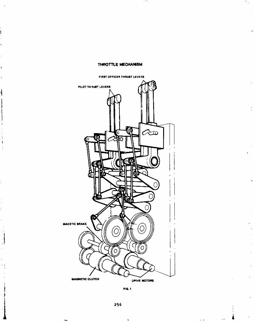
THROTTLEMECHANI8M
FIRST OFFICER THRUST LEVE;_S
PILOT TH qUST LEVERS _ _
I
,!
i
MA(;,ETIC BRAKE
!
MAGNETIC CLUTCH _IVE MOTORS
FIG. 1
256
_ --
1985025199-262

ORIGINAL PAGE ISOF POOR QUALITY
RIGHTENGINETI4RUSTLEVERIN FULL REVERSE
MAGNETIC BRAKE
MAGNETICCLUTCH " _ _'_
DRIVE MOTORS
4: FIG 2
.57
1985025199-263

N85-33528
THE DEVELOPP_NT OF STAGING MECHANISMS
FOR iHE JAPANESE SATELLITE LAUNCHER MU-3Sll
JunJlro Onoda t
ABSTRACT
This paper describes the staging mechanisms of the Japanese satellite
launch vehicle Mu-3SII involving a unique separation and jettison mechanismfor the nose-fairing. The design requirements, the design features and the
development problems are presented in this paper together with their solutions.
INTRODUCTION
The Institute of Space and Astronautical Science has developed a solid
propellant launch vehicle, the Mu vehicle, for scientific satellites, and has
successfully launched 9 scientific satellites and 4 test satellites. A
next-generation version, the Mu-3SII, 27.8 m in total length, 1.65 m inmaximum diameter and 61 metric tons in total welght, is now in the final stage
of development. The development of the staging mechanisms has almost beencompleted. In this paper, the staging mechanisms of the vehicle are
described, stressing the unique separation and jettison system of thenose-fairing and strap-on boosters.
SEPARATION AND JETTISON SYSTEM FOR THE NOSE-FAIRING
The nose-falring of the Mu-3SII launch vehicle protects the payload, the3rd stage rocket motor and the optional kick-mo£or (or 4th stage moter, if it
is required for a specific mission), and maintains the desirable aerodynamic
configuration during the ascent phase through the atmosphere. The fairing, ahemisphere-cone-cylinder-cone (hammer-head) configuration as sho_n in Fag. i,
is 6.85 m long and 1.65 m in diameter. The main part of the fairing structure
is made of Fiber Reinforced Plastic {FRP) honeycomb sandwich with GrapblteFiber Reinforced Plastic (GFRP) facing covered with a layer for heat
protection. The total weight of the fairing involving the separation and
Jettisoning system is 480 kg.
Requirements
i) The fairing must be capable of Jettison without collision, contamination
or debris in either a 2nd-stage 5 G acceleration phase with 60 Pa. dynamic
pressure or a coasting phase after the burn-out _f the 2nd motor.
2) lhe disturbance caused by the separation and Jettison must be less than
the counteracting capacity of the actuator of the 2nd stage attitude controlsystem.
*The Institute of Space and Astronautical Science, Meguro-Ku, Tok5 o, Japan.
PRECEDING PAGE BLANK NOT
259
IL
1985025199-264
3) The fairing structure and the clamp/release mechanism must withstand a
loading corresponding to a 4 dog attack-angle with a 0.15 MPa dynamic pressureand a Mach number of 2.6.
4) A payload envelope of 1.4 m diameter must be assured during the ascent
phase and separation/jettison phase.
5) The system must functlcn with high reliability.
Selection of the Mechanisms
During the selection of the clamp/release and jettison mechanism for the
fairing, the following guidelines were formulated in order to attain high
reliability, rigidity and strength for the total fairing system.
i) The halves of the fa_r%ng should be clamped to each other continuously or
st many points along the split lines.
2) The clamp mechanisms between the halves and between the fairing and the
2nd stage should be released by ignition of a minimum number of pyroinitiators.
3) The Jettison system should be of the clamshell type.
According to the above-mentioned guidelines, the separation and jettisonmechanisms described below were selected. A latch mechanism using balls was
also considered. However it was not adopted because of its complexity.
Technical Description
I) The Clamp/Release Mechanism Between the Halves of the Fairing
This mechanism is shown in Fig. 2. The halves of the fairing are provided
with many protrusions with wedge-shaped cross section_ along the split lines.
Figure 2(a) shows the mochanism in the clamped state, where each pair of
protrusions are clamped by a clamp-block. The clamp-blocks are linerallylinked along the spli_ llne, and the bottom end of the train of linked
{ clamp-_locks is retained by the marman bands at the bottom of the fairing.Figure 3 shows the detail of the bottom end of the train. The clamp mechanismcan be released by freeing the train of linked clamp-blocks and pulling up the
train to the release position. Figure 2(b) shows the released mechanism.
2) The Marman Clamp Between the Fairing and the top ring of the 2nd Stage
The end of the marman clamp bands are fastened to each other by bolts and
separation-nuts at the end-blocks. As can be seen in Fig, ;, _e _arman clampalso retains the train of clamp-blocks by holding the end-ball of the train in
the socket between the two end-blocks of the marian band. The marman clamp
can be released by the action of the separation_nuts. Each fastening of themarman band is carried out by two separation-nuts, and the action of any one
of them can release both the merman clamp and the restriction of the chain of
clamp-blocks, proviling the system with r_dundancy.
260
1985025199-265
3) Double-Action Pyro Actuator
The double-action actuator at the top of the nose fairing is shown in
Fig. 4. The actuator consists of: two squibs, a gas-generator, plston-A with
arms for pulling up the trains of the linked clamp-blocks, piston-B, and two
cylinders as shown in the figure. The system has two squibs for the i_nition
of the gas-generator in order to provide the system with redundancy. Theaction of piston-A pulls up the freed trains of the linked clamp-blocks to the
release position. The port to cylinder-B, which was closed before the action
of piston-A, is opened by this action. Piston-B Js restrained by theshear-pins until the pressure in cylinder_B increases to 5 MPa. so that
piston-B pushes away the other half of the fairing, providing the halves ofthe fairing with sufficient velocity after the cutting of the shear-pins.
4) Separation-Nut
The above-mentioned separation-nut consists of a nut split into 3 pieces,
a nut housing, a piston and a cartridge. Before the release action, the 3pieces of the split nut are retained in the housing and compose a normal nut.
When the cartridge is ignited, the nut-housing is pushed away by the
gas-pressure and the pieces of the split nut scatter, releasing the fastening.
The Release and Jettison Sequence
The sequence of events during fairing separation is as follows:
i) Simultaneous ignition of all the squibs of the separation-nuts and the
gas-generator by means of an electric current.
2) Within I0 msec, the release action of the separation-nuts followed by
release of the marman clamp and the train end-balls of the linked clamp-blocks.
3) Within 30 msec, action of piston-A of the actuator, which pulls up thetrains of the linked clamp-blocks to the release position through the levers.
After this action, the two halves of the fairing are fastened to each otheronly by the shear-pin at the top of the fairing. The gas-inlet port to the
cyliner-B is opened by this action.
4) Approximately 300 msec - 400 msec after the ignition of the squl , action
of piston-B of the actuator, which pushes one of the halves of the fairing
away from the other, providing them with necessary separation velocity. This
action starts when the pressure inside the cylinder increases sufficiently to
enable the shear-pins to be cut.
Development Problems
I) Actuator
During the beginning phase of the development, spring actuators were used
to pull up the trains of the l_nked clamp-blocks and tc push away the halves
of the fairing with sufficient separation velocity. However, it was found
261
AH
1985025199-266

ORIGINAL PAGE IS
OF POOR QUALITY
that a relatively large force was occasionally necessary In order to pull upthe train of linked clamp-blocks. Thls occurred because of the spring forceof the actuator_ which a_ways acts so that the halves separate from eachother, and because of the variation of the friction coefficient between theprotruslon_ along the split lines and the clamp-blocks. It proved difficultfor the light weight spring actuator to provide the halves wlth sufficientinitial velocity. Therefore, a powerful double-action actuator with agas-generator was adopted, in spite of the increase of the number of squibs.
2) Initial Separation Velocity of the Halves
As can be seen in Fig. 5) the centers of grsvlty of the halves move upslightly before the halves fall outward and downward during the Jettisoningprocess. Therefore, the halves must be provided wlth sufficient velocity to
climb this "hill" of potential energy in the acceleration phase of 5 G. Itwas found from ground tests that the force produced by the pyre actuator doesnot provide the halves with tanslatlonal velocity efficiently because of the
: elastic deformation of the halves caused by the actuator force. This problemwas overcome by an increase in the operational pressure of the actuator and anincrease in the stroke length of piston-B.
3) Deformation of the Fairing
The main structure of the unseparated fairing deforms under externalascent loads. The trains of the linked clamp-blocks must follow thisdeformation. As a result, the trains are sometimes subjected to a relativelylarge load. The load on the trains is especially hi&h in the bottom area,_h_re the deformation of the main structure is large, because of the highbending load and because of the tapered configuration in this area. Thisproblem has been overcome by reinforcing the main structure and by introducingbuffer devices wlth preloaded springs as shown In Flg. 3, which _ermlt somedeformation.
Tests
i) Functional test
During the process of developing the fairing, separation and Jettisonteats were performed 8 times. The last q tests were quallfloatlon teats
utilizing the final configuration.
All the separation and Jettison tests were carried out under groun_
conditions. The performance under flight conditions during both theacceleration phase and the coasting phase -- was estimated by means ofanalytical stL'llation based on the measured data of the ground tests. Thesffec.s of air, especially the negative pressure inside the fairing caused bythe separation action, was conspicuous, although the test adapter was providedwith relatively large holes. The effect of elastic deformation on the, initialseparation velocity of the halves was also litntftoant. All these effectswere taken into account, based on the measured pressure inside the falrln6 andthe measured vibration. The results of the numerical llmulation lnd£oated
normal fune_ional performance £_ bQ____ at_ the eeaatt_-' phase. -"
:62
t
1985025199-267
2) Load Test
The fairing was subjected to a load equivalent to an attack angle of 4 deg
with dynamic pressure of 0.15 MPa. The maximum bending moment at the bottom
end of the fairing was 0.32 MN-m. The main structure w_s fractured by 98
percent or' the above-mentioned load in the third test, after twice
withstanding the i00 percent load.
THE SEPARATION AND JETTISON MECHANISM OF THE STRAP-On BOOSTER
The first-stage rocket motor of the Mu-3SII vehicle is accompanied by two
strap-on boosters w_ _ch must be Jettisoned after burn-out. The boosters are
9.1 m long and 0.735 m in nominal diameter. A strap-on booster weights5.1 metric tons before ignition and i.i tons after burn-out.
Requirements
i) The Joint between the strap-on booster and the core motor must withstand
the longitudinal load caused by the 0.3_ MN thrust of each strap-on boosterand the lateral inertial force due to the lateral bending vibration of thevehicle.
2) The sub-boosters must be separated from the core motor and must be
jettisoned without collision, excessive shock or disturbance on the core
motor. The acceleration Just before the separation is nominally 3.80. The
nominal dynamic pressure at that time is 95 KPa. with a Mach number of 3.2 anda roll rate of less than 0.3 rps.
In the selection of the separation and Jettison mechanism, the follow_-_
' guidelines were adhered to:
!! i) The separatio_ mechanism should be designed and adjusted to provide the,_ strap-on boosters with both the initial attitude and the initial translational
I and angular velocity for a collison-free Jettison action.
i 2) Separation and jettison should be perf_ _ed with a minimum number of pyro
1 initiators.
I Following the above guidelines, the separation and Jettison mechanism
shown in Fig. 6 was selected. A featu'e of this mechanism is that the front
and rear braces push the strap-on boosters away from the core-motor when the
boosters travel rearward, and therefore the initial attitude and velocity ofI boosters can be easily adjusted by selection of the length of the braces and
l their attach points.i_[ The trajectories of the strap-on boosters after the separation werei numerloally calculatsd taking account of the aerodynamic Force and the effect
I of the plume of the core-motor exhaust Jet. This analysis was used to!
dete.-mine the attac:_ points and lengths of the braces. No •
assisb-rccket-motors for separation were adopted because of the possibility ofdamaging the core motor casing and because of the increase in the requirednumber of pyro initiators.
263
A
1985025199-268
Yechnical Descriptior
i Figure 6 shows the separation and jettison mechanism for the strap-on; boosters. Figure 6(a) shows the mechanism before the separation. The thrustsof the strap-on boosters are carried to the core motor mainly by the;i thrust-tubes. The bottom part of each booster is supported by the
! thrust-tubes, rear braces and a rear attach-flttlng. The top part of each
_I booster is supported by the front attach-fitting, which restricts the relativemovement of the booster in the radial and circumferential directions, and the
_ stabillzers, which restrict the rotation of the _ooster around the front
.t attach-fitting. The front brace can be shortene telescopically and is
i preloaded by a compression-spring installed inside. Therefore, the relativemovement in the axial direction is not restricted at this station.
i Separation and Jettison is initiated by action of the separation-nutsinstalled in the thrust-tubes, disconnecting the tubes. Subsequently, the
i strap-on boosters are pushed rearward by the aerodynamic drag and the inertialforce due to the acceleration caused by the thrust of core motor. As a
i the front of the booster rearward and the frontresult, portion moves axially
braces are shortened. After a certain amount of rearward travel of the top .part of the booster, the front attach-fitting is freed and subsequently the
front braces push the booster away from the core-motor when the braces have
i been shortened to the limit. The rear portion of the booster is pushed away, from the core motor by the rear braces from the beginning of the Jettison
action. After a certain amount of rotation of the braces, the compressiveloads on the braces decrease, and finally the braces are pulled away from the
core-motor as shown in Fig. 6(b). The rear braces are fixed to both the
core-motor and the booster in the state shown in Fig. 6(a), and can carry both
tensile and compressive loads. However, the core-motor-side ends of the rear
braces are freed by a certain amount of rotation of rear-braces. Therefore,
the braces, 3tabilizers and most of the thrust-tubes are Jettisoned, together
with the boosters, as shown in Fig. 6(b).
A Development Problem
As has been mentioned, the front-braces are shortened in the initial phaseof separation. After a certain amount of shortening, they impact the
stroke-ends and they begin to function as rigid rods. As a result of these
impacts, the braces and the adjacent structure are subjected to a shock load.
It is difficult to use powerful buffers to reduce the shock, not only becausethe space for installation is limited, but also because too powerful buffers
may _revent the braces from being shortened to the expected length when
conditions, such as thrust and dynamic pressure, vary, and may in the worst
case result in a failure of the release of the front attach-fitting.
Therefore, a certain level of shock is unavoidable in the separdtion action.
The estimation of the shock level during the early phase of design was
somewhat difficult because the shock level depends on the effective
flexibility of the structures, which is sometimes governed not only by the
longitudinal stiffness of the braces but also by the local dynamicdeformations of the Joint structures, core-motor and boosters. The shock load
was estimated by a law of similarity based on the results of sub-scale
264
i
1985025199-269
(i/2-s.a_e) grc.und tests as well -=¢_the namerzcal s:muiatzo: :n ire fzna_ she;of development basea on t_e measare_ _t:;: _ _ = . =.... nes. c-t- c_ r._totype strut" _-icomponents.
Tests
As a first step in the _eve_cp_,ent test_, the " 2-scale grounZ tests vere
carried out seven times. Three _.':them were in t_e zero-spln concit__n an:
the others were with a sTin _._: . : r_s-. The ._,n.-'iena..perf_.'mance w_confirmed ant the loads Outing separation were measarez.
In order to confirm the functional perfc_ance, loads at separatlon ant
the motion of the strap-on boosters s&b_er ,ent %o the separat&on in nearlyactaa] conditions, a separation test was c_cr_ed _.t uneer flight _o_,_-on._-_"
with an approximately 2/2-scale vehicle. "% was otservec by means of anon-bo_rd TV camera, _rcu_d telescope cameras ant telemetry data, that the
separation action and the s_bsequent motzon of the boosters were nG_mal.
Full-scale structural components were sutfeczec :: a cad of _ .....
percent of the oeslgn ioad ana _% was confi_mec that they withstood the
loads. No separation tea's using the full-scale mec_an:s= have :een perfo.-med.
INTEH-STAGE $EPAEATIDN SYSTEMS
The Mu-3SII-i, the flrst venlcle cf the Mu-}S_i _erles, has fDurinterstage joints as ilsted In gaols i, because an c;tional KicK-motor has
been installed for an interplanetary misslon. However a oetaile_ oescriptlonof the joint between the Kick motor an: the ;,ayloaas _s omittec in this paper
because it is an ordinary marman clam; jcLnt.
The Interstate Leparatlon S_stem 5etween the ist ana 2no Sta e_
The interstage structure between the 1st ano 2n_ sta4_es joins the _-rings
of the motor casin_s of each tags. The nozzle of the 2nd stage rocket motor,
thrust vector control equipment, slde-Jet equipment aria hemispherical
end-plates of the motor casings are installed ins_e the interstage oolnt.
Therefore, an open-petal joint was adopted as shown in Fig. 7, because of the
large diameter of the nozzle of the 2nO sta6e installed in the _o_nt, aria to
reduce the inert mass of the joint to be left on the 2nd sta£e after theseparation. A %russ structure was selected for the joznt, which has the
advantage of ease of access to the equipmert installed around the nozzle. As
can be seen in Fi_. 7(a), in the clamped state the top nodes of the trian6ular
trusses are fastened tc the upper-stage structure airectly by bolts ant
separmtlon-nuts. Two separatlon-nuts are used for each fastening point, ant
action of any one of them releases the fastening, provldln_ redundancy. This
system is used because the load on the joint was estimated to be relativelylarge. Figure 7(b) shows the Joint in released state. The relative velocity
of 0.8 m/s is provided by 12 separation sprin_s installed at the fastenin_
points. The petals of truss are opened by the 5croton spring ins_aile_ a% _behiD4 _s.
26.=
1985025199-270
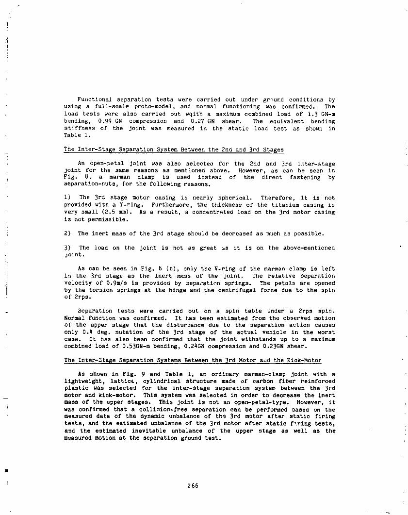
i]
Functional separation tests were carried out under grqund conditions byusing a full-scale proto-model, and normal functioning was confirmed. The
load tests were also carried out wqith a maximum combined load of 1.3 GN-m
bending, 0.99 GN compression and 0.27 GN shear. The equivalent bending
stiffness of the Joint was measured in the static load test as shown inTable i.
The Inter-Stage Separation System Between the 2rid and 3rd Sta_e_ss
An open-petal Joint was also selectee for the 2nd and 3rd inter-stage
joint for the same reasons as mentloned above. However, as can be seen in
I Fig. 8, a marman clamp is used instead of the direct fastening by_ separation-nuts, for the following reasons.
i) The 3rd stage motor casing is nearly spherical. Therefore, it is not
provided with a Y-ring. Furthermore, the thicknese of the titanium casing is
very small (2.5 mm). As a result, a concentrated load on the 3rd motor casing
is not permissible.q
i 2) The inert mass of the 3rd stage should be decreased as much as possible.
3) The load on the joint is not as great as it is on the above-mentioned
joint.
As can be seen in Fig. 8 (b), only the V-ring of the marman clamp is left
i in the 3rd stage as the inert mass of the joint. The relative separation
.j velocity of 0.9m/s is provided by sepa.-ation springs. The petals are opened
I by the torsion springs at the hinge and the centrifugal force due to the spinof 2rps.
Separation tests were carried out on a spin table under a 2rps spin.Normal function was confirmed. It has been estimated from the observed motion
of' the upper stage that the disturbance due to the separation action causes
only 0.4 deg. nutatlon of the 3rd stage of the actual vehicle in the worst
case. It has also been confirmed that the Joint withstands up to a maximum
combined load of O.53GN-m bending, 0.24GN compression and 0.23GN shear.
The Inter-StaRe Separation Systems Between the 3rd Motor a,ld the Kick-Motor
As shown in Fig. 9 and Table i, an ordinary marman-cl_mp Joint with a
lightweight, lattice, cylindrical structure made of carbon fiber reinforced
plastic was selected for the inter-stage separation syste_ between the 3rd
motor and kick-motor. This system was selected in order to decrease the inert
mass of the upper stages. This Joint is not an open-petal-type. However, it{
was confirmed that a collision..free separation can be performed based on themeasured data of the dynamic unbalance of ths 3rd motor after static firing
tests, and the estimated unbalance of the 3rd motor after static f,ring tests,
and the estimated inevitable unbalance of the upper stage as well as the
measured motion at the separation ground test.
266
i
1985025199-271
CONCLUDING REMARKS
Staging systems for the Mu-3SII _ _elli_e launcher, including the unique
separation and jettison systemo fnr _nr _trap-on booster_ and nose-fairing,
have been devetoped. Normal performance of the sytems is expected based on
func;ional tests, load tests and numerical simultions utilizing test data, andwill be confi_eC in thc first launch of the vehicle in January 1985.
ACKNOWLEDGMENTS
The development of the Mu-3SII vehicle has been carried out with the
cooperation of the staff members o£ the development team of the Institute of
Space and Astronautical Science. The present work is a part of the work of
the project team. The uuthor appreciates the cooperation and authorization
for presentation of this paper by the team, especially the chief manager R.
Akiba and the co-manager H. Matsuo. The author also app'eciates the
contribution and the cooperation of the NISSAN Motor Co. The systems
presented here were developed in cooperation with NISSAN Motor Co., whichcontributed many useful ideas.
267
A A
1985025199-272
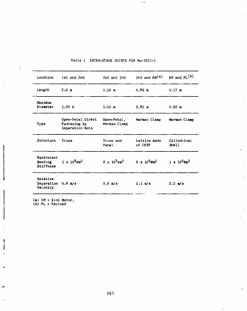
Table 1 INTER-STAGE JOINTS FOR Mu-3SII-I
Location ist and 2nd 2nd and 3rd 3rd and KM (a) KM and PL (b)
Length 2.0 m 1.36 m 0.86 m 0.17 m
Maximum
Diameter 1.65 m 1.42 m 0.82 m 0.50 m
Open-Petal Direct Open-Petal, Marman Clamp Marman Clamp
Type Fastening by Merman Clamp
Separation Nuts
Structure Truss Truss and Lattice made CylindricalPanel of CFRP Shell
Equivalent
Bending 3 x 10⁸Nm 2 8 x 10⁷Nm 2 6 x 10⁶Nm 2 1 x 10⁶Nm 2Stiffness
Relative
Separation 0.8 m/s 0.9 m/s 2.1 m/s 2.2 m/sVelocity
(a) KM = Kick Motor,(b) PL = Payload
26_
J
1985025199-273

-I.EVERTO PULL UP LINKED CLAMP-[;LOCKS
SEPAI_ATION-NUT_7
• - • . .. ;-_ _,_-_._,_=_.__._,__--
ACTUATOR MA_ BAND/ \HINGE _
SEPARATION-NUTS
HINGE
J ISCREW FOR PRETENSION
"-MARMAN BAND
igure I, Nose-Fairing Separation and !ettison System
_CLAMP-BLOCK ,PHOTRUSI.,NS _,PROTRUSIONS RETAINER\
\_',, [SPLIT LINE
\(a) CLAMPZD STATE
SPLIT LI(b) RELEASED STATE
Figure 2. C_,_p Mechan,L,_ Alor: Split Line
P69
A
1985025199-274

ORIGINAL PAGE IS
OF POOR QUALITY "
SPLIT LINE
PROTRUSION /MAIN STRUCTUREROD /WIRE
PROTRUSION -END-BALL-SOCKET FOR END-BALL
-BOLT
CASING m
RETAINER / ,-
ADJUST SCREW/
BUFFER
L_D-BLOCKMARMANBAND
r
Fig_e 3. Detail Of Bottom End ol Split Fairing
270
6 k _
1
1985025199-275
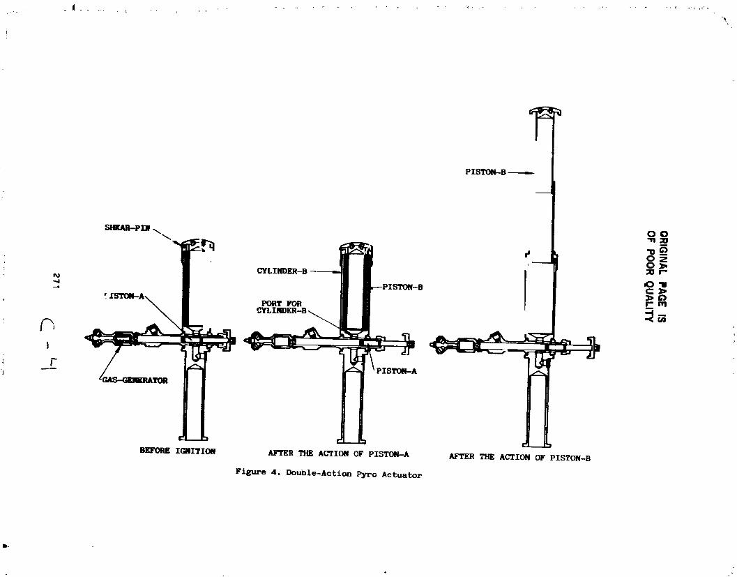
OR
IGIN
ALP
AG
EIS
OF
PO
OR
QU
AL
ITY
271
-......
i
1985025199-276

ORIGINAL PAGE ISOF POOR QUALITY
Figure 5. Nose-Falrtn_ Separation and Jettison Test
i
]985025]99-277
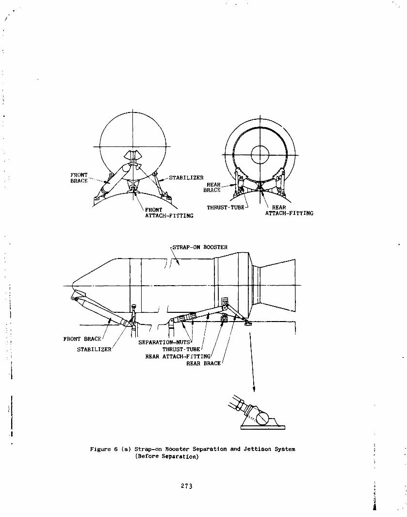
ATTACH-FITTING ATTACH-FITTING
TRAP-ON BOOSTER A
STABILIZER' THRUST- TUBE' / /REAR ATTACH.-FITTING I /
! REAR BRACE--
i
! !,!
Figure 6 (a) Strap-on Booster Separation and Jettison System
(Before Separation)
273 ._
|
1985025199-278
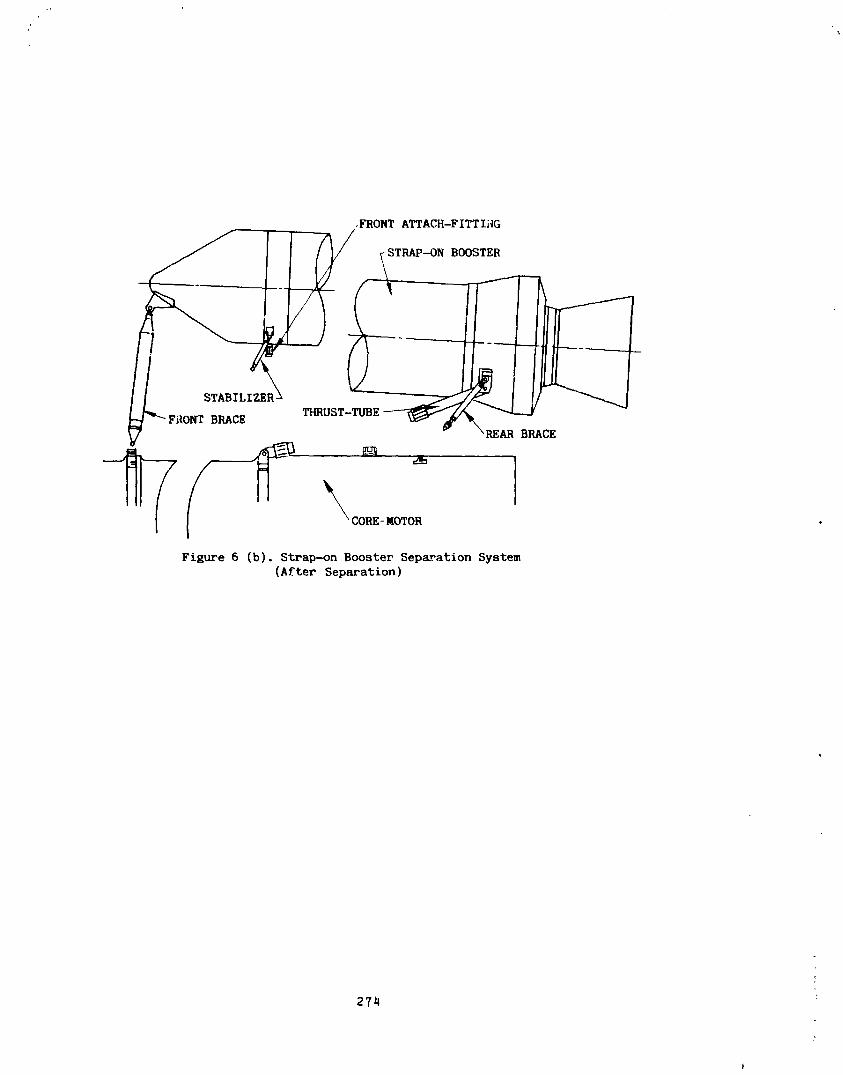
,FRONT A_ACH-FITTIHG
TRAP-..ON BOOSTER
STABILIZER _THRUST-TUBE __/_"_ --j
_'-Fi_ONT BRACE _' \REAR BRACE
Figure 6 (b). Strap-on Booster SeP a-_ati°n System(After Separation)
27_
i
1985025199-279
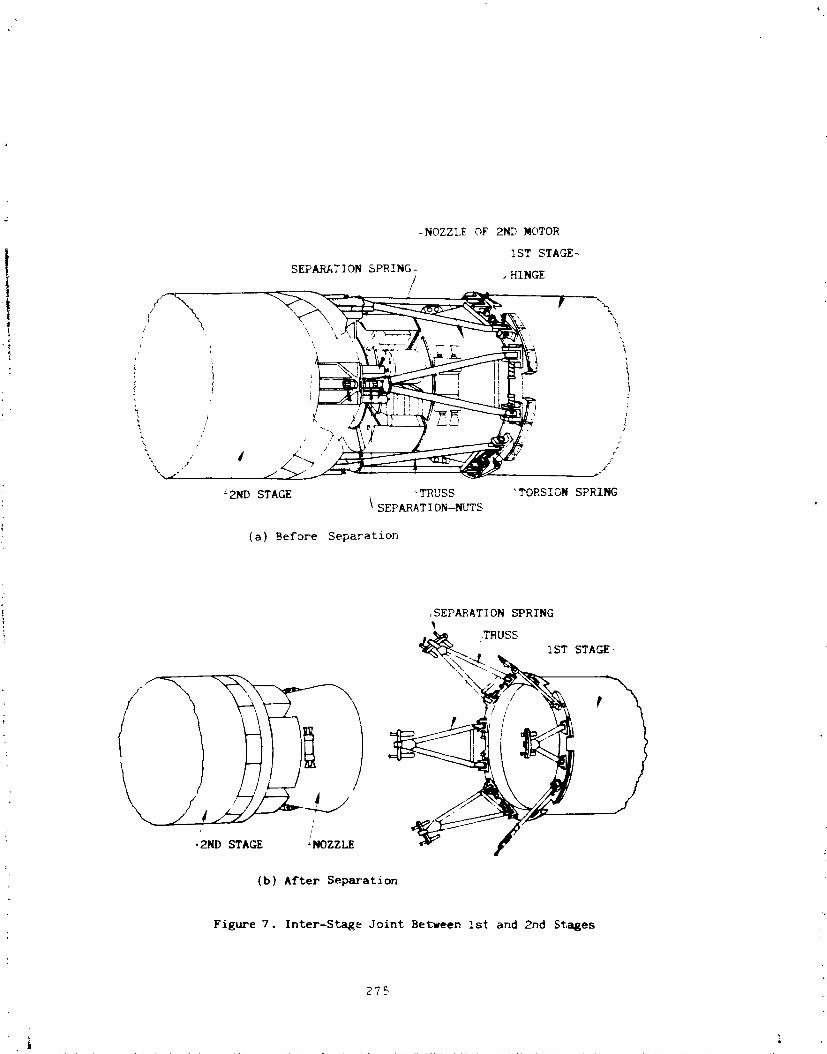
_NOZZLE OF _ MOTOR
1ST STAGE_
SEPARATION SPRING-/ . HINGE
} -, !, :i
"_k / ./
L2ND STAGE "TRUSS 'TORSION SPRING
SEPARAT] ON-NL_FS
(a) Before Separation
SEPARATION SPRING
i _,TRUSs _STSTAGE-
(b) After Separation
Figure 7. Inter-Sta_e Joint Between ist and 2nd Stages
275
1985025199-280
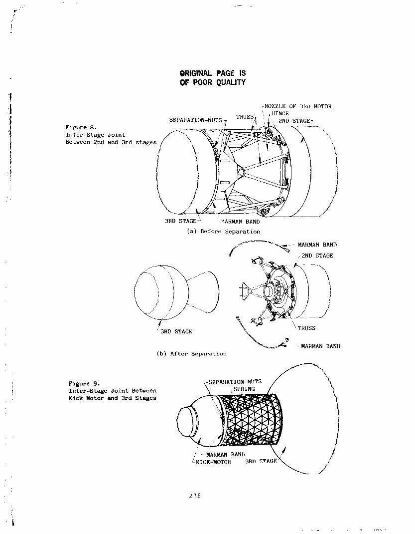
W
F
J
ORIGINAL PAGE ISOF POOR QUALITY
_|| _NOZZLE OF 3RO MOTOR• _, _HINGE
. SEPA[_ATION-NUTS)_ TI_USS_ ,;., 2ND STAGE_" _ig_o a. _ _, .._ ;,./_ --4;I _, \-:_,\
Between 2nd and 3rd stages \
'i __ _.- /I
i
3RD STAGE A '_ARMAN BAND
(a) Before Separation
/___ -_RMANBANDr2ND STAGE
(b) After Separation
Figure 9. k-SEPARATION-NUTS / _
Inter-Stage Joint Between
Kick Motor and 3rd Stages
(/ _NAP_4AN BAN[, \7 /
_KICK-_OTOH3RD_'AGK_._ ///
276
f
i
1985025199-281

@R[GINALPAGE:IS N 8 5- 33 5 2 9OFPOORQUALITY
A ROTATING ELECTRICAL %PA_SFER DEVICE
Ryan S. Porterj
ABSTRACT
This paper describes the design, development, and performancecharacteristics of two roll-rlng configurations - a roll ring being a deviceuse in transferring electrical energy across a continuously rotating o_oscillating interface through one or more flexible rolling contacts, orflexures. Emphasis is placed on the design problems and solutions en-
" countered during development in the areas of flexure fatigue, contact ele-! ctroplating, electrical noise, and control of interface geometry. Also, the
I present status of each configuration is summarized.
'I INTRODUCTION
A roll ring consists of one or more flexures captured by their own spring
• ! force in the annular space between two concentric conductors, or contactrings. Figure 1 shows a photograph of each configuration. These inner andouter contact rings are rigidly mounted to the rotating and fixed sides ofthe rotating axis.
Two basic roll-ring configurations are presently under continuous re-search: the single flexure, O- to 15-amp configuration and the multiflexure,O- to 200-amp, high-power design.
The single circuit shown in Figure IA is typical of over 400 circuits
with a cumulative test history of approximately 600,000 circuit-hours, testedunder several parameter-controlled conditions in an effort to optimize opera-tional performance.
Figure IA. Single-Flexure, 15-Amp Roll-Ring Circuits
mSperrF Corporation, Aerospace & Marine Group, Space Systems Division,Phoenix, AZ
277 "'
,a
1985025199-282
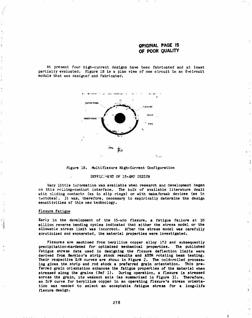
OPIGINAL PAGE ISOF POOR QUALITY
At present four high-current designs have been fabricated and at least
partially evaluated. Figure IB is a plan view of one circuit in an 8-circuit
module that was designed and fabricated•
"".. . . fLExu._
• _ _ IDLER
INNER RING _t W "E RAIL
,
/
Figure lB. Multiflexure High-Current Configuration
DEVEh_3:'_/_NTOF 15-AMP DESIGN
Very little information was available when research and development began
on this rolilng-contact interface. The bulk of available literature dealt
with sildlng contacts (as in slip rings) or with make/break devices (as in
_..itches). It was, therefore, necessary to empirically determine the designsensitivities of this new technology.
Flexure Fatigue
Early in the development of the 15-amp flexure, a fatigue fallure at 30
million reverse bending cycles indicated that either the stress model or the
allowable stress limit was incorrect. After the stress model was carefully
scrutinized and exonerated, the material properties were investigated.
Flexures are machined from beryllium copper alloy 172 and subsequentlyprecipitation-hardened for optimized mechanical properties. The published
fatigue stress data used in deslgnJng the flexure deflection limits werederived from Berylco's strip stock results and ASTM rotating beam testing.
Their respective S/N curves are shown in Figure 2. The cold-rolled process-
ing gives the strip and rod stock a preferred grain orlentatlon. This pre-
ferred grain orientation enhances the fatigue properties of the material when
stressed along the grains (Ref I). During operation, a flexure is stressed
across the grain, its weakest axis (as summarized in Figure 3). Therefore,an S/N curve for beryllium copper in an operating flexure's stress orienta-
tion was needed to select an acceptable fatigue stress for a long-lifeflexure design. )
278
i
1985025199-283
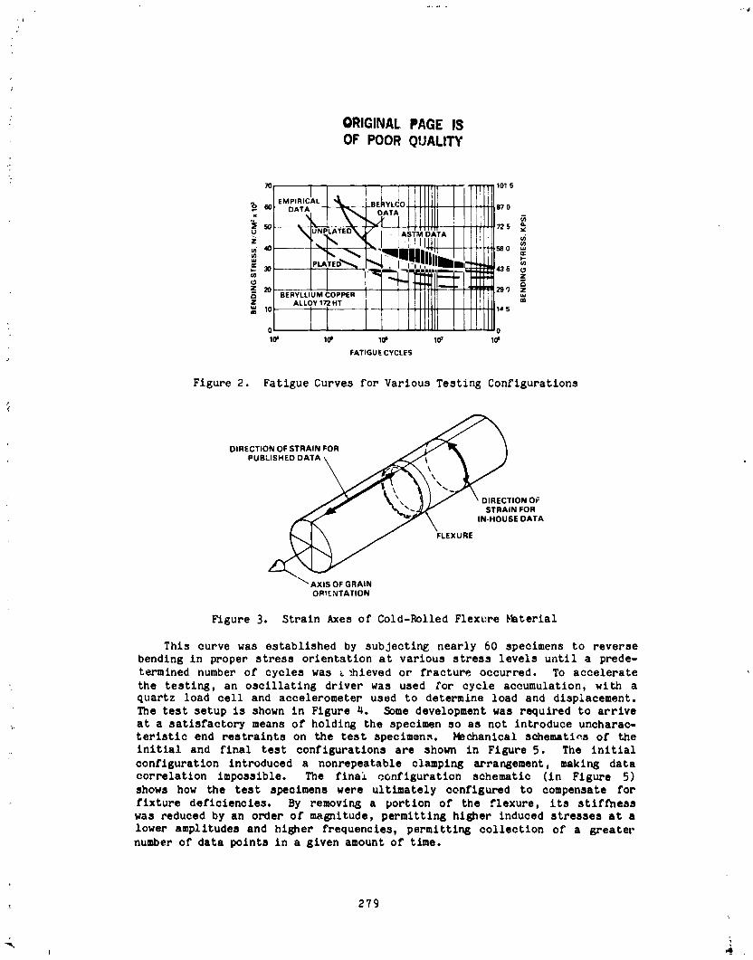
/
: ORIGINAL PAGE ISOF POOR QUALITY
70_
,,_ DATA_
,_ BERYLLIUM COPPER _
Z ALLOY 172 HT10 1A 5
0 _0
10_ 10j 10' 107 10j
FATIGUE CYCLES
Figure 2. Fatigue Curves for Various Testing Configurations
¢
DIRECTION OF STRAIN FOR _--_ "_
PUBLISHED DATA_\\ y
FLEXURE
AXIS OF GRAIN
ORtENTATION
Figure 3. Strain Axes of Cold-Rolled Flexure Meterial
This curve was established by subjecting nearly 60 specimens to reversebending in proper stress orientation at various stress levels until a prede-
termined number of cycles was _ _hieved or fracture occurred. To accelerate
• the testing, an oscillating driver was used for cycle accumulation, with aquartz load cell and accelerometer used to determine load and displacement.
The test setup is shown in Figure 4. Some development was required to arrive
at a satisfactory means of holding the specimen so as not introduce uncharac-teristic end restraints on the test specimens. Mechanical schematins of the
initial and final test configurations are shown in Figure 5. The initial
configuration introduced a nonrepeatable clamping arrangement, making datacorrelation impossible. The final configuration schematic (in Figure 5)
shows how the test specimens were ultimately configured to compensate for
fixture deficiencies, By removing a portion of the flexure, its stifthesswas reduced by an order of magnitude, permitting higher induced stresses at a
lower amplitudes and higher frequencies, permitting collection of a greaternumber of data points in a given amount of time.
279
1985025199-284
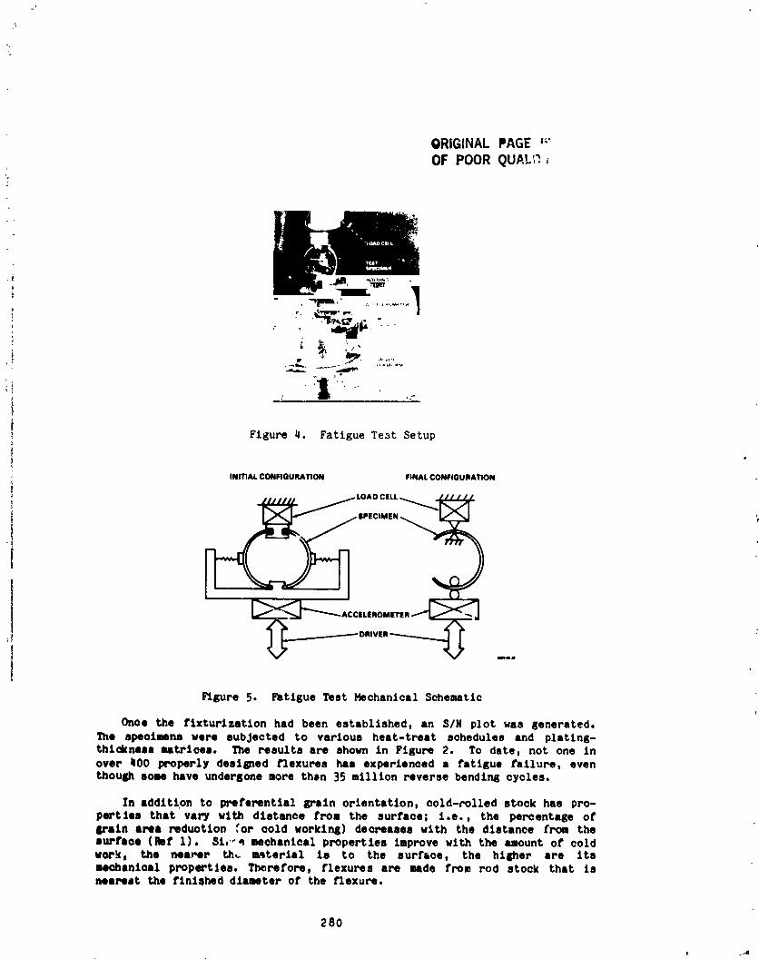
ORIGINAL PAGE _"
OF POOR QUAL_ _%
' T
P_
_.mimN
. I o:"
Figure 4. Fatigue Test Setup
INmAL CONFIGURATION FINAL CONFIGURATION
I
Figure 5. Fatigue Test Mechanical Schematic
Once the flxturlzatlon had been established, an S/N plot was generated.The specimens were subjected to various heat-treat schedules and plating-thickness matrices. The results are shown in Figure 2. To date, not one inover _00 properly destped l_lexuree has experienced a £atiKue failure, eventhough some have undergone more then 35 million reverse bendtn8 cycles.
In addition to preferential grain orientation, cold-rolled stock has pro-pertles that vary wlth distance from the surface; i.e., the percentage orI_'aln area reduction ,'or cold working) decreases with the distance tree thesurface (nit 1). Sl,-e mechanical properties improve with the amount el" cold
work, the nearer th_ materiel is to the eurf6oe, the higher are Itsmechanics1 propertJee. Therefore, flexures are Bade frcm rod stock that isnearest the finished diameter of the flexure.
280
j _'J
1985025199-285
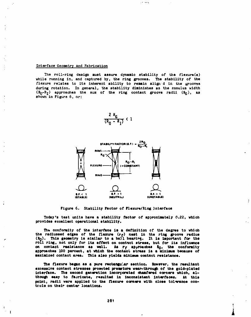
Interface Geometr_ and Fabrication
The roll-rim8 design must assure dynamic stability of the flexure(s)while running in, and captured by, the rink grooves. The stability of the
flexure relates to its inherent ability to remain allgn d in the _roovesdurin8 rotation. In general, the stability diminishes as the _nulus width
(_-R I) approaches the sum of the rink contact groove radii (RG), asshown in Figure 6, or:
8TABIU_Y FACTORIB.F| - 2R GRO - R I
_1 %-"'
FLEXURE --_(8 CON_TANTI
RING--_
Q 2).8.F.< 1 S.F.-1 |.P.> 1
(STABLE) INEUTlt_L) IUNIrYAILEI
Figure 6. Stability Factor of Flexure/Rlr_ ]nterface
Today's test units have a stability Factor oF apiroximately 0.22, whlohprovides excellent operational stability.
The conformity Of the interface Is I definition cT the deKree to whichthe radtusaed edliea of the l"le_ (r t) neat In the rim6 Iroovo radius
: (R0). This poetry is similar to a ball bearln5. It Is important for theroll rln_, not only for its effect on oont_ot stress, but for Its influenceo, contact resistance as wall. As r t ap_oachos P_), the oontor_tyapproaches 100 percent, at wtLtch the oontao_ stress Is a alnimuu because oFnaxl-4:od contact area. This alas yields nlnlmm oontact reslstanoe.
The _exuro helen as a pu_ reotanlu:+_ section. However, the resultantexcessive contact stresses pro_oted premture uea_-thrcu_ of the laid-platedInterFace. The eaooud leneratAon lnoorl_rsted ohantered oornere vhloh, al-though easy to Faorlnato, r_eulted in Jnconeleteat interfaces. At thispoint, radii were apptled to the Flexure corners with o1080 tolqranoe cam-trols on thel_ center lceatlone.
281!
1985025199-286
Initial efforts to apply the radiu' on a lathe were unsuccessful becauseIt was difficult to locate the radius centers by hand. Therefore, blank_with rectanKular sections were made and the radii added Jn a different setup
with a form tool. Speci__ tooling had to be developed that could hold theblank without runout or _istortlon. This process proved acceptable, buttended to be operatur-sensitlve and could only provide parts with the surfacefinish and accuracy of the form tool. Also, because of tolerancesensitivity, the conformity could be _eliably maintained at about only 50percent.
The final solution, in standard practice today, was to manufacture theflexures on a numerically controlled lathe with very low feed rates, largecutter diameters, and empirically determined cutting seque,ces - resultinK insurface finlshe_ of less than 0.2 micrometer. The accuracy and repeat-ability of numerically controlled ma_Inery provide a reliable means ofproducing, in today's desl_s, conformities in exce_s of 90 percent.
Conductor Platlr_
Several different platlng materials and combinations of materials on _on-tact rings and flexures have been evaluated from the standpoint of electricalnoise and wear.
Host of the plating configurations studied are var1_tlons on a nickel andgold matrix on both contact rings and flexures. In alnost all cFses a copperflash Is plated onto the sub,irate (brass for rings aridberyllium copper forflexures) for adhesion purposes. This is then overplated with 2.5 to 4.0microns (i00 to 150 microlnches) of a sulfamate nickel as a copper mlgratlonbarrier and as a hard underlayment for the gold to follow. The nickel isthen overplated with the same thickness of either • hard alloy gold rr a softpure gold. Gold was selected for its excellent electrical prcpertles andcorrosion resistance.
Ion plated end electroplated rhodium configurations were also evaluatedwlth very little success. _odlum is a strong catalyst for the formation ofpolymers In the presence of organlQs. Since It is difficult to eliminate allsources of organic contamination, particularly in a vacuum environment, it
was concluded that rhodium was an Inherently poor choice as a roll rink con-j duotlve overplate. This was demonstrated by exoeptlon_lly poor electrical
performance, altho_ wear resistance was excellent because of Its excep-
tlor_l hardness.It was thou_t that by plating very thick (25 mlcrons or 1000| micro-Inches) layers of gol_ on_ t4_e rl_p and the flexu_-ea, the _ontact
t area could be maximized by allowlnK the £!exure and rinks to mold themselvesL_to eaoh other. The Kold used (3el-_ex BDT-200) turned out to be too hard
4 to permit adequate matlnK, and the _:Lceaalve thickness resulted in unac-oeptably htlEh flex.re bendln_ stresses.
z82
1985025199-287
One source of flexure fatigue in early t_ting was thought to be residualstresses in the nickel layer. Some flexures were, therefore, plated withoutnickel. This theory proved incorrect. However, without the nickel as a mig-ration barrier, the clrcuits developed excessive electrical noise, thought tobe due to metal oxides on the surface.
Thick copper platln_ beneath the nickel was tried in an attempt to im-prove the "imbedlbility" of random contact anomalies. No disposition wasarrived at, but difficulties in plating such thick layers of copper promptedabandoning that approach.
Nominal platir_ thicknesses of pure soft gold on both flexures and ringsseemed suitable to provide low noise, but wear was marginal for long-lifeapplications ( one million revolutio_.s)because of the high ductility ofpure gold. The gold in the contact zones of the rings and flexures would bepartially displaced, and some of these gold extrusions would sometimes break
loose, forming conductive debris. Althou_ some debris was genfrated, itamounted to 2 or 3 orders of magnitude less vol_me than that found in e sllpring assembly with even a fraction of the travel. As flexure fabricationtechniques and conformity improved, the tendency for extrusion was reduced -
particularly with the lot'srstress, lower preload f__exuredesigns. Today'sconfigurations generate virtu fly no debris, even for very-lor_-llfeapplications.
A noise mechanism was hypothesized that correlated high friction toelectrical noise. It was also reported that increased hardness reduces fric-
tion (Ref 2). Therefore a matrix us_r_ hard-gold-plated rings andsoft-gold-plated flexures was tried. This conflgu_.ationresulted in improvedwear because of less extruding, but no zigniflcant noise improvement wasdetected.
The last and most recent configuration under study is hard-gold flexureson hard-gold rings. The wear is practically nonexistent, but the contactresistance tends to be somewhat higher because of the reduced contact areaand higher resistivity of the hard-gold alloy.
The present status indicates that several of the nickel-plus-gold con- ,:figurations may be adequate for most applications if appropriate preloads andconformities, which are now routine, can be maintained. The configurationsto avoid are those that create high bending stresses in the flexure (platingthick,less in excess of 25 microns ( 1000 microinches)), those that t_ecatalytic materials for polymer formation (rhodium, platinum, palladia,etc.), and those that allow metal oxides to form (plating that is too thin toprevent wear-through, is subject to porosity, or has a migration barriwreliminated).
The question arose of cold-welding of a gold-on-gold Interface. Sincethe friction coefficients of most metallics increase in vacuum, the fric-tional forces of sliding members also increase to the point that friction- _welding can occur unCer certain conditions (Ref 3). Another welding pheno-
menon is associated with the molecular adhesion of ultra_lean, hi6hly _stressed interfaces under very special laboratory conditions (Rel 4).
283 '
1985025] 99-288

_,.,^"-........_o v,"hour_ of vacuum testa oz_ the roll ri_ ui_dei:oi._l_t_...... a_pliea-tlon configurations for static, dynamle, and dither modes of operation havenot shown any tendencies toward cold-weldlng. This fact is attributed to themainly rolling interface, the gold contact materials, the contact stresslevel, and the nonsputter-cleaned surfaces. This determination Is made onthe basis of both visual and elemental evaluations of post-te_t items usingSEH/E DXA procedures.
DEVELOPMENTOF 200-AMP DESIGN
In 1979 an application requiring a 60-amp capability for a single circuitlaunched the development of the high-cureent/hiSh-power design presentlyunder intense investigation. This configuration incorporates a full comple-ment of flexures in the annulus space of a single circuit to handle theincreased current loads. It contains a unique idler system for maintainingangular spacing between adjacent flexures.
_zlti flexure Spacing
When a hi,h-current design was first approached, several flexures wereevenly spaced in the same ring set to distribute the current load among them,the number of flexures governed by the current capacity requirements. Duringrotation, however, tolerance variations allowed the flexures to move circum-
ferentlally with respect to one another so that two or more flexures even-tually came into contact, resulting In unmitigated sliding at the line ofcontact. Flexure damage occurred as a result of the high slldlng frictioncoefficient.
The idler concept emerged as the means to maintain clrcum_erentlalspacing without sltdlng. These idlers are guided by the flexures, and rollon a set of rails that are mechanically attached to the inner ring assembly.A unique set of roller diameters exists for every set of flexure and ring
• diameters. These are analytically determined by matching _nstantaneousvelocity vectors of the flexures and rollers at points of mutual contact.Figure 7 identifies the graphlc representation of these various velocity
vectors.
Hechantcal and Electrical Isolation
Althou@: a high degree of mechanical isolation exists in the 15-ampdesip due to the insulator geometry (shown in Figure 1a), the mechanicalisolation is taken a step furthar for the multifiexure, high-currentdest_s. These are also being deslsned to withstand voltage potentials near500 volts in order to obtain power transfer capacities on the order of 100kilowatts. This is accomplished by selecting appropriate materials andgeometry, as well as preventing line of siaht between conductive surfaces ormaterials.
m
284
lg850251gg 28g
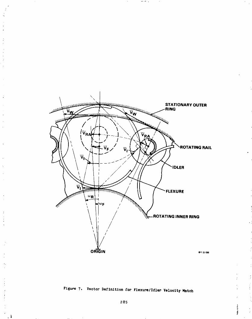
\,\
STATIONARY OUTER
/\
/ \\\
t J- - '/ /
\\ \ / NG RAIL
", v./
/ ERj
J/
/
/
VlFLEXURE
Figure 7. Vector Definition for Flexure/Idler Velocity Match!'
285 "
.i
1985025199-290
The primary concern when designing high-voltage systems is electrical
breakdown, which manifests itsel£ as corona or arcing. _luu_ _v....
by most power standards, is not considered particularly high voltage, it is
still above the minimum spark voltage of 240 volts RMS and requires specialattention.
Corona is not a critical concern since all applications studied to date
operate in a vacuum environment, and a gaseous ambient is required to supportcorona. Therefore, by providing adequate ventilation of the module, the
internal pressure can be maintained below the regime required to sustain
corona - especially if system voltages are kept down to 500 volts or lower.
However, since some ground testing invariably occurs at atmospheric
pressure, the use of overlapping barriers to prevent llne of sight provides
labyrinths that result in relatively large air gaps. These labyrinths are
included primarily to inhibit arcing (by providing a torturous path for an
arc), as well as to keep out external debris.
To inhibit arc susceptibility, a dual insulator system is used between
adjacent conductors. The primary insulation consists of a glass-filled resin
that has a high dielectric strength (15.6 V/ m, 400 V/mil). This is used for
axial as well as radial insulation. The secondary insulation is provided by
teflon-impregnated, hard anodized aluminum. The teflon impregnation tends to
fill the pores typically present in a hard anodized coating, resulting in avery reliable insulator.
The teflon-filled coating (designated Hardtuf by the supplier, Tiodize
Co, Inc.) produces a very low friction surface for structural parts, whichpermits smoother assembly of close-fitting components.
Thermal Considerations
When transferring high power (I0 to I00 kilowatts), a prominent operating
parameter of the system is transfer efficiency. The transfer efficiency
(eT) i8 defined as the percentage of power transferred through the rotatinginterface without thermal loss and is given by
eT= El - 12R : E - IREl E
where E : source voltage, volts
I : system current, ampsR : circuit resistance, ohms
286
t
1985025199-291

Given a circuit with fixed current and supply voltage, the designer maymaximize the transfer efficiency by minimizing the circuit resistance. Inthe case of a roll ring, this is accomplished by increasing the number ofparallel contacts, or flexures, in a given circuit. The measured circuitresistance of the most recent, 10-flexure configuration is approximately 0.38milliohm under current load. The circuit resistance is about 20 percenthigher during a low-current, four-wire measurement because of film effects.Therefore, the transfer efficiency under 500-volt, 200-amp condition is
eT = 500 - 200 x .00038500 x 100% : 99.985%
However, even with transfer efficiencies this high, thermal losses aregenerated because of the finite circuit resistance. At maximum current, thedevelopment module generates approximately 15 watts per circuit; so that,being an 8-circuit assembly, it converts 120 watts of power to thermal energywhich must be managed.
Since this device operates in a vacuum, the primary modes of heat trans-fer are conduction and radiation. Therefore, geometries were selected tomaximize the contact area of adjacent components, and materials with highheat-transfer coefficients were used for fabrication.
Besides providing secondary insulation, the hard anodized aluminum railsprovide an axial heat conduction path for the thermal energy in the rings aswell as a radial path for the roller/rail heat-transfer interface. The
roller, in turn, is acting as a partial sink for the flexures.
Although the test setup was not configured to model the radiation mode ofheat transfer seen in flight operation, the hard anodized housings providehigh-emisslvity surfaces to act as radiators should a receiver be present.
In an effort to predict the temperature profile of a unit in operation, athermal model is being developed and the thermal resistances are being deter-mined empirically. Several interface resistances must be determined
empirically because very little literature exists on the interface charac-teristics of various material combinations. Because of the symmetric natureof the plan view of a multlflexure circuit, a lumped analytical approach isused (i.e., the characteristics of all i0 flexures can be thermally equatedto a single flexure with appropriate coefflclents).
In the model, only the current-carrying components are considered active,heat-generating components: those consisting of the contact rings, con-necting bolts, flexures, and their contacts. Since the contact resistance ofthis particular gold-on-gold interface can be directly measured and thematerials used are well documented, the Q (rate of heat generation) and K(thermal conductivity) terms can easily be determined. However, hundreds of
empirical measurements are necessary to determine the remaining terms. Atthe writing of this paper, this work is still in progress.
287
J i
1985025199-292
_ ELECTRICAL NOISEi
"_ Electrical noise is defined as resistance transients of the electrical
_! interface that occur during operation. This is distinguished from c_eady_ state resistance, which is a function of the material properties and remains
constant. Several applications, however, can tolerate various levels of
, electrical noise - characterized by amplitude, duration, wave shape, and
=I frequency of occurrence.
During the course of several years of investigation, a variety of
ii mechanisms that may or may not cause electrical noise have been theorized andproven ¢r disproven. Several of these studies and conclusions are included
here for the benefit of the reader. It should be pointed out that, although
these mechanisms may behave as described herein for a ro13 ring - which uses
conformal rolling interfaces - they may behave differently when applied to" conceptually different devices.
Organic Films
It is believed that, for a roll ring, the presence of an organic film
does not cause electrical noise under most conditions. Indeed, the presence
of a large quantity, as in an oil film, actually benefits the electrical per-formance for signal current levels. Though organics are by nature primarily
nonconductive, their viscous properties permit a flexure with sufficient
mechanical preload to make electrical contact-either by complete displace-
ment of the film or by partial di_-placement to a thickness that will permit
I conduction by tunneling.
There are exceptions, however. In the presence of large quantities of a
viscous organic, experience has shown that currents exceeding 3 amps may
cause breakdown of the organic into less viscous insulators that will not
permit efficient conduction. Also, viscous films result in hydroplaning of
the contact at elevated rotational rates. The speed at which transitionoccurs is a function of both flexure preload and film viscosity. These
results were compiled during testing of contacts intentionally lubricatedwith a variety of lubricants.
_I Stick Slip
It was suggested that tae high friction coefficient of gold-on-gold invacuum was permitting the flexure to edge up the ring groove until some sur-
face anomaly initiated a "skid" back into the bottom of the ring groove.During the "skid" the contact surfaces were thought to separate elastohydro-
• dynamically. After much study and investigation, it is felt that this is a
r ' very impPobable mechanism.
First, a stick-slip mechanism implies a fairly random nature with unpre-
dlctable periods. However, whenever a roll-ring circuit is experiencingresistance transients, it uan almost always be traced to the defect period of
- an outer ring, inner ring, flexure, or combination thereof.
288
!
1985025199-293
Second, stick slip is a dynamic condition that can occur only duringactual rotation or oscillation. However, it is sometimes possible to "park"on an area of increased resistance.
Third, there has been no visible physical evidence of such an action.
Gold, being exceptionally malleable, would leave some sort of a ransverse
scratch in the gold that has never been seen. The only nonclreumferential
markings that have been observed on the rings are epicyclic swirls associatedwith the entry and exit paths cf the flexure contact across the footprlnt'sfinite width.
Fourth, stick slip is by nature _ very rapid event that would have a
distinct repeatable tlme-history wave shape. Roll-ring noise tends to be
randomly shaped and of various durations despite its often periodic nature.
Preload
Experience has shown that there is very little correlation between
flexure preload and electrical noise. Dreloads as low as 0.09 newton(0.02 ibf) and as high as 2.0 newtons (0.45 ibf) have yielded low noise per-
form_nce. The preload does have a small effect on dc contact resistance,
which is to be expected since a higher preload establishes a larger footprintand hence lower resistance. Finite deflection and therefore finite preload
is necessary, however, to ensure running stability. Typical 15-amp flexures
today have preloads of 0.22 to 0.36 newton (0.05 to 0.08 ibf) and deflectionsaround 0.6 mm (0.025 in.).
Polymers
As mentioned earlier, the only instances that nonconductive polymers were
encountered were when rhodium was used as part of the plating matrix. It was
discovered during testing that rhodlum is a very good catalyst for polymer
formation for a roll ring in the presence of organic films or vapors. Since
organic vapors are habitually present in vacuum systems because of the out-
gassing of several materials, polymers did form on the roll ring and poorelectrical performance resulted. However, to date, no indications of
polymers have been detected when a gold-on-gold system has been used.
Silicon
A high correlation was found between the presence of silicon in the
system and resultant electrical noise. Although the exact form of the non-
conductive film containing sil_con was never identified, several sources ofsilicon contamination were eliminated from the test system, resulting in
greatly improved electrlcal performance. The primary source of silicon con-
tamination was the result of operating fixture drive motors with silicon-
grease-lubrlcated gear-heads Jn the vacuum chamber with the circuits undertest.
289
L
1985025199-294

Metallic Oxides
Recently, a correlation between electrical noise and codeposited copper
in the gold has been established. Copper is a very active metal that
oxidizes readily and has a tendency to migrate (Ref 5). That is why a nickel
migration barrier is generally included in most gold-piatlng matrices.
Most gold-plated electrical contacts can tolerate a small level of copper
in the gold because they quite often have wiping actions that scrape away any
oxide layers before making contact. This may explain why small amounts of
active metal contamin_tlon would not alarm a plating vendor. However, the
roll ring does not have an aggressive wiping action and is therefore more
sensitive to the presence of oxide films on the contact surface. Once thisis known by the plater, it is a relatively sim_ e matter to control theactive metal contaminants and so reduce or eliminate the presence of metallic
oxide films.
Surface analysis techniques have been, and are, invaluable tools for
investigating resistive films. The Scanning Electron Microscope (SEM) hasprovided a great deal of visual support and some help in identifying bulk
materials on the contact surface through Energy Dispersive X-ray Analysis
(EDXA). However, the electron beam has a finite penetration that does not
permit analysis of very thin surface films. To examine very thin surface
films (0 to i00 Angstroms), Electron Spectroscopy for Chemical Analysis
(ESCA) is used. ESCA is the only surface analytical technique that providesdirect information on the chemical (as well as elemental) nature of the atoms
in an unknown sample (Ref 6). For three-dimensional mapping of varie',_
elements in a sample, Auger Electron Spectroscopy (AES)N is used in conjunc-
tion with sputter etching. ESCA demonstrated the presence of copper on the
surface, while AES d_termlned that it was codeposited with the gold rather
than a result of migration or a surface condition only.
SUMMARY
A great deal of development has been completed, and is in progress, rela-
tive to a rolling electrical contact device that is uniquely suited for
signal/power transfer in present and future space applications. Several
technology areas had to be enlarged, resulting in new knowledge in a variety
of areas. This virgin technology has provided two configurations of theroll-ring mechanism that demonstrate not only a very low torque capability
but reduced resistivity and a high voltage capability as well.
290
L i.
1985025199-295

r_ A design and performance sum_ary of the two configurations is given inthe listing below:
RGLL-RING D_IGN SUMMARY
Parameter Single Flexure Multi flexure
Current Capacity 15 amp 200 amp
DC Circuit Resistance i0 milliohms 0.4 to 0.5 milliohm
Peak Electrical Noise 50 milliohm goal a 3 milliohms
Life 107 revs (proven) 107 revs (theoretical)
Torque per Circuit 1.4 x 10⁻⁴ N-M 3.5 x 10⁻³ N-M (i0 flexures)
Weight per Circuit 35 grams 900 grams
Transfer Efficiency 99.50% (15 A, 30 V) 99.985% (200 A, 500 V)
REFERENCES
i. Spotts, M. F. 1971. Design of Machine Elements, 4th ed. Englewood •Cliffs, NJ: Prentlce-Hall, Inc.
2. Antler, M. March 1974. Wear of Cold Plate: Effect of Surface Films and
Polymer Codeposits. Trans IEEE, Vol PHP-IO, No. 1.
3. Cuthrell, R. E., and D. W. Tipping. May 1973. Factors That Affect the
Solid-Phase Bondin_ of Gold Wire Electricai Leads. Sandia Laboratories
Report S&A-73-0535.
4. Cuthrell, R. E., and D. W. Tipping. December 1972. Electric Contacts:
Equipmer,t and Mechanics of Closure for Gold Contacts. SandiaLaboratories Research Report No. SC-RR-72-0783.
5. Antler, M. March 1973. Tribological Properties of Gold for ElectricContacts. Trans IEEE, Vol PHP-9, No. i. _
6. Evans, Charles A., Jr., and Richard J. Blattner. 1978. Modern Experi-
mental Methods for Surface and Thin-Film Chemical Analysis. AnnualReviews Inc, p. 199.
7. Patent No. 4,372,633. 8 February 1983. High Current Transfer. Roll Ring
Assembly •
aDevelopment in this area, although converging rapidly, is not yetcomplete. Therefore, a definitive value for peak electrical noise isdifficult to reference.
291
1985025199-296

N85-33530
A DUAL, FAULT-'TOLERANT AEROSPACE 'ICTUATOR
Clete J. Siebert*
ABSTRACt
The requirements for mechanisms used in the Space Transportation System
(STS) are to provide dual fault tolerance, and if the payload equipment
violates the Shuttle bay door envelope, these deploymentlrestow mechanisms
must have independent primary and backup features. This paper describes the
research and development of an electromechanical actuator that meets these
requirements and will be used on the Transfer Orbit Stage (TOS) _rogram.
INTRODUCTION
This depioymentlrestow mschanism will be used to perform three separatefunctions on the _OS program:
o Provide power to latch and unlatch the upper half of the forward
Airborne Support Equipment (ASE) cradle.
o Provide power to open and close the upper half of the forward ASEcradle.
o Tilt the TOS/spaoeoraft (TOS/SC) combination for separation from the. Shuttle and restow the aft ASE cradle for landing.
The Shuttle/TOS on-orbit configuration is illustrated in Figure 1.
REQUIR_NTS
The requirements imposed on the actuator mechanism to perform the
required functions are summarized as follows:
Safety Requirements (in accordance with NXB 1700.7A)
o Independent primary and backup actuator functions are mandatory.
o Combination of primary and backup methods must be two-failuretol e_ant.
aMartlnHarlettaAerospace,Denver,Colorado
293
PRECEDIIqG PAG_ BLANK NOT _
1985025199-297

Operational Requ._ements
o Provide power to lat_ and unlatch the for,_ardcradle halves.
o Provide power to open and close the upper half of the forward cradle
112° +_5° .
o Erect tho TOS/SC combination 45° +5° for separation.
o Provide erection capability under active Vernier Reaction Control
System (VRCS) or free-drift conditions the Primary Reactlon ControlSystem, (PRCS) and Orbiter Maneuvering System (0143)are inhibitedduring rotation,
o Provide capability to react VP._S and PRCS when TOS/SC is in theerected position.
o Provide multiple erecticn/restow cycle capability for each mission;restow capability for an abortive mission is mandatory.
o Provide performance for 80 orbiter missions over i0 years.
3_stem Requlrments
o _latch or latch forward cradle in less than 4 minutes.
o kiae or _ower forward cradle half 112• in less than 2 minutes.
o Erect or restow TOS/SC _5° in leas than 2 minu_es.
o Withstand all deployment and landing loads (each actuator). Theseloads to be reacted through the actuator str_Ictureand lock gears.
o Not to exceed 310 N (70 ib) per actuator.
o Operate at temperatures from -28ec to +59eC (-15eP to +llloep).
o Provide redundant limit switches, solaloida, OC power and avionics.
o Provide (one motor/clutch combination) sufficient torque underworst-case conditions to perfom required f_notton.
o Provide force mar6ina of 100_ at worst-nase conditions for allactuators.
29_
1985025199-298

CONCEPT DEVELO?MENT
During the design trade-off phase, several priorities were established asdesign goaIs. These were
o Satisfy alI safety requirements of NHB I700-7A without any waiverrequests.
o Use minimal design complexity and manufacturing simplicity.
o Use previously qualified space hardware and components.
o Provide a common design capable of a broad range of torque output
forces :_Ith minimal configuration changes.
o Combine additional mechanism functions within the actuator to
eliminate additional separate mechanisms.
HARDWARE CONFIGURATION
Each actuator, as illustrated in Figure 2 consists of the following majorcomponents:
o Structural housing containing the ball screw and nut assembly,reduction gear train, and attachment clevis ends.
o Redundant DC searhead _otors.
o Redundant DC solenoid-type, positive-engagement clutches.
o Sprlng-loaded drlve-engagement pin and pyrotechnic disengage.
o Redundant positlon-indication potentlometers.
o Redundant solenold-powered lock gears.
o Redundant mlcroswitches for lock-gear and actuator-engagement-pinindication.
ACTUATOR FEATURES
Most actuator systems presently being used on the STS are physically
separated from the structure in the event of primary actuator failure, th,,s
allowln_ the backup actuator to b_ used. These systems require separate
swlngaway, _atch, and latch mechanisms. The Martin Marietta actuator isself-contained in the event of primary actuator disengagement. This is
possible since the actuator selector drive pin with its pyro release Is
contained within the actuator. The disengaged primary activator simply
becomes a free-slidlr_, telescoping tube assembly.
295
I
l
1985025199-299

Additionally, the actuator has been designed to wlth3tand the crbiter
launch and landing loads, the TOS/SC deployment loads, and the orbiter
maneuvering loads. This design feature eliminated the requizement for a
separate landing lock mechanism and a deployment lock mechanism.
R_te control is normally used with actuators to control the output speedand prevent excessive slew rates to the payload being raised for deployment.
This closed-loop, complex electronic control is required on rotarT actuator
systems and some existing screw-drlve systems to prevent a possible runawaycondition.
In the Martin Marietta actuator, this ,ate controller can be eliminated
because drive motor gearhead reduction limits th_ ._axlmum RPM. Maximum screw
extenslon/retraction rates cannot exceed the free running speed of the drive
motor as reduced through the reduction gear train and drlve nut.
The maximum impact force when erecting the TOS/SC is less than 33.9 N-m
(25 ib ft.). This low impact fol_e alluws the use of a simple structural
hard stop, rather than a viscous damper.
The actuator motor shutoff is accomplished by use of a ,edundant motor
current limiting circuit. The structure being deployed, or stowed, contactsa structural hard stop, thus increasing motor current demand, and motorshutoff Occurs.
This method allows the required ].00% force margin at worst-case
conditions, while preventing structural overloads under best-case
conditions. Additionally, the clutch assembly can be adjusted to slip at a
predetermined torque, also preventing an acaldental overload conditlon.
Posltlon indication to the crew Is accomplished by the use of redundant
rotary potentiometers that provide actuator extension/retraction data.
Since the actuator mechanism ls a back-driveable device, a locking
mechanism must be incorporated. A redundant, solenoid-operated, dual-gear,mesh lock has been s_lected for this design. A similar design ha_ previously
been used on the Inertial UpDer StaKe (IUS) program.
DISCUSSION
This actuator mechenisa m_ete all the STS safety requirements as defined
in E_B 1700.7A, and also meets the structural, life, an_ TOS missior+ requirements for the followlng reasons:+
o The orbiter crew can use the Standard _Itc_ Panel (SSP) at any! point in the actuation cycle to stop, restart, and dlsenease the
primary actuator, and engage the backup actuator. This allows for
complete restow of the TOS/SC in case of a mission abort.
! o Force margln_ are at least 100_ greater than the required torques at
! worst-case con |itions (FiKure_ 3A, B and C).
l
296
1985025199-300

o Each pair of actuators, primary and backup, has triple electrical
redundancy and complete mechanical redundancy°
o All rolling-element bearings are sized to exceed the LlO life by aminimum factor of 17.
o Each actuator is capable of greater than i000 duty cycles during itsoperating life, which far exceeds the 80 mission requirement.
i o Clutches are designed for positive power-off disengagement usingredundant, captive compression springs.
o The structural ultimate factor of safety is 1.4 minimum. Gearstress levels are less than one-fourth of the material ultimate
stresses.
o Lubrication is a combination of wet and dry lubricants. All sliding
, surfaces are treated with space-qualified dry lubricants; however,
they are desired to function without ]ubrication. All bearings,
gears, and ball screw are lubricated with Bray Oil 3_-38RP, a
qualifled vacuum-stable grease.
o The static load capability of the actuator is 8000 lb.
o The actuator design can be easily modified to meet a variety offorc_ and extension/retraction rate requirements (Table i).
CONCLUSION
The actuator design selected for use on the TOS program meets the
requirements for STS safety requirements. This design has successfullypassed the NASA Phase I Safety Review without receiving any mechanical Review
Item Disc,'_pancies, nor were any safety waivers required. The desi_ studlea
and tradeoff analysis resulted in a multifunction, simple mechanism that is
easily adaptable to various output torque requirements aria
extension/retraction cycle times.
297
1
1985025199-301
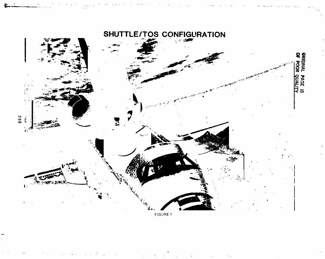

299
1985025199-303
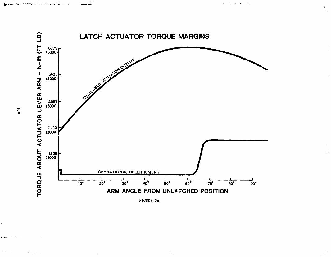
LI
(8"11
-I)ILI-N
-V
ii:IVE
I3A37
UO
lVnlO
vln
oev
:lnou
01
i300
:
"°Ltli
1985025199-304
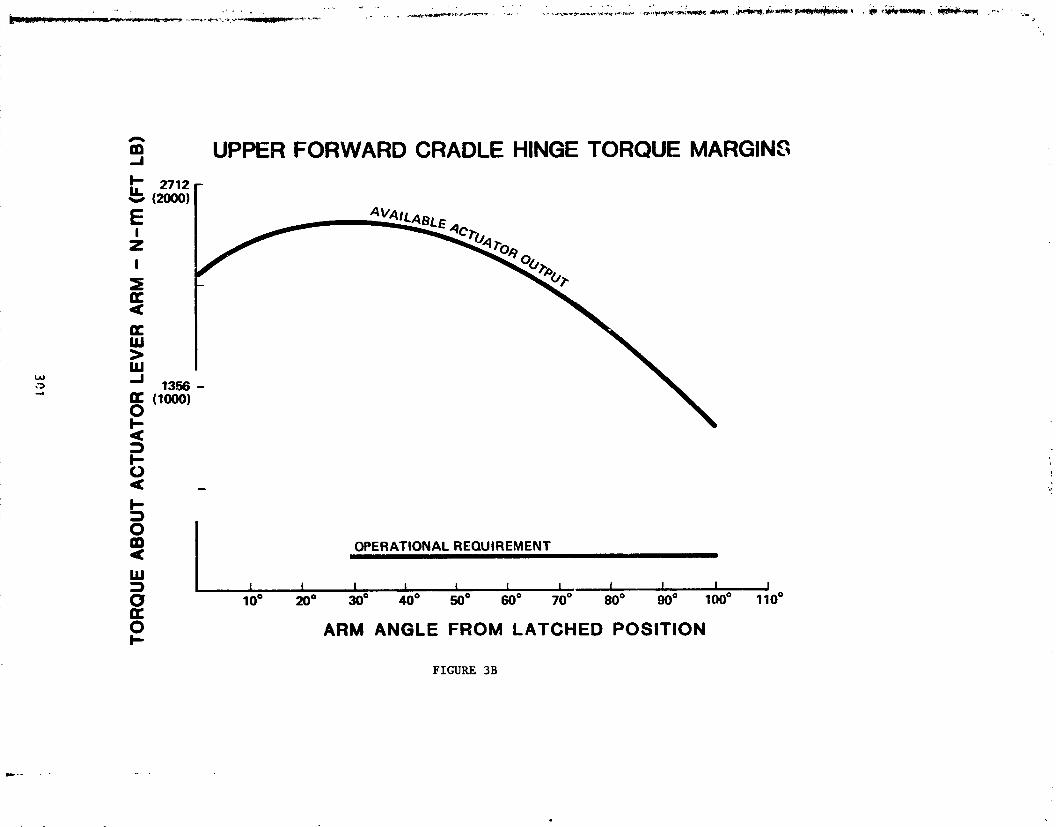
301
1985025199-305
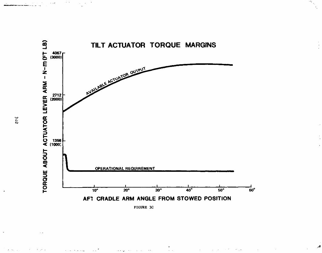
-8
vv
,._
(81Z
.-I)tU-N
-nU
VU
:lA:rlu
ozvn
zov
±no
ev:ln
ou
oz
JiI3o2
t
1985025199-306

'_1303
1985025199-307

N85-33531DESIGN OF A DUAL FAULT TOLERANT
SPACE SHUTTLE PAYLOAD DEPLOYMENT ACTUATOR
DUANE R. TESKE*
ABSTRACT
As the Shuttle Transportation System (STS) becomes operational, the number and variety of: payloads will increase. Th_ need to deploy these cargo elements will require a variety of unique actuator
designs, all of which will have to conform with STS safety policy.
For those missions where payload operations extend beyond the payload bay door envelope, thispolicy deems the prevention of door closure as a catastrophic hazard. As such, it must be controlled byindependent, primary and back-up methods. The combination of these methods must be two-faultto:erant.
This paper describes the deslgn of such an actuator. The device consists of a single linear ballscreww!th two ballnuts, each ballnut forming an independent actuator using the common ballscrew. The designrequirements, concept development, hardware configuration, and fault tolerance rationale arehighlighted.
INTRODUCTION
An Orbiter based satellite delivery system is presently under development. Comprising an upperstage and associated airborne support structure, this system is carried "lying down" within the Orbiterbay and raised from the bay for deployment, Figure 1. As the raised element extends beyond the payloadbay door envelope, failure could impede door closure and prevent safe return of the Orbiter. The actuatorsystem thus can cause a catastrophic hazard, raquiring control by independent primary and backupmethods, the combination of which must be two-failure tolerant. 1
PAYLOAD & SUPPORT STRUCTURE
45 o
Figure 1 Payload Deployment Schematic
*Sundstrand Energy Systems, Rockford, Illinois305
1985025199-308

\
CONCEPT DEVELOPMENT
A survey of existing deployment systems was made to determine if any were adaptable to thisapplication. In general, dual fault tolerant capability is achieved by using two actuators.
IThe shortcoming of this approacl',, however, is the ability of a failed actuator to lock the entire drive
l train, defeating the backup unit. Either extra vehicular activity (EVA) or a disconnect mechanism, such as
! a pyrotechnic devioe,pinpuller or clutch is, therefore, lequlred. However, each device adds its reliability" factor to the system _..ndincreases complexity. In addition, to prevent inadvertent disconnection cf the'i healthy unit, either a method of discriminating the failed actuator must be devised,or a mechanism which
allows reliable reconnection must be conceived. Similarly, a retention/stowage device for thedisconnected unit is oftan required.
.: Existing ._ystems solve this problem in various ways, but with considerable proliferation of parts.Further, such solutions usually result in a number of items or functions which cannot be allowed to fail.These "noncredible" failure items are always the subject of debate and generally increase the precisionof manufacture required.
Nevertheless, in an attempt to _mproveexisting designs, several dual actuator design studies weremade. All the resulting concepts, however, offered o_-,lymarginal improvement. As a result, a singleactuator system which would possess the necessary fault tolerance was sought.
DESIGN DESCRIPTION
The singleactuatordesign concept which evolved is illustratedinFigure 2. The mechanism consistsof a linearballscrew upon which are mounted two independent ballnuts. Each ballnut is enclosed initsown housing,forming, inessence, an independentactuator free to transita portionof the ballscrew. Themountingarrangement of the actuator, Figure 3, is such that retracting the actuator raises the payloadand extending the actuator lowers it.
EMERGENCYSTOW
PRIMARY ORIVE (UNIT A) BACKUP DRIVE {UNIT B) ORIVE UNIT.A- _ ,J_ ,.
l o.,v.]lc o.c.lIo.,.]lcc.! lo.,v.}MOTOR MO 'OR MOTOR MOTOR MOTOR
1 1lwo..j ]wo..L !w.-L .,GEARsET l CAR ,IER J GEARsET I CAR IIIER.I _ _R
I !Figure 2 Actuator Block Diagram
, 306
1985025199-309

ORIGINAL PAGE ISOF POOR QUALITY
Xo=:1229.27 PRIMARY/BACKUP HOUSING
/,,,PAYLOAD "INTERFACE
FITTING 7.0=433.50 _ ----4:_ _-x°=1243'354 // RETRACTED1"169METERS
_1 , _'7_.'_._ Zo=428.499 ..STowEMERGENCYI "_ /f _ 1.544 METERS J HOUSING' EXTENDED
I I " "
, 7,o=414,00 _ _,'
260 53' x--
ORBITER \ , , _ ....PAYLOAD ROTATION "" . 7-o=406.00ATTACHMENT AXIS
-%
,# _,r" _fl-
)(o=1230.27 JACTUATOR Xe= 1283.50SUPPORT BRIDGE
Figure 3 Actuator Installation
Dual-faulttolerance is achieved by providingeach actuatorhalf withthe fullstroke necessary fortheapplication. For normal operation, one ballnut is used to extend or retract the actuator, Figure 4. Twoindependentmethodsof dnvingth_sIoallnutare provided,permftting full missionperformance even withone failure.
PAYLOAD STOWED
PAYLOAD DEPLOYED
i
Figure 4 Normal Operating Sequence
30T
t
1985025199-310
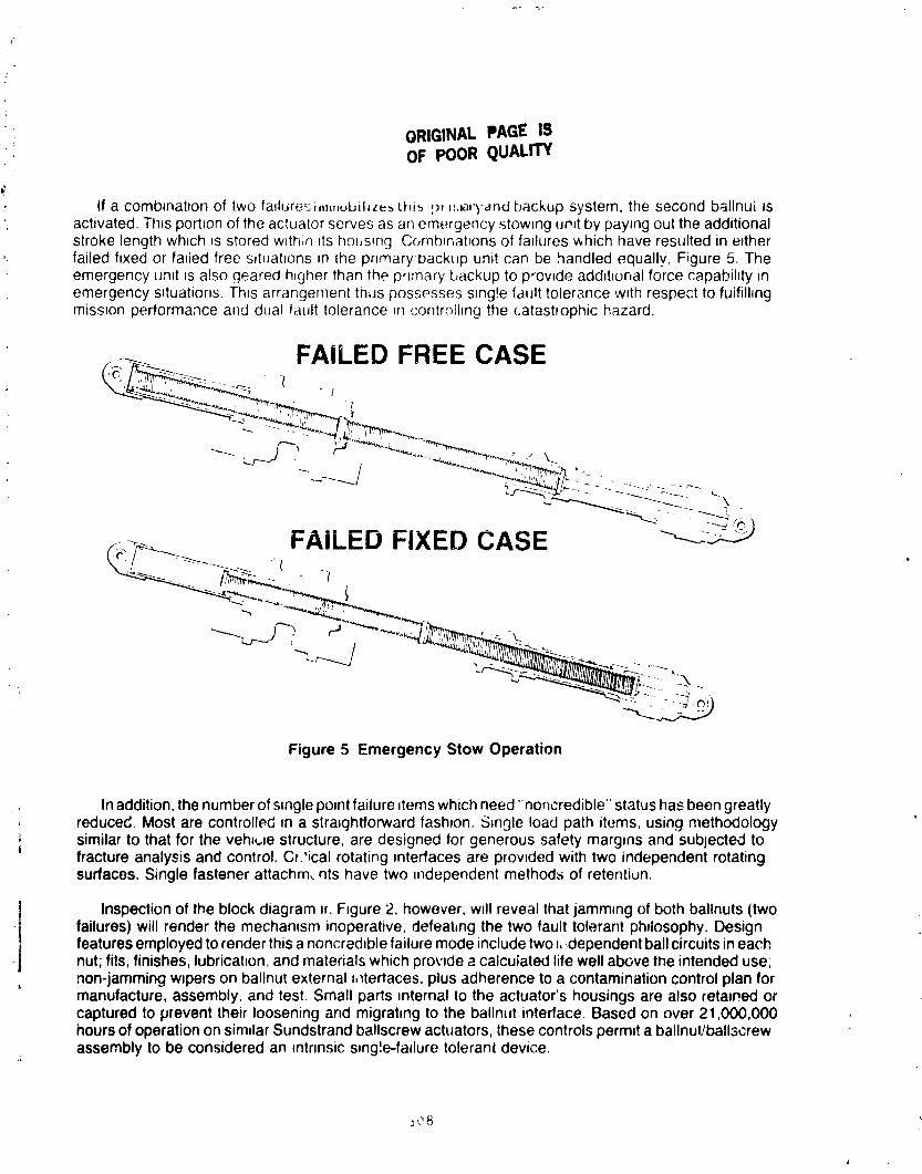
ORIGINAL PAGE ISOF POOR QUALITY
#
If a comb4natlon of two faduresi_l,obil_ze_ thi_ _r _,_atb-andbackup system, the second ballnui isactivated. Ttl,s portron of the actuator serves as an emergency stowing ur,Jtby paying out the additionalstroke length which _sstored wlth;n _tshousang Combanat_onsof failures which have resulted in eitherfailed fixed or failed free s_tuatlons in (he pnmary'loackLJpunit can be handled equally, Figure 5. Theemergency unit zsalso geared h_gherthan the p,lmary'backup to p-owde addlhonal force capabihty Jnemergency situations. Thts arrangement thus possesses s_ng!efault tolerance w_threspect to fuifilhngmission performance and dual fault tolerance _n('ontrolhng the catastrophic hazard.
FAILED FREE CASE: "t
In addition, the number of single po,nt failure items which need "noncredible" status has been greatlyreduced. Most are controlled fn a straightforward fashion. Single load path items, using methodologysimilar to that for the veha_,Jestructure, are designed for generous safety margins and sublected tofracture analysis and control. Cr?ical rotating interfaces are provided with two independent rotatingsurfaces. Single fastener attachm, his have two independent methods of retention.
Inspectionof the block diagram or.F_gure2, however, w_llreveal that jamm,ng of both ballnuts (twofailures) will render the mechanism inoperative, defeating the two fault tolerant phdosophy. Designfeatures employed to render this a noncred_blefailure mode include two _,,dependent ball circuits in each
•j nut; fits,finishes, lubricahon, and materials which provide a calculated life well above the intended use;• non-jamming w_person ballnut external ,_tertaces, plus adherence to a contamination control plan for
manufacture, assembly, and test. Small parts ,nternal to the actuator's housings are also retained orcaptured to prevent their loosening and migrating to the ballnut interface. Based on over 21,000,000hours of operation on similar Sundstrand ballscrew actuators, these controls perm=ta ballnut/ballscrewassembly to be considered an mtnnsic s,ngle-fa,lure tolerant device.
1985025199-311

)
_" ORI31NAL PAGE IS! OF POOR QUALITY)?
|' TheresultingactuatorisillustratedinFigure6. Actualweightof_n_F,gl.neeringprototypeis15% less
.., thanthatcalculate,"for a comparahledualactuatorsystem.
SINGLE BALLSCREW
PRIMARY BALLNUT
; BALL CIRCUITS)
CLUTCH CARRIER--/
LENGTH:EXTEND 1.54 MRETRACT 1.17 MSTROKE 0.37 M
PRELOADEDWEIGHT:43 KG BELLEVILLE
SPRINGSFigure 6 Actuator Cutaway
DESIGN CONSIDERATIONS
Inadditiontothefaul!tolerancerequirements,otherperformanceissuesimposedesignconstraints,manyoftenconflicting,Figure7. Forexample,stabilityinlaunchingthespacecraftisnecessarytoavoidcollisionwiththeairbomesupportstructure.This dictatesa lowbacklash,highstiffnessactuatortopreventpitchoscillationsas thespececraP,pushesoft andexitsthe cargobay. Highstiffnessis also
-, desiredto preventdynamiccouplingof the cargoelementwiththeOrbiterthrustersduringpayloaderectionandstow.
309
L
1985025199-312

Safety
• Independent Primary and Backup Actuation Methods
_ • Combination of Primary and Backup Methods Must Be: Two-Failure Tolerant
Operational
• Erect the Payload tu Any Angle From 0 ° to 45 oin Less Than10 Minutes
• Maintain High Stiffness/Low Backlash to React Upper StageSeparation at Any Angle
• Prevent Backdriving Under Load
• Maintain a Minimum Force Capability of 5340 Newtons Overthe Operating Environment
• Provide an Emergency Force Capability of 15,570 Newtons
• Limit th,- Maximum Force From Combined Impact Loadsand Actuator Output to a Level Compatible With OrbiterStructure
• React Orbiter Vernier and Primary Reaction Control Leads
• Minimize Dynamic Coupling Between the Orbiter and thePayload
• Minimize Telemetry and Monitoring Requirements to Perm;tMinimal Crew Involvement
• Provide 10 Mission Life
Figure7 Requirements
However,dutingOrbiter;aunchandlanding,thevehiclewillbesubjectedtostructuraldeflectionsandl vibrationenvironmentsthatcauserelativemotionbetweenthe two actuatormountingpoints.A stiff
. i actuatorinthissituationcanpotentiallyimpartundesirableloadsto thesupportingstructure.
The initialdesignsolutionwastoaccommodatethemotionthroughfree-wheelingof theunclu;ched; . primary/backupballnut.However,therewas a degreeof uncertaintyas to theability,of the ballnutto
respondrapidlyenoughto attentuateloadsat higherf,equencies.Inaddition,a clutch-engagedfailureoccurringduringdeploymentcan defeatthisfeaturefor the subsequentlanding.
i"
Forthesereasons,a loadreliefdevicewasconceived,Figure8. Consistingof preloadedbellvillesprings,thedevicepresentsa stiffactuatorup to 26,690 newtons(6,000 Ib) a_!alload,eithercompressiveor tensile.Above26,690 newtons,deflectionof thedeviceaccommodatesthe relativ8motionof themountswithoutoverloadingthestructure,Figure9.
310
q
1985025199-313
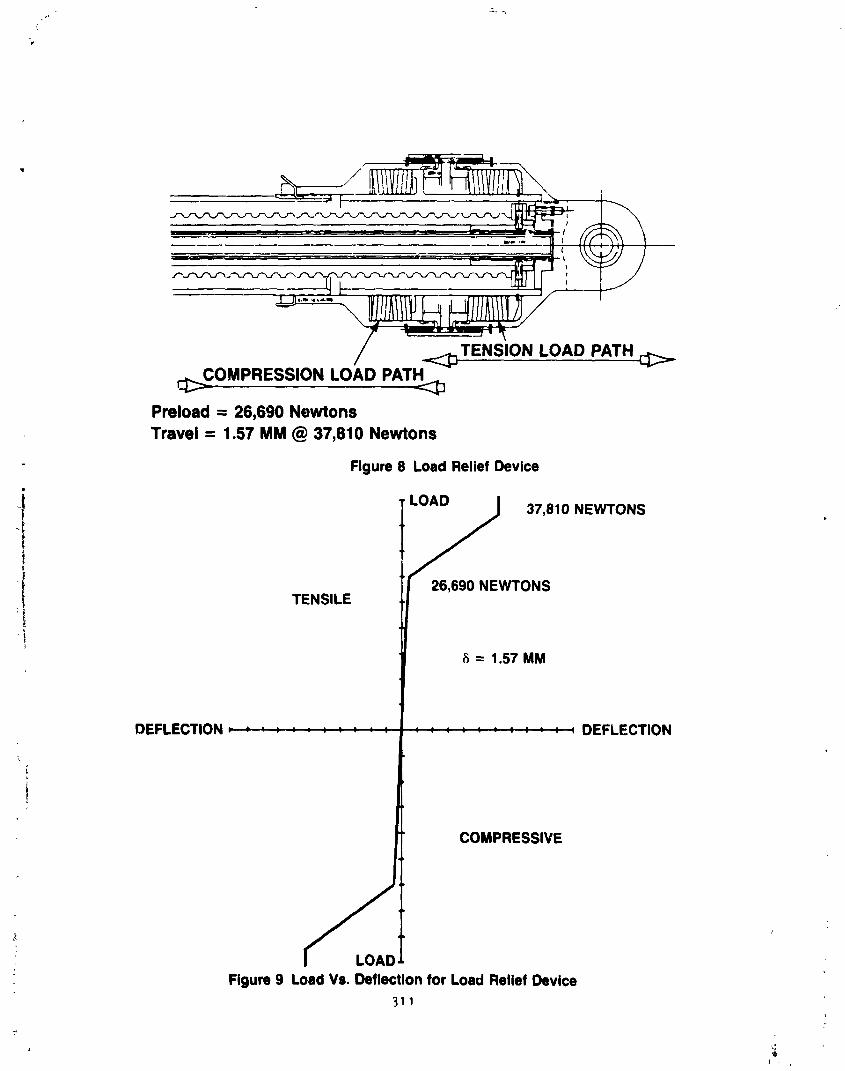
._,_,s,o..o.o,.,. _._o.,,_ss,o._o.o_,_
Preload= 26,6g0NewtonsTravel = 1.57 MM @ 37,810 Newtons
Figure 8 Load Relief Device
I 26,690 NEWTONSTENSILE
:i
8 = 1.57 MM
DEFLECTION DEFLECTION
.!
COMPRESSIVE
: Figure 9 Load Vs. Deflection for Load Relief Device
311
I ,
1985025199-314

"\
Fault tolerance considerations extended to the design of the load relief device. Spr!ngs were sizedsuch that adequate preload would remain after two spring failures.
The need for load relief is predicated on two factors, the ascent/descent vibration induced deflectionsand the strength limitations of the mounting structure. Both of these areas incompletely defined at.the time the actuator wa._designed. For that reason, the load relief device was designed to be modular,permitting its easy removal if subsequent tests and analyses should indicate it to be unnecessary.
Competing requirements also arose in establishing the force vs. speed characteristics of the actuator.In service, the actuator can be subjected to a variety of loads as illustrated in Figure 10. Because thedynamics of the interaction between the cargo element and the Orbiter are complex, the precision withwhich these loads could be defined was uncertain. In addition, the loads are bi-directional, capable ofeither aiding or opposing actuator motion. Yet the actuator has to provide sufficient force capability toperform at all credible load combinations. Operating force requirements of 0 to 1600 newton- (360 Ib),which excursions to 15,520 newtons (3,500 Ib), were specified.
• Operating (On-Orbit)
m Vernier Reaction Control System
Primary Reaction Control System
- _ Dynamic
; -- Stop Impact at 450
-- Spacecraft Upper Stage Separation
• Nonoperating (Ascent/Descent)--- Random Vibration
-- Shock
-- Structural Deflections
Figure 10 In-Service Loads
In providingsufficient force capability to satisfy these requirements, it was necessary, however, to; limitthe maximumforce potential of the actuator so that the mechanism'soutputwould not exceed the, strength of surrounding structure. This consideration limited the maximum actuator output to 37,810
newtons (8,500 Ib ).
-_'=it 312 ,
]985025]99-3]5
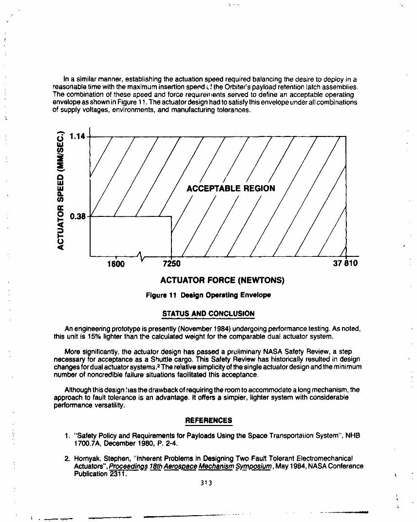
Ina similarmanner,establishingtheactuationspeedrequiredbalancingthedesireto deployinareasonabletimewiththemaximuminsertionspe_d_.f theOrbiter'spayloadretentionlatchassemblies.The combinationof thesespeedand forcerequJre_,entsservedto definean acceptableoperatingenvelopeasshowninFigure11.Theactuatordesignhadtosatisfythisenvelopeunderallcombinationsof supplyvoltages,environments,and manufacturingtolerances.
' = 2cal._. LE
_) 0.38
< •
,1600 7250 37 I10
ACTUATOR FORCE (NEWTONS)
Figure 11 Design OperatingEnvelope
STATUSAND CONCLUSION
Anengineeringprototypeispresently(November1984)undergoingperformancetesting.Asnoted,thisunitis 15% lighterthanthe calculatedweightfor thecomparabledualactuatorsystem.
Moresignificantly,theactuatordesignhas passeda preliminaryNASASafety Review,a stepnecessaryfor acceptanceas a Shuttlecargo.ThisSafety Reviewhas historicallyresultedin designchangesfordualactuatorsystems.=The relativesimplicityof thesingleactuatordesignandtheminimumnumberof noncrediblefailuresituationsfacilitatedthisacceptance.
Althoughthisdesignhasthedrawbackof requiringtheroomto accommodatea longmechanism,theapproachto faulttoleranceis an advantage.It offersa simpler,lightersystemwithconsiderableperformanceversatility.
REFERENCES
: 1. "Safety PolicyandRequirementsfor PayloadsUsingtheSpaceTransportationSystem",NHB1700.7A,December1980, P. 2-4.
2. Hornyak,Stephen,"InherentProblemsin DesigningTwo FaultTolerantElectromechanicalActuators",Proceedings18thAerospaceMechanismSymposium,May1984,NASAConferencePublication2311,
313
p,
1985025199-316

N85-33532
FEATURES O_ THE SOLAR ARRAY DRIVE MECHANISMFOR THE SPACE TELESCOPE
Eaimund O. Hostenkamp*
ABSTRACT
The Solar Array Drive Mechanism for the Space Telescope embodies several
features not customarily found on Solar Array Drives. Power and signal
transfer is achieved by means of a flexible wire harness for which the chosen
solution, consisting of 168 standard wires, is described. The torqueperformance data of the harness over its temperature range are presented.
The off-load system whleh protects the bearings from the launch loads is
released by a trigger made from Nitinol, the memory alloy. The benefits of
memory alloy and the caveats for the design are briefly discussed. The
design of the off-load system Js described and test experience is reported.
INTRODUCTION
The solar array is part of the equipment contributed to NASA's Space
Telescope (ST) by the European Space Agency. Figure i0 shows an overall view
of the ST Solar Array (SA). The Solar Array Drive Mechanism (SADM) and its
electronics are a subassembly of the SA. The rotational range of the wings
is limited to some 340 degrees because of vehicle pointing constraints which
prevent the sunlight from getting into the ST aperture. Under thesecircumstances a flexible wire harness is an obvlou_ choice for the transfer
of a large number of electrical channels.
In the launch configuration the SAs are stowed along the ST body and
fixed by clamps. Since the loads induced into the SADM through the primary
deployment mechanism exceed the load-carrying capability of the bearings, itwas necessary to provide an off-load system in order to protect them.
Because pyrotechnic devices were banned from use in the SADM, memory alloy
elements were chosen to trigger the release of the bearing off-load device.
* Dornier System GmbH, Friedrichshafen, Federal Republic of Germany
PRECEDING PAC_ BLANK NOT l_
1985025199-317
J
FLEXIBLE WIRE HARNESS
Each SA wing provides I0 solar cell modules with a nominal current of
7.5 A each. These modules were wired independently from each other and the
wiring had to be redundant. This resulted in a minimum of 40 lines of AWO 16for 50 percent derating.
In addition to these SA power lines, 20 wires with a maximum capacity of
3 A were required for the redundant motors of the primary and secondary
deployment mechanisms, the redundant resolvers of the solar array driveitself and for bonding.
l
Finally, 68 housekeeping data lines were needed with a current capacity
i of up to 250 mA. These data lines had to be separated from the power lines
[ by a screen.
II Since a high wind-up torque was anticipated from the American Wire Gauge(AWG) 16 wires needed for the SA power, it was necessary to find an
I alternative which met the redundancy approach which aimed to avoid singlepoint failures for vital functions. The chosen approach utilized 80 cablesAWG 22, of which 20 cables are for redundancy purposes.
:IFour options of flexible wire harnesses were studied by breadboarding and
-, analysis. The trade-off is presented in Table I.
Though torque, torque noise and hysteresis of the flexible wire harness
:. played an important role in the design of the SADM control system, the
printed circuit, which is best in these respects, was not selected. The
-, printed conductors for power transfer would have had to be very wide in orderto achieve the necessary cross section. In addition to serious difficulties
at the Printed Circuit (PC)Iconnector interface, this design would have
exceeded the given envelope, even with a double-layer arrangement of the PC
belts and a reduced derating. In fact the criterion of compatibility with
the given volume rendered the option with the single wires the only feasiblesolution.
The principle of the chosen solution is shown in Figure I. The axial
degree of freedom required for one cable end of this twisted wire
configuration was provided by performing the cables in a half circle from
their shaft location towards their fixation points at the stator. Twisting
and shielding of cable pairs within the flexible wire harness was discarded
because it impaired cable flexibility. The required shielding between the
signal lines and the power lines is achieved by a screening tube. The signal
' lines (68 off AWG 24) pass through the screening tube and the power lines
(100 off AWG 22) are arranged in the annulus between the tube and the hollow
shaft. The length of the flexible wires amounts to some 580 mm. Although
the wires are neither fixed nor tied together over that length, both a
centrifuge test, giving up to 4.5 g's, and vibration tests showed that the
wires would suffer no permanent deformation as a result of toe launch,_ mechanical environment.
316
#
1985025199-318

i
_ The torque at the boundaries of the rotational range is adjusted to aboutthe same level by suitable pre-orlentation of the power and signal leads
I during assembly. A breadboard model (see Fig. 5) was built in order todetermine the spring constant, torque noise and hysteresis characteristics of
I the harness. The wires were short-circuited outside the flexlead• compartment. This allowed the routing of current through the leads and t_e
i determination of their performance at elevated temperatures. Low-temperature
tests down to -25_C were carried out in a large temperature chamber. The
results met expectations and, with a margin of 2, were taken into account for
the design of the control circuit.
i Following testing of the Ouallfication Model SADM in a dynamic test rig,to verify pointing accuracy and interactive torque between the ST and the
wings, it was demonstrated that the torque characteristics of the flexiblewire harness had an unexpectedly large impact on the system performance.
Both maximum torque and hysteresis of the flight-configured qualification
model exceeded the corresponding values of the breadboard model by a factorof 3, even though the flexleads inside were ldentlcal. The difference wasattributed to the harness located outside the flexlead section. In contrast
to the short-circuit looms of the breadboard model, the cables of the
Qualification Model harness outside the mechanism were twisted, shielded,
bundled and fixed as required to form the conventional harness between the SA
panel and the diode box (see Fig. 6). These measures had resulted in a
deterioration of the torque and hysteresis characteristics to an unexpected
extent. By corrective actions, e.g., deletion of most of the spare lines and
provision of slight slack at those tle-down points where the bundles emerge
from the housing, it was possible to recover the original harness performance.
The harness torque and hysteresis characteristics of the flight modelmechanisms are summarized In Figures 2, 3 and 4.
Figure 2 shows the basic shape of the torque/hysteresis loop for the full
- angular range. Torque rises linearily as the shaft Is rotated in one
I direction. Upon reversal there ls a steep ( Ic) decay of torque followed bya steady transition ( i0°) towards the linear wind-back behavior. The area
between wind-up and wlnd-back torque ls due to hysteresis. As a result of
- the deletion of spare lines, which were mainly in the signal section, them
hysteresis is not constant over the whole angular range. The mechanical
- properties of the wlre insulation are changed by temperature fluctuations of
the harness. This affects the whole torque envelope, i.e.,the slopes and
resulting maximum torques as well as the hysteresis.
Figures 3 and 4 show the maximum torque values at the ends of the angular
range and the corresponding hystereses as functions of temperature. The data
for a specific temperature give the corners of the torque envelope"trapezoid".
317
i
1985025199-319

' OFF-LOAD SYSTEM
Discussion of Memory Alloy
Nitinol Memory Alloy Elements (MAE) are used as release triggers for the
off-load system. The choice of this actuator type was encouraged by some
experience from a Joint test programmer with the manufacturer and from
In-house development studies.
The memory effect is based on a reversible maternistic transformation of
the crystal lattice of the nickle-titanium alloy. The effect is imparted by
plastic deformation of the element at low (ambient) temperature. When
subsequently heated above t_e transfort_tion temperature, the element returnsalmost completely to its initial shape. _Ii kinds of motion can be
achieved: bending or torsion, expansion or contraction. During motion, the
element is capable of exerting a force (or torque). Both force and stroke
are controlled by the dimensions of the element. The trigger temperature canbe adjusted by the manufacturer rather accurately by controlling the
percentage of the alloy constituents. If an "educating force" is appliedduring cooling, the effect can repeat many times.
These characteristics suggest a very simple design for all kinds ofmechanisms which have to lock or release an item. However there are some
constraints which limit the use of memory alloy:
- machining is very difficult because the alloy is susceptible to heat,
developed by most machining processes, and to work-hardening.
Therefore the shape of the element should be simple, commensurate with
the still-growing experience of the manufacturer.
- together with the desired stroke there is a minute change of the other
dimensions of the element resulting from the alteration of the crystalstructure.
- when the element cools, after having produced the memory effect, it
may, to a certain extent, return to its deflected shape.
- the efficiency of mechanical energy output to heating energy input isvery low compared to other systems.
If these constraints are taken into account with the design, memory alloycan be a suitable material for relatively c.heap actuator elements.
Description of the System
The SADM is equipped with two separable, thi:-section, angular-contact ball
bearings in a back-to-back mounting. The outer race of one hearing is fixed
to the housing through a diaphragm which controls the axial preload. This
arrangement allows a slight axial displacement of the shaft, with the resultthat the bearing in the diaphragm experiences small increased axial load
318
-il
1985025199-320
corresponding to the additional deflection of the diaphragm, and the other
bearing becomes completely unloaded.
_ This method is utilized by the off-load device of the SADM. Figure 7
shows two orthogonal views of the off-load device.
Four supports are mounted on the outboard front face of the mechanism
housing, and extend two tabs each over a collar at shaft. "L"-shaped rockinglevers are hinged in the supports (see Fig. 7). Under a radial force the
levers press against the collar from underneath, lifting the shaft and
clamping it against the tabs of the supports. The radial force is applied to
the rocking levers by a cable through intermediate levers which are hingedbetween the side walls of the rocking levers. The cable is routed over
\
pulley segments mounted on the intermediate levers. Rotation of theintermediate levers is prevented by locking elements. In two places the
locking elements are bolts, and in the other two places there are latches.
The latch position is secured by a pin made of Nitinol protruding through an
eye in the latch. The pin is fixed by a bracket which is bolted to the
housing. The shaft is released as one of the locking elements (bolt orlatch) is disengaged from the corresponding intermediate lever.
Automatic release is performed by one of the MAEs. The MAEs are mountedto the mechanism in a bent form. A tubular heater encloses each element.
When heated up to the threshold temperature the element becomes straight andlifts the latch. Under the pre-tension of the cable, the intermediate lever
rotates outwards. The cable is then disengaged from the pulleys and secured
by four soft springs on a sheet metal tray which is located underneath the
: off-load system (see Fig. 8). Since only one locking element has been
removed, the other intermediate levers move inwards together with their mainrocking levers under the _ction of springs. The shaft is then pulled back
into its operational position by the diaphragm.
In an emergency, when the off-load device cannot be released, even by one
of the redundant MAEs, an astronaut can unlock one of the other intermediate
levers by actuating one of the bolts. This bolt is accessible through a holein the thermal shield. Release is verified by redundant micro-switchcircuits.
This rather complex configuration evolved from a series of breadboardtests. Initially the MAE was clamped in a slot between the ,main rockingI
1 lever and the intermediate lever (see Fig. 9). When heated to the triggertemperature, the MAE deformed into a flat "S"-shape rather than becomingstraight, because friction could not be controlled effectively. The problem
was solved by the introduction of the latch. The force required to llft the
latch is less than 50 percent of the capability of the MAE. However it was
necessary to add a spring to prevent the intermediate lever from swinging
back to its original position since, during coolinR down after release, theMAE could deform back and reengage the latch, thereby Jamming the shaft again.
319
i[
1985025199-321

:iThe MAEs for the SADM off-load system have a diameter of i0 mm, a length
i of 56 mm and a force capability of more than 450 N over the full stroke of 6
"! mm. The triEEer temperature amounts to llSOC which is well above the hot
! survival temperature of 85°C stipulated for the SADM. After use, MAEs can be•_ "recharged" by the manufacturer (which involves a heat-treatment) to achieve
i the same certified performance.i
i{ For development tests, however, it is sufficient to rebend the MAE at|
ambient temperature to restore the memory. More than i0 consecutive reuse
| cycles have been achieved, this being a notable economic advantage over the
use of pyrotechnics. Only a gradual decrease of the trigger temperature has! been observed in this series.,i
| The heaters consist of a heating wire embedded in silicone rubber. Atthe nominal power output of 40 Watts, the trigger temperature is reachedafter about I00 seccnds when starting from ambient conditions and about
180 seconds when starting from -60oC thermal vacuum conditions.
Thirty-five of the procured lot of 60 MAEs have been subjected to date toformal qualification and acceptance tests. The first 25 elements were used
for lot qualification. This qualification included verification of the
i dimensions prior and after subjection to hot and cold survival temperaturesand subsequent function tests in order to demonstrate strer_th and stroke
I capability at the triEEer temperature. The other i0 element_ were used torelease the off-lo_d devices of the individual SADM models during the course
of the program. _ testa the can ademonstrated Nittnol elements be
reliable replacement for pyrotechnics.
_NCLUSIONS
Based on the experience with the SADM harness, similar flexible wireharnesses have been implemented in further space mechanisms, e.g., the gimbal
drives of the Instrument Pointing System (IPS) for the Spacelab.i
The utilization of memory alloy elements for other space applications has
not yet progressed beyond breadboardinE. At the present time the prime
impetus in MAE development comes from terrestrial applications ranging fromNitinol motors to medical applications, and there is considera[_e progress
being made in the manufacturing techniques applied to these useful alloys.
320
{
1985025199-322

OR
IGIN
AL
PA
GE
ISO
FP
OO
RQ
UA
LIT
Y

1
i ,, i tI_i ; ,.,! If
i , i I '_ III
Ii ;1i ,
0 o 180 ° 360 °
Fig. i Flexible Wire Harness - Schematic
TORQUE TM 35
-i10 °
• 9'0°/V _ 2700 350 °
i,TM_tO .,, I I Shaft Position
Fig. 2 Flexible Wire Harness Torque Envelcpeas Function of Shaft Position ,,
322
!J
1985025199-324

(,#)..--._
0n"
_.._
_--rrt
0a
_
(/)-J¢c
_'=1
w_-_
/"r"Z
i-./
e®
O<
E/
_.2
o•f-I
•
-1_
_
I--_)_.,
9
u)erz
U.I_
u.
_w
Zzv)
I_..
_
'T'_
,w
®®
I0
G.
=:c_'l.q
y
"'<E
X""
z,
_.
0'
''
'0
323
Ai
1985025199-325

ORIGINALPAGE ISOF POOR QUALITY
Fig. 5 Flexible Wire HarnessI)readboard Mode i
{
FtK. 6 _brnesa OonttgurationQualification Model
32_

ORIGINAL PAGE ISOF POOR QUALITY
i rX Shaft__.I_'_-- , ][[/' ,/MAEa_velth ,MAE Bracket
! _ _fiiirT-'] ! i v 7 ,]t_--j--_-__l naut
• .h--_._hl4-u I L / _£_11 _,over, "' ride|
L X H°usingL _ _ --]nternledlate " PulleySupports Levers Segment
MAE Bracket Collar Memory.Alloy
_=_ ' _ T- [ / Tab ,,_lement/_/_,_4" 'Latch
Thrust
C able Rocking SpringLevers
View X -Xj,
FiE. 7 O-r£-Load Device
325
1985025199-327

, .... ,,,
ORIGINAL PAGE IS
OF POORQUALITY
t
326
1985025199-328

ORIGINAL PACE IS
OF POOR QUALITY
olar_ ray
DriveMechanism
-Primary
Secondary Deployment• Deployment Mechanism
Mechanism
Blanket
Fig. 10 ST - SA Orientation &Deployment Mechanisms
327
1985025199-329

N85-33533
,[I! APPENDAGE D_LOYMENT MECHANISM
_ FOR THE HUBBLE SPACE TELESCOPE PR_RAM
_ Herbert T. Greenfield*
; ABSTRACT
This paper presents the key requirements, a design overview, developmenttesting (qualification levels), and two problems and their solutions resolved
during the mechanism development testing phase. The me_anism described herein
• has demonstrated its capability to deploy/restow two large Hubble Space
; Telescope deployable appendages in a varying but controlled manner.
INTRODUCTION
As part of the NASA Hubble Space Telescope (ST), a Shuttle-launched
spacecraft, three appendages are deployed/stowed by an electromechanical hinge
mechanism: two antennas and an aperture door. One use of the mechanism is for
the deployment/stowing of the two high gain antennas (HGA) used to transmit
scientific data to the ground station. The second use is to open/close thelarge aperture door (AD) located at the end of the telescope aperture, which
must close to preclude the sun from shining in on the telescope primary
mirror. Figure I shows the deployed telescope. The deployment mechanisms are
shown in Figure 2.
DESIGN REQUIREMENTS
The deployment mechanism, a limlted-angle hinge device, was designed to
deploy/stow two spacecraft appendages with the following specific requirements:
o The deployment mechanism must be capable of surviving five Shuttle
launches, four returns to Earth, and eight in-orbit docking operationswith appendages stowed and locked.
o The deployment mechanism must be redundant so that no single component
failure will jeopardize recovery of the spacecraft or result inhazards to personnel.
o The deployable appendages must be capable of manual operation and
Jettison by an Extra Vehicular Activity (EVA) crewmember to ensure
deployment, restowage, and safe return of the ST spacecraft to Earth.
o The aperture door deployment mechanism must be capable of closingwithin one minute after a command from the sun sensor, precluding
irreversible damage to the telescope optics if the spacecraft pointsthe aperture toward the sun.
•Lockheed Missiles & Space Company, Inc., Sunnyvale, California
329
_ P_NG PAOR _ NOT 3I
]985025]99-330
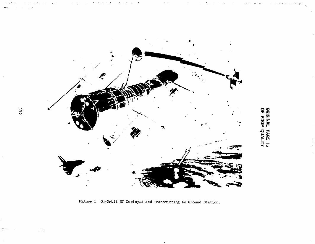
530
i
1985025199-331

HIGH GAIN ANTENNA
ANTENNA
GRAPHITE/ALUMINUMMAST FWD
PASSIVE HINGE _-_ f /_ACTIVE HINGE
___,___ (AC TUA TOR DRIVEN)
'" 1 "
SPACE
APERTUREDOOR__<"\ACTIVE HINGE(ACTUATORDRIVEN
: PASSIVE HINGE
Figure 2 Stowed ST, Close-up of Two Deployed Appendages,
_ 331 ,;
1985025199-332
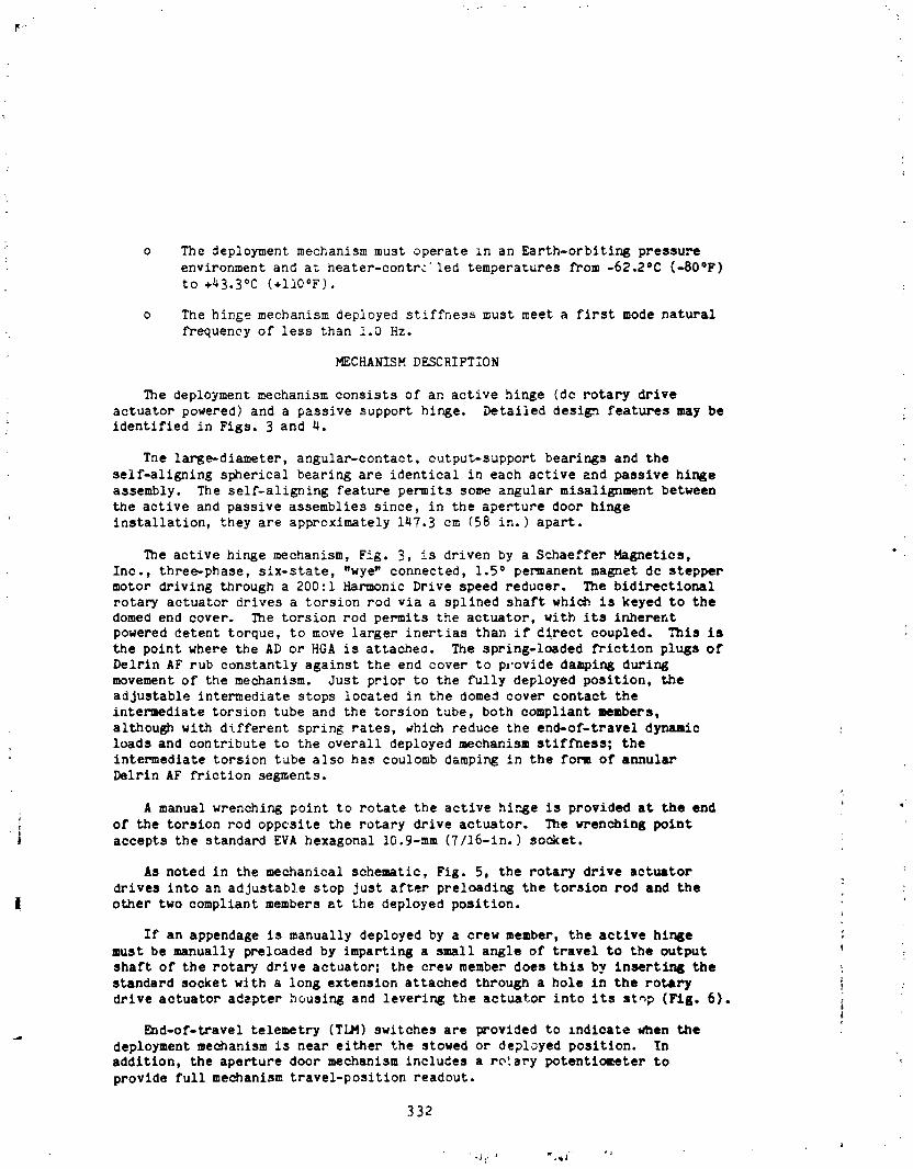
o The deployment mechanism must operate in an Earth-orblting pressu:-e
environment and at heater-contr_ led temperatures from -62.2°C (-80°F)
to +43.3°C (+II0°F).
o The hinge mechanism deployed stiffhess must meet a first mode natural
frequency of less than 1.0 Hz.
MECHANISM DESCRIPTION
The deployment mechanism consists of an active hinge (dc rotary drive+
actuator powered) and a passive support hinge. Detailed design features may beidentified in Figs. 3 and 4.
The large-diameter, angular-contact, output-support bearin6s and the
self-aligning spherical bearing are identical in each active and passive hinge
assembly. The self-aligning feature permits some angular mlsaliEnment between
the active and passive assemblies since, in the aperture door hinge
installation, they are approximately 147.3 cm (58 in.) apart.
The active hinge mechanism, Fig. 3, is driven by a Schaeffer Magnetics,
Inc., three-phase, six-state, "wye" connected, 1.5 ° permanent magnet de stepper
motor driving through a 200:1 Harmonic Drive speed reducer. The bidirectional
rotary actuator drives a torsion rod via a splined shaft whic_ is keyed to thedomeO end cover. The torsion rod permits the actuator, with its inherent
powered detent torque, to move larger inertias than if direct coupled. This is
the point where the AD or HGA is attacheo. The spring-loaded friction plugs of
Delrin AF rub constantly against the end cover to p,,ovide da_ing duringmovement of the mechanism. Just prior to the fully deployed position, the
adjustable intermediate stops located in the domed cover contact the
intermediate torsion tube and the torsion tube, both compliant members,
although with different spring rates, which reduce the end-of-travel d_o
loads and contribute to the overall deployed mechanism stiffness; the
intermediate torsion tube also has coulomb dampi_ in the form of annularDelrln AF friction segments.
A manual wrenching point to rotate the active hir_e is provided at the end
; of the torsion rod oppcsite the rotary drive actuator. The wrenching point
i accepts the standard EVA hexagonal lO.9-mm (7/16-in.) socket.
As noted in the mechanical schematic, Fig. 5, the rotary drive actuator
drives into an adjustable stop just after preloadinE the torsion rod and the L
l other two compliant members at the deployed position.J
If an appendage is manually deployed by a crew member, the active hlnge ,'
must be manually preloaded by Imparting a small angle of travel to the output _shaft of the rotary drive actuator; the crew member does this by insertir_ the _
standard socket with a long extension attached through a hole in the rotary _ .,
drive actuator adapter housing and levering the actuator into its stop (Fig. 6). i
End-of-travel telemetry (TLM) switches are provided to indicate when the
deployment mechanism is near either the stowed or deployed position. Inaddition, the aperture door mechanism includes a rotary potentlometer to
provide full mechanism travel-position readout.
332
i
1985025199-333

r
3
i ORIGINALp:,;.:.: r,i! oFPOORQuA_,_,_
' _" SELF-ALIGNING SPHERICALBEARING
INTERMEDIATETORSION TUBE
FRICTION'i TORSION TUBE PLUGS
ACTUATOR STOP_ BACKUP(HIDDEN) MANUAL
MANUAL PRELOAD DRIVE
POINT --_
(HIDDEN)_
COVER
_NNULAR'_ FRICTION
_ SEGMENTS "
! CONTACT' BEARINGSJ
TORSION ROD
. POTENTIOMETERI
-'- " ROTARY DRIVE_. STOP PLATE
i (HIDDEN)
ROTARY DEPLOYED/STOWED
-|I DRIVE TIM SWITCHES
i ACTUATOR
i Figure 3. Active Hinge Asaembly,
333
i
1985025199-334
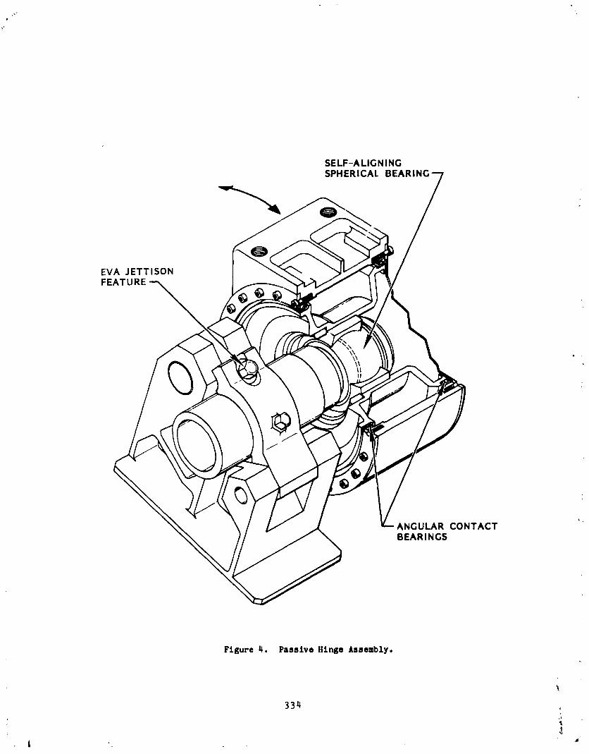
SELF-ALIGNINGSPHERICAL
EVA JETTISON
FEATURE --_
ANGULAR CONTACTBEARINGS
Figure 4. Passive Hinge Assembly.
334
j"
1985025199-335

The self-aligning bearing not only provides mechanism misalignment
correction capability, but also acts as a redundant rotational bearing to the
two angular contact bearings. Note that the angular contact bearing inner
races are supported on a "zee" _ection spring diaphragm support. This provides
some compliance between the inner and outer components as the mechanism goes to
orbital temperatures where different material coefficients of thermal expansion
(contraction) could cause additional bearing loads. The zee shape deflects
sufficiently to maintain only a slight increase in bearing preload at thecoldest orbital temperatures.
Bray Oil Co. wet lubricants, Brayco Micronic 815Z oil as well as their
Braycote 3L-38RP (Braycote 601) grease are used to lubricate vital componentswithin the mechanism, including the rotary drive actuator as well as the
potentionmeter. The large angular contact bearings are lubricated with a
solvent-thinned solution of the Braycote 3L-38RP grease (grease plating), thenvacuum-baked, leaving a thin, evenly distributed film of the lubricant.
The passive h_nge, Fig. 4, uses the same rotational bearing support, exceptfor one additional feature: the 15-5 PH stainless steel stub shaft is
permitted to slide along the axis of rotation of the inner race of the
stainless steel spherical bearing. A groove is cut into the shaft, providing areservoir for Braycote 3L-38RP grease. The sliding feature is important for
t
the AD use of the mechanism since the active and passive hinges are
approximately 147.3 cm (58 in.) apart and small temperature gradients between
the large aluminum honeycomb door and the 3.05-m (lO-ft)-diameter spacecraft
structure change the width between the two hinge assemblies. The sllp feature
then accommodates this dimensional change.
Both active and passive hinge assemblies carry radial loads via the
bearings; however, only _he active hinge resists thrust bearing loads (parallel
to hinge line), and they are carried out through a conical pin installed in the
hinge support bracket and seated in the outer support tube of the mechanism.
HINGE MECHANISM OPERATION
The rotary drive actuator is a current-controlled device which also has its
step rate (pulses per second), rotational angular travel (total steps), and
direction of travel controlled. For the two deployment mechanisms deacrlbed
here, the actuator is driven at two rates, e_ther 30 pulses per second(0.23 deg/sec), or 300 pulses per second (?.25 deg/sec), or a sequential
oomblnation of the two. The total travel angle in ei_ler use Is IQsa than one
revolution; 92.7 • to deploy/stow the HGA or 105.3 ° _o open/close the AD, Theelectronic control unit commands the travel angle to the stepper motor via a
predetermined number of steps which includes approximately 1000 more steps thanare actually needed to reach the co_anded position. This assures more than
sufficient steps for any contingency.
The deployment sequence is initiated by driving the actuator at the desired
stepping rate, which relieves a slight stowed preload in the torsion rod. With
the preload relieved, the actuator begins winding up the torsion rod, which
335
1985025199-336
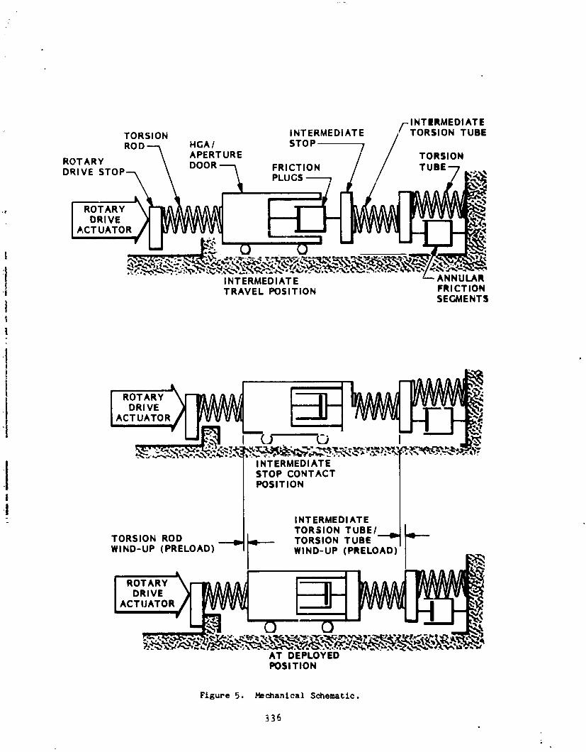
/-INTERMEDIATETORSION INTERMEDIATE /--TORSION TUBEROD --_ HGA/ STO P --------- 7 /OT_ \ ___ ,u,,7DOOR FRICTION •DRIVE STOP "-"-_ F,LUCS _
I ROTARY _I DRIVE ,_ _'_YA'_'(/,_,_,IJ /"-"1 I'-'! I|__II r --,,_-_ "_IACT°^,'o,, , ,
i
INTERMEDIATE'I! TRAVEL POSITION FRICTION
i SEGMENTSti
AT DEPLOYEDPOSITION
Figure 5, Mechanical Schematlc.
336
1985025199-337
Figure 6. Hanually Preloadlng Meehanlsm,
337
i
1985025199-33_
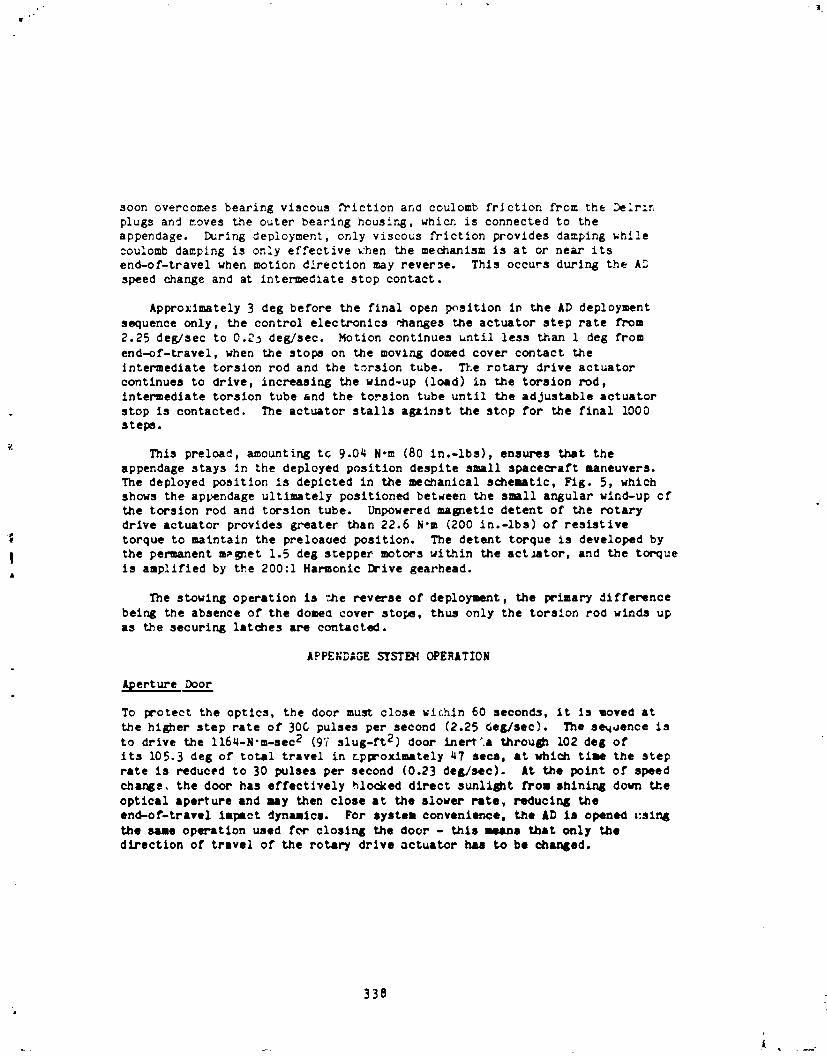
soon overcomes bearing viscous friction and coulomb fr_ction from the Delrln
plugs and moves the outer bearing housing, which is connected to the
appendage. I_rlr_ deployment, only viscous friction provides damping while
:oulomb damping is only effective khen the me_anlsm is at or near itsend-of-travel when motion direction may reverse. This occurs during the AD
speed change and at intermediate stop contact.
Approximately 3 deg before the final open p_sltlon in the AD deployment
sequence only, the control electronics Manges the actuator step rate from
2.25 deg/sec to 0.2j de_sec. Motion continues until less than 1 deg from
end-of-travel, when the stops on the moving domed cover contact the
Jntermedlate torsion rod and the torsion tube. The rotary drive actuatorcontinues to drive, incr_asir_ the wind-up (load) in the torsion r_d,
intermediate torsion tube and the torsion tube until the adjustable actuator
stop is contacted, be actuator stalls against the stop for the final iO00
steps.
1_nls preload, amounting tc 9.04 N.m (80 in.-Ibs), ensures t_t the
appendage stays in the deployed position despite small spacecraft maneuvers.be deployed position is depicted in the mechanical schematic, Fig. 5, which
shows the appendage ultimately positioned between the small ar_ular wind-up ofthe torsion rod and torsion tube. Unpowered malefic detent of the rotaury
drive actuator provides g_-eater than 22.6 N'm (200 in.-ibs) of resistive
| torque to maintain the preloaued position. _'ne detent torque is developed by
| the permanent m_et 1.5 deg stepper motors within the actmtor, and the torqueis amplified by the 200:1 Harmonic Drive gearhead.
The stowing operation is "_hereverse of deployment, the prlmary difference
being the absence of the domec cover stops, thus only the torsion rod winds upas the securing latches are contacted.
APPENDAGE S"tST_ OPERATION
Aperture Door
To _'otect the optics, the door must close wlc.hin 60 seconds, it is moved at
the higher step rate of 30C pulses per second (2.25 _e_;/sec). The se_oence is
to drive the ll6,-N'm-sec 2 (97 slug-ft 2) door inert'a throu_ 102 deg of
its 105.3 deg of total travel in _pproxlmately 47 secs, at which time the steprate is reduced to 30 pulses per second (0.23 deg/sec). At the point of speed
cha_s, the door has effectively _locked direct sunli_t from shln_ng down the
optical aperture and may then close at the slower rate, reducing theend-of-travel impact dynamics. For syste_ convenience, the £D is openeO _:sln_the sue operation used for closing the door - this _a t_t c_ly the
direction of travel of the rotar7 drive actuator h_ to be cha_ed.
338
1985025199-339
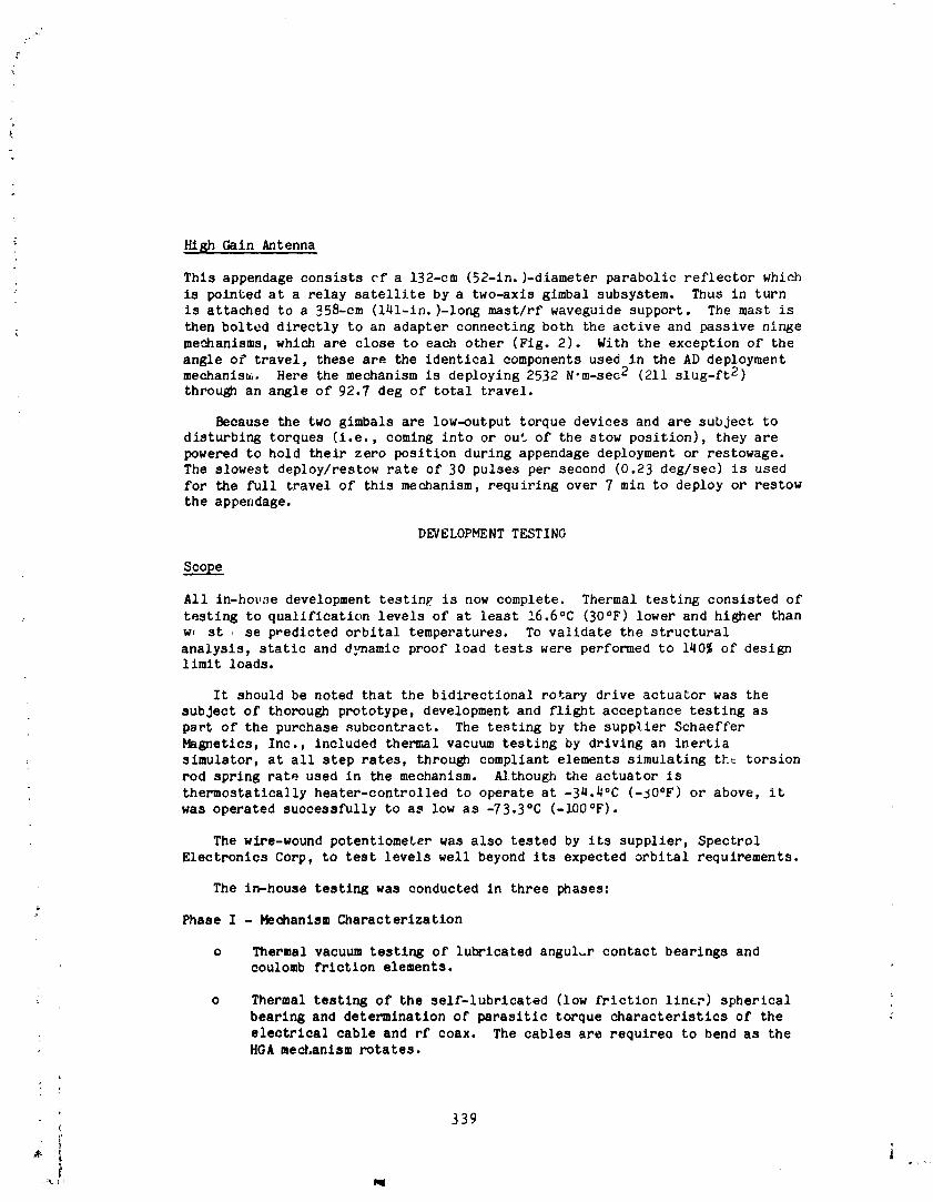
High Gain Antenna
This appendage consists cf a 132-cm (52-in.)-diameter parabolic reflector which
is pointed at a relay satellite by a two-axls glmbal subsystem. Thus in turn
is attached to a 358-cm (141-in.)-long mast/rf wavegulde support. The mast is
then bolted directly to an adapter connecting both the active and passive nin_e
meehanlsms, which are close to each other (Fig. 2). With the exception of the
angle of travel, these are the identical components used in the AD deploymentmechanism. Here the mechanism is deploying 2532 N'm-sec 2 (211 slug-ft 2)
through an angle of 92.7 deg of total travel.
Because the two gimbals are low-output torque devices and are subject todisturbing torques (i.e., comlng into or out of the stow position), they are
powered to hold their zero position during appendage deployment or restowage.
The slowest deploy/restow rate of 30 pulses per second (0.23 deg/sec) is used
for the full travel of this mechanism, requiring over 7 min to deploy or restow
the appendage.
DEVELOPMENT TESTING
scope
All in-ho_,se development testln£ is now complete. Thermal testing consisted of
testing to qualification levels of at least 16.6°C (30°F) lower and higher thanw, st se predicted orbital temperatures. To validate the structural
analysis, static and d:_amlc proof load tests were performed to 140% of designlimit loads.
It should be noted that the bidirectional rotary drive actuator was the
subject of thorough prototype, development and flight acceptance testing as
part of the purchase subcontract. The testing by the supplier Schaeffer
Magnetlcs, Inc., included thermal vacuum testing by driving an inertia
simulator, at all step rates, through compliant elements simulating tht torsion
rod spring rate used in the mechanism. A/though the actuator is
thermostatlca]ly heater-controlled to operate at -3_.4°C (-50°F) or above, it
was operated successfully to as low as -73.3°C (-100°F).
The wiFe-wound potentiometer was also tested by its supplier, Spectrol
Electronics Corp, to test levels well beyond its expected orbital requirements.
The in-house testing was conducted in three phases:
Phase I - Mechanism Characterization
o Thermal vacuum testing of lubricated anguLr contact bearings andcoulomb friction elements.
o Thermal testing of the self-lubricated (low friction liner) spherical
bearing and determination of parasitic torque characteristics of the
electrical cable and rf coax. The cables are requirec to bend as theHGA med_anlsm rotates.
339(
]985025]99--340
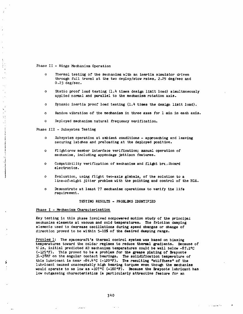
Phase II - Hinge Mechanism Operation
o Thermal testing of the mechanism with an inertia simulator driven
through full travel at the two deploy/stow rates, 2.25 deg/sec and0.23 deg/sec.
o Static proof load testing (1.4 times design limit load) simultaneously
applied normal and parallel to the mechanism rotation axis.
o Dynamic inertia proof load testing (1.4 times the design limit load).
_ o Random vibration of the mechanism in three axes for 1 mln in each axis.
: o Deployed mechanism natural frequency verification.
i Phase III - Subsystem Testing1}
i o Subsystem operation at ambient conditions - approaching and leavingsecuring latches and preloading at the deployed position.
o Flightcrew member interface verification; manual operation ofi mechanism, including appendage Jettison features.i
i! o Compatibility verification of mechanism and flight bre_Jboard, electronics.
t o Evaluation, using flight two-axis gimbals, of the solution to a
line-of-sight jitter problem with the pointing and control of the HGA.
o Demonstrate at least 77 mechanism operations to verify the llfereq uirement.
TESTING RESULTS - PROBL_dS IDENTIFIED
Phase I - Mechanism Characterization
Key testing in this phase involved nonpowered motion study of the principal
mechanism elements at vacuum and cold temperatures. The friction damping
elements used to decrease oscillations during speed changes or change ofdirection proved to be within 5-10% of the desired damping range.
Problem i: The spacecraft's thermal control system was based on biasingtemperatures toward the colde; regimes to reduce thermal gradients. Because of
t:is, initial predicted AD mechanism temperatures could be well below -87.2oC
(-125OF). This proved to be a problem for the grease plating of Braycote
3L-38RP on the angular contact bearings. The solidification temperature of
this lubricant is near -84.4°C (-120°F). The resulting "stiffness. of thelubricant caused unacceptably high bearing torques even though the mechanism
would operate to as low as -iO7°C (-16OOF). Because the Braycote lubricant has
low outgassing characteristics (a particularly attractive feature for an
340
1985025199-341

ORIGINAL PAGE ISOF POOR QUALITY
P
Flgtwe 7. HingeOperation w:L_ Cold Box,
3_I- i
LL
1985025199-342
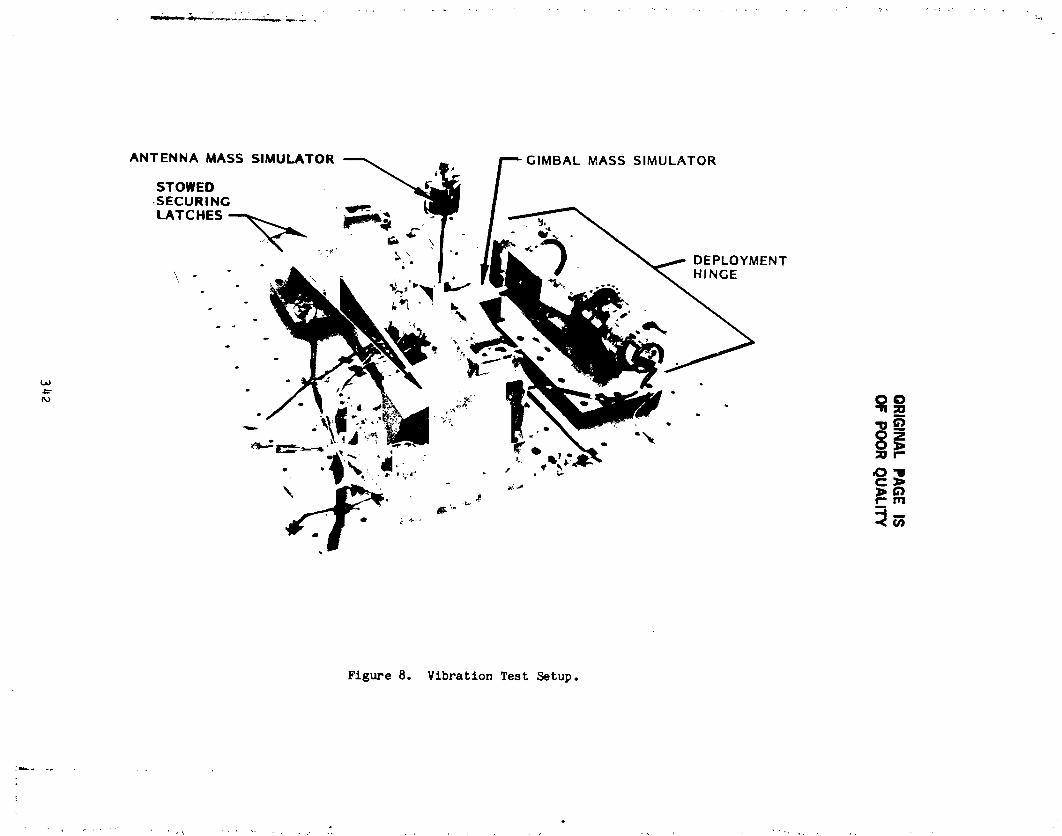
OR
IGIN
AL
PA
GE
IS
OF
PO
OR
QU
AL
ITY
342
1985025199-343

ORIGINAL PAGE ISOF.POORQUALITY
!
I
_ _--ANTENNA DISH f ZERO "G" LINE DEPLOYMENT
_'_' L SIMULATOR HINGE
%" h WAVE GUIDE
l _ TWO AXIS
_ GIMBAL STOWED _
SECURING
LATCHES
LATCH
INTERFACE
(2 PLACES)
Figure 9, HGAAppendage Test Setup.
343
¢
.t1,
1985025199-344
_" optical system) and because of a desire to avoid a lengthy lubrication
development program, heaters capable of keeping the mechanism at a temperature
of -62.2°C (-80°F) or above were installed to solve the problem. The addition
of heaters to both the active and passive hinge mechanisms for the AD assured
: consistent operation for this important appendage. The HGA mechanism is not
fitted with heaters (other than the one on the rotary drive actuator) since
predicted cold operation is -47.2°C (-53°F) or above.
Thermal testing of the self-alignlnE spherical bearing was needed since
(I) it is the redundant rotational feature to the angular contact bearinp and
(2) no cold-test data were available from the supplier. The cold-testlng
results were acceptable and the bearing torque contribution was factored into
the overall mechanism torque margin.
Likewise, a cold test of the HGA power and TLM data cable, routed across
the mechanism along with the rf coax from the mast/wavegulde, showedacceptable parasitic torque contributions. This series of tests sensed the
torque contribution of the cable routir_, as a function of temperature, overthe full an_ular travel range of the mechanism.
; Phase II - Hinge Mechanism Operation
This series of tests involved mechanism operation over the full range of travelat hot and cold temperatures and with the test specimen connected to inertia
simulators representing both the HGA and the AD. The mechanism rotational axis
was mounted vertically and the additional weJ _ht was supported by a zero "G"
line pivoting in line with the mechanism rotational centerline. A cold box was
constructed around the mechsnism (Fig. 7); the rotary drive actuator was keptoutside the test environment so the mechanism operation contributors could be
identified directly.
This test phase permitted verification of the analytical model as well as
providing a test bed for a two-axis, static-proof test and a deploy-dlrectlon,
dynamlc-proof test. These tests at ambient temperature were preceded and
followed by functional operation and no anomalies were identified.
The deployed and preloaded natural-mode frequency of the mechanism wasverified during this test phase to be 0.875 Hz, below the l.O-Hz maximum.
: : The deployed or open position of the mechanism was also verifled duringthis test phase and was shown to be repeatable within 0.033 deg, well within
the AD position accuracy needed of +0.25 deg.
• The final phase of this test series centered on a three-axis vibration test
using the mechanism configured for the HGA usage (Fig. 8). The mechanism was
connected via a short tube to a pivoted mass simulating one of the two-axls
344I
t _
1985025199-345

gimbals. The assembly was then secured by fllght-like development latches.The antenna dish was also represented by a mass simulator. The rotary driveactuator was monitored during the test to sense unacceptable mechanism motionand none was detected during all three orientations of the vibration test. An
ambient functional test, performed after each axis was tested, revealed nodamage to the mechanism.
Phase III- Subsystem Testing
, This test phase addressed, in particular, the HGA configuration and itsdeployment and restow. Figure 9 shows this setup which included thepreproduction mast/waveguide, a foam-core simulation of the antenna dish, andthe pair of securing latches. The configuration was initially fitted withnonpowered gimbal simulators; these were later replaced with flight gimbals forthe last segment of this test phase.
Problem 2: The first portion of this test sequence was plagued by a problemthat was finally diagnosed as "lost motion", which resulted in variableperformance at the stow position. As the mechanism drives into the stowposition, it must be positioned correctly for the latches to "capture" andsecure the appendage. This involves also tripping four telemetry switcheswhich indicate to the ground station when the latches may be closed, a separateoperation. Althou@h always within latch "capture" range, the inconsistantperformance needed correcting.
"Play" in the keyway tying the torsion rod to the domed aluminum cover was
de&emmlned to be the cause, and once corrected by small shims in the keyway,consistent and reliable results were demonstrated. A redesign, however, wasinitiated to effect a long-term solution to compression yielding of thealuminum portion of the cover interface brou@ht on by numerous manualdeployments and stowlngs. The solution selected was to provide a conical ortapered flt-up of the 15-5 Ph stainless steel torsion rod to the aluminum domed
houslng. The tight friction fit in conjunction with the keyway assures a"no-lash" Joint. (See Reference 1 for an in-depth discussion of this designfeature.)
Because the Hubble Space Telescope is designed to be compatible with the_huttle crew members, it was important to demons+_-ateand verify crew member
; interfaces, including manual deployment and resto _of the appendages. Two crewmember foot restraints are located to permit lifting or pulling on the longmast/wavegulde for manual deployment or stowage. If a Jettison of the
appendage should be required, one crew member must first disconnect the wingtab electrical harness connectors, then back off the two bolts securing thejettison clamp-halves, while another crew member pushes the append.,geaway fromthe spacecraft. All of these interfaces were verified and were shown to
•: function satisfactorily.
345
i :
1985025199-346
During this test, the flight breadboard mechanism drive electronics became
available and this interface was also successfully validated. A specifically
built drive electronics panel is normally used for devel_,pment testing and hasfaithfully represented the interface as confirmed by the breadboard check.
The final portion of testing was to fit a flight pair of gimbals to the HGA
appendage to validate a solution to a control problem in pointing the antennas
at the relay satellite. Testing with fullypowered and computer-controlledgimbals did confirm the design solution which involved counterbalancing the
offset mass of the antenna dish about the outboard gimbal rotation axis
(F_g. 9). Additionally, with the fully powered gimbals, it was feasible to
demonstrate a simulated on-orbit deployment and restowage.
One final note to the total tests completed in the various environments: a
70% life margin was demonstrated for the mechanism and, other than the problems
noted, partial disassembly has revealed no areas of concern.
TESTING STATUS
All development testing to qualification temperature and load levels has
been successfully completed. Acceptance testing of the three flight hingemechanisms is scheduled for the first quarter of i985. Detail fabrication and
assembly is complete.
Future system-level testing, will include functional demonstrations before
and after an acoustic test and during a month*long thermal vacuum test.
CONCLUSIONS
A deployment mechanism has been designed, tested and has demonstrated its
versatility to move two large appendages, one twice the inertia of the other
and one deployed at an angular rate lO times that of the other, with a common
i design utilizing a single rotary drive actuator. Two significant designproblems have been overcome with minimum disruption to the program in terms ofcost and schedule.
ACKNO_hEDG_NT
._neauthor wishes to thank the National Aeronautics and Space
Administration, Marshall Space Flight Center, for their permission to publish
this paper and to acknowledge the contributions of the engineering staff atLocKheed Missiles and Space Co and in particular H. F. Schmidt and D.T. Packard
(now of Jet Propulsion _aboratory) for their early Oesign work leading to a
successful flight mechanism.
REFERENCE
i. Angle, Thomas L., "Analyzing Taper Fits", Machine Desi6n , February 24,1983, Vol. 55, No. 4.
346
1985025199-347

N85-33534
! SIX MECHANISMS USED ON THE SSM/I RADIOMETER
Howard R. Ludwigm
ABSTRACT
Future USAF Block 5D Defense H_teorological Satellites will carry ascanning microwave radiometer sensor known as SSM/I. SSM.I senses theemission of microuave energy and returns to earth data used to determineweather conditions, such as rainfall rates, soil moisture, and oceanic windspeed.
The overall design of the SSM/I radiometer was largely influenced by themechanisms. The radiometer was designed to be stowed in a cavity on theexisting spacecraft. The deployment of the sensor is complex due to the
constraint of this cavity and the need for precision in the deployment. Theradiometer will continuously rotate, instead of oscillate, creating the needfor a bearing and power transfer assembly (BAPTA) and a momentum compensationdevice. The six mechanisms developed for this program are described in thispaper.
i. INTRODUCTION
Future spacecraft of the USAF Defense Meteorological Satellite Program(DM_) will carry a passive microwave radlometrlc system known as the specialsensor microwave/imager (SSH/I). It is a seven channel, four frequency,linearly polarized, passive system. The SSM/I measures ocean, atmospheric,and land surface brightness temperatures. The Air Force Air Weather Serviceand the Naval Oceanography Command will process these data to obtainprecipitation maps, oceanic wind speed, sea ice morphology, and sell moisturepercentage. Figure i illustrates the SSN/I integrated into the DMSP satellite.
2. SSM/I OVERALL_CHANICAL DESIGN
The existing DHSP Block 5 spacecraft had only two possible lucations to
stow the sensor. Potential designs were made to use these locatlons. Foreach of these designs, mechanisms were selected. The final selection was
based on an efficient, low-rlsk system. Figure 2 illustrates the selectedsensor in stowed and deployed configurations. The mechanisms had a majorinfluence in the overall design of the sensor. These account forapproximately 30 percent of the weight of the SSM/I. The stowed volume is
approximately 20 percent of the deployed on-orbit swept volu_e.
One of the major decisions was in the manner of scanning. It was decidedto continuously rotate the sensor at 31.6 rpm to provide 103 ° of uninterrupted ,earth scan. As the sensor rotates beyond this range, the sensor passes a hotload and a cold apace reflector that calibrate the serisor. This method ismore efficient and accurate than a back and forth or oscillating reflector.Continuous rotation of the sensor adds uncompensated momentum to the
s Hughes Aircraft Company, E1 Segundo, California
1/
1985025199-348
spacecraft. Preview- studies (Ref. 1) su_ested use of gear or belt drivencounterrotati-g masses to compensate for sensor momentum. A trade-off studyfor providing compensating momentum determined that an existing momentum wheelwould be more reliable and efficient than the previously proposed devices.Developing a geared or belted system for a 3-q year life was felt to be toorisky. The momentum wheel could be located in a separate compartment of thespacecraft to help its balance and not take up volume in the location chosenfor the sensor.
Deployment of the SSM/Z is unique. First, the whole sensor is deployed f_omthe spacecraft. The reflector is then released and rotated 170 ° by thereflector deployment mechanism. At that point a four-bar linkage is engagedwhich translates the reflector into its final location (Figure 3). Thissequence does not interfere with the view of the DM_'s other sensors. Sixmechanisms are used on the SSM/I: bearing and power transfer assembly,momentum wheel, three deployment mechanisms, and pyrotechnic devices.
3. _CHANISMS
_.i Trlbologtcal Design
In the design of mechanisms there are two general philosophies (usuallyunstated) on the tribologtcal aspects. One is to perform the electrical andmechanical dea_igns and to then add the lubrication method. The otherapproach, and the one used on the SSM/I mechanisms, is to consider thetribologioal aspects of the design f_om Inception. The general type oflubrication is chosen early in the design, and compatible materials areselected. The final lubricant is based on requirements such as temperature,load, and speed.
3,2 Bearing and Power Transfer Assembly
Continuous rotation of the SSM/I sensor is provided by the BAPTA(Figure _). The BAPTA developed for this program has some unique features,but it was baied on existing technologies. The BAPTA provides rotatingmechanical and electrical interfaces between the spinning and stationary
i set,lens of the sensor. The physical characteristics are shown in TaLble 1.._, 4
The trtbolo_tcal design of the 33M/I BAPTA uses state o1: _he art
i teohnolo_. A pair of CEVM q40C angular contact bearings with patentednitrileaorylio oopolyaer retainers (Refs. 2-3), in an open cell configuration,are used. Stainless steel stdeplates provide the required mechanicalstiffness and 8tre_th. The copolymer material has a large capac_tty For oilstorage (Fibre 5).
Kach bearln8 is lubricated with _3 20-1727 o11, which is s highlyrefined, low vapor pressure, Ltneral oil with a 5 percent lead naphthanateextreme pressure additive. The nitrile-aoryltc copolymer with this o_1 is nowat the 9 year Bark in a oontlnuir_ life test and has been successfully flovnon the Pioneer Venus, 0143II, and OOE_ prosrm.
348
|d
1985025199-349

The electrical power and signal transfers are through slip rings made of
silver and brushes of a self-lubricating material made of 85 percent silver, 3percent graphite, and 12 percent molybdenum disulfide. Based on the wear rate
from a IO year llfe test, these brushes will last more than i00 years.
3.3 Deployment Mechanisms
3.3.1 General Design Philosophy. There are two general approaches to thedesign of spring-driven deployment mechanisms for delicate appendages or
devices that have to point precisely. One method is to use a deployment
spring that is only slightly stronger than the resistive torque. This is done
to avoid shock damage at the end of stroke. A great deal of testing andadjustments are usually associated with this approach. The second approach isto employ very large _orque margins and to rate-limlt the deployment. This is
accomplished by viscous or eddy current damping. The bottom llne of the
trade-off study indicates that the high torque margin rate limited method is
more reliable and easier to test at the expense of weight. Although thesimple spring mechanism is less costly as a unit, the overall cost is usually
higher due to the complexity of testing ".,idneed for exotic offloaders for
system level testing.
The use of the high torque margin was chose for SSM/I so that there would
be no risk of a failure to deploy. Additionally, all tests were performed in
IG without offloaders. Thls was accomplished by mounting the sensor with the
deployment hinge in line with the gravity vector for each deployment.
3.3.2 Viscous Damping. The deployment mechanisms for SSM/I are multispeed.There was a system requirement that all deployments be made in a i0 minute
period and also a self-imposed rate requirement to keep the precision and
repeatability. The two wer_ not compatible with a single speed device. In
order to make the mechanism multi_peed, the damping gap is varied. The
radiometer deployment mechanism (RDM) has two speeds and the antennadeployment mechanism (ADM_ has four speeds (two fast and two slow) to mee_ the
time requirement at cold condition.
The two main deployment mechanisms for SSM/I are rotary viscous damped.
These devices combined the features of the pivot hinge and bearings,
deployment springs, viscous damper, and hard stops into one unit. The
mechanisms are powered by redundant laminated spring sets. They feature
redundant sprlng-loaded tapered latch pins to provide a positive lock at
latch-up and adjustable hard stops to ensure positioning accuracy. These
i actuator designs have evolved from the basic JPL concept originally developed
for Mariner '71 and Viki g Orbiter to their current compact third ge_eratlon
design (Ref. _).
The actuator mechanism consists of a housing, two end plates containing
O-ring seals, and a stator shaft with integral damping paddles. These are all
made of aluminum. A take-up reel is provided for the deployment springs. The
dimethyl silicone fluid of O.l m2/s kinematic viscosity provides damping. Areservoir compensates for the change of fluid volume with temperature.Figure 6 is a cutaway view of an actuator.
349
1985025199-350

Double paddle wheels are used for deployment angles less than 130 ° and a_ngle paddle is used for angles greater than 130 °. The nouslng rotatesabout the slator shaft. Torque is s_pp_ied by the constant torque deployment
springs. Damping is provided by flow of the damper fluid from the high
pressure side of each paddle, through the gaps between each paddle and the
housing, into the low pressure side. The majority of the damping comes fromthe flow of fluid through these orifices (the gap between each paddle and the
housing), while the remainder is due to viscous shear.
The main pivot ball bearings are _eleoted to provide proper stiffness and
strength. Lubrication of the deployment devices is a combination of wet and
dry. The main bearings are in the silicone fluid. The laminated springs,
take-up reel bearings, and latch pins are lubricated wlth sputtered Ho_(Ref. 5). The tips of the latch pins are made of a self_lubrlcatlng plasticmat-rial.
3.3.3 Radiometer Deployment Mechanis_. Deployment of the 3_q/l radiometer
from the stowed position is accomplished by the RDH. The pyroteohnlc devices
at the base plate are fired, releasing the radiometer. The RDH rotates the
•ensor 90° about the deployment axis, bringing the BAPTA spin axle parallel
to the local vertical. Tapered latch pins drop into place to braes the
radiometer in the deployed position. Completion of the deployment Is
indicated by a normally closed microswitch which opens as the latch pln dr_psinto place. Adjustable hard stops control the deployment angl_ and
repeatability of the deployment angle. Figure 7 shows the RDH. As can be
seen, the mounting base for the radiometer was made integral with the RDH.
Table 2 provides test results for the englneerir_, qualification, and thefirst flight models. Figure 8 shows a typical deployment anglo versus time
plot for the RDM. As can be seen, the first (70° ) Is at a rate ofO.q rad/s and the last (20 °) at a rate of O.Oq rad/s.
3.3.4 Antenna Deployment Mechanism. after the radiometer has been deployed
from the spacecraft, the antenna is released by firing another _t of
pyrotechnic devices. The antenna is then driven 170 ° about the first
antenna deployment axis by the deployment springs. As the antenna reaches
this fully extended position, a four-bar linkage is engaged. The antenna isthen translated into the operating position. Again, tapered latch pins are
engaged and microswltches are closed to indicate latch-up (Figure 3). Thedeployment scheme is a result of a customer imposed requ_resent that othersensors on the spacecraft not have their fields of view obscured by _4/Iduring its deployment. Table 3 summarizes the teat results.
3.3.5 Bias Momentum Wheel Assembl Z. The specification for the _{/Iradiometer required no unbiased momentum from the radiometer system. Thechoice of using a continuously rotating antenna, together with the unbAaaedmomentum specification, led to incorporating a bias momentum vheel Into the
design.
350
i
1985025199-351

The momentum compensation system, an independent open loom aomcntum wheeland a continuously rotating radiometer, was compared with meehanioall.y coupledmomentum wheels through sear or belt drives. These alternatives wereelimlnated as a result of radiometer Jitter caused by the coupling system, drylubricant llfe limitations, and velume constraints. Gear or belt drive
*" linking the radiometer to the compensation wheel would feed back any Jitter tothe radiomeuer spin control loop inducir_ rate errors. It would also resultin an excessive we!gl_t penalty (for gear ratios near unity) or excessivenumber of revolutions of the compensation wheel (for gear ratios of 50 or_re). Dry film gear lubricant is not co_patlble with a 3-q year llferequirement. Wet lubrication could be _mployed, but would require _naddltio_al sealed housing, adding complexity and weight. Otheraelf-lubrlca'ir_ gear meterlala would require extensive development and llfetesting. Belt drives similar to those used on JPL designed radiometers wereconsidered, but aSaln additional development/ills testing would be necessal_',to meet reliability requirements. Discussions with other aerospace companypersonnel have indicated the critical nature of belt drive details to
reliability. Tt was unlikely that a belt drive system development programcould be satisfactorily accomplished during the lq month SSH/I developmentperlod.
The momentum required to compensate for the SSM/I in nominally 3.0 N •m. Therb were several commercial momentum wheels in this size range. Thefinal momentum specified can be adjusted over the range of 2.75 to 4.25 N •m in 205 increments by final adJustmen_ of the drive electronics. The desiredspeed of the momentumwheel Is programmed by using 10 Jumpers on a programming.m_eotor plus. This system allows final selection and momentum adJustmerts
_:_c4hthe momentum of the radiometer as the two are integrated. T_ ",_ 4
,t _e'tee the characteristics of the momentum wheel, and Figure 9 shows themomentum wheel with its drive electronics.
3.4 Simple Deployments
When proolslon pointing or end of stroke shock are not important, simpleundamped deployments are ample. The fact that a deployment is without ratecontrol doe,_ not mean t:_t the details of deslF- and lubrication are not
j important. The materials should be selected with brioatton in mind and thedrive sprJ._4_ should be redundant. In the case of _M/T, there are two such 'derloyments •
3._.1 Lubrication AsPects. The general lubrication technique used on almpledeployment meoha_lamm Is to choose shaft and bushing or pivot materials thatwill not gall. For example, a hard stainless steal pin and a hard anodizedalmainum bearing have to be used on most of the S3H/I pivot Joints. All
rubbing st'-faoea and springs are then sputtere_ with _3 2 to give a lowcoefficient Of friction. This combination of materlala and lubricants hasbeen reliable and trouble-free throughout the development and hardwareprogram.
35_
, i
1985025199-352

3.4.2 Launch Support Bracket Deployment. The SSM/I antenna is held in the
_ stowed position with a pyrotechnic device. The launch support bracket is aswing-away structural member. The loads from the antenna are passed through
_ this bracket into the radiometer structure. Upon firing the pin i.ullers, the
launch support bracket pivots ]35 ° and is held in place by the redundant
deployment springs. The springs and part of the bracket can be seen inFigure I0.
3.4.3 Cold Sky Reflector Depl_. The SSM/I radiometer is calibrated eachrevolution. An ambient hot load and reflected cold space are viewed by the
sensor each revolution. The cold sky reflector can be seen in Figure i0. It
is the small reflector on the top surface of the sensor body. During launch
it is stowed under the larger antenna. It is kept from deploying by a strip
of self-lubricating plastic material attached to the back of the main,eflector. As the r,lainreflector deploys approximately 45°, the cold sky
reflector is no longer restrained and rapidly rotates to its deployed position.
3.5 P[rotecnnic Release Devices
The selection of pyrotechnic release device types is dictated by loca_ions
and mass properties of the items to be released and the amount of preloading
required. For SSM/I an additional requirement of pyrotechnic redundance wass-ccified.
The SSM/I is secured to its bate plate by two independent redundant pyro
lock systems, and is preioaded againat four posts attached to the spacecraft
interface mounting plate (Figure ii). Launch locking in this fashion providestwo distinct advantages. First, pulling down the spinning portion of the
_ensor against the base provides rigid nesting without carrying undue loads
through the radiometer deployment mechanism bearings of the BAPTA bearings.Second, the launch loads, spread ove_ a large area of the spacecraft panel,
place no local moment loading on this panel.
The two pyro systems with redundancy pro_islons have been fully qualifiea
and flown on the NASA Pioneer Venus peogram. The same hardware was : "ed.
Redundant pint pullers tie down a "whiffle tree': fitting so that retraction of
either pin will release the loau. The pins are in double shear. With this *
dual system, retraction of either pin in each of the two circuits will deploythe radiometer.
i The antenna lock system uses the same hardware as the has lock system,
} except that two whiffle trees are in the doub_ shear clevis to effect a dual :element release. The antenna support arm is locked to the support arm as
: shown in Figure i0. Both of these elements are independently preloaded to_ achieve an overall rigiJ system.
t,
t
_52
, !3
a li
1985025199-353
There were two structural failures during development test in the launch
: restraint devices. The whiffie tree pivots failed structuraii_ u_Ide_ t_he_ 454 kg load. The whiffle tree material was then changed from aluminum to
stainless steel. The second failure occurred when the bracket holding the pin
pullers on the antenna support arm broke off as the pin pullers were fired.
It was theorized that the shock load caused by the pistons in the pin pullers
pulled the bonded-on bracket loose. This bracket was redesigned to be a
bolted-on bracket. After these two redesigns were made, no further failuresoccurred.
4. CONCLUSION
Six mechanisms were successfully designed, developed, and qualified for
the SSM/I radiometer. The major accomplishment was in the successful• development of high preci.sion, repeatable, multispeed deployment mechanisms.
5. REFERENCES
i. NASA-CR-144853, "Scannin_ Mechanism Study for Multi-Frequency Microwave
Radiometers," General Electric Company.
2. Christy, R. I., "Evaluation of a Nitrile Acrylic Copolymer As A Ball
Bearing Retainer," ASLE preprint 74 AM5A-I_ 1974.
3. U.S. Patent 4,226,484 (lO80), Bearing Retainer.
4. JPL Drawing Package, Deploy/Damper/Latch Assembly Solar Panel 10040060,
Rev D, 197_.
5. Christy, R.I. _nd Ludwig, H.R., "?F Sputtered MoS2 Parameter Effect onWear Life" Thin 3olld Films, 64 (1979) 223-229.
t
353 i
1985025199-354
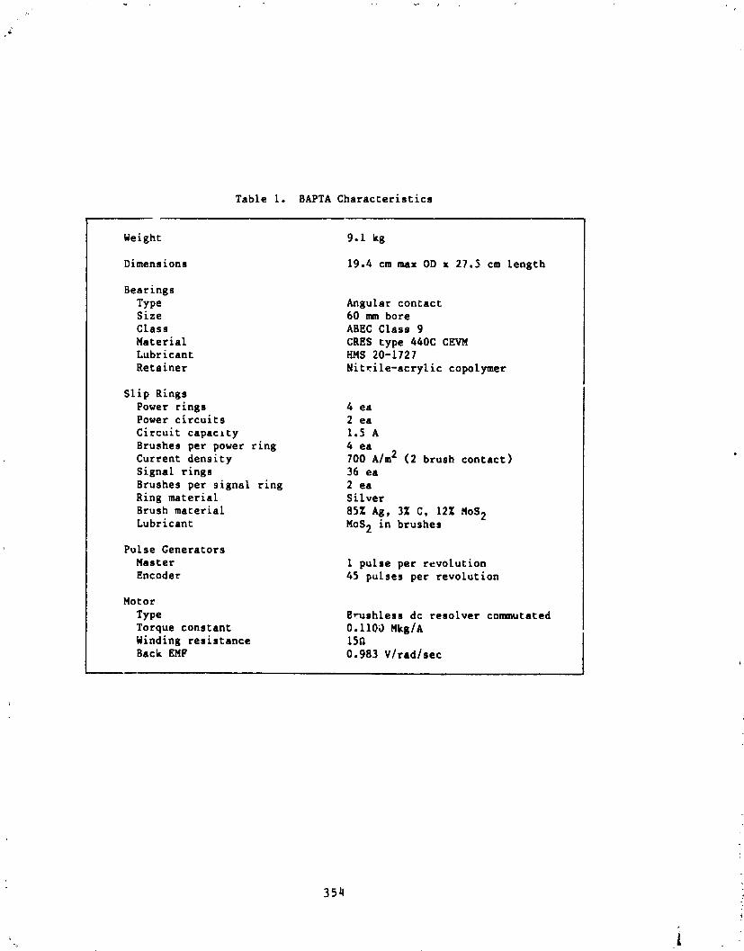
Table i. BAPTA Characteristics
Weight 9.1 kg
Dimensions 19.4 cm max OD x 27.3 cm length
BearingsType Angular contactSize 60 mm boreClass ABEC Class 9
Material CRES type 440C CEVMLubricant HMS 20-1727
Retainer Nitrile-acrylic copolymer
Slip Rings
Power rings 4 eaPower circuits 2 ea
Circuit capacity 1.5 A
Brushes per power ring 4 eaCurrent density 700 Aim 2 (2 brush contact)
Signal rings 36 eaB_ushes per signal ring 2 ea
Ring material Sitver
Brush material 8§Z Ag, 3Z C, 12Z MoB 2Lubricant MoS 2 in brushes
Pulse Generators
Master i purse per revotucionEncoder 45 pulses per revolutlon
Motor
Type Erushless dc resolver commutated
Torque constant 0,II0_ Mkg/AWinding resistance 15_
Back EMF 0.983 Vlradlsec
35_/
1985025199-355
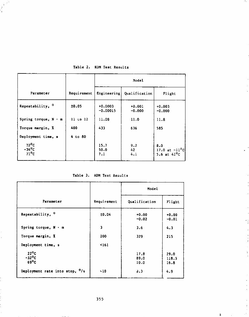
Table 2. RDM Test Results
Model
Parameter Requirement Engineering Qualification Flight
Repeatability, o ±0.05 +0.0003 +0.001 +0.003-0.00015 -0.000 -0.000
Spring torque, N • m Ii to 12 11.08 ii.0 11.8
Torque margin, % 400 433 636 585
Deployment time, s 4 to 80
22°C 15.7 9.2 8.0
-34°C 50.0 42 17.0 at -ll°C •
71°C 7.1 4.i 5.6 at 41°C
Table 3. ADM Test Results
Model
Parameter Requirement Qualification Flight
Repeatability, o ±0.04 +0.00 +0.00
-0.02 -0.01 ,_
Spring torque, N • m 3 3.6 4.3
Torque margin, % 200 329 215
Deployment time, s <161
22°C 17.8 29.0-32°C 89.0 118.5
69°C 10.0 16.8
Deployment rate into stop, °/s _I0 3.3 4.9
355
1985025199-356

y_
i
Table 4. SSM/I Momentum Wheel Design Data
Unit angular momentum 3.0 N • m at 1300 rpm
Unit weight 5.5 kg without electronics
Rotor inertia 0.022 kg • m2
Rotating weight 3.64 kg
Rotor diameter 18 cm
Envelope dimensions 20 cm dia by 28.5 cm high excludingmounting feet and connector
Spin motor type AC squirrel cage induction
Synchronous speed 2400 rpm (theoretical) at 400 Hz
Unit internal atmosphere 98% HE, 2% 02, 50% ATM
Friction and windage torque 58 gm • cm at 1400 rpm
Bearing type Deep groove Rg, double shielded
Lubrication type and quantity MIL-L-6085A, +5% TCP, 20\to 25 mg
Tachometer type Permanent magnet pulse
Generator - 12 pulses/rev
356
1985025199-357
o
; ORIGINAL PAGE IS:, OF pOOR QUALITY
' b
Figure 1. DMSP satellite with SSM/I
¢
1985025199-358

ORIGINAL PAGE ISOF POOR QUALITY
SENSOR
s) Stowed
I__ OeM_'wl
' Figure 2. Sensor location
i) Instrumentpivoting b) kmmna_leetm' N)tltkm el _ m(lem.wt_!
Figure 3. Deployment sequence
358
1985025199-359

ORIGINAL PAGE IS
.OF..POOR QUALITY
Jr v.
Figure4. SSM/I BAPTA
t •
:! - ............. - ............. ,,;..........
._ Figure5. Retainerlubricantcapacity ,
ill359 ;l
1 J "
198,5025199-360

i q '
P
ORIGINALPAGE ISOF POOR QUALITY
CONTROLLEDGAP HOUSING
/
CAVI_'YFILLEDWITH0.1m_/iVISCOSITYCIL "
- PADDLEIS PINNEDTOSUPPORTSTRUCTURr!- HOUSINGROTATE,_WITHRESPECTTOPADDLE- FLUID ISFORCEDTHROUGHCONTROLLEDGAPS
Figure 6. Deployment mechanism cross section
J'4
:o
i,l Figure7. Radiometerdeploymentmechanism lr
360 J "
]985025]99-36]
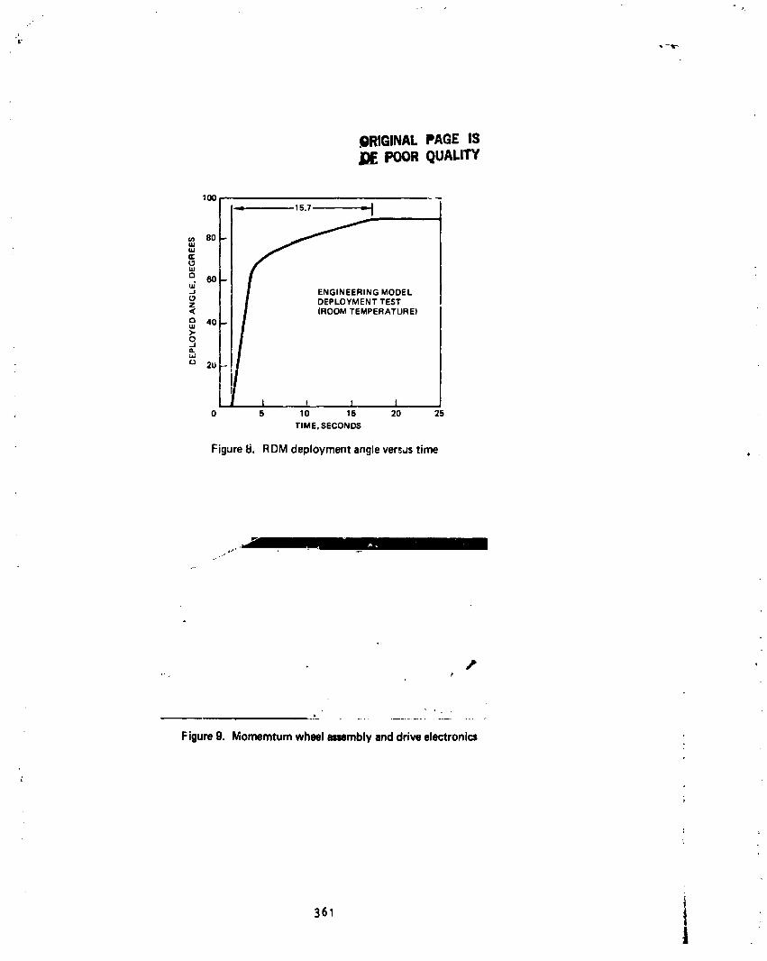
.--lr-
.QRIGINALPAGEISJOEPOORQUALITY
100 _
15.7 _ I
u)(3c:tu.,tuouj.80-60-.J G MODEL(3Z DEPLOYMENT TEST< (ROOM TEMPERATURE)o 40-uJ>-o.JQ._J
O 2U-.,
J M I I ,0 5 10 15 20 25
TIME, SECONDS
Figure 8. RDM deployment angle versustime
v
i
Figure 9. Momemtum wheel assemblyanddrive electronic=
|361
J
1985025199-362
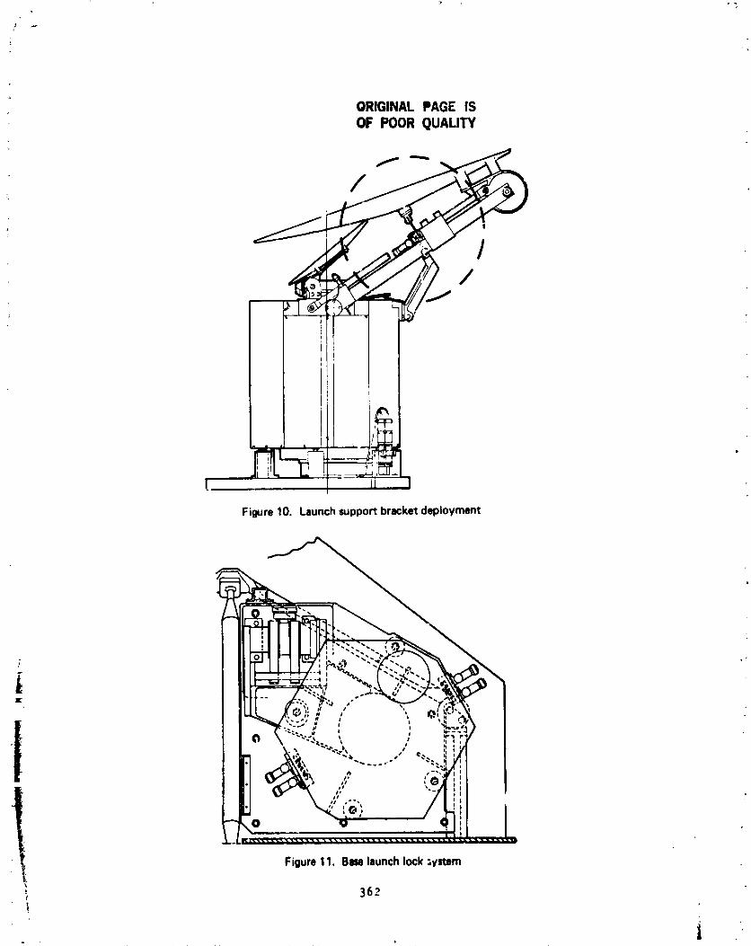
ORIGINAL PAGE ISOF POOR QUALITY
' -'i, / "h(
Figure 10. Launch support bracketdeployment
Figure 11. Baselaunchlock ;Vztem
362
tt
1985025199-363
N85-33535
CIRCULATIONCUNTROLLIFT GENERATIONEXPERIMENT:HARDWAREDEVELOPMENT
Tlna L. Panontln*
ABSTRACT
A clrculatloncontrolalrrol]and Its accompanylnghardwarehave beendevelopedto al]ow the !nvestlgatlonof ]|ft generat|onthat Is Independentofalrfol]anyle of attackand re]atlveflow ve|oclty. The test equlpment,deslgnedfor use In a water tunnel,Includesthe blownalrfoI1,the supportsystemsfor both flow vlsuallzatlonand alrfollload measurement,an_ thefluld-controlsystm, _Ich utlllzeshydraulictechnology. Tn|s paperdescrlbesthe pr|mry deslgntasks,the selectedsolutlons,and the unforseenprob|Ms |nvolved|n the developmentof these Indlvldualcomponentsofhardware.
INTRODUCTION
,nherentIn current 11ftgero-atlonmethodsare the constralntsImpos_ bythemr dependenceon _.ee-streamvelocityand angle of dttack. For fixndwlngaircraftto perfom |c_v-speedlandlngsand takeoffs,comp]exflap systemsm'stbe used to Increasethe effectlvearea of the wings to compensatefor thedecreaseIn alrstrem veloclty. More severe limitationsare demonstratedbystandardrotorblade designs;here, llft generation|s Inhlbltedby thereversedrelativeflow _per|enc_ by retreatingbladesand by theeventuality,as angleof attack Is Increased,of d_mamlcstall. As aconsequenceof these contralnts,conventionalrotorcrafthave been unabletoachievedeslredIncreasesIn forwardfl|ghtspeeo.
The meth_ of clrculat|_ controllift ge ratlonmo removethese typesof constra|nts. Utilized wtth a blunt atrfoai, circulation control refers tothe discharge of a Jet blown tangentially over the surface of the a|rfol]'srounded tra|llng edge. The Jet, by adhering to the atrfotl contour, moves thestagflatton po!nt further toward t_e lower ¢..rface to Increase the circulation,
Z Milch, tn turn, Increases the l|ft generated (see Ftg. 1). Hence, circulationcr_ltrol can provide htgh Itft coefficients as, functton of Jet blowing alone,unhmpered by tha problems attributed to free-stream ve|octly and ang|e-of-attack dependence.
In applications to fixed wlno aircraft, circulation control would negatethe need for flap systems and allow for even lower landing _ncl takeoff speeds.
, - A_ltcatton of circulation con_rai to rotorcrart would see rotor bladesections, symmetric about mtdch_rd ,_ possessing upper surfare leadtng andtrailing edge Jets, develop_n_ hlgh ift c "ftctents Irrespective of relattve
?
*Research Engineer, NASAtvnes R_search Center
363
i
1985025199-364
velocitydirectionand withoutangle-of-attackstall. Controlof the aircraftIn both caseswould be _c.on,pllshedthroughmodulationof the jet{s) blowing.
Althoughthe potentialof circulationcontrolas a viablealternailvetocurrenthlgh-liftgenerationmethods Is attractive,its exploitationIshinderedby an insufficientunderstandingof the flow field surroundln_theblown airfoil. Withoutthls knowledge,accuratepredictionmethods for theairfoil'sperformancecannotbe formulated. Moreover,in proposeoImplementatlt. of this technology,aircraftlift controlwo,ld be achieved lthrough the periodicand transientblowingof the jets, and yet littleexperimentalInfo-matlonexists concerningunsteadyleadinge#ge or tra,lsienttraili% edge Jet blowing.
NASA scientistshave devisedan experimentto obtainexperlmer*aldataconcernlngthe aerodynamicsdevelopedby a clrculati_icontrolalrrollundervarlousblowingconditions. Its prlmaryobjectiveis to visu_liydefinethefluidmechanlcalstructureof the flow fleld for steaJ://unsteadyleadingandtralllngedge blowing.To this end, water Is to be use,.!as the test medium;visuallza_Ionof the flow field is facilitatedby the use of dye injectionorhydrogenbubbletracers,and is made mcre dlscernablebecauseof increasedtlme scales(one order of magnitudegreaterIn water than In air). Also to beex'.minedin thls study is the influenceof unste._dyblowingon airfoilperfomance (forcesand moments)and the influencenf unsteadyb!ow)ngon thermvementof the leadingand trailingedge stagnatlon-polntloc'tlons. Thlslattercomplicationposesa major obstaclein the developmentof a theoreticalmOdel.
/
To realizethe objectivesdescribedabove, NASAengineershave develope,_severalmajor piece'.-of hardware. First,a model ha_ been designedto :capture,on a reducedscale,the charactarlstlcsof clrculatloncontrolllftgenerationas utilizedIn applicationsto rotorcraft. Second,modifications
, to an existingwater tunnelhave been made to accommodatethe model duringflow-vlsuallzatlonstudles-rd to provldeuncontamlnatedalrfollload
. measurements. And ftnally, a fluid-control system has been designed to supplythe model wlth the specifiedperiodicand transientblowl_ conditions
I demandedIn the ex_rlment.i
Thls paper describesthe developmentof the hardwarelistedabove. Thedetailsof each componentdesignare given below Individually,each precededby the pertinentdesign requirements.The problemsencounteredduring the
, manufactureand testingof the hardwareare describedcollectivelyIn thesectiontltledPROJECTSTATU%
I DESIGN
Hodel Des_
The model is a two-dlmenslonalrepresentationof the clrculatlnmcon[rolmethodologyproposedfor rotorcraftapplicatlon. Designedfor use in a wttertunnel,the model,is shoe in FigureI, simulatesrotor blade _peritlonby
36_
i
1985025199-365

blowlng Jets of water from the leadlng and tralllng edge slots of a;winerr|ca1 (about mtdchord) atrfoll. The specifics of the.Irculatlon control atrfotl geometry and flow generation were deftn_ by thePrincipal Researcher and are as follows :
o Shapeand Size Constra|nts
- th_ alrfot1 cross sectton must be elliptical, with ctrcular arcleading and tra|11ng edges and a 10.16-cm (4.0-1n.) chord.
- the Jet slots must be sttuated on the upper surface of the leadtngand tralllng edges over the entire 21.08-om (8.3-1n.) length of themodel.
- the slot exlt helght,the narrowest_int of the Jet con:tructlon,must be .015+ .0013cm (.006+ .0005In.).
o Flow _neratlon _ntralnts
- the Jet plenumchambersmust be Isolatedfro each other.- the veloctt,y of the water leaving the jets should be 100 ttmes
faster than the veloctty of the water In the plenum chambers.
o Structural Constraints
- the mxlel must withstand 2.07 x lOspa (30 pst) tntennal pressure,133.Z N (30 lb) itft load, 22.2 N (5 lb) drag load, and 3.38 N-m(30 |n-lb) pttchtng moment.
- t_e he|ght of each slot cannot deflect more than .00254 on (.001|n.) under load (t.e., the applted plenum chamber pressure).
The prtmary destgn task consisted of ftndtng the configuration that wouldfulftil the geometr|cal contralnts and yet maintain the structural Integrityand destred flow characteristics of the model.
In terns of the severlty of the gtven requirements, the Jet slot proved tobe the rest difficult design area. Deflection of the jet slot by the pressuredeveloped tn the plenum chamber had to he minimized wtthout drast|cally
: chengtng the tnternal 'features of tbe model. The plenum chamberhetght, whtch, controls the veloctty of the Jet discharge, and the slot entrance area, whtch
detemtnes the flow fteld untfomtty, were especially sensitive to alteration.
Thts des|gn ms further c_pl ;cated by the positioning of the slot 1tpalong the atrfot1 chord. The slot lip had to be located on the upper surfaceof the airfoil so that the Jet discharge would extt through the mtntmumthroat
slot) hetght. Adherence to destgn requirements necessitated that the slott_ be located m]ong the chord at 4.708 ca (1.8537 In.) and cut to a thicknessof .010 am (.004 tn.)o
A specific effort also had to be dtrected toward assurtng the Integrity of: the model as a pressurt vessel. Matertal was trimmed from the model tnterlor
/
1985025199-366

to enlargethe plenumchambersand establisha minimumflow velocity("deadwater")in the plenums. The structureof the model was furtherre(lucedto
: allow spaceto divertthe water, supportthe wing, and isolatethe plenumchambers. Hence,a maximum internalpressureof 2.07 X 10SPa had to becontainedwith a minimumof structure.
Supplyingisolatedplenumchamberswith independentsourcesof waterwas adifficultdesigntask as well. Water had to flow into the plenumchamberswith sufficientlyslow velocityso that it would not be forceddirectlyoutthe slots. However,the model size constraintswould not permit increasingthe diameterof the tubes bringingthe water to the chambers. And decreasingthe wall thicknessof the tubes was undesirablesince the tubes would act asthe structuralmemberssupportingthe model againstthe airfoilforcesdescribedabove.
The model'sfinaldesign is shown in Figure3. Manufacturedin severalpieces,the model consistsof two main bo<lyhalves,two end pieces,a solidspar support,and two water injectionpipes. The main body was sectionedsothat the jet slot lip is part of the top half, while the circulararc leadingand trailingedges are part of the bottomhalf. This allowedthe jet slotarea and the model interiorto be easilyaccessedduring fabrication.
The plenumchambersare isolatedfrom each other by the solid centersectionof the wing halvesand are suppli_ with water by separatewaterinjectionpipes. The largecutoutsin the pipes allow the water to fill thechambersslowly. Lateralmovementof the pipes is preventedby pin- slottedinto the bottomwing half. Plugs (not shown)welded into the ends _f thepipes preventthe pipes from being eject_lfrom the model by the pressureforce.
Six supportpostsare evenlydistributedalong the lengthof each jet slotto preventthe deflectionof the slot lip. Screwsare thread_ throughtheseposts to provideincreasedresistanceto the internalpressure. The slot lip,therefore,is constrain_ ratherthan cantilever_ and the deflectionof theslot lip edge is reduced;NASTRANanalysisshows this deflectionto b_.0023cm (.0009in.). In addition,the supportpostsallow for the a_ustmentof the slot height,using shimsor a file, shouldthe height deviatefrom .015on (.006in.) for a_ reason. Althoughthe postsdo pr_uce some obstructionto the flow throughthe _lot entrancearea,they are contouredinto thesurroundinginternalgeometryas much as possibleto re(lucethis effect.
As mentionedabove,the supportposts aid in containingthe internal,Jressure.The 12 screwsthroughthe posts,along with the four throughthesolidcentersection,hold the body of the wing together,_hile the endviec__s,which slip over the solidspar and the water inJecti(:_pipes,bolti.qtf,the main body to completethe pressure-vesselconstruction. The,_ssembledwing is supportedin the tunnelby the solid spar on the one sideand the aater injectlonpipes on the other.
366 li
i
1985025199-367

Control of the slot li._ deflection allowed the plenum chamber height to bemaximized as a function ot geometry alone. At the final design, the heightmeasured 1.02 cm (.4 in.), 70 times the jet slot height. As a consequence,the flow through the jet slot is blown out of the airfoil at 70 times thevelocity with _tch it enters the plenum chamber, achieving 70_ of the designrequtrement. :-
Support System Destgn
The support system for the circulation control airfoil is the meansbywhich the model is held in the water tunnel during the flow studies. Thesuccess of the experiment, namely howwell the flow field is defined and theairfoil forces measured, depends on howwell the support system fulfil!s therequirements listed below.
The support system must
o provide an unobstructed view of the model during flow-visualizationtests;
o allow the adjustment (static) of the angle of attack prior to testing;
o contain pressurized water within the tunnel (1,03 x 10SPaor 15 psimax.);
o conform to existing load cell and tunnel frame apparatuses;
o isolate the load path from the model to the load cells;
o comply with model movementto allow measurement of airfoil forces.
At the onset of the support system design, a decision was made to separatethe flow-visualization and load-measurement phases of the experiment; theconfiguration of the water injection pipes madett impossible to fulfill therequirements for measuring the loads without obstructing the view of themodel. Hence, two support systems were designed, one permitting flow ,visualization and documentation and the other permitting atr_oil loadmeasurement. ]n addition, a dectston was made to orient the model in the testsection so that it could be observed from the solid spar end. In order tosupply water to the model through the water, injection pipes, the fluid-controlsystem needs to be adjacent to the model, close to the tunnel window.Consequently, the solid spar side of the model was deemedto be the "viewing
" side,"
•' The subsystemdesigned for flow visualization consists simply of twotransparent polycarbonate windowswhtch mount tnto the existing test section.Cut tnto the water Injection side window is a clrcular plug that may berotated, by loosening the wing nuts holdtn9 it in place, to adjust the model°sangle-of-attack. The water injection pipe_ extend through two holes in the
367
_q
1
1985025199-g68
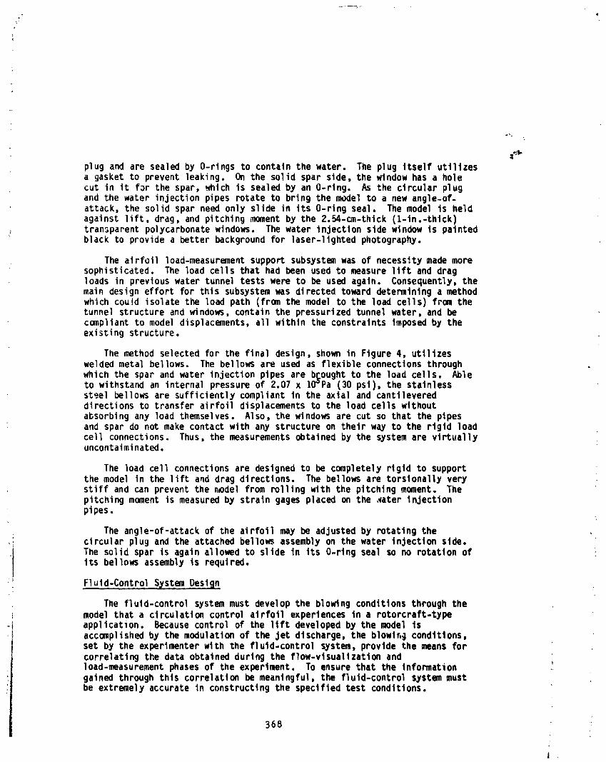
plug and are sealedby O-ringsto containthe water. The plug Itselfutilizesa gasketto preventleaking. On the solid spar side,the window has a holecut in it for the spar,_hlch is sealedby an O-rlng. As the circularplugand the water injectionpipes notateto bring the model to a new angle-of-attack,the solid spar need only slide in Its O-ringseal. The model is heldagainst lift,drag, and pitchingmoment by the 2.54-an-thlck(l-in.-thlck)transparentpolycarbonatewindows. The water injectionside windowIs paintedblack to providea betterbackgroundfor laser-llghtedphotography.
The airfoilload-measurementsupportsubsystemwas of necessitymade moresophisticated. The load cells that had been used to measure lift and dragloads in previouswater tunneltests were to be used again. Consequently,themain designeffort for this subsystemwas directedtowarddetermininga methodwhichcou!d isolatethe load path (fromthe model to the load cells) from thetunnel structureand Windows,containthe pressurizedtunnelwater, and becompliantto model displacements,all within the constraintsimposedby theexistingstructure.
The methodselectedfor the final design,shown in Figureq, utilizesweldedmetal bellows. The bellowsape used as flexibleconnectionsthroughwhich the spar and water injectionpipes are b_oughtto the load cells. Ableto withstandan internalpressureof Z.07 x lO_Pa (30 psi),the stainlesssteel bellowsare sufficientlycompliantIn the axialand cantilevereddirectionsto transferairfoildisplacementsto the load cells withoutabsorbingany load themselves. Also, the windowsare cut so that the pipesand spar do not make contactwith any structureon their way to the rigid loadcell connections. Thus, the measurementsobtainedby the systemare virtuallyuncontaiminated.
The load cell connectionsare designedto be completelyrigidto supportthe model in the lift and drag directions. The bellowsare torsionallyverystiff and can preventthe n_del from rollingwith the pitchingmoment. Thepitchingmoment is measuredby straingages placed on the ,waterinjectionplpes.
The angle-of-attackof the airfollmay be adjustedby rotatingthe; circularplug and the attachedbellowsassemblyon the water injectionside.i The solid spar is again allowedto slide In its O-rlngseal so no rotationof
) its bellowsassemblyis required.
) Flu!d-ControlS@stemDesign
The fluld-controlsystemmust developthe blowingconditionsthroughthei model that a circulationcontrolairfoilexperiencesin a rotorcraft-type
°I application. Becausecontrolof the llft developedby the model Is) accomplishedby the modulationof the Jet discharge,the blowlr,g conditions,
set by the experimenterwith the fluld-controlsystem,providethe means forcorrelatingthe data obtainedduring the flow-vlsuallzatlonandload-measurement phases of the experiment. To ensure that the information _gainedthroughthls correlationbe meanlngful,the fluld-controlsystemmustbe extremelyaccurateIn constructingthe specifiedtest conditions.
368
I ,
1985025199-369
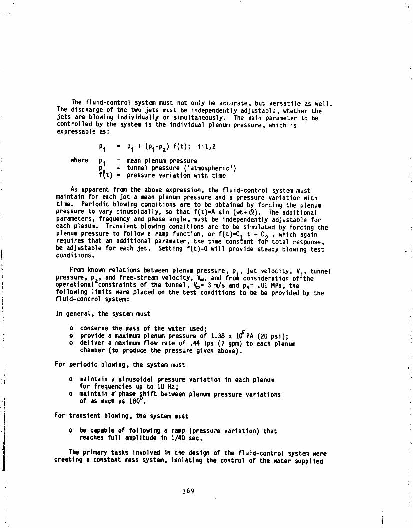
/-
The fluid-controlsystemmust not only be accurate,but versatileas well.The dischargeof the two jets must be independentlyadjustable,nether thejets are blowingindividuallyor simultaneously.The main parameterto becontrolledby the system is the individualplenumpressure,which isexpressableas:
Pi = Pi + (Pl-Pa)f(t); I=I,2
mere Pl = mean plenumpressurep= = tunnelpressure('atmospheric')f_t) = pressurevariationwith time
As apparentfromthe above expression,the fluid-controlsystemmustmaintainfor each jet a mean plenumpressureand a pressurevariationwithtime. Periodicblowingconditionsare to be obtainedby forcingthe plenumpressureto vary ._Inusoidally,so that f(t)=Asin (_+_). The additionalparameters,frequencyand phase angle,must be independentlyadjustableforeach plenum. Transientblowingconditionsare to be simulatedby forcingtheplenumpressureto follow( ramp function,or f{t)=CI t + C_ , which againrequiresthat an additionalparameter,the tim constantfop total response,be adjustablefor each jet. Settingf(t)=Owill providesteadyblowingtestconditlons.
From known relationsbetweenplenum pressure,Pi, jut velocity,V_, tunnelpressure, Pa' and free-stream velocity, V=, and fro_ consideration of_theoperational constraints of the tunnel, V== 3 m/s and pa= .01 MPa, thefollowing limits were placed on the test conditions to be be provided by thefl uld-controlsystem:
In general, the system must
o conserve the mass of the water used;; o provide a maximumplenum pressure of 1.38 x IOcPA (20 psi);
o deliver a maximumflow rate of .44 lps (7 gPm) to each plenumchamber (to produce the pressure given above).
For periodic blowing, the system must
i o maintain a slnusoldal pressure variation tn each plenumfor frequencies up to 10 Hz;
o maintain a"phase _hift between plenum pressure variations;_ of as much as 180_.
For transient blowing, the system musto be capable of followtn9 a ramp (pressu_ variation) thatreaches full amplitude In 1/40 sec.
The primarytasks involvedin the designof the fluld-controlsystemwerecreatinga constantmass system,isolatingthe controlof the water supplied
369
|
i
1985025199-370
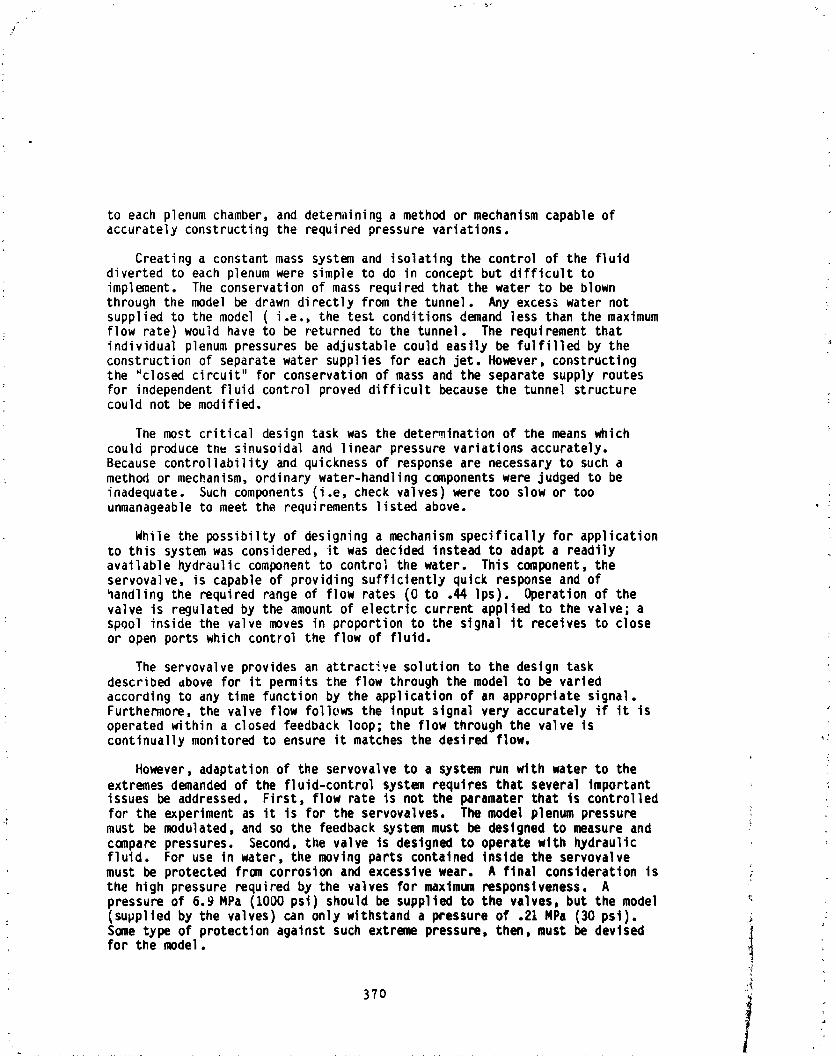
to each plenumchamber,and determininga method or mechanismcapableofaccuratelyconstructingthe requiredpressurevariations.
Creatinga constantmass systemand isolatingthe controlof the fluiddivertedto each plenumwere simpleto do in conceptbut difficulttoimplement. The conservationof mass requiredthat the water to be blownthroughthe model be drawn directlyfrom the tunnel. Any exces_water not )suppliedto the model ( i.e., the test conditionsdemand less than the maximumflow rate)would have to be returnedto the tunnel. The requirementthatindividualplenum pressuresbe adjustablecould easilybe fulfilledby theconstructionof separatewater suppliesfor each jet. However,constructingthe "closedcircuit"for conservationof mass and the separatesupplyroutesfor independentfluid controlproveddifficultbecausethe tunnel structurecould not be modified.
The most criticaldesigntask was the determinationof the means whichcould producetnu sinusoidaland linearpressurevariationsaccurately.Because controllabilityand quicknessof responseare necessaryto such amethod or mechanism,ordinarywater-handlingcomponentswere judged to beinadequate. Such components(i.e, check valves)were too slow or toounmanageableto meet the requirementslistedabove.
While the possibiltyof designinga mechanismspecificallyfor applicationto this systemwas considered,it was decided insteadto adapta readilyavailablehydrauliccomponentto controlthe water. This component,theservovalve,is capableof providingsufficientlyquick responseand ofhandlingthe requiredrangeof flow rates (0 to .44 Ips). Operationof thevalve is regulatedby the amountof electrlccurrentappliedto the valve;aspool insidethe valve moves in proportionto the signalit receivesto closeor open portswhich controlthe flow of fluid.
The servovalveprovidesan attractivesolutionto the designtaskdescribedabove for it permitsthe flow throughthe model to be variedaccordingto any time functionby the applicationof an appropriatesignal.Furthermore,the valve flow followsthe inputsignalvery accuratelyif it isoperatedwithina closed feedbackloop;the flow throughthe valve iscontinuallymonitoredto ensure it matchesthe desiredflow.
However,adaptationof the servovalveto a systemrun with water to theextrenesdemandedof the fluid-controlsystem requiresthat severalimportantissuesbe addressed. First,flow rate is not the parameterthat Is controlledfor the experiment as it is for the servovalves. The model plenum pressure
: must be modulated, and so the feedback system must be designed to measure andcompare pressures. Second, the valve is designed to operate with hydraulicfluid. For use in water, the moving parts contained inside the servovalvemust be protected from corrosion and excessive wear. A ftnal consideration isthe high pressure required by the valves for maximumresponsiveness. Apressure of 6.9 MPa (1000 psi) should be supplied to the valves, but the model ':
: (supplied by the valves) can only withstand a pressure of .21NPa (30 psi). _Some type of protectionagainstsuch extremepressure,then,must be devised ] '
for the model. !?
370
1985025199-371

A schematic of the f|uld-contro] system's fina] design is shown inFtgure 5. A constant displacement pumpde]ivers 1.64 ]ps (26 gpm) at 6.9 MPa(1000 psi) to two servovalves, one to supply each plenum chamber. Theregulator, located just after the accumulator used to dampenthe pressurefluctuations developed by the pump, is set at 6.9 HPa; if the test conditionsare such that less than 1.64 lps are allowed through the va]ves, pressure willbulld tn the supply line and cause the regulator to respond to divert theexcess water away from the valves. Shou]d the regu!ator fail to operate, areltef valve set to blow at 8.3 HPa (1200 psi) is tncluded in the system toprevent the pressure in the supply line from butldtng to dangerous levels.
The accumulator sltuated behind the servovalves is used to dampenthepressure surges generated by the opentng and closing of the valves.Contamination of atrfotl load measurementsfrom these samepressurefluctuations ts prevented by utilizing flextble hose to connect the va]ves tothe water Injection pipes. Hard ltnes containing rupture discs areconstructed tn parallel to these soft ltnes. The dtscs are set to rupture at2.07 x 10"Pa (30 psi) to provtde protection for the model agatnst a]lpressures greater than the destgn pressure.
The tnternal parts of the servova]ves are protected from wear andcorrosion by a mtcrosealing process; the spool ts impregnated wtth carbon tolubricate tts movomentthrough the s]eeve. In addition, spectal sea]s wereInstalled to replace those used for hydraulic flutd servtce. The water sentthrough the valve must remain extreme]y c]ean stnce a parttcle the size of3v_Jncan destroy the prectse valve operation. Two hydraulic ftlters, one15/_m and the other 3_m, are placed upstream of the servovalves to preventtheir contamination.
As apparent from the schematic (Ftgure 5), the fluid-control system Istndeed a constant mass system. Water, however, cannot be drawn directly fromthe tunnel for the pumprequires a _arger Intake ltne than can be accommodatedby the tunnel. Instead, a tank !_ used tc ho]d water for the pumptntake.The water blown off by the regulator and the overflow from the tunnel (waterblown through the model) are diverted back to thts tank.
The schematic tn Ftgure 6 depicts the control loop of one of theservovalves. The desired pressure variation for each plenum Is constructed bya stgnal generator and sent to the servovalve electronics In the fom of a
voltage. There, the voltage slgnal ts converted to a current, whtch ts thenapplted to the servovalve to |nlttate the corresponding flow rate. The flowcharacteristics of the model are such that the plenum pressure ts directlyproportional to the square of the flow rate through the plenum chamber. In asense, then, the model converts the valve flow to plenum pressure. A pressuretransducer, mounted tn the model plenum, measures the pressure and feeds thtsvoltage back to the valve electronics. Py comparing thts signal to the stgnalrepresenting the destred pressure, an error stgnal ts produced to correct thevalve flow. which t, turn. corrects the plenum pressure.
T
T 371
t _J
1985025199-372
/
PROJECTSTATUS
The circulation control airfoil J,,cered the shop for fabrication InOctober 1983 and was completed tn February 1984. Since that time, the modelhas been run in the tunnel, using the flow-visualization supports, so that ttsflow characteristics could be verified. It has subsequently been returned tothe shop for installation of the pressure tranducers.
Few difficulties arose during the fabrication of the model. One problemthat dtd occur, though, was that the two model halves would shift relative toone another durtn9 the contouring of the model ends. The dowel ptns placedalong the centerltne of the model that were to hold the halves duringmachining dtd not control thts problem; the slippage occured at the jet slotsupport interfaces and was caused W play in the screw threads. To correctthis, cylindrical tnserts were pressed tnto the support posts on one modelhalf so that upon assembly, they fit lnto corresponding counterberes cutaround the threads of the other half. The play tn the screw threads was thuscontained.
The flow-visualization support system was submitted for fabricationshortly after the model. While no difficulties were encountered during thesystem's manufacture, a problem dtd arise during lts implementation when themodel's angle-of-attack was to be changed. The seal developed by the gasketused to prevent water from leaking around the circular plug could not bebroken eastly. As a consequence, tt was difficult to rotate the plug to seta new angle-of-attack. The problem was remedied In thts design by ftxtng twoptas In the plug to assist the operator tn breaking the seal. All subsequentdesigns trt which plugs are required uttltze O-rtngs tnstead gaskets to avoidthe problem entlrely.
Fabrication of the load-measurement supports began tn July 1984. Thepteces have been machined and assembled (welded). The estimated Installationdate Is May 1985.
The fluid-control Systemhas been constructed and is being qualified foroperation. Problems with the perfomance of the regulator have beendiscovered; tts response to an increase tn pressure tn the supply ltnets tooslow and too harsh. One solutton that ts to be attempted Is to pumplesswater (.95 lps instead of 1.64 lps) through the regulator by slowtng the speedof the pump. The regulator, not having to work as hard, should respond lessharshly. Several more weeks of making adjustments to the fluid-control =ystemare foreseen.
372
1985025199-373

QRIGIHAL PAGE ISIDF POOR QUALITY
g
V
a > 0 IrlrAONATIONPOINT
(al CONVeNTIONAl.AIIIPOII.
I_rA(INATIONPOINT
(b)CIRCULATIONOOiilTROI.AIRFOIL
FLTure 1. LLft Genm'stLon
373 1i
i
1985025199-374
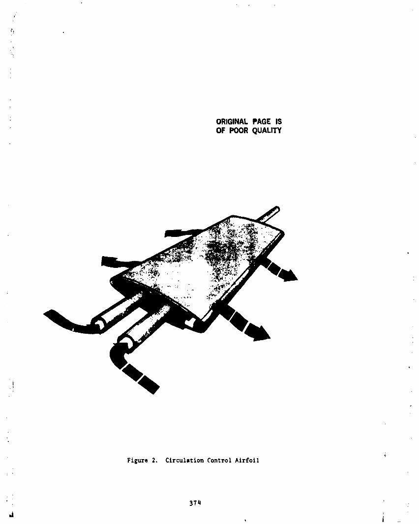
ORIGINAL PAGE IS
OF POOR QUALITY
Figure 2. Circulation Control Airfoil
3711
J , i _
1985025199-375
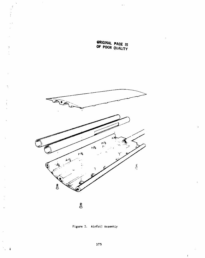
ORIGINALPAGE ISOF POOR QUALITY
Figure 5, Airfoi! Assembly
375
i
1985025199-37(

• ORIGINAL PAGE ISOF POOR QUALITY
Figure _. Load Heasuremt_nt $_ppor¢ System(Test C_nFi£u_ation)
376
I
1985025199-377
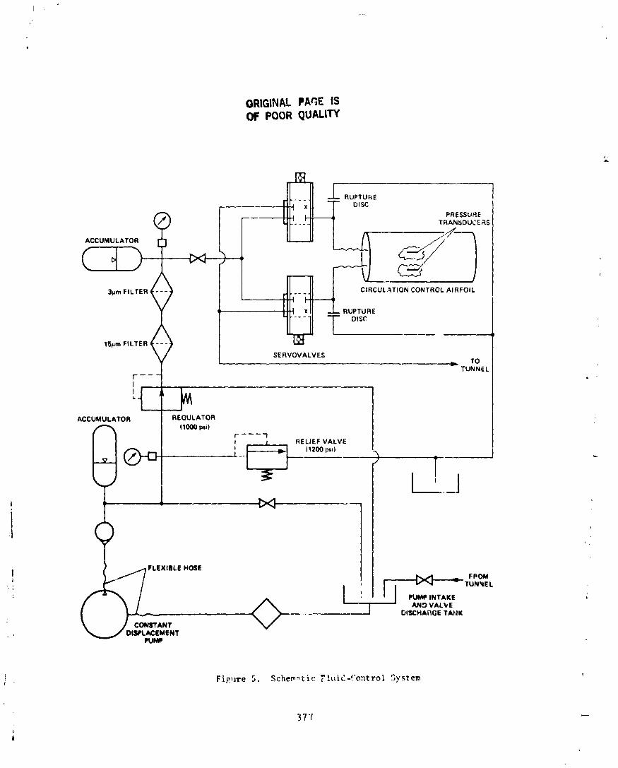
ORIGINAL PAGE ISPOOR QUALITY
E
(_j) PRESSURETRANSDUCERS
ACCUMULATOR _--_
L
3pro FILTER < -_ _ -. RUPTUREDIscCIRCULATION CONTROL AIRFOIL
15pro FILTER < ) SERVOVALVESTO
TUNNEL
I
L ....
ACCUMULATOR L_ REGULATORI (1000 I_i)
i [ RELIEF VALVE(1200 psi)
': l ,' I I _"_ -TO_,ELAND VALVE
__--_ , DISCHARGE TAF,_K
rrANT
DISPLACEMENTI_JMP
I Fi?,lre 5. Scher_tic TluidJ?ontrol _ystem "_
37 7 ---
i,
at
1985025199-378
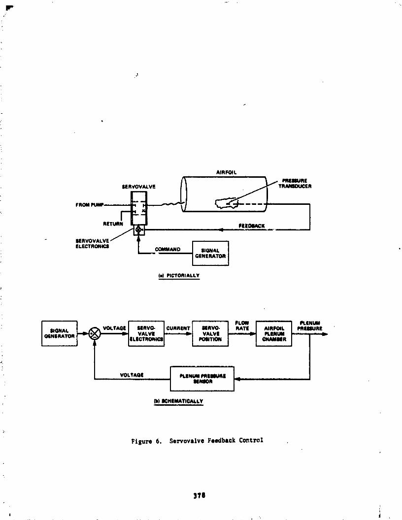
AIRFOIL
SER_OVALVE
RETURN FEEDIACK
- $ERVOVALVE
ELECTRONICS COMMAND I _GNAL I'' GENERATOR I....
(a) PICTORIALLY
SIGNAL I _ VOLTAGE I MRVO- I CURRENT | ilEMVO. I RATE I AIRFOIL I PREEIURE
_IENIMATICALLY
Figure 6, Se2"vovalve Feedback Control
3fO
t, ., iI
1985025199-379

ORIGINAL PAGE ISQuA- N8 5 - 3 3 5 3 6
_ 'NO-PLANEBALANCE• Ale
_IP_IN6 OESIGN
Phil N. Luna *
ABSTRACT
A 3.2_m (l._tP.) _pla_ balen_ aM eight-channel s11p-rt_easily Ms Men Mst9_ to masure and trinsm|t the thrust (667-N;lSO-lb)aM torque (13_-a;l_l_f*_) careen, prMucN by wind-tunnel _elturbopropsanddrive motorsoperating at 300 Hz.
INTROOUCTTON
An Advanc4dTurbopropProgramts currently under developmnt at AlesResearchCenter. Thepurposeof the programts to Investigate aM developtheuse of iar_-dtiter, h|gh-_ltdtty _oN11ers (turboprops) as an _tcalaM efftcte_ runs of atrcra_ p_lston. TM _sslble fuel sav|_s thatcould be ettalned from vstn| _r_rops can be as htgh u 15_. Thts tsespecially Important _ cmmerctal atrllnes stn, the :ost of fuel ts about
of _etr operating expenditure.
TM _qrm M11 feature a fully _ve_, ._-_ale, _nd _nnel _el ofa _tftM _glu K.| trensN_ aircraft.
of the _l's vemttla _eractertatlca tncl_:
o _ng-muntM Nver plantso pl_-mountN wmr plants secur_ _ the _tlo ln_rche_ble _qs _1_ _ be muntM tn
three dtffemt l_ettm$ ileal U_ _sela_ ,_o tnte_M_le Mrtzmtal tails vi_ _vs_kle
angle of attack setttng$
Eachparer pIMt eoestst| of eight .3_i.a.41im (l-ft) grlpktte composite' propeller bibles driven _ 3QOHs.(Ul.OOOrim) We lila11, 141)-KII (LqDO-Oilp)
air motor. Tim etr me,or rlqvteu air _ 3.48 _ (040 psi) _ 1._ kg/s (3Ibis).
In order to _v_ _ _st m4 teeq_ _qiemmte _ t_ tM
them tn fl|ure I, _e Ineer sleeve of the MINce _11 i ptl _ _ 'forv_rd eM of tM atr niter sMft, _ _tM |ltl)-rtq IsM_II will M secured
, to _ aft _ _ _ atr meter _ft. _ elll_eal tlol_im of lmoMIIKe "
*ResearchEngineer, NASAAmesImaHirck Center "
3?9
985025 99-380
outer sleeve will then be pinned to a hub which secures the propeller blades.Instrumentation wires from strain gages on the balance will be routed to theslip-ring assembly tnrough the center of the hollow air motor shaft.
The sizes of the balance and slip-ring assembly were defined by the
anticipated thrust and torque loads, and the geometrical contraints imposed bythe size of the air motor nacelle. This paper will describe the design of thebalance and slip-ring assembly.
Two-Plane Balance Design
The two-plane balance, developed at Ames Research Center several yearsago, is shown in figure 2. It consists of an outer sleeve attached at its
extremities to an inner, hollow sleeve by a brazing/heat treatment-process.Nicoro braze wire (.127-cm-diam) is wrapped around the inner sleeve grooves(two at each end) prior to the outer sleeve/inner sleeve assemblage. The gapbetween the two sleeves is equalized by setscrews located at each end of theouter sleeve. An inert gas vacuum furnace is used to braze the two sleeves
together while the balance is supported in a vertical position. The brazing: cycle also serves as the condition A heat treatment. Afterwards, the balance
is cooled to room temperature and then reheated to attain the precipitation-hardening phase of the heat treatment.
The outer sleeve has eight identical flexures, four at each end, arrangedsymmetrically in two parallel planes, perpendicular to the longitudinal axis.The flexures are instrumented with strain gages and can detect loads along anyof the three axes in addition to moments about the three axes. A load alongthe longitudinal axis (thrust load) will be equally distributed among theeight flexures and will produce a bending stress in each flexure. Thetorsional load will also be equally distributed among the eight flexures, butit will produce a column-type (compression/tension) stress in each flexure.For a further description of a two-plane balance, refer to NASA TechnicalMemorandum X-1278.
By adapting this basic design to suit the needs of this program, a: two-plane balance was designed specifically toT;
I o measure a 667-N (150-Ib) maximum thrust loado measure a 135-N-m (lO0-]b-ft)maximum torsional loado have a 3.25-cm (I.28-in.) outside diametero have a l.gl-cm (0.75-In.) inside diameter
o withstand an out-of-balance radial load of 8.9 KN (2000-lb) causedby an accidental loss of four of the eight propeller blades
o utilize flexures with natural frequencies about and alonga11 axes greater than 900 Hz (three times the exitation frequency)to prevent dynamic excitation
:i 380
i
1985025199-381

The size of each flexure, shown in figure 3, is detemined by the. fol I owlng factors :
o sensitivity (strain level) to each design loado interactions between design loadso adequate surface area to bond miniature strain gageso geometrical constraints
The geometry of the balance is such that the length (L) and width (B,C) of: each flexure are inversely related to each other, while the thickness (H) ts
an independent variable. Consequently, each flexure may be either long and: narrow, or short and wide, and may have any thickness.
Additionally, the length and width are futher defined by the inner andouter diameter of the outer sleeve. Since the outer diameter is fixed(3.25-cm), the inner diameter (to someextent) is a variable. It is boundedby the size of the inner sleeve.
The maximumbending stress producedby the thrust load (P) occurs at theflexure base. This stress is • = 3PL/8C_ where L is the flexure length, H isthe thickness, and C is the base width. ]n order to produce an adequatestrain level, the flexure should be thin and long (and consequently narrow)because of the moderate thrust load.
4
The column-type stress produced by the torsional load (T) on each flexureis # = T/4_D, where O is the outer sleeve meandiameter, and 8 is the width.The large torsional load coupled with the small diameter requires a flexurewith a large cross-sectional area (HB) to prevent the flexure from beingoverstressed.
The above parameters demonstrated that designing to the torsional loadrequired a flexure wtth a large width or thickness, However, the thrust loadrequired a flexure wtth a large length (I.e., a small width) and smallthickness. Consequently, the design of the flexures and of the related outersleeve inner diameter was an tterative process.
The final size of the flexures and strain levels produced by the designloads are as follows:
: o length (L) = 9.12-m (.359-tn.)o thickness (H)-= 2.28-m, (.090-in.)o width (B) = 1.78-m (.070-In.)
.._ o base width (C) - 3.45-mm (.136-tn.)o 610 mtcrostratn for the {i57-N thrust loado 1440 mtcrosratn for the 135-N-m torsional load
Someother features of the 3.25-an, two-plane balance includethe following:
o a stop nut to prevent the propeller blade hub from separating from thenacelle in case the balance/hub shear ptns fat1
381
1985025199-382

o a stop nut to prevent the balance and propeller blade hub fromseparatingfrom the nacellein case the balance/alrmotor shaftshear pins fail
o solderingpins embeddedthroughthe forwardend of the balanceto easeand improvethe strain-gagewire-solderingprocedure
o a phenoliccoveron the forwardend of the balancewhich protectstheinstrumentationwlres
o a spiralgrooveon the exteriorsurfaceof the outer sleeveto easebalar,ce/propellerhub installationand removalby providinga cavityfor dirt particlessince the gap betweenthe balanceand the propellerhub is only .O03-mm
Slip R.ingAssemblyDesi9_
A slip ring assemblywas designedto transmitthe electricalsignalsfromthe balancestrain-gagesto a data-acqulsltionsystemwhile operatingat 300Hz. The constraintsgoverningthe designwere that the slip-ringassemblyhadto interfacewith the existingair motor shaft, flt withinan exlt guide vaneset locatedat the aft end of the air motor,and providea means fordeliveringan air/freonmixture for cleaningand coollngthe contacts.
The slip ring assembly,shown in figure4, is securedto the aft end ofthe air motor shaft and consistsof tr,e followingmajor items:
o a hollow kevlarshafto coin silvercontactdiscs
o silver,graphite,molybdenum-disulfldebrushes! o phenolic brush housing and sleeve) o exit guide vane set( o stainlesssteel retainingand adapt_.rnuts
i
t The contact discs are positioned over the kevlar shaft and sandwiched) betweenphenolicspacersto orientthem with respectto the shaft's
longitudinalaxis. Instrumentationwires are solderedto the contactdiscsand routed through the hollow kevlar shaft to its aft end. Before the kevlar
i shaft is inserted into the hollow air motor shaft, the lead vires from thebalance strain-gages are routed through the center of the hollow air motorshaft and connected to the lead vires from the contact discs.
The kevlar shaft, which has a key on the surface of its flange, is_i inserted into the air motor shaft so that the key fits into a slot in an
adapter nut at the end of the air motor shaft. The kevlar shaft ts retained_t by a nut which fits over the flange and threads onto the adapter nut. The
l retainingnut and key preventthe kevlarshaft from slipping. The kevlar
shaft must always rotate at the samespeed as the air mc;:or shaft so that theinstrumentation wires are not damaged.
,t 382
L
1985025199-383
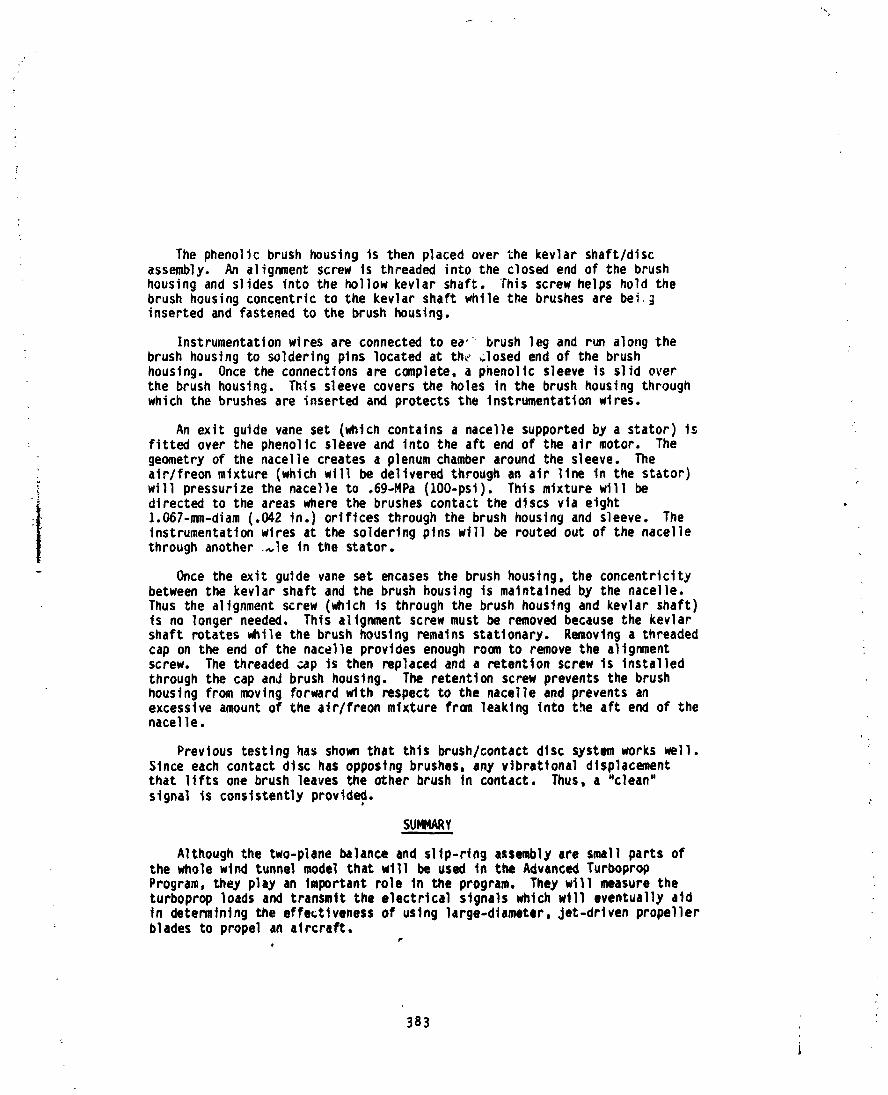
The phenolic brush housing is then placed over the kevlar shaft/discassembly. An alignment screw ts threaded into the closed end of the brushhousing and slides into the hollow kevlar shaft. This screw helps hold thebrush housing concentric to the kevlar shaft while the brushes are bei _inserted and fastened to the brush housing.
Instrumentation wires are connected to ea" brush leg and run along thebrush housing to soldering pins located at th_ _losed end of the brushhoustng. Once the connections are complete, a phenolic sleeve is slid overthe brush housing. This sleeve covers the holes in the brush houstng throughwhich the brushes are inserted and protects the Instrumentation wtres.
An exit guide vane set (which contains a nacelle supported by a stator) isfitted over the phenolic sleeve and into the aft end of the air motor. Thegeometry of the nacel]e creates a plenum chamber around the sleeve. Thealr/freon mixture (which will be delivered through an air ]the tn the St_tor)will pressurize the nacelle to .69-MPa (lO0-pst). This mixture w111 be
ii directed to the areas where the brushes contact the discs via etght
1.067-mm-diam (.042 in.) orifices through the brush housing and sleeve. TheInstrumentation wtres at the soldering pins will be routed out of the nacellethroughanother ,_le In the Stator.
- Once the exit guide vane set encases the brush housing, the concentricitybetween the kevlar shaft and the brush housing is maintained by the nacelle.Thus the alignment screw (which is through the brush housing and kevlar shaft)is no longer needed. Thts alignment screw must be removed because the kevlarshaft rotates while the brush housing rematns stationary. Removinga threadedcap on the end of the nacelle provides enoughroom to remove the alignmentscrew. The threaded _ap is then replaced and a retention screw ts Installedthrough the cap and brush housing. The retention screw prevents the brushhousing from moving forward with respect to the nacelle and prevents anexcessive amount of the air/freon mixture from leaking Into the aft end of thenacelle.
Previous testing has shownthat this brush/contact disc SYstem works well.Since each contact disc has opposing brushes, any vibrational displacementthat lifts one brush leaves the other brush in contact. Thus, a "clean"slgnal is conslstentlyprovld_.
SUMMAAY
Although the two-plane balance and slip-ring assembly are small parts ofthe whole wind tunnel model thatwtl1 be used in the Advanced TurbopropProgram, they play an Important role In the program. They w111 measure theturboprop loads and transmit the electrical stgnals which will eventually atdin determining the effectiveness of using large-diameter, Jetldrivenpropellerblades to propel an aircraft.
P
383 _ '
1985025199-384
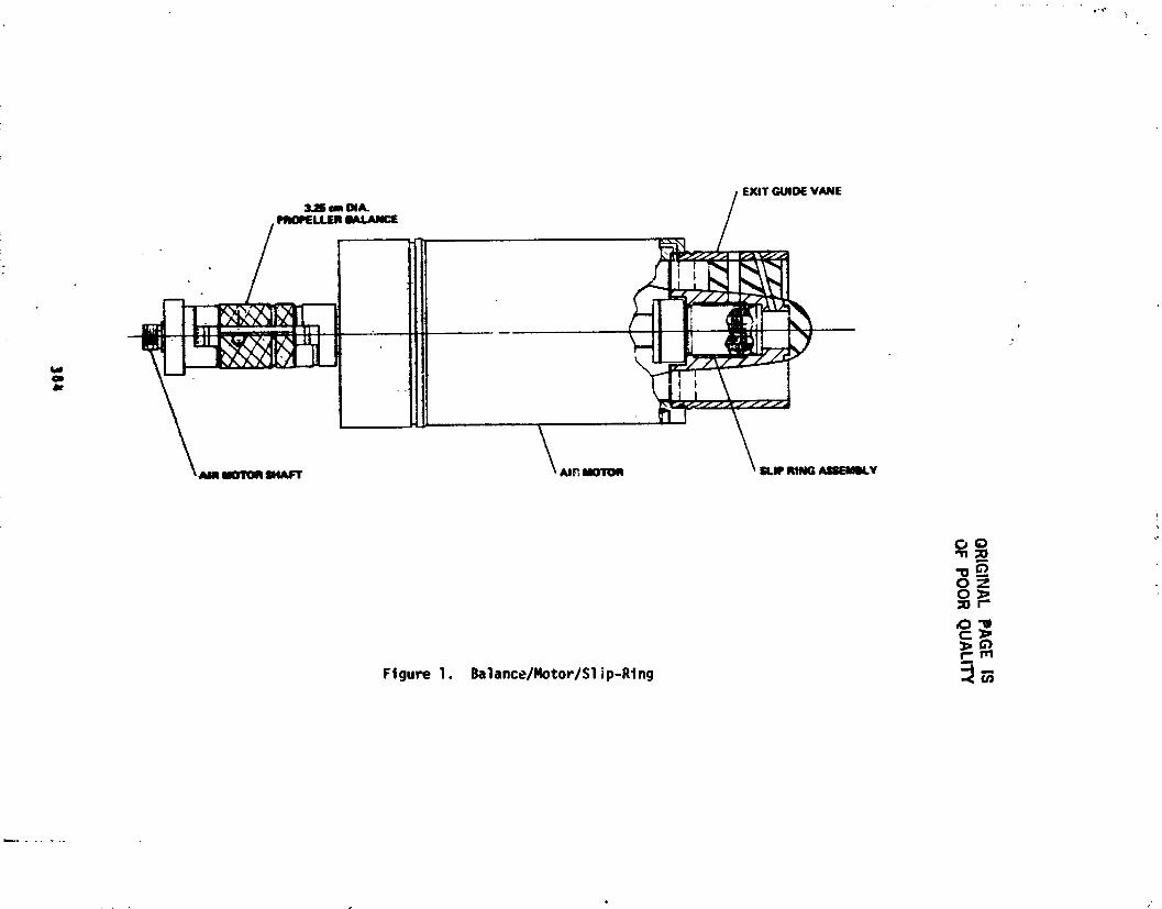
OR
IGIN
AL
PA
GE
ISO
FP
OO
RQ
UA
LIT
Y
381
1985025199-385

ORIGINALPAGE IS!
_ POOR QUAI,,ITY
:_
! :
! m
SECTION B-B
SI"OPNUT \
_ _ \ou,.,,v, .SECTION A-A
Ftgure 2. Two-PlaneBalance|
1
_, 385
1985025199-386

±
Figure 3. Flexure
eU.S._IqUNTUCC.OlqqcE:I g85-537-08_ 20005HCK)NNO_4
386 _ ;"i
1
]985025]99-387

ORIGINALPAGE,_POORQUALtTt
i
CONTACTD,SCBRUSHSLEEVE_I _ ....._ _-"/
/
_ .... p
i I- •
l
,/
// , 1....../---....- --ADAPTERNUT _ SHAFT SPACER BRUSH HOUSINGRETAINING NUT EXIT GUIDE VANE
LT
' iL
Figure 4. 511p-RlngAssembly
387
1985025199-388
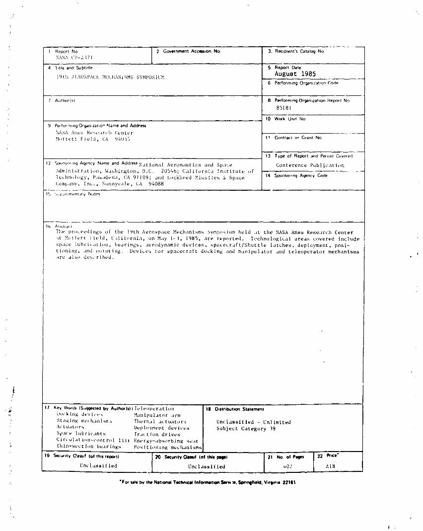
¼ 1 Report No [ 2 GovernmentAcc_lon No, 3. Recip_ent'sCatalog NoXASA ('P-2371 1
4 T_tleand Subtltle 5 ReportDate
IUth AI,RUSPAt:t-. HE(,FtANiqHS SYMPOSIUH August 1985, 6 Performing Orgamzat,on Co,C-
7 Author(s) B PerformlngOrganlzatlon Report No85181
10 Work'Unlt NO
9 Performing Organ;zatto_ %_ameand AddressNA?;A _ne,_ Re.earth Center
Motfett Field, CA 94035 17 Contract or Grant No
i3 Type of Report and Period Covered
12 Slxmsor,ng Agency Name and Address Nation:l l Aeronautics and SpaLe Conference PublicationAdministration, _'abhington, D.C. 20546; California [n:;titute of
14 SponiormgAgencyCodelc_hn(_logy, Pa_,ldena, CA 91109; and l,ockheed M£,-,siles & SpaceCoral, ally , Inc. , Sunnyvale, CA 94088
15 '.,,Jpphenlentary Notes
1(_ A b'..tr a( t
The pr(_eedlngs of the !gth Aerospace Mechanisms Symposium held .t the NASA Ames Research Center
,it ,qolfett Yield, C,l!lf(_rnia, on Hay 1-3, 1985, are reported. Technological areas covered include
space lubriL,ltion, bearings, aerodynamic devices, spacecraft/Shuttle latches, deployment, posi-
tioning, and n,.)lnting, Devl_es for spacecraft docking and manipulator and teleoperator mechanismsare also described.
i{
. _ 'i'l Key Words ISugg_t_l by Authotl$)lTeleoperat ion 18 O_$trlbuti_ State.hi_ l_t_ck lng dev ices Han ipulator arm
StaRing met hanlsm._ 'riwrmaL actuators Unclassified - Unl lmited
,\c tu,Jtor_ bep torment dee ices Subject Category 39SII'IUe lubricants [r.t{ t ion dr lees
Circulation-control lift Energy-absorbing s_..tt; thin-section bearings Po'_itiontng mechanisms
19 _urlty C'_,ISSI|lof th*sreport) :_O Slcurll'; C311_! (of thai pill) 21 No of Pages 22 Prtce"
Unclassified Unclassified _¢02 At8
: *For sateby the N41ttonalTechn.cal|nformatlon _ ,'11.$wmQfi*kl. V*r_tl 22161
i ,
1985025199-389