L. R. Xu and A. J. Rosakis, “Real-time Experimental Investigation on Dynamic Failure of Sandwich...
33
Real-Time Experimental Investigation on Dynamic Failure of Sandwich Structures and Layered Materials L. Roy Xu and Ares J. Rosakis Abstract We present a systematic experimental investigation of the generation and subsequent evolution of dynamic failure modes in sandwich structures and layered materials subjected to out-of-plane low-speed impact. Model sandwich specimens involving a compliant polymer core sandwiched between two metal layers and other model layered materials were designed to simulate failure evolution mechanisms in real sandwich structures and layered materials. High-speed photography and dy- namic photoelasticity were utilized to study the nature and sequence of such failure modes. In all cases, inter-layer (interfacial) cracks appeared first. These cracks were shear-dominated and were often intersonic even under moderate impact speeds. The transition from inter-layer crack growth to intra-layer crack formation was also observed. The shear inter-layer cracks kinked into the core layer, propagated as opening-dominated intra-layer cracks and eventually branched as they attained high enough growth speeds causing brittle core fragmentation. In-depth failure me- chanics experiments on the dynamic crack branching, crack kinking and penetration at a weak interface, interfacial debonding ahead of a main incident crack were also conducted to understand the physical insight of the dynamic failure modes and their transition observed from sandwich structures and layered materials. 1 Introduction Layered materials and sandwich structures have diverse and technologically inter- esting applications in many areas of engineering. These include the increased use of composite laminates in aerospace and automotive engineering; the introduction L.R. Xu ( ) Department of Civil and Environmental Engineering, Vanderbilt University, Nashville, TN 37235, USA e-mail: [email protected] A.J. Rosakis Graduate Aeronautical Laboratories, California Institute of Technology, Pasadena, CA 91125, USA e-mail: [email protected] I.M. Daniel et al. (eds.), Major Accomplishments in Composite Materials and Sandwich Structures: An Anthology of ONR Sponsored Research, c Springer Science+Business Media B.V. 2009 571
Transcript of L. R. Xu and A. J. Rosakis, “Real-time Experimental Investigation on Dynamic Failure of Sandwich...
Real-Time Experimental Investigationon Dynamic Failure of Sandwich Structuresand Layered Materials
L. Roy Xu and Ares J. Rosakis
Abstract We present a systematic experimental investigation of the generation andsubsequent evolution of dynamic failure modes in sandwich structures and layeredmaterials subjected to out-of-plane low-speed impact. Model sandwich specimensinvolving a compliant polymer core sandwiched between two metal layers and othermodel layered materials were designed to simulate failure evolution mechanisms inreal sandwich structures and layered materials. High-speed photography and dy-namic photoelasticity were utilized to study the nature and sequence of such failuremodes. In all cases, inter-layer (interfacial) cracks appeared first. These cracks wereshear-dominated and were often intersonic even under moderate impact speeds.The transition from inter-layer crack growth to intra-layer crack formation wasalso observed. The shear inter-layer cracks kinked into the core layer, propagatedas opening-dominated intra-layer cracks and eventually branched as they attainedhigh enough growth speeds causing brittle core fragmentation. In-depth failure me-chanics experiments on the dynamic crack branching, crack kinking and penetrationat a weak interface, interfacial debonding ahead of a main incident crack were alsoconducted to understand the physical insight of the dynamic failure modes and theirtransition observed from sandwich structures and layered materials.
1 Introduction
Layered materials and sandwich structures have diverse and technologically inter-esting applications in many areas of engineering. These include the increased useof composite laminates in aerospace and automotive engineering; the introduction
L.R. Xu (�)Department of Civil and Environmental Engineering, Vanderbilt University, Nashville,TN 37235, USAe-mail: [email protected]
A.J. RosakisGraduate Aeronautical Laboratories, California Institute of Technology, Pasadena,CA 91125, USAe-mail: [email protected]
I.M. Daniel et al. (eds.), Major Accomplishments in Composite Materials and SandwichStructures: An Anthology of ONR Sponsored Research,c� Springer Science+Business Media B.V. 2009
571
572 L.R. Xu and A.J. Rosakis
of layered concrete pavements in civil engineering; the use of thin films and lay-ered structures in micro-electronic components, and recently, the introduction ofsandwich structures in a variety of naval engineering applications (Hutchinson andSuo [1]; Rajapakse [2]). While failure characteristics of layered materials and sand-wich structures subjected to static loading have been investigated extensively in thepast years, their dynamic counterparts have remained elusive (Sun and Rechak [3];Cantwell and Morton [4]; Abrate [5]). Indeed, the presence of highly complex andtransient dynamic failure modes in such materials and the inaccessibility of inter-nal damage have resulted in experimental studies limited to only the final impactdamage and the residual strengths. To begin addressing the need for real-time ob-servations of failure events, the work presented here focuses on the study of suchevents in model sandwich structures, and in particular, on the identification of theirnature, chronological evolution and interaction.
To identify the evolution of failure modes, it is convenient to first classifythese modes based on the material constitutions of layered/reinforced structures.As shown schematically in Fig. 1, there are two major categories of failure observedin post-mortem studies. The first major failure category is decohesion (or cracking)between bonded layers at an interface. This is often referred to as delamination incomposite laminates or interfacial debonding in thin films or sandwich structures. Itis also called inter-layer failure. Generally, two distinct inter-layer failure modes areobserved. The first one involves opening-dominated inter-layer cracking or “delam-ination buckling” (Gioia and Ortiz [6]; Kadomateas [7]). The second one involvesshear-dominated inter-layer cracks or “shear delaminations,” and often occurs inlayered materials subjected to out-of-plane impact (Choi et al. [8]; Lambros andRosakis [9]).
The second major category is referred to as intra-layer failure. There are threepossible intra-layer failure modes depending on the material constitution. The first
Inter-layer failure
Intra-layer failure
1. Opening dominatedinter-layer crack
2. Shear dominatedinter-layer crack
3. Intra-layer crack(matrix crack)
4. Fiber breakage
5.fiber/matrixdebonding
Fig. 1 Failure modes for layered materials based on material constitution
Dynamic Failure of Sandwich Structures and Layered Materials 573
100 μs 375 μs 492 μs 667 μs
Delamination
Kinked matrix cracks
56 m/s
Field of view
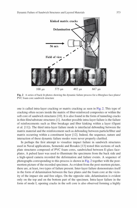
Fig. 2 A series of back lit photos showing the dynamic failure process for a fiberglass face plates/PVC foam core sandwich structure
one is called intra-layer cracking or matrix cracking as seen in Fig. 2. This type ofcracking often occurs inside the matrix of fiber-reinforced composites or within thesoft core of sandwich structures [10]. It is also found in the form of tunneling cracksin thin film/substrate structures [1]. Another possible intra-layer failure is the failureof reinforcements such as fiber breakage and fiber kinking within a layer (Oguniet al. [11]). The third intra-layer failure mode is interfacial debonding between thematrix material and the reinforcement such as debonding between particle/fiber andmatrix occurring within a constituent layer [12]. Indeed, the sequence, nature andinteraction of these dynamic failure modes were never properly clarified.
In perhaps the first attempt to visualize impact failure in sandwich structuresused in Naval applications, Semenski and Rosakis [13] tested thin sections of suchplate structures composed of PVC foam cores, sandwiched between E-glass face-plates. A pulsed laser was used to illuminate the specimens from the back side anda high-speed camera recorded the deformation and failure events. A sequence ofphotographs corresponding to this process is shown in Fig. 2 together with the post-mortem picture of the recorded specimen. As evident from the post-mortem picture,there are, at least, two types of failure present. Inter-layer failure demonstrates itselfin the form of delamination between the face plates and the foam core at the vicin-ity of the impact site and free edges. On the opposite side, delamination is evidentonly on the top and on the bottom part of the specimen. Intra-layer failure in theform of mode I, opening cracks in the soft core is also observed forming a highly
574 L.R. Xu and A.J. Rosakis
symmetric pattern. Because the core is opaque, the high-speed pictures shown be-low are of limited use. What they show, however, is the emergence and propagationof the opening intra-layer (matrix) cracks inside the foam core. Indeed, these cracksseem to originate at the fiber glass/PVC interface opposite to the side of impact,and to symmetrically propagate towards the impact point. These cracks originate atthe same location where the fiberglass/PVC delamination terminates. However, thetime sequence and interaction between such inter-layer delamination and the visibleintra-layer, opening cracks in the core are not obvious. Indeed, the backlit real-timephotographs do not show any evidence of interfacial delamination within the timewindow of observation. As we will show later, this observation is misleading and isdue to the fact that inter-layer fractures are typically shear-dominated. As such theydo not allow for light to go through during the recording event because the shearcrack faces remain in contact at the early stages of this process.
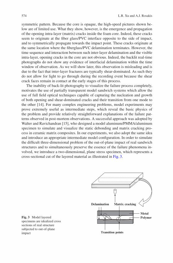
The inability of back-lit photography to visualize the failure process completely,motivates the use of partially transparent model sandwich systems which allow theuse of full field optical techniques capable of capturing the nucleation and growthof both opening and shear-dominated cracks and their transition from one mode tothe other [14]. For many complex engineering problems, model experiments mayprove extremely useful as intermediate steps, which reveal the basic physics ofthe problem and provide relatively straightforward explanations of the failure pat-terns observed in post-mortem observations. A successful approach was adopted byWalter and Ravichandran [15], who designed a model aluminum/PMMA/aluminumspecimen to simulate and visualize the static debonding and matrix cracking pro-cess in ceramic matrix composites. In our experiments, we also adopt the same ideaand introduce an appropriate intermediate model configuration. In order to simulatethe difficult three-dimensional problem of the out-of-plane impact of real sandwichstructures and to simultaneously preserve the essence of the failure phenomena in-volved, we introduce a two-dimensional, plane stress specimen, which represents across-sectional cut of the layered material as illustrated in Fig. 3.
Fig. 3 Model layeredspecimens are idealized crosssections of real structuresubjected to out-of-planeimpact
Matrix crackingDelamination
Transition points
MetalPolymer
Dynamic Failure of Sandwich Structures and Layered Materials 575
For this type of model specimen, the failure process is easy to record, visualizeand analyze. It is noted that although the exact impact mechanics involved in twoconfigurations is not identical (the real case is three-dimensional while the modelspecimen is closer to a plane stress state), the mechanisms of stress wave propaga-tion and failure progression of the real and the model layered materials are quiteanalogous. In designing these model two-dimensional sandwich specimens, it isimportant to select model materials whose elastic mismatch is similar to that of ma-terials used in real engineering applications (in our case PVC/composites). Selectingsimilar Dundurs’ parameters [1] may ensure similarity of the elasto-static responsefor the interfacial mechanics problem. Meanwhile, selecting model material combi-nations with similar ratios of wave speeds of two constitution materials to the realstructure is perhaps the most important consideration in the dynamic case, wheretiming of events and stress intensity are governed by the constituent material wavespeeds. Also, the ratio of inter-layer and intra-layer strengths (or fracture tough-nesses) is important. These three issues provide sets of similarity rules to connectthe real structures to our models experiments. As schematically shown in Fig. 3,matrix cracks and delamination are the two major impact failure modes in sandwichstructures and layered composites. At some intersection points, matrix cracks anddelamination are connected as also seen in the post-impact picture of Fig. 2. Onefrequently asked question in the literature is whether the matrix cracks lead to thedelamination or the delamination happens first and subsequently kinks into the ad-jacent layer inducing the matrix crack. This is a typical problem of sequence andfailure mode transition identification.
Since the nature and origin of such failure mechanisms can only be theorizedby post-mortem observations, the necessity of full-field real-time, high-speed mea-surements becomes obvious. To this effect, the objectives of the current work areto conduct systematic experimental studies of the time evolution and nature of dif-ferent dynamic failure modes and to investigate their interactions. Through thesemodel experiments, we try to identify the basic physical phenomena, and to provideguidance for theoretical models and much needed, real-time, validation of numer-ical codes. To make this comparison more meaningful, we choose model materialcombinations that have the ratios of wave speeds very close to those used in realsandwich structures.
2 Experimental Procedure
2.1 Materials and Specimens
Two kinds of materials were used in the experiments described below. A 4340-carbon steel was employed to simulate the stiff and strong fiberglass faceplates ofsandwich structures. The polymeric material, which was used to simulate the weakcore layer, such as the PVC foam core or balsa wood in sandwich structures or
576 L.R. Xu and A.J. Rosakis
the 90ı plies in cross-ply laminates, is Homalite-100. The adhesive used to bondthe metal/polymer interface is Weldon-10. The detailed properties of this adhesiveand the effect of interfacial strength variation on dynamic failure mode selectionare reported by Xu and Rosakis [16, 17]. The shear wave speed is an importantparameter in this investigation. The shear wave speed ratio for the core and faceplateis 3.2 for typical E-glass/PVC sandwich structures of the type that have recentlybeen used in construction of full-scale composite ships. Details on the complete setof physical and constitutive properties for E-glass composite materials have recentlybeen discussed by Oguni et al. [11]. For comparison, the same shear wave speedratio, for the idealized steel/Homalite model sandwiches, is about 2.7 based on thedata from Ref. [14]. Although the absolute values of these constituent propertiesare very different in the “idealized” versus the “real” solids, the idealized materialcombinations have been chosen in such a way as to have a shear wave speed ratiothat is very similar to its real sandwich counterparts.
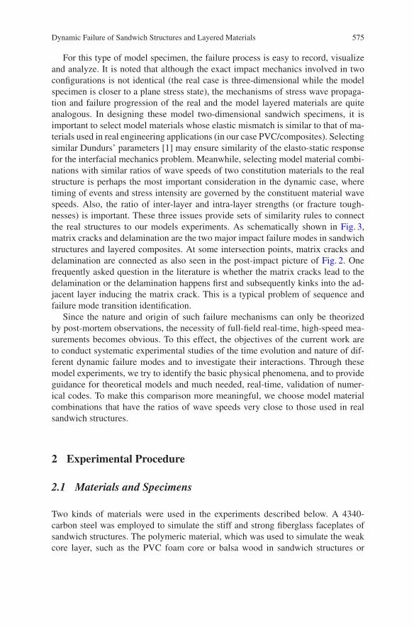
As shown in Fig. 4, three different types of model sandwich specimen geometrieswere designed and tested. Type A specimens have equal layer widths and involvetwo different materials. They contain two metal layers with one polymer layer sand-wiched between them. Type B specimens involve two thin metal layers (faceplates)and one polymer layer. This type of specimens is quite similar in geometry (ratio ofcore to face plate thickness) to realistic sandwich plates used in engineering appli-cations. The only difference between type C and type B specimens is their lengths.Type C specimens are twice as long as type B specimens. The purpose of type Cspecimens is to explore the impact failure patterns with least edge effect present inthe time scale of the failure process. All three types of specimens have the sameout-of-plane thickness of 6.35 mm.
254 mma
c
b254 mm
38mm
38mm
38mm
508 mm
38 mm6 mm
6 mm
Fig. 4 Model specimens simulating sandwich structures (shaded layers – metals; transparentlayers – polymers)
Dynamic Failure of Sandwich Structures and Layered Materials 577
2.2 Experimental Setup
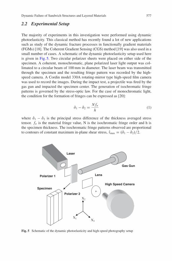
The majority of experiments in this investigation were performed using dynamicphotoelasticity. This classical method has recently found a lot of new applicationssuch as study of the dynamic fracture processes in functionally gradient materials(FGMs) [18]. The Coherent Gradient Sensing (CGS) method [19] was also used in asmall number of cases. A schematic of the dynamic photoelasticity setup used hereis given in Fig. 5. Two circular polarizer sheets were placed on either side of thespecimen. A coherent, monochromatic, plane polarized laser light output was col-limated to a circular beam of 100 mm in diameter. The laser beam was transmittedthrough the specimen and the resulting fringe pattern was recorded by the high-speed camera. A Cordin model 330A rotating-mirror type high-speed film camerawas used to record the images. During the impact test, a projectile was fired by thegas gun and impacted the specimen center. The generation of isochromatic fringepatterns is governed by the stress-optic law. For the case of monochromatic light,the condition for the formation of fringes can be expressed as [20]:
O�1 � O�2 DNf�
h(1)
where O�1 � O�2 is the principal stress difference of the thickness averaged stresstensor. f� is the material fringe value, N is the isochromatic fringe order and h isthe specimen thickness. The isochromatic fringe patterns observed are proportionalto contours of constant maximum in-plane shear stress, O�max D . O�1 � O�2/=2.
Polarizer 2
Polarizer 1 Lens
Specimen
Laser
Gas Gun
High Speed Camera
X2
X3X1
Fig. 5 Schematic of the dynamic photoelasticity and high-speed photography setup
578 L.R. Xu and A.J. Rosakis
3 Results and Discussion
3.1 Failure Process of Short Model Sandwich Specimenswith Equal Layer Widths
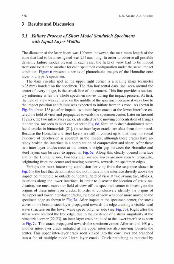
The diameter of the laser beam was 100 mm; however, the maximum length of thezone that had to be investigated was 254 mm long. In order to observe all possibledynamic failure modes present in each case, the field of view had to be movedfrom one location to another for each specimen configuration under the same impactcondition. Figure 6 presents a series of photoelastic images of the Homalite corelayer of a type A specimen.
The dark circular spot at the upper right corner is a scaling mark (diameter6.35 mm) bonded on the specimen. The thin horizontal dark line, seen around thecenter of every image, is the streak line of the camera. This line provides a station-ary reference when the whole specimen moves during the impact process. At first,the field of view was centered on the middle of the specimen because it was close tothe impact position and failure was expected to initiate from this zone. As shown inFig. 6b, about 158�s after impact, two inter-layer cracks at the lower interface en-tered the field of view and propagated towards the specimen center. Later on (around182�s), the two inter-layer cracks, identified by the moving concentration of fringesat their tips, are seen to meet each other in Fig. 6d. Similar to shear-dominated inter-facial cracks in bimaterials [21], those inter-layer cracks are also shear-dominated.Because the Homalite and steel layers are still in contact up to that time, no visualevidence of decohesion is apparent in the images, although these cracks have al-ready broken the interface in a combination of compression and shear. After thesetwo inter-layer cracks meet at the center, a bright gap between the Homalite andsteel layers can be seen to appear in Fig. 6e. Along this clearly opened interfaceand on the Homalite side, two Rayleigh surface waves are now seen to propagate,originating from the center and moving outwards, towards the specimen edges.
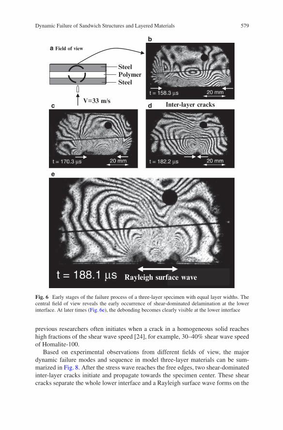
Perhaps the most interesting conclusion deriving from the sequence shown inFig. 6 is the fact that delamination did not initiate in the interface directly above theimpact point but did so outside our central field of view at two symmetric, off-axis,locations along the lower interface. In order to discover the location of crack nu-cleation, we must move our field of view off the specimen center to investigate theorigins of these inter-layer cracks. In order to conclusively identify the origins ofthe upper and lower inter-layer cracks, the field of view was once more moved to thespecimen edge as shown in Fig. 7a. After impact at the specimen center, the stresswaves in the bottom steel layer propagated towards the edge creating a visible headwave structure on the lower wave speed polymer side (see Fig. 7b). Right after thestress wave reached the free edge, due to the existence of a stress singularity at thebimaterial corner [22,23], an inter-layer crack initiated at the lower interface as seenin Fig. 7c. This crack propagated towards the specimen center. After around 160�s,another inter-layer crack initiated at the upper interface also moving towards thecenter. This upper inter-layer crack soon kinked into the core layer and branchedinto a fan of multiple mode-I intra-layer cracks. Crack branching as reported by
Dynamic Failure of Sandwich Structures and Layered Materials 579
Polymer Steel
V=33 m/s
b
dc
e
a Field of view
Steel
Inter-layer cracks
Rayleigh surface wave
Fig. 6 Early stages of the failure process of a three-layer specimen with equal layer widths. Thecentral field of view reveals the early occurrence of shear-dominated delamination at the lowerinterface. At later times (Fig. 6e), the debonding becomes clearly visible at the lower interface
previous researchers often initiates when a crack in a homogeneous solid reacheshigh fractions of the shear wave speed [24], for example, 30–40% shear wave speedof Homalite-100.
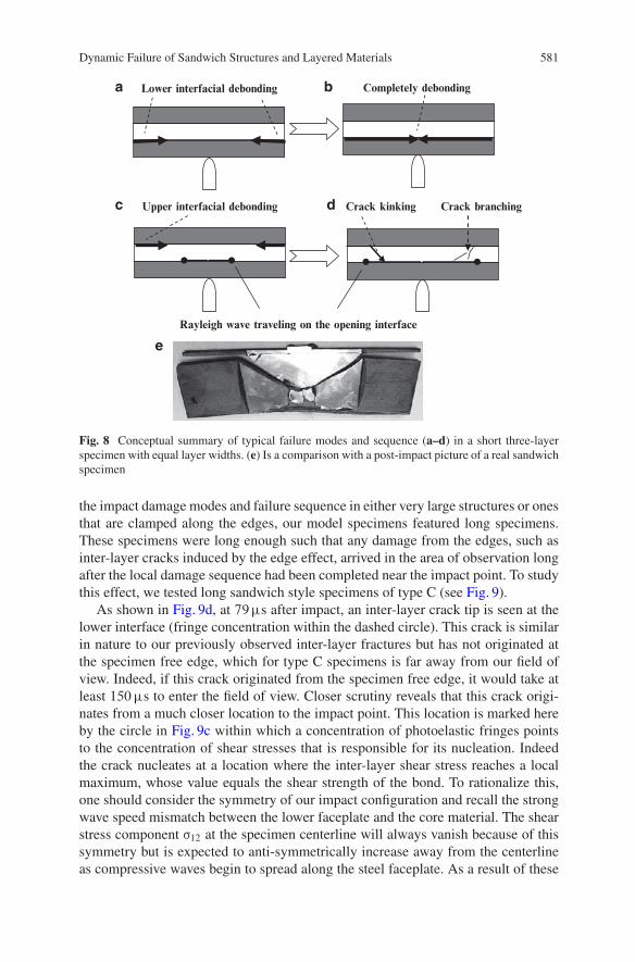
Based on experimental observations from different fields of view, the majordynamic failure modes and sequence in model three-layer materials can be sum-marized in Fig. 8. After the stress wave reaches the free edges, two shear-dominatedinter-layer cracks initiate and propagate towards the specimen center. These shearcracks separate the whole lower interface and a Rayleigh surface wave forms on the
580 L.R. Xu and A.J. Rosakis
Homalite
Steel
interfacial crack initiation
V=33 m/s
ba Field of view
dc
fe
Fig. 7 Edge view of damage evolution: delaminations are shown to form at the intersection of,first lower, and then upper interfaces with the specimen edge. A fan of kinked intra-layer cracksbranches into the core layer from the upper interface
separated free surface. At a later stage, inter-layer cracks also originate from the up-per interface at the free edge and travel towards the specimen center. However, theseupper inter-layer cracks soon kink into the core layer to form opening-dominatedintra-layer cracks. Under certain circumstances (e.g., if the core material is verybrittle), such kinked cracks may also branch into a fan of multiple branches frag-menting the core. The model experiments described here seem to capture the basicnature of the post-mortem impact failure modes observed in real sandwich struc-tures. Indeed, the kinked matrix crack of the core layer of the glass fiber/foamcore sandwich shown in Fig. 8e seems to follow the same initiation and propagationprocess as the kinked intra-layer crack in the model three-layer specimens schemat-ically shown in Fig. 8d.
3.2 Failure Process in Long Model Sandwich Specimens
In type A specimens, inter-layer cracks always initiated from the specimen freeedges due to the bi-material stress concentration at such locations. In order to study
Dynamic Failure of Sandwich Structures and Layered Materials 581
Crack kinking
Lower interfacial debonding
Crack branching
Completely debonding
Rayleigh wave traveling on the opening interface
Upper interfacial debonding
a b
c
e
d
Fig. 8 Conceptual summary of typical failure modes and sequence (a–d) in a short three-layerspecimen with equal layer widths. (e) Is a comparison with a post-impact picture of a real sandwichspecimen
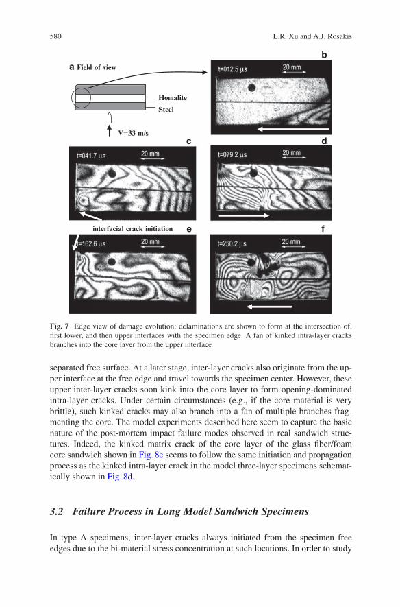
the impact damage modes and failure sequence in either very large structures or onesthat are clamped along the edges, our model specimens featured long specimens.These specimens were long enough such that any damage from the edges, such asinter-layer cracks induced by the edge effect, arrived in the area of observation longafter the local damage sequence had been completed near the impact point. To studythis effect, we tested long sandwich style specimens of type C (see Fig. 9).
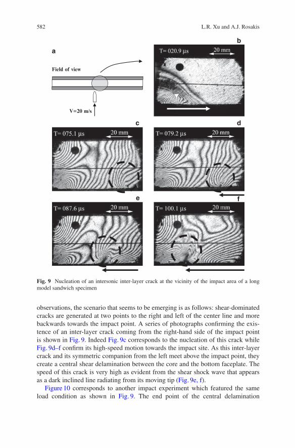
As shown in Fig. 9d, at 79�s after impact, an inter-layer crack tip is seen at thelower interface (fringe concentration within the dashed circle). This crack is similarin nature to our previously observed inter-layer fractures but has not originated atthe specimen free edge, which for type C specimens is far away from our field ofview. Indeed, if this crack originated from the specimen free edge, it would take atleast 150�s to enter the field of view. Closer scrutiny reveals that this crack origi-nates from a much closer location to the impact point. This location is marked hereby the circle in Fig. 9c within which a concentration of photoelastic fringes pointsto the concentration of shear stresses that is responsible for its nucleation. Indeedthe crack nucleates at a location where the inter-layer shear stress reaches a localmaximum, whose value equals the shear strength of the bond. To rationalize this,one should consider the symmetry of our impact configuration and recall the strongwave speed mismatch between the lower faceplate and the core material. The shearstress component ¢12 at the specimen centerline will always vanish because of thissymmetry but is expected to anti-symmetrically increase away from the centerlineas compressive waves begin to spread along the steel faceplate. As a result of these
582 L.R. Xu and A.J. Rosakis
Field of view
V=20 m/s
b
a
dc
fe
Fig. 9 Nucleation of an intersonic inter-layer crack at the vicinity of the impact area of a longmodel sandwich specimen
observations, the scenario that seems to be emerging is as follows: shear-dominatedcracks are generated at two points to the right and left of the center line and morebackwards towards the impact point. A series of photographs confirming the exis-tence of an inter-layer crack coming from the right-hand side of the impact pointis shown in Fig. 9. Indeed Fig. 9c corresponds to the nucleation of this crack whileFig. 9d–f confirm its high-speed motion towards the impact site. As this inter-layercrack and its symmetric companion from the left meet above the impact point, theycreate a central shear delamination between the core and the bottom faceplate. Thespeed of this crack is very high as evident from the shear shock wave that appearsas a dark inclined line radiating from its moving tip (Fig. 9e, f).
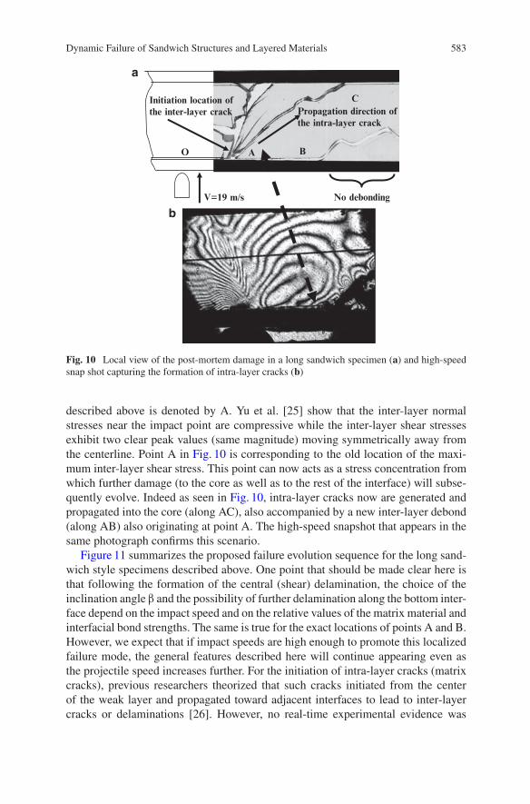
Figure 10 corresponds to another impact experiment which featured the sameload condition as shown in Fig. 9. The end point of the central delamination
Dynamic Failure of Sandwich Structures and Layered Materials 583
No debonding
Propagation direction ofthe intra-layer crack
Initiation location ofthe inter-layer crack
A B
C
O
V=19 m/s
a
b
Fig. 10 Local view of the post-mortem damage in a long sandwich specimen (a) and high-speedsnap shot capturing the formation of intra-layer cracks (b)
described above is denoted by A. Yu et al. [25] show that the inter-layer normalstresses near the impact point are compressive while the inter-layer shear stressesexhibit two clear peak values (same magnitude) moving symmetrically away fromthe centerline. Point A in Fig. 10 is corresponding to the old location of the maxi-mum inter-layer shear stress. This point can now acts as a stress concentration fromwhich further damage (to the core as well as to the rest of the interface) will subse-quently evolve. Indeed as seen in Fig. 10, intra-layer cracks now are generated andpropagated into the core (along AC), also accompanied by a new inter-layer debond(along AB) also originating at point A. The high-speed snapshot that appears in thesame photograph confirms this scenario.
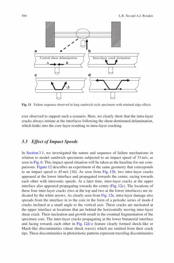
Figure 11 summarizes the proposed failure evolution sequence for the long sand-wich style specimens described above. One point that should be made clear here isthat following the formation of the central (shear) delamination, the choice of theinclination angle “ and the possibility of further delamination along the bottom inter-face depend on the impact speed and on the relative values of the matrix material andinterfacial bond strengths. The same is true for the exact locations of points A and B.However, we expect that if impact speeds are high enough to promote this localizedfailure mode, the general features described here will continue appearing even asthe projectile speed increases further. For the initiation of intra-layer cracks (matrixcracks), previous researchers theorized that such cracks initiated from the centerof the weak layer and propagated toward adjacent interfaces to lead to inter-layercracks or delaminations [26]. However, no real-time experimental evidence was
584 L.R. Xu and A.J. Rosakis
b
A B
Central shear delamination Intra-layer crack formation
a
c d
b
Fig. 11 Failure sequence observed in long sandwich-style specimens with minimal edge effects
ever observed to support such a scenario. Here, we clearly show that the intra-layercracks always initiate at the interfaces following the shear-dominated delamination,which kinks into the core layer resulting in intra-layer cracking.
3.3 Effect of Impact Speeds
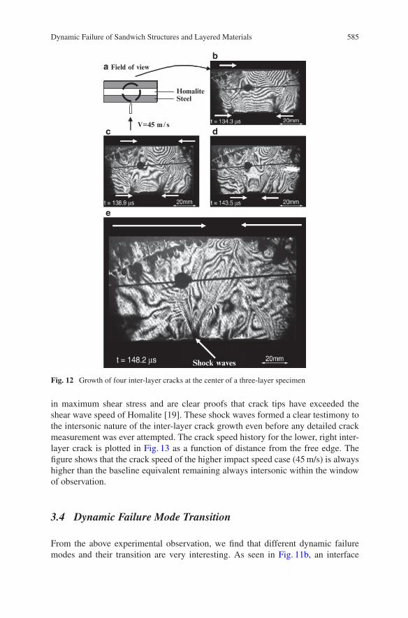
In Section 3.1, we investigated the nature and sequence of failure mechanisms inrelation to model sandwich specimens subjected to an impact speed of 33 m/s, asseen in Fig. 6. This impact speed situation will be taken as the baseline for our com-parisons. Figure 12 describes an experiment of the same geometry that correspondsto an impact speed is 45 m/s [16]. As seen from Fig. 12b, two inter-layer cracksappeared at the lower interface and propagated towards the center, racing towardseach other with intersonic speeds. At a later time, inter-layer cracks at the upperinterface also appeared propagating towards the center (Fig. 12c). The locations ofthese four inter-layer cracks (two at the top and two at the lower interfaces) are in-dicated by the white arrows. As clearly seen from Fig. 12e, intra-layer damage alsospreads from the interface in to the core in the form of a periodic series of mode-Icracks inclined at a small angle to the vertical axis. These cracks are nucleated atthe upper interface at locations that are behind the horizontally moving inter-layershear crack. Their nucleation and growth result in the eventual fragmentation of thespecimen core. The inter-layer cracks propagating at the lower bimaterial interfaceand facing towards each other in Fig. 12d–e feature clearly formed shock-like orMach-like discontinuities (shear shock waves) which are emitted from their cracktips. These discontinuities in photoelastic patterns represent traveling discontinuities
Dynamic Failure of Sandwich Structures and Layered Materials 585
HomaliteSteel
V=45 m / s
Shock waves
b
dc
e
a Field of view
Fig. 12 Growth of four inter-layer cracks at the center of a three-layer specimen
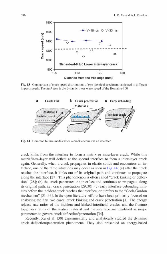
in maximum shear stress and are clear proofs that crack tips have exceeded theshear wave speed of Homalite [19]. These shock waves formed a clear testimony tothe intersonic nature of the inter-layer crack growth even before any detailed crackmeasurement was ever attempted. The crack speed history for the lower, right inter-layer crack is plotted in Fig. 13 as a function of distance from the free edge. Thefigure shows that the crack speed of the higher impact speed case (45 m/s) is alwayshigher than the baseline equivalent remaining always intersonic within the windowof observation.
3.4 Dynamic Failure Mode Transition
From the above experimental observation, we find that different dynamic failuremodes and their transition are very interesting. As seen in Fig. 11b, an interface
586 L.R. Xu and A.J. Rosakis
3lshssbwd-8 & 6 Lower inter-layer crack
800
1000
1200
1400
1600
1800
100 110 120 130
Distance from the free edge (mm)
Cra
ck s
pee
d (
m/s
)
V=45m/s V=33m/s
Cs
Fig. 13 Comparison of crack speed distributions of two identical specimens subjected to differentimpact speeds. The dash line is the dynamic shear wave speed of the Homalite-100
Crack kink Crack penetration Early debonding
Incident crackIncident crack
Material 2
Incident crackMaterial 1
a b c
Fig. 14 Common failure modes when a crack encounters an interface
crack kinks from the interface to form a matrix or intra-layer crack. While thismatrix/intra-layer will deflect at the second interface to form a inter-layer crackagain. Generally, when a crack propagates in elastic solids and encounters an in-terface, one of the three situations may occur as seen in Fig. 14: (a) after the crackreaches the interface, it kinks out of its original path and continues to propagatealong the interface [27]. This phenomenon is often called “crack kinking or deflec-tion” [28]; (b) the crack penetrates the interface and continues to propagate alongits original path, i.e., crack penetration [29, 30]; (c) early interface debonding initi-ates before the incident crack reaches the interface, or it refers to the “Cook-Gordonmechanism” [31–33]. In the open literature, efforts have been primarily focused onanalyzing the first two cases, crack kinking and crack penetration [1]. The energyrelease rate ratios of the incident and kinked interfacial cracks, and the fracturetoughness ratios of the matrix material and the interface are identified as majorparameters to govern crack deflection/penetration [34].
Recently, Xu et al. [30] experimentally and analytically studied the dynamiccrack deflection/penetration phenomena. They also presented an energy-based
Dynamic Failure of Sandwich Structures and Layered Materials 587
criterion to investigate the competition between the dynamic crack penetration anddeflection. The criterion for interfacial dynamic crack kinking is a ratio comparisonbetween two energy release rates for the deflected/kinked crack along the interface,and the incident crack inside the matrix (driving force) and the fracture toughnessvalues (material resistance):
Gd.ˇ; v2/GPI .v1/
�� ITc .v2/
�MAId .v1/(2)
where ˇ is the crack kinking angle or interface angle, and v1 and v2 are the incidentparent crack speed and the kinked daughter crack speed respectively (Freund [40]).�MAId .v1/ is the dynamic fracture toughness of the matrix material and �ITC .v2/ is theinterfacial fracture toughness. If the left side is less than the right side, a dynamiccrack penetration will occur.
However, in order to apply the energy-based criterion, putative crack deflectionand crack penetration lengths are needed to evaluate the corresponding energy re-lease rates. Several researchers [29, 35] have demonstrated that the two putativelengths have a significant effect on the energy release rate ratios, and sometimes theenergy-based criterion fails to predict the crack deflection or crack penetration. Forthese cases, “Cook-Gordon mechanism” provides an alternative explanation since acrack may not kink right after it reaches the interface as shown in Fig. 14a. The case(interface debonding before kinking) shown in Fig. 14c is quite possible.
3.5 Dynamic Interface Debonding Aheadof a Main Incident Crack
In Fig. 14c, correlations of the fracture mechanics parameters of the kinked inter-facial crack and the incident crack are not easy to obtain. Therefore, in order tomodel the “Cook-Gordon mechanism”, we tend to use strength-based criteria to pre-dict interfacial debonding initiation only (rather than crack growth) induced by anincident crack. In terms of the dynamic “Cook-Gordon mechanism”, only Needle-man and co-workers [36–38] have simulated this problem using a cohesive elementmodel. In their model, an artificial initial flaw was introduced so they assumed somematerial properties for predictions. In our investigation, a strength criterion with di-rect interfacial strength measurements will be used to predict the critical distancerc of the incident crack tip to the intersection point of the incident crack path andthe interface. Indeed, our work will be complementary to Needleman’s work, sinceour work aims to predict interfacial debonding initiation, while their efforts werefocused on simulating the late interfacial crack propagation after crack initiation.
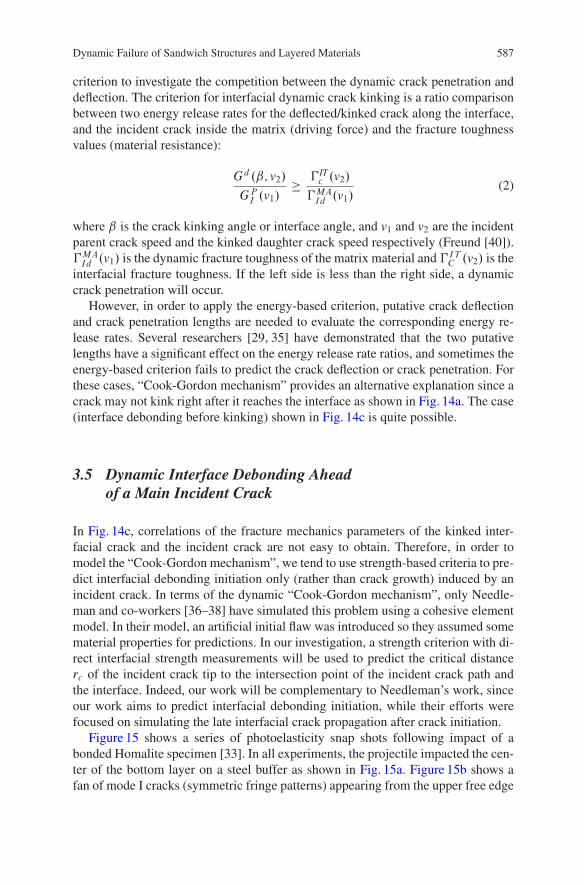
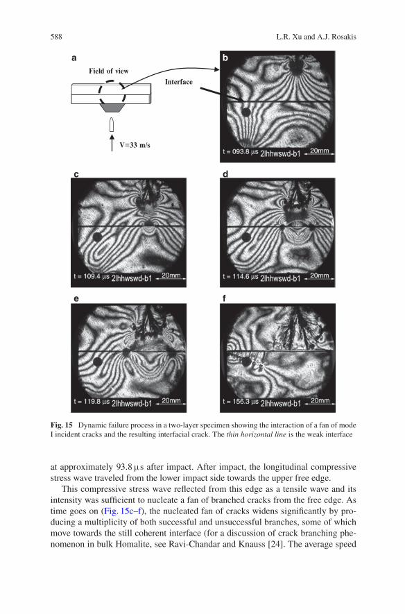
Figure 15 shows a series of photoelasticity snap shots following impact of abonded Homalite specimen [33]. In all experiments, the projectile impacted the cen-ter of the bottom layer on a steel buffer as shown in Fig. 15a. Figure 15b shows afan of mode I cracks (symmetric fringe patterns) appearing from the upper free edge
588 L.R. Xu and A.J. Rosakis
Interface
Field of view
V=33 m/s
ba
c d
e f
Fig. 15 Dynamic failure process in a two-layer specimen showing the interaction of a fan of modeI incident cracks and the resulting interfacial crack. The thin horizontal line is the weak interface
at approximately 93:8�s after impact. After impact, the longitudinal compressivestress wave traveled from the lower impact side towards the upper free edge.
This compressive stress wave reflected from this edge as a tensile wave and itsintensity was sufficient to nucleate a fan of branched cracks from the free edge. Astime goes on (Fig. 15c–f), the nucleated fan of cracks widens significantly by pro-ducing a multiplicity of both successful and unsuccessful branches, some of whichmove towards the still coherent interface (for a discussion of crack branching phe-nomenon in bulk Homalite, see Ravi-Chandar and Knauss [24]. The average speed
Dynamic Failure of Sandwich Structures and Layered Materials 589
of these locally mode I, branched cracks is 0:41CS, which is the branching speedin bulk Homalite. Well before the branched cracks reached the interface, a centralinter-layer crack was nucleated at the intersection of the specimen center line and thebond line as seen in Fig. 15c. This interfacial crack propagated in both directions offthe center as shown in Fig. 15d. At the specimen centerline, the shear stresses vanishbecause of symmetry. As a result, the nucleated inter-layer crack is initially and, fora very short time, mode I dominated. Its nucleation is induced by the stress fieldproduced by the fan of branched cracks approaching the interface. As this crackspreads symmetrically, opening up the interface (see distinct evidence of decohe-sion in Fig. 15f, the fan of branched cracks decelerates and arrests just before thesecracks reach the decohered interface. The above described scenario is perhaps thefirst real-time visualization of the dynamic equivalent of the “Cook-Gordon Mech-anism” describing the remote decohesion of an interface due to the approach ofa matrix (intra-layer) crack. As the interfacial crack spreads away from the speci-men centerline, it almost immediately encounters increasing amount of interfacialshear stress, which quickly converts it to a mixed-mode and eventually to a mode IIdominated crack. Unlike propagating cracks in bulk Homalite, interfacial cracks areconstrained to propagate along the weak interface and, as a result, they can do sounder mixed-mode or primarily mode II conditions. They can also propagate at veryhigh (even intersonic) speeds compared to their bulk (intra-layer) counterparts. Inorder to predict the dynamic crack initiation, Wang and Xu [27] proposed a strengthcriterion �
� 022=�t�2C�� 012=�s
�2D 1 (3)
where �t ; �s are the interface tensile and shear strengths, � 011; �012; �
022 are stresses
acting on the interface which are induced by an incident dynamic crack close to theinterface. The stress field of a steady mode I crack inside a linear elastic solid isgiven by a well-known form [39, 40]:
�Iij DKI .t/p2�r
†Iij. ; v/C T ıi1ıj1 CO.1/ (4)
where KI .t/ is the dynamic stress intensity factor of the mode I crack as a func-tion of time t ;T is a non-singular term, which is called “the T-stress” or ¢ox [20];O.1/ represents higher order terms; the functions †Iij. ; v/ that represent the angu-lar variation of stress components for an instantaneous crack tip speed v. For thekinked/deflected interface crack, it is a mixed-mode crack with a stress field:
�ij D �Iij C �
IIij
DKI .t/p2�r
XI
ij. ; V /C T ıi1ıj1 C
KII.t/p2�r
XII
ij. ; V /CO.1/ (5)
where KII.t/ is the dynamic stress intensity factor of the mode II crack as a func-tion of time t and the functions †II
ij . ; v/ represents the angular variation of stresscomponents for an instantaneous crack tip speed v.
590 L.R. Xu and A.J. Rosakis
3.6 New Progress on Dynamic Crack Branching
As observed in the above dynamic failure experiments, we find that dynamic crackbranching is an important dynamic failure mode for brittle materials, and for ductilematerials subjected to certain conditions. This phenomenon has received extensiveattention in the past decades. However, previous major efforts have primarily fo-cused on analytical and numerical studies [41–43]. Very few new experimentalresults were available to verify predictions or to provide guidance for modeling[24, 44]. Some important issues, such as the crack speed change before and afterbranching, effect of dynamic loading rate on the crack branching, and crack branch-ing induced by stress wave loading are still open. Therefore, we try to focus onhow to realize various forms of dynamic crack branching under a variety of condi-tions [45]. The objectives are to elucidate a series of new phenomena; and to provideguidance for developing theoretical models and validating numerical simulations.
3.6.1 Special Experiments for Dynamic Crack Kinking and Branching
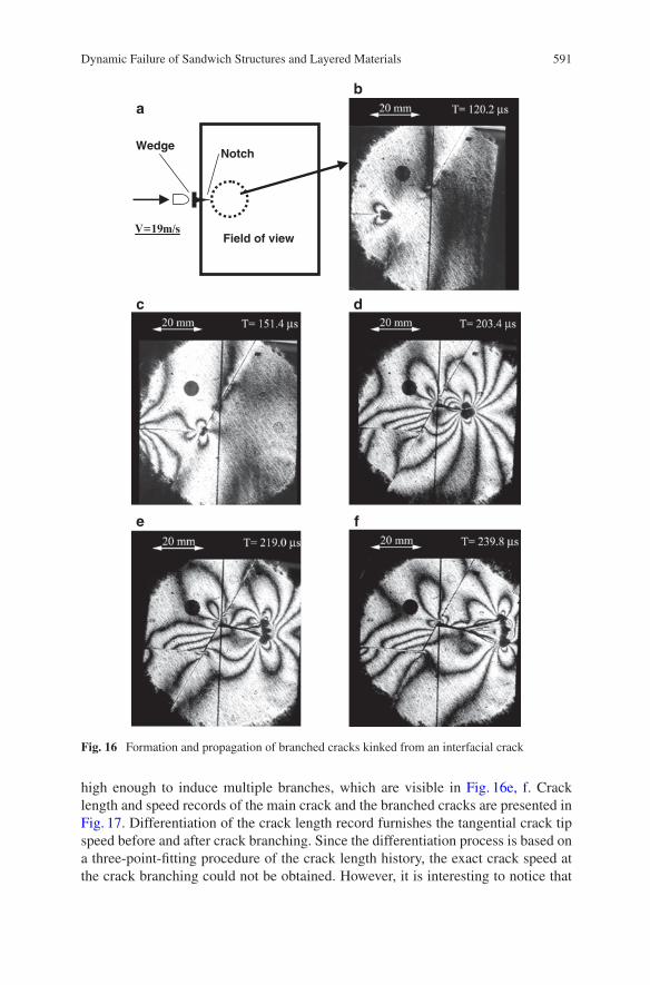
Two kinds of polymeric materials were used in conjunction with two kinds of opticaldiagnostic techniques. Homalite-100 was chosen for the photoelasticity experimentswhile PMMA was used in the Coherent Gradient Sensing experiments. Varioustypes of specimens were designed and some of them had pre-notches with differ-ent radii. One major specimen used in this investigation was a novel wedge-loadedspecimen, which was designed to produce a single, straight dynamic crack as shownin Fig. 16a. An aluminum wedge was inserted into a pre-notch and impacted by aprojectile, causing the wedge to open the notch faces thus producing a single modeI crack [30]. The notch tip was cut using a diamond afering blade (Buehler, Series15 LC). A strain gauge was bonded onto the wedge to trigger the high-speed cameraand laser system.
3.6.2 Dynamic Crack Branching and Kinking from a Weak Interface
As shown in Fig. 16, the in-plane Homalite specimen dimensions were 457 mmlong, 254 mm wide and the plate thickness was 9.5 mm. In this photoelasticity ex-periment, the initial notch radius was 0.127 mm (0.005 in.). For a low impact speed,V D 19m=s, only a pure mode I crack initiated from the notch. As seen in Fig. 16b,we created an artificial interface (an inclined thin line) in front of the horizontallypropagating crack. The incident mode I crack approached the interface at about151�s after impact and transitioned into a mixed-mode interfacial crack. A ver-tical line appearing in every image is the camera streak line, which was used forpositioning and reference purposes.
At approximately 177�s, this mixed-mode interfacial crack kinked into the rightside of the interface. A significant caustics (or shadow spot) is seen in Fig. 16d toshow the mode I nature of the kinked crack. The speed of the kinked crack was
Dynamic Failure of Sandwich Structures and Layered Materials 591
Field of viewV=19m/s
NotchWedge
b
dc
a
e f
Fig. 16 Formation and propagation of branched cracks kinked from an interfacial crack
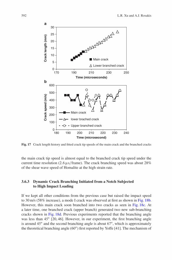
high enough to induce multiple branches, which are visible in Fig. 16e, f. Cracklength and speed records of the main crack and the branched cracks are presented inFig. 17. Differentiation of the crack length record furnishes the tangential crack tipspeed before and after crack branching. Since the differentiation process is based ona three-point-fitting procedure of the crack length history, the exact crack speed atthe crack branching could not be obtained. However, it is interesting to notice that
592 L.R. Xu and A.J. Rosakis
0
5
10
15
20
25
30
170 190 210 230 250
Time (microseconds)
a
b
Cra
ck le
ng
th (
mm
)
Main crack
Lower branched crack
0
100
200
300
400
500
600
180 190 200 210 220 230 240
Time (microsecond)
Cra
ck s
pee
d (
m/s
)
Main crack
lower brached crack
Upper branched crack
Fig. 17 Crack length history and fitted crack tip speeds of the main crack and the branched cracks
the main crack tip speed is almost equal to the branched crack tip speed under thecurrent time resolution (2:6�s=frame). The crack branching speed was about 28%of the shear wave speed of Homalite at the high strain rate.
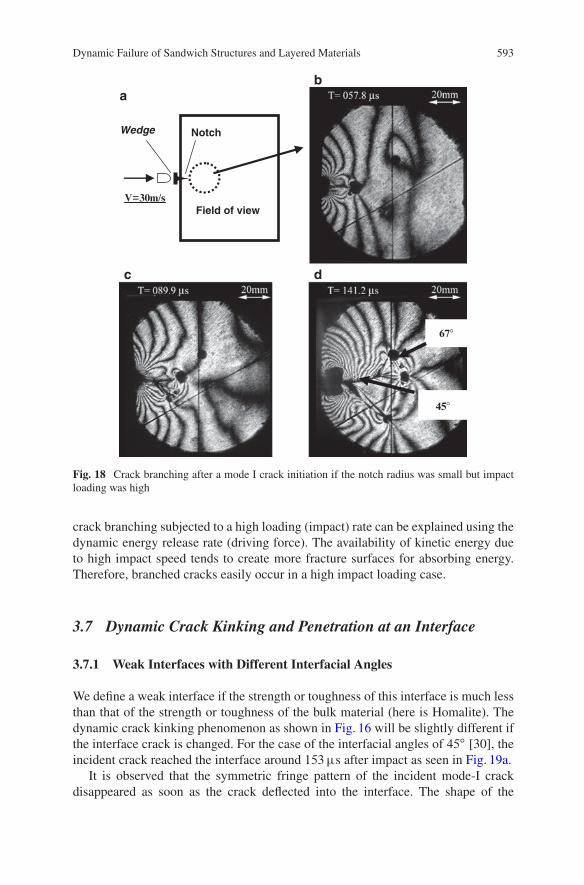
3.6.3 Dynamic Crack Branching Initiated from a Notch Subjectedto High Impact Loading
If we kept all other conditions from the previous case but raised the impact speedto 30 m/s (58% increase), a mode I crack was observed at first as shown in Fig. 18b.However, this main crack soon branched into two cracks as seen in Fig. 18c. Ata later time, one branched crack (upper branch) generated two new sub-branchingcracks shown in Fig. 18d. Previous experiments reported that the branching anglewas less than 45ı [20, 46]. However, in our experiment, the first branching angleis around 45ı and the second branching angle is about 67ı, which is approximatelythe theoretical branching angle (60ı) first reported by Yoffe [41]. The mechanism of
Dynamic Failure of Sandwich Structures and Layered Materials 593
Field of view V=30m/s
NotchWedge
45�
67�
ba
dc
Fig. 18 Crack branching after a mode I crack initiation if the notch radius was small but impactloading was high
crack branching subjected to a high loading (impact) rate can be explained using thedynamic energy release rate (driving force). The availability of kinetic energy dueto high impact speed tends to create more fracture surfaces for absorbing energy.Therefore, branched cracks easily occur in a high impact loading case.
3.7 Dynamic Crack Kinking and Penetration at an Interface
3.7.1 Weak Interfaces with Different Interfacial Angles
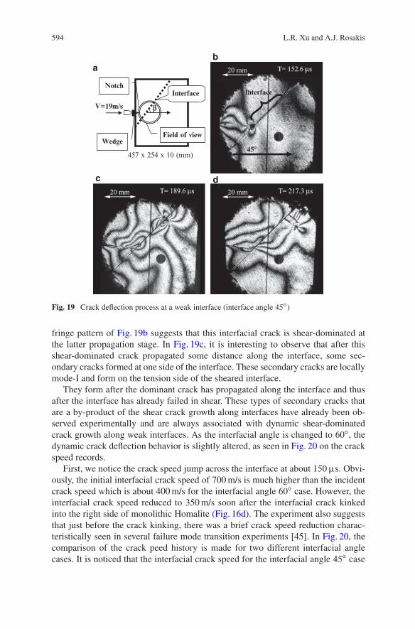
We define a weak interface if the strength or toughness of this interface is much lessthan that of the strength or toughness of the bulk material (here is Homalite). Thedynamic crack kinking phenomenon as shown in Fig. 16 will be slightly different ifthe interface crack is changed. For the case of the interfacial angles of 45ı [30], theincident crack reached the interface around 153�s after impact as seen in Fig. 19a.
It is observed that the symmetric fringe pattern of the incident mode-I crackdisappeared as soon as the crack deflected into the interface. The shape of the
594 L.R. Xu and A.J. Rosakis
45�
Interface
Field of view
InterfaceNotch
Wedge
bV=19m/s
457 x 254 x 10 (mm)
ba
c d
Fig. 19 Crack deflection process at a weak interface (interface angle 45ı)
fringe pattern of Fig. 19b suggests that this interfacial crack is shear-dominated atthe latter propagation stage. In Fig. 19c, it is interesting to observe that after thisshear-dominated crack propagated some distance along the interface, some sec-ondary cracks formed at one side of the interface. These secondary cracks are locallymode-I and form on the tension side of the sheared interface.
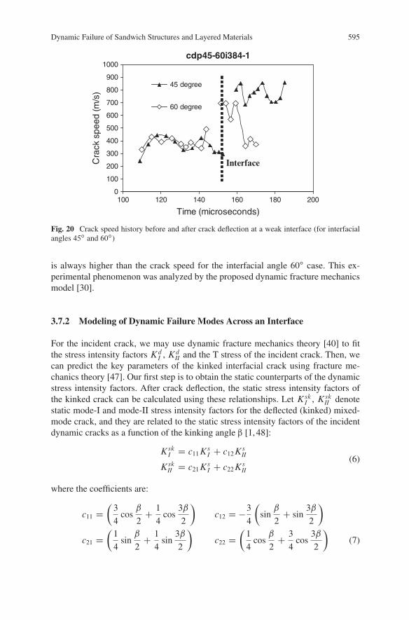
They form after the dominant crack has propagated along the interface and thusafter the interface has already failed in shear. These types of secondary cracks thatare a by-product of the shear crack growth along interfaces have already been ob-served experimentally and are always associated with dynamic shear-dominatedcrack growth along weak interfaces. As the interfacial angle is changed to 60ı, thedynamic crack deflection behavior is slightly altered, as seen in Fig. 20 on the crackspeed records.
First, we notice the crack speed jump across the interface at about 150�s. Obvi-ously, the initial interfacial crack speed of 700 m/s is much higher than the incidentcrack speed which is about 400 m/s for the interfacial angle 60ı case. However, theinterfacial crack speed reduced to 350 m/s soon after the interfacial crack kinkedinto the right side of monolithic Homalite (Fig. 16d). The experiment also suggeststhat just before the crack kinking, there was a brief crack speed reduction charac-teristically seen in several failure mode transition experiments [45]. In Fig. 20, thecomparison of the crack peed history is made for two different interfacial anglecases. It is noticed that the interfacial crack speed for the interfacial angle 45ı case
Dynamic Failure of Sandwich Structures and Layered Materials 595
cdp45-60i384-1
0
100
200
300
400
500
600
700
800
900
1000
100 120 140 160 180 200
Time (microseconds)
Cra
ck s
peed
(m/s
)45 degree
60 degree
Interface
Fig. 20 Crack speed history before and after crack deflection at a weak interface (for interfacialangles 45ı and 60ı)
is always higher than the crack speed for the interfacial angle 60ı case. This ex-perimental phenomenon was analyzed by the proposed dynamic fracture mechanicsmodel [30].
3.7.2 Modeling of Dynamic Failure Modes Across an Interface
For the incident crack, we may use dynamic fracture mechanics theory [40] to fitthe stress intensity factors Kd
I , KdII and the T stress of the incident crack. Then, we
can predict the key parameters of the kinked interfacial crack using fracture me-chanics theory [47]. Our first step is to obtain the static counterparts of the dynamicstress intensity factors. After crack deflection, the static stress intensity factors ofthe kinked crack can be calculated using these relationships. Let Ksk
I , KskII denote
static mode-I and mode-II stress intensity factors for the deflected (kinked) mixed-mode crack, and they are related to the static stress intensity factors of the incidentdynamic cracks as a function of the kinking angle “ [1, 48]:
KskI D c11K
sI C c12K
sII
KskII D c21K
sI C c22K
sII
(6)
where the coefficients are:
c11 D
�3
4cos
ˇ
2C1
4cos
3ˇ
2
�c12 D �
3
4
�sin
ˇ
2C sin
3ˇ
2
�
c21 D
�1
4sin
ˇ
2C1
4sin
3ˇ
2
�c22 D
�1
4cos
ˇ
2C3
4cos
3ˇ
2
�(7)
596 L.R. Xu and A.J. Rosakis
Let KdkI , Kdk
II be dynamic mode-I and mode-II stress intensity factors for thedeflected (kinked) mixed-mode crack. We still assume that the universal relationbetween the dynamic and static stress intensity factors also holds for the deflectedcrack tip, i.e.,
KdkI D kI .v2/K
skI
KdkII D kII.v2/Ksk
II
(8)
where kI.v2/ and kII.v2/ are universal functions of the crack tip speed defined byFreund [40]. Based on the above relations, if we know the dynamic stress intensityfactors, the crack tip speed of the incident crack, the kinking angle as well as thecrack tip speed of the kinked crack, we can get the dynamic stress intensity fac-tors of the kinked crack and hence the crack tip stress fields around the deflectedcrack using Eq. 7. Then, the fringe patterns of the interfacial crack at the momentof crack deflection can be predicted using Eqs. 1 and 5. Because it is very hard torecord the exact moment of crack kinking at the interface in dynamic fracture ex-periments, average values of the stress intensity factors of the incident crack wereused to calculate the stress intensity factors of the kinked interfacial crack.
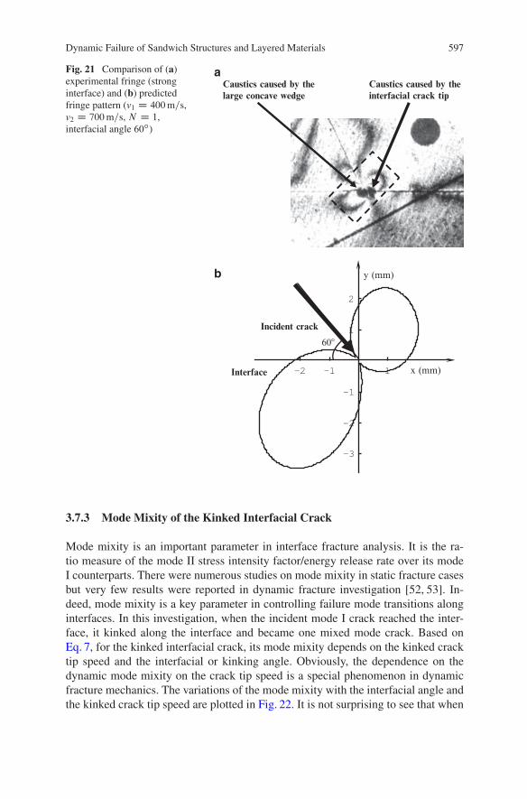
Figure 21 shows the predicted fringe pattern of a kinked interfacial crack (inter-facial angle 60ı). The coordinate origin is located at the intersection point of theincident crack and the kinked crack, and its x-axis is along the interface. For thiscase, the crack tip speed of the incident crack was around 400 m/s.
Right after crack kinking, the interfacial crack tip speed was about 700 m/s [30].Since the T-stress of the incident crack is around 1 MPa, and there are no accurateresults for the T-stress of the kinked crack [49], the T-stress of the kinked crackwas assumed to be zero in all our predictions. In order to highlight our comparisonof the predicted and experimental fringe patterns, only fringe order 1 was plotted.Figure 21a presents the experimental fringe showing the transition from an incidentcrack to an interface crack (the horizontal line was the interface). Figure 21b showedthe predicted fringe and the two kinds of photoelasticity fringes were very similar soour dynamic fracture mechanics modeling and assumptions were reasonable. How-ever, some discrepancy is also noticed because it is very hard to take one photo atthe right time and right position as the theoretically predicted one.
One interesting observation is the large concave wedge effect. As seen inFig. 21a, two caustic spots (one caused by the kinked crack tip and the otherdue to a large concave wedge) were clearly observed when a mode-I incident crackkinked along a weak interface with a large kinking angle (60ı, see the same photoin Fig. 16c).
In most previous crack kinking analyses, researchers only considered the singu-lar stress field due to a kinked daughter crack and ignored the singular stress fieldof a concave wedge. Interestingly, William’s classical solution of wedge stress sin-gularities [22] is the foundation of the full-field stress field of a traction-free crackin Linear Elastic Fracture Mechanics. Indeed, Cotterell and Rice’s classical workmainly deals with a slightly kinked crack, not a large kinking angle case [50]. Toauthors’ knowledge, only Azhdari and Nemat-Nasser provided a simple explanationto this phenomenon for a static crack kinking case [51].
Dynamic Failure of Sandwich Structures and Layered Materials 597
Fig. 21 Comparison of (a)experimental fringe (stronginterface) and (b) predictedfringe pattern (v1 D 400m=s,v2 D 700m=s, N D 1,interfacial angle 60ı)
Caustics caused by theinterfacial crack tip
Caustics caused by thelarge concave wedge
–2 –1 1
–3
–2
–1
1
2
x (mm)
y (mm)
Incident crack
Interface
60�
a
b
3.7.3 Mode Mixity of the Kinked Interfacial Crack
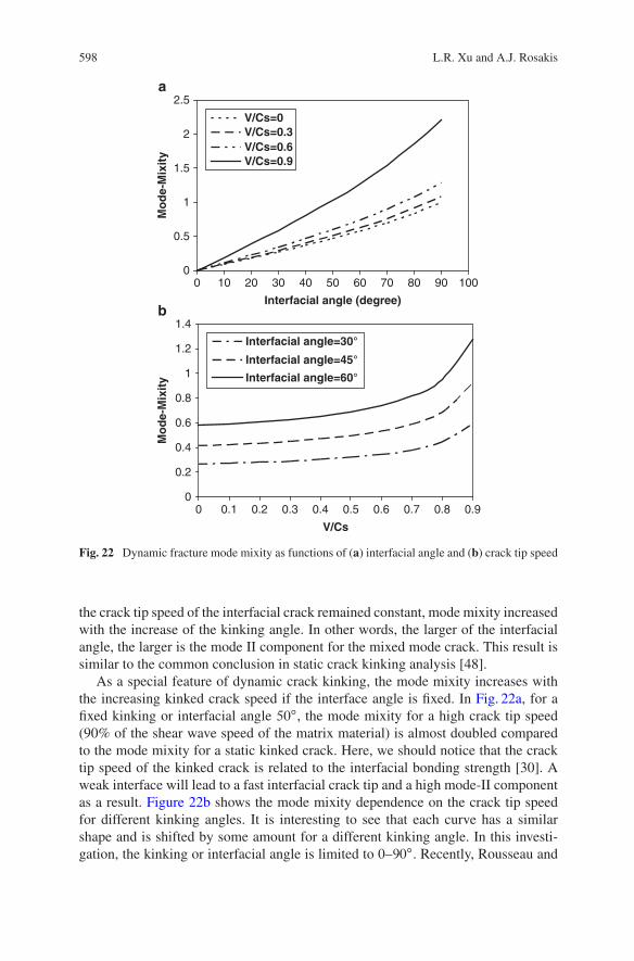
Mode mixity is an important parameter in interface fracture analysis. It is the ra-tio measure of the mode II stress intensity factor/energy release rate over its modeI counterparts. There were numerous studies on mode mixity in static fracture casesbut very few results were reported in dynamic fracture investigation [52, 53]. In-deed, mode mixity is a key parameter in controlling failure mode transitions alonginterfaces. In this investigation, when the incident mode I crack reached the inter-face, it kinked along the interface and became one mixed mode crack. Based onEq. 7, for the kinked interfacial crack, its mode mixity depends on the kinked cracktip speed and the interfacial or kinking angle. Obviously, the dependence on thedynamic mode mixity on the crack tip speed is a special phenomenon in dynamicfracture mechanics. The variations of the mode mixity with the interfacial angle andthe kinked crack tip speed are plotted in Fig. 22. It is not surprising to see that when
598 L.R. Xu and A.J. Rosakis
0
0.5
1
1.5
2
2.5
0 10 20 30 40 50 60 70 80 90 100
Interfacial angle (degree)
Mo
de-
Mix
ity
V/Cs=0V/Cs=0.3V/Cs=0.6V/Cs=0.9
0
0.2
0.4
0.6
0.8
1
1.2
1.4
0 0.1 0.2 0.3 0.4 0.5 0.6 0.7 0.8 0.9
V/Cs
Mo
de-
Mix
ity
Interfacial angle=30°
Interfacial angle=45°
Interfacial angle=60°
a
b
Fig. 22 Dynamic fracture mode mixity as functions of (a) interfacial angle and (b) crack tip speed
the crack tip speed of the interfacial crack remained constant, mode mixity increasedwith the increase of the kinking angle. In other words, the larger of the interfacialangle, the larger is the mode II component for the mixed mode crack. This result issimilar to the common conclusion in static crack kinking analysis [48].
As a special feature of dynamic crack kinking, the mode mixity increases withthe increasing kinked crack speed if the interface angle is fixed. In Fig. 22a, for afixed kinking or interfacial angle 50ı, the mode mixity for a high crack tip speed(90% of the shear wave speed of the matrix material) is almost doubled comparedto the mode mixity for a static kinked crack. Here, we should notice that the cracktip speed of the kinked crack is related to the interfacial bonding strength [30]. Aweak interface will lead to a fast interfacial crack tip and a high mode-II componentas a result. Figure 22b shows the mode mixity dependence on the crack tip speedfor different kinking angles. It is interesting to see that each curve has a similarshape and is shifted by some amount for a different kinking angle. In this investi-gation, the kinking or interfacial angle is limited to 0–90ı. Recently, Rousseau and
Dynamic Failure of Sandwich Structures and Layered Materials 599
Rosakis [54] examined important crack kinking behavior for very large interfacialangle (greater than 90ı). One important difference is that their incident crack wasan inter-sonic shear crack along a weak path rather than a slow mode-I crack as inour investigation. In order to suppress possible crack branching, our incident crackspeed was controlled to be less than the crack branching speed (around 30–40% ofthe shear wave speed for Homailte-100 [55].
3.8 Two-layer Specimens with Direct Impact on the BrittlePolymeric Layer (Fig. 23)
The above discussions are focused on the three-layer specimen or the model sand-wich structure. In order to understand the dynamic response and failure of generallayered materials or structures, experimental investigation on the two-layer speci-men is necessary [56].
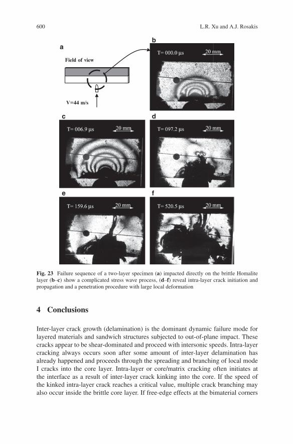
In some applications of layered materials, direct impact on the brittle layer suchas ceramics layer in composite armor is also very important since their failure be-havior might be very different [57]. As shown in Fig. 23 a complicated stress wavepropagation, projectile penetration and large deformation process was observed fora two-layer system with a weak and ductile 5083 bond. As soon as the projectileimpacted the transparent Homalite layer, a series of fringe patterns related to stresswaves developed around the impact site. The projectile head kept moving and com-plicated stress wave interaction and propagation were observed around 10�s afterimpact (Fig. 23b, c).
It should be noticed that the movement of the projectile was not obvious. In thenext stage of projectile penetration, a black contact zone was observed at the im-pact site and an intra-layer crack initiated and propagated towards the interface. InFig. 23e, it seemed that this intra-layer crack arrested at the interface since no signif-icant interfacial crack propagation (moving fringe concentration) was observed inthe following images. As discussed by Xu and Rosakis [33], the crack arrest mech-anism by a ductile and weak adhesive layer is due to the dramatically stress wavegradient change across the adhesive layer. After 300�s of impact (Fig. 23f), a largecontact zone appeared in a growing black zone connected to the projectile. Dueto large deformation inside the contact zone, those transmitted laser rays were de-flected and cannot enter the camera so only a black zone was recorded. Meanwhile,some materials were flying out from the Homalite layer because of the fragmentsof brittle Homalite subjected to high contact force. Compared to the impact on thestrong steel layer of previous cases, direct impact on the brittle Homalite layer hasmore severe damage in the local impact site.
600 L.R. Xu and A.J. Rosakis
Field of view
V=44 m/s
ba
dc
e f
Fig. 23 Failure sequence of a two-layer specimen (a) impacted directly on the brittle Homalitelayer (b–c) show a complicated stress wave process, (d–f) reveal intra-layer crack initiation andpropagation and a penetration procedure with large local deformation
4 Conclusions
Inter-layer crack growth (delamination) is the dominant dynamic failure mode forlayered materials and sandwich structures subjected to out-of-plane impact. Thesecracks appear to be shear-dominated and proceed with intersonic speeds. Intra-layercracking always occurs soon after some amount of inter-layer delamination hasalready happened and proceeds through the spreading and branching of local modeI cracks into the core layer. Intra-layer or core/matrix cracking often initiates atthe interface as a result of inter-layer crack kinking into the core. If the speed ofthe kinked intra-layer crack reaches a critical value, multiple crack branching mayalso occur inside the brittle core layer. If free-edge effects at the bimaterial corners
Dynamic Failure of Sandwich Structures and Layered Materials 601
are eliminated (long model sandwich specimens), the failure sequence is slightlymodified. Specifically, the inter-layer cracks initiate from positions where theinter-layer shear stress reaches a local maximum equal to the shear strength of thebond. These cracks create a local shear-driven delamination directly above the pointof impact. Intra-layer cracks following this process also kink from these positionsinto the sandwich core.
For some individual dynamic failure modes, we find that the dynamic crackbranching can exceed the limit angles 45ı (theoretical result) for a second dynamiccrack, and the crack tip speeds before and after the crack branching are almost same.Crack kink and penetration at interfaces are mainly governed by the ratio competi-tion of the dynamic energy release rates of the incident crack and the kinked crack,and the dynamic fracture toughness ratio of the matrix (bulk material) and the inter-face. For the kinked crack speed, it increases if the interfacial angle and interfacialstrength decrease. A strength-based criterion is proposed to predict the interfacialdebonding ahead of a main crack well.
Acknowledgements The authors gratefully acknowledge the support of the Office of Naval Re-search through a MURI grant to Caltech (N00014–06–1–0730), a research grant to Vanderbilt(N00014–08–1–0137), Dr. Y.D.S Rajapakse, Program Manager of both projects.
References
1. Hutchinson JW, Suo Z (1992) Mixed mode cracking in layered materials. Adv Appl Mech 29:63–191.
2. Rajapakse YDS (1995) Recent advances in composite research for marine structures. In:Allen, HG (ed) Sandwich Construction 3, Proceedings of the Second International Conference.Chameleon, London, Vol. II, pp 475–486.
3. Sun CT, Rechak S (1988) Effect of adhesive layers on impact damage in composite laminates.In: Whitcomb JD (ed) Composite materials: testing and design (eighth conference). ASTMSTP 972, American Society for Testing and Materials, Philadelphia, pp 97–123.
4. Cantwell WJ, Morton J (1991) The impact resistance of composite materials – a review. Comps22: 347–362.
5. Abrate S (1994) Impact on laminated composites: recent advances. Appl Mech Rev 47:517–544.
6. Gioia G, Ortiz M (1997) Delamination of compressed thin films. Adv Appl Mech 33: 119–192.7. Kadomateas GA (1999) Post-buckling and growth behavior of face-sheet delaminations in
sandwich composites. In: Rajapakse YDS, Kadomateas GA (eds) Thick Composites for LoadBearing Structures. AMD 235: 51–60.
8. Choi HY, Wu HT, Chang FK (1991) A new approach toward understanding damage mecha-nisms and mechanics of laminated composites due to low-velocity impact: part II – analysis.J Comp Mat 25: 1012–1038.
9. Lambros J, Rosakis AJ (1997) An experimental study of the dynamic delamination of thickfiber reinforced polymeric matrix composite laminates. Exp Mech 37: 360–366.
10. Lee JW, Daniel IM (1990) Progressive transverse cracking of crossply composite laminates.J. Comp Mat 24: 1225–1243.
11. Oguni K, Tan CY, Ravichandran G (2000) Failure mode transition in unidirectionalE-Glass/Vinylester composites under multiaxial compression. J Comp Mat 34: 2081–2097.
12. Ju JW (1991) A micromechanical damage model for uniaxially reinforced composites weak-ened by interfacial arc microcracks. J Appl Mech 58: 923–930.
602 L.R. Xu and A.J. Rosakis
13. Semenski D, Rosakis, AJ (1999) Dynamic crack initiation and growth in light-core sandwichcomposite materials. Proceedings of the 17th Danubia-Adria Symposium on Experimental Me-chanics in Solid Mechanics, Prague, pp 297–300.
14. Xu LR, Rosakis AJ (2002) Impact failure characteristics of sandwich structures; Part I: BasicFailure Mode Selections. Int J Sol Struct 39:4215–4235.
15. Walter ME, Ravichandran G (1997) Experimental simulation of matrix cracking and debondingin a model brittle matrix composite. Exp Mech 37: 130–135.
16. Xu LR, Rosakis AJ (2002) Impact failure characteristics of sandwich structures; Part II: effectsof impact speeds and interfacial bonding strengths. Int J Sol Struct 39: 4237–4248.
17. Xu LR, Sengupta H. Kuai (2004) An experimental and numerical investigation on adhesivebonding strengths of polymer materials. Int J Adh Adhes 24: 455–460.
18. Parameswaran V, Shukla A (1998) Dynamic fracture of a functionally gradient material havediscrete property variation. J Mat Sci 33: 3303–3311.
19. Rosakis AJ, Samudrala O, Singh RP, Shukla A (1998) Intersonic crack propagation in bimate-rial systems. J Mech Phys Solids 46: 1789–1813.
20. Dally JW (1979) Dynamic photoelastic studies of fracture. Exp Mech 19: 349–61.21. Singh RP, Shukla A (1996) Subsonic and intersonic crack growth along a bimaterial surface.
J App Mech 63: 919–924.22. Williams ML (1957) Stress singularities resulting from various boundary conditions in angular
corners in extension. J Appl Mech19: 526–528.23. Xu LR, Kuai H, Sengupta S (2004) Dissimilar material joints with and without free-edge stress
singularities; Part I: a biologically inspired design. Exp Mech 44: 608–615.24. Ravi-Chandar K, Knauss WG (1984) An experimental investigation into dynamic fracture: III.
On steady-state crack propagation and crack branching. Int J Fract 26: 141–154.25. Yu C, Ortiz M, Rosakis, A (2003) 3D modelling of impact failure in sandwich structures.
Fracture of Polymers, composites and adhesives, II Elsevier and ESIS, pp 527–537.26. Geubelle PH, Baylor JS (1998) Impact-induced delamination of composites: a 2D simulation.
Composites B29B: 589–602.27. Wang P, LR Xu (2006) Dynamic Interfacial Debonding Initiation Induced by an Incident Crack.
Int J Solids Struct 43: 6535–6550.28. Martinez D, Gupta V (1994) Energy criterion for crack deflection at an interface between two
orthotropic media. J Mech Phys Solids 42(8): 1247–1271.29. He MY, Hsueh CH, Becher PF (2000) Deflection versus penetration of a wedge-loaded crack:
effect of branch-crack length and penetrated-layer width. Comps Part B: Engng 31: 299–308.30. Xu LR, Huang YY, Rosakis AJ (2003) Dynamic crack deflection and penetration at interfaces
in homogeneous materials: experimental studies and model predictions. J Mech Phys Solids51: 461–486
31. Cook J, Gordon JE (1964) A mechanism for the control of crack propagation in all brittlesystems. Proc Royal Soc London 282A: 508–520.
32. Martin E, Leguillon D, Lacroix C (2001) A revisited criterion for crack deflection at an inter-face in a brittle material. Comp Sci Techn 61: 1671–1679.
33. Xu LR, Rosakis AJ (2003) An experimental study of impact-induced failure events in homo-geneous layered materials using dynamic photoelasticity and high-speed photography. OpticsLasers Engng 40: 263–288.
34. Evans AG, Zok FW (1994) Review the physics and mechanics of fiber-reinforced brittle matrixcomposites. J Mat Sci 29: 3857–3896.
35. Ahn BK, Curtin WA, Parthasarathy TA, Dutton RE (1998) Criterion for crack deflec-tion/penetration for fiber-reinforced ceramic matrix composites. Comp Sci Techn 58:1775–1784.
36. Siegmund T, Fleck NA, Needleman A (1997) Dynamic crack growth across an interface. I JFract 85: 381–402.
37. Arata JJM, Needleman A, Kumar KS, Curtin WA (2000) Microcrack nucleation and growth inlamellar solids. Int J Fract 105: 321–342.
38. Xuan W, Curtin WA, Needleman A (2003) Stochastic microcrack nucleation in lamellar solids.Engng Fract Mech 70: 1869–1884.
Dynamic Failure of Sandwich Structures and Layered Materials 603
39. Ramulu M, Kobayashi AS (1985) Mechanics of crack curving and branching – a dynamicfracture analysis. Int J Fract 27:187–201.
40. Freund LB (1990) Dynamic fracture mechanics. Cambridge University Press, New York.41. Yoffe E H (1951) The moving Griffith crack. Phil Mag, Series 7, 42, 739.42. Gao H (1993) Surface roughness and branching instabilities in dynamic fracture. J Mech Phys
Solid 41 (23): 457–486.43. Seelig Th, Gross D (1999) On the interaction and branching of fast running cracks – a numer-
ical investigation. J Mech Phys Solids 47: 945–952.44. Sharon E, Fineberg J (1999) Confirming the continuum theory of dynamic brittle fracture for
fast cracks. Nature 397: 333–335.45. Xu LR, Rosakis AJ (2003b) Real-time experimental investigation of dynamic crack branching
using high-speed optical diagnostics. Exp Techn 27: 23–26.46. Shukla A, Nigam H, Zervas H (1990) Effect of stress field parameters on dynamic crack
branching. Engng Fract Mech 36: 429–438.47. Xu LR, Wang P (2006) Dynamic fracture mechanics analysis of failure Mode transitions along
weaken interfaces in elastic solids. Engng Fract Mech 73: 1597–1614.48. Anderson TL (1995) Fracture Mechanics, 2nd edn. CRC, Boca Raton.49. Li XF, Xu LR (2007) T-stresses across static crack kinking. ASME J Appl Mech 74: 181–190.50. Cotterell B, Rice JR (1980) Slightly curved or kinked cracks. Int J Fract 16(2): 155–169.51. Azhdari A, Nemat-Nasser S (1996) Energy-release rate and crack kinking in anisotropic brittle
solids. J Mech Phys Solids 44: 929–951.52. Gupta V, Argon AS, Suo Z (1992) Crack deflection at an interface between two orthotropic
materials. J Appl Mech 59: 79–87.53. Ravi-chandar K, Lu J, Yang B, Zhu Z (2000) Failure mode transitions in polymers under high
strain rate loading. Int J Fract 101: 33–72.54. Rousseau C-E, Rosakis AJ (2003) On the influence of fault bends on the growth of Sub-
Rayleigh and intersonic dynamic shear ruptures. J Geophys Res 108: 2411–2431.55. Broberg KB (1999) Cracks and fracture. Academic, San Diego.56. Xu LR, Rosakis AJ (2005) Impact damage visualization of heterogeneous two-layer materials
subjected to low-speed impact. Int J Dam Mech 14: 215–233.57. Cheeseman B, Jensen R, Hoppel C (2004) Protecting the future force: advanced materials and
analysis enable robust composite armor. AMPTIAC 8(4): 37–43.