Identifying Defects in Aerospace Composite Sandwich Panels ...
13
sensors Letter Identifying Defects in Aerospace Composite Sandwich Panels Using High-Definition Distributed Optical Fibre Sensors James A. Mills 1, * , Andrew W. Hamilton 2 , David I. Gillespie 2,3 , Ivan Andonovic 2 , Craig Michie 2 , Kenneth Burnham 4 and Christos Tachtatzis 2 1 Lightweight Manufacturing Centre, Department of Design, Manufacturing and Engineering Management, University of Strathclyde, Glasgow G1 1RD, UK 2 Department of Electronic and Electrical Engineering, University of Strathclyde, Glasgow G1 1RD, UK; [email protected] (A.W.H.); [email protected] (D.I.G.); [email protected] (I.A.); [email protected] (C.M.); [email protected] (C.T.) 3 Collins Aerospace, 1 Dow Avenue, Prestwick International Aerospace Park, Ayrshire KA9 2SA, UK 4 Advanced Forming Research Centre, Department of Design, Manufacturing and Engineering Management, University of Strathclyde, Glasgow G1 1RD, UK; [email protected] * Correspondence: [email protected] Received: 23 October 2020; Accepted: 23 November 2020; Published: 25 November 2020 Abstract: Automated methods for detecting defects within composite materials are highly desirable in the drive to increase throughput, optimise repair program effectiveness and reduce component replacement. Tap-testing has traditionally been used for detecting defects but does not provide quantitative measurements, requiring secondary techniques such as ultrasound to certify components. This paper reports on an evaluation of the use of a distributed temperature measurement system—high-definition fibre optic sensing (HD-FOS)—to identify and characterise crushed core and disbond defects in carbon fibre reinforced polymer (CFRP)-skin, aluminium-core, sandwich panels. The objective is to identify these defects in a sandwich panel by measuring the heat transfer through the panel thickness. A heater mat is used to rapidly increase the temperature of the panel with the HD-FOS sensor positioned on the top surface, measuring temperature. HD-FOS measurements are made using the Luna optical distributed sensor interrogator (ODISI) 9100 system comprising a sensor fabricated using standard single mode fibre (SMF)-20 of external diameter 250 μm, including the cladding. Results show that areas in which defects are present modulate thermal conductivity, resulting in a lower surface temperature. The resultant data are analysed to identify the length, width and type of defect. The non-invasive technique is amenable to application in challenging operational settings, offering high-resolution visualisation and defect classification. Keywords: HD-FOS; OFDR; aerospace; thermal analysis 1. Introduction The aerospace maintenance, repair and overhaul (MRO) market was valued at $81.9 billion in 2019 and is projected to rise to $116 billion by 2029 [1]. Aerospace MRO companies face significant challenges in meeting the demand as traditional inspection methods rely on manual processes and discrete analysis equipment that are labour intensive and consequently slow [2]. There is growing pressure within the MRO Sensors 2020, 20, 6746; doi:10.3390/s20236746 www.mdpi.com/journal/sensors
-
Upload
khangminh22 -
Category
Documents
-
view
1 -
download
0
Transcript of Identifying Defects in Aerospace Composite Sandwich Panels ...

sensors
Letter
Identifying Defects in Aerospace Composite SandwichPanels Using High-Definition Distributed OpticalFibre Sensors
James A. Mills 1,* , Andrew W. Hamilton 2 , David I. Gillespie 2,3 , Ivan Andonovic 2 ,Craig Michie 2 , Kenneth Burnham 4 and Christos Tachtatzis 2
1 Lightweight Manufacturing Centre, Department of Design, Manufacturing and Engineering Management,University of Strathclyde, Glasgow G1 1RD, UK
2 Department of Electronic and Electrical Engineering, University of Strathclyde, Glasgow G1 1RD, UK;[email protected] (A.W.H.); [email protected] (D.I.G.); [email protected] (I.A.);[email protected] (C.M.); [email protected] (C.T.)
3 Collins Aerospace, 1 Dow Avenue, Prestwick International Aerospace Park, Ayrshire KA9 2SA, UK4 Advanced Forming Research Centre, Department of Design, Manufacturing and Engineering Management,
University of Strathclyde, Glasgow G1 1RD, UK; [email protected]* Correspondence: [email protected]
Received: 23 October 2020; Accepted: 23 November 2020; Published: 25 November 2020�����������������
Abstract: Automated methods for detecting defects within composite materials are highly desirable in thedrive to increase throughput, optimise repair program effectiveness and reduce component replacement.Tap-testing has traditionally been used for detecting defects but does not provide quantitativemeasurements, requiring secondary techniques such as ultrasound to certify components. This paperreports on an evaluation of the use of a distributed temperature measurement system—high-definitionfibre optic sensing (HD-FOS)—to identify and characterise crushed core and disbond defects in carbonfibre reinforced polymer (CFRP)-skin, aluminium-core, sandwich panels. The objective is to identifythese defects in a sandwich panel by measuring the heat transfer through the panel thickness. A heatermat is used to rapidly increase the temperature of the panel with the HD-FOS sensor positioned on thetop surface, measuring temperature. HD-FOS measurements are made using the Luna optical distributedsensor interrogator (ODISI) 9100 system comprising a sensor fabricated using standard single mode fibre(SMF)-20 of external diameter 250 µm, including the cladding. Results show that areas in which defectsare present modulate thermal conductivity, resulting in a lower surface temperature. The resultantdata are analysed to identify the length, width and type of defect. The non-invasive technique isamenable to application in challenging operational settings, offering high-resolution visualisation anddefect classification.
Keywords: HD-FOS; OFDR; aerospace; thermal analysis
1. Introduction
The aerospace maintenance, repair and overhaul (MRO) market was valued at $81.9 billion in 2019and is projected to rise to $116 billion by 2029 [1]. Aerospace MRO companies face significant challengesin meeting the demand as traditional inspection methods rely on manual processes and discrete analysisequipment that are labour intensive and consequently slow [2]. There is growing pressure within the MRO
Sensors 2020, 20, 6746; doi:10.3390/s20236746 www.mdpi.com/journal/sensors

Sensors 2020, 20, 6746 2 of 13
sector to improve the number of composite components that are repaired rather than replaced, and toreduce the number of inspections of a given component to fully capture all defects, thus optimising currentprocesses and reducing costs.
Currently, composite components represent 50% of the weight of commercial air frames with sandwichpanels most often used for nacelles, rudders, elevators and wing-lets [3]. Aerospace sandwich panelstypically consist of two outer layers (or skins) over a lightweight core, a combination proven to offeran excellent strength-to-weight ratio; although foam cores are used, aluminium honeycomb cores arepreferred. Figure 1 depicts a carbon fibre reinforced polymer (CFRP) sandwich panel with an aluminiumhoneycomb core. The top and bottom skins are typically bonded to the core using an adhesive film [4].
The paper explores the use of high-definition fibre optic sensing (HD-FOS) for the detection of defectsin aerospace-grade composite sandwich panels. Of particular interest are crushed core and disbonddefects that occur in CFRP-skin, aluminium-core sandwich panels either during manufacture or in-service.The technique offers a more agile solution for MRO settings. The use of HD-FOS for the detection of defectswithin composite sandwich panels is novel and has huge potential for academic and industrial applications.
It is important to stress the distinction between non-destructive inspection (NDI) and non-destructivetesting (NDT) in order to position the reported development. NDI methods can identify if a defect ispresent; NDT methods permit certification of a component or repair.
A traditional NDI method for composite components is acoustic testing (also known as tap-testing),during which a testing hammer lightly taps the component surface to induce an acoustic response fromthe structure [5]. Healthy regions will produce an even tone, whilst defective areas will create a dullertone owing to the damping of the resonance [6]. This method has been proven effective for identifying thefollowing types of defect:
• Disbond—a break in the resin between the composite skin and the aluminium core allowing an airgap to form.
• Crushed core—compression of the aluminium core.
Figure 1. Structure of composite sandwich panel with two outer skins of carbon fibre reinforced polymer(CFRP) and inner core of aluminium honeycomb.
An NDT procedure must be undertaken to fully characterise the defect after tap-testing, typicallytaking the form of an ultrasonic-enabled inspection [7]. High-frequency sound waves are passed throughthe object and the resultant ultrasonic response provides insight on the integrity of the material [8].In well-bonded structures, the transmitted acoustic energy will be attenuated by the combination of

Sensors 2020, 20, 6746 3 of 13
components and adhesive. Transmission through a defective section of the sandwich structure underinspection modulates the amplitude of the signal, manifesting in the received acoustic energy.
2. Related Work
Ultrasonic inspection can be performed with pulse-echo [9], pitch-catch [10] or through transmissionultrasound (TTU) [11] techniques; the former uses one probe to generate and receive the sound signalwhilst the latter two require a separate receiver. Ultrasonic pulse-echo inspection can be highly sensitiveto surface defects but is less effective for identifying and characterising crushed core defects [7], a resultof the largely porous nature of the aluminium honeycomb structure. Pitch-catch can be used to detectdefects in sandwich structures, however the method is applicable for large defects and not suitable foruneven surfaces [12]. TTU is capable of providing defect information, however, in order to inspectcomplex geometries, dexterous robotic solutions are required [13], which are often difficult to deploy in anMRO setting.
Inductively coupled ultrasonic sensors, an alternative use of ultrasonic technology, facilitate in-situmeasurement of defects in composite components. The method requires two components: a thin sensorlocated either on the surface or embedded in the component and a hand-held data collector. The sensorrequires no battery resulting in a profile thickness of 1 mm. The method also removes the possibility ofhuman error that may be a factor in traditional ultrasound techniques. However, the disadvantages are thequantity of in-situ sensors required to establish a true mapping of all component defects and the sensors’limited capability to detect defects in thick materials or complex geometries [14].
A variety of other inspection methods have been explored in industrial environments includingradiography, laser shearography, thermography and eddy current detection [15–18]. In radiography,defects are detected by penetrating electromagnetic waves through the component, which are captured bya detection unit on the reverse side of the material. The presence of a defect results in a reduction in theintensity of the detected radiation in comparison to a non-damaged region, visualised on the generatedradiograph. Radiography is particularly useful for the detection of cracks and water ingress with a limitedcapability to identify delaminations. Conversely, it is ineffective in identifying disbonds and barely visibleimpact damage (BVID) [7], limited by some of the same issues as are encountered with acoustic methodsin MRO settings, viz., restriction in the practical location of the receiver unit.
Laser shearography executes a comparison of the same component in two states, under-load andfree-standing. The applied laser light produces surface excitations which are compared by means of aninterferometer to reveal any defects in the material. Shearography has been successfully used to detectsurface defects in honeycomb sandwich panels, such as delaminations and disbonds, but has been shownto be less effective at detecting defects in the core. The resolution of the defects detected is lower thanthat achievable with ultrasound [12]. In eddy current detection, the conductivity of carbon fibre and theresistance of resin systems are used to determine variations in the impedance across the component, whichhelp to identify the locations of defects. A prior knowledge of the resistance of the undamaged componentis the reference against which measured increases across the CFRP indicate the presence of a defect [18].The location and size of the defect may be determined by monitoring the resistance across multiple routes(fibres) within the material. Eddy current mapping is limited to the detection of surface defects such asdelaminations and surface cracks but cannot identify crushed core damage.
Thermography is implemented through measurements of the surface temperature of a componentto determine the location of a defect by identifying the changes in the local thermal conductivity, carriedout using transient or lock-in techniques. Transient thermography measures the heat signature of thecomponent as it cools using an infrared camera. Lock-in thermography uses a series of heat pulses at aspecific frequency. The input and output heat excitations are subsequently compared, with out-of-phase

Sensors 2020, 20, 6746 4 of 13
readings indicating the presence of defects [17]. Thermography has been proven to be a viable approachfor the detection of delaminations and disbonds. However, a series of readings is required under consistentmeasurement conditions in order to capture accurate thermographic responses, which is a challenge inMRO settings where the component may be under vacuum conditions. However, contact temperaturesensors and heater mats have been demonstrated as an NDI method suitable for the MRO environment [19].
2.1. Rayleigh Backscattering Sensors
Optical fibre distributed temperature and strain sensors (ODTSS) systems have been studiedextensively for a wide range of structural integrity monitoring applications [20–22]. Brillouin-scatter-basedsystems have been demonstrated to provide measurement sensitivities in the order of 2.2 ◦C and ±44 µε
over distances that extend to several tens of kilometres [23]. Rayleigh-scatter-based optical time domainreflectometry (OTDR) measures the losses within an optical fibre as a function of distance [24]. OTDRhas often been applied over extended lengths of fibre (km) at a spatial resolution in the order of metresdepending upon the optical pulse width [25]. Losses can be induced by temperature, strain or both; thoseattributed to temperature variations have a low sensitivity in the region of 5 ◦C [26].
Fibre Bragg gratings (FBGs) also measure changes in backscatter to identify changes in physicalphenomena. FBGs are written into an optical fibre and act as a filter, designed to only reflect certainwavelengths. This results in a change in the reflected wavelength, owing to changes in temperature orstrain within the optical fibre [27]. Multiple FBGs can be embedded into the same optical fibre and canbe interrogated individually by either time or wavelength division multiplexing. However there is alimit to the number of gratings that can be multiplexed, typically ≈100 [28], although some research haspostulated that a value of up to 1000 gratings is theoretically possible [29]. Optical frequency domainreflectometry (OFDR), implemented by frequency chirped sources, provides higher spatial resolution(in the region of mm) and temperature sensitivity in the order of (0.1 to 1 ◦C) [30].
The main limitation in the sensitivity and accuracy of Rayleigh-scatter-based measurements arisesfrom the fact that the scattered light captured by the fibre and returned to the detector is low. Higherscattering fibres such as liquid filled hollow core fibres have been shown to increase the signal-to-noiseratio (SNR), but require specialist manufacturing techniques and are therefore costly. The sensitivity ofstandard single-mode fibre can be significantly enhanced by UV exposure, yielding improvements insensitivity of the order of 1 mC [31].
Changes in both temperature and strain affect the length of the fibre and the core refractive index andlead to cross sensitivity between measurands [32]. In order to decouple the two parameters, a combinationof Brillouin scatter and Rayleigh backscatter can be measured using OFDR. The scheme was reportedto yield a measurable range of 92 m and a spatial resolution of 50 cm with accuracies of ±1.2 ◦C intemperature and ±15 µε in strain [33].
The potential for the utilisation of sensors based on standard SMF28 single mode fibre, interrogatedusing a coherent OFDR (Luna Inc) to detect temperature changes along the length of an optical fibre,is explored here. Temperature variations of the order of 1 ◦C, compatible with the performance of theOFDR, are sufficient to detect defects within composite structures.
2.2. Industrial Applications
HD-FOS has been used in a variety of industrial applications. The strain detection capabilitiesare aligned with the needs in structural health monitoring such as fatigue analysis of wind turbineblades [34]. Optical fibres have also been embedded in pressure vessel over-wrapping, allowing damagedetection during both the manufacturing process and in-service operation [35]. The temperature detectioncapabilities of the technology have also been utilised in the nuclear industry for reactor monitoring and
Sensors 2020, 20, 6746 5 of 13
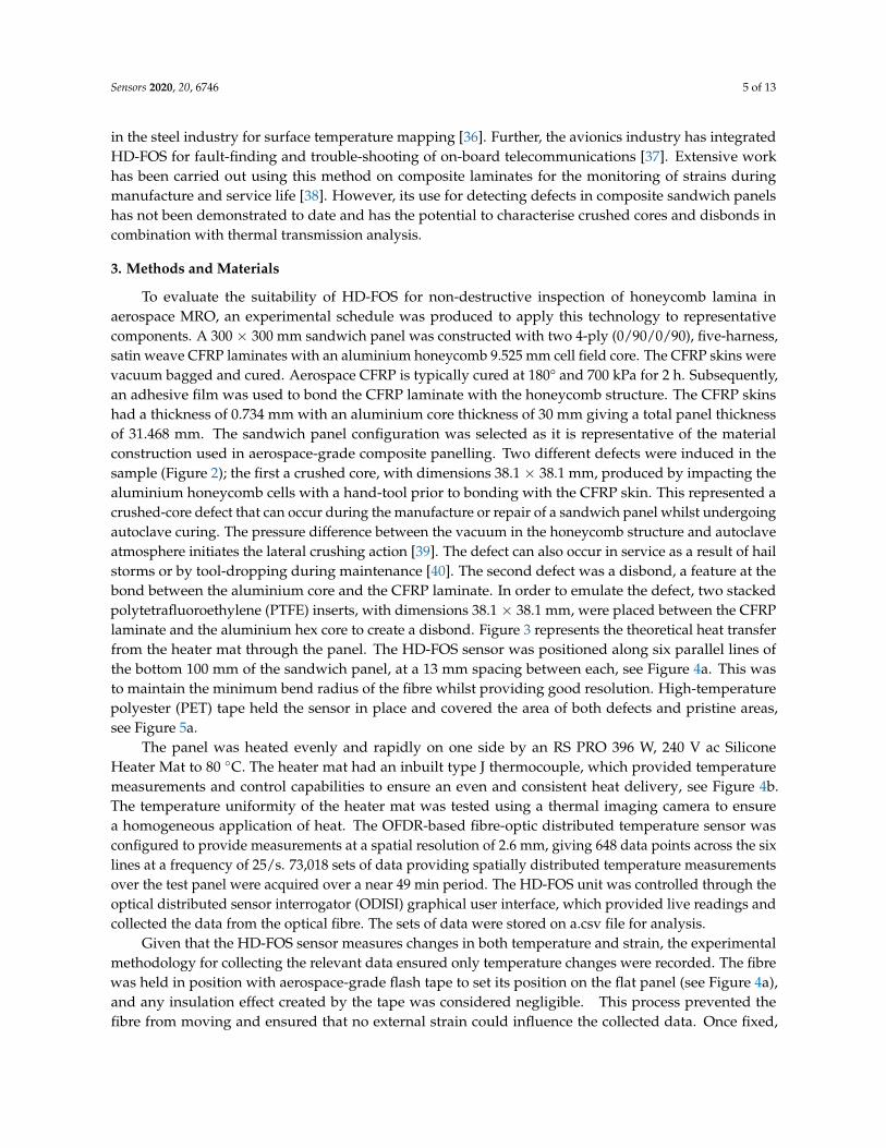
in the steel industry for surface temperature mapping [36]. Further, the avionics industry has integratedHD-FOS for fault-finding and trouble-shooting of on-board telecommunications [37]. Extensive workhas been carried out using this method on composite laminates for the monitoring of strains duringmanufacture and service life [38]. However, its use for detecting defects in composite sandwich panelshas not been demonstrated to date and has the potential to characterise crushed cores and disbonds incombination with thermal transmission analysis.
3. Methods and Materials
To evaluate the suitability of HD-FOS for non-destructive inspection of honeycomb lamina inaerospace MRO, an experimental schedule was produced to apply this technology to representativecomponents. A 300 × 300 mm sandwich panel was constructed with two 4-ply (0/90/0/90), five-harness,satin weave CFRP laminates with an aluminium honeycomb 9.525 mm cell field core. The CFRP skins werevacuum bagged and cured. Aerospace CFRP is typically cured at 180° and 700 kPa for 2 h. Subsequently,an adhesive film was used to bond the CFRP laminate with the honeycomb structure. The CFRP skinshad a thickness of 0.734 mm with an aluminium core thickness of 30 mm giving a total panel thicknessof 31.468 mm. The sandwich panel configuration was selected as it is representative of the materialconstruction used in aerospace-grade composite panelling. Two different defects were induced in thesample (Figure 2); the first a crushed core, with dimensions 38.1 × 38.1 mm, produced by impacting thealuminium honeycomb cells with a hand-tool prior to bonding with the CFRP skin. This represented acrushed-core defect that can occur during the manufacture or repair of a sandwich panel whilst undergoingautoclave curing. The pressure difference between the vacuum in the honeycomb structure and autoclaveatmosphere initiates the lateral crushing action [39]. The defect can also occur in service as a result of hailstorms or by tool-dropping during maintenance [40]. The second defect was a disbond, a feature at thebond between the aluminium core and the CFRP laminate. In order to emulate the defect, two stackedpolytetrafluoroethylene (PTFE) inserts, with dimensions 38.1 × 38.1 mm, were placed between the CFRPlaminate and the aluminium hex core to create a disbond. Figure 3 represents the theoretical heat transferfrom the heater mat through the panel. The HD-FOS sensor was positioned along six parallel lines ofthe bottom 100 mm of the sandwich panel, at a 13 mm spacing between each, see Figure 4a. This wasto maintain the minimum bend radius of the fibre whilst providing good resolution. High-temperaturepolyester (PET) tape held the sensor in place and covered the area of both defects and pristine areas,see Figure 5a.
The panel was heated evenly and rapidly on one side by an RS PRO 396 W, 240 V ac SiliconeHeater Mat to 80 ◦C. The heater mat had an inbuilt type J thermocouple, which provided temperaturemeasurements and control capabilities to ensure an even and consistent heat delivery, see Figure 4b.The temperature uniformity of the heater mat was tested using a thermal imaging camera to ensurea homogeneous application of heat. The OFDR-based fibre-optic distributed temperature sensor wasconfigured to provide measurements at a spatial resolution of 2.6 mm, giving 648 data points across the sixlines at a frequency of 25/s. 73,018 sets of data providing spatially distributed temperature measurementsover the test panel were acquired over a near 49 min period. The HD-FOS unit was controlled through theoptical distributed sensor interrogator (ODISI) graphical user interface, which provided live readings andcollected the data from the optical fibre. The sets of data were stored on a.csv file for analysis.
Given that the HD-FOS sensor measures changes in both temperature and strain, the experimentalmethodology for collecting the relevant data ensured only temperature changes were recorded. The fibrewas held in position with aerospace-grade flash tape to set its position on the flat panel (see Figure 4a),and any insulation effect created by the tape was considered negligible. This process prevented thefibre from moving and ensured that no external strain could influence the collected data. Once fixed,

Sensors 2020, 20, 6746 6 of 13
and at ambient room temperature, the sensor was zeroed by subtracting the baseline values from thesignal. The manufacturer-defined calibration procedure was followed to ensure the best results wereattained. Given that the panel expands uniformly when heated, it can be assumed that the collected datais representative of the temperature change on the surface of the panel.
Figure 2. Cross-sectional view of the sandwich panel with highlighted defect types.
Figure 3. Cross-sectional view of the sandwich panel with heat transfer from the heater mat.
(a) (b)Figure 4. Experimental set-up. (a) Top-skin of the sandwich panel with the high-definition fibre opticsensing (HD-FOS) sensor located on the CFRP surface. (b) Heater mat located on the bottom-skin of thesandwich panel, with integrated type J thermocouple.

Sensors 2020, 20, 6746 7 of 13
Figure 5. (a) Annotated segment of the composite sandwich panel top surface with defects and HD-FOSsensor shown. (b) Sensor Line 3 raw data and Savitzky–Golay filtered data comparison with cold edgeshighlighted. (c) Sensor Line 3 Savitzky–Golay filtered data with cold edges removed.

Sensors 2020, 20, 6746 8 of 13
4. Results and Discussion
Figure 5b shows the raw measurement data from Sensor Line 3, shown in Figure 5a. The data wasfiltered using a Savitzky–Golay Filter, with a window length of 15 and a degree-3 polynomial, to smoothnoise, selected as it provides excellent performance without loss of key data features, e.g., peaks andtroughs, when compared with moving average filtering [41]. An example of the output of the filtering isshown in Figure 5b. The IDX (index) value represents the data set number, out of the total 73,018 data setscollected. A value of 5000 equates to 3 min and 20 s after the heater mat was turned on.
As a result of convection, the “cold” edges of the panel were more prominent than expected,potentially masking defects on the colour-mapping of the component. Thus, the uppermost sensor output(unaffected by defects), shown as “Sensor Line 6”, was used as a datum from which the temperaturedifferences of the other five sensors were recorded. As shown in Figure 5c, the methodology successfullyremoved the cold edges from the data.
In Figure 6, the temperature differences of the remaining five sensor outputs are displayed over a10 min period. The sensor length is displayed on the x-axis, and temperature difference from a datum valueof 0 ◦C on the y-axis. A region of significantly lower surface temperature—a reduction of approximately13 ◦C from the datum—is visible in alignment with the position of the crushed core. The position isidentified at 364 mm along the fibre, which corresponds to 86 mm along Sensor Line 2 (from the left).The second trough in temperature, which begins at 474 mm along the optical fibre corresponding to195 mm along Sensor Line 2 (from the left), is less pronounced, nevertheless identifying the position of thedisbond defect; the disbond induces a temperature difference of 6 ◦C.
Figure 6. Graph series showing the temperature differences of Sensor Lines 1–5 from Sensor Line 6 (datum)at four points in the experiment. IDX (index) values indicate which data set is displayed.
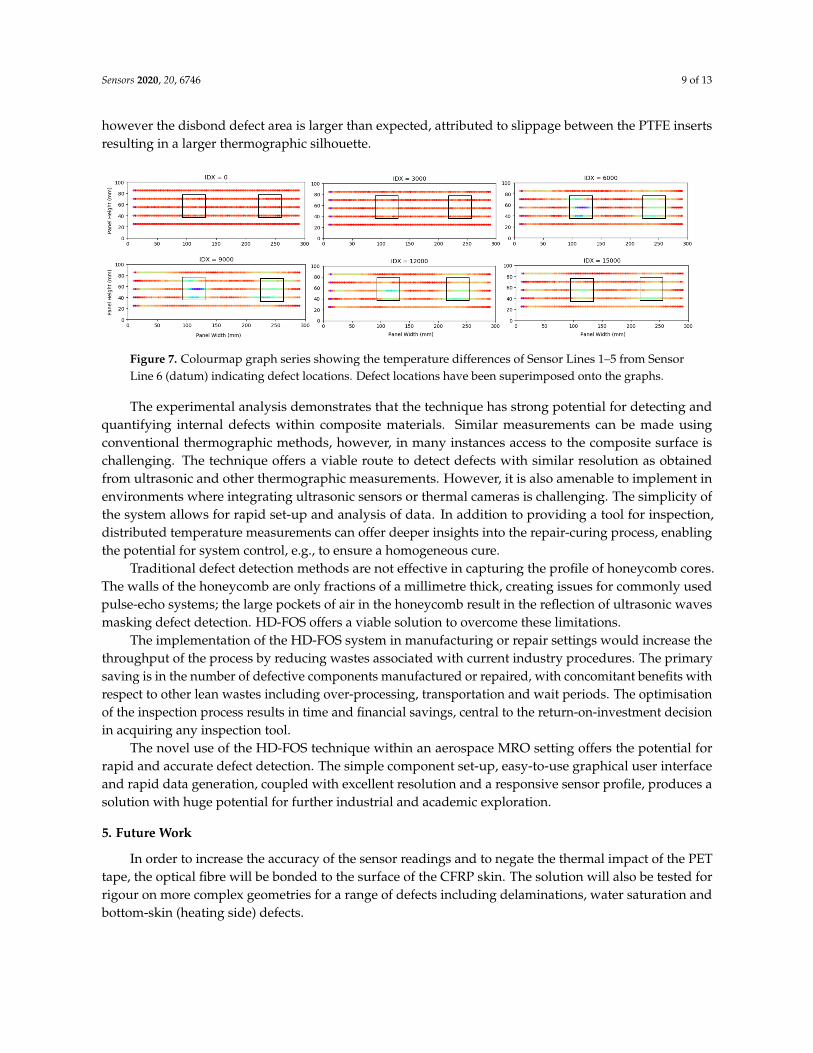
Figure 7 depicts the data on a colour map, highlighting the locations of the defects. The lengths andapproximate widths of the crushed core and disbond defects were estimated from the data. The crushedcore has a length of 39 mm and width of approximately 26 mm; the disbond has a length of 54 mm andan approximate width of 39 mm. The PTFE inserts used for the disbond were 38.1 × 38.1 mm and thecrushed core area was approximately 38.1 × 38.1 mm. The derived area of the crushed core is accurate;
Sensors 2020, 20, 6746 9 of 13
however the disbond defect area is larger than expected, attributed to slippage between the PTFE insertsresulting in a larger thermographic silhouette.
Figure 7. Colourmap graph series showing the temperature differences of Sensor Lines 1–5 from SensorLine 6 (datum) indicating defect locations. Defect locations have been superimposed onto the graphs.
The experimental analysis demonstrates that the technique has strong potential for detecting andquantifying internal defects within composite materials. Similar measurements can be made usingconventional thermographic methods, however, in many instances access to the composite surface ischallenging. The technique offers a viable route to detect defects with similar resolution as obtainedfrom ultrasonic and other thermographic measurements. However, it is also amenable to implement inenvironments where integrating ultrasonic sensors or thermal cameras is challenging. The simplicity ofthe system allows for rapid set-up and analysis of data. In addition to providing a tool for inspection,distributed temperature measurements can offer deeper insights into the repair-curing process, enablingthe potential for system control, e.g., to ensure a homogeneous cure.
Traditional defect detection methods are not effective in capturing the profile of honeycomb cores.The walls of the honeycomb are only fractions of a millimetre thick, creating issues for commonly usedpulse-echo systems; the large pockets of air in the honeycomb result in the reflection of ultrasonic wavesmasking defect detection. HD-FOS offers a viable solution to overcome these limitations.
The implementation of the HD-FOS system in manufacturing or repair settings would increase thethroughput of the process by reducing wastes associated with current industry procedures. The primarysaving is in the number of defective components manufactured or repaired, with concomitant benefits withrespect to other lean wastes including over-processing, transportation and wait periods. The optimisationof the inspection process results in time and financial savings, central to the return-on-investment decisionin acquiring any inspection tool.
The novel use of the HD-FOS technique within an aerospace MRO setting offers the potential forrapid and accurate defect detection. The simple component set-up, easy-to-use graphical user interfaceand rapid data generation, coupled with excellent resolution and a responsive sensor profile, produces asolution with huge potential for further industrial and academic exploration.
5. Future Work
In order to increase the accuracy of the sensor readings and to negate the thermal impact of the PETtape, the optical fibre will be bonded to the surface of the CFRP skin. The solution will also be tested forrigour on more complex geometries for a range of defects including delaminations, water saturation andbottom-skin (heating side) defects.

Sensors 2020, 20, 6746 10 of 13
6. Conclusions
In this paper we have reported preliminary evidence of the potential for HD-FOS-enabled temperaturemeasurements to detect crushed core and disbond defects in composite sandwich panels. A 300 × 300 mmaerospace-grade test panel constructed with CFRP skins and an aluminium honeycomb core with twodefects, a crushed core and a disbond, induced within the panel during manufacture was monitored.A thermal stimulus, from a bottom-surface mounted silicone heat mat with embedded type J thermocouple,was applied to reveal areas with poor thermal conductivity owing to defects. The thermal profile wasdetected with a top-surface mounted HD-FOS sensor secured to the panel. The sensor data, collectedthrough OFDR, was subsequently processed to provide a colour map of a section of the test panel.A crushed core defect of 39 × 26 mm and a disbond defect of 54 × 39 mm were identified successfully.Initial results suggest that differentiation between the defects is possible given the recorded temperaturedifferential on the panel surface attributed to each defect.
The paper has reported on the first use of HD-FOS for defect detection in composite sandwich panelsand the findings offer a significant opportunity for further research. The technique is also applicable in arange of post-manufacture and post-repair inspection processes within industries such as oil and gas andautomotive, offering advantages over currently used NDT methods based on ultrasound and infraredthermography. Future work will include bonding of the optical fibre to the CFRP to increase accuracy andmore comprehensive evaluation in complex geometries. Characterisation of performance over a widerrange of defects is required to quantify the capability to reliably differentiate between disbond and crushedcore damage. There is scope to test the technique on defects such as water saturation, delaminations andbottom-surface flaws.
Author Contributions: Conceptualisation, J.A.M., A.W.H., D.I.G. and C.T.; methodology, J.A.M., A.W.H., D.I.G.and C.T.; software, J.A.M., A.W.H. and D.I.G.; validation, J.A.M., A.W.H., D.I.G. and C.T.; formal analysis, J.A.M.;investigation, J.A.M., A.W.H., D.I.G. and C.T.; resources, J.A.M., A.W.H., D.I.G. and C.T.; data curation, J.A.M., A.W.H.and D.I.G.; writing—original draft preparation, J.A.M.; writing—review and editing, J.A.M., A.W.H., D.I.G., C.M., I.A.and C.T.; visualisation, J.A.M., A.W.H. and D.I.G.; supervision, K.B., A.W.H., D.I.G. and C.T.; project administration,D.I.G., A.W.H. and C.T.; funding acquisition, D.I.G. and C.T. All authors have read and agreed to the published versionof the manuscript.
Funding: This research received no external funding.
Acknowledgments: The authors would like to thank Collins Aerospace, a Raytheon Technologies company, for theprovision of aerospace-quality test samples.
Conflicts of Interest: The authors declare no conflicts of interest.
Abbreviations
The following abbreviations are used in this manuscript:
BVID Barely visible impact damageCFRP Carbon fibre reinforced polymersFBG Fibre Bragg gratingHD-FOS High-definition fibre optic sensingMRO Maintenance, repair and overhaulNDI Non-destructive inspectionNDT Non-destructive testingODISI Optical distributed sensor interrogatorODTSS Optical fibre distributed temperature and strain sensorsOFDR Optical frequency domain reflectometry

Sensors 2020, 20, 6746 11 of 13
OTDR Optical time domain reflectometryPTFE PolytetrafluoroethyleneSMF Single mode fibreSNR Signal-to-noise ratioTTU Through transmission ultrasound
References
1. Wyman, O. Global Fleet & MRO Market Forecast Commentary 2019–2029; Oliver Wyman: New York, NY, USA, 2019.2. de Boer, R.J.; Pelt, M.; Schoemaker, C.; Borst, M.; Groves, R. Accelerating MRO procedures for composite
materials using innovative detection techniques. Chall. Eur. Aerosp. 2015, 5, 1–8.3. Alemour, B.; Badran, O.; Hassan, M.R. A review of using conductive composite materials in solving lightening
strike and ice accumulation problems in aviation. J. Aerosp. Technol. Manag. 2019, 11. [CrossRef]4. Farooq, U.; Ahmad, M.S.; Rakha, S.A.; Ali, N.; Khurram, A.A.; Subhani, T. Interfacial Mechanical Performance
of Composite Honeycomb Sandwich Panels for Aerospace Applications. Arab. J. Sci. Eng. 2017, 42, 1775–1782.[CrossRef]
5. Ehrhart, B.; Valeske, B.; Bockenheimer, C. Non-destructive evaluation (NDE) of aerospace composites: Methodsfor testing adhesively bonded composites. Non-Destr. Eval. Polym. Matrix Compos. Tech. Appl. 2013, 220–237.[CrossRef]
6. Kim, S.J. Damage detection in composite laminates using coin-tap method. J. Acoust. Soc. Am. 2008, 123, 3064.[CrossRef]
7. Bossi, R.; Giurgiutiu, V. Nondestructive testing of damage in aerospace composites. Polym. Compos. Aerosp. Ind.2015, 413–448. doi:10.1016/B978-0-85709-523-7.00015-3. [CrossRef]
8. Holland, S.D.; Teles, S.V.; Chimenti, D.E. Air-coupled, focused ultrasonic dispersion spectrum reconstruction inplates. J. Acoust. Soc. Am. 2004, 115, 2866–2872. doi:10.1121/1.1710501. [CrossRef]
9. Shen, Q.; Omar, M.; Dongri, S. Ultrasonic NDE Techniques for Impact Damage Inspection on CFRP Laminates.J. Mater. Sci. Res. 2011, 1, 1–16. doi:10.5539/jmsr.v1n1p2. [CrossRef]
10. Kažys, R.; Demcenko, A.; Mažeika, L.; Šliteris, R.; Žukauskas, E. Air-coupled ultrasonic non-destructive testingof aerospace components. Insight Non-Destr. Test. Cond. Monit. 2007, 49, 195–199. [CrossRef]
11. Michaels, T.E.; Michaels, J.E. Application of acoustic wavefield imaging to non-contact ultrasonic inspection ofbonded components. AIP Conf. Proc. 2006, 820, 1484–1491. [CrossRef]
12. Belský, P.; Kadlec, M. Non-destructive Methods for Damage Assessment of Composite Sandwich Structures.MATEC Web Conf. 2018, 188. [CrossRef]
13. Riise, J.; Pierce, S.G.; Nicholson, P.I.; Cooper, I.; Wright, B. Deployment of ultrasonic through transmissioninspection using twin cooperative industrial robots. In Proceedings of the 55th Annual Conference of the BritishInstitute of Non-Destructive Testing, NDT 2016, Nottingham, UK, 12–14 September 2016; pp. 463–475.
14. Chilles, J.S.; Koutsomitopoulou, A.F.; Croxford, A.J.; Bond, I.P. Monitoring cure and detecting damage incomposites with inductively coupled embedded sensors. Compos. Sci. Technol. 2016, 134, 81–88. [CrossRef]
15. Ružek, R.; Lohonka, R.; Jironc, J. Ultrasonic C-scan and shearography NDI techniques evaluation of impactdefects identification. NDT E Int. 2006, 39, 132–142. [CrossRef]
16. Jandejsek, I.; Jakubek, J.; Jakubek, M.; Prucha, P.; Krejci, F.; Soukup, P.; Turecek, D.; Vavrik, D.; Zemlicka, J. X-rayinspection of composite materials for aircraft structures using detectors of Medipix type. J. Instrum. 2014, 9.[CrossRef]
17. Meola, C.; Carlomagno, G.M.; Squillace, A.; Vitiello, A. Non-destructive evaluation of aerospace materials withlock-in thermography. Eng. Fail. Anal. 2006, 13, 380–388. [CrossRef]
18. Gros, X.E.; Ogi, K.; Eddy, K.T. Current, Ultrasonic C-Scan and Scanning Acoustic Microscopy Testing ofDelaminated Quasi-Isotropic CFRP Materials: A Case Study. J. Reinf. Plast. Compos. 1998, 17, 389–405. [CrossRef]

Sensors 2020, 20, 6746 12 of 13
19. Gillespie, D.I.; Hamilton, A.W.; Mckay, E.J.; Neilson, B.; Atkinson, R.C.; Andonovic, I.; Tachtatzis, C.Non-Destructive Identification of Fibre Orientation in Multi-Ply Biaxial Laminates Using Contact TemperatureSensors. Sensors 2020, 20, 3865, [CrossRef]
20. Kluth, R.; Watley, D.; Farhadiroushan, M.; Park, D.S.; Lee, S.U.; Kim, J.Y.; Kim, Y.S. Case Studies on DistributedTemperature and Strain Sensing ( DTSS ) by using optic fibre. In Proceedings of the International Conference onCondition Monitoring and Diagnosis, Sheffield, UK, 16–18 July 1996; p. 4.
21. Johannson, S.; Watley, D. Distributed Sensing of Seepage and Movements Using Optical Fibres—Resultsfrom Some Embankment Dams in. International Water Power and Dam Construction. 2005. Availableonline: https://www.researchgate.net/journal/0306-400X_International_Water_Power_and_Dam_Construction(accessed on 6 October 2020).
22. Tanimola, F.; Hill, D. Distributed fibre optic sensors for pipeline protection. J. Nat. Gas Sci. Eng. 2009, 1, 134–143.[CrossRef]
23. Thévenaz, L. Brillouin distributed time-domain sensing in optical fibers: State of the art and perspectives.Front. Optoelectron. China 2010, 3, 13–21. [CrossRef]
24. O’Sullivan, M.S.; Lowe, R.S. Interpretation of SM fiber OTDR signatures. Opt. Test. Metrol. 1986, 661, 171–176.[CrossRef]
25. Peng, F.; Wu, H.; Jia, X.H.; Rao, Y.J.; Wang, Z.N.; Peng, Z.P. Ultra-long high-sensitivity Φ-OTDR for high spatialresolution intrusion detection of pipelines. Opt. Soc. Am. 2014, 22, 13804–13810. [CrossRef] [PubMed]
26. Sakairi, Y.; Uchiyama, H.; Li, Z.X.; Adachi, S. A system for measuring temperature and strain separately byBOTDR and OTDR. Adv. Sens. Syst. Appl. 2002, 4920, 274–284. [CrossRef]
27. Yuan, W.; Stefani, A.; Bang, O. Tunable polymer fiber Bragg grating (FBG) inscription: Fabrication of dual-FBGtemperature compensated polymer optical fiber strain sensors. IEEE Photonics Technol. Lett. 2012, 24, 401–403.[CrossRef]
28. Berkoff, T.A.; Davis, M.A.; Bellemore, D.G.; Kersey, A.D.; Optic, F.; Structures, S.; Williams, G.M.; Putnam, M.A.;Section, O.M.; Division, O.S. Hybrid time and wavelength division multiplexed fiber bragg grating sensor array.In Smart Structures and Materials 1995: Smart Sensing, Processing, and Instrumentation; International Society forOptics and Photonics: Bellingham, WA, USA, 1995; Volume 2444, pp. 288–294.
29. Zhang, M.; Sun, Q.; Wang, Z.; Li, X.; Liu, H.; Liu, D. A large capacity sensing network with identical weak fiberBragg gratings multiplexing. Opt. Commun. 2012, 285, 3082–3087. [CrossRef]
30. Schenato, L. A review of distributed fibre optic sensors for geo-hydrological applications. Appl. Sci. 2017, 7, 896.[CrossRef]
31. Loranger, S.; Gagné, M.; Lambin-Iezzi, V.; Kashyap, R. Rayleigh scatter based order of magnitude increasein distributed temperature and strain sensing by simple UV exposure of optical fibre. Sci. Rep. 2015, 5, 1–7.[CrossRef]
32. Kreger, S.T.; Soller, B.J.; Gifford, D.K.; Duncan, R.G.; Wolfe, M.S.; Froggatt, M.E. Optical Backscatter Reflectometry asa Measurement Tool for Fiber-Optics in Avionics and Aerospace Applications; SAE Technical Papers; SAE: Warrendale,PA, USA, 2007; [CrossRef]
33. Zhou, D.P.; Li, W.; Chen, L.; Bao, X. Distributed temperature and strain discrimination with stimulated brillouinscattering and rayleigh backscatter in an optical fiber. Sensors 2013, 13, 1836–1845. [CrossRef]
34. Klute, S.M.; Sang, A.K.; Gifford, D.K.; Froggatt, M.E. Defect detection during manufacture of composite windturbine blade with embedded fiber optic distributed strain sensor. In Proceedings of the International SAMPETechnical Conference, Long Beach CA, USA, 23–26 May 2011.
35. Klute, S.M.; Metrey, D.R.; Garg, N.; Rahim, N.A. In-situ structural health monitoring of composite-overwrappedpressure vessels. SAMPE J. 2016, 52, 7–17.
36. Sang, A.K.; Froggatt, M.E.; Gifford, D.K.; Kreger, S.T.; Dickerson, B.D. One centimeter spatial resolution temperaturemeasurements in a nuclear reactor using Rayleigh scatter in optical fiber. IEEE Sens. J. 2008, 8, 1375–1380. [CrossRef]
37. Duncan, R.G.; Soller, B.J.; Gifford, D.K.; Kreger, S.T.; Seeley, R.J.; Sang, A.K.; Wolfe, M.S.; Froggatt, M.E.OFDR-based distributed sensing and fault detection for single-and multi-mode avionics fiber-optics.In Proceedings of the Joint Conference on Aging Aircraft, Palm Springs, CA, USA, 16–19 April 2007; pp. 10–14.

Sensors 2020, 20, 6746 13 of 13
38. Sanborn, E.E.; Sang, A.K.; Wesson, E.; Wigent, D.E.; Lucier, G.; Czabaj, M.W.; Tubbs, W.R.; Zehnder, A.T.;Davidson, B.D. Distributed Fiber Optic Strain Measurement Using Rayleigh Scatter in Composite Structures.In Experimental and Applied Mechanics; Proulx, T., Ed.; Springer: New York, NY, USA, 2011; Volume 6, pp. 461–470,[CrossRef]
39. Hsiao, H.M.; Lee, S.; Buyny, R. Core Crush Problem in the Manufacturing of Composite Sandwich Structures:Mechanisms and Solutions. AIAA J. 2008, 44, 901–907. [CrossRef]
40. Tomblin, J.; Lacy, T.; Smith, B.; Hooper, S.; Vizzini, A.; Lee, S. Review of Damage Tolerance for Composite SandwichAirframe Structures; Technical Report; Wichita State University: Wichita, KS, USA, 1999.
41. Guiñón, J.L.; Ortega, E.; García-Antón, J.; Pérez-herranz, V. Moving Average and Savitzki-Golay SmoothingFilters Using Mathcad. In Proceedings of the International Conference on Engineering Education, Honolulu,HI, USA, 22–24 June 2007; pp. 1–4.
Publisher’s Note: MDPI stays neutral with regard to jurisdictional claims in published maps and institutionalaffiliations.
© 2020 by the authors. Licensee MDPI, Basel, Switzerland. This article is an open access articledistributed under the terms and conditions of the Creative Commons Attribution (CC BY)license (http://creativecommons.org/licenses/by/4.0/).