Residual strength of sandwich panels with hail damage
10
Residual strength of sandwich panels with hail damage Manabendra Das a , Erkan Oterkus a , Erdogan Madenci a, * , Hamid Razi b a Department of Aerospace and Mechanical Engineering, The University of Arizona, Tucson, AZ 85721, United States b Stress Methods and Allowables, Boeing Commercial Airplanes, Seattle, WA 98124, United States article info Article history: Available online 15 May 2008 Keywords: Repair Sandwich Indentation Residual strength abstract Hail strikes, possibly exceeding an energy level of 50 J, may cause damage to thin-gauged composite airplane structures in the form of an indentation or puncture of the top facesheet. If not repaired properly, they may trigger extensive damage to airplane structures and disruptions to airline operations, therefore posing a major maintenance and repair concern for the airlines. It is important that both the original equipment manufacturer and the airlines be able to classify the hail strike damage in order to establish appropriate repair procedures. This study presents a methodology to assist engineers in the classification of the repair type for hail strike damage through the determination of allowable damage size. The meth- odology involves an accurate prediction of stress and strain fields and residual strength prediction. The stress analysis is performed by utilizing a plate element based on a higher-order single-layer theory. The damage zone model, previously used for notched panels, has been employed to predict the residual strength of sandwich panels with indented facesheets subjected to tensile load. The failure load is estab- lished when crack propagation in the facesheet becomes unstable. Ó 2008 Elsevier Ltd. All rights reserved. 1. Introduction Thin-gauged composite airplane structures may suffer from hail strikes that result in dents and punctures, as shown in (Fig. 1). Dis- regarding such damage may lead to a significant loss of stiffness, which can cause extensive damage to airplane structures and, therefore, disruptions to airline operations. Thus, hail strike dam- age poses a major maintenance and repair concern for the airlines. Depending on the severity of the hail strikes, the OEM (original equipment manufacturers) classifies the repair as either ‘‘major” or ‘‘minor.” A minor repair has no appreciable effect on airline operations. However, a major repair has a significant effect and may require extensive static, fatigue, and damage tolerance strength justification and/or testing. Most of these repairs are not covered by the aircraft structural repair manual. The Federal Aviation Agency (FAA) and European Aviation Safety Agency (EASA) require that a repair scheme for a major re- pair be submitted to the OEM for their approval before starting the repair. However, minor repairs can be approved by an airline’s de- sign engineers, provided they submit justification of the classifica- tion to the OEM. It is important that both the OEM and the airlines are able to classify the hail strike damage in order to determine the appropriate repair procedures so as to minimize disruptions of operations. This study presents an analysis method to assist engi- neers in determining allowable damage size through the residual strength prediction of sandwich panels having hail strike damage. An efficient analysis method is required to compute the stress and strain fields in the damaged panel before undertaking the task of failure prediction. A stress analysis of sandwich panels with de- fects such as dents and punctures is a formidable task because of the presence of dissimilar materials and sharp changes in geome- try. The effect of local bending in the vicinity of punctures and dents is significant in predicting the stress field and, thus, the residual strength. In addition, computational difficulties arise be- cause the thickness of the facesheet is highly disproportionate to the in-plane dimensions. A comprehensive review by Abrate [1] deals with the effect of impact on sandwich panels whereas the review by Tomblin et al. [2] focuses on the damage tolerance methods relevant to sandwich panels. Several analysis tools have been developed that are based on various assumptions, such as disregarding the presence of local bending due to the unsymmetrical nature of the damaged panel. Moreover, very often the damage is modeled as a soft inclusion [3,4] or a single equivalent delamination [5,6] and the actual geom- etry of the dent is not considered. Cairns [3] utilized complex analytic functions for calculating the strains in an anisotropic plate with an elastic inclusion while disre- garding the presence of the core and the back facesheet. Utilizing the near- and far-field strain values, the ultimate strength predic- tion was based on the Whitney–Nuismer criterion. A similar ap- proach was adopted by Razi et al. [4] to determine the stress distribution in sandwich panels with arbitrarily located damage. 0263-8223/$ - see front matter Ó 2008 Elsevier Ltd. All rights reserved. doi:10.1016/j.compstruct.2008.05.002 * Corresponding author. Tel.: +1 520 621 6113; fax: +1 520 621 8191. E-mail address: [email protected] (E. Madenci). Composite Structures 88 (2009) 403–412 Contents lists available at ScienceDirect Composite Structures journal homepage: www.elsevier.com/locate/compstruct
-
Upload
independent -
Category
Documents
-
view
1 -
download
0
Transcript of Residual strength of sandwich panels with hail damage
Composite Structures 88 (2009) 403–412
Contents lists available at ScienceDirect
Composite Structures
journal homepage: www.elsevier .com/locate /compstruct
Residual strength of sandwich panels with hail damage
Manabendra Das a, Erkan Oterkus a, Erdogan Madenci a,*, Hamid Razi b
a Department of Aerospace and Mechanical Engineering, The University of Arizona, Tucson, AZ 85721, United Statesb Stress Methods and Allowables, Boeing Commercial Airplanes, Seattle, WA 98124, United States
a r t i c l e i n f o a b s t r a c t
Article history:Available online 15 May 2008
Keywords:RepairSandwichIndentationResidual strength
0263-8223/$ - see front matter � 2008 Elsevier Ltd. Adoi:10.1016/j.compstruct.2008.05.002
* Corresponding author. Tel.: +1 520 621 6113; faxE-mail address: [email protected] (E. M
Hail strikes, possibly exceeding an energy level of 50 J, may cause damage to thin-gauged compositeairplane structures in the form of an indentation or puncture of the top facesheet. If not repaired properly,they may trigger extensive damage to airplane structures and disruptions to airline operations, thereforeposing a major maintenance and repair concern for the airlines. It is important that both the originalequipment manufacturer and the airlines be able to classify the hail strike damage in order to establishappropriate repair procedures. This study presents a methodology to assist engineers in the classificationof the repair type for hail strike damage through the determination of allowable damage size. The meth-odology involves an accurate prediction of stress and strain fields and residual strength prediction. Thestress analysis is performed by utilizing a plate element based on a higher-order single-layer theory.The damage zone model, previously used for notched panels, has been employed to predict the residualstrength of sandwich panels with indented facesheets subjected to tensile load. The failure load is estab-lished when crack propagation in the facesheet becomes unstable.
� 2008 Elsevier Ltd. All rights reserved.
1. Introduction
Thin-gauged composite airplane structures may suffer from hailstrikes that result in dents and punctures, as shown in (Fig. 1). Dis-regarding such damage may lead to a significant loss of stiffness,which can cause extensive damage to airplane structures and,therefore, disruptions to airline operations. Thus, hail strike dam-age poses a major maintenance and repair concern for the airlines.Depending on the severity of the hail strikes, the OEM (originalequipment manufacturers) classifies the repair as either ‘‘major”or ‘‘minor.” A minor repair has no appreciable effect on airlineoperations. However, a major repair has a significant effect andmay require extensive static, fatigue, and damage tolerancestrength justification and/or testing. Most of these repairs are notcovered by the aircraft structural repair manual.
The Federal Aviation Agency (FAA) and European AviationSafety Agency (EASA) require that a repair scheme for a major re-pair be submitted to the OEM for their approval before starting therepair. However, minor repairs can be approved by an airline’s de-sign engineers, provided they submit justification of the classifica-tion to the OEM. It is important that both the OEM and the airlinesare able to classify the hail strike damage in order to determine theappropriate repair procedures so as to minimize disruptions ofoperations. This study presents an analysis method to assist engi-
ll rights reserved.
: +1 520 621 8191.adenci).
neers in determining allowable damage size through the residualstrength prediction of sandwich panels having hail strike damage.
An efficient analysis method is required to compute the stressand strain fields in the damaged panel before undertaking the taskof failure prediction. A stress analysis of sandwich panels with de-fects such as dents and punctures is a formidable task because ofthe presence of dissimilar materials and sharp changes in geome-try. The effect of local bending in the vicinity of punctures anddents is significant in predicting the stress field and, thus, theresidual strength. In addition, computational difficulties arise be-cause the thickness of the facesheet is highly disproportionate tothe in-plane dimensions.
A comprehensive review by Abrate [1] deals with the effect ofimpact on sandwich panels whereas the review by Tomblin et al.[2] focuses on the damage tolerance methods relevant to sandwichpanels. Several analysis tools have been developed that are basedon various assumptions, such as disregarding the presence of localbending due to the unsymmetrical nature of the damaged panel.Moreover, very often the damage is modeled as a soft inclusion[3,4] or a single equivalent delamination [5,6] and the actual geom-etry of the dent is not considered.
Cairns [3] utilized complex analytic functions for calculating thestrains in an anisotropic plate with an elastic inclusion while disre-garding the presence of the core and the back facesheet. Utilizingthe near- and far-field strain values, the ultimate strength predic-tion was based on the Whitney–Nuismer criterion. A similar ap-proach was adopted by Razi et al. [4] to determine the stressdistribution in sandwich panels with arbitrarily located damage.
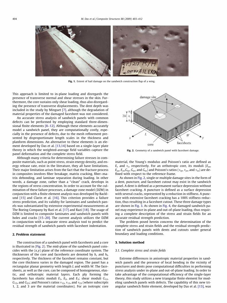
Fig. 2. Geometry of a sandwich panel with facesheet damage.
Fig. 1. Extent of hail damage on the sandwich construction flap of a wing.
404 M. Das et al. / Composite Structures 88 (2009) 403–412
This approach is limited to in-plane loading and disregards thepresence of transverse normal and shear stresses in the skin. Fur-thermore, the core sustains only shear loading, thus also disregard-ing the presence of transverse displacements. The dent depth wasincluded in the study by Minguet [7], although the degradation ofmaterial properties of the damaged facesheet was not considered.
An accurate stress analysis of sandwich panels with commondefects can be performed by employing standard three-dimen-sional finite elements [8–12]. Although these elements accuratelymodel a sandwich panel, they are computationally costly, espe-cially in the presence of defects, due to the mesh refinement pre-sented by disproportionate length scales in the thickness andplanform dimensions. An alternative to these elements is an ele-ment developed by Das et al. [13,14] based on a single-layer platetheory in which the weighted-average field variables capture thepanel deformation and the complete stress field.
Although many criteria for determining failure stresses in com-posite materials, such as point stress, strain energy density, and en-ergy release rate, exist in the literature, they all have limitations.Their major limitation arises from the fact that the fracture processin composites involves fiber breakage, matrix cracking, fiber–ma-trix debonding, and laminae separation during loading. In otherwords, a damage zone, rather than a ‘‘clean” crack, develops inthe regions of stress concentration. In order to account for the cul-mination of these failure processes, a damage zone model (DZM) inconjunction with a finite element analysis was developed by Backl-und [15] and Clarin et al. [16]. This criterion provides a failurestress prediction, and its validity for laminates and sandwich pan-els was substantiated by extensive experimental measurements atThe Boeing Company by Razi et al. [17] and Razi [18]. The usage ofDZM is limited to composite laminates and sandwich panels withholes and cracks [15–20]. The current analysis utilizes the DZMin conjunction with a separate stress analysis tool to predict theresidual strength of sandwich panels with facesheet indentation.
2. Problem statement
The construction of a sandwich panel with facesheets and a coreis illustrated in (Fig. 2). The mid-plane of the sandwich panel coin-cides with the (x,y) plane of the reference coordinate system. Thethicknesses of the core and facesheets are denoted by hc and hf,respectively. The thickness of the facesheet remains constant, butthe core thickness varies in the damaged region. The panel has arectangular planar geometry with length L and width W. The face-sheets, as well as the core, can be composed of homogeneous, elas-tic, and orthotropic material layers. Each ply forming thefacesheets has elastic moduli E1, E2, and E3; shear moduli G12,G13, and G23; and Poisson’s ratios m12, m13, and m23 (where subscripts1, 2, and 3 are the material coordinates). For an isotropic core
material, the Young’s modulus and Poisson’s ratio are defined asEc and mc, respectively. For an orthotropic core, its moduli (Exx,Eyy, Ezz,Gxy, Gyz, and Gxz) and Poisson’s ratios (mxy, myz, and mxz) are de-fined with respect to the reference frame.
As shown in Fig. 2, single or multiple damage sites in the form ofa dent, puncture, and facesheet cutout may exist in the sandwichpanel. A dent is defined as a permanent surface depression withoutfacesheet cracking. A puncture is defined as a surface depressionwith several cracks, represented by a reduction in stiffness. A punc-ture with extensive facesheet cracking has a 100% stiffness reduc-tion, thus resulting in a facesheet cutout. These three damage typesare shown in Fig. 3. As shown in Fig. 4, the damaged sandwich pa-nel may experience in-plane and out-of-plane loading, thus requir-ing a complete description of the stress and strain fields for anaccurate residual strength prediction.
The problem posed herein concerns the determination of thecomplete stress and strain fields and the residual strength predic-tion of sandwich panels with dents and cutouts under generalboundary and loading conditions.
3. Solution method
3.1. Complete stress and strain fields
Extreme differences in anisotropic material properties in sand-wich panels and the presence of local bending in the vicinity ofpunctures and dents pose computational difficulties in performingstress analysis under in-plane and out-of-plane loading. In order totake advantage of the computational efficiency of the single-layertheory, this study utilizes a new triangular finite element for mod-eling sandwich panels with defects. The capability of this new tri-angular sandwich finite element, developed by Das et al. [13], was
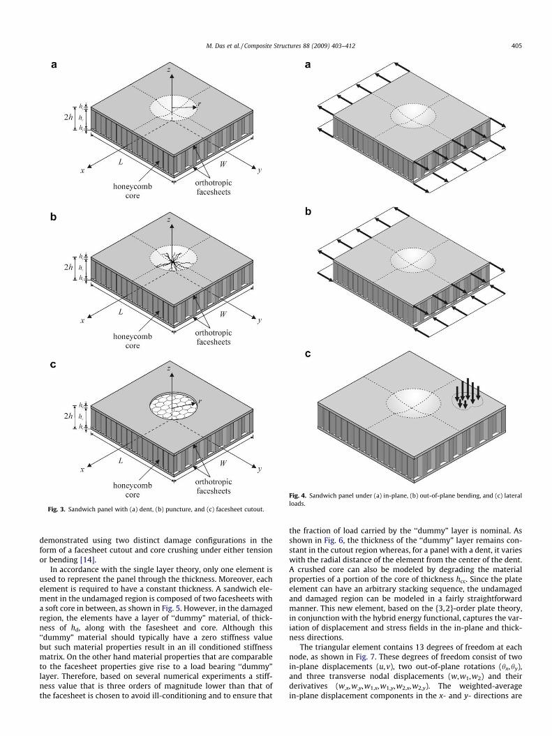
Fig. 3. Sandwich panel with (a) dent, (b) puncture, and (c) facesheet cutout.
Fig. 4. Sandwich panel under (a) in-plane, (b) out-of-plane bending, and (c) lateralloads.
M. Das et al. / Composite Structures 88 (2009) 403–412 405
demonstrated using two distinct damage configurations in theform of a facesheet cutout and core crushing under either tensionor bending [14].
In accordance with the single layer theory, only one element isused to represent the panel through the thickness. Moreover, eachelement is required to have a constant thickness. A sandwich ele-ment in the undamaged region is composed of two facesheets witha soft core in between, as shown in Fig. 5. However, in the damagedregion, the elements have a layer of ‘‘dummy” material, of thick-ness of hd, along with the fasesheet and core. Although this‘‘dummy” material should typically have a zero stiffness valuebut such material properties result in an ill conditioned stiffnessmatrix. On the other hand material properties that are comparableto the facesheet properties give rise to a load bearing ‘‘dummy”layer. Therefore, based on several numerical experiments a stiff-ness value that is three orders of magnitude lower than that ofthe facesheet is chosen to avoid ill-conditioning and to ensure that
the fraction of load carried by the ‘‘dummy” layer is nominal. Asshown in Fig. 6, the thickness of the ‘‘dummy” layer remains con-stant in the cutout region whereas, for a panel with a dent, it varieswith the radial distance of the element from the center of the dent.A crushed core can also be modeled by degrading the materialproperties of a portion of the core of thickness hcc. Since the plateelement can have an arbitrary stacking sequence, the undamagedand damaged region can be modeled in a fairly straightforwardmanner. This new element, based on the {3,2}-order plate theory,in conjunction with the hybrid energy functional, captures the var-iation of displacement and stress fields in the in-plane and thick-ness directions.
The triangular element contains 13 degrees of freedom at eachnode, as shown in Fig. 7. These degrees of freedom consist of twoin-plane displacements (u,v), two out-of-plane rotations (hx,hy),and three transverse nodal displacements (w,w1,w2) and theirderivatives (w,x,w,y,w1,x,w1,y,w2,x,w2,y). The weighted-averagein-plane displacement components in the x- and y- directions are
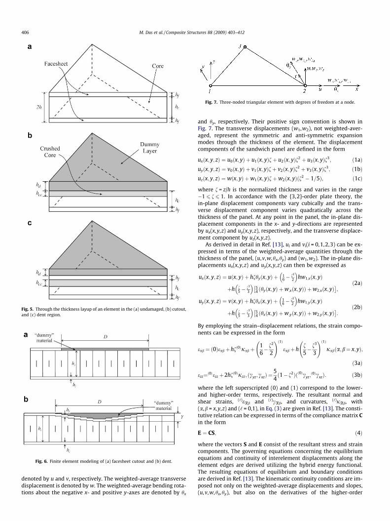
Fig. 5. Through the thickness layup of an element in the (a) undamaged, (b) cutout,and (c) dent region.
Fig. 6. Finite element modeling of (a) facesheet cutout and (b) dent.
Fig. 7. Three-noded triangular element with degrees of freedom at a node.
406 M. Das et al. / Composite Structures 88 (2009) 403–412
denoted by u and v, respectively. The weighted-average transversedisplacement is denoted by w. The weighted-average bending rota-tions about the negative x- and positive y-axes are denoted by hx
and hy, respectively. Their positive sign convention is shown inFig. 7. The transverse displacements (w1,w2), not weighted-aver-aged, represent the symmetric and anti-symmetric expansionmodes through the thickness of the element. The displacementcomponents of the sandwich panel are defined in the form
uxðx; y; zÞ ¼ u0ðx; yÞ þ u1ðx; yÞfþ u2ðx; yÞf2 þ u3ðx; yÞf3; ð1aÞuyðx; y; zÞ ¼ v0ðx; yÞ þ v1ðx; yÞfþ v2ðx; yÞf2 þ v3ðx; yÞf3; ð1bÞuzðx; y; zÞ ¼ wðx; yÞ þw1ðx; yÞfþw2ðx; yÞðf2 � 1=5Þ; ð1cÞ
where f = z/h is the normalized thickness and varies in the range�1 6 f 6 1. In accordance with the {3,2}-order plate theory, thein-plane displacement components vary cubically and the trans-verse displacement component varies quadratically across thethickness of the panel. At any point in the panel, the in-plane dis-placement components in the x- and y-directions are representedby ux(x,y,z) and uy(x,y,z), respectively, and the transverse displace-ment component by uz(x,y,z).
As derived in detail in Ref. [13], ui and vi(i = 0,1,2,3) can be ex-pressed in terms of the weighted-average quantities through thethickness of the panel, (u,v,w,hx,hy) and (w1,w2). The in-plane dis-placements ux(x,y,z) and uy(x,y,z) can then be expressed as
uxðx; y; zÞ ¼ uðx; yÞ þ hfhyðx; yÞ þ 16�
f2
2
� �hw1;xðx; yÞ
þh f5�
f3
3
� �54 ðhyðx; yÞ þw;xðx; yÞÞ þw2;xðx; yÞ� �
;ð2aÞ
uyðx; y; zÞ ¼ vðx; yÞ þ hfhxðx; yÞ þ 16�
f2
2
� �hw1;yðx; yÞ
þh f5�
f3
3
� �54 ðhxðx; yÞ þw;yðx; yÞÞ þw2;yðx; yÞ� �
:ð2bÞ
By employing the strain–displacement relations, the strain compo-nents can be expressed in the form
eab ¼ ð0Þeabþhfð0Þjab þ16� f2
2
!ð1Þeabþh
f5� f3
3
!ð1Þjabða;b¼ x;yÞ;
ð3aÞ
ezz¼ð0Þezzþ2hfð0Þjzz; ðcyz;cxzÞ ¼54ð1� f2Þðð0Þcyz;
ð0ÞcxzÞ: ð3bÞ
where the left superscripted (0) and (1) correspond to the lower-and higher-order terms, respectively. The resultant normal andshear strains, (‘)eab and (‘)cab, and curvatures, (‘)jab, with(a,b = x,y,z) and (‘ = 0,1), in Eq. (3) are given in Ref. [13]. The consti-tutive relation can be expressed in terms of the compliance matrix Cin the form
E ¼ CS; ð4Þ
where the vectors S and E consist of the resultant stress and straincomponents. The governing equations concerning the equilibriumequations and continuity of interelement displacements along theelement edges are derived utilizing the hybrid energy functional.The resulting equations of equilibrium and boundary conditionsare derived in Ref. [13]. The kinematic continuity conditions are im-posed not only on the weighted-average displacements and slopes,(u,v,w,hx,hy), but also on the derivatives of the higher-order

Fig. 8. Composite panel (a) with a damage zone and (b) the corresponding cohesive
M. Das et al. / Composite Structures 88 (2009) 403–412 407
displacement modes, (w1,w2), in the transverse direction. Therefore,the finite element implementation of the equilibrium equations re-quires at least C1 interelement continuity for the out-of-plane dis-placement modes of w, w1, and w2. Because of this requirement,the finite element implementation of the total potential energyfunctional in terms of the assumed displacement field becomesrather difficult. The hybrid energy functional formulation over-comes the difficulty of the C1 interelement continuity requirementbecause the displacements, as well as the slopes, are independentlyassumed only along element boundaries, which can be renderedidentical along the common boundaries of adjacent elements. How-ever, the kinematic compatibility between the displacements andslopes along the element boundaries is preserved in order to avoida possible shear-locking phenomenon. Also, as part of the hybridenergy functional formulation, the stress and moment resultantswithin the element are selected in the form of complex power seriesso as to satisfy the equilibrium equations.
The hybrid energy functional for an element, PH, is defined as
PH ¼12
ZAe
STCSdAþZ
Ae
STt EdA�
ZCe
TTbubdC; ð5Þ
in which the element boundary is denoted by Ce and its area by Ae.The vectors Tb and ub include the components of the boundaryforces and boundary displacements, respectively. In accordancewith the hybrid energy formulation, the resultant stress vector, S,must satisfy the equilibrium equations identically. The derivationof the resultant stress vector, S, satisfying the equilibrium equationsis presented in Ref. [13]. Also, the boundary displacement vector,uðkÞb , containing the assumed boundary displacement componentsand the boundary stress vector, TðkÞb , containing the resultant stres-ses and moments corresponding to the boundary displacement vec-tor uðkÞb are given in Ref. [13]. Therefore, substituting for the stressvector, the boundary displacement and boundary stress vectors inthe hybrid energy functional result in
PH ¼12
bTHbþ kTcbþ RTbb� RT
vv� bTGvþP0; ð6Þ
where
H ¼Z
Ae
PTCPdA; ð7aÞ
G ¼X
k
ZCðkÞ
PTBðkÞs BðkÞb LðkÞdC; ð7bÞ
Rb ¼Z
Ae
ST0CPdA; ð7cÞ
Rv ¼X3
k¼1
ZCðkÞ
ST0BðkÞs BðkÞb LðkÞdC; ð7dÞ
P0 ¼12
ZAe
ST0CS0dA; ð7eÞ
in which the explicit definition of each of the matrices and vectors isgiven in Ref. [13]. In matrix form, the hybrid energy functional, PH,can be rewritten as
PH ¼12
bTHbþ RTbb� RT
vvþ bTGvþP0; ð8Þ
where
bT ¼ fbT; kTg; H ¼ H cT
c 0
� �; RT
b ¼ fRTb;0
Tg; G ¼G0
� �:
In accordance with the concept of energy minimization, the firstvariation of the hybrid energy functional with respect to the un-known vector b of generalized coordinates yields
dbTðHbþ Rb � GvÞ ¼ 0 or b ¼ H�1ðGv� RbÞ: ð9Þ
With this explicit solution form, the hybrid energy functionalbecomes
PH ¼ �12
vTkvþ fT0vþP0; ð10Þ
in which the stiffness matrix k and the resultant force (load) vectorf0 are defined as
k ¼ GTH�1G and fT0 ¼ RT
bH�1G� RTv : ð11Þ
Finally, the element equilibrium equation is obtained by requiringthe first variation of the hybrid energy functional to vanish
dPH ¼ dvTðkv� f0Þ ¼ 0: ð12Þ
For arbitrary variation of dv, the element equilibrium equationsbecome
kv ¼ f0: ð13Þ
3.2. Residual strength prediction
The damage zone model (DZM) developed by Backlund [15] andClarin et al. [16] and later extended by Razi et al. [17] is employedfor the residual strength prediction of sandwich panels with vari-ous types of damage. Sandwich panels subjected to tensile loadhave been considered for the present analysis, and it is assumedthat the mode of failure is facesheet failure. Therefore, only thedamaged facesheet is considered for residual strength prediction.Prior to failure, a damage zone (DZ) develops in the region of stressintensification in the facesheet, as illustrated in Fig. 8a. As shown inFig. 8b, the DZ manifests itself as a strain-softening material that ispartially intact and still sustains loading.
The DZ is replaced with a through-the-thickness crack whileimposing cohesive stresses, r(x), on the crack surfaces. An exten-sive DZ is represented by either reduction or removal of the cohe-sive stresses. As illustrated in Fig. 9, the removal of the cohesivestresses represents a completely impaired damage zone, leadingto the creation of crack surfaces. A real crack is formed for a crackopening displacement, u(x), greater than its critical value, uc. TheDZM is based on a bilinear softening law (shown in Fig. 10) and,thus, a progressive failure analysis accounts for the formationand growth of the crack.
crack.
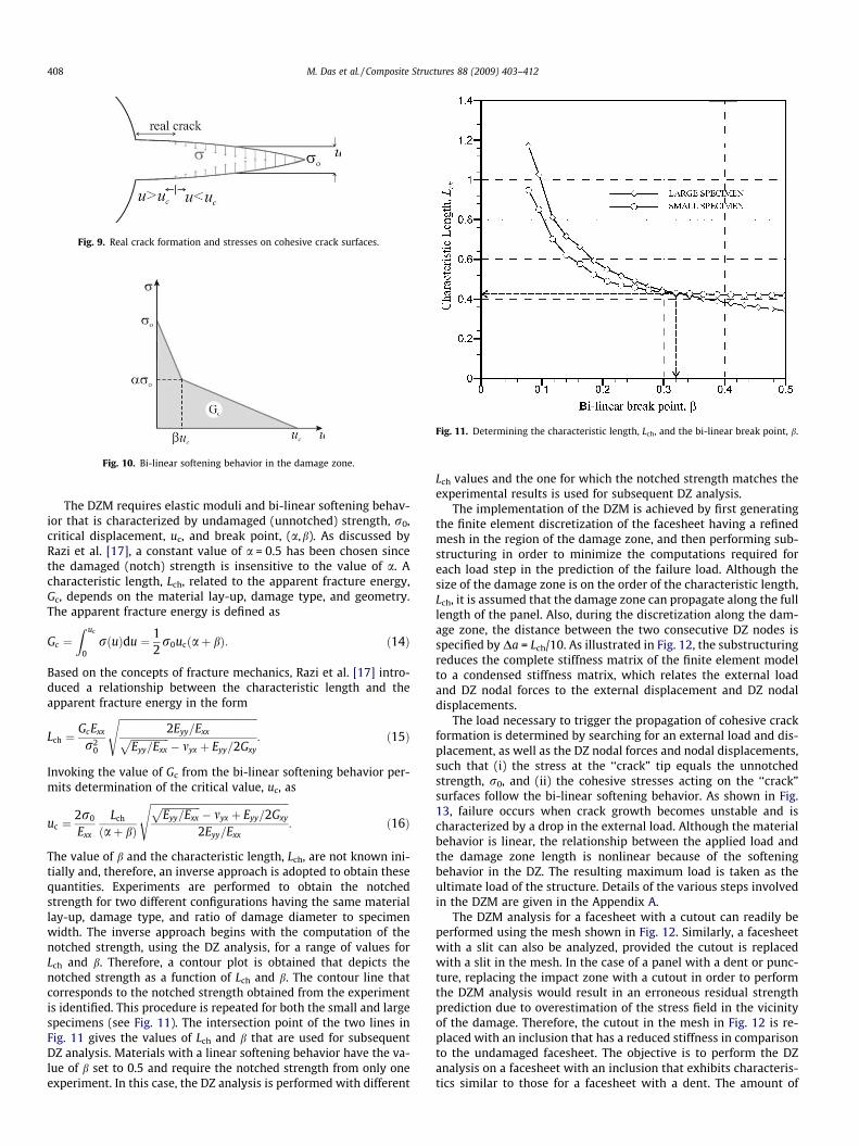
Fig. 9. Real crack formation and stresses on cohesive crack surfaces.
Fig. 10. Bi-linear softening behavior in the damage zone.
Fig. 11. Determining the characteristic length, Lch, and the bi-linear break point, b.
408 M. Das et al. / Composite Structures 88 (2009) 403–412
The DZM requires elastic moduli and bi-linear softening behav-ior that is characterized by undamaged (unnotched) strength, r0,critical displacement, uc, and break point, (a,b). As discussed byRazi et al. [17], a constant value of a = 0.5 has been chosen sincethe damaged (notch) strength is insensitive to the value of a. Acharacteristic length, Lch, related to the apparent fracture energy,Gc, depends on the material lay-up, damage type, and geometry.The apparent fracture energy is defined as
Gc ¼Z uc
0rðuÞdu ¼ 1
2r0ucðaþ bÞ: ð14Þ
Based on the concepts of fracture mechanics, Razi et al. [17] intro-duced a relationship between the characteristic length and theapparent fracture energy in the form
Lch ¼GcExx
r20
ffiffiffiffiffiffiffiffiffiffiffiffiffiffiffiffiffiffiffiffiffiffiffiffiffiffiffiffiffiffiffiffiffiffiffiffiffiffiffiffiffiffiffiffiffiffiffiffiffiffiffiffiffiffiffi2Eyy=Exxffiffiffiffiffiffiffiffiffiffiffiffiffiffiffi
Eyy=Exx
p� myx þ Eyy=2Gxy
s: ð15Þ
Invoking the value of Gc from the bi-linear softening behavior per-mits determination of the critical value, uc, as
uc ¼2r0
Exx
Lch
ðaþ bÞ
ffiffiffiffiffiffiffiffiffiffiffiffiffiffiffiffiffiffiffiffiffiffiffiffiffiffiffiffiffiffiffiffiffiffiffiffiffiffiffiffiffiffiffiffiffiffiffiffiffiffiffiffiffiffiffiffiffiffiffiffiffiffiffiffiffiffiffiffiffiffiEyy=Exx
p� myx þ Eyy=2Gxy
2Eyy=Exx
s: ð16Þ
The value of b and the characteristic length, Lch, are not known ini-tially and, therefore, an inverse approach is adopted to obtain thesequantities. Experiments are performed to obtain the notchedstrength for two different configurations having the same materiallay-up, damage type, and ratio of damage diameter to specimenwidth. The inverse approach begins with the computation of thenotched strength, using the DZ analysis, for a range of values forLch and b. Therefore, a contour plot is obtained that depicts thenotched strength as a function of Lch and b. The contour line thatcorresponds to the notched strength obtained from the experimentis identified. This procedure is repeated for both the small and largespecimens (see Fig. 11). The intersection point of the two lines inFig. 11 gives the values of Lch and b that are used for subsequentDZ analysis. Materials with a linear softening behavior have the va-lue of b set to 0.5 and require the notched strength from only oneexperiment. In this case, the DZ analysis is performed with different
Lch values and the one for which the notched strength matches theexperimental results is used for subsequent DZ analysis.
The implementation of the DZM is achieved by first generatingthe finite element discretization of the facesheet having a refinedmesh in the region of the damage zone, and then performing sub-structuring in order to minimize the computations required foreach load step in the prediction of the failure load. Although thesize of the damage zone is on the order of the characteristic length,Lch, it is assumed that the damage zone can propagate along the fulllength of the panel. Also, during the discretization along the dam-age zone, the distance between the two consecutive DZ nodes isspecified by Da = Lch/10. As illustrated in Fig. 12, the substructuringreduces the complete stiffness matrix of the finite element modelto a condensed stiffness matrix, which relates the external loadand DZ nodal forces to the external displacement and DZ nodaldisplacements.
The load necessary to trigger the propagation of cohesive crackformation is determined by searching for an external load and dis-placement, as well as the DZ nodal forces and nodal displacements,such that (i) the stress at the ‘‘crack” tip equals the unnotchedstrength, r0, and (ii) the cohesive stresses acting on the ‘‘crack”surfaces follow the bi-linear softening behavior. As shown in Fig.13, failure occurs when crack growth becomes unstable and ischaracterized by a drop in the external load. Although the materialbehavior is linear, the relationship between the applied load andthe damage zone length is nonlinear because of the softeningbehavior in the DZ. The resulting maximum load is taken as theultimate load of the structure. Details of the various steps involvedin the DZM are given in the Appendix A.
The DZM analysis for a facesheet with a cutout can readily beperformed using the mesh shown in Fig. 12. Similarly, a facesheetwith a slit can also be analyzed, provided the cutout is replacedwith a slit in the mesh. In the case of a panel with a dent or punc-ture, replacing the impact zone with a cutout in order to performthe DZM analysis would result in an erroneous residual strengthprediction due to overestimation of the stress field in the vicinityof the damage. Therefore, the cutout in the mesh in Fig. 12 is re-placed with an inclusion that has a reduced stiffness in comparisonto the undamaged facesheet. The objective is to perform the DZanalysis on a facesheet with an inclusion that exhibits characteris-tics similar to those for a facesheet with a dent. The amount of
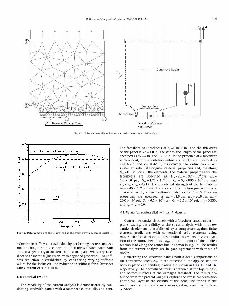
Fig. 12. Finite element discretization and substructuring for DZ analysis.
Fig. 13. Determination of the failure load as the crack growth becomes unstable.
M. Das et al. / Composite Structures 88 (2009) 403–412 409
reduction in stiffness is established by performing a stress analysisand matching the stress concentration in the sandwich panel withthe actual geometry of the dent to those of a panel whose top face-sheet has a material (inclusion) with degraded properties. The stiff-ness reduction is established by considering varying stiffnessvalues for the inclusion. The reduction in stiffness for a facesheetwith a cutout or slit is 100%.
4. Numerical results
The capability of the current analysis is demonstrated by con-sidering sandwich panels with a facesheet cutout, slit, and dent.
The facesheet has thickness of hf = 0.0498 in., and the thicknessof the panel is 2h = 1.0 in. The width and length of the panel arespecified as W = 4 in. and L = 12 in. In the presence of a facesheetwith a dent, the indentation radius and depth are specified asr = 0.65 in. and Y = 0.042 in., respectively. The entire core is as-sumed to retain its original material properties and, therefore,hcc = 0.0 in. for all the elements. The material properties for thefacesheets are specified as Exx = Eyy = 6.92 � 106 psi, Ezz =1.0 � 106 psi, Gxy = 1.77 � 106 psi, Gyz = Gxz = 885 � 103 psi, andmxy = myz = mxz = 0.217. The unnotched strength of the laminate isr0 = 3.46 � 104 psi. For this material, the fracture process zone ischaracterized by a linear softening behavior, i.e. b = 0.5. The coreproperties are specified as Exx = 51.0 psi, Eyy = 26.0 psi, Ezz =20.0 � 103 psi, Gxz = 6.5 � 103 psi, Gyz = 3.5 � 103 psi, mxy = 0.333,and myz = mxz = 0.0.
4.1. Validation against FEM with brick elements
Concerning sandwich panels with a facesheet cutout under in-plane loading, the validity of the stress analysis with this newsandwich element is established by a comparison against finiteelement predictions with conventional solid elements usingANSYS. The facesheet cutout has a radius of r = 0.65 in. A compar-ison of the normalized stress, ryy, in the direction of the appliedtension load along the center line is shown in Fig. 14. The resultsfrom the current analysis are in good agreement with those ofANSYS.
Concerning the sandwich panels with a dent, comparisons ofthe normalized stress, ryy, in the direction of the applied load forboth in-plane and bending loading are shown in Figs. 15 and 16,respectively. The normalized stress is obtained at the top, middle,and bottom surfaces of the damaged facesheet. The results ob-tained from the present analysis capture the stress concentrationat the top layer in the vicinity of the dent. The trends in themiddle and bottom layers are also in good agreement with thoseof ANSYS.
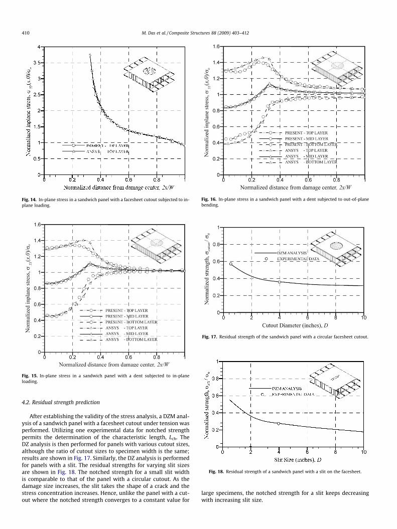
Fig. 14. In-plane stress in a sandwich panel with a facesheet cutout subjected to in-plane loading.
Fig. 15. In-plane stress in a sandwich panel with a dent subjected to in-planeloading.
Fig. 16. In-plane stress in a sandwich panel with a dent subjected to out-of-planebending.
Fig. 17. Residual strength of the sandwich panel with a circular facesheet cutout.
Fig. 18. Residual strength of a sandwich panel with a slit on the facesheet.
410 M. Das et al. / Composite Structures 88 (2009) 403–412
4.2. Residual strength prediction
After establishing the validity of the stress analysis, a DZM anal-ysis of a sandwich panel with a facesheet cutout under tension wasperformed. Utilizing one experimental data for notched strengthpermits the determination of the characteristic length, Lch. TheDZ analysis is then performed for panels with various cutout sizes,although the ratio of cutout sizes to specimen width is the same;results are shown in Fig. 17. Similarly, the DZ analysis is performedfor panels with a slit. The residual strengths for varying slit sizesare shown in Fig. 18. The notched strength for a small slit widthis comparable to that of the panel with a circular cutout. As thedamage size increases, the slit takes the shape of a crack and thestress concentration increases. Hence, unlike the panel with a cut-out where the notched strength converges to a constant value for
large specimens, the notched strength for a slit keeps decreasingwith increasing slit size.
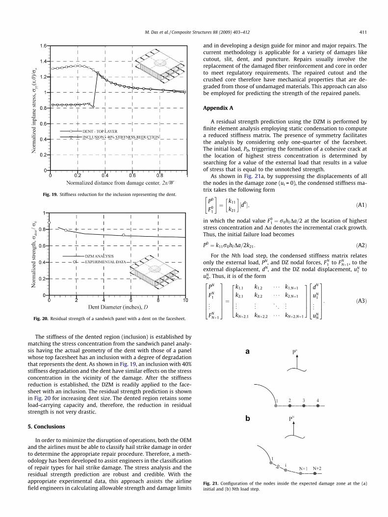
Fig. 19. Stiffness reduction for the inclusion representing the dent.
Fig. 20. Residual strength of a sandwich panel with a dent on the facesheet.
Fig. 21. Configuration of the nodes inside the expected damage zone at the (a)initial and (b) Nth load step.
M. Das et al. / Composite Structures 88 (2009) 403–412 411
The stiffness of the dented region (inclusion) is established bymatching the stress concentration from the sandwich panel analy-sis having the actual geometry of the dent with those of a panelwhose top facesheet has an inclusion with a degree of degradationthat represents the dent. As shown in Fig. 19, an inclusion with 40%stiffness degradation and the dent have similar effects on the stressconcentration in the vicinity of the damage. After the stiffnessreduction is established, the DZM is readily applied to the face-sheet with an inclusion. The residual strength prediction is shownin Fig. 20 for increasing dent size. The dented region retains someload-carrying capacity and, therefore, the reduction in residualstrength is not very drastic.
5. Conclusions
In order to minimize the disruption of operations, both the OEMand the airlines must be able to classify hail strike damage in orderto determine the appropriate repair procedure. Therefore, a meth-odology has been developed to assist engineers in the classificationof repair types for hail strike damage. The stress analysis and theresidual strength prediction are robust and credible. With theappropriate experimental data, this approach assists the airlinefield engineers in calculating allowable strength and damage limits
and in developing a design guide for minor and major repairs. Thecurrent methodology is applicable for a variety of damages likecutout, slit, dent, and puncture. Repairs usually involve thereplacement of the damaged fiber reinforcement and core in orderto meet regulatory requirements. The repaired cutout and thecrushed core therefore have mechanical properties that are de-graded from those of undamaged materials. This approach can alsobe employed for predicting the strength of the repaired panels.
Appendix A
A residual strength prediction using the DZM is performed byfinite element analysis employing static condensation to computea reduced stiffness matrix. The presence of symmetry facilitatesthe analysis by considering only one-quarter of the facesheet.The initial load, P0, triggering the formation of a cohesive crack atthe location of highest stress concentration is determined bysearching for a value of the external load that results in a valueof stress that is equal to the unnotched strength.
As shown in Fig. 21a, by suppressing the displacements of allthe nodes in the damage zone (ui = 0), the condensed stiffness ma-trix takes the following form
P0
F01
" #¼
k11
k21
� �½d0�; ðA1Þ
in which the nodal value F01 ¼ r0hfDa=2 at the location of highest
stress concentration and Da denotes the incremental crack growth.Thus, the initial failure load becomes
P0 ¼ k11r0hfDa=2k21: ðA2Þ
For the Nth load step, the condensed stiffness matrix relatesonly the external load, PN, and DZ nodal forces, FN
1 to FNNþ1, to the
external displacement, dN, and the DZ nodal displacement, uN1 to
uNN . Thus, it is of the form
PN
FN1
..
.
FNNþ1
2666664
3777775 ¼
k1;1 k1;2 � � � k1;Nþ1
k2;1 k2;2 � � � k2;Nþ1
..
. ... . .
. ...
kNþ2;1 kNþ2;2 � � � kNþ2;Nþ1
266664
377775
dN
uN1
..
.
uNN
2666664
3777775: ðA3Þ
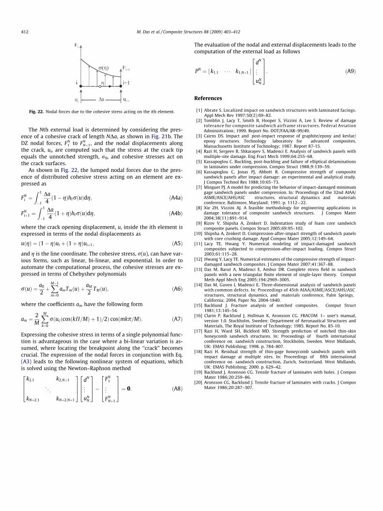
Fig. 22. Nodal forces due to the cohesive stress acting on the ith element.
412 M. Das et al. / Composite Structures 88 (2009) 403–412
The Nth external load is determined by considering the pres-ence of a cohesive crack of length NDa, as shown in Fig. 21b. TheDZ nodal forces, FN
1 to FNNþ1, and the nodal displacements along
the crack, ui, are computed such that the stress at the crack tipequals the unnotched strength, r0, and cohesive stresses act onthe crack surfaces.
As shown in Fig. 22, the lumped nodal forces due to the pres-ence of distributed cohesive stress acting on an element are ex-pressed as
FNi ¼
Z 1
�1
Da4ð1� gÞhfrðuÞdg; ðA4aÞ
FNiþ1 ¼
Z 1
�1
Da4ð1þ gÞhfrðuÞdg; ðA4bÞ
where the crack opening displacement, u, inside the ith element isexpressed in terms of the nodal displacements as
uðgÞ ¼ ð1� gÞui þ ð1þ gÞuiþ1; ðA5Þ
and g is the line coordinate. The cohesive stress, r(u), can have var-ious forms, such as linear, bi-linear, and exponential. In order toautomate the computational process, the cohesive stresses are ex-pressed in terms of Chebyshev polynomials
rðuÞ ¼ a0
2þXM�1
m¼0
amTmðuÞ þaM
2TMðuÞ; ðA6Þ
where the coefficients am have the following form
am ¼2M
XM
k¼0
rðucðcosðkP=MÞ þ 1Þ=2Þ cosðmkp=MÞ: ðA7Þ
Expressing the cohesive stress in terms of a single polynomial func-tion is advantageous in the case where a bi-linear variation is as-sumed, where locating the breakpoint along the ‘‘crack” becomescrucial. The expression of the nodal forces in conjunction with Eq.(A3) leads to the following nonlinear system of equations, whichis solved using the Newton–Raphson method
k2;1 k2;Nþ1
. ..
kNþ2;1 kNþ2;Nþ1
2664
3775
dN
..
.
uNN
2664
3775�
FN1
..
.
FNNþ1
2664
3775 ¼ 0: ðA8Þ
The evaluation of the nodal and external displacements leads to thecomputation of the external load as follows
PN ¼ k1;1 � � � k1;Nþ1½ �dN
..
.
uNN
2664
3775: ðA9Þ
References
[1] Abrate S. Localized impact on sandwich structures with laminated facings.Appl Mech Rev 1997;50(2):69–82.
[2] Tomblin J, Lacy T, Smith B, Hooper S, Vizzini A, Lee S. Review of damagetolerance for composite sandwich airframe structures. Federal AviationAdministration; 1999. Report No. DOT/FAA/AR–99/49.
[3] Cairns DS. Impact and post-impact response of graphite/epoxy and kevlar/epoxy structures. Technology laboratory for advanced composites,Massachusetts Institute of Technology; 1987. Report 87-15.
[4] Razi H, Sergeev B, Shkarayev S, Madenci E. Analysis of sandwich panels withmultiple-site damage. Eng Fract Mech 1999;64:255–68.
[5] Kassapoglou C. Buckling, post-buckling and failure of elliptical delaminationsin laminates under compression. Compos Struct 1988;9:139–59.
[6] Kassapoglou C, Jonas PJ, Abbott R. Compressive strength of compositesandwich panels after impact damage: an experimental and analytical study.J Compos Technol Res 1988;10:65–73.
[7] Minguet PJ. A model for predicting the behavior of impact-damaged minimumgage sandwich panels under compression. In: Proceedings of the 32nd AIAA/ASME/ASCE/AHS/ASC structures, structural dynamics and materialsconference, Baltimore, Maryland; 1991. p. 1112—22.
[8] Xie ZH, Vizzini AJ. A feasible methodology for engineering applications indamage tolerance of composite sandwich structures. J Compos Mater2004;38(11):891–914.
[9] Rizov V, Shipsha A, Zenkert D. Indentation study of foam core sandwichcomposite panels. Compos Struct 2005;69:95–102.
[10] Shipsha A, Zenkert D. Compression-after-impact strength of sandwich panelswith core crushing damage. Appl Compos Mater 2005;12:149–64.
[11] Lacy TE, Hwang Y. Numerical modeling of impact-damaged sandwichcomposites subjected to compression-after-impact loading. Compos Struct2003;61:115–28.
[12] Hwang Y, Lacy TE. Numerical estimates of the compressive strength of impact-damaged sandwich composites. J Compos Mater 2007;41:367–88.
[13] Das M, Barut A, Madenci E, Ambur DR. Complete stress field in sandwichpanels with a new triangular finite element of single-layer theory. ComputMeth Appl Mech Eng 2005;194:2969–3005.
[14] Das M, Guven I, Madenci E. Three-dimensional analysis of sandwich panelswith common defects. In: Proceedings of 45th AIAA/ASME/ASCE/AHS/ASCstructures, structural dynamics, and materials conference, Palm Springs,California; 2004. Paper No. 2004-1840.
[15] Backlund J. Fracture analysis of notched composites. Comput Struct1981;13:145–54.
[16] Clarin P, Backlund J, Hollman K, Aronsson CG. FRACOM 1– user’s manual,version 1.0. Stockholm, Sweden: Department of Aeronautical Structures andMaterials, The Royal Institute of Technology; 1985. Report No. 85-10.
[17] Razi H, Ward SH, Bickford MD. Strength prediction of notched thin-skinhoneycomb sandwich structures. In: Proceedings of fourth internationalconference on sandwich construction, Stockholm, Sweden. West Midlands,UK: EMAS Publishing; 1998. p. 784–807.
[18] Razi H. Residual strength of thin-gage honeycomb sandwich panels withimpact damage at multiple sites. In: Proceedings of fifth internationalconference on sandwich construction, Zurich, Switzerland. West Midlands,UK: EMAS Publishing; 2000. p. 629–42.
[19] Backlund J, Aronsson CG. Tensile fracture of laminates with holes. J ComposMater 1986;20:259–86.
[20] Aronsson CG, Backlund J. Tensile fracture of laminates with cracks. J ComposMater 1986;20:287–307.