
High-order theory for the analysis of multi-layer plate assemblies and its application for the...
12
High-order theory for the analysis of multi-layer plate assemblies and its application for the analysis of sandwich panels with terminating plies Ole Thybo Thomsen *,1 Department of Mechanical Engineering, Spencer Laboratory, University of Delaware, Newark, DE 19716, USA Abstract Multi-layer sandwich type structures can be identified in many structural assemblies involving composite materials. Such multi- layer composite assemblies are characterized by having interchanging layers of high density and high stiness separated by com- pliant interface layers. A characteristic feature of these multi-layer assemblies is that severe and highly localized stress concentrations appear under certain conditions. The quantitative understanding of these phenomena involves a detailed description of the com- plicated mechanical interaction of the sti layers through the compliant interface layers. The paper presents a high-order plate theory formulation, which includes the through-thickness flexibility, and which inherently includes a description of the global re- sponse as well as the local responses of the individual layers of an arbitrary, multi-layer structural plate assembly. The features of the high-order multi-layer plate theory are demonstrated through analysis of the elastic response of a CFRP/honeycomb-cored sand- wich panel with symmetric exterior ply drops. The chosen example involves a 7-layer sandwich plate assembly that changes to a 3- layer assembly at the position of the ply-drops. Ó 2000 Elsevier Science Ltd. All rights reserved. Keywords: Multi-layer plates; Sandwich type structures; Localized bending; Interface layers; Interlaminar stresses; Transverse flexibility; High-order plate theory; Cylindrical bending; Terminating plies; Ply-drops 1. Introduction Multi-layer sandwich type structures can be identified in many structural assemblies involving composite ma- terials. Such multi-layer composite assemblies are char- acterized by having interchanging high stiness layers separated by low stiness interface layers. The simplest example of such a layered composite assembly is the classical 3-layer sandwich configuration, where a compliant core material separates two sti face sheets. Another example is a composite laminate consisting of an arbitrary number of plies in between which distinct interface layers can be identified (N sti layers separated by (N 1) compliant interface layers). A characteristic feature of such multiple layer assemblies is that severe and strongly localized stress concentrations appear un- der certain conditions, where the sti layers interact through the compliant interface layers. Classical exam- ples of such localized stress build-up in layered struc- tures could be the well-known free edge problem in composite laminates, or the problem of application of localized loading to a classical 3-layer sandwich panel with a soft/compliant core. The understanding of these localized phenomena involves a detailed description of the interaction between the sti layers through the compliant interface layers. There are several suggestions for the development of theories for the analysis of multi-layer plates. The sim- plest approach is to use the classical laminated plate theory (CLT) based on the classical Love–Kirchho as- sumptions, as described by, e.g. Whitney [1] and Jones [2]. A more refined approach includes the transverse shear eects, and was suggested by Reissner [3] and Mindlin [4]. They assumed a linear through-thickness distribution of the in-plane displacements and a uniform through-thickness distribution for the transverse dis- placements (first-order shear theory). The Reissner– Mindlin approach is suggested in the monographs of Vinson and Sierakowski [5], for the analysis of general www.elsevier.com/locate/compstruct Composite Structures 50 (2000) 227–238 * Tel.: +1-302-831-8930; fax: +1-302-831-3619. E-mail addresses: [email protected], [email protected] (O.T. Thomsen). 1 On academic leave from Institute of Mechanical Engineering, Aalborg University, Denmark. Tel.: (+45) 96 359 319; fax: (+45) 98 151 411. 0263-8223/00/$ - see front matter Ó 2000 Elsevier Science Ltd. All rights reserved. PII: S 0 2 6 3 - 8 2 2 3 ( 0 0 ) 0 0 0 9 6 - 9
Transcript of High-order theory for the analysis of multi-layer plate assemblies and its application for the...

High-order theory for the analysis of multi-layer plate assembliesand its application for the analysis of sandwich panels
with terminating plies
Ole Thybo Thomsen *,1
Department of Mechanical Engineering, Spencer Laboratory, University of Delaware, Newark, DE 19716, USA
Abstract
Multi-layer sandwich type structures can be identi®ed in many structural assemblies involving composite materials. Such multi-
layer composite assemblies are characterized by having interchanging layers of high density and high sti�ness separated by com-
pliant interface layers. A characteristic feature of these multi-layer assemblies is that severe and highly localized stress concentrations
appear under certain conditions. The quantitative understanding of these phenomena involves a detailed description of the com-
plicated mechanical interaction of the sti� layers through the compliant interface layers. The paper presents a high-order plate
theory formulation, which includes the through-thickness ¯exibility, and which inherently includes a description of the global re-
sponse as well as the local responses of the individual layers of an arbitrary, multi-layer structural plate assembly. The features of the
high-order multi-layer plate theory are demonstrated through analysis of the elastic response of a CFRP/honeycomb-cored sand-
wich panel with symmetric exterior ply drops. The chosen example involves a 7-layer sandwich plate assembly that changes to a 3-
layer assembly at the position of the ply-drops. Ó 2000 Elsevier Science Ltd. All rights reserved.
Keywords: Multi-layer plates; Sandwich type structures; Localized bending; Interface layers; Interlaminar stresses; Transverse ¯exibility; High-order
plate theory; Cylindrical bending; Terminating plies; Ply-drops
1. Introduction
Multi-layer sandwich type structures can be identi®edin many structural assemblies involving composite ma-terials. Such multi-layer composite assemblies are char-acterized by having interchanging high sti�ness layersseparated by low sti�ness interface layers. The simplestexample of such a layered composite assembly is theclassical 3-layer sandwich con®guration, where acompliant core material separates two sti� face sheets.Another example is a composite laminate consisting ofan arbitrary number of plies in between which distinctinterface layers can be identi®ed (N sti� layers separatedby (N ÿ 1) compliant interface layers). A characteristicfeature of such multiple layer assemblies is that severeand strongly localized stress concentrations appear un-
der certain conditions, where the sti� layers interactthrough the compliant interface layers. Classical exam-ples of such localized stress build-up in layered struc-tures could be the well-known free edge problem incomposite laminates, or the problem of application oflocalized loading to a classical 3-layer sandwich panelwith a soft/compliant core. The understanding of theselocalized phenomena involves a detailed description ofthe interaction between the sti� layers through thecompliant interface layers.
There are several suggestions for the development oftheories for the analysis of multi-layer plates. The sim-plest approach is to use the classical laminated platetheory (CLT) based on the classical Love±Kirchho� as-sumptions, as described by, e.g. Whitney [1] and Jones [2].
A more re®ned approach includes the transverseshear e�ects, and was suggested by Reissner [3] andMindlin [4]. They assumed a linear through-thicknessdistribution of the in-plane displacements and a uniformthrough-thickness distribution for the transverse dis-placements (®rst-order shear theory). The Reissner±Mindlin approach is suggested in the monographs ofVinson and Sierakowski [5], for the analysis of general
www.elsevier.com/locate/compstruct
Composite Structures 50 (2000) 227±238
* Tel.: +1-302-831-8930; fax: +1-302-831-3619.
E-mail addresses: [email protected], [email protected] (O.T.
Thomsen).1 On academic leave from Institute of Mechanical Engineering,
Aalborg University, Denmark. Tel.: (+45) 96 359 319; fax: (+45) 98
151 411.
0263-8223/00/$ - see front matter Ó 2000 Elsevier Science Ltd. All rights reserved.
PII: S 0 2 6 3 - 8 2 2 3 ( 0 0 ) 0 0 0 9 6 - 9

laminated composites, and Vinson [6] for the analysis of3-layer sandwich structures.
A special class of so-called `antiplane' plate theorieshas been developed for the analysis of classical 3-layersandwich structures. The features of the antiplanesandwich theories are summed up in the monographs byPlantema [7], Allen [8], Stamm and Witte [9] andZenkert [10]. The term antiplane is equivalent to theterms `weak' or `compliant' cores, and is used to de-scribe an idealized sandwich core in which the stretchingand shearing sti�nesses in planes parallel with thesandwich panel face sheets are zero, but where the shearmodulus perpendicular to the face sheets is ®nite.
Neither of the Love±Kirchho�, Mindlin±Reissner orantiplane plate theory formulations include the trans-verse ¯exibility. Consequently they cannot account forlocalized bending e�ects where the face sheets tend tobend about their own middle plane, and where thethickness of the plate assembly may change during de-formation.
Higher-order theories have been proposed by amongothers Lo et al. [11], Stein [12], Reddy [13,14] and Savoiaet al. [15]. In these references high-order through-thickness displacement ®elds in the form of polynomialsof varying order or trigonometric series are assumed apriori. All of the quoted high-order theories use inte-gration through the thickness along with a variationalprinciple to derive the governing equations and the ap-propriate boundary conditions. One particular featureof high-order theories based on polynomial displace-ment distributions assumed a priori is that, in someformulations, terms appear in the governing equations,
as well as in the boundary conditions, which are di�cultto attribute any physical meaning.
A special high-order formulation for the analysis ofsymmetric 3-layer sandwich plates was suggested byLibrescu [16], including the presence of transverse nor-mal stresses in the core material. The transverse ¯exi-bility is not included in the formulation, however, thusignoring the e�ects associated with changes of the lam-inate plate thickness.
Frostig and co-workers [17±21] have developed ahigh-order theory especially adapted for 3-sandwichpanels with soft/compliant cores (two face sheets sepa-rated by a core material). In this particular formulationno restrictions on the through-thickness displacementdistributions are imposed a priori, and the high-ordere�ects predicted by the theory are results of the formu-lation. The formulation includes the transverse ¯exibil-ity of the core material, thus enabling the description oflocalized bending e�ects associated with local changes ofthe sandwich panel thickness. The high-order sandwichtheory, as applied for the analysis of 3-layer sandwichbeams with soft/compliant cores, was validated experi-mentally by Thomsen and Frostig [22].
This paper presents a general high-order multi-layerplate theory, which inherently includes a description ofthe global response as well as the local responses of theindividual layers of an arbitrary multiple layer structuralassembly. The theory includes the transverse ¯exibilityof the interface layers in the modeling, and it is based onthe principles suggested in Refs. [17±22] for 3-layersandwich beams, and used by Thomsen and Rits [23]and Thomsen [24] for the analysis of 3-layer sandwich
Symbols
ci thickness of interface layer ifi thickness of solid laminate iki
m coe�cients depending on Aijk, Bi
jk, Dijk;
m � 1; . . . ; 10ui
0, vi0, wi middle plane displacement compo-
nents in x, y and z directions of solidlaminate i
uic, vi
c, wic displacement components in x, y and
z directions of interface layer ix, y, z spatial coordinatesAi
jk, Bijk, Di
jk extensional, coupling and bendingsti�nesses of the ith solid laminate;j; k � 1; 2; 6
Eicz, Gi
cxz, Gicyz transverse YoungÕs modulus and
shear modulus of the ith interfacelayer material
Ei11, Ei
22 YoungÕs moduli of solid laminate iGi
12 in-plane shear modulus of solid lami-nate i
Mixx, Mi
yy , Mixy bending moment resultants of the ith
solid laminateN i
xx, N iyy , Ni
xy in-plane stress resultants of the ithsolid laminate
N number of solid laminates in multi-layer plate assembly
P prescribed external tension load perunit width
Qix, Qi
y transverse shear stress resultants ofthe ith solid laminate
aim coe�cients depending on Ai
jk, Bijk, Di
jk;m � 1; . . . ; 9
bix, bi
y rotations of the normals to the ithsolid laminate mid-planes
mi12 Poisson's ratio of the ith solid lami-
natesi
zx, sizy , si
z shear and transverse normal stressesin interface layer i
228 O.T. Thomsen / Composite Structures 50 (2000) 227±238

plates. The suggested multi-layer high-order plate theorycan be used for the analysis of arbitrary multi-layer plateassemblies ranging from classical sandwich plates (threelayers), over multi-layer sandwich plates to generalcomposite laminates (N plies separated by N ÿ 1 com-pliant interface layers).
2. High-order multi-layer plate formulation
2.1. Basic assumptions
With reference to Fig. 1, which de®nes an arbitrarymulti-layer plate assembly, the high-order plate theoryincludes the following features:· N high sti�ness layers separated by (N ÿ 1) compliant
interface layers.· The N high sti�ness layers, denoted as solid lami-
nates, are modeled as generally orthotropic laminatedplates adopting the Love±Kirchho� assumptions.
· The (N ÿ 1) compliant interface layers are modeled asa special type of orthotropic solid, only possessingsti�ness in the out-of-plane direction. Accordingly,the in-plane stresses are assumed to be negligible inthe interface layers, while transverse shear and trans-verse normal stresses are accounted for.
· The constituent materials are assumed to obey linearelastic constitutive laws.
· Only small deformations are considered.
2.2. Modeling of solid laminates
For the purposes of the present paper, the generalplate theory is shown for the special case of cylindricalbending. With reference to Fig. 1, cylindrical bending isde®ned as a state of deformation where the fundamentalvariables are functions of the longitudinal coordinate xalone, see also Ref. [1]. Consequently, the displacement
®eld is uniform in the width direction (y), and can bedescribed by
ui0 � ui
0�x�; vi0 � vi
0�x�; wi � wi�x�; �1�where ui
0, vi0 and wi are the middle plane displacements in
the x, y and z directions, respectively, and superscript irefers to the ith solid laminate of the multi-layer plate�i � 1; . . . ;N�. As a consequence of Eq. (1) the followingcan be deduced:
ui0;y � vi
0;y � wi;y � wi
;yy � 0; �2�where di�erentiation with respect to the spatial coordi-nates is represented by a subscript comma. It should benoted that the concept of cylindrical bending is notunique, and that other de®nitions than the one used inthe present formulation can be adopted [1].
According to the Love±Kirchho� assumptions, andby adoption of Eq. (2), the kinematic relations for theith solid laminate �i � 1; . . . ;N� are expressed as:
ui � ui0 � zbi
x; bix � ÿwi
;x;
vi � vi0 � zbi
y ; biy � ÿwi
;y � 0:�3�
Substitution of Eq. (2) into the general constitutive re-lations for a laminated generally orthotropic plate, seeRefs. [1,2], yields the constitutive relations for the ithsolid laminate in a state of cylindrical bending; i �1; . . . ;N :
Nixx � Ai
11ui0;x � Ai
16vi0;x ÿ Bi
11wi;xx;
Mixx � Bi
11ui0;x � Bi
16vi0;x ÿ Di
11wi;xx;
Niyy � Ai
12ui0;x � Ai
26vi0;x ÿ Bi
12wi;xx;
Miyy � Bi
12ui0;x � Bi
26vi0;x ÿ Di
12wi;xx;
Nixy � Ai
16ui0;x � Ai
66vi0;x ÿ Bi
16wi;xx;
Mixy � Bi
16ui0;x � Bi
66vi0;x ÿ Di
16wi;xx;
�4�
where Aijk, Bi
jk, Dijk �j; k � 1; 2; 6� are the extensional,
coupling and bending sti�nesses of the ith solid lami-nate. N i
xx, Niyy , N i
xy are the in-plane stress resultants, and
Mixx, Mi
yy , Mixx are the moment resultants of the ith solid
laminate.For the case of cylindrical bending, where all deriv-
atives with respect to y vanish, the equilibrium equations(see Fig. 2) for the ith solid laminate read; i � 1; . . . ;N :
Nixx;x � si
zx ÿ siÿ1zx ;
Nixy;x � si
zy ÿ siÿ1zy ;
Qix;x � ri�top�
z ÿ riÿ1�bottom�z ;
Mixx;x � Qi
x ÿfi
2fsi
zx � siÿ1zx g;
Mixy;x � Qi
y ÿfi
2fsi
zy � siÿ1zy g;
�5�
where sizx, si
zy are the shear stress components in the ithinterface layer, ri�top�
z is the transverse normal stresscomponent along the boundary between the ith solid
Fig. 1. Multi-layer plate assembly consisting of N high sti�ness solid
laminates and (N ÿ 1) compliant interface layers.
O.T. Thomsen / Composite Structures 50 (2000) 227±238 229

laminate and the ith interface layer (i.e. the topboundary of the ith interface layer), riÿ1�bottom�
z is thetransverse normal stress component along the boundarybetween the ith solid laminate and the (iÿ 1)th interfacelayer (i.e. the bottom interface of the (iÿ 1)th interfacelayer), fi is the thickness of the ith solid laminate, andQi
x, Qiy are the transverse shear stress resultants in the ith
solid laminate.
2.3. Modeling of interface layers
The (N ÿ 1) compliant interface layers are modeled asa special type of orthotropic linear elastic solid onlypossessing sti�ness in the out-of-plane direction (z or zi
c);[17±24]. Consequently, the sti�ness properties of the ithinterface layer are characterized exclusively by thetransverse YoungÕs modulus Ei
cz and the two transverse
shear moduli Gicxz, Gi
cyz. As a consequence of the as-sumption of zero in-plane sti�ness the in-plane stressesare nil, and the stress ®eld is described solely by thetransverse normal stress ri
z and the transverse shearstresses si
xz, siyz as shown in Fig. 2.
The response of the ith interface layer is coupled withthe responses of the surrounding solid laminates by re-quiring continuity of the displacements across the solidlaminate/interface layer boundaries, i.e. at z � zi
c ��ci=2(ci is the thickness of interface layer i). For cylindricalbending the continuity/compatibility conditions read;i � 1; . . . ;N ÿ 1:
wic x; y;
ci
2
� �� wi�x; y�;
wic x; y;�
ÿ ci
2
�� wi�1�x; y�;
uic x; y;
ci
2
� �� ui x; y;
�ÿ fi
2
�� ui
0 � wi;x
fi
2;
uic x; y;�
ÿ ci
2
�� ui�1 x; y;
fi�1
2
� �� ui�1
0 ÿ wi�1;x
fi�1
2;
vic x; y;
ci
2
� �� vi x; y;
�ÿ fi
2
�� vi
0 � wi;y
fi
2� vi
0;
vic x; y;�
ÿ ci
2
�� vi�1 x; y;
fi�1
2
� �� vi�1
0 ÿ wi�1;y
fi�1
2� vi�1
0 :
�6�The compatibility conditions, given by equations (6),imply that the solid laminates and the interface layersinteract through the transfer of surface tractions andshear stresses as shown in Fig. 2, and as included in thesolid laminate equilibrium equations (5).
By combining the interface layer equilibrium equa-tions with the interface layer kinematic and constitutiverelations, followed by integration by parts through thethickness of the interface layers and some algebraicmanipulations, the interface layer displacement andstress ®elds are derived in explicit form. In this explicitform the interface layer stress and displacement ®eldsare expressed in terms of the transverse coordinate z (orzi
c, i � 1; . . . ;N ÿ 1), and in terms of the solid laminatedisplacement components. The details of the derivationsare given in Appendix A for the general case; i.e. with-out the assumption of cylindrical bending.
For the special case of cylindrical bending the re-sulting interface layer ®eld equations read; i � 1; . . . ;N ÿ 1:
sixz�x; y; z� � si
xz�x�;si
yz�x; y; z� � siyz�x�;
riz�x; y; z� � ri
z�x; z� �Ei
cz
ciwi� ÿ wi�1
ÿ sixz;xz;
wic�x; y; z� � wi
c�x; z� � wi � wi ÿ wi�1f gci
znÿ ci
2
oÿ 1
2Eicz
sixz;x z2
(ÿ �ci�2
4
);
Fig. 2. Equilibrium elements of the ith solid laminate and the ith in-
terface layer.
230 O.T. Thomsen / Composite Structures 50 (2000) 227±238

uic�x; y; z� � ui
c�x; z� � ui0 �
wi;x
2fi
�ÿ z2
ciÿ z� 3ci
4
�� wi�1
;x
2
z2
ci
�ÿ z� ci
4
�� si
xz
Gicxz
znÿ ci
2
o� 1
2Eicz
sixz;xx
z3
3
(ÿ �ci�2z
4� �ci�3
12
);
vic�x; y; z� � vi
c�x; z� � vi0 �
siyz
Gicyz
znÿ ci
2
o; �7�
where uic; v
ic;w
ic are the in-plane and out-of-plane inter-
face layer displacements, and ci is the thickness of the ithinterface layer. From Eq. (7) it is observed that si
xz andsi
yz do not vary across the thickness of interface layer i. Itis further seen that ri
z varies linearly, that wic varies
quadratically, that uic varies cubically and ®nally that vi
cvaries linearly (because of the assumption of cylindricalbending) across the thickness of the ith interface layer.
2.4. Complete set of governing equations
Combination of the solid laminate equations, (1)±(5),with the compatibility equations (6), and the interfacelayer ®eld equations (7), yields the complete set ofgoverning di�erential equations for the ith solid lami-nate and the ith interface layer.
For the case of cylindrical bending, the governingequations can be expressed in the form:
2.4.1. ith solid laminate; i � 1; . . . ;N
ui0;x � ai
1Nixx � ai
2Nixy � ai
3Mixx;
vi0;x � ai
4Nixx � ai
5N ixy � ai
6Mixx;
wi;x � ÿbi
x;
bix;x � ai
7N ixx � ai
8Nixy � ai
9Mixx;
N ixx;x � ÿ siÿ1
zx
� ÿ sizx
;
N ixy;x � ÿ siÿ1
zy
nÿ si
zy
o;
Mixx;x � Qi
x ÿfi
2siÿ1
zx
� � sizx
;
Qix;x � ÿwiÿ1 Eiÿ1
cz
ciÿ1
ÿ qiÿ1x
ciÿ1
2� wi Eiÿ1
cz
ciÿ1
�� Ei
cz
ci
�ÿ qi
x
ci
2ÿ wi�1 Ei
cz
ci:
�8�
2.4.2. ith interface layer; i � 1; . . . ;N ÿ 1
sixz;x � qi
x;
siyz;x � qi
y ;
qix;x �
12Eicz
�ci�3�ÿ ui
0 ��fi � ci�
2bi
x � ui�10 �
�fi�1 � ci�2
bi�1x
� ci
Gicxz
sixz
�;
qiy;x �
Gicyz
ciki
7Qix
n� ki
8siÿ1xz � ki
9
ÿ ki�18
�si
xz
ÿ ki�19 si�1
xz ÿ ki3s
iÿ1yz � ki
3
� ki�13
�si
yz
ÿ ki�13 si�1
yz ÿ ki�17 Qi�1
x
o: �9�
From Eqs. (8) and (9) it is seen that the mechanical re-sponse of the ith solid laminate or interface layer de-pends explicitly of the responses of the two neighboringlayers on each side. Or in other words, the explicit`connectivity' of the governing equations extends to twolayers on each side of the considered solid laminate orinterface layer.
The coe�cients aij ( j� 1±9) and ki
j ( j� 1±10) in Eqs.(8) and (9) are determined from the solid laminate ex-tensional, coupling and bending sti�nesses Ai
mn;Bimn;D
imn
�m; n � 1; 2; 6� as follows, where i � 1; . . . ;N :
ki1 �
Ai11
Ai11Di
11 ÿ Bi11� �2 ; ki
2 �Bi
11Ai16
Ai11
ÿ Bi16;
ki3 �
Ai11
Ai11Ai
66 ÿ Ai11ki
1 ki2� �2 ÿ Ai
16� �2 ;
ki4 �
1
Ai11
Ai16
� � Bi11ki
1ki2
�; ki
5 � ki4 ÿ
fi
2ki
1ki2;
ki6 � ÿki
4 ÿfi
2ki
1ki2; ki
7 � ki1ki
2ki3; ki
8 � ki3ki
5;
ki9 � ki
3ki6; ki
10 �Ai
11
Ai11Ai
66 ÿ Ai16� �2 ;
�10�
ai1 �
1
Ai11
1� ÿ ai
4Ai16 ÿ ai
7Bi11
�;
ai2 � ÿ
1
Ai11
ai5Ai
16
� � ai8Bi
11
�;
ai3 � ÿ
1
Ai11
ai6Ai
16
� � ai9Bi
11
�;
ai4 � ki
10 ai7ki
2
�ÿ Ai
16
Ai11
�; ai
5 � ki10 1� � ai
8ki2
�;
ai6 � ai
8; ai7 � ÿ
ai9
Ai11
Bi11
� � ki2ki
10Ai16
�;
ai8 � ki
2ki10a
i9; ai
9 �ki
1
1ÿ ki1 ki
2� �2ki10
:
�11�
For the ith solid laminate and the ith interface layer thesolution vectors containing the fundamental variables,de®ned by:
O.T. Thomsen / Composite Structures 50 (2000) 227±238 231

ui0; v
i0;w
i; bix;N
ixx;N
ixy ;M
ixx;Q
ix
n o; i � 1; . . . ;N ;
sixz; s
iyz; q
ix; q
iy
n o; i � 1; . . . ;N ÿ 1
�12�
are determined from the solution of the ®eld equations(8) and (9). When the solution given by Eq. (12) hasbeen obtained, the following additional solid laminateand interface layer quantities can be determined directlyfrom Eqs. (4), (5) and (7):
Niyy ;M
iyy ;M
ixy ;Q
iy
n o; i � 1; . . . ;N ;
uic; v
ic;w
ic; r
iz
� ; i � 1; . . . ;N ÿ 1:
�13�
The solid laminate quantities given by Eq. (13) canphysically be interpreted as the stress and momentresultants, which have to be applied along the edg-es y� constant in order to maintain a state of cylin-drical bending in the considered multi-layer plateassembly.
2.5. Multi-segment method of integration
For an arbitrary multi-layer plate assembly the orderof the set of governing equations is N � 8� �N ÿ 1� � 4,since the necessary number of boundary conditions tobe speci®ed along an edge x� constant exactly equalshalf this number.
The governing equations (8) and (9), together withthe statement of the boundary conditions, constitute aboundary value problem, which in the present investi-gation has been solved numerically using the multi-segment method of integration suggested by Kalnins[25], and used recently by Thomsen et al. [23,24,26] andMortensen and Thomsen [27]. The principle behind themethod is to transform the original boundary valueproblem into a series of interconnected initial valueproblems. For the actual problem, the considered multi-layer plate is divided into a ®nite number of segments,and the solution within each segment is obtained directlyby numerical integration. Formulating and solving a setof linear algebraic equations ensures continuity of thesolution vectors, given by Eq. (12), across the separationpoints between the integration segments, as well as ful-®llment of the boundary conditions.
3. Case study: CFRP-sandwich panel with ply-drops
The developed high-order multi-layer plate theoryenables the prediction of the mechanical responsecharacteristics displayed by a number of complicatedstructural problems. Pertinent examples could includethe analysis of interlaminar stresses in composite lami-
nates including free edge e�ects, analysis of adhesivebonded joints (high-order 3-layer beam analysis: Frostiget al. [28]), analysis of structural multi-layer sandwichplates, and many other problems involving layeredstructural assemblies.
In this paper the capabilities of the theory are dem-onstrated through analysis of a CFRP/honeycomb-cored sandwich panel subjected to external tensionloading, and with exterior ply drops placed symmetri-cally on each side, as shown schematically in Fig. 3. Theply-drop con®guration shown in Fig. 3 illustrates asimpli®ed version of an important practical problem,since the thickness of composite laminates and sandwichpanels (with composite face sheets) is often increasedlocally in order to provide for the load transfer aroundhighly loaded locations such as joints, rivets, bolts orinserts. Usually plies are dropped internally, but exteriorply drops are also used quite frequently. At the stationswhere ply drops are made, the local bending sti�ness ofthe face laminates changes discontinuously, thus in-ducing severe local bending e�ects. These local bendinge�ects induce severe stress concentrations, which mayinitiate delamination, core crushing or solid laminatebending failure.
Several approaches of varying complexity have beensuggested for the analysis of composite laminates withply-drops. Approximate closed form beam solutionswere suggested by Thomas and Webber [29] and Wis-nom and Jones [30]. 2D and 3D ®nite element analysistechniques were adopted by among others Curry et al.[31], D�avila and Johnson [32], Vizzini and Lee [33],Vizzini [34] and Botting et al. [35]. Vizzini [36] used ashear±lag model to analyze the interlaminar stresses inthe regions near ply-drops. Finally, Thomsen et al.[26,37,38] and Mortensen and Thomsen [27] adopted anelastic foundation approach for the analysis of localizedbending and shearing e�ects as well as interlaminarstresses in the vicinity of ply-drops.
In the forthcoming section the exterior ply-dropproblem, as illustrated in Fig. 3 and treated recently byThomsen et al. [26,37,38], will be analyzed using themulti-layer high-order theory outlined in this paper.
Fig. 3. CFRP/honeycomb-cored sandwich panel subjected to external
tension loading, and with symmetric exterior ply-drops.
232 O.T. Thomsen / Composite Structures 50 (2000) 227±238

3.1. De®nition of CFRP-sandwich plate ply-drop problem
The CFRP-sandwich plate ply-drop con®gurationconsidered is assumed to be identical with a particulartest specimen con®guration reported in Ref. [38]. Withreference to Figs. 1 and 3, the sandwich plate is com-posed of a 3-layer structural assembly for 06 x6 L1 anda 7-layer assembly for L16 x6L1 � L2. The materialproperties, stacking sequences, geometric data andboundary conditions are given in Tables 1±3.
The analyzed con®guration is geometrically sym-metric about the middle plane of interface layer 2 (thesandwich core), but solid laminates 1 and 4 (droppedsub laminates) are stacked asymmetrically with respectto their own middle planes as well as with respect to themiddle plane of interface layer 2. Consequently, themechanical response will display coupling e�ects in-cluding non-zero `width direction' displacements (vi
0, vic),
non-zero width direction interface layer shear stresses�si
yz�, and non-zero width direction solid laminate stressand moment resultants (Ni
yy , Nixy , Mi
yy , Mixy , Qi
y).
3.2. Numerical results
Fig. 4 shows the predicted solid laminate displace-ments. It is observed from the distribution of wi that
Table 1
Material data for solid laminates and interface layers
Layer Material Material properties
Solid laminates 1±4
(i� 1±4)
Narmco/BASF 5245C T-800; toughened carbon
(T-800 ®bers)/bismaleimide prepreg
Ei11 � 165 GPa, Ei
22 � 9:7 GPa, mi12 � 0:31, Gi
12 �4:8 GPa, cured ply thickness� 0.152 mm
Interface layers 1
and 3 (i� 1,3)
Prepreg bismaleimide resin Eiz � 3:3 GPa, Gi
xz � Giyz � 1:2 GPa
Interface layer 2 Aluminum honeycomb; Hexcel 3/16"-5052-0.001" E2z � 517 MPa, G2
xz � 310 MPa, G2yz � 152 MPa
Table 2
Material speci®cation, geometry and stacking sequences
Layer Material Thickness fi or ci (mm) L1 (mm) L2 (mm) Stacking sequencea
Solid laminate 1 5245 C T-800 0.456 ) 20 [90°/)45°/45°]
Solid laminates 2 and 3 5245 C T-800 0.456 20 20 [0°/90°/0°]
Solid laminate 4 5245 C T-800 0.456 ) 20 [)45°/45°/90°]
Interface layers 1 and 3 Bismalimide resin 0.1 ) 20 )Interface layer 2 Hexcel honeycomb 10 20 20 )
a The stacking sequences are counted from the top and downwards.
Table 3
Boundary conditions for sandwich plate assembly with ply-drops
Position Speci®ed boundary conditions
x� 0 Solid laminates 2±3: vi0 � wi � bi
x � 0�i � 2; 3�, u20 ÿ u3
0 � 0, N 2xx � N 3
xx � P, P � 100 N/mm (external loading)
Interface layer 2 (sandwich `core'): w2 ÿ w2c � 0; v2
0 ÿ v2c � 0) s2
zx;x � s2zy � 0
x�L1 Solid laminates 1 and 4: ``Free edge conditions''; Nixx � Ni
xy � Mixx � Qi
x � 0 �i � 1; 4�Interface layers 1 and 3: ``Free edge conditions'': si
zx � sizy;x � 0 �i � 1; 3�
Solid laminates 2 and 3: `Continuity conditions'
Interface layer 2 (sandwich `core'): `Continuity conditions'
x � L1 � L2 Solid laminates 1±4: ``Clamping conditions''; ui0 � vi
0 � wi � bix � 0 (i� 1±4)
Interface layers 1±3: Clamping conditions''; wi ÿ wic � 0 & vi
0 ÿ vic � 0) si
zx;x � sizy � 0 (i� 1±3)
Fig. 4. Solid laminate displacements ui0�x�, vi
0�x�, wi(x); i� 1±4.
O.T. Thomsen / Composite Structures 50 (2000) 227±238 233

severe local bending e�ects are induced near the ply-drop position at x � L1 � 20 mm. In particular it isnoticed that the dropped laminates (i� 1 and 4) tends topeel of solid laminates 2 and 3, thus indicating thepresence of tensile transverse normal stresses (peelingstresses) in interface layers 1 and 3. The in-plane dis-placements ui
0 display the linear pattern expected for asandwich plate subjected to uniform tension loading.Non-zero width direction displacements vi
0 are also seendue to the asymmetric stacking of the dropped laminates1 and 4.
Figs. 5 and 6 display the predicted interface layerstresses, which have been normalized with respect to thenominal stress in solid laminates 2 and 3 at x� 0 (pointof load introduction; see Fig. 3 and Table 3)
rnom � N 2xx
f2
� N 3xx
f3
� P2f2
� 109:6 MPa: �14�
Fig. 5 shows the transverse normal stresses along the top�ri�top�
z � and bottom �ri�bottom�z � boundaries between the
interface layers and the solid laminates. According tothe third of Eq. (7), the variation of the transversenormal stresses through the thickness of the interface
layers is linear, and it is seen that the variation is verylarge (the interface layer thickness is only c1 � c3 �0:1 mm) close to the free edges of interface layers 1 and 3at x � L1 � 20 mm. Extremely large tensile transversenormal stresses are induced along the interface layerboundaries closest to the middle plane of the sandwichpanel, whereas large compressive transverse normalstresses are induced along the outer interface layerboundaries. The di�erence between ri�top�
z and ri�bottom�z
only exists in a narrow region of about one interfacelayer thickness (c1 � c3 � 0:1 mm) adjacent to the freeedges at x � L1 � 20 mm. It is further seen that thepresence of transverse normal stresses in interface layers1 and 3 is very localized, and a complete decay is ob-served a short distance away from the ply drop position.The transverse normal stresses in the core material (in-terface layer 2) are very small compared with the stressesin interface layers 1 and 3. The rz-distributions obtainedfor the top and bottom boundaries of interface layer 2are identical, which implies that the transverse normalstresses are constant through the core thickness. It isfurther observed that the rz-distribution pattern in thecore (interface layer 2) is nearly identical (proportional)to the distribution pattern displayed by the out-of-planedisplacements of solid laminates 2 and 3, see Fig. 4. This
Fig. 5. Normalized interface layer transverse normal stresses
ri�top�z =rnom;rz�bottom�=rnom (i� 1±3) along the boundaries of the solid
laminates. Upper: Distribution over full length. Lower: Zoom:
x 2 �18:5; 21:5� mm.
Fig. 6. Normalized interface layer shear stresses sixz=rnom and si
yz=rnom,
i � 1; 3. Upper: Distribution over full length. Lower: Zoom:
x 2 �19:5; 22:5� mm.
234 O.T. Thomsen / Composite Structures 50 (2000) 227±238
proportionality indicates that the core material (inter-face layer 2) acts as a simple elastic foundation.
Fig. 6 shows the distribution of normalized shearstresses si
xz and siyz, i� 1±3. According to the ®rst two of
Eq. (7), the shear stresses are constant across the inter-face layers. The longitudinal shear stresses in interfacelayers 1 and 3 (s1
xz; s3xz) are of equal magnitude but of
opposite signs, and the imposed free edge conditions (seeTable 3) of zero shear stresses at the ply-drop position,x � L1 � 20 mm, are ful®lled. The peak values of s1
xz; sxz
are obtained about 1±2 interface layer thicknesses awayfrom the ply drop position. The interface layer shearstresses in the width direction, i.e. s1
xz; s3xz, are also shown
in Fig. 6. However, these shear stresses are very smallcompared with s1
xz, s3xz, and their presence is due to the
coupling e�ects induced by the use of asymmetricdropped solid laminates (solid laminates 1 and 4). Fi-nally, the core shear stresses s2
xz and s2yz are also shown,
where s2xz equals zero throughout �s2
xz � 0� and s2yz is
negligibly small.Fig. 7 shows the distribution of the in-plane normal
stress resultants N ixx, i� 1±4. The distributions displayed
appear as expected with N 2xx � N 3
xx � constant �P=2 � 50 N/mm for x < L1 � 20 mm. N 1
xx � N 4xx are
equal to zero at the ply-drop due to the free edge con-ditions imposed for solid laminates 1 and 4 at thisposition. The in-plane stress resultants redistribute im-mediately after the ply-drop, however, and the loading isshared between all four solid laminates according to themagnitude of their respective extensional sti�nesses. Thenormal stress resultants approach constant valuesN 2
xx � N 3xx � 37:8, N 1
xx � N 4xx � 1:2 N/mm about one half
sandwich plate thickness away from the ply-dropposition. Fig. 7 also shows the distribution of in-planeshear stress resultants Ni
xy , i� 1±4. Their presence is dueto the asymmetry of solid laminates 1 and 4, but it isseen that they are of insigni®cant magnitude comparedwith Ni
xx.
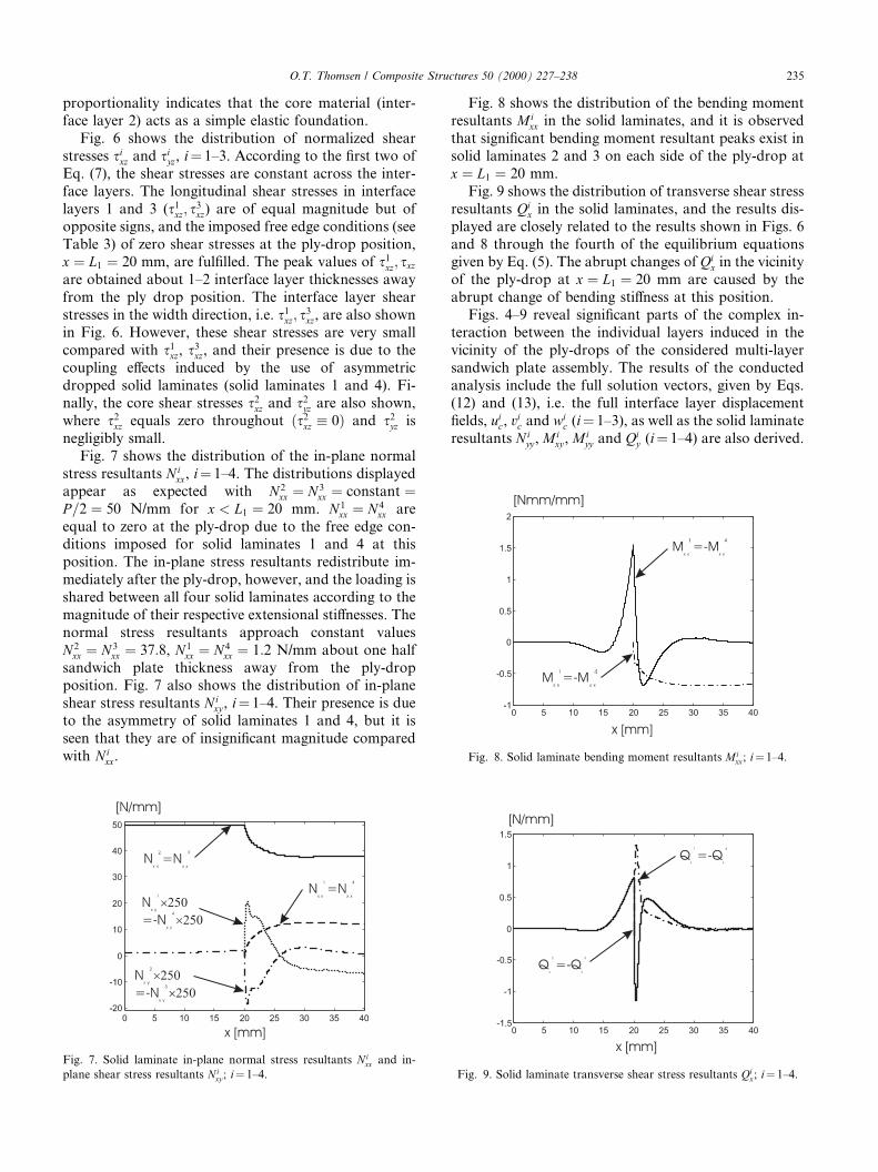
Fig. 8 shows the distribution of the bending momentresultants Mi
xx in the solid laminates, and it is observedthat signi®cant bending moment resultant peaks exist insolid laminates 2 and 3 on each side of the ply-drop atx � L1 � 20 mm.
Fig. 9 shows the distribution of transverse shear stressresultants Qi
x in the solid laminates, and the results dis-played are closely related to the results shown in Figs. 6and 8 through the fourth of the equilibrium equationsgiven by Eq. (5). The abrupt changes of Qi
x in the vicinityof the ply-drop at x � L1 � 20 mm are caused by theabrupt change of bending sti�ness at this position.
Figs. 4±9 reveal signi®cant parts of the complex in-teraction between the individual layers induced in thevicinity of the ply-drops of the considered multi-layersandwich plate assembly. The results of the conductedanalysis include the full solution vectors, given by Eqs.(12) and (13), i.e. the full interface layer displacement®elds, ui
c, vic and wi
c (i� 1±3), as well as the solid laminateresultants N i
yy , Mixy , Mi
yy and Qiy (i� 1±4) are also derived.
Fig. 7. Solid laminate in-plane normal stress resultants Nixx and in-
plane shear stress resultants Nixy ; i� 1±4.
Fig. 8. Solid laminate bending moment resultants Mixx; i� 1±4.
Fig. 9. Solid laminate transverse shear stress resultants Qix; i� 1±4.
O.T. Thomsen / Composite Structures 50 (2000) 227±238 235

However, no further numerical results will be shown inthis paper.
The results displayed in Figs. 4±9 match the experi-mental and theoretical results presented in Refs.[26,37,38] very well. The high-order multi-layer platetheory presented in this paper, however, provides muchmore detailed information about the interaction be-tween the individual layers of the composite assembly aswell as the interface layer stress distributions (interla-minar stresses) than is the case for the simpler `elasticfoundation' approach suggested in Refs. [26,37,38].
4. Conclusions
A high-order theory for the analysis of arbitrarymulti-layer plate assemblies with N high sti�ness layers,referred to as solid laminates, separated by (N ÿ 1)compliant interface layers has been presented. Thetheory includes the transverse ¯exibility of the interfacelayers, thus allowing the thickness of the multi-layerplate assembly to change during deformation. As aconsequence of this, the theory inherently includes adescription of the global structural response, as well asthe local responses of the individual layers of the con-sidered multi-layer assembly. The theory provides acomplete solution with respect to the solid laminatedisplacements, stress resultants and moment resultants,as well as the interface layer displacements, transversenormal stresses and shear stresses.
The high-order multi-layer plate theory can be usedfor the analysis of the mechanical response displayed bya number of complicated structural problems involvingmulti-layer assemblies. In the present paper, the featuresof the theory have been demonstrated through analysisof the elastic response of a CFRP/honeycomb-coredsandwich panel with exterior ply drops. For this partic-ular example, it has been demonstrated that the theoryenables the prediction of very complicated load transfermechanisms, including the interaction of the solid lami-nates (sandwich face sheets and dropped sub laminates)through the compliant interface and core layers. Theobtained results compare very well with experimentaland theoretical results presented in Refs. [26,37,38].
Acknowledgements
Parts of the work reported in this paper were carriedout during the period of an academic leave spent withthe research group of Professor Jack R. Vinson at theDepartment of Mechanical Engineering, University ofDelaware, USA. The academic leave was made possiblethrough support from the Airforce O�ce of Scienti®cResearch, (AFOSR Grant No. F49620-98-1-0384), theDanish Technical Research Council (STVF), the Insti-tute of Mechanical Engineering at Aalborg University,
Denmark and from the Danish private foundations``Otto Mùnsteds Fond'', ``Thomas B. Thriges Fond''and ``Det Obelske Familiefond''. The ®nancial supportreceived is gratefully acknowledged.
Appendix A. Derivation of interface layer ®eld equations
A.1. Basic assumptions
The interface layers are assumed to made from ma-terials, which are assumed to behave as a special type oftransversely isotropic solids only possessing sti�ness inthe through-thickness direction, and with the plane ofisotropy parallel with the interface layer middle planes(i.e., the in-plane stretching and shearing sti�nesses areassumed to be negligible). Thus the interface layers aremodeled as antiplane or compliant layers, as discussedin Refs. [8±10,16]. Consequently the in-plane stresscomponents of the ith interface layers are nil (see Figs. 1and 2); i � 1; . . . ;N ÿ 1
rix � ri
y � sixy � 0: �A:1�
Adopting Eq. (A.1) the equilibrium conditions of the ithinterface layer read; i � 1; . . . ;N ÿ 1:
rix;x � si
yx;y � sizx;z � 0
sixy;x � ri
y;y � sizy;z � 0
sixz;x � si
yz;y � riz;z � 0
9>>=>>;)
sizx;z � 0;
sizy;z � 0;
riz;z � ÿsi
xz;x ÿ siyz;y :
�A:2�
From Eq. (A.2) it follows; i � 1; . . . ;N ÿ 1:
sizx�x; y; z� � si
zx�x; y�; sizy�x; y; z� � si
zy�x; y�; �A:3�i.e., the shear stresses si
zx and sizy are predicted to be
constant through the thickness of the interface layers.It is further assumed that the interface layer materials
display linear elastic behavior, and that only small dis-placements and very small rotations are considered.Given these additional restrictive assumptions, the in-terface layer constitutive equations and the interfacelayer kinematic relations can be expressed as; i �1; . . . ;N ÿ 1:
riz � Ei
czeiz; si
xz � Gicxzc
ixz; si
yz � Gicxzc
iyz; �A:4�
eiz � wi
c;z; cixz � wi
c;x � uic;z; ci
yz � wic;y � vi
c;z: �A:5�Combination of Eqs. (A.4), (A.5) yields; i � 1; . . . ;N ÿ 1
riz � Ei
czwic;z;
sixz � Gi
cxz wic;x
n� ui
c;z
o; si
yz � Gicyz wi
c;y
n� vi
c;z
o: �A:6�
236 O.T. Thomsen / Composite Structures 50 (2000) 227±238

A.2. Thickness variation of displacement and stress ®elds
By integration of the ®rst of Eq. (A.6) with respect tothe thickness coordinate between limits z � ci=2 (ci is theinterface layer thickness, see Fig. 1) and z (using inte-gration by parts and using the last of Eq. (A.2)), and byrequiring continuity of the transverse displacementsacross the boundaries between the ith interface layer andthe surrounding solid laminates i and �i� 1�, i.e.
wic x; y;
ci
2
� �� wi�x; y�;
wic x; y;�
ÿ ci
2
�� wi�1�x; y�
�A:7�
the following is obtained; i � 1; . . . ;N ÿ 1
wic;z �
riz
Eiccz
()Z z
ci=2
dwic �
Z z
ci=2
riz
Eicz
dz ()
wic�x; y; z� � wi � 1
Eicz
zriz�x; y; z�
"ÿ ci
2ri
z x; y;ci
2
� �� si
xz;x
n� si
yz;y
o z2
2
(ÿ �ci�2
8
)#; �A:8�
where wi � wi�x; y� is the out-of-plane displacement ofthe ith solid laminate. Inserting z � ÿci=2 (correspond-ing to the lower boundary of the ith interface layer) inEq. (A.8), and requiring continuity of the out-of-planedisplacements across the lower boundary of the ith in-terface layer (expressed by the last of Eq. (A.7)), yields;i � 1; . . . ;N ÿ 1
wic x; y;�
ÿ ci
2
�� wi � 1
Eicz
nÿ ci
2ri
z x; y;�
ÿ ci
2
�ÿ ci
2ri
z x; y;ci
2
� �o()
riz x; y;�
ÿ ci
2
�� ri
z x; y;ci
2
� �� 2Ei
cz
ciwi� ÿ wi�1
; �A:9�
where wi�1 � wi�1�x; y� is the out-of-plane displacementof solid laminate �i� 1�.
Integration of the last of Eq. (A.2), and utilizing Eq.(A.3), yields; i � 1; . . . ;N ÿ 1
ric;z � ÿsi
xz;x ÿ siyz;y ()Z z
ci=2
driz � ÿ si
xz;x
n� si
yz;y
oZ z
ci=2
dz ()
riz�x; y; z� ÿ ri
z x; y;ci
2
� �� ÿ si
xz;x
n� si
yz;y
oznÿ ci
2
o:
�A:10�Setting z � ÿci=2 in Eq. (A.10)
riz x; y;�
ÿ ci
2
�ÿ ri
z x; y;ci
2
� �� si
xz;x
n� si
yz;y
oci: �A:11�
Addition of Eqs. (A.11) and (A.9) yields
riz x; y;�
ÿ ci
2
�� Ei
cz
ciwi� ÿ wi�1
� sixz;x
n� si
yz;y
o ci
2:
�A:12�Subtraction of Eq. (A.11) from Eq. (A.9) yields
riz x; y;
ci
2
� �� Ei
cz
ciwi� ÿ wi�1
ÿ sixz;x
n� si
yz;y
o ci
2:
�A:13�Inserting Eq. (A.13) into Eq. (A.10) gives the desiredexpression for ri
z�x; y; z�; i � 1; . . . ;N ÿ 1
riz�x; y; z� �
Eicz
ciwi� ÿ wi�1
ÿ sixz;x
n� si
yz;y
oz: �A:14�
Inserting Eqs. (A.13) and (A.14) in the expression forwi
c�r; y; z� given by Eq. (A.8), yields; i � 1; . . . ;N ÿ 1
wic�x; y; z� � wi � wi ÿ wi�1f g
ciznÿ ci
2
oÿ 1
2Eicz
sixz;x
n� si
yz;y
oz2
(ÿ �ci�2
4
)�A:15�
from which it is observed that wic varies as a quadratic
function through the thickness of the ith interface layer.The variation of the longitudinal displacement com-
ponent uic over the ith interface layer thickness can be
derived by integration of the second of Eq. (A.6) withrespect to the thickness coordinate between limitsz � ci=2 and z. In the computations, Eq. (A.15) has beenutilized and ful®llment of continuity of the longitudinaldisplacements across the interface layer/solid laminateinterfaces, i.e.:
uic x; y;
ci
2
� �� ui x; y;
�ÿ fi
2
�� ui
0 � wi;x
fi
2;
uic x; y;�
ÿ ci
2
�� ui�1 x; y;
fi�1
2
� � �A:16�
has been required; i � 1; . . . ;N ÿ 1:
uic;z �
sixz
Gicxz
ÿ wic;x ()Z z
ci=2
duic �
Z z
ci=2
sixz
Gicxz
�ÿ wi
c;x
�dz ()
uic�x; y; z� � ui
0 �wi;x
2fi
�ÿ z2
ciÿ z� 3ci
4
�� wi�1
;x
2
z2
ci
�ÿ z� ci
4
�� si
xz
Gicxz
znÿ ci
2
o� 1
2Eicz
sixz;xx
n� si
yz;yx
o z3
ci
(ÿ �ci�2z
4� �ci�3
12
):
�A:17�It is seen from Eq. (A.17) that ui
c varies as a cubicfunction through the thickness of the ith interface layer.
Similar to the derivations shown for uic, the thickness
variation of the width direction displacement vic in the
O.T. Thomsen / Composite Structures 50 (2000) 227±238 237

ith interface layer can be found. By integration of thelast of Eq. (A.6) between limits ci/2 and z, utilization ofEq. (A.15), and ®nally requiring continuity of the widthdirection displacements across the solid laminate/inter-face layer boundaries, i.e.:
vic x; y;
ci
2
� �� vi x; y;
�ÿ fi
2
�� vi
0 � wi;y
fi
2;
vic x; y;�
ÿ ci
2
�� vi�1 x; y;
fi�1
2
� � �A:18�
the following is obtained; i � 1; . . . ;N ÿ 1
vic;z �
siyz
Gicyz
ÿ wic;y ()
Z z
ci=2
dvic �
Z z
ci=2
siyxz
Gicyz
(ÿ wi
c;y
)dz
() vic�x; y; z� � vi
0 �wi;y
2fi
�ÿ z2
ciÿ z� 3ci
4
�� wi�1
;y
2
z2
ci
�ÿ z� ci
4
�� si
yxz
Gicyz
znÿ ci
2
o� 1
2Eicz
sixz;xy
n� si
yz;yy
o z3
ci
(ÿ �ci�2z
4� �ci�3
12
):
�A:19�As is the case for ui
c it is observed that vic varies as a cubic
function through the thickness of the ith interface layer.
References
[1] Whitney JM. Structural analysis of laminated anisotropic plates.
Lancaster: Technomic Publishing Company, 1987.
[2] Jones RM. Mechanics of composite materials, Second ed.
Philadelphia, PA: Taylor&Francis, 1999.
[3] Reissner E. Finite de¯ections of sandwich plates. J Aerospace Sci
1948;15(7):435±40.
[4] Mindlin RD. In¯uence of rotatory inertia and shear on ¯exural
motions of isotropic elastic plates. Trans ASME, J Appl Mech
1951;18:31±8.
[5] Vinson JR, Sierakowski RL. The behavior of structures composed
of composite materials. Dordrecht: Kluwer Academic Publishers,
1986.
[6] Vinson JR. The behavior sandwich structures of isotropic and
composite materials. Lancaster: Technomic Publishing Company,
1999.
[7] Plantema FJ. Sandwich construction. New York: Wiley, 1966.
[8] Allen HG. Analysis and design of structural sandwich panels.
Oxford: Pergamon, 1969.
[9] Stamm K, Witte H. Sandwichkonstruktionen. Wien: Springer,
1973 [in German].
[10] Zenkert D. An introduction to sandwich construction. London:
Chameleon Press, 1995.
[11] Lo KH, Christensen RM, Wu EM. A high-order theory of plate
deformation. Trans ASME, J Appl Mech 1977;44:669±76.
[12] Stein M. Nonlinear theory for plates and shells including the
e�ects of transverse shearing. AIAA J 1986;24(9):1537±44.
[13] Reddy JN. A simple higher-order theory for laminated composite
shells. Trans ASME, J Appl Mech 1984;51:745±52.
[14] Reddy JN. Exact solution of moderately thick laminated shells.
Trans ASCE, J Engrg Mech 1984;10(5):794±809.
[15] Savoia M, Laudiero F, Tralli A. A two-dimensional theory for the
analysis of laminated plates. Comput Mech 1994;14:38±51.
[16] Librescu L. Elastostatics and kinetics of anisotropic and hetero-
geneous shell-type structures. Leyden: Noordho� International
Publishing, 1975.
[17] Frostig Y, Baruch M. Bending of sandwich beams with trans-
versely ¯exible core. AIAA J 1990;28(11):523±31.
[18] Frostig Y, Baruch M, Vilnai O, Sheinman I. High-order theory
for sandwich beam bending with transversely ¯exible core.
J ASCE, EM Division 1992;118:1026±43.
[19] Frostig Y. On stress concentration in the bending of sandwich
beams with transversely ¯exible core. Comp Struct 1993;24:161±9.
[20] Frostig Y, Shenhar Y. High-order bending of sandwich beams
with a transversely ¯exible core and unsymmetrical laminated
composite skins. Comp Engrg 1995;5:405±14.
[21] Frostig Y, Baruch M. Localized load e�ects in high-order bending
of sandwich panels with transversely ¯exible core. J ASCE, EM
Division 1996;122 (11).
[22] Thomsen OT, Frostig Y. Localized bending e�ects in sandwich
panels: photoelastic investigation versus high-order sandwich
theory results. Comp Struct 1997;37(1):97±108.
[23] Thomsen OT, Rits W. Analysis and design of sandwich plates
with inserts: a higher order sandwich plate theory approach.
Comp Part B 1998;29B:795±807.
[24] Thomsen OT. Sandwich plates with through-the-thickness and
fully potted inserts: evaluation of di�erences in structural behav-
iour. Comp Struct 1998;40:159±74.
[25] Kalnins A. Analysis of shells of revolution subjected to symmet-
rical and non-symmetrical loads. J Appl Mech 1964;31:467±76.
[26] Thomsen OT, Rits W, Eaton DCG, Brown S. Ply drop-o� e�ects
in CFRP/ honeycomb sandwich panels ± theory. Comp Sci
Technol 1996;56:407±22.
[27] Mortensen F, Thomsen OT. A simple approach for the analysis of
embedded ply drops in composite and sandwich laminates. Comp
Sci Technol 1999;59:1213±26.
[28] Frostig Y, Thomsen OT, Mortensen F. Analysis of adhesive
bonded joints, square-end and spew-®llet: closed form high-order
theory approach. ASCE J, Engrg Mech Division
1999;125(11):1298±307.
[29] Thomas DM, Webber JPH. A design-study into the delamination
behaviour of tapered composites. Comp Struct 1994;27:379±88.
[30] Wisnom MR, Jones MI. Delamination due to interaction between
overall inter-laminar shear and stresses at terminating plies. Comp
Struct 1995;31:39±47.
[31] Curry JM, Johnson ER, Starnes JH. E�ect of Dropped Plies on
the Strength of Graphite/Epoxy Laminates. Paper No. AIAA 87-
0874. In: Structural Dynamics and Materials Conference. Pro-
ceedings of AIAA/ASME/ASCE/AHS 28th Structures, Monterey,
1987. p. 737±47.
[32] D�avila CG, Johnson ER. Analysis of delamination initiation in
post-buckled dropped-ply laminates. AIAA J 1993;31(4):721±7.
[33] Vizzini AJ, Lee SW. Damage analysis of composite tapered
beams. J Amer Helicopter Soc 1995;40(2):43±9.
[34] Vizzini AJ. In¯uence of realistic ply-drop geometries on interla-
minar stresses in tapered laminates. In: Martin RH, editor.
Composite materials: fatigue and fracture-®fth volume, ASTM
STP 1230. Philadelphia, PA: American Society for Testing and
Materials, 1995. p. 467±85.
[35] Botting AD, Vizzini AJ, Lee SW. E�ect of ply-drop con®guration
on delamination strength of tapered composite structures. AIAA J
1996;34(8):1650±6.
[36] Vizzini AJ. Shear-lag analysis about an internally-dropped ply.
J Reinforced Plastics Comp 1997;16(1):73±85.
[37] Thomsen OT, Rits W, Eaton DCG, Dupont O, Queekers P. Ply
drop-o� e�ects in CFRP/honeycomb sandwich panels ± experi-
mental results. Comp Sci Technol 1997;56:425±7.
[38] Thomsen OT, Mortensen F, Frostig Y. 1999. Interface failure at
ply drops in CFRP/sandwich panels. J Comp Mater 2000;34 (2):
135±57.
238 O.T. Thomsen / Composite Structures 50 (2000) 227±238