Physical-Mechanical properties of H-10 blocks manufactured ...
Upload
khangminh22Category
view
8download
0
Protecting Manufactured Homes from Floods and Other HazardsA Multi-Hazard Foundation and Installation Guide
FEMA P-85, Second Edition / November 2009
FEMA


Protecting Manufactured Homes from Floods and Other HazardsA Multi-Hazard Foundation and Installation Guide
FEMA P-85, Second Edition / November 2009
FEMA


PROTECTING MaNufaCTuREd HOMEs fROM flOOds aNd OTHER HazaRds A Multi -Hazard Foundation and Installation Guide
i
PrefaceThe Federal Emergency Management Agency (FEMA) first published Manufactured Home Instal-lation in Flood Hazard Areas (FEMA 85) in 1985. Since then, manufactured homes have become better built, and natural hazards like flood, wind, and earthquake (seismic) events are better understood.
To benefit from the advances made in the last 24 years, FEMA 85 has been updated to reflect the requirements of the most current codes and standards and to provide a best practices approach in reducing damages from natural hazards. While the original version of FEMA 85 concentrated on flood and wind events, this version also addresses seismic hazards and recommends several multi-hazard resistant foundation designs. Designs are included for wood-framed foundations, conventional concrete and masonry pier founda-tions, and ground anchors. The ground anchor foundations are based on results from a series of first-of-its-kind saturated and dry soil anchor tests. The anchor tests were conduct-ed with the support of the U.S. Department of Housing and Urban Development (HUD), the Manufactured Housing Institute (MHI), the Systems Building Research Alliance (SBRA, formerly the Manufactured Housing Research Alliance [MHRA]), and several ground an-chor manufacturers. A detailed example showing step-by-step procedures on how to design a foundation for a manufactured home is also included.
This guidance is also valuable to designers of alternate foundations allowed by the HUD 24 CFR 3285 Model Manufactured Home Installation Standards, especially for homes located in Special Flood Hazard Areas (SFHAs) for which certain 24 CFR 3285 foundation designs are not applicable (24 CFR 3285.303, Table 1, Note 4, et al.).
The foundation designs discussed in Chapter 10 and shown in Appendix H of this guide are but one group of acceptable foundation solutions. They should not be considered manda-tory or all inclusive. Alternative foundation systems, designed to resist equivalent loads and provide equivalent performance, should be considered equally acceptable.
Limitations of the Guide
This manual has been prepared to assist in protecting manufactured homes from floods and other hazards. Builders, installers, architects, and engineers using this guide assume responsibility for the resulting designs and the performance during a natural hazard event.
The foundation designs and analyses presented in the guide are based on load combinations con-tained in the American Society of Civil Engineers (ASCE 7-05) and the 2006 version of the International Residential Code® (IRC®).


PROTECTING MaNufaCTuREd HOMEs fROM flOOds aNd OTHER HazaRds A Multi -Hazard Foundation and Installation Guide
iii
AcknowledgmentsThe Federal Emergency Management Agency would like to acknowledge the significant contribu-tions made by the following individuals in developing the Second Edition of this publication.
John Ingargiola FEMA Building Science Branch
Edward Laatsch FEMA Building Science Branch
Marcus Barnes FEMA Building Science Branch
Lois Forster FEMA Floodplain Management Branch
Brad Loar FEMA Region IV
Mike Mahoney FEMA Building Science Branch
Cliff Oliver FEMA Acquisition Branch
John Plisich FEMA Region IV
Mike Robinson FEMA Floodplain Management Branch
Paul Rooney FEMA Data and Dissemination Management Section
Juanita Thompson FEMA Floodplain Management Branch
Phil Bergeldt Florida Department of Highway Safety and Motor Vehicles, Mobile Home and Recre-ational Vehicle Construction
Mike Blanford HUD Office of Policy Development and Research
Jason McJury HUD Office of Manufactured Housing Programs
Rick Mendlen HUD Office of Manufactured Housing Programs
Kelly Cobeen Cobeen & Associates
Bill Coulbourne Applied Technology Council
Deb Daly Greenhorne & O’Mara
Bill Farish Clayton Homes
Jeff Inks Manufactured Housing Institute
Joseph Klein Dewberry
Emmanuel Levy Systems Building Research Alliance (formerly Manufactured Housing Research Alliance)
Julie Liptak Greenhorne & O’Mara

iv PROTECTING MaNufaCTuREd HOMEs fROM flOOds aNd OTHER HazaRds A Multi -Hazard Foundation and Installation Guide
ACKNOWLEDGMENTS
Thayer LongManufactured Housing Institute
Dave LowDK Low and Associates
Bonnie ManleyAmerican Iron and Steel Institute
Therese McAllisterNational Institute of Standards and Technology
Ken MorrisOklahoma Water Resources Board
Mark NunnManufactured Housing Institute
George PorterManufactured Housing Resources
Jim RossbergAmerican Society of Civil Engineers
Chuck Sandersformer Alabama State NFIP Coordinator
Adrienne SheldonURS
John SquerciatiDewberry
Bill TurneyFlorida Manufactured Housing Association
Frank WalterManufactured Housing Institute
Mark WeissManufactured Housing Association for Regulatory Reform
Jimmy YeungGreenhorne & O’Mara
Naomi Chang ZajicGreenhorne & O’Mara
Brian ZelenkoURS

PROTECTING MaNufaCTuREd HOMEs fROM flOOds aNd OTHER HazaRds A Multi -Hazard Foundation and Installation Guide
v
Table of ContentsPreface...........................................................................................................................................i
Acknowledgments.................................................................................................................. iii
1 Introduction.................................................................................................................. 1-1
1.1 Purpose and Scope of the Guide............................................................................................ 1-1
1.2 Background.........................................................................................................................1-3.
1.2.1. Manufactured.Homes.in.the.United.States...........................................................1-3
1.2.2.. National.Flood.Insurance.Program.......................................................................1-5
1.2.3. Performance.of.Manufactured.Homes.in.Wind.and.Flood.Events.....................1-6
1.2.3.1..Performance.of.Pre-1994.Manufactured.Homes.....................................1-6
1.2.3.2. Performance.of.Post-1994.Manufactured.Homes....................................1-7
1.2.3.3. Performance.of.Manufactured.Homes.During.Hurricane.Charley..(2004).in.Florida.........................................................................................1-8
2 Manufactured Homes............................................................................................... 2-1
2.1 Manufactured Home Characteristics...................................................................................... 2-1
2.1.1. Chassis.Support.System........................................................................................... 2-1
2.1.2. Integrated.Support.System.....................................................................................2-2
2.1.3. Envelope.Construction...........................................................................................2-2
2.1.4. Double.Section........................................................................................................2-3
2.2 Types of Foundation Systems................................................................................................2-3
2.2.1. Typical.Foundation.Systems...................................................................................2-5
2.2.1.1. Typical.Installation.....................................................................................2-5
2.2.1.2. Piers.and.Ground.Anchors........................................................................2-6
2.2.1.3. Perimeter.Wall.Foundations......................................................................2-7
2.2.2. Proprietary.Systems.................................................................................................2-7
2.3 Utilities and Mechanical Equipment.......................................................................................2-8
2.3.1. Utilities.Placement..................................................................................................2-8

vi PROTECTING MaNufaCTuREd HOMEs fROM flOOds aNd OTHER HazaRds A Multi -Hazard Foundation and Installation Guide
2.3.2. Mechanical.Access...................................................................................................2-9
2.4 Attachments – Carports, Decks, Porches, and Awnings..........................................................2-10
3 Regulatory Requirements........................................................................................ 3-1
3.1 Introduction to the NFIP........................................................................................................ 3-1
3.2 Identifying and Mapping Flood Hazards..................................................................................3-2
3.3 The NFIP's Community Rating System (CRS)...........................................................................3-8
3.4 NFIP Definitions Related to Manufactured Homes...................................................................3-8
3.5 General NFIP Floodplain Management Requirements for Manufactured Homes.........................3-9
3.6 NFIP Requirements for Manufactured Homes in Riverine and Inland Flood Zones....................3-10
3.6.1. Approximate.A.Zones........................................................................................... 3-11
3.6.2. Elevation.in.A,.A1-30,.AE,.and.AH.Zones............................................................3-13
3.6.3. 3-Foot.Pier.Foundation.........................................................................................3-14
3.6.4. Elevation.in.Zone.AO...........................................................................................3-16
3.6.5. Anchoring..............................................................................................................3-17
3.6.6. Flood.Damage-Resistant.Materials.......................................................................3-18
3.6.7. Utilities.and.Mechanical.Equipment...................................................................3-18
3.6.8. Enclosed.Areas......................................................................................................3-19
3.6.9. Floodways...............................................................................................................3-20
3.7 NFIP Requirements for Manufactured Homes in Coastal Flood Areas......................................3-22
3.7.1. Elevation.and.Anchoring......................................................................................3-23
3.7.2. Fill..........................................................................................................................3-25
3.7.3. Enclosed.Areas.and.Breakaway.Walls...................................................................3-25
3.7.4. Setbacks.................................................................................................................3-26
3.8 Existing Manufactured Homes in Flood Hazard Areas............................................................ 3-27
3.8.1. Relocation..............................................................................................................3-27
3.8.2. Evacuation.............................................................................................................3-28
3.8.2.1. Manufactured.Home.Substantially.Improved.or.Returned.to.a..Different.Site.or.Pad.in.an.Existing.Manufactured.Home.Park............3-29
3.8.2.2. Manufactured.Home.Placed.in.a.New.Manufactured.Home.Park.or..Subdivision................................................................................................3-30
TABLE OF CONTENTS

PROTECTING MaNufaCTuREd HOMEs fROM flOOds aNd OTHER HazaRds A Multi -Hazard Foundation and Installation Guide
vii
3.9 HUD Manufactured Home Construction and Safety Standards................................................3-30
3.10 HUD Model Manufactured Home Installation Standards.........................................................3-32
3.11 Model Building Code Requirements.....................................................................................3-34
3.11.1. IRC.2006................................................................................................................3-34
3.11.2. NFPA.5000.............................................................................................................3-35
3.11.3. NFPA.501...............................................................................................................3-36
3.11.4. NFPA.225...............................................................................................................3-36
4 Site and Development Options.............................................................................. 4-1
4.1 Step 1: Compiling Site Information.........................................................................................4-2
4.2 Step 2: Reviewing Basic Siting Information............................................................................4-4
4.3 Step 3: Hazard Analysis and Risk Assessment........................................................................4-4
4.3.1. Flooding...................................................................................................................4-5
4.3.1.1. Accessibility.................................................................................................4-6
4.3.2. Other.Hazards.........................................................................................................4-8
4.4 Step 4: Protecting Properties In and Near Hazard-Prone Areas...............................................4-10
4.4.1. Placement.Options...............................................................................................4-10
4.4.1.1. Flood-Prone.Areas....................................................................................4-10
4.4.1.2. Areas.Subject.to.Landslides.....................................................................4-12
4.4.2. Design.and.Construction.Techniques.................................................................4-12
4.4.2.1. Flood-Prone.Areas....................................................................................4-12
4.4.2.2. Dam.Failure.Inundation.Areas................................................................4-12
4.4.2.3. Areas.Subject.to.Landslides.....................................................................4-13
4.4.2.4. Areas.Subject.to.Seismic.Events...............................................................4-13
4.4.2.5. Areas.Subject.to.Wind/Debris.Hazards..................................................4-13
4.5 Step 5: Deciding on Property Development: Proceed or Reject...............................................4-13
5 Natural Hazards – Design Considerations........................................................ 5-1
5.1 Flood Data........................................................................................................................... 5-1
5.2 Flood Characteristics............................................................................................................5-5
5.2.1. Frequency,.Duration,.and.Rate.of.Rise..................................................................5-5
TABLE OF CONTENTS

viii PROTECTING MaNufaCTuREd HOMEs fROM flOOds aNd OTHER HazaRds A Multi -Hazard Foundation and Installation Guide
5.2.2. Flood.Elevation.and.Depth....................................................................................5-7
5.2.3. Hydrostatic.(Buoyancy).Forces..............................................................................5-8
5.2.4. Hydrodynamic.Forces.............................................................................................5-9
5.2.5. Erosion.and.Scour.................................................................................................5-12
5.2.6. Debris.Impact.Forces............................................................................................5-13
5.3 Wind .................................................................................................................................5-14
5.3.1.. Wind.Forces.on.Structures...................................................................................5-15
5.3.2. Wind.Forces.in.Combination.with.Flood.Forces................................................5-15
5.4 Earthquakes.......................................................................................................................5-16
5.4.1. Design.Philosophy.................................................................................................5-16
5.4.2. Design.Standard....................................................................................................5-16
5.5 Evaluation of Multi-Hazards................................................................................................ 5-17
5.5.1. Load.Combinations.(ASCE.7).............................................................................5-18
5.5.1.1. Strength.Design.(Load.and.Resistance.Factor.Design).........................5-18
5.5.1.2. Allowable.Stress.Design.(also.known.as.Working.Stress.Design)..........5-19
6 Soils................................................................................................................................. 6-1
6.1 Bearing Capacity.................................................................................................................. 6-1
6.2 Effects of Flood Duration and Frequency on Soil.....................................................................6-2
6.3 Soil Liquefaction..................................................................................................................6-2
6.4 Recommended Soil Testing and Criteria for Manufactured Home Installations...........................6-3
7 Ground Anchors........................................................................................................... 7-1
7.1 Types of Anchors and Installed Configurations........................................................................7-2
7.1.1. Types.of.Anchors.....................................................................................................7-2
7.1.1.1. Helical.Earth.Anchors................................................................................7-2
7.1.1.2. Concrete.Anchors.......................................................................................7-2
7.1.1.3. Cross.Drive.Anchors...................................................................................7-2
7.1.2. Anchor.Construction.and.Capacity.......................................................................7-3
7.1.3. Anchor.Selection.....................................................................................................7-3
TABLE OF CONTENTS

PROTECTING MaNufaCTuREd HOMEs fROM flOOds aNd OTHER HazaRds A Multi -Hazard Foundation and Installation Guide
ix
7.1.4. Anchor.Installation.................................................................................................7-4
7.1.5. Anchor.Performance..............................................................................................7-5
7.1.6. Anchors.and.Other.Foundation.Elements............................................................7-8
7.2 FEMA Anchor Test Program...................................................................................................7-8
7.2.1. Anchors.in.Saturated.Soils.....................................................................................7-8
7.2.2. Anchor.Test.Results.................................................................................................7-9
7.3 Recommended Ground Anchor Certification, Performance, and Design Values......................... 7-11
7.3.1. Recommended.Ground.Anchor.Certification.Performance............................. 7-11
7.3.2. Recommended.Ground.Anchor.Design.Values.................................................. 7-11
7.4 Ground Anchors in Seismically Active Areas.........................................................................7-13
8 Foundation Systems.................................................................................................. 8-1
8.1 Introduction......................................................................................................................... 8-1
8.2 Enclosed Foundations...........................................................................................................8-2
8.3 Open Foundations and Breakaway Walls................................................................................8-3
8.3.1. Pier.Systems.............................................................................................................8-3
8.3.1.1.Reinforced.Pier.Systems.............................................................................8-4
8.3.1.2.Unreinforced.Pier.Systems........................................................................8-5
8.3.2. Pile.Foundations.....................................................................................................8-7
8.4 Bracing................................................................................................................................8-9
8.5 Footings............................................................................................................................8-10
8.6 Foundation Materials Selection........................................................................................... 8-11
8.6.1. Wood.Foundations................................................................................................8-12
8.6.2. Concrete.Foundations..........................................................................................8-12
8.6.3. Steel.Foundations.................................................................................................8-13
8.6.4. Masonry.Foundations...........................................................................................8-13
8.7 Foundation Selection and Flood Resistance..........................................................................8-13
8.7.1. Flooding.Types......................................................................................................8-14
8.7.2. Flood.Characteristics............................................................................................8-14
8.7.3. Flood.Hazard.Zones..............................................................................................8-15
TABLE OF CONTENTS

x PROTECTING MaNufaCTuREd HOMEs fROM flOOds aNd OTHER HazaRds A Multi -Hazard Foundation and Installation Guide
8.7.4. Proximity.to.Flood.Source....................................................................................8-15
8.7.5. Foundation.Selection.Guidance..........................................................................8-16
9 Recommended Design Process and Criteria for Manufactured Home Foundations in SFHAs.................................................................................. 9-1
9.1 Performance Criteria............................................................................................................ 9-1
9.2 Design Criteria..................................................................................................................... 9-1
9.3 Design Process....................................................................................................................9-2
9.3.1. Step.1:.Determine.Design.Criteria.........................................................................9-3
9.3.2. Step.2:.Select.a.Design.Methodology.and.Assess.Load.Combinations.and..Failure.Modes..........................................................................................................9-4
9.3.2.1.Design.Methodology..................................................................................9-4
9.3.2.2.Load.Combinations....................................................................................9-4
9.3.2.3..Primary.Failure.Modes...............................................................................9-4
9.3.3. Step.3:.Select.Foundation.Type.and.Material.......................................................9-5
9.3.4. Step.4:.Determine.Forces.at.Connections.and.on.Foundation.Components.....9-6
9.3.5. Step.5:.Specify.Connections.and.Framing.Methods.Along.with.Component..Dimensions.to.Satisfy.Load.Conditions.................................................................9-6
9.3.6. Step.6:.Note.All.Design.Assumptions.and.Details.on.Drawings...........................9-6
10 Recommended Foundations................................................................................. 10-1
10.1 Design Criteria for Recommended Foundations.................................................................... 10-1
10.1.1. Reinforced.Masonry.Perimeter.Foundation.Walls..............................................10-2
10.1.2. Wood.Framed.Perimeter.Foundation.Walls........................................................10-3
10.1.3. Braced.Masonry.Pier.Designs...............................................................................10-3
10.1.4. Wood.H-Frame.Designs........................................................................................10-4
10.1.5. Ground.Anchor.Designs.......................................................................................10-4
10.2 Summary of Recommended Foundations.............................................................................10-5
10.3 Floodwater Velocity Design Considerations for Pier Foundations............................................10-6
10.4 Recommended Foundation Designs for Seismic Areas.......................................................... 10-7
10.4.1. Concrete.Masonry.Pier.Foundation.Designs.......................................................10-7
TABLE OF CONTENTS

PROTECTING MaNufaCTuREd HOMEs fROM flOOds aNd OTHER HazaRds A Multi -Hazard Foundation and Installation Guide
xi
10.4.2. Masonry.Wall.Foundation.Designs......................................................................10-7
10.4.3. Wood.Framed.Foundation.Designs.....................................................................10-8
10.5 Design Drawings................................................................................................................10-8
Appendices
Appendix.A:.References.
Appendix.B:.Sources.for.Flood.Information.
Appendix.C:.Flood.Velocity.Determination
Appendix.D:.Definitions.
Appendix.E:.Acronyms.and.Abbreviations.
Appendix.F:.Example.Calculations
Appendix.G:.Wind.Zone.Comparisons.(HUD's.MHCSS.and.ASCE.7-05)
Appendix.H:.Pre-Engineered.and.Prescriptive.Foundation.Designs
Figures
Chapter 1Figure.1-1... Basic.wind.zone.map.for.manufactured.housing...................................................1-4
Figure.1-2... Inadequate.turnbuckle.anchor.installed.by.the.homeowner.on.this.pre-1994.manufactured.home,.coupled.with.lack.of.elevation.and.an.unreinforced.foundation.system,.led.to.severe.damage...............................................................1-7
Figure.1-3... The.addition.to.this.manufactured.home.was.destroyed,.causing.considerable.damage.to.the.rest.of.the.home..............................................................................1-7
Figure.1-4... Reinforced.masonry.pier.foundation.system.under.a.manufactured.home.installed.after.1994.that.performed.well................................................................1-8
Figure.1-5... Manufactured.home.in.Cudjoe.Key,.Florida,.built.and.installed.after.1994,.survived.Hurricane.Georges.with.only.minor.damage.caused.by.the.loss.of.an.awning......................................................................................................................1-8
Chapter 2Figure.2-1... Traditional.chassis.system........................................................................................2-2
Figure.2-2... Integrated.floor.system.consisting.of.steel-reinforced.perimeter.framing...........2-2
Figure.2-3... Main.construction.features.of.a.typical.manufactured.home...............................2-4
Figure.2-4... One.section.of.a.double-section.manufactured.home.being.transported............2-5
TABLE OF CONTENTS

xii PROTECTING MaNufaCTuREd HOMEs fROM flOOds aNd OTHER HazaRds A Multi -Hazard Foundation and Installation Guide
Figure.2-5... Typical.installation.of.a.manufactured.home.on.masonry.block.piers..with.tie-down.straps.................................................................................................2-6
Figure.2-6... Typical.installation.of.a.double-section.manufactured.home.on.a.pier.and.ground.anchor.foundation.system.........................................................................2-6
Figure.2-7... Perimeter.wall.foundation.under.a.manufactured.home.....................................2-7
Figure.2-8... Utility.line.damage.in.unstable.soils.......................................................................2-9
Chapter 3Figure.3-1.. Sample.DFIRM.........................................................................................................3-4
Figure.3-2(a)..Sample.FIS.Summary.of.Discharges.table...........................................................3-5
Figure.3-2(b)..Sample.FIS.Floodway.Data..................................................................................3-5
Figure.3-2(c)..Sample.FIS.Flood.Profile.....................................................................................3-6
Figure.3-3.. Manufactured.home.with.lowest.floor.elevated.to.the.BFE................................3-14
Figure.3-4.. Manufactured.home.on.reinforced.pier.foundation.36.inches.high.................3-16
Figure.3-5.. DFIRM.showing.the.floodway.(cross-hatched.area.in.Zone.AE)........................ 3-21
Figure.3-6.. Manufactured.home.with.the.bottom.of.the.lowest.horizontal.structural..member.elevated.to.the.BFE.................................................................................3-24
Figure.3-7.. Mean.high.tide.line.development.restriction...................................................... 3-27
Figure.3-8... Coastal.development.well-suited.to.the.land:.generous.setbacks,.in.combination.with.deep.lots.and.avoidance.of.dune.areas,.should.afford.protection.from.erosion.and.flooding.for.years.to.come............................................................... 3-27
Figure.3-9... Certification.plate.for.manufactured.homes.built.after.June.15,.1976............... 3-31
Chapter 4Figure.4-1... Portions.of.an.FIS.and.a.FIRM................................................................................4-7
Figure.4-2... Floodplain/floodway.schematic............................................................................ 4-11
Chapter 5Figure.5-1... Example.of.a.FIRM..................................................................................................5-2
Figure.5-2... FIS.Summary.of.Discharges.table...........................................................................5-3
Figure.5-3... FIS.Stream.Flood.Profile.........................................................................................5-4
Figure.5-4... FIS.Floodway.Data.table..........................................................................................5-4
Figure.5-5... Buoyancy.forces.acting.on.a.structure....................................................................5-9
Figure.5-6... Failure.due.to.sliding.............................................................................................5-10
Figure.5-7... A.manufactured.home.destroyed.by.the.hydrodynamic.forces.of.flooding.......5-10
Figure.5-8... Failure.of.a.modular.home.due.to.high.winds..The.home.lifted.off.of.its.foundation.(concrete.slab).when.the.connections.failed...................................5-14
TABLE OF CONTENTS

PROTECTING MaNufaCTuREd HOMEs fROM flOOds aNd OTHER HazaRds A Multi -Hazard Foundation and Installation Guide
xiii
Figure.5-9... A.manufactured.home.that.failed.during.a.high-wind.event..............................5-15
Chapter 7Figure.7-1... Cross.drive.anchor...................................................................................................7-2
Figure.7-2... Single.and.double.helix.ground.anchors.with.strap.connection.and.single..helix.anchor.with.a.closed-eye.connection............................................................7-3
Figure.7-3... Electric.anchor.drive.machine................................................................................7-4
Figure.7-4... Typical.ground.anchor.installation.........................................................................7-5
Figure.7-5... In.line.ground.anchor.installation.........................................................................7-6
Figure.7-6... Typical.response.for.an.axially.loaded.anchor.......................................................7-7
Figure.7-7... Typical.response.for.a.non-axially.loaded.anchor.used.with.a.stabilizer.plate.....7-8
Figure.7-8... Failed.foundation.system.that.used.masonry.piers................................................7-9
Figure.7-9... Three.graphics.showing.the.anchor.configurations.described.in.Tables.7-2..and.7-3.................................................................................................................... 7-11
Chapter 8Figure.8-1... A.manufactured.home.elevated.on.a.perimeter.foundation.wall.........................8-2
Figure.8-2... Reinforced.masonry.and.concrete.piers................................................................8-5
Figure.8-3... Bolted.connection.between.frame.and.reinforced.pier........................................8-6
Figure.8-4... Manufactured.home.on.a.pile.foundation.............................................................8-7
Figure.8-5... Pile.driving.methods................................................................................................8-8
Figure.8-6... Diagonal.bracing...................................................................................................8-10
Figure.8-7... Knee.bracing..........................................................................................................8-10
Chapter 9Figure.9-1.. A.home.that.was.partially.submerged.and.displaced.from.its.foundation.by..
hydrostatic.forces.....................................................................................................9-5
Tables
Chapter 3Table.3-1... Common.SFHA.Designations.for.Riverine.or.Inland.Flood.Zones.......................3-6
Table.3-2... Common.SFHA.Designations.for.Coastal.Flood.Areas..........................................3-6
Chapter 4Table.4-1... Information.Checklist..............................................................................................4-2
Table.4-2... Partial.Listing.of.Local,.Regional,.and.State.Responsibilities................................4-4
TABLE OF CONTENTS

xiv PROTECTING MaNufaCTuREd HOMEs fROM flOOds aNd OTHER HazaRds A Multi -Hazard Foundation and Installation Guide
Table.4-3... Flood.Hazards...........................................................................................................4-5
Table.4-4... Hazard-Prone.Areas.................................................................................................4-9
Chapter 5Table.5-1... Sources.for.Information.About.Past.Flood.Events.................................................5-6
Table.5-2... Load.Combination.Nomenclature.(ASCE.7)....................................................... 5-17
Chapter 7Table.7-1... Soil.Classifications.Using.a.Standard.Torque.Probe.(STP)...................................7-4
Table.7-2... Dry.Site.Anchor.Data.............................................................................................7-10
Table.7-3... Wet.Site.Anchor.Data.............................................................................................7-10
Table.7-4... Recommended.Design.Loads.–.from.FEMA.Ground.Anchor.Testing..Program..................................................................................................................7-12
Table.7-5... Recommended.Design.Stiffness.for.Tested.Anchors............................................7-12
Chapter 8Table.8-1... Recommended.Manufactured.Home.Foundation.Selection.for.Lake/Pond..
Flooding.(for.very.low.velocity.less.than.1.fps).....................................................8-16
Table.8-2... Recommended.Manufactured.Home.Foundation.Selection.for.Riverine.Flood.Zones.(and.maximum.flood.flow.velocity)........................................................... 8-17
Table.8-3... Recommended.Manufactured.Home.Foundation.Selection.for.Coastal.Flood..Zones.......................................................................................................................8-18
Chapter 9Table.9-1.. Design.Standards.and.Publishers.for.Building.Materials.......................................9-6
Chapter 10Table.10-1...Summary.of.Recommended.Foundations............................................................10-5
Table.10-2...Design.Flood.Flow.Velocity.for.Concrete.Masonry.Unit.Foundations................10-6
Table.10-3.. Foundation.Drawings.............................................................................................10-8
TABLE OF CONTENTS

PROTECTING MaNufaCTuREd HOMEs fROM flOOds aNd OTHER HazaRds A Multi -Hazard Foundation and Installation Guide
1-1
1 IntroductionThis revised edition of FEMA 85 provides new recommendations for manufactured home foun-dation design and installation. The initial 1985 edition of FEMA 85 provided guidance on installation methods designed to make manufactured homes less susceptible to damage caused by flood and wind events. Significant advances in design and construction technologies, miti-gation strategies, and regulatory requirements since 1985 have all contributed to the need for updated guidance.
1.1 PurposeandScopeoftheGuideLike the original guide, this updated version of FEMA 85 focuses primarily on the installation and foundation requirements for manufactured homes in floodplains for communities par-ticipating in the National Flood Insurance Program (NFIP). However, it also addresses other natural hazards such as high winds and earthquakes.
The purpose of the second edition of FEMA 85 is to provide guidance for the design and con-struction of alternative foundation systems as described in the HUD Model Manufactured Home Installation Standards (24 CFR 3285). It is important to rec-ognize that both the U.S. Department of Housing and Urban Development (HUD) and the NFIP require that foundation systems for manufactured homes located in Special Flood Hazard Areas (SFHAs) prevent flotation, collapse, or lateral movement of the structure (24 CFR 3285.302 and 44 CFR 60.39(a)(3), respectively).
With its broad and comprehensive scope, this document provides guidance on siting and install-ing manufactured homes in areas exposed to natural hazards. The guide is organized into 10 chapters, each covering a different aspect of manufactured homes in the United States, and 8 appendices.
Chapter 1 provides a historical overview of Federal, State, and local regulations that affect the design, construction, and installation of manufactured homes, including guidance on the NFIP and HUD installation requirements.
Chapter 2 presents and defines the characteristics of a manufactured home, the types of founda-tions used, typical installation techniques, and additional design considerations of attachments to manufactured homes (e.g., carports, decks, porches, and awnings).
Chapter 3 provides the regulatory requirements pertaining to the installation of manufactured homes in flood-prone areas. NFIP, HUD and model building code requirements are discussed as well as methods for mitigating manufactured homes (e.g., elevation and relocation).
The manufactured housing industry has adopted the term “community” for manufactured home develop-ments. However, the term “park” is used in the NFIP and is also used in this publication.

1-2 PROTECTING MaNufaCTuREd HOMEs fROM flOOds aNd OTHER HazaRds A Multi -Hazard Foundation and Installation Guide
1 INTRODUCTION
Chapter 4 presents issues to consider in the siting of manufactured homes.
Chapter 5 provides a review of natural hazards that must be considered in site selection, founda-tion design, and installation of manufactured homes. The discussion covers flooding, including the special hazards associated with coastal flooding (e.g., storm surge, velocity flow, and wave impact), high winds, and seismic events. The combined effects of multiple hazards are also cov-ered.
Chapter 6 contains a review of the geology and hydrology of soils and their effects on manu-factured home foundation systems. Soil characteristics and the behavior of saturated soils are discussed. Recommendations are provided for soil testing criteria applicable for manufactured home installation.
Chapter 7 presents a review of the use of ground anchors with manufactured home foundations, including the results of laboratory and field tests of anchor performance in saturated soils.
Chapter 8 presents different types of manufactured home foundation systems, including their performance, installation procedures, maintenance requirements, and possible modifications. Systems discussed include pier systems that incorporate ground anchors, braced piers and piles, slabs, elevated floors or crawlspaces, and proprietary systems.
Chapter 9 discusses recommended design processes and criteria for manufactured home foundations in SFHAs. Recommended design criteria, performance requirements, and best practice recommendations are presented. Sites that fall outside of the criteria specified for recommended foundations in Chapter 10 can use the design process detailed in this chapter.
Chapter 10 provides design criteria for recommended foundations appropriate for typical in-stallation of manufactured homes in flood zones designated A, AE, A1-A30, A0, or AH on a FEMA Flood Insurance Rate Map (FIRM). Criteria are presented regarding maximum flood depth, flow velocity, wind speed, and seismic force. The designs are shown in Appendix H.
The appendices include:
A: References
B: Sources for Flood Information
C: Flood Velocity Determination
D: Definitions
E: Acronyms and Abbreviations
F: Example Calculations
G: Wind Zone Comparisons
H: Pre-Engineered and Prescriptive Foundation Designs
The foundation designs discussed in Chapter 10 and shown in Appendix H are but one of a group of acceptable foundation solutions. They should not be considered mandatory or all

PROTECTING MaNufaCTuREd HOMEs fROM flOOds aNd OTHER HazaRds A Multi -Hazard Foundation and Installation Guide
1-3
INTRODUCTION 1
inclusive. Any modifications to the foundation drawings must be designed and approved by a li-censed professional engineer. Alternative foundation systems designed to resist equivalent loads and to provide equivalent performance should be considered equally acceptable.
Flowcharts, checklists, maps, formulas, and drawings are provided throughout the guide to help in understanding the issues to consider when installing a manufactured home in a floodplain. Examples are presented to demonstrate decisions and calculations designers must make to re-duce the potential damage to manufactured homes from natural hazard events.
1.2 Background
1.2.1 ManufacturedHomesintheUnitedStates
Manufactured homes help fill a demand for affordable housing in many parts of the United States. In 2007, the U.S. Census reported that the industry shipped 95,700 homes with an aver-age price of $64,500. Single-section homes had an average price of $35,200, and double-section homes had an average price of $73,100. U.S. Census Bureau figures from Census 2007 show that 74 percent of new manufactured homes were located on private properties and 26 percent were located in manufactured home parks. The average floor area of a manufactured home placed in 2007 was approximately 1,600 square feet. Approximately 31 percent of the manufactured homes placed in 2007 were located in four States (Florida, California, Louisiana, and Texas).
Since 1976, the NFIP has regulated the installation of manufactured homes in floodplains. Over the years, the NFIP has strengthened the regulations by defining existing and new manufactured home parks and applying differing standards for each. The standards governing manufactured homes continue to improve; Federal, State, and local governments and the manufactured home industry strive to institute construction practices and regulations to increase the safety of man-ufactured homes in natural hazard environments. The following list summarizes regulations, programs, and actions that have been developed to improve the resistance of manufactured homes to natural hazards:
n On July 13, 1994, HUD adopted new structural resistance guidelines for the construction of manufactured homes to be placed in HUD Wind Zones II and III (Figure 1-1).
n Section 605 of the National Manufactured Housing Construction and Safety Standards Act of 1974 (42 U.S.C. 5401), as amended by the Manufactured Housing Improvement Act of 2000, authorized the Secretary of HUD to establish and implement a national manufactured housing installation program to include (1) installation standards, (2) the training and licensing of manufactured home installers, and (3) the inspection of manufactured home installations.
States may choose to operate an installation program for manufac-tured homes in lieu of the Federal program. The State must implement standards that provide protection to its residents that equals or ex-ceeds the Model Manufactured Home Installation Standards (24 CFR 3285.1(a)(1). See http: / /www.hud.gov/offices/adm/hud-clips for more information.

1-4 PROTECTING MaNufaCTuREd HOMEs fROM flOOds aNd OTHER HazaRds A Multi -Hazard Foundation and Installation Guide
1 INTRODUCTION
Figure1-1.Basicwindzonemapformanufacturedhousing.

PROTECTING MaNufaCTuREd HOMEs fROM flOOds aNd OTHER HazaRds A Multi -Hazard Foundation and Installation Guide
1-5
INTRODUCTION 1
n Installation program requirements have been established under 24 CFR 3286, Federal Manufactured Home Installation Program effective October 20, 2008. Compliant training and licensing programs for installation and inspections are being implemented in all States.
n The National Fire Protection Association (NFPA) has published three documents on the subject of manufactured housing:
n NFPA 501, Standard on Manufactured Housing
n NFPA 501A, Standard for Fire Safety Criteria for Manufactured Home Installations, Sites and Communities
n NFPA 225, Model Manufactured Home Installation Standard, which will, in adopted areas, govern installation of manufactured homes.
n The National Technology Transfer Act of 1995 included a goal that Federal agencies use technical standards developed or adopted by voluntary consensus standard bodies. Although HUD has recognized NFPA as a consensus standard developing body, HUD is not obligated to use standards developed by that body.
n Several States and localities, including Florida and North Carolina, have strong installation standards, which include requiring manufactured homes to meet State and local building code requirements; a manufactured home installer education, testing, and certification program for HUD homes; and aggressive inspection programs to ensure proper installation.
1.2.2 NationalFloodInsuranceProgram
The U.S. Congress established the NFIP with the passage of the National Flood Insurance Act of 1968, as amended. The NFIP is a Federal program enabling property owners in participating communities to purchase insurance as a protection against flood losses in exchange for State and community floodplain management regulations that reduce future flood damages. Partici-pation by communities in the NFIP is based on an agreement between communities and the Federal Government. If a community adopts and enforces floodplain management regulations to reduce future flood risks to new construction in floodplains, the Federal Government will make flood insurance available within the community as a financial protection against flood losses. Participation in the NFIP by communities is voluntary.
Federal flood insurance is designed to provide an alternative to disaster assistance and disaster loans for home and business owners. Disaster assistance rarely comes close to covering all of the costs to repair and cleanup. While available to qualified victims, disaster loans do not sig-nificantly ease the financial burden due to repayment terms. It is important to remember that disaster assistance is available only after floods have been declared major disasters by the Presi-dent of the United States. In contrast, insurance claims will be paid any time damage from a qualifying flood event occurs.
Another important objective of the NFIP is to break the cycle of flood damage. Many buildings have been flooded, repaired, or rebuilt, and flooded again. In some parts of the country, this cycle occurs every couple of years; people rebuilt in the same flood-prone areas and used the

1-6 PROTECTING MaNufaCTuREd HOMEs fROM flOOds aNd OTHER HazaRds A Multi -Hazard Foundation and Installation Guide
1 INTRODUCTION
same construction techniques that did not adequately protect the structure. By encouraging communities to guide development to lower risk areas, and by requiring the elevation of new buildings and older nonconforming buildings that are subject to flood damage, one of the long-term objectives of the NFIP can be achieved: reducing flood damage and losses. Older buildings may be removed or replaced, or they may be upgraded or modified with techniques that lead to little or no future flood damage.
The NFIP is administered by the Federal Emergency Management Agency (FEMA), which is part of the Department of Homeland Security (DHS).
In order to participate in the NFIP, communities must adopt minimum floodplain management requirements that meet or exceed the minimum requirements of the NFIP. Communities can adopt NFIP floodplain management requirements through building codes, zoning ordinances, subdivision regulations, health and safety codes, and stand-alone floodplain ordinances.
NFIP regulations have specific floodplain management requirements for manufactured homes located in a SFHA. In general, manufactured homes must be elevated and anchored to resist flotation, collapse, or lateral movement. At sites having a base flood elevation (BFE) identified for Zones A1-30, AH, or AE on the community’s FIRM, NFIP regulations generally require that manufactured homes be elevated on a permanent foundation such that the lowest floor is at or above the BFE, and be securely anchored to an adequately anchored foundation system to re-sist flotation, collapse, or lateral movement. At sites having a BFE identified for Zone VE on the community’s FIRM, NFIP regulations require that manufactured homes be elevated on pilings and columns so that the bottom of the lowest horizontal structural member of the lowest floor is elevated to or above the BFE. More detailed information pertaining to the NFIP requirements for manufactured homes installed in flood hazard areas is provided in Chapter 3.
1.2.3 PerformanceofManufacturedHomesinWindandFloodEvents
1.2.3.1PerformanceofPre-1994ManufacturedHomes
In 1992, Hurricane Andrew struck Dade County, Florida, destroying 97 percent of the manufac-tured homes in its path. In 1994, in response to the devastating damage, HUD adopted more stringent wind design criteria for manufactured homes installed in HUD Wind Zones II and III. Provisions for doors and windows more resistant to wind pressures were required. Although nu-merous hurricanes have made landfall in the U.S. since 1994, none have produced winds that approached those of Hurricane Andrew. In 1998, Hurricane Georges caused damage through-out Monroe County (the Florida Keys), Florida. FEMA dispatched a Building Performance Assessment Team (BPAT) to report on the performance of manufactured housing in impacted areas. Most of the damage observed occurred to homes installed before Monroe County had ad-opted the NFIP regulations that required new and substantially damaged manufactured homes located in SFHAs be elevated to the BFE and anchored to resist flotation, collapse, or lateral movement.
Most of the flood damage caused by Hurricane Georges to the manufactured homes construct-ed before 1994 was the result of a lack of adequate elevation, the use of unreinforced piers

PROTECTING MaNufaCTuREd HOMEs fROM flOOds aNd OTHER HazaRds A Multi -Hazard Foundation and Installation Guide
1-7
INTRODUCTION 1
(dry-stacked blocks) in areas exposed to moving floodwaters, inadequate anchoring, and fail-ure of attached site-built additions (Figures 1-2 and 1-3). Anchoring failure problems included poorly attached anchors; lack of corrosion-resistant materials; homes not fastened to their sup-port piers; and improperly attached tie-down straps.
1.2.3.2 PerformanceofPost-1994ManufacturedHomes
The lessons learned from Hurricane Andrew in Florida have resulted in manufactured homes being built stronger and installed more solidly; thus these homes are able to better resist ex-treme loading (in particular, flood and wind loads).
Figure1-2.Inadequateturnbuckleanchorinstalledbythehomeowneronthispre-1994manufacturedhome,coupledwithlackofelevationandanunreinforcedfoundationsystem,ledtoseveredamage.
Figure1-3.Theadditiontothismanufacturedhomewasdestroyed,causingconsiderabledamagetotherestofthehome.

1-8 PROTECTING MaNufaCTuREd HOMEs fROM flOOds aNd OTHER HazaRds A Multi -Hazard Foundation and Installation Guide
1 INTRODUCTION
Figure 1-4 shows the success of the reinforced masonry pier foundation of a manufactured home installed after 1994. Although the area experienced moving floodwaters fast enough to displace the air conditioning compressor shown under the home and create localized erosion and scour, the reinforced masonry piers survived without damage.
The manufactured home shown in Figure 1-5, on Cudjoe Key in Monroe County, was built to the 1994 standards. It survived Hurricane Georges with only minor damage.
1.2.3.3 PerformanceofManufacturedHomesDuringHurricaneCharley(2004)inFlorida
Based on field observations, the Hurricane Charley Mitigation Assessment Team (MAT) pro-vided the following conclusions in their report as related to the performance of manufactured homes:
Figure1-5.ManufacturedhomeinCudjoeKey,Florida,builtandinstalledafter1994,survivedHurricaneGeorgeswithonlyminordamagecausedbythelossofanawning.Theoldermanufacturedhomeonthelotnextdoorwasdestroyedbyhighwindsandcoastalsurge.
Figure1-4.Reinforcedmasonrypierfoundationsystemunderamanufacturedhomeinstalledafter1994thatperformedwell.

PROTECTING MaNufaCTuREd HOMEs fROM flOOds aNd OTHER HazaRds A Multi -Hazard Foundation and Installation Guide
1-9
INTRODUCTION 1
“Finally, performance of manufactured housing was also observed to be a func-tion of age of the building and the regulations to which the units were designed, constructed, and installed. Widespread damage was observed to manufactured housing designed and constructed prior to the 1976 HUD regulations. The per-formance of units installed between 1976 when the first HUD regulations were enacted and the implementation of the 1994 HUD regulations was observed to be somewhat improved, but significant improvements in performance were ob-served in the units designed and installed to the HUD regulations implemented after 1994 in response to Hurricane Andrew. Although some instances of struc-tural failure were observed, the newer manufactured housing units typically sustained minimal structural damage and remained secured to their foundations when installation followed State requirements (e.g., enforced by the Division of Motor Vehicles, Department of Highway Safety and Motor Vehicles, etc.) of unit tie-downs (anchors) at 5 feet, 4 inches on-center (if no ancillary structures were attached to the unit). Much of this improved performance was difficult to ob-serve due to widespread damage caused by the failures of improperly designed and constructed attached structures (including screen enclosures, carports, and accessory structures). The failure of these attached structures, in many places occurring where wind speeds were below the design wind speed for the area, re-sulted in extensive damage to roof coverings, siding, windows, and doors of the manufactured units, and generated significant amounts of debris. Very few man-ufactured homes had glazing protection and, as a result, numerous unprotected windows on units along the path of the eye of the storm were damaged and bro-ken. Had the [HUD design wind speed] Zone II and Zone III homes installed in areas where debris protection is required for site-built one- and two-family dwell-ings been shipped with appropriate glazing protection, these homes [within the path of Hurricane Charley] would have been protected from windborne debris.”


PROTECTING MaNufaCTuREd HOMEs fROM flOOds aNd OTHER HazaRds A Multi -Hazard Foundation and Installation Guide
2-�
2 ManufacturedHomes2.1 ManufacturedHomeCharacteristics
Manufactured homes are one of several types of homes constructed entirely or partially in an off-site factory, transported over roadways, and then placed or assembled on a site-built foundation. After the home is in position, utilities (e.g., water, sewer, electric) are connected, ancillary com-ponents (e.g., siding, skirting) are installed, and the home is ready for habitation. Factory built homes include manufactured homes, modular homes, panelized homes, and pre-cut homes.
Modular, panelized, and pre-cut homes must comply with the same State and local building codes as “site stick built” codes. Manufactured homes must meet HUD regulations.
HUD regulations for manufactured homes are contained in 24 CFR 3280, Manufactured Home Construction and Safety Standards (MHCSS), and 24 CFR 3285, Model Manufactured Home Installa-tion Standards (collectively referred to as the HUD codes). HUD regulations define manufactured housing as:
“..a structure, transportable in one or more sections, which in the traveling mode is 8 body feet or more in width or 40 body feet in length or which when erected on-site is 320 or more square feet, and which is built on a permanent chassis and designed to be used as a dwelling with or without a permanent foundation when connected to the required utilities” (24 CFR 3280.2 and 24 CFR 3285.5)
2.1.1 ChassisSupportSystem
Manufactured homes are constructed on a chassis consisting of main steel beams and cross members; fitted axles, leaf springs, and wheels making up the running gear; and a steel hitch assembly. After the home is sited, the chassis frame distributes the manufactured home loads to the foundation system. The hitch assembly is generally removed for appearance purposes.
There are two general chassis designs. The traditional chassis system consists of two longitudi-nal steel beams (between �0 and �2 inches deep); steel cross members that span between the beams; and steel “outriggers” extend beyond the beams to support exterior walls of the home (Figure 2-�). Manufactured homes designed to be placed on perimeter foundation walls often are manufactured with shorter outriggers to provide clearance for the site-built foundation walls.
2-2 PROTECTING MaNufaCTuREd HOMEs fROM flOOds aNd OTHER HazaRds A Multi -Hazard Foundation and Installation Guide
2 MANUFACTURED HOMES
2.1.2 Integrated Support System
An alternative configuration relocates the steel main beams to the perimeter of the home, elimi-nating the cantilever “outriggers” (Figure 2-2).
2.1.3 Envelope Construction
The manufactured home envelope must be designed to meet MHCSS (24 CFR 3280) strength and rigidity requirements. The floor decking material, attached to the floor joists, is usually wood composite panels or plywood. Floor joists spanning between steel cross beams generally are spaced at �6-inch centers. Exterior wall frames generally are constructed with wood studs, and the exterior of the home is generally covered with vinyl, aluminum, or wood siding. Com-mon wood stud dimensions used in HUD Code housing are typically 2 inches wide by 3 inches deep, or 2 inches wide by 4 inches deep based on the design vertical and lateral loads. Some de-signs for manufactured homes located in HUD Wind Zone III require the use of studs 2 inches wide by 6 inches deep.
Figure 2-1. Traditionalchassis system.
Figure 2-2. Integratedfloor system consisting ofsteel-reinforced perimeterframing.
Source: Manufactured Home Producer’s Guide to the Site-Built Market, HUD.

PROTECTING MaNufaCTuREd HOMEs fROM flOOds aNd OTHER HazaRds A Multi -Hazard Foundation and Installation Guide
2-3
MANUFACTURED HOMES 2
Interior structural walls must have the structural capacity adequate for their intended use, with a minimum capacity to resist a horizontal load of 5 pounds per square foot (24 CFR 3280.305(f)(2). Interior wall frames typically use 2-inch by 3-inch wood studs. Interior non-structural walls can use �-inch by 2-inch studs for framing.
The roof and ceiling system is typically constructed with prefabricated scissor trusses or other peaked trusses, sheathed with composite roof panels, underlayment, and shingles. Roof trusses typically are spaced at 24-inch centers.
Other construction features of manufactured homes include insulation, vapor barriers, gypsum wall and ceiling board, exterior roof and wall sheathing, doors and windows, and other finishing materials similarly found in site-built and modular homes. Figure 2-3 shows the main construc-tion features of a typical manufactured home, including the envelope construction elements.
2.1.4 DoubleSection
A double-section manufactured home is constructed from two single floor sections and is, there-fore, generally twice as wide as the normal �2- to �6-foot wide single-section unit. The design and construction of the chassis/floor system is comparable to that of the single-section unit. The double section is transported as two separate floor sections (Figure 2-4). The floor sections are then attached at the home’s site. The area where the two floor sections come together is called the marriage line. Marriage beams, beam joists, and walls are properly aligned and con-nected at the site. The roof, walls, and floor along the marriage line must be properly aligned, sealed, and supported.
2.2 TypesofFoundationSystems
Typical types of foundation systems used to support a manufactured home located in SFHAs in-clude the following:
n Piers and ground anchors.
n Perimeter wall foundations.
n Proprietary foundation systems that transmit loads from the manufactured home to the ground using patented components or assemblies.
The HUD Codes (24 CFR 3285 Subparts D – Foundations and E – Anchorage Against Winds) provide design standards for pier foundations and anchor systems, including ground anchors. Alternative foundations must be manufactured and installed in accordance with their listings by a nationally recognized testing laboratory, based on a nationally recognized testing protocol, or be designed or tested by a registered professional engineer or architect in accordance with ac-cepted engineering practice, and must not take the home out of compliance with the MHCSS (24 CFR 3285.30�).

2-4 PROTECTING MaNufaCTuREd HOMEs fROM flOOds aNd OTHER HazaRds A Multi -Hazard Foundation and Installation Guide
2 MANUFACTURED HOMES
Figure2-3.Mainconstructionfeaturesofatypicalmanufacturedhome.

PROTECTING MaNufaCTuREd HOMEs fROM flOOds aNd OTHER HazaRds A Multi -Hazard Foundation and Installation Guide
2-5
MANUFACTURED HOMES 2
Additional technical information on foundation systems for installation of manufactured homes is provided in Chapter 8 of this guide.
2.2.1 TypicalFoundationSystems
2.2.1.1TypicalInstallation
A manufactured home is typically placed on a site that has been stabilized and improved to provide adequate support for the home and anchoring system. Site and area improvements techniques vary widely across the country. Typical improvement techniques include simple ground stabilization (ground compaction), application of gravel, and/or construction of a con-crete runner or slab.
Typical manufactured home foundations consist of a system of piers and ground anchors (refer to Section 2.2.�.2). Piers are typically placed beneath the two steel beams at a spacing of 8 to �0 feet along the length of the manufactured home. Frame ties are connected to the steel chassis or perimeter beams, and run to ground anchors (Figure 2-5) that are used with tie-downs and straps to secure a manufactured home in place. The frame ties and anchors provide lateral sup-port; the piers provide vertical support.
Although typical manufactured home foundations and installation methods often address wind events, many give little consideration to the forces associated with flooding and seismic events. They generally are not designed for flood effects such as hydrodynamic and hydrostatic forces, buoyancy, erosion, and scour. Potential failure modes observed in a typical installation include:
n Buoyancy, particularly during rapidly rising floodwaters
n Lateral movement, particularly when exposed to moving floodwaters that extend above the home’s steel beams
Figure2-4.Onesectionofadouble-sectionmanufacturedhomebeingtransported.
Source: Manufactured Housing Institute.
2-6 PROTECTING MaNufaCTuREd HOMEs fROM flOOds aNd OTHER HazaRds A Multi -Hazard Foundation and Installation Guide
2 MANUFACTURED HOMES
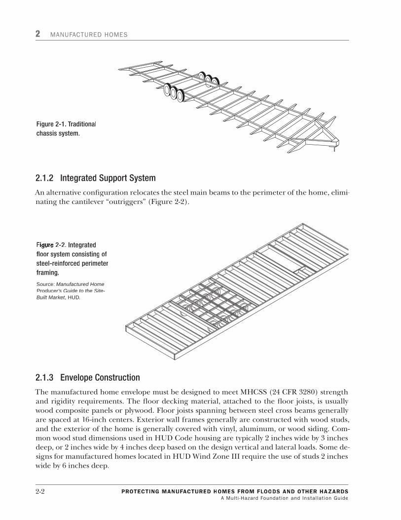
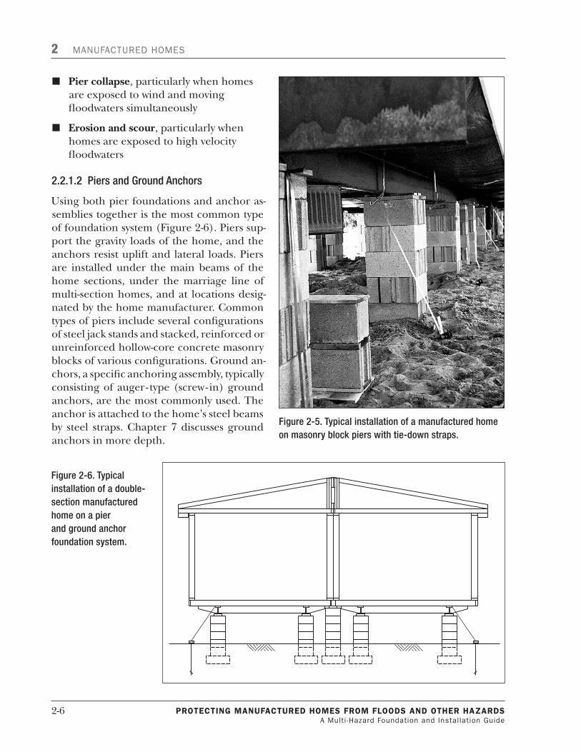
n Pier collapse, particularly when homes are exposed to wind and moving floodwaters simultaneously
n Erosion and scour, particularly when homes are exposed to high velocity floodwaters
2.2.1.2PiersandGroundAnchors
Using both pier foundations and anchor as-semblies together is the most common type of foundation system (Figure 2-6). Piers sup-port the gravity loads of the home, and the anchors resist uplift and lateral loads. Piers are installed under the main beams of the home sections, under the marriage line of multi-section homes, and at locations desig-nated by the home manufacturer. Common types of piers include several configurations of steel jack stands and stacked, reinforced or unreinforced hollow-core concrete masonry blocks of various configurations. Ground an-chors, a specific anchoring assembly, typically consisting of auger- type (screw-in) ground anchors, are the most commonly used. The anchor is attached to the home’s steel beams by steel straps. Chapter 7 discusses ground anchors in more depth.
Figure2-5.Typicalinstallationofamanufacturedhomeonmasonryblockpierswithtie-downstraps.
Figure2-6.Typicalinstallationofadouble-sectionmanufacturedhomeonapierandgroundanchorfoundationsystem.

PROTECTING MaNufaCTuREd HOMEs fROM flOOds aNd OTHER HazaRds A Multi -Hazard Foundation and Installation Guide
2-7
MANUFACTURED HOMES 2
The advantages of this foundation system are that it adapts easily to the site conditions, does not require much dimensional precision, is installed very quickly, and is economical to install.
2.2.1.3 PerimeterWallFoundations
When perimeter foundations are used with a manu-factured home constructed with chassis beams, the chassis beams provide support for gravity loads, and the perimeter walls resist uplift and lateral loads. When used with a manufactured home constructed with an integral floor framing system, the perimeter walls resist uplift, lateral, and gravity loads (Figure 2-7). With chassis systems, interior piers support the chassis, points along the marriage wall, and other ar-eas of concentrated loads.
Perimeter walls can be constructed with typical build-ing materials (e.g., cast-in-place concrete, masonry, or preservative-treated wood); footings are generally cast-in-place concrete. Attaching the floor joists to the foundation wall provides resistance to horizontal and uplift forces.
Some considerations in using this system include the following:
n The system must be precisely measured and constructed before the home is delivered to the site.
n Typically, a crane or roller system will be needed to place the home onto the foundation.
The cost and construction time of this system is greater than the pier and ground anchor foun-dation system.
2.2.2 ProprietarySystems
A proprietary foundation is a patented system manufactured and sold only by the owner of the patent or licensee. If a proprietary system is selected for a manufactured home, it must be ca-pable of resisting all design loads of the MHCSS, and those imposed by any site-specific natural hazards. (See the checklist on the next page for more information.)
The Systems Building Research Alliance (SBRA, formerly the Manufactured Housing Re-search Alliance [MHRA]) has evaluated proprietary and non-proprietary foundation systems for manufactured homes. Their publication, Guide to Foundation and Support Systems for Manu-factured Homes, provides guidance for deciding among alternative foundation designs that are appropriate for a given site and budget. The SBRA is also continuing to conduct research foun-dation systems developed for use in SFHAs.
Figure2-7.Perimeterwallfoundationunderamanufacturedhome.

2-8 PROTECTING MaNufaCTuREd HOMEs fROM flOOds aNd OTHER HazaRds A Multi -Hazard Foundation and Installation Guide
2 MANUFACTURED HOMES
2.3 UtilitiesandMechanicalEquipment
2.3.1 UtilitiesPlacement
Care needs to be taken in the placement of utilities (such as water, sewer, and gas services) and mechanical systems. Connecting the manufactured home to these utility and mechanical sys-tems requires them to extend from the grade beneath the home up through the floor. Their location makes them susceptible to being inundated by floodwaters and damaged by floating debris. Therefore, separating these systems to protect them is important. To minimize damage to utility lines, they should be placed in waterproof risers located adjacent to the elevated foun-dation member on the downstream side of the expected (or anticipated) flood flow.
State and local codes and regulations must also be followed for utility services installations and connections. These provisions may require the waterproofing of all connections, the use of certain specific waterproof materials, and backflow preventers on water and sewage service. Un-derground telephone and electric service should also be enclosed in a riser and protected from damage in a similar manner. If electrical and telephone service is supplied from overhead lines, the service connection to the manufactured home must be located above anticipated flooding.
Special care must be taken in running underground utilities to homes. Differential movement between the home and utility can cause failure of the home to utility connection. Failures can cause electrical shock hazard or leakage of gas, water, or raw sewage. Similar problems can oc-cur when utilities run through uncompacted backfill around a basement excavation or when utilities are subjected to seismic loads. Installing a flexible connection in the line is one way to reduce potential line breakage.
It is possible that a home with utility services could be displaced in a design wind or a seismic event. By design, ground anchors that are used to hold down many homes will displace on the order of 2 to 3 inches. Seismic forces can cause even higher displacements to utility connec-tions than a design wind event (Figure 2-8). Therefore, some flexibility must be provided in the
Proprietary Foundation System Checklist
n Identify type of natural hazards for the manufactured home site. Follow the steps in Chapter 9 of this guide.
n Identify natural hazards design loads for the manufactured home. Follow the steps in Chapter 9.
n Check design loads on engineering drawings or specifications. Design loads must be greater than or equal to the loads identified in Step 2 of Chapter 9.
n The drawing must have a professional engineer’s or architect’s seal, ensuring the system was designed by a professional.

PROTECTING MaNufaCTuREd HOMEs fROM flOOds aNd OTHER HazaRds A Multi -Hazard Foundation and Installation Guide
2-�
MANUFACTURED HOMES 2
utility lines to accommodate for any potential movements. Utility attachments to the manufac-tured home should be capable of accommodating the anticipated seismic and wind displacement of the support and anchorage system.
Propane and fuel oil tanks used to supply energy for heating or other services should be an-chored against flotation or elevated above the anticipated flood level. Tank foundations should be separated from the home's foundation system. To minimize the potential for debris impact and damage, tanks and their supporting foundations should be located on the downstream side of homes. Bollards can be used to deflect floodborne debris and reduce the potential of impact damage. Additional information on utility systems for manufactured homes in the floodplain is provided in Section 3.6.7.
For manufactured homes located in seismic areas, site-installed water heaters should be pro-vided with seismic bracing straps in accordance with the manufacturer’s recommendations. Strapping a water heater to a wall to prevent it from falling over is an easy and cost-effective seismic mitigation measure. Other site-installed equipment weighing more than �00 pounds should be anchored to resist horizontal seismic forces.
2.3.2 MechanicalAccess
Components of heating and air-conditioning systems installed within manufactured homes are generally located above the floor. When the home is elevated to the BFE, interior compo-nents are protected. However, components located below the floor remain vulnerable to flood damage. In particular, exterior heating and air conditioning compressors, and crossover ducts are common components that are damaged by floodwaters.
Figure2-8.Utilitylinedamageinunstablesoils.

2-�0 PROTECTING MaNufaCTuREd HOMEs fROM flOOds aNd OTHER HazaRds A Multi -Hazard Foundation and Installation Guide
2 MANUFACTURED HOMES
Compressor units can be elevated by placing them on platforms at the BFE; however, crossover ducts require the entire home to be elevated � to 2 feet above the BFE to prevent them from being damaged during the design flood.
2.4 Attachments–Carports,Decks,Porches,andAwnings
Carports, decks, porches, and awnings are often attached after the manufactured home has been installed. The HUD installation standard (24 CFR 3285.3) requires that attachments must not impose loads to the manufactured home or its foundations unless the attachments are included in the manufacturer’s approved designs and installation instructions, or the attach-ments are designed by a registered engineer or architect consistent with the manufacturer’s design. Similarly, the International Residential Code® (IRC®) requires that accessory buildings (e.g., carports, decks, porches, and awnings) shall not be structurally supported by or attached to a manufactured home unless engineering calculations are submitted to substantiate any pro-posed construction (IRC 2006 AE 504.�).
Carports, decks, porches, and awnings should only be built as stand-alone units. Additional-ly, if a stand-alone deck or porch is going to be added, design criteria for vertical foundation members on the addition should be equivalent to those for the foundation system of the main structure to prevent damage to the main structure from adjacent structures.
During the Hurricane Charley post-event assessment (2004), engineers noted the failure of these attached structures (in many places, occurring where wind speeds were below the design wind speed for the area), resulting in extensive damage to roof coverings, siding, and windows of the manufactured units, and generating significant amounts of debris.

3. RegulatoryRequirementsFederal, State, and local regulatory requirements must be identified and assessed as an initial step in the installation of manufactured housing. The following discussion provides a summary of the applicable NFIP minimum requirements for the installation of manufactured homes in floodplains. In addition, HUD MHCSS and model building code requirements are summarized. Appendix A provides a list of publications for further guidance for the installation and place-ment of manufactured homes in hazard-prone areas.
3.1 IntroductiontotheNFIPThe NFIP has three main elements:
Flood insurance that provides financial protection for property owners to cover flood-re-lated damage to buildings and contents.
Floodplain management requirements within the mapped flood hazard areas that are designed to prevent new development from increasing the flood threat and to protect new and existing buildings from anticipated flood events.
Hazard identification and mapping under which engineering studies are conducted and flood maps are prepared to delineate areas that are predicted to be subject to flooding under certain conditions.
Federal flood insurance is designed to provide an alternative to disaster assistance and disaster loans for home and business owners. Disaster assistance rarely comes close to covering all of the costs to repair and cleanup. While available to qualified victims, disaster loans do not sig-nificantly ease the financial burden due to repayment terms. It is important to remember that disaster assistance is available only after floods have been declared major disasters by the Presi-dent of the United States. In contrast, insurance claims will be paid any time damage from a qualifying flood event occurs.
The NFIP is intended to encourage States and local governments to recognize and incorporate flood hazards in land use and development decisions. In some communities, this is achieved by guiding development to areas with lower risk. When decisions result in development within floodplains, application of the criteria set forth in 44 CFR 59.1 and 60.3 is intended to minimize exposure and flood-related damage. These are the minimum requirements that a communi-ty must adopt in order to participate in the NFIP. In general, the NFIP minimum floodplain management regulations require that new residential structures or substantially improved or substantially damaged existing residential buildings in A zones must have their lowest floor (including basement) elevated to or above the BFE. Non-residential structures in A zones can be either elevated or dry-floodproofed to the BFE. In V zones, the building must be elevated on piles and columns such that the bottom of the lowest horizontal structural member of the
1.
2.
3.
PROTECTING MaNufaCTuREd HOMEs IN flOOd HazaRd aREas A Multi -Hazard Foundation and Installation Guide
3-1

3 REGULATORY REQUIREMENTS
lowest floor of all new construction or substantially improved existing buildings must be elevat-ed to or above the BFE.
Any community may exceed the minimum NFIP requirements by adopting more restrictive regulations. Communities often do this when they have access to information or knowledge of conditions that require, particularly for human safety, higher standards than the minimum NIFP requirements. Therefore, any floodplain management regulations that are more restric-tive than the NFIP requirements shall take precedence.
By encouraging communities to guide development to lower risk areas, and by requiring the elevation of new construction and existing buildings that have been substantially improved or substantially damaged, one of the long-term objectives of the NFIP can be achieved: reducing flood damage and losses.
In addition to providing flood insurance and reducing flood damages through floodplain management regulations, the NFIP identifies and maps the nation’s floodplains. Mapping flood hazards creates a broad-based awareness of the flood hazards and provides the data needed for floodplain management programs and to actuarially rate new construction for flood insurance.
3.2 IdentifyingandMappingFloodHazardsFEMA is required by statute to identify and map the nation’s flood-prone areas and to establish flood-risk zones in these areas. Since the inception of the NFIP, FEMA has complied with this statutory requirement by performing engineering studies of flood-prone communities and pro-ducing flood maps. The flood maps are used by mortgage lenders, insurers, real estate agents, map determination companies, community officials, land developers, engineers and surveyors, State and local emergency response officials, and property owners. The flood maps are also used by States and communities for emergency management, land use planning, and water re-sources planning and by Federal agencies implementing Executive Order 11988, Floodplain Management for Federal actions proposed in or affecting floodplains.
The NFIP would not be able to offer insurance at affordable rates without the existence of risk management (floodplain management) to reduce flood losses. To assess and manage the flood risk, a national standard was needed. The 1-percent annual chance flood was chosen on the ba-sis that it provides a higher level of protection while not imposing overly stringent requirements or the burden of excessive costs on property owners. The 1-percent annual chance flood (or 100-year flood) represents a magnitude and frequency that has a statistical probability of being equaled or exceeded in any given year or, stated alternatively, the 100-year flood has a 26 per-cent (or 1 in 4) chance of occurring over the life of a 30-year mortgage.
FEMA performs a Flood Insurance Study (FIS) and creates FIRMs delineating the extent of the flood that has a 1-percent chance of being equaled or exceeded in any given year. The delin-eated area is designated an SFHA, which is the area in which development must be regulated by NFIP floodplain management regulations. Under the NFIP, a floodplain is defined as any land area susceptible to being inundated by floodwaters from any source.
3-2 PROTECTING MaNufaCTuREd HOMEs fROM flOOds aNd OTHER HazaRdsA Multi -Hazard Foundation and Installation Guide

REGULATORY REQUIREMENTS 3
When producing a new FIS and FIRMs or updating existing ones, FEMA typically uses a combi-nation of the two study approaches (approximate and detailed) in identifying a community’s flood hazards. Detailed study methods typically employ the use of engineering models and, at a minimum, result in the determination of BFEs or flood depths and floodways that will be dis-played on the flood map. Approximate study methods are used to identify flood hazards, but they use more simplified engineering methods to determine the floodplain boundaries; how-ever, BFEs and floodways are not identified or mapped.
In general, the decision on whether to use approximate or detailed study methods is based on existing and anticipated development in and near the floodplain in the community. Flood haz-ard information for flooding sources that affect developed or developing areas are based on detailed studies whenever possible; approximate study methods generally are used for undevel-oped or sparsely developed areas.
When a new or updated detailed FIS is performed, the following information is usually gener-ated:
n BFEs are presented as either water-surface elevations or average depths of flow above the ground surface. These elevations and depths were historically referenced to the National Geodetic Vertical Datum of 1929 (NGVD 29). However, as a result of advances in tech-nology, an updated vertical datum – the North American Vertical Datum of 1988 (NAVD 88) – was created and has been officially adopted by the Federal Government as a new basis for measuring heights. Newly updated maps and BFEs are now generally referenced to NAVD 88.
n Water-surface elevations for the 10-year (10-percent annual chance), 50-year (2-percent annual chance), 100-year (1-percent annual chance), and 500-year (0.2-percent annual chance) floods.
n Boundaries of the regulatory floodway. The regulatory floodway is defined as the channel of a stream plus any adjacent floodplain areas that must be kept free of encroachment so that the entire base flood (1-percent annual chance flood) discharge can be conveyed with no greater than a 1.0-foot increase in the BFE.
n Boundaries of the 1- and 0.2-percent annual chance floodplains. The 1-percent annual chance floodplain is referred to as the SFHA. The 0.2-percent annual chance flood is the flood that has a 0.2 percent chance of being equaled or exceeded in any given year and is also known as the 500-year flood.
The results of the FIS are presented on the FIRM. An example of a FIRM showing the map and title box is shown in Figure 5-1. FIRMs are now being prepared as a digital product, known as a Digital Flood Insurance Rate Map (DFIRM), which may involve converting an existing manually produced FIRM to digital format, or creating a product from new digital data sources using a Geographic Information System (GIS) environment. A sample DFIRM is shown in Fig-ure 3-1.
PROTECTING MaNufaCTuREd HOMEs fROM flOOds aNd OTHER HazaRds A Multi -Hazard Foundation and Installation Guide
3-3

3 REGULATORY REQUIREMENTS
The results of the FIS are also presented in a report that accompanies the FIRMs or DFIRMs. The FIS report contains a narrative that describes the flooding conditions in the community, and the types of studies that were performed. The report also contains tables and Flood Profiles. For determining a BFE at a building site, communities should use the Flood Profiles rather than the BFE on the FIRM. A sample FIS summary of discharges is shown in Figure 3-2(a), a sample FIS floodway data table is shown in Figure 3-2(b), and a sample FIS flood profile is shown in Fig-ure 3-2(c). Refer to Section 5.1 for additional details on obtaining FIRM and FIS data. The NFIP FISs and FIRMs can be viewed and ordered online at http://store.msc.fema.gov.
Flood risk zones are shown on the FIRM or DFIRM for the 1-percent annual chance flood as Zone A, Zone A1-30 (on older FIRMs), Zone AE, Zone AO, Zone AH, Zone AR, Zone A99, Zone AR/A, Zone AR/AE, Zone AR/A1-30 (on older FIRMs), Zone AR/AH, Zone AR/AO, Zone V, Zone V1-30 (on older FIRMs), or Zone VE. Table 3-1 provides a general description of the most common flood zone designations for riverine flood areas and inland flood zones in coastal ar-eas. Table 3-2 provides a general description of the most common flood zone designations for coastal flood areas. The zone designations presented on the FIRM or DFIRM depend on the type of flood hazard and type of study performed. The 0.2-percent annual chance floodplain is labeled as Zone B (on older FIRMs) or Zone X (shaded). Areas outside of the SFHA are labeled as Zone C or Zone X (unshaded). Definitions and descriptions of the flood insurance risk zones can be found at: http://www.fema.gov/plan/prevent/floodplain/nfipkeywords/flood_zones.shtm.
Figure3-1.SampleDFIRM.
3-4 PROTECTING MaNufaCTuREd HOMEs fROM flOOds aNd OTHER HazaRdsA Multi -Hazard Foundation and Installation Guide

REGULATORY REQUIREMENTS 3
Figure3-2(a).SampleFISSummaryofDischargestable.
Figure3-2(b).SampleFISFloodwayData.
PROTECTING MaNufaCTuREd HOMEs fROM flOOds aNd OTHER HazaRds A Multi -Hazard Foundation and Installation Guide
3-5

3 REGULATORY REQUIREMENTS
Figure3-2(c).SampleFISFloodProfile.
Table3-1.CommonSFHADesignationsforRiverineorInlandFloodZones
Zone DescriptionFlood Risk Zones
A Areas subject to inundation by the 1-percent annual chance flood event. Because detailed hydraulic analyses are not used, no BFE or depths are shown.
AE and A1-301
Areas subject to inundation by the 1-percent annual chance flood event determined by detailed methods. BFEs are shown.
AH and AO Areas subject to inundation from the 1-percent annual chance flood that have flood depths of between 1 and 3 feet. AO zones can be either ponding areas or sheet flow and are assigned a base flood depth measured in feet above the ground. AH zones are generally ponding areas and are assigned a BFE.
1 Zone designations found on older FIRMS have been replaced by the designation listed in the same box above them.
Table3-2.CommonSFHADesignationsforCoastalFloodAreas
Zone DescriptionFlood Risk Zones
V Areas subject to inundation from the 1-percent annual chance flood in coastal areas where there is a velocity hazard due to wave action and, by definition, the entire Primary Frontal Dune. No BFEs have been determined.
VE V1-301
Areas subject to inundation from the 1-percent annual chance flood in coastal areas where there is a velocity hazard due to wave action. BFEs have been determined and are shown on the FIRM.
1 Zone designations found on older FIRMs have been replaced by the designation listed in the same box above them.
3-6 PROTECTING MaNufaCTuREd HOMEs fROM flOOds aNd OTHER HazaRdsA Multi -Hazard Foundation and Installation Guide

REGULATORY REQUIREMENTS 3
In addition to the SFHAs labeled as V zones, there are some A zones, generally located landward of and contiguous to V zones, where flooding characteristics may include wave action, high ve-locity flows, and erosion or scour. These are referred to as Coastal A zones, and they are further described below and in Section 3.7.
Along rivers, streams, and lakes within the U.S., FEMA computes BFEs using computer models, statistical techniques, or both. These elevations are a function of the amount of water expect-ed to enter a particular system by means of precipitation and runoff. The SFHAs along rivers, streams, and lakes are labeled as A zones.
Along the coast, FEMA determines SFHAs by an analysis of storm surge, wind direction, wind speed, wave heights, and other factors. FEMA designates these areas along the coast as both V and A zones on the FIRM or DFIRM.
FEMA applies the VE zone designation to those areas along the coast where water depth and other conditions would support at least a 3-foot wave height. FEMA also considers other factors in identifying VE zones, such as wave runup and the existence of a Primary Frontal Dune. FEMA usually designates AE zones in coastal areas landward of the VE zone. Coastal flood hazard ar-eas mapped as AE zones can be subject to storm surge and damaging waves; however, the waves are less than 3 feet in height.
Currently, NFIP regulations make no distinction between the design and construction require-ments for coastal AE zones and riverine AE zones. However, evidence suggests that design and construction requirements in some portions of coastal AE zones should be more like VE zone requirements. One of the hazard identification criteria for VE zone designation is where wave heights are estimated to be equal to or greater than 3 feet. Unfortunately, post-storm investiga-tions have shown that typical AE zone construction techniques (e.g., wood frame, light gauge steel, or masonry walls on shallow footings or slabs, etc.) are subject to damage when exposed to waves less than 3 feet in height. Laboratory tests and post-disaster field investigations con-firm that wave heights as small as 1.5 feet can cause failure of the above-listed wall types. Other flood hazards associated with coastal waves (e.g., floating debris, high velocity flow, erosion, and scour) also damage AE zone-type construction in these coastal areas.
As a result, for all new detailed coastal studies starting in 2009, FEMA will delineate the land-ward limit of waves 1.5 feet in height on the FIRMs and include this information in the DFIRM database as an informational layer. The landward limit of the area affected by waves greater than 1.5 feet is called the Limit of Moderate Wave Action (LiMWA). The LiMWA will be included on the preliminary FIRM; however, if a community does not want to delineate the limit on its final FIRMs, the community may provide a written request to FEMA with justification for such a re-quest. There are no NFIP floodplain management requirements that communities must adopt or special insurance ratings associated with the designation of the LiMWA. However, communi-ties are encouraged to adopt higher standards than the minimum NFIP requirements in these areas to address the increased risks associated with waves and velocity action.
PROTECTING MaNufaCTuREd HOMEs fROM flOOds aNd OTHER HazaRds A Multi -Hazard Foundation and Installation Guide
3-7

3 REGULATORY REQUIREMENTS
3.3 TheNFIP'sCommunityRatingSystem(CRS)The NFIP's Community Rating System (CRS) is a voluntary incentive program that recognizes and encourages community floodplain management activities that exceed the minimum NFIP requirements.
As a result, flood insurance premium rates are discounted to reflect the reduced flood risk re-sulting from the community actions meeting the three goals of the CRS:
Reduce flood losses
Facilitate accurate insurance rating
Promote the awareness of flood insurance
For CRS participating communities, flood insurance premium rates are discounted in incre-ments of 5 percent; a Class 1 community would receive a 45 percent premium discount, while a Class 9 community would receive a 5 percent discount (a Class 10 is not participating in the CRS and receives no discount). The CRS classes for local communities are based on 18 credit-able activities, organized under four categories:
Public Information
Mapping and Regulations
Flood Damage Reduction
Flood Preparedness
3.4 NFIPDefinitionsRelatedtoManufacturedHomesIn addressing the NFIP floodplain management requirements for manufactured homes, it is useful to define key terms. The following definitions are found in the NFIP floodplain manage-ment regulations at 44 CFR 59.1 unless noted otherwise. Several NFIP definitions can also be found in Appendix D. The definition for “manufactured home” does not include a recreational vehicle.
n "Manufactured home” means a structure, transportable in one or more sections built on a chassis and designed for use with/without a permanent foundation when attached to utilities.
n “Manufactured home park or subdivision” means a parcel (or contiguous parcels) of land divided into two or more manufactured home lots for rent or sale.
n “Existing manufactured home park or subdivision” means a manufactured home park or subdivision for which the construction of facilities for servicing the lots on which the manufactured homes are to be
1.
2.
3.
1.
2.
3.
4.
Permanent Foundations
A permanent foundation is a founda-tion constructed of durable materials that may include masonry, reinforced concrete, corrosion resistant steel, or pressure treated timber. The foun-dation designs provided in Appendix H are considered permanent founda- tions in accordance with this defin- ition.
3-8 PROTECTING MaNufaCTuREd HOMEs fROM flOOds aNd OTHER HazaRdsA Multi -Hazard Foundation and Installation Guide

REGULATORY REQUIREMENTS 3
affixed (including, at a minimum, the installation of utilities, the construction of streets, and either final site grading or the pouring of concrete pads) is completed before the effective date of the floodplain management regulations adopted by the community.
n “New manufactured home park or subdivision” means a manufactured home park or subdivision for which the construction of facilities for servicing the lots on which the manufactured homes are to be affixed (including, at a minimum, the installation of utilities, the construction of streets, and either final site grading or the pouring of concrete pads) is completed on or after the effective date of the floodplain management regulations adopted by a community.
n “Expansion to an existing manufactured home park or subdivision” means the preparation of additional sites by the construction of facilities for servicing the lots on which the manufactured homes are to be affixed (including the installation of utilities, the construction of streets, and either final site grading or the pouring of concrete pads).
n “Substantial damage” means damage of any origin sustained by a structure whereby the cost of restoring the structure to the condition before damage would equal or exceed 50 percent of the market value of the structure before the damage occurred.
n "Substantial improvement" means any reconstruction, rehabilitation, addition, or other improvement of a structure, the cost of which equals or exceeds 50 percent of the market value of the structure before the “start of construction” of the improvement. This term includes structures that have incurred “substantial damage,” regardless of the actual repair work performed. The term does not, however, include either (1) any project for improvement of a structure to correct existing violations of State or local health, sanitary, or safety code specifications that have been identified by the local code enforcement official and that are the minimum necessary to ensure safe living conditions, or (2) any alteration of a “historic structure,” provided that the alteration will not preclude the structure’s continued designation as a “historic structure.”
3.5 GeneralNFIPFloodplainManagementRequirementsforManufacturedHomes
Under the NFIP, participating communities are required to regulate all development in SFHAs. “Development” is defined in the NFIP regulations as:
“Any man-made change to improved or unimproved real estate, including but not limited to buildings or other structures, mining, dredging, filling, grading, pav-ing, excavation or drilling operations or storage of equipment or materials.” [44 CFR 59.1]
Before a property owner can undertake any development in the SFHA, a permit must be ob-tained from the community. The community is responsible for reviewing all permit applications to determine whether development complies with the community’s floodplain management regulations. Communities are also required to review proposed development in SFHAs to
PROTECTING MaNufaCTuREd HOMEs fROM flOOds aNd OTHER HazaRds A Multi -Hazard Foundation and Installation Guide
3-9

3 REGULATORY REQUIREMENTS
ensure that all necessary permits have been received from those government agencies from which approval is required by Federal or State law, such as 404 wetland permits from the U.S. Army Corps of Engineers (USACE) or permits under the Endangered Species Act.
The NFIP requires manufactured homes to meet the same basic regulatory requirements that are required for residential structures in the floodplain. The following general NFIP minimum standard applies to all residential structures in the floodplain in which communities are to:
“Review all permit applications to determine whether proposed building sites will be reasonably safe from flooding. If a proposed building site is in a flood-prone area, all new construction and substantial improvements shall (i) be designed (or modified) and adequately anchored to prevent flotation, collapse, or lateral movement of the structure resulting from hydrodynamic and hydrostatic loads, including the effects of buoyancy, (ii) be constructed with materials resistant to flood damage, (iii) be constructed by methods and practices that minimize flood damages, and (iv) be constructed with electrical, heating, ventilation, plumbing, and air conditioning equipment and other service facilities that are designed and/or located so as to prevent water from entering or accumulating within the components during conditions of flooding.” [44 CFR 60.3(a)]
The NFIP also requires that new manufactured home parks and subdivisions meet the same ba-sic requirements as all other subdivision proposals in which communities are to:
"Review subdivision proposals and other proposed new development, including manufactured home parks or subdivisions, to determine whether such proposal will be reasonably safe from flooding. If a subdivision proposal or other proposed development is in a flood-prone area, any such proposals shall be reviewed to as-sure that:
(i) all such proposals are consistent with the need to minimize flood damages within the flood-prone area,
(ii) all public utilities and facilities, such as sewer, gas, electrical, and water systems are located and constructed to minimize or eliminate flood damage, and
(iii) adequate drainage is provided to reduce exposure to flood hazards." [44 CFR 60.3(a)(4)]
3.6 NFIPRequirementsforManufacturedHomesinRiverineandInlandFloodZones
Generally, manufactured homes must meet the same flood protection requirements as a “stick built” or typical housing. The general requirement for manufactured homes like typically built residential structures is that they must be elevated so that the lowest floor is above the BFE. This applies to new or substantially improved or substantially damaged manufactured homes.
3-10 PROTECTING MaNufaCTuREd HOMEs fROM flOOds aNd OTHER HazaRdsA Multi -Hazard Foundation and Installation Guide

REGULATORY REQUIREMENTS 3
3.6.1 ApproximateAZones
Approximate A zones are not studied using detailed methods; therefore, BFEs have not been developed. When a manufactured home is proposed on an approximate A zone site, the com-munity must make every effort to obtain any BFE data and floodway data in order to achieve a reasonable measure of flood protection.
“Obtain, review, and reasonably utilize any base flood elevation and floodway data available from a Federal, State, or other source….”[44 CFF 60.3(b)(4)]
BFE data may be available from a variety of sources such as local hydrologic and hydraulic (H&H) studies, State Departments of Natural Resources, or from Federal agencies such as the USACE. Several other sources of BFE data are identified in FEMA 265, Managing Floodplain De-velopment in Approximate Zone A Areas, A Guide for Obtaining and Developing Base (100-year) Flood Elevations.
If BFE or floodway data cannot be obtained from these sources, the community should consider conducting, or requiring the applicant to conduct, a site-specific engineering analysis to deter-mine a BFE. Guidance for developing a BFE is available in FEMA 265.
If no BFE data are available, communities must ensure that building sites will be reasonably safe from flooding for proposed developments. A simplified method for estimating a BFE as well as other methods for ensuring a building site is reasonably safe from flooding can also be found in FEMA 265.
BFE and DFE
Base flood elevation (BFE) – The water surface elevation resulting from the base, or 100-year (1 per-cent annual chance) flood.
Design flood elevation (DFE) – The elevation to which development in the regulatory floodplain is built. At a minimum, the DFE is equivalent to the BFE. However, in some areas, the DFE includes an additional freeboard height above the BFE as shown in the formula below.
DFE = BFE + Freeboard
Freeboard – An additional elevation requirement some height (1, 2, or more feet) above the BFE that provides a margin of safety above the estimated BFE.
As indicated above, the minimum DFE requirement for NFIP communities is the BFE. However, in com-munities where a higher degree of protection is promoted or required, the DFE includes a freeboard height above the BFE. This freeboard provides a margin of safety above the estimated BFE and against extraordinary or unknown risks. As in all natural hazard events, the design event can only be predicted in probabilistic terms and some uncertainties remain in any analysis. Freeboard is intended to allow for those uncertainties. The NFIP encourages participating communities to adopt and enforce freeboard requirements as part of their local floodplain management ordinance. This is shown in 44 CFR 60.1(d); which states, “Any floodplain management regulations adopted by a State or a community which are more restrictive than the criteria set forth in this part are encouraged and shall take precedence.”
PROTECTING MaNufaCTuREd HOMEs fROM flOOds aNd OTHER HazaRds A Multi -Hazard Foundation and Installation Guide
3-11

3 REGULATORY REQUIREMENTS
When a new manufactured home park or subdivision is being planned on a site that is greater than 50 lots or 5 acres (whichever is less), BFE data must be developed for approximate A zones through the use of detailed study methodologies similar to those used in creating the FIS. Un-der this requirement, the community must:
“Require that all new subdivision proposals and other proposed development (in-cluding proposals for manufactured home parks and subdivisions) greater than 50 lots or 5 acres, whichever is the lesser, include within such proposals base flood elevation data.” [44 CFR 60.3(b)(3)]
The community can perform a study to determine these elevations or require the developer to fund or complete the study. When the 50-lot, 5-acre threshold is surpassed and the develop-ment includes one or more lots that lie at least partially within the floodplain, BFE data must be developed through detailed study methodologies. If the developer completes the study, it is subject to approval by the community.
For manufactured home sites that are below the 50-lot/5-acre threshold and BFE data for those sites are not available from other sources, communities should consider conducting or requir-ing the permit applicant to develop a BFE in an approximate A zone. In addition to reducing flood damages, there are other advantages of developing a BFE. For example, flood insurance policies obtained in approximate A zones that are rated using a BFE developed using a detailed study methodology will often qualify for significantly lower insurance rates than policies that are rated without a BFE. The difference in flood insurance premiums could be substantial.
If a manufactured home is proposed in an approximate A zone where BFE data are not avail-able from a Federal, State, or other source, the community must require that:
“…all manufactured homes to be placed within Zone A on a community FHBM or FIRM shall be installed using methods and practices which minimize flood dam-age. For the purpose of this requirement, manufactured homes must be elevated and anchored to resist flotation, collapse, or lateral movement. Methods of an-choring may include, but are not limited to, the use of over-the-top frame ties to ground anchors. This requirement is in addition to applicable State and local an-choring requirements for resisting wind forces.” [44 CFR 60.3(b)(8)]
This minimum standard requires that manufactured homes be elevated and anchored to resist flood and wind forces. If elevation data are not available from a Federal, State, or other source, FEMA advises communities to require manufactured homes under this provision to be elevated at a minimum of 3 feet or higher from the highest adjacent grade to minimize flood damages. Guidance for anchoring is further addressed in Section 3.6.5 and in Chapter 7. The areas below the 3-foot elevation must be constructed with flood-resistant materials and utilities, and mechanical equipment must be elevated to the 3-foot elevation. Any utility and mechanical components that must be below the BFE must be made watertight to the 3-foot elevation as described in 3.6.7.
3-12 PROTECTING MaNufaCTuREd HOMEs fROM flOOds aNd OTHER HazaRdsA Multi -Hazard Foundation and Installation Guide

REGULATORY REQUIREMENTS 3
When BFEs or floodway data are obtained for manufactured home sites, the manufactured home must meet the elevation and floodway standards described in Sections 3.6.2 and 3.6.9.
3.6.2 ElevationinA,A1-30,AE,andAHZones
Most manufactured home placements are subject to the same performance standards as typically built residential structures. The performance standard for the placement of these manufac-tured homes is addressed in this section. An exception has been made for the placement of manufactured homes in existing manufactured home parks or subdivisions which is addressed in Section 3.6.3.
The NFIP requires that manufactured homes placed or substantially improved in Zones A1-30, AH, or AE on the community’s FIRM on sites:
(i) “Outside of a manufactured home park or subdivision,
(ii) In a new manufactured home park or subdivision,
(iii) In an expansion to an existing manufactured home park or subdivision, or
(iv) In an existing manufactured home park or subdivision on which a manufactured home has incurred substantial damage as the result of a flood,
be elevated on a permanent foundation such that the lowest floor of the manu-factured home is elevated to or above the base flood elevation and be securely anchored to an adequately anchored foundation system to resist flotation, col-lapse and lateral movement.” [44 CFR 60.3(c)(6)]
This requirement establishes the basic elevation and anchoring standards that apply to most manufactured home placements, including those outside of manufactured home parks and sub-divisions and in new manufactured home parks and subdivisions. These manufactured homes must have their lowest floors elevated to or above the BFE. These requirements also apply to manufactured homes placed in expansions to existing manufactured home parks and on lots where manufactured homes are substantially damaged by flood. Once a manufactured home in an existing manufactured home park or subdivision is substantially damaged by flood, from that point on all manufactured homes placed on that lot must be elevated to or above the BFE.
The best way to meet the elevation requirement described above is to elevate the bottom of the manufactured home steel frame to the BFE. The manufactured home must be securely anchored to an adequately anchored foundation system to resist flotation, collapse, or lateral movement. Section 3.6.5 and Chapter 7 address anchoring in more detail.
As with stick built housing, all parts of the manufac-tured home below the BFE must be constructed with
This guide recommends for A zones the best practice of placing the bot-tom of the manufactured home's steel frame at the BFE and not the lowest floor of the manufactured home in order to prevent flood dam-age to the floor and other interior finishes and contents (Figure 3-3).
PROTECTING MaNufaCTuREd HOMEs fROM flOOds aNd OTHER HazaRds A Multi -Hazard Foundation and Installation Guide
3-13

3 REGULATORY REQUIREMENTS
flood damage-resistant materials and utility systems must either be elevated or made water-tight to the BFE.
3.6.3 3-FootPierFoundation
The NFIP allows for a limited exemption to elevating to the BFE by allowing elevating to no less than 36 inches in height above grade for lots in existing manufactured home parks in Zones A1-30, AE, or AH on the community’s FIRM. A manufactured home placed in an existing manu-factured home park must meet either of the following requirements:
"(1) The lowest floor of the manufactured home is at or above the base flood elevation; or
(2) The manufactured home chassis is supported by reinforced piers or other founda-tion elements of at least equivalent strength that are no less than 36 inches in height above grade and be securely anchored to an adequately anchored foundation sys-tem to resist flotation, collapse, and lateral movement." 44 CFR 60.3(c)(12).
The elevation requirements above apply in existing manufactured home parks or subdivisions es-tablished before the date of the community’s initial floodplain management regulations when:
Figure3-3.ManufacturedhomewithlowestfloorelevatedtotheBFE.
3-14 PROTECTING MaNufaCTuREd HOMEs fROM flOOds aNd OTHER HazaRdsA Multi -Hazard Foundation and Installation Guide

REGULATORY REQUIREMENTS 3
1) A manufactured home is being placed or replaced with a new model in an existing community or subdivision, or
2) A manufactured home is being replaced in an existing manufactured home park or subdivision when the previous home had sustained substantial damage due to reasons other than a flood.
The selection of the 36-inch pier foundation does not ap-ply to the repair or replacement of a manufactured home on a site in an existing manufactured home park where a manufactured home has been substantially damaged by flood.
The option of allowing elevating 36 inches in height above grade is a compromise to balance the flood haz-ard against the economic impacts on some manufactured park owners that would result if elevation to the BFE were required. There are often practical difficulties in elevat-ing manufactured homes to the BFE in many older parks due to small lot sizes and the split ownership of the manu-factured home and the lot itself.
It is important to note that, when the 36-inch pier foundation is selected, the manufactured home may not be protected to the level of the BFE. For this reason, care must be exercised in using the 36-inch pier foundation option. This option may not be appropriate in communities where the flood hazard may be so severe, such as deep floodplains and high velocity areas, that it would place lives and property at too great a risk. Some communities may find placement of a manufactured home in an existing manufactured home park can accommodate elevation to the BFE.
If the option of elevating the manufactured home to 36 inches above grade is chosen, the strength of the anchoring system must be increased in order to resist the additional flood forces that will be exerted upon the foundation since it is possible that water will reach or exceed the level of the home’s floor. Therefore, under this scenario, the use of typical manufactured home installation methods such as foundations using dry-stack blocks and ground anchors would pre-clude the use of the other foundation designs in this guide.
No matter which option is chosen for elevating a manufactured home in an existing manu-factured home park, the manufactured home must be securely anchored to an adequately anchored foundation system to resist flotation, collapse, or lateral movement.
As with stick built housing, all parts of the manufactured home below the BFE must be construct-ed with flood-resistant materials and utility systems must either be elevated or made watertight to the BFE. The best way to meet the requirement for flood resistance is to elevate the bottom of the manufactured home steel frame to the BFE.
3-Foot Pier Foundation
The 3-foot pier foundation is one option for manufactured homes installation in existing manufac-tured home parks or subdivisions. However, the NFIP strongly en-courages elevating to the level of the BFE or higher for increased safety and property protection and reduced flood insurance pre- miums.
PROTECTING MaNufaCTuREd HOMEs fROM flOOds aNd OTHER HazaRds A Multi -Hazard Foundation and Installation Guide
3-15

3 REGULATORY REQUIREMENTS
Figure 3-4 shows a typical example of a foundation used on manufactured housing per the 36-inch pier foundation alternative. The pier, footing, and connection between the pier and the home must be designed to resist flotation, collapse, or lateral movement.
3.6.4 ElevationinZoneAO
A Zone AO is an area of shallow flooding with flood depths between 1 and 3 feet with no clearly defined channel. FIRMs indicate a flood height above grade that is based on an average depth to which structures must be raised for Zone AO.
Manufactured homes placed or substantially improved in Zone AO must meet the same stan-dards as other residential structures and have their lowest floor elevated above the highest adjacent grade at least as high as the depth number specified on the FIRM.
HUD manufactured home standard 24 CFR 3285.305 requires a minimum clearance of 12 inches between the lowest member of the main frame and the ground surface, and the manu-factured home main frame is typically 0.5 feet to 1 feet deep; therefore, the lowest floor level is typically 1.5 to 2 feet above grade. Under this scenario, meeting the NFIP elevation requirement for Zone AO may already be met or require a relatively small additional elevation of up to 1.5 feet. This additional elevation can be accomplished using installation techniques found in this guide, such as placing the home on piers and securing it with ground anchors.
Figure3-4.Manufacturedhomeonreinforcedpierfoundation36incheshigh.
3-16 PROTECTING MaNufaCTuREd HOMEs fROM flOOds aNd OTHER HazaRdsA Multi -Hazard Foundation and Installation Guide

REGULATORY REQUIREMENTS 3
Standard installation techniques provide a foundation that is typically elevated at least 3 feet above grade, and flood depths in Zone AO are typically 3 feet or less. Therefore, the place-ment or substantial improvement of manufactured homes in Zone AO are typically elevated to or above the base flood level, even if they are being placed in an existing manufactured home park or subdivision. However, the recommended best practice is to elevate the bottom of the steel frame to the BFE in Zone AO.
As in the other A zones, manufactured homes in Zone AO must be anchored to resist flotation, collapse, or lateral movement. The areas below the Zone AO flood depth must be made with flood damage-resistant materials, and utilities and mechanical equipment must be elevated to the flood depth specified on the FIRM. Any utility and mechanical components that must be be-low the BFE must be made watertight to the Zone AO flood depth. Refer to Sections 3.6.6 and 3.6.7 and Chapter 7 for additional details on these requirements.
3.6.5 Anchoring
In addition to the elevation requirement, manufactured homes are required to be securely attached to an adequately anchored foundation system to resist flotation, collapse, or lateral movement:
"[Manufactured homes must] …and be securely anchored to an adequately an-chored foundation to resist flotation, collapse and lateral movement." [44 CFR 60.3(c)(6) and (c)(12)]
“Adequately anchored” is considered to be a system of ties, anchors, and anchoring equipment that will withstand flood and wind forces.
Additional guidance on anchoring manufactured homes can be found in Chapter 7.
Anchor and Tie-down Systems
Anchor and tie-down systems must meet load requirements stipulated in locally adopted installation ordinances. Many communities across the country have adopted or are in the process of adopting the International Code Council’s (ICC's) model building codes, which include the International Residential Code® of 2009 (IRC® 2009). IRC 2009 stipulates working load requirements of 3,150 pounds with a 50 percent overload or 4,725 pounds for manufactured home anchoring systems.
Florida’s manufactured home installation requirements, Rules of Department of Highway Safety and Motor Vehicles Division of Motor Vehicles, Chapter 15C-1, for homes manufactured before July 14, 1994, have the same loading standards for anchor systems as those found in the IRC 2009, a working load of 3,150 pounds with an ultimate load of 4,725 pounds. However, for homes manufactured after July 14, 1994, the system must be able to resist a working load of 4,000 pounds with an ultimate load of 6,000 pounds.
PROTECTING MaNufaCTuREd HOMEs fROM flOOds aNd OTHER HazaRds A Multi -Hazard Foundation and Installation Guide
3-17

3 REGULATORY REQUIREMENTS
3.6.6 FloodDamage-ResistantMaterials
When a manufactured home is elevated, it is important that all parts exposed to floodwaters be made of flood damage-resistant materials. This includes all portions of the manufactured home such as foundation elements and any enclosures below the BFE.
“[Community must] Review all permit applications to determine whether pro-posed building sites will be reasonably safe from flooding. If a proposed building site is in a floodprone area, all new construction and substantial improvements shall...(ii) be constructed with materials resistant to flood damage...” [44 CFR 60.3(a)(3)]
“Flood [damage]-resistant material” is described in FEMA Technical Bulletin 2 as “any building product [material, component or system] capable of withstanding direct and prolonged contact with floodwaters without sustaining significant damage.” The term “prolonged contact” means at least 72 hours, and the term “significant damage” means any damage requiring more than cosmetic repair. “Cosmetic repair” includes cleaning, sanitizing, and resurfacing (e.g., sanding, repair of joints, repainting) of the material.
For further information on flood-resistant materials refer to FEMA Technical Bulletin 2, Flood Damage-Resistant Material Requirements for Buildings Located in Special Flood Hazard Areas in accor-dance with the National Flood Insurance Program.
3.6.7 UtilitiesandMechanicalEquipment
The manufactured home’s utilities and mechanical equipment need to be protected. Their location below the BFE can make them susceptible to being inundated by floodwaters and dam-aged by floating debris. Utilities and mechanical equipment must:
“…be constructed with electrical, heating, ventilation, plumbing, and air condi-tioning equipment and other service facilities that are designed and/or located so as to prevent water from entering or accumulating within the components during conditions of flooding." [44 CFR 60.3(a)(3)(iii)]
Essentially, utility systems and mechanical equipment must be elevated to or above the BFE. El-evating utilities and mechanical equipment such as furnaces, hot water heaters, and heating, ventilation, and air conditioning equipment (HVAC) is the best protection. With most outdoor HVAC compressors, the main issues presented by floodwaters are inundation, velocity flow, and debris impact. The control and power circuits and mechanical parts in HVAC equipment, even when they are designed for outdoor installations, are not designed to withstand inundation by floodwaters. The most effective flood-resistant design for outdoor HVAC compressors is to strap or bolt the equipment onto a platform above the BFE.
Utility and mechanical components that must be below the BFE must be made watertight to the BFE. Examples of this include sealing on-site water well casings to prevent water intrusion or en-closing HVAC equipment in a flood-resistant enclosure so that it is protected to the BFE.
3-18 PROTECTING MaNufaCTuREd HOMEs fROM flOOds aNd OTHER HazaRdsA Multi -Hazard Foundation and Installation Guide

REGULATORY REQUIREMENTS 3
The NFIP does not recommend locating ductwork below the BFE for manufactured homes lo-cated in SFHAs. There is no known or cost-effective technique for designing air ducts to keep floodwaters from entering or accumulating within the systems components during inundation by floodwaters. If ductwork must be installed below the BFE, it should be minimized as much as possible. Placing the bottom of the steel frame at the BFE as recommended enhances pro-tection of utility and mechanical equipment. The exception would be installation of cross-over duct work for manufactured housing that needs to pass under chassis frame members. If cross-over ducts are used, elevating the manufactured home 1 to 2 feet above the BFE will prevent them from being damaged during flood events.
Additional guidance for protecting utility and mechanical systems can be found in FEMA 348, Protecting Building Utilities From Flood Damage, Principles and Practices for the Design and Construction of Flood Resistant Building Utility Systems.
3.6.8 EnclosedAreas
Generally, the space beneath the lowest floor of manufactured home is covered by some type of skirting or screening. Manufactured homes are also often installed on an enclosed foundation (see Chapter 8) when the BFE is several feet above grade.
When an enclosed area below the lowest floor of a manufactured home is created, special atten-tion is needed for two reasons:
n The walls of enclosed areas are subject to flood damage from hydrostatic and hydrodynamic forces.
n People are tempted to convert enclosures that are intended to flood into areas that can sustain damage in a flood.
To protect enclosed areas below the lowest floor, the community must:
"Require, for all new construction and substantial improvements, that fully en-closed areas below the lowest floor that are usable solely for parking of vehicles, building access or storage in an area other than a basement and which are subject to flooding shall be designed to automatically equalize hydrostatic flood forces on exterior walls by allowing for the entry and exit of floodwaters. Designs for meeting this requirement must either be certified by a registered professional engineer or architect or meet or exceed the following minimum criteria: A mini-mum of two openings having a total net area of not less than one square inch for every square foot of enclosed area subject to flooding shall be provided. The bottom of all openings shall be no higher than one foot above grade. Openings may be equipped with screens, louvers, valves, or other coverings or devices pro-vided that they permit the automatic entry and exit of floodwaters." [44 CFR 60.3(c)(5)]
PROTECTING MaNufaCTuREd HOMEs fROM flOOds aNd OTHER HazaRds A Multi -Hazard Foundation and Installation Guide
3-19

3 REGULATORY REQUIREMENTS
The NFIP allows only certain uses of the enclosed area below the lowest floor of an elevated manufactured home. These spaces can only be used for parking of vehicles, building access, or storage.
Additionally, the enclosure must be designed to automatically equalize hydrostatic flood forces on exterior walls by allowing for the entry and exit of floodwaters. To protect the enclosure, the NFIP minimum requirements are:
n A minimum of two openings in walls of the enclosure having a total net area of not less than 1 square inch for every square foot of enclosed area subject to flooding.
n The bottom of all openings must not be higher than 1.0 foot above the higher of the exterior or interior grade or floor immediately below the opening.
n Openings must permit the automatic entry and exit of floodwaters. The openings may be equipped with screens, louvers, valves, or other coverings or devices provided that they meet this requirement.
n Alternative designs are allowed but must be certified by a registered professional engineer or architect as meeting the requirement to automatically equalize forces on exterior walls by allowing for the entry and exit of floodwaters.
To further minimize flood damages, mechanical, electrical, plumbing equipment, and other service facilities must be designed and/or located so as to prevent damage during conditions of flooding (see Section 3.6.7). Enclosures below the BFE must also be constructed with flood damage-resistant materials.
If the area below the manufactured home is enclosed with rigid skirting that is less likely to be dislodged by wind or flood loads, openings are required to equalize hydrostatic pressure in ac-cordance with NFIP regulations.
For further information on enclosed areas refer to FEMA Technical Bulletin 1, Openings in Foundation Walls and Walls of Enclosures Below Elevated Buildings in Special Flood Hazard Areas in Ac-cordance with the National Flood Insurance Program.
3.6.9 Floodways
If a community receives a proposal for the development in the SFHA, the community must ensure that the proposal will not impose flood problems on other properties. To prevent this, communities must adopt floodways to designate those areas where flood flows are most sensitive to changes brought on by development. The NFIP defines the floodway as:
"….the channel of a river or other watercourse and adjacent land area that must be reserved in order to discharge the base flood without cumulatively increasing the water surface elevation more than a designated height." [44 CFR 59.1]
A floodway is the central portion of a riverine floodplain needed to carry the deeper, faster mov-ing water. A floodway is included with most riverine Flood Insurance Studies and will generally
3-20 PROTECTING MaNufaCTuREd HOMEs fROM flOOds aNd OTHER HazaRdsA Multi -Hazard Foundation and Installation Guide

REGULATORY REQUIREMENTS 3
be shown on the FIRM or DFIRM as indicated in Figure 3-5. A floodway schematic is provided in Section 4.4.1.1 (Figure 4-2). The area chosen for the regulatory floodway must be designed to carry the waters of the 1-percent annual chance flood without increasing the water surface elevation of that flood more than 1 foot at any point.
Once a community has adopted a floodway, it must prohibit development in the floodway un-less it has been demonstrated through H&H analyses performed using standard engineering practice that the development will not result in any increase in flood levels during the base flood. This “encroachment analysis” is required under the following NFIP provision:
"Prohibit encroachments in the floodway, including fill, new construction, sub-stantial improvements, and other development within the adopted regulatory floodway unless it has been demonstrated through hydrologic and hydraulic analyses performed in accordance with standard engineering practice that the proposed encroachment would not result in any increase in flood levels with-in the community during occurrence of the base flood discharge." [44 CFR 60.3(d)(3)]
FEMA defines “any increase” as meaning a zero increase (greater than 0.00 feet). This anal-ysis is usually called a “no-rise” or “zero-rise” analysis and results in a “no-rise” or “zero-rise” certification by a qualified registered professional engineer. Remember that considerable en-croachment into the floodplain was already allowed when the floodway was designated by the community. Although some communities or States perform the H&H analyses themselves, most
Figure3-5.DFIRMshowingthefloodway(cross-hatchedareainZoneAE).
PROTECTING MaNufaCTuREd HOMEs fROM flOOds aNd OTHER HazaRds A Multi -Hazard Foundation and Installation Guide
3-21

3 REGULATORY REQUIREMENTS
require the permit applicant to obtain the services of a qualified registered professional engi-neer to perform the analysis and provide the certification. Generally, very little development or disturbance is permitted in the floodway because even minor encroachments in the floodway lead to increases in the BFE. Unless the engineering analysis demonstrates that there will not be an increase in the BFE as a result of the development, the permit must be denied.
For streams and other watercourses where FEMA has provided BFEs, but no floodway has been designated, the community must review developments on a case-by-case basis to ensure that these increases do not occur, as stated in 44 CFR 60.3(c)(10), in which communities must:
"Require until a regulatory floodway is designated, that no new construction, sub-stantial improvements, or other development (including fill) shall be permitted within Zones A1–30 and AE on the community’s FIRM, unless it is demonstrated that the cumulative effect of the proposed development, when combined with all other existing and anticipated development, will not increase the water surface elevation of the base flood more than one foot at any point within the commu-nity." [44 CFR 60.3(c)(10)]
3.7 NFIPRequirementsforManufacturedHomesinCoastalFloodAreas
Flood hazard areas along coastlines that are subject to flooding from storm surge and wave im-pacts during coastal storms and hurricanes are designated on the FIRMs as Zones V1-30, VE, and V. In general, different standards than those in riverine floodplains apply in V zones to help manufactured homes withstand wave impacts. Many V zones are also subject to erosion and scour, which can undercut manufactured home foundations.
In addition, some A zones near the coast, generally locat-ed landward of and contiguous to V zones, experience V zone flooding characteristics, including wave action, high velocity flows, and erosion or scour. These are referred to as Coastal A zones. While the forces in Coastal A zones are not as severe as those in V zones, they can still cause damage to manufactured housing and foundations.
Although there are no distinct NFIP floodplain man-agement regulations for Coastal A zones, this guide recommends that V zone regulations be followed within Coastal A zones where flood forces are generally stronger and more destructive than those in non-Coastal A zones.
44 CFR 60.3(e) outlines the NFIP requirements for manufactured homes in coastal flood hazard areas in relation to elevation and anchoring, fill, enclosed areas and breakaway walls, and set-backs. Each of these requirements will be addressed in Sections 3.7.1 through 3.7.4, respectively.
Coastal A Zones
NFIP regulations do not differen-tiate between Coastal and non- Coastal A zones. However, this guide recommends that manu-factured housing in Coastal A zones be installed to be more resistant to flood forces found in coastal flood areas, including wave effects, velocity flows, ero-sion, and scour.
3-22 PROTECTING MaNufaCTuREd HOMEs fROM flOOds aNd OTHER HazaRdsA Multi -Hazard Foundation and Installation Guide

REGULATORY REQUIREMENTS 3
In addition to these requirements, manufactured homes in coastal flood areas are required to meet many of the same requirements as manufactured homes constructed in riverine and in-land flood areas, such as the use of flood damage-resistant materials below the BFE (Section 3.6.6) and protection of utilities and mechanical equipment (Section 3.6.7).
3.7.1 ElevationandAnchoring
Manufactured homes placed or substantially improved in V zones must be elevated so that the bottom of the lowest horizontal structural member of the lowest floor is elevated to or above the BFE in sites:
"(i) Outside of a manufactured home park or subdivision, (ii) In a new manufac-tured home park or subdivision, (iii) In an expansion to an existing manufactured home park or subdivision, or (iv) In an existing manufactured home park or sub-division on which a manufactured home has incurred substantial damage as the result of a flood, meet the standards of paragraphs (e)(2) through (e)(7) of 44 CFR 60.3." [44 CFR 60.3(e)(8)]
Elevation requirements for structures in the V zones differ from those in the A zones. In A1-30, AE, A, and AO zones, the finished floor elevation (i.e., top of floor) must be elevated to or above the BFE. Structures in V zones must be elevated so that “the bottom of the lowest horizontal structural member of the lowest floor is elevated to or above the BFE.” For manufactured homes, the lowest hori-zontal structural member would generally be the chassis main steel beams. Having the bottom of the lowest horizontal structural member to or above the BFE minimizes flood damages due to wave action. Figure 3-6 illustrates the reference level requirement.
44 CFR 60.3 (e)(4) requires the community to:
“Provide that all new construction and substantial improvements in Zones V1-30, VE, and also Zone V if base flood elevation data is available, on the community’s FIRM, are elevated on pilings and columns so that (i) the bottom of the lowest horizontal structural member of the lowest floor (excluding the pilings or col-umns) is elevated to or above the base flood level; and (ii) the pile or column foundation and structure attached thereto is anchored to resist flotation, col-lapse and lateral movement due to the effects of wind and water loads acting simultaneously on all building components. Water loading values used shall be those associated with the base flood. Wind loading values used shall be those re-quired by applicable State or local building standards. A registered professional engineer or architect shall develop or review the structural design, specifications and plans for the construction, and shall certify that the design and methods of construction to be used are in accordance with accepted standards of practice for meeting the provisions of paragraphs (e)(4)(i) and (ii) of this section.”
Satisfying 44 CFR 60.3(e)(4)(ii) means that flood and wind loads are to be considered act-ing simultaneously in the design of elevated portions of the building, its foundation, and its attachment to the structure, so that the building will not be subject to flotation, collapse,
PROTECTING MaNufaCTuREd HOMEs fROM flOOds aNd OTHER HazaRds A Multi -Hazard Foundation and Installation Guide
3-23

3 REGULATORY REQUIREMENTS
displacement, or other structural damage. Design wind loads are to comply with State or local building standards.
Manufactured homes to be placed or substantially improved on sites in an existing manufac-tured home park or subdivision in V zones must be elevated so that the bottom of the lowest horizontal structural member of the lowest floor is to or above the BFE or meet the 3-foot pier foundation addressed in Section 3.6.3. In the case of the 3-foot foundation, it is important to note that structures in V zones are subject to wave action, intense hydrodynamic pressures, and generally deeper flood depths than riverine areas. Foundations in V zones need to be designed to withstand flood forces from breaking waves and greater flood depths from storm surge. The 3-foot foundation should not be expected to withstand these forces. For these reasons, the NFIP recommends that all manufactured homes in V zones be elevated to or above the BFE. FEMA’s Coastal Construction Manual (FEMA 55) recommends that the lowest horizontal structural mem-bers in coastal areas should be perpendicular to the expected wave crest.
As discussed in Section 3.2, post-storm investigations have indicated that typical AE Zone con-structed buildings along the coast are subject to considerable damage when exposed to waves less than 3 feet and as small as 1.5 feet in height. Evidence from these post-storm investiga-tions suggests that design and construction requirements in some portions of Coastal AE zones should be more like the VE zone requirements to minimize damages.
Figure3-6.ManufacturedhomewiththebottomofthelowesthorizontalstructuralmemberelevatedtotheBFE.
3-24 PROTECTING MaNufaCTuREd HOMEs fROM flOOds aNd OTHER HazaRdsA Multi -Hazard Foundation and Installation Guide

REGULATORY REQUIREMENTS 3
To help communities identify those Coastal AE zone areas subject to damaging wave heights, FEMA will delineate the landward limit of the area affected by waves greater than 1.5 feet in height on the FIRMs and include this information in the DFIRM database as an informational layer. As indicated in Section 3.2, FEMA refers to this limit as the LiMWA. Communities are en-couraged but not required to adopt the coastal AE Zone area defined by the LiMWA and adopt and enforce higher building standards than the minimum NFIP requirements in these areas.
Furthermore, the 2009 International Building Code® (IBC®) references the American Society of Civil Engineers (ASCE) 24-05 Flood Resistant Design and Construction standard, which has specific design requirements, similar to Zone VE construction, that apply to areas that may be affected by waves greater than 1.5 feet (which ASCE 24 refers to as Coastal A zones). In addition, ev-ery FEMA coastal construction publication since the issuance of FEMA 55, Coastal Construction Manual, dated June 2000, has recommended the use of Zone VE construction practices in areas subject to wave heights greater than 1.5 feet. The NFIP's CRS provides credits for communities that adopt and enforce more stringent floodplain management requirements in these areas.
3.7.2 Fill
Due to the wave action and more intense hydrodynamic forces experienced in coastal flood ar-eas that lead to erosion and scour, elevating on structural fill is not permitted in V zones. Under the NFIP, the use of fill is prohibited for structural support.
“[The community must ] Prohibit the use of fill for structural support of buildings within Zones V1-30, VE, and V on the community’s FIRM.”[44 CFR 60.3(e)(6)]
While fill is not allowed for structural support, a limited amount of fill is allowed for landscap-ing, local drainage needs, and to smooth out a site for an unreinforced concrete pad. Fill must not divert floodwaters or deflect floodwaters and waves beneath elevated buildings. Fill must also not divert floodwaters or deflect waves such that increased flood damages is sustained by adjacent and nearby buildings.
For further information on fill in coastal flood areas refer to FEMA Technical Bulletin 5, Free-of-Obstruction Requirements for Buildings Located in Coastal High Hazard Areas in accordance with the National Flood Insurance Program.
3.7.3 EnclosedAreasandBreakawayWalls
The preferred method of constructing a V zone building is to leave the area below the elevated floor free of obstruction or to enclose the area only with latticework or insect screening. That way waves can freely flow under the building without placing additional loads on the founda-tion. The only solid foundation walls allowed below the lowest floor of a manufactured home in a V zone area are breakaway walls that will give way under wind and water loads without causing collapse, displacement, or other damage to the elevated portion of the manufactured home or supporting to the piles. The NFIP requirements for enclosures below an elevated building are:
PROTECTING MaNufaCTuREd HOMEs fROM flOOds aNd OTHER HazaRds A Multi -Hazard Foundation and Installation Guide
3-25

3 REGULATORY REQUIREMENTS
“[The community must] Provide that all new construction and substantial im-provements within Zones V1-30, VE, and V on the community’s FIRM have the space below the lowest floor either free of obstruction or constructed with non-supporting breakaway walls, open wood lattice-work, or insect screening intended to collapse under wind and water loads without causing collapse, displacement, or other structural damage to the elevated portion of the building or supporting foundation system. For the purpose of this section, a breakaway wall shall have a design safe loading resistance of not less than 10 and no more than 20 pounds per square foot. Use of breakaway walls which exceed a design safe loading re-sistance of 20 pounds per square foot (either by design or when so required by local or State codes may be permitted only if a registered professional engineer or architect certifies that the designs proposed meet the following conditions…..” [44 CFR 60.3(e)(5)]
Just as in A zones, the space enclosed by walls is to be used solely for parking of vehicles, building access, or storage, and must be constructed with flood-resistant materials. Solid breakaway walls are allowed, as are garage doors that meet the same breakaway requirements. Solid breakaway walls are intended to collapse under the force of wave impacts without damaging the building's foundation or the elevated portion of the building. All solid breakaway walls should have their designs certified by a registered professional engineer or architect. The area enclosed by solid breakaway walls should be limited to less than 300 square feet because flood insurance rates in-crease dramatically for enclosures larger than 300 square feet.
For further information on enclosed areas and breakaway walls in coastal flood areas, refer to FEMA Technical Bulletin 5, Free-of-Obstruction Requirements for Buildings Located in Coastal High Hazard Areas in accordance with the National Flood Insurance Program and Technical Bulletin 9, De-sign and Construction Guidance for Breakaway Walls Below Elevated Buildings Located in Coastal High Hazard Areas in accordance with the National Flood Insurance Program.
3.7.4 Setbacks
44 CFR 60.3 (e)(3) requires the community to “provide that all new construction within Zones V1-30, VE, and V on the community’s FIRM is located landward of the reach of mean high tide.”
In coastal areas, there is a mean high tide line used for regulatory purposes. This means that the high tide line is physically shifting over time as beach and coastal areas are dynamic. However, the community, region, or State will have a regulatory line defined. The NFIP does not allow any development or construction to occur seaward of this line. Figure 3-7 illustrates how the mean high tide line defines the area of no development in coastal regions. Figure 3-8 shows coastal development in an area where setback requirements are enforced.
3-26 PROTECTING MaNufaCTuREd HOMEs fROM flOOds aNd OTHER HazaRdsA Multi -Hazard Foundation and Installation Guide

REGULATORY REQUIREMENTS 3
3.8 ExistingManufacturedHomesinFloodHazardAreas
3.8.1 Relocation
The best way to prevent damage to manufactured homes and to prevent loss of life and injury during a flood is to install manufactured homes outside of flood-prone areas. For existing man-ufactured homes, relocation of the manufactured home out of the floodplain may be a viable option to minimize damages.
Manufactured homes are relatively easy to transport and can be moved from areas prone to flooding to sites located outside of the flood hazard area. This not only allows the homeowner to prevent damage to the manufactured home, but also provides peace of mind concerning safety risks and property damages due to flooding.
Figure3-7.Meanhightidelinedevelopmentrestriction.
Figure3-8.Coastaldevelopmentwell-suitedtotheland:generoussetbacks,incombinationwithdeeplotsandavoidanceofduneareas,shouldaffordprotectionfromerosionandfloodingforyearstocome.
PROTECTING MaNufaCTuREd HOMEs fROM flOOds aNd OTHER HazaRds A Multi -Hazard Foundation and Installation Guide
3-27

3 REGULATORY REQUIREMENTS
Some issues to consider when evaluating relocation as a mitigation option include:
n Will it be cost-effective (cost of incurring damages versus cost of preventing damages)?
n Is the home in good enough condition for transporting?
n Is the removal of existing utility connections easily done prior to transportation?
n Is there a suitable new site for relocation?
n Are utilities with similar connections available at the new site?
n Is there a route that will provide adequate clearance for transporting the manufactured home?
The relocation process consists of nine steps that are fairly clear, but include many design con-siderations:
Step 1. Select a manufactured home moving contractor
Step 2. Analyze the existing site and manufactured home conditions
Step 3. Select, analyze, and design foundation for the relocated home at the new site
Step 4. Prepare the existing site
Step 5. Evaluate and plan the moving route
Step 6. Prepare the manufactured home for relocation
Step 7. Move the manufactured home
Step 8. Prepare the new site
Step 9. Restore the old site
More information on relocation as a retrofitting technique can be found in Chapter 7 of FEMA 312, Homeowner’s Guide to Retrofitting (2nd Edition, 2009), and FEMA 259, Engineering Principles and Practices of Retrofitting Flood-Prone Residential Structures (2nd Edition, 2001).
3.8.2 Evacuation
Evacuation of a manufactured home from a site when there is a flood threat can result in exten-sive flood damages being avoided to the home. Communities may have procedures in place for evacuating homes when there is a flood threat and may provide assistance to the occupant of the manufactured home to remove the manufactured home to a protected site. The NFIP will pay up to $1,000 for the reasonable expenses incurred to move an insured manufactured home to a place other than the described location that contains the manufactured home in order to protect it from flood or the imminent danger of flood. Any insured manufactured home moved
3-28 PROTECTING MaNufaCTuREd HOMEs fROM flOOds aNd OTHER HazaRdsA Multi -Hazard Foundation and Installation Guide

REGULATORY REQUIREMENTS 3
to a place other than the described location must be placed outside of the Special Flood Hazard Area or above ground level.
Communities may allow the evacuation of manufactured homes in Zones A1-30, AH, and AE only in the following cases:
n Evacuation of a manufactured home from an existing manufacture home park or subdivision; or
n Evacuation of a manufactured outside of a manufactured home park or subdivision.
After the threat of flooding from a specific event has passed, these manufactured homes can be returned to their original site without being elevated in accordance with the requirements at either 44 CFR 60.3(c)(6) or (c)(12) provided the manufactured home was not subject to the elevation requirements in these two paragraphs when first installed on the site.
Communities that allow existing manufactured homes to be removed to avoid flooding should have some type of permitting and tracking system in place to ensure that the same home is being returned to the original permanent site or pad. Communities may require a permit to ensure that utility reconnections meet local codes. If a community has developed a plan that pre-identifies manufactured homes that would be removed in the event of a flood, the plan should include procedures for determining which manufactured homes are to be removed and which ones are to be returned to their original site or pad. If a community has not developed a plan or individual manufactured homeowners initiate removal of their home on their own, the community is still responsible for determining whether the same home is being returned to the original site or pad. Since much can go wrong in trying to evacuate a manufactured home, evacuation is not a substitute for permanently protecting the manufactured home by elevating it to or above the BFE.
The community should issue some type of re-occupancy permit for owners who want to return the home to the original site or pad as a record to distinguish these from new or substantially improved manufactured homes that must meet the community’s floodplain management regu-lations. A variance under the NFIP floodplain management regulations at 44 CFR 60.6(a) is not required for returning a manufactured home that was evacuated to the original site or pad be-cause it is not a new placement, a replacement of, or substantial improvement.
3.8.2.1 ManufacturedHomeSubstantiallyImprovedorReturnedtoaDifferentSiteorPadinanExistingManufacturedHomePark
If the manufactured home that was evacuated due to the threat of flooding is placed on a different site or pad in the existing manufactured home park or subdivision or is substantial-ly improved on the original site or pad, it would have to meet the requirements at 44 CFR 60.3(c)(12) in all A zones (the manufactured home would have to be elevated to the BFE or be elevated at 36 inches in height above grade).
PROTECTING MaNufaCTuREd HOMEs fROM flOOds aNd OTHER HazaRds A Multi -Hazard Foundation and Installation Guide
3-29

3 REGULATORY REQUIREMENTS
3.8.2.2 ManufacturedHomePlacedinaNewManufacturedHomeParkorSubdivision
If the manufactured home that was evacuated due to the threat of flooding is placed in a new manufactured home park or subdivision or in the expanded part of an existing manufactured home park or subdivision, or is placed on a different site outside a manufactured home park or subdivision, it would have to meet the elevation requirements of 44 CFR 60.3(c)(6) in Zones A1-30, AE, and AH and elevate to the BFE or 44 CFR 60.3(e)(8) in Zones V1-30, VE, and V and elevate to the BFE.
3.9 HUDManufacturedHomeConstructionandSafetyStandardsPrior to 1975, there were no Federal mandatory regulations or standards governing the de-sign and construction of manufactured homes. Since 1976, HUD’s Manufactured Home Construction and Safety Standards (MCHSS), or “HUD codes,” have regulated the design and construction of factory-built manufactured housing.
After Hurricane Andrew in 1992, the HUD codes underwent many improvements regarding design and construction of manufactured homes. The lateral (wind) load provisions were up-dated to a modified American National Standards Institute/American Society of Civil Engineers (ANSI/ASCE) 7-88 design standard.
The HUD codes were revised to include three wind zones (Figure 1-1). Zone II homes are de-signed to resist a 100-mph (fastest mile) wind event; Zone III homes are designed for 110 mph. The design wind speed for Zone I homes is not specified. Rather, HUD I homes are designed to resist specified lateral and uplift wind pressures. Also, as point of interest, the HUD codes' en-ergy design requirements were updated around this time frame. HUD codes program standards are found in 24 CFR 3280.
HUD’s MHCSS include provisions for support and anchoring systems based on HUD Wind Zones I, II, and III. HUD’s standards specify design requirements for the body and frame of the manufactured home. However, the HUD standards do not take seismic loading into account for the design of foundations and attachments.
The program has been in effect since 1976, and all manufactured homes built on or after June 15, 1976, are subject to HUD requirements. Although building codes are usually regulated at a local level, an exception is made with manufactured housing because it is most often built outside of the locality where it is eventually sited for use. Prior to the MHCSS, the quality of manufactured housing was unreliable, which resulted in the severe restriction or banning of the housing within several localities.
Under the program, manufacturers who build manufactured homes for sale in the U.S. are required to follow HUD-mandated design and construction standards. The standards are en-forced either through HUD or approved Primary Inspection Agencies (either private firms or State administrative agencies) that perform reviews of manufacturers’ designs and inspect the homes during construction to ensure compliance with the standards.
3-30 PROTECTING MaNufaCTuREd HOMEs fROM flOOds aNd OTHER HazaRdsA Multi -Hazard Foundation and Installation Guide

REGULATORY REQUIREMENTS 3
According to 24 CFR 3280, the purpose of the MHCSS is to establish standards for “all equipment and installations in the design, construction, transportation, fire safety, plumbing, heat-produc-ing and electrical systems of manufactured homes which are designed to be used as dwelling units.”
A manufactured home designed and constructed in accordance with the MHCSS standards will have a data plate and a certification label attached to it. The data plate will be affixed in a per-manent manner near the main electrical panel or other readily accessible and visible location. The data plate contains the following information:
n The name and address of the home’s manufacturing plant
n The serial number and model designation of the unit
n The date it was manufactured
n A list of the certification label numbers that are affixed to each transportable section
n A list of factory-installed equipment, including the manufacturer’s name and the model number for each appliance
n Reference to the roof and wind load zones for which the home is designed
The certification label will be a 2-inch by 4-inch aluminum plate. The plate will be permanently attached to the home on the tail light end of the home, approximately 1 foot from the floor and 1 foot in from the road side. Figure 3-9 is a certification plate for homes built after June 15, 1976.
Siting and installation requirements for manufactured homes are generally a State or local regulatory responsibility, where such regulatory authority exists. Some State and local regula-tions require licensed or registered installers, and/or require permits to be obtained prior to installation. Inspections are often required in conjunction with the permits, to ensure correct
Figure3-9.CertificationplateformanufacturedhomesbuiltafterJune15,1976.
PROTECTING MaNufaCTuREd HOMEs fROM flOOds aNd OTHER HazaRds A Multi -Hazard Foundation and Installation Guide
3-31

3 REGULATORY REQUIREMENTS
installation. The new installation standards in Part 3285 dictate that manufacturers’ installation instructions be approved by a Design Approval Primary Inspection Agency (DAPIA) and the protections contained therein meet or exceed all requirements of HUD’s model installation standards. This requirement is to ensure that the purchaser has the correct procedures avail-able for installing the manufactured home.
As part of the 1994 changes, the provisions for “Windstorm protection” in 24 CFR 3280.306 that address anchoring systems were also modified to be consistent with the revisions made for wind design requirements for manufactured housing in high-wind areas. This section of the standard requires that the manufacturer provide instructions, including drawings and speci-fications, detailing at least one acceptable system of anchoring the manufactured home that has been approved by a registered professional engineer or architect (24 CFR 3280.306(b)). Requirements are detailed in 24 CFR 3280.306 for the instructions and stipulate wind loading requirements for design. At this time, the standards do not instruct the designer to consider the forces of floodwaters or seismic loads when designing the foundation system.
3.10HUDModelManufacturedHomeInstallationStandardsSiting and installation requirements for manufactured homes are generally a State or local regulatory responsibility, where such regulatory authority exists. Some State and local regula-tions require licensed or registered installers, and/or require permits to be obtained prior to installation. Inspections are often required in conjunction with the permits, to ensure correct installation. The new installation standards in Part 3285 dictate that manufacturers’ installation instructions be approved by a Design Approval Primary Inspection Agency (DAPIA) and the protections contained therein meet or exceed all requirements of HUD’s model installation standards. This requirement is to ensure that the purchaser has the correct procedures avail-able for installing the manufactured home.
The Manufactured Housing Improvement Act of 2000 required that HUD establish minimum National Model Installation Standards (which were published in 24 CFR 3285 in October 2007). The Act also set out requirements that States must meet in order to continue to regulate manu-factured home installation in their State. To be eligible, States must meet certain requirements as indicated in HUD’s Installation Program published in June 2008, including a requirement that State Standards meet or exceed HUD’s Model Installation Standards.
State Manufactured Home Installation Programs
As of January 2009, according to HUD’s Office of Manufactured Housing Programs, the following States have Approved or Conditionally Approved Manufactured Home Installation Programs: Alabama, Arizona, Arkansas, California, Kentucky, Ohio, Pennsylvania, South Carolina, Tennessee, Washington, and West Virginia.
The following States have submitted applications for Manufactured Home Installation Programs: Georgia, Idaho, Indiana, Kansas, Maine, Michigan, Minnesota, Mississippi, Nevada, New Jersey, New York, North Carolina, North Dakota, Oklahoma, Texas, and Virginia.
3-32 PROTECTING MaNufaCTuREd HOMEs fROM flOOds aNd OTHER HazaRdsA Multi -Hazard Foundation and Installation Guide

REGULATORY REQUIREMENTS 3
The installation standards in 24 CFR 3285 include requirements for pre-installation and in-stallation considerations, site preparation, foundations, and home installation procedures. Additionally, standards on installation, preparation, and/or testing of optional features, appli-ances, utility system connections, and life safety features have been incorporated. The standard is designed for adoption and use by authorities who are responsible for the safety and health of manufactured home users. The standards address natural hazards (wind, flooding, and freez-ing) by incorporating the following requirements:
n A section on Installation of Manufactured Homes in Flood Hazard Areas states that FIRMs must be consulted prior to installation to determine a property’s flood risk and identify whether floodplain development permits may be necessary.
n In areas prone to flooding, elevation and anchoring techniques are required, as well as consultation with a registered professional engineer and local authorities to ensure installation conforms to all applicable codes and regulations.
n Piers, anchoring, and support systems of the foundation in flood hazard areas must be capable of resisting loads associated with design flood and wind events.
n Oil storage tanks in flood hazards areas must be protected from damage by anchoring and elevation or other design.
n Appliances located on the outside of the manufactured home and air inlets must be elevated to or above the design flood elevation (DFE), which is defined in Appendix D.
n Special requirements for footings and foundations for manufactured home placement in freezing climates apply.
n The installer is required to secure the manufactured home against the wind according to the HUD codes.
n Anchor type requirements (longitudinal) for manufactured homes subject to higher winds (Wind Zones II and III) apply.
n Provisions for maximum diagonal tie-down strap spacing, dependent on the wind zone in which the property is located, apply.
The standard can be viewed online at http://www.nfpa.org/assets/files/PDF/CodesStandards/MHCCHUD/MHCCInstallationStandardsFinalRule.pdf.
In October 2007, HUD issued 24 CFR 3285 Model Man-ufactured Home Installation Standards, which regulates manufactured home installations.
The new standard creates a baseline standard for man-ufactured housing installation; it presents the minimum requirements for installation that must be equaled or ex-ceeded by States and are also a minimum requirement for manufacturers’ installation instructions.
Manufactured Home Installation Standards for Flood Hazard Areas
24 CFR 3285.302 also requires manufacturers to indicate in the installation instructions if the foun-dation specifications have been designed for flood-resistant con- siderations and, if so, the condi- tions of applicability for velocit- ies, depths, or wave action; or to indicate if the foundations are not designed to address flood loads.
PROTECTING MaNufaCTuREd HOMEs fROM flOOds aNd OTHER HazaRds A Multi -Hazard Foundation and Installation Guide
3-33

3 REGULATORY REQUIREMENTS
Model Manufactured Home Installation Standards 24 CFR 3285.302 – Flood Hazard Areas re-quires:
“…foundations, anchoring and support systems must be capable of resisting loads associated with design flood and wind events, or combined wind and flood wind events, and homes must be installed on foundation supports that are designed and anchored to prevent flotation, collapse, or lateral movement of the struc-ture”
3.11ModelBuildingCodeRequirementsModel building codes can be adopted and enforced by localities and States to specifically ad-dress manufactured housing installation. Two major building codes within the U.S. are the ICC’s International Code Series, and NFPA 5000, Building Construction and Safety Code (2006). The International Code Series includes the IRC for 2006 (IRC 2006), which applies to one- and two-family dwellings. In addition, the IRC for 2009 (IRC 2009) is now available.
3.11.1 IRC2006
The IRC 2006 is a comprehensive residential building code that includes provisions for develop-ment in the SFHAs that meet the minimum requirements of the NFIP. Appendix E of the IRC 2006 contains a section dedicated to “Manufactured Housing Used as Dwellings.” Section 502 of this appendix describes requirements for foundation systems, which, in part, refer to the gen-eral provisions of the code. Under the IRC Appendix E, all footings for manufactured housing shall be as follows:
n Extend below the frost line
n Be constructed of materials specified by the code, including masonry and concrete
n Be made of solid material (concrete and masonry footings)
n Be designed in accordance with seismic specifications, including minimum reinforcements near the bottom of the footing, and specifications on joints between footings and stem walls if located in a Seismic Design Category D1 or D2 area
n Be elevated to the DFE for new and replacement manufactured homes
Appendix E, Section AE604.1 of the IRC 2006 also details requirements for anchorage installa-tion. The code ground anchor requirements are:
n The load carrying portion of the ground anchors shall be installed to the full design depth and shall extend below the established frost line into undisturbed soil.
n The manufacturer’s installation directions should provide preload requirements and load capacities for various soil types.
n Approved ground anchors must be capable of resisting an allowable working load 3,150 pounds in the direction of the tie plus a 50 percent overload or 4,725 pounds without
3-34 PROTECTING MaNufaCTuREd HOMEs fROM flOOds aNd OTHER HazaRdsA Multi -Hazard Foundation and Installation Guide

REGULATORY REQUIREMENTS 3
failure. Failure is considered to have occurred when the anchor moves more than 2 inches at a load of 4,725 pounds.
n Ground anchors designed to be installed so that loads on the anchors are other than direct withdrawal must be designed and installed to resist an applied design load of 3,150 pounds at 40 to 50 degrees from vertical without displacing the end of the anchor more than 4 inches horizontally.
Appendix E, Section AE605 of the IRC 2006 establishes performance requirements for ties, ma-terials, and installation. The requirements include:
n Ties must be attached to ground anchors with turnbuckles or other adjustable tensioning devices, and
n Ties must be capable of resisting a working load of 3,150 pounds with less than a 2 percent elongation, and a 50 percent overload of 4,725 pounds.
FEMA has evaluated the IRC 2006 and has determined that it is consistent with NFIP regula-tions. The IRC 2009 has also been determined to be consistent with NFIP regulations.
3.11.2 NFPA5000
NFPA 5000’s Chapter 39 (Flood-Resistant Design and Construction) includes many of the mini-mum NFIP requirements. According to the code, manufactured housing located in the flood hazard area must adhere to the following requirements:
n Foundations must be designed and constructed as required by Structural Engineering Institute (SEI)/ASCE 24, Flood Resistant Design and Construction.
n In flood areas subject to high velocity wave action, structural fill, slabs-on-ground, and foundation walls are prohibited.
n The lowest floor of the structure must be elevated to or above the DFE (see Appendix D for DFE description).
n Manufactured homes must be installed using methods that minimize flood damage and shall be securely anchored to a foundation (meeting the requirements of SEI/ASCE 24). These requirements are in addition to the manufacturer’s specifications and State and local anchoring requirements for resistance to wind.
n Where temporary structures are proposed, the authority having jurisdiction must consider flood warning time as well as the location of the structure in relation to any floodways, alluvial fan areas, or high velocity wave action areas before granting a permit.
NFPA 5000 also dictates that ASCE 7 is to be used to determine the design loads associated with environmental loads, including wind, seismic, snow, and ice events. The code states that all buildings and other structures shall be designed to resist these design loads.
PROTECTING MaNufaCTuREd HOMEs fROM flOOds aNd OTHER HazaRds A Multi -Hazard Foundation and Installation Guide
3-35

3 REGULATORY REQUIREMENTS
3.11.3 NFPA501
NFPA 501, Standard on Manufactured Housing, addresses the design, manufacture, and transpor-tation of manufactured homes and adopts, by reference, ASCE 7-2002. NFPA 501 also added some seismic provisions by requiring all homes placed in seismic areas to have their water heat-ers braced to prevent falling or horizontal movement.
3.11.4 NFPA225
NFPA 225, Model Manufactured Home Installation Standard, is the first multi-hazard installation standard for manufactured homes. NFPA specifies wind provisions (ASCE 7-02), includes provi-sions for homes sited in SFHAs, and contains the latest National Earthquake Hazards Reduction Program (NEHRP) criteria for homes susceptible to earthquake damages.
FEMA has evaluated the 2005 edition of NFPA 225 and has determined it is consistent with NFIP regulations. In addition, the 2009 edition of NFPA 225 is now available and has also been deter-mined to be consistent with NFIP regulations.
3-36 PROTECTING MaNufaCTuREd HOMEs fROM flOOds aNd OTHER HazaRdsA Multi -Hazard Foundation and Installation Guide

PROTECTING MaNufaCTuREd HOMEs fROM flOOds aNd OTHER HazaRds A Multi -Hazard Foundation and Installation Guide
4-�
4 SiteandDevelopmentOptions
Site evaluation is a critical step in the decision-making process of installing a manufactured home. Decisions are sometimes made without accurately assessing or considering a proper-ty’s vulnerability to flooding and other hazards. By conducting a thorough site assessment, a property owner or developer can mitigate the following types of losses, damage, and as-sociated problems:
n Injuries and loss of life
n Damage or loss to buildings and contents
n Damage to attendant infrastructure
n The need for emergency evacuation
A complete and detailed understanding of the advantages and disadvantages of potential sites for manufactured home installation helps lead to informed decisions; not all sites are suitable for development.
A thorough evaluation of property for development purposes is completed through a five-step process:
Compile lot/parcel information for one or more candidate properties.
Determine if local, regional, State, and Federal regulatory requirements allow the develop-ment and installation of a manufactured home and, if so, determine the requirements.
Identify the hazards present at the site (e.g., wind, flooding, seismic, etc.).
Determine whether potential effects from hazards could be avoided through siting, design, and construction and whether the residual risks to the site and the building are acceptable.
Proceed either with the purchase or development of a property, or reject the candidate site, and find and evaluate alternative sites.
Basic information about the property (e.g., lot size, zoning and land use requirements, and util-ity and infrastructure availability) enables the potential property owner or developer to assess if the site is suitable for development as a manufactured home site. If development is feasible, the potential property owner should conduct Steps 3 and 4 of the process to assess the property’s hazard vulnerability. Based on the assessment findings, the property is determined to be either suitable or unsuitable for the installation of a manufactured home. The following sections pro-vide additional information for the recommended assessment process.
�.
�.
3.
4.
�.

4-� PROTECTING MaNufaCTuREd HOMEs fROM flOOds aNd OTHER HazaRds A Multi -Hazard Foundation and Installation Guide
4 SITE AND DEVELOPMENT OPTIONS
4.1 Step1:CompilingSiteInformationAfter a site for possible purchase and/or development has been identified, basic information about the site is collected for a development analysis. It is vital that all pertinent information is collected in order to complete a thorough analysis.
Community building permitting or planning and zoning offices are helpful in steering potential property buyers toward information they need to evaluate a property. This is true of individuals looking at isolated lots or lots within existing manufactured housing subdivisions. A checklist of information to be collected is provided in Table 4-�. Not all of this information will be available for all sites and properties.
Although much of the information listed in Table 4-� will need to be obtained locally, State and Federal government resources are also useful. Table 4-� presents a partial listing of the most likely resources (i.e., local, regional, or State government) for obtaining specific information.
Table4-1.InformationChecklist
PropertyLocation
Municipal, township, county, or other local jurisdiction
Street address
Parcel designation (e.g., tax map ID)
Subdivision information
Special zoning or land use districts
•
•
•
•
•
Flood-prone area designation
Seismic hazard area designation
High-wind area designation
Other hazards areas
Natural resource protection area designation
•
•
•
•
•
PropertyDimensions
Total acreage
Property shape
Property elevations and topography
Location relative to adjacent properties; configuration of adjacent properties
•
•
•
•
Acreage outside of designated floodplain area or other hazard-prone area
Acreage landward/outside of natural, physical, or regulatory construction or development limits (i.e., usable acreage)
•
•

PROTECTING MaNufaCTuREd HOMEs fROM flOOds aNd OTHER HazaRds A Multi -Hazard Foundation and Installation Guide
4-3
SITE AND DEVELOPMENT OPTIONS 4
LegalandRegulatoryInformation
Land use designation at property and adjacent properties
Zoning classification and resulting restrictions on use
Building codes and local amendments
Floodplain management requirements
Erosion hazard area: construction setback and regulations
Natural resource protection area: siting, construction, or use restrictions
Easements and rights-of-way on property (including beach access locations for nearby properties or the general public)
Local/State siting and construction regulations
Regulatory front, back, and side setbacks
•
•
•
•
•
•
•
•
•
Local/State permitting procedures and requirements
Local/State regulations regarding use, construction, and repair of erosion control measures
Riparian rights
Local/State restrictions on cumulative repairs or improvements
Conditions or other requirements attached to building or zoning permits
Subdivision plat covenants and other restrictions imposed by developers and homeowners’ associations
Hazard disclosure requirements for property transfer, including geologic hazard reports
•
•
•
•
•
•
•
PhysicalandNaturalCharacteristics
Soils, geology, and vegetation – site and region
Site drainage – surface water and groundwater
Storm, erosion, and hazard history of property
Development/potential flood debris upstream and adjacent to property
Erosion control structure on site: type, age, condition, and history
•
•
•
•
•
Proximity to inlets and navigation structures
Previous or planned community/regional beach/dune restoration projects (coastal)
Relative sea-level/water-level changes – land subsidence or uplift (coastal)
Wind missile hazards – utility poles, trees
•
•
•
•
InfrastructureandSupportingDevelopment
Access road(s)
Emergency evacuation route(s)
Electric, gas, water, telephone, and other utilities – on-site or off-site lines and hookup
•
•
•
Sewer or septic
Limitations imposed by utility, infrastructure locations on property use
•
•
FinancialConsiderations
Intended use: owner-occupied or rental property
Real estate taxes
Development impact fees
Permit fees
Hazard insurance: availability, premiums, deductibles, and exclusions
Property management fees
•
•
•
•
•
•
Special assessments for community/association projects (e.g., private roads and facilities)
Maintenance and repair of private erosion control structures
Increased building maintenance and repairs in areas subject to high winds or wind-driven rain
Building damage costs (insured and uninsured) from previous storms, floods, and other hazard events
•
•
•
•
Table4-1.InformationChecklist(continued)
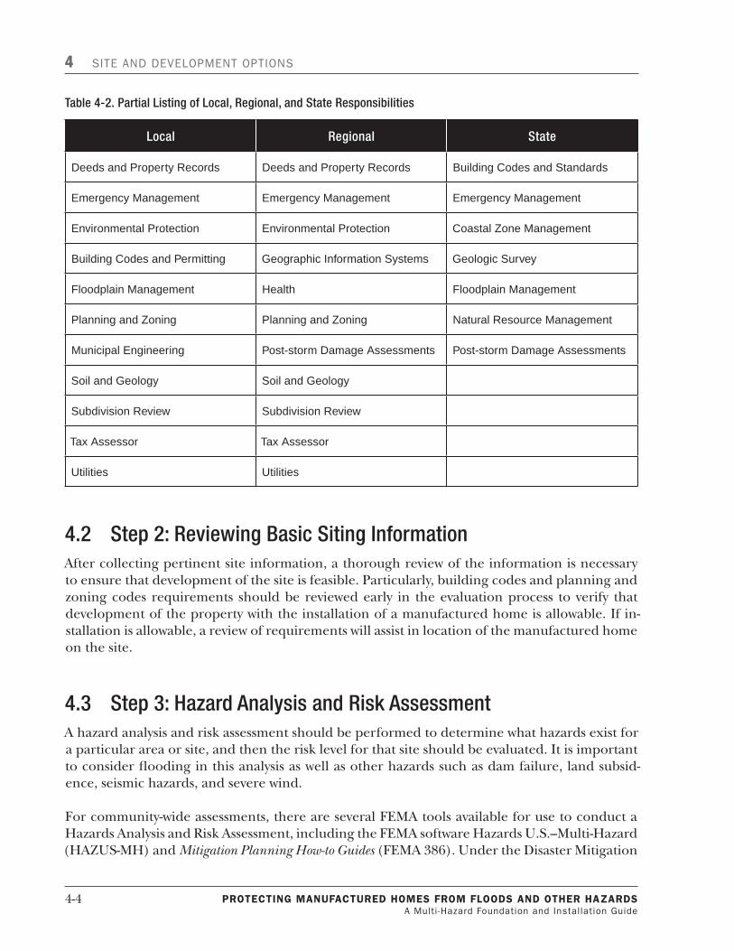
4-4 PROTECTING MaNufaCTuREd HOMEs fROM flOOds aNd OTHER HazaRds A Multi -Hazard Foundation and Installation Guide
4 SITE AND DEVELOPMENT OPTIONS
Local Regional State
Deeds and Property Records Deeds and Property Records Building Codes and Standards
Emergency Management Emergency Management Emergency Management
Environmental Protection Environmental Protection Coastal Zone Management
Building Codes and Permitting Geographic Information Systems Geologic Survey
Floodplain Management Health Floodplain Management
Planning and Zoning Planning and Zoning Natural Resource Management
Municipal Engineering Post-storm Damage Assessments Post-storm Damage Assessments
Soil and Geology Soil and Geology
Subdivision Review Subdivision Review
Tax Assessor Tax Assessor
Utilities Utilities
4.2 Step2:ReviewingBasicSitingInformationAfter collecting pertinent site information, a thorough review of the information is necessary to ensure that development of the site is feasible. Particularly, building codes and planning and zoning codes requirements should be reviewed early in the evaluation process to verify that development of the property with the installation of a manufactured home is allowable. If in-stallation is allowable, a review of requirements will assist in location of the manufactured home on the site.
4.3 Step3:HazardAnalysisandRiskAssessmentA hazard analysis and risk assessment should be performed to determine what hazards exist for a particular area or site, and then the risk level for that site should be evaluated. It is important to consider flooding in this analysis as well as other hazards such as dam failure, land subsid-ence, seismic hazards, and severe wind.
For community-wide assessments, there are several FEMA tools available for use to conduct a Hazards Analysis and Risk Assessment, including the FEMA software Hazards U.S.–Multi-Hazard (HAZUS-MH) and Mitigation Planning How-to Guides (FEMA 386). Under the Disaster Mitigation
Table4-2.PartialListingofLocal,Regional,andStateResponsibilities

PROTECTING MaNufaCTuREd HOMEs fROM flOOds aNd OTHER HazaRds A Multi -Hazard Foundation and Installation Guide
4-�
SITE AND DEVELOPMENT OPTIONS 4
Act of �000, communities are required to complete hazard mitigation plans, which include a hazard identification and risk assessment section, should they wish to remain eligible for post-disaster mitigation funding. As a result, many regional and local governments have already used tools like HAZUS-MH and the How-to Guides to conduct their own risk assessments, which may be available for public review.
4.3.1 Flooding
Table 4-3 presents a list of the types of hazards that can result from flooding and the flood sourc-es or types of flood-prone areas where they are generally of concern.
Table4-3.FloodHazards
FloodHazard AssociatedFloodHazardAreasorPropertyCharacteristics
Long duration floodingLarge water bodies (rivers, bays)
Water bodies with slow drainage (lakes, ponds)
•
•
Inadequate storm drainage
Flat or poorly graded land
Land located directly adjacent to a flood source
•
•
Impact forcesCoastal areas subject to wave action flooding
Riverine flooding areas subject to high velocity flooding
•
•
High velocity flows
Coastal areas subject to wave action
Steeply-sloped riverine flooding areas or areas otherwise subject to high velocity flood flows
•
•
Erosion
Coastal areas subject to wave action
Steeply-sloped riverine areas with high velocity flood flows or areas otherwise subject to high velocity flood flows
•
•
Sediment deposition Coastal overwash areas•
Movable stream beds Dynamic river systems•
Flood depthAreas adjacent to the flood source
Areas with poor capacity for drainage
•
•
Two of the best sources to research a property’s susceptibility to flooding are the community’s FIRM and FIS. The FIRM shows the extent of the �-percent annual chance flood, and might also include flooding corresponding to the 0.�-percent annual chance flood (also known as the �00-year flood). For areas where detailed studies have been performed, FIRMs will also show BFEs along streams and may provide delineations of floodways.

4-6 PROTECTING MaNufaCTuREd HOMEs fROM flOOds aNd OTHER HazaRds A Multi -Hazard Foundation and Installation Guide
4 SITE AND DEVELOPMENT OPTIONS
An FIS summarizes the methods used to develop the hydrologic and hydraulic studies, which to-gether determine the extent of the �-percent annual chance floodplain. The FIS also presents a summary of results of the study, including information about floodwater surface elevations and velocities for detailed study areas. Figure 4-� shows portions of an FIS and a FIRM.
The FIRM is used in conjunction with the FIS to determine the flood risk for a given area or property. For detailed study areas, while the FIRM shows the extent of the base flood and the BFEs, the FIS includes flood profiles that show flood elevations for various frequency events as well as the channel bottom elevation (for riverine flooding) over the length of a given waterway. If the property is located in the base floodplain where a detailed study has been performed, the FIRM and FIS will provide the following valuable information:
n The elevation of a base flood at a site as well as elevations for the �0-, �0- and �00-year floods, which can be found on the flood profiles within the FIS
n The average velocity of floodwaters within the floodway for a base flood (where a floodway study was performed)
n Areas of coastal wave action flooding
n Riverine flooding areas
n Areas susceptible to ponding
n Areas susceptible to sheet flow or alluvial fan flooding
n Areas protected by levees
Information about an area’s susceptibility to flooding can also be gathered from community of-ficials and past storm event records and reports. Such reports usually provide information about what types of damage were inflicted on structures. For coastal areas, there may be information about beach and shoreline erosion.
A field assessment for a particular site is a way to collect information for a hazard analysis. In-formation gathered during a field visit (ideally conducted by a geologist or an engineer) can be used to assess what type of impact such forces will have on a manufactured home located on a particular site. This is determined by assessing what type of structures and potential debris are located upstream and adjacent to the property that could impact the manufactured home dur-ing a flood event. A field assessment can also be conducted to estimate the erosion potential for a site by investigating existing land slopes on the site as well as vegetation cover. Finally, the site’s grading/topography should be evaluated. As part of the assessment, it should be determined whether or not the site will drain in a reasonable amount of time in order to prevent long du-ration flooding. This issue is generally only relevant for smaller storm events or more localized flooding for which floodwaters have somewhere to drain.
4.3.1.1 Accessibility
The flood risk to both the manufactured home and access routes should be assessed. Inhabit-ants of manufactured homes in flood-prone areas should prepare to evacuate an area should a flood watch be issued by the local or State government and should not wait for flood conditions

PROTECTING MaNufaCTuREd HOMEs fROM flOOds aNd OTHER HazaRds A Multi -Hazard Foundation and Installation Guide
4-�
SITE AND DEVELOPMENT OPTIONS 4
Figure4-1.PortionsofanFISandaFIRM.

4-8 PROTECTING MaNufaCTuREd HOMEs fROM flOOds aNd OTHER HazaRds A Multi -Hazard Foundation and Installation Guide
4 SITE AND DEVELOPMENT OPTIONS
to begin before evacuating the area. In fact, drowning in vehicles is the number one cause of flood-related deaths and often happens when victims mistakenly think that a washed-out road-way or bridge is still open. Therefore, access to the manufactured home during flood events needs to be considered during the siting process.
Inhabitants of manufactured homes in flood-prone areas should never remain within the home during a flood, regardless of the home’s elevation level above the BFE. They should always evacuate when a flood warning is issued by the local or State government and not wait for flood conditions to begin before evacuating the area.
Actual damage to roadways during flood events, as well as high-wind, seismic, and land subsid-ence events, can leave roads impassable for several days or for weeks after a major disaster. Even roadways that are located outside of, but adjacent to, flood-prone areas can be undermined by severe erosion along stream banks. Therefore, even if a home is adequately protected from incurring major damage due to a flood event, its location within (or surrounded by) a flood-prone area could either force occupants to repeatedly evacuate or become stranded for several days if access and egress routes are blocked.
A clear access and egress path during a flood event ensures that building occupants can evacu-ate and that emergency and critical services can continue to be provided. Both access and egress should be addressed while evaluating a potential site to ensure that feasible alternatives exist. Necessary considerations may also include bridges, walkways, and areas of refuge for safe evacu-ation.
Similarly, accessibility to potential sites after major wind and seismic events should be consid-ered. After wind and seismic events, roadways can be blocked by debris and remain unusable for several days while cleanup efforts are underway. Potential property buyers or property owners should consider possible evacuation routes from the property in all cases.
It is important to note that accessibility is more than ingress and egress in an emergency. Fre-quent and long duration flooding can cause major problems for occupants of flood-prone structures; a site is not a good location for a manufactured home if its occupants are forced to evacuate several times a year due to a flood threat, or must stay out of their homes for days or weeks at a time when they do evacuate. Frequent and/or long-term displacement often results in significant financial hardships and emotional distress for flooding victims.
4.3.2 OtherHazards
In addition to flooding, there are a variety of other hazards that should be considered during the manufactured home siting process. Table 4-4 presents some of these hazards, their associat-ed hazard-prone areas, and sources to use to determine an area’s susceptibility. Historical storm or hazard event records are additional resources for this hazard analysis; they provide details on how hazards have previously affected a given area.

PROTECTING MaNufaCTuREd HOMEs fROM flOOds aNd OTHER HazaRds A Multi -Hazard Foundation and Installation Guide
4-�
SITE AND DEVELOPMENT OPTIONS 4
Table4-4.Hazard-ProneAreas
Hazards AssociatedHazardAreas SourceforDetermination
Dam failure Dam failure inundation areas located downstream of dam structures
• Dam failure inundation maps usually created at the State, regional, or local level
•
Land subsidence
Steeply sloped land• United States Geological Survey (USGS) Landslide Overview Map of the Conterminous United States (national level)
State Geologist
Local Public Works Director
•
•
•
Seismic Area within 6 miles of a known fault• USGS Seismic Maps (as found in FEMA 450 and ASCE 7)
Building Codes
•
•
Wind/Debris Coastal areas
Tornado-prone areas
Alluvial fans
•
•
•
Wind Zone Maps (as found in FEMA 320 and ASCE 7)
Building Codes
•
•
Dam failure inundation maps provide the best tool for determining the risk from a dam failure event and are usually available at the State or local level. Every State has a Dam Safety Officer re-sponsible for coordinating its Dam Safety Program. State-specific information about State dam safety regulations is available at the Association of State Dam Safety Officials’ web site: http://www.damsafety.org.
To avoid damage that can be caused in areas subject to land subsidence, manufactured homes should be sited away from steep slopes and areas where land subsidence has been known to oc-cur in the past. While the USGS Landslide National Map indicates relative risk on a national basis, State geologists and local public work directors can provide better community-specific information about landslide risk. A listing of State geologists is available at the Association of American State Geologists web site: http://www.stategeologists.org.
USGS seismic maps as well as local officials are the best sources for determining the seismic risk for a site. The types of soils present on the site should also be taken into consideration. Poor soils, often found in flood-prone areas, can greatly amplify ground motions and seismic forces.
During wind events, large structures or items such as trees and telephone poles can be damaged and either collapse or become separated from their anchoring to the ground to become sizable pieces of debris. Manufactured homes should be sited away from or in a manner that provides protection from such items since airborne debris can act as missiles during a wind event.

4-�0 PROTECTING MaNufaCTuREd HOMEs fROM flOOds aNd OTHER HazaRds A Multi -Hazard Foundation and Installation Guide
4 SITE AND DEVELOPMENT OPTIONS
Generally, coastal areas are susceptible to high winds from storm and/or hurricane events. A good reference to determine the susceptibility of a property to wind and seismic hazards is ASCE �, which provides maps that show the risk of wind and seismic activity for the entire Unit-ed States and detail design considerations for areas based on the risk posed by these hazards.
4.4 Step4:ProtectingPropertiesInandNearHazard-ProneAreasThe best way to avoid damage to a manufactured home is to site the home away from areas susceptible to hazards. If the home is to be sited in or near a hazard-prone area, the developer must establish that the risk for the site is acceptable by ensuring that the home can be installed on the proposed site in accordance with applicable hazard-resistant codes and standards. In ad-dition, mitigation techniques can be used during the installation process to further reduce the hazard risk.
NFIP floodplain requirements and HUD installation standards exist to lessen manufactured home vulnerability to flood hazards. Two aspects to consider during this process include the following:
n Placement options
n Design and construction techniques
4.4.1 PlacementOptions
One way to reduce the risk of damage to manufactured housing and attendant infrastructure is to select a site outside the limits of the hazard areas. This option is most applicable to areas sub-ject to flooding and landslides where hazard areas can be reasonably well defined. Flood and landslide hazards are often localized so that all or a portion of the proposed site development can be located outside of the hazard-prone area. Note that this method is best suited for land that is initially subdivided or in the overall design of a manufactured home park.
4.4.1.1 Flood-ProneAreas
Within floodplain areas, portions of an individual site may be outside the defined floodplain. Portions of the site outside the identified floodplain typically have higher ground elevations and are less susceptible to flooding. Locating the manufactured home outside the identified flood hazard area reduces the home’s exposure to the hazard. For individual sites located en-tirely within the flood-prone area, this method is not an option. Another option for siting in flood-prone areas is to determine if there are portions of the property that, while susceptible to flooding, are not exposed to some of the more destructive characteristics of flooding such as long duration flooding, high flood levels, and high velocity flows.
Generally, the farther a manufactured home is sited from the flood source, the less likely it is to be exposed to high velocity flows. Within riverine flooding areas, the highest velocity flows are usually recorded within and near the floodway. In areas vulnerable to coastal flooding, wave action and/or storm surge can cause floodwaters to be particularly destructive. These types of

PROTECTING MaNufaCTuREd HOMEs fROM flOOds aNd OTHER HazaRds A Multi -Hazard Foundation and Installation Guide
4-��
SITE AND DEVELOPMENT OPTIONS 4
forces are the strongest in FEMA high hazard coastal zones labeled as V zones on FIRMs and the portions of A zones adjacent to V zones.
Similarly, flood levels usually decrease as the distance from the flood source increases. Setbacks from the flood source help to keep structures out of areas most susceptible to high velocity and high depth flooding. Damage to structures is directly related to the depth of floodwaters to which they are exposed.
Additionally, floodwaters can make access to and from manufactured homes difficult both dur-ing and after a flood event and greatly increase the safety hazards of flooding. For this reason, manufactured home installation in the floodplain is strongly discouraged within areas of in-creasing flood depths (greater than � to 3 feet) and high velocity flood flow (greater than � fps).
The duration of flooding is generally dependent on the flood source (size of the watershed), the slope of the stream, and the type of flood event (e.g., hurricane, snow melt event).
Figure 4-� shows a floodplain/floodway schematic. The floodway is generally the area where floodwaters are deepest and have the fastest flow rate for most waterways. Development in the floodway is restricted through floodplain management regulations and, in some communities, it is prohibited. Under minimum NFIP regulations, in order to place a new structure within the floodway, a floodplain development permit applicant must show that the development will not result in any increase to the �-percent annual chance flood elevation. In most situations, de-velopment in the floodway is not permitted by communities because it almost always leads to a water surface elevation increase.
Figure4-2.Floodplain/floodwayschematic.

4-�� PROTECTING MaNufaCTuREd HOMEs fROM flOOds aNd OTHER HazaRds A Multi -Hazard Foundation and Installation Guide
4 SITE AND DEVELOPMENT OPTIONS
4.4.1.2 AreasSubjecttoLandslides
In areas subject to landslides, placing manufactured housing away from steeply sloped portions of a site, including relatively flat areas at the bottom of steep slopes, reduces exposure of the structure to damage. This is an option where landslides occur as the result of increased stresses from natural or manmade conditions. Some of the events or activities that can cause increased stresses include heavy rainfall, rapid snowmelts, melting of permafrost, groundwater withdrawal, soil liquefaction, and land development.
4.4.2 DesignandConstructionTechniques
A thorough review of design and construction techniques (as they relate to manufactured hous-ing) and their applicability and feasibility is another consideration in the evaluation of site alternatives. A site located in a hazard-prone area cannot be deemed suitable for manufactured home installation if mitigation methods cannot be implemented at the site.
4.4.2.1 Flood-ProneAreas
Ideally, all manufactured homes should be located outside of the SFHA; however, if that is not possible, manufactured homes located in the SFHA must be installed to resist damage from flooding. Some questions for consideration in determining if design and construction tech-niques that prevent flood damage are feasible for a particular site follow:
n What are the flood risks for manufactured home installation at the site?
n Can structural fill be placed to elevate the site? If fill is placed, will it withstand forces from velocity flows?
n If long-duration flooding is an issue at the site, can the foundation be designed and constructed to resist long-duration floodwaters?
n Can the foundation be designed and constructed to withstand the expected design velocity flows?
n Can adequate storm drainage be provided?
Chapters � and �0 of this guide present methods for the design and construction of manufac-tured home foundations installed in flood-prone areas.
4.4.2.2 DamFailureInundationAreas
In dam failure inundation areas, the decision to install a manufactured home at the site will de-pend on assessment of the inundation risk. In higher risk areas where dam failures can trigger high flood depths and/or velocities, manufactured homes should be located elsewhere. High velocity flood surges can overwhelm typical residential foundation systems, including those used to support manufactured homes. However, in lower risk areas where relatively small flood depths and velocities are anticipated, the developer should determine if a foundation can be constructed that will provide adequate protection from expected inundation forces.
As with all hazards, safety issues such as warning times are also of vital importance.

PROTECTING MaNufaCTuREd HOMEs fROM flOOds aNd OTHER HazaRds A Multi -Hazard Foundation and Installation Guide
4-�3
SITE AND DEVELOPMENT OPTIONS 4
4.4.2.3 AreasSubjecttoLandslides
Although it is preferable to site housing outside of areas vulnerable to damage from landslides, it might be feasible to undertake a grading project to reduce the risk of landslides. A developer must determine if this is feasible and consider whether it would be cost-effective. Licensed pro-fessionals specializing in earth movement (geotechnical, structural, and/or civil engineering) should be consulted.
4.4.2.4 AreasSubjecttoSeismicEvents
For manufactured housing being placed in areas subject to seismic events, it is important to consider whether or not the foundation can be economically designed and constructed to with-stand the expected forces for a design seismic event. Additionally, the property owner must consider the cost and effort of securing non-structural items in the manufactured home to prevent them from being damaged or dislodged. Relatively heavy items like domestic water heaters and HVAC units are particularly vulnerable to seismic events. Sewer, water, and gas lines should be sufficiently flexible to allow the home to move without damaging them. Inspections of manufactured homes after seismic events reveal that homes can be destroyed by broken util-ity connections (particularly natural gas connections) even where only minor damages occur to the home’s structure.
4.4.2.5 AreasSubjecttoWind/DebrisHazards
Manufactured housing being placed in areas subject to wind/debris events need to have a foundation that is designed and constructed to withstand the expected forces associated with a design wind event. In areas subject to seismic activity and wind, the design standard for the hazard requiring the most resistance should be used. Even if the design of a foundation to meet this requirement is cost- effective, the developer still must consider whether or not the manufac-tured home can withstand the forces expected from a design wind event and debris impact.
4.5 Step5:DecidingonPropertyDevelopment:ProceedorRejectAfter reviewing the results of the data/information in Steps � through 4, deciding whether property development continues is the last step. Is the property suitable for development and for the installation of a manufactured home? If the siting evaluation shows that development of the property is feasible, and a hazard analysis and risk assessment also indicates development may be feasible, the proposed installation must be designed and constructed to adequately re-sist the hazard threat. If the proposed site satisfactorily addresses all of the conditions listed above, the site can be considered suitable for manufactured home installation.


PROTECTING MaNufaCTuREd HOMEs fROM flOOds aNd OTHER HazaRds A Multi -Hazard Foundation and Installation Guide
5-�
5 NaturalHazards–DesignConsiderations
Many regions in the U.S., such as coastal areas, are subjected to severe flooding and wind events at the same time. Other areas are simultaneously subjected to snow and seismic loads. Manu-factured homes can be subjected to more than one hazard at the same time and should be designed to appropriate concurrent loading (or load combinations) based on ASCE 7 design standards. However, Manufactured Home Construction and Safety Standards (24 CFR 3280) do not require that designs include simultaneous flood and earthquake loads. The MHCSS specifies that snow loads shall not be considered as simultaneously acting with the wind loads. HUD standards also require that foundations for manufactured homes be designed to resist loads for combined wind and flood events.
The first part of this chapter describes what kind of information is provided in FIRMs and FIS reports. The remainder of this chapter describes the characteristics of several natural hazards (flood, wind, and earthquake) that must be considered when making decisions about siting and selecting a foundation system for a manufactured home.
5.1 FloodDataFIRMs and FIS reports are two sources that can provide vital information about flooding charac-teristics. Both of these tools are generally available for viewing at community permitting offices such as Zoning and Planning Departments or Building Permit Offices. The local permit official can go over these tools and help to explain floodplain development requirements. These tools are also available from FEMA’s Map Service Center and can be accessed online at http://store.msc.fema.gov.
FIRMs provide key information about a property’s flood vulnerability by showing the extent of the floodplain, the flood zone, the floodway (when floodway studies are performed), and the BFE (for detailed studies). Figure 5-� shows an example of a FIRM. For example, Point � (white box) is located in the AE zone and has a BFE of 9 feet. For rivers and streams, FIS reports con-tain stream profiles that provide more accurate BFE data and should be used when determining BFEs for manufactured home installations or other types of development.

5-2 PROTECTING MaNufaCTuREd HOMEs fROM flOOds aNd OTHER HazaRds A Multi -Hazard Foundation and Installation Guide
5 NATURAL HAZARDS – DESIGN CONSIDERATIONS
There are two principal digital options for using flood maps. The simplest option is FIRM Scan data. These are simply digital images of a map and are available everywhere FEMA has a pub-lished FIRM. FEMA provides tools to view these maps and create a FIRMette, which is a printout of the area of interest, along with FIRM title block, scale bar, and north arrow. There is an on-line FIRMette tool that allows you to find, view, and print any map when you need it. There is also a Desktop FIRMette tool that can be faster and easier to use if you frequently use the maps for one area or need to use them without an internet connection. You can download or order the FIRMette Desktop and FIRM Scans you need.
The second digital option is flood data in GIS format. GIS technology provides powerful abili-ties to create custom maps and perform sophisticated analyses. It also requires the user to have specialized skills and software to use. FEMA now produces a GIS product called the DFIRM Da-tabase for use with all map updates. Beginning on or after October �, 2009, FEMA will provide a single paper flood map and FIS to each mapped community. FEMA will convert all other dis-tribution of maps and FIS reports for digital delivery. FEMA will continue to provide free digital map products and data to Federal, State, Tribal, and local NFIP stakeholders.
Base Flood Elevation
ZONE AE(EL 9)
ZONE AE(EL 9)
Flood Insurance Zone
Portion of FIRM Panel
FIRM Title Box1
Figure5-1.ExampleofaFIRM.

PROTECTING MaNufaCTuREd HOMEs fROM flOOds aNd OTHER HazaRds A Multi -Hazard Foundation and Installation Guide
5-3
NATURAL HAZARDS – DESIGN CONSIDERATIONS 5
fIs Reports
Several key components of an FIS report can help users identify specific flooding character-istics. For example, summary of discharge tables report the flow rate of water within streams for a given frequency storm (Figure 5-2). These values can be used with updated topography and cross-section information to conduct hydraulic modeling and to estimate updated flood elevations.� FISs generally generate water surface elevations for the �0-year (�0-percent annual chance), 50-year (2-percent annual chance), �00-year (�-percent annual chance), and 500-year (0.2-percent annual chance) floods (Figure 5-3). Floodway data tables provide cross-section spe-cific information, including the width of the floodway, mean floodway velocity, and the BFE where there is no encroachment in the flood fringe (or the regulatory BFE) and where there is full encroachment in the flood fringe (Figure 5-4). However, these tables are only available when a floodway study has been performed. See Appendix C for additional information.
� Hydraulic modeling can be performed to estimate updated flood elevations where new or more accurate topography data are available. However, if the modeling shows lower flood elevations, they cannot be used for regulatory purposes unless a map revision (e.g., Letter of Map Amendment (LOMA) or Letter of Map Revision [LOMR]) is granted.
Figure5-2.FISSummaryofDischargestable.

5-4 PROTECTING MaNufaCTuREd HOMEs fROM flOOds aNd OTHER HazaRds A Multi -Hazard Foundation and Installation Guide
5 NATURAL HAZARDS – DESIGN CONSIDERATIONS
Figure5-3.FISStreamFloodProfile.
Figure5-4.FISFloodwayDatatable.

PROTECTING MaNufaCTuREd HOMEs fROM flOOds aNd OTHER HazaRds A Multi -Hazard Foundation and Installation Guide
5-5
NATURAL HAZARDS – DESIGN CONSIDERATIONS 5
5.2 FloodCharacteristicsA variety of factors contribute to the type and strength of flood forces. For instance, structures and their foundations are subject to different forces if they are flooded by standing or slowly moving floodwater versus high velocity or wave action flooding. Similarly, factors such as the duration of flooding and flood depth help to define how structures and foundations will be af-fected by flood events.
5.2.1 Frequency,Duration,andRateofRise
Frequency of flooding is the rate of flood occurrence at a particular location. This frequency is the probability, expressed as a percentage, that a flood of a specific size will be equaled or ex-ceeded in any year. For example, the flood that has a �-percent probability (� in �00) of being equaled or exceeded in any given year is referred to as the “base flood” and sometimes called the “�00-year flood;” the latter term is simply a convenient way to express probability. The base flood is particularly important for homeowners because it is used by the NFIP to determine flood insurance rates and define regulatory floodplain management requirements.
A �-percent annual chance flood is a probability term and does not mean that a flood will hap-pen approximately once every �00 years. Nor does it imply that once a �-percent annual chance flood occurs there is little chance of another �-percent annual chance flood occurring in the near future. To the contrary, changes in climatic conditions, such as those caused by El Niño or La Niña, often result in a cluster of floods that occur over relatively short periods of time at the same location.
Manufactured homes located within the �00-year floodplain on a FIRM might also be in the �0- or 5-year floodplain and subject to even more frequent flooding. Although more frequent floods such as the �0- or 20-percent annual chance flood (�0- or 5-year flood) cause less dam-age to the manufactured home than the �-percent annual chance flood, the repetitive damages can result in significant financial loss to the homeowner. Data describing the extent of more frequent but less intense flooding is also important in determining the foundation system most appropriate for resisting forces imposed by the smaller floods.
Information about the base flood can be found in the FIS and the FIRM, including the flood elevation and the extent of flooding. In areas where detailed studies have been performed, flood elevation information may also be available for the more frequent �0- or 2-percent annual chance flood as well as the less frequent 0.2-percent annual chance flood (500-year flood).
For historical flood events, flood frequency estimations are sometimes found in the FIS under the Principal Flood Problems section. Documentation of past flood events is sometimes avail-able from other Federal sources as well as State and local agencies. Table 5-� lists such sources and agencies.

5-� PROTECTING MaNufaCTuREd HOMEs fROM flOOds aNd OTHER HazaRds A Multi -Hazard Foundation and Installation Guide
5 NATURAL HAZARDS – DESIGN CONSIDERATIONS
Table5-1.SourcesforInformationAboutPastFloodEvents
OtherFederalSources StateAgencies LocalorRegionalAgenciesUSACE Floodplain Information Reports Departments of Environmental
Conservation/ProtectionFlood Control Districts
USGS Water Resources Investigations State Floodplain Management Office
Levee Improvement Districts
Natural Resources Conservation Service (NRCS) Watershed Studies
Departments of Natural Resources
Local Planning Commissions
Federal Highway Administration (FHWA) Floodplain Studies
Departments of Transportation Local Public Works Departments
Tennessee Valley Authority (TVA) Floodplain Studies
Departments of Water Resources
Municipal Utility Districts
Geologic Surveys River Basin Commissions
Water Control Boards
Flood duration is the time from the inundation to the recession of floodwaters. Flood dura-tion provides an estimate of how long a manufactured home’s foundation (not the home itself, assuming the home is properly elevated) will be subjected to pressures and forces exerted by floodwaters, the degree of floodwater seepage, and the length of time that a structure may be inaccessible and/or inhabitable for the occupants. For identical flood characteristics, long du-ration flooding is usually much more destructive than short duration flooding.
The rate of rise is a measure of how rapidly water depths increase during flooding. A slow rise of floodwaters will allow seepage of water into a manufactured home (only if it is not elevated above the flood level) and may prevent buoyancy forces from acting on a home. When water ris-es rapidly, however, there may be insufficient time for seepage, exposing the home to buoyancy forces. The buoyancy forces could result in failure of the foundation, the floor, or the framing of the home.
The rate of rise (and fall) also affects the amount of warning for an impending flood. For exam-ple, homeowners in the floodplains of large rivers like the Mississippi may know days in advance of upstream flooding that will eventually reach their homes. But in the floodplains of streams with high rates of rise, homeowners may have only a few hours’ notice (or none at all) of an ap-proaching flood.
The rate of rise and fall is important in planning emergency evacuations and determining the feasibility of emergency loss mitigation procedures. Although surrounding and upstream ter-rain is a good indicator of the rate, flooding duration for particular areas is best determined from historical data and accounts of past flood events. This information might be available lo-cally from accounts given by homeowners and local emergency management staff, or it may be documented in the FIS or local, State, or Federal studies. See Table 5-� for a list of potential sources of information.

PROTECTING MaNufaCTuREd HOMEs fROM flOOds aNd OTHER HazaRds A Multi -Hazard Foundation and Installation Guide
5-7
NATURAL HAZARDS – DESIGN CONSIDERATIONS 5
5.2.2 FloodElevationandDepth
The BFE is the elevation of the flooding, including wave height, if applicable (in V zones), hav-ing a �-percent chance of being equaled or exceeded in any given year. The elevation of the flooding is the floodwater’s height above or below an established reference datum. Ground el-evation is the height of the ground surface also above or below an established reference datum. The standard datum used by most Federal agencies and many State and local agencies are the NGVD 29, and the NAVD 88; however, other datum are used. Ground elevations are established by topographic surveys; flood elevations are calculated for a particular flood event. BFEs can be found on FIRM panels where a detailed study has been performed, and should be estimated us-ing the flood profile in the corresponding FIS.
Some flood zones are delineated by approximate methods without BFEs determined. When a manufactured home is proposed on an approximate A zone site, the community must make every effort to obtain, review, and reasonably utilize BFE data and floodway data from a Fed-eral, State, or other source in order to provide a reasonable measure of flood protection in accordance with 44 CFR �0.3(b)(4). If BFE or floodway data cannot be obtained from available sources, the community should consider conducting or requiring the applicant to conduct a site-specific engineering analysis to determine a BFE or floodway. FEMA has developed Quick-2: Computation of Water Surface Elevations in Open Channels, which is useful in developing a BFE. Quick 2 is available from the FEMA web site http://www.fema.gov/plan/prevent/fhm/dl_qck22.shtm. If no BFE data are available through Federal, State, or other sources, communities must
BFE and DFE
Base flood elevation (BFE) – The water surface elevation resulting from the base, or 100-year (1 per-cent annual chance) flood.
Design flood elevation (DFE) – The elevation to which development in the regulatory floodplain is built. At a minimum, the DFE is equivalent to the BFE. However, in some areas, the DFE includes an additional freeboard height above the BFE as shown in the formula below.
DFE = BFE + Freeboard
Freeboard – An additional elevation requirement some height (1, 2, or more feet) above the BFE that provides a margin of safety above the estimated BFE.
As indicated above, the minimum DFE requirement for NFIP communities is the BFE. However, in com-munities where a higher degree of protection is promoted or required, the DFE includes a freeboard height above the BFE. This freeboard provides a margin of safety above the estimated BFE and against extraordinary or unknown risks. As in all natural hazard events, the design event can only be predicted in probabilistic terms and some uncertainties remain in any analysis. Freeboard is intended to allow for those uncertainties. The NFIP encourages participating communities to adopt and enforce freeboard requirements as part of their local floodplain management ordinance. This is shown in 44 CFR 60.1(d); which states, “Any floodplain management regulations adopted by a State or a community which are more restrictive than the criteria set forth in this part are encouraged and shall take precedence.”

5-8 PROTECTING MaNufaCTuREd HOMEs fROM flOOds aNd OTHER HazaRds A Multi -Hazard Foundation and Installation Guide
5 NATURAL HAZARDS – DESIGN CONSIDERATIONS
ensure that building sites will be reasonably safe from flooding for proposed developments. A simplified method for estimating BFEs as well as other methods for ensuring a building site is reasonably safe from flooding can be found in FEMA 2�5, Managing Floodplain Development in Approximate Zone A Areas, A Guide for Obtaining and Developing Base (100-year) Flood Elevations. Addi-tional guidance on approximate A zones and requirements for developing BFEs in subdivision proposals and other proposed developments can be found in Section 3.�.�.
Flood depth is the difference between the water surface elevation and the grade elevation of the flooded area (Figure 5-5). Any differences in datum between the flood elevation and the grade elevation must be taken into account when calculating flood depths.
Many communities have adopted more stringent requirements for an additional elevation (e.g., � foot, �.5 feet, etc.) above the BFE. The additional height (or freeboard) is used to establish the DFE. Freeboard provides a margin of protection above the estimated base flood.
5.2.3 Hydrostatic(Buoyancy)Forces
For manufactured homes that are not elevated to above the BFE or DFE, hydrostatic forces can cause significant damages. Hydrostatic pressures are also a concern for enclosed areas under-neath elevated manufactured homes.
When a body or a structure is immersed in water, the body is subjected to forces exerted by the surrounding water. These forces are called hydrostatic forces and act perpendicular to the surface on which they are applied. For example, hydrostatic forces exert lateral forces on verti-cal walls and vertical forces on horizontal floors.
The total vertical force (also called buoyancy force) on a submerged structure is equal to the weight of the displaced volume of water. For each foot of fresh water submersion, a buoyancy force of �2.4 psf is created. Salt water, with a greater density than fresh water, creates �4 psf for each foot of submersion. That is
Fbuoy = γ x VOL
Where: γ = specific weight of water (�2.4 pcf for fresh water; �4 pcf for salt water)
VOL = volume of water displaced by the submergence object (ft3)
The lateral force of water acting against a surface is related to the water’s depth (d) and specific weight (γ). Hydrostatic forces create a triangular loading on vertical surfaces with zero psf on the water surface to a force equal to γ (pcf) multiplied by d (feet).
FL = ½ γ d2

PROTECTING MaNufaCTuREd HOMEs fROM flOOds aNd OTHER HazaRds A Multi -Hazard Foundation and Installation Guide
5-9
NATURAL HAZARDS – DESIGN CONSIDERATIONS 5
Where: FL = lateral force
γ = specific weight of water (pcf)
d = depth (ft)
FL is applied at a distance 2/3 d from the water’s surface.
Hydrostatic forces act perpendicular to submerged sur-faces. If the water depth is the same on both sides of a wall, the lateral component of hydrostatic forces are equal such that the resultant force is zero.
If floodwater rises above the lowest floor, hydrostatic forces can lift an inadequately anchored manufactured home off its foundation. If buoyancy forces exceed the weight of a manufac-tured home, the home will float off its foundation if it is not securely fastened to the foundation. Floods do not need to be deep to displace a home. Flood depths of only 4 to 5 inches above the lowest floor can be capable of floating unsecured manufactured homes off their foundations.
The walls and floors of manufactured homes are not typically designed to resist hydrostatic forc-es, which can cause extensive structural damage. Floodwaters in contact with a home generally seep into it through openings around doors, windows, vents, and utility entrances. Floodwaters inside the structure add weight to the structure, thus reducing the net buoyancy force of the structure. Figure 5-5 shows hydrostatic forces acting on the walls and lowest floors below the flood level. As illustrated in Figure 5-5, an effective method of avoiding damage from hydrostat-ic forces is to elevate the home above the flood levels.
5.2.4 HydrodynamicForces
Forces due to moving floodwaters are called hydrodynamic forces. The magnitude of these forces depends on the floodwater depth, floodwater velocity, and the drag coefficient. Higher
d FL = ½ γ d2
γ ⋅ dγ ⋅ d
Figure5-5.Buoyancyforcesactingonastructure.

5-�0 PROTECTING MaNufaCTuREd HOMEs fROM flOOds aNd OTHER HazaRds A Multi -Hazard Foundation and Installation Guide
5 NATURAL HAZARDS – DESIGN CONSIDERATIONS
depths and velocities produce greater hydrodynamic forces. The drag coefficient is a function of the shape of the body subjected to the hydrodynamic forces.
Moving floodwaters can cause foundation failure by pushing (sliding failure) (Figure 5-�) or by overturning. Either can topple foundation elements and destroy a home. In addition, mov-ing floodwaters can cause erosion and scour that can undermine foundation elements (Figure 5-7).
Flood velocity depends on the slope and roughness of the terrain. For example, water moves faster along streams in steep mountains than streams in flatter areas, and water moves faster over a parking lot with a paved surface as opposed to an area with dense vegetation or other ob-stacles. Flood velocities are not shown on the FIRMs, but can be found in the FIS for floodways
Figure5-7.Amanufacturedhomedestroyedbythehydrodynamicforcesofflooding.
Figure5-6.Failureduetosliding.

PROTECTING MaNufaCTuREd HOMEs fROM flOOds aNd OTHER HazaRds A Multi -Hazard Foundation and Installation Guide
5-��
NATURAL HAZARDS – DESIGN CONSIDERATIONS 5
where floodways have been studied. Mean floodway velocities can be obtained from the FIS by matching the cross-section on the FIRM with the cross-section in the floodway data table. The floodway’s mean velocity usually overestimates the flood velocity within the flood fringe; flood-waters generally move slower as they extend outward from the floodway. However, the floodway velocities can be used as a general measure to determine cross-section locations within the floodplain where floodwaters will move relatively faster or slower, and provide an upper limit for velocities in the flood fringe. One of the best sources for flood velocities is records of past flood events. In addition to the FIS, a list of potential sources for documentation of past flood-ing is included in Table 5-�.
Coastal areas are particularly hazardous because of flooding accompanied by wave impacts that are associated with storm surges from coastal storms. Flow velocity can be further increased by manmade or natural obstructions that restrict floodwaters and channel the flow.
The hydrodynamic force exerted by a fluid in the direc-tion of the flow stream is defined as the drag force Fd. Hydrodynamic forces are calculated as follows:
Where: Fd = hydrostatic force (pounds)
Cd = dynamic coefficient (�.25 for round piers; 2.0 for square or rectangular piers; �.4 for continuous foundations)
γ = specific weight of water
g = acceleration due to gravity (32.2 ft/s2)
V = floodwater velocity (fps)
A = projected vertical area submerged (sq. ft.)
A = d x w
w = width of the submerged object
An alternative approach to consider the dynamic effects of moving water is to use an equivalent hydrostatic load approach. When water velocities are less than �0 fps, ASCE 7 permits adding an equivalent surcharge water depth to the design flood elevation to simulate the hydrodynamic load.
d
FL = ½ γ (d+dh)(d+dh)" and "γ (d+dh)"NOTE: Formulas should be identical. Symbols should be "gamma" for consistency with pages 5-8 and 5-10.
Cd x A x γ x V 2
2gFd =
FL = ½ γ (d+dh)(d+dh)" and "γ (d+dh)"NOTE: Formulas should be identical. Symbols should be "gamma" for consistency with pages 5-8 a

5-�2 PROTECTING MaNufaCTuREd HOMEs fROM flOOds aNd OTHER HazaRds A Multi -Hazard Foundation and Installation Guide
5 NATURAL HAZARDS – DESIGN CONSIDERATIONS
The equivalent surcharge water depth (dh) is determined by:
Where: Cd = dynamic coefficient (�.25 for round piers; 2.0 for square or rectangular piers; �.4 for continuous foundations)
V = average velocity of water (fps)
g = acceleration due to gravity (32.2 ft/s2)
Hydrodynamic forces apply to any portion of the home or its foundation exposed to moving floodwaters. Elevating the home so that its lowest floor is at the BFE reduces the effects of hy-drodynamic forces on the building envelope. However the floor framing, chassis frame, and the foundation elements remain exposed to the hydrodynamic forces. For open foundations, elevating the home so the lowest chassis frame member is at the BFE reduces the effects of hy-drodynamic forces by reducing the number of components exposed to those forces during a base flood event.
5.2.5 ErosionandScour
Erosion is the result of moving waters removing soil from the ground surface. Scour is the result of those moving waters removing soil beneath and around objects located in the path of flow. Scour under and around building foundations and erosion of fill embankments can result in foundation failure. For example, when Hurricane Ike struck Galveston, Texas, in 2008, several homes were destroyed due to a loss of lateral support of pile foundations caused by scouring. Moving floodwaters will erode soil around any obstruction placed in the flow until a maximum scour depth is reached. The maximum scour is a function of flow velocity, soil particle size, and obstruction geometry. Determining maximum potential scour is critical in designing a founda-tion system that prevents failure during and after flooding. In coastal areas, scour depth can be significant due to both storm-induced erosion and localized scour resulting from storm surge. Because storm-induced erosion is difficult to predict, local regulatory officials should be con-tacted for further information and historical perspectives.
Scour susceptibility is a function of foundation geometry, flow depth, flow velocity, and the soil particle size. Fine grain soils (i.e., silts and clays) scour at a lower flow velocity than coarse grain soils. Coarse grain, non-cohesive soils can erode and/or scour quickly, possibly reaching the ul-timate scour depth in a single flood event. Fine grain, cohesive soils can scour just as deep but take longer to reach the ultimate depth. It is important to note that foundations frequently are well above the ultimate scour depth and that foundation undermining can occur in a relatively short time period. Undermining of foundations can result in the collapse of the home.
Because flood velocities are not shown on FIRMs, the FIS must be consulted to determine flood velocities, which are only provided for floodways. In some SFHAs, floodways and mean floodway velocities have not been determined as part of the FIS.
Cd x V 2
2gdh=

PROTECTING MaNufaCTuREd HOMEs fROM flOOds aNd OTHER HazaRds A Multi -Hazard Foundation and Installation Guide
5-�3
NATURAL HAZARDS – DESIGN CONSIDERATIONS 5
The preferred scour mitigation technique is to place the manufactured home’s foundation be-low the predicted ultimate scour depth. In areas where placing foundations below maximum scour depth is not economically feasible, alternative scour protection methods include reinforc-ing foundation soils with large diameter materials such as coarse aggregate or riprap.
5.2.6 DebrisImpactForces
Floodwaters can transport objects of all types (e.g., trees, portions of flood-damaged buildings, automobiles, boats, storage tanks, manufactured homes, etc.). In cold climates, winter floods can also carry large pieces of ice. Substances such as dirt, oil, gasoline, sewage, and various types of debris add to the dangers of flooding. Even when flow velocity is relatively low, large objects carried by floodwaters can easily damage windows, doors, walls, and, more importantly, critical structural components. As the flood velocity increases, the danger of damage from floodborne debris also increases.
Waterborne debris impacts caused significant damage to buildings and enclosures, slabs, decks, utilities, and other ancillary features when Hurricane Ivan struck the Florida panhandle and coastal Baldwin County, Alabama in 2004. Manufactured homes typically are not designed to withstand loads to walls or floor systems that may be exerted by attached carports, decks, porch-es, or awnings, although some manufacturers have designed homes that are “awning ready” to provide a load path through the structure to handle the increased stresses. The alternative is to build the attachments with adequately anchored foundations to resist these debris impact forces.
Damages caused by floodborne debris impacting a manufactured home depend not only on the weight and velocity of the debris, but also on the size and material. Historically, the forces developed when floating debris hits a home have been estimated using the principles of con-servation of momentum with impact duration of � second. Recent research, however, indicates that the impact from floodborne debris occurs over intervals of only 0.0� to 0.05 second. Since impact force is inversely proportional to duration (i.e., the shorter the duration, the larger the impact force), historical methods may underestimate impact forces. Typical impact duration ranges from 0.� second for stiff foundations (such as concrete) to � second for flexible founda-tions (such as wood).
Fi = (W/g) x (Vb/t)
Where: Fi = impact force (pounds)
W = weight of floodborne object (pounds)
Vb = velocity of object (fps)
t = time for object to decelerate from Vb to zero (seconds)
g = acceleration due to gravity (32.2 ft/s2)

5-�4 PROTECTING MaNufaCTuREd HOMEs fROM flOOds aNd OTHER HazaRds A Multi -Hazard Foundation and Installation Guide
5 NATURAL HAZARDS – DESIGN CONSIDERATIONS
ASCE 7-05 updates the methods of calculating impact debris forces. Recent research indicates that the impact durations are much shorter and impact loads are significantly higher than previously recommended. Foundations for manufactured homes located in SFHAs should be designed to resist floodborne debris impact forces calculated based on the most recent edition of ASCE 7 protocols.
The relatively light and frequently unreinforced foundation systems used to support and an-chor manufactured homes are susceptible to impact damage from floating debris. The cost to strengthen foundations, ground anchors, and anchor straps to resist debris impact may be ec-onomically impractical. An alternative method is to install additional foundation elements to provide redundancy in the system. For example, reducing the frame span length by reducing pier spacing allows the frame to span across a damaged pier without excessive deflections or fail-ure. This method requires post-flood inspection and maintenance to repair or replace damaged foundation elements to allow the home’s foundation to survive any subsequent events. Also, if more foundation elements than what have been assumed are damaged, a finite risk of system failure remains.
5.3 WindDesign and installation of foundations of manufactured homes is a controlling factor on the homes’ ability to withstand forces from wind events. Connections used to secure the manufactured homes to the foundations have historically lacked the attention given to the manufacturing of the homes themselves. Lack of proper connections has caused numerous homes to fail during high-wind events. Figures 5-8 and 5-9 are examples of wind damage to modular and manufactured homes.
Several factors influence the direction and magnitude of wind forces on a structure, which should be considered in manufac-tured home foundation design.
When a structure is exposed to these wind forces in combination with flood forces, the damage potential is greatly increased.
Figure5-8.Failureofamodularhomeduetohighwinds.Thehomeliftedoffofitsfoundation(concreteslab)whentheconnectionsfailed.

PROTECTING MaNufaCTuREd HOMEs fROM flOOds aNd OTHER HazaRds A Multi -Hazard Foundation and Installation Guide
5-�5
NATURAL HAZARDS – DESIGN CONSIDERATIONS 5
5.3.1 WindForcesonStructures
The texture and roughness of the terrain, as well as its surface contours and topography, have a profound effect on the wind loads. A structure in an open flat area with few trees and obstruc-tions is likely to see a substantially higher wind load than one situated in a developed area with numerous buildings or other obstructions. Similarly, a structure situated on a hilltop may be subjected to significantly greater loads than one on flat terrain. All structures should be built to withstand the forces caused by the strongest wind speeds likely to happen at the site.
The basic design wind speeds for the United States can be obtained from the map given in Fig-ure �-� of ASCE 7. The wind speeds correspond to 3-second gust speeds in mph at 33 feet (�0 meters) above the ground for open terrain with scattered obstructions having heights generally less than 30 feet (9.� meters), Exposure C category. This includes flat open country and grass-lands.
When a building is exposed to wind, the wind flows over and around the building. This imposes positive pressure on the windward side of the building and negative pressure (suction) on the leeward side and roof of the building.
5.3.2 WindForcesinCombinationwithFloodForces
Damage potential is increased when wind forces are exerted on a structure in combination with flood forces, as is often the case in coastal and mountainous areas. For example, tensile forces can develop at the windward piers and the home can be lifted. If the windward piers are ex-posed to moving floodwaters, they can topple when no longer in contact with the home’s steel frame.
Elevating a manufactured home to minimize the effects of flood forces does not significantly increase the wind loads on the home.
Figure5-9.Amanufacturedhomethatfailedduringahigh-windevent.

5-�� PROTECTING MaNufaCTuREd HOMEs fROM flOOds aNd OTHER HazaRds A Multi -Hazard Foundation and Installation Guide
5 NATURAL HAZARDS – DESIGN CONSIDERATIONS
The HUD Model Manufactured Home Installation Standards require foundations to consider flood and wind load combinations. Sections 2.3.3 and 2.4.2 in Chapter 2 of ASCE 7, Minimum Design Loads for Buildings and Other Structures contain load combinations that should be used.
5.4 EarthquakesDesigning resistance of structures and foundations for earthquakes requires a different ap-proach than that used for flooding and wind. Because earthquakes can affect internal building elements without requiring penetration of the building like flooding or wind, there are design considerations specific to earthquakes.
Often designing for wind load standards will allow a manufactured home installation to be ad-equate for protecting the home from earthquake forces. However, there are instances when forces resulting from earthquakes can result in greater loads than those for wind.
5.4.1 DesignPhilosophy
Earthquake-caused ground accelerations cause forces on building elements attached to or into the ground. Foundation movements are transmitted to structural and non-structural compo-nents. Consequently, exterior and interior building components should be designed for seismic loads to be transferred to the remaining elements.
In the event of an earthquake, a structure will be simultaneously subjected to vertical and hori-zontal accelerations. The weight of a manufactured home on its foundation is not sufficient to resist a moderate or severe earthquake. Therefore, the manufactured home and its foundation should be properly connected to avoid damage during an earthquake event. Soil liquefaction resulting from an earthquake is also an important consideration for earthquake design because soil liquefaction is a major cause of damage in a seismic event. Refer to Chapter � for a discus-sion on liquefaction.
5.4.2 DesignStandard
Regulations governing the construction and design of manufactured homes currently do not specifically address seismic loads but rather specify loading requirements primarily to provide basic wind resistance. However, seismic requirements exist in most model codes and standards. Seismic requirements have been included in the Model Manufactured Home Installation Guide (NFPA 225).
Historically, communities with low seismicity have considered wind load provisions as sufficient for resisting seismic events. Although this may be true in the case of transverse loading (i.e., wind pressures acting on the long walls) where wind loads are high, it is often not the case with longitudinal loading where wind loads are low. Also, the nature of seismic loading is greatly dif-ferent than wind loading. These differences make comparisons between wind resistance and seismic resistance tenuous at best.

PROTECTING MaNufaCTuREd HOMEs fROM flOOds aNd OTHER HazaRds A Multi -Hazard Foundation and Installation Guide
5-�7
NATURAL HAZARDS – DESIGN CONSIDERATIONS 5
Studies list the following typical damages to manufactured homes during design earthquakes:
n Homes falling off support systems
n Damage to floors from piers puncturing them
n Disruption of gas, water, and electrical lines from seismic motions of the home
n Fire resulting from damaged water heaters, and gas and electric lines. (A simple and cost-effective seismic mitigation measure for manufactured homes is to strap the water heater to a wall to prevent it from falling over.)
For a manufactured home installed on a foundation system, providing adequate resistance to later- al movement, uplift, and rotation is very important. It is also necessary to provide tensile con-nections between the main frame and the piers supporting the home to resist all seismic forces. Earthquake-resistant bracing systems (ERBSs) can be installed to minimize damage to the home, but they do not provide the protection of a seismic-resistant foundation system. ERBSs are sec-ondary supports that do not resist seismic forces, but rather allow the home to fall from its primary supports and “catch” it before it hits the ground.
The State of California has had an ERBS certification program since �987. To be certified, the ERBS must be able to limit seismic movement and limit vertical drop of the manufactured home to 2 inches. A list of certified ERBSs is available from the State of California, Department of Housing and Community Development, Division of Codes and Standards. The price range of ERBSs is from approximately $2,000 up to $5,000; the average cost of an ERBS is about $2,500. The State of California also permits the use of other systems that do not require the home to fall off supports, as is the case with ERBSs.
5.5 EvaluationofMulti-HazardsManufactured homes, like all buildings, can be simultaneously subjected to many natural haz-ards, and the combined effects of the forces generated from these hazards must be considered. The different loads that must be considered in the design of a manufactured home foundation are shown in Table 5-2.
Table5-2.LoadCombinationNomenclature(ASCE7)
Nomenclature LoadDescription
D Dead load
L Live load
F Load due to fluid with well-defined pressures and maximum heights
Fa Flood loads
HLoad due to lateral earth pressure, groundwater pressure, or pressure of bulk materials
T Self-straining force
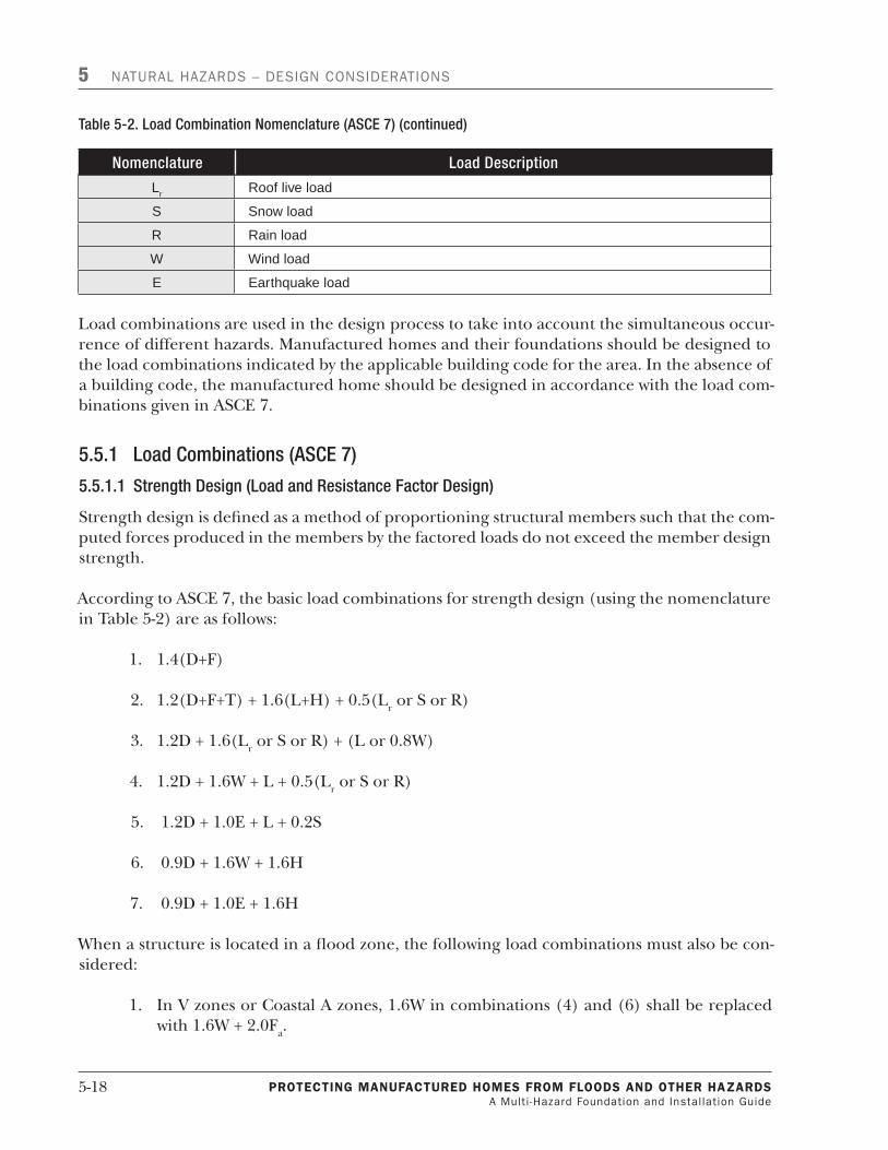
5-�8 PROTECTING MaNufaCTuREd HOMEs fROM flOOds aNd OTHER HazaRds A Multi -Hazard Foundation and Installation Guide
5 NATURAL HAZARDS – DESIGN CONSIDERATIONS
Nomenclature LoadDescription
Lr Roof live load
S Snow load
R Rain load
W Wind load
E Earthquake load
Load combinations are used in the design process to take into account the simultaneous occur-rence of different hazards. Manufactured homes and their foundations should be designed to the load combinations indicated by the applicable building code for the area. In the absence of a building code, the manufactured home should be designed in accordance with the load com-binations given in ASCE 7.
5.5.1 LoadCombinations(ASCE7)
5.5.1.1StrengthDesign(LoadandResistanceFactorDesign)
Strength design is defined as a method of proportioning structural members such that the com-puted forces produced in the members by the factored loads do not exceed the member design strength.
According to ASCE 7, the basic load combinations for strength design (using the nomenclature in Table 5-2) are as follows:
�. �.4(D+F)
2. �.2(D+F+T) + �.�(L+H) + 0.5(Lr or S or R)
3. �.2D + �.�(Lr or S or R) + (L or 0.8W)
4. �.2D + �.�W + L + 0.5(Lr or S or R)
5. �.2D + �.0E + L + 0.2S
�. 0.9D + �.�W + �.�H
7. 0.9D + �.0E + �.�H
When a structure is located in a flood zone, the following load combinations must also be con-sidered:
�. In V zones or Coastal A zones, �.�W in combinations (4) and (�) shall be replaced with �.�W + 2.0Fa.
Table5-2.LoadCombinationNomenclature(ASCE7)(continued)

PROTECTING MaNufaCTuREd HOMEs fROM flOOds aNd OTHER HazaRds A Multi -Hazard Foundation and Installation Guide
5-�9
NATURAL HAZARDS – DESIGN CONSIDERATIONS 5
2. In non-Coastal A zones, �.�W in combinations (4) and (�) shall be replaced by 0.8W + �.0Fa.
5.5.1.2 AllowableStressDesign(alsoknownasWorkingStressDesign)
Allowable stress design (ASD) is defined as a method of proportioning structural members such that computed stresses produced in the members by nominal loads do not exceed specified al-lowable stresses.
According to ASCE 7, the basic load combinations for ASD are as follows:
�. D + F
2. D + H + F + L + T
3. D + H + F + (Lr or S or R)
4. D + H + F + 0.75(L + T) + 0.75(Lr or S or R)
5. D + H + F + (W or 0.75E)
�. D + H + F + 0.75(W or 0.7E) + 0.75L + 0.75(Lr or S or R)
7. 0.�D + W + H
8. 0.�D + 0.7E + H
When a structure is located in a flood zone, the following load combinations must be consid-ered:
�. In V zones or Coastal A zones, �.5 Fa shall be added to other loads in combinations 5, �, and 7 and E shall be set equal to zero in 5 and �.
2. In non-Coastal A zones, 0.75Fa shall be added to combinations 5, �, and 7 and E shall be set equal to zero in 5 and �.
Either ASD or strength-based design can be used for manufactured housing. In both design methods, wind and seismic loads need to be evaluated. In addition, increases in allowable stress shall be used with these load combinations where allowed by the locally adopted building code.


PROTECTING MaNufaCTuREd HOMEs fROM flOOds aNd OTHER HazaRds A Multi -Hazard Foundation and Installation Guide
6-�
6 SoilsSoil properties can significantly impact manufactured homes exposed to flooding. Properly determining soil type and allowable bearing capacity is important for the selection and per-formance of the foundation. It is recommended that a geotechnical engineer make these determinations. For example, highly erodible soils are not desirable as fill for elevating a struc-ture in a high velocity area because it can be washed away by moving floodwaters. Other soils lose strength as moisture content increases, reducing a foundation’s load capacity. This chapter discusses the effect of flooding on soil properties.
6.1 BearingCapacityBearing capacity is a soil’s capability to support load without catastrophic failure. Bearing capac-ity is derived from the soil shear strength, which is expressed as:
s = c + ρ (tan φ)
Where s = soil shear strength
c = soil cohesive strength
ρ = lateral confining pressure
φ = soil angle of internal friction
The general bearing capacity equation is:
q = (γb/2)Nγ + cNc + ρNρ
Where q = soil bearing capacity
γ = unit weight of soil
b = footing width
Nγ = bearing capacity factor for soil density and footing size
Nc = bearing capacity factor for cohesion
Nρ = bearing capacity factor for surcharge
As previously discussed, soil strength frequently changes as a function of moisture content. In granular soils, as moisture content approaches saturation (i.e., intergranular voids are �00 percent filled with water), the effective unit weight is reduced, thus reducing the confining pres-sure (ρ).

6-2 PROTECTING MaNufaCTuREd HOMEs fROM flOOds aNd OTHER HazaRds A Multi -Hazard Foundation and Installation Guide
6 SOILS
For preliminary design purposes, allowable bearing capacities can be established based on national model codes, local building codes, and soil surveys. Local officials may also have infor-mation on soil types and soil bearing capacities.
Soil classifications of a general nature and a typical range of their maximum allowable bear-ing capacities can be found in publications such as the IBC ( 2009 Edition), NFPA 5000 (2009 Edition), and NFPA 225 (2009 Edition). These documents can provide the allowable bearing pressures considered sufficient to support foundations at well drained sites. Excessive foun-dation movement or settlement may occur where unusual soil or moisture conditions are encountered. A geotechnical engineer should be consulted when unusual soil or moisture con-ditions are present.
6.2 EffectsofFloodDurationandFrequencyonSoilFor granular soils located below the water surface, the effective confining pressure (ρ’) is used to determine the effective shear strength’. The effective confining pressure is calculated using the effective unit weight of the soil where:
γ’ = γs – γw
γ’ = effective unit weight of soil
γs = total unit weight of soil and
γw = unit weight of water
The submerged weight can be estimated as about half of the total weight of many granular soils. The angle of internal friction (φ) is not appreciably changed by submergence. Therefore, if the water table rises from a depth greater than the width of the footing to the ground surface, as can be the case of flooding, the bearing capacity of the soil is reduced by approximately 50 per-cent.
Cohesive soils (silt and clay) are bound together by electrochemical bonds between individual particles. Increasing the moisture content can change the distance between particles, decreas-ing the strength of the inter-particle bonds. The decrease in bond strength results in a decrease in cohesion and a loss of shear strength.
6.3 SoilLiquefactionSeismic soil liquefaction is an important consideration for earthquake design because soil liq-uefaction can be a major cause of damage in a seismic event. Liquefaction is defined as the significant loss of strength resulting from an increase in soil pore pressure. Seismic vibrations act to realign soil particles into a denser configuration. The realignment decreases the inter-par-ticle void space, thus increasing the water pressure in the voids. The increase in water pressure

PROTECTING MaNufaCTuREd HOMEs fROM flOOds aNd OTHER HazaRds A Multi -Hazard Foundation and Installation Guide
6-�
SOILS 6
has the effect of decreasing the effective strength of the soil. A sufficient increase in pore pres-sure can reduce the effective strength to zero, at which time the soil mass behaves as a liquid. The loss of shear strength in soils supporting buildings can be catastrophic. Building foun-dations can slide or unevenly settle, bridges can collapse, and empty fuel tanks buried under ground can rise to the surface.
Liquefaction-induced soil movements can push foundations out of place to the point where the manufactured home will lose support.
Loose clean sands with relatively few fines, and silty soils with little or no clay, are vulnerable to seismic induced liquefaction. It is necessary to identify the presence of liquefaction susceptible soils expected to support building foundations, and design the manufactured home foundation accordingly.
To reduce liquefaction hazards, the best approach is to avoid construction on soils susceptible to liquefaction. Other options such as making the structure liquefaction resistant or improving the strength, density, and/or drainage characteristics of the soil are probably not economical for most manufactured home sites.
6.4 RecommendedSoilTestingandCriteriaforManufacturedHomeInstallations
Shallow subsurface investigations should be conducted to evaluate the soil bearing conditions at the proposed manufactured home site. An experienced geotechnical engineer can conduct an appropriate investigation using hand augers, field strength tests, and visual classification methods. Field strength testing includes dynamic cone penetration tests, pocket penetrometer tests for cohesive soils, and torvane tests for granular soils. The investigation should evaluate soils to a depth of twice the width of the bearing surface or 5 feet, whichever is greater. The in-vestigation will provide information on soil type and bearing capacity.
When footings are eccentrically loaded, the effective bearing area is reduced so footing sizes must be increased accordingly. Eccentric loading occurs when piers are not centered over foot-ings and when a manufactured home frame is not centered on its pier. Eccentrically loaded foundation conditions should be avoided.
Ground anchors consist of a specific anchoring device designed to transfer home anchoring loads to the ground (24 CFR �285.5). Axially loaded ground anchors support loads by mobi-lizing soil shear strength along a subsurface shear plane. Ground anchors loaded non-axially resist loads through both the axial shear strength and passive soil resistance against the horizon-tal component of the non-axial load. Development of passive soil resistance requires some soil movement. The required movement will generally result in larger total movement in non-axi-ally loaded anchors than axially loaded anchors in the same soil conditions.


PROTECTING MaNufaCTuREd HOMEs fROM flOOds aNd OTHER HazaRds A Multi -Hazard Foundation and Installation Guide
7-�
7 GroundAnchorsBoth the NFIP regulations (44 CFR 60.3) and the HUD Model Manufactured Home Installation Standards (24 CFR 3285.305) require that manufactured homes installed in flood-prone or SFHAs be anchored to resist flotation, collapse, or lateral movement.�
Ground anchors consist of a specific anchoring assembly designed to transfer home anchoring loads to the ground (24 CFR 3285.5). They are used extensively in manufactured home instal-lations. Ground anchors are economical, readily available, and can be installed with relatively lightweight tools and equipment.
Ground anchors have potential limitations. One significant limitation arises from multiple soil-anchor response mechanisms as a function of soil type, anchor depth, and load configuration. Ground anchors have historically been allowed to move up to 3 inches horizontally or 2 inches vertically as the basis for determining acceptable performance. (Appendix E of the IRC estab-lished a ground anchor moving 2 inches in the direction of pull of the load as being acceptable.) When a manufactured home is secured with ground anchors, it too can move up to 3 inches when exposed to flood, wind, or seismic events.
Three inches of horizontal movement can produce eccentrically applied loads on piers under a home, which can cause the piers to topple and the home to collapse. Two inches of vertical movement can allow the home to lift and lose contact with the supporting piers. Unless the home is securely fastened to the piers and the piers constructed as monolithic units, the loss of contact can make the piers vulnerable to being displaced by moving floodwaters.
Ground anchor movements of several inches can have significant negative impacts on long-term performance. In cohesive soils, such anchor movements in a vertical direction can approach or exceed the soil’s shear strength. In such cases, the ground anchor is supported by the soil’s re-sidual shear strength, resulting in a decrease in anchor capacity. In granular soils, large lateral movements may produce failure planes that can reduce the strength on the vertical direction.
Anchor assemblies, including ground anchors, should be inspected periodically, especially after hazard events. Loose anchor straps need to be retightened, and loose or failed anchors need to be reset or replaced. If movement has made the manufactured home structurally unstable, it should be reset to center it on its supporting piers. If this maintenance is not performed, the anchor assembly may fail during subsequent hazard events, resulting in significant damage to or destruction of the home. Tightening ground anchor straps typically costs a few hundred dollars or less. Replacing anchors or resetting a home is estimated to cost at least $�,000.
� 44 CFR 60.3(a), 44 CFR 60.3(b), and 24 CFR 3285.305 use the phrase “flotation, collapse or lateral movement.” 44C FR 60.3(c) uses the phrase “flotation, collapse and lateral movement." To account for both usages, this publica-tion uses “or.”

7-2 PROTECTING MaNufaCTuREd HOMEs fROM flOOds aNd OTHER HazaRds A Multi -Hazard Foundation and Installation Guide
7 GROUND ANCHORS
7.1 TypesofAnchorsandInstalledConfigurations
7.1.1 TypesofAnchors
Several styles of anchor assemblies are available that can adequately secure a manufactured home to resist flood, wind, and seismic forces. Helical earth anchors, cast-in-place concrete foot-ings, drilled concrete anchors, and cross drive anchors are just a few of the types available.
7.1.1.1HelicalEarthAnchors
Helical earth anchors are designed to be augured (screwed) into the ground and are often re-ferred to as ground anchors. Helical earth anchors typically consist of a shaft, head, and one or more helixes. The head is used for installing and fastening the anchor to the home, and ten-sioning the anchor. Toward the bottom of the shaft, there is one (single) or more helical disks for the anchor to be screwed into the soil. The helix provides much of the anchor’s load capac-ity. The typical lengths of helical ground anchors are 30, 36, 48, and 60 inches.
Helical anchors also may be installed with stabilizer plates to increase the lateral capacity of the anchor by enlarging the surface area used to develop passive soil resistance.
7.1.1.2ConcreteAnchors
Concrete anchors use dead weight of a concrete footing or a combination of concrete weight and soil uplift resistance. Uplift resistance can be increased by the use of drilled concrete piers. In both cases, the home must be securely attached to the concrete elements using anchor bolts, tie-rods, or other structural connection. Anchor attachments placed in concrete must be in-stalled with adequate depth to develop the required strength. The load capacity of the anchors must be sufficient to resist applicable design loads.
7.1.1.3CrossDriveAnchors
Like helical ground anchors, cross drive anchors are constructed with a head secured to a metal shaft. Cross drive anchors are shafts driven into competent soils to develop their resistance. As their name implies, cross drive anchors are driv-en in pairs that form an “X” or cross (Figure 7-�). The heads of the anchors are secured to the home with metal straps.
Figure7-1.Crossdriveanchor.(CourtesyofTieDownEngineering)

PROTECTING MaNufaCTuREd HOMEs fROM flOOds aNd OTHER HazaRds A Multi -Hazard Foundation and Installation Guide
7-3
GROUND ANCHORS 7
7.1.2 AnchorConstructionandCapacity
Steel ground anchors are the most common anchor assembly application for manufactured home installations. Ground anchors are typically constructed with a circular shaft of one or more helixes; a head connects at the opposite end of the anchor, which then connects to the home’s frame and/or sidewalls with steel straps or cables. Anchor shafts are typically 5/8 inch to 3/4 inch in diameter, and helixes range from 3 inches to 8 inches in diameter. Most anchors used for manufactured home applications have one helix, although anchors with two to four helixes are available (Figure 7-2).
Most anchor heads are “U” shaped and contain predrilled bolt holes. The bolts connect the anchor to the home’s frame or sidewalls with �¼-inch anchor straps. Some anchors have heads with closed eyes for cable connections. The bolts in “U” shaped anchor heads can be used to pre-tension the anchor. Pre-tensioning an anchor with closed-eye heads requires using other devices like turnbuckles.
HUD requires anchoring equipment and anchoring assemblies to be capable of resisting allow-able minimum working loads of 3,�50 pounds and ultimate loads of 4,725 pounds without failure of either the anchoring equipment or the attachment point on the manufactured home.
7.1.3 AnchorSelection
Ground anchors should be selected based on the specific soils conditions at the manufactured home site. Short anchors with smaller helixes may be used in firm, well compacted soils. Longer anchors or anchors with larger or multiple helixes are required in weaker soils.
Most anchors are selected based on standard torque probe tests conducted at the site. During those tests, a 5-foot long auger probe is screwed into the ground to the approximate depth of the anchor helix. A torque wrench measures the torque required to advance the probe. The resulting torque value is used to classify the soils and select an appropriate anchor based on
Figure7-2.Singleanddoublehelixgroundanchorswithstrapconnectionandsinglehelixanchorwithaclosed-eyeconnection.
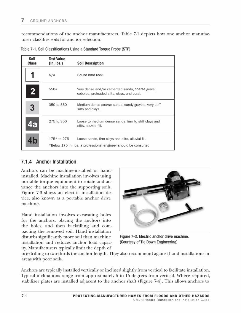
7-4 PROTECTING MaNufaCTuREd HOMEs fROM flOOds aNd OTHER HazaRds A Multi -Hazard Foundation and Installation Guide
7 GROUND ANCHORS
recommendations of the anchor manufacturers. Table 7-� depicts how one anchor manufac-turer classifies soils for anchor selection.
7.1.4 AnchorInstallation
Anchors can be machine-installed or hand-installed. Machine installation involves using portable torque equipment to rotate and ad-vance the anchors into the supporting soils. Figure 7-3 shows an electric installation de-vice, also known as a portable anchor drive machine.
Hand installation involves excavating holes for the anchors, placing the anchors into the holes, and then backfilling and com-pacting the removed soil. Hand installation disturbs significantly more soil than machine installation and reduces anchor load capac-ity. Manufacturers typically limit the depth of pre-drilling to two-thirds the anchor length. They also recommend against hand installations in areas with poor soils.
Anchors are typically installed vertically or inclined slightly from vertical to facilitate installation. Typical inclinations range from approximately 5 to �5 degrees from vertical. Where required, stabilizer plates are installed adjacent to the anchor shaft (Figure 7-4). This allows anchors to
Table7-1.SoilClassificationsUsingaStandardTorqueProbe(STP)
Figure7-3.Electricanchordrivemachine.(CourtesyofTieDownEngineering)

PROTECTING MaNufaCTuREd HOMEs fROM flOOds aNd OTHER HazaRds A Multi -Hazard Foundation and Installation Guide
7-5
GROUND ANCHORS 7
be installed after the manufactured home is positioned and locates the exposed anchor heads behind the manufactured home’s skirting. Anchor straps are then installed to the manufac-tured home frames and, in HUD Wind Zones II and III, to the wall ties installed when the home is fabricated. When used in this configuration, stabilizer plates are installed to provide addition-al lateral resistance for the anchor assembly.
When fastened as vertical wall ties and loaded axially, ground anchors may be used without stabilizer plates. When ground anchors are used with some proprietary foundation systems, an-chors can be installed 45 degrees to the horizontal and loaded axially (Figure 7-5).
7.1.5 AnchorPerformance
The capacity of anchoring systems is a function of the soil response to loads applied to the an-chor assembly. For ground anchors, important geotechnical considerations include soil type or classification, soil shear strength, load-deformation characteristics (i.e., modulus of subgrade reaction, or stiffness), and moisture condition. Research has identified additional consider-ations impacting the capacity and performance of ground anchors, including anchor geometry, anchor depth, anchor orientation, and direction of load relative to that orientation.
Soil response mechanisms are different for axially and non-axially loaded ground anchors. Soil response for axially loaded ground anchors is the result of shear stresses along the failure plane.
Figure7-4.Typicalgroundanchorinstallation.

7-6 PROTECTING MaNufaCTuREd HOMEs fROM flOOds aNd OTHER HazaRds A Multi -Hazard Foundation and Installation Guide
7 GROUND ANCHORS
Failure occurs when the stresses exceed the soil shear strength. The geometry of the failure surface varies based on the critical depth of the anchor. Ground anchors with an embedment depth less than the critical depth to anchor base width ratio ((D/B)cr) respond as a shallow foundation. Ground anchors with a depth greater than (D/B)cr respond as a deep foundation.
Non-axially loaded ground anchors resist lateral movement by mobilizing the passive resistance of the surrounding soil. As small diameter rods develop little passive soil pressure resistance, stabilizer plates are used in the contact area to increase the passive resistance and reduce move-ment.
Figure 7-6 plots anchor load (in pounds) as a function of anchor head displacement (in inches), and shows the typical response for an anchor installed vertically and loaded axially. A test load of 6,000 pounds resulted in a movement of less than 2 inches. The graph also indicates that little or no movement occurred at loads less than about 225 pounds.
Vertical, axially loaded anchors are relatively efficient. The soil shear failure is a symmetrical, roughly truncated cone extended from the anchor bearing plate to the ground surface. Non-vertical, axially loaded ground anchors are somewhat less efficient due to the asymmetrical shape of the shear failure surface. The asymmetry is the result of the shallow depth at the top side of the anchor relative to the bottom side.
Movements of axially loaded anchors are proportional to the applied loads. The load-movement is approximately linear in granular or non-cohesive soils. Cohesive soils tend to be less linear, particularly as the amount of clay in the soil increases. Soil related anchor failure in granular soils may occur rapidly and may cause ground surface movements around the anchor. Anchors in cohesive soil typically fail more slowly.
Figure7-5.Inlinegroundanchorinstallation.

PROTECTING MaNufaCTuREd HOMEs fROM flOOds aNd OTHER HazaRds A Multi -Hazard Foundation and Installation Guide
7-7
GROUND ANCHORS 7
Anchor failure may also result from weld failure between the anchor shaft and the anchor head, weld failure between the shaft and the helix, collapsing of the anchor helix, or metal tearing around the anchor head strap bolts.
Anchors used with stabilizer plates respond differently than axially loaded anchors. Figure 7-7 shows the typical response for non-axially loaded anchors used with stabilizer plates. The small diameter shaft does not create much passive resistance in the soil; therefore, small loads pro-duce relatively large movements. After the anchor shaft contacts the stabilizer plate, lateral movement as a function of load decreases significantly as a result of a larger area of passive re-sistance mobilized by the stabilizer plate. After the shaft contacts the stabilizer plate, stiffness, as indicated by the slope of the load vs. movement curve, increases significantly. However, the apparent stiffness, as indicated by the slope of the curve, remains less than axially loaded an-chors.
For both axially and non-axially loaded anchors, the design stiffness should be selected to ac-count for the variability of individual anchor performance during anchor tests, including an assessment of the upper limit of the applicability of the stiffness factor.
Shear strength in saturated soil is typically less than in non-saturated soils. Thus, anchors in saturated soils have a lower load capacity than non-saturated soils, and may exhibit decreased stiffness, especially in clays.
Figure7-6.Typicalresponseforanaxiallyloadedanchor.

7-8 PROTECTING MaNufaCTuREd HOMEs fROM flOOds aNd OTHER HazaRds A Multi -Hazard Foundation and Installation Guide
7 GROUND ANCHORS
7.1.6 AnchorsandOtherFoundationElements
Ground anchors are used with masonry piers, wood posts, or steel jack stands. For satisfactory performance, the piers, posts, and stands must function with relatively large displacements that the anchors may experience when subjected to flood, high-wind, or seismic loads. Large dis-placements are especially likely for non-axially loaded ground anchors. If subjected to relatively large movements, many foundation components cannot maintain their integrity. Piers, for ex-ample, can experience failure due to sliding of unmortared blocks or overturning of reinforced piers supported on ground surface pads (Figure 7-8).
7.2 FEMAAnchorTestProgram
7.2.1 AnchorsinSaturatedSoils
Flooding can decrease soil shear strength and change the subsurface hydrostatic pressures as a result of an increase in the pressure gradient. The two mechanisms affect ground anchor performance differently. The effects are a function of soil characteristics, anchor end plate di-ameter, installation depth, and change in hydrostatic pressure. Research has indicated that, for a fixed depth, the ultimate capacity of screw anchors in dry sand is higher than screw anchors in submerged conditions. The impact of the reduction in capacity is significantly greater for shal-low anchors than for deep anchors.
In 2002, FEMA participated in a field test program of �20 anchors to provide performance data for developing pre-engineered foundation designs using ground anchors. Sixty anchors were tested in a saturated site, and 60 anchors were tested in an adjacent dry site as a control group.
Figure7-7.Typicalresponseforanon-axiallyloadedanchorusedwithastabilizerplate.
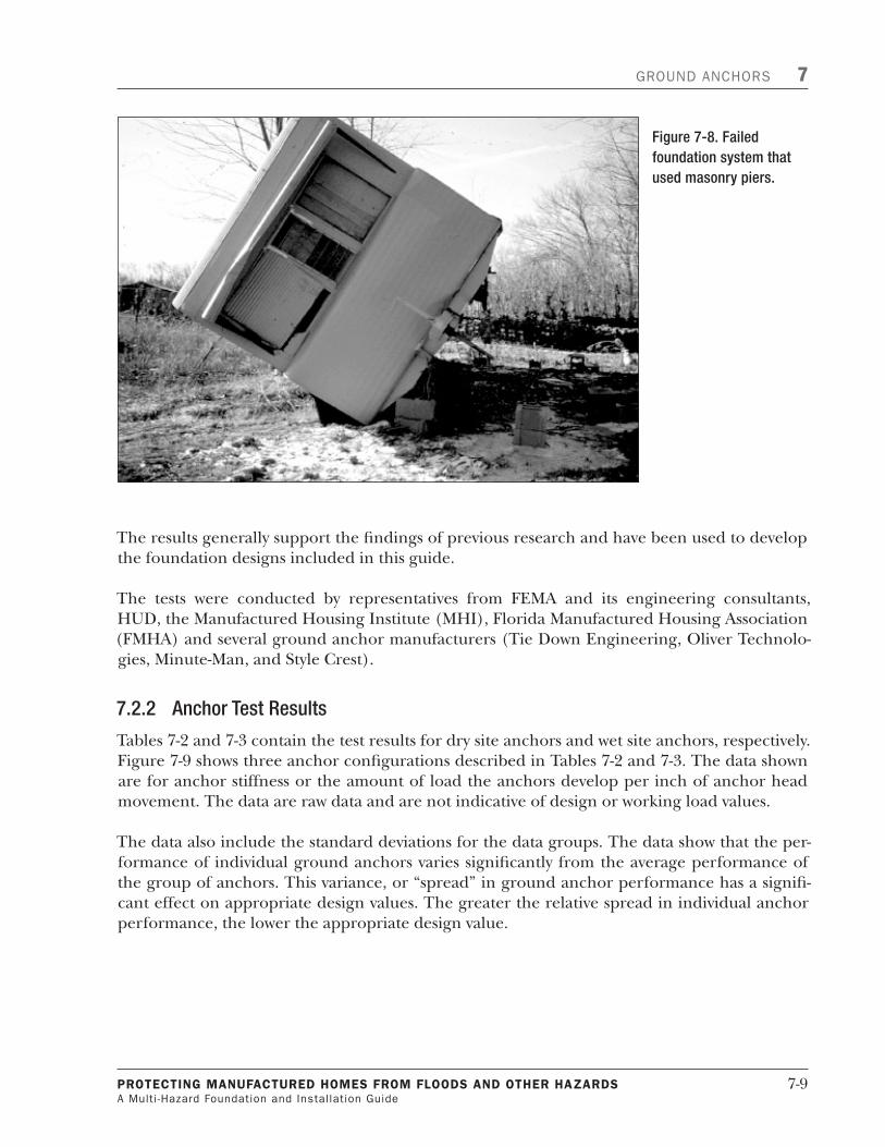
PROTECTING MaNufaCTuREd HOMEs fROM flOOds aNd OTHER HazaRds A Multi -Hazard Foundation and Installation Guide
7-�
GROUND ANCHORS 7
The results generally support the findings of previous research and have been used to develop the foundation designs included in this guide.
The tests were conducted by representatives from FEMA and its engineering consultants, HUD, the Manufactured Housing Institute (MHI), Florida Manufactured Housing Association (FMHA) and several ground anchor manufacturers (Tie Down Engineering, Oliver Technolo-gies, Minute-Man, and Style Crest).
7.2.2 AnchorTestResults
Tables 7-2 and 7-3 contain the test results for dry site anchors and wet site anchors, respectively. Figure 7-� shows three anchor configurations described in Tables 7-2 and 7-3. The data shown are for anchor stiffness or the amount of load the anchors develop per inch of anchor head movement. The data are raw data and are not indicative of design or working load values.
The data also include the standard deviations for the data groups. The data show that the per-formance of individual ground anchors varies significantly from the average performance of the group of anchors. This variance, or “spread” in ground anchor performance has a signifi-cant effect on appropriate design values. The greater the relative spread in individual anchor performance, the lower the appropriate design value.
Figure7-8.Failedfoundationsystemthatusedmasonrypiers.

7-�0 PROTECTING MaNufaCTuREd HOMEs fROM flOOds aNd OTHER HazaRds A Multi -Hazard Foundation and Installation Guide
7 GROUND ANCHORS
Table7-2.DrySiteAnchorData
AnchorStyleandInstallation
AnchorStiffness(pound/inch)
Min Max AverageStandardDeviation
5-foot anchor installed at 45° and loaded axially (Figure 7-9a)
1,505 3,283 2,426 543
5-foot anchor installed vertically and loaded axially (Figure 7-9c)
1,774 6,639 3,801 1,394
5-foot anchor installed 15° from vertical and used with an 11-inch by 17-inch stabilizer plate (Figure 7-9b)
1,006 2,001 1,475 294
4-foot anchor installed 15° from vertical and used with an 8-inch by 24-inch acrylonitrile butadiene styrene (ABS) stabilizer plate (Figure 7-9b)
1,019 2,612 1,721 497
4-foot anchor installed 15° from vertical and used with an 11-inch by 17-inch stabilizer plate (Figure 7-9b)
817 1,614 1,197 257
Table7-3.WetSiteAnchorData
AnchorStyleandInstallation*
AnchorStiffness(pound/inch)
Min Max AverageStandardDeviation
5-foot anchor installed at 45° and loaded axially (Figure 7-9a)
2,874 9,019 5,506 1,829
5-foot anchor installed vertically and loaded axially (Figure 7-9c)
2,166 6,581 4,112 1,391
5-foot anchor installed 15° from vertical and used with an 11-inch by 17-inch stabilizer plate (Figure 7-9b)
833 1,412 1,094 193
4-foot anchor installed 15° from vertical and used with an 8-inch by 24-inch ABS stabilizer plate (Figure 7-9b)
655 2,006 1,538 370
4-foot anchor installed 15° from vertical and used with an 11-inch by 17-inch stabilizer plate (Figure 7-9b)
1,024 1,894 1,319 300
* See Figure 7-9.
Note that anchor stiffness values are based on the linear portion of the load deflection data. In most cases, the non-axially loaded anchors’ significant movements occurred prior to reaching the linear response range. It should also be noted that the upper and lower limits of applicabil-ity of the stiffness values have not been fully evaluated. For axially loaded anchors in dry sand, the linear zone appears to exceed 6,000 pounds, about the limit of the test. Vertically loaded vertical anchors in wet sand had similar results; however, axially loaded anchors installed at 45

PROTECTING MaNufaCTuREd HOMEs fROM flOOds aNd OTHER HazaRds A Multi -Hazard Foundation and Installation Guide
7-��
GROUND ANCHORS 7
degrees in wet sand had an upper limit of about 4,500 to 5,000 pounds. Similar differences were observed for inclined anchors.
7.3 RecommendedGroundAnchorCertification,Performance,andDesignValues
7.3.1 RecommendedGroundAnchorCertificationPerformance
Currently, there is no consensus based standard protocol for certifying ground anchors used to anchor manufactured homes. Some States have developed certification procedures and a task group under HUD’s Manufactured Housing Consensus Committee (MHCC) has been working on a Ground Anchor Test Protocol (GATP) for certifying ground anchors. Although no stan-dard protocol had been completed at the time this guide was published, the ground anchor design strengths included in this guide assume that the ground anchors will achieve a level of performance that can be relied upon to anchor the home and resist applied loads from a de-sign event.
7.3.2 RecommendedGroundAnchorDesignValues
The following data present recommended ground anchor design values for use when ground anchors have not been load tested or otherwise certified for a specific capacity. The informa-tion, while limited, is based on the best available data from the FEMA ground anchor testing program. FEMA’s testing program gathered data on ground anchor performance and soil satu-ration effects, and was conducted on sandy Class 4b soils.
Figure7-9.ThreegraphicsshowingtheanchorconfigurationsdescribedinTables7-2and7-3.Fromlefttoright,theyare(a)groundanchorinstalledat45degreesandloadedaxially,(b)groundanchorinstalledat15degreesfromverticalandloaded45degreesfromhorizontal,and(c)groundanchorinstalledverticallyandloadedaxially.

7-�2 PROTECTING MaNufaCTuREd HOMEs fROM flOOds aNd OTHER HazaRds A Multi -Hazard Foundation and Installation Guide
7 GROUND ANCHORS
The recommended design loads contained in Table 7-4 were developed by applying the statisti-cal factors required to produce a design load that provides a �0 percent lower exclusion limit with a �0 percent confidence level. The factors were applied to the FEMA test data.
Table7-4.RecommendedDesignLoads–fromFEMAGroundAnchorTestingProgram
AnchorStyleandInstallation–FEMATests RecommendedDesignLoad(pounds)
5-foot anchor installed at 45°and loaded axially 3,150
5-foot anchor installed vertically and loaded axially 3,000
5-foot anchor used with an 11-inch by 17-inch stabilizer plate 2,000
4-foot anchor with an 8-inch by 24-inch ABS stabilizer plate 2,000
4-foot anchor used with an 11-inch by 17-inch stabilizer plate 2,000
Recommended design stiffness values were selected that provide a �0 percent confidence level; this means that no more than �0 percent of individual anchors would provide resistances less than design values. This level of statistical performance is less conservative, but similar to statis-tical performance levels applied to other structural materials like steel or concrete.
The lowest stiffness values from the dry and wet sites were selected for design. Generally, the dry site values controlled for axial pull anchors while the saturated site anchor values controlled for anchors using stabilizer plates. Table 7-5 lists the recommended design stiffness for the anchors tested.
Table7-5.RecommendedDesignStiffnessforTestedAnchors
AnchorStyleandInstallationAnchorDesign
Stiffness(pound/inch)
ControllingSoils
5-foot anchor installed at 45° and loaded axially 1,200 dry
5-foot anchor installed vertically and loaded axially 1,010 dry
5-foot anchor used with an 11-inch by 17-inch stabilizer plate 675 wet
4-foot anchor with an 8-inch by 24-inch ABS stabilizer plate 708 wet
4-foot anchor used with an 11-inch by 17-inch stabilizer plate 659 wet
With a 3-inch displacement, the axially loaded anchors provide working loads greater than the 3,�50-pound loads required by HUD (e.g., �,200 pounds/inch x 3 inches = 3,600 pounds). However, the anchors with stabilizer plates provide only about two-thirds of the HUD required capacity. The anchor stiffness values in Table 7-5 are based on the linear portion of the load-de-flection curve. Designers need to evaluate potential deflections at loads below the linear range, particularly for inclined anchors loaded non-axially.
PROTECTING MaNufaCTuREd HOMEs fROM flOOds aNd OTHER HazaRds A Multi -Hazard Foundation and Installation Guide
7-�3
GROUND ANCHORS 7
7.4 GroundAnchorsinSeismicallyActiveAreasWhile data exist on the performance of ground anchors in static saturated soils, no definitive testing has been completed that predicts how ground anchors will perform in saturated soils during a seismic event. Seismic events can result in soil liquefaction, particularly in fine sands like those in the test program. Liquefaction may result in a significant and potentially total loss of anchor capacity during a seismic event. A registered engineer should be consulted to evalu-ate the liquefaction potential at the proposed manufactured home installation site.


8 FoundationSystems8.1 IntroductionProperly designed and constructed manufactured home foundations can significantly reduce the potential for damages from flooding, high winds, and seismic events. Many styles of founda-tions are available for supporting manufactured homes. Continuous perimeter walls, constructed of concrete, masonry, or treated wood; concrete or masonry piers; wood posts and piles; and systems consisting of piers and ground anchors are some of the options available to a manufac-tured homeowner and installer.
To be effective, manufactured home foundations must perform the following:
n Support the weight of the home, its contents, and its occupants
n Resist design loads from wind, snow, seismic events, and moving floodwaters
n Elevate the home sufficiently to prevent losses from a design flood event
Elevated foundations are classified as enclosed or open. As the name implies, enclosed foun-dations enclose the space below the elevated home. Perimeter masonry, concrete, or sheathed wood walls are enclosed styles. Open foundations consist of a system of individual members that support the home only at discrete locations. Pier, post, and pile foundation systems are open systems. Many open foundations have a non-structural skirting to enclose the space below the home. The skirting is primarily for aesthetics and does not add to the strength of the founda-tion. Skirting can help to protect piping installed below the home from freezing and reduce both heat loss from the home and the potential for animal or insect entry into the home.
Selecting an appropriate foundation system depends on a number of variables, including the building site conditions (elevation, slope, access restrictions, drainage); the flood zone; the design loads (wind, flood, snow, and, if appropriate, seismic) at the site; the availability of ma-terials; on-site soil characteristics; local construction practices; and cost. Whatever foundation system is chosen, both the HUD Code and NFIP require a foundation to resist flotation, collapse, or lateral movement during a design event to prevent damages to the home and surrounding structures. Tables 8-1 through 8-3 at the conclusion of this chapter provide guidance to the se-lection of appropriate manufactured home foundation systems as a function of flood depth and flow velocity.
Proprietary systems are also an option for the manufactured homeowner. Proprietary systems are discussed in Section 2.2.2 and the system must meet the design and performance criteria described in Chapter 9.
More information on proprietary foundations is contained in the SBRA’s Guide to Foundation and Support Systems for Manufactured Homes available at http://www.research-alliance.org/pages/foundations_guide.htm.
PROTECTING MaNufaCTuREd HOMEs fROM flOOds aNd OTHER HazaRds A Multi -Hazard Foundation and Installation Guide
8-1

8 FOUNDATION SYSTEMS
8.2 EnclosedFoundationsEnclosed foundations consist of perimeter foundation walls placed on continuous footings. The walls enclose the area below the living space of the home (Figure 8-1). Perimeter walls are com-monly constructed of concrete, masonry, or wood. Enclosed foundations are occasionally used to raise manufactured homes, often creating the appearance of a site-built home (Figure 8-1).
NFIP regulations permit enclosed foundations for manufactured homes in SFHA A zones with a requirement that the foundation walls include flood vents. 44 CFR 60.3(c)(5) requires that:
“all new construction and substantial improvements, that fully enclosed areas be-low the lowest floor that are usable solely for parking of vehicles, building access or storage in an area other than a basement and which are subject to flooding shall be designed to automatically equalize hydrostatic flood forces on exterior walls by allowing for the entry and exit of floodwaters. Designs for meeting this requirement must either be certified by a registered professional engineer or architect or meet or exceed the following criteria: A minimum of two openings having a total net area of not less than one square inch for every square foot of enclosed area subject to flooding shall be provided. The bottom of all openings shall be no higher than one foot above grade. Openings may be equipped with screens, louvers, valves, or other covering or devices provided that they permit the automatic entry and exit of floodwaters.”
This elevation technique should not be used in high-velocity or highly erosive flood conditions, and is not permitted in V zones. Additional information on wall vents for floodwater flow is pro-vided in FEMA Technical Bulletin 1, Openings in Foundation Walls and Walls of Enclosures (2008).
Figure8-1.Amanufacturedhomeelevatedonaperimeterfoundationwall.Althoughitappearstheopeningsaretoohigh,thebottomsoftheopeningsarelessthan1footabovethetopoftheinteriorslab.
8-2 PROTECTING MaNufaCTuREd HOMEs fROM flOOds aNd OTHER HazaRdsA Multi -Hazard Foundation and Installation Guide

FOUNDATION SYSTEMS 8
Perimeter walls of enclosed foundations should include adequate reinforcement to resist unbal-anced hydrostatic and/or hydrodynamic loads that may occur in fast rising flood events. Such floods may result in water levels higher on the exterior side of the wall than the inside until flow through the flood vents can equalize them.
8.3 OpenFoundationsandBreakawayWallsNFIP regulations require manufactured homes in SFHAs designated V1-30, VE, or V on the community’s FIRM have the space below the lowest floor either free of obstruction or construct-ed with non-supporting breakaway walls (44 CFR 60.3(e)(5)). Elevating a manufactured home on an open foundation involves raising it onto piers, posts, or piles. If the home is located in an area of coastal flooding, an open foundation is the only way to safely elevate the home. If the home is subjected to high-velocity riverine floodwaters, significant water depth, or potential erosions, the home should also be elevated on an open foundation. Open foundations are in-trinsically more resistant to moving floodwaters and breaking waves than enclosed foundations since the home has a smaller surface area exposed to flood forces. Selection of the proper open foundation for various flooding and site characteristics is critical to the success of the founda-tion.
Breakaway walls, including non-structural skirting around a manufactured home, are walls that are not part of the structural support of the home. They are designed and constructed to fail un-der the loads imposed by floodwaters without jeopardizing the elevated portion of the home or the structural support of the home. Because such enclosures are designed to fail at a lateral load of no greater than 20 pounds per square foot, they will transfer minimal additional loads to the foundation. Insect screening and latticework both allow floodwaters to pass through. Detailed discussions on design and construction for breakaway walls can be found in FEMA Technical Bulletin 9, Design and Construction Guidance for Breakaway Walls (2008).
8.3.1 PierSystems
Most manufactured homes are placed on pier foundations. Although there are many variations, pier foundations fall into two general styles. One style contains pier foundations combined with other components (such as anchors and frame straps) for lateral stability; the second style relies on the piers and their footings to resist all imposed loads. The foundation styles that use supple-mental lateral-supporting devices often do not require reinforced piers. The determination of the need for and the amount of reinforcing required is part of the design analyses. The final design requirements for pier reinforcing is a function of the combination of flood, wind, and seismic loads acting on the manufactured home, and the resulting pier capacity required to re-sist flotation, collapse, or lateral movement.
When flood velocities are less than 1 fps, piers can be constructed using unbonded (dry-stacked) concrete blocks or steel piers. When pier foundation systems are used without separate compo-nents to resist lateral loads, the piers and footings must be much stronger. They not only have to transfer all imposed loads to the bearing soils, but also must do so in a manner that does not damage the piers and footings or overload the supporting soils.
PROTECTING MaNufaCTuREd HOMEs fROM flOOds aNd OTHER HazaRds A Multi -Hazard Foundation and Installation Guide
8-3

8 FOUNDATION SYSTEMS
Piers designed to resist lateral and/or uplift loads without the use of ground anchors or straps typically consist of reinforced brick masonry, reinforced concrete masonry units, or reinforced cast-in-place concrete with steel reinforcing bars for both the piers and the below-grade foot-cast-in-place concrete with steel reinforcing bars for both the piers and the below-grade foot-cast-in-place concrete with steel reinforcing bars for both the piers and the below-grade footings. Because the ground around pier footings in SFHAs can be susceptible to erosion and scour, the footings must be embedded below the anticipated scour depth.
In areas exposed to moving floodwaters, special consideration must also be given to controlling scour around the pier foundation elements. Moving floodwaters can remove soil around and beneath foundations, potentially reducing their load capacity to the point of foundation fail-ure.
Floodwaters with high flow rates and floodwaters that carry a large sediment load create more scour than low velocity or clear water flood flow. Because of this, scour is particularly damaging where floodwaters converge or abruptly change direction. Scour is generally greatest around discrete interior piers and the corners of perimeter wall foundations.
Scour removes soil particles from beside and, in severe cases, from beneath foundations. The loss of soil around and/or beneath a foundation affects its capacity to support the design loads. The loss of vertical foundation capacity can result in large settlements and potential collapse. The loss of lateral capacity not only reduces the capacity of the foundation to resist lateral wind and flood loads, but also can reduce the vertical capacity. The loss of lateral support for long thin vertical elements (e.g., single block masonry stack piers) can result in buckling under the design vertical loads.
Piers designed to resist lateral and/or uplift loads must be constructed using mortared horizon-tal joints between courses and reinforced grout used to fill the vertical cell. The piers must be firmly attached to the supporting footings.
8.3.1.1 Reinforced Pier Systems
Reinforced piers typically have steel reinforcements placed inside of the piers. Reinforced pier systems are commonly constructed of concrete masonry units (CMUs) or cast-in-place concrete (Figure 8-2).
In high-wind areas and in areas exposed to seismic or hy-In high-wind areas and in areas exposed to seismic or hy-In high-wind areas and in areas exposed to seismic or hydrodynamic loads, piers may require much larger footings to ensure applied loads do not exceed the soil’s bearing capacity or allow tensile forces to develop in foundation elements in the upstream and windward side of the home. Laterally bracing the piers can allow the structure to dis-tribute imposed loads to the entire foundation system. Lateral bracing also provides protection against buckling failure of vertical elements due to loss of confining soil from erosion or scour.
Concrete Masonry unit (CMu) Reinforced Piers
The International Residential Code limits the height of solid masonry piers, including hollow concrete ma-sonry units filled solidly with con-crete or Type M or S mortar to ten times their least dimension. The height limitation for unfilled hol-low concrete masonry unit piers is four times their least dimension (IRC§606.6).
8-4 PROTECTING MaNufaCTuREd HOMEs fROM flOOds aNd OTHER HazaRdsA Multi -Hazard Foundation and Installation Guide

FOUNDATION SYSTEMS 8
Adequate connections between the piers and the manufactured home are necessary for the manufactured home and its foundation to resist lateral and uplift loads from floods, winds, and earthquakes. Generally, multiple fastener bolted connections are needed to connect the top of the piers to the manufactured home frames when the piers must transfer moments. If the piers must resist only uplift loads, fastening requirements may be simplified. Regardless of the com-plexity of the connection, consult the manufactured home manufacturer to ensure the factory built components are not overloaded. Figure 8-3 shows a method used to fasten a home’s steel frames to reinforced masonry piers using nuts, steel plates, and bolts grouted into the piers.
8.3.1.2 UnreinforcedPierSystems
Unreinforced brick or CMU pier systems have no rein-forcing steel and, therefore, have very little resistance to overturning, sliding, and uplift. Because of this, unreinforced piers should always be provided with other stabilizing devices like ground anchors.
When used with stabilizing devices, many styles of unreinforced piers are available to support manufactured homes; the styles provide varying degrees of strength to resist loads on the home. These systems can be construct-ed without mortar (called dry-stacked masonry); with dry-stacked block lightly secured with a surface bonding material; with mortared block; or with fully mortared, grouted block.
Figure8-2.Reinforcedmasonryandconcretepiers.
dry-stacked Piers
Dry-stacked block piers can fail when a home is exposed to com-bined wind and flooding (ASCE 7, Load Combination #6). Failure re-sults when wind forces lift the manufactured home’s frame off its windward piers. Without the weight of the home to stabilize the piers, the piers can easily fail by sliding or overturning.
PROTECTING MaNufaCTuREd HOMEs fROM flOOds aNd OTHER HazaRds A Multi -Hazard Foundation and Installation Guide
8-5

8 FOUNDATION SYSTEMS
Figure8-3.Boltedconnectionbetweenframeandreinforcedpier.
When placed directly on concrete footings or pads, 3-foot tall piers constructed with single, dry-stacked blocks to create an 8-inch by 16-inch pier can only resist flood velocities of ap-proximately 1.0 fps. Three-foot tall (16-inch by 16-inch) double-stacked piers can resist flood velocities of approximately 1.75 fps. Dry-stacked piers or posts supported on ABS pads fail at lower velocities than piers supported on concrete. The failure at lower velocities is due to a re-duced frictional resistance between the pier blocks or posts and the ABS pad. The design flood velocity for double-stacked piers on ABS pads is 1.25 fps.
If dry-stacked piers are not fully submerged, they can resist higher flood velocities. This is be-cause the portion of the pier above the water line adds to the pier’s stability but does not add to the flood load that the pier must resist. Engineers can calculate the ability of partially sub-merged piers to resist moving floodwaters or their resistance can be determined by testing.
Applying surface-bonding materials strengthens the piers by increasing their shear resistance. However, surface bonding has limited impact on their resistance to bending moments from lateral loads; therefore, surface bonded piers still need to be used with other foundation com-ponents. The increased shear resistance allows 3-foot tall (16-inch by 16-inch) piers to resist hydrodynamic loads from floodwaters moving at approximately 2.0 fps for single-stacked piers and 3.0 fps for double-stacked piers. This resistance to moving floodwaters can only be achieved when the surface bonding materials not only bond the individual pier blocks to each other, but also the pier to the concrete footing below. A FEMA sponsored testing program conducted at the Haynes Coastal Engineering Laboratory, Texas A&M University verified the design values.
8-6 PROTECTING MaNufaCTuREd HOMEs fROM flOOds aNd OTHER HazaRdsA Multi -Hazard Foundation and Installation Guide

FOUNDATION SYSTEMS 8
The Texas A&M testing program included piers constructed using a polyurethane based ma-sonry adhesive as joint bonding material. The Illinois Tool Works (ITW) TACC Division's Mason Bond was certified by ICC Evaluation Service as meeting the IBC and IRC for Types M, N, O, and S Portland cement/lime mortar. Test results showed the single stack adhesive bonded piers to be the strongest configuration tested.
Mortared block and fully grouted mortared block are much stronger than dry-stacked and sur-face-bonded piers, but their strengths do not match piers with #3 reinforcing steel bars grouted into the vertical cells. Mortared and fully grouted piers usually require other foundation com-ponents (like shear walls) to resist lateral loads.
Reinforced piers (constructed by introducing reinforcing steel to fully grouted piers) can be made to resist lateral and vertical loads when used with other foundation components like large concrete footings.
Unreinforced piers cannot be used in V zones. In Coastal A zones, fully grouted piers may be adequate for low flood velocities, but reinforcing with steel is recommended.
8.3.2 PileFoundations
Pile foundations provide protection for the broadest range of flooding conditions. This foun-dation system consists of the pile supports, horizontal beams, longitudinal support under the manufactured home, and foundation bracing for additional resistance to lateral wind, floodwa-ters, and seismic events. A properly designed pile foundation can withstand high-wind and water velocities, and can resist erosion and scour around its base if embedded to an adequate depth (Figure 8-4). Because of this, pile foundations meet the NFIP requirements for installation in V zones. Pile foundations are also appropriate for Coastal A zones and for areas exposed to high-velocity riverine flooding.
Figure8-4.Manufacturedhomeonapilefoundation.
PROTECTING MaNufaCTuREd HOMEs fROM flOOds aNd OTHER HazaRds A Multi -Hazard Foundation and Installation Guide
8-7

8 FOUNDATION SYSTEMS
Saturated soils with low bearing capacities are less of a stability problem for a pile foundation than for a pier foundation; thus, pile foundations are preferable in coastal areas. The design of pile foundations requires determining the number, size, length, and location of piles appropri-ate to the particular manufactured home, soil conditions, and flooding situation at the site. A pile design methodology is provided in the Coastal Construction Manual (FEMA 55) that requires input parameters, including soil property and loading information.
Piles are vertical supports similar to posts, but differ in the method and depth of placement. Piles are embedded much deeper than posts and do not rest on footings for resistance. Instead, the piles are driven until they rest on a solid support layer, such as bedrock, or until they are embedded deep enough that the friction between the ground and the piles will enable them to resist the gravity, lateral, and uplift loads expected to act on them.
The most commonly used piles in residential construction are wood. Steel and precast concrete piles are also used. Pile foundations are primarily used in areas where other elevation methods are not feasible, such as V zones.
A major consideration in the effectiveness of pile foundations is the method of installation. Piles are placed into the ground by impact driving, water jetting, augering, or some combination of these methods (Figure 8-5). Piles are often driven by a single- or double-acting diesel hammer or an air/steam hammer. Pile driving is an excellent method due to the strength of the pile and the ability of the pile and its soil interface to resist vertical and horizontal loads.
A less desirable, but frequently used method is jetting. Jetting inserts piles into sandy soil by forcing a high-pressure stream of water through a pipe along the side of the pile. The stream of water creates a hole in the sand while the pile is continuously pushed or dropped to the desired depth. Jetting results in a lower load capacity due to loose soils that create decreased friction be-tween the piles and the surrounding soil. Jetted piles must be inserted deeper into the ground than driven piles in order to achieve the same load capacity.
Figure8-5.Piledrivingmethods.
8-8 PROTECTING MaNufaCTuREd HOMEs fROM flOOds aNd OTHER HazaRdsA Multi -Hazard Foundation and Installation Guide

FOUNDATION SYSTEMS 8
Another method is the use of an auger to pre-drill holes for piles. If the soil is composed of ad-equate clay or silt, using an auger to create holes for piles is sufficient. Additionally, some sands may contain enough clay or silt to permit the use of an auger. This method can be used by itself or in conjunction with pile driving.
Pile installation methods, including driving, jetting, and, to a lesser extent, augering can make precise location control difficult. Also, irregularities in the piles and soil will often prevent the piles from being driven perfectly vertical. When using piles to support manufactured housing, wood beams are typically secured to the piles and the home is secured to the beams.
When soils near the top of a pile are lost due to scour, the pile loses some of its ability to resist vertical and lateral loads. Erosion and scour must be taken into account when determining pile embedment depth and lateral bracing requirements. Due to the variability associated with dif-fering installation methods and erosion/scour potential, a geotechnical engineer should be involved in the design process to verify that intended pile capacities are achieved.
8.4 BracingBracing is often used to lower the point of application of lateral loads to reduce moments applied to the foundation system (cross bracing) or to provide lateral support to resist buck-ling (knee bracing). Diagonal bracing runs diagonally from one vertical supporting member to another, stiffening the vertical supporting members and increasing their strength and lateral stability (Figure 8-6). Unfortunately, with greater strength comes a larger exposure to wave and debris impact. Diagonal bracing is too slender to resist compressive forces and is typically only designed to carry tension forces. This technique of bracing is especially beneficial in higher el-evated homes.
Steel rods are often used to diagonally brace wood posts or piles. The rods are fitted through drilled holes filled with wood preservative and fastened with nuts and cast beveled washers. Rod bracing offers two important benefits. One, rod bracing can easily be fitted with turnbuck-les that allow bracing to be tightened after an event that creates loads in the bracing; two, rod bracing has smaller cross-sections than bracing created with dimensional lumber and thus is exposed to lower flood forces.
Knee bracings are short diagonal braces that run from a vertical support member to a horizon-tal support member (Figure 8-7). Knee braces can be effective in supporting the pile against the lateral forces of wind and water, Knee bracing increases the strength and stiffness of the extended pile foundation by retraining rotation near the top of the pile and reducing the pile bending length. Knee bracing is not as stiff as diagonal bracing. Knee braces have an advantage over diagonal braces in that they present less obstruction to waves and debris. Knee braces are shorter than diagonal braces and are usually designed for both tension and compression forces. Engineers should be consulted to determine bracing designs, particularly for knee bracing.
PROTECTING MaNufaCTuREd HOMEs fROM flOOds aNd OTHER HazaRds A Multi -Hazard Foundation and Installation Guide
8-9

8 FOUNDATION SYSTEMS
8.5 FootingsFootings are the components of a foundation system that transfer loads applied to a home to the earth below it. Footings continuously support gravity loads (and are generally well designed for this purpose), but they also must transfer lateral and uplift loads produced by wind events, seismic events, snow accumulation, and moving floodwaters.
Figure8-6.Diagonalbracing.
Figure8-7.Kneebracing.
8-10 PROTECTING MaNufaCTuREd HOMEs fROM flOOds aNd OTHER HazaRdsA Multi -Hazard Foundation and Installation Guide

FOUNDATION SYSTEMS 8
The soils below the footings must support the home and resist all the loads applied to the home. When soils are strong, footings can be relatively small and foundation systems relatively compact. When soils are weak, however, the footings become large, complicated, difficult to construct, and quite expensive. Even when placed on firm soils, footings often need to be over-sized to provide sufficient weight to resist uplift forces and overturning moments.
The design size of a pier footing is a direct function of soil bearing capacity. Soil bearing capac-ity can be directly determined by soils tests. In some jurisdictions, approximate bearing capacity can be assessed by soil classification. Model building codes (such as the IBC and NFPA 5000) have presumptive soil bearing capacity values that can be used in the absence of soils test data.
The depth of the footings depends on local frost levels and expected scour depths (whichever is greater). Local codes may provide specific requirements for the depth of footings based on local soil conditions.
8.6 FoundationMaterialsSelectionAs stated in 44 CFR 60.3(a)(3), all structural and non-structural materials at or below the BFE must be flood damage-resistant. A flood damage-resistant material is defined as any building material capable of withstanding direct contact with floodwaters for 72 hours without sustaining significant damage (i.e., damage requiring more than low-cost cosmetic repair, such as paint-ing). In addition, materials should be durable and resistant to decay and corrosion.
Some flood damage-resistant foundation material choices include the following:
n Pressure-treated lumber
n Naturally decay-resistant lumber (only for applications above grade)
n Concrete: a minimum 28-day compressive strength of 5,000 lb/in2 is recommended in coastal environments
n Masonry: reinforced and fully grouted in coastal environments
n Steel: corrosion-resistant
n Closed-cell foam insulation
n Other flood damage-resistant materials approved by local building officials
The most commonly used foundation materials are wood, concrete, steel, and masonry. Their properties, advantages, and special considerations are discussed in Sections 8.6.1 through 8.6.4. Additional information on materials’ durability can be found in FEMA 55 and trade organi-zation publications. FEMA’s Technical Bulletin 2, Flood Damage-Resistant Materials Requirements (2008) also contains information on appropriate materials used in SFHAs.
PROTECTING MaNufaCTuREd HOMEs fROM flOOds aNd OTHER HazaRds A Multi -Hazard Foundation and Installation Guide
8-11

8 FOUNDATION SYSTEMS
8.6.1 WoodFoundations
Wood is a very workable material and one of the most cost-effective; however, it is susceptible to decay, insect infestation, marine borers, and weathering. Wood must be adequately maintained to ensure the foundation’s integrity. All wood used in foundation piles, girders, beams, braces, and walls must be pressure-preservative treated or, when not in direct contact with the ground, naturally decay-resistant. No wood with natural resistance to decay is considered to have suf-ficient decay resistance for ground contact or partial water immersion. Wood exposed to the ground and exterior elements should be pressure-preservative treated to increase its resistance to infestation and decay. The degree of resistance depends on the treatment chemical and the amount of retention in lb/ft3 of wood.
The preservatives used in pressure treating wood for foun-dation applications; e.g. piles, piers, and posts, include:
n chromated copper arsenate (CCA)
n pentachlorophenol
n creosote
n copper azole
8.6.2 ConcreteFoundations
Concrete is an economical and workable foundation material that is extremely good at resisting compressive loads. Concrete can be reinforced to increase its ability to withstand tensile loads that often result from flood, wind, and seismic ac-tivity. Corrosion of the reinforcement and the cracking of the concrete weaken the concrete structural element, reducing its ability to resist loads. Providing adequate concrete cover to reinforcement is the best defense against corrosion. Consult the latest version of American Concrete Institute (ACI) publication 318, Building Code Requirements for Structural Concrete, for minimum concrete cover requirements. Additional protection from corrosion can be achieved by using epoxy-coated reinforcement.
Proper mixing, placement, and curing are essential for durable concrete. During placement, concrete will normally require vibration to eliminate air pockets and voids in the finished sur-face. The vibration must be sufficient to eliminate the air, but not to separate the concrete or water from the mix. Appropriate freeze protection may be needed if pouring is done in cold temperatures. Concrete placed in cold weather takes longer to cure, and the uncured concrete may freeze, which will adversely affect its final strength. Methods of preventing concrete from freezing during curing include the following:
n Heating adjacent soil before pouring
n Warming the mix ingredients before batching
n Placing insulating blankets over and around the forms after pouring
n Selecting a cement mix that will shorten curing time
aCQ- or aCza-Treated Wood
Designers and builders considering the use of ACQ- or ACZA-treated wood should consider using stain-less steel hardware and fasteners or obtain the latest information on the chemicals’ interaction with hardware due to reports of alleged problems with corrosion of galvanized framing hardware and nails in contact with wood treated with these chemicals.
8-12 PROTECTING MaNufaCTuREd HOMEs fROM flOOds aNd OTHER HazaRdsA Multi -Hazard Foundation and Installation Guide

FOUNDATION SYSTEMS 8
Because the environmental impact of salt-laden air and moisture make the damage potential significant for concrete, this guide recommends that all concrete construction in and near coastal flood hazard areas (both V and A zones) be built with the more durable 5,000-pounds per square inch (psi) minimum compressive strength concrete regardless of the purpose of the construction and the design loads.
8.6.3 SteelFoundations
Prefabricated steel stands are available for supporting manufactured housing. Like unreinforced masonry piers, steel stands have little resistance to overturning and should only be used in conjunction with other foundation components like ground anchors or perimeter shear walls. Metal stands should also be firmly secured to the homes’ frames.
8.6.4 MasonryFoundations
Reinforced masonry has much more strength and ductility than unreinforced masonry for re-sisting large flood, wind, and earthquake forces. It is recommended that permanent masonry construction in and near coastal flood hazard areas be reinforced and fully grouted regardless of the purpose of the construction and the design loads. Moisture can have a damaging effect on masonry con-struction. Moisture-borne salts in coastal environments entering the piers through cracks or openings in the masonry joints can cause cracking and spalling of the masonry. Moisture entering piers in cold weather envi-ronments can expand upon freezing, causing small cracks to become large cracks. The entry of moisture into rein-forced masonry construction can lead to corrosion of the reinforcement and additional cracking and spalling of the masonry. Moisture resistance is high-ly influenced by the quality of the materials and the quality of the masonry construction at the site. For CMUs, choosing Type I “moisture controlled” units and keeping them dry in transit and on the job will minimize shrinkage and cracking. For optimum crack prevention, Type S mortar should be used for below-grade applications and Type M mortar may be used for above-grade applications.
In addition to Portland cement/lime based mortar, polyurethane based masonry adhesives are now available. Care must be taken in the selection and application of masonry adhesives. As a minimum, the selected adhesive must be certified by a nationally recognized organization as meeting or exceeding the requirements for Types M, O, and S cement/lime based mortar and approved for use in masonry construction designed in accordance with applicable provisions of the IRC and IBC.
8.7 FoundationSelectionandFloodResistanceFlooding can have a dramatic effect on the suitability and stability of a manufactured home foundation. But not all floods are the same, and the type of flooding, along with its
Open Masonry foundations
Open masonry foundations in earth-quake hazard areas require special reinforcement detailing and pier pro-portions to meet the requirements for increased ductility.
PROTECTING MaNufaCTuREd HOMEs fROM flOOds aNd OTHER HazaRds A Multi -Hazard Foundation and Installation Guide
8-13

8 FOUNDATION SYSTEMS
char-acteristics and severity at a site, will eliminate many foundation types. Sections 8.7.1 through 8.7.5 provide guidance (for installers, owners, community officials, and designers) on selecting foundations suitable to different flood types and site conditions.
8.7.1 FloodingTypes
Flooding can be divided into seven major types: coastal, riverine, flash flood, alluvial fan, mud-flow, lake or pond overflow, and poor drainage. Unique hazards are associated with each of these flooding types.
n Coastal flooding is usually accompanied by waves, high velocity flow, and erosion. Damages to structures are usually the results of erosion and scour, and direct impact from wave action.
n Riverine flooding is associated with dominant hazards, including velocity, depth, and duration. These hazards are determined by several factors, including the slope of the channel and watershed, land uses within the watershed, and the extent, intensity, and duration of precipitation. (Both coastal and riverine flooding can transport damaging debris. Debris impact can weaken a structure and make it more vulnerable to damages from flooding.)
n Flash floods are accompanied by rapidly rising water and extreme flood velocities, with high debris carrying potential. Although they are generally of short duration, the forces exerted on structures by the high velocity floodwaters and debris can cause extensive damage in a very short time.
n Alluvial fan flooding is distinct in that the region of greatest flood hazard is not well-defined, and floodwaters can follow many different paths across a normally dry area. Alluvial fan floods usually occur in arid areas at the base of steeply sloping terrain, and can have extreme flood velocities and debris loads.
n Mudflows are proximately caused by flooding and can be considered a river of liquid and flowing mud on the surfaces of normally dry land areas. Mudslides usually offer little warning and can be very destructive due to their debris load and velocity.
n Lake or pond overflow is rarely as hazardous as coastal or riverine flooding, and is usually limited to inundation by slowly moving or standing water.
n Poor drainage can lead to backups and generally results in ponding type flooding. Poor drainage is usually caused by a lack of topographic relief to allow for natural drainage from a site, or it might be the result of a specific hindrance such as blockage of a drainage ditch or an undersized culvert. In areas where drainage impediments become severe, they can compound risk and damages from other types of flooding such as riverine or flash floods.
8.7.2 FloodCharacteristics
The flood source, its proximity to a site, and the flood hazard zone will provide information about flood characteristics. However, historical flood events at and near the site can also pro-vide important clues about expected flood conditions at the site. All should be considered when home foundations are evaluated.
8-14 PROTECTING MaNufaCTuREd HOMEs fROM flOOds aNd OTHER HazaRdsA Multi -Hazard Foundation and Installation Guide

FOUNDATION SYSTEMS 8
High velocities, large waves, and large floating debris can cause many home installations to fail, especially those on stacked masonry block, crawlspace, slab, shallow pier, and post foundations. Large flood depths can float or wash homes off their foundations. Long-duration floods can weaken soils, foundations, and anchor systems. Refer to Section 5.2 for more information on flood characteristics.
8.7.3 FloodHazardZones
Table 8-1 is provided as general guidance for the selection of foundation systems for manu-factured homes located at different flood hazard zones, Different flood hazard zones are represented on FIRMs by different zone designations. Detailed information pertaining to flood hazard zone designations and current NFIP regulations is provided in Chapter 3.
8.7.4 ProximitytoFloodSource
Proximity to the flood source will, to a large extent, determine whether a home site is in a more or less hazardous location. As discussed in Chapter 4, sites in a floodway or closest to a river or stream will be subject to the greatest flood depths, highest velocities, and greatest debris poten-tial. Sites outside the floodway and far from a river or stream and closer to the landward limit of the floodplain will be subject to reduced flood hazards (e.g., shallow flood depths, lower veloci-ties, low erosion potential, and only small debris).
Sites in a V or Coastal A zone will be subject to the highest waves, greatest flood velocities and depths, greatest erosion potential, and largest debris. Sites outside the V zone and far from the shoreline will be subject to reduced wave, velocity, depth, erosion, and debris conditions.
Closeness is a relative issue, however. Therefore, it may be useful to look at the location of a home site relative to the flood source or floodplain boundary. Two approaches may be useful, a distance approach and a floodplain width approach.
The distance approach relies on a distance measurement between the home site and the stream or river bank or floodway (in the case of a riverine flood source), or between the home site and the V zone boundary or shoreline (in the case of an A zone in a coastal area).
The floodplain width approach considers the relative position of the home site within the floodplain. (See Figure 4-2, which is a schematic of a floodplain/floodway.)
For riverine areas outside the floodway:
Distance approach: If a home site lies within a few hundred feet of a river or stream or floodway, it should be considered “close,” and foundations should be appropriate to sites with greater flood hazards.
Floodplain width approach: If a home site lies within the third of the floodplain closest to the river or stream or floodway, it should be considered “close,” and foundations should be appropriate to sites with greater flood hazards.
1.
2.
1.
2.
PROTECTING MaNufaCTuREd HOMEs fROM flOOds aNd OTHER HazaRds A Multi -Hazard Foundation and Installation Guide
8-15

8 FOUNDATION SYSTEMS
For Coastal A zones:
Distance approach: If a home site lies within a few hundred feet of the V zone boundary (or shoreline, if a V zone has not been mapped), it should be considered “close,” and V zone foundations should be used. Beyond that point, A zone foundations may be suitable.
Floodplain width approach: If a home site lies within the half of the floodplain closest to the V zone boundary (or shoreline, if a V zone has not been mapped), it should be considered “close,” and V zone foundations should be used. Beyond that point, A zone foundations may be suitable.
8.7.5 FoundationSelectionGuidance
The recommendations contained in Tables 8-1 through 8-3 should be evaluated in light of spe-cific soil, terrain, and base flood conditions at a home site. The pier information contained in the tables is appropriate for piers used in foundation systems that contain other components (like ground anchors) that are properly selected, designed, and installed to resist flood and wind forces on the manufactured home itself. The pier construction styles listed are those re-quired to resist flood forces on the piers themselves.
Areas exposed to flash flooding, alluvial fans, and mudslides pose unique (and often not specifi-cally known) hazards. Foundations for homes in those areas should be developed by licensed engineers working closely with local floodplain managers.
Table8-1.RecommendedManufacturedHomeFoundationSelectionforLake/PondFlooding(forverylowvelocitylessthan1fps)
Lake/PondFlooding(standingwater;maximumfloodflowvelocity1.00fps)
Flood Zone/Foundation Type A, AE, A 1-30, AO/AH
Steel pier 3
Dry-stacked masonry blockSingle block stack 3
Double block stack 3
Dry-stacked masonry block with surface-bonded mortar
Single block stack 3
Double block stack 3
Mortar or adhesive-bonded masonry block
Single block stack 3
Double block stack 3
Reinforced and grouted masonry block
Single block stack 3
Double block stack 3
Fill/slab 3
Posts 3
Perimeter foundation walls 3
Piles 3
3 = OK
fps = feet per second
1.
2.
8-16 PROTECTING MaNufaCTuREd HOMEs fROM flOOds aNd OTHER HazaRdsA Multi -Hazard Foundation and Installation Guide

FOUNDATION SYSTEMS 8
Single block stack (8 inch by 16 inch) on concrete footing or ABS pad
Double block stack (16 inch by 16 inch) on concrete footing or ABS pad
Table8-2.RecommendedManufacturedHomeFoundationSelectionforRiverineFloodZones(andmaximumfloodflowvelocity)
RiverineFlooding
Flood Zone/Foundation Type Floodway1 A, AE, AE1-30, AO/AH
Steel pier 3 Vmax=1.00 fps
Dry-stacked masonry block
Single block stack Do Not Use 3 Vmax=1.25 fps2
Double block stack Do Not Use 3 Vmax=1.75 fps3
Dry-stacked masonry block with surface-bonded mortar
Single block stack Do Not Use 3 Vmax=2.00 fps
Double block stack Do Not Use 3 Vmax=3.00 fps
Mortar or adhesive-bonded masonry block
Single block stack Do Not Use 3 Vmax=2.50 fps
Double block stack Do Not Use 3 Vmax=3.00 fps
Reinforced and grouted masonry block
Single block stack Do Not Use 3 Vmax=5.00 fps
Double block stack Do Not Use 3 Vmax=5.00 fps
Fill/slab Do Not Use 3
Posts Do Not Use 34
Perimeter foundation walls Do Not Use 3
Piles5 3 3
1 Any construction in the floodway requires certification that the construction will not cause a rise in flood levels.
2 Vmax shown for single stack block on concrete pad or footing. Vmax = 1.00 fps for single stack block on ABS pad.
3 Vmax shown for double stack block on concrete pad or footing. Vmax = 1.25 fps for double stack block on ABS pad.
4 Scour protection is recommended around shallow foundations where velocities exceed 2 fps.
5 Pile foundations are suggested for all sites exposed to flood velocities greater than 5 fps unless designed by a licensed engineer or architect.
3 = OK
Vmax = maximum design flood velocity (ft/sec) for foundation type
Single stack (8 inch by 16 inch)
Double stack (16 inch by 16 inch)
PROTECTING MaNufaCTuREd HOMEs fROM flOOds aNd OTHER HazaRds A Multi -Hazard Foundation and Installation Guide
8-17

8 FOUNDATION SYSTEMS
Table8-3.RecommendedManufacturedHomeFoundationSelectionforCoastalFloodZones
CoastalFlooding
Flood Zone/Foundation Type V, VE, V1-30A, AE, A1-30, AO/
AH (LiMWA area)2
A, AE, A1-30, AO/AH
(Outside LiMWA area)2
Steel pier Do Not Use Do Not Use 3 where Vmax=1.00 fps
Dry-stacked masonry block
Single block stack Do Not Use Do Not Use 3 where Vmax=1.25 fps3
Double block stack Do Not Use Do Not Use 3 where Vmax=1.75 fps4
Dry-stacked masonry block with surface-bonded mortar
Single block stack Do Not Use Do Not Use 3 where Vmax=2.00 fps
Double block stack Do Not Use Do Not Use 3 where Vmax=3.00 fps
Mortar or adhesive-bonded masonry block
Single block stack Do Not Use Do Not Use 3 where Vmax=2.50 fps
Double block stack Do Not Use Do Not Use 3 where Vmax=3.00 fps
Reinforced and grouted masonry block
Single block stack Do Not Use Do Not Use 3 where Vmax=5.00 fps
Double block stack Do Not Use Do Not Use 3 where Vmax=5.00 fps
Fill/slab Do Not Use Do Not Use 3
Posts Do Not Use Do Not Use 35
Perimeter foundation walls Do Not Use Do Not Use 3
Piles1 3 3 3
1 Pile foundations are suggested for all sites exposed to flood velocities greater than 5 fps unless designed by a licensed engineer or architect.
2 The Limit of Moderate Wave Action (LiMWA) is the inland limit of the area affected by waves greater than 1.5 feet.
3 Vmax shown for single stack block on concrete pad or footing. Vmax = 1.00 fps for single stack block on ABS pad.
4 Vmax shown for double stack block on concrete pad or footing. Vmax = 1.25 fps for double stack block on ABS pad.
5 Scour protection is recommended around shallow foundations where velocities exceed 2 fps.
3 = OK
Vmax = maximum design flood velocity (ft/sec) for foundation type
Single stack (8 inch by 16 inch)
Double stack (16 inch by 16 inch)
8-18 PROTECTING MaNufaCTuREd HOMEs fROM flOOds aNd OTHER HazaRdsA Multi -Hazard Foundation and Installation Guide

PROTECTING MaNufaCTuREd HOMEs fROM flOOds aNd OTHER HazaRds A Multi -Hazard Foundation and Installation Guide
9-�
9 RecommendedDesignProcessandCriteriaforManufacturedHomeFoundationsinSFHAs
9.1 PerformanceCriteriaPerformance criteria for manufactured home foundation systems are provided in the HUD Manufactured Home Construction and Safety Standards (24 CFR 3280) and Model Manufactured Home Installation Standards (24 CFR 3285). The HUD regulations require that manufactured homes installed in flood hazard areas use foundations, anchoring, and support systems capable of re-sisting loads associated with the design flood and wind events. Foundation, anchoring, and support systems must be capable of resisting flotation, collapse, or lateral movement.
The International Residential Code for One and Two Family Residential Dwellings also requires that residential structures, including manufactured home foundations, be designed and connected to resist flotation, collapse, or lateral movement due to structural loads and stresses from flood-ing equal to the design flood event (R324.�.�). IRC Appendix E: Manufactured Housing Used as Dwellings requires that foundations be designed and constructed to minimize differential move-ments (IRC AE502.4).
The NFIP regulations also establish performance requirements for structures, including manu-factured homes, installed in flood-prone SFHAs. The NFIP requires homes be:
"adequately anchored to prevent flotation, collapse, or lateral movement of the structure resulting from hydrodynamic and hydrostatic loads, including the ef-fects of buoyancy." [44 CFR 60.3(a)(i)]
9.2 DesignCriteriaTo meet the performance requirements outlined in Section 9.�, design criteria must be estab-lished that identify the anticipated design loads the structure is expected to experience. Design loads can be categorized as dead loads, live loads, or environmental loads.

9-2 PROTECTING MaNufaCTuREd HOMEs fROM flOOds aNd OTHER HazaRdsA Multi -Hazard Foundation and Installation Guide
RecoMMended desIGn PRocess And cRIteRIA FoR MAnuFActuRed HoMe FoundAtIons In sFHAs 99 RecoMMended desIGn PRocess And cRIteRIA FoR MAnuFActuRed HoMe FoundAtIons In sFHAs RecoMMended desIGn PRocess And cRIteRIA FoR MAnuFActuRed HoMe FoundAtIons In sFHAs 9
Dead loads depend on the weight of the manufactured home, its foundation, and any acces-sory supported by the structure such as walls, piping, electrical service panels and conduits, and HVAC equipment.
Live loads depend on the weight of occupants, furnishings, and non-fixed equipment and the function of the building or specific space.
HUD 24 CFR 3280.305(g) requires floors be designed to support a minimum uniform live load of 40 psf.
Environmental loads are loads for given recurrence intervals specified by the engineering com-munity and vary with locality. Wind loads (which are proportional to the square of the design wind speed) can exceed 80 psf near coastal areas, while those inland can be as low as �5 psf. Snow loads are non-existent in much of the southern U.S., but can exceed 50 psf in northern and mountainous regions.
Environmental loads that act on manufactured homes and foundations include the following:
Flood loads depend on flood depth, flood velocity, surrounding debris sources, wave effects, elevation of the building relative to the flood condition, and surrounding to-pography and exposure. Flood loads include hydrodynamic and hydrostatic (including buoyancy) and floating debris impact loads.
Wind loads depend on the geometry (particularly roof shape and pitch) and building height, exposure, and, of course, on the design wind speed for the site. Coastal areas in the U.S. are generally exposed to greater wind speeds than interior areas, but special wind regions exist in mountainous areas.
Seismic loads depend on the mass of the building, additional loads that the building may occasionally support (e.g., snow loads), the building geometry and distribution, its lateral force resisting system, and local soil conditions.
Snow loads depend on roof geometry, building orientation, and the geographical loca-tion of the site.
Most model building codes contain requirements on estimating the normal and environmen-tal loads on a structure. After the design loads are identified, how these loads interact with the structures can be assessed and the foundation system can be designed.
9.3 DesignProcessAfter the performance criteria are established, the design process can begin. The design pro-cess involves the following steps:

PROTECTING MaNufaCTuREd HOMEs fROM flOOds aNd OTHER HazaRds A Multi -Hazard Foundation and Installation Guide
9-3
RecoMMended desIGn PRocess And cRIteRIA FoR MAnuFActuRed HoMe FoundAtIons In sFHAs 9RecoMMended desIGn PRocess And cRIteRIA FoR MAnuFActuRed HoMe FoundAtIons In sFHAs 9
Each step of this process is described below. The entire design process is based on the funda-mental premise that anticipated normal and environmental loads can and must be transferred through the manufactured home to the foundation in a continuous path to the supporting soils. Any weakness in the continuous path is a potential point of failure of the building, and any fail-ure creates the possibility for large property losses and the loss of life.
This guide does not cover every combination of loads, materials, building shapes and functions, hazard risks, and elevations. Engineering judgment will need to be applied to a range of prob-lems during the design of a manufactured home foundation located in an SFHA. Therefore, the intent of this guide is to provide sufficient background for designers to effectively design manufactured home foundations for forces and issues encountered when sited in an SFHA.
9.3.1 Step1:DetermineDesignCriteria
As discussed in Section �0.�, HUD’s Model Manufactured Home Installation Standards require man-ufactured home foundations be capable of resisting loads associated with the design flood and wind events. However, the designs do not consider flood or seismic loads (24 CFR 3285.303 foot-notes to Tables �, 2, and 3). The HUD standards do not provide guidance on determining the design criteria for flood and seismic events.
The IRC establishes required minimum design loads for residential structures, including manu-factured homes. The IRC requires minimum design wind loads where basic wind speeds exceed �00 miles per hour (mph) in hurricane-prone areas or ��0 mph elsewhere shall be in accordance with ASCE 7, Minimum Design Loads for Buildings and Other Structures. ASCE 7 is a state-of-the-art consensus standard that establishes minimum required design loads to be resisted by structures and their foundations.

9-4 PROTECTING MaNufaCTuREd HOMEs fROM flOOds aNd OTHER HazaRdsA Multi -Hazard Foundation and Installation Guide
RecoMMended desIGn PRocess And cRIteRIA FoR MAnuFActuRed HoMe FoundAtIons In sFHAs 99 RecoMMended desIGn PRocess And cRIteRIA FoR MAnuFActuRed HoMe FoundAtIons In sFHAs RecoMMended desIGn PRocess And cRIteRIA FoR MAnuFActuRed HoMe FoundAtIons In sFHAs 9
9.3.2 Step2:SelectaDesignMethodologyandAssessLoadCombinationsandFailure
Modes
9.3.2.1 DesignMethodology
The two predominant design methods being used in engineering practices today are allowable, or working, stress design (ASD) and strength design. ASD (sometimes referred to as elastic design) is based on the calculated stress in members due to service loads. Strength design (also known as limit state design) is based on ultimate loads (i.e., the load that will cause a member to fail) and the mode associated with the failure. For designing manufactured home installation, either ASD or strength design methodology is acceptable.
9.3.2.2 LoadCombinations
After the design criteria are determined, the possibility of more than one hazard occurring at the same time must be considered for all modes of failure as well as the possibility of imposed loads counteracting gravity loads. For example, it is common to expect simultaneous flood-ing with high winds during hurricane events. In similar situations, uplift forces due to the high winds from hurricanes can counteract gravity loads. Load combinations are used to assess the probability of more than one hazard occurring simultaneously and the probability of imposed loads exceeding gravity loads. Refer to Section 5.5.� for a discussion of ASCE 7 load combina-tions.
Load combinations must be resolved directionally so that all loads in a given combination are acting in the same direction, either vertically or horizontally. The Commentary in ASCE 7 states
“Wind and earthquake loads need not be assumed to act simultaneously. However, the most un-favorable effect of each should be considered in design, where appropriate. In some instances, forces due to wind might exclude those due to earthquake, while ductility requirements might be determined by earthquake loads.”
All design loads create forces in and on the building. All forces acting on the manufactured home must be transferred through the foundation and into the soil that supports the structure. The foundation designer must ensure integrity of this load path. The primary failure modes in load path integrity include uplift failure, overturning, and sliding (or shearing).
9.3.2.3 PrimaryFailureModes
Uplift failure occurs when vertical forces caused by wind or buoy-ancy exceed the weight of both the structure and the strength of the soil anchorage. The structure fails by being lifted off its foundation or because the foundation pulls out of the soil.
Uplift failure mode is particularly likely when the 3-foot pier rule is used in areas where the BFE is greater than 3 feet above the ground elevation. In that situation, the home will become sub-merged and exposed to buoyancy forces. For relatively low levels of flooding (9 to �2 inches or less), buoyancy forces can exceed the weight of the home and lift the home off its foundation. To resist buoyancy, foundations must provide sufficient resistance to overcome buoyancy (and

PROTECTING MaNufaCTuREd HOMEs fROM flOOds aNd OTHER HazaRds A Multi -Hazard Foundation and Installation Guide
9-5
RecoMMended desIGn PRocess And cRIteRIA FoR MAnuFActuRed HoMe FoundAtIons In sFHAs 9RecoMMended desIGn PRocess And cRIteRIA FoR MAnuFActuRed HoMe FoundAtIons In sFHAs 9
wind) and all connections between the home’s foundation must be designed to prevent flota-tion, collapse, or lateral movement, of the submerged home (Figure 9-�).
Overturning failure occurs when the combined forces of wind, waves, and buoyancy or earthquake exceed the resisting forces of the building’s weight and anchorage. The building fails by rotat-ing off its foundation or rotating out of the soil (see Figure 7-8).
Sliding or shearing failure occurs when horizontal forces exceed the friction force or strength of the foundation. The building fails by sliding off its foundation, shear failure of components transfer-ring loads to its foundation, or the foundation sliding.
All three of these failure modes can result in a wide range of damage, from minor, such as loosening of the anchor straps, to catastroph-ic, such as structural collapse. It is important to emphasize that other load combinations and failure modes may exist, and professional judgment should be exercised in any situations not covered by this guide.
9.3.3 Step3:SelectFoundationTypeandMaterial
After loads are determined and failure modes are assessed, the foundation type and materials must be selected. Both are described in Chapter 8 as well as advantages and special consider-ations for the selection process.
Figure9-1.Ahomethatwaspartiallysubmergedanddisplacedfromitsfoundationbyhydrostaticforces.Althoughitappearstheopeningsaretoohigh,thebottomsoftheopeningsarelessthan1footabovethetopoftheinteriorslab.

9-6 PROTECTING MaNufaCTuREd HOMEs fROM flOOds aNd OTHER HazaRdsA Multi -Hazard Foundation and Installation Guide
RecoMMended desIGn PRocess And cRIteRIA FoR MAnuFActuRed HoMe FoundAtIons In sFHAs 99 RecoMMended desIGn PRocess And cRIteRIA FoR MAnuFActuRed HoMe FoundAtIons In sFHAs
9.3.4 Step4:DetermineForcesatConnectionsandonFoundationComponents
The loads on components and at connections through the load path must be determined to design an adequate foundation. Some examples of critical points of the load path include the following:
n Connections between the site-built foundation and the home’s steel frames (and the home’s wall ties if in higher wind zones)
n Load path connections through the site-built foundation
n Load path connections from the foundation to footings
n Adequacy of the footing and surrounding soil
9.3.5 Step5:SpecifyConnectionsandFramingMethodsAlongwithComponent
DimensionstoSatisfyLoadConditions
The loads determined in Step 4 are used in the design and detailing of connections, foundation components, and anchoring. The loads at connections will be used to design the connections (i.e., number of bolts or nails, size of clip angles). The reactions at the support points will be used to design the foundations (i.e., size of piers and footings, amount of reinforcement, and spacing between piers and ground anchors).
Components and connections design should meet the requirements of an appropriate material standard, some of which are listed in Table 9-�.
Table9-1.DesignStandardsandPublishersforBuildingMaterials
BuildingMaterial StandardandPublisher
Wood National Design Specification (NDS) for Wood Construction and Commentary published by American Forest and Paper Association (AF&PA)/American Wood Council (AWC)
Steel Manual of Steel Construction (AISC 325-05) published by American Institute of Steel Construction (AISC)
Concrete Building Code Requirements for Structural Concrete (ACI 318) published by American Concrete Institute (ACI)
Masonry Building Code Requirements for Masonry Structures (ACI 530) published by ACI
9.3.6 Step6:NoteAllDesignAssumptionsandDetailsonDrawings
To ensure a quality design and installation, all assumptions, calculations, and details should be clearly documented or noted on the construction documents so that installers and floodplain managers clearly understand the design and design assumptions.
Appendix F provides a detailed example of vertical and lateral load, overturning moment, and, foundation and ground anchor calculations.

PROTECTING MaNufaCTuREd HOMEs fROM flOOds aNd OTHER HazaRds A Multi -Hazard Foundation and Installation Guide
10-1
10 RecommendedFoundations
Manufactured home foundations must be designed and constructed to resist gravity, lateral, and uplift loads. Foundation systems provide load resistance by transferring the loads to soils at the site. Load transfer can be accomplished using a single element or a combination of ele-ments. For example, driven piles are an effective foundation element for transferring gravity, lateral, and uplift loads to the soil. Unreinforced masonry piers can be effective at transferring gravity loads, but are not effective in transferring lateral and uplift loads.
This chapter provides descriptions and design recommendations for six foundation systems suitable for use in many SFHAs in the U.S. The six foundation systems presented are: reinforced masonry, wood framed, braced masonry pier, wood H-frame, ground anchors with stabilizer plate, and ground anchor (in-line). These foundations can be used for sites in A zones with low to moderate floodwater velocities and depths. They are not suitable for V zones, Coastal A zones, and home sites in floodways or other high velocity areas.
Also included in this chapter are three foundation designs suitable for all seismic regions in the U.S. The seismic designs can only be used for sites with maximum 90-mph design wind speeds.
Although the foundation designs can be used in many flood areas, they are not “all inclusive” and do not provide a “one-size-fits-all” design. Because natural loads vary greatly from site to site, any single design may be overly conservative in some areas, but would provide inadequate protection in other areas.
10.1 DesignCriteriaforRecommendedFoundationsCriteria used in the design of the recommended foundations were selected to provide a bal-ance between cost and applicability. Homes placed in areas where anticipated events exceed the design criteria used will require custom designed foundations. Foundation designs provid-ed in this guide are not appropriate for manufactured homes within V zones, Coastal A zones, floodways, and all sites where design event flood velocities exceed 5 fps. The recommended foundations were designed to the following criteria:
n Maximum flood depth of 36 inches above finished grade.
n BFE no higher than the bottom flanges of the home’s I-beams.
n Maximum flood velocities of 5 fps.
n No breaking wave forces.
10-� PROTECTING MaNufaCTuREd HOMEs fROM flOOds aNd OTHER HazaRds A Multi -Hazard Foundation and Installation Guide
10 RECOMMENDED FOUNDATIONS
n 3-second gust wind speeds of 90 mph, 110 mph, 130 mph, and 150 mph. The seismic foundations (drawings SP, SM, and SWF in Appendix H) may be used in areas with design 3-second gust wind speeds of 90 mph or less.
n Manufactured home with width of at least 14 feet wide for single units and �8 feet wide for double units. Minimum home length of 48 feet for both single and double units.
n Manufactured home eave heights of 8 feet � inches or less.
n Chassis main beam spacing of 8� to 96 inches (for ground anchor foundations).
n Maximum snow loads of 40 psf.
n Manufactured home weight of at least �5 psf and not greater than 40 psf.
Foundations have been designed to resist loads and load combinations calculated using ASCE 7. Where additional design guidance was needed, other documents have been used, including the Coastal Construction Manual (FEMA 55). A brief description of each design follows in Sections 10.1.1 through 10.1.5. The drawings are presented in Appendix H.
10.1.1 ReinforcedMasonryPerimeterFoundationWalls
(drawing Numbers: M-1 to M-4)
The reinforced masonry (RM) foundation consists of reinforced masonry walls supported on cast-in-place concrete strip footings.
Reinforced masonry perimeter walls transfer gravity loads to the soil through the bearing pres-sure imposed on the strip footing. Lateral loads are resisted by a combination of frictional resistance between the strip footing and the soil, and lateral resistance of the soil against the below grade portion of the wall footing. Uplift loads are resisted by a combination of the weight of the footing, soil resistance to vertical failure, and increased bearing pressures in the leeward footing.
RM foundations are likely the most expensive of the recommended foundations that have been developed. For example, properly grouting the masonry wall cores will likely require the home to be crane set on the RM foundation.
Openings or vents, required by the NFIP, are spaced throughout the foundation walls. The openings are designed to automatically allow floodwater to enter the crawlspace and equalize hydrostatic pressures on the foundation walls. Flood openings must automatically open to allow floodwaters to flow and must be installed within 1 foot of grade. Detailed guidance for flood openings is provided in FEMA Technical Bulletin 1: Openings in Foundation Walls and Walls of Enclosures, August �008. A minimum of two flood vents with a total net area of 1 square inch per square foot of enclosed space must be provided (44 CFR 60.3(c)(5)). Vents for moisture control are typically installed at the top of the foundation wall. In areas where high crawlspace moisture levels predominate, additional vents may need to be installed in the upper portions of the foun-dation walls for adequate ventilation.
PROTECTING MaNufaCTuREd HOMEs fROM flOOds aNd OTHER HazaRds A Multi -Hazard Foundation and Installation Guide
10-3
RECOMMENDED FOUNDATIONS 10
Final connections between the factory-built home and the site-built foundation are made by bolting the home to the foundation wall anchor bolts (if an adequately attached pressure-treat-ed sill plate is provided with the home) or by anchoring a pressure-treated sill to the foundation wall and installing framing clips between the site-installed sill plate and the home’s band joist (if a pressure-treated sill is not provided with the home).
10.1.2 WoodFramedPerimeterFoundationWalls
(drawing Numbers: Wf-1 to Wf-4)
The wood framed (WF) foundation consists of �-inch by 6-inch (nominal) treated framing sheathed with plywood that is treated to resist rot and wood destroying insect damage. The WF foundation walls are constructed over continuous poured concrete strip footings. Like the RM foundation, the WF foundation encloses the underside of the home to create a crawlspace, and flood vents are required to equalize hydrostatic loads and provide crawlspace moisture control. Because wood framed walls resist less shear per unit length than masonry, the WF foundation design requires interior shear walls to adequately resist lateral (wind, flood, and seismic) loads. In higher wind zones, plywood sheathing is needed on both sides of the shear walls.
Unlike the RM foundation wall design, the WF foundation was designed to enable “building to the box.” Footings can be poured prior to placing the home (for installation tolerance, they can be constructed slightly wider), the home can be rolled onto the sites, and the walls can be con-structed between the factory-built home and the site-built foundation.
A home destined to be placed on a WF perimeter foundation will require some fabrication modifications. Most notable is the need to shorten outriggers to avoid interferences with the foundation wall. Shear reinforcement may be necessary to adequately transfer lateral and verti-cal loads from the home to the foundation. Manufacturers should provide connection details specific to their homes.
10.1.3 BracedMasonryPierDesigns
(drawing Numbers: BM-1.1 to BM-2.2)
The braced masonry pier (BMP) designs utilize materials developed for more typical founda-tions. The BMP designs use metal straps and masonry piers found in ground anchor foundations. But instead of using ground anchors to resist vertical and lateral loads, the weight of continu-ous concrete footings are used to resist uplift and soil pressure while friction forces resist lateral loads.
Pier construction varies with flood velocity. With low flood velocities, piers can be dry stacked and adhered with surface bonding mortar. For increased flood velocities, piers with greater lateral strength are needed to ensure that they do not become dislodged under the combined effects of wind (or seismic) loads and flood loads. Increasing design flood flow velocities re-quire that the masonry piers be strengthened to resist higher loads. Section 10.3 outlines flood flow velocity design considerations for several masonry pier configurations.

10-4 PROTECTING MaNufaCTuREd HOMEs fROM flOOds aNd OTHER HazaRds A Multi -Hazard Foundation and Installation Guide
10 RECOMMENDED FOUNDATIONS
The metal straps are an integral component in the braced masonry foundation. Failure of any strap will redistribute loads to adjacent portions of the foundation. If straps are loaded to their maximum working load, redistributing the load can lead to progressive strap failure and home collapse. To reduce potential for progressive failure, redundant straps have been included in the designs.
10.1.4 WoodH-FrameDesigns
(drawing Numbers: Hf-1.1 to Hf-2.2)
The wood H-frame designs are similar to pile foundations used to elevate structures in coastal areas. The greatest difference between the two designs is the use of the weight of concrete foot-ings to resist uplift and lateral forces instead of the friction between earth soils and piles.
The designs allow setting the manufactured home on the site and constructing the H-frames from below. This “building to the box” provides flexibility in site construction, but some installers have expressed concerns regarding the amount of work required under the home. Temporary piers or metal jack stands can support the home during construction, or all H-frames can be built and the home can be set with a crane.
A critical component to the H-frame designs is the post bases that connect the vertical posts to the concrete footing. The design specifies cast-in-place bases be accurately positioned during the concrete pour. The fasteners used to construct the frames are sized to resist uplift and lat-eral forces only. They are not sized to support all gravity loads. Because of this, the posts must be constructed tight to the bottoms of the I-beam frames or provided with shim pairs to transfer gravity loads.
10.1.5 GroundAnchorDesigns
(drawing Numbers: GasP-90-1.1 to GasP-110/130/150-2.2 and Ga-90-1.1 to Ga-110/130/150-2.2)
In many areas of the U.S., ground anchors are used as part of the support and anchorage sys-tems for manufactured homes. Anchors are inexpensive, easily installed in many types of soils, and readily available in many portions of the U.S. Despite these advantages, support and an-chorage systems using ground anchors do not perform as well as typical foundations. Most of the shortcomings result from the fact that shallow earth anchors are relatively weak and their performance is highly variable, and foundations using ground anchors lack the structural stiff-ness that typical foundation materials provide.
Ground anchors can be effective in resisting uplift and lateral loads. Loads are resisted by mobilizing the soil shear strength along the potential failure surface. The surface area of the potential failure plane is a function of helix area and embedment depth. Mobilization of soil shear strength requires movement along the failure plane. Shallow anchors typically used for manufactured home installations require mobilization of a significant portion of the ultimate soil shear strength, which results in relatively large movements.

PROTECTING MaNufaCTuREd HOMEs fROM flOOds aNd OTHER HazaRds A Multi -Hazard Foundation and Installation Guide
10-5
RECOMMENDED FOUNDATIONS 10
Ground anchors used in manufactured home installations frequently use stabilizer plates to enhance lateral load resistance capacity. The stabilizer plates resist lateral loads by mobilizing passive resistance of the soil. Development of soil passive resistance requires deformations, or movement, in the direction of the applied load. As with uplift, the greater the amount of passive resistance mobilized, the larger the horizontal movement required.
Two recommended foundation designs using ground anchors have been developed. One de-sign uses ground anchors with stabilizer plates. The ground anchor/stabilizer plate design is similar to a “standard set,” but includes additional aspects required to resist flood forces and flood damage.
The second ground anchor design has been developed using ground anchors installed for axi-al (in-line) loading. In-line anchors offer superior performance to anchors used with stabilizer plates because fewer are needed for the same level of performance. More importantly, in-line anchors are less prone to becoming loose and can withstand repeated loading better than an-chors with stabilizer plates. One consideration of in-line anchors is that they need to be installed prior to home placement. This requires additional advanced planning of home placement and also requires using installers with experience in the use of in-line anchors.
10.2 SummaryofRecommendedFoundationsA summary and a comparison of the six different recommended foundation systems proposed in this guide are given in Table 10-1.
Table10-1.SummaryofRecommendedFoundations
TypeofFoundation Advantages DisadvantagesReinforced masonry (M-1 to M-4)
Little or no maintenance• Need crane to set home
Expensive
Need custom feature built into home to accommodate foundation wall
Shear reinforcement needed
•
•
•
•
Wood framed (WF-1 to WF-4)
No crane installation necessary• Need modification to home to accommodate foundation wall
Shear reinforcement needed
•
•
Braced masonry pier (BM-1.1 to BM-2.2)
Typical installation methods• Adjustment of straps needed after a design event
•
Wood H-frame (HF-1.1 to HF-2.2)
Uses common materials
Easily adapted to site conditions
•
•
Need crane to set home
Amount of work under home
Accurate placement of vertical posts at concrete footings
•
•
•

10-6 PROTECTING MaNufaCTuREd HOMEs fROM flOOds aNd OTHER HazaRds A Multi -Hazard Foundation and Installation Guide
10 RECOMMENDED FOUNDATIONS
TypeofFoundation Advantages DisadvantagesGround anchors with stabilizer plate (GASP-90-1.1 to GASP-110/130/150-2.2)
Inexpensive
Readily available
Easy to install
Anchors installed after home is in place
•
•
•
•
Not as strong as typical foundation
Human intervention needed after a design event
Home likely to move during a design event
Home may need to be lifted and re-centered on foundation
•
•
•
•
Ground anchor – in-line (GA-90-1.1 to GA-110/130/150-2.2)
Better performance than anchors with stabilizer plate – uses fewer
Anchors readily available
•
•
Adjustment of straps after a design event
Anchors need to be accurately installed prior to placement of home
•
•
10.3 FloodwaterVelocityDesignConsiderationsforPierFoundations
As is noted on the design drawings for the recommended foundations (Appendix H), the de-sign of the pier is dependent on the floodwater velocities. There are four basic pier designs, each of which has a different design flood flow velocity. Furthermore, whether or not a single or double block design is used will also affect the design floodwater velocity. Pier designs and the corresponding recommended limit design velocities are provided in Table 10-�.
Table10-2.DesignFloodFlowVelocityforConcreteMasonryUnitFoundations1
PierConstruction DryStack DryStackwith
FaceMortar BondedStack2
FullyGrouted,Reinforced,and
AnchoredtoConcreteFoundation
Single Stack1.00 fps3
1.25 fps42.00 fps 2.50 fps 5.00 fps
Double Stack 1.25 fps5
1.75 fps6 3.00 fps 3.00 fps 5.00 fps
1 Velocities are the maximum design flood flow for each masonry block pier shown. Design velocity applicable to piers up to 36 inches high.
2 Bonded piers use Type M or S Portland cement and lime mortar to adhere horizontal and vertical joints between block. Polyurethane based masonry adhesive certified by a recognized national testing agency for use in masonry construction in accordance with the IRC and IBC also may be used.
3 Dry stack pier design velocity of 1.00 fps applies to single stack block piers supported on ABS pads.
4 Dry stack pier design velocity of 1.25 fps applies to single stack block piers supported on concrete pad or footing
5 Dry stack pier design velocity of 1.25 fps applies to double stack block piers supported on ABS pad
6 Dry stack pier design velocity of 1.75 fps applies to double stack piers supported on a concrete pad or footing
Table10-1.SummaryofRecommendedFoundations(continued)

PROTECTING MaNufaCTuREd HOMEs fROM flOOds aNd OTHER HazaRds A Multi -Hazard Foundation and Installation Guide
10-7
RECOMMENDED FOUNDATIONS 10
Methods of determining flood velocities are presented in Appendix C.
10.4 RecommendedFoundationDesignsforSeismicAreasThe recommended foundation designs proposed in this chapter are designed mainly for flood and wind loadings. They are not specifically designed for seismic loadings. However, some of the designs have some seismic resisting capabilities. In Sections 10.4.1 through 10.4.3, three rec-ommended foundation designs suitable for seismic areas are introduced. These are designs that have been included in the most recent release of Model Manufactured Home Installation Standards (NFPA ��5) and are presented in Appendix H.
10.4.1 ConcreteMasonryPierFoundationDesigns
(drawing Numbers: sP-1/2.1 to sP-1/2.2)
This design applies to concrete masonry piers located along and attached to the chassis beams, providing both vertical and lateral force support to a manufactured home. The pier cannot be less than 16 inches square and must be supported on a concrete footing. Each concrete masonry pier must be provided with no less than two No. 4 vertical reinforcing bars located in diagonally opposite corners. Anchorage shall be provided between the support system and manufactured home that is capable of resisting the greater of the load and forces specified in Standard on Manufactured Housing (NFPA 501), Table SP-1.� (Drawing SP-1/�.�), and the reac-tions specified by the home manufacturer.
The grouting required for pier construction will likely require homes to be crane set on this style of foundation.
10.4.2 MasonryWallFoundationDesigns
(drawing Numbers: sM-1/2.1 to sM-1/2.2)
This design applies to foundation walls located at the manufactured home perimeter and to provide lateral force support. Foundation stem wall construction must consist of concrete or concrete masonry units supported on a continuous concrete footing. The stem cannot be less than 6 inches thick.
Each concrete or concrete masonry foundation wall must use no less than No. 4 vertical rein-forcing bars at a space not exceeding 4 feet with a standard hook of not less than 8 inches in the footing. Anchorage shall be provided between the support system and manufactured home that is capable of resisting the greater of the loads and forces specified in NFPA 501, Table SM-1.1 (Drawing SM-1/�.�), and the reaction specified by the home manufacturer.

10-8 PROTECTING MaNufaCTuREd HOMEs fROM flOOds aNd OTHER HazaRds A Multi -Hazard Foundation and Installation Guide
10 RECOMMENDED FOUNDATIONS
10.4.3 WoodFramedFoundationDesigns
(drawing Numbers: sWf-1/2.1 to sWf-1/2.2)
This design applies to continuous wood framed cripple walls located at the manufactured home perimeter to provide lateral force support. The continuous concrete perimeter footing cannot have a width less than 1� inches. Also, the concrete shall extend less than 8 inches above the highest adjacent grade.
When the home length exceeds 60 feet, two interior transverse shear walls with continuous foot-ings must be added with spacing between walls not exceeding 30 feet. Access openings shall be provided at the center transverse interior footings. The height of the cripple walls shall exceed 4 feet above the top of the footing.
The concrete footing shall be provided with not less than two No. 4 horizontal reinforcing bars. Lap splice No. 4 bars no less than �4 inches straight and provide no less than 1� inches bend around corners. Anchorage shall be provided between the cripple wall and manufactured home that is capable of resisting the greater of the reaction forces specified in NFPA ��5, Table 13.4.7, the reactions specified in SWF-1.1 (Drawing SWF-1/�.�), and anchorage requirements specified by the home manufacturer. If anchorage requirements from the home manufacturer are not available or if the manufactured home’s weight and dimensions are not within the cri-teria established in these designs, anchorage requirements shall be determined by engineering analysis based on loads specified by ASCE 7.
Anchorage between the cripple wall sill plate and the concrete footing shall be provided not less than 1/�-inch diameter anchor bolts, starting with no more than 8 inches from the end of each foundation wall. Anchor bolts cannot be less than 8 inches embedded into the concrete. Also, anchor bolts shall exceed 16 inches on center for an end wall of single-wide homes, and 3� inches on center for the other walls. Each anchor bolt shall be provided with a steel plate washer dimensions of no less than 1/4 inch by 3 inch by 3 inch that has a hole diameter of 11/16 of an inch that is installed with a standard cut washer.
The wood framed perimeter design should allow the foundation to be built to the dimensions of the manufactured home; therefore, crane installation should not be required.
10.5 DesignDrawingsThe design drawings for this guide are listed in Table 10-3 and are contained in Appendix H.
Table10-3.FoundationDrawings
DrawingNo. Title
GN-1.1 Recommended Foundation – General Notes
M-1 Single Unit Masonry Foundation Plan

PROTECTING MaNufaCTuREd HOMEs fROM flOOds aNd OTHER HazaRds A Multi -Hazard Foundation and Installation Guide
10-9
RECOMMENDED FOUNDATIONS 10
DrawingNo. Title
M-2 Double Unit Masonry Foundation Plan
M-3 Masonry Wall Foundation Detail
M-4 End Wall Foundation Detail
WF-1 Single Unit Wood Framed Foundation Plan
WF-2 Double Unit Wood Framed Foundation Plan
WF-3 Wood Framed Foundation Detail
WF-4 Wood Framed Shear Wall Detail
BM-1.1 Single Unit Braced Masonry Pier Foundation Plan
BM-1.2 Braced Masonry Pier Detail
BM-2.1 Double Unit Braced Masonry Pier Foundation Plan
BM-2.2 Braced Masonry Pier Detail
HF-1.1 Single Unit Braced Wood H-Frame Foundation Plan
HF-1.2 Single Unit Wood H-Frame Detail
HF-2.1 Double Unit Braced Wood H-Frame Foundation Plan
HF-2.2 Double Unit Wood H-Frame Detail
GASP90-1.1 Single Unit Ground Anchor Foundation Plan
GASP90-1.2 Ground Anchor and Pier Detail (Single Unit)
GASP90-2.1 Double Unit Ground Anchor Foundation Plan
GASP90-2.2 Ground Anchor and Pier Detail (Double Unit)
GASP110/130/150-1.1 Single Unit Ground Anchor Foundation Plan
GASP110/130/150-1.2 Ground Anchor and Pier Detail (Single Unit)
GASP110/130/150-2.1 Double Unit Ground Anchor Foundation Plan
GASP110/130/150-2.2 Ground Anchor and Pier Detail (Double Unit)
GA90-1.1 Single Unit Ground Anchor Foundation Plan
GA90-1.2 Ground Anchor and Pier Detail (Single Unit)
GA90-2.1 Double Unit Ground Anchor Foundation Plan
GA90-2.2 Ground Anchor and Pier Detail (Double Unit)
GA110/130/150-1.1 Single Unit Ground Anchor Foundation Plan
GA110/130/150-1.2 Ground Anchor and Pier Detail (Single Unit)
GA110/130/150-2.1 Double Unit Ground Anchor Foundation Plan
GA110/130/150-2.2 Ground Anchor and Pier Detail (Double Unit)
APD-1.1 Alternative Pier Details for Flood Velocities Not Shown on Plans
AS-1.1 Lateral Ground Anchor Spacing
AS-1.2 Longitudinal Ground Anchor Spacing and Anchor Notes
Table10-3.FoundationDrawings(continued)

10-10 PROTECTING MaNufaCTuREd HOMEs fROM flOOds aNd OTHER HazaRds A Multi -Hazard Foundation and Installation Guide
10 RECOMMENDED FOUNDATIONS
DrawingNo. Title
SP-1/2.1 Single Unit Concrete Masonry Pier Foundation Plan
SP-1/2.2 Concrete Masonry Pier Details
SM-1/2.1 Single Unit Concrete Masonry Wall Foundation Plan
SM-1/2.2 Concrete Masonry Wall Foundation Detail
SWF-1/2.1 Single Unit Wood Framed Foundation Plan
SWF-1/2.2 Wood Framed Foundation Detail
Table10-3.FoundationDrawings(continued)
PROTECTING MaNufaCTuREd HOMEs IN flOOd HazaRd aREas A Multi -Hazard Foundation and Installation Guide
A-�
A. ReferencesAmerican Concrete Institute, Building Code Requirements for Masonry Structures (ACI 530), 2008.
American Concrete Institute, Building Code Requirements for Structural Concrete (ACI 3�8) and Commentary (3�8R), 2005.
American Forest and Paper Association and American Wood Council, National Design Specifica-tion (NDS) for Wood Construction and Commentary, 2006.
American Institute of Steel Construction, Manual of Steel Construction (AISC 325-05, �3th Edi-tion), 2005.
American National Standards Institute/American Institute of Steel Construction, Specification for Structural Steel Buildings (ANSI/AISC 360-05), 2005.
American Society of Civil Engineers, Minimum Design Loads for Buildings and Other Structures, (ASCE 7-98, 7-02, and 7-05).
American Society of Civil Engineers, Flood Resistant Design and Construction, (ASCE 24-05).
Bowles, J.E., Foundation Analysis and Design, McGraw-Hill Book Company, �977.
Code of Federal Regulations (CFR), General Provisions (44 CFR 59), 2004.
Code of Federal Regulations (CFR), Criteria for Land Management and Use (44 CFR 60), 2004.
Das, B. M., Seeley, G. R., “Breakout Resistance of Shallow Horizontal Anchors,” Journal of the Geo-technical Engineering Division, ASCE, Vol. �0�(T9), 999-�03, �975.
Das, B. M., Seeley, G. R., “Inclined Load Resistance in Sand,” Journal of the Geotechnical Engineer-ing Division, ASCE, Vol. �0�(9), 995-998, �975.
FEMA, Coastal Construction Manual (FEMA 55, 3rd Edition), June 2000 (reissued August 2005 under a new cover with no change in technical content).
FEMA, Elevated Residential Structures (FEMA 54), March �984.
FEMA, Engineering Principles and Practices of Retrofitting Flood-Prone Residential Structures (FEMA 259), June 200�.
FEMA, Homeowner’s Guide to Retrofitting (FEMA 3�2, 2nd Edition), 2009.

A-2 PROTECTING MaNufaCTuREd HOMEs fROM flOOds aNd HazaRds A Multi -Hazard Foundation and Installation Guide
A REFERENCES
FEMA, Installing Seismic Restraints for Mechanical Equipment (FEMA 4�2), December 2002.
FEMA, Managing Floodplain Development in Approximate A Zone Areas, A Guide for Obtaining and De-veloping Base (100-year) Flood Elevations, (FEMA 265), July �995.
FEMA, Mitigation Assessment Team Report: Hurricane Ike in Texas and Louisiana, Building Perfor-mance Observations, Recommendations, and Technical Guidance (FEMA P-757), April 2009.
FEMA, Mitigation Assessment Team Report: Hurricane Ivan in Alabama and Florida, Observations, Rec-ommendations, and Technical Guidance (FEMA 489), August 2005.
FEMA, Mitigation Planning How-to Guides (FEMA 386), May 2005.
FEMA, NEHRP Recommended Provisions for Seismic Regulations for New Buildings and Other Structures (FEMA 450), 2003 Edition.
FEMA, Protecting Building Utilities from Flood Damage (FEMA 348), November �999.
FEMA, Taking Shelter From the Storm: Building A Safe Room for Your Home or Small Business (FEMA 320, 3rd Edition), August 2008.
FEMA, Technical Bulletin �, Openings in Foundation Walls and Walls of Enclosures Below Elevated Buildings in Special Flood Hazard Areas in accordance with the National Flood Insurance Program, Au-gust 2008.
FEMA, Technical Bulletin 2, Flood Damage-Resistant Materials Requirements for Buildings Located in Special Flood Hazard Areas in accordance with the National Flood Insurance Program, August 2008.
FEMA, Technical Bulletin 5, Free-of-Obstruction Requirements for Buildings Located in Coastal High Hazard Areas in accordance with the National Flood Insurance Program, August 2008.
FEMA, Technical Bulletin 9, Design and Construction Guidance for Breakaway Walls Below Elevated Buildings Located in Coastal High Hazard Areas in accordance with the National Flood Insurance Pro-gram, August 2008.
FEMA, Technical Bulletin �0-0�, Ensuring That Structures Built on Fill In or Near Special Flood Haz-ard Areas Are Reasonably Safe from Flooding in accordance with the National Flood Insurance Program, May 200�.
Federal Manufactured Housing Consensus Committee (MHCC), Model Manufactured Home In-stallation Standards, 2003 Edition.
Geddes, J.D., Murray, E.J. “Passive Inclined Anchorages in Sand,” Journal of Geotechnical Engineer-ing, ASCE, Vol. ��7 (5), 8�0-8�4. �99�.
Ghaly, A.M., Hanna, A., Hanna, M. “Uplift Behavior of Screw Anchors in Sand I: Dry Sand,” Journal of Geotechnical Engineering, ASCE, Vol. ��7 (5), 773 – 783. �99�.

PROTECTING MaNufaCTuREd HOMEs fROM flOOds aNd HazaRds A Multi -Hazard Foundation and Installation Guide
A-3
REFERENCES A
Ghaly, A.M., Hanna, A., Hanna, M. “Uplift Behavior of Screw Anchors in Sand II: Hydrostatic and Flow Conditions,” Journal of Geotechnical Engineering, ASCE, Vol. ��7 (5), 784 – 808. �99�.
Ghaly, A.M., Clemence, S.P. “Pullout Performance of Inclined Helical Screw Anchors in Sand,” Journal of Geotechnical and Geoenvironmental Engineering, ASCE, Vol. �24(7), 6�7-627. �998.
FHWA NHI 01-001, Evaluating Scour at Bridges, 4th Edition, May 2001, Hydraulic Engineering Cir-cular No. 18.
International Code Council, Inc. (ICC), International Residential Code 2009, Falls Church, VA. 2009.
International Council of Building Officials (ICBO), Acceptance Criteria for Expansion Anchors in Concrete and Masonry Elements (AC0�), July �99�.
Longinow, A., Guidance for Support of Manufactured Housing and Other Relocatable Structures for the Idaho Bureau of Disaster Services, for FEMA, under the National Earthquake Technical Assis-tance Contract EMW-92-C-3852, Task #45, June 22, �995.
Longinow, A., Meinheit D. F., and Pearson, J. F., Laboratory Testing of Soil Anchors for the U.S. De-partment of Housing and Urban Development, Washington, DC, WJE No. 93�299, December �5, �994.
Manufactured Housing Research Alliance (MHRA), Guide to Foundation and Support Systems for Manufactured Homes, March 2002.
Marshall, Richard D., Manufactured Homes – Probability of Failure and the Need for Better Windstorm Protection Through Improved Anchoring Systems, United States Department of Commerce, National Institute of Standards and Technology, November �994.
Marshall, Richard D., and Yokel, Felix Y., Recommended Performance-Based Criteria for the Design of Manufactured Home Foundation Systems to Resist Wind and Seismic Loads (NISTIR 5664), U.S. De-partment of Commerce, National Institute of Standards and Technology, Gaithersburg, MD, August �995.
Marshall, Richard D., Wind Load Provisions of the Manufactured Home Construction and Safety Stan-dards – A Review and Recommendations for Improvement, United States Department of Commerce, National Institute of Standards and Technology, May �993.
National Fire Protection Association (NFPA), Building Construction and Safety Code, (NFPA 5000), Quincy, MA, 2009.
National Fire Protection Association (NFPA), Model Manufactured Home Installation Standard, (NFPA 225), Quincy, MA, 2009.
National Fire Protection Association (NFPA), Standard for Fire Safety Criteria for Manufactured Home Installations, Sites, and Communities, (NFPA 50�A), Quincy, MA, 2009.

A-4 PROTECTING MaNufaCTuREd HOMEs fROM flOOds aNd HazaRds A Multi -Hazard Foundation and Installation Guide
A REFERENCES
National Fire Protection Association (NFPA), Standard on Manufactured Housing, (NFPA 50�), Quincy, MA, 2005.
Peck, R.A., Hanson, W.E., and Thornburn, T.H., Foundation Engineering, Second Edition, John Wiley & Sons, Inc., �973.
Pearson, John E., Longinow, Anatol, and Meinheit, Donald F., “Wind Protection Tie-Downs for Manufactured Homes,” Practice Periodical on Structural Design and Construction, �996.
State of California, Department of Housing and Community Development, The Effectiveness of Manufactured Home Support Systems During Earthquakes, April �992.
State of California, Department of Housing and Community Development, Division of Codes and Standards, Manufactured Homes: A Handbook for Local Government, July 200�.
Systems Building Research Alliance, Guide to Foundation and Support Systems for Manufactured Homes. 2002.
United States Code (USC), The National Manufactured Housing Construction and Safety Standards Act of 1974, (42 USC 5404, Section 605).
U.S. Army Corps of Engineers, Shore Protection Manual, 4th Edition. �984.
U.S. Department of Housing and Urban Development, The Effect of Earthquakes on Manufactured Home Installation (HUD-7004), December �995.
U.S. Department of Housing and Urban Development, NAHB Research Center, Factory and Site-Built Housing: A Comparison for the 21st Century, October �998.
U.S. Department of Housing and Urban Development, NAHB Research Center, Manual for the Construction of Residential Basements in Non-Coastal Flood Environs (CR-997), March �977.
U.S. Department of Housing and Urban Development, Manufactured Home Construction and Safe-ty Standards (24 CFR Part 3280), �999.
U.S. Department of Housing and Urban Development, Manufactured Home Producer’s Guide to the Site-Built Market, May 2000.
U.S. Department of Housing and Urban Development, Minimizing Damage and Repair Costs to Manufactured Homes During an Earthquake, February �996.
U.S. Department of Housing and Urban Development, Model Manufactured Home Installation Standards (24 CFR 3285), 2008.
U.S. Department of Housing and Urban Development, Northridge Earthquake Effect on Manufac-tured Housing in California (HUD-0006466), Prepared by the NAHB Research Center, Inc., June �994.

PROTECTING MaNufaCTuREd HOMEs fROM flOOds aNd HazaRds A Multi -Hazard Foundation and Installation Guide
A-5
REFERENCES A
U.S. Department of Housing and Urban Development, Office of Policy Development and Re-search, Permanent Foundations Guide for Manufactured Housing (HUD-007487), September �996.
U.S. Department of Housing and Urban Development, Office of Policy Development and Re-search, Residential Structural Design Guide: 2000 Edition, Prepared by the NAHB Research Center, Inc., February 2000.
U.S. Department of Transportation, Federal Highway Administration, Evaluating Scour at Bridges, 4th Edition (FHWA NHI 0�-00�), Hydraulics Engineering Circular No. �8, May 200�.
Yokel, F. Y. “A Study of Reaction forces on Mobile Home Foundations by Wind and Flood Loads.” NBS Building Science Series 132. U.S. Department of Commerce, National Bureau of Standards, Washington, DC, �98�.


PROTECTING MaNufaCTuREd HOMEs fROM flOOds aNd OTHER HazaRds A Multi -Hazard Foundation and Installation Guide
B-�
B. SourcesforFloodInformation
To develop an effective manufactured home installation strategy applicable to a flood hazard area, several hydrological factors must be evaluated. These include the regulatory floodplain boundaries and the anticipated flooding characteristics for the site, such as location of the floodway, depth, velocity, duration, rate-of-rise, and frequency. Various sources for this infor-mation are available. Also, there are methods by which portions of such information can be individually developed.
As part of the NFIP, FEMA develops FIS reports that contain the most current and detailed in-formation available for a community. Such studies can include a FIRM and a Flood Boundary and Floodway Map (FBFM). Although studies completed prior to �986 are no longer separate from FIRMs, many communities still have pre-�986 studies and an FIS report from which the following information can be obtained:
n Floodplain and floodway boundaries
n Stream profiles that show the elevations of the �00-year or “base flood” (a flood that has a �-percent chance of being equaled or exceeded in any given year) and other flood events
n Mapped base flood elevations that can be used to develop flood depths for a specific site in combination with other data
n Flood velocity data
n Flood frequency data
n Flood discharge data
n Historical flood information
FIS reports can be extremely valuable sources for much of the information necessary to evaluate a potential manufactured home site. The specific hydrologic data elements, and ways to obtain them, are described below.
B.1 MapModernizationandRiskMapping,Assessment,andPlanning(RiskMAP)
FEMA developed a plan in �997 to modernize the FEMA flood mapping program. The plan outlined the steps necessary to update FEMA’s flood maps for the nation to digital format and streamline FEMA’s operations in raising public awareness of the importance of the maps and responding to requests for revision. Since �997, the plan has continually evolved as new

B-� PROTECTING MaNufaCTuREd HOMEs fROM flOOds aNd OTHER HazaRds A Multi -Hazard Foundation and Installation Guide
B SOURCES FOR FLOOD INFORMATION
products, processes, and technical specifications have been developed and implemented within current funding levels. The goal of FEMA’s Map Modernization Plan is to upgrade the �00,000 panel flood map inventory by the following methods:
n Develop up-to-date flood hazard data for all flood-prone areas nationwide to support sound floodplain management and prudent flood insurance decisions
n Provide the maps and data in digital format to improve the efficiency and precision with which mapping program customers can use this information
n Fully integrate FEMA’s community and State partners into the mapping process to build on local knowledge and efforts
n Improve processes to expedite creating and updating the maps
n Improve customer services to speed processing of flood map orders and raise public awareness of flood hazards
Building on the Map Modernization Program, FEMA’s Risk Mapping, Assessment, and Plan-ning (Risk MAP) is a seamless program aimed at reducing losses of life and property through effective local mitigation activities enabled by quality flood hazard data, risk assessments, and mitigation planning. Risk MAP will provide an integrated national assessment of risks based on digital flood hazard data and web-accessible data. Risk MAP information and tools will help communities develop informed mitigation plans that will reduce losses from natural hazards.
The goals of Risk MAP are:
n Flood Hazard Data: Address gaps in flood hazard data to form a solid foundation for risk assessments, floodplain management, and actuarial soundness of the National Flood Insurance Program.
n Public Awareness/Outreach: Ensure that a measurable increase of the public’s awareness and understanding of risk results in a measurable reduction of current and future vulnerability.
n Hazard Mitigation Planning: Lead and support State, Local, and Tribal communities to effectively engage in risk-based mitigation planning resulting in sustainable actions that reduce or eliminate risks to life and property from natural hazards.
n Enhanced Digital Platform: Provide an enhanced digital platform that improves management of Risk MAP and also improves communication and sharing of risk data and related products to all levels of government and the public.
n Alignment and Synergies: Align Risk Analysis programs and develop synergies to enhance decision-making capabilities through effective risk communication and management.
B.2 Flood Study Software Programs
FEMA has approved the use of several modeling programs to support the NFIP and flood hazard mapping. These programs were created by various agencies and organizations, including the

PROTECTING MaNufaCTuREd HOMEs fROM flOOds aNd OTHER HazaRds A Multi -Hazard Foundation and Installation Guide
B-�
SOURCES FOR FLOOD INFORMATION B
U.S. Natural Resources Conservation Service (NRCS), U.S. Army Corps of Engineers (USACE), U.S. Department of Agriculture (USDA), U.S. Geological Survey (USGS), and FEMA mapping contractors. Information about approved software is available at the FEMA website at http://www.fema.gov/plan/prevent/fhm/frm_soft.shtm. The models can be organized into several categories:
NationallyAcceptedModels
n Coastal Models: coastal storm surge, coastal wave height, and coastal wave effect models, including FEMA Surge, AdCIRC, WHAFIS �.0, and RUNUP �.0.
n Hydrologic Models: single event, continuous event, and interior drainage analysis models, including HEC-�, HEC-HMS, and TR-�0.
n Hydraulic Models: one-dimensional steady flow, one-dimensional unsteady flow, two-dimensional steady/unsteady flow, and floodway analysis models, including HEC-RAS, HEC-�, and WSPRO.
Coastal model outputs include stillwater elevations (FEMA Surge and AdCIRC), wave height profiles along a transect (WHAFIS �.0), and wave run-up elevations (RUNUP �.0). Hydrolog-ic model outputs are generally discharge values. Hydraulic model outputs include floodway analyses (where applicable) and flood elevations for �0-, �-, �-, and 0.�-percent exceedance probability floods.
LocallyAcceptedModels
n Hydrologic Models: single event models
n Hydraulic Models: one- and two-dimensional unsteady flow models
The FEMA website also provides guidance on the use of automated hydrologic and hydraulic (H&H) techniques as part of the NFIP Map Modernization efforts at http://www.fema.gov/plan/prevent/fhm/mm_main.shtm.
B.3 FloodHazardBoundariesFlood hazard boundaries must be identified for the different degrees and types of flooding, in-cluding floodways, floodway fringe areas, coastal high hazard areas, coastal fringe areas, and shallow flooding areas. These boundaries are significant for determining the specific flood hazard zones that would be part of a proposed development site and, thereby, influence site development. In addition, boundaries indicate where floodplain management regulations and flood insurance requirements apply. Flood hazard boundary data can be obtained from FBFMs, FIRMs, and floodplain maps, or can be developed from topographic maps, zoning maps, aerial photographs, and related hydrologic data.

B-� PROTECTING MaNufaCTuREd HOMEs fROM flOOds aNd OTHER HazaRds A Multi -Hazard Foundation and Installation Guide
B SOURCES FOR FLOOD INFORMATION
B.4 FloodDepthFlood depths are determined by the difference between water surface elevations at times of flooding and normal ground surface elevations. This information is important both in determin-ing the elevations at which floodwaters will likely cause damage and in defining the appropriate elevations for flood insurance and floodplain management regulations. Flood depths also in-fluence the hydrostatic forces in effect during flooding, including the horizontal loads that can cause lateral displacement or overturning and the vertical loads that can cause uplift and flota-tion. Therefore, it is important to know the flood depth to determine appropriate foundations for the site.
Flood depths for a particular site can be derived using a FIRM showing BFEs in combination with a topographic map depicting ground elevations. Flood depth data are also available from various technical studies that include flood elevations, water surface profiles, or stream and coast cross-sections. In the absence of official reports, information on flood depths can be ob-tained from site surveys and historical records.
B.5 FloodwaterVelocityThe average and maximum velocity of floodwater determines the hydrodynamic forces that in-fluence horizontal loads in excess of hydrostatic loads. Velocity also affects the magnitude of debris impact loads (i.e., force of flotation objects carried by floodwaters), and can increase ero-sion and affect soil stability on slopes. Data on water velocity are listed in Floodway Data Tables and are often included in FIS reports. Data might also be available from various floodplain tech-nical studies or determined by special hydrological studies. FIS Floodway Data Tables include the mean velocity of floodwaters (for the base flood event) within the floodway. These mean velocities can be used to estimate the upper limit of floodwater velocity in the adjacent flood fringe portion of the floodplain.
Velocity can also be calculated by assuming floodwaters are at a uniform flow, estimating some floodplain characteristic, and using Manning’s Equation:
Where: V = Average flow velocity (fps)
k = �.�9, unit conversion
A = Cross-sectional flow area (square feet) (shaded area, Figure B-�)
P = Wetted perimeter of A (feet) (labeled in Figure B-�)
= Hydraulic radius (feet)AP
k A�/�
n PV = (S)�/�

PROTECTING MaNufaCTuREd HOMEs fROM flOOds aNd OTHER HazaRds A Multi -Hazard Foundation and Installation Guide
B-�
SOURCES FOR FLOOD INFORMATION B
S = Gradient (feet/feet) (use average ground surface slope within a reach from approximately 0.� mile upstream to approximately 0.� mile downstream)
n = Manning’s channel roughness coefficient, empirical value developed through lab testing of flow through a pipe
B.6 FrequencyFrequency of flooding is a major consideration in evaluating potential installation sites. Frequen-cy of flooding is the probability (in percent) that a random flood event will equal or exceed a specified magnitude in a given time period. Manufactured homes sited at lower elevations near a flooding source will likely have higher frequency of flooding than those located at higher el-evations. Flood frequency information is included in FIS reports and other technical floodplain studies. Frequency of flooding can also be statistically determined using historical records.
If manufactured homes are installed on sites vulnerable to high frequency floods (i.e., floods that occur often), there is a greater risk of damage and there will be a need for more frequent evacuations. Not only do frequent evacuations present an increased risk to owners and/or ten-ants, but also to a community’s emergency management officials who provide assistance during evacuations.
B.7 RateofRiseThe rate of rise is how rapidly water depth increases during a flooding event. This factor is im-portant in evaluating buoyancy hazards and investigating the feasibility of an evacuation plan. The rate can be derived from a stream flow hydrograph that compares flooding depth to time for the area under consideration. Determining the rate of rise requires information that may be obtained from existing hydrological studies, on-site investigations, historical records, and nearby gauge records.
B.8 DurationThe duration of a flood is a function of the rate of rise and fall of water. Duration influences the saturation of soils and building materials, the amount of seepage, and the length of time that a
FigureB-1.Streamcross-sectionforManning’sEquation

B-6 PROTECTING MaNufaCTuREd HOMEs fROM flOOds aNd OTHER HazaRds A Multi -Hazard Foundation and Installation Guide
B SOURCES FOR FLOOD INFORMATION
manufactured home might be inaccessible. Various floodplain technical studies and historical records are sources of information concerning duration of flooding.
B.9 SourcesofInformationTables B-� and B-� provide sources of various types of information and assistance.
TableB-1.FloodplainManagementInformation
FloodplainAgencies
DataType
Flo
odpr
oofin
g In
form
atio
n
Pre
serv
e C
hann
el C
apac
ity
Dev
elop
men
t Reg
ulat
ions
Land
Use
Con
trol
s
Flo
odw
ater
Con
trol
Pub
lic In
form
atio
n
Pos
t-F
lood
Rel
ief
Flo
od W
arni
ng S
yste
m
Federal Emergency Management Agency n n n n n
U.S. Army Corps of Engineers n n n n n n n
Natural Resources Conservation Service n n n n
Department of Housing and Urban Development n n
National Oceanic and Atmospheric Administration n n
U.S. Geological Survey n
Federal Highway Administration n n n
State Floodplain Management Coordinating Agency n n n n n
Regional Authorities n n n n n n
Local Government Planning Agencies n n n

PROTECTING MaNufaCTuREd HOMEs fROM flOOds aNd OTHER HazaRds A Multi -Hazard Foundation and Installation Guide
B-7
SOURCES FOR FLOOD INFORMATION B
TableB-2.SummaryofHydrologicDataSources
Agencies
DataType
Coa
stal
Sur
veys
and
Rep
orts
Flo
od C
ontr
ol M
easu
res
Flo
od B
ound
ary
Map
s
Flo
od In
sura
nce
Rat
e M
aps
Flo
odpl
ain
Info
rmat
ion
Rep
orts
and
Tec
hnol
ogic
al S
tudi
es
Flo
od R
ecor
ds a
nd P
roba
bilit
ies
Hyd
rolo
gic
Atla
ses
Nat
iona
l Flo
od In
sura
nce
Pro
gram
Reg
ulat
ions
Sta
te F
lood
plai
n R
egul
atio
ns
Tech
nica
l Ass
ista
nce
Topo
grap
hic
Map
s
Zon
ing
Ord
inan
ces
and
Map
s
Coa
stal
Mod
elin
g S
oftw
are
Hyd
rolo
gic
Mod
elin
g S
oftw
are
Sta
tistic
al M
odel
ing
Sof
twar
e
Hyd
raul
ic M
odel
ing
Sof
twar
e
Federal Emergency Management Agency n n n n n n n n n
U.S. Army Corps of Engineers n n n n n n n n n n n n n
National Resources Conservation Service n n n n
National Oceanic and Atmospheric Administration
n n n n n
U.S. Geological Survey n n n n n n n
State Floodplain Management Coordinating Agency
n n n n n n n n
Regional Authorities (e.g., Tennessee Valley Authority)
n n n n n n
Local Government Planning Agency or Municipal Engineer
n n n n n n n n n n n n n n


PROTECTING MaNufaCTuREd HOMEs fROM flOOds aNd OTHER HazaRds A Multi -Hazard Foundation and Installation Guide
C-�
C. FloodVelocityDetermination
C.1 VelocityDataDetermining the design floodwater velocity (velocity associated with base flooding) is important to properly design manufactured home foundations. Only hydraulic modeling or measure-ments from historic events can produce actual estimated velocity values. In addition to those resources, this section presents some of the tools and sources of information available that can help to provide an estimate of the floodwater velocity.
C.1.1 HydraulicModeling
Hydrologic and hydraulic (H&H) modeling is done as part of floodplain mapping. Through hydraulic models such as the USACE’s Hydrologic Engineering Center’s River Analysis System (HEC-RAS), riverine systems are modeled to determine the elevation of a given flood, such as the base flood, and the extent of flooding. Hydraulic modeling tools also provide additional helpful information about flood scenarios, including average channel and overbank floodwater velocities at particular cross-section locations. These velocities can be used as design velocities for structures when they correspond to a cross-section at or very near the development site. Figure C-� shows an example of output from a HEC-RAS model run that includes overbank velocities. While these data can be very helpful, communities are expected to use the best avail-able data, and overbank flood velocities may not be readily available in FIS reports.
Generally, the most easily accessible tool to use in estimating velocities will be the community’s FIS. As described in Section 5.2.4, mean floodway velocities are determined during hydraulic modeling and can be obtained from the FIS using the following 3-step process:
n Step �: Locate the manufactured housing site on the FIRM or DFIRM. This first step is illustrated in Figure C-2 using an example DFIRM.
n Step 2: Locate the stream cross-section on the FIRM or DFIRM that is located closest to the manufactured housing site. This second step is illustrated in Figure C-3 using an example DFIRM.
n Step 3: Match the cross-section for a particular stream on the FIRM or DFIRM with the cross-section in the stream’s Floodway Data Table found in the FIS. This third step is illustrated in Figure C-4 using an example Floodway Data Table. At cross-section A, the mean floodway velocity is 0.4 fps.
It is important to note that the floodway’s mean velocity is not a good measure of the actual flood velocity within the flood fringe, but it can be used as a general measure to determine

C-2 PROTECTING MaNufaCTuREd HOMEs fROM flOOds aNd OTHER HazaRds A Multi -Hazard Foundation and Installation Guide
C FLOOD VELOCITY DETERMINATION
cross-section locations within the floodplain where floodwaters will move relatively faster or slower, and to provide an upper limit for velocities in the flood fringe.
Hydraulic modeling with the potential to provide overbank flood velocities might also be avail-able. Modeling used to complete a community’s FIS can be ordered through FEMA’s Project Library by completing a FIS data request form (http://www.fema.gov/plan/prevent/fhm/st_order.shtm). These data are usually, but not always, available for communities with existing FISs. Depending on the data format (e.g., paper, diskettes, or microfiche), it may be possible to deter-Depending on the data format (e.g., paper, diskettes, or microfiche), it may be possible to deter-Depending on the data format (e.g., paper, diskettes, or microfiche), it may be possible to determine overbank velocities at cross-sections without significant effort. While this modeling can be helpful, the community is not expected to use it to create any new data; use of the best available data is all that is necessary. However, there is a possibility that this modeling will be available lo-cally, perhaps through the municipal engineer, especially if new or updated modeling for the FIS has been recently completed.
H&H modeling might also be available regionally or locally if other agencies have done stud-ies. Table 5-� lists several Federal, State, and local agencies that might have information about past flooding events. These same agencies are the ones most likely to have performed flood studies, separate from the communities’ FIS reports, for a localized area. Such studies might be performed in order to further characterize flooding in a particularly vulnerable area or to
Figure C-1. ExampleHEC-RAS output.
profile corresponds to event frequency (e.g., 50- or 100-year)
overbank velocities

PROTECTING MaNufaCTuREd HOMEs fROM flOOds aNd OTHER HazaRds A Multi -Hazard Foundation and Installation Guide
C-3
FLOOD VELOCITY DETERMINATION C
provide updated information about an area that may have experienced significant development since the FIS was completed.
C.1.2 DocumentedHistoricInformation
Another potential source of documented floodwater velocities are post-flood reports. Refer to Table 5-� for Federal, State, and local agencies that often publish post-event flood information. Such documentation might include information about observed damages, flood elevations, and other flood characteristics, including floodwater velocities. One such example of these types of reports is the Delaware Geologic Survey (http://www.udel.edu/dgs/index.html) Open File Re-ports completed after coastal storms in �992 and �998. These reports provide synopses of the events, high water mark survey results, rainfall and stream gauge records, and wave height re-cords. Another example is The South Florida Water Management District, which offers reports documenting past flood events via its website (http://www.sfwmd.gov). Additionally, the Harris County (Texas) Flood Control District provides a summary of past flooding, including observed damages noting areas that were hardest hit, on their website (http://www.hcfcd.org). Local offi-cials (e.g., engineers, floodplain managers, building inspectors, planners) are probably the best resource for determining if these types of reports exist and where they can be found.
One agency listed in Table 5-�, the U.S. Geological Survey (USGS), measures stream flow characteristics at established gauges throughout the U.S. during flood events. The specific char-acteristics measured depend on the gauge’s capabilities, but can include discharge and mean channel velocity. These data are available at the USGS website via the National Water Informa-tion System (NWIS) Web Water Data system (http://waterdata.usgs.gov/nwis). The USGS also frequently takes measurements of depth and velocity at discrete cross-section locations along gauged streams during flood events. This information is not available online, but can be ob-tained from the appropriate USGS office.
C.2 AlternateMethodologiesforEstimatingVelocitiesIn the absence of hard data such as those found in stream modeling or historic measurements and reports, local expertise and evaluation of site indicators can be used to determine relative velocities. To estimate site floodwater velocities, local officials, such as engineers and floodplain managers, with knowledge of past flood events can be consulted. Additionally, there are some site indicators that local officials can use to estimate relative velocities.
C.2.1 KnowledgeofPastFlooding
Local floodplain management and building officials are encouraged to use their knowledge of past flood events and exercise their judgment in determining relative flood velocities in the ab-sence of hard data. Some questions to consider include the following:
n Have base flood conditions consisted of very shallow (less than � foot) or ponding (slow draining, no velocity) flooding?

C-4 PROTECTING MaNufaCTuREd HOMEs fROM flOOds aNd OTHER HazaRds A Multi -Hazard Foundation and Installation Guide
C FLOOD VELOCITY DETERMINATION
If the answer to this question is yes, then a pier foundation with dry-stacked blocks would be appropriate. With no velocity and/or very shallow floodwaters, the stability and strength provided by either surface bonded mortar or grouted/rebar/anchored piers may not be necessary.
n Have structures at or near the site been damaged by high velocity flows in the past?
If there are any indications that high velocity floodwaters have caused damage to structures in the past, none of the pre-engineered foundations described in Appendix H should be used. Some examples of foundation failure as the result of high velocity floodwaters include: �) structures shifting from their foundations (sliding failure), 2) scour occurring at the foundation, and 3) uplift of the structure from the foundation (in conjunction with buoyancy forces). Section 5.2.4 provides further information on hydrodynamic forces and foundation failure.
n Have moving floodwaters damaged appurtenant structures such as decks and porches?
Floodborne debris often consists of lumber and other pieces of decking and porches. High velocity floodwaters damage attachments, such as carports, decks, porches, and awnings, and/or their connections and can lead to structural failure of the attachment. Field observations have noted that the primary cause of this failure has been inadequate support; the attachments’ support systems were simply not designed or constructed to withstand the hydrodynamic loadings imposed upon them. At or near sites where appurtenant structures have been severely damaged or destroyed by fast moving floodwaters, only designs for high velocity foundations (not Appendix H foundations) should be used.
C.2.2 SiteIndicators
Another set of tools to use in estimating relative velocity are characteristics of the site and/or the surrounding watershed. These indicators provide a broader frame of reference for estimat-ing relative velocities.
The proximity of a site to the flood source (stream or river) is one of the most basic gauges of floodwater velocity. Generally, the velocity of floodwater will decrease from the channel center out to the edges of the flood fringe as illustrated in Figure C-5. The floodway is the area of the stream where floodwaters are likely to be the deepest and have the highest velocities. There-fore, in the outer edges of the flood fringe, velocities can be expected to be relatively low. Sites located well within the flood fringe closer to the floodway will tend to have higher floodwater velocities. Figure C-6 shows an aerial view of a stream with the floodway highlighted in dark gray and the floodplain outlined in white. Within the floodway, velocities will be higher. As you move outwards to the edges of the flood fringe, velocities will decrease.

PROTECTING MaNufaCTuREd HOMEs fROM flOOds aNd OTHER HazaRds A Multi -Hazard Foundation and Installation Guide
C-5
FLOOD VELOCITY DETERMINATION C
FigureC-2.ManufacturedhousingsitelocationonDFIRM.
FigureC-3.DFIRMdetailshowingstreamcross-sectionlocatedclosesttothemanufacturedhousingsitelocation.
Nearest Cross-Section: Country Club Creek, Cross-Section A
MH Location

C-6 PROTECTING MaNufaCTuREd HOMEs fROM flOOds aNd OTHER HazaRds A Multi -Hazard Foundation and Installation Guide
C FLOOD VELOCITY DETERMINATION
FigureC-4.FloodwayDataTableandmeanvelocity.
FigureC-6.Floodwatersinthefloodway(darkgray)willhavehighervelocitiesthanthoseinthefloodfringes(betweenblackandgray).
FigureC-5.Floodvelocityprofiles.
Floodplain
Floodway

PROTECTING MaNufaCTuREd HOMEs fROM flOOds aNd OTHER HazaRds A Multi -Hazard Foundation and Installation Guide
C-�
FLOOD VELOCITY DETERMINATION C
Terrain characteristics can also help to provide some clues about floodwater velocities. Flood velocity is largely dependent on the slope and roughness of the stream channel and overbank terrain. Water moves downstream faster when the channel and overbank areas are steeply sloped. Water also flows faster over paved or smooth surfaces such as roadways or parking lots as opposed to densely vegetated stream banks. Streams in steep or mountainous areas tend to have higher floodwater velocities capable of more damage than those in flatter areas. Figure C-� shows a damaged home along a stream that is surrounded by steep, mountainous terrain and subject to flash flooding.
Velocity patterns are also affected by the sinuosity of a waterway. Within streams with some meandering characteristics, channel velocities are higher along the exterior bends of streams. Stream banks along the exterior bends of meandering streams are subject to erosion due to forces exerted by moving waters while deposition of material often occurs along interior bends due to lower velocities. Therefore, sites along the exterior bends of streams should be consid-ered at risk for higher floodwater velocities. Figure C-8 illustrates a meandering stream system where there are several exterior bends.
Stream hydraulics can be greatly impacted by flow constrictions within the waterway, including bridges, culverts, and levees. Higher floodwater velocities are often observed both within the constricted area and directly downstream of these constrictions. Velocity within an open stream is equal to the discharge rate divided by the flow area. When a constriction reduces the area that water may flow through, water must either flow faster or pond up (thereby reducing the discharge rate); it often does both.
Typically there is some ponding or storage upstream of a constriction during major flood-ing, but the velocity is also likely to increase dramatically through and just downstream of the
FigureC-7.Homedamagedalongastreamsubjecttoflashfloodingduetosurroundingmountainousterrain.

C-8 PROTECTING MaNufaCTuREd HOMEs fROM flOOds aNd OTHER HazaRds A Multi -Hazard Foundation and Installation Guide
C FLOOD VELOCITY DETERMINATION
constriction. As the flow area decreases, the depth of the water will also increase through the constriction and continue to be elevated for some time downstream of the constriction as the flow area gradually expands into more natural terrain. Therefore, areas just downstream of con-strictions may be prone to high velocity waters during flooding.
Figure C-8. Meanderingstream system. Velocitiesare generally higheralong the outer bends ofstreams.

D. DefinitionsGENERAL NOTE: NFIP definitions in quotes taken from 44 CFR 59.1 unless otherwise noted.
Base flood – Defined by the NFIP as “The flood having a one percent chance of being equaled or exceeded in any given year.” The base flood is also called the 100-year flood.
Base flood elevation (BFE) – The elevation of the base flood as given in the community’s FIRM and FIS.
Breakaway wall – Defined by the NFIP as “A wall that is not part of the structural support of the building and is intended through its design and construction to collapse under specific lateral loading forces, without causing damage to the elevated portion of the building or supporting foundation system.” Breakaway walls are used in V1-30, VE, and V zones to enclose parking, building access, and storage areas below buildings.
Coastal A Zone – See Limit of Moderate Wave Action (LiMWA).
Coastal High Hazard Area – Defined by the NFIP as “An area of special flood hazard extending from offshore to the inland limit of a primary frontal dune along an open coast and any other area subject to high velocity wave action from storms or seismic sources.” Coastal High Hazard Areas are identified as V1-30, VE, and V zones on FIRMs.
Community – Defined by the NFIP as “Any State or area or political subdivision thereof, or any Indian tribe or authorized tribal organization, or Alaska Native village or authorized native or-ganization, which has authority to adopt and enforce floodplain management regulations for the areas within its jurisdiction.”
Design flood elevation (DFE) – The elevation to which development in the regulatory flood-plain is built. The minimum requirement for this elevation in NFIP communities is the BFE. In areas where a higher degree of protection is promoted or required, a freeboard is added; in this case, the DFE is some height (1, 2, or more feet) above the BFE. The 2009 International Resi-dential Code Sections R 322.2.1 and R 322.3.2 require a minimum DFE equal to the BFE plus 1 foot for elevation projects located in Coastal A zones and Coastal High Hazard Areas.
Enclosed areas – The portion of an elevated building below the BFE that is partially or fully surrounded by solid (including breakaway) walls. These enclosed areas can only be used for parking, building access, or storage and must meet other construction requirements.
Encroachment – Any type of development within the floodplain that results in a loss of its flood carrying capacity. Encroachments in floodways are particularly important in floodplain develop-ment because, under NFIP minimum requirements, any development within the floodway that results in an increase in the BFE elevation is not permitted.
PROTECTING MaNufaCTuREd HOMEs fROM flOOds aNd OTHER HazaRds A Multi -Hazard Foundation and Installation Guide
D-1

D DEFINITIONS
Existing manufactured home park or subdivision – Defined by the NFIP as “A manufactured home park or subdivision for which the construction of facilities for servicing the lots on which the manufactured homes are to be affixed (including, at a minimum, the installation of utili-ties, the construction of streets, and either final site grading or the pouring of concrete pads) is completed before the effective date of the floodplain management regulations adopted by a community.”
Expansion to an existing manufactured home park or subdivision – Defined by the NFIP as “The preparation of additional sites by the construction of facilities for servicing the lots on which the manufactured homes are to be affixed (including the installation of utilities, the construction of streets, and either final site grading or the pouring of concrete pads).”
Flood damage-resistant material – Any building material capable of withstanding direct and pro-longed contact with floodwaters without sustaining significant damage. The term “prolonged contact” means at least 72 hours, and the term “significant damage” means any damage requir-ing more than low-cost cosmetic repair.
Flood depth – The difference in height between the water surface elevation at the time of flood-ing and the normal grade elevation of the flooded area.
Flood Hazard Boundary Map (FHBM) – Defined by the NFIP as “An official map of a com-munity, issued by the Administrator, where the boundaries of the flood and/or mudslide (i.e., mudflow) related to erosion areas having special hazards have been designated as Zones A, M, and/or E.”
Flood Insurance Rate Map (FIRM) – Defined by the NFIP as “An official map of a community, on which the Administrator has delineated both the SFHAs and the risk premium zones appli-cable to the community.”
Flood Insurance Study (FIS) – Defined by the NFIP as “An examination, evaluation, and de-termination of flood hazards and, if appropriate, corresponding water surface elevations, or an examination, evaluation, and determination of mudslide and/or flood-related erosion haz-ards.”
Floodplain – Defined by the NFIP as “Any land area susceptible to being inundated by water from any source.”
Floodway – Defined by the NFIP as “The channel of a river or other watercourse and the adja-cent land areas that must be reserved in order to discharge the base flood without cumulatively increasing the water surface elevation more than a designated height.”
Freeboard – An additional elevation requirement some height above the BFE; this additional height is added to the BFE to produce the DFE. Freeboard provides a margin of safety above the estimated BFE and against extraordinary or unknown risks. As in all natural hazard events, the design event can only be predicted in probabilistic terms and some uncertainties remain in any analysis. Freeboard is intended to allow for those uncertainties.
D-2 PROTECTING MaNufaCTuREd HOMEs fROM flOOds aNd OTHER HazaRdsA Multi -Hazard Foundation and Installation Guide

DEFINITIONS D
Limit of Moderate Wave Action (LiMWA) – The inland limit of the area affected by waves great-er than 1.5 feet. The area between this inland limit and the V zone boundary is known as the Coastal A zone.
Manufactured home – Defined by the NFIP as “A structure, transportable in one or more sec-tions, that is built on a permanent chassis and is designed for use with or without a permanent foundation when attached to the required utilities. The term ‘manufactured home’ does not include a ‘recreational vehicle.’”
Manufactured home park or subdivision – Defined by the NFIP as “A parcel (or contiguous par-cels) of land divided into two or more manufactured home lots for rent or sale.”
New manufactured home park or subdivision – Defined by the NFIP as “A manufactured home park or subdivision for which the construction of facilities for servicing the lots on which the manufactured homes are to be affixed (including, at a minimum, the installation of utilities, the construction of streets, and either final site grading or the pouring of concrete pads) is com-pleted on or after the effective date of the floodplain management regulations adopted by a community.”
Permanent foundation – A foundation constructed of durable materials that may include ma-sonry, reinforced concrete, corrosion resistant steel, or pressure treated timber. Note that this definition of a permanent foundation is provided for the purposes of this publication. The foundation designs provided in Appendix H are considered permanent foundations in accor-dance with this definition.
Regulatory floodplain – The floodplain to which a community applies their floodplain develop-ment regulations. A community participating in the NFIP is required to adopt the floodplain on their FIRM, or use a more restrictive (larger aerial extent or higher floodplain water surface elevations) floodplain.
Special Flood Hazard Area (SFHA) – Defined by the NFIP as “The land in the floodplain within a community subject to a 1-percent or greater chance of flooding in any given year. The area may be designated as Zone A on the FHBM. After detailed ratemaking has been completed in preparation for publication of the FIRM, Zone A is usually refined into Zones A, AO, AH, A1-30, AE, A99, AR, AR/A1-30, AR/AE, AR/AO, AR/AH, AR/A, VO or V1-30, VE, or V.” The SFHA is also called the base floodplain, 100-year floodplain, or 1-percent annual chance floodplain.
Structural fill – Engineered fill, compacted to 90 percent compaction, Modified Proctor Test, ASTM D1557. It should have a minimum bearing capacity as recommended by geotechnical en-gineer, and be free of organic material such as weeds, or grasses, or other organic matter.
Substantial damage – Defined by the NFIP as “Damage of any origin sustained by a structure whereby the cost of restoring the structure to its before damaged condition would equal or ex-ceed 50 percent of the market value of the structure before the damage occurred.”
PROTECTING MaNufaCTuREd HOMEs fROM flOOds aNd OTHER HazaRds A Multi -Hazard Foundation and Installation Guide
D-3

D DEFINITIONS
Substantial improvement – Defined by the NFIP as “Any reconstruction, rehabilitation, addi-tion, or other improvement of a structure, the cost of which equals or exceeds 50 percent of the market value of the structure before the ‘start of construction’ of the improvement. This term includes structures that have incurred ‘substantial damage,’ regardless of the actual repair work performed. The term does not, however, include either: (1) any project for improve-ment of a structure to correct existing violations of State or local health, sanitary, or safety code specifications that have been identified by the local code enforcement official and that are the minimum necessary to ensure safe living conditions, or (2) any alteration of a ‘historic struc-ture,’ provided that the alteration will not preclude the structure’s continued designation as a ‘historic structure.’”
D-4 PROTECTING MaNufaCTuREd HOMEs fROM flOOds aNd OTHER HazaRdsA Multi -Hazard Foundation and Installation Guide

PROTECTING MaNufaCTuREd HOMEs fROM flOOds aNd OTHER HazaRds A Multi -Hazard Foundation and Installation Guide
E-�
E. Acronyms and Abbreviations
AaBs acrylonitrilebutadienestyrene
aCI AmericanConcreteInstitute
aCQ alkalinecopperquaternary
aCza ammoniacalcopperzincarsenate
adCIRC AdvancedCirculationModel
af&Pa AmericanForestandPaperAssociation
aIsC AmericanInstituteofSteelConstruction
aNsI AmericanNationalStandardsInstitute
aPa AmericanPlywoodAssociation
asCE AmericanSocietyofCivilEngineers
asd allowablestressdesign
asfPM AssociationofStateFloodplainManagers
asTM AmericanSocietyforTestingMaterials
aWC AmericanWoodCouncil
aWPa AmericanWoodPreserversAssociation
BBfE basefloodelevation
BMP bracedmasonrypier
BPaT BuildingPerformanceAssessmentTeam
CC&C componentsandcladding
CCa chromatedcopperarsenate

E-� PROTECTING MaNufaCTuREd HOMEs fROM flOOds aNd OTHER HazaRdsA Multi -Hazard Foundation and Installation Guide
E AcronyMs And AbbrevIAtIons
CfR CodeofFederalRegulations
CMu concretemasonryunit
COsaa CouncilofStateAdministrativeAgencies
CRs CommunityRatingSystem
DdaPIa DesignApprovalPrimaryInspectionAgency
dfE designfloodelevation
dfIRM DigitalFloodInsuranceRateMap
dHs DepartmentofHomelandSecurity
dMa 2000 DisasterMitigationActof�000
EERBs earthquake-resistantbracingsystem
FfBfM FloodBoundaryandFloodwayMap
fEMa FederalEmergencyManagementAgency
fHBM FloodHazardBoundaryMap
fHWa FederalHighwayAdministration
fIa FederalInsuranceAdministration
fIRM FloodInsuranceRateMap
fIs FloodInsuranceStudy
fMHa FloridaManufacturedHousingAssociation
fps feetpersecond
ft footorfeet
fY fiscalyear
Gg accelerationduetogravity
Ga groundanchor

PROTECTING MaNufaCTuREd HOMEs fROM flOOds aNd OTHER HazaRdsA Multi -Hazard Foundation and Installation Guide
E-�
AcronyMs And AbbrevIAtIons E
GaaTP GroundAnchorAssemblyTestProtocol
GasP groundanchorwithstabilizerplate
GIs GeographicInformationSystem
GPO GovernmentPrintingOffice
HH&H hydrologicandhydraulic
Hazus-MH HazardsU.S.–Multi-Hazard
HEC HydrologicEngineeringCenter(USACE)
HEC-HMs HydrologicEngineeringCenter'sHydrologicModelingSystem
HEC-Ras HydrologicEngineeringCenter'sRiverAnalysisSystem
HMs HydrologicModelingSystem
Hud U.S.DepartmentofHousingandUrbanDevelopment
HVaC heating,ventilation,andairconditioning
IIBC InternationalBuildingCode
ICBO InternationalCouncilofBuildingOfficials
ICC InternationalCodeCouncil
Id identification
in inchorinches
IRC InternationalResidentialCode
ITW IllinoisToolWorks
Llb poundorpounds
liMWa LimitofModerateWaveAction
lOMa LetterofMapAmendment
lOMR LetterofMapRevision

E-� PROTECTING MaNufaCTuREd HOMEs fROM flOOds aNd OTHER HazaRdsA Multi -Hazard Foundation and Installation Guide
E AcronyMs And AbbrevIAtIons
MMaT MitigationAssessmentTeam
MH manufacturedhousing
MHCC ManufacturedHousingConsensusCommittee
MHCss ManufacturedHomeConstructionandSafetyStandards
MHI ManufacturedHousingInstitute
MHIa 2000 ManufacturedHousingActof�000
MHRa ManufacturedHousingResearchAlliance(nowSystemsBuildingResearch Alliance)
mm millimeter
mph milesperhour
MWfRs mainwindforceresistingsystem
NNaHB NationalAssociationofHomeBuilders
NaVd NorthAmericanVerticalDatum
NCsBCs NationalConferenceofStatesonBuildingCodesandStandards
Nds NationalDesignStandard
NEHRP NationalEarthquakeHazardsReductionProgram
NfHl NationalFloodHazardLayer
NfIa NationalFloodInsuranceAct
NfIP NationalFloodInsuranceProgram
NfPa NationalFireProtectionAssociation
NGVd NationalGeodeticVerticalDatum
NIsT NationalInstituteofStandardsandTechnology
NRCs NationalResourcesConservationService
NWIs NationalWaterInformationSystem

PROTECTING MaNufaCTuREd HOMEs fROM flOOds aNd OTHER HazaRdsA Multi -Hazard Foundation and Installation Guide
E-�
AcronyMs And AbbrevIAtIons E
Oo.c. oncenter
OC OversightCommittee
PPaTH PartnershipforAdvancingTechnologyinHousing
pcf poundspercubicfoot
PfGMH PermanentFoundationsGuideforManufacturedHousing
plf poundsperlinearfoot
psf poundspersquarefoot
psi poundspersquareinch
RRiskMaP RiskMapping,Assessment,andPlanning
RM reinforcedmasonry
RuNuP waverunupmodule
SsBRa SystemsBuildingResearchAlliance(formerlyManufacturedHousingResearch Alliance)
sd substantialdamage
sEI StructuralEngineeringInstitute
sfHa SpecialFloodHazardArea
sI substantialimprovement
sTP StandardTorqueProbe
TTVa TennesseeValleyAuthority

E-� PROTECTING MaNufaCTuREd HOMEs fROM flOOds aNd OTHER HazaRdsA Multi -Hazard Foundation and Installation Guide
E AcronyMs And AbbrevIAtIons
UusaCE U.S.ArmyCorpsofEngineers
u.s.C. UnitedStatesCode
usda UnitedStatesDepartmentofAgriculture
usGs UnitedStatesGeologicalSurvey
WWf woodframed
WHafIs WaveHeightAnalysisforFloodInsuranceStudies
WsPRO watersurfaceprofilecomputationmodule

F. ExampleCalculationsDesign a CMU pier and ground anchor foundation for a manufactured home to be placed in an SFHA Zone AE having a flood velocity of 2 fps. The BFE is 9 feet and existing ground eleva-tion is approximately 7 feet. The flood depth is 2 feet and the freeboard is 1 foot, which yields a DFE depth of 3 feet. The manufactured home dimensions for these example calculations are shown in Figure F-1. The manufactured home is a single unit, 16 feet wide and 60 feet long with a 30-degree gable roof with a 1-foot overhang. Roofing members are spaced 16 inches on center (o.c.). The manufactured home weighs 20 psf. Assume an NFPA 5000 soil classification of soft, sandy clay, or clay (allowable bearing pressure qa =1,000 psf ; ultimate bearing pressure qu = 2,000 psf). Use ASCE 7 to calculate loads.
Foundation loads selected for this example of a manufactured home in an SFHA differ from those that may be found in HUD standard 24 CFR 3280. Design loads in this example are in ac-cordance with ASCE 7-05 and other standards.
These example calculations assume transverse wind loads produce the controlling loading. Wind in the direction parallel to the roof ridge may produce greater loads for certain cases and must be evaluated during final design.
FigureF-1.Manufacturedhomedimensions.
ASCE 7-05
PROTECTING MaNufaCTuREd HOMEs fROM flOOds aNd OTHER HazaRdsA Multi -Hazard Foundation and Installation Guide
F-1

F EXAMPLE CALCULATIONS
Step1: DetermineDesignCriteria
NORMALLOADS
DeadLoad(D)D = 20 psf Given in the example statement
LiveLoad(L)L is based on one- and two-family dwellings
L = 40 psf
RoofLiveLoad(Lr)Lr = 20R1R2 =20(1)(0.85)=17 psf
R1 = 1 for At ≤ 200 ft2
At = 2(9.2 ft)(16 in) =24.5 ft2
F = number of inches of rise per foot
F = 1ft tan 30˚ = 7 in
Note that the roof live load falls between the limits giv-en:
12 ≤ Lr ≤ 20
ENVIRONMENTALLOADS
WindLoading
Structure is a regular shape, located in a windborne debris region with terrain classification of Exposure C and surrounded by flat terrain.
Mean roof height (h)
h = 3 ft + 10 ft + 0.5(4 ft)
= 15 ft
h < 16 ft (least horizontal dimension)
Calculations are for a foundation system, which is a main wind force re-sisting system (MWFRS).
VelocityPressures
Velocity pressures are determined using
Method 2: Analytical Procedure
ASCE 7-05 Table 4-1
ASCE 7-05
Section 6.2
Section 6.5
1 ft 12 in( )
12 in 1 ft( )
F-2 PROTECTING MaNufaCTuREd HOMEs fROM flOOds aNd OTHER HazaRdsA Multi -Hazard Foundation and Installation Guide

EXAMPLE CALCULATIONS F
(A simplified alternative is to use ASCE 7, Section 6.4, Method 1. Wind pressures are tabulated for basic conditions. The wind pressure must be adjusted for mean roof height and exposure category.)
Velocity Pressure Coefficient (qz)
qz = 0.00256KzKztKdV2I
Velocity pressure exposure coefficient evaluated at height z (the height above ground level in feet) (Kz)
Kz= 0.85
Topographical factor (Kzt)
Kzt=1 (assume a flat surface)
Wind directionality factor (Kd)
Kd = 0.85
Basic Wind Speed (V)
V = 110 mph (3-second gust)
I = 1 (Category II building: Table 1-1 (ASCE 7))
Therefore, qz = 0.00256(0.85)(1)(0.85)(110)2(1)
= 23 psf
DesignPressuresforMWFRS
Internal Pressure Coefficient (GCpi)
GCpi = ± 0.18
External Pressure Coefficient (Cp)
h = Mean roof height, in feet
L = Horizontal dimension of building, in feet, measured par-allel to wind direction
B = Horizontal dimension of building, in feet, measured nor-mal to wind direction
Table F-1 shows the External Pressure Coefficients calculated for the windward, leeward and side walls. Computations of the External Pres-sure Coefficients for the windward and leeward roof are shown Table F-2.
Section 6.5.10Eq. 6-15
Section 6.5.6 Table 6-3
Section 6.5.6
Section 6.5.4.4 Section 6.5.5
Table 6-1Section 6.5.4
Section 6.5.11.1 Figure 6-5
Section 6.5.11.2.1 Figure 6-6
Figure 6-6
PROTECTING MaNufaCTuREd HOMEs fROM flOOds aNd OTHER HazaRdsA Multi -Hazard Foundation and Installation Guide
F-3

F EXAMPLE CALCULATIONS
TableF-1.ExternalWallPressureCoefficients
Surface WindDirection L/B Cp
Windward Wall n/a n/a 0.8
Leeward WallPerpendicular to
roof ridge-0.5
Side Wall n/a n/a -0.7
TableF-2.ExternalRoofPressureCoefficients
Surface WindDirection h/L Cp
Windward RoofPerpendicular to
roof ridge
-0.3 0.2
Leeward Roof -0.6
Foundation systems are considered rigid, therefore, G = 0.85.
Design Pressure (p)
The basic pressure equation (ASCE 7 6-17), which includes the internal pressure coefficient is as follows:
p = qGCp – qi(GCpi)
However, this would only be used if designing individual components whose effective tributary area is equal to or greater than 700 sf (ASCE 7-05 6.5.12.1.3 and IBC 2006 1607.11.2.1). When determining loads on the global structure (i.e., shear walls or foundation design), the inter-nal pressure components will act in equal and opposite directions on the roof/floor and the leeward/windward walls, thereby algebraical-ly canceling each other. The resulting simplified form of the pressure equation is:
p = q x GCp
Table F-3 summarizes the design pressures calculated using this simpli-fied wind design pressure equation. Figure F-2 shows the application of these design pressures on the structure. For foundation design, internal pressures need not be considered since internal pressure on windward walls, leeward walls, floors, and roofs cancel each other. For example, internal pressures acting on a windward wall are equal and opposite to those acting on a leeward wall and the net force on the foundation from internal pressures is zero.
15 ft16 ft
= 0.94
16 ft60 ft
= 0.27Figure 6-6
Figure 6-6Section 6.5.8
Eq. 6-17
F-4 PROTECTING MaNufaCTuREd HOMEs fROM flOOds aNd OTHER HazaRdsA Multi -Hazard Foundation and Installation Guide

EXAMPLE CALCULATIONS F
While internal pressures cancel, internal pressures for a partially en-closed building have been included in the example. This is to provide an example of more general wind load calculations.
TableF-3.DesignPressuresforWindPerpendiculartotheRoofRidge
Surface DesignWindPressureCalculations
pressure(psf)
Windward Wall p = 23 psf(0.85)(0.8) 15.7
Leeward Wall p = 23 psf(0.85)(-0.5) -9.8
Side Walls p = 23 psf(0.85)(-0.7) -13.7
Windward Roofp = 23 psf(0.85)(-0.3) -5.9
p = 23 psf(0.85)(0.2) 4.0
Leeward Roof p = 23 psf(0.85)(-0.6) -11.8
MWFRSRoofOverhangPressures
ASCE 7 only addresses the windward overhang, specifying the use of a positive pressure coefficient of Cp = 0.8. Acting on the bottom surface of the overhang in combination with pressures acting on the top surface. For the leeward overhang, the coefficient for the leeward wall (Cp = -0.5) could be used, but the coefficient has been conservatively taken as zero.
p = 23 psf(0.85)(0.8)
= 15.7 psf
pOH = -5.9 psf – 15.7 psf = -21.6 psf
A conservative simplification is to use the wind pressure acting away from the roof case for uplift roof pressure simultaneously with the wind pres-sure toward the roof for the lateral roof pressure.
ASCE 7-05
Section 6.5.11.4.1
PROTECTING MaNufaCTuREd HOMEs fROM flOOds aNd OTHER HazaRdsA Multi -Hazard Foundation and Installation Guide
F-5

F EXAMPLE CALCULATIONS
FigureF-2.Maximumupliftandlateralwindloadsonroof.
SNOWLOADINGGround Snow Load (pg)
pg = 20 psf
Flat Roof Snow Load (pf)
pf = 0.7CeCtIpg
pf = 0.7(1.0)(1.0)(1.0)(20)
= 14 psf
But not less than pf =(I)pg = 20 psf
ASCE 7-05
Section 7.2 Figure 7-1
Section 7.3Eq. 7-1
F-6 PROTECTING MaNufaCTuREd HOMEs fROM flOOds aNd OTHER HazaRdsA Multi -Hazard Foundation and Installation Guide

EXAMPLE CALCULATIONS F
Section 7.3.1Table 7-2
Section 7.3.2Table 7-3
Section 7.3.3Table 7-4
Section 7.4
Eq. 7-2
Section 7.4.1Figure 7-2
Section 7.6
Section 7.6.1
Figure 7-9Eq. 7-3
PROTECTING MaNufaCTuREd HOMEs fROM flOOds aNd OTHER HazaRdsA Multi -Hazard Foundation and Installation Guide
F-7
Exposure Coefficient (Ce)
Ce = 1.0 (partially exposed roof)
Thermal Factor (Ct)
Ct = 1.0
Importance Factor (I)
I = 1.0 (Category II building: Table 7-4 (ASCE 7))
Sloped Roof Snow Load (ps)
ps = Cspf
= (1.0)(20 psf)
= 20 psf
Warm Roof Slope Factor (Cs)
Cs = 1.0 (asphalt shingle not slippery)
Unbalanced Roof Snow Load (pu)
Since the roof’s eave to ridge distance ≤ 20 ft, unbalanced uniform snow loads shall be applied as follows:
Pwindward = 0.3 ps
= 6 psf
Pleeward.1 = ps
= 20 psf
Pleeward.2 = (hd)(γ)/√(S)
= (1.44 ft)(16.6 pcf)/√(1.73)
= 18.2 psf
From the ridge toward the leeward eave a distance of:
x = (8/3)(hd)√(S)
= 5.1 ft
hd = 1.44 ft
γ = 0.13 pg + 14 ≤ 30 pcf
= 16.6 pcf

F EXAMPLE CALCULATIONS
FLOODLOADINGHydrostatic Load (Fh)
If the manufactured home is elevated above the BFE on an enclosed foundation, venting must be provided in all manufactured homes placed in a SFHA; the hydrostatic forces on either side of the foundation wall will cancel. However, the hydrostatic load is calculated because it is used in the hydrodynamic load calculation.
Fh = ½ PhH
Hydrostatic Pressure (Ph)
Ph = γH
Specific Weight of Fresh Water (ω)
γ = 62.4 pcf
Floodproofing Design Depth (H)
H = 2 ft (base flood depth) + 1 ft
Hydrodynamic Load
The hydrodynamic load is calculated by converting it to an equivalent hydrostatic load by increasing the flood depth. The increase in flood depth is referred to as dh.
Drag Coefficient (Cd)
In the above equation, a value of 2.0 was assumed for Cd. This is a conservative estimate; the actual value for Cd could be anywhere between 1.2 and 2.0.
Acceleration Due to Gravity (g)
g = 32.2 ft/s2
with a hydrodynamic pressure of
Phydr = γ(dh) = 62.4 pcf (0.13 ft) = 8.2 psf
The equivalent hydrostatic load (Fh/ad) taken into consid-eration the hydrodynamic load is :
Fh/ad = Phydr x H = 8.2 psf x3 ft = 24.6 plf
ASCE 7
Eq. 7-5CdV 2
2gdh = = = 0.13 ft
2.0(2 ft/s)2
2(32.2 ft/s)
FEMA’s Coastal Construction Man- ual (FEMA 55) recommends a value of 2.0 for square or rectangular piles and 1.2 for round piles.
For additional guidance regarding drag coefficients, refer to Volume II of the U.S. Army Corps of Engineers’ Shore Protection Manual (USACE 1984), FEMA 55, and the Engineering Principles and Practices for Retro- fitting Flood-Prone Residential Struc- tures (FEMA 259).
Note: A 1-foot freeboard is added to the BFE depth to provide a protection above the BFE; 3 feet becomes the “design” depth or the DFE.
F-8 PROTECTING MaNufaCTuREd HOMEs fROM flOOds aNd OTHER HazaRdsA Multi -Hazard Foundation and Installation Guide

EXAMPLE CALCULATIONS F
Since piers are 16 inches wide, the total hydrodynamic force on the pier is
CHECKSCOUR
Reference: Publication No. FHWA NHI 00-001, Evaluating Scour at Bridges, 4th Edition, May 2001, Hydraulic Engineering Circular No. 18.
Ys = 2.0 x (K1)x (K2) x(K3) x(K4) x (a/Y1)0.65 x Fr1
0.43 Y1
Where: Y = Scour depth
Y1 = Flow depth directly upstream of pier
a = Pier width (ft.)
L = Pier length (ft)
Fr1 = Froude number
Fr1= V1/(gY1)1/2
Where V1 = Mean velocity of flow directly upstream of pier
g = acceleration due to gravity (32.2 feet/sec2)
lbft
= 24.6 16 in 32 lbs per pier1 ft
12 in
L = 16"
a = 8"
L = 16"
PROTECTING MaNufaCTuREd HOMEs fROM flOOds aNd OTHER HazaRdsA Multi -Hazard Foundation and Installation Guide
F-9

F EXAMPLE CALCULATIONS
K1 = Factor for pier nose shape. For square nose
K2 = Factor for Angle of attack . K2 = (cosine φ + (L/a) x sine φ)0.65
K3 = Factor for bed condition/. K3 = 1.1
K4 = Factor for armoring by bed material size.
Project parameters:
Flood low = 2 fps
Flood depth = 3 ft
Assume flood angle of attack = 0º
So that:
K1 = 1.1 (Table 6.1)
K2 = [cosine 0o +(L/a)x sine 00]0.65 = [1.00 + (1.33’/0.67”) x 0]0.65 = 1.00
K3 = Factor for bed condition/. K3 = 1.1 (Table 6.3)
K4 = Factor for armoring by bed material size. K4 = 1.0 unarmored
Fr1 = V1/(gY1)1/2 = 2/[32.2 x 3]1/2 =2/9.84 = 0.203
AndYs = (2) x (1.1) x (1.0) x (1.1) x (1.0) x (0.67/2)0.65 x (0.203)0.43 Y1
Ys = (2.42) x (0.491) x (.504) = 0.6 Y1
Ys = (0.6) x (Y1) = (0.6)x(3) = 1.8 ft
Scour protection or increased footing embedment required.
F-10 PROTECTING MaNufaCTuREd HOMEs fROM flOOds aNd OTHER HazaRdsA Multi -Hazard Foundation and Installation Guide

EXAMPLE CALCULATIONS F
Step2: SelectaDesignMethodologyandAssessLoadCombinationsandFailureModes
Figure F-3 illustrates the loads applied to the manufactured home. Table F-4 lists the nomencla-ture of the applied loads shown in Figure F-3.
TableF-4.LoadNomenclature
Nomenclature LoadDescription
D dead load
L live load
LR roof live load
RH horizontal reaction
RLV leeward vertical reaction
RWV windward vertical reaction
SB balanced snow load
WH horizontal wall wind pressure
WRH roof horizontal wind pressure
FigureF-3.Loadingonamanufacturedhome.
PROTECTING MaNufaCTuREd HOMEs fROM flOOds aNd OTHER HazaRdsA Multi -Hazard Foundation and Installation Guide
F-11

F EXAMPLE CALCULATIONS
Nomenclature LoadDescription
WLRV leeward roof vertical wind pressure
WWRV windward roof vertical wind pressure
Note that snow load governs over roof live load and wind downward load, and wind lateral load governs over earthquake lateral load. Load combinations for non-governing cases are not shown.
For the purposes of these calculations, the worst case wind load is taken to be perpendicular to the roof ridge for all failure modes. Wind in the direction parallel to the roof ridge may pro-duce greater loads for certain failure modes.
UpliftandDownwardFailureMode
Uplift failure is a vertical force phenomenon. The loads that act vertically are wind, snow, dead, and live loads. Table F-5 summarizes the loads that influence uplift and downward failure mode. Table F-6 assesses uplift and downward failure load combinations. Note that uplift is based on MWFRS pressures for the global foundation design. Design of the connections to the founda-tion may require components and cladding (C&C) pressures to be used.
TableF-5.VerticalLoadValues
LoadType Totalloadactingonthestructureand,therefore,mustbesupportedbythefoundation
D D = [dead load per square foot][width of the manufactured home]D = [20 psf][16 ft]D = 320 lbs per linear ft of manufactured home length
L L = [live load per square foot][width of the manufactured home]L = [40 psf][16 ft]L = 640 lbs per linear ft of manufactured home length
Lr Lr = [roof live load per square foot][width of the manufactured home]Lr = [17 psf][18 ft]Lr = 306 lbs per linear ft of manufactured home length
TableF-4.LoadNomenclature(continued)
F-12 PROTECTING MaNufaCTuREd HOMEs fROM flOOds aNd OTHER HazaRdsA Multi -Hazard Foundation and Installation Guide

EXAMPLE CALCULATIONS F
LoadType Totalloadactingonthestructureand,therefore,mustbesupportedbythefoundation
W Maximum wind uplift loads occur for winds parallel to the roof ridge at the windward end.W = WWRV+WLRV = [(vertical component roof wind pressures)(area roof)]/manufactured home length W = [-17.6 psf][(9 ft)(15 ft)(2)] 0 ft to 15 ft + [-9.8 psf][(9 ft)(15 ft)(2)] 15 ft to 30 ft + [-5.9 psf][(9 ft)(30 ft)(2)] 30 ft to 60 ftW = -10,584 lbs/60 ft = -176 lbs per linear foot of manufactured home length (average)In this case, vertical uplift loads are low and so this simplification is acceptable. However, to account for the unbalanced uplift if wind loads were higher, either overturning in this direction would need to be considered, or the windward uplifts conservatively made symmetrical about the middle. Maximum wind downward loads occur for wind perpendicular to the roof ridge; however, they are much less than, and do not govern over, roof live or snow loads.
S S = [snow pressure][horizontal projected roof area]S = [20 psf][(9 ft)]SW + [20 psf][(9 ft)]SLS = 360 lbs per linear ft of manufactured home length
TableF-6.VerticalFailureModeASDLoadCombinations
LoadCombinations
4D + 0.75L + 0.75S320 lbs + 0.75(640 lbs) + 0.75(360 lbs) = 1,070 lbs per linear ft of manufactured home length
70.6D + W0.6(320 lbs) - 176 lbs = 16 lbs per linear ft of manufactured home length acting downward
Note that, for load combination 7, the 0.6 load factor should be applied to the dead load that would actually be present over the whole structure. Additions to the dead load tabulation such as mechanical and miscellaneous or shingles should not be included in this value as they may not be present in all areas or during a high-wind event and their inclusion would not be con-servative.
SlidingorShearingFailureMode
Sliding failure is a lateral force phenomenon. The loads that act laterally are wind and flood loads. Table F-7 summarizes the lateral loads and their values. Maximum lateral wind loads oc-cur when the wind is perpendicular to the roof ridge. Note that lateral wind loads act on the overall structure (i.e., foundation), whereas flood loads act on the individual piers. Table F-8 gives the load combinations for sliding failure. Once the number of piers is defined, the hy-drodynamic forces on these piers are to be added to load combination 4, and the foundation design will have to be checked to make sure it can resist the added hydrodynamic loads.
TableF-5.VerticalLoadValues(continued)
PROTECTING MaNufaCTuREd HOMEs fROM flOOds aNd OTHER HazaRdsA Multi -Hazard Foundation and Installation Guide
F-13

F EXAMPLE CALCULATIONS
TableF-7.LateralLoadValues
LoadType Totalloadactingonthestructureand,therefore,mustbesupportedbythefoundation
W Maximum lateral wind loads occur for winds ┴ to the roof ridge W = WRH + WH =[lateral roof pressures][roof height] + [wall pressures][wall height]W = [4 psf – (-11.8 psf)] (4.7 ft) [(15.7 psf + 9.8 psf)(10 ft)] W = 329.3 lbs per linear ft of manufactured home length
Fa Hydrodynamic load per pierFa = [hydrodynamic force][pier length]Fa = 32.8 lbs per pierAssume total of 9 piers x 2 rows for 1st iterationFa = (32.8 lbs per pier)(9 piers per row)(2 rows)Fa = 590.4 lbs / 60 ft = 9.84 lbs per linear ft of manufactured home length
TableF-8.SlidingLoadCombinations
LoadCombinations
5 W + 1.5Fa
329.3 lbs + 1.5(9.84 lbs) = 344 lbs per linear ft of manufactured home length
Note: The vertical gravity loads are not considered to be conservative. Thus, the frictional re-sistance of the footings under the piers has been neglected. This component may be used in borderline situations at the discretion of the engineer.
OverturningFailureMode
Overturning failure results from loads that act on the whole structure and pivot about the bot-tom of the leeward pier. Dead, live, wind, and snow loads can all influence the overturning moment. Table F-9 summarizes the moments that affect overturning due to wind in this case. Table F-10 assesses the moment load combinations. Only the portions of the roof and floor live loads that are over the part that cantilevers out past the leeward pier will contribute to the overturning. Since this is the worst overturning case for each, only these conditions will be cal-culated.
F-14 PROTECTING MaNufaCTuREd HOMEs fROM flOOds aNd OTHER HazaRdsA Multi -Hazard Foundation and Installation Guide

EXAMPLE CALCULATIONS F
TableF-9.MomentLoadValues
MomentType
Totalmomentaboutthebottomoftheleewardfoundationsupport(positivemomentiscounterclockwise)
D D = [dead load per square foot][home width][moment arm]D = [20 psf][(16 ft)(4 ft)]D = +1,280 ft-lbs per linear ft of manufactured home length
L L1 = [live load per square foot][home width][moment arm]L1 = [40 psf][(16 ft)(4 ft)]L1 = 2,560 ft-lbs per linear ft of manufactured home lengthL2 = [live load per square foot][cantilever width][moment arm]L2 = [40psf][4 ft][-1 ft]L2 = -160 ft lbs per linear ft of manufactured home length
Lr Lr = [roof live load per square foot][roof width][moment arm]Lr = [17 psf][4 ft][1 ft]Lr = -68 ft-lbs per linear ft of manufactured home length
W WIND PERPENDICULAR TO THE ROOF RIDGEWWRV = [vertical component roof wind pressures][roof width][moment arm]WWRV (-21.6 psf)(1 ft)(12.5 ft) + (-5.9 psf)(8 ft)(8 ft)WWRV = -648 ft-lbs per linear ft of manufactured home length
WLRV = [vertical component roof wind pressures][roof width][moment arm]WLRV (-11.8 psf)(9 ft)(-0.5 ft)WLRV = +53 ft-lbs per linear ft of manufactured home length
WRH = [horizontal component roof wind pressures][roof height][moment arm]WRH = [4 psf – (-11.8 psf)](-4.67 ft)](15.3 ft)WRH = -1,129 ft-lbs per linear ft of manufactured home length
WW+L = [windward wall pressure + leeward wall pressure][home’s height from ground to roof eave][moment arm]WW+L = [15.7 psf + 9.8 psf](10 ft)(-8 ft)WW+L = -2,040 ft-lbs per linear ft of manufactured home length
Fa Hydrodynamic load on piersFa = [horizontal component][moment arm] = (9.84 plf)(-3 ft/2) = -15 ft-lbs per linear foot of manufactured home length
S SB = [balanced snow pressure][horizontal projected roof area][moment arm]SB = [20 psf][18 ft][-4 ft]SB = 1,440 ft-lbs per linear ft of manufactured home length
PROTECTING MaNufaCTuREd HOMEs fROM flOOds aNd OTHER HazaRdsA Multi -Hazard Foundation and Installation Guide
F-15

F EXAMPLE CALCULATIONS
TableF-10.OverturningLoadCombinations
MomentLoadCombinations(positivemomentiscounterclockwise)
6 D + 0.75W + 0.75L + 0.75Lr + 1.5Fa (Partial live loading to produce max OT)(1,280 ft-lbs) + (0.75)(-648 ft-lbs + 53 ft-lbs – 1,129 ft-lbs – 2,040 ft-lbs) + (0.75)(-160 ft-lbs)+ (0.75) (-68 ft-lbs) + (1.5)(-15 ft-lbs) = -1,737 ft-lbs per linear ft of manufactured home length
D + 0.75W + 0.75L + 0.75S + 1.5Fa (Full live and snow to produce max downward reaction)(1,280 ft-lbs) + (0.75)(-648 ft-lbs + 53 ft-lbs – 1,129 ft-lbs – 2,040 ft-lbs) + (0.75)(-2,560 ft-lbs) + (0.75)(1,440 ft-lbs) + (1.5)(-15 ft-lbs) = 1,435 ft-lbs per linear ft of manufactured home length
7 0.6D + W + 1.5Fa
(0.6)(1,280 ft-lbs) + (-648 ft-lbs + 53 ft-lbs – 1,129 ft-lbs – 2,040 ft-lbs) + (1.5)(-15 ft-lbs) = -3,019 ft-lbs per linear ft of manufactured home length
Table F-11 summarizes the load combinations that govern for each of the three failure modes. The maximum roof vertical and lateral load cases are assumed to act simultaneously as a con-servative simplification.
TableF-11.ASDLoadCombinationsforExampleProblem(loadsareinpoundsperlinearfoot)
FailureModes
LoadCombinations
4 5 7
Uplift 1,070 lbs n/a1 15 lbs
Sliding n/a1 313 lbs n/a1
Overturning n/a1 n/a1 -979 ft-lbs
1 Load combination does not govern.
Load combinations 1-3 do not govern. Load combination 6 does not comply with HUD 24 CFR 3280.
Step3: SelectFoundationTypeandMaterialsThe example statement specified a CMU pier and ground anchor foundation type. Since the flood velocity is 2 fps, CMU piers must have surface bonded mortar that meets ASTM C887-79a (2001) and ASTM C946-91 (2001) and maintain bonding between CMUs.
Step4: DetermineForcesatConnectionsandonFoundationComponents
CMU piers transfer the compressive loads from the manufactured home into footings and then into the ground. The masonry piers are not considered to provide any lateral or uplift
F-16 PROTECTING MaNufaCTuREd HOMEs fROM flOOds aNd OTHER HazaRdsA Multi -Hazard Foundation and Installation Guide

EXAMPLE CALCULATIONS F
resistance. The governing load combination for downward forces is the vertical failure mode (load combination 4), which produces a total downward force from the manufactured home equal to
(downward force)(length of manufactured home)
Therefore, (1,070 lbs)(60 ft) = 64,200 lbs
This downward force governs the number of footings and, therefore, piers needed to transfer the downward load into the ground.
Following the braced masonry pre-engineered foundation design for flood velocities over 2 fps specification given in Chapter 10 of the use of a dry-stack 16-inch by 8-inch block pier with a minimum of an 1/4-inch thick surface bonded mortar and a 24-inch square, 10-inch deep foot-ing, calculate the number of footings needed to adequately transfer the downward loads to the ground.
Required footing area =
Consult the geotechnical engineer for the ultimate soil bearing capacity value. An approximate method to calculate the ultimate soil bearing capacity is to multiply the allowable soil bearing capacity by a safety factor. The maximum pressure given in the NFPA 5000 Soil Classification Table can also be used as the ultimate soil bearing capacity.
Required footing area = = 64 ft2
Individual footing area = (24 in x 24 in) = 4 ft2
Number of footings =
= = 16 footings/piers
Therefore, provide 8 piers per side of the manufactured home
Pier spacing =
= = 8.6 ft
The maximum spacing of the piers is set to 8 feet to provide effective floodborne debris protec-tion. To protect against floodborne debris, it is assumed that 1 pier will be lost due to floodborne debris.
Minimum number of piers = +1= 8.5 piers, say 9 piers per side (i.e., 8 spaces at 7.5 feet). Therefore, the home will be supported by a total of 18 piers (9 piers on each side) spaced at 7.5 feet.
comprehensive loadallowable soil bearing capacity
64,200 lbs1,000 psf
1 ft2
144 in2( )total required footing areaindividual footing area
64 ft2
4 ft2
manufactured home length(number piers per side-1)60 ft8-1
60 ft2
8 ft
PROTECTING MaNufaCTuREd HOMEs fROM flOOds aNd OTHER HazaRdsA Multi -Hazard Foundation and Installation Guide
F-17

F EXAMPLE CALCULATIONS
Lateral wind loads are resisted by the strapping and ground anchors. The final number of piers equals the initial guess; therefore, the lateral load on the piers does not have to be updated.
Calculate the number of anchors needed to resist sliding failure.
The recommended design stiffness of the anchors in Table 7-5 in this guide is given for 5-foot anchors installed at 45 degrees and axially loaded is 1,200 lb/in (Figure 7-4). The horizontal component of the ground anchors strength is equal to
(1,200 lbs/in)(cos 45°) = 848 lb/in
The manufactured home industry gives an allowable lateral manufactured home movement of 3 inches. So the total lateral strength of a ground anchor is (3 in)(848 lbs) = 2,544 lbs.
Number of ground anchors needed =
Number of ground anchors needed = = 8 anchors per side
Calculate ground anchor spacing = = 8.5 ft
The anchor strapping should attach into a wall stud; therefore, anchor spacing must be adjusted to 16-inch increments.
Both uplift and overturning failure modes are resisted by the vertical strength of ground an-chors. The uplift forces will be resisted by all the ground anchors and the overturning moment will be resisted only by the windward ground anchors.
For the worst uplift of the vertical failure mode, load combination 7 (refer to Table F-6) governs. However, the maximum net uplift is 16 plf downward, which means that overturning will govern the uplift requirements.
For the overturning failure mode, load combination 7 (refer to Table F-10) governs for wind perpendicular to the roof ridge. Overturning moment is only resisted by the windward anchors. Therefore, the total vertical load each anchor will have to resist is
= 612 lbs per anchor
The vertical component of the anchor stiffness equals
(1,200 lbs/in)(cos 45) = 848 lbs/in
The manufactured home industry gives an allowable vertical movement of 2 inches. This results in a vertical strength per anchor equal to
(2 in)(848 lbs/in) = 1,697 lbs per anchor
60 ft(8-1)
(979 ft-lbs)(60 ft)12 ft
8 anchors
(overturning moment)(length of home)moment arm
number of anchors per side=
lateral loadanchors lateral capacity
(313 lb)(60 ft)2.544 lbs
F-18 PROTECTING MaNufaCTuREd HOMEs fROM flOOds aNd OTHER HazaRdsA Multi -Hazard Foundation and Installation Guide

EXAMPLE CALCULATIONS F
This is more than the strength needed by each anchor to resist the overturning moment.
The anchor strapping should attach into a wall stud and, therefore, anchor spacing must be ad-justed to 16-inch increments. Place anchors at each end of the home and space at 72 inches.
For the overturning case, the connection of the straps to the stud and the ground anchor em-bedment is based on MWFRS pressures. However, although it would likely not govern, to be thorough, the uplift only condition using C&C pressures should be checked for these two an-chorages (straps to studs and anchors in ground).
Step5: SpecifyConnectionsandFramingMethodsAlongwithComponentDimensionstoSatisfyLoadConditions
The CMU pier and ground anchor foundation will consist of 16 dry-stack, 16-inch by 8-inch block piers with a minimum of a 1/4-inch thick surface bonded mortar and 24-inch square, 10-inch deep footings. Ground anchors will be placed at 45-degree angles at each end of the manufactured home and spaced at 72 inches.
Step6: NoteAllDesignAssumptionsandDetailsonDrawingsRefer to pre-engineering foundation design drawings contained in Appendix H and specifica-tions presented in Chapter 10 herein as to how to adequately document assumptions and detail drawings.
PROTECTING MaNufaCTuREd HOMEs fROM flOOds aNd OTHER HazaRdsA Multi -Hazard Foundation and Installation Guide
F-19


G. WindZoneComparisons(HUD'sMHCSSandFEMA85)
G.1 BackgroundHUD’s Manufactured Home Construction and Safety Standards (MHCSS; 24 CFR 3280) and its Model Manufactured Home Installation Standards (24 CFR 3285) categorize the United States and many of its territories and protectorates into three wind zones: Zone I, Zone II, and the highest wind zone, Zone III.
FEMA 85, NFPA 225 Model Manufactured Home Installation Standard, and NFPA 501 Standard on Manufactured Housing categorize the U.S. into four wind zones: Zone I, Zone II, Zone III, and the highest wind zone, Zone IV. However, to avoid confusion, in this appendix Zones 1, 2, 3, and 4 will be used to distinguish the NFPA zones from the HUD zones.
This appendix explains the differences between the wind provisions contained in the HUD stan-dards and those contained in FEMA 85 and the NFPA standards.
G.2 WindProvisionsThe HUD standards, FEMA 85, and the NFPA standards all contain wind provisions based on ASCE 7, Minimum Design Loads for Buildings and Other Structures; however, they are not all based on the same edition of ASCE 7. HUD documents are based on a modified version of the 1988 edition of ASCE 7. FEMA 85 and the NFPA standards are based on more recent editions. The wind loads used to design FEMA 85 foundations comply with ASCE 7-02; the NFPA standards reference ASCE 7-05.
Only minor differences exist between the wind provisions of ASCE 7-05 and ASCE 7-02; however, the wind provisions of both ASCE 7-05 and ASCE 7-02 differ greatly from the wind provisions of ASCE 7-88.
Two major differences exist between ASCE 7-88 and ASCE 7-05. The basic wind speed map (Fig-ure 6-1) in ASCE 7-88 was completely redrawn in 1995 and revised in 1998. The newer maps show high-wind zones extending much farther inland than those shown on the 1988 map. Also, the basic wind speeds are based on different averaging times. The 1988 edition of ASCE 7 uses
PROTECTING MaNufaCTuREd HOMEs fROM flOOds aNd OTHER HazaRds A Multi -Hazard Foundation and Installation Guide
G-1

g WIND ZONE COMPARISONS (HUD'S MHCSS AND FEMA 85)
fastest mile wind speeds; ASCE 7-02 and 7-05 use 3-second gust wind speeds. The wind speeds in the older standard are numerically less than those in the contemporary standards. For example, ASCE 7-88 required buildings in the interior portion of the U.S. to be designed for a 70-mph (fastest mile) wind speed; ASCE 7-02 and 7-05 place the interior portions of the U.S. in a 90-mph (3-second gust) wind speed area. While the wind speeds are numerically greater, the design wind loads are often not greater and, in some areas, the wind loads are less.
G.3 WindZonesHUD regulates wind zones as:
HUD Zone II: Areas where the basic wind speed is 100 mph (fastest mile)
HUD Zone III: Areas where the basic wind speed is 110 mph (fastest mile)
HUD Zone I includes all areas not identified as either HUD Zone II or HUD Zone III and is not associated with a specific wind speed.
FEMA 85 and the NFPA Codes Zones identify wind zones as:
Zone 1: Areas bounded by the 90-mph isotach1 in ASCE 7-02 (ASCE 7-05 for the NFPA codes)
Zone 2: Areas between the 90-mph and the 110-mph isotachs
Zone 3: Areas between the 110-mph and the 130-mph isotachs
Zone 4: Areas between the 130-mph and the 150-mph isotachs
Figure G-1 shows the HUD wind speed map contained in 24 CFR 3280. Figure G-2 shows the wind speed map used for FEMA 85 and the NFPA standards.
Note that the 2006 IBC Section §1609.3.1 shows the relationship between fastest mile and 3-sec-ond gust wind speeds.
Vfm = (V3 sec – 10.5)/1.05
Where: Vfm = Fastest mile wind speed (mph)
V3 sec = 3-second gust wind speed (mph)
1 Anisotachisalineinagivensurfaceconnectingpointswithequalwindspeeds.
G-2 PROTECTING MaNufaCTuREd HOMEs fROM flOOds aNd OTHER HazaRdsA Multi -Hazard Foundation and Installation Guide

WIND ZONE COMPARISONS (HUD'S MHCSS AND FEMA 85) g
FigureG-1.Basicwindzonemapformanufacturedhousing.
PROTECTING MaNufaCTuREd HOMEs fROM flOOds aNd OTHER HazaRds A Multi -Hazard Foundation and Installation Guide
G-3

g WIND ZONE COMPARISONS (HUD'S MHCSS AND FEMA 85)
FigureG-2.NFPA501windspeedmap.
G-4 PROTECTING MaNufaCTuREd HOMEs fROM flOOds aNd OTHER HazaRdsA Multi -Hazard Foundation and Installation Guide
WIND ZONE COMPARISONS (HUD'S MHCSS AND FEMA 85) g
G.4 WindSpeedsandCountyListsWind speeds for communities are typically determined when building codes are adopted. The wind speeds should agree with those specified by ASCE 7, but are often decided upon by local officials particularly in large municipalities where several wind speeds apply.
For manufactured homes, wind zones are specified by the MHCSS and are listed by State and County. The MHCSS lists Counties contained in Wind Zones II and III. By default, all Counties not listed as either in Zone II or III are in HUD Zone I.
The following list identifies Counties by State for the various wind zones used in FEMA 85. Counties that are not listed or that are within the 90-mph isotach are in Zone 1.
Zone4(150mph)
Florida: Broward, Martin, Miami-Dade, Monroe, Palm Beach
Louisiana: Parishes of Cameron, Lafourche, Plaquemines, St. Bernard, St. Mary, Terrebonne, Vermillion
Mississippi: Jackson
North Carolina: Brunswick, Carteret
Texas: Cameron
The U.S. Territories of Guam, Northern Mariana Islands, Puerto Rico, Trust Territory of the Pa-cific Islands, and the United States Virgin Islands
Zone3(130mph)
American Samoa
Alabama: Baldwin, Mobile
Alaska: The coastal regions seaward of the 110-mph isotach on the ASCE 7 map
Connecticut: Middlesex, New London
Florida: Bay, Brevard, Calhoun, Charlotte, Citrus, Collier, DeSoto, Dixie, Duval, Escambia, Fla-gler, Gulf, Hendry, Hernando, Hillsborough, Holmes, Indian River, Jackson, Lee, Levy, Liberty, Manatee, Nassau, Okaloosa, Okeechobee, Pasco, Pinellas, Santa Rosa, Sarasota, St. Johns, St. Lu-cie, Taylor, Volusia, Wakulla, Walton, Washington
Georgia: Bryan, Camden, Chatham, Glynn, Liberty, McIntosh
PROTECTING MaNufaCTuREd HOMEs fROM flOOds aNd OTHER HazaRds A Multi -Hazard Foundation and Installation Guide
G-5

g WIND ZONE COMPARISONS (HUD'S MHCSS AND FEMA 85)
Louisiana: Parishes of Assumption, Iberia, Lafayette, Orleans, St. Charles, St. James, St. John the Baptist, St. Martin, St. Tammany
Maryland: Somerset, Worchester
Massachusetts: Barnstable, Bristol, Dukes, Nantucket, Plymouth
Mississippi: George, Greene, Hancock, Harrison, Pearl River, Perry, Stone
New Jersey: Atlantic, Cape May, Ocean
New York: Nassau, Suffolk
North Carolina: Beaufort, Camden, Chowan, Columbus, Craven, Currituck, Dare, Hyde, Jones, New Hanover, Onslow, Pamlico, Pasquotank, Pender, Perquimans, Tyrrell, Washington
Rhode Island: Bristol, Kent, Newport, Washington
South Carolina: Beaufort, Charleston, Georgetown, Horry
Texas: Brazoria, Calhoun, Chambers, Galveston, Jefferson, Kenedy, Kleberg, Matagorda, Nuec-es, Refugio, San Patricio, Willacy
Virginia: Accomack, Northampton
Zone2(110mph)
Alabama: Autauga, Barbour, Bibb, Bullock, Butler, Chambers, Chilton, Choctaw, Coffee, Cone-cuh, Coosa, Covington, Crenshaw, Dale, Dallas, Elmore, Escambia, Macon, Montgomery, Perry, Pike, Russell, Sumter, Tallapoosa, Washington, Wilcox
Connecticut: Fairfield, Hartford, Litchfield, New Haven, Tolland, Windham
Delaware: Kent, Sussex
Florida: Alachua, Baker, Bradford, Clay, Columbia, De Soto, Gadsden, Gilchrist, Glades, Ham-ilton, Hardee, Highlands, Jefferson, Lafayette, Lake, Leon, Madison, Marion, Orange, Osceola, Putnam, Polk, Seminole, Sumter, Suwannee, Union
Georgia: Appling, Atkinson, Bacon, Baker, Baldwin, Ben Hill, Berrien, Bibb, Bleckley, Brant-ley, Brooks, Bulloch, Burke, Calhoun, Charlton, Chattahoochee, Clay, Clinch, Coffee, Colquitt, Columbia, Cook, Crawford, Crisp, Decatur, Dodge, Dooly, Dougherty, Early, Echols, Effingham, Emanuel, Evans, Glascock, Grady, Hancock, Harris, Houston, Irwin, Jeff Davis, Jefferson, Jen-kins, Johnson, Jones, Lamar, Lanier, Laurens, Lee, Long, Lowndes, Macon, Marion, McDuffie, Meriwether, Miller, Mitchell, Monroe, Montgomery, Muscogee, Peach, Pierce, Pike, Pulaski, Quitman, Randolph, Richmond, Schley, Screven, Seminole, Stewart, Sumter, Talbot, Tattnall,
G-6 PROTECTING MaNufaCTuREd HOMEs fROM flOOds aNd OTHER HazaRdsA Multi -Hazard Foundation and Installation Guide

WIND ZONE COMPARISONS (HUD'S MHCSS AND FEMA 85) g
Taylor, Telfair, Terrell, Thomas, Tift, Toombs, Treutlen, Troup, Turner, Twiggs, Upson, Ware, Warren, Washington, Wayne, Webster, Wheeler, Wilcox, Wilkinson, Worth
Hawaii: the entire state
Louisiana: Parishes of Acadia, Allen, Ascension, Avoyelles, Beauregard, Calcasieu, Catahoula, Concordia, East Baton Rouge, East Feliciana, Evangeline, Iberville, Jefferson Davis, Jefferson, Livingston, Pointe Coupee, Rapides, St. Helena, St. Landry, St. Martin, Tangipahoa, Vermilion, Vernon, Washington, West Baton Rouge, West Feliciana
Maine: Androscoggin, Cumberland, Hancock, Kennebec, Knox, Lincoln, Sagadahoc, Waldo, York
Maryland: Caroline, Dorchester, Queen Annes, Talbot, Wicomico
Massachusetts: Bristol, Essex, Franklin, Hampden, Hampshire, Middlesex, Norfolk, Suffolk, Worcester
Mississippi: Adams, Amite, Claiborne, Clarke, Copiah, Covington, Forrest, Franklin, Hinds, Jas-per, Jefferson, Jefferson Davis, Jones, Kemper, Lamar, Lauderdale, Lawrence, Leake, Lincoln, Marion, Neshoba, Newton, Noxubee, Pike, Rankin, Scott, Simpson, Smith, Walthall, Wayne, Wilkinson, Winston
New Hampshire: Cheshire, Hillsborough, Merrimack, Rockingham, Strafford
New Jersey: Bergen, Burlington, Camden, Cumberland, Essex, Gloucester, Hudson, Mercer, Middlesex, Monmouth, Morris, Passaic, Salem, Somerset, Union
New York: Bronx, Kings, New York, Putnam, Queens, Richmond, Rockland, Westchester
North Carolina: Bertie, Bladen, Cumberland, Duplin, Edgecombe, Gates, Greene, Halifax, Har-nett, Hertford, Hoke, Johnston, Lenior, Martin, Nash, Northampton, Pitt, Robeson, Sampson, Scotland, Wayne, Wilson
Pennsylvania: none
Rhode Island: Providence
South Carolina: Aiken, Allendale, Bamberg, Barnwell, Berkeley, Calhoun, Chesterfield, Claren-don, Colleton, Darlington, Dillon, Dorchester, Fairfield, Florence, Hampton, Jasper, Kershaw, Lancaster, Lee, Lexington, Marion, Marlboro, Orangeburg, Richland, Sumter, Williamsburg
Texas: Angelina, Atascosa, Austin, Bastrop, Bee, Brooks, Burleson, Caldwell, Colorado, De Witt, Duval, Fayette, Fort Bend, Goliad, Gonzales, Grimes, Guadalupe, Hardin, Harris, Hidalgo, Jack-son, Jasper, Jim Hogg, Jim Wells, Karnes, Lavaca, Lee, Liberty, Live Oak, McMullen, Montgomery,
PROTECTING MaNufaCTuREd HOMEs fROM flOOds aNd OTHER HazaRds A Multi -Hazard Foundation and Installation Guide
G-7

g WIND ZONE COMPARISONS (HUD'S MHCSS AND FEMA 85)
Newton, Orange, Polk, San Jacinto, Starr, Trinity, Tyler, Victoria, Walker, Waller, Washington, Webb, Wharton, Wilson, Zapata
Virginia: Gloucester, Isle of Wight, James City, Lancaster, Mathews, Middlesex, Northumberland, Southampton, Surry, York. Cities of Chesapeake, Hampton, Newport News, Norfolk, Suffolk, Virginia Beach
G-8 PROTECTING MaNufaCTuREd HOMEs fROM flOOds aNd OTHER HazaRdsA Multi -Hazard Foundation and Installation Guide

PROTECTING MaNufaCTuREd HOMEs fROM flOOds aNd OTHER HazaRds A Multi -Hazard Foundation and Installation Guide
H-�
H. Pre-EngineeredandPrescriptiveFoundationDesigns
DrawingNo. Title
GN-1.1 Recommended Foundation – General Notes
M-1 Single Unit Masonry Foundation Plan
M-2 Double Unit Masonry Foundation Plan
M-3 Masonry Wall Foundation Detail
M-4 End Wall Foundation Detail
WF-1 Single Unit Wood Framed Foundation Plan
WF-2 Double Unit Wood Framed Foundation Plan
WF-3 Wood Framed Foundation Detail
WF-4 Wood Framed Shear Wall Detail
BM-1.1 Single Unit Braced Masonry Pier Foundation Plan
BM-1.2 Braced Masonry Pier Detail
BM-2.1 Double Unit Braced Masonry Pier Foundation Plan
BM-2.2 Braced Masonry Pier Detail
HF-1.1 Single Unit Braced Wood H-Frame Foundation Plan
HF-1.2 Single Unit Wood H-Frame Detail
HF-2.1 Double Unit Braced Wood H-Frame Foundation Plan
HF-2.2 Double Unit Wood H-Frame Detail
GASP90-1.1 Single Unit Ground Anchor Foundation Plan
GASP90-1.2 Ground Anchor and Pier Detail (Single Unit)
GASP90-2.1 Double Unit Ground Anchor Foundation Plan
GASP90-2.2 Ground Anchor and Pier Detail (Double Unit)
GASP110/130/150-1.1 Single Unit Ground Anchor Foundation Plan
GASP110/130/150-1.2 Ground Anchor and Pier Detail (Single Unit)
GASP110/130/150-2.1 Double Unit Ground Anchor Foundation Plan
GASP110/130/150-2.2 Ground Anchor and Pier Detail (Double Unit)
GA90-1.1 Single Unit Ground Anchor Foundation Plan
GA90-1.2 Ground Anchor and Pier Detail (Single Unit)

H-� PROTECTING MaNufaCTuREd HOMEs fROM flOOds aNd OTHER HazaRds A Multi -Hazard Foundation and Installation Guide
H Pre-enGIneered And PrescrIPtIve FoundAtIon desIGns
DrawingNo. Title
GA90-2.1 Double Unit Ground Anchor Foundation Plan
GA90-2.2 Ground Anchor and Pier Detail (Double Unit)
GA110/130/150-1.1 Single Unit Ground Anchor Foundation Plan
GA110/130/150-1.2 Ground Anchor and Pier Detail (Single Unit)
GA110/130/150-2.1 Double Unit Ground Anchor Foundation Plan
GA110/130/150-2.2 Ground Anchor and Pier Detail (Double Unit)
APD-1.1 Alternative Pier Details for Flood Velocities Not Shown on Plans
AS-1.1 Lateral Ground Anchor Spacing
AS-1.2 Longitudinal Ground Anchor Spacing and Anchor Notes
SP-1/2.1 Single Unit Concrete Masonry Pier Foundation Plan
SP-1/2.2 Concrete Masonry Pier Details
SM-1/2.1 Single Unit Concrete Masonry Wall Foundation Plan
SM-1/2.2 Concrete Masonry Wall Foundation Detail
SWF-1/2.1 Single Unit Wood Framed Foundation Plan
SWF-1/2.2 Wood Framed Foundation Detail

N otes 1. These recommended founda tion designs c onta in gu idance fo r making manufactured homes, p laced
in Special Flood H azard Areas, resistant to na tura l haza rds. The designs do not cover a llinsta lla tions. Manufactured homes placed in the follow ing areas are excluded:
a . V zones b . C oasta l A zones: Areas ident ified on FIR M as areas o f Lim ited Modera te W ave Action
(L IMW A) w here c ond it ions can produce breaking w ave he ights o f 1 .5 feet o r g reate r. c. F loodways d . Areas w ith Flood Velocit ies over 5 fee t per second e . Areas w ith Flood Depths over 3 fee t f . Areas w ith Se ism ic Spect ra l Ac celera tion C onstants Ss greater than 0 .5g o r S1 greater than
0 .15g g . Areas w ith ground snow loads grea te r than 40 pounds per square foo t h . Instal lations with p ier he ights ove r 36 inches i. Manufactured homes w eighing less than 25 psf j. Manufactured homes w ith frames spaced les s than 95 inches k. Manufactured homes w ith endwa ll heights ove r 8 fee t 2 inches
2. The foundation s ystems have been designed to resis t loads specified in ASC E 7 Min imum Design Loads fo r Bu ild ings and Othe r Structures. Any locally adopted code or o rdinance w ith more stringentrequirements shall gove rn .
3. D esigns are p rovided as gu idance for foundations tha t sa tisfy the recommended design crite riaspecif ied in C hapter 10 . Se lect ion o f specific foundation type and fina l design must be made on thebasis o f ind ividual site cond itions, manu factu re r insta lla tion inst ruct ions, and regu la toryrequirements.
4. R ecomm ended foundat ion design is based on a 14-foot w ide (single un it ) and a 28 -foo t wide (doub le unit) manufactured home. T hese designs can be used with section wid ths up to 16 fee t p rovided the spacing of fasteners connecting the hom e to the long itud inal foundation wa lls ar ereduced by the factor (14 divided by the actua l sec tion w idth).
5. Se ism ic resistan t foundation designs provided (drawings SP, SM, SW F) are a su itab le for homes p laced in areas w ith Seism ic D es ign Criteria D 0, D 1, D 2 and E with a basic wind speed of 90 mph (3-second gust) o r less.
6. The foundat ions are dep icted on fla t s ites. W here manufactured homes are p lac ed on sloped lo ts,re fe r to N FPA 5000 Chapter 36 .8 or IR C-2009 Sect ions R 403 .1 .5 and R 403 .1 .7 for add itiona l requirements.
7. So il bearing capacity sha ll be as requ ir ed by the authority having ju risd iction. W here presumpt iveva lues ar e a llowed , they sha ll be pe r NF PA 5000-2009 Table 36 .3 .4(a) IRC 2009 Tab le R401 .4 .1 or24CF R Tab le 3285 .202 as d irected by the Bu ild ing of ficia l.
8. Anchor perfo rmance sha ll be based on load test ing and p robab ilistic analysis o f ancho rs tested in bo th d ry and sa tu rated so ils . Anchor design va lues shall be based on a maximum 10% lower exclusion lim it and a m inimum 90% confidence in terva l. Anchor spacing in these designs is basedon a m inimum s tif fness o f 1 ,200 pounds per inch fo r in-line anchors and 675 pounds per inch fo r anchors used with 11”x17 ” stee l stab ilizer p la tes. These st iffness va lues were dete rm ined f rom tests o f 5 -foo t anchors c onducted in sa tura ted and unsatura ted un ifo rm (poorly g raded) med ium to f ine g rained sandy so ils (so il class 4 A) in Kissimmee, Flo rida , Ju ly 2002. Torque and/or Standardpenet ra t ion tests (ASTM D -1586-99) tests shou ld be used in ground ancho r s election .
9. Pre load ancho rs a m in imum of 500 pounds or as requ ired to fu lly ac tiva te the resistance o f the stab ilizer p lates and the anchor he lices.
10 . Anchor st raps sha ll be ga lvan ized, tested per AST M D 3 953, and shall have a m in im um a llowab lew ork ing load o f 3,150 pounds and a m in imum tens ile strength o f 4 ,725 pounds.
11 . C oncre te anchors sha ll p rovide a m inimum allowab le working load o f 3,150 pounds and a m in im umultimate load o f 4 ,725 pounds. Place concrete anchors a m in imum of 3 inches away from a ll edgesof foo tings.
12 . C oncre te masonry un its sha ll be Type I or Type I I per ASTM C 90. Mortar sha ll be Type M , N, or Sper AST M C270.
13 . Po lyure thane based masonry adhesives may be used in p lace o f Portland cement/lime morta r.Masonry adhesives used shall have been tested and ce rt if ied by a nat iona lly recogn ized agency asequiva len t to Type M , O, and S Portland cement/ lime masonry. C ert if ica tion sha ll ind ica te tha tmasonry adhesive is app licable to mas onry const ruct ion designed in accordanc e w ith therequirements o f IRC Section 606 . Masonry adhesives shall be installed in st rict accordance w ith themanufacture's inst ruct ion .
14. Grout shall be coarse aggregate and shall be apportioned per ASTM C476. 15. Surface bonded mortar shall meet ASTM C887-79a (2001) and ASTM C946-91 (2001). 16. Wind speed is a 3-second gust speed in miles per hour at 33 feet above ground in Exposure Category C. 17. Maximum anchor spacing is the spacing designed to limit manufactured home movement during a design event to 3”
horizontal or 2” vertical. This criterion has historically been used by the manufactured housing industry. 18. End anchors shall be located no more than 2 feet from the ends of the home per 24 CFR Part 3280.306 (c)(2). 19. Flood vents required by the NFIP, in accordance with NFIP Section 60.3(c)(5), may be omitted for homes with
non-structural skirting providing: • The skirting system will prevent differential flood depths from reaching 12 inches. • Performance of skirting under flood conditions is certified by a licensed professional engineer or architect.
Symbols and Abbreviations ABS - acrylonitrile butadiene styrene CMU - concrete masonry unit fps - feet per second fb - Bending strength (wood) fc - compressive strength parallel to grain (wood) fc - compressive strength perpendicular to grain (wood) f’c - compressive strength (concrete) ft - tensile strength parallel to grain (wood) fv - shear strength parallel to grain (wood) fy - yield strength of reinforcing steel g - gravitational force max - maximum mph - miles per hour
o.c. - on center psf - pounds per square foot psi - pounds per square inch PL - plate PT - preservative treated Ss - spectral response acceleration at short periods S1 - spectral response acceleration at a period of 1 second T and B - top and bottom Typ. - typical a > b - a is greater than or equal to b a < b - a is less than or equal to b a < b - a is less than b
Material Specifications 1. All exposed hardware shall be hot dipped galvanized per ASTM A-153. Nails and hardware in contact with framing or
plywood with preservative treatment concentration exceeding 0.40 pound per cubic foot shall be stainless steel.
2. All concrete shall be a mixture of Portland Cement, water, and aggregate and shall be proportioned to provide a minimum 3,000 psi 28-day compressive strength (f’c). Portland Cement shall be per ASTM C150.
3. Reinforcing steel shall be deformed bars per ASTM A615, A617 or A706 and shall have a minimum 60 ksi yield strength (fy). Lap splices in reinforcing steel a minimum of 36 bar diameters.
4. All wood below the BFE and not in contact with the soil (framing, shims, etc.) shall meet or exceed NFIP flood resistant material requirements. One acceptable method is to provide rot and insect resistance that meets or exceeds protection provided by ACQ (alkaline copper quaternary) at a retention of 0.25 pounds per cubic foot. See FEMA Technical Bulletin 2 for additional guidance.
5. All wood shall be of a species recognized for structural use by the authority having jurisdiction and shall provide the minimum design values as follows:
fb > 975 psi ft > 550 psi fv > 90 psi
fc > 565 psi fc > 1,450 psi
6. Foundation wall sheathing shall be American Plywood Association (APA) rated panels and constructed with cross laminated full width veneers that conform to Voluntary Product Standard PSI-95. Sheathing shall be pressure preservative treated with ACQ-B (ammoniacal copper quat) Type B or D to a minimum retention of 0.25 pounds per cubic foot.
_ _
_ _ _
_ _


Table 1 - Side Wall Framing Connector Schedule 1
Wind Speed Single Unit Double Unit 90 mph 8’–0” 8’–0”
110 mph 8’–0” 8’–0”130 mph 4’–0” 4’–0”150 mph 4’–0” 4’–0”


Braced Masonry Pier Foundation - Pier, Footing and Tie Schedule(Minimum 1,000 lb/ft2 Soil Bearing Capacity Required)
Wind Speed
Frame Footing (W by D)
Perimeter Footing (W by D)
PierSpacing1
Wall Tie Spacing2,3
Frame Tie Spacing2,3
Single Unit
90 mph 16” by 10” Not Required 10’-0” Not
Required 8’-0”
110 mph 16” by 12” 8” by 16” 10’-0” 10’-8” 5’-4” 130 mph 16” by 12” 12” by 16” 8’-0” 8’-0” 4’-0” 150 mph 16” by 12” 12” by 24” 8’-0” 5’-4” 2’-8”
1 Locate end piers within 2’-0” of the ends of the home. 2 Wall and frame ties may be connected to a single concrete anchor. 3 Install wall and frame straps in other locations if required by the manufacturer.


P i e r S p a c i n g T a b le


Table SP-1.2 of Pier to Chassis Seismic/Wind Anchorage Forces1
Width Pier
Height (ft)
Maximum Pier Spacing
(ft)
Horizontal Seismic/Wind Force Each
Pier (lb)
Net Seismic/Wind Uplift Force
Each Pier (lb)2
4 320 720
7 560 1250 single 3
10 800 1790
4 290 860
7 440 1510 double 3
10 600 2150
4 350 720
7 620 1250 single 5
10 880 1790
4 340 860
7 490 1510 double 5
10 650 2150
Notes 1. Listed loads are in accordance with ASCE/SEI 7 Section 2.4 Allowable Stress Design (ASD)
2. Based on 14 ft section width. Multiply by 1.15 for 16 ft section width


Table SM-1.1 Required Anchorage Capacity Between Foundation Wall and Floor Diaphragm.
Home Width Wall Location
Horizontal Seismic/Wind Force Per Foot
Wall (Shear) (lb/ft)1
Net Seismic/Wind Uplift Force
Per Foot Wall Length (lb/ft)1,
end 510 50 single
side 70 120
end 260 50 double
side 140 150 1 Based on anchorage over entire home perimeter. Forces shall be increase proportionally if anchorage length on any side is decreased.
Table SM-1.2 Manufactured Home Minimum Perimeter to Foundation Wall Seismic/Wind Anchorage
Home Width Wall
Location
Maximum Spacing for
1/2-in Anchor Bolt Anchoring
Sill to Foundation
Wall (in)
Maximum Spacing for
Framing Plate with Shear and Uplift Capacity
(in)1
end 16 12 single
side 48 42
end 32 18 double
side 32 18 1Not less than 18 ga. Galvanized plate, fastened to sill and home with not less than six 8d common short nails each.


FEMAFEMA P-85
Catalog No. 08211-1
Copyright © 2022 FDOKUMEN