The Abrasive Wear Resistance of Coatings Manufactured on ...
13
coatings Article The Abrasive Wear Resistance of Coatings Manufactured on High-Strength Low-Alloy (HSLA) Offshore Steel in Wet Welding Conditions Jacek Tomków 1, * , Artur Czupry ´ nski 2 and Dariusz Fydrych 1 1 Faculty of Mechanical Engineering, Gda ´ nsk University of Technology, G. Narutowicza 11/12, 80–233 Gda ´ nsk, Poland; [email protected] 2 Department of Welding Engineering, Silesian University of Technology, Konarskiego 18A, 44–100 Gliwice, Poland; [email protected] * Correspondence: [email protected]; Tel.: +48-58-347-1863 Received: 3 February 2020; Accepted: 27 February 2020; Published: 29 February 2020 Abstract: Some marine and offshore structure elements exploited in the water cannot be brought to the surface of the water as this will generate high costs, and for this reason, they require in-situ repairs. One of the repair techniques used in underwater pad welding conditions is a wet welding method. This paper presents an investigation of the abrasive wear resistance of coatings made in wet welding conditions with the use of two grades of covered electrodes—an electrode for underwater welding and a commercial general use electrode. Both electrodes were also used for manufacturing coatings in the air, which has been also tested. The Vickers HV10 hardness measurements are performed to demonstrate the correlation in abrasive wear resistance and the hardness of each specimen. The microscopic testing was performed. For both filler materials, the coatings prepared in a water environment are characterized by higher resistance to metal–mineral abrasion than coatings prepared in an air environment—0.61 vs. 0.44 for commercial usage electrode and 0.67 vs. 0.60 for underwater welding. We also proved that in the water, the abrasive wear was greater for specimens welded by the general use electrode, which results in a higher hardness of the layer surface. In the air welding conditions, the layer welded by the electrode for use in the water was characterized by a lower hardness and higher resistance to metal–mineral abrasion. The microstructure of the prepared layers is different for both the environment and both electrodes, which results in abrasive wear resistance. Keywords: wet welding; underwater welding; abrasive wear resistance; high-strength low-alloy steel; hardness measurements; metal–mineral abrasion 1. Introduction The number of offshore structures that are operated in changing and harsh conditions increases each year [1]. The aggressive environmental factors are responsible for offshore damages, due to, e.g., fatigue, mechanical damages, erosion and corrosion [2–4]. Undersea structures can be damaged due to abrasion as a consequence of the movement of sand and other solid particles caused by sea currents and waves. In addition, the internal surfaces of fluid transport pipelines may be damaged due to abrasion and cavitation [5]. Apart from typical damage in the form of cracks, these phenomena can cause a reduction in the cross-section of the elements. These factors make it necessary to use protective coatings on the steel surfaces, which improve the corrosion and wear resistance [6,7]. These coatings can be deposited by thermal spraying during the production of offshore structures [8]. In some applications, the composite coatings can be used [9,10]. However, the most commonly deposited layers are manufactured by the use of ceramics and metals. The ceramic coatings Coatings 2020, 10, 219; doi:10.3390/coatings10030219 www.mdpi.com/journal/coatings
-
Upload
khangminh22 -
Category
Documents
-
view
2 -
download
0
Transcript of The Abrasive Wear Resistance of Coatings Manufactured on ...

coatings
Article
The Abrasive Wear Resistance of CoatingsManufactured on High-Strength Low-Alloy(HSLA) Offshore Steel in Wet Welding Conditions
Jacek Tomków 1,* , Artur Czuprynski 2 and Dariusz Fydrych 1
1 Faculty of Mechanical Engineering, Gdansk University of Technology, G. Narutowicza 11/12, 80–233 Gdansk,Poland; [email protected]
2 Department of Welding Engineering, Silesian University of Technology, Konarskiego 18A, 44–100 Gliwice,Poland; [email protected]
* Correspondence: [email protected]; Tel.: +48-58-347-1863
Received: 3 February 2020; Accepted: 27 February 2020; Published: 29 February 2020�����������������
Abstract: Some marine and offshore structure elements exploited in the water cannot be broughtto the surface of the water as this will generate high costs, and for this reason, they require in-siturepairs. One of the repair techniques used in underwater pad welding conditions is a wet weldingmethod. This paper presents an investigation of the abrasive wear resistance of coatings made in wetwelding conditions with the use of two grades of covered electrodes—an electrode for underwaterwelding and a commercial general use electrode. Both electrodes were also used for manufacturingcoatings in the air, which has been also tested. The Vickers HV10 hardness measurements areperformed to demonstrate the correlation in abrasive wear resistance and the hardness of eachspecimen. The microscopic testing was performed. For both filler materials, the coatings prepared ina water environment are characterized by higher resistance to metal–mineral abrasion than coatingsprepared in an air environment—0.61 vs. 0.44 for commercial usage electrode and 0.67 vs. 0.60 forunderwater welding. We also proved that in the water, the abrasive wear was greater for specimenswelded by the general use electrode, which results in a higher hardness of the layer surface. In theair welding conditions, the layer welded by the electrode for use in the water was characterizedby a lower hardness and higher resistance to metal–mineral abrasion. The microstructure of theprepared layers is different for both the environment and both electrodes, which results in abrasivewear resistance.
Keywords: wet welding; underwater welding; abrasive wear resistance; high-strength low-alloysteel; hardness measurements; metal–mineral abrasion
1. Introduction
The number of offshore structures that are operated in changing and harsh conditions increaseseach year [1]. The aggressive environmental factors are responsible for offshore damages, due to, e.g.,fatigue, mechanical damages, erosion and corrosion [2–4]. Undersea structures can be damaged due toabrasion as a consequence of the movement of sand and other solid particles caused by sea currentsand waves. In addition, the internal surfaces of fluid transport pipelines may be damaged due toabrasion and cavitation [5]. Apart from typical damage in the form of cracks, these phenomena cancause a reduction in the cross-section of the elements. These factors make it necessary to use protectivecoatings on the steel surfaces, which improve the corrosion and wear resistance [6,7].
These coatings can be deposited by thermal spraying during the production of offshorestructures [8]. In some applications, the composite coatings can be used [9,10]. However, the mostcommonly deposited layers are manufactured by the use of ceramics and metals. The ceramic coatings
Coatings 2020, 10, 219; doi:10.3390/coatings10030219 www.mdpi.com/journal/coatings

Coatings 2020, 10, 219 2 of 13
Al2O3/TiO2, ZrO2/CaO can be applied by a thermal spraying process [11–13]. The arc thermal sprayingis also used to deposit the metals and its alloys [14,15]. The metals can be applied by laser cladding [16],arc welding [17] and friction surfacing [18]. Information on thermal spraying directly in water isvery limited. Liu et al. proposed a novel underwater repairing and remanufacturing process andcharacterized the impact of the water environment on the process of applying aluminum coating bythe cold spray method on a steel substrate [19]. Another promising technology to repair damagedcomponents and prepare coatings is in-situ underwater laser welding [20–22]. However, most of thecoatings used in offshore structures are applied by arc welding processes during manufacturing [23,24].
The research works are focused on the improvement of wear and corrosion resistance of laid layers.One of the methods to reduce the fracture of coatings could be the use of heating/cooling controlsand buffers [25]. The coating applications are made in anair environment. Increasing theinterpasstemperature decreasesthe abrasive wear resistance, which is a result of the increase in the grain size [26].Unfortunately, the offshore structures still need to be repaired, which must be carried out in the waterenvironment (in-situ) as it is lower in cost than in the case of transferring the structures into air weldingconditions. The most often used underwater repair method underwater is wet welding. This processis carried out in direct contact with water and can be performedusing different methods, e.g., by theself-shielded flux-cored arc welding (FCAW-S) method [27–29]. The FCAW-S process does not requirethe use of shielding gas, and it is easy to automate and train welders [23,27–30]. However, manualmetal arc (MMA) welding is still the most commonly used as an underwater welding process [31,32].
The water environment generates some essential problems during repair works. The first is ahigher diffusible hydrogen content in deposited metal than in air conditions, which is the result of thedissociation of water in the welding environment [32,33]. The problems of hydrogen embrittlementincrease when the structure is in sea water [34]. The second disadvantage associated with weldingunderwater is the high susceptibility of steel to form brittle structures in the heat-affected zone(HAZ), which causes high values of residual stress [35]. These factors, including a high cooling rate,are responsible for the cold cracking of high-strength low-alloy steel (HSLA) joints made in underwaterconditions [35,36].
As the results of wear tests of the underwater welded joints properties are extremely rarely reported,in this study, underwater manual metal arc coating deposition on HSLA S355G10+N steel was carriedout. The deposit appearance, microstructure and hardness of specimens were investigated andcompared with the results of tests carried out on specimens welded in an air environment. In addition,tests on abrasion resistance were carried out for specimens manufactured in both conditions. To thebest of the author’s knowledge, in the literature, there are no researches published that providea detailed discussion on the problem of abrasive wear resistance of coatings manufactured in thewater environment.
2. Materials and Methods
2.1. Used Materials
For welding, S355G10+N steel plates (U.S. STEEL, Košice, Slovak Republic) with dimensionsof 120 × 100 × 16 mm were chosen as a base material (BM). This is an HSLA steel grade dedicatedto making offshore structure elements [9]. The chemical composition of the BM has been tested byemission spectroscopy with a spark excitation method. As a filler material, two grades of coveredelectrodes were chosen. The first was an ISO 2560-A: E38 0 R11 [37] Omnia rutile electrode with adiameter of 4.0 mm for general use, which provides welds with good plasticity, which decreases thesusceptibility to cold cracking. The second electrode was a specially formulated wet welding BarracudaGold electrode—the nearest equivalent is ISO 2560-A: E42 2 1Ni RR 51 [37]. The chemical compositionsof the used materials are listed in Table 1.

Coatings 2020, 10, 219 3 of 13
Table 1. Chemical compositions of used materials wt %.
Material C Si Mn P Cr Mo Ni Al Cu S CeIIW **
S355G10+N 0.11 0.35 1.39 0.008 0.02 0.02 0.25 0.039 0.27 - 0.385Omnia E38 0 R 11 electrodes deposit * 0.07 0.45 0.50 0.010 - - - - 0.05 - -
Barracuda Gold E42 2 1Ni RR 51 deposit * 0.05 0.45 0.55 0.025 - - 0.30 - - 0.025 -
* In accordance to manufacturer data; **CeIIW—carbon equivalent by International Institute of Welding.
2.2. Welding Procedure
For the tests, four specimens were prepared with the use of MMA. Two of them were welded in thewater environment (0.25 m water depth) by two different grades of covered electrodes. Two specimenswere made in the air by different electrodes. To cover all surfaces of the steel plate, the numberof beads were different for each environment: for specimens welded in the air—12 beads—and forspecimens made underwater—14 beads. The welding parameters were chosen according to previousinvestigations [32,35,38] and the manufacturer’s data. Welding with Omnia electrodes was carriedout by a welding current with the range 150–160 A (the manufacturer allows the range 130–160 A),and with Barracuda Gold electrodes the range 190–200 A (the manufacturer allows the range 170–220 A).These parameters produced heat input values in the range of 0.7–0.8 kJ/mm for Omnia electrodes andhigher than 0.9 kJ/mm for Barracuda Gold electrodes, which limits the susceptibility to cold crackingof used steel. For specimens made in the air, beads were laid one after the other. The research plandeveloped at the beginning assumed conducting the experiment in conditions as close as possible to realconditions, used in industrial applications. During welding in the air of the tested steel grade, there isusually no need to use a special bead sequence. However, during welding in the water environment,due to the need to reduce the tendency of steel to cold cracking, a change in welding technique isrecommended, which was found in our previous study [38]. Specimens welded underwater werecharacterized by a lower width of laid beads. This resulted in a higher number of beads for underwaterwelding conditions than for specimens manufactured in the air. The scheme of the specimens ispresented in Figure 1.
Coatings 2020, 10, x FOR PEER REVIEW 3 of 13
Table 1. Chemical compositions of used materials wt %.
Material C Si Mn P Cr Mo Ni Al Cu S CeIIW** S355G10+N 0.11 0.35 1.39 0.008 0.02 0.02 0.25 0.039 0.27 - 0.385
Omnia E38 0 R 11 electrodes deposit*
0.07 0.45 0.50 0.010 - - - - 0.05 - -
Barracuda Gold E42 2 1Ni RR 51 deposit*
0.05 0.45 0.55 0.025 - - 0.30 - - 0.025 -
* In accordance to manufacturer data; **CeIIW—carbon equivalent by International Institute of Welding
2.2. Welding Procedure
For the tests, four specimens were prepared with the use of MMA. Two of them were welded in the water environment (0.25 m water depth) by two different grades of covered electrodes. Two specimens were made in the air by different electrodes. To cover all surfaces of the steel plate, the number of beads were different for each environment: for specimens welded in the air—12 beads—and for specimens made underwater—14 beads. The welding parameters were chosen according to previous investigations [32,35,38] and the manufacturer’s data. Welding with Omnia electrodes was carried out by a welding current with the range 150–160 A (the manufacturer allows the range 130–160 A), and with Barracuda Gold electrodes the range 190–200 A (the manufacturer allows the range 170–220 A). These parameters produced heat input values in the range of 0.7–0.8 kJ/mm for Omnia electrodes and higher than 0.9 kJ/mm for Barracuda Gold electrodes, which limits the susceptibility to cold cracking of used steel. For specimens made in the air, beads were laid one after the other. The research plan developed at the beginning assumed conducting the experiment in conditions as close as possible to real conditions, used in industrial applications. During welding in the air of the tested steel grade, there is usually no need to use a special bead sequence. However, during welding in the water environment, due to the need to reduce the tendency of steel to cold cracking, a change in welding technique is recommended, which was found in our previous study [38]. Specimens welded underwater were characterized by a lower width of laid beads. This resulted in a higher number of beads for underwater welding conditions than for specimens manufactured in the air. The scheme of the specimens is presented in Figure 1.
(a)
(b)
Figure 1. The schematic view of the specimens with the order of laid beads(a) welded in the air and(b) welded underwater.
2.3. Examination Procedure
After welding, steel plates were cut for specimens for hardness HV10 measurements (one specimen from each plate) and for abrasive wear resistance tests (two specimens from each plate). For specimens, for the abrasive wear test, after cutting, the upper surfaces of specimens were groundwith a surface grinder to ensure parallelism with the lower surface. The scheme of cutting a steel plate is presented in Figure 2.
Figure 1. The schematic view of the specimens with the order of laid beads (a) welded in the air and(b) welded underwater.
2.3. Examination Procedure
After welding, steel plates were cut for specimens for hardness HV10 measurements (one specimenfrom each plate) and for abrasive wear resistance tests (two specimens from each plate). For specimens,for the abrasive wear test, after cutting, the upper surfaces of specimens were groundwith a surfacegrinder to ensure parallelism with the lower surface. The scheme of cutting a steel plate is presented inFigure 2.

Coatings 2020, 10, 219 4 of 13Coatings 2020, 10, x FOR PEER REVIEW 4 of 13
(a)
(b)
(c)
Figure 2. The schematic view of cutting of specimens for investigations:(a) top view;(b) cross-section—specimen for abrasive wear resistance test; (c) cross-section—specimen for hardness measurements.
To determine quantitatively the abrasive wear resistance of Omnia and Barracuda Gold electrode layer MMA surface deposits, the tests of abrasive wear type metal–ceramic were conducted in accordance with standard ASTM G 65-00 Procedure A [39]. The 25 mm wide and 75 mm long abrasive wear resistance test specimens were cut from the middle area of Omnia and Barracuda Gold electrode layer MMA surface deposits. All specimens were weighed to the nearest 0.0001 g, as required by ASTM G65-00. During the tests, the rubber wheel apparatus made six thousand revolutions, and the flow rate of the abrasive (sand A. F. S. Testing Stand 50–70) was 335 g/min. The force applied to press the test coupon against the wheel was TL = 130 N (test load (TL)). After the abrasive wear resistance test, the specimen was weighed at a weight sensitivity of 0.0001 g. The mass loss of specimens of Omnia and Barracuda Gold electrode layer MMA surface deposits was reported directly and relatively in comparison to the mass loss of the reference Hardox 450 steel, which is commonly used [40]. Next, the densities of surface deposits were measured and the abrasive tests’ results were reported. The deposits density was determined using hydrostatic RADWAG WAX 60/220 weight, based on the three measurements of specimens taken from each of the prepared coatings weighed in the air and in the water. The schematic diagram of ASTM G65-00 Procedure A abrasive wear resistance test and test stand are presented in Figure 3.
Figure 2. The schematic view of cutting of specimens for investigations: (a) top view;(b) cross-section—specimen for abrasive wear resistance test; (c) cross-section—specimen forhardness measurements.
To determine quantitatively the abrasive wear resistance of Omnia and Barracuda Gold electrodelayer MMA surface deposits, the tests of abrasive wear type metal–ceramic were conducted inaccordance with standard ASTM G 65-00 Procedure A [39]. The 25 mm wide and 75 mm long abrasivewear resistance test specimens were cut from the middle area of Omnia and Barracuda Gold electrodelayer MMA surface deposits. All specimens were weighed to the nearest 0.0001 g, as required byASTM G65-00. During the tests, the rubber wheel apparatus made six thousand revolutions, and theflow rate of the abrasive (sand A. F. S. Testing Stand 50–70) was 335 g/min. The force applied to pressthe test coupon against the wheel was TL = 130 N (test load (TL)). After the abrasive wear resistancetest, the specimen was weighed at a weight sensitivity of 0.0001 g. The mass loss of specimens ofOmnia and Barracuda Gold electrode layer MMA surface deposits was reported directly and relativelyin comparison to the mass loss of the reference Hardox 450 steel, which is commonly used [40].Next, the densities of surface deposits were measured and the abrasive tests’ results were reported.The deposits density was determined using hydrostatic RADWAG WAX 60/220 weight, based on thethree measurements of specimens taken from each of the prepared coatings weighed in the air and inthe water. The schematic diagram of ASTM G65-00 Procedure A abrasive wear resistance test and teststand are presented in Figure 3.

Coatings 2020, 10, 219 5 of 13
Coatings 2020, 10, x FOR PEER REVIEW 5 of 13
(a)
(b)
Figure 3. Schematic diagram of ASTM G65-00 Procedure A abrasive wear resistance test (a) and apparatus overview (b).
The Vickers HV10 hardness measurements were taken in accordance with EN ISO 9015:2011 [41], using a Sinowon V-10 stand, with a measurement error of ±3HV10. Before measurements were performed, the tested cross-sections were ground by sandpaper with a granulation of up to 1000. Then, they were etched by Nital 4% to show the structure of the layer and HAZ and to calculate the depth that the upper surface was ground to. Then, the upper surfaces wereground at the surface grinder to ensure the parallelism with the lower surface. The hardness HV10 measurements were prepared on the upper surface of the specimen and on cross-sections in accordance with the two measurement layers. The schematic view of the hardness HV10 measurements is presented in Figure 4.
.
Figure 4. The scheme of the hardness measurement points.
The microscopic tests were done in accordance with the EN ISO 17639:2013 [42]. Observations were carried out with the use of an optical microscope. From each specimen, the welds and HAZ were observed. The specimens wereground, polished and etched by Nital 4%.
3. Results and Discussions
3.1. Abrasive Wear Resistance
The density of Omnia and Barracuda Gold electrode layer MMA surface deposits were measured and the abrasive tests’ results were reported as volume loss in cubic millimeters, by converting mass loss to volume loss as follows [39]:
Volume loss, (mm3) = mass loss (g) : density (g/cm3) x 1000, (1)
Figure 3. Schematic diagram of ASTM G65-00 Procedure A abrasive wear resistance test (a) andapparatus overview (b).
The Vickers HV10 hardness measurements were taken in accordance with EN ISO 9015:2011 [41],using a Sinowon V-10 stand, with a measurement error of ±3HV10. Before measurements wereperformed, the tested cross-sections were ground by sandpaper with a granulation of up to 1000. Then,they were etched by Nital 4% to show the structure of the layer and HAZ and to calculate the depththat the upper surface was ground to. Then, the upper surfaces wereground at the surface grinderto ensure the parallelism with the lower surface. The hardness HV10 measurements were preparedon the upper surface of the specimen and on cross-sections in accordance with the two measurementlayers. The schematic view of the hardness HV10 measurements is presented in Figure 4.
Coatings 2020, 10, x FOR PEER REVIEW 5 of 13
(a)
(b)
Figure 3. Schematic diagram of ASTM G65-00 Procedure A abrasive wear resistance test (a) and apparatus overview (b).
The Vickers HV10 hardness measurements were taken in accordance with EN ISO 9015:2011 [41], using a Sinowon V-10 stand, with a measurement error of ±3HV10. Before measurements were performed, the tested cross-sections were ground by sandpaper with a granulation of up to 1000. Then, they were etched by Nital 4% to show the structure of the layer and HAZ and to calculate the depth that the upper surface was ground to. Then, the upper surfaces wereground at the surface grinder to ensure the parallelism with the lower surface. The hardness HV10 measurements were prepared on the upper surface of the specimen and on cross-sections in accordance with the two measurement layers. The schematic view of the hardness HV10 measurements is presented in Figure 4.
.
Figure 4. The scheme of the hardness measurement points.
The microscopic tests were done in accordance with the EN ISO 17639:2013 [42]. Observations were carried out with the use of an optical microscope. From each specimen, the welds and HAZ were observed. The specimens wereground, polished and etched by Nital 4%.
3. Results and Discussions
3.1. Abrasive Wear Resistance
The density of Omnia and Barracuda Gold electrode layer MMA surface deposits were measured and the abrasive tests’ results were reported as volume loss in cubic millimeters, by converting mass loss to volume loss as follows [39]:
Volume loss, (mm3) = mass loss (g) : density (g/cm3) x 1000, (1)
Figure 4. The scheme of the hardness measurement points.
The microscopic tests were done in accordance with the EN ISO 17639:2013 [42]. Observationswere carried out with the use of an optical microscope. From each specimen, the welds and HAZ wereobserved. The specimens wereground, polished and etched by Nital 4%.
3. Results and Discussions
3.1. Abrasive Wear Resistance
The density of Omnia and Barracuda Gold electrode layer MMA surface deposits were measuredand the abrasive tests’ results were reported as volume loss in cubic millimeters, by converting massloss to volume loss as follows [39]:
Volume loss, (mm3) = mass loss (g) : density (g/cm3) x 1000, (1)

Coatings 2020, 10, 219 6 of 13
The results of low-stress abrasion wear resistance to the metal–ceramic scratching when usingdryquartz sand as the abrasion material of the HARDOX 450 wear plate and MMA surface layer depositsof the Omnia and Barracuda Gold electrodes tested are presented in Table 2.
Table 2. Results of abrasive wear resistance test.
SpecimenDesignation
Numberof
Specimens
Weightbefore Test
(g)
Weightafter Test
(g)
Mass Loss(g)
Density(g/cm3)
VolumeLoss
(mm3)
Average 1
Volume Loss(mm3)
Relative 2
AbrasionResistance
O(OMNIA 46
electrode)
W1 156.6923 155.4087 1.2836 7.6927 166.8595 174.7537(11.1641) 0.61W2 157.5938 156.1770 1.4168 7.7570 182.6479A1 152.3573 150.9207 1.4366 6.9626 206.3310 240.0881(47.7398) 0.44A2 158.2508 156.1954 2.0554 7.5057 273.8452
B(Barracuda
Goldelectrode)
W1 152.0878 150.8147 1.2731 7.6565 166.2770 158.7265(10.6780) 0.67W2 148.5804 147.4337 1.1467 7.5852 151.1760A1 151.3845 149.9140 1.4705 7.5319 195.2363 179.0374(22.9087) 0.60A2 144.0795 142.8275 1.252 7.6886 162.8385
Reference materialH
(Hardox 450)1 112.5135 111.6854 0.8281 7.7531 106.8089 106.5779(0.3267) 1.02 114.7009 113.8025 0.8284 7.7896 106.3469
Remarks: 1 Standard deviation in brackets; 2 relative to Hardox 450 steel plate. Test load on specimen 130 N.W—specimen surfacing under water. A—specimen surfacing in the air atmosphere.
The views of the specimen abrasion marks after the test are presented in Figure 5. The observedsurfaces of investigated coatings (Figure 5a–d) have typical morphology for abrasive wear resistancetest. It was stated that two mechanisms are responsible for the wear of the surface. In addition tothe expected rolling mechanism [43], the effect of the grooving mechanism was found. This effectresults from sharp-edge abrasive particles, which penetrated deep into the investigated surface.The effect of penetration is a larger amount of material removal from specimens, which initiatedthe grooving mechanism [44]. In contrast to the wear mechanism for Hardox 450 steel (grooving),the rolling mechanism was predominant in investigated coatings. Another aspect of determininghigher wear resistance of Hardox 450 (C=0.26%, Cr=1.40%) steel is lower carbon and chromium contentin investigated coatings (Table 1). For this reason, the layers are intensively strained and cut by abrasivegrains [45].
Coatings 2020, 10, x FOR PEER REVIEW 6 of 13
The results of low-stress abrasion wear resistance to the metal–ceramic scratching when usingdry quartz sand as the abrasion material of the HARDOX 450 wear plate and MMA surface layer deposits of the Omnia and Barracuda Gold electrodes tested are presented in Table 2.
Table 2. Results of abrasive wear resistance test.
Specimen Designation
Number of Specimens
Weight before Test (g)
Weight after Test
(g)
Mass Loss (g)
Density (g/cm3)
Volume Loss
(mm3)
Average1Volume Loss (mm3)
Relative2 Abrasion
Resistance
O (OMNIA 46 electrode)
W1 156.6923 155.4087 1.2836 7.6927 166.8595 174.7537 (11.1641)
0.61 W2 157.5938 156.1770 1.4168 7.7570 182.6479 A1 152.3573 150.9207 1.4366 6.9626 206.3310 240.0881
(47.7398) 0.44
A2 158.2508 156.1954 2.0554 7.5057 273.8452 B
(Barracuda Gold
electrode)
W1 152.0878 150.8147 1.2731 7.6565 166.2770 158.7265 (10.6780)
0.67 W2 148.5804 147.4337 1.1467 7.5852 151.1760 A1 151.3845 149.9140 1.4705 7.5319 195.2363 179.0374
(22.9087) 0.60
A2 144.0795 142.8275 1.252 7.6886 162.8385 Reference material
H (Hardox 450)
1 112.5135 111.6854 0.8281 7.7531 106.8089 106.5779 (0.3267)
1.0 2 114.7009 113.8025 0.8284 7.7896 106.3469
Remarks: 1Standard deviation in brackets;2 relative to Hardox 450 steel plate. Test load on specimen 130 N. W—specimen surfacing under water. A—specimen surfacing in the air atmosphere.
The views of the specimen abrasion marks after the test are presented in Figure 5. The observed surfaces of investigated coatings (Figure 5a–d) have typical morphology for abrasive wear resistance test. It was stated that two mechanisms are responsible for the wear of the surface. In addition to the expected rolling mechanism [43], the effect of the grooving mechanism was found. This effect results from sharp-edge abrasive particles, which penetrated deep into the investigated surface. The effect of penetration is a larger amount of material removal from specimens, which initiated the grooving mechanism [44]. In contrast to the wear mechanism for Hardox 450 steel (grooving), the rolling mechanism was predominant in investigated coatings. Another aspect of determining higher wear resistance of Hardox 450 (C=0.26%, Cr=1.40%) steel is lower carbon and chromium content in
(a) (b)
Figure 5. Cont.
Coatings 2020, 10, 219 7 of 13Coatings 2020, 10, x FOR PEER REVIEW 7 of 13
(c)
(d)
(e)
Figure 5. View of the specimen abrasion marks after the abrasive wear resistance test. O—Omnia Electrode; B—Barracuda Gold electrode; H—Hardox 450 steel; W—welding underwater; A—welding in the air; (a) OW1; (b) OA1;(c) BW1;(d) BA1;(e) H1.
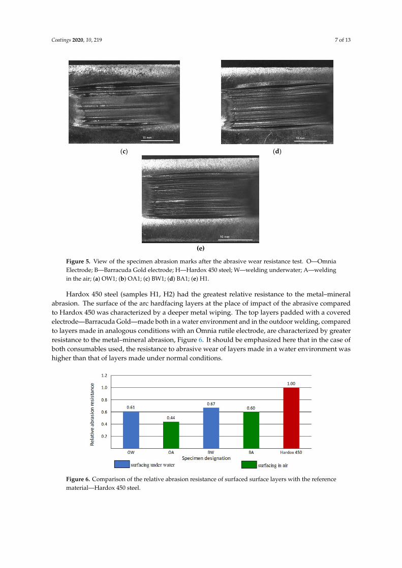
Hardox 450 steel (samples H1, H2) had the greatest relative resistance to the metal–mineral abrasion. The surface of the arc hardfacing layers at the place of impact of the abrasive compared to Hardox 450 was characterized by a deeper metal wiping. The top layers padded with a covered electrode—Barracuda Gold—made both in a water environment and in the outdoor welding, compared to layers made in analogous conditions with an Omnia rutile electrode, are characterized by greater resistance to the metal–mineral abrasion, Figure 6. It should be emphasized here that in the case of both consumables used, the resistance to abrasive wear of layers made in a water environment was higher than that of layers made under normal conditions.
Figure 6. Comparison of the relative abrasion resistance of surfaced surface layers with the reference material—Hardox 450 steel.
Figure 5. View of the specimen abrasion marks after the abrasive wear resistance test. O—OmniaElectrode; B—Barracuda Gold electrode; H—Hardox 450 steel; W—welding underwater; A—weldingin the air; (a) OW1; (b) OA1; (c) BW1; (d) BA1; (e) H1.
Hardox 450 steel (samples H1, H2) had the greatest relative resistance to the metal–mineralabrasion. The surface of the arc hardfacing layers at the place of impact of the abrasive comparedto Hardox 450 was characterized by a deeper metal wiping. The top layers padded with a coveredelectrode—Barracuda Gold—made both in a water environment and in the outdoor welding, comparedto layers made in analogous conditions with an Omnia rutile electrode, are characterized by greaterresistance to the metal–mineral abrasion, Figure 6. It should be emphasized here that in the case ofboth consumables used, the resistance to abrasive wear of layers made in a water environment washigher than that of layers made under normal conditions.
Coatings 2020, 10, x FOR PEER REVIEW 7 of 13
(c)
(d)
(e)
Figure 5. View of the specimen abrasion marks after the abrasive wear resistance test. O—Omnia Electrode; B—Barracuda Gold electrode; H—Hardox 450 steel; W—welding underwater; A—welding in the air; (a) OW1; (b) OA1;(c) BW1;(d) BA1;(e) H1.
Hardox 450 steel (samples H1, H2) had the greatest relative resistance to the metal–mineral abrasion. The surface of the arc hardfacing layers at the place of impact of the abrasive compared to Hardox 450 was characterized by a deeper metal wiping. The top layers padded with a covered electrode—Barracuda Gold—made both in a water environment and in the outdoor welding, compared to layers made in analogous conditions with an Omnia rutile electrode, are characterized by greater resistance to the metal–mineral abrasion, Figure 6. It should be emphasized here that in the case of both consumables used, the resistance to abrasive wear of layers made in a water environment was higher than that of layers made under normal conditions.
Figure 6. Comparison of the relative abrasion resistance of surfaced surface layers with the reference material—Hardox 450 steel.
Figure 6. Comparison of the relative abrasion resistance of surfaced surface layers with the referencematerial—Hardox 450 steel.

Coatings 2020, 10, 219 8 of 13
3.2. Hardness HV10 Measurements
Before measurements were carried out, the macroscopic tests were performed for each cross-sectionin accordance with the EN ISO 17639:2013 [42]. There were no imperfections detected duringmacroscopic testing. An example view of the prepared cross-section is presented in Figure 7.
Coatings 2020, 10, x FOR PEER REVIEW 8 of 13
3.2. Hardness HV10 Measurements
Before measurements were carried out, the macroscopic tests were performed for each cross-section in accordance with the EN ISO 17639:2013 [42]. There were no imperfections detected during macroscopic testing. An example view of the prepared cross-section is presented in Figure 7.
Figure 7. An example view of a cross-section of the layer made by an Omnia electrode in the air, with etching using Nital 4%.
The macroscopic photographs were used to calculate the dilution for layers performed in the air and in the water. The dilution is a factor that complicates predicting the effects of multi-pass welding, which affects, among other aspects, hardenability [46]. The dilution was calculated i.e., D = Abase/A, where A is the total molten area, and Abase is the molten area of BM [47]. The scheme of dilution calculation is presented in Figure 8.
Figure 8. The schematic view of the methodology of dilution calculations; A—total molten area, Aclad—molten cladded area and Abase—molten area of BM.
The dilution values for specimens welded in the air were higher than those for specimens welded underwater. These values depend on the bead sequences used for the surface of specimens, which was described in our previous studies [38]. Coronado et al. [48] stated that higher dilution levels reduced wear resistance. The different dilution values result from an assumed methodology of bead sequences.
The hardness HV10 measurements show differences in all specimens. For the specimens welded inthe air, the coating made by electrodes for underwater welding was characterized by higher hardness. Different situations were observedfor measurements of specimens welded in the water environment. The coating produced by electrodes for underwater welding was characterized by a lower hardness. The investigated S355G10+N steel is classified as material from group 2.1. in accordance with EN ISO 15614-1:2017 [49]. The maximum hardness assumed by this standard for this group cannot exceed that of 380HV10. The hardness measurement showed that the coatings made underwater by the Omnia electrode did not fulfill the requirements of hardness by the standard EN ISO 15614-1:2017. The results of the hardness HV10 measurements are presented in Table 3.
Table 3. The results of the hardness HV10 measurements.
Specimen Place of Measurements Hardness HV10 (±3) Measurement Point
1 2 3 4 5
OA Upper surface 220 245 236 220 215 Cross-section 218 234 242 230 228
BA Upper surface 253 246 265 277 245 Cross-section 242 253 270 242 252
OW Upper surface 455 459 445 472 444 Cross-section 441 451 462 445 439
BW Upper surface 331 321 335 310 296 Cross-section 342 333 327 330 337
Figure 7. An example view of a cross-section of the layer made by an Omnia electrode in the air, withetching using Nital 4%.
The macroscopic photographs were used to calculate the dilution for layers performed in the airand in the water. The dilution is a factor that complicates predicting the effects of multi-pass welding,which affects, among other aspects, hardenability [46]. The dilution was calculated i.e., D = Abase/A,where A is the total molten area, and Abase is the molten area of BM [47]. The scheme of dilutioncalculation is presented in Figure 8.
Coatings 2020, 10, x FOR PEER REVIEW 8 of 13
3.2. Hardness HV10 Measurements
Before measurements were carried out, the macroscopic tests were performed for each cross-section in accordance with the EN ISO 17639:2013 [42]. There were no imperfections detected during macroscopic testing. An example view of the prepared cross-section is presented in Figure 7.
Figure 7. An example view of a cross-section of the layer made by an Omnia electrode in the air, with etching using Nital 4%.
The macroscopic photographs were used to calculate the dilution for layers performed in the air and in the water. The dilution is a factor that complicates predicting the effects of multi-pass welding, which affects, among other aspects, hardenability [46]. The dilution was calculated i.e., D = Abase/A, where A is the total molten area, and Abase is the molten area of BM [47]. The scheme of dilution calculation is presented in Figure 8.
Figure 8. The schematic view of the methodology of dilution calculations; A—total molten area, Aclad—molten cladded area and Abase—molten area of BM.
The dilution values for specimens welded in the air were higher than those for specimens welded underwater. These values depend on the bead sequences used for the surface of specimens, which was described in our previous studies [38]. Coronado et al. [48] stated that higher dilution levels reduced wear resistance. The different dilution values result from an assumed methodology of bead sequences.
The hardness HV10 measurements show differences in all specimens. For the specimens welded inthe air, the coating made by electrodes for underwater welding was characterized by higher hardness. Different situations were observedfor measurements of specimens welded in the water environment. The coating produced by electrodes for underwater welding was characterized by a lower hardness. The investigated S355G10+N steel is classified as material from group 2.1. in accordance with EN ISO 15614-1:2017 [49]. The maximum hardness assumed by this standard for this group cannot exceed that of 380HV10. The hardness measurement showed that the coatings made underwater by the Omnia electrode did not fulfill the requirements of hardness by the standard EN ISO 15614-1:2017. The results of the hardness HV10 measurements are presented in Table 3.
Table 3. The results of the hardness HV10 measurements.
Specimen Place of Measurements Hardness HV10 (±3) Measurement Point
1 2 3 4 5
OA Upper surface 220 245 236 220 215 Cross-section 218 234 242 230 228
BA Upper surface 253 246 265 277 245 Cross-section 242 253 270 242 252
OW Upper surface 455 459 445 472 444 Cross-section 441 451 462 445 439
BW Upper surface 331 321 335 310 296 Cross-section 342 333 327 330 337
Figure 8. The schematic view of the methodology of dilution calculations; A—total molten area,Aclad—molten cladded area and Abase—molten area of BM.
The dilution values for specimens welded in the air were higher than those for specimens weldedunderwater. These values depend on the bead sequences used for the surface of specimens, which wasdescribed in our previous studies [38]. Coronado et al. [48] stated that higher dilution levels reducedwear resistance. The different dilution values result from an assumed methodology of bead sequences.
The hardness HV10 measurements show differences in all specimens. For the specimens weldedinthe air, the coating made by electrodes for underwater welding was characterized by higher hardness.Different situations were observedfor measurements of specimens welded in the water environment.The coating produced by electrodes for underwater welding was characterized by a lower hardness.The investigated S355G10+N steel is classified as material from group 2.1. in accordance with EN ISO15614-1:2017 [49]. The maximum hardness assumed by this standard for this group cannot exceed thatof 380HV10. The hardness measurement showed that the coatings made underwater by the Omniaelectrode did not fulfill the requirements of hardness by the standard EN ISO 15614-1:2017. The resultsof the hardness HV10 measurements are presented in Table 3.
Table 3. The results of the hardness HV10 measurements.
Specimen Place of Measurements
>Hardness HV10 (±3)
Measurement Point
1 2 3 4 5
OAUpper surface 220 245 236 220 215Cross-section 218 234 242 230 228
BAUpper surface 253 246 265 277 245Cross-section 242 253 270 242 252
OWUpper surface 455 459 445 472 444Cross-section 441 451 462 445 439
BWUpper surface 331 321 335 310 296Cross-section 342 333 327 330 337

Coatings 2020, 10, 219 9 of 13
After welding in the air, the coating made by the electrode for underwater welding wascharacterized by higher hardness and higher relative abrasion resistance than the coating welded bythe Omnia electrode. In the case of underwater welding, the layer (Barracuda Gold electrode) withlower hardness was characterized by a higher relative abrasion resistance. The literature [48] showedthat there is no relationship between the hardness and relative abrasion resistance, which was provenin this investigation. For both environments, the Barracuda Gold electrodes produced the layer withthe higher wear resistance. The Barracuda Gold layers were welded with higher values of heat inputs,which decreased the cooling rate. This providesa higher abrasive wear resistance for layers producedby the Barracuda Gold electrodes. The same factor was responsible for higher abrasive wear resistanceof layers welded inthe air. The water, as a welding environment, increased the cooling rate, whichgenerated brittle structures [27–31,35,38] with lower wear resistance.
3.3. Microscopic Study
The microscopic observations confirmed the earlier results. There were observed significantdifferences in the weld and in HAZ of specimens produced by different electrodes in differentenvironments. The layers prepared in the water are characterized by the presence of dendritic structurein welds, which consisted of bright fine-grained pearlite arranged in columns. At the boundariesof dendrites, the acicular ferrite grew from these columns (Figure 9a,b). In the welds performed bythe Omnia electrodes, cracks were observed (Figure 9b). This may be the result of Ni content in theBarracuda Gold electrode deposit, which improved the mechanical properties of weld metal [50].The structure of the welds of coatings performed in the air is different. They are characterized by apartial disappearance of the dendritic structure (Figure 9c,d). This area is built by a fine-grained ferriteand pearlite structure, which results from the lower cooling rate in the air in comparison to the water.The weld produced by Barracuda Gold in the air is characterized by finer grain size, which improvedwear resistance. This is in agreement with the results presented by Cui et al. [51]. The structureof HAZ was similar for coatings performed by both electrodes in the air. The structure indicatedthe presence of refined and tempered low-carbon martensite mixed with normalization structureswith fine ferrite and pearlite (Figure 9d). The HAZ of underwater specimens is characterized by thepresence of brittle bainitic and martensitic structures, which results in cracking observed for bothused electrodes. In specimens prepared by Barracuda Gold, these cracks are located perpendicularto the fusion line (Figure 9e). The cracks observed in specimens performed bythe Omnia electrodesare located perpendicular and parallel to the fusion line. The length of those cracks was much higher.It was stated in the literature [44] that the presence of the cracks influencesa lower abrasive wearresistance of performed coatings. The exemplary results of metallographic microscopic tests arepresented in Figure 9.
Coatings 2020, 10, x FOR PEER REVIEW 9 of 13
After welding in the air, the coating made by the electrode for underwater welding was characterized by higher hardness and higher relative abrasion resistance than the coating welded by the Omnia electrode. In the case of underwater welding, the layer (Barracuda Gold electrode) with lower hardness was characterized by a higher relative abrasion resistance. The literature [48] showed that there is no relationship between the hardness and relative abrasion resistance, which was proven in this investigation. For both environments, the Barracuda Gold electrodes produced the layer with the higher wear resistance. The Barracuda Gold layers were welded with higher values of heat inputs, which decreased the cooling rate. This providesa higher abrasive wear resistance for layers produced by the Barracuda Gold electrodes. The same factor was responsible for higher abrasive wear resistance of layers welded inthe air. The water, as a welding environment, increased the cooling rate, which generated brittle structures [27–31,35,38] with lower wear resistance.
3.3. Microscopic Study
The microscopic observations confirmed the earlier results. There were observed significant differences in the weld and in HAZ of specimens produced by different electrodes in different environments. The layers prepared in the water are characterized by the presence of dendritic structure in welds, which consisted of bright fine-grained pearlite arranged in columns. At the boundaries of dendrites, the acicular ferrite grew from these columns (Figure 9a,b). In the welds performed by the Omnia electrodes, cracks were observed (Figure 9b). This may be the result of Ni content in the Barracuda Gold electrode deposit, which improved the mechanical properties of weld metal [50]. The structure of the welds of coatings performed in the air is different. They are characterized by a partial disappearance of the dendritic structure (Figure 9c,d). This area is built by a fine-grained ferrite and pearlite structure, which results from the lower cooling rate in the air in comparison to the water. The weld produced by Barracuda Gold in the air is characterized by finer grain size, which improved wear resistance. This is in agreement with the results presented by Cui et al. [51]. The structure of HAZ was similar for coatings performed by both electrodes in the air. The structure indicated the presence of refined and tempered low-carbon martensite mixed with normalization structures with fine ferrite and pearlite (Figure 9d). The HAZ of underwater specimens is characterized by the presence of brittle bainitic and martensitic structures, which results in cracking observed for both used electrodes. In specimens prepared by Barracuda Gold, these cracks are located perpendicular to the fusion line (Figure 9e). The cracks observed in specimens performed bythe Omnia electrodes are located perpendicular and parallel to the fusion line. The length of those cracks was much higher. It was stated in the literature [44] that the presence of the cracks influencesa lower abrasive wear resistance of performed coatings. The exemplary results of metallographic microscopic tests are presented in Figure 9.
(a)
(b)
Figure 9. Cont.

Coatings 2020, 10, 219 10 of 13
Coatings 2020, 10, x FOR PEER REVIEW 10 of 13
(c)
(d)
(e)
(f)
Figure 9. Exemplary results of microscopic testing:(a) weld made in the water by the Omnia electrode; (b) weld made in the water by the Barracuda Gold electrode;(c) weld made in the air by the Omnia electrode; (d) weld and heat-affected zone (HAZ) made in the air by the Barracuda Gold electrode; (e) HAZ of specimen made in the water—Barracuda Gold electrode; (f) HAZ of specimen made in the water—Omnia electrode.
4. Conclusions
The results of the performed investigations showed a significant influence of the welding environment on the hardness and wear resistance of the produced layers. We proved that relative abrasion resistance depends on the type of electrodes and the environment of welding. From a practical point of view, the most important finding is that there is no need to transport elements to the surface, and they can be repaired in-situ in the water. It will reduce the cost of maintaining and repairing of offshore infrastructure.
The performed examinations allow us to draw these conclusions: 1. Water, as an environment of the welding processes, generates higher HV10 hardness of steel
coatings than air does. The microstructure of coatings performed in the water contains the brittle structures in the HAZ, which resulted from a high cooling rate. The structures for specimens manufactured in the air are characterized by the presence of normalized structures.
2. The hardness strongly depends on the welding environment, but no influence on the abrasive wear resistancewas found, neither in the air nor in the water environment.
3. The coatings produced by the electrodes for underwater welding (Barracuda Gold) are characterized by a lower volume loss in the metal–mineral abrasion conditions than layers welded by the general usage electrodes (Omnia). This is due to the smaller grain size of the weld metal produced in the air (Barracuda Gold), and the greater number of cracks for coating made in the water (Omnia).
Figure 9. Exemplary results of microscopic testing:(a) weld made in the water by the Omnia electrode;(b) weld made in the water by the Barracuda Gold electrode;(c) weld made in the air by the Omniaelectrode; (d) weld and heat-affected zone (HAZ) made in the air by the Barracuda Gold electrode;(e) HAZ of specimen made in the water—Barracuda Gold electrode; (f) HAZ of specimen made in thewater—Omnia electrode.
4. Conclusions
The results of the performed investigations showed a significant influence of the weldingenvironment on the hardness and wear resistance of the produced layers. We proved that relativeabrasion resistance depends on the type of electrodes and the environment of welding. From a practicalpoint of view, the most important finding is that there is no need to transport elements to the surface,and they can be repaired in-situ in the water. It will reduce the cost of maintaining and repairing ofoffshore infrastructure.
The performed examinations allow us to draw these conclusions:
1. Water, as an environment of the welding processes, generates higher HV10 hardness of steelcoatings than air does. The microstructure of coatings performed in the water contains the brittlestructures in the HAZ, which resulted from a high cooling rate. The structures for specimensmanufactured in the air are characterized by the presence of normalized structures.
2. The hardness strongly depends on the welding environment, but no influence on the abrasivewear resistancewas found, neither in the air nor in the water environment.
3. The coatings produced by the electrodes for underwater welding (Barracuda Gold) arecharacterized by a lower volume loss in the metal–mineral abrasion conditions than layerswelded by the general usage electrodes (Omnia). This is due to the smaller grain size of the weldmetal produced in the air (Barracuda Gold), and the greater number of cracks for coating made inthe water (Omnia).

Coatings 2020, 10, 219 11 of 13
4. The water environment of welding produces coatings with higher abrasive wear resistance thanlayers welded in the air, which resulted from different metallographic microstructures formed incoatings manufactured in other environments.
Author Contributions: Conceptualization, J.T.; methodology, J.T. and A.C.; formal analysis, J.T., A.C. and D.F.;investigation, J.T. and A.C.; writing—original draft preparation, J.T, A.C. and D.F.; writing—review and editing,J.T., A.C. and D.F. All authors have read and agreed to the published version of the manuscript.
Funding: This research received no external funding.
Acknowledgments: None.
Conflicts of Interest: The authors declare no conflicts of interest.
References
1. Dehghani, A.; Aslani, F. A review on defects in steel offshore structures and developed strengtheningtechniques. Structures 2019, 20, 635–657. [CrossRef]
2. Price, S.J.; Figueira, R.B. Corrosion protection systems and fatigue corrosion in offshore wind structures:Current status and future perspectives. Coatings 2017, 7, 25. [CrossRef]
3. Papatheocharis, T.; Saravanis, G.C.; Perdikaris, P.C.; Karamanos, S.A. Fatigue of welded tubular X-joints inoffshore wind platforms. In International Conference on Offshore Mechanics and Arctic Engineering, Proceedings ofthe ASME 2019 38th International Conference on Ocean, Offshore and Arctic Engineering, Glasgow, Scotland, UK,9–14 June 2019; Materials Technology; ASME: New York, NY, USA, 2019; Volume 4. [CrossRef]
4. Kong, X.; Lv, J.; Gao, N.; Peng, X.; Zhang, J. An experimental study of galvanic corrosion on an underwaterweld joint. J. Coast. Res. 2018, 84, 63–68. [CrossRef]
5. Liang, L.; Pang, Y.; Zhu, Z.; Tang, Y.; Xiang, Y. Influencing factors of various combinations of abrasion,cavitation and corrosion caused by multiphase flow impact. Trans. Can. Soc. Mech. Eng. 2019, 43, 130.[CrossRef]
6. Momber, A.W.; Marquardt, T. Protective coatings for offshore wind energy devices (OWEAs): A review.J. Coat. Technol. Res. 2018, 15, 13–40. [CrossRef]
7. López-Ortega, A.; Arana, J.L.; Rodriguez, E.; Bayón, R. Corrosion, wear and tribocorrosion performance ofa thermally sprayed aluminum coating modified by plasma electrolytic oxidation technique for offshoresubmerged components protection. Corros. Sci. 2018, 143, 258–280. [CrossRef]
8. Łatka, L.; Szala, M.; Michalak, M.; Pałka, T. Impact of atmospheric plasma spray parameters on cavitationerosion resistance of Al2O3-13% TiO2 coatings. Acta Phys. Pol. A 2019, 136, 342–347. [CrossRef]
9. He, X.; Song, R.G.; Kong, D.J. Microstructure and corrosion behaviours of composite coatings on S355offshore steel prepared by laser cladding combined with micro-arc oxidation. Appl. Surf. Sci. 2019, 497,143703. [CrossRef]
10. Li, Y.; Li, C.; Tang, S.; Zheng, Q.; Wang, J.; Zhang, Z.; Wang, Z. Interfacial bonding and abrasive wear behaviorof iron matrix composite reinforced by ceramic particles. Materials 2019, 12, 3646. [CrossRef]
11. Czuprynski, A. Properties of Al2O3/TiO2and ZrO2/CaO flame-sprayed coatings. Mater. Tehnol./Mater. Technol.2017, 51, 205–212. [CrossRef]
12. Szala, M.; Dudek, A.; Maruszczyk, A.; Walczak, M.; Chmiel, J.; Kowal, M. Effect of atmospheric plasmasprayed TiO2—10% NiAl cermet coating thickness on cavitation erosion, sliding and abrasive wear resistance.Acta Phys. Pol. A 2019, 136, 335–341. [CrossRef]
13. Czuprynski, A.; Górka, J.; Adamiak, M.; Tomiczek, B. Testing of flame sprayed Al2O3matrix coatingscontaining TiO2. Arch. Metall. Mater. 2016, 61, 1363–1370. [CrossRef]
14. Adamiak, M.; Czuprynski, A.; Kopysc, A.; Monica, Z.; Olender, M.; Gwiazda, A. The Properties ofArc-Sprayed Aluminum Coatings on Armor-Grade Steel. Metals 2018, 8, 142. [CrossRef]
15. Chmielewski, T.; Siwek, P.; Chmielewski, M.; Piatkowska, A.; Grabias, A.; Golanski, D. Structure and selectedproperties of arc sprayed coatings containing in-situ fabricated Fe-Al intermetallic phases. Metals 2018, 8,1059. [CrossRef]
16. Czuprynski, A. Flame spraying of aluminum coatings reinforced with particles of carbonaceous materials asan alternative for laser cladding technologies. Materials 2019, 12, 3467. [CrossRef]

Coatings 2020, 10, 219 12 of 13
17. Górka, J.; Czuprynski, A.; Zuk, M.; Adamiak, M.; Kopysc, A. Properties and structure of depositednanocrystalline coatings in relation to selected construction materials resistant to abrasive wear. Materials2018, 11, 1–15. [CrossRef]
18. Chmielewski, T.; Hudycz, M.; Krajewski, A.; Sałacinski, T.; Skowronska, B.; Swiercz, R. Structure investigationon titanium metallization coating deposited onto AlN ceramics substrate by means of friction surfacingproces. Coatings 2019, 9, 845. [CrossRef]
19. Liu, Y.; Li, C.X.; Huang, X.F.; Ma, K.; Luo, X.T.; Li, C.J. Effect of water environment on particle deposition ofunderwater cold spray. Appl. Surf. Sci. 2020, 506, 144542. [CrossRef]
20. Feng, X.; Cui, X.; Zheng, W.; Lu, B.; Dong, M.; Wen, X.; Zhao, Y.; Jin, G. Effect of the protective materials andwater on the repairing quality of nickel aluminum bronze during underwater wet laser repairing. Opt. LaserTechnol. 2019, 114, 140–145. [CrossRef]
21. Wen, X.; Jin, G.; Cui, X.; Feng, X.; Lu, B.; Cai, Z.; Zhao, Y.; Fang, Y. Underwater wet laser cladding on 316Lstainless steel: A protective material assisted method. Opt. Laser Technol. 2019, 111, 814–824. [CrossRef]
22. Fu, Y.; Guo, N.; Zhou, L.; Cheng, Q.; Feng, J. Underwater wire-feed laser deposition of the Ti–6Al–4V titaniumalloy. Mater. Des. 2020, 186, 108284. [CrossRef]
23. Cevik, B. The effect of pure argon and mixed gases on microstructural and mechanical properties of S275structural steel joined by flux-cored arc welding. Kov. Mater. 2020, 56, 81–87. [CrossRef]
24. Kik, T.; Moravec, J.; Nováková, I. Numerical simulations of X22CrMoV12-1 steel multilayer welding. Arch.Metall. Mater. 2019, 64, 1441–1448. [CrossRef]
25. Srisuwan, N.; Kumsri, N.; Yingsamphancharoen, T.; Kaewvilai, A. Hardfacing welded ASTM A572-based,high-strength low-alloy steel: Welding, characterization, and surface properties related to the wear resistance.Metals 2019, 9, 244. [CrossRef]
26. Triwanapong, S.; Angthong, A.; Kimapong, K. Interpass temperature affecting abrasive wear resistance ofSMAW hard-faced weld metal on JIS-S50C carbon steel. Mater. Sci. Forum 2019, 950, 60–64. [CrossRef]
27. Wang, J.; Sun, Q.; Teng, J.; Feng, J. Bubble evolution in ultrasonic wave-assisted underwater wet FCAW. Weld.J. 2019, 98, 150–163. [CrossRef]
28. Guo, N.; Du, Y.; Maksimov, S.; Feng, J.; Yin, Z.; Krazhanovskyi, D.; Fu, Y. Study of metal transfer control inunderwater wet FCAW using pulsed wire feed method. Weld. World 2018, 62, 87–94. [CrossRef]
29. Yang, Q.; Han, Y.; Jia, C.; Wu, J.; Dong, S.; Wu, C. Impeding effect of bubbles on metal transfer in underwaterwet FCAW. J. Manuf. Process. 2019, 45, 682–689. [CrossRef]
30. Chen, H.; Guo, N.; Xu, K.; Xu, C.; Zhou, L.; Wang, G. In-situ observations of melt degassing and hydrogenremoval enhanced by ultrasonics in underwater wet welding. Mater.Des. 2020, 108482. [CrossRef]
31. Yan, C.; Kan, C.; Li, C.; Tian, S.; Bai, Y.; Xue, F. Experimental and numerical investigation on underwater wetwelding of HSLA steel. IOP Conf. Ser. Mater. Sci. Eng. 2018, 394, 022016. [CrossRef]
32. Tomków, J.; Fydrych, D.; Rogalski, G.; Łabanowski, J. Effect of the welding environment and storage time ofelectrodes on the diffusible hydrogen content in deposited metal. Rev. Metal. 2019, 55, e140. [CrossRef]
33. Chen, H.; Gui, N.; Liu, C.; Zhang, X.; Xu, C.; Wang, G. Insight into hydrostatic pressure effects on diffusiblehydrogen content in wet welding joints using in-situ X-ray imaging method. Int. J. Hyd. Energy 2020, inpress. [CrossRef]
34. Swierczynska, A.; Fydrych, D.; Landowski, M.; Rogalski, G.; Łabanowski, J. Hydrogen embrittlement ofX2CRNiMoCuN25-6-2- super duplex stainless steel welded joints under cathodic protection. Constr. Build.Mater. 2020, 238, 117697. [CrossRef]
35. Tomków, J.; Fydrych, D.; Rogalski, G.; Łabanowski, J. Temper bead welding of S460N steel in wet weldingconditions. Adv. Mater. Sci. 2018, 18, 5–14. [CrossRef]
36. Gao, W.; Wang, D.; Cheng, F.; Di, X.; Den, C.; Xu, W. Microstructural and mechanical performance ofunderwater wet welded S355 steel. J. Mater. Process. Technol. 2016, 238, 333–340. [CrossRef]
37. ISO 2560-A. Classification of Coated Rod Electrodes for Arc Welding of Unalloyed Steel and Fine-Grained Steel; ISO:Geneva, Switzerland, 2010.
38. Tomków, J.; Fydrych, D.; Rogalski, G. Role of bead sequence in underwater welding. Materials 2019, 12, 3372.[CrossRef] [PubMed]
39. ASTM G 65-00. Standard Test Method for Measuring Abrasion Using the Dry Sand/Rubber Wheel Apparatus;West Conshohocken, PA, USA, 2016.

Coatings 2020, 10, 219 13 of 13
40. Szala, M.; Szafran, M.; Macek, W.; Marchenko, S.; Hejwowski, T. Abrasion resistance S235, C45, AISI 304 andHardox 500 steels with usage of garnet, corundum and carborundum abrasives. Adv. Sci. Technol. Res. J.2019, 13, 151–161. [CrossRef]
41. EN ISO 9015-1:2011. Destructive Tests on Welds in Metallic Materials. Hardness Testing. Hardness Test on ArcWelded Joint; ISO: Geneva, Switzerland, 2011.
42. EN ISO 17639:2013. Destructive Tests on Welds in Metallic Materials. Macroscopic and Microscopic Examination ofWelds; ISO: Geneva, Switzerland, 2013.
43. Chand, N.; Neogi, S. Mechanism of material removal during three-body abrasion of FRF composite. Tribol.Lett. 1998, 4, 81. [CrossRef]
44. Singh, P.T.; Singla, A.K.; Singh, J.; Singh, K.; Gupta, M.K.; Ju, H.; Song, Q.; Liu, Z.; Pruncu, C.I. Abrasive wearbehavion of cryogenically treated boron steel (30MnCrB4) used for rotavator blades. Materials 2020, 13, 436.[CrossRef]
45. Jankauskas, V.; Kreivaitis, R.; Milcius, D.; Baltusnikas, A. Analysis of abrasive wear performance of arcwelded hard layers. Wear 2008, 265, 1626–1632. [CrossRef]
46. Sun, Y.L.; Obasi, G.; Hamelin, C.J.; Vasileiou, A.N.; Flint, T.F.; Balakrishnan, J.; Smith, M.C.; Francis, J.A.Effects of dilution on alloy content and microstructure in multi-pass steel welds. J. Mater. Process. Technol.2019, 265, 71–86. [CrossRef]
47. Saida, K.; Bunda, K.; Ogiwara, H.; Nishimoto, K. Microcracking susceptibility in dissimilar multipass weldsof Ni-base alloy 690 and low-alloy steel. Weld. Int. 2015, 29, 668–680. [CrossRef]
48. Coronado, J.J.; Caicedo, H.F.; Gómez, A.L. The effects of welding process on abrasive wear resistance forhardfacing deposits. Tribol. Int. 2009, 42, 745–749. [CrossRef]
49. EN-ISO 15614-1:2017. Specification and Qualification of Welding Procedures for Metallic Materials—WeldingProcedure Test—Part 1: Arc and Gas Welding of Steels and Arc Welding of Nickel and Nickel Alloys; ISO: Geneva,Switzerland, 2017.
50. Guo, N.; Liu, D.; Guo, W.; Li, X.; Feng, J. Effect of Ni on microstructure and mechanical properties ofunderwater wet welding joint. Mater. Des. 2015, 77, 25–31. [CrossRef]
51. Cui, Z.; Bhattacharya, S.; Green, D.E.; Alpas, A.T. Mechanisms of die wear and wear-induced damage at thetrimmed edge of high strength steel sheets. Wear 2019, 426, 1635–1645. [CrossRef]
© 2020 by the authors. Licensee MDPI, Basel, Switzerland. This article is an open accessarticle distributed under the terms and conditions of the Creative Commons Attribution(CC BY) license (http://creativecommons.org/licenses/by/4.0/).