VACMASTER® 15T TIER III DIESEL ABRASIVE VACUUMS
104
Before using this equipment, read, understand and follow all instructions in the Operator’s Manuals provided with this equipment. If the user and/ or assistants cannot read or understand the warnings and instructions, the employer of the user and/or assistants must provide adequate and necessary training to ensure proper operation and compliance with all safety procedures pertaining to this equipment. If Operator’s Manuals have been lost, please visit www.marco.us, or contact Marco at 563.324.2519 for replacements. Failure to comply with the above warning could result in death or serious injury. OPERATOR’S MANUAL VACMASTER ® 15T TIER III DIESEL ABRASIVE VACUUMS
-
Upload
khangminh22 -
Category
Documents
-
view
0 -
download
0
Transcript of VACMASTER® 15T TIER III DIESEL ABRASIVE VACUUMS

Before using this equipment, read, understand and follow all instructions in the Operator’s Manuals provided with this equipment. If the user and/or assistants cannot read or understand the warnings and instructions,
the employer of the user and/or assistants must provide adequate and necessary training to ensure proper operation and compliance with all safety procedures pertaining to this equipment. If Operator’s Manuals have been lost, please visit www.marco.us, or contact Marco at 563.324.2519 for replacements. Failure to comply with the above warning could result in death or serious injury.
OPERATOR’S MANUAL
VACMASTER® 15T TIER III DIESEL ABRASIVE VACUUMS

Vacmaster® 15T Tier III Diesel Abrasive Vacuums1
Company ProfileSince 1944, Marco has developed a strong tradition of providing innovative and reliable products and services to the surface preparation and protective coatings industries. We are the world’s premier provider of Abrasives, Blasting, Coating, Dust Collectors, Engineered Systems, Rental, Safety, Service, Repair, & Modernization, and Vacuums.
Through innovative designs and a total commitment to quality, Marco manufactures products that increase production rates, create a safer workplace, and reduce maintenance costs. Marco’s industry experience, manufacturing capabilities, legendary customer service, product availability, logistics services, and technology leadership is your assurance that we deliver high quality products and services, providing the best value to you, our customer.
The Marco Difference• Industry Experience – With Marco on your team, you have access to expertise which can only come from
decades of industry leadership. We have organized our engineering department, production specialists, customer operations, and safety support into a “Center of Competence.” As a Marco customer, you have access to hundreds of years of cumulative experience related to your operations.
• Manufacturing Excellence – Marco is a U.S. based, ISO 9001:2008 certified manufacturer of equipment for the Surface Preparation and Protective Coatings industries. Marco’s engineers benchmark the industry to ensure that we design and manufacture superior products that set the “Gold Standard” for performance, safety, and quality.
• Legendary Customer Service – Marco’s legendary customer service team is staffed by friendly, highly-trained individuals who are focused on providing the highest level of product support, order accuracy, and customer satisfaction.
• Product Availability – We stock over 10,000 SKU’s and have more than 45 shipping locations to serve North American and International markets for all major brands of blasting and coating equipment. As the largest provider of surface preparation and protective coatings equipment in the world, our inventory levels and product availability are unmatched.
• Logistics Services – Marco’s in-house logistics team is dedicated to moving your shipment anywhere in the world. We move more than 14,000 truckloads every year, allowing you to save on freight costs by leveraging our buying power. Lower your process costs with a single invoice, which includes product and freight.
• Technology Leadership – Our website provides: Operator’s Manuals, Part Numbers and Schematics Guides, SDS information, and Features & Specifications Guides, providing access to information 24/7. Our Extranet application allows you to receive quotes and place orders online. Our Intranet maintains a complete record of your purchase history to assist with ongoing support of your existing equipment and future purchasing decisions.
Vision Statement Marco is the world’s premier provider of Abrasives, Blasting, Coating, Dust Collectors, Engineered Systems, Rental, Safety, Service, Repair, & Modernization, and Vacuums.
Mission Statement Marco provides strong leadership and innovation to the surface preparation and protective coatings industries. We dedicate our efforts to the continuous improvement of our products, services, processes, people, and most importantly, the quality of our customer’s experience.
Quality Statement Marco is committed to providing superior quality in the design, manufacturing, distribution, rental, service, and repair of our products. Our ISO 9001:2008 certification extends throughout all operations in all locations. Continuous improvement of our processes and supply chain Integration comprise the core of our business strategy for delivering exceptional quality and value in all Marco products and services.
Management Philosophy We are a company dedicated to the success of every customer and associate. We discuss, debate, challenge, measure, and test our ideas. We will be boundless and limitless in our passion to improve. Through sound leadership and dedicated associates, we will ensure a long term, profitable future for Marco, our associates, customers, and suppliers.

Vacmaster® 15T Tier III Diesel Abrasive Vacuums 2
DEFINITION OF TERMS
This is an example of a warning. This indicates a potentially hazardous situation which, if not avoided, could result in death or serious injury.
This is an example of a notice. This indicates policy or practice directly related to safety of personnel or protection of property.
This is an example of danger. This indicates an imminently hazardous situation which, if not avoided, will result in death or serious injury.
This is an example of a caution. This indicates a potentially hazardous situation which, if not avoided, may result in minor or moderate injury. It can also be used to alert against unsafe practices.

Vacmaster® 15T Tier III Diesel Abrasive Vacuums3
TABLE OF CONTENTS
Company Profile . . . . . . . . . . . . . . . . . . . . . . . . . 1
Definition of Terms . . . . . . . . . . . . . . . . . . . . . . 2
Air & Abrasive Consumption Chart . . . . . . . 8
Daily Pre-Operation Checklist . . . . . . . . . . . 10
Operating Instructions . . . . . . . . . . . . . . . . . . 11
Description . . . . . . . . . . . . . . . . . . . . . . . . . . . . 11
Operational Requirements . . . . . . . . . . . . . . . . 11
Towing Safety Instructions . . . . . . . . . . . . . . . . 11
Operating Instructions . . . . . . . . . . . . . . . . . . . 11
Connect Vacuum Hose. . . . . . . . . . . . . . . . . . . 14
Raise and Lower Collection Hopper . . . . . . . . . 15
Pre-Startup . . . . . . . . . . . . . . . . . . . . . . . . . . . . 16
Unit Startup & Shutdown . . . . . . . . . . . . . . . . . 17
Adjust Vacuum Timer . . . . . . . . . . . . . . . . . . . . 19
Pulser System Startup . . . . . . . . . . . . . . . . . . . 20
Reading Magnehelic Gauge . . . . . . . . . . . . . . . 21
Lubricate Grease Points . . . . . . . . . . . . . . . . . . 22
Specifications . . . . . . . . . . . . . . . . . . . . . . . . . .24
Maintenance . . . . . . . . . . . . . . . . . . . . . . . . . . .25
Adjust Tension of Blower Drive Belt . . . . . . . . . 25
Adjust Pulse Separation . . . . . . . . . . . . . . . . . . 26
Hydraulic System Schematic . . . . . . . . . . . . . . 27
Remove & Install Pressure Tank . . . . . . . . . . . 28
Remove & Install Blower Drive Belt Assembly 29
Remove & Install Engine Assembly . . . . . . . . . 31
Remove & Install 12-Volt DC Hydraulic Power Unit With Tank. . . . . . . . . . . . . . . . . . . . . . . . . . 32
Remove & Install Compressor . . . . . . . . . . . . . 33
Remove & Install Governor . . . . . . . . . . . . . . . 36
Remove & Install Clutch . . . . . . . . . . . . . . . . . . 37
Remove & Install Vacuum Timer Control Box. . 37
Remove & Install Pulser Manifold. . . . . . . . . . . 38
Remove & Install Auxiliary Pulser Manifold . . . 39
Remove & Install Vacuum Light Bar . . . . . . . . . 39
Remove & Install Timer Board . . . . . . . . . . . . . 40
Remove & Install Air Dryer . . . . . . . . . . . . . . . . 41
Remove & Install Alcohol Evaporator . . . . . . . . 41
Remove & Install Vacuum Control Box. . . . . . . 42
Remove & Install Blower . . . . . . . . . . . . . . . . . 43
Remove & Install Butterfly Springs . . . . . . . . . . 46
Remove & Install Filter Bags . . . . . . . . . . . . . . 47
Remove & Install Filter Cartridge . . . . . . . . . . . 48
Remove & Install Fuel Tank . . . . . . . . . . . . . . . 49
Remove & Install Front Emergency-Stop Station . . . . . . . . . . . . . . . . . . . . . . . . . . . . . . . 50
Remove & Install Pendant Emergency-Stop Station . . . . . . . . . . . . . . . . . . . . . . . . . . . . . . . 51
Remove & Install Hopper Magnehelic Gauge . 52
Remove & Install Blower Filter Magnehelic Gauge. . . . . . . . . . . . . . . . . . . . . . . . . . . . . . . . 53
Remove & Install Pneumatic Piston Vibrators . 54
Disassemble & Assemble Diaphragm Valve. . . 54
Check Lubricator Oil Level . . . . . . . . . . . . . . . . 55
Remove & Install Lubricator . . . . . . . . . . . . . . . 56
Remove & Install Hopper Wear Plates . . . . . . . 57
Remove & Install Hopper Access Door Wear Plate . . . . . . . . . . . . . . . . . . . . . . . . . . . . . . . . . 59
Remove & Install Double Lock Valve Assembly 60
Hazard Identification Decals. . . . . . . . . . . . . . . 61
Troubleshooting . . . . . . . . . . . . . . . . . . . . . . . . 65
Assembly Part Numbers and Schematics 67
Front Assembly. . . . . . . . . . . . . . . . . . . . . . . . . 67
Rear Assembly . . . . . . . . . . . . . . . . . . . . . . . . . 69
Right Side Front Assembly . . . . . . . . . . . . . . . . 71
Right Side Center Assembly. . . . . . . . . . . . . . . 73

Vacmaster® 15T Tier III Diesel Abrasive Vacuums 4
TABLE OF CONTENTS
Right Side Rear Assembly . . . . . . . . . . . . . . . . 75
Left Side Front Assembly . . . . . . . . . . . . . . . . . 77
Left Side Center Assembly . . . . . . . . . . . . . . . . 79
Left Side Rear Assembly . . . . . . . . . . . . . . . . . 81
Double Lock Valve Assembly . . . . . . . . . . . . . . 83
Fuel Tank . . . . . . . . . . . . . . . . . . . . . . . . . . . . . 84
Fan Belt Assembly . . . . . . . . . . . . . . . . . . . . . . 85
Intake Filter Housing. . . . . . . . . . . . . . . . . . . . . 86
Vacuum Light Bar . . . . . . . . . . . . . . . . . . . . . . . 87
Pneumatic Piston Vibrators . . . . . . . . . . . . . . . 88
Pulser System Assembly . . . . . . . . . . . . . . . . . 89
Filter Bag Pulsers . . . . . . . . . . . . . . . . . . . . . . . 91
Emergency-Stop Stations. . . . . . . . . . . . . . . . . 92
Compressor Assembly . . . . . . . . . . . . . . . . . . . 93
Compressor Governor . . . . . . . . . . . . . . . . . . . 95
Vacuum Hose Support Bracket . . . . . . . . . . . . 96
Trailer . . . . . . . . . . . . . . . . . . . . . . . . . . . . . . . . 97
Wear Plates and Baffles . . . . . . . . . . . . . . . . . . 99
Hydraulic Hoses . . . . . . . . . . . . . . . . . . . . . . . 101
Limited Warranty . . . . . . . . . . . . . . . . . . . . . .102
Disclaimer of Warranty . . . . . . . . . . . . . . . . . . 102
Exclusive Remedy for Warranty Claims . . . . . 102
Limitation of Remedies . . . . . . . . . . . . . . . . . . 102

Vacmaster® 15T Tier III Diesel Abrasive Vacuums5
HAZARD IDENTIFICATIONS
Failure to comply with ANY WARNING listed below could result in death or serious injury.OSHA sets exposure limits to protect workers from exposure to respirable crystalline silica, 29 CFR 1910.1053.
Airborne dust could increase the exposure levels beyond permissible limits. Breathing dust containing silica could cause silicosis, a fatal lung disease. Breathing dust during abrasive blasting operations, post-blast cleaning operations, and/or servicing equipment within the abrasive blasting area may expose an individual to conditions that could cause asbestosis, lead poisoning and/or other serious or fatal diseases. Harmful dust containing toxic material from abrasives or surfaces being abrasive blasted can remain suspended in the air for long periods of time after abrasive blasting has ceased. A NIOSH-approved, well-maintained, respirator designed for the specific operation being performed must be used by anyone abrasive blasting, handling or using the abrasive, and anyone in the area of the dust.
Contact NIOSH and OSHA offices to determine the proper respirator for your specific application. The air supplied to the respirator must be at least Grade D quality as described in Compressed Gas Association Commodity Specification G-7.1 and as specified by OSHA Regulation 1910.134. Ensure air filter and respirator system hoses are not connected to non-air sources or in-plant lines that may contain nitrogen, oxygen, acetylene or other non-breathable gases. Before removing respirator, use an air monitoring instrument to determine if the atmosphere is safe to breathe.
You must comply with all OSHA, local, City, State, Province, Country and jurisdiction regulations, ordinances and standards, related to your particular work area and environment. Keep unprotected individuals out of the work area.
Abrasive blasting operators must receive thorough training on the use of abrasive resistant attire which includes: supplied-air respirator, abrasive blasting suit, safety shoes, gloves, ear protection and eye protection. Protect the operator and bystanders by complying with NIOSH and OSHA Safety Standards.
Inspect all equipment for wear or damage before and after each use. Failure to use Original Equipment Manufacturer repair parts and failure to immediately replace worn or damaged components could void warranties and cause malfunctions.
OSHA requires abrasive blasting nozzles be equipped with an operating valve, which shall be designed to be held open only by continuous hand pressure and shall close immediately upon release of hand pressure (i.e., a “deadman” control). The valve shall not be modified in any manner that would allow it to remain open without the application of continuous hand pressure by the operator. Failure to comply with the above warning could result in release of high speed abrasive and compressed air resulting in death or serious injury. OSHA 29CFR 1910.244(b)
Point the abrasive blasting nozzle only at the surface being abrasive blasted. Never point the abrasive blasting nozzle or abrasive stream at yourself or others.
Unless otherwise specified, maximum working pressure of abrasive blasting pots and related components must not exceed 150 psi. Exceeding maximum working pressure of 150 psi could cause the abrasive blasting pot and components to burst. Failure to comply with the above warning could result in death or serious injury.
Never weld, grind or drill on the abrasive blasting pot (or any pressure vessel). Doing so will void ASME certification and manufacturer’s warranty. Welding, grinding or drilling on the abrasive blasting pot (or any pressure vessel) could weaken the vessel causing it to burst. Failure to comply with the above warning could result in death or serious injury. (ASME Pressure Vessel Code, Section VIII, Division 1)
This equipment is not intended for use in any area that might be considered a hazardous location, as described in the National Electric Code NFPA 70, Article 500. Use of this equipment in a hazardous location could cause an explosion or electrocution.
Never attempt to move an abrasive blasting pot containing abrasive. Never attempt to manually move abrasive blasting pots greater than 6.5 cubic foot capacity. Always use at least two capable people to manually move an abrasive blasting pot on flat, smooth surfaces. A mechanical lifting device must be used if an abrasive blasting pot is moved in any other manner.

Vacmaster® 15T Tier III Diesel Abrasive Vacuums 6
HAZARD IDENTIFICATIONS
Failure to comply with ANY WARNING listed below could result in death or serious injury.This product is not for use in wet environments. Always use a Ground Fault Interrupter Circuit (GFIC) for
all electrical power source connections. Use of this product in wet environments could create a shock or electrocution hazard.
Frozen moisture could cause restrictions and obstructions in pneumatic control lines. Any restriction or obstruction in the pneumatic control lines could prevent the proper activation and deactivation of the remote control system, resulting in the release of high speed abrasive and compressed air. In conditions where moisture may freeze in the control lines an antifreeze injection system approved for this application can be installed.
Do not cut, obstruct, restrict or pinch pneumatic control lines. Doing so could prevent the proper activation and deactivation of the remote control system, resulting in the release of high speed abrasive and compressed air.
Use of Marco remote control switches with other manufacturer’s remote control systems could cause unintended activation of remote control systems resulting in the release of high speed abrasive and compressed air. Only Marco remote control switches should be used with Marco remote control systems.
Always be certain to have secure footing when abrasive blasting. There is a recoil hazard when abrasive blasting starts that may cause user to fall and misdirect the abrasive stream at operator or bystander.
Never use an abrasive blasting pot or attachments as a climbing device. The person could slip and fall. The abrasive blasting pot could become unstable and tip over.
For equipment manufactured by entities other than Marco, you must consult the Original Equipment Manufacturer operator’s manuals, information, training, instructions and warnings, for the proper and intended use of all equipment.
Flammable fumes, such as solvent and paint fumes in the work area can present an ignition or explosion hazard if allowed to collect in adequate concentrations. To reduce conditions that could result in a fire or an explosion, provide adequate ventilation, eliminate all ignition or spark sources, keep the work area free of debris, store solvents and solvent contaminated rags in approved containers, follow proper grounding procedures, do not plug/unplug power cord or turn on/off power switches when flammable fumes are present, keep a working fire extinguisher or provide another fire suppression system in the work area. Cease all operations and correct condition if a spark or ignition source is identified during operation.
Always depressurize the entire system, disconnect all power sources and lockout/tagout all components before any maintenance or troubleshooting is attempted. Failure to comply with the above warning could cause electrical shock and inadvertent activation of equipment resulting in death or serious injury.
Moving parts can present an area where crushing, pinching, entanglement or amputation may occur. Do not place body parts or foreign objects in any area where there are moving parts.
Surfaces of heated supply tanks, drums and/or lines as well as the adjoining plumbing may become hot during normal use. Do not touch these heated surfaces without proper protection. Deactivate and allow sufficient time for all surfaces to cool before attempting any maintenance.
High-pressure fluid from gun, hose leaks, or ruptured components can pierce skin and can cause a serious injury that may result in amputation. Do not point gun or spray tip at anyone or at any part of the body. Keep clear of any leaks or ruptures. Depressurize the entire system before attempting cleaning, inspecting, or servicing equipment.
Exposure to toxic fluids or fumes may occur during the normal operation of this system. Before attempting to fill, use, or service this system, read SDS’s to know the specific hazards of the fluids you are using. Always use proper Personal Protective Equipment when attempting to fill, use, or service this system.
The use of this product for any purpose other than originally intended or altered from its original design is prohibited.
Never hang objects from the abrasive blasting pot handle. Doing so may cause the abrasive blasting pot to become unstable and tip over.

Vacmaster® 15T Tier III Diesel Abrasive Vacuums7
HAZARD IDENTIFICATIONS
Failure to comply with ANY CAUTION listed below may result in minor or moderate injury.Static electricity can be generated by abrasive moving through the abrasive blasting hose causing a shock
hazard. Prior to use, ground the abrasive blasting pot and abrasive blasting nozzle to dissipate static electricity. High decibel noise levels are generated during the abrasive blasting process which may cause loss of hearing.
Ensure appropriate Personal Protective Equipment and hearing protection is in use.
Failure to comply with ANY NOTICE listed below could pose a hazard to personnel or property.See Air & Abrasive Consumption Chart for estimated abrasive consumption rates and required air flow (cubic feet
per minute). Your system must meet these minimum requirements to ensure proper function and performance.Always use abrasive that is dry and properly screened. This will reduce the potential for obstructions to enter the
remote control system, abrasive metering valve and abrasive blasting nozzle.Moisture build-up occurs when air is compressed. Any moisture within the abrasive blasting system will cause
abrasive to clump, clogging metering valves, hoses and nozzles. Install an appropriately sized moisture separator at the inlet of the abrasive blasting system. Leave the moisture separator petcock slightly open to allow for constant release of water. If insufficient volume of air exists and petcock is unable to be left open (at all times) petcock should be opened frequently to release water.
To reduce abrasive intrusion in the air supply hose, depressurize the abrasive blasting pot before shutting off air supply from compressor.
Inspect abrasive blasting nozzle before placing into service. Damage to abrasive blasting nozzle liner or jacket may occur during shipping. If you receive a damaged abrasive blasting nozzle, contact your distributor immediately for replacement. Abrasive blasting nozzles placed into service may not be returned. Abrasive blasting nozzle liners are made of fragile materials and can be damaged by rough handling and striking against hard surfaces. Never use a damaged abrasive blasting nozzle.
Abrasive blasting at optimal pressure for the abrasive used is critical to productivity. Example: For an abrasive with an optimal abrasive blasting pressure of 100 psi at the abrasive blasting nozzle, one pound per square inch of pressure loss will reduce abrasive blasting efficiency by 1.5%. A 10 psi reduction in air pressure will cause a 15% loss of efficiency. Use a Needle Pressure Gauge to identify pressure drops in your system. Consult with your abrasive supplier for the requirements of your abrasive.
Replace abrasive blasting nozzle if liner or jacket is cracked or damaged. Replace abrasive blasting nozzle if original orifice size has worn 1/16” or more. Determine abrasive blasting nozzle wear by inserting a drill bit 1/16” larger than original size of abrasive blasting nozzle orifice. If the drill bit passes through abrasive blasting nozzle, replacement is needed.

Vacmaster® 15T Tier III Diesel Abrasive Vacuums 8
Failure to comply with ANY NOTICE listed below could pose a hazard to personnel or property.See Air & Abrasive Consumption Chart for estimated abrasive consumption rates and required air flow
(cubic feet per minute). Your system must meet these minimum requirements to ensure proper function and performance.
When it comes to air & abrasive mixtures, more is not necessarily better. Optimum abrasive blasting efficiency takes place when a lean air & abrasive mixture is used. To correctly set the abrasive metering valve, begin with the valve fully closed and slowly increase the amount of abrasive entering the airstream. As you increase the abrasive flow, watch for a “blue flame” at the exit of the abrasive blasting nozzle. Faster cutting, reduced abrasive consumption and lower clean up costs, are benefits of the “blue flame”.
Abrasive blasting at optimal pressure for the abrasive used is critical to productivity. Example: For an abrasive with an optimal abrasive blasting pressure of 100 psi at the abrasive blasting nozzle, one pound per square inch of pressure loss will reduce abrasive blasting efficiency by 1.5%. A 10 psi reduction in air pressure will cause a 15% loss of efficiency. Use a Needle Pressure Gauge to identify pressure drops in your system. Consult with your abrasive supplier for the requirements of your abrasive.
*Abrasive consumption is based on abrasive with a bulk density of 100 lbs per Cubic Foot
Air & Abrasive Consumption Chart*NozzleOrifice
Pressure at the Nozzle (PSI) Air (in cfm), Abrasive & Compressor Requirements50 60 70 80 90 100 125 140
No. 2(1/8ˮ)
11672.5
13773
15883.5
171014
181124.5
201235
251525.5
281706.2
Air (cfm)Abrasive (lbs/hr)Compressor Horsepower
No. 3(3/16ˮ)
261506
301717
331968
382169
4123810
4526410
5531912
6235713
Air (cfm)Abrasive (lbs/hr)Compressor Horsepower
No. 4(1/4ˮ)
4726811
5431212
6135414
6840816
7444817
8149418
9860822
11068125
Air (cfm)Abrasive (lbs/hr)Compressor Horsepower
No. 5(5/16ˮ)
7746818
8953420
10160423
11367226
12674028
13781231
16898237
188110041
Air (cfm)Abrasive (lbs/hr)Compressor Horsepower
No. 6(3/8ˮ)
10866824
12676428
14386432
16196036
173105239
196115244
237139352
265156058
Air (cfm)Abrasive (lbs/hr)Compressor Horsepower
No. 7(7/16ˮ)
14789633
170103238
194117644
217131249
240144854
254158457
314193169
352216377
Air (cfm)Abrasive (lbs/hr)Compressor Horsepower
No. 8(1/2ˮ)
195116044
224133650
252151256
280168063
309185669
338202475
409245990
4582754101
Air (cfm)Abrasive (lbs/hr)Compressor Horsepower
No. 10 (5/8ˮ)
308187568.5
356214079.5
404242290
4522690100.5
5042973112
5483250122
6633932146
7424405165
Air (cfm)Abrasive (lbs/hr)Compressor Horsepower
No. 12 (3/4ˮ)
432267296
5043056112
5723456127
6443840143
6924208154
7844608174.5
9485570209
10626238236
Air (cfm)Abrasive (lbs/hr)Compressor Horsepower
Inspect abrasive blasting nozzle before placing into service. Damage to abrasive blasting nozzle liner or jacket may occur during shipping. If you receive a damaged abrasive blasting nozzle, contact your distributor immediately for replacement. Abrasive blasting nozzles placed into service may not be returned. Abrasive blasting nozzle liners are made of fragile materials and can be damaged by rough handling and striking against hard surfaces. Never use a damaged abrasive blasting nozzle.
Replace abrasive blasting nozzle if liner or jacket is cracked or damaged. Replace abrasive blasting nozzle if original orifice size has worn 1/16” or more. Determine abrasive blasting nozzle wear by inserting a drill bit 1/16” larger than original size of abrasive blasting nozzle orifice. If the drill bit passes through abrasive blasting nozzle, replacement is needed.
“Blue Flame”
AIR & ABRASIVE CONSUMPTION CHART

Vacmaster® 15T Tier III Diesel Abrasive Vacuums9
“THE BIG PICTURE”
3
5
7
4
4
3
21
8
9
1714
1615
1319
18
10
20
23
21
424
272625
22
28
5
3
6
11
12

Vacmaster® 15T Tier III Diesel Abrasive Vacuums 10
Daily Pre-operation Checklist 1. Abrasive
2. Air Compressor
3. Air Hose Couplings & Gaskets
4. Air Hose
5. Safety Cable
6. Ambient Air Pump*
7. Breathing Air Filter
8. CO Monitor
9. Breathing Line
10. Climate Control Device
11. Abrasive Blasting Suit
12. Gloves
13. Abrasive Blasting Nozzle
14. Lighting System*
15. Abrasive Blasting Nozzle Holder
16. Remote Control Switch
17. Supplied-Air Respirator
18. Control Line
19. Abrasive Blasting Hose
20. Abrasive Blasting Hose Couplings & Gaskets
21. Abrasive Metering Valve
22. Remote Control System
23. Moisture Separator
24. Abrasive Blasting Pot Exhaust Muffler
25. Abrasive Blasting Pot
26. Abrasive Blasting Pot Screen
27. Abrasive Blasting Pot Lid
28. Aftercooler*
* Optional or alternative device. Ask your Marco Representative for more details.
Abrasive – Select the correct Abrasive (1) for the application. Review the SDS (Safety Data Sheet) to ensure the correct PPE (Personal Protective Equipment) and Environmental Controls have been selected and are in place.Air Compressor – Select an Air Compressor (2) of adequate size to support all equipment requirements. Refer to “Air & Abrasive Consumption Chart” for Abrasive Blasting Nozzle (13) air consumption requirements. Before connecting Air Hose (4), sample the air being produced by the air compressor (2) to ensure it is free of petroleum contaminants.Air Hose, and Air Hose Couplings & Gaskets – Select Air Hoses (4) of sufficient size to support all subsequent volumetric requirements and with a sufficient PSI (pound per square inch) rating. Inspect all Air Hoses (4), and Air Hose Couplings & Gaskets (3) for damage or wear. Repair or replace damaged or worn components.Abrasive Blasting Hose, Abrasive Blasting Hose Couplings & Gaskets, and Abrasive Blasting Nozzle Holder – Select an Abrasive Blasting Hose (19) that has an inner diameter 3 to 4 times larger than your Abrasive Blasting Nozzle (13). Inspect Abrasive Blasting Hose (19), Abrasive Blasting Hose Couplings & Gaskets (20), and Abrasive Blasting Nozzle Holder (15) for damage or wear. Repair or replace damaged or worn components.Safety Cables – Install a Safety Cable (5) at each Abrasive Blasting Hose (19), and Air Hose (4) connection points.Aftercooler and Moisture Separator – Ensure Aftercooler (28) is positioned on stable ground. Keep petcock drain of Moisture Separator (23) slightly open during use. Drain both devices after each use.Supplied-Air Respirator, Breathing Line, Breathing Air Filter, Climate Control Device, CO Monitor, Ambient Air Pump – You MUST consult the Operator’s Manual supplied with your Respiratory Equipment (6, 7, 8, 9, 10, 17) for ALL applicable instructions and warnings. Inspect all Respiratory Equipment components for damage or wear. Repair or replace damaged or worn components.Abrasive Blasting Suit and Gloves – Select an abrasive-resistant Abrasive Blasting Suit (11) that is slightly oversized to allow ease of movement and allows air to flow around your body. Select abrasive-resistant Gloves (12) with a tight fit and a long cuff that overlaps the sleeve of the Abrasive Blasting Suit (11).Abrasive Metering Valve and Abrasive Blasting Pot – Confirm Abrasive Blasting Pot (25) is positioned on stable ground. Inspect Abrasive Blasting Pot (25) and Abrasive Metering Valve (21) for damage or wear. Repair or replace damaged or worn components.Abrasive Blasting Pot Screen and Abrasive Blasting Pot Lid – Always use an Abrasive Blasting Pot Screen (26) when filling Abrasive Blasting Pot (25) with Abrasive (1) to prevent debris from entering the Abrasive Blasting Pot (25). Remove Abrasive Blasting Pot Lid (27) before operating the Abrasive Blasting Pot (25). Install Abrasive Blasting Pot Lid (27) after use to protect the Abrasive Blasting Pot’s (25) interior.Remote Control System, Remote Control Switch, Control Line, – Inspect Remote Control System (22) and Control Line (18) for damage or wear. Repair or replace damaged or worn components. Ensure Control Line (18) fittings connected to the Remote Control System (22) are tight and free of leaks. Ensure Remote Control Switch (16) is functioning properly. Consult Remote Control Switch Operator's Manual for applicable instructions.Abrasive Blasting Pot Exhaust Muffler – Inspect Abrasive Blasting Pot Exhaust Muffler (24) at start and end of daily use. Replace element of Abrasive Blasting Pot Exhaust Muffler (24) per Operator's Manual instructions.Lighting System – Ensure the Lighting System (14) is connected to a proper power supply before use.
DAILY PRE-OPERATION CHECKLIST

Vacmaster® 15T Tier III Diesel Abrasive Vacuums11
Description The Vacmaster® 15T Tier III Diesel Abrasive Vacuums are a trailer mounted vacuum designed to convey granulated materials from a work area to a container for recycling or disposal. Using a powerful 174 HP Perkins diesel engine to drive the rotary lobe blower, the Vacmaster® 15T Tier III Diesel Abrasive Vacuums easily create 27” Hg of suction to quickly move large quantities of material from inside tanks, ship hulls, and containment areas, reducing clean up time on work sites. The large hopper with automatic direct dump gate can be raised and lowered to match the height of your disposal container. The Vacmaster® 15T Tier III Diesel Abrasive Vacuums can easily clean up surface preparation work sites of spent abrasives like garnet, coal slag, cooper slag, crushed glass, steel shot, steel grit, and aluminum oxide. Typical applications include blast yards, bridges, oil refineries, pipelines, shipyards, storage tanks, and water treatment plants.
Operational RequirementsThis equipment is self-contained and powered by a Diesel engine. It will provide excellent service if properly maintained. There are no unique or complicated parts that require sophisticated maintenance procedures under normal operation. The diesel engine is equipped with automatic shutdowns for low oil pressure and high temperature.
The following may cause safety hazards or reduced performance:• Improper installation and/or maintenance of components.• Failing to properly secure unit from movement when not in transport.• Exceeding 55 mph speed limit when towing unit.• Operating the Vacmaster® 15T Tier III Diesel Abrasive Vacuums under electrical wires or
near power cables of any kind.• Raising the hopper without all four jack stands lowered and pinned.• Standing under the raised Hopper without support struts pinned in place.
Towing Safety Instructions• Due to the height of 11’2”, extra caution is required for overhead clearance.• Do not ship or transport via semi-truck trailer. The Vacmaster® 15T Tier III Diesel Abrasive
Vacuums must be towed behind an appropriate motor vehicle.• Be sure all lights on the trailer are functioning properly before traveling with this unit.• Always tow the Vacmaster® 15T Tier III Diesel Abrasive Vacuums with the safety chains
and the emergency brake cable attached to the towing vehicle.• Before towing the Vacmaster® 15T Tier III Diesel Abrasive Vacuums, inspect the tires and
the hitch mechanism for damage.• Always tow the Vacmaster® 15T Tier III Diesel Abrasive Vacuums with the Hopper in the
lowered and locked position.• Always tow the Vacmaster® 15T Tier III Diesel Abrasive Vacuums with the Hopper
completely empty and the discharge door secured in closed position.• Tow vehicle must have electric brake controller.• Do not exceed 55 mph speed limit.
Operating InstructionsBefore use:• Ensure the surface is level, stable, and is sufficient to support the weight of the unit. Block
wheels to prevent unintended movement.• Level Vacmaster® 15T Tier III Diesel Abrasive Vacuums by adjusting height using four
Jack Stands (1) so that it is sitting no more than 5 degrees off level in any direction.
You must comply with all OSHA, local, City, State, Province, Country and jurisdiction regulations, ordinances and standards, related to your particular work area and environment. Keep unprotected individuals out of the work area. Failure to comply with the above warning could result in death or serious injury.
W-503
Ensure the surface is level, stable, and is sufficient to support the weight of the Device or System. Uneven or unstable surfaces, and/or surfaces that cannot support the gross weight of the Device or System could cause the Device or System to overturn. Failure to comply with the above warning could result in death or serious injury.
W-575
OPERATING INSTRUCTIONS
Ground machine to a suitable ground before operation. Static discharge could result in a fire or an explosion. Failure to comply with above warning could result in death or serious injury.
W-601
Do not move vacuum while hopper is in raised position. Failure to comply with the above danger will result in death or serious injury.
D-506

Vacmaster® 15T Tier III Diesel Abrasive Vacuums 12
OPERATING INSTRUCTIONS
The use of this product for any purpose other than originally intended or altered from its original design is prohibited. Failure to comply with the above warning could result in death or serious injury.
W-520
Inspect all equipment for wear or damage before and after each use. Failure to use Original Equipment Manufacturer repair parts and failure to immediately replace worn or damaged components could void warranties and cause malfunctions. Failure to comply with the above warning could result in death or serious injury.
W-505
Before use (Cont.):• Ground machine to a suitable ground.• Perform daily lubrication. See Lubricate Grease Points.• Connect vacuum hose. See Connect Vacuum Hose.• Run vacuum hose and E-Stop Pendant (3) to suction site.• Close Ball Valves (2).• Raise collection hopper to working height. See Raise and Lower Collection Hopper.During use:• Monitor all fluid levels. • Monitor air pressure.• Monitor vacuum pressure• Monitor both Magnehelic gauges.• Monitor amount of material collected in catch container to prevent overflowing.
1
2
1
1
Do not place any part of body into or over any suction inlet of vacuum or connected hose. Failure to comply with the above warning could result in death or serious injury.
W-596
3
Do not use vacuum with hopper in raised position with winds greater than 28 MPH. Unit can tip over. Failure to comply with above warning could result in death or serious injury.
W-600
Do not raise hopper unless area around and above unit is inspected and found to be free of electrical wires or other obstructions. Failure to comply with above warning could result in death or serious injury.
W-599
2

Vacmaster® 15T Tier III Diesel Abrasive Vacuums13
After use:• See Unit Shutdown Instructions.• Lower collection hopper. See Raise and Lower Collection Hopper.Note: Allow diesel engine to idle for at least 5 minutes after it has been under load before
shutting off.• Shut unit down.• Open Pulser System Ball Valve (1).• Disconnect vacuum hose (not shown) from Inlet Port (2).
OPERATING INSTRUCTIONS
Inspect all equipment for wear or damage before and after each use. Failure to use Original Equipment Manufacturer repair parts and failure to immediately replace worn or damaged components could void warranties and cause malfunctions. Failure to comply with the above warning could result in death or serious injury.
W-505
Do not place any part of body into or over any suction inlet of vacuum or connected hose. Failure to comply with the above warning could result in death or serious injury.
W-596
1
2For equipment manufactured by entities other than Marco, you must consult the Original Equipment Manufacturer operator’s manuals, information, training, instructions and warnings, for the proper and intended use of all equipment. Failure to comply with the above warning could result in death or serious injury.
W-511
When a dust collector is used to service a storage tank, ensure there is adequate ventilation to prevent tank collapse due to pressure imbalance between external and internal tank surfaces. Failure to properly ventilate storage tank may result in damage to property. If proper ventilation is in question, consult with tank manufacturer or engineer.
N-536

Vacmaster® 15T Tier III Diesel Abrasive Vacuums 14
Connect Vacuum Hose
Note: Do not attach hose to vacuum inlet port while machine is running.1) Ensure unit is off.2) Attach Vacuum Hose (not shown) to Inlet Port (1). 3) Secure with Quick Disconnect Coupling (2).
OPERATING INSTRUCTIONS
Always depressurize the entire system, disconnect all power sources and lockout/tagout all components before any maintenance or troubleshooting is attempted. Failure to comply with the above warning could cause electrical shock and inadvertent activation of equipment resulting in death or serious injury.
W-562
12
Do not place any part of body into or over any suction inlet of vacuum or connected hose. Failure to comply with the above warning could result in death or serious injury.
W-596

Vacmaster® 15T Tier III Diesel Abrasive Vacuums15
OPERATING INSTRUCTIONSRaise and Lower Collection Hopper
Note: Do not leave the collection cylinder in the raised position without the support struts pinned in place.
1) Power up the unit. See Unit Startup and Shutdown.
2) Push "RAISE" Button (1), to raise collection hopper to about five feet above base.
3) Remove Pin (2) and pivot Support Strut (3) to Pin Hole (4) and insert pin. Repeat for opposite side.
4) Continue raising hopper to sufficient height to clear the collection device. When the proper height is reached, place Support Strut Pin (5) in the closest hole on the Support Struts (3). Repeat for opposite side.
5) Push "LOWER" Button (6), to gradually lower the hopper until it is resting on Support Strut Pins (5).
6) Reverse procedure to lower collection hopper.
1
2
3
4
6
Always install safety struts when collection hopper is in raised position. Do not stand under collection hopper or between collection hopper and trailer when hydraulic cylinders are in raised position without support struts secured in place. Failure to comply with the above warning could result in death or serious injury.
W-597
Do not raise hopper unless area around and above unit is inspected and found to be free of electrical wires or other obstructions. Failure to comply with above warning could result in death or serious injury.
W-599
Do not raise hopper unless vacuum is on a level surface and jack stands are down and secured using a proper device. Failure to comply with the above danger will result in death or serious injury.
D-504
Do not leave hopper in raised position without support strut in place and secured using a proper device. Failure to comply with the above danger will result in death or serious injury.
D-505
5
3
4
35

Vacmaster® 15T Tier III Diesel Abrasive Vacuums 16
Pre-Startup Instructions:1) Check engine oil and coolant levels. See
Engine Operator's Manual for instructions.2) Check diesel fuel level using Fuel Gauge (1).
Add diesel fuel, as needed.3) Check hydraulic oil level using Dip Stick (2)
on Hydraulic Oil Tank (3). Add hydraulic oil, as needed.
OPERATING INSTRUCTIONSPre-Startup
Escaping fluid under pressure can penetrate skin and tissue causing injury. Stop pump and relieve pressure before attempting maintenance or repair. Ensure all fittings are properly tightened before restoring pressure. If injury should occur, immediately seek medical attention. Failure to comply with the above warning could result in death or serious injury.
W-587
Exposure to toxic fluids or fumes may occur during the normal operation of this system. Before attempting to fill, use, or service this system, read SDS’s to know the specific hazards of the fluids you are using. Always use proper Personal Protective Equipment when attempting to fill, use, or service this system. Failure to comply with the above warning could result in death or serious injury.
W-566
1
2 3

Vacmaster® 15T Tier III Diesel Abrasive Vacuums17
Unit Startup Instructions:1) Ensure Clutch Handle (2) is disengaged.2) Turn Key (1) to “R” until Murphy PowerView fully comes online.3) Turn key until engine starts, 30 seconds maximum. Release key when engine starts.4) Run engine for approximately 5 minutes.Note: Ensure that personnel are away from inlet duct opening.
Note: Rapid engagement of clutch may cause damage to clutch and belts to slip from pulleys.
5) Slowly engage clutch until fully engaged and handle is in its locked position.6) On Vacuum Control Box (4), turn Vacuum Selector Switch (5) "ON".7) Check Air Pressure Gauge (3) for 90 95 psi of air.8) Start pulser system. See Pulser System Startup.9) Adjust vacuum timer. See Adjust Vacuum Timer.10) Turn Vibrator Selector Switch (7) "ON".11) Ensure Pulse Selector Switch (6) is "ON".
OPERATING INSTRUCTIONSUnit Startup & Shutdown
Do not place any part of body into or over any suction inlet of vacuum or connected hose. Failure to comply with the above warning could result in death or serious injury.
W-596
4
56
7
Do not vacuum flammable or combustible material. An explosion is possible. Failure to comply with the above warning will result in death or serious injury.
D-503
High decibel noise levels are generated during the vacuum process which may cause loss of hearing. Ensure appropriate hearing protection is in use. Failure to comply with the above caution may result in minor or moderate injury.
C-514
12
3

Vacmaster® 15T Tier III Diesel Abrasive Vacuums 18
You must comply with all OSHA, local, City, State, Province, Country and jurisdiction regulations, ordinances and standards, related to your particular work area and environment. Keep unprotected individuals out of the work area. Failure to comply with the above warning could result in death or serious injury.
W-503
Breathing dust containing silica could cause silicosis, a fatal lung disease. Breathing dust during abrasive blasting operations, post-blast cleaning operations, and/or servicing equipment within the abrasive blasting area may expose an individual to conditions that could cause asbestosis, lead poisoning and/or other serious or fatal diseases. Harmful dust containing toxic material from abrasives or surfaces being abrasive blasted can remain suspended in the air for long periods of time after abrasive blasting has ceased. A NIOSH-approved, well-maintained, respirator designed for the specific operation being performed must be used by anyone abrasive blasting, handling or using the abrasive, and anyone in the area of the dust. Failure to comply with the above warning could result in death or serious injury.
W-501
Unit Shutdown Instructions:
Note: In the event of an emergency, press one of the Emergency-Stop Stations to cease operation of the system.
1) Allow all material to clear suction hose. 2) Decrease engine speed to Idle by turning Vacuum Selector Switch (1) "OFF". 3) Disengage Clutch Handle (4).4) Turn Vibrator Selector Switch (3) "OFF".5) Turn Pulse Selector Switch (2) "OFF".6) Follow After Use instructions.
OPERATING INSTRUCTIONSUnit Startup & Shutdown Cont.
1 2 3
4

Vacmaster® 15T Tier III Diesel Abrasive Vacuums19
Always depressurize the entire system, disconnect all power sources and lockout/tagout all components before any maintenance or troubleshooting is attempted. Failure to comply with the above warning could cause electrical shock and inadvertent activation of equipment resulting in death or serious injury.
W-562
This equipment is not intended for use in any area that might be considered a hazardous location, as described in the National Electric Code NFPA 70, Article 500. Use of this equipment in a hazardous location could cause an explosion or electrocution. Failure to comply with the above warning could result in death or serious injury.
Adjust Vacuum Timer
Note: Run times will need to be adjusted according to the bulk density of material being collected and length of hose.
Note: Dump Door (4) opens and closes automatically with timer control settings.
1) Inside Vacuum Timer Control Box (1), the "T2" Knob (3) controls the time that vacuum runs and the "T1" Knob (2) controls the time that vacuum is off (dump time).
2) Turn knobs clockwise to increase time and counterclockwise to reduce time.
OPERATING INSTRUCTIONS
Stay clear of dump door while machine is in operation. Dump door activates automatically. Failure to comply with above warning could result in death or serious injury.
W-602
4
1
23

Vacmaster® 15T Tier III Diesel Abrasive Vacuums 20
Pulser System Startup Instructions:The Pulser System is a cleaning system for the filter bags. This system blows a burst of air into a set of filters to dislodge dust from the filters into the hopper. To change time duration of pulse, see Adjust Pulse Separation.
1) Ensure Ball Valves (2) are closed.2) To Pulse, turn "PULSE" Switch (1) on control box to “On”.3) While powered, the pulser system should be easily heard. The timer controller will be
factory set.4) Material will fall from the filters to the bottom of the hopper to dump during the dump
cycle.
Pulser System Startup
OPERATING INSTRUCTIONS
Always depressurize the entire system, disconnect all power sources and lockout/tagout all components before any maintenance or troubleshooting is attempted. Failure to comply with the above warning could cause electrical shock and inadvertent activation of equipment resulting in death or serious injury.
W-562
This equipment is not intended for use in any area that might be considered a hazardous location, as described in the National Electric Code NFPA 70, Article 500. Use of this equipment in a hazardous location could cause an explosion or electrocution. Failure to comply with the above warning could result in death or serious injury.
When performing service or maintenance on systems or devices requiring access from an elevated position, you must comply with all OSHA, local, City, State, Province, Country and jurisdiction regulations, ordinances and standards, as related to working in elevated work areas. Failure to comply with the above warning could result in death or serious injury.
W-590
2
1
2

Vacmaster® 15T Tier III Diesel Abrasive Vacuums21
Reading Magnehelic Gauge
The Magnehelic Gauge provides a means to tell how clean the filter cartridges/bags are. It measures the static pressure and the resistance of air flow across the filters.Magnehelic Gauge located on hopper• New Filters will register approximately 1” water column (w.c.) on the gauge. Normal
operating range for conditioned filters will show 20” – 30” (w.c) on gauge.• If Magnehelic Gauge is reading above the normal operating range, see Troubleshooting
Section.Magnehelic Gauge located near intake filter housing• New Filters will register approximately 2” water column (w.c.) on the gauge. Normal
operating range will register approximately 10” water column (w.c.) on the gauge.• If Magnehelic Gauge reading climbs rapidly, stop operating the unit, perform shut-down
procedure, and check pulser system and filter bags.• If reading above 30" (w.c.), stop operating the unit immediately, perform shut-down
procedure, check pulser system, and replace filter bags.
OPERATING INSTRUCTIONS
Before using this equipment, read, understand and follow all instructions in the Operator’s Manuals with this equipment. If the user and/or assistants cannot read or understand the warnings and instructions, the employer of the user and/or assistants must provide adequate and necessary training to ensure proper operation and compliance with all safety procedures pertaining to this equipment. If Operator’s Manuals have been lost, visit www.marco.us or call (563) 324-2519 for replacements. Failure to comply with the above warning could result in death or serious injury.
W-577

Vacmaster® 15T Tier III Diesel Abrasive Vacuums 22
Lubricate Grease Points
Lubricate Vacmaster® 15T Tier III Diesel Abrasive Vacuums at points indicated. Points are indicated by Lubrication Point Grease Daily Decal (1).
OPERATING INSTRUCTIONS
1
Escaping fluid under pressure can penetrate skin and tissue causing injury. Stop pump and relieve pressure before attempting maintenance or repair. Ensure all fittings are properly tightened before restoring pressure. If injury should occur, immediately seek medical attention. Failure to comply with the above warning could result in death or serious injury.
W-587
Always depressurize the entire system, disconnect all power sources and lockout/tagout all components before any maintenance or troubleshooting is attempted. Failure to comply with the above warning could cause electrical shock and inadvertent activation of equipment resulting in death or serious injury.
W-562

Vacmaster® 15T Tier III Diesel Abrasive Vacuums23
Lubricate Grease Points (Cont)
Lubricate Vacmaster® 15T Tier III Diesel Abrasive Vacuums at points indicated. Points are indicated by Lubrication Point Grease Monthly Decal (1).
OPERATING INSTRUCTIONS
1
Escaping fluid under pressure can penetrate skin and tissue causing injury. Stop pump and relieve pressure before attempting maintenance or repair. Ensure all fittings are properly tightened before restoring pressure. If injury should occur, immediately seek medical attention. Failure to comply with the above warning could result in death or serious injury.
W-587
Always depressurize the entire system, disconnect all power sources and lockout/tagout all components before any maintenance or troubleshooting is attempted. Failure to comply with the above warning could cause electrical shock and inadvertent activation of equipment resulting in death or serious injury.
W-562
Vacmaster® 15T Tier III Diesel Abrasive Vacuums 24
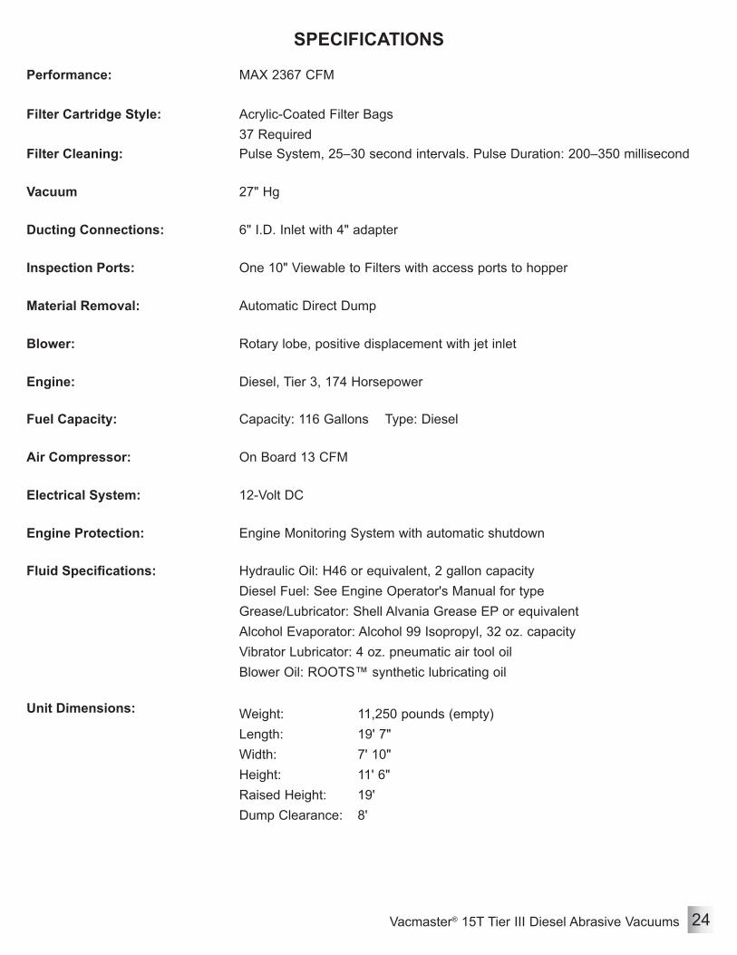
SPECIFICATIONS
Performance: MAX 2367 CFM
Filter Cartridge Style: Acrylic-Coated Filter Bags37 Required
Filter Cleaning: Pulse System, 25–30 second intervals. Pulse Duration: 200–350 millisecond
Vacuum 27" Hg
Ducting Connections: 6" I.D. Inlet with 4" adapter
Inspection Ports: One 10" Viewable to Filters with access ports to hopper
Material Removal: Automatic Direct Dump
Blower: Rotary lobe, positive displacement with jet inlet
Engine: Diesel, Tier 3, 174 Horsepower
Fuel Capacity: Capacity: 116 Gallons Type: Diesel
Air Compressor: On Board 13 CFM
Electrical System: 12-Volt DC
Engine Protection: Engine Monitoring System with automatic shutdown
Fluid Specifications: Hydraulic Oil: H46 or equivalent, 2 gallon capacityDiesel Fuel: See Engine Operator's Manual for type Grease/Lubricator: Shell Alvania Grease EP or equivalentAlcohol Evaporator: Alcohol 99 Isopropyl, 32 oz. capacityVibrator Lubricator: 4 oz. pneumatic air tool oilBlower Oil: ROOTS™ synthetic lubricating oil
Unit Dimensions: Weight:Length:Width:Height:Raised Height:Dump Clearance:
11,250 pounds (empty)19' 7"7' 10"11' 6"19' 8'

Vacmaster® 15T Tier III Diesel Abrasive Vacuums25
MAINTENANCE
1) Depressurize system.2) Disconnect battery cables from battery.3) Remove three Bolts (1).4) Remove Front Belt Cover (2).
Adjust Tension of Blower Drive Belt
5) Inspect Belt (3) for damage. Replace as needed.
6) Check tension of Belt (3) by pushing downward on Belt and measure Distance (A) of travel. Belts should have a deflection distance of approximately 21/32 inch; applied force of approximately 88–94 pounds.
7) To adjust tension of Belt, loosen Slide Bolts (4). Adjust threaded rod (5) until deflection distance is approximately 21/32 inch; applied force of approximately 88–94 pounds. If distance cannot be attained, replace belt. Tighten Slide Bolts (4).
8) Install parts in reverse order using the following special instructions:• Use medium-strength thread-locker on all nuts and bolts.
Always depressurize the entire system, disconnect all power sources and lockout/tagout all components before any maintenance or troubleshooting is attempted. Failure to comply with the above warning could cause electrical shock and inadvertent activation of equipment resulting in death or serious injury.
W-562
Moving parts can present an area where crushing, pinching, entanglement or amputation may occur. Do not place body parts or foreign objects in any area where there are moving parts.
W-586
A
3
Do not walk on, stand on, or climb on any surface other than the designated work platform. Doing so poses a slip and fall hazard. Failure to comply with the above warning could result in death or serious injury.
W-583
1
2
When performing service or maintenance on systems or devices requiring access from an elevated position, you must comply with all OSHA, local, City, State, Province, Country and jurisdiction regulations, ordinances and standards, as related to working in elevated work areas. Failure to comply with the above warning could result in death or serious injury.
W-590
5
4

Vacmaster® 15T Tier III Diesel Abrasive Vacuums 26
MAINTENANCEAdjust Pulse Separation
5) Set the Pulse Separation, the elapsed time between pulses, by rotating Knob (3). The recommended elapsed time between pulses is 25 seconds. Depending on conditions, the elapsed time may need to be changed. Elapsed time between pulses should be between 20–30 seconds.
1) Depressurize system.2) Disconnect battery cables from battery.3) Open enclosure door of Timer Controller.4) Locate Adjustment Knobs (1 and 2).
6) Set Pulse Duration, the elapsed time of compressed air entering the filters, by rotating Knob (4). The recommended elapsed time of compressed air entering the filters is 200 milliseconds (mSEC). Depending on conditions, the elapsed time of air entering the filters should be between 200–350 milliseconds.
7) Close enclosure door of Timer Controller.
3
Always depressurize the entire system, disconnect all power sources and lockout/tagout all components before any maintenance or troubleshooting is attempted. Failure to comply with the above warning could cause electrical shock and inadvertent activation of equipment resulting in death or serious injury.
W-562
1 2
4

Vacmaster® 15T Tier III Diesel Abrasive Vacuums27
MAINTENANCEHydraulic System Schematic
Escaping fluid under pressure can penetrate skin and tissue causing injury. Stop pump and relieve pressure before attempting maintenance or repair. Ensure all fittings are properly tightened before restoring pressure. If injury should occur, immediately seek medical attention. Failure to comply with the above warning could result in death or serious injury.
W-587
1) Hydraulic Power Unit with Tank2) Lock Valve3) Cylinder4) Flow Restrictor
1
3
3
24

Vacmaster® 15T Tier III Diesel Abrasive Vacuums 28
MAINTENANCE
Always depressurize the entire system, disconnect all power sources and lockout/tagout all components before any maintenance or troubleshooting is attempted. Failure to comply with the above warning could cause electrical shock and inadvertent activation of equipment resulting in death or serious injury.
W-562
Remove & Install Pressure Tank
1) Depressurize system.2) Ensure Ball Valve (1) is open.3) Depressurize Tank (2)4) Disconnect Hoses and Fittings (4).5) Remove Pressure Relief Valve (3).6) Remove Manifold (5).7) Remove Elbow (6) and Nipple (7). 1
Label all hoses and connections to aid installation.
N-530
8) Remove Alcohol Evaporator (8). See Remove & Install Alcohol Evaporator.
9) Remove Air Dryer (9). See Remove & Install Air Dryer.
Note: Approximate weight of Pressure Tank is 51 pounds. Use suitable lifting device to support or maneuver Pressure Tank.
10) Attach a suitable lifting device to Pressure Tank.
11) Remove four Bolts, Lock Washers, Nuts and eight Washers (10).
12) Remove Pressure Tank.13) Install parts in reverse order using the
following special instructions:• Use medium-strength thread-locker on all nuts and bolts.
• Use PTFE Sealing Tape on union and fitting threads.
2
4
5
3
4 6 7
108
9

Vacmaster® 15T Tier III Diesel Abrasive Vacuums29
Remove & Install Blower Drive Belt Assembly
1) Depressurize system.2) Disconnect battery cables from battery.3) Remove three Bolts (1).4) Remove Front Belt Cover (2).
5) Loosen Slide Bolts (4). 6) Remove tension of belt by adjusting
Threaded Rods (5) until belt is loose enough to remove.
7) Remove Belt (3).
MAINTENANCE
Always depressurize the entire system, disconnect all power sources and lockout/tagout all components before any maintenance or troubleshooting is attempted. Failure to comply with the above warning could cause electrical shock and inadvertent activation of equipment resulting in death or serious injury.
W-562
Moving parts can present an area where crushing, pinching, entanglement or amputation may occur. Do not place body parts or foreign objects in any area where there are moving parts.
W-586
When performing service or maintenance on systems or devices requiring access from an elevated position, you must comply with all OSHA, local, City, State, Province, Country and jurisdiction regulations, ordinances and standards, as related to working in elevated work areas. Failure to comply with the above warning could result in death or serious injury.
W-590
1
2
3
5
4

Vacmaster® 15T Tier III Diesel Abrasive Vacuums 30
Remove & Install Blower Drive Belt Assembly (Cont.)
8) Remove six Bolts and Lock Washers (6) and Bushings (7).
9) Remove Sheaves (8) and Keys (9) from shaft.
10) Remove four Bolts, Lock Washers and eight Washers (10) from Belt Guard Back (11).
11) Remove Belt Guard Back (11).
MAINTENANCE
Moving parts can present an area where crushing, pinching, entanglement or amputation may occur. Do not place body parts or foreign objects in any area where there are moving parts.
W-586
Always depressurize the entire system, disconnect all power sources and lockout/tagout all components before any maintenance or troubleshooting is attempted. Failure to comply with the above warning could cause electrical shock and inadvertent activation of equipment resulting in death or serious injury.
W-562
12
Label all hoses and connections to aid installation.
N-530
6 7
8
67
8910 11
9
12) Remove two Bolts, Lock Washers and four Washers (12) from two piece Belt Guard Bracket (13).
13) Remove two piece Belt Guard Bracket (13).
14) Install parts in reverse order using the following special instructions:• Use medium-strength thread-locker on all nuts and bolts.
• Adjust blower drive belt tension. See Adjust Tension of Blower Drive Belt.
1313

Vacmaster® 15T Tier III Diesel Abrasive Vacuums31
Remove & Install Engine Assembly
1) Depressurize system.2) Remove Blower Drive Belt Cover
Assembly. See Remove & Install Blower Drive Belt Cover Assembly.
3) Disconnect fuel supply hose and fuel return hose.
4) Disconnect fuel hoses and battery cables from engine. See engine Operator's Manual.
5) Route all hoses and wiring away from Engine Assembly.
Note: Approximate weight of Engine Assembly is 2450 pounds. Use suitable lifting devices to support or maneuver Engine Assembly.
6) Attach suitable lifting devices to Engine Assembly.
7) Remove four Washers, four Lock Washers and four Nuts (1).
8) Remove Engine Assembly.9) Install parts in reverse order using the
following special instructions:• Use medium-strength thread-locker on all nuts.
• Tighten Nuts to 320 ft.-lbs.
Always depressurize the entire system, disconnect all power sources and lockout/tagout all components before any maintenance or troubleshooting is attempted. Failure to comply with the above warning could cause electrical shock and inadvertent activation of equipment resulting in death or serious injury.
W-562
MAINTENANCE
1

Vacmaster® 15T Tier III Diesel Abrasive Vacuums 32
Remove & Install 12-Volt DC Hydraulic Power Unit With Tank
1) Depressurize system.2) Disconnect battery cables from battery.3) Disconnect power unit electrical wires from
Terminal (1).Note: Drain hoses into container suitable for
collecting fluids. Comply with all OSHA, local, City, State, Province, Country and jurisdiction regulations, ordinances and standards, related to your particular work area and environment.
Note: Hydraulic Oil Tank capacity is approximately 2 gal.
4) Remove Drain Plug (6) to drain hydraulic oil.5) Remove Hoses (4) and Fittings (5).6) Remove four Bolts, Washers, Lock Washers
and Nuts (3). Remove Shield (2).7) Remove two Bolts and Lock Washers (7) and
remove power unit with tank. 8) Install parts in reverse order using the
following special instructions:• Use medium-strength thread-locker on all nuts and bolts.
Always depressurize the entire system, disconnect all power sources and lockout/tagout all components before any maintenance or troubleshooting is attempted. Failure to comply with the above warning could cause electrical shock and inadvertent activation of equipment resulting in death or serious injury.
W-562
MAINTENANCE
1
3
4
5
6
Exposure to diesel fuel, lubricant grease and oil, hydraulic oil, or engine coolant can cause personal injury. Do not allow these products to remain in contact with the skin or eyes. Ingestion of these products or inhalation of fumes from these products can cause dizziness, nausea, vomiting, or poisoning. If exposure to any of these products occurs, or if any of these products are ingested or if fumes are inhaled, please consult the product’s SDS for proper first aid or medical procedures. Failure to comply with the above warning could result in death or serious injury.
W-589
7
2
Label all hoses and connections to aid installation.
N-530
4

Vacmaster® 15T Tier III Diesel Abrasive Vacuums33
Remove & Install Compressor
Always depressurize the entire system, disconnect all power sources and lockout/tagout all components before any maintenance or troubleshooting is attempted. Failure to comply with the above warning could cause electrical shock and inadvertent activation of equipment resulting in death or serious injury.
W-562
MAINTENANCE
1) Depressurize system.2) Disconnect battery cables from battery.3) Remove Housing Panel (1).Note: Drain hoses into container suitable
for collecting fluids. Comply with all OSHA, local, City, State, Province, Country and jurisdiction regulations, ordinances and standards, related to your particular work area and environment.
Note: Label all hoses and connections to aid installation.
4) Drain Radiator.5) Disconnect Coolant Hoses (2 and 3).6) Disconnect Air Hoses (4 and 5).
1
2
3
4
5
7) Note orientation and location of five Fittings (6) and remove.
666
66
Exposure to diesel fuel, lubricant grease and oil, hydraulic oil, or engine coolant can cause personal injury. Do not allow these products to remain in contact with the skin or eyes. Ingestion of these products or inhalation of fumes from these products can cause dizziness, nausea, vomiting, or poisoning. If exposure to any of these products occurs, or if any of these products are ingested or if fumes are inhaled, please consult the product’s SDS for proper first aid or medical procedures. Failure to comply with the above warning could result in death or serious injury.
W-589
Label all hoses and connections to aid installation.
N-530
Vacmaster® 15T Tier III Diesel Abrasive Vacuums 34
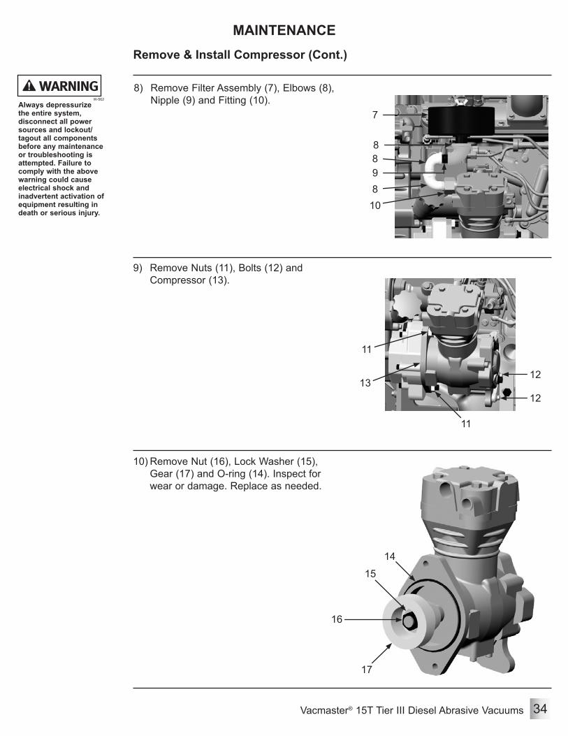
Remove & Install Compressor (Cont.)
MAINTENANCE
8) Remove Filter Assembly (7), Elbows (8), Nipple (9) and Fitting (10).
10
7
8
98
8
9) Remove Nuts (11), Bolts (12) and Compressor (13).
11
1213
11
12
10) Remove Nut (16), Lock Washer (15), Gear (17) and O-ring (14). Inspect for wear or damage. Replace as needed.
14
15
16
17
Always depressurize the entire system, disconnect all power sources and lockout/tagout all components before any maintenance or troubleshooting is attempted. Failure to comply with the above warning could cause electrical shock and inadvertent activation of equipment resulting in death or serious injury.
W-562

Vacmaster® 15T Tier III Diesel Abrasive Vacuums35
Remove & Install Compressor (cont.)
MAINTENANCE
11) Remove five Bolts (18) and Adapter Plate (19).12) Remove and replace O-ring (20). 18
19
20
18
13) Install parts in reverse order using the following special instructions:• Align dot found on rear of compressor to timing mark "A" that is closest to timing mark "6".
• Coat O-rings with engine oil before installing.• Use medium-strength thread-locker on all nuts and bolts.
• Use PTFE Sealing Tape on all fitting threads.
Always depressurize the entire system, disconnect all power sources and lockout/tagout all components before any maintenance or troubleshooting is attempted. Failure to comply with the above warning could cause electrical shock and inadvertent activation of equipment resulting in death or serious injury.
W-562
18

Vacmaster® 15T Tier III Diesel Abrasive Vacuums 36
Remove & Install Governor
MAINTENANCE
1) Depressurize system.2) Disconnect battery cables from battery.3) Remove Housing Panel (1).Note: Label all hoses and connections to
aid installation.4) Disconnect Air Hoses (7).5) Remove Swivel Union (5), four Push-On
Fittings (6), two Tees (4) and two Hex Nipples (8).
6) Remove two Bolts, Lock Washers and Nuts (3).
7) Install parts in reverse order using the following special instructions:• Use medium-strength thread-locker on all nuts and bolts.
• Use PTFE Sealing Tape on union and fitting threads.
1
Always depressurize the entire system, disconnect all power sources and lockout/tagout all components before any maintenance or troubleshooting is attempted. Failure to comply with the above warning could cause electrical shock and inadvertent activation of equipment resulting in death or serious injury.
W-562
Label all hoses and connections to aid installation.
N-530
25
7
77
6
6
6
48
3
Vacmaster® 15T Tier III Diesel Abrasive Vacuums37
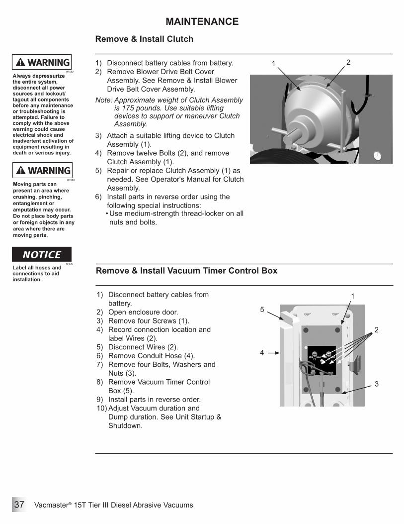
Remove & Install Clutch
1) Disconnect battery cables from battery.2) Remove Blower Drive Belt Cover
Assembly. See Remove & Install Blower Drive Belt Cover Assembly.
Note: Approximate weight of Clutch Assembly is 175 pounds. Use suitable lifting devices to support or maneuver Clutch Assembly.
3) Attach a suitable lifting device to Clutch Assembly (1).
4) Remove twelve Bolts (2), and remove Clutch Assembly (1).
5) Repair or replace Clutch Assembly (1) as needed. See Operator's Manual for Clutch Assembly.
6) Install parts in reverse order using the following special instructions:• Use medium-strength thread-locker on all nuts and bolts.
MAINTENANCE
Moving parts can present an area where crushing, pinching, entanglement or amputation may occur. Do not place body parts or foreign objects in any area where there are moving parts.
W-586
Always depressurize the entire system, disconnect all power sources and lockout/tagout all components before any maintenance or troubleshooting is attempted. Failure to comply with the above warning could cause electrical shock and inadvertent activation of equipment resulting in death or serious injury.
W-562
1 2
Remove & Install Vacuum Timer Control Box
1) Disconnect battery cables from battery.
2) Open enclosure door.3) Remove four Screws (1).4) Record connection location and
label Wires (2).5) Disconnect Wires (2).6) Remove Conduit Hose (4).7) Remove four Bolts, Washers and
Nuts (3).8) Remove Vacuum Timer Control
Box (5).9) Install parts in reverse order.10) Adjust Vacuum duration and
Dump duration. See Unit Startup & Shutdown.
Label all hoses and connections to aid installation.
N-530
1
2
3
4
5

Vacmaster® 15T Tier III Diesel Abrasive Vacuums 38
Remove & Install Pulser Manifold
1) Open Ball Valve (1).2) Disconnect Air Hoses (2).3) Remove Light Bar (3).
4) Remove Connector (9) by loosening Screw (8).
5) Loosen two Clamps (6) and remove Hose (5) from Nipple (4).
6) Remove Nipple (4).7) Remove Diaphragm Valve (7).8) Repeat for remaining Diaphragm
Valves.
MAINTENANCE
Always depressurize the entire system, disconnect all power sources and lockout/tagout all components before any maintenance or troubleshooting is attempted. Failure to comply with the above warning could cause electrical shock and inadvertent activation of equipment resulting in death or serious injury.
W-562
When performing service or maintenance on systems or devices requiring access from an elevated position, you must comply with all OSHA, local, City, State, Province, Country and jurisdiction regulations, ordinances and standards, as related to working in elevated work areas. Failure to comply with the above warning could result in death or serious injury.
W-590
Label all hoses and connections to aid installation.
N-530
1 2
3 2
2
9
9) Remove Fittings (10).10) Remove four Bolts, eight Washers, four
Lock Washers and four Nuts (12) and remove Pulser Manifold (11).
11) Install parts in reverse order using the following special instructions:• Use medium-strength thread-locker on all nuts and bolts.
• Use PTFE Sealing Tape on union and fitting threads.
78
10
10
4 5
10
6
11
12

Vacmaster® 15T Tier III Diesel Abrasive Vacuums39
Remove & Install Auxiliary Pulser Manifold
1) Open Ball Valve (1).2) Disconnect Air Hoses (3).Note: Approximate weight of Auxiliary
Pulser Manifold is 37 pounds. Use suitable lifting devices to support or maneuver Auxiliary Pulser Manifold.
3) Attach suitable lifting devices to Auxiliary Pulser Manifold (4).
4) Remove Fittings (2).5) Remove four Bolts, eight Washers, four
Lock Washers and four Nuts (5) and remove Auxiliary Pulser Manifold (4).
6) Install parts in reverse order using the following special instructions:• Use medium-strength thread-locker on all nuts and bolts.
• Use PTFE Sealing Tape on union and fitting threads.
MAINTENANCE
Always depressurize the entire system, disconnect all power sources and lockout/tagout all components before any maintenance or troubleshooting is attempted. Failure to comply with the above warning could cause electrical shock and inadvertent activation of equipment resulting in death or serious injury.
W-562
When performing service or maintenance on systems or devices requiring access from an elevated position, you must comply with all OSHA, local, City, State, Province, Country and jurisdiction regulations, ordinances and standards, as related to working in elevated work areas. Failure to comply with the above warning could result in death or serious injury.
W-590
Label all hoses and connections to aid installation.
N-530
1
345
2
22
3
3
Remove & Install Vacuum Light Bar
1) Disconnect battery cables from battery.
2) Disconnect Cable (1).3) Remove two Bolts, lock Washers,
Nuts and four Washers (2).4) Remove Light Bar (3).5) Install parts in reverse order.
123

Vacmaster® 15T Tier III Diesel Abrasive Vacuums 40
MAINTENANCERemove & Install Timer Board
1) Disconnect battery cables from battery.2) Open enclosure door.3) Remove four Screws (2).4) Record connection location and label
Wires (1).5) Disconnect Wires (1).
6) Install parts in reverse order using labels as a guide.
7) Adjust pulse duration and pulse separation. See Adjust Pulse Separation.
Always depressurize the entire system, disconnect all power sources and lockout/tagout all components before any maintenance or troubleshooting is attempted. Failure to comply with the above warning could cause electrical shock and inadvertent activation of equipment resulting in death or serious injury.
W-562
Label all hoses and connections to aid installation.
N-530
1 2

Vacmaster® 15T Tier III Diesel Abrasive Vacuums41
Remove & Install Air Dryer
1) Depressurize system.2) Disconnect Air Dryer electrical connections
from Electrical Box (5).3) Disconnect Hoses (3) from Air Dryer (2).4) Remove three Fittings (4).5) Remove four Bolts, Lock Washers, Nuts and
eight Washers (1). Remove Air Dryer (2).6) Install parts in reverse order using the
following special instructions:• Use medium-strength thread-locker on all nuts and bolts.
• Use PTFE Sealing Tape on union and fitting threads.
MAINTENANCE
Always depressurize the entire system, disconnect all power sources and lockout/tagout all components before any maintenance or troubleshooting is attempted. Failure to comply with the above warning could cause electrical shock and inadvertent activation of equipment resulting in death or serious injury.
W-562
Label all hoses and connections to aid installation.
N-530
Remove & Install Alcohol Evaporator
1) Depressurize system.2) Drain Evaporator (2).3) Disconnect Hoses (3) from Alcohol
Evaporator (2).4) Remove two Fittings (4) and Bushings (5).5) Remove two Bolts, Lock Washers, Nuts
and four Washers (1). Remove Alcohol Evaporator (2).
6) Install parts in reverse order using the following special instructions:• Fill evaporator with 32 oz. Alcohol 99
Isopropyl.• Use medium-strength thread-locker on all
nuts and bolts.• Use PTFE Sealing Tape on union and
fitting threads.
1 2
4
3
5
1
2
3
4
4
34
545

Vacmaster® 15T Tier III Diesel Abrasive Vacuums 42
MAINTENANCE
Always depressurize the entire system, disconnect all power sources and lockout/tagout all components before any maintenance or troubleshooting is attempted. Failure to comply with the above warning could cause electrical shock and inadvertent activation of equipment resulting in death or serious injury.
W-562
Label all hoses and connections to aid installation.
N-530
Remove & Install Vacuum Control Box
1) Disconnect battery cables from battery.2) Open enclosure door.3) Record connection location and label all
Wires (2).4) Disconnect Wires (2).5) Remove Conduit Hoses (1).6) Remove four Bolts, Washers and Nuts (3).7) Remove Vacuum Control Box (4).8) Install parts in reverse order using the
following special instructions:• Use medium-strength thread-locker on all nuts and bolts.
3 42
1
1
1
1

Vacmaster® 15T Tier III Diesel Abrasive Vacuums43
Remove & Install Blower
1) Depressurize system.2) Disconnect battery cables from battery.3) Remove Blower Drive Belt Cover Assembly.
See Remove & Install Blower Drive Belt Cover Assembly.
4) Remove Vacuum Control Box (1). See Remove and Install Vacuum Control Box.
5) Remove Vacuum Timer Control Box (2). See Remove and Install Vacuum Timer Control Box.
6) Disconnect Emergency E-Stop at Plug (3).
MAINTENANCE
Always depressurize the entire system, disconnect all power sources and lockout/tagout all components before any maintenance or troubleshooting is attempted. Failure to comply with the above warning could cause electrical shock and inadvertent activation of equipment resulting in death or serious injury.
W-562
Label all hoses and connections to aid installation.
N-530
7) Remove Blower Filter Magnehelic Gauge (4). See Remove and Install Blower Filter Magnehelic Gauge.
8) Disconnect hoses from filter housing.9) Disconnect Electrical Connector (6).10) Remove Differential Pressure Switch (5).
1
2
3
4
5
6
9
10
11
7 811) Remove Double Bolt Clamp (8).12) Remove Vacuum Hoses (7).Note: Approximate weight of Blower Exhaust Silencer
is 460 pounds. Use suitable lifting devices to support or maneuver Blower Exhaust Silencer.
13) Attach a suitable lifting device to Blower Exhaust Silencer (11).
14) Loosen top Banding Clamp (10).15) Remove four Bolts, Lock Washers, Nuts and eight
Washers (9). 16) Remove Blower Exhaust Silencer (11).

Vacmaster® 15T Tier III Diesel Abrasive Vacuums 44
Remove & Install Blower (Cont.)
MAINTENANCE
Always depressurize the entire system, disconnect all power sources and lockout/tagout all components before any maintenance or troubleshooting is attempted. Failure to comply with the above warning could cause electrical shock and inadvertent activation of equipment resulting in death or serious injury.
W-562
Note: Approximate weight of Intake Filter Housing is 390 pounds. Use suitable lifting devices to support or maneuver Filter Housing.
17) Open Valve (A) to remove any fluid build up.
18) Attach a suitable lifting device to Filter Housing (12).
19) Remove twelve Bolts, Lock Washers and Washers (13), and remove Filter Housing (12).
12
13
Note: Approximate weight of Blower Intake Silencer is 460 pounds. Use suitable lifting devices to support or maneuver Blower Intake Silencer.
20) Attach a suitable lifting device to Blower Intake Silencer (14).
21) Loosen top Banding Clamp (16).22) Remove four Bolts, Lock Washers, Nuts
and eight Washers (15). 23) Remove Blower Intake Silencer (14).
14
1516
Note: Approximate weight of Silencer Mount is 140 pounds. Use suitable lifting devices to support or maneuver Filter Housing.
24) Attach a suitable lifting device to Silencer Mount (17).
25) Remove four Bolts, Lock Washers, Nuts and eight Washers (18), and remove Silencer Mount (17).
26) Loosen bottom Banding Clamps (19).27) Remove Hoses (20) and Banding Clamps
(19).
17
18
1920
20
A

Vacmaster® 15T Tier III Diesel Abrasive Vacuums45
Remove & Install Blower (Cont.)
MAINTENANCE
Always depressurize the entire system, disconnect all power sources and lockout/tagout all components before any maintenance or troubleshooting is attempted. Failure to comply with the above warning could cause electrical shock and inadvertent activation of equipment resulting in death or serious injury.
W-562
28) Remove twelve Bolts, Lock Washers and Washers (21), and remove Flange (22).
Note: Approximate weight of Elbow Flange is 115 pounds. Use suitable lifting devices to support or maneuver Elbow Flange.
29) Attach a suitable lifting device to Elbow Flange (24).
30) Remove twelve Bolts, Lock Washers and Washers (23), and remove Elbow Flange (24).
Note: Approximate weight of Blower is 1750 pounds. Use suitable lifting devices to support or maneuver Blower.
31) Attach a suitable lifting device to Blower (25).
32) Remove four Bolts, Nuts and eight Washers (26), and remove Blower (25).
33) Repair or replace Blower (25) as needed. See Operator's Manual for Blower.
34) Install parts in reverse order using the following special instructions:• Apply silicone sealant to base of flanges.
• Use medium-strength thread-locker on all nuts and bolts.
21 22
23
24
25
26

Vacmaster® 15T Tier III Diesel Abrasive Vacuums 46
Remove & Install Butterfly Springs
1) Open Ball Valve (1).2) Remove four Bolts and Washers (3).3) Remove Butterfly Cover (2).
Note: Replace springs one at a time.4) Remove Outer Nut (5) and Outer
Washer (6) on each end of Spring (4).5) Remove Spring (4) and replace.6) Install Outer Nut (5) and Outer
Washer (6) on each end of Spring (4).7) Repeat for remaining spring.8) Install butterfly cover.
MAINTENANCE
Always depressurize the entire system, disconnect all power sources and lockout/tagout all components before any maintenance or troubleshooting is attempted. Failure to comply with the above warning could cause electrical shock and inadvertent activation of equipment resulting in death or serious injury.
W-562
When performing service or maintenance on systems or devices requiring access from an elevated position, you must comply with all OSHA, local, City, State, Province, Country and jurisdiction regulations, ordinances and standards, as related to working in elevated work areas. Failure to comply with the above warning could result in death or serious injury.
W-590
1 2
3
456

Vacmaster® 15T Tier III Diesel Abrasive Vacuums47
MAINTENANCERemove & Install Filter Bags
1) Depressurize system.2) Loosen Clamp (1) and remove Hose
Tube (5) and Vacuum Hose (4).3) Lower Lid Clamps (2) to free Lid (3).
4) Turn Crank (6) to raise Lid (9).5) Rotate lid on Shaft (7) counterclockwise
until clear of Hopper (8).
Always depressurize the entire system, disconnect all power sources and lockout/tagout all components before any maintenance or troubleshooting is attempted. Failure to comply with the above warning could cause electrical shock and inadvertent activation of equipment resulting in death or serious injury.
W-562
Breathing dust containing silica could cause silicosis, a fatal lung disease. Breathing dust during abrasive blasting operations, post-blast cleaning operations, and/or servicing equipment within the abrasive blasting area may expose an individual to conditions that could cause asbestosis, lead poisoning and/or other serious or fatal diseases. Harmful dust containing toxic material from abrasives or surfaces being abrasive blasted can remain suspended in the air for long periods of time after abrasive blasting has ceased. A NIOSH-approved, well-maintained, respirator designed for the specific operation being performed must be used by anyone abrasive blasting, handling or using the abrasive, and anyone in the area of the dust. Failure to comply with the above warning could result in death or serious injury.
W-501
1
23
4
5
67
89
6) Remove four Bolts, Washers and Nuts (10). Remove Frame (11).
7) Remove Air Hose with Clamps (12) from Pulser System Blowpipes (13).
8) Remove Pulser System Blowpipes (13). 9) Remove Filter Bags (14).10) Install parts in reverse order using the
following special instructions:• Use medium-strength thread-locker on all nuts and bolts.
10
11
12
13
14
12
12
13

Vacmaster® 15T Tier III Diesel Abrasive Vacuums 48
MAINTENANCERemove & Install Filter Cartridge
1) Depressurize system.2) Remove six Bolts, Lock Washers and
Nuts (1). 3) Remove Filter Cap and Housing
Gasket (2).
4) Remove Nut, Washer and Rubber Washer (3).
5) Remove Filter (4).6) Install parts in reverse order using the
following special instructions:• Use medium-strength thread-locker on all nuts and bolts.
Always depressurize the entire system, disconnect all power sources and lockout/tagout all components before any maintenance or troubleshooting is attempted. Failure to comply with the above warning could cause electrical shock and inadvertent activation of equipment resulting in death or serious injury.
W-562
Breathing dust containing silica could cause silicosis, a fatal lung disease. Breathing dust during abrasive blasting operations, post-blast cleaning operations, and/or servicing equipment within the abrasive blasting area may expose an individual to conditions that could cause asbestosis, lead poisoning and/or other serious or fatal diseases. Harmful dust containing toxic material from abrasives or surfaces being abrasive blasted can remain suspended in the air for long periods of time after abrasive blasting has ceased. A NIOSH-approved, well-maintained, respirator designed for the specific operation being performed must be used by anyone abrasive blasting, handling or using the abrasive, and anyone in the area of the dust. Failure to comply with the above warning could result in death or serious injury.
W-501
1 2
3 4

Vacmaster® 15T Tier III Diesel Abrasive Vacuums49
MAINTENANCERemove & Install Fuel Tank
10) Inspect Isolation Mat (13) for damage. Replace as needed.
11) Install parts in reverse order using the following special instructions: • Use medium-strength thread-locker on all nuts and bolts.
• See engine Operator's Manual for priming of engine.
Note: Fuel Tank capacity is approximately 116 gallons.
Note: Drain into container suitable for collecting fluids. Comply with all OSHA, local, City, State, Province, Country and jurisdiction regulations, ordinances and standards, related to your particular work area and environment.
1) Remove Blower Exhaust Silencer (10), Blower Intake Silencer (11) and Silencer Mount (12). See Remove & Install Blower.
2) Empty fuel from Tank (9).3) Disconnect Supply Hose (8) and
remove Fitting (7).4) Remove Withdraw Tube (6).5) Disconnect electrical cable from
Sensor (3) and remove sensor.6) Disconnect vent hose from Hose
Fitting (4) and remove fitting.7) Disconnect Return Hose (1) and
Fitting (2) from tank.8) Remove two Bolts, Lock Washers,
Nuts and four Washers (5).Note: Approximate empty weight of
Fuel Tank is 100 pounds. Use suitable lifting devices to support or maneuver Fuel Tank.
9) Attach a suitable lifting device to Tank (9), and remove.
Always depressurize the entire system, disconnect all power sources and lockout/tagout all components before any maintenance or troubleshooting is attempted. Failure to comply with the above warning could cause electrical shock and inadvertent activation of equipment resulting in death or serious injury.
W-562
Exposure to diesel fuel, lubricant grease and oil, hydraulic oil, or engine coolant can cause personal injury. Do not allow these products to remain in contact with the skin or eyes. Ingestion of these products or inhalation of fumes from these products can cause dizziness, nausea, vomiting, or poisoning. If exposure to any of these products occurs, or if any of these products are ingested or if fumes are inhaled, please consult the product’s SDS for proper first aid or medical procedures. Failure to comply with the above warning could result in death or serious injury.
W-589
Label all hoses and connections to aid installation.
N-530
Drain tanks into container suitable for collecting fluids. Comply with all OSHA, local, City, State, Province, Country and jurisdiction regulations, ordinances and standards, related to your particular work area and environment.
N-531
1 2 3
4568 7
9
10
11
12
13

Vacmaster® 15T Tier III Diesel Abrasive Vacuums 50
MAINTENANCERemove & Install Front Emergency-Stop Station
1) Disconnect battery cables from battery.2) Remove two Screws (1) and Cover (2).
3) Label Wires (4 and 5) to aid installation.
4) Disconnect Wires (4 and 5) and pull Cable (6) from Housing (8).
5) Remove two Screws,Washers, and Nuts (7) and Housing (8).
6) Install parts in reverse order.
6
8
Always depressurize the entire system, disconnect all power sources and lockout/tagout all components before any maintenance or troubleshooting is attempted. Failure to comply with the above warning could cause electrical shock and inadvertent activation of equipment resulting in death or serious injury.
W-562
Label all hoses and connections to aid installation.
N-530
77
4
5
1
2

Vacmaster® 15T Tier III Diesel Abrasive Vacuums51
MAINTENANCERemove & Install Pendant Emergency-Stop Station
Always depressurize the entire system, disconnect all power sources and lockout/tagout all components before any maintenance or troubleshooting is attempted. Failure to comply with the above warning could cause electrical shock and inadvertent activation of equipment resulting in death or serious injury.
W-562
Label all hoses and connections to aid installation.
N-530
1) Disconnect Connector (1).2) Remove two Screws (2) and Cover (3).3) Label Wires (6 and 9) to aid installation.
4) Disconnect Wires (6 and 9) and pull Cable (10) from Housing (8).
5) Remove two Screws,Washers, and Nuts (7) and Housing (8).
6) Install parts in reverse order.
1
2
3
4
5
6
7
8
5

Vacmaster® 15T Tier III Diesel Abrasive Vacuums 52
MAINTENANCERemove & Install Hopper Magnehelic Gauge
1) Label Hose (2) as "Negative".2) Label Hose (3) as "Positive".3) Disconnect Hoses (2,3) from 90°
Elbows (1,4).4) Disconnect Hoses (2,3) from
Magnehelic Gauge (6).5) Remove Washers and Bolts (5) and
Magnehelic Gauge (6).
6) Install parts in reverse order using the following special instructions:
7) Ensure labeled hoses are installed correctly. "Negative" hose installed in lower port. "Positive" hose in upper port.
Always depressurize the entire system, disconnect all power sources and lockout/tagout all components before any maintenance or troubleshooting is attempted. Failure to comply with the above warning could cause electrical shock and inadvertent activation of equipment resulting in death or serious injury.
W-562
Label all hoses and connections to aid installation.
N-530
1
2
3
4
65
Negative
Positive

Vacmaster® 15T Tier III Diesel Abrasive Vacuums53
MAINTENANCERemove & Install Blower Filter Magnehelic Gauge
1) Label Hose (5) as "Negative".2) Label Hose (4) as "Positive".3) Disconnect Hoses (4,5) from 90°
Elbows (3,6).4) Disconnect Hoses (4,5) from tee fittings
on Magnehelic Gauge (7).5) Disconnect Hoses (1,2) from tee fittings
on Magnehelic Gauge (7).
6) Remove three Screws (8) and Magnehelic Gauge (7).
7) Install parts in reverse order using the following special instructions:• Ensure labeled hoses are installed correctly.
Always depressurize the entire system, disconnect all power sources and lockout/tagout all components before any maintenance or troubleshooting is attempted. Failure to comply with the above warning could cause electrical shock and inadvertent activation of equipment resulting in death or serious injury.
W-562
Label all hoses and connections to aid installation.
N-530
1 2
3
4
56
7
8

Vacmaster® 15T Tier III Diesel Abrasive Vacuums 54
MAINTENANCE
Disassemble & Assemble Diaphragm Valve
1) Depressurize system.2) Close Ball Valve (1)3) Disconnect Hose (2).4) Remove two Bolts, Nuts and Flat
Washers (4).5) Remove Piston Vibrator (3).6) Install parts in reverse order.
1) Remove Solenoid Assembly (7,8,9,10,11)
2) Remove four Bolts (6) and Washers (5).
3) Remove Cover (4).4) Remove Diaphragm (3)
from Base (1).5) Install parts in reverse
order using the following special instructions:• Check Vent Hole (2) is not blocked or occluded.
Remove & Install Pneumatic Piston Vibrators
Always depressurize the entire system, disconnect all power sources and lockout/tagout all components before any maintenance or troubleshooting is attempted. Failure to comply with the above warning could cause electrical shock and inadvertent activation of equipment resulting in death or serious injury.
W-562
Label all hoses and connections to aid installation.
N-530
1
2 3
4
1
1011
2 3 4 5 67
89

Vacmaster® 15T Tier III Diesel Abrasive Vacuums55
MAINTENANCECheck Lubricator Oil Level
1) Check oil level in Sight Glass (3).2) To add oil, close Ball Valve (1). 3) Pull down Lock Tab (2) and twist
container (4) counterclockwise to release.
4) Add oil and install parts in reverse order.
5) Set oil drip rate if needed by turning the Site Dome Adjustment Screw (5).
Escaping fluid under pressure can penetrate skin and tissue causing injury. Stop pump and relieve pressure before attempting maintenance or repair. Ensure all fittings are properly tightened before restoring pressure. If injury should occur, immediately seek medical attention. Failure to comply with the above warning could result in death or serious injury.
W-587
Always depressurize the entire system, disconnect all power sources and lockout/tagout all components before any maintenance or troubleshooting is attempted. Failure to comply with the above warning could cause electrical shock and inadvertent activation of equipment resulting in death or serious injury.
W-562
Exposure to diesel fuel, lubricant grease and oil, hydraulic oil, or engine coolant can cause personal injury. Do not allow these products to remain in contact with the skin or eyes. Ingestion of these products or inhalation of fumes from these products can cause dizziness, nausea, vomiting, or poisoning. If exposure to any of these products occurs, or if any of these products are ingested or if fumes are inhaled, please consult the product’s SDS for proper first aid or medical procedures. Failure to comply with the above warning could result in death or serious injury.
W-589
1
2
34
5

Vacmaster® 15T Tier III Diesel Abrasive Vacuums 56
MAINTENANCERemove & Install Lubricator
1) Depressurize system.2) Ensure Ball Valve (1) is open.3) Disconnect Hoses (4).4) Remove Swivel (3).5) Remove Ball Valve (5).6) Remove Nipple (6).7) Remove Swivel Union (7).8) Remove Street Elbow (8).9) Remove Bushings (9).10) Remove two Bolts and Nuts (2).11) Remove Lubricator (10).12) Install parts in reverse order using the
following special instructions:• Use medium-strength thread-locker on all nuts and bolts.
• Use PTFE Sealing Tape on union and fitting threads.
Escaping fluid under pressure can penetrate skin and tissue causing injury. Stop pump and relieve pressure before attempting maintenance or repair. Ensure all fittings are properly tightened before restoring pressure. If injury should occur, immediately seek medical attention. Failure to comply with the above warning could result in death or serious injury.
W-587
Always depressurize the entire system, disconnect all power sources and lockout/tagout all components before any maintenance or troubleshooting is attempted. Failure to comply with the above warning could cause electrical shock and inadvertent activation of equipment resulting in death or serious injury.
W-562
Exposure to diesel fuel, lubricant grease and oil, hydraulic oil, or engine coolant can cause personal injury. Do not allow these products to remain in contact with the skin or eyes. Ingestion of these products or inhalation of fumes from these products can cause dizziness, nausea, vomiting, or poisoning. If exposure to any of these products occurs, or if any of these products are ingested or if fumes are inhaled, please consult the product’s SDS for proper first aid or medical procedures. Failure to comply with the above warning could result in death or serious injury.
W-589
1
2
3 4
5
6
8
9
7
4 10

Vacmaster® 15T Tier III Diesel Abrasive Vacuums57
Remove & Install Hopper Wear Plates
Always depressurize the entire system, disconnect all power sources and lockout/tagout all components before any maintenance or troubleshooting is attempted. Failure to comply with the above warning could cause electrical shock and inadvertent activation of equipment resulting in death or serious injury.
W-562
When performing service or maintenance on systems or devices requiring access from an elevated position, you must comply with all OSHA, local, City, State, Province, Country and jurisdiction regulations, ordinances and standards, as related to working in elevated work areas. Failure to comply with the above warning could result in death or serious injury.
W-590
MAINTENANCE
1) Depressurize system.2) Close Ball Valve (1)3) Disconnect Hose (2) from Piston
Vibrator (4).4) Remove Hose Clamp (3).5) Disconnect Hoses (5) at Air Cylinder (6).6) Remove Bolts, Washers, Lock Washers
and Nuts (7) and move air assemblies out of way.
Label all hoses and connections to aid installation.
N-530
1
2
4
3
5
77
6

Vacmaster® 15T Tier III Diesel Abrasive Vacuums 58
Remove & Install Hopper Wear Plates (Cont.)
MAINTENANCE
Note: Approximate empty weight of Hopper Cone is 190 pounds. Use suitable lifting device to support or maneuver Hopper Cone .
7) Attach a suitable lifting device to Hopper Cone (10).
8) Remove 14 Bolts, Lock Washers and Nuts (9) and remove Hopper Cone (10).
9) Remove Gasket (8). Inspect for damage. Replace as needed.
9
10
8
10) Remove 15 Bolts, Lock Washers, Nuts and 30 Washers (11).
11) Remove Baffles (12). Inspect for damage. Replace as needed.
12) Remove four Nuts, Lock Washers and Washers (13).
13) Remove Wear Plate (14).14) Repeat steps 11-12 for all hopper
wear plates being removed.15) Install parts in reverse order using
the following special instructions:• Use medium-strength thread-locker on all nuts and bolts.
11
12
13
14
Always depressurize the entire system, disconnect all power sources and lockout/tagout all components before any maintenance or troubleshooting is attempted. Failure to comply with the above warning could cause electrical shock and inadvertent activation of equipment resulting in death or serious injury.
W-562

Vacmaster® 15T Tier III Diesel Abrasive Vacuums59
Remove & Install Hopper Access Door Wear Plate
Always depressurize the entire system, disconnect all power sources and lockout/tagout all components before any maintenance or troubleshooting is attempted. Failure to comply with the above warning could cause electrical shock and inadvertent activation of equipment resulting in death or serious injury.
W-562
MAINTENANCE
1) Depressurize system.2) Close Ball Valve (1)3) Remove six Nuts, Lock Washers and
Washers (2).4) Remove Hopper Access Door (3).5) Remove six Nuts, Lock Washers and
Washers (5).6) Remove Hopper Access Door Wear
Plate (4).7) Install parts in reverse order using the
following special instructions:• Use medium-strength thread-locker on all nuts and bolts.
1
23
2
4
5

Vacmaster® 15T Tier III Diesel Abrasive Vacuums 60
Remove & Install Double Lock Valve Assembly
Always depressurize the entire system, disconnect all power sources and lockout/tagout all components before any maintenance or troubleshooting is attempted. Failure to comply with the above warning could cause electrical shock and inadvertent activation of equipment resulting in death or serious injury.
W-562
MAINTENANCE
Label all hoses and connections to aid installation.
N-530
1) Depressurize system.2) Disconnect Hoses (8).3) Remove Tees (3).4) Remove Elbows (2).5) Remove Flow Restrictor (6).6) Remove Unions (4,5).7) Remove two Bolts, Nuts and Lock
Washers (7).8) Remove Double Lock Valve (1).9) Install parts in reverse order using the
following special instructions:• Use medium-strength thread-locker on all nuts and bolts.
• Use PTFE Sealing Tape on union and fitting threads.
1
2
3
4
6
3
5
2
7
8
8
8
8
8 8

Vacmaster® 15T Tier III Diesel Abrasive Vacuums61
Hazard Identification Decals
MAINTENANCE

Vacmaster® 15T Tier III Diesel Abrasive Vacuums 62
Hazard Identification Decals (cont.)
MAINTENANCE

Vacmaster® 15T Tier III Diesel Abrasive Vacuums63
Hazard Identification Decals (cont.)
MAINTENANCE

Vacmaster® 15T Tier III Diesel Abrasive Vacuums 64
Hazard Identification Decals (cont.)
MAINTENANCE

Vacmaster® 15T Tier III Diesel Abrasive Vacuums65
If the Vacmaster® 15T Tier III Diesel Abrasive Vacuum does not function properly, check the following:
TROUBLESHOOTING
SYMPTOM (Cause) ACTIONDiesel Engine will not start or runs poorly(Damaged components, insufficient connections, fuel supply)
See original equipment Operator's Manual for service.
Ensure an Emergency-Stop Station is not activated. Return Emergency-Stop Station to operating position.
Inspect Emergency-Stop Stations for damage. Repair as needed.
Drive Belt slips or vibrates(Loose connections, worn parts)
Inspect Blower Drive Belt for damage. Replace as needed.
Inspect alignment.
Adjust Blower Drive Belt Tension. See Adjust Blower Drive Belt Tension.
Magnehelic Gauge reading greater than normal operating range(Hopper Filter Bags)
A reading greater than 40” (w.c) on Magnehelic Gauge indicates clogged filters. Decrease engine RPM to idle speed and disengage clutch while allowing engine to run. Pulsers will clean down the filters. Once gauge reads back into the normal operation range of 20" – 30" (w.c), re-engage clutch and increase RPM to operating speed.
If Magnehelic Gauge is reading above 30" (w.c.), perform After Use procedure. Inspect Pulser System and Filters. Replace filter bags, if needed.
If Magnehelic Gauge is reading above 40" (w.c.), shut down unit immediately. Replace filter bags.
Always depressurize the entire system, disconnect all power sources and lockout/tagout all components before any maintenance or troubleshooting is attempted. Failure to comply with the above warning could cause electrical shock and inadvertent activation of equipment resulting in death or serious injury.
W-562

Vacmaster® 15T Tier III Diesel Abrasive Vacuums 66
TROUBLESHOOTING
SYMPTOM (Cause) ACTIONFilter Pulser System pressurizes but does not pulse(No power to control box, blown fuse in control box or timer board, disconnected wires, timer board, solenoid, diaphragm valve)
Inspect all power connections. Repair or replace faulty connections.
Turn main power switch "OFF". Replace fuse if required.
Inspect all solenoids and listen for audible sound as it engages to pulse. Replace solenoid.
Inspect diaphragm valve breather vent for obstruction.
Pulser System leaks(Loose or missing hoses or connections, loose or missing urethane tubing, damaged diaphragm valves)
Check hose and hose connections between diaphragm valves and hopper wall.
Check all tubing for secure connections and fittings. If fittings do not fit tightly in hose, cut a small section from the end of the hose and re-insert fitting in tube.
Inspect diaphragm valve for damage or debris. Repair or replace diaphragm valve.
Always depressurize the entire system, disconnect all power sources and lockout/tagout all components before any maintenance or troubleshooting is attempted. Failure to comply with the above warning could cause electrical shock and inadvertent activation of equipment resulting in death or serious injury.
W-562
Moving parts can present an area where crushing, pinching, entanglement or amputation may occur. Do not place body parts or foreign objects in any area where there are moving parts.
W-586

Vacmaster® 15T Tier III Diesel Abrasive Vacuums67
Front Assembly
ASSEMBLY PART NUMBERS AND SCHEMATICS
Item # Part # DescriptionFig. 11 10103494 Perkins Engine 174 Hp Tier 32 10104455 Trailer3 10103986 Clutch4 10103972 Engine Control Panel5 10104821 Wema Analog Fuel Level Gauge6 —
1010397410103970
Key SwitchPerkins Key
7 10103969 Murphy PowerView8 10103440R 3/4-10 UNC GR8 Draw Bolt (Two Required)9 10103418 Washer - 3/4" - Grade 8 (Four Required)10 10103420 3/4-10 UNC Grade 8 Nut (Four Required)— 10104126 Oil Filter— 10103958 Primary Fuel Filter— 10104117 Secondary Fuel Filter— 10106547 Fuel Filter Water Bowl— 10104130 Outer Air Filter— 10104131 Inner Air Filter— 1091147 Vacmaster® Abrasive Vacuum Label Sheets— 109V044 Operator's Manual - Perkins® Engine— 109V039 Operator's Manual - Murphy PowerView®
— 105M132 Features & Specifications Guide – Vacmaster® 15T Tier III Diesel Abrasive Vacuums — 106M132 Part Numbers & Schematics Guide – Vacmaster® 15T Tier III Diesel Abrasive Vacuums — 1090132 Operator's Manual – Vacmaster® 15T Tier III Diesel Abrasive Vacuums

Vacmaster® 15T Tier III Diesel Abrasive Vacuums 68
PART NUMBERS AND SCHEMATICSFront AssemblyFigure 1:
1
23
4
6
5
7
8,9,10

Vacmaster® 15T Tier III Diesel Abrasive Vacuums69
PART NUMBERS AND SCHEMATICSRear Assembly
Item # Part # DescriptionFig. 21 10104673 0-50" Differential
Pressure Gauge2 10105189 Wear Door Liner3 10104665 APV Series Piston
Vibrator4 10104506 Dump Door 5 10104411 Vacuum Hopper Cone6 10106511 Vacuum Wear Door
Assembly (Includes Item #'s: 18, 19, 48, 49, and 50)
7 10104638 Bulldog Trailer Jack8 10104439 Knappco Hatch9 10105334 Vacuum Light Bar10 10104498 Vacuum Header 11 10104459 Blower Exhaust Silencer12 10104461 Blower Intake Silencer13 20PFHA60UA0406 1/4" (M) x 3/8" (F) 90°
Swivel (Two Required)14 10104667 Pneumatic Cylinder –
2.5" 15 10104668 Piston Rod Clevis16 10104507 Dump Arm 17 10104234 3/8-16 x 1-1/4 Hex Bolt
Zinc (Four Required)18 10101942 3/8" Flat Washer –
Galvanized (20 Required)
19 10101936 3/8" Lock Washer – Zinc (16 Required)
20 1012318 3/8-16 Hex Nut (Four Required)
21 10104512 Dump Door Gasket— 10104511 Dump Door Internal
Plate22 20100160 1/2-13 x 4-1/2" Zinc Hex
Bolt23 10100674 1/2" Flat Washer
(Two Required)24 20100124 1/2-13 Hex Lock Nut –
Zinc25 20PFHA25UA0404 1/4" Male 90° Elbow
Item # Part # Description26 1019044 1/4-20 x 1-3/4" Zinc Bolt
(Two Required)27 1012323 1/4-20 Zinc Lock Nut
with Nylon Insert (Two Required)
28 10104670 Solenoid29 1019024 Breather Vent30 10104676 Series MPR Mini
Pressure Relief31 10L803035 1/2" Close Nipple32 1019025 1/2" Straight Conduit
Body33 10104703 Cord Grip 1/2" Nylon
.2-.47 Diameter34 10104678 Pressure Gauge 100 psi
1/8"35 1080050 1/4" Ball Valve36 20PFHA60SG0406 1/4" (F) x 3/8" (F) Swivel
Union (Two Required)37 20PFHA24SA0404 1/4" Hex Nipple
(Three Required)38 1014239 1/8" x 1/8" 90° Fitting39 1011210 1/4" NPT x 1 1/2" Nipple40 20PFHA60SA0806 1/2" (M) x 3/8" (F) Swivel
Union41 1011819 1/2" Street Elbow 42 20100571 1/2" NPT 3-Way Brass
Ball Valve43 1011818 1/2" x 1/4" Galvanized
Bushing44 10104486 Vacuum Lid Overcenter
Clamp (12 Required)45 10101938 3/8-16 Hex Nut –
Galvanized (12 Required)
46 10104705 3/8-16 FH SQ Neck x 1" Bolt Zinc (12 Required)
47 10104679 3/8" (M) Swivel Recoil AH 225 psi
— 109V521 Operator's Manual –Blower

Vacmaster® 15T Tier III Diesel Abrasive Vacuums 70
PART NUMBERS AND SCHEMATICSRear AssemblyFigure 2:
110
11
34
5
6
7
8
9
12
47
13
14
15
16
21
4
13
17,18,19,20
22,23,24
25 28 29 30 31 32 33
34
36
35
41
40
36 39 2937383737
42
43
26,27
18,19,45,46 2

Vacmaster® 15T Tier III Diesel Abrasive Vacuums71
PART NUMBERS AND SCHEMATICSRight Side Front AssemblyItem # Part # DescriptionFig. 31 10104559 Vacuum Butterfly Cover2 10104493 Vacuum Aux Header 3 10104456 Blower Top Shaft Left Discharge4 10104071 E-Stop Control Station5 10104579 Vacuum Belt Guard Cover6 10104673 0–50" Differential Pressure7 10104614 10" x 8" x 4" Nema 4 Enclosure8 10104615 8" x 4" x 5" Fiberglass Latch Enclosure9 10104674 Lubricator 1/2" NPT 156 CFM (See Figure 5)10 10VH620B 6" I.D. Vacuum Hose 20' Section11 20RCG5050 1/2" NPT x .5–.625 Diameter Cord Grip12 20100125 1/4-20 x 3/4" Zinc Hex Bolt (Eight Required)13 10104703 1/2" NPT x .2–.47 Diameter Nylon Cord Grip (Three Required)14 20RST9050 90° Liquid Tite Connection Fitting15 10104692 12-Volt Pilot Light – Red16 20RST50 Straight Liquid Tite Connection Fitting (Two Required)17 10104686 10 Amp Circuit Breaker18 10103305 Selector Switch – 2-Way (Three Required)19 10106818 Vacuum Control Timer20 10104109 6 Amp 50-Volt Rectifier21 10105193 Enclosure Panel for 1010461422 20PFHA25VJ02 1/8" Female Tee (Two Required)23 10104672 Differential Pressure Switch24 20100579 1/4" O.D. Tube x 1/8" NPT PTC Swivel (Four Required)25 20PFBA31095614 1/4" Tube x 1/4" NPT 90° Fitting (Two Required)26 10104677 Liquid Filled Vacuum Gauge27 1011844 1/4" Pipe Tee – Galvanized28 10104073 Panel Lock Nut – 1/2"29 10101940 1/4" Flat Washer – Galvanized (Four Required)30 10101939 1/4-20 Stainless Steel Lock Nut with Nylon Insert (Four Required)31 20PFHA60UA0606 3/8" (M) x 3/8" (F) 90° Swivel Union (Four Required)32 10103631 3/8" Barb x 3/8" NPTF Brass (Seven Required)33 1011809 3/8" NPT Tee (Two Required)34 1011209 3/8 NPT Close Nipple35 1011747 3/8-16 x 1" Bolt – Zinc (Four Required)36 10101942 3/8" Flat Washer – Galvanized (Four Required)37 10101936 3/8" Lock Washer – Zinc (Four Required)38 10101938 3/8"-16 Hex Nut – Galvanized (Four Required)39 20PFHA60SA0606 Union Swivel 3/8" (M) x 3/8" (F) (Two Required)40 10104048 6-32 x 3/8" L Pan Head Machine Screw (Three Required)

Vacmaster® 15T Tier III Diesel Abrasive Vacuums 72
PART NUMBERS AND SCHEMATICSRight Side Front AssemblyFigure 3:
1
3
10
9
8
2
4
5
12,29,30
2122 23
24
25
26
27
28
7
13
12,29,30
18
17
34
33
19
35,36,37,38
20
40
6
1116
14
16
1313
15
31
393131
31 32
25

Vacmaster® 15T Tier III Diesel Abrasive Vacuums73
PART NUMBERS AND SCHEMATICSRight Side Center Assembly
Item # Part # DescriptionFig. 41 10104703 1/2" Npt x .2—.47
Diameter Nylon Cord Grip (Two Required)
2 20000031 8-32 x 1-1/2" Machine Screw (Two Required)
3 10105897 Terminal Box4 10101943 1/2-13 x 1-3/4" Hex Bolt
(Eight Required)5 10100674 1/2" Flat Washer
(16 Required)6 10100675 1/2" Lock Washer
(Eight Required)7 10101941 1/2-13 Hex Nut -
(Eight Required)8 10104774 10-3/4" I.D. Hose
(Two Required)9 10103416 Banding Clamp
(Four Required)10 10104715 7/8-9 X 2" Grade 5 Bolt11 10104716 7/8" Flat Washer - Zinc12 10104717 7/8" Lock Washer - Zinc13 20100195 3/8-16 X 1" Bolt
(Two Required)14 10103400 3/8-16 X 3/4" Bolt
(Four Required)15 1035045 5/16-18 x 1" Bolt
(Six Required)16 10103235 Cover17 10104610 Compressed Air Tank -
15 Gal18 20PFHA60UA0606 3/8"M x 3/8"F
90° Swivel Union (Three Required)
19 10104618 3 Outlet Pressure Manifold
20 20PFHA60SA0604 3/8"M x 1/4"F Swivel Union (Two Required)
21 1028617 3/8-16 x 1-3/4" Shoulder Bolt (Four Required)
22 10101942 3/8" Flat Washer (48 Required)
23 10101936 3/8" Lock Washer - Zinc (15 Required)
Item # Part # Description24 1012318 3/8-16 Hex nut
(15 Required)25 10104681 1/2" NPT Pressure
Relief Valve26 10DSHP75 3/4" Square Head Pipe
Plug (Two Required)27 1011217 Galvanized 1/4" x 2"
Nipple28 1011832 Galvanized 1/4" 90°
Elbow29 10SME025 1/4" NPT x 1/4" (F)
Straight Swivel30 20PFHA60SA0606 3/8"M x 3/8"F Swivel
Union31 20100195 3/8-16 x 1" Bolt
(12 Required)32 20PFHA24SB0806 1/2" x 3/8"
Reducing Bushing (Three Required)
33 10104611 Haldex Air Dryer34 1012326 1/4"M x 1/4"F 90°
Swivel Union 35 20PFHA60SA0806 1/2"M x 3/8"F Swivel
Union36 10104612 Haldex Alcohol
Evaporator37 10105838 1/2" x 168" Stainless
Steel Braided Hose Assembly with 1/2" (M) NPT Ends
38 10104684 3/8" x 2' Braided Hose39 10104683 3/8" x 4-1/2' Braided
Hose40 20PFHA60UA0808 1/2"M x 1/2"F 90°
Swivel Union41 10105779 Hydraulic Power Unit42 10105782 SAE 6 x JIC 8 Elbow
(Two Required)43 10104714 3/4-10 X 1-5/8" Bolt
(Eight Required)44 10100596 3/4" Lock Washer
(Eight Required)45 10100704 3/4" Flat Washer
(Eight Required) — 10105292 Alcohol 99 Isopropyl -
16 Oz

Vacmaster® 15T Tier III Diesel Abrasive Vacuums 74
PART NUMBERS AND SCHEMATICSRight Side Center AssemblyFigure 4:
4,5,6,7
1 2 3
1
8
9
10,11,12
43,44,45
1516
26
272829
18
19
20
21,22,23,24
25
30
22,23,24,3122,23,24,31
17
1314
3232
33
3435
36
3738
39
40
41
42
18
18

Vacmaster® 15T Tier III Diesel Abrasive Vacuums75
PART NUMBERS AND SCHEMATICSRight Side Rear Assembly
Item # Part # DescriptionFig. 51 10104559 Vacuum Butterfly Cover 2 10101942 3/8" Flat Washer -
Galvanized (Five Required)
3 10103400 3/8-16 x 3/4" Bolt (Four Required)
4 10104554 Butterfly Cover Mount Weldment
5 10104537 Betts 12" Butterfly6 10107175 6.5" Extension Spring7 10104668 Piston Rod Clevis8 10104538 Vacuum Butterfly
Cylinder Weldment9 10104543 Butterfly Actuating Arm 10 20100125 1/4-20 x 3/4" Zinc Hex
Bolt11 10104667 Pneumatic Cylinder -
2.5" 12 1011824 1/4" Street Elbow 13 1011217 Galvanized 1/4" x 2"
Nipple14 10104669 Solenoid For Butterfly15 20PFHA60UA0406 1/4" (M) x 3/8" (F) 90°
Swivel16 10105287 Humphrey Din Connector17 10104706 3/8-16 x 2-1/2" Thread
Stud18 10100674 1/2" Flat Washer (Eight
Required)19 20100124 1/2 - 13 Hex Lock Nut
(Eight Required)20 20PFHA60UA0606 3/8"M x 3/8"F 90° Swivel
Union21 20PFHA60SA0606 Union Swivel 3/8" (M) x
3/8" (F) (Three Required)22 1011209 3/8 NPT Close Nipple23 20PFHA25UG0606 3/8" Street Elbow24 20PFHA24SB0806 1/2" x 3/8" Reducing
Bushing (Two Required)25 10104674 Lubricator 1/2" NPT 156
CFM
Item # Part # Description26 1080060 3/8" NPT Full Port
Brass Ball Valve (Two Required)
27 10103624 1" Rubber Cushioned Loop Clamp
28 1028617 3/8-16 x 1-3/4" Shoulder Bolt
29 10101936 3/8" Lock Washer - Zinc30 1012318 3/8 -16 Hex Nut31 10104597 Airline Drain 32 20RCG5050 1/2" Npt x .5—.625
Diameter Cord Grip (Two Required)
33 10104671 Vibrator Solenoid34 20PFHA60UA0406 1/4" (M) x 3/8" (F) 90°
Swivel (Two Required)35 10104703 1/2" Npt x .2—.47
Diameter Nylon Cord Grip (Three Required)
36 10101939 1/4-20 Stainless Steel Lock Nut with Nylon Insert (Four Required)
37 10101940 1/4" Flat Washer - Galvanized (Four Required)
38 20100125 1/4-20 x 3/4" Zinc Hex Bolt (Four Required)
39 10101942 3/8" Flat Washer - Galv. (Eight Required)
40 10101938 3/8 -16 Hex Nut GALV. (Four Required)
41 1011747 3/8 -16 x 1" Bolt - Zinc (13 Required)
42 10104546 Vacuum Inlet Elbow43 10104496 Vacuum Inlet Insert 44 10104550 Vac Inlet Adapter45 10107797 4" Quick Disconnect
Coupling Assy46 10107176 6.5" Long Extension
Spring - Zinc47 10107204 Remote Control Pendant

Vacmaster® 15T Tier III Diesel Abrasive Vacuums 76
PART NUMBERS AND SCHEMATICSRight Side Rear AssemblyFigure 5:
21
22
23
24
21
25
2624
28,2,29,30
27
26
32
32
35
3536,37,38
35
34
33
21
31
22
20
39,40,41
42
43
44
45
41
1
10
1213
14151617
23
4 5 6 7 89
23
11
18,19
46
47

Vacmaster® 15T Tier III Diesel Abrasive Vacuums77
PART NUMBERS AND SCHEMATICSLeft Side Front Assembly
Item # Part # DescriptionFig. 61 10104457 Intake Filter Housing (See Figure 11)2 10104640 6" Double Bolt Clamp3 10VH620B 6" I.D. x 20' Vacuum Hose4 10104082 Jack Stand (Four Required)5 10103342 Battery Box6 10104273 Document Holder7 10104608 Support Arm8 10105896 Tool Box9 10104704 116 Gallon Rectangle Fuel Tank (See Figure 9)10 10104708 Straight Grease Zerk - 1/4"-2811 10106402 5/8-11 Grease Zerk Thru Bolt12 10106403 3/16" x 5/8" Dowel Pin13 10101061 5/8" Lock Washer14 10104600 Vacuum Pin Cap15 10104602 Vacuum Shoulder Pin— 10103343 Battery Cables, 156" Long— 10103341 Battery (not shown)

Vacmaster® 15T Tier III Diesel Abrasive Vacuums 78
PART NUMBERS AND SCHEMATICSLeft Side Front AssemblyFigure 6:
1
2 3
4
5
6
7
8
9
10,11,12,13,14,15

Vacmaster® 15T Tier III Diesel Abrasive Vacuums79
PART NUMBERS AND SCHEMATICSLeft Side Center Assembly
Item # Part # DescriptionFig. 71 10101943 1/2-13 x 1-3/4" Hex Bolt (12 Required)2 10100674 1/2" Flat Washer (24 Required)3 10100675 1/2" Lock Washer (12 Required)4 10101941 1/2-13 Hex Nut - (12 Required)5 10101927 1/2-13 x 3" Galvanized Hex Bolt (Four Required)6 10104584 Silencer Mount Weldment7 10104461 Blower Intake Silencer8 10104459 Blower Exhaust Silencer9 10104824 8" Raincap

Vacmaster® 15T Tier III Diesel Abrasive Vacuums 80
PART NUMBERS AND SCHEMATICSLeft Side Center AssemblyFigure 7:
1,2,3,4
1,2,3,4
1,2,3,4
1,2,3,4
1,2,3,5
6
7
8
9

Vacmaster® 15T Tier III Diesel Abrasive Vacuums81
PART NUMBERS AND SCHEMATICSLeft Side Rear Assembly
Item # Part # DescriptionFig. 81 10104234 3/8-16 x 1-1/4" Hex Bolt Zinc (Eight Required)2 10101942 3/8" Flat Washer - Galvanized (40 Required)3 10101936 3/8" Lock Washer - Zinc (11 Required)4 1012318 3/8 -16 Hex Nut (11 Required)5 10104472 Vacuum Lid Lift 6 10104434 Vacuum Top Section 7 10104638 Bulldog Trailer Jack8 10104728 Lift Arm Support Bracket (Two Required)9 10104729 Lift Arm Support Bracket Pin (Two Required)10 10104608 Support Arm Outer (Two Required)— 10104605 Support Arm Inner (Two Required) (not shown)11 10103308 Elbow - 90° - JIC 8 x SAE 10 10 (Four Required)12 10104645 Hopper Lift Cylinders (Two Required)13 10104646 Lift Cylinder Clevis (Two Required)14 10104647 1" x 3-1/8" Pin (Two Required)15 10105290 3/16" x 1-5/8" Pin16 10104486 Over Center Clamp (12 Required)

Vacmaster® 15T Tier III Diesel Abrasive Vacuums 82
PART NUMBERS AND SCHEMATICSLeft Side Rear AssemblyFigure 8:
5
6
7
1,2,3,4
1,2,3,4
10
11
12
13
14
8 915,2,3,4 22
16

Vacmaster® 15T Tier III Diesel Abrasive Vacuums83
PART NUMBERS AND SCHEMATICSDouble Lock Valve Assembly
1
2
3
4
6
3
5
2
7,8,9
Item # Part # DescriptionFig. 91 10104650 Double Lock Valve2 10103309 Elbow - 90° - JIC 8 x SAE 8 (Two Required)3 10105081 JIC 8 Tee (Two Required)4 10104651 Union - Straight SAE 8 x JIC 8 (Two Required)5 10103613 Union - Straight SAE 8 x SAE 86 10105288 Flow Restrictor SAE 87 10105286 5/16-18 x 2-1/2" Grade 5 Zinc Bolt (Two Required)8 10L805014 5/16" Lock Washer (Two Required)9 1035046 5/16-18 Nut (Two Required)
Figure 9:

Vacmaster® 15T Tier III Diesel Abrasive Vacuums 84
PART NUMBERS AND SCHEMATICSFuel TankFigure 10:
Item # Part # DescriptionFig. 101 10104704 116 Gallon Rectangle Fuel Tank2 10103423 3/8" I.D. Fuel Hose (Per Foot)3 20PFHA60UA0606 3/8" (M) x 3/8" (F) 90° Swivel Union4 10103631 3/8" Barb x 3/8" NPT Brass Female Fitting5 10103617 Withdraw Tube - 16"6 20PFHA60SA0606 3/8" (M) x 3/8" (F) Swivel Union7 10103618 Straight - 3/8" NPT x 1/2"8 10104064 Oetiker Clamp For 1/2" Hose9 10103619 1/2" Flexible Fuel Line (Per Foot)10 10104065 Oetiker Clamp - 3/8" I.D. Hose11 10103968 Locking Fuel Cap with Keys12 10104234 3/8-16 x 1-1/4" Hex Bolt Zinc (Two Required)13 10101942 3/8" Flat Washer - Galvanized (Two Required)— 10104631 Fuel Tank Rubber Cushioning Pad (not shown)— 10103620 3/8" Inline Filter (not shown)
1
11
2
1213
10
6
7
8
9
2
3
4 5

Vacmaster® 15T Tier III Diesel Abrasive Vacuums85
PART NUMBERS AND SCHEMATICS
Item # Part # DescriptionFig. 111 1012318 3/8" Galvanized Hex Nut (Four Required)2 10101936 3/8" Zinc Lock Washer (Four Required)3 10101942 3/8" Galvanized Flat Washer (15 Required)4 10104573 Vacuum Belt Guard Mount5 10104576 Belt Guard Clamp6 1028617 3/8-16 x 1-3/4" Shoulder Bolt (Two Required)7 1011747 3/8-16 x 1" Bolt (Four Required)8 10104641 12.5" 5V 5 Groove Sheave9 10104642 8.5" 5V 5 Groove Sheave10 10104644 5VX 1180 Banded Belt11 10103485 Bushing 2.5" Bore12 10104643 Bushing 2" Bore13 10103643 5/8" Key Cut (Two Required)14 10100675 1/2" Lock Washer (Six Required) (Included with Item 12)15 10102820 1/2-13 x 2-3/4" Gade 5 Bolt (Six Required) (Included with Item 12)16 10103400 3/8-16 x 3/4" Bolt (Three Required)17 10104579 Belt Guard Cover18 10104577 Belt Guard Back
Figure 11:Fan Belt Assembly
1
23
23
1
2 3
1
3
31
2
3
2 33
4
5
6
6 12
137
8
9
710
1113
7
1415 16
1714
15
16
15
3
3
18

Vacmaster® 15T Tier III Diesel Abrasive Vacuums 86
PART NUMBERS AND SCHEMATICSFigure 12:Intake Filter Housing
Item # Part # DescriptionFig. 121 10104234 3/8-16 x 1-1/4" Hex Bolt Zinc (Six Required)2 10106508 Intake Filter Housing Cap3 10104727 Air Filter Housing Gasket4 10101936 3/8" Lock Washer - Zinc (Four Required)5 10101938 3/8-16 Hex Nut - Galvanized (Four Required)6 10104457 Intake Filter Housing7 10100704 3/4" Flat Washer (Six Required)8 10100596 3/4" Lock Washer (Six Required)9 10104714 3/4-10 x 1-5/8" Zinc Bolt (Six Required)10 10L363 1/2" Npt Full Port Ball Valve11 10L803035 Galvanized 1/2" Close Nipple12 10100674 1/2" Flat Washer13 10102005 Rubber Washer 1.25OD x .375ID x .1314 10101941 1/2-13 Hex Nut - Galvanized15 1011820 1-1/4" x 1/2" Bushing - Galvanized— 10102253 Filter Cartridge
23
1
46
5
78
9
1011
12
1314
15

Vacmaster® 15T Tier III Diesel Abrasive Vacuums87
PART NUMBERS AND SCHEMATICSVacuum Light BarFigure 13:
Item # Part # DescriptionFig. 131 10105334 Vacuum Light Bar (Includes Item #2)2 10104086 2" Round LED Red Clearance Light (Three Required)3 10104703 Cord Grip Nylon 1/2" NPT .2-.47 Diameter4 10101942 3/8" Flat Washer - Galvanized (Four Required)5 10101936 3/8" Lock Washer - Zinc (Two Required)6 1011747 3/8-16 x 1" Bolt (Two Required)7 1012318 3/8 -16 Hex Nut (Two Required)
1
2 3
4,5,6,74,5,6,7

Vacmaster® 15T Tier III Diesel Abrasive Vacuums 88
PART NUMBERS AND SCHEMATICSPneumatic Piston VibratorsFigure 14:
Item # Part # DescriptionFig. 141 20100124 1/2-13 Hex Lock Nut - Zinc (Two Required)2 10100674 1/2" Flat Washer (Two Required)3 10102652 1/2-13 x 2-1/4" Grade 5 Bolt (Two Required)4 20PFHA60UA0406 1/4" (M) x 3/8" (F) 90° Swivel Union5 10104665 APV Series Piston Vibrator
1,2,3
1,2,3
4
5

Vacmaster® 15T Tier III Diesel Abrasive Vacuums89
Pulser System Assembly
PART NUMBERS AND SCHEMATICS
Item # Part # DescriptionFig. 151 10101942 3/8" Flat Washer - Galvanized (Eight Required)2 10101936 3/8" Lock Washer - Zinc (Four Required)3 1011747 3/8-16 x 1" Bolt (Four Required)4 10101938 3/8 -16 Hex Nut (Four Required)5 20PFHA60UA0606 3/8"M x 3/8"F 90° Swivel Union6 10104498 Vacuum Header 7 10103736 T-Bolt Hose Clamp For 1" I.D. (10 Required)8 10106509 Air Hose 1" ID 200 psi - Red9 10104500 3/4" NPT x 1-1/2" Toe Nipple (Five Required)10 10105287 Humphrey Din Connector (Included with Item #16) (Five Required)11 10104666 3/4" Diaphragm Valve with Solenoid (Five Required)— 10107192 Pilot Valve Repair Kit— 10107193 Diaphragm Repair Kit

Vacmaster® 15T Tier III Diesel Abrasive Vacuums 90
PART NUMBERS AND SCHEMATICSPulser System AssemblyFigure 15:
1,2,3,4
10
11
7 8
9
7 6
5
5
5

Vacmaster® 15T Tier III Diesel Abrasive Vacuums91
PART NUMBERS AND SCHEMATICSFilter Bag PulsersFigure 16:
Item # Part # DescriptionFig. 161 10103736 T-Bolt Hose Clamp For 1" I.D. (10 Required)2 10106509 1" 75W Marine Hose - 100 PSI (Five Required)3 10104562 Pulser System Short Blowpipe (Two Required)4 10104565 Pulser System Medium Blowpipe (Two Required)5 10104680 1" Flexible Tubing For Blowpipes (Two Required)6 10104567 Pulser System Long Blowpipe (Three Required)7 10104633 Vacuum Baghouse Filter (37 Required)— 10104634 Vacuum Baghouse Filter Cage (37 Required)
1 2
3
4
5
6
7

Vacmaster® 15T Tier III Diesel Abrasive Vacuums 92
PART NUMBERS AND SCHEMATICSEmergency-Stop StationsFigure 17:
Item # Part # DescriptionFig. 17— 10107200 Remote Emergency-Stop Station
(Includes Item #'s: 2, 4, 5, and 6 (100'))1 1015552 Female twist lock plug two prong2 10104071 E-Stop Control Station3 1015551 Male Twist Lock Plug Two Prong4 10104703 Cord Grip Nylon 1/2"-NPT .2-.47 Diameter5 10104063 Legend Plate - Emergency Stop6 1015540 16/2 Xtreme Duty Power Cord - Red— 1015009 8-32 x 1" Pan Head Phillips Screw (Four Required)— 20000021 8-32 Zinc Nut (Four Required)— 20000018 #8 Zinc Lock Washer (Four Required)— 20000019 #8 Zinc Flat Washer (Four Required)
4
5
6
2
1
2
3
4
5
6

Vacmaster® 15T Tier III Diesel Abrasive Vacuums93
PART NUMBERS AND SCHEMATICSCompressor Assembly
Item # Part # DescriptionFig. 18— 10105814 Compressor 3054 Kit1 10106030 Compressor to PTO Adapter2 10106031 M8 x 80 Bolt (Four Required)3 10106032 SAE A O-Ring 4 10101062 5/8-11 Hex Nut5 10101061 5/8" Lock Washer6 10106033 Compressor Gear 7 10106034 Compressor 8 10106035 SAE A 2-Bolt Cover with O-Ring9 10106036 M8 x 16 Bolt (Two Required)10 20PFHA60SA0204 1/8" (M) x 1/4" (F) Swivel Union11 10106037 M8 x 25 Bolt (Two Required)12 10106042 PTO O-Ring 13 10101941 1/2-13 Hex Nut (Two Required)14 10106038 Metric Straight to NPT 15 10103615 M10 x 25MM Zinc Bolt (Two Required)16 10106039 Compressor Bracket 17 10101002 1/2" x 1" 90° Elbow18 10106040 Metric Straight to 1/2" Hose Barb (Two Required)19 10PAF025 1/4" x 1/4" Push-On Fitting20 20PFHA60UA0808 1/2" (M) x 1/2" (F) 90° Swivel Union21 10000057 1/2" x 1/2" Street Elbow (Two Required)22 10L803035 1/2" Close Nipple23 10105870 Filter Assembly (Includes 10106362)24 10106041 Metric Straight to NPT — 10106362 5 Micron Filter Element (Replacement Filter for 10105870)

Vacmaster® 15T Tier III Diesel Abrasive Vacuums 94
PART NUMBERS AND SCHEMATICSCompressor AssemblyFigure 18:
1
2
3
4
5
6
7
8
9
10
11
12
1415
16
1718
1920
21
22
23
8
18
24
13

Vacmaster® 15T Tier III Diesel Abrasive Vacuums95
PART NUMBERS AND SCHEMATICSCompressor GovernorFigure 19:
Item # Part # DescriptionFig. 191 10PAF025 1/4" x 1/4" Push on Fitting (Four Required)2 20PFHA60SA0204 1/8" (M) x 1/4" (F) Swivel Union3 20PFHA25VJ02 1/8" Female Tee (Two Required)4 1035046 5/16-18 Nut (Two Required)5 10L805014 5/16" Lock Washer (Two Required)6 1012905 1/8" Breather Muffler7 10105816 Compressor Governor8 1014112 5/16-18 X 3-1/4" Hex Bolt (Two Required)9 10105717 1/8" Hollow Hex Pipe Plug Male (Four Required)10 20PFHA24SA0202 1/8" Hex Nipple (Two Required)
12
34
5
6
7
8
1
1 3
1
8
10 45
10
9

Vacmaster® 15T Tier III Diesel Abrasive Vacuums 96
PART NUMBERS AND SCHEMATICSVacuum Hose Support BracketFigure 20:
Item # Part # DescriptionFig. 201 10105264 Vacuum Hose Bracket2 1011747 3/8-16 x 1" Bolt - Zinc3 10101942 3/8" Flat Washer - Galvanized4 10101936 3/8" Lock Washer - Zinc5 10101938 3/8-16 Hex Nut - Galvanized6 10106374 1.9" Diameter Conveyor Roller - 9" Long
1 62,3,4,5

Vacmaster® 15T Tier III Diesel Abrasive Vacuums97
PART NUMBERS AND SCHEMATICSTrailer
Item # Part # DescriptionFig. 21— 10104455 7 Ton Double Axle Trailer1 10104082 10,000# Heavy Spring Loaded Jack (Four Required)2 10104087 2" Round LED Amber Clearance Light (Two Required)3 10104088 2" Round Rubber Grommet (Six Required)4 10104089 16 - 8 Hole Pattern Rim with Tire (Five Required)5 10106084 7,000# Axle With Electric Brakes, Complete With Hubs And Springs 89" HF x 71" SC6 10104079 Pintle Hitch with Flat Plate7 10104085 Oval Rubber Grommet (Two Required)8 10104084 Oval LED Red Tail Light (Two Required)9 10104086 2" Round LED Red Clearance Light (Four Required)10 10106086 Axle Hub Only - No Bearings or Seal (Two Required)11 10106087 Left-Hand Electric Brake Assembly (Two Required)12 10106088 Right-Hand Electric Brake Assembly (Two Required)13 10104096 Tire - ST235/80R/16 - 10-ply (Five Required)14 10106085 Axle Beam/Tube Only15 10105746 5/8 x 2-1/2" Grade 8 Bolt (16 Required)16 10105747 5/8 Reverse Lock Nut (16 Required)17 10103398 5/8" Flat Washer (40 Required)18 10103397 5/8 x 2" Grade 8 Bolt (4 Required)19 10103393 5/8 Reverse Lock Nut (4 Required)20 10107126 16 x 6 8-Hole White Rim— 10105826 Redline 12V - 5AH Battery Sealed— 10104081 Breakaway Kit— 10104142 Wire Harness - Complete (Front, Middle & Rear)— 10105827 Breakaway Switch with Pin— 10104769 3/8" x 41" Safety Chain with Hook— 10103879 2" x 6" x 6" Red/White Conspicuity Tape— 10105829 Cable With Plug— 10105826 Redline 12V - 5AH Battery Sealed— 109V582 Operator’s Manual - Behnke Trailer

Vacmaster® 15T Tier III Diesel Abrasive Vacuums 98
TrailerFigure 21:
PART NUMBERS AND SCHEMATICS
1
45
2,3
9,3
13
112
17,18,19 15,16,17
9,3 7,8
9,3
9,3
7,8
1
1410
6
20
11

Vacmaster® 15T Tier III Diesel Abrasive Vacuums99
Wear Plates and Baffles
PART NUMBERS AND SCHEMATICS
Item # Part # DescriptionFig. 221 10101942 3/8" Flat Washer – Galvanized (35 Required)2 10101936 3/8" Lock Washer – Zinc (35 Required)3 10101938 3/8-16 Hex Nut (35 Required)4 1011747 3/8-16 x 1" Bolt (15 Required)5 10104489 Vacuum Wear Plates (Four Required)6 10104490 Vacuum Baffle (Three Required)7 10104705 3/8-16 FH Square Neck x 1" Bolt Zinc (16 Required)8 10101942 3/8" Flat Washer – Galvanized (Six Required)9 10101936 3/8" Lock Washer – Zinc (Six Required)10 10101938 3/8-16 Hex Nut – Galvanized (Six Required)11 10106511 Vacuum Wear Door Assembly (See Figure 2)

Vacmaster® 15T Tier III Diesel Abrasive Vacuums 100
Wear Plates and BafflesFigure 22:
PART NUMBERS AND SCHEMATICS
1,2,3
1,2,3,4
6
5
7
8,9,10
11

Vacmaster® 15T Tier III Diesel Abrasive Vacuums101
PART NUMBERS AND SCHEMATICSHydraulic Hoses
Item # Part # DescriptionFig. 231 10104664 3/8-16 x 1-1/4" Hex Bolt Zinc (Eight Required)2 10104663 3/8" Flat Washer - Galvanized (40 Required)
Hyd
raul
ic U
nit
Lock Valve
Flow RestrictorCylinder
Cylinder
1 2
2 2
21
Figure 23:

Vacmaster® 15T Tier III Diesel Abrasive Vacuums 102
LIMITED WARRANTYSeller warrants to the original purchaser that the Product covered by this Limited Warranty will remain free from defects in workmanship or material under normal commercial use and service for a period of one year from the date of shipment to the original Purchaser. This Warranty shall not apply to defects arising, in whole or in part, from any accident, negligence, alteration, misuse or abuse of the Product, operation of the Product which is not in accordance with applicable instructions or manuals or under conditions more severe than, or otherwise exceeding, those set forth in the written specifications for the Product, nor shall this Warranty extend to repairs or alterations of the Product and/or any maintenance part by persons other than Seller or Seller’s authorized representatives. This warranty does not apply to accessory items. Further, this Warranty does not apply to damage or wear to the surface finish or appearance of the Product or normal wear and tear to the Product. This Warranty is limited to a purchaser who purchases the Product either directly from the Seller or from one of Seller’s “Authorized Distributors”. An Authorized Distributor is a Seller approved distributor that purchases the Product directly from the Seller for the sole purpose of re-selling the Product at retail, without any use or modifications whatsoever, to an end-purchaser. This warranty is specifically non-assignable and non-transferable.
DISCLAIMER OF WARRANTYThe foregoing Limited Warranty is exclusive and is in lieu of all other warranties, whether oral or written and whether express, implied, or statutory. SELLER HEREBY DISCLAIMS ALL OTHER WARRANTIES, INCLUDING BUT NOT LIMITED TO THE WARRANTIES OF MERCHANTABILITY AND/OR FITNESS FOR A PARTICULAR PURPOSE AND ALL SUCH OTHER WARRANTIES ARE HEREBY EXCLUDED AND ARE INAPPLICABLE TO THE PRODUCT. Seller makes no warranties or representations of any kind concerning respirators, or equipment made by other manufacturers. Seller’s agents and representatives are not authorized to offer any further warranties.
EXCLUSIVE REMEDY FOR WARRANTY CLAIMSTHE SOLE AND EXCLUSIVE REMEDY UNDER THE FOREGOING LIMITED WARRANTY, AND TO THE EX-TENT PERMITTED BY LAW, ANY WARRANTY OR CONDITION IMPLIED BY LAW, COVERING THIS PROD-UCT SHALL BE, AT THE SELLER’S OPTION, THE REPAIR OR REPLACEMENT, FREE OF CHARGE, F.O.B. POINT OF MANUFACTURE, OF ANY DEFECTIVE PART OR PARTS OF THE PRODUCT THAT WERE MANU-FACTURED BY SELLER, AND WHICH ARE RETURNED TO SELLER AT SELLER’S PRINCIPAL PLACE OF BUSINESS , POSTAGE PREPAID BY THE PURCHASER. THIS SOLE AND EXCLUSIVE REMEDY IS CON-DITIONED UPON PURCHASER’S PROMPT WRITTEN NOTICE TO SELLER AT SELLER’S PLACE OF BUSI-NESS THAT A DEFECT HAS BEEN DISCOVERED, TOGETHER WITH A REASONABLY DETAILED DESCRIP-TION OF THE DEFECT IN THE PRODUCT, PROOF OF PURCHASE OF THE PRODUCT, AND THE MODEL AND IDENTIFICATION NUMBER OF THE PRODUCT WITHIN THIRTY (30) DAYS AFTER DISCOVERY OF THE DEFECT, OTHERWISE SUCH CLAIMS SHALL BE DEEMED WAIVED. NO ALLOWANCE WILL BE GRANTED FOR ANY REPAIRS OR ALTERATIONS MADE BY PURCHASER OR OTHERS WITHOUT SELLER’S PRIOR WRITTEN CONSENT. IF SUCH NOTICE IS TIMELY GIVEN, SELLER WILL HAVE THE OPTION TO EITHER MODIFY THE PRODUCT OR COMPONENT PART THEREOF TO CORRECT THE DEFECT, REPLACE THE PRODUCT OR PART WITH COMPLYING PRODUCTS OR PARTS, OR REFUND THE AMOUNT PAID FOR THE DEFECTIVE PRODUCT, ANY ONE OF WHICH WILL CONSTITUTE THE SOLE LIABILITY OF SELLER AND FULL SETTLEMENT OF ALL CLAIMS. IN NO EVENT SHALL SELLER BE LIABLE FOR ANY OBLIGATION GREATER THAN THE ORIGINAL PURCHASE PRICE OF THE PRODUCT UNDER THIS WARRANTY. PUR-CHASER SHALL AFFORD SELLER PROMPT AND REASONABLE OPPORTUNITY TO INSPECT THE PROD-UCT FOR WHICH A CLAIM IS MADE. THE SOLE PURPOSE OF THE FOREGOING STIPULATED EXCLUSIVE REMEDY SHALL BE TO REPAIR OR REPLACE DEFECTIVE PRODUCTS OR COMPONENTS THEREOF, OR TO REFUND PURCHASER THE PURCHASE PRICE THEREOF. THIS STIPULATED EXCLUSIVE REMEDY SHALL NOT BE DEEMED TO HAVE FAILED OF ITS ESSENTIAL PURPOSE SO LONG AS SELLER IS WILL-ING AND ABLE TO REPAIR OR REPLACE THE DEFECTIVE PARTS OR REFUND THE PURCHASE PRICE IN ACCORDANCE WITH THE TERMS HEREOF. PRODUCTS THAT HAVE BEEN REPAIRED OR REPLACED UN-DER THIS WARRANTY DO NOT RECEIVE A NEW WARRANTY AND ARE ONLY COVERED BY THE REMAIN-ING PORTION OF THE ORIGINAL WARRANTY.
LIMITATION OF REMEDIESThe foregoing stipulated exclusive remedy is in lieu of all other remedies for breach of contract, warranty, and/or tort or otherwise. Seller shall not be liable, either directly or indirectly, for any consequential, incidental or special losses or damages of Purchaser, including but not limited to the Purchaser’s expenses for downtime or for making up downtime, damages for which the Purchaser may be liable to other persons and/or entities, damages to prop-erty, and injury to or death of any persons and/or any claims for incidental or consequential damages, including but not limited to loss of profits, regardless of whether Seller has been informed of the possibility of such dam-ages. Seller neither assumes, nor authorizes any person to assume for it, any other liability in connection with the sale or use of any Products covered by the foregoing Warranty and Disclaimers, and there are no oral agreements relating to remedies which are collateral to or which affect this limitation.
ADDITIONAL TECHNICAL DATAThe associations listed below offer information, materials and videos pertaining to abrasive blasting and safe operating practices.• American Society for Testing and Materials (ASTM) 100 Barr Harbor Drive West Conshohockon, PA 19428-2959
Phone: (610) 832-9585 FAX: (610) 832-9555 www.astm.org
• Occupational Safety & Health Administration (OSHA) United States Department of Labor 200 Constitution Avenue Washington, DC 20210
Phone: (800) 321-OSHA (800) 321-6742 www.osha.gov
• The National Board of Boiler & Pressure Vessel Inspectors 1055 Crupper Avenue Columbus, Ohio 4322
Phone: (614) 888-8320 FAX: (614) 888-0750 www.nationalboard.org
• National Association of Corrosion Engineers (NACE) 1440 South Creek Drive Houston, TX 77084-4906
Phone: (281) 228-6200 FAX: (281) 228-6300 www.nace.org
• The Society for Protective Coatings (SSPC) 40-24th Street, 6th Floor Pittsburgh, PA 15222-4656
Phone: (412) 281-2331 FAX: (412) 281-9992 www.sspc.org
• American National Standards Institute (ANSI) 1899 L Street, NW, 11th Floor Washington, DC 20036
Phone: (202) 293-8020 FAX: (202) 293-9287 www.ansi.org

Part # 1090132_06/20/17Marco® and Blastmaster® are registered trademarks of Marco. All other brand names or marks are used for identification purposes and are trademarks of their respective owners.
GLOBAL HEADQUARTERS• 3425 East Locust Street
Davenport, IA 52803 ph: 800.BLAST.IT (800.252.7848) ph: 563.324.2519 fax: 563.324.6258
40+ NATIONWIDE SHIPPING LOCATIONS
Marco Regional Branch Offices and Shipping Locations
Direct Shipping Locations
CONTACT MARCO
800.BLAST.IT (800.252.7848)563.324.2519FAX: 563.324.6258
REGIONAL BRANCH OFFICES• Iowa
Davenport
• Louisiana Gonzales Harvey
Lafayette
• Ohio Youngstown
• Texas Beaumont Corpus Christi Deer Park
ABRASIVES
BLASTING
COATING
DUST COLLECTORS
ENGINEERED SYSTEMS
RENTAL
SAFETY
SERVICE & REPAIR
VACUUMS