Two-body abrasive wear of nano- and microcrystalline TiC–Ni-based thermal spray coatings
11
Two-body abrasive wear of nano- and microcrystalline TiC–Ni-based thermal spray coatings X. Qi a, * , N. Eigen a , E. Aust a , F. Ga ¨rtner b , T. Klassen a , R. Bormann a a GKSS Research Centre, Max-Planck-Str. 1, 21502 Geesthacht, Germany b University of the Federal Armed Forces, Holstenhofweg 85, 22043 Hamburg, Germany Received 17 January 2005; accepted in revised form 13 May 2005 Available online 6 July 2005 Abstract In the present study, the wear behaviour of nanocrystalline coatings of the composition (Ti,Mo)(C,N)–45 vol. % NiCo, prepared by vacuum plasma spraying (VPS) and high-velocity oxy-fuel (HVOF) spraying of high-energy-milled powder, is characterized and compared to microcrystalline coatings of the same composition. Two-body abrasive wear tests, as well as scratch tests, are applied to produce wear traces on the surfaces of the nano- and microcrystalline coatings. While nanocrystalline HVOF coatings are weaker than their microcrystalline counterparts, nanocrystalline VPS coatings show superior wear resistance. The worn surface morphologies are investigated with optical microscopy, scanning electron microscopy and atomic force microscopy. The wear mechanisms and failure of nano- and microcrystalline coatings are distinctly different and are discussed in detail. D 2005 Elsevier B.V. All rights reserved. Keywords: Wear mechanism; Nano- and microcrystalline coatings; TiC–Ni; Thermal spray; Two-body abrasive wear 1. Introduction Wear-protective coatings are mostly based on WC– Co and Cr 2 C 3 – NiCr composites, with hard phase particles of some micrometers embedded in a metallic matrix [1]. While WC–Co composites lead to a high wear resistance and can be used only at moderate temperatures [2–4], Cr 2 C 3 – NiCr composites can guarantee high hot gas corrosion resistance. However, compared to WC–Co, the wear resistance of Cr 2 C 3 –NiCr is about an order of magnitude lower [5–8]. TiC – Ni-based cermets can bridge the gap between WC – Co and Cr 2 C 3 – NiCr with comparable good performance under abrasive and corrosive attack [1,4,9,10]. In addition, TiC as the hard phase has a lower density and is less expensive [11]. The TiC–Ni-based composites can be alloyed with other elements, tailoring the composition for the needs of different processes and applications [12]. Alloying Co to the binder phase increases the hardness of the matrix. Adding Mo to the hard phases or metallic alloys enhances the adhesion between ceramics and binder and positively influences oxidation kinetics. Moreover, from sintered ceramics, it is known that replacing C by N of up to 20% in the hard phase limits carbide growth during sintering and leads to a more uniform phase distribution [12,13]. Unlike the WC–Co composites, TiC shows significantly higher thermal and thermodynamic stabilities and can lead to less undesired reaction with metallic matrixes and less decom- position of nanocrystalline carbide phases. The respective TiC-based composites should be ideal to study size effect without the disturbance of side reactions. In order to improve the wear resistance of cermet materials, a combination of high toughness and high hardness is desired [14,15]. Such a combination has been achieved by the reduction of the hard phase particle sizes in sintered WC–Co cermets [16,17]. Furthermore, nanocrys- talline WC–Co composite material with very high hardness possesses a higher wear resistance compared to conven- tional material [18–22]. Therefore, it is expected that the 0257-8972/$ - see front matter D 2005 Elsevier B.V. All rights reserved. doi:10.1016/j.surfcoat.2005.05.007 * Corresponding author. Tel.: +49 4152 87 1944; fax: +49 4152 87 1927. E-mail address: [email protected] (X. Qi). Surface & Coatings Technology 200 (2006) 5037 – 5047 www.elsevier.com/locate/surfcoat
Transcript of Two-body abrasive wear of nano- and microcrystalline TiC–Ni-based thermal spray coatings
www.elsevier.com/locate/surfcoat
Surface & Coatings Technolog
Two-body abrasive wear of nano- and microcrystalline TiC–Ni-based
thermal spray coatings
X. Qia,*, N. Eigena, E. Austa, F. Gartnerb, T. Klassena, R. Bormanna
aGKSS Research Centre, Max-Planck-Str. 1, 21502 Geesthacht, GermanybUniversity of the Federal Armed Forces, Holstenhofweg 85, 22043 Hamburg, Germany
Received 17 January 2005; accepted in revised form 13 May 2005
Available online 6 July 2005
Abstract
In the present study, the wear behaviour of nanocrystalline coatings of the composition (Ti,Mo)(C,N)–45 vol. % NiCo, prepared by
vacuum plasma spraying (VPS) and high-velocity oxy-fuel (HVOF) spraying of high-energy-milled powder, is characterized and compared
to microcrystalline coatings of the same composition. Two-body abrasive wear tests, as well as scratch tests, are applied to produce wear
traces on the surfaces of the nano- and microcrystalline coatings. While nanocrystalline HVOF coatings are weaker than their
microcrystalline counterparts, nanocrystalline VPS coatings show superior wear resistance. The worn surface morphologies are investigated
with optical microscopy, scanning electron microscopy and atomic force microscopy. The wear mechanisms and failure of nano- and
microcrystalline coatings are distinctly different and are discussed in detail.
D 2005 Elsevier B.V. All rights reserved.
Keywords: Wear mechanism; Nano- and microcrystalline coatings; TiC–Ni; Thermal spray; Two-body abrasive wear
1. Introduction
Wear-protective coatings are mostly based on WC–Co
and Cr2C3–NiCr composites, with hard phase particles of
some micrometers embedded in a metallic matrix [1]. While
WC–Co composites lead to a high wear resistance and can
be used only at moderate temperatures [2–4], Cr2C3–NiCr
composites can guarantee high hot gas corrosion resistance.
However, compared to WC–Co, the wear resistance of
Cr2C3–NiCr is about an order of magnitude lower [5–8].
TiC–Ni-based cermets can bridge the gap between WC–Co
and Cr2C3–NiCr with comparable good performance under
abrasive and corrosive attack [1,4,9,10]. In addition, TiC as
the hard phase has a lower density and is less expensive
[11]. The TiC–Ni-based composites can be alloyed with
other elements, tailoring the composition for the needs of
different processes and applications [12]. Alloying Co to the
0257-8972/$ - see front matter D 2005 Elsevier B.V. All rights reserved.
doi:10.1016/j.surfcoat.2005.05.007
* Corresponding author. Tel.: +49 4152 87 1944; fax: +49 4152 87 1927.
E-mail address: [email protected] (X. Qi).
binder phase increases the hardness of the matrix. Adding
Mo to the hard phases or metallic alloys enhances the
adhesion between ceramics and binder and positively
influences oxidation kinetics. Moreover, from sintered
ceramics, it is known that replacing C by N of up to 20%
in the hard phase limits carbide growth during sintering and
leads to a more uniform phase distribution [12,13]. Unlike
the WC–Co composites, TiC shows significantly higher
thermal and thermodynamic stabilities and can lead to less
undesired reaction with metallic matrixes and less decom-
position of nanocrystalline carbide phases. The respective
TiC-based composites should be ideal to study size effect
without the disturbance of side reactions.
In order to improve the wear resistance of cermet
materials, a combination of high toughness and high
hardness is desired [14,15]. Such a combination has been
achieved by the reduction of the hard phase particle sizes in
sintered WC–Co cermets [16,17]. Furthermore, nanocrys-
talline WC–Co composite material with very high hardness
possesses a higher wear resistance compared to conven-
tional material [18–22]. Therefore, it is expected that the
y 200 (2006) 5037 – 5047

X. Qi et al. / Surface & Coatings Technology 200 (2006) 5037–50475038
wear resistance of thermal spray composite coatings can be
also improved by using nanocrystalline cermet precursor
material. However, in contrast to bulk material, coatings
may show processing flaws, which influence the wear
resistance. For instance, Usmani et al. [23] and Stewart et al.
[24] have reported poorer sliding and abrasive wear of high-
velocity oxy-fuel (HVOF) sprayed nanocrystalline WC–Co
coatings compared to microcrystalline coatings under a
variety of wear test conditions. Qiao et al. [25,26] produced
coatings of WC–Co showing inferior or superior wear
resistance of nanocrystalline coatings compared to conven-
tional coatings, depending on the spray parameters used.
Kear et al. [19,20] and Zhu et al. [27] reported that low-
pressure plasma-sprayed nanocrystalline WC–Co compo-
site coatings display superior hardness and wear resistance
compared to microcrystalline coatings.
Recently, coatings of the composition (Ti,Mo)(C,N)–45
vol.% (Ni–20 wt.% Co) were produced by a combination of
high-energy milling and thermal spraying [28]. It was
shown that the nanocrystalline feedstock material produced
by high-energy milling was not significantly coarsened
during thermal spraying. In the coating, the crystallite size
of most hard phases and matrix were in the range of 10–100
nm. Although it was likely that a fraction of carbide phase
might be dissolved in the binder during the spray process,
the result showed that in the deposited nanocrystalline
coating, only very minor amount of carbide were dissolved.
Therefore, the hard phases could be mainly maintained in
the material [28].
In order to highlight specific advantages of these nano-
crystalline coatings, in the present paper, nano- and micro-
crystalline (Ti,Mo)(C,N)–45 vol.% (Ni–20 vol.% Co)
HVOF and vacuum plasma spraying (VPS) coatings are
investigated, which are based on high-energy milled or
agglomerated and sintered composite powders. Two-body
abrasive wear tests and scratch tests are carried out to evaluate
the wear resistance of the coatings. The wear mechanisms are
discussed on the basis of microstructure, hardness, wear
morphologies of the coatings, as well as the morphology of
the wear debris and the mass loss during wear tests.
2. Experimental
Nanocrystalline (Ti,Mo)(C,N)–45 vol.% (Ni–20 vol.%
Co) powders were prepared by high-energy ball milling.
Commercially available (Ti,Mo)(C,N), Ni and Co powders
with a mean particle size of FSSS 1.5–2.5 Am were mixed
and processed in a horizontal attrition mill, a modified
simoloyer CM08 (Zoz GmbH, Wenden, Germany) under
argon, using hardened bearing steel balls as milling media.
The details of the milling processes and the properties of the
powders were described in previous publications [28–30]. It
was shown in Refs. [28,29] that the carbide phase and the
metallic matrix in the high-energy milled powders had the
crystallite sizes of about 10 nm. Microcrystalline powder
was prepared by agglomerating and sintering of the same
initial material as used for the high-energy milled nano-
crystalline powders. Subsequently, nano- and microstruc-
tured (Ti,Mo)(C,N)–45 vol.% NiCo cermet powders were
used as feedstock for thermal spraying. HVOF spraying was
performed with a Sulzer Metco Diamond Jet 2700 torch by
using oxygen and ethylene in a slightly under-stoichiometric
ratio to obtain maximum temperatures and velocities of the
gas jet. For the VPS process, a modified Medicoat Mach 3
system was used with an Ar–He–H2–plasma gas mixture
to guarantee optimum velocities. The coatings were sprayed
onto mild steel substrates. The exact spraying parameters
are given in previous publications [31–33].
Abrasive wear tests were carried out according to the
Japanese standard JIS H8615 [30]. In this standard test, a
metallic wheel, wrapped with a 320-grit SiC abrasive paper,
is pressed against the coating with a load of 30 N and is
moved back and forth over a distance of 30 mm. After each
double stroke (DS), the wheel is rotated by 0.9-. The
abrasive wear is determined by the mass loss of the
specimen (in mg) after 1200 DS. In addition to the 320-
grit SiC paper (main SiC particle size 45 Am), variant JIS
H8615 tests using 500 grit (main SiC particle size 30 Am),
150 grit (main SiC particle size 100 Am) and 80 grit (main
SiC particle size 200 Am) were carried out to investigate the
influence of the load of individual abrasive particle on wear
behaviours of the nano- and microcrystalline coatings.
Furthermore, for a deeper understanding of the interaction
between the individual SiC abrasive particles and the
coating and to eliminate the influence of wear debris, single
grooves were prepared by applying only one DS on the
polished coating surfaces. In addition, single grooves were
also prepared on the polished coating surfaces by scratching
using a standardized Vickers indenter. These scratch tests
were performed with a Micro Scratch Tester (MST) at CSM
Instruments SA, Peseux, Switzerland. Different loads and a
scratch speed of 3 mm/min were applied.
Microhardness measurements were conducted on pol-
ished cross sections of the coatings using a Vickers indenter
and a load of 100 g (HV 0.1) according to DIN EN ISO
6507. The values presented are an average of 30 readings.
For the microstructural analysis, surfaces and polished
cross sections of the coatings were investigated by optical
microscopy (OM) using an Olympus PMG 3, Olympus
Corporation, Tokyo, Japan, and scanning electron micro-
scopy (SEM) using a Zeiss DSM 962, Carl Zeiss AG,
Oberkochen, Germany, in back-scattered electron (BSE)
mode. Detailed information about the surface morphology
was obtained by SEM in secondary electron (SE) mode.
Additionally, the morphologies of the worn coating surfaces
and the profiles of wear grooves after different abrasive
wear tests were recorded by atomic force microscopy
(AFM). An AFM of type Dimension 3000, Digital Instru-
ments, Inc., Santa Barbara, USA, was employed using a tip
of type TAP300/RTESP, NanoDevice, Inc, Santa Barbara,
USA, with a tip radius <10 nm. The measurements were
X. Qi et al. / Surface & Coatings Technology 200 (2006) 5037–5047 5039
conducted in tapping mode in order to keep the mechanical
influence of the tip on the surface morphology negligible.
With the tapping mode, the AFM measures the morphology
by slightly tapping, instead of contacting, the surface with
the tip.
3. Results
3.1. Coating microstructure
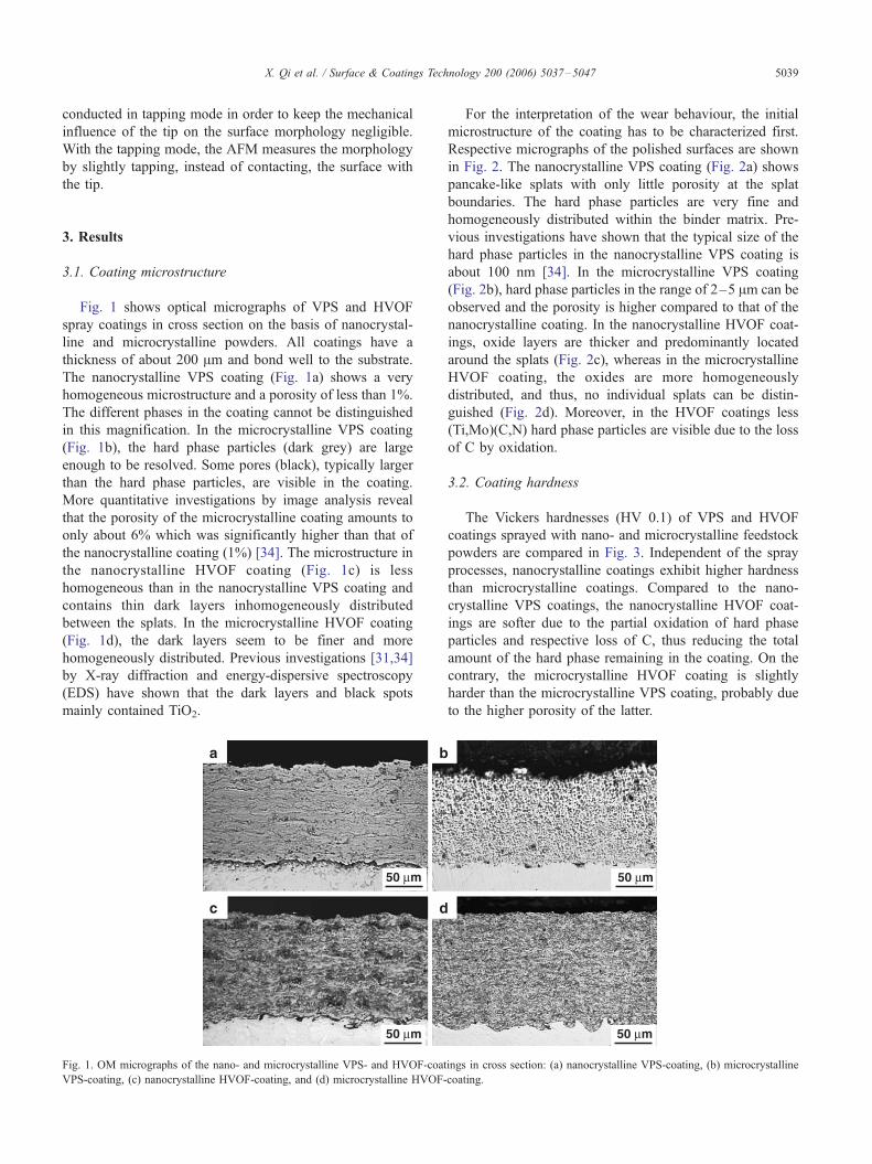
Fig. 1 shows optical micrographs of VPS and HVOF
spray coatings in cross section on the basis of nanocrystal-
line and microcrystalline powders. All coatings have a
thickness of about 200 Am and bond well to the substrate.
The nanocrystalline VPS coating (Fig. 1a) shows a very
homogeneous microstructure and a porosity of less than 1%.
The different phases in the coating cannot be distinguished
in this magnification. In the microcrystalline VPS coating
(Fig. 1b), the hard phase particles (dark grey) are large
enough to be resolved. Some pores (black), typically larger
than the hard phase particles, are visible in the coating.
More quantitative investigations by image analysis reveal
that the porosity of the microcrystalline coating amounts to
only about 6% which was significantly higher than that of
the nanocrystalline coating (1%) [34]. The microstructure in
the nanocrystalline HVOF coating (Fig. 1c) is less
homogeneous than in the nanocrystalline VPS coating and
contains thin dark layers inhomogeneously distributed
between the splats. In the microcrystalline HVOF coating
(Fig. 1d), the dark layers seem to be finer and more
homogeneously distributed. Previous investigations [31,34]
by X-ray diffraction and energy-dispersive spectroscopy
(EDS) have shown that the dark layers and black spots
mainly contained TiO2.
ba
c d
50 µm
50 µm
Fig. 1. OM micrographs of the nano- and microcrystalline VPS- and HVOF-coat
VPS-coating, (c) nanocrystalline HVOF-coating, and (d) microcrystalline HVOF-
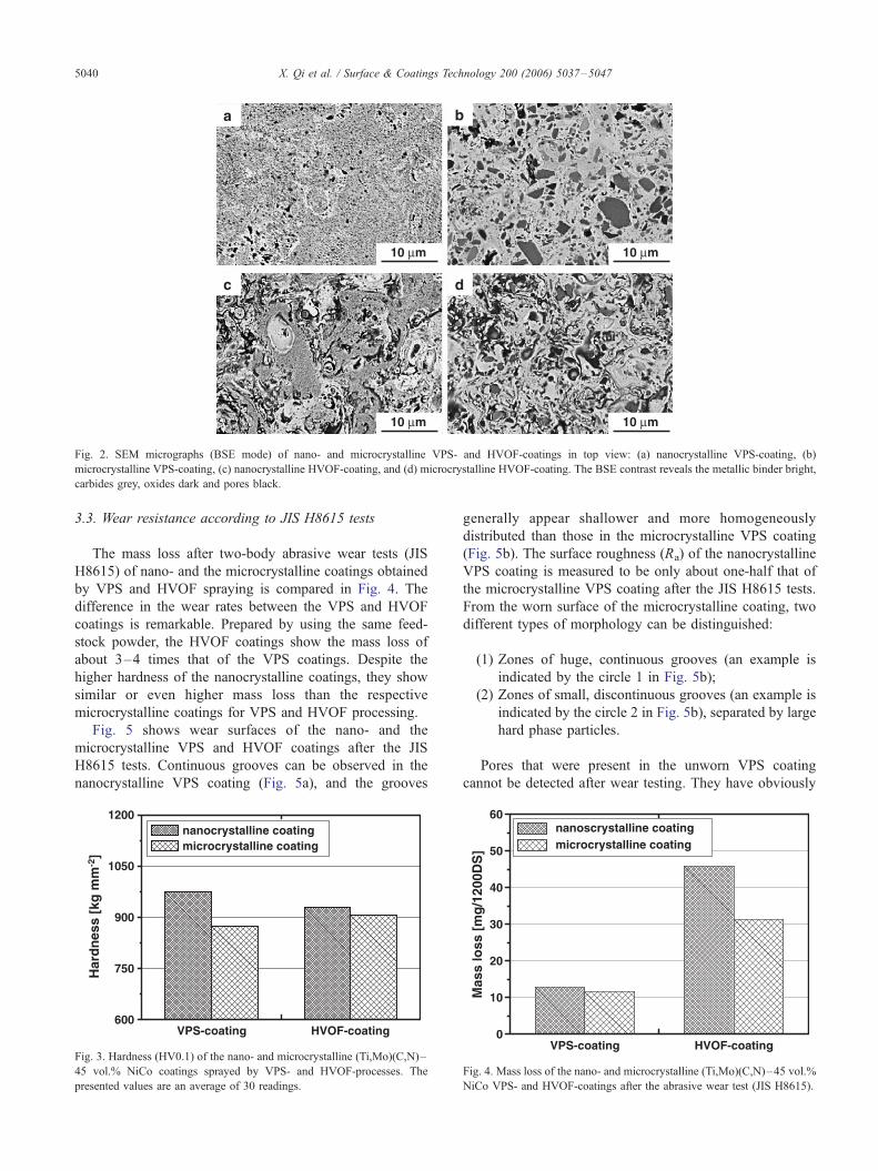
For the interpretation of the wear behaviour, the initial
microstructure of the coating has to be characterized first.
Respective micrographs of the polished surfaces are shown
in Fig. 2. The nanocrystalline VPS coating (Fig. 2a) shows
pancake-like splats with only little porosity at the splat
boundaries. The hard phase particles are very fine and
homogeneously distributed within the binder matrix. Pre-
vious investigations have shown that the typical size of the
hard phase particles in the nanocrystalline VPS coating is
about 100 nm [34]. In the microcrystalline VPS coating
(Fig. 2b), hard phase particles in the range of 2–5 Am can be
observed and the porosity is higher compared to that of the
nanocrystalline coating. In the nanocrystalline HVOF coat-
ings, oxide layers are thicker and predominantly located
around the splats (Fig. 2c), whereas in the microcrystalline
HVOF coating, the oxides are more homogeneously
distributed, and thus, no individual splats can be distin-
guished (Fig. 2d). Moreover, in the HVOF coatings less
(Ti,Mo)(C,N) hard phase particles are visible due to the loss
of C by oxidation.
3.2. Coating hardness
The Vickers hardnesses (HV 0.1) of VPS and HVOF
coatings sprayed with nano- and microcrystalline feedstock
powders are compared in Fig. 3. Independent of the spray
processes, nanocrystalline coatings exhibit higher hardness
than microcrystalline coatings. Compared to the nano-
crystalline VPS coatings, the nanocrystalline HVOF coat-
ings are softer due to the partial oxidation of hard phase
particles and respective loss of C, thus reducing the total
amount of the hard phase remaining in the coating. On the
contrary, the microcrystalline HVOF coating is slightly
harder than the microcrystalline VPS coating, probably due
to the higher porosity of the latter.
50 µm
50 µm
ings in cross section: (a) nanocrystalline VPS-coating, (b) microcrystalline
coating.
a b
dc
10 µm 10 µm
10 µm 10 µm
Fig. 2. SEM micrographs (BSE mode) of nano- and microcrystalline VPS- and HVOF-coatings in top view: (a) nanocrystalline VPS-coating, (b)
microcrystalline VPS-coating, (c) nanocrystalline HVOF-coating, and (d) microcrystalline HVOF-coating. The BSE contrast reveals the metallic binder bright,
carbides grey, oxides dark and pores black.
X. Qi et al. / Surface & Coatings Technology 200 (2006) 5037–50475040
3.3. Wear resistance according to JIS H8615 tests
The mass loss after two-body abrasive wear tests (JIS
H8615) of nano- and the microcrystalline coatings obtained
by VPS and HVOF spraying is compared in Fig. 4. The
difference in the wear rates between the VPS and HVOF
coatings is remarkable. Prepared by using the same feed-
stock powder, the HVOF coatings show the mass loss of
about 3–4 times that of the VPS coatings. Despite the
higher hardness of the nanocrystalline coatings, they show
similar or even higher mass loss than the respective
microcrystalline coatings for VPS and HVOF processing.
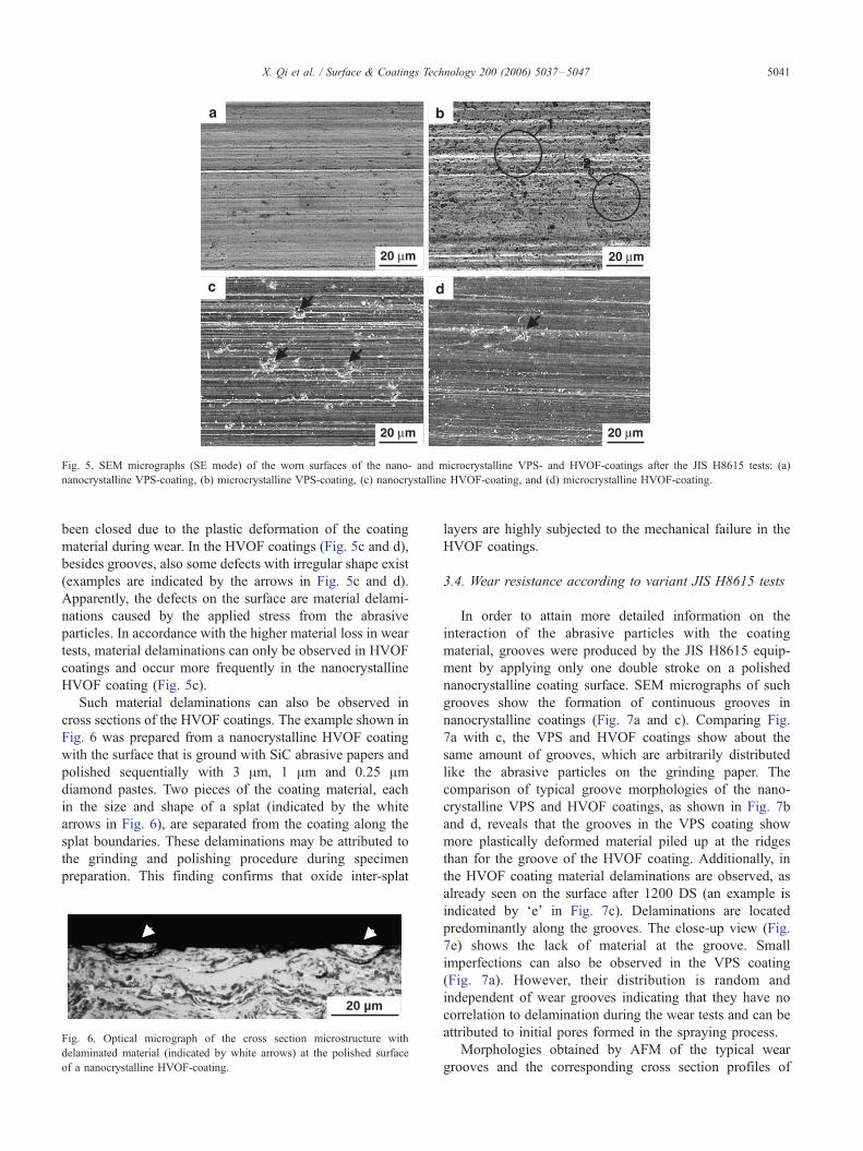
Fig. 5 shows wear surfaces of the nano- and the
microcrystalline VPS and HVOF coatings after the JIS
H8615 tests. Continuous grooves can be observed in the
nanocrystalline VPS coating (Fig. 5a), and the grooves
600
750
900
1050
1200
VPS-coating HVOF-coating
Har
dn
ess
[kg
mm
-2]
nanocrystalline coatingmicrocrystalline coating
Fig. 3. Hardness (HV0.1) of the nano- and microcrystalline (Ti,Mo)(C,N)–
45 vol.% NiCo coatings sprayed by VPS- and HVOF-processes. The
presented values are an average of 30 readings.
generally appear shallower and more homogeneously
distributed than those in the microcrystalline VPS coating
(Fig. 5b). The surface roughness (Ra) of the nanocrystalline
VPS coating is measured to be only about one-half that of
the microcrystalline VPS coating after the JIS H8615 tests.
From the worn surface of the microcrystalline coating, two
different types of morphology can be distinguished:
(1) Zones of huge, continuous grooves (an example is
indicated by the circle 1 in Fig. 5b);
(2) Zones of small, discontinuous grooves (an example is
indicated by the circle 2 in Fig. 5b), separated by large
hard phase particles.
Pores that were present in the unworn VPS coating
cannot be detected after wear testing. They have obviously
0
10
20
30
40
50
60
HVOF-coatingVPS-coating
nanoscrystalline coatingmicrocrystalline coating
Mas
s lo
ss [
mg
/120
0DS
]
Fig. 4. Mass loss of the nano- and microcrystalline (Ti,Mo)(C,N)–45 vol.%
NiCo VPS- and HVOF-coatings after the abrasive wear test (JIS H8615).
c d
a b
20 µm 20 µm
20 µm 20 µm
1
2
Fig. 5. SEM micrographs (SE mode) of the worn surfaces of the nano- and microcrystalline VPS- and HVOF-coatings after the JIS H8615 tests: (a)
nanocrystalline VPS-coating, (b) microcrystalline VPS-coating, (c) nanocrystalline HVOF-coating, and (d) microcrystalline HVOF-coating.
X. Qi et al. / Surface & Coatings Technology 200 (2006) 5037–5047 5041
been closed due to the plastic deformation of the coating
material during wear. In the HVOF coatings (Fig. 5c and d),
besides grooves, also some defects with irregular shape exist
(examples are indicated by the arrows in Fig. 5c and d).
Apparently, the defects on the surface are material delami-
nations caused by the applied stress from the abrasive
particles. In accordance with the higher material loss in wear
tests, material delaminations can only be observed in HVOF
coatings and occur more frequently in the nanocrystalline
HVOF coating (Fig. 5c).
Such material delaminations can also be observed in
cross sections of the HVOF coatings. The example shown in
Fig. 6 was prepared from a nanocrystalline HVOF coating
with the surface that is ground with SiC abrasive papers and
polished sequentially with 3 Am, 1 Am and 0.25 Amdiamond pastes. Two pieces of the coating material, each
in the size and shape of a splat (indicated by the white
arrows in Fig. 6), are separated from the coating along the
splat boundaries. These delaminations may be attributed to
the grinding and polishing procedure during specimen
preparation. This finding confirms that oxide inter-splat
20 µm
Fig. 6. Optical micrograph of the cross section microstructure with
delaminated material (indicated by white arrows) at the polished surface
of a nanocrystalline HVOF-coating.
layers are highly subjected to the mechanical failure in the
HVOF coatings.
3.4. Wear resistance according to variant JIS H8615 tests
In order to attain more detailed information on the
interaction of the abrasive particles with the coating
material, grooves were produced by the JIS H8615 equip-
ment by applying only one double stroke on a polished
nanocrystalline coating surface. SEM micrographs of such
grooves show the formation of continuous grooves in
nanocrystalline coatings (Fig. 7a and c). Comparing Fig.
7a with c, the VPS and HVOF coatings show about the
same amount of grooves, which are arbitrarily distributed
like the abrasive particles on the grinding paper. The
comparison of typical groove morphologies of the nano-
crystalline VPS and HVOF coatings, as shown in Fig. 7b
and d, reveals that the grooves in the VPS coating show
more plastically deformed material piled up at the ridges
than for the groove of the HVOF coating. Additionally, in
the HVOF coating material delaminations are observed, as
already seen on the surface after 1200 DS (an example is
indicated by Fe_ in Fig. 7c). Delaminations are located
predominantly along the grooves. The close-up view (Fig.
7e) shows the lack of material at the groove. Small
imperfections can also be observed in the VPS coating
(Fig. 7a). However, their distribution is random and
independent of wear grooves indicating that they have no
correlation to delamination during the wear tests and can be
attributed to initial pores formed in the spraying process.
Morphologies obtained by AFM of the typical wear
grooves and the corresponding cross section profiles of

100 µm 5 µm
5 µm
c
e
c
e
a
100 µm
b
5 µm
b
d
Fig. 7. SEM (SE mode) micrographs of the morphologies of wear traces produced by the JIS H8615 equipment (abrasive particle size 45 Am, normal load 30 N,
1 DS) on a polished surface of the nanocrystalline VPS- and HVOF-coatings: (a and b) VPS-coating, (c), (d and e) HVOF-coating. The figure in (b), (d) and (e)
show the close-up microstructures at the places marked by Fb_, Fd_ and Fe,_ respectively in (a) and (c).
X. Qi et al. / Surface & Coatings Technology 200 (2006) 5037–50475042
nanocrystalline coatings are depicted in Fig. 8. The different
widths can be attributed to locally different loads of the
abrasives. Aside from the groove in the VPS coating, ridges
have built up that protrude from the surface level. The total
0 1 2 3 4 5 6-160-120-80-40
04080
VPS-groovedept
h [n
m]
width [µm]
(a)
Fig. 8. AFM analysis of single-groove morphologies on the nanocrystalline VPS- a
the micrographs indicate the places where the profiles are located. The wear traces
load 30 N, 1 DS) on the polished coating surfaces.
section area of both ridges is about half of the section area of
the groove, which means that half of the material was cut
and half was plastically deformed and pushed to both sides
of the groove. In the HVOF coating, ridge formation is
0 1 2 3 4 5-160-120-80-40
04080
HVOF-groovedept
h [n
m]
width [µm]6
(b)
nd HVOF-coatings: (a) VPS-coating, (b) HVOF-coating. The white lines in
were produced by the JIS H8615 tester (abrasive particle size 45 Am, normal
0
10
20
30
40
200 µm100 µm45 µm30 µm
nanocrystalline VPS coatingmicrocrystalline VPS coating
Abrasive particle size
Mas
s lo
ss [
mg
/ 12
00 D
S]
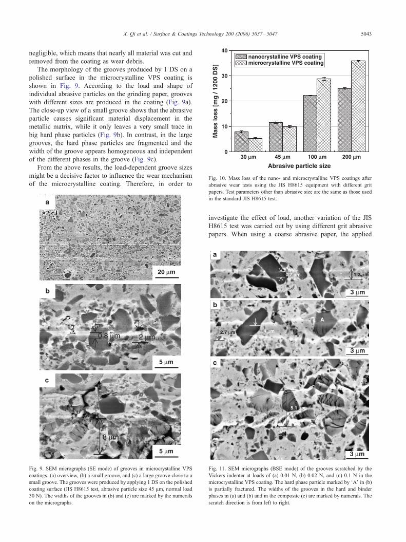
Fig. 10. Mass loss of the nano- and microcrystalline VPS coatings after
abrasive wear tests using the JIS H8615 equipment with different grit
X. Qi et al. / Surface & Coatings Technology 200 (2006) 5037–5047 5043
negligible, which means that nearly all material was cut and
removed from the coating as wear debris.
The morphology of the grooves produced by 1 DS on a
polished surface in the microcrystalline VPS coating is
shown in Fig. 9. According to the load and shape of
individual abrasive particles on the grinding paper, grooves
with different sizes are produced in the coating (Fig. 9a).
The close-up view of a small groove shows that the abrasive
particle causes significant material displacement in the
metallic matrix, while it only leaves a very small trace in
big hard phase particles (Fig. 9b). In contrast, in the large
grooves, the hard phase particles are fragmented and the
width of the groove appears homogeneous and independent
of the different phases in the groove (Fig. 9c).
From the above results, the load-dependent groove sizes
might be a decisive factor to influence the wear mechanism
of the microcrystalline coating. Therefore, in order to
8 µm
c
5 µm
2 µm 0.8 µm
b
5 µm
20 µm
a
Fig. 9. SEM micrographs (SE mode) of grooves in microcrystalline VPS
coatings: (a) overview, (b) a small groove, and (c) a large groove close to a
small groove. The grooves were produced by applying 1 DS on the polished
coating surface (JIS H8615 test, abrasive particle size 45 Am, normal load
30 N). The widths of the grooves in (b) and (c) are marked by the numerals
on the micrographs.
papers. Test parameters other than abrasive size are the same as those used
in the standard JIS H8615 test.
investigate the effect of load, another variation of the JIS
H8615 test was carried out by using different grit abrasive
papers. When using a coarse abrasive paper, the applied
1.2 µm0.7 µm
2.7 µm 1.4 µm
5.1 µm
b
a
c
A
3 µm
3 µm
3 µm
Fig. 11. SEM micrographs (BSE mode) of the grooves scratched by the
Vickers indenter at loads of (a) 0.01 N, (b) 0.02 N, and (c) 0.1 N in the
microcrystalline VPS coating. The hard phase particle marked by FA_ in (b)
is partially fractured. The widths of the grooves in the hard and binder
phases in (a) and (b) and in the composite (c) are marked by numerals. The
scratch direction is from left to right.
X. Qi et al. / Surface & Coatings Technology 200 (2006) 5037–50475044
load is shared by a smaller number of abrasive particles. For
a constant contact area of the coating and the counterbody,
this results in a higher effective load on each abrasive
particle.
Wear test results on the nano- and microcrystalline VPS
coatings using abrasive papers with different grit sizes are
shown in Fig. 10. Mass loss increases with increasing size of
abrasive particles. However, the increasing rate in mass loss
is lower for the nanocrystalline coating than that for the
microcrystalline coating. For instance, when the abrasive
particle size is changed from 30 Am to 200 Am, the mass
loss of the nanocrystalline coating is increased by about
300%, whereas the increase for the microcrystalline coating
is more than 700 %. Therefore, compared to the micro-
crystalline coating, the nanocrystalline coating shows a
superior wear resistance against larger abrasive particles
while it shows an inferior wear resistance against smaller
abrasive particles. Under the present experimental condi-
tions, the critical mean abrasive particle size, above which
the nanocrystalline coating shows higher wear resistance
e f
a b
c d
10 µm
10 µm
20 µm
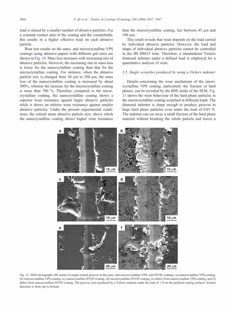
Fig. 12. SEM micrographs (SE mode) of single-scratch grooves in the nano- and m
(b) microcrystalline VPS-coating, (c) nanocrystalline HVOF-coating, (d) microcry
debris from nanocrystalline HVOF-coating. The grooves were produced by a Vick
direction is from top to bottom.
than the microcrystalline coating, lies between 45 Am and
100 Am.
This result reveals that wear depends on the load carried
by individual abrasive particles. However, the load and
shape of individual abrasive particles cannot be controlled
in the JIS H8615 tests. Therefore, a standardized Vickers
diamond indenter under a defined load is employed for a
quantitative analysis of wear.
3.5. Single scratches produced by using a Vickers indenter
Details concerning the wear mechanism of the micro-
crystalline VPS coating, particularly the fracture of hard
phases, can be revealed by the BSE mode of the SEM. Fig.
11 shows the wear behaviour of the hard phase particles in
the microcrystalline coating scratched at different loads. The
diamond indenter is sharp enough to produce grooves in
large hard phase particles even under the load of 0.01 N.
The indenter can cut away a small fraction of the hard phase
material without breaking the whole particle and leaves a
10 µm
10 µm
20 µm
icrocrystalline VPS- and HVOF-coatings: (a) nanocrystalline VPS-coating,
stalline HVOF-coating, (e) debris from nanocrystalline VPS-coating, and (f)
ers indenter under the load of 1 N on the polished coating surfaces. Scratch
X. Qi et al. / Surface & Coatings Technology 200 (2006) 5037–5047 5045
groove in the hard phase particle. However, the width of the
grooves in the hard phase particles is smaller than that in the
binder phase (Fig. 11a). If the load is increased to 0.02 N,
the groove widths in the binder phase and in the hard phase
particles are increased (Fig. 11b). Some of the hard phase
particles are partially fractured (marked by FA_ in Fig. 11b).
Whereas the groove width in the fractured hard phases is not
significantly lowered in comparison with that in the binder,
it is reduced to about a half in the non-broken carbides. If
the load is further increased up to 0.1 N, most of the hard
phase particles in the groove are severely fractured. The
width of the groove appears to be constant and independent
of the phase distribution in the groove (Fig. 11c). It might be
worth noting that small hard phase particles with diameters
less than about 0.5 Am seem not to be fractured under the
applied load.
Fig. 12 shows the SEM micrographs of the grooves
generated by scratching with a Vickers indenter on the VPS
and HVOF coatings at a load of 1 N. The smaller width of
the grooves in the nanocrystalline coatings with respect to
those in the microcrystalline coatings correlates with their
higher hardness. While the groove in the nanocrystalline
VPS coating is very homogeneous (Fig. 12a), there are
cracks in the hard phase particles and at the side of the
groove in the microcrystalline VPS coating (Fig. 12b). It is
evident that the fragmented material at the side of the groove
can be easily removed in subsequent scratches. In the
nanocrystalline HVOF coating, severe material delamina-
tions at the groove are observed (Fig. 12c). Material
delamination, although significantly less, is also found at
the groove in the microcrystalline HVOF coating (Fig. 12d).
The wear debris observed in the grooves of the nanocrystal-
line VPS and HVOF coatings is distinctly different. The
more ductile debris from the VPS coating is long and curved
(Fig. 12e), while the brittle debris from the HVOF coating
has the shape of isometric polygons (Fig. 12f).
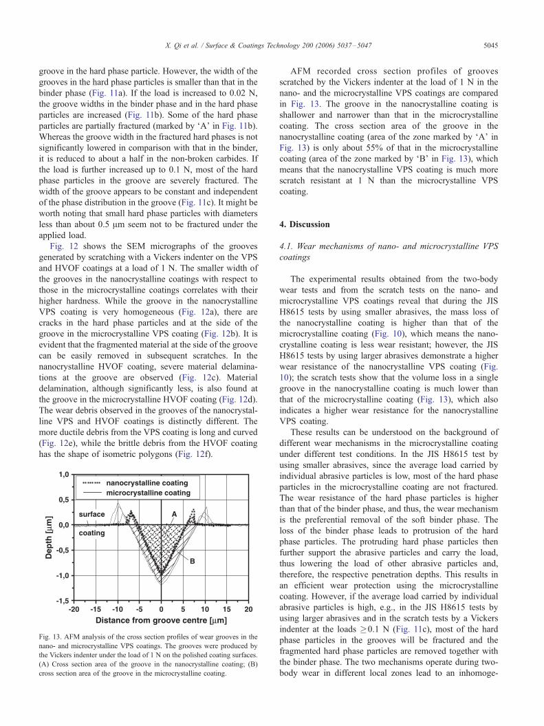
-20 -15 -10 -5 0 5 10 15 20-1,5
-1,0
-0,5
0,0
0,5
1,0
coating
surface
B
A
nanocrystalline coatingmicrocrystalline coating
Distance from groove centre [µm]
Dep
th [
µm]
Fig. 13. AFM analysis of the cross section profiles of wear grooves in the
nano- and microcrystalline VPS coatings. The grooves were produced by
the Vickers indenter under the load of 1 N on the polished coating surfaces.
(A) Cross section area of the groove in the nanocrystalline coating; (B)
cross section area of the groove in the microcrystalline coating.
AFM recorded cross section profiles of grooves
scratched by the Vickers indenter at the load of 1 N in the
nano- and the microcrystalline VPS coatings are compared
in Fig. 13. The groove in the nanocrystalline coating is
shallower and narrower than that in the microcrystalline
coating. The cross section area of the groove in the
nanocrystalline coating (area of the zone marked by FA_ inFig. 13) is only about 55% of that in the microcrystalline
coating (area of the zone marked by FB_ in Fig. 13), which
means that the nanocrystalline VPS coating is much more
scratch resistant at 1 N than the microcrystalline VPS
coating.
4. Discussion
4.1. Wear mechanisms of nano- and microcrystalline VPS
coatings
The experimental results obtained from the two-body
wear tests and from the scratch tests on the nano- and
microcrystalline VPS coatings reveal that during the JIS
H8615 tests by using smaller abrasives, the mass loss of
the nanocrystalline coating is higher than that of the
microcrystalline coating (Fig. 10), which means the nano-
crystalline coating is less wear resistant; however, the JIS
H8615 tests by using larger abrasives demonstrate a higher
wear resistance of the nanocrystalline VPS coating (Fig.
10); the scratch tests show that the volume loss in a single
groove in the nanocrystalline coating is much lower than
that of the microcrystalline coating (Fig. 13), which also
indicates a higher wear resistance for the nanocrystalline
VPS coating.
These results can be understood on the background of
different wear mechanisms in the microcrystalline coating
under different test conditions. In the JIS H8615 test by
using smaller abrasives, since the average load carried by
individual abrasive particles is low, most of the hard phase
particles in the microcrystalline coating are not fractured.
The wear resistance of the hard phase particles is higher
than that of the binder phase, and thus, the wear mechanism
is the preferential removal of the soft binder phase. The
loss of the binder phase leads to protrusion of the hard
phase particles. The protruding hard phase particles then
further support the abrasive particles and carry the load,
thus lowering the load of other abrasive particles and,
therefore, the respective penetration depths. This results in
an efficient wear protection using the microcrystalline
coating. However, if the average load carried by individual
abrasive particles is high, e.g., in the JIS H8615 tests by
using larger abrasives and in the scratch tests by a Vickers
indenter at the loads �0.1 N (Fig. 11c), most of the hard
phase particles in the grooves will be fractured and the
fragmented hard phase particles are removed together with
the binder phase. The two mechanisms operate during two-
body wear in different local zones lead to an inhomoge-
X. Qi et al. / Surface & Coatings Technology 200 (2006) 5037–50475046
neous wear morphologies in the microcrystalline coating
(Fig. 5b).
In contrast, the nanocrystalline coating shows a very
homogeneous wear morphology leading to the conclusion
that only one wear mechanism is operating. Since the hard
phase particles in the nanocrystalline coating are very small,
they cannot support the abrasive particles. Consequently, the
wear mechanism of the nanocrystalline VPS coating is a
combination of cutting and ploughing. The nanoscale hard
phase particles and the binder phase are simultaneously
displaced and removed by abrasive particles like in a
homogeneous rather ductile material, forming wear debris,
in which the hard phase particles are embedded in the binder
matrix. This also explains the slightly lower wear resistance
of the nanocrystalline coating in comparison to micro-
crystalline coatings, as measured with the JIS H8615 tests
by using smaller abrasives, in which a lower average load is
applied by individual abrasive particles as compared to the
scratch test.
However, in the nanocrystalline coating, even under high
local loads, breaking of the hard phase particles is very
unlikely because of the high strength of very fine ceramic
particles [35]. Moreover, being surrounded by a ductile
matrix, the nanoscale hard phase particles are exposed to
smaller local stress concentrations than the larger ones.
Therefore, at higher loads the nanocrystalline coating is
advantageous over microcrystalline coatings; the formation
of areas severely damaged by wear is avoided, thus leading
to a higher wear resistance and a smoother worn surface.
4.2. Wear mechanisms of nano- and microcrystalline HVOF
coatings
The result from the JIS H8615 tests (Fig. 4) shows that
the mass loss of the HVOF coatings is several times higher
than that of VPS coatings processed with the same feedstock
powders and tested under the same wear conditions. This
can be explained by the occurrence of material delamina-
tions during the abrasive wear of the HVOF coatings. In
HVOF spraying, oxygen is present in the combustion gas
mixture and in the ambient air [36]. Therefore, carbon is
partially lost, and titanium oxide layers are formed on the
surface of the spray particles. During impingement of the
spray particles on the substrate, the oxides remain at the
boundaries of the spray splats. During wear, cracks can be
generated and grow at the brittle splat boundaries. These
cracks finally lead to the removal of the splats. Moreover,
the presence of oxides reduces the ductility of the overall
composite. Therefore, the coating exhibits a brittle wear
behaviour and almost all the material from the wear grooves
in the HVOF coatings is removed as debris (Fig. 8b). On the
contrary, for the VPS coating under the same wear
conditions, a considerable amount of the displaced material
from the wear grooves is ploughed aside the groove,
forming ridges, and thus, still remains in the coatings
(Fig. 8a). Hence, besides the delamination of material, the
overall lower ductility is another reason for the substantially
higher wear rate of the HVOF coatings compared to the
VPS coatings.
It should also be noted that the difference in the wear rate
between the nanocrystalline HVOF and VPS coating is
larger than that between the microcrystalline HVOF and
VPS coatings (Fig. 4). This difference seems to be related to
the oxide distribution in the HVOF coatings. The nano-
crystalline coating (Figs. 1c and 2c) shows some oxygen-
rich zones and thick bands of oxides, whereas in the
microcrystalline coatings oxides are thinner and more
homogeneously distributed (Figs. 1d and 2d). The smaller
oxygen-rich zones in the microcrystalline HVOF coating
contain fewer defects that can promote crack formation and
crack propagation compared to those in the nanocrystalline
coating. Therefore, less material delaminations occur,
resulting in a lower mass loss in the microcrystalline HVOF
coatings.
5. Summary and conclusions
Both nano- and microcrystalline HVOF coatings show
much lower wear resistance than the VPS coatings on the
basis of same feedstock powders, due to the presence of
oxide layers amongst the spray splats. The oxide layers
weaken the cohesion between splats and embrittle the
HVOF coating material, leading to a higher wear of these
coatings. The nanocrystalline HVOF coatings show a lower
wear resistance than the microcrystalline HVOF coatings,
due to more concentrated zones of oxides.
The microcrystalline VPS coatings have higher wear
resistance, if the stress exerted by individual abrasive
particles is low, such that the hard phase particles can carry
the load and support the counterbody. The wear mechanism
of the microcrystalline coatings undergoes a transition from
predominant removal of the binder phase to wear involving
hard phase fracture with increasing load of individual
abrasive particles. Under tougher wear conditions, the hard
phase particles are fragmented and removed together with
the binder matrix. In this case, the nanocrystalline VPS
coatings show superior wear resistance compared to the
microcrystalline coatings. In addition, the nanocrystalline
VPS coatings have also the advantage of showing a
smoother worn surface than the microcrystalline VPS
coatings. This is a significant advantage, if keeping a
smooth worn surface is more important than keeping the
clearance between wear parts low in the technical applica-
tion, e.g., rolls in paper industry.
The dominant abrasive wear mechanism of the VPS
sprayed nanocrystalline coatings can be described by cutting
and ploughing. The nanoscale hard phase particles and the
binder phase in the nanocrystalline coating are simulta-
neously displaced, forming ridges and wear debris, in which
the hard phase particles are still embedded in the binder
phase, as in the coating.
X. Qi et al. / Surface & Coatings Technology 200 (2006) 5037–5047 5047
Acknowledgements
The support by W. Krommer and P. Heinrich from the
Linde AG, Unterschleißheim, Germany, in performing
HVOF experiments is greatly acknowledged. In addition,
the authors thank V. Borck and R. Henne, DLR, Stuttgart,
Germany, for their support in vacuum plasma spraying.
Thanks are due to M. Lembke and G. Favaro from CSM
Instruments, Switzerland, for the execution of scratch tests.
F. Felten from Technical University Hamburg, Germany, is
also acknowledged for his kind instruction during AFM
investigation.
This work was partly supported by the German Research
Society (DFG) within the collaborative research program
SFB 371 FMicromechanics of Multiphase Materials,_Project D3.
References
[1] L.-M. Berger, P. Vuoristo, T. Mantylat, W. Gruner, in: C. Coddet (Ed.),
Proc. of the 15th International Thermal Spray Conference, ASM
International, Materials Park, OH, USA, 1998, p. 75.
[2] B.Q. Wang, Wear 188 (1995) 40.
[3] M. Bjordal, E. Bardal, T. Rogne, Wear 186–187 (1995) 508.
[4] S. Berger, R. Porat, R. Rosen, Prog. Mater. Sci. 42 (1997) 311.
[5] J.M. Guilemany, J. Nutting, N.L. Isern, J. Therm. Spray Technol. 5
(1996) 483.
[6] S. Wirojanupatump, P.H. Shipway, D.G. McCartney, Wear 249 (2001)
829.
[7] R. Schwetzke, H. Kreye, J. Therm. Spray Technol. 8 (1999) 433.
[8] S. Zimmermann, H. Kreye, in: C.C. Berndt (Ed.), Thermal Spray: A
United Forum for Scientific and Technological Advances, ASM
International, Materials Park, OH, USA, 1996, p. 147.
[9] A. Bellosi, F. Monteverde, R. Calzavaroni, C. Zancolo, Int. J. Refract.
Met. Hard Mater. 19 (2001) 191.
[10] T. Rogne, J. Berget, T. Solem, in: German Welding Society (Ed.),
United Thermal Spray Conference, ASM Thermal Spray Society,
Materials Park, Dusseldorf, Germany, 1999, p. 487.
[11] T.H. Stenberg, K.J. Niemi, P.M.J. Vuoristo, J.E. Vuorinen, T.A.
Mantyla, in: C.C. Berndt (Ed.), Proc. ITSC ’95, ASM International,
Materials Park, OH, USA, 1995, p. 1145.
[12] L.M. Berger, M. Nebelung, P. Vuoristo, M. Heinonen, T. Mantyla, T.
Reinhardt, in: German Welding Society (Ed.), United Thermal Spray
Conference, ASM Thermal Spray Society, Materials Park, Dusseldorf,
Germany, 1999, p. 128.
[13] H. Doi, in: E.A. Almond, C.A. Brooks, R. Warren (Eds.), Proc. 2nd
Intern. Conf. Sci. Hard Materials, Inst. Phys. Conf. Ser., vol. 75, Adam
Hilger Ltd, Bristol and Boston, 1986, p. 489.
[14] I.M. Hutchings, Tribology: Friction and Wear of Engineering
Materials, Butterworth-Heinemann, Oxford, UK, 1992.
[15] K.-H. Zum Gahr, Microstructure and Wear of Materials, Elsevier
Science Publishers B.V., Netherlands, 1987.
[16] K. Jia, T.E. Fischer, B. Gallois, Nanostruct. Mater. 10 (1998) 875.
[17] K. Jia, T.E. Fischer, Wear 203–204 (1997) 310.
[18] W. Schlump, J. Willbrand, H. Grewe, Metallurgy 48 (1994) 34.
[19] B.H. Kear, P.R. Strutt, Nanostruct. Mater. 3 (1993) 19.
[20] B.H. Kear, R.K. Sadangi, M. Jain, R. Yao, Z. Kalman, G. Skandan,
W.E. Mayo, J. Therm. Spray Technol. 9 (2000) 399.
[21] Z. Fang, J.W. Eason, Int. J. Refract. Met. Hard Mater. 13 (1995)
297.
[22] K. Jia, T.E. Fischer, Wear 200 (1996) 206.
[23] S. Usmani, S. Sampath, D. Houck, D. Lee, Tribol. Trans. 40 (1997)
470.
[24] D.A. Stewart, P.H. Shipway, D.G. McCartney, Wear 225–229 (1999)
789.
[25] Y. Qiao, T.E. Fischer, A. Dent, Surf. Coat. Technol. 172 (2003) 24.
[26] Y. Qiao, Y. Liu, T.E. Fischer, J. Therm. Spray Technol. 10 (2001)
118.
[27] Y. Zhu, K. Yukimura, C. Ding, P. Zhang, Thin Solid Films 388 (2001)
277.
[28] N. Eigen, T. Klassen, E. Aust, R. Bormann, F. Gartner, Surf. Coat.
Technol. 159 (2005) 344.
[29] N. Eigen, T. Klassen, E. Aust, R. Bormann, F. Gartner, Mater. Sci.
Eng., A Struct. Mater.: Prop. Microstruct. Process. 356 (2003) 114.
[30] X. Qi, E. Aust, N. Eigen, F. Gartner, R. Bormann, Mat.-Wiss.
Werkstofftech. 35 (2004) 779.
[31] F. Gartner, H. Kreye, V. Borck, K. Krommer, in: C.C. Berndt
(Ed.), Proc. ITSC, ASM International, Materials Park, OH, USA,
2000, p. 463.
[32] F. Gartner, R. Bormann, T. Klassen, H. Kreye, N. Mitra, Mater. Sci.
Forum 343–346 (2000) 933.
[33] F. Gartner, H. Kreye, T. Klassen, R. Bormann, in: H. Dimigen (Ed.),
Proc. International Congress on Advanced Materials and Processes,
EUROMAT 99, Volume 11, Surface Engineering Held in Munchen,
Germany, September 27–30, 1999, WILEY-VCH, Weinheim, Ger-
many, 2000, p. 88.
[34] N. Eigen, Einsatzpotenzial des Hochenergiemahlens fur die Herstel-
lung nanokristalliner Werkstoffe, PhD thesis, Hamburg University of
Technology, Germany, 2004, p. 82.
[35] K. Schonert, in: K. Winnaker (Ed.), 4th edR Chemische Technologie,
vol. 1, Allgemeines, 1984, p. 80.
[36] H. Kreye, F. Gartner, A. Kirsten, R. Schwetzke, in: P. Heinrich (Ed.),
Proc. 5. Kolloqium Hochgeschwindigkeits-Flammspritzen, Erding,
Germany, November 16–17, 2000, Gemeinschaft Thermisches Sprit-
zen e.V, Unterschleißheim, Germany, 2000, p. 5.