Repair of Reinforced Concrete Elements using Fiber Reinforced Polymers
Upload
khangminh22Category
view
1download
0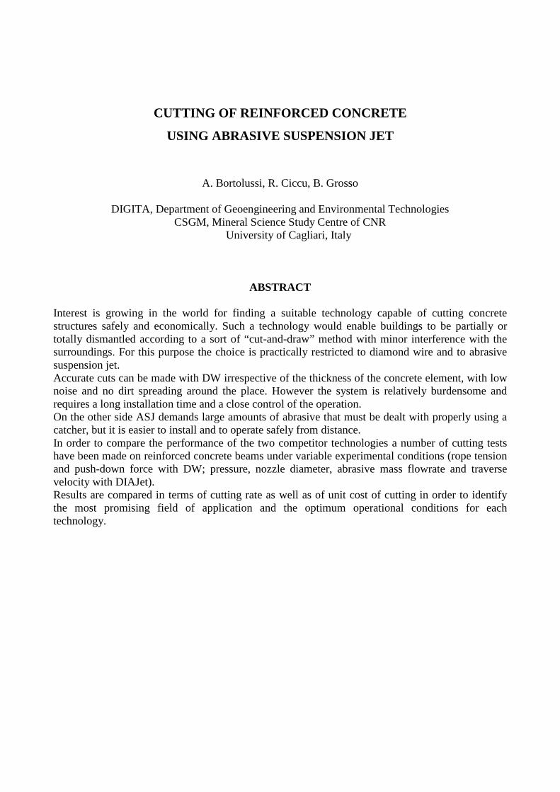
CUTTING OF REINFORCED CONCRETE
USING ABRASIVE SUSPENSION JET
A. Bortolussi, R. Ciccu, B. Grosso
DIGITA, Department of Geoengineering and Environmental Technologies CSGM, Mineral Science Study Centre of CNR
University of Cagliari, Italy
ABSTRACT Interest is growing in the world for finding a suitable technology capable of cutting concrete structures safely and economically. Such a technology would enable buildings to be partially or totally dismantled according to a sort of “cut-and-draw” method with minor interference with the surroundings. For this purpose the choice is practically restricted to diamond wire and to abrasive suspension jet. Accurate cuts can be made with DW irrespective of the thickness of the concrete element, with low noise and no dirt spreading around the place. However the system is relatively burdensome and requires a long installation time and a close control of the operation. On the other side ASJ demands large amounts of abrasive that must be dealt with properly using a catcher, but it is easier to install and to operate safely from distance. In order to compare the performance of the two competitor technologies a number of cutting tests have been made on reinforced concrete beams under variable experimental conditions (rope tension and push-down force with DW; pressure, nozzle diameter, abrasive mass flowrate and traverse velocity with DIAJet). Results are compared in terms of cutting rate as well as of unit cost of cutting in order to identify the most promising field of application and the optimum operational conditions for each technology.
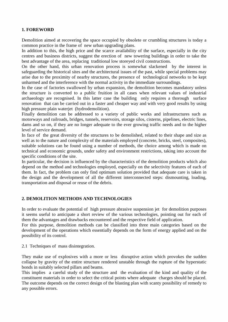
1. FOREWORD Demolition aimed at recovering the space occupied by obsolete or crumbling structures is today a common practice in the frame of new urban upgrading plans. In addition to this, the high price and the scarce availability of the surface, especially in the city centres and business districts, suggest the erection of new towering buildings in order to take the best advantage of the area, replacing traditional low storeyed civil constructions. On the other hand, this urban renovation process is somewhat slackened by the interest in safeguarding the historical sites and the architectural issues of the past, while special problems may arise due to the proximity of nearby structures, the presence of technological networks to be kept unharmed and the interference with the normal activity in the immediate surroundings. In the case of factories swallowed by urban expansion, the demolition becomes mandatory unless the structure is converted to a public fruition in all cases when relevant values of industrial archaeology are recognised. In this latter case the building only requires a thorough surface renovation that can be carried out in a faster and cheaper way and with very good results by using high pressure plain waterjet (hydrodemolition). Finally demolition can be addressed to a variety of public works and infrastructures such as motorways and railroads, bridges, tunnels, reservoirs, storage silos, cisterns, pipelines, electric lines, dams and so on, if they are no longer adequate to the ever growing traffic needs and to the higher level of service demand. In face of the great diversity of the structures to be demolished, related to their shape and size as well as to the nature and complexity of the materials employed (concrete, bricks, steel, composites), suitable solutions can be found using a number of methods, the choice among which is made on technical and economic grounds, under safety and environment restrictions, taking into account the specific conditions of the site. In particular, the decision is influenced by the characteristics of the demolition products which also depend on the method and technologies employed, especially on the selectivity features of each of them. In fact, the problem can only find optimum solution provided that adequate care is taken in the design and the development of all the different interconnected steps: dismounting, loading, transportation and disposal or reuse of the debris. 2. DEMOLITION METHODS AND TECHNOLOGIES In order to evaluate the potential of high pressure abrasive suspension jet for demolition purposes it seems useful to anticipate a short review of the various technologies, pointing out for each of them the advantages and drawbacks encountered and the respective field of application. For this purpose, demolition methods can be classified into three main categories based on the development of the operations which essentially depends on the form of energy applied and on the possibility of its control. 2.1 Techniques of mass disintegration. They make use of explosives with a more or less disruptive action which provokes the sudden collapse by gravity of the entire structure rendered unstable through the rupture of the hyperstatic bonds in suitably selected pillars and beams. This implies a careful study of the structure and the evaluation of the kind and quality of the constituent materials in order to select the critical points where adequate charges should be placed. The outcome depends on the correct design of the blasting plan with scanty possibility of remedy to any possible errors.

The implosion debris form a huge heap, the mucking of which generally takes a long time and requires a further breaking of larger elements using other technologies. For a rapid destruction of tall buildings having considerable elevation, a big implosion can represent the only viable solution. This is also the case of monolithic concrete items such as chimneys and stacks, towers, walls, pillars and thick beams, for which blasting is the first step followed by splitting and severing stages of the toppled-down sections. It becomes unrivalled in all instances where the access of machines is hindered, difficult or unsafe. In the case of smaller structures other purpose-tailored competitor methods are likely do become preferable. The demolition cost based on explosive blasting can be relatively low only if resulting debris are easily mucked away and disposed of. 2.2 Techniques of controlled dismantling Based on the use of mechanical equipment they lend themselves to the demolition of structures having a relatively small elevation within the reach of the active tool. For the higher parts of the structure the use of impacting heavy bodies with swinging movement is often the simplest solution. For the lower parts it is more convenient to employ earth moving machines, like crawler tractors with pull rope or back-hoe excavators equipped with hydraulic hammer supported by the articulated boom, standing on the floor at safety distance. The work is efficiently carried out in the case of light structures possibly weakened by explosive charges at selected points. The operation is controlled very well by the machine operator. 2.3 Techniques of cutting and disassembly Material selectivity can be optimised by applying demolition methods based on cutting operations which also produce a lesser impact on the environment. Instead of destroying the entire structure or progressively dismantling it with mechanical tools, the constituent elements are individually severed and withdrawn according to a process of ordered disassembly from top to bottom. Each element can be reused as such or treated for alternate uses. With this “cut-and-draw” method, the formation of debris stockpiles is avoided since each element is put to ground by means of a crane and directly loaded onto the truck platform, thus overcoming the problem of dealing with heterogeneous materials often entangled and difficult to handle. The disturbances (dust, noise, vibration) are substantially avoided and safety conditions in the working area acceptable (absence of projections, better control of structural failures). The overall time required is generally very long depending on the size and complexity of the structure, although it can be shortened by multiplying the resources employed since there is a perfect compatibility of many machines working within the same area. Not taking into account the simple manual tools (diamond blade for shallow cuts, oxyhydrogen flame for thermal cutting of metals, shearing of cables and re-bars) the cutting technnologies available for the job are restricted to diamond wire and to abrasive suspension jet. In order to compare the performance of these competitor technologies a plan of cutting tests has been carried out at the DIGITA Laboratories on samples of reinforced concrete having the following characteristics: - Cross section: 0.3 x 0.3 m2 - Density: 2,350 kg/m3 - Re-bars: Two sets of three steel elements 10 mm in diameter (see fig. 2) - Top size of aggregate: 20 mm - Aggregate composition: mixed (limestone and granite)

Figure 1. Size of the test sample and close view of the cross section cut with diamond blade
3. CUTTING WITH DIAMOND WIRE Diamond wire, widely employed in the extraction of dimensional stone blocks (marble, granite) from the quarry face as well as in some further stage of stone processing, has recently been proposed for demolition purposes. Successful results can be achieved especially in those cases where only a part of the structure must be removed, while leaving the rest intact. The cut is made by embracing the perimeter of the section to be cut and applying a pull-back force to the machine (loop cutting) or by pushing the wire with the help of a pair of driving pulleys against the leading edge of the cut (penetration cutting). The wire is moved at a relatively high peripheral speed (20 - 30 m/s) by means of a flywheel of adequate power (some tens of kW). The tool is cooled by injecting water into the slot. The surface obtained is very smooth and cutting rate is substantially independent of the shape and size of the cut section. In order to reduce the length of wire and for a better visual control of the process the machine and the operator should stay at close distance from the cutting area with all the consequent implications. 3.1 Experimental tests 3.1.1 Equipment Cutting tests with diamond wire have been done using a tool for granite consisting of a steel rope wrapped by a protective plastic sheath to which the beads (40 per metre) are fastened.
Figure 2. Overall view (left) and a detail (right) of the Diamond Wire cutting frame

The wire is wound in closed loop around the flywheel driven by an electric motor and a tail sheave at the opposite ends of a beam moving vertically along a pair of columns. The idler pulley can be displaced sideways by means of a pneumatic piston enabling to adjust the tension of the rope. The lower section of the wire is pushed downwards against the sample with a known force imparted to the beam by a pair of electric motors through screw-volute couplings. The sample is placed onto the base platform and kept fast with a holding fixture. The equipment used for the tests at the DIGITA Laboratories ids shown in figure 2.
3.1.2 Experimental plan In order to single out the optimum conditions for cutting reinforced concrete, the chief setting parameters have been varied as follows: - Pull-back force on the tail sheave: 1,000 and 2,000 N - Downwards penetration (drop) velocity of the wire: 2, 3, 4 and 5 cm/min Peripheral velocity of the wire was kept constant (around 20 m/s). After each test the diameter of the control beads was measured on order to assess the rate of wear that is a capital factor concerning the unit cost of cutting. Wear was expressed in terms of volume lost per metre of wire length Uv from which the wear coefficient Cu was calculated as:
Cu = Uv L/A [cm3/m2] where L is the overall length of wire loop and A is the cut area in each test (equal to 0.09 m2). Knowing the final diameter of the worn-out bead (9.0 mm against an initial diameter of 10.5 mm) it was possible to calculate the wire yield (or productivity), i.e. the total area that can be cut per metre of wire under the different experimental conditions. Cutting rate [m2/h] is given by Ca = (60 10-4) W x P where W is the sample width (30 cm) and P is the penetration velocity of the wire (cm/min). 3.2 Results 3.2.1 Technical performance The fundamental relationship found between cutting rate and wire yield is represented in figure 3.
Figure 3. Cutting rate versus wire yield for 1,000 N and 2,000 N pull-back force
It appears that a higher rope tension is slightly better (the corresponding curve lies below), owing to a smaller curvature of the leading front of the cut and thence a more favourable distribution of the bead/rock contact force which strongly influences the wear process.
0
10
20
30
40
50
60
0 0,2 0,4 0,6 0,8 1
Cutting Rate [m2h]
Yie
ld [m
2 /m]
1000 N
2000 N
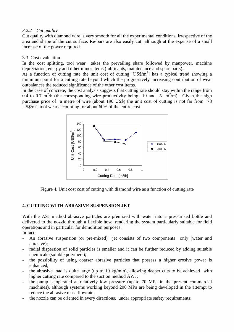
3.2.2 Cut quality Cut quality with diamond wire is very smooth for all the experimental conditions, irrespective of the area and shape of the cut surface. Re-bars are also easily cut although at the expense of a small increase of the power required. 3.3 Cost evaluation In the cost splitting, tool wear takes the prevailing share followed by manpower, machine depreciation, energy and other minor items (lubricants, maintenance and spare parts). As a function of cutting rate the unit cost of cutting [US$/m2] has a typical trend showing a minimum point for a cutting rate beyond which the progressively increasing contribution of wear outbalances the reduced significance of the other cost items. In the case of concrete, the cost analysis suggests that cutting rate should stay within the range from 0.4 to 0.7 m2/h (the corresponding wire productivity being 10 and 5 m2/m). Given the high purchase price of a metre of wire (about 190 US$) the unit cost of cutting is not far from 73 US$/m2, tool wear accounting for about 60% of the entire cost.
Figure 4. Unit cost cost of cutting with diamond wire as a function of cutting rate
4. CUTTING WITH ABRASIVE SUSPENSION JET With the ASJ method abrasive particles are premixed with water into a pressurised bottle and delivered to the nozzle through a flexible hose, rendering the system particularly suitable for field operations and in particular for demolition purposes. In fact: - An abrasive suspension (or pre-mixed) jet consists of two components only (water and
abrasive); - radial dispersion of solid particles is smaller and it can be further reduced by adding suitable
chemicals (soluble polymers); - the possibility of using coarser abrasive particles that possess a higher erosive power is
enhanced; - the abrasive load is quite large (up to 10 kg/min), allowing deeper cuts to be achieved with
higher cutting rate compared to the suction method AWJ; - the pump is operated at relatively low pressure (up to 70 MPa in the present commercial
machines), although systems working beyond 200 MPa are being developed in the attempt to reduce the abrasive mass flowrate;
- the nozzle can be oriented in every directions, under appropriate safety requirements;
0
20
40
60
80
100
120
140
0 0,2 0,4 0,6 0,8 1
Cutting Rate [m2/h]
Uni
t C
ost
[US
$/m
2 ]
1000 N
2000 N

- owing to the small size of the cutting head, difficult-to-reach points become accessible making the tool manipulation in restricted room easier;
- the abrasive is amenable to circulation back to the system provided that a suitable catching system is added;
- the remote control of the cutting operation is feasible even from far distances; - ASJ can be employed in submerged environment or in a flammable atmosphere and it is suitable
for cutting through explosive substances. These features make the system applicable in the field for performing cuts through a variety of materials for the solution of problem such as: - Dismantling of nuclear power stations (cutting of reactor elements); - demilitarisation of weapons (cut of missile heads for the safe removal of the explosive); - decommissioning of off-shore oil rigs (cutting of steel legs at sea depths); - cleaning of oil tanks (cutting of access windows); - recovery of oil wells (cutting and removal of damaged casing sections); - cutting of concrete beams, pillars and platforms; - piercing of water drainage pipes and so on. Therefore premixed abrasive jet is very interesting for demolition according to the “cut-and-draw” method as an alternative to diamond wire. The periodic interruption of cutting for bottle refilling is not a major drawback in this kind of operation.
4.1 Experimental tests 4.1.1. Equipment The equipmment used for the tests on concrete is composed of : - Hammelmann plunger pump - DIAJet slurry forming unit - Cutting vessel with the lance manipulation device (figure 5).
Figure 5. Cutting vessel used in the tests with concrete at the DIGITA waterjet laboratory
4.1.2 Experimental plan The experimental plan was aimed at understanding the influence of the relevant operational variables on cutting performance and on cost. The following variables have been considered: - Pressure at the pump: 35 and 65 MPa - Nozzle diameter: 1.6 and 2.0 mm - Traverse velocity: variable from 3 to 80 cm/min - Number of passes until achieving a separation cut: variable from 1 to 20 - Kind of abrasive: Garnet HP80 and copper slag - Abrasive mass flowrate: 2.5 and 5 kg/min

Since the result at 35 MPa with the 2 mm nozzle was poor, all the other tests have been made at 65 MPa, the maximum allowed by the DIAJet 700 system, using the 1.6 mm nozzle. 4.2 Results 4.2.1 Technical performance Results are reported in Table 1 grouped into three sets, the first two with garnet and the third with copper slag. For the various experimental conditions a different number of passes was necessary for achieving a separation cut of the test sample through concrete. However, while the upper re-bars were always easily cut, it was not so for intermediate and especially the lower re-bars for wich additional passes are required. Table 1-a. Garnet HP 80. Low number of passes Characteristics Cut 1 Cut 2 Cut 5 Cut 6 Cut 11 Pressure [MPa] 35 65 65 65 65 Nozzle Diameter [mm] 2 1,6 1.6 1.6 1,6 Water flowrate [l/min] 52 52 52 52 52
Abrasive mass flowrate [kg/min] 5 5 2,5 5 2.5 Traverse velocity [cm/min] 8.82 9 3.16 3.16 8.82 Number of passes 4 3 1 1 2 Cutting rate [m2/h] 0.397 0.529 0.568 0.568 0.788 Upper re-bars Yes Yes Yes Yes Yes Intermediate re-bars Partial Yes No No ** Lower re-bars No No No No No Table 1-b. Garnet HP 80. High number of passes Characteristics Cut 3 Cut 4 Cut 12 Cut 13 Pressure [MPa] 65 65 65 65 Nozzle Diameter [mm] 1.6 1.6 1.6 1.6 Water flowrate [l/min] 52 52 52 52 Abrasive mass flowrate [kg/min] 2.5 2.5 2.5 2.5 Traverse velocity [cm/min] 8.82 77.42 77.42 35.71 Number of passes 5 21 14 8 Cutting rate [m2/h] 0.318 0.995 0.995 0.804 Upper re-bars Yes Yes Yes Intermediate re-bars Yes ** ** Lower re-bars No No No Table 1-c. Copper slag Characteristics Cut 7 Cut 8 Cut 9 Cut 10 Pressure [MPa] 65 65 65 65 Nozzle Diameter [mm] 1.6 1.6 1.6 1.6 Water flowrate [l/min] 52 52 52 52 Abrasive mass flowrate [kg/min] 2.5 5 2.5 2.5 Traverse velocity [cm/min] 3.16 3.16 8.82 77.42 Number of passes 1 1 2 21 Cutting rate [m2/h] 0.568 0.568 0.794 0.664 Upper re-bars Yes Yes Yes Yes Intermediate re-bars Partial Partial No No Lower re-bars No No No No ** Cutting from opposite directions according to the strategy devised.
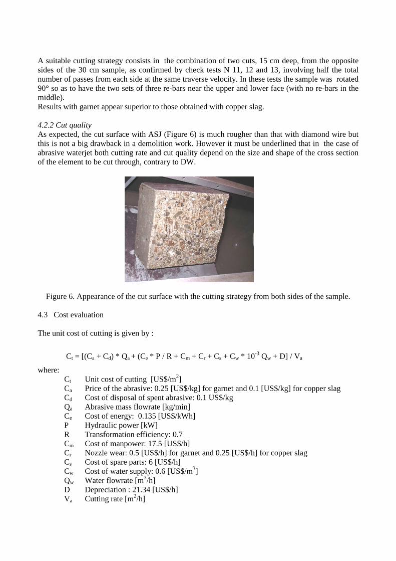
A suitable cutting strategy consists in the combination of two cuts, 15 cm deep, from the opposite sides of the 30 cm sample, as confirmed by check tests N 11, 12 and 13, involving half the total number of passes from each side at the same traverse velocity. In these tests the sample was rotated 90° so as to have the two sets of three re-bars near the upper and lower face (with no re-bars in the middle). Results with garnet appear superior to those obtained with copper slag. 4.2.2 Cut quality As expected, the cut surface with ASJ (Figure 6) is much rougher than that with diamond wire but this is not a big drawback in a demolition work. However it must be underlined that in the case of abrasive waterjet both cutting rate and cut quality depend on the size and shape of the cross section of the element to be cut through, contrary to DW.
Figure 6. Appearance of the cut surface with the cutting strategy from both sides of the sample.
4.3 Cost evaluation The unit cost of cutting is given by :
Ct = [(Ca + Cd) * Qa + (Ce * P / R + Cm + Cr + Cs + Cw * 10-3 Qw + D] / Va
where: Ct Unit cost of cutting [US$/m2] Ca Price of the abrasive: 0.25 [US$/kg] for garnet and 0.1 [US$/kg] for copper slag Cd Cost of disposal of spent abrasive: 0.1 US$/kg Qa Abrasive mass flowrate [kg/min] Ce Cost of energy: 0.135 [US$/kWh] P Hydraulic power [kW] R Transformation efficiency: 0.7 Cm Cost of manpower: 17.5 [US$/h] Cr Nozzle wear: 0.5 [US$/h] for garnet and 0.25 [US$/h] for copper slag Cs Cost of spare parts: 6 [US$/h] Cw Cost of water supply: 0.6 [US$/m3] Qw Water flowrate [m3/h] D Depreciation : 21.34 [US$/h] Va Cutting rate [m2/h]

For the various tests numbered from 1 to 13 the resulting unit cost of cutting is reported in the bar diagram of figure 7. In reality cutting with ASJ suffers from a technical efficiency E not higher than 0.8 because of the need to interrupt the process for filling the bottle with new abrasive, whereas in the case of DW the operation is almost continuous.
Figure 7. Unit cost of cutting for the various experimental conditions (Table 1) and cost splitting for
Test N. 12
The advantage of cutting with multiple passes at relatively high traverse speed of the nozzle is evident: in fact the lowest cutting cost is obtained in tests N. 4 and 12 (with 21 and 14 passes respectively) for which a cutting rate close to 1 m2/h was achieved. 5. TECHNOLOGICAL COMPARISON Cutting tests in similar conditions show that both technologies are suitable for concrete cutting. However some aspects are worth underlining: - At optimum operational conditions for each technology, DW appears to be about 30% cheaper
than ASJ in terms of unit cost of cutting [US$/m2]; - regarding the cut area there is no practical limitation for diamond wire with a negligible
influence on cutting rate and on the unit cost of cutting, contrary to ASJ (cutting rate gradually decreases and cost increases for larger cut sections);
- cutting deeper than 30 - 40 cm with ASJ would imply a penetration of the nozzle into a wider slot with no great advantage on the technical and economic performance;
- the presence of re-bars is not a major drawback with DW but it poses some problems with ASJ unless they are placed near the surface of the concrete element.
5.1 Fields of application A comparison of the different methods and technologies applicable in the field of demolition is not easy, due to a great variability of the situations. In fact performance and cost levels vary according to the characteristics of the structure to be demolished (type, position, size, shape, component materials) as well as to a number of side conditions (reliability, safety, environmental impact, disposal or reuse of debris) Therefore the most appropriate choice must be made for each individual case. However they can be ranked as shown in table 2, although the indication has only the meaning of a rough orientation. The respective fields of application of the different methods are summarised in table 3.
0
100
200
300
400
1 2 3 4 5 6 7 8 9 10 11 12 13
Test Number
Uni
t Cos
t [U
S$/
m2]
Cost splitting(in clockwise order)
Abrasive
Manpower
Depreciation
Energy
Water supply
Spare parts
Abrasive disposal
11
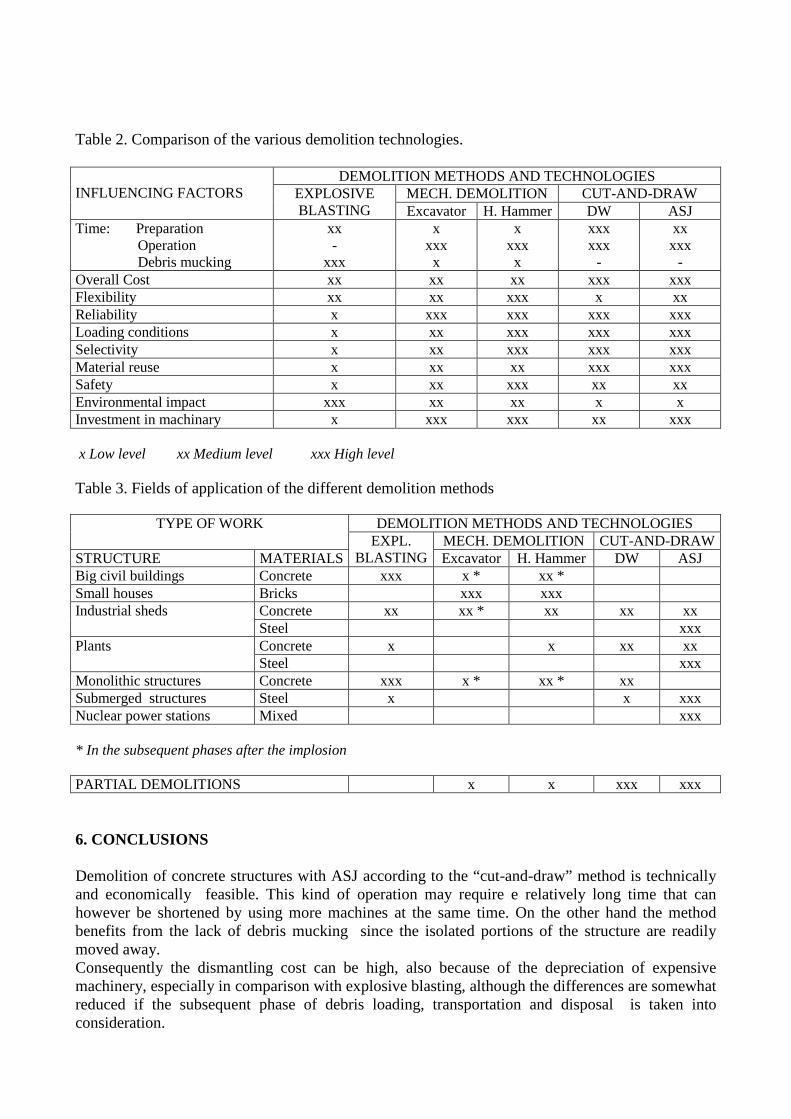
Table 2. Comparison of the various demolition technologies. INFLUENCING FACTORS
DEMOLITION METHODS AND TECHNOLOGIES EXPLOSIVE BLASTING
MECH. DEMOLITION CUT-AND-DRAW Excavator H. Hammer DW ASJ
Time: Preparation Operation Debris mucking
xx -
xxx
x xxx x
x xxx x
xxx xxx
-
xx xxx
- Overall Cost xx xx xx xxx xxx Flexibility xx xx xxx x xx Reliability x xxx xxx xxx xxx Loading conditions x xx xxx xxx xxx Selectivity x xx xxx xxx xxx Material reuse x xx xx xxx xxx Safety x xx xxx xx xx Environmental impact xxx xx xx x x Investment in machinary x xxx xxx xx xxx x Low level xx Medium level xxx High level Table 3. Fields of application of the different demolition methods
TYPE OF WORK DEMOLITION METHODS AND TECHNOLOGIES EXPL.
BLASTING MECH. DEMOLITION CUT-AND-DRAW
STRUCTURE MATERIALS Excavator H. Hammer DW ASJ Big civil buildings Concrete xxx x * xx * Small houses Bricks xxx xxx Industrial sheds Concrete xx xx * xx xx xx
Steel xxx Plants Concrete x x xx xx
Steel xxx Monolithic structures Concrete xxx x * xx * xx Submerged structures Steel x x xxx Nuclear power stations Mixed xxx * In the subsequent phases after the implosion
PARTIAL DEMOLITIONS x x xxx xxx 6. CONCLUSIONS Demolition of concrete structures with ASJ according to the “cut-and-draw” method is technically and economically feasible. This kind of operation may require e relatively long time that can however be shortened by using more machines at the same time. On the other hand the method benefits from the lack of debris mucking since the isolated portions of the structure are readily moved away. Consequently the dismantling cost can be high, also because of the depreciation of expensive machinery, especially in comparison with explosive blasting, although the differences are somewhat reduced if the subsequent phase of debris loading, transportation and disposal is taken into consideration.
Abrasive waterjet, as an alternative to diamond wire, features some advantages concerning flexibility, reliability, operations selectivity, product handling, environmental impact and working safety, provided that adequate care is taken for controlling the risk of accidents The possibility of material reuse is good especially if the recovered portions of the structure can find a suitable applicationn as such. ACKNOWLEDGEMENTS Work carried out with within the research projects supported by MURST and CNR REFERENCES A - ASJ - Agus, M., Bortolussi, A., Ciccu, R., Imolesi, E., Vargiu, A.: Stone Cutting with DIAJet, Proc.
14th Mining Congress of Turkey, 1995, pp. 29-35 - Agus, M., Bortolussi, A., Ciccu, R., Vargiu, A.: A comparative study of Suspension and
Injection methods in rock cutting with abrasive waterjet, Proc. 9th American Waterjet Conference, Dearborn August 1997, pp. 47-60
- Bloomfield, E.J. e Yeomans, M.: DIAJet - a review of progress, Proc. 1st Asian Conf. on Recent Advances in Jetting Tech., Singapore, 1991, p.21-30.
- Fairhurst, R.M., e altri: DIAJET - a new abrasive water jet cutting technique, Proc. 8th Int. Symp. Jet Cutting Tech., Durham, England, 1986, p.395-402.
- Galecki, G. e Summers, D.A. : Steel shot entrained ultra high pressure waterjet for cutting and drilling in hard rocks, Proc. 11th Int. Conf. Jet Cutting Tech., St. Andrews, England, 1992, p.371-388.
- Hashish, M. : Cutting with high-pressure abrasive suspension jets, Proc. 6th American Water Jet Conf., Houston, U.S.A., 1991, p.439-455.
- Kiyoshige, M. : A study of abrasive waterjet cutting using slurried abrasives, Proc. 9th Int. Symp. Jet Cutting Tech., Sendai, Japan, 1988, p.61-73.
- Summers, D.A., e Yazici, S.: The investigation of DIAJet (Direct Injection of Abrasive Jet) cutting of granite, Proc. 5th American Water Jet Conf., Toronto, Canada, 1989, p.343-356.
- Vasek, J., e altri : Influence of properties of garnet on cutting process, Proc. 7th American Water Jet Conf., Seattle, U.S.A., 1993, p.375-387.
- Yao, J., e altri : DIAjet cutting of dolomite & chart - a case study at the St. Louis Arch, Proc. 6th American Water Jet Conf., Houston, U.S.A., 1991, p.529-543.
- Yao, J., e altri : Field trials and developments of the DIAdrill concept, Proc. 6th American Water Jet Conf., Houston, U.S.A., 1991, p.545-559.
B – DW - Berry P., Bortolussi A., Ciccu R., Manca P.P., Massacci G., Pinzari M.: Optimum use of
diamond wire equipment in stone quarrying. Proceedings APCOM 89, 21st Int. Symp., Las Vegas, Feb 27 - March 2, 1989 SME AIME, Feb. 1989, pp. 351-365
- Biasco G.: L'utilizzazione del filo diamantato nel taglio al monte dei materiali non calcarei. ACIMM for Marble, 21, 1989, pp. 89-103
- Bortolussi A., Ciccu R., Manca P.P., Massacci G.: Computer-simulation of diamond wire cutting of hard and abrasive rocks, Trans. Inst. Min. Metall. Amin I 103 (May-August 1994), pp. A124-A128

- Bortolussi A., Ciccu R., Manca P.P., Massacci G.: Simulation and optimisation of rock cutting with diamond wire. In: Proceedings 22st APCOM, Berlin, 1990, vol. III, pp. 163-176
- Ciccu R., Massacci G., Vargiu A.: Prediction of diamond wire performance by computer simulation. Proc. APCOM 96, State College, USA, R.V. Ramani Ed., 1996, pp. 165-168
- Lawn B.R. and Swain M.V.: Microfracture beneath point indentations in brittle solids, J. Materials Science, 10, 1975, pp. 113-122
- J. Wilks and E. Wilks: Properties and application of diamond, Butterworth Heinemann, Oxford, 1991 and references quoted therein
- D.N. Wright: La predizione dell’usura del diamante nella segagione della pietra, Marmi Graniti e Pietre, Dicembre 1990
Copyright © 2022 FDOKUMEN