Fine abrasive water jet machining of piezoelectric ceramics: cutting parameters optimization
13
Fine abrasive water jet machining of piezoelectric ceramics: cutting parameters optimization M. Annoni, F. Arleo, A. Trolli Politecnico di Milano A. Suarez, A. Alberdi Tecnalia R&I Piezoelectric ceramics are increasingly applied in optical, electronic, mechanical and biomedical applications thanks to their inherent physical properties such as electrical behavior, electromagnetic response, high temperature strength, hardness and corrosion resistance. Nevertheless, this kind of materials is usually very difficult-to-machine by conventional technologies, while its applications become more and more demanding in terms of quality and precision. In such a scenario, the Fine Abrasive Water Jet (jet diameter less than 0.5 mm) represents a very appealing and promising technology compared to micro-milling, laser or EDM, offering many advantages such as the absence of thermal distortions, high flexibility and versatility, small cutting forces and the increasing capability to cut smaller and smaller features. In the present work, carried out at Tecnalia R&I in collaboration with Politecnico di Milano, piezoelectric material lead titanate zirconate (PZT) thin sheets machining is investigated with a DOE approach, in order to optimize the FAWJ cutting parameters and to test its capability as a concrete high-precision technology to machine ceramic materials. Finally, an application of PZT as base material for micro positioning actuators is presented as a case study. Keywords: fine abrasive water jet, piezoelectric ceramic, cutting optimization, design of experiments AWJ Abrasive Water Jet DOE Design Of Experiments E x Modulus of elasticity (longitudinal) E z Modulus of elasticity (transversal) FAWJ Fine Abrasive Water Jet (jet diameter less than 500 μm) G yz Modulus of elasticity in shear HAZ Heat Affected Zone MAWJ Micro Abrasive Water Jet (jet diameter less than 200 μm) PZT Lead Zirconate Titanate Ra Average roughness ABSTRACT 1 NOMENCLATURE AND ACRONYMS
Transcript of Fine abrasive water jet machining of piezoelectric ceramics: cutting parameters optimization

Fine abrasive water jet machining of piezoelectric
ceramics: cutting parameters optimization
M. Annoni, F. Arleo, A. Trolli Politecnico di Milano A. Suarez, A. Alberdi Tecnalia R&I
Piezoelectric ceramics are increasingly applied in optical, electronic, mechanical and
biomedical applications thanks to their inherent physical properties such as electrical
behavior, electromagnetic response, high temperature strength, hardness and corrosion
resistance. Nevertheless, this kind of materials is usually very difficult-to-machine by
conventional technologies, while its applications become more and more demanding in
terms of quality and precision. In such a scenario, the Fine Abrasive Water Jet (jet
diameter less than 0.5 mm) represents a very appealing and promising technology
compared to micro-milling, laser or EDM, offering many advantages such as the absence
of thermal distortions, high flexibility and versatility, small cutting forces and the
increasing capability to cut smaller and smaller features. In the present work, carried out
at Tecnalia R&I in collaboration with Politecnico di Milano, piezoelectric material lead
titanate zirconate (PZT) thin sheets machining is investigated with a DOE approach, in
order to optimize the FAWJ cutting parameters and to test its capability as a concrete
high-precision technology to machine ceramic materials. Finally, an application of PZT
as base material for micro positioning actuators is presented as a case study.
Keywords: fine abrasive water jet, piezoelectric ceramic, cutting optimization, design of
experiments
AWJ Abrasive Water Jet
DOE Design Of Experiments
Ex Modulus of elasticity (longitudinal)
Ez Modulus of elasticity (transversal)
FAWJ Fine Abrasive Water Jet (jet diameter less than 500 µm)
Gyz Modulus of elasticity in shear
HAZ Heat Affected Zone
MAWJ Micro Abrasive Water Jet (jet diameter less than 200 µm)
PZT Lead Zirconate Titanate
Ra Average roughness
ABSTRACT
1 NOMENCLATURE AND ACRONYMS

SEM Scanning Electron Microscope
Tc Curie temperature
WJ Water Jet
ρ Density
νxy Poisson’s ratio of piezoelectric material
νxz Poisson’s ratio of piezoelectric material along the direction of polarization
Advanced piezoelectric ceramics have been increasingly applied in the optical,
electronic, mechanical and biological industries due to their peculiar electromagnetical
response. Unfortunately, these materials are usually very difficult-to-cut, and this is a
great limitation to their further employment in more and more complex innovative
applications.
Cold-cutting and non-intrusiveness are peculiar features of AWJ that make it especially
well-suited for cutting unusual shapes out of exotic and heat-sensitive materials, such as
the piezoelectric ceramics. Particularly, this technology is very appealing because it is a
cold-cutting process, it does not create a heat-affected zone (HAZ), which in turn induce
thermal damage or localized loss of the piezoelectric behavior of the parent material.
Nevertheless, recent technological progresses often bring along a down-sizing of
products together with small tolerances and high precision: this pushes machining
technologies to continuously improve in order to reach higher and higher standards of
quality and precision on the final workpiece, along with the capability to machine smaller
and smaller complex features (1). There are actually great opportunities for low-cost
micro-manufacturing due to the recent advent of micro and nano components, MEMS
devices, green energy products and biomedical technologies: MAWJ could be a
profitable technology, taking advantage of the inherent merits of WJ cutting, namely
versatility (material independence), flexibility, non-intrusiveness and cost effectiveness.
With the aim to start studying these topics and go towards micro machining with AWJ,
the cutting head used during the experimentation has the peculiarity of having an internal
geometry equal to one half that of a standard system: the jet produced is then about
0.5 mm wide and the size of the used abrasive is #200 (particle dimension around
74 μm).
The dimension of the out flowing jet is actually slightly large for defining it strictly as a
MAWJ (jet diameter of around 0.2 mm or lower), but this is a first attempt to gradually
face the arising problems associated with reducing the size of the cutting head towards
MAWJ current standards.
The piezoelectric ceramics are particular ceramic materials which are characterized by a
close correlation between their electrical and mechanical behavior.
If a piezoelectric material is subjected to a mechanical strain, an electrical polarization
will appear within it (direct piezoelectric effect); similarly, if the material is exposed to
an external electric field, it reacts with a mechanical deformation (inverse piezoelectric
effect).
Therefore, these materials are used to convert electric energy into mechanical or vice-
versa and thanks to this unique property they are suitable to be employed both as
actuators or sensors.
2 INTRODUCTION
3 THE CASE STUDY: PIEZOELECTRIC ACTUATORS
Most of the piezo-ceramic materials used in mechanical applications have not a single-
crystal structure, but they have a polycrystalline structure formed by various grains.
In general, the grain polarization in a polycrystalline body is statistically distributed in all
directions: therefore, the global polarization is zero. However, by adopting ad hoc
techniques during the production process, it is possible to align the induced polarization
direction within each individual crystal, obtaining pieces with a uniform polarization (2).
Normally, these materials are divided into two main categories, namely soft and hard,
depending on their piezo-electric behavior and mechanical properties.
For the present work purposes, the only useful information is that significant changes in
their piezo-electric properties starts around 100°C while their Curie temperature is
relatively low, around 150°C.
Because of this reason, thermal processes such as laser or EDM machining are often not
suitable, while water jet represents a perfect alternative technology able to machine hard
piezoelectric materials without thermally or chemically altering the materials often used
in the field of micro applications.
There is a growing demand for actuators with a micro-scale design. This need has been
reported across the micro-robotics industry and the most recent medical applications.
Despite such different fields of use, the core characteristics required by millimeter and
sub-millimeter-scale actuators are basically the same: actuators at these scales are widely
used in smart structure applications due to their high bandwidth, high output force,
compact size, low response times, simple design and simple operating mechanism (3).
The present case study was initially promoted by a specific application regarding some
bending actuators and it was proposed by Università di Pisa.
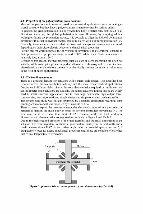
These actuators exploit the resonant eigenmodes electrically induced in a piezo-electric
material to deform the main body in order to perform controlled movements (4). The
base material is a 0.5 mm thin sheet of PZT ceramic, while the final workpiece
dimensions and characteristics are reported respectively in Figure 1 and Table 1.
Due to the high required precision of the final assembly and the small dimensions of the
actuator, it is very important to obtain a good surface quality on the kerf walls and a
small or even absent HAZ: in fact, when a piezoelectric material approaches the Tc it
progressively loses its electro-mechanical properties until these are completely lost when
that critical temperature is overcome.
Figure 1: piezoelectric actuator geometry and dimensions (4)(Bertini).
3.1 Properties of the polycrystalline piezo-ceramics
3.2 The bending actuators
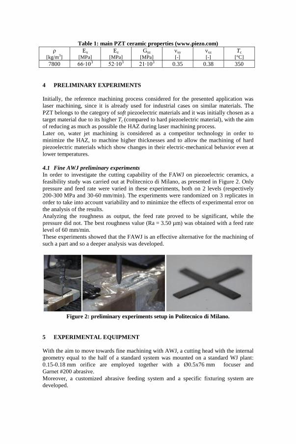
Table 1: main PZT ceramic properties (www.piezo.com)
ρ [kg/m3]
Ex [MPa]
Ez [MPa]
Gyz [MPa]
νxy [-]
νxz [-]
Tc
[°C]
7800 66∙103 52∙103 21∙103 0.35 0.38 350
Initially, the reference machining process considered for the presented application was
laser machining, since it is already used for industrial cases on similar materials. The
PZT belongs to the category of soft piezoelectric materials and it was initially chosen as a
target material due to its higher Tc (compared to hard piezoelectric material), with the aim
of reducing as much as possible the HAZ during laser machining process.
Later on, water jet machining is considered as a competitor technology in order to
minimize the HAZ, to machine higher thicknesses and to allow the machining of hard
piezoelectric materials which show changes in their electric-mechanical behavior even at
lower temperatures.
In order to investigate the cutting capability of the FAWJ on piezoelectric ceramics, a
feasibility study was carried out at Politecnico di Milano, as presented in Figure 2. Only
pressure and feed rate were varied in these experiments, both on 2 levels (respectively
200-300 MPa and 30-60 mm/min). The experiments were randomized on 3 replicates in
order to take into account variability and to minimize the effects of experimental error on
the analysis of the results.
Analyzing the roughness as output, the feed rate proved to be significant, while the
pressure did not. The best roughness value (Ra = 3.50 µm) was obtained with a feed rate
level of 60 mm/min.
These experiments showed that the FAWJ is an effective alternative for the machining of
such a part and so a deeper analysis was developed.
Figure 2: preliminary experiments setup in Politecnico di Milano.
With the aim to move towards fine machining with AWJ, a cutting head with the internal
geometry equal to the half of a standard system was mounted on a standard WJ plant:
0.15-0.18 mm orifice are employed together with a Ø0.5x76 mm focuser and
Garnet #200 abrasive.
Moreover, a customized abrasive feeding system and a specific fixturing system are
developed.
4 PRELIMINARY EXPERIMENTS
4.1 Fine AWJ preliminary experiments
5 EXPERIMENTAL EQUIPMENT

The implementation of a FAWJ system in a traditional water jet plant involves a new
hopper to improve the versatility of the machine by allowing the operator to switch from
the FAWJ system to the standard one more rapidly and avoiding losing time emptying
and cleaning the hopper. This self-made feeding system is characterized by a small
cylinder that contains the abrasive, a selector to manually switch on and off the abrasive
flow and a selector to regulate the abrasive flow rate, as shown in Figure 3 .
Figure 3: a scheme of the employed abrasive feeding system.
Since the mini-hopper is self-made, the abrasive feeding system requires a specific
calibration in order to determine the abrasive flow rate corresponding to the specific
calibrated hole in the selector base working at different process conditions. The abrasive
flow is mainly influenced by the gravity, the calibrated hole diameter through which the
abrasive flows and the suction caused by the Venturi effect of the jet inside the mixing
chamber depending on the upstream water pressure. To prevent a strong dependence
between the abrasive flow rate and the vacuum pressure inside the mixing chamber, a
connection with the outside ambient is made downstream the calibrated hole selector: in
this way, the system works at atmospheric pressure and the abrasive falls only by gravity,
uncoupling the average flow rate from upstream water pressure.
Anyway, fluctuations of the Venturi effect still can cause fluctuations of the abrasive
suction inside the mixing chamber. Because of this, the calibration is performed by
measuring the difference in the hopper weight after 30 s in real working conditions with
different calibrated holes and upstream pressures; the results are reported in Table 2.
It is necessary to demonstrate that the experimental conditions with the self-made mini
hopper keep constant: this essential condition is verified when working with a new
orifice every run. In fact, a signal of the depression in the abrasive feeding tube is
acquired in order to demonstrate that there is no relationship between the water pressure
level and the suction caused by the Venturi effect: as shown in Figure 4, the suction
capability with a new orifice is relatively low and pressure independent, while with a
worn one the suction power is higher and pressure dependent.
This behavior suggests that working with new orifices prevents water pressure to play a
significant role on the Venturi effect in the selected range; this fact allows abrasive flow
rate not to depend on water pressure.
5.1 The abrasive feeding system
5.2 Process monitoring and abrasive flow rate calibration

Figure 4: suction pressure signals at different upstream pressures and for different
orifice conditions (good and worn).
Finally, the abrasive flow rate calibration is performed by measuring the difference in the
hopper weight after 30 s in real working conditions with two different calibrated holes;
the results are reported in Table 2: the behavior shown in Figure 4 is confirmed by the
low variation of the results with respect to the water pressure variation with new orifices.
Table 2: abrasive flow rate calibration.
Calibrated
hole diameter
[mm]
Water jet
pressure
[MPa]
Measured
abrasive flow rate
[g/min]
Mean
[g/min]
Std dev
[g/min]
2 250 83.6
84.2 5.6 2 300 90.1
2 350 79.0
2.5 250 132.8
134.1 3.5 2.5 300 138.0
2.5 350 131.4
The fixturing system is quite simple but specifically customized for the target material.
In fact, the piezoelectric thin specimen is very brittle, so it needs to be properly fixed on
a rigid substrate in order to avoid shocks, vibrations or inflections which could be
dangerous for its integrity: as a final solution, it is fixed on a piece of hard polystyrene
with an adhesive tape, as shown in Figure 5; finally, some weights are put on the
polystyrene in order to avoid vibrations of the base. Due to the small applied forces on
the workpiece, this was found to be the best and easiest solution.
Figure 5: the fixturing system used during this experimentation.
5.3 The fixturing system

DOE is a very effective way to investigate the influence of a variable factor, as
demonstrated in (5)(6) and other scientific works. This approach is used as a statistical
method of analysis during the present work: the choice of the variable parameters for this
experimentation is made starting from the literature review (7) which points out that
orifice diameter, focus diameter, upstream pressure, feed rate, abrasive dimensions and
mass flow rate are the most influential parameters. In particular, feed rate seems to be the
most important influencing parameter for ceramic machining, while the influence of
focuser length has less importance, thus this parameter is not involved in the present
investigation.
The aim of the optimization experiments is to find the best parameters in terms of kerf
quality, particularly in terms of roughness, in order to verify if water jet is an appealing
technology in the machining of piezoelectric ceramics.
The DOE variable factors are feed rate, pressure and abrasive flow rate, while orifice
diameter is considered as a blocking factor1.
As always, the choice of the levels of each parameter is very important and must be done
carefully as it is presented below.
Some screening tests show that the flow rate is quite regular up to 150 g/min: this is due
to the physical limits of the FAWJ cutting head. Up to this level of abrasive flow rate,
there is no abrasive clogging in the mixing chamber. The lower level is set at the value of
80 g/min.
The upper level of feed rate is fixed at 110 mm/min after being determined by some
screening tests, showing that above this value, up to 190 mm/min, the kerf quality gets
worse and worse in terms of brittle chipping and irregularities on the bottom edge, as
shown in Figure 6. The lower value of feed rate is set to 30 mm/min to keep it in
accordance with the preliminary tests presented in Section 4.1. Additionally, the typical
orifices in FAWJ have a diameter of 0.15-0.18 mm and the Garnet#200 is characterized
by finer abrasive particles. The standoff distance is set at 1 mm.
Figure 6: kerf bottom quality at feed rates of (a) 190 mm/min and (b) 110 mm/min.
Table 3 shows a summary of both the variable factors and the constant parameters used
within this experimentation.
1 A blocking factor is a known and controllable nuisance source of variability whose effects can be
hidden by particular DOE techniques.
6 OPTIMIZATION EXPERIMENTS

Table 3: DOE parameters setup summary.
Variable factors Levels
Orifice [mm] 0.15 0.18
Abrasive flow rate [g/min] 80 140
Feed rate [mm/min] 30 70 110
Pressure [MPa] 250 300 350
Constant parameters
Abrasive type GMA garnet
Garnet mesh number #200
Focuser diameter [mm] 0.5
Standoff distance [mm] 1
The introduction of a block on the factor “orifice” is needed since the operation of
changing the orifice is usually tricky and can easily cause its damage: consequently, in
order to assure the homogeneity of the experimental conditions within all the
experimental runs, it is not possible to randomize this factor (6).
Setting to 4 the number of replicates, the resulting total number of experiments is 144
which are considered a good compromise between experimental effort and results
reliability, as it will be presented in the next Section 6.1 .
The Pearson–Hartley charts can be used in order to perform a statistical power analysis
and help in defining the experimental effort; briefly, using the sample size and the
desired effect size, it is possible to determine which is the statistical power of the carried
out analysis assuming that the effect size in the sample is equal to the effect size in the
population (6).
Generally, when the analysis aims to detect small effects a high power is required which
needs in turn several replicates and so a higher number of experimental runs. In the
present study, 4 replicates were performed, resulting in a statistical power of 41% if the
minimum detectable difference on roughness is set to 0.5 μm or equivalently 90% to
detect a difference of 1 μm. In conclusion, taking into account that the work is a
preliminary study to understand which process parameters are the most influencing and
whether they are affecting the kerf quality in such an application, the actual power seems
a good compromise to achieve enough precise and reliable results with a reasonable
experimental effort.
The quality of the machined surface is the result of four different results analysis,
developed starting from literature (8). Provided that the hypothesis of symmetric kerf is
verified as shown in Figure 7, the analyzed results are the top kerf width, the bottom kerf
width, the kerf taper and the roughness. An optical microscope is used for the analysis of
the geometrical kerf dimensions, while a profilometer is used for the roughness analysis.
6.1 Statistical power analysis
7 DOE RESULTS

Figure 7: the kerf symmetry.
The DOE results are summarized in Table 4 and Figure 9.
Table 4: significant factors summary table.
Orifice
diameter Pressure Feed rate
Abrasive
flow rate
Top kerf width ● ○ ● ●
Bottom kerf width ● ○ ● ●
Kerf taper ● ● ○ ●
Kerf roughness ● ○ ● ○
● : significant factor ○ : not significant factor
Since the thickness of the machined material is very low, the cut is performed mainly in
the “cutting wear region” where the jet still has high energy rather than the “deformation
wear region” (see Figure 8)(9): this could explain the fact that some parameters are non-
significant, even if they are usually influencing in a traditional AWJ cut such as the
pressure and the abrasive flow rate on the kerf roughness and the feed rate on the kerf
taper.
Figure 8: traditional kerf regions forming in an AWJ cut (9).
Moreover, the interactions among any of the parameters have no statistical relevance.
7.1 Statistical results
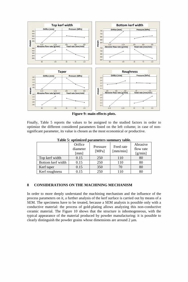
Figure 9: main effects plots.
Finally, Table 5 reports the values to be assigned to the studied factors in order to
optimize the different considered parameters listed on the left column; in case of non-
significant parameter, its value is chosen as the most economical or productive.
Table 5: optimized parameters summary table.
Orifice
diameter
[mm]
Pressure
[MPa]
Feed rate
[mm/min]
Abrasive
flow rate
[g/min]
Top kerf width 0.15 250 110 80
Bottom kerf width 0.15 250 110 80
Kerf taper 0.15 350 70 80
Kerf roughness 0.15 250 110 80
In order to more deeply understand the machining mechanism and the influence of the
process parameters on it, a further analysis of the kerf surface is carried out by means of a
SEM. The specimens have to be treated, because a SEM analysis is possible only with a
conductive material: the process of gold-plating allows analyzing this non-conductive
ceramic material. The Figure 10 shows that the structure is inhomogeneous, with the
typical appearance of the material produced by powder manufacturing: it is possible to
clearly distinguish the powder grains whose dimensions are around 2 μm.
8 CONSIDERATIONS ON THE MACHINING MECHANISM

Figure 10: kerf surface at an enlargement of 5000X.
The Figure 11 shows how the material removal mechanism is characterized by brittle
fractures among powder grains, but there are also traces of ductile fractures (10) (11). A
possible explanation for the presence of ductile behavior is that the interaction between
the material and the abrasive particles produces friction heat leading to very high local
temperatures, which in turn can cause thermal stresses and reactions which may promote
thermal wear processes and the transition from brittle to ductile behavior of the ceramic
(12) and (13).
Figure 11: traces of ductile fracture on the kerf surface.
Moreover, a common characteristic to all the specimens is the presence of embedded
abrasive particles in the ceramic matrix, as shown in Figure 12. The shape of the particle
is sharp and irregular and the dimension is smaller than the nominal dimension. It is not
possible to exactly determine the specific degree of fragmentation occurring at any
different stage of the process (i.e. during particle mixing and acceleration), even if the
main contribution is probably given by the crumbling during the cutting process since the
hardness of the piezoelectric material is comparable to the abrasive one.
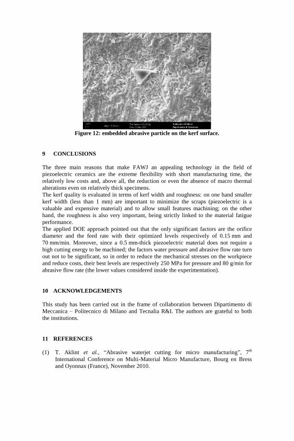
Figure 12: embedded abrasive particle on the kerf surface.
The three main reasons that make FAWJ an appealing technology in the field of
piezoelectric ceramics are the extreme flexibility with short manufacturing time, the
relatively low costs and, above all, the reduction or even the absence of macro thermal
alterations even on relatively thick specimens.
The kerf quality is evaluated in terms of kerf width and roughness: on one hand smaller
kerf width (less than 1 mm) are important to minimize the scraps (piezoelectric is a
valuable and expensive material) and to allow small features machining; on the other
hand, the roughness is also very important, being strictly linked to the material fatigue
performance.
The applied DOE approach pointed out that the only significant factors are the orifice
diameter and the feed rate with their optimized levels respectively of 0.15 mm and
70 mm/min. Moreover, since a 0.5 mm-thick piezoelectric material does not require a
high cutting energy to be machined; the factors water pressure and abrasive flow rate turn
out not to be significant, so in order to reduce the mechanical stresses on the workpiece
and reduce costs, their best levels are respectively 250 MPa for pressure and 80 g/min for
abrasive flow rate (the lower values considered inside the experimentation).
This study has been carried out in the frame of collaboration between Dipartimento di
Meccanica – Politecnico di Milano and Tecnalia R&I. The authors are grateful to both
the institutions.
(1) T. Aklint et al., “Abrasive waterjet cutting for micro manufacturing”, 7th
International Conference on Multi-Material Micro Manufacture, Bourg en Bress
and Oyonnax (France), November 2010.
9 CONCLUSIONS
10 ACKNOWLEDGEMENTS
11 REFERENCES

(2) R. Guo, C. Wang and A. Yang, “Piezoelectric Properties of the 1-3 Type Porous
Lead Zirconate Titanate Ceramics”, Journal of American Ceramic Society, vol. 94,
pp. 1794 – 1799, (2011).
(3) B. Watson,J. Friend and L. Yeo, “Piezoelectric ultrasonic micro/milli-scale
actuators”, Sensors and Actuators A, vol. 152, pp. 219-233, (2009).
(4) L. Bertini, “Modelling, testing and design of a miniaturized piezoelectric actuator”,
PhD thesis, Università di Pisa, Facoltà di Ingegneria Meccanica, (2010).
(5) A. Devineni, “AWSJ cutting of glass: An experimental study of the effect of
process parameters on the depth of cut and kerf width using doe”, International
Conference on Mechanical and Electrical Technology, (2010).
(6) D. Montgomery, “Design and analysis of experiments”, 5th edition ed. John Wiley
and Sons, (1997).
(7) A. Momber and R. Kovacevic, “Principles of Abrasive Water Jet Machining”,
Springer, (1998).
(8) R. Groppetti, T. Gutema, and A. D. Lucchio, “A contribution to the analysis of
some kerf quality attributes for precision abrasive waterjet cutting”,
14thInternational Conference on Jetting Technology, Brugge (Belgium), September
1998.
(9) M. Hashish, “Abrasive-waterjet (AWJ) studies”, 16th International Conference on
Water Jetting, Aix-en-Provence, France, 16-18 October 2002.
(10) J. Zeng and T. Kim, “An erosion model of polycristalline ceramics in abrasive
waterjet cutting”, Wear, vol. 193, pp. 207 – 217, (1996).
(11) L. Chen, E. Siores, and W. Wong, “Kerf characteristic in abrasive water jet cutting
of ceramic materials”, International Journal of Machined Tools Manufacturing, vol.
36, pp. 1201 – 1206, (1996).
(12) L. Kahlman, K. Ojmertz, and L. Falk, “Abrasive waterjet testing of
thermomechanical wear of ceramics”, Wear, vol. 248, pp. 16 – 28, (2001).
(13) P. Gudimetla, J. Wang, and W. Wong, “Kerf formation analysis in the abrasive
waterjet cutting of industrial ceramics”, Journal of Materials Processing
Technology, vol. 128, pp. 123 – 129, (2002).