A new beam finite element for the analysis of functionally graded materials
Available online at www.sciencedirect.com
www.elsevier.com/locate/compstruct
Composite Structures 83 (2008) 168–179
Generalized coupled thermoelasticity of functionally gradedannular disk considering the Lord–Shulman theory
A. Bagri, M.R. Eslami *
Amirkabir University of Technology, Fellow of Academy of Sciences, Thermoelasticity Center of Excellence, Mechanical Engineering Department,
424 Hafez Avenue, P.O. Box 15875-4413, Tehran, Iran
Available online 22 May 2007
Abstract
The generalized coupled thermoelasticity based on the Lord–Shulman (LS) model that admits the second sound effect is considered tostudy the dynamic thermoelastic response of functionally graded annular disk. The disk material is considered to be graded along theradial direction, where a power law distribution is assumed. The thermal and mechanical waves propagation are investigated applyinga sudden thermal exposure to the boundary. The Laplace transform is used to transform the governing equations into the Laplacedomain, where the Galerkin finite element method is employed to solve the system of equations in space domain. Finally, the numericalinversion of the Laplace transform is used to obtain the actual physical quantities in the time domain. The time dependent temperature,radial displacement, radial stress, and hoop stress are plotted.� 2007 Published by Elsevier Ltd.
Keywords: Generalized thermoelasticity; Lord–Shulman; Functionally graded disk; Thermal and stress waves
1. Introduction
The conventional heat conduction theory assumes thatthe thermal disturbances propagate at infinite speeds. Thisunrealistic prediction leads to propose the generalized the-ories of thermeolasticity such as Lord–Shulman [1], Green–Lindsay [2], and Green–Naghdi [3] models. These modifieddynamic coupled thermoelastic models are proposed toanalyze the problems with second sound effects. These non-classical theories are referred to as the generalized thermo-elasticity theories, or thermoelasticity theories with finitethermal wave speed. According to the Lord–Shulman the-ory, the Fourier’s law of heat conduction is modified byintroducing the relaxation time. In the Green–Lindsay the-ory two relaxation times are introduced by modifying theDuhamel–Neumann relationships and the entropy densityrelation. Green and Naghdi have formulated three modelsof thermoelasticity for homogeneous and isotropic materi-als [3,4], which are labeled as models I, II, and III. Bagri
0263-8223/$ - see front matter � 2007 Published by Elsevier Ltd.
doi:10.1016/j.compstruct.2007.04.024
* Corresponding author. Tel.: +98 21 6640 5844; fax: +98 21 6641 9736.E-mail address: [email protected] (M.R. Eslami).
et al. [5] suggested a new system of coupled equations thatcontains the LS, GL and GN models in a unified form.They employed the suggested formulation and then analyt-ically solved the coupled system of equations for a layerusing the Laplace transform. Francis [6], Ignaczak [7],and Chandrasekharaiah [8,9] have reported brief reviewsof this topic.
The structures under combined dynamic thermal andmechanical loads may be analyzed according to the cou-pled or uncoupled thermoelastic assumption. The struc-tures under thermal shock loads may be analyzedaccording to the coupled thermoelastic assumption. Furuk-awa et al. [10] reported an analytical solution for a half-space that contains a circular cylindrical hole based onthe Lord–Sulman theory. They investigated the short timeresponse of the problem under thermal shock load andstudied the relaxation time effects. However, some specialcases of coupled problems are analytically solved, but theclosed-form solutions of these types of problems are math-ematically complicated and the numerical procedures aremost suitable method of solution. Tamma and Namburu[11] have an overview of these numerical methods. Takeuti
A. Bagri, M.R. Eslami / Composite Structures 83 (2008) 168–179 169
and Furukawa [12] considered the quasi-static coupledthermoelastic problem and uncoupled dynamical thermo-elastic problem for a plate under thermal shock conditionand showed that the coupling coefficient has a significanteffect on temperature and thermal stress distributions com-pared to the inertia term. Bagri and Eslami [13] studied thegeneralized coupled thermoelasticity of disks and showedthat for thermal shock problems the coupling coefficienthas significant effect on the distribution of the thermalstresses, deformation, and temperature. Chen and Lin[14] proposed a hybrid numerical method based on theLaplace transform and control volume method to analyzethe transient coupled thermoelastic problems with relaxa-tion times involving a nonlinear radiation boundarycondition.
Functionally graded materials (FGMs) are basicallymade from some materials that are graded through thegeometry of the structure. Therefore, the properties ofFGM are changed gradually by position in the structures.Tanigawa [15] reported a comprehensive review of theclosed-form solutions of problems restricted to thesteady-state condition for the heat conduction problemsand thermal stresses that occur in a structure made of non-homogeneous materials. Also, he employed the layer-wisetheory to study the one-dimensional transient thermalstress problem of a nonhomogeneous plate and then con-sidered the optimization of the material composition tominimize the thermal stress distribution [16]. Obata andNoda [17] investigated the steady-state thermal stresses ina cylinder and a sphere of functionally graded materialsand explained the minimization of the thermal stresses con-sidering the volume fraction of the constituent materials.The static and dynamic responses of the functionallygraded plates have been studied by Praveen and Reddy[18]. They studied the FG plates by varying the volumefraction of the constituent materials (ceramic and metal)and found that the response of the FG plates is not inter-mediate to the response of the ceramic and metal plates.
Since, the solution of the coupled thermoelasticity equa-tions of FGMs are analytically complicated to achieve, theclosed-form solution of these problems is rare in the litera-ture and the numerical solutions are most suitable for thesetypes of problems. Reddy and Chin [19] illustrated theresponse of functionally graded cylinders and plates usingthe dynamic coupled form of the equations. They com-pared the coupled and uncoupled results and discussedthe effect of volume fraction of constituent materials (cera-mic and metal) using a power law distribution. The coupledthermoelasticity of FG cylindrical shells based on the clas-sical coupled themoelastic assumption is studied by Bahtuiand Eslami [20]. Bakhshi et al. [21] investigated the coupledthermoelasticity of functionally graded disk and showedthe volume fraction effects on distribution of temperature,displacement and stresses.
The aim of this paper is to present the dynamic thermo-elastic behavior of functionally graded disk based on theLord–Shulman (LS) theory that admits the second sound
effect. The thermal and mechanical waves propagationare studied applying a sudden thermal shock to the bound-ary. The coupled system of equations for the functionallygraded disk based on the LS model are derived andemployed to be solved for the temperature and displace-ment fields. To transform the governing equations fromtime domain to the space domain, the Laplace transformis employed. The geometry of the disk is divided into anumber of elements, where the Galerkin finite elementmethod is used to derive the base element stiffness andforce matrices. Then, the system of equations are solvedto obtain the unknown nodal temperature and displace-ment. Finally, the numerical inversion of the Laplace trans-form proposed by Honig and Hirdes [22] is applied toobtain the results in the time domain.
2. Mathematical formulation
The fundamental equations of the linear thermoelastic-ity theory based on the Lord–Shulman (LS) model arethe equations of motion and the energy balance equation as
Equations of motion
rij;j þ qbi ¼ q€ui ð1ÞEnergy balance equation
qi;i ¼ qh� T 0_S ð2Þ
where rij, q, bi, ui, qi, h, T0, and S are the components ofstress tensor, density, components of body force vectorper unit mass, components of displacement vector, compo-nent of heat flux vector, reference temperature and entropyper unit volume, respectively. In above equations subscriptcomma (,) is used to denote the partial differentiation withrespect to the space variables and the superscript dot (.) de-notes the time differentiation. The preceding equations to-gether with the constitutive equations and the kinematicalstrain–displacement relations provide the system of equa-tions of the LS theory of thermoelasticity. The constitutiveequations are:
Stress–strain–temperature relations for the linear ther-moelastic materials
rij ¼ Cijklekl � bijðT � T 0Þ ð3Þ
Entropy relationship
S ¼ qcT 0
� �ðT � T 0Þ þ bijeij ð4Þ
Heat conduction equation
qi þ sij _qj ¼ �kijT ;i ð5ÞThe strain–displacement relations that relate the strain
components to the components of displacement vector are
eij ¼1
2ðui;j þ uj;iÞ ð6Þ
Here, T, eij, bij, Cijkl, kij, c and sij are the absolute tem-perature, strain tensor components, components of tensorof stress–temperature moduli, components of tensor of

170 A. Bagri, M.R. Eslami / Composite Structures 83 (2008) 168–179
elastic moduli, components of tensor of thermal conductiv-ity, specific heat, and the general form of relaxation time(proposed by Lord and Shulman), respectively. It is notedthat the equation of motion and the energy equation are ofhyperbolic type that admit propagation of the displace-ment and temperature waves with finite speeds. Whensij = 0, the energy equation becomes of parabolic type pre-dicting an infinite speed for thermal wave propagation, andthe system of equations reduce to that of the classical the-ory of thermoelasticity. For isotropic functionally gradedmaterials we have
Cijkl ¼ �kdijdkl þ lðdikdjl þ dildjkÞbij ¼ �bdij
kij ¼ kdij
sij ¼ t0dij ð7ÞHere, the symbol dij is the Kronecker delta. The govern-
ing system of equations may be obtained in terms of tem-perature and displacement components. To this end, inthe absence of heat source and body forces, terms S, qi,eij, and rij may be substituted by ui and T in Eqs. (1) and(2). The equation of motion in terms of displacement com-ponents and temperature may be obtained by substitutionof Eq. (6) in Eq. (3) and substituting the result into Eq. (1).This equation for the isotropic functionally graded materi-als appeared in the form
½�kuk;kdij þ lðuj;i þ ui;jÞ�;j � ½�bðT � T 0Þ�;i ¼ q€ui ð8ÞFor isotropic materials when initially heat flux through
the body is zero, from Eq. (5) which is a Bernoulli type dif-ferential equation with respect to time variable, the heatflux, qi, may be obtained in term of temperature gradient,T,i, which yields
qi ¼ �kt0
Z t
0
e�ðt�~tÞ=t0 T ;i d~t ð9Þ
For isotropic functionally graded materials, differentia-tion of Eq. (5) with respect to the space variable, xi, andsubstituting terms qi,i and _qi;i using Eq. (2), and then utiliz-ing Eqs. (4) and (6) together with substitution of term _qi
using the time derivative of Eq. (9) results in the energyequation in terms of temperature and displacement compo-nents as
ðkT ;iÞ;i � qc _T � qct0€T � k
t0
t0;i T ;i �1
t0
Z t
0
e�ðt�~tÞ=t0 T ;i d~t� �
� �bT 0ðt0€ui;i þ _ui;iÞ ¼ 0 ð10Þwhere under plane stress and plane strain assumptions �kand �b may be related to the Lame constants k, l andstress–temperature modulus, b = (3k + 2l)a, as
under plane strain assumption �k ¼ k; �b ¼ b
under plane stress assumption �k ¼ 2lkþ2l k; �b ¼ 2l
kþ2l b
)ð11Þ
where in above equations k, a, q, c, k, and l are the effectiveheat conductivity, effective linear thermal expansion coeffi-
cient, effective density, effective specific heat, and the effec-tive Lame constants of FGMs, respectively. The indices forthe plane stress and plane strain conditions are i, j = 1, 2.Also, for isotropic functionally graded materials, the ther-mal stress–displacement relations, Eq. (3), are of the form
rij ¼ �kuk;kdij þ lðui;j þ uj;iÞ � �bðT � T 0Þdij ð12ÞSince FGMs consist of some constituent materials
(mostly metal and ceramic), the effective properties ofFGMs can be introduced as a function of the constituentmaterial properties. This function relates the effective mate-rial properties of FGMs to the simple law of moisture ofmaterial constituents. Thus, for a ceramic–metal FGM,the effective properties may be defined as
P ¼ V mP m þ V cP c ¼ V mðP m � P cÞ þ P c ð13Þwhere P indicates the effective property of FGM, Vm and Vc
are the volume fractions of metal and ceramic, and Pm andPc are the properties of metal and ceramic, respectively.
3. Thermoelasticity of axisymmetric disk made of FGMs
Consider an annular disk initially at rest and referencetemperature T0. Now suppose that the disk is exposed toan axisymmetric thermal shock load applied into its innersurface. The coupled thermoelastic equations of the disk, withplane-stress assumption and based on the Lord–Shulmanmodel of thermoelasticity theory, is obtained from Eqs. (8),(10) and (12) as
ð�kþ 2lÞ o2
or2þ 1
ro
or� 1
r2
� �þ oð�kþ 2lÞ
oro
orþ 1
ro�kor� q
o2
ot2
� �u
� �bo
orþ o�b
or
� �ðT � T 0Þ ¼ 0 ð14Þ
ko2
or2þ 1
ro
or
� �þ ok
oro
or� qc
o
ott0
o
otþ 1
� �� �T
� �b t0
o2
ot2þ o
ot
� �ouorþ u
r
� �� k
t0
ot0
oroTor� 1
t0
Z t
0
e�ðt�~tÞ=t0oTor
d~t� �
¼ 0 ð15Þ
rrr
rhh
� �¼ 2l
ouor
u=r
� �þ �k
ouorþ u
r
� �1
1
� ��
�bðT � T 0Þ�bðT � T 0Þ
� �ð16Þ
Under the plane stress assumption, the von Mises stressin an annular disk is
re ¼ ðr2rr þ r2
hh � rrrrhhÞ1=2 ð17ÞIt is convenient to introduce the above equations in
dimensionless forms using the dimensionless terms intro-duced as
r ¼cm
ffiffiffiffiffiffiffiffiffiffiffiffiffiffiffiffiffiffiffiffiffiffiffiffiffiffiffiffiffiqmð�km þ 2lmÞ
qkm
r; bT ¼ T � T 0
T d
; rij ¼rij
�bmT d
t ¼ tð �km þ 2lmÞcm
km
; t0 ¼t0ð�km þ 2lmÞcm
km
ð18Þ
Fig. 1. Power law index effect on metal volume fraction.
A. Bagri, M.R. Eslami / Composite Structures 83 (2008) 168–179 171
qi¼qi
cmT d
ffiffiffiffiffiffiffiffiffiffiffiffiffiffiffiffiffiffiffiffiffiffiffiffiffiffiffiffiqmð �kmþ2lmÞ
q ; ui¼ð�kmþ2lmÞ
3=2q1=2m cmui
km
�bmT d
The subscript ‘‘m’’ denotes the metal property and Td isa characteristic temperature defined to normalize the tem-perature. Using the introduced dimensionless terms, Eqs.(14)–(17) are written as
ð�kþ2lÞð�kmþ2lmÞ
o2
or2þ1
ro
or� 1
r2
� �þ 1
ð�kmþ2lmÞoð�kþ2lÞ
oro
or
�þ 1
ð�kmþ2lmÞ1
ro�kor� q
qm
o2
ot2
��u� 1
�bm
�bo
rþo�b
or
� �bT ¼0 ð19Þ
kkm
o2
or2þ1
ro
or
� �þ 1
km
okor
o
or� qc
qmcm
o
ott0
o
otþ1
� �� �bT�C
�b�bm
o
ott0
o
otþ1
� �o
orþ1
r
� �u
� kkm t0
ot0
orobTor
(� 1
t0
Z t
0
e�ðt�~tÞ=t0obTor
d~t
)¼0 ð20Þ
rrr
rhh
� �¼ 2l
ð�kmþ2lmÞ
ouor
u=r
� �þ
�k
ð�kmþ2lmÞouorþ u
r
� ��
�bbT�bm
!1
1
� �ð21Þ
re¼ðr2rrþ r2
hh� rrrrhhÞ1=2 ð22Þ
where
C ¼ T 0�b2
m
qmcmð�km þ 2lmÞð23Þ
In uncoupled case, thermal field is not affected by dis-placement field and thus those terms related to displace-ment in Eq. (20) are vanished. The uncoupled system ofEqs. (19) and (20) may be obtained when C = 0. In the pre-ceding equations, it is to be noted that the FGM’s proper-ties are position-dependent functions, and thus the elasticand thermal waves propagation speeds vary as functionsof position in an FGM.
To find the temperature and displacement fields in thesolution domain, the boundary conditions of the diskshould be defined. The boundary conditions consist oftwo thermal and two mechanical boundary conditionsdefined at the inner and outer radial surfaces of the disk.We assume that the outside surface of the disk is thermallyinsulated, using a material with low thermal conductivity.On the other hand, a hot gas with high coefficient of ther-mal convection is considered to flow in the inner surface ofthe disk. Thus, the temperature at the inner side of the diskis assumed to vary rapidly from T0 to the gas temperaturedefined by Td. The temperature at the inside of the diskmay be approximated as
T ¼ T 0 þ T d 1� 1þ 100tc2
1m
jm
� ��� exp �100
tc21m
jm
� ��at r ¼ r1 ð24Þ
where jm = km/qmcm and c1m ¼ffiffiffiffiffiffiffiffiffiffiffiffiffiffiffiffiffiffiffiffiffiffiffiffiffiffiffiffiffiffiffið�km þ 2lmÞ=qm
qare the
metal thermal diffusivity and the speed of longitudinal
wave propagation in metal, respectively. The precedingfunction reduce to T = T0 and _T ¼ 0 at t = 0. Also, themechanical boundary conditions on the inside and outsidesurfaces of the disk are assumed to be traction free andfixed, respectively. Thus
T ¼ T 0 þ T d 1� 1þ 100tc2
1m
jm
� �exp �100
tc21m
jm
� �� �;
rrr ¼ 0 at r ¼ r1
oTor¼ 0; u ¼ 0 at r ¼ r2 ð25Þ
where r1 and r2 are the inner and outer radii of the disk,respectively. The dimensionless form of the boundary con-ditions is
bT ¼ 1� ð1þ 100tÞe�100t; rrr ¼ 0 at r ¼ a
obTor ¼ 0; u ¼ 0 at r ¼ b
ð26Þ
Here, a and b are the dimensionless inner and outerradii, respectively.
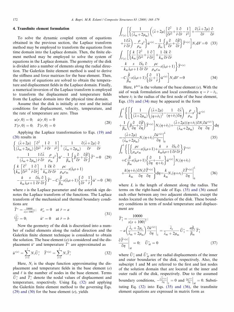
As discussed by Eq. (13), the FGM properties are posi-tion-dependent function. This functional relationship maybe assumed to have a power law form [18–21]. For this rea-son, the metal volume fraction Vm for a functionallygraded disk with inner radius a and outer radius b maybe introduced as
V m ¼r � ab� a
� �n
ð27Þ
where n is power law index that constitute the metal con-stituent richness in functionally graded annular disk.Substituting this equation in Eq. (13) gives the position-dependent material properties of FGMs in the geometryof the disk. The metal volume fraction change in anFGM is shown in Fig. 1. As shown, the fully metallic diskmay be obtained when n = 0 and the case of n!1 repre-sents a fully ceramic disk. The power law index may be var-ied to obtain different profiles for the distribution ofmaterials.
172 A. Bagri, M.R. Eslami / Composite Structures 83 (2008) 168–179
4. Transfinite element formulation
To solve the dynamic coupled system of equationsobtained in the previous section, the Laplace transformmethod may be employed to transform the equations fromtime domain into the Laplace domain. Then, the finite ele-ment method may be employed to solve the system ofequations in the Laplace domain. The geometry of the diskis divided into a number of elements along the radial direc-tion. The Galerkin finite element method is used to derivethe stiffness and force matrices for the base element. Then,the system of equations are solved to obtain the tempera-ture and displacement fields in the Laplace domain. Finally,a numerical inversion of the Laplace transform is employedto transform the displacement and temperature fieldsfrom the Laplace domain into the physical time domain.
Assume that the disk is initially at rest and the initialconditions for displacement, velocity, temperature, andthe rate of temperature are zero. Thus
uðr; 0Þ ¼ 0; _uðr; 0Þ ¼ 0
T ðr; 0Þ ¼ 0; _T ðr; 0Þ ¼ 0ð28Þ
Applying the Laplace transformation to Eqs. (19) and(20) results in
ð�kþ2lÞð�kmþ2lmÞ
o2
or2þ1
ro
or� 1
r2
� �þ 1
ð�kmþ2lmÞoð�kþ2lÞ
oro
or
�þ 1
ð�kmþ2lmÞ1
ro�kor� q
qm
s2
��u�� 1
�bm
�bo
orþo�b
or
� �bT � ¼0 ð29Þ
kkm
o2
or2þ1
ro
or
� �þ 1
km
okor
o
or� qc
qmcm
sðt0sþ1Þ�� k
km
st0sþ1
ot0
oro
or
�bT ��C�b
�bm
sðt0sþ1Þ o
orþ1
r
� �u� ¼0 ð30Þ
where s is the Laplace parameter and the asterisk sign de-notes the Laplace transform of the functions. The Laplacetransform of the mechanical and thermal boundary condi-tions arebT � ¼ 10000
sðsþ100Þ2 ; r�rr ¼ 0 at r ¼ a
obT �or ¼ 0; u� ¼ 0 at r ¼ b
ð31Þ
Now the geometry of the disk is discretized into a num-ber of radial elements along the radial direction and theGalerkin finite element technique is considered to obtainthe solution. The base element (e) is considered and the dis-placement u� and temperature bT � are approximated as
u�ðeÞ ¼Xl
i¼1
NibU �i bT �ðeÞ ¼Xl
i¼1
N ibT �i ð32Þ
Here, Ni is the shape function approximating the dis-placement and temperature fields in the base element (e)and ‘ is the number of nodes in the base element. TermsbU �i and bT �i denote the nodal values of displacement andtemperature, respectively. Using Eq. (32) and applyingthe Galerkin finite element method to the governing Eqs.(29) and (30) for the base element (e), yields
ZV ðeÞ
1
ð�kmþ2lmÞð�kþ2lÞ o2
or2þ1
ro
or� 1
r2
� �þoð�kþ2lÞ
oro
or
���þ1
ro�kor
�� q
qm
s2
�u�ðeÞ � 1
�bm
�bo
orþo�b
or
� �bT �ðeÞ�N idV ¼0 ð33ÞZV ðeÞ
kkm
o2
or2þ1
ro
or
� �þ 1
km
okor
o
or
��� k
km
st0sþ1
ot0
oro
or� qc
qmcm
sðt0sþ1Þ�bT �ðeÞ
�C�b
�bm
sðt0sþ1Þ o
orþ1
r
� �u�ðeÞ
�N idV ¼0 ð34Þ
Here, V(e) is the volume of the base element (e). With theaid of weak formulation and local coordinates g ¼ r � rf ,where rf is the radius of the first node of the base element,Eqs. (33) and (34) may be appeared in the formZ L
0
1
ð�kþ2lmÞð�kþ2lÞðgþrfÞ2
� 1
ðgþrfÞo�kog
!þ q
qm
s2
( )u�ðeÞ
"(
þ 1�bm
�bo
ogþo�b
og
� �bT �ðeÞ�NiðgþrfÞþð�kþ2lÞðgþrfÞð�kmþ2lmÞ
oNi
ogou�ðeÞ
og
�dg
¼ ð�kþ2lÞð�kmþ2lmÞ
NiðgþrfÞou�ðeÞ
og
L0
ð35ÞZ L
0
qcqmcm
sðt0sþ1Þþ kkm
st0sþ1
ot0
oro
or
� �bT �ðeÞ��þC
�b�bm
sðt0sþ1Þ o
ogþ 1
gþrf
� �u�ðeÞ
�NiðgþrfÞ
þkðgþrfÞkm
oN i
ogobT �ðeÞ
og
)dg¼ k
km
NiðgþrfÞobT �ðeÞ
og
L
0
ð36Þ
where L is the length of element along the radius. Theterms on the right-hand side of Eqs. (35) and (36) canceleach other between any two adjacent elements, except thenodes located on the boundaries of the disk. These bound-ary conditions in term of nodal temperature and displace-ment are
bT �1 ¼ 10000
sðsþ 100Þ2;
� a�kc þ 2lc
�km þ 2lm
� �ou�ðeÞ
og
1
¼�kc
�km þ 2lm
bU �1 �
a�bc
�bm
bT �1obT �ðeÞ
og
M
¼ 0; bU �M ¼ 0 ð37Þ
where bU �1 and bU �
M are the radial displacements of the innerand outer boundaries of the disk, respectively. Also, thesubscript 1 and M are referred to the first and last nodesof the solution domain that are located at the inner andouter radii of the disk, respectively. Due to the assumed
boundary conditions, �obT �ðeÞog
1¼ 0 and ou�ðeÞ
og
M¼ 0. Substi-
tuting Eq. (32) into Eqs. (35) and (36), the transfiniteelement equations are expressed in matrix form as

A. Bagri, M.R. Eslami / Composite Structures 83 (2008) 168–179 173
K11½ � K12½ �K21½ � K22½ �
� � bU �ðeÞbT �ðeÞ( )
¼Ff gQf g
� �ð38Þ
The submatrices [K11], [K12], [K21], [K22], {F} and {Q}are
Kij11
�¼Z L
0
1
ð�kmþ2lmÞð�kþ2lÞðgþ rfÞ
�o�kog
� �þ q
qm
s2ðgþ rfÞ� ��
NiNj
þ ð�kþ2lÞðgþ rfÞð�kmþ2lmÞoNi
ogoNj
og
)dg ð39Þ
Kij12
�¼ 1
�bm
Z L
0
�bðgþ rfÞNioN j
ogþo�b
ogðgþ rfÞNiN j
� �dg ð40Þ
Kij21
�¼ C
�bm
Z L
0
�bsðt0sþ1Þ ðgþ rfÞNioNj
ogþNiN j
� �dg ð41Þ
Kij22
�¼Z L
0
ðgþ rfÞqc
qmcm
sðt0sþ1ÞNiN jþk
km
st0sþ1
ot0
orN i
oNj
or
� ��þ k
km
ðgþ rfÞoNi
ogoNj
og
�dg ð42Þ
Ff g¼
�kc�kmþ2lm
bU �1�a�bc�bm
bT �10
��0
8>>>>>><>>>>>>:
9>>>>>>=>>>>>>;; Qf g¼
0
0
���0
8>>>>>>>><>>>>>>>>:
9>>>>>>>>=>>>>>>>>;ð43Þ
Now the system of equations may be solved to find thedisplacement and temperature fields in the Laplacedomain.
5. Inversion of the Laplace transform
Solving the system of equations in the Laplace domainfor the unknown nodal values of temperature and displace-ment, distributions and time variations of the displace-ment, temperature and stresses may be obtained using thenumerical inversion of the Laplace transform method pro-posed by Honig and Hirdes [22]. The inversion of theLaplace transform of function f*(s) is defined by
f ðtÞ ¼ £�1ff �ðsÞg ¼ 1
2pi
Z eþi1
e�i1f �ðsÞsst dt ð44Þ
where i ¼ffiffiffiffiffiffiffi�1p
and s = e + ix that e is an arbitrary real va-lue but greater than real parts of all singularities of f*(s).Another form of Eq. (44) may be defined as
f ðtÞ ¼ eet
p
Z 1
0
½Reff �ðsÞg cos xt � Imff �ðsÞg sin xt�dx
ð45ÞDerivation of this equation may be found in the work of
Durbin [23]. Further, using the Fourier series expansion ofg(t) = e�etf(t) in the interval [0,2s], Durbin obtained theapproximation formula in the form
f ðtÞ ¼ eet
s� 1
2Re f �ðeÞf g þ
X1n¼0
Re f � eþ inps
� n ocos
nps
t
"
�X1n¼0
Im f � eþ inps
� n osin
nps
t� � Er1ðe; t; sÞ
ð46Þwhere Er1(e, t,s) is the discretization error defined by
Er1ðe; t; sÞ ¼X1n¼1
e�2nesf ð2nsþ tÞ ð47Þ
that may be made small for sufficiently large value of e [22].Estimation of the infinite series appeared in Eq. (46) by Nterms enters another error named truncation error into theequation. Thus
f ðtÞ ¼ eet
s� 1
2Reff �ðeÞg þ
XN
n¼0
Re f � eþ inps
� n ocos
nps
t
"
�XN
n¼0
Im f � eþ inps
� n osin
nps
t
#� Er1ðe; t; sÞ
þ Er2ðN ; e; t; sÞ ð48Þ
where Er2(N, e, t,s) is given by
Er2ðN ; e; t; sÞ ¼ eet
s
X1n¼Nþ1
Re f � eþ inps
� n ocos
nps
t
�X1
n¼Nþ1
Im f � eþ inps
� n osin
nps
t
!ð49Þ
The reduction of the discretization and truncation errorsmay be obtained by the Korrectur method [22]. It may beseen from Eq. (47) that the discretization error can be madesmall if the product es is sufficiently large. By assuming alarge value for es, the truncation error introduced by Eq.(49) may diverge. To overcome this paradox, the Korrekturmethod provides reductions of the discretization errorwithout enlarging the truncation error and enables us toapproximately determine an optimal value for e with fixedvalues of N and s. In the Korrectur method the optimalvalue of e is found by minimization of the sum of absolutevalues of the discretization and truncation errors [22].
6. Numerical results and discussion
To validate the formulation, a comparison between theresults of the present work and known data in the literatureis needed. For this reason, a comparison between theresults of the present work and the results of [10], usingthe same boundary conditions given in reference [10] andfor pure Aluminum (n = 0), is given in Fig. 3. Since theintroduced dimensionless parameters in this paper andthose of [10] are different, one may expect a similar pattern,as observed from the figure.
The results obtained from the present formulation for afunctionally graded annular disk are shown for several
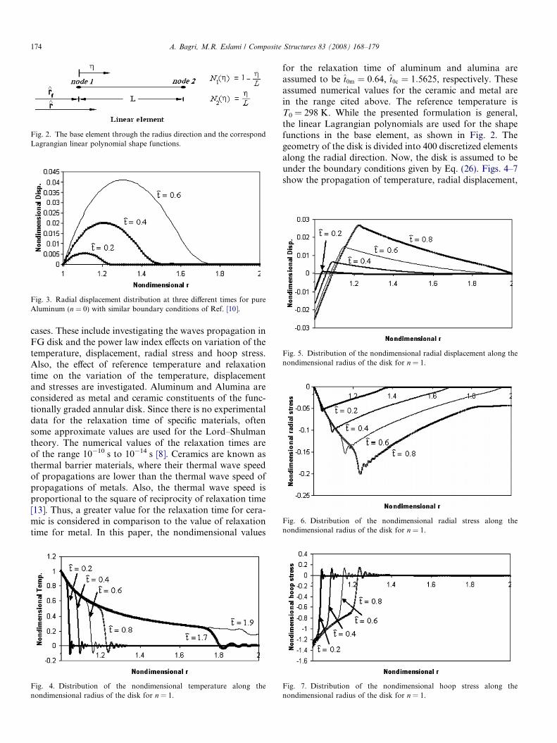
Fig. 3. Radial displacement distribution at three different times for pureAluminum (n = 0) with similar boundary conditions of Ref. [10].
Fig. 5. Distribution of the nondimensional radial displacement along thenondimensional radius of the disk for n = 1.
Fig. 6. Distribution of the nondimensional radial stress along thenondimensional radius of the disk for n = 1.
Fig. 2. The base element through the radius direction and the correspondLagrangian linear polynomial shape functions.
174 A. Bagri, M.R. Eslami / Composite Structures 83 (2008) 168–179
cases. These include investigating the waves propagation inFG disk and the power law index effects on variation of thetemperature, displacement, radial stress and hoop stress.Also, the effect of reference temperature and relaxationtime on the variation of the temperature, displacementand stresses are investigated. Aluminum and Alumina areconsidered as metal and ceramic constituents of the func-tionally graded annular disk. Since there is no experimentaldata for the relaxation time of specific materials, oftensome approximate values are used for the Lord–Shulmantheory. The numerical values of the relaxation times areof the range 10�10 s to 10�14 s [8]. Ceramics are known asthermal barrier materials, where their thermal wave speedof propagations are lower than the thermal wave speed ofpropagations of metals. Also, the thermal wave speed isproportional to the square of reciprocity of relaxation time[13]. Thus, a greater value for the relaxation time for cera-mic is considered in comparison to the value of relaxationtime for metal. In this paper, the nondimensional values
Fig. 4. Distribution of the nondimensional temperature along thenondimensional radius of the disk for n = 1.
for the relaxation time of aluminum and alumina areassumed to be t0m ¼ 0:64, t0c ¼ 1:5625, respectively. Theseassumed numerical values for the ceramic and metal arein the range cited above. The reference temperature isT0 = 298 K. While the presented formulation is general,the linear Lagrangian polynomials are used for the shapefunctions in the base element, as shown in Fig. 2. Thegeometry of the disk is divided into 400 discretized elementsalong the radial direction. Now, the disk is assumed to beunder the boundary conditions given by Eq. (26). Figs. 4–7show the propagation of temperature, radial displacement,
Fig. 7. Distribution of the nondimensional hoop stress along thenondimensional radius of the disk for n = 1.
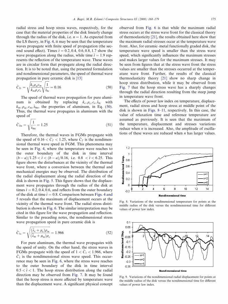
Fig. 8. Variations of the nondimensional temperature for points at themiddle radius of the disk versus the nondimensional time for differentvalues of power law index.
Fig. 9. Variations of the nondimensional radial displacement for points atthe middle radius of the disk versus the nondimensional time for differentvalues of power law index.
A. Bagri, M.R. Eslami / Composite Structures 83 (2008) 168–179 175
radial stress and hoop stress waves, respectively, for thecase that the material properties of the disk linearly changethrough the radius of the disk, i.e. n = 1. As expected fromthe LS theory, in Fig. 4, it may be seen that the temperaturewaves propagate with finite speed of propagation (the sec-ond sound effect). Times t ¼ 0:2; 0:4; 0:6; 0:8; 1:7 show thewave propagation along the radius, while time t ¼ 1:9 rep-resents the reflection of the temperature wave. These wavesare in circular form that propagate along the radial direc-tion. It is to be noted that, using the presented formulationand nondimensional parameters, the speed of thermal wavepropagation in pure ceramic disk is [13]
CTc ¼ffiffiffiffiffiffiffiffiffiffiffiffiffiffiffikcqmcm
kmqccc
s ffiffiffiffiffi1
t0c
s¼ 0:16 ð50Þ
The speed of thermal wave propagation for pure alumi-num is obtained by replacing kc;qc; cc; t0c withkm; qm; cm; t0m, the properties of aluminum, in Eq. (50).Thus, the thermal wave propagates in aluminum with thespeed of
CTm ¼
ffiffiffiffiffiffi1
t0m
s¼ 1:25 ð51Þ
Therefore, the thermal waves in FGMs propagate withthe speed of 0:16 < CT < 1:25, where CT is the nondimen-sional thermal wave speed in FGM. This phenomena maybe seen in Fig. 4, where the temperature wave reaches tothe outer boundary of the disk in time intervalðb� aÞ=1:25 < t < ðb� aÞ=0:16, i.e. 0.8 < t < 6:25. Thisfigure shows the disturbances at the vicinity of the thermalwave front, where a conversion between the thermal andmechanical energies may be observed. The distribution ofthe radial displacement along the radial direction of thedisk is shown in Fig. 5. This figure shows that the displace-ment wave propagates through the radius of the disk attimes t ¼ 0:2; 0:4; 0:6, and reflects from the outer boundaryof the disk at time t ¼ 0:8. Comparison between Figs. 4 and5 reveals that the maximum of displacement occurs at thevicinity of the thermal wave front. The radial stress distri-bution is shown in Fig. 6. The similar interpretation may becited in this figure for the wave propagation and reflection.Similar to the preceding notes, the nondimensional stresswave propagation speed in pure ceramic disk is
C1c ¼
ffiffiffiffiffiffiffiffiffiffiffiffiffiffiffiffiffiffiffiffiffiffiffiffiffið�kc þ lcÞqm
ð�km þ lmÞqc
s¼ 1:966 ð52Þ
For pure aluminum, the thermal wave propagates withthe speed of unity. On the other hand, the stress waves inFGMs propagate with the speed of 1 < C1 < 1:966, whereC1 is the nondimensional stress wave speed. This occur-rence may be seen in Fig. 6, where the stress wave reachesto the outer boundary of the disk in time interval0:5 < t < 1. The hoop stress distribution along the radialdirection may be observed from Fig. 7. It may be foundthat the hoop stress is more affected by temperature wavethan the displacement wave. A significant physical concept
observed from Fig. 6 is that while the maximum radialstress occurs at the stress wave front for the classical theoryof thermoelasticity [21], the results obtained here show thatthe maximum radial stresses occur at the temperature wavefront. Also, for ceramic–metal functionally graded disk, thetemperature wave speed is smaller than the stress wavespeed, which significantly influences the maximum stressesand makes larger values for the maximum stresses. It maybe seen from figures that at the stress wave front the stressvalues are smaller than the stresses occurred at the temper-ature wave front. Further, the results of the classicalthermoelasticity theory [21] show no sharp change inhoop stress distribution, while it may be observed fromFig. 7 that the hoop stress wave has a sharply changesthrough the radial direction resulting from the steep jumpin temperature wave front.
The effects of power law index on temperature, displace-ment, radial stress and hoop stress at middle point of thedisk is shown in Figs. 8–11, respectively. In this case, thevalue of relaxation time and reference temperature areassumed as previously. It is seen that the maximum ofthe temperature, displacement and stresses variationsreduce when n is increased. Also, the amplitude of oscilla-tions of these waves are reduced when n has larger values.
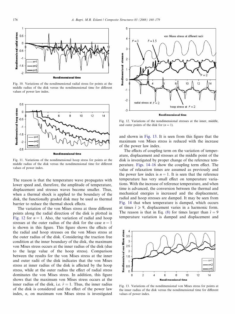
Fig. 10. Variations of the nondimensional radial stress for points at themiddle radius of the disk versus the nondimensional time for differentvalues of power law index.
Fig. 11. Variations of the nondimensional hoop stress for points at themiddle radius of the disk versus the nondimensional time for differentvalues of power index.
Fig. 12. Variations of the nondimensional stresses at the inner, middle,and outer points of the disk for (n = 1).
Fig. 13. Variations of the nondimensional von Mises stress for points atthe inner radius of the disk versus the nondimensional time for differentvalues of power index.
176 A. Bagri, M.R. Eslami / Composite Structures 83 (2008) 168–179
The reason is that the temperature wave propagates withlower speed and, therefore, the amplitude of temperature,displacement and stresses waves become smaller. Thus,when a thermal shock is applied to the boundary of thedisk, the functionally graded disk may be used as thermalbarrier to reduce the thermal shock effects.
The variation of the von Mises stress at three differentpoints along the radial direction of the disk is plotted inFig. 12 for n = 1. Also, the variation of radial and hoopstresses at the outer radius of the disk for the case n = 1is shown in this figure. This figure shows the effects ofthe radial and hoop stresses on the von Mises stress atthe outer radius of the disk. Considering the traction freecondition at the inner boundary of the disk, the maximumvon Mises stress occurs at the inner radius of the disk (dueto the large value of the hoop stress). Comparisonbetween the results for the von Mises stress at the innerand outer radii of the disk indicates that the von Misesstress at inner radius of the disk is affected by the hoopstress, while at the outer radius the effect of radial stressdominates the von Mises stress. In addition, this figureshows that the maximum von Mises stress occurs at theinner radius of the disk, i.e. r ¼ 1. Thus, the inner radiusof the disk is considered and the effect of the power lawindex, n, on maximum von Mises stress is investigated
and shown in Fig. 13. It is seen from this figure that themaximum von Mises stress is reduced with the increaseof the power law index.
The effects of coupling term on the variation of temper-ature, displacement and stresses at the middle point of thedisk is investigated by proper change of the reference tem-perature. Figs. 14–16 show the coupling term effect. Thevalue of relaxation times are assumed as previously andthe power law index is n = 1. It is seen that the referencetemperature has very small effect on temperature varia-tions. With the increase of reference temperature, and whentime is advanced, the conversion between the thermal andmechanical energies is increased and the displacement,radial and hoop stresses are damped. It may be seen fromFig. 14 that when temperature is damped, which occursat times t P 9, displacement varies in a harmonic form.The reason is that in Eq. (8) for times larger than t ¼ 9temperature variation is damped and displacement and
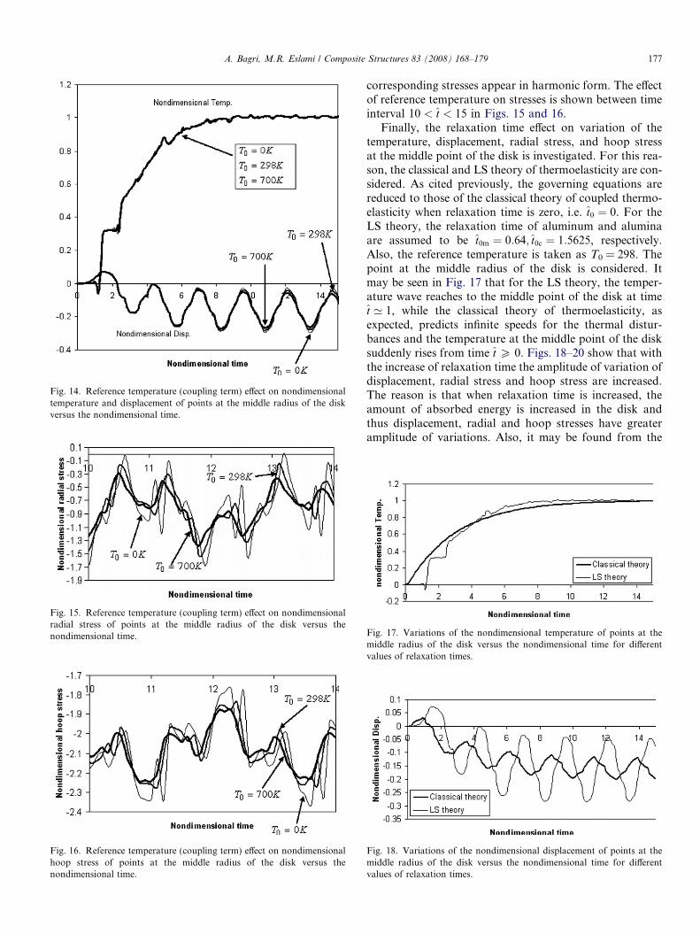
Fig. 14. Reference temperature (coupling term) effect on nondimensionaltemperature and displacement of points at the middle radius of the diskversus the nondimensional time.
Fig. 15. Reference temperature (coupling term) effect on nondimensionalradial stress of points at the middle radius of the disk versus thenondimensional time.
Fig. 16. Reference temperature (coupling term) effect on nondimensionalhoop stress of points at the middle radius of the disk versus thenondimensional time.
A. Bagri, M.R. Eslami / Composite Structures 83 (2008) 168–179 177
corresponding stresses appear in harmonic form. The effectof reference temperature on stresses is shown between timeinterval 10 < t < 15 in Figs. 15 and 16.
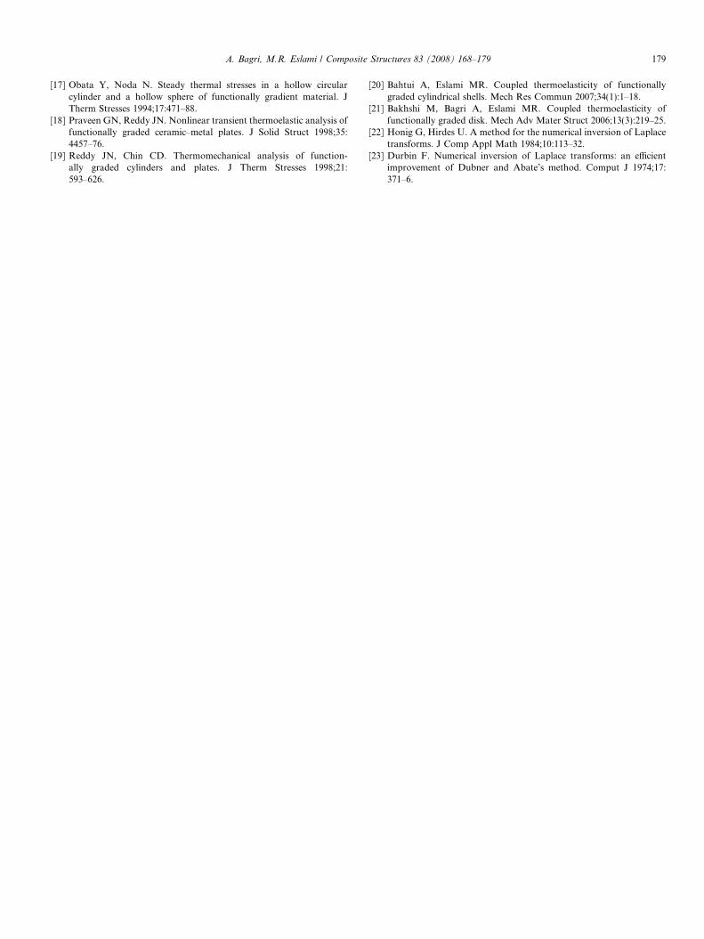
Finally, the relaxation time effect on variation of thetemperature, displacement, radial stress, and hoop stressat the middle point of the disk is investigated. For this rea-son, the classical and LS theory of thermoelasticity are con-sidered. As cited previously, the governing equations arereduced to those of the classical theory of coupled thermo-elasticity when relaxation time is zero, i.e. t0 ¼ 0. For theLS theory, the relaxation time of aluminum and aluminaare assumed to be t0m ¼ 0:64; t0c ¼ 1:5625, respectively.Also, the reference temperature is taken as T0 = 298. Thepoint at the middle radius of the disk is considered. Itmay be seen in Fig. 17 that for the LS theory, the temper-ature wave reaches to the middle point of the disk at timet ’ 1, while the classical theory of thermoelasticity, asexpected, predicts infinite speeds for the thermal distur-bances and the temperature at the middle point of the disksuddenly rises from time t P 0. Figs. 18–20 show that withthe increase of relaxation time the amplitude of variation ofdisplacement, radial stress and hoop stress are increased.The reason is that when relaxation time is increased, theamount of absorbed energy is increased in the disk andthus displacement, radial and hoop stresses have greateramplitude of variations. Also, it may be found from the
Fig. 17. Variations of the nondimensional temperature of points at themiddle radius of the disk versus the nondimensional time for differentvalues of relaxation times.
Fig. 18. Variations of the nondimensional displacement of points at themiddle radius of the disk versus the nondimensional time for differentvalues of relaxation times.
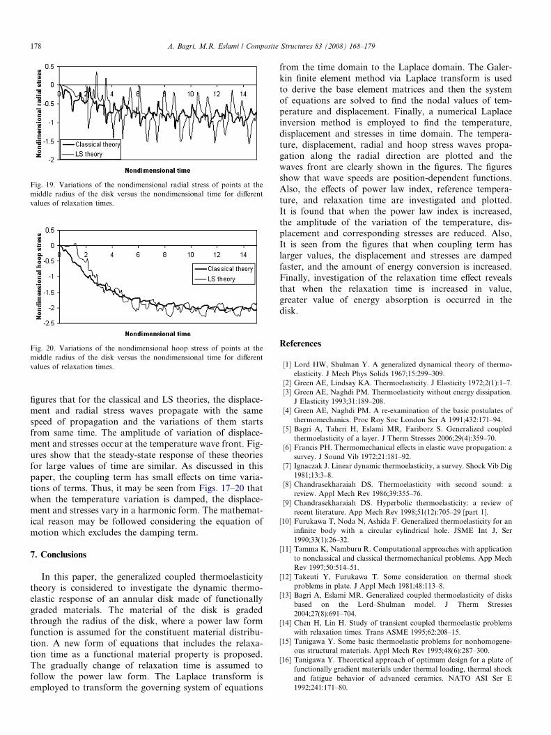
Fig. 19. Variations of the nondimensional radial stress of points at themiddle radius of the disk versus the nondimensional time for differentvalues of relaxation times.
Fig. 20. Variations of the nondimensional hoop stress of points at themiddle radius of the disk versus the nondimensional time for differentvalues of relaxation times.
178 A. Bagri, M.R. Eslami / Composite Structures 83 (2008) 168–179
figures that for the classical and LS theories, the displace-ment and radial stress waves propagate with the samespeed of propagation and the variations of them startsfrom same time. The amplitude of variation of displace-ment and stresses occur at the temperature wave front. Fig-ures show that the steady-state response of these theoriesfor large values of time are similar. As discussed in thispaper, the coupling term has small effects on time varia-tions of terms. Thus, it may be seen from Figs. 17–20 thatwhen the temperature variation is damped, the displace-ment and stresses vary in a harmonic form. The mathemat-ical reason may be followed considering the equation ofmotion which excludes the damping term.
7. Conclusions
In this paper, the generalized coupled thermoelasticitytheory is considered to investigate the dynamic thermo-elastic response of an annular disk made of functionallygraded materials. The material of the disk is gradedthrough the radius of the disk, where a power law formfunction is assumed for the constituent material distribu-tion. A new form of equations that includes the relaxa-tion time as a functional material property is proposed.The gradually change of relaxation time is assumed tofollow the power law form. The Laplace transform isemployed to transform the governing system of equations
from the time domain to the Laplace domain. The Galer-kin finite element method via Laplace transform is usedto derive the base element matrices and then the systemof equations are solved to find the nodal values of tem-perature and displacement. Finally, a numerical Laplaceinversion method is employed to find the temperature,displacement and stresses in time domain. The tempera-ture, displacement, radial and hoop stress waves propa-gation along the radial direction are plotted and thewaves front are clearly shown in the figures. The figuresshow that wave speeds are position-dependent functions.Also, the effects of power law index, reference tempera-ture, and relaxation time are investigated and plotted.It is found that when the power law index is increased,the amplitude of the variation of the temperature, dis-placement and corresponding stresses are reduced. Also,It is seen from the figures that when coupling term haslarger values, the displacement and stresses are dampedfaster, and the amount of energy conversion is increased.Finally, investigation of the relaxation time effect revealsthat when the relaxation time is increased in value,greater value of energy absorption is occurred in thedisk.
References
[1] Lord HW, Shulman Y. A generalized dynamical theory of thermo-elasticity. J Mech Phys Solids 1967;15:299–309.
[2] Green AE, Lindsay KA. Thermoelasticity. J Elasticity 1972;2(1):1–7.[3] Green AE, Naghdi PM. Thermoelasticity without energy dissipation.
J Elasticity 1993;31:189–208.[4] Green AE, Naghdi PM. A re-examination of the basic postulates of
thermomechanics. Proc Roy Soc London Ser A 1991;432:171–94.[5] Bagri A, Taheri H, Eslami MR, Fariborz S. Generalized coupled
thermoelasticity of a layer. J Therm Stresses 2006;29(4):359–70.[6] Francis PH. Thermomechanical effects in elastic wave propagation: a
survey. J Sound Vib 1972;21:181–92.[7] Ignaczak J. Linear dynamic thermoelasticity, a survey. Shock Vib Dig
1981;13:3–8.[8] Chandrasekharaiah DS. Thermoelasticity with second sound: a
review. Appl Mech Rev 1986;39:355–76.[9] Chandrasekharaiah DS. Hyperbolic thermoelasticity: a review of
recent literature. App Mech Rev 1998;51(12):705–29 [part 1].[10] Furukawa T, Noda N, Ashida F. Generalized thermoelasticity for an
infinite body with a circular cylindrical hole. JSME Int J, Ser1990;33(1):26–32.
[11] Tamma K, Namburu R. Computational approaches with applicationto nonclassical and classical thermomechanical problems. App MechRev 1997;50:514–51.
[12] Takeuti Y, Furukawa T. Some consideration on thermal shockproblems in plate. J Appl Mech 1981;48:113–8.
[13] Bagri A, Eslami MR. Generalized coupled thermoelasticity of disksbased on the Lord–Shulman model. J Therm Stresses2004;27(8):691–704.
[14] Chen H, Lin H. Study of transient coupled thermoelastic problemswith relaxation times. Trans ASME 1995;62:208–15.
[15] Tanigawa Y. Some basic thermoelastic problems for nonhomogene-ous structural materials. Appl Mech Rev 1995;48(6):287–300.
[16] Tanigawa Y. Theoretical approach of optimum design for a plate offunctionally gradient materials under thermal loading, thermal shockand fatigue behavior of advanced ceramics. NATO ASI Ser E1992;241:171–80.
A. Bagri, M.R. Eslami / Composite Structures 83 (2008) 168–179 179
[17] Obata Y, Noda N. Steady thermal stresses in a hollow circularcylinder and a hollow sphere of functionally gradient material. JTherm Stresses 1994;17:471–88.
[18] Praveen GN, Reddy JN. Nonlinear transient thermoelastic analysis offunctionally graded ceramic–metal plates. J Solid Struct 1998;35:4457–76.
[19] Reddy JN, Chin CD. Thermomechanical analysis of function-ally graded cylinders and plates. J Therm Stresses 1998;21:593–626.
[20] Bahtui A, Eslami MR. Coupled thermoelasticity of functionallygraded cylindrical shells. Mech Res Commun 2007;34(1):1–18.
[21] Bakhshi M, Bagri A, Eslami MR. Coupled thermoelasticity offunctionally graded disk. Mech Adv Mater Struct 2006;13(3):219–25.
[22] Honig G, Hirdes U. A method for the numerical inversion of Laplacetransforms. J Comp Appl Math 1984;10:113–32.
[23] Durbin F. Numerical inversion of Laplace transforms: an efficientimprovement of Dubner and Abate’s method. Comput J 1974;17:371–6.
Copyright © 2022 FDOKUMEN