NTS Beam System
10
NTS Beam System Easy Systems Noordervaart 33 | 2200 Herentals | Belgium T: +32 (0)14/72.93.84 | F: +32 (0)14/72.93.85 [email protected] | www.easy-systems.be
-
Upload
khangminh22 -
Category
Documents
-
view
0 -
download
0
Transcript of NTS Beam System

NTS Beam System
Easy Systems Noordervaart 33 | 2200 Herentals | Belgium
T: +32 (0)14/72.93.84 | F: +32 (0)14/72.93.85 [email protected] | www.easy-systems.be

Profile overview
For detailed dimensions, please see theenclosed 1:1 die drawings.
NTS 23x16 ldie No. 41735G=19,82 kg/m
NTS 16x11,5 ldie No. 41732G=13,53 kg/m
NTS 23x16 sdie No. 41738G=29,74 kg/m
NTS 32x23 ldie No. 41741G=34,65 kg/m
NTS 46x32 ldie No. 41747G=51,05 kg/m
NTS 46x32 sdie No. 41750G=66,78 kg/m
T-slots:
NTS 16x11,5 l:for DIN M10 T-nuts
NTS 23x16 to 46x32:for DIN M12 T-nuts
Corner spacings of the edge slot axis:40 mm
Attention:Profiles are not
symmetrical with theexception of
16x11,5 l
NTS 32x23 sdie No. 41744G=46,09 kg/m
z
z
y y
>>> CONTENTS <<<

Formulae for design
AlloyAlMgSi0,5 (6060/6063) F22 acc. to DIN
1748.1(6063 T6 after the changeover toDIN EN 755-2)Rm 215 N/mm2
Rp0,2 160 N/mm2
A5 5 % 1)
HB 70
Permissible stresses acc. to DIN 4113:(loading case H)
Tension/compression/bending:95 N/mm2
Shear: 55 N/mm2
Bearing stress for bolts 1: 120 N/mm2
(clearance of bolts 1 mm)Bearing stress for bolts 2: 145 N/mm2
(clearance of bolts 0,3 mm)Bearing stress for bolts 3: 125-205 N/mm2
(prestressed bolts)
Physical valuesDensity ρ: 2,7 g/cm3
Modulus of elasticity E: 70 000 N/mm2
Shear modulus G: 27 000 N/mm2
Poisson‘s ration ν : 0,33Coefficient ofthermal expansion α : 23,5•10-6 1/KSpecific heat: 0,9 J/(g K)Electrical conductivity: 28-35 m/(Ω mm2)
Basic values for verification
Cross section values 2):
SectionNo. G A Iy Wy Iz Wz IT CM
NTS ... [kg/m] [cm2] [cm4] [cm3] [cm4] [cm3] [cm4] [cm6]
16x11,5 l 13,53 50,12 1649 206 859 149 526 2472
23x16 l 19,82 73,42 5128 446 2716 336 1865 22370
23x16 s 29,74 110,15 7471 650 3847 473 2769 25850
32x23 l 34,65 128,33 17407 1081 9203 792 8091 51800
32x23 s 46,09 170,71 23619 1460 12225 1047 10882 81930
46x32 l 51,05 189,06 53788 2326 27620 1713 32108 275000
46x32 s 66,78 247,32 74147 3191 35526 2195 40706 920200
Calculation programme DUENQ of Messrs. Dlubal (thin-walled sections) was used for the calculation of torsionconstants.The indicated section moduli are minimum values. Sincethe axes through the centre of gravity almost coincidewith the centre lines, maxW = minW = W can be used forpractical design.
1) varying from DIN or EN2) Orientation of axes in acc.to DIN 1080
Short-time temperature load (e.g.stovelacquering) without consider-able loss of strength (max. 10 %;values are valid for AlMgSi0,5 only)270 C 8 min240 C 40 min220 C 70 min200 C ~2 h
WeldingAs with most aluminium alloys the
welding heat reduces the strengthin the area up to 50 mm from theseam.With AlMgSi0,5 the following valuesare defined for the verification ofbutt welds (in acc. to E-DIN 4113.2):
Rm = 110 N/mm2
Rp0,2 = 65 N/mm2
Cantilever beam
The easiest way to verify cantileverbeams for deflection and twist is touse the formulae:
Deflection: f =F•l3
3•E•I
Angle of twist:
a =MT
•l[rad]=
MT•l•180
[ ]G•IT G•IT
•π
f
>>> CONTENTS <<<

0
Beam on two supports
Deflection under point loadDeflection fxF of point x in mm under
unit load F = 1 kN (100 kg) at thepoint x for a unit span of l = 1 m
Calculation of general cases:fx = fxF
•F•l3 [mm](with F in kN, l in m)
e.g. beam 23x16 l (z-z);(bending about the weak axis)l = 8 m, F = 5 kN at x = 3,2 m
=> x/l = 0,4 and fxF = 0,01fx = 0,01•5•83 = 25,6 mm
Twist under torsional momentAngle of twist axM of point x in [ ]
under unit torsional momentMT = 1 kNm at the point x for a unitspan of l = 1 m.
Calculation of general cases:αx = αxM
•MT•l [ ] or = αxM
•F•e•l(with e = lever arm in m,F in kN, l in m)
e.g. beam 46x32 l; l = 10 mF = 7 kN at x = 3,5 m, e = 2 m
=> x/l = 0,35 and αxM = 0,0015αx = 0,0015•7•2•10 = 0,21
Deflection under dead weightDeflection ordinates fxe in mm
under dead weight as a functionof point x for a unit span ofl = 1 m
Calculation of general cases:fx = fxe
•l4 [mm](with l in m)
e.g. beam 23x16 l (z-z);(bending about the weak axis)l = 8 m, x = 3,2 m
=> x/l = 0,4 and fxe = 0,00128fx = 0,00128•84 = 5,2 mm
* For these sections the ratio I / G is betweenvariant l and s which is almost identical.

6
Formulae for design
Load carrying effect of attachedsteel parts
If steel parts such as guide rails ortoothed racks are connected to thealuminium profiles this often resultsin a considerable increase of thestiffness/rigidity.
This is the case when the steel partsa) are the length of the beamb) are fixed to the aluminium beam
with rigid means of connection.
The following calculation methodapplies:
This is to calculate an I* which is basedon the modulus of elasticity of alu-minium as comparative modulus.An additional assumption is that theaxes through the centre of gravityof the aluminium profiles coincidewith the respective centre lines(error 1,5 % max.) and that theratio of the moduli of elasticityESt/EAl is 3.
∆e which is the distance between thenew axis through the centre ofgravity and the (original) centre lineis calculated on the basis of thefollowing formulae:
∆e =3 Σ (ASt,i• ei) or
(AAl + 3 Σ ASt,i)
∆e =Σ (Ai*• ei)
Σ Ai*
Therefore the relation
I* = IAl +3 Σ ISt +3 Σ (ASt,i•(ei - ∆e)2)+AAl
•∆e2
and in summary
I* = Σ Ii* +Σ (Ai*˙ei2) - ∆e2
˙Σ Ai*
Stresses are calculated on the basis of the following formulae:for Al: σ = M/( I*/e)for steel: σ = 3 M/( I*/e)
The shearing force per fixing means between steel and Al-beam is
T = 3 Q S .d,
I*
with S = Ai,St.(ei - ∆e) and
d = distance between the fixing means.
Example:Calculation of the values for NTS 23x16 l with bending about the Y-axis
b h Ai ei Ii
[cm] [cm] [cm2] [cm] [cm4]Beam NTS 23x16 l 16 23 73,42 0 5128Guide rail A1 5 4 20 -13,5 26,67Toothed rack A2 3 5 15 0 31,25Guide rail A3 4 5 20 +7,5 41,67
Ai Ai* ei –> Ai*.ei ei2 –> Ai*.ei
2Ii Ii*
Al-beam 73,42 x 1 = 73,42 0 0 0 0 5128 x 1 = 5128
Steel sec. 1 20 x 3 = 60 -13,5 -810 182,25 10935 26,67 x 3 = 80,01Steel sec. 2 15 x 3 = 45 0 0 0 0 31,25 x 3 = 93,75Steel sec. 3 20 x 3 = 60 7,5 450 56,25 3375 41,67 x 3 = 125,01Steel sec. 4 x 3 = x 3 =
Σ Ai* = 238,42 Σ (Ai*.ei) = -360 Σ (Ai*.ei2) = 14310 Σ Ii* = 5426,8
∆e = / = -1,51
ΣAi*.∆e2 = . 2 = 543,6 I* = + - = 19193 cm
4
Ai Ai* ei –> Ai*.ei ei2 –> Ai*.ei
2Ii Ii*
Al-beam x 1 = 0 0 0 0 x 1 =
Steel sec. 1 x 3 = x 3 =
Steel sec. 2 x 3 = x 3 =
Steel sec. 3 x 3 = x 3 =
Steel sec. 4 x 3 = x 3 =
Σ Ai* = Σ (Ai*.ei) = Σ (Ai*.ei2) = Ii* =
∆e = / =
Σ Ai*.∆e2 = .2 = I* = + - =
( 3,7. IAl)
applies to the higher moment of inertia.To calculate the above, please use thetable below.
>>> CONTENTS <<<
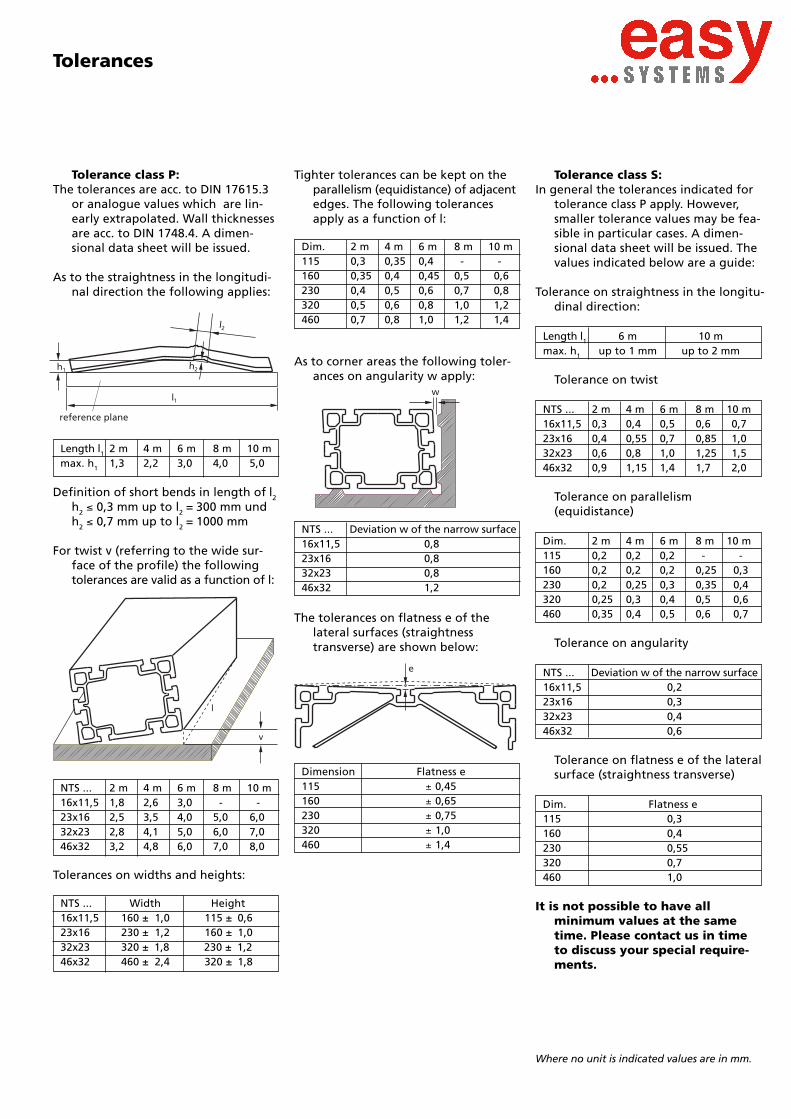
Tolerance class P:The tolerances are acc. to DIN 17615.3
or analogue values which are lin-early extrapolated. Wall thicknessesare acc. to DIN 1748.4. A dimen-sional data sheet will be issued.
As to the straightness in the longitudi-nal direction the following applies:
Tolerances
h1
l2
reference plane
h2
Length l1 2 m 4 m 6 m 8 m 10 mmax. h1 1,3 2,2 3,0 4,0 5,0
Definition of short bends in length of l2
h2 0,3 mm up to l2 = 300 mm undh2 0,7 mm up to l2 = 1000 mm
For twist v (referring to the wide sur-face of the profile) the followingtolerances are valid as a function of l:
NTS ... 2 m 4 m 6 m 8 m 10 m16x11,5 1,8 2,6 3,0 - -23x16 2,5 3,5 4,0 5,0 6,032x23 2,8 4,1 5,0 6,0 7,046x32 3,2 4,8 6,0 7,0 8,0
Tolerances on widths and heights:
Tighter tolerances can be kept on theparallelism (equidistance) of adjacentedges. The following tolerancesapply as a function of l:
As to corner areas the following toler-ances on angularity w apply:
Dim. 2 m 4 m 6 m 8 m 10 m115 0,3 0,35 0,4 - -160 0,35 0,4 0,45 0,5 0,6230 0,4 0,5 0,6 0,7 0,8320 0,5 0,6 0,8 1,0 1,2460 0,7 0,8 1,0 1,2 1,4
NTS ... Deviation w of the narrow surface16x11,5 0,823x16 0,832x23 0,846x32 1,2
The tolerances on flatness e of thelateral surfaces (straightnesstransverse) are shown below:
Tolerance class S:In general the tolerances indicated for
tolerance class P apply. However,smaller tolerance values may be fea-sible in particular cases. A dimen-sional data sheet will be issued. Thevalues indicated below are a guide:
Tolerance on straightness in the longitu-dinal direction:
Length l1 6 m 10 mmax. h1 up to 1 mm up to 2 mm
Tolerance on twist
NTS ... 2 m 4 m 6 m 8 m 10 m16x11,5 0,3 0,4 0,5 0,6 0,723x16 0,4 0,55 0,7 0,85 1,032x23 0,6 0,8 1,0 1,25 1,546x32 0,9 1,15 1,4 1,7 2,0
Tolerance on parallelism(equidistance)
Dim. 2 m 4 m 6 m 8 m 10 m115 0,2 0,2 0,2 - -160 0,2 0,2 0,2 0,25 0,3230 0,2 0,25 0,3 0,35 0,4320 0,25 0,3 0,4 0,5 0,6460 0,35 0,4 0,5 0,6 0,7
Tolerance on angularity
NTS ... Deviation w of the narrow surface16x11,5 0,223x16 0,332x23 0,446x32 0,6
Tolerance on flatness e of the lateralsurface (straightness transverse)
Dim. Flatness e115 0,3160 0,4230 0,55320 0,7460 1,0
It is not possible to have allminimum values at the sametime. Please contact us in timeto discuss your special require-ments.
NTS ... Width Height16x11,5 160 ± 1,0 115 ± 0,623x16 230 ± 1,2 160 ± 1,032x23 320 ± 1,8 230 ± 1,246x32 460 ± 2,4 320 ± 1,8
Where no unit is indicated values are in mm.
Dimension Flatness e115 0,45160 0,65230 0,75320 1,0460 1,4

Closer tolerances can be kept on theparallelism (equidistance) of adja-cent edges. The following toler-ances apply as a function of l:
Dim. 2 m 4 m 6 m 8 m 10 m115 0,4 0,4 0,5 - -160 0,5 0,6 0,7 0,8 0,9230 0,7 0,8 0,9 1,0 1,2320 0,9 1,0 1,2 1,3 1,6460 1,1 1,3 1,5 1,8 2,1
As to the corner areas the followingtolerances w on angularity apply:
NTS ... Deviation w of the narrow surface16x11,5 0,923x16 1,332x23 1,646x32 1,9
The tolerances on flatness e of the lat-eral surfaces (straightness transvers)are shown below:
Dim. Flatness e115 0,7160 0,9230 1,2320 1,8460 2,4
Tolerance class N:In general the tolerances acc. to DIN
1748.4, “fine straightened” applywith regard to the dimensions ofthe profiles. No dimensional datasheet will be issued.
As to the straightness in the longitudi-nal direction the following applies:
Length l1 2 m 4 m 6 m 8 m 10 m
max. h1 2,0 3,5 5,0 7,0 9,0
Definition of short bends in length of l2
h2 0,3 mm up to l2 = 300 mm andh2 1,0 mm up to l2 = 1000 mm
For twist v (referring to the wide surfaceof the profile) the following toler-ances are valid as a function of l:
NTS ... 2 m 4 m 6 m 8 m 10 m16x11,5 3,0 3,0 3,0 - -23x16 4,0 4,0 4,0 6,0 6,032x23 4,0 5,0 5,0 8,0 10,046x32 5,0 6,0 6,0 8,0 10,0
Tolerances on widths and heights:
NTS ... Width Height16x11,5 160± 1,5 115± 1,123x16 230± 1,9 160± 1,532x23 320± 3,0 230± 1,946x32 460± 3,5 320± 3,0
Tolerances
h1
l2
reference plane
h2
Stock lengthsProfile 16x11,5 is available ex stock in
lengths of 6 m; all other profiles inlengths of 6 m and 10 m. Otherlengths upon request.Tolerance on length: +200/-0 mmAlways subject to prior agreement.
Profiles cut to lengthThe profiles are cut with a tolerance tS
which means that the length be-tween the cut (first grip of sawingteeth) and the stop is within therange of this tolerance value.
Additionally the cutting angle wS mustbe defined. Unless otherwiseagreed, this angle is to be wS = tS/2(on the basis of the mean profileaxis).
Fixed lengths with plustolerances
The values in mm for tS are as follows:
NTS ... up to 5 m up to 10 m16x11,5
6 823x1632x23
8 1046x32
Note: To be able to machine a “preciselength L“ (parallel at both ends)from a cut-to-length profile, thelength to be ordered has to beincreased by 2wS = tS.
Explanation:
(On the basis of this definition the pro-jected length of a profile can bemax. L+tS+3wS.)
Length to be ordered:Lorder = L+ tS........
+tS-0
Example: precise length L 4800 mm;section 23x16 i.e. tS = 6 mm.This results in a length to beordered of 4806 mm +6/-0.
Stock lengths/Profiles cut to length
Where no unit is indicated values are in mm
>>> CONTENTS <<<>>> CONTENTS <<<>>> CONTENTS <<<

Fixed lengths with minustolerances
The values in mm for tS are as follows:
NTS ... up to 5 m up to 10 m16x11,5
4 623x1632x23
6 846x32
Note: To obtain the fit in length (i.e. itmust be possible to fit the cut-to-length profile between two parallelsurfaces at a distance L) the lengthto be ordered must be reduced bywS = tS/2 referring to the net space.
Explanation:
(On the basis of this definition thelength of the shortest edge of aprofile can be L-tS-3wS.)
Length to be ordered:Lorder = L- tS/2........+0
-tS
Example: Net space 4800 mm, section23x16 results in tS = 4 mmand a length to be ordered of4798 mm +0/-4.
Upon special agreement, profilescan be supplied which are cutwith tighter tolerances.
>>> CONTENTS <<<

DesignationWeight per
meterHeight/width
Parallelismsmall side
Parallelismwide side
Straightnessincluding
twistShort bends
in length
Flatness(straightness transverse)small side
Flatness(straightness transverse)wide side Angularity
41732
NTS 16x11,5W=13.5kg
115±0.8160±1.1
0.5mm/ 10m 0.6mm/ 10m 6.0mm/ 10m 1.0mm/ 2000mm 0.4mm 0.6mm 0.8mm
41735
NTS 23x16lW=19.8kg
160±1.0230±1.1
0.6mm/ 10m 0.9mm/ 10m 6.5mm/ 10m 1.0mm/ 2000mm 0.6mm 0.8mm 0.9mm
41738
NTS 23x16sW=29.7kg
160+1.1/-0.4
230±1.00.3mm/ 3000mm
0.6mm/ 10m0.8mm/ 10m 7.0mm/ 10m 1.0mm/ 2000mm 0.6mm 0.7mm 0.6mm
41741
NTS 32x23lW=34.7kg
230±0.8320±1.3
0.8mm/ 10m 1.0mm/ 10m 7.5mm/ 10m 1.2mm/ 2000mm 1.0mm 1.0mm 0.8mm
41744
NTS 32x23sW=46.1kg
230±1.2320±1.8
1.0mm/ 10m 1.3mm/ 10m 8.0mm /10m 1.2mm/ 2000mm 0.8mm 1.2mm 1.0mm
41747
NTS 46x32lW=51.1kg
320±1.8460±2.4
1.3mm/ 10m 1.5mm/ 10m 8.5mm/ 10m 1.5mm/ 2000mm 1.8mm 2.4mm 1.9mm
41750
NTS 46x32sW=66.8kg
320±1.8460±2.4
1.3mm/ 10m 1.5mm/ 10m 9.0mm/ 10m 1.5mm/ 2000mm 1.2mm 1.6mm 1.5mm
T O L E R A N C E S
As of July 2007 the following delivery conditions apply for the NTS profiles: Profiles 41732, 41735, 41738 and 41741 are available from stock, in lengths up to 10 m.Profiles 41744, 41747 and 41750 are available upon request.
The three tolerance classes N, P, and S are replaced by the consistent tolerances listed below. ( They correspond to approx. the previous class "P" tolerance).A drawing is available upon request with the exact tolerance details.
Modified Delivery Terms for NTS Profiles

Ø<
600
mm
Ø<
600
mm
< 800 mm
<10
0 m
m
< 800 mm
<60
mm
The way to your own individual section
In many cases the question will be asked,whether or not it is an advantage tohave your own individual section.
The advantages are: a section withoptimum shape and weight, so thatin the final analysis there are costsaving advantages as well as distinc-tive design features making thesection exclusive.
Necessary concessions: Capital expendi-ture on a product whose marketpossibilities cannot be specificallyassessed, die costs, minimum quanti-ties, development decisions taken inhaste, uncertainty regarding thefinal shape of the profile.
However these entrepreneurial deci-sions must be taken. At this stagethe argument may be, that whencompared with steel, die costs andminimum quantities are not nearlyso high for aluminium extrusionsand for these reasons many compa-nies have already taken the step ofhaving their own individual section.
The NTS beam system offers the designeralternatives in different situations:
For machines and frameworks that areproduced and sold in small quantities.
When it is possible to adapt an existingsystem to use NTS beams, one savesdie costs with the advantages of anindividual section.
By starting a new development withNTS beams and changing later to anindividual shape, the entrance riskinto the market is minimised andthe design can be proved.
AlloysBased on its excellent combination of
characteristics alloy AlMgSi0,5(6060,6063) was chosen for the NTSbeam system. Practically all extru-sion alloys are heat-treatable alloys.They extrude well, but attain theirstrength only by heat-treatmentwhich includes quenching.
According to the alloy, quenching mustbe done with water or with air.As a rule mechanical engineeringrequires tight tolerances on theshape and small residual stresses.Therefore air-quenched alloys havethe advantage.
Besides AlMgSi0,5 (6060,6063) there isalso alloy AlZn4,5Mg1 (7020), whichis air-quenchable. The high strengthof this alloy would be an additionalincentive for many applications.However, it has a higher flow stress,which means it requires larger wallthicknesses, simpler profile shapesand is more expensive. Therefore itis only considered for special cases.
When new sections are being developed,the conclusion is, that AlMgSi0,5(6060,6063) should be the first alloyto be considered.
DimensionsFor maximum cross-sectional dimensions
the following diagrams illustratethe general limits. These limits arewithin our manufacturing capabili-ties. However any borderline sectionshould be discussed at the planningstage with the application engineersat Alusuisse Singen.
Solid section
Solid section
Hollow section
Hollow section
Minimum wall thicknesses andweights
There are also factors governing theminimum wall thicknesses and mini-mum weights, which should not beoverlooked.
For AlMgSi0,5 (6060,6063) the follow-ing applies:
Circumscr. min. min.circle weight wall thickness
ø [mm] [kg/m] [mm]
< 40 0,15 1,2up to 100 0,35 1,8up to 160 0,7 2,0up to 200 1,3 2,5up to 320 3,5 3,0up to 400 6,0 4,0> 400 On request
Tolerances:DIN 1748/4 is applied in most cases,
however, depending on the applica-tion DIN 17615/3 can be a basis fordesign and production. The toler-ances stated in this publication cannot be taken as a general guideline.For symmetrical sections, which aremanufactured in large quantities,relatively small tolerances can beheld.
Please feel free to discuss your ideasand plans with us at the planningstage.
The above explanations are validexclusively for applicationssimilar to the NTS beam system.Alusuisse Singen supplies pro-files in a comprehensive rangeof sizes, alloys and mechanicalstrength. Data for these possi-bilities are available on requestthrough brochures or by directcontact.
>>> CONTENTS <<<