Conversion Tables, Formulas and Suggested Guidelines for ...
Upload
independentCategory
view
7download
0
CHAPTER 2BEAM
FORMULAS
Downloaded from Digital Engineering Library @ McGraw-Hill (www.digitalengineeringlibrary.com)Copyright © 2004 The McGraw-Hill Companies. All rights reserved.
Any use is subject to the Terms of Use as given at the website.
Source: CIVIL ENGINEERING FORMULAS

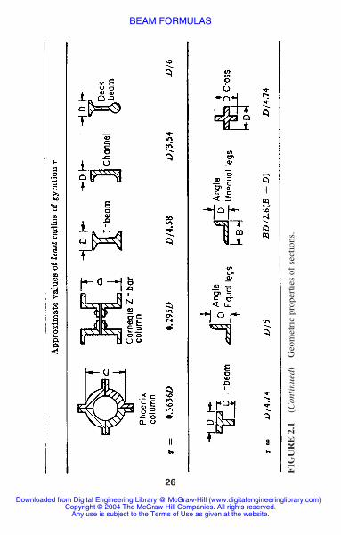
In analyzing beams of various types, the geometric proper-ties of a variety of cross-sectional areas are used. Figure 2.1gives equations for computing area A, moment of inertia I,section modulus or the ratio S � I/c, where c � distancefrom the neutral axis to the outermost fiber of the beam orother member. Units used are inches and millimeters andtheir powers. The formulas in Fig. 2.1 are valid for bothUSCS and SI units.
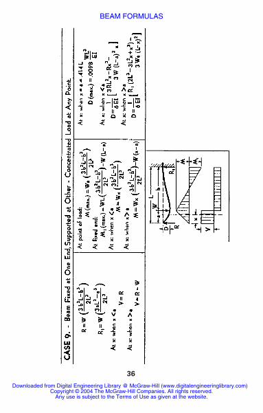
Handy formulas for some dozen different types ofbeams are given in Fig. 2.2. In Fig. 2.2, both USCS and SIunits can be used in any of the formulas that are applicableto both steel and wooden beams. Note that W � load, lb(kN); L � length, ft (m); R � reaction, lb (kN); V � shear,lb (kN); M � bending moment, lb � ft (N � m); D � deflec-tion, ft (m); a � spacing, ft (m); b � spacing, ft (m); E �modulus of elasticity, lb/in2 (kPa); I � moment of inertia,in4 (dm4); � � less than; � � greater than.
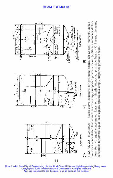
Figure 2.3 gives the elastic-curve equations for a varietyof prismatic beams. In these equations the load is given asP, lb (kN). Spacing is given as k, ft (m) and c, ft (m).
CONTINUOUS BEAMS
Continuous beams and frames are statically indeterminate.Bending moments in these beams are functions of thegeometry, moments of inertia, loads, spans, and modulus ofelasticity of individual members. Figure 2.4 shows how anyspan of a continuous beam can be treated as a single beam,with the moment diagram decomposed into basic com-ponents. Formulas for analysis are given in the diagram.Reactions of a continuous beam can be found by using theformulas in Fig. 2.5. Fixed-end moment formulas forbeams of constant moment of inertia (prismatic beams) for
16 CHAPTER TWO
Downloaded from Digital Engineering Library @ McGraw-Hill (www.digitalengineeringlibrary.com)Copyright © 2004 The McGraw-Hill Companies. All rights reserved.
Any use is subject to the Terms of Use as given at the website.
BEAM FORMULAS

17
FIG
UR
E 2
.1G
eom
etri
c pr
oper
ties
of s
ectio
ns.
Downloaded from Digital Engineering Library @ McGraw-Hill (www.digitalengineeringlibrary.com)Copyright © 2004 The McGraw-Hill Companies. All rights reserved.
Any use is subject to the Terms of Use as given at the website.
BEAM FORMULAS

18
Downloaded from Digital Engineering Library @ McGraw-Hill (www.digitalengineeringlibrary.com)Copyright © 2004 The McGraw-Hill Companies. All rights reserved.
Any use is subject to the Terms of Use as given at the website.
BEAM FORMULAS

19
FIG
UR
E 2
.1(C
onti
nued
)G
eom
etri
c pr
oper
ties
of s
ectio
ns.
Downloaded from Digital Engineering Library @ McGraw-Hill (www.digitalengineeringlibrary.com)Copyright © 2004 The McGraw-Hill Companies. All rights reserved.
Any use is subject to the Terms of Use as given at the website.
BEAM FORMULAS

20
Downloaded from Digital Engineering Library @ McGraw-Hill (www.digitalengineeringlibrary.com)Copyright © 2004 The McGraw-Hill Companies. All rights reserved.
Any use is subject to the Terms of Use as given at the website.
BEAM FORMULAS

21
FIG
UR
E 2
.1(C
onti
nued
)G
eom
etri
c pr
oper
ties
of s
ectio
ns.
Downloaded from Digital Engineering Library @ McGraw-Hill (www.digitalengineeringlibrary.com)Copyright © 2004 The McGraw-Hill Companies. All rights reserved.
Any use is subject to the Terms of Use as given at the website.
BEAM FORMULAS

22
Downloaded from Digital Engineering Library @ McGraw-Hill (www.digitalengineeringlibrary.com)Copyright © 2004 The McGraw-Hill Companies. All rights reserved.
Any use is subject to the Terms of Use as given at the website.
BEAM FORMULAS

23
FIG
UR
E 2
.1(C
onti
nued
)G
eom
etri
c pr
oper
ties
of s
ectio
ns.
Downloaded from Digital Engineering Library @ McGraw-Hill (www.digitalengineeringlibrary.com)Copyright © 2004 The McGraw-Hill Companies. All rights reserved.
Any use is subject to the Terms of Use as given at the website.
BEAM FORMULAS

24
Downloaded from Digital Engineering Library @ McGraw-Hill (www.digitalengineeringlibrary.com)Copyright © 2004 The McGraw-Hill Companies. All rights reserved.
Any use is subject to the Terms of Use as given at the website.
BEAM FORMULAS

25
FIG
UR
E 2
.1(C
onti
nued
)G
eom
etri
c pr
oper
ties
of s
ectio
ns.
Downloaded from Digital Engineering Library @ McGraw-Hill (www.digitalengineeringlibrary.com)Copyright © 2004 The McGraw-Hill Companies. All rights reserved.
Any use is subject to the Terms of Use as given at the website.
BEAM FORMULAS
26
FIG
UR
E 2
.1(C
onti
nued
)G
eom
etri
c pr
oper
ties
of s
ectio
ns.
Downloaded from Digital Engineering Library @ McGraw-Hill (www.digitalengineeringlibrary.com)Copyright © 2004 The McGraw-Hill Companies. All rights reserved.
Any use is subject to the Terms of Use as given at the website.
BEAM FORMULAS

several common types of loading are given in Fig. 2.6.Curves (Fig. 2.7) can be used to speed computation offixed-end moments in prismatic beams. Before the curvesin Fig. 2.7 can be used, the characteristics of the loadingmust be computed by using the formulas in Fig. 2.8. Theseinclude , the location of the center of gravity of the load-ing with respect to one of the loads; G2 � � Pn/W, wherebnL is the distance from each load Pn to the center of gravity of the loading (taken positive to the right); and S3 �� Pn/W. These values are given in Fig. 2.8 for some com-mon types of loading.
Formulas for moments due to deflection of a fixed-endbeam are given in Fig. 2.9. To use the modified momentdistribution method for a fixed-end beam such as that inFig. 2.9, we must first know the fixed-end moments for abeam with supports at different levels. In Fig. 2.9, the rightend of a beam with span L is at a height d above the leftend. To find the fixed-end moments, we first deflect thebeam with both ends hinged; and then fix the right end,leaving the left end hinged, as in Fig. 2.9b. By noting that aline connecting the two supports makes an angle approxi-mately equal to d/L (its tangent) with the original positionof the beam, we apply a moment at the hinged end to pro-duce an end rotation there equal to d/L. By the definition ofstiffness, this moment equals that shown at the left end ofFig. 2.9b. The carryover to the right end is shown as the topformula on the right-hand side of Fig. 2.9b. By using thelaw of reciprocal deflections, we obtain the end moments ofthe deflected beam in Fig. 2.9 as
(2.1)
(2.2)MRF � K R
F (1 � C LF)
d
L
MFL � K F
L (1 � C FR)
d
L
bn3
bn2
xL
BEAM FORMULAS 27
Downloaded from Digital Engineering Library @ McGraw-Hill (www.digitalengineeringlibrary.com)Copyright © 2004 The McGraw-Hill Companies. All rights reserved.
Any use is subject to the Terms of Use as given at the website.
BEAM FORMULAS

28
Downloaded from Digital Engineering Library @ McGraw-Hill (www.digitalengineeringlibrary.com)Copyright © 2004 The McGraw-Hill Companies. All rights reserved.
Any use is subject to the Terms of Use as given at the website.
BEAM FORMULAS

29
FIG
UR
E 2
.2B
eam
for
mul
as.
(Fro
m J
. C
alle
nder
,Ti
me-
Save
r St
anda
rds
for
Arc
hite
ctur
al D
esig
n D
ata,
6th
ed.,
McG
raw
-Hil
l,N
.Y.)
Downloaded from Digital Engineering Library @ McGraw-Hill (www.digitalengineeringlibrary.com)Copyright © 2004 The McGraw-Hill Companies. All rights reserved.
Any use is subject to the Terms of Use as given at the website.
BEAM FORMULAS

30
Downloaded from Digital Engineering Library @ McGraw-Hill (www.digitalengineeringlibrary.com)Copyright © 2004 The McGraw-Hill Companies. All rights reserved.
Any use is subject to the Terms of Use as given at the website.
BEAM FORMULAS

31
FIG
UR
E 2
.2(C
onti
nued
)B
eam
for
mul
as.
Downloaded from Digital Engineering Library @ McGraw-Hill (www.digitalengineeringlibrary.com)Copyright © 2004 The McGraw-Hill Companies. All rights reserved.
Any use is subject to the Terms of Use as given at the website.
BEAM FORMULAS

32
Downloaded from Digital Engineering Library @ McGraw-Hill (www.digitalengineeringlibrary.com)Copyright © 2004 The McGraw-Hill Companies. All rights reserved.
Any use is subject to the Terms of Use as given at the website.
BEAM FORMULAS

33
FIG
UR
E 2
.2(C
onti
nued
)B
eam
for
mul
as.
Downloaded from Digital Engineering Library @ McGraw-Hill (www.digitalengineeringlibrary.com)Copyright © 2004 The McGraw-Hill Companies. All rights reserved.
Any use is subject to the Terms of Use as given at the website.
BEAM FORMULAS

34
Downloaded from Digital Engineering Library @ McGraw-Hill (www.digitalengineeringlibrary.com)Copyright © 2004 The McGraw-Hill Companies. All rights reserved.
Any use is subject to the Terms of Use as given at the website.
BEAM FORMULAS

35
FIG
UR
E 2
.2(C
onti
nued
)B
eam
for
mul
as.
Downloaded from Digital Engineering Library @ McGraw-Hill (www.digitalengineeringlibrary.com)Copyright © 2004 The McGraw-Hill Companies. All rights reserved.
Any use is subject to the Terms of Use as given at the website.
BEAM FORMULAS
36
Downloaded from Digital Engineering Library @ McGraw-Hill (www.digitalengineeringlibrary.com)Copyright © 2004 The McGraw-Hill Companies. All rights reserved.
Any use is subject to the Terms of Use as given at the website.
BEAM FORMULAS

37
FIG
UR
E 2
.2(C
onti
nued
)B
eam
for
mul
as.
Downloaded from Digital Engineering Library @ McGraw-Hill (www.digitalengineeringlibrary.com)Copyright © 2004 The McGraw-Hill Companies. All rights reserved.
Any use is subject to the Terms of Use as given at the website.
BEAM FORMULAS

38
Downloaded from Digital Engineering Library @ McGraw-Hill (www.digitalengineeringlibrary.com)Copyright © 2004 The McGraw-Hill Companies. All rights reserved.
Any use is subject to the Terms of Use as given at the website.
BEAM FORMULAS

39
FIG
UR
E 2
.2(C
onti
nued
)B
eam
for
mul
as.
Downloaded from Digital Engineering Library @ McGraw-Hill (www.digitalengineeringlibrary.com)Copyright © 2004 The McGraw-Hill Companies. All rights reserved.
Any use is subject to the Terms of Use as given at the website.
BEAM FORMULAS

40
FIG
UR
E 2
.3E
last
ic-c
urve
equ
atio
ns f
or p
rism
atic
bea
ms.
(a)
She
ars,
mom
ents
,de
flect
ions
for
ful
l un
i-fo
rm l
oad
on a
sim
ply
supp
orte
d pr
ism
atic
bea
m.
(b)
Shea
rs a
nd m
omen
ts f
or u
nifo
rm l
oad
over
par
t of
asi
mpl
y su
ppor
ted
pris
mat
ic b
eam
. (c
) Sh
ears
,m
omen
ts,
defle
ctio
ns f
or a
con
cent
rate
d lo
ad a
t an
y po
int
ofa
sim
ply
supp
orte
d pr
ism
atic
bea
m.
Downloaded from Digital Engineering Library @ McGraw-Hill (www.digitalengineeringlibrary.com)Copyright © 2004 The McGraw-Hill Companies. All rights reserved.
Any use is subject to the Terms of Use as given at the website.
BEAM FORMULAS
41
FIG
UR
E 2
.3(C
onti
nued
)E
last
ic-c
urve
equ
atio
ns f
or p
rism
atic
bea
ms.
(d
) Sh
ears
,m
omen
ts,
defle
c-tio
ns f
or a
con
cent
rate
d lo
ad a
t mid
span
of
a si
mpl
y su
ppor
ted
pris
mat
ic b
eam
. (e)
She
ars,
mom
ents
,defl
ec-
tions
for
tw
o eq
ual
conc
entr
ated
loa
ds o
n a
sim
ply
supp
orte
d pr
ism
atic
bea
m.
(f)
Shea
rs,
mom
ents
,de
flect
ions
for
sev
eral
equ
al lo
ads
equa
lly s
pace
d on
a s
impl
y su
ppor
ted
pris
mat
ic b
eam
.
Downloaded from Digital Engineering Library @ McGraw-Hill (www.digitalengineeringlibrary.com)Copyright © 2004 The McGraw-Hill Companies. All rights reserved.
Any use is subject to the Terms of Use as given at the website.
BEAM FORMULAS

42
FIG
UR
E 2
.3(C
onti
nued
)E
last
ic-c
urve
equ
atio
ns f
or p
rism
atic
bea
ms.
(g)
She
ars,
mom
ents
,de
flec-
tions
for
a c
once
ntra
ted
load
on
a be
am o
verh
ang.
(h)
She
ars,
mom
ents
,defl
ectio
ns f
or a
con
cent
rate
d lo
adon
the
end
of a
pri
smat
ic c
antil
ever
. (i)
She
ars,
mom
ents
,defl
ectio
ns f
or a
uni
form
load
ove
r th
e fu
ll le
ngth
of a
bea
m w
ith o
verh
ang.
Downloaded from Digital Engineering Library @ McGraw-Hill (www.digitalengineeringlibrary.com)Copyright © 2004 The McGraw-Hill Companies. All rights reserved.
Any use is subject to the Terms of Use as given at the website.
BEAM FORMULAS

43
FIG
UR
E 2
.3(C
onti
nued
)E
last
ic-c
urve
equ
atio
ns f
or p
rism
atic
bea
ms.
(j)
She
ars,
mom
ents
,defl
ectio
nsfo
r un
ifor
m l
oad
over
the
ful
l le
ngth
of
a ca
ntile
ver.
(k)
Shea
rs,m
omen
ts,d
eflec
tions
for
uni
form
loa
d on
abe
am o
verh
ang.
(l)
She
ars,
mom
ents
,defl
ectio
ns f
or tr
iang
ular
load
ing
on a
pri
smat
ic c
antil
ever
.
Downloaded from Digital Engineering Library @ McGraw-Hill (www.digitalengineeringlibrary.com)Copyright © 2004 The McGraw-Hill Companies. All rights reserved.
Any use is subject to the Terms of Use as given at the website.
BEAM FORMULAS

44
FIG
UR
E 2
.3(C
onti
nued
)E
last
ic-c
urve
equ
atio
ns f
or p
rism
atic
bea
ms.
(m
) Si
mpl
e be
am—
load
incr
eas-
ing
unif
orm
ly to
one
end
.
Downloaded from Digital Engineering Library @ McGraw-Hill (www.digitalengineeringlibrary.com)Copyright © 2004 The McGraw-Hill Companies. All rights reserved.
Any use is subject to the Terms of Use as given at the website.
BEAM FORMULAS

45
FIG
UR
E 2
.3(C
onti
nued
)E
last
ic-c
urve
equ
atio
ns f
or p
rism
atic
bea
ms.
(n)
Sim
ple
beam
—lo
ad in
crea
s-in
g un
ifor
mly
to c
ente
r.
Downloaded from Digital Engineering Library @ McGraw-Hill (www.digitalengineeringlibrary.com)Copyright © 2004 The McGraw-Hill Companies. All rights reserved.
Any use is subject to the Terms of Use as given at the website.
BEAM FORMULAS

46
FIG
UR
E 2
.3(C
onti
nued
)E
last
ic-c
urve
equ
atio
ns f
or p
rism
atic
bea
ms.
(o)
Sim
ple
beam
—un
ifor
m lo
adpa
rtia
lly d
istr
ibut
ed a
t one
end
.
Downloaded from Digital Engineering Library @ McGraw-Hill (www.digitalengineeringlibrary.com)Copyright © 2004 The McGraw-Hill Companies. All rights reserved.
Any use is subject to the Terms of Use as given at the website.
BEAM FORMULAS

47
FIG
UR
E 2
.3(C
onti
nued
)E
last
ic-c
urve
equ
atio
ns f
or p
rism
atic
bea
ms.
(p)
Can
tilev
er b
eam
—co
ncen
-tr
ated
load
at f
ree
end.
Downloaded from Digital Engineering Library @ McGraw-Hill (www.digitalengineeringlibrary.com)Copyright © 2004 The McGraw-Hill Companies. All rights reserved.
Any use is subject to the Terms of Use as given at the website.
BEAM FORMULAS

48
FIG
UR
E 2
.3(C
onti
nued
)E
last
ic-c
urve
equ
atio
ns f
or p
rism
atic
bea
ms.
(q
) B
eam
fixe
d at
bot
h en
ds—
conc
entr
ated
load
at c
ente
r.
Downloaded from Digital Engineering Library @ McGraw-Hill (www.digitalengineeringlibrary.com)Copyright © 2004 The McGraw-Hill Companies. All rights reserved.
Any use is subject to the Terms of Use as given at the website.
BEAM FORMULAS

49
FIG
UR
E 2
.4A
ny s
pan
of a
con
tinuo
us b
eam
(a)
can
be
trea
ted
as a
sim
ple
beam
,as
show
n in
(b)
and
(c)
.In
(c)
,the
mom
ent d
iagr
am is
dec
ompo
sed
into
bas
ic c
ompo
nent
s.
Downloaded from Digital Engineering Library @ McGraw-Hill (www.digitalengineeringlibrary.com)Copyright © 2004 The McGraw-Hill Companies. All rights reserved.
Any use is subject to the Terms of Use as given at the website.
BEAM FORMULAS

50 CHAPTER TWO
FIGURE 2.5 Reactions of continuous beam (a) found by makingthe beam statically determinate. (b) Deflections computed withinterior supports removed. (c), (d ), and (e) Deflections calculatedfor unit load over each removed support, to obtain equations foreach redundant.
Downloaded from Digital Engineering Library @ McGraw-Hill (www.digitalengineeringlibrary.com)Copyright © 2004 The McGraw-Hill Companies. All rights reserved.
Any use is subject to the Terms of Use as given at the website.
BEAM FORMULAS

BEAM FORMULAS 51
FIGURE 2.6 Fixed-end moments for a prismatic beam. (a) For aconcentrated load. (b) For a uniform load. (c) For two equal con-centrated loads. (d) For three equal concentrated loads.
In a similar manner the fixed-end moment for a beam withone end hinged and the supports at different levels can befound from
(2.3)
where K is the actual stiffness for the end of the beam thatis fixed; for beams of variable moment of inertia K equalsthe fixed-end stiffness times .(1 � C L
FC RF)
MF � Kd
L
Downloaded from Digital Engineering Library @ McGraw-Hill (www.digitalengineeringlibrary.com)Copyright © 2004 The McGraw-Hill Companies. All rights reserved.
Any use is subject to the Terms of Use as given at the website.
BEAM FORMULAS

FIGURE 2.7 Chart for fixed-end moments due to any type ofloading.
FIGURE 2.8 Characteristics of loadings.
Downloaded from Digital Engineering Library @ McGraw-Hill (www.digitalengineeringlibrary.com)Copyright © 2004 The McGraw-Hill Companies. All rights reserved.
Any use is subject to the Terms of Use as given at the website.
BEAM FORMULAS

BEAM FORMULAS 53
FIGURE 2.8 (Continued) Characteristics of loadings.
ULTIMATE STRENGTH OFCONTINUOUS BEAMS
Methods for computing the ultimate strength of continuousbeams and frames may be based on two theorems that fixupper and lower limits for load-carrying capacity:
1. Upper-bound theorem. A load computed on the basis ofan assumed link mechanism is always greater than, or atbest equal to, the ultimate load.
Downloaded from Digital Engineering Library @ McGraw-Hill (www.digitalengineeringlibrary.com)Copyright © 2004 The McGraw-Hill Companies. All rights reserved.
Any use is subject to the Terms of Use as given at the website.
BEAM FORMULAS

54 CHAPTER TWO
FIGURE 2.9 Moments due to deflection of a fixed-end beam.
2. Lower-bound theorem. The load corresponding to anequilibrium condition with arbitrarily assumed valuesfor the redundants is smaller than, or at best equal to, theultimate loading—provided that everywhere momentsdo not exceed MP. The equilibrium method, based onthe lower bound theorem, is usually easier for simplecases.
Downloaded from Digital Engineering Library @ McGraw-Hill (www.digitalengineeringlibrary.com)Copyright © 2004 The McGraw-Hill Companies. All rights reserved.
Any use is subject to the Terms of Use as given at the website.
BEAM FORMULAS

BEAM FORMULAS 55
For the continuous beam in Fig. 2.10, the ratio of theplastic moment for the end spans is k times that for the cen-ter span (k � 1).
Figure 2.10b shows the moment diagram for the beammade determinate by ignoring the moments at B and C andthe moment diagram for end moments MB and MC appliedto the determinate beam. Then, by using Fig. 2.10c, equilib-rium is maintained when
(2.4)
The mechanism method can be used to analyze rigidframes of constant section with fixed bases, as in Fig. 2.11.Using this method with the vertical load at midspan equalto 1.5 times the lateral load, the ultimate load for the frameis 4.8MP/L laterally and 7.2MP /L vertically at midspan.
Maximum moment occurs in the interior spans AB andCD when
(2.5)
or if
(2.6)
A plastic hinge forms at this point when the moment equalskMP. For equilibrium,
M � kMP when x �L
2�
kMP
wL
x �L
2�
M
wL
�wL2
4(1 � k)
�wL2
4 � kMP
MP �wL2
4�
1
2MB �
1
2MC
Downloaded from Digital Engineering Library @ McGraw-Hill (www.digitalengineeringlibrary.com)Copyright © 2004 The McGraw-Hill Companies. All rights reserved.
Any use is subject to the Terms of Use as given at the website.
BEAM FORMULAS

56 CHAPTER TWO
FIGURE 2.10 Continuous beam shown in (a) carries twice asmuch uniform load in the center span as in the side span. In (b) areshown the moment diagrams for this loading condition with redun-dants removed and for the redundants. The two moment diagramsare combined in (c), producing peaks at which plastic hinges areassumed to form.
Downloaded from Digital Engineering Library @ McGraw-Hill (www.digitalengineeringlibrary.com)Copyright © 2004 The McGraw-Hill Companies. All rights reserved.
Any use is subject to the Terms of Use as given at the website.
BEAM FORMULAS

57
FIG
UR
E 2
.11
Ulti
mat
e-lo
ad p
ossi
bilit
ies
for
a ri
gid
fram
e of
con
stan
t sec
tion
with
fixe
d ba
ses.
Downloaded from Digital Engineering Library @ McGraw-Hill (www.digitalengineeringlibrary.com)Copyright © 2004 The McGraw-Hill Companies. All rights reserved.
Any use is subject to the Terms of Use as given at the website.
BEAM FORMULAS

leading to
(2.7)
When the value of MP previously computed is substituted,
from which k � 0.523. The ultimate load is
(2.8)
In any continuous beam, the bending moment at anysection is equal to the bending moment at any other section,plus the shear at that section times its arm, plus the productof all the intervening external forces times their respectivearms. Thus, in Fig. 2.12,
Table 2.1 gives the value of the moment at the varioussupports of a uniformly loaded continuous beam over equal
Mx � M3 � V3x � P3a
� P1 (l2 � c � x) � P2 (b � x) � P3a
Mx � R1 (l1 � l2 � x) � R2 (l2 � x) � R3x
Vx � R1 � R2 � R3 � P1 � P2 � P3
wL �4MP (1 � k)
L� 6.1
MP
L
7k2 � 4k � 4 or k (k � 4�7) � 4�7
k2MP2
wL2 � 3kMP �wL2
4� 0
�w
2 � L
2�
kMP
wL � � L
2�
KMP
wL � � � 1
2�
kMP
wL2 � kMP
kMP �w
2x (L � x) �
x
LkMP
58 CHAPTER TWO
Downloaded from Digital Engineering Library @ McGraw-Hill (www.digitalengineeringlibrary.com)Copyright © 2004 The McGraw-Hill Companies. All rights reserved.
Any use is subject to the Terms of Use as given at the website.
BEAM FORMULAS

BEAM FORMULAS 59
FIGURE 2.12 Continuous beam.
FIGURE 2.13 Relation between moment and shear diagrams fora uniformly loaded continuous beam of four equal spans.
spans, and it also gives the values of the shears on each sideof the supports. Note that the shear is of the opposite signon either side of the supports and that the sum of the twoshears is equal to the reaction.
Figure 2.13 shows the relation between the moment andshear diagrams for a uniformly loaded continuous beam offour equal spans. (See Table 2.1.) Table 2.1 also gives themaximum bending moment that occurs between supports,in addition to the position of this moment and the points of
Downloaded from Digital Engineering Library @ McGraw-Hill (www.digitalengineeringlibrary.com)Copyright © 2004 The McGraw-Hill Companies. All rights reserved.
Any use is subject to the Terms of Use as given at the website.
BEAM FORMULAS

60
TA
BLE
2.1
Uni
form
ly L
oade
d C
ontin
uous
Bea
ms
over
Equ
al S
pans
(Uni
form
load
per
uni
t len
gth
�w
; le
ngth
of e
ach
span
�l)
Dis
tanc
e to
poin
t of
Dis
tanc
e to
Shea
r on
eac
h si
dem
ax m
omen
t,po
int o
fN
otat
ion
of s
uppo
rt. L
�le
ft,
mea
sure
d to
infle
ctio
n,N
umbe
rof
R�
righ
t. R
eact
ion
atM
omen
tM
axri
ght f
rom
m
easu
red
toof
supp
ort
any
supp
ort i
s L
�R
over
eac
hm
omen
t in
from
righ
t fro
msu
ppor
tsof
spa
nL
Rsu
ppor
tea
ch s
pan
supp
ort
supp
ort
21
or 2
00
0.12
50.
500
Non
e
31
00
0.07
030.
375
0.75
02
0.07
030.
625
0.25
0
41
00
0.08
00.
400
0.80
02
0.02
50.
500
0.27
6,0.
724
10
00.
0772
0.39
30.
786
52
0.03
640.
536
0.26
6,0.
806
30.
0364
0.46
40.
194,
0.73
41
00
0.07
790.
395
0.78
915� 3
8
2 � 28
13� 2
813
� 28
3 � 28
15� 2
817
� 28
11� 2
8
1 � 10
5 � 10
6 � 10
4 � 10
1 � 85 � 8
5 � 8
3 � 81 � 2
Downloaded from Digital Engineering Library @ McGraw-Hill (www.digitalengineeringlibrary.com)Copyright © 2004 The McGraw-Hill Companies. All rights reserved.
Any use is subject to the Terms of Use as given at the website.
BEAM FORMULAS

61
62
0.03
320.
526
0.26
8,0.
783
30.
0461
0.50
00.
196,
0.80
41
00
0.07
770.
394
0.78
82
0.03
400.
533
0.26
8,0.
790
73
0.04
330.
490
0.19
6,0.
785
40.
0433
0.51
00.
215,
0.80
41
00
0.07
780.
394
0.78
9
82
0.03
380.
528
0.26
8,0.
788
30.
0440
0.49
30.
196,
0.79
04
0.04
050.
500
0.21
5,0.
785
Val
ues
appl
y to
wl
wl
wl2
wl2
ll
The
num
eric
al v
alue
s gi
ven
are
coef
ficie
nts
of th
e ex
pres
sion
s at
the
foot
of
each
col
umn.
12� 1
4271� 1
4272
� 142
11� 1
4270� 1
4267
� 142
15� 1
4275� 1
4286
� 142
56� 1
42
9 � 104
53� 1
0453
� 104
8 � 104
51� 1
0449
� 104
11� 1
0455� 1
0463
� 104
41� 1
04
3 � 38
19� 3
818
� 38
4 � 38
20� 3
823
� 38
Downloaded from Digital Engineering Library @ McGraw-Hill (www.digitalengineeringlibrary.com)Copyright © 2004 The McGraw-Hill Companies. All rights reserved.
Any use is subject to the Terms of Use as given at the website.
BEAM FORMULAS

62 CHAPTER TWO
inflection. Figure 2.14 shows the values of the functions fora uniformly loaded continuous beam resting on three equalspans with four supports.
Maxwell’s Theorem
When a number of loads rest upon a beam, the deflection atany point is equal to the sum of the deflections at this pointdue to each of the loads taken separately. Maxwell’s theo-rem states that if unit loads rest upon a beam at two points,A and B, the deflection at A due to the unit load at B equalsthe deflection at B due to the unit load at A.
Castigliano’s Theorem
This theorem states that the deflection of the point ofapplication of an external force acting on a beam is equal
FIGURE 2.14 Values of the functions for a uniformly loadedcontinuous beam resting on three equal spans with four supports.
Downloaded from Digital Engineering Library @ McGraw-Hill (www.digitalengineeringlibrary.com)Copyright © 2004 The McGraw-Hill Companies. All rights reserved.
Any use is subject to the Terms of Use as given at the website.
BEAM FORMULAS

BEAM FORMULAS 63
to the partial derivative of the work of deformation withrespect to this force. Thus, if P is the force, f is the deflec-tion, and U is the work of deformation, which equals theresilience:
According to the principle of least work, the deforma-tion of any structure takes place in such a manner that thework of deformation is a minimum.
BEAMS OF UNIFORM STRENGTH
Beams of uniform strength so vary in section that the unitstress S remains constant, and I/c varies as M. For rectangu-lar beams of breadth b and depth d, I/c � I/c � bd 2/6 andM � Sbd2/6. For a cantilever beam of rectangular cross sec-tion, under a load P, Px � Sbd2/6. If b is constant, d2 varieswith x, and the profile of the shape of the beam is a parabola,as in Fig. 2.15. If d is constant, b varies as x, and the beamis triangular in plan (Fig. 2.16).
Shear at the end of a beam necessitates modification ofthe forms determined earlier. The area required to resistshear is P/Sv in a cantilever and R/Sv in a simple beam. Dot-ted extensions in Figs. 2.15 and 2.16 show the changes nec-essary to enable these cantilevers to resist shear. The wastein material and extra cost in fabricating, however, makemany of the forms impractical, except for cast iron. Figure2.17 shows some of the simple sections of uniformstrength. In none of these, however, is shear taken intoaccount.
dU
dP� f
Downloaded from Digital Engineering Library @ McGraw-Hill (www.digitalengineeringlibrary.com)Copyright © 2004 The McGraw-Hill Companies. All rights reserved.
Any use is subject to the Terms of Use as given at the website.
BEAM FORMULAS

64 CHAPTER TWO
SAFE LOADS FOR BEAMSOF VARIOUS TYPES
Table 2.2 gives 32 formulas for computing the approximatesafe loads on steel beams of various cross sections for anallowable stress of 16,000 lb/in2 (110.3 MPa). Use theseformulas for quick estimation of the safe load for any steelbeam you are using in a design.
FIGURE 2.15 Parabolic beam of uniform strength.
Downloaded from Digital Engineering Library @ McGraw-Hill (www.digitalengineeringlibrary.com)Copyright © 2004 The McGraw-Hill Companies. All rights reserved.
Any use is subject to the Terms of Use as given at the website.
BEAM FORMULAS

BEAM FORMULAS 65
FIGURE 2.16 Triangular beam of uniform strength.
Table 2.3 gives coefficients for correcting values inTable 2.2 for various methods of support and loading.When combined with Table 2.2, the two sets of formulasprovide useful time-saving means of making quick safe-load computations in both the office and the field.
Downloaded from Digital Engineering Library @ McGraw-Hill (www.digitalengineeringlibrary.com)Copyright © 2004 The McGraw-Hill Companies. All rights reserved.
Any use is subject to the Terms of Use as given at the website.
BEAM FORMULAS

TA
BLE
2.2
App
roxi
mat
e Sa
fe L
oads
in P
ound
s (k
gf)
on S
teel
Bea
ms*
(Bea
ms
supp
orte
d at
bot
h en
ds;
allo
wab
le fi
ber
stre
ss fo
r st
eel,
16,0
00 lb
/in2
(1.1
27 k
gf/c
m2 )
(ba
sis
of ta
ble)
for
iron
,red
uce
valu
es g
iven
in ta
ble
by o
ne-e
ight
h)
Gre
ates
t saf
e lo
ad,l
b‡D
eflec
tion,
in‡
Shap
e of
sec
tion
Loa
d in
mid
dle
Loa
d di
stri
bute
dL
oad
in m
iddl
eL
oad
dist
ribu
ted
Solid
rec
tang
le
Hol
low
rec
tang
le
Solid
cyl
inde
r
Hol
low
cyl
inde
rw
L3
38(A
D2
�ad
2 )
wL
3
24(A
D2
�ad
2 )
1,33
3(A
D�
ad)
L
667(
AD
�ad
)
L
wL
3
38A
D2
wL
3
24A
D2
1,33
3AD
L
667A
D
L
wL
3
52(A
D2
�ad
2 )
wL
3
32(A
D2
�ad
2 )
1,78
0(A
D�
ad)
L
890(
AD
�ad
)
L
wL
3
52A
D2
wL
3
32A
D2
1,78
0AD
L
890A
D
L
66
Downloaded from Digital Engineering Library @ McGraw-Hill (www.digitalengineeringlibrary.com)Copyright © 2004 The McGraw-Hill Companies. All rights reserved.
Any use is subject to the Terms of Use as given at the website.
BEAM FORMULAS

67
Eve
n-le
gged
ang
le o
r te
e
Cha
nnel
or
Z b
ar
Dec
k be
am
I be
am
* L�
dist
ance
bet
wee
n su
ppor
ts,f
t (m
);A
�se
ctio
nal a
rea
of b
eam
,in2
(cm
2 );D
�de
pth
of b
eam
,in
(cm
);a
�in
teri
or a
rea,
in2
(cm
2 );d
�in
teri
or d
epth
,in
(cm
); w
�to
tal w
orki
ng lo
ad,n
et to
ns (
kgf)
.
wL
3
93A
D2
wL
3
58A
D2
3,39
0AD
L
1,79
5AD
L
wL
3
80A
D2
wL
3
50A
D2
2,76
0AD
L
1,38
0AD
L
wL
3
85A
D2
wL
3
53A
D2
3,05
0AD
L
1,52
5AD
L
wL
3
52A
D2
wL
3
32A
D2
1.77
0AD
L
885A
D
L
Downloaded from Digital Engineering Library @ McGraw-Hill (www.digitalengineeringlibrary.com)Copyright © 2004 The McGraw-Hill Companies. All rights reserved.
Any use is subject to the Terms of Use as given at the website.
BEAM FORMULAS

68
TA
BLE
2.3
Coe
ffici
ents
for
Cor
rect
ing
Val
ues
in T
able
2.2
for
Var
ious
Met
hods
of
Sup
port
and
of
Loa
ding
†
Max
rel
ativ
ede
flect
ion
unde
rM
ax r
elat
ive
max
rel
ativ
e sa
feC
ondi
tions
of
load
ing
safe
load
load
Bea
m s
uppo
rted
at e
nds
Loa
d un
ifor
mly
dis
trib
uted
ove
r sp
an1.
01.
0L
oad
conc
entr
ated
at c
ente
r of
spa
n0.
80Tw
o eq
ual l
oads
sym
met
rica
lly c
once
ntra
ted
l/4c
Loa
d in
crea
sing
uni
form
ly to
one
end
0.97
40.
976
Loa
d in
crea
sing
uni
form
ly to
cen
ter
0.96
Loa
d de
crea
sing
uni
form
ly to
cen
ter
1.08
3 � 23 � 41 � 2
Downloaded from Digital Engineering Library @ McGraw-Hill (www.digitalengineeringlibrary.com)Copyright © 2004 The McGraw-Hill Companies. All rights reserved.
Any use is subject to the Terms of Use as given at the website.
BEAM FORMULAS

69
Bea
mfix
ed a
t one
end
,can
tilev
erL
oad
unif
orm
ly d
istr
ibut
ed o
ver
span
2.40
Loa
d co
ncen
trat
ed a
t end
3.20
Loa
d in
crea
sing
uni
form
ly to
fixe
d en
d1.
92
Bea
m c
ontin
uous
ove
r tw
o su
ppor
ts e
quid
ista
nt f
rom
end
sL
oad
unif
orm
ly d
istr
ibut
ed o
ver
span
1.If
dis
tanc
e a
�0.
2071
ll2 /
4a2
2.If
dis
tanc
e a
�0.
2071
ll/(
l–4a
)3.
If d
ista
nce
a�
0.20
71l
5.83
Two
equa
l loa
ds c
once
ntra
ted
at e
nds
l/4a
†l
�le
ngth
of
beam
; c�
dist
ance
fro
m s
uppo
rt to
nea
rest
con
cent
rate
d lo
ad; a
�di
stan
ce f
rom
sup
port
to e
ndof
beam
.
3 � 81 � 81 � 4
Downloaded from Digital Engineering Library @ McGraw-Hill (www.digitalengineeringlibrary.com)Copyright © 2004 The McGraw-Hill Companies. All rights reserved.
Any use is subject to the Terms of Use as given at the website.
BEAM FORMULAS

70
Downloaded from Digital Engineering Library @ McGraw-Hill (www.digitalengineeringlibrary.com)Copyright © 2004 The McGraw-Hill Companies. All rights reserved.
Any use is subject to the Terms of Use as given at the website.
BEAM FORMULAS

71
FIG
UR
E 2
.17
Bea
ms
of u
nifo
rm s
tren
gth
(in
bend
ing)
.
Downloaded from Digital Engineering Library @ McGraw-Hill (www.digitalengineeringlibrary.com)Copyright © 2004 The McGraw-Hill Companies. All rights reserved.
Any use is subject to the Terms of Use as given at the website.
BEAM FORMULAS

72
Downloaded from Digital Engineering Library @ McGraw-Hill (www.digitalengineeringlibrary.com)Copyright © 2004 The McGraw-Hill Companies. All rights reserved.
Any use is subject to the Terms of Use as given at the website.
BEAM FORMULAS

73
FIG
UR
E 2
.17
(Con
tinu
ed)
Bea
ms
of u
nifo
rm s
tren
gth
(in
bend
ing)
.
Downloaded from Digital Engineering Library @ McGraw-Hill (www.digitalengineeringlibrary.com)Copyright © 2004 The McGraw-Hill Companies. All rights reserved.
Any use is subject to the Terms of Use as given at the website.
BEAM FORMULAS

74
Downloaded from Digital Engineering Library @ McGraw-Hill (www.digitalengineeringlibrary.com)Copyright © 2004 The McGraw-Hill Companies. All rights reserved.
Any use is subject to the Terms of Use as given at the website.
BEAM FORMULAS

75
FIG
UR
E 2
.17
(Con
tinu
ed)
Bea
ms
of u
nifo
rm s
tren
gth
(in
bend
ing)
.
Downloaded from Digital Engineering Library @ McGraw-Hill (www.digitalengineeringlibrary.com)Copyright © 2004 The McGraw-Hill Companies. All rights reserved.
Any use is subject to the Terms of Use as given at the website.
BEAM FORMULAS

76
Downloaded from Digital Engineering Library @ McGraw-Hill (www.digitalengineeringlibrary.com)Copyright © 2004 The McGraw-Hill Companies. All rights reserved.
Any use is subject to the Terms of Use as given at the website.
BEAM FORMULAS

77
FIG
UR
E 2
.17
(Con
tinu
ed)
Bea
ms
of u
nifo
rm s
tren
gth
(in
bend
ing)
.
Downloaded from Digital Engineering Library @ McGraw-Hill (www.digitalengineeringlibrary.com)Copyright © 2004 The McGraw-Hill Companies. All rights reserved.
Any use is subject to the Terms of Use as given at the website.
BEAM FORMULAS

78
FIG
UR
E 2
.17
(Con
tinu
ed)
Bea
ms
of u
nifo
rm s
tren
gth
(in
bend
ing)
.
Downloaded from Digital Engineering Library @ McGraw-Hill (www.digitalengineeringlibrary.com)Copyright © 2004 The McGraw-Hill Companies. All rights reserved.
Any use is subject to the Terms of Use as given at the website.
BEAM FORMULAS

BEAM FORMULAS 79
ROLLING AND MOVING LOADS
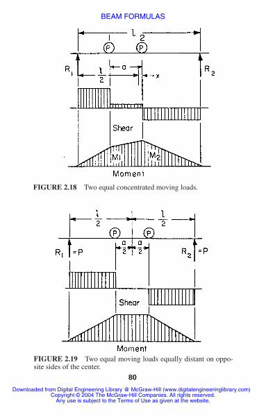
Rolling and moving loads are loads that may change theirposition on a beam or beams. Figure 2.18 shows a beamwith two equal concentrated moving loads, such as twowheels on a crane girder, or the wheels of a truck on abridge. Because the maximum moment occurs where theshear is zero, the shear diagram shows that the maximummoment occurs under a wheel. Thus, with x � a/2:
M2 max when x � a
M1 max when x � a
Figure 2.19 shows the condition when two equal loadsare equally distant on opposite sides of the center of thebeam. The moment is then equal under the two loads.
Mmax �Pl
2 �1 �a
2l �2
�P
2l �l �a
2 �2
3�4
1�4
M1 �Pl
2 �1 �a
l�
2a2
l 2 �2x
l
3a
l�
4x2
l 2 �
R2 � P �1 �2x
l�
a
l �
M2 �Pl
2 �1 �a
l�
2x
l
a
l�
4x2
l 2 �
R1 � P �1 �2x
l�
a
l �
Downloaded from Digital Engineering Library @ McGraw-Hill (www.digitalengineeringlibrary.com)Copyright © 2004 The McGraw-Hill Companies. All rights reserved.
Any use is subject to the Terms of Use as given at the website.
BEAM FORMULAS
80
FIGURE 2.18 Two equal concentrated moving loads.
FIGURE 2.19 Two equal moving loads equally distant on oppo-site sides of the center.
Downloaded from Digital Engineering Library @ McGraw-Hill (www.digitalengineeringlibrary.com)Copyright © 2004 The McGraw-Hill Companies. All rights reserved.
Any use is subject to the Terms of Use as given at the website.
BEAM FORMULAS

BEAM FORMULAS 81
If two moving loads are of unequal weight, the condi-tion for maximum moment is the maximum moment occur-ring under the heavier wheel when the center of the beambisects the distance between the resultant of the loads andthe heavier wheel. Figure 2.20 shows this position and theshear and moment diagrams.
When several wheel loads constituting a system are on abeam or beams, the several wheels must be examined inturn to determine which causes the greatest moment. Theposition for the greatest moment that can occur under a given
FIGURE 2.20 Two moving loads of unequal weight.
Downloaded from Digital Engineering Library @ McGraw-Hill (www.digitalengineeringlibrary.com)Copyright © 2004 The McGraw-Hill Companies. All rights reserved.
Any use is subject to the Terms of Use as given at the website.
BEAM FORMULAS

wheel is, as stated earlier, when the center of the spanbisects the distance between the wheel in question and theresultant of all loads then on the span. The position for max-imum shear at the support is when one wheel is passing offthe span.
CURVED BEAMS
The application of the flexure formula for a straight beamto the case of a curved beam results in error. When all“fibers” of a member have the same center of curvature,the concentric or common type of curved beam exists(Fig. 2.21). Such a beam is defined by the Winkler–Bachtheory. The stress at a point y units from the centroidalaxis is
M is the bending moment, positive when it increases curva-ture; y is positive when measured toward the convex side; Ais the cross-sectional area; R is the radius of the centroidalaxis; Z is a cross-section property defined by
Analytical expressions for Z of certain sections are givenin Table 2.4. Z can also be found by graphical integrationmethods (see any advanced strength book). The neutralsurface shifts toward the center of curvature, or inside fiber,an amount equal to e � ZR/(Z � 1). The Winkler–Bach
Z � �1
A� y
R � ydA
S �M
AR �1 �y
Z (R � y) �
82 CHAPTER TWO
Downloaded from Digital Engineering Library @ McGraw-Hill (www.digitalengineeringlibrary.com)Copyright © 2004 The McGraw-Hill Companies. All rights reserved.
Any use is subject to the Terms of Use as given at the website.
BEAM FORMULAS

83
TA
BLE
2.4
Ana
lytic
al E
xpre
ssio
ns f
or Z
Sect
ion
Exp
ress
ion
A�
2 [(
t�
b)C
1�
bC2]
Z�
�1
�R A�b l
n �R
�C
2
R�
C2��
(t�
b) ln
�R�
C1
R�
C1��
and
A�
tC1
�(b
�t)
C3
�bC
2
Z�
�1
�R A�t ln
(R
�C
1)�
(b�
t) ln
(R
�C
0)�
b ln
(R
�C
2)�
Z�
�1
�2�R r
��R r
�√�
R r�2
�1�
Z�
�1
�R h�ln
R�
C
R�
C�
Downloaded from Digital Engineering Library @ McGraw-Hill (www.digitalengineeringlibrary.com)Copyright © 2004 The McGraw-Hill Companies. All rights reserved.
Any use is subject to the Terms of Use as given at the website.
BEAM FORMULAS

theory, though practically satisfactory, disregards radialstresses as well as lateral deformations and assumes purebending. The maximum stress occurring on the inside fiberis S � Mhi/AeRi, whereas that on the outside fiber is S �Mh0/AeR0.
The deflection in curved beams can be computed bymeans of the moment-area theory.
The resultant deflection is then equal to in the direction defined by Deflections canalso be found conveniently by use of Castigliano’s theorem.It states that in an elastic system the displacement in thedirection of a force (or couple) and due to that force (or cou-ple) is the partial derivative of the strain energy with respectto the force (or couple).
A quadrant of radius R is fixed at one end as shown inFig. 2.22. The force F is applied in the radial direction atfree-end B. Then, the deflection of B is
tan � � y / x.0 � √2
x � 2y
FIGURE 2.21 Curved beam.
84 CHAPTER TWO
Downloaded from Digital Engineering Library @ McGraw-Hill (www.digitalengineeringlibrary.com)Copyright © 2004 The McGraw-Hill Companies. All rights reserved.
Any use is subject to the Terms of Use as given at the website.
BEAM FORMULAS

By moment area,
y � R sin � x � R(1 � cos �)
ds � Rd� M � FR sin �
and
at
By Castigliano,
Bx �FR3
4EI By � �
FR3
2EI
� 32.5�
� tan�1 2
�x � tan�1 ��FR3
2EI�
4EI
FR3 �
B �FR3
2EI √1 �2
4
Bx �FR3
4EI By � �
FR3
2EI
FIGURE 2.22 Quadrant with fixed end.
BEAM FORMULAS 85
Downloaded from Digital Engineering Library @ McGraw-Hill (www.digitalengineeringlibrary.com)Copyright © 2004 The McGraw-Hill Companies. All rights reserved.
Any use is subject to the Terms of Use as given at the website.
BEAM FORMULAS

Eccentrically Curved Beams
These beams (Fig. 2.23) are bounded by arcs having differ-ent centers of curvature. In addition, it is possible for eitherradius to be the larger one. The one in which the sectiondepth shortens as the central section is approached may becalled the arch beam. When the central section is thelargest, the beam is of the crescent type.
Crescent I denotes the beam of larger outside radius andcrescent II of larger inside radius. The stress at the centralsection of such beams may be found from S � KMC/I.In the case of rectangular cross section, the equationbecomes S � 6KM/bh2, where M is the bending moment, bis the width of the beam section, and h its height. The stressfactors, K for the inner boundary, established from photo-elastic data, are given in Table 2.5. The outside radius
86 CHAPTER TWO
FIGURE 2.23 Eccentrically curved beams.
Downloaded from Digital Engineering Library @ McGraw-Hill (www.digitalengineeringlibrary.com)Copyright © 2004 The McGraw-Hill Companies. All rights reserved.
Any use is subject to the Terms of Use as given at the website.
BEAM FORMULAS

BEAM FORMULAS 87
TABLE 2.5 Stress Factors for Inner Boundary at Central Section
(see Fig. 2.23)
1. For the arch-type beams
(a)
(b)
(c) In the case of larger section ratios use the equivalent beamsolution
2. For the crescent I-type beams
(a)
(b)
(c)
3. For the crescent II-type beams
(a)
(b)
(c) K � 1.081 � h
Ro � Ri�
0.0270 if Ro � Ri
h� 20
K � 1.119 � h
Ro � Ri�
0.0378 if 8 �Ro � Ri
h� 20
K � 0.897 � 1.098h
Ro � Ri
if Ro � Ri
h� 8
K � 1.092 � h
Ro � Ri�
0.0298 if Ro � Ri
h� 20
K � 0.959 � 0.769h
Ro � Ri
if 2 �Ro � Ri
h� 20
K � 0.570 � 1.536h
Ro � Ri
if Ro � Ri
h� 2
K � 0.899 � 1.181h
Ro � Ri
if 5 �Ro � Ri
h� 10
K � 0.834 � 1.504h
Ro � Ri
if Ro � Ri
h� 5
is denoted by Ro and the inside by Ri. The geometry ofcrescent beams is such that the stress can be larger in off-center sections. The stress at the central section determinedabove must then be multiplied by the position factor k,
Downloaded from Digital Engineering Library @ McGraw-Hill (www.digitalengineeringlibrary.com)Copyright © 2004 The McGraw-Hill Companies. All rights reserved.
Any use is subject to the Terms of Use as given at the website.
BEAM FORMULAS

88 CHAPTER TWO
given in Table 2.6. As in the concentric beam, the neutralsurface shifts slightly toward the inner boundary. (SeeVidosic, “Curved Beams with Eccentric Boundaries,”Transactions of the ASME, 79, pp. 1317–1321.)
ELASTIC LATERAL BUCKLING OF BEAMS
When lateral buckling of a beam occurs, the beam under-goes a combination of twist and out-of-plane bending(Fig. 2.24). For a simply supported beam of rectangularcross section subjected to uniform bending, buckling occursat the critical bending moment, given by
where L � unbraced length of the member
E � modulus of elasticity
Iy � moment of inertial about minor axis
G � shear modulus of elasticity
J � torsional constant
The critical moment is proportional to both the lateralbending stiffness EIy /L and the torsional stiffness of themember GJ/L.
For the case of an open section, such as a wide-flange orI-beam section, warping rigidity can provide additional tor-sional stiffness. Buckling of a simply supported beam of opencross section subjected to uniform bending occurs at thecritical bending moment, given by
Mcr �
L√EIyGJ
Downloaded from Digital Engineering Library @ McGraw-Hill (www.digitalengineeringlibrary.com)Copyright © 2004 The McGraw-Hill Companies. All rights reserved.
Any use is subject to the Terms of Use as given at the website.
BEAM FORMULAS

TABLE 2.6 Crescent-Beam Position Stress Factors
(see Fig. 2.23)†
Angle �,k
degree Inner Outer
10 1 � 0.055 H/h 1 � 0.03 H/h20 1 � 0.164 H/h 1 � 0.10 H/h30 1 � 0.365 H / h 1 � 0.25 H/h40 1 � 0.567 H / h 1 � 0.467 H/h
50 1 � 0.733 H/h
60 1 � 1.123 H/h
70 1 � 1.70 H/h
80 1 � 2.383 H/h
90 1 � 3.933 H/h
†Note: All formulas are valid for 0 � H/h 0.325. Formulas for the innerboundary, except for 40 degrees, may be used to H/h 0.36. H � distancebetween centers.
2.531 �(0.2939 � 0.7084 H/h)1/2
0.3542
2.070 �(0.4817 � 1.298 H/h)1/2
0.6492
1.756 �(0.2416 � 0.6506 H/h)1/2
0.6506
1.521 �(0.5171 � 1.382 H/h)1/2
1.382
where Cw is the warping constant, a function of cross-sectional shape and dimensions (Fig. 2.25).
In the preceding equations, the distribution of bendingmoment is assumed to be uniform. For the case of a nonuni-form bending-moment gradient, buckling often occurs at
Mcr �
L √EIy �GJ � ECw
2
L2
BEAM FORMULAS 89
Downloaded from Digital Engineering Library @ McGraw-Hill (www.digitalengineeringlibrary.com)Copyright © 2004 The McGraw-Hill Companies. All rights reserved.
Any use is subject to the Terms of Use as given at the website.
BEAM FORMULAS
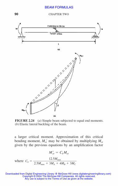
90 CHAPTER TWO
FIGURE 2.24 (a) Simple beam subjected to equal end moments.(b) Elastic lateral buckling of the beam.
a larger critical moment. Approximation of this criticalbending moment, Mcr� may be obtained by multiplying Mcr
given by the previous equations by an amplification factor
where Cb �12.5Mmax
2.5Mmax � 3MA � 4MB � 3MC
M �cr � Cb Mcr
Downloaded from Digital Engineering Library @ McGraw-Hill (www.digitalengineeringlibrary.com)Copyright © 2004 The McGraw-Hill Companies. All rights reserved.
Any use is subject to the Terms of Use as given at the website.
BEAM FORMULAS

BEAM FORMULAS 91
and Mmax � absolute value of maximum moment in theunbraced beam segment
MA � absolute value of moment at quarter point ofthe unbraced beam segment
MB � absolute value of moment at centerline of theunbraced beam segment
MC � absolute value of moment at three-quarterpoint of the unbraced beam segment
FIGURE 2.25 Torsion-bending constants for torsional buckling.A � cross-sectional area; Ix � moment of inertia about x–x axis;Iy � moment of inertia about y–y axis. (After McGraw-Hill, NewYork). Bleich, F., Buckling Strength of Metal Structures.
Downloaded from Digital Engineering Library @ McGraw-Hill (www.digitalengineeringlibrary.com)Copyright © 2004 The McGraw-Hill Companies. All rights reserved.
Any use is subject to the Terms of Use as given at the website.
BEAM FORMULAS

Cb equals 1.0 for unbraced cantilevers and for memberswhere the moment within a significant portion of theunbraced segment is greater than, or equal to, the larger ofthe segment end moments.
COMBINED AXIAL AND BENDING LOADS
For short beams, subjected to both transverse and axialloads, the stresses are given by the principle of superpositionif the deflection due to bending may be neglected withoutserious error. That is, the total stress is given with sufficientaccuracy at any section by the sum of the axial stress andthe bending stresses. The maximum stress, lb/in2 (MPa),equals
where P � axial load, lb (N )
A � cross-sectional area, in2 (mm2)
M � maximum bending moment, in lb (Nm)
c � distance from neutral axis to outermost fiber atthe section where maximum moment occurs,in (mm)
I � moment of inertia about neutral axis at thatsection, in4 (mm4)
When the deflection due to bending is large and the axial load produces bending stresses that cannot be neglect-ed, the maximum stress is given by
f �P
A�
Mc
I
92 CHAPTER TWO
Downloaded from Digital Engineering Library @ McGraw-Hill (www.digitalengineeringlibrary.com)Copyright © 2004 The McGraw-Hill Companies. All rights reserved.
Any use is subject to the Terms of Use as given at the website.
BEAM FORMULAS

BEAM FORMULAS 93
where d is the deflection of the beam. For axial compres-sion, the moment Pd should be given the same sign as M;and for tension, the opposite sign, but the minimum valueof M � Pd is zero. The deflection d for axial compressionand bending can be closely approximated by
where do � deflection for the transverse loading alone, in(mm); and Pc � critical buckling load 2EI / L2, lb (N).
UNSYMMETRICAL BENDING
When a beam is subjected to loads that do not lie in a planecontaining a principal axis of each cross section, unsym-metrical bending occurs. Assuming that the bending axis ofthe beam lies in the plane of the loads, to preclude torsion,and that the loads are perpendicular to the bending axis, topreclude axial components, the stress, lb/in2 (MPa), at anypoint in a cross section is
where Mx � bending moment about principal axis XX,in lb (Nm)
My � bending moment about principal axis YY,in lb (Nm)
f �Mx y
Ix
�My x
Iy
d �do
1 � (P/Pc)
f �P
A� (M � Pd)
c
I
Downloaded from Digital Engineering Library @ McGraw-Hill (www.digitalengineeringlibrary.com)Copyright © 2004 The McGraw-Hill Companies. All rights reserved.
Any use is subject to the Terms of Use as given at the website.
BEAM FORMULAS

94 CHAPTER TWO
x � distance from point where stress is to becomputed to YY axis, in (mm)
y � distance from point to XX axis, in (mm)
Ix � moment of inertia of cross section about XX,in (mm4)
Iy � moment of inertia about YY, in (mm4)
If the plane of the loads makes an angle � with a principalplane, the neutral surface forms an angle � with the otherprincipal plane such that
ECCENTRIC LOADING
If an eccentric longitudinal load is applied to a bar in theplane of symmetry, it produces a bending moment Pe,where e is the distance, in (mm), of the load P from thecentroidal axis. The total unit stress is the sum of thismoment and the stress due to P applied as an axial load:
where A � cross-sectional area, in2 (mm2)
c � distance from neutral axis to outermost fiber, in(mm)
f �P
A�
Pec
I�
P
A �1 �ec
r 2 �
tan � �Ix
Iy
tan �
Downloaded from Digital Engineering Library @ McGraw-Hill (www.digitalengineeringlibrary.com)Copyright © 2004 The McGraw-Hill Companies. All rights reserved.
Any use is subject to the Terms of Use as given at the website.
BEAM FORMULAS

BEAM FORMULAS 95
I � moment of inertia of cross section about neutralaxis, in4 (mm4)
r � radius of gyration � , in (mm)
Figure 2.1 gives values of the radius of gyration for severalcross sections.
If there is to be no tension on the cross section undera compressive load, e should not exceed r2/c. For a rectangularsection with width b, and depth d, the eccentricity, there-fore, should be less than b/6 and d/6 (i.e., the load shouldnot be applied outside the middle third). For a circular crosssection with diameter D, the eccentricity should not exceedD/8.
When the eccentric longitudinal load produces a deflec-tion too large to be neglected in computing the bendingstress, account must be taken of the additional bendingmoment Pd, where d is the deflection, in (mm). This deflec-tion may be closely approximated by
Pc is the critical buckling load 2EI/L2, lb (N).If the load P, does not lie in a plane containing an axis
of symmetry, it produces bending about the two principalaxes through the centroid of the section. The stresses, lb/in2
(MPa), are given by
where A � cross-sectional area, in2 (mm2)
ex � eccentricity with respect to principal axis YY,in (mm)
f �P
A�
Pexcx
Iy
�Peycy
Ix
d �4eP/Pc
(1 � P/Pc)
√I/A
Downloaded from Digital Engineering Library @ McGraw-Hill (www.digitalengineeringlibrary.com)Copyright © 2004 The McGraw-Hill Companies. All rights reserved.
Any use is subject to the Terms of Use as given at the website.
BEAM FORMULAS

96 CHAPTER TWO
ey � eccentricity with respect to principal axis XX,in (mm)
cx � distance from YY to outermost fiber, in (mm)
cy � distance from XX to outermost fiber, in (mm)
Ix � moment of inertia about XX, in4 (mm4)
Iy � moment of inertia about YY, in4 (mm4)
The principal axes are the two perpendicular axes throughthe centroid for which the moments of inertia are a maxi-mum or a minimum and for which the products of inertiaare zero.
NATURAL CIRCULAR FREQUENCIESAND NATURAL PERIODS OF VIBRATION OF PRISMATIC BEAMS
Figure 2.26 shows the characteristic shape and gives con-stants for determination of natural circular frequency � andnatural period T, for the first four modes of cantilever,simply supported, fixed-end, and fixed-hinged beams. Toobtain �, select the appropriate constant from Fig. 2.26 and multiply it by . To get T, divide the appropriate constant by .
In these equations,
� � natural frequency, rad/s
W � beam weight, lb per linear ft (kg per linear m)
L � beam length, ft (m)
√EI/wL4√EI/wL4
Downloaded from Digital Engineering Library @ McGraw-Hill (www.digitalengineeringlibrary.com)Copyright © 2004 The McGraw-Hill Companies. All rights reserved.
Any use is subject to the Terms of Use as given at the website.
BEAM FORMULAS

97
FIG
UR
E 2
.26
Coe
ffici
ents
for
com
putin
g na
tura
l ci
rcul
ar f
requ
enci
es a
nd n
atur
al p
erio
ds o
f vi
brat
ion
ofpr
ism
atic
bea
ms.
Downloaded from Digital Engineering Library @ McGraw-Hill (www.digitalengineeringlibrary.com)Copyright © 2004 The McGraw-Hill Companies. All rights reserved.
Any use is subject to the Terms of Use as given at the website.
BEAM FORMULAS

98 CHAPTER TWO
E � modulus of elasticity, lb/in2 (MPa)
I � moment of inertia of beam cross section, in4 (mm4)
T � natural period, s
To determine the characteristic shapes and natural peri-ods for beams with variable cross section and mass, use theRayleigh method. Convert the beam into a lumped-masssystem by dividing the span into elements and assuming themass of each element to be concentrated at its center. Also,compute all quantities, such as deflection and bending moment,at the center of each element. Start with an assumed charac-teristic shape.]
Downloaded from Digital Engineering Library @ McGraw-Hill (www.digitalengineeringlibrary.com)Copyright © 2004 The McGraw-Hill Companies. All rights reserved.
Any use is subject to the Terms of Use as given at the website.
BEAM FORMULAS
Copyright © 2022 FDOKUMEN