System Design Guide Induction Beam Terminals with DOAS
94
System Design Guide Inducon Beam Terminals with DOAS
-
Upload
khangminh22 -
Category
Documents
-
view
1 -
download
0
Transcript of System Design Guide Induction Beam Terminals with DOAS

System Design GuideInduction Beam Terminals with DOAS
ActivAIR_Design-Guide_w-Cover_2014-09-09.indd 1 9/9/14 5:21 PM

System Design Guide / Induction Beam Terminals with DOAS2
The information in this manual is offered as a general guide for the use of industry and consulting engineers in designing systems. Judgement is required for application of this information to specific installations and design applications. Carrier is not responsible for any uses made of this information and assumes no responsibility for the performance or desirability of any resulting system design.
The information in this publication is subject to change without notice. No part of this publication may be reproduced or transmitted in any form by any means, electronic or mechanical, for any purpose, without the express written permission of Carrier Corporation.
ActivAIR_Design-Guide_w-Cover_2014-09-09.indd 2 9/9/14 5:21 PM

System Design Guide / Induction Beam Terminals with DOAS 1
TABLE OF CONTENTSPREVIEW .................................................................................................................................................................................... 3
EVOLVING HVAC SYSTEM DESIGN GOALS .................................................................................................................................. 5
Healthy, Energy-Efficient Buildings ............................................................................................................................................. 5
Energy-Efficient HVAC Systems .................................................................................................................................................. 5
The Induction Beam Advantage ................................................................................................................................................ 5
INDUCTION BEAM + DOAS SYSTEM COMPONENTS .................................................................................................................. 8
DESIGN SEQUENCE .................................................................................................................................................................... 9
Designing the Induction Beam System ....................................................................................................................................... 9
Step 1 - Examine System Criteria .............................................................................................................................................. 10
Step 2 - Gather Building Data ................................................................................................................................................... 11a. Primary School Building Example .................................................................................................................................. 11
Primary School Building – PNNL Benchmark Building Scoresheet Data .................................................................. 12
b. Large Office Building Example ....................................................................................................................................... 13Large Office Building – PNNL Benchmark Building Scoresheet Data ....................................................................... 13
c. Getting Started with HAP ............................................................................................................................................... 14
Step 3 - Calculate the Cooling, Heating, Dehumidifying, and Ventilating Loads ..................................................................... 15a. Calculating Loads ............................................................................................................................................................ 15
i. Load Estimating Approach .............................................................................................................................. 15ii. Space Cooling and Heating Loads ................................................................................................................... 22iii. Outdoor Air Ventilating Loads ......................................................................................................................... 24iv. Space Dehumidifying Loads ............................................................................................................................ 25v. System Primary Air and Water Requirements ................................................................................................ 27vi. Design Load Summary .................................................................................................................................... 27
Step 4 - Make Selections of Induction Terminals ..................................................................................................................... 35a. Induction Beam Products ............................................................................................................................................... 35
i. Induction Beam Operation ............................................................................................................................. 35 ii. Unique Features of Induction Beams ............................................................................................................. 35 iii. Basic Styles of Induction Beam Terminals ....................................................................................................... 36 iv. Additional Product Features ........................................................................................................................... 37
b. Terminal Selection .......................................................................................................................................................... 39 i. IB Terminal Styles ........................................................................................................................................... 39 ii. Data for Terminal Selection ............................................................................................................................. 39
c. Using Carrier E-CAT Software for Terminal Selection .................................................................................................... 40 i. Classroom Example ......................................................................................................................................... 40 ii. Corridor Example............................................................................................................................................. 44 iii. Office Example ................................................................................................................................................ 47 iv. Finalizing Selections ........................................................................................................................................ 49
Step 5 - Make Selections of DOAS Ventilating Units ................................................................................................................ 50a. Ventilation Equipment Selection .................................................................................................................................... 50b. Ventilation Equipment Products .................................................................................................................................... 50
i. Consideration of Energy Recovery .................................................................................................................. 51 ii. Zoning and Layout ........................................................................................................................................... 51
c. Using Carrier E-CAT Software for Ventilation Equipment Selection ....................................................................................................................................................... 52
i. Direct Expansion DOAS Unit Selection ............................................................................................................ 53 ii. Chilled Water DOAS Air-Handler Unit Selection ............................................................................................. 58 iii. Finalizing Selections ........................................................................................................................................ 62
ActivAIR_Design-Guide_w-Cover_2014-09-09.indd 1 9/9/14 5:22 PM

System Design Guide / Induction Beam Terminals with DOAS2
Step 6 - Design the Air Distribution System (Terminal Layout and Duct Design) ..................................................................... 63a. Terminal Layout ............................................................................................................................................................. 63
i. 1-Way Blow Units ............................................................................................................................................ 63 ii. 2-Way Blow Units ............................................................................................................................................ 63 iii. All-Way Blow Units .......................................................................................................................................... 63 iv. Layout examples ............................................................................................................................................. 64
b. Duct Design .................................................................................................................................................................... 65 i. Layout .............................................................................................................................................................. 67 ii. Sizing ............................................................................................................................................................... 69
Step 7 - Design the Hydronic System ....................................................................................................................................... 71a. Types of Piping Systems ................................................................................................................................................. 71
i. Closed-Loop Systems ...................................................................................................................................... 71 ii. Open-Loop Systems ........................................................................................................................................ 72 iii. Once-Thru Systems ......................................................................................................................................... 72
b. Water Distribution Systems............................................................................................................................................ 72 i. 1-Pipe Systems (Heating Only) ........................................................................................................................ 72 ii. 2-Pipe Systems ................................................................................................................................................ 73 iii. 3-Pipe Systems ................................................................................................................................................ 73 iv. 4-Pipe Systems ................................................................................................................................................ 74
c. Water Piping Components and Accessories .................................................................................................................. 74 i. Pipe, Joints and Fittings ................................................................................................................................... 75 ii. Valves .............................................................................................................................................................. 75 iii. System Components ...................................................................................................................................... 77
d. System Piping Arrangements ......................................................................................................................................... 79 i. VAVR (Variable Air Volume Reheat) System .................................................................................................... 79 ii. ACB System ..................................................................................................................................................... 80 iii. IB System, Version 1 ........................................................................................................................................ 81 iv. IB System, Version 2 ........................................................................................................................................ 82 v. IB System, Version 3 ........................................................................................................................................ 83 vi. Water Economizer ........................................................................................................................................... 83
e. Pipe Sizing and Pump Selection .................................................................................................................................... 84
Step 8 - Design the Control System .......................................................................................................................................... 85a. Space Set Point Temperatures (°F, db / wb) ................................................................................................................... 85b. Schedules (Occupancy / Lights / Equipment / System / Space / Plant) ......................................................................... 85c. Primary Air Temperatures (°F, db / wb) .......................................................................................................................... 86d. Primary Airflow (cfm) ..................................................................................................................................................... 86e. Inlet Static Pressure of the Primary Airflow (in. wg) ...................................................................................................... 86f. Entering Chilled Water Supply Temperature (°F, CHWS) ................................................................................................ 86g. Entering Condenser Water Supply Temperature (°F, CWS) ........................................................................................... 86h. Economizer Control ........................................................................................................................................................ 87i. Entering Heating Water Supply Temperature (°F, HWS) ................................................................................................ 87j. Entering Waterflows and Pumping (gpm) ..................................................................................................................... 87k. Space Moisture Level (% rh) ........................................................................................................................................... 87
JOB SITE SUGGESTIONS ............................................................................................................................................................... 88On-Site Conditions.................................................................................................................................................................... 88
Prevention of Noise and Vibration Problems ........................................................................................................................... 88
Ductwork Construction ............................................................................................................................................................ 89
Drain Piping .............................................................................................................................................................................. 89
Installation and Start-Up .......................................................................................................................................................... 90
Operation and Maintenance .................................................................................................................................................... 90
ActivAIR_Design-Guide_w-Cover_2014-09-09.indd 2 9/9/14 5:22 PM

System Design Guide / Induction Beam Terminals with DOAS 3
PREVIEW
LEGEND
1 Primary air from dedicated outdoor air source enters terminal2 Specialized nozzles increase velocity at low noise levels3 Return grille for drawing in room air4 Room air passes over coil and mixes with primary air5 Mixed air is discharged through louvers
This system design guide reintroduces a system that had provided building heating, ventilating, and air conditioning for many decades. Many things have changed since perimeter induction went out of favor, but a new version is now available to meet today’s needs and provide flexibility for tomorrow. The changes that have brought induction terminals once again to the forefront of HVAC systems are: 1) improvements in nozzle design that lower both generated sound and required inlet pressure, 2) the ability to handle both sensible and latent loads at the zone, and 3) the use of energy recovery ventilator dedicated outdoor air systems to supply the primary air. The modern induction system offers significantly lower energy usage intensities (EUI), with kBtu/sq ft values as low as the best systems commonly used today in commercial buildings.
Today’s induction beam (IB) terminals operate in a manner similar to active chilled beams (refer to item numbers in Figure 1). The IB terminals utilize low-pressure primary air that is ducted (1) from a dedicated outdoor air system (DOAS) to drive induction of the return air from the space. The primary air is discharged through a bank of nozzles (2) in the induction beam terminal plenum. The nozzles increase the velocity of the discharge air, creating a velocity pressure differential, which enables a draw of room air (3) across a coil (4). The coil imparts either cooling (sensible and latent) or heating to the induced air as it passes over the coil, after which it mixes with the primary air and enters the room (5) as supply air.
Figure 1 — Induction Beam Operation
ActivAIR_Design-Guide_w-Cover_2014-09-09.indd 3 9/9/14 5:22 PM

System Design Guide / Induction Beam Terminals with DOAS4
PREVIEW
The primary difference between the induction beam and active chilled beam is that the induction beam configuration allows higher capacity coils with drain pans to be included in the terminal device. An integrated drain pan eliminates the risk of condensation leaking into the space when latent loads fluctuate. The drain pan also allows the specifying professional to design the system for use with chilled water that is below the dew point of the space. The ability to use colder water means that a greater cooling capacity can be produced by each individual induction beam unit, while reducing chilled water distribution piping size and pump size. These features also enable induction beams to be used in a wide variety of applications, making them an excellent choice for buildings where indoor air quality, energy efficiency, and zone level control are priorities.
The induction beam with dedicated outdoor air system (IB + DOAS) is inherently simple and therefore easy to design. The purpose of this publication is to serve as a practical and comprehensive working guide for those involved in designing, selecting, and installing IB + DOAS systems.
We wish to acknowledge the help given by those in the field whose working experience with this reintroduction of Carrier’s perimeter conduit induction system has been invaluable in preparing this material.
For this system design guide we will be using Carrier’s eDesign Suite of HVAC-design and E-CAT equipment-selection software programs. Our modeling examples use the Hourly Analysis Program (HAP) version 4.8 and assume the user either has a basic level of experience with the program, is concurrently reading a HAP tutorial, or has received help from the local Carrier Sales Engineer.
A copy of the completed HAP archive for the building example can be downloaded to follow along with the system design guide. Go to http://www.docs.hvacpartners.com/idc/groups/public/documents/software/HAP48-SCHOOL-IB-EXAMPLE.E3A to download the HAP v4.8 archive for this building project.
ActivAIR_Design-Guide_w-Cover_2014-09-09.indd 4 9/9/14 5:22 PM

System Design Guide / Induction Beam Terminals with DOAS 5
Healthy, Energy-Efficient Buildings
As we evolve towards net-zero energy buildings, the HVAC system will be required to produce far less heating and cooling per square foot than even 20 years ago. At the same time, the number of people occupying the space is changing. The number of persons per 1,000 square feet in code references like ASHRAE’s Indoor Air Quality (IAQ) standard has not changed in over a decade. However, industry trends report decreasing square feet per office worker as more employers adopt mobile work options and open office floor plans. IAQ (indoor air quality) is even more important than before. We are working diligently to reduce indoor-generated pollutants, just as we did with outside pollutants in the 1980s and 1990s, but both remain issues (Figure 2). Proper ventilation and filtration are key factors in providing superior occupant comfort, supporting occupant productivity, and guarding overall health. This is where a system using induction beam zoning terminals with a dedicated outdoor air ventilation system (DOAS) can excel. The DOAS system provides a measurable and consistent amount of outdoor air to satisfy the ventilation requirements of all the spaces. It is not possible to measure directly the ventilation air at the zone level with a VAV system. The ventilation air is measured at the air-handling unit in a VAV system and mixed with return air; then the mixed air is provided to the space. Because VAV systems
provide a mixture of outdoor air and return air to each space, VAV systems must often utilize more outdoor air than a DOAS system in order to meet the ventilation requirements of the most critical space as defined in ASHRAE 62.1. Utilizing an induction terminal with DOAS system, no return air is recirculated back into the building, so cross-contamination between zones is minimized.
Energy-Efficient HVAC Systems
Ever since society’s level of energy awareness began increasing in the early 1970s, building codes have become stricter and more focused on reducing the energy needed to power HVAC systems. After decades of sustained effort, we have reached a point of diminishing returns for increasing the efficiency of individual heating and cooling units. Building envelopes and lighting systems are also reaching maximum levels of affordable improvement. Attention has rightly turned towards systems and integrated design to squeeze every ounce of work out of the power required to
operate the HVAC systems that are traditionally responsible for a full third of the energy bill in a typical office building. The HVAC subsystems that offer the best opportunity for realizing sought-after improvements are energy transfer, fans and ductwork, and pumps and piping. These prime movers usually run continuously during the occupied period, so every incremental gain multiplies across many hours. As we move through the design process for an IB + DOAS system, the improvements possible in fan and pump energy efficiency will become apparent.
The Induction Beam Advantage
Carrier’s new ActivAIR™ induction beam zoning terminal allows the design of an HVAC system that competes favorably with traditional commercial zoning systems like VAV and newer systems like active chilled beams (ACB) for new construction and retrofit.
Induction beams circulate primary air mixed with room return air, quietly turning over the space for greater levels of draft-free occupant comfort than is achieved with most other common systems. Induction beam systems are ideal for use in high cooling load applications and where constant room air circulation is desired to assist in providing closer temperature control. With the ability to provide both
sensible and latent cooling, the induction beam delivers more capacity per unit than sensible-only active chilled beams, so spaces can be conditioned using fewer units. The only control needed is a simple space dry bulb thermostat connected to the coil control valves. The IB terminal also has no moving parts, and requires only minimal maintenance from the occupied space, making it ideal for dormitories and other applications where occupant privacy must be considered. Table 1 compares the features of the induction beam system to features of competing systems.
Figure 2 — Indoor Air Quality & HVAC Systems
EVOLVING HVAC SYSTEM DESIGN GOALS
ActivAIR_Design-Guide_w-Cover_2014-09-09.indd 5 9/9/14 5:22 PM

System Design Guide / Induction Beam Terminals with DOAS6
Table 1 - System Features Comparison
Feature Induction Beam Active Chilled Beam Variable Air Volume Room Fan-CoilIAQ Level Constant, measurable
ventilation air to the space
Building humidity is controlled
Once through airside system
Average efficiency MERV 6 and 8 filters available
Constant, measurable ventilation air to the space
Building humidity is controlled
Once through airside system
Filters generally not available
Ventilation air is not measurable at the space level due to the mixture of ventilation and return air provided
Humidity control is generally not used on a VAV system
Cross-contamination of spaces is possible
High efficiency MERV 11 and 13 filters available
Inconsistent ventilation air delivered to the space as fan speed varies when DOAS is not used
Humidity control is generally not used on a fan-coil system
NA
High efficiency MERV 11 and 13 filters available
Energy Usage May require over-ventilation of the space to meet cooling load requirements
DOAS can cycle on demand during unoccupied hours to maintain building set points
Chiller efficiency gained by using warmer water for cooling at the beams
Often requires over-ventilation of the space to meet cooling load requirements
Constant volume DOAS operates 24/7 to maintain humidity levels in the space
Chiller efficiency gained by using warmer water for cooling at the beams
May require over-ventilation of the spaces to meet the ventilation requirement of the critical space
Fan operation varies based on demand and occupancy schedule
Significant fan energy saving is possible
NA
DOAS only operates when ventilation is required, with terminal fans cycling on demand to maintain space set points
Energy-efficient motors are now available in fan-coil units
Zone-ability Occupant control of each space is possible since beams are installed in each space
Occupant control of each space is possible since beams are installed in each space
Multiple spaces are typically served by a single VAV box, not allowing occupant control of each space individually
Occupant control of each space is possible with one or more fan-coil units installed in each space
Zone Latent Control
Using chilled water to the beams, and taking advantage of the integral drain pan, the DOAS provides neutral air to the space and zone latent cooling can be accomplished by the cooling coil in the beam
Sensible only beams do not have the ability to provide latent cooling in the zone
Zone latent loads are controlled by dehumidification of the primary air
Fluctuating latent loads in the zone can cause condensation in the space or can force the cooling coil in the beam to be disabled
Dehumidification is accomplished at the AHU unit
Not effective at controlling humidity in zones with high latent loads
Fan-coil units have the ability to provide latent cooling in the zone
EVOLVING HVAC SYSTEM DESIGN GOALS
ActivAIR_Design-Guide_w-Cover_2014-09-09.indd 6 9/9/14 5:22 PM

System Design Guide / Induction Beam Terminals with DOAS 7
Feature Induction Beam Active Chilled Beam Variable Air Volume Room Fan-CoilTypical Terminal Unit Controls
Space temperature sensor connected to a hydronic coil control valve for the beams
Optional 2-position damper for reducing airflow based on occupancy scheduling
Space temperature sensor connected to a hydronic coil control valve for the beams
NA
Means to prevent condensation in the space, such as a condensate sensor on the chilled water supply pipe to the beams
Space temperature sensor connected to DDC controller on the VAV box
Optional occupancy sensor (CO2) for demand controlled ventilation
Thermostat capable of controlling fan speed and hydronic coil control valves
Recommended Maintenance Required within the Occupied Space
Periodic cleaning of the coil
Periodic changing of filters
Periodic inspection and possible cleaning of condensate drain pan
Periodic inspection of controls
Periodic cleaning of the coil
Periodic inspection of controls
Periodic inspection of controls
Periodic cleaning of the coil
Periodic changing of filters
Periodic inspection of condensate drain pan Periodic inspection of electrical wiring and controls
Periodic cleaning of blower wheel and housing
Equipment Installation Considerations
NA Avoid areas with fluctuating or high latent zone loads
Large ductwork requires significant space above the ceiling Unit fluctuation of airflow may be acoustically objectionable in some applications
Floor-mounted units may occupy valuable floor space Unit fan motor noise may be objectionable in some applications
LEGENDAHU – Air-handling unitDDC – Direct digital controlDOAS – Dedicated outdoor air systemIAQ – Indoor air qualityMERV – Minimum efficiency reporting valueNA – Not applicableVAV – Variable air volume
Table 1 - System Features Comparison, cont.
EVOLVING HVAC SYSTEM DESIGN GOALS
ActivAIR_Design-Guide_w-Cover_2014-09-09.indd 7 9/9/14 5:22 PM
System Design Guide / Induction Beam Terminals with DOAS8
INDUCTION BEAM + DOAS SYSTEM COMPONENTS
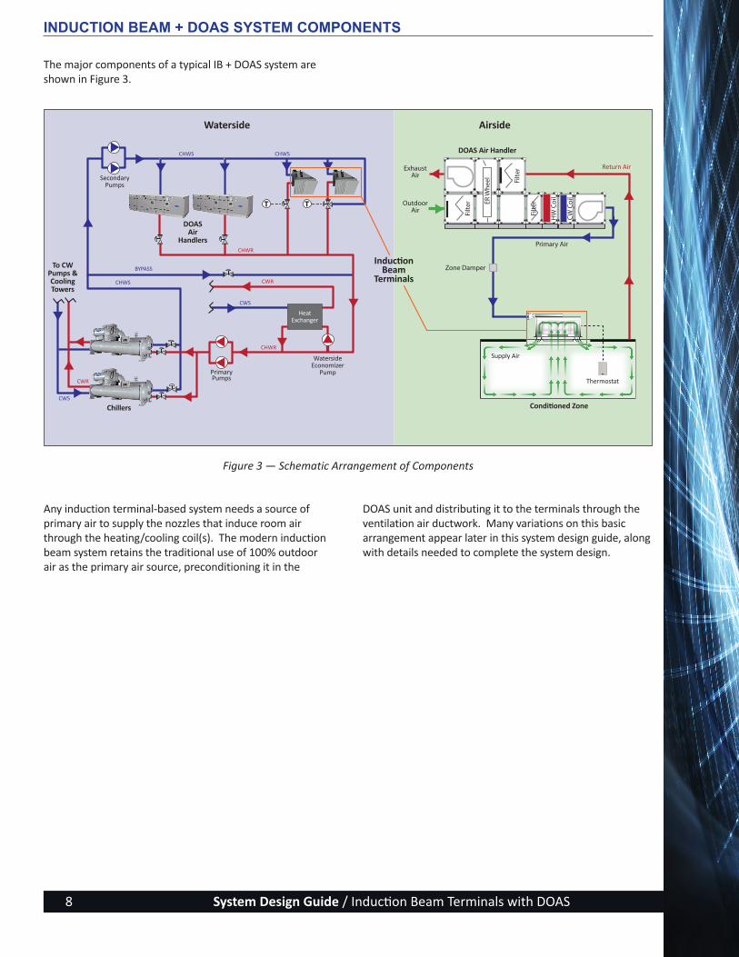
The major components of a typical IB + DOAS system are shown in Figure 3.
Figure 3 — Schematic Arrangement of Components
T T
CWS
CWR
CWS
ExhaustAir
Outdoor Air
Zone Damper
Primary Air
Waterside Airside
SecondaryPumps
To CW Pumps &CoolingTowers
Primary Pumps Thermostat
Supply Air
Return Air
CHWR
CWR
CHWS
BYPASS
CHWR
CHWS CHWS
Chillers
DOASAir
Handlers
DOAS Air Handler
Induction Beam
Terminals
Conditioned Zone
WatersideEconomizer
Pump
HeatExchanger
Any induction terminal-based system needs a source of primary air to supply the nozzles that induce room air through the heating/cooling coil(s). The modern induction beam system retains the traditional use of 100% outdoor air as the primary air source, preconditioning it in the
DOAS unit and distributing it to the terminals through the ventilation air ductwork. Many variations on this basic arrangement appear later in this system design guide, along with details needed to complete the system design.
ActivAIR_Design-Guide_w-Cover_2014-09-09.indd 8 9/9/14 5:22 PM

System Design Guide / Induction Beam Terminals with DOAS 9
1
2
3
4
5
6
7
8
Induction Beam Products
Building Data
Terminal Selection
Step Chapter
Cooling & Heating Loads
Ventilation Equipment Selection
System Variations
Terminal Layout & Duct
Design
System Variations
Hydronic Design
System Variations
Controls
System Variations
DESIGN SEQUENCE Designing the Induction Beam System
The following sequence outlines the steps that make the design of the IB + DOAS both simple and effective. Throughout the system design guide, each step is backed by actual calculations related to a Building Example. Each step is keyed to the applicable section of the design guide (Figure 4).
1. Examine the criteria for induction beam systems.2. Gather building data.3. Calculate the cooling, dehumidifying, and
heating loads.4. Make selections of induction terminals.5. Make selections of ventilating units.6. Design the air distribution system (terminals layout
and duct design).7. Design the hydronic system.8. Design the control system.
Figure 4 — Design Sequence Flow Diagram
System Overview
ActivAIR_Design-Guide_w-Cover_2014-09-09.indd 9 9/9/14 5:22 PM

System Design Guide / Induction Beam Terminals with DOAS10
DESIGN SEQUENCE STEP 1Step 1 - Examine System Criteria
This system is a good choice for many buildings, including office buildings, primary and secondary schools, higher education buildings (including dormitories), heat-driven laboratories, nursing and other outpatient healthcare spaces, and governmental facilities. In fact, IB terminals can be used in almost any type of commercial building that has several temperature control zones, proper occupant comfort as a foundational design element, and an owner/operator committed to achieving energy conservation and providing superior IAQ (Indoor Air Quality).
The benefits of using an induction beam with DOAS system include the following:
Flexibility of operation — By nature, IB terminals are small-zone devices, which can be scheduled on-off with the simple addition of a primary air damper to one or more terminals. The DOAS units can be sized to handle less than the whole building, or if a single whole-building unit is chosen, the unit works as a VAV unit, responding to only the active zones.
Lower initial investment — An induction beam-based system will have less ductwork than all-air systems, better kW/ton when higher chilled water temperatures are used, and no electrical power wiring to be run in the conditioned spaces.
Low operating cost — Improved induction nozzle designs, coupled with decreased airflow (often only the ventilation airflow is required for primary air to the terminal), significantly bring down the fan energy usage compared to active chilled beams.
Superior ventilation — As a constant volume terminal using outdoor air for primary air to the induction nozzles, induction beams provide consistent and measurable ventilation air to all spaces during occupied times.
Improved dehumidification — The terminal cooling coil can be supplied with chilled water sufficiently cooled to remove space latent load from people and infiltration, allowing more neutral (within 10⁰ F± of room set point) DOAS primary air to be provided, potentially lowering system energy requirements.
Reduced maintenance — With no electrical or mechanical equipment in the terminal, maintenance in the occupied space is virtually eliminated (beyond normal coil and drain pan cleaning and filter changeout).
ActivAIR_Design-Guide_w-Cover_2014-09-09.indd 10 9/9/14 5:22 PM
System Design Guide / Induction Beam Terminals with DOAS 11
Step 2 - Gather Building Data
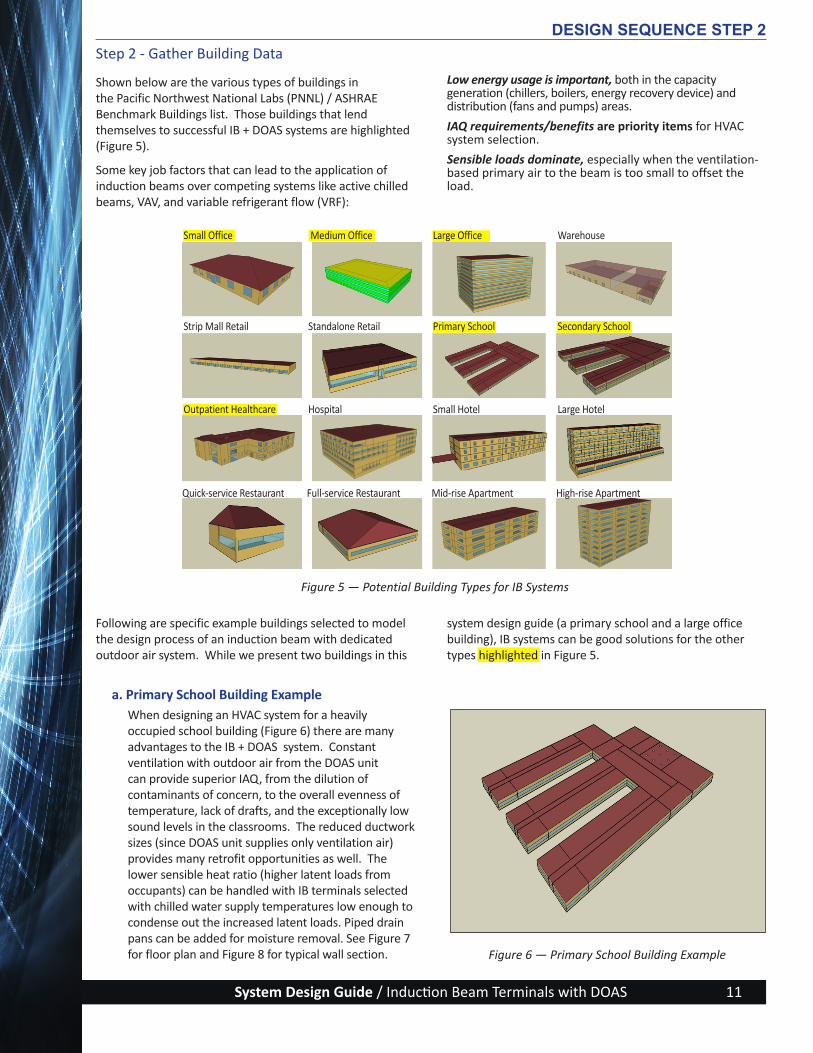
Shown below are the various types of buildings in the Pacific Northwest National Labs (PNNL) / ASHRAE Benchmark Buildings list. Those buildings that lend themselves to successful IB + DOAS systems are highlighted (Figure 5).
Some key job factors that can lead to the application of induction beams over competing systems like active chilled beams, VAV, and variable refrigerant flow (VRF):
Low energy usage is important, both in the capacity generation (chillers, boilers, energy recovery device) and distribution (fans and pumps) areas.
IAQ requirements/benefits are priority items for HVAC system selection.
Sensible loads dominate, especially when the ventilation-based primary air to the beam is too small to offset the load.
DESIGN SEQUENCE STEP 2
Figure 5 — Potential Building Types for IB Systems
Figure 6 — Primary School Building Example
Following are specific example buildings selected to model the design process of an induction beam with dedicated outdoor air system. While we present two buildings in this
system design guide (a primary school and a large office building), IB systems can be good solutions for the other types highlighted in Figure 5.
a. Primary School Building Example When designing an HVAC system for a heavily occupied school building (Figure 6) there are many advantages to the IB + DOAS system. Constant ventilation with outdoor air from the DOAS unit can provide superior IAQ, from the dilution of contaminants of concern, to the overall evenness of temperature, lack of drafts, and the exceptionally low sound levels in the classrooms. The reduced ductwork sizes (since DOAS unit supplies only ventilation air) provides many retrofit opportunities as well. The lower sensible heat ratio (higher latent loads from occupants) can be handled with IB terminals selected with chilled water supply temperatures low enough to condense out the increased latent loads. Piped drain pans can be added for moisture removal. See Figure 7 for floor plan and Figure 8 for typical wall section.
Small Office Medium Office Large Office Warehouse
Strip Mall Retail Standalone Retail Primary School Secondary School
Outpatient Healthcare Hospital Small Hotel Large Hotel
Quick-service Restaurant Full-service Restaurant Mid-rise Apartment High-rise Apartment
ActivAIR_Design-Guide_w-Cover_2014-09-09.indd 11 9/9/14 5:22 PM
System Design Guide / Induction Beam Terminals with DOAS12
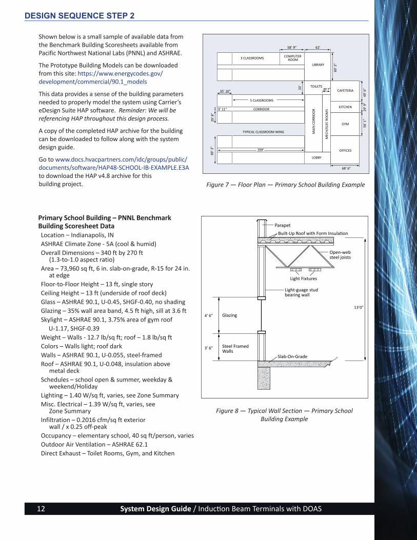
Shown below is a small sample of available data from the Benchmark Building Scoresheets available from Pacific Northwest National Labs (PNNL) and ASHRAE.
The Prototype Building Models can be downloaded from this site: https://www.energycodes.gov/development/commercial/90.1_models
This data provides a sense of the building parameters needed to properly model the system using Carrier’s eDesign Suite HAP software. Reminder: We will be referencing HAP throughout this design process.
A copy of the completed HAP archive for the building can be downloaded to follow along with the system design guide.
Go to www.docs.hvacpartners.com/idc/groups/public/documents/software/HAP48-SCHOOL-IB-EXAMPLE.E3A to download the HAP v4.8 archive for this building project.
Primary School Building – PNNL Benchmark Building Scoresheet DataLocation – Indianapolis, INASHRAE Climate Zone - 5A (cool & humid)Overall Dimensions – 340 ft by 270 ft
(1.3-to-1.0 aspect ratio)Area – 73,960 sq ft, 6 in. slab-on-grade, R-15 for 24 in.
at edgeFloor-to-Floor Height – 13 ft, single storyCeiling Height – 13 ft (underside of roof deck)Glass – ASHRAE 90.1, U-0.45, SHGF-0.40, no shadingGlazing – 35% wall area band, 4.5 ft high, sill at 3.6 ftSkylight – ASHRAE 90.1, 3.75% area of gym roof U-1.17, SHGF-0.39Weight – Walls - 12.7 lb/sq ft; roof – 1.8 lb/sq ftColors – Walls light; roof darkWalls – ASHRAE 90.1, U-0.055, steel-framedRoof – ASHRAE 90.1, U-0.048, insulation above
metal deckSchedules – school open & summer, weekday &
weekend/HolidayLighting – 1.40 W/sq ft, varies, see Zone SummaryMisc. Electrical – 1.39 W/sq ft, varies, see
Zone SummaryInfiltration – 0.2016 cfm/sq ft exterior
wall / x 0.25 off-peakOccupancy – elementary school, 40 sq ft/person, variesOutdoor Air Ventilation – ASHRAE 62.1 Direct Exhaust – Toilet Rooms, Gym, and Kitchen
Figure 8 — Typical Wall Section — Primary School Building Example
DESIGN SEQUENCE STEP 2
13’0”
3’ 6”
4’ 6”
Light Fixtures
Slab-On-Grade
Glazing
Steel Framed Walls
Light-guage stud bearing wall
Open-web steel joists
Built-Up Roof with Form Insulation
Parapet
Figure 7 — Floor Plan — Primary School Building Example
3 CLASSROOMS
5 CLASSROOMS
COMPUTER ROOM
LIBRARY
TOILETS
MA
IN C
ORR
IDO
R
MEC
H/E
LEC
ROO
MS
CAFETERIA
KITCHEN
GYM
OFFICES
LOBBY
CORRIDOR
TYPICAL CLASSROOM WING
58’ 9”
35’ 10”
62’
20’ 7”
68’ 6”
209’
69’ 3
”
49’ 6
”29
’ 9”
56’ 1
”
33’
9’ 11”
29’ 8
”69
’ 3”
ActivAIR_Design-Guide_w-Cover_2014-09-09.indd 12 9/9/14 5:22 PM

System Design Guide / Induction Beam Terminals with DOAS 13
Figure 6 – Unknown, unidentified
13’ 0”
3’ 0”
9’ 0”
13’ 0”
2’ 0”
5’2”
8’6”
PRECAST CONC. PANELS
B.U. ROOF W/ FORM INSUL
STRUC CONC. TEE SECTIONS
STRUC CONC. TEE SECTIONS
LIGHT FIXTURES
LAY IN T-BAR CEILING
TYP
FLR-
TO-F
LR
Exterior Zone
Interior Zone
Corner Zone
b. Large Office Building Example This type of building (Figure 9) is found in center-city renewals and around interstate ring highways of larger metropolitan areas. A variety of owner/operators, from governmental and private offices to developers and real estate investment trusts, all have slightly different demands that influence HVAC system selection. These buildings commonly have much lower occupant density than educational facilities, so using only the DOAS unit outdoor ventilation air for the primary air to the induction-style terminals may prove problematic in overcoming higher sensible heat ratios. This is where the greater capacity coils found with induction beams outperform active chilled beams. See Figure 10 for floor plan and Figure 11 for typical wall section.
Large Office Building – PNNL Benchmark Building Scoresheet DataLocation – Indianapolis, INASHRAE Climate Zone - 5A (cool & humid)Overall Dimensions – 240 ft by 160 ft by 156 ft tallArea – 499,200 sq ftFloor-to-Floor Height – 13 ft (12 story, plus basement)Ceiling Height – 9 ftGlass – ASHRAE 90.1, U-0.45, SHGF-0.40, no shadingGlazing – 40% wall area band, 5.2 ft high, sill at 3 ftWeight – Walls - 95.7 lb/sq ft; roof – 5.8 lb/sq ftColors – Walls dark; roof lightWalls – ASHRAE 90.1, U-0.063, pre-cast concreteRoof – ASHRAE 90.1, U-0.046, insulation above
concrete deckSchedules –Weekday & weekend/HolidayLighting – 0.90 W/sq ftMisc. Electrical – 0.75 W/sq ftInfiltration – 0.75 air changes per hourOccupancy – Office, 275 sq ft/personOutdoor Air Ventilation – ASHRAE 62.1 Direct Exhaust – Toilet rooms, break roomsZoning – 4 perimeter exposures (15 ft deep)
plus interior
DESIGN SEQUENCE STEP 2
Figure 9 — Large Office Building Example
Figure 10 — Floor Plan — Large Office Building Example
Figure 11 — Typical Wall Section — Large Office Building Example
WALL SECTION (TYP.)
ActivAIR_Design-Guide_w-Cover_2014-09-09.indd 13 9/9/14 5:22 PM
System Design Guide / Induction Beam Terminals with DOAS14
WALL SECTION (TYP.)
Infiltration
Summer = 0 cfm Winter = 0.03 sfm/sq ft Supply Air Temperature 56 F (Assumed)
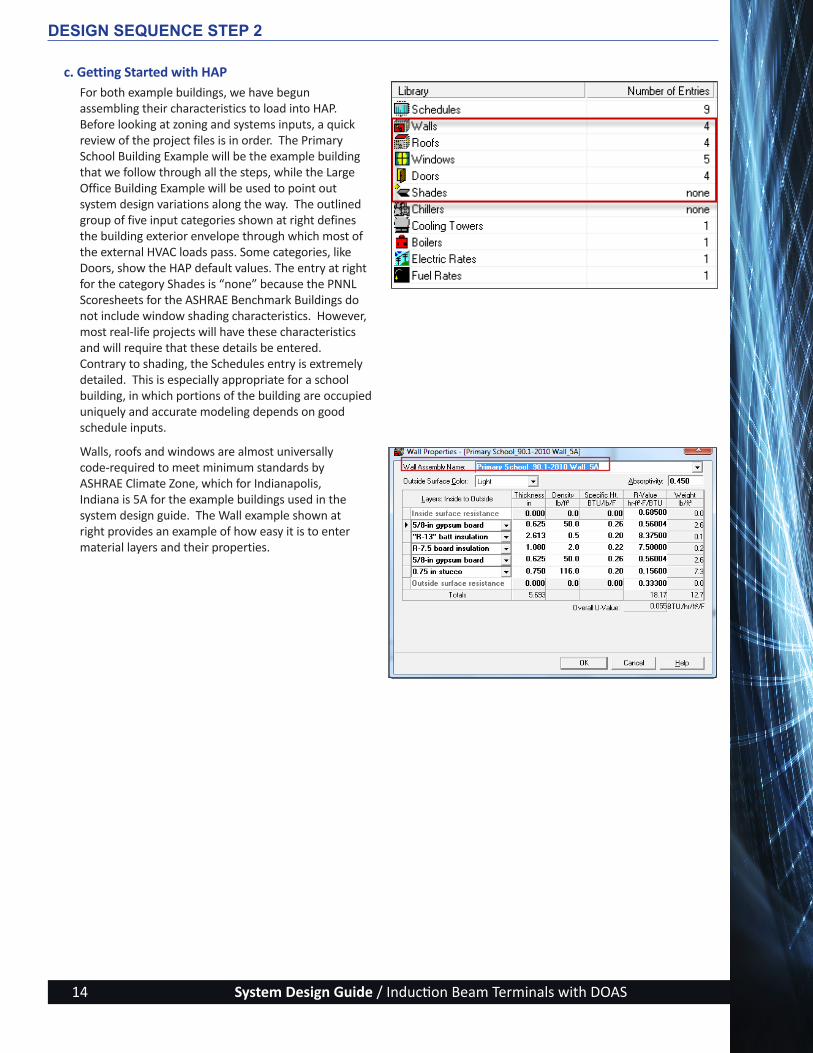
c. Getting Started with HAPFor both example buildings, we have begun assembling their characteristics to load into HAP. Before looking at zoning and systems inputs, a quick review of the project files is in order. The Primary School Building Example will be the example building that we follow through all the steps, while the Large Office Building Example will be used to point out system design variations along the way. The outlined group of five input categories shown at right defines the building exterior envelope through which most of the external HVAC loads pass. Some categories, like Doors, show the HAP default values. The entry at right for the category Shades is “none” because the PNNL Scoresheets for the ASHRAE Benchmark Buildings do not include window shading characteristics. However, most real-life projects will have these characteristics and will require that these details be entered. Contrary to shading, the Schedules entry is extremely detailed. This is especially appropriate for a school building, in which portions of the building are occupied uniquely and accurate modeling depends on good schedule inputs.
Walls, roofs and windows are almost universally code-required to meet minimum standards by ASHRAE Climate Zone, which for Indianapolis, Indiana is 5A for the example buildings used in the system design guide. The Wall example shown at right provides an example of how easy it is to enter material layers and their properties.
DESIGN SEQUENCE STEP 2
ActivAIR_Design-Guide_w-Cover_2014-09-09.indd 14 9/9/14 5:22 PM

System Design Guide / Induction Beam Terminals with DOAS 15
Step 3 - Calculate the Cooling, Heating, Dehumidifying, and Ventilating Loads
a. Calculating LoadsCalculating the various building HVAC loads has become much easier with computerized analysis programs and input wizards that let you quickly and accurately model the project at the very earliest conceptual stage of design. As mentioned earlier, for this system design guide we will be working on example building designs using Carrier’s eDesign Suite of HVAC-design and E-CAT equipment-selection software programs.
i. Load Estimating ApproachHVAC loads must be calculated in great detail for an IB + DOAS design because the ventilation load is decoupled from the space load and must therefore be carefully determined and addressed in the terminal and ventilation equipment selections. This is particularly the case when designing a sensible-only terminal project, IB or ACB. The procedure for calculating the building HVAC loads can be broken down into the following basic steps:
• Space Cooling and Heating Loads• Outdoor Air Ventilating Loads• Space Dehumidifying Loads
• System Primary Air & Water Requirements
At this early stage of the design process, it is quite effective to begin using HAP calculation software to model the building, even if many details are yet undecided. Taking the information we have from the Example Building step for the Primary School Building (page 12), open up HAP (version 4.8 or later) and choose a Full Wizard Session.
DESIGN SEQUENCE STEP 3
ActivAIR_Design-Guide_w-Cover_2014-09-09.indd 15 9/9/14 5:22 PM

System Design Guide / Induction Beam Terminals with DOAS16
As shown previously in the Primary School Building – PNNL Benchmark Building Scoresheet Data, everything needed to input the project characteristics is set up in the program. Ignoring the default values, begin the tasks of changing the various category inputs to represent the project, starting with the Weather Wizard.
You may work from the graphic or the pull- down lists to make your selections. This will load the weather data for both loads and energy simulation.
DESIGN SEQUENCE STEP 3
ActivAIR_Design-Guide_w-Cover_2014-09-09.indd 16 9/9/14 5:22 PM
System Design Guide / Induction Beam Terminals with DOAS 17
DESIGN SEQUENCE STEP 3
Figure 12 — Primary School Building Floor Plan with Dimensions
3 CLASSROOMS
5 CLASSROOMS
COMPUTER ROOM
LIBRARY
TOILETS
MA
IN C
ORR
IDO
R
MEC
H/E
LEC
ROO
MS
CAFETERIA
KITCHEN
GYM
OFFICES
LOBBY
CORRIDOR
TYPICAL CLASSROOM WING
58’ 9”
35’ 10”
62’
20’ 7”
68’ 6”
209’
69’ 3
”
49’ 6
”29
’ 9”
56’ 1
”
33’
9’ 11”
29’ 8
”69
’ 3”
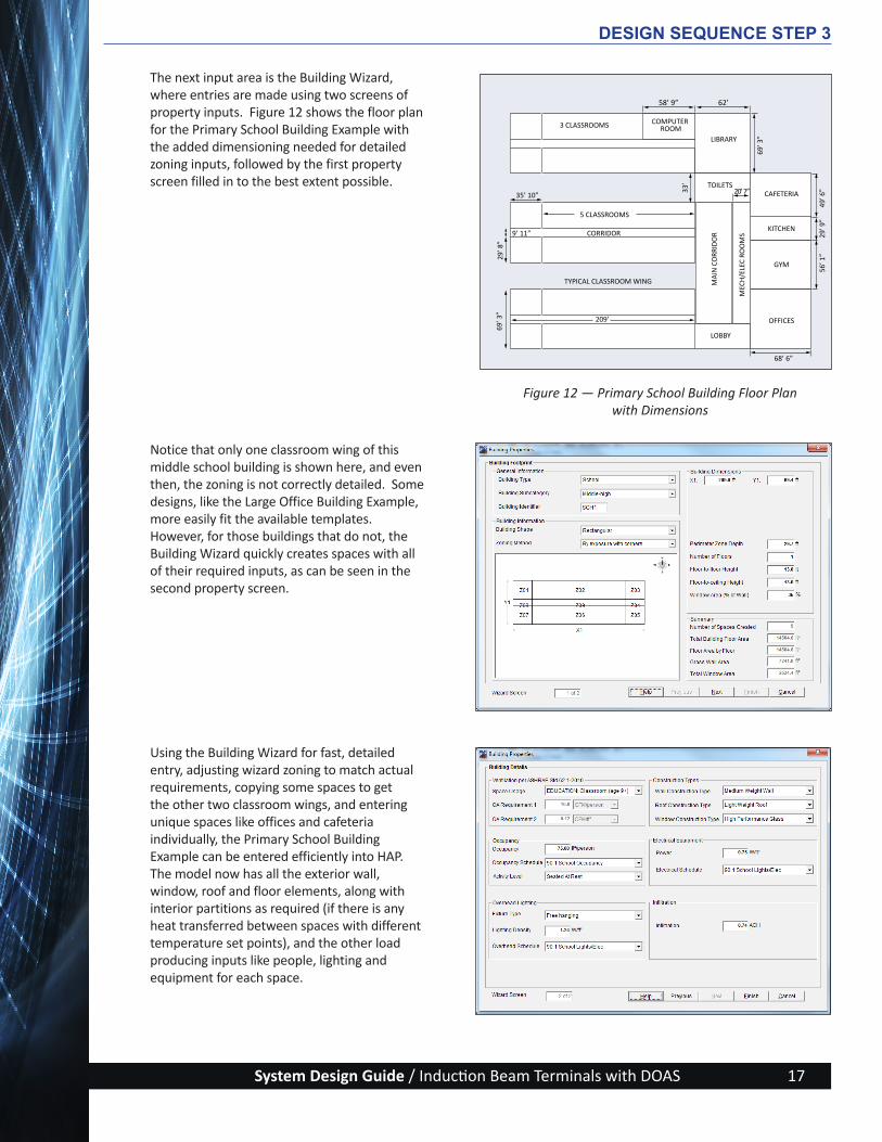
The next input area is the Building Wizard, where entries are made using two screens of property inputs. Figure 12 shows the floor plan for the Primary School Building Example with the added dimensioning needed for detailed zoning inputs, followed by the first property screen filled in to the best extent possible.
Notice that only one classroom wing of this middle school building is shown here, and even then, the zoning is not correctly detailed. Some designs, like the Large Office Building Example, more easily fit the available templates. However, for those buildings that do not, the Building Wizard quickly creates spaces with all of their required inputs, as can be seen in the second property screen.
Using the Building Wizard for fast, detailed entry, adjusting wizard zoning to match actual requirements, copying some spaces to get the other two classroom wings, and entering unique spaces like offices and cafeteria individually, the Primary School Building Example can be entered efficiently into HAP. The model now has all the exterior wall, window, roof and floor elements, along with interior partitions as required (if there is any heat transferred between spaces with different temperature set points), and the other load producing inputs like people, lighting and equipment for each space.
ActivAIR_Design-Guide_w-Cover_2014-09-09.indd 17 9/9/14 5:22 PM

System Design Guide / Induction Beam Terminals with DOAS18
Before running loads, return to the Full Wizard Session and click the Add button to begin adding equipment for the required systems.
The first system set up is the Induction Beams System that will take care of the classroom wings and offices area.
The second screen provides many choices for defining the Chiller Plant characteristics.
DESIGN SEQUENCE STEP 3
ActivAIR_Design-Guide_w-Cover_2014-09-09.indd 18 9/9/14 5:22 PM
System Design Guide / Induction Beam Terminals with DOAS 19
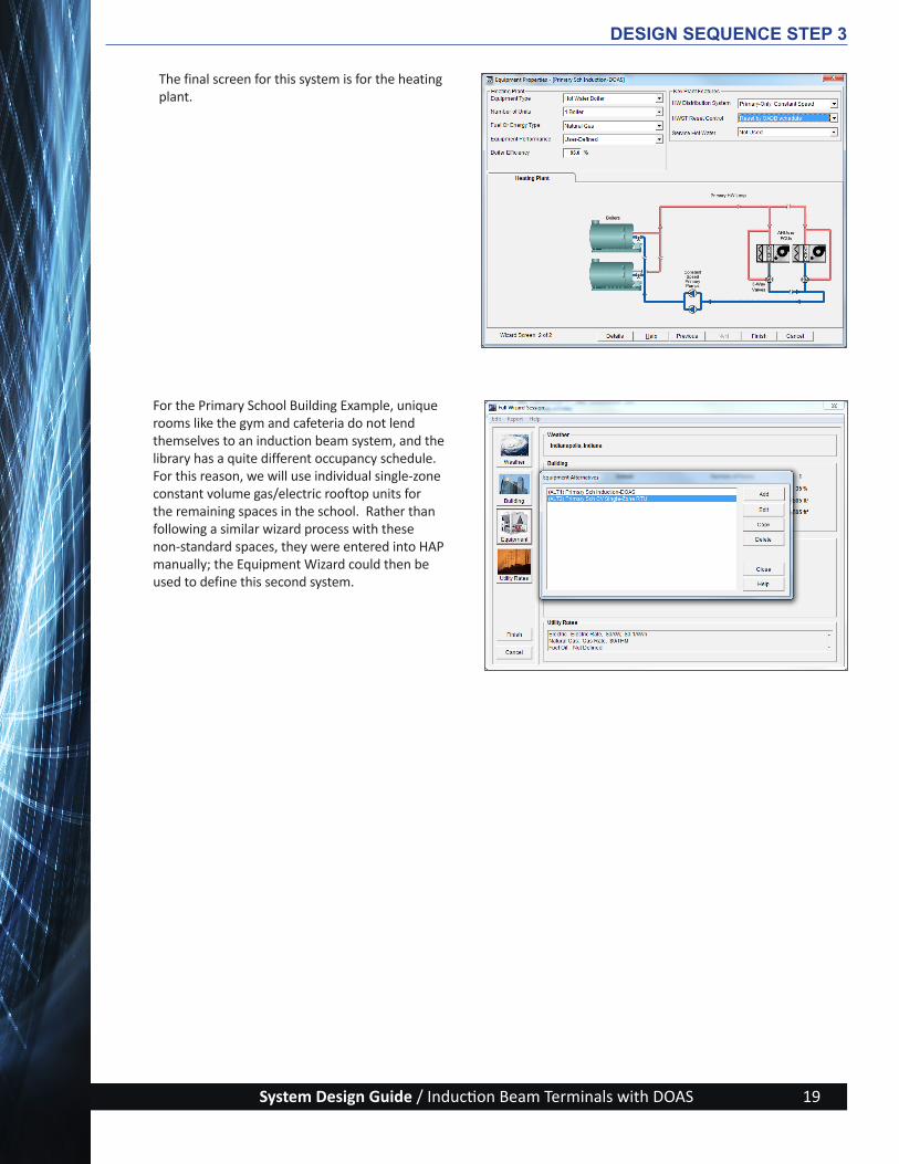
The final screen for this system is for the heating plant.
For the Primary School Building Example, unique rooms like the gym and cafeteria do not lend themselves to an induction beam system, and the library has a quite different occupancy schedule. For this reason, we will use individual single-zone constant volume gas/electric rooftop units for the remaining spaces in the school. Rather than following a similar wizard process with these non-standard spaces, they were entered into HAP manually; the Equipment Wizard could then be used to define this second system.
DESIGN SEQUENCE STEP 3
ActivAIR_Design-Guide_w-Cover_2014-09-09.indd 19 9/9/14 5:22 PM

System Design Guide / Induction Beam Terminals with DOAS20
The last thing to do in the wizards is to pick or input the utility rates. If the precise rate structure applicable to the project is known, enter it here; otherwise, use the Energy Information Administration rates imbedded in HAP on a state-by-state basis.
Before finishing the Full Wizard Session, it is useful to print the Wizard reports for future reference.
A copy of the completed HAP archive for the building can be downloaded to follow along with the system design guide. Go to ocs.hvacpartners.com/idc/groups/public/documents/software/HAP48-SCHOOL-IB-EXAMPLE.E3A to download the HAP v4.8 archive for this building project.
DESIGN SEQUENCE STEP 3
ActivAIR_Design-Guide_w-Cover_2014-09-09.indd 20 9/9/14 5:22 PM

System Design Guide / Induction Beam Terminals with DOAS 21
Before getting into the load calculation steps required to design a good induction beam system, here are a few reminders on the layout of HAP. The HAP software builds from the location (Weather), to the individual areas/rooms (Spaces), which are then put together in thermostatically-controlled zones which are served by air systems, which might require obtaining cooling and heating capacity from other equipment like chillers and boilers (Plants), then everything is grouped into a single entity (Building). Remember the sequence as you work through the Full Wizard Session. Here is what it will look like when all finished (almost there).
Classrooms can be copied from the first wing to complete the other two wings. Unique spaces must be entered and adjustments must be made to the spaces that had been quickly created in the Building Wizard, for proper representation of the actual design. This has been completed, and the final list of zones is shown at right.
In addition, here is the list of systems, four IB + ERV DOAS systems to cover classrooms and offices, and five medium efficiency RTU (Carrier HC series) systems for the other spaces:
DESIGN SEQUENCE STEP 3
ActivAIR_Design-Guide_w-Cover_2014-09-09.indd 21 9/9/14 5:22 PM

System Design Guide / Induction Beam Terminals with DOAS22
DESIGN SEQUENCE STEP 3
Figure 13 — Function of Hydronic Coils in Induction Beam Terminal
ii. Space Cooling and Heating LoadsInduction beam terminals cool and heat the spaces they serve in an all-air manner. The terminals have hydronic coils, but because the coils are internal to the terminal they will not interact radiantly with the space (Figure 13).
The space loads will be met effectively and efficiently when the following HVAC system parameters are properly set up and controlled:
Primary air temperatures (°F, db / wb) — The preconditioned air from the DOAS unit can be provided to the terminals at a neutral condition, providing little-to-no sensible or latent load offsetting (good for light-load conditions), or it can be provided at a significantly cooler and drier condition to handle a fair portion of the space sensible and latent loads. Doing so comes with a penalty of higher energy use for the chiller, but limiting terminal quantity and/or size may be a strong project design driver to use the lower primary air temperatures.
Primary air relative humidity (%, rh) — The process of cooling the primary air outdoor content in the DOAS unit will usually lower the moisture content of that air. By adding a dehumidification control loop in addition to the standard dry bulb temperature control, fluctuation in space relative humidity is avoided and a sensible-only terminal selection can be made. This also avoids condensation on any surfaces below the space air dew point temperature, such as piping components or even building envelope elements in older building retrofit projects.
Primary airflow (cfm) — At a minimum, the DOAS unit must deliver enough outdoor air content in the primary air to meet the ventilation air requirements of each space. If the primary air is kept towards neutral temperatures, the airflow may need to be increased to provide the needed induction to meet the space loads. If the increase results in an airflow that is too large, the IB system advantages of smaller ductwork and lower fan energy requirements begin to disappear. These variables must be balanced to achieve the design goals.
Supply air temperature (°F, db) — The supply air temperature is the temperature of the mixed air streams being discharged from the induction terminal. Once the space return air has been induced into the terminal, the air passes through the terminal coil(s), which provides the heating or cooling required to meet space loads. Once heated or cooled, the return air is blended with the neutral temperature primary air being discharged through the nozzles, and the resultant supply air is diffused into the space.
Supply airflow (cfm) — The supply airflow is the sum of the primary airflow delivered to the terminal by the DOAS unit and the return airflow induced from the space. The supply airflow can be determined by using the IB terminal’s characteristic airflow ratio, which establishes the ratio of supply air to primary air. The primary airflow should ideally be equal to the required ventilation airflow. When HAP runs the design loads, using the other parameter inputs that set up the model, it either accepts this ventilation airflow as the primary airflow, or increases the ventilation airflow to meet the maximum load of the space served. Factors that influence this potential increase in primary air from the ventilation airflow are terminal airflow ratio (3.0 default value), terminal design supply temperature (58 F default), temperature of chilled water supply (CHWS) to the coil (54 F default), and room set point (75 F default). If the project design drivers dictate a smaller primary airflow (and therefore smaller ductwork sizes and lower fan energy), CHWS to the DOAS must be decreased to increase the space cooling capacity of the primary air. Alternatively, an IB terminal with a higher airflow ratio could be used, but that would also likely require an increase in inlet static pressure. Instead, consider lowering the CHWS to the terminal coil and/or increasing the coil waterflow, but watch out for overly increasing pump brake horsepower (bhp). This is similar to the situation noted earlier regarding the need to weigh an increase in airflow against fan energy requirements. The variables must be balanced against each other, something that a modeling program like HAP can do most efficiently
ActivAIR_Design-Guide_w-Cover_2014-09-09.indd 22 9/9/14 5:22 PM

System Design Guide / Induction Beam Terminals with DOAS 23
once it is set up. This will be discussed further in the terminal and ventilating equipment selection steps.
Inlet static pressure of the primary airflow (in. wg) — Working on the induction principal, the inlet static pressure to the nozzle is the air mover of the terminal, setting the conditioned supply air delivered to the space. Selecting terminals using a value at the lower end of the normal range (0.4 in. wg to 0.8 in. wg) will keep fan energy low, but the reduced cooling and/or heating capacity may force an increase in the number or types of IB terminals needed in a space. If the inlet static pressure is set too high, not only will fan energy increase, so will generated noise. The evenness of distribution of air in the space can also be affected negatively.
Entering chilled water supply temperature (°F, CHWS) — The CHWS temperature must be cold enough to condense out the moisture on the cooling coil, but not so cold as to cause condensation on any of the piping system components. In addition, lowering the CHWS temperature too much unnecessarily elevates the operational cost of running the chiller. When the DOAS unit provides all the latent cooling (outdoor air and space loads), CHWS temperature to the air handler is usually set around 44 F. In this situation, the terminals are now only providing sensible cooling, so the CHWS supplying them can be raised well into the 50s in °F. If the latent cooling will be handled both at the DOAS unit and at the IB terminal, either individual temperatures can be provided to each circuit, or a common temperature, somewhere around 50 F, may do the work in each situation. This will need to be confirmed when equipment selections are made.
Entering heating water supply temperature (°F, HWS) — Room heating is provided by a separate water-heating loop in the terminal coil, which can use water temperatures from 120 to 180 F. Since heating capacity will usually exceed the cooling capacity, it is more energy efficient to use a lower water temperature, like 130 F. The lower HWS temperature also supports effective warm air distribution using IB terminals, maintaining uniform space temperature within 1° to 2° F of set point in both cooling and heating modes. Using higher heating water temperatures may cause the water control valve to cycle open and close too frequently. Depending on the cycle time of the valve and response time of the room thermostat, this could cause some uncomfortable temperature swings in the heating mode.
Entering waterflows (gpm) — Cooling coils within the IB terminals are multiple rows deep to achieve the required latent cooling, so waterflows are low and delta t’s are high. Heating coils have similar characteristics. With the use of 2-way, 2-position valves, variable-flow primary-only piping designs can be used, contributing to lowered capital cost and higher operating efficiency for the hydronic subsystem.
DESIGN SEQUENCE STEP 3
ActivAIR_Design-Guide_w-Cover_2014-09-09.indd 23 9/9/14 5:22 PM

System Design Guide / Induction Beam Terminals with DOAS24
iii. Outdoor Air Ventilating LoadsHVAC system design requirements for ventilation using outdoor air are set by ASHRAE’s Standard 62.1, Ventilation for Acceptable Indoor Air Quality. These outdoor airflow values are design minimums and can be adjusted upwards for better dilution of indoor contaminants of concern, or as a means of increasing worker productivity and positively influencing overall health of the occupants. Designing high efficiency cooling and heating subsystems, and including energy recovery ventilators in the DOAS unit, will lessen the operating cost impacts of the higher ventilation rates.
HAP includes all the ASHRAE 62.1 minimum values for required outdoor air ventilation.
You may override these values with the Global Settings found in the View/Preference section of HAP.
DESIGN SEQUENCE STEP 3
ActivAIR_Design-Guide_w-Cover_2014-09-09.indd 24 9/9/14 5:22 PM
System Design Guide / Induction Beam Terminals with DOAS 25
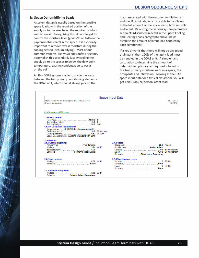
iv. Space Dehumidifying LoadsA system design is usually based on the sensible space loads, with the required portion of the supply air to the area being the required outdoor ventilation air. Recognizing this, do not forget to control the moisture level (grains/lb or lb/lb on the psychrometric chart) in the space. It is especially important to remove excess moisture during the cooling season (dehumidifying). Most of our common systems, like VAVR and rooftop systems, accomplish this secondarily just by cooling the supply air to the spaces to below the dew point temperature, causing condensation to occur on the coil.
An IB + DOAS system is able to divide the loads between the two primary conditioning elements: the DOAS unit, which should always pick up the
loads associated with the outdoor ventilation air; and the IB terminals, which are able to handle up to the full amount of the space loads, both sensible and latent. Balancing the various system parameter set points (discussed in detail in the Space Cooling and Heating Loads paragraphs above) helps establish the amount of latent load handled by each component.
If a key driver is that there will not be any piped drain pans, then 100% of the latent load must be handled in the DOAS unit. A simple hand calculation to determine the amount of dehumidified primary air required is based on the two primary moisture loads in a space, the occupants and infiltration. Looking at the HAP space input data for a typical classroom, you will get 120.0 BTU/hr/person latent load.
DESIGN SEQUENCE STEP 3
ActivAIR_Design-Guide_w-Cover_2014-09-09.indd 25 9/9/14 5:22 PM

System Design Guide / Induction Beam Terminals with DOAS26
Infiltration can be covered by a simple safety factor on top of the occupant load. For a new structure like the Primary School Building Example, 10% should be sufficient, giving a latent load of 1.1 times 120 or 132.0 BTU/hr/person. The SW Corner Classroom with 25 people would have a space latent load of 3300 BTU/hr. The next step is to determine the moisture content in grains for the primary air and the space exhaust air. The difference between the values is the “sponge” that is absorbing the latent load just calculated. Use either a psychrometric chart or one of the available psychrometric properties software programs as shown on the right.
We now have the data needed to plug into the simple spreadsheet shown below.
DESIGN SEQUENCE STEP 3
The answer of 27.3 cfm/person is above the 15.12 cfm/person set by ASHRAE 62.1, so expect the presence of drain pan condensate with the space latent load being handled by both the primary air and the IB terminal cooling coil. If we were to design the school with IB terminal dry coils, we would need to increase the space set points a little, to perhaps 75/50.8, then dry the primary out to about 55 grains, perhaps 58/74.3.
If the building is an existing structure with a known high level of infiltration that will not to be remedied as part of the project, then pipe up the drain pans
and make good use of the IB terminals’ ability to remove space latent loads. Regardless, always remove the outdoor air latent load at the DOAS unit for the best project IAQ outcomes. When modeling in HAP, the default value for the DOAS unit primary air temperature set point is 60 F dry bulb with a 75% relative humidity (58 gr/lb / 0.00828 lb/lb). This “neutral air” will reduce overcooling potential at light space loads, (and provide dry enough air to absorb a decent amount of space latent load, which will be looked at in detail soon.
ActivAIR_Design-Guide_w-Cover_2014-09-09.indd 26 9/9/14 5:22 PM

System Design Guide / Induction Beam Terminals with DOAS 27
v. System Primary Air and Water RequirementsIn summary of the above discussions on establishing design set points and flow values for the IB + DOAS system parameters, each of these energy transfer fluids have important and multi-faceted functions to be addressed as the design begins to materialize.
Primary air — As the primary fluid in our system, air performs multiple functions and must be sufficient for each of them. The design airflow (cfm) will be set based on the largest airflow required by a function, plus the inlet static pressure used for terminal selection. The largest airflow may be the amount required for outdoor air ventilation, or it may be the amount required to drive the induction effect nozzles to induce sufficient quantity of room air across the terminal coils to meet peak space loads. Moisture content must be low enough to absorb any space latent loads assigned to it.
Chilled water — In most system designs, chilled water is supplied to both the terminals and the DOAS unit to cool and dehumidify the primary and supply airstreams. Some designs will use a DX DOAS unit, so in this instance the chilled water is only for the IB terminals. Chiller efficiency across the full load profile is important, as is pumping bhp, so selections of set points and equipment are equally important. Use the warmest CHWS temperature possible and select coils with the highest functional waterside delta temperature to keep chilled water plant energy usage low. Increasing pressure from
building energy codes has increased the use of economizers. Energy recovery components are taking a larger portion of the cooling bin hours, reducing the portion of the building energy usage attributed to the chilled water plant.
Heating water — As the system elements have been explored, we have seen that the heating water has a relatively small part to play in the actual design. Keep in mind that for many large metropolitan areas in the northern U.S., the seasonal heating work to be done is larger than the cooling work, and it all needs to be done with either new or recovered energy. There is no such thing as a heating economizer in the HVAC setting. To keep energy usage at acceptably low values, seriously consider using natural gas-fired condensing boilers and distribute low temperature heating water to the coils in the DOAS unit and terminals with a variable-primary hydronic-pumping scheme. Another energy saving alternative is to use a heat recovery chiller for applications that have simultaneous heating and cooling loads, such as a large office or healthcare facility.
vi. Design Load SummaryNow go back into the HAP model for the Primary School Building Example to confirm the various set points and characteristics for the chosen systems. Table 2 below summarizes the choices for this design example and the basic reasons for the decisions.
System Parameter Range of Choices Selection Made System ImpactsPrimary Air Temperature-Occupied
55 – 68 F 60 (clg & htg) Neutral air to limit overcooling at light loads
Primary Air Temperature-Unoccupied
55 – 68 F 64 (clg & htg) Warmer air to reduce cycling DOAS unit
Primary Air Relative Humidity
75 – 57 % 75 Moderately dry air to absorb some latent load
Primary Air Humidity Ratio 48 – 58 gr/lb 58 Equivalent to rh % valuePrimary Airflow ≥ Ventilation Air ~Ventilation Air Keeps primary airflow lowPrimary Air Static Press 0.4 – 0.8 in. wg 0.4 Keeps sound levels low and
fan energy requirements to a minimum
Airflow Ratio 2.0 – 5.0 3.0 Average of most terminalsCHWS & Δt 42 – 60 F 54 & 10 Δt’s are for HAPHWS & Δt 120 – 180 F 120 & 20 CHWS and HWS are for E-CATTerminal Supply Air Temperature - clg
50 – 60 F 58 Helps avoid cold spots
Terminal Supply Air Temperature - htg
80 – 115 F 85 Best for overhead air htg
DESIGN SEQUENCE STEP 3
Table 2 – System Selection Parameters
LEGENDCHWS - Chilled water supplyDOAS - Dedicated outdoor air systemHWS - Heated water supply
ActivAIR_Design-Guide_w-Cover_2014-09-09.indd 27 9/9/14 5:22 PM

System Design Guide / Induction Beam Terminals with DOAS28
DESIGN SEQUENCE STEP 3
It is now time to run the design load calculations. Pick one of the IB + ERV DOAS systems, then, on the choice of System Design Reports, pick the first three summary reports (System Sizing, Zone Sizing, and Ventilation Sizing), which will provide the data required to check the design and make equipment
selections. Run Preview first to make sure the results make sense and adjust if required; then, when results are good, the files can be printed or archived. The Project can be reopened at any time to review any input or output element of the building and system models.
We will review these example reports to point out the elements of importance for the next step of equipment sizing and selection.
ActivAIR_Design-Guide_w-Cover_2014-09-09.indd 28 9/9/14 5:22 PM

System Design Guide / Induction Beam Terminals with DOAS 29
First is the System Sizing Summary:
DESIGN SEQUENCE STEP 3
ActivAIR_Design-Guide_w-Cover_2014-09-09.indd 29 9/9/14 5:22 PM

System Design Guide / Induction Beam Terminals with DOAS30
DESIGN SEQUENCE STEP 3
The first two report groupings (Air System Information and Sizing Calculation Information) identify the system and the months for which the loads were run. The remaining five groups address the elements of the DOAS, and are not associated with the IB terminals conditioning the spaces. System 06 - IB + ERV DOAS supplies primary air to two zones, the offices and lobby. The lobby is a large area that has no people assigned to it in the ASHRAE Benchmark building model, so when HAP computes the air needed to handle the space loads, and divides it by the few occupants in the offices, the very large 80 cfm of outdoor air per person value results. This situation repeats itself for the other corridors, restrooms, and mechanical equipment room as well, leading to System 05 - HC RTU indicating 0.00 cfm per person, yet it has almost 80% outdoor air because of the need to make up the restrooms exhaust cfm. This situation can be modeled more accurately in part by changing the Space Usage to something more descriptive (like “GENERAL: Corridor” shown at right), which will cause the load to include some outdoor air on a cfm/ft2 basis.
ActivAIR_Design-Guide_w-Cover_2014-09-09.indd 30 9/9/14 5:22 PM
System Design Guide / Induction Beam Terminals with DOAS 31
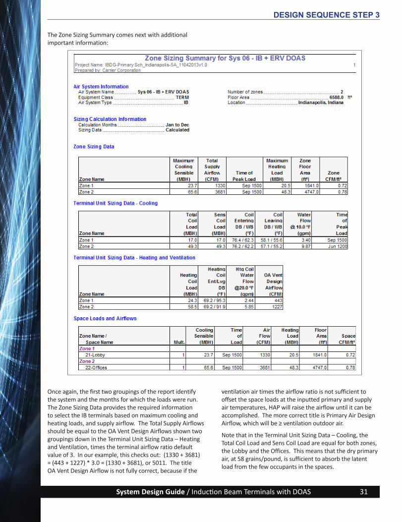
The Zone Sizing Summary comes next with additional important information:
DESIGN SEQUENCE STEP 3
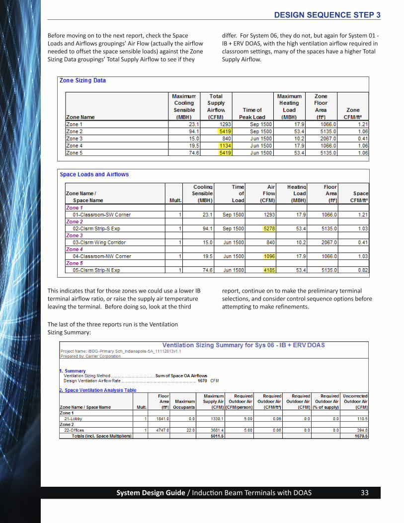
Once again, the first two groupings of the report identify the system and the months for which the loads were run. The Zone Sizing Data provides the required information to select the IB terminals based on maximum cooling and heating loads, and supply airflow. The Total Supply Airflows should be equal to the OA Vent Design Airflows shown two groupings down in the Terminal Unit Sizing Data – Heating and Ventilation, times the terminal airflow ratio default value of 3. In our example, this checks out: (1330 + 3681) = (443 + 1227) * 3.0 = (1330 + 3681), or 5011. The title OA Vent Design Airflow is not fully correct, because if the
ventilation air times the airflow ratio is not sufficient to offset the space loads at the inputted primary and supply air temperatures, HAP will raise the airflow until it can be accomplished. The more correct title is Primary Air Design Airflow, which will be ≥ ventilation outdoor air.
Note that in the Terminal Unit Sizing Data – Cooling, the Total Coil Load and Sens Coil Load are equal for both zones, the Lobby and the Offices. This means that the dry primary air, at 58 grains/pound, is sufficient to absorb the latent load from the few occupants in the spaces.
ActivAIR_Design-Guide_w-Cover_2014-09-09.indd 31 9/9/14 5:22 PM

System Design Guide / Induction Beam Terminals with DOAS32
Looking at a different system, Classroom Wing DOAS (System 01 - IB + ERV DOAS) for example, we find that this is the case there too, so the primary air is doing all the latent cooling, which means the IB terminal coils will be dry under
normal circumstances. Since most schools have operable windows, it would be advisable to plan on piping up the drain pans for unexpected conditions of high infiltration.
DESIGN SEQUENCE STEP 3
ActivAIR_Design-Guide_w-Cover_2014-09-09.indd 32 9/9/14 5:22 PM
System Design Guide / Induction Beam Terminals with DOAS 33
DESIGN SEQUENCE STEP 3
This indicates that for those zones we could use a lower IB terminal airflow ratio, or raise the supply air temperature leaving the terminal. Before doing so, look at the third
report, continue on to make the preliminary terminal selections, and consider control sequence options before attempting to make refinements.
Before moving on to the next report, check the Space Loads and Airflows groupings’ Air Flow (actually the airflow needed to offset the space sensible loads) against the Zone Sizing Data groupings’ Total Supply Airflow to see if they
differ. For System 06, they do not, but again for System 01 - IB + ERV DOAS, with the high ventilation airflow required in classroom settings, many of the spaces have a higher Total Supply Airflow.
The last of the three reports run is the Ventilation Sizing Summary:
ActivAIR_Design-Guide_w-Cover_2014-09-09.indd 33 9/9/14 5:22 PM

System Design Guide / Induction Beam Terminals with DOAS34
This report provides good insight into the system operations, but there are a couple of “corrections” needed. The last column, Uncorrected Outdoor Air, does not show a correct total. Move that over to a new column and title it Primary Air (CFM), which may not change if the ventilation
air is sufficient to cool the space. The two systems we have been looking at show two quite different results. The classroom-dominated System 01 has quite a bit of ventilation air, so it is fine.
DESIGN SEQUENCE STEP 3
This has been a lengthy discussion on space and equipment loads, but necessary for proper understanding of how an induction beam system works differently than the more common systems used for building HVAC systems in the U.S.
Now it is the time to move on to equipment selections.
Look above at System 06 right-hand column and note that HAP raised the outdoor ventilation airflows quite a bit to get primary airflows large enough to offset the space sensible loads.
ActivAIR_Design-Guide_w-Cover_2014-09-09.indd 34 9/9/14 5:22 PM

System Design Guide / Induction Beam Terminals with DOAS 35
Step 4 - Make Selections of Induction Terminals
a. Induction Beam ProductsThis step describes the various equipment types, control packages, and accessories that are available from Carrier for use in induction beam systems and can serve as an aid in the early stages of system design. The information below may help in selecting the units and controls most likely to be the best choices for a particular IB project.
Keep in mind when making equipment selections that IB terminals provide the following functions:
• Cooling and dehumidifying• Heating• Ventilating• Filtering• Air distribution
i. Induction Beam Operation An induction beam (IB) uses a source of primary ventilation air at an inlet static pressure ranging from 0.4 to 0.8 in. wg. Induction beams use this pre-conditioned (cooled and dehumidified) primary air in a quantity necessary to ensure good air quality for the occupied space.
The terminal inlet plenum distributes this primary air through a bank of aerodynamic nozzles and discharges the air as a high-velocity jet into a mixing chamber (see Figure 14). This jet creates a differential negative pressure, which enables a draw
of room air across a coil. This imparts either cooling (and possibly dehumidifying) or heating to the induced air as it passes over the coil.
The primary air and induced air are then mixed and discharged through a supply air louver that creates a Coanda effect air distribution pattern at the ceiling.
This airflow ratio is the sum of the primary air plus recirculated room air (called supply air) divided by the primary air. Typical values range from 2.0 to 5.0. If you have specific induction beam equipment in mind, consult manufacturer’s data to determine the appropriate value. A representative value of 3.0 is used in our example. This means that for every one cfm of primary air ducted to the beam, 2 cfm of room air (called induced air) will be drawn into the beam and across the coil. Other manufacturers establish an induction ratio, which is usually the induced room air divided by the primary air. This will be a smaller number than the airflow ratio; in fact, airflow ratio = induction ratio +1, if the induction ratio is how the terminal flow is determined.
ii. Unique Features of Induction BeamsThe induction beam terminal can utilize primary air at temperatures as low as 48 F with optional cabinet insulation. The inclusion of a full drain pan permits
DESIGN SEQUENCE STEP 4
Figure 14 — Induction Beam Operation
ActivAIR_Design-Guide_w-Cover_2014-09-09.indd 35 9/9/14 5:22 PM
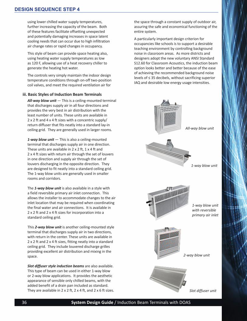
System Design Guide / Induction Beam Terminals with DOAS36
using lower chilled water supply temperatures, further increasing the capacity of the beam. Both of these features facilitate offsetting unexpected and potentially damaging increases in space latent cooling needs that can occur due to high infiltration air change rates or rapid changes in occupancy.
This style of beam can provide space heating also, using heating water supply temperatures as low as 120 F, allowing use of a heat recovery chiller to generate the heating hot water.
The controls very simply maintain the indoor design temperature conditions through on-off two-position coil valves, and meet the required ventilation air for
the space through a constant supply of outdoor air, assuring the safe and economical functioning of the entire system.
A particularly important design criterion for occupancies like schools is to support a desirable teaching environment by controlling background noise in classroom areas. As more districts and designers adopt the new voluntary ANSI Standard S12.60 for Classroom Acoustics, the induction beam option looks better and better because of the ease of achieving the recommended background noise levels of ≤ 35 decibels, without sacrificing superior IAQ and desirable low energy usage intensities.
DESIGN SEQUENCE STEP 4
iii. Basic Styles of Induction Beam TerminalsAll-way blow unit — This is a ceiling-mounted terminal that discharges supply air in all four directions and provides the very best in air distribution with the least number of units. These units are available in 2 x 2 ft and 4 x 4 ft sizes with a concentric supply/return diffuser that fits neatly into a standard lay-in ceiling grid. They are generally used in larger rooms.
1-way blow unit — This is also a ceiling-mounted terminal that discharges supply air in one direction. These units are available in 2 x 2 ft, 1 x 4 ft and 2 x 4 ft sizes with return air through the set of louvers in one direction and supply air through the set of louvers discharging in the opposite direction. They are designed to fit neatly into a standard ceiling grid. The 1-way blow units are generally used in smaller rooms and corridors.
The 1-way blow unit is also available in a style with a field reversible primary air inlet connection. This allows the installer to accommodate changes to the air inlet location that may be required when coordinating the final water and air connections. It is available in 2 x 2 ft and 2 x 4 ft sizes for incorporation into a standard ceiling grid.
This 2-way blow unit is another ceiling-mounted style terminal that discharges supply air in two directions, with return in the center. These units are available in 2 x 2 ft and 2 x 4 ft sizes, fitting neatly into a standard ceiling grid. They include louvered discharge grilles providing excellent air distribution and mixing in the space.
Slot diffuser style induction beams are also available. This type of beam can be used in either 1-way blow or 2-way blow applications. It provides the aesthetic appearance of sensible only chilled beams, with the added benefit of a drain pan included as standard. They are available in 2 x 2 ft, 2 x 4 ft, and 2 x 6 ft sizes.
All-way blow unit
1-way blow unit
1-way blow unit with reversible primary air inlet
2-way blow unit
Slot diffuser unit
ActivAIR_Design-Guide_w-Cover_2014-09-09.indd 36 9/9/14 5:22 PM

System Design Guide / Induction Beam Terminals with DOAS 37
iv. Additional Product FeaturesNozzles — A variety of nozzle sizes and multiple rows of nozzles are available, allowing the design professional to tailor the configuration to meet the airflow needs of the space. The nozzle can be replaced in the field if a change in utilization of the space results in a change to required unit capacity. The nozzles are color coded for ease of determining the differences among the nozzle sizes when installing them at the factory or replacing them in the field.
Coil — The hydronic coil options include 2-pipe or 4-pipe configurations, for application in cooling only, heating only, cooling/heating changeover, or simultaneous cooling and heating system types.
Filters — Permanent washable and throwaway filters are optional with the units (Figure 15).
Grilles — A variety of grille styles are available, including louvered supply and return (Figure 16), egg crate, or perforated return. The grilles come in a variety of colors, as well as aluminum finish.
Drain pans — The presence of International Mechanical Code-approved drain pans in each terminal allows for the use of lower water temperatures, down to 42 F. As an option, drain pans can come with antimicrobial coatings to increase protection of the drainage system against contamination (Figure 17). Drain pan piping connections can be either CPVC or copper.
Height extensions — Available height extension collars give additional height for gravity drainage. Extension collars from 3 in. to 6 in. are available. A standard unit provides 3-¾ in. of height without any extension collar.
DESIGN SEQUENCE STEP 4
Figure 15 — Optional FiltersThrowaway Filter
Figure 16 — Example Grille Styles
Washable Filter
Stainless Steel Drain Pan
Figure 17 — Drain Pans
Antimicrobial-Coated Drain Pan
ActivAIR_Design-Guide_w-Cover_2014-09-09.indd 37 9/9/14 5:22 PM
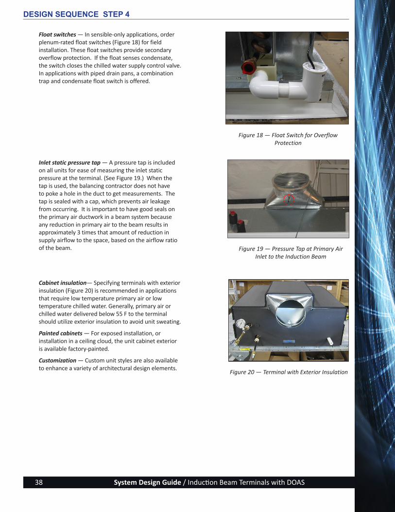
System Design Guide / Induction Beam Terminals with DOAS38
Float switches — In sensible-only applications, order plenum-rated float switches (Figure 18) for field installation. These float switches provide secondary overflow protection. If the float senses condensate, the switch closes the chilled water supply control valve. In applications with piped drain pans, a combination trap and condensate float switch is offered.
Inlet static pressure tap — A pressure tap is included on all units for ease of measuring the inlet static pressure at the terminal. (See Figure 19.) When the tap is used, the balancing contractor does not have to poke a hole in the duct to get measurements. The tap is sealed with a cap, which prevents air leakage from occurring. It is important to have good seals on the primary air ductwork in a beam system because any reduction in primary air to the beam results in approximately 3 times that amount of reduction in supply airflow to the space, based on the airflow ratio of the beam.
Cabinet insulation— Specifying terminals with exterior insulation (Figure 20) is recommended in applications that require low temperature primary air or low temperature chilled water. Generally, primary air or chilled water delivered below 55 F to the terminal should utilize exterior insulation to avoid unit sweating.
Painted cabinets — For exposed installation, or installation in a ceiling cloud, the unit cabinet exterior is available factory-painted.
Customization — Custom unit styles are also available to enhance a variety of architectural design elements.
Figure 18 — Float Switch for Overflow Protection
Figure 19 — Pressure Tap at Primary Air Inlet to the Induction Beam
Figure 20 — Terminal with Exterior Insulation
DESIGN SEQUENCE STEP 4
ActivAIR_Design-Guide_w-Cover_2014-09-09.indd 38 9/9/14 5:22 PM

System Design Guide / Induction Beam Terminals with DOAS 39
b. Terminal SelectionAlthough terminal selection and layout are shown as separate steps, the proper layout of the terminals in the occupied space must be determined before terminal selections can be finalized.
Selection of an induction unit should be based first on meeting the space ventilation and heating needs and then on the cooling requirements, both sensible and latent. The project floor plans, individual room sizes, shapes, and ceiling heights will affect the choice of 1-way, 2-way or all-way blow terminals.
i. IB Terminal Styles To select the appropriate unit style for the zone, see Table 3 and the recommendations below:
• Small rooms and private office areas - start with 1-way or 2-way blow 4 ft long or 6 ft long units.
• Open office areas, or conference room or classroom areas — start with all-way blow units.
• Hallway areas — start with 1-way or 2-way blow 2 x 2 ft units.
ii. Data for Terminal SelectionTo size IB terminals for a given application, the following information is required.
Ventilation air requirement — The primary airflow delivered to the induction beams should match the desired building ventilation in order to optimize HVAC system energy efficiency and first cost. The minimum ventilation rate required by most building codes can be determined using ASHRAE Standard 62.1, Ventilation for Acceptable Indoor Air Quality. The desired ventilation may exceed ASHRAE 62.1 requirements for a variety of reasons, such as
a desire for improved indoor air quality. In an application where the IB terminal coils are providing sensible-only cooling, the primary air may need to be increased to absorb the internal latent load of the space.
The ventilation airflow requirement will be used first to determine the number and size of induction beam terminals required in the space. Each model and size has an operating cfm range that can be tailored by selecting a nozzle size and quantity of nozzle rows, and by varying the primary air inlet static pressure entering the beam.
Space cooling and heating loads — The total space cooling capacity of each IB terminal is the sum of the sensible and latent capacity supplied by the primary air, plus the sensible and latent capacity of the IB cooling coil. The capacity of this coil is determined based on the induced room airflow across the coil, the coil chilled water supply temperature and chilled waterflow (gpm) provided.
In spaces with low population density and low ventilation requirements, a designer may find that the cooling or heating capacity of the beam does not meet the requirements of the space due to the low amount of primary airflow to the beam. In this situation, consider changing the chilled water supply temperature and/or waterflow to increase coil capacity. The temperature of the primary air supplied to the beam may also be changed to increase the capacity of the beam. However, care must be taken not to overcool or overheat the space during low load conditions, so a neutral primary air temperature is generally recommended. Another way to increase the capacity of the beam is to
DESIGN SEQUENCE STEP 4
Table 3 – Terminal Styles and Sizes (ft)
All-Way Blow 1-Way Blow 2-Way Blow
2 x 2 1 x 4 2 x 2
4 x 4 2 x 2 2 x 4
2 x 4 2 x 6
ActivAIR_Design-Guide_w-Cover_2014-09-09.indd 39 9/9/14 5:22 PM

System Design Guide / Induction Beam Terminals with DOAS40
increase the primary airflow to the beam. If there is a desire to avoid over ventilation of the space, the primary air can be a mixture of outdoor air and return air.
Zone layout and air distribution — The IB terminal devices come in several styles and sizes to meet a variety of unique application requirements. Step 6 on Terminal Layout provides recommendations
based on the space geometry and application. Once a style of beam is selected, preliminary performance can be generated, including air throw data for the IB terminal. By looking at the layout of beams in the space and using the performance data generated by Carrier’s E-CAT Induction Terminal Builder software, the designer will be able to verify that proper air distribution is achieved in the space.
c. Using Carrier E-CAT Software for Terminal Selection When using Carrier’s Hourly Analysis Program (HAP) for modeling the system (version 4.8 or later), the ventilation requirements and space loads by zone are exportable using the “Publish Equipment Sizing Requirements” feature. The HAP equipment sizing data then can be used in the E-CAT Induction Terminal Builder software (version 1.07 or later) to create terminal unit selections based on the HAP outputs.
To start the process of converting equipment-sizing data from HAP into an IB terminal selection, you will first need to have an idea of the style of unit and approximate quantity planned for that zone.
Following are examples using three zones in our Primary School Building Example.
i. Classroom ExampleUsing the Primary School Building Example, begin with the Air System named ‘Sys 01 – IB + ERV DOAS.’ Within that system, start the selections with
zone 1, which is a 1066 sq ft classroom that has a southwest corner exposure. The primary ventilation air requirements for this zone is 431 cfm, the coil cooling load is 16.1 MBH and the coil heating load is 22.1 MBH. For large areas such as classrooms, the all-way blow style unit is a good choice. To get a rough idea of how many units may be required for the classroom, refer to Carrier’s quick selection guide, “Selection Criteria for Carrier ActivAIR™ Induction Beams”, shown on the next page.
Download this guide from www.carrier.com to see the performance range for various models and sizes.
Using the quick selection guide to find a model that can meet our capacity requirements, it becomes clear that at least two units will be required to meet our primary airflow requirement of 431 cfm, since the maximum primary airflow shown on the quick selection guide is 419 cfm. Therefore, we will choose two all-way blow 36IBACD units for this classroom.
DESIGN SEQUENCE STEP 4
ActivAIR_Design-Guide_w-Cover_2014-09-09.indd 40 9/9/14 5:22 PM

System Design Guide / Induction Beam Terminals with DOAS 41
DESIGN SEQUENCE STEP 4
Quick Selection Guide
Note: Selections based on 75FDB/55%RH return air and 2-row coils. Additional coil, nozzle, and inlet configurations are available to meet performance criteria specific to your application. Coil capacities above do not include the capacity of the primary air. For total unit capacity, and customized performance, utilize the Carrier electronic selection software.
ModelNumber
NozzleCode
Inlet Static
Pressure: in.w.c.
PrimaryAirflow: CFM
NCRatings
Throw: Ft @ 100
FPM
Airflow Ratings: CFM Coil Cooling Capacity: BTUH
InductionAirflow
TotalAirflow
45 Deg EWT3 GPM
55 Deg EWT3 GPM
60 Deg EWT3 GPM
Size: 24" x 24"/4" Round Inlet
36IBACC
A 0.4 60 NC18 8' 163 223 6279 3174 2095A 0.5 67 NC21 8' 182 249 6701 3405 2278A 0.6 75 NC24 10' 203 278 7125 3644 2471A 0.7 83 NC27 10' 225 308 7528 3883 2663A 0.8 90 NC29 12' 244 334 7847 4069 2821C 0.4 78 NC18 10' 175 253 6553 3319 2212C 0.5 88 NC21 10' 197 285 7008 3578 2417C 0.6 98 NC24 12' 220 318 7440 3829 2620C 0.7 106 NC27 12' 237 343 7732 4001 2763C 0.8 116 NC29 14' 260 376 8096 4219 2949E 0.4 90 NC18 12' 158 248 6159 3107 2045E 0.5 102 NC21 12' 180 282 6659 3382 2259E 0.6 112 NC24 12' 197 309 7008 3578 2417E 0.7 124 NC27 14' 218 342 7404 3808 2603E 0.8 135 NC29 16' 238 373 7749 4011 2771
Size: 48" x 48"/8" Round Inlet
36IBACD
B 0.4 186 NC18 8' 316 502 12845 6543 4142B 0.5 208 NC21 8' 354 562 13723 7036 4519B 0.6 231 NC24 10' 393 624 14514 7520 4886B 0.7 263 NC27 11' 447 710 15469 8146 5364B 0.8 280 NC29 12' 476 756 15943 8469 5608D 0.4 242 NC18 10' 411 653 14865 7743 5058D 0.5 270 NC21 11' 459 729 15754 8336 5508D 0.6 300 NC24 12' 510 810 16315 8733 5819D 0.7 342 NC27 14' 581 923 17139 9305 6268D 0.8 363 NC29 16' 617 980 17838 9861 6681F 0.4 279 NC18 11' 474 753 15911 8446 5591F 0.5 312 NC21 12' 530 842 16732 9019 6040F 0.6 346 NC24 14' 588 934 17510 9587 6474F 0.7 395 NC27 16' 672 1067 18496 10342 7057F 0.8 419 NC29 17' 712 1131 18891 10375 7316
ActivAIR_Design-Guide_w-Cover_2014-09-09.indd 41 9/9/14 5:22 PM

System Design Guide / Induction Beam Terminals with DOAS42
Once a tag is selected, for example, ‘Sys 01 – IB_ERV DOAS-Zone 1,’ the Product Wizard will open. The Product Wizard is a tool for selecting equipment based on performance. The Product Wizard will generate multiple selections and display them in a table, showing performance for each selection, from which you can choose the option that will best meet the requirements.
For this example, in the Product Wizard, select “All-Way Discharge Cassette” as the model type, and “Select By Performance” for the size. Then select the Next button at the bottom of the wizard screen to proceed to the performance criteria tab of the wizard.
DESIGN SEQUENCE STEP 4
Using the E-Cat Induction Terminal Builder software, we can open the terminal unit sizing data that was generated by HAP for this zone. When you publish the data from HAP, it creates a project in your X-Builder framework with the same name
as your HAP project, and contains tags for each zone containing the unit sizing data specific for that zone. These tags contain an image of a triangle with a pencil to differentiate them from a standard equipment tag.
ActivAIR_Design-Guide_w-Cover_2014-09-09.indd 42 9/9/14 5:22 PM
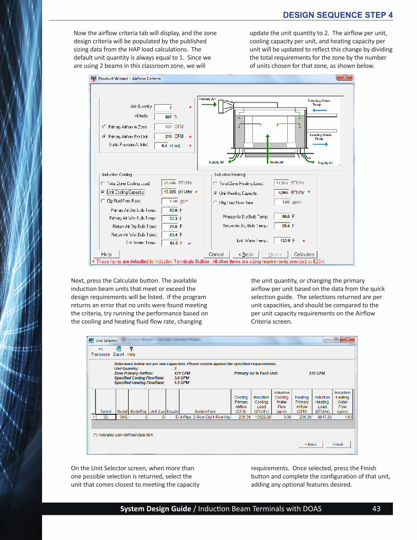
System Design Guide / Induction Beam Terminals with DOAS 43
Now the airflow criteria tab will display, and the zone design criteria will be populated by the published sizing data from the HAP load calculations. The default unit quantity is always equal to 1. Since we are using 2 beams in this classroom zone, we will
update the unit quantity to 2. The airflow per unit, cooling capacity per unit, and heating capacity per unit will be updated to reflect this change by dividing the total requirements for the zone by the number of units chosen for that zone, as shown below.
DESIGN SEQUENCE STEP 4
Next, press the Calculate button. The available induction beam units that meet or exceed the design requirements will be listed. If the program returns an error that no units were found meeting the criteria, try running the performance based on the cooling and heating fluid flow rate, changing
the unit quantity, or changing the primary airflow per unit based on the data from the quick selection guide. The selections returned are per unit capacities, and should be compared to the per unit capacity requirements on the Airflow Criteria screen.
On the Unit Selector screen, when more than one possible selection is returned, select the unit that comes closest to meeting the capacity
requirements. Once selected, press the Finish button and complete the configuration of that unit, adding any optional features desired.
ActivAIR_Design-Guide_w-Cover_2014-09-09.indd 43 9/9/14 5:22 PM

System Design Guide / Induction Beam Terminals with DOAS44
ii. Corridor ExampleNext, look at zone 3 from that same Air System developed in the HAP model for the Primary School Building Example. This zone is a long corridor. The CFM/sf requirement for this type of space is approximately one-third of that required for the
classroom modeled in zone 1. Therefore, a different style induction beam is recommended that can provide the desired supply air throw distance at a low primary air requirement. The 2 x 2 ft square 1-way discharge unit (36IBASC) is a good selection for a corridor, since the louvered 1-way supply provides longer throw distances at low airflows.
DESIGN SEQUENCE STEP 4
ActivAIR_Design-Guide_w-Cover_2014-09-09.indd 44 9/9/14 5:22 PM

System Design Guide / Induction Beam Terminals with DOAS 45
Using the Quick Selection Guide to obtain the throw of this model, and reviewing the dimensions of the corridor, it is determined that 8 units will
be needed to provide an even air distribution throughout the corridor.
1-800-CARRIER www.carrier.com
© Carrier Corporation 2013 Cat. No. 04-811-50030 Manufacturer reserves the right to discontinue, or change at any time, specifications or designs, without notice and without incurring obligations.1LEED® isaregisteredtrademarkofU.S.GreenBuildingCouncil.2ETL® and Intertek® are registered trademarks of Intertek.
Note: Selections based on 75FDB/55%RH return air. Additional coil, nozzle, and inlet configurations are available to meet performance criteria specific to your application. Coil capacities above do not include the capacity of the primary air. For total unit capacity, and customized performance, utilize the Carrier electronic selection software.
ModelNumber
NozzleCode
Inlet Static
Pressure: in.w.c.
PrimaryAirflow:
CFM
NCRatings
Throw: Ft @ 100 FPM
Airflow Ratings: CFM Coil Cooling Capacity: BTUH
InductionAirflow
TotalAirflow
45 Deg EWT3 GPM
55 Deg EWT3 GPM
60 Deg EWT3 GPM
Size: 48"x24"/6" Round Inlet
36IBANB
A 0.4 30 NC18 6' 90 120 3760 1886 1185A 0.5 32 NC18 6' 96 128 3931 1963 1247A 0.6 35 NC22 8' 105 140 4158 2084 1337A 0.7 37 NC22 8' 111 148 4298 2157 1395A 0.8 40 NC23 10' 120 160 4506 2266 1480B 0.4 59 NC24 10' 158 217 5237 2676 1809B 0.5 64 NC25 10' 171 235 5438 2799 1912B 0.6 69 NC26 11' 184 253 5640 2927 2011B 0.7 75 NC26 12' 200 275 5857 3073 2127B 0.8 81 NC26 12' 216 297 6056 3205 2238F 0.4 126 NC27 14' 214 340 6018 3189 2225F 0.5 140 NC29 15' 238 378 6299 3390 2383F 0.6 152 NC32 16' 258 410 6501 3336 2507F 0.7 160 NC33 19' 272 432 6829 3612 2715F 0.8 179 NC35 20' 304 483 6913 3685 2770
Size: 48"x12"/4" Round Inlet
36IBANA
A 0.4 26 NC18 6' 77 103 3379 1693 1045A 0.5 30 NC18 6' 89 119 3731 1872 1174A 0.6 33 NC22 8' 98 131 3982 1991 1267A 0.7 36 NC22 8' 107 143 4207 2109 1356A 0.8 39 NC23 10' 115 154 4374 2207 1433E 0.4 61 NC22 8' 161 222 5286 2706 1833E 0.5 68 NC22 8' 180 248 5578 2890 1981E 0.6 76 NC24 10' 201 277 5869 3082 2134E 0.7 83 NC25 10' 219 302 6091 3229 2258E 0.8 90 NC26 11' 238 328 6299 3390 2383
Size: 24"x24"/4" Round Inlet
36IBASC
E 0.4 39 NC22 8' 61 100 1697 1164 839E 0.5 42 NC23 10' 65 107 1779 1191 891E 0.6 45 NC24 13' 70 115 1907 1267 946E 0.7 48 NC27 13' 75 123 2008 1339 1001E 0.8 51 NC28 14' 80 131 2105 1409 1054F 0.4 64 NC26 14' 102 166 2501 1702 1273F 0.5 70 NC27 15' 111 181 2652 1815 1357F 0.6 77 NC28 16' 120 197 2790 1926 1437F 0.7 84 NC30 16' 134 218 2997 2093 1557F 0.8 90 NC32 17' 140 230 3081 2162 1607
Engineered Comfort for Today’s Buildings
Selection Criteria for Carrier ActivAIR Induction Beams
DESIGN SEQUENCE STEP 4
Quick Selection Guide
When we input the quantity of 8 on the airflow criteria screen of the Product Wizard, we find that the unit heating capacity turns red because the minimum capacity of the beam is more than the heating load requirement per unit. We can either
manually raise the heating capacity required or select the heating fluid flow rate as the criteria on which to provide selections. Let’s run selections based on the minimum heating fluid flow rate of 0.6 gpm in this case.
ActivAIR_Design-Guide_w-Cover_2014-09-09.indd 45 9/9/14 5:22 PM

System Design Guide / Induction Beam Terminals with DOAS46
Once we press the Calculate button, the following possible selections are returned.
When reviewing the performance against the ventilation airflow, heating, and cooling load requirements of the corridor, we find that we meet the airflow requirements with the first selection, and exceed the heating and cooling requirements. The unit heating and cooling capacities cannot be reduced any further on this model because they have already been calculated at the minimum
allowable water flow rate through the coil that will avoid a laminar flow condition. This is a good selection for the corridor units because it will meet the airflow requirement and exceed the cooling and heating requirements, while providing a 12-ft throw distance for even distribution of air throughout the corridor. With a 2-way control valve to the unit cooling and heating coils, over-cooling or over-heating of the space is avoided.
DESIGN SEQUENCE STEP 4
ActivAIR_Design-Guide_w-Cover_2014-09-09.indd 46 9/9/14 5:22 PM

System Design Guide / Induction Beam Terminals with DOAS 47
iii. Office ExampleNext, look at the office area of the school, which was defined as zone 2 of Air System named ‘Sys 06 – IB + ERV DOAS.’ We will assume that half of this 4747 sq ft office area contains private offices that are 10 ft x 10 ft in size, and the rest is open area and hallways. This equates to approximately 24 private offices. We will need to provide an induction beam in each private office, and several in the remaining open space. Since each private office is relatively small, again start by looking at the 2 x 2 ft 1-way blow unit for these offices.
Using the same process described above, use the Quick Selection Guide to determine the quantity of units required to meet the zone ventilation airflow requirement of 1227 cfm. We need 24 beams for the offices, plus at least 6 beams for the open area, totaling at least 30 beams for this office space.
The primary ventilation airflow capacity of the 2 x 2 ft 1-way blow 36IBASC at the 0.4 in. inlet static pressure and 807 ft altitude is 37.9 CFM per beam, which gives us a total of 1137 CFM ventilation air to the office area using 30 beams, which is less than our ventilation requirement. Dividing the ventilation requirement of 1227 CFM by the per beam capacity of 37.9 CFM, we find that we require 33 beams to meet the ventilation requirements for the entire office area. However, we find that the combined sensible cooling capacity of the 33 beams does not meet the sensible cooling requirements for the zone. The performance report for our initial office area selection is shown below. The coil sensible capacity of 1,350 BTU/hr multiplied by 33 units equates to a total sensible capacity of 44.6 MBH, which is less than our sensible coil load of 49.3 MBH from the HAP sizing data report for this zone.
DESIGN SEQUENCE STEP 4
ActivAIR_Design-Guide_w-Cover_2014-09-09.indd 47 9/9/14 5:22 PM

System Design Guide / Induction Beam Terminals with DOAS48
This is a relatively common result for an office space. In comparison to a classroom, an office space has lower ventilation requirements, resulting in reduction of primary airflow to the beam, and reduced total airflow in the space. The reduction in airflow lowers the heating and cooling capacity of the beam in the space. Common practice is to increase the primary airflow to the beam. Increased ventilation may have a positive effect on employee health and productivity, but it can come with the added cost of increased energy usage at the DOAS unit to supply this additional primary air.
Another approach to solving this problem is to look at an alternate beam model with greater coil capacity or a higher induction rate. If we change our model to a 4 x 1 ft size 1-way blow unit, we find that we are now exceeding our load requirements for the space, while maintaining the primary airflow at the required ventilation rate, reducing the chilled waterflow rate to each unit and reducing the total number of units to 30.
DESIGN SEQUENCE STEP 4
This simple change of models provided a more optimized selection for the office area of this school in Indianapolis. However, in some instances, particularly in warmer climates, the designer may need to consider using a lower chilled water supply
temperature to the beams to provide the additional capacity required. This strategy will allow you to maintain the primary airflow close to the required ventilation rates, while avoiding an excessive number of beams in the space to meet the loads.
ActivAIR_Design-Guide_w-Cover_2014-09-09.indd 48 9/9/14 5:22 PM

System Design Guide / Induction Beam Terminals with DOAS 49
iv. Finalizing SelectionsEquipment selection normally starts at the design development stage of a project to determine system requirements, begin detailed cost estimating, initiate writing of control sequences, and start filling in the equipment schedules. Many things can change during the contract documents stage of a project, so confirm the selection parameters, and if adjustments have been made, reselect the induction beam equipment and adjust other systems, i.e., duct design
and/or hydronic design for instance. Pay particular attention to the DOAS unit primary air temperature, its required chilled water, and heating water supply temperature set points, as well as primary airflow to the zones, since these parameters will directly affect the capacity of the beam. The beams are zone-level conditioning devices, and if the configuration of the zone changes during the design, the beam selections will need to be re-visited to ensure adequate airflow distribution in the space.
DESIGN SEQUENCE STEP 4
ActivAIR_Design-Guide_w-Cover_2014-09-09.indd 49 9/9/14 5:22 PM

System Design Guide / Induction Beam Terminals with DOAS50
Step 5 - Make Selections of DOAS Ventilating Units
a. Ventilation Equipment SelectionWhen selecting the equipment to provide the ventilation air to the IB terminals, keep in mind the many capacities that air serves:
Providing outdoor air for ventilating, and possibly dehumidifying — Every induction terminals project will bring in the ventilation air to the spaces using the primary air supplied by the ventilating unit. A sensible-only beam job will also use the primary air to absorb the space latent loads, from occupants, infiltration, and miscellaneous equipment or processes that have a moisture-producing component.
Conditioning space loads, both sensible and latent — An induction terminals system will likely be designed
so that the preconditioned primary air only handles a portion of the space loads; the remainder of the space loads must be handled by the terminal cooling and/or heating coils.
Energy for air distribution and powering terminal induction effect — The fan in the ventilating air-handler not only must deliver the primary air to the terminals, but there must be residual inlet static pressure sufficient to flow through induction-effect producing nozzles, a room return air filter if present, and the water coil(s). From 0.4 to 0.6 in. wg static pressure is required, similar to the static pressure required by a VAVR system to overcome control dampers, reheat coils, downstream ductwork, and supply air diffusers.
b. Ventilation Equipment ProductsThe DOAS unit can be either an air-handling unit (AHU), like a compact or custom Carrier AERO™ 39 Series product with separate sources of cooling and heating, or a fully-packaged rooftop dedicated outdoor air unit, like the Carrier 62 series unit with DX cooling
and auxiliary or heat pump heating. Either is designed and selected to perform the required duty on a 100% outdoor airflow. Below are a few offerings to be considered.
DESIGN SEQUENCE STEP 5
39M custom double-wall AHU, available from 1,500 to 60,500 cfm.
39L compact single or double-wall AHU, available from 1,800 to 15,000 cfm.
39S compact single or double-wall AHU, available from 400 to 8,500 cfm.
62D direct expansion dedicated outdoor unit, available from 1,000 to 10,000 cfm (6 to 35 tons)
ActivAIR_Design-Guide_w-Cover_2014-09-09.indd 50 9/9/14 5:22 PM

System Design Guide / Induction Beam Terminals with DOAS 51
62R dedicated outdoor air water source heat pump unit, available from 1,000 to 10,000 cfm (6 to 35 tons)
DESIGN SEQUENCE STEP 5
i. Consideration of Energy RecoverySince the DOAS is preconditioning 100% of the outdoor ventilation air, the sensible and latent loads will be quite high over a typical year in most North American climate zones. The operating costs associated with this mechanical cooling and heating can be significantly reduced by ducting all the zone exhaust air back to the unit and including an enthalpy-style energy recovery ventilator function in the DOAS unit (AHU or dedicated outdoor air unit). Whether using a rotating wheel or fixed flat-plate style ERV, provide adequate filters for both entering airstreams to preserve ERV performance, and to remove particulates from the outdoor air that may adversely affect human health. A filter with a MERV 13 rating is recommended, but each case should be separately evaluated.
This use of energy recovery will minimize the need to reheat the primary air. Additional static pressure will be added to the AHU fan, but this is far better than paying for significant reheat to minimize over-cooling of low-load zones.
ii. Zoning and LayoutFor the Primary School Building Example, the loads were run as though four separate DOAS units were being used, one each for the three classroom wings, and a fourth for the offices area. We will continue with the design and do a selection for a typical classroom wing using the 62D DOAS unit installed on the roof. Another system variation that can be considered is to combine the primary airflows of all four systems, or at least the classroom wings, and locate a DOAS AHU remotely inside the Mechanical/Electrical Room by the main toilet rooms.
For the Large Office Building, with its larger floor plan size (240 ft x 160 ft), a potential problem may develop if exposure-dominant loads require different primary air temperatures in order to avoid overcooling during light-load periods. If the differences are significant, consider using multiple units or working with a more neutral primary air temperature and addressing the majority of the space loads with the IB terminals.
ActivAIR_Design-Guide_w-Cover_2014-09-09.indd 51 9/9/14 5:22 PM

System Design Guide / Induction Beam Terminals with DOAS52
c. Using Carrier E-CAT Software for Ventilation Equipment Selection
Returning to the HAP loads for one of the classroom wings, the following conditions must be met by the DOAS unit:
DESIGN SEQUENCE STEP 5
Whether choosing a chilled water 39 series air handler or a direct expansion 62 series rooftop dedicated outdoor unit as the DOAS unit, all the data required to make the selection is shown above. We have picked the individual DX solution per classroom wing for the Primary School Building Example, and later select a single chilled water solution for the combination of the three classroom wings to demonstrate each selection process.
Cooling coil performance, along with the desired energy recovery ventilator, are the key components of the DOAS unit. The Air System Sizing Summary
shown above provides the coil total and sensible loads to be met, the outdoor ventilation airflow across the coil, entering and leaving air temperatures for both the ERV and the cooling coil, and for the chilled water example, a calculated waterflow based on the specified 10 F rise. The HAP software also computes the fan brake horsepower (and kW) for the shown airflow and the specified system static pressure resistance that must be overcome. We will use this information as a crosscheck when we review the E-CAT selections.
ActivAIR_Design-Guide_w-Cover_2014-09-09.indd 52 9/9/14 5:22 PM

System Design Guide / Induction Beam Terminals with DOAS 53
i. Direct Expansion DOAS Unit SelectionTo begin the selection of the packages DOAS unit, open Carrier E-CAT’s Dedicated Outdoor Air Systems Builder and create a new project. Configure a new unit tag for the classroom wing DOAS unit. The Product Wizard provides two methods to select a 62 series unit, Describe Rooftop Model and Select Rooftop Model. In this example, we will focus on the Describe Rooftop Model process.
Select “Describe Rooftop Model” in the Product Wizard, then select the appropriate unit type and unit model. This application requires an air-code DX unit with energy recovery, so the unit type will be “100% Outdoor Air w/Energy Recovery” and the unit model will be “62D”. Configure the remaining unit options as necessary.
DESIGN SEQUENCE STEP 5
To determine the appropriate unit size for this selection, refer to the unit sizing guide in the DOAS Builder, as shown below. The size 24 unit is the first
unit capable of meeting the 4701 CFM ventilation. Enter the unit size in the Product Wizard and press Finish to continue with the unit configuration.
ActivAIR_Design-Guide_w-Cover_2014-09-09.indd 53 9/9/14 5:22 PM

System Design Guide / Induction Beam Terminals with DOAS54
DESIGN SEQUENCE STEP 5
After completing the configuration of the Product Wizard, we are transferred to the Base Unit tab in the DOAS builder. This screen is automatically configured to match the Product Wizard input. After verifying the base unit configuration, continue to the Factory
Options screen by clicking on the Factory Options tab on the upper part of the screen. We will not cover every available factory option, only those required to meet the project needs and performance requirements.
ActivAIR_Design-Guide_w-Cover_2014-09-09.indd 54 9/9/14 5:22 PM

System Design Guide / Induction Beam Terminals with DOAS 55
DESIGN SEQUENCE STEP 5
ActivAIR_Design-Guide_w-Cover_2014-09-09.indd 55 9/9/14 5:22 PM

System Design Guide / Induction Beam Terminals with DOAS56
DESIGN SEQUENCE STEP 5
Referring to Table 2 – System Selection Parameters, we see that the Primary Air temperature supplied to the induction beams by the DOAS unit will be 60 F. Since the unit evaporator leaving air temperature specified in the Air System Sizing Summary is 52.3 F, we will require a reheat system that can raise the temperature of the air exiting the evaporator by a minimum of 7.7 F (60 F to 52.3 F). From the DX Reheat drop down list, select Modulating Hot Gas Reheat on all circuits. Hot gas reheat on all circuits will allow the unit to easily meet the project reheat requirements, and modulating reheat control will provide accurate reheat operation.
Next, we must select the energy recovery wheel. Since the outdoor air conditions are not too extreme, we can try selecting the smallest wheel size available. From the Energy Conservation Wheel drop down list,
select a 42-in. wheel with VFD (variable frequency drive) defrost. The VFD defrost is recommended to prevent wheel icing whenever the winter wheel entering air temperature is below 15 F. After configuring the remaining unit options, continue to the Design Criteria tab.
In the Design Criteria screen, enter the unit operating conditions as provided by the HAP software’s Air System Sizing Summary report. The DOAS builder will use this data to develop unit performance. Since we have chosen a hot water coil as the unit heat source, we must input the hot water performance criteria found on the Hot Water Coil Design screen. Finally, we are ready to calculate unit performance by clicking on the Performance tab.
ActivAIR_Design-Guide_w-Cover_2014-09-09.indd 56 9/9/14 5:22 PM

System Design Guide / Induction Beam Terminals with DOAS 57
DESIGN SEQUENCE STEP 5
Comparing the Performance Summary below to the Air System Sizing Summary at the start of this section, we can see that the unit cooling performance and heating performance meet or exceed the application requirements. Additionally,
the hot gas reheat performance exceeds the required temperature rise to meet the specified unit leaving air temperature. We have successfully selected a unit that will meet the performance requirements of this application.
ActivAIR_Design-Guide_w-Cover_2014-09-09.indd 57 9/9/14 5:22 PM

System Design Guide / Induction Beam Terminals with DOAS58
ii. Chilled Water DOAS Air-Handler Unit SelectionA system variation to consider is to switch from DX to chilled water and provide the system cooling capacity for both the DOAS air handlers and the IBs through a common chilled water plant. Some possible piping arrangements are shown in Step 7, Hydronic Design. This variation will be used for the Primary School Building Example three classroom wings, where we will switch to a single DOAS AHU located within the mechanical electrical room. We will also lower the chilled water supply temperature from 54 F to 48 F, and the terminal supply air temperature from 58 F to 50 F, to show a selection where a larger amount
of the space latent cooling will be handled by the IB terminals. While it is not shown in the terminal selection step, when the IB selections were rerun using the lower temperatures, the total beam quantity was reduced from 30 to 20 (assuming a mostly open layout with a few private offices). The DOAS primary air set points are unchanged.
Table 4 shows the system selection parameters with revised values for selecting the consolidated DOAS AHU used in the Primary School Building Example classroom wings.
DESIGN SEQUENCE STEP 5
Table 4 – Revised System Selection Parameters
System Parameter Range of Choices Selection Made System ImpactsPrimary Air Temperature-Occupied
55 – 68 F 60 (clg & htg) Neutral air to limit overcooling at light loads
Primary Air Temperature-Unoccupied
55 – 68 F 64 (clg & htg) Warmer air to reduce cycling DOAS unit
Primary Air Relative Humidity
75 – 57 % 75 Moderately dry air to absorb some latent load
Primary Air Humidity Ratio 48 – 58 gr/lb 58 Equivalent to rh % valuePrimary Airflow ≥ Ventilation Air ~Ventilation Air Keeps primary airflow lowPrimary Air Static Press 0.4 – 0.8 in. wg 0.4 Balance fan energy to
ductwork & terminals $’sAirflow Ratio 2.0 – 5.0 3.0 Average of most terminalsCHWS & Δt 42 – 60 F 48 & 10 Δt’s are for HAPHWS & Δt 120 – 180 F 120 & 20 CHWS and HWS are for E-CATTerminal Supply Air Temperature - clg
50 – 60 F 50 Helps avoid cold spots
Terminal Supply Air Temperature - htg
80 – 115 F 85 Best for overhead air htg
LEGEND CHWS – Chilled water supply DOAS – Dedicated outdoor air system HWS – Heated water supply
ActivAIR_Design-Guide_w-Cover_2014-09-09.indd 58 9/9/14 5:22 PM

System Design Guide / Induction Beam Terminals with DOAS 59
Returning to HAP and reconfiguring the DOAS systems, now with only one unit serving all classroom-related IB terminals, we get the following Air System Sizing Summary to use in making the selection in E-CAT’s Air Handler Builder.
Remembering the earlier selection work for induction terminals, this is a good time to check the primary air requirements for each zone. Compare
what is shown in HAP’s Zone Sizing Summary and Ventilation Sizing Summary reports to the IB terminal Performance Summary reports, to make sure the DOAS supplies the right amount of primary air. With the 4⁰F cooler Terminal Supply Air Temperature and 6⁰F cooler CHWS, that will not be an issue using the HAP-determined 14591 CFM for the DOAS AHU selection.
DESIGN SEQUENCE STEP 5
ActivAIR_Design-Guide_w-Cover_2014-09-09.indd 59 9/9/14 5:22 PM

System Design Guide / Induction Beam Terminals with DOAS60
Open Carrier’s E-CAT AHUBuilder and select an appropriate unit, a 39MN - ERV Draw Thru with Direct Drive Plenum Fan, for this example. Remember to fill in the Project fields, save the
Project, and then begin with the Unit tab in the builder. We will not go through each tab, but will cover mainly those associated with the fan, coils and ERV.
DESIGN SEQUENCE STEP 5
ActivAIR_Design-Guide_w-Cover_2014-09-09.indd 60 9/9/14 5:22 PM

System Design Guide / Induction Beam Terminals with DOAS 61
Once the airflows, air and water temperatures, etc. from the Revised System Selection Parameters table have been entered into the builder, the unit selection should be complete, short of determining accessories like filters and controls. Unit coil and fan performance options are extensive with a central station air handling unit option, so there were no problems meeting the performance requirements shown above in the Air System Sizing Summary.
As can be seen in Figure 21, the unit is large (just over 10 ft high by nearly 27 ft long), so space considerations must be closely evaluated. Fortunately, the Mechanical/Electrical Rooms space in the Primary School Building Example is almost 20 ft wide and at least six times as long, so this will not be an issue.
DESIGN SEQUENCE STEP 5
Before clearing up our red-circled Chk Rules issues, add the Angle Filter and Hot Water Coil and
Plenum sections. Doing so gives us more rules issues to clear up.
ActivAIR_Design-Guide_w-Cover_2014-09-09.indd 61 9/9/14 5:22 PM

System Design Guide / Induction Beam Terminals with DOAS62
iii. Finalizing SelectionsEquipment selection normally starts at the design development stage of a project to determine space requirements, begin detailed cost estimating, initiate writing of control sequences, and start filling in the equipment schedules. Many things can change during the contract documents stage of a project, so confirm the System Selection Parameters, and if
adjustments have been made, reselect the ventilating equipment and adjust other systems, for example, duct design and/or hydronic design. Pay particular attention to the required primary air requirement of the IB terminals. The DOAS must meet this value for proper system performance and adherence to outdoor air ventilation requirements.
DESIGN SEQUENCE STEP 5
Figure 21 — Air Handler Dimensions
ActivAIR_Design-Guide_w-Cover_2014-09-09.indd 62 9/9/14 5:22 PM

System Design Guide / Induction Beam Terminals with DOAS 63
Step 6 - Design the Air Distribution System (Terminal Layout and Duct Design)
The air distribution system is comprised of the air diffuser functional portion of the terminal and the ventilation air ductwork interconnecting the DOAS unit with the induction beam terminals. Air distribution design starts in the occupied spaces and works back to
the DOAS unit. Following is a quick review of how best to apply each type of IB terminal and then two layout examples, one for a classroom and one for the office area of the Primary School Building Example.
DESIGN SEQUENCE STEP 6
a. Terminal Layout
i. 1-Way Blow UnitsThe 1-way blow units are best in smaller spaces like offices, dormitory rooms, labs and corridors, and are normally positioned at the perimeter blowing into the room. They can also be positioned on an inside wall blowing toward the outside wall as a second choice when high solar gains on windows and outside walls require it (see Figure 22).
ii. 2-Way Blow Units
The 2-way blow units work well when placed in the center of the room, away from the wall (see Figure 23). With the induced room air entering at the center of the terminal, the units can be located above desks and chairs without any worry of creating uncomfortable drafts for the occupants.
iii. All-Way Blow Units
The all-way blow units are designed for larger spaces with higher population densities like classrooms and conference rooms. All-way blow units provide uniform air distribution in the occupied zone. These units should be located near the center of the room, or in large spaces where multiple units are needed, they should be distributed evenly (see Figure 24). It is recommended that unit locations should be separated by a minimum of 8 feet from grille edge to grille edge to avoid downdrafts from opposing airstreams.
Figure 22 — Application of 1-Way Blow Unit
Figure 23 — Application of 2-Way Blow Unit
Figure 24 — Application of All-Way Blow Unit
ActivAIR_Design-Guide_w-Cover_2014-09-09.indd 63 9/9/14 5:22 PM

System Design Guide / Induction Beam Terminals with DOAS64
iv. Layout examples Looking at two typical rooms in the Primary School Building Example, we can see how the different layout styles lend themselves to differing room requirements.
The typical classroom is 30 ft x 30 ft. Using standard 2 x 4 ft dropped ceiling tiles, with the normal lighting layout and a single return air grille, two 4 x 4 ft all-way blow IB terminals are centered in the
room (Figure 25). Looking back at the terminal selection made for the classroom, and checking its performance data, we see that the throw from the unit is 16 feet, making for a good design with the two terminals staggered, rather than positioned on-center in the room. With a 9-ft ceiling height, there is no concern over the opposing airstreams hitting one another and dropping down into the occupied zone, which starts at 6 feet above the floor.
CLASSROOM 30’ x 30’
SPRINKLER HEADS
HVAC EXHAUST AIR GRILLE
INDUCTION BEAM GRILLE
RECESSED LIGHT FIXT
DESIGN SEQUENCE STEP 6
Figure 25 — Typical Classroom Ceiling Plan
ActivAIR_Design-Guide_w-Cover_2014-09-09.indd 64 9/9/14 5:22 PM
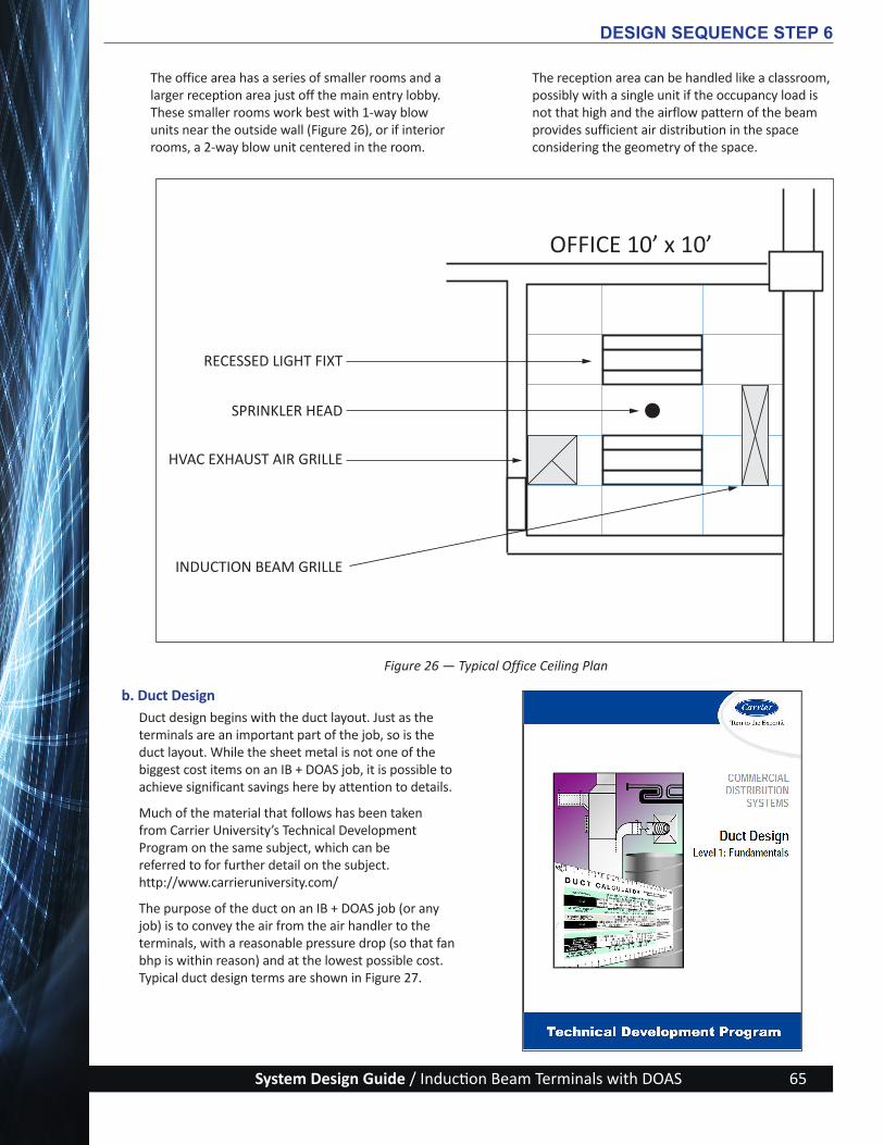
System Design Guide / Induction Beam Terminals with DOAS 65
OFFICE 10’ x 10’
SPRINKLER HEAD
HVAC EXHAUST AIR GRILLE
INDUCTION BEAM GRILLE
RECESSED LIGHT FIXT
DESIGN SEQUENCE STEP 6
Figure 26 — Typical Office Ceiling Plan
The office area has a series of smaller rooms and a larger reception area just off the main entry lobby. These smaller rooms work best with 1-way blow units near the outside wall (Figure 26), or if interior rooms, a 2-way blow unit centered in the room.
The reception area can be handled like a classroom, possibly with a single unit if the occupancy load is not that high and the airflow pattern of the beam provides sufficient air distribution in the space considering the geometry of the space.
b. Duct DesignDuct design begins with the duct layout. Just as the terminals are an important part of the job, so is the duct layout. While the sheet metal is not one of the biggest cost items on an IB + DOAS job, it is possible to achieve significant savings here by attention to details.
Much of the material that follows has been taken from Carrier University’s Technical Development Program on the same subject, which can be referred to for further detail on the subject. http://www.carrieruniversity.com/
The purpose of the duct on an IB + DOAS job (or any job) is to convey the air from the air handler to the terminals, with a reasonable pressure drop (so that fan bhp is within reason) and at the lowest possible cost. Typical duct design terms are shown in Figure 27.
ActivAIR_Design-Guide_w-Cover_2014-09-09.indd 65 9/9/14 5:22 PM

System Design Guide / Induction Beam Terminals with DOAS66
Several factors must be considered when designing a duct system. Generally, in order of importance, they are as follows:
Space availability — Many building services use the space above the dropped ceiling, and developing a straightforward and simple layout early in the project helps “reserve space” for the larger trunk ducts and IB terminals, with more flexibility available when it comes to smaller sizes and runouts.
Installation cost — Ductwork is seldom the major cost of an HVAC system, and this is even more the case on an IB + DOAS system that possibly could be moving just the ventilation air in the primary air and return ductwork.
Air friction loss — Round ducts with few size changes are the most efficient for both labor and fan horsepower, lowering both capital and operating costs for the project.
Noise level — An undersized duct system will have higher velocities and create noise that is often objectionable to the occupants. Poorly selected or installed fittings also create turbulence, which creates additional noise and air pressure drops. Dampers used for balancing need to be located out of the turbulence and not too close to the diffusers and registers in the space. There are many ways to limit noise creation (Figure 28) that need to be followed when designing ductwork.
Figure 27 — Typical Duct Design Terms
DESIGN SEQUENCE STEP 6
Figure 28 — Methods to Limit Noise in Ductwork
ActivAIR_Design-Guide_w-Cover_2014-09-09.indd 66 9/9/14 5:22 PM

System Design Guide / Induction Beam Terminals with DOAS 67
Duct heat transfer and airflow leakage — Ductwork that runs through very warm or very cold areas can incur a heat gain or loss that effectively reduces the capacity of the cooling and heating equipment, and will likely result in occupant discomfort and higher operating costs. Leaky ducts have the same energy-wasting effect, and may create odors and stained ceiling tiles if duct thermal insulation becomes wet from the formation of condensation at the leak points. The ASHRAE 90.1 Energy Code dictates using appropriate levels of insulation and joint seal levels for all ductwork in order to minimize these energy-wasting conditions.
Codes and standards requirements — HVAC duct systems are addressed in a number of building construction codes. Now that the International Codes Council’s family of publications has been adopted across the United States, it is safe to say that familiarity with the International Building Code, International Mechanical Code, and International Energy Conservation Code will capture most of the code-related requirements for duct systems. Always check with your specific project code requirements for additional design-related issues.
The design is performed in two steps, layout and sizing:
i. LayoutThe best way to deliver air to the terminals is by a simple, direct route while following the line of maximum clearance.
Some basic rules for laying out the trunk duct follow.
Try to ensure that all terminals are located no more than 25 ft from a trunk duct. This will simplify the runout duct design, and keep the costs reasonable. This practice will also ensure that if additional terminals are added in the future or space changes are made, there will be sufficient primary air nearby. This is especially important when the original design is not a partition layout.
Lay out the trunk duct in straight lines; it will reduce costs and be worth the time spent to carefully locate one or two straight runs with very few fittings.
Usually the space above the corridors (or likely corridor locations) is a good location for the trunk duct. The offices are located at the minimum distance from the corridor, the same as the relationship between the terminals and the trunk duct.
If possible, place the DOAS rooftop unit or air-handling unit in a central location. This is an obvious benefit in terms of cost, but it also helps to have all legs of the trunk duct symmetrical, so you can use the same duct sizes and avoid job site confusion.
DESIGN SEQUENCE STEP 6
ActivAIR_Design-Guide_w-Cover_2014-09-09.indd 67 9/9/14 5:22 PM

System Design Guide / Induction Beam Terminals with DOAS68
Spine Duct Layout
H Pattern Duct Layout
Loop Duct Layout
To the right are illustrations of simple symmetrical duct arrangements.
Try to pick a simple duct arrangement such as the “H” pattern trunk duct layout shown here. This pattern would work well in a medium-sized floor plan building.
If the building were a little narrower, like one of the classroom wings on the Primary School Example Building, a single “spine” trunk duct running down the center of the building (over a corridor) would work well and be less expensive.
Another arrangement that works very well, especially for a bigger building like the Large Office Building Example, is a loop or “doughnut” trunk duct pattern. This is actually a modified “H” pattern with the ends of the H connected together. The use of this type of layout results in particularly smooth, even changes in static pressure at the fan as the load varies around the building.
Once the trunk duct layout has been drawn onto the floor plan, connect the IB terminals to the duct trunk with runout branch ducts, completing the layout of the ductwork. Before switching to sizing, go back to the load output forms and pencil in the maximum primary airflow for each terminal. Now, working backwards to the DOAS unit, add up the airflows, noting them on the ductwork sketch every time it increases.
DESIGN SEQUENCE STEP 6
ActivAIR_Design-Guide_w-Cover_2014-09-09.indd 68 9/9/14 5:22 PM

System Design Guide / Induction Beam Terminals with DOAS 69
ii. SizingSelect cost effective ductwork that conserves material and installs quickly. Following are descriptions of the two methods of duct sizing that are most often used for air conditioning system design.
Equal friction — Most designers will use the equal friction method where ducts are sized for constant pressure loss per unit length, because this method is simple and fast when sizing manually. When energy cost is high and installed ductwork cost is low, which is the case for ventilation-only primary air duct system, a low friction-rate design is more economical. For low energy cost and high duct cost, a higher friction rate is more economical. After initial sizing, you can choose to improve the design by calculating the total pressure loss for all duct sections, and then resize sections to balance pressure losses at each junction.
Static regain — On large primary air systems with long trunk duct runs, it is good practice to use the static regain method because the total system static pressure becomes unreasonably high using the equal friction method. Using the equal friction method, the available static pressure at each tap will vary widely from one end of the system to the other, which makes balancing difficult. With greater use of BIM (Building Information Modeling) and its embedded design plugins, it is much easier to use the static regain method than in the past.
Whichever method of duct sizing is employed, here are design factors and recommendations to keep in mind to create a cost-effective and energy-efficient design:
Select a maximum duct velocity that you will use in the duct system. This velocity will occur in the largest trunk duct. A normal maximum for low-pressure systems is between 1500 to 2000 fpm to keep the system quiet. See Table 5 for recommended maximum duct velocities.
Table 5 - Recommended Maximum Duct Velocities for Low Velocity Systems (fpm)
DESIGN SEQUENCE STEP 6
APPLICATION
CONTROLLING FACTOR
NOISE GENERATION Main Ducts
CONTROLLING FACTOR-DUCT FRICTION
Main Ducts Branch Ducts
Supply Return Supply Return
Residences 600 1000 800 600 600
Apartments Hotel Bedrooms Hospital Bedrooms
1000 1500 1300 1200 1000
Private Offices Directors Rooms Libraries
1200 2000 1500 1600 1200
Theaters Auditoriums
800 1300 1100 1000 800
General Offices High Class Restaurants High Class Stores Banks
1500 2000 1500 1600 1200
Average Stores Cafeterias
1800 2000 1500 1600 1200
Industrial 2500 3000 1800 2200 1500
ActivAIR_Design-Guide_w-Cover_2014-09-09.indd 69 9/9/14 5:22 PM

System Design Guide / Induction Beam Terminals with DOAS70
When using the equal friction method, 0.1 in. wg/100 ft results in reasonable duct velocities and total system pressure drop. On some systems, up to 0.15 in. wg/100 ft can be used, but you will have to check carefully to be sure that pressure
drop and velocities are not excessive. Table 6 below presents multipliers to use when the duct system is made of material other than smooth sheet metal (roughness ε = 0.0003 ft)
DESIGN SEQUENCE STEP 6
*Flexible duct multipliers assume that the duct is installed fully extended.
Note: For internal ductwork surfaces other than smooth sheet metal, multiply equivalent lengths by the appropriate multiplier to calculate the total footage equivalent to the same friction loss in smooth sheet metal ductwork.
Table 6 – Duct Material Roughness Multipliers
Do not forget to include duct fittings in the pressure drop calculations, using either loss coefficients or equivalent lengths.
When choosing duct sizes, change the size between sections in one dimension only (either height or width, not both). The fittings are less expensive. Usually a duct height can be selected for most of
the system that will clear all the building structural components. The first duct section off of the AHU should not exceed an aspect ratio of 4:1, duct width ≤ 4 times duct height. Finally, change the size of the trunk duct as infrequently as possible, because it saves money on fittings. (This is easier to do when using the static regain method.)
Ductwork Description Supply Return
Rigid Fiberglass — Preformed Round Ducts — Smooth Inside 1.0 1.0
Rigid Fiberglass Duct Board 1.32 1.30
Duct Liner — Airside has Smooth Facing Material 1.32 1.30
Flexible Metal Duct (Straight Installation)* 1.6 1.6
Duct Liner — Airside Spray-Coated 1.9 1.8
Flexible, Vinyl-Coated Duct with Helical Wire Core (Straight Installation)* 3.2 3.4
ActivAIR_Design-Guide_w-Cover_2014-09-09.indd 70 9/9/14 5:22 PM

System Design Guide / Induction Beam Terminals with DOAS 71
Step 7 - Design the Hydronic System
The functions of the hydronic system in an IB + DOAS project are to both deliver the chiller/boiler/economizer capacity to the DOAS central station air handler (when used), and to distribute this water to the IB terminals throughout the building in an effective and efficient manner. There are important components and accessories that are required to complete a water piping system, and while all these components must be properly designed and selected to give satisfactory year-round performance at a reasonable cost, we will only briefly touch on them in this system design guide.
Much of the material that follows has been taken from Carrier University’s Technical Development Program on the same subject, which can be referred to for further detail on the subject at http://www.carrieruniversity.com/
a. Types of Piping SystemsBefore discussing piping design in detail, we will review the three basic types of piping systems: closed-loop, open-loop, and once-thru.
i. Closed-Loop SystemsIn a closed-loop piping system (Figure 29), the water is contained within a closed piping system, or loop, through which it circulates. While there may be some nominal contact with the air depending on the type of expansion tank used, the system is considered closed to the environment. Typically, closed-loop
Figure 29 — Example of a Closed-Loop Piping System
DESIGN SEQUENCE STEP 7
Includes:
• A chiller and/or boiler
• Coils that produce cooling or heating
• Two or three-way valves to control the coils
• Piping and pump to circulate water
• An expansion tank (insignificant water contact with air)
systems are chemically treated to control corrosion, scale, slime, and algae within the piping but their chemical treatment requirements typically are not as extensive as an open-loop system. In a chilled water system, this loop is called the evaporator circuit.
ActivAIR_Design-Guide_w-Cover_2014-09-09.indd 71 9/9/14 5:22 PM
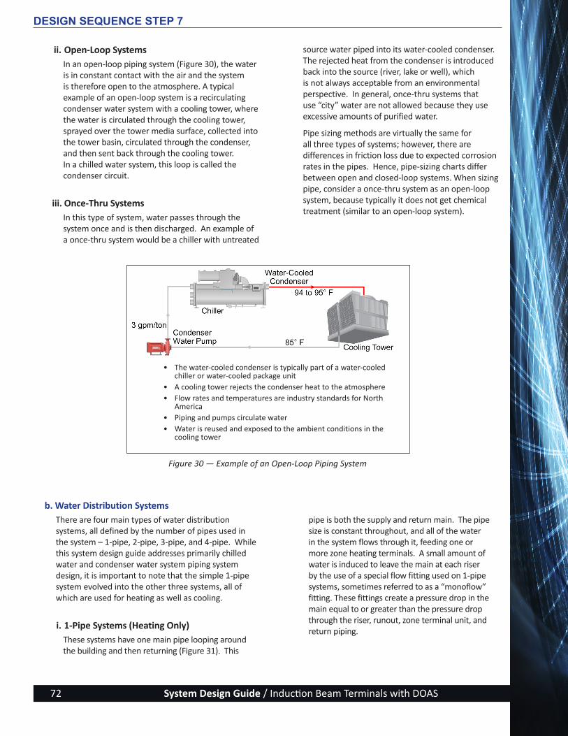
System Design Guide / Induction Beam Terminals with DOAS72
ii. Open-Loop Systems In an open-loop piping system (Figure 30), the water is in constant contact with the air and the system is therefore open to the atmosphere. A typical example of an open-loop system is a recirculating condenser water system with a cooling tower, where the water is circulated through the cooling tower, sprayed over the tower media surface, collected into the tower basin, circulated through the condenser, and then sent back through the cooling tower. In a chilled water system, this loop is called the condenser circuit.
iii. Once-Thru SystemsIn this type of system, water passes through the system once and is then discharged. An example of a once-thru system would be a chiller with untreated
source water piped into its water-cooled condenser. The rejected heat from the condenser is introduced back into the source (river, lake or well), which is not always acceptable from an environmental perspective. In general, once-thru systems that use “city” water are not allowed because they use excessive amounts of purified water.
Pipe sizing methods are virtually the same for all three types of systems; however, there are differences in friction loss due to expected corrosion rates in the pipes. Hence, pipe-sizing charts differ between open and closed-loop systems. When sizing pipe, consider a once-thru system as an open-loop system, because typically it does not get chemical treatment (similar to an open-loop system).
Figure 30 — Example of an Open-Loop Piping System
DESIGN SEQUENCE STEP 7
• The water-cooled condenser is typically part of a water-cooled chiller or water-cooled package unit
• A cooling tower rejects the condenser heat to the atmosphere• Flow rates and temperatures are industry standards for North
America• Piping and pumps circulate water• Water is reused and exposed to the ambient conditions in the
cooling tower
b. Water Distribution SystemsThere are four main types of water distribution systems, all defined by the number of pipes used in the system – 1-pipe, 2-pipe, 3-pipe, and 4-pipe. While this system design guide addresses primarily chilled water and condenser water system piping system design, it is important to note that the simple 1-pipe system evolved into the other three systems, all of which are used for heating as well as cooling.
i. 1-Pipe Systems (Heating Only)These systems have one main pipe looping around the building and then returning (Figure 31). This
pipe is both the supply and return main. The pipe size is constant throughout, and all of the water in the system flows through it, feeding one or more zone heating terminals. A small amount of water is induced to leave the main at each riser by the use of a special flow fitting used on 1-pipe systems, sometimes referred to as a “monoflow” fitting. These fittings create a pressure drop in the main equal to or greater than the pressure drop through the riser, runout, zone terminal unit, and return piping.
ActivAIR_Design-Guide_w-Cover_2014-09-09.indd 72 9/9/14 5:22 PM

System Design Guide / Induction Beam Terminals with DOAS 73
Figure 31 — 1-Pipe Heating Water Distribution System
ii. 2-Pipe SystemsThe 2-pipe system (Figure 32) is used with both heating and cooling equipment containing water coils. This system is equally useful for IB terminals and medium or large central air handlers using combination hot water and chilled water coils. The 2-pipe system can be used to distribute either hot or cold water, or alternate between the two. The same piping is used for both heating and cooling so there must be a definite outdoor temperature, which is called the “changeover temperature,” or some other indicator of building load, at which point the hot water in the piping is replaced by the chilled water and vice versa.
iii. 3-Pipe SystemsThe 3-pipe system has two supply mains feeding each zone terminal, one for chilled water and one for hot water, plus a common return main. The chilled water supply and hot water supply lines are sized according
to normal standards and the return is sized to handle the maximum flow rate (which is the cooling flow rate). As with 2-pipe systems, the return main can be either direct return or reverse return configuration. Because of the two supply mains to each coil, there is always hot and cold water present at the entrance to the zone or AHU coil ready to be used when needed. This gives any device supplied by the 3-pipe water distribution system the ability to heat or cool at any time. No changeover from summer to winter cycle is needed in the 3-pipe system. However, the operating cost of this system can become prohibitively high because of the mixing of hot and cold return water. It is important to be familiar with 3-pipe systems because they have been installed in existing buildings and are still in use. For new system designs, ASHRAE 90.1 does not allow for use of 3-pipe systems because mixing hot and cold water in the common return pipe uses excess energy.
Figure 32 — 2-Pipe Reverse Return Water Distribution System
DESIGN SEQUENCE STEP 7
ActivAIR_Design-Guide_w-Cover_2014-09-09.indd 73 9/9/14 5:22 PM
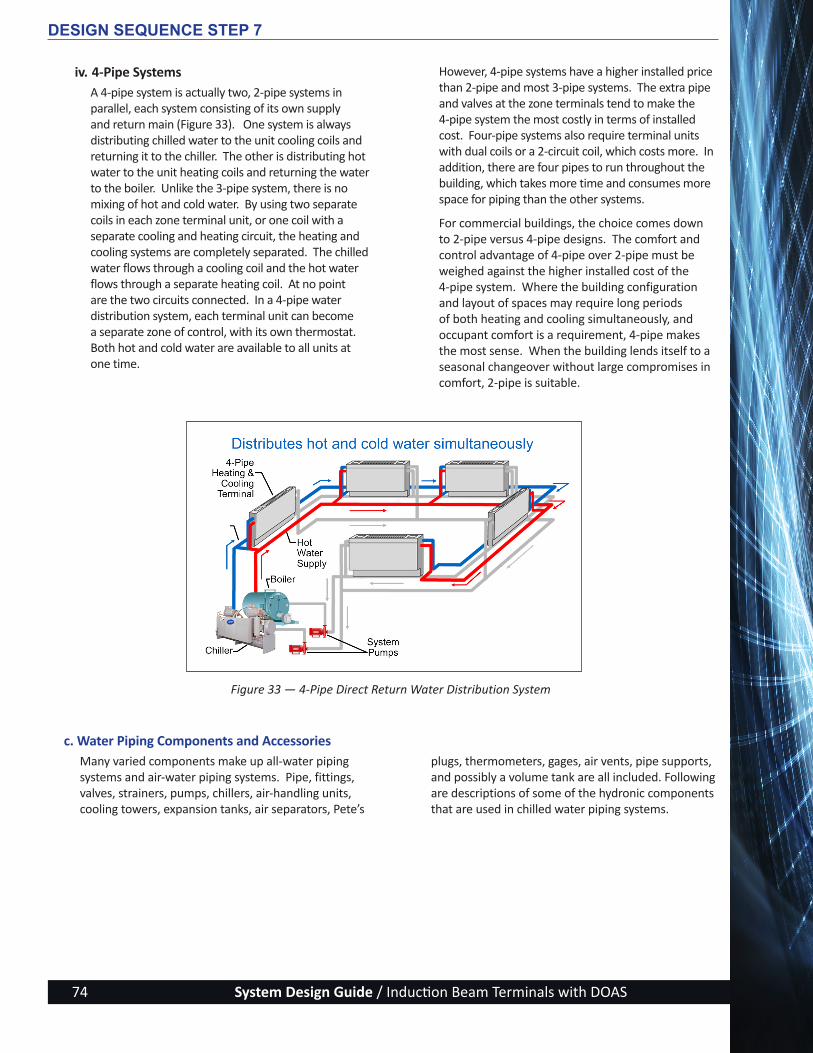
System Design Guide / Induction Beam Terminals with DOAS74
iv. 4-Pipe SystemsA 4-pipe system is actually two, 2-pipe systems in parallel, each system consisting of its own supply and return main (Figure 33). One system is always distributing chilled water to the unit cooling coils and returning it to the chiller. The other is distributing hot water to the unit heating coils and returning the water to the boiler. Unlike the 3-pipe system, there is no mixing of hot and cold water. By using two separate coils in each zone terminal unit, or one coil with a separate cooling and heating circuit, the heating and cooling systems are completely separated. The chilled water flows through a cooling coil and the hot water flows through a separate heating coil. At no point are the two circuits connected. In a 4-pipe water distribution system, each terminal unit can become a separate zone of control, with its own thermostat. Both hot and cold water are available to all units at one time.
However, 4-pipe systems have a higher installed price than 2-pipe and most 3-pipe systems. The extra pipe and valves at the zone terminals tend to make the 4-pipe system the most costly in terms of installed cost. Four-pipe systems also require terminal units with dual coils or a 2-circuit coil, which costs more. In addition, there are four pipes to run throughout the building, which takes more time and consumes more space for piping than the other systems.
For commercial buildings, the choice comes down to 2-pipe versus 4-pipe designs. The comfort and control advantage of 4-pipe over 2-pipe must be weighed against the higher installed cost of the 4-pipe system. Where the building configuration and layout of spaces may require long periods of both heating and cooling simultaneously, and occupant comfort is a requirement, 4-pipe makes the most sense. When the building lends itself to a seasonal changeover without large compromises in comfort, 2-pipe is suitable.
DESIGN SEQUENCE STEP 7
Figure 33 — 4-Pipe Direct Return Water Distribution System
c. Water Piping Components and Accessories Many varied components make up all-water piping systems and air-water piping systems. Pipe, fittings, valves, strainers, pumps, chillers, air-handling units, cooling towers, expansion tanks, air separators, Pete’s
plugs, thermometers, gages, air vents, pipe supports, and possibly a volume tank are all included. Following are descriptions of some of the hydronic components that are used in chilled water piping systems.
ActivAIR_Design-Guide_w-Cover_2014-09-09.indd 74 9/9/14 5:22 PM

System Design Guide / Induction Beam Terminals with DOAS 75
Figure 34 — Examples of Various Pipe Weld Fittings
Figure 35 — Angle Valve
i. Pipe, Joints and FittingsTypically, the piping used in an HVAC system is either schedule 40 black steel welded, cut-grooved pipe, or lighter gage rolled-groove steel pipe for sizes 2-1/2-in. diameter and above. Type L copper or threaded schedule 40 black steel pipe is normally used for 2-in. diameter and smaller. Steel pipe is offered with weld, mechanical groove, or threaded connections. Copper pipe is offered with solder or mechanical rolled-groove connections. Numerous fittings are available such as 90 and 45-degree elbows, tees, concentric reducers, eccentric reducers, flanges, etc. (See Figure 34.)
Just as was done in determining ductwork pressure losses, pipe fittings that allow for the least pressure drop, best routing and proper drainage should be used. Include the friction loss that best represents the type of fittings for a specific project (standard radius elbow versus long radius elbow for instance). The friction loss can be found in any of numerous Fitting Equivalent Length Pressure Drop Charts available from manufacturers or found in ASHRAE handbooks.
ii. ValvesMany types of valves are available in the HVAC industry. Each type of valve has certain characteristics that make it better for certain applications such as shutoff, balancing, control (also referred to as “throttling”), or 1-way flow. Some valves are suitable for multiple applications. A brief description of the different types of valves and their applications are listed below.
Butterfly valves — Butterfly valves are generally found on larger-sized systems. They can be used for shutoff duty, throttling duty, and for frequent operation. They have good flow control (linear relationship between percent open and percent of full flow through the valve), low cost, high capacity and low pressure drop. They typically are bigger valves and are used on pipe sizes 2 ½-in. and larger. Lug-pattern will either through-bolt between two flanges, or be secured at the end of a pipe section, while a wafer-pattern is a more economical style that just sits between the bolted flanges without its own lugs.
Gate valves — Also known as “stop valves,” gate valves are designed for shutoff duty. When the valve is in the wide-open position, the gate is completely out of the fluid stream, thus providing straight through flow and a very low pressure drop. Gate valves should not be used for throttling. They are not designed for this type of service and consequently it is difficult to control waterflow with any degree of accuracy.
DESIGN SEQUENCE STEP 7
45° Elbow
ConcentricReducer
Saddle Tee Cap
Tee Flange
90° Short Radius Elbow
Globe, angle and “Y” valves — These valves are of the same basic design and are applied primarily for throttling (balancing) duty. The angle or Y-pattern valve is recommended for full-flow service since it has a substantially lower pressure drop at this condition than the globe valve. Another advantage of the angle valve is that it can be located to replace an elbow, thus eliminating one fitting. (See Figure 35.)
Plug valves — Also called plug cocks, plug valves are used primarily for balancing flow rates in systems not subject to frequent flow changes. They come with cylindrical or tapered plugs that are usually lubricated to reduce galling, turning torque, and face leakage. Plug valves have approximately the same loss as a gate valve when in the fully open position. When partially closed for balancing, this line loss increases substantially. For large flow rate applications, a globe or butterfly valve will be used instead of a plug valve. Their sizes are limited to smaller applications because of cost.
ActivAIR_Design-Guide_w-Cover_2014-09-09.indd 75 9/9/14 5:22 PM

System Design Guide / Induction Beam Terminals with DOAS76
Ball valves — Ball valves are used for full open/closed service, with limited requirement for precise control. They are best suited for quick-open linear control. Their advantages are low cost, high capacity, low leakage, and tight sealing.
Check valves — prevent the flow of water in the reverse direction. There are two basic designs of check valves, the swing check and the lift check. The swing check valve may be used in a horizontal line or in a vertical line if flow is upward. The flow through the swing check is in a straight line and without restriction at the seat. Swing checks are generally used in combination with gate valves. The lift check operates like a globe valve, so pressure drop is greater. The lift check should only be installed in horizontal piping, and usually in combination with globe, angle, and Y valves.
Control valves — can be 2-position (open or closed), 2-way modulating (modulates to vary flow through the coil and system), or 3-way modulating (modulates flow through the coil by bypassing water back to the return, thereby maintaining a nearly constant flow through the system). (See Figure 36.) Three-way valves are used for hot and cold waterflow control on
chillers, boilers, air coils, and most all HVAC hydronic units where temperature control is necessary.
Three-way mixing valves have two inlets and one outlet. Three-way diverting valves have one inlet and two outlets. Mixing valves are typically used to vary the flow through a load (such as a chilled or hot water coil). Diverting valves are used to direct the flow one way or another and are useful in applications like 2-pipe changeover or in bypass applications.
Three-way valves are used in many applications such as waterflow variation, temperature variation, and primary-secondary pumping systems in both 2-pipe and 4-pipe systems. Two-way modulating valves are used for variable waterflow through heating and cooling coils. They throttle the water for part-load control instead of bypassing it around the coil.
Six-way control valves are also available that operate similarly to a set of two 3-way valves, with a single actuator instead of two. They can be used in a 4-pipe system and eliminate the need to use a 4-pipe coil in the beam, allowing the system to take advantage of the added capacity of a 2-pipe coil in both heating and cooling.
DESIGN SEQUENCE STEP 7
Figure 36 — Types of Control Valves
ActivAIR_Design-Guide_w-Cover_2014-09-09.indd 76 9/9/14 5:22 PM
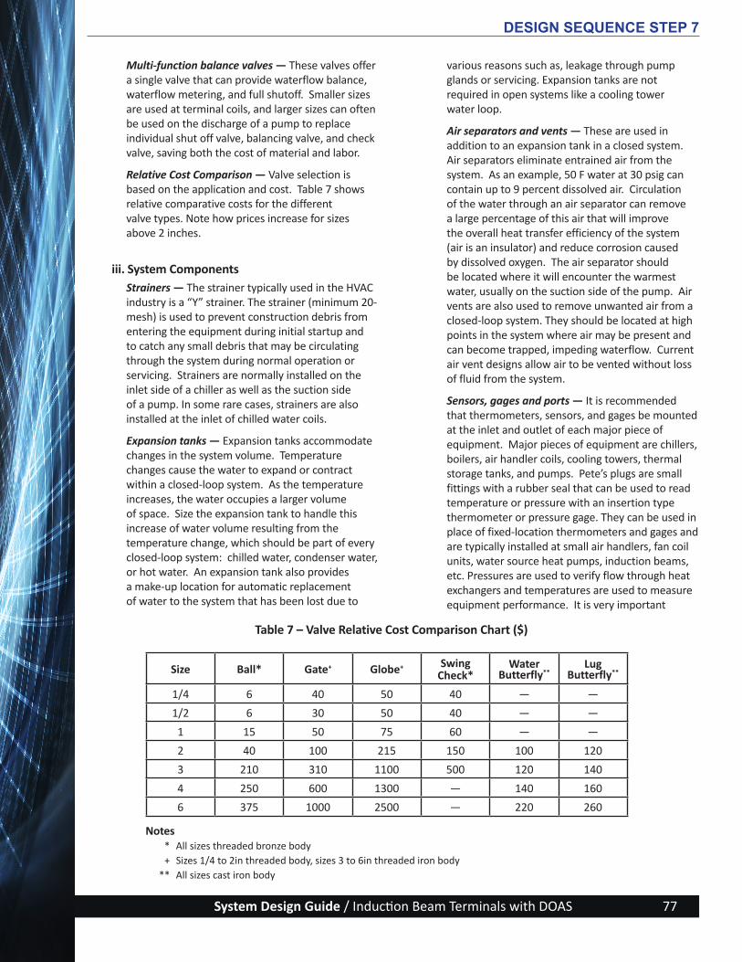
System Design Guide / Induction Beam Terminals with DOAS 77
Table 7 – Valve Relative Cost Comparison Chart ($)
Multi-function balance valves — These valves offer a single valve that can provide waterflow balance, waterflow metering, and full shutoff. Smaller sizes are used at terminal coils, and larger sizes can often be used on the discharge of a pump to replace individual shut off valve, balancing valve, and check valve, saving both the cost of material and labor.
Relative Cost Comparison — Valve selection is based on the application and cost. Table 7 shows relative comparative costs for the different valve types. Note how prices increase for sizes above 2 inches.
iii. System Components Strainers — The strainer typically used in the HVAC industry is a “Y” strainer. The strainer (minimum 20-mesh) is used to prevent construction debris from entering the equipment during initial startup and to catch any small debris that may be circulating through the system during normal operation or servicing. Strainers are normally installed on the inlet side of a chiller as well as the suction side of a pump. In some rare cases, strainers are also installed at the inlet of chilled water coils.
Expansion tanks — Expansion tanks accommodate changes in the system volume. Temperature changes cause the water to expand or contract within a closed-loop system. As the temperature increases, the water occupies a larger volume of space. Size the expansion tank to handle this increase of water volume resulting from the temperature change, which should be part of every closed-loop system: chilled water, condenser water, or hot water. An expansion tank also provides a make-up location for automatic replacement of water to the system that has been lost due to
various reasons such as, leakage through pump glands or servicing. Expansion tanks are not required in open systems like a cooling tower water loop.
Air separators and vents — These are used in addition to an expansion tank in a closed system. Air separators eliminate entrained air from the system. As an example, 50 F water at 30 psig can contain up to 9 percent dissolved air. Circulation of the water through an air separator can remove a large percentage of this air that will improve the overall heat transfer efficiency of the system (air is an insulator) and reduce corrosion caused by dissolved oxygen. The air separator should be located where it will encounter the warmest water, usually on the suction side of the pump. Air vents are also used to remove unwanted air from a closed-loop system. They should be located at high points in the system where air may be present and can become trapped, impeding waterflow. Current air vent designs allow air to be vented without loss of fluid from the system.
Sensors, gages and ports — It is recommended that thermometers, sensors, and gages be mounted at the inlet and outlet of each major piece of equipment. Major pieces of equipment are chillers, boilers, air handler coils, cooling towers, thermal storage tanks, and pumps. Pete’s plugs are small fittings with a rubber seal that can be used to read temperature or pressure with an insertion type thermometer or pressure gage. They can be used in place of fixed-location thermometers and gages and are typically installed at small air handlers, fan coil units, water source heat pumps, induction beams, etc. Pressures are used to verify flow through heat exchangers and temperatures are used to measure equipment performance. It is very important
DESIGN SEQUENCE STEP 7
Size Ball* Gate+ Globe+ Swing Check*
Water Butterfly**
Lug Butterfly**
1/4 6 40 50 40 — —
1/2 6 30 50 40 — —
1 15 50 75 60 — —
2 40 100 215 150 100 120
3 210 310 1100 500 120 140
4 250 600 1300 — 140 160
6 375 1000 2500 — 220 260
Notes * All sizes threaded bronze body + Sizes 1/4 to 2in threaded body, sizes 3 to 6in threaded iron body ** All sizes cast iron body
ActivAIR_Design-Guide_w-Cover_2014-09-09.indd 77 9/9/14 5:22 PM

System Design Guide / Induction Beam Terminals with DOAS78
Figure 37 — Typical Thermometers, Pete’s Plugs, and Gauges. Gauges and thermometer photos courtesy of Weiss Instruments, Inc.
Figure 38 — Volume Tank Requirements
DESIGN SEQUENCE STEP 7
Pipe hangers and anchors — All piping should be supported with hangers that can withstand the combined weight of pipe, pipefittings, valves, fluid in the pipe, and the insulation. They must also be capable of keeping the pipe in proper alignment when necessary. Where extreme expansion or contraction exists, roller-type hangers and saddles should be used.
Volume tanks — An important factor in piping design involves having enough volume of chilled water in the piping system to assure stable operation of the chiller. Loop volume is the amount of fluid in the
cooler, piping, cooling coils and optional volume tank that remains in circulation at all times. (See Figure 38.) If the loop volume is too small, fluctuations in the loading will affect the chiller much more quickly and result in greater compressor cycling with resulting chilled water temperature swings. All chiller manufacturers require a minimum loop volume for proper operation of their chillers to prevent rapid changes in water temperature and short cycling of the compressor. In effect, adequate loop volume acts as a “flywheel” so that the chiller does not cycle too quickly.
Rule of thumb for chilled-water systems
• 3 gallons per ton of chiller for normal air-conditioning duty
• 6 to 10 gallons per ton of chiller for process duty or low ambient unit operation
Suggested volume tank designs
Pete’s Plugs:Temperature and Pressure Ports
Locate thermometers and gauges at inlets and outlets of equipment
that gages or Pete’s plugs be located immediately upstream and downstream of each piece of equipment’s connection stub-out but prior to any valves. If mounted after the valve, the pressure
reading would include the pressure loss through the valves and this would give an inaccurate reading. (See Figure 37.)
ActivAIR_Design-Guide_w-Cover_2014-09-09.indd 78 9/9/14 5:22 PM

System Design Guide / Induction Beam Terminals with DOAS 79
Figure 39 — VAVR (Variable Air Volume Reheat System)
DESIGN SEQUENCE STEP 7
SecondaryPumps
Primary Pumps
VAVRTerminal
VAVDiffusers
CHWR
CHWS
BYPASS
CHWR
CHWS
Chillers
DOASAir
Handlers
T
d. System Piping ArrangementsNow that we have a basic understanding of piping systems and valves, we will review various chilled water piping arrangements that can be used on an IB + DOAS system, plus compare them to a traditional VAVR system and the recently introduced active chilled beam (ACB) system that is popular in Europe.
i. VAVR (Variable Air Volume Reheat) SystemThis is a basic primary-secondary piping arrangement, with the primary chilled water loop
located in a central mechanical equipment room and the secondary loop going out to the central station air-handling units (AHUs). A separate primary heating water loop (not shown) would circulate to both the AHUs and the VAV terminal reheat coils. We will treat this as the base system and compare subsequent designs to it, including potential improvements in energy cost to operate the HVAC system. (See Figure 39.)
ActivAIR_Design-Guide_w-Cover_2014-09-09.indd 79 9/9/14 5:22 PM

System Design Guide / Induction Beam Terminals with DOAS80
Figure 40 — ACB (Active Chilled Beam) System
SecondaryPumps
Primary Pumps
Tertiary Pumps
ACB Terminals
CHWR
CHWS
BYPASS
CHWR
CHWS
Chillers
DOASAir
Handlers
T T
Precise CHWR Temperature Control Modulating Mixing Valve
CondensateSensor
ii. ACB SystemThe ACB system consists of the base system described in (i) above, with ACBs replacing the VAVR terminals. A few piping changes are needed to avoid the possibility of condensation forming on the chilled beam coils and dripping into the space. The CHWS directly from the chiller would be too cold; instead, the ACBs are piped in series with the AHUs. A mixing valve and another secondary loop pump just for the ACBs are added as a precaution. A controls addition includes condensate sensors on the CHWS pipes to the ACBs, serving as another necessary precaution; if moisture is sensed, the additional loop pump will be turned off.
Typical of any induction system, the air handlers can be much smaller, possibly moving only the necessary ventilation air, reducing fan energy. Pumping energy requirements will have increased over the VAVR base system, and piping and controls complexity increases will offset some or all of the capital reductions seen in the DOAS AHU and ductwork. Depending on climate zone and building load profile, the VAVR cooling energy could still be lower due to airside economizer savings magnitude compared to the waterside economizer that would be used in the ACB DOAS subsystem. Energy recovery ventilators can and should be used in both systems to optimize energy cost savings. (See Figure 40.)
DESIGN SEQUENCE STEP 7
ActivAIR_Design-Guide_w-Cover_2014-09-09.indd 80 9/9/14 5:22 PM

System Design Guide / Induction Beam Terminals with DOAS 81
iii. IB System, Version 1The first of the induction beam system arrangements keeps the primary-secondary main piping scheme, with a few improvements over the ACB system. The mixing valve, condensate sensors and controls schemes (added to the ACB system to guard against forming condensate on the terminal cooling coils) are not needed. Induction beams all have a full drain pan under the cooling coil, making them ideal for providing latent cooling in the space or eliminating
concerns about latent load variances that could be so damaging to an ACB system. (See Figure 41.)
Hydronic subsystems energy costs (chiller + boiler + pumping) would be similar between this IB version and the ACB system. There could be fan savings because there is seldom a need to over-air the space to get the needed sensible cooling (often an ACB issue).
Figure 41 — IB (Induction Beam) System, Version 1
DESIGN SEQUENCE STEP 7
SecondaryPumps
Primary Pumps
Tertiary Pumps
IB Terminals
CHWR
CHWS
BYPASS
CHWS
Chillers
DOASAir
Handlers
T T
ActivAIR_Design-Guide_w-Cover_2014-09-09.indd 81 9/9/14 5:22 PM

System Design Guide / Induction Beam Terminals with DOAS82
iv. IB System, Version 2Since the induction beam with full drain pan is designed to handle latent loads directly in the space, the cold CHWS from the chillers can be piped directly
to the beams. This eliminates the dedicated loop pump for the IB terminals and potentially reduces some pipe sizes if selections are made for higher Δt at the terminal cooling coils. (See Figure 42.)
DESIGN SEQUENCE STEP 7
Figure 42 — IB (Induction Beam) System, Version 2
SecondaryPumps
Primary Pumps
IB Terminals
CHWR
CHWS
BYPASS
CHWR
CHWS
Chillers
DOASAir
HandlersT T
ActivAIR_Design-Guide_w-Cover_2014-09-09.indd 82 9/9/14 5:22 PM

System Design Guide / Induction Beam Terminals with DOAS 83
Figure 43 — IB (Induction Beam) System, Version 3
Primary Pumps
To minimum waterflow
logic sensorIsolation Bypass
IB Terminals
NC NC
To CW pumps and
cooling towers
CHWR
BYPASS
CHWR
CWR
CHWS
CWS
Chillers
DOASAir
Handlers T T
v. IB System, Version 3A tight energy budget is one reason to consider using a water-cooled chiller in place of the air-cooled chiller shown in previous examples. When project size and characteristics are favorable, the use of series counter flow-piped screw chillers may be the best choice for this version of the IB system. The Large Office Building Example is just such a project, so this variation to the air-cooled chiller arrangements is shown in Figure 43.
vi. Water EconomizerRecent editions of the Energy Code, ASHRAE 90.1 Energy Standard for Buildings, Except Low-Rise
Residential Buildings, require each cooling system ≥ 54,000 Btu/hr to have either an air or a water economizer. A DOAS by its very nature uses less air than is required to meet the peak zone loads, so it cannot qualify as having an air economizer function. Therefore, a DOAS must include a water economizer that can provide the expected system cooling load at outdoor air temperatures of 50 F dry bulb / 45 F wet bulb and below through indirect evaporation (compression cooling is turned off). This can be met with an evaporative cooler piped directly in the CHWR line, or indirectly connected through a plate-and-frame heat exchanger in the same location.
DESIGN SEQUENCE STEP 7
ActivAIR_Design-Guide_w-Cover_2014-09-09.indd 83 9/9/14 5:22 PM

System Design Guide / Induction Beam Terminals with DOAS84
e. Pipe Sizing and Pump Selection Once the piping system with all pipe routing, piping accessories and equipment has been drawn and the flow rate for each piece of equipment has been determined, it becomes necessary to size the piping. Sizing of the piping will allow the total resistance (head) in the system to be determined so the pumps can be selected. Pipe size is limited by velocity based on noise and pipe erosion considerations. Both sound and erosion increase as the velocity increases. Table 8 gives recommended velocity limits in feet per second, which are based on experience and are designed to give good balance between pipe size and system life.
The header pipe is close to the pump and carries fluid to the mains and risers. Mains (horizontal) and risers (vertical) distribute the fluid to the various areas of the building where branches and runouts feed the water flow to the air terminals, fan coils, baseboard, etc.
Overall piping system friction loss can be determined by the manual method involving friction loss rate charts
for the pipe sections, plus equivalent lengths for fittings and valves. Add to this subtotal the pressure drops for the IB terminals and DOAS air handlers, remembering to check more than one circuit so you will find the largest overall pressure drop that the pump(s) are working against. Today, most designers do this more efficiently with piping design software available from many providers.
Pumps should be selected based on design, size, service, and performance. In terms of performance, a pump should be selected to provide the required flow rate at the design head while trying to achieve the lowest possible horsepower. Pump catalogs, with pump performance curves, allow the proper pump to be selected. Most pump manufacturers also have software programs that can select the optimal pump for each application.
DESIGN SEQUENCE STEP 7
Table 8 - Recommended Water Velocities
Service Velocity Range (fps)
Pump Discharge 8 to 12
Pump Suction 4 to 7
Drain line 4 to 7
Header 4 to 15
Mains and Riser 4 to 10
Branches and Runouts 5 to 10
City water 3 to 7
ActivAIR_Design-Guide_w-Cover_2014-09-09.indd 84 9/9/14 5:22 PM

System Design Guide / Induction Beam Terminals with DOAS 85
Step 8 - Design the Control System
This step covers principles and general guidelines that apply to the design or selection of control algorithms for IB + DOAS systems. General methods of controls integration are also discussed.
To begin, we review the controllable physical parameters of the IB + DOAS systems and describe the ideal control scenarios for projects like our Primary School Building Example.
a. Space Set Point Temperatures (°F, db / wb)During occupied periods the cooling set points used in the HAP models have been 75 F db / 62.5 F wb (50% rh / 65 gr), and unoccupied shifting to 80 F db / 69.6 F wb (60% rh / 92 gr). Corresponding heating set points were 70 F db / 52.9 F wb (30% rh / 33 gr) and for unoccupied they shifted to 60 F db / 48.6 F wb (43% rh / 33 gr).
These are flexible set points, but further widening of the deadbands between heating and cooling or the reset during unoccupied periods brings with it special considerations outside the scope of this system design guide.
b. Schedules (Occupancy / Lights / Equipment / System / Space / Plant)
Schedules are important to accurate modeling and to building systems operations, so they should be defined in detail in the control system. A control system capable of addressing each schedule discussed below will result in a more accurate control of the systems to the actual loads and usage of the building, and therefore, a lower overall energy usage index.
Occupancy — How many hours of the day are there people in the building, and how many people are actually in the individual building spaces at any given hour? Occupied hours are easily implemented using a time clock function. However, the ability to determine the actual number of occupants in each space in the building will allow much more sophistication in the algorithms that can be written. HAP permits entry of the maximum number of people in each space, and a fractional occupancy schedule reduces that maximum number, albeit evenly across a system, not on a space-by-space level. Carbon dioxide (CO2) sensors have been used as a surrogate for occupancy, but a better method is to put in sensors that actually determine how many people are in the space. This eliminates the lag in response that CO2 sensors exhibit and even allows matching rate of response of the HVAC system to the rate of change in the occupancy load.
Equipment — Both plug load and specific large heat-producing equipment affect space loads according to how they are scheduled. These loads are seldom seen as an I/O in a control algorithm. If, sometime in the future, these loads become addressable and can communicate their on/off/load status, then control algorithm upgrades should be considered.
Lights — Refinement of lighting schedules is not as important as with occupancy because lights produce only sensible heat, not the moisture and gases that are more challenging for the HVAC system. When advanced occupancy sensors become cost-effective and reliable,
connect them to the lighting schedules, especially task lighting, as another modifying factor that can make the effort of creating additional algorithms worthwhile.
Systems — When scheduling with dual heating sources, like heating in the DOAS system via gas combustion, and heating in the IB terminals using hot water from a separate boiler-based system, it might be desirable to turn off the boiler/pumps/coils, and heat the spaces only with the DOAS-supplied warmer primary air.
Spaces — To reduce system fan energy usage, the ability to separately schedule conditioning of spaces would be helpful, and is possible when a 2-position damper is provided in the primary air duct to the terminals serving a space. When the presence of occupants is no longer sensed, the primary air can be reduced. If sensible loads are more than can be handled by full waterflow to the coils, the setting would be overridden and full flow would be reestablished. In addition to airflow reduction, the temperature set points could also be reset during such space occupancy reset situations.
Plant — Since plants provide the heating and cooling capacity to the system, usually through waterflows at appropriate temperatures, they are normally considered available whenever needed. The control system should also be set up to make the heating plant, or at least a portion of it, unavailable when deemed desirable. This can be the case when there is more than one source of heat, such as a fuel-fired or electric heat DOAS unit preconditioning the primary air, and a separate boiler/pumps/piping/coils subsystem serving only the IB terminals. When the spaces served by the terminals go into unoccupied mode, and heating loads are minimal to moderate, it could well prove to be more efficient to make the hot water heating subsystem “unavailable” and do the heating with an elevated temperature primary air from the DOAS unit.
DESIGN SEQUENCE STEP 8
ActivAIR_Design-Guide_w-Cover_2014-09-09.indd 85 9/9/14 5:22 PM

System Design Guide / Induction Beam Terminals with DOAS86
c. Primary Air Temperatures (°F, db / wb)The preconditioned air from the DOAS unit can come to the terminals at a neutral condition, providing little-to-no sensible or latent load offsetting (good for light-load conditions), or it can be provided at a significantly cooler and dryer condition to handle a fair portion of the load. Initial set points off the DOAS will be neutral air, 60 F db / 55.4 F wb (75% rh / 58 gr)
during occupied times, and 64 F db / 56.9 F wb (65% rh / 58 gr) unoccupied. The control system, whether in a product integrated format or a layered on building automation system, uses sensors in the DOAS discharge duct, controlling the primary air to both the dry bulb temperature and the relative humidity set points.
d. Primary Airflow (cfm)At a minimum, the DOAS must deliver enough outdoor air to meet the ventilation air requirements of each space. If this primary air is kept towards neutral temperatures, the airflow may need to be increased with either more outdoor air or blended return air to provide the needed induction effect to meet the space loads. If the increase results in an airflow that is too large, the IB system advantages of smaller ductwork and lower fan energy requirements begin to disappear. These variables must be balanced to achieve the design goals. If the terminal primary air feeds have 2-position dampers, then DOAS airflow will change over time, as
sensed by the primary air main duct static pressure sensor, which is the variable controlling the unit VFD. Another sequence to consider for the building unoccupied period is to reduce overall DOAS airflow to all terminals by as much as 50% and/or cycle the unit on/off based on key zone loss of set point, either in heating or cooling modes. If the terminal heating water system is disabled, the primary air temperature would need to be raised above the unoccupied space heating set point, perhaps to 70 F, from an unoccupied set point of 60 F.
e. Inlet Static Pressure of the Primary Airflow (in. wg)The inlet static pressure is the driving force at the terminal nozzles that create the induction effect. The higher the inlet pressure, the higher the nozzle discharge velocity, and therefore the greater the induction effect. As the value increases, so do the generated noise and the fan energy requirements.
Recommended values range between 0.4 and 0.6 in. wg, with maximums possible upwards of 1.0 in. wg. This is a fixed design value that factors into the primary air duct main static pressure set point for the VFD control algorithm analog input sensor.
f. Entering Chilled Water Supply Temperature (°F, CHWS)
After primary air values, chilled water supply temperature is the most important variable to control and so it is important to establish the set point properly. Since IB terminals often remove latent loads from the space, the CHWS must be cold enough to condense out the moisture on the cooling coil, but not so cold as to cause condensation on any of the piping system components. In addition, lowering the CHWS temperature too much unnecessarily elevates the operational cost of running the chiller. When the DOAS provides all the latent cooling, quite cold CHWS is needed (usually around 44 F) not only to remove the outdoor air latent load, but also to further dry out the
primary air in order to absorb the space latent loads from occupants and infiltration. In this situation, the terminals are only providing sensible cooling, so the CHWS temperature to the induction beam terminals can be raised as high as 58 F or 59 F. This is especially easy with a separate DX DOAS unit and a dedicated chiller for the terminals; otherwise, it will take two uniquely set up chillers, or special piping to blend the temperature up to the higher temperature. Resetting CHWS temperature is not recommended because of the need to dehumidify the primary air under all ambient and load conditions.
g. Entering Condenser Water Supply Temperature (°F, CWS)
There are no special requirements for this variable, so a standard tower control algorithm appropriate for the chiller being used could be employed.
DESIGN SEQUENCE STEP 8
ActivAIR_Design-Guide_w-Cover_2014-09-09.indd 86 9/9/14 5:22 PM

System Design Guide / Induction Beam Terminals with DOAS 87
h. Economizer ControlBuilding codes and referenced standards will require either an air economizer or a water economizer in most locations in North America. A DOAS unit does not qualify as an air economizer; furthermore, with only ventilation air being supplied to the terminals in most cases, they would not be able to offset the full space loads in most instances. Therefore, plan on setting up a water economizer, for either a standard
open tower, or a series-piped evaporative condenser or dry cooler in the CHWR main leading to an air-cooled tower. In either case, keeping the CHWS temperature as high as possible, while meeting the requirement to cost effectively select the IB terminals, will maximize the number of operating hours the integrated water economizer can offset space loads and lower chiller operating costs.
i. Entering Heating Water Supply Temperature (°F, HWS)Heating is much simpler, and with the high capacity coils in the IB terminals, HWS does not need to be more than 120 to 130 F, making the use of high efficiency condensing gas-fired boilers ideal. Resetting
HWS against either ambient dry bulb temperature or load with highest demand can be used to lower system energy usage.
j. Entering Waterflows and Pumping (gpm) Cooling coils within the IB terminals are multiple rows deep to achieve the required latent cooling, so waterflows are low and ∆t’s are high. Heating coils have similar characteristics. Valve control in both subsystems is simple, using 2-way 2-position valves,
which cycle between opened and closed to meet the space load demands. This arrangement makes it easy to provide primary-only variable-flow pumping, again within the minimum waterflow requirements of the boiler and chiller.
k. Space Moisture Level (% rh)Like most zoning air terminal systems, moisture level is indirectly controlled for comfort conditioning scenarios. The DOAS air-handling unit directly controls the moisture content of the primary air, which in turn can absorb space latent loads, if sent out dry enough for the duty. A sensible-only IB terminal selection will operate under these conditions. If latent load is to be removed from the space as coil condensate, then the process of controlling to the thermostat space dry bulb temperature indirectly maintains acceptable moisture levels.
A special condition that needs to be addressed by the control system is extended unoccupied periods where normal infiltration can cause elevated space % rh
values, particularly at times of high outdoor ambient enthalpy, whether hot summer nights or cool and clammy spring and fall periods. At start-up after such unoccupied periods, the primary air system is operated while the secondary water system to the IB terminals remains off. Once the moisture level has reached the occupied relative humidity set point, the secondary water system is started. In this manner, operation of the cooled and dehumidified primary air flushes the moisture out of the building before the secondary chilled water pumps are initiated. It is normal during this period to lock out the ERV.
DESIGN SEQUENCE STEP 8
ActivAIR_Design-Guide_w-Cover_2014-09-09.indd 87 9/9/14 5:22 PM

System Design Guide / Induction Beam Terminals with DOAS88
JOB SITE SUGGESTIONS
The following material may be useful for planning IB + DOAS system installation and start-up. Refer to the manufacturer’s installation instructions for actual installation requirements.
On-Site Conditions
New building projects start with a clean slate but often fail to take advantage of the space-saving benefit offered by the smaller ductwork and fewer number of zoning terminals needed by an IB system. Remember to mention the reduced space needs to the design team early in the process so every trade can take advantage of this feature.
Existing building projects present a completely different set of conditions, in particular the existing use of the space above the ceiling by building services. Such jobs, especially if they will not include a major demolition and replacement of the existing pipes, conduits and ductwork, work best when they are sensible-only designs, eliminating the need for a condensate removal system.
New central chiller and boiler plants that are common in larger projects make it easier to find space for plate and frame heat exchangers, additional pumps, and even thermal storage tanks that might be part of more involved hydronic system designs.
Connecting to existing chillers and boilers on building HVAC terminal system change-outs have to be carefully evaluated to make sure any planned changes to water supply temperatures and flow rates do not produce poor operating conditions or loss of capacity for the central equipment.
Ceiling height can be increased because less space is needed in the ceiling plenum for ductwork, but remember, if the design is making use of the IB terminals’ ability to do latent cooling in the zone, there will need to be a condensate drainage system, either gravity or pumped. Depending on the depth of the structural members for the floor or roof above, IB terminals may have to be placed partially up into the space between structural members.
Special ventilation requirements for occupancies like laboratories, where code-required ventilation rates and space pressure requirements come into play, have to be accommodated. They may dictate the primary airflows for the IB terminals, and may even require that an air measurement station be provided before the primary air connection to the unit.
Locating IB terminals is done from the inside of the building, but the outside conditions must be considered when locating the DOAS unit. Access to a rooftop unit is a key consideration for proper service, but IAQ conditions are equally important and could suggest alternate locations to avoid re-entrainment of building exhaust or ingestion of contaminants from delivery vehicles and adjacent property source points.
Prevention of Noise and Vibration Problems
Locate all mechanical equipment away from building areas that are sensitive to noise. This is more easily accomplished when separate mechanical rooms exist, so pay particular attention to rooftop and near-building site locations for DOAS units, chillers and cooling towers. Additional structural supports under units reduce vibrations and massing under and around units helps reduce issues associated with radiated low-frequency sound.
Provide at least two right-angle turns in the ductwork prior to making a take off to a zone. Do this with long radius elbows or use turning vanes, and do not make
any tight turns in the flex duct final connections to the IB terminals.
Externally-insulated ductwork mains and branches will reduce the radiated sound, as will a 6-ft flexible duct connection to each induction unit reduce the sound being transferred to the terminal unit.
Balancing dampers should be placed a minimum of 4 duct diameters before the terminal or the flexible duct connection to the unit.
A 4-ft straight run into the terminal is recommended to minimize airflow turbulence at the unit inlet.
ActivAIR_Design-Guide_w-Cover_2014-09-09.indd 88 9/9/14 5:22 PM

System Design Guide / Induction Beam Terminals with DOAS 89
JOB SITE SUGGESTIONS Ductwork Construction
All ductwork must be constructed and installed to SMACNA standards for 2 in. wg, class 1, with all joints and seams sealed appropriately, and any temporary openings plugged.
For proper balancing, it is recommended that one balancing damper per IB terminal be installed. The balancing damper should be adjusted to achieve the proper static pressure at the terminal.
The airflow pressure is measured at the factory-installed pressure tap at the inlet collar. The balancing contractor should attach a magnehelic gage to the factory-mounted pressure tap and adjust the volume damper to the proper inlet pressure per the factory-calibrated setting. The inlet pressure at the IB is normally 0.4 to 0.8 in. wg static pressure.
Drain Piping
When using a lower chilled water supply temperature, drain pans should be connected to the building condensate drainage system. Traps are not required for condensate drainage applications unless the local plumbing code requires connection to the sanitary sewer. However, it must be kept in mind that traps can dry out in the winter months when condensate is not being generated.
In sensible-only applications, as a precaution, a plenum-rated float switch connected to the drain pan will warn of a wet coil condition and close the chilled water supply control valve before any condensate overflow condition occurs. The float switch must conform to UL 508 per the International Mechanical Code (IMC).
Since most schools have operable windows, it would be advisable still to plan on piping up the drain pans for unexpected conditions of high infiltration.
Height extension collars can provide additional height for gravity drainage. Extension collars from 3 in. to 6 in. are available. A standard unit provides 3¾ in. of height without any extension collar. A 3-in. collar would give 6¾ in. of total height to accommodate gravity drainage. Height of 1/8 in. is required for every foot of condensate pipe length.
ActivAIR_Design-Guide_w-Cover_2014-09-09.indd 89 9/9/14 5:22 PM

System Design Guide / Induction Beam Terminals with DOAS90
FRONT VIEW
TOP VIEW
4” Ø PRIMARY AIR CONNECTION
3/4” CONDENSATE DRAIN
HANGING BAR
DIFFUSER PLATE(SUPPLY/RETURN GRILLE NOT SHOWN)
1/2” FPT HWR
1/2” FPT HWR
3/4” FPT CHWR
RIGHT SIDE VIEW
3/4” FPT CHWS
Figure 44 — 36IBAC 2 x 2, All-Way Blow, 4-Pipe Unit Drawing Views
Installation and Start-Up
As with all equipment, follow the manufacturers’ published literature, which should include information on storage and handling, initial inspection, and installation precautions. It is especially important that construction debris does not enter the DOAS unit or primary air ductwork. Accumulated dust and construction debris distributed through the ductwork can adversely affect the IB terminal operation.
IB terminals have no power connections, but there are more piping connections than in most systems. It is important to pay attention to piping during design so that hook-ups go smoothly. Figure 44 shows details for a typical 2 by 2 ft all-way blow unit.
Operation and Maintenance
Carefully follow the manufacturers’ published literature. When designing a project that will provide latent cooling at the IB terminal, remember to include a filter for induced room air before it enters the wetted cooling coil. The 2013 version of ASHRAE 62.1 Ventilation for Acceptable Indoor Air Quality has increased the MERV rating for such filters from 6 to 8. This applies to the DOAS unit as well.
With or without a filter, the cooling coil should vacuumed be regularly. The frequency of the vacuuming depends on how high the coil face velocity is (above 100 fpm means more often) and the amount of airborne particulates (hospitality occupancies with frequent linen changes will increase this value), but vacuuming should be done at least once every 2 to 3 years. If regular latent cooling occurs, the drain pan should be inspected at the end of the cooling season, and cleaned and disinfected as appropriate.
JOB SITE SUGGESTIONS
ActivAIR_Design-Guide_w-Cover_2014-09-09.indd 90 9/9/14 5:22 PM


System Design GuideInduction Beam Terminals with DOAS
1-800-CARRIER www.carrier.com
© Carrier Corporation 2014 04-581078-01A member of the United Technologies Corporation family.Stock symbol UTX. Manufacturer reserves the right to discontinue, or change at any time, specifications or designs, without notice and without incurring obligations.
Together, the United Technologies expert team of global AdvanTE3C engineers are developing integrated solutions in energy, safety and security. And on a larger scale, we’re driving the future of the green building movement. To learn more about how we’re working together to create smarter, safer, more energy efficient buildings, visit naturalleader.com/advantec.
ActivAIR_Design-Guide_w-Cover_2014-09-09.indd 91 9/9/14 5:22 PM