DOCTORAL THESIS - TDX (Tesis Doctorals en Xarxa)
105
DOCTORAL THESIS Title Biodegradable Poly‐(D,L‐lactide) and Poly‐(D,L‐lactide‐co‐ glycolide) Nanoparticles for Photodynamic Therapy Presented by Ester Boix Garriga Centre IQS School of Engineering Department Analytical and Applied Chemistry Supervised by Prof. Santi Nonell Marrugat Dr. Mª Lluïsa Sagristá Gratovil
-
Upload
khangminh22 -
Category
Documents
-
view
0 -
download
0
Transcript of DOCTORAL THESIS - TDX (Tesis Doctorals en Xarxa)

DOCTORAL THESIS
Title Biodegradable Poly‐(D,L‐lactide) and Poly‐(D,L‐lactide‐co‐
glycolide) Nanoparticles for Photodynamic Therapy
Presented by Ester Boix Garriga
Centre IQS School of Engineering
Department Analytical and Applied Chemistry
Supervised by Prof. Santi Nonell Marrugat
Dr. Mª Lluïsa Sagristá Gratovil


“Inténtalo. Fracasa.
No importa.
Inténtalo otra vez.
Fracasa de nuevo.
Fracasa mejor.”
Samuel Beckett
“Nuestra gran debilidad es siempre la renuncia.
El único camino cierto para lograrlo es volver a intentarlo una vez más.”
Thomas Alva Edison
“Success consists of going from failure to failure without loss of enthusiasm.”
Winston Churchill


Acknowledgments
Primer de tot vull agrair al Dr. Santi Nonell l’oportunitat d’haver pogut desenvolupar aquesta
tesi i d’haver confiat en mi. Gràcies, Santi, per la paciència i dedicació durant aquests anys, per
haver‐me transmès el teu esperit, qualitat i passió científiques, i també per haver‐me ajudat a
volar.
També vull agrair a les meves codirectores de tesi, les Dres. Ma Lluïsa Sagristá i Margarita Mora,
l’oportunitat d’haver pogut desenvolupar bona part de la meva tesi al seu laboratori i la seva
gran ajuda en els camps dels nanovehicles i dels cultius cel∙lulars.
I would also like to express my best gratitude to Prof. Ross W. Boyle and Prof. Norbert Lange,
for accepting me as a student in their laboratory, for their warm welcome, and for transmitting
to me their vast knowledge on synthesis, nanovehicles and photodynamic therapy. A special
thanks to Prof. Lange for trusting me and being delighted to accept me for two extra months in
his group.
Als Drs. Salvador Borrós, Carlos Semino, Iñaki Borrell, Xavier Batllori, Francesc Broto i Jordi Abellà
i a tots els seus col∙laboradors i investigadors, que m’han permès utilitzar les seves instal∙lacions
i els seus equips per poder realitzar certs experiments que sinó no haurien estat possibles. A la
Dra. Judith Báguena per tota la confiança dipositada en mi durant les auxiliaries del laboratori
de segon. I a la Sra. Núria Ruiz pel seu servei de pesada de mostres i d’espectroscòpia infraroja.
También quiero agradecer a la Dra. Ángeles Villanueva y a todo el equipo de la Universidad
Autónoma de Madrid la realización y dedicación en los experimentos de localización subcelular
y mecanismo de muerte celular. Gracias también a Pili, cuando viniste a Barcelona y me
enseñaste los protocolos de fijación y tinción celular así como a distinguir los distintos
mecanismos de muerte celular según la morfología de las células. Gracias a ti y también a Mireia
por haberme dado la oportunidad de trabajar con vosotras en el proyecto del 3D, y por haber
compartido esos largos días (y noches) de ardua investigación.
Un especial agraïment es mereixen els meus companys de fotoquímica. Als més veterans, Adaya,
María i Rubén, gràcies per la vostra paciència i per haver‐me ajudat en els meus primers passos
en la fotoquímica. I als més “nous”, què us he de dir que no sapigueu... Oriol, Bea, Joaquim i
Roger, gràcies per omplir el laboratori d’alegria fins i tot en els moments més difícils. Gràcies per
haver estat al meu costat i per la vostra incontestable ajuda en innombrables ocasions. I als
companys de sala, els “compus”, especialment al Roger Estrada, l’Àlex i l’Eli, gràcies per la vostra
amistat i companyerisme.

Als companys del laboratori de Vehiculització de Fàrmacs de la UB, Ana, Begoña, Fèlix i Joan
Carles. Moltes gràcies per la vostra càlida acollida al laboratori i la vostra ajuda en els moments
necessaris. Sense vosaltres aquest camí hagués estat molt més difícil.
I would also like to thank my labmates from the laboratories where I have developed my
internships. Dr. Francesca Bryden, thank you very much for having taught me all your expertise
in the synthesis of porphyrins and their conjugation to biological molecules, and thank you as
well for helping me over the distance with the synthetic procedures concerning our
collaboration. Thank you as well to you, Lauren and Louis for having readily accepted me in your
lab, and specially, for helping me with the moving rooms at the beginning of my stay . I would
also like to thank Ms Huguette Savoie for her valuable help in gel electrophoresis as well as in
her disposition to complete some additional experiments regarding the nanoparticles with
conjugated photosensitizers. A special thanks to Alberto, the colleague of the neighboring lab,
for having introduced me to his scientist friends, with whom we shared many lunches and
dinners. Another special thanks to Beppe for your support and your help and sharing with me
some special moments over the last month in Hull.
To my colleagues in Geneva… what can I say? Thank you all for you warm welcome and your
help. Karine, thank you very much for supervising me during my first three months in Geneva.
Your expertise but also your scientific mentality have been very valuable to become the scientist
who I am now. Andréj, many thanks for shining a light in the synthesis when I was completely
stuck and for teaching me some key aspects in product manipulation that have been really
helpful. Viktorija, I think there is nothing you do not know yet… an enormous thanks for sharing
with me my time in Geneva, for your unconditional friendship and support in the worst
moments. I hope this is only the start of a very good relationship. Karolina, you deserve a special
acknowledgment as well for having taken care of the last purification step of my conjugates and
sending them to Barcelona, and also for all your help during my stay (and our lunches
together). Jordan, many thanks for our scientific discussions as well as for your unconditional
help in the lab. Céline, Nathalie(s), Pierre, Cédric, Tiziana, Katrine, Stella, Christian, Damei,
Vineetha, Marco and a long etcetera of colleagues: as I said, many thanks for welcoming me in
your group and also in your social life. Merci spécialement à Florence von Ow pour toute l’aide
bureaucratique pendant mes séjours à Genève. Thank you as well to Markus, for the special
moments shared and for your comprehension during my hard‐working period.
Moltes gràcies a la meva amiga de la infància Anna Reche. Buf… quantes coses que hem arribat
a passar tu i jo. Sobretot vull agrair‐te la paciència i el suport durant tot aquest llarg camí. Tot
arriba, i al final t’hauré de donar la raó (tu ja saps de què parlo ). A la meva colla d’amics de

Sant Feliu, Caldes, Palau, us vull agrair també l’interès que sempre heu mostrat cap a la meva
tesi i els ànims que m’heu donat per seguir endavant. Sempre ajuda sentir‐se valorat pels amics.
I a l’Arantxa, que tot i que no ens veiem gaire, sé que puc comptar amb tu. Moltes gràcies pel
kit per preparar‐me pel dia D, m’ha ajudat molt durant aquestes setmanes d’escriptura.
A les meves “noietes” de la UB, especialment a l’Anna i la Nathaly. Gràcies per escoltar‐me en
els moments en què ho necessitava i per la vostra empenta quan ha estat necessària.
Vull agrair al tango, sí, al tango, haver‐me ajudat a canalitzar els moments més durs de la tesi. A
mis profesores de tango, en especial a Eugenia Deanna y Silvia Lezcano, que mediante la danza
me han enseñado a confiar más en mi misma dentro y fuera del baile. Moltes gràcies també als
innumerables amics, coneguts i ballarins que s’han creuat al meu camí durant tot aquest temps.
Especialment el trio tanguero, Fina, Hermínia i Sol. Moltíssimes gràcies per la vostra saviesa i
experiència i el vostre suport i escolta incondicionals, a més dels viatges i els moments
compartits. No sé què hauria fet sense vosaltres. También quiero agradecer a Maxi, Santi, Jordi,
Camila y Ana, por haberme sabido comprender. Y a Hugo... gracias por acompañarme en buena
parte de este largo viaje. Gracias por las risas, las charlas y todos los momentos compartidos.
También por tu escucha y tu comprensión en los momentos más difíciles, y sobre todo tu soporte
en estos últimos días. Gracias por estar allí cuando te he necesitado.
També vull agrair a tota la meva família la seva comprensió durant tot aquest temps. I
especialment a l’investigador pioner de la família: gràcies Cesc, per saber‐me dir les paraules
necessàries en els moments clau. Els teus consells m’han ajudat molt a seguir endavant.
I finalment, un dels agraïments més importants és pels meus pares, sense els quals aquesta
aventura no hagués estat possible. Crec que mil paraules no serien suficients per agrair‐vos tot
el que heu fet per mi. Gràcies per confiar en mi, per la vostra paciència i el vostre amor
incondicional, per consolar‐me en els moments més durs i saber inculcar‐me la confiança
necessària per tirar endavant. I també per valorar els èxits i poder‐los compartir amb mi.
Finalment, esmentar que el desenvolupament d’aquesta tesi ha estat possible gràcies als ajuts
predoctoral FPI BES‐2011‐04412 i projecte CTQ2013‐48767‐C3‐1‐R del Ministerio de Economía
y Competitividad, així com al suport econòmic de l’Institut Químic de Sarrià, la Universitat
Ramon Llull i la Universitat de Barcelona.


ABSTRACT
This thesis reports the study of poly‐(D,L‐lactide‐co‐glycolide) (PLGA) and poly‐(D,L‐lactide) (PLA)
nanoparticles and their poly‐(ethylene glycol) (PEG)‐coated counterparts as delivery systems for
photosensitizers in photodynamic therapy.
First, the influence of the polymeric matrix and of the PEG surface coating on the
physicochemical, photophysical and photobiological properties of nanoparticle suspensions
containing a physically entrapped photosensitizer has been studied. PEG coating confers a
higher stability to the nanoparticles in biological media containing serum proteins. Singlet
oxygen produced in bare PLGA nanoparticles remains confined within them, while PEG surface
coating facilitates singlet oxygen diffusion to the external medium as well as a faster drug release
from the nanoparticles. In both cases, the photosensitizer localizes in lysosomes and induces cell
death by apoptosis. The phototoxic effect is superior and faster for PEGylated NPs, in agreement
with the singlet oxygen observations.
The role of the chemical structure of the photosensitizer on the photophysical and
photobiological properties of the colloidal suspensions has been subsequently investigated. Free
base photosensitizers aggregate when entrapped in the nanoparticles, whereas metallated ones
are incorporated in monomeric form. When the photosensitizers are covalently conjugated to
the nanoparticles, their chemical properties influence their localization in the nanoparticles and
consequently, the photophysical properties of the suspension, although they remain
photophysically active. Physically entrapped photosensitizers are able to induce cell mortality in
cells even if they are aggregated in the nanoparticles, while covalently conjugated
photosensitizers are not. This drives us to the conclusions that the delivery of the
photosensitizer into the cell is crucial to achieve a photodynamic response, and that PEG‐PLGA
nanoparticles are not internalized by cells but they rather deliver their cargo at the cell surface,
which does not occur when the photosensitizer is covalently bound to the nanoparticles.
Finally, we have explored the potential of the active targeting strategy by conjugating the
cRGDfK peptide to the surface of the nanoparticles. The presence of a PEG side chain is essential
to achieve an enhanced increase in the photosensitizer delivery into the cell, but unfortunately,
it does not render a higher phototoxicity to the cells compared to the non‐targeted
nanoparticles, which suggests that a higher internalization is not the only important factor in the
final outcome of photodynamic therapy.

RESUMEN
Esta tesis profundiza en el estudio de nanopartículas de poli‐(D,L‐láctido‐co‐glicólido) (PLGA) o
poli‐(D,L‐láctido) (PLA) y sus homólogas recubiertas con polietilenglicol (PEG) como sistemas de
vehiculización para fotosensibilizadores empleados en terapia fotodinámica.
En primer lugar se ha investigado la influencia de la matriz polimérica y del recubrimiento
superficial con PEG sobre las características fisicoquímicas, fotofísicas y fotobiológicas de
suspensiones con un fotosensibilizador atrapado físicamente. El recubrimiento con PEG confiere
una mayor estabilidad a las nanopartículas en medio biológico. El oxígeno singlete generado en
las nanopartículas de PLGA permanece confinado en su interior, mientras que la presencia de
PEG facilita la difusión del oxígeno singlete al medio externo, así como una liberación más rápida
del fotosensibilizador. En ambos casos, éste se localiza en los lisosomas en el interior de las
células e induce muerte celular por apoptosis, lo que indica que ambos tipos de nanopartículas
liberan el fotosensibilizador dentro de la célula. El efecto fototóxico es sin embargo superior y
más rápido para las nanopartículas PEGiladas de acuerdo con las observaciones de oxígeno
singlete.
El papel de la estructura química del fotosensibilizador en las propiedades fotofísicas y
fotobiológicas de las nanopartículas también se ha investigado. Los fotosensibilizadores no
metalados se agregan dentro de las nanopartículas, mientras que los metalados restan en forma
monomérica. Cuando éstos se unen covalentemente a las nanopartículas, sus propiedades
químicas influyen en su localización en las mismas y, en consecuencia, en las propiedades
fotofísicas de la suspensión, aunque preservan sus propiedades fotofísicas. Los
fotosensibilizadores encapsulados son capaces de inducir mortalidad celular aunque estén
agregados dentro de las nanopartículas, mientras que los que están unidos covalentemente no
lo son. Este hecho permite concluir que la liberación del fotosensibilizador dentro de la célula es
crucial para lograr una respuesta fotodinámica, y que las nanopartículas de PEG‐PLGA no son
internalizadas por las células, sino que liberan el fotosensibilizador en la superficie celular, lo
que no ocurre cuando el fotosensibilizador se une covalentemente a las nanopartículas.
Finalmente, se ha examinado el potencial de la vehiculización activa mediante la conjugación
del péptido cRGDfK a la superficie de las nanopartículas. La presencia de PEG es esencial para
lograr un mayor aumento en la concentración celular de fotosensibilizador. Sin embargo, dicha
mayor concentración no produce una mayor fototoxicidad en comparación con las
nanopartículas no marcadas, lo que sugiere que una mayor internalización no es el único factor
importante en el resultado final de la terapia fotodinámica.
RESUM
Aquesta tesi aprofundeix en l'estudi de les nanopartícules de poli‐(D, L‐làctid‐co‐glicòlid) (PLGA)
o poli‐(D, L‐làctid) (PLA) i les seves nanopartícules homòlogues recobertes amb polietilenglicol
(PEG) com a sistemes de vehiculització per fotosensibilitzadors emprats en teràpia fotodinàmica.
En primer lloc s'ha investigat la influència de la matriu polimèrica i del recobriment superficial
amb PEG sobre les característiques fisicoquímiques, fotofísiques i fotobiològiques de
suspensions amb un fotosensibilitzador atrapat físicament. El recobriment amb PEG confereix
una major estabilitat a les nanopartícules en medi biològic. L'oxigen singlet generat en les
nanopartícules de PLGA resta confinat en el seu interior, mentre que la presència de PEG facilita
la difusió de l'oxigen singlet al medi extern, així com un alliberament més ràpid del
fotosensibilitzador. En ambdós casos, el fotosensibilitzador es localitza als lisosomes a l'interior
de les cèl∙lules i indueix la mort cel∙lular per apoptosi, la qual cosa indica que ambdós tipus de
nanopartícules alliberen el fotosensibilitzador dins de la cèl∙lula. L'efecte fototòxic és tanmateix
major i més ràpid per a les nanopartícules PEGilades d'acord amb les observacions d'oxigen
singlet.
El paper de l'estructura química del fotosensibilitzador en les propietats fotofísiques i
fotobiològiques de les nanopartícules també s'ha investigat. Els fotosensibilitzadors no
metal∙lats s'agreguen dins de les nanopartícules, mentre que els metal∙lats romanen en forma
monomèrica. Les seves propietats químiques també influeixen en la seva localització i, en
conseqüència, en les propietats fotofísiques de les nanopartícules quan hi estan units
covalentment, encara que hi siguin fotofísicament actius. Els fotosensibilitzadors encapsulats
són capaços d'induir mortalitat cel∙lular encara que estiguin agregats dins de les nanopartícules,
mentre que els que estan units covalentment no ho són. Aquest fet permet concloure que
l'alliberament del fotosensibilitzador dins de la cèl∙lula és crucial per aconseguir una resposta
fotodinàmica, i que les nanopartícules de PEG‐PLGA no són internalitzades per les cèl∙lules sinó
que alliberen el fotosensibilitzador en la superfície cel∙lular, cosa que no passa quan el
fotosensibilitzador s'uneix covalentment a les nanopartícules.
Finalment, s'ha examinat el potencial de la vehiculització activa mitjançant la conjugació del
pèptid cRGDfK a la superfície de les nanopartícules. La presència de PEG és essencial per
aconseguir un major augment en la concentració cel∙lular de fotosensibilitzador. No obstant
això, aquesta major concentració no produeix una major fototoxicitat en comparació amb les
nanopartícules no marcades, el que suggereix que una major internalització no és l'únic factor
important en el resultat final de la teràpia fotodinàmica.

Table of contents
1. CHAPTER 1: Introduction
1.1. Photodynamic therapy of cancer: general aspects ................................................... 3
1.1.1. Photochemical aspects ...................................................................................... 4
1.1.2. Photosensitizers ................................................................................................ 5
1.1.3. Mechanisms of cell death ................................................................................. 7
1.1.4. Clinical applications ........................................................................................... 8
1.2. Drug delivery systems in photodynamic therapy ..................................................... 9
1.3. Poly‐(D,L‐lactide) and poly‐(D,L‐lactide‐co‐glycolide) nanoparticles as drug
delivery agents for photodynamic therapy ............................................................ 12
1.4. Targeted photodynamic therapy ........................................................................... 16
1.4.1. Passive targeting ............................................................................................ 16
1.4.2. Active targeting .............................................................................................. 17
1.5. Objectives ............................................................................................................... 19
1.6. References .............................................................................................................. 20
2. CHAPTER 2: General techniques and methods
2.1. Steady‐state optical techniques .............................................................................. 29
2.1.1. Absorbance .................................................................................................... 29
2.1.2. Fluorescence .................................................................................................. 29
2.2. Time‐resolved optical techniques ........................................................................... 30
2.2.1. Time‐correlated single photon counting (TCSPC) ........................................... 30
2.2.2. Time‐resolved NIR phosphorescence detection (TRPD) ................................. 31
2.2.3. UV‐vis nanosecond laser flash photolysis ...................................................... 33
2.3. General synthetic techniques for functionalization of poly‐(D,L‐lactide) and
poly‐(D,L‐lactide‐co‐glycolide) polymers ................................................................ 34
2.3.1. Conjugation of porphyrins to poly‐(D,L‐lactide‐co‐glycolide) ........................ 34
2.3.2. Conjugation of peptides to poly‐(D,L‐lactide) ................................................ 34
2.4. General techniques for analysis of functionalized polymers .................................. 35
2.4.1. Nuclear Magnetic Resonance .......................................................................... 35
2.4.2. Ultra‐High Performance Liquid Chromatography ........................................... 35
2.5. Preparation and characterization of nanoparticles ................................................ 35
2.5.1. Preparation of nanoparticles by nanoprecipitation ....................................... 35
2.5.2. Characterization ............................................................................................. 36
2.6. Cell culture .............................................................................................................. 37
2.6.1. Cell lines ......................................................................................................... 37
2.6.2. Cellular uptake ............................................................................................... 38
2.6.3. Light sources ................................................................................................... 39
2.6.4. Photodynamic treatments in vitro ................................................................. 39
2.6.5. Spectroscopic measurements of cell suspensions ......................................... 40
2.7. References .............................................................................................................. 41

3. CHAPTER 3: Preparation, characterization and phototoxicity studies of poly‐
(ethylene glycol)‐coated poly‐(D,L‐lactide‐co‐glycolide) nanoparticles with
occluded photosensitizers
3.1. Introduction ........................................................................................................... 45
3.2. Experimental section .............................................................................................. 46
3.3. Results ..................................................................................................................... 49
3.4. Discussion ................................................................................................................ 63
3.5. Conclusions ............................................................................................................. 66
3.6. References .............................................................................................................. 68
4. CHAPTER 4:Preparation, characterization and phototoxicity studies of poly‐
(ethylene glycol)‐coated poly‐(D,L‐lactide‐co‐glycolide) nanoparticles with
conjugated photosensitizers
4.1. Introduction ............................................................................................................ 75
4.2. Experimental section .............................................................................................. 76
4.3. Results ..................................................................................................................... 82
4.4. Discussion ................................................................................................................ 90
4.5. Conclusions ............................................................................................................. 94
4.6. References .............................................................................................................. 95
5. CHAPTER 5: Preparation, characterization and phototoxicity studies of peptide‐
targeted poly‐(D,L‐lactide) or poly‐(ethylene glycol)‐poly‐(D,L‐lactide)
nanoparticles
5.1. Introduction ............................................................................................................ 99
5.2. Experimental section ............................................................................................ 101
5.3. Results ................................................................................................................... 111
5.4. Discussion .............................................................................................................. 116
5.5. Conclusions ........................................................................................................... 119
5.6. References ............................................................................................................ 120
6. CHAPTER 6: General discussion
6.1. General discussion ................................................................................................ 125
6.2. Future perspectives .............................................................................................. 130
6.3. References ............................................................................................................ 131
7. CHAPTER 7: Conclusions .............................................................................................. 137
8. List of abbreviations ..................................................................................................... 139
9. List of publications ....................................................................................................... 141


CHAPTER 1
Introduction
A general introduction to the subject of this thesis is given in this chapter, as well
as the main objectives of this work. The basis of photodynamic therapy as an
anticancer therapy are reviewed, together with the state of art of drug delivery
systems applied to this treatment modality, especially centered in poly‐(D,L‐lactide)
and poly‐(D,L‐lactide‐co‐glycolide) nanoparticles.


Introduction
3
1.1. Photodynamic therapy of cancer: general aspects
According to the WHO estimates in 2012, cancer is the second cause worldwide of human death
after cardiovascular diseases.1,2 Furthermore, it has been estimated that only in 2012 there were
14.1 million new cases and 8.2 million of cancer deaths.3 These data thus remark the seriousness
of this medical condition and urge the scientific community to come up with new drugs or
treatment methods capable of decreasing these death rates and improving life quality of
patients.
Photodynamic therapy (PDT) is a clinically approved therapeutic modality for the treatment of
malignant and non‐malignant diseases as well as pathogenic infections. It consists on the
administration of a drug, called photosensitizer (PS), followed by light exposure in the presence
of oxygen. The combination of these three elements, which are not harmful per se, leads to
reactive oxygen species (ROS) which ultimately cause cell death via apoptosis, necrosis or
autophagy. Moreover, PDT not only exerts its curative effect through direct phototoxicity in
tumor cells, but also through damage to tumor vasculature and through an induction of an
inflammatory response that can lead to systemic immunity. The contribution of each of these
mechanisms in tumor eradication is believed to depend on many variables, among them the
type and dose of PS used, the time between PS and light administration, total light dose and its
fluence rate or oxygen concentration in the tumor milieu.4 Clinical studies have shown that PDT
can be curative in early stage tumors, can prolong survival of patients with inoperable cancers
and can significantly improve quality of life with minimal normal tissue toxicity, negligible
systemic effects and lack of intrinsic or acquired resistance mechanisms.
The photodynamic treatment is a 2‐stage process: first, the PS is administered to the patient
either systemically or locally, in the absence of light, and is left certain time to accumulate in
tumor tissue. When the ratio between PS concentration in malignant tissue respect to that in
healthy tissue is considered to be maximal, light of appropriate wavelength and dose is delivered
to the specific tumor area.5 Selectivity of the treatment is thus achieved by specific PS
accumulation into the tumor and localized light delivery. In fact, how and why the PS
accumulates at the tumor tissue is not completely understood yet, although it is believed to be
mainly a combination of receptor‐mediated uptake, which internalizes the circulating PS, and
the leaky neovasculature present in tumors, which fails to clear the PS from the tumor.6 In spite
of these mechanisms, many PSs tend to accumulate as well in neighboring healthy tissue and
skin epithelium, causing unnecessary damage or long‐lasting skin photosensitivity upon
illumination as common side effects. Therefore, new agents with higher selectivity are needed.
Chapter 1
4
Another current limitation of PDT is the poor penetration of light in biological tissues and skin.
Blue light scarcely penetrates the tissue whereas red and near infrared (NIR) light are those with
the highest penetration depth and less absorbed by biological components. Thus, the optimal
wavelength range, called the optical window, is between 600‐1200 nm. However, light of a
wavelength longer than 800 nm typically does not have enough energy to excite the PS and
further promote its reaction with molecular oxygen.4 Therefore, the optimal window of
administered light for PDT is in the range 600‐800 nm.
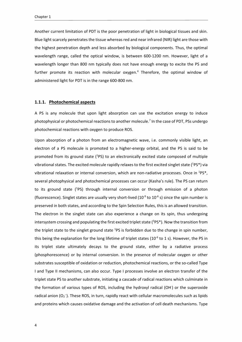
1.1.1. Photochemical aspects
A PS is any molecule that upon light absorption can use the excitation energy to induce
photophysical or photochemical reactions to another molecule.7 In the case of PDT, PSs undergo
photochemical reactions with oxygen to produce ROS.
Upon absorption of a photon from an electromagnetic wave, i.e. commonly visible light, an
electron of a PS molecule is promoted to a higher‐energy orbital, and the PS is said to be
promoted from its ground state (1PS) to an electronically excited state composed of multiple
vibrational states. The excited molecule rapidly relaxes to the first excited singlet state (1PS*) via
vibrational relaxation or internal conversion, which are non‐radiative processes. Once in 1PS*,
several photophysical and photochemical processes can occur (Kasha’s rule). The PS can return
to its ground state (1PS) through internal conversion or through emission of a photon
(fluorescence). Singlet states are usually very short‐lived (10‐9 to 10‐6 s) since the spin number is
preserved in both states, and according to the Spin Selection Rules, this is an allowed transition.
The electron in the singlet state can also experience a change on its spin, thus undergoing
intersystem crossing and populating the first excited triplet state (3PS*). Now the transition from
the triplet state to the singlet ground state 1PS is forbidden due to the change in spin number,
this being the explanation for the long lifetime of triplet states (10‐6 to 1 s). However, the PS in
its triplet state ultimately decays to the ground state, either by a radiative process
(phosphorescence) or by internal conversion. In the presence of molecular oxygen or other
substrates susceptible of oxidation or reduction, photochemical reactions, or the so‐called Type
I and Type II mechanisms, can also occur. Type I processes involve an electron transfer of the
triplet state PS to another substrate, initiating a cascade of radical reactions which culminate in
the formation of various types of ROS, including the hydroxyl radical (OH∙) or the superoxide
radical anion (O2‐∙). These ROS, in turn, rapidly react with cellular macromolecules such as lipids
and proteins which causes oxidative damage and the activation of cell death mechanisms. Type

Introduction
5
II reactions comprise electron energy transfer from the triplet state PS to triplet ground state
molecular oxygen (3O2) in a process called triplet‐triplet annihilation, thus forming the highly
reactive singlet oxygen (1O2). 1O2 has been proven to be generated in vitro in most studies
concerning photocytotoxic experiments, and hence the type II process is thought to be the main
mechanism in PDT.
Scheme 1.1. Jablonski diagram representing the energetic states of a PS, the photophysical processes
occurring upon light absorption and the Type I and Type II photochemical reactions. IC: internal
conversion, ISC: intersystem crossing, VR: vibrational relaxation, et: electron transfer, ET: energy transfer.
1.1.2. Photosensitizers
PSs are commonly organic planar molecules which are aromatic or with a high degree of ‐
orbital conjugation. Although there are a number of distinct types of molecules that can
photosensitize ROS, a vast majority are derivatives of the cyclic tetrapyrrole structure porphine,5
for instance porphyrins, chlorins, bacteriochlorins, phthalocyanines, or porphycenes.8 Porphine
is a conjugated planar macrocycle which consists of four pyrrolic sub‐units linked on opposing
sides (‐positions, Figure 1.1) through four methane (CH) bridges, known as the meso‐carbon
positions (Figure 1.1). Substitutions on the porphine macrocycle may be carried out at the meso‐
or ‐positions, leading to the so‐called porphyrins.

Chapter 1
6
Figure 1.1. Structure of some of the existing cyclic tetrapyrrolic PSs.
The first‐generation PS, hematoporphirin derivative or Photofrin®, is a mixture of porphyrin
oligomers and although still largely employed, it suffers from three important disadvantages: it
renders a long‐lasting skin photosensitivity to patients, it has a relatively low absorbance in the
red (630 nm) and it is not a pure compound but a mixture of active compounds.9 Due to these
drawbacks, many efforts have been made to synthesize second‐generation PSs which could be
more promising candidates for PDT. These second‐generation PSs were meant to pursue the
characteristics of the ideal PS, some of them being the following: 4,5,9
It should be a pure compound
It should have low manufacturing costs
Have good stability in storage
Be water soluble
Have a high absorption between 600‐800 nm
Have low levels of dark toxicity
Show a relatively rapid clearance from healthy tissues (minimizing phototoxic side
effects)

Introduction
7
Although several compounds meeting some of the above features have aroused, it has been
difficult to build up molecules which meet all these criteria. Even more challenging is that they
become clinically approved by the Regulatory Agencies; indeed, only a few PSs have reached the
market over the last 25 years after the launching of Photofrin®.4 Therefore, despite all the
efforts made by the scientific community, there are still some important limitations on the PSs
developed, especially their insolubility in water at physiological pH or their lack of selectivity for
targeted tissue.5 Thus, third‐generation PSs, i.e. the association of PSs to multiple‐platform
nanodevices or PSs direct linkage to targeting ligands are the main current strategies to
overcome solubility impairment and enhance diseased tissue selectivity and are now being the
focus of research.
1.1.3. Mechanisms of cell death
As already mentioned, photosensitized ROS oxidize surrounding cellular macromolecules,
leading to an irreparable cellular damage which triggers tumor cell death by any of the three
main pathways‐ apoptosis, necrosis or autophagy.10 The type of mechanism involved in cell
death depends on several factors, for instance treatment dose, cell line or subcellular
localization of the PS.11,12 The latter plays a key role in PDT since 1O2 has a very short lifetime in
living organisms13,14 and ultimate cellular response largely depends on where the photochemical
damage is produced, i.e. the internalized PS must be localized near its intracellular target.
Charge, amphiphilicity and partition coefficients are important parameters of the PS structure
that affect its main site of intracellular localization and consequently its efficiency and
mechanism of cell death. For the above reasons, ascertaining the variables that determine the
final subcellular localization of a PS becomes a key factor for understanding how PDT works and
what ultimately determines its efficacy.15–18 A large number of biochemical studies have
demonstrated that most of the subcellular organelles, such as mitochondria, nucleus,
lysosomes, plasma membrane, endoplasmic reticulum or Golgi apparatus, can become targets
for PSs.17 Moreover, in vivo, tumor cell destruction is sometimes accompanied by induction of
an acute local inflammatory reaction that participates in the removal of dead cells, restoration
of normal tissue homeostasis, and, sometimes, in the development of systemic immunity.4,19
Apoptosis is a regulated cell death mechanism which can be triggered by external or internal
signals and is a common cell death modality in cells treated with PDT.4 Apoptotic cells are
characterized by some morphological features, including chromatin condensation, nuclear
fragmentation, pyknosis, cell shrinkage and plasma membrane blebbing. Cells are ultimately

Chapter 1
8
fragmented into multiple membrane vesicles, called apoptotic bodies, which contain degraded
cellular compartments. Apoptotic bodies are engulfed by phagocytes in vivo, which prevents
inflammation and tissue destruction.11,20 Some reports suggest, though, that in some cases PDT‐
induced apoptosis might stimulate the extracellular release and binding of certain heat‐shock
proteins (HSPs) which would subsequently trigger their association to innate immunity cells such
as dendritic cells or natural killer cells. These immunity cells would in turn segregate pro‐
inflammatory cytokines, and altogether would propitiate the development of an anti‐tumor
immune response.19 Regarding to the biochemical level, oxidation of cellular components by
ROS initiates a stress response which elicits a cascade of signaling events commonly involving
activation of caspases, mitochondrial damage or cytochrome c release, among many others.11,20
Mitochondria plays a key role in regulating pro‐apoptotic signals and triggering the apoptosis
mechanism as a response, although some recent investigations indicate that other organelles
such as lysosomes, Golgi Apparatus or endoplasmic reticulum may be important in prompting
pro‐apoptotic signaling cascades.21,22
On the contrary, necrosis has traditionally been thought as a passive, not regulated, cell death
modality, although recent reports have remarked that some forms of necrosis may also occur in
a regulated manner.20,23,24 Excessive chemical or physical injury to the cell results in this cell
death modality. Necrotic cells are characterized by cytoplasm swelling, destruction of organelles
and uncontrolled rupture of the plasma membrane, leading to the release of intracellular
contents and pro‐inflammatory molecules, which leads to an acute inflammatory response.11
Photochemical damage of cells can also lead to cell death by autophagy. Whole organelles and
intracellular proteins which need to be degraded or recycled are encapsulated by a double
membrane forming the autophagosome, which ultimately fuses with a lysosome. Autophagy is
in fact a cytoprotective mechanism to preserve cellular homeostasis but it can also promote cell
death in response to excessive stress signals including oxidative stress caused by PDT.4,20 Recent
studies show that autophagy could both have a prodeath25 or preservation26 role after PDT
treatment.
1.1.4. Clinical applications
The current era of PDT can be considered to begin in 1960 when R. L. Lipson and S. Schwartz
observed that injection of crude preparations of hematoporphyrin led to fluorescence of
neoplastic lesions visualized during surgery. Schwartz further purified the hematoporphyrin
crude and obtained a more phototoxic version that he called hematoporphyrin derivative (HpD),

Introduction
9
which was used by Lipson et al. for further investigations.27 In 1978, Dougherty et al. conducted
the first clinical trial combining HpD and red light and obtained partial or complete tumor
eradication in almost all lesions treated.28 Indeed, Dougherty and co‐workers highly contributed
to the development and clinical implementation of PDT. Importantly, they further purified HpD
up to the launching of the first clinically approved PS known as Photofrin®,29 which nowadays
is still one of the most clinically used PSs.4
After the first clinical trial in 1976, numerous studies have contributed to promote PDT as a
reasonable treatment option in malignant skin lesions, Barret esophagus, unresectable
cholangiocarcinoma, head and neck cancer or lung cancer. However, for other tumors, only a
few randomized controlled trials have been performed to date,4 thus PDT is not yet a
preferential treatment for many neoplastic lesions. This underestimated condition is likely due
in part to the limitations of PDT itself: the depth of tumor destruction usually ranges from a few
millimeters up to 1 centimeter due to the limited penetration of light into the tissues; and the
high selectivity of this therapy makes it at the same time unviable for metastatic lesions. These
drawbacks, in combination with the shortcomings of some second‐generation PSs (see above),
have urged scientists to explore other alternatives for rendering PDT more active and efficient,
such as photochemical internalization (PCI),30 combination of PDT with other anticancer
therapies, or the use of delivery systems for PDT. Indeed, some clinically approved formulations
employing nanoliposomes (Foslip® and Visudyne®)31,32 shine some light on the near future of
PDT.
1.2. Drug delivery systems in photodynamic therapy
Nanotechnology is the science, engineering and technology at the nanoscale, i.e. from 1 to some
hundreds of nanometers. The concept of nanotechnology originated in 1959 when the physicist
Richard Feynman gave a conference entitled “There is Plenty of Room at the Bottom”. Later in
1974, Norio Taniguchi first used the word nanotechnology, and in 1980’s Eric Drexler wrote the
first book about nanotechnology. From 1990s this field has incredibly expanded and has
revolutionized other areas of science, from physics to medicine.
Generally speaking, the main goal of drug vehiculization into nanocarriers or drug delivery
systems is to reduce therapy associated side effects and improve bioavailability, thereby leading
to a higher efficacy of the drug with a decreased overall toxicity. Additionally, nanocarriers
protect the drug from premature degradation and from interactions with the biological
environment in the organism, increase the circulation time of the drug in the body and also

Chapter 1
10
enhance drug penetration into the diseased tissue cells.33 Employing nanoparticles (NPs) for PDT
can also have the following advantages:34–36
At their reduced size, NPs have unique physicochemical properties, such as a large
surface area to volume ratio. This is advantageous when the PS is transported through
covalent conjugation at the surface of the NP, since the large surface area enables to
construct nanocarriers with a high degree of payload
NPs improve the aqueous solubility of the PSs
Shape, size and surface nature of the NPs govern their biological interactions such as
intracellular uptake, blood circulation times, or their clearance through
reticuloendothelial system. The optimization of these parameters during synthetic
procedures can result in promising delivery systems. For instance, NP surface can be
modified either with certain polymers such as chitosan or poly‐(ethylene glycol) (PEG)
to improve their biodistribution and pharmacokinetics or with targeting moieties to
enhance cellular uptake through active targeting
They can be designed as multifunctional nanoplatforms to carry multiple components
together with the PSs, such as imaging agents or chemotherapeutic drugs
As previously mentioned, many second‐generation PSs with promising photophysical properties
were developed although most of them suffered from a high degree of hydrophobicity and
reduced tumor selectivity. The lack of aqueous solubility hinders their systemic administration
and also provokes their aggregation in this media, which leads to a loss of their photophysical
properties, for instance, a decrease in 1O2 formation.37 Thus, NPs have risen as an interesting
option to overcome the limitations of classic PSs over last years.
A nanocarrier should meet a series of characteristics. The ideal delivery system should be
biodegradable, have a small size and a high loading capacity, be stable, non‐immunogenic and
non‐toxic, have a prolonged circulation in the body after administration, and selectively
accumulate in the target area. Additionally, it was traditionally believed that the PS should be
incorporated in the nanocarrier without alteration of its photophysical properties in order to be
ready to generate ROS once inside the cell.35 Although this holds true for some PSs in certain
vehicles due to the improved solubility of the PS in the local environment of the nanovehicle, in
other cases the photosensitizing ability of the PS becomes reduced inside the nanocarrier due
to the high local concentration of the PS itself.38 This phenomenon might actually be valuable in
terms of preventing systemic phototoxicity to the patient before the nanocarrier reaches its
target.
Introduction
11
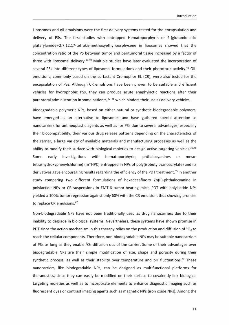
Liposomes and oil emulsions were the first delivery systems tested for the encapsulation and
delivery of PSs. The first studies with entrapped Hematoporphyrin or 9‐(glutamic acid
glutarylamide)‐2,7,12,17‐tetrakis(methoxyethyl)porphycene in liposomes showed that the
concentration ratio of the PS between tumor and peritumoral tissue increased by a factor of
three with liposomal delivery.39,40 Multiple studies have later evaluated the incorporation of
several PSs into different types of liposomal formulations and their phototoxic activity.41 Oil‐
emulsions, commonly based on the surfactant Cremophor EL (CR), were also tested for the
encapsulation of PSs. Although CR emulsions have been proven to be suitable and efficient
vehicles for hydrophobic PSs, they can produce acute anaphylactic reactions after their
parenteral administration in some patients,42–45 which hinders their use as delivery vehicles.
Biodegradable polymeric NPs, based on either natural or synthetic biodegradable polymers,
have emerged as an alternative to liposomes and have gathered special attention as
nanocarriers for antineoplastic agents as well as for PSs due to several advantages, especially
their biocompatibility, their various drug release patterns depending on the characteristics of
the carrier, a large variety of available materials and manufacturing processes as well as the
ability to modify their surface with biological moieties to design active‐targeting vehicles.35,46
Some early investigations with hematoporphyrin, phthalocyanines or meso‐
tetra(hydroxyphenylchlorine) (mTHPC) entrapped in NPs of poly(isobutylcyanoacrylate) and its
derivatives gave encouraging results regarding the efficiency of the PDT treatment.35 In another
study comparing two different formulations of hexadecafluoro Zn(II)‐phthalocyanine in
polylactide NPs or CR suspensions in EMT‐6 tumor‐bearing mice, PDT with polylactide NPs
yielded a 100% tumor regression against only 60% with the CR emulsion, thus showing promise
to replace CR emulsions.47
Non‐biodegradable NPs have not been traditionally used as drug nanocarriers due to their
inability to degrade in biological systems. Nevertheless, these systems have shown promise in
PDT since the action mechanism in this therapy relies on the production and diffusion of 1O2 to
reach the cellular components. Therefore, non‐biodegradable NPs may be suitable nanocarriers
of PSs as long as they enable 1O2 diffusion out of the carrier. Some of their advantages over
biodegradable NPs are their simple modification of size, shape and porosity during their
synthetic process, as well as their stability over temperature and pH fluctuations.37 These
nanocarriers, like biodegradable NPs, can be designed as multifunctional platforms for
theranostics, since they can easily be modified on their surface to covalently link biological
targeting moieties as well as to incorporate elements to enhance diagnostic imaging such as
fluorescent dyes or contrast imaging agents such as magnetic NPs (iron oxide NPs). Among the

Chapter 1
12
vast range of non‐biodegradable NPs, some of the most studied in the PDT field have been
polyacrylamide NPs,48 silica‐based NPs,49 gold NPs,50 fullerenes,51 or upconversion NPs.52
Moreover, some of these nanomaterials have significant optical properties which promote their
use as PSs themselves. For instance gold NPs have unique optical properties due to their surface
plasmon resonance absorption band that can be exploited to enhance the photophysical
properties of the PS or can be utilized for dual therapy (phototherapy and PDT). Fullerenes are
light absorbers and act as PSs per se. Upconversion NPs, on the other hand, are being explored
as systems that may enable patient irradiation to the NIR area of the spectrum thanks to their
ability to absorb NIR radiation and emit light at the visible region. Although most of them have
been shown to be biocompatible, their main disadvantage is that their possible long term
toxicity has not yet been evaluated, and most of them have not received FDA approval.
1.3. Poly‐(D,L‐lactide) and poly‐(D,L‐lactide‐co‐glycolide) nanoparticles
as drug delivery agents for photodynamic therapy
Among the synthetic polymers, the ‐hydroxy)‐polyesters polylactide (PLA), polyglycolide
(PGA), and specially their copolymer poly‐(lactide‐co‐glycolide) (PLGA) have generated a strong
interest due to their excellent biocompatibility, biodegradability and toxicologically safe by‐
products. More importantly, PLGA received the US Food and Drug Administration (FDA) approval
in 1999 as a delivery system for therapeutic uses.33
PLA, PGA and PLGA polymers are commonly synthesized by ring opening polymerization from
the cyclic dimers of lactic acid and glycolic acid (lactide and glycolide rings)53 and in the case of
PLGA, copolymers with varying compositions can be obtained depending on the ratio lactide to
glycolide employed. For instance, PLGA 75:25 stands for a PLGA with a composition of a 75%
lactide and 25% glycolide. According to the presence of a chiral center on the lactic acid
monomer, the corresponding polymer can be synthesized in its enantiomerically pure forms,
namely poly‐(D‐lactide) (PDLA) or poly‐(L‐lactide) (PLLA), or the racemic form poly‐(D,L‐lactide)
(PLA). The physicochemical properties of optically active PDLA and PLLA are nearly the same,
except for their solid structure, since PDLA is completely amorphous while PLLA is crystalline.
The methyl side group in lactic acid (Figure 1.2) renders a high hydrophobicity to this polymer.
On the contrary, glycolic acid does not contain any methyl side group, which makes PGA slightly
more hydrophilic and highly crystalline, similarly to PLLA. The copolymer PLGA is crystalline if it
is formed from PLLA and PGA, but PDLA or PLA reduce its crystallinity.

Introduction
13
Figure 1.2. Chemical structure of the ‐hydroxy)‐polyesters PLA, PGA and PLGA.
Additionally, the higher the lactide content, the higher the hydrophobicity of the copolymer.54
Biodegradation of these polymers or its NPs in vivo is accomplished mainly by hydrolysis of the
ester linkages, resulting in the building block monomers lactic acid and glycolic acid which are
further eliminated by common metabolic pathways. The degradation rate of PLGA depends on
several factors, mainly the composition of the polymer, its molecular weight, its hydrophobicity,
its degree of crystallinity and its glass transition temperature (Tg). Environmental factors such
as pH, temperature or ionic strength of the medium are also detrimental, although in vivo only
significant changes would alter the degradation rate. In general, the degradation time is shorter
for low molecular weight, more hydrophilic and more amorphous polymers. Exceptionally, it has
been proven that PLGA 50:50 has the fastest degradation rate in vivo (around 50‐60 days). Thus,
by modifying the molecular weight and lactide to glycolide ratio, the degradation time of PLGA
and consequently the release profile of the entrapped drug can be modified. Indeed, drug
release depends on drug diffusion and degradation of the polymeric matrix, as well as on the
nature of the delivery system (nanocapsule or nanosphere). In the case of a nanosphere, the
drug is distributed/dissolved in the polymeric matrix and the release occurs by diffusion of the
drug or erosion of the matrix, the main mechanism being the faster of the two. Rapid initial
release or “burst” release is generally attributed to the fraction of drug which is adsorbed or
weakly bound to the surface of NPs. The subsequent exponential release rate observed is
probably due to the drug more internalized in the matrix.55 In the case of a chemically
conjugated drug its release is also achieved, although it has been reported to be in a time 5 fold
longer than for the same system with the drug physically entrapped (25 days vs 5 days).56
Regarding NP internalization, a number of studies have proposed that PLGA NPs are internalized
by cells via endocytosis,57–61 an energy dependent process which is blocked at low temperatures.

Chapter 1
14
Thus, the observation of a significant reduction of the internalization of NPs at 4 ᵒC compared
to 37 ᵒC suggests that NP uptake is mediated by endocytosis.59,62 Moreover, another study
employing Raman spectral imaging as a non‐invasive technique showed that HeLa cells
presented intracellular PLGA inclusions after 2 h of incubation, supporting the internalization of
the NPs.63 The exact endocytic mechanism, however, is not fully known yet. Fluid phase
pinocytosis or clathrin‐mediated endocytosis have been suggested by some authors,57 whereas
others have observed that the endocytic process might be independent of clatrhin and caveolin
proteins.58 The intracellular fate of these NPs would naturally be the endosomal structures after
the endocytic process,62 although there is evidence that NPs may escape endo‐lysosomal
degradation and may be trafficked to other relevant subcellular compartments after
endocytosis.57,59,63 Moreover, it is known that uptake is influenced by the physicochemical
properties of the NP itself such as its charge or its size, and that not all cell lines may follow the
same internalization pathways when exposed to the same NPs.64 Thus, some of the above results
might show discrepancy due to the different cell lines and NPs tested. However, it is clear that
further research is needed to better elucidate the cellular internalization process.
All the aforementioned characteristics of the polyester‐based NPs, together with their ability to
encapsulate hydrophilic but especially lipophilic drugs, has promoted the research on the
benefits of PS incorporation into these nanodelivery systems. In a series of publications, Konan
et al. reported the encapsulation of meso‐tetra(4‐hydroxyphenyl)porphyrin (p‐THPP) in NPs of
PLGA 50:50, PLGA 75:25 and PLA. They observed that polymer composition did not affect
significantly the physical characteristics of NPs such as size, surface charge, drug loading or
redispersibility.65 They did observe that at the lowest concentration of p‐THPP tested, 3 g/mL,
50:50 PLGA NPs were the most efficient in inducing cell death (80%) followed by 75:25 PLGA or
PLA NPs, which showed almost the same phototoxic outcome (40%). This higher efficiency of
PLGA 50:50 NPs was likely due to a faster degradation rate and release for this copolymer ratio
as well as its influence on the rate of carrier uptake.66 Vargas et al. studied the impact of NP size
on the photodynamic activity of meso‐tetra(3‐hydroxyphenyl)porphyrin (m‐THPP)‐loaded PLGA
NPs in the chick chorioallantoic membrane (CAM) model. They observed that m‐THPP was less
effective in large NPs (~600 nm) than free in solution or small NPs (~100 nm). In following
studies, they showed that the batch with the smallest particle size and most active in vivo (~100
nm) exhibited in vitro the highest ROS formation and the fastest m‐THPP release. Absorption,
fluorescence intensity and fluorescence lifetime of entrapped m‐THPP varied among NP batches
of different size suggesting that location and aggregation states of entrapped m‐THPP was
dependent on NP size.38 McCarthy et al. showed that the encapsulation of meso‐

Introduction
15
tetraphenylporpholactol in PLGA NPs with a 12% drug loading also results in the quenched
excited states of the PS, yet it is released and activated upon cell internalization. In cell culture,
the phototoxicity caused by non‐internalized NPs was minimal (9%) in contrast to the effect of
internalized NPs (95%), and in vivo animal studies showed complete eradication of tumors.67
These results emphasized that quenching of PS excited state inside the NP could be
advantageous for preventing healthy tissue damage as long as the NPs are internalized and the
PS released and reactivated. In this line, entrapment and phototoxic activity of Zn(II)‐
phthalocyanine (ZnPc) was also tested in PLGA NPs. It was found that once ZnPc was released
from NPs to an organic solvent, its photophysical properties remained the same as for free ZnPc,
although there was no report on the photophysical properties of the ZnPc entrapped into the
NPs.68 Gomes et al. studied the photophysical properties of an aqueous PLGA NP suspension of
entrapped bacteriochlorophyll‐a (BChl‐a). Regarding the absorption spectrum, they reported a
decrease in intensity as well as a bathochromic shift of the Q bands for entrapped BChl‐a
compared to BChl‐a in solution, as well as a bathochromic shift in fluorescence spectrum.
However, they did not attribute these spectroscopic changes to the formation of aggregates
since the fluorescence quantum yield was the same for free BChl‐a and entrapped BChl‐a, and
1O2 quantum yield, measured by indirect methods, was also comparable between both
systems.69
Differing from the previous PSs, a study conducted by Da Silva et al. encapsulating 0.21% of
In(III)‐tetraphenylporphine (InTPP) into sub‐200 nm PLGA NPs reported that InTPP was not
aggregated since absorption and emission spectra of the entrapped InTPP did not show any
spectroscopic differences compared to free InTPP in a non‐polar solvent. It was also more
efficient in inducing cell death than free InTPP in human prostate carcinoma, mainly by
apoptosis. This increase was attributed to an observed higher uptake of encapsulated InTPP as
well as to the aggregation state of free InTPP in culture medium, which reduces its ability to
produce singlet oxygen. Zeisser‐Labouèbe et al. studied the encapsulation of Hypericn (Hyp) in
PLA NPs in various drug loadings, as well as in two types of PLGA 50:50 NPs with different PLGA
molecular weight. NP size was nearly the same for all formulations, but entrapment efficiency
was much higher in PLA (70% vs 20% for PLGA NPs at the same initial drug loading). Interestingly,
they observed that the greater the drug loading, the lower the phototoxic effect after 1h
incubation, explained by an observed faster release in the less loaded NPs and a likely increased
aggregation of Hyp in highly loaded NPs.70 In another study, they used Hyp‐loaded PLA NPs in a
much higher drug loading (3.7%) to study the usefulness of NPs in a rat model of ovarian cancer.
The selectivity of Hyp administered with free Hyp or Hyp‐loaded NPs was assessed by

Chapter 1
16
fluorescence endoscopy and quantified after tissue extraction. Hyp accumulation was greater in
ovarian micrometastases when administered with NPs after 24 h compared to free Hyp and it
was also higher than in surrounding muscle.71 The FDA approved 5,10,15,20‐tetrakis(3‐
hydroxyphenyl)chlorin (m‐THPC) has also been encapsulated in PLGA 50:50 NPs and its cellular
internalization and phototoxicity compared to that of the free drug. It was found that mTHPC
administered in PLGA NPs had the same mechanism of cell internalization, the same intracellular
localization pattern as well as a similar phototoxic effect than the free drug. Nevertheless,
mTHPC incorporated in PLGA NPs was advantageous since it did not produce any dark toxicity
to the cultured cells.
Altogether, these variety of results show that interactions between the PS and the PLGA or PLA
matrix may depend on each PS and copolymer used, and thus photophysical properties as well
as photodynamic activity need to be studied for each particular case.
1.4. Targeted photodynamic therapy
1.4.1. Passive targeting
Nanoparticulate systems administered to the body with a size range of 10‐500 nm can reach
neoplastic cells by means of the enhanced permeability and retention (EPR) effect. This
phenomenon is characterized by a leaky and more permeable vasculature and poor lymphatic
drainage in tumor tissue, which enables the NPs to easily extravasate the endothelial cells of the
vessels and accumulate at the interstitial space.72
Pharmacokinetic studies in vivo have shown that PLGA NPs suffer from adsorption of opsonins
onto their surface likely due to the hydrophobic character of the polymer, resulting in their rapid
uptake by the cells of the reticuloendothelial system (RES).53,73,74 RES uptake of NPs depends on
particle size, surface charge and especially surface hydrophobicity.75 It has been demonstrated
that coating the hydrophobic surface of such NPs with hydrophilic polymers, the most popular
of which being poly‐(ethylene glycol) (PEG), is efficient in preventing their rapid uptake by
macrophages, and hence, in lengthening their circulation time.76 Therefore, long‐circulating
PEGylated NPs are more favorable to passively accumulate in tumors than non‐PEGylated
counterparts thanks to their prolonged half‐life in the organism.35 The most accepted theory for
this increased circulation time is that PEG reduces protein interactions on the surface of PLGA
NPs thereby preventing opsonin binding.77 Hence, PEG‐modified PLA or PLGA NPs, prepared
mostly by using a di‐block copolymer PLA‐PEG or PLGA‐PEG as an additive, have been proposed

Introduction
17
as long circulating nanodevices and have already been evaluated for PDT.60,78,79 First studies
were related to the encapsulation of ZnPc16 into PEGylated PLA NPs or into Chremophor EL
emulsions and the comparison of their photodynamic properties.80 In other subsequent works,
in addition to phototoxicity studies in vitro or in vivo, the photophysical characteristics of the
PEGylated nanosystems were evaluated.81,82 Recently, PLGA‐PEG NPs encapsulating ZnPc,
combined with gold NPs and an immunostimulating agent were developed as a multifunctional
platform.83 Although in all these studies the feasibility and suitability of the PEGylated
nanosystems as vehicles for photodynamic therapy were demonstrated, the relevance of the
photophysical properties on the characteristics of the nanosystems and their influence on the
photodynamic response were not determined in detail.
1.4.2. Active targeting
An alternative strategy to convey the nanovehicles to the desired target cell is to functionalize
the surface of NPs with specific ligands that bind with high affinity to certain biomolecules
overexpressed or unique to diseased tissue or vasculature. A large variety of ligands have been
explored including monoclonal antibodies and antibody fragments, proteins, peptides or small
molecules such as folic acid or monosaccharides.84
Figure 1.3. Representation of the most common ligands explored for active targeting.

Chapter 1
18
The most popular approach adopted to improve PDT selectivity does not imply nanovehicles but
rather the direct conjugation of PSs to monoclonal antibodies (mAbs) or antibody fragments,
called photoimmunoconjugates (PICs), since these biomolecules have a high degree of
specificity for its binding moiety. Despite favorable advances in the photodynamic effect of these
conjugates, it has been found that obtaining well‐purified and well‐characterized PICs is rather
problematic, mainly due to the tendency of PICs to aggregate and of the hydrophobic PSs to
remain attached via non‐covalent binding to the hydrophobic pockets of the antibodies.85 mAbs
can also be immunogenic, have limited half‐lives, are expensive to manufacture and may vary
from batch to batch, which limits their efficiency as targeting molecules.84 Therefore, other
active targeting strategies involving smaller ligands, such as aptamers, proteins, peptides or folic
acid, have been studied. The direct conjugation of some PSs to these biomolecules has afforded
some promising results, for instance Ce6‐aptamer conjugates yielded a more than 500‐fold
increase in phototoxicity than the free Ce6 in cells overexpressing the specific targeted antigen.86
Translation of the active targeting strategy to nanovehicles has resulted in several targeted
delivery systems for PDT. Interestingly, most of these studies have reported an increased
phototoxic effect exerted by the targeted vehicles, although it seems that its extent depends
largely on the type of targeting moiety and probably the nanovehicle. For instance, folate‐
targeted liposomes have been reported to produce a moderate increase in the phototoxic effect
(~2 fold),87,88 whereas gold NPs conjugated with the lectin jacalin or with an anti‐ HER‐2 mAb
have shown a 5‐fold photodynamic effect.50 It is thus clear that active targeting looks promising
and that research in this direction should continue in order to discover other potential targeted‐
nanodelivery systems. In this sense, targeted PLGA or PLA NPs have been previously reported to
enhance cytotoxicity of chemotherapeutic agents, but no studies have been carried out
regarding PDT, which makes them suitable for investigation.

Introduction
19
1.5. Objectives
The main goal in this thesis is to design and study biodegradable polymer‐based nanoparticles
for photodynamic therapy, either passively or actively targeted. This main goal is further set in
the following specific objectives:
Development of passive targeting nanoparticle formulations for entrapping lipophilic
photosensitizers and evaluation of their physicochemical, photophysical and
photodynamic properties in vitro
Development of biodegradable nanodelivery systems comprising a covalently linked
photosensitizer and evaluation of their suitability for photodynamic therapy
Elaboration of actively targeted biodegradable nanoparticles by conjugation of an active
ligand to be exposed on the surface of nanoparticles and study of their photodynamic
efficacy in vitro

Chapter 1
20
1.6. References:
(1) World Health Organization. Global Health Observatory Data Repository http://apps.who.int/gho/data/node.main.CODWORLD?lang=en (accessed Aug 16, 2015).
(2) World Health Organization (WHO). Cancer http://www.who.int/mediacentre/factsheets/fs297/en/ (accessed Oct 15, 2015).
(3) Ferlay, J.; Soerjomataram I, I.; Dikshit, R.; Eser, S.; Mathers, C.; Rebelo, M.; Parkin, D. M.; Forman D, D.; Bray, F. Cancer Incidence and Mortality Worldwide: Sources, Methods and Major Patterns in GLOBOCAN 2012. Int. J. Cancer 2014, 136, E359–E386.
(4) Agostinis, P.; Berg, K.; Cengel, K. A.; Foster, T. H.; Girotti, A. W.; Gollnick, S. O.; Hahn, S. M.; Hamblin, M. R.; Juzeniene, A.; Kessel, D.; et al. Photodynamic Therapy of Cancer: An Update. CA. Cancer J. Clin. 2011, 61, 250–281.
(5) Josefsen, L. B.; Boyle, R. W. Photodynamic Therapy and the Development of Metal‐Based Photosensitisers. Met. Based. Drugs 2008, 2008, 1–23.
(6) Allison, R. R.; Moghissi, K. Oncologic Photodynamic Therapy: Clinical Strategies That Modulate Mechanisms of Action. Photodiagnosis Photodyn. Ther. 2013, 10, 331–341.
(7) Wilkinson, A.; McNaught, A. D. IUPAC. Compendium of Chemical Terminology; M. Nic, J. Jirat, B. K., Ed.; 2nd ed.; Blackwell Scientific Publications: Oxford, 2014.
(8) Aramendia, P. F.; Redmond, R. W.; Braslavsky, S. E.; Schaffnerlf, K.; Vogel, E.; Nonell, S. The Photophysical Properties of Porphycenes: Potential Photodynamic Therapy Agents. Photochem Photobiol 1986, 44, 555–559.
(9) Castano, A. P.; Demidova, T. N.; Hamblin, M. R. Mechanisms in Photodynamic Therapy: Part One ‐ Photosensitizers, Photochemistry and Cellular Localization. Photodiagnosis Photodyn. Ther. 2004, 1, 279–293.
(10) Kiesslich, T.; Tortik, N.; Pichler, M.; Neureiter, D.; Plaetzer, K. Apoptosis in Cancer Cells Induced by Photodynamic Treatment – a Methodological Approach. J. Porphyr. Phthalocyanines 2013, 17, 197–209.
(11) Castano, A. P.; Demidova, T. N.; Hamblin, M. R. Mechanisms in Photodynamic Therapy: Part Two: Cellular Signaling, Cell Metabolism and Modes of Cell Death. Photodiagnosis and photodynamic therapy, 2005, 2, 1–23.
(12) Soriano, J.; García‐Díaz, M.; Mora, M.; Sagrista, M. L.; Nonell, S.; Villanueva, A.; Stockert, J. C.; Canete, M. Liposomal Temocene (m‐THPPo) Photodynamic Treatment Induces Cell Death by Mitochondria‐Independent Apoptosis. Biochim. Biophys. Acta 2013, 1830, 4611–4620.
(13) Jiménez‐Banzo, A.; Sagristà, M. L.; Mora, M.; Nonell, S.; Sagrista, M. L. Kinetics of Singlet Oxygen Photosensitization in Human Skin Fibroblasts. Free Radic. Biol. Med. 2008, 44, 1926–1934.
(14) Ragàs, X.; Agut, M.; Nonell, S. Singlet Oxygen in Escherichia Coli: New Insights for Antimicrobial Photodynamic Therapy. Free Radic. Biol. Med. 2010, 49, 770–776.
(15) Blázquez‐Castro, A.; Stockert, J. C.; Sanz‐Rodríguez, F.; Zamarrón, A.; Juarranz, A. Differential Photodynamic Response of Cultured Cells to Methylene Blue and Toluidine Blue: Role of Dark Redox Processes. Photochem. Photobiol. Sci. 2009, 8, 371–376.

Introduction
21
(16) Dovigo, L.; Pavarina, A.; de Oliveira Mima, E.; Giampaolo, E.; Vergani, C.; Bagnato, V. Fungicidal Effect of Photodynamic Therapy against Fluconazole‐Resistant Candida Albicans and Candida Glabrata. Mycoses 2009, 54, 123–130.
(17) Oliveira, C. S.; Turchiello, R.; Kowaltowski, A. J.; Indig, G. L.; Baptista, M. S. Major Determinants of Photoinduced Cell Death: Subcellular Localization versus Photosensitization Efficiency. Free Radic. Biol. Med. 2011, 51, 824–833.
(18) Tejedor‐Estrada, R.; Nonell, S.; Teixido, J.; Sagrista, M. L.; Mora, M.; Villanueva, A.; Canete, M.; Stockert, J. C. An Artificial Neural Network Model for Predicting the Subcellular Localization of Photosensitisers for Photodynamic Therapy of Solid Tumours. Curr. Med. Chem. 2012, 19, 2472–2482.
(19) Garg, A. D.; Nowis, D.; Golab, J.; Agostinis, P. Photodynamic Therapy: Illuminating the Road from Cell Death towards Anti‐Tumour Immunity. Apoptosis 2010, 15, 1050–1071.
(20) Galluzzi, L.; Bravo‐San Pedro, J. M.; Kroemer, G. Organelle‐Specific Initiation of Cell Death. Nat. Cell Biol. 2014, 16, 728–736.
(21) Liu, L.; Zhang, Z.; Xing, D. Cell Death via Mitochondrial Apoptotic Pathway due to Activation of Bax by Lysosomal Photodamage. Free Radic. Biol. Med. 2011, 51, 53–68.
(22) Moserova, I.; Kralova, J. Role of ER Stress Response in Photodynamic Therapy: ROS Generated in Different Subcellular Compartments Trigger Diverse Cell Death Pathways. PLoS One 2012, 7, e32972.
(23) Coupienne, I.; Fettweis, G.; Rubio, N.; Agostinis, P.; Piette, J. 5‐ALA‐PDT Induces RIP3‐Dependent Necrosis in Glioblastoma. Photochem. Photobiol. Sci. 2011, 10, 1868–1878.
(24) Coupienne, I.; Fettweis, G.; Piette, J. RIP3 Expression Induces a Death Profile Change in U2OS Osteosarcoma Cells after 5‐ALA‐PDT. Lasers Surg. Med. 2011, 43, 557–564.
(25) Dewaele, M.; Maes, H.; Agostinis, P. ROS‐Mediated Mechanisms of Autophagy Stimulation and Their Relevance in Cancer Therapy. Autophagy 2010, 6, 838–854.
(26) Reiners, J. J.; Agostinis, P.; Berg, K.; Oleinick, N. L.; Kessel, D. Assessing Autophagy in the Context of Photodynamic Therapy. Autophagy 2010, 6, 7–18.
(27) Lipson, R. L.; Baldes, E. J. The Photodynamic Properties of a Particular Hematoporphyrin Derivative. Arch. Dermatol. 1960, 82, 508–516.
(28) Dougherty, T. J.; Kaufman, J. E.; Goldfarb, A.; Weishaupt, K. R.; Boyle, D.; Mittleman, A. Photoradiation Therapy for the Treatment of Malignant Tumors Photoradiation Therapy for the Treatment of Malignant Tumors. Cancer Res. 1978, 2628–2635.
(29) Dougherty, T. J.; Gomer, C. J.; Henderson, B. W.; Jori, G.; Kessel, D.; Korbelik, M.; Moan, J.; Peng, Q. Photodynamic Therapy. J. Natl. Cancer Inst. 1998, 90, 889–905.
(30) Weyergang, A.; Berstad, M. E. B.; Bull‐Hansen, B.; Olsen, C. E.; Selbo, P. K.; Berg, K. Photochemical Activation of Drugs for the Treatment of Therapy‐Resistant Cancers. Photochem. Photobiol. Sci. 2015.
(31) Kiesslich, T.; Berlanda, J.; Plaetzer, K.; Krammer, B.; Berr, F. Comparative Characterization of the Efficiency and Cellular Pharmacokinetics of Foscan‐ and Foslip‐Based Photodynamic Treatment in Human Biliary Tract Cancer Cell Lines. Photochem. Photobiol. Sci. 2007, 6, 619–627.

Chapter 1
22
(32) Christie, J. G.; Kompella, U. B. Ophthalmic Light Sensitive Nanocarrier Systems. Drug Discov. Today 2008, 13, 124–134.
(33) Acharya, S.; Sahoo, S. K. PLGA Nanoparticles Containing Various Anticancer Agents and Tumour Delivery by EPR Effect. Adv. Drug Deliv. Rev. 2011, 63, 170–183.
(34) Paszko, E.; Ehrhardt, C.; Senge, M. O.; Kelleher, D. P.; Reynolds, J. V. Nanodrug Applications in Photodynamic Therapy. Photodiagnosis Photodyn. Ther. 2011, 8, 14–29.
(35) Konan, Y. N.; Gurny, R.; Allémann, E. State of the Art in the Delivery of Photosensitizers for Photodynamic Therapy. J. Photochem. Photobiol. B. 2002, 66, 89–106.
(36) Lucky, S. S.; Soo, K. C.; Zhang, Y. Nanoparticles in Photodynamic Therapy. Chem. Rev. 2015, 115, 1990–2042.
(37) Bechet, D.; Couleaud, P.; Frochot, C.; Viriot, M.‐L. L.; Guillemin, F.; Barberi‐Heyob, M. Nanoparticles as Vehicles for Delivery of Photodynamic Therapy Agents. Trends Biotechnol. 2008, 26, 612–621.
(38) Vargas, A.; Lange, N.; Arvinte, T.; Cerny, R.; Gurny, R.; Delie, F. Toward the Understanding of the Photodynamic Activity of M‐THPP Encapsulated in PLGA Nanoparticles: Correlation between Nanoparticle Properties and in Vivo Activity. J. Drug Target. 2009, 17, 599–609.
(39) Jori, G.; Reddi, E.; Cozzani, I.; Tomio, L. Controlled Targeting of Different Subcellular Sites by Porphyrins in Tumour‐Bearing Mice. Br. J. Cancer 1986, 53, 615–621.
(40) Reddi, E. Role of Delivery Vehicles for Photosensitizers in the Photodynamic Therapy of Tumours. J. Photochem. Photobiol. B. 1997, 37, 189–195.
(41) Jin, C. S.; Zheng, G. Liposomal Nanostructures for Photosensitizer Delivery. Lasers Surg. Med. 2011, 43, 734–748.
(42) Howrie, D. L.; Ptachcinski, R. J.; Griffith, B. P.; Hardesty, R. J.; Rosenthal, J. T.; Burckart, G. J.; Venkataramanan, R. Anaphylactoid Reactions Associated with Parenteral Cyclosporine Use: Possible Role of Cremophor EL. Drug Intell. Clin. Pharm. 1985, 19, 425–427.
(43) Wang, Y.; Wu, K.‐C.; Zhao, B.‐X.; Zhao, X.; Wang, X.; Chen, S.; Nie, S.‐F.; Pan, W.‐S.; Zhang, X.; Zhang, Q. A Novel Paclitaxel Microemulsion Containing a Reduced Amount of Cremophor EL: Pharmacokinetics, Biodistribution, and in Vivo Antitumor Efficacy and Safety. J. Biomed. Biotechnol. 2011, 2011, 854872.
(44) Bennett, C. L.; Adegboro, O. S.; Calhoun, E. A.; Raisch, D. Beyond the Black Box: Drug‐ and Device‐Associated Hypersensitivity Events. Drug. Healthc. Patient Saf. 2010, 2, 1–5.
(45) Szebeni, J.; Alving, C. R.; Savay, S.; Barenholz, Y.; Priev, A.; Danino, D.; Talmon, Y. Formation of Complement‐Activating Particles in Aqueous Solutions of Taxol: Possible Role in Hypersensitivity Reactions. Int. Immunopharmacol. 2001, 1, 721–735.
(46) Li, W.‐T. Nanoparticles for Photodynamic Therapy. In Handbook of biophotonics; Popp, J.; Tuchin, V. V.; Chiou, A.; Heinemann, S. H., Eds.; Wiley‐VCH Verlag GmbH & Co. KGaA: Weinheim, Germany, 2013.
(47) Allémann, E.; Brasseur, N.; Benrezzak, O.; Rousseau, J.; Kudrevich, S. V; Boyle, R. W.; Leroux, J. C.; Gurny, R.; Van Lier, J. E. PEG‐Coated Poly(lactic Acid) Nanoparticles for the Delivery of
Introduction
23
Hexadecafluoro Zinc Phthalocyanine to EMT‐6 Mouse Mammary Tumours. J. Pharm. Pharmacol. 1995, 47, 382–387.
(48) Kuruppuarachchi, M.; Savoie, H.; Lowry, A.; Alonso, C.; Boyle, R. W. Polyacrylamide Nanoparticles as a Delivery System in Photodynamic Therapy. Mol. Pharm. 2011, 8, 920–931.
(49) Couleaud, P.; Morosini, V.; Frochot, C.; Richeter, S.; Raehm, L.; Durand, J. O. Silica‐Based Nanoparticles for Photodynamic Therapy Applications. Nanoscale 2010, 2, 1083–1095.
(50) Obaid, G.; Chambrier, I.; Cook, M. J.; Russell, D. A. Cancer Targeting with Biomolecules: A Comparative Study of Photodynamic Therapy Efficacy Using Antibody or Lectin Conjugated Phthalocyanine‐PEG Gold Nanoparticles. Photochem. Photobiol. Sci. 2015, 14, 737–747.
(51) Sharma, S.; Chiang, L.; Hamblin, M. Photodynamic Therapy with Fullerenes in Vivo: Reality or a Dream? Nanomedicine 2011, 6, 1813–1825.
(52) Lim, S. F.; Austin, R. H. Upconverting Nanoparticle‐Based Multi‐Functional Nanoplatform for Enhanced Photodynamic Therapy: Promises and Perils; Hamblin, M. R.; Avci, P., Eds.; 1st ed.; Elsevier, 2015.
(53) Locatelli, E.; Comes Franchini, M. Biodegradable PLGA‐B‐PEG Polymeric Nanoparticles: Synthesis, Properties, and Nanomedical Applications as Drug Delivery System. J. Nanoparticle Res. 2012, 14, 1316.
(54) Makadia, H. K.; Siegel, S. J. Poly Lactic‐Co‐Glycolic Acid (PLGA) as Biodegradable Controlled Drug Delivery Carrier. Polymers (Basel). 2011, 3, 1377–1397.
(55) Parveen, S.; Sahoo, S. K. Polymeric Nanoparticles for Cancer Therapy. J. Drug Target. 2008, 16, 108–123.
(56) Yoo, H. S.; Oh, J. E.; Lee, K. H.; Park, T. G. Biodegradable Nanoparticles Containing Doxorubicin‐PLGA Conjugate for Sustained Release. Pharm. Res. 1999, 16, 1114–1118.
(57) Panyam, J.; Labhasetwar, V. Biodegradable Nanoparticles for Drug and Gene Delivery to Cells and Tissue. Adv. Drug Deliv. Rev. 2003, 55, 329–347.
(58) Qaddoumi, M. G.; Gukasyan, H. J.; Davda, J.; Labhasetwar, V.; Kim, K.‐J.; Lee, V. H. L. Clathrin and Caveolin‐1 Expression in Primary Pigmented Rabbit Conjunctival Epithelial Cells: Role in PLGA Nanoparticle Endocytosis. Mol. Vis. 2003, 9, 559–568.
(59) Cartiera, M. S.; Johnson, K. M.; Rajendran, V.; Caplan, M. J.; Saltzman, W. M. The Uptake and Intracellular Fate of PLGA Nanoparticles in Epithelial Cells. Biomaterials 2009, 30, 2790–2798.
(60) Rojnik, M.; Kocbek, P.; Moret, F.; Compagnin, C.; Celotti, L.; Bovis, M. J.; Woodhams, J. H.; Macrobert, A. J.; Scheglmann, D.; Helfrich, W.; et al. In Vitro and in Vivo Characterization of Temoporfin‐Loaded PEGylated PLGA Nanoparticles for Use in Photodynamic Therapy. Nanomedicine (Lond). 2012, 7, 663–677.
(61) Lei, T.; Srinivasan, S.; Tang, Y.; Manchanda, R.; Nagesetti, A.; Fernandez‐Fernandez, A.; McGoron, A. J. Comparing Cellular Uptake and Cytotoxicity of Targeted Drug Carriers in Cancer Cell Lines with Different Drug Resistance Mechanisms. Nanomedicine 2011, 7, 324–332.
(62) Konan, Y. N.; Chevallier, J.; Gurny, R.; Allémann, E. Encapsulation of P‐THPP into Nanoparticles: Cellular Uptake, Subcellular Localization and Effect of Serum on Photodynamic Activity. Photochem. Photobiol. 2003, 77, 638–644.

Chapter 1
24
(63) Chernenko, T.; Matthäus, C.; Milane, L.; Quintero, L.; Amiji, M.; Diem, M. Label‐Free Raman Spectral Imaging of Intracellular Delivery and Degradation of Polymeric Nanoparticle Systems. ACS Nano 2009, 3, 3552–3559.
(64) Hillaireau, H.; Couvreur, P. Nanocarriers’ Entry into the Cell: Relevance to Drug Delivery. Cell. Mol. Life Sci. 2009, 66, 2873–2896.
(65) Konan, Y. N.; Cerny, R.; Favet, J.; Berton, M.; Gurny, R.; Allémann, E. Preparation and Characterization of Sterile Sub‐200 Nm Meso‐tetra(4‐Hydroxyphyenyl)poprhyrin‐Loaded Nanoparticles for Photodynamic Therapy. Eur. J. Pharm. Biopharm. 2003, 55, 115–124.
(66) Konan, Y. N.; Berton, M.; Gurny, R.; Allemann, E. Enhanced Photodynamic Activity of Meso‐tetra(4‐Hydroxyphenyl) Porphyrin by Incorporation into Sub‐200 Nm Nanoparticles. Eur. J. Pharm. Sci. 2003, 18, 241–249.
(67) McCarthy, J. R.; Perez, J. M.; Brückner, C.; Weissleder, R. Polymeric Nanoparticle Preparation That Eradicates Tumors. Nano Lett. 2005, 5, 2552–2556.
(68) Ricci‐Junior, E.; Marchetti, J. M. Zinc(II) Phthalocyanine Loaded PLGA Nanoparticles for Photodynamic Therapy Use. Int. J. Pharm. 2006, 310, 187–195.
(69) Gomes, A. J.; Lunardi, C. N.; Tedesco, A. C. Characterization of Biodegradable poly(D,L‐Lactide‐Co‐Glycolide) Nanoparticles Loaded with Bacteriochlorophyll‐a for Photodynamic Therapy. Photomed. Laser Surg. 2007, 25, 428–435.
(70) Zeisser‐Labouebe, M.; Lange, N.; Gurny, R.; Delie, F. Hypericin‐Loaded Nanoparticles for the Photodynamic Treatment of Ovarian Cancer. Int. J. Pharm. 2006, 326, 174–181.
(71) Zeisser‐Labouèbe, M.; Delie, F.; Gurny, R.; Lange, N. Benefits of Nanoencapsulation for the Hypercin‐Mediated Photodetection of Ovarian Micrometastases. Eur. J. Pharm. Biopharm. 2009, 71, 207–213.
(72) Torchilin, V. Tumor Delivery of Macromolecular Drugs Based on the EPR Effect. Adv. Drug Deliv. Rev. 2011, 63, 131–135.
(73) Avgoustakis, K.; Beletsi, A.; Panagi, Z.; Klepetsanis, P.; Livaniou, E.; Evangelatos, G.; Ithakissios, D. S. Effect of Copolymer Composition on the Physicochemical Characteristics, in Vitro Stability, and Biodistribution of PLGA–mPEG Nanoparticles. Int. J. Pharm. 2003, 259, 115–127.
(74) Betancourt, T.; Byrne, J. D.; Sunaryo, N.; Crowder, S. W.; Kadapakkam, M.; Patel, S.; Casciato, S.; Brannon‐Peppas, L. PEGylation Strategies for Active Targeting of PLA/PLGA Nanoparticles. J. Biomed. Mater. Res. A 2009, 91, 263–276.
(75) Alexis, F.; Pridgen, E.; Molnar, L. K.; Farokhzad, O. C. Factors Affecting the Clearance and Biodistribution of Polymeric Nanoparticles. Mol. Pharm. 5, 505–515.
(76) Gref, R.; Lück, M.; Quellec, P.; Marchand, M.; Dellacherie, E.; Harnisch, S.; Blunk, T.; Müller, R. “Stealth” Corona‐Core Nanoparticles Surface Modified by Polyethylene Glycol (PEG): Influences of the Corona (PEG Chain Length and Surface Density) and of the Core Composition on Phagocytic Uptake and Plasma Protein Adsorption. Colloids Surf. B. Biointerfaces 2000, 18, 301–313.
(77) Owens, D. E.; Peppas, N. a. Opsonization, Biodistribution, and Pharmacokinetics of Polymeric Nanoparticles. Int. J. Pharm. 2006, 307, 93–102.

Introduction
25
(78) Allemann, E.; Rousseau, J.; Brasseur, N.; Kudrevich, S. V; Lewis, K.; van Lier, J. E. Photodynamic Therapy of Tumours with Hexadecafluoro Zinc Phthalocynine Formulated in PEG‐Coated Poly(lactic Acid) Nanoparticles. Int. J. cancer.Journal Int. du cancer 1996, 66, 821–824.
(79) Marrache, S.; Choi, J. H.; Tundup, S.; Zaver, D.; Harn, D. A.; Dhar, S. Immune Stimulating Photoactive Hybrid Nanoparticles for Metastatic Breast Cancer. Integr. Biol. (Camb). 2013, 5, 215–223.
(80) Allémann, E.; Rousseau, J.; Brasseur, N.; Kudrevich, S. V; Lewis, K.; van Lier, J. E. Photodynamic Therapy of Tumours with Hexadecafluoro Zinc Phthalocynine Formulated in PEG‐Coated Poly(lactic Acid) Nanoparticles. Int. J. Cancer 1996, 66, 821–824.
(81) Li, B.; Moriyama, E. H.; Li, F.; Jarvi, M. T.; Allen, C.; Wilson, B. C. Diblock Copolymer Micelles Deliver Hydrophobic Protoporphyrin IX for Photodynamic Therapy. Photochem. Photobiol. 2007, 83, 1505–1512.
(82) Rojnik, M.; Kocbek, P.; Moret, F.; Compagnin, C.; Celotti, L.; Bovis, M. J.; Woodhams, J. H.; MacRobert, A. J.; Scheglmann, D.; Helfrich, W.; et al. In Vitro and in Vivo Characterization of Temoporfin‐Loaded PEGylated PLGA Nanoparticles R Esearch A Rticle. Nanomedicine 2012, 7, 663–677.
(83) Marrache, S.; Choi, J. H.; Tundup, S.; Zaver, D.; Harn, D. a; Dhar, S. Immune Stimulating Photoactive Hybrid Nanoparticles for Metastatic Breast Cancer. Integr. Biol. (Camb). 2013, 5, 215–223.
(84) Singhana, B.; Slattery, P.; Melancon, M. P. Targeted Gold Nanoshells; Hamblin, M. R.; Avci, P., Eds.; 1st ed.; Elsevier, 2015.
(85) Planas, O.; Boix‐Garriga, E.; Rodríguez‐Amigo, B.; Torra, J.; Bresolí‐Obach, R.; Flors, C.; Viappiani, C.; Agut, M.; Ruiz‐González, R.; Nonell, S. Chapter 9: Newest Approaches to Singlet Oxygen Photosensitisation in Biological Media. In Photochemistry: Specialist Periodical Report; Fasani, E.; Albini, A., Eds.; Photochemistry; Royal Society of Chemistry: Cambridge, 2015; Vol. 42, pp. 233–278.
(86) Ferreira, C. S. M.; Cheung, M. C.; Missailidis, S.; Bisland, S.; Gariepy, J. Phototoxic Aptamers Selectively Enter and Kill Epithelial Cancer Cells. Nucleic Acids Res. 2009, 37, 866–876.
(87) Moret, F.; Scheglmann, D.; Reddi, E. Folate‐Targeted PEGylated Liposomes Improve the Selectivity of PDT with Meta‐Tetra(hydroxyphenyl)chlorin (m‐THPC). Photochem. Photobiol. Sci. 2013, 12, 823–834.
(88) García‐Díaz, M.; Nonell, S.; Villanueva, A.; Stockert, J. C.; Cañete, M.; Casadó, A.; Mora, M.; Sagristá, M. L. Do Folate‐Receptor Targeted Liposomal Photosensitizers Enhance Photodynamic Therapy Selectivity? Biochim. Biophys. Acta 2011, 1808, 1063–1071.


CHAPTER 2
General techniques and methods
This chapter describes the common photophysical techniques, general synthetic
procedures as well as analytical techniques that have been employed over this
work. The general methodology for preparation of nanoparticles and the
techniques and methods for their characterization are also described. Finally,
general protocols of in vitro cell culture are also explained. Specific details will be
described in the experimental section of each corresponding chapter.


General techniques and methods
29
2.1. Steady state optical techniques
With the goal of determining the photophysical properties of the PS embedded in the NPs, NP
suspensions were appropriately diluted in water for all photophysical measurements. When the
main interest was to ascertain the maintenance of the photophysical properties of the PS once
released from the NP, an aliquot of the suspension was diluted in an organic solvent, typically
tetrahydrofuran (THF) or dimethylsulfoxide (DMSO), which could dissolve the PS and the
polymer constituting the NPs, thereby disrupting them and releasing the PS.
2.1.1. Absorbance
Absorption spectra were recorded on a double beam Varian Cary 6000i UV‐vis‐NIR
spectrophotometer (Agilent Technologies, Santa Clara, CA, USA). In order to remove the
scattering baseline when measuring the absorption spectra of PSs entrapped or conjugated to
the NPs, a spectrum of a suspension of blank NPs of the same dilution was subsequently
recorded. Both spectra were mathematically subtracted to yield the baseline corrected
absorption spectrum of the PS.
2.1.2. Fluorescence
Fluorescence spectra were recorded in a Fluoromax 4 spectrofluorometer (Horiba Jobin Yvon,
Edison, NJ, USA) exciting at the appropriate wavelength according to the PS.
Fluorescence quantum yields (F) were determined by the comparative method.1 Fluorescence
emission spectra (F) were collected for a set of sample and reference solutions of increasing
absorbance values and the area under the spectrum was plotted against the absorption factor
1 10 . According to equation (2.1), a linear plot should be obtained the slope of which is
proportional to F:
Φ 1 10 Eq. (2.1)
is an instrumental factor, I0 is the radiant power of the excitation beam, and nr is the solvent’s
refractive index. Thus, F for PS‐loaded or –conjugated NPs was determined from the ratio of
slopes measured for the NP suspensions and the proper reference.

Chapter 2
30
2.2. Time‐resolved optical techniques
Time‐resolved optical techniques enable the detection of excited states or intermediate species
upon pulsed irradiation of a sample. These species formed upon light absorption can be
monitored through changes in the signal intensity of an analyzing beam (for absorption
spectroscopy) or through photon emission (in the case of fluorescence or phosphorescence
spectroscopy), in all cases the detection being temporally resolved.
Nowadays these techniques are usually coupled to photon counting detectors due to their
better time resolution, better sensitivity and lower interference from sensitizer luminescence or
scattered laser light compared to analog detectors. Photomultiplier tubes (PMTs) are detectors
the response of which is based on the initiation and amplification of a pulse of electrical current
when a photon strikes their surface. This principle has inspired the photon counting mode and
therefore the detectors employed are commonly photomultiplier tubes (PMTs). Of the three
photon counting techniques existing, namely gated photon counting (GPC), multichannel scaling
(MCS) and time‐correlated single photon counting (TCSPC), only the last two have been
employed for the herein described experiments.2
2.2.1. Time‐correlated single photon counting (TCSPC)
This method is common for time‐resolved fluorescence measurements and it is based on the
precisely timed registration of the first single photon arrival to the detector from the emitting
sample. The reference for time registration is the excitation pulse. The cumulative signal
obtained from repetitive cycles is a histogram of photon arrivals per time bin which represents
the time decay one would have obtained from the observation of a single excitation‐emission
cycle (Figure 2.1). It is a prerequisite of this technique to keep the probability of registering more
than one photon per cycle low, which can be accomplished by attenuating the light level arriving
at the sample, or in other words, to keep the count rate at the detector equal or below 1% of
the excitation rate. It must be taken into account that the measured fluorescence decay is the
convolution of the “real” fluorescence decay with the instrumental response factor (IRF).
Measurement of the IRF is achieved by placing some scattering medium at the sample
compartment, thus no fluorescence but only some scattered excitation light will reach the
detector. In order to obtain the real fluorescence decay, reconvolution by data analysis software
with the measured fluorescence decay and the IRF needs to be performed.3
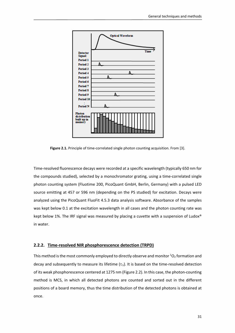
General techniques and methods
31
Figure 2.1. Principle of time‐correlated single photon counting acquisition. From [3].
Time‐resolved fluorescence decays were recorded at a specific wavelength (typically 650 nm for
the compounds studied), selected by a monochromator grating, using a time‐correlated single
photon counting system (Fluotime 200, PicoQuant GmbH, Berlin, Germany) with a pulsed LED
source emitting at 457 or 596 nm (depending on the PS studied) for excitation. Decays were
analyzed using the PicoQuant FluoFit 4.5.3 data analysis software. Absorbance of the samples
was kept below 0.1 at the excitation wavelength in all cases and the photon counting rate was
kept below 1%. The IRF signal was measured by placing a cuvette with a suspension of Ludox®
in water.
2.2.2. Time‐resolved NIR phosphorescence detection (TRPD)
This method is the most commonly employed to directly observe and monitor 1O2 formation and
decay and subsequently to measure its lifetime (). It is based on the time‐resolved detection
of its weak phosphorescence centered at 1275 nm (Figure 2.2). In this case, the photon‐counting
method is MCS, in which all detected photons are counted and sorted out in the different
positions of a board memory, thus the time distribution of the detected photons is obtained at
once.

Chapter 2
32
Figure 2.2. Near‐infrared spectrum of 1O2 phosphorescence. From [2].
1O2 phosphorescence was detected using a customized PicoQuant Fluotime 200 system
described elsewhere.2 Briefly, a diode‐pumped pulsed Nd:YAG laser (FTSS355‐Q, Crystal Laser,
Berlin, Germany) working at 10 or 1 kHz repetition rate at 532 nm (1 μJ per pulse) was used for
excitation. A 1064 nm rugate notch filter (Edmund Optics, York, UK) was placed at the exit port
of the laser to remove any residual component of its fundamental emission in the NIR region.
The luminescence exiting from the side of the cuvette was filtered by a cold mirror and a
bandpass filter of the appropriate wavelength‐1220, 1275 or 1325 nm (Spectrogon AB, Täby,
Sweden). A TE‐cooled Hamamatsu near IR photomultiplier (model H9170‐45, Hamamatsu
Photonics, Japan), sensitive from 950 to 1400 nm, was used to detect IR luminescence. The
detector was operated in photon counting mode and its output sent to a multichannel scaler
(PicoQuant Nanoharp 250). Photon histograms were analyzed using the PicoQuant FluoFit 4.5.3
data analysis software. For temperature‐dependent measurements, an Ultraterm 6000383 (JP
Selecta S.A., Abrera, Spain) thermostat was used in order to control the temperature.
The temporal profile of the time‐resolved 1O2 phosphorescence signals (St) is typically a rise‐and‐
decay function that can be fit with the following mathematical model (Eq. 2.2):4
T
0T
i i i
i
i i
t t
ti
S S e e
(Eq. 2.2)
The subscript i refers to the number of independent 1O2 populations in the sample. S0 is a
quantity proportional to the concentration of 1O2 created by the laser pulse and and T are
the lifetimes of 1O2 and 3PS*, respectively.

General techniques and methods
33
The photosensitizer’s triplet lifetime was determined, whenever possible, by fitting with Eq. 2.3
to the signal obtained at a wavelength where the triplet state of the photosensitizer emits,
typically at 1110 nm:
∑ / (Eq. 2.3)
Ai is proportional to the concentration of excited triplet states of the photosensitizer and T is
the actual triplet state lifetime of the photosensitizer.
2.2.3. UV‐vis nanosecond laser flash photolysis
This technique is employed to examine the absorption or emission with temporal resolution of
triplet states or other photochemically generated intermediate species. In this study, it served
to determine the PS triplet state kinetics by triplet‐triplet absorption when information obtained
from the observation of its time‐resolved phosphorescence was insufficient. Several setups exist
for the detection of triplet‐triplet absorption, but most of them have two features in common
(Figure 2.3). Firstly, any setup comprises an excitation source to produce triplet states,
commonly a pulsed laser. Second, a “monitoring” light source, in this case a Xe lamp, probes the
changes in absorbance at the sample.
Figure 2.3. Experimental setup for UV‐visible nanosecond laser flash photolysis. Adapted from [4].
Transient absorption experiments in the UV–visible (UV–vis) region were carried out using a
home‐built nanosecond laser flash photolysis system. In this instrument, the 2nd harmonic (532
nm) of a Continuum Surelite I‐10 Nd:YAG laser (10 Hz, 5 ns pulsewidth, 0.05‐1 mJ per pulse) was

Chapter 2
34
directed onto the sample. Changes in the sample absorbance were detected by a Hamamatsu
R928 photomultiplier in order to monitor the intensity variations of an analyzing beam produced
by a 75W short arc Xe lamp (USHIO) and spectral discrimination was provided by a PTI 101
monochromator. The signal was fed to a Lecroy Wavesurfer 454 oscilloscope for digitizing (1
shot, typically) and finally transferred through a GPIB interface (National Instruments) to a PC
computer for data storage and analysis. The TTL sync output of the laser was used to trigger the
oscilloscope. The energy of the laser pulse was varied by controlling the Q‐switch delay and
measured with a pyroelectric energy meter (RJP 735 and RJ 7610) from Laser Precision Corp.
The system was controlled by the in house‐developed LKS software (LabView, National
Instruments).
2.3. General synthetic techniques for functionalization of poly‐(D,L‐
lactide) and poly‐(D,L‐lactide‐co‐glycolide) polymers
2.3.1. Conjugation of porphyrins to poly‐(D,L‐lactide‐co‐glycolide)
A cationic (hydrophilic) and a hydrophobic porphyrin were respectively conjugated to PLGA in a
two‐step synthetic procedure involving amide coupling chemistry in the first step and Cu(I)‐
catalyzed azide‐alkyne cycloaddition (CuAAC) click chemistry in the second step. The reader is
referred to the Experimental Section in Chapter 4 (4.2) for a detailed description of the
procedures.
2.3.2. Conjugation of peptides to poly‐(D,L‐lactide)
PLA was coupled either directly (cRGD‐PLA) or through a PEG spacer (cRGD‐PEG‐PLA) to the
cyclic peptide cRGDfK (hereinafter cRGD), a ligand binding with high affinity to v3 integrin
receptors. Furthermore, two more polymers containing the spacer PEG were synthesized: PLA
coupled to PEG with no peptide (PEG‐PLA) and PLA coupled to PEG and the non‐binding peptide
cRADfK (hereinafter cRAD), obtaining the conjugate cRAD‐PEG‐PLA.
The direct conjugation between PLA and cRGD was accomplished by peptide coupling chemistry.
On the contrary, the conjugation of these two moieties with the PEG as a spacer required a 5‐
step synthetic procedure involving peptide coupling chemistry and a metal‐free azide‐alkyne
cycloaddition. The reader is referred to the Experimental Section in Chapter 5 (5.2) for a detailed
description of the procedures.
General techniques and methods
35
2.4. General techniques for analysis of functionalized polymers
2.4.1. Nuclear Magnetic Resonance
Proton Nuclear Magnetic Resonance (1H‐NMR) spectra were recorded in a Varian Gemini 300,
or 400 MHz or on a Varian Innova 500 MHz. Samples were dissolved in deuterated solvents,
commonly chloroform (CDCl3), DMSO (DMSO‐d6) or acetone (acetone‐d6) for spectra recording.
Obtained spectra were analyzed by the software MestreNova 8.1. Chemical shifts (are quoted
in parts per million (ppm), with residual solvent peaks being used as the internal reference for
chemical shifts of sample signals. In parentheses it is reported the integration, yielding the
number of 1H corresponding to a given signal, or in the case of polymers, a number proportional
to the total amount of protons; the multiplicity of the signal, indicated as singlet (s), doublet (d),
triplet (t) or multiplet (m); and the coupling constant (J, Hz), which can be calculated for systems
with a defined multiplicity.
2.4.2. Ultra‐High Performance Liquid Chromatography
Ultra‐High Performance Liquid Chromatography (UHPLC) was performed for checking
completeness of reactions and assessing qualitatively the adequacy of the purification
procedure.
UHPLC was carried out with a ThermoScientific Hypersil GOLD column (50 x 2.1 mm, particle size
19 m) in a ThermoScientific Accela system coupled to a PDA detector (PDA Accela 80 Hz
detector, ThermoScientific) complementarily set at 210 and 258 nm. The mobile phase was a
H2O / ACN mixture acidified with 0.1% formic acid (Merck) in a gradient mode; an initial mixture
with 2% ACN was ramped linearly up to 100% ACN from minute 0.50 to minute 5.80, and 100%
ACN was kept until minute 7.50. The gradient was returned back to the initial composition in 10
seconds and kept for 1.90 min.
2.5. Preparation and characterization of nanoparticles
2.5.1. Preparation of nanoparticles by nanoprecipitation
Conventionally, two groups of techniques for NP formation have been reported: the first
involves polymerization of monomers while the second is based on the dispersion of preformed
polymers. Some of the techniques in the second classification group include salting‐out,
emulsification‐diffusion, emulsification‐evaporation, or nanoprecipitation. The advantage of

Chapter 2
36
this second group is that physicochemical features of the NPs such as morphology, internal
structure, size, drug loading and release kinetics can be modulated more easily. In this study,
NPs were prepared in all cases by a modified nanoprecipitation method,5,6 since it was found to
be the most convenient in terms of the length of time needed for NP preparation, simplicity of
the method and obtention of the smallest NPs. This technique consists in adding dropwise an
organic phase to an aqueous phase in continuous stirring. The organic solvent employed must
be miscible in water, and this phase contains the hydrophobic components of the NPs, i.e. the
PLA or PLGA polymers and the PSs in the current case. The aqueous phase can be either water
or an aqueous solution of a surfactant such as polyvinyl alcohol (PVA) or poloxamer, although
PVA is the emulsifier most commonly used during NP formulation because the particles formed
are relatively uniform, smaller in size and easy to redisperse in aqueous medium. In this method,
contrary to salting‐out or emulsification‐diffusion, no precursor emulsion is formed during NP
preparation. NP formation is explained by solvent diffusion from the organic phase into the
aqueous phase, which produces polymer chain aggregation to form NPs.7 The reader is referred
to the Experimental Section of each corresponding chapter for a detailed explanation of the
procedure in each particular case.
2.5.2. Characterization
NP suspensions were characterized in terms of their physicochemical properties, i.e. PS
concentration, size, polydispersity index and surface charge, as well as in terms of their stability
in culture medium containing 10% fetal bovine serum (FBS).
Photosensitizer concentration: Bulk PS concentration was estimated by UV‐visible absorption
spectroscopy or fluorescence, depending on the type and amount of incorporated PS. An aliquot
of PS‐loaded or PS‐conjugated NPs was dissolved in an organic solvent, typically THF or DMSO
(NP suspension:solvent 1:15, v/v) to disrupt NPs and dissolve the PS. This solution was stirred to
ensure a complete dissolution of the polymer and the PS, and the absorption or fluorescence
spectra were recorded. PS concentration was determined by comparison with standard curves
obtained at the same conditions. Drug loading and entrapment efficiency were calculated as
follows:
%
100 Eq. (2.4)
%
100 Eq. (2.5)
General techniques and methods
37
Size, polydispersity and surface charge: Size and polydispersity index of NPs were determined
by dynamic light scattering (DLS) and zeta potential by laser Doppler micro‐electrophoresis,
using a Zetasizer Nano ZS (Malvern Instruments Ltd, Malvern, UK) at room temperature. To carry
out the measures, NP suspensions were diluted (NP suspension:H2O 1:6 v/v). Size measurements
were performed at the excitation wavelength of 633 nm. To measure zeta potential, the Malvern
device was calibrated with carboxy‐modified polystyrene latex samples of known zeta potential.
Stability of formulations in cell culture medium: Stability of NPs was assessed in cell culture
medium in presence of 10% FBS (the same concentration supplied to cultured cells). NP
suspension was diluted to a final PS concentration of 10 M in supplemented culture medium
with a 10% FBS. These suspensions were incubated for various times at 37 ᵒC at 400 rpm in a
Termomixer Comfort equipped with an exchangeable thermoblock for 15 mL falcon tubes
(Eppendorf AG, Hamburg, Germany). After certain time, an aliquot of 700 L was removed, put
in ice to stop the interaction, and centrifuged at 6400xg for 15 min, at 4 ᵒC (Hermle Z 233 M‐2
Microliter centrifuge, HERMLE Labortechnik GmbH, Germany). The pellet, containing NP
aggregates, was discarded and an aliquot of the supernatant was diluted in DMSO
(supernatant:DMSO 1:15, v/v) to disrupt the remaining NPs. Spectra were recorded in a
Beckman DU40 UV‐vis spectrophotometer (Beckman Coulter, Inc., Brea, CA, USA) or in a Synergy
H1 Hybrid microplate reader (BioTek Instruments, Inc., Winooski, VT, USA) and PS concentration
was determined by comparison with standard curves obtained in the same conditions.
2.6. Cell culture
2.6.1. Cell lines
Cell lines used in Chapters 3 and 4 were Human HeLa cervix adenocarcinoma cells (ATCC CCL‐2).
In Chapter 5 experiments were performed with Human U‐87 MG glioblastoma (ECACC‐
89081402), which is one of the most overexpressing v3 integrin receptor‐cell lines.8 Both of
them are adherent and grow in monolayer up to confluence after seeding. HeLa cells were
cultured with Dulbeco’s Modified Eagle’s Medium (DMEM)‐High Glucose supplemented with
10% (v/v) FBS, 1% L‐Glutamine, 1% (v/v) Streptomycin and 1% (v/v) Penicillin. HeLa cells were
seeded in T‐25 flasks and allowed to grow up to 80% confluence before subculturing. U‐87 MG
cells were cultured with Minimum Essential Media (MEM) (ThermoFisher, 31095‐029) with L‐
Glutamine supplemented with 10% (v/v) Fetal Calf Serum (FCS), 1% (v/v) Streptomycin and 1%

Chapter 2
38
(v/v) Penicillin, seeded in T‐75 flasks and allowed to grow up to 80% confluence before
subculturing. Both cell lines were grown at 37 ᵒC in a humidified sterile atmosphere of 95% air
and 5% CO2.
These cell lines were maintained frozen in liquid nitrogen in CryoTubesTM (Nunc, Nalge Nunc
International, IL, USA) with their corresponding supplemented culture medium with 5% DMSO
as a cryoprotecting agent.
2.6.2. Cellular uptake
Cellular uptake of the PS‐loaded NPs was determined by fluorescence spectroscopy of the
incubated cells (Chapter 5).
U‐87 MG cells were seeded in 96‐well plates in a density of 10000 cells/well and allowed to grow
overnight. NP suspensions were diluted in supplemented MEM to obtain a final Ppa
concentration of 1 M. Supernatant medium was discarded and the medium containing the NPs
was added to the adhered cells at different time points in order to obtain different incubation
times. After incubation, medium was discarded, cells were washed twice with supplemented
MEM, and finally DMSO was added to dissolve cell content as well as the internalized Ppa. DMSO
was employed instead of an aqueous solution of SDS 2% to ensure that NPs that might have
been internalized but not completely degraded were dissolved completely and their cargo
completely released for quantification. Fluorescence spectra of the samples were recorded in a
SynergyMxTM or Synergy H1 Hybrid microplate reader (BioTek Instruments, Inc., Winooski, VT,
USA). Fluorescence intensity was normalized by determining the protein content per each
sample by the Bicinchoninic acid (BCA) assay (Thermo Scientific™Pierce™, Thermo Fisher
Scientific, Inc). Briefly, this assay is based on the colorimetric quantification of the total
concentration of protein in the medium. Protein reduces Cu2+ to Cu+ in alkaline medium, and
one cation of Cu+ is chelated by two molecules of BCA, forming a water‐soluble complex with
strong absorbance at 562 nm. After fluorescence measurements, DMSO was discarded and SDS
2% added in order to lysate the cells. 25 L of each sample were mixed with 200 L of the
reagent, the microplate shaken for 30 s, and incubated at 37 ᵒC for 30 min. After this incubation
time, the microplate was cooled to room temperature and the absorbance read at 562 nm on
the microplate reader. Absorbance values were interpolated to a standard curve prepared with
bovine serum albumin (BSA) under the same conditions. Samples were quantified in triplicate.

General techniques and methods
39
2.6.3. Light sources
For cell culture irradiation, three types of light sources were employed. In Chapter 3, irradiation
was carried out with a Sorisa Photocare LED source (Barcelona, Spain) of a wavelength range of
530 ± 20 nm. The light intensity at the irradiation site was 5.2 mW/cm2 measured with a
LaserStar Ophir power meter (Logan, UT, USA). In Chapter 4, irradiation was carried out with a
LED source of a wavelength range of 515 ± 50 nm, with a light intensity at the irradiation site of
6.6 mW/cm2. In Chapter 5, irradiation was carried out with OSRAM L18/W67 tubular fluorescent
lamps of a wavelength range of 450 ± 50 nm with a light intensity at the irradiation site of 11
mW/cm2.
2.6.4. Photodynamic treatments in vitro
Reduction in cell viability as a result of the phototoxic effect of the PS delivered by different
types of vehicles was determined by means of the 3‐(4,5‐dimethylthiazol‐2‐yl)‐2,5‐
diphenyltetrazolium bromide (MTT) assay.9
HeLa or U‐87 MG cells were seeded in 24‐ or 96‐well plates and grown up to 70% confluence.
Cells were then incubated in the dark at 37 ᵒC for a certain time with PS‐loaded NPs, usually at
ranges of PS concentration between 0.1 and 10 M in complete culture medium. Empty NPs at
equivalent concentrations of the loaded ones were used as controls to ensure that
photocytotoxicity was not caused by the delivery systems. Cells without any treatment were
taken as controls. Subsequently, the medium was discarded, cells were washed three times with
cold PBS 1x and fresh complete medium was added. Samples were irradiated at different times
to achieve the intended light fluence. Cells were again incubated for 24 h in the dark and
reduction in cell viability was determined by the MTT assay. Briefly, remaining cells were
incubated with 0.05 mg/mL MTT (HeLa) or 0.1 mg/mL (U‐87 MG) in supplemented culture
medium for 3 h, after which MTT had been metabolized by viable cells to form purple crystals
of formazan. Medium was discarded, crystals were solubilized with pure DMSO and formazan
concentration was determined by absorption at ex: of 562 nm. Cell viability was determined by
the ratio between the absorbance of treated cells and that of non‐treated cells (control, 100%
viability).

Chapter 2
40
2.6.5. Spectroscopic measurements of cell suspensions
Time‐resolved phosphorescence detection of 1O2 in cell suspensions was assessed with the
system described in section 2.2.2 in order to ascertain the production of these species after
delivery of PSs into the cells (Chapter 3).
HeLa cells were seeded in T‐175 flasks and grown up to 70% confluence in supplemented growth
medium, in the dark at 37 ᵒC and 5% CO2. Cells were then incubated with ZnTPP‐loaded PLGA
and PEG‐PLGA NPs for different periods of time (2, 6 and 24 h). A bulk 5 M concentration of
ZnTPP was chosen as a good compromise between acceptable 1O2 signals and avoiding particle
aggregation. Cells incubated with complete medium in the absence of nanoparticles were used
as control. After incubation, the medium was discarded and cells were washed three times with
cold PBS 1x, scrapped and resuspended. Subsequently, the suspension was centrifuged at 1000
rpm for 5 min at 20 ᵒC; the supernatant was discarded, and the pellet was resuspended in 1.5
mL deuterated‐PBS (d‐PBS). 1O2 phosphorescence of these final cellular suspensions was then
detected using the customized equipment described in the previous section. Afterwards, a series
of control experiments were carried out in order to ensure that the signal detected was due to
1O2 inside the cells: 1) detection of luminescence at 1220 and 1325 nm, where 1O2 does not emit,
to ensure that the 1275 nm luminescence was due to 1O2; 2) addition of sodium azide (NaN3), a
known 1O2 quencher,10 to further confirm the presence of 1O2; 3) after the measurements,
centrifugation of cell suspensions at 5000 rpm for 12 min at room temperature followed by
analysis of the supernatant luminescence at 1275 nm to demonstrate that there was no
significant leakage of the PS during the measurements.

General techniques and methods
41
2.7. References
(1) Brouwer, A. M. Standards for Photoluminescence Quantum Yield Measurements in Solution
(IUPAC Technical Report). Pure Appl. Chem. 2011, 83, 2213–2228.
(2) Jiménez‐Banzo, A.; Ragàs, X.; Kapusta, P.; Nonell, S. Time‐Resolved Methods in Biophysics. 7.
Photon Counting vs. Analog Time‐Resolved Singlet Oxygen Phosphorescence Detection. Photochem.
Photobiol. Sci. 2008, 7, 1003–1010.
(3) Becker, W.; Bergmann, A.; Biscotti, G.; Rück, A. Advanced Time‐Correlated Single Photon
Counting Technique for Spectroscopy and Imaging in Biomedical Systems. Springer 2004, 5340, 1–9.
(4) Nonell, S.; Braslavsky, S. E. Time‐Resolved Singlet Oxygen Detection. Methods Enzymol. 2000,
319, 37–49.
(5) Barichello, J. M.; Morishita, M.; Takayama, K.; Nagai, T. Encapsulation of Hydrophilic and
Lipophilic Drugs in PLGA Nanoparticles by the Nanoprecipitation Method. Drug Dev. Ind. Pharm. 1999,
25, 471–476.
(6) Yallapu, M. M.; Gupta, B. K.; Jaggi, M.; Chauhan, S. C. Fabrication of Curcumin Encapsulated
PLGA Nanoparticles for Improved Therapeutic Effects in Metastatic Cancer Cells. J. Colloid Interface Sci.
2010, 351, 19–29.
(7) Galindo‐Rodriguez, S.; Allémann, E.; Fessi, H.; Doelker, E. Physicochemical Parameters
Associated with Nanoparticle Formation in the Salting‐Out, Emulsification‐Diffusion, and
Nanoprecipitation Methods. Pharm. Res. 2004, 21, 1428–1439.
(8) Zhang, X.; Xiong, Z.; Wu, Y.; Cai, W.; Tseng, J. R.; Gambhir, S. S.; Chen, X. Quantitative PET
Imaging of Tumor Integrin alphavbeta3 Expression with 18F‐FRGD2. J. Nucl. Med. 2006, 47, 113–121.
(9) Mosmann, T. Rapid Colorimetric Assay for Cellular Growth and Survival ‐ Application to
Proliferation and Cyto‐Toxicity Assays. J. Immunol. Methods 1983, 65, 55–63.
(10) Wilkinson, F.; Brummer, J. G. Rate Constants for the Decay and Reactions of the Lowest
Electronically Excited Singlet State of Molecular Oxygen in Solution. J. Phys. Chem. Ref. Data 1981, 24,
809–999.


CHAPTER 3
Preparation, characterization and phototoxicity studies of poly‐(ethylene glycol)‐coated poly‐(D,L‐lactide‐co‐glycolide) nanoparticles with occluded
photosensitizers
The use of drug delivery systems for PSs to improve their solubility in aqueous
medium is being extensively explored. PLGA or PEG‐PLGA NPs are favorable
nanocarriers thanks to their biodegradable and biocompatible properties as well as
their ability to incorporate hydrophobic drugs, among others. In this chapter, we
have investigated the role of the PLGA matrix as well as of the additional PEG
coating on the physicochemical and specially photophysical and photobiological
properties of the encapsulated PSs. We have also compared the role of the
chemical nature of the PS on its photophysical properties once being in the NP
suspension.


Nanoparticles with occluded photosensitizers
45
3.1. Introduction
Much attention has recently been given to PLGA NPs as delivery vehicles for PDT, since this
polymer is biodegradable, biocompatible, non‐immunogenic, and it has been approved by the
FDA for therapeutic use.1 Abundant literature has been published on the benefits of PS
incorporation into PLGA nanodelivery systems.2–9 NPs coated with suitable polymers such as
poly‐(ethylene glycol) (PEGylated NPs) show an enhanced circulation time in the body, making
them more attractive as passive targeting agents.10 These features have made PEGylated PLA or
PLGA NPs attractive as nanocarriers for photosensitizing agents, and have therefore been
evaluated in terms of their photodynamic activity10 as well as in terms of their photophysical
aspects.11,12 However, the influence of the coating polymer on the photophysical properties of
the encapsulated PS, on its ability to photosensitize 1O2, as well as on the photodynamic
response of the NPs have not been studied in detail.
Scheme 3.1. Chemical structure of the two porphyrins under study.
On the basis of these considerations, a comparative study of bare and PEG‐coated PLGA NPs as
delivery vehicles for Zn(II)‐tetraphenylporphine (ZnTPP) (Scheme 3.1) was performed. ZnTPP
was chosen since it is a model of a hydrophobic PS and its encapsulation in other delivery agents,
i.e. liposomes, had been previously studied in our group.13 Here, we evaluated (i) the
physicochemical characteristics of both types of ZnTPP‐loaded NPs; (ii) their spectroscopic and
photophysical properties; (iii) their ability to photosensitize 1O2, (iv) their photodynamic activity;
(v) their effect on the subcellular localization of ZnTPP in HeLa cells; and (vi) their effect on the
Zn(II)‐tetraphenylporphine (ZnTPP) Protoporphyrin IX (PpIX)

Chapter 3
46
cell death mechanism induced by PDT. Our results demonstrate that coating the PLGA surface
with PEG leads to a faster and superior photodynamic response in HeLa cells.
Once the optimal coating was identified, PEG‐coated PLGA NPs were used to encapsulate the
clinically approved PS protoporphyrin IX (PpIX) (Scheme 3.1). Comparative analysis of the
physicochemical and photophysical properties of the two nanosystems provided insight into the
role of the PS structure on its photochemical behavior inside the PLGA NPs.
3.2. Experimental section
3.2.1. Materials
Poly‐(ethylene glycol)‐block‐poly‐(D,L‐lactide‐co‐glycolide) (PEG‐PLGA), with PEG Mn 5000, 5
wt% PEG (RGP d 5055) or 15 wt% PEG (RGP d 50155), and molar ratio D,L‐lactide:glycolide 50:50,
were purchased from Evonik Industries (Birmingham, AL, USA). Poly‐(D,L‐lactide‐co‐glycolide)
(PLGA) RESOMER® RG 752 H (molar ratio of D,L‐lactide:glycolide 75:25, Mw 4000‐15000 Da, acid
terminated) and 5,10,15,20‐tetraphenyl‐21H,23H‐porphine zinc (ZnTPP) were purchased from
Sigma‐Aldrich Chemical Co. (St. Louis, MO,USA). Protoporphyrin IX was purchased from Frontier
Scientific (Logan, UT, USA). The porphyrins used had a minimal purity of 99% and were used as
received. Deuterium oxide (99.9%) was purchased from Solvents Documentation Synthesis (SDS,
Peypin, France). All other chemicals were commercially available reagents of at least analytical
grade. Milli‐Q water (Millipore Bedford, Massachusetts system, resistivity of 18 MΩ cm) was
used.
Fetal Bovine Serum was purchased from Lonza Ibérica S.A.U. (Barcelona, Spain). Trypsin (0.05%
Trypsin‐EDTA (1x)) was purchased from Life Technologies S.A. (Madrid, Spain). L‐Glutamine 200
mM was purchased from PAA GmbH (Pasching, Austria). Penicillin‐Streptomycin Solution 100x
was purchased from Biowest (Nuaillé; France). PlasmocinTM was purchased from Nucliber S.A.
(Zaragoza, Spain). Dulbecco's Modified Eagle's Medium (DMEM) with 4.5 g/L glucose, Sterile
Dulbecco's phosphate‐buffered saline (PBS 1x) and 3‐[4,5‐dimethylthiazol‐2‐yl]‐2,5‐
diphenyltetrazolium bromide (MTT) were purchased from Sigma‐Aldrich. The sterilized cell
culture material was purchased from LabClinics S.A. (Barcelona, Spain).
3.2.2. Preparation of poly‐(D,L‐lactide‐co‐glycolide) nanoparticles
PLGA and PEG‐PLGA (with 5, 10 or 15% PEG) NPs (NPs) were prepared by a modified
nanoprecipitation method.14,15 Briefly, for bare PLGA NPs, PLGA 75:25 was dissolved in acetone

Nanoparticles with occluded photosensitizers
47
at a concentration of 9 mg/mL. For PEG coated PLGA NPs (PEG‐PLGA NPs) either the commercial
polymers were used directly (5% or 15% PEG) or a mixture of 33% PLGA 75:25 and 67% PEG15%‐
PLGA 50:50 was used in order to obtain a mixture with a 10% of PEG, keeping in all cases the
same final polymer concentration in acetone as for bare PLGA NPs. To obtain ZnTPP‐loaded or
PpIX‐loaded NPs, the porphyrin was dissolved in the organic solution at a 0.8% or 1.3% (w/w)
drug loading concentration, respectively, regarding total polymer mass. This solution was then
injected dropwise to ultrapure water (organic phase:aqueous phase 1:2 v/v) under continuous
magnetic stirring at 800 rpm for 10 min. Subsequently, acetone was removed from the colloidal
suspension under reduced pressure for at least 1 h. Larger aggregates, free PLGA polymer and
non‐encapsulated porphyrin were removed by centrifugation at 5000 rpm (for ZnTPP‐loaded
NPs) or 6000 rpm (for PpIX‐loaded NPs) on an Avanti J21 centrifuge (Beckman Coulter, Inc., Brea,
CA, USA) and the suspensions were stored at 4 ᵒC.
3.2.3. Physicochemical characterization of NPs
Drug concentration was estimated by UV‐visible absorption spectroscopy as stated in section
2.5.3. An aliquot of ZnTPP‐ or PpIX‐loaded NPs was dissolved in THF or DMSO, respectively (NP
suspension:solvent 1:15, v/v) to disrupt NPs and extract the entrapped PS. This solution was
stirred to ensure a complete dissolution of the polymer and the PS, and the absorption spectra
were recorded on a Varian Cary 6000i UV‐vis‐NIR spectrophotometer (Agilent Technologies,
Santa Clara, CA) for ZnTPP or in a Synergy H1 Hybrid microplate reader (BioTek Instruments, Inc.,
Winooski, VT, USA) for PpIX. Absorbance values were interpolated in a calibration curve
obtained in the same conditions for each PS. Multiplication of the concentration obtained by
the dilution factor yielded the total concentration of the PS in the formulation. Drug loading and
entrapment efficiency were calculated as mentioned in section 2.5.3.
3.2.4. Photosensitization of HeLa cells
Photodynamic treatment in HeLa cells was carried out as explained in section 2.6.5. In this
particular case, cells were incubated in the dark at 37 ᵒC for 24 h with ZnTPP‐loaded PLGA or
ZnTPP‐loaded PEG‐PLGA NPs at ZnTPP concentrations of 1, 5 and 10 M in complete culture
medium.

Chapter 3
48
3.2.5. Subcellular localization
These assays were carried out by Dr. Acedo and Dr. Villanueva at the Universidad Autónoma de
Madrid and are included here for a better understanding of the photophysics and photodynamic
activity results.
To determine the intracellular localization of ZnTPP encapsulated in PLGA or PEG‐PLGA NPs,
endocytic compartments of HeLa cells were labeled with the fluoroprobe LysoTracker Green (50
nM, Molecular Probes, Eugene, Oregon, USA) in the culture medium at 37 ᵒC for 30 min.
Previously, cells were incubated with ZnTPP‐loaded NPs at 5 M for 24 h. After labelling,
coverslips were washed with PBS and were observed in a multispectral Leica TCS SP5 confocal
microscope (Wetzlar, Germany), operating with 405 nm (Argon‐UV) to detect the internalized
ZnTPP NPs and 488 nm (Argon) for emission of LysoTracker Green.
3.2.6. Characterization of cell death mechanisms
These assays were carried out by Dr. Acedo and Dr. Villanueva at the Universidad Autónoma de
Madrid and are included here for a better understanding of the photophysics and photodynamic
activity results.
Morphological changes after different photodynamic treatments were assessed by visualizing
control and treated cells under phase contrast and fluorescence microscopy. HeLa cells were
fixed with methanol at ‐20 ᵒC for 5 minutes, stained with Neutral red (NR; Panreac Química,
Spain; 0.5% in distilled water, 2 min) for analysis of general morphology, or with Hoechst‐33258
(H‐33258; Sigma‐Aldrich; 5 g/ml in distilled water, 3 min) for visualization of DNA. After
washing and air drying, preparations were mounted in DePeX (Serva, Heidelberg, Germany).
For indirect immunofluorescence detection of cytochrome c, cells on coverslips were fixed in
formol‐PBS (1:10) for 20 min at 4 ᵒC, washed three times with PBS (5 min each), and
permeabilized with 0.5% Triton X‐100. After 5 min, Triton X‐100 was removed and cells were
incubated in blocking solution (5% bovine serum albumin, 5% FBS, 0.02% Triton X‐100 in PBS)
for 30 min at room temperature. Once removed from blocking solution, 25 l of a 1:25 solution
of primary antibody (monoclonal mouse anti‐cytochrome c, Invitrogen) were added to each
sample and incubated at 37 ᵒC for 1 h. Three 5 min washings with PBS were then carried out
before addition of Triton X‐100 for 5 min. Incubation with secondary antibody was performed
at 37 o C for 1h (Fab specific goat anti‐mouse FITC‐IgG; Sigma‐Aldrich). Cells were washed 3 times
with PBS and counterstained using H‐33258 and mounted in ProLong Gold antifade reagent.

Nanoparticles with occluded photosensitizers
49
3.3. Results
3.3.1. Physicochemical characterization of ZnTPP‐and PpIX‐loaded PLGA formulations
ZnTPP was encapsulated in bare or PEG‐decorated PLGA NPs, following a modified
nanoprecipitation method. Following studies were carried out entrapping PpIX in PEG‐
decorated PLGA NPs. Table 3.1 summarizes the physicochemical properties of the formulations
and the incorporation efficiency of ZnTPP or PpIX in NPs.
Table 3.1. Physicochemical characteristics of PLGA NPs and ZnTPP entrapment.
Composition Z‐avea
(nm) PIb
ζ potc
(mV)
Drug loadingd
(%)
E.E.e
(%)
[PS]f
(M)
PLGA 114 ± 5 0.10 ± 0.01 ‐45 ± 2 ‐ ‐ ‐
ZnTPP / PLGA (0.8% ZnTPP, w/w)
115 ± 4 0.10 ± 0.02 ‐44 ± 1 0.6 ± 0.1 73 ± 4 41 ± 2
5% PEG‐PLGA 72 ± 1 0.13 ± 0.01 ‐32 ± 7 ‐ ‐ ‐
ZnTPP / 5% PEG‐PLGA
(0.8% ZnTPP, w/w) 71 ± 1 0.10 ± 0.01 ‐27 ± 1 0.6 ± 0.1 68 ± 2 43 ± 2
10% PEG‐PLGA 58 ± 18 0.19 ± 0.07 ‐23 ± 7 ‐ ‐ ‐
ZnTPP / 10% PEG‐PLGA (0.8% ZnTPP, w/w)
52 ± 6 0.26 ± 0.12 ‐19 ± 5 0.7 ± 0.1 81 ± 4 45 ± 2
15% PEG‐PLGA 58 (65%)
500 (35%) 0.41 ± 0.02 ‐20 ± 0.3 ‐ ‐ ‐
PpIX / 10% PEG‐PLGA (1.3% PpIX, w/w)
76 ± 6 0.20 ± 0.03 ‐23 ± 2 0.8 ± 0.1 60 ± 3 60 ± 3
a Particle size measured as Z average mean b Polydispersity Index c Zeta Potential d Drug loading expressed as percentage of PS relative to PLGA (w/w) e Encapsulation efficiency f Bulk PS concentration in the NPs suspension Values reported are the mean ± SD of at least three independent experiments.
Coating of PLGA NPs with 5% or 10% PEG resulted in a reduction of their size, in agreement with
previous observations,16 a somewhat higher polydispersity, a less‐negative zeta potential, and a
slightly larger encapsulation efficiency. When entrapping ZnTPP, the final entrapment efficiency
(~ 70%) and ZnTPP bulk concentration were comparable for bare PLGA or PEG‐PLGA NP

Chapter 3
50
formulations. In the case of PpIX NPs, entrapment efficiency (~ 60%) was slightly lower than for
ZnTPP. No remarkable differences in the size, PI or zeta potential were observed when
encapsulating PpIX compared to ZnTPP. Finally, NPs containing 15% PEG yielded two populations
of different size and were thus ruled out for further studies.
3.3.2. Stability of formulations in cell culture medium
PLGA NPs aggregate in presence of serum albumin and other plasma proteins.17–19 Thus, a study
of NP stability in cell culture medium was carried out to analyze the formation of NP aggregates
due to the FBS content of the medium, and to determine the influence of PEGylation on their
stability. Aliquots of ZnTPP‐loaded PLGA or ZnTPP‐loaded PEG‐PLGA suspensions containing the
same amount of ZnTPP were added to the medium containing a 10% FBS and the remaining
ZnTPP in suspension was determined after defined periods of time.
Figure 3.1. Stability of ZnTPP‐loaded PLGA and PEG‐PLGA NPs in cell culture medium. NP suspensions were
diluted in supplemented cell culture medium (DMEM) at a concentration of 10 μM ZnTPP for various
periods of time, at 37 ᵒC. The stability was measured as the percentage of remaining ZnTPP in suspension
in the incubation medium after each period of time. Results are the mean ± SD of two replicate values.
Figure 3.1 shows that all ZnTPP entrapped in PEG‐PLGA NPs containing 10% PEG remains in the
suspension, even after 30 h of incubation, whereas 75% of the ZnTPP initially embedded in the
bare NPs precipitates already at 1 h. PEG‐PLGA NPs containing 5% PEG showed intermediate
results but since they were less stable than those containing 10% PEG we decided to rule them
out at this stage. Hereafter the term PEG‐PLGA NPs refers to NPs containing 10% PEG. The
elimination of ZnTPP can be attributed to the formation of large aggregates of PLGA NPs that
precipitate as a consequence of their interaction with FBS proteins. This experiment also shows
1h 8h 30h 1h 8h 30h 1h 8h 30h0
50
10010% PEG5% PEGPLGA
Time (h)
Rem
ain
ing
Zn
TP
P (
%)

Nanoparticles with occluded photosensitizers
51
that PEGylation of the NPs protects them from FBS proteins and yields a stable formulation of
the PS.
3.3.3. Absorption, steady‐state and time‐resolved fluorescence
Absorption and emission spectra (Figure 3.2 a, b) of aqueous suspensions of ZnTPP‐loaded PLGA
and ZnTPP‐loaded PEG‐PLGA NPs were recorded in water and in THF to compare the behavior
of ZnTPP entrapped in the NPs or solubilized in the organic solvent. THF dissolves the PLGA
polymer and causes the release of all the ZnTPP content into the organic solvent, where it is
completely soluble.
Figure 3.2. Absorption (a) and emission spectra (b) (ex: 556 nm) of 3 M ZnTPP in PLGA ( ) and
PEG‐PLGA ( ) NPs in aqueous suspension or PLGA ( ) and PEG‐PLGA ( ) NPs dissolved in THF.
Normalized absorption (c) and normalized emission spectra (d) (ex: 591 nm) of an aqueous suspension
of PpIX‐loaded PEG‐PLGA NPs ( ), the same suspension disrupted in acetone ( ) or free PpIX in
acetone ( ).
The spectra in the NPs were essentially identical to those in THF, which suggests that entrapped
ZnTPP is largely in a monomeric state. On the contrary, the normalized absorption spectrum of
aqueous suspensions of PpIX‐loaded PEG‐PLGA NPs (Figure 3.2 c, d) shows a remarkable blue
shift for the Soret and the first Q band, a red shift for the last two Q bands as well as a remarkable
difference on the relative intensities of the bands compared to the spectrum of free PpIX or
400 500 600
0.0
0.5
1.0
1.5
x10Ab
sorb
ance
(a.
u.)
600 650 700 7500
4.0×10⁴
8.0×10⁴
1.2×10⁵ Inten
sity (cou
nts)
400 500 6000.0
0.5
1.0
No
rmal
ized
ab
sorb
ance
(a.
u.)
650 700 750 8000.0
0.5
1.0
No
rmalized
inten
sity (a.u.)
Wavelength (nm)
a b
c d
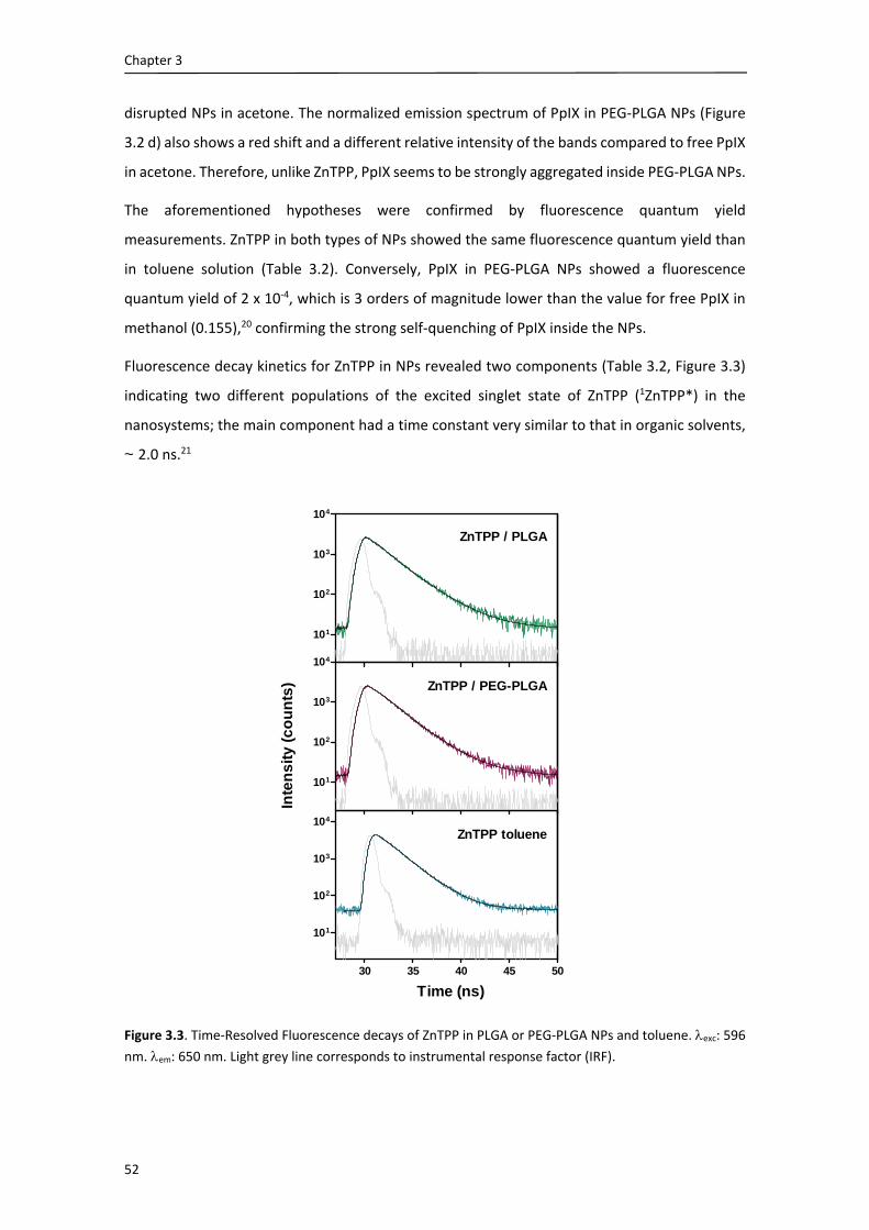
Chapter 3
52
disrupted NPs in acetone. The normalized emission spectrum of PpIX in PEG‐PLGA NPs (Figure
3.2 d) also shows a red shift and a different relative intensity of the bands compared to free PpIX
in acetone. Therefore, unlike ZnTPP, PpIX seems to be strongly aggregated inside PEG‐PLGA NPs.
The aforementioned hypotheses were confirmed by fluorescence quantum yield
measurements. ZnTPP in both types of NPs showed the same fluorescence quantum yield than
in toluene solution (Table 3.2). Conversely, PpIX in PEG‐PLGA NPs showed a fluorescence
quantum yield of 2 x 10‐4, which is 3 orders of magnitude lower than the value for free PpIX in
methanol (0.155),20 confirming the strong self‐quenching of PpIX inside the NPs.
Fluorescence decay kinetics for ZnTPP in NPs revealed two components (Table 3.2, Figure 3.3)
indicating two different populations of the excited singlet state of ZnTPP (1ZnTPP*) in the
nanosystems; the main component had a time constant very similar to that in organic solvents,
~ 2.0 ns.21
Figure 3.3. Time‐Resolved Fluorescence decays of ZnTPP in PLGA or PEG‐PLGA NPs and toluene. exc: 596
nm. em: 650 nm. Light grey line corresponds to instrumental response factor (IRF).
101
102
103
104
101
102
103
104
30 35 40 45 50
101
102
103
104
Inte
ns
ity
(c
ou
nts
)
Time (ns)
ZnTPP / PLGA
ZnTPP / PEG-PLGA
ZnTPP toluene

Nanoparticles with occluded photosensitizers
53
3.3.4. Triplet lifetime and quenching by oxygen
Laser flash photolysis experiments were used to monitor the triplet state of ZnTPP (3ZnTPP*)
through its time‐resolved absorption at 470 nm (Figure 3.4). Data analysis revealed two and
three populations of ZnTPP in bare and PEG‐coated PLGA NPs, respectively. The triplet states
could be quenched by oxygen with rate constants that varied for each population and for each
type of NP (Table 3.2).
Table 3.2. Fluorescence quantum yields, singlet state lifetimes and their relative amplitudes, and triplet
state lifetimes and their quenching rate constants by oxygen of the individual components observed in
ZnTPP‐loaded PLGA and PEG‐PLGA NPs or PpIX‐loaded PEG‐PLGA NPs in water suspensions.
Sample F si (ns) Asi (%) Ti (s) (M‐1s‐1)
ZnTPP / PLGA 0.036 ± 0.005 1.7 ± 0.2
3.1 ± 0.5
67 ± 14
33 ± 14
77 ± 10
209 ± 35
(3.7 ± 0.3) x 107
(1.2 ± 0.4) x 107
ZnTPP / PEG‐PLGA 0.034 ± 0.002
1.8 ± 0.2
3.4 ± 0.5
‐
78 ± 14
22 ± 14
‐
17 ± 3
105 ± 29
286 ± 13
(2.7 ± 0.6) x 108
(1.2 ± 0.1) x 107
(4.9 ± 1.9) x 106
ZnTPP toluenea 0.033 2.0 ± 0.2 100 ‐ ‐
PpIX / PEG‐PLGAb (1.9 ± 0.2) x 10‐4 n. d. n. d. n. d. n. d.
a ZnTPP in toluene was used as reference.22 bTMPyP in PBS was used as reference.23 n.d. not determined Results are the mean ± SD of at least three independent experiments.
3.3.5. 1O2 production and kinetics
Quenching of 3ZnTPP* by oxygen led to the production of the cytotoxic species 1O2 as
unequivocally demonstrated by the observation of the specific NIR phosphorescence of this
species at 1275 nm. The temporal profile of the signals (St, Figure 3.4) showed the typical rise‐
and‐decay function that characterizes 1O2 kinetics (Eq. 2.2). Data analysis (Table 3.3) confirmed
the presence of two and three populations of 3ZnTPP* and 1O2 in bare and PEG‐coated PLGA
NPs, respectively. The 3ZnTPP* lifetimes derived from NIR phosphorescence matched those from
the laser flash photolysis experiments. NaN3 had no effect on the 1O2 lifetime in bare PLGA but
quenched one of the 1O2 populations in the PEG‐coated NPs (Table 3.4).
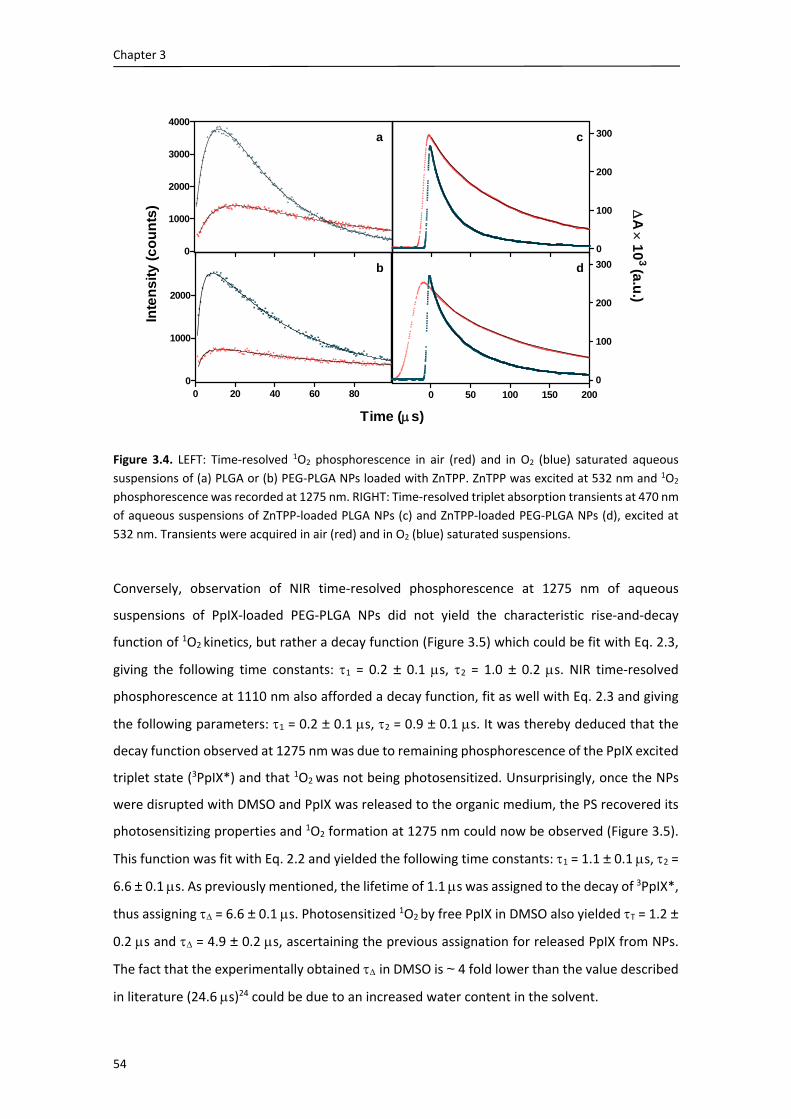
Chapter 3
54
Figure 3.4. LEFT: Time‐resolved 1O2 phosphorescence in air (red) and in O2 (blue) saturated aqueous
suspensions of (a) PLGA or (b) PEG‐PLGA NPs loaded with ZnTPP. ZnTPP was excited at 532 nm and 1O2
phosphorescence was recorded at 1275 nm. RIGHT: Time‐resolved triplet absorption transients at 470 nm
of aqueous suspensions of ZnTPP‐loaded PLGA NPs (c) and ZnTPP‐loaded PEG‐PLGA NPs (d), excited at
532 nm. Transients were acquired in air (red) and in O2 (blue) saturated suspensions.
Conversely, observation of NIR time‐resolved phosphorescence at 1275 nm of aqueous
suspensions of PpIX‐loaded PEG‐PLGA NPs did not yield the characteristic rise‐and‐decay
function of 1O2 kinetics, but rather a decay function (Figure 3.5) which could be fit with Eq. 2.3,
giving the following time constants: 1 = 0.2 ± 0.1 s, 2 = 1.0 ± 0.2 s. NIR time‐resolved
phosphorescence at 1110 nm also afforded a decay function, fit as well with Eq. 2.3 and giving
the following parameters: 1 = 0.2 ± 0.1 s, 2 = 0.9 ± 0.1 s. It was thereby deduced that the
decay function observed at 1275 nm was due to remaining phosphorescence of the PpIX excited
triplet state (3PpIX*) and that 1O2 was not being photosensitized. Unsurprisingly, once the NPs
were disrupted with DMSO and PpIX was released to the organic medium, the PS recovered its
photosensitizing properties and 1O2 formation at 1275 nm could now be observed (Figure 3.5).
This function was fit with Eq. 2.2 and yielded the following time constants: 1 = 1.1 ± 0.1 s, 2 =
6.6 ± 0.1 s. As previously mentioned, the lifetime of 1.1 s was assigned to the decay of 3PpIX*,
thus assigning = 6.6 ± 0.1 s. Photosensitized 1O2 by free PpIX in DMSO also yielded T = 1.2 ±
0.2 s and = 4.9 ± 0.2 s, ascertaining the previous assignation for released PpIX from NPs.
The fact that the experimentally obtained in DMSO is ~ 4 fold lower than the value described
in literature (24.6 s)24 could be due to an increased water content in the solvent.
0
1000
2000
3000
4000
0
100
200
300
0 20 40 60 800
1000
2000
Inte
ns
ity
(c
ou
nts
) A
10
3(a
.u.)
Time (s)
a c
b
0 50 100 150 200
0
100
200
300d

Nanoparticles with occluded photosensitizers
55
Figure 3.5. Time‐resolved 1O2 phosphorescence at 1275 nm of PpIX‐loaded PEG‐PLGA NPs in aqueous
suspension or disrupted in DMSO.
Table 3.3. Time constants of 1O2 luminescence of ZnTPP‐loaded PLGA NPs or ZnTPP‐loaded PEG‐PLGA NPs
under air and oxygen saturated solutions.
ZnTPP‐PLGA ZnTPP‐PEG‐PLGA
air O2 air O2
1 (s) 5.0 ± 0.5 4.0 ± 0.1 1.6 ± 0.3 1.3 ± 0.2
T1 (s) 92 ± 8 45 ± 3 18 ± 1 3.5 ± 0.3
2 (s) 14 ± 2 13 ± 2 5.0 ± 0.3 4.8 ± 0.3
T2 (s) 219 ± 10 20 ± 1 79 ± 6 43 ± 2
3 (s) ‐ ‐ 12 ± 1 10 ± 1
T3 (s) ‐ ‐ 307 ± 54 100 ± 10
Results are the mean SD of two independent experiments.
3.3.6. Temperature and quenching effects
The results obtained for ZnTPP‐loaded NPs prompted us to investigate the effect of temperature
on the kinetics of 1O2 production and decay since both processes appear to be constrained by
the rigidity of the PLGA NP. The decay rate constants of both 3ZnTPP* and 1O2 increased at higher
temperatures (Figure 3.6 a; Table 3.4). At the highest temperature studied (55 ᵒC) the two 1O2
populations previously observed in bare PLGA merged, and the 1O2 lifetime was close to the
value commonly observed in water (~ 3 µs). Addition of NaN3 reduced it further (Figure 3.6 c;
Table 3.4). Similar observations were made in the PEG‐coated NPs: increasing the temperature
caused a general decrease of the 3ZnTPP* and 1O2 lifetimes and two of the three populations
0 5 10 15 20
0
200
400
600PpIX NPs in DMSO
PpIX NPs in H2O
Time (s)
Inte
nsi
ty (
cou
nts
)

Chapter 3
56
merged at the highest temperature (Figure 3.6b, Table 3.4). Quenching by azide at this
temperature caused and even more pronounced decrease of the 1O2 lifetime than in the bare
NPs.
Figure 3.6. Time‐resolved 1O2 phosphorescence of aqueous suspensions of ZnTPP‐loaded PLGA (TOP: a, c)
and PEG‐PLGA (BOTTOM: b, d) NPs as a function of temperature: 20 ᵒC (black), 37 ᵒC (blue), 55 ᵒC (red)
and of NaN3 concentration: [NaN3] = 0 mM (LEFT: a, b) and [NaN3] = 10 mM (RIGHT: c, d). ZnTPP was
excited at 532 nm and the luminescence was observed at 1275 nm.
0
2000
4000
6000
8000
0
1000
2000
3000
4000
5000
0 20 40 60 800
2000
4000
6000
8000
0 20 40 60 80
0
500
1000
1500
2000
a
b
c
d
Inte
ns
ity
(c
ou
nts
) Inte
ns
ity (c
ou
nts
)
Time (s)

57
Table 3.4. Time constants of 1O2 luminescence transients of ZnTPP‐loaded PLGA and PEG‐PLGA NPs at three different temperatures and in absence and presence of NaN3, a
typical 1O2 quencher.
ZnTPP‐PLGA [NaN3] = 0 [NaN3] =10 mM
20 ᵒC 37 ᵒC 55 ᵒC 20 ᵒC 37 ᵒC 55ᵒC
1 (s) 5.0 ± 0.5 4.4 ± 0.4 2.9 ± 0.5 6.0 ± 1.0 4.0 ± 0.1 1.4 ± 0.3
T1 (s) 92 ± 8 36 ± 3 14 ± 1 110 ± 15 41 ± 5 15 ± 1
2 (s) 14 ± 2 4.4 ± 0.4 ‐ 16 ± 1 4.0 ± 0.1 ‐
T2 (s) 219 ± 10 78 ± 7 ‐ 265 ± 18 99 ± 18 ‐
ZnTPP‐PEG‐PLGA [NaN3] = 0 [NaN3] =10 mM
20 ᵒC 37 ᵒC 55 ᵒC 20 ᵒC 37 ᵒC 55ᵒC
1 (s) 1.6 ± 0.3 2.1 ± 0.4 2.7 ± 0.5 0.4 ± 0.3 0.2 ± 0.1 <0.2
T1 (s) 18 ± 1 12 ± 1 10 ± 2 15 ± 1 8.1 ± 2.2 10 ± 2.2
2 (s) 5.0 ± 0.3 4.4 ± 0.7 2.7 ± 0.5 4.0 ± 1 5.3 ± 0.6 <0.2
T2 (s) 79 ± 6 37 ± 4 22 ± 4 91 ± 14 49 ± 4 22 ± 4
3 (s) 12 ± 1 4.4 ± 0.7 ‐ 12 ± 1 5.3 ± 0.6 ‐
T3 (s) 307 ± 54 97 ± 14 ‐ 356 ± 50 116 ± 2 ‐
Results are the mean SD of two independent experiments.

Chapter 3
58
3.3.7. 1O2 in HeLa cells
Cells incubated with ZnTPP‐loaded PLGA NPs, either bare or coated with PEG, showed clear 1O2
phosphorescence signals at 1275 nm (Figure 3.7).
Figure 3.7. Time‐resolved 1O2 phosphorescence of ZnTPP‐loaded PLGA (LEFT) and PEG‐PLGA (RIGHT) NPs
in aqueous suspensions (TOP) and in HeLa cell suspensions (BOTTOM) after 24 h incubation. ZnTPP was
excited at 532 nm and 1O2 phosphorescence was recorded at 1275 nm. The signal at 1220 nm, where 1O2
shows almost no emission, was recorded to measure light scattering by cells. All measurements were
taken at 20 ᵒC; dPBS stands for D2O‐based PBS.
Control experiments confirmed that the signals were due to 1O2 and that they originated in the
cells since the luminescence showed a maximum at 1275 nm and no signal could be observed
from the supernatant obtained by centrifugation of the suspensions. Analysis of the 1O2 kinetics
revealed important differences with respect to the aqueous suspension of the NPs. For bare
PLGA, only one of the previously observed two 1O2 populations could now be detected and it
0 5 10 15 20 100 200 300
dPBS
PBS + NaN3
PBS
dPBS 1220 nm
supernatant
0 5 10 15 20 100 200 300
dPBS
PBS
PBS + NaN3
supernatant
dPBS 1220 nm
Inte
ns
ity
(a
.u.)
Inte
ns
ity
(a
.u.)
Time (s)
PLGA NPs PEG-PLGA NPs
Time (s)
H2O suspensionsH2O suspensions
Cell suspensions Cell suspensions

Nanoparticles with occluded photosensitizers
59
showed similar kinetics as in aqueous suspensions. Moreover it could not be quenched by 10
mM NaN3 and the only effect of solvent deuteration was to slightly increase its intensity. In
contrast, cells incubated with PEG‐coated NPs failed to show the long emission tail and the
short‐lived decay component could be quenched by azide. In this case also, deuteration allowed
the observation of a longer‐lived emission (Figure 3.7 RIGHT).
3.3.8. Photosensitization of HeLa cells
HeLa cells were incubated in the dark with various concentrations of ZnTPP‐loaded PLGA and
PEG‐PLGA NPs for 24 h. Afterwards cells were exposed to various fluences of LED green light and
cell viability was assessed 24 h after treatment. Cell death was observed in a concentration‐ and
light fluence‐dependent manner (Figure 3.8, Panel A).
Figure 3.8. Panel A. HeLa cells viability (expressed in percentage) after incubation with ZnTPP‐loaded PLGA
or PEG‐PLGA NPs at various concentrations and subsequent irradiation at various light fluences. ZnTPP
concentrations are 1 M ( ), 5 M ( ) and 10 M ( ). Plain circles ( ) represent cell controls incubated
only with complete growth medium. Panel B. HeLa cells viability as a function of light fluence after
incubation with empty PLGA (blue dotted bars) or PEG‐PLGA (red lined bars) NPs. In both cases, the
concentration of NPs in incubates was equivalent to that delivered at 10 μM ZnTPP. White bars represent
cell controls exposed to light without NPs.
0 2 4 6 8
0
50
100
0
50
100
Light fluence (J.cm-2)
A
B
Light fluence (J.cm-2)
Cel
l vi
abil
ity
(%)
Cel
l vi
abil
ity
(%)
PLGA NPs
0 2 4 80
50
100
PEG-PLGA NPs

Chapter 3
60
ZnTPP delivered in PEGylated NPs was more phototoxic than in bare PLGA, particularly at low
light fluences. On the other hand, it also showed a slightly higher dark cytotoxicity. Light alone
or in combination with empty NPs was devoid of any detectable cytotoxicity (Figure 3.8, Panel
B).
The results below (Subsections 3.3.9. and 3.3.10.) were obtained by Dr. Acedo and Dr.
Villanueva at the Universidad Autónoma de Madrid and are included here for a better
understanding of the photophysics and photodynamic activity results shown above.
3.3.9. Subcellular localization
Figure 3.9. Panel A. (a) Live imaging HeLa cells showing the localization of ZnTPPdelivered by PLGA NPs,
(b) lysosomes labelling with LysoTracker Green, (c) merged image. Yellow in the overlay images (a and b)
appears where the red fluorescence of ZnTPP colocalizes with the green fluorescence of LysoTracker
Green, (d) and overlap of UV and green channels with differential interference contrast (DIC) image of the
same cells. Panel B. Same instrument settings were used to acquire images after incubation of the cells
with ZnTPP delivered by PEG‐PLGA NPs by confocal microscopy. Scale bar = 10 μm.

Nanoparticles with occluded photosensitizers
61
ZnTPP delivered in PLGA or PEG‐PLGA NPs showed similar intracellular localization in lysosome‐
like structures (Figure 3.9). Co‐localization studies performed in non‐fixed HeLa cells using
LysoTracker Green, a marker for lysosomes, confirmed that ZnTPP entrapped in both types of
NPs was specifically accumulated in lysosomes.
3.3.10. Mechanism of cell death
Apoptotic cell death induced by PDT treatments was confirmed by two methods: analysis of
morphological alterations25 and cellular distribution of cytochrome c.
Morphological changes
Photodynamic treatments on HeLa cells with ZnTPP‐loaded PLGA or PEG‐PLGA NPs at 5 M
ZnTPP and 4 J.cm‐2 light fluence resulted in apoptotic pattern of cell death morphology, revealed
by neutral red and Hoechst‐33258 (H‐33258) staining (Figure 3.10). After photodynamic
treatment with ZnTPP‐loaded PLGA but specially with ZnTPP‐loaded PEG‐PLGA, cells showed
significant morphological changes depending on the time elapsed after the end of treatment (6
and 24 h). As shown in Figure 3.10, a significant number of cells have undergone apoptosis 6 h
after ZnTPP‐loaded PEG‐PLGA photodynamic treatment, as deduced from the cell shrinkage,
chromatin condensation, and nuclear fragmentation, which are typical apoptotic features. At 24
h most cells have undergone apoptosis and only scarce cells remain alive. Cells treated with
ZnTPP‐loaded NPs but not irradiated, as well as cells irradiated without preincubation with NPs,
presented similar morphology to control HeLa cells (data not shown).
Detection of cytosolic cytochrome c
Immunofluorescence techniques showed that cytochrome c was confined to mitochondria in
control cells (Figure 3.11). However, photoactivated ZnTPP‐loaded PEG‐PLGA triggered release
of cytochrome c from the mitochondria to the cytosol and the majority of cells displayed diffuse
cytochrome c cytoplasmic staining and condensed and fragmented nuclei (Figure 3.11, a’’‐d’’).

Chapter 3
62
Figure 3.10. Morphology of cells treated with PDT by ZnTPP‐loaded PLGA (Panel A) and ZnTPP‐loaded
PEG‐PLGA (Panel B) NPs, after neutral red or H‐33258 staining. (a‐a’) HeLa control cells morphology. (b‐
b’) Cells incubated 24 h with empty PLGA or PEG‐PLGA NPs followed by green light irradiation (4 J.cm‐2)
and observed 24 h later. (c‐d and c’‐d’) Cells incubated 24 h with 5 M ZnTPP entrapped in PLGA or PEG‐
PLGA NPs followed by green light irradiation (4 J.cm‐2) and observed 6 and 24 h later, respectively. Note
that ZnTPP‐loaded PEG‐PLGA induced apoptotic cell death more effectively than ZnTPP‐loaded PLGA.
Most of HeLa cells displayed the morphological features of apoptosis (cell shrinkage and chromatin
fragmentation) after 24 h PDT‐treatment. Scale bar = 10 μm.

Nanoparticles with occluded photosensitizers
63
Figure 3.11 HeLa cells visualized by cytochrome c immunofluorescence (green) and DNA counterstaining
with H‐33258 (blue), overlap images and corresponding phase‐contrast of HeLa cells. (a‐d) Control cells
showing mitochondrial cytochrome c. (a’‐d’) Cells 24 h after PDT treatment with ZnTPP‐loaded PLGA and
green light irradiation (4 J.cm‐2) show cytochrome c release to cytosol only in cells with condensed and
fragmented chromatin. (a’’‐d’’) The same PDT treatment with ZnTPP‐loaded PEG‐PLGA led to diffuse
cytoplasmic cytochrome c staining with condensed and fragmented chromatin 24 h after irradiation. Scale
bar = 10 m.
3.4. Discussion
We have investigated the photodynamic activity of the model PS ZnTPP delivered to cancer cells
using bare or PEGylated PLGA NPs. Additionally, we have entrapped the clinically approved PpIX
in PEGylated PLGA NPs and we have compared the photophysical properties of the two
entrapped PSs
PLGA NPs, prepared by a modified nanoprecipitation method, had a diameter of around 100 nm
and a pronounced negative zeta potential, consistent with the terminal carboxylic groups of the
polymer. Coating their surface with 5% or 10% PEG chains led to a decrease in their size, as
previously observed,16,26 and to a less negative zeta potential. However, increasing the PEG
content to 15% produced highly heterogeneous NP populations (Table 3.1). No significant
differences in size were reported when any of both PSs were encapsulated.

Chapter 3
64
Bare PLGA NPs aggregated and precipitated when added to culture medium containing 10%
FBS,17–19,26 whereas 10% PEG coating conferred stability to the suspension (Figure 3.1). These
results rule out bare PLGA NPs as drug carriers for in vivo PDT.
Absorption and fluorescence spectra as well as fluorescence quantum yields of ZnTPP in both
types of NPs were similar to those in THF or toluene solution (Figure 3.2), indicating that ZnTPP
is not appreciably aggregated in the core of the NPs. These results are in contrast to those
obtained for PpIX; shifts and different relative intensities in the spectra of encapsulated PpIX
indicate a strong aggregation of this PS inside the NPs, which is confirmed by its extremely low
fluorescence quantum yield. Similarly to the case of PpIX, meso‐tetrahydroxyphenyl porphyrin
(m‐THPP) in PLGA shows large red shifts and an important reduction of intensities.6 This
indicates that the chemical properties of the PS exert a profound influence on its interaction
with PLGA.
Time‐resolved fluorescence and triplet‐triplet absorption revealed different populations of
ZnTPP in the NPs (Table 3.2). Thus, two different populations were identified in bare PLGA
whereas in PEG‐PLGA a third population could also be detected. The long triplet lifetimes
observed in aerated suspensions indicate that 3ZnTPP* is largely shielded from oxygen in the
NPs. The rate constants for oxygen quenching (Table 3.2) were 1‐3 orders of magnitude lower
than in aqueous solutions27 depending on the specific 3ZnTPP* population and type of NP. This
would indicate that each population occupies a different region inside the NPs.
Despite such shielding, ZnTPP is able to produce 1O2 and we find different populations for this
species as well, which is in agreement with a heterogeneous microenvironment within the NPs.
The fact that NaN3, a water‐soluble 1O2 quencher, is unable to reduce the 1O2 lifetime in bare
PLGA, indicates that 1O2 is confined within these NPs. Although NaN3 is a small anion that can
readily enter the cell from the extracellular medium28 our results indicate that it is not able to
enter the NPs, probably due to electrostatic repulsion by their negative surface charge. The
situation is slightly different for PEGylated NPs, in which the zeta potential is less negative and
we see quenching of the third population. We therefore tentatively assign this population to 1O2
molecules at the PLGA/PEG interface. Increasing the temperature reduced the differences
between the different populations, which ultimately merged into a single one that decayed with
the typical lifetime in aqueous solutions ( 3 s)27 and that was amenable to azide quenching
(Table 3.4, Figure 3.6). This likely reflects the decrease in PLGA rigidity at higher temperatures,
which facilitates the diffusion of ZnTPP, O2 and 1O2. In line with these observations, in films of
poly‐(lactide) (PLA) an increase in oxygen permeability with temperature has also been
observed.29 Conversely, PpIX entrapped in PEGylated PLGA NPs fails to produce 1O2 (Figure 3.5),

Nanoparticles with occluded photosensitizers
65
which is another confirmation of the self‐quenched state of PpIX inside the NPs. Nevertheless,
once PpIX is released from the NPs it recovers its photosensitizing ability, as demonstrated in
Figure 3.5. This observation points out that it may not be indispensable to keep the PS
photoactive inside its vehicle to produce a phototoxic effect, as long as the PS is released to the
cells before light irradiation.
A key question is whether or not the NPs are internalized or release their cargo at the cell
surface. Chernenko et al.30 proposed that PLGA NPs are internalized and completely digested by
HeLa cells within 6 h but this conclusion has been challenged by others.31 Furthermore, many
publications support the hypothesis of an endocytosis‐mediated uptake of the intact NPs3,32–35
while others advocate for delivery of their cargo via extracellular release or contact‐based
transfer.31,36,37 The kinetics of 1O2 production and decay in HeLa cells yielded a number of striking
findings (Figure 3.7). Firstly, the decay of the phosphorescence signal was, in the case of bare
PLGA, essentially as long as in aqueous suspensions, even after 24 h of incubation. However, a
fast and more accessible decay component was also observed in the early part of the signal,
which is demonstrated by the shortening of the early component in the presence of azide, the
increase of the signal intensity upon solvent deuteration, and by the induction of cell mortality
(Figures. 3.8 and 3.10). This suggests that a large fraction of 1O2 molecules is still confined within
the NP, implying that bare NPs hold their cargo, or at least a substantial fraction of it, even after
24 h, while another is nevertheless outside the NP and leads to the fast decay component. This,
together with the observation that 1O2 signals resemble so much those in aqueous suspensions
of the NPs indicate that a substantial fraction of 1O2 molecules are still within the NPs while
another is nevertheless outside of it. This observation, however, does not resolve the question
as to whether the NP has been internalized or not (but see Chapter 4). Notice that laser light
scattered by the cells decays much faster (Figure 3.7), as demonstrated by the signal at 1220 nm
where 1O2 has almost no emission.
The situation for PEGylated NPs is much different. The slow decay observed in aqueous
suspensions is no longer detectable, which indicates the faster release of ZnTPP in this case,
confirmed by the quenching effect of azide, the signal enhancement upon solvent deuteration
(Figure 3.7), and the faster appearance of dead cells after PDT treatments (Figure 3.10). This
finding is consistent with the observations reported by Avgoustakis et al., who studied the in
vitro degradation and drug release of a series of PLGA‐mPEG polymers with various PLGA:PEG
compositions and observed that both the rate of NP degradation and drug release at 37 ᵒC
increased with PEG content.38 In another work comparing free and encapsulated temoporfin in
PLGA or PEG‐PLGA NPs, Rojnik et al. also observed a faster temoporfin release for PEGylated

Chapter 3
66
NPs than for PLGA NPs.39 Again, these results do not clarify whether the NPs have been
internalized or have released their cargo at the cell surface.
The photodynamic activity of ZnTPP delivered by PLGA NPs was evaluated in vitro against HeLa
cells. ZnTPP was more effective when encapsulated into PEG‐PLGA NPs (Figures 3.8 and 3.10),
which is consistent with the results of 1O2 production. The inactivation process led to a significant
percentage of apoptotic morphology 24 h after irradiation, characterized by cell shrinkage,
chromatin condensation and nuclear fragmentation with apoptotic body formation (Figure
3.11).
Internalization of ZnTPP was demonstrated by confocal fluorescence microscopy. ZnTPP was
mainly located in the acidic endo‐lysosomal compartment independently of the delivery vehicle
used, as evidenced by its co‐localization with Lyso Tracker Green (Figure 3.9).40,41 The same
localization has been previously observed for ZnTTP delivered using liposomes.13 Lysosomes are
the final destination for many macromolecules and PSs taken up by endocytosis from the
extracellular space and from the cell surface.42 Once again, the results are inconclusive as to
whether NP internalization or ZnTPP release occurs first.
After the photodynamic treatments, cytochrome c was released from the mitochondrial
compartment to the cytosol in cells with condensed and fragmented chromatin (Figure 3.11).
This increase in mitochondrial membrane permeability must therefore be held responsible for
the initiation of apoptotic cell death processes.43,44 All these results together indicate that
treatment with 5 M ZnTPP entrapped in NPs for 24 h followed by irradiation (4 J.cm‐2) induced
massive apoptotic cell death (> 90%), PEG‐PLGA NPs being a more effective vehicle than bare
PLGA NPs.
3.5. Conclusions
In this chapter, we have investigated the physicochemical and biological aspects of the use of
PLGA NPs as delivery vehicles for the model hydrophobic photosensitizer ZnTPP in
photodynamic killing of HeLa cells. 10% PEG coating confers higher stability to the PLGA NPs in
the presence of serum proteins, thereby enabling its use in vivo. ZnTPP molecules are distributed
between two and three different compartments within bare and PEG‐coated NPs, respectively.
As a result, 1O2 is confined within the NP in the case of bare PLGA, however coating with PEG
facilitates its release to the external medium, as does rising the temperature. In agreement with
these observations, ZnTPP delivered with PEG‐coated PLGA NPs acts faster and more efficiently

Nanoparticles with occluded photosensitizers
67
in inducing cell death upon exposure to light. ZnTPP delivered by both types of PLGA NPs
localizes in lysosomes and kills cells mainly by apoptosis.
On the other hand, we have also evaluated the physicochemical and photophysical properties
of the clinically approved PS PpIX entrapped in PEGylated PLGA NPs. Unlike ZnTPP, PpIX is
strongly aggregated inside these NPs, which completely inhibits 1O2 production. However,
release of PpIX reestablishes its photosensitizing activity.
The reported results indicate that the chemical nature of the PS likely affects its interaction with
the NP material, and thus, affects its photophysical activity. We can also conclude that PEG‐PLGA
NPs show high potential as delivery agents for PDT.

Chapter 3
68
3.6. References
(1) Panyam, J.; Labhasetwar, V. Biodegradable Nanoparticles for Drug and Gene Delivery to Cells and Tissue. Adv. Drug Deliv. Rev. 2003, 55, 329–347.
(2) Gomes, A. J.; Lunardi, C. N.; Tedesco, A. C. Characterization of Biodegradable poly(D,L‐Lactide‐Co‐Glycolide) Nanoparticles Loaded with Bacteriochlorophyll‐a for Photodynamic Therapy. Photomed. Laser Surg. 2007, 25, 428–435.
(3) Konan, Y. N.; Berton, M.; Gurny, R.; Allemann, E. Enhanced Photodynamic Activity of Meso‐tetra(4‐Hydroxyphenyl) Porphyrin by Incorporation into Sub‐200 Nm Nanoparticles. Eur. J. Pharm. Sci. 2003, 18, 241–249.
(4) Konan, Y. N.; Cerny, R.; Favet, J.; Berton, M.; Gurny, R.; Allémann, E. Preparation and Characterization of Sterile Sub‐200 Nm Meso‐tetra(4‐Hydroxyphyenyl)poprhyrin‐Loaded Nanoparticles for Photodynamic Therapy. Eur. J. Pharm. Biopharm. 2003, 55, 115–124.
(5) Allemann, E.; Konan, Y.; Gurny, R.; Boch, R. E.; Alleman, E. Compositions and Methods for Delivery of Photosensitive Drugs. US 2004/0047913 A1, 2004.
(6) Vargas, A.; Lange, N.; Arvinte, T.; Cerny, R.; Gurny, R.; Delie, F. Toward the Understanding of the Photodynamic Activity of M‐THPP Encapsulated in PLGA Nanoparticles: Correlation between Nanoparticle Properties and in Vivo Activity. J. Drug Target. 2009, 17, 599–609.
(7) Vargas, A.; Eid, M.; Fanchaouy, M.; Gurny, R.; Delie, F. In Vivo Photodynamic Activity of Photosensitizer‐Loaded Nanoparticles: Formulation Properties, Administration Parameters and Biological Issues Involved in PDT Outcome. Eur. J. Pharm. Biopharm. 2008, 69, 43–53.
(8) Vargas, A.; Pegaz, B.; Debefve, E.; Konan‐Kouakou, Y.; Lange, N.; Ballini, J.‐P.; van den Bergh, H.; Gurny, R.; Delie, F. Improved Photodynamic Activity of Porphyrin Loaded into Nanoparticles: An in Vivo Evaluation Using Chick Embryos. Int. J. Pharm. 2004, 286, 131–145.
(9) Zeisser‐Labouebe, M.; Lange, N.; Gurny, R.; Delie, F. Hypericin‐Loaded Nanoparticles for the Photodynamic Treatment of Ovarian Cancer. Int. J. Pharm. 2006, 326, 174–181.
(10) Allemann, E.; Rousseau, J.; Brasseur, N.; Kudrevich, S. V; Lewis, K.; van Lier, J. E. Photodynamic Therapy of Tumours with Hexadecafluoro Zinc Phthalocynine Formulated in PEG‐Coated Poly(lactic Acid) Nanoparticles. Int. J. cancer.Journal Int. du cancer 1996, 66, 821–824.
(11) Li, B.; Moriyama, E. H.; Li, F.; Jarvi, M. T.; Allen, C.; Wilson, B. C. Diblock Copolymer Micelles Deliver Hydrophobic Protoporphyrin IX for Photodynamic Therapy. Photochem. Photobiol. 2007, 83, 1505–1512.
(12) Rojnik, M.; Kocbek, P.; Moret, F.; Compagnin, C.; Celotti, L.; Bovis, M. J.; Woodhams, J. H.; MacRobert, A. J.; Scheglmann, D.; Helfrich, W.; et al. In Vitro and in Vivo Characterization of Temoporfin‐Loaded PEGylated PLGA Nanoparticles R Esearch A Rticle. Nanomedicine 2012, 7, 663–677.
(13) García‐Díaz, M.; Nonell, S.; Villanueva, A.; Stockert, J. C.; Cañete, M.; Casadó, A.; Mora, M.; Sagristá, M. L. Do Folate‐Receptor Targeted Liposomal Photosensitizers Enhance Photodynamic Therapy Selectivity? Biochim. Biophys. Acta 2011, 1808, 1063–1071.

Nanoparticles with occluded photosensitizers
69
(14) Barichello, J. M.; Morishita, M.; Takayama, K.; Nagai, T. Encapsulation of Hydrophilic and Lipophilic Drugs in PLGA Nanoparticles by the Nanoprecipitation Method. Drug Dev. Ind. Pharm. 1999, 25, 471–476.
(15) Yallapu, M. M.; Gupta, B. K.; Jaggi, M.; Chauhan, S. C. Fabrication of Curcumin Encapsulated PLGA Nanoparticles for Improved Therapeutic Effects in Metastatic Cancer Cells. J. Colloid Interface Sci. 2010, 351, 19–29.
(16) Gref, R.; Lück, M.; Quellec, P.; Marchand, M.; Dellacherie, E.; Harnisch, S.; Blunk, T.; Müller, R. “Stealth” Corona‐Core Nanoparticles Surface Modified by Polyethylene Glycol (PEG): Influences of the Corona (PEG Chain Length and Surface Density) and of the Core Composition on Phagocytic Uptake and Plasma Protein Adsorption. Colloids Surf. B. Biointerfaces 2000, 18, 301–313.
(17) Armstrong, T. I.; Davies, M. C.; Illum, L. Human Serum Albumin as a Probe for Protein Adsorption to Nanoparticles: Relevance to Biodistribution. J. Drug Target. 1997, 4, 389–398.
(18) Chang, J.; Paillard, A.; Passirani, C.; Morille, M.; Benoit, J.‐P.; Betbeder, D.; Garcion, E. Transferrin Adsorption onto PLGA Nanoparticles Governs Their Interaction with Biological Systems from Blood Circulation to Brain Cancer Cells. Pharm. Res. 2012, 29, 1495–1505.
(19) Karmali, P. P.; Simberg, D. Interactions of Nanoparticles with Plasma Proteins: Implication on Clearance and Toxicity of Drug Delivery Systems. Expert Opin. Drug Deliv. 2011, 8, 343–357.
(20) Lozovaya, G. I.; Masinovsky, Z.; Sivash, A. A. Protoporphyrin IX as a Possible Ancient Photosensitizer: Spectral and Photochemical Studies. Orig. Life Evol. Biosph. 1990, 20, 321–330.
(21) Karolczak, J.; Kowalska, D.; Lukaszewicz, A.; Maciejewski, A.; Steer, R. P. Photophysical Studies of Porphyrins and Metalloporphyrins: Accurate Measurements of Fluorescence Spectra and Fluorescence Quantum Yields for Soret Band Excitation of Zinc Tetraphenylporphyrin. J. Phys. Chem. A 2004, 108, 4570.
(22) Strachan, J.‐P.; Gentemann, S.; Seth, J.; Kalsbeck, W. A.; Lindsey, J. S.; Holten, D.; Bocian, D. F. Effects of Orbital Ordering on Electronic Communication in Multiporphyrin Arrays. J. Am. Chem. Soc. 1997, 119, 11191–11201.
(23) Dosselli, R.; Tampieri, C.; Ruiz‐González, R.; De Munari, S.; Ragàs, X.; Sánchez‐García, D.; Agut, M.; Nonell, S.; Reddi, E.; Gobbo, M. Synthesis, Characterization, and Photoinduced Antibacterial Activity of Porphyrin‐Type Photosensitizers Conjugated to the Antimicrobial Peptide Apidaecin 1b. J. Med. Chem. 2013, 56, 1052–1063.
(24) Wilkinson, F.; Brummer, J. G. Rate Constants for the Decay and Reactions of the Lowest Electronically Excited Singlet State of Molecular Oxygen in Solution. J. Phys. Chem. Ref. Data 1981, 24, 809–999.
(25) Rello, S.; Stockert, J. C.; Moreno, V.; Gamez, A.; Pacheco, M.; Juarranz, A.; Cañete, M.; Villanueva, A. Morphological Criteria to Distinguish Cell Death Induced by Apoptotic and Necrotic Treatments. Apoptosis 2005, 10, 201–208.
(26) Avgoustakis, K.; Beletsi, A.; Panagi, Z.; Klepetsanis, P.; Livaniou, E.; Evangelatos, G.; Ithakissios, D. S. Effect of Copolymer Composition on the Physicochemical Characteristics, in Vitro Stability, and Biodistribution of PLGA–mPEG Nanoparticles. Int. J. Pharm. 2003, 259, 115–127.
(27) Redmond, R. W.; Gamlin, J. N. A Compilation of Singlet Oxygen Yields from Biologically Relevant Molecules. Photochem. Photobiol. 1999, 70, 391–475.

Chapter 3
70
(28) Snyder, J. W.; Skovsen, E.; Lambert, J. D. C.; Poulsen, L.; Ogilby, P. R. Optical Detection of Singlet Oxygen from Single Cells. Phys. Chem. Chem. Phys. 2006, 8, 4280–4293.
(29) Auras, R.; Harte, B.; Selke, S. Effect of Water on the Oxygen Barrier Properties of Poly (ethylene Terephthalate) and Polylactide Films. J. Appl. Polym. Sci. 2004, 92, 1790–1803.
(30) Chernenko, T.; Matthäus, C.; Milane, L.; Quintero, L.; Amiji, M.; Diem, M. Label‐Free Raman Spectral Imaging of Intracellular Delivery and Degradation of Polymeric Nanoparticle Systems. ACS Nano 2009, 3, 3552–3559.
(31) Xu, P.; Gullotti, E.; Tong, L.; Highley, C. B.; Errabelli, D. R.; Hasan, T.; Cheng, J.‐X.; Kohane, D. S.; Yeo, Y. Intracellular Drug Delivery by Poly(lactic‐Co‐Glycolic Acid) Nanoparticles, Revisited. Mol. Pharm. 2009, 6, 190–201.
(32) Cartiera, M. S.; Johnson, K. M.; Rajendran, V.; Caplan, M. J.; Saltzman, W. M. The Uptake and Intracellular Fate of PLGA Nanoparticles in Epithelial Cells. Biomaterials 2009, 30, 2790–2798.
(33) Danhier, F.; Vroman, B.; Lecouturier, N.; Crokart, N.; Pourcelle, V.; Freichels, H.; Jérôme, C.; Marchand‐Brynaert, J.; Feron, O.; Préat, V. Targeting of Tumor Endothelium by RGD‐Grafted PLGA‐Nanoparticles Loaded with Paclitaxel. J. Control. Release 2009, 140, 166–173.
(34) Lei, T.; Srinivasan, S.; Tang, Y.; Manchanda, R.; Nagesetti, A.; Fernandez‐Fernandez, A.; McGoron, A. J. Comparing Cellular Uptake and Cytotoxicity of Targeted Drug Carriers in Cancer Cell Lines with Different Drug Resistance Mechanisms. Nanomedicine 2011, 7, 324–332.
(35) Reix, N.; Parat, A.; Seyfritz, E.; Van der Werf, R.; Epure, V.; Ebel, N.; Danicher, L.; Marchioni, E.; Jeandidier, N.; Pinget, M.; et al. In Vitro Uptake Evaluation in Caco‐2 Cells and in Vivo Results in Diabetic Rats of Insulin‐Loaded PLGA Nanoparticles. Int. J. Pharm. 2012, 437, 213–220.
(36) Chen, H.; Kim, S.; Li, L.; Wang, S.; Park, K.; Cheng, J. Release of Hydrophobic Molecules from Polymer Micelles into Cell Membranes Revealed by Förster Resonance Energy Transfer Imaging. 2008, 105.
(37) Sunoqrot, S.; Bae, J. W.; Jin, S.‐E.; M Pearson, R.; Liu, Y.; Hong, S. Kinetically Controlled Cellular Interactions of Polymer‐Polymer and Polymer‐Liposome Nanohybrid Systems. Bioconjug. Chem. 2011, 22, 466–474.
(38) Avgoustakis, K.; Beletsi, A.; Panagi, Z.; Klepetsanis, P.; Karydas, A. G.; Ithakissios, D. S. PLGA‐mPEG Nanoparticles of Cisplatin: In Vitro Nanoparticle Degradation, in Vitro Drug Release and in Vivo Drug Residence in Blood Properties. J. Control. Release 2002, 79, 123–135.
(39) Rojnik, M.; Kocbek, P.; Moret, F.; Compagnin, C.; Celotti, L.; Bovis, M. J.; Woodhams, J. H.; Macrobert, A. J.; Scheglmann, D.; Helfrich, W.; et al. In Vitro and in Vivo Characterization of Temoporfin‐Loaded PEGylated PLGA Nanoparticles for Use in Photodynamic Therapy. Nanomedicine (Lond). 2012, 7, 663–677.
(40) García‐Díaz, M.; Kawakubo, M.; Mroz, P.; Sagristà, M. L.; Mora, M.; Nonell, S.; Hamblin, M. R. Cellular and Vascular Effects of the Photodynamic Agent Temocene Are Modulated by the Delivery Vehicle. J. Control. Release 2012, 162, 355–363.
(41) Tamietti, B. F. P.; Machado, A. H. A.; Maftoum‐Costa, M.; Da Silva, N. S.; Tedesco, A. C.; Pacheco‐Soares, C. Analysis of Mitochondrial Activity Related to Cell Death after PDT with AlPCS(4). Photomed. Laser Surg. 2007, 25, 175–179.

Nanoparticles with occluded photosensitizers
71
(42) Bonifacino, J. S.; Traub, L. M. Signals for Sorting of Transmembrane Proteins to Endosomes and Lysosomes. Annu. Rev. Biochem. 2003, 72, 395–447.
(43) Liu, L.; Zhang, Z.; Xing, D. Cell Death via Mitochondrial Apoptotic Pathway due to Activation of Bax by Lysosomal Photodamage. Free Radic. Biol. Med. 2011, 51, 53–68.
(44) Moserova, I.; Kralova, J. Role of ER Stress Response in Photodynamic Therapy: ROS Generated in Different Subcellular Compartments Trigger Diverse Cell Death Pathways. PLoS One 2012, 7, e32972.


CHAPTER 6
General discussion
A general discussion of the entire work presented as well as a brief discussion about
the future research in photodynamic therapy is comprised in this chapter.


General discussion
125
6.1. General discussion
The results presented along the previous chapters deal with the study of biodegradable
polymeric NPs as delivery vehicles for PDT. Specifically, we have explored the (‐hydroxy)‐
polyesters PLGA and PLA and their copolymers with PEG to form nanodelivery systems for
photosensitizing agents. We have pursued: i) a better understanding of the role of both the PS
and the delivery system itself on the physicochemical and photophysical properties of the PS‐
loaded NP suspensions; ii) the adequacy of formulating biodegradable NPs with conjugated PSs;
iii) the use of active targeting strategies to enhance PS accumulation and phototoxicity in tumor
cells.
Although a vast range of 2nd generation PSs with improved photophysical properties respect to
Photofrin® have been developed, many of them still suffer from a low aqueous solubility or a
poor selectivity for tumor tissue, therefore being indispensable their association to nanodelivery
systems for their administration.1 Among the numerous nanovehicles under study, we have
chosen PLGA and PLA NPs due to their interesting properties such as their biodegradability and
biocompatibility, their ability to encapsulate hydrophobic drugs, the possibility to modify their
surface to introduce targeting moieties, and their approval by the FDA for therapeutic use.2
On a first basis we have compared bare PLGA and PEG‐coated PLGA NPs as passive targeting
systems for PDT. We have fist evaluated their stability in biological medium, and have observed,
in agreement with previous reports,3 that PEGylated NPs are more stable than bare PLGA NPs in
a medium with a high content of proteins since PEG chains prevent protein adsorption at the
surface of the NP.4 It is thus clear that non‐PEGylated NPs remain as a system for proof‐of‐
concept studies, but PEGylation is unavoidable for in vivo use.
In order to evaluate the role of the vehicle on the properties of the PS‐loaded NP suspensions,
we compared the physicochemical, photophysical and phototoxic properties of PLGA and PEG‐
PLGA NPs when the model hydrophobic PS ZnTPP was physically entrapped. The inclusion of the
PEG‐PLGA copolymer to the formulation lead to a reduction of the NP size by the half up to ~50
nm, pointing out that micellar structures might be formed for this specific blend,5 and it also
increased the zeta potential of the PEGylated NP suspensions. ZnTPP was incorporated mainly
in monomeric form in both types of NPs, although multiple populations of the excited singlet
and triplet states denoted various locations of ZnTPP in the NPs. Time‐resolved detection of 1O2
by its NIR phosphorescence provided uncontestable evidence of the lack of ZnTPP aggregation
once inside the NPs and enabled us to gain insight in the characteristics of these polymeric
nanoparticle systems. We have found that PLGA and PEG‐PLGA NPs are systems within which

Chapter 6
126
O2 diffusion is hampered and 1O2 is largely confined (Scheme 6.1), as evidenced by the long
triplet state and 1O2 lifetimes. PEGylation of the NP results in an additional yet more accessible
1O2 population. Due to this hampered diffusion and the presence of multiple populations of
excited states, we have found that the best model to describe 1O2 formation and decay kinetics
is represented by Eq. 2.2, which takes into account each population of excited states forming
1O2, representing the microheterogenous character of these NPs. These findings are opposed to
what had been observed for micellar suspensions by Lee & Rodgers,6 where the observed 1O2
lifetime was an average of that in the various compartments due to a fast 1O2 diffusion between
them (Scheme 6.1). Despite the confinement of 1O2 in PLGA or PEG‐PLGA polymeric NPs, both
induced HeLa cell death by apoptosis after photodynamic treatment, although PEGylated NPs
induced a faster and superior mortality in agreement with the observation of faster 1O2 kinetics
in HeLa cells for ZnTPP delivered by PEGylated NPs.
Scheme 6.1. Representation of the diffusion of 1O2 in PLGA NPs or micelles.
In order to assess the suitability of a certain nanocarrier system for PDT, it is also important to
understand how the photophysical properties of the PS may become altered upon
encapsulation.7 Besides the metallated ZnTPP, we have also incorporated in PEGylated NPs the
clinically approved free‐base porphyrin PpIX, as well as the hydrophobic chlorin Ppa. Although
ZnTPP is still photophysically active once embedded into the NPs, both the free‐base PpIX and
Ppa become completely aggregated. A similar pattern had been previously observed for the
encapsulation of metallated and free‐base porphyrins into liposomes,8 concluding that the
presence of the metal central ion in the porphyrin structure prevented the formation of large
aggregated supramolecular structures and consequently favored a higher percentage of
encapsulation in the lipid bilayers. This observation seems to hold true for our polymeric
1O21O2

General discussion
127
nanostructures, since PpIX and Ppa also presented a lower entrapment efficiency than ZnTPP.
Moreover, some previous studies of free‐base porphyrins encapsulated in PLGA or PLA NPs had
also shown certain aggregation of the encapsulated PS.9 Notwithstanding, another group has
reported the incorporation of PpIX into polymeric micelles of PCL‐PEG, and they have found no
appreciable aggregation of this PS inside such micelles.10 The reason of this difference could be
the higher hydrophobic nature of the PCL polymer. Altogether, the reported results indicate that
the chemical structure of the PS and also of the nanocarrier exert a profound effect on the final
physicochemical properties of the NP suspension.
Delivery vehicles in PDT initially emerged as a means of overcoming water solubility and
aggregation of the hydrophobic PSs. Therefore, it has traditionally been thought that an
adequate nanocarrier for a PS should preserve the photophysical activity of the embedded PS,
i.e. its capacity of photosensitizing 1O2.11 We have shown, though, that in the case of physically
entrapped PSs in biodegradable PEG‐PLGA or PEG‐PLA NPs, the aggregated PpIX and Ppa recover
its monomeric form and photosensitizing properties once released from the NP to an organic
solvent. Given that a large number of cellular structures have lipidic regions, it is plausible that
these PSs will exist as monomers inside the cells. Indeed, Ppa delivered by PEG‐PLA NPs induces
an important phototoxic effect in U‐87 MG cells, corroborating that the key step is the
intracellular delivery of the PS in monomeric form. Indeed, some approaches such as molecular
beacons to keep the PS inactive until it reaches its intracellular target are currently under
study,12 which supports the idea that the aggregation of the PS inside a biodegradable
nanocarrier might in fact be advantageous to avoid undesired phototoxicity until the nanocarrier
reaches its target.
The aim of synthesizing PS‐conjugated NPs responded to a double objective: on one hand, the
exploration of a methodology that had not been previously reported for the encapsulation of
PSs in biodegradable PLGA NPs; on the other hand, deepening on the role of the chemical nature
of the PS on its location in the NP and its influence on the properties of the NP suspension.
Conjugation of the hydrophobic ZnTPP and the hydrophilic ZnTriMPyP to PLGA was
accomplished by CuAAC, and NPs with various percentages of the conjugates with the
copolymer PEG‐PLGA could be obtained. Both PSs remained mainly in monomeric form in the
NPs and were able to photosensitize 1O2, yet its kinetics of formation and decay were remarkably
different: the hydrophilic ZnTriMPyP showed fast 1O2 production and kinetics according to its
location at the external surface of the NP, whilst ZnTPP showed slower 1O2 kinetics as previously
observed for ZnTPP‐loaded PEG‐PLGA NPs, confirming its localization inside the PLGA core.
Despite the ability of both PSs to generate 1O2, we were unable to induce any phototoxicity in

Chapter 6
128
HeLa cells in vitro. This striking finding drove us to the conclusion that PEG‐PLGA NPs might not
be internalized by HeLa cells and therefore, would be unable to deliver their cargo when the PSs
are covalently conjugated to the NP (Scheme 6.2). Numerous publications have addressed the
internalization of PLGA or PEG‐PLGA NPs, the vast majority of them suggesting that PLGA or PEG‐
PLGA NPs are internalized by endocytosis.13–16 However, a thorough analysis of these reports
evidences that most of these studies have relied on the assumption that the physically
entrapped fluorophore used to track the NP would remain entrapped during cell internalization
and would be indicative of the NP fate inside the cell, without considering that the fluorophore
might actually leak from the NP and follow an independent pathway of internalization.
Therefore, it may be advisable to covalently conjugate the fluorophore labels to the NPs to be
sure that the fluorophore remains attached to the NP and reports its trafficking. Two
publications have addressed this issue comparing the uptake of PLGA and PEG‐PLGA NPs with
conjugated or physically entrapped fluorophores;17,18 they have observed no intracellular
fluorescence when the NPs are covalently labeled, emphasizing the absence of internalization
of PLGA or PEG‐PLGA NPs, and have proposed a contact‐based transfer between the NP and the
cellular membrane as the mechanism of drug delivery to the cell.
Scheme 6.2. Representation of the release of the cargo of PEG‐PLGA NPs into a cell. An entrapped PS is
released at the cell surface, whereas a bound PS does not cross the cellular membrane.
Entrapped PS
Bound PS

General discussion
129
In the light of these observations, our own results also suggest that neither PLGA nor PEG‐PLGA
NPs are internalized by cells (Scheme 6.2). On one hand, the lack of phototoxicity for PS‐
conjugated PEG‐PLGA NPs would clearly support this notion since such NPs do indeed release
1O2. In the case of ZnTPP‐loaded NPs, the lysosomal subcellular localization of ZnTPP as well as
the different 1O2 formation and decay kinetics when HeLa cells were incubated with bare PLGA
or with PEG‐PLGA NPs confirm internalization of the PS. Taken together, both observations are
consistent with a model in which the NPs stick to the cell membrane and release the entrapped
PS there, which is subsequently internalized. However, if the PS is covalently bound to the NP it
cannot be uptaken by the cell (Scheme 6.2).
Another desired feature of drug delivery systems is to enhance accumulation of the drug in the
diseased tissue while avoiding drug distribution in healthy organs. Active targeting of the
nanocarriers with moieties that selectively bind to overexpressed receptors in diseased tissue is
an area in continuous expansion.19 With the objective of enhancing not only drug delivery but
also the phototoxic response in cancer cells, we have evaluated a series of cRGD‐targeted PLA
NPs incorporating the chlorin Ppa. The conjugation of the peptide through a PEG spacer is vital
to enhance cellular internalization of Ppa respect to non‐targeted NPs. Although cRGD‐PEG‐PLA
NPs show a higher intracellular concentration of Ppa compared to the controls, the phototoxicity
induced by the targeted NPs in receptor positive U‐87 MG cells was comparable to that of non‐
targeted NPs. This observation could be attributed to a possibly different subcellular localization
of the PS in the two cases.20 Alternatively, one may suggest that receptor‐mediated endocytosis
internalizes the NP as a whole, in which the PS remains entrapped in a photoinactive form owing
to aggregation until it is (slowly) released. A modest increased internalization of the drug or PS
delivered by cRGD‐targeted NPs has also been reported by other authors,21–24 indicating that
non‐specific internalization mechanisms of the NPs or the drug are competing with the receptor‐
mediated internalization of the targeted NPs. Overall, cRGD‐targeted PEG‐PLA NPs are
promising delivery systems for PDT although they need further optimization.

Chapter 6
130
6.2. Future perspectives
Almost 30 years after the first PDT clinical trial with Photofrin®, PDT has largely evolved as a
treatment modality but there is still much research to do in order to situate it among the
preferential anticancer treatments.
Numerous 2nd generation PSs improving many of the drawbacks of hematoporphyrin derivative
have been developed over the years, yet meeting all the characteristics of the ideal PS is rather
rare. 3rd generation PSs have been designed with the main goals of overcoming aqueous
solubility and enhancing selectivity for the diseased tissue. Although relevant advances have
been made in this field, resulting in clinically approved formulations (Foslip® and
Visudyne®),25,26 further optimization is needed for developing therapeutics with enhanced
selectivity for tumor tissue or vasculature.
The work carried out in this thesis evidences the importance of a thorough characterization and
understanding of the physicochemical and photophysical features of 3rd generation PSs as well
as of its internalization mechanisms and drug release to the cell, and further research should
consider to do a step forward in the elucidation of these mechanisms for PLGA or PLA NPs, either
bare or PEGylated. Targeted NPs should also be better characterized regarding their uptake
mechanism as it might depend on the target receptor,27 and the optimization of the vehicles
might consider trying to avoid their non‐specific internalization. Future work is also necessary
to ascertain if the comparable phototoxicity achieved by non‐targeted vehicles despite their
lower drug delivery is due to a different subcellular localization of the PS or if there are other
processes involved.
Additional selectivity of the delivery systems seems to be linked to the development of
activatable PSs, which comprise the use of scaffolds for quenching the photophysical properties
of the PS but which become degraded in contact with specific enzymes present in the target
tissue.12,28 Similarly, the development of photo‐triggered nanocarriers29 which can become
activated by a photo‐isomerization30 or by light‐to‐heat conversion in gold NPs31 are only a few
examples of this innovative and expanding field.
Another strategy to improve PDT efficacy is its combination with other anticancer therapies.
One of the most relevant approaches is PCI, a treatment modality that exploits the damage
exerted by a PS in lysosomal membranes to translocate other drugs from the endo/lysosomes
to the cytosolic space. Various studies have reported the benefits of this therapy in multi‐drug
resistance cancerous cell lines,33 pointing out that PCI may become a promising anticancer
therapy in the near future.

General discussion
131
6.3. References
(1) Josefsen, L. B.; Boyle, R. W. Photodynamic Therapy and the Development of Metal‐Based
Photosensitisers. Met. Based. Drugs 2008, 2008, 1–23.
(2) Acharya, S.; Sahoo, S. K. PLGA Nanoparticles Containing Various Anticancer Agents and Tumour
Delivery by EPR Effect. Adv. Drug Deliv. Rev. 2011, 63, 170–183.
(3) Avgoustakis, K.; Beletsi, A.; Panagi, Z.; Klepetsanis, P.; Livaniou, E.; Evangelatos, G.; Ithakissios, D.
S. Effect of Copolymer Composition on the Physicochemical Characteristics, in Vitro Stability, and
Biodistribution of PLGA–mPEG Nanoparticles. Int. J. Pharm. 2003, 259, 115–127.
(4) Owens, D. E.; Peppas, N. a. Opsonization, Biodistribution, and Pharmacokinetics of Polymeric
Nanoparticles. Int. J. Pharm. 2006, 307, 93–102.
(5) Letchford, K.; Burt, H. A Review of the Formation and Classification of Amphiphilic Block
Copolymer Nanoparticulate Structures: Micelles, Nanospheres, Nanocapsules and
Polymersomes. Eur. J. Pharm. Biopharm. 2007, 65, 259–269.
(6) Lee, P. C.; Rodgers, M. A. J. Singlet Molecular Oxygen in Micellar Systems. 1. Distribution
Equilibria between Hydrophobic and Hydrophilic Compartments. J. Phys. Chem. 1983, 87, 4894–
4898.
(7) Bechet, D.; Couleaud, P.; Frochot, C.; Viriot, M.‐L.; Guillemin, F.; Barberi‐Heyob, M.
Nanoparticles as Vehicles for Delivery of Photodynamic Therapy Agents. Trends Biotechnol.
2008, 26, 612–621.
(8) Postigo, F.; Mora, M.; de Madariaga, M. A.; Nonell, S.; Sagrista, M. L. Incorporation of
Hydrophobic Porphyrins into Liposomes: Characterization and Structural Requirements. Int. J.
Pharm. 2004, 278, 239–254.
(9) Vargas, A.; Lange, N.; Arvinte, T.; Cerny, R.; Gurny, R.; Delie, F. Toward the Understanding of the
Photodynamic Activity of M‐THPP Encapsulated in PLGA Nanoparticles: Correlation between
Nanoparticle Properties and in Vivo Activity. J. Drug Target. 2009, 17, 599–609.
(10) Li, B.; Moriyama, E. H.; Li, F.; Jarvi, M. T.; Allen, C.; Wilson, B. C. Diblock Copolymer Micelles
Deliver Hydrophobic Protoporphyrin IX for Photodynamic Therapy. Photochem. Photobiol. 2007,
83, 1505–1512.
(11) Konan, Y. N.; Gurny, R.; Allémann, E. State of the Art in the Delivery of Photosensitizers for
Photodynamic Therapy. J. Photochem. Photobiol. B. 2002, 66, 89–106.
(12) Liu, T. W. B.; Chen, J.; Zheng, G. Peptide‐Based Molecular Beacons for Cancer Imaging and
Therapy. Amino Acids 2011, 41, 1123–1134.
(13) Panyam, J.; Labhasetwar, V. Biodegradable Nanoparticles for Drug and Gene Delivery to Cells
and Tissue. Adv. Drug Deliv. Rev. 2003, 55, 329–347.
(14) Qaddoumi, M. G.; Gukasyan, H. J.; Davda, J.; Labhasetwar, V.; Kim, K.‐J.; Lee, V. H. L. Clathrin and
Caveolin‐1 Expression in Primary Pigmented Rabbit Conjunctival Epithelial Cells: Role in PLGA
Nanoparticle Endocytosis. Mol. Vis. 2003, 9, 559–568.
(15) Cartiera, M. S.; Johnson, K. M.; Rajendran, V.; Caplan, M. J.; Saltzman, W. M. The Uptake and
Intracellular Fate of PLGA Nanoparticles in Epithelial Cells. Biomaterials 2009, 30, 2790–2798.
(16) Rojnik, M.; Kocbek, P.; Moret, F.; Compagnin, C.; Celotti, L.; Bovis, M. J.; Woodhams, J. H.;
Macrobert, A. J.; Scheglmann, D.; Helfrich, W.; et al. In Vitro and in Vivo Characterization of

Chapter 6
132
Temoporfin‐Loaded PEGylated PLGA Nanoparticles for Use in Photodynamic Therapy.
Nanomedicine (Lond). 2012, 7, 663–677.
(17) Chen, H.; Kim, S.; Li, L.; Wang, S.; Park, K.; Cheng, J. Release of Hydrophobic Molecules from
Polymer Micelles into Cell Membranes Revealed by Förster Resonance Energy Transfer Imaging.
2008, 105.
(18) Xu, P.; Gullotti, E.; Tong, L.; Highley, C. B.; Errabelli, D. R.; Hasan, T.; Cheng, J.‐X.; Kohane, D. S.;
Yeo, Y. Intracellular Drug Delivery by Poly(lactic‐Co‐Glycolic Acid) Nanoparticles, Revisited. Mol.
Pharm. 2009, 6, 190–201.
(19) Danhier, F.; Pourcelle, V.; Marchand‐Brynaert, J.; Jérôme, C.; Feron, O.; Préat, V. Targeting of
Tumor Endothelium by RGD‐Grafted PLGA‐Nanoparticles. Methods Enzymol. 2012, 508, 157–
175.
(20) Conway, C. L.; Walker, I.; Bell, A.; Roberts, D. J. H.; Brown, S. B.; Vernon, D. I. In Vivo and in Vitro
Characterisation of a Protoporphyrin IX‐Cyclic RGD Peptide Conjugate for Use in Photodynamic
Therapy. Photochem. Photobiol. Sci. 2008, 7, 290–298.
(21) Danhier, F.; Vroman, B.; Lecouturier, N.; Crokart, N.; Pourcelle, V.; Freichels, H.; Jérôme, C.;
Marchand‐Brynaert, J.; Feron, O.; Préat, V. Targeting of Tumor Endothelium by RGD‐Grafted
PLGA‐Nanoparticles Loaded with Paclitaxel. J. Control. Release 2009, 140, 166–173.
(22) Liu, P.; Qin, L.; Wang, Q.; Sun, Y.; Zhu, M.; Shen, M.; Duan, Y. cRGD‐Functionalized mPEG‐PLGA‐
PLL Nanoparticles for Imaging and Therapy of Breast Cancer. Biomaterials 2012, 33, 6739–6747.
(23) Wang, Z.; Chui, W.‐K.; Ho, P. C. Design of a Multifunctional PLGA Nanoparticulate Drug Delivery
System: Evaluation of Its Physicochemical Properties and Anticancer Activity to Malignant
Cancer Cells. Pharm. Res. 2009, 26, 1162–1171.
(24) Selvestrel, F.; Moret, F.; Segat, D.; Woodhams, J. H.; Fracasso, G.; Echevarria, I. M. R.; Baù, L.;
Rastrelli, F.; Compagnin, C.; Reddi, E.; et al. Targeted Delivery of Photosensitizers: Efficacy and
Selectivity Issues Revealed by Multifunctional ORMOSIL Nanovectors in Cellular Systems.
Nanoscale 2013, 5, 6106–6116.
(25) Kiesslich, T.; Berlanda, J.; Plaetzer, K.; Krammer, B.; Berr, F. Comparative Characterization of the
Efficiency and Cellular Pharmacokinetics of Foscan‐ and Foslip‐Based Photodynamic Treatment
in Human Biliary Tract Cancer Cell Lines. Photochem. Photobiol. Sci. 2007, 6, 619–627.
(26) Christie, J. G.; Kompella, U. B. Ophthalmic Light Sensitive Nanocarrier Systems. Drug Discov.
Today 2008, 13, 124–134.
(27) Hillaireau, H.; Couvreur, P. Nanocarriers’ Entry into the Cell: Relevance to Drug Delivery. Cell.
Mol. Life Sci. 2009, 66, 2873–2896.
(28) Gabriel, D.; Zuluaga, M. F.; Lange, N. On the Cutting Edge: Protease‐Sensitive Prodrugs for the
Delivery of Photoactive Compounds. Photochem. Photobiol. Sci. 2011, 10, 689–703.
(29) Rai, P.; Mallidi, S.; Zheng, X.; Rahmanzadeh, R.; Mir, Y.; Elrington, S.; Khurshid, A.; Hasan, T.
Development and Applications of Photo‐Triggered Theranostic Agents. Adv. Drug Deliv. Rev.
2010, 62, 1094–1124.
(30) Barhoumi, A.; Kohane, D. S. Light‐Controlled Nanoparticulate Drug Delivery Systems; Hamblin,
M. R.; Avci, P., Eds.; Elsevier, 2015.
(31) Kah, J. C. Y.; Yeo, E. L. L.; He, S.; Engudar, G. Gold Nanorods in Photomedicine; Hamblin, M. R.;
Avci, P., Eds.; Elsevier, 2015.

General discussion
133
(32) Kelkar, S. S.; Reineke, T. M. Theranostics: Combining Imaging and Therapy. Bioconjug. Chem.
2011, 22, 1879–1903.
(33) Weyergang, A.; Berstad, M. E. B.; Bull‐Hansen, B.; Olsen, C. E.; Selbo, P. K.; Berg, K.
Photochemical Activation of Drugs for the Treatment of Therapy‐Resistant Cancers. Photochem.
Photobiol. Sci. 2015.


CHAPTER 7
Conclusions


Conclusions
137
Conclusions
1. Poly‐(D,L‐lactide‐co‐glycolide) (PLGA) nanoparticles have been scrutinized as potential
vehicles for hydrophobic photosensitizers in photodynamic therapy. Addition of the
copolymer poly‐(ethylene glycol)‐poly‐(D,L‐lactide‐co‐glycolide) (PEG‐PLGA) enhances
their stability in biological medium, increases the permeability of the nanoparticle to
oxygen, the release of the photosensitizer into the cell, and the phototoxic effect
exerted by the photodynamic drug on HeLa cancer cells.
2. Unlike other vehicles, singlet oxygen generated within PLGA and to a lesser extent,
within PEG‐PLGA nanoparticles, remains confined within it, which keeps the
photodynamic drug harmless until it is released from the nanoparticles. Therefore
fulfilment of the phototoxic potential of the drug requires its previous release from the
nanoparticles.
3. The chemical structure of the photosensitizer determines its state inside the PLGA
nanoparticles. Thus, metallated porphyrins are entrapped in monomeric form, whereas
free‐base porphyrins and chlorins aggregate within the nanoparticle, which further
prevents their phototoxicity while incorporated. Notwithstanding, their
photosensitizing ability is restored when they are released from the nanoparticles.
4. Comparison of the phototoxicity results obtained with covalently‐bound and occluded
photosensitizers indicates that the nanoparticles are not internalized by HeLa cells but
release the entrapped cargo at the cell surface for subsequent internalization. PS
molecules covalently bound to the nanoparticle do not enter the cells.
5. Surface modification of PEG‐PLA nanoparticles with the peptide cRGDfK is a successful
strategy to promote a higher internalization of entrapped PSs in cells that overexpress
v3 receptors, however there is no parallel increase in phototoxicity.


139
List of abbreviations
ACN Acetonitrile
CR Cremophor EL
CuAAC Cu(I)‐catalyzed azide‐alkyne cycloaddition
EDC 1‐ethyl‐3‐(3‐dimethylaminopropyl)carbodiimide
DCM Dichloromethane
DMF Dimethylformamide
DMSO Dimethyl sulfoxide
FBS Fetal Bovine Serum
NIR Near‐infrared
NHS N‐hydroxysuccinimide
DBCO‐NH2 Dibenzocyclooctyne‐amine
DIPEA N,N‐diisopropylethylamine
dPBS D2O‐based PBS
HpD Hematoporphyrin derivative
Hyp Hypericin
NP Nanopartice
NaN3 Sodium azide
PpIX Protoporphyrin IX
Ppa Pyropheophorbide a
PCI Photochemical internalization
PDT Photodynamic therapy
PEG Poly‐(ethylene glycol)
PLGA Poly‐(D,L‐lactide‐co‐glycolide)
PLA Poly‐(D,L‐lactide)
PGA Poly‐(glycolide)

140
PS Photosensitizer
RES Reticuloendothelial system
ROS Reactive oxygen species
TEA Triethylamine
TFA Trifluoroacetic acid
Tg Glass transition temperature
THF Tetrahydrofuran
TMPyP 5,10,15,20‐tetrakis(N‐methyl‐4‐pyridyl)‐21H,23H‐porphine
TriMPyP 5‐phenyl‐10, 15, 20‐tri‐(N‐methyl‐4‐pyridyl)‐21H,23H‐porphine
UHPLC Ultra‐High Performance Liquid Chromatography
ZnTriMPyP 5‐[4‐Azidophenyl]‐10,15,20‐tri‐(N‐methyl‐4‐pyridinium)porphyrinato zinc (II)
trichloride
ZnTPP Zn(II)‐tetraphenylporphine
1H‐NMR Proton nuclear magnetic resonance
1O2 Singlet oxygen

141
List of publications:
Boix‐Garriga, E.; Acedo, P.; Casadó, A.; Villanueva, A.; Stockert, J. C.; Cañete, M.; Mora,
M.; Sagristá, M. L.; Nonell, S. Poly(D,L‐lactide‐co‐glycolide) nanoparticles as delivery
agents for photodynamic therapy: enhancing singlet oxygen release and phototoxicity
by surface PEG coating. Nanotechnology, 2015, 26, 365104 (16pp). DOI: 10.1088/0957‐
4484/26/36/365104
Planas, O.; Boix‐Garriga, E.; Rodríguez‐Amigo, B.; Torra, J.; Bresolí‐Obach, R.; Flors, C.;
Viappiani, C.; Agut, M.; Ruiz‐González, R.; Nonell, S. (2015). Newest approaches to
singlet oxygen photosensitisation in biological media. In Photochemistry, 42, 233–278.
Fasani, E.; Albini, A. (Ed.). RSC, Cambridge. Print ISBN: 978‐1‐84973‐956‐6. DOI:
10.1039/9781782624547‐00233
Boix‐Garriga, E.; Rodríguez‐Amigo, B.; Planas, O.; Nonell, S. (2015). Properties of Singlet
Oxygen. In Singlet Oxygen: Applications in biosciences and nanosciences, Chapter 2.
Nonell, S.; Flors, C. (Ed.) RSC Publishing. ISSN: 2041‐9716 (In press)
Communications in Schools and Congresses:
Boix, E.; Nonell, S.; Sagristá, M.L.; Mora, M. Preparation, characterization and in vitro
photodynamic activity of ZnTPP loaded PLGA nanoparticles. 2nd Photobiology School of
the European Society for Photobiology, Bressanone (Italia), June 18‐23, 2012
Boix, E.; Nonell, S.; Sagristá, M.L.; Mora, M. Influence of polyethyleneglycol side chains
on oxygen and drug permeability of PLGA nanoparticles. 15th Congress of the European
Society for Photobiology, Liège (Belgium), September 2–6, 2013
Boix‐Garriga, E.; Nonell, S.; Sagristá, M.L.; Mora, M. Singlet oxygen generation by Zn(II)‐
tetraphenylporphine in poly(D,L‐lactide‐co‐glycolide) nanoparticles: temperature and
polyethyleneglycol side‐chain effects. XXV IUPAC Symposium on Photochemistry,
Bordeaux (France), July 13‐18, 2014
Boix‐Garriga, E.; Lange, N.; Nonell, S.; Sagristá, M.L.; Mora, M. PLA targeted
nanoparticles for photodynamic therapy. 16th Congress of the European Society for
Photobiology, Aveiro (Portugal), August 31–September 4, 2015