
distribution and organic pollutant - TDX (Tesis Doctorals en ...
Upload
khangminh22Category
view
1download
0

This page intentionally left blank.

Technical University of Catalonia
School of Civil Engineering
Department of Applied Mathematics III
Control, Dynamics and Applications Group, CoDAlab
Doctoral Thesis
An Innovative Isolation Devicefor Aseismic Design
Doctoral Program:
Seismic Engineering and Structural Dynamics
Department of Soil Engineering, Mapping andGeophysics
Author
Mohammed Ismail Abdel-Kareem Moustafa
Advisors
Jose RodellarFaycal Ikhouane
Barcelona September 27, 2009


Universitat Politecnica de Catalunya
Escola Tecnica Superior d’Enginyers de Camins,Canals i Ports de Barcelona
Departament de Matematica Aplicada III
Grup de Control, Dinamica i Aplicacions, CoDAlab
Tesi Doctoral
An Innovative Isolation Devicefor Aseismic Design
Programa de Doctorat:
Enginyeria Sısmica i Dinamica Estructural
Departament d’Enginyeria del Terreny, Cartograficai Geofisica
Autor
Mohammed Ismail Abdel-Kareem Moustafa
Asesors
Jose Rodellar
Faycal Ikhouane
Barcelona September 27, 2009

Resumen
Basado en la idea de reducir la demanda sısmica en lugar de aumentar la capaci-dad resistente de las estructuras, el aislamiento sısmico es un metodo simplepara mitigar o reducir los posibles danos producidos por los terremotos. Lacorrecta aplicacion de esta tecnologıa conduce a un mejor comportamiento delas estructuras, que sigue siendo esencialmente elastico durante los terremotosde gran magnitud. El nucleo de esta tecnologıa es el aislador. La mayorıa delos aisladores sısmicos disponibles en la actualidad siguen teniendo limitacionespracticas que impiden que funcionen segun lo previsto e imponen restriccionesa su uso efectivo y al nivel de proteccion proporcionado.
En esta Tesis, se presenta un aislador sısmico avanzado llamado roll-n-cage(RNC). Se propone investigar su eficiencia a traves de simulacion numerica,en un intento de crear un sistema de aislamiento sısmico practico, efectivo yeconomico, que tiene por objeto resolver los principales inconvenientes de losactuales sistemas de aislamiento sısmico, manteniendo sus principales ventajas.Este aislador incorpora aislamiento, disipacion de energıa, amortiguamiento ycapacidad de fuerza recuperadora en una sola unidad. Ademas, ofrece unaresistencia al viento significativa y una amplia gama de flexibilidad horizontal,por lo que es adecuado para proteger las estructuras de masa ligera, moderada ygrande, ası como para proteger equipos sensibles, hardware y / o antiguedadesalojados en edificios. Por otra parte, las cuestiones relativas a la viabilidad, loscostes de construccion y la disponibilidad de materiales, reduccion o prevencionde las respuestas de torsion y la resistencia a la elevacion son abordados a fondodurante el diseno del aislador RNC.
El aislador RNC propuesto es descrito en profundidad y sus principios defuncionamiento son presentados en detalle. La caracterizacion mecanica deldispositivo se ha llevado a cabo por medio de un codigo computacional sofisti-cado que simula la respuesta de los dispositivos como si estuvieran sujetos a

4
una maquina de pruebas reales. A traves de este esquema, se consigue analizarnumericamente el comportamiento del aislador RNC bajo el efecto simultaneode cargas horizontales y verticales, como se da tıpicamente en situacionespracticas. Ademas, se presenta una descripcion matematica de las principalescaracterısticas asociadas a la rodadura de los aisladores RNC. Asimismo se ob-tiene un modelo matematico para describir en una forma razonable y manejablela relacion fuerza desplazamiento exhibida por el aislador de RNC.
Para evaluar la viabilidad del aislador RNC y para comprobar su capaci-dad para proteger los sistemas estructurales y no estructurales de los riesgossısmicos, el dispositivo se implementa numericamente en una variedad de es-tructuras con masas ligeras y grandes, ademas de en equipos sensibles alojadosen los pisos superiores de dichas estructuras. Para extraer conclusiones decaracter relativamente general sobre el funcionamiento del aislador RNC, seestudia una amplia gama de terremotos y de caracterısticas y propiedades delos aisladores y de las estructuras. Los resultados numericos revelan que elaislador RNC propuesto puede reducir la respuesta sısmica frente a un ampliorango de excitaciones sısmicas, mientras que exhibe un rendimiento robustopara una gran variedad de estructuras.
La Tesis incluye como apendice un estudio en profundidad sobre el modelode histeresis de Bouc-Wen. El estudio contiene una revision de los primeros yultimos avances y aplicaciones de este modelo, que es ampliamente utilizadoen la descripcion de fenomenos de histeresis en las estructuras.

Abstract
Based on the concept of reducing seismic demand rather than increasing theearthquake resistant capacity of structures, seismic isolation is a surprisinglysimple approach to mitigate or reduce earthquake damage potential. Properapplication of this complex technology leads to better performing structuresthat will remain essentially elastic during large earthquakes. The core of thistechnology is the isolator. Most currently available seismic isolators still havepractical limitations causing them not to function as anticipated and imposerestrictions to their proper use and to the provided protection level.
In this dissertation, an advanced rolling-based seismic isolator, named roll-n-cage (RNC) isolator, is proposed and investigated via numerical simulationas an attempt to create a practical, effective, and economic seismic isolationsystem that aims to fix the main drawbacks of the current seismic isolationsystems while keeping their main advantages. This isolator incorporates isola-tion, energy dissipation, buffer and restoring force mechanisms in a single unit.Further, it offers a significant wind resistance and a great range of horizontalflexibility making it ideal to protect light, moderate and heavy mass structuresas well as precious housed motion-sensitive equipment, hardware and/or antiq-uities. Moreover, issues related to practicality, construction costs and materialavailability, reducing or preventing torsional responses and uplift resistance arethoroughly addressed during the RNC bearing design.
The proposed RNC isolator is deeply described and its principles of op-eration are extensively highlighted. The mechanical characterization of thedevice has been carried out by means of a sophisticated computer code ina machine-like environment, which accurately simulates the response of thedevice subjected to a real testing machine. Through this machine-like envi-ronment, a general scheme is followed to numerically examine the behavior ofthe RNC isolator under simultaneous horizontal and vertical loads as in typical
6
practical situations. Further, a mathematical description of the main featuresassociated to rolling of the RNC isolator is presented. An input-output math-ematical model is obtained to describe in a reasonable and manageable formthe force-displacement relationship exhibited by the RNC isolator.
To assess the feasibility of the RNC isolator and to check its ability toprotect structural and nonstructural systems from seismic hazards, it is nu-merically implemented to a variety of structures having light to heavy masses,in addition to motion-sensitive equipment housed in upper building floors. Fur-ther, and to draw relatively general conclusions about the performance of theRNC isolator, a wide range of ground motions, isolator characteristics andstructural properties is considered. The numerical results reveal that the pro-posed RNC isolation bearing can mitigate the seismic responses under a varietyof ground motion excitations while exhibiting robust performance for a widerange of structures.
The dissertation is appended with an in-depth survey, that contains a reviewof the past, recent developments and implementations of the versatile Bouc-Wen model of smooth hysteresis, which is used extensively in modeling thehysteresis phenomenon in the dynamically excited nonlinear structures. Thissurvey is the first of its kind about the model since its origination more than30 years ago. The objective is to present some of the popular approaches thathave utilized and/or developed that model to capture the hysteretic behavioroffered by a variety of nonlinear systems. Then, the evaluation of their resultsand contributions (if any) is carried out to highlight their assets and limitationsand to identify future directions in this research area.

Acknowledgements
First and foremost, I would like to express my deepest thanks and gratitudeto my advisors, Prof. Jose Rodellar and Prof. Faycal Ikhouane for their sup-port and guidance throughout the research. I am very grateful to the smilingprofessor Jose Rodellar for his tireless guidance, extreme support, insightfuldiscussions and patient conduct. He has been very interested, active, open andsmart. I would also like to extend my appreciation to Prof. Faycal Ikhouanewho smartly introduced me to the Bouc-Wen hysteretic model. I never forgettheir earnest and great efforts that enabled me to win a PhD grant and tostudy in the Technical University of Catalonia (UPC) in Barcelona, Spain.
My sincere appreciation is extended to all those who gave me the possibilityto complete this thesis, especially the support of the Generalitat de Catalunyathrough the FI fellowship program by the Catalan Agency for Management ofUniversity and Research Grants (AGAUR). The support of the patent office inthe Technical University of Catalonia (UPC) is also deeply appreciated.
I want to thank the Department of Applied Mathematics III and the Depart-ment of Soil Engineering, Mapping and Geophysics for giving me permissionto commence this thesis in the Earthquake Engineering and Structural Dy-namics doctoral program. I was also lucky to be able to associate myself withthe talented and hard working members of the group of Control, Dynamics andApplications (CoDAlab) that never save effort nor support to help its members.
Finally, I would like to express my deepest appreciation to each memberof my family. Especially I would like to give my special thanks to my wife.Without her unlimited encouragement, patience and love, since I knew her, Icould never have a chance to finish my PhD in Spain.

This page intentionally left blank.

Dedication
To whom I owe my life, my parents.
To whom I always owe gratefulness, Samah, my wife.
To the eyes I have, Randa and Rana, my daughters.
To all brothers.

This page intentionally left blank.
Contents
Resumen . . . . . . . . . . . . . . . . . . . . . . . . . . . . . . . . . 3Abstract . . . . . . . . . . . . . . . . . . . . . . . . . . . . . . . . . . 5Acknowledgements . . . . . . . . . . . . . . . . . . . . . . . . . . . . 7Dedication . . . . . . . . . . . . . . . . . . . . . . . . . . . . . . . . . 9Contents . . . . . . . . . . . . . . . . . . . . . . . . . . . . . . . . . . 15List of Tables . . . . . . . . . . . . . . . . . . . . . . . . . . . . . . . 18List of Figures . . . . . . . . . . . . . . . . . . . . . . . . . . . . . . 21Nomenclature . . . . . . . . . . . . . . . . . . . . . . . . . . . . . . . 26
1 Introduction 27
1.1 Motivations to seismic isolation . . . . . . . . . . . . . . . . . . 271.2 Dissertation motivations . . . . . . . . . . . . . . . . . . . . . . 291.3 Dissertation objectives . . . . . . . . . . . . . . . . . . . . . . . 301.4 Dissertation scope . . . . . . . . . . . . . . . . . . . . . . . . . 321.5 Dissertation outline . . . . . . . . . . . . . . . . . . . . . . . . . 32
2 Literature review 33
2.1 Introduction . . . . . . . . . . . . . . . . . . . . . . . . . . . . . 332.2 Philosophy behind seismic isolation . . . . . . . . . . . . . . . . 33
2.2.1 Fundamental period perspective . . . . . . . . . . . . . 342.2.2 Base shear perspective . . . . . . . . . . . . . . . . . . . 362.2.3 Energy perspective . . . . . . . . . . . . . . . . . . . . . 37
2.3 Historical development of isolation systems . . . . . . . . . . . 382.4 Seismic isolation devices . . . . . . . . . . . . . . . . . . . . . . 41
2.4.1 Elastomeric-based isolation systems . . . . . . . . . . . 412.4.2 Sliding-based isolation systems . . . . . . . . . . . . . . 432.4.3 Spring-based isolation systems . . . . . . . . . . . . . . 472.4.4 Rolling-based isolation systems . . . . . . . . . . . . . . 47
12
2.4.5 Synthetic liners and artificial soil layers . . . . . . . . . 512.4.6 Rocking isolation system . . . . . . . . . . . . . . . . . . 512.4.7 Sleeved-pile isolation system . . . . . . . . . . . . . . . . 522.4.8 Other isolation systems . . . . . . . . . . . . . . . . . . 52
3 A new device for seismic isolation 55
3.1 Motivations for a new isolator . . . . . . . . . . . . . . . . . . . 553.2 Concepts of the proposed isolator . . . . . . . . . . . . . . . . . 573.3 Technical field . . . . . . . . . . . . . . . . . . . . . . . . . . . . 583.4 Main forms . . . . . . . . . . . . . . . . . . . . . . . . . . . . . 583.5 Main components . . . . . . . . . . . . . . . . . . . . . . . . . . 593.6 Principles of operation . . . . . . . . . . . . . . . . . . . . . . . 613.7 Component-mechanism relationship . . . . . . . . . . . . . . . 69
3.7.1 Rolling mechanism . . . . . . . . . . . . . . . . . . . . . 693.7.2 Damping mechanism . . . . . . . . . . . . . . . . . . . . 713.7.3 Bearing mechanism . . . . . . . . . . . . . . . . . . . . . 723.7.4 Recentering mechanism . . . . . . . . . . . . . . . . . . 733.7.5 Buffer mechanism . . . . . . . . . . . . . . . . . . . . . 743.7.6 Uplift-restraining mechanism . . . . . . . . . . . . . . . 753.7.7 Initial stiffness mechanism . . . . . . . . . . . . . . . . . 75
3.8 Conclusions . . . . . . . . . . . . . . . . . . . . . . . . . . . . . 76
4 Modeling and characterization 77
4.1 Introduction . . . . . . . . . . . . . . . . . . . . . . . . . . . . . 774.2 Mechanical characterization . . . . . . . . . . . . . . . . . . . . 78
4.2.1 Types of tests . . . . . . . . . . . . . . . . . . . . . . . . 794.2.2 Nonlinear modeling . . . . . . . . . . . . . . . . . . . . 794.2.3 Mechanical characteristics . . . . . . . . . . . . . . . . . 82
4.3 Mechanics of the elliptical rolling body . . . . . . . . . . . . . . 844.3.1 Motion of the elliptical rolling body . . . . . . . . . . . 854.3.2 Restoring mechanism of the elliptical rolling body . . . 87
4.4 Resistance to minor vibrations . . . . . . . . . . . . . . . . . . 894.5 Hysteretic modeling of the energy dissipation mechanism . . . . 92
4.5.1 The Bouc-Wen model . . . . . . . . . . . . . . . . . . . 924.5.2 The standard Bouc-Wen model form . . . . . . . . . . . 934.5.3 Parameters estimation of the standard form . . . . . . . 934.5.4 The normalized Bouc-Wen model form . . . . . . . . . . 934.5.5 Parameters estimation of the normalized form . . . . . . 944.5.6 Verification of the Bouc-Wen model . . . . . . . . . . . 94
4.6 Conclusions . . . . . . . . . . . . . . . . . . . . . . . . . . . . . 94
5 Isolation of heavy mass buildings 97
5.1 Introduction . . . . . . . . . . . . . . . . . . . . . . . . . . . . . 975.2 The used RNC isolator type . . . . . . . . . . . . . . . . . . . . 975.3 Mechanical characteristics . . . . . . . . . . . . . . . . . . . . . 98

13
5.4 Hysteretic modeling . . . . . . . . . . . . . . . . . . . . . . . . 995.4.1 Bouc-Wen model parameters estimation . . . . . . . . . 995.4.2 Seismic verification of the Bouc-Wen model . . . . . . . 102
5.5 Implementation . . . . . . . . . . . . . . . . . . . . . . . . . . . 1035.5.1 Equations of motion . . . . . . . . . . . . . . . . . . . . 1045.5.2 Performance measures . . . . . . . . . . . . . . . . . . . 1065.5.3 Simulation tool . . . . . . . . . . . . . . . . . . . . . . . 1065.5.4 Numerical study . . . . . . . . . . . . . . . . . . . . . . 107
5.6 Effect of isolator characteristics . . . . . . . . . . . . . . . . . . 1075.7 Recentering, damping and time response . . . . . . . . . . . . . 1095.8 Influence of superstructure flexibility . . . . . . . . . . . . . . . 1115.9 Behavior under long-period earthquakes . . . . . . . . . . . . . 1145.10 Influence of earthquake characteristics . . . . . . . . . . . . . . 1145.11 Conclusions . . . . . . . . . . . . . . . . . . . . . . . . . . . . . 117
6 Isolation of light-to-moderate mass buildings 121
6.1 Introduction . . . . . . . . . . . . . . . . . . . . . . . . . . . . . 1216.2 The used RNC isolator type . . . . . . . . . . . . . . . . . . . . 1226.3 Mechanical characteristics . . . . . . . . . . . . . . . . . . . . . 1226.4 Hysteretic modeling . . . . . . . . . . . . . . . . . . . . . . . . 123
6.4.1 Bouc-Wen model parameters estimation . . . . . . . . . 1236.4.2 Seismic verification of the Bouc-Wen model . . . . . . . 124
6.5 Implementation . . . . . . . . . . . . . . . . . . . . . . . . . . . 1256.5.1 Equations of motion . . . . . . . . . . . . . . . . . . . . 1266.5.2 Performance measures . . . . . . . . . . . . . . . . . . . 1276.5.3 Simulation tool . . . . . . . . . . . . . . . . . . . . . . . 1286.5.4 Numerical study . . . . . . . . . . . . . . . . . . . . . . 128
6.6 Frequency response analysis . . . . . . . . . . . . . . . . . . . . 1286.7 Time history analysis . . . . . . . . . . . . . . . . . . . . . . . . 1296.8 Influence of superstructure flexibility . . . . . . . . . . . . . . . 1306.9 Influence of isolator and earthquake characteristics . . . . . . . 1326.10 Conclusions . . . . . . . . . . . . . . . . . . . . . . . . . . . . . 135
7 Equipment isolation: isolated raised floor approach 141
7.1 Introduction . . . . . . . . . . . . . . . . . . . . . . . . . . . . . 1417.2 The used RNC isolator type . . . . . . . . . . . . . . . . . . . . 1437.3 Mechanical characteristics . . . . . . . . . . . . . . . . . . . . . 1437.4 Hysteretic modeling . . . . . . . . . . . . . . . . . . . . . . . . 143
7.4.1 Bouc-Wen model parameters estimation . . . . . . . . . 1447.4.2 Seismic verification of the Bouc-Wen model . . . . . . . 144
7.5 Implementation . . . . . . . . . . . . . . . . . . . . . . . . . . . 1457.5.1 Equations of motion . . . . . . . . . . . . . . . . . . . . 1487.5.2 Performance measures . . . . . . . . . . . . . . . . . . . 1497.5.3 Simulation tool . . . . . . . . . . . . . . . . . . . . . . . 1497.5.4 Displacement demand against isolator height . . . . . . 149
14
7.6 Numerical assessment . . . . . . . . . . . . . . . . . . . . . . . 1507.6.1 Actual earthquakes . . . . . . . . . . . . . . . . . . . . . 1517.6.2 Harmonic excitations . . . . . . . . . . . . . . . . . . . . 155
7.7 Conclusions . . . . . . . . . . . . . . . . . . . . . . . . . . . . . 155
8 Equipment isolation: isolated structure approach 163
8.1 Introduction . . . . . . . . . . . . . . . . . . . . . . . . . . . . . 1638.2 The used RNC isolator type . . . . . . . . . . . . . . . . . . . . 1648.3 Mechanical characteristics . . . . . . . . . . . . . . . . . . . . . 1658.4 Hysteretic modeling . . . . . . . . . . . . . . . . . . . . . . . . 165
8.4.1 Bouc-Wen model parameters estimation . . . . . . . . . 1668.4.2 Seismic verification of the Bouc-Wen model . . . . . . . 166
8.5 Implementation . . . . . . . . . . . . . . . . . . . . . . . . . . . 1678.5.1 Equations of motion . . . . . . . . . . . . . . . . . . . . 1698.5.2 Structure equipment interaction . . . . . . . . . . . . . 1708.5.3 Performance measures . . . . . . . . . . . . . . . . . . . 1728.5.4 Simulation tool . . . . . . . . . . . . . . . . . . . . . . . 173
8.6 Response of structure–equipment systems . . . . . . . . . . . . 1738.6.1 Harmonic excitations . . . . . . . . . . . . . . . . . . . . 1758.6.2 Actual earthquakes . . . . . . . . . . . . . . . . . . . . . 177
8.7 Conclusions . . . . . . . . . . . . . . . . . . . . . . . . . . . . . 181
9 Conclusions and future work 185
9.1 Contributions . . . . . . . . . . . . . . . . . . . . . . . . . . . . 1859.2 Publications . . . . . . . . . . . . . . . . . . . . . . . . . . . . . 187
9.2.1 Patents . . . . . . . . . . . . . . . . . . . . . . . . . . . 1879.2.2 Journal papers . . . . . . . . . . . . . . . . . . . . . . . 1879.2.3 Conference papers . . . . . . . . . . . . . . . . . . . . . 189
9.3 Future work . . . . . . . . . . . . . . . . . . . . . . . . . . . . . 189
A The Bouc-Wen model, a survey 191
A.1 Introduction . . . . . . . . . . . . . . . . . . . . . . . . . . . . . 191A.2 Physical and mathematical consistency of the model . . . . . . 194
A.2.1 Physical consistency of the Bouc-Wen model . . . . . . 195A.2.2 Mathematical consistency of the Bouc-Wen model . . . 200
A.3 Description of the hysteresis loop . . . . . . . . . . . . . . . . . 201A.4 Variation of hysteresis loop with model parameters . . . . . . . 204
A.4.1 Parameters-loop relationship, analytical study . . . . . . 205A.4.2 Parameters-loop relationship, numerical study . . . . . . 206
A.5 Interpretation of the model parameters . . . . . . . . . . . . . . 208A.5.1 Interpretation of the standard model parameters . . . . 208A.5.2 Interpretation of the normalized model parameters . . . 209
A.6 The Bouc-Wen model parameter identification . . . . . . . . . 209A.6.1 Least-squares based identification . . . . . . . . . . . . . 209A.6.2 Kalman filter based identification . . . . . . . . . . . . . 212

15
A.6.3 Genetic algorithm based identification . . . . . . . . . . 214A.6.4 Gauss-Newton iterative based identification . . . . . . . 216A.6.5 Bootstrap filter based identification . . . . . . . . . . . 217A.6.6 Identification using periodic signals . . . . . . . . . . . . 217A.6.7 Simplex method based identification . . . . . . . . . . . 220A.6.8 Support vector regression based identification . . . . . . 220A.6.9 Constrained nonlinear optimization based identification 220A.6.10 Non-parametric identification . . . . . . . . . . . . . . . 221
A.7 Modeling using the Bouc-Wen model . . . . . . . . . . . . . . . 221A.7.1 Magnetorheological dampers . . . . . . . . . . . . . . . 221A.7.2 Structural elements . . . . . . . . . . . . . . . . . . . . . 224A.7.3 Base isolation devices . . . . . . . . . . . . . . . . . . . 225A.7.4 Mechanical systems . . . . . . . . . . . . . . . . . . . . 226A.7.5 Piezoelectric actuators . . . . . . . . . . . . . . . . . . . 227A.7.6 Soil behavior . . . . . . . . . . . . . . . . . . . . . . . . 227A.7.7 Energy dissipation systems . . . . . . . . . . . . . . . . 228
A.8 Conclusion . . . . . . . . . . . . . . . . . . . . . . . . . . . . . 229
B Used softwares 231
Bibliography 232
Index 266

This page intentionally left blank.

List of Tables
3.1 Isolation devices advantages and disadvantages . . . . . . . . . 56
4.1 Contact pairs properties of the modeled RNC isolator . . . . . 82
5.1 Characteristics of different RNC–a and RNC–b isolator sets. . . 99
5.2 Identified model parameters for RNC–a and RNC–b isolators . 100
5.3 Discrepancy between measured and predicted outputs . . . . . 104
5.4 Modal properties of example structures . . . . . . . . . . . . . 118
5.5 Influence of earthquake intensity on RNC–a isolator . . . . . . 119
5.6 Influence of earthquake frequency contents on RNC–a isolator . 119
5.7 Results summary using 36 earthquakes, RNC–a and RNC–b . . 120
6.1 Different RNC–c isolator design sets . . . . . . . . . . . . . . . 123
6.2 Modal properties of fixed-base and isolated light structures . . 127
6.3 Effect of superstructure flexibility, isolation set II . . . . . . . . 136
6.4 Effects of isolator properties and earthquake intensity, set I . . 137
6.5 Effects of isolator properties and earthquake intensity, set II . . 138
6.6 Effects of isolator properties and earthquake intensity, set III . 139
6.7 Results summary under 36 earthquakes, RNC–c . . . . . . . . . 140
7.1 Modal properties of example structures without equipment . . 157
7.2 Response summary under 36 seismic excitations . . . . . . . . . 158
7.3 Displacement demands against the RNC isolator heights . . . . 159
7.4 Harmonic excitation frequency vs equipment responses, 12Ks . . 160
7.5 Harmonic excitation frequency vs equipment responses, Ks . . 161
7.6 Harmonic excitation frequency vs equipment responses, 2Ks . . 162

18 LIST OF TABLES
8.1 Characteristics of different RNC–c isolator sets . . . . . . . . . 1658.2 Modal properties of housing structures without equipment . . . 1828.3 Influence of structural period and equipment tuning . . . . . . 1838.4 Response summary under 36 seismic excitations . . . . . . . . . 184
A.1 Classification of BIBO stable Bouc-Wen models . . . . . . . . . 196A.2 Maximal hysteretic output vs the normalized model parameters 207A.3 Hysteretic zero x◦ vs the normalized model parameters . . . . . 207A.4 Hysteretic output w(x) vs the normalized model parameters . . 230
List of Figures
2.1 Single story base-isolated structure . . . . . . . . . . . . . . . . 352.2 Acceleration and deformation spectra . . . . . . . . . . . . . . 37
3.1 RNC isolator for light to moderate mass systems type c, RNC–c 613.2 RNC isolator for heavy mass systems type a, RNC–a . . . . . . 623.3 RNC isolator for heavy mass systems type b, RNC–b . . . . . . 633.4 Unidirectional RNC isolator, type c . . . . . . . . . . . . . . . . 643.5 Details of the RNC type c, RNC–c . . . . . . . . . . . . . . . . 653.6 Details of the RNC type a, RNC–a . . . . . . . . . . . . . . . . 663.7 Details of the RNC type b, RNC–b . . . . . . . . . . . . . . . . 673.8 Connection between metallic dampers and bearing plates . . . 683.9 Rolling, damping and zero uplift mechanisms . . . . . . . . . . 693.10 Buffer mechanism . . . . . . . . . . . . . . . . . . . . . . . . . . 703.11 Gravity-based recentering mechanism . . . . . . . . . . . . . . . 713.12 The main design bearing area of RNC–a and RNC–b . . . . . . 72
4.1 ANSYS model, non-deformed shape, RNC–c . . . . . . . . . . . 834.2 ANSYS model, non-deformed + deformed shapes, RNC–c . . . 844.3 ANSYS model, non-deformed shape, RNC–a . . . . . . . . . . 854.4 ANSYS model, non-deformed + deformed shapes, RNC–a . . . 864.5 ANSYS model, non-deformed shape, RNC–b . . . . . . . . . . 874.6 ANSYS model, non-deformed + deformed shapes, RNC–b . . . 884.7 ANSYS measured response and its bilinear approximation . . . 894.8 Mechanics of the elliptical rolling body . . . . . . . . . . . . . . 904.9 Free-body-diagram of the elliptical rolling body . . . . . . . . . 91
5.1 Actual ANSYS output vs predicted Bouc-Wen model output . 101
20 LIST OF FIGURES
5.2 Simplified ANSYS output, bilinear and Bouc-Wen model outputs 1015.3 Actual ANSYS output force and its bilinear approximation . . 1025.4 Bouc-Wen model validation for RNC–a and RNC–b isolators . 1035.5 Case-study heavy-mass structure isolated by the RNC–a isolator 1055.6 Frequency response of different designs of RNC–a isolator . . . 1085.7 Frequency response of different designs of RNC–b isolator . . . 1095.8 Harmonic response time history, RNC type b, set II . . . . . . 1105.9 Time history of top floor acceleration under Kobe earthquake . 1115.10 Time history of bearing displacement under Kobe earthquake . 1125.11 Accel. and disp. response spectra under three earthquakes . . . 1135.12 Response spectra under long-period Mexico City earthquake . . 1155.13 Normalized Fourier amplitude of Kobe, Northridge and Parkfield 116
6.1 Measured vs calculated restoring force for RNC–c . . . . . . . . 1246.2 Model validation for RNC–c in light building isolation . . . . . 1256.3 Case study light mass building structure . . . . . . . . . . . . . 1266.4 Frequency response of different designs of RNC–c isolator . . . 1306.5 Acceleration time histories using different RNC–c isolator sets . 1316.6 Behavior of RNC–c isolator under a long-period earthquake . . 134
7.1 Measured vs calculated restoring of the reduced scale RNC–c . 1447.2 Model validation for the reduced scale RNC–c isolator . . . . . 1457.3 Idealized building, raised-floor and equipment model . . . . . . 1467.4 Cases of study . . . . . . . . . . . . . . . . . . . . . . . . . . . 1477.5 Acceleration response spectra for the ground and the 7th floors 1507.6 Absolute acceleration time history, El-Centro earthquake . . . . 1527.7 Relative displacement time history, El-Centro earthquake . . . 1537.8 Absolute acceleration time history, Mexico-city earthquake . . . 1547.9 Isolated vs non-isolated equipment response . . . . . . . . . . . 154
8.1 Measured vs calculated restoring force, harmonic excitation . . 1668.2 Measured vs calculated restoring force, seismic excitation . . . 1678.3 Idealized structure-equipment system . . . . . . . . . . . . . . . 1688.4 Model of an isolated structure-equipment system . . . . . . . . 1708.5 Acceleration response spectra for ground and 7th floors . . . . 1748.6 Structural fundamental frequency vs equipment acceleration . . 1758.7 Harmonic equipment displacement time history . . . . . . . . . 1768.8 Harmonic acceleration time history of equipment . . . . . . . . 1778.9 Acceleration time history of equipment . . . . . . . . . . . . . . 1788.10 Equipment acceleration time history, long-period earthquake . 180
A.1 Graph force versus displacement for a hysteresis function . . . 192A.2 Evolution of the Bouc-Wen model literature . . . . . . . . . . . 194A.3 The T -periodic input signals . . . . . . . . . . . . . . . . . . . . 202A.4 Methodologies of the analysis of the variation of w(x) . . . . . 206
Nomenclature
a The larger radius of an ellipse
b The smaller radius of an ellipse
A A parameter of Bouc-Wen model
Aloop The hysteresis loop area
c01 A material constant that characterizes its deviatoric deformation
c10 A material constant that characterizes its deviatoric deformation
c1 The damping of the first floor
ceff The effective damping coefficient
ce The damping of equipment
keff The effective damping coefficient
C The damping matrix
Cs The damping matrix of the superstructure
C1 The base-isolated natural frequency of vibration coefficient or yieldstress
C2 The base-isolated natural period of vibration coefficient or tangentmodulus
d The material incompressibility parameter
dmax The peak positive isolator shear displacement

22 NOMENCLATURE
dmin The peak negative isolator shear displacement
D The yield displacement
e The base of natural logarithm or eccentricity of an ellipse
E The energy quantity
Esb The strain energy of the isolator
Esp The strain energy potential
Ess The strain energy of the structure
Es The total strain energy of the system (isolator plus structure)
f The structural natural frequency
fe The frequency ratio of excitation to equipment
fs The frequency ratio of excitation to structure
Fb The hysteretic restoring force of Bouc-Wen model
FLR The limiting lateral force due to rolling
FLY The limiting lateral force due to yielding
FL The total limiting lateral force
Fmax The peak positive isolator shear force
Fmin The peak negative isolator shear force
g The ground acceleration
xg The ground displacement
i The complex numbers notation
I1 The first deviatoric strain invariant
I2 The second deviatoric strain invariant
Jr The rotational moment of inertia
k A parameter of the Bouc-Wen model
k1 The stiffness of the first floor
kb The isolator post-yield stiffness
keff The effective stiffness of a bearing

NOMENCLATURE 23
ke The stiffness of equipment or elastic isolator stiffness
K The stiffness matrix
Ks The stiffness matrix of the superstructure
K The initial bulk modulus
mb The base mass
mr The raised-floor mass
M The mass matrix
Ms The mass matrix of the superstructure
Mr The recentering couple
n A parameter of Bouc-Wen model
p Half a vertical distance
Pdes The design vertical load
Q The isolator characteristic strength
r The vector of influence coefficients
Sa The spectral absolute acceleration
Sd The spectral relative displacement
t The time
T The duration, or vibration period
Tnb The base-isolated natural vibration period
Tn The natural vibration period
Vmax The maximum base shear
w An auxiliary variable of Bouc-Wen model
W The structural weight
xb The base mass acceleration
xe The relative acceleration at the CG of equipment
xf The mounting floor acceleration
xg The ground acceleration

24 NOMENCLATURE
xr The raised-floor acceleration
xe The relative velocity at the CG of equipment
xs The relative acceleration vector of superstructure
xs The relative velocity vector of superstructure
xs The relative displacement vector of superstructure
x1 The base mass relative displacement
x2 The main mass relative displacement
xb The base displacement
xe The relative displacement at the CG of equipment
xr The horizontal displacement of the rolling body
Xg The amplitude of harmonic ground excitation
y1 The base mass total displacement
y2 The main mass total displacement
yr The vertical displacement of the rolling body
z An auxiliary variable of Bouc-Wen model
βeff The effective damping ratio of a bearing
η The number of isolators
β A parameter of Bouc-Wen model
γ A parameter of Bouc-Wen model
κx A parameter of Bouc-Wen model
κw A parameter of Bouc-Wen model
µ The initial shear modulus, or friction coefficient
ν The poisson ratio
ω The circular frequency in rad/sec
ωnb The circular base-isolated natural frequency in rad/sec
ωn The circular natural frequency in rad/sec
ρ A parameter of Bouc-Wen model
NOMENCLATURE 25
σ A parameter of Bouc-Wen model
θ The eccentric angle of an ellipse
θr The rotation of the elliptical body
ε The relative error
εb The mass ratio of base to structure
εe The mass ratio of equipment to structure
ξ The damping ratio
1 Subscript that refers to the L1 norm, or first floor, or fundamental modeof vibration
∞ Subscript that refers to the L∞ norm
b Subscript that refers to the base mass, or the Bouc-Wen model restoringforce
e Subscript that refers to the equipment, or the excitation
f Subscript that refers to the floor
g Subscript that refers to the ground
i Subscript that refers to the variable number, or the input energy
k Subscript that refers to the kinetic energy
m Subscript that refers to the measured restoring force from ANSYS
N Subscript that refers to the number of degrees of freedom
p Subscript that refers to the potential energy
r Subscript that refers to the raised floor
s Subscript that refers to the structure, or the strain energy
y Subscript that refers to the metallic yield damper
ξ Subscript that refers to the structural damping
ANSYS ANSYS finite element computer code
BIBO Bounded input bounded output
CG Center of gravity
DE Dissipated energy

26 NOMENCLATURE
DOF Degree of freedom
EDF Electric de France
EERC Earthquake engineering research center
FKN Contact stiffness factor
FKT Default tangent stiffness factor
FNA Fast nonlinear analysis
FP Friction pendulum
FPS Friction pendulum system
FTOLN Penetration tolerance factor
HDR High damping rubber bearing
HE Hysteretic energy
IE Input energy
KE Kinetic energy
LRB Lead rubber bearing
MFPS Multiple friction pendulum system
MU Maximum initial friction coefficient
PGA Peak ground acceleration of an earthquake
PINB Default pinball region factor
R-FBI Resilient-friction base isolation base isolation
RNC–a Roll-n-cage isolator, type a
RNC–b Roll-n-cage isolator, type b
RNC–c Roll-n-cage isolator, type c
RNC Roll-n-cage isolator
SCF Sliding concave foundation
SE Strain energy
SLTOL Default elastic slip factor
TAUMAX Maximum friction stress
VE Viscous energy
max Special function of maximum value
sign Special function of maximum value

1Introduction
1.1 Motivations to seismic isolation
Earthquakes are potentially devastating natural events which threaten lives,destroy property, and disrupt life-sustaining services and societal functions.Hence, to ensure human safety and comfort, it is necessary to mitigate earth-quake hazards in vulnerable communities through investigating how buildingsand their nonstructural components, lifelines, and highway structures behaveand are affected by earthquakes, how damage to these structures impacts soci-ety, and how these damages can be attenuated through innovative means.
Conventionally, seismic design of building structures is based on the con-cept of increasing the resistance capacity of the structures against earthquakesby employing, for example, the use of shear walls, braced frames, or moment-resistant frames. However, these traditional methods often result in high flooraccelerations for stiff buildings, or large interstory drifts for flexible build-ings. Because of this, the building contents and nonstructural componentsmay suffer significant damage during a major earthquake, even if the struc-ture itself remains basically undamaged. This is not tolerable for buildingswhose contents are more costly and valuable than the buildings themselves.High-precision production factories are one example of buildings that containextremely costly and sensitive equipment. Additionally, hospitals, police andfire stations, and telecommunication centers are examples of facilities that con-tain valuable equipment and should remain operational immediately after anearthquake.
In order to minimize interstory drifts and to reduce floor accelerations, theconcept of seismic isolation is increasingly being adopted as a nonconventionaldesign approach of structures. Seismic isolation is a practical design strategy

28 Introduction
that has been used for seismic rehabilitation of existing buildings and in thedesign of a number of new buildings. The effect of seismic isolation can beachieved through installation of certain devices between the building and thesupporting foundation, so as to separate or isolate the motion of the buildingfrom that of the ground making them basically uncoupled. The applicabilityof the concept of seismic isolation need not be restricted to the structure inits entirety. It can be applied as well to the isolation of sensitive equipmentmounted inside a building from undesired floor vibrations through, for exam-ple, installation of an isolation system between the equipment base and thesupporting floor.
Conceptually, isolation reduces the superstructure response by separatingthe structure from damaging seismic ground motions. Typical isolation sys-tems reduce seismic forces transmitted to the superstructure by lengtheningthe period of the building and adding some amount of damping. Added damp-ing is an inherent property of most isolators, but may also be provided bysupplemental energy dissipation devices installed across the isolation interface.Under favorable conditions, the isolation system reduces drift in the super-structure by a factor of at least two and sometimes by as much as factor offive from that which would occur if the building were not isolated. Floor ac-celerations are also reduced in the structure, although the amount of reductiondepends on the force-deflection characteristics of the isolators and may not beas significant as the reduction of drift. Reduction of drift in the superstructureprotects structural components and elements as well as nonstructural compo-nents sensitive to drift-induced damage. Reduction of acceleration protectsnonstructural components that are sensitive to acceleration-induced damagesuch as motion-sensitive equipment, machinery and hardware.
Another nonconventional design approach to improving earthquake re-sponse performance and damage control is that of supplemental energy dis-sipation systems. In these systems, mechanical devices are incorporated intothe frame of the structure to dissipate energy throughout the height of thestructure. In addition to increasing the energy dissipation capacity of a struc-ture, some energy dissipation systems also increase the strength and stiffness.Such systems include: metallic-yielding, friction, and viscoelastic. Energy dis-sipation systems utilizing fluid viscous dampers will not generally increase thestrength or stiffness of a structure unless the excitation frequency is high. Ingeneral, the addition of an energy dissipation system will result in a reduc-tion in drift, therefore, reduction of damage, but this is accompanied with anincrease in the total lateral force exerted on the structure due to increasedstrength and/or stiffness.
It is not possible with conventional structural systems nor supplementalenergy dissipation systems to reduce simultaneously both inter-story drift andfloor accelerations. However, the dynamics of seismic isolation allow the de-signer to do just that. Further, seismic isolation allows the reflection of a great
1.2 Dissertation motivations 29
deal of the total lateral force (base shear) transmitted into the structure fromthe ground due to earthquake shocks, which can not be attained using energydissipation systems.
Seismic isolation and supplemental energy dissipation systems belong tothe so called passive control systems, as the control of structural motions isnot exercised through a logically driven external force, but rather through aspecially designed interface at the structural base or within the structure. Incontrast, the techniques of active structural control, which are still under re-search and development for the seismic resistance of structures, require theinstallation of some logically controlled external systems, such as actuators,to counteract the structural motions. One drawback with active control tech-niques is the relatively high cost of maintenance for the control system andactuators, which should remain functional at all times in order to respond toa major earthquake. There also exists another categories of techniques, calledsemiactive and hybrid control, that attempt to make use of the best of bothpassive control and active control devices.
1.2 Dissertation motivations
Seismic isolation is a mature technology that has been proven to be an effectivemeans for protecting structures and attached equipment. There are a numberof acceptable isolation systems, the construction of which is well understood.Nevertheless, the concept appears to have an irresistible attraction to inventors,and many new and different systems of isolators are proposed and patented eachyear. Many of these new systems will prove to be impractical and some mightactually be lethal, but the number continues to increase year by year.
The existing passive seismic isolation systems can be categorized into fourmain groups [401, 333]: (1) elastic, (2) rolling-based, (3) elastomeric, and (4)sliding-based bearings. The elastic bearings provide adequate horizontal flex-ibility, but it is accompanied with vertical flexibility. This generates verticalacceleration component out from the horizontal acceleration. Further, theylack damping and efficient re-centering mechanisms. The rolling-based bear-ings provide incomparable horizontal flexibility, but they require damping, re-centering mechanisms and sufficient bearing capacity for heavy mass structures.Moreover, they offer no wind resistance. The elastomeric bearings offer greatvertical stiffness, for heavy masses, associated with sufficient horizontal flexi-bility. However, some design limitations must be fulfilled to avoid buckling orp−∆ failure of the bearing, which imposes restrictions on their use for a varietyof structures especially those of light masses. Furthermore, an isolated struc-ture by elastomeric bearings is susceptible to torsion under earthquakes. Onthe other hand, a sliding-based bearing, named the friction pendulum system(FPS), could overcome the majority of drawbacks stated before, but unfor-

30 Introduction
tunately on account of structure uplift, changeable coefficient of friction andfixed vibration period, which represents a severe practical difficulty for aseismicdesign [331].
The above isolation systems are based on well known and accepted physicalprinciples, but no device is perfect as they are still having some functionaldrawbacks. This urges the efforts either to enhance the existing devices orto innovate others with the aim of attaining the maximum protection level ofstructural and nonstructural elements through seismic isolation. Unfortunately,most of the isolation systems reported in the literature are patented products.The same is also true with most newly invented products. Therefore, not allof them are readily available for procurement and direct enhancement. Thus,the intention may be directed toward creating more efficient isolation devices.
1.3 Dissertation objectives
So far, no one has solved the problems associated with ideal isolation systemsthat necessitate full structure-ground horizontal separation with no negativeeffects. This dissertation attempts to develop a novel practical and more effi-cient isolation system than the current ones. Such isolation system is referredto as roll-n-cage (RNC) isolator. It integrates, in a single unit, the best of thepresent day isolation devices, while discarding their main drawbacks. Briefly,the proposed isolator is designed to possess unique properties for a seismicisolator, including:
1. Multi- and unidirectional isolation.
2. Energy dissipation.3. Uplift restraint.
4. Resistance to wind and minor vibrations.
5. Built-in buffer.6. Inherent gravity-based recentering mechanism.
7. Suitable for light, moderate and heavy mass systems.
8. Resistance to flattening of contact surfaces.9. Wide range of stiffness and damping.
10. Independent damping and bearing mechanisms.
11. Independent stiffness and bearing mechanisms.
12. Great system-base decoupling.13. Non-fixed vibration period.
14. Expected reasonable construction cost.
Then, the dissertation follows a carefully designed strategy that allows fulldescription, mechanical characterization, mathematical modeling and numeri-cal assessment of the proposed isolator. Such strategy may be summarized inthe following specific objectives:

1.3 Dissertation objectives 31
• Introducing the proposed isolation device highlighting the following points:
– Concepts of the proposed isolator.
– Technical field.
– Main forms.
– Main components.
– Principles of operation.
– Component-mechanism relationship.
• Modeling and characterization of the proposed isolation device through:
– Mechanical characterization, using a commercial finite-element com-puter code, in a machine-like environment, which accurately simu-lates the response of the device subjected to a real testing machine.
– Analytical description of the mechanics of the elliptical rolling body.
– Estimation of the resistance to minor vibrations.
– Hysteretic modeling of the energy dissipation mechanism.
– Verification of the obtained hysteretic model.
– Providing a design tool for the rolling body geometry.
• Application of the proposed isolation device to a variety of structuraland nonstructural systems for the purpose of efficiency assessment. Thisincludes:
– Isolation of heavy-mass buildings structures.
– Isolation of light- to moderate-mass buildings structures.
– Isolation of motion-sensitive equipment using two approaches:
1. Isolated raised-floor in a fixed-base housing structure.
2. Isolated housing structure equipped with fixed-base equipment.
• Performing thorough numerical studies using time history analysis, re-sponse spectrum analysis and frequency response analysis, which aim ata comprehensive assessment of the proposed isolator. These studies in-clude:
– Influence of isolator characteristics.
– Evaluation of self-recentering mechanism and added damping.
– Influence of the superstructure flexibility.
– Behavior under long-period earthquakes.
– Influence of earthquake characteristics.
– Structure-equipment interaction and influence of different structure-equipment tuning conditions.
32 Introduction
1.4 Dissertation scope
As far as the scope is concerned, only linear building structures and their in-ner motion-sensitive equipment are adopted for the numerical evaluation ofthe proposed isolation device efficiency. Only a single horizontal componentof the earthquake ground motion is considered at a time. The effects of soil-structure interaction is not considered in this work. The most important re-sponse quantities, from structural engineering point-of-view, are chosen as per-formance measures to represent the comparison reference between base-isolatedand fixed-base conditions. Such performance measures are:
• Structural absolute accelerations at the topmost point.
• Base or bearing relative-to-ground displacements.
• Story drift.
• Base shear.
• Equipment absolute accelerations.
• Equipment relative-to-floor displacement, only when the isolated raisedfloor approach is adopted.
1.5 Dissertation outline
This dissertation has been structured as follows. In Chapter 1, the problem ofseismic-resistant structural design is presented. Motivations to seismic isolationare highlighted. The dissertation motivations and objectives are briefly stated.Chapter 2 introduces the philosophy behind seismic isolation systems and theirhistorical development. Chapter 3 motivates the need to innovate an isolationbearing and presents a novel rolling-based isolation bearing named roll-n-cage(RNC) isolator. A detailed description of the RNC isolator is presented and itsprinciples of operation are explained. Mechanical characterization and mathe-matical modeling of the RNC isolator are given in Chapter 4. The RNC isola-tor is numerically implemented to heavy mass building structures in Chapter5, and to light-to-moderate mass buildings in Chapter 6. The motion-sensitiveequipment are protected from seismic hazards by means of the RNC isolatorusing two different approaches: the isolated raised floor housed in a fixed-basestructure in Chapter 7 and the isolated housing structure that is equippedwith fixed-base equipment in Chapter 8. The main research conclusions andrecommendations for future work are summarized in Chapter 9. Further, allthe different publications taken from this dissertation are also listed. In Ap-pendix A, an extensive survey about the versatile Bouc-wen model of smoothhysteresis is presented. All the papers that the author used and is aware ofhave been cited in the Bibliography.

2Literature review
2.1 Introduction
Seismic isolation is a design strategy based on the premise that it is bothpossible and feasible to uncouple a structure from the ground and therebyprotect it from the damaging effects of the earthquake motions. to achievethis result, while at the same time satisfying all of the in-service functionalrequirements, additional flexibility is introduced usually at the base of thestructure. Additional damping is also provided so as to control the deflectionswhich occur across the isolation interface.
2.2 Philosophy behind seismic isolation
Decoupling the structure from the horizontal components of the ground motiongives the structure a fundamental frequency that is much lower than its fixed-base frequency and the predominant frequencies of the ground motion. Thefirst dynamic mode of the isolated structure involves deformation only in theisolation system, the structure above being to all intents and purposes rigid.The higher modes that produce deformation in the structure are orthogonal tothe first mode, and consequently, to the ground motion. These higher modesdo not participate in motion, so that the high energy in the ground motion atthese higher frequencies can not be transmitted to the structure. The isolationsystem does not absorb the earthquake energy, but rather deflects it throughthe dynamics of the system; this effect does not depend on damping, but acertain level of damping is beneficial to suppress possible resonance at theisolation frequency.
34 Literature review
2.2.1 Fundamental period perspective
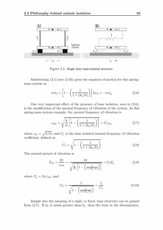
Insight into the benefits of using base isolators in structures can be gainedby considering the special case of a single-storey linear undamped structure,which is separated from the ground by flexible bearings of lateral linear stiffnesskb as shown in Fig. 2.1(a). The bearings are connected together through a(base mass) rigid horizontal diaphragm of mass mb, which lies just above thebearings. The whole system is idealized as a 2DOFs spring-mass system asshown in Fig. 2.1(b). The governing equations of motion are
mb y1 + k(y1 − y2) + kb(y1 − xg) = 0 (2.1a)
my2 + k(y2 − y1) = 0 (2.1b)
where m is the main mass, k is the stiffness of the structure above the isolatorand y1 and y2 are the total displacements of the base and the main masses,respectively.
If the relative displacements between the masses and the supports aredefined to be
x1 = y1 − xg (2.2a)
x2 = y2 − xg (2.2b)
it then follows from substituting (2.2) into (2.1) that
mb x1 − kx2 + (k + kb)x1 = −mb xg (2.3a)
mx2 + kx2 − kx1 = −mxg (2.3b)
Consider the special case where mb is very small and so is assumed to bezero. Therefore (2.3a) becomes
− kx2 + (k + kb)x1 = 0 (2.4)
Solving for x1 in terms of x2 in (2.4) gives
x1 =
(
k
k + kb
)
x2 =
(
1
1 + (kb/k)
)
x2 (2.5)
The displacement x1 is the displacement of the base isolator relative to theground. Equation (2.5) gives the value of x1 in terms of x2 and the ratio of thestiffness of the isolator to the structure. Note that if kb goes toward infinity(i.e. very stiff bearing), then x1 goes toward zero. Also, if kb is equal k, thenx1 is equal to one half of x2. The ideal, or perfect, isolation case is attainedif kb goes toward zero. In this case, x1 = x2 which translates into zero storydrift, perfect rigid-body vibration of the structure and full structure-groundseparation in the horizontal direction.
2.2 Philosophy behind seismic isolation 35
Figure 2.1: Single story base-isolated structure
Substituting (2.5) into (2.3b) gives the equation of motion for this spring-mass system as
mx2 +
[
1 −(
1
1 + (kb/k)
)]
kx2 = −mxg (2.6)
One very important effect of the presence of base isolators, seen in (2.6),is the modification of the natural frequency of vibration of the system. In thisspring-mass system example, the natural frequency of vibration is
ωnb =
√
k
m
[
1 −(
1
1 + (kb/k)
)]
= C1ωn (2.7)
where ωn =√
k/m, and C1 is the base isolated natural frequency of vibrationcoefficient, defined as
C1 =
√
1 −(
1
1 + (kb/k)
)
(2.8)
The natural period of vibration is
Tnb =2π
ωnb=
2π√
km
[
1 −(
11+(kb/k)
)]
= C2Tn (2.9)
where Tn = 2π/ωn, and
C2 =1
√
1 −(
11+(kb/k)
)
=1
C1(2.10)
Insight into the meaning of a rigid, or fixed, base structure can be gainedfrom (2.7). If kb is much greater than k1, then the term in the denominator,

36 Literature review
that is, 1 + (kb/k), of (2.7) becomes large, and therefore ωnb approach thenatural frequency of a rigid base system
√
k/m and Tnb approaches the natural
period of vibration of a rigid base system 2π/√
k/m.
The situation of interest for a base isolated structure is the case where kb
is less than k. In the limit if kb is very small, then ωnb goes to zero, see (2.7),and the natural period of vibration of the structure Tnb goes to infinity, see(2.9) which corresponds to the fully isolated condition. Equation (2.5) can berewritten to express the ratio x1/x2 as a function of the ratio kb/k. In thiscase, if kb/k becomes large, then x1/x2 tends to zero. This is the fixed basecondition.
2.2.2 Base shear perspective
The response of the spring-mass system, shown in Fig. 2.1, to an earthquakeground motion can be obtained using the response spectra analysis. It fol-lows from Eq. (2.6) that the maximum relative displacement, (x1)max, andmaximum base shear, Vmax, are equal to:
(x1)max = Sd
(
Tnb, ζ)
=(
Tnb/2π)2Sa(
Tnbζ)
(2.11)
Vmax = mSa
(
Tnb, ζ)
(2.12)
in which Sd is the spectral displacement and Sa is the pseudo spectral acceler-ation.
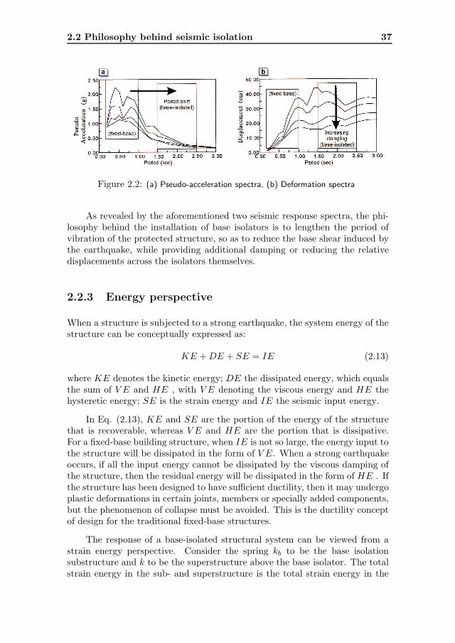
The pseudo acceleration response spectra, as shown schematically in Fig.2.2(a), represent plots of the peak value of Sa with respect to the fundamentalnatural period of vibration Tnb of the structure, which can be obtained as aby-product of the deformation response spectra shown in Fig. 2.2(b) throughthe use of the relation in Eq. (2.11).
From Eq. (2.9), smaller value of kb increases the value of Tnb. Then, twoimportant features can be observed from the response spectra given in Figs.2.2(a) and 2.2(b). The first is the so-called period shift effect. As indicated byFig. 2.2(a) and Eq. (2.12), substantial reduction in the pseudo accelerationor the base shear of a structure is possible, if the period of vibration of thestructure is significantly lengthened through installation of base isolators. Ingeneral, the additional flexibility needed to lengthen the period of the structurewill give rise to large relative displacements across the isolators, as indicated byFig. 2.2(b). The second is the so-called energy dissipating effect. If additionaldamping is introduced into the structure, then the deformation of the structurecan be significantly reduced (see Fig. 2.2(b)). Also, it can be seen that asmaller base shear force will be induced on a structure having larger damping(see Fig. 2.2(a)), and that a structure responds less sensitively to variations inground motion characteristics, as indicated by the smoother response curvesfor structures with higher damping levels in both figures.
2.2 Philosophy behind seismic isolation 37
Figure 2.2: (a) Pseudo-acceleration spectra, (b) Deformation spectra
As revealed by the aforementioned two seismic response spectra, the phi-losophy behind the installation of base isolators is to lengthen the period ofvibration of the protected structure, so as to reduce the base shear induced bythe earthquake, while providing additional damping or reducing the relativedisplacements across the isolators themselves.
2.2.3 Energy perspective
When a structure is subjected to a strong earthquake, the system energy of thestructure can be conceptually expressed as:
KE +DE + SE = IE (2.13)
where KE denotes the kinetic energy; DE the dissipated energy, which equalsthe sum of V E and HE , with V E denoting the viscous energy and HE thehysteretic energy; SE is the strain energy and IE the seismic input energy.
In Eq. (2.13), KE and SE are the portion of the energy of the structurethat is recoverable, whereas V E and HE are the portion that is dissipative.For a fixed-base building structure, when IE is not so large, the energy input tothe structure will be dissipated in the form of V E. When a strong earthquakeoccurs, if all the input energy cannot be dissipated by the viscous damping ofthe structure, then the residual energy will be dissipated in the form of HE . Ifthe structure has been designed to have sufficient ductility, then it may undergoplastic deformations in certain joints, members or specially added components,but the phenomenon of collapse must be avoided. This is the ductility conceptof design for the traditional fixed-base structures.
The response of a base-isolated structural system can be viewed from astrain energy perspective. Consider the spring kb to be the base isolationsubstructure and k to be the superstructure above the base isolator. The totalstrain energy in the sub- and superstructure is the total strain energy in the

38 Literature review
whole structure and can be written as
Esb =1
2kb x
21 (2.14)
Ess =1
2k(x2 − x1)
2 (2.15)
where Esb is the strain energy in spring kb (i.e. the base isolator) and Ess isthe strain energy in spring k (i.e. the superstructure). The strain energy inthe superstructure is a function of (x2 −x1). Therefore, the total strain energyof the system, Es (i.e. base isolator plus superstructure), is
Es = Esb + Ess =1
2kb x
21 +
1
2k(x2 − x1)
2 (2.16)
The difference in displacements between x2 and x1 can be written using(2.5), and it follows that
x2 − x1 =
(
k + kb
k
)
x1 − x1 =
(
kb
k
)
x1 (2.17)
Therefore, substituting (2.17) into (2.15), the strain energy in the superstruc-ture above the isolator is equal to
Ess =1
2k
(
kb
k
)2
x21 =
1
2kb
(
kb
k
)
x21 (2.18)
It then follows from (2.16) that
Es = Esb + Ess =1
2kb x
21 +
1
2kb
(
kb
k
)
x21 (2.19)
Equations (2.14), (2.15), (2.18), and (2.19) show that as kb decreases in mag-nitude, the strain energy in the kb spring (base isolator substructure) increasesin relation to the strain energy in the k spring (superstructure). Therefore,introducing base isolators redirects the strain energy from the superstructureabove the base isolators into the base isolators themselves.
2.3 Historical development of isolation systems
Seismic isolation is not a very new idea. More than a century ago, in 1885,John Milne, a professor of engineering in Japan, built a small wooden houseon balls in cast-iron plates with saucer-like edges on the heads of piles, todemonstrate that a structure could be isolated from earthquake shaking [181].However, the building behavior under wind loads was not satisfactory. So,he reduced the balls diameter from 10 inch to 1/4 inch. By this mean, the

2.3 Historical development of isolation systems 39
building became stable against wind loads and was evidently successful underactual earthquake action. In 1891, after Narobi earthquake, a Japanese person,Kawai, proposed a base isolated structure with timber logs placed in severallayers in the longitudinal and transverse direction [220].
In 1906, Jacob Bechtold of Germany applied for a U.S. patent in which aseismic-resistant building is to be placed on rigid plate supported on sphericalbodies of hard material [59]. In 1909, a medical doctor from England, Calen-tarients, had submitted a patent application to the British patent office for amethod of building construction. In his method, a building is constructed ona layer of fine sand, mica, or talc that would allow the building to slide in anearthquake, thereby reducing the force transmitted to the building itself [243].
In 1929, Robert de Montalk of New Zealand filed a patent application foran invention comprising a means whereby a bed is placed and retained betweenthe base of a building and its solid foundation. The bed was being composedof material which will absorb or minimize seismic shocks [116].
There are almost a hundred known proposals for a seismic isolation systemsmade prior to 1960, but as far as can be determined, none were ever built. Themost probable reason is a lack of practicality and the fact that the engineeringprofession of the day had little or no confidence in their success [59]. Onenotable historetic structure, however, is Frank Lloyd Wright’s Imperial Hotelin Tokyo, completed in 1921. This building was founded on a shallow layer offirm soil which in turn was supported by an underlying layer of mud. Cushionedfrom devastating ground motion, the hotel survived the 1923 Tokyo earthquakeand later Wright wrote in his autography [465] of the “merciful provision” of60 to 70 feet of soft mud below the upper 8 foot thick surface soil layer whichsupported the building. The imperial Hotel is evidence that base isolationworks and seismic protection can be achieved by relatively simple means.
Since the 1920s there have been other “accidents” in which some structureshave survived earthquakes while neighboring buildings have collapsed. Severalunreinforced masonry buildings were only lightly damaged in the 1933 LongBeach earthquake because they were able to slide on their grade beams. Atleast one masonry house survived the 1976 Tangshan earthquake because italso slid on its foundation inadvertently. Reconnaissance reports also describeinstances of slender structures surviving earthquakes because of their ability torock or sidesway. Water tanks and statues, chandeliers and suspension bridgesare some examples.
Attempts were made in the 1930s to protect the upper floors of multistorybuildings by designing very flexible first-story columns. It was proposed thatthe first-story columns should be designed to yield during an earthquake toproduce isolation and energy-absorbing actions. However, to produce enoughdamping, several inches of displacements is required, and a yielded column hasgreatly buckling loads, proving the concept to be impractical. To prevent thestructure from moving too far, the first story is constructed underground and

40 Literature review
energy dissipators are installed at the top of this story [23]. To overcome theinherent dangers of soft supports at the base, many types of roller bearingsystems have been proposed. The rollers and spherical bearings are very low indamping and have no inherent resistance to lateral loads, and therefore someother mechanisms that provide wind restraint and energy absorbing capacityare needed. A long duration between two successive earthquakes may result inthe cold welding of bearings and plates, thus causing the system to become rigidafter a time. Therefore, the application of the rolling supports was restrictedto the isolation of special components of low or moderate weight [73].
Parallel to the development of the soft first-story approach, the flexibility ofnatural rubber was also seen to be another solution for increasing the flexibilityof the system. The first use of a rubber isolation system to protect a structurefrom earthquakes was in 1969 for a three-story elementary school in Skopje,Republic of Macedonia. The building was constructed of reinforced concreteshear walls and supported by 54 large blocks of hard rubber. These rubberblocks were completely unreinforced, so the weight of the building causes themto bulge sideways. To improve the building stability under minor vibrations,glass blocks acting as seismic fuzes are intended to break when the seismicloading exceeds a certain threshold. Owing to having the same stiffness of theisolation system in all directions, the building bounces and rocks backwardsand forwards [234]. These types of bearings are unsuitable for the earthquakeprotection of structures.
The subsequent development of laminated rubber bearings in 1970s hasmade seismic isolation a practical reality [374, 375, 433]. These bearings arevery stiff in the vertical direction to carry the structural weight but are veryflexible horizontally to enable the isolated structure to move laterally understrong ground motion. In the early 1980s, developments in rubber technol-ogy led to new rubber compounds which were termed high damping rubber(HDR) [117]. Later, a large number of isolation devices were developed includ-ing rollers, springs, friction slip plates, capable suspension, sleeved piles, androcking foundations. Now seismic isolation has reached the stage of gainingacceptance and replacing the conventional construction, at least for importantstructures.
It is not just the invention of the elastomeric bearing which has madeseismic isolation a practical reality. Three other parallel, but independent,developments have also contributed to its success. The first of these was thedevelopment of reliable software for the computer analysis of structures soas to predict their performance and determine design parameters. The seconddevelopment was the use of shaking tables which are able to simulate the effectsof real recorded earthquake ground motions on different types of structures. Athird important development is in the skill of the engineering seismologist inestimating ground motions at a particular site.

2.4 Seismic isolation devices 41
2.4 Seismic isolation devices
By now seismic isolation is used in many countries, and there are a numberof acceptable isolation systems, whose mechanisms and characteristics are wellunderstood. Nevertheless, the concept is irresistable to inventors, and manynew and different systems or isolators are proposed and patented each year.Many of these new systems have been proven impractical and some mightactually be lethal, but the number continues to increase year by year [333].
The successful seismic isolation of a particular structure is strongly depen-dent on the appropriate choice of the isolation system. In addition to providingadequate horizontal flexibility and appropriate damping, the isolation systemshould essentially have the capability of self-centering after deformation, highvertical stiffness to avoid rocking, and enough initial stiffness to avoid frequentvibration from wind and minor seismic events. Different types of isolators havebeen developed and proposed to achieve these properties, and some of themare discussed below.
2.4.1 Elastomeric-based isolation systems
Rubber bearings offer a simple method of seismic isolation and are relativelyeasy to manufacture. The bearings are made by vulcanization bonding of suc-cessive rubber and steel reinforcing thin sheets [245]. The bearings are very stiffin the vertical direction and flexible in the horizontal direction. High verticalstiffness is achieved through the laminated construction of the bearing usingsteel plates, where the horizontal flexibility is caused by rubber layers. Thecommon elastomers used in elastomeric bearings are natural rubber, neoprenerubber, butyl rubber and nitrile rubber. The natural rubber is the most fre-quently recommended material because its main mechanical characteristics aresuperior to those of synthetic elastomers [422]. Laminated elastomeric bearingsare available in three main classes: low-damping rubber bearings, high-dampingrubber bearings and lead-plug rubber bearings.
Low-damping rubber bearings
In these bearings, the damping ratio provided by the elastomer is low, in theorder of 2 to 4%, and therefore they are unusual to be used without someother elements that provide suitable damping. The rubber material behaviorin shear is quite linear up to shear strains above 100%. The low-dampingrubber bearings are simple to manufacture, easy to model and their mechanicalresponse is unaffected by rate, temperature, or aging [333].

42 Literature review
Lead-plug rubber bearings
These bearings were invented in New Zealand in 1975 [374, 375] and are similarto the laminated rubber bearings, but a central lead core is used to providean additional means of energy dissipation. The energy absorbing capacity bythe lead core reduces the lateral displacements of the isolator. The lead plugproduces a substantial increase in damping from about 3% of critical dampingin the natural rubber to about 15%, and also increases the resistance to minorearthquakes or wind. The steel plates force the lead plug to deform in shear.Generally, the lead yields at a relatively low stress of about 10 MPa in shear andbehaves approximately as an elasto-plastic solid. The interrelated simultaneousprocess of recovery, recrystallization and grain growth is continuously restoringthe mechanical properties of the lead. The lead has good fatigue propertiesduring cyclic loading at plastic strains and is also readily available at highpurity of 99.9% required for its predictable mechanical properties. The lead-plug bearings behave essentially as hysteretic damper device and were widelystudied by [249, 252, 400].
High-damping rubber bearings
In the early 1980s, developments in rubber technology lead to new rubbercompounds, which were termed “high damping rubber”. These compoundsproduced bearings that had a high stiffness at low shear strains but a reducedstiffness at high strain levels. These bearings were originally developed inEngland in 1982 to eliminate the need for supplementary damping elements.The damping is increased to levels between 10 and 20% at 100% shear strains[333, 253].
Other elastomeric bearings
The use of steel shims in laminated rubber bearings provides necessary verticalstiffness, but at the same time makes these bearings heavy and expensive.In 2001, [247] proposed an economic seismic isolation system for developingcountry. In this system, the steel plates are replaced by fiber mesh. The fiber-reinforced elastomeric bearing is expected to be significantly lighter and couldbe easier to be manufactured.
A Japanese rubber company has developed an elastomeric bearing thatcombines a standard low-damping rubber bearing with a large internal hole,into which a central plug of a very high-damping synthetic elastomer is placed.The diameter of the internal plug is about half that of the whole bearing. Theshear modulus of the two elastomers is chosen to be very close. The effectivedamping of this combined isolation system is about 18 to 20% [53].
2.4 Seismic isolation devices 43
2.4.2 Sliding-based isolation systems
In this class of isolation systems, the superstructure is allowed to slide duringmajor seismic events. The structure slides whenever the lateral force exceedsthe friction force at the sliding interface. The horizontal friction force at thesliding surface offers resistance to minor seismic events or wind and dissipatesenergy.
Pure sliding systems
Purely sliding systems are the earliest and simplest isolation systems to beproposed. These systems have no inherent natural period and therefore areinsensitive to variations in the frequency content of ground excitations. Theacceleration at the base of the structure is limited to the coefficient of frictionat the sliding interface. Therefore, by keeping this coefficient of friction low, theacceleration transmitted to the structure can be reduced. However, the frictioncoefficient cannot be reduced arbitrarily, as the sliding displacement may exceedacceptable values. The main drawbacks of the these systems are the absenceof restoring force, cold welding, freezing, deterioration of sliding surfaces andthey require regular inspection to maintain the coefficient of friction [401].
Friction pendulum system
The friction pendulum system (FPS) is a frictional isolation system that com-bines a sliding action and a restoring force by geometry [511, 512, 12]. In FPS,the isolation is achieved by means of an articulated slider on spherical, con-cave chrome surface. As the slider moves over the spherical surface, it causesthe supported mass to rise and provide a restoring force of the system. Theslider is faced with a bearing material, which when becomes in contact withthe polished chrome surface, results in a maximum sliding friction coefficientof the order of 0.1 or less at high velocity of sliding and a minimum frictioncoefficient of the order of 0.05 or less for very low velocities of sliding. The de-pendency of coefficient of friction on velocity is a characteristic of Teflon-typematerials [322]. The natural period of the FPS is fixed [331] and is controlledby selection of the radius of curvature of the concave surface. The enclosingcylinder of the isolator provides a lateral displacement restraint and protectsthe interior components from environmental contamination. The displacementrestraint provided by the cylinder provides a safety measure in case of lateralforces exceeding the design values [263].
44 Literature review
Resilient-friction base isolation system
The resilient-friction base isolation base isolation (R-FBI) bearing attemptsto overcome the problem of the high friction coefficient of Teflon on stainlesssteel at high velocities by using many sliding interfaces in a single bearing[325, 329, 330]. Thus the velocity between the top and the bottom of thebearing is divided by a number of layers, so that the velocity at each face issmall, maintaining a low friction coefficient [333]. This base isolator consists ofconcentric layers of Teflon-coated plates that are in friction contact with eachother and contains a central core of rubber. It combines the beneficial effect offriction damping with that of resiliency of rubber. The rubber core distributesthe sliding displacement and velocity along the height of the R-FBI bearing.They do not carry any vertical loads and are vulcanized to the sliding ring.The system provides isolation through the parallel action of friction, dampingand restoring force [263].
Electric-de-France base isolation system
This system was developed in 1970s under the auspices of “Electric de France”(EDF) [160] and is standardized for nuclear power plants in region of highseismicity. The EDF base isolator essentially uses elastomeric bearing andfriction plate in series. It consists of laminated (steel reinforced) neoprenepad topped by lead-bronze plate that is in friction contact with steel plateanchored to the base raft of the structure. The friction surfaces are designed tohave a coefficient of friction of 0.2 during the service life of the base isolationsystem. An attractive feature of EDF isolator is that for lower amplitudeground excitation the lateral flexibility of neoprene pad provides base isolationand at high level of excitation sliding will occur which provides additionalprotection. This dual isolation technique was intended for small earthquakeswhere the deformations are concentrated only in the bearings. However, forlarger earthquakes the bronze and steel plates are used to slide and dissipateseismic energy.
Sliding resilient-friction base isolation system
In 1991, [417] proposed the design of the sliding resilient-friction (S-RF) baseisolator. This isolator combines the desirable features of the EDF and the R-FBI systems. It was suggested to replace the elastomeric bearings of the EDFbase isolation by the R-FBI units. It means that the friction plate replacesthe upper surface of the R-FBI system in the modified design. As a result,the structure can slide on its foundation in a manner similar to that of EDFbase isolation system. For low level of seismic excitation the system behaves asR-FBI system. The sliding at the top friction plate occurs only for a high level

2.4 Seismic isolation devices 45
of ground acceleration that provides additional safety for unexpected severeground motion.
EERC base isolation system
This system is a combination of elastomeric and sliding systems. It was de-veloped and tested at the Earthquake Engineering Research Center (EERC).In this system the interior columns of the structure were carried on teflon onstainless steel sliding elements and the exterior columns on the low-dampingnatural rubber bearings. The elastomeric bearing provides restoring capabilitywhile the sliding elements provides energy dissipation [74].
The TASS base isolation system
The TASS system was developed by the TAISEI Corp. in Japan [244]. Thissystem combines teflon-stainless steel elements to carry vertical load and lami-nated neoprene bearings which carries no load but is used to provide restoringforces. The pressure on the teflon sliding surface is around 10 MPa, and thecoefficient of friction ranges from 0.05 at slow sliding speeds to around 0.15 athigher speeds. The main disadvantage of this system is that because the elas-tomeric bearings carry no vertical load they experience tension and the velocitysensitivity of the sliding surface makes modeling of the system quite difficult.
Variable friction pendulum isolation system
It is a modified form of the friction pendulum isolation system, in which theshape of the sliding surface is non-spherical to allow for variable vibrationperiod [364]. The variation of the friction coefficient in this system is suchthat up to a certain value of displacement the frictional force increases andthen it decreases with further increase in displacement [349]. This isolationsystem retains the advantages of both the pure friction isolation system andFPS, due to amplitude dependent time-period and softening mechanism ofisolator restoring force. The geometry of the isolator can be chosen to achievea progressive period shift at different response levels. The advantage of variablefrequency of oscillation is particularly significant for sliding surfaces with lowcoefficients of friction and during high intensity earthquakes.
Sliding concave foundation base isolation system
It is a foundation system, which includes a lower part and an upper slidingraft. The lower part has a generally concave surface at the top. The uppersliding raft has a convex surface at the bottom that is adapted to rest on the
46 Literature review
concave surface of the lower part and allow for sliding rotational movementtherebetween. The building or the object to be isolated is attached to theupper sliding raft [171]. A structure supported on this system behaves like acompound pendulum during seismic excitation. The isolation takes place dueto sliding and the energy dissipation is because of friction while the restoringforce is attributed to the foundation curvature. However, this system may allowpermanent tilting of isolated objects.
Multiple friction pendulum isolation system
The multiple friction pendulum system (MFPS) was proposed by [428, 429]as an improvement of the FPS. The principal benefit of the MFPS bearing isits capacity to accommodate substantially larger displacements compared toa traditional FPS bearing of identical plan dimensions. The MFPS consistsof two concave surfaces and a specially designed articulated slider, which islocated between these two concave surfaces. Based on this special design of thearticulated slider, pressures on the concave surfaces can be properly distributedduring their movements. The MFPS isolator can be designed with unequal radiiand unequal friction coefficients at the top and bottom concave surfaces. Inthis case, the MFPS bearing behaves much like a traditional FPS bearing witheffective radius of curvature equal to the sum of the radii of curvature of the twoconcave surfaces (but modified for the height of the slider) and friction equalto the average of the coefficient of friction at each sliding interface. Additionalinvestigations of the MFPS were carried out by [427, 143, 144, 145].
Uplift-restraining friction pendulum base isolation system
Based on the Friction Pendulum (FP) principle, the XY-FP isolation bearingwas proposed by [377, 376, 378]. This device consists of two orthogonal concavebeams interconnected through a sliding mechanism that permits tensile forcesto develop in the bearing. Thus preventing potential structure-foundation sep-aration when the bearing is subjected to tension during earthquakes.
The RoGlider isolation system
The RoGlider is a sliding bearing proposed by [373] and includes an elasticrestoring force. The RoGlider either is a double acting unit with the restoringforce provided by two rubber membranes or a single acting unit. The doubleacting RoGlider consists of two stainless steel plates with a PTFE ended pucksitting between the plates. Two rubber membranes are attached to the puckwith each being joined to the top or bottom plates. When the top and bottomplates slide sideways with respect to each other, diagonally opposite parts of themembrane undergo tension or compression. The tension components provide

2.4 Seismic isolation devices 47
the restoring force between the plates and the whole system exhibits hystereticbehavior. A typical RoGlider may have a maximum displacement of ±600 mm,a maximum vertical load of 1 MN, with an outside diameter around 900 mmand a coefficient of friction of 0.11% at 0.5 ms−1.
2.4.3 Spring-based isolation systems
These types of isolation systems are generally used when full three-dimensionalisolation is required, as the case of large generators in power plants. Thesesystems uses large helical steel springs that are flexible in both horizontal andvertical directions. The steel springs are completely without damping and theyare used in conjunction with other damping devices. As in all three-dimensionalsystems, there is a very strong coupling between horizontal motion and rockingmotion. Therefore, the spring isolation systems are not effective in reducingthe accelerations in buildings due to the rocking motion [310].
2.4.4 Rolling-based isolation systems
The concept of rolling is an efficient way to achieve the necessary structure-foundation decoupling if compared to the sliding motion mechanism, as theforce required to initiate rolling motion is significantly smaller than that re-quired to start sliding. This is mainly attributed to the very small rollingfriction if compared to the sliding one. In general, rolling friction is far lessthan sliding friction and the former is only about 1/40 – 1/60 of the later [472].
Rolling rods isolation systems
In 1993, [291] has proposed a new system of free circular rolling rods locatedbetween the base and the foundation. The most attractive feature of thistype of isolator is their low value of rolling friction coefficient, which allows avery low earthquake force to be transmitted to the superstructure. However,such a system lacks re-centering and damping capabilities, resulting in residualand large peak displacements. To provide them with re-centering mechanism,[225] proposed that the shape of rolling rods should be elliptical rather thencircular. The low value of the rolling friction coefficient ensures the transmissionof a limited earthquake force into the superstructure and the eccentricity ofthe elliptical rolling rods provides a restoring force that reduces peak basedisplacements and brings the structure back to its original position. However,the system damping is still absent.

48 Literature review
Rolling pendulum isolation systems
Combining the advantage of free rolling rod isolators and FPS isolators, thebase isolation by a ball system with restoring property was proposed by [517].The resulting system is a self-recentering ball bearing having a fixed vibrationperiod, as the FPS, which represents a severe practical difficulty. This bearingconsists of a spherical rolling body between two opposite spherical grooves. Asimilar approach was presented by [30] where a mushroom-shaped (pendulum-like) basements were used under structures as a base isolation system. Eachbasement have a spherical arc that rests on the foundations in a tangentialmanner. From the arc midpoint there is a radial pinned arms that is connectedto the structure column. The whole system acts like a spring under the struc-ture. The main problems in using of this method are the lack of damping andstress concentration at the contact point between spherical base and founda-tion. Indeed, the idea of the rolling pendulum system is quite old, as it datesback to the US patent [426].
Ball-N-Cone isolation systems
A seismic isolation bearing consisting a steel ball sandwiched between twohorizontal, steel load plates. The load plates have a shallow, concave, conicalrecess of vertical, collinear axis. The cone axis passes through the ball centerlineat rest. The upper and lower load plates are bolted to the structure and base,respectively. Gravity restores the bearing’s displacement in the lack of externalforces. Lateral bearing forces are independent of displacements [254, 238, 237].
Multi-step isolation systems
A manufacture to protect a structure from destructive earthquakes as well as tosecure its stability under the strongest possible wind, having a number of balltransfer units rigidly coupled to a supported superstructure; the same numberof pedestal plates supporting the ball transfer units, each having an upper sur-face having a plurality of curved surfaces with a central depression followingthe shape of the ball. The force of gravity will keep the structure in its steadyinitial position when the balls are inset into corresponding depressions at anywind pressure and at slight earthquakes. With magnitude of earth movementexceeding a certain threshold the balls get out of central depressions thus pro-viding a controlled separation of the superstructure from the foundation, andthe upper surfaces of pedestal plates with properly designed geometry governstransfer of horizontal movement into the superstructure and prevents hazardousstructural vibrations [390].
2.4 Seismic isolation devices 49
Mutually eccentric rotators isolation systems
A base isolator that has four base isolation units placed at four corners betweena floor slab and a floor plate. Each base isolation unit has a middle plate, alower support body which is rotatable in a first direction on the lower side ofthe middle plate, and an upper support body rotatable in a second directionon the upper side of the middle plate. The upper support body and the lowersupport body each have mutually eccentric rollers. The middle plates of thefour base isolation units are separated from one another so that the plates canbe independently displaced or moved [240].
Directional rolling pendulum isolation systems
They are bi-directional rolling pendulum seismic isolation systems for reducingseismic force acting on a structure by rolling pendulum movements. The systemhas a lower plate forming a rolling path in a first direction; an upper plateforming a rolling path in a second direction; and a roller assembly performinga pendulum motion by rolling and moving along the lower and upper plateswherein the roller assembly performs the pendulum motion when seismic loadis applied, thereby reducing the seismic load of a structure [259].
RoBall isolation systems
It consists of two opposite saucer-like rubber containers with flat outer surfacesand curved inner ones [372]. It contains seven solid balls. Other designs of theRoBall suitable for larger displacements could include 13, 19, 25 or more solidballs in close packed arrays. The sides of the RoBall may be made thickerthan the top and bottom surfaces, thereby contributing to a restoring forcefor small displacements, while for large displacements there is cyclic restoringwith a force-displacement wavelength approximately twice the diameter of theRoBall. The rolling action of the RoBall means that the device itself hasno displacement limit and so the maximum displacement is limited only byinstallation requirements. The dynamic behavior of the device is independentof both frequency and ambient temperature within ranges that are applicableto most practical installations. The effective friction coefficient is around 0.10.
Other rolling-based isolation systems
Ref. [110] proposed an isolator to prevent transmitted vibrations that includesa ring which fits within a shaft opening of a housing. A bearing is receivedwithin the isolator and a shaft is received within the bearing. The vibrationsare decoupled from a vibration transmission path by the different material of

50 Literature review
the isolator. The isolator is preferably manufactured of a rigid laminate ma-terial dissimilar to the housing material. Another embodiment of the presentinvention integrates the isolator directly into the bearing assembly. By manu-facturing the outer member of the bearing assembly of the laminated material,the outer member similarly breaks the transmission path of vibrations withoutthe need of the additional member. Noise is thereby substantially preventedfrom reaching, and from being amplified by, the housing. This greatly reducesthe resulting noise and vibration.
A seismic isolation bearing comprises a lower plate, an upper plate, anda cylindrical roller in rolling contact with an upwardly facing, bearing surfaceof the lower plate and a downwardly facing surface of the upper plate wasproposed by [273]. The lower plate is fixable to a base, while the upper plateis fixable to a superstructure. One or both bearing surfaces are sloped to forma central trough at which the cylindrical roller resides under normal weight ofthe superstructure, and toward which the roller is biased when displacementbetween the plates occurs. A pair of sidewall members are fixed to the lowerplate to withstand strong forces directed laterally with respect to the isolationaxis along which rolling displacement occurs, and a pair of sliding guides carriedone at each end of the roller provide dry frictional damping as they engage aninner wall surface of a corresponding sidewall member. A similar isolationbearing was presented in [490].
A rolling-based seismic isolation apparatus is structured by [348] such thata pair of seismic isolation mechanisms are formed each having a pair of up-per and lower clamping members formed in the shape of a rectangular frame,wherein upper and lower roller guide surfaces, in each of which a longitudinalcentral portion is formed as a concavely arcuate curved surface and portions re-spectively extending therefrom are formed as convexly arcuate curved surfaces,are formed on the four sides of the upper and lower clamping members, andwherein rollers each having a circular cross section are respectively interposedbetween the upper and lower roller guide surfaces. The pair of seismic isolationmechanisms are installed by being superposed on top of each other such that therolling directions of the rollers in the two seismic isolation mechanisms are per-pendicular to each other. During the occurrence of an earthquake, the rollersare adapted to roll in contact with the upper and lower roller guide surfacesso as to absorb and dampen seismic waves in the longitudinal and transversedirections of the apparatus. Two similar isolation systems were proposed by[169, 345].
Ref. [493] proposed a vibration isolation unit in which a rolling elementhaving a first curved surface that is a convex surface is interposed betweena first and second members, and the rolling element is allowed rolling withrespect to the first member in the first curved surface thereof. The rollingelement has a second curved surface that faces the first curved surface andis formed of a curved surface center different from that of the first curved

2.4 Seismic isolation devices 51
surface. As the rolling element, resulting from an additional force applied onthe first and second curved surfaces, rolls with respect to the first member, thesecond member vibrates with a restoring force determined based on an averagecurvature radius of the first and second curved surfaces of the rolling elementand a distance between curved surface centers of the first and second curvedsurfaces.
2.4.5 Synthetic liners and artificial soil layers
Placing smooth synthetic materials beneath the foundation of structures wasproposed by [495] to provide a friction base-isolating layer. It was concludedthat a high strength, non-woven geo-textile placed over an ultra molecularweight polyethylene was most suitable and gave a static and dynamic coef-ficient of friction of 0.10 and 0.07, respectively. This coefficient was almostindependent of sliding velocity and normal stress. This system has the advan-tage in that the sliding surface is placed below a concrete slab and the systemis therefore less likely to slide excessively in wind storms. Similar systems wereproposed by [257, 494, 496].
Interposing an artificial soil layer between the superstructure and the foun-dation of the buildings was proposed by [128]. This soil layer has a low shearingresistance, which allows the building to slip under the action of strong seismicmotions. However, the system constructability is dubious and the design isproblematic. Moreover, the coefficient of friction of the system is 0.2, whichdoes not provide large force reductions. A similar base-isolation layer but onlyfor heavy construction was suggested by [467]. [430] proposed a similar seismicisolation method particularly suitable for developing countries. This methodmakes use of rubber–soil mixtures as a thick layer beneath the structure toprovide horizontal and vertical seismic isolation effect.
2.4.6 Rocking isolation system
Rocking mechanism can be an effective means of seismic isolation, despite thefact that it is rarely conceived a possible alternative [87]. Tall slender struc-tures suffer tension at the foundation level under lateral loads. It is extremelyexpensive to provide tension capacity in building foundation for such purpose.As an alternative, it is possible to allow the building columns or bridge piers tostep off the foundation [333]. This form of partial isolation reduces the seismicloads throughout the structure. The dynamics of the stepping structures havebeen extensively studied theoretically [500] and experimentally [252, 103].

52 Literature review
2.4.7 Sleeved-pile isolation system
In situations where it is necessary to use deep pile foundations for buildingson very soft soil, it can be advantageous to use these piles to provide thehorizontal flexibility needed for the isolation system. The piles are made flexibleby enclosing them in tubes with suitable gap for clearance [46, 77].
2.4.8 Other isolation systems
In 2004, [10] proposed an isolation system that uses a commercially availableair-spring of diameter 600 mm to act as a belt on a fabric bag filled with achosen percentage of liquid and air. Although it was claimed that the resultswere satisfactory, this system is not robust and is unlikely to be acceptable.
Rocking pillars were used as an isolation system to support a superstruc-ture by [241]. The pillar is from a steel tube filled with concrete with sphericalcaps. A damper between the pillars and caisson is required to limit movementand provide restraint to wind movement. The system motion is rolling-basedand is self-recentering. The natural period with dampers was rather low for abase-isolated structure (0.63 sec) and indicated limited isolation. Although thissystem has potential as bridge piers, it is expected that this type of constructionbe expensive in practice and to be beset by practical problems. Waterproofingthe system would also be a problem. A similar isolation system was proposed by[359] as a low-cost solution for seismic protection of low-income people housing.
Based on employing the first soft story in a building as an isolation system,[321] proposed a system for the design of earthquake-resistant buildings. Inthis system, first story shear walls are fitted with flat Teflon sliders while theremaining first story columns are designed with reduced yielding stress. Inthis system a major part of the weight of the building is carried by the Teflonsliders, which makes the system behave almost like a plane friction isolationsystem, but with one more advantage that is the remaining first story columnsmay provide a restoring mechanism during small earthquakes. However, thepartial structure-foundation separation provided by this system makes it onlyvalid for low-intensity earthquakes.
A base-isolation device that takes advantage of the reduced accelerationexperienced by masses moving on inclined planes and which systematicallytransforms kinetic energy into potential energy has been proposed by [304]. Inits simplest form, the device consists of two wedges sliding on a horizontal planein opposite directions and constrained from retreating by ratchets or bilineardampers. The superstructure rests at the intersection of the two wedges. Fora sufficiently large horizontal acceleration of the base, the structure starts tomove up the inclined plane of one of the wedges, which remains fixed while thesecond wedge is slaved to follow the structure. As the direction of the baseacceleration reverses, the process is reversed and the structure starts to climb
2.4 Seismic isolation devices 53
on the second inclined plane while the first wedge follows. The overall resultis that the horizontal acceleration of the structure is reduced with respect tothat of the base and that kinetic energy associated with horizontal velocities issystematically transformed into potential energy.
A base isolation device was proposed, deeply examined and modeled by [71,69, 72]. It consists of two disks, one vertical cylinder with an upper enlargementsustained by three horizontal cantilevers, and at least three inclined shapememory alloy (SMA) bars. The role of the SMA bars is to limit the relativemotion between the base and the superstructure, to dissipate energy by theirsuper-elastic constitutive law and to guarantee the re-centring of the device.A prototype was built and tested under sinusoidal waves of displacement ofincreasing frequency with different amplitudes. Further, application of thedevice to a highway bridge benchmark problem was presented by [70].

This page intentionally left blank.

3A new device for seismic isolation
3.1 Motivations for a new isolator
Nowadays, many new materials and devices continue to be proposed for use inbase isolation. Based on the extent of control to be achieved over the seismicresponse, the choice of the isolation system varies and thereupon its designis done to suit the requirements of use of the structure. A practical seismicisolation system should meet the following four requirements:
1. Sufficient horizontal flexibility to increase the structural period.
2. Sufficient energy dissipation capacity to limit the isolator displacementsto a practical level.
3. Adequate rigidity under general service loading.
4. Adequate vertical stiffness to support the isolated object weight.
Most commonly used seismic isolating systems can satisfy all the aboverequirements while having their own characteristics. However, no one type de-vice is perfect as each device has its own drawbacks. Therefore, there is alwaysa continuous need to enhance the existing isolation systems or even to innovateothers to get the most benefits of seismic isolation while avoiding any unwantednegative effects. Table 3.1 summarizes the advantages and disadvantages of themost commonly used device types. These advantages and disadvantages arebrief, general and may not be comprehensive. Further, the listed disadvantagesmay apply to a generic type, some manufactures may have specific proceduresto alleviate the disadvantages.

56 A new device for seismic isolation
Table 3.1: Advantages and disadvantages of the most commonly used iso-lation systems
Device Advantages Disadvantages
Elastomeric - Low structural accelerations - Large displacements- Relatively low cost - Low damping
- No recentering mechanism- Shear strain reduces capacity- Minimum flexibility limit- No resistance to service loads- No buffer- P-∆ influence
HDR - Moderate structural accel. - Strain dependent stiffness- Resistance to service loads - Strain dependent damping- Moderate to high damping - Complicated analysis
- Scragging-change properties- Narrow range of stiffness- Narrow range of damping- No buffer- P-∆ influence
LRB - Moderate structural accel. - Cyclic change in properties- Resistance to service loads - Bearing area reduction- Wide range of stiffness - P-∆ influence- Wide range of damping - Not for low-mass structures- High damping levels - No buffer
Flat - Simple in concept - High structural accel.Sliders - Resistance to service loads - Changing friction coefficient
- No strain hardening - High initial stiffness- Low profile - No recentering mechanism- High damping levels - No buffer- Earthquake independent- Structure independent
Curved - Low profile - High structural accel.Sliders - Resistance to service loads - Changing friction coefficient
- Relatively wide damping range - High initial stiffness- Reduced structural torsion - High cost- High damping levels - Fixed vibration period
- Uplifted structure with motion- Likely permanent eccentricity
Rollers - Very low structural accel. - No damping- Simple means and concept - No buffer- Great horizontal flexibility - No recentering mechanism
- Not for heavy massesContinued . . .

3.2 Concepts of the proposed isolator 57
Device Advantages Disadvantages
- Flattening of contact surfaces
Springs - Provide 3D isolation - No damping- Commonly used for machinary - Produces vertical accelerations
- No buffer- No recentering mechanism- Not for heavy masses
Hysteretic - Control displacements - Add force to systemDampers - Low cost
- Provide stiffness and damping- Wide damping range- Widely available
Table 3.1: (continued)
Rough inspection of Table 3.1 confirms the fact that each of the seismicisolation systems mentioned above has specific dynamic properties and func-tions but no device is perfect. This motivates the efforts either to enhance theexisting devices or to innovate others with the aim of attaining the maximumprotection level of structures through seismic isolation. Unfortunately, mostof the isolation systems reported in the literature are patented products (thesame is also true with most newly invented products), not all of them are read-ily available for procurement and direct enhancement. Therefore, the intentionmay be directed toward creating more efficient isolation devices. This chapterpresents an attempt to innovate a practical isolation device that aims to get thebest of the present day isolation systems while avoiding their main drawbacks.
3.2 Concepts of the proposed isolator
The proposed isolation bearing is referred to as roll-n-cage (RNC) isolator. It isrecently patented through the Spanish Office of Patents and Marks [211]. Thestarting point of designing such isolation system was to seek a motion mech-anism that provides the maximum structure-foundation decoupling. The con-cept of rolling is an efficient way to achieve the necessary structure-foundationdecoupling if compared to the sliding motion mechanism, as the force requiredto initiate rolling motion is significantly smaller than that required to startsliding. This is mainly attributed to the very small rolling friction if comparedto the sliding one. In general, rolling friction is far less than sliding friction
58 A new device for seismic isolation
and the former is only about 1/40 – 1/60 of the later [472]. Therefore, the pro-posed RNC isolator is a rolling-based isolation bearing. The most attractivefeature of this isolator is its ability to allow a very low earthquake force to betransmitted to the superstructure.
Briefly, owing to its distinct configuration, the RNC isolator possessesunique properties for a seismic isolator, including:
1. Multi- and unidirectional isolation.
2. Energy dissipation.
3. Uplift restraint.
4. Resistance to wind and minor vibrations.
5. Built-in buffer.
6. Inherent gravity-based recentering mechanism.
7. Suitable for light, moderate and heavy mass systems.
8. Resistance to flattening of contact surfaces.
9. Wide range of stiffness and damping.
10. Independent damping and bearing mechanisms.
11. Independent stiffness and bearing mechanisms.
12. Great system-base decoupling.
13. Non-fixed vibration period.
14. Expected reasonable construction cost.
3.3 Technical field
The proposed RNC bearing is intended to mitigate or reduce the damage poten-tial and casualties of structural and/or nonstructural systems due to dynamicshock loading, especially seismic loading. The structural systems can be build-ings, bridges, water tanks . . . etc, such that the systems to be protected are validfor seismic isolation. The nonstructural systems can be any motion-sensitiveequipment, hardware and/or antiquities.
3.4 Main forms
The proposed RNC isolator has two main forms, having the same core andspirit, that are distinguished according to the needed vertical load capacity.The first of these two forms is referred to as RNC–c and is devoted to supportlight to moderate mass systems. The RNC–c is shown schematically in Fig.3.1, where the vertical loads are only supported by the rolling body of theRNC isolator. The second form of the RNC isolator is designed for heavy masssystems and is referred to as RNC–a and RNC–b as shown in Figs. 3.2 and
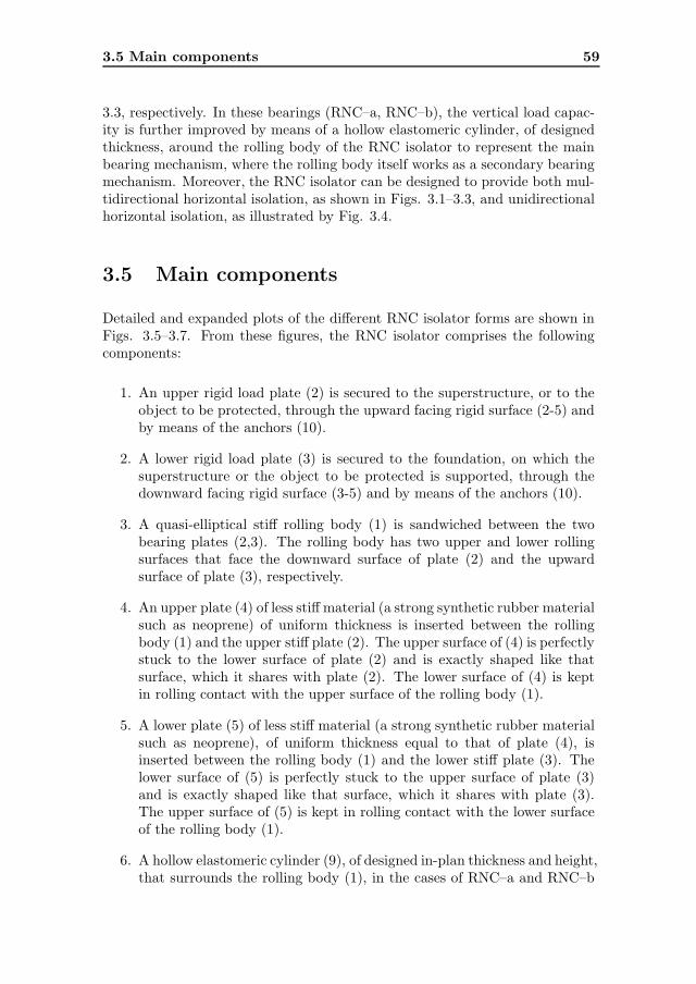
3.5 Main components 59
3.3, respectively. In these bearings (RNC–a, RNC–b), the vertical load capac-ity is further improved by means of a hollow elastomeric cylinder, of designedthickness, around the rolling body of the RNC isolator to represent the mainbearing mechanism, where the rolling body itself works as a secondary bearingmechanism. Moreover, the RNC isolator can be designed to provide both mul-tidirectional horizontal isolation, as shown in Figs. 3.1–3.3, and unidirectionalhorizontal isolation, as illustrated by Fig. 3.4.
3.5 Main components
Detailed and expanded plots of the different RNC isolator forms are shown inFigs. 3.5–3.7. From these figures, the RNC isolator comprises the followingcomponents:
1. An upper rigid load plate (2) is secured to the superstructure, or to theobject to be protected, through the upward facing rigid surface (2-5) andby means of the anchors (10).
2. A lower rigid load plate (3) is secured to the foundation, on which thesuperstructure or the object to be protected is supported, through thedownward facing rigid surface (3-5) and by means of the anchors (10).
3. A quasi-elliptical stiff rolling body (1) is sandwiched between the twobearing plates (2,3). The rolling body has two upper and lower rollingsurfaces that face the downward surface of plate (2) and the upwardsurface of plate (3), respectively.
4. An upper plate (4) of less stiff material (a strong synthetic rubber materialsuch as neoprene) of uniform thickness is inserted between the rollingbody (1) and the upper stiff plate (2). The upper surface of (4) is perfectlystuck to the lower surface of plate (2) and is exactly shaped like thatsurface, which it shares with plate (2). The lower surface of (4) is keptin rolling contact with the upper surface of the rolling body (1).
5. A lower plate (5) of less stiff material (a strong synthetic rubber materialsuch as neoprene), of uniform thickness equal to that of plate (4), isinserted between the rolling body (1) and the lower stiff plate (3). Thelower surface of (5) is perfectly stuck to the upper surface of plate (3)and is exactly shaped like that surface, which it shares with plate (3).The upper surface of (5) is kept in rolling contact with the lower surfaceof the rolling body (1).
6. A hollow elastomeric cylinder (9), of designed in-plan thickness and height,that surrounds the rolling body (1), in the cases of RNC–a and RNC–b

60 A new device for seismic isolation
as shown in Figs. 3.6 and 3.7 respectively. It is made of reinforced elas-tomeric rubber while its upper and lower ends are perfectly attached tothe upper and lower stiff plates (2,3) through suitable grooves as shownin Figs. 3.6 and 3.7.
7. Metallic yield dampers (6a) in the cases of RNC–c and RNC–a shownin Figs. 3.5 and 3.6, respectively. They are arranged along the perime-ter of the isolation bearing and are attached to the rigid bearing plates(2,3) through connection (11) as demonstrated by Fig. 3.8, or via anyequivalent rigid connection. The number and cross section of these yielddampers are designed based on the required resistance to minor shakingand the desired protection level. The dampers (6a) are shaped to allowfor enough extension during rolling and to reduce the stress concentrationat different bends. Accordingly, the used yield dampers (6a) are providedwith outside triple curvature (6-1).
8. Lead bar dampers (6b), in the case of RNC–b as shown by Fig. 3.7, thatpenetrate the full height of the hollow elastomeric cylinder defined in Item6 and replace the metallic yield dampers defined in Item 7. The ends ofthe lead bars fit into suitable grooves in the upper and lower plates (2,3)in Fig. 3.7.
9. The lower surface of the upper stiff plate (2) and the upper surface of thelower stiff plate (3) are provided with properly designed slopes to form anedge troughs, that exactly absorb the expected elevation of the supportedobject during rolling of the quasi-elliptical rolling body (1), as shown inFig. 3.9.
10. The lower stiff plate (2) and the upper stiff plate (3) are provided withvertical side walls to help forming a maximum limit of rolling displace-ment as demonstrated by Fig. 3.10.
11. The stiff rolling body is provided with two right-angle grooves. Suchgrooves form a lock with the side walls, defined in Item 10, upon reachingthe predetermined lateral displacement limit of the rolling body (1) asdemonstrated by Fig. 3.10.
12. The upper and lower stiff plates (2,3), in the cases of RNC–c and RNC–ain Figs. 3.5 and 3.6, are provided with edge stiffeners (7,8), respectively.These stiffeners improve the rigidity of the outer edges of plates (2,3),with less construction material, where the metallic yield dampers (Item7) are connected.
13. The upper and lower spherical surfaces (1-3) of the stiff rolling body (1),that are in rolling contact with the surrounding less stiff plates (4,5), arecoarse regular surfaces to improve the sliding friction coefficient.

3.6 Principles of operation 61
14. The plane coarse surfaces (1-2) surround the coarse regular spherical sur-faces (1-3) of the rolling body (1), in order to satisfy the required bearingarea for vertical loads at the positions of maximum lateral displacement,Figs. 3.9(a,c).
15. The edge troughs of the upper plates (2,4) and lower plates (3,5) areprovided with plane horizontal parts (2-3, 4-3) and (3-3, 5-3) respectively.These plane surfaces correspond to what defined in Item 14.
Figure 3.1: RNC isolator for light to moderate mass systems type c, RNC–c
3.6 Principles of operation
From its name, the roll-n-cage isolation bearing adopts the rolling mechanismto cut off the load path between the superstructure and the base. Such rolling
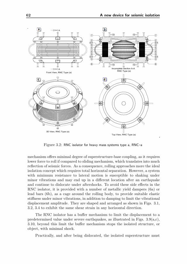
62 A new device for seismic isolation
Figure 3.2: RNC isolator for heavy mass systems type a, RNC–a
mechanism offers minimal degree of superstructure-base coupling, as it requireslower force to roll if compared to sliding mechanism, which translates into muchreflection of seismic forces. As a consequence, rolling approaches more the idealisolation concept which requires total horizontal separation. However, a systemwith minimum resistance to lateral motion is susceptible to shaking underminor vibrations and may end up in a different location after an earthquakeand continue to dislocate under aftershocks. To avoid these side effects in theRNC isolator, it is provided with a number of metallic yield dampers (6a) orlead bars (6b), as a cage around the rolling body, to provide suitable elasticstiffness under minor vibrations, in addition to damping to limit the vibrationaldisplacement amplitude. They are shaped and arranged as shown in Figs. 3.1,3.2, 3.4 to exhibit the same shear strain in any horizontal direction.
The RNC isolator has a buffer mechanism to limit the displacement to apredetermined value under severe earthquakes, as illustrated in Figs. 3.9(a,c),3.10, beyond this limit the buffer mechanism stops the isolated structure, orobject, with minimal shock.
Practically, and after being dislocated, the isolated superstructure must

3.6 Principles of operation 63
Figure 3.3: RNC isolator for heavy mass systems type b, RNC–b
return back to its original position before excitation. So, the RNC is providedwith an efficient gravity-based recentering mechanism through the ellipticallyshaped rolling body (1), along with the weight of the supported superstructure(or object) to generate a restoring couple Mr opposite to the motion-causingcouple as seen in Fig. 3.11.
During the maximum displacement positions, the less stiff plates (4,5) actas shock absorbers as illustrated in Figs. 3.9(a,c), 3.10. A strong synthetic(hyperelastic) rubber material, such as neoprene, is recommended for theseplates (4,5). These plates (4,5) increase the sliding friction coefficient with therolling body (1), which also has regular coarse rolling surfaces in order to forcethe rolling motion and to avoid any unwanted slip of the rolling body (1). Inaddition, plates (4,5) eliminate the stiff-to-stiff pointwise contact between thestiff body (1) and the stiff plates (2,3), and therefore prevent flattening at suchcontact points.
As the elliptical rolling body rolls back and forth, the isolated superstruc-ture is elevated upward. This negative effect is alleviated in the RNC isolator,

64 A new device for seismic isolation
Figure 3.4: Unidirectional RNC isolator, type c
along the full motion time history, by the properly designed curvatures of the in-ner faces of the upper and lower stiff plates (2,3), see Fig. 3.5–3.7 and 3.9(a,b,c).These curvatures prevent the pendulum motion (which results a fixed vibrationperiod) of the RNC-isolated structure. Therefore, the RNC isolator does nothave a fixed vibration period. Moreover, such geometry absorbs exactly thevertical elevation of the isolated superstructure (or object), due to rolling ofthe elliptical body (1), keeping the same vertical offset between the upper andlower plates (2,3) as illustrated in Fig. 3.9(c,d,e) by dashed horizontal lines.This guarantees that the RNC isolator does not modify the vertical componentof the acceleration as recommended by international codes.
Since the RNC isolator is rolling-based bearing, the rocking motion of the
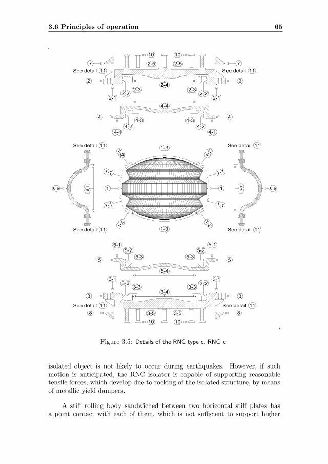
3.6 Principles of operation 65
Figure 3.5: Details of the RNC type c, RNC–c
isolated object is not likely to occur during earthquakes. However, if suchmotion is anticipated, the RNC isolator is capable of supporting reasonabletensile forces, which develop due to rocking of the isolated structure, by meansof metallic yield dampers.
A stiff rolling body sandwiched between two horizontal stiff plates hasa point contact with each of them, which is not sufficient to support higher
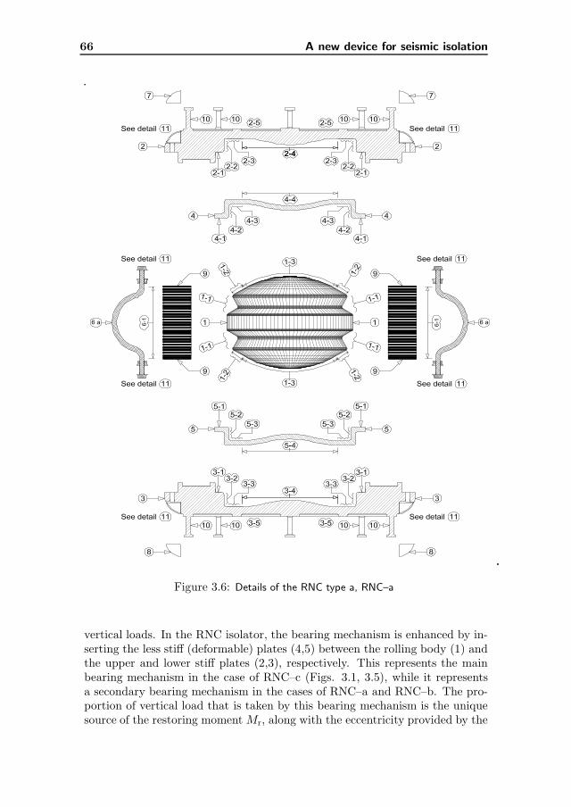
66 A new device for seismic isolation
Figure 3.6: Details of the RNC type a, RNC–a
vertical loads. In the RNC isolator, the bearing mechanism is enhanced by in-serting the less stiff (deformable) plates (4,5) between the rolling body (1) andthe upper and lower stiff plates (2,3), respectively. This represents the mainbearing mechanism in the case of RNC–c (Figs. 3.1, 3.5), while it representsa secondary bearing mechanism in the cases of RNC–a and RNC–b. The pro-portion of vertical load that is taken by this bearing mechanism is the uniquesource of the restoring moment Mr, along with the eccentricity provided by the

3.6 Principles of operation 67
Figure 3.7: Details of the RNC type b, RNC–b
elliptical rolling body (1) as illustrated by Fig. 3.11. Regarding the RNC–a andRNC–b, the main supporting system of vertical loads is the hollow elastomericcylinder (9) that permits much higher structural weight to be supported, asshown in Fig. 3.2, 3.6, 3.3, 3.7. It is worthwhile to mention that the max-imum vertical load capacity of the RNC isolator, types RNC–a and RNC–b,is calculated according to the overlapped areas between the topmost and thelowermost surfaces of the hollow elastomeric cylinder, at the extreme deformedposition, as demonstrated by solid hatched areas in Fig. 3.12(a,d and c,f) with
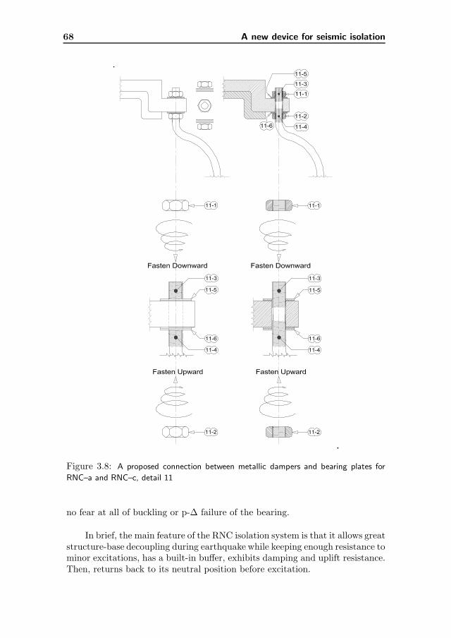
68 A new device for seismic isolation
Figure 3.8: A proposed connection between metallic dampers and bearing plates for
RNC–a and RNC–c, detail 11
no fear at all of buckling or p-∆ failure of the bearing.
In brief, the main feature of the RNC isolation system is that it allows greatstructure-base decoupling during earthquake while keeping enough resistance tominor excitations, has a built-in buffer, exhibits damping and uplift resistance.Then, returns back to its neutral position before excitation.

3.7 Component-mechanism relationship 69
Figure 3.9: Rolling, damping and zero uplift mechanisms
3.7 Component-mechanism relationship
The appeal and potential of the RNC bearing are not only being a simplepassive device, but also it is based on technologies and principles that areuniversally accepted in practice, just applied in an innovative manner. Thissection relates each component of the RNC isolator to its intended function/sin the whole assembled RNC isolation device. It is worthwhile to mention thatmany individual components are designed to serve for more than one purposewith the aim of simplicity and getting a relatively optimum compact design.In what follows, the components and their functions are categorized accordingto the main mechanisms included in the RNC isolation device. It is necessaryto refer to Figs. 3.5–3.7 together with the reference figures in the next items.
3.7.1 Rolling mechanism
Rolling is the motion mechanism that the RNC isolator adopts to decouple thesuperstructure from its base. This sufficiently lengthens the period of vibra-tion of the total system to reduce the seismic force response. The followingcomponents govern the rolling of the RNC isolator:
• The rolling body (1) through regular spherical surfaces (1-3) that arecoarse enough to improve the friction and consequently force rolling mo-tion instead of sliding motion.
• The deformable less stiff plates (4,5) help magnifying the sliding frictioncoefficient with the rolling body and allow for smooth and comfort rolling.Further, these deformable plates (4,5) help alleviating flattening, whichincrease the required force to initiate rolling, at contact points if the stiffplates (2,3) and the stiff body (1) are in direct contact.
• The upper and lower bearing plates (2,3) provide a suitable platform forrolling. Moreover, the curvatures (2-4, 3-4) makes rolling of the elliptical

70 A new device for seismic isolation
Figure 3.10: Buffer mechanism
roller exactly similar to rolling of the spherical roller, in the sense thatelliptical roller consumes some energy to elevate the supported structureor object at the end of stroke. This forces the isolated system to vibrate asa pendulum having a limited vibration period, which represents a severepractical difficulty. Such limitation does not exist at all in spherical rollersand the RNC isolator as well, as shown in Fig. 3.9, thanks to curvatures(2-4, 3-4).

3.7 Component-mechanism relationship 71
Figure 3.11: Gravity-based recentering mechanism
3.7.2 Damping mechanism
Metallic yield dampers are one of the most effective means of providing a sub-stantial level of damping through hysteretic energy dissipation. These dampersare inexpensive and can provide a wide range of damping. Moreover, they arepractical and widely available. So, they have been incorporated into the RNCisolator to control the relative deflections between isolated structure and groundto a practical design level. The following issues have been considered duringthe design of metallic yield dampers of the RNC isolator:
• To yield just after the seismic forces exceed the designed resistance towind or minor vibrations.

72 A new device for seismic isolation
Figure 3.12: The main design bearing area of RNC–a and RNC–b
• To be long enough to allow the rolling body (1) to reach the edge buffer.
• To avoid sharp bends to reduce or even prevent stress concentrations atthat bends.
• To exhibit the same shear strain in any horizontal direction.
• Never touch the rolling body (1) along the excitation duration.
• At the extreme deformed position, they should still have some outer cur-vature, i.e. away from the rolling body. This enables the metallic yielddampers to almost restore their initial shapes before deformation to starta new rolling stroke, see Figs. 3.12(a,c).
3.7.3 Bearing mechanism
The pointwise contact in the case of roller bearings reduces their ability tosupport heavier loads without flattening at the contact points. This maindrawback has been alleviated in the RNC isolator whose bearing mechanism isimproved by the following:
• Large radius of curvature of the rolling surfaces (1-3).
• Insertion of deformable less stiff (but strong, such as of neoprene material)plates (4,5) between the rolling body (1) and the upper and lower stiffbearing plates (2,3). This ensures getting contact areas instead of contact
3.7 Component-mechanism relationship 73
points. In addition, the less stiff plates (4,5) prevent stiff-to-stiff pointwisecontact between the stiff rolling body (1) and the stiff bearing plates (2,3).Certainly, this avoids flattening of the stiff materials at the contact pointsunder long-term vertical loading.
• The spherical rolling surfaces (1-3) are surrounded with plane surfaces (1-2) to substitute the reduction in the bearing area at the extreme displacedposition, Fig. 3.9(a,c). Further, and with the aim of coincidence, the edgetroughs of the upper (2,4) and the lower (3,5) plates are provided withsimilar plane parts (2-2, 2-3, 4-2, 4-3) and (3-2, 3-3, 5-2, 5-3), respectively.
• For more heavier vertical loads, the RNC isolator is provided with ahollow reinforced elastomeric cylinder (9), around the rolling body (1), ofdesigned in-plan thickness to suit the anticipated vertical weights. Thisworks as a main bearing mechanism in this case, while the rolling bodyitself acts as a secondary bearing mechanism. The design bearing area,of the elastomeric part, is the overlapped areas between upper and lowersurfaces of the elastomeric cylinder at the extreme deformed position ofthe RNC isolator as shown in Fig. 3.12(a,d and c,f).
• Forming the elastomeric part as a hollow cylinder around the rolling body(1) allows for choosing any in-plan designed thickness without fear at allof buckling failure.
• In the case of elastomeric cylinder, the cumulative thickness of the upperand lower less stiff plates (4,5) are taken equal to the cumulative thicknessof rubber layers of the elastomeric cylinder. This insures better distri-bution of the vertical loads between the main and the secondary bearingmechanisms.
3.7.4 Recentering mechanism
Wherever possible, practical isolation systems should be designed to provide arestoring force to return the isolated structure (or object) to its original positionafter earthquake and to reduce or prevent torsion response. The RNC isolatoris provided with an efficient gravity-based recentering mechanism through theelliptically shaped rolling body (1) along with the weight of supported structureor object. Such mechanism works as follows:
• At neutral position, the structural weight has the same line of action of itsreaction. Therefore, the developed restoring moment Mr is zero, keepingsteady situation.
• As the relative motion between the isolated structure and the groundinitiates, an eccentricity or offset develops between the two vertical lines ofaction of the downward weight and its upward reaction. This eccentricity
74 A new device for seismic isolation
is equal to the developed relative displacement between structure andground. Therefore, a restoring couple Mr is generated opposite to themotion-causing couple as illustrated by Fig. 3.11, so as to the two linesof actions of the structural weight and its reaction coincide again at zerorestoring couple Mr.
• The restoring moment Mr is directly proportional to the displacementamplitude, eccentricity of the rolling body and the structural, or object,weight.
3.7.5 Buffer mechanism
Isolators are normally designed to accommodate a travel distance greater thanthat which would occur during design earthquakes. However, during extremelow-probability earthquakes there is a possibility that the base of the structurewill arrive at the end of the isolator design displacement when the structure stillhas considerable kinetic energy. If a stiff structure encounters a rigid base bufferwith considerable kinetic energy, the ductility demand on the structure maybe high, and may even substantially exceed the structure’s design deformationcapacity. The use of an energy-absorbing buffer can considerably decreasestructure-base impact velocity. The RNC is provided with a rigid buffer coveredwith a deformable hyperelastic material, such as neoprene material, through thedeformable less stiff plates (4,5). In the RNC isolator, the following componentscollectively constitute the buffer mechanism as shown in Fig. 3.10:
• The two right-angle grooves (1-1) in the stiff rolling body (1).
• The vertical side walls (2-2, 3-2) of the upper and lower stiff plates (2,3),along with the flat horizontal parts (2-1, 2-3, 3-1, 3-3). These side wallsalong with the grooves mentioned in the previous item in addition to thestructural weight make the rolling body works as a rigid link in com-pression, at the extreme deformed positions, in an opposite direction tomotion, as illustrated by Figs. 3.10(f,g), to force the isolated structureto stop at that point.
• The less stiff deformable plates (4,5) through the parts (4-1, 4-2, 4-3, 5-1,5-2, 5-3) to attenuate the possible severe shocks during extreme earth-quakes.
• The metallic yield dampers (6a) help reducing the rolling velocity of therolling body (1) before reaching the extreme deformed position, wherethey suffer high tensile forces to stretch their curvatures at that position,see Figs. 3.9(a,c) and 3.12(a,c).
• The plain parts (1-2) of the rolling surfaces of the rolling body (1) alsohelp reducing the rolling body velocity just before hitting the vertical sidewalls.
3.7 Component-mechanism relationship 75
Note: In this dissertation, the maximum rolling displacements of the RNCisolators during earthquakes were determined without using the built-in buffer(stoppers) mechanism, to check weather they are affordable or not. Then, thebuffer is designed to allow for rolling displacements a little bit higher. Duringstronger earthquakes, the rolling displacement limits may be exceeded but thebuffer prevents such excessive displacements with minimal shock. This lastpoint has not been studied in this dissertation, because there is no availablemodel, at the moment, for the built-in buffer mechanism of the RNC isolator.Such study is postponed to the near future experimental work.
3.7.6 Uplift-restraining mechanism
When seismic isolated structure is subjected to strong ground excitation, in-cluding near-fault effects, undesirable uplift (or tension) in the isolation bear-ings may be induced. In fact, a variety of conditions may contribute to thedevelopment of either tensile forces or uplift in isolation bearings. Typicalexamples include slender structures with large height-to-width aspect ratios,certain types of bridges with large ratios of height of the centroidal axis tothe distance between the bearings, and buildings incorporating bearings belowbraced columns or stiff walls. Owing to its distinct configuration, the RNC iso-lator possesses a reasonably efficient mechanism to resist uplift or tension. Thefollowing components contribute establishing an uplift resistance mechanism inthe RNC isolator:
• As the rolling motion necessitates very low force to initiates, the rockingmotion and consequently the developed tension in the RNC bearing isunlikely to occur to some extent.
• If the RNC has to support tensile forces under any condition, the metallicyield dampers can support reasonable amount of tension.
• To prevent the vertical elevation of the RNC-supported structure (orobject) during rolling, the upper and lower stiff plates (2,3) are providedwith triple curvatures (2-4, 3-4) that are carefully designed to exactlyabsorb the expected elevation during rolling of the elliptical rolling body(1), over the full time history of excitation, as seen in Fig. 3.9.
3.7.7 Initial stiffness mechanism
Practical isolation systems usually offer adequate resistance to minor excita-tions, to guarantee structural stability and human comfort under service loads.The RNC isolator is provided with some different mechanisms to achieve suf-ficient resistance under low-level excitations:
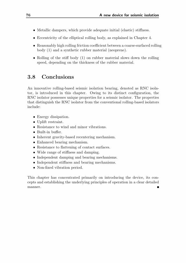
76 A new device for seismic isolation
• Metallic dampers, which provide adequate initial (elastic) stiffness.
• Eccentricity of the elliptical rolling body, as explained in Chapter 4.
• Reasonably high rolling friction coefficient between a coarse-surfaced rollingbody (1) and a synthetic rubber material (neoprene).
• Rolling of the stiff body (1) on rubber material slows down the rollingspeed, depending on the thickness of the rubber material.
3.8 Conclusions
An innovative rolling-based seismic isolation bearing, denoted as RNC isola-tor, is introduced in this chapter. Owing to its distinct configuration, theRNC isolator possesses unique properties for a seismic isolator. The propertiesthat distinguish the RNC isolator from the conventional rolling-based isolatorsinclude:
• Energy dissipation.
• Uplift restraint.
• Resistance to wind and minor vibrations.
• Built-in buffer.
• Inherent gravity-based recentering mechanism.
• Enhanced bearing mechanism.
• Resistance to flattening of contact surfaces.
• Wide range of stiffness and damping.
• Independent damping and bearing mechanisms.
• Independent stiffness and bearing mechanisms.
• Non-fixed vibration period.
This chapter has concentrated primarily on introducing the device, its con-cepts and establishing the underlying principles of operation in a clear detailedmanner.

4Modeling and characterization
4.1 Introduction
Mechanical characterization of a system or a device can be performed exper-imentally or via numerical simulation. The former approach is more costlythan the later one, but helps getting physical understanding of the system andtherefore it can be employed for final verification. In contrast, numerical sim-ulation uses numerical methods to quantitatively represent the evolution of aphysical system. By using accurate models, the result of such simulation canhave a good representation of the real environment. This enables safe drawingof proper conclusions and getting a reasonable understanding of the system.
In this dissertation, the numerical simulation is adopted to allow fullyidentification of the RNC1 isolator mechanical characteristics before its con-struction. A general scheme is presented in this chapter for that purposethrough subjecting the RNC isolator to simultaneous horizontal and verticalloads as in typical practical situations. Further, a mathematical description ofthe main features associated to rolling of the RNC isolator is presented, and aninput-output mathematical model is obtained to describe in a reasonable andmanageable form the force-displacement relationship exhibited by the RNCisolator.
1The term RNC isolator refers generically to any of the forms described in Section 3.4.
When referring to a particular RNC isolator form, the terms RNC–a, RNC–b or RNC–c are
used instead.
78 Modeling and characterization
4.2 Mechanical characterization
The general-purpose finite element code ANSYS Multiphysics [4] is used toenable computer-aided design and testing of the RNC isolation system. For adesired configuration of the RNC system, the following steps are followed2:
• Design and modeling of the individual components of the RNC isolationsystem: rolling body (1), upper and lower stiff bearing plates (2,3) andless stiff plates (4,5), metallic yield dampers (6), elastomeric cylinder (9)and bearing plate stiffeners (7,8).
• Assembly of the individual components to set up the whole isolator andidentification of all contact conditions among them.
• Definition and assignment of materials for each individual component.
• Selection of appropriate finite element type and mesh size according tothe expected behavior of the component materials.
• Assignment of boundary conditions through nodal constraints and nodalrestraints.
• Static application of the vertical structural weight and running full non-linear analysis to capture all nonlinearities arising from the load applica-tion.
• Dynamic application of the horizontal ground motion starting from thelast load step in the previous static analysis and running of full nonlineartransient dynamic analysis.
• Analysis of the results.
Through this scheme, a real scale model is designed. An extensive and detailedseries of tests is carried out in a machine-like environment, which accuratelysimulates the response of the device subjected to a real testing machine. Thisallows fully identification of the RNC mechanical characteristics before its con-struction. In the machine-like testing, the topmost surface of the modeled RNCunit is allowed to move vertically (without rotation) under the structure ownweight but it is always kept fixed in horizontal direction. The lowermost surfaceof the RNC unit is kept always fixed in the vertical direction. In horizontaldirection, it is kept fixed only during the vertical application of the structureown weight. When the ground motion is applied, the lowermost surface is re-leased horizontally without rotation. The less stiff plates (4,5) are completelyglued to the inner surfaces of the upper and lower steel bearing plates (2,3),respectively, while they are kept in rolling contact with the rolling body (1).
2The different elements of the RNC isolator are numbered according to Figs. 3.5–3.8 in
Chapter 3.
4.2 Mechanical characterization 79
In this dissertation, the rolling body (1), top stiff plate (2), lower stiff plate(3) and stiffeners (7,8) are made of steel. The less stiff plates (4,5) are madeof neoprene material. The hollow elastomeric cylinder is designed according to[3] using method B for steel-reinforced elastomeric bearings. The metallic yielddampers are made of mild steel and are replaced with the embedded lead barsthat are used to provide damping in the case od RNC–b.
4.2.1 Types of tests
The designed real-scale model of the RNC bearing is tested in the machine-likeenvironment by subjecting the bearing to simultaneous horizontal and verticaldynamic loading. The maximum mesh element size of the nonlinear parts is0.005 m for better accuracy and robust nonlinear analysis.
Basic test
The basic type of test is a sinusoidal horizontal displacement-controlled loading,conducted at the design vertical load, and for 5 cycles of loading at shear strainamplitudes of 5%, 10%, and 20% that correspond to 25.4 mm, 50.8 mm, and101.6 mm, respectively. The frequency of loading is 1 Hz for all of these tests.
Variable axial load test
The basic test is also performed at a number of different axial loads. The loadis constant during each test, and tests are performed at loads of 2Pdes, Pdes,and 0.5Pdes, where Pdes represents the design axial load. The rate of loadingand the strain increments are the same as for the basic test described above.
Variable frequency test
The basic test is also performed at loading frequencies of 0.2, 0.3, 0.5, 0.7, 1.1,1.3, 1.7, 1.9, 2.3, and 2.9 Hz. The other test variables are the same as for thebasic test.
4.2.2 Nonlinear modeling
Structural nonlinearities arise from a number of causes, which can be groupedinto these principal categories:
• Contact
Contact problems are highly nonlinear since they are status-dependent.
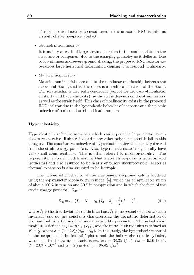
80 Modeling and characterization
This type of nonlinearity is encountered in the proposed RNC isolator asa result of steel-neoprene contact.
• Geometric nonlinearity
It is mainly a result of large strain and refers to the nonlinearities in thestructure or component due to the changing geometry as it deflects. Dueto low stiffness and severe ground shaking, the proposed RNC isolator ex-periences large horizontal deformation causing it to respond nonlinearly.
• Material nonlinearity
Material nonlinearities are due to the nonlinear relationship between thestress and strain, that is, the stress is a nonlinear function of the strain.The relationship is also path dependent (except for the case of nonlinearelasticity and hyperelasticity), so the stress depends on the strain historyas well as the strain itself. This class of nonlinearity exists in the proposedRNC isolator due to the hyperelastic behavior of neoprene and the plasticbehavior of both mild steel and lead dampers.
Hyperelasticity
Hyperelasticity refers to materials which can experience large elastic strainthat is recoverable. Rubber-like and many other polymer materials fall in thiscategory. The constitutive behavior of hyperelastic materials is usually derivedfrom the strain energy potentials. Also, hyperelastic materials generally havevery small compressibility. This is often referred to incompressibility. Thehyperelastic material models assume that materials response is isotropic andisothermal and also assumed to be nearly or purely incompressible. Materialthermal expansion is also assumed to be isotropic.
The hyperelastic behavior of the elastomeric neoprene pads is modeledusing the 2-parameter Mooney-Rivlin model [4], which has an applicable strainof about 100% in tension and 30% in compression and in which the form of thestrain energy potential, Esp, is
Esp = c10(
I1 − 3)
+ c01(
I2 − 3)
+1
d(J − 1)2, (4.1)
where I1 is the first deviatoric strain invariant; I2 is the second deviatoric straininvariant; c10, c01 are constants characterizing the deviatoric deformation ofthe material; d is the material incompressibility parameter. The initial shearmodulus is defined as µ = 2(c10+c01), and the initial bulk modulus is defined asK = 2
d , where d = (1− 2ν)/(c10 + c01). In this study, the hyperelastic materialis the neoprene of the less stiff plates and the hollow elastomeric cylinder,which has the following characteristics: c10 = 38.25 t/m2, c01 = 9.56 t/m2,d = 2.09 × 10⁻⁵ and µ = 2(c10 + c01) = 95.62 t/m2.
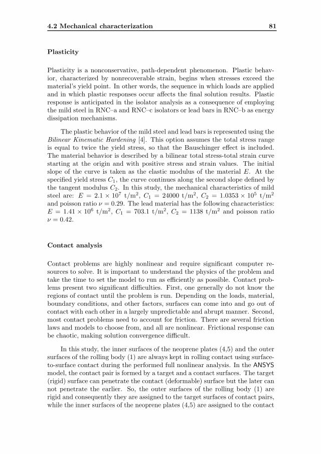
4.2 Mechanical characterization 81
Plasticity
Plasticity is a nonconservative, path-dependent phenomenon. Plastic behav-ior, characterized by nonrecoverable strain, begins when stresses exceed thematerial’s yield point. In other words, the sequence in which loads are appliedand in which plastic responses occur affects the final solution results. Plasticresponse is anticipated in the isolator analysis as a consequence of employingthe mild steel in RNC–a and RNC–c isolators or lead bars in RNC–b as energydissipation mechanisms.
The plastic behavior of the mild steel and lead bars is represented using theBilinear Kinematic Hardening [4]. This option assumes the total stress rangeis equal to twice the yield stress, so that the Bauschinger effect is included.The material behavior is described by a bilinear total stress-total strain curvestarting at the origin and with positive stress and strain values. The initialslope of the curve is taken as the elastic modulus of the material E. At thespecified yield stress C1, the curve continues along the second slope defined bythe tangent modulus C2. In this study, the mechanical characteristics of mildsteel are: E = 2.1 × 10⁷ t/m2, C1 = 24000 t/m2, C2 = 1.0353 × 10⁵ t/m2
and poisson ratio ν = 0.29. The lead material has the following characteristics:E = 1.41 × 10⁶ t/m2, C1 = 703.1 t/m2, C2 = 1138 t/m2 and poisson ratioν = 0.42.
Contact analysis
Contact problems are highly nonlinear and require significant computer re-sources to solve. It is important to understand the physics of the problem andtake the time to set the model to run as efficiently as possible. Contact prob-lems present two significant difficulties. First, one generally do not know theregions of contact until the problem is run. Depending on the loads, material,boundary conditions, and other factors, surfaces can come into and go out ofcontact with each other in a largely unpredictable and abrupt manner. Second,most contact problems need to account for friction. There are several frictionlaws and models to choose from, and all are nonlinear. Frictional response canbe chaotic, making solution convergence difficult.
In this study, the inner surfaces of the neoprene plates (4,5) and the outersurfaces of the rolling body (1) are always kept in rolling contact using surface-to-surface contact during the performed full nonlinear analysis. In the ANSYS
model, the contact pair is formed by a target and a contact surfaces. The target(rigid) surface can penetrate the contact (deformable) surface but the later cannot penetrate the earlier. So, the outer surfaces of the rolling body (1) arerigid and consequently they are assigned to the target surfaces of contact pairs,while the inner surfaces of the neoprene plates (4,5) are assigned to the contact

82 Modeling and characterization
surfaces of the contact pairs as they are deformable in order to approach therealistic behavior of the assembled components.
In the ANSYS model, deformable-deformable contact pairs, between thestiff rolling body and the deformable neoprene plates of the RNC isolator, areidentified using the options listed in Table 4.1.
Contact algorithm : Augmented Lagrange methodContact detection at : Gauss integration pointContact stiffness factor FKN : 1.0000The resulting contact stiffness : 0.11387E+08 kN m−1
Penetration tolerance factor FTOLN : 0.10000The resulting penetration tolerance : 0.50383E-03 mMax. initial friction coefficient MU : 0.50000Default tangent stiffness factor FKT : 1.0000Default elastic slip factor SLTOL : 0.10000E-01The resulting elastic slip : 0.49371E-04Update contact stiffness at each iteration : YesMax. friction stress TAUMAX : 0.10000E+22 kN m−2
Average contact surface length : 0.49371E-02 mAverage contact pair depth : 0.50383E-02 mDefault pinball region factor PINB : 2.0000The resulting pinball region : 0.10077E-01 mAuto contact offset used to close gap : 0.47132E-05 mInitial penetration is excluded : Yes
Table 4.1: Contact pairs properties of the ANSYS-modeled RNC isolator
The contact surfaces are initially modeled to be in the just-in-touch po-sition, but minimum initial gap of 4.667E-06 m was detected between contactelements due to finite element meshing. However, the gap is closed due toinitial adjustment of contact surfaces.
4.2.3 Mechanical characteristics
To determine the maximum vertical load capacity of the proposed RNC isola-tor, a trial and error procedure has been carried out using ANSYS such thatthe vertical strain in the neoprene plates (4,5) does not exceed 30% as recom-mended by [3].
Figs. 4.1, 4.3, 4.5 and 4.2, 4.4, 4.6, respectively, show the overall behaviorof the assembled RNC unit before and after the static application of the verticalown weight of the supported structure (or object), respectively. The meshing

4.2 Mechanical characterization 83
Figure 4.1: ANSYS finite element model, non-deformed shape, RNC–c.
is much more dense in components that exhibit nonlinear behavior (neopreneplates, metallic yield dampers and lead bars, rolling contact surfaces and elas-tomeric cylinder) if compared to other components that behave linearly (steelbearing plates, stiffeners and rolling body). Also, the behavior of the neopreneplates under loads seems to be realistic. Indeed, Figs. 4.2, 4.4, 4.6 show howthese neoprene plates get deformed and how the corresponding contact areaswith the rolling body increase, which translates into higher capacity to sup-port vertical loads in addition to the vertical load supported by the hollowelastomeric bearing. Moreover, the RNC unit shows no lateral motion duringthis loading stage, in which the topmost surface exhibits the maximum verti-cal displacement (without rotation) contrary to the lowermost surface which isfixed vertically and exhibits no rotation.
Starting from the last load step of the performed static analysis, a sinu-soidal horizontal displacement is applied at the lowermost surface of the RNCisolator, and the resulting force at the topmost surface is measured. The mea-sured force-displacement relationship for the a RNC design is plotted using timeand displacement scales, in dashed lines, as shown in Figs. 4.7(a,b) respectively.Then, an equivalent bilinear approximation of the measured hysteresis response[401, 333] is carried out as shown in solid lines in Figs. 4.7(a,b). From this bi-linear force-displacement relationship, the following mechanical characteristicsare obtained for the RNC isolator:

84 Modeling and characterization
Figure 4.2: ANSYS finite element model, non-deformed + deformed shapes due to
vertical structural weight, RNC–c.
1. Pre-yield stiffness.
2. Post-yield stiffness.
3. Yield displacement.
4. Yield force.
5. Characteristic strength.
The actual obtained values of these characteristics, for each RNC isolator type,are given in the corresponding chapters.
4.3 Mechanics of the elliptical rolling body
In this section, a mathematical description of the main features associated torolling of the RNC isolator is presented. Consider the free body diagram ofthe elliptical rolling body between the base mass and the foundation, as shownin Figs. 4.8, 4.9. The proposed bearing can roll in one or more horizontaldirections using (quasi-) elliptical rolling rods or (quasi-) ellipsoidal bearings,respectively, having the same cross-sectional configurations. Further, it is as-sumed that the rolling friction coefficient µ between the rolling body, the base
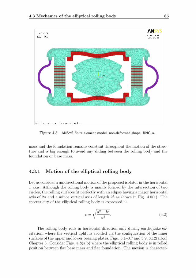
4.3 Mechanics of the elliptical rolling body 85
Figure 4.3: ANSYS finite element model, non-deformed shape, RNC–a.
mass and the foundation remains constant throughout the motion of the struc-ture and is big enough to avoid any sliding between the rolling body and thefoundation or base mass.
4.3.1 Motion of the elliptical rolling body
Let us consider a unidirectional motion of the proposed isolator in the horizontalx axis. Although the rolling body is mainly formed by the intersection of twocircles, the rolling surfaces fit perfectly with an ellipse having a major horizontalaxis of 2a and a minor vertical axis of length 2b as shown in Fig. 4.8(a). Theeccentricity of the elliptical rolling body is expressed as
e =
√
a2 − b2
a2. (4.2)
The rolling body rolls in horizontal direction only during earthquake ex-citation, where the vertical uplift is avoided via the configuration of the innersurfaces of the upper and lower bearing plates, Figs. 3.1–3.7 and 3.9, 3.12(a,b,c)Chapter 3. Consider Figs. 4.8(a,b) where the elliptical rolling body is in rolledposition between flat base mass and flat foundation. The motion is character-

86 Modeling and characterization
Figure 4.4: ANSYS finite element model, non-deformed + deformed shapes due to
vertical structural weight, RNC–a.
ized by the following variables:
xr =xb2, (4.3)
yr = p− b, (4.4)
θr = tan−1
(
b
atan θ
)
, (4.5)
where xr and yr are the horizontal and vertical displacements of the center ofgravity (CG) relative to ground; θr is the rotation angle of the rolling body;xb is the horizontal displacement of the base mass relative to the ground; p =a sin θ sin θr + b cos θ cos θr is half the vertical distance between the lower andupper contact points [points A and B in Figs. 4.8(a)(b)] of the rolling body; θis the eccentric angle such that the coordinates of point A are (−a sin θ, b cos θ)
and hence the distance OA =√
a2 sin2 θ + b2 cos2 θ = a√
1 − e2 cos2 θ.
By equating the distances AA′ and AA′′ in Fig. 4.8(b), a relation betweenthe eccentric angle θ and the base displacement xb can be expressed as
xb2
+ c = a
∫ θ
0
√
1 − e2 cos2 φ dφ , (4.6)

4.3 Mechanics of the elliptical rolling body 87
Figure 4.5: ANSYS finite element model, non-deformed shape, RNC–b.
where c = a sin θ cos θr − b cos θ sin θr is half the horizontal distance betweenthe upper and lower contact points. Note that the right hand side of Eq. (4.6)contains a special function known as an elliptic integral of the second kind. Thevalue of this integral is available in standard charts and tables [521] knowing eand θ. Eq. (4.6) gives a design tool for the rolling body geometry. For a givenvalue of e and θ, Eq. (4.6) allows to calculate the corresponding horizontalbase displacement xb.
4.3.2 Restoring mechanism of the elliptical rolling body
Considering the equilibrium of inertia forces acting on the rolling body, Fig.4.9, the horizontal restoring force Fb1 is expressed as
Fb1 =1
2pJr θr +mr yr
c
p+
1
2mr(xr + xg) , (4.7)
where mr and Jr are the mass and the moment of inertia of the rolling bodyand xg is the ground acceleration.
In the RNC isolator, as shown by Figs. 3.9, 3.12(a,b,c), the inner faces(facing the rolling body) of the upper and lower bearing plates are configuredso that the vertical uplift of the supported object is inhibited along the whole
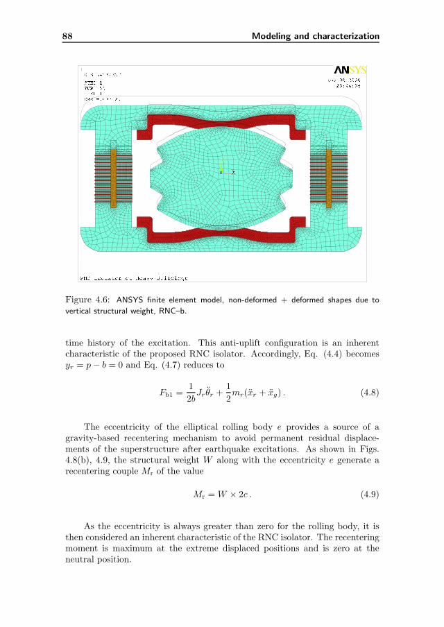
88 Modeling and characterization
Figure 4.6: ANSYS finite element model, non-deformed + deformed shapes due to
vertical structural weight, RNC–b.
time history of the excitation. This anti-uplift configuration is an inherentcharacteristic of the proposed RNC isolator. Accordingly, Eq. (4.4) becomesyr = p− b = 0 and Eq. (4.7) reduces to
Fb1 =1
2bJr θr +
1
2mr(xr + xg) . (4.8)
The eccentricity of the elliptical rolling body e provides a source of agravity-based recentering mechanism to avoid permanent residual displace-ments of the superstructure after earthquake excitations. As shown in Figs.4.8(b), 4.9, the structural weight W along with the eccentricity e generate arecentering couple Mr of the value
Mr = W × 2c . (4.9)
As the eccentricity is always greater than zero for the rolling body, it isthen considered an inherent characteristic of the RNC isolator. The recenteringmoment is maximum at the extreme displaced positions and is zero at theneutral position.
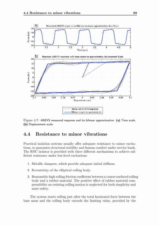
4.4 Resistance to minor vibrations 89
Figure 4.7: ANSYS measured response and its bilinear approximation: (a) Time scale,
(b) Displacement scale.
4.4 Resistance to minor vibrations
Practical isolation systems usually offer adequate resistance to minor excita-tions, to guarantee structural stability and human comfort under service loads.The RNC isolator is provided with three different mechanisms to achieve suf-ficient resistance under low-level excitations:
1. Metallic dampers, which provide adequate initial stiffness.
2. Eccentricity of the elliptical rolling body.
3. Reasonably high rolling friction coefficient between a coarse-surfaced rollingbody and a rubber material. The positive effect of rubber material com-pressibility on resisting rolling motion is neglected for both simplicity andmore safety.
The system starts rolling just after the total horizontal force between thebase mass and the rolling body exceeds the limiting value, provided by the
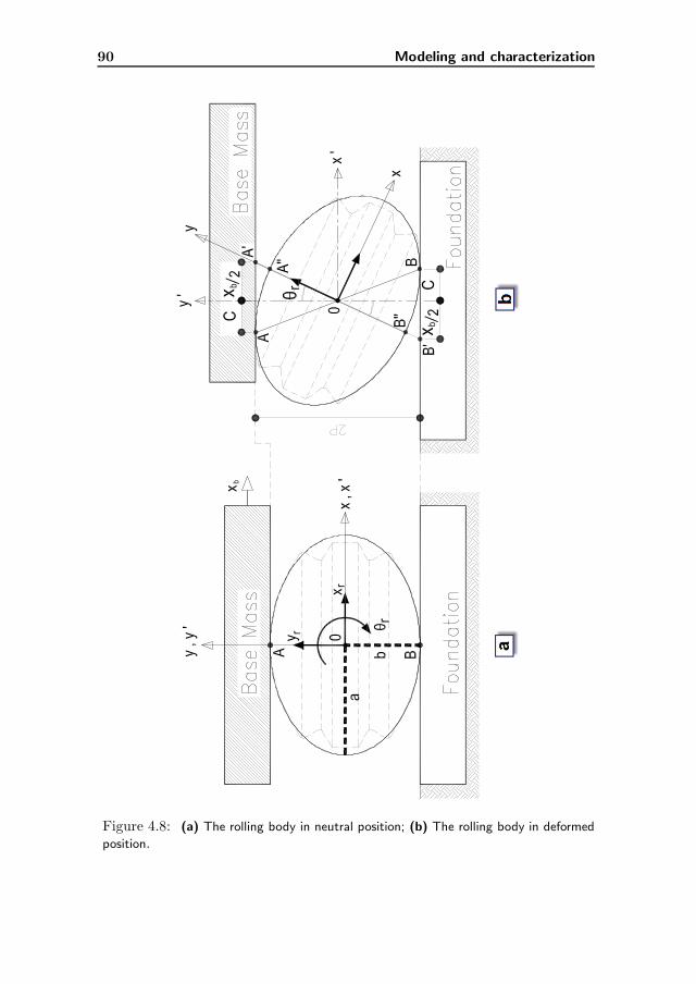
90 Modeling and characterization
Figure 4.8: (a) The rolling body in neutral position; (b) The rolling body in deformed
position.
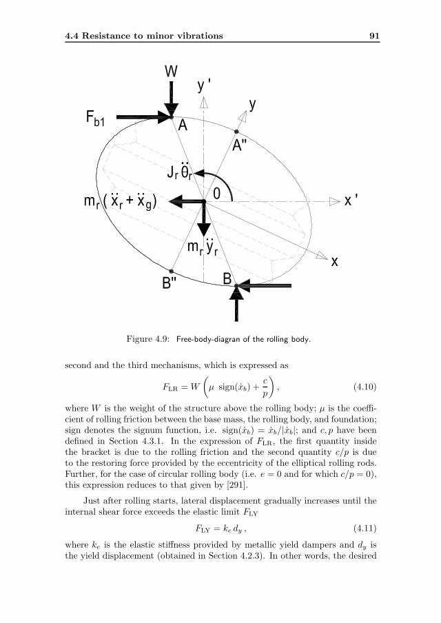
4.4 Resistance to minor vibrations 91
Figure 4.9: Free-body-diagran of the rolling body.
second and the third mechanisms, which is expressed as
FLR = W
(
µ sign(xb) +c
p
)
, (4.10)
where W is the weight of the structure above the rolling body; µ is the coeffi-cient of rolling friction between the base mass, the rolling body, and foundation;sign denotes the signum function, i.e. sign(xb) = xb/|xb|; and c, p have beendefined in Section 4.3.1. In the expression of FLR, the first quantity insidethe bracket is due to the rolling friction and the second quantity c/p is dueto the restoring force provided by the eccentricity of the elliptical rolling rods.Further, for the case of circular rolling body (i.e. e = 0 and for which c/p = 0),this expression reduces to that given by [291].
Just after rolling starts, lateral displacement gradually increases until theinternal shear force exceeds the elastic limit FLY
FLY = ke dy , (4.11)
where ke is the elastic stiffness provided by metallic yield dampers and dy isthe yield displacement (obtained in Section 4.2.3). In other words, the desired

92 Modeling and characterization
isolation effects take place when the total horizontal force exceeds the totallimiting FL, which represents the maximum value of the RNC isolator resistanceto wind or minor vibrations and is given by
FL = FLR + FLY , (4.12)
= W
(
µ sign(xb) +c
p
)
+ ke dy . (4.13)
4.5 Hysteretic modeling of the energy dissipa-
tion mechanism
The characterization described in Section 4.2 has shown that the RNC isolatorexhibits a hysteretic behavior, as shown in Fig. 4.7(b). The objective of thissection is to obtain an input-output mathematical model to describe in a rea-sonable and manageable form the force-displacement relationship exhibited bythe RNC isolator. The Bouc-Wen model of smooth hysteresis is considered.
4.5.1 The Bouc-Wen model
The Bouc-Wen model [455, 208] has been extensively used to describe nonlin-ear hysteretic behaviors, particularly, in seismic isolation devices. A thoroughsurvey on that model is given in Appendix A. That survey is the first of itskind on the model since its origination more than 30 years ago. The Bouc-Wen model appears in two forms in this dissertation, the standard and thenormalized forms. The former form can be dealt with numerically to identifyits parameters and it is overparametrized. The later (normalized) form pro-vide exact analytical treatment for parameters identification and eliminates theoverparametrization found in the standard form.
The motivation beyond using the standard form of the Bouc-Wen model isthat all the response quantities of interest are obtained by means of a practicalcomputer code SAP2000 advanced [6], which incorporates only the standardform of the Bouc-Wen model. While the normalized form of the model isused herein to capture three main advantages: (i) the warranty of a uniqueinput/output behavior for each set of parameters which is ideal for identificationpurpose; (ii) the elimination of parameter redundancy or overparametrization;(iii) the availability of a robust parametric nonlinear, nonrecursive identificationmethod of the normalized Bouc-Wen model [201, 194] based on an exact andexplicit expression for the hysteretic limit cycle [200].
4.5 Hysteretic modeling of the energy dissipation mechanism 93
4.5.2 The standard Bouc-Wen model form
The standard form of the Bouc-Wen model is expressed as [455]
Fb2(t) = αkx(t) + (1 − α)Dy kz(t), (4.14)
z = D−1y (Ax− β|x||z|n−1z − γx|z|n), (4.15)
where x is the displacement, z is an auxiliary variable, Fb2 is the isolatorrestoring force, αkx is the elastic force component, z denotes the time deriva-tive, n > 1 is a parameter that governs the smoothness of the transition fromelastic to plastic response, Dy > 0 is the yield constant displacement, k > 0and 0 < α < 1 represents the post to pre-yielding stiffness ratio (kb/ke), whileA, β and γ are non-dimensional parameters that govern the shape and size ofthe hysteresis loop.
The Bouc-Wen model can match a hysteretic behavior by properly tuningits parameters. It is a black-box model, i.e. the model parameters may nothave physical meanings. For this reason, the Bouc-Wen model has to fulfillsome general physical properties. It was asserted by [199] that, for n ≥ 1,the Bouc-Wen model is bounded-input bounded-output (BIBO), passive, andconsistent with physical asymptotic motion if and only if
A > 0, β + γ > 0, β − γ ≥ 0. (4.16)
4.5.3 Parameters estimation of the standard form
By comparing the Bouc-Wen model output to the experimental (ANSYS) data,for a given periodic input displacement signal, the model parameters are esti-mated to characterize the RNC isolator. A total of 7 parameters (A, α, β, γ,D, n, and k) are forced to obey the necessary conditions given in Section 4.5.2.
A constrained nonlinear least-squares optimization algorithm, available inmatlab [5], is used to obtain the 7 model parameters in Eqs. (4.14) and (4.15).The optimized parameters are then determined to fit the model to the ANSYS
output data.
4.5.4 The normalized Bouc-Wen model form
The normalized form of the Bouc-Wen model was proposed by [200] where thehysteretic restoring force is expresses as
Fb2(t) = κx x(t) + κw w(t), (4.17)
w(t) = ρ(x− σ|x||w|n−1w − (σ − 1)x|w|n), (4.18)
94 Modeling and characterization
where κx, κw, ρ, σ and n are the shape controlling parameters of the hysteresisloop; and w(t) is an auxiliary variable which is not accessible to measurement.Furthermore, and to guarantee BIBO stability, passivity, and consistency withphysical asymptotic motion, the lower value of the parameter σ is limited to 1
2 .
4.5.5 Parameters estimation of the normalized form
The normalized Bouc-Wen form provides an exact and explicit expression forthe hysteretic limit cycle, [200]. Therefore, by using an input signal x(t) as aperiodic T -wave (see Fig. A.3) along with analytic description of limit cycle,a robust parametric nonlinear, nonrecursive identification method or the nor-malized Bouc-Wen model was presented by [201, 194]. This method providesexact values of the model parameters in the absence of disturbances, and givesa guaranteed relative error between the estimated parameters and the true onesin the presence of the perturbations. A detailed description of such methodis given at the end of Section A.6.6, Appendix A. The relation between thenormalized and the standard model parameters are given by Eq. (A.39).
4.5.6 Verification of the Bouc-Wen model
To check the validity of the identified parameters, an actual random seismicdisplacement is input into the ANSYS and the Bouc-Wen models. The dis-crepancy between the measured Fm (ANSYS) and the predicted Fb (Bouc-Wenmodel) outputs is quantified using the L1 and L∞-norms and the correspondingrelative errors ε:
||f ||1 =
∫ Te
0
|f(t)| d t ; ||f ||∞ = maxt∈[0,Te]
|f(t)| ; ε1,∞ =||Fm − Fb||1,∞
||Fm||1,∞.
(4.19)The relative error ε1 quantifies the ratio of the bounded area between theoutput curves to the area of the measured force along the excitation durationTe, while ε∞ measures the relative deviation of the peak force.
The above mentioned models along with their parameter estimation andverification techniques are applied to different case studies, considering eachRNC isolator type, in the in the next chapters.
4.6 Conclusions
In this chapter, a general scheme is presented to assess the feasibility of theRNC isolator its behavior under simultaneous horizontal and vertical loads in

4.6 Conclusions 95
typical practical situations. Further, a mathematical description of the mainfeatures associated to rolling of the RNC isolator is presented. At the end, aninput-output mathematical model is obtained to describe in a reasonable andmanageable form the force-displacement relationship exhibited by the RNCisolator.

This page intentionally left blank.
5Isolation of heavy mass buildings
5.1 Introduction
As effective isolation needs to achieve a long period response, most practicalisolation systems work best with heavy masses. The period is proportional tothe square root of mass M and inversely proportional to the square root of thestiffness K:
T = 2π
√
M
K(5.1)
To achieve a given isolated period, a low mass must be associated with a lowstiffness. The present day isolation devices do not have an infinite range ofstiffness. Thus, heavy buildings isolation can achieve the required long periodwith no need to very low isolator stiffness.
The aim of this chapter is to perform an extensive numerical assessmentof the RNC isolator performance considering this class of buildings. In orderto do this, a heavy mass building structure supported by the RNC isolators isdesigned and simulated as a case study. Several designs of the RNC isolatorare considered along with a wide range of structural fundamental periods andearthquake ground motions.
5.2 The used RNC isolator type
The RNC–a and RNC–b isolators, that are more suitable for heavy mass struc-tures, are designed and used in this chapter. These RNC types are shown inFigs. 3.2 and 3.3, respectively. For the designed RNC–a isolator, the horizontal

98 Isolation of heavy mass buildings
and vertical distances between the furthermost points are 3.177 m and 1.50 m,respectively, whereas the horizontal and vertical distances between the further-most points are 2.707 m and 1.50 m, respectively, for the RNC–b. The isolatorsdimensions are chosen to allow for 53 cm as a maximum rolling displacement,beyond which the buffer mechanism stops the isolated structure with minimalshock.
5.3 Mechanical characteristics
Following the mechanical characterization scheme described in Section 4.2, thedesigned RNC–a isolator used in this chapter has the following mechanicalcharacteristics:
• Maximum vertical load capacity = 4000 kN.
• Pre-yield stiffness = 23508.6 kN m−1.
• Post-yield stiffness = 926.9 kN m−1.
• Yield displacement = 1.3 cm.
• Yield force = 316.8 kN.
• Characteristic strength = 307.8 kN.
Similarly, the designed RNC–b isolator has the following mechanical charac-teristics:
• Maximum vertical load capacity = 4000 kN.
• Pre-yield stiffness = 95052.6 kN m−1.
• Post-yield stiffness = 8672.3 kN m−1.
• Yield displacement = 0.30 cm.
• Yield force = 316.7 kN.
• Characteristic strength = 291.5 kN.
Further, and to draw relatively general conclusions about the performanceof the RNC isolator under a variety of structural and ground motion properties,four different designs of each RNC isolator ranging from very stiff (sets I) to veryflexible (sets IV) designs, are evaluated in this study. The maximum verticalload capacity per bearing is 4000 kN. Table 5.1 gives the basic mechanicalcharacteristics of such designs. These characteristics have been also obtainedfollowing the scheme given in Section 4.2.
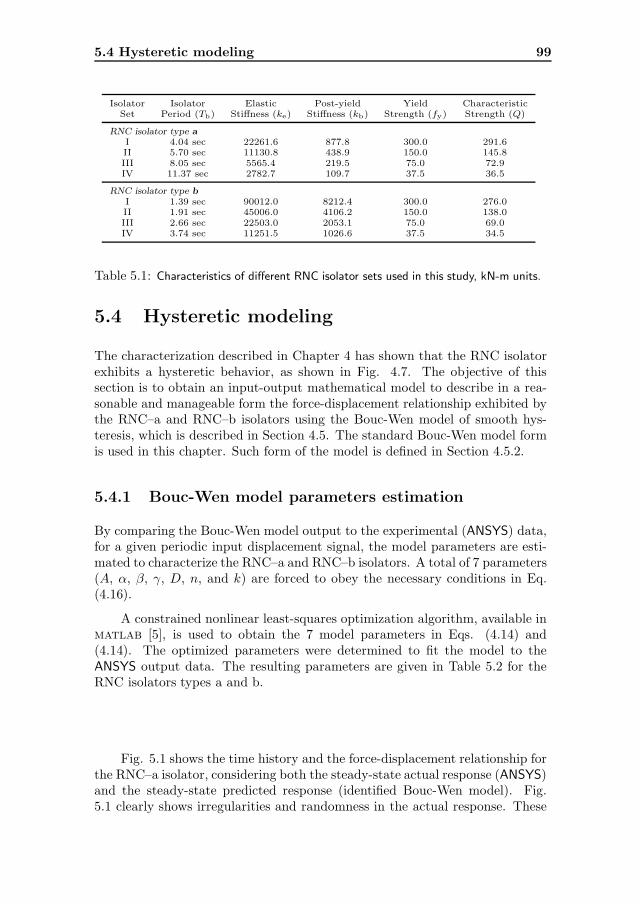
5.4 Hysteretic modeling 99
Isolator Isolator Elastic Post-yield Yield CharacteristicSet Period (Tb) Stiffness (ke) Stiffness (kb) Strength (fy) Strength (Q)
RNC isolator type aI 4.04 sec 22261.6 877.8 300.0 291.6II 5.70 sec 11130.8 438.9 150.0 145.8III 8.05 sec 5565.4 219.5 75.0 72.9IV 11.37 sec 2782.7 109.7 37.5 36.5
RNC isolator type bI 1.39 sec 90012.0 8212.4 300.0 276.0II 1.91 sec 45006.0 4106.2 150.0 138.0III 2.66 sec 22503.0 2053.1 75.0 69.0IV 3.74 sec 11251.5 1026.6 37.5 34.5
Table 5.1: Characteristics of different RNC isolator sets used in this study, kN-m units.
5.4 Hysteretic modeling
The characterization described in Chapter 4 has shown that the RNC isolatorexhibits a hysteretic behavior, as shown in Fig. 4.7. The objective of thissection is to obtain an input-output mathematical model to describe in a rea-sonable and manageable form the force-displacement relationship exhibited bythe RNC–a and RNC–b isolators using the Bouc-Wen model of smooth hys-teresis, which is described in Section 4.5. The standard Bouc-Wen model formis used in this chapter. Such form of the model is defined in Section 4.5.2.
5.4.1 Bouc-Wen model parameters estimation
By comparing the Bouc-Wen model output to the experimental (ANSYS) data,for a given periodic input displacement signal, the model parameters are esti-mated to characterize the RNC–a and RNC–b isolators. A total of 7 parameters(A, α, β, γ, D, n, and k) are forced to obey the necessary conditions in Eq.(4.16).
A constrained nonlinear least-squares optimization algorithm, available inmatlab [5], is used to obtain the 7 model parameters in Eqs. (4.14) and(4.14). The optimized parameters were determined to fit the model to theANSYS output data. The resulting parameters are given in Table 5.2 for theRNC isolators types a and b.
Fig. 5.1 shows the time history and the force-displacement relationship forthe RNC–a isolator, considering both the steady-state actual response (ANSYS)and the steady-state predicted response (identified Bouc-Wen model). Fig.5.1 clearly shows irregularities and randomness in the actual response. These
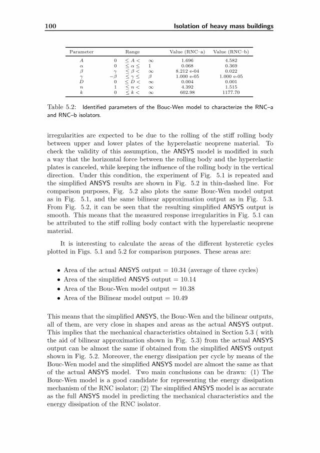
100 Isolation of heavy mass buildings
Parameter Range Value (RNC–a) Value (RNC–b)
A 0 ≤ A < ∞ 1.696 4.582α 0 ≤ α ≤ 1 0.068 0.369β γ ≤ β < ∞ 8.212 e-04 0.022γ −β ≤ γ ≤ β 1.000 e-05 1.000 e-05D 0 ≤ D < ∞ 0.004 0.001n 1 ≤ n < ∞ 4.392 1.515k 0 ≤ k < ∞ 602.98 1177.70
Table 5.2: Identified parameters of the Bouc-Wen model to characterize the RNC–a
and RNC–b isolators.
irregularities are expected to be due to the rolling of the stiff rolling bodybetween upper and lower plates of the hyperelastic neoprene material. Tocheck the validity of this assumption, the ANSYS model is modified in sucha way that the horizontal force between the rolling body and the hyperelasticplates is canceled, while keeping the influence of the rolling body in the verticaldirection. Under this condition, the experiment of Fig. 5.1 is repeated andthe simplified ANSYS results are shown in Fig. 5.2 in thin-dashed line. Forcomparison purposes, Fig. 5.2 also plots the same Bouc-Wen model outputas in Fig. 5.1, and the same bilinear approximation output as in Fig. 5.3.From Fig. 5.2, it can be seen that the resulting simplified ANSYS output issmooth. This means that the measured response irregularities in Fig. 5.1 canbe attributed to the stiff rolling body contact with the hyperelastic neoprenematerial.
It is interesting to calculate the areas of the different hysteretic cyclesplotted in Figs. 5.1 and 5.2 for comparison purposes. These areas are:
• Area of the actual ANSYS output = 10.34 (average of three cycles)
• Area of the simplified ANSYS output = 10.14
• Area of the Bouc-Wen model output = 10.38
• Area of the Bilinear model output = 10.49
This means that the simplified ANSYS, the Bouc-Wen and the bilinear outputs,all of them, are very close in shapes and areas as the actual ANSYS output.This implies that the mechanical characteristics obtained in Section 5.3 ( withthe aid of bilinear approximation shown in Fig. 5.3) from the actual ANSYS
output can be almost the same if obtained from the simplified ANSYS outputshown in Fig. 5.2. Moreover, the energy dissipation per cycle by means of theBouc-Wen model and the simplified ANSYS model are almost the same as thatof the actual ANSYS model. Two main conclusions can be drawn: (1) TheBouc-Wen model is a good candidate for representing the energy dissipationmechanism of the RNC isolator; (2) The simplified ANSYS model is as accurateas the full ANSYS model in predicting the mechanical characteristics and theenergy dissipation of the RNC isolator.

5.4 Hysteretic modeling 101
Figure 5.1: Actual ANSYS steady-state response versus predicted (Bouc-Wen model)
steady-state response under harmonic input for the RNC–a isolator: (a) Time scale, (b)
Displacement scale.
Figure 5.2: Comparison between the simplified ANSYS output, the bilinear approxima-
tion and the identified Bouc-Wen model using the actual ANSYS output.

102 Isolation of heavy mass buildings
Figure 5.3: Actual ANSYS output force and its equivalent bilinear approximation,
RNC–a isolator.
Running the simulation of the full ANSYS model requires huge computa-tional efforts and computer resources and long time for each run. The mainbenefit of the assumed simplification of the ANSYS model is to get the samemechanical characteristics of the RNC isolator and almost the same energy dis-sipation per cycle, but using much lower computer resources and incomparableshort run time. As a result, more extensive case studies and design improve-ment of the RNC isolator can be performed with much less cost and reasonableaccuracy. Therefore, the simplified ANSYS output is considered for the rest ofthis study and is referred to as the measured response.
5.4.2 Seismic verification of the Bouc-Wen model
To check the validity of the identified parameters, an actual random seismicdisplacement (Kern Country earthquake, Taft Lincoln school tunnel, July 21,1952) is input into the ANSYS and the Bouc-Wen models. The input and theoutputs are plotted in Fig. 5.4 for RNC–a and RNC–b isolators. The discrep-ancy between the measured and predicted outputs, Fm and Fb, is quantifiedusing the L1 and L∞-norms and the corresponding relative errors ε as expressedin (4.19).
As shown in Figs. 5.4(b,c) and with the small relative errors ε1 and ε∞in Table 5.3, the hysteretic Bouc-Wen model can be seen as a very powerfulrepresentation of the RNC isolator for further studies.

5.5 Implementation 103
Figure 5.4: Bouc-Wen model validation: (a) Input seismic displacement, (b) Measured
vs predicted restoring forces for RNC–a isolator, (c) Measured vs predicted restoring forces
for RNC–b isolator.
5.5 Implementation
An idealized six bays, fifteen story (16-DOFs including the suspended base)base-isolated concrete moment-resisting frame is considered in the present studyas a case-study structure. It is modeled as a shear type structure mounted onthe proposed isolation bearing, Fig. 5.5, with one lateral degree-of-freedomDOF at each floor where all the vibrational modes are included in the analysis.The following assumptions are made for the structural system under consider-ation:
1. The superstructure remains within the elastic limit during the earthquakeexcitation.
2. The floors are assumed rigid in its own plane and the mass is lumped ateach floor level.
3. The columns are inextensible and weightless providing the lateral stiff-ness.
4. The system is subjected to single horizontal component of the earthquakeground motion.
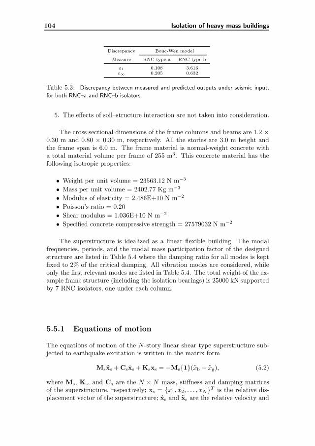
104 Isolation of heavy mass buildings
Discrepancy Bouc-Wen model
Measure RNC type a RNC type b
ε1 0.108 3.616ε∞ 0.205 0.632
Table 5.3: Discrepancy between measured and predicted outputs under seismic input,
for both RNC–a and RNC–b isolators.
5. The effects of soil–structure interaction are not taken into consideration.
The cross sectional dimensions of the frame columns and beams are 1.2 ×0.30 m and 0.80 × 0.30 m, respectively. All the stories are 3.0 m height andthe frame span is 6.0 m. The frame material is normal-weight concrete witha total material volume per frame of 255 m3. This concrete material has thefollowing isotropic properties:
• Weight per unit volume = 23563.12 N m−3
• Mass per unit volume = 2402.77 Kg m−3
• Modulus of elasticity = 2.486E+10 N m−2
• Poisson’s ratio = 0.20
• Shear modulus = 1.036E+10 N m−2
• Specified concrete compressive strength = 27579032 N m−2
The superstructure is idealized as a linear flexible building. The modalfrequencies, periods, and the modal mass participation factor of the designedstructure are listed in Table 5.4 where the damping ratio for all modes is keptfixed to 2% of the critical damping. All vibration modes are considered, whileonly the first relevant modes are listed in Table 5.4. The total weight of the ex-ample frame structure (including the isolation bearings) is 25000 kN supportedby 7 RNC isolators, one under each column.
5.5.1 Equations of motion
The equations of motion of the N -story linear shear type superstructure sub-jected to earthquake excitation is written in the matrix form
Msxs + Csxs + Ksxs = −Ms{1}(xb + xg), (5.2)
where Ms, Ks, and Cs are the N × N mass, stiffness and damping matricesof the superstructure, respectively; xs = {x1, x2, . . . , xN}T is the relative dis-placement vector of the superstructure; xs and xs are the relative velocity and

5.5 Implementation 105
Figure 5.5: Case-study structure isolated by the RNC isolator
acceleration vectors, respectively; xj(j = 1, 2, . . . , N) is the lateral displace-ment of the jth floor relative to the base mass; {1} = {1, 1, 1, . . . , 1}T is theinfluence coefficient vector; xb is the relative acceleration of the base mass; andxg is the earthquake ground acceleration.
The governing equation of motion for the base mass is given by
mbxb + ηFb − c1x1 − k1x1 = −mbxg, (5.3)
where mb is the mass of the base raft; c1 and k1 are the damping and stiffnessof the first story, respectively; η is the total number of isolators and Fb is therestoring force transmitted to the base mass by a single RNC isolator. Thisforce is expressed by the Bouc-Wen model as
Fb(t) = αkxb(t) + (1 − α)Dy kz(t), (5.4)
z = D−1y (Axb − β|xb||z|n−1z − γxb|z|n), (5.5)
where xb is the relative base displacement, αkx is the elastic force component,z is an auxiliary variable, z denotes the time derivative, n > 1 is a parametergoverns the smoothness of the transition from elastic to plastic response,Dy > 0is the yield constant displacement, k > 0 and 0 < α < 1 represents the postto pre-yielding stiffness ratio (kb/ke), while A, β and γ are non-dimensionalparameters that govern the shape and size of the hysteresis loop.
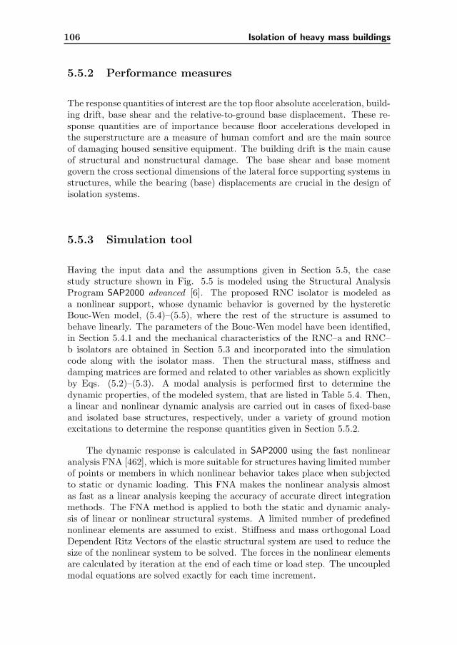
106 Isolation of heavy mass buildings
5.5.2 Performance measures
The response quantities of interest are the top floor absolute acceleration, build-ing drift, base shear and the relative-to-ground base displacement. These re-sponse quantities are of importance because floor accelerations developed inthe superstructure are a measure of human comfort and are the main sourceof damaging housed sensitive equipment. The building drift is the main causeof structural and nonstructural damage. The base shear and base momentgovern the cross sectional dimensions of the lateral force supporting systems instructures, while the bearing (base) displacements are crucial in the design ofisolation systems.
5.5.3 Simulation tool
Having the input data and the assumptions given in Section 5.5, the casestudy structure shown in Fig. 5.5 is modeled using the Structural AnalysisProgram SAP2000 advanced [6]. The proposed RNC isolator is modeled asa nonlinear support, whose dynamic behavior is governed by the hystereticBouc-Wen model, (5.4)–(5.5), where the rest of the structure is assumed tobehave linearly. The parameters of the Bouc-Wen model have been identified,in Section 5.4.1 and the mechanical characteristics of the RNC–a and RNC–b isolators are obtained in Section 5.3 and incorporated into the simulationcode along with the isolator mass. Then the structural mass, stiffness anddamping matrices are formed and related to other variables as shown explicitlyby Eqs. (5.2)–(5.3). A modal analysis is performed first to determine thedynamic properties, of the modeled system, that are listed in Table 5.4. Then,a linear and nonlinear dynamic analysis are carried out in cases of fixed-baseand isolated base structures, respectively, under a variety of ground motionexcitations to determine the response quantities given in Section 5.5.2.
The dynamic response is calculated in SAP2000 using the fast nonlinearanalysis FNA [462], which is more suitable for structures having limited numberof points or members in which nonlinear behavior takes place when subjectedto static or dynamic loading. This FNA makes the nonlinear analysis almostas fast as a linear analysis keeping the accuracy of accurate direct integrationmethods. The FNA method is applied to both the static and dynamic analy-sis of linear or nonlinear structural systems. A limited number of predefinednonlinear elements are assumed to exist. Stiffness and mass orthogonal LoadDependent Ritz Vectors of the elastic structural system are used to reduce thesize of the nonlinear system to be solved. The forces in the nonlinear elementsare calculated by iteration at the end of each time or load step. The uncoupledmodal equations are solved exactly for each time increment.

5.6 Effect of isolator characteristics 107
5.5.4 Numerical study
In the following numerical study, thorough investigation of the RNC isolatorhas been carried out to assess its effectiveness considering two main possibledesigns RNC–a and RNC–b. In Section 5.6, the behavior of the RNC isola-tor is investigated under harmonic ground motions, using frequency responseanalysis, considering different RNC characteristics. Section 5.7 briefly inves-tigates some characteristics of the RNC isolator, and presents a comparisonbetween fixed-base and base-isolated structural responses using time historyanalysis. The influence of the superstructural flexibility is studied in Section5.8. The effect of long period earthquakes is considered in Section 5.9. Finally,the influence of different earthquake characteristics is examined in Section 5.10.
5.6 Effect of isolator characteristics
The four different designs of each RNC isolator types a and b are studied underharmonic ground motion, which is defined as a sinusoidal ground acceleration
xg(t) = 0.5g sin(2πfgt) (5.6)
where fg denotes the excitation frequency and g is the gravitational accelera-tion.
Fig. 5.6(a) shows the peak structural absolute acceleration as a functionof the excitation frequency in Hz, using the four RNC–a isolator designs. Thestructural acceleration in the fixed-base structure is included for comparison.Fig. 5.6(b) shows the corresponding peak base floor displacement. By com-paring the frequency response curves in Fig. 5.6(a), one observes that exceptfor very low excitation frequencies, which are unlikely to occur, the structuralabsolute acceleration is significantly reduced. This response reduction grows aswe move from the very stiff design (RNC–a set I) toward the very flexible one(RNC–a set IV). There is a single resonant peak at the structural fundamentalfrequency (1.99 Hz) in the fixed-base case. For isolator sets I and II, two res-onant peaks are clear at low frequencies of 0.25 Hz and 0.18 Hz, respectively.Moreover, some secondary peaks occur around the resonant frequency of thefixed-base case. These secondary peaks become clearer as the isolator flexibilityincreases (sets III and IV). The corresponding base displacement shown in Fig.5.6(b) seem to be within reasonable ranges, except those at very low excitationfrequencies. These base displacements become larger as the isolator flexibilityincreases. Further, resonant peaks occur for the stiffer isolator sets I and II.
Fig. 5.7(a) shows the peak structural accelerations against the excitationfrequency in Hz, using the four RNC–b isolator designs. The main differencesin behavior, relative to that of the RNC–a, arise from the relatively stiff na-ture of the RNC–b isolators. Such nature limits the isolator efficiency, as can

108 Isolation of heavy mass buildings
Figure 5.6: Frequency response of different designs of RNC–a isolator: (a) Absolute
acceleration at the topmost point, (b) Relative-to-ground base displacement.
be seen when we compare Figs 5.6(a) and 5.7(a), where the isolated accelera-tion response is lower using RNC–a, around the fixed-base resonant frequency.Moreover, this higher stiffness shifts the resonant peaks in the base-isolatedcases toward higher frequencies, which increases the probability of their occur-rence. These resonant peaks are 0.72 Hz, 0.52 Hz, 0.38 Hz, and 0.27 Hz forisolator sets I, II, III, and IV, respectively. In Fig. 5.7(b), the correspondingbase displacements are plotted versus ground motion frequency. In this figure,four resonant peaks are evident when compared to Fig. 5.6(b). However, inFig. 5.7(b) the frequency response curves has steeper slopes from the peaks on.This means that, due to the relatively higher stiffness of the RNC–b isolatorsets, they exhibit higher rate of displacement reduction, specially as we movefrom the resonant peaks toward higher frequencies.
As can be seen, the acceleration response reduction is maximum in thecases of very flexible designs (sets IV) for RNC–a and RNC–b. However, theassociated base displacements are the highest, but are still affordable. More-over, the efficiency of the RNC–a is significantly higher than the RNC–b inreducing accelerations due to its higher flexibility. Further, the probability ofresonance using the RNC–a is far from occurrence if compared to the RNC–b,that might be more likely to occur.
Practically, seismic isolators have to resist minor vibrations. Lower pre-

5.7 Recentering, damping and time response 109
Figure 5.7: Frequency response of different designs of RNC–b isolator: (a) Absolute
acceleration at the topmost point, (b) Relative-to-ground base displacement
yield stiffness renders the isolator highly sensitive to minor vibrations. Consid-ering that the wind loads represent the source of minor vibrations, the structurein Fig. 5.5 has been subjected to a wind pressure of 2 kN m−2 including suc-tion. Although the details are omitted here, it has been found that the RNCisolator sets II for RNC–a and RNC–b (see Table 5.1) offer adequate initialstiffness to resist the presumed wind pressure on the structure. Sets I are alsopractical with respect to wind resistance, but their higher stiffness render themless efficient for seismic response attenuation. On the other hand, design setsIII and IV are softer than sets II, and therefore are impractical with respect towind resistance. Therefore, only the RNC design sets II are considered in therest of this study.
5.7 Recentering, damping and time response
In this section, the inherent gravity-based recentering mechanism of the RNCisolator is verified and the damping added to the structure by the RNC isolatoris estimated. Moreover, a preliminary impression about the efficiency of theRNC isolator is briefly sought under earthquake ground motion.
The structure shown in Fig. 5.5, isolated by the RNC–b isolator set II,
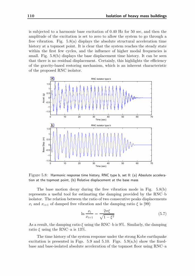
110 Isolation of heavy mass buildings
is subjected to a harmonic base excitation of 0.40 Hz for 50 sec, and then theamplitude of the excitation is set to zero to allow the system to go through afree vibration. Fig. 5.8(a) displays the absolute structural acceleration timehistory at a topmost point. It is clear that the system reaches the steady statewithin the first few cycles, and the influence of higher modal frequencies issmall. Fig. 5.8(b) displays the base displacement time history. It can be seenthat there is no residual displacement. Certainly, this highlights the efficiencyof the gravity-based restoring mechanism, which is an inherent characteristicof the proposed RNC isolator.
Figure 5.8: Harmonic response time history, RNC type b, set II: (a) Absolute accelera-
tion at the topmost point, (b) Relative displacement at the base mass
The base motion decay during the free vibration mode in Fig. 5.8(b)represents a useful tool for estimating the damping provided by the RNC–bisolator. The relation between the ratio of two consecutive peaks displacementsxi and xi+1 of damped free vibration and the damping ratio ξ is [99]:
lnxi
xi+1=
2πξ√
1 − ξ2(5.7)
As a result, the damping ratio ξ using the RNC–b is 9%. Similarly, the dampingratio ξ using the RNC–a is 13%.
The time history of the system response under the strong Kobe earthquakeexcitation is presented in Figs. 5.9 and 5.10. Figs. 5.9(a,b) show the fixed-base and base-isolated absolute acceleration of the topmost floor using RNC–a

5.8 Influence of superstructure flexibility 111
and RNC–b, respectively. The figures show the ability of the RNC isolatorto reduce the structural responses. This reduction is more significant usingthe RNC–a. This is mainly due to the lower post-yield stiffness in the case ofRNC–a, as it was already pointed out in Section 5.6.
Figure 5.9: Time history of top floor acceleration response under Kobe earthquake,
using sets II: (a) Fixed-base vs base-isolated structure by RNC–a, (b) Fixed-base vs base-
isolated structure by RNC–b.
The peak accelerations at the top floor of the base-isolated structure are0.307 and 0.973 g for the RNC–a and RNC–b, respectively, while the peakacceleration at the same point of the fixed-base structure is 1.529 g.
In a similar manner, the corresponding relative base displacements underthe same excitation are plotted in Fig. 5.10. Figs. 5.10(a,b) show the rela-tive bearing displacement using RNC–a and RNC–b, respectively. The peakbearing displacements for the base-isolated structure are 0.349 and 0.514 mfor the RNC–a and RNC–b, respectively. This indicates that the bearing dis-placements can be reasonable and affordable, especially for RNC–a, under suchstrong motion Kobe earthquake.
5.8 Influence of superstructure flexibility
The isolation systems are robust and practically useful when they are effectivefor different structures with wide range of properties. The fundamental time

112 Isolation of heavy mass buildings
Figure 5.10: Time history of bearing relative displacement response under Kobe earth-
quake, using sets II: (a) Base-isolated structures by RNC–a, (b) Base-isolated structures
by RNC–b.
period of a structure is the most important property from the dynamic responsepoint of view. For most typical building structures, the fundamental timeperiod varies between 0.1 to 0.5 s. Tall buildings and flexible structures haveperiods of up to 2 s or longer. A base isolator derives its effectiveness byincreasing the time period of the structure. It is therefore essential that thisperiod be shorter than the time period of the isolator. In this investigation,two RNC isolator sets II (one for each type a and b) are considered to isolatecase-study structures with different fundamental periods within a wide rangefrom 0.1 to 2.0 sec. This choice corresponds to the most likely practical valuesof these parameters.
The response spectra for the structural absolute acceleration, at the top-most point, and the relative base displacement are shown in Fig. 5.11 for threeearthquakes of different intensities, ranging from low to severe peak groundaccelerations (PGA). The three earthquakes are Kern (low intensity, PGA =0.18g), El-Centro (moderate intensity, PGA = 0.35g) and San-Fernando (se-vere intensity, PGA = 1.17g) earthquakes. The following conclusions can bedrawn drawn after analyzing the results in Fig. 5.11:
• The isolation efficiency increases as the earthquake intensity increases.
• The RNC–a isolator offers better isolation performance than the RNC–b

5.8 Influence of superstructure flexibility 113
Figure 5.11: Acceleration and displacement response spectra under three earthquakes:
(a) Acceleration of the top floor under Kern earthquake, (b) Base displacement under
Kern earthquake, (c) Acceleration of the top floor under El Centro earthquake, (d) Base
displacement under El Centro earthquake, (e) Acceleration of the top floor under San
Fernando earthquake, (f) Base displacement under San Fernando earthquake.
isolator, but it is accompanied with larger base displacement, which isstill within reasonable ranges.
• Although the isolation efficiency decreases as the structural fundamentalperiod increases, the RNC isolator is still valid for very long fundamentalperiods, specially under severe intensity earthquakes.
• Under all intensities, the maximum acceleration is almost independentof the structure time period, particularly under the highest earthquakeintensity (San Fernando).
Therefore, the RNC isolator is a robust isolation device, as it exhibits a rela-tively similar behavior for a very wide range of structural time periods, underthe same earthquake intensity.

114 Isolation of heavy mass buildings
5.9 Behavior under long-period earthquakes
This section investigates the usefulness of the proposed RNC isolator underlong-period seismic excitations. The Mexico City 1985 earthquake has beenused as an excitation for fixed-base and isolated-base cases. The whole build-ing drift (difference between the topmost and base displacements), absoluteacceleration of top floor, and base shear are chosen as performance measures,and they are plotted against the structural fundamental period in Fig. 5.12.From this figure, the following notes are drawn:
• The RNC–a isolator reduces the building drift significantly for all struc-tural periods, specially at long structural periods, contrary to RNC–b.
• The RNC–a is reasonably effective in reducing the acceleration responseat short periods (up to 0.60 sec), whereas it offers a relatively neutralbehavior for higher periods.
• Considering the base shear, the RNC–a exhibits a robust behavior for allthe structural periods considered.
• For all the performance measures, the RNC–b isolator appears to beineffective or at maximum neutral for periods up to almost 1.60 sec, butit shows some efficiency at longer periods. This emphasizes that theRNC–a is much superior to the RNC–b isolator under such long-periodearthquake.
5.10 Influence of earthquake characteristics
Robust performance of the RNC isolator against changes of earthquake char-acteristics is investigated in this Section. This investigation is carried outfollowing three steps:
1. In the first step, the RNC–a is considered as the isolation device in thecase-study structure of Fig. 5.5 under 3 scaled intensities (PGA = 50%,100% and 200%) of El Centro earthquake, in order to investigate theinfluence of earthquake amplitude on the RNC behavior. The results ofthis step are listed in Table 5.5.
2. In the second step, the RNC–a is used along with three other earthquakes(Kobe, Northridge and Parkfield) of equally scaled amplitudes to 0.5g asthe excitation source. In this step, a relation between the RNC–a isolatorperformance and the frequency content is sought. The results of this stepare listed in Table 5.6. In both first and second steps, a wide range ofstructural fundamental periods (Ts = 0.20 − 2.0 sec) is considered.

5.10 Influence of earthquake characteristics 115
Figure 5.12: Response spectra under long-period Mexico City earthquake: (a) Building
drift, (b) Acceleration at top floor, (c) Base shear.
3. Finally, and to confirm the results obtained from the first two steps, a setof 36 earthquakes is used to excite the structure shown in Fig. 5.5 witha fundamental period of 0.50 sec. In this step, both RNC types a and bare examined, and the results are listed in Table 5.7.
From Table 5.5, it can be observed that the fixed base responses are dou-bled as the excitation amplitudes are doubled, which is not always the case forthe RNC-isolated structural acceleration response. In all cases, the attenuationof the structural absolute acceleration (at top floor) by means of the RNC–a iso-lator is evident, especially under higher intensities and short structural periods.This response attenuation is accompanied with affordable base displacements,under all conditions. This may clearly highlight the independence of the RNCisolator efficiency on the excitation amplitude.
Fig. 5.13 shows the normalized Fourier amplitude of the three used earth-quakes in the second step. Comparing the structural response in Table 5.6 and
116 Isolation of heavy mass buildings
Figure 5.13: Normalized Fourier amplitude of: (a) Kobe earthquake, (b) Northridge
earthquake, (c)Parkfield earthquake.
the Fourier amplitudes in Fig. 5.13 for each earthquake, it is obvious that thereis no clear relation between the RNC–a isolator efficiency and the frequencycontent. Moreover, significant acceleration response attenuation is apparentwith reasonable base displacement.
Table 5.7 presents the results of the extensive study under a wide set ofdistinct earthquake ground motions (third step). The building drift, the topfloor absolute acceleration and the base shear are the three used performancemeasures. From this table, the following main observations can be emphasized:
• The RNC–a always mitigates very substantially the building drift, theabsolute acceleration at the topmost floor and the base shear, on theaccount of reasonable bearing displacement.
• Except for Mexico City earthquake, the RNC–b is also efficient in miti-gating the same seismic responses, although it is not as effective as theRNC–a.
In summary, the RNC isolator may be seen as a robust isolation device undervariations in earthquake characteristics.
5.11 Conclusions 117
5.11 Conclusions
Chapters 3 and 4 presented a detailed description of the main principles ofoperation, modeling and characterization of the RNC–a and RNC–b isolators.In this chapter, an extensive numerical assessment of the performance of suchRNC isolators has been presented. The numerical investigations affirmed theeffectiveness of the device by attaining significant reduction of the building ac-celerations, drifts and base shears, while keeping reasonable base displacement.Even when very flexible structures (time period exceeding 1.0 sec ) are isolatedand long time-period excitations are considered, the proposed system is foundto be highly effective. Further, the proposed RNC isolation bearing is foundto exhibit a robust performance for a wide range of structures, isolators andground motion characteristics.
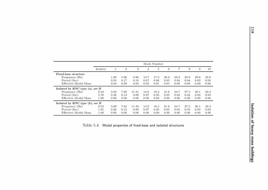
118
Isola
tion
ofheavy
mass
build
ings
Mode Number
Isolator 1 2 3 4 5 6 7 8 9 10
Fixed-base structureFrequency (Hz) 1.99 5.96 9.86 13.7 17.3 20.8 23.9 26.9 29.6 32.0Period (Sec) 0.50 0.17 0.10 0.07 0.06 0.05 0.04 0.04 0.03 0.03Effective Modal Mass 0.84 0.09 0.03 0.02 0.01 0.01 0.00 0.00 0.00 0.00
Isolated by RNC type (a), set IIFrequency (Hz) 0.18 3.83 7.60 11.31 14.9 18.4 21.6 24.7 27.5 30.1 32.3Period (Sec) 5.70 0.26 0.13 0.09 0.07 0.05 0.05 0.04 0.04 0.03 0.03Effective Modal Mass 1.00 0.00 0.00 0.00 0.00 0.00 0.00 0.00 0.00 0.00 0.00
Isolated by RNC type (b), set IIFrequency (Hz) 0.52 3.89 7.64 11.33 14.9 18.4 21.6 24.7 27.5 30.1 32.3Period (Sec) 1.91 0.26 0.13 0.09 0.07 0.05 0.05 0.04 0.04 0.03 0.03Effective Modal Mass 1.00 0.00 0.00 0.00 0.00 0.00 0.00 0.00 0.00 0.00 0.00
Table 5.4: Modal properties of fixed-base and isolated structures

5.11 Conclusions 119
El-Centro 50% El-Centro 100% El-Centro 200%
Ts Fixed Isolated Fixed Isolated Fixed Isolated
Top Base Top Top Base Top Top Base TopAccel. Disp. Accel. Accel. Disp. Accel. Accel. Disp. Accel.
0.20 5.944 0.066 0.533 11.888 0.138 0.659 23.777 0.230 1.2090.30 5.412 0.066 0.643 10.824 0.139 0.919 21.649 0.231 1.2140.40 6.248 0.067 0.827 12.497 0.143 1.534 24.994 0.230 2.8290.50 6.359 0.066 1.124 12.717 0.141 2.133 25.434 0.235 2.6300.60 6.820 0.069 1.103 13.640 0.133 1.881 27.280 0.235 2.4060.70 6.916 0.074 1.110 13.832 0.132 1.860 27.665 0.246 3.9260.80 5.770 0.068 1.230 11.539 0.112 2.734 23.079 0.244 4.6740.90 6.212 0.063 1.413 12.425 0.114 2.467 24.850 0.235 4.6311.00 4.959 0.055 1.996 9.917 0.094 2.689 19.835 0.240 5.2941.10 4.791 0.036 1.793 9.581 0.098 3.375 19.163 0.240 6.1311.20 3.921 0.041 1.891 7.843 0.086 3.844 15.685 0.229 6.0471.30 3.360 0.032 1.993 6.720 0.095 3.943 13.440 0.231 5.9261.40 3.543 0.031 2.209 7.086 0.087 4.094 14.172 0.218 5.8611.50 3.013 0.051 2.290 6.026 0.098 4.423 12.051 0.216 6.1141.60 3.604 0.049 2.125 7.208 0.094 4.218 14.416 0.210 6.3201.70 3.110 0.057 1.908 6.220 0.091 3.757 12.439 0.204 6.1771.80 2.742 0.049 2.201 5.484 0.086 3.842 10.968 0.192 6.6251.90 3.181 0.048 2.302 6.363 0.078 4.099 12.726 0.186 6.4712.00 3.164 0.050 2.260 6.329 0.090 3.535 12.658 0.176 5.495
Table 5.5: Influence of earthquake intensity on RNC–a isolator performance, m-sec
units.
Kobe 0.5g Northridge 0.5g Parkfield 0.5g
Ts Fixed Isolated Fixed Isolated Fixed Isolated
Top Base Top Top Base Top Top Base TopAccel. Disp. Accel. Accel. Disp. Accel. Accel. Disp. Accel.
0.20 21.986 0.346 0.952 23.260 0.071 0.517 16.689 0.082 0.6990.30 24.225 0.346 1.231 12.698 0.072 0.722 12.220 0.082 0.9710.40 21.758 0.347 1.848 11.150 0.074 1.374 10.809 0.084 1.2020.50 11.834 0.341 2.097 8.426 0.075 1.685 11.060 0.087 1.4900.60 14.015 0.344 2.459 9.696 0.079 1.747 9.074 0.085 1.7500.70 14.224 0.353 3.113 11.928 0.080 1.918 8.973 0.077 1.9280.80 13.975 0.335 3.085 11.711 0.075 2.453 10.963 0.079 2.5940.90 20.544 0.322 4.390 7.233 0.087 2.431 9.434 0.072 2.3831.00 18.153 0.323 3.517 9.225 0.098 1.977 8.291 0.075 2.4031.10 24.315 0.336 3.759 9.602 0.093 2.647 10.912 0.057 2.3361.20 24.545 0.348 3.652 8.705 0.097 2.550 7.992 0.049 2.3641.30 20.874 0.358 5.298 6.725 0.106 3.571 6.905 0.062 2.1311.40 14.557 0.353 4.688 8.828 0.089 3.005 6.914 0.065 2.6421.50 11.423 0.302 5.092 5.899 0.094 3.707 6.423 0.066 2.5721.60 11.315 0.278 4.857 7.071 0.101 3.625 6.532 0.053 2.6691.70 11.120 0.278 4.466 7.482 0.096 4.268 6.197 0.064 3.1331.80 11.206 0.277 4.882 7.270 0.103 4.035 6.432 0.072 3.4991.90 13.795 0.273 6.555 8.319 0.106 5.203 5.114 0.083 3.4862.00 12.485 0.240 5.665 6.763 0.124 5.143 4.959 0.059 3.266
Table 5.6: Influence of earthquake frequency contents on RNC–a isolator performance,
m-sec units.

120
Isola
tion
ofheavy
mass
build
ings
Fixed-base Isolated by RNC type (a), set II Isolated by RNC type (b), set II
No. Earthquake Record Building Top Base Base Building Top Red.a Base Red. Base Building Top Red. Base Red.Drift Accel. Shear Disp. Drift Accel. (%) Shear (%) Disp. Drift Accel. (%) Shear (%)
1 ALTADENA 0◦ 0.087 17.36 1837.13 0.03 0.003 2.03 88% 122.35 93% 0.05 0.006 3.32 81% 249.25 86%2 ALTADENA 90◦ 0.046 8.95 1061.07 0.01 0.003 0.67 93% 102.76 90% 0.01 0.004 1.47 84% 123.03 88%3 ARRAY06 0◦ 0.052 9.26 1299.02 0.34 0.006 1.69 82% 263.46 80% 0.23 0.023 3.99 57% 769.67 41%4 ARRAY06 90◦ 0.073 12.08 1853.28 0.99 0.014 2.23 82% 409.70 78% 0.30 0.027 5.10 58% 966.25 48%5 CORRALIT 0◦ 0.125 21.35 2809.14 0.11 0.006 2.06 90% 141.78 95% 0.09 0.011 3.93 82% 374.00 87%6 CORRALIT 90◦ 0.093 16.37 2512.62 0.14 0.006 2.27 86% 148.12 94% 0.06 0.010 3.42 79% 421.89 83%7 HOLLISTE 0◦ 0.127 19.59 3159.75 0.29 0.004 1.96 90% 199.81 94% 0.26 0.026 5.23 73% 841.45 73%8 HOLLISTE 90◦ 0.072 12.06 1721.99 0.11 0.004 1.32 89% 137.28 92% 0.05 0.007 2.37 80% 282.42 84%9 LACC-NOR 0◦ 0.055 9.62 1263.41 0.07 0.004 1.82 81% 124.81 90% 0.06 0.012 2.53 74% 274.41 78%10 LACC-NOR 90◦ 0.041 7.40 1087.29 0.10 0.005 1.28 83% 134.00 88% 0.04 0.007 2.53 66% 227.48 79%11 LEXINGT 0◦ 0.075 12.21 1893.83 0.22 0.005 2.04 83% 178.85 91% 0.26 0.029 5.17 58% 839.16 56%12 LEXINGT 90◦ 0.071 11.64 1719.58 0.38 0.007 1.46 87% 226.87 87% 0.30 0.033 5.81 50% 964.05 44%13 LUCERNE 0◦ 0.034 13.99 1108.82 0.13 0.005 0.94 93% 151.56 86% 0.11 0.012 2.69 81% 411.93 63%14 LUCERNE 90◦ 0.050 17.62 1395.45 0.06 0.003 1.90 89% 130.45 91% 0.03 0.008 2.95 83% 233.30 83%15 NEW-HALL 0◦ 0.179 27.49 4400.92 0.47 0.009 2.66 90% 256.62 94% 0.34 0.033 5.25 81% 1087.43 75%16 NEW-HALL 90◦ 0.118 20.74 3124.83 0.19 0.009 3.03 85% 164.57 95% 0.17 0.016 4.15 80% 596.30 81%17 OAK-WHAF 0◦ 0.057 8.84 1465.21 0.18 0.004 1.67 81% 161.49 89% 0.12 0.018 3.53 60% 454.82 69%18 OAK-WHAF 90◦ 0.052 7.44 1458.03 0.08 0.004 1.37 82% 133.08 91% 0.14 0.018 4.11 45% 507.79 65%19 PETROLIA 0◦ 0.124 20.01 2934.93 0.05 0.006 2.84 86% 156.74 95% 0.07 0.018 4.50 78% 440.22 85%20 PETROLIA 90◦ 0.125 21.10 3379.69 0.53 0.008 2.60 88% 268.81 92% 0.28 0.029 5.01 76% 921.44 73%21 POMONA 0◦ 0.019 4.57 445.67 0.03 0.004 0.83 82% 112.72 75% 0.02 0.006 2.49 46% 146.52 67%22 POMONA 90◦ 0.014 4.70 343.51 0.02 0.004 0.70 85% 110.44 68% 0.01 0.004 2.14 54% 153.10 55%23 SANTA-MONICA 0◦ 0.051 9.70 1100.61 0.04 0.005 0.90 91% 130.95 88% 0.05 0.008 2.74 72% 238.84 78%24 SANTA-MONICA 90◦ 0.071 14.88 1616.43 0.11 0.006 2.99 80% 165.01 90% 0.14 0.014 6.22 58% 500.77 69%25 SYLMAR 0◦ 0.185 29.60 4216.62 0.48 0.006 2.63 91% 265.88 94% 0.53 0.055 8.32 72% 1603.14 62%26 SYLMAR 90◦ 0.144 22.05 3739.71 0.26 0.008 2.30 90% 192.69 95% 0.29 0.033 6.08 72% 929.76 75%27 YERMO 0◦ 0.056 8.92 1365.22 0.08 0.004 1.01 89% 142.86 90% 0.06 0.010 2.31 74% 315.81 77%28 YERMO 90◦ 0.060 10.10 1518.83 0.20 0.003 1.64 84% 162.34 89% 0.17 0.020 3.62 64% 579.72 62%29 EL-CENTRO 0.080 12.72 2054.51 0.14 0.004 2.13 83% 148.88 93% 0.06 0.011 3.09 76% 305.50 85%30 KERN 0.029 5.17 809.78 0.04 0.005 1.06 80% 116.31 86% 0.04 0.009 1.81 65% 216.14 73%31 KOBE 0.101 16.07 2640.23 0.32 0.008 2.82 82% 252.72 90% 0.70 0.067 9.55 41% 2118.55 20%32 LOMA-PRIETA 0.053 8.35 1367.53 0.08 0.005 1.51 82% 130.73 90% 0.10 0.014 4.03 52% 382.35 72%33 MEXICO 0.013 1.88 355.02 0.20 0.006 1.20 36% 165.35 53% 0.20 0.022 3.48 -85% 680.11 -92%34 NORTHRIDGE 0.071 14.88 1616.55 0.11 0.006 2.99 80% 165.02 90% 0.14 0.014 6.22 58% 500.84 69%35 PARKFIELD 0.027 5.24 625.93 0.05 0.003 0.95 82% 116.20 81% 0.02 0.006 1.31 75% 149.42 76%36 SAN-FERNANDO 0.169 37.48 3772.02 0.51 0.007 2.18 94% 271.16 93% 0.44 0.044 8.50 77% 1348.62 64%
Table 5.7: Results summary using 36 earthquakes and two RNC types: a and b, ton-m-sec units.
aReduction as a percentage of the corresponding fixed-base response
Copyright © 2022 FDOKUMEN