D6.4 Final Report - CORDIS
55
D6.4 - Final Report page 1/55 FCH JU Grant Agreement no.: 621216 Project acronym: Second Act Project title: Simulation, Statistics and Experiments Coupled to develop Optimized aNd Durable µCHP systems using ACcelerated Tests Funding scheme: Collaborative Project Area: Area SP1-JTI-FCH.3: Stationary Power Generation & CHP AIP SP1-JTI-FCH.2013.3.1 - Improving understanding of cell & stack degradation mechanisms using advanced testing techniques, and developments to achieve cost reduction and lifetime enhancements for Stationary Fuel Cell power and CHP systems Start date of project: 01.05.2014 Duration: 42 months Project Coordinator: CEA – Sylvie Escribano Tel: +33 4 38 78 94 06 E-mail: [email protected] D6.4 Final Report Document properties D6.4 Final Report Author (Partner - Role) S. Escribano (CEA - Coordinator) WP# name (leader) WP6 Management (CEA) Other Authors (Partner - Role) Released by Author: 16/01/2018 Released by WP leader: Released by coordinator: Approved by (Partner - Role) S. Escribano (CEA - Coordinator) Date of first issue: 31/12/2017 Dissemination level Confidential (i.e. only for consortium and JTI) Distribution: Second Act partners & FCH-JU (SESAM portal) Project website address: www.second-act.eu
-
Upload
khangminh22 -
Category
Documents
-
view
1 -
download
0
Transcript of D6.4 Final Report - CORDIS

D6.4 - Final Report
page 1/55
FCH JU Grant Agreement no.: 621216
Project acronym: Second Act
Project title: Simulation, Statistics and Experiments Coupled to develop Optimized
aNd Durable µCHP systems using ACcelerated Tests
Funding scheme: Collaborative Project
Area: Area SP1-JTI-FCH.3: Stationary Power Generation & CHP
AIP SP1-JTI-FCH.2013.3.1 - Improving understanding of cell & stack
degradation mechanisms using advanced testing techniques, and
developments to achieve cost reduction and lifetime enhancements
for Stationary Fuel Cell power and CHP systems
Start date of project: 01.05.2014
Duration: 42 months
Project Coordinator: CEA – Sylvie Escribano
Tel: +33 4 38 78 94 06
E-mail: [email protected]
D6.4 Final Report
Document properties D6.4 Final Report
Author
(Partner - Role)
S. Escribano
(CEA - Coordinator) WP# name (leader) WP6 Management (CEA)
Other Authors
(Partner - Role)
Released by Author:
16/01/2018 Released by WP leader:
Released by
coordinator:
Approved by
(Partner - Role)
S. Escribano
(CEA - Coordinator) Date of first issue: 31/12/2017
Dissemination level Confidential (i.e. only for consortium and JTI)
Distribution: Second Act partners & FCH-JU (SESAM portal)
Project website address: www.second-act.eu

D6.4 - Final Report
page 2/55
Revisions
Version: Date: Changed by: Comments:
Final 16/01/2018 Sylvie Escribano
Content
1. Executive summary ................................................................................................................................... 3
2. Context – objectives ................................................................................................................................. 4
3. S & T results - foregrounds ....................................................................................................................... 6
3.1. Summary of main actions and results achieved in the first period ................................................... 6
3.2. Summary of main actions and results achieved in the second period .............................................. 8
3.3. Selected technical results ................................................................................................................ 12
3.3.1. Summary of experimental investigations ................................................................................ 12
3.3.1.1. In-situ ageing tests in single cells and stacks ................................................................... 12
3.3.1.2. Local degradation analysis by in-situ and post-mortem ex-situ tests ............................. 14
3.3.1.3. Ex-situ analysis of degradation mechanisms comparing pristine and aged samples ...... 18
3.3.2. Summary of modelling investigations ..................................................................................... 25
3.3.2.1. Modelling of reversisible and non-reversible mechanisms related to Pt based catalysts
25
3.3.2.1. Implementation of degradation mechanisms in performance models and simulation of
degradation and heterogeneities ....................................................................................................... 31
3.3.3. Summary of durability improvements results ......................................................................... 41
3.3.3.1. DMFC and PEMFC single cell tests with tuned operation strategies and improved MEAs
42
3.3.3.2. PEMFC stacks test with tuned operation strategies and improved MEAs ...................... 45
3.3.4. General conclusion of the scientific and technological results ............................................... 48
3.3.5. Exploitation of the scientific and technological results planned ............................................. 48
3.3.6. Dissemination .......................................................................................................................... 49

D6.4 - Final Report
page 3/55
1. EXECUTIVE SUMMARY
Second Act aims at improving understanding of stack degradation in order to propose solutions enabling
significant lifetime improvements for µCHP systems using PEMFC (Proton Exchange Membrane Fuel Cell),
operating under Hydrogen or Reformate, or DMFC (Direct Methanol) technology. The project is founded and
focused on two efforts: degradation understanding and durability improvement. These efforts are oriented
towards existing systems available in the project thanks to the involvement of three industry partners willing
to enhance lifetime and hence competiveness for market deployment.
Application of advanced testing techniques and procedures allowed to identify specific diagnostics and to
clarify with segmented cells the heterogeneities along the cells surface during ageing. Hydrogen, reformate
and methanol fuelled single cell have been tested under reference (at fixed load) and load cycling conditions.
PEMFC Stacks have been tested under pure hydrogen or reformate fuel, containing carbon monoxide. Effects
of load or voltage profiles, of impurities and electrodes materials, mainly catalysts, have been characterized.
The presence of common degradation mechanisms feeding different fuels have been confirmed, especially
in regard to cathode electrode and membrane; reversible degradation has been confirmed in all the tested
conditions, whose origin is mainly attributed to water redistribution in the porous components and PtOx
mechanism. Both temporary and permanent degradations and heterogeneities are considerably affected by
materials. Accelerated stress tests (AST) were analysed, developed and validated for cathode degradation by
platinum particles growth with particular focus on water effect, for membrane degradation by adapting the
common open circuit voltage protocol, and for start-up/shut-down protocol in a PEMFC stack.
Ex-situ analyses were conducted to enhance understanding of degradation mechanisms using: fluoride ion
detection, Infrared Thermography, XPS, XRD and TEM/EDX analyses and also electrochemical measurements.
For DMFC, some ionomer is lost anode side but major degradation is the cathode Pt nanoparticles growth.
For PEMFC, Pt, Co and Ru catalysts dissolution are main issues, along with ionomer contamination by cobalt
ions, and local carbon corrosion when applying start-stops.
Much effort was put on developing and validating numerical tools for the simulation and analysis of
degradation mechanisms from the MEA to the stack level, in close link with experimental investigations.
Reversible mechanisms have been modelled, mainly platinum oxide formation and reduction and carbon
monoxide poisoning, as well as irreversible catalyst particles dissolution. Models describing degradation
mechanisms were implemented in cell models, allowing to investigate the heterogeneities and to evaluate
the effect of these mechanisms on cell performance and on local operation for DMFC and PEMFC.
Experimental and modelling investigations of the reference MEAs highlighted several durability issues to be
subject for further optimization in Second Act. The first set of MEAs have traditionally uniform electrodes,
but novel catalysts and/or gas diffusion layers (GDLs). To face heterogeneities, third generation MEAs were
made with graded electrodes or locally optimized cathodes and anodes, composed of a few zones with
different compositions.
Thus, the main conclusion of this project is the demonstration that locally optimized electrodes and tuned
operating condition and strategies, as defined based on advanced investigations of degradation coupling in-
situ and ex-situ experimental analyses and modelling can actually lead to durability improvements at stack
level applicable in the systems.

D6.4 - Final Report
page 4/55
2. CONTEXT – OBJECTIVES
Second Act (Simulation, statistics and Experiments Coupled to develop Optimized aNd Durable µCHP systems
using ACcelerated Tests) was proposed to address the topic: “Improving understanding of cell & stack
degradation mechanisms using advanced testing techniques, and developments to achieve cost reduction and
lifetime enhancements for Stationary Fuel Cell power and CHP systems”.
Second Act aims at improving understanding of stack degradation in order to propose solutions enabling
significant lifetime improvements for µCHP systems using PEMFC (Proton Exchange Membrane Fuel Cell),
operating under Hydrogen or Reformate, or DMFC (Direct Methanol) technology. The project is founded and
focused on two efforts: degradation understanding and durability improvement. These efforts are oriented
towards existing systems available in the project thanks to the involvement of three industry partners willing
to enhance lifetime and hence competiveness for market deployment.
The main double objective of Second Act is to improve understanding of stack degradation and propose
durability improvements for µCHP systems using PEMFC or DMFC. The project aims at:
• Analysing long term lifetime tests data from existing systems to identify main causes for failure related
to system operation and quantify performance degradation of the stacks, over the long term (at least
10,000 hrs and more than 20,000 hrs for some systems considered)
• Conducting lifetime tests to investigate degradation at cell and stack levels and to better understand
mechanisms involved. Common degradation mechanisms in stack components (electrodes mainly) will
be particularly considered to help identifying similar type of improvements on materials and processes
to be implemented for lifetime extension.
• Developing, applying and validating accelerated stress tests (AST) and specific tests representative of
failures in harsh conditions for the different Fuel Cell technologies
• Developing and applying in-situ and ex-situ investigation techniques for better identification and local
resolution of the degradation mechanisms. Heterogeneities in degradation over the cells surface and
across the stacks will be particularly tackled, with regards to local operation and local conditions
(including fuel composition)
D6.4 - Final Report
page 5/55
• Developing new statistical approach and models for better understanding and description of systems
stochastic/deterministic degradation, reversible/permanent degradation and heterogeneities of
degradation in single cells and stacks.
• Demonstrating stack lifetime improvements increased tolerance to applications’ relevant cycling or
operating modes (e.g. start/stop or idle), mainly through stack components modifications (in materials,
components design, manufacturing processes…) for Pure H2, Reformate PEMFC and DMFC. For the
improvements of membrane electrodes assemblies (MEAs) that will be particularly considered as core
components, two routes will be followed, one on raw materials and manufacturing processes to face
mainly defects and one on structured (non-homogeneous) electrodes and gas diffusion layers (GDLs) to
face mainly degradation heterogeneities.
The overall strategy is based on degradation understanding based on lifetime tests information followed by
durability improvement thanks to the exploitation of all degradation investigations. The approach is an
iterative process with proposal of improvements at two periods: near mid-term and again before the end for
final demonstration.
First period was thus focused on ageing investigations and degradation understanding. This understanding
work has been continued until the end of the project. In parallel, the efforts during the second period have
been dedicated to the proposal, selection and implementation of modified components in cells and stacks
for their characterisation towards degradation, in addition to the proposal and application of operating
strategies leading to final demonstration of durability improvements for different ageing conditions.

D6.4 - Final Report
page 6/55
3. S & T RESULTS - FOREGROUNDS
3.1. Summary of main actions and results achieved in the first period
The activities of the first period have been conducted in three technical work packages dedicated to
“specification of reference components and degradation data” (WP1), “Investigation of degradation
processes” (WP2), and “Statistical analysis and simulation of stack performance degradation” (WP3).
Summary of actions and results are listed below.
WP1
• Definition and description of systems, stacks, cells and reference components… And
• Preparation and delivery of reference components, cells, stacks
The considered systems and reference samples for the three technologies (hydrogen and reformate PEM and
DMFC) have been defined. An inventory has been made to define the required samples for the project
partners and the components have been provided in due time for ageing tests in cells or stacks. More than
400 MEAs have been assembled in small (25 cm²) or stack size (200 cm²) single cells for tests at 6 partners
lab, in short low power (8 cells) or higher power stacks (up to 75 cells) for tests by 3 partners on test stations
or directly on real systems (incl. a 70kW power plant reaching total of 50000 hrs of operation).
In the second period of the project more samples will be supplied and tested.
• Available degradation and durability data at systems, stacks, cells
Three different technologies are evaluated: hydrogen and reformate PEMFC and DMFC. Previous experiences
have been summarized and data have been provided as input for further understanding and statistical
analysis. For pure hydrogen PEM, field tests have been performed by Nedstack for stationary industrial
applications and by IRD for µCHP. Reformate PEM has been studied by CEA via AST and by ICI in real life
systems. DMFC has been studied by Polimi and by IRD in long-term lab tests and via AST.
For the three technologies, the overall decay includes permanent and reversible contributions. Irreversible
cathode electrochemical active surface area loss is a common cause of degradation. Then additional specific
causes have been identified for each technology (contaminants, CO, catalysts modifications, systems’
operation mode).
WP2
• Planning of the whole experimental activities to ensure data statistical significance
• Application of advanced testing techniques and procedures
Improved tools from new segmented cells to reformate CHP prototype and new specific diagnostics.
• Characterization by state of art technologies
H2, Reformate and Methanol fuelled single cell or stacks have been tested under reference, cycling or
accelerated conditions. Effects of overall conditions and of particular cases such as impurities in Air or Fuel,
have been characterized. Impact of operation modes such as load cycles, start-up/shut-down, flow
orientation have been investigated.
Both temporary and permanent degradation are thus considerably affected by materials applied in anode
catalyst layers. A main mechanism occurring cathode side in DMFC has been proposed to interpret reversible

D6.4 - Final Report
page 7/55
degradation: its contribution in the reversible degradation for hydrogen PEM will be further investigated
through specific experiments within Second Act.
• Quantification of local degradation and heterogeneities effects
Current density distribution in PEMFC and DMFC single cells and hydrogen and reformate fuelled PEMFC
stacks. Heterogeneities are strongly affected by initial local conditions. Current redistribution over time is
observed; it appears caused by local temporary degradation phenomena related to catalysts surface.
• Analysis of induced failure
Improper shut down effect on DMFC degradation has been investigated: no significant effect observed,
thanks to the fast cathode potential decrease promoted by methanol presence.
Membrane pinhole effect has been characterized: it resulted to be strongly affected by pinhole position
• Development and validation of AST for specific failure modes
AST representative of DMFC operation has been improved, thanks to local investigation with RHE. Specific
work on membrane degradation has been carried out, evidencing a beneficial role of catalysts layer presence.
New AST's to analyse water effect on local ECSA loss have been proposed and preliminary adopted.
• Ex-situ analysis of degradation mechanisms in pristine and aged samples
Fluoride ion detection, Infrared Thermography, XPS have been carried out on aged samples to enhance
degradation mechanisms understanding.
Electrochemical and Transmission Electron Microscopy analyses have been conducted on small samples
extracted from MEAs aged in stacks to try and relate modifications of local properties and microstructure to
local in-situ measurements obtained by segmented cells.
WP3
Numerical tools for the simulation of degradation mechanisms at the MEA and cell levels have been
developed. First simulations have been performed and model validation is on-going. For PEMFC and DMFC
reversible mechanisms are addressed. Especially in the case of DMFC, specific experiments have been
proposed for the model validation and calibration. Simulations analysis and sensitivity studies will allow to
propose specific experiments for the calibration and validation of the mechanisms involved in PEMFC.
Main expected outcome was to identify major performance degradation related to heterogeneous operation
in a cell. The simulation performed at the MEA level for reversible degradation show a strong heterogeneous
degradation through the thickness of the catalyst layer, mainly due to overvoltage variation. The first cell
level simulations show heterogeneities between the inlet and the outlet of the cell. As degradation
mechanism strongly depend on local condition, the degradation rate will obviously be heterogeneous over
the surface of the cell.
Outcomes from WP1, WP2 and WP3 result suitable to prepare the list describing main causes for failure or
performance losses to be used as a basis of first set of improvements for next period.

D6.4 - Final Report
page 8/55
3.2. Summary of main actions and results achieved in the second period
During the second period, investigation activities have been conducted in the technical work packages
already started from the beginning of the project “specification of reference components and degradation
data” (WP1), “Investigation of degradation processes” (WP2), “Statistical analysis and simulation of stack
performance degradation” (WP3) and new actions have been started and completed in the work package
“durability improvements” (WP4).
Main achievements are listed below.
WP1
The activities conducted in WP1 “specification of reference components and degradation data” have been
to continue delivering reference components (MEAs for cells and stacks).
WP2
� Application of advanced testing techniques and procedures
Novel macro-segmented cells and cell equipped with hydrogen reference electrodes have been developed
and validated also at large scale for DMFC (180 cm2), then used for durability improvements.
Current density distribution mapping in cells and stacks have been further exploited with specific ageing
protocols and diagnostic tools for the proposal of locally improved components.
Diagnostic procedure to study platinum oxides formation/reduction onto the catalyst surface (PtOx
mechanism identified as main cause for reversible degradation) has been further validated and used for
models development.
� Characterization by state of art technologies
Hydrogen, reformate and methanol fuelled single cell have been tested under reference (at fixed load) and
load cycling conditions. Few-cells stacks as well as higher power in PEMFC systems have also been tested
under pure hydrogen or reformate fuel, containing carbon monoxide. Effects of load or voltage profiles, of
impurities and electrodes materials, mainly catalysts, have been characterized.
The presence of common degradation mechanisms feeding different fuels have been confirmed, especially
in regard to cathode electrode and membrane; reversible degradation has been confirmed in all the tested
conditions, whose origin is mainly attributed to water redistribution in the porous components and PtOx
mechanism. Both temporary and permanent degradations are considerably affected by materials applied in
cathode catalyst layers.
� Quantification of local degradation and heterogeneities effects
Segmented cells have been used in PEMFC and DMFC single cell, as well as in hydrogen and reformate fuelled
PEMFC stacks. Local conditions resulted to be strongly affected by air and fuel flows inlet conditions.
Current redistribution appears caused by local reversible phenomena (transient water content, PtOx
mechanim and catalyst poisoning) and by non-reversible degradation of components (such as carbon
corrosion, catalyst dissolution), depending on the ageing conditions applied.
Heterogeneity in cathode catalyst electrochemical active surface area (ECSA) loss appears to be related to
severe gradient of water content and flux, catalyst poisoning, PtOx formation, that affect at local level catalyst

D6.4 - Final Report
page 9/55
degradation mechanisms.
For some cases, like under reformate operation or during accelerated start-up/shut-down test, it appeared
that the local degradation of the cathodes are also impacted by the composition of the anode catalyst layer.
It was indeed shown that the anode operation interplays significantly in determining local cathode
conditions, especially current and overpotential, and thus its degradation.
� Development and validation of accelerated stress tests (AST) for specific failure modes
A specific AST developed to analyse water effect on local ECSA loss have been further used and validated:
water content at cathode side is confirmed to be detrimental for Pt growth mechanism; improved catalyst
layers resulted insensitive to increased water content; high water content, especially liquid, is suspected to
hinders GDL hydrophobicity, resulting in a worse oxygen transport at high current density.
The characterization of different MEAs (non-aged and degraded) behaviour with the common open circuit
voltage (OCV) AST test has allowed to propose new insights on the impact of the electrochemical diagnostics
on the membrane degradation and to define another option for the application of this protocol.
An accelerated start-up/down protocol has been applied on a PEMFC stack to demonstrate the impact of fuel
starvation and reverse current mechanisms at local level and the correlation between the degradation
mechanisms occurring on the cathode catalyst and the local conditions related to the design.
� Ex-situ analysis of degradation mechanisms comparing pristine and aged samples
Fluoride ion detection, Infrared Thermography, XPS, XRD and TEM/EDX analyses have been carried out on
aged samples to enhance degradation mechanisms understanding.
Electrochemical analyses have also been conducted on small samples extracted from MEAs aged in stacks to
try and correlate modifications of local properties and microstructure to local in-situ measurements obtained
by segmented cells and conditions.
For aged DMFC, the ex-situ analyses have shown an increase of amount of carbon oxide in the anode likely
associated with carbon corrosion and the ionomer degradation revealed by increase of carbon/ionomer ratio
associated with reduction of fluorine concentration. However, the major degradation is the cathode Pt
nanoparticles growth.
For aged PEMFC, an increased carbon/ionomer ratio indicating a loss of surface ionomer at the anode and
cathode is observed. No anode PtRu nanoparticle degradation can clearly be revealed even if the Ru
dissolution is highlighted by the Pt-Ru precipitates observed within the membrane after ageing. At the
cathode side, after ageing, a thicker Pt shell surrounding the Pt3Co nanoparticles is observed. This Pt shell
increase in size is explained by the electrochemical Ostwald ripening mechanism that leads to the dissolution
of the smaller Pt3Co nanoparticles following by the Pt redeposition on the larger nanoparticles. In this
mechanism the Co ions that cannot be not redeposited within the MEA lead to the ionomer contamination.
Thus, the Pt3Co cathode catalyst degradation also leads to the alteration of cathode ionomer proton
conductivity.
WP3
Some long term ageing data on stacks have been analysed by statistical approach to try and identify causes
for degradation. Results showed link between some events occurring during stack ageing and performance

D6.4 - Final Report
page 10/55
decay, like stops and reversible losses. However, more data would be needed to get more relevant results
on this topic and moreover, following mid-term, this aspect was not major focus for the second period.
Main efforts were put on developing and validating numerical tools for the simulation and analysis of
degradation mechanisms from the MEA to the stack level, in close link with experimental investigations of
WP2, as decided at mid-term. For PEMFC and DMFC reversible mechanisms have been addressed, mainly
platinum oxide formation and reduction (PtOx mechanism) and carbon monoxide (CO) poisoning, as well as
irreversible catalyst particles dissolution and platinum band formation in the membrane:
• Simplified platinum oxide model could be used to deeply investigate catalyst surface coverage in various
conditions (gas composition and humidity) allowing to clarify reversible losses related to PtOx for all the
PEMFC types investigated.
• PtOx model was also coupled to platinum particle growth model to evaluate non-reversible catalyst
degradation.
• CO poisoning model allowed to describe the contamination process along the cells surface and the
impact of ageing under reformate on the electrodes potentials explaining their degradations.
• More detailed description of the platinum dissolution model allowed to describe properly the Pt band
formed within the membrane, providing valuable tool for post-mortem observations interpretation.
Models describing degradation mechanisms were implemented in along the channel or 2D phase cell models,
allowing to investigate the heterogeneities and to evaluate the effect of these mechanisms on cell
performance and on local operation for DMFC and PEMFC. These coupled models combined with
experiments for their validation, actually allowed to simulate cells and stack performance including
heterogeneities and reversible or non-reversible losses for several specific operation or ageing modes such
as DMFC refresh procedure, ageing at fixed load under hydrogen, reformate including CO or methanol,
catalyst accelerated stress test (AST), start-stops with air starvation and local defect propagation in stacks.
As a conclusion, models developed at the MEA level addressing mainly catalysts degradation mechanisms
and coupled to cell models allowed to clarify the impact of local conditions on both performance and
degradations and thus to contribute designing locally optimized components, as described in WP4.
WP4
WP4 has solely been active in the second period of Second Act (month 18-42). The starting (reference) MEAs
in Second Act was defined based on well-proven precursors in the projects KeePEMAlive, Stayers and
PremiumAct.
The improved understanding of degradation in LT PEMFC that was obtained in WP1-WP3 with reference
MEAs has been utilised within WP4 to design two sets of improved MEAs.
Test of the reference MEAs indeed highlighted several durability issues to be subject for further optimisation
in Second Act like reversible degradation that was proven to be pronounced in all steady state experiments
with reference MEAs. In addition, several ageing tests using segmented cells devices at single cell or stack
level confirmed strong heterogeneous degradation along the MEAs surfaces for the traditional uniform
electrodes. Investigations with specific experiments and simulations allowed to correlate the mechanisms
involved to the local conditions and to electrodes compositions thus allowing to propose improvements.

D6.4 - Final Report
page 11/55
Reference MEAs at the beginning of Second Act were based on precursors from these three projects and
were made with homogeneous electrodes using whether EWII or CEA processes. Tests with reference MEAs
have been conducted in the single cells of different partners and in Nedstack or CEA designed stacks for
respectively EWII and CEA MEAs to identify the degradation issues in the different conditions of interest for
the systems studied in the project. Test of the reference MEAs highlighted several durability issues to be
subject for further optimisation in Second Act. Particularly, reversible degradation was proven to be
pronounced in all steady state experiments with reference MEAs and a major subject for optimisation.
The first set of MEA improvements (2G MEAs) were related to improved catalysts and alternative GDLs, the
latter with a significant cost reduction potential. The first set of improved MEAs included ten different MEAs,
in total was 273 MEAs manufactured and long-term tested both in single cells and stacks in the laboratory,
the MEAs aimed for hydrogen operation was furthermore field tested in 75-cell stacks. Novel precursors
particular Pt-catalyst on graphitised support proved superior stability to the baseline precursors. Significant
durability improvements have been proven for the 2G MEAs. Several reference and 2G MEAs were
characterised in segmented test setup at single cell and stack level that proved heterogeneous degradation
along the MEAs surfaces for the traditional uniform electrodes.
The test results of these MEAs not only pin-pointed more durable catalysts, but confirmed the heterogeneous
degradation that also was recorded in the reference MEAs.
These results lead to design the third generation MEAs with graded (non-homogeneous) electrodes, mainly
cathodes for the EWII MEAs and both anodes and cathodes for CEA MEAs, although the overall catalyst
loadings were unchanged. Several types of heterogeneous electrodes and of corresponding 3G MEAs (about
12) were designed and manufactured (in total 63 MEAs) applying EWII and CEA processes for tests in single
cells and in respectively Nedstack and CEA stack designs. New graded electrodes are mainly composed of a
few zones (3 to 5) with different compositions, mainly varying the local catalysts loadings for the cathodes
and, for some cases, also the anodes. Twelve different third generation MEAs were designed and
manufactured (in total 63 MEAs manufactured and tested). The 3G MEAs with graded electrodes have been
tested in single cells or stacks for prolonged time.
EWII MEAs with parabolic graded cathodes proved to degrade homogeneously over the full active area in
contrast to MEAs with uniform cathodes and CEA MEAs with active layers locally modified at both anode and
cathode sides also proved strong decrease in degradation rates for different conditions and ageing protocols.
The results from long-term test of these MEAs thus actually demonstrated reduced performance losses or
lower degradation rates thanks to the tuned modification of the zones submitted to stronger corrosion when
using reference MEAs.
In addition to components developments, different operation strategies, such as refresh and air starvation
protocols have thus been proposed and demonstrated actual performance stability improvements.
Thus, the main conclusion of the project is the demonstration that locally optimized electrodes and tuned
operating conditions or strategies, as defined based on advanced investigations of degradation coupling
in-situ and ex-situ experimental analyses and modelling can actually lead to durability improvements at
stack level applicable in the systems.

D6.4 - Final Report
page 12/55
3.3. Selected technical results
Below are described some major actions conducted to analyse the degradation issues and improve durability
of Membrane Electrode Assemblies in DMFC or PEMFC single cells or stacks, as done in the frame of technical
WPs.
First part of this section is giving short summary of experimental investigations, with figures mainly
illustrating in-situ and ex-situ diagnostics and characterizations, because ageing tests results are mostly
shown in last section, including improvements.
In the next section are reported modelling investigations and simulation results with selected figures
showing the validation of main degradation models.
The last section is reporting results and figures of ageing tests showing the durability improvements
reached thanks to the optimization of MEAs components or operation strategy.
3.3.1. Summary of experimental investigations
3.3.1.1. In-situ ageing tests in single cells and stacks
Durability or ageing tests are conducted for each type of fuel (hydrogen, reformate, methanol), by the
different partners using various test objects (single cells and stacks from 25 to 200 cm²).
Table 1: summarized table of test objects.
Several types of segmented cells were used to measure the current density distribution maps within single
cells or stacks.
Figure 1: segmented cells used for 25 cm² single cells or 220 cm² CEA stack.

D6.4 - Final Report
page 13/55
The type of tests and their main conclusions are listed below.
Durability tests of reference H2 PEMFC MEA.
The reference H2 PEMFC MEA was tested at DLR in single cell (5x5 cm2) configuration in constant load and
cycling conditions. Each of the test consists of several periods of continuous operation that are interrupted
by a shut-down recovery procedure in order to discriminate between reversible and irreversible degradation.
Applying even short OCV transients has a refreshing effect on reversible voltage losses.
Durability test of H2 PEMFC CEA stack with reference MEA.
The objective was to analyze the evolution of the voltage over aging periods with fixed current of 100 hours.
During these periods, the voltage drops with a higher degradation rates over the first ten hours (several
hundreds of μV/h against approximately 100-150 μV/h over the next 90 hours); much of the performance is
recovered after shutdowns and electrochemical diagnostics. In order to verify if the reversible losses could
actually be limited or suppressed at lower potential, the current density was increased to 0,8 A/cm² for three
periods of 100h: in this case, the average voltage shows a rise and not a decrease after the stop and the
diagnostics thus confirming the removal of the reversible source of degradation.
These single cell and stack results along with also DMFC results allowed to confirm role of water distribution
and also key role of platinum oxide formation/reduction in the reversible losses.
Durability testing of H2 PEMFC for full stacks in Nedstack’s power plant.
This section describes continued test results of the reference samples, which started in the first reporting
period. Electrochemical diagnostic testing was performed on the reference stacks to identify the influence of
durability testing on the MEA components. The hydrogen crossover data is limited, the anode catalyst surface
appeared unaffected by operation lifetime in the field, in contrast to the catalyst surface area on the cathode.
Results suggest that the losses due to ‘mass transfer’ become larger over time and could be related to the
changing hydrophilicity/phobicity of the MEA, thus influencing water management.
Durability test of reformate PEMFC in CEA stack.
CEA stacks made with reformate MEAs have been tested following similar reference protocols as for single
cell tests under reformate fuel: at fixed current density of 0,5 A/cm² or following a load profile with steps of
0,5/1,5 hours at respectively 0,065/0,5 A/cm² as defined in Premium Act. Reformate including 24% of CO2
and 10 ppm of CO has been used as the nominal case for these ageing tests. The degradation rates estimated
on the polarization curves at 0,5 A/cm² reached -75µV/h for pure hydrogen operation and -145µV/h for
reformate case, after about 900 hours of cycles. So, the losses are stronger under reformate but they are
lower than the rates measured during ageing test at fixed load (respectively -125 and -330µV/H for H2 and
Ref.). In-situ electrochemical diagnostics showed moderate degradation of the cathode active surface area,
the same for the anode side during most of the ageing but finally a stronger deterioration near the end of
test. For this ageing test, post-mortem have been also conducted.
Durability test of Reformate Fuelled CHP – ICI (FC stack Nedstack S0285 & Ballard FCgen-1330).
10 kWel power - CHP system

D6.4 - Final Report
page 14/55
ICI developed a 10 kWel power new CHP system with a stable CO contents during nominal operation. This
new system, which replaces the 30 kWel µCHP system in order to proceed with experimental activities. The
Nedstack stack S0285 was evaluated. It was possible to appreciate how the CO poisoning effect strongly
affects the cells performances during the long term-test.
Figure 2: Nedstack FC stack S0335 – 40 cells
Development and analysis of specific accelerated stress tests.
New AST to analyse water effect on particle growth has been proposed: a suitable ast has been developed
to determining the durability of cathode catalyst layer (CCL) to elucidate water content and flux influence on
particle growth. With modified components, high current density region highlights a remarkably different
behaviour for water ASTs compared to the reference one. Transport losses are significantly larger, leading to
the hypothesis of a change in material properties, as far as GSL/MPL are concerned.
Humidity induced Platinum Agglomeration: effect of humidity and gradients have been tested on reference
and new MEAs. Significant MEA improvement was possible by changing the catalyst. The improved MEA
shows a better stability under standardised testing conditions but the new catalyst has shown to be more
prone to humidity induced degradation.
OCV Hold Testing has been studied for Chemical Membrane Degradation Analysis: conclusion is that both
dissociation of acidic ion conducting groups as well as the decomposition of the structure giving backbone
may take place in parallel to obtain the given results.
Analyses of the common OCV AST in PEMFC single cell showed how the role of frequent intermediate
electrochemical characterization is of high importance. It was shown that an accelerated membrane
degradation protocol without intermediate electrochemical characterization could be more efficient and
selective than the standardised one.
3.3.1.2. Local degradation analysis by in-situ and post-mortem ex-situ tests
Electrochemical investigation of local degradation effects of DMFC on single cells.
Several complete steady-state experimental campaigns have been performed at POLIMI, based on the
performance distribution characterization (through local polarization curves and l-EIS) varying key operating

D6.4 - Final Report
page 15/55
parameters such as cathode and anode stoichiometries, air saturation, flow orientation and methanol
concentration. Cathode inlet area has been identified to be detrimental for the overall performance also
during cell operation. Such a strong heterogeneous degradation is mostly recovered with procedures
primarily intended to recovery temporary degradation (such as the full refresh), pointing out the existence
of a recoverable contribution to degradation heterogeneity as well as a permanent one. Internal anode-
cathode reference electrodes array has been developped: key observation here was that the standard refresh
cycle procedure results in a spatially varying evolution of cathode potential over long periods, which could
lead to redistribution of current density over time and, possibly, non-homogeneous degradation of MEA
components.
In order to verify the validity of the results obtained with lab scale (25 cm2) DMFC mSegFC campaign, and to
check the reliability of the methodology, the formerly developed hardware has been scaled up to a
commercially relevant geometry (180cm²).
Figure 3. maxi-Segmented Fuel Cell (XSegFC) setup pictures, featuring a 5 segments macro-segmentation
on 180 cm2 MEA
Electrochemical investigation of local degradation effects in a PEMFC single cell.
Effect of humidity on H2 PEMFC MEA performance has been studied in a single cell at DLR. Low humidity
conditions represent critical operation of modified cathodes, and have to be avoided to mitigate accelerated
degradation.
1
3 4
3

D6.4 - Final Report
page 16/55
Figure 4: Performance test of H2 MEA CAT13 under different operation conditions specified in the figure. The current
density distributions are measured at 30%RH, 50%RH and 90%RH at the current densities indicated by the arrows.
Electrochemical investigation of local degradation effects in PEMFC stacks.
Segmented cell analyses were also conducted using S++ devices on short stacks : 5-cell stacks with reference
H2 MEA at Nedstack and 8 cells PEMFC stacks at CEA.
The current distribution is only marginally changed during aging at fixed load under pure hydrogen with both
Nedstack and CEA results, while it was strongly affected during start-up shut-down protocol or during ageing
under reformate. Very strong degradations occured related to the cathode catalyst layer degradation and
also carbon monoxide tolerance losses when operating with reformate fuel.
Figure 5: CDDM recorded for the MEAs aged in the short PEMFC stack under reformate and load cycles at BOT and
EoT (left side) and their difference (right side) with zones identified for further ex-situ analuyses.
A CO poisoning diagnostic was developed and applied during the ageing tests showing the decrease in CO
tolerance as well as an acceleration of the contamination process from H2 inlet to outlet. These effects of
ageing were already noticed during the ageing test at fixed load but it appeared that they are in fact less
D6.4 - Final Report
page 17/55
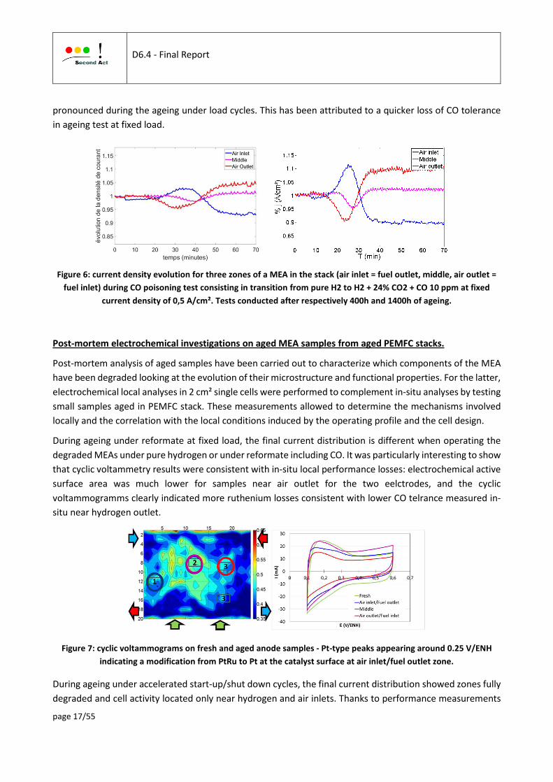
pronounced during the ageing under load cycles. This has been attributed to a quicker loss of CO tolerance
in ageing test at fixed load.
Figure 6: current density evolution for three zones of a MEA in the stack (air inlet = fuel outlet, middle, air outlet =
fuel inlet) during CO poisoning test consisting in transition from pure H2 to H2 + 24% CO2 + CO 10 ppm at fixed
current density of 0,5 A/cm². Tests conducted after respectively 400h and 1400h of ageing.
Post-mortem electrochemical investigations on aged MEA samples from aged PEMFC stacks.
Post-mortem analysis of aged samples have been carried out to characterize which components of the MEA
have been degraded looking at the evolution of their microstructure and functional properties. For the latter,
electrochemical local analyses in 2 cm² single cells were performed to complement in-situ analyses by testing
small samples aged in PEMFC stack. These measurements allowed to determine the mechanisms involved
locally and the correlation with the local conditions induced by the operating profile and the cell design.
During ageing under reformate at fixed load, the final current distribution is different when operating the
degraded MEAs under pure hydrogen or under reformate including CO. It was particularly interesting to show
that cyclic voltammetry results were consistent with in-situ local performance losses: electrochemical active
surface area was much lower for samples near air outlet for the two eelctrodes, and the cyclic
voltammogramms clearly indicated more ruthenium losses consistent with lower CO telrance measured in-
situ near hydrogen outlet.
Figure 7: cyclic voltammograms on fresh and aged anode samples - Pt-type peaks appearing around 0.25 V/ENH
indicating a modification from PtRu to Pt at the catalyst surface at air inlet/fuel outlet zone.
During ageing under accelerated start-up/shut down cycles, the final current distribution showed zones fully
degraded and cell activity located only near hydrogen and air inlets. Thanks to performance measurements

D6.4 - Final Report
page 18/55
on samples, the heterogeneities observed at end of test could be related to cathode degradation by carbon
corrosion, strong in the middle of the cell, only partial near hydrogen outlet and also to in-situ local
conditions, particularly oxygen partial pressure.
Figure 8: difference between the local current maps (in A / cm²) obtained after and before aging. After accelerated
SU/SD cycles - Stack operating point: 0.5 A / cm², conditions: 60 ° C, 50/50%RH, Sto H2 / air 1.5 / 2 (left side) -
Polarization curves and electrochemical impedance spectra at 0.6A / cm² obtained on samples from new MEA
(black curves) or different zones of an aged MEA. Conditions 60 ° C, 1.5 bar, 50% RH (right side).
Figure 9: Scanning electron microscopy images obtained from samples from new MEA or different areas of an aged
MEA. To be considered: densification of the cathode (top of the images) and platinum band in the membrane.
3.3.1.3. Ex-situ analysis of degradation mechanisms comparing pristine and aged
samples
Post-mortem ex-situ analyses of DMFC samples.
Major degradation effects were observed with ex-situ techniques XPS, XRD, EDX, TEM in the Parabolic (non-
uniform tuned electrodes with different compositions from air inlet to air outlet) and Uniform MEAs.
Apparently, major effects occur in the Uniform MEA. These include: local delamination of MPL/GDL at the
anode; increase of amount of carbon oxide in the anode likely associated with carbon corrosion; increase of
Csupport:Cionomer ration which indicates ionomer degradation also associated with reduction of F concentration.
The major degradation observed at the Parabolic sample is Pt crystallite growth which also occurs at the
Uniform sample.

D6.4 - Final Report
page 19/55
Figure 10: XPS analysis of DMFC electrodes. Atomic concentrations of C1s species identified in the analyzed DMFC
samples. Left: anode; Right: cathode.
Figure 11: Nanoparticle size histogramms of a) the Pristine and aged cathode of b) Parabolic and c) Uniform MEA in
the AIR IN and AIR OUT zones. d) and e) Comparaison of two aged MEA histograms analysed respectively in the AIR
IN and AIR OUT zones.

D6.4 - Final Report
page 20/55
Figure 12: Summary of degradation changes observed in the Uniform and Parabolic DMFC MEAs.
Post-mortem ex-situ analyses of PEMFC samples.
Analysis of hydrogen PEMFC MEA samples after ageing in Nedstack designed stacks.
Samples are analysed after ageing under stationary conditions in a 75 cells stack: 2 cells with higher
performance at end of test (25 and 26) and 2 cells with lower performance (71 and 72).
XPS results show an increased Csupport:Cionomer ratio indicating a loss of surface ionomer at the anode and
cathode for cells 71 and 72 but also for cell 26. This effect seems to be linked with a change of surface ionomer
composition of these samples which exhibit a significant reduction of the CF2:CF3 ratio.
XRD analysis was used to study the growth of particle size, or more specifically, of crystallite size. The
corresponding spectra. The relative growth is calculated for the different samples using four different Pt
peaks, showing growth of about 200%.
Figure 13: EOL single cell voltages of a NEDSTACK. MEAs 25, 26 and 71, 72 were analyzed in this section.

D6.4 - Final Report
page 21/55
Figure 14: XRD spectra of H2 PEMFC MEAs from a stack from NEDSTACK.
Analysis of reformate PEMFC MEA samples after ageing in CEA designed stacks.
The degradation of MEAs aged at CEA in short PEMFC stacks of 8 cells were analysed by TEM: after ageing
under reformate at fixed load and under load cycles, in the same zones as the ones studied by
electrochemical methods, one located near the air inlet/fuel outlet zone and the second located near the air
outlet/fuel inlet zone, compared to fresh sample.
Due to the strong heterogeneity PtRu particles , TEM analyses were not able to evidence any clear PtRu
nanoparticle microstructure and chemical evolution between the fresh and four aged anodes. However, as
observed in the similar aged MEA, Ru dissolution can be highlighted by the presence of Pt-Ru precipitates
within the membrane. PtRu precipitates were observed within the membrane in the four TEM samples; the
largest precipitates form a precipitate band at 6 or 8 µm far from the cathode, near the membrane
reinforcement, while smaller precipitates are observed up to the anode. The membrane precipitates
analyzed in the MEA aged under load cycles test are richer in Ru than the membrane precipitates analyzed
in the MEA aged under stationary conditions. Considering that the quantity of Ru present in the Pt-Ru
membrane precipitates is an indicator of the Ru dissolution rate of the PtRu anode catalyst, a raw calculation
taking into account the volume and the composition of the largest membrane precipitates can be made. This
calculation indicates that the Ru present in membrane precipitates located in the air inlet is also more than
twice time larger.

D6.4 - Final Report
page 22/55
a)
b)
c)
d)
Figure 15: Pt and Ru X-EDS elemental maps of membrane precipitates observed in a) and b) MEA aged under the
reference stationary durability test respectively in the air inlet and air outlet zones and in c) and d) MEA aged under
the reference load cycles test respectively in the air inlet and air outlet zones.
HAADF/STEM and X-EDS mapping analyses were performed on the Pt3Co catalyst at the cathode side. The
histograms of nanoparticle size measured in the fresh and aged MEAs in the air inlet and outlet zones reveal
a nanoparticle size increase in the aged samples. For the MEA aged under the stationary test quite similar
evolution between the air inlet and outlet zones is observed whereas for the MEA aged under the load cycles
test a larger particle size is observed in the air outlet zone. The histograms clearly suggest that nanoparticles
smaller than 5 nm are not stable.

D6.4 - Final Report
page 23/55
a)
b)
c)
d)
Figure 16: Histograms of the nanoparticle diameter size (in nm) a) for the MEA aged under the reference stationary
durability test and b) for the MEA aged under the reference load cycles test. c) and d) histograms built from the
two previous histograms by subtracting the fresh cathode histogram from the aged air outlet cathode histograms
showing that nanoparticles smaller than 5 nm are not stable.
Furthermore, in order to determine the cathode chemical composition evolution, X-EDS analyses were
performed in the fresh and aged cathodes. No variation on the global composition of the cathodes is
observed. However, the high resolution Pt and Co X-EDS elemental maps show a more significant evolution
of Pt3Co nanoparticle chemical structure in the air outlet zone: the Pt shell surrounding the Pt3Co
nanoparticle core resulting from a Co chemical leaching during nanoparticle synthesis process is increased
by aging, mainly at air outlet.

D6.4 - Final Report
page 24/55
Figure 17: X-EDS Pt and Co elemental maps associated with the line-scan of the Pt (in red) and Co (in green)
distribution through the nanoparticle of a) fresh cathode, b) and c) cathode aged under stationary test respectively
in air inlet and air outlet zones, d) and e) cathode aged under load cycles test respectively in air inlet and air outlet
zones.
Results showed an increase of thickness of the Pt shell around the Pt-Co partcicles: this could result from the
continuously Co dissolution during fuel cell operation but was more probably attributed to the
electrochemical Ostwald ripening mechanism, for which the smaller nanoparticles are oxidized and produced
ions migrating through the ionomer toward the larger nanoparticles where Pt ions are reduced at their
surface, but, because the negative Co2+/Co standard potential prevents Co ions reduction within the MEA.

D6.4 - Final Report
page 25/55
Consequently, for Pt3Co catalyst, the electrochemical Ostwald ripening mechanism leads to the dissolution
of smallest nanoparticles and the formation of a thicker Pt shell surrounding the larger nanoparticles. This
mechanism increases their size but also decreases their activity as Pt is less active than Pt3Co, and in addition
this mechanism leads to the contamination of the ionomer by the Co ions. As the dissolution of nanoparticles
smaller than 5 nm leads to the contamination of the ionomer by Co ions, more damaging than with pure Pt
catalysts, an optimized robust Pt3Co catalyst should not have nanoparticles smaller than 4-5 nm.
TEM analysis of the air inlet and air outlet of the cathodes aged under the two conditions clearly shows that
the electrochemical Ostwald ripening mechanism more largely occurred in the air outlet cathode zone than
in the air inlet cathode zone.
Figure 18: Scheme of the electrochemical Ostwald ripening mechanism considering Pt3Co nanoparticles. WP2
conclusive summary for the reporting period
3.3.2. Summary of modelling investigations
3.3.2.1. Modelling of reversisible and non-reversible mechanisms related to Pt based
catalysts
Platinum oxides formation / reduction modelling and validation (by DLR and POLIMI).
The experimental activities carried out during the first period of this project confirmed that the formation of
platinum oxides has a key role in the reversible degradation, as first shown with specifc experiments in DMFC
single cells, then confirmed by experiments conducted on PEMFC single cells and stacks.
It was indeed highlighted in previous study (Premium Act project) that temporary degradation occurs at both
anode and cathode electrodes and the most of it occurs at the cathode and can be recovered operating for
short periods at low cathode potentials. This behavior suggested as a possible explanation of cathode
temporary degradation in DMFC the Platinum oxides (PtOx) formation and reduction mechanism. Cathode
temporary voltage decay was investigated by means of dedicated and innovative OCV tests feeding the anode
with a mixture of methanol and hydrogen, in order to keep the anode potential negligible and constant in
time. The effect of potential has been deeply investigated with cyclic voltammetry (CV) tests, feeding
humidified hydrogen and nitrogen at anode and cathode, respectively. The CV procedure consists in holding
selected potential values for different times and scanning back, forth and back again the potential at a scan
rate of 25 mV/s, in order to highlight the area related to Platinum oxidation. CVs are reported for different
holding potential and the corresponding active area coverage, calculated on PtOH basis, assuming a single
electron transfer reaction. These results are coherent with the PtOx formation mechanism and highlight that
the onset potential of PtOx formation is around 0.63 V.

D6.4 - Final Report
page 26/55
Figure 19: CVs with different holding potential and active area coverage.
The main focus was to develop a model able to describe the platinum oxide formation and reduction kinetics
properly. The development of such a model is not only required to describe the reversible degradation, but
also for modeling the irreversible degradation by means of platinum dissolution and particle growth, since
platinum oxides affect the dissolution rates. Thus, taking into account the platinum oxide formation and
reduction is crucial to correctly predict the degradation rates under transient operating conditions, e.g.,
during an AST with fast potential cycling.
The platinum oxide kinetics can be studied using cyclic voltammetry (CV), since the current density peaks at
high potential are caused by the platinum oxide formation and reduction, respectively. Therefore, the first
goal of this work was to develop a model which is able to describe the experimentally observed CVs, in order
to ensure that the platinum oxide formation and reduction kinetics is described correctly. A special feature
of the model is the distinction between edge and planar sites of the platinum particle. Due to their different
energy, oxides will form on both sites with different kinetics.
The model has been validated with dedicated CV experiments performed at POLIMI. In these experiments
the potential was hold at various values for a certain holding time. Afterwards a cathodic sweep followed by
a full CV has been performed. During the hold at high potentials, the platinum oxide coverage increases,
which leads to an increased current density during the following cathodic sweep.
A good agreement between simulation and experiment is achieved. The model is able to describe the effect
of both, potential and holding time, on the platinum oxide formation. Furthermore, the reduction kinetics is
described accurately, as the typical shape of the CVs is correctly reproduced. Therefore, the model is suitable
to investigate the oxide formation and reduction during operation, e.g., to investigate the effect of the
refresh procedure.
E vs RHE / V
0.55 0.6 0.65 0.7 0.75 0.8 0.850
0.1
0.2
0.3
0.4
0.5
0.6
0.7
0.8
1 min Holding
0.55 0.650
0.03

D6.4 - Final Report
page 27/55
Figure 20: Comparison between CV experiment (symbols) and simulation (lines) for different holding potentials:
0.75V (green); 0.8V (blue); 0.85V (grey).
The loss of electrochemically active surface area (ECSA) on the cathode side is the main cause of irreversible
performance degradation. This loss of ECSA is related to a growth in the platinum particles. On the one hand,
the particle growth affects the oxide formation and reduction. On the other hand the oxide coverage also
affects the particle growth. Thus, both mechanisms are strongly coupled.
The model was shown able to predict the significantly increased degradation during the AST due to the
periodic reduction of the platinum oxides and the consequent increase of platinum dissolution rates.
During second period, more detailed experiments and models have been performed to enhance
understading of this mechanim. In addition, these PtOx mechanisms were included into a 2D cell model in
order to investigate the reversible and irreversible degradation.
Considering voltammetry measurements in inert conditions, the oxide coverage (calculated on a PtO-basis)
shows a clear exponential trend as upper potential limit increases. Instead, potentiostatic experiments in
inert conditions confirm that the longer is the holding time, the greater is the oxide reduction peaks. For long
holding times, two dominant peaks can be recognized: they are named for the sake of simplicity α-oxide (at
higher potentials) and β-oxide (at lower potentials). The presence of different oxides is further investigated
developing two different potentiodynamic tests in inert conditions.
In addition, a dedicated potentiodynamic experiment in-operando conditions has been setup in order to
evaluate the impact of Platinum oxides on PEMFC performance: different potential profiles composed by
cycling and/or holding are imposed in inert conditions and then a switch to in-operando conditions (H2/Air)
is performed to monitor cell performance.
Finally, in order to elucidate the relation between permanent and recoverable degradation phenomena
occurring at the cathode, two different Accelerated Stress Tests are proposed. The standard-AST consists in
30’000 potential cycles between 1 and 0.6 V at 50 mV s-1, while in the so-called beta-AST the lower potential
limit is raised to 0.7 V in order not to reduce β-oxide. The measurements evidence a reduced ECSA loss for

D6.4 - Final Report
page 28/55
beta-AST compared to the standard one. Hence, β-oxide coverage has a negative effect in terms of
recoverable performance loss, but it has a protective behavior against dissolution. During standard-AST, both
kind of oxides are continuously formed and reduced during each cycle, which is detrimental to Platinum
stability and may enhance dissolution phenomena. Thus, it is clear that Platinum oxides play a fundamental
role both in performance and durability PEMFC issues, hence an optimization strategy to find the best
compromise is required.
Figure 21: Linear sweep voltammetry after a variable number of cycles between 0.7 and 0.85 V (left) and effect of
Cycling and Holding on PEMFC performance, measured during in-operando potentiostatic tests (right).
In the second period a simplified platinum oxide model has been derived, in order to reduce the
computational cost while still being capable of describing the evolution of platinum oxide coverage. This
model has been validated with dedicated CV measurements which yield the evolution of the total oxide
coverage at various cathode potentials. The model is able to correctly describe the oxide evolution over the
whole potential range considered in the experiments. Due to the significantly reduced computational cost, it
was possible to couple this model with the detailed single cell models developed at DLR in order to investigate
the effect of platinum oxide formation on cell performance for DMFC and PEMFC. Furthermore, the model
was coupled with a platinum particle growth model to simulate the catalyst degradation in DMFC and PEMFC
in different degradation tests.
Figure 22: Comparison between experimental (symbols) and simulated (lines) coverage evolution.

D6.4 - Final Report
page 29/55
Contribution from CEA on Pt dissolution and deposition inside the membrane
Platinum of the catalyst layer can dissolve but also redeposit. Dissolution or re-deposition depends on particle
radius, on local electrochemical potential and on local platinum ions concentration. During this second period
of the project, the 1D MEA model of CEA (presented in deliverable D3.1) has been coupled with platinum and
re-deposition mechanisms module in order to analyze the platinum-band formation in the membrane.
A 1D model of the MEA in the “through thickness” direction was already available. This model computes the
local ionic and electronic potentials in the MEA, taking into account ORR and HOR. The model has been
improved in order to consider gases permeation through the membrane. Furthermore, a new
implementation of the electrochemical equations have been developed in order to be able to compute mixed
potentials in the MEA. The estimation of this “electrode” potential in the membrane is of little practical
interest for the computation of the MEA performance, but becomes crucial when it comes to predict the
possibility of platinum re-deposition. The developed approach allows to easily put multiple reactions in
competition as well as to account for the disappearance of given species, which is not possible with the
Nernst equation. The open-circuit voltage is not imposed anymore as an external parameter, but it is
computed taking into account gases permeation (mainly hydrogen) through the membrane and the resulting
mixed potential at the cathode.
Figure 23. Left: Dissolved oxygen and hydrogen profiles in the whole MEA. Right: “electrode” potential in the
membrane
This potential is also representative of the electrode potential, as at OCV the ionic potential is expected to
be constant over the membrane thickness. It appears that the oxygen affects strongly the “electrode
potential” in the membrane, as sharp drop appears when the oxygen concentration reaches zero. We can
expect that the over-potential for the platinum dissolution or re-deposition will also be affected by this
potential discontinuity.
Regarding the platinum dissolution and redeposition, the developed model takes into account five families
of particles, as well as the impact of particle radius on the free activation enthalpies of the dissolution
(oxidation) and re-deposition (reduction) reactions. The kinetics reaction are coupled with mass balance and
some geometric considerations in order to compute the evolution of particles size (and resulting platinum
surface) over time.

D6.4 - Final Report
page 30/55
It is interesting to observe that the re-deposition of Pt does not start at the membrane boundary with the
cathode, where the potential is too high due to oxygen presence, but only after around 5 µm (which
corresponds to the potential drop). The deposition leads to platinum apparition in the membrane.
Figure 24: Platinum band formation in the membrane
The platinum “band” appears toward the cathode, approximatively at ¼ of the membrane thickness. The fact
that platinum also redeposits close to the anode can be due to an overestimation of the platinum ions
diffusion in the membrane. The non-linearity compared to deposition rate comes from the fact that Pt surface
increases fasters in the regions where deposition rate is higher. In the simulation, platinum redeposition can
also be observed in the anode, where the particle size increases over time, and then stabilizes.
Reversible degradation due to CO poisoning (by CEA).
The MEA model takes into account gas transport, heat transfer, proton and electron migration and
electrolyte behaviour for the different layers of the MEA (GDL, MPL, CL and membrane). For the first period,
the model has been operated in 1D through the thickness of the MEA.
A CO poisoning model is superimposed to the performance model in order to simulate reversible
degradation. The reaction kinetic model for the anode is replaced by the comprehensive set of reactions
proposed by Shah and al. [16]. So 7 reactions, coupling CO poisoning with hydrogen oxidation and CO
oxidation are implemented: H2 adsorption at the anode; H2 electro-oxidation at the anode; CO adsorption
(and desorption) at the anode (reduction of available Pt sites); Electrochemical oxidation of CO at the anode
(increase of available Pt sites); Chemical oxidation of CO at the anode from oxygen cross-over, internal air-
bleeding (increase of available Pt sites).
In the model, we follow: H2, O2, CO concentrations (gas phase) and surface coverage. CO2 concentration is
not computed (assumed inert). Water production if taken into account but negligible compared to feeding
gases hydration. The effect of feeding the cell with hydrogen mixed with CO for a given duration can be
simulated.

D6.4 - Final Report
page 31/55
After a stabilization time, a few ppm of CO are injected for 2 hours before switching back to pure hydrogen.
Different level of CO concentration (from 5 to 60 ppm) are simulated. The simulations are performed at
constant 0.7V cell potential. The effect of CO is observed on the current density.
Figure 25: CO poisoning simulation
Even if not fully validated, the model gives some insight on the pollution mechanisms; progress had to be
made concerning the stabilization time under CO (very fast in the model) and the performance recovery
which is very slow in the model for full recovery.
The model allows also to investigate the CO pollution on the CL operation. For instance, the effect on current
distribution production through the thickness of the layer can be computed. It appears that the current
production is more homogeneous when feeding the cell with a few ppm of CO in the hydrogen. On the other
hand, the overpential for the hydrogen oxydation is shifted homogneously all over the layer.
3.3.2.1. Implementation of degradation mechanisms in performance models and
simulation of degradation and heterogeneities
The aim is to get more insight on the link between the local conditions in large cells, which depend on the
operating conditions and components properties, and the observed local performance and degradations in
order to provide recommendation for the design of optimized and robust components.
Single cell DMFC case (by POLIMI and DLR).
Modelling of DMFC at cell level.
A physically based DMFC cathode model has been developed in the fisrt period to simulate impedance and
performance. The model describes the impact of the methanol oxidation reaction (MOR) on the cathode
conditions. The current density distribution across the cathode CL has been described in OCV condition: this
internal current is greater at channel inlet, where the methanol crossover through the membrane is higher.

D6.4 - Final Report
page 32/55
A detailed description of cathode CL behavior is fundamental to reproduce in a representative way its
potential through the electrode and along the channel, which strongly influences both temporary and
permanent degradation mechanisms. The model qualitatively reproduce cathode potential along the channel
for different current densities.
Then, the integration of the degradation models has been developed in order to provide insights into the
heterogeneities evolution trough the MEA and along the channel.
In order to investigate the heterogeneities in a DMFC single cell, a two-dimensional two-phase
multicomponent cell model has been implemented in the new DLR fuel cell model, allowing the simulation
of flow and transport in porous media. The modelling domain is a cross-section of the DMFC single cell,
including anode and cathode gas diffusion layers (GDL), catalyst layers (CL) and the membrane.
Figure 26: Modeling Domain for the DMFC Cell Model in 2D
On the anode, water, methanol and carbon dioxide are the relevant species; on the cathode, oxygen and
nitrogen are additionally present in both phases. In the membrane domain diffusive transport and
electroosmotic drag are considered. All three subdomains, anode GDL/CL, membrane and cathode GDL/CL,
are coupled and water and methanol can crossover from one side to the other. In order to identify
heterogeneities, polarization curves for different configurations (co-flow/counter-flow) with varying
stoichiometry were simulated. In a co-flow configuration, cell inlet and cell outlet vary significantly in terms
of saturation and concentration.
The findings show that the 2D-model is able to capture general phenomena in the DMFC and delivers
reasonable results. However, it is highly dependent on the boundary conditions set for the simulations. In
order to find out how the saturations and concentrations of species distribute over the channel, a model with
a different setup (“along the channel”) has to be created as a next step. This “along the channel” model in
2D should incorporate a coupling of channel transport with GDL transport and be able to predict the
conditions within the DMFC single cell. Reversible and irreversible degradation models shall then be
integrated in this new 2D-model in order to study the effect of heterogeneities on DMFC degradation.

D6.4 - Final Report
page 33/55
The 1D+1D numerical model developed within Second Act project has been further used during the second
period of the project to provide an insight into DMFC local operation in order to design locally optimized
DMFC components. The model has been validated with respect to segmented cell data with different
configations, using the counter-flow with uniform and non-uniform catalyst loadings distribution. Results
allowed to propose a relevant parabolic distribution, and adapted air flow at cathode outlet to stringly reduce
heterogeneities.
The promising results achieved by means of model predictions have been validated with experimental data.
Figure 27: Simulated (left) and measured (right) local polarization curves with parabolic distribution of catalyst
layer and increased airflow
In order to confirm that modeling results obtained for a 25 cm2 DMFC can be extended to larger area,
dedicated experiments have been performed on a 180 cm2 DMFC with commercial flow fields (following EWII
commercial geometry). The local polarization curves of a 180 cm2 DMFC are consistent with the one obtained
for a smaller cell: cathode inlet segment generally suffers from dehydration, while cathode outlet is usually
working in limiting conditions, due to a low oxygen concentration. Moreover, cell dynamics between 25 cm2
and 180 cm2 DMFCs are analogous at both anode and cathode, resulting in similar Pt oxides formation and
reduction mechanism. In addition, also the local evolution of cathode ECSA (expressed as percentage
variation compared to the value at BoL) confirms that the trend is compatible with the same degradation
mechanisms.
Simulations of refresh procedure for DMFC.
A physically based, transient 2D cell model with an along-the-channel configuration was developed in the
DLR modeling framework NEOPARD-X in order to study the influence of local effects on cell performance
and reversible degradation in DMFC. The developed platinum oxide model was integrated into the 2D cell
model. Galvanostatic simulations were performed.
The DMFC operation at 0.25 A/cm² is periodically interrupted for a refresh procedure, which is performed to
recover reversible performance losses. The refresh procedure is a sequence of changing operating conditions
at the cathode: First, the load is switched off, then the air flow is stopped to reduce the platinum oxide
species, then air flow and current are switched on to return to the operation point. The voltage and current
density evolution during this refresh procedure have been simulated.

D6.4 - Final Report
page 34/55
Figure 28: Simulated voltage and current density evolution during refresh procedure
The changes in the cell and especially in the cathode catalyst layer (CCL) during this refresh sequence and the
initial phase of the next operating period are highly dynamic. Detailed simulations of the refresh procedure
with the 2D cell model have been performed to better understand those transient effects.
During air stop, the oxygen reduction reaction (ORR) continues at the CCL-PEM interface due to methanol
crossover from the anode. This leads to a full depletion of oxygen at cathode outlet, causing a drop of cathode
potential and complete reduction of the platinum oxides. As soon as there is no more oxygen available,
methanol accumulates in the cathode. At cathode inlet, a residual amount of oxygen remains in the CCL due
to steady diffusion of air from the inlet tube into the cell. That is why the platinum oxides are only partially
reduced at cathode inlet.
When the air flow is switched on, a reaction front moves through the CCL from inlet to outlet at the CL-MPL
interface. Methanol, which has accumulated during the air stop, gets oxidized when the inflowing oxygen
hits the CCL. This leads to strong heterogeneities in the local current densities at the initial phase of operation
at 0.25 A/cm². After this initial phase, when the species concentrations in the CCL have redistributed, the cell
returns to its nominal behavior at 0.25 A/cm². In the further course of operation, the formation of platinum
oxides dominates the cell behavior and logarithmic voltage decay over time can be observe.

D6.4 - Final Report
page 35/55
Figure 29: Oxygen reaction front in cathode CL at start of air flow and operation after refresh
Simulations of irreversible catalyst degradation for DMFC.
In order to investigate the irreversible catalyst degradation in DMFC, the developed platinum oxide model
has been coupled with a platinum particle growth model. Due to the complexity of the mechanisms occurring
in the DMFC during transient operation, a simplified approach is followed to simulate the 500h degradation
test performed at POLIMI. The platinum oxide coverages have been fixed at values which correspond to the
coverages reached 5 minutes after refresh at inlet and outlet conditions respectively. With these coverages
the cathode potential is hold at fixed 0.85V which corresponds to the average cathode potential at the
current density 0.25A/cm² used in the degradation tests. This simplification allows simulating the catalyst
degradation of the 500h degradation test in less than 20 minutes. The comparison of simulated and
measured ECSA-evolution shows good agreement in the ECSA loss at inlet and outlet is achieved. In addition
to the ECSA also the particle size distributions have been measured for the pristine cell and at end of the
degradation test, which allows for further validation of the degradation model.

D6.4 - Final Report
page 36/55
Figure 30: Comparison of simulated and measured ECSA loss during at cathode inlet and outlet during DMFC
degradation test
The comparison of simulated and measured PSD at inlet and outlet shows that good agreement is achieved
at the outlet, indicating that the observed ECSA loss is indeed mainly caused by the particle growth. On the
other hand at the inlet the particle growth seems to be slightly overestimated by the model which indicates
that another mechanism has contributed to the ECSA loss in this region of the cell.
Figure 31: Comparison of simulated and measured particle size distributions at DMFC inlet (left) and outlet (right)
PEMFC case at cell and stack level (by CEA)
A 2D cell model has been developed in order to estimate the local operating conditions at the channel/MEA
interface.
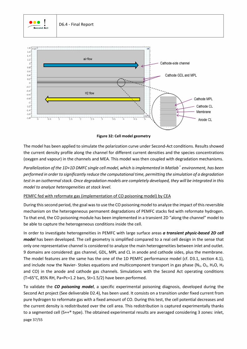
D6.4 - Final Report
page 37/55
Figure 32: Cell model geometry
The model has been applied to simulate the polarization curve under Second-Act conditions. Results showed
the current density profile along the channel for different current densities and the species concentrations
(oxygen and vapour) in the channels and MEA. This model was then coupled with degradation mechanisms.
Parallelization of the 1D+1D DMFC single cell model, which is implemented in Matlab® environment, has been
performed in order to significantly reduce the computational time, permitting the simulation of a degradation
test in an isothermal stack. Once degradation models are completely developed, they will be integrated in this
model to analyze heterogeneities at stack level.
PEMFC fed with reformate gas (implementation of CO poisoning model) by CEA
During this second period, the goal was to use the CO poisoning model to analyze the impact of this reversible
mechanism on the heterogeneous permanent degradations of PEMFC stacks fed with reformate hydrogen.
To that end, the CO poisoning module has been implemented in a transient 2D “along the channel” model to
be able to capture the heterogeneous conditions inside the cell.
In order to investigate heterogeneities in PEMFC with large surface areas a transient physic-based 2D cell
model has been developed. The cell geometry is simplified compared to a real cell design in the sense that
only one representative channel is considered to analyze the main heterogeneities between inlet and outlet.
9 domains are considered: gas channel, GDL, MPL and CL in anode and cathode sides, plus the membrane.
The model features are the same has the one of the 1D PEMFC performance model (cf. D3.1, section 4.1),
and include now the Navier- Stokes equations and multicomponent transport in gas phase (N2, O2, H2O, H2
and CO) in the anode and cathode gas channels. Simulations with the Second Act operating conditions
(T=65°C, 85% RH, Pa=Pc=1.2 bars, St=1.5/2) have been performed.
To validate the CO poisoning model, a specific experimental poisoning diagnosis, developed during the
Second Act project (See deliverable D2.4), has been used. It consists on a transition under fixed current from
pure hydrogen to reformate gas with a fixed amount of CO. During this test, the cell potential decreases and
the current density is redistributed over the cell area. This redistribution is captured experimentally thanks
to a segmented cell (S++® type). The obtained experimental results are averaged considering 3 zones: inlet,

D6.4 - Final Report
page 38/55
middle and outlet. The obtained current density maps allow to follow the progressive effect of the CO
poisoning on the redistribution of the local current. This transient behavior is well captured by the developed
model.
Figure 33 - Evolution of the current densities during a transition from pure hydrogen to reformate gas with 10 ppm
of CO. Left: Definition of the averaging zones. Middle: Experimental results. Right: Simulation results
Furthermore, with the transient 2D model, we have access to the local physical quantities in the different
compartments of the cell during the propagation of the CO front, particularly the evolution of the anode and
cathode potentials during this poisoning diagnosis. The reversible loss of performance induced by the CO
poisoning has a clear impact on the cell heterogeneities and this redistribution can be well understood thanks
to the 2D model.
The developed model has then been used to investigate degradation heterogeneities in reformate conditions
for an ageing test in short stacks of 8 large area (220 cm²) cells conducted under constant load. The
simulations give further insights to analyze the local conditions between pure hydrogen and reformate with
CO to try to understand the phenomena at the origin of the different aging behavior observed in stack tests
in WP2 between PEMFC fed with pure H2 and those fed with reformate with ppm of CO. The analysis has
also been supported with electrochemical and microscopy post-mortem analysis of the aged MEAs.
The local physical quantities (exchange current densities, concentrations, local potentials,..) in the anode and
cathode for pure hydrogen or reformate with 10ppm of CO have been compared. Finally, our main
conclusions are that under reformate:
- the anode potential is higher and more heterogeneous between inlet and outlet,
- the cathode potential is higher at the cathode inlet and during CO transient,
- the current density and thus the water production is higher at the cathode outlet

D6.4 - Final Report
page 39/55
Figure 34 – Comparison of electrodes potentials (left and middle) and current density (right) under pure hydrogen
and reformate with 10 ppm of CO
At the anode, the high potential at the anode outlet due to heterogeneous CO coverage promotes the Ru
dissolution in this zone which increases the current density shift towards the anode inlet. Because of the CO
poisoning in the anode outlet, the cathode has its highest current density at the outlet, where its potential is
the lowest. This implies more local water in this zone, which promotes the Oswald degradation mechanisms.
Since the Co ions do not redepose, they pollute the cathode ionomer at the outlet, increasing the local
overpotential and the catalyst degradation. Given these observations, optimized MEAs have been designed,
by varying the catalyst loading and its composition. These MEAs have been tested at stack level,
demonstrating a clear improvement of the MEA durability.
As conclusion, coupling CO poisoning at the anode with a transient 2D performance cell model allowed to
have access to the local conditions in the different compartments of the cell. Coupled to experimental local
observations, they provided useful information to analyze the degradation mechanisms responsible of the
strong performance decay observed in PEMFC cells fed with reformate gas and run under constant current.
PEMFC fed with pure hydrogen (implementation of cathode catalyst degradation models) by DLR
The catalyst degradation model developed at DLR has also been applied to simulate various degradation
tests for PEMFC, coupling the degradation model with a PEMFC transient 2D cell model which includes the
relevant mechanisms to describe the cell behaviour.
The coupled cell model and degradation model has then be used to simulate the degradation during the
standard catalyst degradation AST, which consists of potential cycles between 0.6V and 1.0V with a duration
of 16s per cycle. Simulating this AST is computationally demanding since it is highly dynamic. Therefore, only
the first 1000 cycles of the AST performed at POLIMI have been simulated. The very fast initial drop of the
ECSA is explained by the dissolution of the smallest, very unstable particles (≤1nm) which almost completely
vanish within the first few cycles. Afterwards the degradation slows down due to the growth and consequent
stabilization of the particles. The ECSA loss mainly occurs during the short high potential periods, because
the platinum oxides have been reduced during the previous low potential periods and therefore the platinum
dissolution at high potential is accelerated.

D6.4 - Final Report
page 40/55
The model has also been used to simulate an ageing test at constant load. The 800h PEMFC degradation
test performed at DLR in which the load was hold constant at 0.5A/cm² at 65°C and 80%RH has been
considered. Stronger heterogeneities with higher ECSA loss close to the membrane are obtained for the long
term test, due to stronger gradients in the electrode potential and water concentration under normal
operation compared to the more homogeneous distributions during the AST.
Figure 35: Comparison between measured and simulated change of ECSA during AST (left). ECSA loss mainly occurs
during the high potential periods (right).
Figure 36: Simulated local ECSA after 1000 AST cycles (left) and simulated local ECSA after 800h long term test
(right)
Simulation and prediction of heterogeneities at stack level
Model of PEMFC stack case by CEA.
For PEMFC, a multi-cell “3D” stack model has been developed during the second period of the project,
starting from a 2D model based on an equivalent single-cell representation. With the multi-cell model, it is
possible to simulate simultaneously different cells of a stack, including their thermal and electrical coupling.
After a model verification with a failure-free stack, two kind of defaults have been investigated: a default in
the catalyst effective surface or activity and a default in the air feeding of one cell. It has been shown that,
even though the considered default can affect very strongly the considered cells, neighboring cells are only
weekly affected. No long range default propagation could be observed for the considered defaults.

D6.4 - Final Report
page 41/55
Model of DMFC large cell case by POLIMI.
For DMFC technology, due to the limited experimental work performed at stack level and considering that in
Task 3.3 it has been demonstrated that the operation of 25 cm2 and 180 cm2 DMFC is similar, stack model
simply reduces to parallel 25 cm2 cell models without defaults propagation. The 1D+1D cell performance
model includes all the main physical phenomena and minimizes the number of fitting parameters and
computation time in order to be validated over a wide range of operating conditions, being an effective tool
for components design and optimization. A detailed description of the model can be found in deliverable
D3.2. During the second period of the project the model has been improved introducing in the original model
an iterative algorithm that permits to solve counter-flow configuration for anode and cathode feeding. The
local simulation results are then averaged in geometrical consistence with the four macro-segments of the
segmented cell hardware, in order to reproduce the local results coming from the experimental activity.
Moreover, since local water concentration is of crucial importance in determining cell performance,
correlations have been developed and used to take into accout flooding and dehydration effects on
performance.
The model simulations reproduce local experiments with acceptable accuracy. It is worth noting that it is not
possible to reproduce the local polarization curves without considering dehydration and flooding effects, that
play a crucial role in determining local cell performance. The model is also able to reproduce experiments
varing airflow and relative umidity at cathode, further confirming that it can be used as a tool for component
design and optimization.
Figure 37: Comparison between simulated (left) and measured (right) local polarization curves in counter-flow.
3.3.3. Summary of durability improvements results
Two generations of improvements have been implemented on MEA level. The overall target has been to
understand and in this way minimise degradation (both ir- and reversible degradation) without increasing
cost. Several initiatives have been explored as described below.

D6.4 - Final Report
page 42/55
For second generation MEAs, with uniform electrodes, new materials have been implemented: mainly new
catalyst with more graphitised carbon support for all technologies; other GDLs for pure hydrogen operation
in power stacks and at lesser extent, a novel additive (cobalt porphyrin) to anode catalyst for reformate case.
The third generation MEAs were made with selected materials and non uniform electrodes, with optimized
compositions cathode side and for some cases also anode side to decrease heterogeneities and degradation
rates. Reference or Improved components weer also coupled with specific operating conditions or strategy
for enhanced stability.
3.3.3.1. DMFC and PEMFC single cell tests with tuned operation strategies and
improved MEAs
Results obtained from single cells to stacks with the improved cathode implemented to reduce particularly
reversible losses and then permanent degradation associated to the type of catalyst actually proved more
stable performance for all types of fuel (DMFC and PEMFC cases). Improvement related to refresh procedures
was also even more important with parabolic MEAs, locally tuned.
Effect of refresh on uniform and parabolic MEA in PEMFC single cells (25 cm²).
For PEMFC, three refresh strategies have been tested: High-Current Refresh not allowing a full recovery from
temporary degradation losses; Short Refresh very quick (about 2 minutes) and more effective than the High-
Current Refresh yet it does not recover the Beginning of Test performance; Long Refresh (several hours)
allowing a full recovery of the Beginning of Test performance, excluding the onset of permanent losses.
Long Refresh strategy has been selected as the standard method to recover temporary degradation losses.
Figure 38: Comparison of durability test of reference MEA (1G) and improved MEA CAT13 (2G) performed in a 25
cm2 single cell at DLR.

D6.4 - Final Report
page 43/55
Figure 39. Voltage/Time diagram. Total test duration: 762 h at fixed current density (0.5 A/cm2). Long refresh
procedure performed every 127 h. Comparison between UNF sample (blue) and PRB sample (red). Markers highlight
the initial performance after long refresh.
Effect of refresh on MEA in DMFC single cells.
For DMFC, refresh strategy has been optimized for small and large single cells (with the commercial size
segmented single cell specifically developed for the validation of DMFC components and local operation).
Comparison of uniform and parabolic MEA during ageing in PEMFC single cell (25 cm²).
The strongly heterogeneous degradation is mostly recovered with procedures primarily intended to recover
temporary degradation (such as the full refresh performed every 100 h to perform local diagnostics), pointing
out the existence of a recoverable contribution to degradation heterogeneity as well as a permanent one:
current decrease at cathode outlet, is compensated by current produced in the remaining areas ensuring a
galvanostatic operation.

D6.4 - Final Report
page 44/55
Figure 40. Voltage (A) and current density distribution (B) during 500-h degradation test for parabolic gradient MEA
Comparison of uniform and parabolic MEA during ageing in DMFC single cell (180 cm²).
In the large size single cell, interruption every 100 hours are applied with the aim to recover temporary
degradation and to perform the diagnostic phase. Both higher temporary and permanent degradation rates
are observed, with a stronger heterogeneous operation attributed to local inhomogeneity in operating
conditions enhanced by the large dimension (like in large size PEMFC cells). Concerning the whole
degradation test, local current distribution undergoes deep modifications.
Figure 41. Voltage (A) and current density distribution (B) during 600-h degradation test for parabolic gradient
mxSFC MEA
A B
λc=3.25 λ
c=3.5

D6.4 - Final Report
page 45/55
3.3.3.2. PEMFC stacks test with tuned operation strategies and improved MEAs
Performance of New MEA types in hydrogen fuelled PEMFC stacks at Nedstack
New MEAs with improved cathode material or different GDLs could be validated at stack level, confirming
the gain in stability and durability for PEMFC Nedstack aged under pure hydrogen at Nedsatck and also
reformate at ICI. New MEAs showed wether better performance and higher recovery at the end of ageing,
or lower reversible decay under hydrogen and higher CO tolerance and endurance under reformate.
In parallel, and following conclusions of previous project Stayers, improved gaskets type were developed and
manufactured in pilot and production volumes respectively for the gas and coolant gaskets for Nedstack
stacks. These improved materials were tested in the Second Act full stacks that have been evaluated for
durability in field tests.
Figure 42 Operation of first improved type supplied by EWII MEP0122 and final improved types MEP0210 and -211 at
Pilot plant facilities after <2khrs � MEP0210 is clearly showing a performance that is several mV in cell voltage higher
and also shows a high recovery at the end. MEP0211 seems to have the lowest reversible decay.

D6.4 - Final Report
page 46/55
Figure 43. Nedstack S0335 voltage, current and CO trends (left) - S0285 & S0335 voltage VS. CO amount (right)
Locally improved MEAs for better durability of PEMFC stack (CEA designed 220 cm²)
After ageing in stacks under specific procedures, tuned local compositions were proposed to optimize local
operation of MEAs and compensate local degradation mechanisms identified thanks to in-situ current
distribution during ageing, post-mortem analyses and modelling results. MEAs were locally modified by
changing in some zones both anode and cathode catalyst layers compositions.
Locally improved reformate MEAs for fixed load operation in PEMFC stack (CEA 220 cm²)
For reformate case, new MEAs were made to improve particularly their tolerance to carbon monoxide near
hydrogen outlet and cathode catalyst stability towards dissolution, particularly avoinding contamination of
ionomer by cobalt ions near air outlet, that were major mechanisms leading to excessive and quick
performance decrease at fixed load. Results actually showed improved voltage stability allowing to more
than double durability compared to the reference test with ten time lower decay rates.
a) b)
Figure 44. Voltage evolution for the two stacks made with reference homogeneous electrodes (Reference MEA) and
with optimized electrodes (Locally modified MEA) (a) – Degradation rates for the two stacks (b).

D6.4 - Final Report
page 47/55
Locally improved hydrogen MEAs for start-up/shut-down operation in PEMFC stack (CEA 220 cm²)
To improve endurance towards accelerated start-up/shut-down cycles, new MEAs were made to improve
particularly their tolerance to carbon corrosion in the middle zone of the MEAs, where activity was totally
lost. Lower platinum loading anode side and graphitized carbon cathode side were used. Results
demonstrated actual improvement decreasing the losses in performance and in the electrochemical active
area by five.
Figure 45. Initial and final polarization curves (post 70 accelerated stop-start cycles) at 60°C, 1.5 bar, RH 50/50%,
Stoichiometry H2/ air 1.5/2 (left) - Evolution of the relative decrease in surface areas for the two types of stacks
with reference homogeneous MEAs (red and blue) and with locally improved MEAs (green) (right).
Hydrogen PEMFC stability improved vs. reversible losses with air starvation strategy
The selected operation strategy was to cause regular air starvation periods by reducing for short periods the
air stoichiometry during the ageing. The method could actually act as prevention mean for the formation of
the platinum oxides as expected. An important result of this study is to have shown that irreversible damage
was not affected by 2000 hours spent under air starvation.
Figure 46. Evolution of the average voltage of cells on almost 5000 h during ageing steps under H2/air at fixed load
(left) and passage from a step without air starvation to a step under air starvation (right) showing the slope
inversion on the voltage at the beginning of the step.

D6.4 - Final Report
page 48/55
3.3.4. General conclusion of the scientific and technological results
The main conclusion of the Second Act project is the demonstration that locally optimized electrodes and
tuned operating conditions or strategies, as defined based on advanced investigations of degradation
coupling in-situ and ex-situ experimental analyses and modelling can actually lead to durability
improvements at stack level applicable in the systems.
3.3.5. Exploitation of the scientific and technological results planned
The possible exploitation of the project Second Act results is summarized for the industry partners.
EWII MEAs
Due to the Second Act project EWII has developed several new generations of MEAs. One of the improved
MEAs can tolerate the gas composition that is generated by the reformer. This gas contains significant
amount of CO (up to 30 ppm) that negatively affected the former type of MEA. Another very important result
of Second Act is the graduated cathodes that hold a much more uniform current density and is believed to
possess significantly improved durability. The Second Act work has resulted in significantly improved MEAs
that show excellent performance and very low degradation rates. As for the previous generation of MEAs the
new type can be manufactured in all sizes using the EWII production technology.
NEDSTACK Fuel Cell Stack
Within Second Act, NEDSTACK developed full-size 10 kWe fuel cell stacks, using two variations of EWII MEAs:
pure hydrogen and reformate. The hydrogen stacks have extensively been tested by Nedstack, while the
reformate stacks have been tested by Nedstack and ICI.
Several iterations of stacks were tested with pure hydrogen for durability, each time showing improved
performance. The iterations produced at the end of the project are considered promising, but have only
achieved limited cumulative operating time. Hence, further durability testing is required. Tests will continue
and will to allow for final evaluation in the beginning of 2018.
Apart from durability tests in an industrial CHP system, stacks were also assessed for other applications and
were found to be versatile, also allowing applications outside the CHP area.
Also the second iteration of reformate stacks showed to be adequate, though not performing on par with
the benchmark, indicating further development in this field is required.
ICI CHP system
Within Second Act, NEDSTACK developed in conjunction with EWII (MEAs) the Full Stacks, which have been
integrated into ICI CHP system. In this Full Stack module (FCS-5) LT-PEM MEAs have been implemented. The
module has an output of 3 kW electrical power and is liquid cooled. The stack module is suitable for reformate
from reforming of natural gas or pure hydrogen. As it could be shown within Second Act, these LT-PEM full
stacks can be used for CHP applications, which are the unique selling point. The Second Act LT-PEM fuel cell
module is at prototype level and needs development for stability, robustness and lifetime in CHP application.
To improve the development of LT-PEM fuel cell stacks, further research projects are needed.

D6.4 - Final Report
page 49/55
Thanks to the higher CO tolerance of FCS-5, the whole CHP system became more stable and able to work
with reformate syngas. The CO instability caused by system perturbations (like transient between different
load, natural gas pressure variation in the grid, etc.) are now better tolerate by the stack and consequentially
by the whole system. This higher tolerance permits an easier control and longer operational lifetime and in
the end a reduction of production cost, maintenance and operation. Further research is still necessary for
the obtainment of a more competitive CHP system.
3.3.6. Dissemination
In order to openly communicate project results to the scientific community and the general public the
members of the consortium provided 25 conference contributions during the second period of the project.
Moreover, since mid-term review 11 articles in scientific journal have been published or submitted. Both, the
conferences and the journal papers since mid- term report are listed in the following.
A common patent by EWII and Polimi was applied.
Conference and Workshop Contributions:
1. I. Profatilova, S. Escribano, L. Guétaz, D. Thoby, B. Hladys and P.-A. Jacques (CEA), Deep insight into
degradation of a PEMFC in reformate hydrogen for stationary applications, 2017 Fuel Cell Seminar and
Energy Exposition, Long Beach, California, 07.11-09.11, 2017.
2. A. Casalegno, A. Baricci, M. Zago (Polimi): Experimental and Physically Based Modelling Analysis of
Electrochemical Impedance in PEMFC to Interpret Performance Degradation Causes; 232nd ECS Meeting
2017, 5.10.2017, National Habor, MD, USA
3. T. Jahnke, G. Futter, A. Latz (DLR), „A transient 2D PEMFC model to investigate cell performance and
degradation”, 647. WE-Heraeus-Seminar, 02.07.-05.07.2017, Bad Honnef, Germany
4. A. Baricci (Polimi), M. Zago (Polimi), T. Jahnke (DLR), A. Casalegno (Polimi): Effect of Platinum Oxides on
reversible and irreversible degradation in Polymer Electrolyte Fuel Cells; 6th European PEFC & Electrolyser
forum, 4-7.07.2017, Lucerne, Switzerland
5. C. Rabissi (Polimi), M. Zago (Polimi), M. Odgaard (EWII), L. Grahl-Madsen (EWII), A. Casalegno (Polimi):
Improved durability in DMFC: local optimization of catalyst layers; 6th European PEFC & Electrolyser
forum, 4-7.07.2017, Lucerne, Switzerland
6. S. Escribano, F. Micoud, A. Finkler, H. Lafôret, L. Guetaz & M. Chandesris (CEA), Impact of the operation
modes on the reversible and non-reversible degradation mechanisms of a PEMFC, 6th European PEFC &
Electrolyser forum, Lucerne, Switzerland, 04.07-07.07, 2017
7. T. Jahnke, G. Futter, A. Latz (DLR), „A transient 2D PEMFC model to investigate cell performance and
degradation”, 20th Topical Meeting of the International Society of Electrochemistry, 19.03-22.03.2017,
Buenos Aires, Argentina
8. M.-D. Baum (DLR), C. Rabissi (Polimi), A. Casalegno (Polimi), A. Latz (DLR) and T. Jahnke (DLR): Analysis of
local heterogeneities and their effect on DMFC performance with a physical 2D cell model; 14th

D6.4 - Final Report
page 50/55
Symposium on Fuel Cell and Battery Modelling and Experimental Validation; 02.03. – 03.03.2017;
Karlsruhe, Germany
9. C. Rabissi, A. Casalegno, M. Zago (Polimi): Local degradation analysis in DMFC, SECOND-ACT PUBLIC
WORKSHOP ON DURABILITY ISSUES IN PEMDC AND DMFC (@FDFC 2017), 31.01.2017, Stuttgart,
Germany
10. S. Escribano (CEA), Investigation of PEMFC degradation during ageing tests on stack under pure hydrogen
or reformate, Second Act Workshop, Stuttgart, Germany, 30.01, 2017
11. M. Chandesris & L. Guétaz (CEA), Simulation and characterization of degradation mechanisms for PEMFC
electrodes aged under reformate, Second Act Workshop, , Stuttgart, Germany, 30.01, 2017.
12. M.-D. Baum (DLR), C. Rabissi (Polimi), A. Casalegno (Polimi), A. Latz (DLR) and T. Jahnke (DLR):
Identification of local heterogeneities in direct methanol fuel cells with a physical 2D model; 7th
International Conference on Fundamentals and Development of Fuel Cells; 30.01. – 03.02.2017;
Stuttgart, Germany
13. M. Chandesris, L. Guetaz, P. Schott & S. Escribano (CEA), A transient 2D PEMFC cell model to investigate
degradation heterogeneities in reformate conditions 7th international conference on Fundamentals and
Development of Fuel Cells, FDFC, Stuttgart, Germany, 31.01.-02.02, 2017
14. S. Escribano, A. Finkler, M. Chandesris, L. Guétaz (CEA); Local Investigations of Membrane Electrode
Assemblies’ Degradation During and After Ageing in PEMFC Stacks Operated Under Reformate; 7th
International Conference on Fundamentals And Developments of Fuel Cells (FDFC), Stuttgart, Germany,
31.01.-02.02.2017.
15. P. Gazdzicki, J. Mitzel, A. Dreizler, M. Schulze, K. A. Friedrich, Degradation of PEMFC at low loadings, 7th
International Conference on Fundamentals And Developments of Fuel Cells (FDFC), Stuttgart, Germany,
31.01.-02.02.2017.
16. M.-D. Baum, A. Latz , T. Jahnke (DLR): Understanding heterogeneities in DirectMethanol Fuel Cells – A
modelling approach; 13th Symposium on Modeling & Experimental Validation of Fuel Cells, Batteries &
Electrolysers, 22.03.-23.03.2016; Lausanne, Switzerland
17. M. Chandesris, L. Guetaz, P. Schott, J.-P. Poirot-Crouvezier & S. Escribano (CEA) Investigation of
degradation heterogeneities in PEMFC stacks combining local in-situ measurements, post-mortem
analysis and multiphysic simulation 67th Annual Meeting of the Int. Soc. Electrochemistry, ISE, The
Hague, Netherland, 21.08-26.08, 2016
18. S. Escribano, A. Finkler, M. Chandesris, L. Guétaz (CEA), Further understanding of PEMFC stack
degradation thanks to in situ local measurements Fuel Cells Gordon Research Conference, Stone Hill
College, North Easton, USA, 07.08-12.8, 2016
19. P. Gazdzicki, M. Schulze, K. A. Friedrich, Durability Testing of Polymer Electrolyte Fuel Cells Under
Stationary and Automotive Conditions, 229th ECS Meeting, San Diego, USA (06/2016)

D6.4 - Final Report
page 51/55
20. A. Casalegno, A. Baricci, M. Zago (Polimi): Coupling experiments and models to interpret degradation in
polymer electrolyte fuel cell; THERMEC 2016 International Conference on Processing & Manufacturing
of Advanced Materials Processing, Fabrication, Properties, Applications, 30.05.2016, Graz, Austria
21. I. Profatilova, S. Escribano, L. Guétaz, B. Hladys and P.-A. Jacques (CEA), Towards cheaper fuel:
degradation of a PEMFC in reformate hydrogen, EMN Meeting on Fuel Cells, Energy Materials and
Nanotechnology, Jeju Island, South Korea, 23.05-27.05, 2016
22. C. Rabissi, M. Zago, A. Casalegno (Polimi): Investigation of localized temporary and permanent
degradation in PEMFC; FUEL CELLS SCIENCE AND TECHNOLOGY (FUCE) 2016, 13-14.04.2016, Glasgow,
United Kingdom
23. M. Chandesris & P. Schott (CEA), T. Jahnke & M.-D. Baum (DLR), T. A. Aarhaug (SINTEF), M. Zago & A.
Casalegno (Polimi), Investigation of permanent and reversible degradations in PEMFC and DMFC
stationary applications using statistical and modelling tools, 13th Symposium on fuel cell and battery
modeling and experimental validation, Modval13, Lausanne, EPFL, 22.03-23.03, 2016
24. C. Rabissi (Polimi), J. L. Bonde (EWII), E. Brightman, G. Hinds and A. Casalegno (Polimi): Novel macro-
Segmented Fuel Cell approach to investigation of localized degradation in PEMFCs, EUROPEAN FUEL CELL
(EFC) 2015, 16-18.12.2015, Napoli, Italy
25. M. Zago, A. Baricci, A. Casalegno (Polimi): Physical modelling of cathode impedance in low temperature
fuel cells, EUROPEAN FUEL CELL (EFC) 2015, 16-18.12.2015, Napoli, Italy
Articles in scientific journals:
1. Marion Chandesris, Laure Guétaz, Pascal Schott and Sylvie Escribano (CEA) "Investigation of
degradations heterogeneities in PEMFC stack aged under reformate coupling in situ diagnosis, post-
mortem ex situ analyses and multi-physic simulations" (submitted to JES dec. 2017)
2. I. Profatilova, P. A. Jacques, D. Thoby and S. Escribano (CEA, LITEN): Impact of Electrochemical Pre-
Treatment Step on Accelerated Ageing of Membrane Under Ocv Protocol in Polymer Electrolyte
Membrane Fuel Cell, (Submitted to ECS trans, Dec 2017)
3. Claudio Rabissi (Polimi), E. Brightman, G. Hinds, A. Casalegno (Polimi), Mitigating temporary
degradation of direct methanol fuel cell via operando measurement of localised cathode potential.
International Journal Of Hydrogen Energy; (submitted 2017)
4. Thomas Jahnke (DLR), Matteo Zago (Polimi), Andrea Casalegno (Polimi), Wolfgang G. Bessler, Arnulf
Latz- A transient multi-scale model for direct methanol fuel cells, Electrochimica Acta (2017) 232, pp.
215-225
5. Bodner M, Schenk A, Salaberger D, Rami M, Hochenauer C, Hacker V.: Air Starvation Induced
Degradation in Polymer Electrolyte Fuel Cells. Fuel Cells. 2017 Feb 2;17(1):18-26. Available from, DOI:
10.1002/fuce.201600132

D6.4 - Final Report
page 52/55
6. Matteo Zago (Polimi), Andrea Bisello (Polimi), Andrea Baricci (Polimi), Claudio Rabissi (Polimi),
Edward Brightman, Gareth Hinds, Andrea Casalegno (Polimi) On the actual cathode mixed potential
in direct methanol fuel cells, Journal of Power Sources (2016) 325, pp 714-722
7. Bodner M, Rami M, Marius B, Schenk A, Hacker V.: Determining Membrane Degradation in Polymer
Electrolyte Fuel Cells by Effluent Water Analysis. ECS transactions. 2016 Sep 23;75(14):703-706.
Available from, DOI: 10.1149/07514.0703ecst
8. Bodner M, Schenk A, Marius B, Rami M, Hacker V.: Air Starvation Accelerated Stress Tests in Polymer
Electrolyte Fuel Cells. ECS transactions. 2016 Sep 23; 75(14):769-776. Available from, DOI:
10.1149/07514.0769ecst
9. Bodner M, Cermenek B, Hacker V.The effect of platinum electrocatalyst on membrane degradation in
polymer electrolyte fuel cells. Membranes 2015, 5(4), 888-902
10. Merit Bodner; Christoph Hochenauer; Viktor Hacker (TU Graz), Effect of pinhole location on
degradation in polymer electrolyte fuel cells. Journal of Power Sources (2015) 295, S. 336 – 348
11. Bodner M, Hofer A, Hacker V.: H2 generation from alkaline elctrolyzer. Wiley interdisciplinary reviews
/ Energy and enviroment [Electr. Res.]. 2015; (4):365- 381. Available from: 10.1002/wene.150
Internal workshop:
In order to share results obtained in the SecondAct related to fuel cell degradation mechanisms and
processes and to discuss these results with experts and stakeholders an internal workshop on “Durability
Issues in PEMFC and DMFC” was organized on 19th May 2016 in Milan, Italy, with POLIMI acting as the local
organizer. Thereby both technologies, PEMFC and DMFC, are of interest since they are affected by common
issues. Moreover, contributions focusing on stationary as well as on automotive applications have been
planned. All invited participants have been encouraged to share their results as presentations and discuss
them in the frame of the workshop. The workshop was targeted at 4 talks by SecondAct partners and 8 talks
by invited speakers to be given during a single day. 27 people from Europe participated in the workshop, see
D5.4. The Programme is provided in Figure 47.

D6.4 - Final Report
page 53/55
Figure 47: Programme of SecondAct internal workshop
International workshop:
A goal agreed in the frame of SecondAct’s dissemination activity was to share results on problems related to
degradation of low temperature fuel cells and limitation of their lifetime. Thereby both technologies, PEMFC
and DMFC, are of interest since they are affected by common issues.
In this context an international public workshop on Durability Issues in PEMFC and DMFC was organized by
the SecondAct consortium on 30th January 2017 in the conference room “Reutlingen” in “Haus der
Wirtschaft” in the center of Stuttgart, Germany. Moreover, contributions focusing on stationary as well as

D6.4 - Final Report
page 54/55
on automotive applications have been considered. All invited participants have been encouraged to share
their results as presentations and discuss them in the frame of the workshop.
In order to address a broad audience and to assure a high number of participants the workshop was
organized in Stuttgart in the frame of the international FDFC conference taking place in “Haus der
Wirtschaft” as well. The workshop was scheduled one day before the official start of the conference. DLR
was responsible for the local organization. The workshop was attended by 26 participants, see D5.5. The
Programme is provided in Figure 48.
Figure 48: Programme of SecondAct international workshop.
Contact to other EU projects and National projects (M1-M36)
The SecondAct consortium interacts with past and on-going EU projects that focus in MEA durability
improvement to exchange ideas and profit from on-going developments. A List of EU-projects that cooperate
with SecondAct are listed in the following.

D6.4 - Final Report
page 55/55
Table 2: List of projects cooperating with SecondAct
PremiumAct Knowledge on methodology and protocols for degradation testing for H2PEM,
Reformate PEM and DMFC
Keepemalive Knowledge on methodology and protocols for degradation testing of PEMFC for
stationary applications
Stayers Knowledge on methodology and protocols for degradation testing of PEMFC for
stationary applications
Pumamind Methodology and knowledge for fuel cell development
Interactions about the degradation models and mechanisms
Matisse Joint development of segmented cell analyses by common partners (Nedstack and
CEA)
Contribution to Second Act first internal workshop (May 2016) - Nedstack S++®
Results
Impact Knowledge on discrimination of reversible/irreversible degradation
Contribution to Second Act international workshop (held the 30th of January 2017
in conjunction to the 7th FDFC conference which took place in Stuttgart)
P. Gazdzicki (DLR) – Degradation behavior of PEMFC
Stack Test Recommendations on tests and data processing
Contribution to Second Act international workshop (held the 30th of January 2017
in conjunction to the 7th FDFC conference which took place in Stuttgart)
Jenz Mitzel (DLR) - Stack test – Development of tests and procedure to evaluate
performance and durability
Hycora Exchange about methods and analyses of fuel contaminants impact
Moreover, the Second Act consortium collaborates with the EU harmonization activities related to fuel cell
testing.
Second Act partners are involved in the IEA Advanced Fuel Cells implementing agreement, Annex 31 (Polymer
Electrolyte Fuel Cells) and Annex 35 (Fuel Cells for Portable Applications).
Specifically, CEA and TUG are members and can disseminate key aspects of Second Act in IEA workshops.
Findings were disseminated by TU Graz in Annex 34 (Fuel Cells for Transportation) in Nov. 2015.