
Bio Fuel Oil - Upgrading by Hot Filtration and Novel ... - CORDIS
Upload
khangminh22Category
view
0download
0
PROPRIETARY RIGHTS STATEMENT This document contains information, which is proprietary to the NEWCOM# Consortium.
Network of Excellence
NEWCOM#
Network of Excellence in Wireless Communications#
FP7 Contract Number: 318306
WP1.3 – Energy- and bandwidth-efficient communications and networking
D13.3
Overall assessment of selected techniques on energy- and bandwidth-efficient communications
Contractual Delivery Date: October 31, 2015 Actual Delivery Date: November 20, 2015 Responsible Beneficiary: IASA Contributing Beneficiaries: CNIT, Bilkent, CNRS, CTTC, UPC, IASA, INOV, PUT, TUD,
UCAM, UCL, UOULU, VUT Estimated Person Months: 23.5 Dissemination Level: Public Nature: Report Version: 1.0

PROPRIETARY RIGHTS STATEMENT This document contains information, which is proprietary to the NEWCOM# Consortium.
This page is left blank intentionally

FP7 Contract Number: 318306 Deliverable ID: WP1.3 / D13.3
Distribution Level: Public Page 3
Document Information
Document ID: D13.3 Version Date: November 15, 2015 Total Number of Pages: 120 Abstract: The report presents the outcome of the Joint Research Activities
(JRA) of WP1.3 in the last year of the Newcom# project. The activities focus on the investigation of bandwidth and energy efficient techniques for current and emerging wireless systems. The JRAs are categorized in three Tasks: (i) the first deals with techniques for power efficiency and minimization at the transceiver and network level; (ii) the second deals with the handling of interference by appropriate low interference transmission techniques; (iii) the third is concentrated on Radio Resource Management (RRM) and Interference Management (IM) in selected scenarios, including HetNets and multi-tier networks.
Keywords: energy-, bandwidth-, power-efficiency, resource allocation, interference management, HetNets, simulation, algorithms
Authors
Full Name Beneficiary / Organisation
e-mail Role
Andreas Zalonis IASA [email protected] Overall Editor/ Contributor
Andreas Polydoros IASA [email protected] Overall Editor/ Contributor
Ioannis Dagres IASA [email protected] Overall Editor/ Contributor
Javier Rubio UPC [email protected] Contributor
Maria Gregori CTTC [email protected] Contributor
Antonio Pascual UPC [email protected] Contributor
Miquel Payaró CTTC [email protected] Contributor
Jesus Gomez CTTC [email protected] Contributor
Michel KIEFFER Supelec [email protected] Contributor
Francesca Bassi Supelec [email protected] Contributor
M. Danilo Abrignani CNIT/UniBO danilo.abrignani@unibo,it Contributor
Lorenza Giupponi CTTC [email protected] Contributor
Adrian Kliks PUT [email protected] Contributor
Paweł Kryszkiewicz PUT [email protected]
Contributor
Hanna Bogucka PUT [email protected] Contributor
Marius Caus CTTC [email protected] Contributor

FP7 Contract Number: 318306 Deliverable ID: WP1.3 / D13.3
Distribution Level: Public Page 4
Ana I. Pérez Neira CTTC/UPC [email protected] Contributor
Carlos Bader Supelec [email protected] Contributor
Quentin Bodinier Supelec [email protected] Contributor
Paolo Del Fiorentino CNIT/UniPI [email protected] Contributor
Filippo Giannetti CNIT/UniPI [email protected] Contributor
Vincenzo Lottici CNIT/UniPI [email protected] Contributor
Jeroen Van Hecke UGent [email protected] Contributor
Marc Moeneclaey UGent [email protected] Contributor
Jordi Pérez-Romero CTTC/UPC [email protected] Contributor
Katerina Koutlia CTTC/UPC [email protected] Contributor
Ramon Agustí CTTC/UPC [email protected] Contributor
Abdelrahman Abdelkader CTTC/UPC [email protected] Contributor
Mehmet Koseoglu BILKENT [email protected] Contributor
Ezhan Karasan BILKENT [email protected] Contributor
Lin Chen CNRS/UPSUD [email protected] Contributor
Reviewers
Full Name Beneficiary / Organisation
e-mail Date
Pierre Duhamel CNRS [email protected] October 30, 2015 Marco Luise CNIT/UniPI [email protected] November 15, 2015
Version history
Issue Date of Issue Comments 0.1 June 2, 2015 Table of Contents, guidelines and assignments 0.2 September 30, 2015 First draft version 0.3 October 9, 2015 Second draft version after first revision round 0.4 October 27, 2015 Overall editing 0.5 October 30, 2015 Internal review made by the Track Leader 1.0 November 15, 2015 Final version

FP7 Contract Number: 318306 Deliverable ID: WP1.3 / D13.3
Distribution Level: Public Page 5
Executive Summary
In the last two decades there was a rapid increase in the data-rate requirements as a result of the significant proliferation of services provided by wireless systems and networks. At the same time spectrum availability remains scarce, with only some isolated efforts to expand to TVWS. The main approach to address the limited spectral availability and increase the data rates, is to add more nodes into the network – increase the infrastructure – allowing the re-use of the available spectrum more often. This had led to the development of coexisting, heterogeneous networks – multi-tier networks within the same operator or multi-operator networks sharing a band. In these topologies an important objective is the control and/or mitigation of the generated interference and the efficient use of the resources. In addition to these aspects, the limitations of battery-powered mobile devices have become apparent, requiring novel approaches towards power and energy efficiency.
The objective of this WP is to investigate and propose bandwidth and energy efficient techniques for current and emerging wireless systems and networks. Based on the participants’ interests and expertise the WP is divided into three Tasks, each with specific scope and objectives. Task 1.3.1 deals with techniques for power efficiency at the transceiver and network level. Task 1.3.2 deals with low interference transmission techniques (e.g. beam-forming, MIMO, GMC). Finally, Task 1.3.3 deals with Radio Resource Management (RRM) and Interference Management (IM) in selected scenarios, including HetNets and multi-tier networks. In each Task, the work is organized in a harmonized list of Joint Research Activities (JRAs) in order to enhance cooperation between partners and promote research harmonization.
In the present deliverable, each JRA presents a summary of the main results and the produced publications for the reporting period. The research work in Track 1 is mainly focused on algorithmic development and on theoretical performance assessment. In order to better examine the validity of the proposed solutions, some JRAs established a close cooperation with the experimentation activities of Track 2.
In Task 1.3.1, the focus was at the physical layer, taking into consideration the use of energy harvesting devices and the existence of removable energy sources. New estimation strategies for Wireless Sensors Networks have been developed by putting especial emphasis in the energy consumption optimization – their performance was verified both through simulation and in the EuWin experimental platform. The Joint Source-Channel Decoding (JSCD) was investigated targeting the energy efficiency of receivers. Finally, energy efficient CSMA-based standards were under investigation by utilizing a novel performance modelling approach.
In Task 1.3.2 the Filter-Bank Multi-Carrier (FBMC) system capacity has been investigated and the closed form formulas have been derived. The main contribution of this work was the conclusion that the self-interference that is inherent to FBMC systems, due to overlapping of pulses in time and frequency domains, can be utilized as useful part of the received power. Another research activity is related to the derivation of the Peak-to-Average Power Ratio (PAPR) and Out-of-Band Emission (OOBE) metrics for the Non-Contiguous (NC) multicarrier schemes, mainly concentrating on the NC-OFDM scheme. The theoretical analysis has been supported by experiments – the proposed techniques have been verified using USRP board and the achieved results proved that it is practically possible to achieve, at relatively low price, high OOBE attenuation.
Task 1.3.3 is concentrated in Radio Resource Management and Interference Management techniques, in selected scenarios, including HetNets and multi-tier networks. A significant result was the development of a comprehensive framework for how Radio Environmental

FP7 Contract Number: 318306 Deliverable ID: WP1.3 / D13.3
Distribution Level: Public Page 6
Maps (REMs) can be used for interference management in a 3GPP-LTE network with tight integration of WLAN. Different interference management techniques have been assessed both quantitatively and qualitatively in the context of this framework, including practical and architectural implications. Furthermore, a novel eICIC algorithm for managing ABS subframes has been proposed that jointly exploits the time, frequency and power dimensions. The use of imperfect channel state information was also investigated in the development of new resource allocation algorithms.
FP7 Contract Number: 318306 Deliverable ID: WP1.3 / D13.3
Distribution Level: Public Page 7
Table of Contents
1. Introduction ....................................................................................................... 10 1.1 Glossary ................................................................................................................ 10 1.2 List of Joint Research Activities (JRAs) ............................................................ 13 1.3 Description of the Main WP Achievemnts in the Reporting Period ................. 13
1.3.1 Task 1.3.1: Techniques for Power-Efficient Communications ............................ 13 1.3.2 Task 1.3.2: Low-interference, low-emission, radio interfaces ............................. 15 1.3.3 Task 1.3.3: Resource Allocation for optimized radio access .............................. 15
2. Detailed Activity and Achieved Results ......................................................... 17 2.1 JRA 1.3.1A on resource allocation and scheduling strategies for energy harvesting devices ........................................................................................................... 17
2.1.1 Description of Activity ......................................................................................... 17 2.1.2 Relevance with the identified fundamental open issues ..................................... 17 2.1.3 Main Results Achieved in the Reporting Period and planned activities .............. 18 2.1.4 Publications ........................................................................................................ 18
2.2 JRA 1.3.1B on energy-efficient data collection and estimation in wireless sensor networks ............................................................................................................... 19
2.2.1 Description of Activity ......................................................................................... 19 2.2.2 Relevance with the identified fundamental open issues ..................................... 19 2.2.3 Main Results Achieved in the Reporting Period and planned activities .............. 19 2.2.4 Publications ........................................................................................................ 20
2.3 JRA 1.3.1C on Joint Protocol Channel Decoding (JPCD) ................................. 21 2.3.1 Description of Activity ......................................................................................... 21 2.3.2 Relevance with the identified fundamental open issues ..................................... 21 2.3.3 Main Results Achieved in the Reporting Period and planned activities .............. 21 2.3.4 Publications ........................................................................................................ 22
2.4 JRA 1.3.1D on energy efficient probing in CSMA based multi-rate ad hoc networks ............................................................................................................................ 22
2.4.1 Description of Activity ......................................................................................... 22 2.4.2 Relevance with the identified fundamental open issues ..................................... 22 2.4.3 Main Results Achieved in the Reporting Period and planned activities .............. 22 2.4.4 Publications ........................................................................................................ 23
2.5 JRA 1.3.2A on advanced MIMO techniques (virtual MIMO, MIMO-FBMC) for low-interference transmission ........................................................................................ 23
2.5.1 Description of Activity ......................................................................................... 23 2.5.2 Relevance with the identified fundamental open issues ..................................... 23 2.5.3 Main Results Achieved in the Reporting Period and planned activities .............. 24 2.5.4 Publications ........................................................................................................ 24
2.6 JRA 1.3.2B on advanced filtering and adaptive signal processing (OOB, PAPR, SIC) ........................................................................................................................ 24
2.6.1 Description of Activity ......................................................................................... 24 2.6.2 Relevance with the identified fundamental open issues ..................................... 24 2.6.3 Main Results Achieved in the Reporting Period and planned activities .............. 24 2.6.4 Publications ........................................................................................................ 25
2.7 JRA 1.3.3A on interference management techniques for heterogeneous networks ............................................................................................................................ 25
2.7.1 Description of Activity ......................................................................................... 25 2.7.2 Relevance with the identified fundamental open issues ..................................... 25 2.7.3 Main Results Achieved in the Reporting Period and planned activities .............. 26 2.7.4 Publications ........................................................................................................ 26

FP7 Contract Number: 318306 Deliverable ID: WP1.3 / D13.3
Distribution Level: Public Page 8
2.8 JRA 1.3.3B on game-theoretic energy-efficient control and resource allocation algorithms in heterogeneous networks ....................................................... 26
2.8.1 Description of Activity ......................................................................................... 26 2.8.2 Publications ........................................................................................................ 27
2.9 JRA 1.3.3C on self-configuration and optimization of a hybrid LTE Femto - M2M network for smart city applications ....................................................................... 28
2.9.1 Description of Activity ......................................................................................... 28 2.9.2 Relevance with the identified fundamental open issues ..................................... 29 2.9.3 Main Results Achieved in the Reporting Period and planned activities .............. 29 2.9.4 Publications ........................................................................................................ 29
2.10 JRA 1.3.3D on Radio resource allocation algorithms in cognitive radio networks with outdated CSI ............................................................................................ 29
2.10.1 Description of Activity ..................................................................................... 30 2.10.2 Relevance with the identified fundamental open issues ................................. 31 2.10.3 Main Results Achieved in the Reporting Period and planned activities .......... 31 2.10.4 Publications .................................................................................................... 32
3. General Conclusions ........................................................................................ 33
4. Annex I: Detailed Description of Main technical WP Achievements ........... 35 4.1 Achievement JRA 1.3.1.A – on resource allocation and scheduling strategies for energy harvesting devices ........................................................................................ 35
4.1.1 Energy management for simultaneous information and power transfer in multiuser MIMO networks ............................................................................................... 35 4.1.2 Resource allocation for the uplink with backhaul constraints ............................. 41 4.1.3 References ......................................................................................................... 47
4.2 Achievements JRA 1.3.1C – Robust Packet Type Estimation via JPCD ......... 48 4.2.1 Generic Organization of Packets ........................................................................ 48 4.2.2 MAP Packet Type Estimator ............................................................................... 49 4.2.3 Application to 802.11a standard ......................................................................... 50 4.2.4 References ......................................................................................................... 53
4.3 Achievements JRA 1.3.1D – Study on energy efficient probing in CSMA based multi-rate ad hoc networks .................................................................................. 54 4.5 Achievements JRA 1.3.2 B – PAPR analysis in non-contiguous OFDM system ................................................................................................................................ 65
4.5.1 Description .......................................................................................................... 65 4.5.2 References ......................................................................................................... 67
4.6 Achievements JRA1.3.3A - 1: Framework of REM-based interference management ..................................................................................................................... 67
4.6.1 REM-based eICIC techniques ............................................................................ 68 4.6.2 Architectural considerations ............................................................................... 68 4.6.3 Benefits ............................................................................................................... 69 4.6.4 Practical aspects ................................................................................................ 69 4.6.5 References ......................................................................................................... 71
4.7 Achievements JRA1.3.3A - 2: Time-Frequency-Power eICIC algorithm ......... 71 4.7.1 Proposed eICIC solution ..................................................................................... 72 4.7.2 Optimization of the TFP-eICIC solution .............................................................. 73 4.7.3 Performance evaluation results .......................................................................... 73 4.7.4 References ......................................................................................................... 75
4.8 Achievements JRA1.3.3A - 3: Deployment of indoor small cells in TVWS ..... 75 4.8.1 Considered scenario and problem formulation ................................................... 75 4.8.2 Optimization approach and obtained results ...................................................... 77 4.8.3 References ......................................................................................................... 79

FP7 Contract Number: 318306 Deliverable ID: WP1.3 / D13.3
Distribution Level: Public Page 9
4.9 Achievements JRA1.3.3.C – Self-configuration and optimization of a hybrid LTE Femto – M2M network .............................................................................................. 79 4.10 Achievements JRA1.3.3D – Radio resource allocation algorithms in cognitive radio networks with outdated CSI .................................................................................. 85
4.10.1 State of the art ................................................................................................ 85 4.10.2 Path Selection and Energy Allocation for Goodput based Multi-hop Transmissions with Imperfect CSI .................................................................................. 88 4.10.3 Distributed Dynamic Resource Allocation for Cooperative Cognitive Radio Networks with Multi-Antenna Relays ............................................................................ 100 4.10.4 Testing a resource allocation algorithm for IEEE 802.11 WiFi standard in a over-the-air transmission .............................................................................................. 114 4.10.5 References ................................................................................................... 116

FP7 Contract Number: 318306 Deliverable ID: WP1.3 / D13.3
Security: Public Page 10
1. Introduction The objective of this WP is to investigate techniques at different layers which result in power- and energy- efficient networks and nodes. This also encompasses interference management (control/mitigation) techniques for coexisting networks and modern wireless network topologies such as multi-tier and Heterogeneous Networks (HetNets). Based on the participants’ interests and expertise the WP is divided into three Tasks, each with specific scope and objectives.
Task 1.3.1 “Techniques for power-efficient communications” deals with techniques for power efficiency and minimization at the transceiver and network level.
Task 1.3.2 “Low-interference, low-emission, radio interfaces” deals with the handling of interference by appropriate low interference transmission techniques (e.g. beam-forming, MIMO, GMC).
Task 1.3.3 “Resource Allocation for optimized radio access”: is about Radio Resource Management (RRM) and Interference Management (IM) – for a given interference level – in selected scenarios, including HetNets and multi-tier networks.
In each Task, the work is organized in Joint Research Activities (JRAs) in order to enhance cooperation between partners and promote research harmonization. JRA 1.3.3D on “Radio resource allocation algorithms in cognitive radio networks with outdated CSI” was included in the second year of the project. JRA 1.3.3B on “Game-theoretic energy-efficient control and resource allocation algorithms in heterogeneous networks” completed the activities at the end of the second year of the project.
The structure of the report targets to highlight the main achievements of each JRA and to provide information on the produced results. For this purpose, a summary list of the main achievements is presented in the introductory section 1.3, while in section 2 there is a more complete analysis of these achievements for each JRA. This analysis includes a description of the activity, an illustration of the adherence and relevance with the identified fundamental open issues, a short presentation of the main results, and a list of the produced publications. The main technical details of selected achievements from the JRAs are reported in Annex I.
1.1 Glossary 3D Three Dimensional 3G Third Generation 3GPP Third Generation Partnership Project ABS Almost Blank Subframe ADMM Alternating Direction Method of Multipliers AGP Actual GP AMC Adaptive Modulation and Coding ANDSF Access Network Discovery and Selection Function AP Access Point AWGN Additive white Gaussian noise BAN Body Area Network BIC Bit-Interleaved Coded BICM Bit-Interleaved Coded Modulation BS Base Station CAPEX CAPital EXpenditures CBR Constant Bit Rate CC Cancellation Carrier CDF Cumulative Distribution Function CDMA Code Division Multiple Access

FP7 Contract Number: 318306 Deliverable ID: WP1.3 / D13.3
Security: Public Page 11
CESM Capacity ESM CP Cyclic Prefix CQI Channel Quality Indicator CR Cognitive Radio CRE Cell Range Expansion CSI Channel state information DF Decode and Forward DOD Distributed Outlier Detection DN Destination Node DTV Digital TeleVision DVB-T Digital Video Broadcast - Terrestrial EESM Exponential ESM EGP Expected GP eICIC enhanced InterCell Interference Coordination eNB evolved Node B ESM Effective SNR Mapping FBMC FilterBank MultiCarrier FFR Fractional Frequency Reuse GBR Guaranteed Bit-Rate GP GoodPut GW GateWay H2H Human to Human HARQ Hybrid Automatic Repeat Request HeNB Home evolved Node B HetNet Heterogeneous Network HetNets Heterogeneous Networks HS Hot Spot HUE HeNB User Equipment ICI Inter Carrier Interference IC-kESM Imperfect Channel kESM IDTV Integrated Digital TV IFW Integrated Femto-Wi-Fi ISI Inter Symbol Interference JPCD Joint Protocol Channel Decoding JRA Joint Research Activity kESM Cumulant function based ESM LESM Logarithmic ESM LODT Local Outlier Detection Test LP-ABS Low Power ABS LPP Link Performance Prediction LTE Long Term Evolution LTE-A Long Term Evolution Advanced M2M Machine to Machine MCD Measurement Capable Device MIESM Mutual Information ESM MIMO Multiple input multiple output MME Mobility Management Entity MMSE Minimum Mean Square Error MUE Macrocell User Equipment NC-OFDM Non-Contiguous OFDM OAM Operations, Administration and Maintenance OCCS Optimized Cancellation Carrier(s) Selection

FP7 Contract Number: 318306 Deliverable ID: WP1.3 / D13.3
Security: Public Page 12
OFDM Orthogonal Frequency Division Multiplexing OFDMA Orthogonal Frequency Division Multiple Access OOB Out Of Band OP Optimization Problem OQAM Offset QAM PA Power Allocation PAPR Peak to Average Power Ratio PDF Probability Density Function PER Packet Error Rate PF Proportional fair PR Protection Ratio PSD Power Spectral Density PU Primary User QAM Quadrature Amplitude Modulation QCI QoS Class Indicator QI Quality Indicator QoS Quality of Service RA Resource Allocation RAHPC REM-based Autonomous HeNB Power Control RB Resource Block REM Radio Environmental Map REM-SA REM data Storage and Acquisition RF Radio frequency RFO REM-based Frequency Optimization RMAPC REM-based Macrocell-Assisted Power Control RN Relay Node RSS Received Signal Strength SC Small Cell SC-FDMA Single Carrier Frequency Division Multiple Access SEM Spectrum Emission Mask SIC Successive Interference Cancellation SINR Signal-to-Interference-and-Noise Ratio SN Source Node SNR Signal to Noise Radio SPS Sign-Perturbed-Sum SU Secondary User SWIPT Simultaneous wireless information and power transfer TDD Time Division Duplex TFP-eICIC Time-Frequency-Power eICIC TM Transmission Mode TP Transmission Parameter TTI Transmission Time Interval TV TeleVision TVWS TeleVision White Space UDP User Datagram Protocol UE User Equipment UL Uplink USB Universal Serial Bus WCDMA Wideband Code Division Multiple Access WM Wireless Microphone ZF Zero Forcing

FP7 Contract Number: 318306 Deliverable ID: WP1.3 / D13.3
Security: Public Page 13
1.2 List of Joint Research Activities (JRAs)
JRA 1.3.1A on resource allocation and scheduling strategies for energy harvesting devices
JRA 1.3.1B on energy-efficient data collection and estimation in wireless sensor networks
JRA 1.3.1C on Joint Protocol Channel Decoding (JPCD)
JRA 1.3.1D on energy efficient probing in CSMA based multi-rate ad hoc networks
JRA 1.3.2A on advanced MIMO techniques (virtual MIMO, MIMO-FBMC) for low-interference transmission
JRA 1.3.2B on advanced filtering and adaptive signal processing (OOB, PAPR, SIC)
JRA 1.3.3A on interference management techniques for heterogeneous networks
JRA 1.3.3B on game-theoretic energy-efficient control and resource allocation algorithms in heterogeneous networks (completed in the second year of the project)
JRA 1.3.3C on self-configuration and optimization of a hybrid LTE Femto - M2M network for smart city applications
JRA 1.3.3D on Radio resource allocation algorithms in cognitive radio networks with outdated CSI
1.3 Description of the Main WP Achievemnts in the Reporting Period
This section presents a summary of the main achievements in the reporting period for each JRA in the three Tasks of WP1.3.
1.3.1 Task 1.3.1: Techniques for Power-Efficient Communications Task leader: Jesus Gomez (CTTC)
In this task the objective is the development of techniques and algorithms for the optimization of energy efficient communications either from the terminal or from a network point of view. Concentrated at the physical layer, the focus was on the use of energy harvesting power sources, data collection exploration, estimation and communication techniques. At the MAC and Network layers the work concentrated at the proposed protocol channel decoding techniques and the energy efficiency of considering the MAC layer jointly with the physical layer.
In JRA 1.3.1A the scope is to study and assess the benefits of using energy harvesting wireless communication devices. These nodes harvest energy from nature to sustain their operation. The energy sources in the nature could be solar panels, environmental vibration and thermal gradients, but also the ambient radio signals that are available in the air. One key point is to design resource allocation and scheduling strategies to recharge the batteries by means of passive or active harvesting techniques and, thus, to increase the lifetime of the network for energy harvesting devices. The introduction of such energy sources into the network model introduce new challenges in the terminals and network design: to find good statistical models of the energy harvesting process, identify hardware limitations and efficiencies, apply realistic models of energy consumption, and others.
JRA 1.3.1B aims at optimizing data collection, estimation and communication techniques in Wireless Sensor Networks (WSNs) for energy efficiency. The work consists: (i) the newly proposed compressive sensing data acquisition technique, as well as, distributed source coding techniques that exploit the spatial and temporal correlation of the measured data, (ii) the emerging distributed estimation strategies based on a calibrated weighting and mixing of two previously employed estimation procedures: consensus and innovation, and (iii) the network coding communication strategies.

FP7 Contract Number: 318306 Deliverable ID: WP1.3 / D13.3
Security: Public Page 14
JRA 1.3.1C explored the recently proposed protocol channel decoding techniques, also referred to as Joint source-channel decoding (JSCD), to improve the energy efficiency of receivers improving the synchronization and the channel decoding techniques, and thus, avoiding wasting energy due to packet retransmissions. JSCD consists in using, at the receiver side, the residual redundancy left in the compressed bitstream by the source encoder at the transmitter side in conjunction with bit reliability information provided at the output of a wireless channel or of a channel decoder.
JRA 1.3.1D analyzes the energy efficiency of the CSMA protocol, as most of the MAC protocols for power-constrained devices employ non-persistent CSMA. The goal is to develop an energy efficiency model which can be applicable for CSMA-based standards in general. The energy efficiency of the MAC layer jointly with the physical layer has been also considered.
The main results obtained for each JRA in this task, during the last year of the project, are listed below.
• JRA 1.3.1A on resource allocation and scheduling strategies for energy harvesting devices
- For the scenario of simultaneous information and power transfer in multiuser MIMO networks, development of management strategies for energy harvesting.
- Resource allocation strategies for the uplink considering backhaul constraints.
• JRA 1.3.1B on energy-efficient data collection and estimation in wireless sensor networks
- CNIT/TO and CTTC have provided a number of in-network reconstruction techniques for different jointly sparse models: a distributed iterative thresholding technique for common support detection that merely exchange 1-bit messages; a distributed ADMM-based reconstruction method for in-network reconstruction of jointly sparse signals with innovations.
- CNIT-UniBo and CNRS-UniPS have proposed and analyzed two low-complexity Distributed Outlier Detection (DOD) techniques. Only local information exchange with neighbours is necessary. In the first technique, decision is only taken after a given number of measurements have been taken and exchanged between nodes. In the second approach, a decision is taken after each measurement and exchange of information with neighbours. Theoretical performance has been verified both in simulation and on the EuWin platform at Bologna. During the second visit of W. Li at CNIT-UniBo, experiments have shown the importance and limiting aspects of the MAC layer on the performance of the proposed algorithms. Future investigations will consider these issues.
- CNIT-UniBo and CNRS-UniPS have provided a distributed implementation of the Sign-Perturbed-Sum technique for non-asymptotic confidence region characterization of a multidimensional parameter observed at different network nodes under a linear measurement model. The distributed SPS algorithm is well-suited to WSN, for in-node evaluation of the confidence regions. The performance is evaluated in terms of required traffic load, both analytically and numerically. The best information exchange strategy among nodes depends on the structure of the network. Theoretical performance has been verified on the EuWin platform at Bologna.
• JRA 1.3.1C on Joint Protocol Channel Decoding (JPCD)
- Identification of pilot bits to help channel decoding at PHY layer. The proposed technique is able to determine pilot bits from previously received packets, without having to scrutinize the upper protocol layers, which largely broadens the applicability of the approach.

FP7 Contract Number: 318306 Deliverable ID: WP1.3 / D13.3
Security: Public Page 15
- Reliable identification of packet type before performing channel decoding. This approach has been exploited in the robust packet type determination of ROHC-compressed packets.
• JRA 1.3.1D on energy efficient probing in CSMA based multi-rate ad hoc networks
- Development of a cross-layer energy-efficient method for underwater networks employing random access which significantly improved the energy efficiency of an underwater network by jointly selecting the MAC layer access rate along with the PHY-layer transmission power. As recharging of underwater nodes is difficult, the proposed method improves the lifetime of an underwater network.
1.3.2 Task 1.3.2: Low-interference, low-emission, radio interfaces Task Leader: Adrian Kliks (PUT)
This task deals with the proposal of novel solutions for the efficient use of resources in future wireless communication systems. In the context of 5G networks, these advanced resource utilization schemes have to consider the phenomena of interference induction to the neighboring systems. The research activities within this task are covered by two JRAs: the first considers the problem of energy-efficient communications, whereas the second deals with the issues of non-linearities in the multicarrier systems. The main achievements are listed below.
• JRA 1.3.2A on advanced MIMO techniques (virtual MIMO, MIMO-FBMC) for low-interference transmission
- Continuation of work on MIMO-FBMC systems in the context of detailed system capacity derivation as a function of the selected pulse shape: the frequency domain approach has been studied where real and imaginary parts are treated separately, and the approach considering the improper nature of the used pulses.
• JRA 1.3.2B on advanced filtering and adaptive signal processing (OOB, PAPR, SIC)
- The main effort within this JRA in the last year was put on the derivations on the PAPR distribution in the non-contiguous multicarrier schemes, in particular focusing on NC-OFDM. Significant progress has been achieved in this area – first a journal paper has been submitted on PAPR upper bounds for NC-OFDM transmission schemes. Moreover, a theoretical work on PA linearization in USRP board (inter-WP activity) was done and the results of the carried-out experiments have been presented at ISWCS’2015 (Brussels, Belgium).
1.3.3 Task 1.3.3: Resource Allocation for optimized radio access Task Leader: Luca Sanguinetti (CNIT)
This Task is focused on energy-efficient algorithmic solutions for the management of resources and interference in wireless networks. The Task consists of three active JRAs – JRA 1.3.3B on “Game-theoretic energy-efficient control and resource allocation algorithms in heterogeneous networks” concluded at the end of the second year of the project. The main achievements are listed below:
• JRA 1.3.3A on interference management techniques for heterogeneous networks - A comprehensive framework for how Radio Environmental Maps (REMs) can be
used for interference management has been proposed. It includes a layered REM architecture for a 3GPP LTE network with tight integration of WLAN. Different interference management techniques have been assessed both quantitatively and qualitatively in the context of this framework, including practical and architectural implications.
- A new eICIC algorithm for managing ABS subframes has been proposed that jointly exploits the time, frequency and power dimensions.

FP7 Contract Number: 318306 Deliverable ID: WP1.3 / D13.3
Security: Public Page 16
- The results of the measurement campaign carried out in WP2.1 (JRA#G) to characterize the TV White Space (TVWS) availability in indoor locations have been used as input of an optimization strategy that decides the positions and transmit powers of indoor small cells, so that no harmful interference is generated to digital TV receivers.
• JRA 1.3.3C on self-configuration and optimization of a hybrid LTE Femto - M2M network for smart city applications - Implementation of carrier aggregation on the ns3 LENA simulator.
• JRA 1.3.3D on Radio resource allocation algorithms in cognitive radio networks with
outdated CSI
- Development of a distributed resource allocation and a path selection strategy for cognitive radio multi-hop scenario with decode-and-forward relay nodes and OFDM modulation, considering imperfect channel state information.
- An optimal symbol energy allocation and beamforming scheme are derived to minimize the outage probability in a CR scenario, where a secondary transmitter transmits a signal to the secondary receiver through a single carrier, exploiting an infrastructure of fixed multi-antenna amplify-and-forward relay nodes.
- Practical implementation on USRP platforms of an IEEE 802.11 Wi-Fi transmission system with the aim to a practical implementation of some algorithms derived during WP 1.3 activities. The aim is to evaluate resource allocation algorithms for OFDM in a real-time over-the-air transmission that is a definitely cross-track activity involving track 1 and track 2.

FP7 Contract Number: 318306 Deliverable ID: WP1.3 / D13.3
Security: Public Page 17
2. Detailed Activity and Achieved Results This section provides a summary of the research work in each JRA. For each JRA there is the description of the objectives, the scenarios of investigation, the connection with the identified fundamental open issues, and the relations to others JRAs of both Track 1 and Track 2. In the main results and planned activities sub-section, a summary of the main results of each JRA is presented, along with the key conclusions and the related Newcom# publications.
2.1 JRA 1.3.1A on resource allocation and scheduling strategies for energy harvesting devices
Leader: Javier Rubio (UPC)
Participating researchers: Javier Rubio (UPC), Maria Gregori (CTTC), Miquel Payaró (CTTC), and Antonio Pascual-Iserte (UPC)
2.1.1 Description of Activity The purpose of the JRA is to develop transmission strategies such as resource allocation procedures, user and packet scheduling mechanisms, etc., in networks where the transmitters, the receivers, or both, are energy-constrained and are provided with energy harvesting sources that are capable to produce sustainable networks from the energy point of view. Within this framework, this JRA has studied different scenarios of interest and relevant results have been obtained. The description of the activities performed during the last year is presented herein in a chronological order.
The JRA studied and proposed strategies that managed the harvested energy by the users within the framework of Simultaneous Wireless Information and Power Transfer (SWIPT). Users in this framework are able to recharge their batteries by collecting energy that is intended for sending information to a different group of users. In this scenario, there is a non-trivial trade-off between the network throughput and the energy harvested by the users. Based on a target network throughput, different strategies were examined that control how much energy should be harvested and how to configure that threshold for each particular harvesting user.
Within the same SWIPT framework, some user grouping strategies were also developed in order to select the information users and the harvesting users to be served, at each particular scheduling period. The idea is to provide simple, low complexity, solutions that produce large aggregate network throughput (over time) by grouping users according to their current energy level in their batteries and their past average throughputs.
At a later stage, the problem of assigning resources in downlink and uplink scenarios were addressed, in which the base station was battery limited provided with an energy harvester and the system was backhaul-limited. Constraints were introduced, in terms of average throughputs, considering that queues were placed between the access network and the backhaul. A fair scheduling criterion was defined in terms of the maximum approach.
Finally, and this work is still ongoing, there is the development of efficient algorithms for the SWIPT framework with interference. In the previous works the assumption was that the system is interference-free (based on zero-forcing precoding). By allowing some interference in the system, the aim is at getting greater sum-rates as well as larger energies harvested by users.
2.1.2 Relevance with the identified fundamental open issues The research carried out during the last 12 months covered and addressed some of the identified open issues that were targeted in the previous deliverables and has also studied new open issues that have been encountered and found interesting during the research

FP7 Contract Number: 318306 Deliverable ID: WP1.3 / D13.3
Security: Public Page 18
process. It is important to highlight that, in the second deliverable most of the identified open issues of the first deliverable were covered.
One of the open issues that was still pending was the need for user scheduling mechanisms in the SWIPT framework. Information users and harvesting users must be scheduled over time with the goal of maximizing the network throughput. This has already been addressed and will be published soon.
There is one open issue that was identified at the beginning of the project and is still not being addressed. The goal was to find strategies for relay networks in which the nodes, i.e., transmitters, relays, and receivers, were battery-limited.
Apart from the previous point, some new fundamental open issues have been studied as they have been found during the course of the research. For example, strategies for managing the amount of energy that users harvest, provided there is a target network throughput in [3]. Finally, resource allocation strategies for the downlink and uplink considering backhaul and energy constraints were developed in [1] – [5].
2.1.3 Main Results Achieved in the Reporting Period and planned activities The results obtained in the reporting period for the different target scenarios will be presented in the corresponding section 4.1 of the appendix of this document. In general terms, the conclusion was that if we control how the energy is being harvested and which users should be served at any particular time instant, then large network throughput as well as longer lifetime in terms of longer battery durability can be obtained.
In terms of further research activities, the following area has been identified:
- Development of efficient algorithm for solving non-convex problems that arise in multiuser broadcast SWIPT frameworks with interference.
2.1.4 Publications 1. J. Rubio, O. Muñoz Medina, A. Pascual Iserte and J. Vidal, "Stochastic Resource
Allocation with a Backhaul Constraint for the Uplink", IEEE Global Communications Conference, December 2015.
2. J. Rubio and A. Pascual Iserte, "Harvesting Management in Multiuser MIMO Systems with Simultaneous Wireless Information and Power Transfer", IEEE Vehicular Technology Conference Spring, May 2015.
3. J. Rubio, A. Pascual Iserte, J. Del Olmo and J. Vidal, "User Association for Dynamic Rate Balancing in Heterogeneous Networks with Energy Harvesting Constraints", submitted to IEEE Transactions on Wireless Communications, April 2015.
4. J. Rubio, J. Del Olmo, A. Pascual Iserte, J. Vidal, O. Muñoz Medina and A. Agustin de Dios, "WCDMA Network Dimensioning and Base Station On/Off Switching Strategies for Sustainable Deployments in Remote Areas", submitted to IEEE Transactions on Vehicular Technology, April 2015.
5. J. Rubio, O. Muñoz Medina and A. Pascual Iserte, "A Stochastic Approach for Resource Allocation with Backhaul and Energy Harvesting Constraints", submitted to IEEE Transactions on Vehicular Technology, December 2014.
6. J. Rubio and A. Pascual Iserte, "User Scheduling and Resource Allocation in Multiuser MIMO Systems with Simultaneous Wireless Information and Power Transfer", to be submitted.

FP7 Contract Number: 318306 Deliverable ID: WP1.3 / D13.3
Security: Public Page 19
2.2 JRA 1.3.1B on energy-efficient data collection and estimation in wireless sensor networks
Leader: Francesca Bassi (CNRS/UPS)
Participating Researchers: Michel Kieffer, Francesca Bassi, Wenjie Li (CNRS-UniPS), Davide Dardari, Vincenzo Zambianchi, Alex Callisti, Gianni Pasolini (CNIT-UniBo), Sophie Fosson, Enrico Magli (CNIT-PoliTo), Javier Matamoros, Carles Anton-Haro (CTTC).
2.2.1 Description of Activity This a cross WP JRA between WPs 1.2 and 1.3. Three main research directions have been considered in this JRA.
CNIT/TO and CTTC, during the last period, worked on the design and theoretical analysis of in-network reconstruction techniques of jointly sparse signals. In particular, they have proposed a novel distributed iterative thresholding for the case where sensor signals share a common support and, a distributed Alternating Direction Method of Multipliers (ADMM) for the jointly sparse signals with innovations.
CNIT-UniBo and CNRS-UniPS worked on energy-efficient techniques for Distributed Outlier Detection (DOD) in Wireless Sensor Networks (WSNs). Assuming that only the sensing device may produce outliers, each node uses a Local Outlier Detection Test (LODT) involving its measurements and those of its neighbors to determine the state of its sensor. During two visits of W. Li to CNIT-UniBo, the proposed techniques have been implemented on the EuWin experimental platform at Bologna.
CNIT-UniBo and CNRS-UniPS have in parallel worked on distributed non-asymptotic confidence region characterization for linear estimators. Special attention has been given to energy efficient protocols to enable each node of the WSN to be able to evaluate a confidence region. The proposed techniques have also been implemented on the EuWin experimental platform at Bologna.
Both implementation results, done within Track 2, are described in Deliverable 2.2.3.
2.2.2 Relevance with the identified fundamental open issues One of the focus has been on energy-efficient in-network reconstruction techniques with low signaling overhead that exhibit fast convergence. This is in adherence with the identified open issues 4 and 6 of the relevant section of the previous deliverable (D13.1) (possibility (i) to distribute compressive sensing techniques to enable signal acquisition in wireless sensor networks, (ii) to design and compare efficient information diffusion mechanisms to evaluate confidence region for estimator).
The second focus is on the identification of defective nodes producing outliers. This is in line with the identified open issue 7 of deliverable D13.1.
2.2.3 Main Results Achieved in the Reporting Period and planned activities CNIT/TO and CTTC have provided a number of in-network reconstruction techniques for different jointly sparse models. In particular, they have provided a distributed iterative thresholding technique for common support detection that merely exchange 1-bit messages. In addition to this, a distributed ADMM-based reconstruction method has been proposed for in-network reconstruction of jointly sparse signals with innovations. In this case, it was provided a variant with binary messages. In some cases, convergence was proved to a stationary point and the performance was demonstrated via numerical results.
As future activities, CTTC/CNIT/TO plan to continue working on the aforementioned topics. This activity has been included in the EURACON cost action which, if accepted, will start on October 2015.

FP7 Contract Number: 318306 Deliverable ID: WP1.3 / D13.3
Security: Public Page 20
CNIT-UniBo and CNRS-UniPS have proposed and analyzed two low-complexity DOD techniques. Only local information exchange with neighbors is necessary. In the first technique, decision is only taken after a given number of measurements have been taken and exchanged between nodes. In the second approach, a decision is taken after each measurement and exchange of information with neighbors. Conditions to be satisfied by the LODT to ensure the existence of an equilibrium have been characterized. The stability of this equilibrium is also analyzed. Theoretical performance has been verified both in simulation and on the EuWin platform at Bologna.
During the second visit of W. Li at CNIT-UniBo, experiments have shown the importance and limiting aspects of the MAC layer on the performance of the proposed algorithms. Future investigations will consider these issues.
CNIT-UniBo and CNRS-UniPS have provided a distributed implementation of the Sign-Perturbed-Sum (SPS) technique for non-asymptotic confidence region characterization of a multidimensional parameter observed at different network nodes under a linear measurement model. The distributed SPS algorithm is well-suited to WSN, for in-node evaluation of the confidence regions. The performance is evaluated in terms of required traffic load, both analytically and numerically. The best information exchange strategy among nodes depends on the structure of the network. Theoretical performance has been verified on the EuWin platform at Bologna.
Since this is a cross WP JRA between WPs 1.2 and 1.3, the detailed description of the results mentioned in this section can be found in the Annex I of the deliverable D12.3.
2.2.4 Publications 1. S. M. Fosson, J. Matamoros, E. Magli, C. Antón-Haro, “Distributed algorithms for
innetwork recovery of jointly sparse signals”, in Proceedings of Signal Processing with Adaptive Sparse Structured Representations (SPARS 2015), 6-9 July 2015, Cambridge (UK).
2. J. Matamoros, S. M. Fosson, E. Magli, C. Antón-Haro, In-network reconstruction of jointly sparse signals with ADMM, in Proceedings of European Conference on Networks and Communications (EUCND 2015), 29-2 July 2015, Paris (France).
3. J. Matamoros, S. Fosson, E. Magli, C. Antón-Haro, “Distributed ADMM for in-network reconstruction of sparse signals with innovations”, in Proceedings of IEEE Global Conference on Signal and Information Processing (GlobalSIP), 3-5 December 2014, Atlanta (USA).
4. J. Matamoros, S. Fosson, E. Magli, C. Antón-Haro, “Distributed ADMM for in-network reconstruction of sparse signals with innovations”, submitted to IEEE Transactions on Signal and Information Processing over Networks, 2015.
5. W. Li, F. Bassi, D. Dardari, M. Kieffer, and G. Pasolini, “Low-Complexity Distributed Fault Detection for Wireless Sensor Networks”, in Proceedings of IEEE International Conference on Communications (ICC), 8-12 June 2015, London, UK.
6. W. Li, F. Bassi, D. Dardari, M. Kieffer, and G. Pasolini, “Iterative Distributed Outlier Detection for Wireless Sensor Networks: Equilibrium and Convergence Analysis”, in Proceedings of IEEE Conference on Decision and Control (CDC), 15-18 December 2015, Osaka, Japan.
7. W. Li, F. Bassi, D. Dardari, M. Kieffer, and G. Pasolini, “Distributed Outlier Detection for Wireless Sensor Networks”, submitted to IEEE Transactions on Signal and Information Processing over Networks, 2015.
8. V. Zambianchi, M. Kieffer, G. Pasolini, F. Bassi, D. Dardari, “Distributed Non-Asymptotic Confidence Region Computation over Wireless Sensor Networks”, submitted to IEEE Transactions on Signal and Information Processing over Networks, 2015.
Talks:

FP7 Contract Number: 318306 Deliverable ID: WP1.3 / D13.3
Security: Public Page 21
1. C. Antón-Haro, L. Berbakov, M. Calvo, J. Matamoros, "Energy Harvesting for Wireless Sensor Networks: Recent Work and Challenges", COST IC1004 Final Workshop and MC Meeting, Valencia (Spain), May 2015. Invited Presentation.
2. J. Matamoros, C. Antón-Haro, S. M. Fosson, E. Magli, "In-network reconstruction of correlated sparse signals with innovations", Wireless World Research Forum 34, Santa Clara (California), April 21-23, 2015. Invited Presentation.
3. Energy Harvesting and Distributed Signal Processing Techniques for Information Processing in WSNs (Invited Talk). First BioSense Scientific Workshop, University of Novi Sad (Serbia), Feb. 2015.
2.3 JRA 1.3.1C on Joint Protocol Channel Decoding (JPCD)
Leader: Michel Kieffer (CNRS)
Researchers involved: P. Duhamel CNRS, M. Kieffer CNRS/UniPS, M. Chiani, E. Paolini, M. Mazzotti CNIT/UniBo.
2.3.1 Description of Activity In this JRA, signal processing techniques have been employed to improve the reception of noisy packets using information provided by upper layers of the protocol stack. Two main activities have been considered during the last reporting period:
- Identification of pilot bits to help channel decoding at PHY layer.
- Reliable identification of packet type before performing channel decoding.
2.3.2 Relevance with the identified fundamental open issues The identification of pilot bits in packets priori to channel decoding is in line with the fundamental open issue 2 of Deliverable 1.3.1.
The reliable packet type estimation is related to open issues 1 and 4 of Deliverable 1.3.1. This is clearly a prerequisite to address the reliable decoding of ROHC encoded packets and of RTS/CTS packets to employ JPCD in more realistic scenarios.
2.3.3 Main Results Achieved in the Reporting Period and planned activities The first activity is related to the identification of pilot bits, i.e., information bits which value may be determined in advance when receiving some packet at the PHY layer, and that can help channel decoding. In previous works, these pilot bits were assumed perfectly known from information provided by previously received packets, looking at the upper protocol stacks. This requires communications between layers at the receiver. We have proposed a technique able to determine pilot bits from previously received packets, without having to scrutinize the upper protocol layers, which largely broadens the applicability of the approach. The proposed technique is based on hypothesis tests. We determine for each bit whether it is likely or not to be a pilot bit, examining previously received packets. The resulting likelihood ratio may serve as a priori information to channel decoders at PHY layer.
The identification of the type of a packet when this packet has been corrupted by noise may be difficult, since the packet type is usually coded on a few bits. Determining reliably the type of such corrupted packet is very important when one wants to exploit its content using JPCD techniques. We have proposed some estimation technique for the type of a packet that exploits the field indicating the type, but verifies also the consistency of the remaining parts of the packet with the identified type. This approach has been exploited in the robust packet type determination of ROHC-compressed packets. Detail description can be found in Annex, section 4.2.
Several open issues identified in Deliverable 1.3.1 have still not been addressed. An important work has to be done to combine all proposed JPCD techniques in a demonstrator based on a software-defined radio platform.

FP7 Contract Number: 318306 Deliverable ID: WP1.3 / D13.3
Security: Public Page 22
2.3.4 Publications 1. N. Barbot, M. Kieffer, P. Duhamel, M. Chiani and E. Paolini, Pilot bit estimation for
protocol-assisted channel decoding, Presentation at the Newcom# meeting, Athens, 21-23 Jan. 2015.
2.4 JRA 1.3.1D on energy efficient probing in CSMA based multi-rate ad hoc networks
Leader: Mehmet Koseoglu (BILKENT)
Researchers involved: Mehmet Koseoglu (BILKENT), Ezhan Karasan (BILKENT), Lin Chen (UPS)
2.4.1 Description of Activity Underwater networks suffer from energy efficiency challenges since it is very difficult to recharge the underwater nodes if they have limited power supply. Energy consumed during communication is a major component of the overall energy consumption of an underwater node, hence, energy efficiency is an important consideration in designing underwater communication protocols.
In this JRA, a cross-layer approach and jointly optimized the PHY-layer transmission power and the MAC-layer channel access rate were proposed. The results showed that the cross-layer optimization improves energy efficiently significantly in comparison to the separate optimization of both layers.
2.4.2 Relevance with the identified fundamental open issues As identified in D13.1 Section 2.1.5.4 (1), one of the most important aims of developing energy efficient wireless communication techniques is to improve battery lifetime. This JRA, proposed methods to improve battery lifetime of an underwater sensor network which is one of the most challenging environments for recharging batteries.
As identified in D13.1 Section 2.1.5.4 (2), most of the previous energy efficiency studies either focus on the MAC layer or the physical layer in isolation, which may not give optimum results in terms of energy efficiency. For that reason, a cross-layer approach has been proposed, that improves energy efficiency significantly in comparison to the single-layer optimization.
As identified in D13.1 Section 2.1.5.4 (3), most of the energy-efficiency studies in the literature focuses on a specific standard. However, to obtain energy efficiency principles that can be applicable for a wide range of protocols, a more general analysis is required. By building our study on a general network model, we presented insights that can be generalized to many networking protocols.
As identified in D13.1 Section 2.1.5.4 (4), there is a growing interest on designing random access algorithms with optimum throughput performance. On the other hand, energy efficiency of these algorithms has not been considered jointly with their throughput performance. This JRA, demonstrated that a throughput-optimum policy may not be optimum from an energy-efficiency point-of-view.
2.4.3 Main Results Achieved in the Reporting Period and planned activities In an underwater random access network, both MAC and PHY layers influence the goodput of a node: In the MAC layer, a node's goodput can be increased by selecting a higher channel access rate, i.e., by giving the node an advantage over other users by increasing its channel capture probability. In the physical layer, it is possible to increase goodput by increasing the transmission power which in turn increases the channel capacity. In this JRA, the cross-layer optimization of these layers was investigated to minimize the energy consumption per bit.

FP7 Contract Number: 318306 Deliverable ID: WP1.3 / D13.3
Security: Public Page 23
As a benchmark policy, first it was investigated the isolated optimization of the ALOHA MAC layer and the underwater PHY layer. For the MAC layer, we obtain the energy-optimum channel access rate which minimizes the energy consumption due to the MAC layer. We also obtain the channel access rate which maximizes MAC-layer utilization. Then, we separately optimized the underwater PHY-layer to minimize the energy consumption.
A cross-layer approach and jointly optimize the PHY-layer transmission power and the MAC-layer channel access rate was also proposed. The results show that the nodes which are further away from the base station should be assigned a higher channel access rate in the MAC layer and should be assigned a lower transmission capacity in the PHY layer because distant nodes have less energy-efficient physical layers in comparison to closer nodes. Since the nodes further away from the base station consume more energy while transmitting, they should increase their MAC-layer channel access rate to increase their share in the channel goodput.
As a result of this cross-layer optimization, it was shown that it is possible reduce energy consumption significantly with respect to the isolated optimization of both layers. Besides, cross-layer optimization results in a more homogeneous energy consumption distribution among the nodes. Such a homogeneous distribution significantly increases the amount data transferred until the first node failure due to battery drain. In contrast, separate optimization of layers results in the assignment of very high transmission powers to distant nodes which degrade their lifetime significantly.
Some additional information is given in Annex, section 4.3.
2.4.4 Publications 1. M. Koseoglu, E. Karasan, L. Chen. Cross-layer Energy Minimization for Underwater
ALOHA Networks, accepted to IEEE Systems Journal, Special Issue on Green Communications, Computing, and Systems.
2.5 JRA 1.3.2A on advanced MIMO techniques (virtual MIMO, MIMO-FBMC) for low-interference transmission
Leader: Adrian Kliks (PUT)
Researchers involved: Adrian Kliks, Paweł Kryszkiewicz, Hanna Bogucka (PUT), Màrius Caus, Ana I. Pérez Neira (CTTC, UPC), Carla Oliveira, Luis Correia (INOV), Marco Moretti (UniPi), Carlos Bader, Quentin Bodinier (CentraleSupelec)
2.5.1 Description of Activity The main goal of this JRA is to concentrate on the development of the advanced MIMO techniques for low-emission and low-interference systems. This goal has been achieved in the first project year by derivations on the theoretical relation between the applied precoders applied to the MIMO-FBMC transceiver and the average transmit power. In the second year the whole effort was channelized to the development of efficient multiuser resource allocation schemes assuming that the FBMC is the modulation of choice. Finally, in the third year it was decided to analyze, what are the transmission opportunities in such systems, where MIMO scheme is used jointly with FBMC modulation. Thus, the whole work was focused on the derivation of the channel capacity in the MIMO-FBMC systems, where the formula is by assumption dependent on the selected pulse shape.
2.5.2 Relevance with the identified fundamental open issues The activities undertaken within this JRA fall within the scope of two fundamental open issues identified at the beginning of the project. One of them deals with the assessment of the impact of the selected precoders on the transmit signal and with the general analysis of the FBMC signal. Having this in mind the analysis of the channel capacity for the FBMC based system has been performed, and the closed form formula for SISO case has been

FP7 Contract Number: 318306 Deliverable ID: WP1.3 / D13.3
Security: Public Page 24
derived. Following the assumptions, this formula takes into account the selected pulse shape and improper nature of the applied signalling. In that context three separate cases have been considered: first, when whole existing interference is treated as usable part of the received signal, b) when only ICI is considered as unwanted part, and c) when the whole interference part is treated as distortion that cannot be utilized. The whole analysis has been carried out in the frequency domain, but the mutual dependencies between the pulses on time-frequency plane have been also considered. This particular research task is in line with another fundamental open issue that concentrates on the ICI and ISI analysis.
2.5.3 Main Results Achieved in the Reporting Period and planned activities The main result achieved within this JRA is related to the theoretical analysis of the channel capacity in the wireless systems exploiting the benefits of FBMC modulation. It can be foreseen that the possible achievable rates in the certain scenario will depend on the selected pulse shape, thus on the presence of intercarrier and intersymbol interference. In other words, there exist a relation between the theoretical channel capacity and the selected shape of the pulse pair used at the transmitter and at the receiver. The analysis shows what would be the capacity if the whole or part of the existing interference is treated as useful part of the received signal. The technical details of this work are presented in the Annex, section 4.4. As final outcome, the closed form formula for the channel capacity has been derived. The achieved results will be published in the paper which is currently under preparation.
2.5.4 Publications There is one conference paper currently under preparation.
2.6 JRA 1.3.2B on advanced filtering and adaptive signal processing (OOB, PAPR, SIC)
Leader: Pawel Kryszkiewicz (PUT)
Researchers involved: Adrian Kliks, Paweł Kryszkiewicz, Hanna Bogucka (PUT), Yves Louet (CNRS/SUPELEC)
2.6.1 Description of Activity The aim of this activity is to develop signal processing schemes improving energy efficiency of wireless communications. The problem of spectrum scarcity causes different transmissions to occupy neighbouring frequencies. In order to allow for their coexistence Out-of-Band (OOB) radiation of the transmitted waveform has to be minimized so that inter-device interference is minimized. The focus is on Non Contiguous-OFDM (NC-OFDM) transmission that has ability to aggregate fragmented spectrum resources. In the NC-OFDM, OOB radiation is caused by subcarrier spectrum sidelobes and nonlinear distortion in a real radio front-end. The nonlinear distortion power can be reduced by means of Peak-to-Average Power Ratio (PAPR) minimization. On the other hand, PAPR minimization can increase energy efficiency of NC-OFDM transmitter. This JRA is connected with JRA A of WP21, where models of used hardware and implementation of designed algorithms is made.
2.6.2 Relevance with the identified fundamental open issues The efficient PAPR reduction is not a solved problem, especially in the case of NC-OFDM and in combination with subcarriers spectrum sidelobes reduction. Even PAPR distribution in the case of NC-OFDM has been not characterized so far. Moreover, a design of low computationally complex but spectrally efficient spectrum shaping method is still an open issue.
2.6.3 Main Results Achieved in the Reporting Period and planned activities There was a significant collaboration with Track 2. NC-OFDM waveform including algorithm for subcarrier spectrum sidelobes and PAPR minimization (developed previously within this

FP7 Contract Number: 318306 Deliverable ID: WP1.3 / D13.3
Security: Public Page 25
JRA) has been tested in the Software Defined Radio (SDR) platform. It is reported within Track 2 and in the conference paper [1].
The other result is characterisation of PAPR distribution in the NC-OFDM [2]. Upper and lower bounds have been derived analytically and their correctness has been confirmed by means of simulation. Typically, NC-OFDM has slightly higher PAPR value than in the case of standard OFDM. The results are presented in Annex, section 4.5.
2.6.4 Publications 1. Pawel Kryszkiewicz, Hanna Bogucka, Adrian Kliks, “Obtaining Low Out-Of-Band
Emission Level of an NC-OFDM Waveform in an SDR Platform”, ISWCS 2015, 25-28.08.2015, Brussels, Belgium
2. P. Kryszkiewicz, A. Kliks, and Y. Louet. “PAPR analysis in non-contiguous OFDM systems” submitted to Wireless Communications and Mobile Computing, 2015.
2.7 JRA 1.3.3A on interference management techniques for heterogeneous networks
Leader: Jordi Pérez-Romero (UPC)
Researchers involved: Jordi Pérez-Romero, Katerina Koutlia, Ramon Agusti, Abdelrahman Abdelkader (UPC), Andreas Zalonis, Andreas Polydoros (IASA), Adrian Kliks, Paweł Kryszkiewicz, Hanna Bogucka (PUT), Lila Boukhatem, Steven Martin, Tara Ali Yahia, Reben Kurda (UniPS)
2.7.1 Description of Activity As described in previous deliverables D13.1 and D13.2, the main objective of this JRA is to propose solutions to the interference management problem in wireless Heterogeneous Networks (HetNets), ensuring an efficient use of the available resources while achieving the desired QoS. The Radio Environment Map (REM) concept, as a database that dynamically stores different types of information about the environment plays a very relevant role in all the interference management techniques developed in this JRA.
Some of the considered techniques in this JRA include also the particular case of having some frequency bands (e.g. Television White Spaces - TVWS) that can be used opportunistically to extend the capacity of the cellular networks as long as no harmful interference is generated to primary users (i.e. TV receivers). In this respect, this JRA has taken as input the real measurement results of JRA#G in WP2.1, entitled “Spectrum Occupation Measurements and Database Exploitation”, where a REM for an indoor scenario has been built.
2.7.2 Relevance with the identified fundamental open issues This JRA covers the following fundamental open issues identified in deliverable D13.1:
- Efficient power adjustment techniques for reducing the interference between macro and small cells making use of context information stored in databases such as REMs, assessing the impact of accurate, inaccurate and/or outdated information on the system performance.
- Optimization in the frequency domain, intercell interference coordination for heterogeneous scenarios with both macrocells and small cells.
- Joint optimization of ABS and CRE parameters in heterogeneous networks.
- Allocation of shared spectrum (e.g. TVWS) in small cell scenarios. While the use of shared spectrum such as TVWS to extend the capacity in LTE and LTE-A networks has been found particularly relevant for small cell scenarios, there are actually still very few works that have addressed the problem of how to allocate TVWS spectrum in an optimized way.

FP7 Contract Number: 318306 Deliverable ID: WP1.3 / D13.3
Security: Public Page 26
2.7.3 Main Results Achieved in the Reporting Period and planned activities The main results achieved during the reporting period November 2014-October 2015 can be summarised as:
(1) A comprehensive framework for how REMs can be used for interference management has been proposed. It includes a layered REM architecture for a 3GPP LTE network with tight integration of WLAN to support the operation of Interference Management techniques. Different Interference Management techniques have been proposed and evaluated under the REM-based framework, assessing the quantitative benefits that can be obtained with respect to baseline techniques not using the REM. In addition, practical and architectural implications of the framework have been addressed in relation to the considered techniques, such as the information exchange requirements, robustness against errors in the REM information, and REM ownership and management considerations.
(2) A new eICIC algorithm for managing ABS subframes has been proposed that jointly exploits the time, frequency and power dimensions to improve the resource utilization and better compensate the trade-off between interference reduction to small cell users and capacity degradation for macrocell users. The parameters of the algorithm, namely the number of ABS subframes, the transmit power and the CRE biases have been optimized making used of genetic algorithms.
(3) Based on the results of the measurement campaign carried out in WP2.1 (JRA#G) to characterise the TV White Space (TVWS) availability, an indoor REM database has been built with the 3D characterization of the received power level of Digital TV signals at different points inside a building with four floors. Obtained measurements have been used to optimize the positions and the transmit power of indoor small cells and making use of TVWS, so that no harmful interference is generated to digital TV receivers.
Technical details are presented in Annex, sections 4.6, 4.7, 4.8.
2.7.4 Publications 1. J. Pérez-Romero (UPC), A. Zalonis (IASA), L. Boukhatem (UniPS), A. Kliks (PUT), K.
Koutlia (UPC), N. Dimitriou (IASA), R. Kurda (UniPS), “On the use of Radio Environment Maps for Interference Management in Heterogeneous Networks”, IEEE Communications Magazine, August, 2015.
2. A. Kliks (PUT), J. Pérez-Romero (UPC), L. Boukhatem (UniPS), A. Zalonis (IASA) "Technical Advances in the Design and Deployment of Future Heterogeneous Networks", EURASIP Journal on Wireless Communications and Networking, June, 2015.
3. K. Koutlia (UPC), J. Pérez-Romero (UPC), R. Agustí (UPC) “On Enhancing Almost Blank Subframes Management for efficient eICIC in HetNets”, IEEE Vehicular Technology Conference Spring, Glasgow, UK, May, 2015.
2.8 JRA 1.3.3B on game-theoretic energy-efficient control and resource allocation algorithms in heterogeneous networks
Leader: Luca Sanguinetti (CNIT-PISA)
Researchers involved: Luca Sanguinetti, Giacomo Bacci (CNIT-PISA), E. Veronica Belmega (CNRS-ENSEA), Ivan Stupia, Luc Vanderdorpe (UCL), Panayotis Mertikopoulos (CNRS), Merouane Debbah (CNRS-SUPELEC), Alessio Zappone (TUDresden), Eduard Jorswieck (TUDresden)
2.8.1 Description of Activity The research activity within this JRA was concluded at the end of the second year and was mainly articulated into the three following topics.

FP7 Contract Number: 318306 Deliverable ID: WP1.3 / D13.3
Security: Public Page 27
2.8.1.1 Energy-Aware Competitive Power Allocation for Heterogeneous Networks Under QoS Constraints Researchers involved: Luca Sanguinetti, Giacomo Bacci (CNIT-PISA), E. Veronica Belmega (CNRS-ENSEA), Panayotis Mertikopoulos (CNRS)
This research activity proposes a distributed power allocation scheme for maximizing energy efficiency in the uplink of OFDMA-based HetNets. The UE in the network are modeled as rational agents that engage in a non-cooperative game where each UE allocates its available transmit power over the set of assigned subcarriers so as to maximize its individual utility (defined as the user’s throughput per Watt of transmit power) subject to minimum-rate constraints. The major objectives of this research activity are to study and analyze the equilibrium points and to develop distributed and iterative algorithms that let each player converge to the equilibrium without the need of any centralized unit.
2.8.1.2 Power Control in Networks With Heterogeneous Users: A Quasi-Variational Inequality Approach Researchers involved: Luca Sanguinetti, Giacomo Bacci (CNIT-PISA), Ivan Stupia, Luc Vanderdorpe (UCL)
This research activity deals with the power allocation problem in a multipoint-to-multipoint network, which is heterogenous in the sense that each transmit and receiver pair can arbitrarily choose whether to selfishly maximize its own rate or energy efficiency. This is achieved by modeling the transmit and receiver pairs as rational players that engage in a non-cooperative game in which the utility function changes according to each player’s nature. To overcome the main limitations of existing methodologies, the underlying game is reformulated as a QVI problem and the powerful tools of the QVI theory are used: i) to study the uniqueness of the NE points; ii) and to derive novel algorithms that let players converge to the NE points in an iterative manner both with and without the need for a centralized processing.
2.8.1.3 Energy-Efficient Power Control: A Look at 5G Wireless Technologies Researchers involved: Luca Sanguinetti (CNIT-PISA), Giacomo Bacci (CNIT-PISA), Alessio Zappone (TUDresden), Eduard Jorswieck (TUDresden), Merouane Debbah (CNRS-SUPELEC)
This research activity develops power control algorithms for bit/Joule energy efficiency (EE) maximization in wireless networks. Unlike previous related works, minimum-rate constraints are imposed and the signal-to-interference-plus-noise ratio takes a more general expression which encompasses some of the most promising 5G candidate technologies. Both network-centric and user-centric EE maximizations are considered. In the first scenario, the maximization of the global EE and of the minimum EE of the network are performed. Unlike previous contributions, centralized algorithms are developed which are guaranteed to converge with limited computational complexity to Karush-Kuhn- Tucker points of the considered, non-convex optimization problems. Moreover, closed-form feasibility conditions are derived. In the user-centric scenario, game theory is used to study the equilibria of the network and to derive convergent power control algorithms, which can be implemented in a fully decentralized fashion. Both scenarios above are studied under the assumption that single or multiple resource blocks are employed for data transmission.
2.8.2 Publications Within the reporting period, six (6) publications have been submitted/accepted. More specifically, three (3) journal papers and three (3) conference papers. A complete list of publications is included below.
In recognition of their expertise in game theory for networks, G. Bacci and L. Sanguinetti were invited to submit a tutorial on IEEE Signal Processing Magazine to introduce the basics

FP7 Contract Number: 318306 Deliverable ID: WP1.3 / D13.3
Security: Public Page 28
of game theory along with an overview of its most recent and emerging applications in signal processing.
M1. G. Bacci, S. Lasaulce, W. Saad, L. Sanguinetti, 'Game Theory for Signal Processing in Networks', IEEE Signal Processing Magazine, to appear.
M2. Within the same spirit, G. Bacci, and L. Sanguinetti were also invited to submit a lecture note for absolute beginners in game-theory.
M3. G. Bacci, L. Sanguinetti, M. Luise 'Understanding Game Theory via Wireless Power Control', IEEE Signal Processing Magazine [Lecture Note], vol. 32, no. 4, July 2015.
2.8.2.1 Energy-Aware Competitive Power Allocation for Heterogeneous Networks Under QoS Constraints
1. G. Bacci, E. V. Belmega, P. Mertikopoulos, and L. Sanguinetti 'Energy-Aware Competitive Power Allocation in Heterogeneous Networks with QoS constraints', IEEE Trans. Wireless Commun., vol. 14, no. 9, Sept. 2015.
2.8.2.2 Power Control in Networks with Heterogeneous Users: A Quasi-Variational Inequality Approach
2. I. Stupia, L. Sanguinetti, G. Bacci, L. Vandendorpe 'Power Control in Networks With Heterogeneous Users: A Quasi-Variational Inequality Approach', IEEE Trans. Signal Process., to appear.
2.8.2.3 Energy-Efficient Power Control: A Look at 5G Wireless Technologies 3. A. Zappone, L. Sanguinetti, G. Bacci, E. Jorswieck, M. Debbah 'Energy-Efficient
Power Control: A Look at 5G Wireless Technologies', IEEE Trans. Signal Process., to appear.
4. A. Zappone, E. Bjornson, L. Sanguinetti, E. Jorswieck 'A Framework for Globally Optimal Energy-Efficient Resource Allocation in Wireless Networks', 41st IEEE International Conference on Acoustics, Speech and Signal Processing (ICASSP 2016), Shanghai, China, March. 2016.
5. A. Zappone, L. Sanguinetti, G. Bacci, E. Jorswieck, M. Debbah 'Distributed Energy-Efficient UL Power Control in Massive MIMO with Hardware Impairments and Imperfect CSI', International Symposium on Wireless Communication Systems (ISWCS), Brussels, Belgium, Aug. 2015 (invited paper)
6. A. Zappone, L. Sanguinetti, G. Bacci, E. Jorswieck, M. Debbah 'A Framework for Energy-Efficient Design of 5G Technologies', International Conference on Communications (ICC), London, UK, June 2015.
2.9 JRA 1.3.3C on self-configuration and optimization of a hybrid LTE Femto - M2M network for smart city applications
Leader: Danilo Abrignani (CNIT-UniBo)
Participating Researchers: Danilo Abrignani, UniBo, Lorenza Giupponi, CTTC, Roberto Verdone, UniBo
2.9.1 Description of Activity This JRA tackles the uplink scheduling problem in an urban scenario for future smart cities. The Machine-to-Machine (M2M) traffic is generated by a Mobile Wireless Sensor Network (MWSN), which is characterized by multiple peculiarities: 1) M2M traffic generated by most services/applications is bi-directional, which means that the network must provide the mechanisms to identify a device and know its status; 2) different applications have different requirements in terms of throughput, maximum tolerable packet loss rate, maximum delay, etc. as it is influenced by the information lifetime. The aggregated M2M traffic is collected and scheduled to a gateway connecting to the core network, by LTE small cells intensively

FP7 Contract Number: 318306 Deliverable ID: WP1.3 / D13.3
Security: Public Page 29
deployed over the street lamps of the city. The small cells could be deployed by the network operator, or by the provider of smart city solutions.
The M2M traffic, has to coexist with Human to Human (H2H) traffic, so that the small cells have to take care of handling this coexistence and properly scheduling both traffic types, in a set of resources which is limited by the inrecell interference issues arising in this intensively deployed scenario. M2M traffic is different with respect to human generated traffic, in that generally the amount of data that is necessary to transmit is very low, and cellular networks are not designed to transmit this information efficiently. As a result, there is a scheduling problem where, on one hand there is the need to take into account intercell interference coordination issues, and on the other hand have to serve a huge amount of users with very different requirements in terms of delay, latency, throughput, etc.
For the time being the focus in this JRA is on the uplink segment of the network, as it seems the most challenging issue, due to the fact that cellular networks are especially designed for supporting high traffic mostly in the downlink. In addition, also from the point of view of intercell interference coordination in small cell scenarios, the state of the art is intensively populated by contributions related to the downlink problem, while the uplink problem is more unexplored. However, as new M2M applications arise, the approach will be extended to the downlink segment and to the relations and decoupling of the two links. The SC-FDMA (Single Carrier Frequency Division Multiple Access) scheme standardized for the LTE (Long Term Evolution) uplink, poses also several challenges for the scheduling design, related with the constraint of contiguity of Resource Block (RB) allocation.
The activity has revolved around the following visit between the partner institutions.
- Research visit: Melchiorre Danilo Abrignani (CNIT- UniBo) to CTTC, dates: March 2015 – July 2015
2.9.2 Relevance with the identified fundamental open issues As described in D13.2, that work is being carried out is relevant to the fundamental open issues that have been identified in section 3.9 of Deliverable D13.1.
2.9.3 Main Results Achieved in the Reporting Period and planned activities During the reporting period, the developed algorithms in this JRA have been implemented in the ns3 LENA simulator. Furthermore, the partners in this JRA were working on LTE-A extension including the carrier aggregation feature – the extended model has been evaluated and currently the implementation of carrier aggregation on ns3 LENA simulator is performed. The plan is to release carrier aggregation module for ns3 LENA simulator and, as soon as it will be stable, to ask for official merge in the next ns3 release.
During this period Danilo Abrignani spent 5 months at CTTC, hosted by Lorenza Giupponi and the submission of a journal paper is already planned.
Technical details are presented in Annex, section 4.9.
2.9.4 Publications 1. M.D. Abrignani, L. Giupponi and R. Verdone, “Packet Scheduling of Machine-Type
Communications over the 3GPP LTE Uplink of a Dense Network” - Cost Meeting - IC1004 TD(15)13042–Valencia, Spain 5-7 May, 2015
2. M.D. Abrignani, L. Giupponi and R. Verdone, “Scheduling M2M Traffic over LTE Uplink of a dense Small Cells Network”, ISWCS 2015 – 25 – 28 August 2015 – Bruxelles (BE)
2.10 JRA 1.3.3D on Radio resource allocation algorithms in cognitive radio networks with outdated CSI
Leader: Filippo Giannetti (CNIT-Pisa)

FP7 Contract Number: 318306 Deliverable ID: WP1.3 / D13.3
Security: Public Page 30
Researchers involved: Riccardo Andreotti (CNIT-Pisa), Paolo Del Fiorentino (CNIT-Pisa), Filippo Giannetti (CNIT-Pisa), Vincenzo Lottici (CNIT-Pisa), Marc Moeneclaey (UGent), Jeroen Van Hecke (UGent)
2.10.1 Description of Activity The JRA investigates resource allocation (RA) techniques for packet-oriented bit-interleaved coded OFDM (BIC-OFDM) transmission systems, where the transmission parameters, i.e., energy, modulation and coding-rate, are adapted according to the channel state information (CSI), so that reliable and efficient data packet delivery are achieved over time-varying frequency selective channels. Differently from the works published in the literature, the proposed RA technique focuses on the maximization of the goodput (GP) metric, which is defined as the number of information bits delivered in error-free packets per unit of time. More practically, a link performance prediction (LPP) methodology is employed to provide an estimate of the GP, referred to as “expected GP” (EGP), which represents the objective function of the RA optimization problem. Such a LPP technique is based on the effective signal-to-noise ratio (SNR) mapping (ESM) approach, called as ESM.
In the previous deliverable, the JRA 1.3.3D investigated RA techniques for dual-hop cognitive radio (CR) systems composed of an unlicensed (secondary) transmitter-receiver pair, together with several fixed decode-and-forward (DF) relay nodes (RNs), all using BIC-OFDM format. In this scenario the secondary transmitter (ST), the secondary receiver (SR) and all the RNs operate in the same band of the licensed primary users (PUs). Moreover, only imperfect channel state information (CSI) is assumed to be available at the secondary network’s devices (ST, SR and RNs).
The research has been extended to RA strategies for CR multi-hop transmissions. In detail, a semi-distributed RA (SD-RA) technique jointly with a sub-optimal path selection (Sub-PS) strategy have been derived for CR non-cooperative multi-hop communications, with several fixed DF RNs, in the presence of imperfect CSI. More specifically, the SD-RA algorithm optimizes the GP metric between two nodes, in order to allocate the best coding rate, QAM modulation scheme and symbol energy for each sub-carrier, and for every link of the network, while the Sub-PS strategy selects the path from ST to SR providing the best GP.
Furthermore, another activity has been carried out considering another CR scenario where the ST transmits a signal to the SR through a single carrier, exploiting an infrastructure of fixed multi-antenna RNs, which operate according to the amplify-and-forward (AF) protocol. To be specific, for each transmit device (ST and RNs), the optimal symbol energy allocation and beamforming scheme are derived, so as to minimize the outage probability between the ST and the SR under two constraints: one on the transmit symbol energy on the secondary users, and the other on the interference energy experienced at every primary network’s receiver. The derivation of the RA algorithm was carried out under different levels of channel information knowledge: (i) perfect knowledge of channel status; (ii) imperfect knowledge of channel status, and (iii) knowledge of channel distribution information (CDI) only. For each case, an optimal distributed RA strategy was developed.
Finally, the NEWCOM# 2014 mobility grant enabled an interaction between theoretically-oriented activities of Track 1 (carried out by CNIT-Pisa within WP1.3) and experimentally-oriented activities of Track 2 (carried out at CTTC’s EuWin premises within WP2.1). This cross-track activity allowed a hardware-based validation of the GP-based RA algorithms derived within this JRA. Tests were carried out using a software defined radio (SDR) architecture based upon a USRP N210 platform with the GNU Radio Companion interface. The first goal was to identify the main problems related to the practical implementation on an SDR platform of the communication system at hand, and to compare experimental results with theoretical ones. The second goal was to evaluate the computational complexity and the energy efficiency of a practical implementation of the RA algorithm.
κ

FP7 Contract Number: 318306 Deliverable ID: WP1.3 / D13.3
Security: Public Page 31
2.10.2 Relevance with the identified fundamental open issues The research work (which started in Summer 2013, after the admission of UGent as associate partner of the NEWCOM# consortium) is relevant to the fundamental open issues that have been identified in the survey on the state of the art, reported in Section 4.9.1 of the Annex.
The research activity aimed at providing new RA techniques for “real-world” packet-oriented multicarrier systems. As matter of fact, most of the RA strategies available in the literature are based upon theoretically-oriented performance metrics, such as the capacity or the mutual information, which unfortunately are of little use in the practice. Conversely, in the current JRA work, the GP metric is used, which allows to characterize in a more efficient way the actual performance of packet-oriented communication systems. The GP provides a meaningful “layer-3” performance figure which enables a truly cross-layer and a more realistic design of next generation wireless mobile communication systems. Typical “real-world” impairments, such as inaccurate/outdated estimates of channel parameters, are taken into account, too. Finally, we considered the multi-hop transmission scheme, which enhances coverage, data-rate, quality of service (QoS) performance in terms of bit error rate (BER), and packet error rate (PER).
2.10.3 Main Results Achieved in the Reporting Period and planned activities During the reporting period, three main results have been achieved.
(1) A novel SD-RA technique jointly with a Sub-PS strategy have been developed for CR multi-hop communications with several fixed DF RNs in presence of imperfect CSI. Numerical results, presented in Section 4.10, show that the SD-RA together with Sub-PS significantly reduce both the signaling over the feedback channel and the computational complexity, as well, at the cost of a slight reduction of GP performance. SD-RA and Sub-PS were compared with the optimal RA (O-RA) strategy, which maximizes the end-to-end GP, and the optimal PS (O-PS method), which exhaustively searches the optimal path.
(2) Performance of a CR secondary network has been investigated with multi-antenna AF RNs for different levels of CSI. In such a scenario, optimal energy allocation and beamforming scheme are derived, which minimize the outage probability between the ST and the SR in a dual-hop non-cooperative transmission. Several levels of channel information knowledge were considered: (i) perfect knowledge of channel status; (ii) imperfect knowledge of channel status; and (iii) knowledge of channel distribution information (CDI) only. Performance of the RA algorithm have been derived for operating scenarios featuring all the above listed levels of channel information knowledge and have been compared with each other.
(3) During the NEWCOM# 2014 mobility grant period, a new long-term collaboration was established between CNIT-Pisa and CTTC about hardware implementation, within Track 2, of some innovative signal processing algorithms for wireless communications designed in Track 1. In this contest, the main problems related to the practical implementation on a SDR platform of the RA algorithm have been addressed. These refer to signal format, packet length and path-loss model. Moreover, the efficiency in terms of computational complexity of the GP-based RA algorithm has been numerically evaluated
Two different activities are planned for the future. First, the multi-hop scenario will be extended from a single- to a multi-user (MU) scenario, where possibly the DF RNs are deployed with multi-antenna.
In the second activity, the pros and cons of the GP-based RA algorithm for CR OFDM packed-oriented transmission system will be evaluated over a wireless channel for a 5G scenario by exploiting a SDR platform USRP N210 for both “over-the-air” and emulated channel transmissions.

FP7 Contract Number: 318306 Deliverable ID: WP1.3 / D13.3
Security: Public Page 32
2.10.4 Publications Two journal papers about the main findings of items “1” and “2” in Subsection 2.10.3 are currently under joint preparation by CNIT-Pisa and UGent.
Another journal paper about the outcomes of the experimental activity carried out at CTTC EuWIN, to be jointly written by CNIT-Pisa and CTTC, is planned by early fall, as soon as the lab test will be completed.

FP7 Contract Number: 318306 Deliverable ID: WP1.3 / D13.3
Security: Public Page 33
3. General Conclusions WP1.3 deals with research problems related to energy and bandwidth efficiency. In this last deliverable, each JRA presented a summary of the main results and the produced publications. Even though the research work in WP1.3 was mostly theoretical, focused on algorithmic development, the uncertainties encountered in pragmatic systems have been taken into consideration by appropriate modelling. Furthermore, in order to better examine the validity of the proposed solutions, a close cooperation with experimentation (Track 2) was promoted and significant relevant outcomes are reported in this deliverable for most of the JRAs.
In Task 1.3.1 there was a significant number of activities targeting in the development of techniques and algorithms for the optimization of energy efficient communications either from the terminal or from a network point of view. At the physical layer, the use of energy harvesting devices and the existence of removable energy sources in have been taken into consideration. The research work resulted in a large number of publications that are listed in the present and in the previous deliverables. New advanced estimation strategies for the particular scenario of Wireless Sensors Network have been developed by putting especial emphasis in the energy consumption optimization. The proposed algorithms and techniques techniques were analyzed, their performance was theoretically assessed and, at the end, this performance was verified both through simulation and with the EuWin platform at Bologna. The recently proposed protocol channel decoding techniques, also referred to as Joint Source-Channel Decoding (JSCD) was investigated with the target to improve the energy efficiency of receivers by improving the synchronization and the channel decoding techniques, and thus, avoiding wasting energy due to packet retransmissions. Finally, the energy efficiency of the CSMA protocol was analyzed, as most of the MAC protocols for power-constrained devices employ non-persistent CSMA. The goal was to develop an energy efficiency model which can be applicable for CSMA-based standards in general. That effort led to the development of a cross-layer energy-efficient method for underwater networks employing random access which significantly improved the energy efficiency of an underwater network by jointly selecting the MAC layer access rate along with the PHY-layer transmission power.
Task 1.3.2 focus on the handling of interference by appropriate low interference transmission techniques. More specifically, the detailed analysis of the FBMC system capacity has been investigated and the closed form formulas have been derived. The main contribution of this work was the implication that the self-interference that is inherent to FBMC systems, due to overlapping of pulses in time and frequency domains, can be utilized as useful part of the received power. The proposed formulas show that there exists a relation between the capacity and the used pulses for data transmission – one can try to maximize the capacity by the proper selection of the transmit and receive pulse pair. Such result is of high importance in the context of future wireless communications systems, since FBMC scheme (or its variations) is considered for application in the near future. It is also worth noticing that both SISO and SIMO cases have been analyzed. In terms of the future work, the development of appropriate precoders that will simplify the utilization of the existing interference is highly expected. Moreover, the analysis of the Carrier Frequency Offset on the FBMC system is envisaged.
In the second JRA of Task 1.3.2 the main focus was on the derivation of the Peak-to-Average Power Ratio (PAPR) and Out-of-Band Emission (OOBE) metrics for the Non-Contiguous (NC) multicarrier schemes, mainly concentrating on the NC-OFDM scheme. In the context of coexistence of multiple users in the same geographical vicinity the application of non-contiguous schemes can lead to better spectrum utilization. One can imagine for example such illustrative situation where Program Making and Special Events (PMSE) device, such as wireless microphone, occupies the narrow frequency band for data delivery.

FP7 Contract Number: 318306 Deliverable ID: WP1.3 / D13.3
Security: Public Page 34
Then, the secondary user could utilize the unused spectrum on both sides of the signal spectrum. In that context the incumbent transmission cannot be distorted, thus it is highly necessary to limit the level of OOBE and minimize the energy observed out of the nominal signal band. Although the above example is related mainly to cognitive radio, it can easily by transferred to advanced radio resource management schemes, where the non-contiguous spectrum could be assigned to the users of the same priority due to, e.g., current channel conditions. Thus, the analysis of PAPR and OOBE is crucial in that situation. The theoretical analysis has been supported by experiments carried out within Track 2. The proposed techniques have been verified using USRP board and the achieved results proved that it is practically possible to achieve – at relatively low price – high OOBE attenuation. Thus, the main message that can be extracted from this experiment is that NC-OFDM scheme can be applied in future wireless systems leading for better spectrum utilization.
Task 1.3.3 is concentrated in Radio Resource Management and Interference Management techniques, in selected scenarios, including HetNets and multi-tier networks. A significant result was the development of a comprehensive framework for how Radio Environmental Maps (REMs) can be used for interference management in a 3GPP-LTE network with tight integration of WLAN. Different interference management techniques have been assessed both quantitatively and qualitatively in the context of this framework, including practical and architectural implications. Furthermore, a novel eICIC algorithm for managing ABS subframes has been proposed that jointly exploits the time, frequency and power dimensions. There was also a collaboration with Track 2, where the results of the measurement campaign carried out in WP2.1 (JRA#G) to characterize the TV White Space (TVWS) availability in indoor locations have been used as input of an optimization strategy that decides the positions and transmit powers of indoor small cells, so that no harmful interference is generated to digital TV receivers. The use of imperfect channel state information was also investigated in the development of new resource allocation algorithms. The produced results are described in the Annex of the present deliverable and are expected to lead to new publications after the end of the project. Furthermore, work towards practical implementation of the developed algorithms has been initiated and more results are expected in the near future.
In the framework of the Network of Excellence, in addition to the development of new results, the scope was also to promote the collaboration and cooperation between the participating institutes. The progress of the JRAs, with the significant number of joint research activities and the resulting publications, demonstrates that the achieved cooperation was efficient and has the momentum to continue after the end of the project - in most of the JRAs there are on-going activities that may lead to joint publications after the end of the project.

FP7 Contract Number: 318306 Deliverable ID: WP1.3 / D13.3
Security: Public Page 35
4. Annex I: Detailed Description of Main technical WP Achievements This Annex contains a detailed description of selected achievements.
4.1 Achievement JRA 1.3.1.A – on resource allocation and scheduling strategies for energy harvesting devices
In this section, we will present some of the most interesting techniques and results obtained in the framework of the JRA 1.3.1A during the last year. From all the techniques that we have investigated, the two most representatives will be presented. First, we will address the scenario of simultaneous information and power transfer in multiuser MIMO networks. Within this scenario, we present strategies of how to manage the energy to be harvested by the harvesting. The second technique concerns the resource allocation for the uplink considering backhaul constraints.
4.1.1 Energy management for simultaneous information and power transfer in multiuser MIMO networks Energy harvesting is a promising technology to provide longer connectivity to battery-powered nodes in wireless networks [1], [2]. Such technology enables to recharge the batteries of the network terminals and, thus, to enhance their lifetimes. In fact, energy harvesting is particularly useful in scenarios where the nodes are placed in positions where the replacement of the battery may incur high costs or even be impossible.
Traditionally, energy harvesting techniques have been developed based on energy sources such as, for example, wind or solar energy. Nevertheless, there are other techniques that could be applied to moving sensors (this may be the case of cellular phones) based on piezoelectric technologies. Additionally, ambient radio frequency (RF) signals can be used as a source for energy scavenging. Unfortunately, some measurements in today's urban landscape show that the actual strength of the received electric field is not high and, thus, the proximity to the transmitter is important [1]. In this sense, it is important to emphasize that the newer applications require higher data rates and that this implies that more capacity efficient network deployments must be considered. Up to now, this increase in capacity efficiency has been shown to be achieved through the deployment of networks with reduced coverage area (e.g. femtocells [3]). The use of this kind of networks allows to increase the received power levels and, consequently, to make mobile terminals be able to harvest power from the received radio signals when they are not detecting information data. This is commonly named as wireless power transfer.
The concept of simultaneous energy and data transmission was first proposed by Varshney in [4]. He showed that, for the single-antenna additive white Gaussian noise (AWGN) channel, there exists a nontrivial trade-off in maximizing the data rate versus the power transmission. Later, in [5], authors extended the previous work considering frequency-selective single-antenna AWGN channels. In [6] (and its journal version [7]), authors considered a multiple-input multiple-output (MIMO) scenario with one transmitter capable of transmitting information and power simultaneously to two receivers. They proposed two receiver architectures, namely time-switching and power-splitting that were able to combine both sources (information and energy) at the same time. There is another extension that considers the case of wireless information and power transfer with imperfect channel state information (CSI) [8]. The idea is that the power harvesting users benefit from the radiated power intended to the information receivers. In this context, we consider the sum-rate among the information receivers as the utility function to be optimized considering individual power harvesting constraints, see Figure 4-1.
However, in the previous works, the minimum energy that a given user must harvest is usually known and fixed. Only the existing trade-off between the harvested energy and the system performance has been evaluated [6]. The scope of this work is to provide a

FP7 Contract Number: 318306 Deliverable ID: WP1.3 / D13.3
Security: Public Page 36
procedure that manages and configures how much energy a given user should harvest from ambient RF signals considering the impact in terms of weighted sum-rate for the users that receive information data.
MIMO Transmitter
. . .
Tn MIMOFront-End
. . .
jRn
Battery
Information Decoder
Energy Harvester
MIMOFront-End
. . .
iRn
Battery
Information Decoder
Energy Harvester
{ }iS { }(0)iV
Zero Forcing
Figure 4-1: General scenario of simulataneous information and power transfer in multiuser MIMO networks
Before presenting the techniques to manage the energy, let us introduce the resource allocation in which the energy management techniques are based on. The overall resource allocation strategy is modelled as a convex optimization problem where the objective is given by the sum-rate of the information users and individual harvesting constraints are taken into account explicitly. If we consider a multiuser MIMO network with linear precoding optimization, the optimization problem looks like:
maximizeSi{ }∀i∈UI
logdet I + HiSiHiH( )
i∈UI
∑
subject to C1: Tr H jSiH jH( )
j∈UE
∑ ≥Qj , ∀j∈UE
C2 : Tr Si( )≤ PT i∈UI
∑ C3:HkSiHk
H = 0, ∀k ≠ i, k,i∈UI
C4 :Si !0, ∀i∈UI
(4.1.1)
where Hi are the channel matrices and Si are the transmit covariance matrices. In the
previous optimization problem, the energy to be harvested, {Qj} were known and fixed.
However, the particular value of such constants affects considerably the system performance, i.e., the weighted sum-rate.
In situations where the original problem is feasible but the sum-rate obtained is not enough, the system may be forced to relax (decrease) the energy harvesting constraints so that the overall sum-rate is enhanced. The idea is to identify which are the harvesting constraints that produce the largest enhancement of sum-rate when they are reduced and to apply a reduction on them. On the other hand, if the target sum-rate is below the one achieved, we could spend more resources on recharging the batteries of the harvesting users. In this case, a strategy for increasing the harvesting constants
{Qj} is also needed. Ideally, we would like

FP7 Contract Number: 318306 Deliverable ID: WP1.3 / D13.3
Security: Public Page 37
to modify the harvesting constants that accept a larger positive change and yield a small sum-rate loss.
In order to identify the constraints to be changed, we use the theory of perturbation analysis from convex optimization theory [9]. It is well-known that the Lagrange multipliers (dual variables) provide information about the sensitivity of the objective function with respect to the perturbations in the constraints. Let q0 be the vector of initial power harvesting
constraints, i.e., q0 =Q1
0,…,QM0⎡
⎣⎤⎦T
. Let p! q0( ) be the optimal value of previous optimization problem. From [9] we know that
the function p! q( ) is concave with respect to
q =Q1 ,…,QM⎡⎣
⎤⎦T
where is the power
harvesting perturbed vector defined as q = q0 +Δq , where Δq =ΔQ1 ,…,ΔQM
⎡⎣
⎤⎦T
, being
ΔQj a small change in the initial Qj0 . Given this, we have that the optimal objective value of
the relaxed problem can be upper-bounded as
p! q( )≤ p! q0( )+∇p! q0( )T q−q0( ) (4.1.2)
Then, applying the following result from local sensitivity [9],
∂ p! q0( )∂Qi
=−λi q0( ) (4.1.3)
it follows that
∇p! q0( )=
∂ p! q0( )∂Q1
,…,∂ p! q0( )∂QM
⎡
⎣
⎢⎢⎢
⎤
⎦
⎥⎥⎥
T
=− λ1! q0( ),…,λM! q0( )⎡⎣⎢
⎤⎦⎥=−λ
! q0( ) (4.1.4)
and the expression for the relaxed problem fulfills the following inequality defined by an hyperplane:
p! q( )≤ p! q0( )−λ ! q0( )T q−q0( ) (4.1.5)
Now let us define the target sum-rate as rt and let us assume throughout the paper that
rt > p! q0( ) . We would like to find a vector q such that
rt = p! q( ), but since
p! q( ) is not
known, we force rt to be equal to the upper bound in (4.1.5):
rt =p! q0( )−λ ! q0( )T q−q0( ) (4.1.6)
However, since p! q0( ) is a concave function, the solution obtained
p! q( ) will be indeed
below the desired sum-rate, i.e., p! q( )≤ rt . In order to get a very close solution, we must
proceed iteratively by applying successive perturbations on vector q in a way similar to the well-known Newton's method. Before presenting the iterative algorithm, let us present different approaches (modeled as convex optimization problems) of how we can compute the new relaxed power harvesting parameters
{Qj} since, as we are referring to a vector of variables, there exist different ways to update the vector q that yield the same sum-rate solution.

FP7 Contract Number: 318306 Deliverable ID: WP1.3 / D13.3
Security: Public Page 38
The first approach we propose is the simplest one. In this case, we fix the perturbed vector q
to be a scaled version of the original vector, that is, q=αq0 . In such a case, all the power harvesting constraints are reduced proportionally by the same amount. We seek to find the maximum value of α that produces the perturbed vector to yield the desired sum-rate. Let us
define !rt =p! q0( )+λ ! q0( )T q0−rt . The problem is modeled as follows:
maximizeα
α
subject to C1: αλ ! q0( )Tq0 ≤ !rt
C2 : α≥0
(4.1.7)
where the optimal solution is given by
α! =!rt
λ ! q0( )Tq0
, q! =!rt
λ ! q0( )Tq0
q0 (4.1.8)
Now, we propose a different approach to compute the perturbed vector q . In this approach, we let the harvesting constraints have different relaxations and the objective is to minimize
the sum of the harvesting reduction, i.e., Δq
1= q−q0
1. The problem is modeled as
follows:
minimizeq
q−q0
1
subject to C1: λ ! q0( )Tq ≤ !rt
C2 : q≥0
(4.1.9)
Let n be the index corresponding to the maximum Lagrange multiplier, i.e., λn! >λm
! , ∀n≠ m. The optimal solution of the previous problem is given by
qn! =
1λn!!rt− λi
i≠n∑ Qi
0⎛
⎝⎜⎜⎜
⎞
⎠⎟⎟⎟⎟, qm
! = Qm0 , ∀m≠ n (4.1.10)
As it can be seen, the optimal solution applies the harvesting power reduction to the user who has the largest Lagrange multiplier associated with its harvesting constraint whereas the rest of the users remain with the same harvested power.
The final proposed approach tries to be fair in terms of harvested reduction. The fairness in achieved by considering the objective function to be the maximization of the minimum qi . The reformulated (differentiable) problem is
maximizet ,q
t
subject to C1: t1≤q
C2 : λ ! q0( )Tq ≤ !rt
C3: q≥0
(4.1.11)
The optimal solution of the previous problem is given by

FP7 Contract Number: 318306 Deliverable ID: WP1.3 / D13.3
Security: Public Page 39
q! =!rt
λ ! q0( )T1
1 (4.1.12)
As it can be seen, due to the maximin approach, when we introduce fairness in terms of harvested power reduction, all users end up with the same perturbed power constraint. As a consequence, some users could end up with more harvested energy than the initial one.
As it was commented before, the three previous approaches only yield a solution such that the actual rate rt ≥ p! q( ) due to the concavity of function p
! q( ). For this reason, it is not enough with just one iteration and we have to apply the previous algorithm iteratively to get a better solution (closer solution to the target sum-rate). The idea behind the iterative algorithm is to use the previous procedures but with different iterations over
Qj , starting with Qj
0 .
Numerical results
In this section we present illustrative examples of the behavior of the different strategies developed in the paper. The set up is a BS with four transmit antennas, and two information users and two harvesting users with two antennas each. The maximum transmission power at the BS is PT =10 W. The entries of the matrix channels are generated from a complex Gaussian distribution with zero mean and unit variance. The values of the initial minimum power to be harvested are Q1
0 = 33J/s and Q20 =19 J/s. The target sum-rate is rt = 8.5
bits/s/Hz.

FP7 Contract Number: 318306 Deliverable ID: WP1.3 / D13.3
Security: Public Page 40
Figure 4-2: Performance of the proposed algorithm with minimum energy management
based on (4.1.11)
Figure 4-2 depicts the three dimensional curve of the achieved sum-rate as a function of different values of
Qj{ } known as Rate-Energy curve. In the figure, we have considered the
solution based on (4.1.11). The blue dot represents the achieved sum-rate for the particular values of Q1 and Q2 assigned. In the figure, the black line represents the target sum-rate, which in this particular case is greater than the initial case. In the plot, we show the different iterations that the algorithm performs. As it can be seen, in just 3 iterations we obtain a solution close to the target sum-rate. Note that, when the algorithm converges, both users end up with the same amount of power to be harvested (approximately 20 J/s each one).
The performance of the solution based on (4.1.7) is presented in Figure 4-3. In this case, the figure shows the contour lines of the 3D Rate-Energy curve in order to better visualize the behavior of the algorithm. Also in this case, just 3 iterations are enough to yield a solution in the neighborhood of the target rate. Now, both harvesting users decrease their harvesting requirements by the same amount.

FP7 Contract Number: 318306 Deliverable ID: WP1.3 / D13.3
Security: Public Page 41
Figure 4-3: Performance of the proposed algorithm based on (4.1.7)
Finally, the behavior of the algorithm based on (4.1.9) is shown in Figure 4-4. As expected, just the user who has the largest harvesting requirement is modified while the other is left with its initial value.
Figure 4-4: Performance of the proposed algorithm based on (4.1.9)
4.1.2 Resource allocation for the uplink with backhaul constraints In this section, we consider in this paper an uplink (UL) radio resource allocation strategy for a system with limited backhaul capacity. Although backhaul availability has been taken for granted in conventional systems, backhaul is, in general, a limited resource. This is the case, for instance, in rural deployments, and in particular of the deployment planned in the European project TUCAN3G (http://www.ict-tucan3g.eu) in which 3G femtocells empowered by solar panels of limited size and connected to the core network through a limited capacity WiFi-LD backhaul are used to provide 3G connectivity to users located in rural remote locations in Peru. Such limited WiFi-LD connections already exist and are used basically to
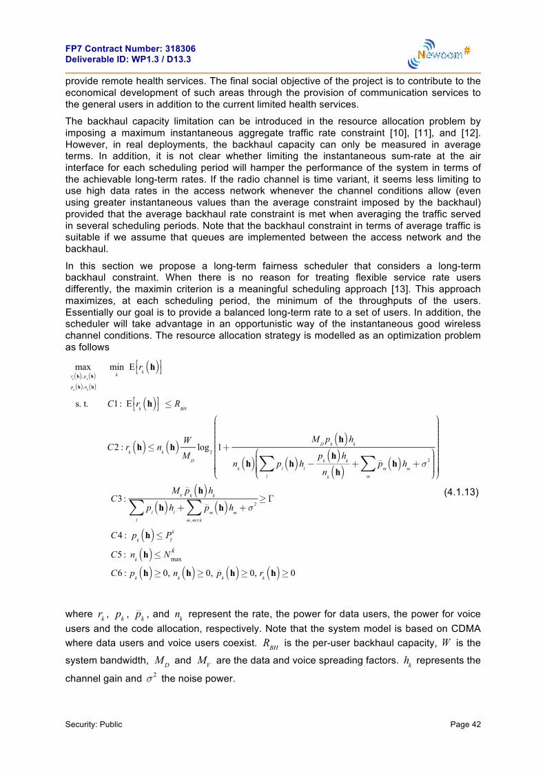
FP7 Contract Number: 318306 Deliverable ID: WP1.3 / D13.3
Security: Public Page 42
provide remote health services. The final social objective of the project is to contribute to the economical development of such areas through the provision of communication services to the general users in addition to the current limited health services.
The backhaul capacity limitation can be introduced in the resource allocation problem by imposing a maximum instantaneous aggregate traffic rate constraint [10], [11], and [12]. However, in real deployments, the backhaul capacity can only be measured in average terms. In addition, it is not clear whether limiting the instantaneous sum-rate at the air interface for each scheduling period will hamper the performance of the system in terms of the achievable long-term rates. If the radio channel is time variant, it seems less limiting to use high data rates in the access network whenever the channel conditions allow (even using greater instantaneous values than the average constraint imposed by the backhaul) provided that the average backhaul rate constraint is met when averaging the traffic served in several scheduling periods. Note that the backhaul constraint in terms of average traffic is suitable if we assume that queues are implemented between the access network and the backhaul.
In this section we propose a long-term fairness scheduler that considers a long-term backhaul constraint. When there is no reason for treating flexible service rate users differently, the maximin criterion is a meaningful scheduling approach [13]. This approach maximizes, at each scheduling period, the minimum of the throughputs of the users. Essentially our goal is to provide a balanced long-term rate to a set of users. In addition, the scheduler will take advantage in an opportunistic way of the instantaneous good wireless channel conditions. The resource allocation strategy is modelled as an optimization problem as follows
maxrk
h( ), pk
h( )⌣p
kh( ), n
kh( )
mink
E rk
h( )⎡⎣ ⎤⎦
s. t. C1: E rk
h( )⎡⎣ ⎤⎦ ≤ RBH
C2 : rk
h( )≤ nk
h( ) W
MD
log2
1+M
Dp
kh( )h
k
nk
h( ) pl
h( )hl−
pk
h( )hk
nk
h( )l
∑ +⌣p
mh( )h
m+σ 2
m
∑⎛
⎝⎜⎜⎜⎜
⎞
⎠⎟⎟⎟⎟
⎛
⎝
⎜⎜⎜⎜⎜⎜⎜⎜⎜⎜⎜
⎞
⎠
⎟⎟⎟⎟⎟⎟⎟⎟⎟⎟⎟⎟⎟
C3 :M
V
⌣pk
h( )hk
pl
h( )hl
l
∑ +⌣p
mh( )h
m+σ 2
m , m≠k
∑≥Γ
C4 : pk
h( )≤ PT
k
C5 : nk
h( )≤ Nmaxk
C6 : pk
h( )≥ 0, nk
h( )≥ 0, ⌣pk
h( )≥ 0, rk
h( )≥ 0
(4.1.13)
where rk , pk , ⌣pk , and nk represent the rate, the power for data users, the power for voice
users and the code allocation, respectively. Note that the system model is based on CDMA where data users and voice users coexist. RBH is the per-user backhaul capacity, W is the
system bandwidth, M D and MV are the data and voice spreading factors. hk represents the
channel gain and σ2 the noise power.

FP7 Contract Number: 318306 Deliverable ID: WP1.3 / D13.3
Security: Public Page 43
It is easy to realize that the problem is separable into voice and data users without loss of optimality as voice users do not affect the objective function and each user has its own power budget constraint. For this reason, we start by analyzing the voice users.
Resource allocation for voice users
Let us define the following variable that takes into account the noise in addition to the received power corresponding to the data connections:
σint
2 = pl h( )hll∑ +σ2 (4.1.14)
According to this, the set of equations from constraint C3 of problem (4.1.13) can be written in matrix form as follows (each row corresponds to each of the voice users that are assumed to be numbered with the following order:
MV −Γ … −Γ
−Γ MV … −Γ
! ! " !−Γ −Γ … MV
⎡
⎣
⎢⎢⎢⎢⎢⎢⎢⎢
⎤
⎦
⎥⎥⎥⎥⎥⎥⎥⎥
×
⌣p1 h( )⌣p2 h( )!⌣pK h( )
⎡
⎣
⎢⎢⎢⎢⎢⎢⎢⎢⎢
⎤
⎦
⎥⎥⎥⎥⎥⎥⎥⎥⎥
= σint2 Γ
11!1
⎡
⎣
⎢⎢⎢⎢⎢⎢
⎤
⎦
⎥⎥⎥⎥⎥⎥
(4.1.15)
Notice that all the previous equations are completely symmetric with respect to users. This implies that the power allocated to each user is inversely proportional to the user channels, i.e., the powers received at the BS from all voice users must be equal:
⌣pk h( )=αhk
(4.1.16)
where
α=σint
2 ΓMV −Γ K−1( )
= pl h( )hl +σ2
l∑⎛
⎝⎜⎜⎜
⎞
⎠⎟⎟⎟⎟
ΓMV −Γ K−1( )
≤mink
PTkhk
(4.1.17)
or equivalently
pl h( )hl ≤l∑ min
kPT
khk( ) MV −Γ K−1( )Γ
−σ2 (4.1.18)
Note that (4.1.18) is a constraint on the maximum power radiated by all data users simultaneously, i.e., sum-power constraint. As a result, (4.1.18) must be added in the resource allocation for data users if we want to assure that all voice users receive the service they demand.
Resource allocation for data users
Now, we can proceed to obtain the optimum power allocation for the data users. Before presenting the optimization problem, let us formulate the achievable rate in terms of the previous found results. The new expression is

FP7 Contract Number: 318306 Deliverable ID: WP1.3 / D13.3
Security: Public Page 44
rk h( )≤ Nmaxk WM D
log2 1+M D pk h( )hk
Nmaxk cv pl h( )hl
l∑ +σ2⎛
⎝⎜⎜⎜⎜
⎞
⎠⎟⎟⎟⎟
⎛
⎝
⎜⎜⎜⎜⎜⎜⎜⎜⎜⎜⎜
⎞
⎠
⎟⎟⎟⎟⎟⎟⎟⎟⎟⎟⎟⎟⎟
(4.1.19)
where cv =1+
Γ×KMV −Γ K−1( )
. Given that, the resource allocation problem is formulated as:
maxs,rk h( ), pk h( )
U s( )
s. t. C1: s≤E rk h( )⎡⎣⎢
⎤⎦⎥
C2 : E rk h( )⎡⎣⎢
⎤⎦⎥ ≤ RBH
C3: rk h( )≤ Nmaxk WM D
log2 1+M D pk h( )hk
Nmaxk cv pl h( )hl
l∑ +σ2⎛
⎝⎜⎜⎜⎜
⎞
⎠⎟⎟⎟⎟
⎛
⎝
⎜⎜⎜⎜⎜⎜⎜⎜⎜⎜⎜
⎞
⎠
⎟⎟⎟⎟⎟⎟⎟⎟⎟⎟⎟⎟⎟
C4 : pl h( )hl ≤l∑ min
kPT
khk( ) MV −Γ K−1( )Γ
−σ2
C5: pk h( )≤ PTk
(4.1.20)
where we have introduced a general differentiable monotonically increasing cost function
U ( ) (e.g., the logarithm) in order to smooth convergence issues when the objective is
linear in the optimization variable. Note that the introduction of such function does not modify the optimal value of the optimization variables (i.e., the solution is the same).
Notice also that the previous optimization problem is time-coupled and it requires the future channel realizations due to the expectation operator appearing in C1 and C2 . In order to deal with such difficult problem involving expectations, we propose to use a stochastic approximation that has been proposed in the literature [14], [15]. In this approach, the constraints involving expectations are dualized, and their Lagrange multipliers are estimated stochastically at each period. For specific technical details of the algorithm, please see [16].
Numerical results
In this section we evaluate the performance of the proposed strategy. For the specific values of the system model please see [16]. For comparison purposes, we also show the resource allocation of the proportional fair (PF) strategy [15] with an instantaneous per-user backhaul constraint,
rk h( )≤ RBH , and an instantaneous sum constraint,
rk h( )
k∑ ≤ RBH K .

FP7 Contract Number: 318306 Deliverable ID: WP1.3 / D13.3
Security: Public Page 45
Figure 4-5: Average bit rates per data user served in the air interface by different
schedulers for a total backhaul capacity of 6 Mbps.
Figure 4-5 and Figure 4-6 show the time evolution of the expected rates of the proposed stochastic scheduler and the PF scheduler. We also plot the time evolution of s! and the per-data user backhaul rate. The total backhaul capacity considered in Figure 4-5 is 6 Mbps and in Figure 4-6 is 2 Mbps. Initially, we assume that the queues at the output of the access network are sufficiently full so that all the bits demanded by the users are served. This makes the initial average rates violate the backhaul capacity constraint for a short period of time (see the initial transient in the figure). This is due to the stochastic approximation of the multipliers but, in any case, when the average rates converge, they fulfill all the constraints of the original problem. As we can also see from the Figure 4-5, the limitation of the rates comes from the limited resources available at the access network, i.e., the power and the codes, as the backhaul capacity is not reached. It should be also emphasized that, the proposed stochastic approach provides a solution that introduces more fairness when compared to the PF approach as the average rates for the different users are quite similar. Considering now Figure 4-6, the limitations comes from backhaul as the expected rates in the air interface converge to the maximum per-user backhaul capacity.
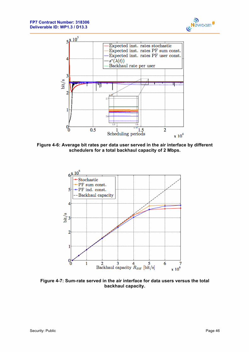
FP7 Contract Number: 318306 Deliverable ID: WP1.3 / D13.3
Security: Public Page 46
Figure 4-6: Average bit rates per data user served in the air interface by different
schedulers for a total backhaul capacity of 2 Mbps.
Figure 4-7: Sum-rate served in the air interface for data users versus the total
backhaul capacity.

FP7 Contract Number: 318306 Deliverable ID: WP1.3 / D13.3
Security: Public Page 47
Figure 4-8: Rate served in the air interface for the worst-case data user versus the
total backhaul capacity.
Figure 4-7 shows the total rate demanded by data users as a function of the backhaul capacity. Note than, the stochastic approach performs slightly worse than the two PF schedulers when the system is limited by the access network and not by the backhaul network but works better than the PF with individual constraint for some backhaul capacities. However, the stochastic scheduler offers a greater fairness in terms of similar bitrates, so the rate for the worst-case user is better for the stochastic scheduler than for the other approaches, as shown in Figure 4-8.
4.1.3 References [1] J. Paradiso and T. Starner, “Energy scavenging for mobile wireless electronics,” IEEE
Computing Pervasive, vol. 4, pp. 18–27, Jan. 2005. [2] S. Sudevalayamand, P. Kulkarni, “Energy harvesting sensor nodes: survey and
implications,” IEEE Communications Surveys & Tutorials, vol. 13, pp. 443–461, Third Quarter 2011.
[3] V. Chandrasekhar, J. Andrews, and A. Gatherer, “Femtocell networks: a survey,” IEEE Comm. Magazine, vol. 46, pp. 59–67, Sep. 2008.
[4] L. R. Varshney, “Transporting information and energy simultaneously,” in International Symposium on Information Theory, Jul. 2008.
[5] P. Grover and A. Sahai, “Shannon meets Tesla: wireless information and power transfer,” in International Symposium on Information Theory, Jun. 2010.
[6] R. Zhang and C. K. Ho, “MIMO broadcasting for simultaneous wire- less information and power transfer,” in IEEE Global Communications Conference (Globecom), 2011.
[7] R. Zhang and C. K. Ho, “MIMO broadcasting for simultaneous wireless information and power transfer,” IEEE Trans. on Wireless Communica- tions, vol. 12, pp. 1989–2001, May 2013.
[8] Z. Xiang and M. Tao, “Robust beamforming for wireless information and power transmission,” IEEE Wireless Communications Letters, vol. 1, pp. 372–375, Aug. 2012.
[9] D. P. Bertsekas, Nonlinear programming. Athena Scientific, second ed., 1999.

FP7 Contract Number: 318306 Deliverable ID: WP1.3 / D13.3
Security: Public Page 48
[10] A. Chowdhery, W. Yu, and J. Cioffi, “Cooperative wireless multicell OFDMA network with backhaul capacity constraints,” in IEEE Int’l. Conference on Comm. (ICC)), Jun. 2011.
[11] L. Zhou and W. Yu, “Uplink multicell processing with limited backhaul via per-base-station successive interference cancellation,” IEEE Journal on Sel. Areas in Comm., vol. 31, pp. 1981–1993, Oct. 2013.
[12] Z. Cui and R. Adve, “Joint user association and resource allocation in small cell networks with backhaul constraints,” in IEEE Conf. on Information Sciences and Systems (CISS), Mar. 2014.
[13] W. Rhee and J. M. Cioffi, “Increase in capacity of multiuser OFDM sys- tem using dynamic subchannel allocation,” in IEEE Vehicular Technology Conference, pp. 1085–1089, May 2000.
[14] A. Ribeiro, “Ergodic stochastic optimization algorithms for wireless communication and networking,” IEEE Trans. on Signal Processing, vol. 58, pp. 6369–6386, Nov. 2010.
[15] X. Wang, G. B. Giannakis, and A. G. Marques, “A unified approach to QoS-guaranteed scheduling for channel-adaptive wireless networks,” Proceedings of IEEE, vol. 95, pp. 2410–2431, Dec. 2007.
[16] J. Rubio, O. Muñoz, A. Pascual, J. Vidal, “Stochastic resource allocation with backhaul constraints for the uplink,” IEEE Globecom, Dec. 2015.
4.2 Achievements JRA 1.3.1C – Robust Packet Type Estimation via JPCD
Determining the type of a packet is the first task performed by the protocol layer processor when it receives some packet from the physical layer, or from a lower layer in the protocol stack. The type of a packet determines its layout and part of its content. Usually, the type is encoded with few bits at the beginning of the header. It is thus very sensitive to transmission impairments and has to be estimated reliably.
In this JRA, we have proposed a MAP estimator of the type of a packet in a given protocol layer. Instead of considering only the type identification field of the considered packet, the proposed technique determines the packet type which is the most consistent with the received data and some a priori information: the whole structure of the packet and the redundancy in the protocol stack is put at work. Soft information, i.e., bit reliability information, is assumed available at the considered layer. It may either come from soft-output channel decoders at physical layer [6, 2] possibly combined with protocol layer permeability mechanisms [8, 12, 15], which allow the transmission of soft information from the physical layer through the upper layers of the protocol stack.
Redundancy in the protocol stack has been previously recognized and used in header compression techniques, such as the Robust Header Compression (RoHC) protocol [3, 16]. Alternatively, Joint Protocol and Channel Decoding (JPCD) techniques make an efficient use of the redundancy present in uncompressed protocol layers (including that introduced at Physical layer, e.g., by channel coding) to obtain optimal performance at a global level. With this family of techniques, physical-layer synchronization can be improved [13], channel decoding is helped by pilot symbols from the protocol [7], aggregated packets are more efficiently delineated [4, 5, 1, 11], or packet headers are more reliably recovered [10, 14].
4.2.1 Generic Organization of Packets This section identifies the various fields of bits forming the packets processed at a generic protocol layer. Usually, the organization, length, position, and/or potential content of each field depends on the type of the packet in the protocol layer. This classification is inspired from [10, 16] and will be useful to build a MAP estimator of the type of a packet.

FP7 Contract Number: 318306 Deliverable ID: WP1.3 / D13.3
Security: Public Page 49
Considering a packet pt of type t belonging to a finite set of types τ, one may identify the following fields. The constant field k contains all bits which value is perfectly known and independent of the type of the packet. The type-determination field dt consists of all bits that are usually employed in a noise-free context to identify the type of the packet. The field of unknown bits ut contains all bits that represent useful information for processing at the considered layer. The other field ot contains bits that are processed at upper layers of the protocol stack. The control field ct is assumed to be evaluated from the previous fields k, dt, ut, ot, and possibly from context information kept in the memory of the processor of the considered layer. This information, which may consist of the content of previously processed packets is represented by R. Finally, the part of the payload that is not protected by the control field is denoted xt. Thus, up to a permutation of the indexes of its bits, a packet of type t is organized as follows
pt = (k,dt,ut,ot,ct,xt), (4.2.1)
see Figure 4-9. The fields dt and ut are assumed to take only a finite number of values belonging respectively to the finite sets Ωd and Ωu. The fields ot and xt are such that ot ∈ {0,1}l(ot) and xt ∈ {0,1}l(xt), where l(x) denotes the length of the field x. Each bit of ot and xt is independently and identically distributed according to a symmetric Bernoulli random variable. One assumes that there exists a deterministic parity-check function ft such that
ct = ft(k,dt,ut,ot,R). (4.2.2)
The set of all values which may be taken by a packet of type t is denoted as Ωt.
Figure 4-9: Organization of the fields depending on the packet type. 4.2.2 MAP Packet Type Estimator The sequence types {Tn} of the packets received by some network node is assumed to be accurately modeled by a time-invariant first-order Markov process described by the transition probability matrix with entries
pi,j = Pr(Tn = j | Tn−1 = i), (i,j) ∈ τ2. (4.2.3)
The main idea of the proposed type estimation approach, when the received packet is corrupted by noise, is to verify the global consistency of its fields with the inferred type. This is obtained by determining the type which is the most probable a posteriori. For that purpose, it is assumed that a vector of bit soft information y is available at the input of the considered layer. This soft information may consist of bit a posteriori probabilities or likelihood ratios provided by the channel decoders at physical layer or by lower protocol layers implementing layer permeability mechanisms [12, 15, 8].
Using y and the knowledge of R, the MAP estimator for the type tn of the n-th packet is
tˆn = argmax ∑Pr(y | p,R)Pr(p | R) (4.2.4) t∈τ p∈Ωt
k
k
k
d1 u1
d2 u2
d3 u3 o3 c
type 1
type 2
type 3
o2 c
o1 c

FP7 Contract Number: 318306 Deliverable ID: WP1.3 / D13.3
Security: Public Page 50
Assuming that the channel is memoryless, that the fields u, o, and x are independent two-by-two, and that only the locations of the fields ot and xt are influenced by the packet type, (4.2.4) becomes
tˆn = argmaxΦt(y), t∈τ
with
Φt(y) = p(yk | k)Pr(k)p(yd,t | dt)Pr(dt | R)
∑p(yx,t | xt)Pr(xt | dt) ∑p(yu,t | ut)Pr(ut | dt,R) xt ut∈Ωu,t
∑p(yo,t | ot)Pr(ot | dt)p(yc,t|ft(k,dt,ut,ot,R)). (4.2.5) ot
The subvectors yt, yd,t, yu,t, yo,t, yc,t, and yx,t form a partition of the vector y. The type subscript t indicates that the bits considered in each subvector may depend on the considered type, see Figure 4-9.
The expression (4.2.5) may be simplified by removing all parts that are common to all types. For each type t, one may partition xt into a common part xc, shared by all types, i.e., bits which belong to the payload, whatever the type, and a specific part x’t. Then, Φt(y) becomes
Φt(y) = p(yd,t | dt)Pr(dt | R)2−l(x’t)−l(ot) ∑p(yx,t | x’t) ) ∑p(yu,t | ut)Pr(ut | dt,R) xt ut∈Ωu,t
∑p(yo,t | ot)Pr(ot | dt)p(yc,t|ft(k,dt,ut,ot,R)). (4.2.6) ot The terms of the first line in Φt(y) are easily evaluated from the channel model, using the characteristics of the soft information, or a priori probabilities. With a memoryless channel,
the complexity for evaluating ∑p(yx,t | x’t) is linear in l(x’t). The last term may be evaluated with a worst-case complexity of O(| Ωu,t | 2l(ot)), where | Ωu,t | is the cardinal number of Ωu,t. This complexity is unmanageable for large values of ot. To address this issue, [10] has proposed an optimal trellis-based evaluation algorithm for Ψ(y,dt) with a complexity O(| Ωu,t | l(ot)2l(yc,t)), exponential in the length of the check field. By partitionning the check field into m parts assumed independent, [10] gets an approximate evaluation of Ψ(y,dt) with a complexity O(m | Ωu,t | l(ot)2l(yc,t)/m). 4.2.3 Application to 802.11a standard The frame type estimation has been applied at the MAC layer in the 802.11a standard.
4.2.3.1 Frame type estimation strategy In what follows, two strategies for packet type estimation are introduced to estimate the frame type of 802.11a packets. Only the most frequently encountered Beacon, Data, RTS, CTS, and ACK frames in 802.11a standard are considered. The first one applies the MAP estimator neglecting the check field of the packet while the second takes the check field into consideration.
1. Reliable frame type estimator
The reliable frame type estimator considers the common fields among the five types of frames. Only the first 10 bytes of the MAC frames are considered, see Figure 4-10. The proposed estimator is then suboptimal.

FP7 Contract Number: 318306 Deliverable ID: WP1.3 / D13.3
Security: Public Page 51
Figure 4-10: Fields considered by the reliable frame type estimator.
2. MAC-lite CRC-reliable frame type estimator
In this estimator, the principle of UDP-Lite is applied at the MAC layer. The CRC-32 is assumed to protect only the MAC header. Since the control frames are short and they do not contain any payload, the MAP estimator should be adapted by making use of the Length field in the PLCP header. As mentioned previously, the Length field in the PLCP header indicates the number of bytes in the PSDU. Assuming that the PLCP header is correctly decoded (checked by the Parity), the Length can help to do a preselection among all types of packets if it is correctly decoded.
Figure 4-11: Fields considered by the MAC-lite CRC-reliable frame type estimator. For example, considering the five types of frames illustrated in Figure 4-11, the following three frame type estimation cases are deduced.
• Case 1: The Length field implies that the PSDU contains 14 bytes. The received frame is immediately an ACK frame since only this frame is 14 bytes long.
• Case 2: The Length field is decoded as 20 bytes. The received frame is then an RTS frame or an CTS frame. The MAP estimator is used to choose between RTS and CTS frames.
• Case 3: The Length field implies a relatively longer PSDU. The MAP estimator is then applied to distinguish Beacon and Data frames.
Fram eControl
Duratio n DA
bytes 2 2 6
constant type-‐deter mina tion unknown
Fram eControl
Duratio n Addr 1
Fram eControl
Fram eControl
Duratio n
Duratio n
RA
RA
beacon
data
rts,cts
ack
Fram eControl
Duratio n DA SA BSS ID Seque nce Control
bytes 2 2 26 6 6
constant type-‐deter mina tion unknown other
Fram eControl
Duratio n Addr 1 Addr 2 Addr 3 Seque nce Control Addr 4
CRC
CRC
CRC
CRC
Fram eControl
Fram eControl
Duratio n
Duratio n
RA TA
RA
Beacon
Data
RTS,CTS
Ack
Fram e Body
payload
4 6

FP7 Contract Number: 318306 Deliverable ID: WP1.3 / D13.3
Security: Public Page 52
4.2.3.2 Simulation conditions We consider a client connected to an access point providing 802.11a wireless service. Only Beacon, Data, RTS, CTS, and ACK frames are considered. The frame type estimation of the previously mentioned five types of frames is considered in simulation. From a typical capture of 802.11a wireless packets, one may estimate the following packet transition matrix:
Beacon Data RTS CTS ACK Beacon 0.9177 0.0124 0.0297 0.0010 0.0392
Data 0.0061 0.2590 0.0143 0.0020 0.7186 RTS 0.0026 0.0035 0.0321 0.9392 0.0226
CTS 0.0027 0.9725 0.0211 0.0018 0.0019 ACK 0.0596 0.0096 0.9114 0.0044 0.0150
In the simulation, a whole PPDU frame is generated for each type of packet where the DATA field is scrambled, encoded by a convolutional encoder and interleaved according to [17]. For the sake of simplicity, the convolutional encoder used for both the SIGNAL and DATA is with the standard generator polynomials g0 = 1338 and g1 = 1718, at coding rate R = 1/2. A new MAC address is inserted in a Data frame and the stored addresses are refreshed every 1000 generated packets. Three techniques are adopted by the client to estimate the frame type: a standard estimator, the reliable frame type estimator, the MAC-lite CRC-reliable frame type estimator. Transmission is performed on an AWGN channel.
4.2.3.3 Results In the simulations, enough packets are generated to observe 100 frame type errors for each value of Eb/N0. Frame-type estimators are compared in terms of frame type error rate (FTER). The standard estimator performs a hard decision on the soft informations provided by a classical BCJR decoder [2], while the other two MAP estimators are implemented according to the description provided in Section 4.4. The simulation results are illustrated in Figure 4-12. A gain of 0.3 to 0.4 dB is observed for the reliable frame type estimator compared to the standard estimator, while a gain of more than 0.7 dB is obtained for the MAC-lite CRC-reliable frame type estimator compared to the standard estimator.
Figure 4-12: Frame type error rate (FTER) as function of Eb/N0.

FP7 Contract Number: 318306 Deliverable ID: WP1.3 / D13.3
Security: Public Page 53
4.2.4 References
[1] U. Ali, M/ Kieffer, P. Duhamel. Joint Protocol-Channel Decoding for Robust Frame Synchronization. IEEE Trans. Comm., 60 (8), pp.2326–2335, 2012.
[2] L. R. Bahl, J. Cocke, F. Jelinek, and J. Raviv. Optimal decoding of linear codes for minimizing symbol error rate. IEEE Trans. Info. Theory, 20:284–287, 1974.
[3] C. Bormann, C. Burmeister, M. Degermark, H. Fukushima, H. Hannu, L.-E. Jonsson, R. Hakenberg, T. Koren, K. Le, Z. Liu, A. Martensson, A. Miyazaki, K. Svanbro, T. Wiebke, T. Yoshimura, and H. Zheng. Robust header compression (ROHC): Framework and four profiles. Technical Report RFC 3095, 2001.
[4] M. Chiani and M. G. Martini. On sequential frame synchronization in AWGN channels. IEEE Trans. Comm., 54:339 – 348, 2006.
[5] M Chiani and M.G Martini. Practical frame synchronization for data with unknown distribution on AWGN channels. IEEE Communication Letter, 9(5):456 – 458, May 2005.
[6] J. Hagenauer and P. Hoeher. A Viterbi algorithm with softdecision outputs and its applications. In Proc. Globecom, pages 1680–1686, Dallas, TX, 1989.
[7] R. Hu, M. Kieffer, and P. Duhamel. Protocol-assisted channel decoding. IEEE Signal Processing Letters, 19(8):483–486, 2012.
[8] H. Jenkac, T. Stockhammer, and W. Xu. Permeable-layer receiver for reliable multicast transmission in wireless systems. In Proc. IEEE Wireless Communications and Networking Conference, volume 3, pages 1805–1811, 13-17 March 2005.
[9] J. F. Kurose and K. W. Ross. Computer Networking: A Top-Down Approach Featuring the Internet. Addison Wesley, Boston, third edition, 2005.
[10] C. Marin, Y. Leprovost, M. Kieffer, and P. Duhamel. Robust mac-lite and soft header recovery for packetized multimedia transmission. IEEE Trans. on Communications, 58(3):775– 784, 2010.
[11] M. G. Martini and M. Chiani. Optimum metric for frame synchronization with Gaussian noise and unequally distributed data symbols. In Proc. IEEE SPAWC, Perugia, Italy, 21-24 June 2009.
[12] M.G. Martini, M. Mazzotti, C. Lamy-Bergot, J. Huusko, and P. Amon. Content adaptive network aware joint optimisation of wireless video transmission. IEEE Communications Magazine, 45(1):84 – 90, 2007.
[13] C. L. Nguyen, A. Mokraoui, and N. Duhamel, P. Linh-Trung. Time synchronization algorithm in IEEE 802.11a communication system. In Proc. European Signal Processing Conference, 2012. submitted.
[14] J. W. Nieto and W. N. Furman. Cyclic redundancy check (CRC) based error method and device. US Patent US 2007/0192667 A1, Aug. 16 2007.
[15] G. Panza, E. Balatti, G. Vavassori, C. Lamy-Bergot, and F. Sidoti. Supporting network transparency in 4G networks. In Proc. IST Mobile and Wireless Communication Summit, 2005.
[16] M. West and S. McCann. TCP/IP field behavior. Technical Report RFC 4413 (Informational), March 2006.
[17] IEEE 802 LAN/MAN Standards Committee. (1999). Wireless LAN medium access control (MAC) and physical layer (PHY) specifications. IEEE Standard, 802(11).

FP7 Contract Number: 318306 Deliverable ID: WP1.3 / D13.3
Security: Public Page 54
4.3 Achievements JRA 1.3.1D – Study on energy efficient probing in CSMA based multi-rate ad hoc networks
In this JRA, we proposed a cross-layer energy-efficient method for underwater networks employing random access. The proposed algorithm significantly improved the energy efficiency of an underwater network by jointly selecting the MAC layer access rate along with the PHY-layer transmission power.
For example, Figure 4-13, show how PHY and MAC layer resources should be allocated in an 11-node scenario where the nodes have an increasing distance to the base station. Fig. (a) shows that the PHY layer transmission capacity that should be allocated for energy minimization and Fig (b) shows the MAC layer access rates. As the distance of a node increases, it should be assigned a higher MAC layer access rate and a lower PHY layer transmission capacity.
We evaluate the performance of cross-layer and separate-layer policies. Numerical results show that the cross-layer optimization outperforms the separate optimization of both layers by reducing the energy consumption per bit up to 66 % for a large-scale network and 7 % for a small-scale network. Cross-layer optimization is more crucial for large-scale networks due to the high transmission power requirements for networks covering large distances. For the large scale network, Fig. © shows that the energy consumption per bit for the proposed cross-layer (CL) policy along with two single-layer policies which optimizes MAC-layer throughput (SL-T) and MAC layer energy consumption (SL-E). CL consumes less energy per bit in comparison to benchmark single layer policies.
Figure 4-13: (a) Capacity allocations made by the proposed cross-layer policy (CL) (b) Channel access rate allocations made by CL. (c) Average energy consumption per bit for CL and SL policies as the goodput per node increases.
0 10 20 30 40 50 60 70 80 90 1000
10
20
30
40
50
60
70
80
90
100
Distance (km)
PHY−
laye
r Tra
nsm
issi
on C
apac
ity, C
(kbp
s)
T=0.1 kbpsT=0.4 kbpsT=0.8 kbpsT=1.2 kbpsT=1.6 kbps
0 10 20 30 40 50 60 70 80 90 1000
0.05
0.1
0.15
0.2
0.25
Distance (km)
Cha
nnel
Acc
ess
Rat
e (1
/s)
T=0.1 kbpsT=0.4 kbpsT=0.8 kbpsT=1.2 kbpsT=1.6 kbps
0 0.2 0.4 0.6 0.8 1 1.2 1.4 1.60
1
2
3
4
5
6
7
8
9x 10¹⁵
Goodput per Node (kbps)
Aver
age
Ener
gy C
onsu
mpt
ion
per B
it ((µ
Pa ×
s) /
b)
CLSL−ESL−TSim.

FP7 Contract Number: 318306 Deliverable ID: WP1.3 / D13.3
Security: Public Page 55
In addition to the significant improvement in energy consumption, cross-layer optimization results in a more homogeneous energy consumption distribution among the nodes. Such a homogeneous distribution significantly increases the amount data transferred until the first node failure due to battery drain. In contrast, separate optimization of layers results in the assignment of very high transmission powers to distant nodes which degrade their lifetime significantly. The improvement obtained by CL in the number of bits transferred until the first node failure can be seen in Figure 4-14. For a large-scale network, CL improves the lifetime up to 14 times in comparison SL-T. SL-E performs very poor due to the increased transmission power.
Figure 4-14: Improvement with CL compared to SL-E and SL-T in the number of bits transmitted during network’s lifetime as a function of node goodput for the large scale network.
4.4 Achievement JRA 1.3.2.A – Study on the FBMC/OQAM system capacity
4.4.1 Introduction Orthogonal frequency division multiplexing (OFDM), though spectrally agile and easily implementable, has proven to be very sensitive to the lack of synchronism [1] as well as to be badly spectrally localized [2]. Besides, the use of a Cyclic Prefix (CP) in order to accommodate for the channel selectivity limits the spectral efficiency of OFDM. These different drawbacks hardly make OFDM a good candidate for 5G physical layer, and new multicarrier approaches have driven the interest of the community. Namely, Filter Bank Multi-Carrier in conjunction with Offset-QAM (FBMC/OQAM) [3] is a promising technique, in which the incoming symbols are pulse-shaped through prototype filters which show good Time-Frequency Localization (TFL) properties. Moreover, no CP is added to the transmitted symbols, and FBMC/OQAM can therefore theoretically achieve better channel capacity. However, the Balian-Low Theorem (BLT) [4] stipulates that Gabor density of 1 and orthogonality cannot be achieved at the same time with well localized pulse shapes. Therefore, FBMC/OQAM achieves orthogonality only on the real plane by staggering real and imaginary parts of the symbols in time and frequency. At the receiver, only the real part of the signal is processed, and the imaginary part is known as intrinsic interference.
Intrinsic interference is the main limiting factor that makes FBMC/OQAM implementation challenging. However, it is tempting to use it as a useful signal, instead of simply dumping it at the receiver side. Namely, it has been shown that intrinsic interference can be used to aid equalization at the receiver [5], and even use it as useful part of the signal [6].
0 0.2 0.4 0.6 0.8 1 1.2 1.4 1.60
500
1000
1500
Goodput (kbps)
Perc
enta
ge Im
prov
emen
t in
Num
ber o
f Bits
unt
il Fi
rst N
ode
Failu
re
SL−ESL−T

FP7 Contract Number: 318306 Deliverable ID: WP1.3 / D13.3
Security: Public Page 56
We now aim to precisely answer the following question: by how much can the capacity of FBMC/OQAM be increased by processing the intrinsic interference? In order to do so, we present a thorough mathematical analysis and derive exact expressions of the capacity of the FBMC/OQAM system.
The description of the achievement has the following form: first, the assumed system model is presented; second, the mathematical analysis of the system capacity is conducted, which is then followed by presentation of the obtained numerical results and drawn conclusions.
4.4.2 System Model Let us consider frame-based multicarrier system with M occupied subcarriers, where the time domain is divided into blocks of N symbols (i.e. we consider a frequency-time (FT) frame of size M × N). We assume that the considered frame is isolated in frequency so that it does not suffer interference from neighbouring blocks. Besides, we consider a transmission established in permanent regime, so that we do not take into account the effect of FBMC ramps up/down on the system capacity. Finally, the application of pulse shape p[n] of length L on each subcarrier is considered. Thus, the demodulated signal on the qth subcarrier and kth time instant can be expressed as:
(4.4.1) where (4.4.2) represents the impulse response between the mth and the qth subchannel, which includes not only the channel impulse response h[n] but also the transmit and reception pulse shapes. The operation ↓! downsamples a sequence by a factor of x. The equivalent channel gqm[k] is different from zero for 𝐿! = − !!!
!/!≤ 𝑘 ≤ !!!!!!"
!/!= 𝐿!, where Lch denotes the
maximum channel excess delay. The function 𝑥 gives the largest integer equal or lower than x. In the context of uniformly modulated filter bank systems, subcarrier signals are generated by frequency-shifting a low-pass filter p[n] as follows: (4.4.3) Furthermore (4.4.4) stands for the noise sample at the FT position (q, k), after filtering the additive noise w[n] that contaminates the received signal. The symbols {dq[k]} are drawn from a PAM constellation and are different from zero, for 0 ≤ M1 ≤ q ≤ M2 ≤ M − 1, 0 ≤ k ≤ N − 1. The bands M1 and M2 determine the number of subcarrier that are active, which is given by Ma = M2 − M1 + 1. The phase term (4.4.5)

FP7 Contract Number: 318306 Deliverable ID: WP1.3 / D13.3
Security: Public Page 57
is set to guarantee that adjacent symbols in the FT plane differ by a phase factor of !
!. A
better analytical tractability is offered by stacking column-wise the samples, allowing us to
express the vector 𝐲 𝑘 = 𝑦!! 𝑘 ⋯ 𝑦!! 𝑘! with this matrix notation
(4.4.6) where (4.4.7)
(4.4.8) The matrix G[τ] ∈ CMa×Ma depends on {gqm[k]} in this form.
(4.4.9) In mildly frequency selective channels, it can be assumed that the channel is flat within the range of one subchannel. Then, the channel seen by the signal transmitted in the mth subcarrier is given by Hm [7], which denotes the frequency response evaluated on the radial frequency !!"
!, yielding this simplified channel model gqm[k] = Hmαqm[k]. The variable αqm[k] is
used to represent the FBMC/OQAM transmultiplexer response, which is given by (4.4.10) Then, (4.4.9) becomes
(4.4.11) Note that H is a diagonal matrix and that A[τ] can be computed offline, since it only depends on the pulses.
4.4.3 Capacity Analysis This section conducts the capacity analysis building upon the model (4.4.6). In order to simplify the notation, we consider the Fourier transform of vector y[k], so that the input/output relation becomes
(4.4.12)

FP7 Contract Number: 318306 Deliverable ID: WP1.3 / D13.3
Security: Public Page 58
Mathematically, G(ω) can be written as
(4.4.13)
The noise and symbol vectors are given by (4.4.14)
(4.4.15)
Once the interplay between the transmitted and the received signal is compactly expressed in the frequency domain, it is easier to evaluate the impact of the interference. To this end, the modulation-induced interference is expanded as G(ω) = G1(ω)+G2(ω). The interference terms that are exploited are gathered in G1(ω). Therefore,
(4.4.16)
represents the residual interference. Based on this notation, the following cases can be analyzed:
(4.4.17)
where diag{A} represents the main diagonal of matrix A. Note that 1) accounts for the case where the whole interference that exists in the FBMC/OQAM systems is treated as noise. By contrast, only ICI terms are regarded as unwanted signals in 2). Finally, in 3) ISI and ICI terms are exploited. In the following we will concentrate only on the last case. Figure 4-15 illustrates how interference is identified depending on the FT position where it comes from.

FP7 Contract Number: 318306 Deliverable ID: WP1.3 / D13.3
Security: Public Page 59
Figure 4-15: Source of interference in generic multicarrier transmission
Before evaluating the capacity it is important to remark that symbols are improper, because the pseudo-covariance matrix does not vanish. In other words, E{x[k]xT[k]} ≠ 0. It has been assumed that symbols are independent and identically distributed with mean energy symbol ES/2, i.e. E(dq[k]dm[l]) = 0.5ESδq,mδk,l. The factor 0.5 indicates that the symbols {dq[k]} correspond to either real or imaginary parts of complex valued QAM symbols, which mean energy is ES. Bearing this assumption in mind, it can be verified that improperness holds true in the frequency domain as well. To deal with the improper nature of the symbols, so that all the second order statistics come into play, we proceed with the definition of these augmented vectors: 𝐲 𝜔 = 𝐲 𝜔 ! 𝐲 𝜔 ! ! and finally 𝐧 𝜔 = 𝐰 𝜔 + ! 𝜔 = 𝐰 𝜔 ! 𝐰 𝜔 ! ! +! 𝜔 ! ! 𝜔 ! !. Then, the achievable rate under the assumption of improper Gaussian
signaling at frequency ω can be formulated as (see (10) in [8]):
(4.4.18)
with 𝐂𝐲 𝜔 = 𝐸 𝐲 𝜔 𝐲 𝜔 ! and 𝐂𝐧 𝜔 = 𝐸 𝐰 𝜔 𝐰 𝜔 ! + 𝐸 ! 𝜔 ! 𝜔 ! . The augmented covariance matrices can be obtained as
(4.4.19)
(4.4.20)
After several derivation steps, the authors in [8] have demonstrated that (4.4.18) can be compactly expressed in this form

FP7 Contract Number: 318306 Deliverable ID: WP1.3 / D13.3
Security: Public Page 60
(4.4.21)
It is worth highlighting that the second term in the right-hand side of (4.4.21) is equal to zero with proper Gaussian signalling. To evaluate R(ω) at a given ω, it is deemed necessary to characterize the second order moments of the symbols and the noise. To this end, the statistical information of the variables that come into play has been provided in the following sections.
A. Statistical information of symbols
Taking into account the statistical information of x[k], the covariance and the pseudo-covariance matrices of x(ω) become
(4.4.22)
(4.4.23)
Due to the fact that real and imaginary parts are interleaved according to (4.4.5), the entries of 𝐂𝐱 𝜔 in the (ith,ith) position are given by
(4.4.24)
To simplify the notation it is useful to realize that the diagonal elements of 𝐂𝐱 𝜔 can be regarded as a geometric progression. Then, we end up with
(4.4.25)
B. Statistical information of noise
If the noise samples at the input of the analysis filter bank are Gaussian distributed, i.e. w[n] ∼ CN (0,N0), then the expectation of the filtered noise satisfies:
(4.4.26)

FP7 Contract Number: 318306 Deliverable ID: WP1.3 / D13.3
Security: Public Page 61
(4.4.27)
As a consequence, E{wq[k]wm[l]}=0 and E{wq[k]w*m[l]}=N0αqm[k − l]. Therefore, 𝐂𝐰 𝜔 = 0 and
the (ith,lth) position of 𝐂𝐰 𝜔 is characterized by this expression
(4.4.28)
for 0 ≤ i, l ≤ Ma−1.
C. Capacity in FBMC/OQAM and OFDM systems
The closed-form expressions obtained in previous sections allows to compute the channel capacity as the integration of supportable information rates over the entire band [9], namely
(4.4.29)
Now, if we project this generic case to OFDM systems, it can be verified that the maximum achievable rate is independent of ω and it is defined as
(4.4.30)
The waste of energy due to the redundancy depends on LCP , which denotes the CP length. In the most general case where subcarriers overlap in time frequency domains, R(ω) is not
simplified. However, an approximate solution of the capacity can be computed when the frequency response of the rate does not present strong variation in the range of !!! radians/sample. If we stick to the FBMC/OQAM modulation scheme, the capacity is
expressed as
(4.4.31)
The higher is P, the closer is the approximation to the exact expression. The factor 2 is included to indicate that two FBMC/OQAM multicarrier symbols are transmitted in one OFDM symbol period. With this modification a fair comparison can be performed between OFDM and FBMC/OQAM.

FP7 Contract Number: 318306 Deliverable ID: WP1.3 / D13.3
Security: Public Page 62
4.4.4 Results This section evaluates the capacity expressions derived previous section. The system parameters are the following: for both OFDM and FBMC cases the sampling frequency was set to 15.36 MHz, the number of subcarriers and the number of active subcarriers were equal to 1024 and 12, respectively. Then, for OFDM 7 consecutive symbols were considered with the cyclic prefix of the length M/14, whereas for FBMC system the number of symbols was set to 14. For channel emulation we used EPA [10] channel model, and each time 1000 channel realizations were generated.
A. Influence of the pulse shape
The considered system is simulated in the case where all interference is processed at the receiver, corresponding to the case where G2(ω) = 0Ma. Both IOTA filter and PHYDYAS filter with overlapping factor 4 are considered for pulse shaping the FBMC/OQAM signal. Unless said otherwise, we took P = 2048 to compute the capacity of the FBMC/OQAM signal.
The capacity achieved by the FBMC and CP-OFDM systems is represented in Figure 4-16. The CP-OFDM system cannot achieve the optimal channel capacity under Gaussian signalling because of the cyclic prefix (by optimal channel capacity we understand capacity of a channel with frequency response H under the assumption that the modulated symbols are i.i.d and Gaussian distributed). On the opposite, it appears that when the intrinsic interference becomes preponderant in the FBMC system, i.e. for SNR higher than 20 dB, the capacity can become slightly higher than the optimal channel capacity under Gaussian signalling through the processing of intrinsic interference. It is also shown that the IOTA based FBMC system achieves higher capacity than its PHYDYAS counterpart. In order to maximize this gain at low SNR, we propose to adopt a Single-In-Multi-Out (SIMO) scheme. The achieved capacity for a 1 × 4 SIMO communication system on EPA channel is represented in Figure 4-17. It appears that this scheme successfully brings improvement in the achieved capacity by lowering the SNR level necessary to process intrinsic interference in a useful way.
Figure 4-16: Capacity against ES/N0 in SISO communication systems. The gain due to the processing of intrinsic interference becomes visible at high SNR

FP7 Contract Number: 318306 Deliverable ID: WP1.3 / D13.3
Security: Public Page 63
Figure 4-17: Capacity against ES/N0 in SIMO communication systems. The array gain makes the benefits of processing intrinsic interference visible at lower SNR than in the SISO case B. Complexity reduction through partial processing of the intrinsic interference
The results presented in Figure 4-16, Figure 4-17 are obtained by processing the whole interference at the receiver. As this could result in a high increase of the receiver complexity and delay, we propose here to consider only a certain part of this interference. In order to do so, we truncate it in time and consider that only a certain number of interfering symbols are taken into account at the receiver, so that we have:
(4.4.32)
with τ1 ≤ τmax. We analyze the achieved capacity for both IOTA and PHYDYAS based systems when the parameter τ1 takes different values. It appears in Figure 4-18 that there is no gain in processing the interference coming from symbols further away than 3 symbols in time for the PHYDYAS based FBMC/OQAM system. The results for the IOTA filter in Figure 4-19 show that performances are satisfying for τ1 ≥ 1, which is less than for the PHYDYAS filter. Moreover, performances tend to saturate for τ1 = 4, which is one more than for the PHYDYAS-based system. Besides, an interesting teaching of these curves lies in the fact that for receivers operating at low SNR, there is no gain in processing many time symbols. This finding could be used to reduce complexity of FMBC/OQAM receivers in challenging environments.

FP7 Contract Number: 318306 Deliverable ID: WP1.3 / D13.3
Security: Public Page 64
Figure 4-18: Capacity against ES/N0 for different values of 1 for the PHYDYAS based system. It appears that there is no gain in processing more than three symbols on each side for the considered values of SNR, as symbols further away do not interfere in a meaningful way.
Figure 4-19: Capacity against ES/N0 for different values of 1 for the IOTA based system. Gain is maximal when τ1 = 4 because IOTA is less localized in time than PHYDYAS filter.
4.4.5 Summary of the achievement As the main achievement we presented a generic model for the filter bank multi-carrier systems, which can easily be extended to other waveforms presented in the literature. Besides, we presented a thorough mathematical analysis of FBMC/OQAM capacity which allowed us to show that a small gain can be observed by processing intrinsic interference at the receiver. We also showed that this gain is more meaningful in the context of SIMO systems as the intrinsic interference becomes preponderant at lower SNR. Moreover, we gave an experimental evaluation of the frequency resolution that should embed precoders in

FP7 Contract Number: 318306 Deliverable ID: WP1.3 / D13.3
Security: Public Page 65
order to fully use the intrinsic interference in FBMC/OQAM systems. Future work should now focus on designing such precoders in order to practically be able to use intrinsic interference as useful signal and get over the maximal theoretical capacity of channels under Gaussian signalling.
4.4.6 References
[1] M. Morelli, C.-C. J. Kuo, and M.-O. Pun, “Synchronization Techniques for Orthogonal Frequency Division Multiple Access (OFDMA): A Tutorial Review,” Proceedings of the IEEE, vol. 95, no. 7, pp. 1394– 1427, Jul. 2007.
[2] B. Farhang-Boroujeny, “OFDM versus filter bank multicarrier,” IEEE Signal Process. Mag., vol. 28, no. 3, pp. 92–112, May 2011.
[3] P. Siohan, C. Siclet, and N. Lacaille, “Analysis and design of OFDM/OQAM systems based on filterbank theory,” IEEE Trans. Signal Process., vol. 50, no. 5, pp. 1170–1183, May 2002.
[4] H. Feichtinger and T. Strohmer, Gabor Analysis and Algorithm - Theory and Applications, Birkhauser, Ed., 1998.
[5] G. Ndo, H. Lin, and P. Siohan, “FBMC/OQAM equalization: Exploiting the imaginary interference,” IEEE 23rd International Symposium on in Personal Indoor and Mobile Radio Communications (PIMRC), 2012, Sept 2012, pp. 2359–2364.
[6] R. Razavi, P. Xiao, and R. Tafazolli, “Information Theoretic Analysis of OFDM/OQAM with Utilized Intrinsic Interference,” IEEE Signal Processing Letters, vol. PP, no. 99, pp. 1–1, 2014.
[7] M. Caus and A. I. P´erez-Neira, “Multi-stream transmission in MIMO-FBMC systems,” IEEE International Conference on Acoustics, Speech and Signal Processing (ICASSP), 2013, may 2013.
[8] Y. Zeng, C. Yetis, E. Gunawan, Y. L. Guan, and R. Zhang, “Transmit Optimization With Improper Gaussian Signaling for Interference Channels,” IEEE Transactions on Signal Processing, vol. 61, no. 11, pp. 2899–2913, June 2013.
[9] X. Zhang and S.-Y. Kung, “Capacity analysis for parallel and sequential MIMO equalizers,” IEEE Transactions on Signal Processing, vol. 51, no. 11, pp. 2989–3002, Nov 2003.
[10] “3rd Generation Partnership Project; Technical Specification Group Radio Access Network; Evolved Universal Terrestrial Radio Access (E-UTRA); User Equipment (UE) radio transmission and reception; (Release 8).” 3GPP TR 36.803 v1.1.0.
4.5 Achievements JRA 1.3.2 B – PAPR analysis in non-contiguous OFDM system
4.5.1 Description The NC-OFDM is a modification of standard OFDM, where just a subset of all available subcarriers is modulated by data symbols. The other are modulated by zeros in order to protect some, neighbouring in frequency transmissions. High variations of instantaneous power are measures typically by PAPR. It can be defined as:
𝑃𝐴𝑃𝑅 𝑥 =max 𝑥! !
𝐸 𝑥! !
where x denotes a vector containing all xn samples from a given OFDM symbol, for n = 0, 1, · · · ,N − 1. Here N stands for the number of input symbols or, equivalently, for number of time-domain samples in OFDM symbol (without cyclic prefix, CP). Typically the complementary cumulative distribution function is used to illustrate the PAPR metric for a given signal, i.e.
𝐶𝐶𝐷𝐹 𝑃𝐴𝑃𝑅 = Pr (𝑃𝐴𝑃𝑅 𝑥 > 𝜆)

FP7 Contract Number: 318306 Deliverable ID: WP1.3 / D13.3
Security: Public Page 66
where Pr() denotes the probability function. So far, only maximal PAPR in the case of NC-OFDM has been defined in [1]. However, this value is much higher than typically achieved PAPR values. In [2] two block of occupied subcarriers, i.e. N1 and N2 has been considered, while N1+N2<N. In Figure 4-20 different cases of subcarriers utilization are presented.
Figure 4-20: Cases of NC-OFDM subcarriers utilization for PAPR bound definition.
In the case A), where all subcarriers are occupied, i.e. N1+N2=N, and there is no oversampling, the PAPR CCDF is equal
Pr 𝑃𝐴𝑃𝑅 𝑥 > 𝜆 = 1 − 1 − 𝑒!! !!!!! .
The oversampling in the case B) increases typically PAPR, giving commonly used approximation:
Pr 𝑃𝐴𝑃𝑅 𝑥 > 𝜆 = 1 − 1 − 𝑒!! !.!(!!!!!).
Essentially, shift in frequency of a single subcarriers block (depicted in case C) does not change PAPR value. Based on triangle inequality PAPR of sum of two subcarriers set can be upper-bounded. The final result is
1 − 1 − 𝑒!! !!!!! ≤ Pr 𝑃𝐴𝑃𝑅 𝑥 > 𝜆
≤ 1 − 5.6 𝑁! + 𝑁! 𝑥 1 − 𝑒!!!!!!!!
!!!.!!!!!
𝑒!!!!!!!!
!! 1 − 𝑒!!!!!!!!
( !!!)!!.!!!!
! .
Although upper bound requires numerical integration, it is relatively easy to be computed. The range of integration is relatively narrow.

FP7 Contract Number: 318306 Deliverable ID: WP1.3 / D13.3
Security: Public Page 67
Figure 4-21: CCDF plots for N1=N2=32 and N=4096 while changing frequency shift between two blocks. Upper and lower bounds provided. Maximum PAPR ploted for comparison. In order to visualize the accuracy of the proposed solution some extensive simulations have been carried out, where the NC-OFDM system with N1 = N2 = 32 subcarriers has been considered. The IFFT size is N = 4096. The second block has been shifted by an integer number of subcarrier spacing from the range {0; 4031}, i.e. all possibilities keeping 0 − th subcarrier empty and both subcarriers blocks non-overlapping. For each shift 104 random, QPSK modulated, NC-OFDM symbols were generated and their PAPR metric was measured. The resultant PAPR CCDF are shown in Figure 4-21. The lower and upper (proposed) bounds are shown. It is visible that the proposed upper bound is more than 6 dB tighter than the maximum PAPR at Pr(PAPR > λ) = 10−2. All the reliable simulation results are between used upper and lower bounds.
4.5.2 References [1] Rajbanshi, R.; Wyglinski, Alexander M.; Minden, G.J., Peak-to-Average Power Ratio
Analysis for NC-OFDM Transmissions, VTC-2007 Fall. 2007 IEEE 66th Vehicular Technology Conference, pp.1351,1355, Sept. 30 2007-Oct. 3 2007,
[2] P. Kryszkiewicz, A. Kliks, and Y. Louet. “PAPR analysis in non-contiguous OFDM systems” submitted to Wireless Communications and Mobile Computing, 2015.
4.6 Achievements JRA1.3.3A - 1: Framework of REM-based interference management
In deliverable D13.2 (sections 4.10 and 4.11) a first version of the framework for REM-based interference management in HetNets was described [1]. During the 3rd year of NEWCOM# the framework has been further elaborated, discussing the practical and architectural implications of the use of different REM-based eICIC techniques. Main developments in this respect are summarized in the following, and can be found in [2].
4 6 8 10 12 14 16 18 2010-3
10-2
10-1
100
λ (dB)
Pr(P
APR
>λ)
simulationsmaximum PAPR
PAPR upper bound (proposed)
PAPR lower bound
FP7 Contract Number: 318306 Deliverable ID: WP1.3 / D13.3
Security: Public Page 68
4.6.1 REM-based eICIC techniques The use of REM as a support tool in interference management in HetNets is applicable to a variety of different categories of eICIC techniques.
- Power control techniques: These techniques adjust the transmit power of certain base stations of the network to reduce the generated interference. In a HetNet topology, with eNBs and HeNBs that serve a closed subscriber group of users, a critical challenge is the interference from an HeNB to nearby co-channel Macrocell User Equipments (MUEs). In this case, the transmit power of the HeNBs should be adjusted to avoid or reduce interference to the victim MUE. In [3], a baseline approach was presented, wherein each HeNB autonomously adjusts its transmit power based on its own received power measurements from the eNB. The introduction of a local REM in HeNB can enhance the effectiveness of this approach using the radio propagation characteristics of the surrounding area and the location of the neighboring MUEs, HeNBs and eNBs. This is demonstrated in the REM-based Autonomous HeNB Power Control (RAHPC) technique in which the HeNB uses the local REM to detect and locate the victim MUE and then it adjusts its transmission power to maintain a predefined Signal-to-Interference-and-Noise Ratio (SINR) target for the MUE [4]. Another proposal is REM-based Macrocell-Assisted Power Control (RMAPC), where the eNBs support the power adjustment of HeNBs by considering the contribution of each HeNB to the total interference and the impact on the outage of both MUEs and HeNB User Equipments (HUEs) [5]. In this case, the HeNBs’ local parameters are stored in the REM, and the eNB can use them to achieve the globally coordinated power adjustment.
- Frequency domain techniques: In this category, the REM can support the optimal selection of sub-bands to be used in the macrocells and small cells, therein targeting the minimization of inter-cell interference. One approach is the Gibbs sampler-based technique originally proposed in [6] in the context of macrocell scenarios. Here, it is extended to a HetNet scenario by also considering its implementation based on the REM concept. In this technique, which is denoted in the following as REM-based Frequency Optimization (RFO), small cells use a single sub-band, while eNBs use two different sub-bands, one for the users located in the inner part of the cell and the other for the users located in the outer part of the cell. Then, at random instants defined by an exponential timer, each cell modifies the used sub-bands following a Gibbs-Boltzmann distribution that selects with higher probability those sub-bands where the cell receives and generates less interference to their neighbor cells. This is performed iteratively so that the system progressively reduces the total inter-cell interference. The estimation of the received and generated interference is performed based on the propagation losses between users and neighbor cells that are obtained from the REM.
- Time-domain techniques: REM-related information can also be helpful in developing an optimal configuration of the muting periods of the macrocells, i.e., Almost Blank Subframes (ABS) [7], to enable interference-free small cell transmission. REM will help in the identification of small-cell users that are more sensitive to macrocell interference and in deciding how many ABSs are needed.
- Wi-Fi offloading: Efficient data offloading from the cellular network via the Wi-Fi network (or, in general, via other non-3GPP networks) allows a decrease in the HeNB/eNB load, and consequently, it can simplify the interference management in the cellular network [8]. REM can be considered as a technical enabler for this offloading because it can contain information about the detailed locations of available Wi-Fi networks and their characteristics.
4.6.2 Architectural considerations The selection of an eICIC technique impacts the choices derived from the REM architecture (see section 4.10 of [1]) concerning the use of the local/global REMs or the type of stored information. The architectural considerations of the techniques described in the previous sub-section are presented in the following.

FP7 Contract Number: 318306 Deliverable ID: WP1.3 / D13.3
Security: Public Page 69
- Local REM information: The more dynamic parameters of the radio environment and the information that only affects a reduced number of nodes will be preferably stored in the local REMs because this would facilitate the REM updates. In the considered example eICIC techniques this mainly includes radio-propagation-related information, such as propagation losses, signal strengths, and the locations of certain nodes such as mobile terminals or HeNBs.
- Global REM information: Usually, global REMs will store the less dynamic parameters or the parameters that may affect a high number of network nodes. In the considered eICIC techniques, the stored information includes certain Quality of Service (QoS) metrics, the positions of eNBs and information related to available Wi-Fi access networks such as the ownership (e.g., private or public, fee-based access or free access, and with or without authorization), the quality of the IP addressing options and the parameters of the available backhauling options for each Wi-Fi.
- Mapping of REM entities: In all of the strategies considered here, the local REM of each cell includes the REM manager and REM SA, and MCDs will be the mobile terminals and the cells, whose measurements will be used to build the REM data.
4.6.3 Benefits The use of a REM in the abovementioned techniques improves the HetNet performance in terms of various metrics.
- Capacity and throughput improvement: The information stored in the REMs helps increase the cell capacity and/or user throughput. To illustrate this, two examples are discussed in [2]. In the first example, the RMAPC strategy is observed to achieve MUE throughput gains of 18% in relation to a baseline solution where no REM-based power control is applied. This is at the cost of a slight degradation of the HUEs’ throughput, which remains under their minimum requirements. In the second example, the RFO technique is able to achieve very significant capacity gains of between 30 and 55% for small-cell users with respect to a reference scheme that assumes that eNBs follow a classical Fractional Frequency Reuse and that the sub-band allocated to a small cell is randomly selected among those not used by the closest eNB.
- MUE outage reduction: In the RAHPC technique, the use of REM can significantly reduce the MUE outage (i.e., the probability of being below the SINR target) with respect to the baseline scheme of [1]. The biggest improvement is observed for the case when the victim MUE is located close to the eNB so that it receives a strong signal from this eNB. In this case, the outage is reduced by approximately 15% (see [2] for details). In this respect, it is envisaged that this type of technique can be useful in future scenarios with extreme densification of cells in certain areas, in which the situations with low signal strength will be reduced and the main challenge will be in the interference control.
- Traffic offloading: The use of REM in Wi-Fi/cellular scenarios can lead to an efficient traffic offloading from the cellular network to the Wi-Fi network, which in turn simplifies the interference management in the cellular network. In particular, it is shown in [7] that up to 30% of the total traffic can be shifted to the Wi-Fi network without violating the QoS, assuming that the REM has perfect knowledge about current Wi-Fi channel utilization, Wi-Fi APs and small-cell base-stations locations.
4.6.4 Practical aspects Interference management techniques compel the REM manager to obtain fast and reliable access to information from various sources (e.g., from cellular or other non-3GPP network elements or from dedicated sensor networks). Depending on the scenario and the applied algorithms, both dynamic and static information can be considered. The singularities of each case will dictate the best practical approach, thereby attempting to balance the accuracy of

FP7 Contract Number: 318306 Deliverable ID: WP1.3 / D13.3
Security: Public Page 70
the utilized information, latency issues, processing complexity, and related management and security aspects. This section analyzes some of these practical considerations.
- Information exchange: Because interference optimization techniques usually require short-time-scale interactions, direct interfaces, such as X2, enable fast data exchange between local REM entities. Signaling requirements will depend on the utilized technique. For example, in the RFO approach, each time the algorithm is executed, the local REM of a cell needs to receive information from its neighbor cells, including the propagation losses to the users of these cells and the transmit power in each sub-band. As detailed in [2]. this leads to a REM signaling requirement of 68 bits/s per cell, which can be considered a quite acceptable value. In the case of more centralized solutions involving global REMs, solutions should be developed under the premise that only local databases are updated frequently, whereas information about global REMs is updated at a lower rate. This will reduce the signaling traffic in the backhaul links.
- Building REM information: Various methods can be used to collect REM-related information. In feedback-based mechanisms, the network elements (eNBs, HeNBs, and terminals) collect/measure and report information related to channel gains, location, sub-band use, etc. However, additional mechanisms may be needed for certain techniques, such as the RAHPC approach, where the local REM in HeNB should estimate the location of victim MUEs that do not communicate their location to the HeNB. In this case, the incorporation of sensing capabilities in the HeNBs or the use of a dedicated sensor network in the HeNB vicinity should be considered.
- Robustness against errors: The abovementioned REM building process will impact the reliability of the stored information, which in turn will influence the performance achieved by a REM-based interference management technique. Results in [2] have analyzed the reduction in capacity gain achieved by the RFO technique as a function of the error in the propagation losses stored in the REM. It is observed that, as the REM error increases, the capacity improvements are progressively reduced, although continuing to maintain significant values, revealing the robustness against errors in the considered approach.
- REM ownership and management: In the context of interference management, a natural approach is that the REM is owned and managed by the cellular network operator, who will have complete control over the REM functionalities. In the case of multi-operated HetNets, such as when a Wi-Fi network belongs to a different provider than the cellular operator, or when different cellular operators cooperate for interference coordination purposes (e.g., when shared or unlicensed spectrum is used), three possible solutions can be identified for REM management and ownership. The first option is that each operator possesses its own databases, and a dedicated and secured protocol is used for data exchange among 3GPP and non-3GPP networks1. In this case, a REM user will have access to the REMs of its operator but will also indirectly benefit from the local and global REMs of cooperating operators. A second option is a hybrid solution whereby some operators decide to merge their REM databases or apply techniques for transparent data sharing. Finally, another option is the establishment of a third-party dedicated provider responsible for REM construction and management. This solution does not exclude the existence of local and global REMs by each operator.
- Security and privacy: From the user perspective, because the REM databases may store sensitive information for interference coordination purposes, security and privacy constitute significant challenges. Privacy threats against personal information, such as fine-grained user locations, should be addressed in order not to disclose this information against the users’ will. When the REM owner is the operator, the REM should be accessible only from entities residing within the network operator itself, which will ensure that the REM contents 1 For example, the Next Generation Hotspot certified with Wi-Fi Certified Passpoint™, from which rich information on the Wi-Fi network can be obtained.

FP7 Contract Number: 318306 Deliverable ID: WP1.3 / D13.3
Security: Public Page 71
will have a similar level of security than other elements of the operator network. Then, users’ data integrity and confidentiality can be guaranteed at the same level as the private data of all the mobile users. The same situation occurs for data that the operator does not want to disclose to others. In the hybrid solution whereby some operators merge their databases, information exchange with non-3GPP networks can be realized by dedicated secured protocols (e.g., IPSec), but again, the ownership and security assurances remain under the auspices of the network operators. In that sense, an extension of existing intra-network security solutions could be envisioned for the secure access of the REM. In the case where the interconnecting databases are under the management of a third-party entity, additional security mechanisms should be designed. Therefore, the relevant regulatory bodies and the operators must determine the best approach to protect the information.
4.6.5 References [1] A. Zalonis (editor), “D13.2: Techniques and performance analysis on energy and
bandwidth-efficient communications and networking”, Deliverable D13.2 of NEWCOM#, November, 2014
[2] J. Pérez-Romero, A. Zalonis, L. Boukhatem, A. Kliks, K. Koutlia, N. Dimitriou, R. Kurda, “On the use of Radio Environment Maps for Interference Management in Heterogeneous Networks”, IEEE Communications Magazine, August, 2015
[3] Femtoforum, “Interference Management in OFDMA Femtocells,” March, 2010. [4] A. Zalonis, N. Dimitriou, A. Polydoros, J, Nasreddine, P. Mähönen, “Femtocell
Downlink Power Control based on Radio Environment Maps,” IEEE Wireless Communications and Networking Conference (WCNC), Paris, France, April 2012.
[5] R. Kurda, L. Boukhatem, T. Ali-Yahiya, M. Kaneko, “Power adjustment mechanism using context information for interference mitigation in two-tier heterogeneous networks,” IEEE 19th Symposium on Computers and Communication (ISCC), Madeira, Portugal, June 2014.
[6] K. Koutlia, J. Pérez-Romero, R. Agustí, M. Ziak, “On the use of Gibbs Sampling for Inter-Cell Interference Mitigation under Partial Frequency Reuse Schemes,” The Third International Conference on Mobile Services, Resources, and Users (MOBILITY), Lisbon, Portugal, November, 2013.
[7] D. Lopez-Perez, I. Guvenc, G. De la Roche, M. Kountouris, T.Q.S. Quek, Jie Zhang, “Enhanced intercell interference coordination challenges in heterogeneous networks,” IEEE Wireless Communications, vol. 18, no. 3, June 2011, pp. 22-30.
[8] A. Kliks, A. Zalonis, N. Dimitrou, O. Holland, “WiFi Traffic Offloading for Energy Saving,” 20th International Conference on Telecommunications (ICT), Casablanca, Morocco, 6-8 May, 2013.
4.7 Achievements JRA1.3.3A - 2: Time-Frequency-Power eICIC algorithm
In deliverable D13.2 (section 4.14) an eICIC scheme that jointly combines the power, frequency and time dimensions was presented [1]. The objective of this approach was to achieve a trade-off between interference mitigation at the small cells and macrocell capacity reduction due to the muting periods imposed by Almost Blank Subframes (ABSs). The solution considered two different situations. When the small cells are located close to the macrocell, the solution exploits the frequency and time dimensions. In turn, when the small cells are located far from the macrocell, it exploits the power and time dimensions. During the 3rd year of NEWCOM# this scheme has been further consolidated to properly combine the abovementioned two situations into a single general algorithm. Besides, the optimization of the resource partitioning in the frequency, time and power dimensions has been studied. The details of the proposed algorithm can be found in [2], and are summarized in the following.

FP7 Contract Number: 318306 Deliverable ID: WP1.3 / D13.3
Security: Public Page 72
4.7.1 Proposed eICIC solution We consider a heterogeneous network consisting of macro and small cells. The set of the macrocells is denoted as i = 1,2…, M and the set of small cells is denoted as k = 1,2,…,S. A set of users U is randomly distributed in the scenario in a heterogeneous way, forming some hot spot areas with higher user density than other parts. The user-to-cell association is based on the user RSS measurements with CRE bias denoted as Δ (dB). According to the cell association, the set of users is divided into two different subsets. Subset UM,i contains the users connected to the i-th macrocell and subset US,k corresponds to the users connected with the k-th small cell. Moreover, US,k is further divided into two: UCRE,k is the subset of CRE users of the k-th small cell (i.e. the users located in the expanded region of the k-th small cell, so that they receive a higher RSS from the macrocell than from the small cell), and UN,k is the subset of normal users (i.e. those that receive a higher RSS from the small cell).
Communication in the downlink direction is assumed. The resource allocation follows the LTE specifications, where the frequency dimension is organized in a total of numRB Resource Blocks (RBs) of bandwidth BRB=180 kHz and the time dimension in subframes of 1 ms organized in frames of 10 ms. As such, the available RBs in a frame are numbered as RB(f,t) where f=1,...,numRB, and t=1,...,10. It is assumed that each cell carries out the scheduling in each frame to decide the allocation of the RBs to the users. ABS technique is applied with µ denoting the number of ABS subframes per frame. Non-ABS subframes are denoted as Normal subframes.
With the introduction of the ABS scheme, the small cells user capacity can be significantly improved since the interference seen by these users is reduced. However, this comes at the cost of a decrease of the macrocells user capacity since macrocells are restricted to utilize only part of the resources, i.e. the Normal subframes. In this respect, in this work a smart Time-Frequency-Power eICIC (TFP-eICIC) mechanism is proposed that allows a more efficient use of the resources. This is achieved by allowing transmission of the macrocell in the ABS subframes under special constraints to avoid generating an excess of interference to the small cells. Such conditions are expressed in terms of the allowed RBs in the frequency domain and the maximum allowed transmit power. More specifically, considering the i-th macrocell and the small cells falling in the coverage area of this macrocell, the proposed strategy is explained in the following and illustrated in Figure 4-22.
Instead of devoting to the small cells all the RBs in the ABS subframes as in the classical ABS scheme, the frequency domain is split in two areas in order to separate the transmissions. This is done by reserving a number of RBs numRBε ≤ in each ABS subframe, as it can be seen in Figure 4-22. These reserved RBs are primarily devoted to the CRE users of the small cells, since they are the most sensitive users to the macrocell interference. This means that no macrocell transmissions are permitted during these ε RBs. Therefore, the macrocell transmissions can take place in either the Normal subframes with transmit power PTM,i,high or in the ( numRB ε− ) non-reserved RBs of the ABS subframes with the restriction of a lower transmit power PTM,i,low. In this way, the generated interference to the normal users of the small cells is kept at low levels, while we avoid having the macrocell completely silenced during an ABS subframe, resulting in an increase of the macro capacity.
Based on the above considerations, the allocation criteria can be summarized as follows, as seen in Figure 4-22:
1. Small cell transmissions to the CRE users will be carried out only in the reserved RBs of the ABS subframes with PTS,k.
2. Transmissions to the normal users will be allocated preferably in RBs of the ABS subframes (either reserved or non-reserved). However they are allowed to be performed in the RBs of the Normal subframes if there are not sufficient RBs in the ABS subframes. In all the cases the transmit power will be PTS,k.

FP7 Contract Number: 318306 Deliverable ID: WP1.3 / D13.3
Security: Public Page 73
3. Macrocell transmissions will be allocated preferably in the RBs of the Normal subframes with PTM,i,high. When the resources are not sufficient they can be assigned to the non-reserved RBs of the ABS subframes with PTM,i,low.
Along with the allocation criteria presented above, the user prioritization for the scheduling in the available RBs follows the principles of the Proportional Fair algorithm
Freq
uency
Time
Normal ABS Normal ABS
ε reserved
RBs
Macro Users PTM,high
Normal UsersPTS,k
Macro Users PTM,low
Normal UsersPTS,k
CRE Users PTS,k
Normal UsersPTS,k
Figure 4-22: User allocation principles in the proposed TFP eICIC approach.
4.7.2 Optimization of the TFP-eICIC solution The proper operation of the TFP-eICIC solution requires that the different parameters of the approach, which define the resource partitioning between the time, frequency and power dimensions, are properly set. In particular, the parameters to be optimized are the number of ABS Subframes µ, the number of reserved RBs ε, the lower transmit power level PTM,low, and the CRE bias of each small cell.
The proposed optimization relies on the use of a genetic algorithm that targets to maximize the aggregated capacity of both macrocells and small cells. This optimization involves two different components:
1.- Estimation of the aggregate capacity that can be obtained for a given configuration of the algorithm in terms of µ, ε, PTM,low and CRE bias. This estimation can be done analytically based on the propagation conditions seen by the different users, which can be obtained e.g. from a REM database, and including some considerations on how the resource allocation is done to the different sets of users as discussed in previous sub-section.
2.- Iterative operation of the genetic algorithm. In each iteration, also referred to as generation, a number of candidate configurations (individuals) is selected and assessed in terms of the estimated aggregate capacity. The individual with the highest capacity among the individuals of the current and the previous generations is retained. A new population of individuals is created for the next generation using the selection, recombination and mutation procedures [3]. The process is iteratively repeated until reaching a maximum number of generations. After this, the best individual found so far provides the parameters to be configured in the TFP-eICIC algorithm.
4.7.3 Performance evaluation results The evaluation of the proposed TFP-eICIC scheme has been carried out by means of simulations. Two different simulation scenarios have been studied with the purpose of evaluating the tested solutions under different macrocell interference conditions (see Figure 4-23). Scenario 1 consists of a macrocell with three small cells located relatively far away from the macrocell Base Station (BS), while in Scenario 2 one of the small cells has been located quite close to the BS, so that the users of the small cell experience higher levels of interference from the macrocell. Two Hot Spots are located in small cells 2 and 3. Hot Spot 1 (HS 1) consists of 20 users, while the number of users of Hot Spot 2 (HS 2) is varied throughout the simulations. Additionally, 120 users, denoted as non-Hot Spot (non-HS) users are distributed uniformly in the scenario.

FP7 Contract Number: 318306 Deliverable ID: WP1.3 / D13.3
Security: Public Page 74
500 m
HS 1 HS 1
HS 2HS 2
SC 1 SC 1
SC 2
SC 2
SC 3 SC 3
BS BS
390 m
280 m
180 m320 m 500 m
390 m
280 m
(a) (b)
Figure 4-23: Simulation Scenarios (a): Scenario 1, (b): Scenario 2. In order to demonstrate the benefits brought by the proposed TFP-eICIC approach, comparisons have been carried out with the classical ABS technique [4] in which the ABS subframes are used exclusively by the small cells, and with the Low Power ABS (LP-ABS) approach [5][6] in which macrocell data transmissions are allowed in all the RBs of the ABS subframes with lower transmit power PTM,low.
Figure 4-24 presents the comparison of the average user capacity between the proposed TFP-eICIC solution and the two reference schemes as a function of the number of users in the hotspot HS2. From the figures it can be clearly seen that the proposed solution outperforms both reference methods. As it can be noticed, especially for the case of the classical ABS, the number of ABS subframes that gives the highest system capacity depends on the network load. This suggests that a fixed configuration is not optimal. On the contrary, in each case the genetic algorithm of the TFP-eICIC approach find the most appropriate configuration of the involved parameters, which results in the increment of the capacity with gains of up to 24% with respect to the Classical ABS and up to 12% with respect to the LP-ABS for both scenarios.
Figure 4-25 presents a similar comparison but now in terms of aggregated capacity. In this case the gain brought by the TFP-eICIC approach with respect to the Classical ABS reaches the 15% and the gain with respect to LP-ABS reaches 13%, proving once again that the proposed solution successfully configures the network parameters to maximize the network capacity.
(a) (b)
Figure 4-24: Comparison between the different schemes in terms of average user capacity. (a): Scenario 1, (b): Scenario 2.

FP7 Contract Number: 318306 Deliverable ID: WP1.3 / D13.3
Security: Public Page 75
(a) (b)
Figure 4-25: Comparison between the different schemes in terms of aggregated capacity. (a): Scenario 1, (b): Scenario 2.
4.7.4 References [1] A. Zalonis (editor), “D13.2: Techniques and performance analysis on energy and
bandwidth-efficient communications and networking”, Deliverable D13.2 of NEWCOM#, November, 2014
[2] K. Koutlia, J. Pérez-Romero, R. Agustí “On Enhancing Almost Blank Subframes Management for efficient eICIC in HetNets”, IEEE Vehicular Technology Conference Spring, Glasgow, UK, May, 2015.
[3] M. Mitchell, “An introduction to Genetic Algorithms”, MIT Press 1999 [4] 3GPP, R1-104661, “Comparison of Time-Domain eICIC Solutions”, Madrid, Spain,
Aug. 2010 [5] 3 GPP, R1-120223, “Potential Issues regarding Low power ABS”, Panasonic, Dresden,
Germany, Feb. 2012 [6] B. Soret, K. I. Pedersen, “Macro Transmission Power Reduction for HetNet Co-channel
Deployments”, IEEE, Global Telecommunications Conference (GLOBECOM), pp. 4342-4346, Dec. 2012
4.8 Achievements JRA1.3.3A - 3: Deployment of indoor small cells in TVWS
The possibility of using TVWS to enhance the capacity of small cells was discussed in previous deliverable D13.2 (see sections 4.12 and 4.13) [1], where the type of information stored in the REM was identified and the maximum power in order not to interfere the TV devices was determined for the case of one indoor small cell [2]. During the third year of NEWCOM#, the indoor measurement results available from the Track 2 activities (JRA#G in WP2.1, see section 2.5 of [3] for details) have been used to develop an optimization mechanism that allows determining the position and transmit powers of different small cell transmitters using TVWS in an indoor building. In the following, a summary of the main outcomes of this activity is presented.
4.8.1 Considered scenario and problem formulation We consider as a reference the measurements of the DVB-T signals collected in [2][3] for a building in Universitat Politècnica de Catalunya (UPC).The building consists of 3 floors and 1 basement floor. A total of 83 measurement points were collected throughout the whole building. As noted in [2], the generated REM includes the received DVB-T power for each of these points. In addition, the REM also includes other information such as the required protection ratio (PR) (i.e. the minimum signal to interference required by a DVB-T receiver) depending on the type of DVB-T receiver and the frequency separation between the DVB-T receiver and the small cell, or an indoor propagation model to evaluate the propagation losses between points inside the building.

FP7 Contract Number: 318306 Deliverable ID: WP1.3 / D13.3
Security: Public Page 76
A total of K small cell transmitters (i.e. secondary transmitters) are deployed inside the building. The k-th transmitter is located at position θk=(xk,yk,zk) and its transmit power is PTk. It is assumed that DVB-T receivers can be located anywhere inside the building, as it would be when USB receivers are used.
Under the above considerations, the general optimization problem considered here is the following:
( )
( )( )( )
( ) ( )
1,
,min
1
max ,...,
',. . ' s.t. ',
,',
T kkT TKP
rr rK
Tk k
k k
f P P
P Ns t PR i P N P
P N iL
θ
θθ θ
θθ θ=
≥ ∀ ≥+
∑ (4.8.1)
where f(·) represents a general optimization target function, Pr(θ’,N) is the received DVB-T power at position θ’ in channel N and Pr,min is the minimum required power level for successful DVB-T reception. The K small cells transmit in channel N+i, where i=0,1,2,... corresponds to the frequency separation between the signal of the small cells and the DVB-T signal. Besides, L(θ’, θk) corresponds to the total propagation loss between the positions θ’ and the θk. The constraint in the problem ensures that the interference generated to any DVB-T receiver located at a position θ’ where DVB-T reception is feasible (i.e. above Pr,min) is such that the signal to interference ratio is above the limit PR(i).
Without loss of generality, and based on the outcomes of [2], it is assumed that the indoor small cells operate in the 1st adjacent channel to the channel used by the DVB-T signal (i.e. i=1). Then, the PR to be ensured should be at least PR(1)=-31 dB [4].
In addition, for the sake of simplicity, it is assumed that the 83 available measurement points are sufficiently representative of all the positions inside the building, so it is assumed that the small cells and the DVB-T receivers can only be located in these positions. However, the proposed framework could be easily extended to the case when more measurement points were available or when interpolation techniques were used to obtain a higher granularity in the points of the REM.
The abovementioned optimization problem is particularized to two different problems:
- Problem 1 - Power optimization. In this case, the target is to maximize the aggregate of the transmitted power by all the small cells, that is:
( )
( )( )( )
( ) ( )
1,
,min
1
max ...
',. . ' s.t. ',
,',
T kkT TKP
rr rK
Tk k
k k
P P
P Ns t PR i P N P
P N iL
θ
θθ θ
θθ θ=
+ +
≥ ∀ ≥+
∑ (4.8.2)
- Problem 2 - Optimization of the performance in terms of SINR seen by the small cell users. In this case, the target of the optimization is to maximize a quality indicator QI that reflects the performance observed by the small cell users, that is:
( )( )( )
( ) ( )
,
,min
1
max
',. . ' s.t. ',
,',
T kkP
rr rK
Tk k
k k
QI
P Ns t PR i P N P
P N iL
θ
θθ θ
θθ θ=
≥ ∀ ≥+
∑ (4.8.3)

FP7 Contract Number: 318306 Deliverable ID: WP1.3 / D13.3
Security: Public Page 77
where QI is the percentage of positions θ’ inside the building where the SINR of the small cell signal is above a certain threshold SINRth. The SINR accounts for the interference generated by the other small cells, as it has been obtained that the interference generated by the DVB-T transmitter to the small cell users can be neglected.
4.8.2 Optimization approach and obtained results Focusing first on Problem 1, the solution is found by means of an iterative and recursive algorithm based on the sectioning method [5]. First of all, initial positions and powers are assigned to the K-1 secondary transmitters. It starts by calculating the maximum possible transmit power of the Kth secondary transmitter, taking into consideration the other K-1 secondary transmitters, by solving (4.8.2) using initial values for the first iteration. Then in a recursive manner, it keeps calculating maximum possible transmit powers until a maximum is reached. Convergence happens when the powers and positions of secondary transmitters stop changing, which occurs after a few iterations. In addition, to avoid that the algorithm falls trapped in local optima, it has been empirically found that a slight perturbation that reduces the transmitted power in each iteration improves the convergence behavior of the algorithm towards a global optimum, leading to more accurate and consistent results (i.e. independent from the initial values).
As a first result, the proposed methodology has been compared against an exhaustive enumeration method that carries out a brute force approach among all possible positions and transmit power levels (with resolution of 0.5 dB) in order to find the optimum solution. It is found that both the proposed approach and the exhaustive enumeration provide the same optimum transmitter positions and very small differences are obtained in terms of maximum transmitted power (actually, the proposed methodology achieves a slightly higher transmitted power due to the finite resolution of the exhaustive enumeration). However, the proposed approach reduces significantly the computation time to obtain the solutions (e.g. for the case K=4 transmitters, the algorithm lasts around 5s while the exhaustive enumeration lasts around 100h).
Figure 4-26 plots the resulting total transmitted power after applying the proposed algorithm with K=2, 3, 4, 5 small cell transmitters. The average SINR seen by small cell users in the whole scenario is also depicted. It is observed that increasing the number of transmitters causes an increase in total transmit power. This, in turn, causes an increase in the intercell interference and results in a drop in the average SINR for the cases of 2, 3 and 4 transmitters. This drop is also emphasized by the fact that in this case, the optimum transmitter positions according to problem 1 are located in a similar area of the building. On the contrary, for K=5 transmitters the algorithm locates one of the transmitters at the other side of the building, which turns out to be beneficial from the perspective of SINR. In any case, the results in Figure 4-26 reflect that the solution of the problem 1, which only takes into consideration transmitted power levels, is not adequate from the perspective of SINR.
Based on these results, the solution to problem 2 has been analyzed, as this problem takes into account the SINR requirements of the small cell users. In this case, as we are mainly interested on the optimized results, the problem is solved by means of the exhaustive enumeration method, while the development of more efficient optimization strategies is left for future work.
Table 4-1 plots the obtained results after solving problem 2 with K=2 small cell transmitters. Results are presented for different SINR requirements of the small cell users, associated with the use of different modulation and coding schemes based on [6]. It is obtained that the solution of this problem allows achieving a value of the quality indicator, i.e. the percentage of positions with SINR above the requirement, thanks to a more efficient placement of the small cell transmitters to provide coverage in a higher part of the building. In particular, Figure 4-27 presents a 3D plot of the building marking with a different color the optimum

FP7 Contract Number: 318306 Deliverable ID: WP1.3 / D13.3
Security: Public Page 78
positions of the transmitters in this case. As it can be observed, the optimization has decided to locate the transmitters at positions which are quite far away from each other, which contributes to reducing the interference among small cells and at the same time providing coverage in more parts of the building.
Figure 4-26: Total transmitted power and average SINR in the scenario as a function of
the number of small cell transmitters
Table 4-1: Transmit powers and percentage of positions above SINRth when solving problem 2
Modulation and Coding scheme
minimum SINR requirement
(SINRth)
PT1 PT2 QI: Percentage of positions
above SINRth
16 QAM 2/3 11.3 dB 7.5 dBm 7 dBm 98.79 %
16 QAM 3/4 12.2 dB 7.5 dBm 7 dBm 98.79%
64 QAM 2/3 15.3 dB 7.5 dBm 7 dBm 95.18%
64 QAM 3/4 17.5 dB 2 dBm 0 dBm 78.31%

FP7 Contract Number: 318306 Deliverable ID: WP1.3 / D13.3
Security: Public Page 79
Figure 4-27: Optimum positions of the transmitters (marked in color) when solving
problem 2.
4.8.3 References [1] A. Zalonis (editor), “D13.2: Techniques and performance analysis on energy and
bandwidth-efficient communications and networking”, Deliverable D13.2 of NEWCOM#, November, 2014
[2] A. Umbert, J. Pérez-Romero, F. Casadevall, A. Kliks, P. Kryszkiewicz, "On the use of Indoor Radio Environment Maps for HetNets Deployment", CROWNCOM conference, June, 2014.
[3] M. Payaró (editor), ”D21.3. Analysis of initial results at EuWIN@CTTC”, Deliverable D21.3 of NEWCOM#, November, 2014.
[4] H. Aïache, et al. “Use-cases Analysis and TVWS Systems Requirements”, Deliverable D3.1 of the COGEU project, August, 2010.
[5] S. Hohmann, “Optimization of Dynamic Systems Lecture notes,” Institute of Control Systems, October 2013.
[6] Rhode and Schwarz, “LTE: System specifications and their impact on RF and baseband circuits,” Application Notes.
4.9 Achievements JRA1.3.3.C – Self-configuration and optimization of a hybrid LTE Femto – M2M network
In this JRA the challenge is on scheduling Machine to Machine (M2M) traffic over a Long Term Evolution (LTE) small cell network densely deployed over the lamp posts of a big boulevard for smart city applications, as is represented in Figure 4-28. In Deliverable D13.1, we have presented the 3rd Generation Partnership Project (3GPP) architecture which supports the proposed scenario and we have discussed the main open research challenges together with the relevant state of the art. We have then proposed to focus on the scheduling of M2M traffic in the uplink of this scenario characterized by high inter-cell interference. Among the research challenges listed in D13.1, we have proposed to focus on the problem of scheduling both M2M and H2H traffic in the same spectrum. Considering that the current applications for M2M traffic are mainly served through the uplink of the communication network, we focus on this problem, which is also more challenging as cellular networks are mainly designed to transfer the great majority of traffic in downlink.

FP7 Contract Number: 318306 Deliverable ID: WP1.3 / D13.3
Security: Public Page 80
Figure 4-28: High Level scenario.
The approach we used to the LTE Uplink scheduling problem is shown in Figure 4-29. The figure shows also the tools we used to go through the problem, i.e. NS3-Lena, a LTE standard compliant network simulator; and IBM ILOG CPLEX, a milp solver.
Figure 4-29: Approach to Lte Uplink scheduling problem
We design a MILP model that performs the scheduling phase having as input the resource mapping matrix F. Our model performs a three-step optimization process, driven by multiple objectives: i) the maximization of the overall throughput, ii) the minimization of the radio resource usage, and iii) the minimization of the ICI.

FP7 Contract Number: 318306 Deliverable ID: WP1.3 / D13.3
Security: Public Page 81
The optimization is carried out through a single hierarchical objective function. This is described by Eq. 4.9.1, where: α, β and γ are coefficients used to give different priority to each optimization variable; xi;j is the problem decision variable, dj is the user demand, while fi;j are the elements of F, and ri;j is the utilization factor, i.e. the ratio between the user demand dj and the corresponding Transport Block (TB) size.
max 𝛼 ∗ 𝑐! − 𝛽 ∗ 𝑓!,! − 𝛾 ∗ 𝑟!,! ∗ 𝑥!,!!!!!
!!!! (4.9.1)
subject to the following constraints: (1) exclusivity: each RB can be assigned to only one UE; 2) interference avoidance: UEs should not be scheduled on highly interfered RBs; (3) adjacency: RBs assigned to a given UE have to be contiguous.
The SC-FDMA UL scheduling problem is already demonstrated in literature to be NP-hard, consequently, we propose a greedy algorithm, which solves the MILP problem in a feasible time, compatible with the LTE scheduling application. In particular, the algorithm has been designed paying special attention to the feasibility of implementation in standards and considering that it has to be executed every TTI. In addition, the computational cost is low, which assures that it can be implemented also in devices with reduced computational capability, as it may be the case for BSs in future dense 5G deployments.
The pseudo-code is described in Figure 4-30. The algorithm’s inputs are:
• dj is the demand vector containing the traffic demand for each UE. This vector is updated on a TTI basis, since it changes as a function of: i) the demand served in previous TTIs, and ii) the traffic produced by each UE.
• fi;j is the resource mapping matrix.
The function sort() takes care of sorting the elements of a queue. The function pop() extracts the first element of the queue. Finally, the function isFeasible() verifies the SC-FDMA adjacency constraint, i.e. whether a set of contiguous RBs can be assigned to a user. All the users are sorted in a queue (DS), based on the demand (dj); then the first element, i.e. the user with largest demand, is removed from queue (CU). The vector represented by the column fi;j = fi;CU is selected and sorted (FS), then the first element (CC) is removed from the FS queue and the feasibility of the assignment is tested. Both the outer loop (related to the assignment of all RBs) and the inner loop (related to the feasibility of the assignment) continue till the queues are empty or all the RBs are assigned. In the algorithm, two reducing phases are performed, one before starting the main loop and the second at each iteration of the main loop. Those phases have as their main objective the reduction of the search space, and of the time to find the solution. Every time the reductions are performed, the algorithm searches for the unfeasiblesets, i.e. it eliminates from fi;j the entries fi;j = -1.

FP7 Contract Number: 318306 Deliverable ID: WP1.3 / D13.3
Security: Public Page 82
Figure 4-30: Greedy algorithm
We implement our algorithm in LENA, the NS3 LTE module. The simulation details are shown in Figure 4-31. As already mentioned, we propose a near future smart city scenario, characterized by a densely deployed small cell network, as it is shown in Figure 4-32. The SCs are located in correspondence of lampposts or similar street furnitures. The lampposts are located every 25 m and a small cell is located every 3 lamp posts, i.e. every 75 m.
Figure 4-31: Simulation parameters

FP7 Contract Number: 318306 Deliverable ID: WP1.3 / D13.3
Security: Public Page 83
Figure 4-32: Smart city scenario
The yellow and red circles represent the lampposts without and with installed small cell, respectively. Each SC has to provide traffic and schedule 60 UEs over an access segment based on 50 RBs, which corresponds to a 10 MHz LTE UL implementation. Without loss of generality, we considered a 10 MHz LTE implementation, which ensures 25 Mbps of theoretical maximum throughput to a single UE at the physical layer, so, enough for the kind of traffic that we are focusing on, and which allows multi-user scheduling per TTI.
Figure 4-33 shows the state diagram of the traffic model of a M2M device, which is based on three states:
• OFF State: In this state the devices are in a deep sleep mode and only a very low power clock is running. The devices move to the ON state when a timer expires.
• ON/Monitoring Mode: the devices in this state generate information on a time-driven fashion. In practice, the device monitors some physical variable and sends periodical information.
• ON/Alarm Mode: this model depends on the application and type of sensor the device is equipped with. In general, the device is triggered by a particular event, when there is the need to send more frequent information than in the monitoring mode. For instance, a temperature sensor in a building provides regular information, e.g., every 5-10 minutes, on the temperature in the building. However, if the temperature exceeds a certain threshold, this maybe associated to a fire alarm, so that the device enters the alarm mode and sends information every 1-5 seconds.
Figure 4-33: Traffic model
Devices in ON state, are supposed to be connected and synchronized with the LTE network. As for the simulation results, we will focus on devices in alarm mode, in order to consider the
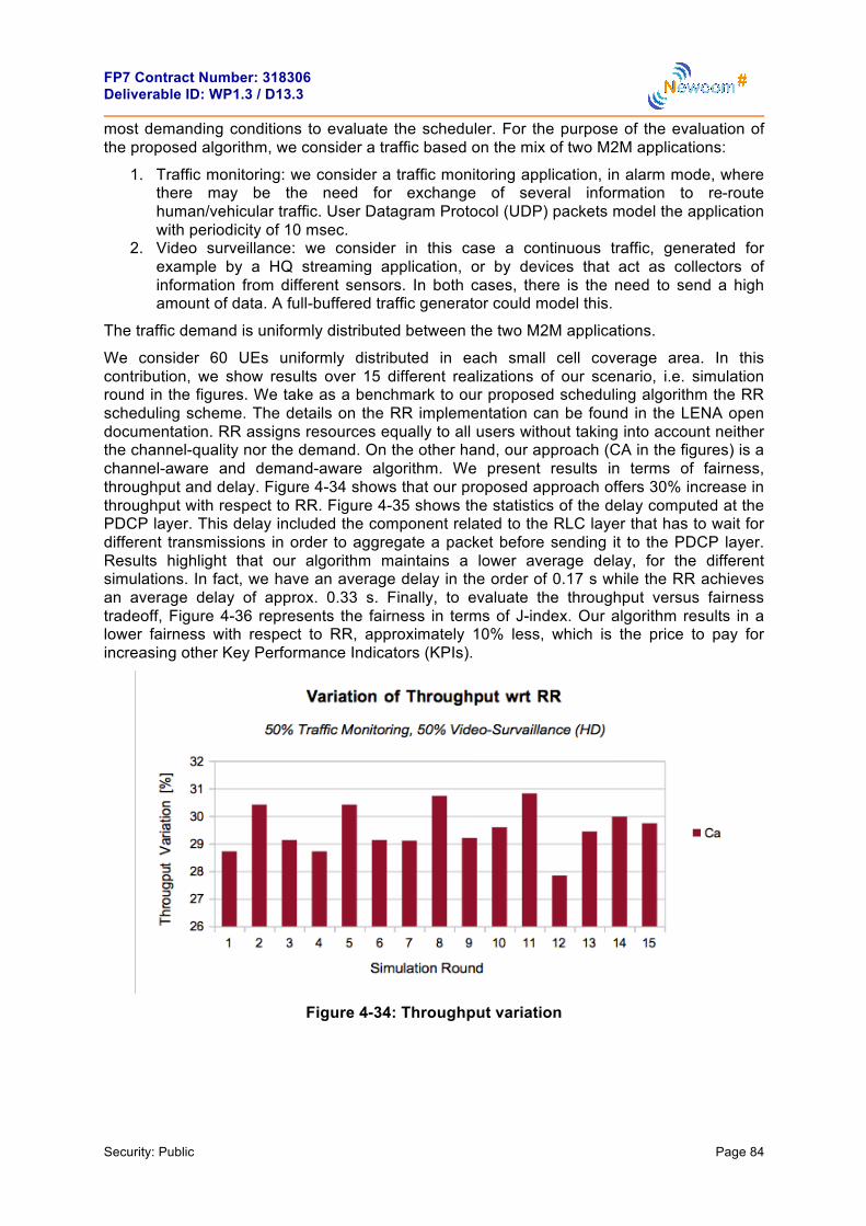
FP7 Contract Number: 318306 Deliverable ID: WP1.3 / D13.3
Security: Public Page 84
most demanding conditions to evaluate the scheduler. For the purpose of the evaluation of the proposed algorithm, we consider a traffic based on the mix of two M2M applications:
1. Traffic monitoring: we consider a traffic monitoring application, in alarm mode, where there may be the need for exchange of several information to re-route human/vehicular traffic. User Datagram Protocol (UDP) packets model the application with periodicity of 10 msec.
2. Video surveillance: we consider in this case a continuous traffic, generated for example by a HQ streaming application, or by devices that act as collectors of information from different sensors. In both cases, there is the need to send a high amount of data. A full-buffered traffic generator could model this.
The traffic demand is uniformly distributed between the two M2M applications.
We consider 60 UEs uniformly distributed in each small cell coverage area. In this contribution, we show results over 15 different realizations of our scenario, i.e. simulation round in the figures. We take as a benchmark to our proposed scheduling algorithm the RR scheduling scheme. The details on the RR implementation can be found in the LENA open documentation. RR assigns resources equally to all users without taking into account neither the channel-quality nor the demand. On the other hand, our approach (CA in the figures) is a channel-aware and demand-aware algorithm. We present results in terms of fairness, throughput and delay. Figure 4-34 shows that our proposed approach offers 30% increase in throughput with respect to RR. Figure 4-35 shows the statistics of the delay computed at the PDCP layer. This delay included the component related to the RLC layer that has to wait for different transmissions in order to aggregate a packet before sending it to the PDCP layer. Results highlight that our algorithm maintains a lower average delay, for the different simulations. In fact, we have an average delay in the order of 0.17 s while the RR achieves an average delay of approx. 0.33 s. Finally, to evaluate the throughput versus fairness tradeoff, Figure 4-36 represents the fairness in terms of J-index. Our algorithm results in a lower fairness with respect to RR, approximately 10% less, which is the price to pay for increasing other Key Performance Indicators (KPIs).
Figure 4-34: Throughput variation
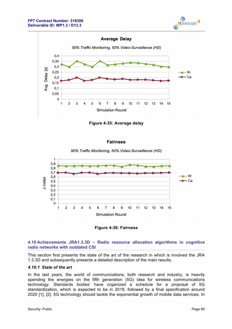
FP7 Contract Number: 318306 Deliverable ID: WP1.3 / D13.3
Security: Public Page 85
Figure 4-35: Average delay
Figure 4-36: Fairness
4.10 Achievements JRA1.3.3D – Radio resource allocation algorithms in cognitive radio networks with outdated CSI
This section first presents the state of the art of the research in which is involved the JRA 1.3.3D and subsequently presents a detailed description of the main results.
4.10.1 State of the art In the last years, the world of communications, both research and industry, is heavily spending the energies on the fifth generation (5G) idea for wireless communications technology. Standards bodies’ have organized a schedule for a proposal of 5G standardization, which is expected to be in 2018, followed by a final specification around 2020 [1], [2]. 5G technology should tackle the exponential growth of mobile data services. In

FP7 Contract Number: 318306 Deliverable ID: WP1.3 / D13.3
Security: Public Page 86
detail, the main challenges are: to satisfy the explosion of data-rate that is increased by roughly 1000x from forth generation (4G) to 5G; to meet higher traffic data asymmetric, the downlinkuplink ratio could rise to 10:1; to improve the energy consumption; to reduce the roundtrip latency time about to 1 ms [3]. The 5G key technologies, to address the challenges mentioned above, are divided between the use of new modulation techniques, i.e., sparse code multiple access (SCMA) [4], and a new cellular network design, i.e., extreme densification with small cell, mmWave spectrum, massive MIMO or WiFi unlicensed spectrum in the 5 GHz band [5]. In this evolution scenario from 4G to 5G is involved the activity research of the JRA 1.3.3.D.
CNIT/UniPi is investigating about the effectiveness of the Good-Put (GP) metric in a resource allocation (RA) problem with imperfect channel state information (CSI) for cognitive radio (CR) multi-hop BIC-OFDM system with decode-and-forward (DF) relay nodes (RNs), jointly with a path selection (PS) strategy. The CR scenario is based on the underlay paradigm proposed in [6]. The purpose of CR is to increase the overall spectral efficiency by allowing additional users in an already crowded spectrum. The underlay paradigm is one way to achieve this goal. In this scenario a secondary user (SU) is considered, who transmits concurrently with the existing users, which are called the primary users (PUs). The SU hereby has to guarantee that the interference power level at the PU receivers is kept below a certain threshold [7].
The GP metric is a significative cross-layer optimization criterion [8], [9], [10]. This metric characterizes in more a suitable way the actual performance of a packet-oriented communication system and it is defined as the number of information bits delivered in error-free packets per unit of time. In this context, [11] and [12] adopt the GP as performance metric to select the best combination of modulation and coding rate with uniform bit and power loading. In [8], instead, the GP criterion motivates the problem of optimally distributing bits and power across a set of subchannels in a coded adaptive OFDM system with hard Viterbi decoding. In particular, the hard decisions on the coded binary symbols are exploited so as to split the cross-layer nature of the problem by using the uncoded BER (at the decoder input) as an intermediate performance metric. On the other side, when soft Viterbi decoding is considered this layer separation is not trivial at all. Thus, to make feasible the RA multiparametric optimization problem (OP), the derivation of an accurate link performance prediction (LPP) metric providing a compact and manageable analytic representation of the GP performance is a crucial task. In this sense, one of the most promising LPP method to be mentioned is the effective signal-to-noiseratio (SNR) mapping (ESM) [13], such as the exponential ESM (EESM), logarithmic ESM (LESM), capacity ESM (CESM), and mutual information ESM (MIESM) schemes [14]. In particular, the EESM has the main advantage of providing a closed-form mapping function, but unfortunately, its generalization to high order modulations [15] does not exist. Differently from EESM, the MIESM solution includes two separates models, one for modulation and the other for coding, thereby enabling the separation between layers and making RA very convenient [16], although the mutual information mapping function has not a closed-form expression. Finally, in the literature it is present perhaps the most promising LPP technique that is called ESM and was originally proposed in [10]. This LPP allows getting an estimate of the GP, referred to as predicted GP (PGP), which represents the objective function of the RA and PS problems in order to get an accurate performance prediction. Moreover, the RA problem is able to perform adaptive modulation and coding (AMC) and energy allocation (EA) strategy in two separated steps by maximizing the EGP function.
With regard to the multi-hop, this transmission technique has traditionally been studied in the context of ad hoc wireless networks mainly as a means of enabling the network operation without any infrastructure. However, an upsurge of interest has been observed in the application of multi-hop relaying in cellular networks in order to create multihop cellular networks (MCNs) [17] in order to potentially enhance coverage, data-rates, quality of service
κ

FP7 Contract Number: 318306 Deliverable ID: WP1.3 / D13.3
Security: Public Page 87
(QoS) performance in terms of bit error rate (BER), packet error rate (PER), as well as QoS fairness for different users [18], [19]. Nevertheless, multi-hop relaying has inherent drawbacks, e.g., the requirement for extra radio resources for relaying hops, and the sensitivity to the quality of relaying routes. Therefore, well-designed RA and PS algorithms are crucial in MCNs, in order to effectively exploit the benefits of relaying. For mobile ad hoc network (MANET) many routing algorithms have been proposed [20], as optimized link state routing (OLSR), ad hoc on-demand distance vector (AODV), and dynamic source routing (DSR). In essence, these algorithms are designed with network infrastructureless in mind, and their main objective is to establish/maintain network connectivity, rather than to maximize system capacity. In the context of MCNs few algorithms have been proposed so far, e.g., location-based routing [21], path-loss-based routing [22], transmission-power-based routing [23], and congestion-based routing [24].
With the coming of 5G, we will attend to the spatial densification of the cellular network, through heterogeneous architectures, i.e., small cells or a flexible combination of evolved existing technologies (3G, 4G, WiFi) as described earlier. Therefore, multi-hop communication could have an increasingly important part [25]. For example, in devise-to-devise (D2D) transmission that allows nearby devices to establish local links so that traffic flows directly between them, instead of through the base station. An interesting case is the D2D relay for traffic offloading, where an user with a better geometry than a base station acts as a relay for another nearby user. D2D relay is a special example of dual-hop communication, and the concept can be extended to multi-hop communication [26]. Furthermore, multi-hop technique can be exploited in mmWave transmission, where are too weak for a long-distance communication. In [27] a D2D multi-hop mmWave transmission is considered, by studying a multi-hop routing protocol for video flow with different QoS.
In parallel, UGent is studing another dual-hop communication in a CR scenario in underlay fashion, where a SU transmits a signal to the receiver through a single carrier, exploiting an infrastructure of fixed multi-antenna RNs, which operate according to the amplify-and-forward (AF) protocol. In this context, for each transmit device (secondary transmitter (ST) and RNs), the optimal symbol energy allocation and beamforming scheme are derived, so as to minimize the outage probability for the dual-hop link.
From a practical viewpoint, the underlay technique for CR is very promising because it requires minimal cooperation with the PU network. However, a disadvantage is that the interference constraints can be very restrictive [28], which severely limits the performance of the SU network. This problem can be circumvented by equipping the ST with multiple transmit antennas. In [29], the multiple transmit antennas at the ST are used to balance between spatial multiplexing to the destination node (DN) and interference avoidance at the PU receivers. This operation is often called cognitive beamforming, and has received much attention over the years [30]-[32]. In [29], the assumption is made that the ST has perfect knowledge of both the channel gains to the DN node and the interfering channel gains to the PU receivers. This is a rather impractical assumption, because it can be very difficult for the SU network to get a reliable estimate of the interference channels. A more robust scenario is proposed in [31], where the ST only has imperfect knowledge about the channel gains to the PU receiver. Because the underlay paradigm requires ideally only minimal or no cooperation with the PU network, several proposals have been done to learn the interfering channel without any cooperation. In [30], a learning-based scheme is investigated, which does not require any prior knowledge of the channel gains to the PU receivers. The learning scheme completely eliminates the overhead for the PU network to estimate the interference channels and feed them back to the SU network. Even more general blind learning schemes were proposed in [33], [34].

FP7 Contract Number: 318306 Deliverable ID: WP1.3 / D13.3
Security: Public Page 88
4.10.2 Path Selection and Energy Allocation for Goodput based Multi-hop Transmissions with Imperfect CSI 4.10.2.1 Detailed Description In the previous deliverable, we presented a RA strategy for a dual-hop transmission in a CR scenario. Now, we have developed a RA method and a new path selection (PS) criterio for a non-cooperative multi-hop communication, exploiting fixed DF RNs, in a CR scenario in underlay fashion. Moreover, any intermediate node transmits with a bit-interleaved coded orthogonal frequency division multiplexing (BIC-OFDM) modulation.
In detail, this section describes:
• A semi-distributed RA (SD-RA) technique for non-cooperative multi-hop communications considering imperfect channel state information (CSI). The SD-RA algorithm optimizes GP metric between two nodes, in order to allocate the best: coding rate, QAM modulation and energy for each sub-carrier, for every link of the network. Two optimal RA (O-RA) solutions are used as benchmark. The O-RA techniques are derived from [35], extending the solution from a dual-hop to a multi-hop transmission. In the first O-RA method is considered a local energy constraint and in the other one global energy constraint. Both bencmarks are described in detail later. The SD-RA is able to reduce the signaling over the feedback channel and the computational complexity, w.r.t., the O-RA methods, paying a very little reduction of GP performance.
• A suboptimal PS (Sub-PS) strategy based on the Bellman-Ford (BF) algorithm [36] is presented, which is able to select the path in the wireless network in order to provide the best end-to-end GP between the ST and SR. An optimal PS (O-PS) method is used as benchmark, which is based on an exhaustive search of the path with the best GP across the network. The computational load required by the O-PS results to be polynomial in the number M of RNs of the network. Therefore, We present the Sub-PS algorithm with complexity O( 3M ). In particular, it is possible to further lower the complexity O( 3M ) of the Sub-PS scheme by introducing an approximated path selection (ASub-PS) strategy based on the Fibonacci-heap based Dijkstra algorithm [37], which runs in O( 2M ), without showing a significant GP performance loss. In contrast to Sub-PS, the ASub-PS selects the path, minimizing an approximation of the end-to-end packet error rate (PER). Moreover, the Sub-PS and the ASub-PS strategies do not require information about the network topology and the coordinates of the source and destination.
In detail, the considered system model is a non-cooperative network in a CR scenario with only one source-destination pair. The SU network consists of a SU transmitter (ST), a SU receiver (SR) and M fixed DF relay nodes (RNs) iR , 1, ,i M= L . The ST operates in the
same bandwidth as PUN PUs according to the underlay paradigm [19]. The transmission of a
data message always occurs in TS 1N M≤ + time slots, simply called hops or links, and
TS 1L N= − is the number of exploited RNs for the transmission. To be clear, the time slots
TSN can have different duration each other and the transmission is not synchronized. For the ease of notation, let us denote with:
1. is the path connecting ST to SR passing through the relays
1, ,
Li iR RL , with 0 L M≤ ≤ (if 0L = , SRLiR @ ), , with j ki i≠
;
2. is the generic link, 0l = is the link 1
ST= iR and l L= is the link LiR -
P (ST,R i1,!,R iL
,SR)
i1,!,iL ∈{1,!,M}
∀j ≠ k ∈{1,!,L}
l ∈L ! {0,"L}

FP7 Contract Number: 318306 Deliverable ID: WP1.3 / D13.3
Security: Public Page 89
SR.
Finally, let us assume:
1. not all nodes can be connected among them; 2. all RNs are connected to the ST; 3. the data message is transmitted from the ST to the SR through L DF RNs by means
of a packed-oriented BIC-OFDM communication system consisting of N subcarriers within a bandwidth B .
Before delving more specifically into the RA and the PS strategies, a brief description of the channel model in order to define the CSI and the GP metric are necessary.
Any transmitting node needs of the CSI and we assume that any transmitter obtains the CSI from the corresponding receiver via a feedback channel. For any link, the CSI are the received signal-to-noise (SNR) for each OFDM subcarrier
(4.10.1)
where nE is the transmit energy on the nth subcarrier, nH is the channel coefficient
normalized for the path loss (PL), nx is the transmitted QAM symbol. However, the transmitter receives an SNR estimate only once every OFDM symbols in order to reduce the signaling over the feedback channel. This means that such received CSI is outdated and imperfect. The transmitter uses a minimum-mean-square-error (MMSE) predictor to predict the actual impulse response to compensate the outdated and imperfect CSI problem and therefore to perform a correct RA strategy [38]. The predicted actual impulse response is derived from the P previously received impulse response estimate
, (4.10.2)
where the index i specifies the the last OFDM received symbol and is the generic vector that collects the received impulse response estimate for each subcarrier. From Eq. (4.10.2) the predicted SNR for each subcarrier is defined
(4.10.3)
where µ nH is the predicted channel coefficient over the subcarrier n . The predicted SNRs (4.10.3), , are the CSI to perform the RA and the PS algorithms. Finally, follow a detailed description of the GP metric. A practical metric for evaluating the performance in a packed-oriented transmission is the GP, which is the number of correctly received information bits per unit of time. Ideally, the transmitter should be able to optimize the GP by a proper selection of the transmission parameters. However, any transmitting node only has outdated and imperfect CSI; therefore the channel prediction is performed and, as a consequence, a predicted GP (PGP) will be optimized. The PGP is defined as the GP that would be achieved when the actual channel equals the predicted
channel . The PGP function depends on the packet error rate (PER)
γ n !
En |Hn |2
σ w2 , ∀n∈N ! {1,…,N},
D
h!(i)
zP (i) ! [h"(i − D)T,…,h"(i − DP)T]T
h!T
γ n !
En | Hn |2
σ w2 , ∀n∈N ! {1,…,N},
∀n∈N
H ! [H1,",HN ]T
H ! [H1,", HN ]T

FP7 Contract Number: 318306 Deliverable ID: WP1.3 / D13.3
Security: Public Page 90
BIC-OFDMPER ( , )Γφ (4.10.4)
where is the vector of the predicted SNRs and is the transmission mode (TM), which is defined from the pair QAM modulation for each subcarrier
(the generic element nm is the number of bit per symbol over the subcarrier ) and the code-rate r . The PER (4.10.4) is difficult to evaluate analytically in a coded OFDM system. We evaluate the PER for any links of the networks, by exploiting the link performance prediction (LPP) method called ESM technique proposed in [10]. By using this approach, we are able to compress the vector of the predicted SNRs Γ into a scalar value called effective SNR effγ , such that the following relationship holds (within a small approximation error)
AWGN eff BIC-OFDMPER ( , ) PER ( , )r ≅ Γγ φ (4.10.5)
where AWGN effPER ( , )r γ is the PER for an equivalent coded BPSK system with code rate
r operating over an additive white Gaussian noise (AWGN) channel with SNR equal to effγ .
The ESM expression is calculated as follows [10]
(4.10.6)
where nα and nβ are constant values depending on the number of coded bits per
constellation symbol nm loaded on the n th subcarrier.
Now, the PGP function can be derived as the ratio of the number of correctly received information bits and the actual transmission time. If we normalize the PGP function by dividing by the actual bandwidth S/N T , where ST is the duration of an OFDM symbol, we get, expressed in (bit/s/Hz), the following result
(4.10.7)
where pN is the number of information bit per packet and uN is the total packet length, i.e.,
CRCp uN N N= + , and CRCN are the bits for the cyclic redundancy check (CRC) section. The PGP (4.10.7) is the result for a single-hop or direct link source-destination.
Now, we consider the PGP for a multi-hop DF network. First of all the probability of a packet error from the ST to the SR is introduced fixing a generic path through L M≤ RNs.
(4.10.8)
Γ ! [γ 1,",γ N ]T
φ ! (m,r)
m ! [m1,",mN ]T
n
κ
κ
γ eff ! − log1
mjj=1
N
∑⋅ α nn=1
N
∑ ⋅e−γ nβn
⎛
⎝
⎜⎜⎜⎜
⎞
⎠
⎟⎟⎟⎟
,
ζ (φ,E) ! TsNNp ⋅[(1− PERAWGN (r,γ eff )]
NuTsr mn
n∑
=Np
NNu
r mnn∑ ⋅[1− PERAWGN (r,γ eff )],
P (ST,R i1,!,R iL
,SR)
PERAWGNtotal (r0,!, rL ,γ 0,eff ,!,γ L,eff ) "
PERAWGN(r0,γ 0,eff )+[1-PERAWGN(r0,γ 0,eff )]⋅PERAWGN(r1,γ 1,eff )
!+ [1-PERAWGN(ri,γ i,eff )]i=1
L-1
∏ ⋅PERAWGN(rL,γ L,eff ).

FP7 Contract Number: 318306 Deliverable ID: WP1.3 / D13.3
Security: Public Page 91
From the formula (4.10.8), the normalized PGP (bits/s/Hz) of the L DF RNs is written as follows
(4.10.9)
where { }0 0 0,m r=φ , { },l l lm r=φ , 0E and lE respectively denote the TM for the ST and RN liR and the transmit energy per symbol for the ST and RN
liR . The denominator
0,
L u sj
j j nn
N Tr m=∑ ∑
in (4.10.9) represents the total transmission time of a packet from ST to SR
through L RNs. Note that the transmission time for a generic link depends on the code-rate jr and the number of bits per subcarrier ,j nm , which may be different from a link to another.
Therefore, the transmission time, or the time slot, of a packet for each link can vary. The PGP (4.10.9) rappresents the objective function of the optimal RA and PS problems with local constraint as well as global one.
At this point, an approximation of the PGP is proposed in order to simplify the RA and the PS problems that just after will be presented. The Approximated PGP (A-PGP) function is defined as
(4.10.10)
where
(4.10.11)
The probability (4.10.11) considers the loss of a packet as an independent event on each link between ST and SR. The approximation (4.10.11) of the true probability (4.10.8) is based on the fact that AWGN ,effPER ( , ) 1l lr =γ and consequently AWGN ,eff(1 PER ( , )) 1l lr− ≅γ for high
levels of effective SNR ,efflγ , l∀ ∈L . Thus, Formula (4.10.11) is a sub-optimal solution, however, it provides an upper-bound, w.r.t., the perfect PER (4.10.8). The motivation to carry out this approximation will be clarified during the description of the Sub-PS techniues.
At this point the O-RA problem is presented first with local energy constraint and syubsequently with global energy constraint. These two methods are used as benchmark for for the SD-RA technique. In the two O-RA problems the objective function is the PGP (4.10.9). In [35] is presented the same RA method for dual-hop transmissions. In the final part of this section part, we introduce the SD-RA problem, where, now, the objective function is the A-PGP (4.10.10). The SD-RA method is able to considerably reduce the feedback information from each RN and the SR to the ST, w.r.t., the O-RA method. All of GP-based
ζ (φ0,!,φL ,E0,!,EL ) "
TsNNp ⋅[1− PERAWGN
total (r0,!, rL ,γ 0,eff ,!,γ L,eff )]NuTs
rj mj ,nn∑j=0
L∑=
Np
NNu
[1− PERAWGNtotal (r0,!, rL ,γ 0,eff ,!,γ L,eff )]
1rj mj ,n
n∑j=0
L∑,
ζ!(φ0,",φL ,E0,",EL ) #Np
NNu
[1− PER$ AWGNtotal
(r0,",rL ,γ 0,eff ,",γ L ,eff )]1
rj mj ,nn∑j=0
L∑,
PER! AWGN
total(r0,",rL ,γ 0,eff ,",γ L ,eff ) # PERAWGN (ri,γ i,eff )
i=0
L
∑ .

FP7 Contract Number: 318306 Deliverable ID: WP1.3 / D13.3
Security: Public Page 92
RA strategies are able to select the TM and energy vector for a packed-oriented BIC-OFDM system with imperfect CSI, in order to maximize the specific objective function, i.e. PGP or A-PGP, so that a robust and spectrally-efficient transmission over frequency selective channels
can be obtained. For each presented RA method a generic path through L of the M available RNs is fixed.
The O-RA problem with local energy constraint, called local-RA (L-RA) for short, can now be introduced as
(4.10.12)
where and are respectively the optimal TM and the optimal
energy vector for the generic link . Moreover ,1
1 Nl nnE S
N =≤∑ is the local energy
constraint, where is the maximum value of the average allocated energy per subcarrier
and is the interference constraint for the primary receiver , is the interference threshold.
Befor presenting the solution of the optimization problem (4.10.12), we also show the O-RA problem with global energy constraint, called global-RA (G-RA) for short. This is because the procedure to find the solution in both cases is the same. Thus, the G-RA problem is introduced
(4.10.13)
where
,0 1
1 L Nl nl nE S K
N = =≤ ⋅∑ ∑ is the global energy constraint and K is a constant value
that defines the maximum available energy.
The optimization problems (OPs) (4.10.12) and (4.10.13) can be divided in two consecutive steps to find the solution:
• given a generic TM , , find the optimal energy allocation vector
, ;
• the best TM , , is selected in order to maximize the PGP metric (4.10.9).
Step 1 – Optimal energy allocation: It follows from (4.10.9) that the PGP depends on the energy allocation vector lE , , only through the effective SNR ,eff ( , )l l lEγ φ , .
Furthermore, since the only decrease as a function of ,eff ( , )l l lEγ φ , , then,
P (ST,R i1,!,R iL
,SR)
(φ0*,!,φL
* ,E0* ,!,EL
* ) = argmaxφ0 ,!,φL ,E0 ,!,EL
{ζ (φ0,!,φL ,E0,!,EL )}
s.t. 1N
El ,nn=1
N∑ ≤ S, ∀l ∈L
El ,n ≥ 0, ∀n∈N , ∀l ∈L
Il ,q ≤ I q , ∀q∈Q , ∀l ∈L
φl* ! {ml
*, rl*} El
* ! [El ,1* ,…,El ,N
* ]T
l ∈L
S
Il ,q ≤ I q q∈Q ! 1,",Q[ ]T
I q
(φ0*,!,φL
* ,E0* ,!,EL
* ) = argmaxφ0 ,!,φL ,E0 ,!,EL
{ζ (φ0,!,φL ,E0,!,EL )}
s.t. 1N
El ,nn=1
N
∑l=0
L
∑ ≤ S ⋅K , ∀l ∈L
El ,n ≥ 0, ∀n∈N , ∀l ∈L
Il ,q ≤ I q , ∀q∈Q , ∀l ∈L
φl ! {ml , rl} ∀l ∈L
El* ! [El ,1
* ,…,El ,N* ]T ∀l ∈L
φl*
∀l ∈L
∀l ∈L ∀l ∈L
PERAWGNtotal
∀l ∈L

FP7 Contract Number: 318306 Deliverable ID: WP1.3 / D13.3
Security: Public Page 93
the optimal energy allocation vector *lE , , can be found for a fixed value of lφ ,
, by maximizing ,eff ( , )l l lEγ φ (4.10.6) that, in turns, is equal to minimize the argument of the logarithm. So we can introduce the new indipendend OPs for each link. For the L-RA is
(4.10.14)
For the G-RA is
(4.10.15)
where in (4.10.14) and (4.10.15) the new objective function is
, ,ˆ,
1( , ) e .l n l n
N
l l l l nn
F −
=
= ⋅∑m E γ βα (4.10.16)
It is easy to see that the OPs (4.10.14) and (4.10.15) remains unchanged, replacing the objective function (4.10.9) by (4.10.16), because a generic TM lφ is fixed. The considered OPs are convex optimization problems [39], and the optimal solutions can be found by the method of Lagrange multipliers. However, the convergence of such algorithms is often slow. Therefore we will use the successive set reduction (SSR) approach introduced in [9]. The SSR algorithm is able to achieve almost the same performance as the method of Lagrange multipliers but with a much faster convergence. We also note that the optimal value of *
lE
only depends on the modulation vector lm and µ lH .
Step 2 – Optimal TM: The optimal TM *φ is obtained for the L-RA and G-RA problems by exhaustively solving the following problem
(4.10.17)
where a uniform bit allocation (UBA), , has been adopted for simplicity. Here, the limitation of the L-RA and G-RA problems for a multi-hop scenario is explained better. Because the ST must solve the OP problems for each possible path, we can deduce that:
• from the OPs (4.10.12) and (4.10.13), the ST must know the vectors of the predicted
∀l ∈L
∀l ∈L
El* = argmax
El{γ l ,eff (φl ,El )} = argmin
El{Fl (ml ,El )}
s.t. 1N
El ,nn=1
N
∑ ≤ S
El ,n ≥ 0, ∀n∈N , ∀l ∈L
Il ,q ≤ I q , ∀q∈Q
El* = argmax
El{γ l ,eff (φl ,El )} = argmin
El{Fl (ml ,El )}
s.t. 1N
El ,nn=1
N
∑l=0
L
∑ ≤ S
El ,n ≥ 0, ∀n∈N , ∀l ∈L
Il ,q ≤ I q , ∀q∈Q
(φ1*,…,φL
* ) = argmaxφ1,…,φL
{ζ (φ0,!,φL ,E0* ,!,EL
* )}
s.t. φl ∈DmN × Dr , ∀l ∈L
ml ,n = ml , ∀n∈N , ∀l ∈L
mn = m,∀n∈N

FP7 Contract Number: 318306 Deliverable ID: WP1.3 / D13.3
Security: Public Page 94
SNR towards the PU of any node of the network to be able to evaluate the interference level. From the eq. (4.10.16), also the predicted SNR of any link must be known. This may lead to an high signaling traffic, causing a congestion of the feedback channel;
• the problem (4.10.17) is solved in a exhaustive way and this causes an exponential growth in computational complexity, directly proportional to the growth of the RNs.
The SD-RA technique is able to solve the problems listed above, which arise by exploiting the L-RA and G-RA methods in a multi-hop transmission. Afterwards, the SD-RA solution is presented. In the SD-RA problem each link maximizes the local PGP function (4.10.7) independently from the others nodes in order to obtain the optimal energy allocation and the optimal TM solutions. Hence, the SD-RA method is being distributed on any RN.
The RA optimization problem (OP) is shown for the generic link .
(4.10.18)
In accordance with the above-described approach, the SD-RA problem is still divided into two consecutive steps:
• given a generic TM lφ find the optimal energy allocation vector *lE . The OP is the
same to the problem (4.10.14), and it can still be solved by exploiting the method of Lagrange multipliers and the convergence of such algorithm is obtained with the SSR approach.
• the best TM *lφ is selected in order to maximize the PGP metric (4.10.7) with the
same approach shown in (4.10.17), simply by replacing the objective function with the PGP (4.10.7)
(4.10.19)
Naturally, the SD-RA method is sub-optimal compared with the O-RA one, i.e., L-|RA and G-RA. In detail, exploiting the SD-RA strategy, the local GP between two generic node is maximized without taking into consideration the end-to-end GP. In other words, the packet transmission time from ST to SR is not considered. This makes up to a big problem, which can be satisfactorily resolved by the Sub-PS strategy subsequently presented in this section. However, when carrying out the local maximization of the GP, the ST has no need to know the CSI of each link as in the L-RA and G-RA methods.
So from this point the PS strategies can be presented. From a set of M available RNs, L relays will be selected to provide the “best” GP between the ST and SR. Three different PS approach are presented, called optimal PS (O-PS), sub-optimal PS (Sub-PS) and approximated Sub-PS (ASub-PS) respectively. The O-PS method is used as a benchmark for the second and third one.
l ∈L
l ∈L
(φl*,El
*) = argmaxφl ,El
{ζ (φl ,El )}
s.t. 1N
El ,nn=1
N∑ ≤ S
El ,n ≥ 0, ∀n∈N
Il ,q ≤ I q , ∀q∈Q
(φl*) = argmax
φl{ζ (φl ,El
*)}
s.t. φl ∈DmN × Dr , ∀l ∈L
ml ,n = ml , ∀n∈N , ∀l ∈L

FP7 Contract Number: 318306 Deliverable ID: WP1.3 / D13.3
Security: Public Page 95
The O-PS method can be finalized by selecting the path that maximizes the overall PGP metric from the ST to the SR. The PS problem can be formulated as
(4.10.20)
where is the set of all possible paths connecting ST with SR and the objective function is
(4.10.21)
The problem (4.10.21) can be solved in an exhaustive way, by exploiting both the L-RA and the G-RA methods. In detail, we can find a solution dividing (4.10.21) in two steps:
• the L-RA method or the G-RA one is performed for any path belonging to the set ; • the best PGP is selected and therefore the best path .
Since there exist !/ ( )!M M L− different routes to go from ST to SR passing through L RNs, solving the problem (4.9.20) via a naive exhaustive search requires combinatorial complexity, which even for small is clearly infeasible. Moreover, in order to solve the O-PS problem (4.10.20), the ST needs to know the CSI lΓ of all active RNs. In this way, the signaling traffic on the feedback channel will be unsustainable. Subsequently, the ST should transmit the best TM *
lφ and the best energy allocation *lE to every RN li
R , .
Thus, the O-PS method is considered only as a benchmark and it is compared with the Sub-PS method presented below.
The Sub-PS method provides a much more efficient path selection algorithm, whose rationale relies on: first, finding the set of candidates, i.e., one path for each value of L , with0 L M≤ ≤ , and then, choosing the best path in the candidate set as the one which maximizes the A-PGP metric (4.10.10).
(4.10.22)
The A-PGP metric is used to solve the Sub-PS problem. Indeed, by means of the approximation of the PGP, we can exploit a sum of PER that is very useful to approximately find the shortest path. Before, it is necessary to define a cost metric for each link of the network. The cost for any link is the PER defined in (4.10.5). Each transmitting node performs first the SD-RA method, in order to find the optimal TM *
lφ and energy allocation
vector *lE , and then each one evaluates the PER (4.10.5). In detail, to execute the Sub-PS
method, two steps are needed:
• the network performs the SD-RA algorithm; • each transmitting node evaluates the cost as
(4.10.23)
where 1li
R+
represents each node directly connected toliR , for 0l = the cost is
1ST ilR +−δ and for l L= the cost is
1 SRilR +−δ .
At this point, we can clarify the Sub-PS method with the following proposition
Proposition (Path selection): The solution for the Sub-PS problem can be obtained with polynomial complexity O( 3M ) by means of a two-step procedure [40]: Step 1: the 1M + sub-problems
Popt ! argmax
P ∈Gη P( ){ },
G
η P( ) ! ζ (φ0,",φL ,E0,",EL ).
G
ζ (φ0*,…,φL
* ,E0* ,!,EL
* ) Popt ∈G
M
∀l ∈L
η! P( ) " ζ!(φ0,#,φL ,E0,#,EL ).
R il
δRilRil+1 ! PERAWGN(rl
*,γ l ,eff* ),

FP7 Contract Number: 318306 Deliverable ID: WP1.3 / D13.3
Security: Public Page 96
(4.10.24)
are solved adopting the path metric
(4.10.25)
where and passes through L RNs only. The result is the set
, which includes the 1M + candidates for the optimal path.
Step 2: the optimal path follows from
(4.10.26)
where is the metric defined in (4.10.22).
Proof: Bearing in mind that: i) all the paths belonging to have relays and ii) the function
A-PGP (4.10.10) increases with decreasing the (4.10.11), then maximizing
is equivalent to minimize (4.10.25), fixing the optimal TM *lφ and energy vector *
lE .
Moreover, is an additive metric, i.e., it is the sum of the positive weights 1i il lR R
+−δ , one
for each link belonging to the path . Hence, each sub-problem (4.10.24) of Step 1 turns into a shortest path problem constrained by L hops with non-negative link metric
1i il lR R+
−δ , which can be efficiently solved with polynomial complexity by applying the modified
Bellman-Ford (BF) algorithm [41].
In order to reduce the overall computational complexity, the Sub-PS algorithm can be suitably approximated, as showed in the following corollary [40].
Corollary: the approximated version of the Sub-PS algorithm, or ASub-PS for short, can be defined by the following OP
(4.10.27)
where is defined in (4.10.25). The problem (4.10.27) can be solved in O( ).
Proof: Since the metric is additive on the links belonging to a given path , the problem (4.10.27) is equivalent to an unconstrained shortest path problem with non-negative
link costs, which can be efficiently solved through the Fibonacci-heap-based Dijkstra algorithm with complexity O( ) [42]. A couple of comments about Corollary can be of help.
• In the case of dual-hop network ( 1M = ), the ASub-PS algorithm reduces to
(4.10.28)
• the ASub-PS algorithm represents a good performance-versus-complexity tradeoff.
Basically, the ASub-PS algorithm does not consider the transmission time of a packet from the ST to the SR, differently from the Sub-PS method.
PSub-PS
(L ) = argminP ∈GL
{µ(P )}, 0 ≤ L ≤ M ,
µ(P ) = δRilRil+1
l=0
L
∑ = PERAWGN(ri,γ i,eff )i=0
L
∑ = PER! AWGNtotal
(r0,",rL ,γ 0,eff ,",γ L ,eff ),
GL ! {P |P ∈G
C ! {PSub-PS(L ) }L=0
M
PSub-PS
(opt ) = argmaxP ∈C
{η!(P )},
η!(P )
GL L
ζ! PER! AWGN
total
ζ!
µ(P )
µ(P )
∀l ∈L P
PASub-PS
(opt ) ! argminP ∈G
µ P( ){ },
µ(P ) M 2
µ(P ) P
M 2
PASub-PS(opt ) =
P(ST,R,SR), if δST,R +δR,SR < δST,SDP(ST,SR), otherwise
⎧⎨⎪
⎩⎪;

FP7 Contract Number: 318306 Deliverable ID: WP1.3 / D13.3
Security: Public Page 97
4.10.2.2 Main Results In this section, the effectiveness of the proposed SD-RA method together to the Sub-PA and ASub-PS strategy is demonstrated, by comparing their performance to the performance of the L-RA and the G-RA methods together to the O-PS strategy.
In Table 4.2 we summarized the simulation parameters for the packet-oriented CR BIC-OFDM transmission system.
Table 4-2: System parameters
BIC-OFDM and Channel Parameters Value Information bits ( ) 1024
CRC ( ) 32
Subcarriers ( ) 1320
FFT size 2048
Bandwidth ( ) 20 MHz
Cyclic prefix 160
4-, 16-, 64-QAM modulation ( ) 2, 4, 6
Convolutional code with rate ( ) 1/2, 2/3, 3/4, 5/6
Noise in OFDM bandwidth ( ) -100 dBm
Doppler frequency ( ) 144 Hz
CSI update interval ( ) 7
Memory of the channel predictor ( ) 4
Interference threshold ( ) 50 dB The considered channel model is the ITU vehicular A and the PL model is taken from the standard IEEE 802.16m. In particular, any simulation is carried out, by exploiting the modified COST231 Hata model, assuming a carrier frequency GHz and a SR high above the floor m [43]. In each simulation the number of PUs is . Each value of the numerical results is obtained by averaging over 1000 independent packets, which experience independent channel realizations. The average GP (AGP) is calculated as the average of the normalized GP of each packet (bits/s/Hz):
1000
1
1 ( )AGP=1000 ( )
s
i p
T B iN T i=∑ (4.10.28)
where ( )B i is equal to pN if the packet was correctly received, or 0 when delivery fails,
( )pT i is equal to the transmission time of the packet. Two network configurations are considerd (NCs), which are depicted in Figure 4-37 a and b.
NP
NCRC
N
B
mn , ∀n∈N
r
N0 i N
fdD
P
I1
f0 = 2hSR = 1.5 NPU = 1

FP7 Contract Number: 318306 Deliverable ID: WP1.3 / D13.3
Security: Public Page 98
Figure 4-37: a) NC1, b) NC2.
• NC1: square configuration with M = 2 relays positioned on the vertices and direct link;
• NC2: random configuration with M=5 relays. RNs and PR are randomly positioned, R1
is fixed between ST and SR. A clarification, when the nodes are at different distant each other, the AGP is calculated w.r.t. the total transmit energy S N⋅ . This is because, for different distances the PL changes and the received SNR is different among the nodes for equal transmitted energy.
First of all, Figure 4-38 verifies the accuracy of the A-PGP function w.r.t. the PGP one. For the scenario NC1, the RA and PS problems are solved with the optimal solution O-RA with local energy constraint (L-RA) and O-PS respectively, exploiting the A-PGP metric and the other PGP. As we can see, the two curves are practically identical. This ensures that the A-PGP is a good approximation of the PGP function even for very low total transmit energy.
Figure 4-39 compares the performance of the SD-RA together with Sub-PS and with ASub-PS. We can see that the performance gap with the benchmark L-RA and G-RA with O-PS is just more evident. This is because the SD-RA with Sub-PS strategy evaluates the RA for each link, considering the end-to-end GP only during the path selection step. In the case with SD-RA with ASub-PS strategy, instead, the path selection method selects the path with the minimum PER sum, without considering the end-to-end GP. In other words, the ASub-PS criterio does not evaluate the transmission time of a packet from the source to the receiver.
Finally, Figure 4-40 shows the numerical result for the scenario NC2. This scenario is depicted in Figure 4-37 b, where 5M = RNs are present. In detail RN 1R is fixed to the midpoint of the square and the other RNs are randomly placed and the configuration of the RNs is the same for any curves. As we can see, the reliability of the SD-RA algorithm with Sub-PS and ASub-PS is still guaranteed. In this generic scenario, the ST can choses different paths to transmit an information to the SR, but we have constrained the number of the hops to 4L = to limit also the computational complexity. Moreover, we can say that the SD-RA with ASub-PS method is a good compromise between GP performance and computational complexity equal to O( 2M ). It's important to emphasize the quality of the Sub-PS solution for any value of total transmit energy, indeed the performance gap between the L-RA, G-RA plus O-PS is very small. Therefore, we can say that the best choose is the SD-
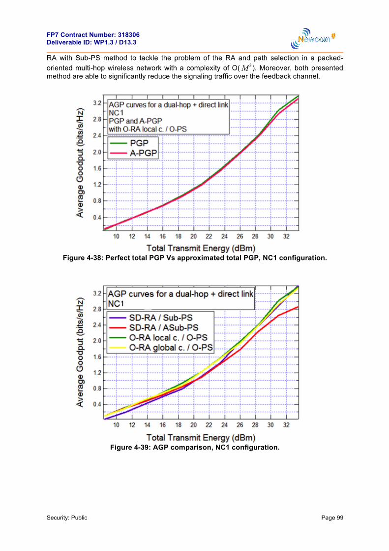
FP7 Contract Number: 318306 Deliverable ID: WP1.3 / D13.3
Security: Public Page 99
RA with Sub-PS method to tackle the problem of the RA and path selection in a packed-oriented multi-hop wireless network with a complexity of O( 3M ). Moreover, both presented method are able to significantly reduce the signaling traffic over the feedback channel.
Figure 4-38: Perfect total PGP Vs approximated total PGP, NC1 configuration.
Figure 4-39: AGP comparison, NC1 configuration.

FP7 Contract Number: 318306 Deliverable ID: WP1.3 / D13.3
Security: Public Page 100
Figure 4-40: AGP comparison, NC2 configuration.
4.10.3 Distributed Dynamic Resource Allocation for Cooperative Cognitive Radio Networks with Multi-Antenna Relays 4.10.3.1 Detailed Description This activity has been carried out by UGent and the aim is to minimize the exact outage probability of a single-carrier dual-hop SU network, under severe interference constraints.
A cooperative SU network is considered as in the previous work presented in the last deliverable. Here the scenario has been extended by introducing multiple transmit and receive antennas on the relay nodes (RNs) in order to apply cognitive beamforming, while the other nodes of the PU and SU network are equipped with a single antenna. The RNs equipped with multiple antennas make the resulting SU network more reliable because of increased diversity. This is a typical scenario for device-to-device communications [44], where two directly-communicating mobile users are aided by several fixed multi-antenna relay stations. The main novel contribution of this activity is the investigation of the optimal performance of the SU network with multi-antenna RNs for different levels of channel information, for both the interference channels and the channels toward the SU destination node (DN). For each type of channels separately, it is assumed that the channel state information (CSI) available at the SU transmitters is perfect or imperfect, or that only channel distribution information (CDI) is available; this approach allows the levels of CSI for the two types of channels to be different. Comparison of the resulting optimized outage probabilities shows how much performance gain a practical algorithm, that uses imperfect CSI, can achieve compared to the CDI case, and how much performance loss occurs compared to the ideal case of perfect CSI.
In detail a CR scenario is considered, where the SU network is an amplify-and-forward (AF) cooperative network, consisting of a source node (SN), a DN and M RNs with the presence of PUN PU receivers in the same bandwidth. The SN transmitter and the DN and PU
receivers are equipped with a single antenna, while the RNs have aN transmit/receive
antennas. The random variables SDh , , ( )s r mh , , ( )r d mh denote zero-mean circularly symmetric complex Gaussian channel gains between the SN and the DN, between the SN

FP7 Contract Number: 318306 Deliverable ID: WP1.3 / D13.3
Security: Public Page 101
and the aN receive antennas of the m th RN, and between the aN transmit antennas of the th RN and the DN, respectively.
The communication from the SN to the DN occurs in two time slots. During the first time slot,
the SN sequentially transmits in time a data sequence to the DN and the M RNs on a single carrier, belonging to a given unit-energy constellation, such that
2E 1, 1kx k K⎡ ⎤ = ≤ ≤⎣ ⎦. Each RN combines the signals from its aN receive antennas using
maximum ratio combining (MRC). Assuming that the noise variance at each antenna of the m th RN takes the same value 2 ( )r mσ , the corresponding signals received by the DN and obtained after MRC at the m th RN are expressed as
(4.10.29)
where 0E denotes the transmit energy per symbol used by the SN, and the noise vectors
,s dn and , ( )s r mn on the channels to the DN and th RN are distributed as and
, respectively ( 1, ,m M= L ), furthermore I refers to the identity matrix and
is the norm operator. In the second time slot the DN selects the RN that yields the highest SNR at the DN and only this RN will amplify the signal received from the SN and forward it to the DN. Assuming that the m th RN is selected, the signal transmitted by its k th antenna is
(4.10.30)
where ( , )m nν is a complex-valued coefficient, with 2( , )m nν denoting the part of the total
transmit energy per symbol mE of the m th RN that is applied to the th transmit antenna;
hence, the beamforming vector [ ]T( ) ( ,1), , ( , )am m m N=v Lν ν has a magnitude equal to
mE . The normalization in (4.10.30) implies that the RN has to determine the average received energy per symbol for every frame. Thus, the signal received by the DN from the mth RN can be written as
H, ,
, ,2 20 , ,
( ) ( ) ( )( ) ( ),
( ) ( )
r d s rr d r d
s r s r
m m mm m
E m m= +
+
v h yy n
h σ (4.10.31)
where the noise vector , ( )r d mn is distributed as .
Concerning the coefficients of the Rayleigh-fading interference channels from the SN to the th PU receiver and from the th RN to the th PU receiver, they are denoted by ,s pg and
, respectively, where and (
1, ,m M= L , PU1, ,p N= L ). The SU network has to keep the interference power level at the
PUs below a certain threshold Γ by appropriately choosing the transmit energy 0E and the size and direction of the beamforming vectors ( )mv ( 1, ,m M= L ). The exact formulation of the interference constraints depend upon the level of channel information that is available at
m
x ! x1,", xK[ ]T
ys,d = E0hs,dx + ns,d ,
ys,r (m) = E0‖hs,r (m)‖x + ns,r (m), m = 1,…,M ,
m N c(0,σ s,d2 I)
N c(0,σ s,r2 (m)I)
s(n) =v*(m,n)ys,r (m)
E0‖hs,r (m)‖2 +σ s,r
2 (m), n = 1,…,Na ,
n
N c(0,σ r,d2 (m)I)
p m p
gr,p (m)∈C Na×1
E[| gs,p |2 ]! ρs,p
2
E gr,p (m)gr,p (m)
H⎡⎣ ⎤⎦ ! Rg,p (m)

FP7 Contract Number: 318306 Deliverable ID: WP1.3 / D13.3
Security: Public Page 102
the transmitter about its channel gains to the PU receivers. This work makes the distinction between three levels of channel state information (CSI) for the interference channels: perfect CSI (PCSI), imperfect CSI (ICSI) and CDI. Below these three levels of (CSI) will be defined.
According to the underlay paradigm the SU network has to limit the interference level at the PU receivers. When PCSI is available at the corresponding transmitting node, the intereference constraints for the SN and the RNs can be expressed as
2
0 , PU, 1, ,s pE g p N≤ Γ = L (4.10.32)
2H, PU( ) , 1, , , 1, ,r pm m M p N≤ Γ = =v g L L (4.10.33)
These constraints guarantee that the interference power level does not exceed / KTΓ , where T denotes the duration of a symbol interval. Constraint (4.10.33) can be rewritten as follows
, PUTr ( ) ( ) , 1, , , 1, , ,r pm m m M p N⎡ ⎤ ≤ Γ = =⎣ ⎦S G L L (4.10.34)
where , and is the trace operator.
The assumption of PCSI of the interference channels is not very realistic, but due to feedback delay and estimation errors, the CSI available at the SU transmitters is not perfect. We assume that each SU transmitter periodically receives an update of the estimate of its channel gain to the th PU receiver. In principle, the feedback of the CSI or CDI related to the interference channels can come directly from the PU; in practice, it will be provided more likely from a band manager, which monitors the spectrum [7]. Note that blind learning schemes as in [30], use the idea of an effective interference channel that requires a different description of the interference channels, but the general approach of this section could also be adapted to those scenarios. The channel estimates received by the SU transmitters are given by
(4.10.35)
where , and the variance of the estimation error is
defined as . Each transmitting node then uses the most recent channel estimates to predict the actual channel gain by using a minimum-mean-square-error (MMSE) predictor. We assume that the transmitter receives an updated channel estimate every D symbol intervals, where the value of D is chosen such that the channel estimates are sufficiently correlated with the corresponding instantaneous channel gain. The actual value of D depends of course on the value of the Doppler spread df . The prediction is denoted by s,ˆ pg
and $r, ( )p mg for the channel between the p th PU receiver and the SN or the m th RN, respectively. These predictions are linked to the actual channel gains as follows [45]
$s, s, s,
r, r,r,
ˆ( ) ,
( ) ( ) ( ),
p p p
p pp
g m g e
m m m
= +
= +g g e (4.10.36)
where the predictions are uncorrelated with the prediction errors. The predictions and prediction errors are distributed as 2
s, c s, ,ˆ ~ (0, )p p e pg r−ρN ,
$c , ,r, ( ) ~ ( , ( ) ( ))p e pp m m m−gg 0 R RN , s, c ,~ (0, )p e pe rN and r, c ,( ) ~ (0, ( ))p e pm me RN . If ( )R τ
S(m) ! v(m)v(m)H
Gr,p (m) ! gr,p (m)gr,p (m)H Tr[ ]
p
!gs,p = gs,p + !es,p ,
g! r,p (m) = gr,p (m)+ e! r,p (m),
!es,p ~ N c (0,σ e
2 ) e! r,p (m) ~ N c (0,σ e
2INa )
σ e2 P
P

FP7 Contract Number: 318306 Deliverable ID: WP1.3 / D13.3
Security: Public Page 103
denotes the normalized channel autocorrelation function, we can define the entries of the matrix P P×∈J £ and the vector a 1NC ×∈j as , ( ( ))k l DT k l−J R@ , 1, ,k P= … , 1, ,l P= … and
( )p DTp=j R 1, ,p P= … . The prediction error covariances are determined as
22 H 1e
, s, 2s,
1 H, ,
(1 ( ) ),
( ) ( ) ( , ) ( , ) ( , ) ,
e p p Pp
e p p
r
m m m p m p m p
−
−
= − +
= −g
j J I j
R R X Y X
σρ
ρ (4.10.37)
where
a
,
2,
( , ) ( ),
( , ) ( ) ,
Hp
p P e N
m p m
m p m
⊗
⊗ + ⊗
g
g
X j R
Y J R I I
@
@ σ (4.10.38)
where ⊗ denotes the Kronecker product. Based on the expressions (4.10.36), and for given
s,ˆ pg , s, pb , $r, ( )p mg , r , ( )p mB , the following ellipsoid channel uncertainty sets can be defined [46]
{ }$ ${ }
2
s, s, s, s, s, s, s, s, s,
2
r, r, r, r, r, r, ,r, r,
ˆ ˆ( , ) : , 1 ,
( ( ), ( )) ( ) : ( ) ( ) ( ) ( ), 1 .
p p p p p p p p p
p p p p p p r pp p
g b g g g b
m m m m m m m
= + ≤
= + ≤g B g g g B@
@U
U
Ú Ú
Ú Ú
(4.10.39)
From (4.10.39) we can see that s,ˆ pg and $r, ( )p mg denote the center of the ellipsoids, while
the variables s, pb and r , ( )p mB define their shape. If s, pb and r , ( )p mB are chosen as (
1, ,m M= … )
2,
s,
12a 2
r, ,
(2),
2
(2 )( ) ( ) ,2
e pp
p e p
rb
Nm m=
=
B R
α
α
χ
χ (4.10.40)
in that case the actual channel gains s, pg and r , ( )p mg belong with probability α to their
respective sets s, s, s,ˆ( , )p p pg bU and $r, r,r,( ( ), ( ))p pp m mg BU . The variable 2 ( )lαχ denotes the α
-percentile of the 2χ -distribution with l degrees-of-freedom. The SU network has to assure that the interference constraints (4.10.32)-(4.10.33) hold for every channel gain in
s, s, s,ˆ( , )p p pg bU and $r, r,r,( ( ), ( ))p pp m mg BU . The desired level of robustness can be controlled
by choosing the probability α , which denotes the minimum probability for which the interference constraints (4.10.32)-(4.10.33) hold. The resulting interference constraints can be expressed as
$
20 s, s, s, s, s,
2r, PU r, r, r,r,
ˆ| | , 1, , , ( , ),
| ( ) ( ) | , 1, , ; 1, , , ( ) ( ( ), ( )).
p PU p p p p
Hp p p pp
E g p N g g b
m m m M p N m m m
≤ Γ = … ∀ ∈
≤ Γ = … = … ∀ ∈v g g g B
U
U
(4.10.41)
Note that the interference constraints must be satisfied for a continuum of channel gains, which can make the resource allocation problem of the SU network much more difficult.

FP7 Contract Number: 318306 Deliverable ID: WP1.3 / D13.3
Security: Public Page 104
However, it is possible to replace these equations by their most restrictive constraint. For equation (4.10.32) we get
s ,0 PUˆ 2s, s,
, 1, , .ˆ|
|pj g
p p
E p Ng b e ∠
Γ≤ = …
+ (4.10.42)
For equation (4.10.33), the most restrictive interference constraint is the one where $Hr,( ( ) ( ))H H
r, r, r,( ) ( ) ( ) / | ( ) ( ) | .pj m mp p pm m m e m m∠
=v gB v B vÚ (4.10.43)
This leads to ( 1, ,m M= … , PU1, ,p N= … )
$
$( )$
2H 2 H H
r, r, r,r,
2H H
r,r,
H Hr, r, r, r, r,
| ( ) ( ) | ( ) ( ) ( ) ( ) ( ))
( ) ( ) ( ) ( )
ˆTr ( ) ( ) Tr ( ) ( ) ( ) 2 ( ) ( ) ( ) ,
p p pp
pp
p p p p p
m m m m m m m
m m m m
m m m m m m m m
= +
= +
⎡ ⎤ ⎡ ⎤= + + ≤ Γ⎣ ⎦⎣ ⎦
v g v g v B
v g B v
G S B B S B S g
Ú
(4.10.44)
where $ Hr, r,r,ˆ ˆ( ) ( ) ( )p ppm m mG g g@ .
When the SU transmitters only have perfect information about the CDI of their channel gains to the PU receivers, the same approach is followed as the case of iimperfect CSI. The interference constraints are the same as in equations (4.10.32)-(4.10.33), but the channel uncertainty sets (4.10.39) are slightly modified. The values of the estimated channel gains are now fixed to the mean of the actual channel gains (i.e., s, s,ˆ E 0p pg g⎡ ⎤= =⎣ ⎦ and
$r,r, ( ) E ( )pp m m⎡ ⎤= =⎣ ⎦g g 0 ), and s, pb and r , ( )p mB are chosen as ( 1, ,m M= … )
2 2s,
s,
122
r, ,
(2),
2
(2 )( ) ( ) .2
pp
ap p
b
Nm m
=
= gB R
α
α
χ ρ
χ (4.10.45)
The interference constraint for the SN becomes
0 PU2s,
, 1, .| |
,p
E p NbΓ
≤ = … (4.10.46)
For the RNs, we can simplify equation (4.10.44) to H
r, r, PUTr ( ) ( ) ( ) , 1, , ; 1, , .p pm m m m M p N⎡ ⎤ ≤ Γ = … = …⎣ ⎦B B S (4.10.47)
After having studied the description of the interference constraints for differet CSI levels, the performance metric is presented. The performance metric used is the link outage probability
outP between the SN and the DN, defined as
out Pr{ },P C R≤@ (4.10.48)
where the rate R is the average number of information bits per channel use and C is the instantaneous capacity of the SN-DN channel (including the relay channels).
Defining

FP7 Contract Number: 318306 Deliverable ID: WP1.3 / D13.3
Security: Public Page 105
20s,r s,r2
s,r
( ) ( ) ,( )Em mm
= hησ
(4.10.49)
2Hr,d
r,d 2r,d
( ) ( )( ) ,
( )m m
mm
=v h
ησ
(4.10.50)
for 1, ,m M= … , the SNR at the DN associated with the m th RN is given by
s,r r,d
s,r r,d
( ) ( ).
( ) ( ) 1m
m mm m
=+ +
η ηη
η η (4.10.51)
The DN selects the best RN (i.e., only the RN yielding the largest mη is allowed to transmit [47]), and applies MRC of the signals received from the SN and the selected RN. The overall received SNR at the DN of the AF cooperative network after MRC yields
0 {1, , }max ,mm M∈ …
= +η η η (4.10.52)
where 2
0 s,d0 2
s,d
| |.
E h=η
σ (4.10.53)
The corresponding instantaneous channel capacity (in bit per channel use) can be expressed as
21 log (1 ),2
C = +η (4.10.54)
where the factor of 1/2 comes from using two slots for transmitting the information.
Once the outage probability outP , several distributed algorithms will be proposed to minimize
outP of the SU network over the transmit energy 0E and the beamforming vectors ( )mv (
1, ,m M= … ). Because the outage probability outP (4.10.48) is a monotonically decreasing
function of 0E and the constraints on 0E and ( )mv ( 1, ,m M= … ) are independent fromeach
other, we can separate the optimization of 0E from the optimization of the beamforming
vector ( )mv ( 1, ,m M= … ). Moreover, for the maximization problems of the 0E and the ( )mv
( 1, ,m M= … ) in order to minimize the outP , a distinction is made between the different levels of channel information available at the SU transmitters about the channel gains to the DN. Note that the level of channel information available about the channel gains to the DN can be different from the level of channel information about the interference channels. For example, the SU transmitters only have CDI about the channels to the PU receivers because the PU network does not cooperate with the SU network, whereas imperfect CSI about the channels to the DN is available. In the following, three levels of CSI (PCSI, ICI, CDI) will be considered for the channels to the PU receivers and to the DN, yielding a total of 9 combinations.
First, the optimization problem (OP) of the transmit energy 0E at the SU transmitter will be presented and subsequently the OP of the beamforming vector ( )mv ( 1, ,m M= … ) for the RNs.
Optimal value of the transmit energy 0E : the SN has to solve the the following OP

FP7 Contract Number: 318306 Deliverable ID: WP1.3 / D13.3
Security: Public Page 106
(4.10.55)
where (max)0 00 E E≤ ≤ is the transmitted energy constraint and s, p ≤ ΓI is the generic
interference constraint for the p th PU receiver independently of the level of channel information. The solution is achieved for the largest 0E that satisfies with equality the most stringent constraint. The SN needs information about the interference channels, but not about the channel to the DN. Depending upon the available level of channel information about the interference channels, different solutions are obtained. When perfect CSI about the channel gains to the PUs is available, we get the following solution
PU
(opt) (max)0 02 2
s,1 s,
min , , , .| | | |N
E Eg g
⎧ ⎫Γ Γ⎪ ⎪= …⎨ ⎬
⎪ ⎪⎩ ⎭ (4.10.56)
When imperfect CSI is available the solution is
s ,1 s , PU
PU PU
(opt) (max)0 0ˆ ˆ2 2
s,1 s,1 s, s,
min , , , ,ˆ| | ˆ| |Nj g j g
N N
E Eg b e g b e∠ ∠
⎧ ⎫Γ Γ⎪ ⎪= …⎨ ⎬
+ +⎪ ⎪⎩ ⎭ (4.10.57)
where s, pb ( PU1, ,p N= … ) is given by equation (4.10.40). Finally, when only perfect CDI is available the solution is
PU
(opt) (max)0 02 2
s,1 s,
min , , , ,| | | |N
E Eb b
⎧ ⎫Γ Γ⎪ ⎪= …⎨ ⎬
⎪ ⎪⎩ ⎭ (4.10.58)
where s, pb ( PU1, ,p N= … ) is given by equation (4.10.45).
Optimal value of the beamforming vector ( )mv : the OPs are presented for each level of information (PCSI, ICSI, CDI) at the RNs about the channel gains to the DN.
In the case where the SU RNs have perfect knowledge (PCSI) of their respective channel gains to the DN, the minimization of the outage probability outP is equivalent to the maximization of the overall received SNR η (4.10.52). This gives the following OP
{ }r, PU
(opt)
2 (max)
( ) , 1, , , 1,
arg max ,
s.t., , ,
0 ( ) , 1, , ,
p
m
m p N m M
m E m M
⎧⎪⎪
≤ Γ = = …⎨⎪≤ = …
=
≤⎪⎩
VV
v
K
η
I (4.10.59)
where 2 (max)0 ( ) mm E≤ ≤v ( 1, ,m M= … ) is the transmitted energy constraint, r, ( )p m ≤ ΓI (
1, ,m M= … ) is the generic interference constraint for the p th PU receiver independently of
the level of channel information and [ (1), (2), , ( )]M…V v v v@ . Because η is a
monotonically increasing function of 2H
r,d( ) ( )m mv h and the constraints on ( )mv (
E0(opt ) = arg max
E0
E0,
s.t. 0 ≤ E0 ≤ E0(max),
Is,p ≤ Γ, p = 1,!,NPU,

FP7 Contract Number: 318306 Deliverable ID: WP1.3 / D13.3
Security: Public Page 107
1, ,m M= … ) are independent, the OP can be split into M independent subproblems. The OP for the m th RN becomes ( 1, ,m M= … )
r, P
2(opt) Hr,d
U
2 (m
)
ax
(
)
( ) , 1,
( ) arg
, , 1, , , .
0 ( ) , 1,
max ( )
,
( ) ,
s.t.,
,
p
m
m
m p N m M
m
E
m
m M
m
m
⎧⎪⎪
≤ Γ = = …⎨⎪
≤ ≤ = …⎪⎩
=v
v
v
v h
KI (4.10.60)
Because the objective function in (4.10.60) is not concave, the OP can be very difficult to solve. As a first step the OP can be rewritten as a function of the matrix ( )mS , which yields
( )
r, PU
(opt) Hr,d r,d
2 (max
( )
)
0
( ) , 1, , , 1, , , .
( ) arg max Tr ( ) ( ) ( )
s.
0 ( ) , 1, , ,
t.,
Rank( ( )) 1,
m
p
m
m p N m M
m E
m m m m
mm M
⎧ =⎪⎪⎪⎨⎪⎪
≤ Γ = = …
≤ ≤ =
⎩
…
=⎪
S
v
S h h S
S
KI±
(4.10.61)
This OP is still as difficult to solve as OP (4.10.60). The difficulty lies in the rank constraint, which is non-convex. Without this constraint, OP (4.10.61) is a semidefinite program (SDP) that can be solved in polynomial time using software packages such as CVX [48]. For this reason the OP (4.10.61) is relaxed by dropping the rank constraint, which yields
( )
r, PU
2 (m
(opt) Hr,d r,d
( )
ax)
0( ) arg max Tr ( ) ( ) ( ) ,
s. ( ) , 1, , , 1, , , .
0 ( ) , 1, ,
,
,
t.m
p
m
m p
m m m
N m M
m E m M
m⎧⎪⎪
≤ Γ = =
=
…⎨⎪
≤ ≤ = …⎪⎩
SS
v
h h S
KI±
(4.10.62)
When the rank of (opt)( )mS from (4.10.62) happens to be equal to 1, we can write (opt) (opt) (opt)H( ) ( ) ( )m m m=S v v , and (opt)( )mv is the optimal solution of OP (4.10.60). However,
by dropping the rank constraint, the matrix (opt)( )mS from (4.10.62) in general can have a rank higher than 1. In this case a feasible rank-1 solution has to extract from the matrix
(opt)( )mS , which in general will not coincide with the optimal solution of OP (4.10.60). A rank-1 solution will be exctract by using the randomization approach. In detail, first L independent random vectors are generated (opt)( ) ~ (0, ( ) )l cm mv SN ( 1, ,l L= … ), which are then scaled such that the most stringent interference constraint is satisfied with equality. Finally, the vector ( )l mv ( 1, ,l L= … ) that gives the best value for the objective function is selected as
an approximation for (opt)( )mv . Depending upon the available channel information of the channel gains to the PU receivers, the constraint functions (4.10.34), (4.10.44) or (4.10.47) have to be used. Fortunately, it can be proven that in all three cases OP (4.10.62) has a rank-1 solution. The demostratioin is provided in [49].
At this point, the description of this work will be concluded evaluating the optimal value of the beamforming vector ( )mv in the remaining cases of channel information (ICSI, CDI). Hence, when the RNs are assumed to predict their channel gains (ICSI) to the SU DN, the actual channel gain to the SU DN can be written as

FP7 Contract Number: 318306 Deliverable ID: WP1.3 / D13.3
Security: Public Page 108
$r,dr,d r,d( ) ( ) ( ),m m m= +h h e (4.10.63)
where the prediction error r,d c e( ) ~ (0, ( ))m me RN . The matrix e ( )mR is defined similarly as
in (4.10.37), but the matrix , ( )p mgR has to be replaced by ( )mhR . Here only the prediction
error r,d ( )me is assumed to be a RV, the other variables are assumed to have a fixed value. In order to have the best average performance, the following objective function is minimized
{ } { }r ,d
2 2out 0 0 r,d{1, , } {1, , }
Pr max ( ) 2 1 E max ( ) 2 1 ,R Rm mm M m M
P∈ … ∈ …
⎡ ⎤= ≤ − − = ≤ − −⎢ ⎥⎣ ⎦E 1 Eη η η η (4.10.64)
where r,d r,d r,d[ (1), , ( )]M= …E e e , while satisfying the constraints of OP (4.10.59). First, the following cumulative density function (CDF) is defined ( 1, ,m M= … )
{ }( ) Pr .m mF x x= ≤η (4.10.65)
By exploiting the CDF (4.10.65), the objective function (4.10.64) is rewritten as 2
01
(2 1 )M
Rm
m
F=
− −∏ η . This shows, together with the independent interference constraints that
the OP can be split into the following M independent OPs ( 1, ,m M= K )
r, PU
2 (ma
(opt)
x
2
)
0( )
( ) , 1,
( ) arg
, , 1, , , .
0 ( ) , 1,
min (2 1 ),
s.t
,
.,
,
p
mm
m
R
m p N m M
m E m M
m F⎧⎪⎪
≤ Γ = = …⎨⎪
≤ ≤ = …⎪⎩
= − −v
v
v
K
η
I (4.10.66)
By taking a closer look to expression (4.10.65), it can write as
[ ]s,r r,d
s,r r,d
s,r r,d s,r
s,rr,d s,r
s,r
s,r
( ) Pr
( ) ( )Pr
( ) ( ) 1
Pr ( ( ) ) ( ) ( ( ) 1)
.0 0
( ( ) 1)Pr ( ) 0 ( )
( )
1 ( )
m mF x x
m mx
m m
m x m x m
x
x mm x m
m x
m x
= ≤
⎡ ⎤= ≤⎢ ⎥
+ +⎢ ⎥⎣ ⎦⎡ ⎤= − ≤ +⎣ ⎦
= ⎧≤⎪
⎪⎪ ⎡ ⎤+⎨ ≤ ≤ <⎢ ⎥
−⎪ ⎢ ⎥⎣ ⎦⎪
≤⎪⎩
η
η η
η η
η η η
ηη η
η
η
(4.10.67)
If 0x ≤ or s,r ( )m x≤η the objective function ( )mF x will be independent from the value of
( )mv . But if s,r0 ( )x m≤ <η the objective function ( )mF x can be rewritten by realizing that
the RV 2H
r,d( ) ( )m mv h is distributed according to a scaled non-central 2χ -distribution. This
gives
( )( ) 1 2 ( ), 2 ( , ) ,mF x Q a m b m x= − (4.10.68)

FP7 Contract Number: 318306 Deliverable ID: WP1.3 / D13.3
Security: Public Page 109
where ( ),Q ⋅ ⋅ represents the first-order Marcum Q-function,
$ 2H H
r,d e( ) ( ) ( ) / ( ) ( ) ( )a m m m m m m= v h v R v and
2 Hr,d s,r s,r e( , ) ( )( ( ) 1) / (( ( ) ) ( ) ( ) ( ))b m x m m x m x m m m= + − v R vσ η η .
Using eq. (8) in [50], the ( )2 ( ), 2 ( , )Q a m b m x can be rewritten as
( ) ( ) ( , )
0 0
12 ( ), 2 ( , ) ( ) ( , ) .! !
ka m b m x k l
k lQ a m b m x e e a m b m x
k l
∞− −
= =
= ∑∑ (4.10.69)
( )2 ( ), 2 ( , )Q a m b m x is increasing in ( )a m and decreasing in ( )b m . Therefore, if the value
of He( ) ( ) ( )m m mv R v is set equal to c , the minimization of equation (4.10.68) with
202 1Rx = − −η can be reduced to the maximization of ( )a m . Using H( ) ( ) ( )m m mS v v@ , the
OP for a fixed value of c can be written as
$ $( )
[ ]
Hr,d r
r, PU
2 (max)
,d( )
e
( ) , 1, , , 1, , , ,
0 ( )
( , ) arg max Tr ( ) ( ) ( ) ,
s.t.,
, 1, ,
Tr ( ) ( )
,
p
m
m
m p N m M
m E
m c m m m
m m c
m M
≤ Γ = = …
⎧ =⎪⎪⎪⎨⎪⎪
=⎪⎩
≤ ≤ = …
SS S h h
R S
v
KI (4.10.70)
where the rank-1 constraint is dropped. This OP then has to be solved for every value of c . Finally, the optimal value of the original OP (4.10.66) is found by substituting ( , )m cS in (4.10.68) and then minimizing equation (4.10.68) over c . If *c minimizes (4.10.68), the optimal value (opt)( , )m cS equals *( , )m cS . In general the rank of (opt)( , )m cS can be higher than 1. In this case, a feasible solution is found according to the randomization approach previously described. Note that for the minimization of equation (4.10.68) the RN has to know the instantaneous value of 0η . In practice, if the channel is fast-varying, it will be very difficult for the RN to obtain this value. Therefore, a distributed version of this OP is also considered. The distributed version solves OP (4.10.70}) for the largest possible value of c , and uses the resulting beamforming vector for the transmission to the DN.
Finally, the case of beamforming with CDI is evaluated. In this case, the SU RNs only have access to the distribution of their channel gains to the DN. To minimize the outage probability
outP , the equation (4.10.68) has to be minimize. The main difference with the previous case
(ICSI) is that r ,d ( )mh is now assumed to be a RV with mean 0 and correlation matrix ( )mhR . This means that in equation (4.10.68) ( )a m is now equal to 0 and ( , )b m x is given by
2r,d s,r
Hs,r
( )( ( ) 1)( , ) .
( ( ) ) ( ) ( ) ( )m m x
b m xm x m m m
+=
− hv R vσ η
η (4.10.71)
Since ( )mF x is increasing in ( , )b m x , which (after dropping the rank-1 constraint) leads to
the following convex OP

FP7 Contract Number: 318306 Deliverable ID: WP1.3 / D13.3
Security: Public Page 110
( )
r, PU
2 (ma
(opt)
( ) 0
x)
( ) , 1, , , 1,
( )
, , .
a
0 ( )
rg max Tr ( ) ( ) ,
s.
, , ,
t.
1
,
,
p
m
m
m p N m M
E
m
M
m
m m
m
≤ Γ = = …
≤ ≤ = …
⎧ =⎪⎪⎨⎪⎪⎩
hS
S R S
v
KI±
(4.10.72)
Depending upon the available information about the channel gains to the PU receivers, the constraint functions (4.10.34), (4.10.44) or (4.10.47) have to be used. Note that the optimum value of (opt)( )mS in general can have a rank higher than 1. For the scenario with PCSI or CDI there is always a rank-1 solution.
4.10.3.2 Main Results The considered scenario for the simulations is depicted in Figure 4-41. The SN is located at coordinates (0,0), and the supporting RNs are assumed to be uniformly distributed inside an annulus with outer radius 1.25 and inner radius 0.25. The DN is located at coordinates (1.375,0) and the PU receivers are uniformly distributed inside an annulus with outer radius 2.5 and inner radius 1.5. The SN broadcasts its message in the first time slot, as illustrated by the solid lines show in the figure. In the second time slot only the best RN amplifies and forwards the message to the DN. The SN and the selected RN thereby cause interference to the PU receivers, which is denoted in the figure by the dashed lines. The outage probabilities are calculated by means of Monte Carlo simulations. For each new channel realization, we also randomly select a different location for the RNs. For the simulation results we assume that 2
s,d s,dE | | 1/ ,h d⎡ ⎤ =⎣ ⎦ν
a
Hs,r s,r s,rE ( ) ( ) 1/ ( ) Nm m d m⎡ ⎤ =⎣ ⎦h h Iν ,
ar,d( ) 1/ ( ) ,Nm d m=hR Iν 2s, s,1/p pd= νρ and
a, r,( ) 1/ ( )p p Nm d m=gR Iν ( 1, ,m M= … , PU1, ,p N= … ). The variable ν
denotes the path-loss exponent, s,dd , s,r ( )d m , r,d ( )d m , s, pd and r , ( )pd m denote the distances between the corresponding nodes. The values of the relevant simulation parameters are summarized in Table 4-3. We will choose the same value (max)E for the maximal transmit energy (max)
mE ( 1, ,m M= … ) of the different SU nodes, and we also choose
the same noise variance 2σ for all the SU nodes. This allows to express the outage probabilities of the different scenarios in function of (max) 2/E σ . Jakes normalized channel autocorrelation function will be used, so the entries of the matrix J and the vector j are
defined as , 0 d(2 ( ))k l J f DT k l−J @ π ( 1, ,k P= … , 1, ,l P= … ) and 0 d(2 )p J f DTp=j π (
1, ,p P= … ), where 0 (.)J represents the zeroth-order Bessel function of the first kind. The
number of PU receivers PUN is chosen equal to 2.

FP7 Contract Number: 318306 Deliverable ID: WP1.3 / D13.3
Security: Public Page 111
Figure 4-41: The topology of the network.
Table 4-3: System parameters
Parameters Value
Predictor memory ( ) 7
Bits per channel use (R ) 0.5
Robustness parameter (α ) 90%
Path loss exponent (υ ) 2
Symbol interval (T ) 50 ns
Doppler frequency ( ) 144 Hz
CSI updated interval (D ) 4096
Interference threshold (Γ ) 2σ
Estimation error ( 2eσ ) 2 (max)/ 2Eσ
In the following, the performance of the direct-link and the relay network will be compared. The direct-link network tries to optimize the following expression for the outage probability
20 s,d
out 2 2s,d
| |Pr{log (1 ) },
E hP R= + ≤
σ (4.10.73)
where the optimum value of 0E can be found by using equation (4.10.56), (4.10.57) and (4.10.58), depending upon the available channel information of the channel gains to the PU receivers. The main disadvantage of the relay network compared to the direct-link network is the fact that we get a factor 1/2 in the formula of the channel capacity (4.10.54). Moreover, a rank-1 solution is always found by applying the randomization approach described in the
SN DN
RNs
PUs
P
fd

FP7 Contract Number: 318306 Deliverable ID: WP1.3 / D13.3
Security: Public Page 112
precedent section. The number of generated vectors L is chosen equal to 50. In the numerical results, the performance loss compared to the multi-rank solution is negligible. So for reasons of clarity, the following sections only show the performance curves of the rank-1 approximation.
In Figure 4-42 a the performances of a SU network with a single RN ( 1M = ) and with 2 RNs ( 2M = ) are compared, respectively; the RNs are each equipped with 3 transmit and receive antennas ( aN ). The Figure shows the exact outage probabilities in the case where the SN and the RNs have PCSI about their interference channel coefficients. The availability of the PCSI will allow the RNs to transmit their beams away from the PU receivers. For the channel coefficients to the DN we consider PCSI, ICSI and CDI. The performance in the case of PCSI and ICSI is very similar, because in both these cases the RNs are able to steer their beams towards the DN and at the same time away from the PU receivers. However, when only CDI is available about the channels gains to the DN, the RNs are only able to reduce the interference at the PU receivers. This explains the large performance gap between the performance curves of CDI and PCSI. Moreover the outage probability outP is considerably improved by going from 1 to 2 RNs. The gain is explained by the fact that the DN is able to select the RN that has the most favourable channel conditions, which are: strong channel gain between SN and RN, a strong channel gain between the RN and the DN and a weak link between the RN and the PU receivers. Instead, in Figure 4-42 b, 2M = is fixed and the different cases for a different number of transmit and receive antennas at each RN
a 1,2,3N = is compared. This Figure shows the performance of the SU network in the case where the SN and the RN have PCSI about their interference channel coefficients. The limiting values of outP is shown in the case of PCSI when (max)E goes to infinity. For a 3,4N =
this limit is given by (4.10.73), which is valid for a PUN N> only; for a 2N = , (4.10.55) and (4.10.60) have been solved without transmit energy constraint. These lower limits clearly show that the largest performance improvement is achieved by going from 2 to 3 antennas. This is because at least 3 antennes are necessary to avoid interference at 2 PU receivers; for 2 or less antennas, the RNs have to limit their transmit energies in order not to violate the interference constraints
Figure 4-43 a shows the exact outage probabilities in the case where the SN and the RN have ICSI about their interference channels. a distinction is again made between PCSI, ICSI and CDI for the channel coefficients to the DN. If these curves are compared with Figure 4-42 a, we clearly see that the ICSI about the interference channels causes a significant performance loss. This shows that the impact on the performance of ICSI instead of PCSI is much larger for the channel gains to the PU receivers than for the channel gains to the DN. Following, In Figure 4-43 b, a distinction between PCSI, ICSI and CDI is made for the channel knowledge of the coefficients to the DN. In the case of CDI, we see an improvement by going from a 2N = to a 3N = , but only a very small improvement by increasing the
number of antennas aN from 3 to 4. The latter gain is only caused by the MRC at the RN,
while the former gain is also caused by the fact that the number of antennas aN becomes
greater than the number of PU receivers PUN . However, in the case of ICSI and PCSI we keep noticing a large performance improvement by increasing the number of antennas at the RNs. The gain is explained by the MRC and beamforming at the RNs. Finally, Figure 4-43 b also shown the performance of the direct link SU network in the case of PCSI about the channel gains to the PU receivers. It is clear that the multi-antenna multi-relay network outperforms the direct link network in all three cases.
Finally, Figure 4-44 shows the exact outage probabilities in the case where the SN and the RN only have CDI about their interference channels. The performance curves denote the

FP7 Contract Number: 318306 Deliverable ID: WP1.3 / D13.3
Security: Public Page 113
three cases of channel information about the channel coefficients to the DN. In this scenario we notice that for increasing (max) 2/E σ the outage probability quickly converges to a non-zero limiting value. This shows that the performance of the SU network is severely limited by the interference constraints: the RNs are unable to steer the transmit beam away from the PU receivers, which means they can't use the additional energy that becomes available by increasing (max) 2/E σ . Also here we notice that there is a performance improvement when 2 RNs are available. To conclude, Figure 4-44 b shows the performance in the case where the
SN and the RN have ICSI about their interference channel coefficients, and for coefficients to the DN we again make a distinction between PCSI, ICSI and CDI. In the case of CDI we again notice that there is an improvement by going from a 2N = to a 3N = . However this
Figure shows that there is almost no performance difference between a 3N = and a 4N = . Because only CDI is available about the channel gains to the DN, transmit beamforming will be impossible and the gain in MRC at the RN is countered by the loss in performance caused by way the uncertainty of the interference constraints is modelled.
Figure 4-42: outP versus SNR (PCSI), a) comparison between 1M = and 2M = , b)
comparison between a 1,2,3N = .
Figure 4-43: outP versus SNR (CDI), a) comparison between 1M = and 2M = , b) comparison between a 1,2,3N = .
0 2 4 6 8 1010�4
10�3
10�2
10�1
100
E(max)/�2 (dB)
Pout
CDI (M = 1) PCSI (M = 1)CDI (M = 2) PCSI (M = 2)ICSI (M = 1) limit (M = 1)ICSI (M = 2) limit (M = 2)
0 2 4 6 8 1010�6
10�5
10�4
10�3
10�2
10�1
100
E(max)/�2 (dB)
Pout
SN-DN PCSI (Na = 2)
CDI (Na = 2) PCSI (Na = 3)
CDI (Na = 3) PCSI (Na = 4)
CDI (Na = 4) limit (Na = 2)
ICSI (Na = 2) limit (Na = 3)
ICSI (Na = 3) limit (Na = 4)
ICSI (Na = 4)
0 2 4 6 8 1010�2
10�1
100
E(max)/�2 (dB)
Pout
CDI (M = 1)CDI (M = 2)ICSI (M = 1)ICSI (M = 2)PCSI (M = 1)PCSI (M = 2)
0 2 4 6 8 1010�3
10�2
10�1
100
E(max)/�2 (dB)
Pout
SN-DN ICSI (Na = 3)
CDI (Na = 2) ICSI (Na = 4)
CDI (Na = 3) PCSI (Na = 2)
CDI (Na = 4) PCSI (Na = 3)
ICSI (Na = 2) PCSI (Na = 4)

FP7 Contract Number: 318306 Deliverable ID: WP1.3 / D13.3
Security: Public Page 114
Figure 4-44: outP versus SNR (ICDI), a) comparison between exact and distributed b) comparison between
2,loweσ ,
2,modeσ ,
2,higheσ .
4.10.4 Testing a resource allocation algorithm for IEEE 802.11 WiFi standard in a over-the-air transmission Paolo Del Fiorentino (CNIT-Pisa) has been awarded by a NEWCOM# 2014 Mobility Grant for a one-month visit at CTTC, which took place in May 2015. This enabled a successful brand-new cooperation between CNIT-Pisa and CTTC and produced a second one-month visit in July 2015. The research activity of Paolo Del Fiorentino at CTTC concerned test and validation of resource allocation (RA) algorithms in real-time communications. In this period Paolo Del Fiorentino (CNIT-Pisa) has acquired the knowledge and the competence for implementing communication systems on the USRP platforms exploiting the GNU Radio Companion interface. Paolo Del Fiorentino (CNIT-Pisa) can now test the GP-based RA algorithm develoed by CNIT-Pisa on the platform USRP N210 with WBX deshboard. The preparation of joint conference paper is planned, too. The activity is carried out under the supervision of Miquel Payaró and Nikos Bartzoudis (CTTC).
The RA technique presented in [10] is able to select the transmission parameters (namely, modulation scheme, code rate and per-subcarrier power) in order to maximize the good-put (GP) performance metric [9], [10]. The GP is defined as the ratio between the probability to correctly receive a packet to the packet transmission time and the bandwidth of the system. The RA technique takes as the input the vector of estimated SNRs on each subcarrier and returns an equivalent signal-to-noise (SNR) figure, called effective SNR. This channel quality indicator is sent to the transmitter that uses it to derive an estimate of the radio link performance expressed by the GP. The estimation of the GP is called expected GP (EGP), which is the objective function of the RA problem.
All simulations are performed exploiting the GNU Radio Companion (GRC) interface from the GNU Radio release 3.7.5.1, which has been downloaded from [51].
The IEEE 802.11 WiFi transmission system is available in [52] with the instructions to install the GRC files.
Simulation 1: In the first simulation, the GRC program of the WiFi transmitter and receiver, called wifi_loopback for short, has been modified with the aim to integrating a USRP N210 WBX. Indeed, the basic program did not consider a USRP devise to transmit and to receive. The structure of the GRC program is shown as a block diagram.
0 2 4 6 8 10
10
�4
10
�3
10
�2
10
�1
10
0
E(max)/�2(dB)
Pout
exact (CDI) distr. (ICSI)
distr. (CDI) exact (PCSI)
exact (ICSI) distr. (PCSI)
0 2 4 6 8 1010!4
10!3
10!2
10!1
100
E(max)/!2 (dB)
Pout
CDI (!2e,high) ICSI (!2
e,low)
CDI (!2e,mod) PCSI (!2
e,high)
CDI (!2e,low) PCSI (!2
e,mod)
ICSI (!2e,high) PCSI (!2
e,low)
ICSI (!2e,mod)

FP7 Contract Number: 318306 Deliverable ID: WP1.3 / D13.3
Security: Public Page 115
Figure 4-45: Simulation 1.
The wifi_loopback file is able to transmit WiFi packets every T seconds by exploiting a single USRP and a laptop through a loopback cable. The test is performed with uniform power allocation and static modulation and code-rate. In this real-time transmission the frame error rate (FER) varies from 0 \% to 1 \%. This is because the computing power of a unique laptop (Mountain Intel i7 3.6 GHz) is not sufficient to simultaneously elaborate the data for the transmitter and the receiver. However, the first simulation of the RA algorithm will be tested with this configuration, because with a laptop, we can perform the RA algorithm in a unique GRC file, therefore without a physical feedback channel to send the channel state information (CSI) from the receiver to the transmitter necessary to perform the RA algortihm.
Simulation 2: This simulation 2 is depicted in Figure 4-46 and Figure 4-47 and it is performed exploiting two GRC files: one for transmit and one for receive. Just open the GRC files and execute them. In this simulation, we are able to obtain a FER = 0 \% and a bandwidth 20B = MHz. The simulation is still performed with uniform power allocation and static modulation and code-rate. In Figure 4-48 is shown the recived signal, which is formed by a 4-QAM and a convolutional code with rate 1/ 2r = .
Therefore, starting from the GRC program used for the simulation 2, we are now able to perform the RA algorithm [10], verifying the computational complexity in a real-time and over-the-air transmission. This project will be termined next spring with the final goal to publish a joint paper between CNIT-Pisa and CNIT.
Figure 4-46: Simulation 2.

FP7 Contract Number: 318306 Deliverable ID: WP1.3 / D13.3
Security: Public Page 116
Figure 4-47: Simulation 2.
Figure 4-48: Simulation 2.
4.10.5 References [1] ITU towards IMT for 2020 and beyond,
“http://www.itu.int/en/ITU-R/study-groups/rsg5/rwp5d/imt-2020/Pages/default.aspx”. [2] Thompson, J.; Ge, X.; Wu, H.-C.; Irmer, R.; Jiang, H.; Fettweis, G.; Alamouti, S.,
“5G wireless communication systems: prospects and challenges [Guest Editorial],” Communications Magazine, IEEE, vol.52, no.2, pp.62,64, February 2014.
[3] Shanzhi Chen; Jian Zhao, “The requirements, challenges, and technologies for 5G of terrestrial mobile telecommunication,” Communications Magazine, IEEE, vol.52, no.5, pp.36, 43, May 2014.
[4] Nikopour, H.; Yi, E.; Bayesteh, A.; Au, K.; Hawryluck, M.; Baligh, H.; Jianglei Ma, “SCMA

FP7 Contract Number: 318306 Deliverable ID: WP1.3 / D13.3
Security: Public Page 117
for downlink multiple access of 5G wireless networks,” Global Communications Conference (GLOBECOM), 2014 IEEE, vol., no., pp.3940, 3945, 8-12, Dec. 2014.
[5] Andrews, J.G.; Buzzi, S.; Wan Choi; Hanly, S.V.; Lozano, A.; Soong, A.C.K.; Zhang, J.C., “What Will 5G Be?,” Selected Areas in Communications, IEEE Journal on, vol.32, no.6, pp.1065,1082, June 2014.
[6] A. Goldsmith, S. Jafar, I. Maric, and S. Srinivasa, “Breaking spectrum gridlock with cognitive radios: An information theoretic perspective,” Proceedings of the IEEE, vol. 97, no. 5, pp. 894 –914, may 2009.
[7] A. Ghasemi and E. S. Sousa, “Fundamental limits of spectrum-sharing in fading environments,” Wireless Communications, IEEE Transactions on, vol. 6, no. 2, pp. 649 –658, feb. 2007.
[8] B. Devillers, J. Louveaux, and L. Vandendorpe, “Bit and power allocation for goodput optimization in coded parallel subchannels with ARQ”, IEEE Transaction on Signal Processing, vol. 56, no. 8, pp.3652–3661, Aug. 2008.
[9] R. Andreotti, I. Stupia, V. Lottici, F. Giannetti, and L. Vandendorpe, “Goodput-based link resource adaptation for reliable packet transmissions in BIC-OFDM cognitive radio networks”, IEEE Transaction on Signal Processing, vol. 61, no. 9, pp. 2267–2281, May 2013.
[10] Stupia, I; Lottici, V.; Giannetti, F.; Vandendorpe, L., ”Link Resource Adaptation for Multiantenna Bit-Interleaved Coded Multicarrier Systems”, IEEE Transactions on Signal Processing, vol.60, no.7, pp.3644, 3656, July 2012.
[11] Q. Liu, S. Zhou, and G. B. Giannakis, “Cross-layer combining of adaptive modulation and coding with truncated ARQ over wireless link,” IEEE Transaction Wireless Communication, vol. 3, no. 5, pp. 1746–1755, Sep. 2004.
[12] D. Qiao, S. Choi, and K.G. Shin, “Goodput analysis and link adaptation for IEEE 802.11a wireless LANs,” IEEE Transaction Mobile Comput., vol. 52, no. 4, pp. 278–292, Oct.–Dec. 2002.
[13] S. Nanda and K. M. Rege, “Frame error rates for convolutional codes on fading channels and the concept of effective Eb/N0,” IEEE Transaction Veh. Technol., vol. 47, no. 4, pp. 1245–1250, Nov. 1998.
[14] E. Tuomaala and H.Wang, “Effective SINR approach of link to system mapping in OFDM/multi-carrier mobile network,” in Proc. 2nd International Conference Mobile Technol., Appl. Syst., Nov. 15–17, 2005, 5 pp.
[15] Y. W. Blankenship, P. J. Sartori, B. K. Classon, V. Desai, and K. L. Baum, “Link error prediction methods for multicarrier systems,” in Proc. IEEE 60th Veh. Technol. Conference 2004 (VTC2004-Fall), Sep. 2004, vol. 6, pp. 4175–4179.
[16] L. Wan, S. Tsai, and M. Almgren, “A fading-insensitive performance metric for a unified link quality model,” in Proc. IEEE Wireless Communication Networks Conference 2006 (WCNC 2006), Apr. 2006, vol. 4, pp. 2110–2114.
[17] R. Pabst, B. H.Walke, D. C. Schultz, P. Herhold, H. Yanikomeroglu, S. Mukherjee, H. Viswanathan, M. Lott, W. Zirwas, M. Dohler, H. Aghvami, D. D. Falconer, and G. P. Fettweis, “Relay-based deployment concepts for wireless and mobile broadband radio,” IEEE Commun. Mag., vol. 42, no. 9, pp. 80–89, Sep. 2004.
[18] Pabst, R.; Walke, B.H.; Schultz, D.C.; Herhold, P.; Yanikomeroglu, H.; Mukherjee, S.; Viswanathan, H.; Lott, M.; Zirwas, W.; Dohler, M.; Aghvami, H.; Falconer, D.D.; Fettweis, G.P., “Relay-based deployment concepts for wireless and mobile broadband radio,” Communications Magazine, IEEE, vol.42, no.9, pp.80,89, Sept. 2004.
[19] Le, L.; Hossain, E.; “Multihop cellular networks: potential gains, research challenges, and a resource allocation framework,” IEEE Commun. Mag., vol.45, no.9, pp.66,73, Sept. 2007.
[20] IETF, “Mobile ad-hoc networks (MANET) charter,” [Online]. Available: http://www.ietf.org/html.charters/manet-charter.html
[21] Z. Dawy, S. Davidovic, and I. Oikonomidis, “Coverage and capacity enhancement of CDMA cellular systems via multihop transmission,” in Proc. IEEE GLOBECOM, Dec.

FP7 Contract Number: 318306 Deliverable ID: WP1.3 / D13.3
Security: Public Page 118
2003, vol. 2, pp. 1147–1151. [22] V. Sreng, H. Yanikomeroglu, and D. D. Falconer, “Relayer selection strategies in cellular
networks with peer-to-peer relaying,” in Proc. IEEE Veh. Technol. Conf.-Fall, Oct. 2003, vol. 3, pp. 1949–1953.
[23] A. A.N. A. Kusuma and L. L.H. Andrew, “Minimum power routing for multihop cellular networks,” in Proc. IEEE GLOBECOM, Nov. 2002, vol. 1, pp. 37–41.
[24] T. Rouse, S. McLaughlin, and I. Band, “Congestion-based routing strategies in multihop TDD-CDMA networks,” IEEE J. Sel. Areas Commun., vol. 23, no. 3, pp. 668–681, Mar. 2005.
[25] Osseiran, A.; Boccardi, F.; Braun, V.; Kusume, K.; Marsch, P.; Maternia, M.; Queseth, O.; Schellmann, M.; Schotten, H.; Taoka, H.; Tullberg, H.; Uusitalo, M.A.; Timus, B.; Fallgren, M., “Scenarios for 5G mobile and wireless communications: the vision of the METIS project,” Communications Magazine, IEEE, vol.52, no.5, pp.26, 35, May 2014.
[26] Bhushan, N.; Junyi Li; Malladi, D.; Gilmore, R.; Brenner, D.; Damnjanovic, A.; Sukhavasi, R.; Patel, C.; Geirhofer, S., “Network densification: the dominant theme for wireless evolution into 5G,” Communications Magazine, IEEE, vol.52, no.2, pp.82, 89, February 2014.
[27] Joongheon Kim; Molisch, A.F., “Quality-aware millimeter-wave device-to-device multi-hop routing for 5G cellular networks,” Communications (ICC), 2014 IEEE International Conference on, vol., no., pp.5251, 5256, 10-14 June 2014.
[28] A. Goldsmith, S. Jafar, I. Maric, and S. Srinivasa, “Breaking spectrum gridlock with cognitive radios: An information theoretic perspective,” Proceedings of the IEEE, vol. 97, no. 5, pp. 894 –914, may 2009.
[29] R. Zhang and Y.-C. Liang, “Exploiting multi-antennas for opportunistic spectrum sharing in cognitive radio networks,” Selected Topics in Signal Processing, IEEE Journal of, vol. 2, no. 1, pp. 88 –102, feb. 2008.
[30] R. Zhang, F. Gao, and Y.-C. Liang, “Cognitive beamforming made practical: Effective interference channel and learningthroughput tradeoff,” in Signal Processing Advances in Wireless Communications, 2009. SPAWC ’09. IEEE 10thWorkshop on, June 2009, pp. 588–592.
[31] L. Zhang, Y.-C. Liang, Y. Xin, and H. Poor, “Robust cognitive beamforming with partial channel state information,” Wireless Communications, IEEE Transactions on, vol. 8, no. 8, pp. 4143–4153, August 2009.
[32] N. Jamal and P. Mitran, “Performance analysis of null-steering beamformers in cognitive radio systems,” in Global Telecommunications Conference (GLOBECOM 2011), 2011 IEEE, dec. 2011, pp. 1 –6.
[33] F. Gao, R. Zhang, Y.-C. Liang, and X. Wang, “Design of learning-based mimo cognitive radio systems,” Vehicular Technology, IEEE Transactions on, vol. 59, no. 4, pp. 1707–1720, May 2010.
[34] Y. Noam and A. Goldsmith, “Blind null-space learning for mimo underlay cognitive radio with primary user interference adaptation,” Wireless Communications, IEEE Transactions on, vol. 12, no. 4, pp. 1722–1734, April 2013.
[35] Van Hecke, J.; Del Fiorentino, P.; Andreotti, R.; Lottici, V.; Giannetti, F.; Vandendorpe, L.; Moeneclaey M.; “Goodputmaximizing Resource Allocation in Cognitive Radio BIC-OFDM systems with DF Relay Selection,” Communications (ICC), 2015 IEEE International Conference on, June 2015.
[36] Guerin, R.; Orda, A., “Computing shortest paths for any number of hops,” Networking, IEEE/ACM Transactions on, vol.10, no.5, pp.613, 620, Oct 2002.
[37] Michael L. Fredman; Robert Endre Tarjan, “Fibonacci heaps and their uses in improved network optimization algorithms,” J. of the ACM, vol.34, no.3, pp.596, 615, July 1987.
[38] Wong, IC.; Evans, B.L., “Optimal resource allocation in the OFDMA downlink with imperfect channel knowledge,” Communications, IEEE Transactions on , vol.57, no.1, pp.232,241, January 2009.
[39] S. Boyd and L. Vandenberghe, “Convex optimization,” Cambridge Univ. Press, 2004.

FP7 Contract Number: 318306 Deliverable ID: WP1.3 / D13.3
Security: Public Page 119
[40] Mondelli, M.; Qi Zhou; Lottici, V.; Xiaoli Ma, “Joint Power Allocation and Path Selection for Multi-Hop Noncoherent De- code and Forward UWB Communications,” Wireless Communications, IEEE Transactions on, vol.13, no.3, pp.1397,1409, March 2014.
[41] Guerin, R.; Orda, A., “Computing shortest paths for any number of hops,” Networking, IEEE/ACM Transactions on , vol.10, no.5, pp.613,620, Oct 2002.
[42] Michael L. Fredman; Robert Endre Tarjan, “Fibonacci heaps and their uses in improved network optimization algorithms,” J. of the ACM, vol.34, no.3, pp.596, 615, July 1987.
[43] IEEE 802.16m Evaluation Methodology Document (EMD), “IEEE 802.16m-08/004r2”, pp. 143, July 2008.
[44] Q. Li, Q. Zhang, R. Feng, L. Luo, and J. Qin, “Optimal relay selection and beamforming in mimo cognitive multi-relay networks,” Communications Letters, IEEE, vol. 17, no. 6, pp. 1188–1191, June 2013.
[45] J. Van Hecke, P. Del Fiorentino, F. Giannetti, V. Lottici, L. Vandendorpe, and M. Moeneclaey, “Resource allocation for multicarrier cooperative cognitive radio networks with imperfect channel state information,” in Personal Indoor and Mobile Radio Communications (PIMRC), 2014 IEEE 25th International Symposium on, Sept 2014, pp. 627–632.
[46] E. Björnson and E. Jorswieck, “Optimal Resource Allocation in Coordinated Multi-Cell Systems.,” Foundations and Trends in Communications and Information Theory, Jan. 2013, vol. 9.
[47] Y. Zhao, R. Adve, and T. Lim, “Improving amplify-and-forward relay networks: optimal power allocation versus selection,” Wireless Communications, IEEE Transactions on, vol. 6, no. 8, pp. 3114 –3123, august 2007.
[48] M. Grant and S. Boyd, “CVX: Matlab software for disciplined convex programming, version 2.1,” http://cvxr.com/cvx, Mar. 2014.
[49] E. Björnson and E. Jorswieck, Optimal Resource Allocation in Coordinated Multi-Cell Systems. Foundations and Trends in Communications and Information Theory, Jan. 2013, vol. 9.
[50] A. Nuttall, Some Integrals Involving the (Q Sub M)-Function. Naval Underwater Systems Center, New London Laboratory, 1974. [Online]. Available: http://books.google.be/books?id=InQtPwAACAAJ
[51] Release GNU Radio 3.7.5.1: http://gnuradio.org/releases/gnuradio. [52] IEEE 802.11a/g/p GNU Radio Companion: https://github.com/bastibl/gr-ieee802-11.

FP7 Contract Number: 318306 Deliverable ID: WP1.3 / D13.3
Security: Public Page 120
Comments and suggestions for the improvement of this document are most welcome and should be sent to:
________________________________________________________________________
http://www.newcom-project.eu
Copyright © 2022 FDOKUMEN