287896 D2.3 Interim - CORDIS
132
ROMEO WP2 Page 1/132 Remote Collaborative Real-Time Multimedia Experience over the Future Internet ROMEO Grant Agreement Number: 287896 D2.3 Interim reference system architecture report
-
Upload
khangminh22 -
Category
Documents
-
view
1 -
download
0
Transcript of 287896 D2.3 Interim - CORDIS

ROMEO WP2 Page 1/132
Remote C ollaborative Real-Time Multimedia Experience over
the Future Internet
ROMEO
Grant Agreement Number: 287896
D2.3
Interim reference system architecture report
ROMEO WP2 Page 2/132
Document description
Name of document Interim reference system architecture report
Abstract This document updates ROMEO reference end-to-end system architecture and the key system components defined in Deliverable 2.2.
Document identifier D2.3
Document class Deliverable
Version 1.0
Author(s) H. Gökmen, B. Demirtaş, E. Ertaş, E. Özdemir, O. Dinçer, V. Ağ, U. Halatoğlu, H. Keskin (ARC) A. Akman, S. O. Pelvan, S. Çiftçi, E. Çimen (TTA) H. Ibl, H. Weigold, J. Lauterjung (R&S) N. Just, P. tho Pesch, M. Weitnauer (IRT) H. Marques, J. Rodriguez, J. Ribeiro (IT) I. Politis, M. Likourgiotis, K. Birkos (UP) E. Ekmekcioglu, C. Kim, I. Elfitri, S. Dogan, V. De Silva, H. Lim (US) X. Shi, B. Evans (MULSYS) F. Pascual Blanco, B. Iribarne (TID) N. Tizon (VITEC) D. Doyen (TEC) V. Petrov(MMS)
QAT team F. Pascual Blanco (TID); A. Akman (TTA); I. Politis (UP)
Date of creation 07-Oct-2012
Date of last modification 20-Dec-2012
Status Final
Destination European Commission
WP number WP2
Dissemination Level Public
Deliverable Nature Report

ROMEO WP2 Page 3/132
TABLE OF CONTENTS
LIST OF FIGURES...................................................................................................................... 7
LIST OF TABLES .................................... ................................................................................... 9
1. INTRODUCTION ............................................................................................................... 11
1.1 Purpose of the Document ......................................................................................... 11
1.2 Scope of the Work ..................................................................................................... 11
1.3 Objectives and Achievements ................................................................................... 11
1.4 Structure of the Document ........................................................................................ 11
2. ARCHITECTURE UPDATES .............................. .............................................................. 12
2.1 System Components Architecture’s Updates ........................................................... 13 2.1.1 P2P .................................................................................................................... 13 2.1.2 Mobility .............................................................................................................. 15 2.1.3 DVB Transmission ............................................................................................. 16 2.1.4 DVB Reception .................................................................................................. 17 2.1.5 Synchronisation ................................................................................................. 18 2.1.6 Network Monitor ................................................................................................ 18 2.1.7 Internet Resource and Admission Control Subsystem ..................................... 19 2.1.8 User Generated Content ................................................................................... 23 2.1.9 Audio Encoding ................................................................................................. 23 2.1.10 Audio Rendering ................................................................................................ 25
2.2 Physical Mapping of System Components Updates ................................................. 25 2.2.1 Spatial audio renderer ....................................................................................... 25
3. REFERENCE ROMEO ARCHITECTURE ........................................................................ 28
3.1 Content Generation ................................................................................................... 28 3.1.1 Fulfilled Requirements ....................................................................................... 28 3.1.2 Detailed Block Diagram ..................................................................................... 28 3.1.3 Module Explanations ......................................................................................... 28 3.1.4 Inter-Module Connections ................................................................................. 29
3.2 3D Video Encoding.................................................................................................... 31 3.2.1 Fulfilled Requirements ....................................................................................... 31 3.2.2 Detailed Block Diagram ..................................................................................... 31 3.2.3 Module Explanations ......................................................................................... 31 3.2.4 Inter-module connections .................................................................................. 32
3.3 P2P ............................................................................................................................ 34 3.3.1 Fulfilled Requirements ....................................................................................... 34 3.3.2 Detailed Block Diagram ..................................................................................... 34 3.3.3 Module Explanations ......................................................................................... 34 3.3.4 Inter-Module Connections ................................................................................. 39
3.4 Mobility ...................................................................................................................... 44 3.4.1 Fulfilled Requirements ....................................................................................... 44 3.4.2 Detailed Block Diagram ..................................................................................... 44

ROMEO WP2 Page 4/132
3.4.3 Module Explanations ......................................................................................... 44 3.4.4 Inter-Module Connections ................................................................................. 45
3.5 DVB Transmission & Reception ................................................................................ 46 3.5.1 Fulfilled Requirements ....................................................................................... 46 3.5.2 Detailed Block Diagrams ................................................................................... 46 3.5.3 Module Explanations ......................................................................................... 47 3.5.4 Inter-Module Connections ................................................................................. 48
3.6 Virtualisation .............................................................................................................. 51 3.6.1 Fulfilled Requirements ....................................................................................... 51 3.6.2 Detailed Block Diagram ..................................................................................... 51 3.6.3 Module Explanations ......................................................................................... 51 3.6.4 Inter-Module Connections ................................................................................. 52
3.7 Synchronisation ......................................................................................................... 56 3.7.1 Fulfilled Requirements ....................................................................................... 56 3.7.2 Detailed Block Diagram ..................................................................................... 56 3.7.3 Module Explanations ......................................................................................... 56 3.7.4 Inter-Module Connections ................................................................................. 57
3.8 Audio-Visual Adaptation ............................................................................................ 59 3.8.1 Fulfilled Requirements ....................................................................................... 59 3.8.2 Detailed Block Diagram ..................................................................................... 59 3.8.3 Module Explanations ......................................................................................... 59 3.8.4 Inter-Module Connections ................................................................................. 60
3.9 A/V Communication Overlay ..................................................................................... 62 3.9.1 Fulfilled Requirements ....................................................................................... 62 3.9.2 Detailed Block Diagram ..................................................................................... 62 3.9.3 Module Explanations ......................................................................................... 62 3.9.4 Inter-Module Connections ................................................................................. 63
3.10 User Interface & Control ............................................................................................ 66 3.10.1 Fulfilled Requirements ....................................................................................... 66 3.10.2 Detailed Block Diagram ..................................................................................... 66 3.10.3 Module Explanations ......................................................................................... 66 3.10.4 Inter-Module Connections ................................................................................. 66
3.11 Authentication, Registration and Security ................................................................. 68 3.11.1 Fulfilled Requirements ....................................................................................... 68 3.11.2 Detailed Block Diagram ..................................................................................... 68 3.11.3 Module Explanations ......................................................................................... 68 3.11.4 Inter-Module Connections ................................................................................. 69
3.12 User Generated Content ........................................................................................... 71 3.12.1 Fulfilled Requirements ....................................................................................... 71 3.12.2 Detailed Block Diagram ..................................................................................... 71 3.12.3 Module Explanations ......................................................................................... 71 3.12.4 Inter-Module Connections ................................................................................. 74
3.13 3D Video Decoding ................................................................................................... 79 3.13.1 Fulfilled Requirements ....................................................................................... 79 3.13.2 Detailed Block Diagram ..................................................................................... 79 3.13.3 Module Explanations ......................................................................................... 79

ROMEO WP2 Page 5/132
3.13.4 Inter-module connections .................................................................................. 80
3.14 Video rendering ......................................................................................................... 82 3.14.1 Fulfilled Requirements ....................................................................................... 82 3.14.2 Detailed Block Diagram ..................................................................................... 82 3.14.3 Module Explanations ......................................................................................... 82 3.14.4 Inter-Module Connections ................................................................................. 82
3.15 Audio Encoding, Decoding & Rendering ................................................................... 84 3.15.1 Fulfilled Requirements ....................................................................................... 84 3.15.2 Detailed Block Diagram ..................................................................................... 84 3.15.3 Module Explanations ......................................................................................... 84 3.15.4 Inter-Module Connections ................................................................................. 85
3.16 Use Cases and System Component Mapping .......................................................... 87 3.16.1 User Join ........................................................................................................... 87 3.16.2 Live stream reception of fixed users with optimal conditions ............................ 88 3.16.3 A/V Adaptation .................................................................................................. 89 3.16.4 Peer disconnect ................................................................................................. 90 3.16.5 Initiating a Video Conference ............................................................................ 92 3.16.6 Starting a Video Conference ............................................................................. 92 3.16.7 Joining an Existing Collaborating Group ........................................................... 93 3.16.8 Leaving from a Collaborating Group ................................................................. 94 3.16.9 Periodic User Condition Reporting .................................................................... 95 3.16.10 User Generated Content Upload ................................................................... 96 3.16.11 User Generated Content Download .............................................................. 97 3.16.12 Intra-System Handover ................................................................................. 98 3.16.13 Multi-homing Transmission ........................................................................... 99 3.16.14 Inter-System Handover ............................................................................... 100 3.16.15 QoS Adjustment .......................................................................................... 103
3.17 Physical Mapping of System Components.............................................................. 106 3.17.1 Content Generation ......................................................................................... 106 3.17.2 Video Encoding ............................................................................................... 108 3.17.3 Video Decoding ............................................................................................... 108 3.17.4 Video Rendering .............................................................................................. 109 3.17.5 Audio Encoding, Decoding & Rendering ......................................................... 109 3.17.6 Mobility ............................................................................................................ 112 3.17.7 DVB Transmission & Reception ...................................................................... 113 3.17.8 Virtualisation .................................................................................................... 113 3.17.9 Synchronisation ............................................................................................... 114 3.17.10 Audio-Visual Adaptation .............................................................................. 114 3.17.11 A/V Communication Overlay ....................................................................... 114 3.17.12 User Interface & Control .............................................................................. 115 3.17.13 Authentication, Registration and Security ................................................... 115 3.17.14 User Generated Content ............................................................................. 115
4. CONCLUSION ................................................................................................................ 117
5. REFERENCES ................................................................................................................ 118
APPENDIX A: List of Requirements .................. .................................................................. 119

ROMEO WP2 Page 6/132
Overall System and Scenario Requirements ...................................................................... 119
Terminal Requirements ....................................................................................................... 121
Media Coding Requirements: .............................................................................................. 122
Networking Requirements ................................................................................................... 123
APPENDIX B: Glossary of Abbreviations: ............ .............................................................. 129

ROMEO WP2 Page 7/132
LIST OF FIGURES
Figure 1: Romeo Architecture user scenario ............................................................................................ 12
Figure 2: Romeo Architecture flow between server and network components ......................................... 12
Figure 3: Romeo Architecture flow between peer and network components ........................................... 13
Figure 4 – Multicast tree construction domain responsibilities ................................................................. 13
Figure 5 - Mobility Component Architecture ............................................................................................. 16
Figure 6 - DVB Transmission ................................................................................................................... 17
Figure 7 - DVB Reception – Test terminal Virtualisation .......................................................................... 17
Figure 8 - DVB Reception component in Mobile Terminal Device ........................................................... 18
Figure 9 – Synchronisation (Detailed module diagram) ........................................................................... 18
Figure 10 – NMS architecture .................................................................................................................. 19
Figure 11 – Network scenario illustrating the requirements and challenges for QoS and resources control. ............................................................................................................................................. 20
Figure 12 - User Generated Data Architecture ......................................................................................... 23
Figure 13 - The AbS-SAC Framework. .................................................................................................... 24
Figure 14 - Simplified block diagram of AAC encoder. ............................................................................. 25
Figure 15 – 3D Video and audio acquisition modules .............................................................................. 28
Figure 16 – 3D Video encoding process .................................................................................................. 31
Figure 17 - P2P Block Diagram ................................................................................................................ 34
Figure 18 - Block diagram for overlay ...................................................................................................... 35
Figure 19 - Block diagram for overlay Tree Management ........................................................................ 36
Figure 20 - Block diagram for packetisation ............................................................................................. 37
Figure 21 – IP Packet Structure ............................................................................................................... 38
Figure 22 – Chunk Selection .................................................................................................................... 39
Figure 23 – Mobility Component .............................................................................................................. 44
Figure 24 – Building blocks and inter module messages in DVB transmission test set-up ...................... 46
Figure 25 – Building blocks and inter module messages in DVB reception at user terminal and test set-up ......................................................................................................................................................... 47
Figure 26 - Virtualisation Network architecture ........................................................................................ 51
Figure 27 - Synchronisation Component .................................................................................................. 56
Figure 28 – Audio-Visual Adaptation messages ...................................................................................... 59

ROMEO WP2 Page 8/132
Figure 29- AV Communication Overlay Main blocks ................................................................................ 62
Figure 30 – User Interface & Control........................................................................................................ 66
Figure 31 – Authentication, Registration & Security Block Diagram ......................................................... 68
Figure 32 – Encryption Data Flow ............................................................................................................ 68
Figure 33 – User Generated Data Block Diagram .................................................................................... 71
Figure 34 – User Content Upload............................................................................................................. 71
Figure 35 – User Content Download ........................................................................................................ 72
Figure 36 – Terminal device with 2D/3D camera ..................................................................................... 73
Figure 37 – 3D Video decoding process .................................................................................................. 79
Figure 38 – Video Rendering block diagram ............................................................................................ 82
Figure 39 – 3D Audio encoding (above) and decoding & rendering (below) ............................................ 84
Figure 40 – User Join Scenario Sequence Diagram ................................................................................ 87
Figure 41 – User with optimal conditions live stream reception sequence diagram ................................. 88
Figure 42 – A/V adaptation triggered by Network Monitoring module sequence diagram ........................ 89
Figure 43 – A/V adaptation triggered by Synchronisation module sequence diagram ............................. 90
Figure 44 – Peer disconnect sequence diagram ...................................................................................... 91
Figure 45 – Initiating a video conference sequence diagram ................................................................... 92
Figure 46 – Starting a video conference sequence diagram .................................................................... 93
Figure 47 – Joining an existing collaborating group sequence diagram ................................................... 94
Figure 48 – Leaving from a collaborating group sequence diagram ........................................................ 95
Figure 49 – Network monitoring use case sequence diagram ................................................................. 96
Figure 50 – User generated content upload sequence diagram .............................................................. 97
Figure 51 – User generated content download sequence diagram .......................................................... 98
Figure 52 – Intra-System handover scenario sequence diagram ............................................................. 99
Figure 53 – Multi-homing transmission scenario diagram ...................................................................... 100
Figure 54 – Inter-System handover scenario sequence diagram ........................................................... 101
Figure 55 – Admission Control use case sequence diagram. ................................................................ 102
Figure 56 – Static QoS Adjustment ........................................................................................................ 103
Figure 57 – Virtual Router Configuration ................................................................................................ 104
Figure 58 – Dynamic QoS Adjustment ................................................................................................... 105

ROMEO WP2 Page 9/132
LIST OF TABLES
Table 1 - P2P Header fields - updated ..................................................................................................... 14
Table 2 – Spatial audio render for the fixed terminal Physical Requirements .......................................... 26
Table 3 – Spatial audio render for the portable terminal Physical Requirements ..................................... 26
Table 4 – Spatial audio render for the mobile terminal Physical Requirements ....................................... 26
Table 5 – Spatial audio renderer for Wave Field Synthesis: Physical Requirements ............................... 27
Table 6 – Content Capture Messages...................................................................................................... 30
Table 7 – 3D Video encoder messages .................................................................................................. 33
Table 8 – P2P Header fields .................................................................................................................... 38
Table 9 – Messages ................................................................................................................................. 43
Table 10 – Media Aware Proxy Messages ............................................................................................... 45
Table 11 – DVB Transmitter & Receiver signals and messages .............................................................. 50
Table 12– Virtualisation Messages .......................................................................................................... 55
Table 13 – Synchronisation & Network Monitor Messages ...................................................................... 58
Table 14 – Audio-Visual Adaptation Messages ........................................................................................ 61
Table 15 – Audio-Visual Communication Overlay Messages ................................................................... 65
Table 16 – User Interface & Control Messages ....................................................................................... 67
Table 17 – Authentication, Registration and Security Messages ............................................................. 70
Table 18 – User Generated Content Messages ....................................................................................... 78
Table 19– 3D video decoding messages ................................................................................................. 81
Table 20 – Video Rendering Messages ................................................................................................... 83
Table 21 – Audio Decoding/Rendering Messages ................................................................................... 87
Table 22 – Video Acquisition Physical Requirements ............................................................................ 107
Table 23 – Audio Acquisition Physical Requirements ............................................................................ 107
Table 24 – Post-acquisition Physical Requirements .............................................................................. 107
Table 25 – Scalable multi-view video encoder Physical Requirements.................................................. 108
Table 26 – Scalable multi-view video decoder Physical Requirements.................................................. 109
Table 27 – Video Rendering Physical Requirements ............................................................................. 109
Table 28 – Spatial audio encoder Physical Requirements ..................................................................... 110
Table 29 – Spatial audio editor Physical Requirements ......................................................................... 110
Table 30 – Spatial audio decoder Physical Requirements ..................................................................... 110

ROMEO WP2 Page 10/132
Table 31 – Spatial audio render for the fixed terminal Physical Requirements ...................................... 111
Table 32 – Spatial audio render for the portable terminal Physical Requirements ................................. 112
Table 33 – Spatial audio render for the mobile terminal Physical Requirements ................................... 112
Table 34 – Spatial audio renderer for Wave Field Synthesis: Physical Requirements ........................... 112
Table 35 – Mobility Physical Requirements ........................................................................................... 112
Table 36 – DVB Transmission & Reception Physical Requirements...................................................... 113
Table 37 – Virtualisation Physical Requirements ................................................................................... 114
Table 38 – Synchronisation Physical Requirements .............................................................................. 114
Table 39 – Audio-Visual Adaptation Physical Requirements ................................................................. 114
Table 40 – A/V Communication Overlay Physical Requirements ........................................................... 114
Table 41 – User Interface & Control Physical Requirements ................................................................. 115
Table 42 – Authentication, Registration and Security Physical Requirements ....................................... 115
Table 43 – User Generated Content Physical Requirements for mobile terminal .................................. 115
Table 44 – User Generated Content Physical Requirements for portable terminal ................................ 116

ROMEO WP2 Page 11/132
1. INTRODUCTION
1.1 Purpose of the Document The main objective of this document is to provide the overall picture of the ROMEO architecture at the end of month 15 and serve as a basis for the development activities in the rest of the project. This document focuses on the ROMEO architecture modules that have been updated since deliverable D2.2 “Definition of the initial reference end-to-end system architecture and the key system components”. This deliverable will also feed deliverable D2.4 “Final reference system architecture report” with the possible updates inserted during the development phase of the ROMEO project.
1.2 Scope of the Work This document is an update document for system architecture of ROMEO project which is submitted in month 6 as Deliverable 2.2 “Definition of the initial reference end-to-end system architecture and the key system components”. This document mainly includes the modifications/changes that have been made on the initial reference architecture since D2.2 [1]. Deliverable D2.2 also kept as a section in this document not only to highlight the modifications but also to have a complete architecture design including the untouched components within this deliverable.
1.3 Objectives and Achievements With this deliverable, it is aimed to provide updates over the ROMEO system architecture. This document is considered as a snapshot of the ROMEO architecture by month 15 of the project which will have a impact on the development activities in the next year.
1.4 Structure of the Document The document is composed of four sections as follows:
• Section 2 is concentrated on updates over base architectural design which has been specified in D 2.2.
• Section 3 is dedicated to the detailed explanations of the system components’ architecture included in D2.2, which also covers the architecture components that have not been modified.
• Section 4 is dedicated for a summary of the document.
References and appendices are placed at the end of the document.

ROMEO WP2 Page 12/132
2. ARCHITECTURE UPDATES ROMEO platform aims collaboration between users. Users can receive content from different domains such as DVB, IP and 3G / LTE. ROMEO considers multiple user types as the content viewer. Users can watch the content on a multi-view display, portable laptop screen or a smartphone. All these users are expected to receive the content at the same time. This will enable users to communicate over an audio-visual overlay channel. Figure 1 shows brief architecture of the whole ROMEO platform.
Figure 1: Romeo Architecture user scenario
ROMEO platform was defined in 2 sections in deliverable 2.2: server and peer. Although there is no new component, it is decided to control the architecture in three parts. Server, network and peer. This is done mainly to control network layer tasks more clearly. ROMEO platform’s content flow is described in the figures below. Figure 1 describes flow from server to network part and Figure 2 describes network to display part.
Figure 2: Romeo Architecture flow between server and network components

ROMEO WP2 Page 13/132
Figure 3: Romeo Architecture flow between peer and network components
2.1 System Components Architecture’s Updates
2.1.1 P2P
2.1.1.1 Topology Builder The P2P Topology Builder (TB) module specification has been updated in D5.1 [2] to delegate the construction of Internet Service Provider (ISP) level multicast trees on the Internet Resource and Admission Control Subsystem (IRACS). The Resource and Admission Manager (RAM) of IRACS is now the module responsible for this operation, see ” Multicast tree construction domain responsibilities ” figure for the details. The main reason for this decision was the foreseen advantage that the construction of QoS aware trees would bring to the ISP’s core network – further details on the reasoning behind this approach can be found on section 3.8.3.1. With this approach, the amount of bandwidth consumed by ROMEO service at the ISP core network is significantly reduced, while allowing peer aggregation by geo-location (based on which ISP Edge router is feeding the peers).
Figure 4 – Multicast tree construction domain responsibilities
The new TB specification enables the construction of the distribution trees per each Edge router, which brings the following advantages to ROMEO:
� Resiliency: by using tree separation, a major fault in a specific part of the network will not affect other parts;

ROMEO WP2 Page 14/132
� Performance: tree depth is significantly reduced, since peers at access level have improved downstream and upstream bandwidth which allows more children per parent;
Quality: the total number of hops between top level parents and its children is significantly lower, which contributes to reduce the packet/chunk delay, jitter and packet loss. Recovery from minor faults (such as peer churn) can also be achieved in a faster way, since the READY link (backup parent) is on the same access network.
2.1.1.2 P2P Packetisation The size of the P2P header is defined as 14 bytes with the size information for the all fields are provided as bits in Table 1. The “Digital Signature” field is replaced by “CRC” field in this version of the header definition.
Header Parameter
Purpose Size (in bits)
Content Identifier
Unique id for the content to match with DVB stream
4
Chunk identifier
Unique id, used for reporting defect P2P chunks
16
PID (Stream id)
Packet ID, used for identifying different elementary streams
13
PCR Program clock reference, used for synchronising P2P and DVB-T2 streams
33
Metadata flag If set, the payload contains metadata (overrides audio flag)
1
View identifier Identifies different video views 3
Descriptor number
Indicates the different descriptors 3
Layer flag Indicates the layer type: either base or enhancement layer
3
Audio flag If set, the payload contains audio data 1
Payload size Size of the payload (number of bytes) 16
CRC CRC value for the payload 16
Priority Indicates priority of the stream to decide if the stream is discardable
3
Table 1 - P2P Header fields - updated

ROMEO WP2 Page 15/132
2.1.2 Mobility In D2.2, it was suggested that the mobile users shall be able to provide feedback regarding their network conditions to the ROMEO Mobility Component. In order to keep the Mobility Component implementation as transparent as possible to the overall architecture no modifications will be introduced to the Mobile Terminal’s stack. Nonetheless wireless channel condition will be monitored from the network’s side.
The architecture of the Mobility component is shown in Figure 5 and it offers a better insight to its functionalities. The Mobility component consists of three modules, the Media Aware Proxy module (MAP), the Media Independent Handover module (MIH) and the Proxy Mobile IP module (PMIP).
MAP acts as a transparent proxy of the P2P mobile client with functionalities extending from the Network layer to the Application layer. MAP receives packets destined to P2P mobile clients and parses their header in order to identify the information without changing the header’s fields. It is worth noting that the whole process is running at kernel level, hence it is very quick and contributes very little to the overall end-to-end delay.
In MIH two distinct handover decisions are defined within the ROMEO platform. The first is called Hard Handover Decision and it is initiated when there is only one candidate network to handover. The second is the QoE Driven Handover Decision which is based on upper layer information, hence is an extension to the standard IEEE 802.21 framework and will ensure high QoE to the mobile and portable user.
Finally, concerning IP Mobility, efficient techniques will be implemented to ensure seamless video streaming to the Mobile Node (MN). In particular, buffering for handover traffic will be used to eliminate packet losses. Additionally, fast handover techniques will be exploited to minimize handover delay by anticipating a handover and performing the PMIP handover process before the establishment of the new link.

ROMEO WP2 Page 16/132
Figure 5 - Mobility Component Architecture
2.1.3 DVB Transmission The DVB Transmission module has been tested with dummy Transport Streams to identify suitable transmission modes for the DVB system. The proposed mode is characterised by the following parameters:
• FFT size: 16k ext. • Modulation: 16QAM • Pilot pattern: PP2 • Guard Interval: 19/128 • Code Rate: 3/5 • Useful data rate: 14.8 Mbps
This transmission mode offers the bit rate that is necessary to transport over the DVB network one or two 3D video programs with HD resolution plus the accompanying audio and the required PSI/SI (Program Specific Information/ Service Information). It is also robust in the sense that it can be received not only by fixed receivers, but also by portable and mobile receivers.
The first examples of MPEG2 Transport Streams that are to be fed into the DVB system and into the Encapsulator (TS in IP), have been generated based on the Elementary Streams provided by other partners.
Figure 6 shows the DVB transmission module with one modification. The signals (both labelled 501) from the TS repository to the Encapsulation and to the DVB modulator/ transmitter have

ROMEO WP2 Page 17/132
been separated to illustrate that they are not identical. They use the same protocol (MPEG2 Transport Stream) but their contents are different. The signal to the DVB modulator/ transmitter contains the video, audio and data for the DVB link only. The signal to the Encapsulator contains a Transport Stream which includes different views and layers on different PIDs which are fed only into the P2P network (here depicted as ‘Internet’).
Figure 6 - DVB Transmission
2.1.4 DVB Reception The building blocks of the test terminal (Figure 7 shows the notebook and the protocol analyser with a DVB frontend) have been rearranged so that the IP frontend module is now located in the notebook and not in the protocol analyser.
The advantage of this arrangement is that the traffic over the Internal IP Interface is reduced, and at the same time the implementation of an LTE network card becomes easier due to the greater resources of the notebook.
Figure 7 - DVB Reception – Test terminal Virtualisation
Figure 7 shows the DVB Reception component in Mobile Terminal Device. DVB-T2 receiver is needed in order to receive DVB-T signal in Mobile Terminal Device. The chosen model for

ROMEO WP2 Page 18/132
ROMEO project is “PCTV nanoStick T2”. This module is connected to the device via internal USB interface. Low level drivers and SW support are specially developed for Mobile Terminal Device. The output stream is transferred to other ROMEO module – TS-Packetiser. After that the data are sent to Synchronization unit. This module is controlled by User Interface.
Figure 8 - DVB Reception component in Mobile Terminal Device
2.1.5 Synchronisation Synchronisation component’s input and delivery mechanisms are updated over deliverable 2.2. There will be 2 input interfaces at input and 2 interfaces at output. These interfaces will transfer data from DVB and P2P and deliver audio and video to decoders. Each view’s base and enhancement layers will be transmitted to the same decoder at the same time. This will enable decoders to construct 3D image more efficiently
Figure 9 – Synchronisation (Detailed module diagram)
2.1.6 Network Monitor The Network Monitoring Subsystem architecture has been now defined according to NMS Architecture graph shown Figure 10. All 4 identified sub-modules run concurrently, being different threads of the same process.

ROMEO WP2 Page 19/132
Figure 10 – NMS architecture
The JSON Server is a new sub-module responsible to listen on port 35000 and to process received JSON messages. It is also responsible to generate, according to a predefined format (ROMEO protocol), Request and Response JSON messages. The JSON Server uses the json-cpp lib that is also the parser used by the other ROMEO components/modules that interact with the NMS.
The Collector&Report sub-module, first introduced in D5.1 [2] is responsible for the collection of the network monitoring data, provided by the Monitoring Agent sub-module, and host specific hardware information. As described in D2.2 [1], after collecting the information, it must be sent (properly formatted) to the ROMEO Server (or super-peer). In order to avoid overwhelming the server with NMS reports, the reporting process was decided to be done iteratively - each peer sends its report to its parent who then aggregates the information with its own and reports it to its upstream parent, and so on – the process is repeated until it reaches the upper level peers. D5.1 [2] explains how this information is aggregated. The new NMS functionality, by which any NMS can query another NMS directly, without waiting for a specific timer, is provided in D6.3 [3]
The Monitoring Agent sub-module passively collects traffic statistics. It was introduced in D5.1 [2] and its specification was updated in D6.2 [4] and also on D6.3 [3]. It is currently capable of providing packet capture filters (IP addresses, port addresses, protocol). This sub-module can be instantiated has many times has needed, if a parent has 4 children, the NMS module will instantiate at least 4 Monitoring Agent instances to keep control of each children flow.
The Link Tester sub-module is responsible to provide link testing functions. It was first introduced in D5.1 [2] and its specification was also updated in D6.2 [4] and D6.3 [3]. This sub-module runs in a thread and gets a new instance for requested link test.
2.1.7 Internet Resource and Admission Control Subsy stem The Internet Resource and Admission Control Subsystem (IRACS) architecture is being developed taking into consideration the International Telecommunication Union – Telecommunication (ITU-T) definition of the Next Generation Network (NGN) [5]. According to ITU-T, the NGN is a packet-based network able to provide telecommunication services and able to make use of multiple broadband, QoS-enabled transport technologies and in which service-related functions are independent from underlying transport related technologies. It enables unfettered access for users to networks and to competing service providers and/or services of their choice. It supports generalized mobility which will allow consistent and ubiquitous provision of services to users
IRACS architecture is aware that a multitude of networking applications exist, each with its own behaviours and quality requirements. While ITU-T [6] recommends that one-way delay

ROMEO WP2 Page 20/132
should not exceed 400ms for general network planning, VoIP applications require 150ms of (mouth-to-ear) delay, 30ms of jitter and no more than 1% packet loss. Interactive Video or Video Conferencing stream embeds voice call and thus, has the same service level requirements as VoIP while Streaming Video has less stringent requirements due to buffering techniques usually built into the applications. Other applications such as FTP (File Transfer Protocol) and e-mails are relatively non-interactive and drop-insensitive. IP Routing and Network Management protocols need moderate bandwidth guarantees to assure proper networking control. This implies that, some services are delay-sensitive, others are not; some are bursty in nature, others are steady; some are lightweight, others are bandwidth consuming (e.g., ROMEO high-quality video), and so on. In this scope, Quality of Service (QoS) and network resource control technologies consist of defining tools and techniques to provide predictable, measurable, and differentiated levels of quality guarantees to applications according to their characteristics and requirements by managing network bandwidth, delay, jitter and loss parameters. Therefore, QoS and resource control is a critical element for the success of network convergence in the NGN and specifically in ROMEO.
In contrast to the IETF Integrated Services (IntServ) QoS architecture in which services are treated individually, IRACS conception is based on the Differentiated Services (DiffServ) architecture, seeking to improve scalability for the ROMEO P2P communication. As illustrated in Figure 11, there is a clear distinction between a Border Router (BR) at network edge and a core router (Core) inside a DiffServ backbone (transit) domain.
Figure 11 – Network scenario illustrating the requirements and challenges for QoS and
resources control.
A BR is responsible for interconnections with other neighbouring network domains and also connects with the core nodes inside the domain. However, a core node only connects to BR(s) and/or other core nodes in the same domain. Thus, all traffic flows entering an IRACS enabled domain are classified into four main Classes of Services (CoSs): Best Effort (BE), Assured Forwarding (AF) [9], Expedited Forwarding (EF) [10], and a dedicated Control Signalling (CS) class, in increasing order of priority. The classification may rely on multi-field in packets header (e.g., source address, destination address, source port, destination port, protocol type, etc.) to mark each IP packet header with a single 6 bits Differentiated Service Code Point

ROMEO WP2 Page 21/132
(DSCP) [8], according to the traffic behaviours and requirements. . For example, signalling or network management packets are mapped to the control class and the most time-sensitive applications flows, which demand express services without queuing delays or loss, are mapped to the EF. Besides, the real time traffic requiring laxer delay is put into the AF while the data traffic with no specific requirement on delay are placed in the BE CoS. This way, traffic flows are distinguished aggregately on nodes along their communication trees and are processed according to the IRACS service provisioning policies. The IRACS policies consist of a means by which a node dynamically allocates its resources to the CoSs on its interfaces to assure a proper differentiation between CoSs to smooth service convergence including the ROMEO-alike service delivery through P2P IP networks. Moreover, service requests to use the network infrastructure are subjects to admission control which is performed by the Network Control Decision Point – NCDP (see Figure 11) and traffic conditioning, involving metering, marking, shaping and policing, is applied to the traffic flows at the ingress BRs. The inter-domain connections are performed based on contracted Service Level Agreement (SLA) to define the services to be provided and Service Level Specification (SLS) to include the traffic treatment and performance metrics between the network provider and customers. A customer may be a single ROMEO user, another DiffServ domain (upstream domain) on a ROMEO P2P path, or a service provider connecting ROMEO users or servers, as illustrated in Figure 11 through server_A, server_B and server_C for simplicity. In addition, a Traffic Conditioning Agreement (TCA) may be included in an SLA to specify the traffic conditioning rules, that is, the rules for packet classification, the traffic profile and the corresponding rules for metering, marking, shaping or dropping.
Moreover, Figure 11 shows a certain number of multicast trees such as tree1 rooted at the BR1, tree2 and 3 rooted at BR2, tree4 and 5 rooted at BR3, which are created for streaming contents from the server_A, _B and _C across the domain. More importantly, It can be observed that multicast trees or communication paths inside a network usually correlate by sharing links. For example, the outgoing interface from core4 to core6 on link L8 in Figure 11 is shared by 3 different trees (tree1, 3 and 4) originated from various ingress BRs. This means that, the active traffic flows in a given class (e.g., BE, AF or EF) on an outgoing interface inside the network may belong to any tree that uses the interface while the traffic demands of a CoS on a tree are mostly unpredictable. Moreover, all the traffic flows on an interface would be competing to access the common interface’s resources which are limited. These dynamics impose that appropriate queuing disciplines or packet scheduling mechanisms (e.g., Weighted Fair Queuing -WFQ-) must be enabled on nodes to govern resource sharing among competing traffic flows on network interfaces in order to effectively assure transparent convergence of services (e.g., voice, video, data, etc) onto a single network. In particular, a minimal portion of the interface’s capacity (e.g., x %) needs to be allocated to each available CoS on the interface according to the local control policies. Besides, queues buffer management techniques (e.g., Random Early Detection - RED) may also be deployed to selectively drop certain packets as congestion avoidance measure when the interface is close to congestion. Figure 11
The IRACS packet dropping relies on the well-known DiffServ policing functions (e.g., RED) which takes into account the conformance of traffic to the contracted SLAs so that the flows that exceed their bandwidth share (out-of-profile traffic) are remarked to a lower priority class where they may be dropped depending on network resource conditions on the interface. This mechanism describes the externally observable packets forwarding behaviour (e.g., loss, delay and jitter) of a node applied to a CoS.

ROMEO WP2 Page 22/132
Strict priority queuing is the simplest scheduling method which consists of serving each CoS with given priority, where the packets of the higher priority CoS are always served, before those of all lower priorities. In such scenario, the ROMEO services may be mapped to the highest priority CoS. However, this approach is unfair to all classes except for the highest priority one and therefore, it cannot meet the convergence requirements imposed in the NGN. In other words, priority alone cannot allow for increasing network values especially in multiple CoSs environment where traffic of various priorities may be entering the domain from all ingress BRs and dynamically struggling to share the network resources. The Weighted fair queuing (WFQ) can guarantee each class with a bandwidth share proportional to its assigned weight and is broadly studied to provide differentiated services. Regardless of the scheduling discipline in use, a major challenge is that each CoS must be allocated with an appropriate amount of the outgoing interface’s capacity. In the legacy DiffServ design, the resource allocation to CoSs is performed in a static manner such that each CoS is assigned a percentage of the link capacity. Nonetheless, static approach has soon shown serious limitations as it leads to very poor resource utilization in the face of dynamic and mostly unpredictable traffic demands. Therefore, network resources assignments to various CoSs must be dynamically carried out by taking network resource current conditions and traffic requirements into account. Besides, a key design feature in DiffServ is to push control complexity to the network edge and leave interior nodes simpler for the purpose of scalability. In this sense, the NCDP as in Figure 11, is responsible for deploying appropriate control signalling (e.g., Next Step In Signalling – NSIS compliant protocol) to send reservations requests to the nodes along the multicast trees upon need where each node is enabled to retrieve the information conveyed in the signalling messages and to reconfigure its local reservation parameters accordingly. Hence, the nodes attempt to dynamically adapt to changes required to improve resource utilization during network operations time.
However, signalling on per-service request basis to readjust reservations is not scalable due to excessive signalling and the related processing overhead [11]. Alternatively, aggregate resource over-reservation was standardized by IETF in [12] to allow for reserving more resources than a CoS needs so that QoS signalling overhead can be reduced. The approach has been researched for many years [13]-[14]-[15] as promising to achieve differentiated QoS in a scalable manner. Prior et al. provided valuable studies and analyses of per-flow and the standard aggregate reservation approaches. They found that, while per-flow approach allows high utilization of bandwidth, it introduces undue signalling overhead and thus fails to scale. On the other hand, the aggregate approach reduces the signalling overhead at the expense of low resource utilization; the more resource is over-reserved, the more the signalling overhead decreases, and the more resource is wasted. It is also deeply investigated in [17] that aggregate over-reservation imposes a strong trade-off between the reduction of signalling overhead and the waste of resources. Therefore, the main objective of IRACS (detailed in Deliverable D5.1) is to implement a scalable aggregate resource over-reservation solution which can allow for significant reduction of the control signalling overhead while assuring differentiated control without wasting resources. This way, IRACS will enable IP networks with flexible and cost-effective control mechanisms to support transparent service convergence, which is of paramount importance to motivate the success of added-value and innovative applications such as the ROMEO-alike services (e.g., real-time and bandwidth consuming) at reasonable cost.

ROMEO WP2 Page 23/132
2.1.8 User Generated Content
Figure 12 - User Generated Data Architecture
For user generated content a new REST API is designed. As described in the figure above a REST API works over the HTTP protocol and lets the clients use URLs for accessing, searching downloading and uploading videos. The API lets the users to provide all the functionality explained in the D2.2 [1].
2.1.9 Audio Encoding In D2.2, two strategies had been suggested for the audio encoding procedure – MPEG Surround (MPS) with the Analysis-by-Synthesis (ABS) technique, and Advanced Audio Coding (AAC). The coder structure and operation for each of these techniques are described briefly in this deliverable. The ABS technique will be developed for the enhancement of the existing MPS encoding, and AAC will be used for the general coding of audio channels or objects to ensure the best achievable audio quality through integration with the rendering module in various configurations from binaural to 5.1-channel or Wave Field Synthesis (WFS). The framework of the analysis by synthesis spatial audio coding (AbS-SAC) is given in AbS-SAC Framework figure below. A spatial synthesis block, similar to that performed at the decoder side, is embedded within the AbS-SAC encoder as a model for reconstructing multichannel audio signals. Assuming that there is no channel error, the audio signals synthesised by the model in the encoder will be exactly the same as the reconstructed audio signals at the decoder side. The error minimisation block is used to compare the input signals with the reconstructed signals based on suitable criterion such as mean squared-error (mse) or other perceptual relevant criteria. The resultant downmix and residual signals as well as the optimal spatial parameters are then transmitted to the decoder.

ROMEO WP2 Page 24/132
Figure 13 - The AbS-SAC Framework. Based on this framework, various implementations are possible. They are listed as follows:
• Any approach of spatial analysis and synthesis can be implemented. In ROMEO, the spatial analysis and synthesis applied in MPS will be implemented within the framework.
• Different numbers of input and output channels can also be used. • Various types of suitable error criterion can be utilised. • For taking into consideration the error introduced in the communication channel, a
block modeling the channel error can be inserted between the spatial analysis and synthesis block.
• The AbS-SAC approach can be implemented to only modify the original blocks of the spatial analysis and synthesis in order to provide the optimal synthesised audio signals. In this case the trial error procedure may not be applied.
• The implementation can be intended to find the optimal synthesised signals by performing the trial and error procedure. Either the original blocks or the adapted version of the spatial analysis and synthesis can be applied.
The algorithm of AAC encoding is standardised in ISO/IEC 13818-7. Figure 14 describes the processes involved in the AAC encoding. The input signal is transferred into frequency domain by means of modified discrete cosine transform (MDCT), decomposed into subbands that approximate the human auditory critical bands. In this process, the block length of the transform and the window shape can be switched dynamically, depending on the signal characteristics, for improved coding efficiency and better frequency selectivity. Temporal Noise Shaping (TNS) technique allows for control of quantisation noise over time in signals to reduce audible artefacts such as pre-echo, by filtering the original spectrum, quantising the filtered signal, and then transmitting the quantised filter coefficients in the bitstream. Then the joint stereo coding process helps to save the bitrate by converting a channel pair of audio signals into the common component and the minimal additional information to recreate the channels. The quantiser block works in an adaptive non-uniform way with a built-in noise shaping function for increased SNR. The noise is further shaped via scale factors which are used to amplify the signal in certain spectral regions, modifying the bit allocation over frequency. The noiseless coding block indicates Huffman coding to encode the quantised spectral coefficients to optimize the redundancy reduction. The iteration process controls the quantiser step size and the amplification amount of signals in the scale factor bands, considering the number of available bits and the requirement of the perceptual model as the constraints to be balanced.

ROMEO WP2 Page 25/132
Figure 14 - Simplified block diagram of AAC encoder.
2.1.10 Audio Rendering In D2.2, the audio rendering section did not take into account a special treatment for the portable terminal. Moreover, the different rendering solutions are described more detailed in the following section.
For the different terminals, two different spatial audio rendering solutions are used. For the fixed terminal, the decoded and upmixed 5.1 signal will be rendered for the WFS playback.
On the mobile terminal, an object-based renderer will be applied. The decoded audio objects and their description will be rendered for Stereo or Binaural playback.
For the mobile terminal, the basic spatial audio rendering will be a dynamic binaural playback of the 5.1 signal. This means, that a pre-measured room and the surround loudspeaker within this room will be synthesized. The binaural signal will be dynamically adapted so the listener will be able to rotate free in the acoustic scene.
2.2 Physical Mapping of System Components Updates
2.2.1 Spatial audio renderer For the fixed terminal, the default rendering setting is 5.1 channel configuration. A PC running Windows®, with a quad-core processor of 2.2 GHz or more will be used for smooth operation. PCI Express and Firewire connectivity is necessary to use the multichannel audio interfaces. The platforms for developing, running and debugging the renderer also need to support ASIO (Audio Stream Input/Output) protocol for low-latency operation.
The binaural rendering for the mobile requires a head-tracker. This has to be connected through USB with the mobile or portable terminal.
For the binaural rendering method, 2 GB of RAM is the minimum and the CPU should also have multimedia / streaming / simd extensions (e.g. NEON). For supplementary audio data, 1GB storage should be available.
The advanced rendering of object-based audio on the portable terminal method requires much more computational power, depending on the number of audio objects and the kind of room that has to be rendered. Hence, a detailed specification of requirements is not possible, but the CPU performance and the available RAM should be as high as possible.
ALSA (Advanced Linux Sound Architecture) support should be also available for both, the portable and the mobile terminal. For a high quality spatial impress, the audio output for the headphones should have the best possible SNR (Signal to noise ratio).

ROMEO WP2 Page 26/132
The method of wave field synthesis (WFS) is for rendering natural and immersive spatial sound equivalent to one generated at the original source position. The system requires input audio signals to include objective data, i.e. source information. The WFS render PC produces output audio signals for each channel and sends them to a MADI-ADAT converter via a HDSPe card in MADI format and then to a ADAT-audio converter. The HDSPe card requires a PCI Express slot in the PC. The WFS sound generation system consists of loudspeaker arrays and power amplifiers. In addition, sub-woofers can also be used for low frequency compensation. The frequency range required for the secondary sources is between from 80 to 18000 Hz, but ideally, 20 to 20000 Hz can be best.
Module Name Spatial audio renderer for the fixed terminal
CPU Requirement 2nd generation Intel® Core™ i7-2670QM Processor
RAM Requirement 8 GB DDR3 (1,333 MHz)
OS Requirement Windows® 7 Professional 64-bit Compiler/Debugger Requirement Microsoft Visual Studio 2008
Table 2 – Spatial audio render for the fixed terminal Physical Requirements
Module Name Spatial audio renderer for the portable terminal
CPU Requirement Quad core or more with 2.8 GHz or more
RAM Requirement 8 GB DDR3 (1,333 MHz)
OS Requirement Linux OS or Windows® 7 Professional 64-bit Compiler/Debugger Requirement -
Table 3 – Spatial audio render for the portable terminal Physical Requirements
Module Name Spatial audio renderer for the mobile terminal
CPU Requirement OMAP5430
RAM Requirement 2 GB
OS Requirement Linux OS Compiler/Debugger Requirement -
Table 4 – Spatial audio render for the mobile terminal Physical Requirements
Module Name Spatial audio renderer for Wave Field Synthesis
CPU Requirement 2nd generation Intel® Core™ i7-2670QM Processor
RAM Requirement 8 GB DDR3 (1,333 MHz)
OS Requirement Windows® 7 Professional 64-bit Compiler/Debugger Requirement Microsoft Visual Studio 2008

ROMEO WP2 Page 27/132
Interfaces HDSP MADI card (PCI/PCI Express Slot), ADAT-MADI converter, A/D converter
Table 5 – Spatial audio renderer for Wave Field Synthesis: Physical Requirements
Each network interface of the peer must be able to provide meta-data (wireless vs. wired interface, kind of technology, maximum throughput, etc)

ROMEO WP2 Page 28/132
3. REFERENCE ROMEO ARCHITECTURE
3.1 Content Generation
3.1.1 Fulfilled Requirements REQ 1.14, REQ 3.1, REQ 3.2, REQ 3.3, REQ 3.4, REQ 3.5, REQ 3.6, REQ 3.7, REQ 3.8, REQ 3.13
3.1.2 Detailed Block Diagram
Figure 15 – 3D Video and audio acquisition modules
3.1.3 Module Explanations The audio and video acquisition modules are supposed to capture the different views and the different audio signals of a scene in real-time and in a synchronised manner.
3.1.3.1 Professional Content Capture
3.1.3.1.1 Audio/Video acquisition The two acquisition modules capture the audio (CAPTURED_AUDIO) and video (CAPTURED_VIDEO) data in real time and store them on hard drives (RECORDED_VIDEO, RECORDED_AUDIO). The corresponding contents are time stamped (TIME_STAMPS) and acquisition metadata (CAMERA_PARAM) are provided jointly.
In the video acquisition module, these metadata (cameras’ parameters, rig configuration, etc) are used for calibration purposes. Then, the obtained acquisition metadata (ACQUISITION_METADATA) are sent to the post-acquisition module.
3.1.3.1.2 Video post-acquisition This module is in charge of image rectification and multiview aligning. In addition, the depth maps are calculated thanks to the acquisition metadata.
3.1.3.1.3 Audio/Video synchronisation Based on the sampling frequencies, the time stamps and the starting signal (clapperboard) the audio and video streams are synchronised.

ROMEO WP2 Page 29/132
3.1.3.1.4 Video post-acquisition metadata Jointly to the raw data, post-acquisition metadata (POSTACQ_V_METADATA) are provided to the video encoders the visual attention metadata generator. In addition to the video format parameters (spatio-temporal resolutions, raw format, ratio…), authoring information could be provided in order to allow a better understanding/modelling of the image content.
3.1.4 Inter-Module Connections
3.1.4.1 CAPTURED_VIDEO (Message # 0100) In function of the multiview camera system, the cameras can transmit the captured video in two different formats:
- 8 cameras (UNIS): SDI (Serial Digital Interface) - 4 cameras (VITEC): GbE (Gigabit Ethernet)
3.1.4.2 RECORDED_VIDEO (Message # 0101) After being captured, the video data are recorded in RGB format on specific hard-drives. This video streams must be then considered with the side information: TIME_STAMPS, CAMERA_PARAM, ACQUISITION_METADATA to allow synchronisation and post-processing stages.
3.1.4.3 CAPTURED_AUDIO (Message # 0102) This simply represents the audio signals received through the various microphones connected to the capturing devices. These include individual audio objects and channels (in conventional 5.1-channel configuration).
3.1.4.4 TIME_STAMPS (Message # 0103) The different signals produced by the acquisition devices are transmitted with timing information. When the sampling rate of the acquisition is not constant, each sampe is provided with the corresponding time stamp. When the sampling is constant, the time stamps can be deduced from the sampling frequency.
3.1.4.5 CAMERA_PARAM (Message # 0104) These messages correspond to the static metadata: with fixed values (configurable or not) over the whole camera life.
3.1.4.6 ACQUISITION_METADATA (Message # 0105) These messages correspond to the ccalibration metadata: parameters whose values are measured or estimated, due to different rigs configurations or to quality decrease in time.
3.1.4.7 POSTACQ_V_METADATA (Message # 0106) These messages correspond to metadata (format description, authoring, scene description…) that are used then by the encoders and visual attention metadata generator to efficiently process the raw audiovisual contents.
3.1.4.8 RAW_VIDEO (Message # 0107) In the post-acquisition module, the recorded video streams are rectified and converted in YUV4:2:0 format. In addition, the corresponding depth map streams are generated and finally, the video+depth data (RAW_VIDEO) are transmitted to the video encoders and the visual attention metadata generator.

ROMEO WP2 Page 30/132
3.1.4.9 RECORDED_AUDIO (Message # 0108) The audio signals from various microphones are stored as raw wave files, sampled at 48 kHz in 24 bits. These are used at the post-acquisition stage along with the audio-related metadata to create the correct spatial audio in 5.1-channel, binaural, or object-based configuration.
3.1.4.10 AUDIO_OBJECTS/CHANNELS (Message # 0109) This represents the “spatialised” audio in case of channel-based configurations such as binaural or 5.1-channel settings, with the audio spatially matched to the video, or the audio objects with scene descriptions in case of object-based configuration.
Message Number Name From To
0100 CAPTURED_VIDEO Cameras Video acquisition module
0101 RECORDED_VIDEO Video acquisition module Video post-acquisition module
0102 CAPTURED_AUDIO Microphones Audio acquisition module
0103 TIME_STAMPS Cameras/Microphones Synchronisation module
0104 CAMERA_PARAM Cameras Video acquisition module
0105 ACQUISITION_METADATA Cameras Video post-acquisition module
0106 POSTACQ_V_METADATA Video post-acquisition module
Video encoders/Visual attention metadata generator
0107 RAW_VIDEO Video post-acquisition module
Video encoders/Visual attention metadata generator
0108 RECORDED_AUDIO Captured Audio Content Audio Post-acquisition Module
0109 AUDIO_OBJECTS/CHANNELS
Audio Post-acquisition Module
Spatial Audio Encoder
Table 6 – Content Capture Messages

ROMEO WP2 Page 31/132
3.2 3D Video Encoding
3.2.1 Fulfilled Requirements REQ 1.14, REQ 3.1, REQ 3.2, REQ 3.3, REQ 3.4, REQ 3.5, REQ 3.6, REQ 3.7, REQ 3.8, REQ 3.13
3.2.2 Detailed Block Diagram
Figure 16 – 3D Video encoding process
3.2.3 Module Explanations In the following subsections, the brief explanations of the involved sub modules within the server side video encoder, as well as the explanations of the inter-module connections are presented.
3.2.3.1 Server side 3D video encoding
3.2.3.1.1 Captured and pre-processed 3D video The input to the scalable video encoders is raw image sequences of each camera (and the corresponding depth maps) in YUV 4:2:0 format.
3.2.3.1.2 Visual attention metadata The raw image sequences are processed to produce the visual attention metadata that will be useful in the video renderer for efficient display adaptation purposes, or to aid video encoding by providing region-of-interest information.
3.2.3.1.3 Multiple description generator This module pre-processes the raw image sequences by temporally or spatially splitting them. In other words, multiple sub-resolution raw image sequences can be generated. This step is optional and can be taken out by letting pre-processed raw camera image sequences be scalable encoded directly. The existence of this step necessitates the existence of multiple description mergers after decoding to aggregate decoded sub-resolution representations.
3.2.3.1.4 SVC encoders This module generates a number of scalable video bit-streams, some layers of which can be discarded (i.e. quality enhancement layers) at times of network scarcity. The streams are composed of Network Abstraction Layer Unit (NALU) packets, each of which comprises a compressed video frame.
3.2.3.1.5 View interpolation metadata encoder This module is optional. It uses the encoded representations of different camera views and computes a set of optimal blending proportions to obtain a particular camera view from a

ROMEO WP2 Page 32/132
combination of others. It is computed in variable size sub-block level. It is intended to increase robustness in the system, such that in case a group of frames of a particular camera view is lost, they can optimally be concealed by warping other decoded cameras using this metadata. It does not interfere with the encoding and decoding stages.
3.2.4 Inter-module connections
3.2.4.1 ELEMENTARY_STREAMS (Message #0200) The encoded video stream from each encoder instance is fed to the MPEG-2 TS encapsulation block.
3.2.4.2 ELEMENTARY_STREAMS (Message #0201) The encoded video streams of each camera view and depth map are also the input of the view interpolation metadata generator (where the reconstructed versions of the encoded camera views and depth maps are used to obtain the interpolation coefficients offline).
3.2.4.3 TRANSPORT_STREAMS (Message #0202) The encapsulated video transport streams are forwarded into the registration and content server, where they are signed, encrypted and stored for streaming. In addition, the central camera pair’s views are directly forwarded to the DVB-Tx module, where the content is modulated and played out.
3.2.4.4 VIEW_INTERPOL_METADATA (Message #0203) The encoded metadata block is forwarded to the P2P packetisation module.
3.2.4.5 VISUAL_ATTN_METADATA (Message #0204) Similar to the interpolation metadata, the visual attention information is forwarded to the P2P packetisation module to be then shared among collaboratively streaming users, who would use this information to adapt the content according to personal interest..
3.2.4.6 RAW_CONTENT (Message #0106) The captured and post-processed camera views are also fed to the visual attention model producing functional block.
3.2.4.7 RAW_CONTENT (Message #0107) This message is sent from Content Generation component. It is explained in section 3.1.4.8
3.2.4.8 SIGNED_STREAMS (Message #1104) The signed transport streams will be delivered to the P2P packetisation block, which deals with fragmenting the compressed content into P2P chunks.
The following table depicts the included inter-module connections’ list and the following subsections provide a brief explanation of each of them.
Message Number Name From To
0200 ELEMENTARY_STREAMS SVC encoders Encapsulation block
0201 ELEMENTARY_STREAMS SVC encoders View interpolation metadata generator
0202 TRANSPORT_STREAMS Encapsulation block Content registration and security
0203 VIEW_INTERPOL_METADATA View interpolation metadata generator
Content registration and security

ROMEO WP2 Page 33/132
0204 VISUAL_ATTN_METADATA Visual attention metadata generator
Content registration and security
0106 RAW_CONTENT Content capture and pre-processing block
Visual attention metadata generator
0107 RAW_CONTENT Content capture and pre-processing block
Video encoders (optionally, first to the multiple description generator)
1104 SIGNED_STREAMS Content registration and security P2P packetisation
Table 7 – 3D Video encoder messages
.

ROMEO WP2 Page 34/132
3.3 P2P
3.3.1 Fulfilled Requirements REQ 4.1, REQ 4.3 , REQ 4.9 , REQ 4.27
3.3.2 Detailed Block Diagram
Figure 17 - P2P Block Diagram
3.3.3 Module Explanations This component is divided into 5 main parts. These are:
1. Topology Builder and Topology Controller. 2. Multicast Tree Manager. 3. Packetisation. 4. Chunk Selection 5. P2P transmitter and Receiver
Besides these modules, "Internet Resource and Admission Control Subsystem" is also an important part of ROMEO platform. It is not mainly in P2P but closely related to it.
The details of these sub-modules will be given in the following sections.
3.3.3.1 Internet Resource and Admission Control Subsystem Resource and Admission Control is one of the key functionalities required not only to effectively provide support for services beyond the best effort service paradigm but also to increase resource utilization in the Internet. In addition to packet classification and traffic conditioning (e.g., metering, marking, shaping and policing), it involves resource reservation control which consists of computing amounts of bandwidth to efficiently connect flows of time-sensitive sessions along communication paths to meet QoS demands of the flows upon needed. The reservation provisioning is usually achieved by means of appropriate signalling protocol (Next Steps In Signalling -NSIS-), which encompasses QoS state enforcement (achieved by configuring packet schedulers) and the state maintenance (installing, updating or removing) at nodes on paths.
In such environment, ROMEO P2P network aims to deliver stringent QoS-sensitive services through the concept of overlay which depends on the transport services provided by the underlying Internet to meet its objectives. Hence, although multiple overlay multicast trees are envisaged with redundant contents delivery to allow a child peer to receive the same content from different parent peers, redundant transmission or retransmission of heavy multimedia

ROMEO WP2 Page 35/132
flows across an operator’s network needs to be carefully managed to minimize the impact of waste of resources. Bearing this in mind, the topology builder and the multicast tree management (MTM) components aim to cross layer by taking into account the Internet resource management to improve performance. In this sense, the Internet Resource and Admission Control Subsystem includes two modules, as being the Resource and Admission Manager, and the Resource Controller as further described below.
3.3.3.1.1 Resource and Admission Manager The main objectives of the Resource and Admission Manager consist of efficiently controlling access and allocation of the Internet resources and therefore the connectivity of the ROMEO P2P nodes in a way to allow for increasing underlying network resource utilization while assisting to enhance the overlay QoS and synchronisation control. In particular, it maintains a good view of the underlying network topology and the related links resource utilization statistics in each CoS and implements appropriate aggregate resource over-reservation techniques to dynamically define and control surplus of reservations for CoSs throughout the Internet keeping low QoS signaling, state and processing overhead. It follows Differentiated Services (DiffServ) control approach by pushing control load to network border and can be implemented at network borders (e.g., ingress routers) or by Central Controller (e.g., QoS Broker). Within the scope of the ROMEO, this module aims to enforce appropriate multicast trees on P2P links so as to pin P2P chunks to the trees assigned to them to allow for improving resource utilization (e.g., a peer will encapsulate and forward chunks using a correct multicast address).
3.3.3.1.2 Resource Controller The Resource Controller is responsible for enforcing resource control decisions taken by the Resource and Admission Manager. It is therefore implemented in each network node (e.g., routers) so as to properly intercept, interpret and enforce control decisions as conveyed through appropriate control signalling.
3.3.3.2 Topology Builder and Topology Controller Units
Figure 18 - Block diagram for overlay
For ROMEO project, it is decided to use a tree based topology structure instead of a mesh based topology structure. The reason for this choice is that data paths are deterministic in tree based systems, which is not the case for mesh based systems., Deterministic paths provide more predictable behaviour compared to mesh based systems in terms of both jitter and latency), which is a very important point to meet the strict synchronisation requirements of

ROMEO WP2 Page 36/132
ROMEO. Besides, for the purpose of load balancing, and fault tolerance, multiple multicast trees will be used instead of a single tree structure. The centralized topology management approach will be used, which provides system wide delay variation and synchronisation control mechanisms. As an improvement to this centralised approach, it is decided to have geographically distributed, high performance super peers in each geographical area, these super peers will be the root of the multiple multicast trees for this area. When a new peer wants to join the P2P network, it will first connect to the main server, the server will then direct it to the nearest super peer and the super peer will insert this new peer to the available multicast trees. For small deployments, the main server and the super peer can be considered to be the same machine; however for large deployments the main server will be unique with several distributed super peers connected to it.
As a result, all topology construction and maintenance work will take place in server’s Topology Builder component. For small deployments, topology builder component resides in server and is responsible for multiple multi-cast tree construction. For large deployments, it can be considered two parts: one is in the main server which directs new peers to the nearest super peers, and the other in super peer which handles the multiple multi-cast tree insertion. In this document, drawings base on the small deployments and Topology Builder is shown as a part of the main server. Topology Controller component resides in peer to communicate with server for topology related issues.
3.3.3.3 Multicast Tree Manager – MTM
Figure 19 - Block diagram for overlay Tree Management
As it is highlighted earlier in Sub-section 3.6.3.1, the control of ROMEO service transport requires deterministic paths to be supported by the use of multiple overlay multicast trees. However, although contents can be delivered in a redundant manner where a child peer may receive the same content from different parent peers to cope with dynamic P2P environment, such redundancy is bandwidth consuming, especially with multimedia services. Therefore, the Multicast Tree Manager (MTM) aims to manage the overlay multicast trees and the related resource efficiently so as to reduce the impact of waste of resources while providing acceptable QoS to the ROMEO service delivery. In order to pin P2P chunks to the deterministic paths, the Resource and Admission Control Manager is used to define appropriate multicast trees which are properly enforced in network nodes on the P2P links by the Resource Controller. Moreover, the Resource and Admission Control Manager is responsible for traffic control and resource allocation and reservation control for multiple Class of Service (CoSs) including ROMEO CoSs on the P2P links. As a result, the Topology Builder and Multicast Tree Manager module may interact with the Resource and Admission Control

ROMEO WP2 Page 37/132
Manager to request for resource reservation on P2P links upon need in a way to efficiently manage the overlay trees with increased network resource utilization.
The overlay multicast trees can be in different states:
• ACTIVE. The tree is being used for multimedia data transmission. • READY. The tree is continuously probed, to keep trace of its conditions. The tree is
ready to transmit data by transitioning to the ACTIVE state. There is no actual data transmission, but the NMS still exchanges packets with other peers’ NMS to monitor the links belonging to this tree.
• SLEEPING. The tree is computed using network information, but no actual data transmission is performed. The tree can transition to ACTIVE state, or it can get obsolete, since no new information is collected.
3.3.3.4 Packetisation
Figure 20 - Block diagram for packetisation
This module is responsible for encapsulation and decapsulation of the media to be carried over the P2P network. Module that corresponds to packetisation work will be part of the main server whereas the module that depacketises the streams will be part of the peer software.
In ROMEO, MPEG-2 Transport Stream will be used for encapsulation since DVB-T2 also uses the same encapsulation method and effective use of MPEG2-TS built-in Program Clock Reference makes the synchronisation task of the streams received from DVB-T2 and P2P network. MPEG2-TS packets are then encapsulated as P2P packets to be distributed over IP network. While encapsulating, the data will be separated into different streams to be distributed over different multicast trees. In two-layered coding using SVC, each frame has a base layer bit-stream and an enhancement layer bit-stream. It is possible to separate the original bit-stream and generate two bit-streams, one for base and one for enhancement layer. Besides, audio data and depth information will be considered as different streams as well.
In order to perform data distribution and synchronisation tasks, some mandatory data is needed for peers and these data which is listed in Table 28 is embedded into the P2P header.
Header Parameter
Purpose
Content Identifier Unique id for the content to match with DVB stream
Chunk identifier Unique id, used for reporting defect P2P chunks

ROMEO WP2 Page 38/132
PID (Stream id) Packet ID, used for identifying different elementary streams
PCR Program clock reference, used for synchronising P2P and DVB-T2 streams
Metadata flag If set, the payload contains metadata (overrides audio flag)
View identifier Identifies different video views
Descriptor number Indicates the different descriptors
Layer flag Indicates the layer type: either base or enhancement layer
Audio flag If set, the payload contains audio data
Payload size Size of the payload (number of bytes)
Signature Digital signature of the payload
Priority Indicates priority of the stream to decide if the stream is discardable
Table 8 – P2P Header fields
P2P packets will be transferred over UDP/IP protocol stack. The resulting structure of the IP packet is shown in figure below.
Figure 21 – IP Packet Structure

ROMEO WP2 Page 39/132
3.3.3.5 Chunk Selection
Figure 22 – Chunk Selection
The Chunk Selection module is responsible for deciding which chunks are going to be pushed to a peer’s children peers and at which order. In doing so, it uses information retrieved from the Network Monitor Subsystem and the Topology Builder. The decision is then passed to the P2P Transmission/Reception module which in turn forwards the selected chunks.
3.3.3.6 P2P Transmitter/Receiver The P2P Transmitter/Receiver module is responsible for encapsulating the network related calls for message and content delivery over the IP network. All of the transmission and reception operations should be performed over this component.
The following messages are used to exchange data between the modules of the P2P component:
3.3.4 Inter-Module Connections
3.3.4.1 MPEG2TS_DATA_TO_PACKETISE (Message # 0300) Data encoded and encapsulated into MPEG2-TS format is sent from stream packetisation module to P2P packetisation module to be prepared for the distribution on the P2P network.
3.3.4.2 MPEG2TS_DATA_TO_SYNCH (Message # 0301) This message contains P2P network received MPEG2-TS messages and it is an input for Synchronisation component in order to be synchronised.
3.3.4.3 SYNCHRONISED_MPEG2TS (Message # 0302) This message contains synchronised data in MPEG2-TS format.
3.3.4.4 CHECK_USER (Message # 0303) This message is sent from the Topology Builder Module to the User Authentication Module. The content of the message contains user id and his/her licence. These inputs will be checked to grant the user certain rights in the system. The rights are as follows:
1. No_Access_Right: The user has no access to the system. 2. Basic_User: User can only access a certain amount of services provided by the
system 3. Premium_User: User can access all possible services.
3.3.4.5 CHECK_USER_ACK (Message # 0304) This message is sent to the Topology Builder module with the user id and corresponding type of access rights.

ROMEO WP2 Page 40/132
3.3.4.6 DECRYPT (Message #0305) The encrypted packages will be decrypted on the peer side by this module. Output will be decrypted packages that can be fed to the synchronisation module.
3.3.4.7 TOPOLOGY_JOIN_REQUEST (Message # 0306) This message is sent from peer’s Topology Controller module to server’s Topology Builder module to request to join the overlay and it includes user licence and capability information.
3.3.4.8 TOPOLOGY_JOIN_RESPONSE (Message # 0307) This message contains response for the peer’s P2P join request. It contains a list of candidate parent peers to which the peer may connect.
3.3.4.9 TOPOLOGY_JOIN_RESPONSE_NOTIFICATION (Messag e # 0308) This message includes the result to be displayed by user about the P2P join request from Topology Controller module to User Interface&Control module to allow the user to select which parent peers to use to connect.
3.3.4.10 P2P LINK_SETUP_REQUEST (Message # 0309) The Topology Controller uses this message to request for Internet connection to the selected peers.
3.3.4.11 RESOURCE_SETUP_REQUEST (Message # 0310) This message is used to request for the resource reservation readjustment or multicast tree decisions enforcement on P2P links. This message is not issued on per-request basis since resource is over-reserved to prevent undue signalling overhead.
3.3.4.12 RESOURCE_SETUP_RESPONSE (Message # 0311) This message is a feedback to the message #310.
3.3.4.13 P2P LINK_SETUP_RESPONSE (Message # 0312) This message is a feedback to the message #309.
3.3.4.14 P2P LINK_SET (Message # 0313) This message is used by the peer to inform the Topology Builder about the peers to which it has been successfully connected.
3.3.4.15 TREE_PROBE (Message # 0314) This message is used to monitor data and collect control information on P2P link.
3.3.4.16 TREE_PROBE_RESPONSE (Message # 0315) This message is a feedback to the message #314.
3.3.4.17 TREE_PROBE_REPORT (Message # 0316) This message is used to report the monitored information to the Topology Builder and Multicast Tree Manager.
3.3.4.18 NETWORK_STATE_REQUEST (Message # 0317) This message is used to request for resource reservation or reservation availability on P2P links to assist the Topology Builder and Multicast Tree Manager to improve performance.
3.3.4.19 NETWORK_STATE_RESPONSE (Message # 0318) This message is a feedback to the message #0317.
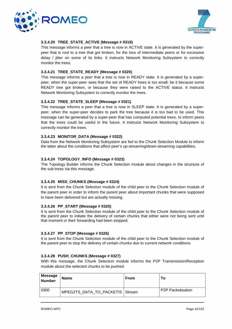
ROMEO WP2 Page 41/132
3.3.4.20 TREE_STATE_ACTIVE (Message # 0319) This message informs a peer that a tree is now in ACTIVE state. It is generated by the super-peer that is root to a tree that got broken, for the loss of intermediate peers or for excessive delay / jitter on some of its links. It instructs Network Monitoring Subsystem to correctly monitor the trees.
3.3.4.21 TREE_STATE_READY (Message # 0320) This message informs a peer that a tree is now in READY state. It is generated by a super-peer, when the super-peer sees that the set of READY trees is too small, be it because some READY tree got broken, or because they were raised to the ACTIVE status. It instructs Network Monitoring Subsystem to correctly monitor the trees.
3.3.4.22 TREE_STATE_SLEEP (Message # 0321) This message informs a peer that a tree is now in SLEEP state. It is generated by a super-peer, when the super-peer decides to park the tree because it is too bad to be used. This message can be generated by a super-peer that has computed potential trees, to inform peers that the trees could be useful in the future. It instructs Network Monitoring Subsystem to correctly monitor the trees.
3.3.4.23 MONITOR_DATA (Message # 0322) Data from the Network Monitoring Subsystem are fed to the Chunk Selection Module to inform the latter about the conditions that affect peer’s up-streaming/down-streaming capabilities.
3.3.4.24 TOPOLOGY_INFO (Message # 0323) The Topology Builder informs the Chunk Selection module about changes in the structure of the sub-trees via this message.
3.3.4.25 MISS_CHUNKS (Message # 0324) It is sent from the Chunk Selection module of the child peer to the Chunk Selection module of the parent peer in order to inform the parent peer about important chunks that were supposed to have been delivered but are actually missing.
3.3.4.26 PP_START (Message # 0325) It is sent from the Chunk Selection module of the child peer to the Chunk Selection module of the parent peer to initiate the delivery of certain chunks that either were not being sent until that moment or their forwarding had been stopped.
3.3.4.27 PP_STOP (Message # 0326) It is sent from the Chunk Selection module of the child peer to the Chunk Selection module of the parent peer to stop the delivery of certain chunks due to current network conditions.
3.3.4.28 PUSH_CHUNKS (Message # 0327) With this message, the Chunk Selection module informs the P2P Transmission/Reception module about the selected chunks to be pushed.
Message Number
Name From To
0300 MPEG2TS_DATA_TO_PACKETIS Stream P2P Packetisation

ROMEO WP2 Page 42/132
E Packetisation
0301 MPEG2TS_DATA_TO_SYNCH P2P Packetisation Playout Synchronisation
0302 SYNCHRONISED_MPEG2TS Playout Synchronisation
Stream Packetisation
0303 CHECK_USER Topology Builder
Authentication, Registration And Security
0304 CHECK_USER_ACK
Authentication, Registration And Security Topology Builder
0305 DECRYPT
Topology Controller
Topology Builder
0306 TOPOLOGY_JOIN_REQUEST Topology Controller
Topology Builder
0307 TOPOLOGY_JOIN_RESPONSE Topology Builder Topology Controller
0308 TOPOLOGY_SET_LINK Topology Controller
User Interface&Control
0309 P2P LINK_SETUP_REQUEST Topology
Controller Resource and Admission Manager
0310 RESOURCE_SETUP_REQUEST
Resource and Admission Manager
Resource Controller
0311 RESOURCE_SETUP_RESPONSE
Resource Controller
Resource and Admission Manager
0312 P2P LINK_SETUP_RESPONSE
Resource and Admission Manager
Topology Controller
0313 P2P LINK_SET Topology
Controller Topology Builder
0314 TREE_PROBE
Network Monitoring Subsystem
Resource Controller
0315 TREE_PROBE_RESPONSE Resource
Controller Network Monitoring Subsystem
0316 TREE_PROBE_REPORT
Network Monitoring Subsystem
Topology Builder and Multicast Tree Manager
0317 NETWORK_STATE_REQUEST
Topology Builder and Multicast Tree Manager
Resource and Admission Manager
0318 NETWORK_STATE_RESPONSE
Resource and Admission Manager
Topology Builder and Multicast Tree Manager
0319 TREE_STATE_ACTIVE
Topology Builder and Multicast Tree Manager
Network Monitoring Subsystem
0320 TREE_STATE_READY Topology Builder and Multicast Tree
Network Monitoring Subsystem

ROMEO WP2 Page 43/132
Manager
0321 TREE_STATE_SLEEP
Topology Builder and Multicast Tree Manager
Network Monitoring Subsystem
0322 MONITOR_DATA Network Monitor Subsystem
Chunk Selection
0323 TOPOLOGY_INFO Topology Builder Chunk Selection
0324 MISS_CHUNKS Chunk Selection Chunk Selection
0325 PP_START Chunk Selection Chunk Selection
0326 PP_STOP Chunk Selection Chunk Selection
0327 PUSH_CHUNKS Chunk Selection P2P Transmission/Reception
1008 TOPOLOGY_JOIN_REQUEST_INTERNAL
User Interface&Control
Topology Controller
Table 9 – Messages

ROMEO WP2 Page 44/132
3.4 Mobility
3.4.1 Fulfilled Requirements REQ 1.10, REQ 4.2, REQ 4.4, REQ 4.5, REQ 4.11, REQ 4.12, REQ 4.13, REQ 4.14, REQ 4.20, REQ 4.22
3.4.2 Detailed Block Diagram
Figure 23 – Mobility Component
3.4.3 Module Explanations The Mobility component is responsible for handling mobility and providing uninterrupted multimedia services to mobile and portable P2P clients across heterogeneous access networks. The component is envisaged as a proxy gateway transparent to the P2P overlay which consists of three modules:
• The Media Aware Proxy (MAP) • The Media Independent Handover (MIH) • The Proxy Mobile IP (PMIP)
The functionality of each module is explained in the following sub-sections.
3.4.3.1 Media Aware Proxy (MAP) The module receives the P2P chunks from the P2P overlay and the encoding and packetisation related metadata. It identifies the NALUs and other video related information and to which view they belong. It can adapt the video streams by increasing or decreasing the number of views that will be delivered to the wireless terminal based on physical, network and application layer information. In the case of multi-homing transmission, the module will select additional ports in order to forward the data and metadata.
3.4.3.2 Media Independent Handover (MIH) The module monitors all networks in the vicinity of the mobile terminal and collects network and physical layer related parameters via the MIH Event Service and updates the corresponding table entries of a database. Additionally, the MIH functionality in the mobile terminal is responsible for updating the user side values of the physical and network layer in database. Additionally, this module executes link layer handover and registration and de-registration to access networks.

ROMEO WP2 Page 45/132
An important functionality of the MIH module is the Handover functionality. It performs effectively a resource management and in parallel decides, whether the available resources and the mobile terminal capabilities can support or not additional enhanced views, or the mobile terminal has to handover to a different network. Upon deciding for handover, the module informs the corresponding MAG of the source network. Moreover, MIH is responsible for selecting the best candidate network in case of inter-system handover or suitable new AP or eNodeB in case of intra-system handover, based on the decision of the Handover Functionality. Upon selecting the most suitable link, the module updates the corresponding parameters in the database and triggers the MIH enabled wireless node.
3.4.3.3 Proxy Mobile IP (PMIP)
3.4.3.3.1 Mobile Access Gateway (MAG) The module consists of the Mobile Access Gateway (MAG) that performs the mobility management on behalf of a mobile node, and it resides on the access link where the mobile node is anchored. The mobile access gateway is responsible for detecting the mobile node’s movements to and from the access link and for initiating binding registrations to the mobile node’s Local Mobility Anchor (LMA). LMA is the topological anchor point for the mobile node’s home network prefix(es) and as so, it receives and forwards A/V steam and metadata to the mobile node through the serving MAG. To achieve that, LMA keeps a Binding Cache entry for each mobile node in the PMIPv6 – Domain through the registration procedure.
3.4.4 Inter-Module Connections
3.4.4.1 CHUNK_STREAM (Message # 0400) Data stream originated from the P2P component that is packetised as P2P chunks that are received by the Mobility Component and specifically the MAP module. The MAP module only considers the information in the chunk header.
3.4.4.2 CHUNK_STREAM_ADAPT (Message # 0401) Adapted data stream forwarded to the mobile or portable P2P client by the PMIP module. The adapted data stream may include less chunks compared to the received stream (Message #400), due to the adaptation process, or the stream may be transmitted through a different access network due to handover decision.
3.4.4.3 MIH_EVENT_SERV (Message # 0402) Periodic MIH signalling exchange between the mobile or portable MIH enabled client and the MIH module of the Mobility Component based on the MIH Event Services as defined by the standard. The message aims to inform the MIH module that an EVENT has occurred and that the MIH Information Service (database inputs) will be changed.
Message Number Name From To 0400 CHUNK_STREAM P2P component Mobility component 0401 CHUNK_STREAM_ADAPT Mobility Component P2P client 0402 MIH_EVENT_SERV Mobility Component P2P client
Table 10 – Media Aware Proxy Messages

ROMEO WP2 Page 46/132
3.5 DVB Transmission & Reception The DVB link is an integral part of the ROMEO set-up and provides the basic 3D (stereoscopic) views. It should be available under all circumstances at stationary (fixed), portable and mobile terminals.
In this section, first the transmission part for the test set-up is described. The transmission part for the demonstrator is very similar to this, especially the modulation part. For the field trials, a medium power DVB transmitter is used with an antenna height sufficient for providing coverage in most parts of the Munich area. The modulator for this medium power transmitter operates with the same software components for modulation and channel coding as the test signal generator.
The part on DVB reception in section 3.8.3.2 refers to the test receiver platform which is used as a test environment for reception and quality measurements of DVB and P2P signals. The results from these measurements and the long-term monitoring of a set of QoS parameters are used to determine suitable parameter thresholds for switch-over between reception paths in case that the quality of one path decreases significantly..
3.5.1 Fulfilled Requirements The table below lists the requirements related to the DVB Transmission part that are fulfilled by the planned solution:
REQ 1.16, REQ 1.17 , REQ 1.18 , REQ 1.19 , REQ 1.20 , REQ 1.21 , REQ 1.22 , REQ 1.23, REQ 1.24.
The following requirements are addressed by the Test receiver platform.
REQ 1.25, REQ 1.26 , REQ 1.27, REQ 1.28, REQ 1.29
3.5.2 Detailed Block Diagrams
Figure 24 – Building blocks and inter module messages in DVB transmission test set-up

ROMEO WP2 Page 47/132
Figure 25 – Building blocks and inter module messages in DVB reception at user terminal and test set-up
3.5.3 Module Explanations
3.5.3.1 MPEG2-TS Encapsulation This module generates standard MPEG-2 Transport Streams by packetising the Elementary Streams, i.e. video and audio, into TS packets of 188 byte payload, label them with the respective PID (Program Identifier) in the packet header and insert all the other header information. In addition, the SI (Service Information) and PSI (Program Specific Service Information) tables are inserted and the correct timing information is calculated and inserted as PCR (Program Clock Reference).
3.5.3.2 DVB Transmission For the test environment, a test signal generator prides standard-compliant DVB-T/T2/T2 Lite signals. The test signal generator input is a MPEG2 Transport Stream and modulation takes place in real-time. It can be configured to output any DVB-T or DVB-T2 modes with bit rates between approx. 7.5 Mbps and 50 Mbps.
The same set of DVB signals is also available for the field trial where the signal is broadcast in the Munich area.
For the purpose of the tasks in ROMEO, the test signal generator is combined with
• a TS player that plays out the TSs from the R&S Stream Library,
• a module that encapsulates the TSs into IP streams,
• a modulator/ transmitter unit
and other software and hardware options providing the required interfaces for TS, I/Q and RF.
3.5.3.3 Test Receiver platform (Test receiver/ prot ocol analyser plus Notebook) The test receiver platform consists of a protocol analyser and a notebook computer.
The protocol analyser can measure and monitor a multitude of parameters related to the MPEG2 Transport Stream, the DVB signals of various standards and IP streams. It can be equipped with different RF front ends. In the case of ROMEO, a DVB-T/T2/T2 Lite frontend is installed.

ROMEO WP2 Page 48/132
The input to this front end is RF via which the DVB signal is received. Other inputs include interfaces for MPEG2 Transport Stream (TS) and 1000BaseT (IP). The latter is used e.g. as input for the P2P IP streams that are available over a WiFi or 3G network in a test environment.
The protocol analyser exchanges data with the notebook via an internal IP interface. The received TSs are internally encapsulated into IP to guarantee the transport between different IP-based entities without problems. The instrument also includes a hardware decoder for 3D video (plus audio). The output of this hardware decoder is fed to an external display via a HDMI interface.
The Notebook serves as a flexible platform for the project-specific tasks such as synchronisation of IP streams received over different networks. For this purpose, it includes an algorithm that identifies the relative delay between the two IP streams (‘Synchronisation engine’) and controls the buffers for both IP streams.
The IP streams at the buffer outputs are time synchronous. Both IP streams are fed in parallel to the ‘IP stream selection’ where, dependent on the QoS parameters taken into account, the IP stream is selected that is forwarded to the hardware decoder on the Protocol analyser platform. Both IP streams are also fed separately into two Video Players that allow a time-synchronous display of the two video signals on the notebook display
3.5.3.4 DVB Reception for User Terminal In ROMEO project DVB signal will be received by RF receiver to synchronise on peer terminal. This device is going to be responsible of reception of content from DVB network and deliver to synchronisation component.
3.5.4 Inter-Module Connections
3.5.4.1 ASI - MPEG2 Transport Stream (TS) (Message # 0501, 506) The MPEG2 Transport Stream complies with The Asynchronous Serial Interface (ASI) is a standard interface for MPEG2 TS
3.5.4.2 IP/UDP stream with multi-view TS received v ia IP network (Message # 0502, 507, 510, 511)
The procedure of encapsulating MPEG2 Transport Stream packets into IP is described in.
3.5.4.3 I/Q output from modulator (Message # 0503) The I/Q output is an internal and external interface of the test signal generator /modulator for DVB signals. The baseband I/Q samples of the modulated signal are transported via this interface in numerical form. The interface was developed by R&S and the spec is proprietary.
3.5.4.4 I/Q input to modulator (Message # 0504) The I/Q input is an internal and external interface of the test signal generator /modulator for DVB signals. The baseband I/Q samples of the modulated signal are transported via this interface in numerical form. The interface was developed by R&S and the spec is proprietary.
3.5.4.5 DVB RF signal (Message # 0505) The DVB RF signal is an OFDM signal with a bandwidth of 7,61 MHz (in a 8 MHz channel) and is compliant to
3.5.4.6 Control signal for Buffer 1 (Message # 0508 ) Internal message between software modules in a proprietary format.
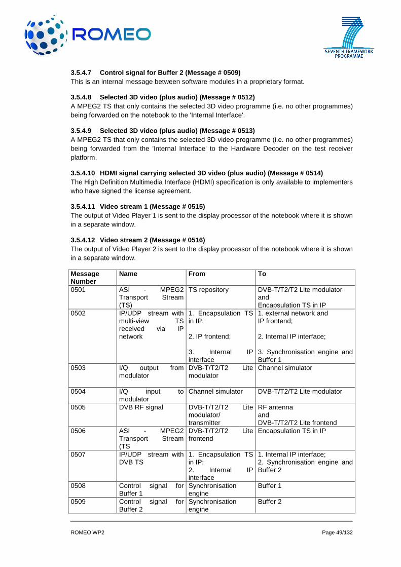
ROMEO WP2 Page 49/132
3.5.4.7 Control signal for Buffer 2 (Message # 0509 ) This is an internal message between software modules in a proprietary format.
3.5.4.8 Selected 3D video (plus audio) (Message # 0 512) A MPEG2 TS that only contains the selected 3D video programme (i.e. no other programmes) being forwarded on the notebook to the 'Internal Interface'.
3.5.4.9 Selected 3D video (plus audio) (Message # 0 513) A MPEG2 TS that only contains the selected 3D video programme (i.e. no other programmes) being forwarded from the 'Internal Interface' to the Hardware Decoder on the test receiver platform.
3.5.4.10 HDMI signal carrying selected 3D video (pl us audio) (Message # 0514) The High Definition Multimedia Interface (HDMI) specification is only available to implementers who have signed the license agreement.
3.5.4.11 Video stream 1 (Message # 0515) The output of Video Player 1 is sent to the display processor of the notebook where it is shown in a separate window.
3.5.4.12 Video stream 2 (Message # 0516) The output of Video Player 2 is sent to the display processor of the notebook where it is shown in a separate window.
Message Number
Name From To
0501 ASI - MPEG2 Transport Stream (TS)
TS repository DVB-T/T2/T2 Lite modulator and Encapsulation TS in IP
0502
IP/UDP stream with multi-view TS received via IP network
1. Encapsulation TS in IP; 2. IP frontend; 3. Internal IP interface
1. external network and IP frontend; 2. Internal IP interface; 3. Synchronisation engine and Buffer 1
0503 I/Q output from modulator
DVB-T/T2/T2 Lite modulator
Channel simulator
0504 I/Q input to modulator
Channel simulator DVB-T/T2/T2 Lite modulator
0505 DVB RF signal DVB-T/T2/T2 Lite modulator/ transmitter
RF antenna and DVB-T/T2/T2 Lite frontend
0506 ASI - MPEG2 Transport Stream (TS
DVB-T/T2/T2 Lite frontend
Encapsulation TS in IP
0507 IP/UDP stream with DVB TS
1. Encapsulation TS in IP; 2. Internal IP interface
1. Internal IP interface; 2. Synchronisation engine and Buffer 2
0508 Control signal for Buffer 1
Synchronisation engine
Buffer 1
0509 Control signal for Buffer 2
Synchronisation engine
Buffer 2
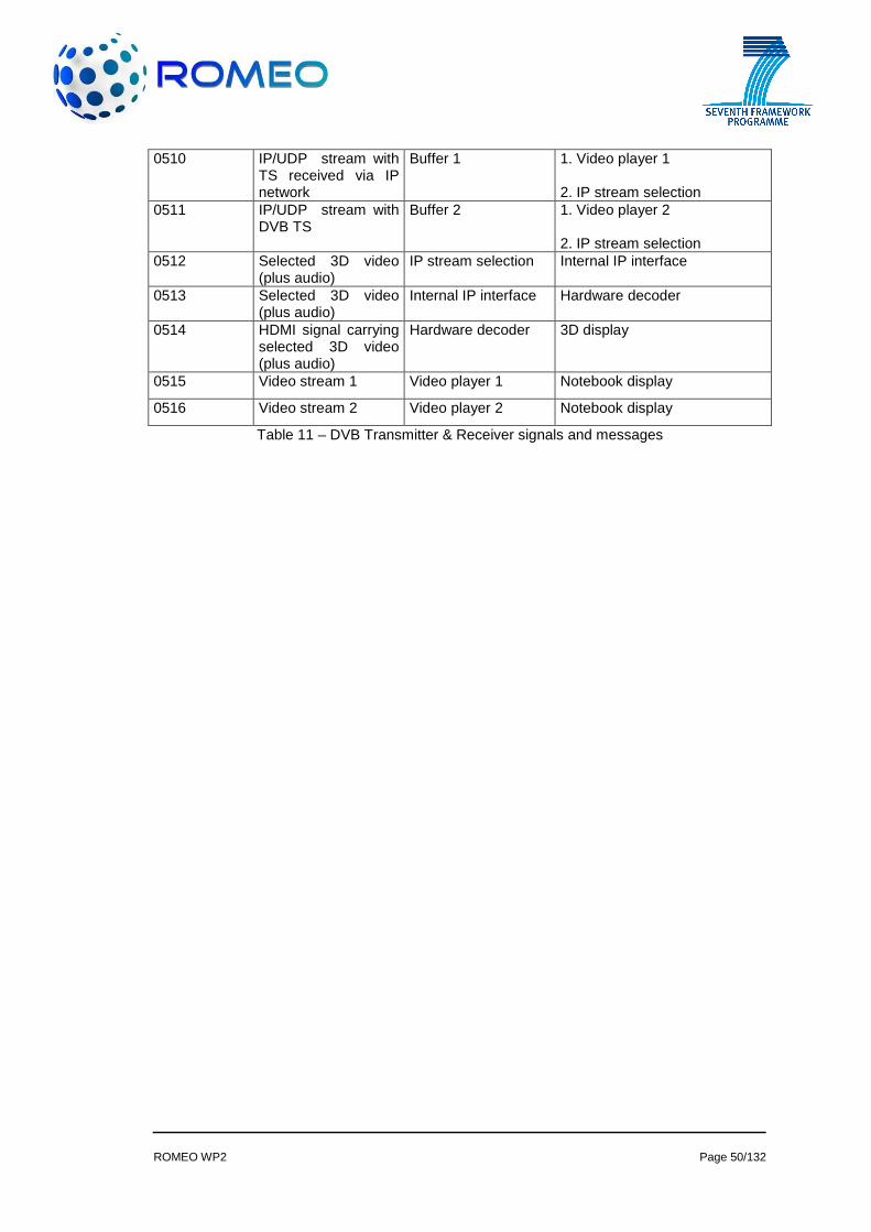
ROMEO WP2 Page 50/132
0510 IP/UDP stream with TS received via IP network
Buffer 1 1. Video player 1 2. IP stream selection
0511 IP/UDP stream with DVB TS
Buffer 2 1. Video player 2 2. IP stream selection
0512 Selected 3D video (plus audio)
IP stream selection Internal IP interface
0513 Selected 3D video (plus audio)
Internal IP interface Hardware decoder
0514 HDMI signal carrying selected 3D video (plus audio)
Hardware decoder 3D display
0515 Video stream 1 Video player 1 Notebook display
0516 Video stream 2 Video player 2 Notebook display
Table 11 – DVB Transmitter & Receiver signals and messages

ROMEO WP2 Page 51/132
3.6 Virtualisation
3.6.1 Fulfilled Requirements REQ 1.30, REQ 1.31, REQ 1.32, REQ 1.33, REQ 1.34, REQ 1.35, REQ 2.23, REQ 2.28, REQ 2.29, REQ 2.30, REQ 2.31, REQ 4.25, REQ 4.26
3.6.2 Detailed Block Diagram The following picture depicts the network architecture for the virtualisation platform:
Figure 26 - Virtualisation Network architecture
3.6.3 Module Explanations The main entities involved in this architecture are:
3.6.3.1 Optical Network Terminator (ONT) It is the subscriber equipment for the Gigabit Passive Optical Network (GPON) access. An ONT (optical network terminal) is used to terminate the fiber optic line, demultiplex the signal into its component parts. One of the challenges of this architecture is to achieve that Ethernet devices may be plugged to any of the Ethernet ports, i.e. achieve a plug & play behaviour. Moreover, it is envisaged to cover the following additional features:
• Enable user devices to be multi-service. • Enable the end user to select the addressing scheme to his network being possible to
overlap other users addressing scheme. • Enable end devices to “dialogue” among them within the LAN.
3.6.3.2 Optical Line Terminator (OLT) It corresponds to the network equipment for the GPON access. While one of its interfaces terminates the optical fibre from the subscriber, the other one connects to the Metropolitan Area Network (MAN) to transmit the traffic to the due service centres. The OLT employs 802.1ad encapsulation (stacked VLANs) for traffic destined to the NATIE. This encapsulation protocol allows multiple VLAN headers to be inserted in a single frame.
3.6.3.3 Network Address Translation Implementer Equipment ( NATIE) This equipment concentrates the user Ethernet Traffic to route it to the different services (voice, IPTV, Internet). The virtualisation platform establishes the NATIE as the key point for hosting the HGW routing and HGW NAT/PAT functionalities. These functionalities will be implemented for each subscriber within a virtual routing forwarding (VRF) instance. In addition, the NATIE will receive the QoS rules that are to be applied to each user in order to enforce the flow prioritization.

ROMEO WP2 Page 52/132
3.6.3.4 Virtual Software Execution Environment (VSEE) It corresponds to the module in charge of hosting the virtualised execution software capacities that currently runs within the RGW (Residential Gateway). The system is able to access the local area network of the subscriber throughout the MAN.
3.6.3.5 Metropolitan Area Network (MAN) It corresponds to the aggregation Ethernet network that connects the OLTs with the different service centres. The main connections throughout the MAN are:
• OLT-NATIE and OLT-VSEE • NATIE-Service Centres • OLT Service Centres
3.6.3.6 Dynamic Host Configuration Protocol (DHCP) SERVER It allocates IP addresses to all devices connected to the Ethernet ports of an ONT.
The DHCP server is located in the MAN. The broadcast requests perform by Ethernet devices will cross the OLT and the MAN in order to reach the NATIE. Thus, in order to enable DHCP server to receive IP address requests from Ethernet home devices, the NATIE must be configured as DHCP relay pointing to the DHCP server.
3.6.3.7 Policy Charging and Rule Function (PCRF) The PCRF is the entity that defines the QoS rules that are to be applied to the user. It receives from the ROMEO server the physical parameters that identify a certain user and then it communicates with the NATIE in order to apply the rules in the access network.
3.6.3.8 Configuration Portal The configuration portal is the entity that will provide to the user a tool for configuring the virtual router functionalities. Besides addressing the current configurable functionalities of a physical HGW (DHCP options, NAT/PAT, IP addressing scheme, etc), the configuration portal will provide a protocol prioritization tool to manually adjust the QoS rules that are to be enforced in the access network..
3.6.4 Inter-Module Connections
3.6.4.1 User Configuration REQUEST/RESPONSE message s:
3.6.4.1.1 GET_CONFIGURATION (Messages #0600, #0602, #0604, #0606) These messages are sent from the configuration portal to the Data Base in order to retrieve current configuration of the virtual router with regard to:
• IP Subnet Configuration (Message #0600) • Relationship among IP and MAC addresses (Message #0602) • Port Forwarding Configuration (Message #0604) • QoS protocol prioritization list (Message #0606)
3.6.4.1.2 GET_CONFIGURATION_RESPONSE (Messages #0601, #0603, #0605, #0607) These messages are sent from the Data Base to the configuration portal providing the information requested by GET_CONFIGURATION with regard to:
• IP Subnet Configuration (Message #0601) • Relationship among IP and MAC addresses (Message #0603)

ROMEO WP2 Page 53/132
• Port Forwarding Configuration (Message #0605) • QoS protocol prioritization list (Message #0607)
3.6.4.2 User Configuration POST/ACK messages:
3.6.4.2.1 POST_CONFIGURATION (Messages #0608, #0610, #0612, #0614) These messages are sent from the configuration portal to the Data Base in order to change the parameters with regard to:
• IP Subnet Configuration (Message #0608) • Relationship among IP and MAC addresses (Message #0610) • Port Forwarding Configuration (Message #0612) • QoS protocol prioritization list (Message #0614)
3.6.4.2.2 POST_ACK (Messages #0609, #0611, #0613, #0615) These messages are sent from the Data Base to the configuration portal in order to acknowledge the POST_CONFIGURATION messages.
• IP Subnet Configuration ACK (Message #0609) • Relationship among IP and MAC addresses ACK (Message #0611) • Port Forwarding Configuration ACK (Message #0613) • QoS protocol prioritization list (Message #0615)
3.6.4.3 DHCP REQUEST/RESPONSE messages
3.6.4.3.1 GET_CONFIGURATION (Message #0616)
3.6.4.3.2 This message is sent from the DHCP server to the Data Base in order to retrieve the configuration of the virtual router established by the user.GET_CONFIGURATION RESPONSE (Message #0617)
This message is sent from the Data Base to the DHCP server providing the information of the configuration of the virtual router.
3.6.4.4 Static QoS Enforcement
3.6.4.4.1 STATIC_QoS_REQUEST (Message #0618) This message is sent from the configuration portal to the PCRF in order to set the QoS protocol prioritization list.
3.6.4.4.2 STATIC_QoS_RESPONSE (Message #0619) This message is sent from the PCRF to the configuration portal acknowledging the STATIC_QoS_REQUEST.
3.6.4.4.3 QoS_ENFORCEMENT_REQUEST (Message #0620) This message is sent from the PCRF to the NATIE in order to enforce the QoS rules of a particular user within the access network.
3.6.4.4.4 QoS_ENFORCEMENT_RESPONSE (Message #0621) This message is sent from the NATIE to the PCRF acknowledging the QoS_ENFORCEMENT_REQUEST.

ROMEO WP2 Page 54/132
3.6.4.5 Dynamic QoS Enforcement
3.6.4.5.1 DYNAMIC_QoS_REQUEST (Message #0622) This message is sent from the ROMEO P2P server to the PCRF containing the physical parameters of a particular user in order to request the appliance of the QoS rules.
3.6.4.5.2 DYNAMIC_QoS_RESPONSE (Message #0623) This message is sent from the PCRF to the ROMEO P2P Server acknowledging the DYNAMIC_QoS_REQUEST.
3.6.4.5.3 QoS_ENFORCEMENT_REQUEST (Message #0620) This message is sent from the PCRF to the NATIE in order to enforce the QoS rules of a particular user within the access network.
3.6.4.5.4 QoS_ENFORCEMENT_RESPONSE (Message #0621) This message is sent from the NATIE to the PCRF acknowledging the QoS_ENFORCEMENT_REQUEST.
The following table shows the messages exchanged for the virtualised platform:
Message Number Name From To User Configuration REQUEST/RESPONSE messages:
• Subnet Configuration. (REQ/RES)[0600-0601] • Relationships among IP addresses and MAC addressed. (REQ/RES)[0602-0603] • Port Forwarding Configuration. (REQ/RES)[0604-0605] • QoS protocol prioritization list (REQ/RES) [0606-0607]
060x (x=0,2,4,6) GET_CONFIGURATION Web Portal Data Base 060y (y=1,3,5,7)
GET_CONFIGURATION_RESPONSE Data Base Web Portal
User Configuration POST/ACK messages: • Subnet Configuration. (POST/ACK)[0608-0609] • Relationships among IP addresses and MAC addressed. (POST/ACK)[0610-0611] • Port Forwarding Configuration. (POST/ACK)[0612-0613] • QoS protocol prioritization list (POST/ACK) [0614-0615]
060z (z=8,10,12,14)
POST_CONFIGURATION Web Portal Data Base
060w (w=9,11,13,15)
POST_ACK Data Base Web Portal
DHCP REQUEST/RESPONSE MESSAGES
0616 GET_CONFIGURATION DHCP Server Data Base
0617 GET_CONFIGURATION RESPONSE Data Base DHCP Server
Static QoS Enforcement
0618 STATIC_QoS_REQUEST Web Portal PCRF

ROMEO WP2 Page 55/132
0619 STATIC_QoS_RESPONSE PCRF Web Portal
0620 QoS_ENFORCEMENT_REQUEST PCRF NATIE
0621 QoS_ENFORCEMENT_RESPONSE NATIE PCRF
Dynamic QoS Enforcement
0622 DYNAMIC_QoS_REQUEST ROMEO P2P Server PCRF
0623 DYNAMIC_QoS_RESPONSE PCRF ROMEO P2P Server
0620 QoS_ENFORCEMENT_REQUEST PCRF NATIE
0621 QoS_ENFORCEMENT_RESPONSE NATIE PCRF
Table 12– Virtualisation Messages

ROMEO WP2 Page 56/132
3.7 Synchronisation
3.7.1 Fulfilled Requirements REQ 1.2, REQ 1.14
3.7.2 Detailed Block Diagram
Figure 27 - Synchronisation Component
3.7.3 Module Explanations Synchronisation component is responsible for the synchronisation of both views from hybrid paths (DVB and P2P) and collaborating users. The aim of this unit is to provide simultaneous multi-view content to decoder. Transport stream which is delivered through DVB and P2P networks needs to be aligned to deliver simultaneous multi-view 3D content to decoder. Synchronisation component will also align multiple users to see the content at the same time for collaboration.
3.7.3.1 Playout sync The Synchronisation module placed in front of P2P-DVB Reception is responsible for synchronising content by using their time-stamps and metadata, and subsequently streaming synchronised content to Audio/Video decoder modules synchronising subsequently
The module is responsible for:
• Buffering decrypted audio/video streams received through DVB and P2P channels before passing it to audio/video decoder.
• Sending the synchronised streams to the audio/video clusters some frames before the indicated presentation time in order to allow the decoders to have enough time to decode and wait till it’s time to send the frame for rendering.
Synchronisation module also communicates with UI module for diagnostics,. It also alerts UI component and Audio/Video decoder components for buffer under run and overrun cases if necessary.
Synchroniser will use the Video Stream Paths (ID 20) area in the metadata which contains the delivery path of the view. (e.g., "0" or "DVB": video layer intended for DVB-T2 broadcasting, "1" or "P2P": video layer intended for IP streaming )”

ROMEO WP2 Page 57/132
Synchronisation module shall extract timing information and video stream from TS streams
3.7.3.2 Collaborative sync This unit is responsible for synchronising the peers to jointly enjoy the content. It is decided to implement it as a configurable delay module. When a user wants to join a collaborating group, the user reports its network conditions to the collaborating group moderator. After calculating optimum waiting time of each user, the moderator informs each user their corresponding total delay amount from DVB clock for the collaborative synchronisation. After receiving the control message from A/V Overlay Control Module, this module delays Audio/Video streams received through DVB and P2P network for a specified amount of time (several seconds) for collaborative synchronisation. Once a peer joins a collaborating group, the delay remains constant until the peer switches to another content channel since adjusting the buffers upon leaving the collaborating group would result in visible disruption of content. The delay is assumed to be zero in case the peer is not actively collaborating with other peers. In order to adapt the changing network conditions, the A/V adaptation module will have a chance to reset this delay amount and this module behaves accordingly.
3.7.4 Inter-Module Connections
3.7.4.1 COLLABORATION_DELAY_SET (Message #0701) This message is sent from collaborative sync buffer to A/V adaptation module as an acknowledgement to SET_COLLABORATION_DELAY message.
Control messages triggering content adaptation mechanisms to avoid buffer under run cases also play important role in achieving smooth playback.
3.7.4.2 SYNCHRONISATION _BUFFER_NOTIFICATION (Messa ge #0702) This message is sent from synchronisation module to A/V adaptation module when the buffer fullness level is below a certain level or above a certain threshold. As a result of receiving this message, A/V adaptation module can decide to drop some of views or receive the content via DVB only depending on the network conditions at that time
3.7.4.3 AUDIO_STREAM_CON (Message #0703) This stream connection is used to transmit synchronised audio data content of different camera views to audio decoder module (media decoder & rendering)
3.7.4.4 VIDEO_STREAM_CON (Message #0704) This stream connection is used to transmit synchronised video data content of different camera views to video decoder module (media decoder & rendering).
3.7.4.5 IP/UDP stream with DVB TS (Message #0507) This stream connection is explained in Section 3.5.4.
3.7.4.6 DECRYPT_CONTENT (Message #1101) This stream connection is explained in Section 3.11.4.
Message Number Name From To
0701 COLLABORATION_DELAY_SET
Collaborative Synchronisation Buffer A/V Adaptation Module
0702 SYNCHRONISATION Synchronisation Buffer A/V Adaptation Module

ROMEO WP2 Page 58/132
_BUFFER_NOTIFICATION
0703 AUDIO_STREAM_CON
Synchronisation Audio Cluster
0704 VIDEO_STREAM_CON
Synchronisation Video Cluster 0507 IP/UDP stream with DVB TS 1. Encapsulation
TS in IP; 2. Internal IP interface
1. Internal IP interface; 2. Synchronisation engine and Buffer 2
1101 DECRYPT_CONTENT
Authentication, Registration And Security Synchronisation
Table 13 – Synchronisation & Network Monitor Messages
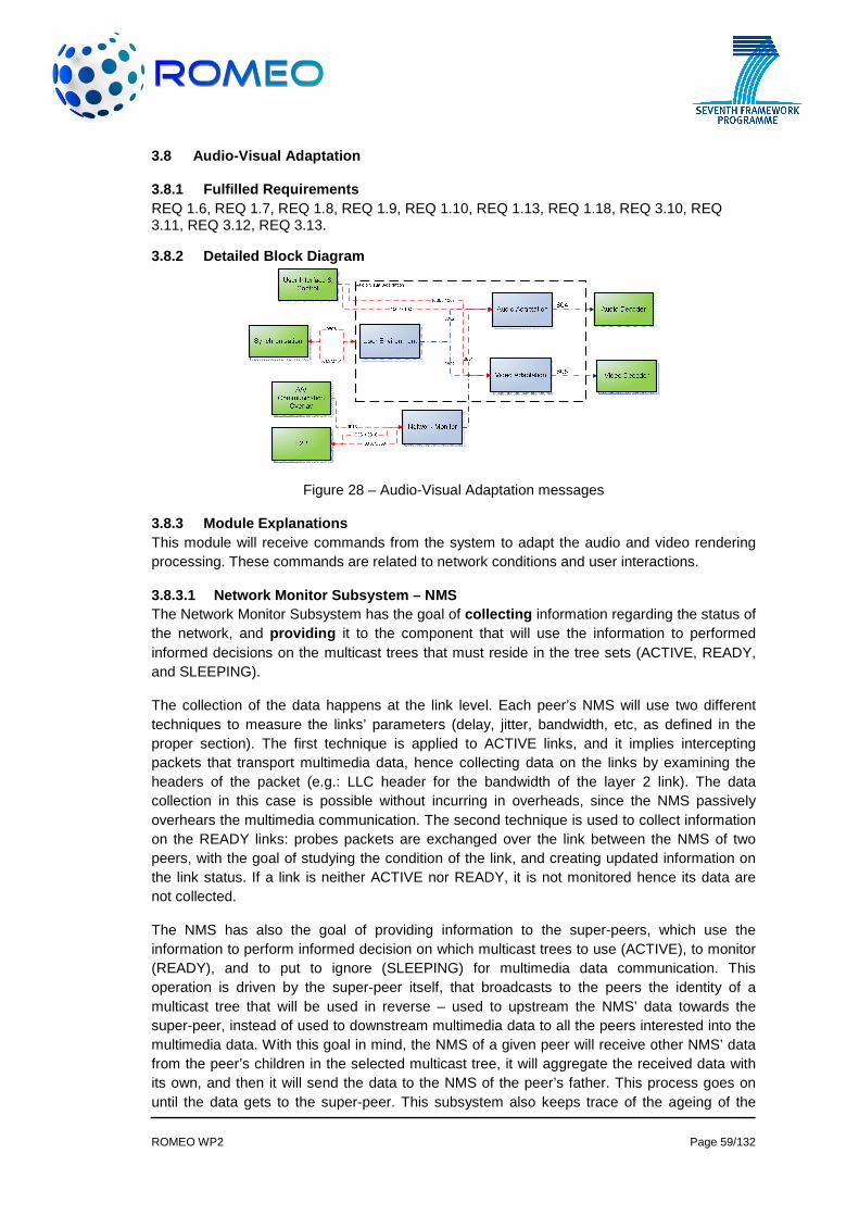
ROMEO WP2 Page 59/132
3.8 Audio-Visual Adaptation
3.8.1 Fulfilled Requirements REQ 1.6, REQ 1.7, REQ 1.8, REQ 1.9, REQ 1.10, REQ 1.13, REQ 1.18, REQ 3.10, REQ 3.11, REQ 3.12, REQ 3.13.
3.8.2 Detailed Block Diagram
Figure 28 – Audio-Visual Adaptation messages
3.8.3 Module Explanations This module will receive commands from the system to adapt the audio and video rendering processing. These commands are related to network conditions and user interactions.
3.8.3.1 Network Monitor Subsystem – NMS The Network Monitor Subsystem has the goal of collecting information regarding the status of the network, and providing it to the component that will use the information to performed informed decisions on the multicast trees that must reside in the tree sets (ACTIVE, READY, and SLEEPING).
The collection of the data happens at the link level. Each peer’s NMS will use two different techniques to measure the links’ parameters (delay, jitter, bandwidth, etc, as defined in the proper section). The first technique is applied to ACTIVE links, and it implies intercepting packets that transport multimedia data, hence collecting data on the links by examining the headers of the packet (e.g.: LLC header for the bandwidth of the layer 2 link). The data collection in this case is possible without incurring in overheads, since the NMS passively overhears the multimedia communication. The second technique is used to collect information on the READY links: probes packets are exchanged over the link between the NMS of two peers, with the goal of studying the condition of the link, and creating updated information on the link status. If a link is neither ACTIVE nor READY, it is not monitored hence its data are not collected.
The NMS has also the goal of providing information to the super-peers, which use the information to perform informed decision on which multicast trees to use (ACTIVE), to monitor (READY), and to put to ignore (SLEEPING) for multimedia data communication. This operation is driven by the super-peer itself, that broadcasts to the peers the identity of a multicast tree that will be used in reverse – used to upstream the NMS’ data towards the super-peer, instead of used to downstream multimedia data to all the peers interested into the multimedia data. With this goal in mind, the NMS of a given peer will receive other NMS’ data from the peer’s children in the selected multicast tree, it will aggregate the received data with its own, and then it will send the data to the NMS of the peer’s father. This process goes on until the data gets to the super-peer. This subsystem also keeps trace of the ageing of the

ROMEO WP2 Page 60/132
stored information, and considers the age of data while performing data aggregation, by giving more statistical weight to newer data.
3.8.3.2 User environment The user environment (e.g. displays and sound systems he will use) will impact the video/audio rendering. This information (802) will be sent to both video adaptation and audio adaptation blocks.
3.8.3.3 User Interface and control The user Interface and control (e.g. the preferred view) will impact the video/audio rendering. This information (803) will be sent to the video adaptation block to be analysed and converted into a global video adaptation signal (805).
3.8.3.4 Video adaptation This block will receive information (801, 802 and 803) from the network monitoring, the user environment and the user Interface and control. It will generate from these signals a global signal to be used by the video renderer indicating:
• The number of views to be generated • The preferred view if any • The amount of data the video renderer will received depending on network conditions
3.8.3.5 Audio adaptation This block will receive information (801, 802 and 803) from the network monitoring, the user environment and the user Interface and control. It will generate from these signals a global signal to be used by the audio renderer..
3.8.4 Inter-Module Connections
3.8.4.1 NETWORK_CONDITION (Message #0801) Metadata describing the network condition that will impact the A/V adaptation block
3.8.4.2 USER_ENVIRONMENT (Message #0802) Metadata describing the user environment (e.g. display and sound system) that will impact the A/V adaptation block. In terms of audio, it would contain the audio reproduction system configuration (5.1-channel, stereo, binaural, etc.) information.
3.8.4.3 USER Interface and control (Message #0803) This message contains inputs from the user (through the user interface) that will impact the A/V adaptation block.
3.8.4.4 AUDIO_ADAPTATION (Message #0804) This message contains metadata describing the audio adaptation mode. This represents the information regarding the rendering configuration to be used for the final audio delivery (5.1-channel, stereo, WFS, etc.) out of the audio adaptation module
3.8.4.5 VIDEO_ADAPTATION (Message #0805) This message contains metadata describing the video adaptation mode
3.8.4.6 SET_COLLABORATION_DELAY (Message #0806) This message is sent from A/V adaptation module to collaborative sync buffer to set the buffer size while joining a collaborating group as well as adapting the changing network conditions. Setting the delay to zero will be used for leaving the collaborating group.

ROMEO WP2 Page 61/132
3.8.4.7 ADAPT_COMP_COMM_MSG (Message #1006, 1007) These Messages are used to communicate parameter exchange with A/V Adaptation & Network Monitor Component.
Message Number Name From To
0801 NETWORK_CONDITION Network monitor Audio/video adaptation
0802 USER_ENVIRONMENT User environment Audio/video adaptation
0803 USER-REQUIREMENT User requirement Audio/video adaptation
0804 AUDIO_ADAPTATION Audio/video adaptation Audio/ renderer
0805 VIDEO_ADAPTATION Audio/video adaptation Video renderer
0806 SET_COLLABORATION_DELAY
Audio/video adaptation Synchronisation
1006 ADAPT_COMP_COMM_MSG User interface Audio/video adaptation
Table 14 – Audio-Visual Adaptation Messages

ROMEO WP2 Page 62/132
3.9 A/V Communication Overlay
3.9.1 Fulfilled Requirements REQ 1.3, REQ 1.4, REQ 4.5
3.9.2 Detailed Block Diagram
Figure 29- AV Communication Overlay Main blocks
3.9.3 Module Explanations A/V Communication Overlay component is responsible from developing a communication channel between users that are watching same content. Since users will be able to see same scenes at the same time, they will be able to share experience through A/V communication overlay component.
3.9.3.1 Server Module This section includes the explanations belonging to Server A/V Communication Overlay module.
3.9.3.1.1 Conference Controller This module is supposed to distribute conference roles (“Standard peer” – Peer delivering its own A/V content only or “Content distributer peer“– Peer distributing all A/V contents) to the peers and administrate the A/V stream between peers in conference. The controller focuses on administrative tasks like deciding which way the streams should follow and adjusting A/V synchronisation, instead of content distributing tasks. The controller does not distribute content to peers, unless it fails to find a suitable content distributer peer. .
3.9.3.1.2 A/V Content Distributor This module is supposed to distribute conference content, in case the conference controller module fails to find a suitable content distributor peer. This module deploys the data collected by A/V Content Receiver module on server.
3.9.3.1.3 A/V Content Receiver This module is supposed to receive all peer-specific A/V contents, in case the conference controller module fails to find a suitable content distributor peer.

ROMEO WP2 Page 63/132
3.9.3.2 Peer Module This section includes the explanations belonging to Peer A/V Communication Overlay Module.
3.9.3.2.1 Conference Controller This module is supposed to make the peer play the role which the server A/V module decides. If the peer is set to be a Standard Peer, the controller only controls receiving data. Otherwise, the controller shall manage content distributing to other peers in conversation.
3.9.3.2.2 A/V Content Distributor If the peer is a Standard Peer, the distributor delivers only its own A/V content. Otherwise, the distributor deploys all data collected by A/V Content Receiver module on peer.
3.9.3.2.3 A/V Content Receiver This module is supposed to receive remote peers’ A/V content.
3.9.3.2.4 Overlay Manager This module is supposed to make A/V conference content shown on the Display Unit, regardless of what is being displayed on the unit.
3.9.3.2.5 Display Unit It is a standard display unit which is not supposed to have any extra features related to A/V Communication Overlay module.
3.9.3.3 Collaboration Synchronisation Control Module This module is responsible for setting the overall collaboration delay from all the users. It will collect the delay from all participating peers and then compute an acceptable overall delay and share it with the synchronisation component of each collaborator.
3.9.4 Inter-Module Connections
3.9.4.1 SERVER_ORDER (Message # 0900) This message contains a server order generated for one of the peers. This order could be about roles, synchronisation or operations on streams.
3.9.4.2 REMOTE_PEER_INFO (Message # 0901) This message contains a package of data about a remote peer in A/V collaboration. The package includes data like user name, delay time and bandwidth
3.9.4.3 PEER_STATUS (Message # 0902) This message contains a package indicating some values about the current peer.
3.9.4.4 DATA_DELIVERY_ACK (Message # 0903) This message contains the delivery acknowledgements, package failures and delay time information about the current peer.
3.9.4.5 AV_TO_SERVER (Message # 0904) This message contains only one stream data related to current peer. The message is delivered to the content receiver on Server. If a content distributor peer exists in conference, this message is not sent.

ROMEO WP2 Page 64/132
3.9.4.6 BCAST_FROM_SERVER (Message # 0905) This message contains the A/V streams of every peer in conference. The message is broadcasted to all peers in collaboration. If a content distributor peer exists in conference, this message is not sent.
3.9.4.7 AV_TO_REMOTE (Message # 0906) This message contains only one stream data related to current peer. The message is delivered to the content distributor peer in collaboration. If none of remote peers is a content distributor, this message is not sent.
3.9.4.8 BCAST_FROM_REMOTE (Message # 0907) This message has the same data structure with Message #908. It contains the A/V streams of every peer in conference. The message is broadcasted to all peers in collaboration including the example peer on the 3.9.2 Detailed Block Diagram. If none of remote peers is a content distributor, this message is not sent.
3.9.4.9 BCAST_TO_REMOTE (Message # 0908) This message contains the A/V streams of every peer in conference. The message is broadcasted to all remote peers in collaboration. If the peer on the 3.9.2 Detailed Block Diagram is not a content distributor, this message is not sent.
3.9.4.10 AV_FROM_REMOTE (Message # 0909) This message has the same data structure with Message #906. It contains only one stream data related to a remote peer in collaboration. It is delivered to the example peer on the 3.9.2 Detailed Block Diagram. If the example peer is not a content distributor, this message is not sent.
3.9.4.11 REC_TO_DIST (Message # 0910) This message contains the A/V streams of every peer in conference. This message is delivered to the A/V Content Distributor to deploy the total stream to all peers in collaboration. If a content distributor peer exists in conference, this message is only sent in A/V Communication Overlay module on Peer.
3.9.4.12 STREAM_TO_OVERLAY (Message # 0911) This message contains only one stream data related to any peer in collaboration. The message is delivered to overlay manager to make the stream displayed.
3.9.4.13 STREAM_TO_DISPLAY (Message # 0912) This message contains only one stream data related to any peer in collaboration. The message is displayed on the screen, while 3D content is being served.
3.9.4.14 GET_DELAY_REQ (Message #0913) This message is sent to the A/V adaptation module to learn the time difference between DVB and P2P streams. This information will be forwarded to the conference moderator to calculate the overall collaboration delay.
3.9.4.15 SET_COLLABORATION_DELAY (Message #0914) This message is sent from A/V adaptation module to collaborative sync buffer to set the buffer size while joining a collaborating group as well as adapting the changing network conditions. Setting the delay to zero will be used for leaving the collaborating group.

ROMEO WP2 Page 65/132
Message Number Name From To
0900 SERVER_ORDER Conference Controller (Server)
Conference Controller (Peer)
0901 REMOTE_PEER_INFO Conference Controller (Server)
Conference Controller (Peer)
0902 PEER_STATUS Conference Controller (Peer)
Conference Controller (Server)
0903 DATA_DELIVERY_ACK Conference Controller (Peer)
Conference Controller (Server)
0904 AV_TO_SERVER A/V Content Distributor (Any Peer)
A/V Content Receiver (Server)
0905 BCAST_FROM_SERVER A/V Content Distributor (Server)
A/V Content Receiver (All Peers)
0906 AV_TO_REMOTE A/V Content Distributor (Peer) Other Peers
0907 BCAST_FROM_REMOTE Other Peers A/V Content Receiver (Peer)
0908 BCAST_TO_REMOTE A/V Content Distributor (Peer) Other Peers
0909 AV_FROM_REMOTE Other Peers A/V Content Receiver (Peer)
0910 REC_TO_DIST A/V Content Receiver (Peer or Server)
A/V Content Distributor (Peer or Server)
0911 STREAM_TO_OVERLAY A/V Content Receiver (Peer) Overlay Manager
0912 STREAM_TO_DISPLAY Overlay Manager Display Unit
0913 GET_DELAY_REQ
Collaboration Synchronisation Control Module A/V Adaptation Module
0914 SET_COLLABORATION_DELAY
Collaboration Synchronisation Control Module Synchronisation Module
Table 15 – Audio-Visual Communication Overlay Messages

ROMEO WP2 Page 66/132
3.10 User Interface & Control
3.10.1 Fulfilled Requirements This component is required for all requirements. This block will make every block operational
3.10.2 Detailed Block Diagram
Figure 30 – User Interface & Control
3.10.3 Module Explanations This component is mainly a user interaction component between ROMEO platform and end user. User will be able to change view of the 3D content through this component. It will also be used for some diagnostic purposes of some components. This module is user interface to the client user at fixed or mobile terminal. End user is changing parameters or communicating with other peers through this module. In other words, it is the interface of the system which a user can reach and communicate with the system components through this interface. It provides the user a graphical interface to change module parameters dynamically, manage user preferences and selections. Based on the preferences, permissions, keys and choices, the corresponding content is processed and displayed.
3.10.4 Inter-Module Connections
3.10.4.1 VID_COMP_COMM_MSG (Message #1000, 1001, 10 11) These Messages are used to communicate parameter exchange with Video Decode and Renderer Component. The user interface and control unit of the user terminal is in charge of communicating the necessary configuration information to the Demultiplexing and decapsulation block. This information includes the number of camera views and depth maps to demultiplex, the program IDs (PIDs) of the relevant transport streams to decapsulate, and the ports that should be used to connect to the video decoders. Moreover, the control unit is in charge of configuring the SVC decoders, such that it should send the information on which ports the video elementary streams to expect from.
The video renderer needs to be configured by receiving the channel configuration information (i.e., which colour views and which depth maps are associated) and the necessary camera parameters to process. It should also receive the information on how to correctly configure the output mode (side-by-side, line-by-line) and window size
3.10.4.2 SYNC_COMP_COMM_MSG (Message #1002, 1003) These Messages are used to communicate parameter exchange with Synchronisation Component

ROMEO WP2 Page 67/132
3.10.4.3 DVB_COMP_COMM_MSG (Message #1004,1005) These Messages are used to communicate parameter exchange with DVB Reception Component
3.10.4.4 ADAPT_COMP_COMM_MSG (Message #1006, 1007) These Messages are used to communicate parameter exchange with A/V Adaptation & Network Monitor Component.
3.10.4.5 P2P_COMP_COMM_MSG (Message #1008) These messages are used to communicate parameter exchange with P2P Component. These messages can be as:
• PARENT_PEERS_OF _INTEREST_NOTIFICATION • TOPOLOGY_JOIN_REQUEST_INTERNAL
3.10.4.6 OVRLY_COMP_COMM_MSG (Message #1009,1010) These Messages are used to communicate parameter exchange with A/V communication overlay Component.
3.10.4.7 AUD_COMP_COMM_MSG (Message #1012, 1013, 10 14) These Messages are used to communicate parameter exchange with Audio Decode and Renderer Component
3.10.4.8 AUT_COMP_COMM_MSG (Message #1015, 1016) These Messages are used to communicate parameter exchange with Authentication, Registration & Security Component.
3.10.4.9 USR_GEN_COMP_COMM_MSG (Message #1017,1018) These Messages are used to communicate parameter exchange with User Generated Content Component.
Message Number Name From To 1000, 1001, 1011 VID_COMP_COMM_MSG
User Interface and Control
Video Decoder & Renderer
1002, 1003 SYNC_COMP_COMM_MSG User Interface and Control Synchronisation
1004, 1005 DVB_COMP_COMM_MSG User Interface and Control DVB
1006, 1007 ADAPT_COMP_COMM_MSG User Interface and Control A/V Adaptation
1008 P2P_COMP_COMM_MSG User Interface and Control P2P
1009, 1010 OVRLY_COMP_COMM_MSG User Interface and Control
A/V Communication Overlay
1012, 1013, 1014 AUD_COMP_COMM_MSG
User Interface and Control
Audio Decoder and Renderer
1015, 1016 AUT_COMP_COMM_MSG User Interface and Control
Authentication, Registration and security
1017, 1018
USR_GEN_COMP_COMM_MSG
User Interface and Control
User Generated Content
Table 16 – User Interface & Control Messages
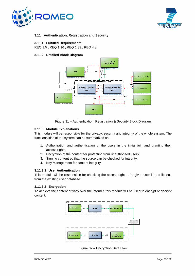
ROMEO WP2 Page 68/132
3.11 Authentication, Registration and Security
3.11.1 Fulfilled Requirements REQ 1.5 , REQ 1.16 , REQ 1.33 , REQ 4.3
3.11.2 Detailed Block Diagram
Figure 31 – Authentication, Registration & Security Block Diagram
3.11.3 Module Explanations This module will be responsible for the privacy, security and integrity of the whole system. The functionalities of the system can be summarized as:
1. Authorization and authentication of the users in the initial join and granting their access rights.
2. Encryption of the content for protecting from unauthorized users. 3. Signing content so that the source can be checked for integrity. 4. Key Management for content integrity.
3.11.3.1 User Authentication This module will be responsible for checking the access rights of a given user id and licence from the existing user database.
3.11.3.2 Encryption To achieve the content privacy over the internet, this module will be used to encrypt or decrypt content.
Figure 32 – Encryption Data Flow

ROMEO WP2 Page 69/132
3.11.3.3 Key Management This module is responsible for distribution of private/public key pairs for user generated data.
3.11.3.4 Content Integrity This module is responsible for checking the integrity of content created by users.
3.11.4 Inter-Module Connections
3.11.4.1 ENCRYPT_CONTENT (Message #1100) The signed transport streams will be delivered to the P2P packetisation block, which deals with fragmenting the compressed content into P2P chunks.
3.11.4.2 DECRYPT_PACKET (Message #1101) This is the packet to be fed to the synchronisation module.
3.11.4.3 RETURN_PRIVATE_KEY (Message #1102) This message is a response to the GET_KEY_PAIR message and is sent to authentication module of the peer with the following: Content Id and Private Key.
3.11.4.4 RETURN_PUBLIC_KEY (Message #1103) This message is sent to the users with access rights to certain user generated content. The message contains: User Id (content generator), content Id and public key.
3.11.4.5 . CONTENT_INTEGRITY_CHECK_RESULT (Message #1104) This message is a response to the CONTENT_INTEGRITY_CHECK request. This contains content id, package id and result. Result can be:
• CONTENT_VERIFIED: Content has been signed correctly. • CONTENT_NOT_VERIFIED: Content has not been signed correctly or is from a
malicious source.
3.11.4.6 SIGNED_CONTENT (Message #1105) This message is response to SIGN_USER_CONTENT. The packet contains content id, packet id, signed data and signed data size.
3.11.4.7 SEND_USER_RIGHTS (Message#1106) This message is responsible for sending the rights of mobile users to the mobility unit. It contains the user id and the user rights.
3.11.4.8 ENCRYPT (Message #204,205,206) These messages are content messages to be encrypted. They are explained in sections 3.2.4.5, 3.2.4.6 and 3.2.4.7 respectively.
Message Number Name From To
1100 ENCRYPT_CONTENT
Authentication, Registration And Security P2P
1101 DECRYPT_CONTENT
Authentication, Registration And Security Synchronisation
1102 RETURN_PRIVATE_KEY
Authentication, Registration And Security
Authentication, Registration And Security Peer

ROMEO WP2 Page 70/132
Server
1103 RETURN_PUBLIC_KEY
Authentication, Registration And Security Server
Authentication, Registration And Security Peer
1104 CONTENT_INTEGRITY_CHECK_RESULT
Authentication, Registration And Security
User Generated Data
1105 SIGNED_CONTENT
Authentication, Registration And Security
User Generated Data
1106 SEND_USER_RIGHTS
Authentication, Registration And Security
Media Aware Network Element
Table 17 – Authentication, Registration and Security Messages
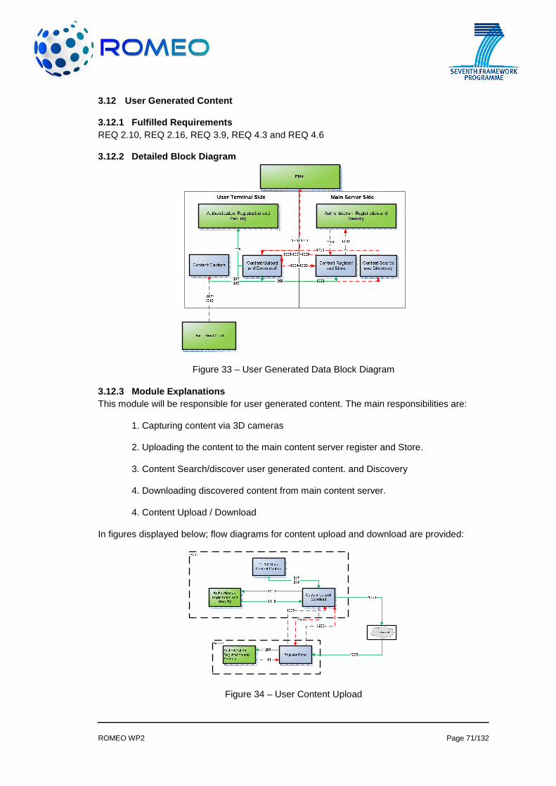
ROMEO WP2 Page 71/132
3.12 User Generated Content
3.12.1 Fulfilled Requirements REQ 2.10, REQ 2.16, REQ 3.9, REQ 4.3 and REQ 4.6
3.12.2 Detailed Block Diagram
Figure 33 – User Generated Data Block Diagram
3.12.3 Module Explanations This module will be responsible for user generated content. The main responsibilities are:
1. Capturing content via 3D cameras
2. Uploading the content to the main content server register and Store.
3. Content Search/discover user generated content. and Discovery
4. Downloading discovered content from main content server.
4. Content Upload / Download
In figures displayed below; flow diagrams for content upload and download are provided:
Figure 34 – User Content Upload

ROMEO WP2 Page 72/132
Figure 35 – User Content Download
3.12.3.1 2D/3D User Content Capture User content can be captured from devices generating 2D/3D content, compatible with formats supported by ROMEO system. User terminal can receive content in several ways:
1. Capture content with internal 2D/3D camera and audio device. 2. Download content from ROMEO server using procedures for User Content
Download. 3. Download content from Internet or using other communication channels – DVB,
Bluetooth, IR,.... 4. Read content from external flash memory 5. Download content from PC or other external device
3.12.3.1.1 Block diagram of user generated content capture for mobile 3D terminal device
3D camera terminal device uses two image sensors to capture 3D video streams and still images. Captured frames should be synchronised to achieve good stereo effect. At the same time all features related to 2D video and image processing should be applied also. Along with algorithms used in 2D video and imaging, additional algorithms specific for 3D are implemented. In 2D mode the camera uses only one image sensor.
Terminal device can receive user generated content from external sources. Generally the terminal can access Internet or communicate using different communication channels (DVB, Bluetooth. The device can be connected to PC or other external devices.
ROMEO mobile 3D terminal device should be implemented based on Texas Instruments OMAP platform
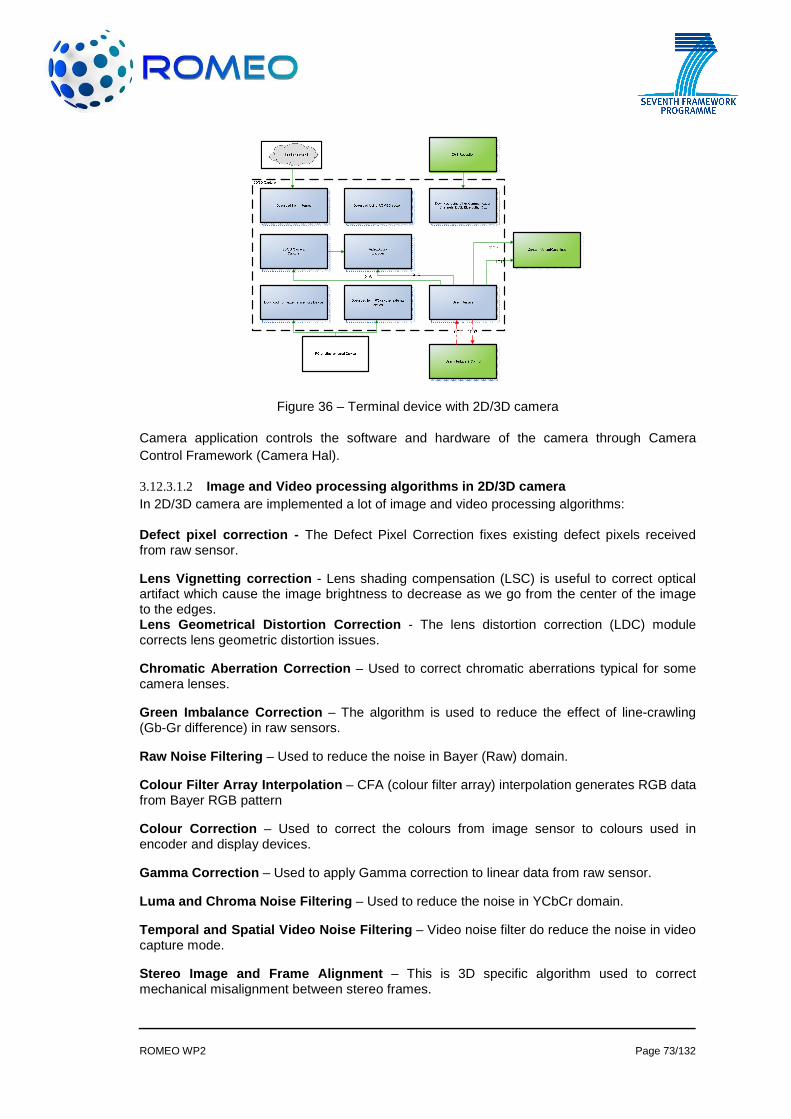
ROMEO WP2 Page 73/132
Figure 36 – Terminal device with 2D/3D camera
Camera application controls the software and hardware of the camera through Camera Control Framework (Camera Hal).
3.12.3.1.2 Image and Video processing algorithms in 2D/3D came ra In 2D/3D camera are implemented a lot of image and video processing algorithms:
Defect pixel correction - The Defect Pixel Correction fixes existing defect pixels received from raw sensor.
Lens Vignetting correction - Lens shading compensation (LSC) is useful to correct optical artifact which cause the image brightness to decrease as we go from the center of the image to the edges. Lens Geometrical Distortion Correction - The lens distortion correction (LDC) module corrects lens geometric distortion issues.
Chromatic Aberration Correction – Used to correct chromatic aberrations typical for some camera lenses.
Green Imbalance Correction – The algorithm is used to reduce the effect of line-crawling (Gb-Gr difference) in raw sensors.
Raw Noise Filtering – Used to reduce the noise in Bayer (Raw) domain.
Colour Filter Array Interpolation – CFA (colour filter array) interpolation generates RGB data from Bayer RGB pattern
Colour Correction – Used to correct the colours from image sensor to colours used in encoder and display devices.
Gamma Correction – Used to apply Gamma correction to linear data from raw sensor.
Luma and Chroma Noise Filtering – Used to reduce the noise in YCbCr domain.
Temporal and Spatial Video Noise Filtering – Video noise filter do reduce the noise in video capture mode.
Stereo Image and Frame Alignment – This is 3D specific algorithm used to correct mechanical misalignment between stereo frames.

ROMEO WP2 Page 74/132
Video Stabilisation – The algorithm is used to reduce handshake effect from mobile device cameras.
Stereo 3A Algorithms – Auto Exposure, Auto White Ba lance, Auto Focus – All automatic control algorithms are designed for stereo capture, to control exposure, white balance and focus.
All image processing algorithms are adaptive. There control parameters are adapted based on light condition and frame content.
3.12.3.1.3 Save 2D/3D videos and images Video frames generated from the camera are directed to mobile device display, video encoder or jpeg encoder. The encoder output is stored on internal device memory. All users’ generated content received using communication channels and connections to external devices are stored in terminal device memory also. After that, the content can be submitted to ROMEO system server. By User Interface on terminal device is selected the content to upload/download on ROMEO server.
3.12.3.2 Content Register and Store After verification and passing the integrity checking, the user generated content is submitted to the Content Register and Store (CRS) module for file storage in the main seed server. A Global Unique Identification (GUID) is associated with the content file and maps it to the CRS file system. Metadata about the content, such as content title, license, authors, generating date, file length, etc. will be used to generate the GUID.
3.12.3.3 Content Search and Discovery This module is responsible for discovering where the requested content file is stored in the main seed server file store. The only search criterion for search is the content file’s GUID. Users will need to send the necessary information about the content to the module for a successful search.
3.12.3.4 Content Upload/Download This module is responsible for uploading/downloading content from server.
3.12.4 Inter-Module Connections
3.12.4.1 CONTENT_REGISTER_REQUEST (Message #1200) This content register request message is relayed to the Verification module and includes the following information:
• Content title, • License, • Authors, • Production date, • Length of file in byte
3.12.4.2 CONTENT_REGISTER_REPLY (Message #1201) This message is to indicate to the requester whether the content is registered or not. If the content is allowed to register, the content data will be stored to the main server’s file system. This message is sent from the user authentication module.

ROMEO WP2 Page 75/132
3.12.4.3 CONTENT_SEARCH_REQUEST (Message #1202) The content search request message is from verification module and should include necessary information about the requested content, such as title, authors, license and file length etc., to generate the GUID for search in the main seed server file store.
3.12.4.4 CONTENT_SEARCH_REPLY (Message #1203) The search reply message is sent to the content requester via Verification mode. The path of the requested content file is included in this message.
3.12.4.5 INITIATE_UPLOAD_DATA (Message #1204) This message will be used to initialize the content upload. The inputs are content id, user id, content size and number of packets. The server checks if the content already exists and sends a message to the authentication unit for checking the key pair.
3.12.4.6 CONTENT_UPLOAD_RESULT (Message #1205) This message is sent to the user generated data module to confirm or deny the request for uploading data to the server. If request is denied a reason is sent with the message and these are:
1. ALREADY_UPLOADED: Content with the same id has already been uploaded to the server
2. NO_KEY_GENERATED: No key pair request has been made for this particular content.
3.12.4.7 INITIATE_DOWNLOAD_DATA (Message #1206) This message will be used to initiate the content download. The inputs are content id (provided from an earlier search query) and user id. The server checks if the user has the right to download the request.
3.12.4.8 CONTENT_DOWNLOAD_RESULT (Message #1207) This message is a response to the INITIATE_DOWNLOAD_DATA. The contents are:
1. USER_VERIFIED: Shows that the user has the rights.
2. USER_NOT_VERIFIED: Shows that user does not possess the rights.
In case content is found, in addition size and number of packets to download are also sent with the message.
3.12.4.9 USER_CONTENT (Message #1208) This contains the package id, user content and its size. The message is forwarded to the Authentication, Registration and Security for verification. The verified content is further forwarded to the rendering unit. In case verification fails the package is requested again from the server
3.12.4.10 CONTENT_REQUEST (Message #1209) In case verification fails this message is sent to request the package again from its source.
3.12.4.11 SIGN_USER_CONTENT(CONTENT (Message #1210) This message is responsible for signing each packet. The packet contains data, data size, package id and content id. This message is sent via the upload/download unit to the authentication unit.

ROMEO WP2 Page 76/132
3.12.4.12 CONTENT_UPLOAD_DOWNLOAD_START (Message #1 211) This message will be sent to the MANE to signal content upload/download start. This contains the user id and the operation id: 0 for download and 1 for upload.
3.12.4.13 CONTENT_UPLOAD_DOWNLOAD_END (Message #121 2) This message will be sent to the MANE to signal content upload/download end. This contains the user id and the operation id: 0 for download and 1 for upload
3.12.4.14 CONTENT_CAPTURE_START_STOP (Message #1215 ) By this message User Interface starts and stops 2D/3D content capture
3.12.4.15 CONTENT_ENCODE_START_STOP (Message #1216) By this message User Interface starts and stops captured 2D/3D content encoding
3.12.4.16 USER_CONTENT_UPLOAD (Message #1217) This message is to send command from terminal user interface to Content Upload/Download module to upload user generated content.
3.12.4.17 USER_CONTENT_DOWNLOAD (Message #1218) This message is to send command from terminal user interface to Content Upload/Download module to download user generated content
3.12.4.18 GET_KEY_PAIR (Message #1219) This message is initiated by the user generated content module on the peer side with the following inputs: User Id of the content generator, an id for the generated content, list of user ids with access rights to the content.
3.12.4.19 CHECK_USER_KEY (Message #1220) User id and content id is sent to check if a key pair is generated for this content. It returns:
• CONTENT_OK: If there exists a created key. • CONTENT_FAILED: If such a key does not exist.
Message Number Name From To
1200 CONTENT_REGISTER_REQUEST
Content Register and Store Module
Authentication, Registration and Security Module
1201 CONTENT_REGISTER_REPLY
Authentication, Registration and Security Module
Content Register and Store Module
1202 CONTENT_SEARCH_REQUEST
Authentication, Registration and Security Module
Content Search and Discovery Module
1203 CONTENT_DATA_DOWNLOAD
Content Search and Discovery Module
Content Upload/Download Module

ROMEO WP2 Page 77/132
1204 INITIATE_UPLOAD_DATA
User Generated Data Peer
User Generated Data Server
1205 CONTENT_UPLOAD_ACK
User Generated Data Server
User Generated Data Peer
1206 INITIATE_DOWNLOAD_DATA
User Generated Data Peer
User Generated Data Server
1207 CONTENT_DOWNLAOD_ACK
User Generated Data Server
User Generated Data Peer
1208 USER_CONTENT
User Generated Data
Authentication, Registration and Security
1209 CONTENT_REQUEST
User Generated Data Peer/Server
User Generated Data Server/Peer
1210 SIGN_USER_CONTENT
User Generated Data
Authentication, Registration and Security
1211 CONTENT_UPLOAD_DOWNLOAD_START
User Generated Data Server
Media Aware Network Element
1212 CONTENT_UPLOAD_DOWNLOAD_END
User Generated Data Server
Media Aware Network Element
1215 CONTENT_CAPTURE_START_STOP User Terminal Interface
2D/3D Content Capture
1216 CONTENT_ENCODE_START_STOP User Terminal Interface
Video/Audio Encoder
1217 USER_CONTENT_UPLOAD User Terminal Interface
Content Upload/Download
1218 USER_CONTENT_DOWNLOAD User Terminal Interface
Content Upload/Download
1219 GET_KEY_PAIR User Generated
Authentication, Registration And
ROMEO WP2 Page 78/132
Data Security
1220 CHECK_USER_KEY
User Generated Data
Authentication, Registration And Security
Table 18 – User Generated Content Messages

ROMEO WP2 Page 79/132
3.13 3D Video Decoding
3.13.1 Fulfilled Requirements REQ 1.6, REQ 1.11, REQ 1.12, REQ 1.13, REQ 1.21, REQ 1.24, REQ 1.25, REQ 2.14, REQ 2.15, REQ 3.10, REQ 3.11, REQ 3.12, REQ 3.13, REQ 3.14, REQ 3.15, REQ 4.24
3.13.2 Detailed Block Diagram
Figure 37 – 3D Video decoding process
3.13.3 Module Explanations In the following subsections, the brief explanations of the involved sub modules within the user terminal video decoder, as well as the explanations of the inter-module connections are presented.
3.13.3.1 Peer Terminal 3D video decoding for Fixed and Mobil e Displays
3.13.3.1.1 Demultiplexing and decapsulation This module demultiplexes different camera viewpoints and depth maps (and also descriptions, if multiple-description is in use) and sends them to different SVC decoder instances that run in parallel. Before sending the transport streams, the TS and Packetised Elementary Stream (PES) packets are decapsulated in to elementary streams (ES). Base layer and Enhancement layer NAL units are aggregated to be sent to the same decoder. The ESs are forwarded to the decoder(s) Access Unit by Access Unit because of the decoding architecture.
3.13.3.1.2 SVC decoder This module decodes the delivered elementary streams and produces raw YUV 4:2:0 image sequences to be processed further.
3.13.3.1.3 View interpolation metadata decoder This module decodes the delivered metadata (if existing in the multiplex) and sends it to the video renderer for improved concealment purposes.
3.13.3.1.4 Visual attention metadata This module extracts the visual attention metadata and forwards them to the video renderer in the required format, such that improved display adaptation can be done.
3.13.3.1.5 Multiple description merger This module receives the raw (uncompressed) descriptions from associated decoders’ output ports and processes them to generate the full representation. If one or several descriptions are

ROMEO WP2 Page 80/132
missing, a reduced quality representation is produced at the end that is forwarded to the video renderer.
3.13.4 Inter-module connections
3.13.4.1 ELEMENTARY_STREAMS (Message #1301) The video elementary streams are forwarded to the input ports of the SVC decoder instances. The stream is forwarded as an access unit NAL packet stream, where each packet comprises the compressed version of a single video frame, in the correct decoding order. Note that the decoded frames correspond to a single description, each.
3.13.4.2 RAW_DESCRIPTIONS (Message #1302) The decompressed video frames, each corresponding to a single description, are forwarded to the Multiple-Descriptions merging block with the associated presentation time stamp information. The block combines the pixels of each decoded description to yield the full resolution decoded video frame and forwards it to the video rendering block over high-throughput connection (e.g. infiniband) using a robust communication scheme, such as TCP.
3.13.4.3 VIEW_INTERPOL_METADATA (Message #1303) The view interpolation metadata carried along with the audio-visual media data is forwarded to the view interpolation metadata decoder to get the optimal blending coefficients and delivered to the video renderer block.
3.13.4.4 VISUAL_ATTN_METADATA (Message #1304) The visual attention metadata carried along with the audio-visual media data is forwarded to the video renderer block for the purpose of display adaptation.
3.13.4.5 VIEW_INTERPOL_METADATA_FORWARD (Message #1 305) The decoded view interpolation metadata is delivered to the video renderer.
3.13.4.6 VID_COMP_COMM_MSG (Message #1000, 1001, 10 11) Video decoder interface with user interface component is explained is Section 3.10. Messages related to video decoder and renderer UI are explained in 3.10.4.1
The following table depicts the included inter-module connections’ list and the following subsections provide a brief explanation of each of them.
Message Number Name From To
1301 ELEMENTARY_STREAMS
Demultiplexing and depacketisation block SVC decoders
1302 RAW_DESCRIPTIONS SVC decoders
Video renderer (or optionally to multiple description merger, if multiple descriptions exist)
1303 VIEW_INTERPOL_METADATA
Demultiplexing and depacketisation block Video renderer
1304 VISUAL_ATTN_METADATA Demultiplexing Video renderer

ROMEO WP2 Page 81/132
and depacketisation block
1305 VIEW_INTERPOL_METADATA_FORWARD
View interpolation metadata decoder Video renderer
Table 19– 3D video decoding messages

ROMEO WP2 Page 82/132
3.14 Video rendering
3.14.1 Fulfilled Requirements REQ 1.6, REQ 1.10, REQ 1.26, REQ 2.1, REQ 2.2, REQ 2.3, REQ 2.4, REQ 2.8, REQ 2.27, REQ 3.1, REQ 3.12
3.14.2 Detailed Block Diagram
Figure 38 – Video Rendering block diagram
3.14.3 Module Explanations The video rendering block will provide the adapted video signal to the targeted display. It will handle the number of views required for this specific display unit.
3.14.3.1 Disparity map projection This block will prepare disparity maps for the future view interpolation processing. It receives disparity maps from the decoder through a high speed interface (e.g. Infiniband interface). Disparity maps are received corresponding to disparity between incoming views. The view interpolation process requires this information projected at the right position in between the video. This block delivers a set of disparity maps corresponding to the number of projection that will be applied in the view interpolation block. Positions of interpolated views are determined by the view renderer control block.
3.14.3.2 View interpolation This block will use projected disparity maps and video signals to generate interpolated views in between incoming ones. It is controlled by the video renderer control block.
3.14.3.3 Video shuffling This block will use all incoming and interpolated views to generate the sub-sampled shuffled video adapted to the display. This block is controlled by the video renderer control block, which adapts the processing to the targeted display.
3.14.3.4 Video renderer control This block masters the video renderer in term of processing to be applied. It is the interface with the audio/visual adaptation block as well as with the video decoder block. It will determine the number of views to be interpolated as well as the ir respective positions.
3.14.4 Inter-Module Connections
3.14.4.1 RAW DISPARITY MAPS (Message #1401) Disparity maps information is decoded by the video decoder and transmitted through a high speed interface (e.g. Infiniband interface)

ROMEO WP2 Page 83/132
3.14.4.2 RAW VIDEO DATA (Message #1402) Video information decoder by the video decoder and transmitted through a high speed interface (e.g. Infiniband interface)
3.14.4.3 PROJECTED DISPARITY MAPS (Message #1403) Disparity maps information projected at the right position to be used by the view interpolation block
3.14.4.4 INTERPOLATED VIEWS (Message #1404) Interpolated view calculated from video and projected disparity maps
3.14.4.5 SHUFFLED VIDEO (Message #1405) Video formatted in accordance with the pixel shuffling of the targeted display
3.14.4.6 VIDEO_RENDERING_CONTROL (Message #1406) Metadata corresponding to the description of the view interpolation to be processed, taking into account incoming metadata (214, 215 and 805)
3.14.4.7 VIDEO_ADAPTATION (Message #805) This message is explained in section 3.8.4
3.14.4.8 VIEW_INTERPOL_METADATA (Message #1303) This message is explained in video decoder component under section 3.13.4
3.14.4.9 VISUAL_ATTN_METADATA (Message #1304) This message is explained in video decoder component under section 3.13.4
Message Number Name From To
1401 RAW DISPARITY MAPS Video Decoder Disparity map projection
1402 RAW VIDEO DATA Video Decoder View interpolation
1403 PROJECTED DISPARITY MAPS
Disparity map projection View interpolation
1404 INTERPOLATED VIEWS View interpolation Video shuffling
1405 SHUFFLED VIDEO Video shuffling Display
1406 VIDEO_RENDERING_CONTROL
Video renderer control
Disparity map projection/view interpolation and video shuffling
Table 20 – Video Rendering Messages

ROMEO WP2 Page 84/132
3.15 Audio Encoding, Decoding & Rendering
3.15.1 Fulfilled Requirements REQ 3.16, REQ 3.17, REQ 3.18, REQ 3.19, REQ 3.20
3.15.2 Detailed Block Diagram
Figure 39 – 3D Audio encoding (above) and decoding & rendering (below)
3.15.3 Module Explanations At the encoding side the audio signals generated by the content generation component are fed to the spatial audio encoder for audio compression while at the decoding side the spatial audio decoder will be used to recreate the audio signals. For audio rendering three options are available: headset/stereo, 5.1, and wave filed synthesis.
3.15.3.1 Audio Encoding and Decoding
3.15.3.1.1 Spatial Audio Encoder Two encoding approaches using standardised spatial audio codecs will be considered for the project: MPEG AAC multichannel and MPEG Surround combined with AAC. The one that would provide the best performance in the investigation will be used in the ROMEO project.
3.15.3.1.2 Audio Stream Packetiser The encoded audio signal will be presented as bit stream through this module.
3.15.3.1.3 Audio Stream Depacketiser This module extracts the audio bit stream from the received audiovisual stream.
3.15.3.1.4 Spatial Audio Decoder This module is the spatial audio decoder that decodes and provides the decoded audio signals.
3.15.3.2 Audio Rendering
3.15.3.2.1 Audio Rendering Control The function of this module is to process the decoded audio signal for a particular audio rendering option: binaural/stereo, 5.1, and wave field synthesis.

ROMEO WP2 Page 85/132
3.15.3.2.2 Binaural/Stereo Processing This module is to be used as an interface for the mobile and portable terminal for binaural audio rendering or for the fixed terminal for stereo audio rendering.
3.15.3.2.3 Wave Field Synthesis The wave filed synthesis (WFS) module is aimed at reproducing higher quality audio rendering when large numbers of loudspeakers are available.
3.15.3.2.4 Headset/Stereo Loudspeaker This module is the mobile user’s headset or stereo loudspeaker.
3.15.3.2.5 5.1-channel Loudspeakers This is the standard 5.1-channel loudspeaker reproduction system for rendering basic audio scheme in the ROMEO.
3.15.3.2.6 Large Number of Loudspeakers This module describes a large number of loudspeakers required for audio rendering using WFS.
3.15.4 Inter-Module Connections
3.15.4.1 COMPRESSED_AUDIO (Message # 1501) This represents the compressed audio streams after the encoder that will be packetised. .
3.15.4.2 PACKETISED_AUDIO (Message # 1502) This represents the packetised elementary audio streams (PES) that will be transmitted for encapsulating in the P2P-Packetisation component .
3.15.4.3 COMPRESSED_AUDIO (Message # 1503) This represents the received compressed audio that have been depacketised and ready to be decoded.
3.15.4.4 DECODED_AUDIO (Message # 1504) This represents the audio streams after the decoder, ready to be rendered through various reproduction settings.
3.15.4.5 OBJECT_BASED_AUDIO (Message # 1505) This represents the audio objects and the scene description that will be passed to the binaural audio renderer.
3.15.4.6 STEREO/BINAURAL_AUDIO (Message # 1506) This represents the downmixed stereo audio signals, or the binaural audio rendered using the audio objects and the scene description.
3.15.4.7 5.1_AUDIO (Message # 1507) This represents the audio streams in 5.1-channel configuration for the default spatial audio rendering for the fixed-user.
3.15.4.8 OBJECT_BASED_AUDIO (Message # 1508) This represents the audio objects and the scene description used for the WFS reproduction.
3.15.4.9 WFS_SIGNAL (Message # 1509) This represents the rendered WFS audio signals that will be passed to the WFS loudspeakers.

ROMEO WP2 Page 86/132
3.15.4.10 AUDIO_CTL2 (Message # 1510) This message is necessary for audio-video synchronisation when binaural audio rendering is performed.
3.15.4.11 AUDIO_CTL3 (Message # 1511) This message is the audio synchronisation information required when performing audio rendering using wave field synthesis..
3.15.4.12 AUDIO_MDATA2 (Message # 1512) This message is the audio metadata that required for binaural rendering
3.15.4.13 AUDIO_MDATA3 (Message # 1513) This message is the audio metadata that required for WFS rendering.
3.15.4.14 AUDIO_OBJECTS/CHANNELS (Message # 0109) This represents the audio objects or channels that have been passed through the content generation component, ready to be encoded.
3.15.4.15 SYNCHRONIZED_AUDIO (Message # 0705) This represents the synchronised audio stream that received from Synchronisation component.
3.15.4.16 AUDIO_ADAPTATION (Message #0804) This message contains metadata describing the audio adaptation mode. This represents the information regarding the rendering configuration to be used for the final audio delivery (5.1-channel, stereo, WFS, etc.) out of the audio adaptation module.
3.15.4.17 AUD_COMP_COMM_MSG (Message #1012, 1013, 1 014) These Messages are used to send necessary information to control the audio decoder and renderer.
Message Number Name From To
1501 COMPRESSED_AUDIO Spatial Audio Encoder Audio Stream Packetiser
1502 PACKETISED_AUDIO Audio Stream Packetiser
Encapsulator
1503 COMPRESSED_AUDIO Audio Stream Depacketiser
Spatial Audio Decoder
1504 DECODED_AUDIO Spatial Audio Decoder
Audio Rendering Control
1505 OBJECT_BASED_AUDIO
Audio Rendering Control
Binaural/Stereo Processing
1506 STEREO/BINAURAL_AUDIO
Binaural/Stereo Processing
Headset/Stereo Loudspeaker
1507 5.1_AUDIO Audio Rendering Control
5.1 Loudspeaker
1508 OBJECT_BASED_AUDIO
Audio Rendering Control
Wave Field Synthesis
1509 WFS_SIGNAL Wave Field Synthesis
Large Number of Loudspeaker Array
1510 AUDIO_CTL2 Audio Rendering Control
Binaural/Stereo Processing

ROMEO WP2 Page 87/132
1511 AUDIO_CTL3 Audio Rendering Control
Wave Field Synthesis
1512 AUDIO_MDATA2 Audio Rendering Control
Binaural/Stereo Processing
1513 AUDIO_MDATA3 Audio Rendering Control
Wave Field Synthesis
0109 AUDIO_OBJECTS/CHANNELS
Content Generation Module Spatial Audio Encoder
0705 SYNCHRONIZED_AUDIO
Synchronisation Audio Stream Depacketiser
0804 AUDIO_ADAPTATION ( A/V Adaptation Audio Rendering Control
1012, 1013, 1014
AUD_COMP_COMM_MSG
User Interface & Control
Audio Decoder and Rendering Control
Table 21 – Audio Decoding/Rendering Messages
3.16 Use Cases and System Component Mapping
3.16.1 User Join Related Reference Scenario: Consumption of 3D audio/video over hybrid delivery paths
Figure 40 – User Join Scenario Sequence Diagram

ROMEO WP2 Page 88/132
• User Interface Component sends a request to P2P component to join the network.
• P2P component’s peer module starts connection process with server side to establish connection and sends Join Request to the server module of P2P component.
• Authentication component of the server performs licence check to the peer (In ROMEO it is assumed that all ROMEO users have a proper licence).
• The user type is also forwarded to Policy Charging and Rule Function (PCRF).
• If the license is not approved, then server module sends disapproval to the peer module and result of the join process is answered to the User Interface Component.
• If the license is approved by server module, approval is sent to the peer module of P2P component.
• After approval of license, peer module sends device & connection capabilities to the server module.
• If the device/connection capabilities of the peer are not appropriate to be placed in the topology, peer is informed by the main server and this peer consumes the main view of the stream via DVB only and it is still inserted to the multiple multicast trees to be able to send/receive network control messages and necessary feedbacks.
• If the device/connection capabilities of the peer are appropriate, it is inserted into the tree by the main server and a list of determined parent is sent to them.
• Peer tries to establish connection with all parents in the list for all multi-cast trees.
• If peer cannot establish connection with some or all parents in multiple multi-cast trees, it informs the main server about the situation and main server sends a new parent list to it until it can connect all of the multi-cast trees.
• The result of the join process is answered to the User Interface Component.
3.16.2 Live stream reception of fixed users with op timal conditions Related Reference Scenario: Consumption of 3D audio/video over hybrid delivery paths
Figure 41 – User with optimal conditions live stream reception sequence diagram

ROMEO WP2 Page 89/132
• User starts to get all pre-processed streams from its parents from each of the multicast trees it joined; that is, peer P2P component receives the data.
• P2P component sends the received data to packetisation component to be depacketised and then the data is sent to Authorization, Registration and Security module to be decrypted (decryption is optional).
• Decrypted streams are sent to the synchronisation component to be buffered.
• Synchronisation component synchronises all views with audio and depth information relative to DVB and then sent to the media encoding/decoding component to be decoded.
• Media encoding/decoding component renders the audio and video to be displayed to the user.
3.16.3 A/V Adaptation Related Reference Scenario: Consumption of 3D audio/video over hybrid delivery paths
Figure 42 – A/V adaptation triggered by Network Monitoring module sequence diagram

ROMEO WP2 Page 90/132
Figure 43 – A/V adaptation triggered by Synchronisation module sequence diagram
• The Network Monitoring module of the peer monitors the user’s QoE and network conditions sufficiency to meet necessary QoE. (Network monitoring module triggered adaptation process is shown in Figure 42. Buffer under run situation may also trigger the adaptation process).
• In case of the detection of a crucial change in the network conditions, the Network Monitoring module notifies the QoE Adaptation module about the change and the QoE Adaptation component of the peer decides on the adaptation steps to be taken to use network resources as efficient as possible to provide best possible QoE and sends the decision to the P2P component.
• Child’s P2P component communicates with the parent’s P2P component to inform it about the adaptation decisions. Adaptation decision also sent to the synchronisation module to inform it.
• If there is no problem as above, parent’s P2P component acts according to the adaptation decision sent by the child and sends an ACK message to the child to inform it.
• Child’s P2P component sends this ACK message to QoE adaptation and Network Monitoring modules as well.
3.16.4 Peer disconnect Related Reference Scenario: Consumption of 3D audio/video over hybrid delivery paths

ROMEO WP2 Page 91/132
Figure 44 – Peer disconnect sequence diagram
Peer disconnect (gracefully):
• When a peer wants to leave live stream gracefully, it sends a disconnect request to the P2P component of the main server.
• The P2P component of the main server reforms the overlay by maintaining the connections of the served peers of the peer requesting to disconnect so that QoE of the other users is not affected with this disconnection and as a result calculates a new parent for children of the disconnected peer and informs the children about new parent to connect.
• Childs of the disconnected parent sends “start” message to the other parent in the tree at which the same stream is sent redundantly.
• Childs of the disconnected parent tries to establish connection with the new parent and inform the server when connection is established successfully.
• The main server sends a disconnect ACK to the peer who wants to disconnect.
• Upon receiving the ACK, peer disconnects to the P2P overlay.
Peer disconnect (ungracefully):
• User suddenly disconnects from the P2P overlay.
• Network monitoring module of the peers served by the disconnected peer reports the failure to the P2P their components.
• Children of the disconnected parent sends “start” message to the other parent in the tree at which the same stream is sent redundantly.
• The main server calculates a new parent for the children of the disconnected peer and informs the children about new parent to connect.

ROMEO WP2 Page 92/132
• Childs of the disconnected parent tries to establish connection with the new parent and inform the server when connection is established successfully.
3.16.5 Initiating a Video Conference Related Reference Scenario: Collaborating group and sharing user generated content
Figure 45 – Initiating a video conference sequence diagram
• User (moderator) chooses group members from a list of available users on her/his screen and then sends an invitation request to these users.
• A/V Conference Module relays the message to the corresponding users with the list of users and content (to watch together).
• The invitee A/V Conference Module forwards the message further to the user interface of the invitee.
• The invited user sees an alert on her/his screen and responds to it either by accepting or rejecting the invitation.
• This message is forwarded to the moderator A/V Conference Module.
• Then there are message changes based on the solution to be used for building the conferencing overlay. When the overlay has been finished building, the moderator receives an alert from the A/V Conference Module that s/he can begin the conference.
3.16.6 Starting a Video Conference Related Reference Scenario: Collaborating group and sharing user generated content

ROMEO WP2 Page 93/132
Figure 46 – Starting a video conference sequence diagram
• User (moderator) initiates the conference by pressing the start conference button. This action causes the user interface module to send a message to A/V Conference Module to start the conference.
• A/V Conference Module relays the message forward to A/V Control Module which starts to collect the network conditions from participating users.
• After network conditions of all participating users have been received, A/V Control Module calculates the delay for the collaborating group.
• A/V Control Module sends the delay value to participating users, so that they can set their buffers.
• After all participants return with an acknowledgement that they are ready, user interface is alerted to start conference.
3.16.7 Joining an Existing Collaborating Group Related Reference Scenario: Collaborating group and sharing user generated content

ROMEO WP2 Page 94/132
Participant
Col. Sync. Buffer
JOIN_CONFERENCE(user id, content id)
Participant
User Interface
Participant
A/V Conference Module
Moderator
A/V Conference Module
JOIN_CONFERENCE(user id, content id)
Proprietary (solution dependent) conference overlay messages
Proprietary (solution dependent) conference overlay messages
Establishing video
conference overlayEstablishing video conference overlay
JOIN_COLLABORATING_GROUP_RESPONSE(user id, content id, reply)
Participant
A/V Control ModuleModerator
A/V Control Module
GET_COLLABORATION_DELAY(user id, content id)
COLLABORATION_DELAY(user id, content id, delay)
SET_COLLABORATION_DELAY(user id, content id, delay)
Set the buffer size
Participant moduleCOLLABORATION_DELAY_SET
GET_COLLABORATION_DELAY(user id, content id)
Solution dependent
overlay construction
COLLABORATION_DELAY_SET
JOIN_CONFERENCE_RESPONSE(user id, content id, reply)
AFFIRMATIVE
Begin video conference
NON-AFFIRMATIVE
JOIN_COLLABORATING_GROUP_RESPONSE(user id, content id, reply)
Streaming continues
Figure 47 – Joining an existing collaborating group sequence diagram
• A user, who wants to join an existing conference and who has been invited to the group already by the moderator, sends a message to the moderator that s/he wants to join.
• Moderator A/V Conference Module responds to the request.
• If the user has been granted her/his entry to the group, first s/he has been added to the conference overlay then the user request for the needed delay and sets her/his buffer accordingly. If the network conditions cannot achieve this delay, stream will be only received from DVB.
• The user interface of the joining user then receives a message that grants it the permission to start conference.
• If the user has not been granted her/his rights, s/he continues watching the stream.
3.16.8 Leaving from a Collaborating Group Related Reference Scenario: Collaborating group and sharing user generated content
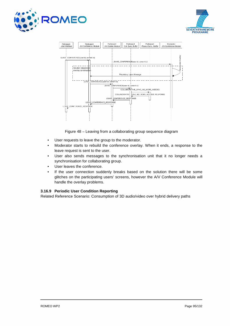
ROMEO WP2 Page 95/132
Figure 48 – Leaving from a collaborating group sequence diagram
• User requests to leave the group to the moderator. • Moderator starts to rebuild the conference overlay. When it ends, a response to the
leave request is sent to the user. • User also sends messages to the synchronisation unit that it no longer needs a
synchronisation for collaborating group. • User leaves the conference. • If the user connection suddenly breaks based on the solution there will be some
glitches on the participating users’ screens, however the A/V Conference Module will handle the overlay problems.
3.16.9 Periodic User Condition Reporting Related Reference Scenario: Consumption of 3D audio/video over hybrid delivery paths

ROMEO WP2 Page 96/132
Figure 49 – Network monitoring use case sequence diagram
• Every packet exchanged within the P2P overlay is intercepted by the Network Monitoring subsystem, to get network information without incurring into overheads. The accounted parameters for a link are delay, throughput, jitter, age of the information, etc.
• When instructed by the Topology Builder, the Network Monitoring subsystem of a peer will connect with the Network Monitoring subsystem of another peer to collect data on a P2P link.
• When an information record is too old (a link belonging only to READY trees, or it would have “data plane” packets producing new information) the Network Monitoring subsystem of a peer will connect with the Network Monitoring subsystem of another peer to collect data on a P2P link.
• By using a timer, the Network Monitor subsystem selects one of its super peers (round robin politics). Then the peer sends a merge of stored information towards the super peer, by sending the data to the fathers of the peer in one of the multicast trees it belongs to.
• When receiving data from a child (see previous point) a Network Monitoring subsystem adds the data to the internal database of collected network information.
• When it is the due time (when instructed to do so by Topology Builder / by timer / by receiving a given number of new data / etc ...) the Network Monitor instructs the Multicast Tree Manager to refresh its list of trees in SLEEPING state by leveraging on the information stored in the Network Manager.
3.16.10 User Generated Content Upload Related Reference Scenario: Collaborating group and sharing user generated content

ROMEO WP2 Page 97/132
Figure 50 – User generated content upload sequence diagram
• User sends request to upload content. This request is sent to User Generated Content component of the peer by the User Interface & Control component.
• Peer’s User Generated Content component communicates with server’s User Generated Content component to initiate content upload.
• Server’s User Generated Content component performs key pair check by communicating with Authentication Registration and security component.
• If result is not positive, failure notification is displayed to user. • If result is positive, data upload starts. • During the upload, server’s User Generated Content component performs integrity
check for the content by communicating with Authentication Registration and security component. If integrity check fails, content is re-requested from the peer.
3.16.11 User Generated Content Download Related Reference Scenario: Collaborating group and sharing user generated content
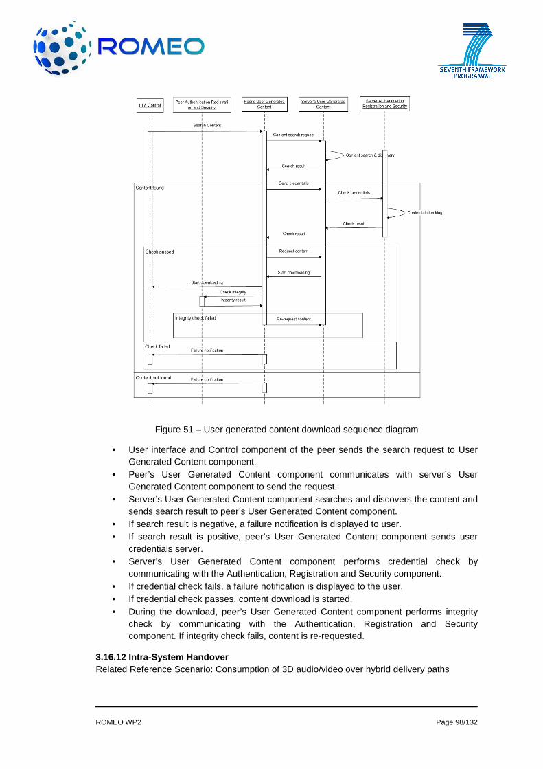
ROMEO WP2 Page 98/132
Figure 51 – User generated content download sequence diagram
• User interface and Control component of the peer sends the search request to User Generated Content component.
• Peer’s User Generated Content component communicates with server’s User Generated Content component to send the request.
• Server’s User Generated Content component searches and discovers the content and sends search result to peer’s User Generated Content component.
• If search result is negative, a failure notification is displayed to user. • If search result is positive, peer’s User Generated Content component sends user
credentials server. • Server’s User Generated Content component performs credential check by
communicating with the Authentication, Registration and Security component. • If credential check fails, a failure notification is displayed to the user. • If credential check passes, content download is started. • During the download, peer’s User Generated Content component performs integrity
check by communicating with the Authentication, Registration and Security component. If integrity check fails, content is re-requested.
3.16.12 Intra-System Handover Related Reference Scenario: Consumption of 3D audio/video over hybrid delivery paths
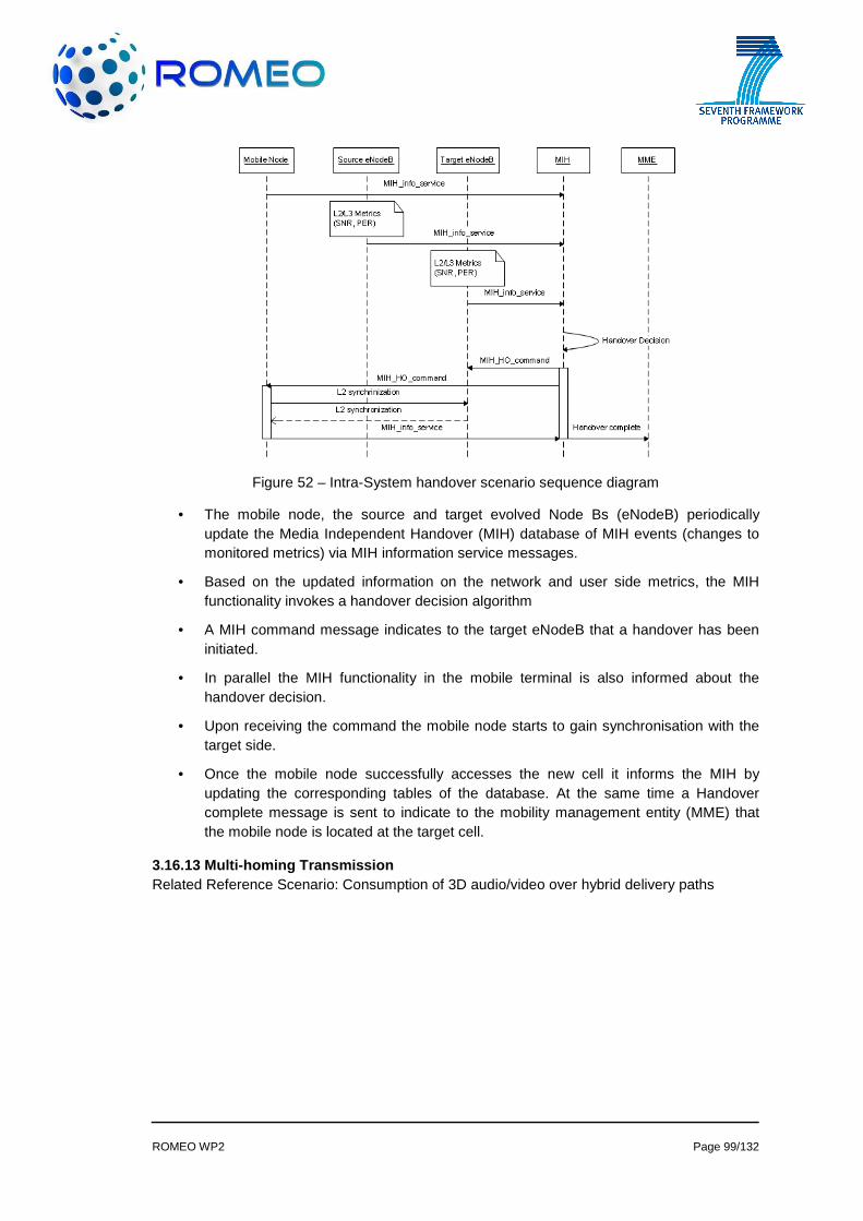
ROMEO WP2 Page 99/132
Figure 52 – Intra-System handover scenario sequence diagram
• The mobile node, the source and target evolved Node Bs (eNodeB) periodically update the Media Independent Handover (MIH) database of MIH events (changes to monitored metrics) via MIH information service messages.
• Based on the updated information on the network and user side metrics, the MIH functionality invokes a handover decision algorithm
• A MIH command message indicates to the target eNodeB that a handover has been initiated.
• In parallel the MIH functionality in the mobile terminal is also informed about the handover decision.
• Upon receiving the command the mobile node starts to gain synchronisation with the target side.
• Once the mobile node successfully accesses the new cell it informs the MIH by updating the corresponding tables of the database. At the same time a Handover complete message is sent to indicate to the mobility management entity (MME) that the mobile node is located at the target cell.
3.16.13 Multi-homing Transmission Related Reference Scenario: Consumption of 3D audio/video over hybrid delivery paths

ROMEO WP2 Page 100/132
Figure 53 – Multi-homing transmission scenario diagram
• The mobile node, the LTE network that the mobile node is currently connected to and a candidate 802.11 network in the area of the mobile node periodically update the Media Independent Handover (MIH) database of MIH events (changes to monitored metrics) via MIH information service messages.
• Based on the updated information on the network and user side metrics, the decision engine of MIH decides to allow multi-homing and sends a MIH command message to the candidate network, as well as, the mobile node triggering the 802.11 interface to wake.
• The mobile node establishes Layer 2 connection to the candidate network, the corresponding MAG of the candidate network registers the mobile node to the LMA.
• Upon successful registration to the LMA, the MAG in the candidate network issues a router advertisement to the MN, in order to configure the IP address of its 802.11 interface and to begin receiving data packets.
• A MIH information service message initiated by the mobile node updates the MIH database about the new network connection.
3.16.14 Inter-System Handover Related Reference Scenario: Consumption of 3D audio/video over hybrid delivery paths

ROMEO WP2 Page 101/132
Figure 54 – Inter-System handover scenario sequence diagram
• The mobile node, the source LTE (eNodeB) and the target 802.11 access point (AP) periodically update the Media Independent Handover (MIH) database, which resides in the Mobility Component platform, of MIH events (changes to monitored metrics) via MIH information service messages.
• Based on the updated information on the network and user side metrics, the MIH functionality invokes a handover decision algorithm.
• The MIH command message triggers LTE to initiate the handover and informs the MAG to initiate a de-registration process. A similar command is sent to the MIH enabled mobile node in order to perform Layer 2 switch.
• The Layer 2 detachment performed by the mobile node, triggers the LTE Mobile Access Gateway (MAG) to deregister the mobile node via a Proxy Mobile IP (PMIP) request to the Local Mobility Anchor (LMA), which is located in the Mobility Component platform. Subsequently, the LAM updates its binding cache entry and responds to MAG.
• As soon as, the mobile node establishes Layer 2 connection to the target network, the corresponding MAG of the target network registers the mobile node to the LMA.
• Upon successful registration to the LMA, the MAG in the target network issues a router advertisement to the MN, in order to configure the IP address of its 802.11 interface and to begin receiving data packets.
• A MIH information service message informs the MIH server that the handover has been successfully completed.

ROMEO WP2 Page 102/132
3.16.14.1 QoS-aware Tree Management
Figure 55 – Admission Control use case sequence diagram.
• Upon receiving network conditions changes report from the network Monitoring Subsystem, the Topology Builder and Multicast Tree Management component takes appropriate adaptation decision in conjunction with the Internet Resource and Admission Control Subsystem. This decision involves adaptation of trees states (e.g., READY to ACTIVE, SLEEPING to READY/ACTIVE, etc.) or new tree creation, depending on the running sessions QoS requirements and the current network resource conditions.
• The Internet Resource and Admission Control Subsystem, usually implemented in the Internet (e.g., QoS Brokers, distributed Gateways, etc.), is considered as a key component beneath the ROMEO overlay network since it controls access to the P2P link resources (e.g., bandwidth in routers, communication paths selections, QoS mapping, traffic control, etc.). In particular, it is used to control the resource and admission on the P2P links in a way to assure a proper transport of the ROMEO services.
• In case the Topology Builder and Multicast Tree Management component manages to quickly adapt to changes occurred in the network by switching among candidate trees, the A/V Adaptation component does not notice the changes placed in the network. Moreover, the Internet Resource and Admission Control Subsystem is responsible for managing the P2P links in a way to hide the underlying network dynamics as much as possible in support for the ROMEO session stability.

ROMEO WP2 Page 103/132
• However, when the changes occurred cannot be addressed by using the feasible overlay trees due to poor network conditions, the A/V Adaptation component is contacted for the purpose of readjusting the QoS requirements of the currently running flows (e.g., removing certain views or descriptions, etc.).
• In case the A/V Adaptation component successfully adjusts the QoS requirements of the concerned flows, the Topology Builder and Multicast Tree Management component and the Internet Resource and Admission Control Subsystem are informed to properly update the transport states accordingly.
However, in the situation where the A/V Adaptation component cannot adjust the QoS requirements of the concerned flows due to serious mismatch between the sessions’ minimum QoS requirements and the current network resource conditions, it decides to drop certain flows. Then, the Topology Builder and Multicast Tree Management component and the Internet Resource and Admission Control Subsystem are informed to properly update the relevant control states accordingly. The dropped views may be transmitted through the DVB only. The same way, a flow should not be admitted on a tree unless there is a minimum available reservation for it.
3.16.15 QoS Adjustment Related Reference Scenario: P2P quality of service (QoS) over fixed access networks
These set of use cases are enclosed in Reference Scenario 3: P2P quality of service (QoS) over fixed access networks.
Reference Scenario 3 depicts a situation in which several users belonging to the same household make use of the same internet connection throughout a Virtual CPE. One user is enjoying a live stream event throughout ROMEO service whereas another user is surfing Internet and downloading a large file. In this situation of high usage of the Internet subscription, some QoS actions must be undertaken in order to ensure the live stream reaches the user with the proper QoE.
Static QoS Adjustment
This use case shows how an end user is able to access his Virtual Router in order to configure the prioritization scheme of the applications running within the home network.
Figure 56 – Static QoS Adjustment

ROMEO WP2 Page 104/132
• The user connects to the Web Portal at 192.168.0.1 • The web page is displayed. • The user requests the QoS settings page. • The Configuration Portal queries the QoS parameters allocated to that user to the Data
Base. • The Data Base retrieves and sends back the information. • QoS parameters are displayed to the user. • 5 The user sets ROMEO service as the application to be prioritized over background
traffic. • The Web Portal requests the Policy Control and Charging Rules Function (PCRF) to
prioritize to that user ROMEO traffic over background traffic. • PCRF enforce in the Network Address Translation Implementer Equipment (NATIE) the
rules that are to be applied to that user. • NATIE acknowledges the changes to the PCRF. • PCRF acknowledges the changes to the Configuration Portal. • The Configuration Portal updates the QoS settings of that user in the Data Base. • The Data Base acknowledges the changes. • The changes are displayed to the user.
However, the configuration portal is not only targeted to provide a prioritization application even if further configuration functionalities of the former Residential Gateway, such as IP address allocation, subnet addressing scheme or port forwarding, are demanded by end users.
Virtual Router Configuration
This use case shows how an end user is able to access his Virtual Router in order to configure the DHCP settings of his network.
Figure 57 – Virtual Router Configuration

ROMEO WP2 Page 105/132
• The user connects to the Web Portal at 192.168.0.1 • The web page is displayed. • The user requests the DHCP settings page. • The Web Portal queries IP parameters allocated to that user to the Data Base. • The Data Base retrieves and sends back the information. • IP parameters are displayed to the user. • The user performs changes in his DHCP configuration. • The configuration portal updates the user DHCP configuration in the Data Base. • The Data Base confirms the changes. • The changes are displayed to the user. • The DHCP client renews the IP address. • The DHCP server queries the Data Base for user DHCP configuration. • The Data Base responds with the required information. • The DHCP server allocates a new IP address to the user according to his configuration.
Dynamic QoS Adjustment
The dynamic implementation of QoS mechanisms implies ROMEO service to inform the QoS entity within the access network about the users that are to be applied with QoS in order to prioritize the Internet live stream traffic at the expense of Internet background traffic. Nevertheless, to achieve a visual demonstration, Reference scenario 3 defines the configuration portal to be accessible to the user in which, manually, the user will be able to establish the priority of ROMEO traffic. Notice that the manual configuration performed by the end user, serves to the project as a proof of concept of what the system should performed automatically. Nevertheless, even if the system reacts automatically to live stream degradation, a technical skilled end user will always have the possibility to configure these parameters by himself/herself.
This use case shows how ROMEO Service is able to dynamically configure the access network with the required QoS rules that are to be applied to a specific user.
Figure 58 – Dynamic QoS Adjustment
• A Peer joins ROMEO service as described in “User Join” use case. • ROMEO Server has performed the steps detailed in “User Join” use case and informs the
PCRF about the identity (IP,MAC parameters) of the user that is to be applied QoS. • PCRF enforce in the NATIE the rules that are to be applied to that user. These rules
involve the prioritization of ROMEO traffic over background traffic.

ROMEO WP2 Page 106/132
• NATIE acknowledges the changes to the PCRF. • PCRF acknowledges the changes to the ROMEO Server. • The user is successfully joined to the tree.
In the above picture, the peer initiates the communication towards the ROMEO server by joining the service. This peer includes all the modules for the reception of the P2P live stream traffic, synchronisation, packetisation, signal decodification, etc One of the benefits of the CPE virtualisation solution is that even the access network is within the user LAN, so having this layer-2 visibility, allows the operator to run some service applications such as they were in user’s home environment. For the sake of providing ROMEO service with no additional infrastructure present in the household, some of the peer modules could run at the operator premises, leaving at user home the minimum software for decoding the stream and presenting the user interface. This light software should be integrated within the device that is supposed to display the live event stream.
3.17 Physical Mapping of System Components This section is prepared to summarize physical requirements of software components. Each sub-section is basically a ROMEO component.
3.17.1 Content Generation
3.17.1.1 Multiview capturing The two configurations available are:
Eight cameras : Eight Thomson Viper HD cameras, designed for high-end digital cinematography. The range of focal length varies between 4.7 mm and 52 mm. The inter-camera distance is fixed at around 21.5 cm (total baseline of 64.5 cm). The vertical disparity between the cameras is initially minimized as much as possible by means of manual control of camera pan and tilt. The electronic viewfinders on each camera, as well as the monitor, to which all eight cameras are connected, are utilised in the manual adjustment stage for vertical disparity minimisation, before proceeding to post-processing.
For simultaneously recording the captured uncompressed (raw) HD content from eight cameras, four DVS ProntoXway video recorders are used, each accepting two of the cameras. All four multi-channel recorders are genlocked via an external synchroniser. All videos are stored on an NTFS Windows® file system, with each frame written to a separate image file.
Four cameras : 4 Stemmer GT1910 cameras (2 Megapixel CCD cameras). The 2 central cameras generate a classical stereo pair and the 2 satellites acquires acquire additional view of the scene.
The camera synchronisation and power supply are provided by a 8 ports cisco gigabit switch. The recording is performed through a SILICON SOFTWARE Ethernet card (4 x RJ45) which provides Bayer to RGB conversion.
CPU Requirement
One Intel Xeon E5620(2.4GHz,5.86GT/s,12MB,4C) - Memory runs at 1066MHz
HD Requirement 600Go SAS x 4 (RAID 5)
RAM Requirement 3.17.1.1.1.1 6Go (3x 2Go) 1333MHz ECC UDIMM
OS Requirement Windows 7 SP1 Professional (SE 64bits)
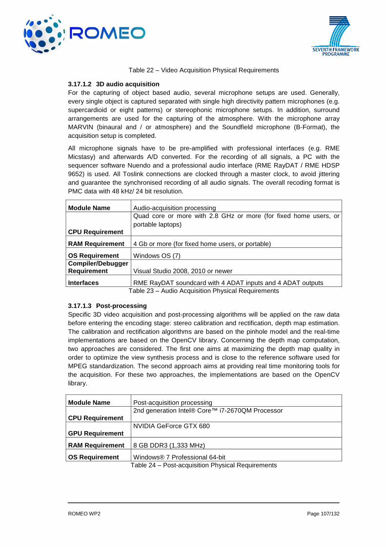
ROMEO WP2 Page 107/132
Table 22 – Video Acquisition Physical Requirements
3.17.1.2 3D audio acquisition For the capturing of object based audio, several microphone setups are used. Generally, every single object is captured separated with single high directivity pattern microphones (e.g. supercardioid or eight patterns) or stereophonic microphone setups. In addition, surround arrangements are used for the capturing of the atmosphere. With the microphone array MARVIN (binaural and / or atmosphere) and the Soundfield microphone (B-Format), the acquisition setup is completed.
All microphone signals have to be pre-amplified with professional interfaces (e.g. RME Micstasy) and afterwards A/D converted. For the recording of all signals, a PC with the sequencer software Nuendo and a professional audio interface (RME RayDAT / RME HDSP 9652) is used. All Toslink connections are clocked through a master clock, to avoid jittering and guarantee the synchronised recording of all audio signals. The overall recoding format is PMC data with 48 kHz/ 24 bit resolution.
Module Name Audio-acquisition processing
CPU Requirement
Quad core or more with 2.8 GHz or more (for fixed home users, or portable laptops)
RAM Requirement 4 Gb or more (for fixed home users, or portable)
OS Requirement Windows OS (7) Compiler/Debugger Requirement Visual Studio 2008, 2010 or newer
Interfaces RME RayDAT soundcard with 4 ADAT inputs and 4 ADAT outputs Table 23 – Audio Acquisition Physical Requirements
3.17.1.3 Post-processing Specific 3D video acquisition and post-processing algorithms will be applied on the raw data before entering the encoding stage: stereo calibration and rectification, depth map estimation. The calibration and rectification algorithms are based on the pinhole model and the real-time implementations are based on the OpenCV library. Concerning the depth map computation, two approaches are considered. The first one aims at maximizing the depth map quality in order to optimize the view synthesis process and is close to the reference software used for MPEG standardization. The second approach aims at providing real time monitoring tools for the acquisition. For these two approaches, the implementations are based on the OpenCV library.
Module Name Post-acquisition processing
CPU Requirement 2nd generation Intel® Core™ i7-2670QM Processor
GPU Requirement NVIDIA GeForce GTX 680
RAM Requirement 8 GB DDR3 (1,333 MHz)
OS Requirement Windows® 7 Professional 64-bit Table 24 – Post-acquisition Physical Requirements
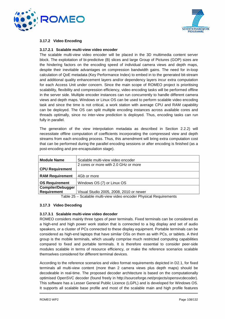
ROMEO WP2 Page 108/132
3.17.2 Video Encoding
3.17.2.1 Scalable multi-view video encoder The scalable multi-view video encoder will be placed in the 3D multimedia content server block. The exploitation of bi-predictive (B) slices and large Group of Pictures (GOP) sizes are the hindering factors on the encoding speed of individual camera views and depth maps, despite their inevitable advantages on compression bandwidth gains. The need for in-loop calculation of QoE metadata (Key Performance Index) to embed in to the generated bit-stream and additional quality enhancement layers and/or dependency layers incur extra computation for each Access Unit under concern. Since the main scope of ROMEO project is prioritising scalability, flexibility and compression efficiency, video encoding tasks will be performed offline in the server side. Multiple encoder instances can run concurrently to handle different camera views and depth maps. Windows or Linux OS can be used to perform scalable video encoding task and since the time is not critical, a work station with average CPU and RAM capability can be deployed. The OS can split multiple encoding instances across available cores and threads optimally, since no inter-view prediction is deployed. Thus, encoding tasks can run fully in parallel.
The generation of the view interpolation metadata as described in Section 2.2.2) will necessitate offline computation of coefficients incorporating the compressed view and depth streams from each encoding process. Thus, this amendment will bring extra computation cost that can be performed during the parallel encoding sessions or after encoding is finished (as a post-encoding and pre-encapsulation stage).
Module Name Scalable multi-view video encoder
CPU Requirement 2 cores or more with 2.0 GHz or more
RAM Requirement 4Gb or more
OS Requirement Windows OS (7) or Linux OS Compiler/Debugger Requirement Visual Studio 2005, 2008, 2010 or newer
Table 25 – Scalable multi-view video encoder Physical Requirements
3.17.3 Video Decoding
3.17.3.1 Scalable multi-view video decoder ROMEO considers mainly three types of peer terminals. Fixed terminals can be considered as a high-end and high power work station that is connected to a big display and set of audio speakers, or a cluster of PCs connected to these display equipment. Portable terminals can be considered as high-end laptops that have similar OSs on them as with PCs, or tablets. A third group is the mobile terminals, which usually comprise much restricted computing capabilities compared to fixed and portable terminals. It is therefore essential to consider peer-side modules scalable in terms of resource efficiency, or make the reference scenarios scalable themselves considered for different terminal devices.
According to the reference scenarios and video format requirements depicted in D2.1, for fixed terminals all multi-view content (more than 2 camera views plus depth maps) should be decodeable in real-time. The proposed decoder architecture is based on the computationally optimised OpenSVC decoder (found freely in http://sourceforge.net/projects/opensvcdecoder). This software has a Lesser General Public Licence (LGPL) and is developed for Windows OS. It supports all scalable base profile and most of the scalable main and high profile features
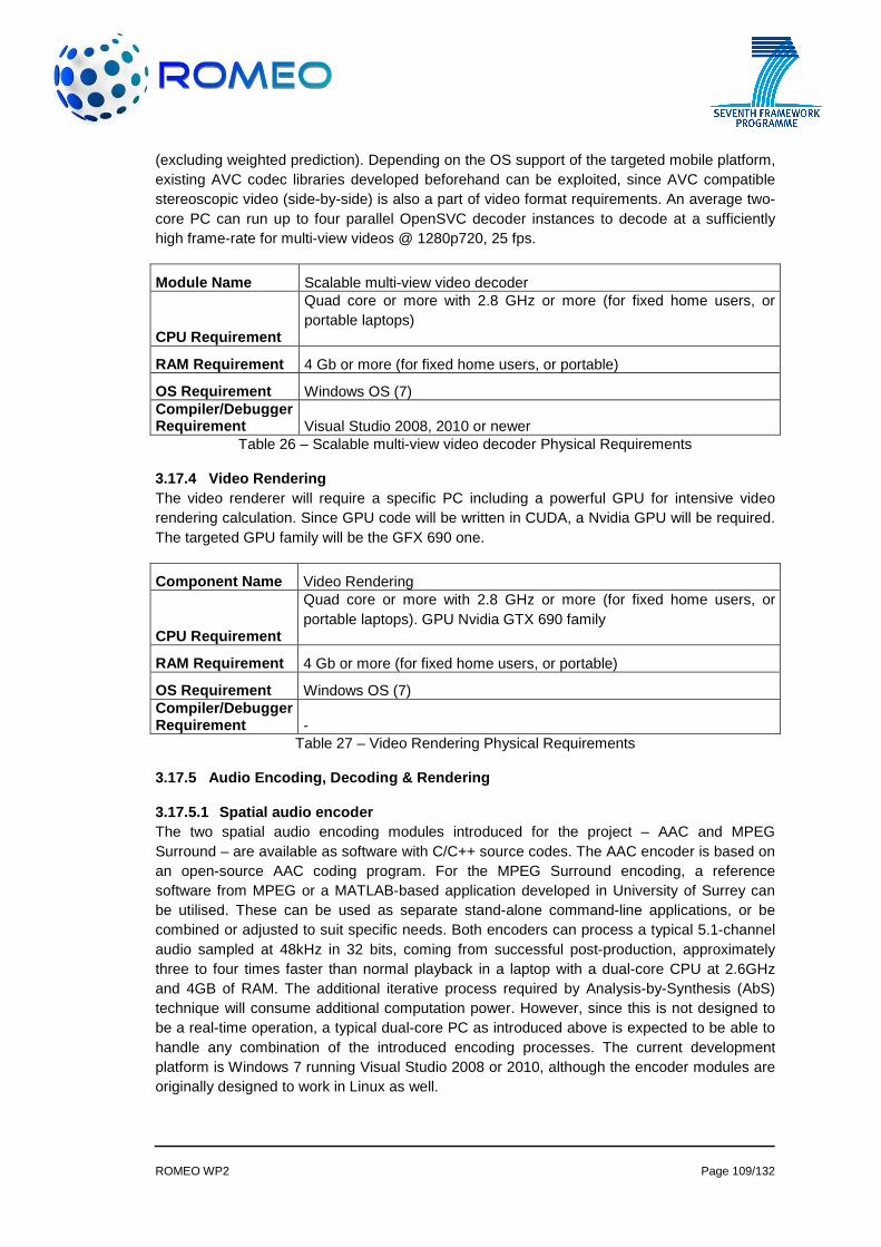
ROMEO WP2 Page 109/132
(excluding weighted prediction). Depending on the OS support of the targeted mobile platform, existing AVC codec libraries developed beforehand can be exploited, since AVC compatible stereoscopic video (side-by-side) is also a part of video format requirements. An average two-core PC can run up to four parallel OpenSVC decoder instances to decode at a sufficiently high frame-rate for multi-view videos @ 1280p720, 25 fps.
Module Name Scalable multi-view video decoder
CPU Requirement
Quad core or more with 2.8 GHz or more (for fixed home users, or portable laptops)
RAM Requirement 4 Gb or more (for fixed home users, or portable)
OS Requirement Windows OS (7) Compiler/Debugger Requirement Visual Studio 2008, 2010 or newer
Table 26 – Scalable multi-view video decoder Physical Requirements
3.17.4 Video Rendering The video renderer will require a specific PC including a powerful GPU for intensive video rendering calculation. Since GPU code will be written in CUDA, a Nvidia GPU will be required. The targeted GPU family will be the GFX 690 one.
Component Name Video Rendering
CPU Requirement
Quad core or more with 2.8 GHz or more (for fixed home users, or portable laptops). GPU Nvidia GTX 690 family
RAM Requirement 4 Gb or more (for fixed home users, or portable)
OS Requirement Windows OS (7) Compiler/Debugger Requirement -
Table 27 – Video Rendering Physical Requirements
3.17.5 Audio Encoding, Decoding & Rendering
3.17.5.1 Spatial audio encoder The two spatial audio encoding modules introduced for the project – AAC and MPEG Surround – are available as software with C/C++ source codes. The AAC encoder is based on an open-source AAC coding program. For the MPEG Surround encoding, a reference software from MPEG or a MATLAB-based application developed in University of Surrey can be utilised. These can be used as separate stand-alone command-line applications, or be combined or adjusted to suit specific needs. Both encoders can process a typical 5.1-channel audio sampled at 48kHz in 32 bits, coming from successful post-production, approximately three to four times faster than normal playback in a laptop with a dual-core CPU at 2.6GHz and 4GB of RAM. The additional iterative process required by Analysis-by-Synthesis (AbS) technique will consume additional computation power. However, since this is not designed to be a real-time operation, a typical dual-core PC as introduced above is expected to be able to handle any combination of the introduced encoding processes. The current development platform is Windows 7 running Visual Studio 2008 or 2010, although the encoder modules are originally designed to work in Linux as well.

ROMEO WP2 Page 110/132
For the object-based audio approach, an audio scene has to be created with a special 3D-audio editor, where all objects are placed according to their position during the recordings. This editor creates then out of the scene the descriptive metadata for each object. This metadata will contain for example distance, height or amplitude for each object. The storage format might be OSC (Open Sound Control) and the description language will probably be SpatDIF (Spatial Sound Description Interchange Format). The editor will run on Linux OS, but Windows and OS X should be also possible.
Module Name Spatial audio encoder
CPU Requirement 2nd generation Intel® Core™ i7-2670QM Processor
RAM Requirement 8 GB DDR3 (1,333 MHz)
OS Requirement Windows® 7 Professional 64-bit
Compiler/Debugger Requirement Microsoft Visual Studio 2008
Table 28 – Spatial audio encoder Physical Requirements
Module Name Spatial audio editor for audio objects
CPU Requirement Quad core or more with 2.8 GHz or more
RAM Requirement 8 GB DDR3 (1,333 MHz)
OS Requirement Linux OS
Compiler/Debugger Requirement GNU Compile Collection (GCC 4.7)
Table 29 – Spatial audio editor Physical Requirements
3.17.5.2 Spatial audio decoder As with the encoding modules, there are two modules that can be used alone or combined for spatial audio decoding: the AAC decoder and the MPEG Surround decoder. In the case of fixed or portable terminals such as a desktop PC or a laptop with specifications equivalent to the example in the previous section, decoding to stereo or typical multichannel (5.1 channel for example) audio rendering is possible in real time. The mobile terminals, on the other hand, only need to support 2-channel playback through AAC decoding with possible downmixing. This is a feature already implemented in most recent mobile devices that can play audio, and is therefore not expected to impose a big processing load. Currently the same development environment is being used as introduced above. The fixed or portable terminals need to support multichannel audio playback through USB, PCI Express, or Firewire connection to relevant audio interface, in the case of stereo or 5.1-channel audio rendering implemented in the same devices
Module Name Spatial audio decoder
CPU Requirement 2nd generation Intel® Core™ i7-2670QM Processor
RAM Requirement 8 GB DDR3 (1,333 MHz)
OS Requirement Windows® 7 Professional 64-bit
Compiler/Debugger Requirement Microsoft Visual Studio 2008
Table 30 – Spatial audio decoder Physical Requirements

ROMEO WP2 Page 111/132
3.17.5.3 Spatial audio renderer For the fixed terminal, the default rendering setting is 5.1 channel configuration. A PC running Windows®, with a quad-core processor of 2.2 GHz or more will be used for smooth operation. PCI Express and Firewire connectivity is necessary to use the multichannel audio interfaces. The platforms for developing, running and debugging the renderer also need to support ASIO (Audio Stream Input/Output) protocol for low-latency operation.
The binaural rendering for the mobile and portable terminal includes a basic and an advanced rendering. For the both rendering methods, a head-tracker is necessary. This has to be connected through USB with the mobile or portable terminal.
For the basic rendering method, 2 GB of RAM is the minimum and the CPU should also have multimedia / streaming / simd extensions (e.g. NEON). For supplementary audio data, 1GB storage should be available.
The advanced rendering method requires much more computational power, depending on the number of audio objects and the kind of room that has to be rendered. Hence, a detailed specification of requirements is not possible, but the CPU performance and the available RAM should be as high as possible.
ALSA (Advanced Linux Sound Architecture) support should be also available for both, the portable and the mobile terminal. For a high quality spatial impress, the audio output for the headphones should have the best possible SNR (Signal to noise ratio).
The method of wave field synthesis (WFS) is for rendering natural and immersive spatial sound equivalent to one generated at the original source position. The system requires input audio signals to include objective data, i.e. source information. The WFS render PC produces output audio signals for each channel and sends them to a MADI-ADAT converter via a HDSPe card in MADI format and then to a ADAT-audio converter. The HDSPe card requires a PCI Express slot in the PC. The WFS sound generation system consists of loudspeaker arrays and power amplifiers. In addition, sub-woofers can also be used for low frequency compensation. The frequency range required for the secondary sources is between from 80 to 18000 Hz, but ideally, 20 to 20000 Hz can be best.
Module Name Spatial audio renderer for the fixed terminal
CPU Requirement 2nd generation Intel® Core™ i7-2670QM Processor
RAM Requirement 8 GB DDR3 (1,333 MHz)
OS Requirement Windows® 7 Professional 64-bit Compiler/Debugger Requirement Microsoft Visual Studio 2008
Table 31 – Spatial audio render for the fixed terminal Physical Requirements
Module Name Spatial audio renderer for the portable terminal
CPU Requirement Quad core or more with 2.8 GHz or more
RAM Requirement 8 GB DDR3 (1,333 MHz)
OS Requirement Linux OS or Windows® 7 Professional 64-bit

ROMEO WP2 Page 112/132
Compiler/Debugger Requirement -
Table 32 – Spatial audio render for the portable terminal Physical Requirements
Module Name Spatial audio renderer for the mobile terminal
CPU Requirement OMAP5430
RAM Requirement 2 GB
OS Requirement Linux OS or Android Compiler/Debugger Requirement -
Table 33 – Spatial audio render for the mobile terminal Physical Requirements
Module Name Spatial audio renderer for Wave Field Synthesis
CPU Requirement 2nd generation Intel® Core™ i7-2670QM Processor
RAM Requirement 8 GB DDR3 (1,333 MHz)
OS Requirement Windows® 7 Professional 64-bit Compiler/Debugger Requirement Microsoft Visual Studio 2008
Interfaces HDSP MADI card (PCI/PCI Express Slot), ADAT-MADI converter, A/D converter
Table 34 – Spatial audio renderer for Wave Field Synthesis: Physical Requirements
Each network interface of the peer must be able to provide meta-data (wireless vs wired interface, kind of technology, maximum throughput, etc)
3.17.6 Mobility With the concept of ROMEO, the Mobility component consists of three modules the Media Aware Proxy, the Media Independent Handover and the Proxy Mobile IP. All three modules will be running in parallel on a single machine that will act as a transparent proxy to the access networks (WiFi and LTE). An additional database that will handle the MIH Information Services and will collect parameters from both the user and the network side will also be running in the same machine.
Component Name Mobility
CPU Requirement Intel® Core™ 2 Duo E6600, 2.4GHz
RAM Requirement 4GB DDR2 (800 MHz)
OS Requirement Linux OS
Compiler/Debugger Requirement Gcc, gdb
Network Interface 2 x Ethernet at least 100Mb preferably 1Gb
Table 35 – Mobility Physical Requirements
Each mobile and portable node needs to be MIH enabled, in order to inform the MIH server of the Mobility Component about downlink physical layer statistics during video streaming.

ROMEO WP2 Page 113/132
3.17.7 DVB Transmission & Reception
Component Name Test generator platform (DVB Transmission )
CPU Requirement n/a
RAM Requirement n/a
OS Requirement Windows XP Pro embedded Compiler/Debugger Requirement n/a
Component Name Protocol analyser platform + notebook (DVB Reception)
CPU Requirement Protocol analyser: n/a; Notebook: Inten i7 or equivalent
RAM Requirement Protocol analyser: n/a; Notebook: 8 GB
OS Requirement Protocol analyser: Windows XP Pro embedded; Notebook: Windows 7 Pro
Compiler/Debugger Requirement Protocol analyser: n/a; Notebook: n/a
Table 36 – DVB Transmission & Reception Physical Requirements
The DVB Transmission component is an existing test instrument. Necessary software and firmware up-dates are provided at least on an annual basis during the lifetime of the instrument.
The Protocol analyser platform is also an existing test instrument. On this platform, additional hardware, software and firmware components are developed in ROMEO to cover the requirements for 3D video signals over a DVB-T/T2/T2 Lite link and the handling of the IP input via the IP interface.
The notebook is equipped with an Intel i7 processor and sufficient memory (minimum 4 GB, extendable to 8 GB).
3.17.8 Virtualisation Hereafter the physical requirements envisaged to deploy the testbed are presented:
Home infrastructure:
Entity Physical Requirement
Switch HUB Netgear
ONT Alcatel I220
Access network infrastructure:
Entity Physical Requirement
OLT Alcatel OLT: FTTH-OLTS-M. Including:
• AACU-C Driver Card • GLT4-A LT Card

ROMEO WP2 Page 114/132
• EHNT-B NT Card
BRAS REDBACK SMART-EDGE 800. Including:
• XCRP3-T1/E1 Driver Card • Ge-10-Port Line Card
VSEE XenServer Hypervisor server Dell PowerEdge SC1420, dual core CPU Intel Xeon 2,8GHz, 1Gb RAM, 40Gb HDD and DVD-Rom. unit
XenCenter PC Optiplex GX1, CPU Pentium 3, 128Mb RAM, Windows 2000 SP4.
DHCP Server PC: HP COMPAQ; Intel-Pentium 4
Table 37 – Virtualisation Physical Requirements
3.17.9 Synchronisation
Module Name Synchronisation
CPU Requirement 2nd generation Intel® Core™ i7-2670QM Processor
RAM Requirement 8 GB DDR3 (1,333 MHz)
OS Requirement Linux Ubuntu v. 11.10 Compiler/Debugger Requirement Gcc, gdb
Table 38 – Synchronisation Physical Requirements
3.17.10 Audio-Visual Adaptation
Component Name Audio-Visual Adaptation
CPU Requirement
Quad core or more with 2.8 GHz or more (for fixed home users, or portable laptops). GPU Nvidia GTX 690 family
RAM Requirement 4 Gb or more (for fixed home users, or portable)
OS Requirement Windows OS (7) Table 39 – Audio-Visual Adaptation Physical Requirements
3.17.11 A/V Communication Overlay A/V communication overlay will be a software component to enable audio/video communication over network. This process is expected to use the following resources over the system.
Component Name A/V Communication Overlay
CPU Requirement 2nd generation Intel® Core™ i7-2670QM Processor
RAM Requirement 512 MB DDR3 (1,333 MHz)
OS Requirement Linux Ubuntu v. 11.10 Compiler/Debugger Requirement Gcc, gdb
Table 40 – A/V Communication Overlay Physical Requirements

ROMEO WP2 Page 115/132
3.17.12 User Interface & Control User Interface will work as a software component to interact with ROMEO platform. It will be used to change some parameters for user experience
Component Name User Interface & Control
CPU Requirement 2nd generation Intel® Core™ i7-2670QM Processor
RAM Requirement 512 MB DDR3 (1,333 MHz)
OS Requirement Linux Ubuntu v. 11.10 Compiler/Debugger Requirement Gcc, gdb
Table 41 – User Interface & Control Physical Requirements
3.17.13 Authentication, Registration and Security Authentication, Registration and Security module is a set of software components that run on server and client terminals. The physical requirements for this module are given as below:
Module Name Authentication, Registration and Security
CPU Requirement 2nd generation Intel® Core™ i7-2670QM Processor
RAM Requirement 8 GB DDR3 (1,333 MHz)
OS Requirement Linux Ubuntu v. 11.10 Compiler/Debugger Requirement Gcc, gdb
Table 42 – Authentication, Registration and Security Physical Requirements
3.17.14 User Generated Content Non-professional user content can be generated and consumed by any mobile or portable terminals with adequate A/V capturing and display capabilities. The physical requirements for this module are given as below:
Mobile terminal platform:
Module Name User Generated Content – Mobile Platform
CPU Requirement OMAP4460(OMAP5/OMAP6 – final release)
RAM Requirement 1 GB DDR2 minimum
Display auto-stereoscopic WVGA (2D - 800x600, 3D - 2x400x480)
OS Requirement Android ICS (Android next versions for final release, Linux Ubuntu as second OS)
Compiler/Debugger Requirement Gcc, gdb
Table 43 – User Generated Content Physical Requirements for mobile terminal
The requirements of the portable platform are given in the table below:
Module Name Portable platform
CPU Requirement Intel Core i7-2630QM (4x2GHz, Turbo to 2,9GHz, 32nm, 6MB L3 Memory)

ROMEO WP2 Page 116/132
RAM Requirement 6 Gb DDR3 (1333MHz)
OS Requirement Windows 7
Graphics Card NVIDIA GeForce GT 540M 1 Gb DDR3
Network Interface PCIe Gigabit Ethernet 802.11b/g/n
Display 15.6’’ LED Glossy 16:9 1080p, capable of 720p glasses-free 3D TOS508F
Table 44 – User Generated Content Physical Requirements for portable terminal

ROMEO WP2 Page 117/132
4. CONCLUSION This document is planned to update ROMEO system architecture in accordance with project developments. In month 6 of the project, deliverable 2.2 “Definition of the initial reference end-to-end system architecture and the key system components” was submitted. From month 6 onwards there are some updates on the components. These updates are defined in their respective parts in section 2. Some points that we need to mention here;
• P2P section updates for topology builder blocks, • Mobility wireless channel control over network, • DVB transmission and reception components’ results, • User generated content related new REST api design, • Details of MPS with ABS and AAC encoding, • Audio rendering updates for portable terminals ,
Section 3 is also added into this document to enable readers to check what updates have been made in this document. In summary section 3 is based on deliverable 2.2 [1] whereas section 2 contains updates over deliverable 2.2 [1] base reference architecture document. This will help readers to understand the progress smoothly.

ROMEO WP2 Page 118/132
5. REFERENCES [1] “ROMEO Deliverable 2.2 - Definition of the initial reference end-to-end system
architecture and the key system components.doc” [2] “ROMEO Deliverable 5.1 - Interim report on 3D media networking and synchronisation of
networks” [3] “ROMEO Deliverable 6.3 - Second report on system components development plan [4] “ROMEO Deliverable 6.2 - First Report on server, peer, user terminal, security and content
registration modules development” [5] ITU-T Recommendation Y.2001, General overview of NGN, December 2004. [6] ITU-T Recommendation G.114, One-way transmission time , May 2003. [7] http://www.cisco.com/en/US/docs/solutions/Enterprise/WAN_and_MAN/QoS_SRND/QoSI
ntro.html [8] S. Blake et al, “An Architecture for Differentiated Services”, IETF RFC 2475, 1998. [9] K. Nichols, S. Blake, F. Baker, D. Black, “Definition of the Differentiated Services Field (DS
Field) in the IPv4 and IPv6 Headers”, IETF RFC 2474, December 1998. [10] J. Heinanen, F. Baker,W.Weiss, J. Wroclawski, “Assured forwarding PHB group.” IETF
RFC 2597, June 1999. [11] B. Davie, A. Charny, J. Bennet, K. Benson, J. Le Boudec, W. Courtney, S. Davari, V.
Firoiu, D. Stiliadis, “An expedited forwarding PHB”, IETF RFC 3246, March 2002. [12] R. Braden, D. Clark, S. Shenker, “Integrated Services in the Internet Architecture: an
Overview”, IETF RFC 1633, June 1994. [13] F. Baker, C. Iturralde, F. Le Faucheur, B. Davie; “Aggregation of RSVP for IPv4 and IPv6
Reservations”, RFC 3175, September 2001. [14] E. Logota, A. Neto, and S. Sargento, “COR: an Efficient Class-based Resource Over-
pRovisioning Mechanism for Future Networks”, IEEE Symposium on Computers and Communications (ISCC), June 2010.
[15] A. Neto, E. Cerqueira, M. Curado, E. Monteiro, and P. Mendes, “Scalable Resource Provisioning for Multi-User Communications in Next Generation Networks”, Global Telecommunications Conference, 2008, IEEE GLOBECOM 2008.
[16] R. Bless, “Dynamic Aggregation of Reservations for Internet Services”, Proc. 10th Int. Conf. on Telecommunication. Systems –Modeling and Analysis (ICTSM'10), vol.1, pp.26-38, Oct. 2002.
[17] R. Sofia, “SICAP, a Shared-segment Inter-domain Control Aggregation Protocol”, Departamento de Informática, Faculdade de Ciências da Universidade de Lisboa, Campo Grande, 1749.016 Lisboa, Portugal, PhD Thesis, March 2004.
[18] Rui Prior and Susana Sargento, “Scalable Reservation-Based QoS Architecture — SRBQ.” In Encyclopedia of Internet Technologies and Applications, pp. 473–482, IGI Global, 2007.

ROMEO WP2 Page 119/132
APPENDIX A: List of Requirements
Overall System and Scenario Requirements
Requirement ID Description
REQ 1.1
Fixed and mobile users shall be able to use broadcast and IP networks to receive live 3D media.
REQ 1.2 Fixed and mobile users shall receive live 3D media with an unnoticeable delay.
REQ 1.3 ROMEO shall provide a real-time audio-visual communication overlay to bring the remote collaborators together for joint interaction and enjoyment
REQ 1.4 3D live stream and collaboration between users shall be synchronised to have proper interaction between users according to stream
REQ 1.5
Collaborating users shall be able to upload and share their own generated content to the IP network main server. The content generator shall be able to determine the access rights of other collaborating users
REQ 1.6
The main view’s Advanced Video Coding (AVC) compatible base layer with sufficient broadcast quality, which is stereoscopic 3D video and 5.1 channel audio, shall always be received through DVB if available
REQ 1.7
ROMEO system shall deliver at most 1 stereoscopic view to mobile terminals and all available camera views (if bandwidth suffices) to compatible portable and fixed terminals (there may be device specific limitations on the number of simultaneously decodable camera views for portable (e.g., at most 2 camera views) and fixed (e.g., at most 4 camera stereoscopic views) terminals)
REQ 1.8 Furthermore the object-based scene description could possibly be delivered via DVB for further development approaches
REQ 1.9 P2P will carry an object-based scene description audio stream and (if the DVB stream is not available) the 5.1 channel audio stream
REQ 1.10
All other views and their enhancement data for 3D multi-view rendering purposes will be sent through the P2P network. The multi-view contents could be delivered to users via different networks depending on the user terminal capabilities and network conditions
• Fixed terminals shall be served via high-speed broadband. • Mobile terminals shall be served via Wi-Fi hotspot and/or mobile
networks such as 3G and LTE. • If a user device has multiple interfaces and all of the interfaces
are able to retrieve data from the P2P network, the device shall use interfaces in the following order for receiving data:
� DVB-T2/T2-lite/NGH, � One of the following devices, in order of priority:
• Fixed broadband connection, • Wi-Fi interface connection to the hotspot, • 3G or LTE mobile connection
REQ 1.11
The camera views comprising the main stereoscopic 3D pair shall also be encoded using SVC simulcast (both views using scalable high profile at Level 4 or over) with two spatial resolution layers (HD as full spatial resolution and preferably SD as lower resolution) and quality enhancement layers to be stored in the seed server and transmitted over P2P
REQ 1.12
The rest of the cameras, and the depth map videos (including the depth of the main stereoscopic view), shall be encoded in the same way as in the previous requirement

ROMEO WP2 Page 120/132
REQ 1.13
The SD frame compatible coded version (AVC compliant) can also be included in the P2P streaming server, considering peers with mobile terminals that are outside the DVB coverage and that cannot decode two 1920x1080p25, or two 720x576p25/ streams simultaneously, which are normally streamed to them over P2P
REQ 1.14 Audio and video streams shall be synchronised for all views (play-out synchronisation)
REQ 1.15 All terminals, either fixed or mobile, shall be able to receive DVB streams
REQ 1.16 DVB streams shall not be encrypted
REQ 1.17 A suitable DVB-T/T2/T2 Lite mode shall be implemented for mobile users.
REQ 1.18 The broadcast link to fixed and portable terminals provides the main 3D stereoscopic view
REQ 1.19 The 3D-stereoscopic video signal to fixed and portable receivers is encoded as a DVB-compliant signal
REQ 1.20 The main 3D stereoscopic view for fixed and portable terminals is transmitted in one Physical Layer Pipe (PLP) of the DVB-T2 signal
REQ 1.21
The bit rate of the main 3D stereoscopic view for fixed and portable terminals is limited to 7...8 Mbps (The complete DVB-T2 multiplex typically carries 3 to 4 different 3D-stereoscopic video signals for fixed and portable terminals with an overall bit rate of up to 30 Mbps.)
REQ 1.22 The DVB-T2 signal to fixed and portable terminals is compliant to standard ETSI EN 302 755 (DVB-T2 Base)
REQ 1.23 The DVB-T2 signal to mobile terminals is compliant to DVB-T2 Lite
REQ 1.24 The output frequency of the test transmitter is adjustable to any channel in the TV Ultra High Frequency (UHF) band
REQ 1.25 The input signal to the test receiver platform is a DVB-T2 Base or DVB-T2 Lite signal, which can be transported in any channel in the TV UHF band
REQ 1.26
The output signal of the test receiver platform is fed to a display via a High-Definition Multimedia Interface (HDMI) carrying video and audio for the selected programme
REQ 1.27
The test receiver platform measures a multitude of Quality of Service (QoS) parameters of the received DVB-T2 signal. A sub-set of these parameters can be selected for monitoring certain QoS aspects permanently. The parameters cover the physical layer (RF level, RF frequency offset, etc.), the I/Q domain (Modulation Error Ratio (MER), amplitude imbalance, phase error, etc.) and the Transport Stream domain (packet loss rate, missing packets, CRC checks on certain packets, etc.)
REQ 1.28
The test receiver platform can combine the different signals received via the DVB-T2 and P2P links in such a way that differences in latency or delay are compensated
REQ 1.29
The test receiver platform can select either the DVB-T2 or the P2P signal as a fall-back solution for displaying in the case that the reception quality of one of the signals is not sufficient
REQ 1.30 Each user shall own Optical Network Terminal (ONT) equipment
REQ 1.31 Access node shall be an Optical Line Terminal (OLT)
REQ 1.32 Virtual routers shall be implemented at BRAS Node
REQ 1.33 Authentication, Authorization and Accounting (AAA) server shall be used to authenticate subscribers
REQ 1.34 Dynamic Host Configuration Protocol (DHCP) server shall be used for Virtual Routers Public IP assignation
REQ 1.35 A dedicated web server shall offer the Virtual Router Configuration Portal to the User

ROMEO WP2 Page 121/132
Terminal Requirements
Requirement ID Description
REQ 2.1
Fixed terminals should have display units to cover both multi-view 3D content and stereoscopic content to present 3D video to the end-user
REQ 2.2 Mobile terminal display (MTD) shall provide minimum one stereoscopic view that corresponds to two camera views (left and right)
REQ 2.3 Mobile terminal display should have a minimum as Wide Video Graphics Array (WVGA)
REQ 2.4 Mobile terminal display shall be able to display both 2D and 3D content
REQ 2.5 Mobile terminal display should have low power operation, suitable for battery operated systems
REQ 2.6 Mobile terminal display should have Thin and lightweight package
REQ 2.7 Mobile terminal display shall have the following interfaces: Electrical interface: MIPI DSI, Parallel or Unipro
REQ 2.8 Mobile terminal display shall have Backlit technology
REQ 2.9 Fixed terminals use JavaScript Object Notation-Remote Procedure Call (JSON-RPC) for inter-module communication
REQ 2.10 Mobile terminals use JSON-RPC for inter-module communication
REQ 2.11
Shall provide power management capabilities in order to maximize the battery life, ensuring a minimum of 2 hours of operation during High Definition Television (HDTV) decoding/playback
REQ 2.12 Shall provide a means for integrating stereoscopic Liquid Crystal Display (LCD).
REQ 2.13 Shall support content streaming using the abovementioned interfaces
REQ 2.14
Shall provide sufficient processing power to decode/encode at least two H.264 Main Profile simulcast coded streams (720x1280p25) simultaneously or a H.264 Main Profile multi-view coded stream (two views)
REQ 2.15 Shall provide means to implement custom type H.264 decoder as a base of multi-view or view+depth type of stereo video encoder
REQ 2.16 Shall provide means for stereo camera system connection
REQ 2.17 Shall be capable to run High Level Operating Systems (HLOS) (Android, Linux, Symbian or Windows)
REQ 2.18 Shall provide at least 1GB of low-power (LP-DDR2, 3) RAM memory, 64GB non-volatile memory (e.g. NAND, e-MMC)
REQ 2.19 Shall provide means for memory extension (e.g. SD, microSD)
REQ 2.20 Shall support capacitive touch screen interface for user interaction
REQ 2.21 Fixed device shall have DVB-T2 reception unit and high bandwidth broadband interface
REQ 2.22 1Gbit/s Ethernet adaptor should be used for P2P 3D signal to be received
REQ 2.23 DHCP Client shall receive IP address from the Virtualised Broadband Access Router
REQ 2.24 Mobile device shall have interfaces for 3G/LTE, Wi-Fi, and DVB-T2-Lite/NGH for receiving 3D content
REQ 2.25 Shall support a variety of interfaces – USB, Wi-Fi, 3G/LTE modems, Bluetooth for connection to other devices
REQ 2.26 Shall provide sufficient processing power to execute DVB-T2-Lite/NGH stack, GUI and encoding/decoding
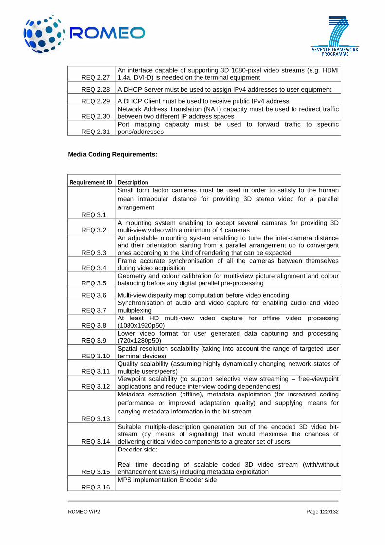
ROMEO WP2 Page 122/132
REQ 2.27 An interface capable of supporting 3D 1080-pixel video streams (e.g. HDMI 1.4a, DVI-D) is needed on the terminal equipment
REQ 2.28 A DHCP Server must be used to assign IPv4 addresses to user equipment
REQ 2.29 A DHCP Client must be used to receive public IPv4 address
REQ 2.30 Network Address Translation (NAT) capacity must be used to redirect traffic between two different IP address spaces
REQ 2.31 Port mapping capacity must be used to forward traffic to specific ports/addresses
Media Coding Requirements:
Requirement ID Description
REQ 3.1
Small form factor cameras must be used in order to satisfy to the human mean intraocular distance for providing 3D stereo video for a parallel arrangement
REQ 3.2 A mounting system enabling to accept several cameras for providing 3D multi-view video with a minimum of 4 cameras
REQ 3.3
An adjustable mounting system enabling to tune the inter-camera distance and their orientation starting from a parallel arrangement up to convergent ones according to the kind of rendering that can be expected
REQ 3.4 Frame accurate synchronisation of all the cameras between themselves during video acquisition
REQ 3.5 Geometry and colour calibration for multi-view picture alignment and colour balancing before any digital parallel pre-processing
REQ 3.6 Multi-view disparity map computation before video encoding
REQ 3.7 Synchronisation of audio and video capture for enabling audio and video multiplexing
REQ 3.8 At least HD multi-view video capture for offline video processing (1080x1920p50)
REQ 3.9 Lower video format for user generated data capturing and processing (720x1280p50)
REQ 3.10 Spatial resolution scalability (taking into account the range of targeted user terminal devices)
REQ 3.11 Quality scalability (assuming highly dynamically changing network states of multiple users/peers)
REQ 3.12 Viewpoint scalability (to support selective view streaming – free-viewpoint applications and reduce inter-view coding dependencies)
REQ 3.13
Metadata extraction (offline), metadata exploitation (for increased coding performance or improved adaptation quality) and supplying means for carrying metadata information in the bit-stream
REQ 3.14
Suitable multiple-description generation out of the encoded 3D video bit-stream (by means of signalling) that would maximise the chances of delivering critical video components to a greater set of users
REQ 3.15
Decoder side:
Real time decoding of scalable coded 3D video stream (with/without enhancement layers) including metadata exploitation
REQ 3.16 MPS implementation Encoder side
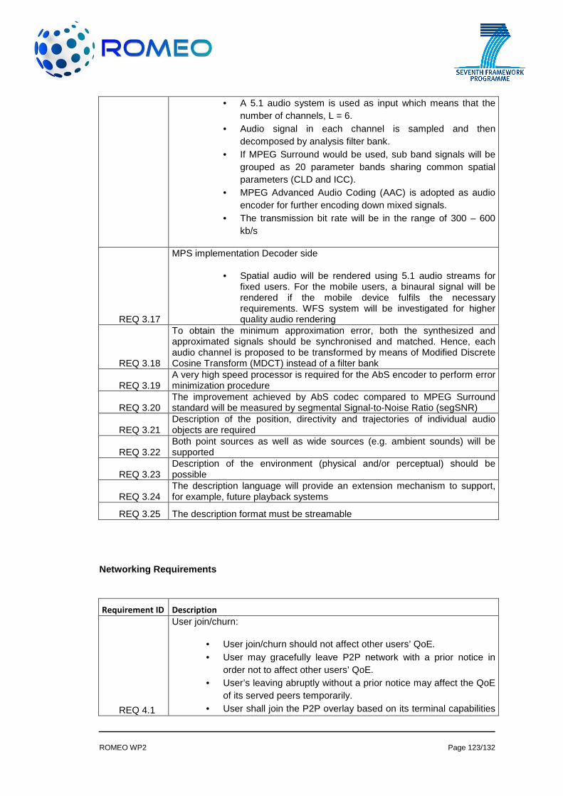
ROMEO WP2 Page 123/132
• A 5.1 audio system is used as input which means that the number of channels, L = 6.
• Audio signal in each channel is sampled and then decomposed by analysis filter bank.
• If MPEG Surround would be used, sub band signals will be grouped as 20 parameter bands sharing common spatial parameters (CLD and ICC).
• MPEG Advanced Audio Coding (AAC) is adopted as audio encoder for further encoding down mixed signals.
• The transmission bit rate will be in the range of 300 – 600 kb/s
REQ 3.17
MPS implementation Decoder side
• Spatial audio will be rendered using 5.1 audio streams for fixed users. For the mobile users, a binaural signal will be rendered if the mobile device fulfils the necessary requirements. WFS system will be investigated for higher quality audio rendering
REQ 3.18
To obtain the minimum approximation error, both the synthesized and approximated signals should be synchronised and matched. Hence, each audio channel is proposed to be transformed by means of Modified Discrete Cosine Transform (MDCT) instead of a filter bank
REQ 3.19 A very high speed processor is required for the AbS encoder to perform error minimization procedure
REQ 3.20 The improvement achieved by AbS codec compared to MPEG Surround standard will be measured by segmental Signal-to-Noise Ratio (segSNR)
REQ 3.21 Description of the position, directivity and trajectories of individual audio objects are required
REQ 3.22 Both point sources as well as wide sources (e.g. ambient sounds) will be supported
REQ 3.23 Description of the environment (physical and/or perceptual) should be possible
REQ 3.24 The description language will provide an extension mechanism to support, for example, future playback systems
REQ 3.25 The description format must be streamable
Networking Requirements
Requirement ID Description
REQ 4.1
User join/churn:
• User join/churn should not affect other users’ QoE. • User may gracefully leave P2P network with a prior notice in
order not to affect other users’ QoE. • User’s leaving abruptly without a prior notice may affect the QoE
of its served peers temporarily. • User shall join the P2P overlay based on its terminal capabilities

ROMEO WP2 Page 124/132
and its available network conditions. • User shall satisfy minimum P2P overlay requirements to join. • Admission control will be enforced, being a session or a peer’s
request to join an overlay will be admitted only when the available resource capabilities of the overlay meet the QoS requirements of the request
REQ 4.2
Network monitoring:
• All users shall monitor their network conditions (bandwidth, jitter, delay, throughput, packet loss, signal strength, etc.) on all interfaces periodically.
• Mobile users shall be able to provide feedback regarding their network conditions to MANE
REQ 4.3
Network security:
• P2P encryption will be optional for all users. • IP network main server should check the access rights of the
uploaded content to let users download it. • User should send his/her credentials to the main IP network
server and his/her terminal capabilities to P2P network management unit while joining the IP network
REQ 4.4
For P2P and DVB networks:
• The main stereoscopic view sent through DVB should be available on P2P server, but is not required to be sent via P2P to end users that have DVB connection.
• Encapsulation format for P2P transmission over IP-based networks (fixed high speed broadband, Wi-Fi, 3G and LTE) will be aligned with the encapsulation format of broadcasting network(e.g. DVB-T2) to achieve synchronisation of multimedia streams.
• The multi-view data received via P2P networks at the user terminal should be buffered for synchronisation purposes. The buffer size depends on the capability of terminal device and the overall system requirement for decoding and rendering delay.
• There should be a mechanism to synchronise the P2P buffer and the DVB stream at the user terminal side. It should operate in such a way that the multi-view data from P2P and the primary stereoscopic 3D view data from DVB should be delivered to the multi-view and audio decoders within a time difference which should not cause any noticeable visual and aural effects.
• Timing information, e.g., timeline, should be integrated into DVB and P2P transmission, so the different delivery paths can be synchronised in the receiver.
• Metadata shall be available through both broadcast and IP network. Metadata through broadcast network should be used as a backup

ROMEO WP2 Page 125/132
REQ 4.5
For collaborating users:
• Collaborating users must receive live streaming content with an unnoticeable delay.
• For demonstration purposes, there will be 6 collaborating users (2 users for each terminal type – mobile, portable and fixed).
• There will be an A/V overlay communication link between collaborating users.
• Any user satisfying the minimum requirements of collaborating group requirements (in terms of its available bandwidth, delay, etc.) should be able to join the group.
• A collaborating user should be able to receive the content through its DVB interface in unfavourable P2P network conditions
REQ 4.6 A peer should have one main identifier in the P2P world. This identifier is used by the ROMEO application as a source when sending data
REQ 4.7
A peer must be able to accept more than one network-based P2P identifier, and must be able to use the correct one while communicating, based on context information (the network it is using to send packet to the P2P system, etc).
REQ 4.8
The P2P layer of the client application is abstracted on the client side by adding a layer that translates the main identifier of the client to the network-based identifier when sending packet, and the other way around when receiving packets from the P2P network
REQ 4.9
A (possibly distributed) resolution system must be able to align automatically in terms of network-based P2P identifiers while managing the P2P overlay. As long as one of the network-based P2P identifiers of a peer is active, and as long as the peer wants to receive a given stream, the P2P system will consider that the network-based P2P identifier (a virtual P2P peer) must receive the stream
REQ 4.10
The resolution system will be informed by either the peer or the network when a network-based P2P identifier is not active anymore (the peer handed over to another network, or the peer disconnected from the P2P overlay, or the P2P is not receiving a stream anymore)
REQ 4.11
Mobile Terminal (MT) with multiple network interfaces:
• The mobile terminal shall be possible to receive either all views in one interface, or concurrently receive different views within the 3D media stream to different interfaces. In particular, MT is required to have at least one Wi-Fi 802.11 g/n network interface, one LTE interface and one DVB interface. Within the context of ROMEO, the aforementioned interfaces will support multi-homing, in order to enable MT to receive video data (views, layers) over different access technologies and exploit their available resources. Multi-homing capability will be implemented by MANE which will handle Layer-2 data flows to MT. Particularly, DVB interface will be used to connect the MT to the DVB network at all times in order to ensure video streaming with signalling minimum QoS and synchronisation among video views received over heterogeneous wireless access technologies
REQ 4.12
.
Smooth multi-view video rate adaptation:

ROMEO WP2 Page 126/132
• The video adaptation functionality within MANE will be responsible for smoothly adapting video rate according to current network conditions. The decision and extend of the rate adaptation will be based on information from the network and the MT side. The network related information will be available from the MIH Information service. Moreover, MT side information regarding the QoE of an ongoing video stream will be monitored in real time by the QoE monitoring functionality incorporated in the enhanced MANE. In case of a handover, the video rate will be adapted smoothly (either increased or decreased) to meet the available bandwidth limitations thus ensuring high levels of QoE across heterogeneous networking environment.
REQ 4.13
MANE to support seamless service continuity:
• An enhanced MANE with additional functionalities shall provide seamless service continuity across heterogeneous wireless access networks. Particularly, the Media Independent Handover framework (IEEE 802.21 MIH) will be integrated within MANE. In particular, MIH Information services, MIH Command services and MIH Control services should be implemented with respect to monitor all available networks in the vicinity of MT, collect information from the network and the client side, make decisions upon handover and/or rate adaptation, creating such events and control their execution. Functionalities designed in accordance to ROMEO networking environment, including network selection, handover decision, video adaptation and mobility control should ensure the selection of the best candidate network and seamless handoff as well as guaranteeing quality levels and seamless service continuity to MT
REQ 4.14 MANE should determine the level of quality and the content delivery of its mobile users
REQ 4.15 Only collaborating users should be able to share their own generated content
REQ 4.16
Collaborating user should be able to:
• Share captured 2D/3D as well as pre-stored content with other collaborating users.
• Sign the captured content. • Upload the content to P2P main seed server. • Authorize other collaborating users to download the content. • Search other user generated content. • Download the user generated content if he/she has access rights
REQ 4.17
Resolution and performance:
• Video: 720x1280p25 • Still: 8Mpix

ROMEO WP2 Page 127/132
REQ 4.18
Audio:
• 2 channels @ 48 KHz
REQ 4.19
Minimal processing:
• Video: Temporal noise filtering, Spatial noise filtering, Video stabilisation
• Still: Spatial noise filtering, Global Brightness Contrast Enhancement (GBCE)
• Audio: Automatic Gain Control (AGC), Adaptive noise control
REQ 4.20
There shall be an adaptation mechanism within the P2P delivery network to advise the P2P network so that it only delivers essential view data and drops some view data if the network condition is deteriorated. The principles of 3D multi-view P2P delivery should be:
• Only necessary view data should be delivered. • Other views and enhancement data should also be delivered if
bandwidth is sufficient and network conditions allow such activity.
• If network conditions have deteriorated to a degree where not enough resource is available, or network is congested, or the delay is intolerable, some of non-essential view data should be removed from the delivering stream so that the change in users’ service quality of experience is unnoticeable or QoE only deteriorates gradually and gracefully.
• The removal of view data in adverse network conditions should be in the order of enhancement data, other non-primary views from the farthest to the nearest user view.
REQ 4.21
Key view frames shall be prioritized in transmitting through P2P network and a metadata description should be included to generate the missing frames at the video decoder in an optimum way
REQ 4.22
Both horizontal and vertical handover decision shall be taken by considering media source QoS requirements such as bit rate, delay, jitter, etc. as well as the traffic conditions of the network to be handed over
REQ 4.23
Based on the network resources available, maximum number of views shall be selected and coded for transmission. Untransmitted views will be interpolated with the available views
REQ 4.24
Source coding configurations of multiple descriptions of MVD content shall be optimized for end-to-end rate-distortion performance given the condition of the network (eg. Packet Loss Rate)
REQ 4.25
A Media Server must be used from which the user downloads some media content for the in order to implement QoS demonstration in (Reference Scenario 3)
REQ 4.26
Correct values of QoS and Traffic Shaping at OLT and BRAS shall be defined to detect and prioritize different streams automatically and under user selection
REQ 4.27 Each peer on a P2P overlay (e.g., interface capacity- bandwidth) must be willing to forward packets of other peers
REQ 4.28 Each peer should allow for configuring its schedulers, to let the system reserve the peer’s bandwidth to assure QoS to data flows

ROMEO WP2 Page 128/132
REQ 4.29
The QoS management information to be enforced on peers will be conveyed to the peers by means of appropriate signalling protocol such as the Internet Engineering Task Force (IETF) proposed Next Steps in Signalling (NSIS). The bandwidth will be over-reserved and dynamically controlled on the overlay to reduce undue signalling and related overheads with increased resource utilization
REQ 4.30
A good view of the network topology and the related peers´ resource capabilities will be monitored and maintained to efficiently improve the performance of the QoS delivered
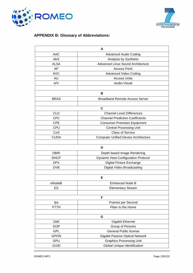
ROMEO WP2 Page 129/132
APPENDIX B: Glossary of Abbreviations:
A
AAC Advanced Audio Coding
AbS Analysis by Synthetis
ALSA Advanced Linux Sound Architecture
AP Access Point
AVC Advanced Video Coding
AU Access Units
A/V Audio-Visual
B
BRAS Broadband Remote Access Server
C
CLD Channel Level Differences
CPC Channel Prediction Coefficients
CPE Consumer-Premises Equipment
CPU Central Processing Unit
CoS Class of Service
CUDA Computer Unified Device Architecture
D
DBIR Depth based Image Rendering
DHCP Dynamic Host Configuration Protocol
DPX Digital Picture Exchange
DVB Digital Video Broadcasting
E
eNodeB Enhanced Node B
ES Elementary Stream
F
fps Frames per Second
FTTH Fiber to the Home
G
GbE Gigabit Ethernet
GOP Group of Pictures
GPL General Public license
GPON Gigabit Passive Optical Network
GPU Graphics Processing Unit
GUID Global Unique Identification

ROMEO WP2 Page 130/132
H
HD High Definition
HDMI High Definition Multimedia Interface
HGW Home Gateway
I
ICC Inter-channel Coherences
IEEE Institute of Electrical and Electronics Engineers
IP Internet Protocol
J
JSON-RPC Javascript Object Notation – Remote Procedure Call
K
L
LAN Local Area Network
LGPL Lesser General Public license
LMA Local Mobility Anchor
LTE Long Term Evolution
M
MAG Mobile Access Gateway
MANE Media Aware Network Element
MAP Media Aware Proxy
MIH Media Independet Handover
MIP Mobile Internet Protocol
MME Mobility Management Entity
MN Mobile Node
MPEG Motion Picture Experts Group
MPS MPEG Surround
MTM Multicast Tree Management
N
NACF Network Atachment Control Functions
NALU Network Abstraction Layer Unit
NAT Network Address Translation
NATIE Network Address Translation Implementer Equipment
NMS Network Monitor SubSystem
NTFS New Technology File System
O
OLT Optical Line Terminator
ONT Open Network Terminator

ROMEO WP2 Page 131/132
OS Operating System
P
PCM Pulse Coded Modulation
PCRF Policy Charging and Rule Function
PES Packetised Elementary Stream
PMIP Proxy Mobile IP
P2P Peer to Peer
Q
QoE Quality of Experience
QoS Quality of Service
R
RAM Random Access Memory
RF Radio Frequency
RGW Residential Gateway
RTP Real Time Protocol
S
SBC Session Border Controller
SDI Serial Digital Interface
SI Service Information
SIP Session Initiation Protocol
SNR Signal to Noise Ration
SVC Scalable Video Coding
T
TCP Transmission Control Protocol
TS Transport Stream
U
UDP User Datagram Protocol
UI User Interface
UMTS Universal Mobile Telecommunications System
USB Universal Serial Bus
V
VCL Video Coding Layer
VoDSAR Video on Demand Service Access Router
VRF Virtual Router Forwarding
VSEE Virtual Software Execution Environment
W
WFS Wave Field Synthesis

ROMEO WP2 Page 132/132
WiFi Wireless Fidelity
WLAN Wireless - LAN
X
Y
Z
Numbers