Deliverable D2.3 GEYSERS architecture technology ...
100
1 G ENERALISED A RCHITECTURE FOR D YNAMIC I NFRASTRUCTURE S ERVICES Large Scale Integrated Project Co‐funded by the European Commission within the Seventh Framework Programme Grant Agreement no. 248657 Strategic objective: The Network of the Future (ICT‐2009.1.1) Start date of project: January 1st, 2010 (36 months duration) Deliverable D2.3 GEYSERS architecture technology benchmarking Version 1.0 Due date: 31/08/2011 Submission date: 29/09/2011 Deliverable leader: AIT Author list: Markos Anastasopoulos (AIT), Konstantinos Georgakilas (AIT), Anna Tzanakaki (AIT), Pasquale Donaldio (ALU‐I), Giorgio Parladori (ALU‐I), Giorgio Buffa (IRT), Alexandros Andronikakis (SAP), Alexandru‐Florian Andonescu, Philip Robinson (SAP), Marc Bogle (SAP), Pawel Kaczmarek (ADVA), Pawel Brzozowski (ADVA), Piotr Drózda (ADVA), Shuping Pen (UEssex), Eduard Escalona (UEssex), Reza Nejabati (UEssex), Alejandro Tovar De Duenyas (TID), Giada Landi (NXW), Gino Carrozzo (NXW), Xiaomin Chen (TUBS), Joan A. García‐Espín (i2CAT), Jordi Ferrer Riera (i2CAT), Ester López (i2CAT), Jens Buysse (IBBT) Dissemination Level PU: Public PP: Restricted to other programme participants (including the Commission Services) RE: Restricted to a group specified by the consortium (including the Commission Services) CO: Confidential, only for members of the consortium (including the Commission Services)
-
Upload
khangminh22 -
Category
Documents
-
view
0 -
download
0
Transcript of Deliverable D2.3 GEYSERS architecture technology ...
1
GENERAL ISED ARCHITECTURE FOR DYNAMIC INFRASTRUCTURE SERVICES
Large Scale Integrated Project Co‐funded by the European Commission within the Seventh Framework Programme Grant Agreement no. 248657 Strategic objective: The Network of the Future (ICT‐2009.1.1)
Start date of project: January 1st, 2010 (36 months duration)
Deliverable D2.3
GEYSERS architecture technology benchmarking
Version 1.0
Due date: 31/08/2011
Submission date: 29/09/2011
Deliverable leader: AIT
Author list: Markos Anastasopoulos (AIT), Konstantinos Georgakilas (AIT), Anna Tzanakaki (AIT), Pasquale Donaldio (ALU‐I), Giorgio Parladori (ALU‐I), Giorgio Buffa (IRT), Alexandros Andronikakis (SAP), Alexandru‐Florian Andonescu, Philip Robinson (SAP), Marc Bogle (SAP), Pawel Kaczmarek (ADVA), Pawel Brzozowski (ADVA), Piotr Drózda (ADVA), Shuping Pen (UEssex), Eduard Escalona (UEssex), Reza Nejabati (UEssex), Alejandro Tovar De Duenyas (TID), Giada Landi (NXW), Gino Carrozzo (NXW), Xiaomin Chen (TUBS), Joan A. García‐Espín (i2CAT), Jordi Ferrer Riera (i2CAT), Ester López (i2CAT), Jens Buysse (IBBT)
Dissemination Level
PU: Public
PP: Restricted to other programme participants (including the Commission Services)
RE: Restricted to a group specified by the consortium (including the Commission Services)
CO: Confidential, only for members of the consortium (including the Commission Services)
GEYSERS architecture technology benchmarking
Project: GEYSERS (Grant Agr. No. 248657) Deliverable Number: D2.3 Date of Issue: 29/09/2011
2
Abstract
This document aims at benchmarking state‐of‐the‐art network and IT infrastructure technologies, suitable for the realization and deployment of the GEYSERS architectural building blocks including the physical infrastructure, the virtualization mechanisms and the control and management tools. The outcome of this technology benchmarking activity will be a set of requirements that IT and network equipment vendors, and infrastructure providers must fulfil in order to deploy and benefit from the GEYSERS architecture functionalities. This activity will also provide input to Task T2.6 focusing on the validation and verification of the GEYSERS architecture through simulations.
GEYSERS architecture technology benchmarking
Project: GEYSERS (Grant Agr. No. 248657) Deliverable Number: D2.3 Date of Issue: 29/09/2011
3
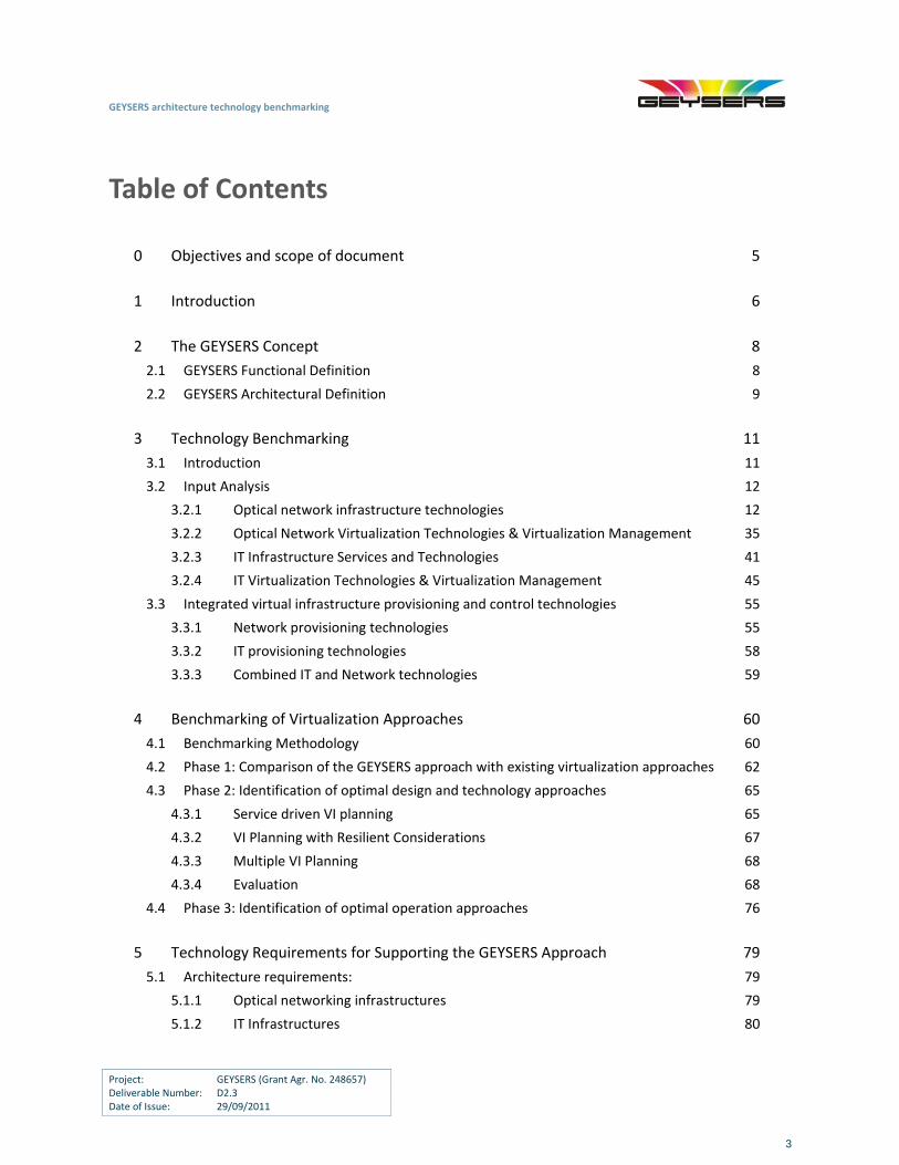
Table of Contents
0 Objectives and scope of document 5
1 Introduction 6
2 The GEYSERS Concept 8
2.1 GEYSERS Functional Definition 8
2.2 GEYSERS Architectural Definition 9
3 Technology Benchmarking 11
3.1 Introduction 11
3.2 Input Analysis 12
3.2.1 Optical network infrastructure technologies 12
3.2.2 Optical Network Virtualization Technologies & Virtualization Management 35
3.2.3 IT Infrastructure Services and Technologies 41
3.2.4 IT Virtualization Technologies & Virtualization Management 45
3.3 Integrated virtual infrastructure provisioning and control technologies 55
3.3.1 Network provisioning technologies 55
3.3.2 IT provisioning technologies 58
3.3.3 Combined IT and Network technologies 59
4 Benchmarking of Virtualization Approaches 60
4.1 Benchmarking Methodology 60
4.2 Phase 1: Comparison of the GEYSERS approach with existing virtualization approaches 62
4.3 Phase 2: Identification of optimal design and technology approaches 65
4.3.1 Service driven VI planning 65
4.3.2 VI Planning with Resilient Considerations 67
4.3.3 Multiple VI Planning 68
4.3.4 Evaluation 68
4.4 Phase 3: Identification of optimal operation approaches 76
5 Technology Requirements for Supporting the GEYSERS Approach 79
5.1 Architecture requirements: 79
5.1.1 Optical networking infrastructures 79
5.1.2 IT Infrastructures 80
GEYSERS architecture technology benchmarking
Project: GEYSERS (Grant Agr. No. 248657) Deliverable Number: D2.3 Date of Issue: 29/09/2011
4
5.1.3 Enhancement of the appropriate GMPLS protocols for integrated optical transport
and IT resources 81
5.2 Scalability requirements 83
5.3 Integration and interoperability requirements 83
5.4 Management Requirements 85
5.4.1 Network + IT management requirements 85
5.4.2 Network + IT service requirements 86
5.5 Security requirements 86
5.6 Comparison of Virtualization Approaches 87
5.7 Summary of Technology Requirements 88
6 Conclusions 90
7 References 91
8 Acronyms 94
Appendix 97
GEYSERS architecture technology benchmarking
Project: GEYSERS (Grant Agr. No. 248657) Deliverable Number: D2.3 Date of Issue: 29/09/2011
5
0 Objectives and scope of document
This document aims at analysing the details and technical requirements of the GEYSERS architecture and evaluating how they can be supported by the various infrastructure technologies available today at a commercial and research level. This analysis involves a detailed market and literature review focusing on both optical network and Information Technology (IT) infrastructures. In addition, possible virtualization approaches will be examined and compared, while optimal solutions will be identified by taking into consideration varying requirements.
GEYSERS architecture technology benchmarking
Project: GEYSERS (Grant Agr. No. 248657) Deliverable Number: D2.3 Date of Issue: 29/09/2011
6
1 Introduction
As the scale of information processing is increasing, from Petabyes of Internet data to the projected Exabytes in networked storage at the end of this decade [Handley], [Swason], novel network solutions are required to support the Future Internet and its new emerging applications such as UHD IPTV, 3D gaming, virtual worlds etc. These high‐performance applications need to be supported by specific IT resources (e.g. computing and data repositories) that may be remote and geographically distributed, requiring connectivity with the end users through a very high capacity transport network with increased flexibility and dynamicity. A strong candidate to support this need is optical networking as shown in recent technology advancements including dynamic control planes among others. In this context, an infrastructure comprising a converged optical network and IT resources that are jointly optimized in terms of infrastructure design and operation can be envisioned as the suitable solution to support the Future Internet challenges. On the other hand, in order to maximize the utilization and efficiency of infrastructures, supporting converged network and IT resources, the concept of virtualization of physical resources [Swason] can be additionally applied. The concept of Virtual Infrastructures (VIs) facilitates the sharing of physical resources among various Virtual Operators (VOs), introducing a new business model that suits the nature and characteristics of the Future Internet, and enables new exploitation opportunities for the underlying physical infrastructures. Through the adoption of VI solutions, optical network and IT resources can be jointly deployed and managed as logical services, rather than physical static resources managed by individual organizations. This results in enhanced enterprise agility, remote access to geographically distributed infrastructures and maximization of network utilization, leading to reduced capital and operational costs. In this context, GEYSERS is defining and implementing a novel architecture, that facilitates the provisioning of “Optical Network and IT resources” in a converged infrastructure for the end‐to‐end delivery of connectivity and infrastructure services. More specifically, GEYSERS focuses on the concept of deploying VIs over one or more interconnected Physical Infrastructures (PIs), belonging to one or more infrastructure providers, comprising both network and IT resources. The objective of this document is to analyse the details and requirements of the GEYSERS architecture and its general approach through benchmarking. This involves the evaluation of a set of inputs, including the various commercial optical network and IT infrastructure technologies available today and of those technologies available on a research level, together with the services that the GEYSERS solution will support. The input data has been collected through a detailed market and literature review as well as an analysis of IT services offering. Specific emphasis will be placed on the optical network and IT resource virtualization technologies required to enable the infrastructure virtualization approach that GEYSERS is proposing. In addition, within the GEYSERS approach, the effectiveness and efficiency of the various technology solutions regarding both network and IT resources will be identified. This will be done through a study of various virtualization
GEYSERS architecture technology benchmarking
Project: GEYSERS (Grant Agr. No. 248657) Deliverable Number: D2.3 Date of Issue: 29/09/2011
7
approaches that will be examined and compared within the GEYSERS scope. In this benchmarking study, the GEYSERS approach will be examined in a holistic manner and the optimal solutions regarding design, operation and technology options will be identified by taking into consideration various requirements in terms of inputs and performance metrics. The output of both benchmarking approaches described above will assist in forming recommendations for technology vendors and infrastructure operators regarding the following: the suitability of existing technologies to support the GEYSERS approach and possible extensions that can facilitate this suitability as well as their performance in terms of several metrics, including capital and operational costs.
GEYSERS architecture technology benchmarking
Project: GEYSERS (Grant Agr. No. 248657) Deliverable Number: D2.3 Date of Issue: 29/09/2011
8
2 The GEYSERS Concept
2.1 GEYSERS Functional Definition
The main services provided by the GEYSERS architecture are: (i) the provisioning of Virtual Infrastructures (VIs) – composed of both IT and optical network resources – and (ii) the provisioning of on‐demand dynamic services – on top of these VIs. In its overall context, the GEYSERS project tackles a complex scenario, involving different interacting actors who cooperate to offer these aggregated services to customers. This section introduces a high‐level view of the functionalities and the new business opportunities created by the GEYSERS architecture, while the next section provides further detail on the layered architecture itself. For a more in‐depth analysis of the business models and the architecture, please refer to the GEYSERS deliverables D1.1 and D2.2, respectively. The GEYSERS architecture enables the abstraction and the virtualization of the optical network and IT resources available in the physical infrastructure. These virtual resources can be combined to form a VI, with a control plane deployed on top that operates the VI and offers enhanced on‐demand and dynamic end‐to‐end services, tailored to the customers’ requirements. These services are offered over customized infrastructures. The VI planning is automated and takes into account the requirements of the customer and a set of parameters such as, for example, the energy consumption of the available resources. More specifically the VI planning phase defines and implements a resource information model to uniquely identify and uniformly abstract physical resources, including energy efficiency properties of physical infrastructure elements. The objective of VI planning is to implement a dynamically reconfigurable virtual network that not only meets customer’s specific needs, but also satisfies the VI Provider’s‐driven requirements, while maintaining cost‐effectiveness and any other specific requirements deemed appropriate (e.g. energy efficiency). Through this process the suitable VI that can support the required services is identified in terms of both topology and resources. To identify this suitable VI the details of the underlying physical infrastructure, including joint consideration of optical network and IT resources, are taken into consideration. Mapping the virtual resources to the physical resources is also part of the VI planning phase. Therefore the VI planning phase is also responsible to define a set of performance parameters that describe the VI itself. Through the VI planning process, virtual resources will be effectively abstracted from the physical devices and will be marked with a specific set of parameters. The VI operation performed by the control plane includes the configuration of the virtual resources and the monitoring of both their status and performance parameters, in order to carry out the provisioning of services, automated recovery actions, or tuning, if necessary. Moreover, the VI re‐planning is one of the innovative services introduced by the GEYSERS architecture, which allows the modifications of the network or
GEYSERS architecture technology benchmarking
Project: GEYSERS (Grant Agr. No. 248657) Deliverable Number: D2.3 Date of Issue: 29/09/2011
9
IT infrastructure, or both, and includes the resizing of the available virtual resources (e.g. to increase the storage on an IT site, or the bandwidth of a link), and the re‐shaping of the VI itself (e.g. to add/remove nodes and/or links). As stated above, the control plane enables the on‐demand provisioning of end‐to‐end services on top of the VI. In other words, the control plane is capable of selecting suitable IT sites (in terms of computational power and available storage) and providing a set of network connectivity services between them. It aims at satisfying the customer’s requirements and optimizing the utilization of the VI itself, while addressing several requirements as it considers various constraints such as energy consumption. While, in general, a single physical infrastructure can provide resources to several VIs, the GEYSERS architecture addresses security and the isolation of these virtual resources and infrastructures. Moreover, multi‐domain scenarios are envisaged, e.g. a single VI could be built on top of different physical infrastructures from different providers. As a final consideration, the GEYSERS architecture is also backward compatible, supporting connections to legacy ASON/GMPLS network control plane and the Path Computation (PCE) architecture. The virtualization capabilities introduced by the GEYSERS architecture allow current Telcos to be more involved within the new flexible cloud business scenarios and to reach new customers. In fact, Telcos would benefit from offering part of their infrastructure as a versatile and customized service (IaaS). This also leads to improved physical resource utilization, by means of partitioning and sharing, thus reducing the operational costs (OPEX) associated with the physical infrastructure itself. Moreover, GEYSERS opens the markets to new roles and players (i.e. business entities such as VI providers, VI operators and control plane stack providers), promoting the diversification of function and responsibilities, and the specialization of each entity. VI operators and service consumers (such as cloud providers) will benefit from the pay‐per‐use and pay‐as‐you‐grow business model in terms of lower investment risks (thus opening the market also to small but highly‐expert companies), reduced time‐to‐market and cost control thanks to the flexibility (and the energy efficiency) of the provided services.
2.2 GEYSERS Architectural Definition
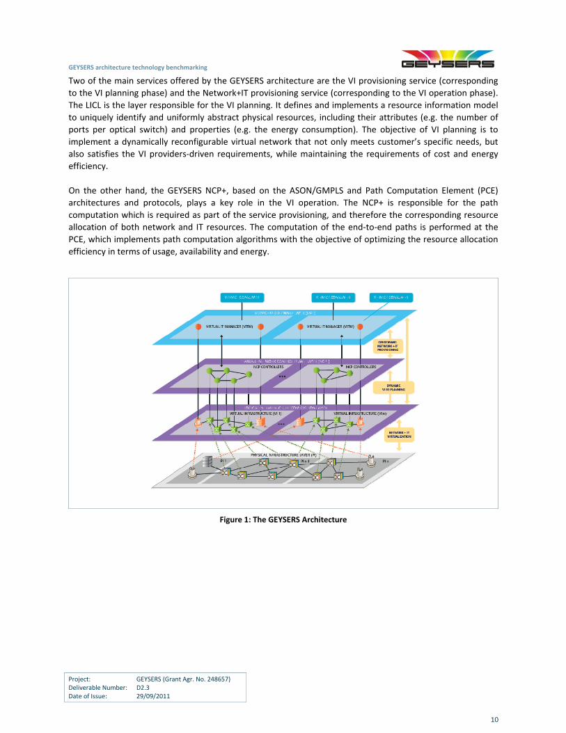
The ability of GEYSERS to present an innovative approach and adopt the concepts of the Infrastructure as a
Service (IaaS) and service oriented networking is facilitated through the GEYSERS architecture that enables
infrastructure operators to offer converged IT and optical network services. Figure 1 shows the GEYSERS
layered architecture, which introduces a virtualization layer for infrastructure services and an enhanced
network control plane (NCP+) for integrated IT and network provisioning over VIs.
In the GEYSERS layered architecture described in detail in [GEYSERS‐D2.1], devices in the PI layer are
abstracted and partitioned or grouped into virtual resources that can be selected to compose the VIs by the
Logical Infrastructure Composition Layer (LICL) service. Within each VI, NCP controllers configure and manage
virtual network resources, while virtual IT node controllers at the Virtual IT Manager (VITM) of the Service
Middleware Layer (SML) control the virtual IT resources. The SML is also responsible for translating the
application requests and Service Level Agreements (SLAs) into technology specific requests to trigger the
provisioning procedures at the NCP+.
GEYSERS architecture technology benchmarking
Project: GEYSERS (Grant Agr. No. 248657) Deliverable Number: D2.3 Date of Issue: 29/09/2011
10
Two of the main services offered by the GEYSERS architecture are the VI provisioning service (corresponding
to the VI planning phase) and the Network+IT provisioning service (corresponding to the VI operation phase).
The LICL is the layer responsible for the VI planning. It defines and implements a resource information model
to uniquely identify and uniformly abstract physical resources, including their attributes (e.g. the number of
ports per optical switch) and properties (e.g. the energy consumption). The objective of VI planning is to
implement a dynamically reconfigurable virtual network that not only meets customer’s specific needs, but
also satisfies the VI providers‐driven requirements, while maintaining the requirements of cost and energy
efficiency.
On the other hand, the GEYSERS NCP+, based on the ASON/GMPLS and Path Computation Element (PCE)
architectures and protocols, plays a key role in the VI operation. The NCP+ is responsible for the path
computation which is required as part of the service provisioning, and therefore the corresponding resource
allocation of both network and IT resources. The computation of the end‐to‐end paths is performed at the
PCE, which implements path computation algorithms with the objective of optimizing the resource allocation
efficiency in terms of usage, availability and energy.
Figure 1: The GEYSERS Architecture
GEYSERS architecture technology benchmarking
Project: GEYSERS (Grant Agr. No. 248657) Deliverable Number: D2.3 Date of Issue: 29/09/2011
11
3 Technology Benchmarking
3.1 Introduction
This section focuses on identifying the technologies of interest within the context of the GEYSERS approach
and architecture, evaluating their suitability in the proposed framework, or identifying the extensions and
modifications needed on existing technologies to support the GEYSERs approach. The methodology applied in
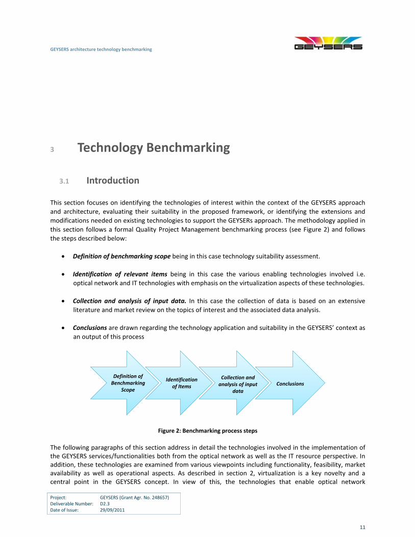
this section follows a formal Quality Project Management benchmarking process (see Figure 2) and follows
the steps described below:
Definition of benchmarking scope being in this case technology suitability assessment.
Identification of relevant items being in this case the various enabling technologies involved i.e.
optical network and IT technologies with emphasis on the virtualization aspects of these technologies.
Collection and analysis of input data. In this case the collection of data is based on an extensive
literature and market review on the topics of interest and the associated data analysis.
Conclusions are drawn regarding the technology application and suitability in the GEYSERS’ context as
an output of this process
Definition of Benchmarking
Scope
Identification of Items
Collection and analysis of input
data
Conclusions
Figure 2: Benchmarking process steps
The following paragraphs of this section address in detail the technologies involved in the implementation of the GEYSERS services/functionalities both from the optical network as well as the IT resource perspective. In addition, these technologies are examined from various viewpoints including functionality, feasibility, market availability as well as operational aspects. As described in section 2, virtualization is a key novelty and a central point in the GEYSERS concept. In view of this, the technologies that enable optical network
GEYSERS architecture technology benchmarking
Project: GEYSERS (Grant Agr. No. 248657) Deliverable Number: D2.3 Date of Issue: 29/09/2011
12
virtualization and IT equipment forming the integrated underlying physical infrastructure are examined as a key aspect. Finally the requirements and options for provisioning the integrated network and IT infrastructure in the form of a common service and its control are also addressed.
3.2 Input Analysis
GEYSERS concentrates on infrastructures which support the interconnection of remote and geographically distributed IT resources that require connectivity between themselves and the end users. This connectivity needs to be supported through a flexible and dynamic transport network that offers very high capacity levels. In this context, when attempting to analyse the details and requirements of the GEYSERS architecture and evaluate how these can be supported by various infrastructure technologies, it is important to identify the availability as well as the functionality, features and characteristics of various optical network and IT technologies. At the same time, an analysis of the services expected to be supported by this type of infrastructure is also of critical importance. This refers to the specific requirements that these services impose across the different types of infrastructure resources i.e. optical network and IT and their interrelationships which are based on the objective to support a common service end‐to‐end. The following sections are dedicated to discussing the state‐of‐the‐art and market availability of optical network and IT technologies. A discussion on IT related services that can be supported by integrated optical network and IT infrastructures is also included.
3.2.1 Optical network infrastructure technologies
Current telecommunications networks widely employ single‐mode optical fibers to interconnect exchanges as they offer enormous transmission bandwidth (potentially as high as 25 THz) that can support ultra‐high‐speed and long reach transmission capabilities. Optical networking exploiting recent technology advances is used not only in existing telecommunications infrastructures but is also expected to play a significant role in next generation networks and the Future Internet. Optical networking will be seen as supporting a large variety of services having very different requirements in terms of bandwidth, latency, availability and other features. With the recent technology evolution in the optical communications domain, the WDM transport layer migrated from simple point‐to‐point transmission links into elaborate network architectures providing similar functionality to the electronic SONET/SDH layer, with improved features, higher manageability and lower complexity and cost [Noirie], [Berthold], [OMahony06]. Integrated WDM networks performing switching and routing are deployed in order to economically support the required functionalities [Tzanakaki02]. In such network scenarios, high capacity optical paths are set in the transport layer forming connections between discrete points of the network topology, utilising intelligent dynamic network elements. These can be identified to be reconfigurable optical add/drop multiplexers (OADMs) and optical cross‐connect (OXC) nodes performing traffic engineering and management of the optical bandwidth [Chikama], [Tzanakaki04], [Tzanakaki03]. Most specifically they support handling of the incoming signals at the appropriate granularity level to enable efficient routing of the traffic demands satisfying the service level requirements including network survivability and security and accommodate network expansion, traffic growth and churn. These types of nodes can offer functionalities such as point‐and‐click provisioning and bandwidth on demand while advanced designs equipped with the required hardware and software are able to also support enhanced network features and new services. These functions are facilitated through the application of the automatically switched optical network/automatic switched transport network (ASON/ASTN) and the
GEYSERS architecture technology benchmarking
Project: GEYSERS (Grant Agr. No. 248657) Deliverable Number: D2.3 Date of Issue: 29/09/2011
13
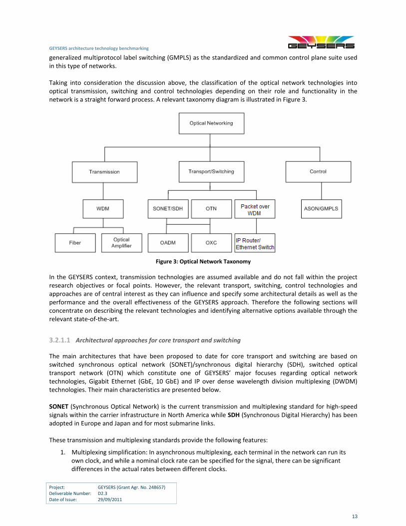
generalized multiprotocol label switching (GMPLS) as the standardized and common control plane suite used in this type of networks. Taking into consideration the discussion above, the classification of the optical network technologies into optical transmission, switching and control technologies depending on their role and functionality in the network is a straight forward process. A relevant taxonomy diagram is illustrated in Figure 3.
Figure 3: Optical Network Taxonomy
In the GEYSERS context, transmission technologies are assumed available and do not fall within the project research objectives or focal points. However, the relevant transport, switching, control technologies and approaches are of central interest as they can influence and specify some architectural details as well as the performance and the overall effectiveness of the GEYSERS approach. Therefore the following sections will concentrate on describing the relevant technologies and identifying alternative options available through the relevant state‐of‐the‐art.
3.2.1.1 Architectural approaches for core transport and switching
The main architectures that have been proposed to date for core transport and switching are based on switched synchronous optical network (SONET)/synchronous digital hierarchy (SDH), switched optical transport network (OTN) which constitute one of GEYSERS’ major focuses regarding optical network technologies, Gigabit Ethernet (GbE, 10 GbE) and IP over dense wavelength division multiplexing (DWDM) technologies. Their main characteristics are presented below. SONET (Synchronous Optical Network) is the current transmission and multiplexing standard for high‐speed signals within the carrier infrastructure in North America while SDH (Synchronous Digital Hierarchy) has been adopted in Europe and Japan and for most submarine links. These transmission and multiplexing standards provide the following features:
1. Multiplexing simplification: In asynchronous multiplexing, each terminal in the network can run its own clock, and while a nominal clock rate can be specified for the signal, there can be significant differences in the actual rates between different clocks.
GEYSERS architecture technology benchmarking
Project: GEYSERS (Grant Agr. No. 248657) Deliverable Number: D2.3 Date of Issue: 29/09/2011
14
2. Management: SONET and SDH incorporate extensive management information for managing the network including extensive performance monitoring, identification of connectivity and traffic type, and reporting of failures.
3. Interoperability: SONET and SDH define standard optical interfaces that enable interoperability between equipment from different vendors on the links.
4. Network availability: SONET and SDH have evolved to incorporate specific network topologies and specific protection techniques and associated protocols to provide high‐availability services. Hence, the restoration time after a failure typically is smaller than 60ms while other standards can take up to seconds or minutes.
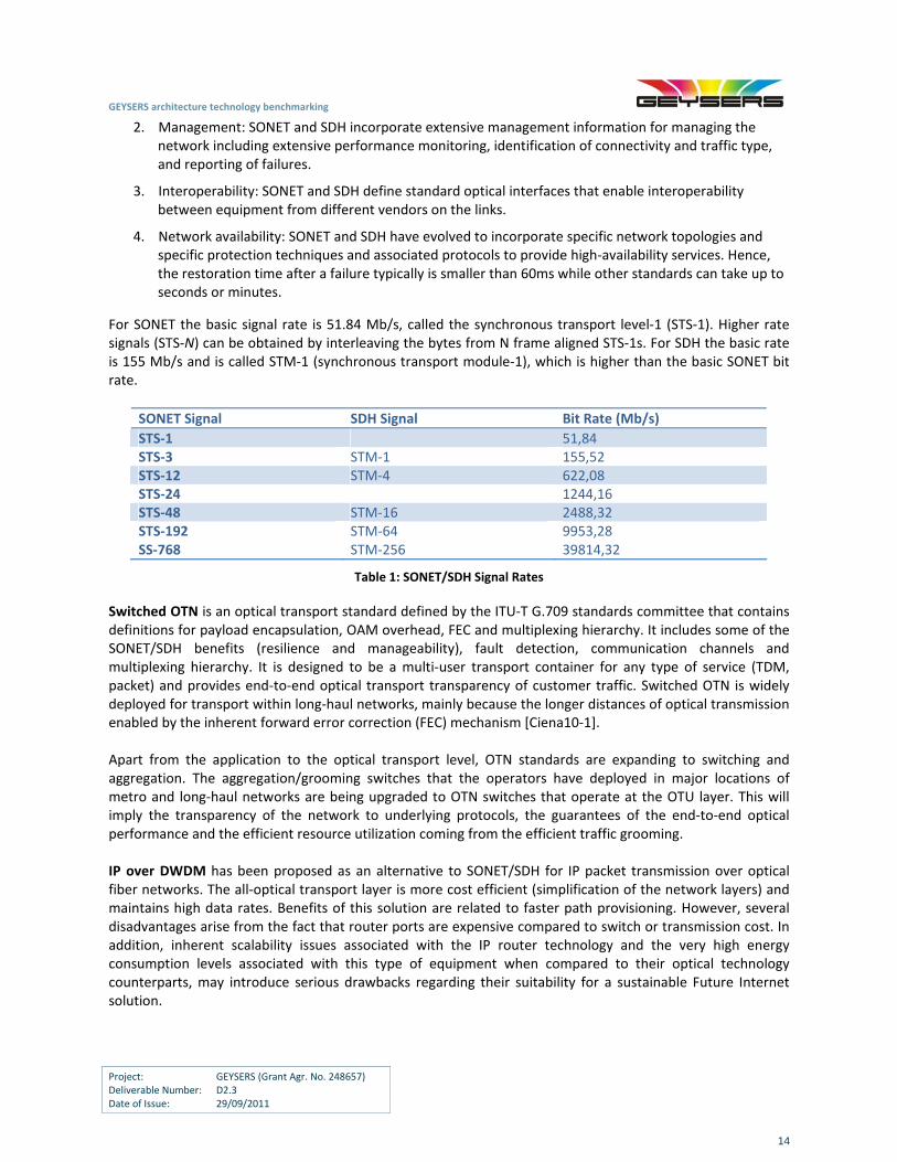
For SONET the basic signal rate is 51.84 Mb/s, called the synchronous transport level‐1 (STS‐1). Higher rate signals (STS‐N) can be obtained by interleaving the bytes from N frame aligned STS‐1s. For SDH the basic rate is 155 Mb/s and is called STM‐1 (synchronous transport module‐1), which is higher than the basic SONET bit rate.
SONET Signal SDH Signal Bit Rate (Mb/s)
STS‐1 51,84 STS‐3 STM‐1 155,52 STS‐12 STM‐4 622,08 STS‐24 1244,16 STS‐48 STM‐16 2488,32 STS‐192 STM‐64 9953,28 SS‐768 STM‐256 39814,32
Table 1: SONET/SDH Signal Rates
Switched OTN is an optical transport standard defined by the ITU‐T G.709 standards committee that contains definitions for payload encapsulation, OAM overhead, FEC and multiplexing hierarchy. It includes some of the SONET/SDH benefits (resilience and manageability), fault detection, communication channels and multiplexing hierarchy. It is designed to be a multi‐user transport container for any type of service (TDM, packet) and provides end‐to‐end optical transport transparency of customer traffic. Switched OTN is widely deployed for transport within long‐haul networks, mainly because the longer distances of optical transmission enabled by the inherent forward error correction (FEC) mechanism [Ciena10‐1]. Apart from the application to the optical transport level, OTN standards are expanding to switching and aggregation. The aggregation/grooming switches that the operators have deployed in major locations of metro and long‐haul networks are being upgraded to OTN switches that operate at the OTU layer. This will imply the transparency of the network to underlying protocols, the guarantees of the end‐to‐end optical performance and the efficient resource utilization coming from the efficient traffic grooming. IP over DWDM has been proposed as an alternative to SONET/SDH for IP packet transmission over optical fiber networks. The all‐optical transport layer is more cost efficient (simplification of the network layers) and maintains high data rates. Benefits of this solution are related to faster path provisioning. However, several disadvantages arise from the fact that router ports are expensive compared to switch or transmission cost. In addition, inherent scalability issues associated with the IP router technology and the very high energy consumption levels associated with this type of equipment when compared to their optical technology counterparts, may introduce serious drawbacks regarding their suitability for a sustainable Future Internet solution.
GEYSERS architecture technology benchmarking
Project: GEYSERS (Grant Agr. No. 248657) Deliverable Number: D2.3 Date of Issue: 29/09/2011
15
Gigabit Ethernet and 10 Gigabit Ethernet are based on a bus architecture where all the nodes are connected to a single bus. The nodes use a simple media access control protocol called Carrier‐Sense Multiple Access with Collision Detection (CSMA/CD). A node wanting to send a packet, checks the bus to see if it is idle. Upon detecting that it is idle, it transmits the packet. If another node happens to check the bus at the same time and transmits a packet, the two packets will collide and become corrupted. In this case, both nodes back off and attempt to transmit again after waiting for a randomized delay interval. Hence for higher speeds and longer bus lengths, the efficiency drops rapidly. Gigabit Ethernet is an extension of the same standard as 1 Gb/s. It operates over both copper and fiber interfaces. Gigabit over fiber is becoming a popular choice in metro networks to interconnect multiple enterprise networks. The 10 Gb/s standard is begin developed with the internet of enable long‐haul interconnections, with the data rate begin aligned to the OC‐192/STM‐64 SONDET/SDH rates for better compatibility with wide area transport.
3.2.1.2 Core Network Transport Rates
The transport rates and the corresponding technology are another choice that the operators have to take into account with the deployment of the appropriate transport and switching technologies. The available options are 1) the continuity of 10G capacity placement and 2) the upgrade to 40/100G. Option 1 benefits from the price reduction of 10G technology that is expected to continue and the existence of corresponding network standards for more than a decade. However, with the estimation of traffic growth in the order of 50% every year as well as the operational complexity and inefficiency that the increase of more 10G capacity acquires, the second option seems a more appropriate solution. 40G has already moved from early adoption to massive deployment from several operators around the globe, such as AT&T, Verizon, DT, China Telecom and others. Moreover, 40GE and 100GE transport over 40G and 100G networks is already fully standardized and some initial deployments of commercial 100G already exist [Ciena10‐1].
3.2.1.3 Transparent and Opaque Networks
Transparency in optical networking refers to the ability to modulate and transmit any kind of payload on the optical channel, independent of its bit‐rate and format (framing, line‐coding, power level, etc). Transparency implies that a specific optical path (lightpath) is assigned between each origin and destination node pair without any optical‐electronic‐optical (OEO) conversion at any intermediate node. In general, transparent optical networks provide reduced operational costs associated with their inherent energy efficiency and small footprint but in contrast are disadvantaged by the physical layer impairments associated with the optical transmission and switching of the data channels. In addition, they do not inherently support wavelength conversion capability and signal monitoring functions. However, wavelength conversion capabilities can be introduced through the use of transparent optical wavelength converters based on all optical technologies [Dutta04]. Opaque networks are on the other hand based on nodes equipped with OEO technologies that can be either receiver/transmitter pairs associated with an optical switching fabric. In this case, the finest granularity that the network supports is that of the wavelength or receiver/transmitter pairs associated with an electrical switching fabric in which case the switching granularity supported by the network could also be sub‐wavelength. These networks commonly inherently support wavelength conversion functionality and signal monitoring capabilities. However, they require higher energy consumption levels for their operation and occupy larger footprint compared to their transparent counterpart. A practical solution that is commonly deployed to overcome the limitations of both transparent and opaque optical networks is translucent optical networks. These networks provide some limited level of transparency, based on what is commonly known as transparency islands, i.e. network parts that are fully transparent and interconnected together through opaque network nodes including OEO signal conversion and the associated
GEYSERS architecture technology benchmarking
Project: GEYSERS (Grant Agr. No. 248657) Deliverable Number: D2.3 Date of Issue: 29/09/2011
16
technologies. This way, the overall network cost and power consumption can be reduced but special network design considerations involving optimal equipment placement are required [Katrinis11]. The presence or absence of wavelength conversion in the network plays a significant role in the way service provisioning is handled and the level of resource utilisation efficiency that is achieved when provisioning the services. Specifically, in the absence of wavelength conversion, optical path assignment is performed by assigning the same wavelength across all links of a path through Wavelength Assignment (WA) algorithms. This is known as the wavelength‐continuity constraint and is referred to as the pure Wavelength Path (WP). However, if wavelength conversion is available, the wavelength across the different links of a lightpath does not need to be the same, but it is assigned based on the associated bandwidth availability on a per link basis and is referred to as the Virtual Wavelength Path (VWP). Several advantages arise from the presence of wavelength converters at the network nodes, such as lower blocking probability performance, lower complexity of algorithms, and the ease of provisioning and management of connections, lower capacity requirements and easier and feasible network design operations.
3.2.1.4 Optical Switching Equipment ‐ General Architecture
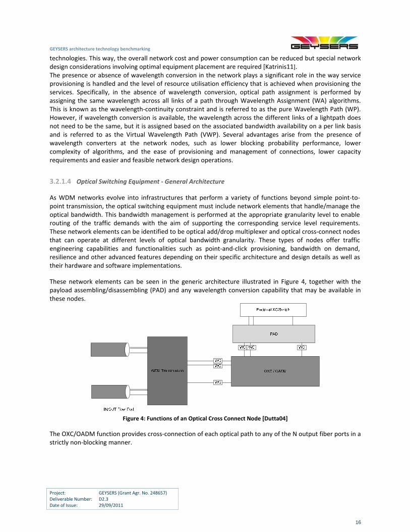
As WDM networks evolve into infrastructures that perform a variety of functions beyond simple point‐to‐point transmission, the optical switching equipment must include network elements that handle/manage the optical bandwidth. This bandwidth management is performed at the appropriate granularity level to enable routing of the traffic demands with the aim of supporting the corresponding service level requirements. These network elements can be identified to be optical add/drop multiplexer and optical cross‐connect nodes that can operate at different levels of optical bandwidth granularity. These types of nodes offer traffic engineering capabilities and functionalities such as point‐and‐click provisioning, bandwidth on demand, resilience and other advanced features depending on their specific architecture and design details as well as their hardware and software implementations.
These network elements can be seen in the generic architecture illustrated in Figure 4, together with the payload assembling/disassembling (PAD) and any wavelength conversion capability that may be available in these nodes.
Figure 4: Functions of an Optical Cross Connect Node [Dutta04]
The OXC/OADM function provides cross‐connection of each optical path to any of the N output fiber ports in a strictly non‐blocking manner.
GEYSERS architecture technology benchmarking
Project: GEYSERS (Grant Agr. No. 248657) Deliverable Number: D2.3 Date of Issue: 29/09/2011
17
3.2.1.5 Transparent Optical Nodes
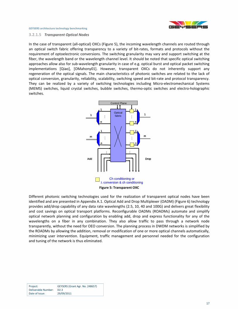
In the case of transparent (all‐optical) OXCs (Figure 5), the incoming wavelength channels are routed through an optical switch fabric offering transparency to a variety of bit‐rates, formats and protocols without the requirement of optoelectronic conversions. The switching granularity may vary and support switching at the fiber, the wavelength band or the wavelength channel level. It should be noted that specific optical switching approaches allow also for sub‐wavelength granularity in case of e.g. optical burst and optical packet switching implementations [Qiao], [OMahony01]. However, transparent OXCs do not inherently support any regeneration of the optical signals. The main characteristics of photonic switches are related to the lack of optical conversion, granularity, reliability, scalability, switching speed and bit‐rate and protocol transparency. They can be realized by a variety of switching technologies including Micro‐electromechanical Systems (MEMS) switches, liquid crystal switches, bubble switches, thermo‐optic switches and electro‐holographic switches.
Ch conditioning or conversion & ch conditioning
......
1
n
1
n
......
1
n
1
n
… …
Control Plane
1
m
1
m
Add Drop
Optical fabric
Ch conditioning or conversion & ch conditioning
......
1
n
1
n
......
1
n
1
n
… …
Control Plane
1
m
1
m
Add Drop
Optical fabric
Figure 5: Transparent OXC
Different photonic switching technologies used for the realization of transparent optical nodes have been identified and are presented in Appendix A.1. Optical Add and Drop Multiplexer (OADM) (Figure 6) technology provides add/drop capability of any data rate wavelengths (2.5, 10, 40 and 100G) and delivers great flexibility and cost savings on optical transport platforms. Reconfigurable OADMs (ROADMs) automate and simplify optical network planning and configuration by enabling add, drop and express functionality for any of the wavelengths on a fiber in any combination. They also allow traffic to pass through a network node transparently, without the need for OEO conversion. The planning process in DWDM networks is simplified by the ROADMs by allowing the addition, removal or modification of one or more optical channels automatically, minimizing user intervention. Equipment, traffic management and personnel needed for the configuration and tuning of the network is thus eliminated.
GEYSERS architecture technology benchmarking
Project: GEYSERS (Grant Agr. No. 248657) Deliverable Number: D2.3 Date of Issue: 29/09/2011
18
n>m
…
Rx Rx
Tx
…
1 m
Tx
1 m
OADMn n
n>m
…
Rx Rx
Tx
…
1 m
Tx
1 m
OADMn n
Figure 6: Generic OADM Architecture
Different optical cross‐connect architectures and technologies have been established to support the different network topologies such as ring, mesh, transparent and opaque network architectures. A common classification defines opaque and transparent optical cross‐connects.
3.2.1.6 Opaque Optical Nodes
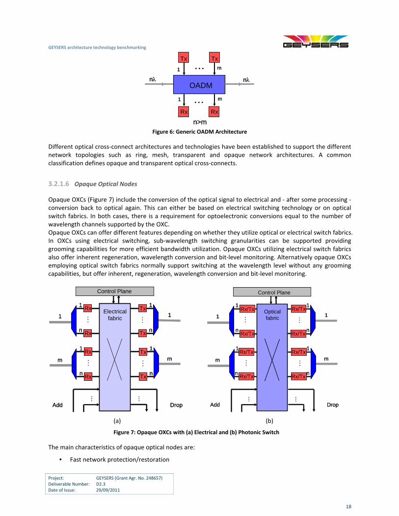
Opaque OXCs (Figure 7) include the conversion of the optical signal to electrical and ‐ after some processing ‐ conversion back to optical again. This can either be based on electrical switching technology or on optical switch fabrics. In both cases, there is a requirement for optoelectronic conversions equal to the number of wavelength channels supported by the OXC. Opaque OXCs can offer different features depending on whether they utilize optical or electrical switch fabrics. In OXCs using electrical switching, sub‐wavelength switching granularities can be supported providing grooming capabilities for more efficient bandwidth utilization. Opaque OXCs utilizing electrical switch fabrics also offer inherent regeneration, wavelength conversion and bit‐level monitoring. Alternatively opaque OXCs employing optical switch fabrics normally support switching at the wavelength level without any grooming capabilities, but offer inherent, regeneration, wavelength conversion and bit‐level monitoring.
......
1
n
1
n
......
1
n
1
n
… …
Control Plane
1
m
1
m
Add Drop
Rx Tx
Rx Tx
Rx Tx
Rx Tx
Electrical fabric...
...
1
n
1
n
......
1
n
1
n
… …
Control Plane
1
m
1
m
Add Drop
Rx Tx
Rx Tx
Rx Tx
Rx Tx
Electrical fabric
......
1
n
1
n
......
1
n
1
n
… …Control Plane
1
m
1
m
Add Drop
Rx/Tx Optical fabric
Rx/Tx
Rx/Tx
Rx/Tx
Rx/Tx
Rx/Tx
Rx/Tx
Rx/Tx
......
1
n
1
n
......
1
n
1
n
… …Control Plane
1
m
1
m
Add Drop
Rx/Tx Optical fabric
Rx/Tx
Rx/Tx
Rx/Tx
Rx/Tx
Rx/Tx
Rx/Tx
Rx/Tx
(a) (b)
Figure 7: Opaque OXCs with (a) Electrical and (b) Photonic Switch The main characteristics of opaque optical nodes are:
• Fast network protection/restoration
GEYSERS architecture technology benchmarking
Project: GEYSERS (Grant Agr. No. 248657) Deliverable Number: D2.3 Date of Issue: 29/09/2011
19
• Potential for trade‐off between cost and networking features
• Transparent for information, but not for the optical signal
• CAPEX issues due to inherent OEO conversion
• High power consumption impacting the OPEX
3.2.1.7 Multi‐granularity Optical Nodes
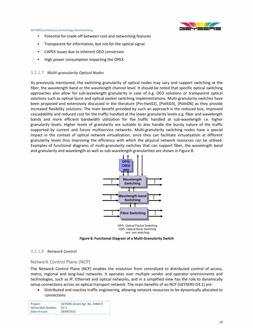
As previously mentioned, the switching granularity of optical nodes may vary and support switching at the fiber, the wavelength band or the wavelength channel level. It should be noted that specific optical switching approaches also allow for sub‐wavelength granularity in case of e.g. OEO solutions or transparent optical solutions such as optical burst and optical packet switching implementations. Multi‐granularity switches have been proposed and extensively discussed in the literature [Pin‐Han02], [Politi03], [Politi06] as they provide increased flexibility solutions. The main benefit provided by such an approach is the reduced loss, improved cascadability and reduced cost for the traffic handled at the lower granularity levels e.g. fiber and wavelength bands and more efficient bandwidth utilization for the traffic handled at sub‐wavelength i.e. higher granularity levels. Higher levels of granularity are suitable to also handle the bursty nature of the traffic supported by current and future multiservice networks. Multi‐granularity switching nodes have a special impact in the context of optical network virtualization, since they can facilitate virtualization at different granularity levels thus improving the efficiency with which the physical network resources can be utilised. Examples of functional diagrams of multi‐granularity switches that can support fiber, the wavelength band and granularity and wavelength as well as sub‐wavelength granularities are shown in Figure 8.
OPS/OBS/oeo
OPS: Optical Packet SwitchingOBS: Optical Burst Switching
oeo: oeo switching
Wavelength-band Switching
Fibre Switching
Wavelength Switching
Figure 8: Functional Diagram of a Multi‐Granularity Switch
3.2.1.8 Network Control
Network Control Plane (NCP)
The Network Control Plane (NCP) enables the evolution from centralized to distributed control of access, metro, regional and long‐haul networks. It operates over multiple vendor and operator environments and technologies, such as IP, Ethernet and optical networks, and in a simplified view has the role to dynamically setup connections across an optical transport network. The main benefits of an NCP [GEYSERS‐D4.1] are:
Distributed and reactive traffic engineering, allowing network resources to be dynamically allocated to connections
GEYSERS architecture technology benchmarking
Project: GEYSERS (Grant Agr. No. 248657) Deliverable Number: D2.3 Date of Issue: 29/09/2011
20
Usage of specific control plane protocols rather than generalised network management protocols
Distributed and reactive restoration upon a network failure, taking into account the current state of the transport network
Reusability of control plane protocols to handle different transport technologies under a common
control framework
ASON/GMPLS NCP
The Automatic Switching Optical Network (ASON) and the Generalized Multi‐Protocol Label Switching (GMPLS) are the two reference architectures for the implementation of the NCP. ITU‐T ASON provides an architecture description for a control plane that operates over a transport network and supports functionalities such as fast connection establishment and restoration for both permanent and soft permanent connections. IETF GMPLS originates from the MPLS protocols suite, whose main goal was to bring the speed of Layer 2 switching to Layer 3 and solve complexity and scalability issues of IP over ATM. The main features of MPLS were label swapping, separation of forwarding and control plane, forwarding hierarchy via label stacking, constraint‐based routing, facilitation of Virtual Private Networks, provision of class of service and elimination of multiple layers. It provides functionalities for resource discovery for links, nodes, topology and services, flow‐through service provisioning, end‐to‐end connection routing for optimal resource utilization and service rerouting and restoration for protection against network failures.
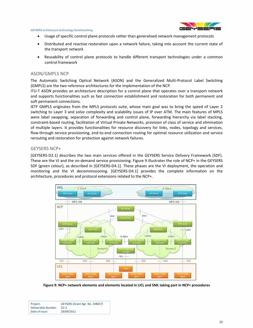
GEYSERS NCP+
[GEYSERS‐D2.1] describes the two main services offered in the GEYSERS Service Delivery Framework (SDF). These are the VI and the on‐demand service provisioning. Figure 9 illustrates the role of NCP+ in the GEYSERS SDF (green colour), as described in [GEYSERS‐D4.1]. These phases are the VI deployment, the operation and monitoring and the VI decommissioning. [GEYSERS‐D4.1] provides the complete information on the architecture, procedures and protocol extensions related to the NCP+.
Figure 9: NCP+ network elements and elements located in LICL and SML taking part in NCP+ procedures
GEYSERS architecture technology benchmarking
Project: GEYSERS (Grant Agr. No. 248657) Deliverable Number: D2.3 Date of Issue: 29/09/2011
21
3.2.1.9 Commercial Availability of Optical Network Technologies
Nowadays, network operators are facing the challenge of adapting their infrastructure in order to support the constant demand for more capacity and the emerging new services and business models. Optical fiber is the communication medium of choice for carriers’ networks because it provides enormous bandwidth, long reach transmission capability, and low levels of distortion of the transmitted signals compared to alternative technology solutions. Optical networks provide a common infrastructure over which a variety of services can be delivered and these networks are becoming capable of delivering bandwidth in a flexible manner with the use of ASON/GMPLS control planes. Established legacy networks are based on SONET/SDH and were designed in order to support voice and private line services. Today, the core of the network is migrating away from a SONET/SDH ring‐based architecture to a meshed optical‐layer based architecture with protection functions, while metro access network are using a hybrid packet‐circuit network as the key element to deliver services. The optical layer itself is migrating from an opaque network (i.e. electric switching), to an all‐optical DWDM network. Furthermore, as stated above, the optical network is becoming dynamic, in the sense that lightpaths can be set up and taken down as needed. The WDM technology has heavily reduced the cost‐per‐bit of transport, and it is now recognized as the Layer 1 transport technology. In today’s vendor portfolio, DWDM is the most common multiplexing technology for core/long‐haul networks. State‐of‐the‐art DWDM systems support up to 160 wavelengths on a single pair of fiber, with each wavelength transporting up to 40Gbit/s capacity. Moreover, network elements transporting 100Gbit/s per wavelength are entering the market (e.g. the Alcatel‐Lucent 1830 Photonic Service Switch). For metro/back‐haul networks, CWDM systems are prevalent on DWDM systems, enabling the reduced costs associated with a simpler underlying optical component technology. State‐of‐the‐art ROADM technology is fully flexible and non‐blocking (the so called triple‐A architecture – any wavelength, any node, any time): it is capable of adding and dropping any wavelength in any direction to any available port on the node.
Some detailed information regarding the capabilities and specifications of the technology available in the
GEYSERs consortium, together with a review of commercially available optical equipment/networking
solutions within the GEYSERS testbed, are provided below
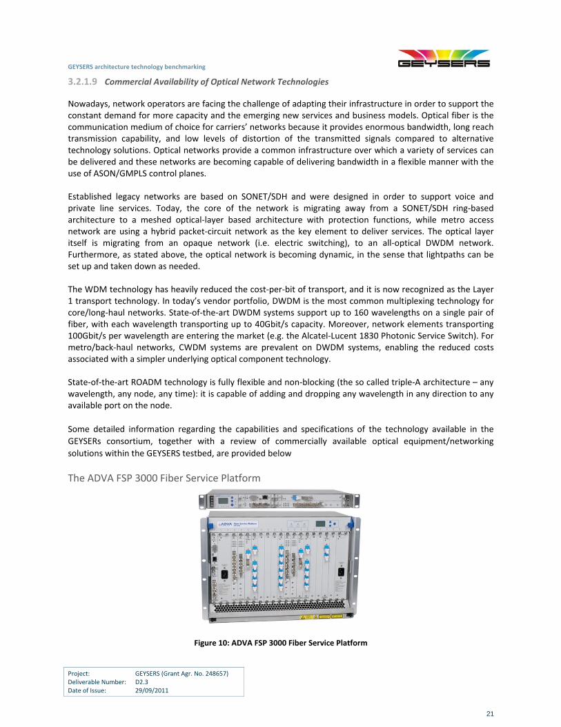
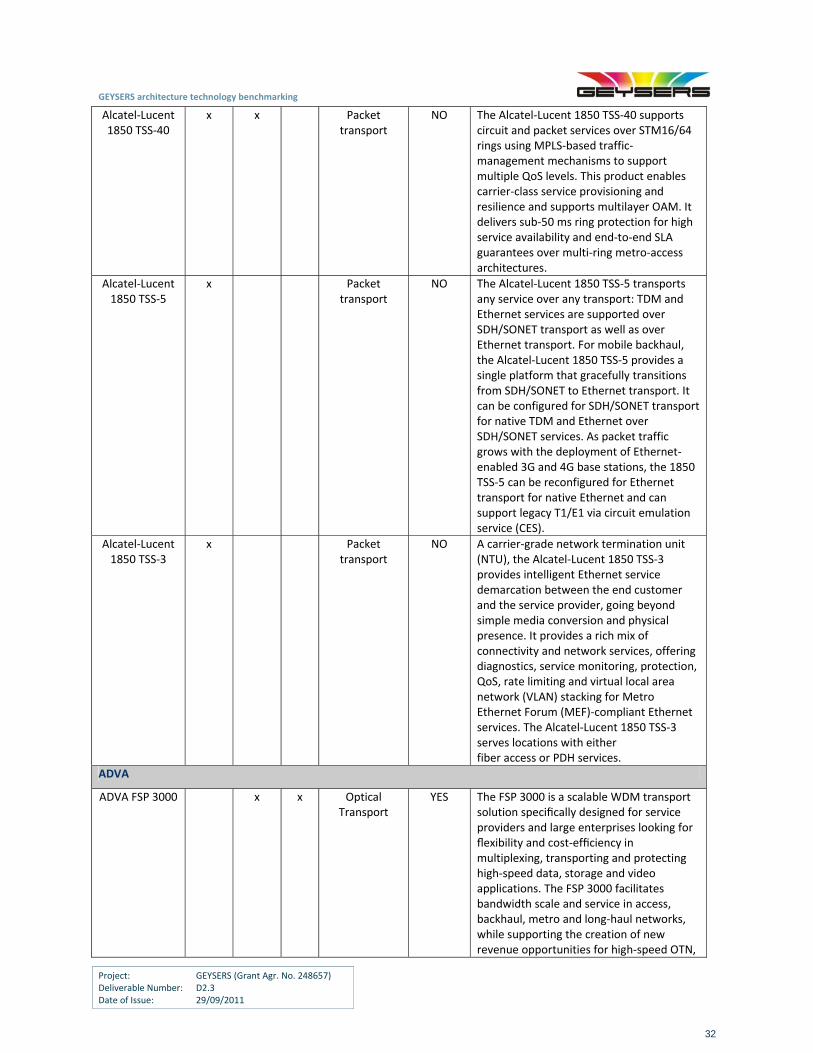
The ADVA FSP 3000 Fiber Service Platform
Figure 10: ADVA FSP 3000 Fiber Service Platform
GEYSERS architecture technology benchmarking
Project: GEYSERS (Grant Agr. No. 248657) Deliverable Number: D2.3 Date of Issue: 29/09/2011
22
Product Overview
The FSP 3000 is a scalable WDM transport solution designed for service provider infrastructure and large enterprises (corporate backbones), intended for flexible and cost‐efficient multiplexing, transport and protection of high‐speed data, storage and video services. The FSP 3000 facilitates bandwidth scale and service flexibility in access, backhaul, metro and long‐haul networks. To minimize transport cost and optimize efficiency in all network areas, the modular architecture of the FSP 3000 comprises a family of hot‐swappable modules to meet diverse network application requirements.
The FSP 3000 offers the so‐called CoherentExpress technology optimized for 100G+ agile optical core networking in addition to the optical layer design supporting DWDM, CWDM and WDM‐PON. Up to 120 wavelengths per fiber pair and a wide range of fully integrated transponder options optimize the spectral efficiency in the transmission fiber and reduce power and space consumption.
The FSP 3000 supports static and (re‐) configurable photonic components, including tunable lasers and multi‐degree ROADM technology for colourless and directionless wavelength routing. The Flexible Remote Node concept allows network operators to deploy WDM‐PON extensions that enable a unified access and backhaul architecture for carrier wholesale, business and residential applications. To achieve further flexibility, service multiplexing options include OTN add/drop, and Ethernet and SONET/SDH aggregation. Special ultra‐low latency modules are optimized for latency‐sensitive enterprise transport applications.
Operation is supported by the FSP Network Manager and FSP Service Manager which allow remote system operation and service‐centric provisioning. The embedded RAYcontrolTM GMPLS control plane enables automated on‐demand delivery and management of any mix of services, thereby simplifying network operations and improving network resiliency also on legacy systems. Within the GEYSERS project, the RAYcontrolTM GMPLS control plane will be used as a software stack to demonstrate and validate the GEYSERS NCP+ control plane backward compatibility. Furthermore, use of FSP Service Manager and RAYcontrolTM GMPLS control plane solutions will enable new network virtualization scenarios, i.e. presentation of an optical network consisting of many physical nodes as a single virtual node (N:1 virtualization).
Main Features
Fixed or reconfigurable optical layer for long‐haul, metro and access applications supporting DWDM, CWDM, WDM‐PON
Colourless, directionless and contentionless multi‐degree ROADM functionality with GMPLS‐based control plane for real‐time provisioning and service restoration
Multi‐service capability supporting Ethernet, OTN, SONET/SDH, storage and video services up to 100 Gbit/s per WDM channel
Erbium and Raman amplification options for non‐regenerated transmission over distances exceeding 2,000 km and up to 50 dB single‐span loss
High‐density design for small footprint and low power consumption
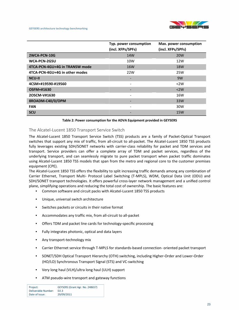
Further details concerning the technical specifications of the ADVA FSP 3000 Fiber Service Platform can be found in the Appendix A2. The power figures for the equipment are provided in Table 2:
GEYSERS architecture technology benchmarking
Project: GEYSERS (Grant Agr. No. 248657) Deliverable Number: D2.3 Date of Issue: 29/09/2011
23
Typ. power consumption
(incl. XFPs/SPFs)
Max. power consumption
(incl. XFPs/SPFs)
2WCA‐PCN‐10G 14W 20W
WCA‐PCN‐2G5U 10W 12W
4TCA‐PCN‐4GU+4G in TRANSW mode 16W 18W
4TCA‐PCN‐4GU+4G in other modes 22W 25W
NCU‐II ‐ 9W
4CSM+#19590‐#19560 ‐ <2W
OSFM+#1630 ‐ <2W
2OSCM‐V#1630 ‐ 16W
8ROADM‐C40/0/OPM ‐ 33W
FAN ‐ 30W
SCU ‐ 15W
Table 2: Power consumption for the ADVA Equipment provided in GEYSERS
The Alcatel‐Lucent 1850 Transport Service Switch
The Alcatel‐Lucent 1850 Transport Service Switch (TSS) products are a family of Packet‐Optical Transport switches that support any mix of traffic, from all‐circuit to all‐packet. The Alcatel‐Lucent 1850 TSS products fully leverages existing SDH/SONET networks with carrier‐class reliability for packet and TDM services and transport. Service providers can offer a complete array of TDM and packet services, regardless of the underlying transport, and can seamlessly migrate to pure packet transport when packet traffic dominates using Alcatel‐Lucent 1850 TSS models that span from the metro and regional core to the customer premises equipment (CPE). The Alcatel‐Lucent 1850 TSS offers the flexibility to split increasing traffic demands among any combination of Carrier Ethernet, Transport Multi‐ Protocol Label Switching (T‐MPLS), WDM, Optical Data Unit (ODU) and SDH/SONET transport technologies. It offers powerful cross‐layer network management and a unified control plane, simplifying operations and reducing the total cost of ownership. The basic features are:
• Common software and circuit packs with Alcatel‐Lucent 1850 TSS products
• Unique, universal switch architecture
• Switches packets or circuits in their native format
• Accommodates any traffic mix, from all‐circuit to all‐packet
• Offers TDM and packet line cards for technology‐specific processing
• Fully integrates photonic, optical and data layers
• Any transport‐technology mix
• Carrier Ethernet service through T‐MPLS for standards‐based connection‐ oriented packet transport
• SONET/SDH Optical Transport Hierarchy (OTH) switching, including Higher‐Order and Lower‐Order
(HO/LO) Synchronous Transport Signal (STS) and VC‐switching
• Very long haul (VLH)/ultra long haul (ULH) support
• ATM pseudo‐wire transport and gateway functions
GEYSERS architecture technology benchmarking
Project: GEYSERS (Grant Agr. No. 248657) Deliverable Number: D2.3 Date of Issue: 29/09/2011
24
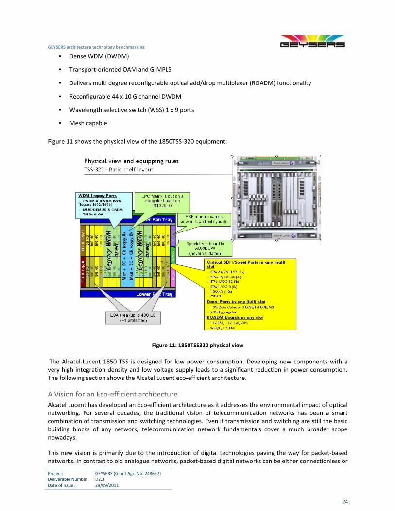
• Dense WDM (DWDM)
• Transport‐oriented OAM and G‐MPLS
• Delivers multi degree reconfigurable optical add/drop multiplexer (ROADM) functionality
• Reconfigurable 44 x 10 G channel DWDM
• Wavelength selective switch (WSS) 1 x 9 ports
• Mesh capable
Figure 11 shows the physical view of the 1850TSS‐320 equipment:
Figure 11: 1850TSS320 physical view
The Alcatel‐Lucent 1850 TSS is designed for low power consumption. Developing new components with a very high integration density and low voltage supply leads to a significant reduction in power consumption. The following section shows the Alcatel Lucent eco‐efficient architecture.
A Vision for an Eco‐efficient architecture
Alcatel Lucent has developed an Eco‐efficient architecture as it addresses the environmental impact of optical networking. For several decades, the traditional vision of telecommunication networks has been a smart combination of transmission and switching technologies. Even if transmission and switching are still the basic building blocks of any network, telecommunication network fundamentals cover a much broader scope nowadays.
This new vision is primarily due to the introduction of digital technologies paving the way for packet‐based networks. In contrast to old analogue networks, packet‐based digital networks can be either connectionless or
GEYSERS architecture technology benchmarking
Project: GEYSERS (Grant Agr. No. 248657) Deliverable Number: D2.3 Date of Issue: 29/09/2011
25
connection‐oriented, have a control plane for the automation of some functions, implement various resilience schemes, but also enhance the power consumption of the network itself.
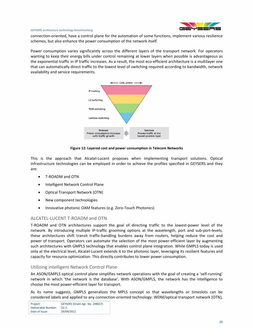
Power consumption varies significantly across the different layers of the transport network. For operators wanting to keep their energy bills under control remaining at lower layers when possible is advantageous as the exponential traffic in IP traffic increases. As a result, the most eco‐efficient architecture is a multilayer one that can automatically direct traffic to the lowest level of switching required according to bandwidth, network availability and service requirements.
Figure 12: Layered cost and power consumption in Telecom Networks
This is the approach that Alcatel‐Lucent proposes when implementing transport solutions. Optical infrastructure technologies can be employed in order to achieve the profiles specified in GEYSERS and they are:
T‐ROADM and OTN
Intelligent Network Control Plane
Optical Transport Network (OTN)
New component technologies
Innovative photonic OAM features (e.g. Zero‐Touch Photonics)
ALCATEL‐LUCENT T‐ROADM and OTN
T‐ROADM and OTN architectures support the goal of directing traffic to the lowest‐power level of the network. By introducing multiple IP‐traffic grooming options at the wavelength, port and sub‐port‐levels, these architectures shift transit traffic‐handling burdens away from routers, helping reduce the cost and power of transport. Operators can automate the selection of the most power‐efficient layer by augmenting such architectures with GMPLS technology that enables control plane integration. While GMPLS today is used only at the electrical level, Alcatel‐Lucent extends it to the photonic layer, leveraging its resilient features and capacity for resource optimization. This directly contributes to lower power consumption.
Utilizing intelligent Network Control Plane
An ASON/GMPLS optical control plane simplifies network operations with the goal of creating a ‘self‐running’ network in which ‘the network is the database’. With ASON/GMPLS, the network has the intelligence to choose the most power‐efficient layer for transport.
As its name suggests, GMPLS generalizes the MPLS concept so that wavelengths or timeslots can be considered labels and applied to any connection‐oriented technology: WDM/optical transport network (OTN),
GEYSERS architecture technology benchmarking
Project: GEYSERS (Grant Agr. No. 248657) Deliverable Number: D2.3 Date of Issue: 29/09/2011
26
SDH/SONET, TDM (T1, E1, T3, E3) and connection‐oriented packet transport technologies. (In ITU‐T G.805 terminology, MPLS labels, wavelengths and timeslots are all link connection identifiers.)
By enabling resilient, automated and power‐efficient networks, GMPLS brings a number of CAPEX and OPEX advantages in addition to eco‐benefits. Specifically, it provides for:
Lower power consumption due to greater cross‐layer intelligence for resource optimization.
Delegation of several OSS processes to the control plane for automation including discovery processes for network topology, resources and services, end‐to‐end connection routing for optimal resource utilization, flow‐through service provisioning, and mesh restoration.
An intelligent restoration mechanism, that boost network reliability and allow network failures and fiber cuts to be accumulated and fixed in batches instead of one at a time as happens today. This allowance for planned network maintenance activities helps to reduce the cost of on‐site maintenance as well as travel‐related CO2 emissions.
Fewer site visits for provisioning.
A smaller footprint due to the use of fewer network elements.
Operators can improve their SLA performance and the quality of their wavelength services with GMPLS provisioning and restoration capabilities at the photonic level.
GMPLS control plane intelligence enables dynamic service provisioning and improves bandwidth monetization through better utilization of network resources. In essence, GMPLS provides the operator with a photonic network that possesses the flexibility, automated operations and resilience typical of digital based networks — along with the ability to forward traffic at the lowest cost per bit without significant limitations.
Utilizing Optical Transport Network (OTN)
OTN provides efficient sub‐wavelength bandwidth management capabilities. Multiple transport options are available for individual management of traffic relations generated in the IP routing layer, which are typically fractions of 10G, 40G or future 100G DWDM line rates and need individual forwarding, operations, monitoring and SLA assurance according to their service mixes and destinations. OTN’s features provide a transport foundation for IP traffic relations on which router ports and even sub‐ports can be mapped to the most optimal transport entity: a wavelength (Optical channel, Och), a fixed‐rate virtual container (Optical Data Unit, ODU) or a variable‐rate virtual container (ODUflex).
Incorporating new component technologies
Building a variety of component technologies into its optical platforms and combining multiple protocols into each individual device. Specific component technologies include:
Lower power cooling fan units
Power‐efficient DC/DC converters and chips
Lower power optical components
Dynamic power and thermal management technologies
Introducing innovative photonic OAM features (e.g. Zero‐Touch Photonics)
The Zero Touch Photonics (ZTP) is a new concept proposed by Alcatel‐Lucent. It consists of OAM features for complete networking capabilities at the photonic layer without requiring on‐site intervention. The chief characteristics of ZTP include:
Photonic switching (T‐ROADM and ROADM architectures: colourless, directionless, multi‐degree)
GEYSERS architecture technology benchmarking
Project: GEYSERS (Grant Agr. No. 248657) Deliverable Number: D2.3 Date of Issue: 29/09/2011
27
Photonic OAM with fault localization and performance monitoring
Photonic design tools for end‐to‐end life cycle management
Photonic restoration via GMPLS
Adaptable optical transport
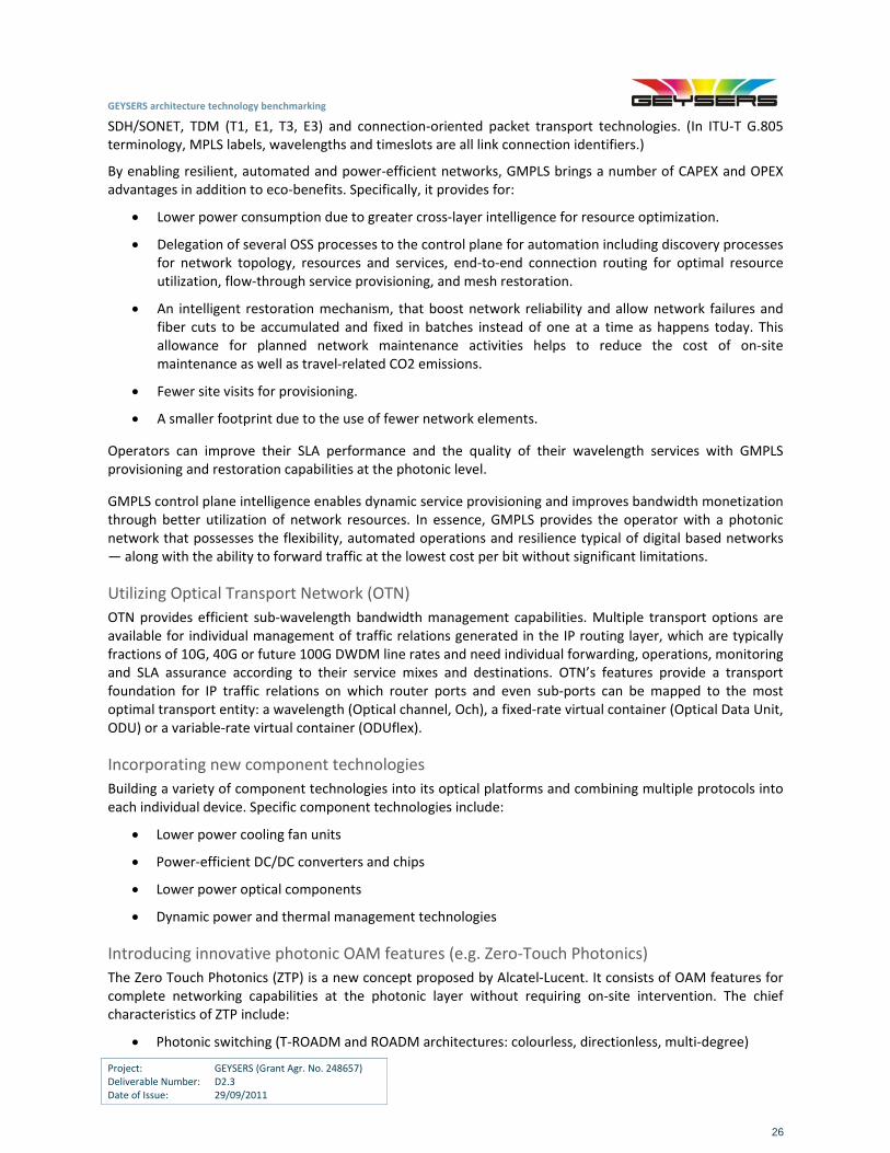
The power figures of the Alcatel 1850 Transport Service Switch, in a full configuration, are described in Table 3:
Table 3: Power figures of the Alcatel 1850 Transport Service Switch
The reference system is a modular packet switch, composed of eight modules 1x10Gigabit Ethernet and seven modules 10x1 Gigabit Ethernet.
By applying eco‐efficient technology improvements such as low power components, low power chips, with dynamic power modulation and lower power cooling fan units, the maximum expected energy improvement is about the 30%.
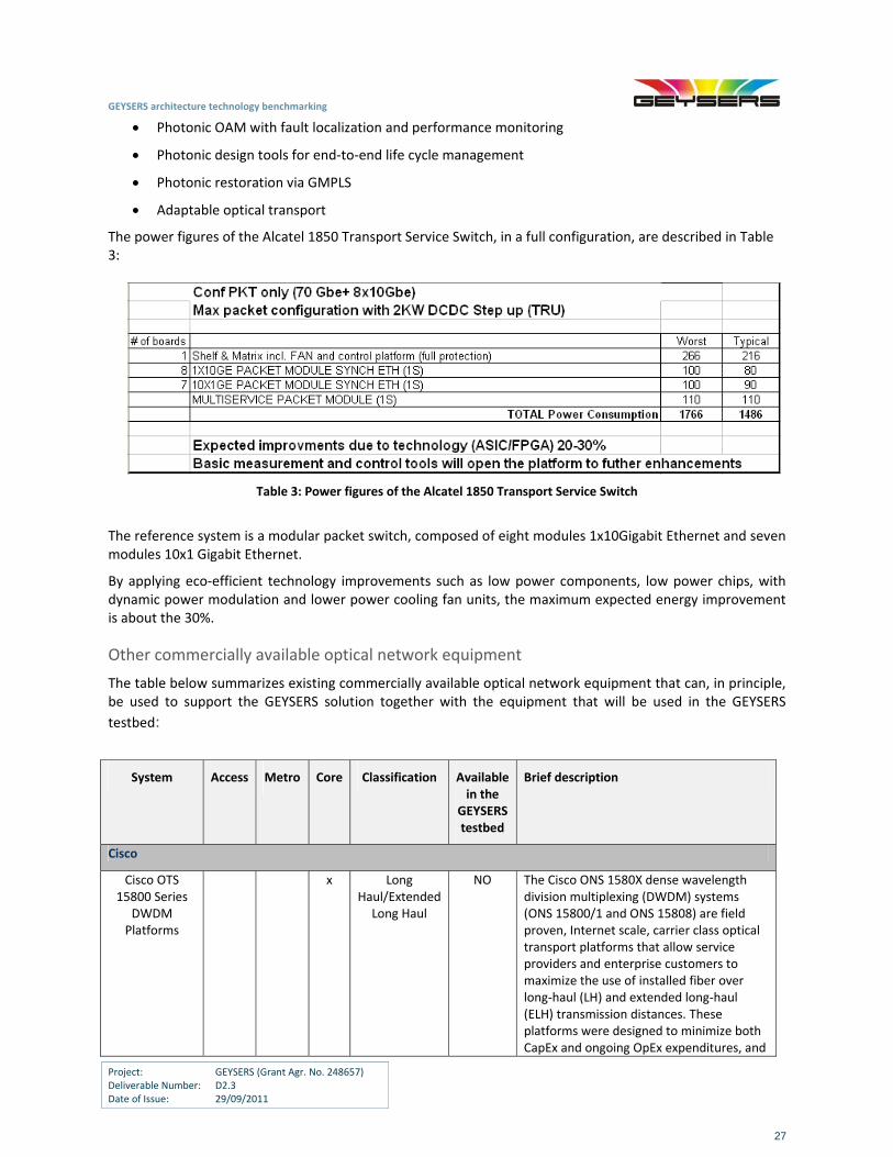
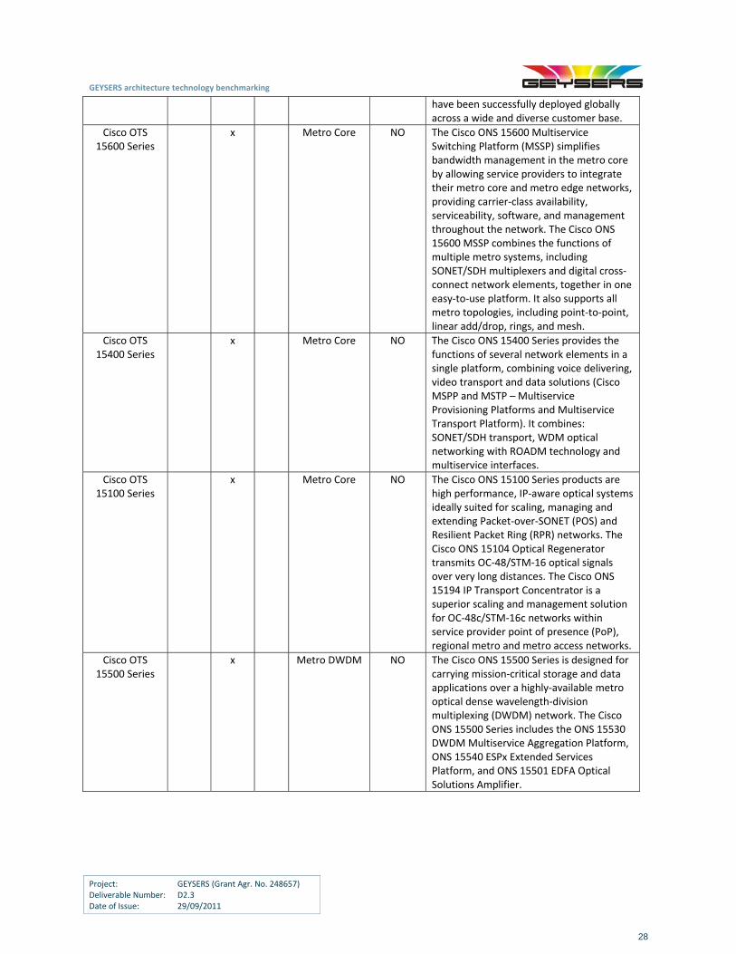
Other commercially available optical network equipment
The table below summarizes existing commercially available optical network equipment that can, in principle, be used to support the GEYSERS solution together with the equipment that will be used in the GEYSERS
testbed:
System Access Metro Core Classification Available in the
GEYSERS testbed
Brief description
Cisco
Cisco OTS 15800 Series
DWDM Platforms
x Long Haul/Extended
Long Haul
NO The Cisco ONS 1580X dense wavelength division multiplexing (DWDM) systems (ONS 15800/1 and ONS 15808) are field proven, Internet scale, carrier class optical transport platforms that allow service providers and enterprise customers to maximize the use of installed fiber over long‐haul (LH) and extended long‐haul (ELH) transmission distances. These platforms were designed to minimize both CapEx and ongoing OpEx expenditures, and
GEYSERS architecture technology benchmarking
Project: GEYSERS (Grant Agr. No. 248657) Deliverable Number: D2.3 Date of Issue: 29/09/2011
28
have been successfully deployed globally across a wide and diverse customer base.
Cisco OTS 15600 Series
x Metro Core NO The Cisco ONS 15600 Multiservice Switching Platform (MSSP) simplifies bandwidth management in the metro core by allowing service providers to integrate their metro core and metro edge networks, providing carrier‐class availability, serviceability, software, and management throughout the network. The Cisco ONS 15600 MSSP combines the functions of multiple metro systems, including SONET/SDH multiplexers and digital cross‐connect network elements, together in one easy‐to‐use platform. It also supports all metro topologies, including point‐to‐point, linear add/drop, rings, and mesh.
Cisco OTS 15400 Series
x Metro Core NO The Cisco ONS 15400 Series provides the functions of several network elements in a single platform, combining voice delivering, video transport and data solutions (Cisco MSPP and MSTP – Multiservice Provisioning Platforms and Multiservice Transport Platform). It combines: SONET/SDH transport, WDM optical networking with ROADM technology and multiservice interfaces.
Cisco OTS 15100 Series
x Metro Core NO The Cisco ONS 15100 Series products are high performance, IP‐aware optical systems ideally suited for scaling, managing and extending Packet‐over‐SONET (POS) and Resilient Packet Ring (RPR) networks. The Cisco ONS 15104 Optical Regenerator transmits OC‐48/STM‐16 optical signals over very long distances. The Cisco ONS 15194 IP Transport Concentrator is a superior scaling and management solution for OC‐48c/STM‐16c networks within service provider point of presence (PoP), regional metro and metro access networks.
Cisco OTS 15500 Series
x Metro DWDM NO The Cisco ONS 15500 Series is designed for carrying mission‐critical storage and data applications over a highly‐available metro optical dense wavelength‐division multiplexing (DWDM) network. The Cisco ONS 15500 Series includes the ONS 15530 DWDM Multiservice Aggregation Platform, ONS 15540 ESPx Extended Services Platform, and ONS 15501 EDFA Optical Solutions Amplifier.
GEYSERS architecture technology benchmarking
Project: GEYSERS (Grant Agr. No. 248657) Deliverable Number: D2.3 Date of Issue: 29/09/2011
29
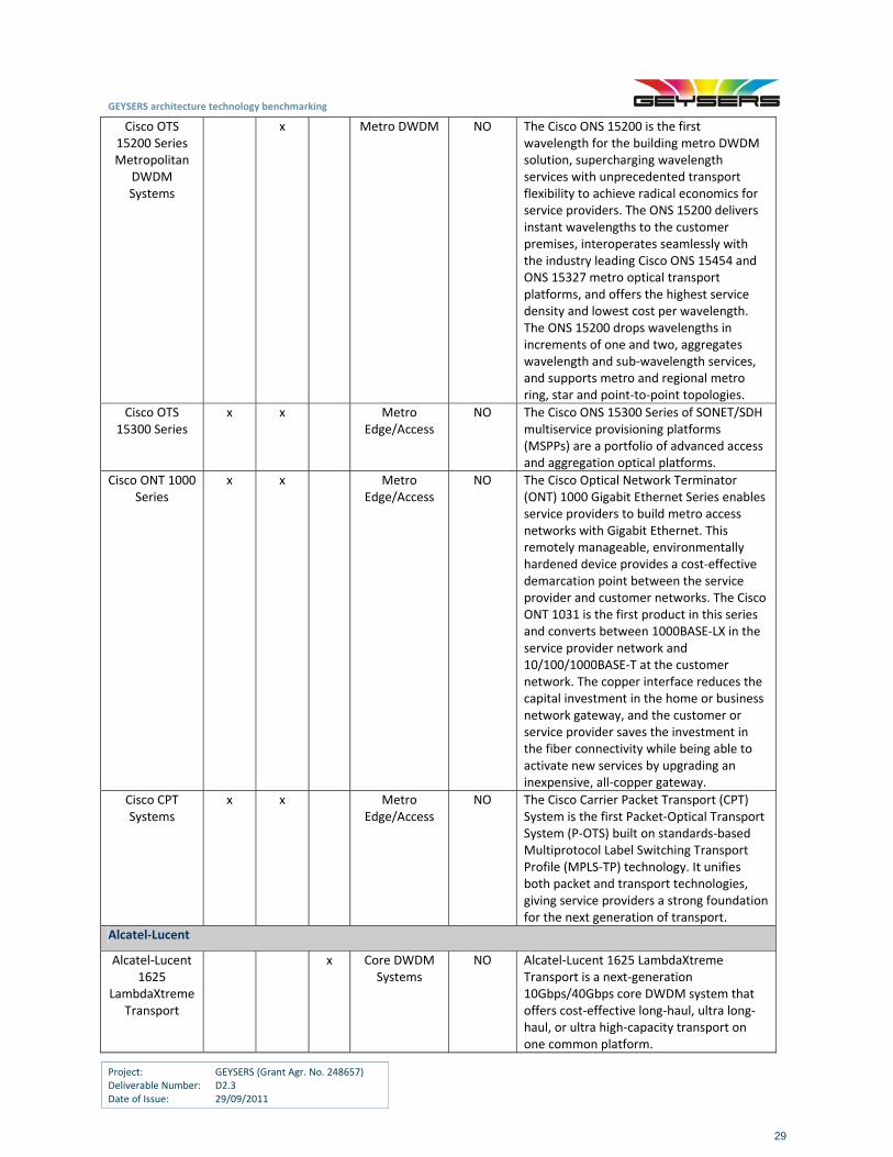
Cisco OTS 15200 Series Metropolitan
DWDM Systems
x Metro DWDM NO The Cisco ONS 15200 is the first wavelength for the building metro DWDM solution, supercharging wavelength services with unprecedented transport flexibility to achieve radical economics for service providers. The ONS 15200 delivers instant wavelengths to the customer premises, interoperates seamlessly with the industry leading Cisco ONS 15454 and ONS 15327 metro optical transport platforms, and offers the highest service density and lowest cost per wavelength. The ONS 15200 drops wavelengths in increments of one and two, aggregates wavelength and sub‐wavelength services, and supports metro and regional metro ring, star and point‐to‐point topologies.
Cisco OTS 15300 Series
x x Metro Edge/Access
NO The Cisco ONS 15300 Series of SONET/SDH multiservice provisioning platforms (MSPPs) are a portfolio of advanced access and aggregation optical platforms.
Cisco ONT 1000 Series
x x Metro Edge/Access
NO The Cisco Optical Network Terminator (ONT) 1000 Gigabit Ethernet Series enables service providers to build metro access networks with Gigabit Ethernet. This remotely manageable, environmentally hardened device provides a cost‐effective demarcation point between the service provider and customer networks. The Cisco ONT 1031 is the first product in this series and converts between 1000BASE‐LX in the service provider network and 10/100/1000BASE‐T at the customer network. The copper interface reduces the capital investment in the home or business network gateway, and the customer or service provider saves the investment in the fiber connectivity while being able to activate new services by upgrading an inexpensive, all‐copper gateway.
Cisco CPT Systems
x x Metro Edge/Access
NO The Cisco Carrier Packet Transport (CPT) System is the first Packet‐Optical Transport System (P‐OTS) built on standards‐based Multiprotocol Label Switching Transport Profile (MPLS‐TP) technology. It unifies both packet and transport technologies, giving service providers a strong foundation for the next generation of transport.
Alcatel‐Lucent
Alcatel‐Lucent 1625
LambdaXtreme Transport
x Core DWDM Systems
NO Alcatel‐Lucent 1625 LambdaXtreme Transport is a next‐generation 10Gbps/40Gbps core DWDM system that offers cost‐effective long‐haul, ultra long‐haul, or ultra high‐capacity transport on one common platform.
GEYSERS architecture technology benchmarking
Project: GEYSERS (Grant Agr. No. 248657) Deliverable Number: D2.3 Date of Issue: 29/09/2011
30
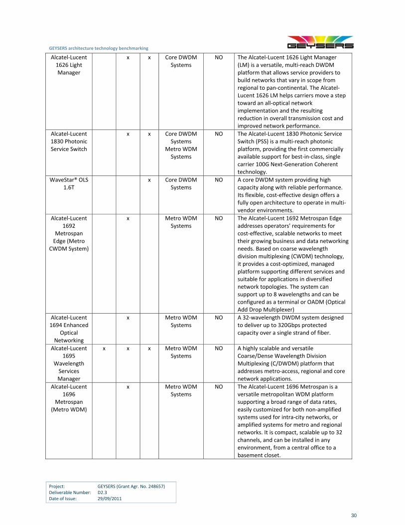
Alcatel‐Lucent 1626 Light Manager
x x Core DWDM Systems
NO The Alcatel‐Lucent 1626 Light Manager (LM) is a versatile, multi‐reach DWDM platform that allows service providers to build networks that vary in scope from regional to pan‐continental. The Alcatel‐Lucent 1626 LM helps carriers move a step toward an all‐optical network implementation and the resulting reduction in overall transmission cost and improved network performance.
Alcatel‐Lucent 1830 Photonic Service Switch
x x Core DWDM Systems
Metro WDM Systems
NO The Alcatel‐Lucent 1830 Photonic Service Switch (PSS) is a multi‐reach photonic platform, providing the first commercially available support for best‐in‐class, single carrier 100G Next‐Generation Coherent technology.
WaveStar® OLS 1.6T
x Core DWDM Systems
NO A core DWDM system providing high capacity along with reliable performance. Its flexible, cost‐effective design offers a fully open architecture to operate in multi‐vendor environments.
Alcatel‐Lucent 1692
Metrospan Edge (Metro
CWDM System)
x Metro WDM Systems
NO The Alcatel‐Lucent 1692 Metrospan Edge addresses operators' requirements for cost‐effective, scalable networks to meet their growing business and data networking needs. Based on coarse wavelength division multiplexing (CWDM) technology, it provides a cost‐optimized, managed platform supporting different services and suitable for applications in diversified network topologies. The system can support up to 8 wavelengths and can be configured as a terminal or OADM (Optical Add Drop Multiplexer)
Alcatel‐Lucent 1694 Enhanced
Optical Networking
x Metro WDM Systems
NO A 32‐wavelength DWDM system designed to deliver up to 320Gbps protected capacity over a single strand of fiber.
Alcatel‐Lucent 1695
Wavelength Services Manager
x x x Metro WDM Systems
NO A highly scalable and versatile Coarse/Dense Wavelength Division Multiplexing (C/DWDM) platform that addresses metro‐access, regional and core network applications.
Alcatel‐Lucent 1696
Metrospan (Metro WDM)
x Metro WDM Systems
NO The Alcatel‐Lucent 1696 Metrospan is a versatile metropolitan WDM platform supporting a broad range of data rates, easily customized for both non‐amplified systems used for intra‐city networks, or amplified systems for metro and regional networks. It is compact, scalable up to 32 channels, and can be installed in any environment, from a central office to a basement closet.
GEYSERS architecture technology benchmarking
Project: GEYSERS (Grant Agr. No. 248657) Deliverable Number: D2.3 Date of Issue: 29/09/2011
31
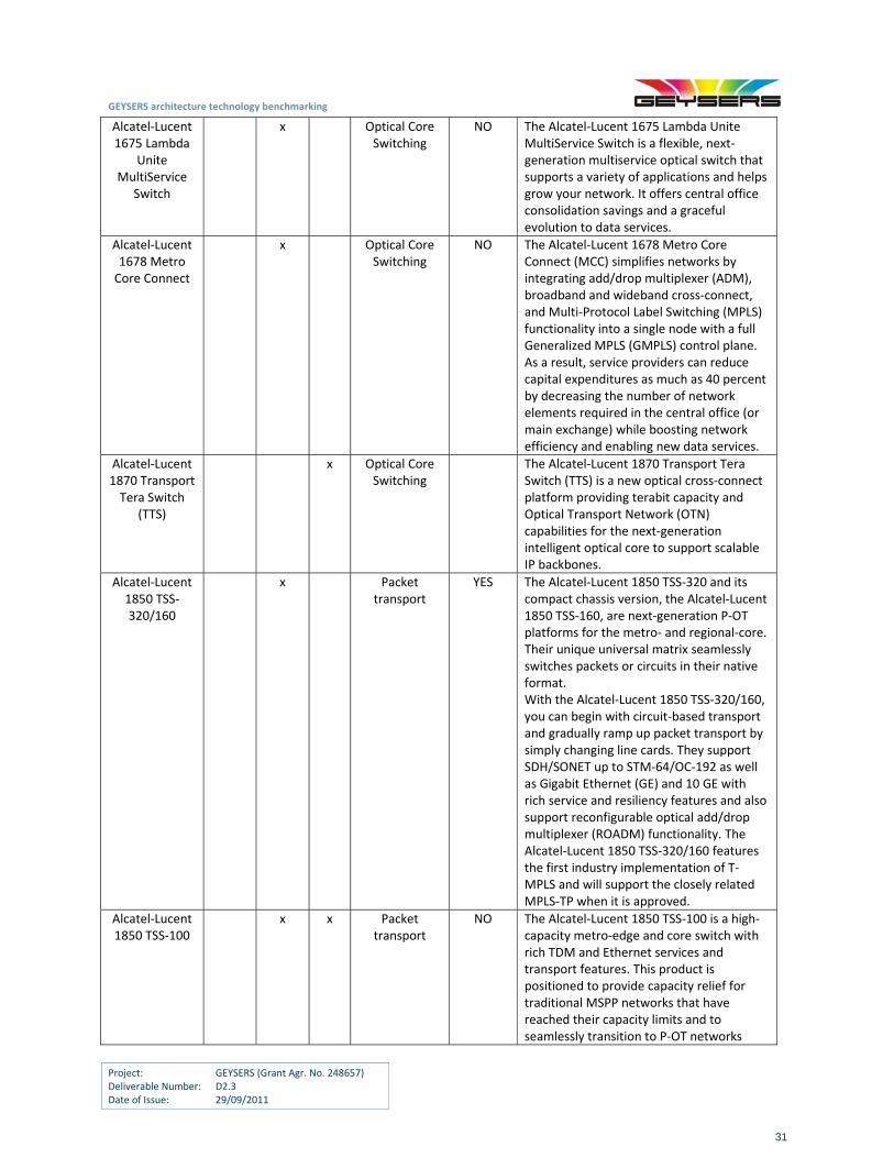
Alcatel‐Lucent 1675 Lambda
Unite MultiService
Switch
x Optical Core Switching
NO The Alcatel‐Lucent 1675 Lambda Unite MultiService Switch is a flexible, next‐generation multiservice optical switch that supports a variety of applications and helps grow your network. It offers central office consolidation savings and a graceful evolution to data services.
Alcatel‐Lucent 1678 Metro Core Connect
x Optical Core Switching
NO The Alcatel‐Lucent 1678 Metro Core Connect (MCC) simplifies networks by integrating add/drop multiplexer (ADM), broadband and wideband cross‐connect, and Multi‐Protocol Label Switching (MPLS) functionality into a single node with a full Generalized MPLS (GMPLS) control plane. As a result, service providers can reduce capital expenditures as much as 40 percent by decreasing the number of network elements required in the central office (or main exchange) while boosting network efficiency and enabling new data services.
Alcatel‐Lucent 1870 Transport Tera Switch
(TTS)
x Optical Core Switching
The Alcatel‐Lucent 1870 Transport Tera Switch (TTS) is a new optical cross‐connect platform providing terabit capacity and Optical Transport Network (OTN) capabilities for the next‐generation intelligent optical core to support scalable IP backbones.
Alcatel‐Lucent 1850 TSS‐320/160
x Packet transport
YES The Alcatel‐Lucent 1850 TSS‐320 and its compact chassis version, the Alcatel‐Lucent 1850 TSS‐160, are next‐generation P‐OT platforms for the metro‐ and regional‐core. Their unique universal matrix seamlessly switches packets or circuits in their native format. With the Alcatel‐Lucent 1850 TSS‐320/160, you can begin with circuit‐based transport and gradually ramp up packet transport by simply changing line cards. They support SDH/SONET up to STM‐64/OC‐192 as well as Gigabit Ethernet (GE) and 10 GE with rich service and resiliency features and also support reconfigurable optical add/drop multiplexer (ROADM) functionality. The Alcatel‐Lucent 1850 TSS‐320/160 features the first industry implementation of T‐MPLS and will support the closely related MPLS‐TP when it is approved.
Alcatel‐Lucent 1850 TSS‐100
x x Packet transport
NO The Alcatel‐Lucent 1850 TSS‐100 is a high‐capacity metro‐edge and core switch with rich TDM and Ethernet services and transport features. This product is positioned to provide capacity relief for traditional MSPP networks that have reached their capacity limits and to seamlessly transition to P‐OT networks
GEYSERS architecture technology benchmarking
Project: GEYSERS (Grant Agr. No. 248657) Deliverable Number: D2.3 Date of Issue: 29/09/2011
32
Alcatel‐Lucent 1850 TSS‐40
x x Packet transport
NO The Alcatel‐Lucent 1850 TSS‐40 supports circuit and packet services over STM16/64 rings using MPLS‐based traffic‐management mechanisms to support multiple QoS levels. This product enables carrier‐class service provisioning and resilience and supports multilayer OAM. It delivers sub‐50 ms ring protection for high service availability and end‐to‐end SLA guarantees over multi‐ring metro‐access architectures.
Alcatel‐Lucent 1850 TSS‐5
x Packet transport
NO The Alcatel‐Lucent 1850 TSS‐5 transports any service over any transport: TDM and Ethernet services are supported over SDH/SONET transport as well as over Ethernet transport. For mobile backhaul, the Alcatel‐Lucent 1850 TSS‐5 provides a single platform that gracefully transitions from SDH/SONET to Ethernet transport. It can be configured for SDH/SONET transport for native TDM and Ethernet over SDH/SONET services. As packet traffic grows with the deployment of Ethernet‐enabled 3G and 4G base stations, the 1850 TSS‐5 can be reconfigured for Ethernet transport for native Ethernet and can support legacy T1/E1 via circuit emulation service (CES).
Alcatel‐Lucent 1850 TSS‐3
x Packet transport
NO A carrier‐grade network termination unit (NTU), the Alcatel‐Lucent 1850 TSS‐3 provides intelligent Ethernet service demarcation between the end customer and the service provider, going beyond simple media conversion and physical presence. It provides a rich mix of connectivity and network services, offering diagnostics, service monitoring, protection, QoS, rate limiting and virtual local area network (VLAN) stacking for Metro Ethernet Forum (MEF)‐compliant Ethernet services. The Alcatel‐Lucent 1850 TSS‐3 serves locations with either fiber access or PDH services.
ADVA
ADVA FSP 3000 x x Optical Transport
YES The FSP 3000 is a scalable WDM transport solution specifically designed for service providers and large enterprises looking for flexibility and cost‐efficiency in multiplexing, transporting and protecting high‐speed data, storage and video applications. The FSP 3000 facilitates bandwidth scale and service in access, backhaul, metro and long‐haul networks, while supporting the creation of new revenue opportunities for high‐speed OTN,
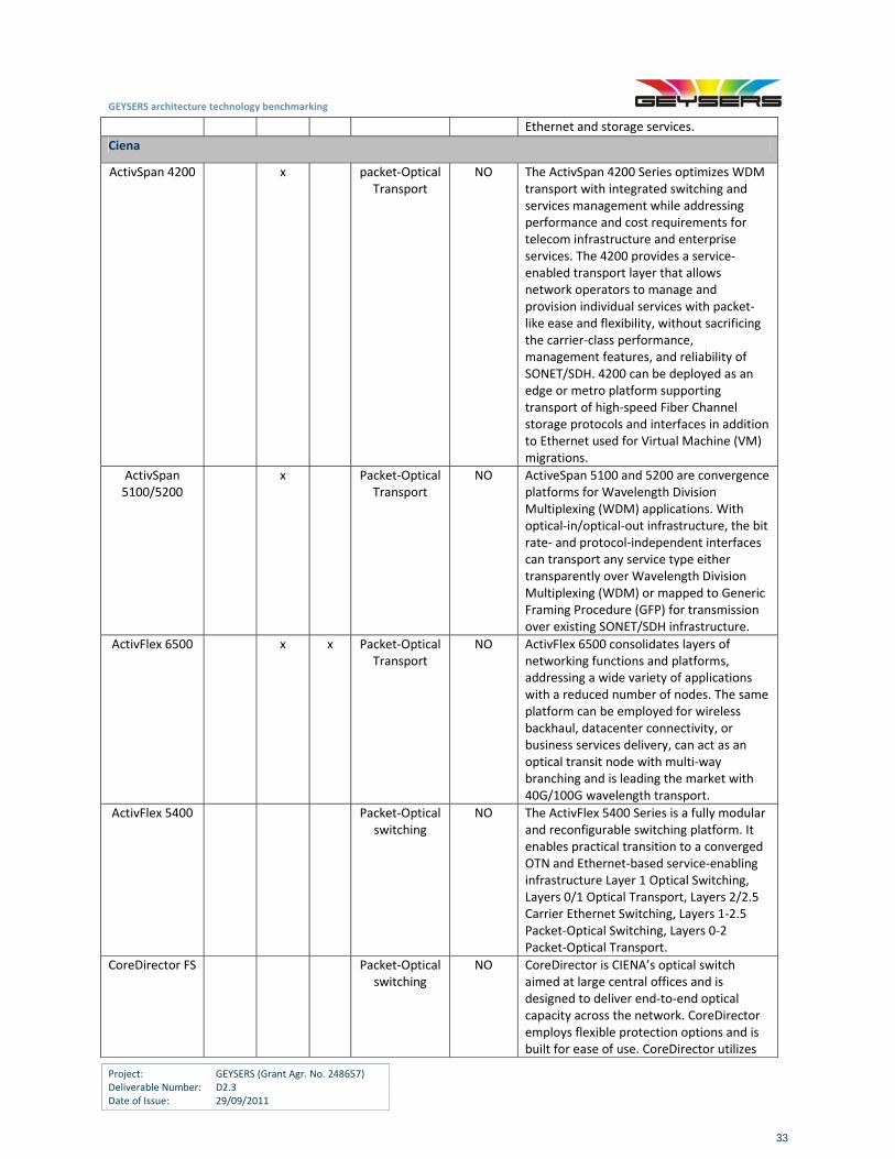
GEYSERS architecture technology benchmarking
Project: GEYSERS (Grant Agr. No. 248657) Deliverable Number: D2.3 Date of Issue: 29/09/2011
33
Ethernet and storage services.
Ciena
ActivSpan 4200 x packet‐Optical Transport
NO The ActivSpan 4200 Series optimizes WDM transport with integrated switching and services management while addressing performance and cost requirements for telecom infrastructure and enterprise services. The 4200 provides a service‐enabled transport layer that allows network operators to manage and provision individual services with packet‐like ease and flexibility, without sacrificing the carrier‐class performance, management features, and reliability of SONET/SDH. 4200 can be deployed as an edge or metro platform supporting transport of high‐speed Fiber Channel storage protocols and interfaces in addition to Ethernet used for Virtual Machine (VM) migrations.
ActivSpan 5100/5200
x Packet‐Optical Transport
NO ActiveSpan 5100 and 5200 are convergence platforms for Wavelength Division Multiplexing (WDM) applications. With optical‐in/optical‐out infrastructure, the bit rate‐ and protocol‐independent interfaces can transport any service type either transparently over Wavelength Division Multiplexing (WDM) or mapped to Generic Framing Procedure (GFP) for transmission over existing SONET/SDH infrastructure.
ActivFlex 6500 x x Packet‐Optical Transport
NO ActivFlex 6500 consolidates layers of networking functions and platforms, addressing a wide variety of applications with a reduced number of nodes. The same platform can be employed for wireless backhaul, datacenter connectivity, or business services delivery, can act as an optical transit node with multi‐way branching and is leading the market with 40G/100G wavelength transport.
ActivFlex 5400 Packet‐Optical switching
NO The ActivFlex 5400 Series is a fully modular and reconfigurable switching platform. It enables practical transition to a converged OTN and Ethernet‐based service‐enabling infrastructure Layer 1 Optical Switching, Layers 0/1 Optical Transport, Layers 2/2.5 Carrier Ethernet Switching, Layers 1‐2.5 Packet‐Optical Switching, Layers 0‐2 Packet‐Optical Transport.
CoreDirector FS Packet‐Optical switching
NO CoreDirector is CIENA’s optical switch aimed at large central offices and is designed to deliver end‐to‐end optical capacity across the network. CoreDirector employs flexible protection options and is built for ease of use. CoreDirector utilizes
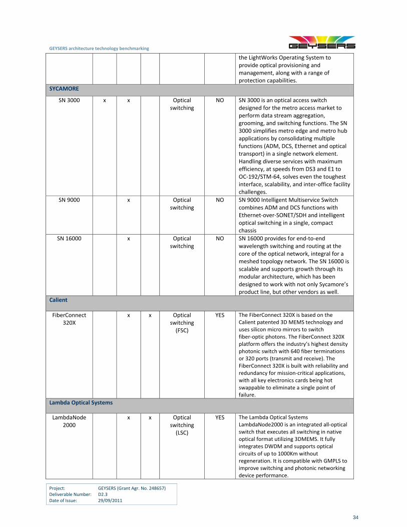
GEYSERS architecture technology benchmarking
Project: GEYSERS (Grant Agr. No. 248657) Deliverable Number: D2.3 Date of Issue: 29/09/2011
34
the LightWorks Operating System to provide optical provisioning and management, along with a range of protection capabilities.
SYCAMORE
SN 3000 x x Optical switching
NO SN 3000 is an optical access switch designed for the metro access market to perform data stream aggregation, grooming, and switching functions. The SN 3000 simplifies metro edge and metro hub applications by consolidating multiple functions (ADM, DCS, Ethernet and optical transport) in a single network element. Handling diverse services with maximum efficiency, at speeds from DS3 and E1 to OC‐192/STM‐64, solves even the toughest interface, scalability, and inter‐office facility challenges.
SN 9000 x Optical switching
NO SN 9000 Intelligent Multiservice Switch combines ADM and DCS functions with Ethernet‐over‐SONET/SDH and intelligent optical switching in a single, compact chassis
SN 16000 x Optical switching
NO SN 16000 provides for end‐to‐end wavelength switching and routing at the core of the optical network, integral for a meshed topology network. The SN 16000 is scalable and supports growth through its modular architecture, which has been designed to work with not only Sycamore’s product line, but other vendors as well.
Calient
FiberConnect 320X
x x Optical switching (FSC)
YES The FiberConnect 320X is based on the Calient patented 3D MEMS technology and uses silicon micro mirrors to switch fiber‐optic photons. The FiberConnect 320X platform offers the industry’s highest density photonic switch with 640 fiber terminations or 320 ports (transmit and receive). The FiberConnect 320X is built with reliability and redundancy for mission‐critical applications, with all key electronics cards being hot swappable to eliminate a single point of failure.
Lambda Optical Systems
LambdaNode 2000
x x Optical switching (LSC)
YES The Lambda Optical Systems LambdaNode2000 is an integrated all‐optical switch that executes all switching in native optical format utilizing 3DMEMS. It fully integrates DWDM and supports optical circuits of up to 1000Km without regeneration. It is compatible with GMPLS to improve switching and photonic networking device performance.
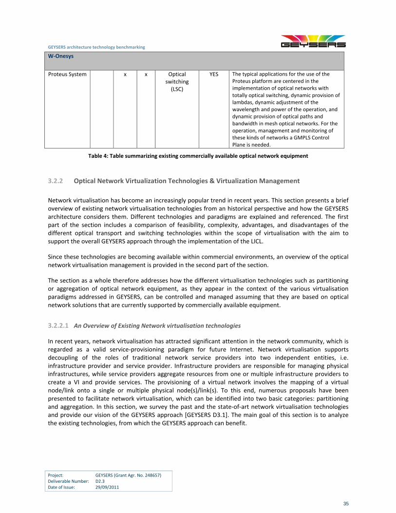
GEYSERS architecture technology benchmarking
Project: GEYSERS (Grant Agr. No. 248657) Deliverable Number: D2.3 Date of Issue: 29/09/2011
35
W‐Onesys
Proteus System x x Optical switching (LSC)
YES The typical applications for the use of the Proteus platform are centered in the implementation of optical networks with totally optical switching, dynamic provision of lambdas, dynamic adjustment of the wavelength and power of the operation, and dynamic provision of optical paths and bandwidth in mesh optical networks. For the operation, management and monitoring of these kinds of networks a GMPLS Control Plane is needed.
Table 4: Table summarizing existing commercially available optical network equipment
3.2.2 Optical Network Virtualization Technologies & Virtualization Management
Network virtualisation has become an increasingly popular trend in recent years. This section presents a brief overview of existing network virtualisation technologies from an historical perspective and how the GEYSERS architecture considers them. Different technologies and paradigms are explained and referenced. The first part of the section includes a comparison of feasibility, complexity, advantages, and disadvantages of the different optical transport and switching technologies within the scope of virtualisation with the aim to support the overall GEYSERS approach through the implementation of the LICL.
Since these technologies are becoming available within commercial environments, an overview of the optical network virtualisation management is provided in the second part of the section.
The section as a whole therefore addresses how the different virtualisation technologies such as partitioning or aggregation of optical network equipment, as they appear in the context of the various virtualisation paradigms addressed in GEYSERS, can be controlled and managed assuming that they are based on optical network solutions that are currently supported by commercially available equipment.
3.2.2.1 An Overview of Existing Network virtualisation technologies
In recent years, network virtualisation has attracted significant attention in the network community, which is regarded as a valid service‐provisioning paradigm for future Internet. Network virtualisation supports decoupling of the roles of traditional network service providers into two independent entities, i.e. infrastructure provider and service provider. Infrastructure providers are responsible for managing physical infrastructures, while service providers aggregate resources from one or multiple infrastructure providers to create a VI and provide services. The provisioning of a virtual network involves the mapping of a virtual node/link onto a single or multiple physical node(s)/link(s). To this end, numerous proposals have been presented to facilitate network virtualisation, which can be identified into two basic categories: partitioning and aggregation. In this section, we survey the past and the state‐of‐art network virtualisation technologies and provide our vision of the GEYSERS approach [GEYSERS D3.1]. The main goal of this section is to analyze the existing technologies, from which the GEYSERS approach can benefit.
GEYSERS architecture technology benchmarking
Project: GEYSERS (Grant Agr. No. 248657) Deliverable Number: D2.3 Date of Issue: 29/09/2011
36
3.2.2.2 Network Virtualisation Paradigms
Historical perspective
The concept of virtual networks appears in the literature in various forms, such as Virtual Local Area Network (VLAN), Virtual Private Networks (VPN), Active and Programmable Networks and Overlay Networks [Mosharaf09].
VLAN and VPN
A VLAN is a group of logically interconnected hosts regardless of the physical connectivity. The VLAN services provide a certain level of isolation from physical layer. A VPN uses dedicated and secured tunnels to connect multiple sites over packet‐switching networks, e.g. Internet, or circuit switching networks, e.g. Carrier Ethernet and Optical networks.
Active and Programmable Networks
While the VLAN and VPN approaches are relatively static, the need for flexible creation, deployment and management of virtual resources has motivated the emergence of active and programmable networks. The concept of isolation is further enhanced by the research on such network virtualisation environments. It allows multiple parties to run virtual nodes over the same physical nodes without conflicts, i.e. partitioning physical resources. In addition, it also allows a physical infrastructure provider to group multiple physical nodes for a virtual node, i.e. aggregating physical resources. In the category of active and programmable networks, a logical layer is commonly created and managed independently from the physical layer, with well‐defined programming interfaces.
Overlay Networks
An overlay network is commonly built on top of the Internet in the application layer. It has been used as an easy and cost efficient solution to deploy new features and provide new services with shared network resources. It is widely used in file sharing applications. Overlay networks have also been used to design and evaluate new architectures, such as the PlanetLab testbed [PlanetLab]. It shall be noted that the implementation of overlay networks in lower layer (layer below IP) do exist in the literature, however, it is more commonly built on IP networks.
3.2.2.3 GEYSERS perspective
GEYSERS network virtualisation falls into the category of active and programmable networks. A Logical Infrastructure Composition Layer is deployed on top of physical infrastructures to facilitate the composition of on‐demand logical networks from single or multiple physical infrastructure providers. The GEYSERS approach decouples the role of traditional network service provider into three entities, referred to as Physical Infrastructure Provider (PIP), Virtual Infrastructure Provider (VIP) and Virtual Infrastructure Operator (VIO), with primary focus on optical resources. The new business model introduced in GEYSERS promotes the benefits of the network virtualisation with regard to the improvement of the utilization of the physical substrates [GEYSERS D3.1].
3.2.2.4 Overview of Network Virtualisation technologies
To this end, network virtualisation technologies can be classified into two categories, namely, partitioning and aggregation. Partitioning refers to the technologies that enable multiple VIs to share the same physical substrate. A simple example is to represent a wavelength into multiple virtual circuits with sub‐wavelength granularities. On the other hand, aggregation refers to the technologies that represent multiple physical
GEYSERS architecture technology benchmarking
Project: GEYSERS (Grant Agr. No. 248657) Deliverable Number: D2.3 Date of Issue: 29/09/2011
37
resources as a single virtual entity, for instance, multiple optical switches with fiber connections can be represent as a single virtual node. These two categories, i.e. partitioning and aggregation, for network virtualisation are also known as 1:N Partitioning and N:1 Aggregation, respectively. Various combinations of these two categories have also been studied in the literature, for example, 1:1 Abstraction is a special case of both virtualisation types which simply abstracts the physical resource as a virtual resource. In the following section, the two main virtualisation technology categories will be explained in detail and a summary of the various technologies will also be presented to show how GEYSERS benefits from these existing technologies.
Partitioning (1:N)
Network resource partitioning has been studied in the literature as a way to improve physical resource utilization. Of note is the Virtual Concatenation (VCAT) protocol in SONET/SDH networks, which is also known as inverse multiplexing. Logical containers with different line rates are defined to divide an optical channel into multiple smaller virtual circuits. Recent researches in the networking community such as GENI [GENI], have focused on allocating different slices of resources across the network for multiple isolated experiments simultaneously. A slice may consist of some optical links, programmable routers and computers. To date, most partitioning approaches use software components to emulate networking functionalities. The early VINI prototype [VINI] uses commodity computers to emulate programmable routers and relies on IP tunnels for link virtualisation, whereas the Openflow architecture [Openflow] utilizes commercial hardware switch/router solutions to partition a physical link into multiple small tunnels with flow switching capability. Such virtualisation methods need a complicated link scheduling algorithm (e.g. virtual clock/WFQ), and accordingly, result in a limited capability of traffic separation. To facilitate the link partitioning, a novel programmable router interface structure, i.e. optical OFDMA interface, is proposed in [Wei09], which utilizes advanced Digital Signal Processing (DSP) technologies for supporting virtual links with programmable bandwidth allocation.
Aggregation (N:1)
Resource aggregation in network virtualisation is enabled by enhancements in software/hardware and
protocol development. Of note are the large‐scale Photonic Integrated Circuit (PIC) technologies, which
enable a single virtual node representing dozens to hundreds of optical components, such as lasers,
modulators, detectors, attenuators, multiplexers/de‐multiplexers, and optical amplifiers into a single device
[Melle08]. With the support of a Digital Virtual Concatenation (DVC) protocol, PIC technologies can enable the
aggregated optical resources to act as a device which is conceptually very similar to an electronic IC
[Nagarajan05]. To this end, PIC technologies can aggregate data rates up to 1.6Tb/s per virtual device
[Melle08].
The Optical Transport Network (OTN) architecture specified in ITU‐T G.709 has defined an optimum hierarchy
to transport a variety of client signals over optical networks. The built‐in Virtual Concatenate (VCAT) feature
has inspired studies on bandwidth virtualisation in OTN/WDM networks with a focus on bandwidth
aggregation, in order to support a virtual tunnel with a line rate higher than the capacity of a wavelength.
Multiple Lane Distribution (MLD) has been proposed in IEEE 802.3ba 40/100GE TF that is compatible with OTN
technologies, which strips high speed Ethernet signals into multiple Lanes [IEEE802.3]. Bandwidth aggregation
is becoming a valid paradigm in the network virtualisation with support from PIC technologies and DVC
protocol.
Virtualisation Granularities
Either partitioning or aggregation can be applied to different layers in a network, which enables a flexible
network virtualisation with various granularities. In optical networks, virtualisation granularities include
wavelength, sub‐wavelength and a group of wavelengths. We hereby summarize the virtualisation
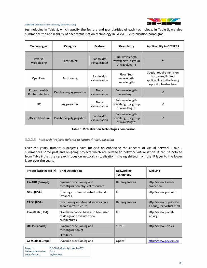
GEYSERS architecture technology benchmarking
Project: GEYSERS (Grant Agr. No. 248657) Deliverable Number: D2.3 Date of Issue: 29/09/2011
38
technologies in Table 5, which specify the feature and granularities of each technology. In Table 5, we also
summarize the applicability of each virtualisation technology in GEYSERS virtualisation paradigms.
Technologies Category Feature Granularity Applicability in GEYSERS
Inverse Multiplexing
Partitioning Bandwidth virtualisation
Sub‐wavelength, wavelength, a group
of wavelengths √
OpenFlow Partitioning Bandwidth virtualisation
Flow (Sub‐wavelength, wavelength)
Special requirements on hardware, limited
applicability to the legacy optical infrastructure
Programmable Router Interface
Partitioning/aggregation Node
virtualisation Sub‐wavelength,
wavelength √
PIC Aggregation Node
virtualisation
Sub‐wavelength, wavelength, a group
of wavelengths √
OTN architecture Partitioning/AggregationBandwidth virtualisation
Sub‐wavelength, wavelength, a group
of wavelengths √
Table 5: Virtualization Technologies Comparison
3.2.2.5 Research Projects Related to Network Virtualisation
Over the years, numerous projects have focused on enhancing the concept of virtual network. Table 6 summarizes some past and on‐going projects which are related to network virtualisation. It can be noticed from Table 6 that the research focus on network virtualisation is being shifted from the IP layer to the lower layer over the years.
Project (Originated in) Brief Description Networking Technology
WebLink
4WARD (Europe) Dynamic provisioning and reconfiguration physical resources
Heterogeneous http://www.4ward‐project.eu
GENI (USA) Creating customized virtual network instances
IP http://www.geni.net
CABO (USA) Provisioning end‐to‐end services on a shared infrastructure
Heterogeneous http://www.cs.princeton.edu/_jrex/virtual.html
PlanetLab (USA) Overlay networks have also been used to design and evaluate new architectures
IP http://www.planet‐lab.org
UCLP (Canada) Dynamic provisioning and reconfiguration of
lightpaths
SONET http://www.uclp.ca
GEYSERS (Europe) Dynamic provisioning and Optical http://www.geysers.eu
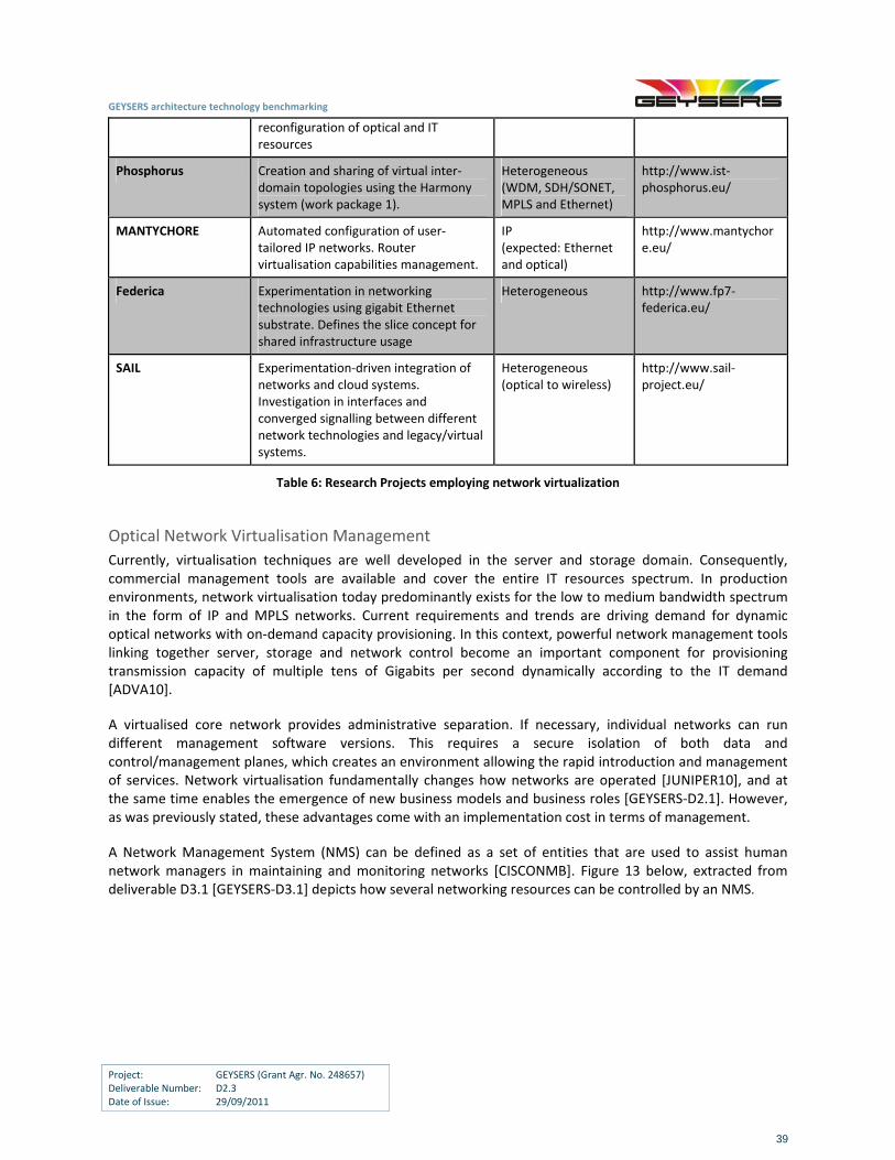
GEYSERS architecture technology benchmarking
Project: GEYSERS (Grant Agr. No. 248657) Deliverable Number: D2.3 Date of Issue: 29/09/2011
39
reconfiguration of optical and IT resources
Phosphorus Creation and sharing of virtual inter‐domain topologies using the Harmony system (work package 1).
Heterogeneous (WDM, SDH/SONET, MPLS and Ethernet)
http://www.ist‐phosphorus.eu/
MANTYCHORE Automated configuration of user‐tailored IP networks. Router virtualisation capabilities management.
IP (expected: Ethernet and optical)
http://www.mantychore.eu/
Federica Experimentation in networking technologies using gigabit Ethernet substrate. Defines the slice concept for shared infrastructure usage
Heterogeneous http://www.fp7‐federica.eu/
SAIL Experimentation‐driven integration of networks and cloud systems. Investigation in interfaces and converged signalling between different network technologies and legacy/virtual systems.
Heterogeneous (optical to wireless)
http://www.sail‐project.eu/
Table 6: Research Projects employing network virtualization
Optical Network Virtualisation Management
Currently, virtualisation techniques are well developed in the server and storage domain. Consequently, commercial management tools are available and cover the entire IT resources spectrum. In production environments, network virtualisation today predominantly exists for the low to medium bandwidth spectrum in the form of IP and MPLS networks. Current requirements and trends are driving demand for dynamic optical networks with on‐demand capacity provisioning. In this context, powerful network management tools linking together server, storage and network control become an important component for provisioning transmission capacity of multiple tens of Gigabits per second dynamically according to the IT demand [ADVA10].
A virtualised core network provides administrative separation. If necessary, individual networks can run different management software versions. This requires a secure isolation of both data and control/management planes, which creates an environment allowing the rapid introduction and management of services. Network virtualisation fundamentally changes how networks are operated [JUNIPER10], and at the same time enables the emergence of new business models and business roles [GEYSERS‐D2.1]. However, as was previously stated, these advantages come with an implementation cost in terms of management.
A Network Management System (NMS) can be defined as a set of entities that are used to assist human network managers in maintaining and monitoring networks [CISCONMB]. Figure 13 below, extracted from deliverable D3.1 [GEYSERS‐D3.1] depicts how several networking resources can be controlled by an NMS.
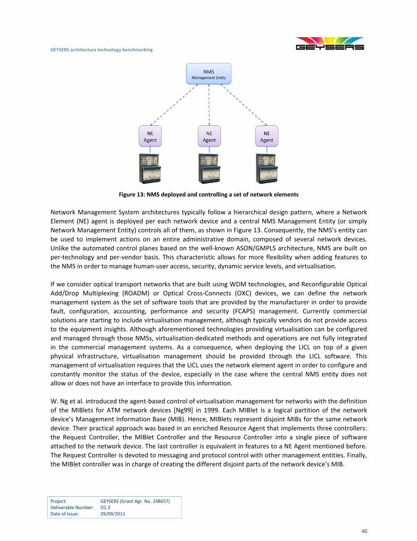
GEYSERS architecture technology benchmarking
Project: GEYSERS (Grant Agr. No. 248657) Deliverable Number: D2.3 Date of Issue: 29/09/2011
40
Figure 13: NMS deployed and controlling a set of network elements
Network Management System architectures typically follow a hierarchical design pattern, where a Network
Element (NE) agent is deployed per each network device and a central NMS Management Entity (or simply
Network Management Entity) controls all of them, as shown in Figure 13. Consequently, the NMS’s entity can
be used to implement actions on an entire administrative domain, composed of several network devices.
Unlike the automated control planes based on the well‐known ASON/GMPLS architecture, NMS are built on
per‐technology and per‐vendor basis. This characteristic allows for more flexibility when adding features to
the NMS in order to manage human‐user access, security, dynamic service levels, and virtualisation.
If we consider optical transport networks that are built using WDM technologies, and Reconfigurable Optical
Add/Drop Multiplexing (ROADM) or Optical Cross‐Connects (OXC) devices, we can define the network
management system as the set of software tools that are provided by the manufacturer in order to provide
fault, configuration, accounting, performance and security (FCAPS) management. Currently commercial
solutions are starting to include virtualisation management, although typically vendors do not provide access
to the equipment insights. Although aforementioned technologies providing virtualisation can be configured
and managed through those NMSs, virtualisation‐dedicated methods and operations are not fully integrated
in the commercial management systems. As a consequence, when deploying the LICL on top of a given
physical infrastructure, virtualisation management should be provided through the LICL software. This
management of virtualisation requires that the LICL uses the network element agent in order to configure and
constantly monitor the status of the device, especially in the case where the central NMS entity does not
allow or does not have an interface to provide this information.
W. Ng et al. introduced the agent‐based control of virtualisation management for networks with the definition
of the MIBlets for ATM network devices [Ng99] in 1999. Each MIBlet is a logical partition of the network
device’s Management Information Base (MIB). Hence, MIBlets represent disjoint MIBs for the same network
device. Their practical approach was based in an enriched Resource Agent that implements three controllers:
the Request Controller, the MIBlet Controller and the Resource Controller into a single piece of software
attached to the network device. The last controller is equivalent in features to a NE Agent mentioned before.
The Request Controller is devoted to messaging and protocol control with other management entities. Finally,
the MIBlet controller was in charge of creating the different disjoint parts of the network device’s MIB.
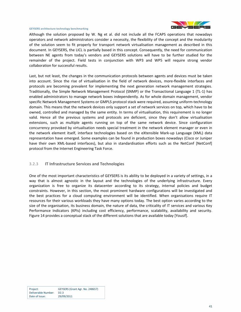
GEYSERS architecture technology benchmarking
Project: GEYSERS (Grant Agr. No. 248657) Deliverable Number: D2.3 Date of Issue: 29/09/2011
41
Although the solution proposed by W. Ng et al. did not include all the FCAPS operations that nowadays
operators and network administrators consider a necessity, the flexibility of the concept and the modularity
of the solution seem to fit properly for transport network virtualisation management as described in this
document. In GEYSERS, the LICL is partially based in this concept. Consequently, the need for communication
between NE agents from today’s vendors and GEYSERS solutions will have to be further studied for the
remainder of the project. Field tests in conjunction with WP3 and WP5 will require strong vendor
collaboration for successful results.
Last, but not least, the changes in the communication protocols between agents and devices must be taken
into account. Since the rise of virtualisation in the field of network devices, more‐flexible interfaces and
protocols are becoming prevalent for implementing the next generation network management strategies.
Traditionally, the Simple Network Management Protocol (SNMP) or the Transactional Language 1 (TL‐1) has
enabled administrators to manage network boxes independently. As for whole domain management, vendor
specific Network Management Systems or GMPLS protocol stack were required, assuming uniform‐technology
domain. This means that the network devices only support a set of network services on top, which have to be
owned, controlled and managed by the same entity. In terms of virtualisation, this requirement is no longer
valid. Hence all the previous systems and protocols are deficient, since they don’t allow virtualisation
extensions, such as multiple agents running on top of the same network device. Since configuration
concurrency provoked by virtualisation needs special treatment in the network element manager or even in
the network element itself, interface technologies based on the eXtensible Mark‐up Language (XML) data
representation have emerged. Some examples can be found in production boxes nowadays (Cisco or Juniper
have their own XML‐based interfaces), but also in standardisation efforts such as the NetConf [NetConf]
protocol from the Internet Engineering Task Force.
3.2.3 IT Infrastructure Services and Technologies
One of the most important characteristics of GEYSERS is its ability to be deployed in a variety of settings, in a way that is almost agnostic in the layout and the technologies of the underlying infrastructure. Every organization is free to organize its datacenter according to its strategy, internal policies and budget constraints. However, in this section, the most prominent hardware configurations will be investigated and the best practices for a cloud computing environment will be identified. When organisations require IT resources for their various workloads they have many options today. The best option varies according to the size of the organisation, its business domain, the nature of data, the criticality of IT services and various Key Performance Indicators (KPIs) including cost efficiency, performance, scalability, availability and security. Figure 14 provides a conceptual stack of the different solutions that are available today [Yousif].
GEYSERS architecture technology benchmarking
Project: GEYSERS (Grant Agr. No. 248657) Deliverable Number: D2.3 Date of Issue: 29/09/2011
42
Figure 14: Conceptual stack for infrastructure services and solutions
Each of the layers in the stack are discussed in relationship to the KPIs listed above, giving examples of existing solutions in the market. The discussion starts from the bottom of the stack with physical IT infrastructure and moves upwards towards cloud computing technologies that represent the new paradigm for the delivery of IT infrastructure services.
Processors
Traditional processor architectures consisted of one processing unit per chip, which had sole access to the caches, registers and I/O bus. Nowadays, almost every modern processor includes more than one independent processing core on the same chip. All these cores usually have independent L1 (and probably L2) caches but share the L3 cache and the I/O bus. These designs are commonly known as CMPs (Chip Multiprocessors). The main advantage of such designs is that they allow the parallel processing of non‐dependent tasks, thus reducing the amount of time that a process needs to wait before it gets executed. Moreover, CMPs often use intelligent algorithms for dynamically controlling the clock speed of each core, thus reducing the overall average energy consumption. However, with every new computing paradigm, multicore processors have given rise to a number of very interesting challenges, that if not addressed properly can cancel out the advantages of the new design. The most important constraint in CMPs is memory speed. Even in traditional single core architectures, the steadily increasing gap between processor and memory speeds was generating a great deal of problems. In modern multicore designs, the situation is even worse, since the required memory bandwidth increases almost linearly with the number of cores per chip. Moreover shared L3 caches often result in conflicts (and consequently memory misses). Another important issue is that the majority of the existing software packages have not been written in a manner that takes parallelization into account. As a result they are executed in a serial way and they can’t take advantage of the multiple available cores per chip. In order to solve this problem, significant effort is required in order to reengineer and refactor old code that was written for single core architectures. Moreover, many known computing intensive algorithms are difficult to parallelize and race conditions can often occur.
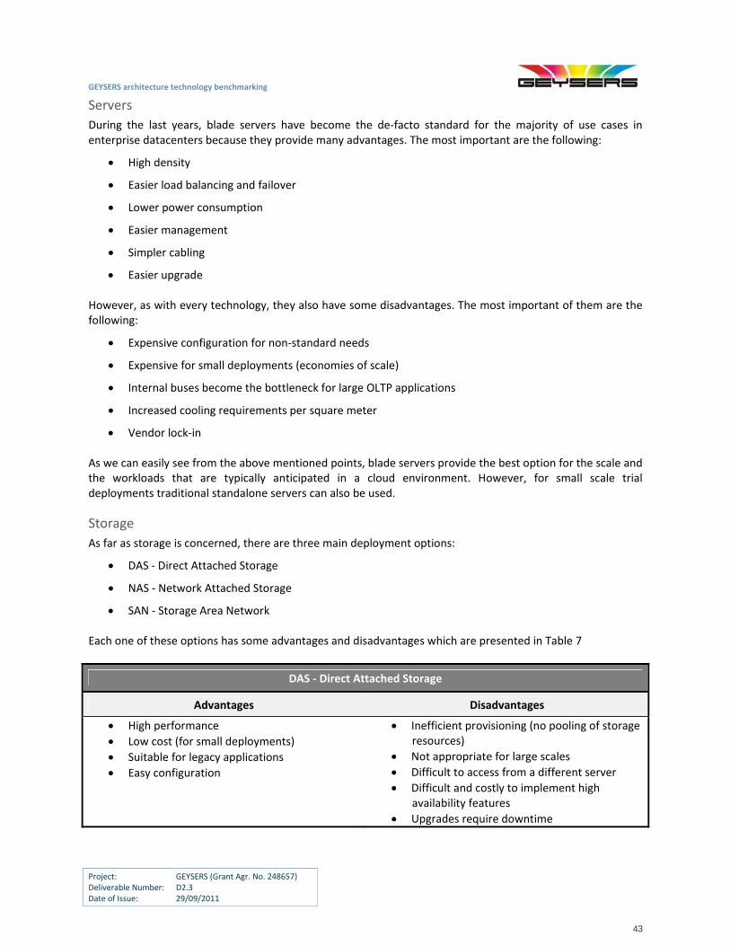
GEYSERS architecture technology benchmarking
Project: GEYSERS (Grant Agr. No. 248657) Deliverable Number: D2.3 Date of Issue: 29/09/2011
43
Servers
During the last years, blade servers have become the de‐facto standard for the majority of use cases in enterprise datacenters because they provide many advantages. The most important are the following:
High density
Easier load balancing and failover
Lower power consumption
Easier management
Simpler cabling
Easier upgrade However, as with every technology, they also have some disadvantages. The most important of them are the following:
Expensive configuration for non‐standard needs
Expensive for small deployments (economies of scale)
Internal buses become the bottleneck for large OLTP applications
Increased cooling requirements per square meter
Vendor lock‐in As we can easily see from the above mentioned points, blade servers provide the best option for the scale and the workloads that are typically anticipated in a cloud environment. However, for small scale trial deployments traditional standalone servers can also be used.
Storage
As far as storage is concerned, there are three main deployment options:
DAS ‐ Direct Attached Storage
NAS ‐ Network Attached Storage
SAN ‐ Storage Area Network Each one of these options has some advantages and disadvantages which are presented in Table 7
DAS ‐ Direct Attached Storage
Advantages Disadvantages
High performance
Low cost (for small deployments)
Suitable for legacy applications
Easy configuration
Inefficient provisioning (no pooling of storage resources)
Not appropriate for large scales
Difficult to access from a different server
Difficult and costly to implement high availability features
Upgrades require downtime
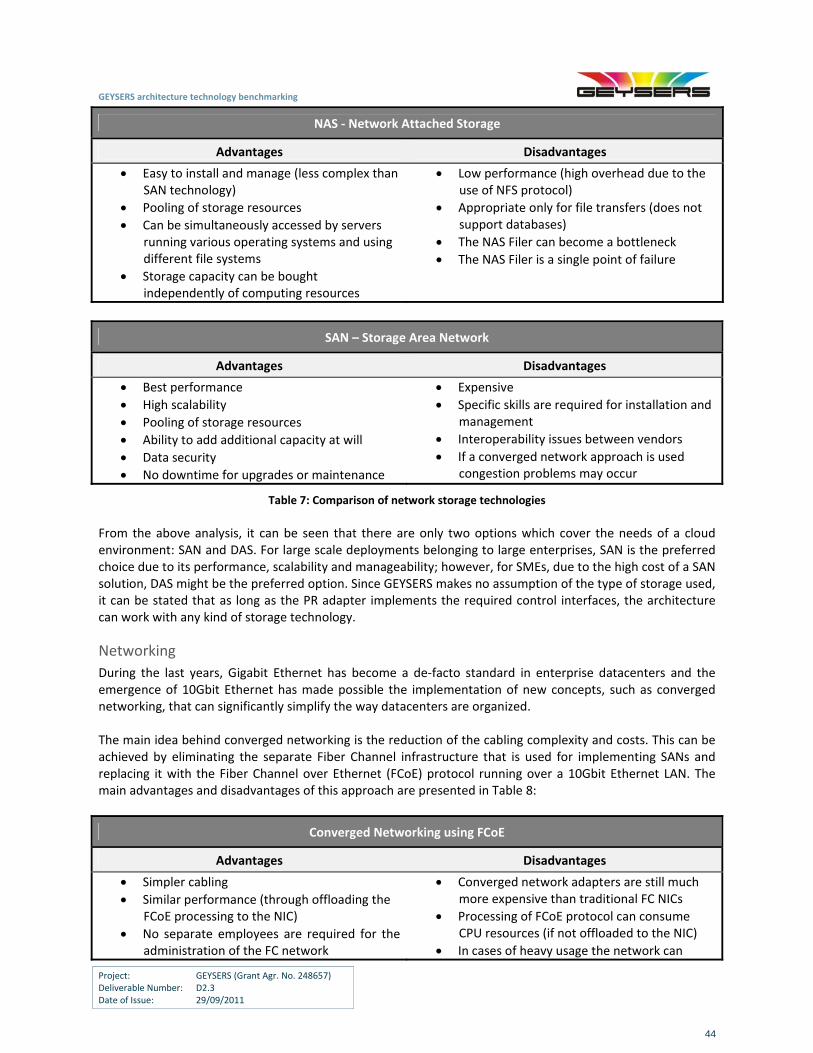
GEYSERS architecture technology benchmarking
Project: GEYSERS (Grant Agr. No. 248657) Deliverable Number: D2.3 Date of Issue: 29/09/2011
44
NAS ‐ Network Attached Storage
Advantages Disadvantages
Easy to install and manage (less complex than SAN technology)
Pooling of storage resources
Can be simultaneously accessed by servers running various operating systems and using different file systems
Storage capacity can be bought independently of computing resources
Low performance (high overhead due to the use of NFS protocol)
Appropriate only for file transfers (does not support databases)
The NAS Filer can become a bottleneck
The NAS Filer is a single point of failure
SAN – Storage Area Network
Advantages Disadvantages
Best performance
High scalability
Pooling of storage resources
Ability to add additional capacity at will
Data security
No downtime for upgrades or maintenance
Expensive
Specific skills are required for installation and management
Interoperability issues between vendors
If a converged network approach is used congestion problems may occur
Table 7: Comparison of network storage technologies
From the above analysis, it can be seen that there are only two options which cover the needs of a cloud environment: SAN and DAS. For large scale deployments belonging to large enterprises, SAN is the preferred choice due to its performance, scalability and manageability; however, for SMEs, due to the high cost of a SAN solution, DAS might be the preferred option. Since GEYSERS makes no assumption of the type of storage used, it can be stated that as long as the PR adapter implements the required control interfaces, the architecture can work with any kind of storage technology.
Networking
During the last years, Gigabit Ethernet has become a de‐facto standard in enterprise datacenters and the emergence of 10Gbit Ethernet has made possible the implementation of new concepts, such as converged networking, that can significantly simplify the way datacenters are organized. The main idea behind converged networking is the reduction of the cabling complexity and costs. This can be achieved by eliminating the separate Fiber Channel infrastructure that is used for implementing SANs and replacing it with the Fiber Channel over Ethernet (FCoE) protocol running over a 10Gbit Ethernet LAN. The main advantages and disadvantages of this approach are presented in Table 8:
Converged Networking using FCoE
Advantages Disadvantages
Simpler cabling
Similar performance (through offloading the FCoE processing to the NIC)
No separate employees are required for the administration of the FC network
Converged network adapters are still much more expensive than traditional FC NICs
Processing of FCoE protocol can consume CPU resources (if not offloaded to the NIC)
In cases of heavy usage the network can
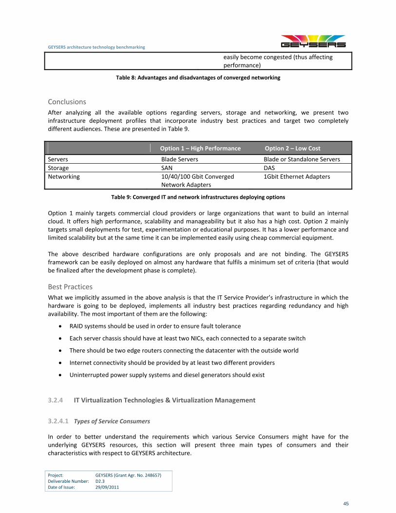
GEYSERS architecture technology benchmarking
Project: GEYSERS (Grant Agr. No. 248657) Deliverable Number: D2.3 Date of Issue: 29/09/2011
45
easily become congested (thus affecting performance)
Table 8: Advantages and disadvantages of converged networking
Conclusions
After analyzing all the available options regarding servers, storage and networking, we present two infrastructure deployment profiles that incorporate industry best practices and target two completely different audiences. These are presented in Table 9.
Option 1 – High Performance Option 2 – Low Cost
Servers Blade Servers Blade or Standalone Servers
Storage SAN DAS
Networking 10/40/100 Gbit Converged Network Adapters
1Gbit Ethernet Adapters
Table 9: Converged IT and network infrastructures deploying options
Option 1 mainly targets commercial cloud providers or large organizations that want to build an internal cloud. It offers high performance, scalability and manageability but it also has a high cost. Option 2 mainly targets small deployments for test, experimentation or educational purposes. It has a lower performance and limited scalability but at the same time it can be implemented easily using cheap commercial equipment. The above described hardware configurations are only proposals and are not binding. The GEYSERS framework can be easily deployed on almost any hardware that fulfils a minimum set of criteria (that would be finalized after the development phase is complete).
Best Practices
What we implicitly assumed in the above analysis is that the IT Service Provider’s infrastructure in which the hardware is going to be deployed, implements all industry best practices regarding redundancy and high availability. The most important of them are the following:
RAID systems should be used in order to ensure fault tolerance
Each server chassis should have at least two NICs, each connected to a separate switch
There should be two edge routers connecting the datacenter with the outside world
Internet connectivity should be provided by at least two different providers
Uninterrupted power supply systems and diesel generators should exist
3.2.4 IT Virtualization Technologies & Virtualization Management
3.2.4.1 Types of Service Consumers
In order to better understand the requirements which various Service Consumers might have for the underlying GEYSERS resources, this section will present three main types of consumers and their characteristics with respect to GEYSERS architecture.
GEYSERS architecture technology benchmarking
Project: GEYSERS (Grant Agr. No. 248657) Deliverable Number: D2.3 Date of Issue: 29/09/2011
46
Large Enterprises
Large multinational corporations have highly customized Enterprise Information Systems (EISs) that incorporate a number of extensions that were developed by consultants during their implementation phase. These modifications allow the EIS to be aligned with the company’s strategy and their internal processes. Such EISs usually run in the corporate datacenter and are maintained by highly specialized IT professionals. During the last 2 years, many large corporations have stated exploring solutions that would help them migrate their EISs to an internal or external cloud in order to improve manageability and scalability. However, since the smooth operation of the whole company is highly dependent on the EIS, managers are reluctant to surrender fully their control. For that reason, such companies progress carefully with only initial steps in the era of cloud computing as they try to operate a cloud deployed EIS in the traditional datacenter way. For these companies, the IT budget is not usually a constraint.
Medium Enterprises
Medium‐sized enterprises that operate either in a local or in an international level often use a small number of customized extensions to their EISs, depending on the special features of the industry in which they are active. These extensions are often developed by partners of the EISs vendors and are segment – and not company – specific. Medium‐sized enterprises also have limited financial resources and therefore employ only a small number of in‐house IT professionals. For such corporations, the main reason for moving their systems into the cloud is the promise of significant cost savings. Through migrating their existing EISs to a cloud provider they can preserve the significant investments that they have done in such systems in the past while at the same time reducing their capital and operational expenses (mainly through reducing the number of IT professionals they employ and getting rid of the purchasing and maintenance costs that are related to IT equipment).
Small Enterprises:
Small companies usually have only basic and standard needs. Most of the time they want to implement an EIS in order to automate manual tasks that were previously performed using Excel or to integrate various independent software packages previously used for tasks such as CRM, accounting, etc. Such companies usually have severe budget constraints and therefore have almost no IT skills since they cannot afford to operate a dedicated IT department.
3.2.4.2 Machine Virtualization
This is the most common form of virtualization utilised today. Machine virtualization enables operating systems (known as guests) and hence applications designed and developed for a specific machine architecture to run on another physical architecture and operating system (known as host). Machine virtualization masks the physical architecture by providing a component known as a hypervisor that translates instructions from the guest to instructions recognised by the host. Proper implementation of this concept can revolutionize the way datacenters are organized, managed and operated by allowing:
Server consolidation:
Traditionally, each application was deployed on a separate (dedicated) physical server. This resulted in a large number of usually underutilized servers which strained the corporate IT budget due to requiring significant capital and operational expenses (energy, air‐conditioning, floor space, administration etc.) Machine virtualization can solve the problem of server sprawl by allowing many applications, which require probably different patches and operating systems, to share the same physical server.
GEYSERS architecture technology benchmarking
Project: GEYSERS (Grant Agr. No. 248657) Deliverable Number: D2.3 Date of Issue: 29/09/2011
47
Isolation:
Virtual machines that run on the same physical server are completely isolated from each other. This refers both to performance and to security. In other words, even if one VM is not responding, crashes or becomes compromised, this doesn’t affect the rest of the machines that run on the same physical host.
Migration:
When the utilization of a physical server is exceeding the desired levels and the virtual machines that run on top need more resources most modern hypervisors allow the migration of one or more VMs to a separate host. Under certain circumstances, this can be achieved seamlessly, without any downtime (live migration). This technique is also very useful in the case of a scheduled upgrade/maintenance.
Check‐pointing and recovery:
The technique of check‐pointing allows administrators to save quickly the entire state (persistent and non‐persistent) of a virtual machine without shutting it down. This can be used in order to increase the availability of a system (by reducing recovery time) and to make debugging and patching much easier.
Elasticity and dynamic scaling:
Virtualization gives users the ability to reserve and use at each point in time only the resources they actually need. Elasticity refers to the ability to dynamically and drastically change the resources that are reserved and used by specific virtual machines with almost zero prior notice and while these machines are up and running. This is particularly important since it allows serving workload peaks at the minimum possible cost.
Fast provisioning:
In traditional datacenters, whenever a corporate unit wanted a new system for test, development or some other non business critical applications, many steps needed to be performed manually by the IT department. As a result, it took several days to fulfill this request. Virtualization, however, has completely transformed this process through allowing users to deploy preconfigured images or stored snapshots in just a couple of minutes.
During the past 10 years, x86 virtualization technologies have improved significantly through reducing the incurred overhead and supporting further guest operating systems. However, the hypervisor landscape today continues to be significantly fragmented, consisting of many products that use different technologies and deployment options. As far as the supported guest operating systems are concerned, the majority of the existing hypervisors support almost all popular operating systems. The situation, however, is completely different in the case of the supported host operating systems. In this case, the existing solutions can be grouped in the following three categories:
Solutions that can use only Linux as a host operating system (Xen and KVM)
Solutions that can be installed in various host operating systems (VMware Server) or directly on top of the underlying hardware (VMware ESX and ESXi)
Solutions that are tightly coupled with the Windows operating system (Microsoft Hyper‐V) In other words, existing solutions can be grouped into three clusters: open source projects that are based on modifications of the Linux kernel, VMware products that try to be agnostic regarding the host operating
GEYSERS architecture technology benchmarking
Project: GEYSERS (Grant Agr. No. 248657) Deliverable Number: D2.3 Date of Issue: 29/09/2011
48
system and Microsoft products that are tightly coupled to Windows. The next section presents the main features of the hypervisors that are suited for enterprise deployments.
Market Review
Xen
Xen is an open source hypervisor that was initially developed by the University of Cambridge Computer Laboratory. It supports a large number of CPU architectures, including x86, x86‐64, IA‐64 (Itanium), ARM and PowerPC. It needs a UNIX‐like operating system as a host OS but it supports a large variety of guest operating systems, such as Linux, Solaris, Windows, NetBSD, FreeBSD etc. Initially, it used the concept of Para virtualization (which requires the modification of the kernel of the guest OS) in order to achieve high performance even in CPU architectures such as x86 which are notoriously difficult to virtualize. Later versions, however, can also use hardware assisted virtualization techniques (such as Intel VT‐x and AMD‐V) in order to run unmodified guests.
KVM
KVM (Kernel‐based Virtual Machine) is an open source hardware assisted virtualization solution that is integrated to the Linux kernel. It currently supports only x86 and x86‐64 CPU architectures, although PowerPC and IA‐64 and versions are currently under development. Since KVM is so tightly integrated to the Linux kernel, only Linux can be used as a host operating system. However, it can run almost all major operating systems as guests. More specifically, it supports Windows, various flavours of Linux, Android, Solaris and many UNIX/BSD derivatives.
VMware ESX & ESXi
ESX and ESXi are both bare metal hypervisors, meaning that they install directly on the physical server without needing a host operating system. In order to achieve this they use their own kernel, which is actually based on the version 2.4 of the Linux kernel. They support various guest operating systems such as Windows, various flavors of Linux, FreeBSD, Solaris and NetWare. They support both binary translation (which gives them the ability to run unmodified guest OSs) and hardware assisted virtualization (which allows them to achieve significantly better performance on compatible processor models). The main difference between the two products is that ESXi is a leaner version of ESX which does not include the service console component, thus having a significantly less footprint (100MB compared to 2GB).
VMware Server
This product, unlike ESX and ESXi, installs as an application on a host operating system, which can be some version of Windows Server or some enterprise Linux distribution (such as RedHat, SUSE, Ubuntu, Mandriva or Mandrake). It uses the same virtualization concepts and supports the same guest operating systems as ESX and ESXi but it offers less management functions. It is mainly targeted for test and development environments.
Microsoft Hyper‐V
There are two deployment options for Hyper‐V: It can be either installed directly on top of the hardware (using the core version of Windows Server 2008 for various supportive and management functions) or as a hosted application on top of Windows Server 2008. It can run only on x86‐64 CPU architectures (it does not support x86‐32 or IA‐64 CPUs). Officially, it supports only various versions of Windows as guest operating systems although many enterprise Linux distributions can also be installed (but they can use only one virtual processor and there is no support or official documentation for them). Hyper‐V supports isolation using partitions on which the guest OSs executes. These partitions have no direct access to the hardware and their requests are redirected via the parent partition which is the hypervisor.
GEYSERS architecture technology benchmarking
Project: GEYSERS (Grant Agr. No. 248657) Deliverable Number: D2.3 Date of Issue: 29/09/2011
49
Libvirt
Libvirt is a set of APIs designed to be used by a management application for accessing and controlling the underlying hypervisors in a uniform way. Libvirt uses a hypervisor‐specific mechanism in order to communicate with each available hypervisor and perform the API requests. According to libvirt terminology, the physical host is called a node, and the guest operating system is called a domain. Libvirt provides two distinct means of control. In the first scenario, the management application and domains exist on the same node. In this case, the management application works through libvirt to control the local domains. In the second scenario, the management application and the domains are on separate nodes. In this case, remote communication is required. This is achieved through a special daemon called libvirtd that runs on remote nodes. This daemon is started automatically when libvirt is installed on a new node and can automatically determine the local hypervisors and set up drivers for them. The management application communicates through the local libvirt to the remote libvirtd through a custom protocol.
Conclusions
According to D2.1, the main goal of GEYSERS is to offer “a framework for abstracting, partitioning and composing VIs from a set of physical resources in an automated way”. In order to achieve this goal in a highly heterogeneous environment where various physical and VI providers can coexist and interact, the solution that is going to be developed should not be dependent on a specific IT virtualization solution. For that reason, GEYSERS partners decided to create a hypervisor agnostic framework by adopting a virtualization management platform that supports the most popular hypervisors currently in use. In the next section, further details about the capabilities of various virtualization management tools and concrete information about the reasons behind the aforementioned decision will be provided.
3.2.4.3 Memory Virtualization
The concept of virtual memory is well‐established as making cheaper, secondary storage appear to be primary storage, when the more‐expensive primary storage (i.e. RAM) does not have the capacity to handle data required to be stored in memory. However, the cost of fast, electronic memory is continuing to decrease, while the enabling technologies are becoming more advanced. Memory virtualization is hence the decoupling of RAM from single servers in the infrastructure such that they can be made available as a pool. In some cases that pool appears as a single coherent memory block, as is the case with clusters. A popular framework that provides this functionality is ScaleMP [ScMP], which aggregates memory across multiple servers making them appear as a single Symmetric Multiprocessor (SMP). The most important technologies that constitute the fundamental building blocks of many memory virtualization solutions are the following:
Distributed Shared Memory (DSM):
In this case multiple processes, which reside probably on different nodes, share a single virtual memory space which is constructed by addressing both local and remote memory pages in a uniform way. This technology can be implemented either through custom hardware or, as it is most often the case, through appropriate software (either through modifying the kernel of an OS or through using specific middleware) and enables inter‐process communication via the modification and subsequent reading of shared memory locations. For a more detailed description of the available hardware and software solutions in this area, one can refer to [DSM].
Remote Direct Memory Access (RDMA):
This is a technique that allows specific hardware components of a computer to access directly the memory of another (remote) computer without involving either operating system. In other words, RDMA offloads the transport and data placement mechanisms to the Network Interface Card (NIC),
GEYSERS architecture technology benchmarking
Project: GEYSERS (Grant Agr. No. 248657) Deliverable Number: D2.3 Date of Issue: 29/09/2011
50
thus allowing the CPU to continue to compute intensive tasks without prolonged interruption. This is particularly useful in the case of High Performance Computing (HPC) clusters, where the network link bandwidth is relatively high compared to the bandwidth of the host CPU and memory.
InfiniBand:
InfiniBand is a relatively new standard for server I/O and inter‐server communication. In contrast with the traditional TCP/IP network stack, InfiniBand uses a top‐down approach, providing applications with an easy to use messaging service that bypasses completely the underlying operating system, thus reducing latency and CPU utilization and increasing the available memory bandwidth. This messaging service can be used to communicate with other applications or processes or to access storage, thus allowing enterprises and research institutions to replace their LANs and SANs by a single network.
3.2.4.4 Storage Virtualization
According to [BPHA], a virtual storage device can be defined as a combination of one or more physical storage devices that appear to applications and users as a single device. Therefore, it can be easily see that the concept of storage virtualization is not new and dates back at least as far as the first specifications of RAID. In a modern context, there are two main types of storage virtualization:
Filesystem Virtualization:
In this case, applications can access files in a uniform way, regardless of their actual physical location. A typical example are remote file servers which run file systems such as NFS or CIFS that are perceived by client applications as running on the client computer, even though they are not.
Block Virtualization:
In this case, blocks that belong to various physical disks are logically brought together in order to appear as a single virtual block device. This device is commonly referred to as a virtual disk or volume. This technology can be managed by software that may run in three different places:
o Disk Array: In this case the reach of the solution is limited to the array itself and the computer systems that are connected to this array.
o Application Server: In this case the solution is available only to a particular computer system
but the host has the ability to aggregate disks that belong to arrays that are constructed by multiple vendors and use various interconnection technologies.
o Storage Network: This solution has the maximum possible reach since the limitations of the
previous two cases are eliminated. The intelligence can reside either in a centralized location through which all virtualized data traffic must pass or can be distributed to the clients and the switches of the network.
It can be seen that storage virtualization adds a new layer between servers and storage systems. In this way the applications no longer need to know the actual physical component (drive, partition or disks subsystem) on which their data reside. This provides the following benefits: Increased Availability: Through storage virtualization techniques such as RAID 1, 5 or 6 that use the
concepts of mirroring and parity, one can increase the availability of a computer system by making it able to survive the failure of a specific hard drive.
GEYSERS architecture technology benchmarking
Project: GEYSERS (Grant Agr. No. 248657) Deliverable Number: D2.3 Date of Issue: 29/09/2011
51
Better I/O Performance: Storage virtualization techniques that range from simple stripping, mirroring or caching to complex automated storage tiering allow users to increase the I/O performance of a storage system by providing the ability to retrieve data from multiple hard drives simultaneously.
Manageability & Expandability:
Most modern storage virtualization solutions come together with advanced management applications that centralize and automate various configuration, provisioning and monitoring tasks that were previously performed manually and separately on each available storage system.
3.2.4.5 Cloud Computing
According to [NIST], cloud computing is composed of five essential characteristics: on‐demand self‐service, broad network access, resource pooling, rapid elasticity and measured service. “Clouds” can also be categorised with respect to the deployment model: public, private, virtual‐private, community and managed. The way in which the GEYSERS architecture can be best applied in each of these cloud deployment models will vary.
Public Clouds are provided by a designated service provider for general public under a utility based pay‐per‐use consumption model. The cloud resources are hosted generally on the service provider’s premises. Popular examples of public clouds are Amazon’s AWS (EC2, S3 etc.), Rackspace Cloud Suite and Microsoft’s Azure Service Platform.
Private Clouds are built, operated and managed by an organization for its internal use only to support its business operations exclusively. Public, private and Government organizations worldwide are adopting this model to exploit the cloud benefits, such as flexibility, cost reduction and agility without having to outsource their operations. They hence use cloud‐enabling technologies such as OpenNebula, Eucalyptus and OpenStack, which are discussed in later sections.
Virtual Private Clouds are a derivative of the private cloud deployment model but are further characterized by an isolated and secure segment of resources, created as an overlay on top of public cloud infrastructure using advanced network virtualization capabilities. Some of the public cloud vendors that offer this capability include Amazon Virtual Private Cloud [AVPC], OpSource Cloud [OpS] and Skytap Virtual Lab [SVL].
Community Clouds are shared by several organizations and support a specific community that has shared concerns (e.g. mission, security requirements, policy, and compliance considerations). They may be managed by the organizations or by a third party and they may exist either on premise or off premise [NIST]. One example of community clouds is OpenCirrus [OCirrus] formed by HP, Intel, Yahoo and others.
Managed Clouds arise when the physical infrastructure is owned by the organization and / or is physically located in its own datacenters while an extension of the management and security control plane is controlled by a managed service provider [CSA]. This deployment model isn’t widely agreed upon. However, some vendors such as ENKI [O‐IT] and NaviSite (with its NaviCloud offering) claim to offer managed cloud solutions.
GEYSERS architecture technology benchmarking
Project: GEYSERS (Grant Agr. No. 248657) Deliverable Number: D2.3 Date of Issue: 29/09/2011
52
Market Review
OpenNebula
OpenNebula is an open source project aimed at building a software framework that aspires to become the industry standard for on‐premise IaaS cloud computing, offering a comprehensive solution for the management of compute virtualization, allowing their operators to build private, public and hybrid clouds. More specifically, it orchestrates hypervisor control, virtual machine images distribution, network isolation, monitoring, and security technologies that enable the dynamic placement of multi‐tier services (groups of interconnected virtual machines) on distributed infrastructures, combining both datacenter resources and remote cloud resources, according to allocation policies. In addition to that, one of the major design principles of OpenNebula is interoperability. This allows organizations to leverage existing IT infrastructure, protect their investments and avoid vendor lock‐in.
Eucalyptus
Eucalyptus is an open source software framework that allows the deployment of private and hybrid clouds on simple computer clusters, without requiring any special purpose hardware or a reconfiguration of the existing IT infrastructure. It is implemented in a modular way as a collection of web services and supports the popular AWS cloud interface, thus allowing on premise deployments to easily interact with public clouds. It supports various hypervisors (VMware, Xen and KVM) and can be installed on almost any modern Linux distribution. In addition to that, it can host both Window and Linux images.
OpenStack
OpenStack is a collection of open source technologies that are bundled together in order to provide a massively scalable open source cloud computing software. Currently OpenStack develops two related projects: OpenStack Compute, which offers computing power through virtual machine and network management, and OpenStack Object Storage which is software for redundant, scalable object storage capacity. Closely related to the OpenStack Compute project is the Image Service project, named Glance. OpenStack can be used by corporations, service providers, VARS, SMBs, researchers, and global datacenters looking to deploy large‐scale cloud deployments for private or public clouds.
AbiCloud
Abicloud is an open source software for the creation and integral management of public and private clouds based on heterogeneous environments. The framework facilitates the creation, deployment and management of cloud computing infrastructures, allowing users to create virtual datacenters over a cloud infrastructure through a rich web interface. Current functionalities offered by AbiCloud are management of infrastructure (hosts and virtual machines), images, virtual applications and users. Future versions will add support for networking management, statistics and monitoring, auto‐scale options, notification system and billing system. All these functionalities are required as they are already offered by public cloud providers.
OpenQRM
OpenQRM is an open source datacenter management platform. Its objective is to achieve automatic and rapid deployment of cloud computing systems using an appliance‐based approach. It supports multiple virtualization technologies and provides a single monitoring and management console for the complete IT infrastructure. Moreover, it provides a well defined API which can be used to integrate third‐party tools as additional plug‐ins. Initially, it was written in Java but now it is ported to PHP.
GEYSERS architecture technology benchmarking
Project: GEYSERS (Grant Agr. No. 248657) Deliverable Number: D2.3 Date of Issue: 29/09/2011
53
Scalr
Scalr is an open source software stack for scaling web‐based application infrastructures. The framework provides a SOAP‐based API for web clients, consoles and applications to connect to scalable machine instances. Machine instances are created using a combination of the AWS SDK and the Scalr SDK. The Scalr SDK sends commands to virtual machine managers and instances in order to configure and size them based on the current (or anticipated) demand. The collection of virtual machine instances that run on a single domain of physical hosts is known as a Scalr Farm and should run on an EC2 compliant cloud.
Conclusions
After a thorough analysis of the available open source solutions, GEYSERS has chosen OpenNebula as the basis for implementing its envisioned functionality. The most important reasons behind this decision, according to deliverable D3.2, were the following:
Using a cloud management system (CMS) such as OpenNebula instead of a virtualization management API like libvirt reduces the amount of code that needs to be written since many functionalities already exist and do not need to be re‐implemented
OpenNebula (in contrast to other CMSs) has already implemented mechanisms for scheduling and federation of infrastructure providers
OpenNebula leverages libvirt for controlling virtual machines in the case of KVM and VMWare (and Xen Tools in case of Xen)
OpenNebula offers a native Java API for accessing its functionalities that is compliant to OCCI specifications. This is very important for GEYSERS since the development of the LICL will be done entirely in Java. In addition to that interface, OpenNebula also offers other APIs (such as EC2, XML‐RPC and OCA)
3.2.4.6 Monitoring and Management Tools
The monitoring process, in case of physical IT resources, consists of gathering metrics about the state of the hardware resources available on each host which is part of the monitored infrastructure. This is performed by a monitoring agent installed on each host, which will afterwards send the gathered data to a collector for processing and persistence. These monitoring architectures can be hierarchical, as in the case of Ganglia, which provides data aggregation at a cluster level. The purpose of monitoring the physical infrastructure is to detect abnormal situations, such as hardware failure, or to prevent degradation of performance by monitoring the resource utilization levels in order to be able to take active measures. For this reason, notifications/alerts are usually used to signal special conditions such as the detection of errors, slow read/write access times, saturation of hardware resources, etc. The alerting functionality can be built in the actual monitoring framework (as in the case of SNMP) or can be leveraged to a different platform.
GEYSERS architecture technology benchmarking
Project: GEYSERS (Grant Agr. No. 248657) Deliverable Number: D2.3 Date of Issue: 29/09/2011
54
Market Review
SNMP
SNMP is a physical resource monitoring protocol based on the manager/agent model, which can be used by a Network Management System consisting of a manager, an agent, a database of management information, managed objects and a network protocol, to exchange information between the manager and the agent by using five basic messages (Get, GetNext, GetResponse, Set, and Trap). More specifically, the Get and GetNext messages allow the manager to request information for a specific variable while the Trap message allows the agent to spontaneously inform the manager about an “important” event. The parameters that are monitored are summarized in a Management Information Base (MIB) and the messages are transmitted using the UDP protocol. The MIB is organized in a tree structure with individual variables being represented as leaves on the branches. A long numeric tag (known as object identifier ‐ OID) is used to distinguish each variable uniquely in the MIB and in SNMP messages. Therefore, an SNMP manager can’t monitor any device unless he has compiled its MIB.
Ganglia
A ganglion is a scalable distributed monitoring system for elastic computing systems such as clusters. It has a hierarchical design in which each node monitors its local resources and then communicates updates to a metadata daemon, which can also send aggregated data to an upper metadata daemon. Ganglia leverages XML for data representation, XDR for data transport and RRD tool for data storage and visualization. Also, it allows an easy addition of other monitoring metrics through the use of gmetric command line utility. It has a large acceptance rate by the community, due to its large number of supported platforms and high concurrency offered.
Ganglia has been integrated in the 2.2 version of OpenNebula for leveraging the monitoring of hosts and virtual machines, due to the fact that it offers improved performance since it doesn’t use SSH for the gathering of information from physical hosts. Also, it offers improved concurrency and it is better suited for monitoring large distributed environments.
Nagios
Nagios is a powerful open source IT and network infrastructure monitoring system. It is scalable due to its hierarchical structure, highly customizable and easy to install. Moreover, it offers users the ability to create additional plug‐ins using various programming languages (sh, bash, perl, c, c++). Nagios can be used for monitoring almost any critical infrastructure component in a datacenter, including system metrics, network protocols, applications, services, servers, HVAC and network infrastructure. When a component fails or recovers, Nagios can send alerts to the responsible administrators via email, SMS or some other custom script. If the alerts are not acknowledged in a timely manner, they can be escalated to other groups higher in the hierarchy. In addition to that, Nagios offers a comprehensive reporting tool that provides a historical record of outages, events, notifications, and alert responses. It can also generate availability reports (in order to ensure compliance with the signed SLAs) and capacity planning graphs (in order to visualize resource utilization trends). Now as far as planned maintenance is concerned, Nagios gives users the ability to schedule downtime (thus preventing alerts to flood the system during the upgrade window).
Conclusions
As was discussed in the previous section, GEYSERS considers OpenNebula for the implementation of LICL because it has a number of desired characteristics that were missing from competitive solutions. As far as infrastructure monitoring is concerned, OpenNebula exposes various metrics regarding both physical and virtual resources. Physical resource metrics include total/free CPU, total/free memory and network Tx/Rx. Virtual resource metrics include the number of running virtual machines and various information gathered by the hypervisors (virtual machine CPU, memory and network usage).
GEYSERS architecture technology benchmarking
Project: GEYSERS (Grant Agr. No. 248657) Deliverable Number: D2.3 Date of Issue: 29/09/2011
55
OpenNebula can also use various external frameworks for monitoring. For example, in version 2.2 of OpenNebula it is possible to use either Ganglia or SNMP for host monitoring. The advantage of using a separate monitoring framework is the addition of various useful metrics (e.g. network/disk throughput, etc.) and the possibility of generating alerts based on collected data. After analyzing thoroughly the available open source monitoring solutions, GEYSERS chose Ganglia in order to augment the capabilities of OpenNebula. According to deliverable D3.2, the main reasons behind this decision were the following:
Ganglia is natively integrated in OpenNebula
Ganglia uses XML for information representation, making it easier to create custom applications that can process the collected data
Ganglia improves performance since (in contrast to the native monitoring tools of OpenNebula) it doesn’t use SSH for gathering information form physical hosts
Ganglia offers improved concurrency and is better suited for monitoring large distributed environments (since it was initially developed for monitoring scientific grids)
3.3 Integrated virtual infrastructure provisioning and control
technologies
In GEYSERS, resources represent either a pure network resource or “any‐IT” resource. IT resources can be considered as licenses, virtual computing capacity, virtualized hosting, or utility storage. IT provisioning services are typically billed on a utility basis and on the amount of resources consumed. By contrast, network resources are related to a backbone infrastructure, which in GEYSERS is scoped to the optical backbone, and are dimensioned on a peak basis (over‐provisioning) and billed accordingly. To fulfil the increasing demands of high capacity network infrastructures which are tightly bounded with IT resources and services, the GEYSERS architecture seamlessly integrates IT and optical network resources to provide unified and tailored services to consumers. Flexible, adaptive and dynamic resource allocations, as well as the integration of heterogeneous network and IT resources, are leveraged. The ease of this integration will depend on the tools available for the provisioning and control of the concerned resources. The use of these tools can be limited to a certain resource kind or alternatively, provide a unified environment regardless of the resource nature. Current technologies are presented in the following section and are categorized based on whether they cope with network resources, IT resources, or both.
3.3.1 Network provisioning technologies
Network resource provisioning is generally provided by deploying a combination of network control plane (i.e. node to node) and network management plane (i.e. NMS to EMS to node) tools and procedures. The major focus in GEYSERS is on network control plane as it is the key performer for seamless on‐demand network + IT service provisioning, once the (virtual) infrastructure has been procured, installed and configured. This
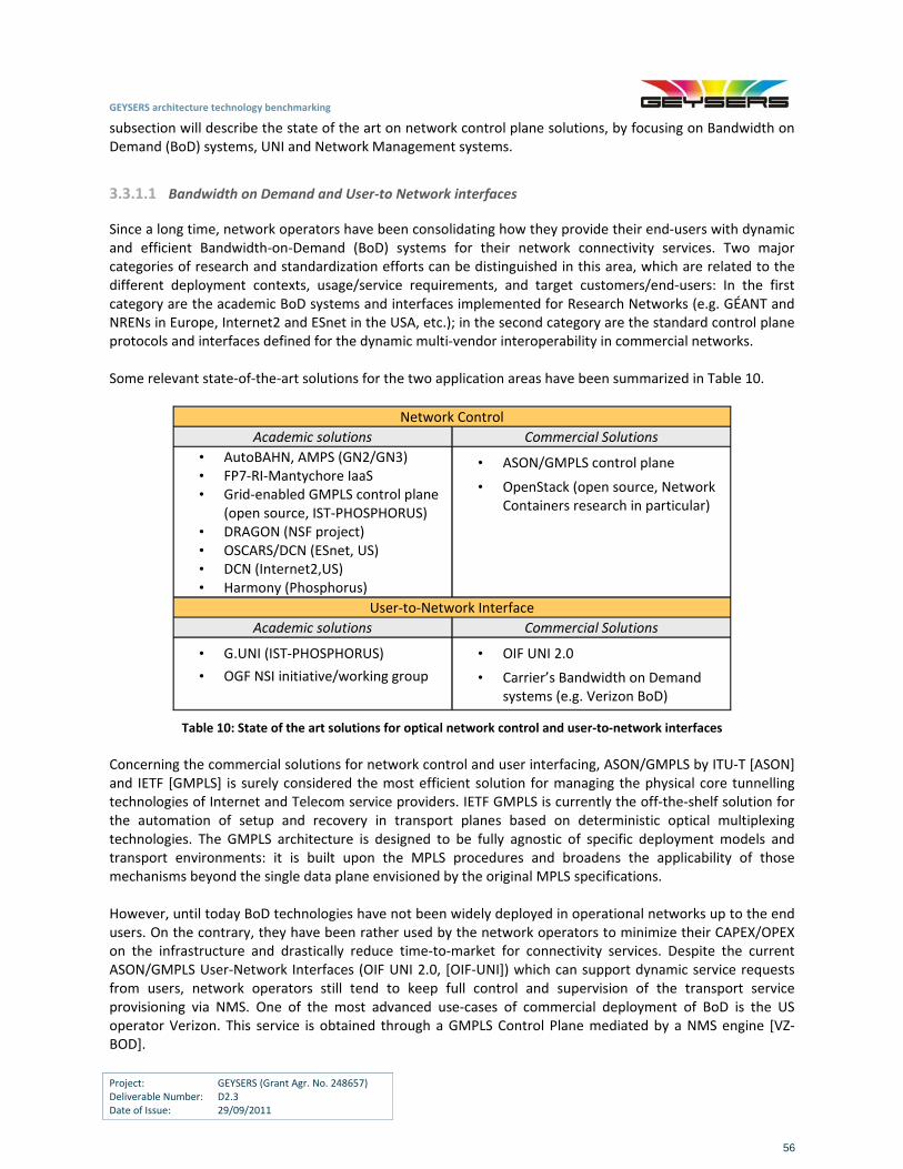
GEYSERS architecture technology benchmarking
Project: GEYSERS (Grant Agr. No. 248657) Deliverable Number: D2.3 Date of Issue: 29/09/2011
56
subsection will describe the state of the art on network control plane solutions, by focusing on Bandwidth on Demand (BoD) systems, UNI and Network Management systems.
3.3.1.1 Bandwidth on Demand and User‐to Network interfaces
Since a long time, network operators have been consolidating how they provide their end‐users with dynamic and efficient Bandwidth‐on‐Demand (BoD) systems for their network connectivity services. Two major categories of research and standardization efforts can be distinguished in this area, which are related to the different deployment contexts, usage/service requirements, and target customers/end‐users: In the first category are the academic BoD systems and interfaces implemented for Research Networks (e.g. GÉANT and NRENs in Europe, Internet2 and ESnet in the USA, etc.); in the second category are the standard control plane protocols and interfaces defined for the dynamic multi‐vendor interoperability in commercial networks. Some relevant state‐of‐the‐art solutions for the two application areas have been summarized in Table 10.
Network Control
Academic solutions Commercial Solutions
• AutoBAHN, AMPS (GN2/GN3) • FP7‐RI‐Mantychore IaaS • Grid‐enabled GMPLS control plane
(open source, IST‐PHOSPHORUS) • DRAGON (NSF project) • OSCARS/DCN (ESnet, US) • DCN (Internet2,US) • Harmony (Phosphorus)
• ASON/GMPLS control plane
• OpenStack (open source, Network Containers research in particular)
User‐to‐Network Interface
Academic solutions Commercial Solutions
• G.UNI (IST‐PHOSPHORUS)
• OGF NSI initiative/working group
• OIF UNI 2.0
• Carrier’s Bandwidth on Demand systems (e.g. Verizon BoD)
Table 10: State of the art solutions for optical network control and user‐to‐network interfaces
Concerning the commercial solutions for network control and user interfacing, ASON/GMPLS by ITU‐T [ASON] and IETF [GMPLS] is surely considered the most efficient solution for managing the physical core tunnelling technologies of Internet and Telecom service providers. IETF GMPLS is currently the off‐the‐shelf solution for the automation of setup and recovery in transport planes based on deterministic optical multiplexing technologies. The GMPLS architecture is designed to be fully agnostic of specific deployment models and transport environments: it is built upon the MPLS procedures and broadens the applicability of those mechanisms beyond the single data plane envisioned by the original MPLS specifications. However, until today BoD technologies have not been widely deployed in operational networks up to the end users. On the contrary, they have been rather used by the network operators to minimize their CAPEX/OPEX on the infrastructure and drastically reduce time‐to‐market for connectivity services. Despite the current ASON/GMPLS User‐Network Interfaces (OIF UNI 2.0, [OIF‐UNI]) which can support dynamic service requests from users, network operators still tend to keep full control and supervision of the transport service provisioning via NMS. One of the most advanced use‐cases of commercial deployment of BoD is the US operator Verizon. This service is obtained through a GMPLS Control Plane mediated by a NMS engine [VZ‐BOD].
GEYSERS architecture technology benchmarking
Project: GEYSERS (Grant Agr. No. 248657) Deliverable Number: D2.3 Date of Issue: 29/09/2011
57
Concerning the academic solutions for network control, AutoBAHN is the most relevant reference in the context of physical controlled networks. AutoBAHN is the BoD framework for the GÉANT and NREN networks, developed through the FP7 Research Infrastructure projects GN2 and GN3 [GN2‐BOD1, GN2‐BOD2]. It controls physical L2 resources in NRENs and GÉANT and is complemented by the separate and independent AMPS system (Advanced Multi‐domain Provisioning System for multi‐domain Premium IP, [GN2‐AMPS]) for L3 resources. AutoBAHN has demonstrated its interoperation with similar BoD systems developed in the US, such as OSCARS by ESnet [ESNET‐OSCARS] and the Dynamic Circuit Network by Internet 2 [I2‐DCN]. Other solutions in the same academic area include the HARMONY network resource brokering system and the Grid‐enabled GMPLS control plane (G2MPLS), both by the IST‐FP6 Phosphorus project [HARMONY] [G2MPLS]. HARMONY integrates different network provisioning systems operating in the heterogeneous domains to provide dynamic interconnections across them. It connects domains in a hierarchical structure to achieve desirable scalability and flexibility. G2MPLS software suite extends the GMLPS/ASON protocol stack with the routing and signalling mechanisms to provision both network and grid resources in a seamless fashion. Focusing on the control of virtualized network resources, relevant academic solutions include the software tools and systems developed by the FP7 Research Infrastructure Mantychore project [MANTYCHORE]. Mantychore brings the Infrastructure as a Service (IaaS) paradigm to the National Research and Education Networks (NRENs) and other e‐Infrastructure providers. Mantychore allows NRENs to provide their infrastructure resources, such as routers, switches, optical devices, and IP networks as a service to virtual research communities. Mantychore builds on the results of previous privately funded research projects MANTICORE I and MANTICORE II (Making Articulated Private Networks Network Topologies on Internet COREs). In the areas of academic solutions, the user to network interfacing is generally part of the control layer architecture of the BoD systems mentioned above. Many solutions exists in the state of the art, but the most relevant for GEYSERS are the Grid‐User to Network Interface (G.UNI, [G2MPLS ]) by the IST‐FP6 Phosphorus project and the Network Service Interface by the Open Grid Forum [OGF‐NSI]. In particular, the OGF NSI is an interface under specification in the OGF to allow a network external entity (e.g. end users, a Grid middleware, and other network service providers) to request network service setup, by triggering all the subsequent configuration, monitoring and orchestration of network resources under particular agreements and policies. Apart from the above mentioned academic and commercial solutions, an interesting emerging initiative in the area of network and cloud virtualized services is the OpenStack [OPENSTACK]. OpenStack aims to produce the ubiquitous open source cloud computing platform that will meet the needs of public and private clouds regardless of size, by being simple to implement and massively scalable. 25 companies are part of the OpenStack project, such as AMD, Citrix and Dell. Also Cisco is recently joined by proposing an extension of the open cloud structure for network services. In particular, the new Network as a Service concept will be implemented through a “Network Abstraction Layer” exposing specific APIs that allow the cloud middleware to configure a set of networking services (e.g. firewall, load balancing, WAN acceleration) opaquely.
3.3.1.2 Network Management System
Network Management Systems are commonly developed by devices manufacturers (e.g. ADVA FSP Network Manager and FSP Service Manager) to provide a centralized operation administration and maintenance of a homogeneous network domain –own and closed NMS‐. NMS generally hinders automatic interoperability as it is vendor‐specific. Higher layer NMS‐s, typically carrier specific, can be deployed in a hierarchy to interface to
GEYSERS architecture technology benchmarking
Project: GEYSERS (Grant Agr. No. 248657) Deliverable Number: D2.3 Date of Issue: 29/09/2011
58
vendor‐specific NMS‐s and integrate summarized views on the entire network and services across multiple technology domains. Apart from the many commercial NMS systems, OpenNMS (http://www.opennms.org/) is an open source network management application platform widely deployed by enterprises and small carriers. Like many commercial products OpenNMS offers:
automated network discovery
alarm repository, correlation and notification (via SNMP traps, syslog or TL/1)
some Service Level Agreements (SLAs) monitoring and reporting
network performance data collections via SNMP and JMX protocols
3.3.2 IT provisioning technologies
The rise of virtualization of datacenters as the way to optimize resource usage generated the apparition of a variety of platforms for IT provisioning and control, boosted with the boom of Cloud Computing specifically, in the Infrastructure as a Service (IaaS) paradigm.
An IT provisioning and control platform consists of a series of tools that allows a user to request, make use of and decommission Virtual Machines or storage units. Commonly, this platform operates over a virtualization platform that actually provides the virtualization of the resource e.g. Xen, VMware, KVM, adding ease of use and control features, such as resource usage monitoring and optimization or VM/data migration.
Both commercial and open‐source platforms have been developed targeting a field spreading dramatically in recent years. Commercial solutions have been deployed by manufacturers entering the cloud (e.g. IBM, CISCO) or by companies entirely dedicated to the cloud business, such as Amazon Web Services, Verizon, Salesforce, CSC, Rackspace. The most relevant example in commercial Cloud platforms is Amazon EC2. Based on web‐services, it is designed to make web‐scale computing easier for developers. Nowadays EC2 is the “de facto” standard for the cloud. It has several functionalities such as creating Amazon Machine Image (AMI), offering multiple locations, supporting static IP endpoints, persistent block storage, etc.
Often, commercial solutions bind the platform to the underling hardware in order to optimize operation, for that reason the focus will be on open‐source platforms, which must be flexible enough to work with many underlying systems. The most referenced examples are OpenNebula and Eucalyptus (explained in section 3.2.4.5). Other notable examples are:
Nimbus: Nimbus (http://workspace.globus.org) is an open source toolkit that allows you to turn your cluster into an IaaS cloud. It provides three sets of remote interfaces: Amazon EC2 WSDLs, Amazon EC2 Query API and Grid community WSRF. It is compatible with S3 REST API for Storage implementation. Virtualization implementation is based on Xen and KVM. You can define an extensible architecture that allows you to customize the software to the needs of your project. It can be downloaded from http://www.nimbusproject.org/news/#218.
Enomaly: The Enomaly Elastic Computing Platform (ECP) (http://www.enomaly.com) is an open source unified IaaS. It provides global scalability, multi‐tenant security, elastic provisioning and orchestration, rich integration with existing infrastructure etc.
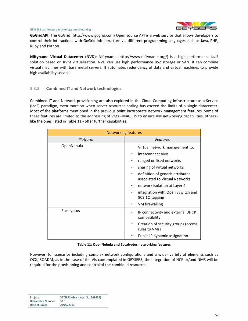
GEYSERS architecture technology benchmarking
Project: GEYSERS (Grant Agr. No. 248657) Deliverable Number: D2.3 Date of Issue: 29/09/2011
59
GoGridAPI: The GoGrid (http://www.gogrid.com) Open source API is a web service that allows developers to
control their interactions with GoGrid infrastructure via different programming languages such as Java, PHP,
Ruby and Python.
Niftyname Virtual Datacenter (NVD): Niftyname (http://www.niftyname.org/) is a high performance IaaS
solution based on KVM virtualization. NVD can use high performance BS2 storage or SAN. It can combine
virtual machines with bare metal servers. It automates redundancy of data and virtual machines to provide
high availability service.
3.3.3 Combined IT and Network technologies
Combined IT and Network provisioning are also explored in the Cloud Computing Infrastructure as a Service (IaaS) paradigm, even more so when server resources scaling has exceed the limits of a single datacenter. Most of the platforms mentioned in the previous point incorporate network management features. Some of these features are limited to the addressing of VMs –MAC, IP‐ to ensure VM networking capabilities, others ‐ like the ones listed in Table 11 ‐ offer further capabilities.
Networking features
Platform Features
OpenNebula Virtual network management to:
• interconnect VMs
• ranged or fixed networks
• sharing of virtual networks
• definition of generic attributes associated to Virtual Networks
• network isolation at Layer 2
• integration with Open vSwitch and 802.1Q tagging
• VM firewalling
Eucalyptus • IP connectivity and external DHCP compatibility
• Creation of security groups (access rules to VMs)
• Public IP dynamic assignation
Table 11: OpenNebula and Eucalyptus networking features
However, for scenarios including complex network configurations and a wider variety of elements such as OCX, ROADM, as in the case of the VIs contemplated in GEYSERS, the integration of NCP or/and NMS will be required for the provisioning and control of the combined resources.
GEYSERS architecture technology benchmarking
Project: GEYSERS (Grant Agr. No. 248657) Deliverable Number: D2.3 Date of Issue: 29/09/2011
60
4 Benchmarking of Virtualization Approaches
This section will focus on benchmarking the virtualization approach proposed by GEYSERS with other existing approaches. Similarly to the approach taken in section 3, the work presented in this section is based on the formal project management benchmarking process commonly applied in the context of project quality management. In general, benchmarking is defined as the process of comparing one's business processes and performance metrics to industry best and/or best practices from other industries.
4.1 Benchmarking Methodology
The benchmarking process adopted in the context of GEYSERS is carried out in three phases.
In the first phase, the virtualization concept addressed in GEYSERS, focuses on the integration of IT and optical network resources for providing unified end‐to‐end services and is compared to similar approaches where virtualization is applied separately to network infrastructures [4WARD][FEDERICA] or IT servers [ORCA], [RSVOIR]. Specifically, [4WARD] focused on virtualization of network devices offering control and dynamic re‐allocation mechanisms to manage the associated virtual networks. The concept of network virtualization is also studied in [FEDERICA] where a technology‐agnostic network infrastructure is designed to support research on Future Internet for the research community. By contrast to these pre‐existing projects, GEYSERS focuses specifically on optical networks and extends these approaches applying the concept of virtualization to both optical network and IT resources. The concept of cloud computing and IT server virtualization are addressed in [RSVOIR]. The mission of [RSVOIR] is to enable smaller infrastructure providers to collaborate through the federation of their resources on demand. A European [RSVOIR] Cloud provider can transparently extend its capacity by connecting over the Internet to another [RSVOIR] Cloud provider with the capacity to handle a higher volume of service requests. A similar problem is addressed in [ORCA] developing a framework for distributed lease‐based resource management where a resource can be any network connected device including a physical machine, a virtual machine, a storage appliance or network bandwidth. However, in [ORCA] the concept of virtualization has not been adopted. In GEYSERS, virtualization is applied not only to IT, but also to optical networking resources.
The ultimate goal of the first benchmarking phase is to identify whether the concept of GEYSERS may help IT and network infrastructure providers to fully deploy and finally benefit from the GEYSERS architecture. The outcome confirms that the GEYSERS approach for virtualization of integrated IT and optical network infrastructures is more efficient for various objectives of interest (e.g. energy consumption, utilization of resources etc) compared to existing approaches. A detailed analysis and discussion regarding the GEYSERS approach and the associated output are presented in the following subsections.
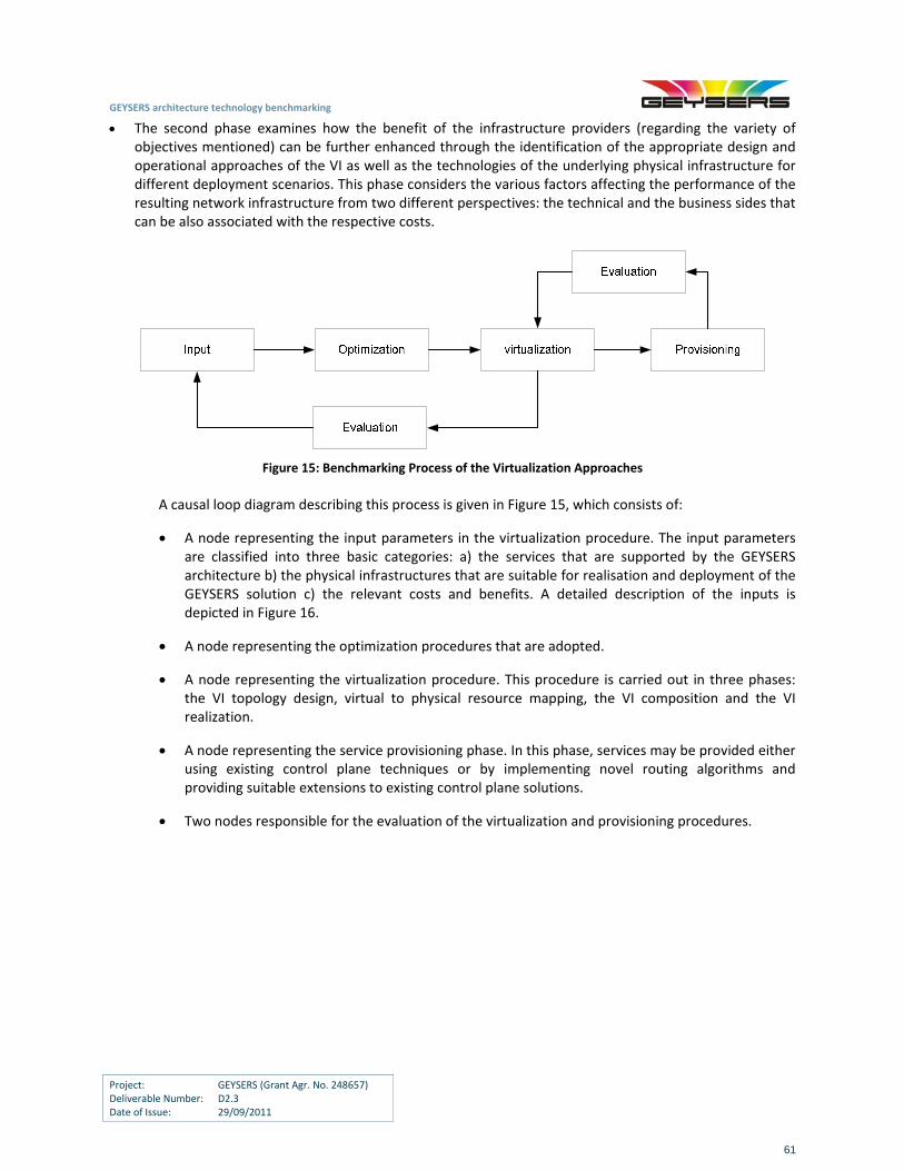
GEYSERS architecture technology benchmarking
Project: GEYSERS (Grant Agr. No. 248657) Deliverable Number: D2.3 Date of Issue: 29/09/2011
61
The second phase examines how the benefit of the infrastructure providers (regarding the variety of objectives mentioned) can be further enhanced through the identification of the appropriate design and operational approaches of the VI as well as the technologies of the underlying physical infrastructure for different deployment scenarios. This phase considers the various factors affecting the performance of the resulting network infrastructure from two different perspectives: the technical and the business sides that can be also associated with the respective costs.
Figure 15: Benchmarking Process of the Virtualization Approaches
A causal loop diagram describing this process is given in Figure 15, which consists of:
A node representing the input parameters in the virtualization procedure. The input parameters are classified into three basic categories: a) the services that are supported by the GEYSERS architecture b) the physical infrastructures that are suitable for realisation and deployment of the GEYSERS solution c) the relevant costs and benefits. A detailed description of the inputs is depicted in Figure 16.
A node representing the optimization procedures that are adopted.
A node representing the virtualization procedure. This procedure is carried out in three phases: the VI topology design, virtual to physical resource mapping, the VI composition and the VI realization.
A node representing the service provisioning phase. In this phase, services may be provided either using existing control plane techniques or by implementing novel routing algorithms and providing suitable extensions to existing control plane solutions.
Two nodes responsible for the evaluation of the virtualization and provisioning procedures.
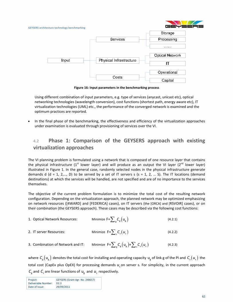
GEYSERS architecture technology benchmarking
Project: GEYSERS (Grant Agr. No. 248657) Deliverable Number: D2.3 Date of Issue: 29/09/2011
62
Figure 16: Input parameters in the benchmarking process
Using different combination of input parameters, e.g. type of services (anycast, unicast etc), optical networking technologies (wavelength conversion), cost functions (shortest path, energy aware etc), IT virtualization technologies (UML) etc., the performance of the converged network is examined and the optimum practices are reported.
In the final phase of the benchmarking, the effectiveness and efficiency of the virtualization approaches
under examination is evaluated through provisioning of services over the VI.
4.2 Phase 1: Comparison of the GEYSERS approach with existing virtualization approaches
The VI planning problem is formulated using a network that is composed of one resource layer that contains the physical infrastructure (1st lower layer) and will produce as an output the VI layer (2nd lower layer) illustrated in Figure 1. In the general case, randomly selected nodes in the physical infrastructure generate demands d (d = 1, 2,…, D) to be served by a set of IT servers s (s = 1, 2, … S). The IT locations (demand destinations) at which the services will be handled, are not specified and are of no importance to the services themselves.
The objective of the current problem formulation is to minimize the total cost of the resulting network configuration. Depending on the virtualization approach, the planned network may be optimized emphasizing on network resources ([4WARD] and [FEDERICA] cases), on IT servers (the [ORCA] and [RSVOIR] cases), or on their combination (the GEYSERS approach). These cases may be described via the following cost functions:
1. Optical Network Resources: Minimize g ggF= uC (4.2.1)
2. IT server Resources: Minimize ssF= sC u (4.2.2)
3. Combination of Network and IT: Minimize g g sg sF= u + sC C u (4.2.3)
where g guC denotes the total cost for installing and operating capacity gu of link g of the PI and s sC u the
total cost (CapEx plus OpEX) for processing demands su on server s. For simplicity, in the current approach
gC and sC are linear functions of gu and su respectively.
GEYSERS architecture technology benchmarking
Project: GEYSERS (Grant Agr. No. 248657) Deliverable Number: D2.3 Date of Issue: 29/09/2011
63
In the general case, the VI planning problem should be solved under the following constraints:
Every demand d has to be processed to a single IT server. This allocation policy reduces the complexity of implementation and increases the reliability of the resulting VI.
The planned VI must have:
a. Adequate IT server resources such as CPU, memory, disk storage to support all requested services.
b. Sufficient Optical link capacity for all demands to be transferred to their destinations.
Τhe capacity of each link in the VI should be realized by specific PI resources.
Depending on which virtualization approach is employed the following cases are examined:
1. If the planned network is optimized, emphasizing on network resources (the [4WARD] and [FEDERICA] case), demands are routed to their destinations via the shortest paths, thus, leading to an underutilization of the optical network resources. At the same time, the impact on the operation of IT infrastructure providers is ignored, thus leading to a suboptimal operation of IT servers.
2. If the planned network is optimized emphasizing on IT resources (the [ORCA] and [RSVOIR] case), demands are optimally allocated to IT servers. In this case, the impact of the proposed planning scheme on network infrastructure providers is ignored, thus leading to an inefficient allocation and exploitation of optical network resources.
3. If the GEYSERS approach is employed, the planned network is optimized both for network and IT resources. In this case, demands are routed to their destination via the shortest paths, keeping at the same time the number of active IT servers to minimum.
Therefore, the question that arises is which planning scheme is more suitable for optimizing the converged IT
and optical network infrastructures. The answer lies in the examination and comparison of the total costs for installing and operating the VI for a specific set of demands. Specifically, let 1a , 2a be the total cost per unit
capacity (CapEx+OpEx) of the optical network and IT infrastructures, respectively, and, x, y be the portion of
the total optical network and IT resources that are necessary to support 1 wavelength. Parameters x and y
may be analytically determined employing algebraic graph theory [Biggs], thus, the resulting total cost per wavelength for the converged PI is equal to 1 2F = a x +a y . After its normalization is transformed to: ax +(1 ‐a)y ,
where /1 1 2a = +a a a is the ratio of the cost per unit capacity of the optical network resources to the total
cost.
Some typical numerical results for a random graph comprising 11 optical nodes with 23 edges, and four
randomly selected sources generating demands to be served to 4 IT servers are depicted in Figure 17. In
Figure 17, where the relative cost for installing and operating the optical network is assumed to be high
(a=0.9), it is observed that in case of low traffic demands it is more efficient to plan the VI emphasizing on IT
servers. On the other hand, if the traffic demands are above a specific threshold, it is optimal to design the VI
emphasizing on optical resources. However, if the planned network is optimized both for IT and optical
resources, then the joint solution offers significant cost reduction for a wide range of traffic demands.
Similar results are drawn in Figure 18 for a=0.1. In this case, the relative cost for using IT infrastructure is high.
It is observed that either the planned network is optimized jointly for optical and IT resources or solely for IT
similar performance is achieved.
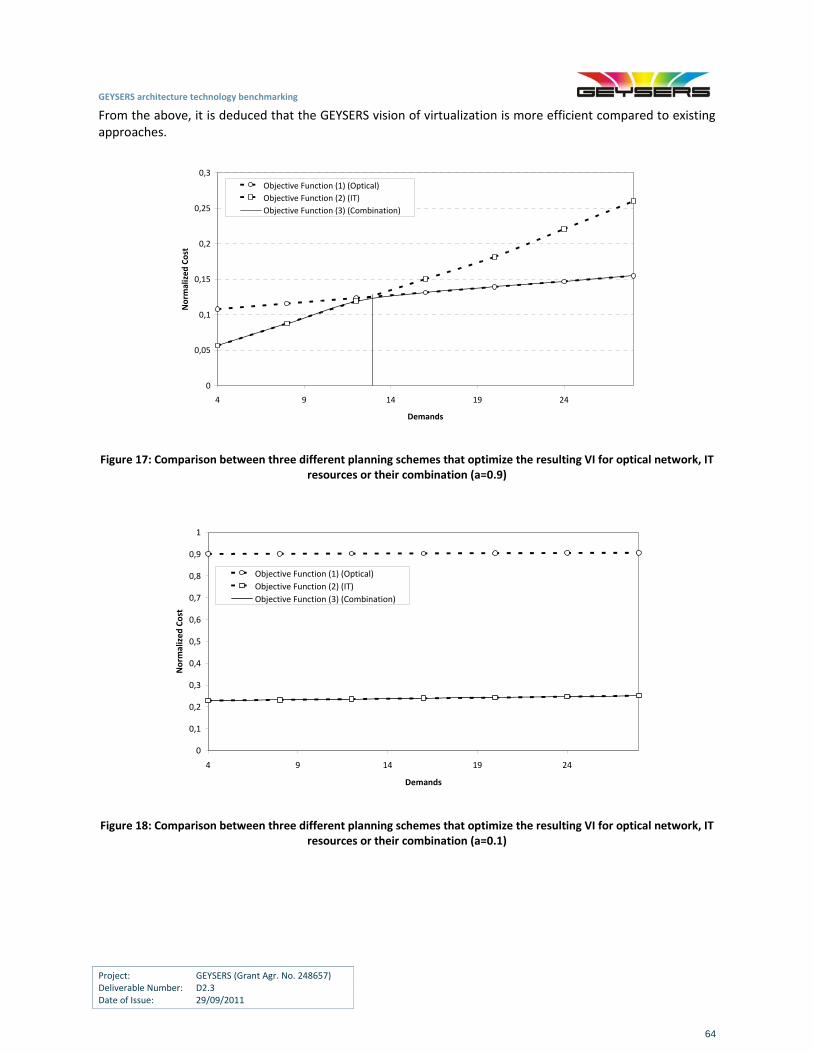
GEYSERS architecture technology benchmarking
Project: GEYSERS (Grant Agr. No. 248657) Deliverable Number: D2.3 Date of Issue: 29/09/2011
64
From the above, it is deduced that the GEYSERS vision of virtualization is more efficient compared to existing approaches.
0
0,05
0,1
0,15
0,2
0,25
0,3
4 9 14 19 24
Demands
Norm
alized Cost
Objective Function (1) (Optical)
Objective Function (2) (IT)
Objective Function (3) (Combination)
Figure 17: Comparison between three different planning schemes that optimize the resulting VI for optical network, IT resources or their combination (a=0.9)
0
0,1
0,2
0,3
0,4
0,5
0,6
0,7
0,8
0,9
1
4 9 14 19 24
Demands
Norm
alized Cost
Objective Function (1) (Optical)
Objective Function (2) (IT)
Objective Function (3) (Combination)
Figure 18: Comparison between three different planning schemes that optimize the resulting VI for optical network, IT resources or their combination (a=0.1)
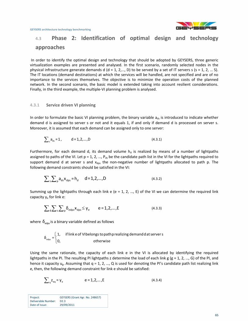
GEYSERS architecture technology benchmarking
Project: GEYSERS (Grant Agr. No. 248657) Deliverable Number: D2.3 Date of Issue: 29/09/2011
65
4.3 Phase 2: Identification of optimal design and technology
approaches
In order to identify the optimal design and technology that should be adopted by GEYSERS, three generic virtualization examples are presented and analysed. In the first scenario, randomly selected nodes in the physical infrastructure generate demands d (d = 1, 2,…, D) to be served by a set of IT servers s (s = 1, 2, … S). The IT locations (demand destinations) at which the services will be handled, are not specified and are of no importance to the services themselves. The objective is to minimize the operation costs of the planned network. In the second scenario, the basic model is extended taking into account resilient considerations. Finally, in the third example, the multiple‐VI planning problem is analysed.
4.3.1 Service driven VI planning
In order to formulate the basic VI planning problem, the binary variable ads is introduced to indicate whether
demand d is assigned to server s or not and it equals 1, if and only if demand d is processed on server s.
Moreover, it is assumed that each demand can be assigned only to one server:
dssa =1 , d=1,2,…,D (4.3.1)
Furthermore, for each demand d, its demand volume hd is realized by means of a number of lightpaths
assigned to paths of the VI. Let p = 1, 2, …, Pds be the candidate path list in the VI for the lightpaths required to
support demand d at server s and xdps the non‐negative number of lightpaths allocated to path p. The
following demand constraints should be satisfied in the VI:
ds dps ds pa x =h d=1,2,…,D (4.3.2)
Summing up the lightpaths through each link e (e = 1, 2, …, E) of the VI we can determine the required link
capacity ye for link e:
eedps dpsd s pδ x y e =1,2,…,E (4.3.3)
where edpsδ is a binary variable defined as follows
edps
1, if link e of VI belongs to path p realizing demand d at server sδ =
0, otherwise
Using the same rationale, the capacity of each link e in the VI is allocated by identifying the required
lightpaths in the PI. The resulting PI lightpaths z determine the load of each link g (g = 1, 2, …, G) of the PI, and
hence it capacity ug. Assuming that q = 1, 2, …, Q is used for denoting the PI’s candidate path list realizing link
e, then, the following demand constraint for link e should be satisfied:
eq eqz = y e =1,2,…,E (4.3.4)
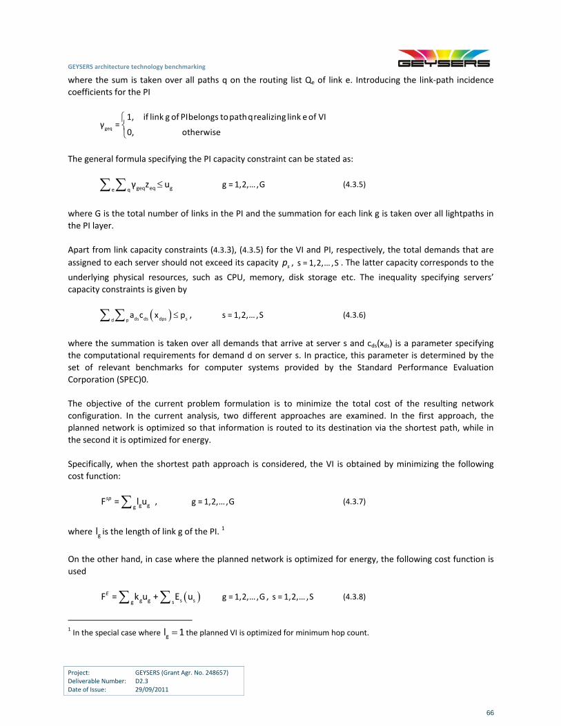
GEYSERS architecture technology benchmarking
Project: GEYSERS (Grant Agr. No. 248657) Deliverable Number: D2.3 Date of Issue: 29/09/2011
66
where the sum is taken over all paths q on the routing list Qe of link e. Introducing the link‐path incidence
coefficients for the PI
geq
1, if link g of PI belongs to path q realizing link e of VIγ =
0, otherwise
The general formula specifying the PI capacity constraint can be stated as:
geq eq ge qγ z u g = 1,2,…,G (4.3.5)
where G is the total number of links in the PI and the summation for each link g is taken over all lightpaths in
the PI layer.
Apart from link capacity constraints (4.3.3), (4.3.5) for the VI and PI, respectively, the total demands that are
assigned to each server should not exceed its capacity sp , s = 1,2,…,S . The latter capacity corresponds to the
underlying physical resources, such as CPU, memory, disk storage etc. The inequality specifying servers’
capacity constraints is given by
ds ds dps sd pa c x p , s = 1,2,…,S (4.3.6)
where the summation is taken over all demands that arrive at server s and cds(xds) is a parameter specifying
the computational requirements for demand d on server s. In practice, this parameter is determined by the
set of relevant benchmarks for computer systems provided by the Standard Performance Evaluation
Corporation (SPEC)0.
The objective of the current problem formulation is to minimize the total cost of the resulting network
configuration. In the current analysis, two different approaches are examined. In the first approach, the
planned network is optimized so that information is routed to its destination via the shortest path, while in
the second it is optimized for energy.
Specifically, when the shortest path approach is considered, the VI is obtained by minimizing the following
cost function:
g ggF = l usp , g = 1,2,…,G (4.3.7)
where gl is the length of link g of the PI. 1
On the other hand, in case where the planned network is optimized for energy, the following cost function is
used
g g s sg sF = k u + E uE g = 1,2,…,G , s = 1,2,…,S (4.3.8)
1 In the special case where gl 1 the planned VI is optimized for minimum hop count.
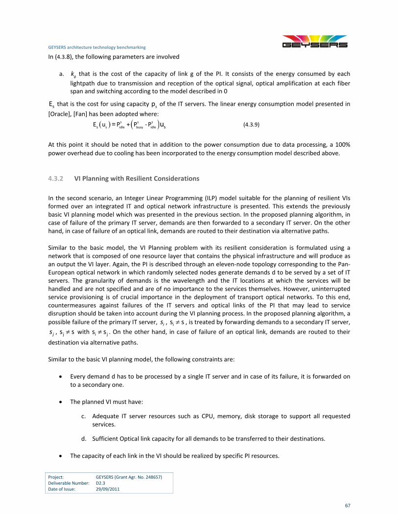
GEYSERS architecture technology benchmarking
Project: GEYSERS (Grant Agr. No. 248657) Deliverable Number: D2.3 Date of Issue: 29/09/2011
67
In (4.3.8), the following parameters are involved
a. gk that is the cost of the capacity of link g of the PI. It consists of the energy consumed by each
lightpath due to transmission and reception of the optical signal, optical amplification at each fiber span and switching according to the model described in 0
sE that is the cost for using capacity sp of the IT servers. The linear energy consumption model presented in
[Oracle], [Fan] has been adopted where:
s s s
s idle busy idles sE u P + P ‐P= u (4.3.9)
At this point it should be noted that in addition to the power consumption due to data processing, a 100%
power overhead due to cooling has been incorporated to the energy consumption model described above.
4.3.2 VI Planning with Resilient Considerations
In the second scenario, an Integer Linear Programming (ILP) model suitable for the planning of resilient VIs formed over an integrated IT and optical network infrastructure is presented. This extends the previously basic VI planning model which was presented in the previous section. In the proposed planning algorithm, in case of failure of the primary IT server, demands are then forwarded to a secondary IT server. On the other hand, in case of failure of an optical link, demands are routed to their destination via alternative paths.
Similar to the basic model, the VI Planning problem with its resilient consideration is formulated using a network that is composed of one resource layer that contains the physical infrastructure and will produce as an output the VI layer. Again, the PI is described through an eleven‐node topology corresponding to the Pan‐European optical network in which randomly selected nodes generate demands d to be served by a set of IT servers. The granularity of demands is the wavelength and the IT locations at which the services will be handled and are not specified and are of no importance to the services themselves. However, uninterrupted service provisioning is of crucial importance in the deployment of transport optical networks. To this end, countermeasures against failures of the IT servers and optical links of the PI that may lead to service disruption should be taken into account during the VI planning process. In the proposed planning algorithm, a
possible failure of the primary IT server, is , is s , is treated by forwarding demands to a secondary IT server,
js , js s with i js s . On the other hand, in case of failure of an optical link, demands are routed to their
destination via alternative paths.
Similar to the basic VI planning model, the following constraints are:
Every demand d has to be processed by a single IT server and in case of its failure, it is forwarded on to a secondary one.
The planned VI must have:
c. Adequate IT server resources such as CPU, memory, disk storage to support all requested services.
d. Sufficient Optical link capacity for all demands to be transferred to their destinations.
Τhe capacity of each link in the VI should be realized by specific PI resources.
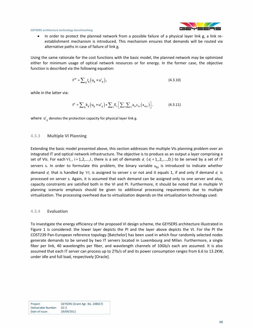
GEYSERS architecture technology benchmarking
Project: GEYSERS (Grant Agr. No. 248657) Deliverable Number: D2.3 Date of Issue: 29/09/2011
68
In order to protect the planned network from a possible failure of a physical layer link g, a link re‐establishment mechanism is introduced. This mechanism ensures that demands will be routed via alternative paths in case of failure of link g.
Using the same rationale for the cost functions with the basic model, the planned network may be optimized
either for minimum usage of optical network resources or for energy. In the former case, the objective
function is described via the following equation:
SPg g gg
F = u +u' l , (4.3.10)
while in the latter via:
Εds ds dpsd pg g g sg s
F = + a c xk u +u' E . (4.3.11)
where u'g denotes the protection capacity for physical layer link g.
4.3.3 Multiple VI Planning
Extending the basic model presented above, this section addresses the multiple VIs planning problem over an
integrated IT and optical network infrastructure. The objective is to produce as an output a layer comprising a set of VIs. For eachVIi , i = 1,2,…,I , there is a set of demands id ( i i i id = 1 ,2 ,...,D ) to be served by a set of IT
servers s. In order to formulate this problem, the binary variable ids
a is introduced to indicate whether
demand id that is handled by VIi is assigned to server s or not and it equals 1, if and only if demand id is
processed on server s. Again, it is assumed that each demand can be assigned only to one server and also,
capacity constraints are satisfied both in the VI and PI. Furthermore, it should be noted that in multiple VI
planning scenario emphasis should be given to additional processing requirements due to multiple
virtualization. The processing overhead due to virtualization depends on the virtualization technology used.
4.3.4 Evaluation
To investigate the energy efficiency of the proposed VI design scheme, the GEYSERS architecture illustrated in
Figure 1 is considered: the lower layer depicts the PI and the layer above depicts the VI. For the PI the
COST239 Pan‐European reference topology [Batchelor] has been used in which four randomly selected nodes
generate demands to be served by two IT servers located in Luxembourg and Milan. Furthermore, a single
fiber per link, 40 wavelengths per fiber, and wavelength channels of 10Gb/s each are assumed. It is also
assumed that each IT server can process up to 2Tb/s of and its power consumption ranges from 6.6 to 13.2KW,
under idle and full load, respectively [Oracle].
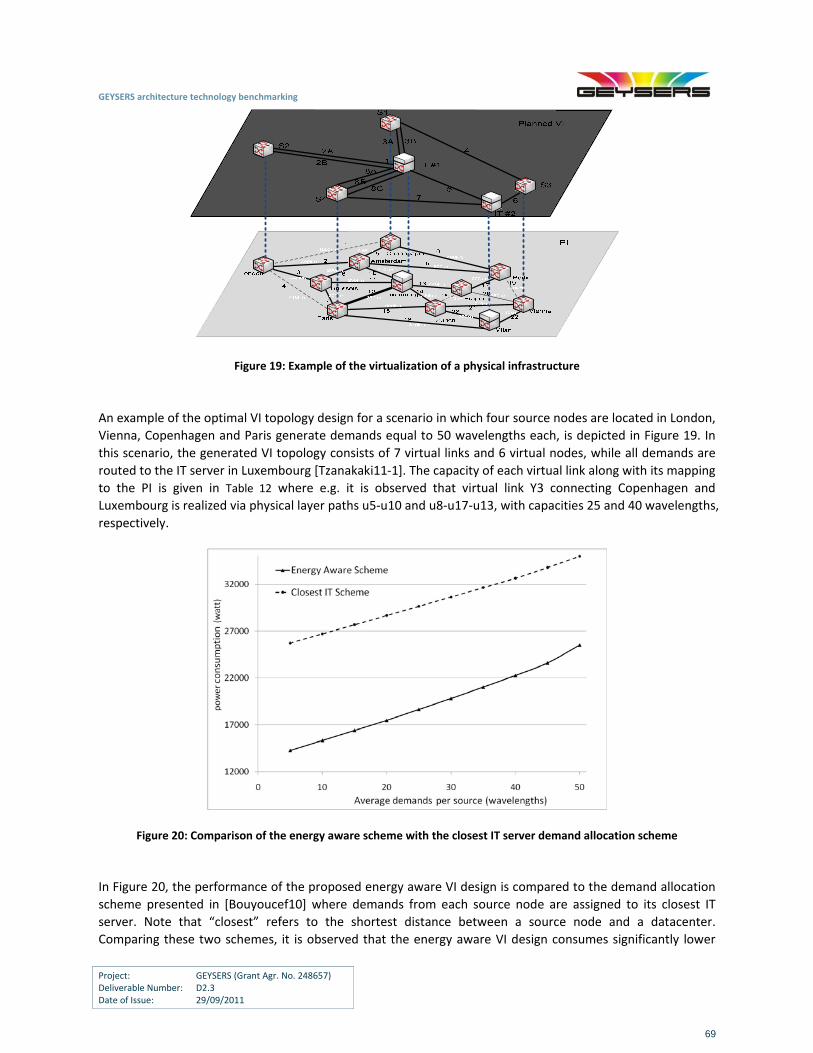
GEYSERS architecture technology benchmarking
Project: GEYSERS (Grant Agr. No. 248657) Deliverable Number: D2.3 Date of Issue: 29/09/2011
69
Figure 19: Example of the virtualization of a physical infrastructure
An example of the optimal VI topology design for a scenario in which four source nodes are located in London,
Vienna, Copenhagen and Paris generate demands equal to 50 wavelengths each, is depicted in Figure 19. In
this scenario, the generated VI topology consists of 7 virtual links and 6 virtual nodes, while all demands are
routed to the IT server in Luxembourg [Tzanakaki11‐1]. The capacity of each virtual link along with its mapping
to the PI is given in Table 12 where e.g. it is observed that virtual link Y3 connecting Copenhagen and
Luxembourg is realized via physical layer paths u5‐u10 and u8‐u17‐u13, with capacities 25 and 40 wavelengths,
respectively.
Figure 20: Comparison of the energy aware scheme with the closest IT server demand allocation scheme
In Figure 20, the performance of the proposed energy aware VI design is compared to the demand allocation
scheme presented in [Bouyoucef10] where demands from each source node are assigned to its closest IT
server. Note that “closest” refers to the shortest distance between a source node and a datacenter.
Comparing these two schemes, it is observed that the energy aware VI design consumes significantly lower
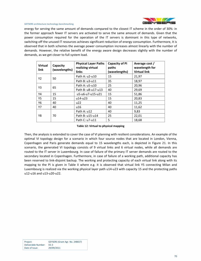
GEYSERS architecture technology benchmarking
Project: GEYSERS (Grant Agr. No. 248657) Deliverable Number: D2.3 Date of Issue: 29/09/2011
70
energy for serving the same amount of demands compared to the closest IT scheme in the order of 30%: in
the former approach fewer IT servers are activated to serve the same amount of demands. Given that the
power consumption required for the operation of the IT servers is dominant in this type of networks,
switching‐off the unused IT resources achieves significant reduction of energy consumption. Furthermore, it is
observed that in both schemes the average power consumption increases almost linearly with the number of
demands. However, the relative benefit of the energy aware design decreases slightly with the number of
demands, as we get closer to full system load.
Virtual link
Capacity (wavelengths)
Physical Layer Paths realizing virtual links
Capacity of PI paths (wavelengths)
Average cost / wavelength for Virtual link
Path A: u2‐u10 15 21,97 Y2 50
Path B: u3‐u11 35 18,97
Path A: u5‐u10 25 20,96 Y3 65
Path B: u8‐u17‐u13 40 29,69
Y4 15 u5‐u6‐u7‐u15‐u21 15 51,86
Y5 15 u14‐u23 15 20,83
Y6 40 u22 40 11,25
Y7 40 u16 40 11,62
Path A: u12 40 9,83
Path B: u15‐u14 25 22,01 Y8 70
Path C: u7‐u11 5 18,68
Table 12: Virtual to physical mapping
Then, the analysis is extended to cover the case of VI planning with resilient considerations. An example of the
optimal VI topology design for a scenario in which four source nodes that are located in London, Vienna,
Copenhagen and Paris generate demands equal to 15 wavelengths each, is depicted in Figure 21. In this
scenario, the generated VI topology consists of 9 virtual links and 6 virtual nodes, while all demands are
routed to the IT server in Luxembourg. In case of failure of the primary IT server demands are routed to the
secondary located in Copenhagen. Furthermore, in case of failure of a working path, additional capacity has
been reserved to link‐disjoint backup. The working and protecting capacity of each virtual link along with its
mapping to the PI is given in Table II where e.g. it is observed that virtual link Y5 connecting Milan and
Luxembourg is realized via the working physical layer path u14‐u23 with capacity 15 and the protecting paths
u12‐u16 and u13‐u20‐u22.
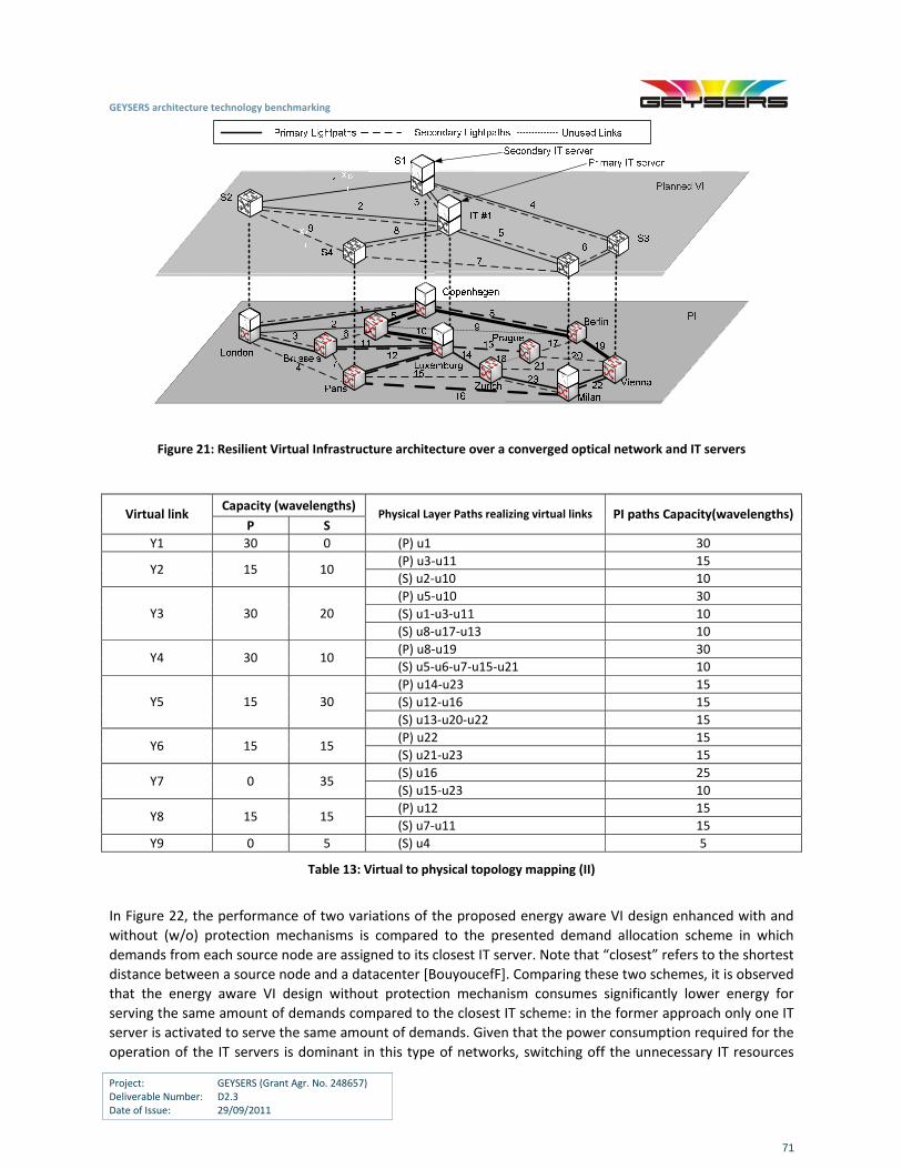
GEYSERS architecture technology benchmarking
Project: GEYSERS (Grant Agr. No. 248657) Deliverable Number: D2.3 Date of Issue: 29/09/2011
71
Figure 21: Resilient Virtual Infrastructure architecture over a converged optical network and IT servers
Capacity (wavelengths) Virtual link
P S Physical Layer Paths realizing virtual links PI paths Capacity(wavelengths)
Y1 30 0 (P) u1 30
(P) u3‐u11 15 Y2 15 10
(S) u2‐u10 10
(P) u5‐u10 30
(S) u1‐u3‐u11 10 Y3 30 20
(S) u8‐u17‐u13 10
(P) u8‐u19 30 Y4 30 10
(S) u5‐u6‐u7‐u15‐u21 10
(P) u14‐u23 15
(S) u12‐u16 15 Y5 15 30
(S) u13‐u20‐u22 15
(P) u22 15 Y6 15 15
(S) u21‐u23 15
(S) u16 25 Y7 0 35
(S) u15‐u23 10
(P) u12 15 Y8 15 15
(S) u7‐u11 15
Y9 0 5 (S) u4 5
Table 13: Virtual to physical topology mapping (II)
In Figure 22, the performance of two variations of the proposed energy aware VI design enhanced with and
without (w/o) protection mechanisms is compared to the presented demand allocation scheme in which
demands from each source node are assigned to its closest IT server. Note that “closest” refers to the shortest
distance between a source node and a datacenter [BouyoucefF]. Comparing these two schemes, it is observed
that the energy aware VI design without protection mechanism consumes significantly lower energy for
serving the same amount of demands compared to the closest IT scheme: in the former approach only one IT
server is activated to serve the same amount of demands. Given that the power consumption required for the
operation of the IT servers is dominant in this type of networks, switching off the unnecessary IT resources
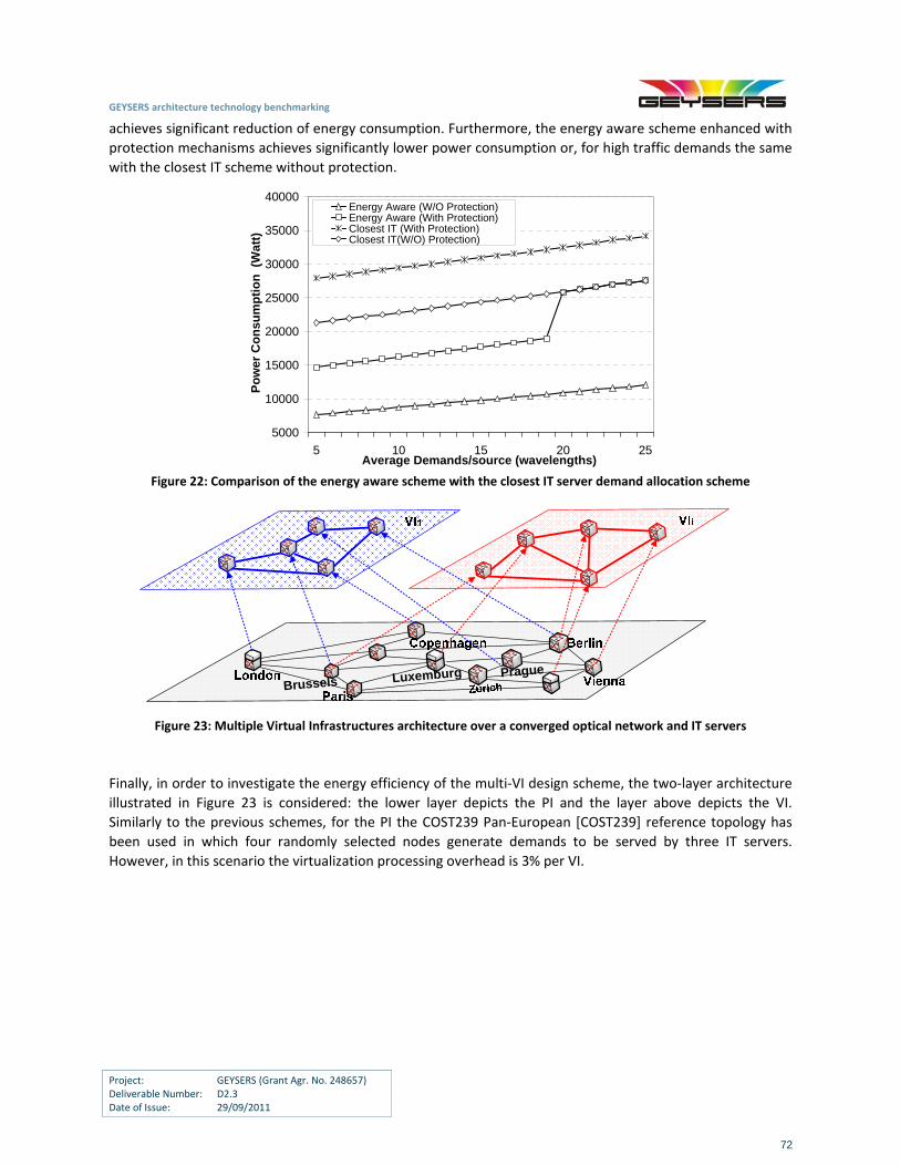
GEYSERS architecture technology benchmarking
Project: GEYSERS (Grant Agr. No. 248657) Deliverable Number: D2.3 Date of Issue: 29/09/2011
72
achieves significant reduction of energy consumption. Furthermore, the energy aware scheme enhanced with
protection mechanisms achieves significantly lower power consumption οr, for high traffic demands the same
with the closest IT scheme without protection.
5000
10000
15000
20000
25000
30000
35000
40000
5 10 15 20 25Average Demands/source (wavelengths)
Po
wer
Co
nsu
mp
tio
n (
Wat
t)
Energy Aware (W/O Protection)Energy Aware (With Protection)Closest IT (With Protection)Closest IT(W/O) Protection)
Figure 22: Comparison of the energy aware scheme with the closest IT server demand allocation scheme
PragueLuxemburg
Brussels
Figure 23: Multiple Virtual Infrastructures architecture over a converged optical network and IT servers
Finally, in order to investigate the energy efficiency of the multi‐VI design scheme, the two‐layer architecture
illustrated in Figure 23 is considered: the lower layer depicts the PI and the layer above depicts the VI.
Similarly to the previous schemes, for the PI the COST239 Pan‐European [COST239] reference topology has
been used in which four randomly selected nodes generate demands to be served by three IT servers.
However, in this scenario the virtualization processing overhead is 3% per VI.
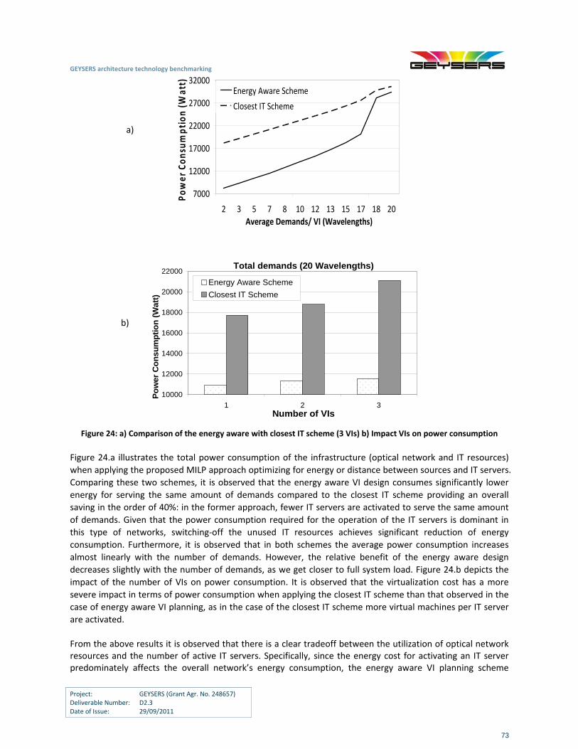
GEYSERS architecture technology benchmarking
Project: GEYSERS (Grant Agr. No. 248657) Deliverable Number: D2.3 Date of Issue: 29/09/2011
73
a)
7000
12000
17000
22000
27000
32000
2 3 5 7 8 10 12 13 15 17 18 20Average Demands/ VI (Wavelengths)
Power Consu
mption (W
att)
Energy Aware Scheme
Closest IT Scheme
b)
Total demands (20 Wavelengths)
10000
12000
14000
16000
18000
20000
22000
1 2 3Number of VIs
Po
wer
Co
nsu
mp
tio
n (
Watt
)
Energy Aware Scheme
Closest IT Scheme
Figure 24: a) Comparison of the energy aware with closest IT scheme (3 VIs) b) Impact VIs on power consumption
Figure 24.a illustrates the total power consumption of the infrastructure (optical network and IT resources)
when applying the proposed MILP approach optimizing for energy or distance between sources and IT servers.
Comparing these two schemes, it is observed that the energy aware VI design consumes significantly lower
energy for serving the same amount of demands compared to the closest IT scheme providing an overall
saving in the order of 40%: in the former approach, fewer IT servers are activated to serve the same amount
of demands. Given that the power consumption required for the operation of the IT servers is dominant in
this type of networks, switching‐off the unused IT resources achieves significant reduction of energy
consumption. Furthermore, it is observed that in both schemes the average power consumption increases
almost linearly with the number of demands. However, the relative benefit of the energy aware design
decreases slightly with the number of demands, as we get closer to full system load. Figure 24.b depicts the
impact of the number of VIs on power consumption. It is observed that the virtualization cost has a more
severe impact in terms of power consumption when applying the closest IT scheme than that observed in the
case of energy aware VI planning, as in the case of the closest IT scheme more virtual machines per IT server
are activated.
From the above results it is observed that there is a clear tradeoff between the utilization of optical network resources and the number of active IT servers. Specifically, since the energy cost for activating an IT server predominately affects the overall network’s energy consumption, the energy aware VI planning scheme
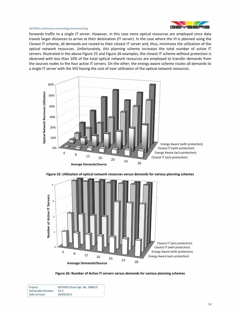
GEYSERS architecture technology benchmarking
Project: GEYSERS (Grant Agr. No. 248657) Deliverable Number: D2.3 Date of Issue: 29/09/2011
74
forwards traffic to a single IT server. However, in this case more optical resources are employed since data travels larger distances to arrive at their destination (IT server). In the case where the VI is planned using the Closest IT scheme, all demands are routed to their closest IT server and, thus, minimizes the utilization of the optical network resources. Unfortunately, this planning scheme increases the total number of active IT servers. Illustrated in the above Figure 25 and Figure 26 examples, the closest IT scheme without protection is observed with less than 10% of the total optical network resources are employed to transfer demands from the sources nodes to the four active IT servers. On the other, the energy aware scheme routes all demands to a single IT server with the VIO having the cost of over utilization of the optical network resources.
4 8 12 16 20 24 28
Closest IT (w/o protection)
Energy Aware (w/o protection)
Closest IT (with protection)Energy Aware (with protection)
0%
10%
20%
30%
40%
50%
60%
Optical N
etwork Resrouces Utilization
Average Demands/Source
Figure 25: Utilization of optical network resources versus demands for various planning schemes
4 8 12 16 20 24 28
Energy Aware (w/o protection)
Energy Aware (with protection)
Closest IT (with protection)
Closest IT (w/o protection)0
1
2
3
4
Nu
mb
er o
f A
ctiv
e IT
Ser
ver
s
Average Demands/Source
Figure 26: Number of Active IT servers versus demands for various planning schemes
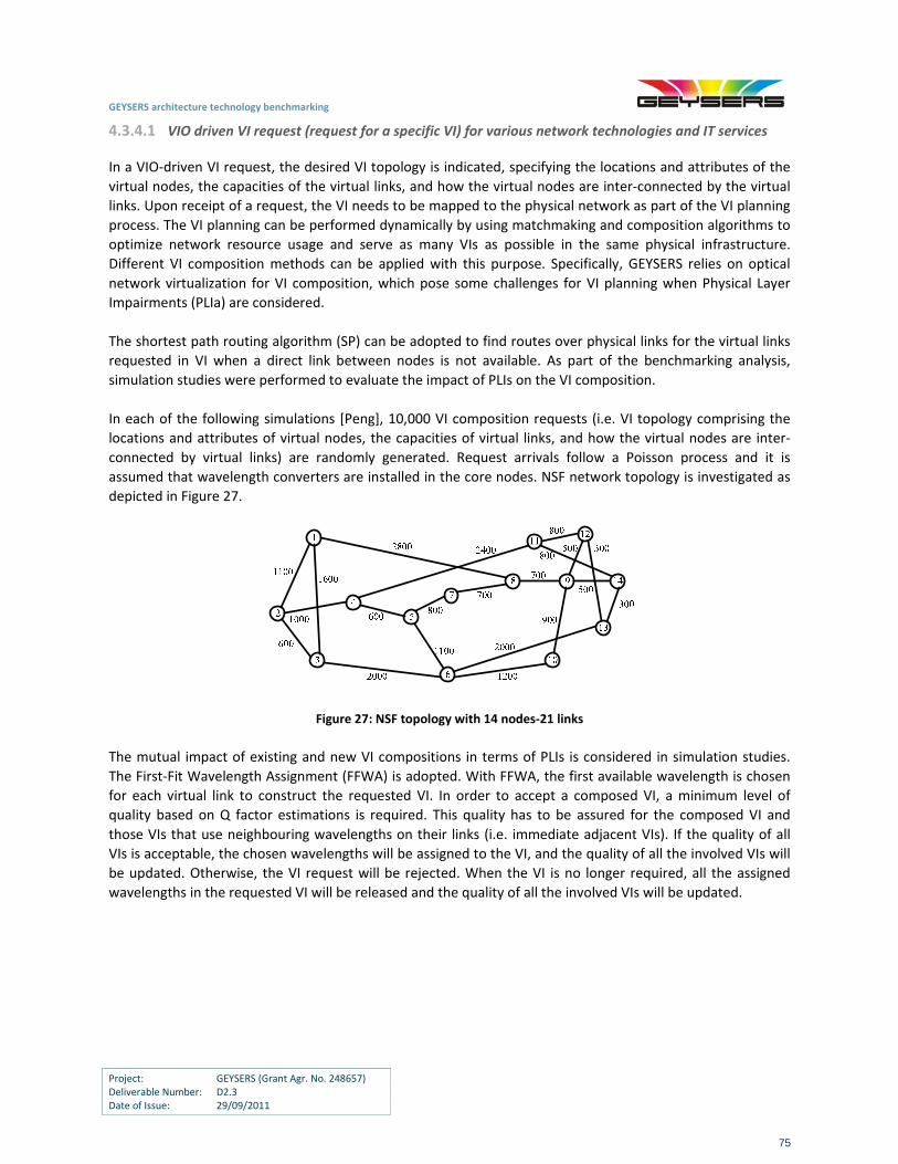
GEYSERS architecture technology benchmarking
Project: GEYSERS (Grant Agr. No. 248657) Deliverable Number: D2.3 Date of Issue: 29/09/2011
75
4.3.4.1 VIO driven VI request (request for a specific VI) for various network technologies and IT services
In a VIO‐driven VI request, the desired VI topology is indicated, specifying the locations and attributes of the
virtual nodes, the capacities of the virtual links, and how the virtual nodes are inter‐connected by the virtual
links. Upon receipt of a request, the VI needs to be mapped to the physical network as part of the VI planning
process. The VI planning can be performed dynamically by using matchmaking and composition algorithms to
optimize network resource usage and serve as many VIs as possible in the same physical infrastructure.
Different VI composition methods can be applied with this purpose. Specifically, GEYSERS relies on optical
network virtualization for VI composition, which pose some challenges for VI planning when Physical Layer
Impairments (PLIa) are considered.
The shortest path routing algorithm (SP) can be adopted to find routes over physical links for the virtual links
requested in VI when a direct link between nodes is not available. As part of the benchmarking analysis,
simulation studies were performed to evaluate the impact of PLIs on the VI composition.
In each of the following simulations [Peng], 10,000 VI composition requests (i.e. VI topology comprising the
locations and attributes of virtual nodes, the capacities of virtual links, and how the virtual nodes are inter‐
connected by virtual links) are randomly generated. Request arrivals follow a Poisson process and it is
assumed that wavelength converters are installed in the core nodes. NSF network topology is investigated as
depicted in Figure 27.
Figure 27: NSF topology with 14 nodes‐21 links
The mutual impact of existing and new VI compositions in terms of PLIs is considered in simulation studies.
The First‐Fit Wavelength Assignment (FFWA) is adopted. With FFWA, the first available wavelength is chosen
for each virtual link to construct the requested VI. In order to accept a composed VI, a minimum level of
quality based on Q factor estimations is required. This quality has to be assured for the composed VI and
those VIs that use neighbouring wavelengths on their links (i.e. immediate adjacent VIs). If the quality of all
VIs is acceptable, the chosen wavelengths will be assigned to the VI, and the quality of all the involved VIs will
be updated. Otherwise, the VI request will be rejected. When the VI is no longer required, all the assigned
wavelengths in the requested VI will be released and the quality of all the involved VIs will be updated.
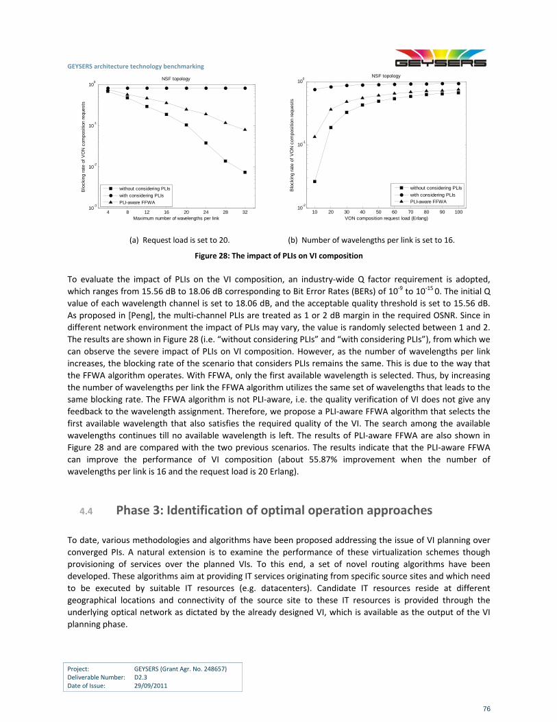
GEYSERS architecture technology benchmarking
Project: GEYSERS (Grant Agr. No. 248657) Deliverable Number: D2.3 Date of Issue: 29/09/2011
76
4 8 12 16 20 24 28 3210
-3
10-2
10-1
100
Maximum number of wavelengths per link
Blo
ckin
g ra
te o
f V
ON
com
posi
tion
requ
ests
NSF topology
without considering PLIs
with considering PLIs
PLI-aware FFWA
10 20 30 40 50 60 70 80 90 100
10-2
10-1
100
VON composition request load (Erlang)
Blo
ckin
g ra
te o
f V
ON
com
posi
tion
requ
ests
NSF topology
without considering PLIs
with considering PLIsPLI-aware FFWA
(a) Request load is set to 20. (b) Number of wavelengths per link is set to 16.
Figure 28: The impact of PLIs on VI composition
To evaluate the impact of PLIs on the VI composition, an industry‐wide Q factor requirement is adopted,
which ranges from 15.56 dB to 18.06 dB corresponding to Bit Error Rates (BERs) of 10‐9 to 10‐15 0. The initial Q
value of each wavelength channel is set to 18.06 dB, and the acceptable quality threshold is set to 15.56 dB.
As proposed in [Peng], the multi‐channel PLIs are treated as 1 or 2 dB margin in the required OSNR. Since in
different network environment the impact of PLIs may vary, the value is randomly selected between 1 and 2.
The results are shown in Figure 28 (i.e. “without considering PLIs” and “with considering PLIs”), from which we
can observe the severe impact of PLIs on VI composition. However, as the number of wavelengths per link
increases, the blocking rate of the scenario that considers PLIs remains the same. This is due to the way that
the FFWA algorithm operates. With FFWA, only the first available wavelength is selected. Thus, by increasing
the number of wavelengths per link the FFWA algorithm utilizes the same set of wavelengths that leads to the
same blocking rate. The FFWA algorithm is not PLI‐aware, i.e. the quality verification of VI does not give any
feedback to the wavelength assignment. Therefore, we propose a PLI‐aware FFWA algorithm that selects the
first available wavelength that also satisfies the required quality of the VI. The search among the available
wavelengths continues till no available wavelength is left. The results of PLI‐aware FFWA are also shown in
Figure 28 and are compared with the two previous scenarios. The results indicate that the PLI‐aware FFWA
can improve the performance of VI composition (about 55.87% improvement when the number of
wavelengths per link is 16 and the request load is 20 Erlang).
4.4 Phase 3: Identification of optimal operation approaches
To date, various methodologies and algorithms have been proposed addressing the issue of VI planning over
converged PIs. A natural extension is to examine the performance of these virtualization schemes though
provisioning of services over the planned VIs. To this end, a set of novel routing algorithms have been
developed. These algorithms aim at providing IT services originating from specific source sites and which need
to be executed by suitable IT resources (e.g. datacenters). Candidate IT resources reside at different
geographical locations and connectivity of the source site to these IT resources is provided through the
underlying optical network as dictated by the already designed VI, which is available as the output of the VI
planning phase.

GEYSERS architecture technology benchmarking
Project: GEYSERS (Grant Agr. No. 248657) Deliverable Number: D2.3 Date of Issue: 29/09/2011
77
In this report, the service provisioning scheme that is examined in terms of energy is based on anycast routing
[Tzanakaki11‐1]. Since the requirement for the IT services is the delivery of results, the exact location of the
execution of the job is of no interest. In this context, energy efficiency is achieved by identifying the least
energy consuming IT and network resources required to support the services, and switching‐off of any unused
network resources (such as links, nodes, etc) and IT resources (such as servers).
To evaluate the performance of energy awareness in the service provisioning phase, an Integer Linear
Program (ILP) has been created based on the model described in [Tzanakaki11‐1]. This ILP assumes a
capacitated VI and an energy consumption model where a datacenter’s energy increases linearly with the
processing load, as described in detail in [Tzanakaki11‐1]. The energy consumption of the optical network is
calculated through the VI planning phase described in detail in [Katrinis11].
The proposed model takes as inputs the following: (a) parameters specifying the energy consumption of the
VI IT and network resources, (b) a set of IT resource sites which are able to handle IT requests, (c) a set of
lightpath requests per source, which need to end in one of the proposed server sites, and (d) the capacity of
the links and the datacenters. The output of the model includes: (a) the IT resource allocation i.e. which server
site serves which source node’s light path request and (b) a route to the allocated IT site allowing switching of
server sites, OXCs and links.
In order to compare the performance of the proposed energy efficient algorithm, three alternative strategies
have been implemented: (i) one where the objective is to minimize the number of used wavelengths, which
corresponds to conventional shortest path (SP) calculation (ii) one where we only try to minimize the energy
consumed by the network elements and (iii) a third one which aims at minimizing the energy consumed by
the IT resource sites only.
The numerical results have been derived using as input the VI that has been generated based on the basic
model presented in Figure 19.
Figure 29: Energy aware service provisioning schemes vs SP routing
Figure 29 illustrates the energy consumption of the VI infrastructure when applying the proposed energy
aware algorithm compared to SP. It can be seen that the energy savings achieved through the energy aware
GEYSERS architecture technology benchmarking
Project: GEYSERS (Grant Agr. No. 248657) Deliverable Number: D2.3 Date of Issue: 29/09/2011
78
scheme reaches 40% for low service loads and reduces with the load. This effect of the energy saving
reduction, with the service load, is due to the fact that at high loads, most of the VI resources are utilized and
the overall energy consumption reaches its maximum value. Among all approaches under consideration, the
highest VI energy consumption is obtained as expected, in the case where no energy consideration is taking
place. In addition, the approach that focuses on the network power consumption provides very similar
performance to that of the SP, with a small difference (3,37% on average). On the other hand, the proposed
scheme considers jointly the energy consumption of IT and network resources which always provide optimum
performance. However, it should be noted that the routing approach takes into consideration only the power
consumption of IT resources, demonstrates only a small additional energy penalty compared to the proposed
solution (a difference ranging from 2,76% up to 11,05% depending on the offered load). These observations
clearly indicate that in the VI under consideration, the IT resources have the most dominant contribution in
the overall power consumption compared to the optical network resources. Figure 29 shows that when
applying the proposed routing approach as well as the approach considering the energy consumption of IT
resources, a step‐wise increase in energy consumption is observed at 195 requests. This is due to a resource
site’s maximum capacity is 200 requests. Hence, the step‐wise increase indicates the startup cost for
switching‐on a second server site. In low loading conditions, the preferable solution for energy minimization
involves the use of only one server site. However, in high load conditions switching‐on a second server site is
inevitable to accommodate the load.
GEYSERS architecture technology benchmarking
Project: GEYSERS (Grant Agr. No. 248657) Deliverable Number: D2.3 Date of Issue: 29/09/2011
79
5 Technology Requirements for Supporting the GEYSERS Approach
This section addresses the technological requirements that both network and IT solutions need to support in order to facilitate the GEYSERS approach in an effective manner. The specific conclusions and proposals of this section have been extracted from the output of the detailed benchmarking process that has been presented in the previous sections and involve architecture, scalability, integration and interoperability, management and security requirements. In addition, this section includes a discussion and comparison of various virtual network design and service provisioning approaches resulting in a set of recommendations for equipment vendors, network operators and service providers, based on the findings reported in section 4.
5.1 Architecture requirements
Architecture requirements provide input to major network technology decisions concerning optical network resources, IT infrastructures and the protocols required to support the provisioning and operation of services over the integrated optical network and IT infrastructure.
5.1.1 Optical networking infrastructures
The GEYSERS approach leverages on specific technologies and solutions at the optical network infrastructure level in order to provide the seamless provisioning of virtualized optical networks and advanced connectivity services:
Optical Transport Network (OTN)
Innovative photonic OAM features
Intelligent Network Control Plane
Optical Transport Networks provide individual forwarding, operations, monitoring and SLA assurance for individual traffic relations generated in the IP routing layer. OTN enables efficient sub‐wavelength bandwidth management capabilities, while multiple transport options are available. Thus, OTN’s features provide a transport foundation for IP traffic relations on which router ports and even sub‐ports can be mapped to the
GEYSERS architecture technology benchmarking
Project: GEYSERS (Grant Agr. No. 248657) Deliverable Number: D2.3 Date of Issue: 29/09/2011
80
most optimal transport entity: a wavelength (optical channel, Och), a fixed‐rate virtual container (optical data unit, ODU) or a variable‐rate virtual container (ODUflex).
Automated methods and procedures for complete photonic layer network management (photonic OAM features) would enable circuit provisioning without on‐site intervention, thus enabling faster services provisioning and flexibility at the optical layer. The main technologies to be deployed are:
Photonic switching and adaptable optical transport: T‐ROADM and ROADM architectures which enable for colourless, directionless, multi‐degree switching
A GMPLS control plane for circuit provisioning, monitoring, fault localization and photonic restoration
An intelligent Network Control Plane makes it possible to create a ‘self‐running’ network in which ‘the network is the database’, thus automating and simplifying network operations. GEYSERS NCP+ is based on ASON/GMPLS (Automatic Switched optical Network/Generalized Multi‐Protocol Label Switching).
5.1.2 IT Infrastructures
One of the main goals of GEYSERS is to support a large‐scale heterogeneous infrastructure that can be built by combining and virtualizing IT and networking resources that are owned by various Physical Infrastructure Providers. For this reason, the design and implementation of the GEYSERS framework tried to be as agnostic as possible to the underlying hardware used.
The basis for the reference implementation of the IT virtualization management functionality in GEYSERS, uses OpenNebula, therefore, physical infrastructure providers should try either to offer products that are compatible with OpenNebula, to contribute to the OpenNebula project by implementing all the extensions that are necessary for the integration of their products to the platform or to offer LICL adapters for interfacing GEYSERS to the virtualization management system used by their infrastructures. The most important architectural restriction that was introduced with the adoption of OpenNebula is the need for shared storage, which can be implemented either through Networked Attached Storage (NAS ‐ direct support by OpenNebula) or through Storage Area Networks (SANs ‐ available through an add‐on module). This eliminates the option of using Direct Attached Storage (DAS) as the sole storage medium in the computer cluster. DAS, however, is still necessary for storing local copies of the operating system images of the VMs that run on a particular host.
Another important restriction imposed by OpenNebula has to do with the configuration of intra‐domain Local Area Networks (LAN) and especially with the IP and MAC address assignment process. More specifically, according to [ON‐DOC], OpenNebula assigns automatically to each virtual machine (VM) a pair of IP and MAC addresses that have been created using the following rule:
MAC = MAC_PREFIX:IP
However, when the VM starts, the operating system either uses a preconfigured static IP address or requests an IP address from the local DHCP server (as it is most often the case). If the actually assigned IP address is different from the one created by OpenNebula, the VM may become unreachable from the control console. In order to avoid this situation there are two possible options. The first (and preferred one) is to configure the DHCP server so that it always assigns the same IP to each particular MAC that is generated by OpenNebula and assigned to the Network Interface Card (NIC) of a VM. In this way, when the VM starts it will always receive from the DHCP server the same IP address that has been assigned to it by OpenNebula. If changing the configuration of the DHCP server is not possible (or not allowed) there is a second way to achieve the desired
GEYSERS architecture technology benchmarking
Project: GEYSERS (Grant Agr. No. 248657) Deliverable Number: D2.3 Date of Issue: 29/09/2011
81
result by using the contextualization features of OpenNebula. More specifically, by executing a specific script during the power‐on process of the VM, we manage to calculate the IP address assigned to this particular VM instance (using the MAC address of the virtual NIC) and configure it as a static IP in the operating system.
5.1.3 Enhancement of the appropriate GMPLS protocols for integrated optical transport and IT
resources
GEYSERS has explored and defined a series of enhancements to RSVP, OSPF, and PCEP protocols in order to facilitate an integrated optical transport and IT resources management. The proposed extensions target IT information dissemination over the network, combined resource reservation, dynamic service modification, common monitoring and recovering mechanisms, energy efficiency and backward interoperability [GEYSERS D4.1]. These services are offered by an interface called NIPS UNI that coordinates the features offered by the underlying protocols.
In the same line, commercial implementations of these protocols willing to fit GEYSERS foreseen services must provide mechanisms to support combined selection of network and IT resources, Dynamic service modification, common monitoring, cross layer recovery, advance reservation, and the handling of energy consumption parameters.
5.1.3.1 Combined selection of IT and network resources
GEYSERS connectivity services are based on the combined selection and provision of both IT and network resources. There are therefore some recommendations on how vendors and operators can support the registration and discovery of combined IT and network resources. Given that both resource types compose a single topology; accordingly, IT resources should be considered as end‐points and characterized according to their capabilities (number of CPUs, storage size). This information should be gathered by the nodes in order to support the combined selection IT and network resources in complex connectivity services. Based on this purpose, commercial implementations of the PCEP and RSVP‐TE protocols must include IT resource description for advertisement (PCEP) and reservation/decommission (RSVP). It should be possible to also poll this information from various directories and configuration management databases (CMDBs) available in an administrative domain.
5.1.3.2 Dynamic service modification
The GEYSERS architecture is designed to give applications a dynamic substrate adaptable to its current demands of traffic load, storage and CPU usage. The up or down‐scaling of a certain network resource (e.g. the bandwidth of a link) is driven by the knowledge of the PCEs, where the OSPF‐TE must implement extensions to keep the PCEs updated with the maximum increment or decrement which can be requested for a network resource. Additionally, NCP implementations must include an element (called re‐planning manager in [GEYSERS D4.1]) able to trigger the adaptation of an empty capacity according to the resource usage statistics that in cooperation with the LICL can provide the dynamic service modification. Infrastructure services that are compatible with GEYSERS must therefore be designed for dynamic modification. This includes decoupling of specification from implementation, separation of the access interface from the point of execution, parameterisation, context‐based instantiation, a means of publishing state to controllers and separate interfaces for usage and management.
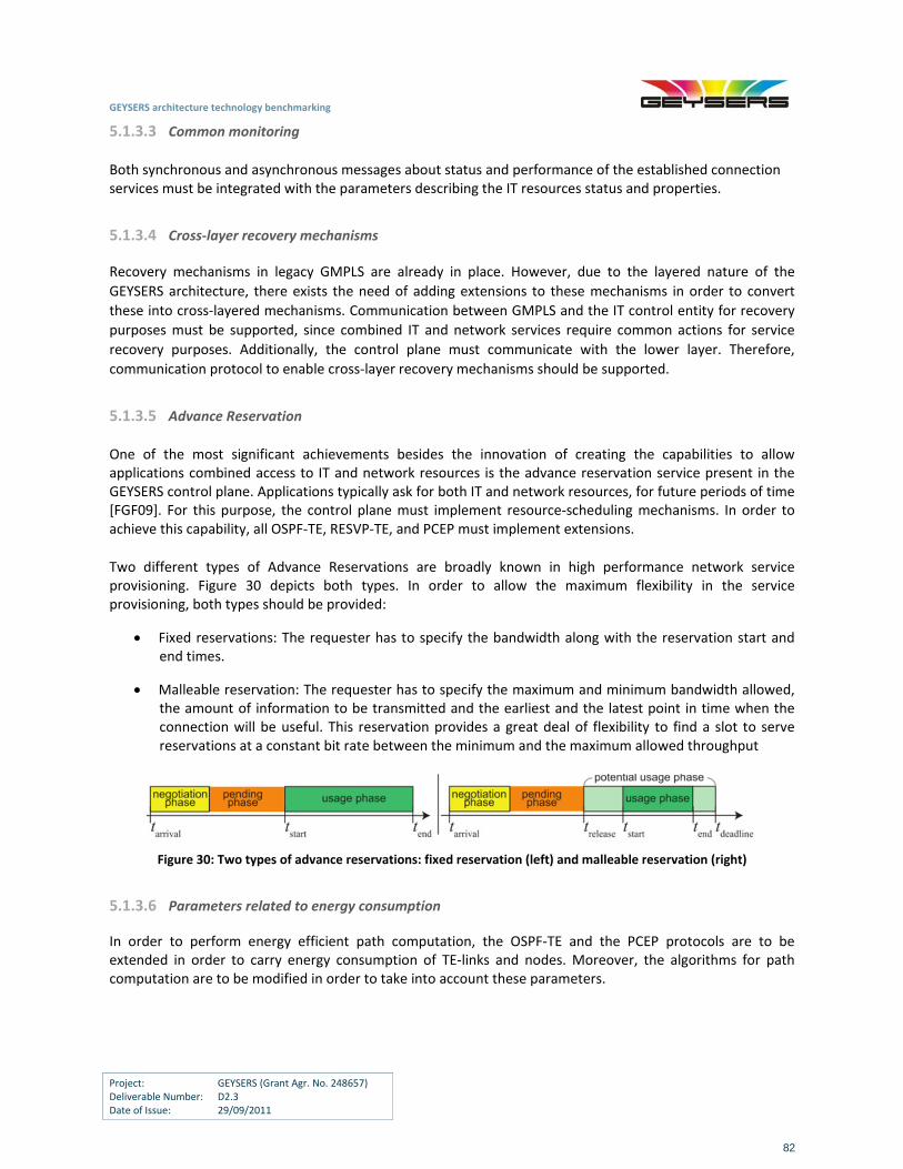
GEYSERS architecture technology benchmarking
Project: GEYSERS (Grant Agr. No. 248657) Deliverable Number: D2.3 Date of Issue: 29/09/2011
82
5.1.3.3 Common monitoring
Both synchronous and asynchronous messages about status and performance of the established connection services must be integrated with the parameters describing the IT resources status and properties.
5.1.3.4 Cross‐layer recovery mechanisms
Recovery mechanisms in legacy GMPLS are already in place. However, due to the layered nature of the
GEYSERS architecture, there exists the need of adding extensions to these mechanisms in order to convert
these into cross‐layered mechanisms. Communication between GMPLS and the IT control entity for recovery
purposes must be supported, since combined IT and network services require common actions for service
recovery purposes. Additionally, the control plane must communicate with the lower layer. Therefore,
communication protocol to enable cross‐layer recovery mechanisms should be supported.
5.1.3.5 Advance Reservation
One of the most significant achievements besides the innovation of creating the capabilities to allow applications combined access to IT and network resources is the advance reservation service present in the GEYSERS control plane. Applications typically ask for both IT and network resources, for future periods of time [FGF09]. For this purpose, the control plane must implement resource‐scheduling mechanisms. In order to achieve this capability, all OSPF‐TE, RESVP‐TE, and PCEP must implement extensions.
Two different types of Advance Reservations are broadly known in high performance network service provisioning. Figure 30 depicts both types. In order to allow the maximum flexibility in the service provisioning, both types should be provided:
Fixed reservations: The requester has to specify the bandwidth along with the reservation start and end times.
Malleable reservation: The requester has to specify the maximum and minimum bandwidth allowed, the amount of information to be transmitted and the earliest and the latest point in time when the connection will be useful. This reservation provides a great deal of flexibility to find a slot to serve reservations at a constant bit rate between the minimum and the maximum allowed throughput
Figure 30: Two types of advance reservations: fixed reservation (left) and malleable reservation (right)
5.1.3.6 Parameters related to energy consumption
In order to perform energy efficient path computation, the OSPF‐TE and the PCEP protocols are to be extended in order to carry energy consumption of TE‐links and nodes. Moreover, the algorithms for path computation are to be modified in order to take into account these parameters.
GEYSERS architecture technology benchmarking
Project: GEYSERS (Grant Agr. No. 248657) Deliverable Number: D2.3 Date of Issue: 29/09/2011
83
5.2 Scalability requirements
A major issue to be addressed is related to how existing optical networking equipment and IT resources used in the support of a GEYSERS‐like solution can be scaled‐up and scaled‐out to support the requirements of the volume of future services and end users.
Vertical scalability (scale‐up) refers to the ability of a system to support more concurrent users by adding more resources to a single node or by replacing the existing node with one of higher capacity. Horizontal scalability (scale‐out) on the other hand, refers to the ability of a system to support more concurrent users by adding more computing nodes (of the same or different capacity) to the system.
As far as the services offered by GEYSERS are concerned, the framework supports both scale‐up (through the migration of an existing virtual machine to a physical server with higher processing power) and scale‐out (through the provisioning of additional resources). As far as the implementation of GEYSERS is concerned, the software is being developed as a set of independent web services that can run on separate hardware and communicate through a REST interface. This allows GEYSERS to scale out easily in order to support a large number of managed hosts. Moreover, OpenNebula has also proven to be very scalable as recent tests at CERN have demonstrated. These tests are described in detail in [ON‐CERN].
GEYSERS control plane scalability leverages on GMPLS capacity to support an increase of number of nodes (including IT), TE‐links, LSPs, regions, layers and ISCDs. GMPLS scales relatively well with the number of nodes and links as well as for multiple regions and layers. However, the number of LSPs in a lower layer may impact the scalability of the protocol. Therefore, due to this scalability concern, the use of Virtual TE‐links [GMPLS‐eval] to reduce the control plane overload is compulsory.
5.3 Integration and interoperability requirements
These requirements drive technology decisions such as vendor functionality and interoperability with the current systems. Interoperability is an important aspect of systems composed of heterogeneous resources, services and mechanisms. In information systems, the need is for dissimilar components with different administrators to still work together for a shared objective. The provisioning and management of VIs is a system that requires the cooperation of various roles and mechanisms, using various protocols and technology platforms. Interoperability can be further described in the following aspects, each of which are requirements for vendors and operators that use the GEYSERS architecture in the context of VIs:
Messaging interoperability: the assumption that two separate entities can communicate and exchange information with the assurance of reception and correct interpretation. This is hence associated with standard languages and communications protocols established between communicating parties.
Invocation interoperability: the ability of different service providers that share the same service classification but different implementations (and possibly locations and domains) to be uniformly invoked. A client of either service should experience similar behaviour when invoking either service, including when faults arise. Standard service descriptions, invocation interfaces and advertisement/discovery protocols are hence required.
Functional interoperability: this is also known as portability or migration‐enablement, where a component that runs in one execution platform or operational environment is capable of correct
GEYSERS architecture technology benchmarking
Project: GEYSERS (Grant Agr. No. 248657) Deliverable Number: D2.3 Date of Issue: 29/09/2011
84
functional execution in another platform or environment. That is, there exists a set of functional/unit tests that can be performed successfully on the component, when it is placed in interoperable platforms.
Non‐functional Interoperability: this is the ability of non‐functional or quality criteria of a component to be maintained when it interacts with interoperable components or is migrated between interoperable platforms or environments. For example, if the performance and scalability of a component are degraded as a result of interacting with another component or being transferred to another platform, then there is a lack of interoperability with the interacting component and new platform.
Policy Interoperability: this is the assurance that a set of policies expected to govern the behaviour and constraints of a component (e.g. access controls) remain enforceable in spite of its interactions with other components or transfer to another platform or operational environment.
Interoperability in GEYSERS is based on the separation of concerns during the design and the selection of standards and technologies used to build components. Vendors and operators that follow these design patterns and adopt the relevant standards (and in some cases technologies), will have some assurance of the aforementioned aspects of interoperability. Furthermore, special components and intermediary layers such as proxies, translators and transformers might be required for the purpose of achieving interoperability, especially in the case of integration with existing platforms and technologies. Furthermore, these integrations can be done in the data, control and management planes of IT and Networking infrastructures, such that verifying interoperability can be complex. The data plane interoperability should be guaranteed by the use of standard protocols. The control plane interoperability should be guaranteed by the GEYSERS developments. Finally, the management interoperability should be guaranteed by the use of management systems or methods which provide standard interfaces for network management. In order for various physical infrastructure providers to interoperate, they would need to offer the appropriate LICL adapters for interfacing GEYSERS to the underlying IT management system, and for exposing the available compute and storage hardware resources.
On the network side, different vendor devices can be integrated by using the GEYSERS architecture as a mediating layer. The LICL software is designed with the integration and interoperability of different devices in mind, by creating unified, abstract models representing each resource kind. This systems management design pattern and approach of representing resources would need to be adopted by vendors and operators. Moreover, each device must be capable of managing each transmission channel in an isolated way independently from the vendor. To achieve this integration and interoperability, physical adaptors are to be installed in the concerned equipment to hinder heterogeneity towards the LICL. Furthermore, the LICL also is intentionally designed such that the interoperability of different administrative domains can be controlled by different Network Management Systems (NMS) or Network Resource Provisioning Systems (NRPS). NMSs and NRPSs must expose standard interfaces to the LICL allowing it to treat them as a complex device. This complex device holds the same functionalities as a single network device, since they are represented by the same abstract model.
A table summarizing the interoperability requirements that must be supported in order to facilitate the
GEYSERS approach is given below.
Layer Interoperability Requirements
PI Standard protocols and networking interfaces should be used between physical
servers and network domains.
Standard management interfaces and protocols are required at vendors such as
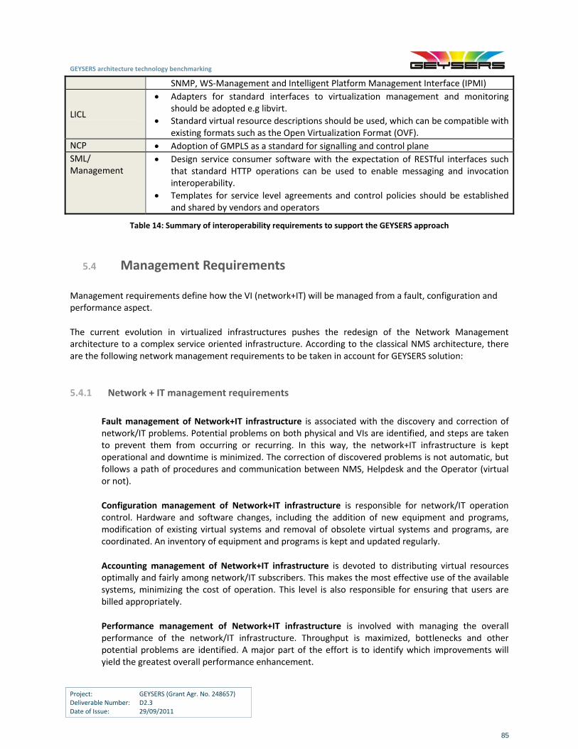
GEYSERS architecture technology benchmarking
Project: GEYSERS (Grant Agr. No. 248657) Deliverable Number: D2.3 Date of Issue: 29/09/2011
85
SNMP, WS‐Management and Intelligent Platform Management Interface (IPMI)
LICL
Adapters for standard interfaces to virtualization management and monitoring should be adopted e.g libvirt.
Standard virtual resource descriptions should be used, which can be compatible with existing formats such as the Open Virtualization Format (OVF).
NCP Adoption of GMPLS as a standard for signalling and control plane
SML/ Management
Design service consumer software with the expectation of RESTful interfaces such that standard HTTP operations can be used to enable messaging and invocation interoperability.
Templates for service level agreements and control policies should be established and shared by vendors and operators
Table 14: Summary of interoperability requirements to support the GEYSERS approach
5.4 Management Requirements
Management requirements define how the VI (network+IT) will be managed from a fault, configuration and performance aspect.
The current evolution in virtualized infrastructures pushes the redesign of the Network Management architecture to a complex service oriented infrastructure. According to the classical NMS architecture, there are the following network management requirements to be taken in account for GEYSERS solution:
5.4.1 Network + IT management requirements
Fault management of Network+IT infrastructure is associated with the discovery and correction of network/IT problems. Potential problems on both physical and VIs are identified, and steps are taken to prevent them from occurring or recurring. In this way, the network+IT infrastructure is kept operational and downtime is minimized. The correction of discovered problems is not automatic, but follows a path of procedures and communication between NMS, Helpdesk and the Operator (virtual or not).
Configuration management of Network+IT infrastructure is responsible for network/IT operation control. Hardware and software changes, including the addition of new equipment and programs, modification of existing virtual systems and removal of obsolete virtual systems and programs, are coordinated. An inventory of equipment and programs is kept and updated regularly.
Accounting management of Network+IT infrastructure is devoted to distributing virtual resources optimally and fairly among network/IT subscribers. This makes the most effective use of the available systems, minimizing the cost of operation. This level is also responsible for ensuring that users are billed appropriately.
Performance management of Network+IT infrastructure is involved with managing the overall performance of the network/IT infrastructure. Throughput is maximized, bottlenecks and other potential problems are identified. A major part of the effort is to identify which improvements will yield the greatest overall performance enhancement.
GEYSERS architecture technology benchmarking
Project: GEYSERS (Grant Agr. No. 248657) Deliverable Number: D2.3 Date of Issue: 29/09/2011
86
5.4.2 Network + IT service requirements
Monitoring of network/IT services. The following services should be monitored: status of physical and virtual interfaces (e.g. on border routers) status of BGP sessions, size of the routing table, CPU utilization on routers/switches, MPLS status, power consumption of network equipment, disk, memory usage and CPU percentage used of the IT system.
Control refers to manipulation of devices. No automatic manipulation is planned for the first burst of planned operations; rather, all such intervention will be accomplished by human interaction.
Reporting refers to documenting abnormal events and circulation of these documents. It will be materialized by the Helpdesk and the TTS (Trouble Tickets System).
5.5 Security requirements
Security requirements define how applications and infrastructure services will be secured. Security services have a dual task to secure the normal operation of the GEYSERS infrastructure provisioning system and to provide infrastructure security services for user applications as part of the provisioned on‐demand VI. At the VIP and VIO level, the network is protected against unauthorized access, and physical or electronic sabotage. Confidentiality of users’ information is maintained when necessary or warranted. The security systems also allow network and VI administrators to control what each individual authorized user can (and cannot) do with the VI (network+IT equipment).
A cloud computing environment has to face a large number of security threats that are similar to those faced by traditional datacenters such as unauthorized access attempts (both to the physical facility and to the managed computer systems), denial of service attacks and various exploits. Moreover, as the common IT and networking infrastructure is shared among many users that constantly move data in and out of the cloud, data confidentiality and integrity must also be ensured. Another important issue in this multi‐tenant environment is isolation, both in terms of remote access (if a virtual machine that is operated by one user becomes compromised, this should not affect the systems that belong to other users and share the same physical server) and in terms of performance (if the VI of a user faces a denial of service attack this should not affect the performance of other VIs that run on the same hardware). In order to protect their systems against these threats, VIPs and VIOs should implement all the necessary security mechanisms that are already widely deployed in traditional datacenters such as frequent patching, firewalls, proper application implementation and strong passwords. In order to assist them in this effort, GEYSERS will implement a strong Authentication and Authorisation Infrastructure (AAI) that will be used to offer secure management and configuration services. The GEYSERS security infrastructure combines security measures and services at different infrastructure layers with the security services managed by the VIO and provisioned as part of the VI. Some threats specific to the network control plane level are LSP creation by an unauthorized element, LSP message interception, attacks against RSVP‐TE, attacks against LDP, denial of service attacks on the network infrastructure, unauthorised access to management interfaces, cross‐connection of traffic between users (one of the largest security concerns of users) and attacks against routing protocols and control traffic. To prevent these attacks, GMPLS protocols may include encryption, authentication, filtering, firewalls, access control, isolation, aggregation, and others. More specific recommendations can be found in [GMPLS‐sec‐frw].
GEYSERS architecture technology benchmarking
Project: GEYSERS (Grant Agr. No. 248657) Deliverable Number: D2.3 Date of Issue: 29/09/2011
87
Infrastructure security services are primarily based on the functionality available in the selected VM management platform such as OpenNebula. In order to offer both performance and remote access isolation, OpenNebula mainly leverages the capabilities of the underlying hypervisors. Moreover, it supports VLANs and uses eptables, a filtering tool for Linux‐based bridging firewalls. Additionally, Dynamic Access Control Infrastructure (DACI) is provisioned as part of VI and can be controlled by VIO and optionally by user to provide better integration with user applications and legacy access control service. Deliverable D3.1 includes a detailed description of the security requirements that need to be implemented in GEYSERS. These requirements mainly deal with the following topics:
Isolation of VIs and virtual resources
Secure management of VIs and virtual resources
Privacy of physical infrastructures internal topology and resources In order to fulfil these requirements, the following security handling services are going to be offered by LICL:
Access control
Data protection
Policy enforcement
Secure service provisioning For a more detailed description of the implementation of the GEYSERS AAI, please refer to [D3.1] and [D3.2]
5.6 Comparison of Virtualization Approaches
Evaluating the performance of converged network and IT physical infrastructures is a very complex task. However, appropriately designed benchmark tests may give useful information on the capabilities of this type of systems. In this deliverable, the benchmarking approach was designed not only to reflect the properties of network or IT elements alone, but also to study the performance of the converged infrastructure. For this reason, after identifying the appropriate infrastructures addressed by the GEYSERS concept, various virtual network design and service provisioning algorithms were examined regarding their performance in terms of resource utilization, energy consumption, blocking probability, network load etc. The analysis was carried out using both analytical and simulation models and concludes with the following recommendations for vendors:
1. When the planned network is optimized for network resources, demands are routed to their destinations via the shortest paths, leading to minimal utilization of optical network resources. This approach allows maintaining maximum level of unused network capacity that can be used for future service requests. At the same time, the impact on the operation of IT infrastructure providers is ignored, thus leading to a suboptimal operation of IT servers. Therefore, this scheme is useful to be applied in cases where optical network resources are scarce.
2. When the planned network is optimized focusing on IT resources, demands are optimally allocated to IT servers. In this case, the impact of the proposed planning scheme on network infrastructure providers is ignored, thus leading to an inefficient allocation and exploitation of optical network resources. This scheme is recommended when optical network resources are abundant.
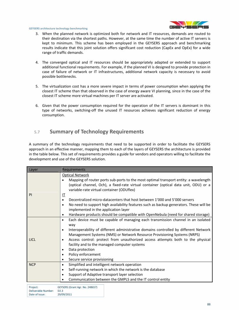
GEYSERS architecture technology benchmarking
Project: GEYSERS (Grant Agr. No. 248657) Deliverable Number: D2.3 Date of Issue: 29/09/2011
88
3. When the planned network is optimized both for network and IT resources, demands are routed to their destination via the shortest paths. However, at the same time the number of active IT servers is kept to minimum. This scheme has been employed in the GEYSERS approach and benchmarking results indicate that this joint solution offers significant cost reduction (CapEx and OpEx) for a wide range of traffic demands.
4. The converged optical and IT resources should be appropriately adapted or extended to support additional functional requirements. For example, if the planned VI is designed to provide protection in case of failure of network or IT infrastructures, additional network capacity is necessary to avoid possible bottlenecks.
5. The virtualization cost has a more severe impact in terms of power consumption when applying the closest IT scheme than that observed in the case of energy aware VI planning, since in the case of the closest IT scheme more virtual machines per IT server are activated.
6. Given that the power consumption required for the operation of the IT servers is dominant in this type of networks, switching‐off the unused IT resources achieves significant reduction of energy consumption.
5.7 Summary of Technology Requirements
A summary of the technology requirements that need to be supported in order to facilitate the GEYSERS approach in an effective manner, mapping them to each of the layers of GEYSERS the architecture is provided in the table below. This set of requirements provides a guide for vendors and operators willing to facilitate the development and use of the GEYSERS solution.
Layer Requirements
PI
Optical Network Mapping of router ports sub‐ports to the most optimal transport entity: a wavelength
(optical channel, Och), a fixed‐rate virtual container (optical data unit, ODU) or a variable‐rate virtual container (ODUflex)
IT Decentralized micro‐datacenters that host between 1’000 and 5’000 servers No need to support high availability features such as backup generators. These will be
implemented in the application layer Hardware products should be compatible with OpenNebula (need for shared storage)
LICL
Each device must be capable of managing each transmission channel in an isolated way
Interoperability of different administrative domains controlled by different Network Management Systems (NMS) or Network Resource Provisioning Systems (NRPS)
Access control: protect from unauthorized access attempts both to the physical facility and to the managed computer systems
Data protection Policy enforcement Secure service provisioning
NCP Simplified and intelligent network operation Self‐running network in which the network is the database Support of Adaptive transport layer selection Communication between the GMPLS and the IT control entity
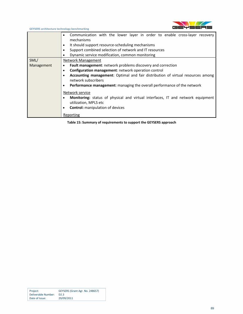
GEYSERS architecture technology benchmarking
Project: GEYSERS (Grant Agr. No. 248657) Deliverable Number: D2.3 Date of Issue: 29/09/2011
89
Communication with the lower layer in order to enable cross‐layer recovery mechanisms
It should support resource‐scheduling mechanisms Support combined selection of network and IT resources Dynamic service modification, common monitoring
SML/ Management
Network Management Fault management: network problems discovery and correction Configuration management: network operation control Accounting management: Optimal and fair distribution of virtual resources among
network subscribers Performance management: managing the overall performance of the network
Network service Monitoring: status of physical and virtual interfaces, IT and network equipment
utilization, MPLS etc Control: manipulation of devices
Reporting
Table 15: Summary of requirements to support the GEYSERS approach
GEYSERS architecture technology benchmarking
Project: GEYSERS (Grant Agr. No. 248657) Deliverable Number: D2.3 Date of Issue: 29/09/2011
90
6 Conclusions
This deliverable focused on benchmarking state‐of‐the‐art network and IT infrastructure technologies, suitable for the realization and deployment of the GEYSERS approach. The benchmarking was applied on the various layers and technologies involved in the GEYSERS architecture including the physical infrastructure, the virtualization mechanisms and the control and management tools. This benchmarking was performed through a discussion on the functional and architectural definition of the GEYSERS approach followed by a detailed description of the state‐of‐the‐art both at a commercial as well as a research level on the various technologies and solutions related to GEYSERS. These technologies and solutions include optical network and IT infrastructure technologies, as well as virtualization and integrated optical network and IT service provisioning technologies. Various virtualization approaches were analysed and examined in a holistic manner, since this is a key aspect of GEYSERS. Through this study, optimal solutions regarding design and operation of VIs were identified taking into consideration varying requirements in terms of inputs and performance metrics. The output of the benchmarking was used to form recommendations for IT and network equipment vendors as well as infrastructure operators and to identify possible extensions to existing technologies that can facilitate the deployment of the GEYSERS approach and the benefits it can provide through its functionalities, capabilities and features.
GEYSERS architecture technology benchmarking
Project: GEYSERS (Grant Agr. No. 248657) Deliverable Number: D2.3 Date of Issue: 29/09/2011
91
7 References
[GEYSERS‐D2.1] http://www.geysers.eu/images/stories/deliverables/geysers‐deliverable_2.1.pdf [GEYSERS‐D3.1] http://www.geysers.eu/images/stories/deliverables/geysers‐deliverable_3.1.pdf [GEYSERS‐D4.1] http://www.geysers.eu/images/stories/deliverables/geysers‐deliverable_4.1.pdf [Handley] M. Handley, “ Why the Internet only just works”, BT Technology Journal, Vol. 24, No 3, 2006 [Swason] B. Swanson et al, “Estimating the Exaflood”, http://www.discovery.org/a/4428, accessed October 2008 [Noirie] L. Noirie, “The Road Towards All‐Opticall Networks”, OFC2003, FA1, pp. 615‐616 [Berthold] J. Berthold, A. A. M. Saleh, L. Blair, and J. M. Simmons, Optical Networking: Past, Present, and Future,
Journal of Lightwave Technology, vol. 26, no. 9, May 2008, pp 1104‐1118 [OMahony06] M. J. O’Mahony, C. Politi, D. Klonidis, R. Nejabati, and D. Simeonidou, “Future Optical Networks”,
Journal of Lightwave Technology, vol. 24, no. 12, Dec. 2006, pp 4684‐4696 [Tzanakaki02] A. Tzanakaki, I. Wright and S. S. Sian, “Wavelength Routed Networks: Benefits and Design Limitations”
(Invited Paper), SCI2002, Orlando, Florida, July 2002. [Chikama] Chikama et al, "Photonic Networking Using Optical Add Drop Multiplexers and Optical Cross‐Connects",
Fujitsu Sci. Tech., J., 35, 1, pp.46‐55, July 1999. [Tzanakaki04] A. Tzanakaki, I. Zacharopoulos and I. Tomkos, “Broadband Building Blocks”, IEEE Circuits and Devices
Magazine, vol. 20 , no. 2 , pp. 32‐37, March‐April 2004. [Tzanakaki03] A. Tzanakaki, I. Zacharopoulos and I. Tomkos, “Optical Add Drop Multiplexers and Optical Cross‐
Connects for Wavelength Routed Networks”, (Invited Paper), ICTON 2003, Warsaw, Poland, June 2003. [CIENA10‐1] Ciena, ”Modernizing The Core With OTN Switching & 40G/100G Transport,” www.heavyreading.com,
December 20010 [Dutta04] A. Dutta, N. Dutta & M.Fujiwara, “WDM Technologies: Optical Networks”, Volume III, Elsevier Academic
Press, 2004 [Theodoras09] J. Theodoras, “A Primer on ROADM Architectures”, ADVA Technology White Paper, May 2009 [Moshafar10] N.M. Mosharaf Kabir Chowdhury and Raouf Boutaba. 2010. A survey of network virtualization. Comput.
Netw. 54, 5 (April 2010), 862‐876. DOI=10.1016/j.comnet.2009.10.017 http://dx.doi.org/10.1016/j.comnet.2009.10.017
[Biggs] Biggs, N.; Lloyd, E. and Wilson, R. (1986), Graph Theory, 1736‐1936, Oxford University Press [SPEC] Standard Performance Evaluation Corporation (SPEC) (www.spec.org) [Tzanakaki11] A. Tzanakaki et al, “Power Considerations towards a Sustainable Pan‐ European Network”, JWA061,
OFC2011 [Oracle] Oracle Data Sheet, “Sun Oracle DataBaseMachine”,
http://www.oracle.com/us/products/database/database‐machine‐ 069034.html [Fan] Xiaobo Fan, Wolf‐Dietrich Weber, and Luiz Andre Barroso, Power provisioning for a warehouse‐sized
computer. SIGARCH Comput. [Kubilinskas] E. Kubilinskas, P. Nilsson, M. Pioro, “Design Models for Robust Multi‐Layer Next Generation Internet
Core Networks Carrying Elastic Traffic”, in proc. of DRCN 2003, 61‐68 (2003). [Peng] Shuping Peng, Reza Nejabati, Siamak Azodolmolky, Eduard Escalona, and Dimitra Simeonidou, “An
Impairment‐aware Virtual Optical Network”. [Azodolmolky] S. Azodolmolky, M. Klinkowski, E. Marín Tordera, D. Careglio, J. Solé‐Pareta and I. Tomkos, “A Survey on
Physical Layer Impairments Aware Routing and Wavelength Assignment Algorithms in Optical Networks”, Computer Networks, vol. 53, no. 7, pp. 926‐944, May 2009.
[Tzanakaki11‐2] A.Tzanakaki, M.P Anastasopoulos et al, "Energy efficiency considerations in integrated IT and optical network resilient infrastructures", in proc. of ICTON 2011.
[Tzanakaki11‐1] A.Tzanakaki, M.P Anastasopoulos et al, "Energy Efficiency in integrated IT and Optical Network Infrastructures: The GEYSERS approach", in proc. of IEEE INFOCOM 2011, Workshop on Green Communications and Networking.
GEYSERS architecture technology benchmarking
Project: GEYSERS (Grant Agr. No. 248657) Deliverable Number: D2.3 Date of Issue: 29/09/2011
92
[Bouyoucef10] K. Bouyoucef, I. Limam‐Bedhiaf, and O.Cherkaoui,“Optimal Allocation Approach of Virtual Servers in Cloud Computing”, in Proc. of 6th Euro‐ NF conference on Next Generation Internet, July 2010
[Buysse10] J. Buysse, M. De Leenheer, B. Dhoedt, C. Develder, “On the impact of relocation on network dimensions in optical grids”, in Proc. Int. Conf. Optical Netw. Design and Modeling (ONDM 2010), Kyoto, Japan, 31 Jan.‐3 Feb. 2010.
[EnegyStar] Energy Star, “Small network equipment”, www.energystar.gov/index.cfm?c=new specs.small networkequip
[Katrinis11] K. Katrinis and A. Tzanakaki, "On the Dimensioning of WDM Optical Networks with Impairment‐aware Regeneration", in IEEE/ACM Transactions on Networking, 2011
[Qiao] C. Qiao and M.Yoo, “Optical Burst Switching – A new Paradigm for an Optical Internet”, Journal of High Speed Networks, Special Issues on Optical Networks, vol. 8, No. 1, pp. 69‐84,1999
[OMahony01] M. J. O’Mahony, D. Simeonidou, D. K. Hunter and A. Tzanakaki, “The Application of Optical Packet Switching in Future Communication Networks”, IEEE Comms Magazine, vol. 39, no. 3, March 2001
[4WARD] 4WARD project. Available Online: http://www.4ward‐project.eu/ Retrieved21‐10‐2010. [FEDERICA] FEDERICA project. Available Online: http://www.fp7‐federica.eu/ Retrieved 27‐10‐2010. [ORCA] Open Resource Control Architecture. Available Online:http://geni‐orca.renci.org Retrieved 27‐10‐2010 [RSVOIR] RESERVOIR project. Available Online: http://www.reservoir‐fp7.eu/ Retrieved 20‐10‐2010. [KVM] Kivity, A., Kamay, Y., Laor, D., Lublin, U. and Liguori, A. “kvm: the Linux Virtual Machine Monitor,” in
Linux Symposium, 2007. [VSERVER] VServer. Available Online: http://linux‐vserver.org [XEN] Barham, P., Dragovic, B., Fraser, K., Hand, S., Harris, T., Ho, A., Neugebauer, R., Pratt, I. and Warfield, A.
“Xen and the art of virtualization,” in SOSP ’03: Proceedings of the nineteenth ACM symposium on Operating systems principles, (New York, NY, USA), pp. 164–177, ACM, 2003.
[Pin‐Han02] H. Pin‐Han, H. T. Mouftah, “Routing and wavelength assignment with multigranularity traffic in optical networks”, Journal of Lightwave Technology, vol. 20, no. 8, Aug. 2002,1292–1303
[Politi 03] C. T. Politi, D. Klonidis, A. Tzanakaki, M. J. O’Mahony and I. Tomkos, “Novel Wavelength/Waveband Cross Connect Architecture based on Optical Wavelength Converters and a Passive Wavelength Router”, LEOS Annual mtg, 2003, vol. 1, pp: 140 – 141, October 2003.
[Politi06] C. T. Politi, C. Matrakidis, A. Stavdas, D. Gavalas and M. J. O’Mahony, “Single‐layer multigranular optical cross‐connect architecture with conversion capability and enhanced flexibility”, JOURNAL OF OPTICAL NETWORKING, vol. 5, No. 12, December 2006, pp 1002‐1012
[YOUSIF] M. Yousif, "Cloud Computing ‐ an IT paradigm changer," Computer Systems and Applications (AICCSA), 2010 IEEE/ACS International Conference on , vol., no., pp.1, 16‐19 May 2010
[DSM] “Distributed Shared Memory”, Changhun Lee, 15th CISL Winter Workshop [ScMP] “ScaleMP Virtual Symmetric Multiprocessor (SMP) technology”, www.scalemp.com [NIST] “Working Definition of Cloud Computing,” NIST, 2009 [CSA] “Guidance for Critical Areas of Focus in Cloud Computing”, Cloud Security Alliance, 2009 [AVPC] “Amazon Virtual Private Cloud”, Amazon [OpS] “OpSource Cloud”, OpSource [SVL] “Virtual Lab”, Skytap [OCirrus] “OpenCirrus Cloud Computing Research Testbed”, OpenCirrus [O‐IT] “Outsourced IT Operations”, ENKI [BPHA] “Blueprints for High Availability”, Evan Marcus, Hal Stern
[Mosharaf09] N.M. Mosharaf Kabir Chowdhury and Raouf Boutaba, “Network Virtualization: State of the Art and Research Challenges”,IEEE Communication Magazine, Vol.47, no.7,pp.20‐26,July 2009
[Melle08] Serge Melle, Rick Dodd, Steve Grubb, Chris Liou, Vijay Vusirikala, and Dave Welch, Infinera Corp., “Bandwidth Virtualization Enables Long‐Haul WDM Transport of 40 Gb/s and 100 Gb/s Services”, IEEE Communications Magazine , February 2008
[Nagarajan05] R. Nagarajan et al, “Large‐Scale Photonic Integrated Circuits,” IEEE J. Select Topics in Quant. Elect., vol. 11, no.1, Jan.–Feb., 2005, pp. 50–65.
[IEEE802.3] IEEE 802.3ba 40Gb/s and 100Gb/s Ethernet Task Force, http://www.ieee802.org/3/ba/public/mar10/index.htm
[GENI] “Global Environment for Network Innovation (GENI), ”http://www.geni.net [VINI] “VINI: A Virtual Network Infrastructure,” www.vini‐veritas.net. [Openflow] Openflow: www.openflowswitch.org. [Wei09] Wei Wei, Junqiang Hu, ChonggangWang, Ting Wang and Chunming Qiao, “A Programmable Router I nterface Supporting Link Virtualization with Adaptive Optical OFDMA Transmission“, OFC/NFOEC2009 [ADVA10] ADVA Optical Networking: Virtualized Optical Networks for sustainable cloud services. White Paper.
Michal Ritter. January 2010. [GEYSERS‐D2.1] Escalona, E. et al. GEYSERS Deliverable D2.1. Initial GEYSERS Architecture & Interfaces Specification.
Available online: http://www.geysers.eu/images/stories/deliverables/geysers‐deliverable_2.1.pdf

GEYSERS architecture technology benchmarking
Project: GEYSERS (Grant Agr. No. 248657) Deliverable Number: D2.3 Date of Issue: 29/09/2011
93
[JUNIPER10]. Juniper Networks, Inc. Virtualization in the Core of the Network. White Paper. 2000299‐002‐EN. August 2010.
[CISCONMB] Cisco Internetworking Handbook. Available Online: http://www.cisco.com/en/US/docs/internetworking/technology/handbook/NM‐Basics.html# wp1020557
[PlanetLab] An open platform for developing, deploying, and accessing planetary‐scale services. Available Online: http://www.planet‐lab.org/
[COST239] P. Batchelor et al, “Study on the implementation of optical transparent transport networks in the European environment‐Results of the research project COST 239”, Photonic Network Communications, vol. 2, no. 1, pp. 15‐32, 2000
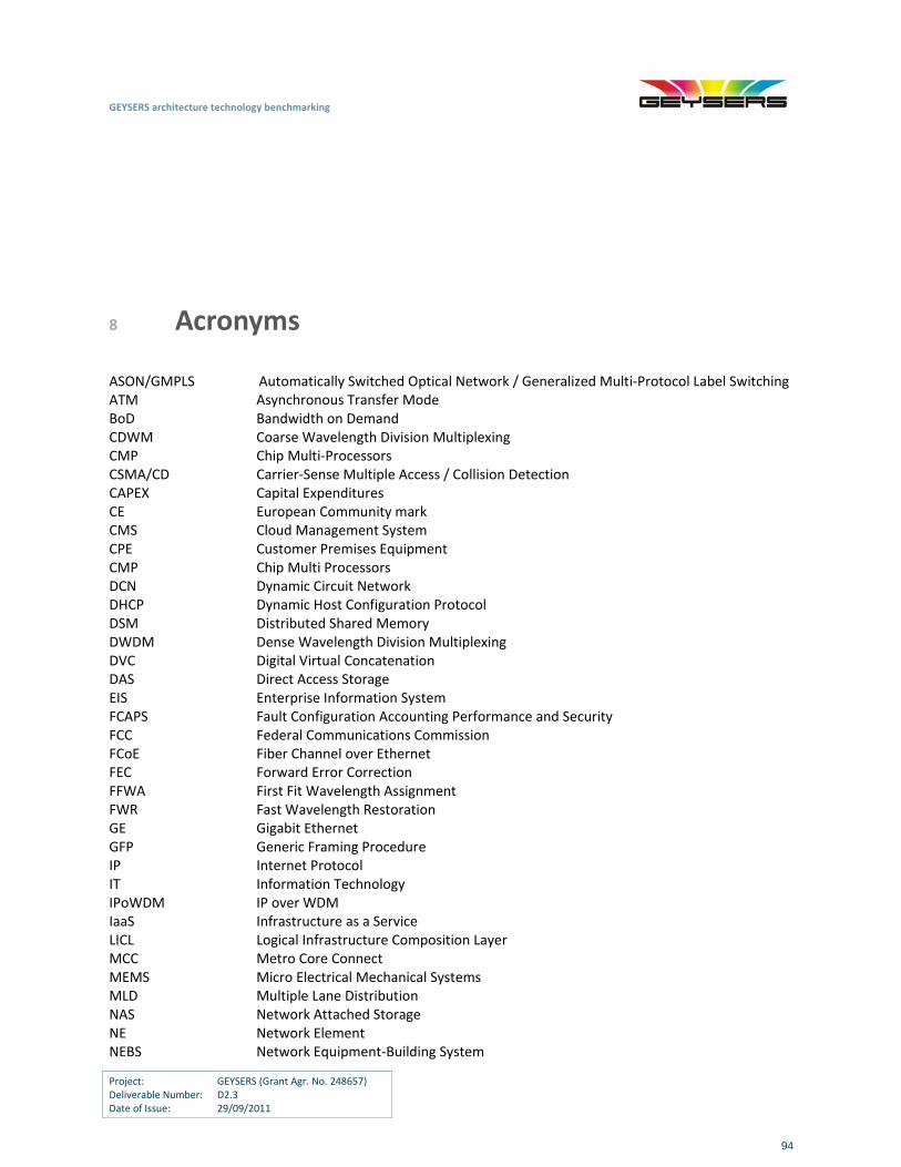
GEYSERS architecture technology benchmarking
Project: GEYSERS (Grant Agr. No. 248657) Deliverable Number: D2.3 Date of Issue: 29/09/2011
94
8 Acronyms
ASON/GMPLS Automatically Switched Optical Network / Generalized Multi‐Protocol Label Switching ATM Asynchronous Transfer Mode BoD Bandwidth on Demand CDWM Coarse Wavelength Division Multiplexing CMP Chip Multi‐Processors CSMA/CD Carrier‐Sense Multiple Access / Collision Detection CAPEX Capital Expenditures CE European Community mark CMS Cloud Management System CPE Customer Premises Equipment CMP Chip Multi Processors DCN Dynamic Circuit Network DHCP Dynamic Host Configuration Protocol DSM Distributed Shared Memory DWDM Dense Wavelength Division Multiplexing DVC Digital Virtual Concatenation DAS Direct Access Storage EIS Enterprise Information System FCAPS Fault Configuration Accounting Performance and Security FCC Federal Communications Commission FCoE Fiber Channel over Ethernet FEC Forward Error Correction FFWA First Fit Wavelength Assignment FWR Fast Wavelength Restoration GE Gigabit Ethernet GFP Generic Framing Procedure IP Internet Protocol IT Information Technology IPoWDM IP over WDM IaaS Infrastructure as a Service LICL Logical Infrastructure Composition Layer MCC Metro Core Connect MEMS Micro Electrical Mechanical Systems MLD Multiple Lane Distribution NAS Network Attached Storage NE Network Element NEBS Network Equipment‐Building System
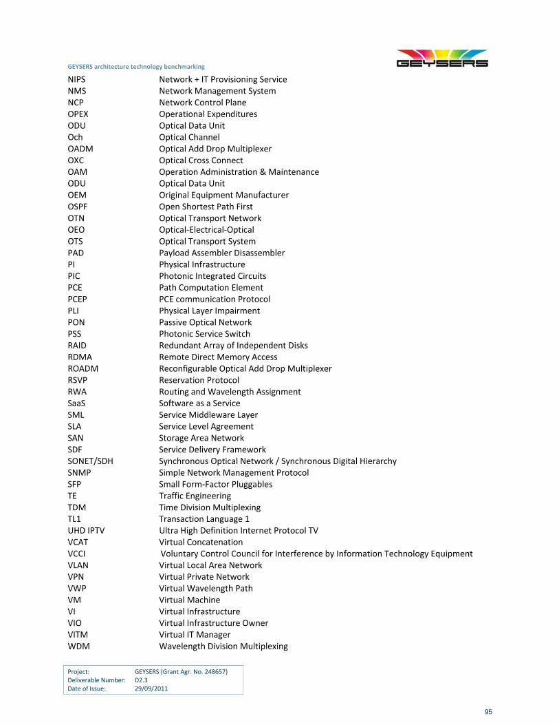
GEYSERS architecture technology benchmarking
Project: GEYSERS (Grant Agr. No. 248657) Deliverable Number: D2.3 Date of Issue: 29/09/2011
95
NIPS Network + IT Provisioning Service NMS Network Management System NCP Network Control Plane OPEX Operational Expenditures ODU Optical Data Unit Och Optical Channel OADM Optical Add Drop Multiplexer OXC Optical Cross Connect OAM Operation Administration & Maintenance ODU Optical Data Unit OEM Original Equipment Manufacturer OSPF Open Shortest Path First OTN Optical Transport Network OEO Optical‐Electrical‐Optical OTS Optical Transport System PAD Payload Assembler Disassembler PI Physical Infrastructure PIC Photonic Integrated Circuits PCE Path Computation Element PCEP PCE communication Protocol PLI Physical Layer Impairment PON Passive Optical Network PSS Photonic Service Switch RAID Redundant Array of Independent Disks RDMA Remote Direct Memory Access ROADM Reconfigurable Optical Add Drop Multiplexer RSVP Reservation Protocol RWA Routing and Wavelength Assignment SaaS Software as a Service SML Service Middleware Layer SLA Service Level Agreement SAN Storage Area Network SDF Service Delivery Framework SONET/SDH Synchronous Optical Network / Synchronous Digital Hierarchy SNMP Simple Network Management Protocol SFP Small Form‐Factor Pluggables TE Traffic Engineering TDM Time Division Multiplexing TL1 Transaction Language 1 UHD IPTV Ultra High Definition Internet Protocol TV VCAT Virtual Concatenation VCCI Voluntary Control Council for Interference by Information Technology Equipment VLAN Virtual Local Area Network VPN Virtual Private Network VWP Virtual Wavelength Path VM Virtual Machine VI Virtual Infrastructure VIO Virtual Infrastructure Owner VITM Virtual IT Manager WDM Wavelength Division Multiplexing

GEYSERS architecture technology benchmarking
Project: GEYSERS (Grant Agr. No. 248657) Deliverable Number: D2.3 Date of Issue: 29/09/2011
96
WA Wavelength Assignment WP Wavelength Path WSS Wavelength Selective Switch XFP ZTP Zero Touch Photonics
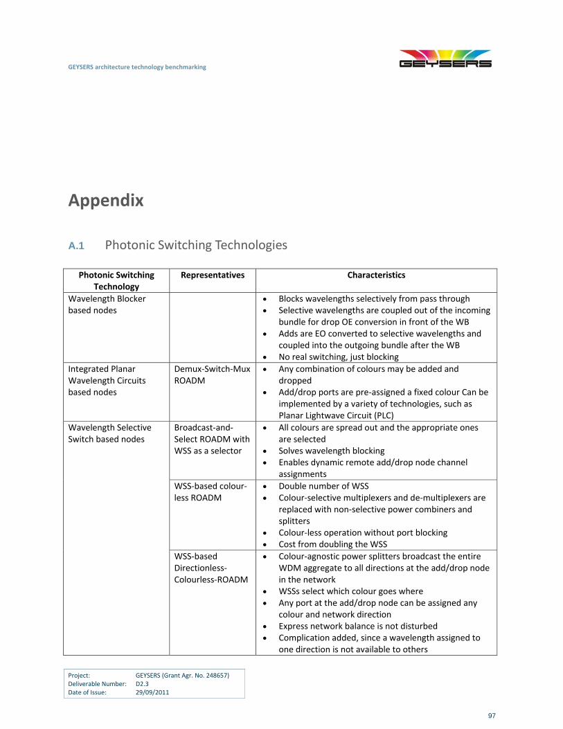
GEYSERS architecture technology benchmarking
Project: GEYSERS (Grant Agr. No. 248657) Deliverable Number: D2.3 Date of Issue: 29/09/2011
97
Appendix
A.1 Photonic Switching Technologies
Photonic Switching Technology
Representatives Characteristics
Wavelength Blocker based nodes
Blocks wavelengths selectively from pass through Selective wavelengths are coupled out of the incoming
bundle for drop OE conversion in front of the WB Adds are EO converted to selective wavelengths and
coupled into the outgoing bundle after the WB No real switching, just blocking
Integrated Planar Wavelength Circuits based nodes
Demux‐Switch‐Mux ROADM
Any combination of colours may be added and dropped
Add/drop ports are pre‐assigned a fixed colour Can be implemented by a variety of technologies, such as Planar Lightwave Circuit (PLC)
Broadcast‐and‐Select ROADM with WSS as a selector
All colours are spread out and the appropriate ones are selected
Solves wavelength blocking Enables dynamic remote add/drop node channel
assignments
WSS‐based colour‐less ROADM
Double number of WSS Colour‐selective multiplexers and de‐multiplexers are
replaced with non‐selective power combiners and splitters
Colour‐less operation without port blocking Cost from doubling the WSS
Wavelength Selective Switch based nodes
WSS‐based Directionless‐Colourless‐ROADM
Colour‐agnostic power splitters broadcast the entire WDM aggregate to all directions at the add/drop node in the network
WSSs select which colour goes where Any port at the add/drop node can be assigned any
colour and network direction Express network balance is not disturbed Complication added, since a wavelength assigned to
one direction is not available to others
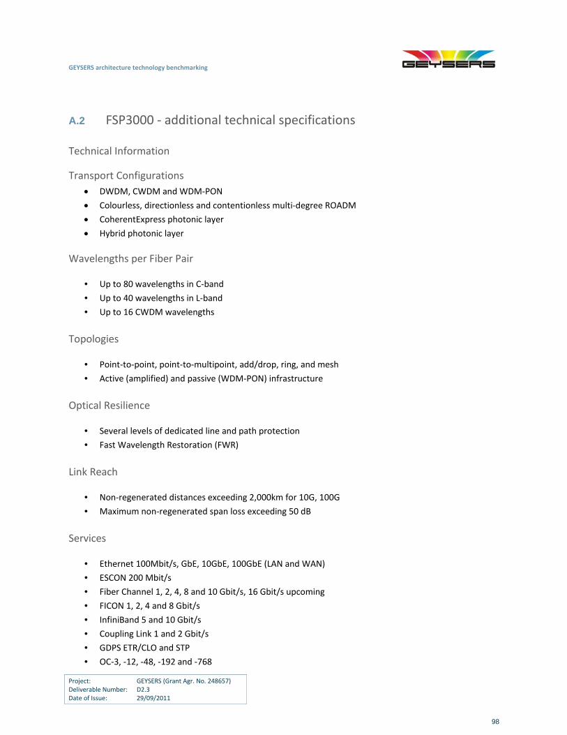
GEYSERS architecture technology benchmarking
Project: GEYSERS (Grant Agr. No. 248657) Deliverable Number: D2.3 Date of Issue: 29/09/2011
98
A.2 FSP3000 ‐ additional technical specifications
Technical Information
Transport Configurations
DWDM, CWDM and WDM‐PON
Colourless, directionless and contentionless multi‐degree ROADM
CoherentExpress photonic layer
Hybrid photonic layer
Wavelengths per Fiber Pair
• Up to 80 wavelengths in C‐band
• Up to 40 wavelengths in L‐band
• Up to 16 CWDM wavelengths
Topologies
• Point‐to‐point, point‐to‐multipoint, add/drop, ring, and mesh
• Active (amplified) and passive (WDM‐PON) infrastructure
Optical Resilience
• Several levels of dedicated line and path protection
• Fast Wavelength Restoration (FWR)
Link Reach
• Non‐regenerated distances exceeding 2,000km for 10G, 100G
• Maximum non‐regenerated span loss exceeding 50 dB
Services
• Ethernet 100Mbit/s, GbE, 10GbE, 100GbE (LAN and WAN)
• ESCON 200 Mbit/s
• Fiber Channel 1, 2, 4, 8 and 10 Gbit/s, 16 Gbit/s upcoming
• FICON 1, 2, 4 and 8 Gbit/s
• InfiniBand 5 and 10 Gbit/s
• Coupling Link 1 and 2 Gbit/s
• GDPS ETR/CLO and STP
• OC‐3, ‐12, ‐48, ‐192 and ‐768
GEYSERS architecture technology benchmarking
Project: GEYSERS (Grant Agr. No. 248657) Deliverable Number: D2.3 Date of Issue: 29/09/2011
99
• STM‐1, ‐4, ‐16, ‐64 and ‐256
• OTU‐1, ‐2, ‐3 and ‐4
• Video (270 Mbit/s, 1.5 Gbit/s)
• Any rate interface ranging from 125 Mbit/s to 2.7 Gbit/s
Optics
• CWDM according to ITU‐T G.694.2
• DWDM channel spacing 50/100GHz according to ITU‐T G.694.1
• C‐ and L‐band support
• Support for pluggable XFP/SFP interfaces on both client and network ports
• Tunable XFPs on network ports
• 850 nm, 1310 nm, 1550 nm, CWDM and DWDM SFP optics
• OptojackTM intelligent demarcation
Modules
• Core transponders (WCC)
• Access transponders (WCA)
• Enterprise transponders (WCE)
• Packet transport modules (xPCA)
• Core muxponders (xTCC)
• Access muxponders (xTCA)
• Enterprise muxponders (xTCE)
• Optical amplifier modules (EDFA, Raman)
• Dispersion compensation modules (DCM)
• Protection modules (PM)
• Filter modules (CLSM, xGSM, xCSM+/‐)
• Optical supervisory channel modules (OSCM, OSFM)
• Reconfigurable Optical Add Drop Multiplexers (ROADM) with dynamic channel equalization
• Splitter modules (SM)
• Controller modules (NCU, SCU)
• Versatile switch and optical line monitoring modules (VSM, RSM, OLM)
• Optical time domain reflectometry module (OTDR)
• AES encryption module for data and storage services
Management & Control Plane
• RAYcontrolTM GMPLS‐based control plane for real‐time optical channel provisioning, dynamic service
recovery and automated resource discovery
• OSPF‐based DCN routing and constraint‐based traffic routing
• SNMP and TL1 management protocol
• FSP Network Manager and FSP Service Manager
GEYSERS architecture technology benchmarking
Project: GEYSERS (Grant Agr. No. 248657) Deliverable Number: D2.3 Date of Issue: 29/09/2011
100
• Integration into OEM partner network management systems
Environmental
• Temperature (operating): +5°C to +40°C
• Temperature (short‐term): ‐5°C to +55°C
• Relative humidity (operating): 5% to 85% (non‐condensing)
• Relative humidity (short‐term): 5% to 90% (non‐condensing)
• Outdoor variants available (e.g. temperature‐hardened filters)
Regulatory
• NEBS Level 3, ETSI and VCCI
• CE, FCC, UL and cUL
Laser Safety Classification
• Hazard Level 1M Product: IEC 60825‐1 and 60825‐2
• Class 1 Laser Product: 21 CFR 1040.10 and 1040.11
Power
• Voltage: ‐36 VDC to ‐72 VDC or 120/240 VAC
• Typical power consumption: 250 W per shelf
Physical
• Mounting brackets for 19”, ETSI and 23” ANSI/NEBS racks
• Back‐to‐back ETSI compliant
Shelf Options
• 1U (active and passive)
• 7U (standard)
• 9U (high power, up to 1000 W per shelf)