Deliverable 1.1 – State of the art -..:: FLEXERGY ::..
47
FLEXERGY Deliverable 1.1 – State of the art Activity 1: Preliminary Studies Editor: Marta Ribeiro Dissemination level: (Confidentiality) Public Suggested readers: Version: 01.00 Total number of pages: 47 Keywords: Energy Storage, System Architecture, Energy Management FLEXERGY is a project co-funded by: FLEXERGY ABSTRACT The FLEXERGY project aims at the development of an advanced management solution, highly innovative and provided of artificial intelligence, for the management of assets of battery energy storage systems, integrated with renewable energy sources or for application within a microgrid
-
Upload
khangminh22 -
Category
Documents
-
view
0 -
download
0
Transcript of Deliverable 1.1 – State of the art -..:: FLEXERGY ::..
FLEXERGY
Deliverable 1.1 – State of the art
Activity 1:
Preliminary Studies
Editor: Marta Ribeiro
Dissemination level:
(Confidentiality)
Public
Suggested readers:
Version: 01.00
Total number of pages: 47
Keywords: Energy Storage, System Architecture, Energy Management
FLEXERGY is a project co-funded by:
FLEXERGY ABSTRACT
The FLEXERGY project aims at the development of an advanced management solution, highly
innovative and provided of artificial intelligence, for the management of assets of battery energy
storage systems, integrated with renewable energy sources or for application within a microgrid

Deliverable 1.1 – State of the art, Doc No.: AS18006373, Rev. 01.0 Page 2/47
Document
Language Requirements (for non-native English speakers)
In order to fully understand the content of this document, it is therefore recommended that the reader possesses a language proficiency equivalent to B1 level,
according to European Language Levels
Disclosure
This document contains information, which is confidential in nature and proprietary to EFACEC, Automation Business Unit, and shall not be reproduced or
transferred to other documents or referenced, or disclosed in any manner to any person or used for any purpose other than that for which it is furnished without
the prior express written permission of EFACEC
Name Deliverable 1.1 – State of the art
Document No. AS18006373
Revision and
Date 01.0 2018-11-30
Project FLEXERGY
Made by Marta Ribeiro
Reviewed by Ismael Miranda
Approved by Ismael Miranda
Total Pages 47
Deliverable 1.1 – State of the art, Doc No.: AS18006373, Rev. 01.0 Page 3/47
Revisions
Rev. Date Comments Author
0.01 2018-09-10 Initial version Marta Ribeiro, Ismael
Miranda
0.02 2018-10-16 INESC Contribution Marta Ribeiro, Clara
Gouveia
1.00 2018-11-30 Minor corrections Marta Ribeiro, Ismael
Miranda

Deliverable 1.1 – State of the art, Doc No.: AS18006373, Rev. 01.0 Page 4/47
Executive Summary
This document, Deliverable 1.1, aims at presenting the analysis of state of art and applications of battery energy
storage solutions available in the market under the scope of the FLEXERGY project. This task includes the state
of art analysis of technological battery solutions with potential applicability in the scope of the project regarding
battery technology, inverter, auxiliary systems and monitoring and management systems of the storage system.
Several types of batteries are available on the market and have distinctive characteristics in terms of materials
and chemical processes, which influence the performance of the batteries and the overall energy storage system.
Therefore, the analysis aims to identify the main technical characteristics that allow to define operating
conditions and favorable applications, from the active management perspective. On the scope of FLEXERGY, this
document presents a competition analyses of the large multinationals, which have a technological solution that
corresponds to the focus of this project. Also, a state of art analyses in the areas of technical and scientific
research on algorithm control and management of distributed energy storage solutions based on different battery
technologies are presented.
The outcomes of this deliverable will be used throughout the project, although they will manly feed Activity 1 –
Preliminary studies and concept formuation, Activity 2 – modelling of the energy storage system based on batteries
and Activity 3 – Specification of the management platform for the energy storage system.
Deliverable 1.1 – State of the art, Doc No.: AS18006373, Rev. 01.0 Page 5/47
Table of Contents
EXECUTIVE SUMMARY ............................................................................................................... 4
GLOSSARY .............................................................................................................................. 8
1. INTRODUCTION ............................................................................................................... 11
2. BESS SOLUTIONS ............................................................................................................. 12
2.1 BATTERY STORAGE TECHNOLOGIES ......................................................................................... 12
2.2 POWER ELECTRONICS ...................................................................................................... 14
2.3 AUXILIARY SERVICES ....................................................................................................... 14
2.4 MONITORING AND CONTROL SYSTEMS ...................................................................................... 15
2.5 ENERGY MANAGEMENT SYSTEM ............................................................................................ 15
3. COMPETITION ANALYSIS.................................................................................................... 16
3.1 SIEMENS ................................................................................................................... 16
3.2 ABB ....................................................................................................................... 19
3.3 GENERAL ELECTRIC ........................................................................................................ 21
3.4 SCHNEIDER ................................................................................................................ 22
3.5 NEC ....................................................................................................................... 24
3.6 NIDEC ..................................................................................................................... 25
3.7 YOUNICOS / AGGREKO .................................................................................................... 27
3.8 GREENSMITH / WARTSILA ................................................................................................. 28
4. MANAGEMENT ALGORITHMS FOR ENERGY STORAGE ................................................................. 30
4.1 BATTERY MODELLING APPROACHES ........................................................................................ 30
4.2 DETERMINISTIC AND HEURISTIC BASED APPROACHES ........................................................................ 32
4.3 DYNAMIC PROGRAMMING AND OPTIMAL CONTROL .......................................................................... 32
4.4 OPTIMIZING THE OPERATION OF DISTRIBUTED STORAGE FOR MULTIPLE SERVICES AND CONTROL OBJECTIVES ................ 34
4.4.1 Energy applications of BESS ................................................................................................................. 34 4.4.2 Application cases – the importance of providing multiple services for economic viability ......................................... 37
5. REFERENCES .................................................................................................................. 42
Deliverable 1.1 – State of the art, Doc No.: AS18006373, Rev. 01.0 Page 6/47
List of Figures
Figure 1- Schematic of a battery energy storage system [7] ................................................................ 12
Figure 2- Variants of power electronic topologies ............................................................................ 14
Figure 3- MGMS Operation Flow [17] ............................................................................................ 17
Figure 4- MGMS dashboard [18] .................................................................................................. 18
Figure 5- Switching between geospatial and schematic displays ........................................................... 19
Figure 6- EPIC process interface ................................................................................................. 20
Figure 7- ABB web HMI [20] ....................................................................................................... 20
Figure 8- Mark* VIe Controls ...................................................................................................... 21
Figure 9- GE microgrid control system architecture [23] .................................................................... 22
Figure 10- Schneider Power Plant Controller for ConextTM Advisor 2 architecture ..................................... 23
Figure 11- ConextTMInsight login platform and site summary HMI .......................................................... 24
Figure 12 - NEC example installation [32] ...................................................................................... 25
Figure 13- AEROS HMI [33] ........................................................................................................ 25
Figure 14- HMI from EMS and AMS modules, respectively ................................................................... 26
Figure 15- Nidec architecture .................................................................................................... 26
Figure 16- Y.Q. architecture ...................................................................................................... 28
Figure 17- Baseline of GEMS software platform [38] ......................................................................... 29
Figure 18 - Two coupled electrical circuits describe the state of a li-ion battery. The “Battery Lifetime Circuit”
on the left-hand side serves the purpose of describing the dynamic nature of the battery’s SoC and the
“Voltage-Current Characteristics Circuit” characterizes how terminal voltage is affected by SoC and by
current load. Adapted from [52]. ........................................................................................ 32
Figure 19 – Energy capacity degradation for different operational policies. Horizontal red line indicates 75% of
the nominal energy capacity. Adapted from [83]. .................................................................... 41
Figure 20 – Total gross revenue during battery lifespan. Adapted from [83]. ........................................... 41

Deliverable 1.1 – State of the art, Doc No.: AS18006373, Rev. 01.0 Page 7/47
List of Tables
Table 1- Range of values of characteristics of different battery technologies .......................................... 13
Table 2- Applications for Energy Storage (adapted from [80]). ............................................................ 35
Deliverable 1.1 – State of the art, Doc No.: AS18006373, Rev. 01.0 Page 8/47
Glossary
AC – Alternating Current
ACBM – AC Battery Manager
ADP – Adaptive Dynamic Programming / Approximate Dynamic Programming
AGC – Automatic Generation Control
AI – Artificial Intelligence
AMS – Asset Management System
BESS – Battery Energy Management System
BMS – Battery Management System
BPPM – Battery Power Plant Manager
CCCV – Constant-Current Constant-Voltage
CHP – Combined Heat and Power
CoE – Cost of Energy
COP – Coefficient Of Performance
CR – Continuous Relaxation
C&I – Commercial and Industrial
DC – Direct Current
DER – Distributed Energy Resources
DMS – Distribution Management System
DSS - Distributed Storage Solution
DP – Dynamic Programming / Deterministic Dynamic Programming
DSO – Distribution System Operator
DOD – Depth of Discharge
DuOS – Dynamic Use of System
ECP – Electric Connection Point
EMPC – Economic Model Predictive Control
EMS – Energy Management System
EPS – Electric Power Systems
ESC – Energy Storage Controller
ESS – Energy Storage System
GE – General Electric
GEMS – Greensmith EMS
GPS – Global Positioning System
HMI – Human-Machine Interface

Deliverable 1.1 – State of the art, Doc No.: AS18006373, Rev. 01.0 Page 9/47
HVAC – Heating, ventilation and air conditioning
IEC – International Electrotechnical Comission
IED – Intelligent Electronic Devices
I/O – Input/Output
KPI – Key Performance Indicators
LAN – Local Area Network
LP – Linear Programming
LV – Low Voltage
MCC – Multistage Constant-Current
MCS - Microgrid Control System
MGMS – Microgrid Management System
MILP – Mixed Integer Linear Programming
ML – Machine Learning
MPC – Model Predictive Control
MV – Medium-Voltage
NiCd – Nickel-Cadmium
NiMH – Nickel-Metal Hybride
NLP – Nonlinear Programming
Pb-acid – Lead-Acid
PCC – Point of Common Coupling
PCS – Power Conversion System
PEV – Plug-In Electric Vehicle
PMC – Power Management System
PNNL – Pacific Northwest National Laboratory
PPC – Power Plant Controller
PV – Photovoltaic
RES – Renewable Energy Sources
RL – Reinforcement Learning
RTU – Remote Terminal Unit
SCADA - Supervisory Control And Data Acquisition
SDP – Stochastic Dynamic Programming
SOC – State Of Charge
SOH – State Of Health
TCP/IP – Transmission Control Protocol / Internet Protocol
ToU – Time-of-Use
UPS – Uninterruptible Power Supply

Deliverable 1.1 – State of the art, Doc No.: AS18006373, Rev. 01.0 Page 10/47
VPN – Virtual Private Network
VPP – Virtual Power Plant
WECC – Western Electricity Coordinating Council
Deliverable 1.1 – State of the art, Doc No.: AS18006373, Rev. 01.0 Page 11/47
1. Introduction
In the Electric Power Systems (EPS) all the electric energy produced at each instant must be also consumed in
that moment. In a society increasingly dependent on electricity, this characteristic presents significant challenges
of quality and continuity of service, which must be guaranteed in the most cost-efficient way possible. In this
regard, the energy storage is one of the major challenges on the electrical sector since it has the potential to
completely change the paradigm of the EPS planning and operation.
Recently, energy storage systems have regained the attention among several players in the electric sector’s value-
chain, from the system operator to political decision-makers, motivated by different technical, economic and
environmental reasons [1]. These reasons are essentially related with the big challenges addressed by the
electrical sector, such as the liberalization of the sector, the increase of the peak consumption all over the world,
high levels of penetration of renewable energy with intermittent behavior, micro-grids, the electric vehicles
dramatic expansion, followed by the progress and the changes on the rational economic of energy storage
technologies [2]. Indeed, the integration of renewable energy sources is the main reason to the integration of
storage and particularly of battery based distributed systems since this type of technologic solution is seen as
complementary to the greater integration of renewable sources with variable and intermittent character such as
wind and photovoltaic (PV) [3].
The inherent characteristics of renewable energy, dependent on weather conditions (bring variability to the supply
side), as well as the fact that a significant part of these sources is connected to the distribution networks establish
critical challenges to their proper integration into the EPS operation [4]. These facts change the traditional
paradigm of planning and operation of distribution networks since networks are designed for unidirectional power
flows with intention of supply the loads. If the presence of generation closer to the consumption can reduce the
power flows, leading to lower Joule losses, the increasing integration of these distributed sources may lead to
their inversion, causing new challenges of voltage control and network congestion [5].
In fact, Energy Storage Systems, and particularly those that do not have limitations regarding their installation
site, such as battery-based energy storage systems, can be a feasible technological solution for the integration of
renewable sources and distributed energy resources, such as microgrids and electric vehicles, in distribution
networks [6]. The ability to quickly charge and discharge allows to effectively equalize the fluctuations and can
compensate a mismatch of consumption and power generation via a coordinated power supply and energy time-
shift, increasing the operational flexibility that is fundamental to improve the reliability and efficiency.
In order to overcome these barriers, it becomes necessary investigate and exploit one of the most notable
advantages of the Battery Energy Storage Systems (BESS), which is their ability to provide multiple services from
the same asset. It is the multifunctional character that allow the aggregation of multiple income sources,
leveraging its added value and leading to the overcoming of the costs associated with them during their lifetime.
This document revises the current state of the art of BESS solutions, namely in what concerns their Energy
Management System (EMS), which is responsible for their overall functional behavior, and therefore for the costs
and benefits of the operation of BESS. The focus of the document is twofold. First, a description and analysis of
the current solutions presented by Efacec’s competition regarding the energy storage EMS is presented. Second,
a review of the state-of-the-art algorithms for the optimal operation of BESS in different contexts and with
different purposes is detailed.
Deliverable 1.1 – State of the art, Doc No.: AS18006373, Rev. 01.0 Page 12/47
2. BESS solutions
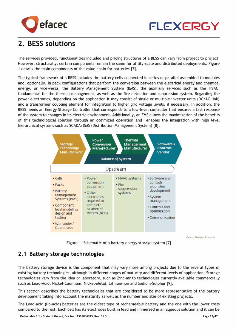
The services provided, functionalities included and pricing structures of a BESS can vary from project to project.
However, structurally, certain components remain the same for utility-scale and distributed deployments. Figure
1 details the main components of the value chain for batteries [7].
The typical framework of a BESS includes the battery cells connected in series or parallel assembled to modules
and, optionally, in pack configurations that perform the conversion between the electrical energy and chemical
energy, or vice-versa, the Battery Management System (BMS), the auxiliary services such as the HVAC,
fundamental for the thermal management, as well as the fire detection and suppression system. Regarding the
power electronics, depending on the application it may consist of single or multiple inverter units (DC/AC link)
and a transformer coupling element for integration to higher grid voltage levels, if necessary. In addition, the
BESS needs an Energy Storage Controller that corresponds to a low-level controller that ensures a fast response
of the system to changes in its electric environment. Additionally, an EMS allows the maximization of the benefits
of this technological solution through an optimized operation and enables the integration with high level
hierarchical systems such as SCADA/DMS (Distribution Management System) [8].
Figure 1- Schematic of a battery energy storage system [7]
2.1 Battery storage technologies
The battery storage device is the component that may vary more among projects due to the several types of
existing battery technologies, although in different stages of maturity and different levels of application. Storage
technologies vary from the idea or laboratory, such as Zinc-air to technologies currently available commercially
such as Lead-Acid, Nickel-Cadmium, Nickel-Metal, Lithium-ion and Sodium-Sulphur [9].
This section describes the battery technologies that are considered to be more representative of the battery
development taking into account the maturity as well as the number and size of existing projects.
The Lead-acid (Pb-acid) batteries are the oldest type of rechargeable battery and the one with the lower costs
compared to the rest. Each cell has its electrodes built in lead and immersed in an aqueous solution and it can be
Deliverable 1.1 – State of the art, Doc No.: AS18006373, Rev. 01.0 Page 13/47
divided in two types: flooded type and valve regulated type. The main limitations of this technology are the low
energy density and only allows a limited number of full discharge cycles – better for standby applications that
require only occasional deep discharges [10].
Following the Lead-acid, Nickel based batteries are the oldest, with over 100 years of development [9]. The major
types of nickel chemistry are the nickel-cadmium (NiCd) and the nickel-metal hydride (NiMH) and the less common
types are the nickel-iron, nickel-hydrogen and nickel-zinc.
• Nickel-cadmium are constituted by a nickel hydroxide anode, a cadmium hydroxide cathode, a separator
and an alkaline electrolyte and the main advantages are related with the simple storage and
transportation and the good performance under low temperatures (-20⁰C to -40⁰C). However, nickel and
cadmium are highly toxic heavy metals and it has memory effect, the NiCd must periodically be exercised
to prevent memory [10].
• Nickel-metal batteries have been introduced as a battery technology later than NiCd and have almost the
double capacity of an equivalent size NiCd. This technology suffers significantly less from the memory
effect and it is more environmental friendly. The main disadvantages of this type of batteries are the high
self-discharge rate (50% higher than NiCd) and are more sensitive to deep cycles [11].
The lithium-ion batteries have, typically, the anode made of graphite carbon with a layered structure and the
cathode is made of a lithiated metal oxide dissolved in organic carbonates. The main variations of lithium-based
technologies concern the cathode. The electrolyte in a non-aqueous organic liquid containing lithium salts. When
in charge, the ions migrate through the electrolyte towards the carbon anode where they combine with external
electrons and are deposited between the carbon layers as lithium ions. The process during the discharge is
reversed [9]. The main advantages of this type of solution are the high energy density and the relatively low self-
discharge rate. In addition, the nominal value of the voltage cell is high, meaning that the number of cells in
series can be lower to achieve the target voltage, compared to other technologies. The main drawbacks are the
reduced depth of discharge, requiring a protection circuit and the battery’s lifetime being affected by
temperatures above 40⁰C [10].
Sodium-sulphur batteries are high temperature electrochemical devices, with operating temperatures between
300⁰C and 350⁰C in order to take advantage of the increasing conductivity of the electrolyte (β-alumina) to ensure
that the active materials are molten (sodium electrode in the centre of each cell). The main disadvantages are
the requirement of a heat source to maintain the operating temperatures. Moreover, this technology has high
power and energy densities, high efficiency and low-cost maintenance [12].
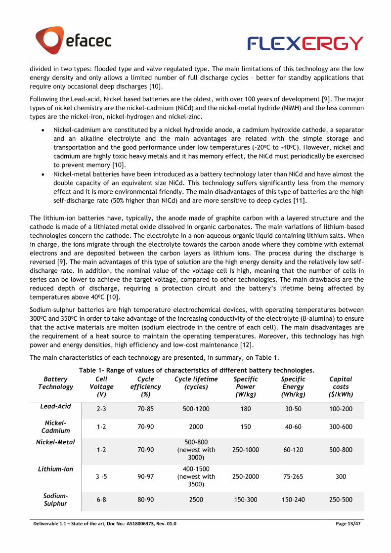
The main characteristics of each technology are presented, in summary, on Table 1.
Table 1- Range of values of characteristics of different battery technologies.
Battery Technology
Cell Voltage
(V)
Cycle efficiency
(%)
Cycle lifetime (cycles)
Specific Power (W/kg)
Specific Energy (Wh/kg)
Capital costs
($/kWh)
Lead-Acid 2-3 70-85 500-1200 180 30-50 100-200
Nickel-Cadmium
1-2 70-90 2000 150 40-60 300-600
Nickel-Metal 1-2 70-90
500-800 (newest with
3000) 250-1000 60-120 500-800
Lithium-Ion 3 -5 90-97
400-1500 (newest with
3500) 250-2000 75-265 300
Sodium-Sulphur
6-8 80-90 2500 150-300 150-240 250-500
Deliverable 1.1 – State of the art, Doc No.: AS18006373, Rev. 01.0 Page 14/47
2.2 Power electronics
Power electronics is the key enabling technology facilitating the connection of the BESS with the grid. The power
conversion system (PCS) is based on power electronics and it is necessary to convert the Alternating Current (AC)
from the grid side to the Direct Current (DC) input/output that the battery system presents, allowing a
bidirectional power flow and the operation in four quadrants. Aside from the AC/DC converter, it may be needed
additional converters (DC/DC converters) to match the output voltage level of the batteries. The power electronic
units also control the power flow of the BESS and regulate the operating points of the batteries, ensuring the life
expectancy of the BESS [13].
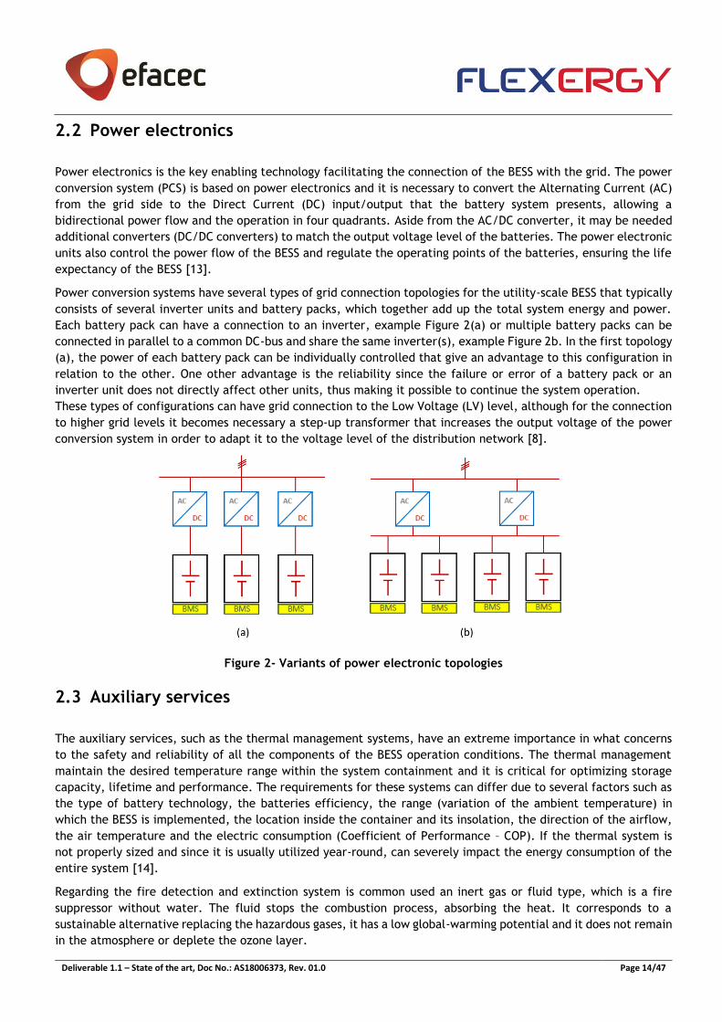
Power conversion systems have several types of grid connection topologies for the utility-scale BESS that typically
consists of several inverter units and battery packs, which together add up the total system energy and power.
Each battery pack can have a connection to an inverter, example Figure 2(a) or multiple battery packs can be
connected in parallel to a common DC-bus and share the same inverter(s), example Figure 2b. In the first topology
(a), the power of each battery pack can be individually controlled that give an advantage to this configuration in
relation to the other. One other advantage is the reliability since the failure or error of a battery pack or an
inverter unit does not directly affect other units, thus making it possible to continue the system operation.
These types of configurations can have grid connection to the Low Voltage (LV) level, although for the connection
to higher grid levels it becomes necessary a step-up transformer that increases the output voltage of the power
conversion system in order to adapt it to the voltage level of the distribution network [8].
Figure 2- Variants of power electronic topologies
2.3 Auxiliary services
The auxiliary services, such as the thermal management systems, have an extreme importance in what concerns
to the safety and reliability of all the components of the BESS operation conditions. The thermal management
maintain the desired temperature range within the system containment and it is critical for optimizing storage
capacity, lifetime and performance. The requirements for these systems can differ due to several factors such as
the type of battery technology, the batteries efficiency, the range (variation of the ambient temperature) in
which the BESS is implemented, the location inside the container and its insolation, the direction of the airflow,
the air temperature and the electric consumption (Coefficient of Performance – COP). If the thermal system is
not properly sized and since it is usually utilized year-round, can severely impact the energy consumption of the
entire system [14].
Regarding the fire detection and extinction system is common used an inert gas or fluid type, which is a fire
suppressor without water. The fluid stops the combustion process, absorbing the heat. It corresponds to a
sustainable alternative replacing the hazardous gases, it has a low global-warming potential and it does not remain
in the atmosphere or deplete the ozone layer.
Deliverable 1.1 – State of the art, Doc No.: AS18006373, Rev. 01.0 Page 15/47
An intrusion detection is usually added to the system which monitors the container, detecting and alerting in case
of intrusion [15].
2.4 Monitoring and control systems
The Energy Storage Controller (ESC) presents functionalities of monitoring, control and communication [39]. The
controller should enable the continuous monitoring of AC and DC magnitudes from the electric grid and battery
system, providing the interfaces with the battery management system and the battery inverter(s). Additionally,
this component monitors all the other equipment including ancillary equipment, the transformer(s) and the
intelligent electronic devices (IED’s) present on the grid. The ESC is also able to monitor electrical measurements
at the Point of Common Coupling (PCC) to achieve an adequate control of the BESS and performs basic functions
such as control and monitoring, the ability to save historical metering data logger and the management of electric
connection and disconnection of the battery system that support the operating modes of the system. The ESC is
responsible for sending active and reactive power set-points to the PCS in order to perform different services, for
example, charging and discharging the batteries through active power setpoints, controlling the reactive power
injection/absorption through reactive power setpoints, fixing the power factor by changing the value of the
reactive power until the pretended power factor is achieved or allowing the BESS to contribute to smoothing the
active power profile at the Referenced Electric Connection Point (ECP) [9].
The ESC, as a core equipment for the local control and monitoring of the battery storage system needs to be
capable of managing different communication protocols. It ensures communication through several standard
protocols such as Modbus, IEC 61850 and IEC 60870-5-104. These protocols ensure a wide range communication
capability, complying with the standard communication protocols of all equipment mentioned before. The
communication network infrastructure could be with fiber optics or Ethernet or other communication cables.
Moreover, by communicating with systems of other electric sector stakeholders (e.g. DSO, electricity market
operator) it is capable of optimising the behaviour of the BESS both in technical and economic terms, as well as
allowing the BESS to respond to external functional requests.
The ESC relies on the EMS for the optimisation of the behaviour of the BESS, which consists in defining the schedule
of the battery system i.e. the most adequate periods of time, considering the objectives of the integration, to
charge and to discharge the BESS.
2.5 Energy Management System
The Energy Storage Manager, ES Manager, corresponds to an advanced management system of the overall energy
storage solution and combined assets. The ES Manager should have a detailed view not only of the storage system,
but also of the other active elements that can share the same grid ECP with the storage system. The active
elements can correspond to renewable energy sources, diesel generators and controllable loads like Electric
Vehicle (EV) charging stations that, by working together, constitute a Micro-Grid (MG). The acquisition and
processing of a significant quantity of data allows the implementation of advanced algorithms in order to maximize
the benefits of the energy storage system during its useful lifetime, gaining a more comprehensive view of the
entire system.
The management platform shall be able of monitoring a high amount of electric measurements and information,
aggregating information of multiple devices and respecting the state of the art of cyber-security standards. This
means, on one hand, that the platform shall integrate different standard communication protocols for
communications with several Intelligent Electronic Devices (IEDs) such as the ES Controller, and with superior
hierarchical systems, such as SCADA. On the other hand, a very significant volume of data must have to be
aggregated, processed and treated in order to ensure an adequate performance of the different functional
modules that integrate the system. For more efficient and informative management of data, the ES Manager shall
incorporate automatic and intelligent functions for alarm/event processing.
Deliverable 1.1 – State of the art, Doc No.: AS18006373, Rev. 01.0 Page 16/47
At the same time, the ES Manager has to maximize the economic performance when the storage system is
combined with a renewable source (wind and PV). The ES Manager shall provide advanced algorithms able to
optimize, for different time horizons (daily or intra-daily based) the management of the cycles of charge and
discharge, responding to multiple operation objectives and integrating forecasting algorithms of renewable
generation and electric demand. Due to the high uncertainty associated with renewable energy sources’
production and considering the multiplicity of conditions in which the energy storage system is operated, with
different impacts on its degradation, these algorithms will be evolutionary, integrating Machine Learning
methodologies. This allows a more efficient and economic participation of the renewable sources in the electricity
markets.
Another responsibility of the ES Manager is the coordination of the useful life cycles of the batteries (useful
lifetime and degradation rate). The optimization process considers not only the battery system operation as well
as some internal variables like the depth of discharge (DoD), the state of charge (SoC) and the cells temperature,
associated with the health of the batteries, which may limit both the overall performance of the system and its
lifetime.
One other feature for the ES Manager is the monitoring and performance evaluation of the integrated storage
system that goes up to performance analysis, generate and provide performance reports and report the
performance analysis to the SCADA/EMS/MGCC. The detailed modeling of the energy storage system, as well as
the dynamic and steady-state simulation in different operating regimes allows a consistent and coherent
identification of the system Key Performance Indicators (KPI). Therefore, the ES Manager shall integrate a
dashboard for the evaluation of different parameters such as the total system efficiency including the ancillary
systems.
The EMS is the technological solution of focus of the FLEXERGY project. Therefore, the competition regarding EMS
solutions is analyzed in section 3.
3. Competition analysis
FLEXERGY focuses on the development of a key product for the management of energy storage solutions, the ES
Manager. In this section, the products of the main competition of the ES Manager are described, namely from the
main players in this market such as Siemens, ABB, General Electric, Schneider, NEC, Nidec, Younicos/Aggreko and
Greensmith/Wartsila.
3.1 Siemens
Siemens presents on its portfolio the Siemens Spectrum Power™ Advanced MicroGrid Management System (MGMS)
that corresponds to an advanced control and optimization software for the optimal management of microgrids,
islands or small-scale local power networks such as industrial areas, military facilities and universities. This
solution is used to maximize the value of the onsite generation and energy storage in coordination with local
utilities. The product is built based on the existing utility grid control center platform – designated Spectrum
Power™, but with the ability of handling and optimizing several local power applications [16].
The main feature of the MGMS is its capability to optimally coordinate the dispatchable generation units (gas,
diesel generators, CHP), renewable generation (PV, wind), energy storage systems based on batteries as well as
controllable loads, aiming at the efficient and reliable control of a microgrid during 24 hours a day. The MGMS
software solution has several features such as the creation of automatic weather forecasts, enabling the reliable
operation planning up to one week in advance, the monitoring and control of generators, storage system and loads
in real-time. It allows the control of voltage and frequency and, consequently, ensures the balance between
consumption and generation with grid security while taking into account the optimization of one economic
Deliverable 1.1 – State of the art, Doc No.: AS18006373, Rev. 01.0 Page 17/47
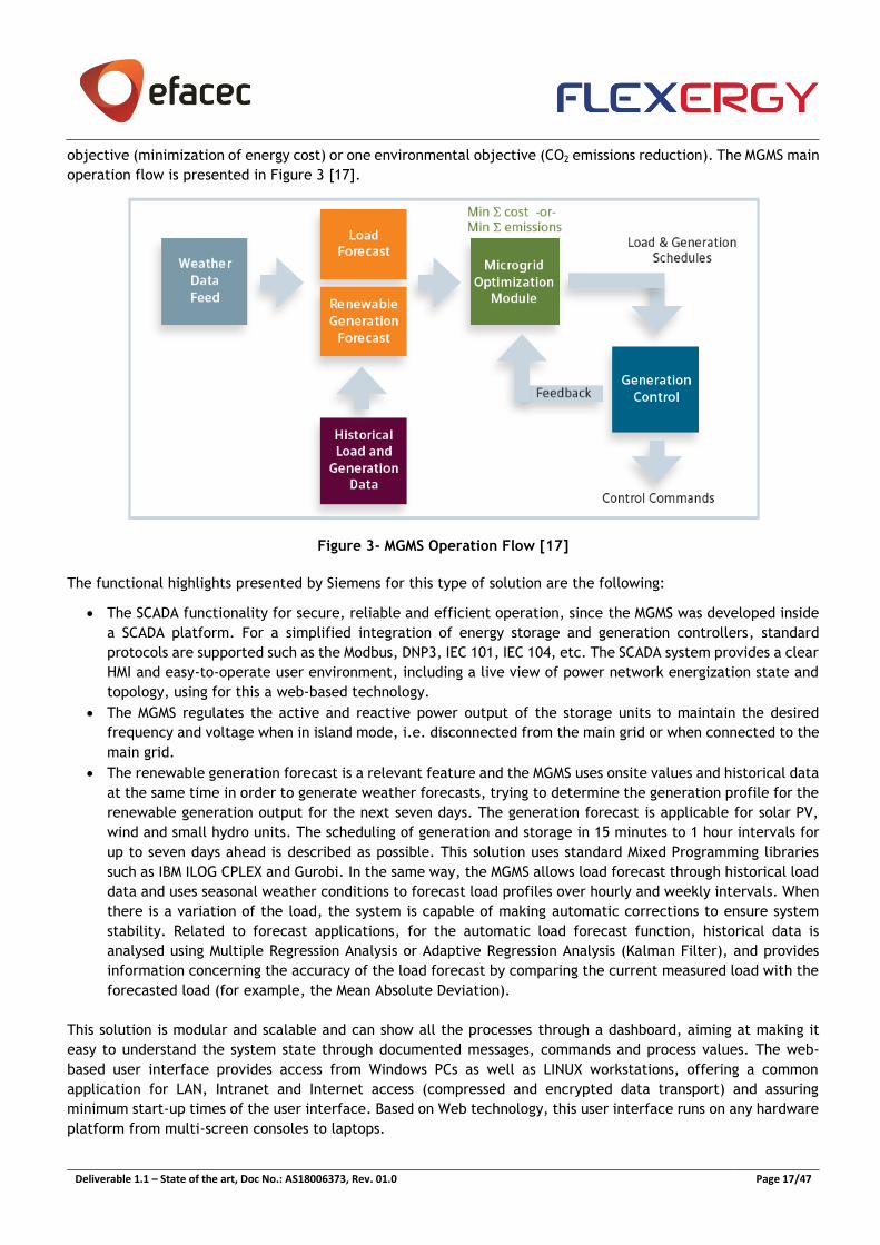
objective (minimization of energy cost) or one environmental objective (CO2 emissions reduction). The MGMS main
operation flow is presented in Figure 3 [17].
Figure 3- MGMS Operation Flow [17]
The functional highlights presented by Siemens for this type of solution are the following:
• The SCADA functionality for secure, reliable and efficient operation, since the MGMS was developed inside
a SCADA platform. For a simplified integration of energy storage and generation controllers, standard
protocols are supported such as the Modbus, DNP3, IEC 101, IEC 104, etc. The SCADA system provides a clear
HMI and easy-to-operate user environment, including a live view of power network energization state and
topology, using for this a web-based technology.
• The MGMS regulates the active and reactive power output of the storage units to maintain the desired
frequency and voltage when in island mode, i.e. disconnected from the main grid or when connected to the
main grid.
• The renewable generation forecast is a relevant feature and the MGMS uses onsite values and historical data
at the same time in order to generate weather forecasts, trying to determine the generation profile for the
renewable generation output for the next seven days. The generation forecast is applicable for solar PV,
wind and small hydro units. The scheduling of generation and storage in 15 minutes to 1 hour intervals for
up to seven days ahead is described as possible. This solution uses standard Mixed Programming libraries
such as IBM ILOG CPLEX and Gurobi. In the same way, the MGMS allows load forecast through historical load
data and uses seasonal weather conditions to forecast load profiles over hourly and weekly intervals. When
there is a variation of the load, the system is capable of making automatic corrections to ensure system
stability. Related to forecast applications, for the automatic load forecast function, historical data is
analysed using Multiple Regression Analysis or Adaptive Regression Analysis (Kalman Filter), and provides
information concerning the accuracy of the load forecast by comparing the current measured load with the
forecasted load (for example, the Mean Absolute Deviation).
This solution is modular and scalable and can show all the processes through a dashboard, aiming at making it
easy to understand the system state through documented messages, commands and process values. The web-
based user interface provides access from Windows PCs as well as LINUX workstations, offering a common
application for LAN, Intranet and Internet access (compressed and encrypted data transport) and assuring
minimum start-up times of the user interface. Based on Web technology, this user interface runs on any hardware
platform from multi-screen consoles to laptops.
Deliverable 1.1 – State of the art, Doc No.: AS18006373, Rev. 01.0 Page 18/47
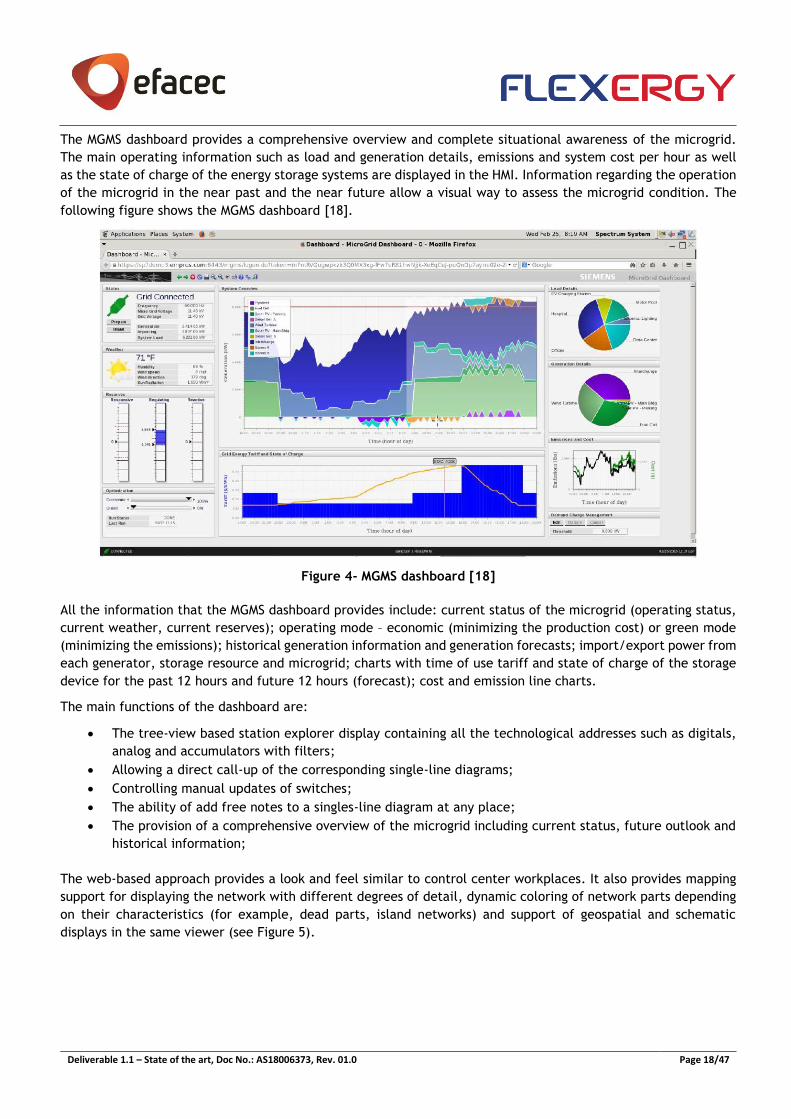
The MGMS dashboard provides a comprehensive overview and complete situational awareness of the microgrid.
The main operating information such as load and generation details, emissions and system cost per hour as well
as the state of charge of the energy storage systems are displayed in the HMI. Information regarding the operation
of the microgrid in the near past and the near future allow a visual way to assess the microgrid condition. The
following figure shows the MGMS dashboard [18].
Figure 4- MGMS dashboard [18]
All the information that the MGMS dashboard provides include: current status of the microgrid (operating status,
current weather, current reserves); operating mode – economic (minimizing the production cost) or green mode
(minimizing the emissions); historical generation information and generation forecasts; import/export power from
each generator, storage resource and microgrid; charts with time of use tariff and state of charge of the storage
device for the past 12 hours and future 12 hours (forecast); cost and emission line charts.
The main functions of the dashboard are:
• The tree-view based station explorer display containing all the technological addresses such as digitals,
analog and accumulators with filters;
• Allowing a direct call-up of the corresponding single-line diagrams;
• Controlling manual updates of switches;
• The ability of add free notes to a singles-line diagram at any place;
• The provision of a comprehensive overview of the microgrid including current status, future outlook and
historical information;
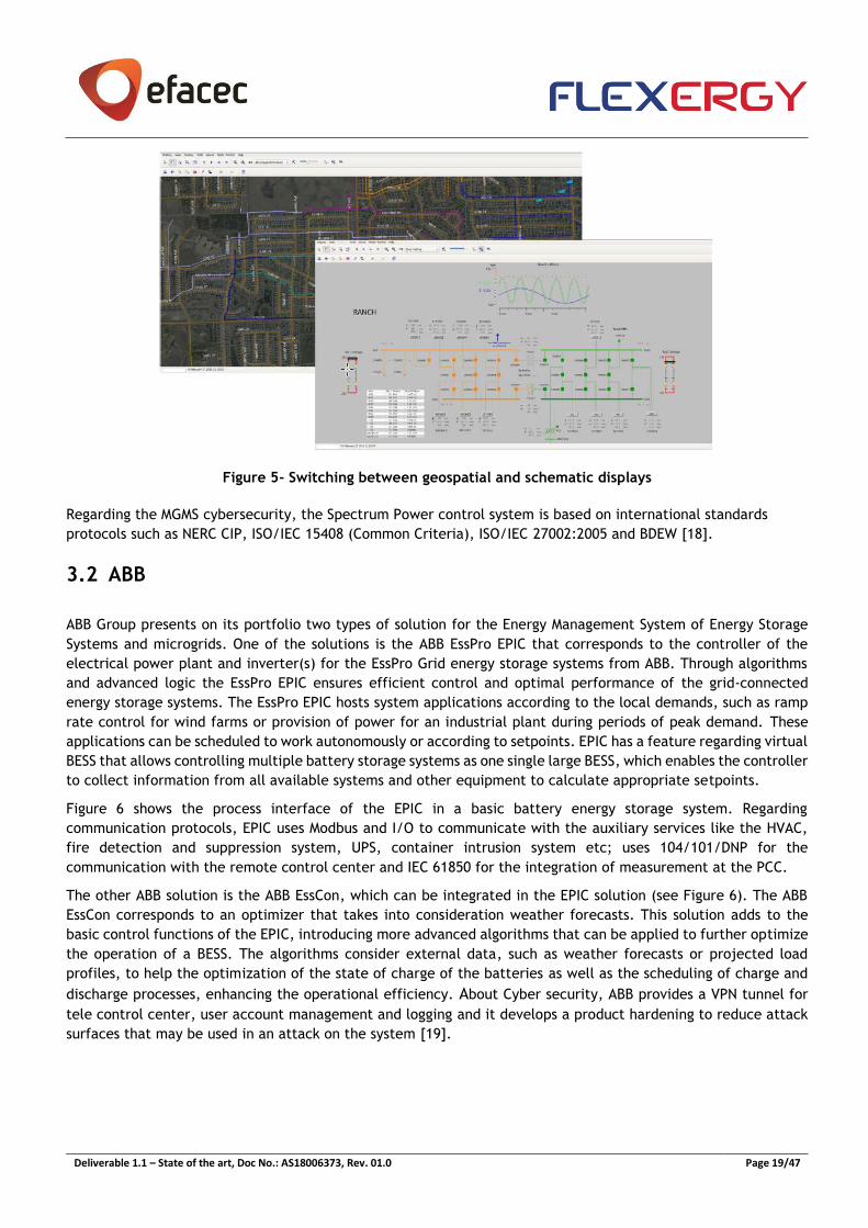
The web-based approach provides a look and feel similar to control center workplaces. It also provides mapping
support for displaying the network with different degrees of detail, dynamic coloring of network parts depending
on their characteristics (for example, dead parts, island networks) and support of geospatial and schematic
displays in the same viewer (see Figure 5).
Deliverable 1.1 – State of the art, Doc No.: AS18006373, Rev. 01.0 Page 19/47
Figure 5- Switching between geospatial and schematic displays
Regarding the MGMS cybersecurity, the Spectrum Power control system is based on international standards
protocols such as NERC CIP, ISO/IEC 15408 (Common Criteria), ISO/IEC 27002:2005 and BDEW [18].
3.2 ABB
ABB Group presents on its portfolio two types of solution for the Energy Management System of Energy Storage
Systems and microgrids. One of the solutions is the ABB EssPro EPIC that corresponds to the controller of the
electrical power plant and inverter(s) for the EssPro Grid energy storage systems from ABB. Through algorithms
and advanced logic the EssPro EPIC ensures efficient control and optimal performance of the grid-connected
energy storage systems. The EssPro EPIC hosts system applications according to the local demands, such as ramp
rate control for wind farms or provision of power for an industrial plant during periods of peak demand. These
applications can be scheduled to work autonomously or according to setpoints. EPIC has a feature regarding virtual
BESS that allows controlling multiple battery storage systems as one single large BESS, which enables the controller
to collect information from all available systems and other equipment to calculate appropriate setpoints.
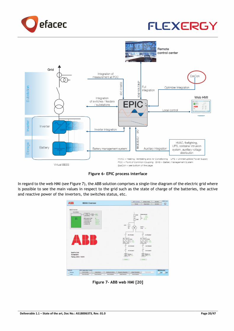
Figure 6 shows the process interface of the EPIC in a basic battery energy storage system. Regarding
communication protocols, EPIC uses Modbus and I/O to communicate with the auxiliary services like the HVAC,
fire detection and suppression system, UPS, container intrusion system etc; uses 104/101/DNP for the
communication with the remote control center and IEC 61850 for the integration of measurement at the PCC.
The other ABB solution is the ABB EssCon, which can be integrated in the EPIC solution (see Figure 6). The ABB
EssCon corresponds to an optimizer that takes into consideration weather forecasts. This solution adds to the
basic control functions of the EPIC, introducing more advanced algorithms that can be applied to further optimize
the operation of a BESS. The algorithms consider external data, such as weather forecasts or projected load
profiles, to help the optimization of the state of charge of the batteries as well as the scheduling of charge and
discharge processes, enhancing the operational efficiency. About Cyber security, ABB provides a VPN tunnel for
tele control center, user account management and logging and it develops a product hardening to reduce attack
surfaces that may be used in an attack on the system [19].
Deliverable 1.1 – State of the art, Doc No.: AS18006373, Rev. 01.0 Page 20/47
Figure 6- EPIC process interface
In regard to the web HMI (see Figure 7), the ABB solution comprises a single-line diagram of the electric grid where
is possible to see the main values in respect to the grid such as the state of charge of the batteries, the active
and reactive power of the inverters, the switches status, etc.
Figure 7- ABB web HMI [20]
Deliverable 1.1 – State of the art, Doc No.: AS18006373, Rev. 01.0 Page 21/47
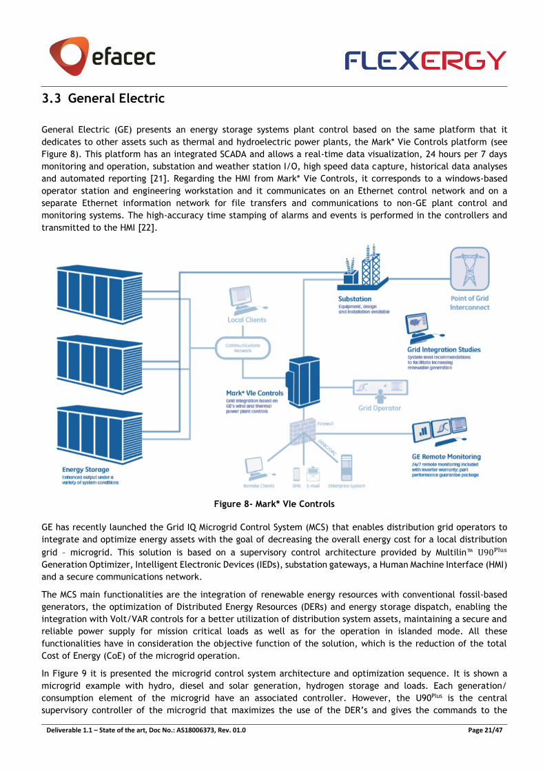
3.3 General Electric
General Electric (GE) presents an energy storage systems plant control based on the same platform that it
dedicates to other assets such as thermal and hydroelectric power plants, the Mark* Vie Controls platform (see
Figure 8). This platform has an integrated SCADA and allows a real-time data visualization, 24 hours per 7 days
monitoring and operation, substation and weather station I/O, high speed data capture, historical data analyses
and automated reporting [21]. Regarding the HMI from Mark* Vie Controls, it corresponds to a windows-based
operator station and engineering workstation and it communicates on an Ethernet control network and on a
separate Ethernet information network for file transfers and communications to non-GE plant control and
monitoring systems. The high-accuracy time stamping of alarms and events is performed in the controllers and
transmitted to the HMI [22].
Figure 8- Mark* VIe Controls
GE has recently launched the Grid IQ Microgrid Control System (MCS) that enables distribution grid operators to
integrate and optimize energy assets with the goal of decreasing the overall energy cost for a local distribution
grid – microgrid. This solution is based on a supervisory control architecture provided by Multilin™ U90Plus
Generation Optimizer, Intelligent Electronic Devices (IEDs), substation gateways, a Human Machine Interface (HMI)
and a secure communications network.
The MCS main functionalities are the integration of renewable energy resources with conventional fossil-based
generators, the optimization of Distributed Energy Resources (DERs) and energy storage dispatch, enabling the
integration with Volt/VAR controls for a better utilization of distribution system assets, maintaining a secure and
reliable power supply for mission critical loads as well as for the operation in islanded mode. All these
functionalities have in consideration the objective function of the solution, which is the reduction of the total
Cost of Energy (CoE) of the microgrid operation.
In Figure 9 it is presented the microgrid control system architecture and optimization sequence. It is shown a
microgrid example with hydro, diesel and solar generation, hydrogen storage and loads. Each generation/
consumption element of the microgrid have an associated controller. However, the U90Plus is the central
supervisory controller of the microgrid that maximizes the use of the DER’s and gives the commands to the
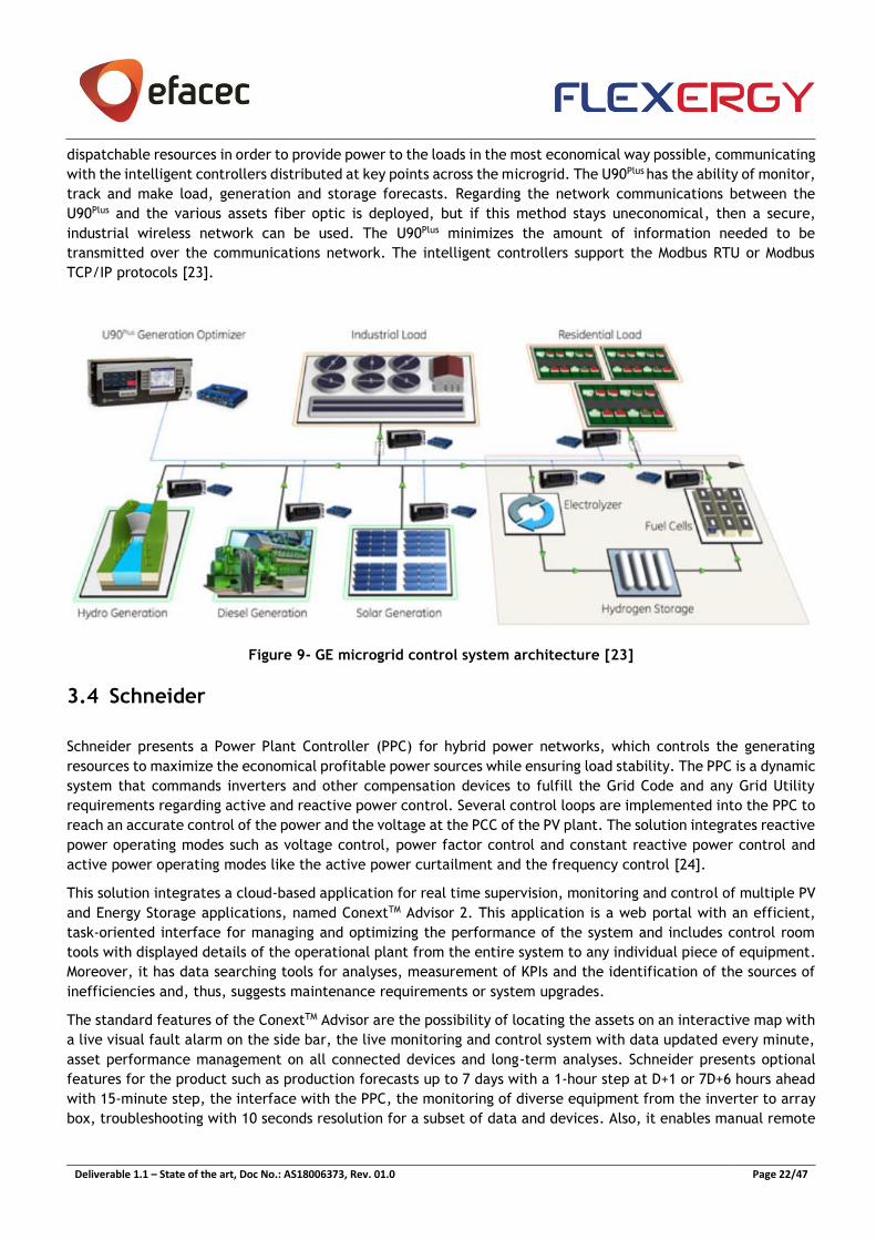
Deliverable 1.1 – State of the art, Doc No.: AS18006373, Rev. 01.0 Page 22/47
dispatchable resources in order to provide power to the loads in the most economical way possible, communicating
with the intelligent controllers distributed at key points across the microgrid. The U90Plus has the ability of monitor,
track and make load, generation and storage forecasts. Regarding the network communications between the
U90Plus and the various assets fiber optic is deployed, but if this method stays uneconomical, then a secure,
industrial wireless network can be used. The U90Plus minimizes the amount of information needed to be
transmitted over the communications network. The intelligent controllers support the Modbus RTU or Modbus
TCP/IP protocols [23].
Figure 9- GE microgrid control system architecture [23]
3.4 Schneider
Schneider presents a Power Plant Controller (PPC) for hybrid power networks, which controls the generating
resources to maximize the economical profitable power sources while ensuring load stability. The PPC is a dynamic
system that commands inverters and other compensation devices to fulfill the Grid Code and any Grid Utility
requirements regarding active and reactive power control. Several control loops are implemented into the PPC to
reach an accurate control of the power and the voltage at the PCC of the PV plant. The solution integrates reactive
power operating modes such as voltage control, power factor control and constant reactive power control and
active power operating modes like the active power curtailment and the frequency control [24].
This solution integrates a cloud-based application for real time supervision, monitoring and control of multiple PV
and Energy Storage applications, named ConextTM Advisor 2. This application is a web portal with an efficient,
task-oriented interface for managing and optimizing the performance of the system and includes control room
tools with displayed details of the operational plant from the entire system to any individual piece of equipment.
Moreover, it has data searching tools for analyses, measurement of KPIs and the identification of the sources of
inefficiencies and, thus, suggests maintenance requirements or system upgrades.
The standard features of the ConextTM Advisor are the possibility of locating the assets on an interactive map with
a live visual fault alarm on the side bar, the live monitoring and control system with data updated every minute,
asset performance management on all connected devices and long-term analyses. Schneider presents optional
features for the product such as production forecasts up to 7 days with a 1-hour step at D+1 or 7D+6 hours ahead
with 15-minute step, the interface with the PPC, the monitoring of diverse equipment from the inverter to array
box, troubleshooting with 10 seconds resolution for a subset of data and devices. Also, it enables manual remote
Deliverable 1.1 – State of the art, Doc No.: AS18006373, Rev. 01.0 Page 23/47
control by sending control orders to all manageable equipment as well as energy not supplied allocation such as
the allocation and arbitration of energy losses [25].
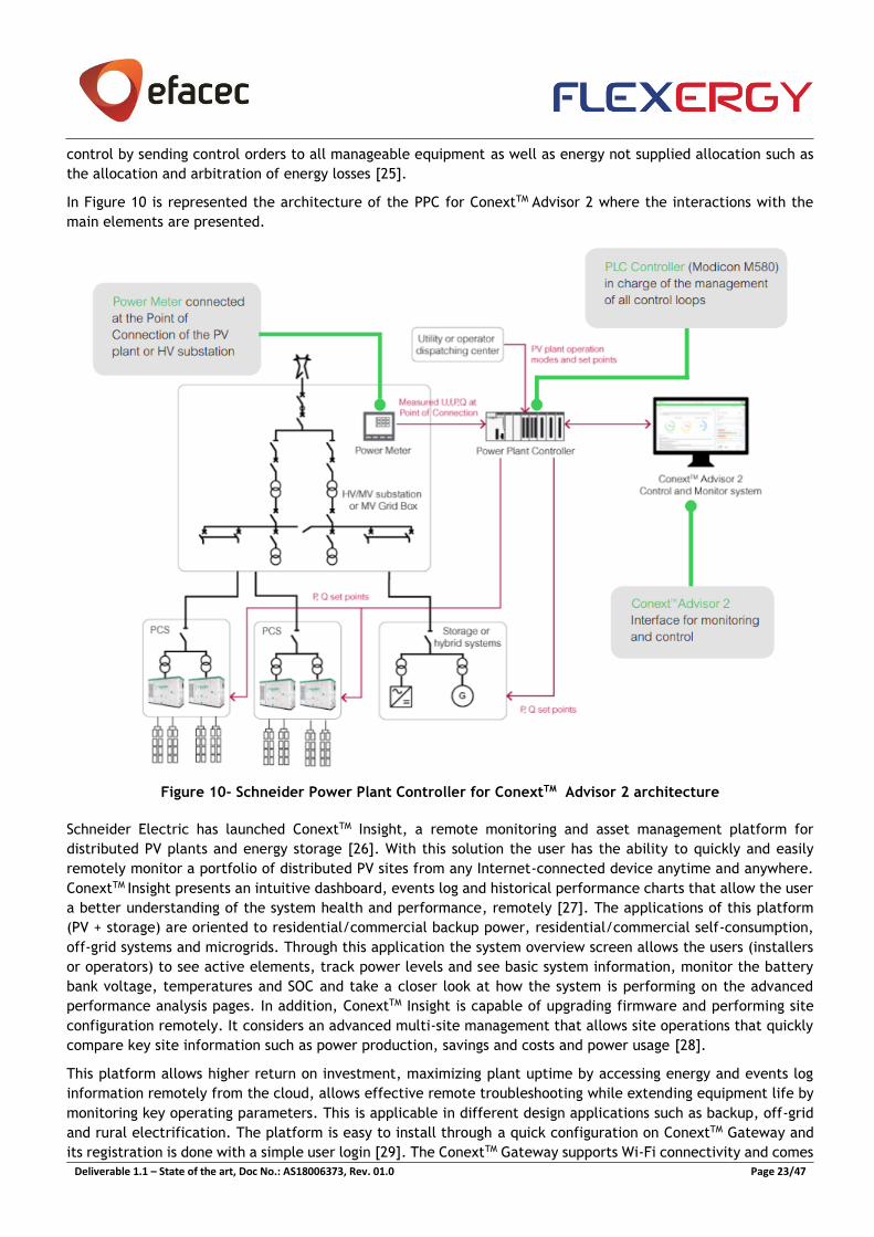
In Figure 10 is represented the architecture of the PPC for ConextTM Advisor 2 where the interactions with the
main elements are presented.
Figure 10- Schneider Power Plant Controller for ConextTM Advisor 2 architecture
Schneider Electric has launched ConextTM Insight, a remote monitoring and asset management platform for
distributed PV plants and energy storage [26]. With this solution the user has the ability to quickly and easily
remotely monitor a portfolio of distributed PV sites from any Internet-connected device anytime and anywhere.
ConextTM Insight presents an intuitive dashboard, events log and historical performance charts that allow the user
a better understanding of the system health and performance, remotely [27]. The applications of this platform
(PV + storage) are oriented to residential/commercial backup power, residential/commercial self-consumption,
off-grid systems and microgrids. Through this application the system overview screen allows the users (installers
or operators) to see active elements, track power levels and see basic system information, monitor the battery
bank voltage, temperatures and SOC and take a closer look at how the system is performing on the advanced
performance analysis pages. In addition, ConextTM Insight is capable of upgrading firmware and performing site
configuration remotely. It considers an advanced multi-site management that allows site operations that quickly
compare key site information such as power production, savings and costs and power usage [28].
This platform allows higher return on investment, maximizing plant uptime by accessing energy and events log
information remotely from the cloud, allows effective remote troubleshooting while extending equipment life by
monitoring key operating parameters. This is applicable in different design applications such as backup, off-grid
and rural electrification. The platform is easy to install through a quick configuration on ConextTM Gateway and
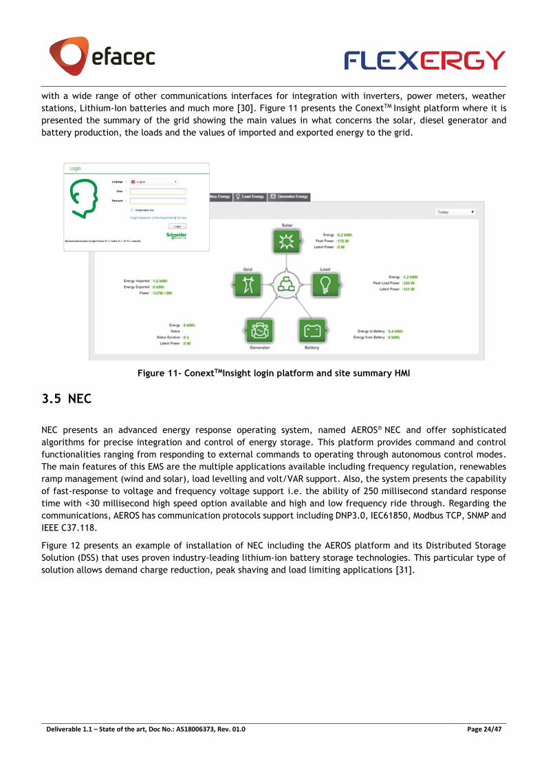
its registration is done with a simple user login [29]. The ConextTM Gateway supports Wi-Fi connectivity and comes
Deliverable 1.1 – State of the art, Doc No.: AS18006373, Rev. 01.0 Page 24/47
with a wide range of other communications interfaces for integration with inverters, power meters, weather
stations, Lithium-Ion batteries and much more [30]. Figure 11 presents the ConextTM Insight platform where it is
presented the summary of the grid showing the main values in what concerns the solar, diesel generator and
battery production, the loads and the values of imported and exported energy to the grid.
Figure 11- ConextTMInsight login platform and site summary HMI
3.5 NEC
NEC presents an advanced energy response operating system, named AEROS® NEC and offer sophisticated
algorithms for precise integration and control of energy storage. This platform provides command and control
functionalities ranging from responding to external commands to operating through autonomous control modes.
The main features of this EMS are the multiple applications available including frequency regulation, renewables
ramp management (wind and solar), load levelling and volt/VAR support. Also, the system presents the capability
of fast-response to voltage and frequency voltage support i.e. the ability of 250 millisecond standard response
time with <30 millisecond high speed option available and high and low frequency ride through. Regarding the
communications, AEROS has communication protocols support including DNP3.0, IEC61850, Modbus TCP, SNMP and
IEEE C37.118.
Figure 12 presents an example of installation of NEC including the AEROS platform and its Distributed Storage
Solution (DSS) that uses proven industry-leading lithium-ion battery storage technologies. This particular type of
solution allows demand charge reduction, peak shaving and load limiting applications [31].
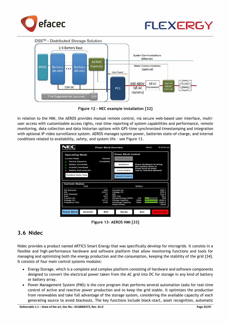
Deliverable 1.1 – State of the art, Doc No.: AS18006373, Rev. 01.0 Page 25/47
Figure 12 - NEC example installation [32]
In relation to the HMI, the AEROS provides manual remote control, via secure web-based user interface, multi-
user access with customizable access rights, real-time reporting of system capabilities and performance, remote
monitoring, data collection and data historian options with GPS-time synchronized timestamping and integration
with optional IP video surveillance system. AEROS manages system power, batteries state-of-charge, and internal
conditions related to availability, safety, and system life - see Figure 13.
Figure 13- AEROS HMI [33]
3.6 Nidec
Nidec provides a product named ARTICS Smart Energy that was specifically develop for microgrids. It consists in a
flexible and high-performance hardware and software platform that allow monitoring functions and tools for
managing and optimizing both the energy production and the consumption, keeping the stability of the grid [34].
It consists of four main control systems modules:
• Energy Storage, which is a complete and complex platform consisting of hardware and software components
designed to convert the electrical power taken from the AC grid into DC for storage in any kind of battery
or battery array.
• Power Management System (PMS) is the core program that performs several automation tasks for real-time
control of active and reactive power production and to keep the grid stable. It optimizes the production
from renewables and take full advantage of the storage system, considering the available capacity of each
generating source to avoid blackouts. The key functions include black-start, asset recognition, automatic
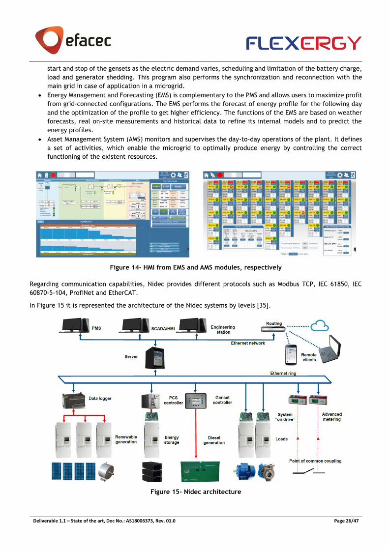
Deliverable 1.1 – State of the art, Doc No.: AS18006373, Rev. 01.0 Page 26/47
start and stop of the gensets as the electric demand varies, scheduling and limitation of the battery charge,
load and generator shedding. This program also performs the synchronization and reconnection with the
main grid in case of application in a microgrid.
• Energy Management and Forecasting (EMS) is complementary to the PMS and allows users to maximize profit
from grid-connected configurations. The EMS performs the forecast of energy profile for the following day
and the optimization of the profile to get higher efficiency. The functions of the EMS are based on weather
forecasts, real on-site measurements and historical data to refine its internal models and to predict the
energy profiles.
• Asset Management System (AMS) monitors and supervises the day-to-day operations of the plant. It defines
a set of activities, which enable the microgrid to optimally produce energy by controlling the correct
functioning of the existent resources.
Figure 14- HMI from EMS and AMS modules, respectively
Regarding communication capabilities, Nidec provides different protocols such as Modbus TCP, IEC 61850, IEC
60870-5-104, ProfiNet and EtherCAT.
In Figure 15 it is represented the architecture of the Nidec systems by levels [35].
Figure 15- Nidec architecture

Deliverable 1.1 – State of the art, Doc No.: AS18006373, Rev. 01.0 Page 27/47
3.7 Younicos / Aggreko
Younicos, recently integrated in the Aggreko group, provides an energy storage management system, the Younicos
Quotient (Y.Q.) that corresponds to an integrated software platform that combine advanced control algorithms
with robust communications architecture. This platform supports multiple storage technologies (lead-acid,
lithium-ion, sodium-sulphur and flow battery technologies), handles high volumes of data, maintaining rigorous
data and security management. Also, it aims at operating several ESS modes ranging from frequency response to
island grid-forming and C&I demand management. Operating conditions can be adjusted to new requirements as
well as to accommodate future components.
Y.Q operates all system components to deliver the real and reactive power needed while facilitating the
integration with external systems, such as existing customer SCADA systems and other on-site devices. This
software platform is designed to maximize the operation efficiency at the same time that minimizes the total
cost of ownership of the ESS asset, thus preventing operations that may damage or prematurely degrade assets.
This platform enables an energy storage system to handle a variety of services using a multi-mode priority stacking
feature. The user decides which functions are the most important and the Y.Q configures an automated control
hierarchy to determine real-time operation according to grid conditions and market requirements. The Y.Q.
functions correspond to island grid-forming, frequency regulation, black start, demand charge management,
capacity markets, voltage control and power factor correction, peak shaving and ramp rate control.
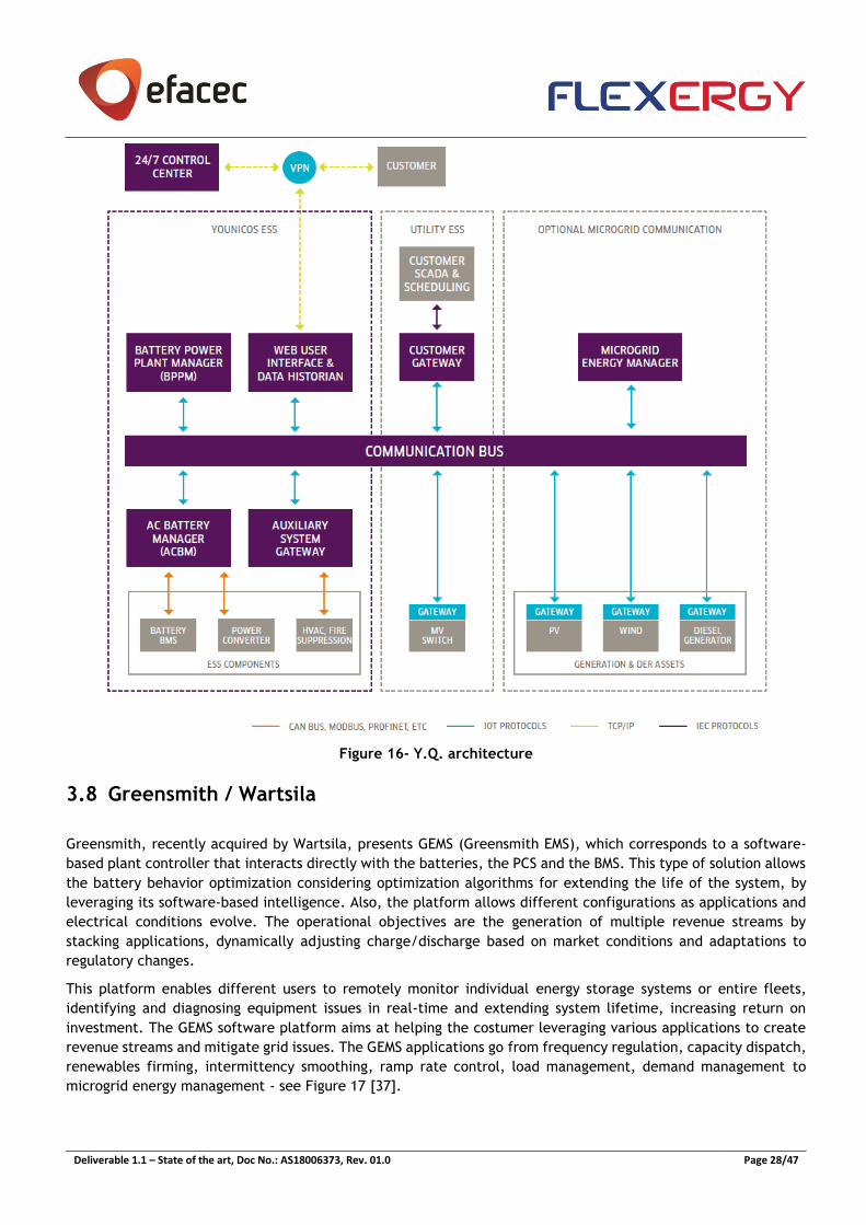
In Figure 16 it is presented the Y.Q. architecture where the interactions with the main components and its
communication protocols are represented. Y.Q ensures interoperability between all energy storage system
components by integrating nonproprietary industry-standard protocols. The external interface with SCADA system
is possible over standard protocols such as IEC 60870-5-104 or DNP3.
Regarding the main components in Figure 16, the AC Battery Manager (ACBM) manages local protection, control
and monitoring each battery rack connected to each PCS unit; the Battery Power Plant Manager (BPPM) is a
centralized controller that takes inputs from the Younicos system database, customer SCADA and grid
measurements to deterministically deliver real and reactive commands to all power units, considering the battery
degradation management, SOC balancing, efficiency optimization and auxiliary load management. The Microgrid
Energy Manager is responsible for the dispatch of multiple energy resources or manage transitions to a grid-forming
mode, and making constant forecasts, monitors and optimizes the dispatch of assets under management, ensuring
a stable and reliable microgrid.
The Y.Q. incorporates a multi-user interface (web interface) for remote system monitoring and control. The HMI
interfaces to the MySQL database and provides real-time and historical trending for the user requirements, such
as performance reporting and maintenance management [36].
Deliverable 1.1 – State of the art, Doc No.: AS18006373, Rev. 01.0 Page 28/47
Figure 16- Y.Q. architecture
3.8 Greensmith / Wartsila
Greensmith, recently acquired by Wartsila, presents GEMS (Greensmith EMS), which corresponds to a software-
based plant controller that interacts directly with the batteries, the PCS and the BMS. This type of solution allows
the battery behavior optimization considering optimization algorithms for extending the life of the system, by
leveraging its software-based intelligence. Also, the platform allows different configurations as applications and
electrical conditions evolve. The operational objectives are the generation of multiple revenue streams by
stacking applications, dynamically adjusting charge/discharge based on market conditions and adaptations to
regulatory changes.
This platform enables different users to remotely monitor individual energy storage systems or entire fleets,
identifying and diagnosing equipment issues in real-time and extending system lifetime, increasing return on
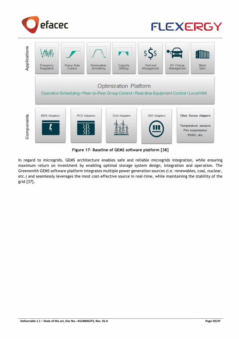
investment. The GEMS software platform aims at helping the costumer leveraging various applications to create
revenue streams and mitigate grid issues. The GEMS applications go from frequency regulation, capacity dispatch,
renewables firming, intermittency smoothing, ramp rate control, load management, demand management to
microgrid energy management - see Figure 17 [37].
Deliverable 1.1 – State of the art, Doc No.: AS18006373, Rev. 01.0 Page 29/47
Figure 17- Baseline of GEMS software platform [38]
In regard to microgrids, GEMS architecture enables safe and reliable microgrids integration, while ensuring
maximum return on investment by enabling optimal storage system design, integration and operation. The
Greensmith GEMS software platform integrates multiple power generation sources (i.e. renewables, coal, nuclear,
etc.) and seamlessly leverages the most cost-effective source in real-time, while maintaining the stability of the
grid [37].
Deliverable 1.1 – State of the art, Doc No.: AS18006373, Rev. 01.0 Page 30/47
4. Management Algorithms for Energy Storage
The optimization of BESS scheduling is a study subject with an impressive and rich literature support due mainly
to the recognized importance of a storage solution for the increased integration of renewable energy sources
(RES) in the electrical grid. Overall, the problem consists of the scheduling of charge and discharge actions of the
BESS at subsequent time steps, over a given time horizon, based on data forecasts, such as load demand, RES
production and market energy prices, with the objective of optimizing a given objective. In theory, sufficient
battery capacity would diminish the need for complex storage optimization strategies. However, oversizing is not
cost-effective, especially considering the still high investment cost of technologies such as Li-ion [39].
Furthermore, depending on the user’s profile, the optimal operation of BESS may have different independent or
complementary objectives, namely:
• minimization of operational costs [40] [41] [42] [43],
• maximization of self-consumption [44],
• provision of ancillary services and other grid support functions [45],
• minimization of BESS degradation [46] [47] [48],
• or a combination of these [49] [50].
Several approaches have been made in recent years differing not only on the objective function but also on the
techniques used for solving the optimization problem, the complexity of the model used to represent the BESS,
the time-step and time horizon and the context of the storage solution’s application namely residential, industrial
or purely for (micro-) grid support.
An analysis of the different methods and techniques is provided in the next sections.
4.1 Battery Modelling Approaches
The development of an optimization strategy for operating storage units or plants, requires the use of models
that describe those systems with sufficient accuracy to ensure their applicability in real life scenarios. In short, a
good optimization model has to be as simple as possible, without compromising the explicit emulation of the
fundamental dynamics that govern the operation of a storage system.
Focusing on Li-ion batteries, several models have been proposed to capture such dynamics. The major differences
on the modelling approaches led to a commonly accepted classification of those models into four categories [51]:
• Empirical models;
• Electrochemical/Physical models;
• Abstract models using artificial intelligence (AI).
• Electrical circuit equivalent models;
All four types of models have advantages and disadvantages, which makes the choice for the best suited model
case-dependent. The main objective of all these models is to describe the relationship between the current
applied to the battery and the voltage observed at its terminals. This relationship is far from linear, given the
electrochemical processes involved. This leads to the following dichotomy: a model that perfectly describes the
physical interactions that take place during a battery’s lifetime will be more complex than simpler models. A
more complex model typically leads to increased configuration effort and more importantly, greater computation
time, which may hinder its applicability to real-time applications. The evaluation of the best model for each
application should, therefore, consider essentially three aspects:
• Accuracy – how closely the model can predict battery state parameters;
• Complexity – number of parameters required by the model;
• Physical interpretability – analytical insight that the model can provide.
Deliverable 1.1 – State of the art, Doc No.: AS18006373, Rev. 01.0 Page 31/47
Empirical models
Empirical models are, as the name hints, based on empirical parameters that have little or no physical significance
at all. Not presenting a formal structure and being solely based on tabulated values, they are extremely simple,
easy to configure and able to achieve quick responses and predictions. Nevertheless, they naturally present very
limited accuracy. Even so, good results may be achieved for stochastic models and/or fuzzy logic approaches.
Electrochemical/Physical models
On the opposite side of the spectrum are the electrochemical/physical models. These are low-level models that
present the highest accuracy but also the highest complexity (often requiring the definition of over 50 parameters)
among all model categories. These models describe the electrochemical phenomena happening at the cell level
namely thermodynamics, active species kinetics and transport phenomena. Therefore, their interest is almost
limited to battery technology specialists and material scientists and are hardly used for control optimization
studies. Nevertheless, these models can be viewed as a good study subject for ageing or thermal studies of
batteries.
Abstract models using AI
Models using AI are considered to be very accurate, since the AI agent is able to capture intrinsically the dynamics
of the electrochemical phenomena that takes place inside the BESS being studied. The downfall of these models
however, resides precisely on their dependency on the data used to calibrate them. A model calibrated for an
individual battery could need a re-calibration for another battery, even if both batteries present the same
chemistry (e.g. two Li-ion batteries). Furthermore, the physical interpretability provided by these models is very
limited, since they act as true “black-boxes”, where the only interpretable data being the input current and the
output voltage. Applications where knowing certain variable quantities such as the SOC is fundamental, would
need to run a parallel model for those estimates.
Electrical circuit equivalent models
The electrical circuit equivalent models occupy the middle ground, being the most popular approach for control
optimization problems. These models approximate the battery’s behavior by equivalent electric circuit
components, typically voltage sources, resistors and capacitors. This confers an abstraction layer over the complex
chemical processes taking place inside the battery, without compromising much of the accuracy. The model is
therefore less complex than low-level models, requiring shorter calculation times, a reduced configuration cost
and is transversal to different chemistries. Nevertheless, the model requires the introduction of several
parameters to describe the circuit components that can be easily obtained from experiments over the BESS
equipment to be modelled.
The complexity of these models is flexible and, depending on the application, more accurate models can be
obtained by the introduction of additional circuit components that take second-order effects like temperature,
aging and capacity fading into consideration. A popular model introduced by Chen and Rincón-Mora in 2006 [52],
serving as the base for several studies so far [53] [54] [55], is a good example that can be viewed on figure 18.
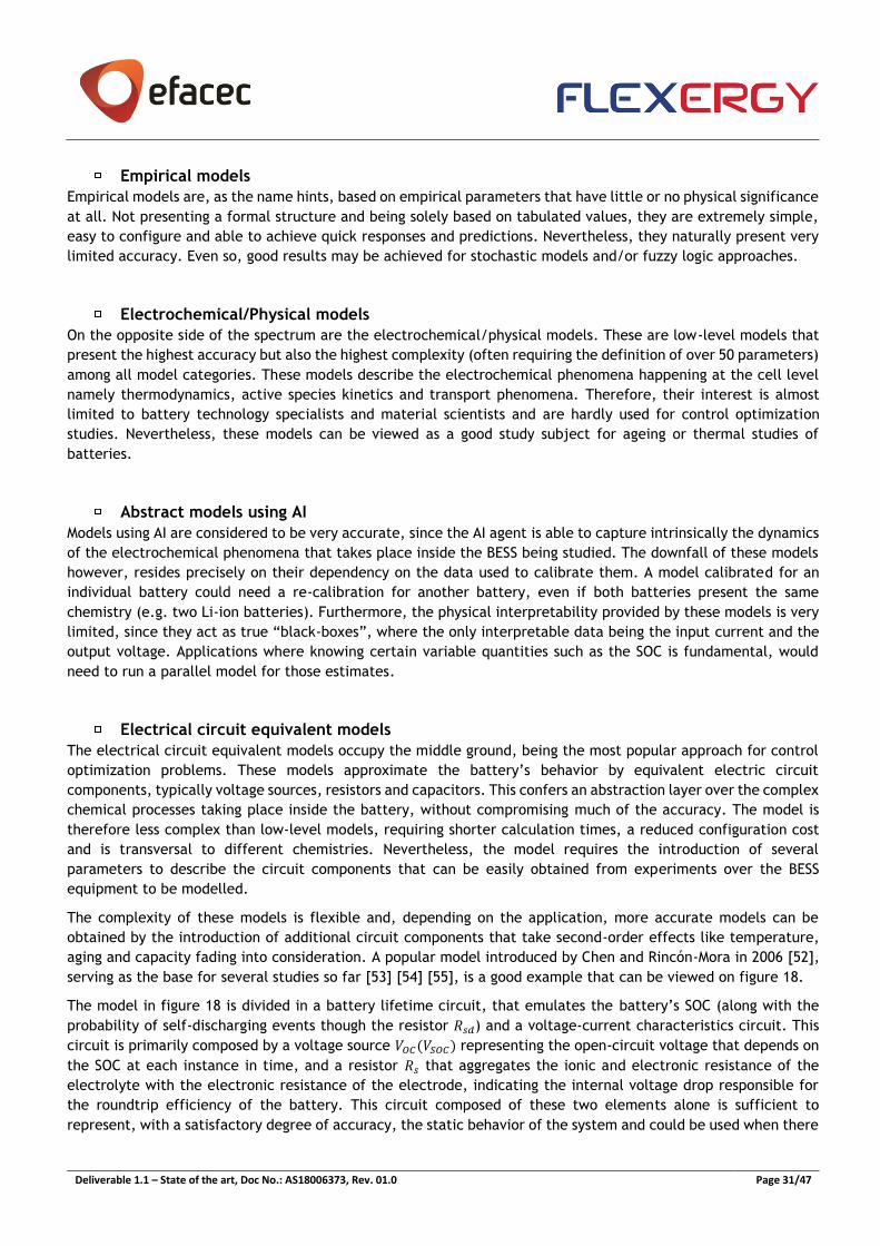
The model in figure 18 is divided in a battery lifetime circuit, that emulates the battery’s SOC (along with the
probability of self-discharging events though the resistor 𝑅𝑠𝑑) and a voltage-current characteristics circuit. This
circuit is primarily composed by a voltage source 𝑉𝑂𝐶(𝑉𝑆𝑂𝐶) representing the open-circuit voltage that depends on
the SOC at each instance in time, and a resistor 𝑅𝑠 that aggregates the ionic and electronic resistance of the
electrolyte with the electronic resistance of the electrode, indicating the internal voltage drop responsible for
the roundtrip efficiency of the battery. This circuit composed of these two elements alone is sufficient to
represent, with a satisfactory degree of accuracy, the static behavior of the system and could be used when there
Deliverable 1.1 – State of the art, Doc No.: AS18006373, Rev. 01.0 Page 32/47
is no interest on the battery’s dynamic behavior. The addition of the two RC circuits, with different time
constants, aims to describe the transient response of the battery during charge and discharge events.
Figure 18 - Two coupled electrical circuits describe the state of a li-ion battery. The “Battery Lifetime
Circuit” on the left-hand side serves the purpose of describing the dynamic nature of the battery’s SoC and
the “Voltage-Current Characteristics Circuit” characterizes how terminal voltage is affected by SoC and by
current load. Adapted from [52].
Some of the elements like 𝑅𝑠 can be further complexed in order to further capture the internal dynamics of BESS.
For example, 𝑅𝑠, obtained empirically, can be added to the model as a scalar or has a function of the temperature.
Again, these complexifications may be able to achieve better accuracy, but always at the expense of computation
time. It is important to define the fundamental modelling aspects that greatly influence the battery’s behavior in
a control optimization perspective in order to avoid unnecessary complexifications.
4.2 Deterministic and heuristic based approaches
Focusing on the different methods and techniques explored in recent literature, some of the simplest encompass
the definition of deterministic rules and strategies with the most sophisticated relying on fuzzy logic [56] and
metaheuristics [57]. These rules convey the knowledge of the researches in an attempt to easily, and
computationally effortlessly, achieve a good (but not optimal) solution. On the other hand, the simplicity of these
approaches is often matched with linear minimalist BESS models and are generally presented as introductory,
theoretic work [41] [56] [57] [58] [59]. Contrastingly, the work of Zou et al. [60] focused on developing better
multi-temporal BESS model representations to capture the dynamic evolution of state of health (SOH). To validate
their model the authors apply some current used, deterministic, battery charging strategies associated with the
maximization of batteries’ SOH, namely the constant-current constant-voltage (CCCV) and the multistage
constant-current (MCC) charging strategies.
Despite the relative good results obtained by these deterministic approaches, and especially their computational
efficiency, they lack the capacity to reach optimality in any of the proposed control problems. They are based on
assumptions about how the optimum should be reached, through the establishment of deterministic rules that
although realistic, do not capture the full extent of a high-dimensionality problem such as this.
4.3 Dynamic Programming and Optimal Control
A comprehensive study by Ranaweera et al. [61] show that a rule based operation is surpassed by dynamic
programming (DP) on a control problem where the objective is to reduce reactive power requirement, in-line
losses and voltage unbalance with relative low impact on fulfilling the client’s needs in a microgrid context.
Another study by Parvini et al. [46] about optimal charging of supercapacitors (including Li-ion batteries),
conclude that a constant current rule achieves slightly less efficiency than an optimal strategy established by DP.

Deliverable 1.1 – State of the art, Doc No.: AS18006373, Rev. 01.0 Page 33/47
The use of deterministic rules can nonetheless still prove very useful in certain contexts, namely when coupled
with other optimization techniques. Henri et al. [42] present a mode-based approach to achieve the best
performance at the lowest cost where the control objective consists in choosing the best operation mode instead
of the charging and discharging power levels. The authors argue that for applications such as residential, the main
issue is often time to find when to charge and when to discharge instead of computing the optimal charging and
discharging power. A two-stage algorithm is developed where in the first stage, an economic model predictive
control (EMPC) algorithm determines the optimal charging and discharging power and in the second stage the
controller selects the best operation modes based on the results from the EMPC. The same authors further improve
their method by introducing a machine learning (ML) approach to predict the optimal operation modes, instead
of the EMPC approach, reducing the dependency of their method on error-prone load forecasts, achieving higher
mean potential savings, prediction accuracy and lower computation times than [43].
The use of model predictive control (MPC) for optimal BESS scheduling can be found in the largest share of
publications directed to this theme given its maturity, versatility and the possibility to interact with linear and
nonlinear programming algorithms. On the other hand, MPC presents a framework for real-time, on-line scheduling
of BESS, something that many other techniques alone do not consider.
In general, the problem at hands can be defined, for a given time horizon, either as a mixed integer linear
programming (MILP) problem, or as a nonlinear programming problem (NLP), depending on how the BESS is
represented. The nonlinearities inherent to BESS dynamics, encompassing interactions between temperature,
SOC, charge and discharge rates, SOH, etc. are often linearized through techniques such as piecewise linearization
in order to increase the problems tractability at the expense of accuracy. Again, the objective of the optimization
should dictate the feasibility of such approximations, and the required threshold of accuracy. Furthermore,
techniques like continuous relaxation (CR) are able to further reduce MILP’s complexity by changing it into a
simple LP solution [56]. With this in mind, several interesting works can be found that address this problem as a
MILP [44] [56], a linearized NLP [50] or as a NLP directly [48] [53]. In any case, these methodologies solve the
problem for a fixed period in time, being it a day or a year, with the resolution of some milliseconds to an hourly
schedule of the charge and discharge of BESS.
MPC and other derived techniques are methods for constrained optimal control that, through a shifting (receding)
time window, are capable of solving a multi-temporal optimization problem such as on-line real-time optimization
of BESS scheduling. The major contribution of MPC is the possibility to compensate at each time step for any
disturbances that occur since the last optimization problem was solved, such as the errors introduced by
predictions of upcoming demand, RES production and market electric energy prices [62]. MPC requires an explicit
model of the process and the clear definition of an objective function subjected to different constraints since it
relies on MILP or NLP to solve the optimization problem at each time-step. Here lies again the aforementioned
dichotomy of better BESS models leading to greater accuracy but higher computational requisites.
The extensive literature that can be found relating MPC to BESS scheduling application, encompasses different
objectives such as overall optimization of microgrid operation [62], maximization of BESS lifetime [47] [63],
provision of system services [45] [64], minimization of residential client’s bills [40], maximization of self-
consumption [65], optimal power flow [66], and combinations of some of these objectives [67].
The aforementioned approach of DP either in its deterministic or stochastic (SDP) form is another frequently used
technique in solving BESS optimal scheduling. Furthermore, some recent attempts have been made in using
Reinforcement Learning (RL), an area of machine learning that shares a common basis with DP but does not require
access to an explicit model of the system to be optimized, instead learns by interaction with the system. DP is a
graph-based technique, supported by shorter path algorithms such as the Bellman-Ford algorithm, being able to
handle any performance index or constraint types (linear or nonlinear, differential or not, convex or concave,
etc.). The approach has the advantages of not requiring the use of any specific mathematical solver and, in the
case of SDP, being able to cope with the deviations inherent to data forecasts when solving a scheduling problem
[68] [69].
A vast number of publications can be found connecting DP and storage scheduling for multiple distinct objectives.
Some examples include profit-maximizing BESS scheduling for primary frequency control [70], optimal control of
Deliverable 1.1 – State of the art, Doc No.: AS18006373, Rev. 01.0 Page 34/47
residential BESS, considering its impact on the enveloping microgrid [61] [68], combining peak shaving and BESS
degradation minimization [71], minimizing electrical costs under different operation modes of interaction
involving plug-in electric vehicle (PEV) energy storage [72] and energy storage arbitrage [73]. Examples of studies
based on ADP/RL include the combined objectives of minimizing total electricity costs and extending the BESS’s
lifetime [74], maximizing self-consumption of local photovoltaic production in a microgrid [75] and accounting for
the unpredictability of eolic resources in satisfying several consumer-defined goals [76]. Contrastingly, however,
a recent comprehensive study by Jiang et al. [77] concludes that by comparing several ADP techniques on solving
benchmark energy storage problems, the lack of reliability of the methods may be an impediment to their scaling
to more complex real-world problems.
A comparison between RL (fitted Q iteration algorithm) and MPC can be found on the 2009 work by Ernst et al.
[78].The object of study was the synthesis of a benchmark electrical power oscillations damping controller. In this
particular study case, MPC performed slightly less robustly than the fitted Q iteration algorithm, showing some
point convergence problems, but showed a slight advantage in terms of numerical accuracy for the optimum. The
authors came to the conclusion, however, that a combination of both methods should be selected when
approaching that and other problems. The fitted Q iteration algorithm was considered a better choice on its own
in cases where a good enough model of the system is not available and only observations of the system are used.
Another interesting and more recent approach by Xi et al. [79] focused on co-optimizing the use of distributed
energy storage for multiple benefits by applying a two stage process. In the first stage, SDP is used in order to
obtain an approximate solution and at the second stage, MILP is applied to the outcomes to find a near-optimal
policy. These two studies further enrich the argument that depending on the application, a combination of more
than one optimization technique may be a valid and even better solution for real-world problems than choosing
between the possible methods available.
4.4 Optimizing the operation of distributed storage for multiple services and
control objectives
4.4.1 Energy applications of BESS
The potential of energy storage for providing multiple services regarding several sectors in electricity industry has
been a trending subject in recent years with several well-succeeded applications being demonstrated. A
comprehensive study by Manz et al. [80] highlights a major division on the nature of these services, based
essentially on their temporal span: power applications, many of them comprising the so-called balancing services
(excluding reserve services), and energy applications.
BESS, given their small rated-power-to-energy ratio (W:Wh rating), tend to be well suited for energy applications,
i.e. services with a greater temporal horizon like economic arbitrage and storage of energy at off-peak hours.
Nevertheless, given their very high ramp rates, traduced in the possibility to arrive at their full power within a
few seconds, power applications, are also considered for this technology, e.g. frequency regulation or spinning
reserve. Table 2 summarizes the applications for energy storage proposed in recent years, referencing their
inherent value and domain (energy, power or both).
The table is divided in upper and lower parts, separated by applications that in themselves justify the investment
costs in a storage facility (upper section) and services that could be provided by a storage facility but do not
justify the said investment (lower section). It is important to notice that, being this study from 2012, the capital
cost of storage technologies such as BESS were even greater than the ones verified nowadays and the premise of
this work was that “a storage system should generate enough revenue to cover its costs and remain profitable”,
all within an acceptable time frame. On the other hand, the key metrics defining the cost of any storage asset
include not also the upfront capital cost but also and equally importantly, the round-trip efficiency and the asset’s
lifetime.
The combination of these economic and technical limitations suggest that the application of energy storage to
the provision of any service or group of services has a “sweet spot”, where a storage solution overcomes the
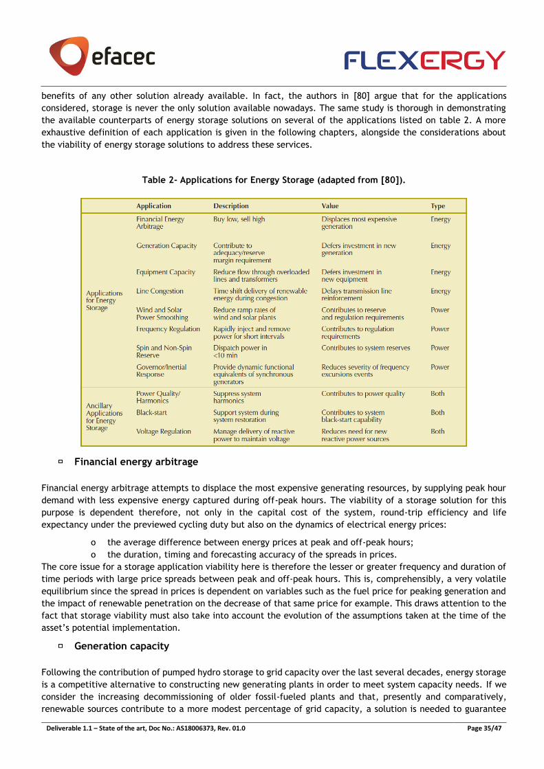
Deliverable 1.1 – State of the art, Doc No.: AS18006373, Rev. 01.0 Page 35/47
benefits of any other solution already available. In fact, the authors in [80] argue that for the applications
considered, storage is never the only solution available nowadays. The same study is thorough in demonstrating
the available counterparts of energy storage solutions on several of the applications listed on table 2. A more
exhaustive definition of each application is given in the following chapters, alongside the considerations about
the viability of energy storage solutions to address these services.
Table 2- Applications for Energy Storage (adapted from [80]).
Financial energy arbitrage
Financial energy arbitrage attempts to displace the most expensive generating resources, by supplying peak hour
demand with less expensive energy captured during off-peak hours. The viability of a storage solution for this
purpose is dependent therefore, not only in the capital cost of the system, round-trip efficiency and life
expectancy under the previewed cycling duty but also on the dynamics of electrical energy prices:
o the average difference between energy prices at peak and off-peak hours;
o the duration, timing and forecasting accuracy of the spreads in prices.
The core issue for a storage application viability here is therefore the lesser or greater frequency and duration of
time periods with large price spreads between peak and off-peak hours. This is, comprehensibly, a very volatile
equilibrium since the spread in prices is dependent on variables such as the fuel price for peaking generation and
the impact of renewable penetration on the decrease of that same price for example. This draws attention to the
fact that storage viability must also take into account the evolution of the assumptions taken at the time of the
asset’s potential implementation.
Generation capacity
Following the contribution of pumped hydro storage to grid capacity over the last several decades, energy storage
is a competitive alternative to constructing new generating plants in order to meet system capacity needs. If we
consider the increasing decommissioning of older fossil-fueled plants and that, presently and comparatively,
renewable sources contribute to a more modest percentage of grid capacity, a solution is needed to guarantee

Deliverable 1.1 – State of the art, Doc No.: AS18006373, Rev. 01.0 Page 36/47
sufficient energy availability. The decision criterion between a storage solution and the constructing of a new
plant resides in the comparison between the capital and marginal costs of both solutions. While the peaking plant
has a marginal cost that is closely tied to its fuel price, the marginal cost of storage is related to its round-trip
efficiency and the prices in the region. However, the provision of this service by BESS is however quite limited
considering both power and energy requirements.
Equipment capacity
Overloads occurring in lines or transformers that cannot be overcome by system reconfigurations can be addressed
either by a reinforcement of the equipment or through a storage solution, downstream of the congestion. Again,
the decision between both hypotheses is supported by the capital costs of an adequate storage solution versus
the equipment upgrade/addition.
Most importantly, however, is the very nature of the constraint, namely its severity, frequency, duration and
regulatory cost if left unaddressed which ultimately dictates the need for such a solution altogether. The choice
for storage in this case must take into consideration these factors in order to adequately size the energy and
power ratings of the storage asset, for the present as well as for the projected life of the equipment upgrade
deferral.
A good use case example where storage would be preferred to equipment upgrade would be a situation where a
substation expansion was the alternative and the location for such expansion was critically scarce, making that
expansion unusually expensive.
Line congestion
Although apparently redundant, given the above application described, line congestion refers to the specific case
where transmission lines are accommodating RES energy, namely wind energy, and the lack for transmission
capacity leads to wind energy curtailment. Analyzing this problem purely from an investment perspective, one
must consider the case where the investment made in a storage solution would be alternatively redirected to the
deployment of a new wind plant where it would be less likely to encounter transmission congestion.
In truth, the annual percentage of hours/days in which congestion would need to be handled would need to be
sufficiently abundant to cover for the investment cost of a storage solution if it were to simply be deployed
envisaging this objective alone. Even if that is indeed the case, care should be given to the sizing of the storage
unit. Events where large wind energy curtailment is verified represent only a small percentage of the total events
of wind spillage, which means that a storage unit sized to accommodate such levels of curtailment would be
underutilized for most of its lifetime. Again the concept of “sweet spot” gains significant meaning. If a storage
solution is preferred, care should be taken in analyzing wind profiles and congestion patterns, not only for the
present but especially for the future.
Wind and Solar Power Smoothing
The potential value attributed to storage systems for smoothing the output of wind and solar power plants resides
on the flexibility conferred by these solutions in particular cases such as:
o Regions where the thermal generation is relatively inflexible;
o Systems with weak interconnections or islanded from a larger grid;
o Regions lacking a relatively large power system, with few generating plants;
o Regions where wind and solar plants are spatially grouped.
In these situations, a storage solution could provide ramp-rate control to the variable power production resulting
in a smoother energy profile injected in the grid.

Deliverable 1.1 – State of the art, Doc No.: AS18006373, Rev. 01.0 Page 37/47
Balancing Services - Frequency Response/Regulation and Reserve Services
The high ramp rates of BESS and flywheels position these technologies as a possible contribution for short-term
system reserves, able to quickly respond to Automatic Generation Control (AGC) actions. This is a more or less
interesting application depending, however, on how the grid operators manage the longer time-scale variability
in wind and solar power. Less regulation is needed when these variations are managed by sub-hourly energy
dispatch and reserve markets, when compared to the case where management is made within an entire hour by
regulation alone. Again the viability of a storage solution for this application is case-dependent.
A curious and successful application case is referenced in [80]. In 1997, on the Alaskan region of Metlakatla, the
implementation of bulk BESS led to massive savings in fuel costs that were being spent on small diesel generators
for the sole purpose of providing frequency regulation to the local community. The BESS operated for 11 years
before being replaced, which exceeded the battery’s life expectancy a priori. This case study suggested that
provision of frequency regulation is an interesting application for storage in regions where fuel costs are high.
Reserve services are the answer to demand-supply balancing over a longer timescale than frequency response
services. The provision of both these services is normally regulated by auction based systems and markets,
potentiating their exploitation for direct profit generation.
Other Applications
Other listed applications for storage systems, integrated into the operation and management of the power system,
include provision of governor/inertial response characteristics, improving power quality by managing harmonics,
regulating voltage through power electronics, contributing to a black-start operation, maximizing self-
consumption, congestion management as well as provisioning other ancillary services at distribution and
transmission levels. Alone, the value of these services may be insufficient to justify the deployment of the storage
solution but when combined with the above mentioned applications, as additional services, the viability of a
storage solution is greatly increased.
In sum, BESS, and storage technologies in general, can be viewed by system operators as a flexible resource that
can free other generating resources to serve the grid in other ways. Its main asset consists in the possibility to
provide multiple services, although not being an exclusive solution and sometimes not even the best solution for
a given application. Therefore, the viability of a storage solution is dictated by a case-dependent identification
of the appropriate technology, a correct sizing and preferential design for multiple services. In fact, the provision
of multiple services is the main favorable argument supporting the deployment of storage from an economic point
of view, as will be discussed in the following paragraphs.
4.4.2 Application cases – the importance of providing multiple services for economic viability
Several studies have been performed in evaluating the economic and technical viability of using storage, and
specifically BESS for the provision of multiple services. In all consulted references, the conclusion is consistent
with the claim that the value of BESS under any single service provision hardly justifies its high capital cost, even
though that cost is quickly decreasing. To make BESS a profitable business case today and in the near future, an
optimized multiple service provision must always be devised. Such objective is met through the development of
efficient dispatch strategies that consider the multi-service provision while recognizing simultaneously the
operational limits of BESS and the service’s requirements. In other words, devising a BESS optimized multiple-
service provision can be transduced into solving an optimization problem. Such problem, depending on the cost
functions of the services considered and the inherent constraints, will be linear or non-linear.
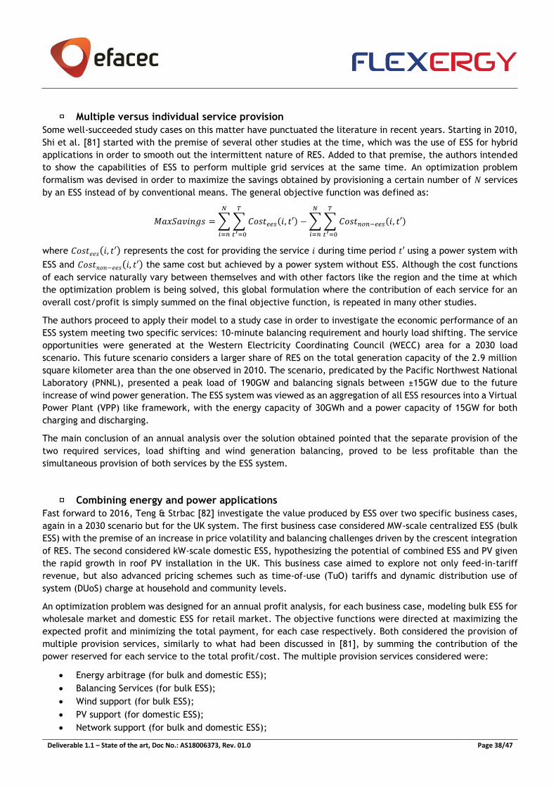
Deliverable 1.1 – State of the art, Doc No.: AS18006373, Rev. 01.0 Page 38/47
Multiple versus individual service provision
Some well-succeeded study cases on this matter have punctuated the literature in recent years. Starting in 2010,
Shi et al. [81] started with the premise of several other studies at the time, which was the use of ESS for hybrid
applications in order to smooth out the intermittent nature of RES. Added to that premise, the authors intended
to show the capabilities of ESS to perform multiple grid services at the same time. An optimization problem
formalism was devised in order to maximize the savings obtained by provisioning a certain number of 𝑁 services
by an ESS instead of by conventional means. The general objective function was defined as:
𝑀𝑎𝑥𝑆𝑎𝑣𝑖𝑛𝑔𝑠 =∑∑ 𝐶𝑜𝑠𝑡𝑒𝑒𝑠(𝑖, 𝑡′)
𝑇
𝑡′=0
𝑁
𝑖=𝑛
−∑∑ 𝐶𝑜𝑠𝑡𝑛𝑜𝑛−𝑒𝑒𝑠(𝑖, 𝑡′)
𝑇
𝑡′=0
𝑁
𝑖=𝑛
where 𝐶𝑜𝑠𝑡𝑒𝑒𝑠(𝑖, 𝑡′) represents the cost for providing the service 𝑖 during time period 𝑡′ using a power system with
ESS and 𝐶𝑜𝑠𝑡𝑛𝑜𝑛−𝑒𝑒𝑠(𝑖, 𝑡′) the same cost but achieved by a power system without ESS. Although the cost functions
of each service naturally vary between themselves and with other factors like the region and the time at which
the optimization problem is being solved, this global formulation where the contribution of each service for an
overall cost/profit is simply summed on the final objective function, is repeated in many other studies.
The authors proceed to apply their model to a study case in order to investigate the economic performance of an
ESS system meeting two specific services: 10-minute balancing requirement and hourly load shifting. The service
opportunities were generated at the Western Electricity Coordinating Council (WECC) area for a 2030 load
scenario. This future scenario considers a larger share of RES on the total generation capacity of the 2.9 million
square kilometer area than the one observed in 2010. The scenario, predicated by the Pacific Northwest National
Laboratory (PNNL), presented a peak load of 190GW and balancing signals between ±15GW due to the future
increase of wind power generation. The ESS system was viewed as an aggregation of all ESS resources into a Virtual
Power Plant (VPP) like framework, with the energy capacity of 30GWh and a power capacity of 15GW for both
charging and discharging.
The main conclusion of an annual analysis over the solution obtained pointed that the separate provision of the
two required services, load shifting and wind generation balancing, proved to be less profitable than the
simultaneous provision of both services by the ESS system.
Combining energy and power applications
Fast forward to 2016, Teng & Strbac [82] investigate the value produced by ESS over two specific business cases,
again in a 2030 scenario but for the UK system. The first business case considered MW-scale centralized ESS (bulk
ESS) with the premise of an increase in price volatility and balancing challenges driven by the crescent integration
of RES. The second considered kW-scale domestic ESS, hypothesizing the potential of combined ESS and PV given
the rapid growth in roof PV installation in the UK. This business case aimed to explore not only feed-in-tariff
revenue, but also advanced pricing schemes such as time-of-use (TuO) tariffs and dynamic distribution use of
system (DUoS) charge at household and community levels.
An optimization problem was designed for an annual profit analysis, for each business case, modeling bulk ESS for
wholesale market and domestic ESS for retail market. The objective functions were directed at maximizing the
expected profit and minimizing the total payment, for each case respectively. Both considered the provision of
multiple provision services, similarly to what had been discussed in [81], by summing the contribution of the
power reserved for each service to the total profit/cost. The multiple provision services considered were:
• Energy arbitrage (for bulk and domestic ESS);
• Balancing Services (for bulk ESS);
• Wind support (for bulk ESS);
• PV support (for domestic ESS);
• Network support (for bulk and domestic ESS);
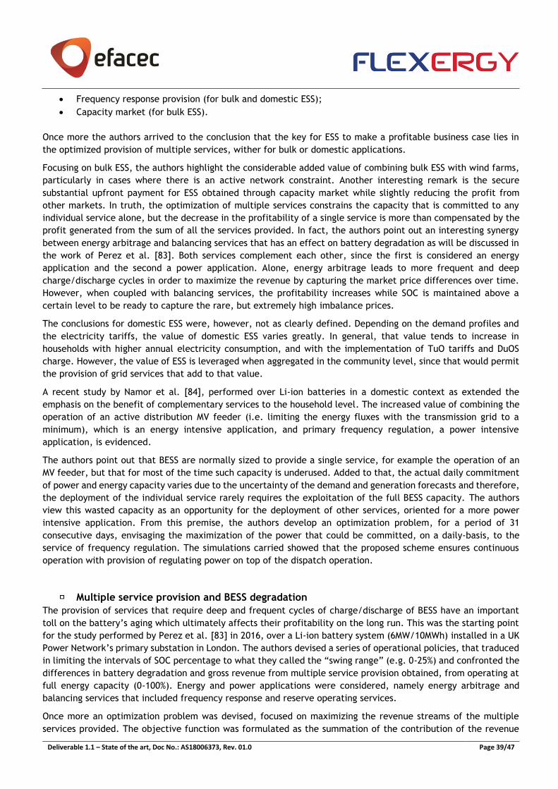
Deliverable 1.1 – State of the art, Doc No.: AS18006373, Rev. 01.0 Page 39/47
• Frequency response provision (for bulk and domestic ESS);
• Capacity market (for bulk ESS).
Once more the authors arrived to the conclusion that the key for ESS to make a profitable business case lies in
the optimized provision of multiple services, wither for bulk or domestic applications.
Focusing on bulk ESS, the authors highlight the considerable added value of combining bulk ESS with wind farms,
particularly in cases where there is an active network constraint. Another interesting remark is the secure
substantial upfront payment for ESS obtained through capacity market while slightly reducing the profit from
other markets. In truth, the optimization of multiple services constrains the capacity that is committed to any
individual service alone, but the decrease in the profitability of a single service is more than compensated by the
profit generated from the sum of all the services provided. In fact, the authors point out an interesting synergy
between energy arbitrage and balancing services that has an effect on battery degradation as will be discussed in
the work of Perez et al. [83]. Both services complement each other, since the first is considered an energy
application and the second a power application. Alone, energy arbitrage leads to more frequent and deep
charge/discharge cycles in order to maximize the revenue by capturing the market price differences over time.
However, when coupled with balancing services, the profitability increases while SOC is maintained above a
certain level to be ready to capture the rare, but extremely high imbalance prices.
The conclusions for domestic ESS were, however, not as clearly defined. Depending on the demand profiles and
the electricity tariffs, the value of domestic ESS varies greatly. In general, that value tends to increase in
households with higher annual electricity consumption, and with the implementation of TuO tariffs and DuOS
charge. However, the value of ESS is leveraged when aggregated in the community level, since that would permit
the provision of grid services that add to that value.
A recent study by Namor et al. [84], performed over Li-ion batteries in a domestic context as extended the
emphasis on the benefit of complementary services to the household level. The increased value of combining the
operation of an active distribution MV feeder (i.e. limiting the energy fluxes with the transmission grid to a
minimum), which is an energy intensive application, and primary frequency regulation, a power intensive
application, is evidenced.
The authors point out that BESS are normally sized to provide a single service, for example the operation of an
MV feeder, but that for most of the time such capacity is underused. Added to that, the actual daily commitment
of power and energy capacity varies due to the uncertainty of the demand and generation forecasts and therefore,
the deployment of the individual service rarely requires the exploitation of the full BESS capacity. The authors
view this wasted capacity as an opportunity for the deployment of other services, oriented for a more power
intensive application. From this premise, the authors develop an optimization problem, for a period of 31
consecutive days, envisaging the maximization of the power that could be committed, on a daily-basis, to the
service of frequency regulation. The simulations carried showed that the proposed scheme ensures continuous
operation with provision of regulating power on top of the dispatch operation.
Multiple service provision and BESS degradation
The provision of services that require deep and frequent cycles of charge/discharge of BESS have an important
toll on the battery’s aging which ultimately affects their profitability on the long run. This was the starting point
for the study performed by Perez et al. [83] in 2016, over a Li-ion battery system (6MW/10MWh) installed in a UK
Power Network’s primary substation in London. The authors devised a series of operational policies, that traduced
in limiting the intervals of SOC percentage to what they called the “swing range” (e.g. 0-25%) and confronted the
differences in battery degradation and gross revenue from multiple service provision obtained, from operating at
full energy capacity (0-100%). Energy and power applications were considered, namely energy arbitrage and
balancing services that included frequency response and reserve operating services.
Once more an optimization problem was devised, focused on maximizing the revenue streams of the multiple
services provided. The objective function was formulated as the summation of the contribution of the revenue

Deliverable 1.1 – State of the art, Doc No.: AS18006373, Rev. 01.0 Page 40/47
stream from each service for the duration of the experiment. Time series with hourly resolution of energy prices
and demand were used, and fixed tariffs for frequency response and reserve services were considered. Given the
convexity of the non-linear constraints, the authors were able to linearize them and solve the problem as a MILP.
The major innovation in the approach was the economic-degradation framework prepared by the authors. Each
week was optimized sequentially in order to determine the level of degradation after each week. That degradation
would traduce in the loss of energy capacity that would be considered for the next week. The total time period
simulated was 1.043 weeks (roughly 20 years).
The authors observed that limiting the swing range of operation to smaller values (e.g. 0-25%) was beneficial to
battery’s lifespan, which came in accordance with the manufacturer’s data. Compared to the unconstrained case,
the authors state that constraining the SOC to low values when deciding the optimal operation of storage plants
can increase lifespan more than twofold when compared to the unconstrained case. Figure 19, gives an overview
of the energy capacity degradation under each operational policy considered by the authors, over the course of
the 1.043 weeks of simulation. Curiously, limiting the SOC to upper values (e.g. 75-100%) had the opposite effect,
being more detrimental to BESS’s lifespan than the unconstrained case.
The operational policy that led to the lowest rate of BESS degradation, constraining SOC between 0 and 25%, led
however to a decrease of 18% on gross revenue levels per year. The authors argue, however, that this short-term
indicator can be compensated by revenue streams in the longer term, associated with the lengthier lifespan of
the storage plant (see figure 20). One explanation found for this, already mentioned in the previous study by Teng
& Strbac [82], was that by constraining SOC, the energy committed to energy arbitrage is limited, which secures
greater capacity margins to be used for further services.
In general, constraining SOC has a higher impact on revenue streams of services associated with intensive energy
usage such as arbitrage and reserve. The revenue streams from frequency response services tend to be more
stable. Depending on the energy and balancing markets conditions, for the present and the future, deciding on
constraining the SOC will have an important outcome on overall gross revenue streams.
Deliverable 1.1 – State of the art, Doc No.: AS18006373, Rev. 01.0 Page 41/47
Figure 19 – Energy capacity degradation for different operational policies. Horizontal red line indicates 75%
of the nominal energy capacity. Adapted from [83].
Figure 20 – Total gross revenue during battery lifespan. Adapted from [83].
Deliverable 1.1 – State of the art, Doc No.: AS18006373, Rev. 01.0 Page 42/47
5. References
[1] A. A. Akhil, G. Huff, A. B. Currier, B. C. Kaun, D. M. Rastler, S. B. Chen, et al., in DOE/EPRI 2013 Electricity
Storage Handbook in Collaboration with NRECA, Albuquerque, Sandia National Laboratories, 2015, p. 347.
[2] “European Energy Storage Technology Development Roadmap Towards 2030,” Alliance, European Energy
Research, European Association for Storage of Energy (EASE), 2013.
[3] “Storage as a Strategic Tool for Managing Variability and Capacity Concerns in the Modern Grid,” Electricity
Advisory Committee, 2008.
[4] N. Jenkins, R. Allan, P. Crossley, D. Kirschen and G. Strbac, Embebed Generation, The Institution of Electrical
Engineers, 2000.
[5] J. A. P. Lopes, “Integration of dispersed generation on distribution networks-impact studies,” in Power
Engineering Society Winter Meeting IEEE, 2002.
[6] D. Pudjianto, M. Aunedi, P. Djapic, and G. Strbac, “Whole-systems assessment of the value of energy storage
in low-carbon electricity systems,” em Smart Grid, IEEE Transactions, 2014.
[7] “Energy Storage Trends and Opportunities in Emerging Markets,” ESMAP, IFC, 2017.
[8] Holger C. Hesse, Michael Schimpe, Daniel Kucevic and Andreas Jossen, “Lithium-Ion Battery Storage for the
Grid—A Review of Stationary Battery Storage System Design Tailored for Applications in Modern Power Grids,”
em energies, 2017.
[9] I. T. S. Miranda, “Integration of Battery Energy Storage Systems in the planning and operation of distribution
networks,” Porto, 2017.
[10
]
M. G. Molina, “Energy Storage and Power Electronics Technologies: A Strong Combination to Empower the
transformation to the Smart Grid,” in IEEE, 2017.
[11
]
“Battery University,” 21 03 2017. [Online]. Available:
https://batteryuniversity.com/learn/archive/whats_the_best_battery. [Accessed 20 Oct 2018].
[12
]
Dunn B1, Kamath H, Tarascon JM., “Electrical energy storage for the grid: a battery of choices,” em Science,
2011.
[13
]
I. T. S. Miranda, “Otimização do Planeamento de Sistemas de Armazenamento Distribuído de Energia em
Redes com Elevada Produção Dispersa,” 2012.
[14
]
J. G. A. P. d. Fonseca, “Análise térmica de um sistema contentorizado de armazenamento de energia em
baterias,” Porto, 2018.
[15
]
“Sistemas ecológicos de extinção de incêndios,” Saphire.
[16
]
Siemens, [Online]. Available: https://www.siemens.com/global/en/home/products/energy/energy-
automation-and-smart-grid/microgrid/spectrum-power-mgms.html. [Accessed 6 11 2018].
Deliverable 1.1 – State of the art, Doc No.: AS18006373, Rev. 01.0 Page 43/47
[17
]
Siemens, 2016. [Online]. Available: https://www.siemens.com/content/dam/webassetpool/mam/tag-
siemens-com/smdb/energy-management/energy-automation-and-smart-grid/microgrids/mgms-advanced-
control-brochure.pdf. [Accessed 6 11 2018].
[18
]
Siemens, 2015. [Online]. Available:
https://w3.usa.siemens.com/smartgrid/us/en/microgrid/Documents/Spectrum_Power_7_MGMS_Applicatio
n_Guide.pdf. [Accessed 6 11 2018].
[19
]
ABB, [Online]. Available: https://library.e.abb.com/public/eefb9712ad0243ff8d38a7671bbd9529/EssPro-
Grid_Brochure_2017.pdf. [Acedido em 7 11 2018].
[20
]
ABB, “Smart Grid - Power to Control Energy - Converters & Battery Energy Storage Systems”.
[21
]
“DocSlide,” [Online]. Available: https://docslide.us/documents/features-and-benefits-ge-renewable-
energy-robust-plant-level-control-outdoor.html. [Accessed 8 11 2018].
[22
]
General Electric, [Online]. Available: http://www.geautomation.com/system/files/files/gea-s1300.pdf.
[Accessed 7 11 2018].
[23
]
General Electric, [Online]. Available: https://www.gegridsolutions.com/multilin/catalog/mcs.htm.
[Accessed 7 11 2018].
[24
]
Schneider, [Online]. Available: https://41j5tc3akbrn3uezx5av0jj1bgm-wpengine.netdna-ssl.com/wp-
content/uploads/2018/09/DS20180919-PPC-CA2-Datasheet.pdf. [Accessed 8 11 2018].
[25
]
Schneider, [Online]. Available: https://41j5tc3akbrn3uezx5av0jj1bgm-wpengine.netdna-ssl.com/wp-
content/uploads/2017/10/BR20171013_Conext-Advisor-2-Brochure.pdf. [Accessed 07 11 2018].
[26
]
“American Solar Energy Society,” Solar Today Magazine, [Online]. Available:
https://www.ases.org/schneider-releases-conext-insight/. [Accessed 8 11 2018].
[27
]
Scneider electric, [Online]. Available: https://41j5tc3akbrn3uezx5av0jj1bgm-wpengine.netdna-ssl.com/wp-
content/uploads/2018/06/BR20180615-Conext-Insight.pdf. [Accessed 8 11 2018].
[28
]
Schneider Electric, [Online]. Available: https://solar.schneider-electric.com/schneider-electric-announces-
new-monitoring-and-edge-control-solutions-for-commercial-industrial-solar-and-storage-projects/.
[Accessed 9 11 2018].
[29
]
Schneider Electric, 9 11 2018. [Online]. Available: https://solar.schneider-electric.com/product/conext-
gateway/.
[30
]
“Solar Quarter,” [Online]. Available: https://solarquarter.com/index.php/solarquarter-blog/103-company-
blogs/13889-schneider-electric-s-new-conext-xw-pro-hybrid-inverter-will-meet-california-rule-21. [Acedido
em 9 11 2018].
[31
]
NEC Energy Solutions, [Online]. Available: https://www.neces.com/products-services/grid-energy-storage-
products/aeros-r-control-system/. [Accessed 9 11 2018].
[32
]
“NEC Energy Solution's Distributed Storage Solution (DSSTM) enables advanced energy management and
resiliency services for commercial & industrial customers and the utilities that serve them,” NEC Energy
Solutions.
[33
]
NEC Energy Solutions, [Online]. Available: https://www.neces.com/products-services/grid-energy-storage-
products/aeros-r-control-system/aeros-display/. [Acedido em 9 11 2018].
Deliverable 1.1 – State of the art, Doc No.: AS18006373, Rev. 01.0 Page 44/47
[34
]
Nidec, [Online]. Available: https://www.aeit.it/man/CA2015/atti/SessioniPlenarie/03_Brocca.pdf.
[Accessed 10 11 2018].
[35
]
Nidec, [Online]. Available: https://www.nidec-industrial.com/wp-
content/uploads/2017/07/DEP2015.07.01.00EN.ARTICS-Smart-Energy.pdf. [Accessed 10 11 2018].
[36
]
Younicos, [Online]. Available: https://www.energy-storage-online.de/vis-content/event-energy2017/exh-
energy2017.2510057/Energy-Storage-Europe-2017-Younicos-AG-Paper-energy2017.2510057-
O4SKur0WQDiCKB8pSuL1MQ.pdf. [Accessed 12 11 2012].
[37
]
Greensmith, [Online]. Available: https://www.greensmithenergy.com/sites/default/files/greensmith-
energy-brochure.pdf. [Accessed 12 11 2018].
[38
]
Greensmith, “Greensmith Energy Management Systems,” in IEEE Supersession on Energy Storage, 2011.
[39
]
O. Schmidt, A. Hawkes, A. Gambhir e I. Staffell, “The future cost of electrical energy storage based on
experience rates,” Nature Energy, vol. 2, nº 8, 2017.
[40
]
B. Liu, Z. Lu, K. Yao e F. Gao, “A MPC Operation Method for A Photovoltaic System with Batteries,” IFAC-
PapersOnLine, vol. 48, nº 8, pp. 807-812, 2015.
[41
]
K. Yuasa, T. Shimakage, N. Takeuchi e Y. Sugiyama, “Optimized storage battery control in hybrid power
distribution system for improving energy self-consumption,” em 2016 IEEE International Telecommunications
Energy Conference (INTELEC), 2016.
[42
]
G. Henri, N. Lu e C. Carrejo, “Design of a novel mode-based energy storage controller for residential PV
systems,” em 2017 IEEE PES Innovative Smart Grid Technologies Conference Europe (ISGT-Europe), 2017.
[43
]
G. Henri, N. Lu e C. Carrejo, “A Machine Learning Approach for Real-time Battery Optimal Operation Mode
Prediction and Control,” em 2018 IEEE/PES Transmission and Distribution Conference and Exposition (T&D),
2018.
[44
]
R. Martins, P. Musilek e H. C. Hesse, “Optimization of photovoltaic power self-consumption using linear
programming,” em 2016 IEEE 16th International Conference on Environment and Electrical Engineering
(EEEIC), 2016.
[45
]
E. Namor, F. Sossan, R. Cherkaoui e M. Paolone, “Control of Battery Storage Systems for the Simultaneous
Provision of Multiple Services,” IEEE Transactions on Smart Grid, pp. 1-1, 2018.
[46
]
Y. Parvini, A. Vahidi e S. A. Fayazi, “Heuristic Versus Optimal Charging of Supercapacitors, Lithium-Ion, and
Lead-Acid Batteries: An Efficiency Point of View,” IEEE Transactions on Control Systems Technology, vol. 26,
nº 1, pp. 167-180, 2018.
[47
]
C. Zou, C. Manzie e D. Nesic, “Model Predictive Control for Lithium-Ion Battery Optimal Charging,”
IEEE/ASME Transactions on Mechatronics, vol. 23, nº 2, pp. 947-957, 2018.
[48
]
J. M. Reniers, G. Mulder, S. Ober-Blöbaum e D. A. Howey, “Improving optimal control of grid-connected
lithium-ion batteries through more accurate battery and degradation modelling,” Journal of Power Sources,
vol. 379, pp. 91-102, 2018.
[49
]
B. Heymann, J. F. Bonnans, P. Martinon, F. J. Silva, F. Lanas e G. Jiménez-Estévez, “Continuous optimal
control approaches to microgrid energy management,” Energy Systems, vol. 9, nº 1, pp. 59-77, 2017.
[50
]
M. Kazemi e H. Zareipour, “Long-Term Scheduling of Battery Storage Systems in Energy and Regulation
Markets Considering Battery’s Lifespan,” IEEE Transactions on Smart Grid, vol. 9, nº 6, pp. 6840-6849, 2018.
Deliverable 1.1 – State of the art, Doc No.: AS18006373, Rev. 01.0 Page 45/47
[51
]
F. Saidani, F. X. Hutter, R.-G. Scurtu, W. Braunwarth e J. N. Burghartz, “Lithium-ion battery models: a
comparative study and a model-based powerline communication,” Advances in Radio Science, vol. 15, pp.
83-91, 2017.
[52
]
M. Chen e G. A. Rincón-Mora, “Accurate Electrical Battery Model Capable of Predicting Runtime and I–V
Performance,” IEEE Transactions on Energy Conversion, vol. 21, nº 2, pp. 504-511, 2006.
[53
]
R. L. Fares e M. E. Webber, “A flexible model for economic operational management of grid battery energy
storage,” Energy, vol. 78, pp. 768-776, 2014.
[54
]
M. Rampazzo, M. Luvisotto, N. Tomasone, I. Fastelli e M. Schiavetti, “Modelling and simulation of a Li-ion
energy storage system: Case study from the island of Ventotene in the Tyrrhenian Sea,” Journal of Energy
Storage, vol. 15, pp. 57-68, 2018.
[55
]
H. Chaoui e H. Gualous, “Adaptive State of Charge Estimation of Lithium-Ion Batteries With Parameter and
Thermal Uncertainties,” IEEE Transactions on Control Systems Technology, vol. 25, nº 2, pp. 752-759, 2017.
[56
]
W. Zhi, Z. Xiao-Ping, J. Brandt, Z. Su-Yang e L. Jia-Ning, “Three Control Approaches for Optimized Energy
Flow With Home Energy Management System,” IEEE Power and Energy Technology Systems Journal, vol. 2,
nº 1, pp. 21-31, 2015.
[57
]
J. Meunier, J. Rohmer, D. Knittel e P. Collet, “Metaheuristic based battery control optimization of a
photovoltaic system with grid connection,” em 2016 IEEE Congress on Evolutionary Computation (CEC), 2016.
[58
]
G. M. Kaci, A. Mahrane, M. Chikh e K. Ghedamsi, “PV self-consumption improvements with energy flow
management and storage — Case of solar home in the north of algeria,” em 2017 5th International
Conference on Electrical Engineering - Boumerdes (ICEE-B), 2017.
[59
]
A. S. M. Shah, Y. Ishikawa, S. Odakura e N. Kakimoto, “Power Control Modelling for Future Energy
Management Based on Photovoltaic Integrated System with Lithium-Ion Storage Batteries,” em 2014 8th Asia
Modelling Symposium, 2014.
[60
]
C. Zou, C. Manzie e D. Nesic, “A Framework for Simplification of PDE-Based Lithium-Ion Battery Models,”
IEEE Transactions on Control Systems Technology, vol. 24, nº 5, pp. 1594-1609, 2016.
[61
]
I. Ranaweera, O. Midtgård, M. Korpås e H. Farahmand, “Control strategies for residential battery energy
storage systems coupled with PV systems,” em 2017 IEEE International Conference on Environment and
Electrical Engineering and 2017 IEEE Industrial and Commercial Power Systems Europe (EEEIC / I&CPS
Europe), 2017.
[62
]
A. Parisio e L. Glielmo, “Energy efficient microgrid management using Model Predictive Control,” em 2011
50th IEEE Conference on Decision and Control and European Control Conference, 2011.
[63
]
P. Fortenbacher, J. L. Mathieu e G. Andersson, “Modeling, identification, and optimal control of batteries
for power system applications,” em 2014 Power Systems Computation Conference, 2014.
[64
]
P. Fortenbacher, G. Andersson e J. L. Mathieu, “Optimal real-time control of multiple battery sets for power
system applications,” em 2015 IEEE Eindhoven PowerTech, 2015.
[65
]
F. R. S. Sevilla, V. Knazkins, C. Park e P. Korba, “Advanced Control of Energy Storage Systems for PV
Installation Maximizing Self-Consumption,” IFAC-PapersOnLine, vol. 48, nº 30, pp. 524-528, 2015.
[66
]
T. Morstyn, B. Hredzak, R. P. Aguilera e V. G. Agelidis, “Model Predictive Control for Distributed Microgrid
Battery Energy Storage Systems,” ArXiv e-prints, 01 February 2017.
Deliverable 1.1 – State of the art, Doc No.: AS18006373, Rev. 01.0 Page 46/47
[67
]
P. Fortenbacher, J. L. Mathieu e G. Andersson, “Modeling and Optimal Operation of Distributed Battery
Storage in Low Voltage Grids,” IEEE Transactions on Power Systems, vol. 32, nº 6, pp. 4340-4350, 2017.
[68
]
Y. Riffonneau, S. Bacha, F. Barruel e S. Ploix, “Optimal Power Flow Management for Grid Connected PV
Systems With Batteries,” IEEE Transactions on Sustainable Energy, vol. 2, nº 3, pp. 309-320, 2011.
[69
]
K. Abdulla, J. De Hoog, V. Muenzel, F. Suits, K. Steer, A. Wirth e S. Halgamuge, “Optimal operation of energy
storage systems considering forecasts and battery degradation,” IEEE Transactions on Smart Grid, vol. 9, nº
3, pp. 2086-2096, 2018.
[70
]
Y. Jun, Zhang, C. Zhao, W. Tang e S. H. Low, “Profit-Maximizing Planning and Control of Battery Energy
Storage Systems for Primary Frequency Control,” ArXiv e-prints, 1 April 2016.
[71
]
A.-a. Mamun, I. Narayanan, D. Wang, A. Sivasubramaniam e H. K. Fathy, “A Stochastic Optimal Control
Approach for Exploring Tradeoffs between Cost Savings and Battery Aging in Datacenter Demand Response,”
IEEE Transactions on Control Systems Technology, vol. 26, nº 1, pp. 360-367, 2018.
[72
]
X. Wu, X. Hu, X. Yin e S. J. Moura, “Stochastic Optimal Energy Management of Smart Home With PEV Energy
Storage,” IEEE Transactions on Smart Grid, vol. 9, nº 3, pp. 2065-2075, 2018.
[73
]
J. Qin, R. Sevlian, D. Varodayan e R. Rajagopal, “Optimal electric energy storage operation,” em 2012 IEEE
Power and Energy Society General Meeting, 2012.
[74
]
Q. Wei, G. Shi, R. Song e Y. Liu, “Adaptive Dynamic Programming-Based Optimal Control Scheme for Energy
Storage Systems With Solar Renewable Energy,” IEEE Transactions on Industrial Electronics, vol. 64, nº 7,
pp. 5468-5478, 2017.
[75
]
B. Mbuwir, F. Ruelens, F. Spiessens e G. Deconinck, “Battery Energy Management in a Microgrid Using Batch
Reinforcement Learning,” Energies, vol. 10, nº 11, p. 1846, 2017.
[76
]
E. Kuznetsova, Y.-F. Li, C. Ruiz, E. Zio, G. Ault e K. Bell, “Reinforcement learning for microgrid energy
management,” Energy, vol. 59, pp. 133-146, 2013.
[77
]
D. R. Jiang, T. V. Pham, W. B. Powell, D. F. Salas e W. R. Scott, “A comparison of approximate dynamic
programming techniques on benchmark energy storage problems: Does anything work?,” em Adaptive
Dynamic Programming and Reinforcement Learning (ADPRL), 2014 IEEE Symposium on, 2014.
[78
]
D. Ernst, M. Glavic, F. Capitanescu e L. Wehenkel, “Reinforcement learning versus model predictive control:
a comparison on a power system problem,” IEEE Trans Syst Man Cybern B Cybern, vol. 39, nº 2, pp. 517-529,
2009.
[79
]
X. Xi, R. Sioshansi e V. Marano, “A stochastic dynamic programming model for co-optimization of distributed
energy storage,” Energy Systems, vol. 5, nº 3, pp. 475-505, 2014.
[80
]
D. Manz, R. Piwko e N. Miller, “Look Before You Leap: The Role of Energy Storage in the Grid,” IEEE Power
and Energy Magazine, vol. 10, nº 4, pp. 75-84, 2012.
[81
]
Y. Shi, C. Træholt e B. Poulsen, “Economic dispatch of electric energy storage with multi-service provision,”
em 2010 Conference Proceedings IPEC, 2010.
[82
]
F. Teng e G. Strbac, “Business cases for energy storage with multiple service provision,” Journal of Modern
Power Systems and Clean Energy, vol. 4, nº 4, pp. 615-625, 2016.
[83
]
A. Perez, R. Moreno, R. Moreira, M. Orchard e G. Strbac, “Effect of Battery Degradation on Multi-Service
Portfolios of Energy Storage,” IEEE Transactions on Sustainable Energy, vol. 7, nº 4, pp. 1718-1729, 2016.

Deliverable 1.1 – State of the art, Doc No.: AS18006373, Rev. 01.0 Page 47/47
[84
]
E. Namor, F. Sossan, R. Cherkaoui e M. Paolone, “Control of Battery Storage Systems for the Simultaneous
Provision of Multiple Services,” IEEE Transactions on Smart Grid, 2018.