
1.1. Company Profile
65
1 CHAPTER 1 INTRODUCTION 1.1. Company Profile FACT (Fertilizers And Chemicals Travancore limited) was setup in 1944 on the bank of river Periyar at Udyogamandal, Ernakulum, with an initial investment of Rs 250 crore as the first large scale nitrogenous fertilizer factory of India. Today it is the largest public sector institution of the state. In 1962, FACT came under the Govt. Of India. A second fertilizer production unit called Cochin division at Ambalamugal and two engineers divisions, FEDO and few were established. Products like factomfos, urea etc gained wide popularity. Next turning point in the history of FACT came with the setting up of Petrochemical division in the 80’s.Caprolactum produced here is of international standards and is mainly used in the production of nylon. FACT’s next endeavour was the 900 TPD Ammonia plant, which was setup in Udyomandal with collaboration. The present turnover of the FACT is about 9000 millions. The company also exports fertilizers and chemicals for about 50 crore. About 8000 employees are working in various wings of FACT. (The main plants in Cochin division are Ammonia, Urea, NDC, Sulphuric acid, Phosphoric acid and Thermal plant). The three production drives of FACT are Udyogamandal divisions, Cochin divisions and Petrochemical divisions.
Transcript of 1.1. Company Profile

1
CHAPTER 1
INTRODUCTION
1.1. Company Profile
FACT (Fertilizers And Chemicals Travancore limited) was setup in 1944 on the bank of river
Periyar at Udyogamandal, Ernakulum, with an initial investment of Rs 250 crore as the first large
scale nitrogenous fertilizer factory of India. Today it is the largest public sector institution of the
state.
In 1962, FACT came under the Govt. Of India. A second fertilizer production unit called
Cochin division at Ambalamugal and two engineers divisions, FEDO and few were established.
Products like factomfos, urea etc gained wide popularity. Next turning point in the history of FACT
came with the setting up of Petrochemical division in the 80’s.Caprolactum produced here is of
international standards and is mainly used in the production of nylon. FACT’s next endeavour was
the 900 TPD Ammonia plant, which was setup in Udyomandal with collaboration.
The present turnover of the FACT is about 9000 millions. The company also exports
fertilizers and chemicals for about 50 crore. About 8000 employees are working in various wings of
FACT. (The main plants in Cochin division are Ammonia, Urea, NDC, Sulphuric acid, Phosphoric
acid and Thermal plant).
The three production drives of FACT are Udyogamandal divisions, Cochin divisions and
Petrochemical divisions.

2
1.2. Objective
Basically here after combustion of sulphur with air produces a gas mixture of sulphur
dioxide. Catalytic oxidation of sulphur dioxide to produce sulphur trioxide. The absorption of
sulphur trioxide with water to produce sulphuric acid.
The aim of this project is to upgrade the existing SO2 Acid plant LURO BURNER PLC
based interlock system into a newer PLC. According to the program burned into the PLC, it is
supposed to produce safety conditions for the burning of sulphur in the furnace with the help of
LURO BURNER. There are conditions like boiler drum water level, main air pressure, speed of
motor driven LURO BURNER, flow rate of primary air supply etc, which are the critical conditions
that must be satisfied before pumping sulphur into the LURO BURNER from the clean sulphur kit.
In order to assure safe and complete burning of sulphur, the furnace temperature must be
raised to the optimum levels. So as to gradually build up the optimum temperature level, kerosene
firing is employed. Kerosene firing also contains critical steps like timed opening of solenoid valve,
detection of pilot pump using PLC so as to ensure operation. PLC used here is OMRON SYSMAC
CPMIA.

3
CHAPTER 2
PROCESS AND PLANT DESCRIPTION
2.1. Process Features
The basic features involved in the manufacture of sulphuric acid by the contact process may
be summarized as:
The combustion of sulphur with air to produce a gas mixture of sulphur dioxide and oxygen
in the described ratio
S+O2
Catalytic oxidation of sulphur dioxide to sulphur trioxide
SO2+1/2 O2
The absorption of SO3 with water in 98.5% sulphuric acid to produce sulphuric acid.
To get SO2 for ASCL , gas after storage is cooled, scribed with 98.5 acid to remove traces of SO3
and sent to ASCL plant.
2.2. Plant Description
2.2.1. Sulphur Handling
Sulphur from the godown is fed to either of the two sulphur feed hoppers by means of a pay
loader. Sulphur from the both bins is taken to sulphur charging bin by conveyors. Sulphur from bin
is taken to melting pit by conveyors.
2.2.2. Sulphur Melting
Sulphur Melters
Sulphur melters are either above ground tanks or in ground pits with steam coils for
melting the sulphur. The tank or pit may be fitted with an agitator which will increase the melting
rate. Solid sulphur is generally delivered from a storage hopper to the melting tank or pit by a
conveyor system. At this time lime may be added to neutralize any acidity in the sulphur to
minimize corrosion of equipment. Each percent of water in the sulphur will increase the heatload by
approximately 20%.

4
Melting Tanks
Melting tanks are generally plain carbon steel lined with acid resistant brick. Tanks should
be equipped with an overflow to discharge any foam generated when the sulphur is melted. A drain
should be installed at the low point of the tank.
Melting Pits
A melting pit is generally rectangular and is made of reinforced concrete lined with acid
resistant brick. Unlined concrete pits are unsatisfactory. The concrete slowly disintegrates because
it is attacked by sulphuric acid, small amounts which will be present in bulk sulphur. As a minimum
requirement, the melting pit walls should be brick lined at the liquid-air interface.
Provision should be made to permit thermal expansion of the pit. Also, the interior surface
of the concrete will be hotter than the exterior surface which will cause cracking of the concrete.
Properly placed reinforcing steel will minimize cracking of the concrete but it is not unusal to find
cracking in concrete melting pits.
Heating/Melting Coils
Melting coils are usually fabricated of 1 1/2” or 2” schedule 80 steel pipe. They should be
located below the minimum sulphur level in order to reduce corrosion. The riser pipes for steam and
condensate should be protected in the region of variable liquid-air interface to prolong their life.
Coils may be fabricated in trombone, helical and other shapes. The use of finned tubes will increase
surface area and enhance heat transfer.
The sulphur combustion furnace consist of a horizontal steel cylinder shell lined inside with
bricks. Sulphur from the clean pit is sprayed by LURO BURNER into the furnace where it is burned
in the presence of dry air to form gas containing 12% SO2 by volume. A major quantity of heat
evolved is due to exothermic reaction is used for steam production in the heat exchanger. Gas enters
the super heater for cooling and there after split into two streams.

5
2.3. Sulphur Combustion
2.3.1. Conversion
2.3.1.1. First stage
One stream of the gas leaving the super heater is taken for the conversion for the acid
production. The gas contains 12% SO2 by volume and is about5000C. This part is diluted with dry
air to bring down the SO2 concentration to about 10% and temperature about 4300. Convertion of
SO2 to SO3 is an exothermic reaction. It is accomplished in the container with the aid of V2O5
catalyst loaded in 4 layers. Inorder to obtain maximum convertion. Certain temperatures at the inlet
of each catalyst bed must be maintained. It is done by cooling the gas between the beds. The gas exit
first layer having a temperature about 6000C is cooled in economiser III to about 4300C. The
reaction heat after second and third layer is removed by heating the gas going to fourth layer, in
intermediate heat exchanger and final heat exchanger respectively.
2.3.1.2. Second stage
To obtain a conversion efficiency of over 99.5% the SO2 content of the gas after the third
pass is removed in the intermediate absorption tower. The SO3 free gas from theintermediate
absorption tower enters the fourth bed catalyst after picking up the required heat from the final heat
exchanger. The final convertion takes place in the fourth layer catalyst raising the total percentage
of convertion to 99.5%. the gas exist the fourth layer catalyst is cooled in economiser II and led to
final absorption tower.
2.3.2. SO2 Production
As already mentioned the gas exit super heater is split into two streams, one going to acid
plant and the other going to SO2 plant. The stream is further cooled to about 1500C in the heat
exchanger and economiser respectively.after this gas moves to scrubbing tower. The scrubbed gas
pressure is boosted SO2 booster blower and is supplied to ASCL plant.

6
2.4. Acid Production
The product (98.5% sulphuric acid) is blend of the IAT circulation system from the
discharge of acid circulation pumps. It is cooled in the product acid cooler and taken to the storage
tank.
2.5. Waste Heat Recovery
DM Water is used as boiler feed water in Waste Heat Recovery System and for dilution of
concentrated Sulphuric Acid in Process Acid Tank.
DM Water from DM Water Plant is first collected in DM Water Tank from where it is pumped by
Deaerator Feed Water Pumps to Boiler Feed Water Storage Tank through Deaerator. Dissolved
gases are removed in Deaerator using saturated steam at a pressure of 0.5 kg/cm² g from Pressure
Reducing Station.
Pressure of steam from Steam Drum is first reduced to 8 kg/cm² g through Pressure
Reducing Station after which part of the steam is sent to Sulphur Melting Pit and remaining
quantity of steam is sent to Pressure Reducing Station where after reducing its pressure to 0.5
Kg/cm² (g), steam is sent to Boiler Feed Water Storage Tank & to Steam Condenser. Steam
Condensate from Condensor is then taken into Condensate Tank from where it is pumped to the
DM Water Storage Tank with the help of Condensate Return Pumps for reusing as boiler feed
water.
2.6. Auxiliary Facilities
2.6.1. Fuel Oil Burning Systems
A separate furnace and heat exchange system is used to preheat the acid plant contact
system as well as preheating combustion air for the regeneration furnace during normal operation.
The preheat system consists of a furnace, heat exchanger; combustion air and tempering air fan
and stack. Natural gas or fuel oil is typically burned in the furnace and tempering air or recycle
gas is added to cool the combustion gases to a suitable temperature before entering the heat
exchanger. Heat is exchanged between the combustion gas and process gas before being
discharged from a local stack.

7
Preheat systems are used for startup and on-line applications. Startup preheaters provide
necessary heat to raise the catalyst bed to its ignition temperature and heat other equipment prior
to introduction of SO2 gas and as such do not operate continuously.
2.6.2. Cooling tower system
Industrial cooling towers can be used to remove heat from various sources such as
machinery or heated process material. The primary use of large, industrial cooling towers is to
remove the heat absorbed in the circulating cooling water systems used in power plants, petroleum
refineries, petrochemical plants, natural gas processing plants, food processing plants, semi-
conductor plants, and for other industrial facilities such as in condensers of distillation columns, for
cooling liquid in crystallization, etc. The circulation rate of cooling water in a typical 700MW coal-
fired power plant with a cooling tower amounts to about 71,600 cubic metres an hour (315,000 U.S.
gallons per minute) and the circulating water requires a supply water make-up rate of perhaps 5
percent (i.e., 3,600 cubic metres an hour).
A cooling tower serves to dissipate the heat into the atmosphere instead and wind and air
diffusion spreads the heat over a much larger area than hot water can distribute heat in a body of
water. Some coal-fired and nuclear power plants located in coastal areas do make use of once-
through ocean water. But even there, the offshore discharge water outlet requires very careful design
to avoid environmental problems.
Petroleum refineries also have very large cooling tower systems. A typical large refinery
processing 40,000 metric tonnes of crude oil per day (300,000 barrels (48,000 m3) per day)
circulates about 80,000 cubic metres of water per hour through its cooling tower system.
2.6.3. Demineralization unit
Demineralization is the Process of removing the mineral salts from water by ion-exchange.
Impurities that remains dissolved in water dissociate to form positive and negative charged particles
known as ions. These impurities or compounds are called electrolytes. Generally, all natural water
has electrolytes in varying concentrations. An ion-exchange vessel holds ion-exchange resin of the
required type through which water is allowed to pass. The selective ions in the water are exchanged
with ions or radicals loosely held by the resin. In this way, the water is passed through several
8
vessels or a mixed bed vessel so that both positive and negative ions are removed and water is
demineralization.
2.6.4. Instrument air compressor
It is the name given to the compressor depending upon the application of air, compressed
air is used for actuating the solenoid valve, control valve, moving hydraulic cylinder, cleaning of
column, flushing of columns (distillation). Compressed air is generally passing through after cooler,
moisture trap, heater and alumina air dryer (adsorption type). There are two main types of
compressed air systems: oil-free and lubricated.

9
CHAPTER 3
PROCESS DIAGRAM
3.1. Process Block Diagram
Fig No.3.1.Process block diagram

10
3.2. P&I Diagram
851/1B
Luro burner 581
xas
ssl
zsb
M
LPG s
Burner control system
To motor of sulphur burner pump
To/from luro burner motor
From level steam drum
to/from main air blower
To/from primary air blower
F1
v-268
n
T
F
F1
v-205
104-AR-250 Process air
Instrument air
From clean sulphur pit
v-201
119-AR-15
118-AR-6
V-265
Kerosine oil
Fig No.3.2.P&I diagram

11
3.3. Gas SO2 Section
Fig No.3.3.Gas SO2 section

12
CHAPTER 4
OPERATING INSTRUCTIONS FOR THE SULPHUR BURNER
Preparation of heat generator.
Prepare the heat generator (boiler, combustor, etc) for operation in accordance with the
indications of the manufacturer.
Preparation of burner.
Removing the blanking plate from the burner opening of the air register.
Pull of the protective hood of the rotator cup from the cup shroud of the burner. Dismount
the sulphur cup shroud and install the start-up cup shroud.
Move the burner into its operational position and lock it.
Starting the oil supply system.
Open all manually operated shut-off valves in the oil piping. If necessary, set the change-
over/ three-way plug valves of the pumps and strainer group of that fuel oil service pump
which will be in use.
Close the manual rapid shut-off valve and the shut-off valves upstream of the burner.
The fuel operating pressure should be approximately 1-25 bars upstream of the burner. Since
the fuel oil operating pressure has an essential influence on the control behaviour of the
plant, an exact determination of the fuel oil operating pressure is necessary when the plant is
initially adjusted.
Open the manual rapid shut-off valve and the manual shut-off valves upstream of the burner.
The plant is now ready to start.
Preparation of ignition and operation.
Switch ON the burner controller.
Bring the emergency switch to operating position.
Switch ON at least for combustion air fan, burner motor, primary air fan.
Actuate the oil pre-heating switch.
If the trouble signal lamp lights up, actuate the ‘reset’ push button.
Open the air damper in the combustion air duct manually.
Indication “open air damper for purge”.
When the indication end of purge appears, bring the damper in the compression air duct
manually in the minimum position (switch) ZSB-2004.

13
Automatic ignition release for ignition transformer and electrical ignition valve (uv-u002)
ignition.
The ignition flame is provided.
The ignition flame is provided by the flame system XAS-X001 and uv-u003, local in caution
main valve open.
Burner is in heating up operation.
4.1. Start Up Operation
The information and procedures indicated below outline the preliminary work of preparing
the plant utilities for start up. Each operator should be familiar with the general instructions for
start up and operation of the plant and operation of individual equipments. For the operation and
maintenance of individual equipments mainly running machinery, reference is made to the
separate manuals provided by the suppliers of these equipments.
The gland of all pumps and valve should be checked for proper working.
All the valves and clampers should be tested to ensure that they can be readily opened and
closed.
All the equipments and pipelines should be free from scales, dust water and debris.
Lubrication of machinery must be thoroughly inspected.
Direction of rotation of motion should be checked.
Trial runs of individual machines should be made to ensure satisfactory performance.
Instruments should be tested for mechanical condition and they must be ready for
operation. Instrument airlines must be free from moisture and dust.
IAT, FAT, GST &ADT must be filled with sufficient concentrated sulphuric acid and
circulates should be carried out through the system and branch lines.
The waste heat boiler system should be filled with properly conditioned water.
Sulphur Melting & Filteration
Steam should be gradually admitted to all the steam heating coils of the sulphur pits and
the jackets. Steam is also to be admitted to the packets of the installed sulphur pumps in
the mixing and clean sulphur pits. All condensate should be drained out.

14
Check that correct steam pressure are maintained viz.6kg/cm2g for melting pit and
3.5kg/cm2g for all others. Check all the steam coils for any leak again and ensure the
satisfactory performance of all steam traps.
Start charging solid sulphur gradually into the melting pit till the molten sulphur level in
the pit reaches the top of the agitator blades. Rotate the melting pit agitator by hand to see
if it is free and if free, start agitator, continue charging sulphur to the melting pit. Molten
sulphur overflows into the mixing pit after filling the melting pit.
Furnace Drying And Heating Up
For the initial start up, the brick inside the combustion furnace must be dried very slowly and
for this, it is advisable that a wood fix be lighted inside the furnace and this heat can be utilized to
dry out the furnace. Combustion gas may be vested off through the vent dummy at super heat
outlet till furnace temperature reaches about 3000 °C.
Valves at preheater (514) tube side inlet, shell side inlet and shell side outlet to be closed.
Converter inlet valve and dilution air valve closed.
After 2 or 3 days of wood firing, the LURO BURNER and its accessories should be
mounted. After wood firing and before kerosene firing furnace and boiler/S.H system
should be cleaned of fly ash, particulate matter.
The boiler system should be ready and filled in with deaerated water, prior to this, the DM
unit and deaerators should be lined up.
Start the main air blower and open and adjust its discharge valve to achieve the minimum
.required flow of air.
Light Luro Burner with kerosene oil as per manufacturer’s instructions.
Gradually raise the flow of air and oil to achieve the heating of the furnace as per the
heating up program.
If flame is extinguished, then the flame scanning device in Luro Burner system sends
signal from burner control system to stop oil flow, but operator should also immediately
check and ensure that the oil flow has actually stopped.
Total quantity of oil required during all the 18 days will be of the order of 34,000kg.

15
Converter Heating Up
When the temperature inside the furnace reaches around 600 °C the starting vent dummy
at super heater outlet may be closed and preheater may be serviced. The oil firing will have to be
interrupted for this purpose. The position of dummies, slip plates and valves at this time should be
as follows:
Slip plates maintained in converter inlet duct, duct to SO2 plant and duct from 600 TPD
DCDA plant.
Converter inlet valve to be opened.
Dilution air valve to be closed.
Shell side inlet valve of preheater to be opened.
Undried air inlet to be opened and dry air inlet valve near combustion furnace is to be
closed.
Slip plate indirect heating line to fourth bed to be removed, slip ring to be introduced and
valve in the same line to be opened.
Vent dummy at FHE tube side inlet to be opened and slip plate at shell side outlet of IHE
to be inserted.
Vent dummy at economiser outlet duct to be opened.
It may be noted that only dry air is to be used to heat catalyst bed.However,when the
lowest temperature at any point in the converter is more than 100 °C undried air may be
used if there is difficulty in supplying dry air during the first start up of the plant.
The required flow of air through the system is achieved by adjusting the air valves at
combustion furnace inlet, blower discharges and 4th bed direct heating line.
Boiling out operation of the boiler is to be complicated during this period if not already
complete.
Charging Sulphur
When the required temperature is achieved in the combustion furnace and converter, the
plant is ready for charging sulphur. The change over to sulphur is carried out as quickly as
possible to avoid heat loss.
Shut off the oil supply. Purge the system for a few minutes with air and stop the air
blower.
Blank flanges, slip plates and valves are to be adjusted as follows:
16
All vent dummies are to be closed.
Preheater shell side inlet and outlet and tube side inlet valves to be closed.
Slip plates at converter inlet and duct to SO2 plant to be removed and slip rings to be
introduced.
Duct form 600 TPD DCDA plant to be kept slip plated.
Dilution air valves to be kept closed initially and to be adjusted as required.
Converter inlet valve and valve to SO2 plant to be opened and adjusted as required.
Slip plate to be introduced in 4th bed direct heating line and slip plate to be removed from
IHE shell side outlet.
Wet air valve to be closed.
Fuel oil valve to be closed and as additional safeguard oil line may be disconnected.
Dilution air valve to stack may be opened and adjusted suitably if there is excess air after
meeting process air requirements.
Clean the sight glass of the furnace if necessary.
Start the main blower and adjust discharge valve and combustion furnace inlet valve to get
a flow of about 60% of its rated capacity.
Start the sulphur burner pump and adjust the bypass valve to get required.
4.1.1. Sulphur Operation
Ready the oil firing and actuate the oil preheated switch.
The electromagnetic oil valves uv-u001 and uv-u003 close automatically.
Close the manual rapid shut-off oil valve.
Switch off two fans as well as the burner.
Close oil valves. Remove the burner from the furnace opening.
Switch the blanking plate into the furnace operation.
Dismount the pilot burner and the flame scanner and blank of the opening.
Dismount the start up cup, mount the sulphur cup.
Swing out the blanking plate, move the burner leads operation, position and lock manually
by doing so electrical interlock is effected at the same time.
Switch on the burner motor.
Release the main sulphur valve.
Sulphur burning.

17
4.1.2. Sulphur Combustion Furnace Details
Table No.4.1.2.1. Sulphur combustion furnace details
Service To burn the sulphur kerosene during start
up, SO2 and to burn.
Type Horizontal, Cylindrical
Dimensions
Length:5419mm
Diameter at burner inlet:1120mm
ID(shell):2900mm
Net ID(after brick lining):1976mm
Front Cone Angle:45deg
Diameter of rare portion:1476mm
Normal operation temperature:1115 C
Lining
1st layer (next to shell) -asbestos: 2/5mm.
2nd layer-insulation brick: 125mm.
3rd layer-insulation refractory brick:
125mm.
4th layer-High duty fire clay refractory:
190mm.
Accessories type LURO Burner
Rotary burner
Kerosene oil 400 kg/hr, minimum
Burning capacity 2000kg/hr, maximum
Sulphur burning capacity 7.625T/hr, normal,9.917T/hr, maximum
and 2.375T/hr, minimum
Burner speed 5200rpm

18
Primary air 3400Nm3/hr
Secondary air 44600Nm3/hr,at 12% SO2
4.2. Normal Operation
Some the guidelines for the operating personnel during normal operation of plant are given
below:
Temperature at various points
First bed inlet -430 C.
First bed outlet -597 C.
Second bed inlet -440 C.
Second bed outlet -526 C
Third bed inlet -450 C.
Third bed outlet -473 C.
Fourth bed inlet -420 C.
Gas inlet FHE -65 C.
Gas exit FHE -330 C.
Analytical control at various points:
SO2 % inlet converter-10.5%.
Acid to GST, IAT & FAT-98.5%.
Acid to ADT-96.0%.
The boiler must be watched for its water level & stream pressure should be maintained as
per the manufacturer’s instructions.
Measure & record regularly the pressure at various points provided & as certain the
pressure drop across system.
It is essential that frequent analytical tests are carried out for smooth operation of plant
which should include:
%SO2 at converter inlet and stack.
Boiler H2O analysis.
Dissolved O2 in feed water.
19
Mist content in gas outlet IAT and FAT.
Acid concentration if ADT, FAT, IAT and GST.
The gas sampling point at the exit of IAT should be opened and checked for the presence
of SO3.Corrective action should be taken to set right acid concentration in IAT since
unabsorbed SO3 can condense on the tubes of FHE and cause damage to the tubes.
Lubricate machinery and instrument as per manufacturer’s advice.
The air filters of the air blowers should be cleaned by compressed air in the reverse
directions when found necessary.
4.3. Shut Down Operation
Emergency Shut Down
Stop the sulphur pump.
Stop SO2 blower first and then main air blower.
Stop dilution H2O.
Stop product bleeding.
Close the blow down valves of the boiler.
Inform strain users about the shutdown of the plant and close the export strain
valve.
If necessary stop acid circulation.
Proceed then with items as in planned shutdown.
Shut Down Due To Power Failure
If the air blower has tripped, immediately check whether the sulphur pump has
tripped if it cannot stop it.
If it is a voltage fluctuation, then the plant can be started immediately.
If it is a power failure, follow the instructions in emergency shutdown.
Ensure the level in the boiler is maintained.
Planned Shut Down For A Short Duration
Notify any stream users involved for the proper authority of the intention to shut
down.

20
Raise the temperature through the gas system, so that healing will not be necessary
at the time of start up.
Shut off the dilution H2O to the absorbers and the inter transfer of acid.
Close the main valve in the sulphur pumping line and store the sulphur pump.
Absolute care is to be taken that the stream cooling of the sulphur burner is not
interrupted.
Close the boiler continous blow down valve, stream outlet valve and maintain
normal level in the boiler.
Allow the blower to run for a few minutes to ensure that all the sulphur is burnt and
the system is purged. Then stop the SO2 blower first and then the main blower.
Shut off water to the acid coolers.
Ensure that the levels in the pump tanks are correct and will allow the towers to
drain back without overflowing.
Close all gas and air valves to prevent air flow through the plant and to retain the
heat.

21
CHAPTER 5
COMPONENTS USED
5.1. Solenoid Pilot Operated Valve
A solenoid valve is an electromechanical valve for use with liquid or gas. The valve is
controlled by an electric current through a solenoid: in the case of a two-port valve the flow is
switched on or off; in the case of a three-port valve, the outflow is switched between the two outlet
ports. Multiple solenoid valves can be placed together on a manifold.
Solenoid valves are the most frequently used control elements in fluidics. Their tasks are to
shut off, release, dose, distribute or mix fluids. They are found in many application areas. Solenoids
offer fast and safe switching, high reliability, long service life, good medium compatibility of the
materials used, low control power and compact design.
A solenoid valve has two main parts: the solenoid and the valve. The solenoid converts
electrical energy into mechanical energy which, in turn, opens or closes the valve mechanically. A
direct acting valve has only a small flow circuit, shown within section E of this diagram (this section
is mentioned below as a pilot valve). This diaphragm piloted valve multiplies this small flow by
using it to control the flow through a much larger orifice.
Solenoid valves may use metal seals or rubber seals, and may also have electrical interfaces
to allow for easy control. A spring may be used to hold the valve opened or closed while the valve is
not activated.
Fig No: 5.1. Solenoid pilot operated valve

22
5.2. Annubar-Differential Pressure Flow Measurement
An annubar is similar to a pitot tube used to measure the flow of gas or liquid in a pipe. The
Pitot tube measures the difference between the static pressure and the flowing pressure of the media
in the pipe. The volumetric flow is calculated from that difference using Bernoulli's principle and
taking into account the pipe inside diameter.
The biggest difference between an annubar and a pitot tube is that an annubar takes multiple
samples across a section of a pipe or duct. In this way, the annubar averages the differential
pressures encountered accounting for variations in flow across the section. A pitot tube will give a
similar reading if the tip is located at a point in the pipe cross section where the flowing velocity is
close to the average velocity.
Annubar is a registered trade name with Emerson Process Management / Rosemount.
Fig No.5.2.Annubar differential pressure flow meter
23
5.3. Flame Detector Photovoltaic Cell
This is an important class of photo detectors. They generate a voltage which is proportional
to EM (Electro Magnetic) radiation intensity. They are called photovoltaic cell because of their
voltage generating characteristics. They are passive transducers i.e; they do not need an external
source to power them.
The cell is giant diode, constructing a PN junction between appropriately doped
semiconductors. Protons striking the cell pass through the thin P-doped upper layer and are absorbed
by the electrons in the lower N layer, causing formation of conductin of electrons and holes. The
depletion zone potential of the PN junction then separates these conduction holes and electrons
causing a difference of potential to develop across the junction.
The open circuit voltage is given by,
E0=Ec logeEe: V
Where, Ec=Calibration voltage; V
Ee=Radiant incidence/m2
All photovoltaic cells have low but finite internal resistance. When connected to a circuit
having some load resistance, the cell voltage is reduced somewhat from the value given by the above
equation.
The photovoltaic cells can operate satisfactorily in the temperature of 100 to 1250C. The
temperature changes have little effect on short circuit current but affect the open circuit voltage
considerably. These changes may be of the order of a few mV/0C.
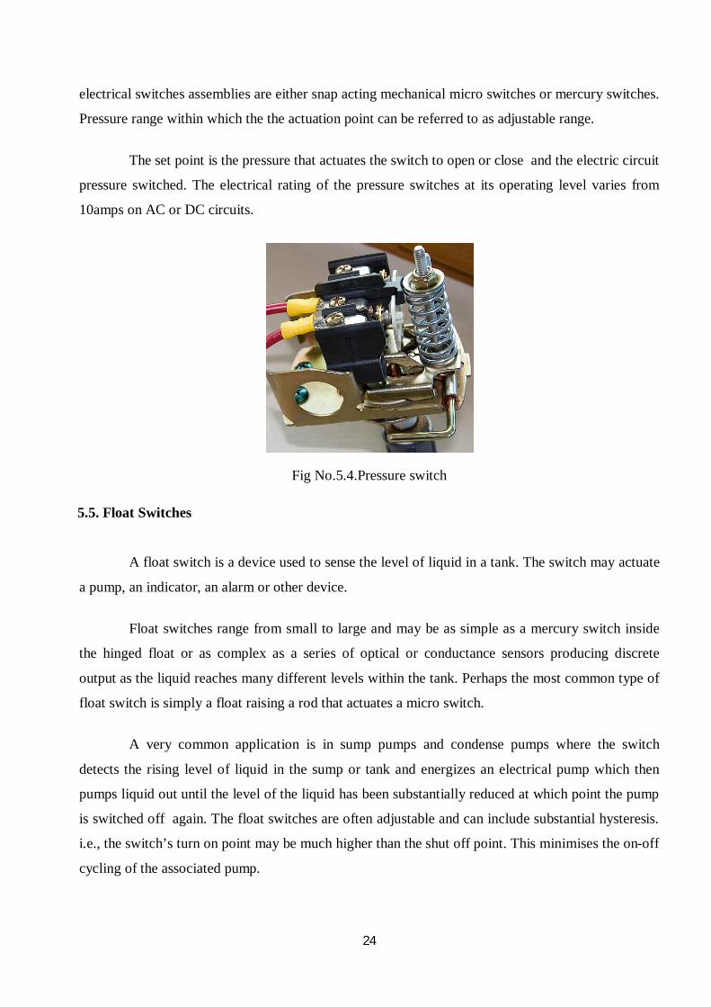
5.4. Pressure Switches
Pressure switches are used to energize and de-energize electrical switches as function of
relationship between the process pressure and the predetermined set point. They are available to
detect absolute compound gauge and differential pressure with accuracies up to ½% of a span. The
24
electrical switches assemblies are either snap acting mechanical micro switches or mercury switches.
Pressure range within which the the actuation point can be referred to as adjustable range.
The set point is the pressure that actuates the switch to open or close and the electric circuit
pressure switched. The electrical rating of the pressure switches at its operating level varies from
10amps on AC or DC circuits.
Fig No.5.4.Pressure switch
5.5. Float Switches
A float switch is a device used to sense the level of liquid in a tank. The switch may actuate
a pump, an indicator, an alarm or other device.
Float switches range from small to large and may be as simple as a mercury switch inside
the hinged float or as complex as a series of optical or conductance sensors producing discrete
output as the liquid reaches many different levels within the tank. Perhaps the most common type of
float switch is simply a float raising a rod that actuates a micro switch.
A very common application is in sump pumps and condense pumps where the switch
detects the rising level of liquid in the sump or tank and energizes an electrical pump which then
pumps liquid out until the level of the liquid has been substantially reduced at which point the pump
is switched off again. The float switches are often adjustable and can include substantial hysteresis.
i.e., the switch’s turn on point may be much higher than the shut off point. This minimises the on-off
cycling of the associated pump.

25
Some float switches contain a two stage switch as liquid level rises to the trigger point of
the first stage, the associated pump is activated. If the liquid continues to rise (perhaps because the
pump has failed or it’s discharged is blocked), this second stage will be triggered. This stage may
switch off the source of the liquid being pumped, trigger an alarm or both.
A very common application is in sump pumps and condensate pumps where the switch
detects the rising level of liquid in the sump or tank and energizes an electrical pump which then
pumps liquid out until the level of the liquid has been substantially reduced, at which point the
pump is switched off again. Float switches are often adjustable and can include substantial
hysteresis. That is, the switch's "turn on" point may be much higher than the "shut off" point. This
minimizes the on-off cycling of the associated pump.
Fig No.5.5.1.Float switch

26
Fig No.5.5.2.Float switch
5.6. Electronic Pressure Transmitter
The FCX-All series transmitter detects the differential pressure of various fluids, convert it
into a current signal of 4 to 20mA DC and transmit. All the adjustment functions are in corporate in
the transmission unit for making adjustment easily and exactly. Transmission setting(such as range
and damping time constant) can be changed from an HHC(handheld communicator).
Principle
The operating principle of the FCX-All series transmitter is shown in the block diagram.
The input pressure is changed into an electrostatic capacitance in the detecting unit. The proportional
to the pressure under goes conditioning and amplification in the transmission unit, and is then output
as a current of 4to 20mA DC.

27
Fig No.5.6.Electronic pressure transmitter
5.7. Inductive Type Proximity Speed Sensor
In automated processes sensors are used to provide signals on positions and limits, serve as
pulse pick-ups for counting task or for monitoring rotational speed. Inductive proximity sensors are
indispensible for these type of applications. As compared to mechanical devices, they offer ideal
features: on contact detection of all metals, high switching frequencies, accuracy, and durability in
the most aggressive environments. They are the intensive to vibrations, dust and moisture.
Inductive proximity sensors take advantage 0 changes in resonant circuit caused by the
eddy current losses in the conductive material. An inductive proximity sensor contains four essential
components: a coil wire wrapped in a ferrite core, an oscillator circuit, an evaluation circuit and an
output circuit. When a voltage is applied to sensor, an oscillating current flows through the coil and
radiates an electromagnetic field from the active face of the sensor. The field is directed and shaped
by the ferrite core.
When an electrical conductor or metal target enters the electromagnetic field, eddy current
are drawn from the oscillator and induced into the target. The eddy current draw energy from the
electromagnetic field. The losses in energy caused by the eddy current are due to the conductivity
and permeability of the target, the distance and position of the target, and the size and shape of the
target.

28
When the metal target is positioned at the precise distance from the active face of the
sensor, the energy loss caused by the eddy current becomes so large that the amplifier cannot output
sufficient energy to maintain oscillation and magnetic field collapses. The breakdown in oscillation
is detected by the evaluation circuit, which then changes the changes the states of the output circuit.
Fig No.5.7.Inductive type speed sensor
5.8. Relays
Relays may be said as electromagnetic switches. When a voltage is applied to coil a
magnetic field is generated. The magnetic field is sucks the contact of the relay in causing them to
make a connection. This contact can be considered as a switch. They allow current to flow between
two points thereby closing the circuit.
Working of a Relay
Relay consists of mainly 3 parts:
Coil Base Contacts
There are three types of contacts:
Normally Closed (NC) Normally Open (NO) Common
When the coil is energised it act as an electromagnet and it attracts the common contact thus
the condition will change that NC will change to NO and vice versa.

29
In this study circuit electrical relays are used of coil supplying 110V. A relay act as switch.
This relay has 3 NC, 3 NO, 3 common contacts, 2 coil contacts are there in this type of relay.
Pin Number 2&10 are used to energise the coil.
Pin Number 4, 5 & 8 are normally closed contacts.
Pin Number 1, 6 & 11 are common contacts.
Pin Number 3, 7 & 9 are Normally Open contacts.
When supply is given to the coil produces a magnetic field it attracts the common terminal
towards the coil. As result common terminal touches contacts 3, 7& 9 So the contact condition
reverse that is the NO at de-energized condition becomes NC and NC becomes NO. At energized
condition we use these NO & NC contacts according to our requirement when it acts as an inter
posing relay.
The relay base used has 11 terminals of which 2 & 10 coil supply, 4,5 & 8are contacts, 1,6
& 11 are common terminals,3,7 & 9 are normally open contacts. The relay is inserting to the base.
The appropriate contacts are taken from the relay base.
Fig No.5.8. Relay

30
5.9. Luro Burner
The Luro burner developed in co operation with Saacke is the first choice in sulphur
combustion technology because of its flexibility from turn down ratio to operation modes, the
superior atomization and its reliability.
The liquid sulphur combustion technology because of its flexibility from turn down ratio to
operation modes, the superior atomization and its reliability.The liquid sulphur is fed into the Luro
burner at virtually atmospheric pressure thereby avoiding the need for costly high pressure pumps
and piping. The spinning cup, rotating at high speed, ensures excellent atomization of sulphur. A
system of adjustable guide vanes imparts a tangential component to the combustion air. the resulting
spiral path of the gases through the furnace not only effectively keeps the flame central but
simultaneously prevents unvapourized sulphur droplets from impinging on the furnace wall.
Fig No.5.9.Luro burner

31
CHAPTER 6
PROGRAMMABLE LOGIC CONTROLLER
The only (or rather the best) way to control a production machine, or any other type of
machine for that matter, was to make up a circuit with something called relays.
All these relays had to be hard wired together in the right order in a control panel to make
the machine operate in the desired manor. This style of control panel gave rise to several problems,
as the relays were electromechanical they failed far too often. Coil failure and contact wear were
difficult to diagnose and replace, also if a circuit change was needed that called for an extensive
rewire of all the involved relays.
Fig No.6.1.1.Programmable logic controller
After the PLC took off, which didn't take very long given the advantages, Bedford
Associates changed their name after some time to Modicon PLC and eventually became the first
supplier of PLC’s.
32
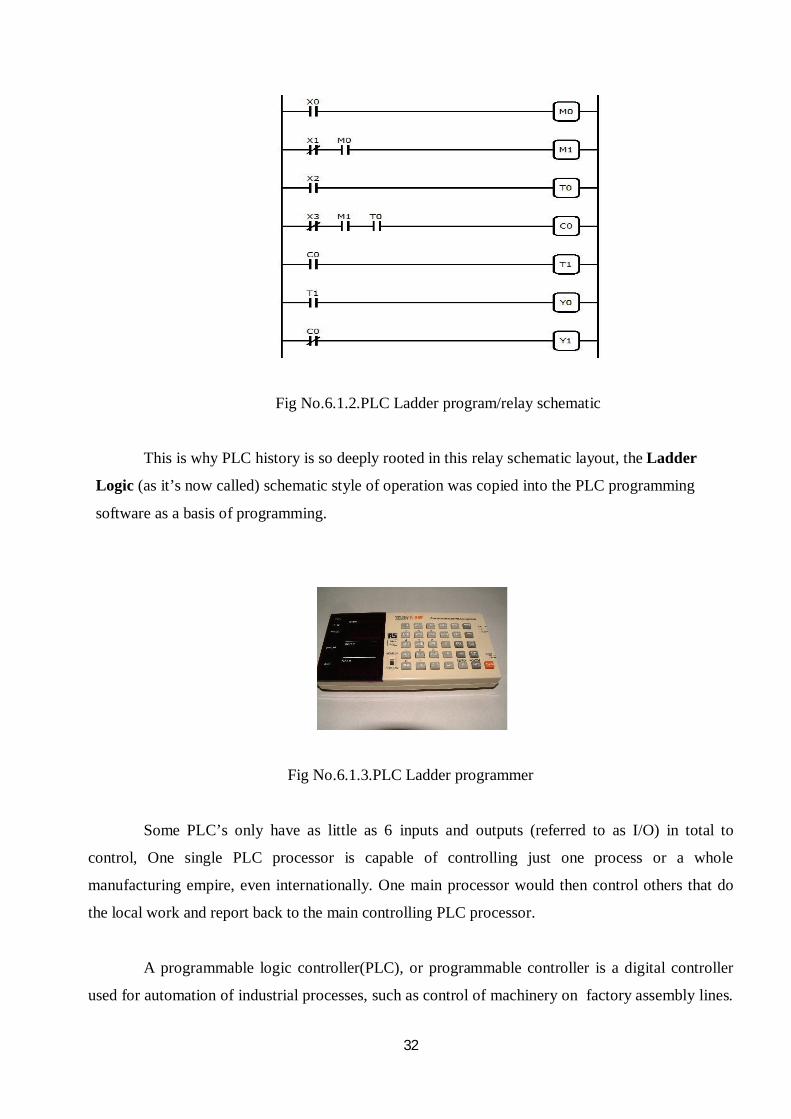
Fig No.6.1.2.PLC Ladder program/relay schematic
This is why PLC history is so deeply rooted in this relay schematic layout, the Ladder
Logic (as it’s now called) schematic style of operation was copied into the PLC programming
software as a basis of programming.
Fig No.6.1.3.PLC Ladder programmer
Some PLC’s only have as little as 6 inputs and outputs (referred to as I/O) in total to
control, One single PLC processor is capable of controlling just one process or a whole
manufacturing empire, even internationally. One main processor would then control others that do
the local work and report back to the main controlling PLC processor.
A programmable logic controller(PLC), or programmable controller is a digital controller
used for automation of industrial processes, such as control of machinery on factory assembly lines.

33
Unlike general purpose computers, the PLC is designed for mutiple inputs and output arrangements,
extended temperature ranges, immunity to electrical noise, and resistance to vibration and impact.
Programs to control machine operation are typically stored in battery-backed or non-volatile
memory. A PLC is an example of a real time system since output results must be produced in
response to input conditions within a bounded time, otherwise unintended operation will result.
6.1. Features
The main difference from other computers is that PLCs are armoured for severe conditions
(such as dust, moisture, heat, cold) and have the facility for extensive input/output (I/O)
arrangements. These connect the PLC to sensors and actuators. PLCs read limit switches, analog
process variables (such as temperature and pressure), and the positions of complex positioning
systems. Some use machine vision. On the actuator side, PLCs operate electric motors, pneumatic or
hydraulic cylinders, magnetic relays, solenoids, or analog outputs. The input/output arrangements
may be built into a simple PLC, or the PLC may have external I/O modules attached to a computer
network that plugs into the PLC.
Scan time
A PLC program is generally executed repeatedly as long as the controlled system is
running. The status of physical input points is copied to an area of memory accessible to the
processor, sometimes called the "I/O Image Table". The program is then run from its first instruction
rung down to the last rung. It takes some time for the processor of the PLC to evaluate all the rungs
and update the I/O image table with the status of outputs.
Special-purpose I/O modules, such as timer modules or counter modules, could be used
where the scan time of the processor was too long to reliably pick up, for example, counting pulses
from a shaft encoder. The relatively slow PLC could still interpret the counted values to control a
machine, but the accumulation of pulses was done by a dedicated module that was unaffected by the
speed of the program execution.
System scale
A small PLC will have a fixed number of connections built in for inputs and outputs.
Typically, expansions are available if the base model has insufficient I/O. Modular PLCs have a

34
chassis (also called a rack) into which are placed modules with different functions. The processor
and selection of I/O modules are customized for the particular application. Several racks can be
administered by a single processor, and may have thousands of inputs and outputs. A special high
speed serial I/O link is used so that racks can be distributed away from the processor, reducing the
wiring costs for large plants.
User interface
PLCs may need to interact with people for the purpose of configuration, alarm reporting or
everyday control. A human-machine interface (HMI) is employed for this purpose. HMIs are also
referred to as man-machine interfaces (MMIs) and graphical user interface (GUIs).
Communications
PLCs have built in communications ports, usually 9-pin RS-232, but optionally EIA-485 or
Ethernet. Modbus, BACnet or DF1 is usually included as one of the communications protocols.
Most modern PLCs can communicate over a network to some other system, such as a
computer running a SCADA (Supervisory Control And Data Acquisition) system or web browser.
Programming
PLC programs are typically written in a special application on a personal computer, then
downloaded by a direct-connection cable or over a network to the PLC. The program is stored in the
PLC either in battery-backed-up RAM or some other non-volatile flash memory. Often, a single
PLC can be programmed to replace thousands of relays.
Digital and analog signals
Digital or discrete signals behave as binary switches, yielding simply an On or Off signal (1
or 0, True or False, respectively). Push buttons, limit switches, and photoelectric sensors are
examples of devices providing a discrete signal. Discrete signals are sent using either voltage or
current, where a specific range is designated as On and another as Off. Initially, PLCs had only
discrete I/O.

35
Analog signals are like volume controls, with a range of values between zero and full-scale.
These are typically interpreted as integer values (counts) by the PLC, with various ranges of
accuracy depending on the device and the number of bits available to store the data. As PLCs
typically use 16-bit signed binary processors, the integer values are limited between -32,768 and
+32,767. For example, an analog 0 - 10 V input or 4-20 mA would be converted into an integer
value of 0 - 32767.Current inputs are less sensitive to electrical noise (i.e. from welders or electric
motor starts) than voltage inputs.
Example
As an example, say a facility needs to store water in a tank. The water is drawn from the
tank by another system, as needed, and our example system must manage the water level in the
tank.
Using only digital signals, the PLC has two digital inputs from float switches (Low Level
and High Level). When the water level is above the switch it closes a contact and passes a signal to
an input. The PLC uses a digital output to open and close the inlet valve into the tank.
When the water level drops enough so that the Low Level float switch is off (down), the
PLC will open the valve to let more water in. Once the water level rises enough so that the High
Level switch is on (up), the PLC will shut the inlet to stop the water from overflowing.
| Low Level High Level Fill Valve |
|------[/]------|------[/]----------------------(OUT)---------|
| | |
| | |
| | |
| Fill Valve | |
|------[ ]------| |
| |
| |
An analog system might use a water pressure sensor or a load cell, and an adjustable
(throttled) control (e.g. by a valve) of the fill of the tank. In this system, to avoid 'flutter' adjustments
that can wear out the valve, many PLCs incorporate "hysteresis" which essentially creates a

36
"deadband" of activity. A technician adjusts this dead band so the valve moves only for a significant
change in rate. This will in turn minimize the motion of the valve, and reduce its wear.
6.2. PLC compared with other control systems
PLCs are well-adapted to a range of automation tasks. These are typically industrial
processes in manufacturing where the cost of developing and maintaining the automation system is
high relative to the total cost of the automation, and where changes to the system would be expected
during its operational life. PLCs contain input and output devices compatible with industrial pilot
devices and controls; little electrical design is required, and the design problem centers on
expressing the desired sequence of operations.
Very complex process control, such as used in the chemical industry, may require
algorithms and performance beyond the capability of even high-performance PLCs. Very high-speed
or precision controls may also require customized solutions; for example, aircraft flight controls.
PLCs may include logic for single-variable feedback analog control loop, a "proportional,
integral, derivative" or "PID controller". A PID loop could be used to control the temperature of a
manufacturing process, for example. Historically PLCs were usually configured with only a few
analog control loops; where processes required hundreds or thousands of loops, a distributed control
system (DCS) would instead be used. As PLCs have become more powerful, the boundary between
DCS and PLC applications has become less distinct.
6.3. Basic Components of PLC
Programmable controllers have grown throughout industrial control applications because of
the ease they bring to creating a controller: ease of programming, ease of wiring, ease of installation,
and ease of changing. PLCs span a wide range of sizes, but all contain six basic components:
processor or central processing unit (CPU);
rack or mounting;
input assembly;
output assembly;
power supply;
programming unit, device, or PC/software
37
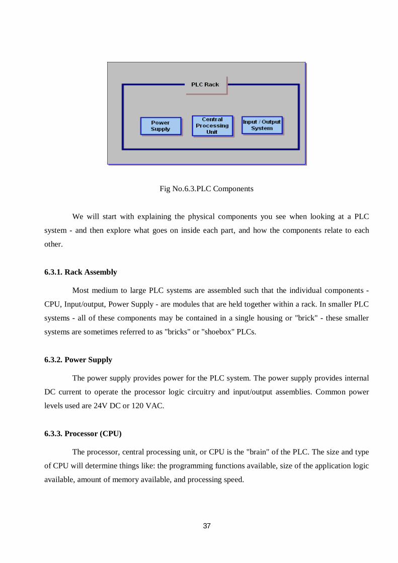
Fig No.6.3.PLC Components
We will start with explaining the physical components you see when looking at a PLC
system - and then explore what goes on inside each part, and how the components relate to each
other.
6.3.1. Rack Assembly
Most medium to large PLC systems are assembled such that the individual components -
CPU, Input/output, Power Supply - are modules that are held together within a rack. In smaller PLC
systems - all of these components may be contained in a single housing or "brick" - these smaller
systems are sometimes referred to as "bricks" or "shoebox" PLCs.
6.3.2. Power Supply
The power supply provides power for the PLC system. The power supply provides internal
DC current to operate the processor logic circuitry and input/output assemblies. Common power
levels used are 24V DC or 120 VAC.
6.3.3. Processor (CPU)
The processor, central processing unit, or CPU is the "brain" of the PLC. The size and type
of CPU will determine things like: the programming functions available, size of the application logic
available, amount of memory available, and processing speed.

38
6.3.4. Input/output Assembly
Inputs carry signals from the process into the controller, they can be input switches,
pressure sensors, operator inputs, etc. These are like the senses and sensors of the PLC.
Outputs are the devices that the PLC uses to send changes out to the world. These are the
actuator the PLC can change to adjust or control the process motors, lights, relays, pumps, etc.
Many types of inputs and outputs can be connected to a PLC, and they can all be divided into two
large groups –
Analog
Digital
Digital inputs and outputs are those that operate due to a discrete or binary change - on/off,
yes/no. Analog inputs and outputs change continuously over a variable range - pressure,
temperature, and potentiometer.
6.3.5. Programming Device
The PLC is programmed using a specialty programmer or software on a computer that can
load and change the logic inside. Most modern PLCs are programmed using software on a PC or
laptop computer. Older systems used a custom programming device.

39
CHAPTER 7
BASIC OPERATION OF A PLC SYSTEM
The operation of the PLC system is simple and straightforward. The Process or CPU
completes three processes: (1) scans, or reads, from the input devices (2) executes or "solves" the
program logic, and (3) updates, or writes, to the output devices.
Fig No.7.1.Basic operation of PLC
7.1. PLC Program
For the PLC to be useful, it must first have a Program or Logic for the CPU to execute. This
logic can be written in Ladder Logic, Instruction List, Sequential Function Charts, or any of the IEC
languages.
The programmer will then download the program to the PLC. This is usually done by
temporarily connecting the programmer to the PLC. Once the program is installed or downloaded to
the CPU - it is usually not necessary for the PC to remain connected.

40
7.2. Basic Scan
Once the program is in the CPU - the PLC is then set to "run", and the PLC executes the
application program repeatedly. In addition to executing the program, the CPU regularly reads the
status of the input devices, and sends data to the output devices. The Input system senses the status
of the real world inputs (a switch, a level, etc.), translates them to values that can be used by the
CPU, and writes those values to the Input table.
This process of reading inputs, executing logic, and writing outputs is called the PLC Scan or
Sweep.
Fig No.7.2.Basic Scan
7.3. Memory
The control program or application program is stored in memory. As the PLC executes
logic, it may also read and store values to memory. The values may also be used and referenced by
the application program.

41
CHAPTER 8
INTRODUCTION TO OMRON SYSMAC CPM1A PLC
The CPM1A is a compact, high speed programmable controller (PC) designed for control
operations in systems requiring from 10-100 points per PC.
OMRON provides one of the robust control systems. The use of PLC improves productivity,
quality, and steamline logistics and gets the products to market faster. OMRON corporation’s
Industrial automation business (IAB)’s global network is recognized worldwide as the leading
supplier of high quality, high technology products. They offer reliable advanced factory
automation systems. Their control components system equipments and advanced networking
technology can be found in manufacturing sites throughout the world supporting the production of
cars, home electronics, food and various other products. OMRON has an enormous range of
innovative products capable of meeting every application requirement and services which can
translate the OMRON sensing and control technology into effective solutions.

42
8.1. General Specifications
Table No.8.1.General specifications
Input type DC input
CPU type 10 point I/O 20 point I/O 30 point I/O 40 point I/O
Power supply
voltage/frequency
AC power
supply 100 to 240VAC,50/60Hz
DC power
supply 24VDC
Operating voltage
range
AC power
supply 85 to 264VAC
DC power
supply 20.4 to 26.4VDC
Power
consumption
AC power
supply 30VA max. 60VA max.
DC power
supply 6 W max. 20 W max.
Inrush current 30A max. 60 A max.
External power
supply(AC only)
Power
supply
voltage
24 VDC
Power
supply
output
capacity
200 mA 300 mA
Insulation resistance 20 MΩ min.at 500 VDC between the AC terminals and the
protective earth terminal.
Dielectric strength
2,300 VAC at 50/60 Hz for one minute with a leakage of 10
mA max. between all the external AC terminals and the
protective earth terminal.
Vibration resistance
10 to 57 Hz with an amplitude of 0.075mm,and 57 to 150 Hz
with an acceleration of 1.5G in the X,Y and Z directions for 10
sweeps of minutes each.

43
Shock resistance 147m/s2 in the X, Y and Z directions 3 times each.
Ambient
temperature
Operating 0 C to 55C (32F to 131 F)
Storage -20 C to 75 C(-4 F to 167 F)
Ambient
humidity Operating 10% to 90% RH no condensation
Ambient
environment Operating With no corrosive gas
Terminal screw size M3
Power supply holding time 10 ms min.for AC models, and 2 ms for DC models
CPU weight AC models 400g max. 500g max. 600g max. 700g max.
DC models 300g max. 400g max. 500g max. 600g max.
Expansion weight
Units with 20 I/O points: 300g max.
Units with 8 output points: 250g max.
Units with 8 input points: 200g max.
MAD01 Analog I/O unit:150g max.
MAD11 Analog I/O unit:250g max.
Temperature sensor units:250g max.
Compo Bus/S I/O link unit:200g max.
Device Net I/O link unit:200g max.
Profibus-DP slave unit:125g

44
8.2. General Characteristics
Table No.8.2.General characteristics
Input type DC input
CPU type 10-point I/O 20-point I/O 30-point I/O 40-point I/O
Control method Stored program method
I/O control method Combination of the cyclic scan and immediate refresh processing methods
Programming language Ladder diagram Instruction word 1 step per instruction, 1 to 5 per instruction
Types of instructions
Basic instruction 14 types
Special instructions 79 types, 139 instructions
Instruction execution
time
Basic instructions 0.72 to 16.2µs
Special instructions MOV instruction =16.3µs
Program capacity 2,048words
Maximum I/O points
CPU only
10 points(6 input/ 4 output points)
20 points (12
input/8 output points)
30 points (18
input/12 output points)
40 points (24 input/16 output points)
With Expansion I/O Module
_ _
Up to 90 points
(54 input/36 output points)
Up to 100 points (60 input/40 output points)
Memory protection Maintains the contents of the HR, AR, Counter and Data Memory Areas.
Memory backup
Flash: User program, data memory (Read only)and PLC setup areas are backed up without a battery.
Super capacitor: Data memory(read/write), holding bits, auxiliary memory bits, counter values, error log area are backed
up by a capacitor for 20-days at an ambient temperature of 25oC.
Self-diagnostic function CPU error (watchdog timer), memory errors , I/O bus errors
Program check No END instruction programming errors (constantly checked during operation)
Pulse output 1 point: 2kHz
High-speed counter
1 point: Single phase at 5kHz or two-phase at 2.5kHz(linear counting method)
Incremental mode: 0 to 65535(16-bit) Decremental mode: -32767 to 32767(16-bit)

45
Quick-response inputs Together with the external interrupt input (minimum pulse width of 0.2ms)
Input time constant Together with the external interrupt input(minimum pulse width of 0.2ms)
Input time constant Can be set at 1ms, 2ms, 4ms, 8ms, 16ms, 32ms, 64ms, or 128ms.
Interrupt processing: External Interrupt
2 points (Response time of 0.3 ms max.)
4 points (Response time of 0.3 ms max.)
Analog settings 2 points:(0 to 200 BCD)
8.3. CPM1A Features
One Piece Construction
The CPM1A CPU units feature a one piece construction including 10, 20, 30 or 40 built in
I/O terminals. All CPU units are provided with relay outputs.
Extra I/O Capacity
Up to 3 I/O units can be connected to a CPM1A-40CDR-D CPU unit to add an extra 20I/O
points for each, for a maximum of up to 100 I/O ports.
Input Filter Function
The CPM1A is equipped with a filter function to prevent incorrect operation caused by
either chatter or noise in the input signal. The user can select an input time constant of 1ms or
128ms.
Low Maintenance Design
Flash memory provides memory backup without a battery.
Input Interrupts
The CPM1A-40CDR-D CPU units can handle 4 interrupt inputs. In addition to the normal
input interrupts, the CPM1A has a counter mode that counts high speed input signals and triggers
interrupts at fixed count multiples.

46
Quick Response Inputs
Quick response inputs can detect input signals with a pulse width as short as 0.2ms
regardless of their timing during the PC cycle. Quick response inputs and interrupt inputs use the
same input terminals.
Interval Timer
CPM1A PC’s have a high speed interval timer which can be set from 0.5ms to
319968ms.The timer can be set trigger a single interrupt(one shot mode)or repeat scheduled
interrupts(scheduled interrupt mode)
High Speed Counter
CPM1A PC’s have a high speed counter that can be used in incremental mode or up/down
mode. The high speed counter can be combined with input interrupts to perform target valve
control or zone comparison control that is not
affected by the PC’s cycle time.
Analog Setting Functions
The CPM1A PC’s have 2 analog volume controls that can be used to make manual and
analog settings.
Host Link Communications
The CPM1A PC’s are compatible with the host link which allows communications with
personal computers. The CPM1A using the host link can also communicate with programmable
terminal using host link commands. An RS232C adapter is used for 1to 1 communications and an
RS422 adapter is used for 1to n communications.
NT Link Communications
High speed operations can be achieved by providing a direct access by connecting the
CPM1A to the OMRON programmable terminal through the NT link interface. An RS232C
adapter is used for this connection.

47
Standard Peripheral Devices
The CPM1A uses the same programming consoles and SYSMAC support software(SSS)
as the C200/HS,C200HX/HE/HG,CPM1,SRM1,CQM1 PC’s.
Programming Is Possible Using PT
Programming operation is possible through the PT screen by using an OMRON PT that
has a built in programming console function.

48
8.4. Terminal And IR Bit Allocation
The following table shows which IR bit are allocated to the I/O terminals on the CPM1A’s
CPU units and expansion I/O unit.
Table No.8.4.Terminal & IR bit allocation
No of
I/O
terminals
on the
CPU unit
CPU Unit
terminals CPU 1A-20 EDR Expansion I/O Unit Terminals
Power
Supply
Model
Number
inputs outputs Inputs Outputs Inputs outputs inputs outputs
40
24
points
00000
to
000011
00100
to
00111
16
points
01000
to
01007
01100
to
01107
12
points
00200
to
00211
8
points
01200
to
01207
12
points
00300
to
00311
8
points
01300
to
00411
12
points
00400
to
00411
8
points
01000
to
01407
AC
CPM1A-
40CDR-
A
CPM1A-
40CDR-
D
49
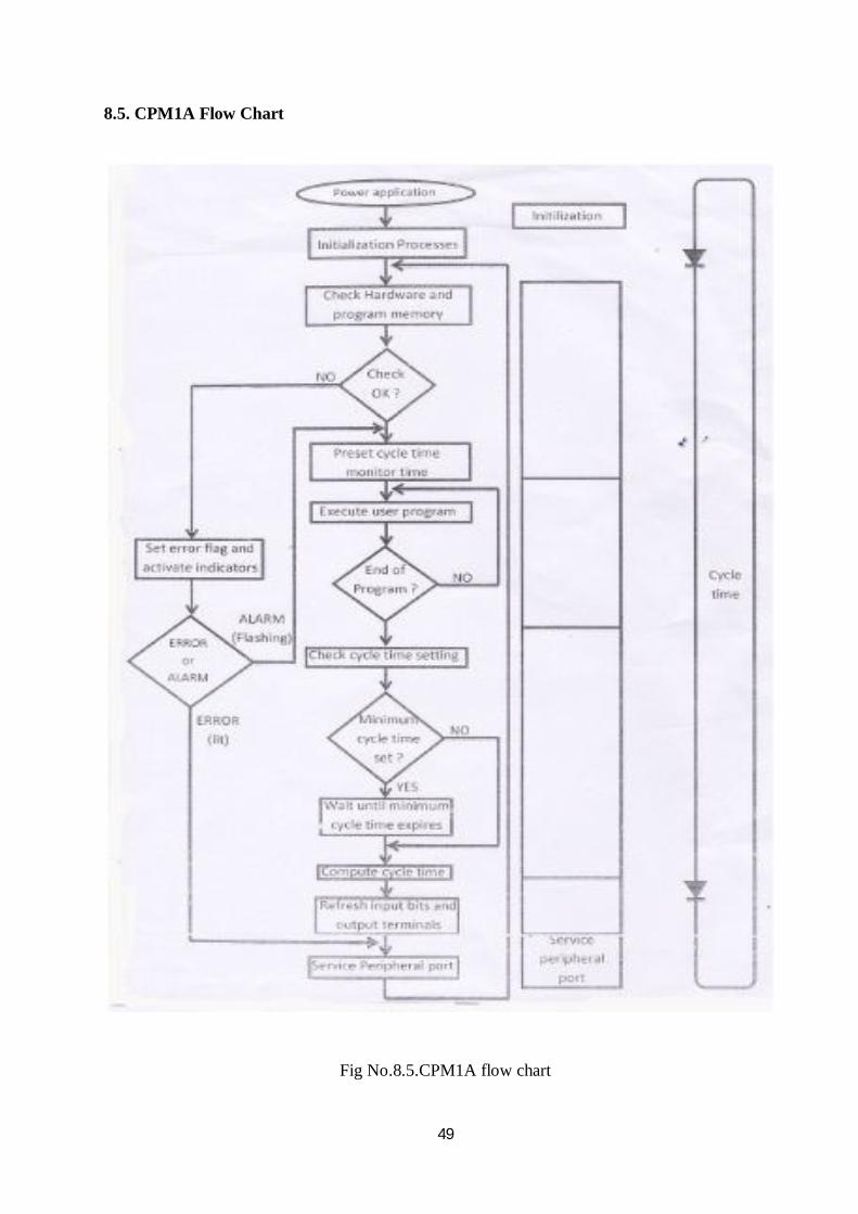
8.5. CPM1A Flow Chart
Fig No.8.5.CPM1A flow chart
50
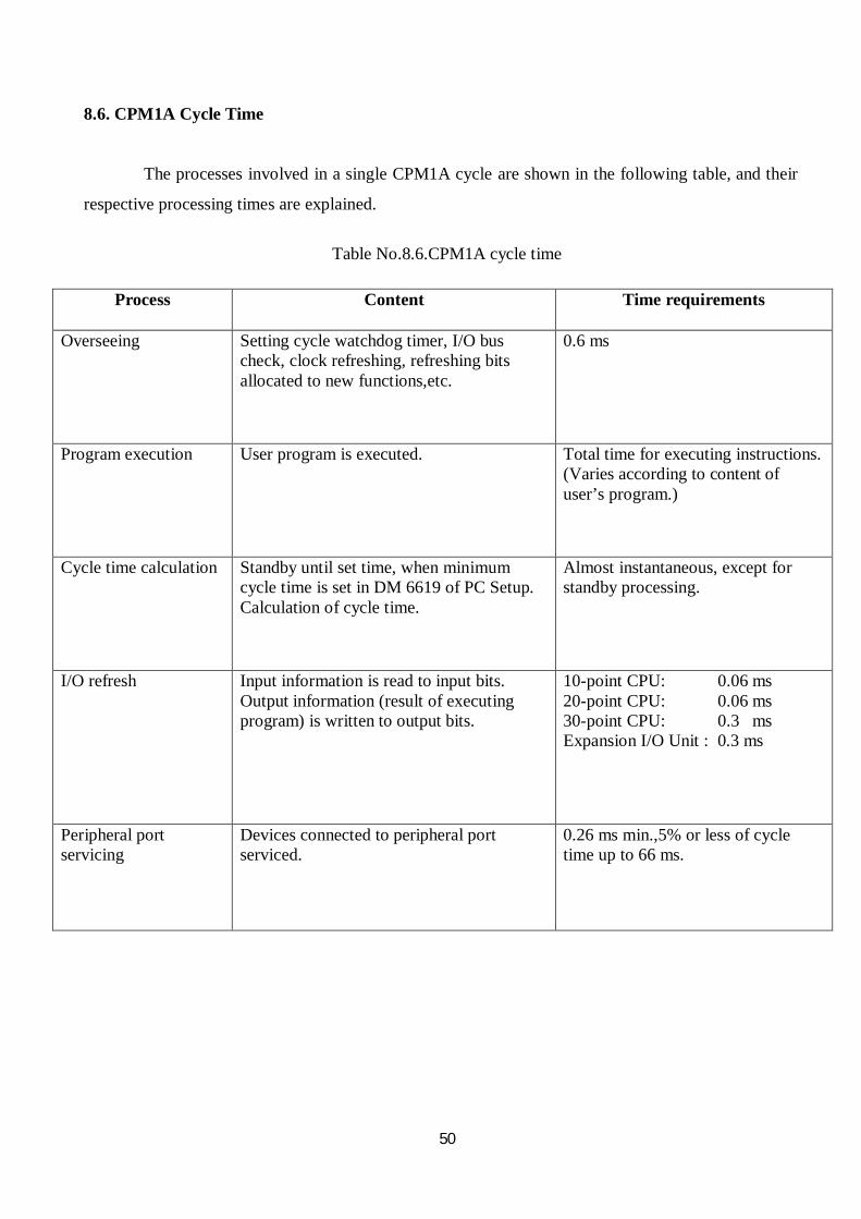
8.6. CPM1A Cycle Time
The processes involved in a single CPM1A cycle are shown in the following table, and their
respective processing times are explained.
Table No.8.6.CPM1A cycle time
Process Content Time requirements
Overseeing Setting cycle watchdog timer, I/O bus check, clock refreshing, refreshing bits allocated to new functions,etc.
0.6 ms
Program execution User program is executed. Total time for executing instructions. (Varies according to content of user’s program.)
Cycle time calculation Standby until set time, when minimum cycle time is set in DM 6619 of PC Setup. Calculation of cycle time.
Almost instantaneous, except for standby processing.
I/O refresh Input information is read to input bits. Output information (result of executing program) is written to output bits.
10-point CPU: 0.06 ms 20-point CPU: 0.06 ms 30-point CPU: 0.3 ms Expansion I/O Unit : 0.3 ms
Peripheral port servicing
Devices connected to peripheral port serviced.
0.26 ms min.,5% or less of cycle time up to 66 ms.

51
CHAPTER 9
PROGRAM
Table No.9.1.Program
NO ADDRESS OPERAND 1 0000 LD 0003 2 0001 OUT 20200 3 0002 LD 0004 4 0003 OUT 20201 5 0004 LD 0005 6 0005 OUT 20202 7 0006 LD 20200 8 0007 AND 20201 9 0008 AND 20202 10 0009 OUT 1102 11 0010 LD 0006 12 0011 OUT 1103 13 0012 LD 00105 14 0013 OR 00103 15 0014 OUT 20010 16 0015 LD NOT 20010 17 0016 LD 1002 18 0017 LD 0008 19 0018 OUT 1003 20 0019 LD 0009 21 0020 OUT 1004 22 0021 LD 1102 23 0022 AND 1103 24 0023 AND 1003 25 0024 AND 1004 26 0025 OUT 20300 27 0026 OUT 20301 28 0027 LD 00010 29 0028 OR 01005 30 0029 OUT 01001 31 0030 LD 00011 32 0031 OUT 01006 33 0032 LD 00100 34 0033 OUT 1007 35 0034 LD 1006 36 0035 AND 1007 37 0036 OR 01101 38 0037 AND 20010 39 0038 AND 1001 40 0039 OUT 1100 41 0040 LD 00101

52
NO ADDRESS OPERAND 42 0041 OUT 1101 43 0042 LD 0007 44 0043 0R 20500 45 004 AND NOT TIM 00 46 0045 AND 1001 47 0046 OUT 20500 48 0047 OUT TIM 00 #10 49 0048 LD 20500 50 0049 OUT 1000 51 0050 LD 0002 52 0051 OR 102 53 0052 AND 1001 54 0053 OUT 20501 55 0054 LD 20501 56 0055 OUT 1104 57 0056 LD 1000 58 0057 OR 20501 59 0058 AND NOT TIM 01 60 0059 OUT 1105 61 0060 LD 20501 62 0061 TIM 01 #20 63 0062 LD 1104 64 0063 TIM 02 #5 65 0064 LD TIM 02 66 0065 AND 1104 67 0066 OUT 1106

53
9.1. Assignment List Of Inputs
Table No.9.1.1.Assignment list of inputs
Name of system : OMRON CPM1A-40CDR Extension :20EDR1
IR000 IR001 IR002
00 Speed trip input from converter
00 Main air flow
00 Ignition push button
01 01 Primary and main air flow bypass
01 Trouble reset push button(NO)
02 Flame OK 02 Total bypass switch
02 Speed reset push button
03 Main Air Pressure 03 Speed on switch
04 LURO motor contact from MMC
04
05 Primary air motor status 05
06 Boiler level 06
07 07
08 Primary air pressure 08
09 Main air pressure 09
10 Sub inter lock bypass switch
10
11 Primary air flow 11
12 12

54
9.2. Assignment List Of Outputs
Table No.9.2. Assignment list of outputs
Name of system :OMRON CPM1A-40CDR
IR 010 IR011
00 Ignition on 00 Sulphur pump interlock
01 Sub interlock ready for operation
01 Primary and main air flow bypass
02 Speed low 02 MMC contacts
03 Primary air pressure 03 Steam drum level
04 Main air pressure 04 Sub interlock + flame
05 Sub interlock bypass 05 Gas solenoid valve
06 Primary air flow 06 Kerosene solenoid valve
07 Main air flow 07 Trouble
08 08

55
CHAPTER 10
LADDER INSTRUCTIONS
This line is the line branching instructions. Throughout this instruction line consists a
combination of logic that states when and how the existing instruction.
Fig No.10.1.PLC Ladder Diagram Example
The logic combination of ladder diagram as following:
A. Instruction LOAD (LD) and LOAD NOT (LD NOT) : The first condition that starts any
logic block in the ladder diagram associated with LOAD instruction (LD) or LOAD NOT. (LD
NOT). Each of these instructions requires one line of mnemonics.
B.Instruction (AND) and AND NOT : If two or more conditions that are connected in series on

56
the same instruction line, then the first condition using LD or LD instruction and the remainder
NOT use the instructions AND or AND NOT. AND instruction can be imagined to produce ON if
both conditions are linked with this instruction in all ON conditions, if anyone in the OFF state, let
alone both OFF, the instruction will always result AND OFF too.
C. Instruction OR and OR NOT : If two or more conditions connected in parallel, meaning in a
different line of instructions and then joined again in the same instruction line, then the first
condition associated with LD or LD instruction and the rest is NOT related to the instructions OR
orA OR NOT. In this case imaginable OR instruction will always result in ON execution
condition when any one of two or more conditions connected with this instruction in the ON
condition.

57
10.1. Ladder Diagram

58

59

60
Fig No: 10.1.1. Ladder diagram

61
CHAPTER 11
SCREEN SHOTS
Fig No.11.1.Screen shots

62
CHAPTER 12
ADVANTAGES AND DISADVANTAGES
12.1. Advantages
Accurate
We can know the status of inputs and outputs.
Takes up less floor space than a relay wired system
12.2. Disadvantages
Large complicated systems

63
CHAPTER 13
APPLICATION
The burner management system focuses on service conditions and safety measures in the
industry.

64
CHAPTER 14
CONCLUSION
The programmable logic control (PLC) which was designed in early 1970’s can be
classified as a state member of the computer family. It is a microprocessor based system which
was evolved from the need of control system that can be easily reprogrammed and can control a
large number of operations simultaneously with high grade of synchronism.
The introduction of PLC resulted in a reduction of large machineries devices and human
efforts. It can simply by design as a small modular programmable controller designed for both
relay replacement and complex mid size application. A unique modular bus structure is used as
the foundation for this convenient architecture.
At present the plant is working under the control of an old model PLC family (OMRON
SYSMAC CQM1). Our projects main aim was the up gradation of the existing PLC logic. For this
purpose we studied the old relay logic and the existing PLC logic and upgraded the PLC logic into
newer faster model of the OMRONPLC family (OMRON SYSMAC CPM1A).

65
CHAPTER 15
REFERENCES
CPM1A Programmable Controllers – Operation & Programming Manual
Curtis D Johnson; Process Control Instrumentation Technology.
Garry Daning; Introduction to PLC (Second Edition)
www.omron.com
www.wikipedia.org