Deliverable D1.1 Guidelines for establishing FoodSHIFT2030 ...
Upload
khangminh22Category
view
2download
0
PORTODIMAREgeoPORtal of TOols & Data for sustaInable Management of coAstaland maRine Environment (ADRION205)
DT1.4.1. Geoportal-Report on the systemarchitecture and design
Ver. 5
05 2019
Author:Project partner 2, CORILA
CNR-ISMAR: Menegon S., Fadini A., Depellegrin D., Sarretta A., Farella G.,Barbanti A.
1

List of abbreviations
AIS Automatic Identification System
AIR Adriatic-Ionian Region, as defined by the Communication from the Commission to theEuropean Parliament, the Council, the European Economic and Social Committee andthe Committee of the Regions concerning the European Union Strategy for theAdriatic and Ionian Region COM(2014) 357 final
API application programming interface
CSW Catalogue Service for the Web
EEZ exclusive economic zone, as defined by the United Nations Convention on the Law ofthe Sea
EUSAIR Strategy for the Adriatic and Ionian Region COM(2014) 357 final
GAIR Geoportal of Adriatic-Ionian Region (the main output of PORTODIMARE project)
GUI graphical user interface
ICZM Integrated Coastal Zone Management, as defined by the Protocol on IntegratedCoastal Zone Management to the Barcelona Convention (Council Decision2010/631/EU)
MCDA Multi-Criteria Decision Analysis
MSF Medium Scale Fishery Footprint
MSP Maritime Spatial Planning, as defined by Directive 2014/89/EU of the EuropeanParliament and of the Council of 23 July 2014 establishing a framework for maritimespatial planning
MSPKC Maritime Spatial Planning Knowledge Catalogue
OGC Open Geospatial Consortium
SQL Structured Query Language
UNIVE University of Venice
VMS Vessel Monitoring System
WGS World Geodetic System
WP Work Package of PORTODIMARE project (as described in the Application Form)
Table of Contents1 INTRODUCTION........................................................................................................1
2
1.1 Requirements....................................................................................................2
1.2 Data needs.......................................................................................................2
1.3 Inventory of existing geoportals & tools.....................................................................2
1.4 Aim and outline.................................................................................................3
2 PORTODIMARE MODULES.............................................................................................4
2.1 MSP-driven approach for multi-objective tools development............................................4
2.1.1 Principles of the GAIR.......................................................................................4
2.1.2 Steps of MSP-driven approach..............................................................................5
2.2 Modules Workflow..............................................................................................6
2.3 Modules description............................................................................................7
2.3.1 Module T1.6: Maritime Use Synergy and Conflict Analysis Tool (MUSC).............................7
2.3.2 Module T1.7: Cumulative Effects Assessment (CEA)....................................................8
2.3.3 Module T1.8: Supporting AZA identification.............................................................9
2.3.4 Module T1.9: Module for particle/conservative contaminants dispersion...........................9
2.3.5 Module T1.10: Module for Coastal Oil Spill Vulnerability Assessment..............................10
2.3.6 Module T1.11: Module for Small Scale Fishery Footprint (SSF)......................................10
2.3.7 Module T1.12: Module on Medium Scale Fishery Footprint (MSF) & Cumulative EffectsAssessment on SSF & MSF...........................................................................................10
3 SYSTEM ARCHITECTURE.............................................................................................12
3.1 General approach.............................................................................................12
3.2 Resource Layer................................................................................................13
3.2.1 Primary resource types....................................................................................14
3.2.2 Secondary resource types.................................................................................15
3.3 Web Services and APIs........................................................................................15
3.4 Graphical User Interface.....................................................................................16
3.5 User profiles, authentication and authorization..........................................................18
3.5.1 Authentication security requirements...................................................................19
3.6 Management tasks.............................................................................................19
3.7 Module integration............................................................................................20
3.7.1 Module GUI..................................................................................................21
3.7.2 Common API.................................................................................................21
3.7.3 Module API...................................................................................................22
3.7.4 Module Engine..............................................................................................22
3

4 TECHNOLOGICAL STACK.............................................................................................23
4.1 Core software products.......................................................................................23
4.1.1 GeoNode.....................................................................................................23
4.1.2 Wagtail.......................................................................................................25
4.2 Resource layer.................................................................................................25
4.2.1 PostgreSQL/PostGIS........................................................................................25
4.3 Access layer and web API....................................................................................26
4.3.1 Geoserver....................................................................................................26
4.3.2 Pycsw.........................................................................................................26
4.3.3 Django........................................................................................................27
4.3.4 Swagger......................................................................................................27
4.3.5 Haystack.....................................................................................................27
4.4 Graphical User Interface.....................................................................................27
4.5 Additional software...........................................................................................28
4.5.1 GeoNode project...........................................................................................28
5 PORTODIMARE EXTENSION APPLICATIONS........................................................................29
5.1 GairBase app...................................................................................................29
5.2 GeoDataBuilder app...........................................................................................31
5.3 ModuleConnect app...........................................................................................31
5.4 INSPIRE Compliance...........................................................................................32
5.5 Internationalization and localization.......................................................................32
6 MODULE USE CASES & SYSTEM INTERACTIONS...................................................................33
6.1 General use case..............................................................................................33
6.1.1 Actors........................................................................................................34
6.1.2 Actions.......................................................................................................34
6.2 Module Use Cases..............................................................................................35
6.2.1 T1.6 – Maritime Use Synergy and Conflict analysis tool (MUSC).....................................35
6.2.2 T1.7 – Cumulative Effects Assessment (CEA)...........................................................38
6.2.3 T1.8– Supporting AZA identification (Aquaculture Zoning Assessment)............................40
6.2.4 T1.9 – Module for particle/conservative contaminants dispersion..................................42
6.2.5 T1.10 – Module for Coastal Oil Spill Vulnerability Assessment.......................................44
6.2.6 T1.11. Module for Small Scale Fishery Footprint (SSF)................................................46
4

6.2.7 T1.12. Module for Medium Scale Fishery Footprint and cumulative effects (MSF)...............48
7 GRAPHICAL USER INTERFACE.......................................................................................50
7.1 PORTODIMARE generic GUIs..................................................................................50
7.1.1 GAIR Welcome page........................................................................................50
7.1.2 Information stocktake and module selection GUI.....................................................50
7.2 Module input GUIs.............................................................................................53
7.2.1 T1.6 – Maritime Use Synergy and Conflict Analysis Tool (MUSC) input GUI........................53
7.2.2 T1.7 – Cumulative Effects Assessment (CEA)...........................................................55
7.2.3 T1.8– Supporting AZA identification (Aquaculture Zoning Assessment)............................58
7.2.4 T1.9 Module for particle/conservative contaminants dispersion (ParTrack)......................58
7.2.5 T1.10 Module for Coastal Oil Spill Vulnerability Assessment.........................................59
7.2.6 T1.11 Module for Small Scale Fishery Footprint (SSF)................................................59
7.2.7 T1.12 Module on Medium Scale Fishery Footprint (MSF) & Cumulative Effects Assessmenton SSF & MSF.........................................................................................................60
7.3 Module output GUIs...........................................................................................60
7.4 GeoDataBuilder................................................................................................62
8 References............................................................................................................63
5

1 INTRODUCTION
The PORTODIMARE project has been designed to capitalize, valorise and give further impulse to the bigamount of knowledge and analytic tools that have been developed during the last decade within variousEuropean projects in the Adriatic-Ionian area (AIR). The resulting infrastructure will become thereference for new projects on ICZM-MSP to be developed in the future in the area. PORTODIMARE mainobjective is, indeed, the development of the Geoportal of the Adriatic-Ionian-Region (GAIR), oriented tosupport transnational cooperation networks for the implementation of ICZM and MSP in the AIR and tosupport the Blue Growth in the area. The GAIR main purposes are:
● to guarantee an operational use to public administrations, as well as to scientific and researchbodies and to civil society;
● to be adequately populated in order to respond to the needs of the MSP/ICZM, through theintegration of data coming from scientific community, public administrations and other thematicportals;
● to provide and support information on the main strategies and legislative instruments applicableto the Adriatic-Ionian basin and coastal areas;
● to integrate data and information that are adequately controlled and validated;
● to be user-friendly for non-technical experts;
● to be well connected to other sources of information, accessing official datasets developed bythe EU Commission and other European projects on issues of interest;
● to develop an effective integrated environment between data and tools and provide concreteand understandable demonstrations on the use of tools and their usefulness for the MSP process;
● to generate technical and non-technical conditions for the GAIR to continue living anddeveloping with the contribution of the partners after the end of the project.
The first work package (WP-T1) of PORTODIMARE project, entitled “Geoportal design and development”,is dedicated to the analysis, design, implementation testing and dissemination of PORTODIMAREGeoportal.
More in details, the activity AT1.4 “Geoportal - System architecture and design based on required toolfunctions” is specifically dedicated to the design of Geoportal architecture and related modules and thisdocument is the main deliverable of such activity. The document describes the final architecture andthe implementation details of the Geoportal and modules integration.
The designed activity has been based on previous project activities that provided backgroundinformation, reviews and analysis:
AT1.1: Geoportal requirements based on ICZM/MSP priorities (local/regional, national, transnational) ofthe Adriatic-Ionian Region. The related deliverable (T1.1.1 – Geoportal requirementspecification) provides a prioritized list of requirements as a guide for the design anddevelopment of the Geoportal itself.
6

AT1.2: Geoportal data and information requirements. The related deliverable (T1.2.1 – Data andinformation requirements specification) provides a list of prioritized requirements in terms ofdata and information needed in order to implement ICZM/MSP and to support transnationalcooperation on ICZM/MSP. It specifies mandatory and optional datasets, data formats, spatialand temporal dimensions.
AT1.3: Inventory and analysis of existing ICZM/MSP tools in the AIR. The first deliverable T1.3.1 –Inventory and analysis of existing tools in the AIR - describes the existing tools and datainfrastructures, the maturity level of software and functionalities, the reliability of the services(pointing out possible service and maintenance agreements). The second deliverable T1.3.2 –Gap analysis report – performs a comparation between the mapping of existing tools and and therequirements set in activities AT1.1 and AT1.2.
The contents of this deliverable (DT1.4.1) are to be considered as guidelines describing the mainobjectives and functionalities expected from the GAIR; during the development and testing phases thespecific provisions can be subject to variation due to the technological complexity and/or theoptimization of the GAIR overall functionality.
1.1 Requirements
According to deliverable T1.1.1 - Geoportal requirement specification - the main requirements for theGAIR can be summarised as follows:
ability to answer to different categories of users: project partners, policy makers and planners,scientific communities, stakeholders, citizens;
the GAIR will have to contain three main typologies of data and information: basic informationto develop knowledge frameworks for ICZM and MSP; data needed for modules; data requiredfor the analysis in testing sites;
description of resources through standard metadata; discovery, view and download of data using standard and interoperable services; connection/interaction with other portals and sources of information; management of data and access policies; integration of modules.
The proposed GAIR infrastructure allows to fulfil all requirements defined in deliverable T1.1.1.
1.2 Data needs
The content of GAIR will come from different sources:
cascaded links to existing data already published or accessible through standard OGC webservices (see inventory, chapter 1.3);
geographical datasets that partners will upload directly through the Geoportal interface; geographical datasets that are part of deliverables of past projects (ADRIPLAN, SHAPE…) that
will be imported in the Geoportal with an automatic procedure.
7
For each software module, the partner who provides the module will have the duty to check theavailability of all required layers inside the Geoportal repository and test the compliance of source datawith the module.
The proposed GAIR infrastructure allows to organize collected resources according to a MSP-orientedmetadata profile and to foster discoverability and of relevant resources adopting a prioritization approach(starred resources).
1.3 Inventory of existing geoportals & tools
An inventory of existing portals and tools available has been realized to avoid duplication in terms of dataand functions. The existing tools have been inventoried and qualified. This analysis focuses particularly ontools relevant for Adriatic-Ionian Region, so to explore all possible connections with existing informationsystems acting in the area and collaborations activated or reinforced. Deliverable T1.3.1 then analyses thespecificities of the tools in terms of content (data and metadata) needed/provided, levels of access,possibility to reuse, functionalities, and carries out a gap analysis to match requirements coming fromdeliverables T1.1.1 and T1.2.1. See also deliverable T1.3.1 - Inventory and analysis of existing tools in theAIR - and deliverable T1.3.2 - Gap analysis report.
1.4 Aim and outline
The following document aims to describe the system architecture as a complex multi-purpose modularsystem able to provide basic and general functionalities and to include/integrate the modules to bedeveloped in activities from T1.6 to 1.12. A preliminary activity aimed to harmonize the different moduleapproaches, to reconceptualize the module in order to effectively support MSP process and to develop acommon conceptual framework for module integration has been carried out during the last months. Anoverview of main results of such activity is presented in chapter 2. (PORTODIMARE Modules). It’s aprerequisite to architecture design stage providing functional and non-functional requirements for moduleintegrations.
GAIR system architecture is presented in chapter 3. (System architecture). The proposed solution follows aservice-oriented geoportal architecture conceptual model where OCG compliant interoperable servicesand Open API services provide functionalities to search, visualize and manage multi-objective MSP-relatedresources and to perform MSP-based analysis through backend module engines.
A full-fledged open source technological stack is presented in chapter 4. (Technological Stack). Theproposed software already provides basic functionalities for geospatial data management and is based ona common development framework (Django) which fosters harmonized integration of external softwareand development of novel application.
According to adopted tech stack, the additional components that have to be developed in order to fullysupport the functional and non-functional requirements are presented in chapter 5. (PORTODIMAREextension applications). Such components (GairBase, GeoDataBuilder and ModuleConnect) are presentedas Django applications.
8

Detailed description of actors, actions and interactions are presented in chapter 6. (Module use cases andsystem interactions) for both the whole GAIR and the single PORTODIMARE module.
Finally, examples of wireframes of novel applications (GeoDataBuilder and ModuleConnect) are presentedin chapter 7. (Graphical User Interface). Wireframes show the skeleton and simple structure of GAIR webpages supplementing functionalities and relation between views presented in the previous chapters.
9
2 PORTODIMARE MODULES
A significant part of activity T1.4 aims at characterising each module, at identifying common principlesand approaches and at proposing a conceptual case-study driven workflow in order to support thesoftware design and implementation. The current chapter presents the main results of such activities andis propaedeutic to subsequent architecture and design stages.
2.1 MSP-driven approach for multi-objective tools development
2.1.1 Principles of the GAIR
The GAIR is based on nine principles:
1. MSP-driven : the design of the Geoportal follows an archetypical MSP implementation process (seeFigure 1) and allows to test planning and management hypotheses in given study domain in terms ofcurrent or near-current conditions, future conditions and comparative analysis.
2. Modular approach : the Geoportal implements a modular approach. In total 7 modules will bedeveloped enabling integrated and sectorial geospatial modelling based on MSP-driven workflow. Infuture, the proposed approach will enable the implementation and update of novel modules alsoafter project life-time.
3. Multi-objective : each of the modules developed have single or multiple objectives, depending onplanning and management constraints identified by the user.
4. Multi-functional : based on the single objective module run (module run), results will be linked tothe more integrated cross-sectorial modules of CEA and MUSC.
5. Case study-driven : a case study is a coherent and harmonized set of geospatial layers (and otherdocumentation) available at different geospatial scales (Adriatic-Ionian Region, national, regional,local, testing site or case study level) and resolutions.
6. Scalable : the modules of the Geoportal are spatially scalable, applicable on local scale (e.g. alsothrough dedicated testing sites), to regional and in the Adriatic-Ionian Region (AIR). The moduleflexibility enables also to consider applications outside the study area domain.
7. Open : the GAIR is based on FOSS (Free and Open Source Software) approach. This includes threedifferent components: (1) use of consolidated and already available FOSS (e.g. GeoNode,GeoServer, PostgreSQL); (2) software development for GAIR baseline functionalities based on systemrequirements (e.g. software integration, interface customization, data flow management); and (3)some geospatial specific modules (e.g. Cumulative Effects Assessment and Maritime Use Synergy andConflict Analysis).
8. Community-based : the Geoportal capitalizes from a community-driven approach. The Geoportaltargets a multi-level community, ranging from students, open public, research/academics, sectorialactors, planners and decision-makers. Users of the GAIR can upload and download relevant
10
geospatial datasets, metadata and documents relevant for MSP, environmental management,sectors and stakeholders in the study area domain.
9. Knowledge-driven : the results of each module run will be available within the Geoportal,enhancing data and knowledge sharing within the community.
2.1.2 Steps of MSP-driven approach
The fundamental component of the GAIR is its MSP-driven approach. Figure 1 illustrates the basic six MSPrelevant steps and the respective links with functionalities of the GAIR. This ensures a full support toplanning relevant steps and iteration (Ehler and Douvere, 2009).
Step 1: definition, principles and goals and objectives of the tool application. This includes the definitionof which module to use for the analysis.
Step 2: based on the module selection, the spatial extent of the study area will be defined. This isensured by the case study-driven principles.
Step 3 & 4: these steps enable users to define the module workflow. Including module run with presentconditions and/or module run with future conditions. If present and future condition model run areperformed, a comparison of the results will be performed.
Step 5: this step includes the valuation of module results in terms geospatial statistical results by the userthrough a dedicated result summary in the Geoportal. An additional option is provided by the user todownload geospatial, statistical results including a PDF summary report of the module. In this case, resultswill be analyzed within the user personal desktop and GIS software. Results from step 5 can be eitheraccepted for proposing wider consideration in a planning process or can be iterated to step 2, by re-defining case study area, datasets and if required incorporate novel or updated datasets of anthropogenicor environmental components relevant to initiate module run.
Step 6: This step includes the evaluation of the results within a spatial management process and thecommunity-based knowledge sharing of results with PORTODIMARE community through the Geoportal.
11
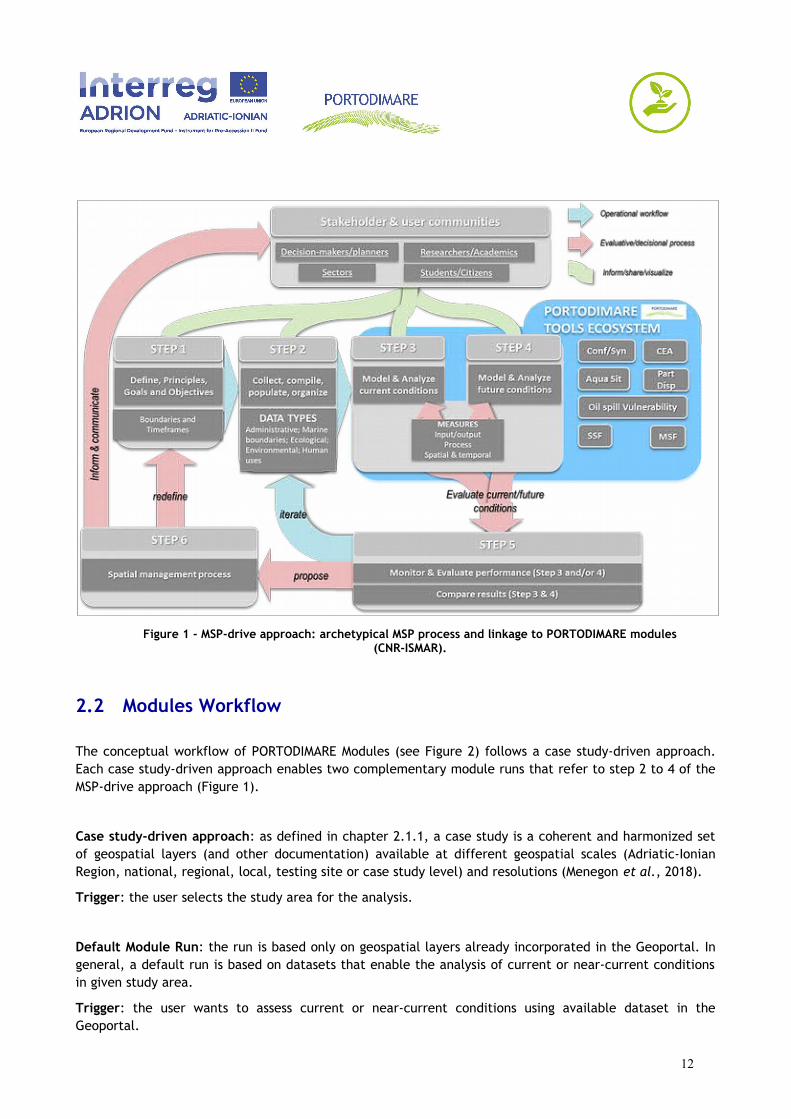
Figure 1 - MSP-drive approach: archetypical MSP process and linkage to PORTODIMARE modules(CNR-ISMAR).
2.2 Modules Workflow
The conceptual workflow of PORTODIMARE Modules (see Figure 2) follows a case study-driven approach.Each case study-driven approach enables two complementary module runs that refer to step 2 to 4 of theMSP-drive approach (Figure 1).
Case study-driven approach: as defined in chapter 2.1.1, a case study is a coherent and harmonized setof geospatial layers (and other documentation) available at different geospatial scales (Adriatic-IonianRegion, national, regional, local, testing site or case study level) and resolutions (Menegon et al., 2018).
Trigger: the user selects the study area for the analysis.
Default Module Run: the run is based only on geospatial layers already incorporated in the Geoportal. Ingeneral, a default run is based on datasets that enable the analysis of current or near-current conditionsin given study area.
Trigger: the user wants to assess current or near-current conditions using available dataset in theGeoportal.
12
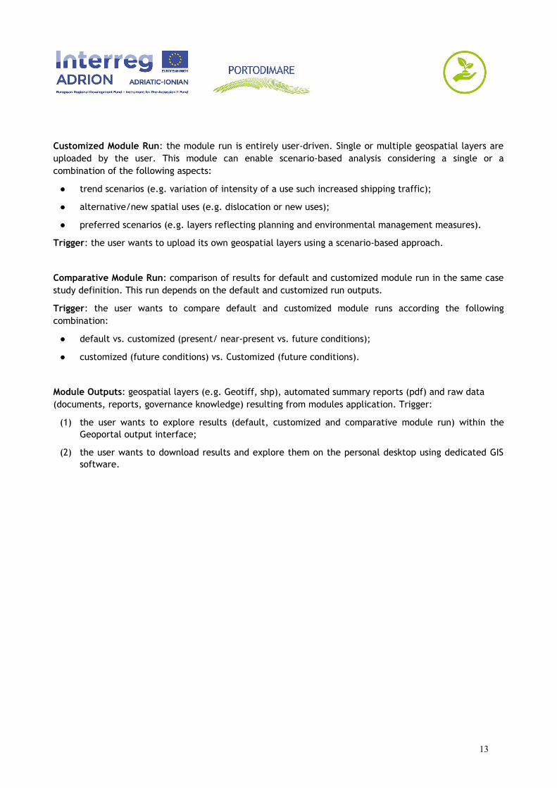
Customized Module Run: the module run is entirely user-driven. Single or multiple geospatial layers areuploaded by the user. This module can enable scenario-based analysis considering a single or acombination of the following aspects:
● trend scenarios (e.g. variation of intensity of a use such increased shipping traffic);
● alternative/new spatial uses (e.g. dislocation or new uses);
● preferred scenarios (e.g. layers reflecting planning and environmental management measures).
Trigger: the user wants to upload its own geospatial layers using a scenario-based approach.
Comparative Module Run: comparison of results for default and customized module run in the same casestudy definition. This run depends on the default and customized run outputs.
Trigger: the user wants to compare default and customized module runs according the followingcombination:
● default vs. customized (present/ near-present vs. future conditions);
● customized (future conditions) vs. Customized (future conditions).
Module Outputs: geospatial layers (e.g. Geotiff, shp), automated summary reports (pdf) and raw data (documents, reports, governance knowledge) resulting from modules application. Trigger:
(1) the user wants to explore results (default, customized and comparative module run) within theGeoportal output interface;
(2) the user wants to download results and explore them on the personal desktop using dedicated GISsoftware.
13

Figure 2 - Overall PORTODIMARE Modules Workflow, describing in detail steps 2, 3 & 4 of theMSP-driven approach (see Figure 1) (CNR-ISMAR).
2.3 Modules description
2.3.1 Module T1.6: Maritime Use Synergy and Conflict Analysis Tool (MUSC)
Objective:
The MUSC module allows to assess and map maritime use conflicts and synergies.
Conflicts (MUC) are defined as the constraints creating disadvantages to maritime activities located in agiven sea area. The method applied is in line with COEXIST Project methodology, already applied withinthe Adriatic-Ionian Sea (Barbanti et al., 2015; Depellegrin et al., 2017). Potential synergies of maritimeuses (MUS) were defined and mapped in terms of Multi-Use (MU) potentials. MU is defined as “the jointuse of resources in close geographic proximity by either a single user or multiple users.” (Schupp et al.under review). Examples include for instance the identification of areas adequate for tourism-driven MU,such as pescatourism or combination of aquaculture activities and tourism.
In addition to geospatial and statistical results, general information on the Driver-Added Value-Barrier-Impact (DABI) of a given MU will be provided.
Rationale:
14
MUSC is based on a case study-driven approach. A case study is defined as pre-configured set of specificdata with consistent spatial and temporal coverage of environmental and anthropogenic uses,incorporating all the necessary parameter for the module run.
The synergy expressed through Multi-Use potentials will be analyzed according to ongoing and pastprojects and through the analysis of EU and macro-regional strategies and national strategies (Blue MEDSRIA; EUSAIR, etc…)
Users:
● Planners and planning team;
● Decision makers (as final end users of the CEA analysis by planners);
● Environmental agencies;
● Research institutions.
Outputs:
Provisional outputs that depend on data availability and system requirement.
2.3.2 Module T1.7: Cumulative Effects Assessment (CEA)
Objective:
The CEA module allows users to assess and map Cumulative Effects based on the Tools4MSP ModellingFramework. An MSP-oriented tool for the analysis and mapping of the effects of single or multiple humanactivities on marine environmental components. An MSFD-friendly application of the CEA should be:
a) Conceptual & Terminological. Definitions and terminology for human uses, pressures andenvironmental components are aligned to the amended Annex III of the MSFD towards Table 1 and2 (a & b).
b) Model-based. Alignment and review of pressure defined with Annex III of the MSFD directive.Including state and pressure-based descriptor integration into the run, as they become availablewithin the Spatial. This alignment of module runs and results within MSFD – Marine Reporting Units(MRU).
c) Functional. Adaptation of a MSFD driven CEA run, including terminology, concept and model intooperational CEA extension within GAIR.
Rationale:
Users can apply CEA to assess and map the effects of single or multiple pressures exerted byanthropogenic activities on the sea space. The method is based on a consolidated methodology developedwithin the Tools4MSP modelling framework. Results of the CEA will highlight sea areas of highestcumulative on a single and multisector level.
Cumulative Effects based on the Tools4MSP Modelling Framework. An MSP-oriented tool for the analysisand mapping of single or multiple human activities on environmental components.
Users:
● planners;
● decision makers (as final end users of the CEA analysis by planners);
● environmental agencies;
15
● research institutions.
Outputs:
Provisional outputs that depend on data availability and system requirements.
2.3.3 Module T1.8: Supporting AZA identification
Objective:
The module implements a spatially explicit MultiCriteria methodology, namely SMCE (Spatial MultiCriteriaEvaluation) for identifying Allocated Zone to Aquaculture (AZA), i.e. marine areas where the developmentof aquaculture is prior to other uses. According to FAO, this is a key step in the implementation of the EAA(Ecosystem Approach to Aquaculture).
Rationale:
Aquaculture is one of the key sectors with high potential for sustainable jobs and growth, as identified bythe EU Blue Growth initiative. The further development of aquaculture in the ADRION region can beconstrained by use conflicts, and should be carried out in compliance with EU and national legislationsaimed at protecting the marine environment. Tools for supporting decision makers in planning andlicensing, based on a transparent methodology for combining environmental and socio-economic criteria,could therefore contribute to shorten the time required to lease new areas, thus facilitating the attractionof new investments.
Users:
● public authorities, involved in maritime spatial planning and in licensing of aquafarms;
● current operators, seeking to expand/diversify their activity;
● investors, interested in a preliminary assessment of areas eligible for the allocation of investment inaquafarming.
Output
Within PORTODIMARE, specific information layers concerning: i) the potential biomass yield of the mostimportant shellfish and fish species, i.e. Mediterranean mussel and seabream, and ii) the assessment ofthe local environmental impact of aquacultures will be made available for a large part of the ADRIONregion. These layers will be obtained by combining remotely sensed and site-specific data with a set ofmodelling tools provided by UNIVE and CNR-ISMAR. Provisional outputs that depend on data availabilityand system requirement.
2.3.4 Module T1.9: Module for particle/conservative contaminants dispersion
Objective:
The module is a tool to evaluate the area of influence of a contaminant source. The tool simulates thedispersion of Lagrangian particles. The hydrodynamic field transporting the particles is calculated asmulti-annual average by a finite element numerical model applied to the Adriatic Sea domain with higherresolution along the coast and including the main lagoons and rivers in the area. The possibility to use thehydrodynamic field corresponding to summer and winter seasons and/or to short time specific events willbe evaluated.
16
Rationale:
The tool can be used to create dispersion scenario for different contaminants in the Adriatic Sea.
Users:
● planners;
● decision makers;
● environmental agencies;
● research institutions.
Outputs:
● A simple ASCII format, containing final position of particles every day of simulation or only at theend of simulation, will be available for internal elaboration in the Geoportal. Other file formats willbe considered to assure the portability and harmonization of the output.
● The map of influence elaborate by the Geoportal tool will be available in common georeferencedformat (e.g. Shapefile).
● Provisional outputs that depend on data availability and system requirement.
2.3.5 Module T1.10: Module for Coastal Oil Spill Vulnerability Assessment
Objective:
The module must allow to represent and query datasets of the Adriatic-Ionic area to support oil-spill riskassessment, contaminants or toxic substances. This includes Coastal Vulnerability index maps (HAZADRdatabase) based on environmental and human components and the development of oil spill risk maps usingthe COMADEX Index. The COMADEX, allowing to identify potential hazardous ships for the coastal area, isbased on seven parameters: type of ship, gross tonnage, launched (age of ship), flag, register andenvironmental conditions, namely Beaufort and Douglas scale reflecting wind intensity and wave heightrespectively. A time selector will enable the identification of risk areas using historical COMADEX recordsand updated COMADEX records (collected within PORTODIMARE project life time).
Rationale:
To set up, within the Adriatic-Ionian area, an Index related to oil-spill risk level.
Objective(s) Evaluate over time the exposure to certain risk of the marine environment and the Adriaticcoastline and being able to assess the areas and the periods most exposed to oil-spill risk. The datacollected and processed within the Geoportal will offer a contribution both for the implementation ofpolicies and instruments for the planning of protection of the sea and the coastline and for theimplementation of specific emergency plans.
Users:
The tool will be useful for institutions that deal with the management policies of economic, commercial ortourism activities in the Adriatic and on the coast but also to the Institutions that deal with themanagement of emergencies, e.g. Port Authority, National and Regional Civil Protection System,Municipalities or Bodies that deal with the management of Marine Protected Areas, Port Authorities.
17

The tool can also be addressed to the citizens and students who want to deepen their knowledge of thepressures of economic and commercial activities in the Adriatic area and of the vulnerability to particularrisks such as oil spill.
Outputs:
Provisional outputs that depend on data availability and system requirement.
2.3.6 Module T1.11: Module for Small Scale Fishery Footprint (SSF)
Objective:
The tool implements a MCDA to assess and map fisheries spatial footprint for Small Scale Fisheries (SSF).
Implementation of a tool for the visualization of fisheries spatial footprint for Small Scale Fisheries (SSF).
Rationale:
The most influential components and criteria affecting SSF will be assessed (bathymetry, distance fromcoast, Chl-a concentration, fishing effort and fleet dynamics, marine traffic activity, etc). This toolcombines MCDA methods and geospatial techniques and provides a way to estimate the impact SSF.
Users:
● fishery managers;
● scientists;
● spatial planning managers;
● scientific groups.
Outputs
Provisional outputs that depend on data availability and system requirement.
2.3.7 Module T1.12: Module on Medium Scale Fishery Footprint (MSF) &Cumulative Effects Assessment on SSF & MSF
Objective:
Implementation of a tool for the visualization of fisheries spatial footprint for Medium Scale Fisheries(MSF), trawlers & purse seines, including the estimation of cumulative additive fishing pressure index(SSF+MSF).
The objective of the tool is to provide an assessment of fishing effort for MSF which typically are equippedwith tracking devices (VMS/AIS). In case where VMS/AIS are not available for all spatial and temporalscales, an approach based on a GIS-MCDA should be employed to estimate a fishing pressure index forbottom trawlers and purse seiners according to methodology proposed by Kavadas et al. 2015 thatcombines geographical data and value judgments (decision-maker’s preferences).
Rationale:
To visualize the spatial distribution of the fishing pressure from MSF. The most influential components andcriteria affecting MSF will be assessed (bathymetry, distance from coast, Chl-a concentration, fleetdynamics, etc.).
18
Users:
● fishery managers;
● researchers;
● spatial planning managers;
● scientific groups.
Outputs
Provisional outputs that depend on data availability and system requirement.
19
3 SYSTEM ARCHITECTURE
3.1 General approach
Overall, the architecture design follows a resource-centered and service-oriented approach as describedin (De Longueville, 2010) and (Yang et al., 2007). The authors propose a so-called Service-OrientedGeoportal Architecture that includes three main layers (De Longueville, 2010):
● the resource layer corresponds to the physical storage of the structured information in databases orfiles;
● the access layer includes all code and software designed to provide access to the resources in theappropriate format;
● the Graphical User Interface (GUI) is the client-side component of the Geoportal architecture. Therole of GUIs is not limited to the rendering of a given set of resources, but includes also theaggregation of relevant resources through lightweight and loosely coupled JavaScript code. In otherwords, the GUI is not only a presentation layer but also creates a mashup of relevant resources.
The overall architecture of the GAIR is described in Figure 3. Furthermore, the schema highlights the usertypologies served by the Geoportal and the interactions/connections with external portals.
The Geoportal is structured by five main components:
1. the “Resource Layer” for storing the datasets, metadata, resources and all the necessaryinformation;
2. the “Module Engines” for performing the module/tools analyses;
3. the “Task Manager middleware” for orchestrating the Geoportal’s tasks and processes;
4. the “Web services & API” (Access Layer) for publishing the API and the web services to interact(e.g. search, visualize, download, manage) with the informative resources and with the “ModuleEngines”;
5. the “Geoportal” (Graphical User Interface) for implementing the end user interfaces and tools tosearch, visualize, explore and analyze informative resources. Dedicate GUIs will allow users toexecute module analyses.
20
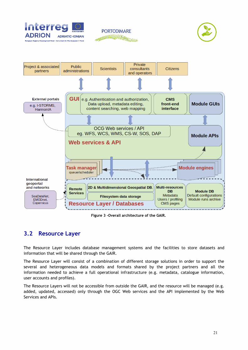
Figure 3 -Overall architecture of the GAIR.
3.2 Resource Layer
The Resource Layer includes database management systems and the facilities to store datasets andinformation that will be shared through the GAIR.
The Resource Layer will consist of a combination of different storage solutions in order to support theseveral and heterogeneous data models and formats shared by the project partners and all theinformation needed to achieve a full operational infrastructure (e.g. metadata, catalogue information,user accounts and profiles).
The Resource Layers will not be accessible from outside the GAIR, and the resource will be managed (e.g.added, updated, accessed) only through the OGC Web services and the API implemented by the WebServices and APIs.
21
3.2.1 Primary resource types
The primary resource types are:
1. Layers: 2-D geospatial datasets (e.g. vector and raster) stored in various data format. GAIR willprimarily share GeoTIFF and Shapefile but should support most common GIS formats (e.g.through gdal abstraction library) (GDAL, 2013).
2. Remote Services: configurations for connecting to external data providers through OGCinteroperable services.
3. Documents: generic file types represented in binary or text formats (e.g csv, odt, ods, dbf, png,pdf) and related to tabular and text data, images, reports, graphs, etc.
4. Maps: collection of various layers and their styles. Layers can be both local layers in GAIRimplementation as well as remote layers either served from other WMS servers or by web servicelayers such as Google or MapQuest.
5. Layer Expressions: represent a logical layer definition through the combination andtransformation of already existing Layer objects.
6. Case Studies: according to definition reported in chapter 2. (PORTODIMARE Modules), a casestudy is a coherent and harmonized set of geospatial layers (and other documentation) availableat different geospatial scales (Adriatic-Ionian Region, national, regional, local, testing site orcase study level) and resolutions. A Case Study is also linked to one of the PORTODIMAREmodules and includes default parameters to completely define a default model run oralternatively, customized parameters defined by end-users to perform a customized model run.A Case Study doesn’t link directly to a Layer object but to a Layer Expression. Independentlyfrom module type, each Case Study has to define a domain area (area of analysis) and aresolution of analysis.
7. Case Studies Layers: rectified grid representation of a Layer Expression in accordance with CaseStudy domain area and with the resolution of analysis. For each Case Study, a set of Case StudyLayers will be stored into the resource layer.
8. Archived model outputs: results of model output analysis saved by the end-users. Archived modeloutputs will contain link to a case study (default or customized), author of analysis, datetime ofanalysis, links to geospatial model outputs (saved as GAIR layers, documents or maps) and otherresources in order to make analysis results persistently accessible.
Coupled with each primary resource types, GAIR will be able to store metadata information related to theuploaded resource. Generally, metadata should cover the following topics:
● title
● abstract
● topic category
● authors, owners, resource providers
● date of creation, publication etc.
● temporal extent
22
● license, constraints and permissions
● genealogy
● data quality
● starred
and, to geospatial resources (e.g. layers, maps):
● reference system, datum
● spatial extent, bounding box.
In addition, for module-generated objects (e.g. output layer created by a PORTODIMARE module)automatically generated metadata should provide information on module type and module run that havecreated the object.
The Starred metadata field allows to mark a GAIR object (e.g. Layers, Document, Map) as starred. Starredobjects are representative datasets for each MSP informative topics (Topic category) and will lead end-users to rapidly identify the most important and significant MSP-related objects. This field must beeditable only by administrators.
In order to support standard geospatial catalogue implementation and standard interoperable servicesthe, special importance is given to standard metadata formats like ISO 19139 and ISO 19115 and, morespecifically, the INSPIRE metadata profile (ISO/TC 211 2013, 19115; European Commission, 2007).
3.2.2 Secondary resource types
GAIR also supports the following additional resource types:
● user accounts and user group definition, including information to support user registration andauthentication through external identity providers;
● per-object permissions (related to users or groups);
● CMS configuration and CMS pages;
● comments for primary resource types;
● announcements and news.
3.3 Web Services and APIs
The “Web Services and APIs” will provide access to the stored resources through standardized interfaces(e.g OGC-Web service, web API).
A core set of OGC web services and other protocols and standards commonly used in the field of geospatialinformation will be implemented:
● OGC Web Feature Service (OGC-WFS; (Open Geospatial Consortium Inc., 2005)): standard interfaceto request and download geographical features across the web;
23
● OGC Web Coverage Service (OGC-WCS; (Open Geospatial Consortium Inc., 2008)): standard interfaceto request and download coverages that is, digital geospatial information representing space/time-varying phenomena;
● OGC Sensor Observation Service (OGC-SOS; (Open Geospatial Consortium Inc., 2012)): standardinterface to request and download real-time sensor data and sensor data time series;
● OGC portrayal service (e.g. Web Map Service; (OGC - Open Geospatial Consortium Inc., 2006); TileMap Service, (OSGeo, 2012); Web Map Tiling Service, (Open Geospatial Consortium Inc., 2010)):standard interfaces to visualize the geospatial datasets;
● OGC Catalogue Service for the Web (CS-W, (Open Geospatial Consortium Inc., 2007)): standard forexposing a catalogue of geospatial resources;
The OGC web service implementation should support the INSPIRE network service specification (EuropeanCommission 2009) as well as the layer metadata should be provided in accordance with INSPIRE metadataspecification (European Commission, 2007).
In addition, the “Web Services and APIs” will implement dedicated APIs for easily supporting interactionwith the “Module Engines”. Such API will follow the Open API Specification (OpenAPI Initiative, 2014).Hence, all of the activities performed by users through GUI should be available also as a machine-to-machine interaction through advanced programming interface (API). The API level will interact with eachmodule engine standardizing the way to set parameters and data sources using a small set of endpoints.
3.4 Graphical User Interface
The GUI layer identifies the end-user web interface of the GAIR. The GAIR GUIs provide interactive toolsfor searching, visualizing, exploring and downloading geospatial layers, maps and PORTODIMARE modeloutputs capitalizing on existing experiences in the ADRION area (ADRIPLAN, SHAPE, HAZADR projects).
The main end-user sections of the Geoportal are:
1. A Search GUI which combines free-text search, faceted navigation and a preview of the filteredresults. Such GUI allows to search over the different GAIR content types (geospatial layers, maps,generic files and documents, archived model outputs). The faceted navigation should allow to refinethe results over the following items: categories, sub-categories, data type, data owners, daterange, geographical extension, domain area, validation level, starred datasets, module (for modulegenerated objects).
2. The Layer Search GUI should provide an “Add to cart” functionality to facilitate the creation ofmulti-layer Maps. More in details, such GUI is strictly connected to the Search GUI allowing end-users to filter the layer objects, select one or more layers adding them to a “Cart” and finally,create a map composed by all selected layers.
3. A Map Viewer and Composer (see Figure 9), which is an interactive and dedicated GUI for creating,managing and sharing multi-layered maps and for navigating and querying them.
More in details the following functionalities should be implemented:
a. search and include geospatial layers provided by IWS itself;
b. allow editing of layer styles;
24

c. access to preconfigured collections of base/background layers provided by global and localtile map services (e.g. OpenStreetMap, OSM/Stamen, OSM/Thunderforest, Google Maps, BingMaps, NASA);
d. import layer from external resources likes Web Map Services (WMS, OGC - Open GeospatialConsortium Inc., 2006) and Arc GIS Rest Services;
e. control layer order, opacity, visibility and map extension;
f. allow map navigation (e.g. zoom, pan);
g. line and area measurement widgets;
h. saving and sharing created maps;
i. editing existing maps;
j. printing maps;
k. per-map permission management.
4. A CMS front-end interface representing end-user facing views of the integrated ContentManagement System. Such GUI allows collaborative management of geoportal and moduledocumentation and other dynamic contents.
5. A layer builder GUI to dynamically define new layers combining and transforming layers alreadypresent into GAIR (see also chapter 5.2 GeoDataBuilder app).
6. The Module GUI is an end-uaser interface to select the already configured module case studies,allow customization, perform the module analysis, visualize the results and explore archived modeloutputs (see also chapter 5.3 ModuleConnect app).
Additional GUIs are dedicated to:
a. manage users;
b. manage user profiles;
c. upload layers and documents;
d. mange layer styles;
e. manage metadata and privileges for layer, maps, documents, case studies and archived modeloutputs.
As example, the upload layer workflow should be implemented as follow:
a. easy-to-use web GUI for single or bulk upload of 2D raster and vector layers (e.g meanhydrodynamic conditions, residence time, background layers of the study area) includingautomatic check of data completeness, consistency and validity;
b. automatic storage, indexing and registration of standard interoperable services to supportdata cataloging, visualization and downloading (backend);
c. automatic metadata extraction from the uploaded resources (e.g. resource type, boundingbox, geospatial reference system (backend);
d. easy-to-use GUI for simplifying metadata editing (e.g. supporting controlled vocabulary,autocompletion, helpers to avoid typos);
25

e. easy-to-use GUI for resource discovering (e.g. faceted and free text search, geospatialfiltering) and visualization (including web mapping application).
26
3.5 User profiles, authentication and authorization
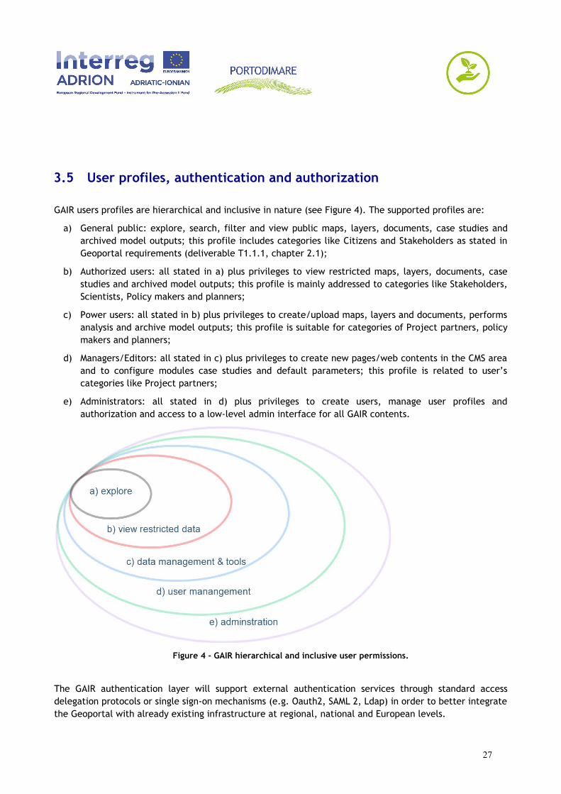
GAIR users profiles are hierarchical and inclusive in nature (see Figure 4). The supported profiles are:
a) General public: explore, search, filter and view public maps, layers, documents, case studies andarchived model outputs; this profile includes categories like Citizens and Stakeholders as stated inGeoportal requirements (deliverable T1.1.1, chapter 2.1);
b) Authorized users: all stated in a) plus privileges to view restricted maps, layers, documents, casestudies and archived model outputs; this profile is mainly addressed to categories like Stakeholders,Scientists, Policy makers and planners;
c) Power users: all stated in b) plus privileges to create/upload maps, layers and documents, performsanalysis and archive model outputs; this profile is suitable for categories of Project partners, policymakers and planners;
d) Managers/Editors: all stated in c) plus privileges to create new pages/web contents in the CMS areaand to configure modules case studies and default parameters; this profile is related to user’scategories like Project partners;
e) Administrators: all stated in d) plus privileges to create users, manage user profiles andauthorization and access to a low-level admin interface for all GAIR contents.
Figure 4 - GAIR hierarchical and inclusive user permissions.
The GAIR authentication layer will support external authentication services through standard accessdelegation protocols or single sign-on mechanisms (e.g. Oauth2, SAML 2, Ldap) in order to better integratethe Geoportal with already existing infrastructure at regional, national and European levels.
27
Creation of new accounts will be possible through admin interfaces (by administrations) or through a self-registration workflow which will support an optional approval stage.
28
Object level grain permissions should be implemented for the following primary resource types:
1. Maps
2. Layers
3. Remote service
4. Documents
5. Case studies
6. Archived model outputs and for CMS content pages.
Permission will be managed by Coarse Grained Authorization with Role-Based approach: differentprivileges will be granted at object level for each user, role or group.
3.5.1 Authentication security requirements
In accordance with deliverable T1.1.1, chapter 2.10 (Security requirements consideration in Geoportaldevelopment), the GAIR authentication mechanism should provide the following functionalities andprecautions:
● automatic password expiring after 180 days;
● password strength checking to avoid creation of weak passwords;
● restriction of excessive authentication attempts to avoid the web application exposure to "bruteforce" attacks, the implementation must:
o impose a limit on the number of login attempts that can be made from a specific IP addresswith a specific username;
o enforce the account disabling after an established number of invalid login attempts (e.g., fiveis a common limit for attempts). The account must be disabled for a period long enough todiscourage brute force guessing of credentials, but not so long as to allow for a denial-ofservice attack to be performed.
● the authentication failure messages should not specify which part of the authentication data wasincorrect.
3.6 Management tasks
In order to guarantee GAIR ordinary and extraordinary maintenance and to simplify the initial import ofgeospatial datasets and other documents, some management task workflows have to be implemented. Inaddition to common maintenance tasks, GAIR should provide at least the following tasks:
● performing bulk upload of geospatial data (supporting Shapefile and GeoTIFF formats) andmetadata (XML format of ISO 19115 generic profile, INSPIRE profile, RNDT profile);
● performing bulk harvesting and importing of data and metadata from a CKAN-based MSPKnowledge Catalogue instance (Menegon 2018). Shapefile and GeoTIFF resources should be directlyimported into the GAIR, whilst OCG-WFS and OCG-WCS provided by full operational SDI (e.g.
29
EMODNet data portals) should be register as remote services. In both cases the metadata shouldbe imported directly from the MSP Knowledge Catalogue.
3.7 Module integration
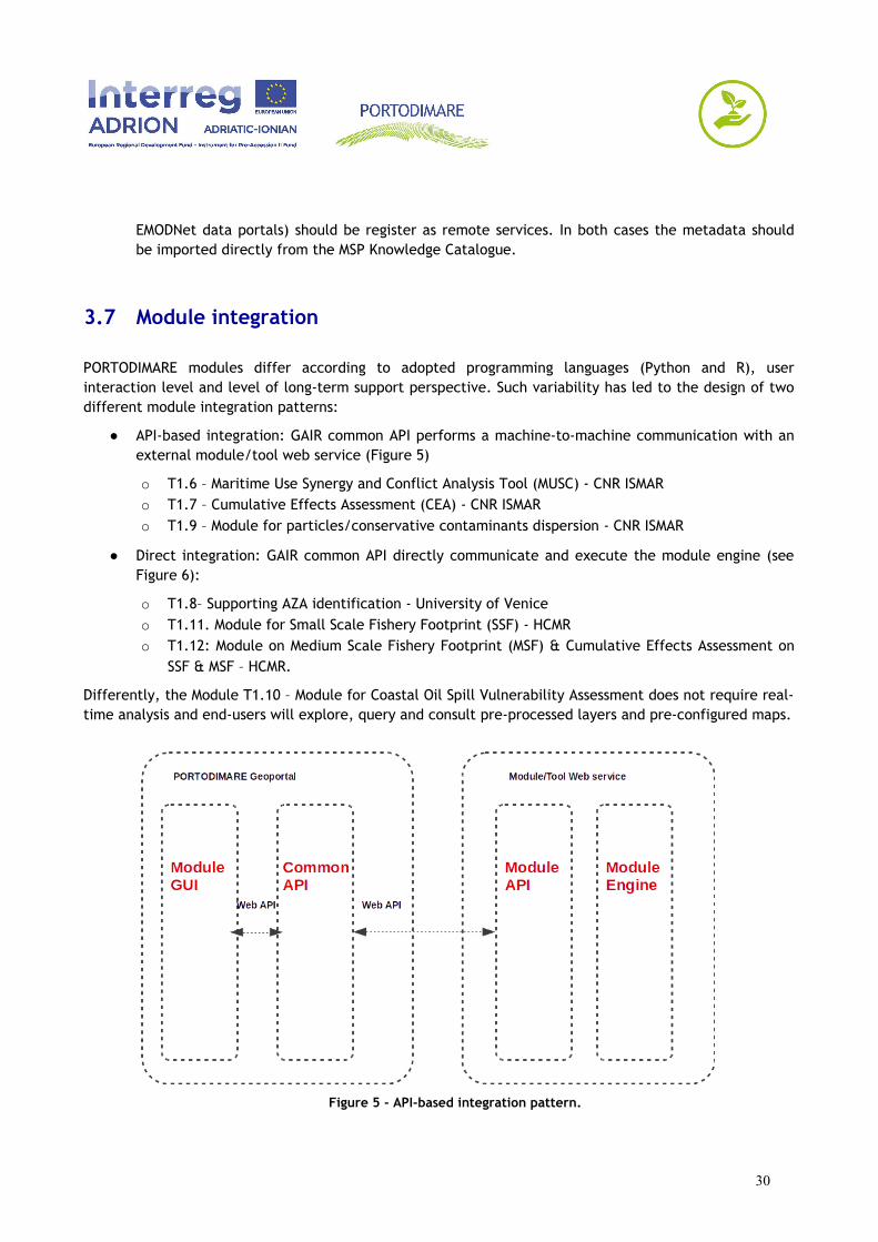
PORTODIMARE modules differ according to adopted programming languages (Python and R), userinteraction level and level of long-term support perspective. Such variability has led to the design of twodifferent module integration patterns:
● API-based integration: GAIR common API performs a machine-to-machine communication with anexternal module/tool web service (Figure 5)
o T1.6 – Maritime Use Synergy and Conflict Analysis Tool (MUSC) - CNR ISMAR o T1.7 – Cumulative Effects Assessment (CEA) - CNR ISMAR o T1.9 – Module for particles/conservative contaminants dispersion - CNR ISMAR
● Direct integration: GAIR common API directly communicate and execute the module engine (seeFigure 6):
o T1.8– Supporting AZA identification - University of Venice o T1.11. Module for Small Scale Fishery Footprint (SSF) - HCMR o T1.12: Module on Medium Scale Fishery Footprint (MSF) & Cumulative Effects Assessment on
SSF & MSF – HCMR.
Differently, the Module T1.10 – Module for Coastal Oil Spill Vulnerability Assessment does not require real-time analysis and end-users will explore, query and consult pre-processed layers and pre-configured maps.
Figure 5 - API-based integration pattern.
30
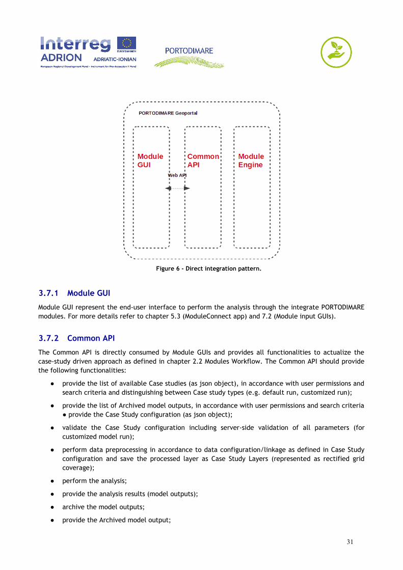
Figure 6 - Direct integration pattern.
3.7.1 Module GUI
Module GUI represent the end-user interface to perform the analysis through the integrate PORTODIMAREmodules. For more details refer to chapter 5.3 (ModuleConnect app) and 7.2 (Module input GUIs).
3.7.2 Common API
The Common API is directly consumed by Module GUIs and provides all functionalities to actualize thecase-study driven approach as defined in chapter 2.2 Modules Workflow. The Common API should providethe following functionalities:
● provide the list of available Case studies (as json object), in accordance with user permissions andsearch criteria and distinguishing between Case study types (e.g. default run, customized run);
● provide the list of Archived model outputs, in accordance with user permissions and search criteria● provide the Case Study configuration (as json object);
● validate the Case Study configuration including server-side validation of all parameters (forcustomized model run);
● perform data preprocessing in accordance to data configuration/linkage as defined in Case Studyconfiguration and save the processed layer as Case Study Layers (represented as rectified gridcoverage);
● perform the analysis;
● provide the analysis results (model outputs);
● archive the model outputs;
● provide the Archived model output;
31
● manage the permissions related to case study and to Archived model output.
In case of API-based integration, the Common API will redirect/proxy some requests (e.g. perform theanalysis) to external services provided by Module API. Alternatively, in case of direct integration, theCommon API will directly interact with module engines.
3.7.3 Module API
The module APIs will be implemented as external services and are in charge of module developers. TheModule API should provide the following functionalities:
● token-based authentication;
● perform the analysis basing on following input parameters:
o Case Study configuration o All preprocessed datasets (rectified grid layers) as defined into the Case Study configuration.
The Module API should implement validation of received parameters and user permissions.
3.7.4 Module Engine
A PORTODIMARE module engine is defined as:
● a standalone executable program running on a linux OS;
● accepting a predefined set of input arguments/parameters;
● supporting basic input validation (e.g. dataset format, geospatial dataset overlapping, rangevalidators),
● accompanied with different set of test cases (input and output) to perform software validationand verification.
32
4 TECHNOLOGICAL STACK
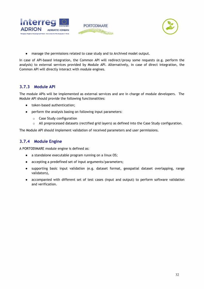
The technology stack is the combination of software products, development frameworks and programminglanguages used to build and run a complete application. This chapter and the diagrams describe the fulltechnology stack (Figure 7) that will be used for GAIR server and client implementation. Each element inthe stack was carefully selected based on requirement fulfillment, robustness and size of softwarecommunity (e.g. developers, users), quality of support (e.g. public groups or forums addressing userqueries regarding installation or other bugs), quality of documentation and software license.
Figure 7 - GAIR Technological stack.
4.1 Core software products
GeoNode and Wagtail have been selected as core software products because they provide a significantnumber of required functionalities and are both based on the same development framework (Django).
4.1.1 GeoNode
Geonode is a complete suite for collaborative managing of geospatial data (Benthall and Gill 2010;GeoNode Development Team, 2019a). Providing geospatial Content Management System functionalities,GeoNode facilitates the upload and management of geospatial datasets, making them discoverable andavailable via standard Open Geospatial Consortium (OGC) protocols and web mapping applications.
33
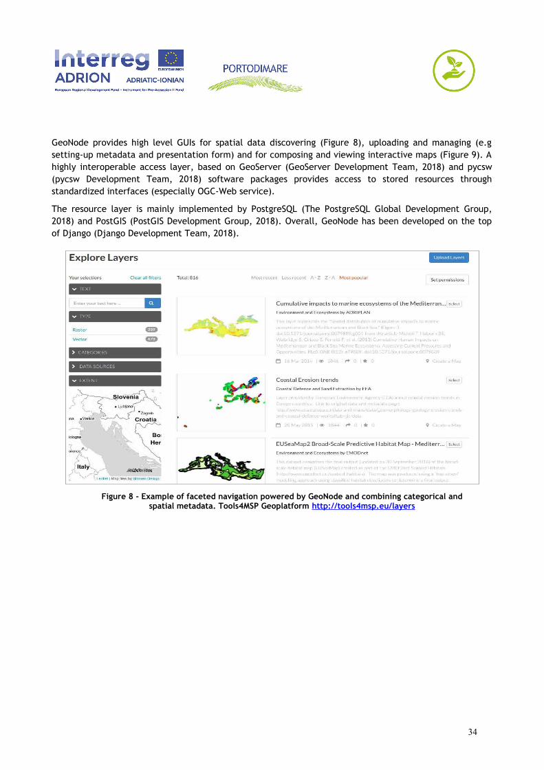
GeoNode provides high level GUIs for spatial data discovering (Figure 8), uploading and managing (e.gsetting-up metadata and presentation form) and for composing and viewing interactive maps (Figure 9). Ahighly interoperable access layer, based on GeoServer (GeoServer Development Team, 2018) and pycsw(pycsw Development Team, 2018) software packages provides access to stored resources throughstandardized interfaces (especially OGC-Web service).
The resource layer is mainly implemented by PostgreSQL (The PostgreSQL Global Development Group,2018) and PostGIS (PostGIS Development Group, 2018). Overall, GeoNode has been developed on the topof Django (Django Development Team, 2018).
Figure 8 - Example of faceted navigation powered by GeoNode and combining categorical andspatial metadata. Tools4MSP Geoplatform http://tools4msp.eu/layers
34
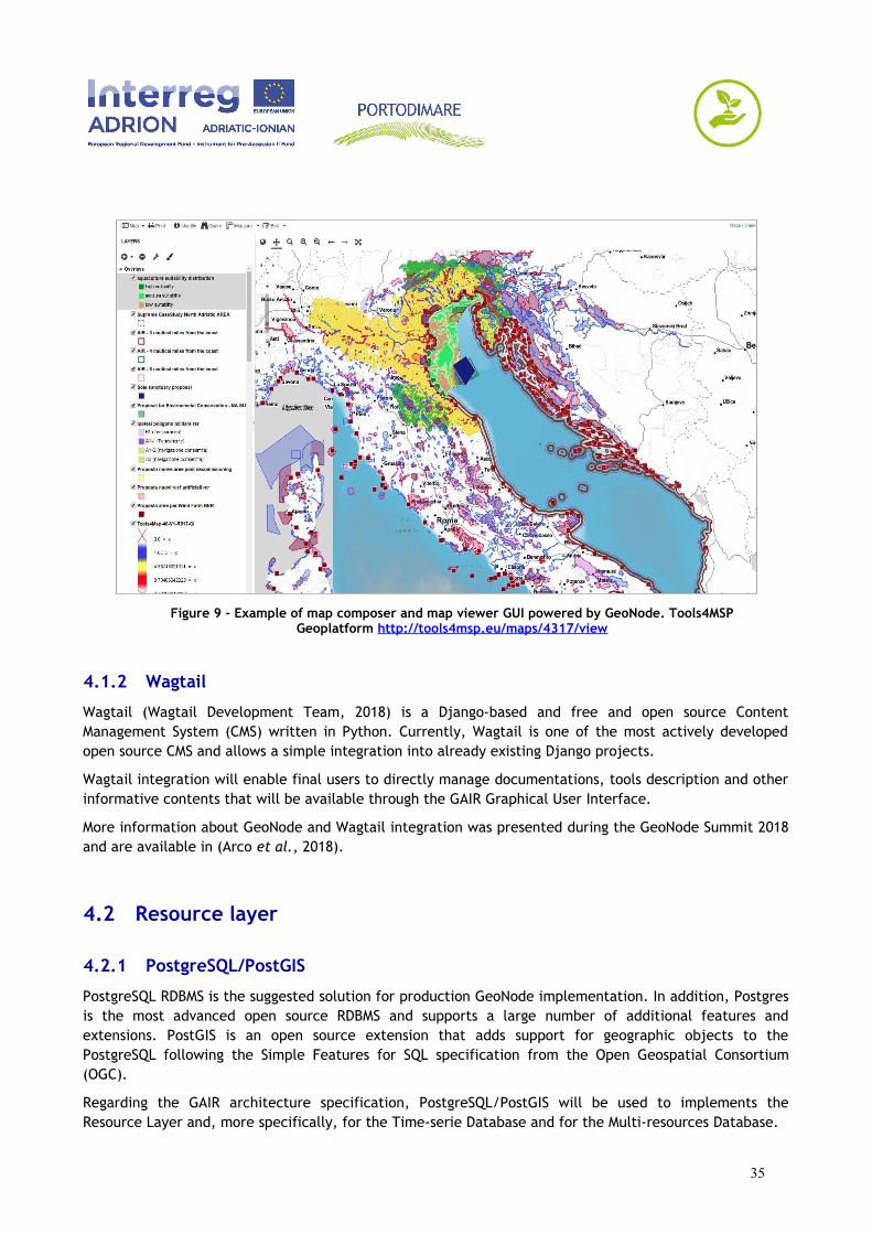
Figure 9 - Example of map composer and map viewer GUI powered by GeoNode. Tools4MSPGeoplatform http://tools4msp.eu/maps/4317/view
4.1.2 Wagtail
Wagtail (Wagtail Development Team, 2018) is a Django-based and free and open source ContentManagement System (CMS) written in Python. Currently, Wagtail is one of the most actively developedopen source CMS and allows a simple integration into already existing Django projects.
Wagtail integration will enable final users to directly manage documentations, tools description and otherinformative contents that will be available through the GAIR Graphical User Interface.
More information about GeoNode and Wagtail integration was presented during the GeoNode Summit 2018and are available in (Arco et al., 2018).
4.2 Resource layer
4.2.1 PostgreSQL/PostGIS
PostgreSQL RDBMS is the suggested solution for production GeoNode implementation. In addition, Postgresis the most advanced open source RDBMS and supports a large number of additional features andextensions. PostGIS is an open source extension that adds support for geographic objects to thePostgreSQL following the Simple Features for SQL specification from the Open Geospatial Consortium(OGC).
Regarding the GAIR architecture specification, PostgreSQL/PostGIS will be used to implements theResource Layer and, more specifically, for the Time-serie Database and for the Multi-resources Database.
35

4.3 Access layer and web API
4.3.1 Geoserver
GeoServer is an Open Source and standard-oriented application for managing and sharing geospatialdatasets (GeoServer Development Team, 2018).
GeoServer provides functionalities to serve vector (features) and raster (grid coverage) datasets andsupports the creation of distributed interoperable spatial data infrastructures (SDI). GeoServer is enabledand configured by default in GeoNode.
The GeoServer INSPIRE extension has to be installed to provide INSPIRE-compliant view and downloadservices.
4.3.2 Pycsw
pycsw is an Open Source OGC Catalogue Service for the Web (pycsw Development Team, 2018)implementation. pycsw provides functionalities and web interfaces to ingest and index geospatial resourcemetadata, to make them discoverable and searchable through multiple interoperable services (includingINSPIRE Discovery Services). pycsw is enabled and configured by default in GeoNode.
4.3.3 Django
Django will form the basic development framework of GAIR.
Django is a python-based framework to facilitate the creation of complex sites-oriented databases and tomake easy the reuse and incorporation of external modules (Django apps). Django also provides anautomatic administrative interface where users can create, manage, update and delete the site contents.
4.3.4 Swagger
Swagger is an Open Source ecosystem of tools that helps the implementation of RESTful Web Servicesfollowing the Open API specification (Open API Initiative, 2014). Swagger toolset includes support forautomated documentation, code generation, test-case generation and a GUI (Swagger UI) to interactivelyexplore and navigate the API.
Module API and Common API (see Figure 5 and 6) will follow the Open API specification.
4.3.5 Haystack
Haystack allows to integrate a complete full text search engine into a GeoNode application. By default,haystack will be used only on the base, layers, maps and documents API.
36
4.4 Graphical User Interface
GeoNode adopts Bootstrap (Bootstrap team, 2019) and Angular (Google, 2019) as base frameworks todevelop end-user interfaces.
Regarding interactive mapping GUIs, GeoNode 2.8 directly integrates multiple and configurable solutions(Client Hooksets):
● GeoExtHookSet: default hookset based on GeoExplorer, gpx, GeoExt stack. This solution offers acomplete and stable framework, for composing and publishing maps. However, the above stack isnot longer updated and maintained.
● ReactHookSet: an alternative GeoNode client based on React (GeoNode Development Team,2018).
● LeafletHookSet: a simple web mapping client based on LeafLet.
● MaploomHookSet: a web mapping client based on Angular and OpenLayers 3. It provides full-featured editing capabilities for data stores in GeoServer - including PostGIS and GeoGig.+
Another solution to develop web mapping client on top of a GeoNode-based implementation is MapStore2(GeoSolutions 2019): a reactJS-based framework to build web mapping applications using standardmapping libraries, such as OpenLayers and Leaflet.
4.5 Additional software
4.5.1 GeoNode project
The GeoNode-project (GeoNode Development Team, 2019b) package is a Django template project forcreating custom GeoNode platforms. It provides shortcuts to deploy the customized project throughmultiple approaches (e.g. virtualenvel, Docker-compose). It also simplifies the software maintenanceactivities ensuring plain dependence on underlying GeoNode implementation.
37

5 PORTODIMARE EXTENSION APPLICATIONS
Basing on the technological stack described in chapter 4, the current chapter explains the additionalcomponents that have to be developed in order to comply with requirements and designed architecture(chapter 3). Such additional components are presented as Django applications and are functional todescribe in detail the required development activities, hence they must be understood as one of thepossible solutions.
As already specified into the PORTODIMARE Application Form and into the deliverable T1.1.1 (Geoportalrequirements based on ICZM/MSP priorities - local/regional, national, transnational - of the Adriatic-IonianRegion) all developed software will be release as free and open source software through an onlinesoftware repository (e.g. github, gitlab).
The development process should follow the requirements defined in deliverable T1.1.1, chapter 2.10(Security requirements consideration in Geoportal development).
5.1 GairBase app
GairBase is a django app providing base customization of a base GeoNode project. More in detail, the appwill provide:
● brand identity: providing a novel GeoNode theme, including logos, graphics, colours and fonts inorder to characterize and differentiate GAIR implementation from other GeoNode-based projects;
● home page customization: incorporating significant text, images or other graphical elements (e.g.slideshows);
● navbar adjustment: adding menu items for linking to additional GAIR sections (es. modulesintroduction and documentations, module and case studies selection pages, archived modeloutputs page, general documentation and other pages created through integrated CMS);
● layouts and styles adjustment: to guarantee the compliance with W3C Web Content AccessibilityGuidelines (WCAG) as specified in the deliverable T1.1.1 chapter 2.9.2;
● ResourceBase extent: extending the metadata fields provided by the geonode.base.ResourceBasemodel class. The following metadata field have to be added:
o subcategory: ForeignKey model field. The related lookup table will contain preloadedsubcategory definitions as described in deliverable T1.2.1 (Data and informationrequirements specification);
o domain area: ManyToMany field. The related table will contain a preload list of possibledomain area as defined in deliverable T1.2.1 (Data and information requirementsspecification);
o data portal: ForeignKey field. The related table will contain a preload set of Geoportal asdescribed in deliverables T1.2.1 (Data and information requirements specification) andT1.3.1 (Inventory and analysis of existing tools in the AIR);
38
o data accessibility: Text field; o validation level: ForeignKey field. The related table will contain the list of possible
validation level as defined in deliverable T1.2.1 (Data and information requirementsspecification).
● topic categories review: in accordance with definitions described in deliverable T1.2.1 (Data andinformation requirements specification);
● faceted navigator improvement: adding additional field to GeNode faceted navigator:
o subcategoryo domain_area o validation_level.
● full text search improvement: installing and configuring “Haystack” with “Elasticsearch” backend;
● metadata editor extension: to allow editing of additional metadata field;
● metadata extension and customization: to provide the missing mandatory metadata required byINSPIRE implementing rules (European Commission, 2007). Both base metadata models extensionand GUI customization are required;
● full_metadata.xml template customization: to dynamically create a downloadable INSPIRE-compliant metadata;
● import controlled vocabularies (e.g. INSPIRE Spatial Data Themes, GEMET Concepts) on GeoNodebase models (base.Thesaurus, .base.ThesaurusKeyword and base.ThesaurusKeywordLabel) tosupport thesaurus keywords for meatadata editing;
● authentication restrictions as described in chapter 3.5.1 (Authentication security requirements);
● bulk importer improvement: to support additional metadata field and to guarantee thecompatibility with SHAPE metadata schema;
● MSPKC importer development: a novel importer module to allow direct retrieving of resources andrelated metadata directly from the MSP Knowledge Catalogue (MSPKC) (Menegon, 2018) CKAN-based repository (Open Knowledge International, 2018). MSPKC is maintained by CNR-ISMAR forsupporting GAIR importing activities. The MSPKC importer module should perform the followingactions:
o connect to MSPKC API and retrieve the whole catalogue. Refer to CKAN Association (2018)for the API documentation.
o filter the catalogue from already imported resources o recognize valid resource basing on presence of Shapefile, GeoTIFF or a reference to a valid
OGC-WFS or OGC-WCS service o if the resource is a Shapefile or a GeoTIFF, import the resource into the GAIR o if the resource is a OGC-compliant service, register it as a GeoNode Remote Service o if the resource is a generic type format, the resource will be uploaded as a Document
resource type (see chapter 3.2.1 Primary resource types) o upload the coupled metadata.
Optionally, GairBase App may support multi-language metadata fields installing and configuring “Django-modeltranslation” application. This should allow end-users to fill-up varchar and text metadata in Englishand in PPs national languages (i.e. Italian, Croatian, Slovenian, Bosnian, Montenegrin, Greek).
39

40
5.2 GeoDataBuilder app
GeoDataBuilder is an application for creating new raster layers combining one or multiple raster or vectorlayer already present into a GeoNode platform. The whole transformation pipeline is defined by a LayerExpression (see chapter 3.2.1 Primary resource types) which could be stored into GAIR and reused bydifferent user and in different context.
The GeoDataBuilder should support at least the following operators:
● base map algebra operations (e.g. addition, subtraction, division, multiplication);
● rescaling (e.g. to rescale a layer into the 0-1 interval);
● log-transformation;
● rasterization of a vector layer.
GeoDataBuilder should provide a high-level GUI in order to simplify the layer selection (e.g. autocompletefrom GeoNode catalogue) and the design of the final expression. Regarding vector layers selection,GeoDataBuilder should also provide an interactive way to select a single vector field.
End-users may be interested to create an expression, save it and retrieve it at a later time to perform therasterization. Alternatively, end-user may be interested in use the designed expression to create a newraster layer. In this case, the user should also specify the final resolution.
However, GeoDataBuilder App will be primarily use in combination with ModuleConnect GUI (see nextsection). Basic security constraints, limits and filters should be implemented on the backend side in orderto:
● avoid processing invalid or malicious expression;
● avoid exceeding of execution time or memory limits (e.g. maximum number of output map cells);
● etc.
GeoDataBuilder frontend/backend communications will be compliant with the Open API specification(Open API Initiative, 2014).
GeoDataBuilder GUI should be developed as a single-page application (SPA) using an appropriate JSframework (e.g. ReactJS).
5.3 ModuleConnect app
ModuleConnect app is the bridge to integrate all PORTODIMARE modules into a bare GeoNodeimplementation. ModuleConnect will be developed in accordance with architecture details presented inchapter 3.7 Module integration and, similarly to GeoDataBuilder, app the frontend/backendcommunications will be compliant with the Open API specification (Open API Initiative 2014).ModuleConnect depends by GeoDataBuilder app which provides basic functionalities to dynamically pre-process the input layers required by PORTODIMARE modules.
41
ModuleConnect defines “Case Study”, “Case Study Layers” and “Archived Model Outputs” primary resourcetypes, implements Common API (see chapter 3.7.2. Common API) and provide highly interactive end-userinterfaces in order visualize case study default configurations, customize the input parameters and theinput layers, visualize the results.
Similarly to Layers, Maps and Documents objects, the ModuleConnect will allow end-users to add“comments” and “rate” the “Case Study” and “Archived model outputs” resources.
More details are available in chapter 6.2. (Module Use Cases), chapter 7.2. (Module input GUIs) andchapter 7.3. (Module output GUIs).
5.4 INSPIRE Compliance
This chapter summarizes the actions that have to be performed in order to allow the GAIR compliancewith INSPIRE services and metadata specifications:
● the pycsw INSPIRE extension has to be enabled and configured to support INSPIRE compliantdiscovery services;
● the GeoServer INSPIRE extension has to be enabled and configured to support INSPIRE compliantview and download services;
● extension of GeoNode base metadata profile (by GairBase app) providing additional metadatafields;
● customization of the default ISO metadata template (full_metadata.xml);
● guarantee the metadata completeness and an adequate level of metadata quality especially forthe Starred Layers resources;
● check the metadata compliance through the INSPIRE validator (European Union, 2019).
5.5 Internationalization and localization
Optionally and according to deliverable T1.1.1, chapter 2.5, GAIR should support (for both GUI andmetadata) the following languages: English, Italian, Slovenian, Croatian, Bosnian, Montenegrin and Greek.Currently, GeoNode doesn’t provide official localizations for Slovenian Croatian, Bosnian and Montenegrin.Consequently, GAIR will provide the basic localization setup for these additional languages and anadministration GUI (based on Django-Rosetta) (Rosetta Development Team, 2019) that fosters the partnerinvolvement to support the translation process.
The GAIR extensions should provide multilanguage support as well, involving the project partners forimplementing the translation process.
42
6 MODULE USE CASES & SYSTEM INTERACTIONS
The following chapter focuses on ModuleConnect application presenting the general use case diagram andthe interaction diagrams for each PORTODIMARE module.
Starting from the different and particular needs of all the modules, a general use case was modelled todescribe a single set of actions that will refer in every module workflow. This general use case should bethe main guideline in designing modules interfaces with a set of reusable widgets and common API.
6.1 General use case
The user experience should be homogenous between different modules. The general use case is depictedin Figure 10 diagram; actors and actions in the diagram are described in the following paragraphs.
43
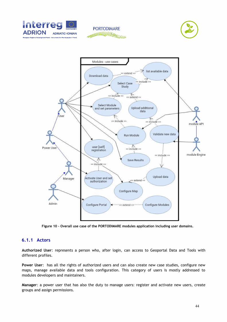
Figure 10 - Overall use case of the PORTODIMARE modules application including user domains.
6.1.1 Actors
Authorized User: represents a person who, after login, can access to Geoportal Data and Tools withdifferent profiles.
Power User: has all the rights of authorized users and can also create new case studies, configure newmaps, manage available data and tools configuration. This category of users is mostly addressed tomodules developers and maintainers.
Manager: a power user that has also the duty to manage users: register and activate new users, creategroups and assign permissions.
44
Admin: can configure and modify all the components of Geoportal and Modules create and manage usersand group and configure how the Geoportal retrieve and shows data.
Module Engine: the software module itself, will be triggered by the API or User’s input, can directlyinteract with data present in the data repository.
Module API: is a generalization of module Engine that can interact with the system as a single entity forall the modules.
6.1.2 Actions
Select Case Study: it is expected to be the first operation done by users after login. Case studies aredefined as a set of layers at the higher resolution available inside a known boundary. The predefined casestudies must be validated and tested so the user can only choose the case study from the list. For thecustomized run, users will replace one or more of the predefined layers with additional layers that will beuploaded and checked for compatibility (see Upload additional data).
List available data: the system (in this case, the module generic API) will check the availability of thegroup of layers that are needed given the case study selected. The list of available input data regardingall the modules is presented to the users with the ability to see detailed information and metadata foreach layer providing a link to the layer info page of the GAIR ( this is a standard feature of Geonode thatwill be extended, see chapter 5.1 Geoportal customization).
Download data: end-users will be able to download (through OGC services and API) case study resources(e.g. Layers) according to object permissions and user rights.
Upload additional data: this action extends the select case study action users can add new layers to thegeoportal, the upload can be done using the standard GAIR interface (Geonode). When a layer isuploaded, the spatial data are stored in the spatial database and metadata are inserted in the catalogue.The additional data can be either accessible only by the owner or shared with other users and groups.
Validate new data: this action is triggered every time that new data is loaded into the system; in the caseof upload additional data (above) the user will replace one or more layer of the predefined set for thecase study, in the case of upload data the power users or admin will add new data to the repository alongwith the default configuration of case study and appropriate metadata.
Select Module and set parameters: this action includes the Case study selection. The user will simplyinteract with the GUI choosing an element from a list. Not all the modules can run on all case studiesbecause the requested data might not be already available inside the GAIR, thus the list of selectablemodules will be modified after case study selection and optional upload of additional data and themodules that aren’t available will be displayed as non-selectable entries.
Run Module: the module will run on user’s input parameters inserted through the GUI and/or through theAPI request.
Save results: the module outputs (usually layers and reports) are stored in a temporary area where theGAIR main system can access and show them to the user. The users can then update metadata for the
45

generated layers (starting from a default set filled by the system) and then save them as standard layersof the geoportal.
User self registration: new users can register themselves to the GAIR filling a registration form.
Activate user: managers will create new users, activate self-registered users and set permissions.
Configure Map: power users can organize GAIR information creating new maps using layers stored into
Geoportal. In detail, Case studies consist in a “defined set of geospatial layers” (see chapter 2.2. ModulesWorkflow) and each case will be presented in the GAIR in form of a map with the same set of layers. Eachmap will have different authorization by user and role/group; e.g. change layers and styles, layer order,layer groups(collection), layers name, extent, initial view.
Upload data: this action extends the configure map action and refers to the initial population of whencreating new maps for case studies, although is technically the same operation, this operation differs fromupload additional data actions because it refers to layers and other data that resides in the GAIRgeoportal as a standard set of input data. On uploading data will be validated by the ModuleConnectbackend which they refer to through the layer preparation process (see chapter 5.2 GeoDataBuilder app).
Configure portal: administrators can configure all components of the GAIR infrastructure, especially increating end set up case studies, parameters and rules for GeoDataBuilder APP, upload standard data foreach theme or module.
Configure Modules: administrators and modules responsible will modify default values and operationallogic of each module.
6.2 Module Use Cases
6.2.1 T1.6 – Maritime Use Synergy and Conflict analysis tool (MUSC)
This module refers to the assessment and mapping of conflict and synergies among different uses ofmaritime/coastal space. The possibility of multi-use and potential synergies are based on the type of useand characteristics of the area of interest. Outputs of the tool will be linked to specific information basedon multi-use possible combinations.
The module is based on two stand-alone analytical tools: the Maritime Use Conflict (MUC) and theMaritime Use Synergy (MUS) analysis.
46
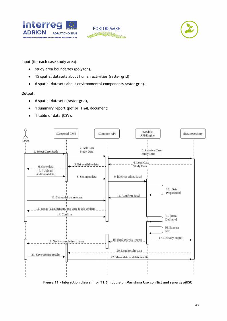
Input (for each case study area):
● study area boundaries (polygon),
● 15 spatial datasets about human activities (raster grid),
● 6 spatial datasets about environmental components raster grid).
Output:
● 6 spatial datasets (raster grid),
● 1 summary report (pdf or HTML document),
● 1 table of data (CSV).
Figure 11 - Interaction diagram for T1.6 module on Maristima Use conflict and synergy MUSC
47
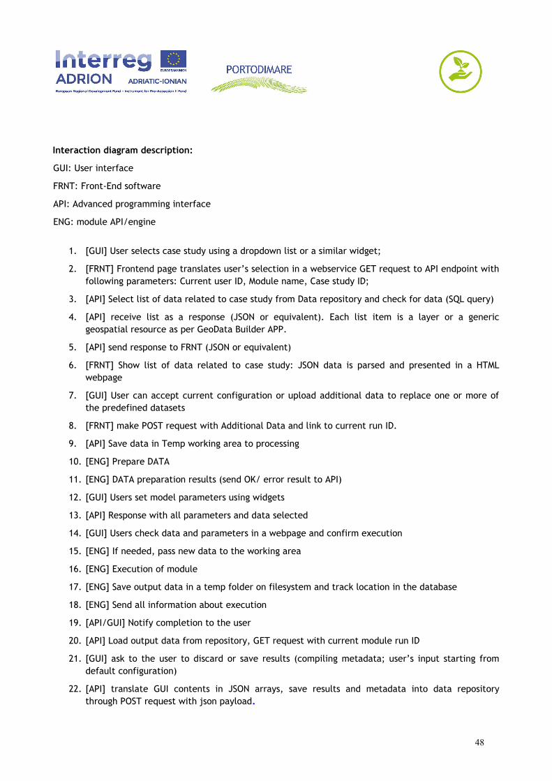
Interaction diagram description:
GUI: User interface
FRNT: Front-End software
API: Advanced programming interface
ENG: module API/engine
1. [GUI] User selects case study using a dropdown list or a similar widget;
2. [FRNT] Frontend page translates user’s selection in a webservice GET request to API endpoint withfollowing parameters: Current user ID, Module name, Case study ID;
3. [API] Select list of data related to case study from Data repository and check for data (SQL query)
4. [API] receive list as a response (JSON or equivalent). Each list item is a layer or a genericgeospatial resource as per GeoData Builder APP.
5. [API] send response to FRNT (JSON or equivalent)
6. [FRNT] Show list of data related to case study: JSON data is parsed and presented in a HTMLwebpage
7. [GUI] User can accept current configuration or upload additional data to replace one or more ofthe predefined datasets
8. [FRNT] make POST request with Additional Data and link to current run ID.
9. [API] Save data in Temp working area to processing
10. [ENG] Prepare DATA
11. [ENG] DATA preparation results (send OK/ error result to API)
12. [GUI] Users set model parameters using widgets
13. [API] Response with all parameters and data selected
14. [GUI] Users check data and parameters in a webpage and confirm execution
15. [ENG] If needed, pass new data to the working area
16. [ENG] Execution of module
17. [ENG] Save output data in a temp folder on filesystem and track location in the database
18. [ENG] Send all information about execution
19. [API/GUI] Notify completion to the user
20. [API] Load output data from repository, GET request with current module run ID
21. [GUI] ask to the user to discard or save results (compiling metadata; user’s input starting fromdefault configuration)
22. [API] translate GUI contents in JSON arrays, save results and metadata into data repositorythrough POST request with json payload.
48

6.2.2 T1.7 – Cumulative Effects Assessment (CEA)
This module refers to the assessment and mapping of Cumulative Effects based on the Tools4MSPModelling Framework. It is an MSP-oriented tool for the analysis and mapping of the effects of single ormultiple human activities on environmental components.
Input (for each case study area):
● study area boundaries and Marine Reporting Unit (polygon),
● 15 spatial datasets about human activities (raster grid),
● 6-10 spatial datasets about environmental components raster grid).
Output:
● 3-5 spatial datasets (raster grid),
● 1 uncertainty map (raster grid),
● 1 summary report (pdf or HTML document),
● 1 table of data (CSV).
49
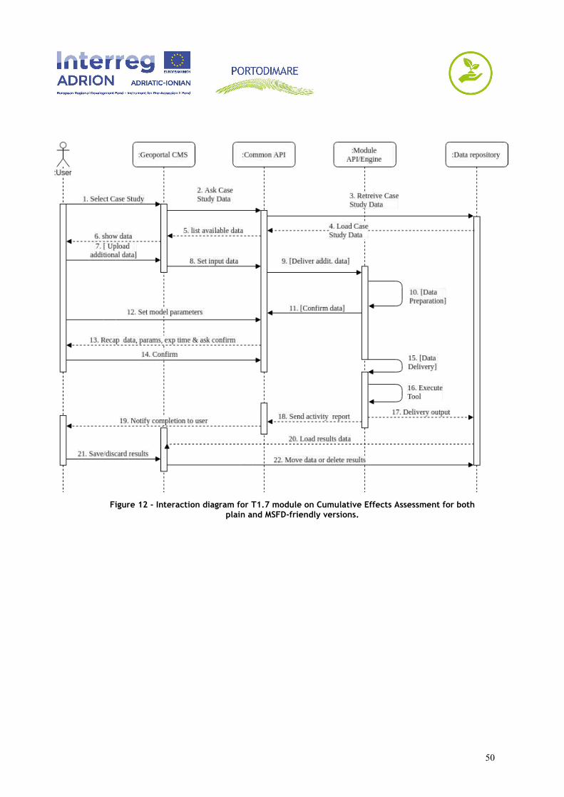
Figure 12 - Interaction diagram for T1.7 module on Cumulative Effects Assessment for bothplain and MSFD-friendly versions.
50

Interaction diagram description:
GUI: User interface
FRNT: Front-End software
API: Advanced programming interface
ENG: module software engine
1. [GUI] User selects case study using a dropdown list or a similar widget (and optionally switch toMSFD friendly version);
2. [FRNT] Frontend page translates user’s selection in a webservice GET request to API endpoint withfollowing parameters: Current user ID, Module name, Case study ID;
3. [API] Select list of data related to case study from Data repository and check for data (SQL query)
4. [API] receive list as a response (JSON or equivalent). Each list item is a layer or a genericgeospatial resource as per GeoData Builder APP.
5. [API] send response to FRNT (JSON or equivalent)
6. [FRNT] Show list of data related to case study: JSON data is parsed and presented in a HTMLwebpage
7. [GUI] User can accept current configuration or upload additional data to replace one or more ofthe predefined datasets
8. [FRNT] make POST request with Additional Data and link to current run ID.
9. [API] Save data in Temp working area to processing
10. [ENG] Prepare DATA
11. [ENG] DATA preparation results (send OK/ error result to API)
12. [GUI] Users set model parameters using widgets
13. [API] Response with all parameters and data selected
14. [GUI] Users check data and parameters in a webpage and confirm execution
15. [ENG] If needed, pass new data to the working area
16. [ENG] Execution of module
17. [ENG] Save output data in a temp folder on filesystem and track location in the database
18. [ENG] Send all information about execution
19. [API/GUI] Notify completion to the user
20. [API] Load output data from repository, GET request with current module run ID
21. [GUI] ask to the user to discard or save results (compiling metadata; user’s input starting fromdefault configuration)
51
22. [API] translate GUI contents in JSON arrays, save results and metadata into data repositorythrough POST request with json payload
6.2.3 T1.8– Supporting AZA identification (Aquaculture Zoning Assessment)
This module implements a spatially explicit MultiCriteria methodology, namely SMCE (Spatial MultiCriteriaEvaluation) for identifying Allocated Zone to Aquaculture (AZA), i.e. marine areas where the developmentof aquaculture is prior to other uses. According to FAO, this is a key step in the implementation of theEAA, Ecosystem Approach to Aquaculture.
Input:
● user’s choices including location or area in the map
● optimal growth model (fixed)
● about 10-30 of spatial datasets regard constraints, socioeconomic and environmental data
Output:
● 3 geospatial layers (criteria map, constraints, suitability map);
● 3 raw dataset (CSV);
● 1 report in HTML or PDF format
52

Figure 13 - Interaction diagram for T1.8 module Supporting AZA identification (AquacultureZoning Assessment).
53

Interaction diagram description:
GUI: User interface
FRNT: Front-End software
API: Advanced programming interface
ENG: module software engine
1. [GUI] User selects type species and size for the module run using three dropdown list or a similarwidget;
2. [FRNT] Frontend page translates user’s selection in a webservice GET request to API endpoint withfollowing parameters: Current user ID, Module name, Case study ID;
3. [API] Select list of available data and they extent from Data repository and check for data (SQLquery with geospatial features)
4. [API] receive list as a response (JSON or equivalent). Each list item is a layer of the GAIR or ageneric geospatial resource as per GeoData Builder APP.
5. [API] send response to FRNT (JSON or equivalent)
6. [FRNT] Show available data and applicable options: JSON data is parsed and presented in a HTMLwebpage
7. [GUI] User can further investigate layer content through link to geoportal layer, accept currentconfiguration and/or upload additional data to replace one or more of the predefined datasets
8. [FRNT] make POST request (with Additional Data if present) and link to current run ID.
9. [API] Save data in Temp working area to processing
10. [ENG] Prepare DATA
11. [ENG] DATA preparation results (send OK/ error result to API)
12. [ENG] If needed, pass new data to the working area
13. [FRNT] Set model parameters that are passed directly to module Engine or use default
14. [ENG] Execution of module and save result in data repository
15. [API/GUI] Notify completion to the user
16. [API] Load output data from repository, GET request with current module run ID
17. [GUI] ask to the user to discard or save results (compiling metadata; user’s input starting fromdefault configuration)
18. [API] translate GUI contents in JSON arrays, save results and metadata into data repositorythrough POST request with json payload.
54
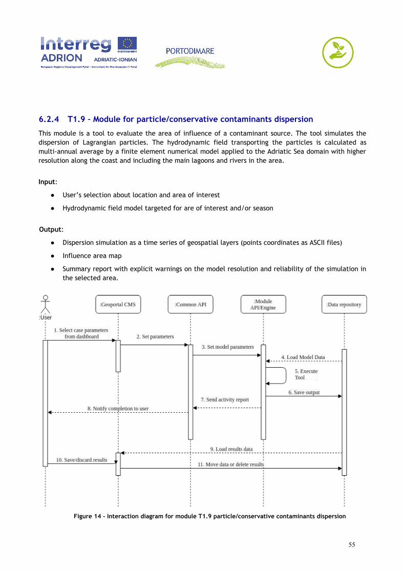
6.2.4 T1.9 – Module for particle/conservative contaminants dispersion
This module is a tool to evaluate the area of influence of a contaminant source. The tool simulates thedispersion of Lagrangian particles. The hydrodynamic field transporting the particles is calculated asmulti-annual average by a finite element numerical model applied to the Adriatic Sea domain with higherresolution along the coast and including the main lagoons and rivers in the area.
Input:
● User’s selection about location and area of interest
● Hydrodynamic field model targeted for are of interest and/or season
Output:
● Dispersion simulation as a time series of geospatial layers (points coordinates as ASCII files)
● Influence area map
● Summary report with explicit warnings on the model resolution and reliability of the simulation inthe selected area.
Figure 14 - Interaction diagram for module T1.9 particle/conservative contaminants dispersion
55

56

Interaction diagram description:
GUI: User interface
FRNT: Front-End software
API: Advanced programming interface
ENG: module software engine
1. [GUI] User selects input parameter including location, intensity and behavior of the particle usingthree dropdown list or a similar widget;
2. [FRNT] Frontend page translates user’s selection in a webservice GET request to API endpoint withfollowing parameters: Current user ID, Module name, module paramenters, start location (point)and area of interest.
3. [API] Invoke module Engine with parameters received form GUI.
4. [ENG] Load appropriate hydrodinamic field at best resolution available
5. [ENG] Execution of module and save result in data repository
6. [ENG] Save otput to a temporary location with current run ID or User ID
7. [ENG] Send completion message and report about data used (JSON or equivalente payload)
8. [API/GUI] Notify completion to the user
9. [API] Load output data from repository, GET request with current module run ID
10. [GUI] ask to the user to discard or save results (compiling metadata; user’s input starting fromdefault configuration)
11. [GUI] results are saved in the data repository with lin to the user that started the module run.
57
6.2.5 T1.10 – Module for Coastal Oil Spill Vulnerability Assessment
The Module must allow to represent the data of the Adriatic-Ionic area to support oil-spill risk assessmentor contaminants or toxic substances and must contain specific tools able to: 1) perform oil-spillsimulations from starting data (real or simulated) in any area of the Adriatic-Ionian to understand the riskscenarios and risk assessment; 2) Generate a real-time early-warning notification in presence of a risksituation represented by a specific index that depends on the weather and sea risk conditions and the riskconditions of the ship. The alarm generated remains as long as these risk conditions do not decrease belowa pre-set index value.
Input:
● Area of interests (by user input);
● Geospatial layers about coastal vulnerability
● Simplified Hydrodynamic field
● Data flow about ships and weather data.
Output:
● 3-5 geospatial layers (vector and raster)
● 1 Video/animation of oil spill simulation
● 1-5 Plots with statistical analysis
58
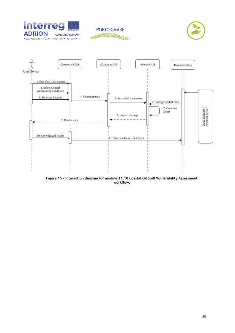
Figure 15 - interaction diagram for module T1.10 Coastal Oil Spill Vulnerability Assessmentworkflow.
59
Interaction diagram description:
GUI: User interface
FRNT: Front-End software
API: Advanced programming interface
ENG: module software engine
1. [GUI] User selects ship characteristics from the GUI: if the case is applied to a ship currentlypresent in the area will click on a map showing daily data or real time data form AIS, if themodule is run against an hypothetic ship will select/input the main properties in a form.
2. [GUI] User selects Coastal vulnerability conditions from a provided layer.
3. [GUI] User set the location (point) of the event investigated
4. [FRNT] Frontend page translates user’s selection in a webservice GET request to API endpoint withfollowing parameters: Current user ID, Module name, module parameters, location (point) andarea of interest.
5. [API] Set model parameter received form GUI.
6. [ENG] Load geospatial data including weather condition and risk index from external server.
7. [ENG] Execution of module
8. [ENG] Create new risk map and show to the user
9. [API] Render map as a GeoDataBuilder object
10. [GUI] ask to the user to discard or save results (compiling metadata; user’s input starting fromdefault configuration)
11. [API] Save Results as new layer.
60
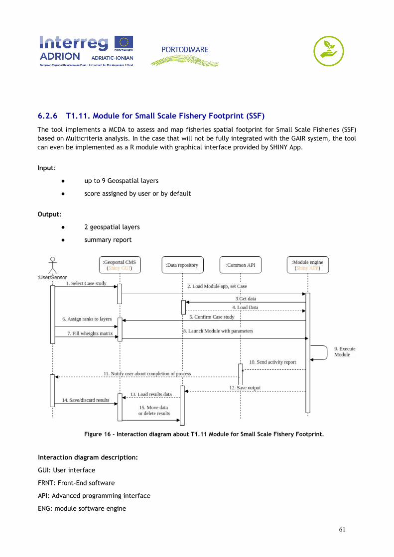
6.2.6 T1.11. Module for Small Scale Fishery Footprint (SSF)
The tool implements a MCDA to assess and map fisheries spatial footprint for Small Scale Fisheries (SSF)based on Multicriteria analysis. In the case that will not be fully integrated with the GAIR system, the toolcan even be implemented as a R module with graphical interface provided by SHINY App.
Input:
● up to 9 Geospatial layers
● score assigned by user or by default
Output:
● 2 geospatial layers
● summary report
Figure 16 - Interaction diagram about T1.11 Module for Small Scale Fishery Footprint.
Interaction diagram description:
GUI: User interface
FRNT: Front-End software
API: Advanced programming interface
ENG: module software engine
61

1. [GUI] User selects case study from a dropdown list or similar widget
2. [FRNT] Load Module APP with case study parameters.
3. [ENG] Get data from repository with a SQL query command or call to GeoDataBuilder APP
4. [ENG] Load data from repository: send files path or GeoDataBuilder response to software engine.
5. [FRNT] Based on previous GUI inputs, stored as session variables, Render a summary HTML pagewith Case study with list of data loaded and ask for user's input or confirmation.
6. [GUI] User assigns ranks to layers.
7. [GUI] User fills weights matrix.
8. [FRNT] Prepare and send startup command form module engine, with options and parameters.
9. [ENG] Execution of module.
10. [ENG] Send activity report as a shell output or a log file.
11. [API] reads log file or shell stout and notify users about completion of process.
12. [ENG] save outputs in a temporary location related to current Run ID.
13. [FRNT] reads output from temporary location and renders it as a map.
14. [GUI] ask to the user to discard or save results (compiling metadata; user’s input starting fromdefault configuration).
15. [API] Save Results as new layer.
62
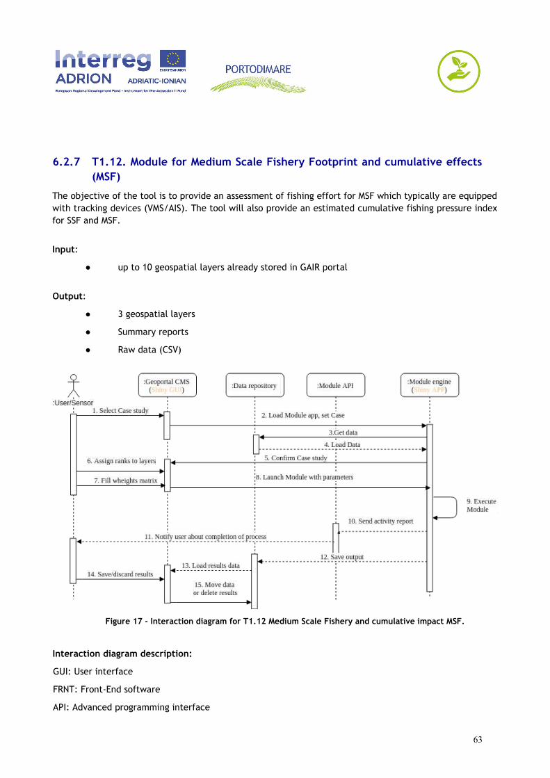
6.2.7 T1.12. Module for Medium Scale Fishery Footprint and cumulative effects(MSF)
The objective of the tool is to provide an assessment of fishing effort for MSF which typically are equippedwith tracking devices (VMS/AIS). The tool will also provide an estimated cumulative fishing pressure indexfor SSF and MSF.
Input:
● up to 10 geospatial layers already stored in GAIR portal
Output:
● 3 geospatial layers
● Summary reports
● Raw data (CSV)
Figure 17 - Interaction diagram for T1.12 Medium Scale Fishery and cumulative impact MSF.
Interaction diagram description:
GUI: User interface
FRNT: Front-End software
API: Advanced programming interface
63
ENG: module software engine
1. [GUI] User selects case study from a dropdown list or similar widget
2. [FRNT] Load Module APP with case study parameters.
3. [ENG] Get data from repository with a SQL query command or call to GeoDataBuilder APP
4. [ENG] Load data from repository: send files path or GeoDataBuilder response to software engine.
5. [FRNT] Based on previous GUI inputs, stored as session variables, Render a summary HTML pagewith Case study with list of data loaded and ask for user's input or confirmation.
6. [GUI] User assigns ranks to layers.
7. [GUI] User fills weights matrix.
8. [FRNT] Prepare and send startup command form module engine, with options and parameters.
9. [ENG] Execution of module.
10. [ENG] Send activity report as a shell output or a log file.
11. [API] reads log file or shell stout and notify users about completion of process.
12. [ENG] save outputs in a temporary location related to current Run ID.
13. [FRNT] reads output from temporary location and render it as a map.
14. [GUI] ask to the user to discard or save results (compiling metadata; user’s input starting fromdefault configuration).
15. [API] Save Results as new layer.
64

7 GRAPHICAL USER INTERFACE
The following Chapter presents wireframes illustrating possible skeleton and indicative structure of GAIRweb pages. We especially focused on wireframes related to novel applications (GeoDataBuilder andModuleConnect).
7.1 PORTODIMARE generic GUIs
As already described in chapter 5.1 (GairBase app), GAIR GUIs are based on GeoNode GUIs. However, anew brand identity formulation is required in order to define a novel GeoNode theme, including logos,graphics, colours and fonts in order to characterize and differentiate GAIR implementation from otherGeoNode-based projects.
7.1.1 GAIR Welcome page
The page includes a definition of the Geoportal and the conditions for usage of the geoportal including adisclaimer on the data and policy.
Figure 18 - example of a welcome page with the disclaimer and data policy summary. Source:http://maps.helcom.fi/website/mapservice/index.html
7.1.2 Information stocktake and module selection GUI
As already defined in section 5.1 GairBase app, refactoring of basic GeoNode home page in required. Atthe same time, the module integration requires to implement shortcuts for accessing to the module GUIs.
A home page refactoring is proposal in Figure 19. This interface provides an overview of the informationstocktake and the modules available in the geoportal.
65
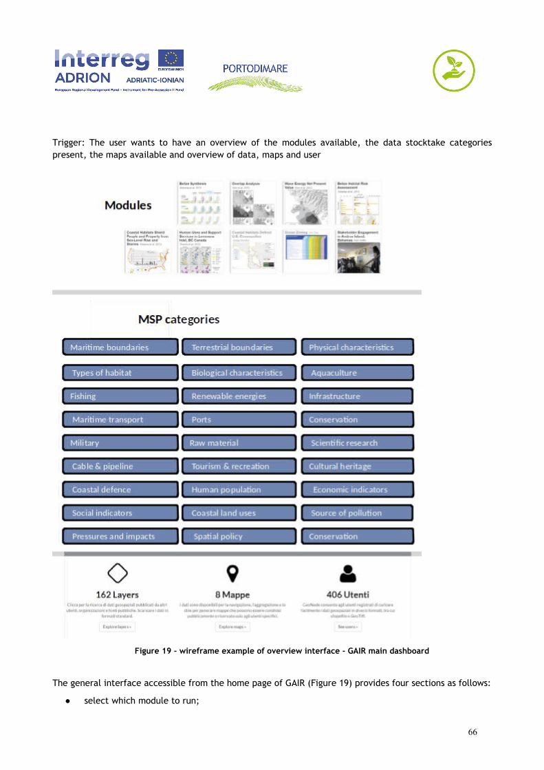
Trigger: The user wants to have an overview of the modules available, the data stocktake categoriespresent, the maps available and overview of data, maps and user
Figure 19 - wireframe example of overview interface - GAIR main dashboard
The general interface accessible from the home page of GAIR (Figure 19) provides four sections as follows:
● select which module to run;
66

● select relevant MSP resources (Starred objects) indexed by MSP Topic Categories;
● overview of number of layers, maps and users.
The first operation that users will do after login into GAIR is the case study selection. The interface willpresent the available case study with different kind of filters based on module type (see Figure 20), typeof run (default or customized) and geographic extent.
● Filter by module:
Trigger: the user wants to use a specific module in different case studies.
● Geographic query of module application domains or testing sites (by map).
Trigger: the user wants to use different modules over the same testing site.
Figure 20 - preliminary draft of case study selection interface.
67
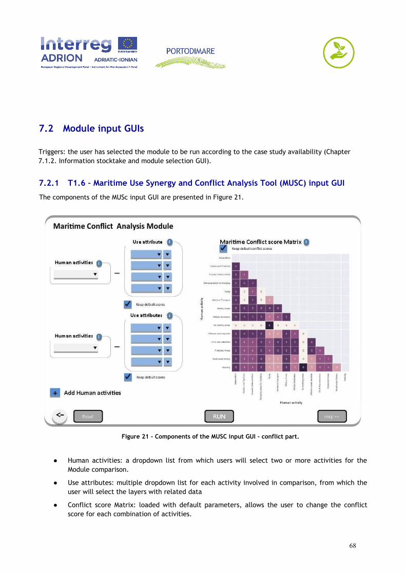
7.2 Module input GUIs
Triggers: the user has selected the module to be run according to the case study availability (Chapter 7.1.2. Information stocktake and module selection GUI).
7.2.1 T1.6 – Maritime Use Synergy and Conflict Analysis Tool (MUSC) input GUI
The components of the MUSc input GUI are presented in Figure 21.
Figure 21 - Components of the MUSC input GUI - conflict part.
● Human activities: a dropdown list from which users will select two or more activities for theModule comparison.
● Use attributes: multiple dropdown list for each activity involved in comparison, from which theuser will select the layers with related data
● Conflict score Matrix: loaded with default parameters, allows the user to change the conflictscore for each combination of activities.
68
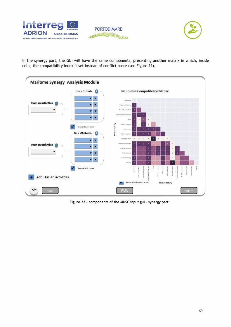
In the synergy part, the GUI will have the same components, presenting another matrix in which, insidecells, the compatibility index is set instead of conflict score (see Figure 22).
Figure 22 - components of the MUSC input gui - synergy part.
69

7.2.2 T1.7 – Cumulative Effects Assessment (CEA)
The CEA module interface comes in two different forms: the plain tool and the MSFD friendly CEA.
Figure 23 - conceptual schema of the components the interface of the plain CEA tool.
In the plain CEA interface, the user will select or compose different impact chains selecting a set ofpredefined uses, pressures and environmental components. Pressure weights and buffer and sensitivitiesof each environmental component can be modified starting from a default value.
70
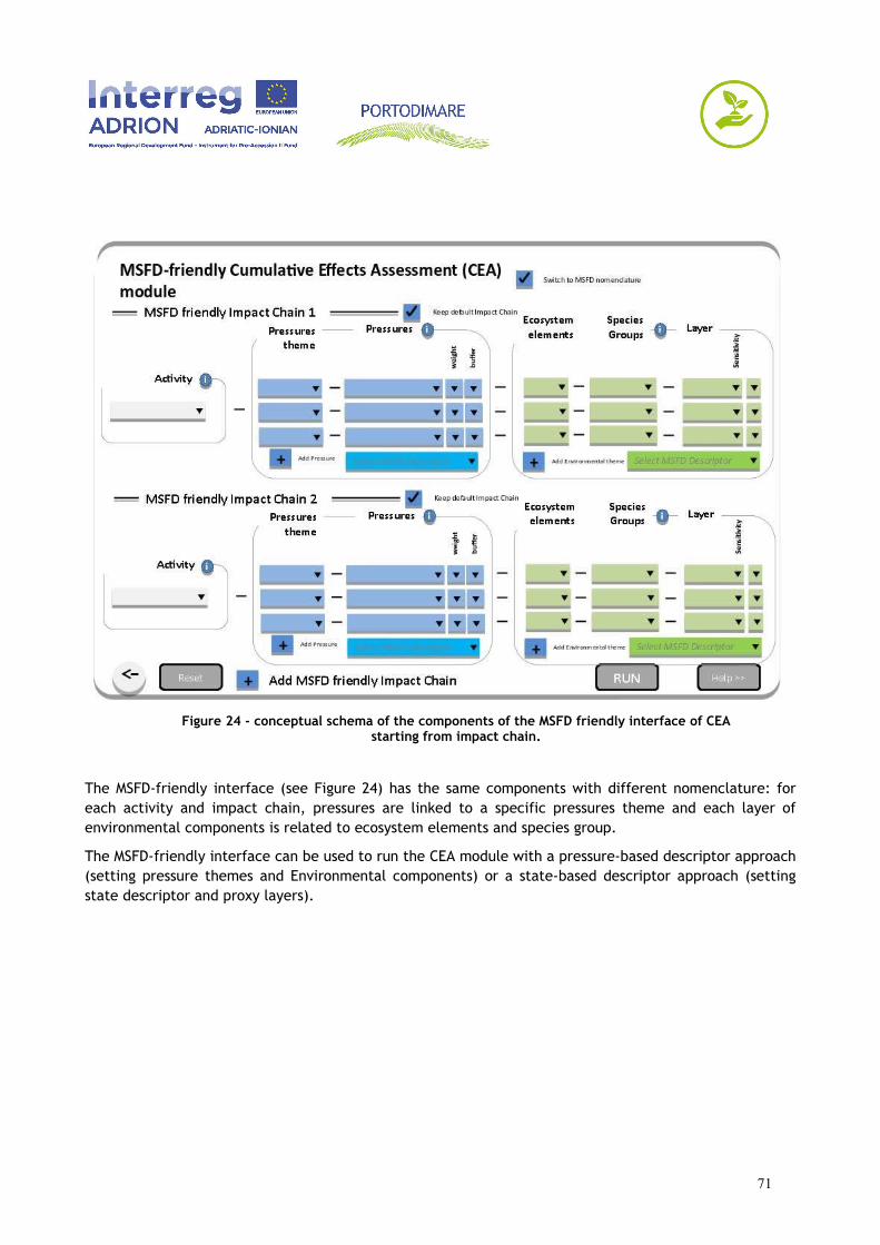
Figure 24 - conceptual schema of the components of the MSFD friendly interface of CEAstarting from impact chain.
The MSFD-friendly interface (see Figure 24) has the same components with different nomenclature: foreach activity and impact chain, pressures are linked to a specific pressures theme and each layer ofenvironmental components is related to ecosystem elements and species group.
The MSFD-friendly interface can be used to run the CEA module with a pressure-based descriptor approach(setting pressure themes and Environmental components) or a state-based descriptor approach (settingstate descriptor and proxy layers).
71
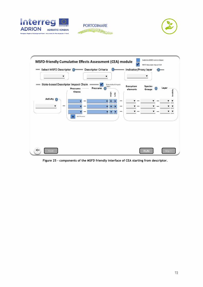
Figure 25 - components of the MSFD friendly interface of CEA starting from descriptor.
72
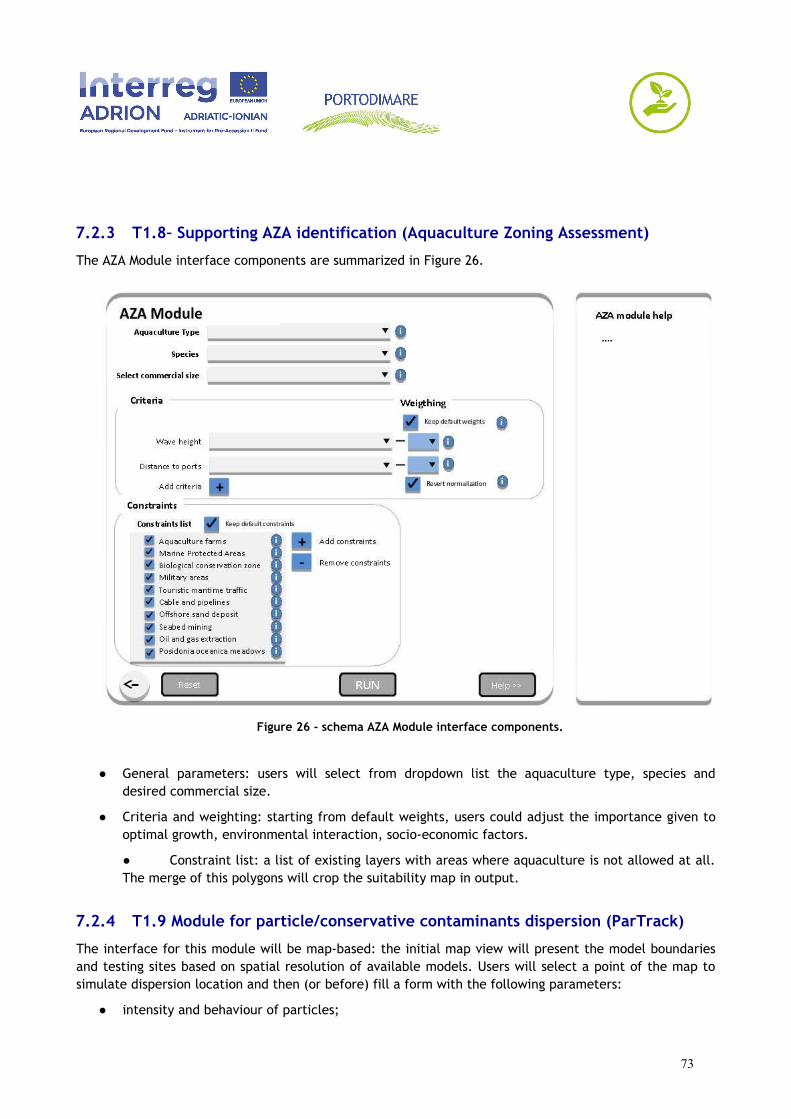
7.2.3 T1.8– Supporting AZA identification (Aquaculture Zoning Assessment)
The AZA Module interface components are summarized in Figure 26.
Figure 26 - schema AZA Module interface components.
● General parameters: users will select from dropdown list the aquaculture type, species anddesired commercial size.
● Criteria and weighting: starting from default weights, users could adjust the importance given tooptimal growth, environmental interaction, socio-economic factors.
● Constraint list: a list of existing layers with areas where aquaculture is not allowed at all.The merge of this polygons will crop the suitability map in output.
7.2.4 T1.9 Module for particle/conservative contaminants dispersion (ParTrack)
The interface for this module will be map-based: the initial map view will present the model boundariesand testing sites based on spatial resolution of available models. Users will select a point of the map tosimulate dispersion location and then (or before) fill a form with the following parameters:
● intensity and behaviour of particles;
73

● substances properties (decay time, life duration, settling velocity);
● max output resolution;
● influence area (by predefined region or bounding box).
In the customized run, at the definition of influence area step, additional layers (human uses andenvironmental components) and or case study specific layers can be used to define model run boundariesand influence areas of the specific contaminant.
7.2.5 T1.10 Module for Coastal Oil Spill Vulnerability Assessment
The interface for this module will be map-based: the initial map view will display the coastal vulnerabilitylayers (coastal segments, ports, infrastructures etc..), a coastal response equipment layer and a threatlayer (maybe a heatmap) related to oil spill probability on current traffic.
By selecting the visible layers, the user will prepare a scenario based on weather conditions, humanactivities, statistical risk and optionally real time data (interaction with other portals or HAZADR projectplatform).
The user will then investigate an area of interest and will obtain a risk map with different time steps. Theresult could be visualized in the same map.
7.2.6 T1.11 Module for Small Scale Fishery Footprint (SSF)
The interface components of SFF module are depicted in Figure 27.
74
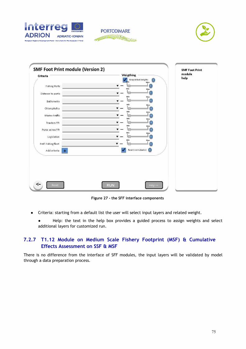
Figure 27 - the SFF interface components
● Criteria: starting from a default list the user will select input layers and related weight.
● Help: the text in the help box provides a guided process to assign weights and selectadditional layers for customized run.
7.2.7 T1.12 Module on Medium Scale Fishery Footprint (MSF) & CumulativeEffects Assessment on SSF & MSF
There is no difference from the interface of SFF modules, the input layers will be validated by modelthrough a data preparation process.
75
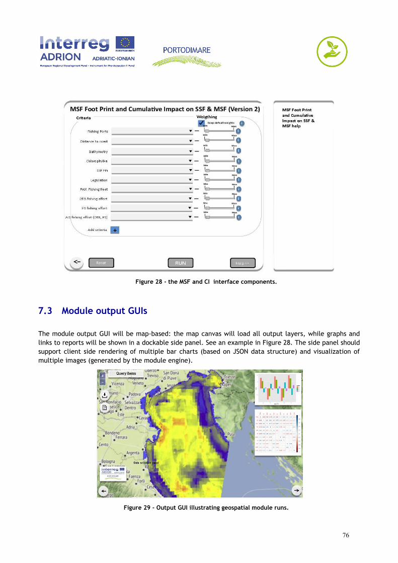
Figure 28 - the MSF and CI interface components.
7.3 Module output GUIs
The module output GUI will be map-based: the map canvas will load all output layers, while graphs andlinks to reports will be shown in a dockable side panel. See an example in Figure 28. The side panel shouldsupport client side rendering of multiple bar charts (based on JSON data structure) and visualization ofmultiple images (generated by the module engine).
Figure 29 - Output GUI illustrating geospatial module runs.
76
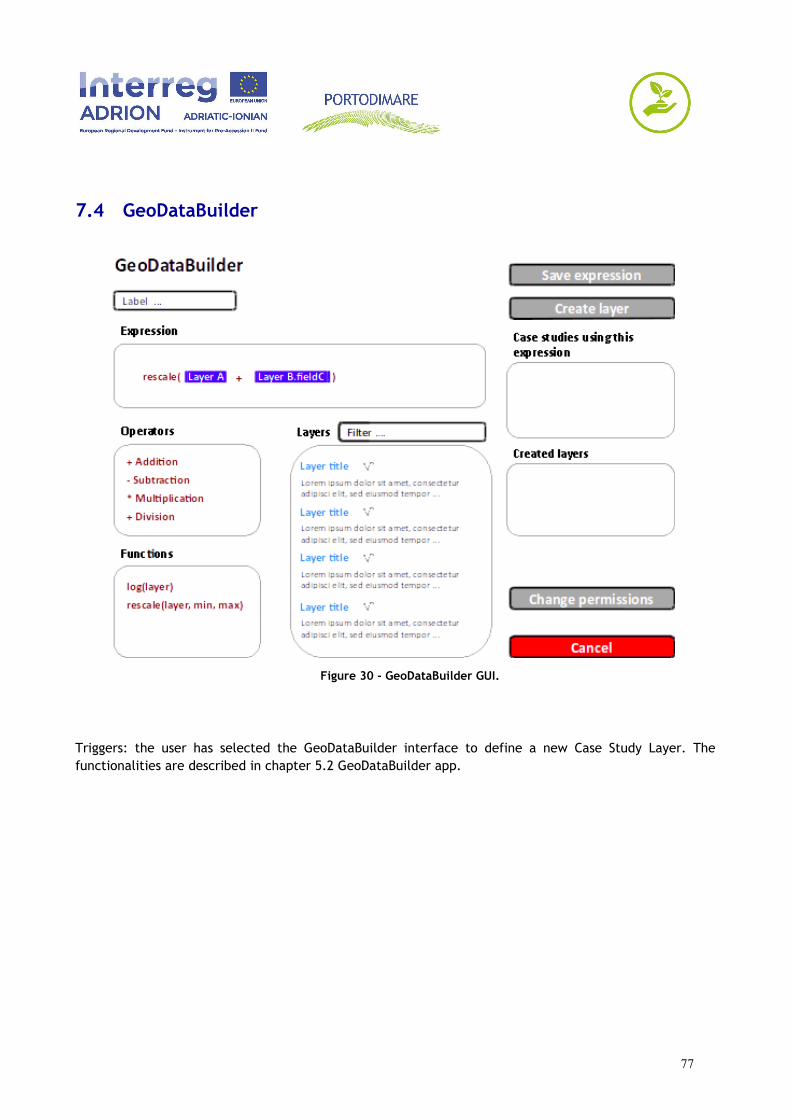
7.4 GeoDataBuilder
Figure 30 - GeoDataBuilder GUI.
Triggers: the user has selected the GeoDataBuilder interface to define a new Case Study Layer. Thefunctionalities are described in chapter 5.2 GeoDataBuilder app.
77
8 References
Barbanti A., Campostrini P., Musco F., Sarretta A., Gissi E. (editors) 2015. Developing a Maritime Spatial Plan for the Adriatic-Ionian Region. CNR-ISMAR, Venice, IT. ISBN 978-88-941335-4-7. ADRIPLAN project final report http://doi.org/10.5281/zenodo.48231
Benthall B. and Gill S. (2010) SDI Best Practices with GeoNode. In Proceedings of Free and Open Source Software for Geospatial Conference (FOSS4G 2010).
Bootstrap team (2019) Bootstrap. 2019. https://getbootstrap.com/
CKAN Association (2018) API Guide — CKAN 2.8.2 Documentation. 2018. https://docs.ckan.org/en/2.8/api/#
De Longueville B. (2010) Community-Based Geoportals: The next Generation? Concepts and Methods for the GeospatialWeb 2.0. Computers, Environment and Urban Systems 34 (4): 299–308.
Depellegrin D. et al. (2017) Multi-objective spatial tools to inform maritime spatial planning in the Adriatic Sea. Science of The Total Environment. 2017;609: 1627–1639. doi:10.1016/j.scitotenv.2017.07.264
Django Development Team (2018) Django: The Web Framework for Perfectionists with Deadlines. https://www.djangoproject.com/
Ehler, C. and Douvere, F. (2009) Marine spatial planning: a step-by-step approach. Paris, France, Unesco, 99pp. (IOC Manuals and Guides 53), ( ICAM Dossier 6). DOI http://dx.doi.org/10.25607/OBP-43
Emere A., Balbo S., Pasquali P., and Sandu C. (2018) Customizing GeoNode. Presentation at the GeoNode Summit, Torino 27/03/2018. http://summit.geonode.org/presentation/Customizing-GeoNode.pdf
European Commission (2007) Relation between ISO 19115 and ISO 19119 and the Elements of the INSPIRE. Draft Metadata Implementing Rules (Informative). https://inspire.ec.europa.eu/reports/ImplementingRules/metadata/MD_IR_and_ISO_20071210.pdf
European Commission (2009) Commission Regulation (EC) No 976/2009 of 19 October 2009 Implementing Directive 2007/2/EC of the European Parliament and of the Council as regards the Network Services. ELI: http://data.europa.eu/eli/reg/2009/976/oj
European Commission (2019) INSPIRE Validator. http://inspire-sandbox.jrc.ec.europa.eu/validator/
GDAL (2013) GDAL: - Geospatial Data Abstraction Library. 2013. http://www.gdal.org/
GeoNode Development Team (2018). OL3: React Map Client for GeoNode. Contribute to GeoNode/Geonode-Client Development by Creating an Account on GitHub. JavaScript. https://github.com/GeoNode/geonode-client
GeoNode Development Team (2019a) GeoNode: Open Source Geospatial Content Management System. http://geonode.org/
78
GeoNode Development Team (2019b) GeoNode-Project: A Django Template Project for Creating Custom GeoNode Projects. https://github.com/GeoNode/geonode-project
GeoServer Development Team (2018) GeoServer: Open Source Server for Sharing Geospatial Data. http://geoserver.org/
GeoSolutions (2019) MapStore HomePage. 2019. https://mapstore2.geo-solutions.it/mapstore/#/
Google (2019) Angular. 2019. https://angular.io/
ISO/TC 211 (2013) ISO/TC 211 Geographic Information/Geomatics. 2013. http://www.isotc211.org/
Kavadas S. et al. (2015) Multi-Criteria Decision Analysis as a tool to extract fishing footprints: application to small scale fisheries and implications for management in the context of the Maritime Spatial Planning Directive. Mediterranean Marine Science. 16. 294-304. 10.12681/mms.1087
Menegon S. (2018) MSP Knowledge Catalogue. Contribute to CNR-ISMAR/Ckanext-Mspkc Development by Creating an Account on GitHub (version 0.3). Python. CNR-ISMAR. https://github.com/CNR-ISMAR/ckanext-mspkc. Open API Initiative. 2014. OpenAPI Specification
Open Geospatial Consortium (2005) Web Feature Service Implementation Specification, Version 1.1.0, http://www.opengeospatial.org/standards/wfs
Open Geospatial Consortium (2006) OpenGIS Web Map Server Implementation Specification, Version 1.3.0, http://www.opengeospatial.org/standards/wms
Open Geospatial Consortium (2007) Catalogue Service for the Web Implementation Specification, Version 1.0.0, http://www.opengeospatial.org/standards/csw
Open Geospatial Consortium (2008) Web Coverage Service (WCS) Implementation Standard, Version 1.1.2, http://www.opengeospatial.org/standards/wfs
Open Geospatial Consortium (2010) Web Map Tile Service Implementation Standard, Version 1.0.0, http://www.opengeospatial.org/standards/wmts
OSGeo (2012) Tile Map Service specification, https://wiki.osgeo.org/wiki/Tile_Map_Service_Specification
Open Knowledge International (2018) CKAN: Comprehensive Knowledge Archive Network. https://ckan.org/
PostGIS Development Group (2018) PostGIS — Spatial and Geographic Objects for PostgreSQL. https://postgis.net/
pycsw Development Team (2018) Pycsw: Metadata Publishing Just Got Easier. http://pycsw.org/
Rosetta Development Team (2019) Rosetta Is a Django Application That Eases the Translation Process of Your Django Projects: Mbi/Django-Rosetta. Python. https://github.com/mbi/django-rosetta
The PostgreSQL Global Development Group (2018) PostgreSQL: The World’s Most Advanced Open Source Database. https://www.postgresql.org/
Wagtail Development Team (2018) Wagtail, the Powerful CMS for Modern Websites. https://wagtail.io
79

Yang P., Evans J., Cole M., Alameh N., Marley S. and Bambacus M. (2007) The Emerging Concepts and Applications of the Spatial Web Portal. Photogrammetric Engineering and Remote Sensing 73 (6): 691.
80
Copyright © 2022 FDOKUMEN