PDM Workbench Release 15.0 - T-Systems
214
PDM Workbench PDM Workbench Release 15.0 for Aras Innovator Installation & Administration Manual Version 1
-
Upload
khangminh22 -
Category
Documents
-
view
2 -
download
0
Transcript of PDM Workbench Release 15.0 - T-Systems

PDM Workbench
PDM Workbench Release 15.0 for Aras Innovator
Installation & Administration Manual Version 1

ii PDM Workbench Release 15.0 - Installation & Administration Manual
Copyright
© 2005-2022 T-Systems International GmbH.
All rights reserved. Printed in Germany.
Contact
T-Systems International GmbH Business Unit PLM Fasanenweg 5 70771 Leinfelden-Echterdingen Germany
https://plm.t-systems-service.com/en/pdm-workbench
+49 (0) 40 30600 5544 +49 (0) 3915 80125688
Email: [email protected]
Manual History
Version Date Version Version Date
1.0 April 2005 3.4 April 2013 7.0 October 2017
2.0 November 2006 3.5 October 2013 8.0 May 2018
2.1 November 2007 3.6 April 2014 9.0 December 2018
2.2 September 2008 3.7 October 2014 10.0 May 2019
2.5 September 2010 3.8 April 2015 11.0 November 2019
3.0 October 2011 3.9 October 2015 12.0 May 2020
3.1 February 2012 4.0 April 2016 13.0 November 2020
3.2 March 2012 5.0 October 2016 14.0 May 2021
3.3 October 2012 6.0 April 2017 15.0 January 2022
This edition 15.0 of the manual obsoletes all previous editions.
Your Comments are Welcome
Please feel free to tell us your opinion; we are always interested in improving our publications. Mail your comments to:
T-Systems International GmbH Business Unit PLM Fasanenweg 5 70771 Leinfelden-Echterdingen Germany
Email: [email protected]

PDM Workbench Release 15.0 - Installation & Administration Manual iii
Preface
About this Manual
This manual provides installation and configuration information for the PDM Workbench. Before using this guide, be sure you understand:
▪ the Microsoft Windows operating system
▪ the administration of the CATIA V5 system
▪ the administration of the Aras Innovator system
Related Documents
The following manuals contain information about installation, administration, usage and customization of the PDM Workbench:
Manual Title Version
PDM Workbench Installation & Administration Manual 15.0 PDM Workbench User Manual 15.0
Trademarks
CATIA is a registered trademark of Dassault Systèmes.
Aras and Aras Innovator are registered trademarks of Aras Corporation.
Names of other products mentioned in this manual are used for identification purpose only and may be trademarks of their companies.


PDM Workbench Release 15.0 - Installation & Administration Manual v
Table of Contents
CHAPTER 1 ........................................................................................................................ 1
OVERVIEW ......................................................................................................................... 1
SYSTEM HARDWARE AND SOFTWARE REQUIREMENTS ......................................................... 1 Aras Server .................................................................................................................. 1 CATIA V5 Client........................................................................................................... 1
INSTALLATION STEPS ......................................................................................................... 2
CHAPTER 2 ........................................................................................................................ 3
ADAPTING CATIA V5 ........................................................................................................ 3
LOADING PWBCATV5 SOFTWARE FROM CD-ROM ............................................................ 3 PWBCATV5 INSTALLATION ............................................................................................... 3
Configuring the installation .......................................................................................... 3 SILENT INSTALLATION ...................................................................................................... 12
Parameters ................................................................................................................ 12 Usage ........................................................................................................................ 13
SILENT UN-INSTALLATION ................................................................................................ 14 Parameters ................................................................................................................ 14 Usage ........................................................................................................................ 14
TROUBLESHOOTING R18 (64 BIT) .................................................................................... 14 TESTING THE INSTALLATION ............................................................................................. 16
Windows .................................................................................................................... 16 CATIA V5 CONFIGURATION ............................................................................................. 16 SWITCHING TO THE PWBSCHEMA FILE SUITED FOR BOM PART STRUCTURES ................... 18 PWBSCHEMA MODIFICATION ........................................................................................... 18 SETTING OF ENVIRONMENT VARIABLES ............................................................................. 19 ADMINISTRATIVE LOCK FOR PDM WORKBENCH PREFERENCES ......................................... 19 INSTALLATION WITHOUT PWB SPECIFIC ENVIRONMENT VARIABLES ..................................... 20 SUPPORT USER SPECIFIC EXCHANGE DIRECTORY WHEN USING “TO CATIA” ........................ 21
CHAPTER 3 ...................................................................................................................... 23
PDM WORKBENCH DATA MODEL ................................................................................ 23
INSTALLATION .................................................................................................................. 23
CHAPTER 4 ...................................................................................................................... 25
PDM WORKBENCH SERVER DLL ................................................................................. 25
COPYING THE DLL ........................................................................................................... 25 MODIFYING THE SERVER CONFIGURATION FILE ................................................................. 25
CHAPTER 5 ...................................................................................................................... 27
CLIENT CUSTOMIZATION .............................................................................................. 27
DISPLAY NAMES .............................................................................................................. 27 ICONS ............................................................................................................................. 27 DATA MODEL DEFINITION ................................................................................................. 28
CHAPTER 6 ...................................................................................................................... 29
SERVER CONFIGURATION ............................................................................................ 29
CONFIGURATION VARIABLES ............................................................................................ 29 CONFIGURATION ITEMS .................................................................................................... 30 REPLACEMENT OF CLASS “ARASUTIL” WITH CLASS “PWBSERVERADDIN.PWBSERVERAPI” IN
CUSTOM SERVER METHODS ............................................................................................ 30 MAKING SURE CAD/NATIVE_FILE DEFINITION IS “FIXED” ..................................................... 31

vi PDM Workbench Release 15.0 - Installation & Administration Manual
AUTOMATICALLY UPDATING THE “PART BOM” QUANTITY IF INSTANCES ARE DELETED IN THE
INNOVATOR WEB CLIENT ................................................................................................. 32
CHAPTER 7 ...................................................................................................................... 33
CONFIGURATIONS FOR SPECIFIC FUNCTIONALITIES ............................................. 33
STANDARD CONFIGURATION ............................................................................................ 33 Exchange map ........................................................................................................... 33 SOAP target URL ...................................................................................................... 33 SOAP client call path environment variable .............................................................. 33 File client call path environment variable .................................................................. 34 Maximum expansion level ......................................................................................... 34 Read only ................................................................................................................... 34 Reload after update ................................................................................................... 34 Allow loading different file versions ........................................................................... 35 Show out-of-date link info .......................................................................................... 35 Update after create new CATIA file ........................................................................... 35 Upload changed files at sync failure .......................................................................... 35 Rollback on File Upload Error .................................................................................... 35 Required attributes .................................................................................................... 36 Maximum description attribute length ........................................................................ 36 Show data source NLS values .................................................................................. 36 Rename existing files in exchange map .................................................................... 36 Auto login on session expired .................................................................................... 36 Session settings (contains setting for Windows Single-Sign On) .............................. 36 Use custom Login Token Provider ............................................................................ 37 Language settings ..................................................................................................... 38 Date format ................................................................................................................ 38 Key attribute ............................................................................................................... 38 Class attribute ............................................................................................................ 38 Relation attribute........................................................................................................ 38 Relationship attribute ................................................................................................. 38 Left relationship attribute ........................................................................................... 39 Right relationship attribute ......................................................................................... 39 Left relation class attribute ......................................................................................... 39 Right relation class attribute ...................................................................................... 39 Extended relation class attribute ............................................................................... 39 Last modification date attribute .................................................................................. 39 Mark superseded nodes ............................................................................................ 39 Part classes ............................................................................................................... 39 Select Type of additional Parts in Document mode .................................................. 40
TOOLBAR CONFIGURATION ............................................................................................... 40 CUSTOMER-SPECIFIC ENVIRONMENT ................................................................................ 40
Use case “Query” (loadOthersReadOnly="true") ...................................................... 42 Use case “Update” ..................................................................................................... 42 Use case “Load” (loadOthersReadOnly="false") ....................................................... 42 Use case “Load” (loadOthersReadOnly="true") ........................................................ 42
DATA MODEL CONFIGURATION ......................................................................................... 42 BOM Part Structure Data Model ................................................................................ 43 Support Part BOM Classification ............................................................................... 43 CAD Document Structure Data Model....................................................................... 44
BOM PART STRUCTURE CONFIGURATION ........................................................................ 45 DIFFERENT LIFE CYCLE STATES FOR CAD AND PART WITH “PROMOTE” ............................. 45 QUERY CONFIGURATION .................................................................................................. 46
Configuring the size of the Query dialog ................................................................... 46 QueryOrderByAttribute .............................................................................................. 46 MaxQueryResults ...................................................................................................... 46 Default sort criteria for query results.......................................................................... 46 Display custom query buttons ................................................................................... 47 Modal dialog .............................................................................................................. 47 Check if no query attribute filled ................................................................................ 47 Display string in query list view .................................................................................. 47

PDM Workbench Release 15.0 - Installation & Administration Manual vii
Automatically loading CATDrawings or linked CATParts .......................................... 48 Keep filter attribute values when changing the type .................................................. 49 “Select Date” Enhancement in the Query Dialog ...................................................... 49
UPDATE CONFIGURATION ................................................................................................. 52 Create dialogs ............................................................................................................ 52 Show Create Dialogs Multi Column ........................................................................... 53 Create version button ................................................................................................ 54 Default create version value ...................................................................................... 54 Unlock after Save ...................................................................................................... 54 Show create parts ...................................................................................................... 55 Default create parts value .......................................................................................... 55 Validate Structure before Update .............................................................................. 55 Let Aras Innovator delete orphaned files created at update ..................................... 58 Add newly created and updated Part or CAD items to existing items ....................... 58 Fetch Part Number allow manual input ..................................................................... 63 Clear pre-filled Attributes from Create Dialog ............................................................ 64 Optional “Clear” Button in “Register” Dialogs of “CAD” Item Definitions ................... 64 Deny create of CAD at top level structure in BOM Part Structure Data Model ......... 64 Custom Row in Update Dialog .................................................................................. 66 Optional Refresh before Update ................................................................................ 67
REVISE CONFIGURATION .................................................................................................. 67 Context action “Revise” ............................................................................................. 67 Modifiable attributes .................................................................................................. 67 Expand structure........................................................................................................ 68 Revising as a different user (“ReviseAs”) .................................................................. 68
DUPLICATE CONFIGURATION ............................................................................................ 68 Configuration ............................................................................................................. 68 Usage ........................................................................................................................ 69
DUPLICATE STRUCTURE CONFIGURATION ......................................................................... 69 Context action “Duplicate Structure”.......................................................................... 69 Variant A .................................................................................................................... 70 Variant B .................................................................................................................... 71 Duplicate Structure provides “originatedFrom” Property (in Variant B) ..................... 71 Duplicate Structure Handling of Standard Parts (in Variant B) ................................. 73 Duplicate Structure enhancements (in Variant B) ..................................................... 74
CATIA V5 WINDOW CONFIGURATION ............................................................................... 75 Properties dialog ........................................................................................................ 75 Allow deactivated CATProduct and CATPart instances ............................................ 77
PDM STATUS INFORMATION IN THE CATIA TREE ............................................................... 78 Configuration ............................................................................................................. 78 Usage ........................................................................................................................ 80
PDM STRUCTURE WINDOW CONFIGURATION.................................................................... 81 Displaying part structure instances as separate nodes ............................................. 81 Displaying attributes in PDM nodes in several lines .................................................. 81 PWB Window color .................................................................................................... 82 Preselection of Nodes ............................................................................................... 83 Context action “Delete relation” ................................................................................. 83 Comparing PDM Structure Trees .............................................................................. 83 Selecting Nodes in the PDM Structure Window ........................................................ 84 Alternative Icons for PDM Structure Nodes ............................................................... 84
EXPAND CONFIGURATION................................................................................................. 85 Context action “Expand” ............................................................................................ 85 Context action “Expand Multiple Levels” ................................................................... 85 Context action “Custom Expand” ............................................................................... 86 Context action “De-Expand” ...................................................................................... 86 Context action “Expand Multiple Levels including Bom Children” ............................. 87 Explicit display and control of ‘AsSaved’ and ‘Current’ expand resolutions .............. 87
MANAGE CONTEXT PRODUCTS ......................................................................................... 87 Configuration ............................................................................................................. 88
USE ENVIRONMENT VARIABLE FOR CONTEXT PRODUCT ..................................................... 88 Configuration ............................................................................................................. 88
NAMING CONFIGURATION - NUMBERING ............................................................................ 89

viii PDM Workbench Release 15.0 - Installation & Administration Manual
CadDocNumberAttr ................................................................................................... 89 PartNumberAttr .......................................................................................................... 89 Autoname Support using Aras Innovator Sequence Items ....................................... 89 Autoname functionality can use a server method ..................................................... 91
INITIAL VERSION STRINGS ................................................................................................ 94 InitialVersionCadDoc ................................................................................................. 94 InitialVersionPart........................................................................................................ 94
PROMOTE STATES ........................................................................................................... 94 Context action “Promote” ........................................................................................... 94 PromoteSourceStates ............................................................................................... 94 PromoteTargetStates ................................................................................................ 95 PromotePartSourceStates ......................................................................................... 95 PromotePartTargetStates .......................................................................................... 95 PromoteCADSourceStates ........................................................................................ 95 PromoteCADTargetStates ......................................................................................... 96
STANDARD PART FUNCTIONALITY ..................................................................................... 96 StandardPartAdmin ................................................................................................... 96 Standard Part functionality for BOM Part Structure Data Model ............................... 96 Standard Part functionality for CAD Document Structure Data Model ...................... 98
MATERIAL ..................................................................................................................... 100 Configuration ........................................................................................................... 102
MANAGEMENT OF CATIA TEMPLATES ............................................................................ 103 TemplateFileAdmin .................................................................................................. 103 Server configuration ................................................................................................ 103 Client configuration .................................................................................................. 105
TEMPLATE FILE SUPPORT FOR 'CREATE PART' WITH TEMPLATES DEPENDING ON THE PART
TYPE ............................................................................................................................. 106 Configuration ........................................................................................................... 107
THUMBNAIL CONFIGURATION .......................................................................................... 108 Create thumbnails from types .................................................................................. 108 Create thumbnails by CATIA ................................................................................... 109
DERIVED FILES CONFIGURATION .................................................................................... 109 Derived files tabulator .............................................................................................. 109
ADDITIONAL CAD DOCUMENT TYPES ............................................................................. 111 Design tables ........................................................................................................... 111 Archives ................................................................................................................... 111 CATIA V4 models .................................................................................................... 112 CGRs as native files ................................................................................................ 113 CATIA Catalogs ....................................................................................................... 114 Support floating content in Catalog ......................................................................... 115 Configurable Catalog Keywords .............................................................................. 115 Custom method to handle Catalog references ........................................................ 116 CATProcess ............................................................................................................. 118
ATTRIBUTE MAPPING CONFIGURATION ............................................................................ 119 Standard attribute mapping ..................................................................................... 119 Allow mapping of Part and CAD property to the same CATIA Standard attribute .. 122 User attribute mapping ............................................................................................ 122 CATIA user defined attributes ................................................................................. 125 Drawing attribute mapping ....................................................................................... 126 Extended attribute mapping functionality ................................................................ 126 Inertia attribute mapping .......................................................................................... 127 PDM to CAD Attribute Mapping only for CATIA Files claimed by the User............. 127
ADD TEMP CONFIGURATION ........................................................................................... 128 Context action “Add Temp” ...................................................................................... 128 AddTemp prefix ....................................................................................................... 128
VERSIONING CONFIGURATION ........................................................................................ 128 Context action “Create new generation” .................................................................. 129 Context action “Delete newest generation” ............................................................. 129 Context action “Unlink and delete newest generation” ............................................ 129
LOAD CONFIGURATION ................................................................................................... 129 Context action “Load” .............................................................................................. 129 Context action “Load (Current)” ............................................................................... 130

PDM Workbench Release 15.0 - Installation & Administration Manual ix
Context action “Load in Context” ............................................................................. 130 Context action “Load with Links” ............................................................................. 130
OPEN CONFIGURATION .................................................................................................. 130 Context action “Open in new PDM Window” ........................................................... 130 Context action “Open File” ....................................................................................... 130 Context action “Open File with Link”........................................................................ 130 Context action “Open File temporarily” .................................................................... 131 CATDrawing: Loading referenced Data as “Current” .............................................. 131 Context action “Open related drawings” .................................................................. 131
SHOW NEIGHBORHOOD CONFIGURATION ........................................................................ 131 Bounding box definition ........................................................................................... 131 Context action “Show Neighborhood” ..................................................................... 131
USE TOOLTIP FOR ATTRIBUTES IN PDM WORKBENCH DIALOGS ....................................... 132 Configuration ........................................................................................................... 132
LINK SUPPORT .............................................................................................................. 134 Basic drawing link support ....................................................................................... 134 Download related 3D File ........................................................................................ 134 Option to block the update if linked file is not saved ............................................... 134 Configuration ........................................................................................................... 134 Usage ...................................................................................................................... 135 Duplicate related drawings ...................................................................................... 135 Basic Multi-Model Link Support ............................................................................... 135
REPRESENTATION TYPES ............................................................................................... 135 Part CAD Filter ......................................................................................................... 135 Additional Rep Types .............................................................................................. 137 Attach additional Non-Bom CATParts to Part ......................................................... 139 Support generic Shape Representations ................................................................ 145
CHECKS ........................................................................................................................ 146 Check file versions in structure ................................................................................ 146 Check CATParts in Visualization mode ................................................................... 146 Check CATIA PartNumbers before update ............................................................. 146 Check for CAD owner .............................................................................................. 147 Check for CAD document CATIA release at PDM update ...................................... 147 Optional check for broken links at update ............................................................... 147 Delete relations of non-loaded instances ................................................................ 147 Check CAD Links..................................................................................................... 148 Context action “Check CAD Links” .......................................................................... 148
MISCELLANEOUS CONTEXT ACTIONS .............................................................................. 148 Context action “Properties” ...................................................................................... 148 Context action “Unlock” ........................................................................................... 148 Context action “Lock” ............................................................................................... 148 Context action “Unlock all” ....................................................................................... 148 Context action “Lock all” .......................................................................................... 149 Context action “Duplicate” ....................................................................................... 149 Context action “Duplicate-Delete” ............................................................................ 149 Context action “Duplicate-Supersede”..................................................................... 149 Context action “Insert PDM Node” ........................................................................... 149 Insert from Aras Innovator keep query dialog ......................................................... 149 Context action “Replace Node” ............................................................................... 150 Context action “Execute” ......................................................................................... 150 Context action “Update structure relations” ............................................................. 150 Context action “Update parent relation” .................................................................. 150 Context action “Newest Generation Info” ................................................................ 150 Context action “Update Item” ................................................................................... 150 Context action “PDM Create in Context” ................................................................. 150 Context action “Highlight” ........................................................................................ 150 Context action “Copy element attributes” ................................................................ 151 Context action “Delete” ............................................................................................ 151 Context action “Synchronize to BOM” ..................................................................... 151
NON-BOM CATPARTS AND CATPRODUCTS .................................................................. 151 PERFORMANCE OPTIMIZATION FOR NON-BOM CATPARTS IN BOM PART STRUCTURE DATA
MODEL .......................................................................................................................... 151

x PDM Workbench Release 15.0 - Installation & Administration Manual
Configuration ........................................................................................................... 151 SUPPORT FOR THE NEW CAD STRUCTURE INSTANCE HANDLING INTRODUCED IN ARAS
INNOVATOR 9.4 AND 10.0............................................................................................... 151 CONFIGURABLE CATIA COMPONENTS SUPPORT ............................................................ 152 SUPPORT ELECTRICAL / TUBING ..................................................................................... 152 SUPPORT FOR RELATING A NEW CATIA FILE TO AN EXISTING PART ................................. 153 LOCAL WORKSPACE INFORMATION ................................................................................. 153 CONFIGURATION OF BOM PART STRUCTURE .................................................................. 154 POSSIBILITY TO CALL A SERVER METHOD FOR A PDM ITEM ............................................. 155 RECONNECT AT UPDATE ................................................................................................ 157 CLEAN UP / HOUSEKEEPING OF PWB_XMAP DIRECTORY ............................................... 161 SETTING CONFIGURATION INFORMATION ON STRUCTURE RELATIONS............................... 162 EXCLUDING CHILD NODE TYPES FOR CREATION ............................................................. 162 USE SERVER METHOD FOR QUANTITY ............................................................................. 163
Configuration ........................................................................................................... 163 RELEASED CACHE MODE ............................................................................................... 164 HTTP COMPRESSION .................................................................................................... 168 “OPEN IN CATIA” FROM THE ARAS INNOVATOR CLIENT ................................................... 169 OPEN IN ARAS IN CATIA V5 CLIENT ............................................................................... 171 OPEN IN ARAS INNOVATOR IN AICD ENVIRONMENT ......................................................... 173 CONFIGURABLE PROPERTIES FOR CUSTOMMETHOD_PREPROCRELINSTCREATTRS ......... 173
Configuration ........................................................................................................... 173 CREATING AND DELETING RELATIONS WITHOUT UPDATING THE SOURCE ITEM ................... 174
Configuration ........................................................................................................... 174 ALIGN CAD STRUCTURES WITH MULTIPLE VERSIONS OF THE SAME CAD .......................... 174
Configuration ........................................................................................................... 174 DENY LOAD IF THE SAME FILE IS LOADED IN DIFFERENT VERSION ...................................... 174 AUTOMATIC SAVE OF PWB SESSION FILE ....................................................................... 174
Configuration ........................................................................................................... 174
CHAPTER 8 .................................................................................................................... 175
CLIENT SCHEMA FILE CONFIGURATION .................................................................. 175
STRUCTURE OF THE SCHEMA FILE .................................................................................. 175 Attributes of the tag “PWBSchema”:........................................................................ 175 NLS Support for Display Names .............................................................................. 176 Configuration settings .............................................................................................. 176 see “134 ................................................................................................................... 179 “object”: 1 - n ............................................................................................................ 180 “relation”: 1 - n ......................................................................................................... 180 “attribute”: 0 - n ........................................................................................................ 180 “pwbAttribute”: 0 - n ................................................................................................. 180 “dataSource”: 0 - n ................................................................................................... 180
PDM ATTRIBUTES AND FORM ATTRIBUTES ..................................................................... 180 Description of the Widget Types .............................................................................. 182 Login Form ............................................................................................................... 184
PDM OBJECTS .............................................................................................................. 185 Description of PDM Objects .................................................................................... 185 Tooltip of PDM Objects ............................................................................................ 186 Actions on PDM Objects .......................................................................................... 186 Context Actions........................................................................................................ 187 Disabling context menu items in the CATIA structure window ................................ 191 PDM Object Forms .................................................................................................. 191
PDM RELATIONS ........................................................................................................... 192 Description of PDM Relations .................................................................................. 192 “Relationship” tags ................................................................................................... 192 “Left and Right Object” Classes ............................................................................... 193 PDM Relation Forms ............................................................................................... 194
DATA SOURCES ............................................................................................................. 194 Data Source “Value” tag .......................................................................................... 194 Complete example of using a data source tag: ....................................................... 195
CHAPTER 9 .................................................................................................................... 197

PDM Workbench Release 15.0 - Installation & Administration Manual xi
TROUBLESHOOTING ................................................................................................... 197
TYPE OR NAMESPACE “ARASUTIL” COULD NOT BE FOUND … ........................................... 197 LOCKING CAD DOCUMENTS IN CATIA FAILS WHEN THE CONVERSION SERVER IS INSTALLED. ..................................................................................................................................... 197 CONVERSION TASKS FAIL FOR UPDATED OR NEW CAD FILES FROM PDM WORKBENCH .... 198


PDM Workbench Release 15.0 - Installation & Administration Manual xiii
Table of Figures
PICTURE 1: DIRECTORY STRUCTURE OF THE PDM WORKBENCH INSTALLATION FILES ............... 3 PICTURE 2: WELCOME TO THE INSTALLATION .......................................................................... 5 PICTURE 3: LICENSE AGREEMENT .......................................................................................... 5 PICTURE 4: CHOOSE USERS .................................................................................................. 6 PICTURE 5: CHOOSE LOCATION OF PDM PACKAGE ................................................................. 6 PICTURE 6: CHOOSE LOCATION OF PDM PACKAGE (WITH PROPOSAL) ..................................... 7 PICTURE 7: CHOOSE INSTALL LOCATION ................................................................................ 7 PICTURE 8: CHOOSE CATIA V5 INSTALLATION ....................................................................... 8 PICTURE 9: CHOOSE ORIGINAL CATIA V5 ENVIRONMENT ....................................................... 8 PICTURE 10: CHOOSE EXCHANGE DIRECTORY ....................................................................... 9 PICTURE 11: CHOOSE LOCATION OF SOAP TARGET URL .................................................... 10 PICTURE 12: CHOOSE DATABASE NAME ............................................................................... 10 PICTURE 13: CHOOSE DATA MODEL .................................................................................... 11 PICTURE 14: SUBSUMPTION ................................................................................................. 11 PICTURE 15: INSTALLATION PROGRESS ................................................................................ 12 PICTURE 16: INSTALLATION FINISHED ................................................................................... 12 PICTURE 17: EVENT PROPERTIES ........................................................................................ 15 PICTURE 18: PDM WORKBENCH TOOLBAR BEFORE THE LOGIN .............................................. 16 PICTURE 19: THE PDM WORKBENCH TOOLBAR AFTER THE LOGIN ......................................... 16 PICTURE 20: CATIA V5 GENERAL→GENERAL SETTINGS ..................................................... 17 PICTURE 21: CATIA V5 GENERAL→DOCUMENT SETTINGS ................................................... 17 PICTURE 22: PDM SESSION CONFIGURATION DIALOG ........................................................... 18 PICTURE 23: PDM WORKBENCH PREFERENCES (ADMINISTRATOR VIEW) ................................ 19 PICTURE 24: PDM WORKBENCH PREFERENCES (USER VIEW) ................................................ 20 PICTURE 25: PDM ARAS INNOVATOR IMPORT UTILITY ........................................................... 23 PICTURE 26: ARAS INNOVATOR SERVER CONFIGURATION VARIABLES ..................................... 29 PICTURE 27: PWB CONFIGURATION ITEM IN ARAS INNOVATOR .............................................. 30 PICTURE 28: ITEM TYPE “CAD”............................................................................................ 31 PICTURE 29: “BOM INSTANCE” SERVER EVENTS .................................................................. 32 PICTURE 30: SAMPLE ROLLBACKCADONERROR CONFIGURATION .......................................... 35 PICTURE 31: ADD PROJECT AND CUSTOMER TO THE CAD AND PART ITEM TYPE .................... 41 PICTURE 32: SAMPLE CUSTOMMETHOD_ CHECKCATIAENVIRONMENT CONFIGURATION ......... 41 PICTURE 33: SAMPLE USEBOMPARTSTRUCTURE CONFIGURATION ........................................ 43 PICTURE 34: STRUCTURE IN THE BOM PART STRUCTURE DATA MODEL ................................ 43 PICTURE 35: CLASS STRUCTURE OF PART BOM ................................................................... 44 PICTURE 36: PWB CONFIGURATION – SPECIAL PART BOM RELATION ................................... 44 PICTURE 37: STRUCTURE IN THE CAD DOCUMENT STRUCTURE DATA MODEL ....................... 45 PICTURE 38: SAMPLE BOMPARTSTRUCTURELOCKUNLOCKRELATEDITEM CONFIGURATION ..... 45 PICTURE 39: SAMPLE QUERYORDERBYATTRIBUTE CONFIGURATION ..................................... 46 PICTURE 40: SAMPLE MAXQUERYRESULTS CONFIGURATION ................................................ 46 PICTURE 41: QUERY LIST VIEW DIALOG WITH DISPLAY STRING............................................... 48 PICTURE 42: “LOAD WITH LINKS” AND “LOAD WITH DRAWINGS” CHECK BOXES ........................ 48 PICTURE 43: PDM WORKBENCH OPTIONS DIALOG WITH HIGHLIGHTED CHECK BOXES ............. 49 PICTURE 44: QUERY DIALOG SETTING IN PDM WORKBENCH OPTIONS DIALOG ....................... 49 PICTURE 45: CUSTOM METHOD DEFINITION ........................................................................... 50 PICTURE 46: SAMPLE SHOWCREATEDIALOGSDURINGUPDATE CONFIGURATION ..................... 52 PICTURE 47: COMBINED “PDM CREATE” DIALOG, WITH THE PART DIALOG ABOVE AND THE CAD
DIALOG BELOW. ............................................................................................................ 53 PICTURE 48: COMBINED “PDM CREATE” DIALOG, WITH THE PART DIALOG ON THE LEFT AND THE
CAD DIALOG ON THE RIGHT. ......................................................................................... 54 PICTURE 49: UPDATE DIALOG WITH “CREATE NEW FILE VERSIONS AT UPDATE?” ..................... 54 PICTURE 50: OPTIONAL “UNLOCK AFTER SAVE” BUTTON ....................................................... 54 PICTURE 51: UPDATE DIALOG WITH “CREATE NEW PARTS AT UPDATE?” ................................. 55 PICTURE 52: SAMPLE CUSTOMMETHOD_PREPROCESSCADSTRUCTURE CONFIGURATION ...... 56 PICTURE 53: SAMPLE PREPROCESSCADSTRUCTUREBEFOREUPDATE CONFIGURATION ......... 56 PICTURE 54: SAMPLE “CUSTOMMETHOD_POSTPROCUPDATEINFO” CONFIGURATION ............. 58

xiv PDM Workbench Release 15.0 - Installation & Administration Manual
PICTURE 55: SAMPLE “CUSTOMMETHOD_POSTPROCUPDATE” CONFIGURATION .................... 59 PICTURE 56: FOLDER LIST ................................................................................................... 62 PICTURE 57: EXPANDING “IS IN FOLDERS” IN THE PDM STRUCTURE WINDOW ......................... 62 PICTURE 58: EXPANDING “FOLDER ITEMS” IN THE PDM STRUCTURE WINDOW ........................ 63 PICTURE 59: EXPANDED FOLDER ITEMS IN THE IN THE PDM STRUCTURE WINDOW .................. 63 PICTURE 60: NON CAD TOP LEVEL STRUCTURE WITH ON THE FLY CREATED CATPRODUCTS .. 65 PICTURE 61: UPDATE NON CAD TOP LEVEL STRUCTURE -> RESULT SKIPPED ..................... 65 PICTURE 62: CUSTOMER-SPECIFIC ROW IN UPDATE DIALOG ................................................. 66 PICTURE 63: REVISE DIALOG WITH MODIFIABLE ATTRIBUTES “MAJOR_REV” AND “DESCRIPTION” 68 PICTURE 64: SAMPLE “REVISEAS” SETTING .......................................................................... 68 PICTURE 65: DUPLICATE STRUCTURE - VARIANT A - PRESELECTED LIST OF DOCUMENTS ........ 70 PICTURE 66: DUPLICATE STRUCTURE - VARIANT A – DUPLICATE PART AND DRAWINGS .......... 70 PICTURE 67: DUPLICATE STRUCTURE - VARIANT B - PRESELECTED LIST OF DOCUMENTS ........ 71 PICTURE 68: ITEM TYPE “CAD” – ADD PROPERTY “PWB_ORIGINATED_FROM” ........................ 71 PICTURE 69: DUPLICATE STRUCTURE HANDLING OF STANDARD PARTS ................................. 73 PICTURE 70: NEW FUNCTION IN THE “DUPLICATE STRUCTURE” DIALOG .................................. 74 PICTURE 71: DUPLICATE STRUCTURE DIALOG, HIDE “CATIA DISPLAY” COLUMN ...................... 75 PICTURE 72: PDM PROPERTIES - UPDATEITEM .................................................................... 76 PICTURE 73: PDM PROPERTIES – PROPERTIES.................................................................... 77 PICTURE 74: CATPRODUCT STRUCTURE WITH A DEACTIVATED NODE .................................... 77 PICTURE 75: SETTING FOR CUSTOM SERVER METHOD FOR PROCESSING ACTIVATION STATE ... 77 PICTURE 76: PDM STATUS INFORMATION IN THE CATIA TREE ............................................... 81 PICTURE 77: SAMPLE USESEPARATERELATIONSFORINSTANCES CONFIGURATION ................. 81 PICTURE 78: EVERY PART INSTANCE IS SHOWN AS SEPARATE NODE ...................................... 81 PICTURE 79: PDM NODE ATTRIBUTES DISPLAYED IN SEVERAL LINES ..................................... 82 PICTURE 80: DEFAULT HIGHLIGHT BEHAVIOR ........................................................................ 83 PICTURE 81: EXAMPLE ICON NAMES ..................................................................................... 85 PICTURE 82: SELECT CONTEXT PRODUCT ............................................................................ 87 PICTURE 83: CURRENTLY USED CONTEXT PRODUCT ............................................................ 87 PICTURE 84: SAMPLE CUSTOMMETHOD_CONTEXTPRODUCT CONFIGURATION ....................... 88 PICTURE 85: SAMPLE CADDOCNUMBERATTR CONFIGURATION ............................................. 89 PICTURE 86: SAMPLE PARTNUMBERATTR CONFIGURATION ................................................... 89 PICTURE 87: SAMPLE SEQUENCE ITEM ................................................................................. 89 PICTURE 88: SEQUENCE ITEMS USED IN EXAMPLE ................................................................. 90 PICTURE 89: SEQUENCE ITEM “CAD DOCUMENT” ................................................................. 92 PICTURE 90: SAMPLE INITIALVERSIONCADDOC CONFIGURATION ........................................... 94 PICTURE 91: SAMPLE INITIALVERSIONPART CONFIGURATION ................................................ 94 PICTURE 92: SAMPLE PROMOTESOURCESTATES CONFIGURATION ........................................ 94 PICTURE 93: SAMPLE PROMOTETARGETSTATES CONFIGURATION ......................................... 95 PICTURE 94: SAMPLE PROMOTEPARTSOURCESTATES CONFIGURATION ................................ 95 PICTURE 95: SAMPLE PROMOTEPARTTARGETSTATES CONFIGURATION ................................. 95 PICTURE 96: SAMPLE PROMOTECADSOURCESTATES CONFIGURATION ................................. 95 PICTURE 97: SAMPLE PROMOTECADTARGETSTATES CONFIGURATION ................................. 96 PICTURE 98: SAMPLE STANDARDPARTADMIN CONFIGURATION .............................................. 96 PICTURE 99: SUBCLASS “STANDARD” .................................................................................. 97 PICTURE 100: MAKING CATPARTS IN A LOCAL FOLDER ACCESSIBLE ...................................... 97 PICTURE 101: DEFINING A CATPART AS A STANDARD PART .................................................. 98 PICTURE 102: “STANDARD PART” CHECK BOX FOR CAD DOCUMENTS .................................... 98 PICTURE 103: “ISSTANDARDPART” USER-DEFINED PROPERTY ............................................... 99 PICTURE 104: THREE EXAMPLE STANDARD PART CATPARTS ................................................ 99 PICTURE 105: USER IS LOGGED IN AS ADMINISTRATOR ........................................................ 100 PICTURE 106: THE STANDARD PART ADMINISTRATOR IDENTITY........................................... 100 PICTURE 107: MATERIAL LOCATED AT CATPART ................................................................ 100 PICTURE 108: MATERIAL LOCATED AT COMPOSITE PARAMETERS ........................................ 101 PICTURE 109: MATERIAL LOCATED AT BODIES .................................................................... 101 PICTURE 110: SAMPLE CUSTOMMETHOD_SAVEUSEDMATERIALS CONFIGURATION .............. 102 PICTURE 111: TEMPLATE FILE ADMINISTRATOR ................................................................... 103 PICTURE 112: TEMPLATE FILE ADMINISTRATOR CONFIGURATION VARIABLE ........................... 103 PICTURE 113: THE TEMPLATE FILE ADMINISTRATOR IDENTITY ............................................. 103 PICTURE 114: PWB CONFIGURATION VARIABLES FOR TEMPLATE CREATION ......................... 104 PICTURE 115: CREATE DIALOG CONTAINING “IS TEMPLATE” CHECKBOX ............................... 104 PICTURE 116: TEMPLATE FILE CREATION ERROR MESSAGE ................................................. 105

PDM Workbench Release 15.0 - Installation & Administration Manual xv
PICTURE 117: SAMPLE CREATETHUMBNAILSFROMTYPES CONFIGURATION .......................... 109 PICTURE 118: WINDOWS THUMBNAILS ............................................................................... 109 PICTURE 119: “DERIVED FILES” TAB ................................................................................... 110 PICTURE 120: ACTIVATE MULTISHEET OPTION IN CATIA V5
TOOLS→OPTIONS→GENERAL→COMPATIBILITY→GRAPHICS FORMATS ....................... 110 PICTURE 121: SAMPLE USEDESIGNTABLES CONFIGURATION .............................................. 111 PICTURE 122: SAMPLE USEARCHIVES CONFIGURATION ...................................................... 111 PICTURE 123: ADD MECHANICAL/ARCHIVE TO CAD ............................................................ 112 PICTURE 124: ADD MECHANICAL/CATIAV4MODEL TO CAD ................................................. 113 PICTURE 125: ADD MECHANICAL/CGR TO CAD................................................................... 114 PICTURE 126: ADD MECHANICAL/CATALOG TO CAD ........................................................... 115 PICTURE 127: PWB CONFIGURATION – “USEFLOATINGCATALOGCONTENT” ........................ 115 PICTURE 128: CONFIGURABLE CATALOG KEYWORDS.......................................................... 116 PICTURE 129: PWB CONFIGURATION – “CATALOGPARTIDENTIFIER” ................................... 116 PICTURE 130: PWB CONFIGURATION – “CATALOGCADIDENTIFIER” ..................................... 116 PICTURE 131: SAMPLE “CUSTOMMETHOD_PROCESSCATALOGCONTENT” CONFIGURATION .. 117 PICTURE 132: SUB CLASS /CAD/MECHANICAL/CATPROCESS ............................................. 118 PICTURE 133: SUB CLASSES /CAD STRUCTURE/CATPROCESSPRODUCT AND /CAD
STRUCTURE/CATPROCESSRESOURCE ....................................................................... 119 PICTURE 134: STANDARD ATTRIBUTES IN THE “PROPERTIES” DIALOG ................................... 120 PICTURE 135: CONFIGURATION OF STANDARD ATTRIBUTES IN ARAS INNOVATOR .................. 120 PICTURE 136: STANDARD ATTRIBUTES IN THE “PROPERTIES” DIALOG OF THE PDM NODE ..... 121 PICTURE 137: STANDARD ATTRIBUTES IN ARAS INNOVATOR WINDOW .................................. 121 PICTURE 138: MAPPING OF CATIA ATTRIBUTE NOMENCLATURE FROM CAD AND PART ........ 122 PICTURE 139: CONFIGURATION OF USER-DEFINED ATTRIBUTES IN ARAS INNOVATOR ............ 123 PICTURE 140: USER-DEFINED ATTRIBUTES IN THE “PROPERTIES” DIALOG OF THE PDM NODE 123 PICTURE 141: USER-DEFINED ATTRIBUTES IN ARAS INNOVATOR WINDOW ............................ 124 PICTURE 142: USER-DEFINED ATTRIBUTES IN THE “PROPERTIES” DIALOG............................. 125 PICTURE 143: CONFIGURATION OF DRAWING ATTRIBUTES IN ARAS INNOVATOR .................... 126 PICTURE 144: EXAMPLE PWB CONFIGURATION ATTRIBUTE MAPPING .................................. 126 PICTURE 145: SAMPLE INERTIA ATTRIBUTES MAPPING ......................................................... 127 PICTURE 146: ITEM TYPE “PART” ....................................................................................... 129 PICTURE 147: DISPLAY HELP FOR PWB ATTRIBUTES .......................................................... 132 PICTURE 148: INFORMATION ABOUT CATPARTS TO BE UPDATED ......................................... 135 PICTURE 149: EXAMPLE REP TYPE ATTRIBUTE .................................................................... 136 PICTURE 150: EXAMPLE REP TYPE VALUE LIST .................................................................... 136 PICTURE 151: SAMPLE PART CAD FILTER CONFIGURATION ................................................. 136 PICTURE 152: DIFFERENT REP TYPE VALUES ON CAD DOCUMENTS IN A STRUCTURE ............ 136 PICTURE 153: TWO CATPARTS WITH DIFFERENT REP TYPES RELATED TO THE SAME PART
LOADED AT THE SAME TIME ......................................................................................... 137 PICTURE 154: CREATE / UPDATE LIST OF REP TYPES ......................................................... 137 PICTURE 155: ASSIGN REP TYPE LIST TO CAD .................................................................. 138 PICTURE 156: CHANGE PWB_REP_TYPE ............................................................................ 138 PICTURE 157: CONFIGURATION ON ITEM TYPE “CAD” ......................................................... 139 PICTURE 158: LIST OF VALID REPRESENTATION TYPES ........................................................ 140 PICTURE 159: CONFIGURATIONS FOR REPRESENTATION TYPES IN THE PWB CONFIGURATION
................................................................................................................................. 141 PICTURE 160: MANAGE REPRESENTATIONS ....................................................................... 145 PICTURE 161: CLASS STRUCTURE “CAD” – ADDED “CATSHAPE” AND “WRL” ....................... 146 PICTURE 162: PWB CONFIGURATION – “CREATETHUMBNAILSFROMTYPES” ........................ 146 PICTURE 163: PWB CONFIGURATION – “DELETENOTLOADEDINSTANCES” ........................... 147 PICTURE 164: SAMPLE CADLINKCHECKQUERYATTRIBUTE CONFIGURATION......................... 148 PICTURE 165: SAMPLE USENONBOM3DCADDOCS CONFIGURATION ................................... 151 PICTURE 166: SAMPLE USECADINSTANCE CONFIGURATION ................................................ 152 PICTURE 167: BOM CONFIGURATION MANAGEMENT TYPE OVERVIEW ................................ 154 PICTURE 168: BOM CONFIGURATION MANAGEMENT TYPES IN ARAS INNOVATOR ................ 155 PICTURE 169: PWB CONFIGURATION SETTING “RECONNECTATUPDATEMETHOD” ............... 157 PICTURE 170: ITEM TYPE “CAD” – ADD PROPERTY “PWB_ORIG_CAD_PARTNUMBER” ........... 158 PICTURE 171: PWB CONFIGURATION – “ORIGCADPARTNUMBERATTR” ............................... 158 PICTURE 172: SETTING FOR CONFIGURATION INFORMATION ON STRUCTURE RELATIONS ....... 162 PICTURE 173: ALL PDM TYPES CAN BE SELECTED ............................................................. 163 PICTURE 174: ONLY A SUB-SET OF THE PDM TYPES CAN BE SELECTED ............................... 163

xvi PDM Workbench Release 15.0 - Installation & Administration Manual
PICTURE 175: PWB CONFIGURATION – “UPDATEQUANTITYMETHOD” .................................. 163 PICTURE 176: “CADCACHEFILEITEMPROPERTY” CONFIGURATION ....................................... 164 PICTURE 177: SETTING THE DERIVED FILE CREATION TO “VIEW_FILE” ................................... 165 PICTURE 178: DEFINING THE CATIA RELEASED CACHE DIRECTORY .................................... 166 PICTURE 179: SETTING THE RELEASED CACHE PWB OPTIONS............................................ 167 PICTURE 180: IIS – COMPRESSION SETTINGS ..................................................................... 168 PICTURE 181: IIS - INSTALL DYNAMIC COMPRESSION MODULE ............................................. 168 PICTURE 182: IMPORT UTILITY ........................................................................................... 169 PICTURE 183: INNOVATOR VARIABLES ................................................................................ 169 PICTURE 184: FILE “DEEPLINKING.JS” ................................................................................ 171 PICTURE 185: FILE “DEEPLINKING.JS” SECOND OPTION ....................................................... 171 PICTURE 186: EMPTY TAB ................................................................................................. 172 PICTURE 187: ARAS INNOVATOR WEB CLIENT WITH CLIENT URL ......................................... 172 PICTURE 188: WINDOW TITLE “ARAS INNOVATOR” .............................................................. 173 PICTURE 189: PWB CONFIGURATION SETTING “ARASWINDOWTITLESUBSTRING” ................ 173 PICTURE 190: SINGLE LINE EDITOR WIDGET, UPDATE MODE ............................................... 182 PICTURE 191: SINGLE LINE EDITOR WIDGET, OUTPUT MODE ............................................... 182 PICTURE 192: MULTI LINE EDITOR WIDGET, UPDATE MODE ................................................. 183 PICTURE 193: COMBO BOX WIDGET, SELECT MODE ............................................................ 183 PICTURE 194: SINGLE CHECK BOX WIDGET, SELECT MODE ................................................. 183 PICTURE 195: CHECK BOXES WIDGET, SELECT MODE ......................................................... 183 PICTURE 196: RADIO BUTTONS WIDGET, SELECT MODE ...................................................... 184 PICTURE 197: SINGLE SELECTOR LIST WIDGET, SELECT MODE ........................................... 184 PICTURE 198: PDM NODE IN PWB WINDOW ...................................................................... 185 PICTURE 199: TOOLTIP OF PDM NODE IN PWB WINDOW .................................................... 186 PICTURE 200: SELECT PDM OBJECT TYPE IN “PDM QUERY” DIALOG ................................... 186 PICTURE 201: CONTEXT ACTIONS FOR THE TYPE /PART/ASSEMBLY - EXAMPLE .................... 188 PICTURE 202: RELATION ICON WITH RELATIONSHIP AND DESCRIPTION ATTRIBUTE ................ 193 PICTURE 203: NAME SPACE COULD NOT BE FOUND ............................................................. 197 PICTURE 204: “ARAS 3D CAD TO PDF CONVERSION” RULE ............................................... 198 PICTURE 205: “UNCHECK LOCK DEPENDENCIES ARAS 3D CAD TO PDF CONVERSION” RULE
................................................................................................................................. 198
PDM Workbench Release 15.0 - Installation & Administration Manual 1
CHAPTER 1
Overview This chapter provides basic information about the installation of the PDM Workbench.
System Hardware and Software Requirements
Aras Server
Hardware
For the Aras Server hardware sizing please refer to Aras recommended hardware sizing document.
Please refer to https://www.aras.com/support/documentation/
and look for the Platform specifications document, e.g.
Aras Innovator 12.0 - Platform Specifications.pdf
Software
Aras Innovator 12
Server Installation of Aras Innovator 12.0 on the following operating systems:
▪ Windows Server 2012, Windows Server 2014, Windows Server 2016
▪ Detailed information see Aras Documentation: “Aras Innovator 12 Platform Specifications”
CATIA V5 Client
Hardware
The T-Systems CATIA V5 Aras Connector PDM Workbench does not introduce any additional requirements to the CAD Workstations. The CAD Workstation spec should be close to the proposed certified hardware spec as defined by Dassault Systèmes for CATIA V5.
Please refer to:
https://www.3ds.com/support/hardware-and-software/hardware-and-software-configurations/ for Graphics and CPU recommendations.
Select the respective CATIA V5 Release and Windows 7 or Windows 10 64 bit as Operating System.
To process large CATIA Product Structures the CAD Workstation should have at least 32 GB RAM. For fast processing a SSD of sufficient size (500 GB) is recommended.
Software
Aras Innovator 12

2 PDM Workbench Release 15.0 - Installation & Administration Manual
On the CATIA client computers .NET 4.7.2 for Aras Innovator 12 has to be installed.
CATIA V5
CATIA V5 Client V5-6R2016, CATIA V5 Client V5-6R2017, CATIA V5 Client V5-6R2018, CATIA V5 Client V5-6R2019, CATIA V5 Client V5-6R2020, and CATIA V5 Client V5-6R2021 on the following operating systems:
▪ Windows 7 (64 Bit)
▪ Windows 10 (64 Bit) for CATIA V5 Client V5-6R2017, CATIA V5 Client V5-6R2018, CATIA V5 Client V5-6R2019, CATIA V5 Client V5-6R2020, and CATIA V5 Client V5-6R2021
Important notice:
CATIA V5-6R2014 SP2 has been retracted by Dassault Systèmes and is not supported. Please use SP3 instead.
Installation steps
This section describes which PDM Workbench modules (client and server) need to be installed.
On the client and the server two steps need to be performed each:
▪ Client installation: CATIA V5 Add-in (chapter 2)
▪ Client installation: License Manager (For the installation of “licman20” please refer to the Licman 2.0 Installation Manual.)
▪ Server installation: PDM Workbench data model and server methods (chapter 3)
▪ Server installation: PDM Workbench server DLL (chapter 4)

PDM Workbench Release 15.0 - Installation & Administration Manual 3
CHAPTER 2
Adapting CATIA V5 The PWBCATV5 module provided by T-Systems International GmbH extends the CATIA V5 functionality to communicate with the Aras Innovator PDM system.
You should perform the following steps with your CATIA system administrator.
The PWBCATV5_Rxx_xx module includes all of the supported platform data in a compressed file. Thus, you should choose an installation location for all CATIA V5 clients.
In the following example sections it is supposed that the software will be installed within the directory C:\Program Files\T-Systems\PWBCATV5_Rxx_xx_Aras_xx on Windows but you can surely choose any other destination for the module.
Within the installation you will need to supply the PDM specific installation package. The file name follows the naming convention PWBCATV5_xx_Aras_xx.zip.
Loading PWBCATV5 Software from CD-ROM
Windows 7
Use the Windows Explorer to locate the D:\pwbcatv5\PWBCATV5_Rxx_xx.zip file on the CD. Extract the content of the archive file to a temporary installation location.
PWBCATV5 Installation
After you have successfully transferred the installation files to your installation host; the following steps will install the files and configure your installation.
Configuring the installation
The PWBCATV5_Rxx_xx Installation Directory has the following structure:
PWBCATV5_Rxx_xx config
data
install
win_b64
windows_64
Picture 1: Directory structure of the PDM Workbench installation files
The config directory contains readme files and special files needed by the installer or the installed program.

4 PDM Workbench Release 15.0 - Installation & Administration Manual
The data directory contains the binary distributions for the PWBCATV5 module for the supported operating system mnemonics.
The supported operation system and its mnemonic is:
Windows 7 (64 Bit) win_b64
The install directory contains the sub directory windows_64 with all necessary data for the installer program.
Windows 7 (64 Bit)
On Windows 7 (64 Bit) use the Windows Explorer to run the setup.exe in the directory PWBCATV5_Rxx_xx\install\windows_64 of the installation package if you have installed the 64 Bit version of CATIA V5.
On Windows Vista/Windows 7 the User Account Control (UAC) will be triggered and you will have to agree that the setup program may make changes to the computer. The installer is signed with a “T-Systems International GmbH” certificate to ensure its integrity and source.
The setup will NOT modify the native installation of CATIA V5.
The licman20 license manager has to be installed on the CATIA V5 client host. For the installation of the license manager please refer to the Licman 2.0 Installation Manual.
In the following the setup is shown step-by-step.

PDM Workbench Release 15.0 - Installation & Administration Manual 5
Installation process:
Picture 2: Welcome to the Installation
The installer software asks to approve the license terms (see Picture 3: License Agreement).
Picture 3: License Agreement
The installer software asks for the following input: User scope.
Next the installer will ask you to define the scope of the installation (see Picture 4: Choose Users). You can choose between an installation for anyone using the computer or just for the current user.

6 PDM Workbench Release 15.0 - Installation & Administration Manual
Picture 4: Choose Users
The installer software asks for the following input: Location of the PDM package.
The installer asks for the location of the PDM package to use (see Picture 5: Choose Location of PDM package). If a PDM package has previously been unpacked within the installer it will be offered to install this package directly (see Picture 6: Choose Location of PDM package (with proposal)).
Picture 5: Choose Location of PDM package

PDM Workbench Release 15.0 - Installation & Administration Manual 7
Picture 6: Choose Location of PDM package (with proposal)
The installer software asks for the following input: Installation directory.
Next the installer will ask you for the target directory for the installation. You can use the given standard location or choose any other location (see Picture 7: Choose Install Location). The chosen folder must be empty or not existent.
Picture 7: Choose Install Location
The installer software asks for the following input: CATIA installation directory.
The installation path of the CATIA to use needs to be specified (see Picture 8: Choose CATIA V5 Installation).

8 PDM Workbench Release 15.0 - Installation & Administration Manual
Picture 8: Choose CATIA V5 Installation
The installer software asks for the following input: Original CATIA V5 Environment.
Afterwards you will be asked for your CATIA V5 environment file (see Picture 9: Choose original CATIA V5 Environment).
The installation of PDM Workbench generates a new CATIA V5 environment file. This new environment file is based on the currently used CATIA V5 environment file.
Picture 9: Choose original CATIA V5 Environment
The installer software asks for the following input: PWB Exchange Directory.

PDM Workbench Release 15.0 - Installation & Administration Manual 9
The PDM Workbench needs a temporary directory to perform the file transfer between CATIA and the PDM system. Make sure this directory exists for every PDM Workbench user on the CATIA client machine.
You can either use the standard location or choose any other location (see Picture 10: Choose Exchange Directory).
If it is planned to run more than one CATIA session at a time each session must use its own PWB Exchange Directory!
Picture 10: Choose Exchange Directory
The installer software asks for the following input: SOAP Target URL.
Finally you have to define the so called “Soap Target URL” for the PDM Server (see Picture 11: Choose Location of SOAP Target URL).
This URL defines the host on which the PDM Server is reachable.

10 PDM Workbench Release 15.0 - Installation & Administration Manual
Picture 11: Choose Location of SOAP Target URL
The installer software asks for the following input: Database Name.
Now you have to add the Database Name (see Picture 12: Choose Database Name).
Picture 12: Choose Database Name
The installer software asks for the following input: Data Model.
Finally you have to choose the data model to be used by the PDM Workbench (see Picture 13: Choose Data Model).

PDM Workbench Release 15.0 - Installation & Administration Manual 11
Picture 13: Choose Data Model
With the optional check you can directly log in into Aras Innovator with an administrative user and verify the setting of the data model (UseBomPartStructure) in the PWB configuration object.
After that you see the subsumption of your inputs before confirming them (see Picture 14: Subsumption).
Picture 14: Subsumption
The installer will proceed in its process. The taken actions will be journalized (see Picture 15: Installation progress).

12 PDM Workbench Release 15.0 - Installation & Administration Manual
Picture 15: Installation progress
Picture 16: Installation finished
Silent Installation
It is possible to use a silent installation for the client installation.
Parameters
The following parameters are available for the silent installation:

PDM Workbench Release 15.0 - Installation & Administration Manual 13
Parameter name Description Sample value
/S Activates the silent mode.
/User= value Installation only for yourself (“User”) or for all users of the computer (“Admin”). Default is the highest possible value.
Admin
/PdmPackageNamePath= (File full path)
The full path of the zip file which includes the PDM package.
D:\aras_client\PWBCAD_15.0.0_Aras_1218.zip
/CatiaInstDir= (Directory path)
The directory of the CATIA V5 installation.
C:\Program Files\Dassault Systemes\B28
/CatiaEnvFile= (File full path)
The full path of the currently used CATIA environment file.
C:\ProgramData\DassaultSystemes\CATEnv64\CATIA.V5-6R2018.B28.txt
/ExchangeMap= (Directory path)
The directory of the Exchange Directory.
C:\Users\Public\PWB_XMAP
/SoapTargetURL= (URL) The SOAP target URL of the Aras server.
http://localhost/InnovatorServer
/DatabaseName= (Database Name)
The Database Name of the Aras server.
InnovatorSolutions
/DataModel = (CAD|BOM) The data model. (Default value: “CAD”)
CAD
/D=(Directory path) The target directory of the installation.
C:\Program Files\T-Systems\ PWBCATV5_R28_15.0.0_Aras_1218
The parameters “/S” and “/SoapTargetURL” are required.
The parameter “/User” is optional. The highest possible value will be used as default value.
The parameter “/PdmPackageNamePath” is optional if the installation had run before. Then the last package will be used. If it is the first installation you have to provide the file path of the PDM package.
The both values for the CATIA installation are optional; the values can be fetched from the Windows registry.
The parameter “/ExchangeMap” is optional. The directory “C:\Users\Public\PWB_XMAP” will be used as default value.
The parameter “/DatabaseName” is optional. The value “InnovatorSolutions” will be used as default value.
The parameter “/DataModel” is optional. The value “CAD” will be used as default value.
The parameter “/D” is optional. A part of the value will be taken from the current directory. It must be the last parameter used in the command line and must not contain any quotes, even if the path contains spaces. Only absolute paths are supported.
If one value is not given and it is not possible to fetch a value from the system the installation process will be stopped and the error message can be found in the file install.log.
Usage
For the silent installation please open a command line window as administrator.

14 PDM Workbench Release 15.0 - Installation & Administration Manual
Inside the temporary installation location, locate the folder “PWBCATV5_Rxx_xx\install\windows _64” for an installation on a client with Windows 64 Bit. Start the silent installation with a command line like this example:
Setup.exe /S /User=Admin
/PdmPackageNamePath=D:\aras_client\PWBCAD_15.0.0_Aras_1218.zip
/CatiaInstDir="C:\Program Files\Dassault Systemes\B28"
/CatiaEnvFile="C:\ProgramData\DassaultSystemes\CATEnv64\CATIA.V5-
6R2018.B28.txt" /ExchangeMap="C:\Users\Public\PWB_XMAP"
/SoapTargetURL="http://localhost/InnovatorServer"
/DatabaseName="InnovatorSolutions" /DataModel=BOM /D=C:\Program
Files\T-Systems\PWBCAD_15.0.0_Aras_1218
The log file of the installation will be stored in the current directory. There you can find the information about the installation process.
When the installation ended successful you will find the success message in this file.
Silent Un-Installation
It is possible to use a silent un-installation for the client un-installation.
Parameters
The following parameter is available for the silent un-installation:
Parameter name Description Sample value
/S Activates the silent mode.
The parameter “/S” is required.
Usage
For the silent un-installation please open a command line window as administrator.
Start the silent un-installation with a command line like this example:
"C:\Program Files\T-Systems\PWBCAD_15.0.0_Aras_1218\uninstall.exe"
/S
Please use the full path of the file uninstall.exe of the installation you want to
uninstall.
Troubleshooting R18 (64 Bit)
If your PDM Workbench Toolbar does not appear when starting up CATIA V5, please check Windows Event Viewer → System. Check if there is a SideBySide error like this.

PDM Workbench Release 15.0 - Installation & Administration Manual 15
Picture 17: Event Properties
This error indicates that you need additional Windows runtime libraries.
You can find these runtimes in one of the following directories:
PWBCATV5_R17_8.0.0\Windows_Runtime\x64\
(required for 64 Bit CATIA only)
PWBCATV5_R18_8.0.0\Windows_Runtime\x64\
(64 Bit CATIA)
PWBCATV5_R18_8.0.0\Windows_Runtime\x86\
(32 Bit CATIA)
There are two possibilities to install the new runtime:
Install the runtime libraries into the Windows installation (recommended).
This may need system privileges.
For 32 Bit PWB/CATIA you have to extract the package vcredist_x86.zip and
execute the setup routine vcredist_x86\vcredist_x86.exe
For 64 Bit PWB/CATIA you have to extract the package vcredist_x64.zip and
execute the setup routine vcredist_x64\vcredist_x64.exe
or
copy the additional libraries in a sub directory of the PWB CATIA V5 installation.
For 32 Bit PWB/CATIA you have to extract the package Microsoft.VC80_x86.zip.
Copy the folder Microsoft.VC80.CRT to the binary location of the PWB CATIA module: PWBCATV5_R18_32V00\intel_a\code\bin\Microsoft.VC80.CRT
For 64 Bit PWB/CATIA you have to extract the package Microsoft.VC80_x64.zip.
Copy the folder Microsoft.VC80.CRT to the binary location of the PWB CATIA module: PWBCATV5_R18_32V00\win_b64\code\bin\Microsoft.VC80.CRT

16 PDM Workbench Release 15.0 - Installation & Administration Manual
Testing the Installation
Windows
Windows 7: Use Start → Programs → T-Systems → PWB CATIA V5 Rxx yyy Innovator zzz → pwb_start to launch CATIA V5.
Windows 10: Use Start → T-Systems PWB CATIA V5 Rxx yyy Innovator zzz → pwb_start to launch CATIA V5.
After the CATIA V5 has started the following message should appear in the command window:
debug on (level 1)
PDM Workbench: Module Number 1030 :
license successfully allocated
The License Module Number may vary.
Within CATIA V5 the following toolbar has to be visible:
Picture 18: PDM Workbench toolbar before the login
Login (deactivated)
Logout
Query
Update
Refresh PDM Structure
Create
About
Show PDM Structure
Picture 19: The PDM Workbench toolbar after the login
CATIA V5 Configuration
In the CATIA V5 Settings the following options have to be set as described below:
The Load Referenced documents option must be set in Tools→Options→General settings (see Picture 20: CATIA V5 General→General Settings).

PDM Workbench Release 15.0 - Installation & Administration Manual 17
Picture 20: CATIA V5 General→General Settings
In the Linked Document Localization the Options Folder of the pointing document and Folder of the link must be set to yes, and should be in this order (see Picture 21: CATIA V5 General→Document Settings).
Picture 21: CATIA V5 General→Document Settings
For PDM Workbench functionality please refer to the PDM Workbench User Manual.

18 PDM Workbench Release 15.0 - Installation & Administration Manual
Switching to the PWBSchema File suited for BOM Part Structures
The PDM Workbench installation package for the Aras Innovator clients also contains the PDM Workbench Schema file suited to the BOM Part Structure Data Model. It is named “PWBSchema_Aras_PartStruc.xml” and it resides in the “config” directory of the PDM specific installation package PWBCAD_xx_Aras_xx.zip, beside the files “PWBSchema.dtd” and “PWBSchema.xml”.
In order to use the BOM Part Structure Data Model please replace the file “PWBSchema.xml” in the installed PDM Workbench client directory (e.g. “C:\Program Files\T-Systems\PWBCATV5_R28_13.0.0_Aras_1209\config\PWBSchema.xml”) with the other configuration file. Please also make sure that the PDM Workbench environment file “catia_env.bat” contains the correct reference to the Schema file (e.g. “SET PWB_SCHEMA_FILE=%PWBDIR%\config\PWBSchema.xml”).
PWBSchema Modification
In case of an update of the CATIA client or changes in the PDM Workbench configuration file “PWBSchema.xml” it is necessary to refresh the List View Column definition for all classes.
Please log in into the PDM system.
Choose in CATIA V5 Tools→Options and there General – Compatibility – PDM Workbench. Click on “Customize List View”. The Configuration dialog opens (see Picture 22: PDM Session Configuration dialog).
Picture 22: PDM Session Configuration dialog
Please click the button “Reset All” in order to refresh the changes from the configuration file.

PDM Workbench Release 15.0 - Installation & Administration Manual 19
Setting of Environment Variables
The PDM Workbench software will use the following environment variables in the CATIA environment:
Environment variable Comment
PWB_XMAP The location of the exchange map directory. The exchange map directory must be unique for every started CATIA session on the same client.
PWB_SCHEMA_FILE Path including file name of the XML configuration file.
PWB_SOAP_TARGET_URL The URL of the web service. http://localhost/InnovatorServer
PWB_DATABASE_NAME The name of the database, e.g. InnovatorSolutions
PWB_DEBUG Set to “ON” to receive PWB debug output in the console.
PWB_ADDTEMP_PREFIX The prefix for the rename of the Part Numbers and File Names for the “Add Temp” and “Open File Temporary” command. Default value is “TMP”.
Administrative Lock for PDM Workbench Preferences
An administrator can lock the PDM Workbench preferences similar to other CATIA preferences, using the CNEXT –admin interface:
Picture 23: PDM Workbench preferences (administrator view)

20 PDM Workbench Release 15.0 - Installation & Administration Manual
Picture 24: PDM Workbench preferences (user view)
The locked preferences will have the administrator’s default values and cannot be changed by the users.
Installation without PWB specific environment variables
By default, the PWB installer uses your standard CATIA V5 installation and environment to create a new CATIA V5 start script and a new CATIA V5 environment file which also holds the information about the PDM Workbench installation.
If you use a CATIA V5 start center that allows you to add an additional path for some 3rd party CATIA V5 modules, but you don’t have the possibility to add extra PDM Workbench environment variables you can install the PDM Workbench client without any additional environment variables.
1. Extract CATIA V5 specific package PWBCATV5_R<XX>_<X>.<X>.<X>.zip
and copy the win_b64 directory
(PWBCATV5_R<XX>_<X>.<X>.<X>\data\win_b64) to your 3rd party CATIA
V5 path.
2. Extract the Aras Innovator specific package PWBCAD_<X>.<X>.<X>_Aras_<XXX> and copy the content of
data\neutral\code\bin\ (IOM.dll, PwbArasClientsCommon.exe,
PwbArasFileClient.exe, PwbArasSoapClient.exe) into
win_b64\code\bin\ of the previous copied directory.
3. From the extracted package PWBCAD_<X>.<X>.<X>_Aras_<XXX> copy the
needed schema XML and DTD file to win_b64\reffiles.
a. You have to copy the file PWBSchema.dtd
b. If you want to use the CAD Structure data model, you have to copy the file PWBSchema.xml. If you want to use the BOM Part Structure data
model, you have to copy PWBSchema_Aras_PartStruc.xml and
rename it to PWBSchema.xml.
4. In the copied PWBSchema.xml file you have to adapt the following settings:

PDM Workbench Release 15.0 - Installation & Administration Manual 21
a. PWB exchange directory <xmap value=… />
To use a user specific xmap you can use system environment variables like follows: <xmap value=”${USERPROFILE}\xmap” />
b. Aras server URL <soapTargetUrl value="…” />
c. Login data base(es) <dataSource name="LoginDatabases" type="ValueList"
additionalValues="DefaultDatabase" >
<value name="InnovatorSolutions" displayName="" />
</dataSource>
If you use the “Open in CATIA” functionality, you also have to create the file
win_b64\code\bin\PwbListenerService.cfg (By default the file
PwbListenerService.cfg is installed in the directory config of the PDM Workbench client
installation. If the config file is located in the same directory like PwbListenerService.exe this configuration will be used):
LISTENER_PORT=8181
CATIA_DIR=C:\Program Files\Dassault Systemes\B30
CATIA_ENV_FILE=<full path>\catiaenv.txt
with:
LISTENER_PORT: Port number to connect from Aras (default: 8181)
CATIA_DIR: Installation directory of native CATIA V5
CATIA_ENV_FILE: full path to a CATIA V5 environment file. This CATIA V5 environment must contain a PDM Workbench installation. It is possible to use a different CATIA V5 environment for the interactive CATIA V5 session.
The PwbListenerService must be installed manually. The service can be installed using Windows PowerShell:
PS C:\> New-Service -Name "PWBListenerService"
-DisplayName "PWBListener"
-BinaryPathName "<…>\win_b64\code\bin\PwbListenerService.exe" -
Description "Triggers PDM Workbench in CATIA V5 to load a
structure from Aras Innovator into CATIA V5"
-StartupType Automatic
Support user specific Exchange Directory when using “To Catia”
In previous releases (up to PWB 12) it was not possible to use user specific exchange directories when using the functionality “ToCatia”. Now it is possible to set the exchange directory in the start script of CATIA V5 like:
SET PWB_XMAP=%USERPROFILE%\xmap
The “ToCatia” functionality now uses the Windows temporary directory for some temporary files.


PDM Workbench Release 15.0 - Installation & Administration Manual 23
CHAPTER 3
PDM Workbench Data Model
Installation
The PDM Workbench data model and several server-side methods which call and support the main server functionality defined in the PDM Workbench server DLL (see chapter 4) need to be imported to Aras Innovator.
For this the “PwbDataModel_xx.zip” file needs to be unpacked first. Then at least three packages need to be imported to Aras Innovator with the Aras Innovator import utility1:
Picture 25: PDM Aras Innovator import utility
1 The import utility has to be downloaded from the Aras homepage and to be installed. Link: www.aras.com → Downloads → Downloads and Support → Additional Utilities → Package Import/Export Utilities

24 PDM Workbench Release 15.0 - Installation & Administration Manual
Please select the manifest files
▪ PwbDataModel\ArasPwbDM\imports.mf
▪ PwbDataModel\ArasPwbDM_PLM\imports.mf
▪ PwbDataModel\ArasPwbDM_Core\imports.mf
in the import utility in this order and perform the import (Type is “Merge”, Mode is “Thorough Mode”) (see Picture 25: PDM Aras Innovator import utility).
For the “Design Tables” functionality select the manifest file
▪ PwbDataModel\Specific\DesignTables\imports.mf
in the import utility in this order and perform the import (Type is “Merge”, Mode is “Thorough Mode”) (see Picture 25: PDM Aras Innovator import utility).
For the “Open in CATIA” functionality select the manifest file
▪ PwbDataModel\Specific\OpenInCAD\imports.mf
in the import utility in this order and perform the import (Type is “Merge”, Mode is “Thorough Mode”) (see Picture 25: PDM Aras Innovator import utility).
For the “BOM Part Structure Configuration” functionality select the manifest files
▪ PwbDataModel\Specific\StructureConfig\BomConfig\imports.mf
▪ PwbDataModel\Specific\StructureConfig\BomConfig_PLM\imports.mf
in the import utility in this order and perform the import (Type is “Merge”, Mode is “Thorough Mode”) (see Picture 25: PDM Aras Innovator import utility).

PDM Workbench Release 15.0 - Installation & Administration Manual 25
CHAPTER 4
PDM Workbench Server DLL
Copying the DLL
Please copy the files
PwbServerAddin.dll
PwbServerAddin.pdb (optional)
from the distribution package to the Aras Innovator server directory
C:\Program Files\Aras\Innovator\Innovator\Server\bin
or to the corresponding directory if the Aras Innovator server has been installed in a different directory.
Modifying the Server Configuration File
Also, please modify the file
C:\Program Files\Aras\Innovator\Innovator\Server\method-config.xml
by adding the highlighted lines:
...
<MethodConfig>
<ReferencedAssemblies>
<name>System.dll</name>
<name>System.XML.dll</name>
<name>System.Web.dll</name>
<name>System.Data.dll</name>
<name>System.Core.dll</name>
<name>System.Configuration.dll</name>
<name>System.Web.Extensions.dll</name>
<name>$(binpath)/IOM.dll</name>
<name>$(binpath)/InnovatorCore.dll</name>
<name>$(binpath)/SPConnector.dll</name>
<name>$(binpath)/ConversionManager.dll</name>
<name>$(binpath)/FileExchangeService.dll</name>
<name>$(binpath)/Conversion.Base.dll</name>
<name>$(binpath)/Aras.TDF.Base.dll</name>
<name>$(binpath)/Aras.ES.dll</name>
<name>$(binpath)/PwbServerAddin.dll</name>
</ReferencedAssemblies>
...
...
<Template name="CSharp" line_number_offset="35">
<
26 PDM Workbench Release 15.0 - Installation & Administration Manual
using System.Collections;
using System.Collections.Generic;
using System.Data;
using System.Globalization;
using System.IO;
using System.Linq;
using System.Net;
using System.Text;
using System.Web;
using System.Web.SessionState;
using System.Xml;
using PwbServerAddin;
namespace $(pkgname)
{
...

PDM Workbench Release 15.0 - Installation & Administration Manual 27
CHAPTER 5
Client Customization The display names in the CATIA V5 workshop can be changed.
The data model of the backend PDM system has to be defined for the CATIA V5 workshop.
The variable $CATIA_INSTALL_DIR defines the installation directory of the PDM Workbench CATIA client.
Display Names
The Native Language Support (NLS) files for the CATIA V5 workshop are placed in the following directory:
$CATIA_INSTALL_DIR\intel_a\resources\msgcatalog
or
$CATIA_INSTALL_DIR\win_b64\resources\msgcatalog
and the sub directories for the different languages.
There are several NLS files for the dialogs and commands.
The displays for the PDM Workbench Schema file (see above) are defined in the following files:
▪ PWBSchemaDisplayNames.CATNls
▪ PWBSchemaDisplayNames_Aras_Aras.CATNls where the first “Aras” corresponds with the “system” value and the second “Aras” corresponds with the “customization” value of the PDM systems in the PDM Workbench Schema file.
The displays for the error messages are defined in the following file:
▪ PWBUserErrors.CATNls
The displays in these NLS files can be changed.
Icons
The icons for the objects for the CATIA V5 workshop are placed in the following directory:
$CATIA_INSTALL_DIR\intel_a\resources\graphic\icons\normal
or
$CATIA_INSTALL_DIR\win_b64\resources\graphic\icons\normal
The icon names correspond to the names used in the PDM Workbench Schema file.

28 PDM Workbench Release 15.0 - Installation & Administration Manual
Data Model Definition
The configuration of the data model for Aras Innovator has to be done in the configuration file (PDM Workbench Schema file) to be used by the PDM Workbench module within CATIA V5.

PDM Workbench Release 15.0 - Installation & Administration Manual 29
CHAPTER 6
Server Configuration This chapter describes the configuration of the server side of the PDM Workbench integration.
Configuration Variables
The following Aras Innovator server configuration variables need to be set for PDM Workbench to work correctly:
Picture 26: Aras Innovator server configuration variables
▪ PwbConfigurationItemName
The name of the PDM Workbench configuration item which contains additional configuration information, like the attribute mapping configuration. Please see “Configuration Items” for more details.
▪ PwbServerLogDir
The absolute path of the directory into which the server log file should be written. If this variable is empty, then no server log file will be written.

30 PDM Workbench Release 15.0 - Installation & Administration Manual
Configuration Items
In order to define the environment variables and to configure the mapping of attributes between Aras Innovator and CATIA V5 a special configuration item (see Picture 27: PWB Configuration item in Aras Innovator) has to be used:
Picture 27: PWB Configuration item in Aras Innovator
Replacement of Class “ArasUtil” with Class “PwbServerAddin.PwbServerApi” in Custom Server Methods
The usage of the class “ArasUtil” in custom server methods is deprecated and should be replaced with calls to “PwbServerAddin.PwbServerApi”. From PDM Workbench versions later than 5.0 on the usage of the class “ArasUtil” will not be possible anymore.
The definition
ArasUtil ArasUtilObj = new ArasUtil();
should be replaced with
var PwbServerApiObj = new PwbServerAddin.PwbServerApi(this);
The corresponding methods are the same, for the most part, except for two:
“GetValueByName” has been renamed to “GetValueOfVariable”, and “HasIdentity” has been renamed to “CurrentUserHasIdentity”.
These are the methods of “PwbServerApi”:
// Converts a string passed to the method to a dictionary.
IDictionary<string, string>
DialogAttrsStringToDictionary(string ItemXmlString)
// Converts an item passed to the method to a dictionary.
IDictionary<string, string>
DialogAttrsItemToDictionary(Item DialogItemObj)

PDM Workbench Release 15.0 - Installation & Administration Manual 31
// Converts a dictionary that may have been modified in the method back
// to an item, in order to return the information to the connector
// process.
Item DialogAttrsDictionaryToItem(
IDictionary<string, string> DialogAttrs)
// Retrieves the value of an Innovator variable.
string GetValueOfVariable(string Name)
// Tests whether the user has a specific identity.
bool CurrentUserHasIdentity(string IdentityName)
// Retrieves the number of relationships of a specific type of an item.
int GetRelationshipCount(Item ParentItem, string RelationshipType)
// Retrieves the ID of the thumbnail file of a CAD item.
string GetThumbnailFileId(Item ItemObj)
// Retrieves the next string of the sequence.
// Used in the Autoname functionality.
string GetNextAutonameSequence(string SequenceName)
// Converts a string to a boolean value.
bool ParseBoolean(string BoolValue)
// Checks whether a string variable has the null value or is empty.
bool IsNullOrEmpty(string Str)
// Throws an exception if an item is null or Item.isError() is true.
void CheckItem(Item ItemObj)
// Throws an exception if an item is null or Item.isError() is true
// and adds a string to the error message.
void CheckItem(Item ItemObjToCheck, string ErrorStringIfFailed)
// Retrieves the version number of the PWB server API.
string GetApiVersion()
Making sure CAD/native_file definition is “Fixed”
Please set the “Item Behavior” of the property “native_file” for the item type “CAD” to “Fixed”, if it doesn’t already have that value (see Picture 28: Item Type “CAD).
Picture 28: Item Type “CAD”

32 PDM Workbench Release 15.0 - Installation & Administration Manual
Automatically updating the “Part BOM” Quantity if Instances are deleted in the Innovator Web Client
For performance reasons the server events for updating the “Part BOM” quantity are not created anymore when the PWB data model is imported. If the quantity needs to be updated when instances are deleted in the Innovator Web Client please add the server events “onAfterAdd” and “onAfterDelete” for the method “PwbSetPartBomQuantity” for the item type “BOM Instance”.
Picture 29: “BOM Instance” Server Events

PDM Workbench Release 15.0 - Installation & Administration Manual 33
CHAPTER 7
Configurations for specific functionalities This chapter describes the configuration of the PDM Workbench for specific functionalities.
Standard Configuration
Exchange map
In the PDM Workbench Schema file the absolute path of the exchange map directory, where the downloaded CATIA files are stored, can be configured.
Example:
<xmap value="C:\PWB_XMAP" sizeThreshold="0" />
If the exchange map value is defined by the environment variable “PWB_XMAP”, then that takes precedence. The definition in the Schema file takes effect only if such a CATIA V5 environment variable does not exist.
If the attribute sizeThreshold exists in the schema and represents a numerical value larger than 0, the PDM Workbench will execute some clean-up actions at the end of the Load and Update commands. It means a size in megabyte. If the sum of the file sizes of all CATIA and jpg files in the exchange map directory is larger than this threshold, then some files, which are not needed by your current CATIA session, are automatically deleted - from oldest to newest - until the remaining file size sum is less than the threshold.
If you want to switch off the automatic clean-up actions, you can set the sizeThreshold to “0” or remove the attribute sizeThreshold from the PWB xml schema.
Optional.
SOAP target URL
In the Schema file the URL of the server process, that the PDM Workbench client uses for its SOAP requests, can be configured.
Example:
<soapTargetUrl value="http://hostname/InnovatorServer" />
If the soap target URL value is defined by the environment variable “PWB_SOAP_TARGET_URL”, then that takes precedence. The definition in the Schema file takes effect only if such a CATIA V5 environment variable does not exist.
Optional.
SOAP client call path environment variable
In the Schema file the name of the environment variable which contains the path to the Aras Innovator SOAP client executable has to be configured.

34 PDM Workbench Release 15.0 - Installation & Administration Manual
Example:
<externalSoapClientCallPathEnvVar
value="PWB_SOAPCLIENT_PATH_ARAS" />
This variable is defined in the start script of the PDM Workbench, e.g.
SET PWB_SOAPCLIENT_PATH_ARAS=
%PWBV5DIR%\code\bin\PwbArasSoapClient.exe
Mandatory.
File client call path environment variable
In the Schema file the name of the environment variable which contains the path to the Aras Innovator file client executable has to be configured.
Example:
<externalFileClientCallPathEnvVar
value="PWB_FILECLIENT_PATH_ARAS" />
This variable is defined in the start script of the PDM Workbench, e.g.
SET PWB_FILECLIENT_PATH_ARAS=
%PWBV5DIR%\code\bin\PwbArasFileClient.exe
Mandatory.
Maximum expansion level
In the Schema file the maximum expansion level can be defined. It describes how many levels, starting from the root node, will be expanded by the PDM Workbench.
Example:
<maxExpansionLevel value="30" />
If not set, then all levels of the assembly will be expanded.
Optional.
Read only
In the Schema file it can be configured that the loaded CATIA files are set to read-only if the PDM nodes are not modifiable.
Example:
<setReadOnly value="true" />
Default value: “false”
Optional. Possible values: “true”, or “false”.
Reload after update
In the Schema file it can be configured that the CATIA document will be reloaded after the update.
Example:
<neverReloadCatiaDocAfterUpdate value="true" />
Default value: “false”
Optional. Possible values: “true”, or “false”.

PDM Workbench Release 15.0 - Installation & Administration Manual 35
Allow loading different file versions
In the Schema file it can be configured that it is allowed to load different file versions in the CATIA session.
Example:
<allowLoadingDifferentFileVersion value="false" />
Default value: “true”
Optional. Possible values: “true”, or “false”.
Show out-of-date link info
In the Schema file it can be configured that the relation should be marked as out-dated, if a newer object exists.
Example:
<showOutOfDateLinkInfo value="true" />
Default value: “false”
Optional. Possible values: “true”, or “false”.
Update after create new CATIA file
In the Schema file it can be configured that the updated should be started after the create of a new CATIA file.
Example:
<startUpdateAfterCreateNewCatiaFile value="false" />
Default value: “true”
Optional. Possible values: “true”, or “false”.
Upload changed files at sync failure
In the Schema file it can be configured that the changed files are uploaded even if an error occurs in the update process.
Example:
<uploadChangedFilesAtSyncFailure value="false" />
Default value: “false”
Optional. Possible values: “true”, or “false”.
Rollback on File Upload Error
This functionality is only available in CAD Document Structure Data Model.
On some Aras installations there are occasional problems to upload a file to Aras Innovator. This causes incomplete CAD Documents with missing native files.
If this functionality is activated it will roll back the incomplete CAD Documents in the case of an error.
To enable the feature you have to set “RollbackCadOnError” to “true” in the PWB configuration on Aras Innovator.
Picture 30: Sample RollbackCadOnError configuration

36 PDM Workbench Release 15.0 - Installation & Administration Manual
Required attributes
In the Schema file it can be configured if the wildcard (e.g. “*”) is an invalid value for required attributes.
If this setting is active it defines values as not valid for required query dialog attributes. For instance, if the item_number attribute is defined as required, then the setting above defines the query value of “*” as invalid for that attribute.
Example:
<requiredDialogAttributes value="true" />
Default value: “false”
Optional. Possible values: “true”, or “false”.
Maximum description attribute length
In the Schema file the maximum length of the description attribute can be defined.
Example:
<maximumDescriptionAttributeLength value="10" />
Optional.
Show data source NLS values
In the Schema file it can be configured if the NLS values of the data source should be shown.
Example:
<showDataSourceNlsValues value="true" />
Default value: “false”
Optional. Possible values: “true”, or “false”.
Rename existing files in exchange map
In the Schema file it can be configured if the existing files in the exchange map should be renamed at load.
Example:
<renameExistingExMapFilesAtLoad value="false" />
Default value: “true”
Optional. Possible values: “true”, or “false”.
Auto login on session expired
In the Schema file it can be configured if an auto login should be performed if the session has been expired.
Example:
<autoLoginOnSessionExpired value="true" />
Default value: “false”
Optional. Possible values: “true”, or “false”.
Session settings (contains setting for Windows Single-Sign On)
In the Schema file the session settings of the PDM Workbench can be defined. The following entries are supported.

PDM Workbench Release 15.0 - Installation & Administration Manual 37
Example:
<sessionSettings>
<-- Set one of these two values as default.
It can be changed in the CATIA session with
Tools->Options->Compatibility->PDM Workbench. -->
<queryMode name="listViewWindow" />
<queryMode name="pwbWindow" />
<-- Set one of these two values as default.
It can be changed in the CATIA session with
Tools->Options->Compatibility->PDM Workbench. -->
<relationDisplayMode name="relDisplay" />
<relationDisplayMode name="noRelDisplay" />
<-- Set one of these three values. -->
<passwordEncryption name="WinAuth" />
<passwordEncryption name="MD5" />
<passwordEncryption name="none" />
</sessionSettings>
Optional.
To enable single-sign-on on Windows please change the setting ‘sessionSettings/passwordEncryption/name’ from “MD5” to “WinAuth”.
The precondition is that single-sign-on has been configured correctly in Aras Innovator.
If single-sign-on has been configured then the ‘PWBLoginUser’ and ‘PWBLoginPassword’ definitions should be removed from the login dialog, because they are not needed anymore:
<form name="Login" info="ShowOnlyLoginData" >
<frame displayName="NLS_UserData">
<pwbFormAttribute name="PWBLoginUser"
widgetType="SingleLineEditor" mode="update"
visibleLength="10" required="true" entryAllowed="true"
/>
<pwbFormAttribute name="PWBLoginPassword"
widgetType="SingleLineEditor" mode="update"
visibleLength="11" required="false" />
<formAttribute name="LoginDatabase"
widgetType="ComboBox" mode="update" visibleLength="10"
required="true" entryAllowed="false" />
</frame>
</form>
Use custom Login Token Provider
For Single Sign On, it is possible to use a custom login token provider to supply the access tokens.
Configuration
The custom login token URL has to be configured in the PWB Schema file:

38 PDM Workbench Release 15.0 - Installation & Administration Manual
<sessionSettings>
<passwordEncryption name="WinAuth"
customLoginTokenUrl="http://localhost:5000/token" />
</sessionSettings>
When using this setting it is also required to copy the DLL Newtonsoft.Json.dll from the Aras Innovator server to the binary path of each client (<PWB_install_dir>\win_b64\code\bin)
Language settings
In the Schema file the name and date format of the installed languages (NLS files) have to be configured.
Example:
<installedLanguages visibleLength="15">
<language name="en_us" displayName="NLS_EN"
dateFormat="PWB_Standard" />
</installedLanguages>
Mandatory.
Date format
In the Schema file the definition of the date format for the installed languages has to be stored.
Example:
<!-- PWB_Standard = YYYY-MM-DD -->
<dateFormat name="PWB_Standard" separator="-">
<dateValue name="year" length="4" />
<dateValue name="month" length="2" />
<dateValue name="day" length="2" />
</dateFormat>
The order of the “dateValue” tags defines the format of the date. For each part of the date the length is defined in the tag.
Mandatory.
Key attribute
Internal attribute; do not change.
Class attribute
Internal attribute; do not change.
Relation attribute
Internal attribute; do not change.
Relationship attribute
Internal attribute; do not change.

PDM Workbench Release 15.0 - Installation & Administration Manual 39
Left relationship attribute
Internal attribute; do not change.
Right relationship attribute
Internal attribute; do not change.
Left relation class attribute
Internal attribute; do not change.
Right relation class attribute
Internal attribute; do not change.
Extended relation class attribute
Internal attribute; do not change.
Last modification date attribute
In the Schema file the name of the last modification date attribute can be defined.
Example:
<lastModificationDateAttribute name="last_mod_date" />
Default value: “last_mod_date”
Optional.
Mark superseded nodes
In the Schema file it can be configured if superseded nodes should be marked as outdated.
If this setting is set to “true” then superseded nodes (nodes where a newer generation exists) are colored magenta, like outdated nodes, where the CAD file has been modified by another user, instead of black.
Example:
<colorSupersededNodesAsOutdated value="true" />
Default value: “false”
Optional. Possible values: “true”, or “false”.
Part classes
In the Schema file a list of class names (possibly of size 1) of all part classes can be defined. It has to be defined if the class can have sub parts.
Example:
<partClasses>
<partClassName name="/Part/Assembly" canHaveSubParts="true" />
<partClassName name="/Part/Component" canHaveSubParts="false"/>
</partClasses>
Optional.

40 PDM Workbench Release 15.0 - Installation & Administration Manual
Select Type of additional Parts in Document mode
In the Schema file you can enable the functionality to select the type of additional parts in the CAD Document Structure Data Model.
You have to add the attribute selectPartClassName="true" to the partClasses XML
tag.
Example:
<partClasses selectPartClassName="true">
<partClassName name="/Part/Assembly" canHaveSubParts="true" />
<partClassName name="/Part/Component" canHaveSubParts="false"/>
<partClassName name="/Part/Standard" canHaveSubParts="false" />
</partClasses>
Optional.
Toolbar Configuration
In the Schema file the toolbar can be configured. It can be defined which toolbar entries have to be removed.
Example:
<removeToolbarIcons>
<!-- available entries:
"LocalWorkspace", "Register", "PreProcessCadStructure",
"Update", "Synchronize", "Refresh", "SetSessionConfig",
"NewPwbWindow", "About" -->
<icon name="LocalWorkspace" />
<icon name="Register" />
<icon name="PreProcessCadStructure" />
<icon name="Synchronize" />
<icon name="NewPwbWindow" />
<icon name="LocalSession" />
</removeToolbarIcons>
Optional.
Customer-Specific Environment
If customers use different CATIA releases, they can configure in the start script of the PDM Workbench which environment should be used. The designer will not be able to modify CAD files which have been created in different customer environments.
The CATIA environment can be defined in the Schema file. This definition can be done by one or more attributes, e.g. customer and project.
For loadOthersReadOnly="true", the user can query for any PDM object. PDM objects which do not fit to the configured environment variables are always loaded in ReadOnly mode. For this configuration the settings of defaultValue are ignored.
Example:

PDM Workbench Release 15.0 - Installation & Administration Manual 41
<catiaEnvironment loadOthersReadOnly="true">
<envAttribute displayName="NLS_env_customer" pdm="pwb_customer"
env="PWB_ENVIRONMENT_CUSTOMER"
defaultValue="Default Customer" />
<envAttribute displayName="NLS_env_project" pdm="pwb_project"
env="PWB_ENVIRONMENT_PROJECT"
defaultValue="Default Project"/>
</catiaEnvironment>
The values of these environment variables PWB_ENVIRONMENT_CUSTOMER and
PWB_ENVIRONMENT_PROJECT must be defined in the start script of the PDM Workbench.
At the server for the Item Types CAD and Part the properties "pwb_customer" and
"pwb_project" must be added:
Picture 31: Add project and customer to the CAD and Part Item Type
Note that the pwb_customer and pwb_project properties are only examples and
more properties could be added with different names.
With loadOthersReadOnly="true" it is possible to use a custom server method to check if an Item fits to the currently used catiaEnvironment.
Create a custom server method and set the value of the PWB Configuration setting “CustomMethod_CheckCatiaEnvironment” to your method name:
Picture 32: Sample CustomMethod_ CheckCatiaEnvironment configuration
Sample Method:
// Sample CustomMethod_CheckCatiaEnvironment
//
// This method is called before an Item is send to CATIA.
// The method checks if the Item fits to the currently
// used CATIA environment.
// If not, the Item can neigther updated nor claimed in CATIA.
var PwbServerApiObj = new PwbServerAddin.PwbServerApi(this);
Item ItemToCheck = this.getPropertyItem("ItemToCheck");
List<String> EnvironmentAttribueNames =
PwbServerApiObj.StringToList(this.getProperty(
"EnvironmentAttribueNames"));

42 PDM Workbench Release 15.0 - Installation & Administration Manual
List<String> EnvironmentAttribueValues =
PwbServerApiObj.StringToList(this.getProperty(
"EnvironmentAttribueValues"));
Item result = this.getInnovator().newItem();
if (ItemToCheck.getType()!= "CAD")
{
// ignore CATIA environment settings
result.setAttribute("EnvironmentOk", "true");
return result;
}
if (EnvironmentAttribueNames != null &&
EnvironmentAttribueValues != null &&
EnvironmentAttribueValues.Count == EnvironmentAttribueNames.Count)
{
for (int i = 0; i < EnvironmentAttribueNames.Count; i++)
{
string AttrValue = ItemToCheck.getProperty(
EnvironmentAttribueNames[i], "");
if (AttrValue != EnvironmentAttribueValues[i] )
{
result.setAttribute("EnvironmentOk", "false");
return result;
}
}
}
result.setAttribute("EnvironmentOk", "true");
return result;
Use case “Query” (loadOthersReadOnly="true")
The user can query for any PDM object.
Use case “Update”
Whenever the user creates new PDM items the strings from the environment variables are written into the specific PDM item attributes. Only new objects or PDM objects fitting to the configured environment variables can be updated.
Use case “Load” (loadOthersReadOnly="false")
In the “Load” or “Open” on PDM items a check is performed whether the value string of the specific item attributes is the same as the one read from the corresponding environment variables.
Only if the value is the same the files will be loaded in CATIA, otherwise the user will get an error message that the environment does not fit.
Use case “Load” (loadOthersReadOnly="true")
The “Load or “Open” will open all files in CATIA. If a PDM object does not fit to the configured environment settings, it is loaded in ReadOnly mode.
Data Model Configuration
The PWB Configuration item setting “UseBomPartStructure” indicates which data model will be used with the PDM Workbench.

PDM Workbench Release 15.0 - Installation & Administration Manual 43
The attribute has to be set to “true” in order to use the “BOM Part Structure Data Model”. Otherwise the “CAD Document Structure Data Model” will be used.
Picture 33: Sample UseBomPartStructure configuration
Default value: “false”
Optional. Possible values: “true”, or “false”.
BOM Part Structure Data Model
In the BOM Part Structure Data Model the PDM structure is represented by Parts (Assembly or Component). The relation “Part BOM” is used.
Each Part is described by a CAD Document which includes the CATIA file for a CATProduct, CATPart, or CATDrawing (see Picture 34: Structure in the BOM Part Structure Data Model).
Picture 34: Structure in the BOM Part Structure Data Model
Support Part BOM Classification
It is possible to configure a relation type and classification for the BOM structure.
You have to create a special Part BOM type like /Part BOM/Default in the class structure of Part BOM:

44 PDM Workbench Release 15.0 - Installation & Administration Manual
Picture 35: Class structure of Part BOM
To use the special Part BOM relation /Part BOM/Default you have to set the PWB Configurations: BomPartStructRelType = “/Part BOM/Default”
(default value: “Part BOM”)
BomPartStructSubClass = “Default” (default value: “”)
BomPartStructMainClass = “Part BOM” (default value: “Part BOM”)
Picture 36: PWB Configuration – Special Part BOM relation
On the client you have to replace all occurrences of “Part BOM” in the PWBSchema.xml file, by “/Part BOM/Default”.
Do not forget the relations “Part BOM_LeftToRight” and “Part BOM_RightToLeft:” “Part BOM/Default_LeftToRight”, “Part BOM/Default_RightToLeft”.
CAD Document Structure Data Model
In the CAD Document Structure Data Model the PDM structure is represented by CAD Documents. The relation “CAD Structure” is used.
Each CAD Document includes the CATIA file for a CATProduct, CATPart, or CATDrawing (see Picture 37: Structure in the CAD Document Structure Data Model).

PDM Workbench Release 15.0 - Installation & Administration Manual 45
Picture 37: Structure in the CAD Document Structure Data Model
BOM Part Structure Configuration
The PWB Configuration item setting “BomPartStructureLockUnlockRelatedItem” sets the behavior of “Lock” and “Unlock”.
Normally the “Lock” and “Unlock” context menus in the CATIA window lock and unlock only the CAD document. Also locking and unlocking a part or a CAD document in the PDM structure window only locks the item where the action was performed on. With this configuration setting this behavior changes such that locking a part also locks its related CAD documents, or locking a CATPart or CATProduct CAD document locks its related part, or both of these actions are activated. So, for instance, if this setting is set to “part” or to “both” then in the BOM structure mode locking a CAD document, either explicitly in the PDM structure window, or in the CATIA window, also locks the corresponding part item.
Picture 38: Sample BomPartStructureLockUnlockRelatedItem configuration
Default value: “both”
Optional. Possible values: “part”, “cad”, or “both”.
Different Life Cycle states for CAD and Part with “Promote”
The promotion of the Part and CAD items is optionally independent now. The setting “BomPartStructurePromoteRelatedItem”, which has the default value “cad”, can be set to “” (the empty string). With this setting promoting the part item does not automatically also promote the related “CAD” item.

46 PDM Workbench Release 15.0 - Installation & Administration Manual
Query Configuration
Configuring the size of the Query dialog
In the Schema file it is possible to configure the size of the Query dialog and its result column widths.
Left Part of query dialog in Pixel - Right part of query dialog [lines / characters].
Example:
<queryDialogDimensions attributeFrameHeight = "375"
attributeFrameWidth = "320"
resultListHeight = "25"
resultListWidth = "60" />
Optional.
In the definition of each query dialog the result column width can be defined for each attribute (default value: “15”).
Example:
<form name="Query">
<formAttribute name="item_number"
...
resultColumnWidth = "15" />
...
</form>
QueryOrderByAttribute
The PWB Configuration item setting “QueryOrderByAttribute” defines an attribute by which the query results are internally ordered. This is not noticeable by the user, but it can result in significant performance improvements when a query is performed if the attribute is in the database index.
Picture 39: Sample QueryOrderByAttribute configuration
Optional.
MaxQueryResults
The PWB Configuration item setting “MaxQueryResults” defines the maximum number of items that are retrieved in a single query. If more items exist the user is informed about that fact.
Picture 40: Sample MaxQueryResults configuration
Optional.
Default sort criteria for query results
In the Schema file for every PDM item type an attribute can be configured to be the default sort order attribute. Query results for that item type are automatically sorted by that attribute.

PDM Workbench Release 15.0 - Installation & Administration Manual 47
The “object” definition can contain a new optional XML attribute: “defaultSortAttribute”.
Example:
<object name="Part" displayName="NLS_Part"
icon="Aras_Part" defaultSortAttribute="item_number" >
This attribute has to contain the internal name (not the CATNls name) of an attribute of the item type, e.g. “item_number”. The query result will be sorted by the values of that attribute.
Display custom query buttons
In the Schema file the layout of the query dialog can be configured.
If the value is set to “true” the buttons will be display on the left side of the bottom of the dialog. In the default layout (value is “false”) the buttons are on the right side of the dialog.
Example:
<displayCustomQueryButtons value="true" />
Default value: “false”
Optional. Possible values: “true”, or “false”.
Modal dialog
In the Schema file it can be configured that the query dialog is modal. In this case the dialog has to be closed in order to continue working with the PDM Workbench.
Example:
<queryDialogIsModal value="true" />
Default value: “false”
Optional. Possible values: “true”, or “false”.
Check if no query attribute filled
In the Schema file it can be configured if a query with empty attributes should be possible.
If the value is set to “false” it is possible to perform a query without filling an attribute in the query dialog.
If the value is set to “true” it is necessary to fill at least one of the attributes in the query dialog.
Example:
<checkIfNoQueryAttrsFilled value="false" />
Default value: “true”
Optional. Possible values: “true”, or “false”.
Display string in query list view
In the Schema file it can be configured if then display string of the object should be shown after the icon in the query list view.
Example:
<showDisplayStringInQueryListView value="true" />
Default value: “false”
Optional. Possible values: “true”, or “false”.

48 PDM Workbench Release 15.0 - Installation & Administration Manual
Picture 41: Query list view dialog with Display String
Automatically loading CATDrawings or linked CATParts
It is possible to automatically load linked CATDrawings or CATParts when a CATPart or a CATProduct structure is loaded. There are two check boxed on the Query dialog where this behavior can be set.
Picture 42: “Load with Links” and “Load with Drawings” check boxes
The check boxes have to be enabled to be displayed:
<showLoadWithLinkInQuery value="true" />
<showLoadWithDrawingInQuery value="true" />
As default they are not displayed.
Default value: “false”
Optional. Possible values: “true”, or “false”.
The default value of the check boxes can be set in the “PDM Workbench Options” dialog:

PDM Workbench Release 15.0 - Installation & Administration Manual 49
Picture 43: PDM Workbench options dialog with highlighted check boxes
Keep filter attribute values when changing the type
If the value of an attribute is set, and if the new type has an attribute with the same name, then the value is kept for the new type.
If the old behavior is wanted (not keeping the attribute values) then the check box “Keep Query Dialog Values for other Types” has to be un-checked in the PDM Workbench options dialog:
Picture 44: Query dialog setting in PDM Workbench options dialog
“Select Date” Enhancement in the Query Dialog
It can be complicated to write a date in the correct format into the date fields of the query dialog. With this functionality you can select the dates from a calendar widget.
In the file “PWBSchema.xml” the widget type of the attributes which represent a date, like “created_on” or “modified_on”, can be changed to “ComboBoxDate”:
<form name="Query">
...
<formAttribute name="created_on"
widgetType="ComboBoxDate" mode="update"
visibleLength="15" required="false"
listViewRelevant="true"
entryAllowed="true"
dataSource="RecentlyUsedValueDataSource" />

50 PDM Workbench Release 15.0 - Installation & Administration Manual
<formAttribute name="modified_on"
widgetType="ComboBoxDate" mode="update"
visibleLength="15" required="false"
listViewRelevant="true"
entryAllowed="true"
dataSource="RecentlyUsedValueDataSource" />
...
</form>
If this functionality is used a server method which pre-processes the query dialog attribute values has to be defined and configured in the settings of the PWB configuration item.
For example, if the server method is named “PwbCus_PreProcQryDlgAttrs”, then a setting with the name “CustomMethod_PreProcQryDlgAttrs” has to be defined, and it has to contain the name of the server method as the value:
Picture 45: Custom method definition
This is the code of that method which processes the new date widget functionality:
var PwbServerApiObj = new PwbServerAddin.PwbServerApi(this); Innovator InnovatorObj = this.getInnovator(); string PdmType = this.getProperty("Type"); string PdmClassification = this.getProperty("Classification"); // Get all property names and data_types of that ItemType IDictionary<string, string> PropertyDict = null; PropertyDict = GetAllPropertyNamesTypes(InnovatorObj, PdmType); if (null == PropertyDict) { return InnovatorObj.newError("Could not retrieve properties of ItemType " + PdmType); } // Get the query dialog attributes IDictionary<string, string> InputDialogDict = null; Item InputDialogItem = this.getPropertyItem("QueryDialogAttrs"); if (InputDialogItem == null) { return InnovatorObj.newError("Could not retrieve query dialog attributes !"); } else { InputDialogDict = PwbServerApiObj.DialogAttrsItemToDictionary(InputDialogItem); if (InputDialogDict == null) { return InnovatorObj.newError("Could not convert query dialog attributes !"); } } // Define the resulting output dialog attributes IDictionary<string, string> OutputDialogDict = new Dictionary<string, string>(); // Only adding to the output dialog if the attribute value has been changed foreach (KeyValuePair<string, string> Attribute in InputDialogDict) { string AttributeType = PropertyDict[Attribute.Key]; if (AttributeType.Equals("date")) { // Check and convert date property values, if necessary // Example: Replace a '/' character by the '-' character) // Parse for specific syntax string ErrorString = "Only \"DATE\", \"< DATE\", \"> DATE\", \"DATE < DATE\", or \"DATE << DATE\" " + "is allowed, where DATE can be a string like \"2017-11-03\".";

PDM Workbench Release 15.0 - Installation & Administration Manual 51
string StringFromDialog = Attribute.Value; string[] DateValueArray = StringFromDialog.Split(' '); if ((DateValueArray.Length > 3) || (DateValueArray.Length < 1)) { throw new Exception(ErrorString); } if (DateValueArray.Length == 1) { string AttrValAfterReplacement = Attribute.Value.Replace('/','-'); if (AttrValAfterReplacement != Attribute.Value) { string AmlAttrValAfterReplacement = PwbServerApiObj.ReturnRegularAttrQueryString( "", Attribute.Key, AttrValAfterReplacement); OutputDialogDict.Add(Attribute.Key, AmlAttrValAfterReplacement); } } else if (DateValueArray.Length == 2) { // AML for 'later than' and 'earlier than' // AmlString += "<created_on condition=\"gt\">2016-10-11T00:00:00</created_on>"; // AmlString += "<created_on condition=\"lt\">2016-10-11T00:00:00</created_on>"; string Sign = DateValueArray[0]; if (!((Sign == "<") || (Sign == ">"))) { throw new Exception(ErrorString); } string DateStr = DateValueArray[1]; string DateStrAfterReplacement = DateStr.Replace('/','-'); if (Sign == "<") { if (-1 == DateStrAfterReplacement.IndexOf('T') ) { DateStrAfterReplacement+="T23:59:59"; } string AmlAttrValAfterReplacement = PwbServerApiObj.ReturnLessThanAttrQueryString( "", Attribute.Key, DateStrAfterReplacement); OutputDialogDict.Add(Attribute.Key, AmlAttrValAfterReplacement); } else // ">" { string AmlAttrValAfterReplacement = PwbServerApiObj.ReturnMoreThanAttrQueryString( "", Attribute.Key, DateStrAfterReplacement); OutputDialogDict.Add(Attribute.Key, AmlAttrValAfterReplacement); } } else // Length == 3 { // AML for 'between two dates' // AmlString += "<created_on condition=\"between\">2016-09-27T00:00:00 and 2016-11-17T00:00:00</created_on>"; string Sign = DateValueArray[1]; if (!((Sign == "<") || (Sign == "<<"))) { throw new Exception(ErrorString); } string DateStr1 = DateValueArray[0]; string DateStrAfterReplacement1 = DateStr1.Replace('/','-');

52 PDM Workbench Release 15.0 - Installation & Administration Manual
string DateStr2 = DateValueArray[2]; string DateStrAfterReplacement2 = DateStr2.Replace('/','-'); if (-1 == DateStrAfterReplacement2.IndexOf('T') ) { DateStrAfterReplacement2+="T23:59:59"; } string AmlAttrValAfterReplacement = PwbServerApiObj.ReturnBetweenAttrQueryString( "", Attribute.Key, DateStrAfterReplacement1, DateStrAfterReplacement2); OutputDialogDict.Add(Attribute.Key, AmlAttrValAfterReplacement); } } else { // Only add the attribute if it is a date, // and if it has been changed during the processing } } Item OutputDialogItem = PwbServerApiObj.DialogAttrsDictionaryToItem(OutputDialogDict); return OutputDialogItem; } // Get the name and data_type of all properties of an ItemType private IDictionary<string, string> GetAllPropertyNamesTypes(Innovator Inn, string ItemType) { IDictionary<string, string> PropertyDict = null; string AML = "<AML><Item action='get' type='Itemtype' select='name'><name>" + ItemType + "</name><Relationships>" + "<Item action='get' type='Property' select='name,data_type'></Item>" + "</Relationships></Item></AML>"; Item ItemTypeItem = Inn.newItem(); ItemTypeItem.loadAML(AML); Item ResultItem = ItemTypeItem.apply(); Item PropertyItems = ResultItem.getRelationships(); PropertyDict = new Dictionary<string, string>(); int count = PropertyItems.getItemCount(); int i; for (i=0; i<count; i++) { Item PropertyItem = PropertyItems.getItemByIndex(i); string PropertyName = PropertyItem.getProperty("name"); string PropertyDataType = PropertyItem.getProperty("data_type"); PropertyDict.Add(PropertyName, PropertyDataType); } return PropertyDict;
Update Configuration
Create dialogs
The PWB Configuration item setting “ShowCreateDialogsDuringUpdate” has to be set to “true” in order to show the create dialogs during the update process.
Picture 46: Sample ShowCreateDialogsDuringUpdate configuration

PDM Workbench Release 15.0 - Installation & Administration Manual 53
Default value: “true”
Optional. Possible values: “true”, or “false”.
Show Create Dialogs Multi Column
If a Part and a CAD are created together, the “PDM Create” dialog shows the combined dialogues of Part and CAD. The Part dialog above and the CAD dialog below.
Picture 47: Combined “PDM Create” dialog, with the Part dialog above and the CAD dialog below.
To show the “PDM Create” dialog in two columns, with the Part dialog on the left and the CAD dialog on the right, the schema setting showCreateDialogsMultiColumn has to be enabled:
<showCreateDialogsMultiColumn value="true" />
Default value: “false”
Optional. Possible values: “true”, or “false”.

54 PDM Workbench Release 15.0 - Installation & Administration Manual
Picture 48: Combined “PDM Create” dialog, with the Part dialog on the left and the CAD dialog on the right.
Create version button
In the Schema file it can be configured if the “Create new file versions at update?” button appears in the update dialog.
If the value of this setting is set to “false” the button does not appear in the update dialog. The default value (overwriting the existing document) will always be active.
Example:
<showCreateVersionAtUpdate value="false" />
Default value: “true”
Optional. Possible values: “true”, or “false”.
Picture 49: Update dialog with “Create new file versions at update?”
Default create version value
In the Schema file the default value of the “Create new file versions at update?” button can be configured.
If the value of this setting is set to “false” the default value of the button is “No”.
If the value of this setting is set to “true” the default value of the button is “Yes”.
Example:
<defaultCreateVersionAtUpdateValue value="true" />
Default value: “false”
Optional. Possible values: “true”, or “false”.
Unlock after Save
It is possible to automatically unlock CAD documents after they have been updated in the PDM update process.
The user has to click on the “Unlock after Save?” button to change the value to “Yes”.
Picture 50: Optional “Unlock after Save” button
In the Schema file the setting “showUnlockAfterUpdate” has to be set to “true” to show the button in the Update dialog:

PDM Workbench Release 15.0 - Installation & Administration Manual 55
Example:
<showUnlockAfterUpdate value="true" />
Default value: “false”
Optional. Possible values: “true”, or “false”.
Show create parts
In the Schema file it can be configured if the “Create new parts at update?” button appears in the update dialog.
If the value of this setting is set to “false” the button does not appear in the update dialog.
If the value of this setting is set to “true” the button appears in the update dialog.
Example:
<showCreatePartsAtUpdate value="true" />
Default value: “false”
Optional. Possible values: “true”, or “false”.
Picture 51: Update dialog with “Create new parts at update?”
Default create parts value
In the Schema file the default value of the “Create new parts at update?” button can be configured.
If the value of this setting is set to “false” the default value of the button is “No”.
If the value of this setting is set to “true” the default value of the button is “Yes”.
Example:
<defaultCreatePartsAtUpdateValue value="true" />
Default value: “false”
Optional. Possible values: “true”, or “false”.
Validate Structure before Update
It is possible to have a CAD structure validated by a server method before the update process is started.
Configuration
There is a new toolbar icon which can be activated by commenting out the line ‘removeToolbarIcons’/’<icon name="PreProcessCadStructure" />’ in the
PWBSchema.xml file:

56 PDM Workbench Release 15.0 - Installation & Administration Manual
<removeToolbarIcons>
<icon name="LocalWorkspace" />
<icon name="Register" />
<!-- <icon name="PreProcessCadStructure" /> -->
<icon name="Synchronize" />
<icon name="NewPwbWindow" />
<icon name="SetSessionConfig" />
</removeToolbarIcons>
Additionally the server setting “CustomMethod_PreProcessCadStructure” has to be set to the name of a C# server method, for example “PwbCus_PreProcessCadStructure”:
Picture 52: Sample CustomMethod_PreProcessCadStructure configuration
It is possible to have the Validate / Pre-process method be automatically called before update. In that case the server setting “PreProcessCadStructureBeforeUpdate” has to be set to “true”:
Picture 53: Sample PreProcessCadStructureBeforeUpdate configuration
Usage
This is an example implementation of the validation or pre-process method.
Item ResultItem = null; var PwbServerApiObj = new PwbServerAddin.PwbServerApi(this); Innovator InnovatorObj = this.getInnovator(); try { // CCO.Utilities.WriteDebug("_PwbOutput", "PwbCus_PreProcessCadStructure -> "); // Retrieving the XML request sent from the client // and passing it to the PwbServerApi object. string RequestContent = getProperty("RequestContent"); PwbServerApiObj.SetRequestXml("PreProcessCadStructure", RequestContent); // Retrieving the list of CAD node information items List<PwbServerAddin.CadNodeInfo> CadNodeInfos = PwbServerApiObj.GetCadNodeInfoList(); foreach (var CadNodeInfoObj in CadNodeInfos) { // Key attributes PwbServerApiObj.AddMessageToUser( "Found CAD info object '" + CadNodeInfoObj.GetPartNumber() + "' / '" + CadNodeInfoObj.GetFileName() + "'.", PwbServerAddin.Base.MessageType.Information); // Standard properties IDictionary<string, string> CadStdAttrs = CadNodeInfoObj.GetCadStdAttrs(); PwbServerApiObj.AddMessageToUser( "CadStdAttrs: " + PwbServerApiObj.GetDictionaryString(CadStdAttrs) + ".", PwbServerAddin.Base.MessageType.Information); // User-defined properties IDictionary<string, string> CadUserDefAttrs =

PDM Workbench Release 15.0 - Installation & Administration Manual 57
CadNodeInfoObj.GetCadUserDefAttrs(); PwbServerApiObj.AddMessageToUser( "CadUserDefAttrs : " + PwbServerApiObj.GetDictionaryString(CadUserDefAttrs) + ".", PwbServerAddin.Base.MessageType.Information); // Special properties IDictionary<string, string> SpecialCadProperties = CadNodeInfoObj.GetSpecialCadProperties(); PwbServerApiObj.AddMessageToUser( "SpecialCadProperties: " + PwbServerApiObj.GetDictionaryString(SpecialCadProperties) + ".", PwbServerAddin.Base.MessageType.Information); // PDM node data IDictionary<string, string> PartPdmNodeData = CadNodeInfoObj.GetPartPdmNodeData(); PwbServerApiObj.AddMessageToUser( "PartPdmNodeData: " + PwbServerApiObj.GetDictionaryString(PartPdmNodeData) + ".", PwbServerAddin.Base.MessageType.Information); IDictionary<string, string> CadPdmNodeData = CadNodeInfoObj.GetCadPdmNodeData(); PwbServerApiObj.AddMessageToUser( "CadPdmNodeData: " + PwbServerApiObj.GetDictionaryString(CadPdmNodeData) + ".", PwbServerAddin.Base.MessageType.Information); int BomChildrenCout = CadNodeInfoObj.GetBomChildrenCount(); for (int i = 0; i < BomChildrenCout; i++) { IDictionary<string, string> BomRelationData = CadNodeInfoObj.GetBomChildData(i); PwbServerApiObj.AddMessageToUser("BomRelationData_" + I + ":" + PwbServerApiObj.GetDictionaryString(BomRelationData) + ".", PwbServerAddin.Base.MessageType.Information); } } // Examples for how to return messages to the CAD client. // PwbServerApiObj.AddMessageToUser("An information", // PwbServerAddin.Base.MessageType.Information); // PwbServerApiObj.AddMessageToUser("Another information", // PwbServerAddin.Base.MessageType.Information); // PwbServerApiObj.AddMessageToUser("A warning", // PwbServerAddin.Base.MessageType.Warning); // PwbServerApiObj.AddMessageToUser("Another warning", // PwbServerAddin.Base.MessageType.Warning); // PwbServerApiObj.AddMessageToUser("An error", // PwbServerAddin.Base.MessageType.Error); // Planned functionality for sending information to the client, // for example for setting the part type of new CATIA files. // PwbServerApiObj.SetPartNumberInfo("PartNumber1", "Key1", "Value1"); // PwbServerApiObj.SetPartNumberInfo("PartNumber1", "Key2", "Value2"); // PwbServerApiObj.SetPartNumberInfo("PartNumber2", "Key3", "Value3"); // PwbServerApiObj.SetPartNumberInfo("PartNumber2", "Key3", "Value4"); // PwbServerApiObj.SetFileNameInfo("FileName1", "Key1", "Value1"); // PwbServerApiObj.SetFileNameInfo("FileName1", "Key2", "Value2"); // PwbServerApiObj.SetFileNameInfo("FileName2", "Key3", "Value3"); // PwbServerApiObj.SetFileNameInfo("FileName2", "Key3", "Value4"); // The result of the validation can be set explicitly // by calling 'SetResultSuccess' with the values 'true' or 'false'. // If the result is not set explicitly it is implicitly 'true' // if only information and warning messages have been returned to the client, // and it is 'false' if error messages have been returned. // PwbServerApiObj.SetResultSuccess(true);

58 PDM Workbench Release 15.0 - Installation & Administration Manual
// This step is mandatory to return the correct response to the client. ResultItem = PwbServerApiObj.GetResultItem(); } catch (Exception) { throw; } finally { PwbServerApiObj.DisposeLog(); } return ResultItem;
Let Aras Innovator delete orphaned files created at update
If you update a file in Aras Innovator, the original file gets orphaned. By default, the PDM Workbench deletes these orphaned files at the end of the update process.
Starting with Aras Innovator 12 it is possible to use the Aras Innovator variable item: Force.Delete.Orphaned.Files=1
to delete orphaned files. To make sure there is no conflict between Aras Innovator and the PDM Workbench about the deletion of the files you have to set the PWB Configuration:
DeleteOrphanFilesAtUpdate=false
Add newly created and updated Part or CAD items to existing items
It is possible to link the Part and CAD items during the update process to an existing item. This can be done by using a custom method which is called at the end of the update process.
Examples:
1. The user wants to link a new top-level item to a selected Folder / Project item.
2. The user has several Change Items he has to work on. During the Update process the user selects the current Change Item he is working on from a list of his Change Items. This Change Item can be related to all updated Part or CAD items. This gives the possibility to understand later why a certain change was made.
The following Configuration shows a sample implementation to link a new top-level item to a selected Folder / Project item.
Configuration
There are two configuration points where a custom method can be called to configure this functionality.
One is called during login, and it returns the list of items (e.g. of a custom “Folder” type), to which CAD or Part items can be related to at the end of the update process.
The setting is “CustomMethod_PostProcUpdateInfo”, and its value has to be the name of a server-side C# method. Here is an example:
Picture 54: Sample “CustomMethod_PostProcUpdateInfo” configuration
This method is supposed to return the names and values of a list of items which are stored in the PDM Workbench session. Entries from this list are then displayed in the update dialog. The user can select one of the items in the list. The ID of the selected item is then passed to the custom method at the end of the update process. In this method the newly created Part and CAD items can be related to the passed folder item.

PDM Workbench Release 15.0 - Installation & Administration Manual 59
The structure of the returned items is supposed to be like this:
‘Item type name’ + ‘|||’ + ‘name of item 1’ + ‘|’ + ‘ID of item 1’ + ‘||’ + ‘name of item 2’ + ‘|’ + ‘ID of item 2’ etc.
The pipe symbols (‘|’) are used for dividing the different entries in the string:
TypeName|||Item Name 1|ItemId1||Item Name 2|ItemId2||Item Name 3|ItemId3
This is an example of an actual returned string:
PwbFolder|||Folder Five|20DB73D8447748CFA067C07019B35ED4||Folder
Four|AAD93194CA8E464FB74166BFAA34994A||Folder
One|44978F9365C149AEA194F040502A85D1||Folder
Six|60EA79EE3E9D46E0A80EE72F99D43F26||Folder
Three|28AEB80AEDCC4C799335D3E3073D023B||Folder
Two|1E45E5D172F54A8CA5C6A00C85DDFA9A
This is an example implementation of the “CustomMethod_PostProcUpdateInfo” method:
var PwbServerApiObj = new PwbServerAddin.PwbServerApi(this);
CCO.Utilities.WriteDebug("_PwbOutput",
"Called method -> PwbCus_PostProcUpdateInfo");
string TypeName = "PwbFolder";
string FolderInfoToReturn = TypeName;
FolderInfoToReturn += "|||";
var ResultList = PwbServerApiObj.PerformQuery(TypeName, "", "", "");
for (int i = 0; i < ResultList.Count; ++i)
{
var ItemObj = ResultList[i];
var Name = ItemObj.getProperty("name");
var Id = ItemObj.getProperty("id");
CCO.Utilities.WriteDebug(
"_PwbOutput", "name:'" + Name + "', id:'" + Id + "'");
FolderInfoToReturn += Name + "|";
FolderInfoToReturn += Id;
if (i < (ResultList.Count - 1))
{
FolderInfoToReturn += "||";
}
}
IDictionary<string, string> OutputInfoDict =
new Dictionary<string, string>();
OutputInfoDict.Add("PostProcUpdateInfo", FolderInfoToReturn);
Item OutputInfoItem =
PwbServerApiObj.DialogAttrsDictionaryToItem(OutputInfoDict);
return OutputInfoItem;
The second configuration point is the method which relates the newly created part items to the selected folder item at the end of the update process. This method is called with information about the Part and CAD items which have been created and updated in the current update process.
The setting is “CustomMethod_PostProcUpdate”, and its value has to be the name of a server-side C# method. Here is an example:
Picture 55: Sample “CustomMethod_PostProcUpdate” configuration

60 PDM Workbench Release 15.0 - Installation & Administration Manual
The input information that is passed to the method looks like this:
<UpdDlgSettings>PwbFolder|28AEB80AEDCC4C799335D3E3073D023B</UpdDlgSettings>
<RootNodeId>B0AA1024532D42FB81916351006644CD</RootNodeId>
<RootNodeFileName>NewProduct3.CATProduct</RootNodeFileName>
<RootPartId>541AD2AB2F7249AFA46D91D7B75D7AAC</RootPartId>
<RootNodePartNumber>NewProduct3</RootNodePartNumber>
<UpdatedFileIds>EFE7E75D91804277917E9277D7725E85|44043BEF8305412A8CC7C06CD0524E9F|B0AA1024532D42FB81916351006644CD</UpdatedFileIds>
<UpdatedFileNames>NewPart4.CATPart|NewPart3.CATPart|NewProduct3.CATProduct</UpdatedFileNames>
<UpdatedPartIds>DD0C0CB5CDB74BE08463C21CA01D1D7F|B1AF4EBA36A447A8B820EEE811BB0890|541AD2AB2F7249AFA46D91D7B75D7AAC</UpdatedPartIds>
<UpdatedPartNumbers>NewPart3|NewPart4|NewProduct3</UpdatedPartNumbers>
<NewPartIds>DD0C0CB5CDB74BE08463C21CA01D1D7F|B1AF4EBA36A447A8B820EEE811BB0890|541AD2AB2F7249AFA46D91D7B75D7AAC</NewPartIds>
<NewFileIds>44043BEF8305412A8CC7C06CD0524E9F|EFE7E75D91804277917E9277D7725E85|B0AA1024532D42FB81916351006644CD</NewFileIds>
This is a sample implementation which relates the root part item of the updated structure to the selected folder item:
// Sample CustomMethod_PostProcUpdate
//
// This method is called at the end of a PWB update command after all
// regular PWB updates of that transaction were processed.
//
// It receives the CAD id of the top node of that PWB Update context
// and some additional xml information about updated children
//
// Should return this item or a new error item
Innovator InnovatorObj = this.getInnovator();
var PwbServerApiObj =
new PwbServerAddin.PwbServerApi(this);
// Debug output of the received information.
string InputAttrXmlString = this.getProperty("InputAttrXmlString");
CCO.Utilities.WriteDebug(
"_PwbOutput",
"PwbCus_PostProcUpdate -> " +
"InputAttrXmlString = '" + InputAttrXmlString + "'");
string AdditionalInfoXmlString =
this.getProperty("AdditionalInfoXmlString");
CCO.Utilities.WriteDebug(
"_PwbOutput", "PwbCus_PostProcUpdate -> " +
"AdditionalInfoXmlString = '" + AdditionalInfoXmlString + "'");
// Parsing the structure.
string XmlString = "<Input>" + InputAttrXmlString + "</Input>";
var XmlDocObj = new XmlDocument();
XmlDocObj.InnerXml = XmlString;
XmlElement RootXmlElementObj = XmlDocObj.DocumentElement;
string UpdDlgSettingsString =
RootXmlElementObj.SelectSingleNode("UpdDlgSettings").InnerText;
string RootNodeIdString =
RootXmlElementObj.SelectSingleNode("RootNodeId").InnerText;
string RootNodeFileNameString =
RootXmlElementObj.SelectSingleNode("RootNodeFileName").InnerText;
string RootPartIdString =
RootXmlElementObj.SelectSingleNode("RootPartId").InnerText;

PDM Workbench Release 15.0 - Installation & Administration Manual 61
string RootNodePartNumberString =
RootXmlElementObj.SelectSingleNode("RootNodePartNumber").InnerText;
string UpdatedFileIdsString =
RootXmlElementObj.SelectSingleNode("UpdatedFileIds").InnerText;
string UpdatedFileNamesString =
RootXmlElementObj.SelectSingleNode("UpdatedFileNames").InnerText;
string UpdatedPartIdsString =
RootXmlElementObj.SelectSingleNode("UpdatedPartIds").InnerText;
string UpdatedPartNumbersString =
RootXmlElementObj.SelectSingleNode("UpdatedPartNumbers").InnerText;
string NewPartIdsString =
RootXmlElementObj.SelectSingleNode("NewPartIds").InnerText;
string NewFileIdsString =
RootXmlElementObj.SelectSingleNode("NewFileIds").InnerText;
CCO.Utilities.WriteDebug(
"_PwbOutput",
"PwbCus_PostProcUpdate -> '" + UpdDlgSettingsString + "' / '" +
RootNodeIdString + "' / '" + RootNodeFileNameString + "' / '" +
RootPartIdString + "' / '" + RootNodePartNumberString + "' / '" +
UpdatedFileIdsString + "' / '" + UpdatedFileNamesString + "' / '" +
UpdatedPartIdsString + "' / '" + UpdatedPartNumbersString + "' / '" +
NewPartIdsString + "' / '" + NewFileIdsString + "'");
if (UpdDlgSettingsString.Equals(""))
{
return this;
}
string[] UpdDlgSettingsArray = UpdDlgSettingsString.Split('|');
if (UpdDlgSettingsArray.Length != 2)
{
throw new Exception(
"CustomMethod_PostProcUpdate -> UpdDlgSettingsArray.Length == " +
UpdDlgSettingsArray.Length + " != 2 --> error");
}
string FolderType = UpdDlgSettingsArray[0];
string FolderId = UpdDlgSettingsArray[1];
Item FolderItemObj = InnovatorObj.getItemById(FolderType, FolderId);
PwbServerApiObj.CheckItem(
FolderItemObj,
"Item of type '" + FolderType +
"' and ID '" + FolderId + "' not found");
string FolderName = FolderItemObj.getProperty("name");
CCO.Utilities.WriteDebug(
"_PwbOutput",
"PwbCus_PostProcUpdate -> FolderName:'" + FolderName +
"' / '" + FolderItemObj.node.InnerXml + "'");
// Relate the folder item to new part items.
string[] NewPartIdsArray = NewPartIdsString.Split('|');
for (int i = 0; i < NewPartIdsArray.Length; ++i)
{
string CurrentPartId = NewPartIdsArray[i];
// Only relate the folder to the root part item.
if (CurrentPartId != RootPartIdString)
{
continue;
}
Item PartItemObj = InnovatorObj.getItemById("Part", CurrentPartId);
PwbServerApiObj.CheckItem(
PartItemObj,
"Part with ID '" + CurrentPartId + "' not found");
string PartNumber = PartItemObj.getProperty("item_number");

62 PDM Workbench Release 15.0 - Installation & Administration Manual
CCO.Utilities.WriteDebug(
"_PwbOutput",
"PwbCus_PostProcUpdate -> Part number:'" + PartNumber + "'");
IDictionary<string, string> Attributes =
new Dictionary<string, string>();
var NewRelationItem =
PwbServerApiObj.CreateRelation(
FolderItemObj, PartItemObj, "PwbFolderPart", Attributes);
}
return this;
Usage
With the correct configuration the user can select an entry from a list of folder names in the update dialog. The list is the one returned by the custom method defined by the setting “CustomMethod_PostProcUpdate”:
Picture 56: Folder list
The item that the user has selected will be the one that the newly created root Part item will be related to.
If the folder item and relationship is defined in the PWBSchema file the user can expand the relations in the PDM structure window and find out which folder, if any, a part item is related to, and which part items are related to a folder:
Picture 57: Expanding “Is in Folders” in the PDM structure window

PDM Workbench Release 15.0 - Installation & Administration Manual 63
Picture 58: Expanding “Folder Items” in the PDM structure window
Picture 59: Expanded folder items in the in the PDM structure window
Fetch Part Number allow manual input
By default “Fetch Part Number” and “Fetch Nomenclature” present a list of possible new Part Numbers / Nomenclatures from a custom method. If the user needs a different number, the default functionality cannot be used.
Now it is possible to enter a new number manually if the custom method does not return a fitting number.
Configuration
The functionality has to be enabled in the settings section of the PWB Schema file:
<settings>
<setting name="FetchPnAllowManualInput" value="true"/>
<setting name="FetchNomenclatureAllowManualInput" value="false"/>
<setting name="FetchPnUseNomenclatureForInstanceName" value="true"/>
<setting name="FetchPnInputWidth" value="32"/>
</settings>
with

64 PDM Workbench Release 15.0 - Installation & Administration Manual
FetchPnAllowManualInput: enable manual input for “Fetch Part Number”.
FetchNomenclatureAllowManualInput: enable manual input for “Fetch Nomenclature / Rename”.
FetchPnUseNomenclatureForInstanceName: set default state of check box to create instance name from Part Number or from Nomenclature.
FetchPnInputWidth: dimension of the input fields.
Clear pre-filled Attributes from Create Dialog
Depending on the attribute mapping, many attributes in the create dialogs for CAD and Part are pre-filled with current CATIA V5 properties. In some cases, like copy structure, this causes additional effort and increases the possibility of wrong values in Aras Innovator.
This functionality offers the possibility to show a button to clear the content of the pre-filled attributes from the create dialog.
Configuration
Configure the register form to
a) create a clear button (info="ShowClearButton") and
b) keep attribute values when clear (pwbAttrInfo="DoNotClear"):
<form name="Register" info="ShowClearButton" >
<formAttribute name="item_number" displayName="NLS_document_number"
widgetType="SingleLineEditor" mode="update"
visibleLength="15" allowedLength="256" required="true"
pwbAttrInfo="DoNotClear"/>
<formAttribute name="name" widgetType="SingleLineEditor" mode="update"
visibleLength="15"
required="false" />
<formAttribute name="description" widgetType="MultiLineEditor"
mode="update" visibleLength="15"
required="false" />
</form>
Optional “Clear” Button in “Register” Dialogs of “CAD” Item Definitions
It is possible to add a “Clear” button to the “Register” dialogs of CATIA files. Clicking on this button clears all the values from the dialog attributes.
Configuration
<form name="Register" info="ShowClearButton">
<formAttribute name="item_number" widgetType="SingleLineEditor" ... />
<formAttribute name="name" widgetType="SingleLineEditor" ... />
<formAttribute name="description" widgetType="MultiLineEditor" ... />
<formAttribute name="is_template" widgetType="SingleCheckBox" ... />
<formAttribute name="is_standard" widgetType="SingleCheckBox" ... />
</form>
Deny create of CAD at top level structure in BOM Part Structure Data Model
It is possible to create a top level Part structure in Aras Innovator without attached CADs. The structure can be loaded to CATIA, the missing CATIA files are created on the fly in CATIA.
This functionality allows to prevent the update of the top level Part structure, including the save of the “On the fly” created CATIA files.
PDM Workbench Release 15.0 - Installation & Administration Manual 65
Picture 60: Non CAD top level structure with on the fly created CATProducts
During update, the on the fly created CATProducts are skipped.
Picture 61: Update Non CAD top level structure -> Result SKIPPED
Configuration
Client: Remove the following line in the PWB Schema file: <ignoreStructureChangeAtUpdateIfReadOnly value="true" />
It is the default behavior now and cannot be configured anymore. Server: A custom method has to be created to determine if an item can be updated in CATIA. The method name has to be set to the PWB Configuration setting: CustomMethod_CheckCatiaAllowUpdate=<Method name> Sample Custom method: // Sample CustomMethod_CheckCatiaAllowUpdate
//
// This method is called before an Item is send to CATIA.
// If not, the Item can neigther updated nor claimed in CATIA.
Item result = this.getInnovator().newItem();
var PwbServerApiObj = new PwbServerAddin.PwbServerApi(this);
Item ItemToCheck = this.getPropertyItem("ItemToCheck");
if (ItemToCheck.getType()!= "Part")
{
// ignore CATIA environment settings
66 PDM Workbench Release 15.0 - Installation & Administration Manual
result.setAttribute("denyUpdate", "false");
return result;
}
string AttrValue = ItemToCheck.getProperty("item_number", "");
if (0 == AttrValue.IndexOf("NoCad", 0, 5))
{
result.setAttribute("denyUpdate", "true");
return result;
}
result.setAttribute("denyUpdate", "false");
return result;
Custom Row in Update Dialog
There is an optional row for customer-specific widgets in the Update dialog:
Picture 62: Customer-specific Row in Update Dialog
Configuration
The widgets in the custom row are configured in the PWB Schema file.
Two widget types are possible: ‘Button’ for check buttons (values checked or unchecked) and ‘ComboBox’ for dropdown lists.
<form name="UpdDlgCustomFrame" info="visible=false|title=false" >
<frame name="SelectedFolderFrame" info="visible=true|title=true" >
<cusAttr name="SelectedFolder" widgetType="ComboBox"
visibleLength="12" />
</frame>
<frame name="LinkToFolderFrame" info="visible=true|title=true" >
<cusAttr name="LinkCad" displayName="NLS_LinkCad"
widgetType="Button" />
<cusAttr name="LinkPart" displayName="NLS_LinkPart"
widgetType="Button" />
</frame>
<frame name="CustomTeamFrame" info="visible=true|title=true" >
<cusAttr name="CustomTeam" widgetType="ComboBox"
visibleLength="12" />
</frame>
<frame name="CustomGroupFrame" info="visible=true|title=true" >
<cusAttr name="CustomGroup" widgetType="ComboBox"
visibleLength="12" />
</frame>
</form>
The NLS strings of the widgets are defined in the file “PWBSchemaDisplayNames_Aras_Aras.CATNls”:
UpdDlgCustomFrame = "Custom Frame";
SelectedFolderFrame = "Selected custom item type 1 (folder)";
LinkToFolderFrame = " Link to custom item type 1 (folder)";
NLS_LinkCad = "CAD";
NLS_LinkPart = "Part";
CustomTeamFrame = " Custom item type 2 (team)";

PDM Workbench Release 15.0 - Installation & Administration Manual 67
CustomGroupFrame = " Custom item type 3 (group)";
The values of the lists are retrieved from the server method configured as CustomMethod_PostProcUpdateInfo every time the main update dialog is created.
If a custom method corresponding to the setting CustomMethod_CheckPostProcUpdate exists, then this method is called before the
update process starts. This method can be used to return an error in the case of invalid custom parameter combinations.
The selected custom widget values are sent to the method configured by the setting CustomMethod_PostProcUpdate which is called at the end of the update process.
Optional Refresh before Update
It is possible now to always automatically refresh the modified CAD documents before the PDM update process.
Configuration
PWBSchema.xml file:
<settings>
<setting name="RefreshBeforeUpdate" value="true"/>
</settings>
Revise Configuration
Context action “Revise”
In the Schema file the context action can be enabled.
Example:
<contextAction name="Revise" usedIn="PdmWindow" />
Modifiable attributes
In the Schema file it can be configured which attributes can by additionally modified in the revise dialog.
Example:
<attrsModifiableAtRevise value="major_rev|description" />
These attribute values can be combined with the pipe “|”.
Optional.

68 PDM Workbench Release 15.0 - Installation & Administration Manual
Picture 63: Revise dialog with modifiable attributes “major_rev” and “description”
Expand structure
In the Schema file it can be configured if the structure should be expanded before the revise.
Example:
<expandStructureForRevise value="true" />
Default value: “false”
Optional. Possible values: “true”, or “false”.
Revising as a different user (“ReviseAs”)
By default only administrators can directly promote the life cycle state of an item. The processes in some companies require that also regular designers should be able to promote items. For this it is possible to perform the “Revise” operation as a different user with the necessary permissions.
The PWB Configuration item setting “ReviseAs” has to be set to an identity with the necessary permissions, for instance “Aras PLM”:
Picture 64: Sample “ReviseAs” setting
Duplicate Configuration
By default, in the Duplicate process, all the attributes of the Create dialog are filled with the corresponding values of the item to be duplicated. It is now possible to configure that specific dialog attributes should not be pre-filled with that value.
Configuration
This behavior is defined by setting the XML attribute “pwbAttrInfo” of the dialog attribute to the value “ClearAtDuplicate” in the PWBSchema.xml file.

PDM Workbench Release 15.0 - Installation & Administration Manual 69
<form name="Register"> ...
<formAttribute name="name" widgetType="SingleLineEditor" mode="update" visibleLength="15" required="true" pwbAttrInfo="ClearAtDuplicate" /> ...
</form>
Usage
For the defined attributes the values in the Create dialog will be empty.
Duplicate Structure Configuration
It is possible to duplicate CATProduct structures, not only single CATPart or CATProduct documents.
Context action “Duplicate Structure”
In the Schema file the context action can be enabled.
Example:
<contextAction name="DuplicateStructure" usedIn="PdmWindow|QueryDialog"/>
In the Schema file one of the following two variants can be configured. It is not possible to use both variants in the same PDM Workbench environment.

70 PDM Workbench Release 15.0 - Installation & Administration Manual
Variant A
Picture 65: Duplicate structure - Variant A - Preselected list of documents
Picture 66: Duplicate structure - Variant A – Duplicate Part and Drawings
Example:
<duplicateStructureDialog onlySelectRootNode="false" height="500"
width="500" maxAttrLength="50"
includeParts="false" includeDrawings="false" />
with
onlySelectRootNode: "true": only the root node is selected
"false": all nodes are selected
height: height of the dialog in pixel
width: width of the dialog in pixel
maxAttrLength: the length of the part number field in characters

PDM Workbench Release 15.0 - Installation & Administration Manual 71
includeParts: set to “true” to display column “Duplicate Part”
includeDrawings: set to “true” to display column “Duplicate Drawings”
Optional.
<duplicateStructure useStructureDialog="false" disableSettings="true"/>
useStructureDialog="false" switches on the dialog for Variant A.
Optional.
Variant B
Picture 67: Duplicate structure - Variant B - Preselected list of documents
Example:
<duplicateStructure useStructureDialog="true" disableSettings="false" />
useStructureDialog="true" switches on the dialog for Variant B.
Optional.
<duplicateStructureRequest size="10000" />
Defines the number of CAT Documents to get the related Drawings for at one shot.
Default value: “10000”.
Optional.
Duplicate Structure provides “originatedFrom” Property (in Variant B)
When using “Duplicate Structure” it is possible to add the original Item to a property in the new Item (CAD / Part).
Configuration
Add an Item property like “pwb_originated_from” to the Item Type “CAD”.
If you use the “BOM Part Structure Data Model” you have also to add the property to the Item Type “Part”.
Picture 68: Item Type “CAD” – Add property “pwb_originated_from”

72 PDM Workbench Release 15.0 - Installation & Administration Manual
Create the server method “PwbCus_PreProcDlgAttrs_OriginatedFrom” to pre-process the create dialog attributes. This method uses the property “pwb_originated_from”.
// Creation of necessary objects
var PwbServerApiObj = new PwbServerAddin.PwbServerApi(this);
Innovator InnovatorObj = this.getInnovator();
string PdmType = this.getProperty("Type");
string PdmClassification = this.getProperty("Classification");
//CCO.Utilities.WriteDebug("_PwbOutput","Called method -> '" + PdmType + "' / '" +
PdmClassification + "'" );
IDictionary<string, string> PartInputDialogDict = null;
if (PdmType == "Part")
{
// Part dialog attributes
Item PartInputDialogItem = this.getPropertyItem("PartDialogAttrs");
if (PartInputDialogItem == null)
{
return InnovatorObj.newError("Could not retrieve part dialog attributes!");
}
else
{
PartInputDialogDict =
PwbServerApiObj.DialogAttrsItemToDictionary(PartInputDialogItem);
if (PartInputDialogDict == null)
{
return InnovatorObj.newError("Could not convert part dialog attributes!");
}
}
}
IDictionary<string, string> CadDocInputDialogDict = null;
if (PdmType == "CAD")
{
// CAD dialog attributes
// The CAD document dialog is only needed when a CAD type needs to be created
Item CadDocInputDialogItem = this.getPropertyItem("CadDocDialogAttrs");
if (CadDocInputDialogItem == null)
{
return InnovatorObj.newError("Could not retrieve CAD document dialog attributes!");
}
CadDocInputDialogDict =
PwbServerApiObj.DialogAttrsItemToDictionary(CadDocInputDialogItem);
if (CadDocInputDialogDict == null)
{
return InnovatorObj.newError("Could not convert CAD document dialog attributes!");
}
}
// CATIA standard properties
// 'CadPartNumber', 'CadRevision', 'CadNomenclature', 'CadDefinition',
// 'CadDescriptionReference', 'CadFileName'
IDictionary<string, string> CatiaStdPropsDict = null;
Item CatiaStdPropsItem = this.getPropertyItem("CadStdProps");
if (CatiaStdPropsItem == null)
{
// return InnovatorObj.newError("Could not retrieve CATIA standard properties!");
}
else
{
CatiaStdPropsDict = PwbServerApiObj.DialogAttrsItemToDictionary(CatiaStdPropsItem);
if (CatiaStdPropsDict == null)
{
// return InnovatorObj.newError("Could not convert CATIA standard properties !");
}
}
// foreach (KeyValuePair<string, string> Attribute in CatiaStdPropsDict)
// {
// CCO.Utilities.WriteDebug("_PwbOutput", "CATIA standard property '" +
// Attribute.Key + "'/'" + Attribute.Value + "'" );
// }
// Resulting output dialog attributes
IDictionary<string, string> OutputDialogDict = new Dictionary<string, string>();
// First copying the dialog attributes
// foreach (KeyValuePair<string, string> Attribute in PartInputDialogDict)
// {
// CCO.Utilities.WriteDebug("_PwbOutput","Part dialog attribute '" +
// Attribute.Key + "'/'" + Attribute.Value + "'" );
// }
IDictionary<string, string> InputDialogDict = null;
if ((PdmType == "CAD") || (PdmType == "Part"))
{

PDM Workbench Release 15.0 - Installation & Administration Manual 73
if (PdmType == "CAD")
{
InputDialogDict = CadDocInputDialogDict;
}
else
{
InputDialogDict = PartInputDialogDict;
if (CatiaStdPropsDict != null)
{
string OriginatedFromPartValue = null;
if (CatiaStdPropsDict.TryGetValue("OriginatedFromPart",
out OriginatedFromPartValue)
&& !String.IsNullOrEmpty(OriginatedFromPartValue))
{
InputDialogDict.Add("pwb_originated_from", OriginatedFromPartValue);
}
}
}
}
Item OutputDialogItem = PwbServerApiObj.DialogAttrsDictionaryToItem(InputDialogDict);
return OutputDialogItem;
The name of the server method must be set in the PWB Configuration setting:
CustomMethod_PreProcCreDlgAttrs =
PwbCus_PreProcDlgAttrs_OriginatedFrom
Duplicate Structure Handling of Standard Parts (in Variant B)
When you duplicate a structure which uses standard parts, it is most likely that the standard parts stay unchanged in the new structure. If you use the default PWB mechanism to handle standard parts, you can exclude the standard parts from the renaming.
Picture 69: Duplicate Structure Handling of Standard Parts
The check box “Duplicate Standard Parts” controls the default behavior for standard parts. The user can change the behavior of a single node by selecting the line.
This functionality is available in “CAD Document Structure Data Model” and “BOM Part Structure Data Model”.
Configuration
The appearance and the default state of the “Duplicate Standard Parts” check box can be configured in the PWB Schema.xml file.
<duplicateStructure useStructureDialog="true"
disableSettings="false"
showDuplicateStdParts="true"
defaultDuplicateStdParts="false" />
showDuplicateStdParts = [true|false] enables / disables the check box.
defaultDuplicateStdParts = [true|false] sets the default state of the check
box

74 PDM Workbench Release 15.0 - Installation & Administration Manual
The settings are independent, it is possible to hide the check box and disable the copy of standard parts.
Duplicate Structure enhancements (in Variant B)
There are some new functionalities in the Duplicate structure dialog:
Picture 70: New function in the “Duplicate structure” dialog
1. Apply rule This function was changed. Now you can use the rule to create new target names multiple times. The target name is only modified if the rule hits the source name. If the source name is not hit by the rule, the target name will stay unchanged.
2. Clear target names This function clears all target names.
3. CATIA display This column shows the same text, like the nodes in the CATIA structure tree.
4. Duplicate all / Select nodes to duplicate By default all nodes except standard parts are selected to be duplicated. If you only want to duplicate some dedicated nodes and their path to root, you can uncheck the box. In this case, all nodes are excluded from the duplicate action. You can select the specific nodes and enable the “Copy node” manually.
Configuration
It is possible to disable the “CATIA display“ column. In this case the original column of the duplicate structure dialog is activated.

PDM Workbench Release 15.0 - Installation & Administration Manual 75
Picture 71: Duplicate structure dialog, hide “CATIA display” column
To disable the “CATIA display” column you have to set DuplicateStructureHideCatiaDisplay=true in the settings section of the PWB Schema file on the client:
<settings>
…
<setting name="DuplicateStructureHideCatiaDisplay"
value="true"/>
</settings>
CATIA V5 Window Configuration
Properties dialog
It is possible to configure the dialog to be displayed for the context action “PDM Workbench → PDM Properties”.
Example:
<catiaWindow pdmPropertiesDialog="Properties" />
Default value: “UpdateItem”.
Optional.

76 PDM Workbench Release 15.0 - Installation & Administration Manual
Picture 72: PDM Properties - UpdateItem

PDM Workbench Release 15.0 - Installation & Administration Manual 77
Picture 73: PDM Properties – Properties
Allow deactivated CATProduct and CATPart instances
It is possible to import and update a structure which contains deactivated nodes (“Case.1” in the picture, as opposed to “Screw.1”, where only the representation is deactivated).
Picture 74: CATProduct structure with a deactivated node
Previously, deactivated nodes were treated as not existing. With this new functionality the nodes can be treated like regular activated nodes.
Also, the activation state of a CATPart or CATProduct instance can be passed to a custom method when the corresponding PDM relation is created, making it possible to different parameter values based on the activation state.
For switching on the management of deactivated nodes the value of the XML attribute “allowDeactivatedNodes” of the XML tag “catiaNodeBehaviorDefinitions” has to be set to “true”:
<catiaNodeBehaviorDefinitions ignoreLeafComponents="false"
allowDeactivatedNodes="true" >
...
</catiaNodeBehaviorDefinitions>
Optional.
For passing the activation state to a custom server method when a new CATIA instance is processed in the update process the server-side configuration setting “CustomMethod_PreProcRelCreAttrs” has to be set to the name of a server-side C# method, for example like this:
Picture 75: Setting for custom server method for processing activation state
Here is an example method “PwbCus_PreProcRelCreAttrs.cs”:
var PwbServerApiObj = new PwbServerAddin.PwbServerApi(this);
CCO.Utilities.WriteDebug("PwbOutput", "PwbCus_PreProcRelCreAttrs");
// Input information
string Type = this.getProperty("Type");
string LeftObjType = this.getProperty("LeftObjType");
string LeftObjId = this.getProperty("LeftObjId");
string RightObjType = this.getProperty("RightObjType");
string RightObjId = this.getProperty("RightObjId");
78 PDM Workbench Release 15.0 - Installation & Administration Manual
string InstanceIsActivatedInCad = this.getProperty("InstanceIsActivatedInCad");
string MsgStr = "Type:'" + Type +
"', LeftObjType:'" + LeftObjType +
"', LeftObjId:'" + LeftObjId +
"', RightObjType:'" + RightObjType +
"', RightObjId:'" + RightObjId +
"', InstanceIsActivatedInCad:'" + InstanceIsActivatedInCad + "'";
CCO.Utilities.WriteDebug("PwbOutput", MsgStr);
Item InputPdmAttrsItem = this.getPropertyItem("InputPdmAttrs");
if (InputPdmAttrsItem == null)
{
throw new Exception(
"PwbCus_PreProcRelCreAttrs -> InputPdmAttrsItem == null !");
}
IDictionary<string, string> InputPdmAttrsDict =
PwbServerApiObj.DialogAttrsItemToDictionary(InputPdmAttrsItem);
// Resulting output PDM attributes
IDictionary<string, string> OutputPdmAttrsDict = new Dictionary<string, string>();
foreach (KeyValuePair<string, string> Attribute in InputPdmAttrsDict)
{
CCO.Utilities.WriteDebug("PwbOutput",
"Attribute.Key:'" + Attribute.Key +
"', Attribute.Value:'" + Attribute.Value + "'");
OutputPdmAttrsDict.Add(Attribute.Key, Attribute.Value);
}
if (Type.Equals("CAD Structure"))
{
if (InstanceIsActivatedInCad.Equals("False"))
{
// Add or modify attributes here
}
}
Item OutputPdmAttrsItem = PwbServerApiObj.DialogAttrsDictionaryToItem(
OutputPdmAttrsDict);
return OutputPdmAttrsItem;
To get all properties of the child Item (avoid query) you have to add the setting PreProcRelInstCreAttrsGetAllChildAttrs to the settings section of the PWB Schema file:
<settings>
<!-- <setting name="PreProcRelInstCreAttrsGetAllChildAttrs" value="true"/> -->
</settings>
PDM status information in the CATIA tree
A PDM status information can be displayed on product structure nodes within the CATIA tree. These nodes show an additional icon mask and additional text and tooltip text corresponding to some information from the PDM system.
Configuration
Edit the following dictionary file on the client, if necessary:
"<PWB Installation dir>\win_b64\code\dictionary\PWBUiCatiaMod.dico".
Remove the comment sign ‘#’ at the beginning of the two lines
#CATProduct CATInit libPWBUiCatiaModLib
#ASMPRODUCT_node CATINavigModify libPWBUiCatiaModLib
Edit the start script on the client:

PDM Workbench Release 15.0 - Installation & Administration Manual 79
Add the variable PWB_CATIA_MOD_ASMPRODUCT=true in the start script
pwb_start.bat :
REM ----------------------------------------
REM Optional PWB Environment Variables START
REM ----------------------------------------
REM SET CNEXTOUTPUT=%PWB_XMAP%\_output.log
REM SET PWB_DEBUG=ON
SET PWB_CATIA_MOD_ASMPRODUCT=true
REM ----------------------------------------
REM Optional PWB Environment Variables END
REM ----------------------------------------
Create two server PWB configuration settings for the CadTreeIconInfo:
Name Value
CustomMethod_CadTreeIconInfo PwbCus_CadTreeIconInfo
CadTreeIconInfoNotInPdm I_MaskNew| - Not in PDM| - Not in PDM
The value of the setting “CustomMethod_CadTreeIconInfo” defines the real name of the
Aras Innovator server method, that you use for your customization.
Example: PwbCus_CadTreeIconInfo
The value of the setting “CadTreeIconInfoNotInPdm” defines the strings to be used, if a
relevant CATIA node does not have a corresponding item in the PDM system (e.g.
because that document was not yet stored in Aras Innovator).
The value is a multi-field string. The fields are separated by a vertical bar “|”.
Field 1: The icon name (without the .bmp suffix)
Field 2: The text to be appended to the regular tree node text
Field 3: The text to be appended to the regular short help (Tooltip)
Example: I_MaskNew| - Not in PDM| - Not in PDM
The server method is called whenever an Aras CAD item information is retrieved by a
PWB CATIA call to the Aras Innovator server. The CAD item information to be returned
is provided to the server method and can be used by the server method to define the
additional PDM info in the CATIA specification tree.
The method returns three strings: IconName, NodeText, HelpText (see example below).
The strings can be simple strings or multi-field strings (see “Released” case below).
Simple strings are faster processed on the client; they simply define what to show on the
related CATIA node.
Multi-field strings lead to more processing on the client, but provide advanced
capabilities:
Field 1: The string is used in regular cases
Field 2: The string is used, if the CATIA document in the current session is dirty
(modified)
Field 3: The string is used, if the CATIA document in the current session is not dirty, but
not synchronized with the Aras Innovator server information.
Strings over multiple lines (containing “\n”) are supported, but only for the HelpText
(Tooltip) in simple strings and multi-field strings.
Sample Aras Innovator server method content (C#): // Provide icon name and text information for the CAD system tree // // IconName must be provided without the .bmp suffix here // NodeText is the text to be appended to the regular tree node text // HelpText is the text to be appended to the regular short help (Tooltip)

80 PDM Workbench Release 15.0 - Installation & Administration Manual
string IconName = ""; string NodeText = ""; string HelpText = ""; // Read the incoming properties Item CadItem = this.getPropertyItem("CadItem"); // Your customizing code if (null != CadItem) { int LockStatus = CadItem.getLockStatus(); if (LockStatus == 1) // Locked by current user { IconName = "I_MaskCheckedOut"; NodeText = " - Claimed"; HelpText = " - Claimed (by the current user)"; } else if (LockStatus == 2) // Locked by other user { string LockedBy = CadItem.getPropertyAttribute("locked_by_id", "keyed_name"); IconName = "I_MaskCheckedIn"; NodeText = " - Claimed by other"; HelpText = " - Claimed by other user (" + LockedBy + ")"; } else // not locked { string IsCurrent = CadItem.getProperty("is_current"); bool bIsCurrent = (!String.IsNullOrEmpty(IsCurrent) && (IsCurrent == "1")); string IsReleased = CadItem.getProperty("is_released"); bool bIsReleased = (!String.IsNullOrEmpty(IsReleased) && (IsReleased == "1")); if (!bIsCurrent) { IconName = "I_MaskCheckedInNotLatest"; NodeText = " - Not current"; HelpText = " - Not current"; } else if (bIsReleased) { IconName = "I_MaskReleased1|I_MaskReleased1Dirty|I_MaskReleased1NotSynchronized"; NodeText = " - Released"; HelpText = " - Released| - Released\n(dirty)| - Released\n(not synchronized)"; } else { IconName = "I_MaskCheckedIn"; NodeText = " - Not claimed"; HelpText = " - Not claimed"; } } } // Return the result item Item ResultItem = this.newItem("PwbInfo"); ResultItem.setProperty("PwbCadTreeIconName", IconName); ResultItem.setProperty("PwbCadTreeNodeText", NodeText); ResultItem.setProperty("PwbCadTreeHelpText", HelpText); return ResultItem;
Usage
If configured by the administrator, a PDM status information is displayed on product structure nodes within the CATIA tree:

PDM Workbench Release 15.0 - Installation & Administration Manual 81
Picture 76: PDM status information in the CATIA tree
These nodes show an additional icon mask in the upper right corner of the icon and additional text and tooltip text corresponding to some information from the PDM system.
PDM Structure Window Configuration
Displaying part structure instances as separate nodes
The display of the part structure in the PDM structure window can be changed such that every part instance is shown as a separate node.
The PWB Configuration item setting “UseSeparateRelationsForInstances” has to be set to “true” to switch on this functionality.
Picture 77: Sample UseSeparateRelationsForInstances configuration
Picture 78: Every part instance is shown as separate node
Displaying attributes in PDM nodes in several lines
It is possible to display the PDM attribute values of nodes in the PDM structure window, like part number or part name, in several lines, as opposed to just one line.
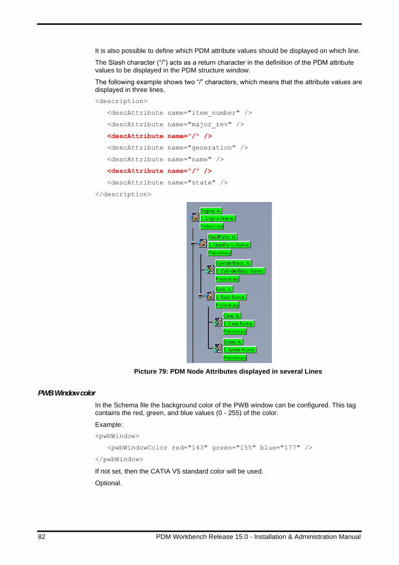
82 PDM Workbench Release 15.0 - Installation & Administration Manual
It is also possible to define which PDM attribute values should be displayed on which line.
The Slash character (“/”) acts as a return character in the definition of the PDM attribute values to be displayed in the PDM structure window.
The following example shows two “/” characters, which means that the attribute values are displayed in three lines.
<description>
<descAttribute name="item_number" />
<descAttribute name="major_rev" />
<descAttribute name="/" />
<descAttribute name="generation" />
<descAttribute name="name" />
<descAttribute name="/" />
<descAttribute name="state" />
</description>
Picture 79: PDM Node Attributes displayed in several Lines
PWB Window color
In the Schema file the background color of the PWB window can be configured. This tag contains the red, green, and blue values (0 - 255) of the color.
Example:
<pwbWindow>
<pwbWindowColor red="143" green="155" blue="177" />
</pwbWindow>
If not set, then the CATIA V5 standard color will be used.
Optional.

PDM Workbench Release 15.0 - Installation & Administration Manual 83
Preselection of Nodes
It is possible to switch off the automatic highlight of the PDM tree nodes which represent the same underlying PDM node.
In the Schema file you have to set the attribute preselectSamePdmNode="false" in
the pwbWindow XML tag in order to change the behavior from the default (highlighting all related nodes) to not highlighting them.
Example:
<pwbWindow preselectSamePdmNode="false" >
<pwbWindowColor red="143" green="155" blue="177" />
</pwbWindow>
In the default behavior related nodes are also highlighted when the user clicks on a PDM node.
Picture 80: Default highlight behavior
Context action “Delete relation”
PDM relations can be deleted in the PDM structure window with a single context menu action, even if the PDM relations are not displayed in the structure.
For any item the context action “Delete Relation” can be added in the Schema file:
<contextAction name="DeleteRelation" usedIn="PdmWindow" />
Comparing PDM Structure Trees
It is possible to compare two structures, or two generations of the same structure, displaying the differences between these two structures.
The functionality can be configured with the “pwbCompareStructureWindow” tag and the “nodeColors” sub-tag in the file “PWBSchema.xml”:
<!—- possible colors for nodes in 'compare structure window':
"green", "red", "magenta", "cyan", "blue", "yellow", "black",
"white", "background" -->
<pwbCompareStructureWindow red="200" green="200" blue="150"
showSameChildNodes="false" >
<nodeColors additionalNodes="green" missingNodes="red"
sameNodesDifferentVersion="magenta"
sameNodes="background" />
</pwbCompareStructureWindow>
The attributes “red”, “green” and “blue” of the tag “pwbCompareStructureWindow” define the respective value, from 0 to 255, of the primary color. The three values define the color of the window background.

84 PDM Workbench Release 15.0 - Installation & Administration Manual
The attribute “showSameChildNodes” defines whether nodes which exist in both structures should be shown.
The attributes “additionalNodes”, “missingNodes”, “sameNodesDifferentVersion”, and “sameNodes” of the tag “nodeColors” define the color of additional nodes, missing nodes, same nodes with a different generation, and the same nodes of one structure compared to the other structure, respectively. The values can be chosen from the fixed set “green”, “red”, “magenta”, “cyan”, “blue”, “yellow”, “black”, “white”, and “background”.
Optional.
To use the functionality the context action “Compare with Assembly” has to be defined for “Part/Assembly” in the part BOM Part Structure Data Model and for “CAD/Mechanical/Assembly” in the CAD Document Structure Data Model.
Example:
<contextAction name="CompareStructure" usedIn="PdmWindow" />
Selecting Nodes in the PDM Structure Window
It is possible to select specific child nodes of a structure by defining logical AND or OR combinations of values of different attributes.
The dialog form “SelectChildNodes” has to be defined. It contains the attributes which can be used for selecting the nodes. This is an example definition of the dialog:
<form name="SelectChildNodes">
<formAttribute name="item_number" widgetType="ComboBox" ... />
<formAttribute name="major_rev" widgetType="ComboBox" ... />
<formAttribute name="generation" widgetType="ComboBox" ... />
<formAttribute name="name" widgetType="ComboBox" ... />
<formAttribute name="state" widgetType="ComboBox" ... />
<formAttribute name="description"
widgetType="MultiLineEditor" ... />
<formAttribute name="created_on" widgetType="ComboBox" ... />
<formAttribute name="modified_on" widgetType="ComboBox" ... />
<formAttribute name="created_by_id" widgetType="ComboBox" ... />
<formAttribute name="modified_by_id" widgetType="ComboBox" ... />
<formAttribute name="locked_by_id" widgetType="ComboBox" ... />
<formAttribute name="PwbSelectChildNodesCondition"
widgetType="RadioButtons" mode="update"
visibleLength="15" required="true"
entryAllowed="true" />
</form>
In addition to this definition the context action “Select Nodes” has to be defined for “Part/Assembly” or for “CAD/Mechanical/Assembly”.
Example:
<contextAction name="SelectNodes" usedIn="PdmWindow" />
Alternative Icons for PDM Structure Nodes
It is possible to define different icons for different PDM attribute values.
To switch on the functionality the value of the XML attribute “attrDepIcons” has to be set to “true”:
<pwbWindow preselectSamePdmNode="true" attrDepIcons="true" >

PDM Workbench Release 15.0 - Installation & Administration Manual 85
<pwbWindowColor red="143" green="155" blue="177" />
</pwbWindow>
In addition to this, for each PDM item that should have attribute-dependent icons the definition string in the “icon” XML tag has to be changed to contain the PDM attributes whose values the icon should be dependent of. The syntax is to write the PDM attribute name contained in the square brackets (“[“ and “]”).
This is an example.
<object name="/Part/Assembly"
displayName="NLS_Assembly" icon="Aras_Part" >
➔
<object name="/Part/Assembly"
displayName="NLS_Assembly"
icon="Aras_Part_[classification]_[state]" >
If this functionality is switched on the icons with the corresponding names will have to exist in the “win_b64\resources\graphic\icons\normal” directory, otherwise the PDM nodes will be displayed without icons.
These are example icon names:
Picture 81: Example icon names
Expand Configuration
Context action “Expand”
In the Schema file the context action can be enabled.
Example:
<contextAction name="Expand" usedIn="PdmWindow|QueryDialog" />
Context action “Expand Multiple Levels”
In the Schema file the context action can be enabled.
Example:
<contextAction name="MultipleExpand" usedIn="PdmWindow" />

86 PDM Workbench Release 15.0 - Installation & Administration Manual
Context action “Custom Expand”
In the Schema file the context action can be enabled.
Example:
<contextAction name="CustomExpand" usedIn="PdmWindow" />
The custom expand for the object class has to be defined:
<customExpand>
<pdmTreeRef name="PartToCatiaFilePdmTree" />
</customExpand>
The PDM tree has to be defined:
<pdmTree name="PartToCatiaFilePdmTree"
displayName="NLS_PartToCatiaFilePdmTree">
<pdmTreeRel class="Part CAD" direction="LEFT_TO_RIGHT">
<pdmTreeObj
class="/CAD/Mechanical/Assembly|/CAD/Mechanical/Part|/CAD/cgr|/CAD
/Mechanical/Drawing|/CAD/Mechanical/cgr|/CAD/Mechanical/CatiaV4Mod
el">
<pdmTreeObjPartToFileInfo partClass="Part|/Part/Assembly"
fileClass="/CAD/Mechanical/Assembly"
fileType="Main" />
<pdmTreeObjPartToFileInfo partClass="Part|/Part/Assembly"
fileClass="/CAD/Mechanical/Drawing"
fileType="Auxiliary" />
<pdmTreeObjPartToFileInfo partClass="/Part/Component"
fileClass="/CAD/Mechanical/Part"
fileType="Main" />
<pdmTreeObjPartToFileInfo partClass="/Part/Component"
fileClass="/CAD/Mechanical/cgr"
fileType="Main" />
<pdmTreeObjPartToFileInfo partClass="/Part/Component"
fileClass="/CAD/Mechanical/CatiaV4Model"
fileType="Main" />
<pdmTreeObjPartToFileInfo partClass="/Part/Component"
fileClass="/CAD/Mechanical/Drawing"
fileType="Auxiliary" />
</pdmTreeObj>
</pdmTreeRel>
</pdmTree>
Context action “De-Expand”
In the Schema file the context action can be enabled.
Example:
<contextAction name="DeExpand" usedIn="PdmWindow" />
<deExpand legacyMode="false" onlyChildNodes="false" />
Default values: “false” and ”false”
Optional. Possible values: “true”, or “false”.

PDM Workbench Release 15.0 - Installation & Administration Manual 87
Context action “Expand Multiple Levels including Bom Children”
In the Schema file the context action can be enabled.
Example:
<contextAction name="MultipleExpandWithBomChildren" usedIn="PdmWindow" />
Explicit display and control of ‘AsSaved’ and ‘Current’ expand resolutions
If a CAD structure is expanded with the ‘Current’ expand resolution the PDM structure window contains information about which generations of the CAD documents are saved (which generation would be retrieved with the ‘AsSaved’ expand resolution.
Also, in the update process the user can define whether the CAD Structure relations should be moved to the current generation of the child CAD document or not.
This information is shown by default. It can be switched off by setting the server configuration ‘ShowCadStrcExpResChildDocGenInfo’ to ‘false’.
Manage Context Products
A user can only work in one Context Product at one time. This Context Product is used to store newly created files to the correct vault.
If the functionality is enabled, there must be at least one valid Context Product for every user.
The Context Product is set during login process in CATIA. If there are multiple valid Context Products, the user must select one. If there is no Context Product available for the user, the user cannot login.
Picture 82: Select Context Product
The currently used Context Product can be seen in the Options dialog of the PDM Workbench.
Picture 83: Currently used Context Product

88 PDM Workbench Release 15.0 - Installation & Administration Manual
Configuration
The possible Context Products for a user have to be determined in a custom method. The name of the custom method has to be set to the PWBConfiguration setting “CustomMethod_ContextProduct”. Setting the name of the custom method to the
PWBConfiguration setting also enables the rest of the functionality.
Picture 84: Sample CustomMethod_ContextProduct configuration
Sample Method:
Innovator InnovatorObj = this.getInnovator();
var userID = InnovatorObj.getUserID();
Item result = InnovatorObj.newItem("result");
result.setAttribute("ContextProduct", "Product X");
result.setAttribute("ContextProductId", "12345678901234567890");
var rand = new Random();
int count = rand.Next(5);
for (int i = 0 ; i < count ; i++)
{
Item x_result = InnovatorObj.newItem("result");
x_result.setAttribute("ContextProduct", "Product " + i.ToString());
x_result.setAttribute("ContextProductId",
(1234567890123456789 *(i+1)).ToString());
result.appendItem(x_result);
}
return result;
The currently used ContextProduct and the corresponding ContextProductId is
available in every custom methods that provides the cadProperties, like CustomMethod_PreProcCreDlgAttrs.
Use Environment variable for Context Product
A designer must select a Context Product during selection of the CATIA start script. To avoid a second select it is possible to use an environment variable to set the Context Product.
Configuration
Set the environment variable:
PWB_CONTEXT_PRODUCT_ID=<Aras Id of the Context Product>
As the name of the Context Product is shown in the PWB Options dialog you can also set the environment:
PWB_CONTEXT_PRODUCT=<Display name of the Context Product>
Note: The functionality is enabled by setting the PWB server configuration “CustomMethod_ContextProduct” to a custom method. The environment variables are only evaluated if this setting is not empty.

PDM Workbench Release 15.0 - Installation & Administration Manual 89
Naming Configuration - Numbering
CadDocNumberAttr
The PWB Configuration item setting “CadDocNumberAttr” contains the name of the “CAD Document Number” attribute of the item type “CAD Document”.
Picture 85: Sample CadDocNumberAttr configuration
Default value: “item_number”
Optional.
PartNumberAttr
The PWB Configuration item setting “PartNumberAttr” contains the name of the “Part Number” attribute of the item type “Part”.
Picture 86: Sample PartNumberAttr configuration
Default value: “item_number”
Optional.
Autoname Support using Aras Innovator Sequence Items
First sequence items which should be used for the autoname functionality need to be created:
Picture 87: Sample Sequence item
The following sequence items will be used in the configuration example:

90 PDM Workbench Release 15.0 - Installation & Administration Manual
Picture 88: Sequence items used in example
Then the sequence items to be used need to be configured in the Schema file:
First an attribute with a data source which contains the names of the sequence items needs to be defined:
<attribute name="pwbAutonameRule" displayName="NLS_AutonameRule"
dataSource="AutonameRules" />
<dataSource name="AutonameRules" type="ValueList">
<value name="PwbTestSequence1" displayName="" />
<value name="PwbTestSequence2" displayName="" />
<value name="CAD Document" displayName="" />
</dataSource>
Then a corresponding form attribute has to be included in the login dialog …
<form name="Login" info="ShowOnlyLoginData" >
<frame displayName="NLS_UserData">
...
<formAttribute name="pwbAutonameRule"
widgetType="ComboBox"
mode="update" visibleLength="15"
required="false" entryAllowed="false" />
</frame>
</form>
… and in the “Set PDM Configuration” dialog.
<form name="PdmSessionConfig">
<formAttribute name="pwbAutonameRule" widgetType="ComboBox"
mode="update" visibleLength="15" required="false"
listViewRelevant="true" />
</form>
This will enable the user to select a sequence item name as an autoname rule either at login or later while working in the PDM Workbench session.
In order for the “Set PDM Configuration” dialog to appear the setting “SetSessionConfig” has to be removed from the “removeToolbarIcons” definition:
<removeToolbarIcons>
<!-- "LocalWorkspace", "Register", "Update", "Synchronize", "Refresh",
"SetSessionConfig", "NewPwbWindow", "About"
-->
<!-- <icon name="LocalWorkspace" /> -->

PDM Workbench Release 15.0 - Installation & Administration Manual 91
<icon name="Register" />
<!-- <icon name="Update" /> -->
<icon name="Synchronize" />
<!-- <icon name="Refresh" /> -->
<!-- <icon name="SetSessionConfig" /> -->
<icon name="NewPwbWindow" />
<!-- <icon name="About" /> -->
</removeToolbarIcons>
The setting “UseServerMethodsForAutoname” has to be set to “false” in the active PWB Configuration item.
Optional.
Autoname functionality can use a server method
The autoname functionality can use a server method for obtaining a PDM-generated part or document number value.
The autoname functionality has to be configured in the file “PWBSchema.xml”.
The server method to be used needs to be configured in the Schema file:
First an attribute with a data source which contains the name of the server method needs to be defined:
<attribute name="pwbAutonameRule" displayName="NLS_AutonameRule"
dataSource="AutonameRules" />
<dataSource name="AutonameRules" type="ValueList">
<value name=" PwbAutonameMethod1" displayName="" />
</dataSource>
Then a corresponding form attribute has to be included in the login dialog …
<form name="Login" info="ShowOnlyLoginData" >
<frame displayName="NLS_UserData">
...
<formAttribute name="pwbAutonameRule"
widgetType="ComboBox"
mode="update" visibleLength="15"
required="false" entryAllowed="false" />
</frame>
</form>
… and in the “Set PDM Configuration” dialog.
<form name="PdmSessionConfig">
<formAttribute name="pwbAutonameRule" widgetType="ComboBox"
mode="update" visibleLength="15" required="false"
listViewRelevant="true" />
</form>
This will enable the user to select a sequence item name as an autoname rule either at login or later while working in the PDM Workbench session.
In order for the “Set PDM Configuration” dialog to appear the setting “SetSessionConfig” has to be removed from the “removeToolbarIcons” definition:
<removeToolbarIcons>

92 PDM Workbench Release 15.0 - Installation & Administration Manual
<!-- "LocalWorkspace", "Register", "Update", "Synchronize", "Refresh",
"SetSessionConfig", "NewPwbWindow", "About"
-->
<!-- <icon name="LocalWorkspace" /> -->
<icon name="Register" />
<!-- <icon name="Update" /> -->
<icon name="Synchronize" />
<!-- <icon name="Refresh" /> -->
<!-- <icon name="SetSessionConfig" /> -->
<icon name="NewPwbWindow" />
<!-- <icon name="About" /> -->
</removeToolbarIcons>
The setting “UseServerMethodsForAutoname” has to be set to “true” (default) in the active PWB Configuration item.
An additionally server method whose name corresponds to the name configured in the file “PWBSchema.xml” (e.g. "PwbAutonameMethod1"; "Server-Side"; "C#";
"Execution allowed to World") has to be defined on the Aras Innovator server.
The server method can use information from standard CATIA attributes of the CATIA files to be imported to PDM, or values from PDM Workbench dialogs.
In this example the Aras Sequence “CAD Document” is used for generating the number.
Picture 89: Sequence item “CAD Document”
This is an example of such a server method:
// CCO.Utilities.WriteDebug("_PwbOutput", "Entering 'PwbAutonameMethod1'" ); var PwbServerApiObj = new PwbServerAddin.PwbServerApi(this); // Preparing the input information string Autoname = this.getProperty("Autoname"); string PdmType = this.getProperty("Type"); string PdmClassification = this.getProperty("Classification"); Item CadStdPropsItem = this.getPropertyItem("CadStdProps"); IDictionary<string, string> CadStdPropsDict = null; if (CadStdPropsItem != null) { CadStdPropsDict = PwbServerApiObj.DialogAttrsItemToDictionary(CadStdPropsItem); } Item CadDocInputDialogItem = this.getPropertyItem("CadDocDialogAttrs"); IDictionary<string, string> CadDocInputDialogDict = null; if (CadDocInputDialogItem != null) { CadDocInputDialogDict = PwbServerApiObj.DialogAttrsItemToDictionary(CadDocInputDialogItem);

PDM Workbench Release 15.0 - Installation & Administration Manual 93
} Item PartInputDialogItem = this.getPropertyItem("PartDialogAttrs"); IDictionary<string, string> PartInputDialogDict = null; if (PartInputDialogItem != null) { PartInputDialogDict = PwbServerApiObj.DialogAttrsItemToDictionary(PartInputDialogItem); } // Place the custom algorithm here string OutputLogInfo = ""; OutputLogInfo += "Autoname:'" + Autoname + "'" + "|"; OutputLogInfo += "PdmType:'" + PdmType + "'" + "|"; OutputLogInfo += "PdmClassification:'" + PdmClassification + "'" + "|"; if (CadStdPropsDict != null) { OutputLogInfo += "CadStdProps:" + "|"; var Enumerator = CadStdPropsDict.GetEnumerator(); while (Enumerator.MoveNext() == true) { var CurrentVal = Enumerator.Current; OutputLogInfo += "'" + CurrentVal.Key + "'->'" + CurrentVal.Value + "'" + "|"; } } if (CadDocInputDialogDict != null) { OutputLogInfo += "CadDocInputDialog:" + "|"; var Enumerator = CadDocInputDialogDict.GetEnumerator(); while (Enumerator.MoveNext() == true) { var CurrentVal = Enumerator.Current; OutputLogInfo += "'" + CurrentVal.Key + "'->'" + CurrentVal.Value + "'" + "|"; } } if (PartInputDialogDict != null) { OutputLogInfo += "PartInputDialog:" + "|"; var Enumerator = PartInputDialogDict.GetEnumerator(); while (Enumerator.MoveNext() == true) { var CurrentVal = Enumerator.Current; OutputLogInfo += "'" + CurrentVal.Key + "'->'" + CurrentVal.Value + "'" + "|"; } } // Getting the actual autoname value string AutonameValue = ""; if (PdmType == "Part") { AutonameValue = PwbServerApiObj.GetNextAutonameSequence("CAD Document"); } else { if ((PartInputDialogDict != null) && (PartInputDialogDict.ContainsKey("item_number"))) { AutonameValue = PartInputDialogDict["item_number"]; } else { AutonameValue = PwbServerApiObj.GetNextAutonameSequence("CAD Document"); } } OutputLogInfo += "done"; // Preparing the output IDictionary<string, string> OutputInfoDict = new Dictionary<string, string>(); OutputInfoDict.Add("AutonameValue", AutonameValue);

94 PDM Workbench Release 15.0 - Installation & Administration Manual
OutputInfoDict.Add("LogLines", OutputLogInfo); Item OutputInfoItem = PwbServerApiObj.DialogAttrsDictionaryToItem(OutputInfoDict); return OutputInfoItem;
Initial Version Strings
InitialVersionCadDoc
The PWB Configuration item setting “InitialVersionCadDoc” is the initial version string for the item type “CAD Document”.
Picture 90: Sample InitialVersionCadDoc configuration
Optional.
InitialVersionPart
The PWB Configuration item setting “InitialVersionPart” is the initial version string for the item type “Part”.
Picture 91: Sample InitialVersionPart configuration
Optional.
Promote States
Context action “Promote”
In the Schema file the context action can be enabled.
Example:
<contextAction name="Promote" usedIn="PdmWindow" />
PromoteSourceStates
The PWB Configuration item setting “PromoteSourceStates” is a list of the promote source states, separated by “|”.
Picture 92: Sample PromoteSourceStates configuration
Default value: “Preliminary|In Review”
Optional.

PDM Workbench Release 15.0 - Installation & Administration Manual 95
PromoteTargetStates
The PWB Configuration item setting “PromoteTargetStates” is a list of the promote target states, separated by “|”.
Picture 93: Sample PromoteTargetStates configuration
Default value: “In Review|Released”
Optional.
PromotePartSourceStates
The PWB Configuration item setting “PromotePartSourceStates” is a list of the promote source states for the item type Part, separated by “|”.
Picture 94: Sample PromotePartSourceStates configuration
This value will overwrite the default value of the PWB Configuration item setting “PromoteSourceStates”.
The settings “PromotePartSourceStates” and “PromotePartTargetStates” have to be defined together to set the Life Cycle States for the item type Part.
Optional.
PromotePartTargetStates
The PWB Configuration item setting “PromotePartTargetStates” is a list of the promote target states for the item type Part, separated by “|”.
Picture 95: Sample PromotePartTargetStates configuration
This value will overwrite the default value of the PWB Configuration item setting “PromoteTargetStates”.
The settings “PromotePartSourceStates” and “PromotePartTargetStates” have to be defined together to set the Life Cycle States for the item type Part.
Optional.
PromoteCADSourceStates
The PWB Configuration item setting “PromoteCADSourceStates” is a list of the promote source states for the item type CAD, separated by “|”.
Picture 96: Sample PromoteCADSourceStates configuration
This value will overwrite the default value of the PWB Configuration item setting “PromoteSourceStates”.
The settings “PromoteCADSourceStates” and “PromoteCADTargetStates” have to be defined together to set the Life Cycle States for the item type CAD.
Optional.
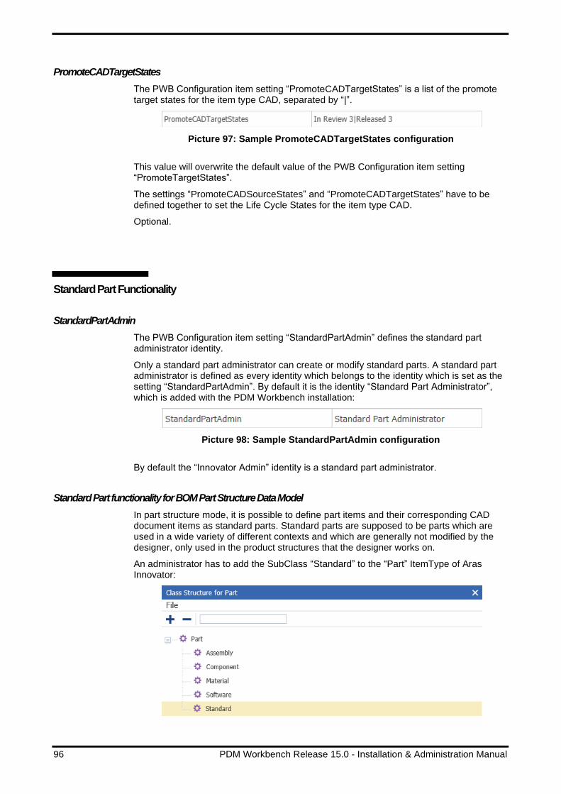
96 PDM Workbench Release 15.0 - Installation & Administration Manual
PromoteCADTargetStates
The PWB Configuration item setting “PromoteCADTargetStates” is a list of the promote target states for the item type CAD, separated by “|”.
Picture 97: Sample PromoteCADTargetStates configuration
This value will overwrite the default value of the PWB Configuration item setting “PromoteTargetStates”.
The settings “PromoteCADSourceStates” and “PromoteCADTargetStates” have to be defined together to set the Life Cycle States for the item type CAD.
Optional.
Standard Part Functionality
StandardPartAdmin
The PWB Configuration item setting “StandardPartAdmin” defines the standard part administrator identity.
Only a standard part administrator can create or modify standard parts. A standard part administrator is defined as every identity which belongs to the identity which is set as the setting “StandardPartAdmin”. By default it is the identity “Standard Part Administrator”, which is added with the PDM Workbench installation:
Picture 98: Sample StandardPartAdmin configuration
By default the “Innovator Admin” identity is a standard part administrator.
Standard Part functionality for BOM Part Structure Data Model
In part structure mode, it is possible to define part items and their corresponding CAD document items as standard parts. Standard parts are supposed to be parts which are used in a wide variety of different contexts and which are generally not modified by the designer, only used in the product structures that the designer works on.
An administrator has to add the SubClass “Standard” to the “Part” ItemType of Aras Innovator:

PDM Workbench Release 15.0 - Installation & Administration Manual 97
Picture 99: SubClass “Standard”
This SubClass “Standard” must be used for all Part items which should be considered as a standard part. It is NOT correct to use a “Component” Part item, attach a CAD item and just mark that CAD item as “is_standard”.
The CATParts which are related to standard parts can either be downloaded like the CATIA files which are related to other parts, or they can reside in a local directory which is accessible to CATIA V5.
This setting in the file “PWBSchema.xml” defines that the standard part CATParts are downloaded to the PWB_XMAP directory:
<standardPartFiles download="true" />
Optional.
This setting defines that they are not downloaded, but taken from a local directory:
<standardPartFiles download="false"
localDir="C:\Users\Public\Documents\StandardParts" />
Optional.
For this setting three conditions need to be fulfilled:
1. The defined directory is accessible in the CATIA V5 environment.
2. The standard part CATPart files reside in that directory.
3. CATIA V5 needs to be set up to be able to use files from that directory.
Picture 100: Making CATParts in a local folder accessible
Another setting makes it possible to import structures containing standard part CATParts to PDM even if those standard parts have not been loaded in the PDM Workbench session.
Normally CATIA files which are not loaded from PDM are treated as new items, and new CAD documents and parts are created for them in the update process. If CATParts contain a certain definition as a user-defined attribute they are treated as standard parts, and the update process queries for existing standard part items in the database instead of trying to create a new part item. If such a standard part item is found it is related to the parent part.

98 PDM Workbench Release 15.0 - Installation & Administration Manual
In the file “PWBSchema.xml” it is possible to define the name of the user-defined attribute which defines a standard part CATPart file, for instance “IsStandardPart”:
<standardPartUserDefPropAttribute name="IsStandardPart" />
Optional.
A user-defined attribute with the same name has to be defined in the CATPart file. If the value is any of the strings “true”, “TRUE”, or “1”, then the CATPart is considered to be a standard part CATPart.
Picture 101: Defining a CATPart as a standard part
In that case the update process does not try to create a new part which corresponds to the CATIA document, but it queries for an existing standard part in PDM instead.
Standard Part functionality for CAD Document Structure Data Model
The standard part functionality has been extended to work with CAD document structures.
There is a new check box which defines whether a CAD document is defined as a standard part item:
Picture 102: “Standard Part” check box for CAD documents

PDM Workbench Release 15.0 - Installation & Administration Manual 99
As in the part structure mode standard part items are treated differently than regular CAD document items. Standard part CATParts (CATProducts are not allowed) are defined by two things:
1. The PDM attribute “is_standard” (“Standard Part”) is set to “1”.
2. In the CATPart there is a user-defined CATIA property with the name “IsStandardPart” and the value of “true”.
Picture 103: “IsStandardPart” user-defined property
In this example there are three CATParts which are defined as standard parts: “StdPart1.CATPart”, “StdPart2.CATPart”, and “StdPart3.CATPart”:
Picture 104: Three example standard part CATParts
Standard part items can only be created by a user which is defined as standard part administrator.

100 PDM Workbench Release 15.0 - Installation & Administration Manual
Picture 105: User is logged in as administrator
By default “Innovator Admin” is a standard part administrator, that is, a member of the identity “Standard Part Administrator”:
Picture 106: The Standard Part Administrator identity
Material
This functionality reads used materials of a CATPart and provides a custom method to handle this information in Aras Innovator.
There are multiple possibilities in CATIA where materials can be specified, only the following locations are checked according to the following rules:
1) Look for Material at CATPart.
Picture 107: Material located at CATPart
If there is a Material we take this material and stop.
2) If there is no Material at CATPart level, look for materials in “Composites
Parameters”.

PDM Workbench Release 15.0 - Installation & Administration Manual 101
Picture 108: Material located at Composite Parameters
Read out all Material Names from the “Composites Parameters”.
3) If there is no Material at CATPart and “Composites Parameters”
Picture 109: Material located at Bodies
Read out the Material information at the available Bodies.

102 PDM Workbench Release 15.0 - Installation & Administration Manual
Configuration
Create a custom server method to handle the material information and set the value of the PWB Configuration setting “CustomMethod_SaveUsedMaterials” to your method name:
Picture 110: Sample CustomMethod_SaveUsedMaterials configuration
Template custom method “PWBCus_SaveUsedMaterials”:
var PwbServerApiObj = new PwbServerAddin.PwbServerApi(this);
Innovator InnovatorObj = this.getInnovator();
string CAD_Id = this.getID();
string CAD_Class = this.getType();
CCO.Utilities.WriteDebug("_PwbOutput",
"PWBCus_SaveUsedMaterials -> CAD_Id:'" +
CAD_Id + "', CAD_Class:'" + CAD_Class + "'");
string Part_Id = this.getAttribute("Part_OBID","");
string Part_Class = this.getAttribute("Part_Class","");
CCO.Utilities.WriteDebug("_PwbOutput",
"PWBCus_SaveUsedMaterials -> Part_Id:'" +
Part_Id + "', Part_Class:'" + Part_Class + "'");
int MaterialCount = 0;
int.TryParse(this.getAttribute("materialCount"),
System.Globalization.NumberStyles.Integer,
System.Globalization.CultureInfo.InvariantCulture,
out MaterialCount);
for (int i = 0; i < MaterialCount; i++)
{
Item material = this.getPropertyItem("material_"+i.ToString());
if (material == null)
{
continue;
}
string MaterialName = material.getAttribute("name","");
string IsVisible = material.getAttribute("visibility","");
string Location = material.getAttribute("location", "");
CCO.Utilities.WriteDebug("_PwbOutput",
"PWBCus_SaveUsedMaterials -> material:'" +
MaterialName +
"', IsVisible:'" + IsVisible +
"', Location:'"+ Location +"'");
}
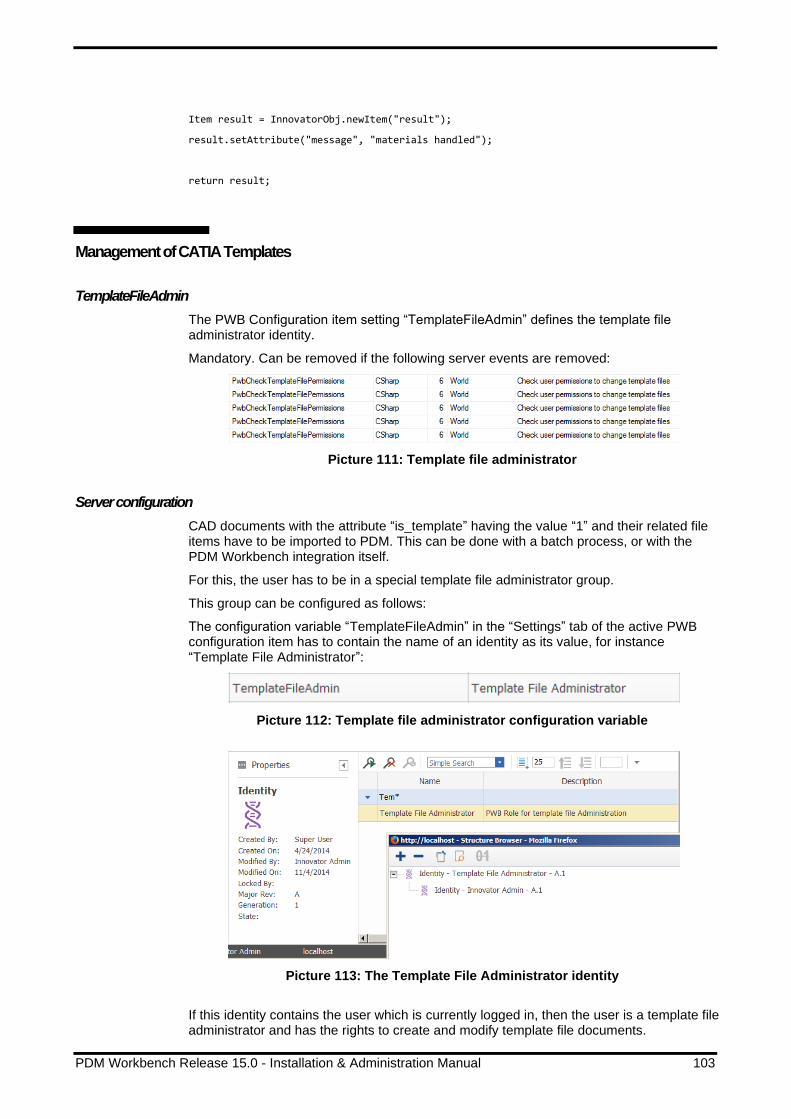
PDM Workbench Release 15.0 - Installation & Administration Manual 103
Item result = InnovatorObj.newItem("result");
result.setAttribute("message", "materials handled");
return result;
Management of CATIA Templates
TemplateFileAdmin
The PWB Configuration item setting “TemplateFileAdmin” defines the template file administrator identity.
Mandatory. Can be removed if the following server events are removed:
Picture 111: Template file administrator
Server configuration
CAD documents with the attribute “is_template” having the value “1” and their related file items have to be imported to PDM. This can be done with a batch process, or with the PDM Workbench integration itself.
For this, the user has to be in a special template file administrator group.
This group can be configured as follows:
The configuration variable “TemplateFileAdmin” in the “Settings” tab of the active PWB configuration item has to contain the name of an identity as its value, for instance “Template File Administrator”:
Picture 112: Template file administrator configuration variable
Picture 113: The Template File Administrator identity
If this identity contains the user which is currently logged in, then the user is a template file administrator and has the rights to create and modify template file documents.

104 PDM Workbench Release 15.0 - Installation & Administration Manual
For regular users existing template file documents are read-only (black text background).
One way of creating template file documents in Innovator with PDM Workbench is this:
1. Make sure the following settings are set in the active PWB configuration item, at least temporarily:
Picture 114: PWB Configuration variables for template creation
2. Log in to Innovator with PDM Workbench as a template file administrator.
3. Open a CATIA file which is supposed to be used as a PDM template document in CATIA V5.
4. Click on the Update icon in the PDM Workbench toolbar to create the CAD document and to upload the file.
Since the two settings are set to the values described in step 1 only a CAD document will be created, and a create dialog is shown to the user:
Picture 115: Create dialog containing “Is Template” checkbox
The document number has to be entered, and it is important that the “Is Template” attribute is checked.
Another possibility would be to first create the template file as a regular file, and to change the “is_template” attribute afterwards. In this case the “ShowCreateDialogsDuringUpdate” setting does not have to be set to “true”. Even the “UseBomPartStructure” setting can be set to “true”, but in this case a Part item is created, too. This Part item may have to be deleted later, because it should probably not be in the bill of materials.
Only a template file administrator can change the “is_template” attribute value of a CAD document item. A regular user will get this error message:

PDM Workbench Release 15.0 - Installation & Administration Manual 105
Picture 116: Template file creation error message
For a regular user template file CAD document items are read-only, and they also can not be locked by a regular user.
Client configuration
In the Schema file the configuration templateFiles has to exist and it has to contain the attribute loadFrom="PDM":
<templateFiles loadFrom="PDM"
catPrt="PwbCatPrtTmplFileNames"
catPrd="PwbCatPrdTmplFileNames"
catDrw="PwbCatDrwTmplFileNames" />
The values of the XML attibutes catPrt, catPrd, and catDrw have to contain the names of data source definitions of the type “ValueList” which contain the file names of the CATPart, CATProduct, and CATDrawing template files:
<dataSource name="PwbCatPrtTmplFileNames" type="ValueList">
<value name="TemplateCatPart1.CATPart" />
<value name="TemplateCatPart2.CATPart" />
</dataSource>
<dataSource name="PwbCatPrdTmplFileNames" type="ValueList">
<value name="TemplateCatProduct1.CATProduct" />
<value name="TemplateCatProduct2.CATProduct" />
</dataSource>
<dataSource name="PwbCatDrwTmplFileNames" type="ValueList">
<value name="TemplateCatDrawing1.CATDrawing" />
<value name="TemplateCatDrawing2.CATDrawing" />
</dataSource>
The first file in each of these lists is the default template, and that template file is used when the template file functionality is switched on, and if a part structure with no related CAD documents is loaded to CATIA.

106 PDM Workbench Release 15.0 - Installation & Administration Manual
The old template file functionality, where locally accessible files are used, is turned on by a definition like this in the Schema file:
<templateFiles loadFrom="C:\Users\Public\PDM-Workbench\Templates"
catPrt="PwbCatPrtTmplFileNames"
catPrd="PwbCatPrdTmplFileNames"
catDrw="PwbCatDrwTmplFileNames" />
In this definition the absolute file path which is defined as the value of the loadFrom XML attribute has to contain the CATIA files which are defined in the data sources which are referenced in the XML attributes catPrt, catPrd, and catDrw.
Optional.
If loadFrom="PDM" is set, then CAD documents with the same document number
(without the file extension) and the PDM attribute “is_template” having the value “1” have to be defined in Innovator, and they have to be related to File items with the same file name (with the file extension).
Additionally the “Create” dialog definitions for the PDM types for CATPart, CATProduct, and CATDrawing files need to contain the form attribute for the template.
Here an example is given for the CATPart type:
<form name="Create">
<formAttribute name="CatPrtTemplate" widgetType="ComboBox"
mode="update" visibleLength="30" required="false" />
</form>
The referenced attribute with the name “CatPrtTemplate” needs to contain two specific definitions: A data source which contains the names of the template files (as described above), and a specific information that this attribute contains information about CATPart template files (shown in red below).
<attribute name="CatPrtTemplate" displayName="NLS_CatPrtTemplate"
dataSource="PwbCatPrtTmplFileNames"
pwbAttrInfo="CatPrtTemplateListAttr" />
When the template files for one of the three types should not be used, e.g. no template support for CATDrawings, then the value “catDrw” has to be removed from the “templateFiles” tag and the form attribute for the template has to be removed from the create dialog.
Template File Support for 'Create Part' with Templates depending on the Part Type
Originally the ‘Create’ functionality only creates the ‘Part’ business item in the database when a part type is selected, without a corresponding CAD document item.
An extension of the ‘Create’ functionality allows to create ‘Part’ items with their corresponding CAD document, and the native file of this CAD document can be based on a list of template files which is defined specifically for this part type.
These part items can also be created in the context of a parent assembly.
The ‘Create’ functionality will create both the CAD document and the corresponding part, with the part having the “default” classification, that is, the first entry in the part definition list in the PWBSchema.xml file with the fitting ‘canHaveSubParts’ value:
<partClasses baseClassName="Part">
<partClassName name="/Part/Design/Assembly/Mechanical"
canHaveSubParts="true" />
<partClassName name="/Part/Design/Harness"
canHaveSubParts="true" />
<partClassName name="/Part/Design/Component"
canHaveSubParts="false" />

PDM Workbench Release 15.0 - Installation & Administration Manual 107
<partClassName name="/Part/Standard"
canHaveSubParts="false"/>
</partClasses>
Configuration
For the new functionality two new entries have to be defined in the global ‘settings’ definition:
CreatePartsWithCadFile: ‘true’ defines that when a BOM part item is created a
corresponding CAD document item with a native CATIA file is also created. This CATIA file can be based on a template file.
ContextCreateParts: ‘true’ defines that the “PDM Create in Context” functionality
includes part types too, not only the CATProduct and CATPart types.
...
<settings>
<setting name="CreatePartsWithCadFile" value="true" />
<setting name="ContextCreateParts" value="true" />
</settings>
<object name="Part" displayName="NLS_Part" icon="Aras_Part">
<description>
...
Also, if specific template files should be associated with a part type, an object-specific setting with the name ‘TemplateFileNameDataSource’ and the value of a string list data source should be defined. The list should contain the names of the template CATIA files which correspond to this part type:
<object name="/Part/Design/Assembly/Mechanical"
displayName="NLS_Assembly" icon="Aras_Part" >
<settings>
<setting name="TemplateFileNameDataSource"
value="TmplFileNames-Assembly-Mechanical" />
</settings>
...
</object>
<object name="/Part/Design/Harness"
displayName="NLS_Harness" icon="Harness" >
<settings>
<setting name="TemplateFileNameDataSource"
value="TmplFileNames-Harness" />
</settings>
...
</object>
<object name="/Part/Design/Component"
displayName="NLS_Component" icon="Aras_Component" >
<settings>
<setting name="TemplateFileNameDataSource"
value="TmplFileNames-Component" />

108 PDM Workbench Release 15.0 - Installation & Administration Manual
</settings>
...
</object>
The data sources should also be defined in the PWBSchema.xml file:
<!-- All CATProduct template files -->
<dataSource name="PwbCatPrdTmplFileNames" type="ValueList">
<value name="TemplateCatProduct1.CATProduct" />
<value name="TemplateCatProduct2.CATProduct" />
<value name="Assembly-Mechanical-1.CATProduct" />
<value name="Assembly-Mechanical-2.CATProduct" />
<value name="Harness-1.CATProduct" />
<value name="Harness-2.CATProduct" />
</dataSource>
<!-- All CATPart template files -->
<dataSource name="PwbCatPrtTmplFileNames" type="ValueList">
<value name="TemplateCatPart1.CATPart" />
<value name="TemplateCatPart2.CATPart" />
<value name="Component-1.CATPart" />
<value name="Component-2.CATPart" />
</dataSource>
<!-- Template files specific to part types -->
<dataSource name="TmplFileNames-Assembly-Mechanical" type="ValueList">
<value name="Assembly-Mechanical-1.CATProduct" />
<value name="Assembly-Mechanical-2.CATProduct" />
</dataSource>
<dataSource name="TmplFileNames-Harness" type="ValueList">
<value name="Harness-1.CATProduct" />
<value name="Harness-2.CATProduct" />
</dataSource>
<dataSource name="TmplFileNames-Component" type="ValueList">
<value name="Component-1.CATPart" />
<value name="Component-2.CATPart" />
</dataSource>
Thumbnail Configuration
Create thumbnails from types
The PWB Configuration item setting “CreateThumbnailsFromTypes” is a list of file extensions for which the thumbnails should be created by update, separated by “|”.

PDM Workbench Release 15.0 - Installation & Administration Manual 109
Picture 117: Sample CreateThumbnailsFromTypes configuration
Default value: “.CATPart|.CATDrawing”
Optional.
Create thumbnails by CATIA
It is possible to let CATIA generate the thumbnail pictures internally, instead of using the pictures used by Windows.
This is an example of thumbnails of CATIA files in the Windows Explorer:
Picture 118: Windows Thumbnails
In some cases, due to some configuration of the Windows registry, the thumbnails in the Windows Explorer are not shown correctly. In this case there will be no thumbnails associated to the CAD documents in PDM either.
With this setting the thumbnail pictures are created inside CATIA, so they are independent of the Windows setting.
In addition, with this setting it is possible to have thumbnail pictures for CGR and CATIA V4 files too, which would not be possible otherwise.
Configuration in the file “PWBSchema.xml”.
Example:
<createThumbnailwithWindows value="true" />
Default value: “false”
Optional. Possible values: “true”, or “false”.
Derived Files Configuration
Derived files tabulator
There is a “Derived Files” tab in the PWB Configuration item. The customer can define there the derived file formats to be created per source format and its storage property.
The storage property must be a file item property, which is defined on the CAD item, like “viewable_file” or “view_file”.

110 PDM Workbench Release 15.0 - Installation & Administration Manual
The PDM Workbench provides the capability to create and store derived files when a user is uploading new or modified CAD files to Aras Innovator. These derived files are created in a CATIA SaveAs operation of the current PDM Workbench user’s CATIA session. Take care, that each defined SaveAs operation results in a single file with the same name as the source file but a different suffix. If CATIA creates multiple files from a single CATIA file during a SaveAs operation, then this type is not supported here.
Picture 119: “Derived Files” tab
Example for single generated PDF file: Only one PDF for a CATDrawing can be stored in Aras as viewable_file (derived file). Therefore, all sheets of a CATDrawing must be stored in a single PDF. The following CATIA setting enables this option:
Picture 120: Activate multisheet option in CATIA V5 Tools→Options→General→Compatibility→Graphics Formats
Please note that the old configuration settings ‘UpdateDerivedPdfFile’ and ‘UpdateDerived3DxmlFile’ are not supported anymore.

PDM Workbench Release 15.0 - Installation & Administration Manual 111
Additional CAD Document Types
Design tables
The PWB Configuration item setting “UseDesignTables” configures the use of Design Tables with the PDM Workbench. The use of Design Tables in Aras Innovator can be enabled or disabled in PDM Workbench.
Please note that when Design Tables are disabled from PDM Workbench, they can still be used in CATIA, but they are not synchronized and uploaded to Aras Innovator.
Picture 121: Sample UseDesignTables configuration
Default value: “false”
Optional. Possible values: “true”, or “false”.
Archives
It is possible to compress a complete CATProduct sub-structure into one Zip file and to manage this compressed file in PDM. This makes it possible to hide a complicated CATProduct structure in one CAD document if it is not necessary to manage the structure information in PDM.
The PWB Configuration item setting “UseArchives” has to be set to “true”:
Picture 122: Sample UseArchives configuration
If archives are used a new classification for the item type CAD needs to be defined, for instance “Mechanical/Archive”.

112 PDM Workbench Release 15.0 - Installation & Administration Manual
Picture 123: Add Mechanical/Archive to CAD
In the Schema file the same classification has to be defined.
Example:
<object name="/CAD/Mechanical/Archive"
displayName="NLS_Archive"
icon="Aras_Archive">
CATIA V4 models
If structures which contain CATIA V4 models are used a new classification for the item type CAD needs to be defined, for instance “Mechanical/CatiaV4Model”.

PDM Workbench Release 15.0 - Installation & Administration Manual 113
Picture 124: Add Mechanical/CatiaV4Model to CAD
In the Schema file the same classification has to be defined.
Example:
<object name="/CAD/Mechanical/CatiaV4Model"
displayName="NLS_model"
icon="model">
CGRs as native files
CGR files are fully supported as native files, including assigning them a new CATIA part number, PDM attribute mapping, “Insert PDM Node” functionality, and replacing the representation with a different file and updating the new representation.
A new classification for the item type CAD needs to be defined, for instance “Mechanical/cgr”.

114 PDM Workbench Release 15.0 - Installation & Administration Manual
Picture 125: Add Mechanical/cgr to CAD
In the Schema file the same classification has to be defined.
Example:
<object name="/CAD/Mechanical/cgr"
displayName="NLS_cgr"
icon="cgr">
CATIA Catalogs
CATIA Catalogs for CATParts are supported. The catalogs can be created and updated by a “Standard Part Administrator”. The catalog functionality supports CATParts used as “Standard Parts”, as “Templates” or CATParts holding a “Power Copy”.
The Catalog functionality adds the catalog keywords PWB_CAD and for Bom CATParts PWB_PART. The values of these keywords must not be changed by a user.
During open a catalog in CATIA Catalog Editor or Catalog Browser using PDM Workbench, placeholder files for the referenced CATParts in Aras are automatically created in the PDM Workbench exchange directory. The actual geometry of a referenced CATPart will be fetched from Aras as soon as the geometry is needed by the native CATIA Catalog functionality.
In the Schema file the context actions can be enabled.
Example:
<contextAction name="OpenCatalog" usedIn="QueryDialog"
defaultAction="true" />
The element defaultAction="true" defines this context action is action to be
performed by double-clicking on an object of this type.
<contextAction name="OpenCatalogForEdit" usedIn="PdmWindow|QueryDialog" />

PDM Workbench Release 15.0 - Installation & Administration Manual 115
A new classification for the item type CAD needs to be defined, for instance “Mechanical/catalog”.
Picture 126: Add Mechanical/catalog to CAD
In the Schema file the same classification has to be defined.
Example:
<object name="/CAD/Mechanical/catalog"
displayName="NLS_catalog"
icon="catalog">
Support floating content in Catalog
By default, the Catalog points to a fixed Aras Innovator version of the contained Aras CAD (Part). If this functionality is enabled, you will get the latest version of the corresponding CAD (Part).
Configuration
In the PWB Configuration you have to add the setting “UseFloatingCatalogContent”:
Picture 127: PWB Configuration – “UseFloatingCatalogContent”
Default value: “false”
Optional. Possible values: “true”, or “false”.
Configurable Catalog Keywords
By default the identifying attributes (id or item_number when using floating catalog content) are stored in the values of PWB_CAD and PWB_PART (for BOM Part).

116 PDM Workbench Release 15.0 - Installation & Administration Manual
Picture 128: Configurable Catalog Keywords
It is possible configure different catalog keywords to store these values. In case of
useBomPartStructure = true, if only BOM CATParts are used in the catalog it is also possible to remove the keyword for the CAD.
Configuration
The changes are done in the PWB Configuration.
To change the PWB_PART keword you have to add the setting “CatalogPartIdentifier”:
Picture 129: PWB Configuration – “CatalogPartIdentifier”
Default value: “PWB_PART”
Optional.
To change the PWB_CAD keyword you have to add the setting “CatalogCadIdentifier”:
Picture 130: PWB Configuration – “CatalogCadIdentifier”
Default value: “PWB_CAD”
Optional.
If “CatalogCadIdentifier” is set to an empty value, the keyword is not used (only for useBomPartStructure = true).
Custom method to handle Catalog references
The standard PDM Workbench Catalog functionality stores the Aras Innovator Id or item_number (depending on the configuration) of the referenced items as a keyword inside the catalog file. This means this information is not available in Aras Innovator.
Thanks to this functionality it is possible to make this data available in Aras Innovator using a custom method which is called during update of a catalog.
Configuration
To enable this functionality, you must create a custom method to handle the referenced items of a catalog.
The PWB Configuration setting “CustomMethod_ProcessCatalogContent” must point to the method name of your custom method:

PDM Workbench Release 15.0 - Installation & Administration Manual 117
Picture 131: Sample “CustomMethod_ProcessCatalogContent” configuration
The following method will write the referenced Id or item_number of the referenced items to a log file. If you work in CAD Structure mode, the list of referenced Parts is always empty.
/*
Sample method PwbCus_ProcessCatalogContent
This method allows to create / update links to referenced items in a
catalog
Set PWB Configuration CustomMethod_ProcessCatalogContent =
PwbCus_ProcessCatalogContent
*/
var PwbServerApiObj = new PwbServerAddin.PwbServerApi(this);
Innovator InnovatorObj = this.getInnovator();
string CAD_Id = this.getID();
string CAD_Type = this.getType();
string CAD_Classification = this.getProperty("classification");
CCO.Utilities.WriteDebug("_PwbOutput",
"PwbCus_ProcessCatalogContent -> CAD_Id:'" +
CAD_Id + "', CAD_Class:'/" + CAD_Type + "/"+ CAD_Classification +
"'");
int referencedPartCount = 0;
int.TryParse(this.getAttribute("referencedPartCount"),
System.Globalization.NumberStyles.Integer,
System.Globalization.CultureInfo.InvariantCulture,
out referencedPartCount);
for (int i = 0; i < referencedPartCount; i++)
{
String referencedPart =
this.getAttribute("referencedPart_"+i.ToString());
if (String.IsNullOrEmpty(referencedPart))
{
continue;
}
CCO.Utilities.WriteDebug("_PwbOutput",
"PwbCus_ProcessCatalogContent -> referencedPart:' " +
referencedPart );
}
int referencedCadCount = 0;
int.TryParse(this.getAttribute("referencedCadCount"),
System.Globalization.NumberStyles.Integer,
System.Globalization.CultureInfo.InvariantCulture,
out referencedCadCount);
for (int i = 0; i < referencedCadCount; i++)
{
String referencedCad =
this.getAttribute("referencedCad_"+i.ToString());
if (String.IsNullOrEmpty(referencedCad))
{
continue;
}
CCO.Utilities.WriteDebug("_PwbOutput",
"PwbCus_ProcessCatalogContent -> referencedCad:' " +
referencedCad );
}
Item result = InnovatorObj.newItem("result");
result.setAttribute("message", "Catalog Content handled ");

118 PDM Workbench Release 15.0 - Installation & Administration Manual
return result;
CATProcess
CATProcess can be updated and loaded from Aras. If the CATProcess uses external references in the CATProcess Product List or in the CATProcess Resources List, PDM Workbench creates a relation to the refenced items during update and downloads the referenced items during load.
Configuration
To use CATProcess documents with the PDM Workbench, the Aras classifications of CAD and CAD Structure must be extended. As the PWB Schema file already holds the necessary object and relation definition, it is necessary to use the same names or also to change the CATProcess definition in the PWB Schema file.
Item type CAD:
Add the sub class CATProcess to /CAD/Mechanical:
Picture 132: Sub class /CAD/Mechanical/CATProcess
Item type CAD Structure
Add the sub classes CATProcessProduct and CATProcessResource to CADStructure:

PDM Workbench Release 15.0 - Installation & Administration Manual 119
Picture 133: Sub classes /CAD Structure/CATProcessProduct and /CAD Structure/CATProcessResource
To use a different relation for the CATProcess – ProductList you must add the setting CadProcessProductRelType to the PWB Configuration. Default value: “/CAD Structure/CATProcessProduct”. If CadProcessProductRelType is set to an empty value, the CATProcess ProductList will be ignored by PDM Workbench. If you use a different value must also change the value in the PWB Schema file.
To use a different relation for the CATProcess – ResourcesList you must add the setting CadProcessResourcesRelType to the PWB Configuration. Default value: “/CAD Structure/CATProcessProduct”. If CadProcessResourcesRelType is set to an empty value, the CATProcess ResourcesList will be ignored by PDM Workbench. This can be useful if you manage the tools in the CATIA environment. If you use a different value must also change the value in the PWB Schema file.
Attribute Mapping Configuration
Standard attribute mapping
Here is a description of how to configure the attribute mapping:
CATIA standard and user-defined properties can be mapped to PDM attributes.
In the following example the standard CATIA attributes “Nomenclature” and “Description” are mapped to the attributes “name” and “description” of the Aras Innovator part object (see Picture 134: Standard attributes in the “Properties” dialog and Picture 135: Configuration of standard attributes in Aras Innovator).

120 PDM Workbench Release 15.0 - Installation & Administration Manual
Picture 134: Standard attributes in the “Properties” dialog
Picture 135: Configuration of standard attributes in Aras Innovator

PDM Workbench Release 15.0 - Installation & Administration Manual 121
After creating the part with Update the defined CATIA attribute values have been written to the PDM part object (see Picture 136: Standard attributes in the “Properties” dialog of the PDM node and Picture 137: Standard attributes in Aras Innovator window).
Picture 136: Standard attributes in the “Properties” dialog of the PDM node
Picture 137: Standard attributes in Aras Innovator window

122 PDM Workbench Release 15.0 - Installation & Administration Manual
Allow mapping of Part and CAD property to the same CATIA Standard attribute
By default, you can either map a Part or a CAD property to a CATIA standard attribute like Nomenclature, Definition, Revision, and Reference Description. This causes a problem if you work in BOM Part Structure Data Model with additional Non-Bom CATIA files. For instance, if you map the value of the Part property “name” to the CATIA attribute “Nomenclature” you cannot map any CAD property to the same CATIA attribute. This means the CATIA attribute “Nomenclature” cannot be controlled by any Aras Innovator property for a Non-BOM CATIA file.
This functionality allows to define a property mapping for both types:
Picture 138: Mapping of CATIA attribute Nomenclature from CAD and Part
The mapping of the Part property is handled with a higher priority. This means only if there is no Part, the mapping of the CAD will be used.
The mapping direction from CATIA to Aras Innovator is not affected.
Configuration
This behavior is only active when using the following PWB settings:
UseBomPartStructure=true
UseNonBom3DCadDocs=true
To disable the functionality, you have to set DisableUniqueStdAttributeCheck=false in the PWB configuration.
User attribute mapping
User-defined CATIA properties can also be mapped (see Picture 139: Configuration of user-defined attributes in Aras Innovator).

PDM Workbench Release 15.0 - Installation & Administration Manual 123
Picture 139: Configuration of user-defined attributes in Aras Innovator
While the structure is imported the values are written to the defined attributes of the Aras Innovator CAD document object (see and Picture 140: User-defined attributes in the “Properties” dialog of the PDM node and Picture 141: User-defined attributes in Aras Innovator window).
Picture 140: User-defined attributes in the “Properties” dialog of the PDM node

124 PDM Workbench Release 15.0 - Installation & Administration Manual
Picture 141: User-defined attributes in Aras Innovator window
After the import or after loading the structure it can be shown that the values are written from the PDM attributes into the CATIA files (see Picture 142: User-defined attributes in the “Properties” dialog).

PDM Workbench Release 15.0 - Installation & Administration Manual 125
Picture 142: User-defined attributes in the “Properties” dialog
CATIA user defined attributes
Several user defined properties can be filled by CATIA. These properties have to be defined in the Schema file. During the update process in CATIA the property values are filled.
Example:
<updateCatiaUserDefinedProperties>
<userDefinedProperty catiaInfo="CatiaLevel"
propertyDisplayName="CATIA Environment" />
<userDefinedProperty catiaInfo="Mass"
propertyDisplayName="The Mass" />
<userDefinedProperty catiaInfo="Volume"
propertyDisplayName="The Volume" />
<userDefinedProperty catiaInfo="Density"
propertyDisplayName="The Density" />
<userDefinedProperty catiaInfo="Area"
propertyDisplayName="The Area" />
</updateCatiaUserDefinedProperties>
Optional.
When the values should to be sent to Aras they have to be mapped before. For details see the section above (see Picture 139: Configuration of user-defined attributes in Aras Innovator).

126 PDM Workbench Release 15.0 - Installation & Administration Manual
Drawing attribute mapping
The mapping attribute definition for drawings is done in the PWB Configuration.
Picture 143: Configuration of drawing attributes in Aras Innovator
Extended attribute mapping functionality
It is possible to define multiple assignments for the same CATIA property in the CAD to PDM direction.
The attribute mapping in the PWB Configuration item can contain multiple PDM attributes for the same CATIA attribute.
Picture 144: Example PWB Configuration attribute mapping

PDM Workbench Release 15.0 - Installation & Administration Manual 127
Inertia attribute mapping
You can configure the server to let the CAD client calculate and provide some inertia attribute values (like the center of gravity) when the CAD file is uploaded to the PDM system. These values can be mapped to properties of your CAD or Part items in Aras Innovator.
A CATIA V5 DMU Space Analysis 2 (SPA) license is required to calculate inertia values within CATIA. If you do not have this license available in your CATIA license configuration, you should not configure the inertia attribute mapping in the PWB configuration of Aras Innovator. The PWB Update process will not try to calculate inertia values then.
If you have the license available, you can define which inertia attribute should be mapped to which Aras Innovator property during the PWB Update process. This is similar to the mapping of CATIA standard properties like nomenclature, but always in the direction CAD to PDM only.
Picture 145: Sample inertia attributes mapping
The inertia values can be displayed in CATIA in different units, but they are always calculated, transferred to and stored in Aras Innovator in SI units:
▪ Mass in kg (kilogram)
▪ Area in m² (square meter)
▪ Volume m³ (cubic meter)
▪ COG position in m (meter)
If you want to display the values differently in Aras Innovator, you have to perform your own GUI customization there.
PDM to CAD Attribute Mapping only for CATIA Files claimed by the User
Changed PDM attribute values should only be written into CATIA files that are claimed by the user. This behavior should be optional.

128 PDM Workbench Release 15.0 - Installation & Administration Manual
The behavior that read-only nodes should not automatically be modified is the new default behavior. The old behavior, writing differing PDM attribute values to read-only CATIA files, can be switched on by defining a global setting AttributeMappingForReadOnlyNodes with the value “true”:
<settings>
<setting name="AttributeMappingForReadOnlyNodes"
value="true" />
</settings>
Add Temp Configuration
Context action “Add Temp”
In the Schema file the context action can be enabled.
Example:
<contextAction name="AddTemp" usedIn="PdmWindow" />
AddTemp prefix
In the Schema file the prefix for the rename of the Part Numbers and File Names for the “Add Temp” and “Open File Temporary” command can be defined.
Example:
<addTempPrefix value="TMP" />
If the add temp prefix value is defined by the environment variable “PWB_ADDTEMP_PREFIX”, then this one takes precedence. The definition in the Schema file takes effect only if such a CATIA V5 environment variable does not exist.
Default value: “TMP”
Optional.
Versioning Configuration
Please set the versioning discipline for the item types “Part” and “CAD” (and “Document”, if you want to manage Design Tables) to “Manual”. Now the new generation of a Part and CAD document will not be created automatically by Aras Innovator in case of an update (see Picture 146: Item Type “Part”).

PDM Workbench Release 15.0 - Installation & Administration Manual 129
Picture 146: Item Type “Part”
Context action “Create new generation”
In the Schema file the context action can be enabled.
Example:
<contextAction name="CreateNewVersion" usedIn="PdmWindow" />
Context action “Delete newest generation”
In the Schema file the context action can be enabled.
Example:
<contextAction name="DeleteNewestVersion" usedIn="PdmWindow" />
Context action “Unlink and delete newest generation”
This function is a combination of “delete Part CAD relation” and “delete newest CAD generation”.
In the Schema file the context action can be enabled.
Example:
<contextAction name="UnlinkAndDeleteNewestVersion"
usedIn="PdmWindow" />
Load Configuration
Context action “Load”
In the Schema file the context action can be enabled.
Example:
<contextAction name="LoadStructure" usedIn="PdmWindow|QueryDialog"
defaultAction="true" />
The element defaultAction="true" defines this context action is action to be
performed by double-clicking on an object of this type.

130 PDM Workbench Release 15.0 - Installation & Administration Manual
Context action “Load (Current)”
In the Schema file the context action can be enabled.
Example:
<contextAction name="LoadStructureCurrent" usedIn="QueryDialog" />
Context action “Load in Context”
It is possible to only load selected nodes of a structure to CATIA.
In the Schema file the contextAction tag with the name “LoadInContext” has to be defined for the needed structure nodes, for example for “/CAD/Mechanical/Part” and “/CAD/Mechanical/Assembly”.
Example:
<contextAction name="LoadInContext" usedIn="PdmWindow" />
Context action “Load with Links”
In the Schema file the context action can be enabled.
Example:
<contextAction name="LoadWithLinks" usedIn="PdmWindow|QueryDialog" />
Open Configuration
Context action “Open in new PDM Window”
In the Schema file the context action can be enabled.
Example:
<contextAction name="OpenInNewPdmWindow"
usedIn="PdmWindow|QueryDialog" />
Context action “Open File”
In the Schema file the context action can be enabled.
Example:
<contextAction name="Open" usedIn="PdmWindow|QueryDialog"
defaultAction="true" />
The element defaultAction="true" defines this context action is action to be
performed by double-clicking on an object of this type.
Context action “Open File with Link”
In the Schema file the context action can be enabled.
Example:
<contextAction name=" OpenWithLinks" usedIn="PdmWindow" defaultAction="true" />
The element defaultAction="true" defines this context action is action to be
performed by double-clicking on an object of this type.

PDM Workbench Release 15.0 - Installation & Administration Manual 131
Context action “Open File temporarily”
In the Schema file the context action can be enabled.
Example:
<contextAction name="TempOpen" usedIn="PdmWindow|QueryDialog" />
CATDrawing: Loading referenced Data as “Current”
It is possible to load the 3D data (CATParts or CATProduct structures) which are referenced by a CATDrawing as “Current” instead of “As Saved”, which is the default.
In the Schema file this functionality is enabled by defining these “contextAction” definitions for the “/CAD/Mechanical/Drawing” object definition.
Example:
<contextAction name="OpenDrawingWithRelated3D"
usedIn="PdmWindow|QueryDialog" />
<contextAction name="OpenDrawingWithRelated3DCurrent"
usedIn="PdmWindow|QueryDialog" />
Context action “Open related drawings”
This action is available in the CATIA V5 window. It allows to open related CATDrawings for the selected object.
In the Schema file the context action can be enabled.
Example:
<contextAction name="OpenRelatedDrawings" />
Show Neighborhood Configuration
Bounding box definition
In the Schema file the names of the bounding box attributes can be defined.
Example:
<boundingBoxAttributes>
<boundingBoxXMinAttr name="x_min" />
<boundingBoxXMaxAttr name="x_max" />
<boundingBoxYMinAttr name="y_min" />
<boundingBoxYMaxAttr name="y_max" />
<boundingBoxZMinAttr name="z_min" />
<boundingBoxZMaxAttr name="z_max" />
</boundingBoxAttributes>
When all bounding box attributes are defined, the bounding box functionality is enabled, otherwise the functionality is disabled.
Optional.
Context action “Show Neighborhood”
In the Schema file the context action can be enabled.

132 PDM Workbench Release 15.0 - Installation & Administration Manual
Example:
<contextAction name="ShowNeighbor" usedIn="PdmWindow|QueryDialog" />
Use Tooltip for Attributes in PDM Workbench Dialogs
If you use query, create, update item or any other PDM Workbench functionality where you must fill in some attributes, you often have to follow special patterns for the attributes.
Now it is possible to configure a help text for every attribute. If needed you can use different help for each kind of dialog.
The help can be configured as tooltip, as text in the status bar and as help which is displayed when using “What’s This” or “?” of the dialog:
Picture 147: Display help for PWB attributes
Configuration
If you want to use the same help texts for an attribute in all kinds of dialogs, you can just add the help texts to the file PWBSchemaDisplayNames_Aras_Aras.CATNls (To create a multi-line help it is possible to use “\n” or a linebreak):
NLS_created_on = "Created on";
NLS_created_on.Help = "Created on: [YYYY-MM-DD]T:*";
NLS_created_on.ShortHelp = "Created on\n[YYYY-MM-DD]T:*";
NLS_created_on.LongHelp = "Created on

PDM Workbench Release 15.0 - Installation & Administration Manual 133
Use the following pattern:
[YYYY-MM-DD]T:*";
<NLS_attribute>.Help … This text is displayed in the status bar.
<NLS_attribute>.ShortHelp … This text is displayed as tooltip.
<NLS_attribute>.LongHelp … This text is displayed when using “What’s This”.
To use a different help text for an attribute in the context of a special dialog you need to define a special displayName for the attribute in the context of the dialog in the PWB Schema:
<object name="[Name]" displayName=”[NLS_name]" icon="[icon]">
…
<form name="[Form name]">
…
<formAttribute name="attribute name"
displayName="NLS_name for attribute in form" … />
…
</form>
…
</object>
Then add the new displayName with its Help, ShortHelp and LongHelp to the file PWBSchemaDisplayNames_Aras_Aras.CATNls.
Example:
PWB Schema file:
<object name="/CAD/Mechanical/Assembly"
displayName="NLS_CATProduct" icon="CATProduct">
…
<form name="Register">
<formAttribute name="item_number"
displayName="NLS_item_number_CAD_Register"
widgetType="SingleLineEditor" mode="update"
visibleLength="15" required="true" />
…
</form>
</object>
PWBSchemaDisplayNames_Aras_Aras.CATNls:
NLS_item_number_CAD_Register = "Doc. Number";
NLS_item_number_CAD_Register.Help = "Doc. Number: XXX.YYY-ZZZ";
NLS_item_number_CAD_Register.ShortHelp = "Doc. Number:
Pattern: XXX.YYY-ZZZ";
NLS_item_number_CAD_Register.LongHelp = "Doc. Number:
Pattern: XXX.YYY-ZZZ
Where
XXX ... Main Project
YYY ... SUB Project
ZZZ ... individual number";

134 PDM Workbench Release 15.0 - Installation & Administration Manual
Link Support
Basic drawing link support
The drawing link functionality has to be switched on by defining the Schema file setting
<updateCatiaLinksInPdm value="true" />
Optional.
In addition to that, an additional form attribute has to be defined in the “Register” form of the CATDrawing object definition. This attribute has to have the attribute displayOnly="true" to indicate that it is not an actual PDM attribute, only a display
attribute in the dialog:
<formAttribute name="LinkedMainGeometryFile" widgetType="ComboBox"
mode="update" visibleLength="15" required="false"
listViewRelevant="false" displayOnly="true" />
The corresponding attribute definition has to contain the XML attribute pwbAttrInfo="MainDrwGeometryFile", and it has to refer to a data source which
contains some special definitions:
<attribute name="LinkedMainGeometryFile"
displayName="NLS_LinkedMainGeometryFile"
dataSource="LinkedGeometryFiles"
pwbAttrInfo="MainDrwGeometryFile" />
The data source definition which is referred has to contain the definition additionalValues="GeometryFilesLinkedInSession":
<dataSource name="LinkedGeometryFiles" type="ValueList"
additionalValues="GeometryFilesLinkedInSession" />
If the configuration is set up correctly then the user will see an additional list widget in the register dialog for CATDrawings which enables him to select one of the linked 3D geometry files (see PDM Workbench User Manual).
Download related 3D File
In the Schema file it can be configured if with the loading of the drawing file the reference 3D file should also be downloaded and opened in CATIA.
Example:
<downloadDrawingRelated3DFile value="true" />
Default value: “false”
Optional. Possible values: “true”, or “false”.
Option to block the update if linked file is not saved
Configuration
The PWBSchema.xml setting “UpdDrw-CheckLinked3DFiles” has to be set to the value “true”. The same applies to the setting “UpdPrt-CheckLinked3DFiles”.
<settings>
<setting name="UpdDrw-CheckLinked3DFiles" value="true"/>
<setting name="UpdPrt-CheckLinked3DFiles" value="true"/>
</settings>

PDM Workbench Release 15.0 - Installation & Administration Manual 135
Usage
When the user tries to update a CATDrawing which has links to CATParts that are loaded in the CATIA session, or a CATPart which has reference links to other CATParts, then the information to update those CATParts first is presented:
Picture 148: Information about CATParts to be updated
Duplicate related drawings
When a CATPart or a CATProduct is duplicated with the PDM Workbench, the related CATDrawing will also be duplicated if the part number of the CATPart/CATProduct is the prefix of the CATDrawing, e.g. “Part1Drw” is related to “Part1” and has the correct prefix.
In the Schema file the length of the prefix to be compared can be defined.
Example:
<duplicateRelatedDrawings charsToCompare="25" />
Default value: “0”
Optional.
Basic Multi-Model Link Support
In the Schema file the multi-model link functionality can be switched on, similar to the drawing link functionality.
Example:
<updateCatiaLinksInPdm value="true" />
Default value: “false”
Optional. Possible values: “true”, or “false”.
Representation Types
It is possible to define an attribute on the CAD document item type which defines the so-called “rep type”, that is, the representation type. Only CAD documents with the default rep types will be loaded to the CATIA session.
This functionality only applies to the part structure mode.
Part CAD Filter
The PWB Configuration item settings “RepTypeAttribute”, “Default3DRepType”, and “Default2DRepType” have to be set.

136 PDM Workbench Release 15.0 - Installation & Administration Manual
The PWB Configuration item setting “RepTypeAttribute” has to be set to the internal attribute name of a list attribute which is defined on the type “CAD”. The list should contain all the values that are possible for the rep type attribute.
Picture 149: Example rep type attribute
Picture 150: Example rep type value list
The PWB Configuration item settings “Default3DRepType” and “Default2DRepType” have to be set to the default type for 3D geometry files (CATParts and CATProducts) and 2D geometry files (CATDrawings), respectively.
Picture 151: Sample Part CAD filter configuration
If this functionality is switched on, then newly created CAD documents will automatically have the rep type attribute value set to their default value. The value can be changed to a different value (e.g. “LITE”). Only CAD documents with the default rep type value will be loaded.
Picture 152: Different rep type values on CAD documents in a structure

PDM Workbench Release 15.0 - Installation & Administration Manual 137
Additional Rep Types
It is possible to load additional 3D rep types in addition to e.g. “CAD_3D” in the CATProduct structure at the same time.
This is only possible when the different 3D rep type CATParts are defined as non-BOM CAD documents. BOM-relevant CAD documents are the CAD items that are related directly to the part item with the “Part CAD” relation. Non-BOM CAD documents are the “CAD Structure/Structure” child nodes of the BOM-relevant CAD documents:
Picture 153: Two CATParts with different rep types related to the same part loaded at the same time
To use the Rep Type Filter functionality, you have to create a list of rep types in Aras and assign the list to the pwb_rep_type attribute at CAD. Then you can change the pwb_rep_type of a CAD Document.
Picture 154: Create / Update list of Rep Types

138 PDM Workbench Release 15.0 - Installation & Administration Manual
Picture 155: Assign Rep Type List to CAD
Picture 156: Change pwb_rep_type
On the client you have to add the list of filter3dRepTypes to the file “PWBSchema.xml”. This is a subset of the pwb_rep_type list that only holds 3D rep types.
Example:
<filter3dRepTypes>
<repType3d name="CAD_3D" />
<repType3d name="CAD_MAF" />
<repType3d name="LITE" />
<repType3d name="CAD_KIN" />
<repType3d name="CAD_WFR" />
</filter3dRepTypes>
Optional.

PDM Workbench Release 15.0 - Installation & Administration Manual 139
Attach additional Non-Bom CATParts to Part
When using the BOM Part Structure Data Model only one CATPart can be attached to an Aras Part (Component). This new functionality extends this behavior and allows you to have additional Non-BOM CATParts attached to an Aras Part (Component).
When loading the Component, the additional CATParts are only loaded into the CATIA session if they are referenced by a CATIA file which is part of the normal BOM structure. It is also possible to load a Non-BOM CATPart directly.
To create a Non-BOM CATPart it is now possible to set the PLM type of a CATPart. There is also a new functionality to relate the active Non-BOM CATPart to an Aras Part.
To use the functionality the usage of Non-BOM CATIA files in BOM mode must be enabled.
On the server side the following configuration is required:
The functionality uses an additional property at of the CAD item to hold the representation type.
Picture 157: Configuration on Item Type “CAD”
With a list of valid representation types:

140 PDM Workbench Release 15.0 - Installation & Administration Manual
Picture 158: List of valid representation types
For the normal CATParts / CATDrawings PDM Workbench uses the representation types CAD_3D and CAD_2D (default).
The property name which holds the representation type and some other settings must be configured in the PDM Workbench Configuration:

PDM Workbench Release 15.0 - Installation & Administration Manual 141
Picture 159: Configurations for Representation Types in the PWB Configuration
• UseNonBom3DCadDocs=true General allow the usage of Non-BOM CATIA files when using BOM Part Structure Data Model.
• AllowNonBom3DCadDocAsRoot=true Allow the usage of a Non-BOM CATIA file in its own window.
• RepTypeAttribute=pwb_rep_type Property at the Item Type “CAD” that holds the representation type.
• NonBom3DRepType=AUX1_3D|AUX2_3D|AUX3_3D List of Representation Types (separated by ‘|’) that indicate a Non-BOM CATPart.
• (Default3DRepType=CAD_3D) Representation Type that indicates a normal BOM CATIA file (if set, the value must not be empty).
• (Default2DRepType=CAD_2D) Representation Type that indicates a CATDrawing.
• CustomMethod_PreProcCreDlgAttrs=PwbCus_PreProcCreateDialogs Automatically set the Representation Type without selecting it in the Create dialog of a CATPart.
Sample custom method to set the representation type to AUX_3D for a non BOM CATPart:
// PwbCus_PreProcCreateDialogs.cs
//
// Creation of necessary objects
var PwbServerApiObj = new PwbServerAddin.PwbServerApi(this);
Innovator InnovatorObj = this.getInnovator();
string PdmType = this.getProperty("Type");
string PdmClassification = this.getProperty("Classification");

142 PDM Workbench Release 15.0 - Installation & Administration Manual
//CCO.Utilities.WriteDebug("_PwbOutput","Called method -> '" + PdmType + "' / '" +
PdmClassification + "'" );
IDictionary<string, string> PartInputDialogDict = null;
if (PdmType == "Part")
{
// Part dialog attributes
Item PartInputDialogItem =
this.getPropertyItem("PartDialogAttrs");
if (PartInputDialogItem == null)
{
return InnovatorObj.newError(
"Could not retrieve part dialog attributes !");
}
else
{
PartInputDialogDict = PwbServerApiObj.DialogAttrsItemToDictionary(
PartInputDialogItem);
if (PartInputDialogDict == null)
{
return InnovatorObj.newError(
"Could not convert part dialog attributes !");
}
}
}
IDictionary<string, string> CadDocInputDialogDict = null;
if (PdmType == "CAD")
{
// CAD dialog attributes
// The CAD document dialog is only needed when a CAD type
// needs to be created
Item CadDocInputDialogItem =
this.getPropertyItem("CadDocDialogAttrs");
if (CadDocInputDialogItem == null)
{
return InnovatorObj.newError(
"Could not retrieve CAD document dialog attributes !");
}
CadDocInputDialogDict =
PwbServerApiObj.DialogAttrsItemToDictionary(
CadDocInputDialogItem);
if (CadDocInputDialogDict == null)
{
return InnovatorObj.newError(
"Could not convert CAD document dialog attributes !");
}
}
// CATIA standard properties
// 'CadPartNumber', 'CadRevision', 'CadNomenclature',
// 'CadDefinition', 'CadDescriptionReference', 'CadFileName',
// 'CadIsBomNode'
IDictionary<string, string> CatiaStdPropsDict = null;
Item CatiaStdPropsItem = this.getPropertyItem("CadStdProps");
if (CatiaStdPropsItem == null)
{
// return InnovatorObj.newError(
// "Could not retrieve CATIA standard properties !");
}
else
{
CatiaStdPropsDict =
PwbServerApiObj.DialogAttrsItemToDictionary(
CatiaStdPropsItem);
if (CatiaStdPropsDict == null)
{
// return InnovatorObj.newError(
// "Could not convert CATIA standard properties !");
}
}
// Resulting output dialog attributes
IDictionary<string, string> OutputDialogDict = new Dictionary<string, string>();
IDictionary<string, string> InputDialogDict = null;
if ((PdmType == "CAD") || (PdmType == "Part"))

PDM Workbench Release 15.0 - Installation & Administration Manual 143
{
if (PdmType == "CAD")
{
InputDialogDict = CadDocInputDialogDict;
if (CatiaStdPropsDict != null)
{
string CadFileName = null;
if (CatiaStdPropsDict.TryGetValue("CadFileName",
out CadFileName) &&
!String.IsNullOrEmpty(CadFileName)
&& CadFileName.EndsWith(".CATPart"))
{
string IsBomNode = null;
if (CatiaStdPropsDict.TryGetValue("CadIsBomNode",
out IsBomNode) && !String.IsNullOrEmpty(IsBomNode))
{
if (IsBomNode == "false")
{
List<string> NonBomRepTypes =
new List<string>();
NonBomRepTypes.Add("AUX1_3D");
NonBomRepTypes.Add("AUX2_3D");
NonBomRepTypes.Add("AUX3_3D");
string currentRepType = null;
if
(InputDialogDict.TryGetValue("pwb_rep_type",
out currentRepType) &&
!String.IsNullOrEmpty(currentRepType))
{
if
(!NonBomRepTypes.Contains(currentRepType))
{
InputDialogDict.Remove("pwb_rep_type");
InputDialogDict.Add("pwb_rep_type",
NonBomRepTypes[0]);
}
}
else
{
InputDialogDict.Remove("pwb_rep_type");
InputDialogDict.Add("pwb_rep_type",
NonBomRepTypes[0]);
}
}
else
{
InputDialogDict.Remove("pwb_rep_type");
InputDialogDict.Add("pwb_rep_type",
"CAD_3D");
}
}
else
{
InputDialogDict.Remove("pwb_rep_type");
InputDialogDict.Add("pwb_rep_type",
"CAD_3D");
}
}
}
}
else
{
InputDialogDict = PartInputDialogDict;
}
}
Item OutputDialogItem =
PwbServerApiObj.DialogAttrsDictionaryToItem(InputDialogDict;
return OutputDialogItem;

144 PDM Workbench Release 15.0 - Installation & Administration Manual
On the Client the following settings are required in the Schema.xml file:
<settings>
…
<!-- enable the possibility to register a new CATPart as -->
<!-- non BOM and relate it to the selected Aras Part -->
<setting name="RelateNonBomToPartEnableRegisterNew"
value="true"/>
</settings>
<object name="/Part/Component" displayName="NLS_Component"
icon="Aras_Component" >
…
<contextAction name="RelateNonBomToPart"
usedIn="QueryDialog"/>
…
</object>
<object name="/CAD/Mechanical/Part" displayName="NLS_CATPart"
icon="CATPart" isDefaultFor="CATPart">
…
<contextAction name="SetPdmType" />
<form name="Query">
…
<formAttribute name="pwb_rep_type" widgetType="ComboBox"
mode="output" visibleLength="15" required="false"
entryAllowed="true" dataSource="RepType" />
</form>
…
</object>
…
<attribute name="pwb_rep_type" displayName="NLS_pwb_rep_type"
dataSource="RepType" />
…
<dataSource name="RepType" type="ValueList">
<value name="AUX1_3D" displayName="AUX1_3D" />
<value name="AUX2_3D" displayName="AUX2_3D" />

PDM Workbench Release 15.0 - Installation & Administration Manual 145
<value name="AUX3_3D" displayName="AUX3_3D" />
<value name="CAD_3D" displayName="CAD_3D" />
</dataSource>
If you are using a custom method to get the filtered models of a Part (CustomMethod_GetFilteredModelsForParts) you have to make sure this method does not return CADs using the property pwb_rep_type="AUX1_3D|AUX2_3D|AUX3_3D".
Support generic Shape Representations
Depending on the CATIA installation it is possible to add a geometry file of a type like CATShape, jt, pkg, wrl, STL or others as a representation to a Component. The present functionality supports to store these additional geometry files in Aras Innovator. The extra geometry files are treated as read-only files, just like CATIA V4 model files.
It is possible to configure up to five additional types to be supported.
Picture 160: Manage Representations
Configuration
Server
To use additional file types like CATShape or wrl, new classifications for the item type CAD need to be defined.

146 PDM Workbench Release 15.0 - Installation & Administration Manual
Picture 161: Class Structure “CAD” – Added “CATShape” and “wrl”
The PWB Configuration item settings “GenericShapeTypeX” have to be set to the type, where X is a number from 1 to 5.
The PWB Configuration item settings “GenericShapeExtensionX” have to be set to the corresponding file extension, where X is a number from 1 to 5.
To generate thumbnails in CATIA for the new types, you have to extend the “CreateThumbnailsFromTypes” in the PWB Configuration.
Picture 162: PWB Configuration – “CreateThumbnailsFromTypes”
Client
The new types have to be configured in the PWBSchema.xml file on the client. The easiest thing is to orientate yourself by the definition of the CATIA V4 model.
Checks
Check file versions in structure
In the Schema file it can be configured that the file versions should be checked in the structure.
Example:
<checkFileVersionsInStructure value="true" />
Default value: “true”
Optional. Possible values: “true”, or “false”.
Check CATParts in Visualization mode
In the Schema file it can be configured that it will be checked for CATParts loaded in Visualisation mode.
Example:
<checkCatPartsInVisuMode value="false" />
Default value: “true”
Optional. Possible values: “true”, or “false”.
Check CATIA PartNumbers before update
In the Schema file it can be configured that the CATIA part numbers are checked for invalid characters before update.
Example:
<checkCatiaPartNumbersBeforeUpdate value="false" />
Default value: “true”

PDM Workbench Release 15.0 - Installation & Administration Manual 147
Optional. Possible values: “true”, or “false”.
Check for CAD owner
In the Schema file it can be configured if it is possible to load structures which have been created by a different CAD integration (“external_owner” attribute value is not “T-Systems.Mechanical.CATIA”).
If this setting is set to “true” then it is not possible to load structures from a different integration.
Example:
<checkForCadOwner value="true" />
Default value: “false”
Optional. Possible values: “true”, or “false”.
Check for CAD document CATIA release at PDM update
In the Schema file a new functionality can be switched on that asks the user before overwriting a file which has been created with a lower release of CATIA V5.
Example:
<checkAuthoringToolVersion value="true" />
Default value: “false”
Optional. Possible values: “true”, or “false”.
Optional check for broken links at update
Normally creating a CATProduct with broken links in PDM gives warnings. It is possible to configure the integration to give errors instead, thereby stopping the update process.
In the Schema file the following has to be added in order to stop Synchronize if there are broken links at new CATProducts.
Example:
<allowBrokenLinkAtNewProduct value="false" />
Default value: “true”
Optional. Possible values: “true”, or “false”.
Delete relations of non-loaded instances
Normally you can only delete relations during PWB Update if the relation was loaded by the PDM Workbench. With this functionality it is possible to delete relations which are not loaded.
In the PWB Configuration you have to add the setting “DeleteNotLoadedInstances”:
Picture 163: PWB Configuration – “DeleteNotLoadedInstances”
Default value: “false”
Optional. Possible values: “true”, or “false”.

148 PDM Workbench Release 15.0 - Installation & Administration Manual
Check CAD Links
When CATIA documents with 3D links need to be imported this functionality helps the user to determine which documents have to be imported in which order, and which documents have to be in the CATIA session so the links are created correctly.
To retrieve the CAD documents which already exist in PDM by default the CAD document number is compared to the CATIA file name. If the CAD documents in PDM have been assigned a PDM-generated number then the original file name has been overwritten. If the original file name has been saved in another PDM attribute this other attribute can be queried instead.
If, for instance, the original file name has been saved in the “name” attribute of the CAD document, then this functionality can be configured to query for the “name” attribute when comparing the value with the CATIA file name.
For this the PWB Configuration item setting “CadLinkCheckQueryAttribute” can be set to a different PDM attribute, e.g. “name”.
Picture 164: Sample CadLinkCheckQueryAttribute configuration
Context action “Check CAD Links”
This action is available in the CATIA V5 window. It allows to check the CAD links for the selected object.
In the Schema file the context action can be enabled.
Example:
<contextAction name="CheckCadLinks" />
Miscellaneous Context Actions
Context action “Properties”
The context action “Properties” is default and not explicitly defined in the Schema file.
The context action “Properties” has a window with two tabs for “Properties”, and “UpdateItem”. The corresponding dialog forms must also be defined for that class.
Context action “Unlock”
In the Schema file the context action can be enabled.
Example:
<contextAction name="CheckIn" usedIn="PdmWindow|QueryDialog" />
Context action “Lock”
In the Schema file the context action can be enabled.
Example:
<contextAction name="CheckOut" usedIn="PdmWindow|QueryDialog" />
Context action “Unlock all”
In the Schema file the context action can be enabled.

PDM Workbench Release 15.0 - Installation & Administration Manual 149
Example:
<contextAction name="CheckInAll" usedIn="PdmWindow" />
Context action “Lock all”
In the Schema file the context action can be enabled.
Example:
<contextAction name="CheckOutAll" usedIn="PdmWindow" />
Context action “Duplicate”
In the Schema file the context action can be enabled.
Example:
<contextAction name="Duplicate" usedIn="PdmWindow|QueryDialog" />
Context action “Duplicate-Delete”
In the Schema file the context action can be enabled.
Example:
<contextAction name="DuplicateDelete" usedIn="PdmWindow|QueryDialog" />
Context action “Duplicate-Supersede”
In the Schema file the context action can be enabled.
Example:
<contextAction name="DuplicateSupersede" usedIn="PdmWindow" />
Context action “Insert PDM Node”
This action is available in the CATIA V5 window. It allows to insert an item directly into the CATIA structure of the selected object.
In the Schema file the context action can be enabled.
Example:
<contextAction name="Insert" />
Insert from Aras Innovator keep query dialog
Changed behavior of the query dialog. Now the query dialog stays open. The user can insert multiple items from the same query dialog.
Configuration
To get the old behavior you have to add the setting InsertFromArasCloseAfterInsert to the settings section of the PWB Schema file.
<settings>
<setting name="InsertFromArasCloseAfterInsert"
value="true"/>
</settings>

150 PDM Workbench Release 15.0 - Installation & Administration Manual
Context action “Replace Node”
This action is available in the CATIA V5 window. It allows to replace the selected item in the CATIA structure.
In the Schema file the context action can be enabled.
Example:
<contextAction name="Replace" />
Context action “Execute”
In the Schema file the context action can be enabled.
Example:
<contextAction name="Execute" usedIn="PdmWindow" />
Context action “Update structure relations”
In the Schema file the context action can be enabled.
Example:
<contextAction name="UpdateSubCmpRels" usedIn="PdmWindow" />
Context action “Update parent relation”
In the Schema file the context action can be enabled.
Example:
<contextAction name="UpdateParentCmpRel" usedIn="PdmWindow" />
Context action “Newest Generation Info”
In the Schema file the context action can be enabled.
Example:
<contextAction name="NewestVersionInfo" usedIn="PdmWindow" />
Context action “Update Item”
In the Schema file the context action can be enabled.
Example:
<contextAction name="UpdateItem" usedIn="PdmWindow|QueryDialog" />
Context action “PDM Create in Context”
This action is available in the CATIA V5 window. It allows to create a new item directly in the CATIA structure.
In the Schema file the context action can be enabled.
Example:
<contextAction name="ContextCreate" />
Context action “Highlight”
In the Schema file the context action can be enabled.
Example:

PDM Workbench Release 15.0 - Installation & Administration Manual 151
<contextAction name="Highlight" usedIn="PdmWindow" />
Context action “Copy element attributes”
In the Schema file the context action can be enabled.
Example:
<contextAction name="CopyAttributes" usedIn="PdmWindow|QueryDialog" />
Context action “Delete”
In the Schema file the context action can be enabled.
Example:
<contextAction name="DeleteItem" usedIn="PdmWindow" />
Context action “Synchronize to BOM”
In the Schema file the context action can be enabled.
Example:
<contextAction name="SyncStrucFileToPart" usedIn="PdmWindow|QueryDialog"/>
Non-BOM CATParts and CATProducts
In the part structure mode it is now possible to define CATParts and CATProducts in the CATIA structure to be defined as not BOM-relevant. In this case no corresponding part items will be created in PDM.
The PWB Configuration item setting “UseNonBom3DCadDocs” has to be set to “true”:
Picture 165: Sample UseNonBom3DCadDocs configuration
Performance Optimization for non-BOM CATParts in BOM Part Structure Data Model
When using UseBomPartStructure=true and UseNonBom3DCadDocs=true,
GetFilteredCadDocsForParts() first expands the normal CADs for the structure and
after this it expands the NonBom structure for each CAD (CATProduct). This should be done in an optional custom code. This would allow to improve the performance if a) there are only free NonBom CATParts which are not attached to any CATProduct and b) if there are NonBom sub-structures only for special CADs.
Configuration
Added server setting ExpandNonBomCadInBom=false (default = true).
Support for the new CAD Structure Instance Handling introduced in Aras Innovator 9.4 and 10.0
A new relation with the name “CAD Instance” has been introduced, which contains instance information for “CAD Structure” relations.

152 PDM Workbench Release 15.0 - Installation & Administration Manual
By default the new CAD Instance relation is used to store CATIA instance information.
If the setting “UseCadInstance” in the used PWB Configuration item is set to “false” then the old instance handling (using three attributes on “CAD Structure” to store the instance name, the instance description, and the transformation matrix) is used.
Picture 166: Sample UseCadInstance configuration
Configurable CATIA Components Support
It is possible to load and update CATProduct structures which contain embedded CATIA components. Depending on the part number prefix the embedded component nodes can either be “skipped”, that is, the node is treated as if it does not exist, but its child nodes are processed, or they can be “ignored”, that is, the node and all its child nodes are treated as if they do not exist.
The configurable node behavior functionality has to be switched on by defining the Schema file setting “catiaNodeBehaviorDefinitions”:
<catiaNodeBehaviorDefinitions>
<catiaNodeBehavior catiaNodeType="EmbeddedComponent"
partNumberPrefix="SKIP_" behavior="SkipNode" />
<catiaNodeBehavior catiaNodeType="EmbeddedComponent"
partNumberPrefix="IGN_" behavior="IgnoreNode" />
</catiaNodeBehaviorDefinitions>
Optional.
The behavior settings “SkipNode” and “IgnoreNode” are allowed.
Support Electrical / Tubing
With this functionality it is possible to use functions like “Electrical Harness”, “Electrical Wire Routing”, “Piping Design”, “Tubing Design”, … of the CATIA “Equipment & Systems Engineering” section.
In the Schema file the following settings have to be made:
a) To allow leaf components of any type:
<catiaNodeBehaviorDefinitions ignoreLeafComponents="true" />
b) To allow special types of components:
<catiaNodeBehaviorDefinitions ignoreLeafComponents="false" >
<catiaNodeBehavior catiaNodeType="ElecWireLight"
behavior="IgnoreNode" />
</catiaNodeBehaviorDefinitions>

PDM Workbench Release 15.0 - Installation & Administration Manual 153
Support for Relating a new CATIA File to an existing Part
The currently active CATIA document (only CATParts or CATDrawings) can be related to an existing BOM part item. If there is already a corresponding CAD document related to the part the document’s file can be overwritten.
For part items the context action “Relate active File to Part” can be added in the Schema file.
Example:
<contextAction name="RelateToPart" usedIn="QueryDialog" />
Local Workspace Information
It is possible to check the status of the CATIA documents which are downloaded to the local working directory (PWB_XMAP). A list displays the local files and information about their corresponding CAD documents in PDM if they exist.
The icon which opens the window which contains the list of files/documents can be switched on by removing the entry “LocalWorkspace” from the “removeToolbarIcons” definition in the file “PWBSchema.xml”.
Example:
<removeToolbarIcons>
<!-- <icon name="LocalWorkspace" /> -->
<icon name="Register" />
<icon name="Synchronize" />
<icon name="NewPwbWindow" />
</removeToolbarIcons>
Optional.
The PDM attributes which are shown can be configured in the file “PWBSchema.xml”.
This is an example configuration:
<form name="LocalWorkspace" defaultSortAttribute="filename">
<formAttribute name="modified" visibleLength="8" required="false"
listViewRelevant="true" />
<formAttribute name="filename" visibleLength="10" required="false"
listViewRelevant="true" />
<formAttribute name="item_number" visibleLength="10"
required="false" listViewRelevant="true" />
<formAttribute name="major_rev" visibleLength="6" required="false"
listViewRelevant="true" />
<formAttribute name="generation" visibleLength="6" required="false"
listViewRelevant="true" />
<formAttribute name="name" visibleLength="10" required="false"
listViewRelevant="true" />
<formAttribute name="state" visibleLength="10" required="false"
listViewRelevant="true" />
<formAttribute name="description" visibleLength="10"
required="false" listViewRelevant="true" />
<formAttribute name="created_on" visibleLength="10"
required="false" listViewRelevant="true" />

154 PDM Workbench Release 15.0 - Installation & Administration Manual
<formAttribute name="modified_on" visibleLength="10"
required="false" listViewRelevant="true" />
<formAttribute name="created_by_id" visibleLength="10"
required="false" listViewRelevant="true" />
<formAttribute name="modified_by_id" visibleLength="10"
required="false" listViewRelevant="true" />
<formAttribute name="locked_by_id" visibleLength="10"
required="false" listViewRelevant="true" />
</form>
Configuration of BOM Part Structure
In the BOM part structure mode it is possible to create product configurations where, depending of the currently set configuration context, only a sub-set of the product structure is expanded and loaded. With this functionality it is possible to create and to work on different configurations of the same product.
Using the BOM part structure configuration costs additional license fees.
In addition to the three standard PDM Workbench packages which have to be imported with the Aras Innovator import tool (ArasPwbDM, ArasPwbDM_PLM, and ArasPwbDM_Core), two additional packages have to be imported: BomConfig and BomConfig_PLM. These two packages contain the item types which are used by the BOM configuration management functionality:
Picture 167: BOM Configuration Management Type Overview
Importing the packages will enable the administrator to access the types in the Aras Innovator web client and to use them to create different product configurations.

PDM Workbench Release 15.0 - Installation & Administration Manual 155
Picture 168: BOM Configuration Management Types in Aras Innovator
Possibility to call a Server Method for a PDM Item
It is possible to call custom server methods with a PDM item and optionally with a dialog as input.
The file “PWBSchema.xml” has to contain the line
<customContextAction name="PwbCustomServerMethod"
usedIn="PdmWindow|QueryDialog"
confirm="true"
multiple="false"
dialog="Query" />
after the <contextAction ... /> definitions of an object.
The dialog attribute is optional and refers to a “form” definition of the same “object” in the file “PWBSchema.xml”.
The confirm and the multiple attributes are also optional, and they make it possible to not show the confirmation dialog to the user (confirm="false") and to pass all items of a
multi-selection to the method at once, and only call the method once (multiple="true").
If the file “PWBSchemaDisplayNames_Aras_Aras.CATNls” contains the NLS string for the server method, for instance
PwbCustomServerMethod = "Custom Server Method";
then the NLS name is shown to the user.
The code of an example server method is shown here (multiple="false"):
var PwbServerApiObj = new PwbServerAddin.PwbServerApi(this);
Innovator InnovatorObj = this.getInnovator();
string PdmType = this.getProperty("Type");
string PdmKey = this.getProperty("Id");
string PdmClassification = this.getProperty("Classification");
string InputDialogStr = this.getProperty("DialogAttributes");

156 PDM Workbench Release 15.0 - Installation & Administration Manual
// Dialog attributes
IDictionary<string, string> InputDialogDict = null;
if (!PwbServerApiObj.IsNullOrEmpty(InputDialogStr))
{
InputDialogDict =
PwbServerApiObj.DialogAttrsStringToDictionary(InputDialogStr);
}
string OutputLogInfo = "";
OutputLogInfo += "PdmType:'" + PdmType + "'" + "|";
OutputLogInfo += "PdmKey:'" + PdmKey + "'" + "|";
OutputLogInfo += "PdmClassification:'" + PdmClassification + "'" + "|";
string OutputUserInfo = "";
OutputUserInfo += "PdmType:'" + PdmType + "'" + "|";
OutputUserInfo += "PdmKey:'" + PdmKey + "'" + "|";
OutputUserInfo += "PdmClassification:'" + PdmClassification + "'" + "|";
if (InputDialogDict != null)
{
foreach (KeyValuePair<string, string> Attribute in InputDialogDict)
{
OutputUserInfo += "'" + Attribute.Key + "' -> '" + Attribute.Value + "'" +
"|";
}
}
Item ItemObject = InnovatorObj.getItemById(PdmType, PdmKey);
// Example action
// ItemObject.unlockItem();
OutputLogInfo += "done";
OutputUserInfo += "done" + "|";
OutputUserInfo += " " + "|";
// Preparing the output
IDictionary<string, string> OutputInfoDict = new Dictionary<string, string>();
OutputInfoDict.Add("LogLines", OutputLogInfo);
OutputInfoDict.Add("UserLines", OutputUserInfo);
Item OutputInfoItem = PwbServerApiObj.DialogAttrsDictionaryToItem(OutputInfoDict);
return OutputInfoItem;
This is example code for (multiple="true"):
var PwbServerApiObj = new PwbServerAddin.PwbServerApi(this);
Innovator InnovatorObj = this.getInnovator();
string PdmType = this.getProperty("Type");
string PdmKey = this.getProperty("Id");
string PdmClassification = this.getProperty("Classification");
string DialogAttrs = this.getProperty("DialogAttributes");
string OutputLogInfo = "";
OutputLogInfo += "PdmType:'" + PdmType + "'" + "|";
OutputLogInfo += "PdmKey:'" + PdmKey + "'" + "|";
OutputLogInfo += "PdmClassification:'" + PdmClassification + "'" + "|";
OutputLogInfo += "DialogAttrs:'" + DialogAttrs + "'" + "|";
string OutputUserInfo = "";
List<string> PdmTypeList = PwbServerApiObj.StringToList(PdmType);
List<string> PdmKeyList = PwbServerApiObj.StringToList(PdmKey);
List<string> PdmClassificationList =
PwbServerApiObj.StringToList(PdmClassification);
List<string> DialogAttrsList = PwbServerApiObj.StringToList(DialogAttrs);
for (int i = 0; i<PdmKeyList.Count; ++i)
{
string CurrentPdmType = PdmTypeList[i];

PDM Workbench Release 15.0 - Installation & Administration Manual 157
string CurrentPdmKey = PdmKeyList[i];
string CurrentPdmClassification = PdmClassificationList[i];
string CurrentDialogAttrs = DialogAttrsList[i];
OutputUserInfo += "CurrentPdmType:'" + CurrentPdmType + "'" + "|";
OutputUserInfo += "CurrentPdmKey:'" + CurrentPdmKey + "'" + "|";
OutputUserInfo += "CurrentPdmClassification:'" +
CurrentPdmClassification + "'" + "|";
OutputUserInfo += "CurrentDialogAttrs:'" + CurrentDialogAttrs + "'" + "|";
// Dialog attributes
IDictionary<string, string> InputDialogDict = null;
if (!PwbServerApiObj.IsNullOrEmpty(CurrentDialogAttrs))
{
InputDialogDict =
PwbServerApiObj.DialogAttrsStringToDictionary(CurrentDialogAttrs);
}
if (InputDialogDict != null)
{
foreach (KeyValuePair<string, string> Attribute in InputDialogDict)
{
OutputUserInfo += "'" + Attribute.Key + "' -> '" + Attribute.Value + "'"
+ "|";
}
}
Item ItemObject = InnovatorObj.getItemById(CurrentPdmType, CurrentPdmKey);
// Example action
//ItemObject.lockItem();
//ItemObject.unlockItem();
OutputUserInfo += "done with item " + i + "|";
OutputUserInfo += " " + "|";
}
OutputLogInfo += "done";
OutputUserInfo += " " + "|";
// Preparing the output
IDictionary<string, string> OutputInfoDict = new Dictionary<string, string>();
OutputInfoDict.Add("LogLines", OutputLogInfo);
OutputInfoDict.Add("UserLines", OutputUserInfo);
Item OutputInfoItem = PwbServerApiObj.DialogAttrsDictionaryToItem(OutputInfoDict);
return OutputInfoItem;
Reconnect at Update
Up to version 9.0 the “Reconnect” functionality was combined with the “Auto Name” functionality. Now the “Reconnect” functionality is no longer connected with the “Auto Name” functionality.
The following setting in the file “PWBSchema.xml” enables the button “Import with Reconnect” in the Update dialog:
<!-- show reconnect at update functionality -->
<showReconnectAtUpdate value = "true" />
Create a new Aras Innovator server method “PwbReconnectAtUpdate”, which searches for an existing CAD in Aras Innovator.
If you want to use a different name for the method, you have to set the name in the PWB Configuration setting “ReconnectAtUpdateMethod”:
Picture 169: PWB Configuration setting “ReconnectAtUpdateMethod”

158 PDM Workbench Release 15.0 - Installation & Administration Manual
If you want to use the original CATIA Part Number to find the items to be reconnected, you have to configure the following:
Create a new String property for CAD that holds the original CATIA Part number:
Picture 170: Item Type “CAD” – Add property “pwb_orig_cad_partnumber”
If you use the “BOM Part Structure Data Model” you also have to create the String property in the Part type.
In the PWB Configuration you have to add the setting “OrigCadPartnumberAttr”.
Picture 171: PWB Configuration – “OrigCadPartnumberAttr”
If this property is set, the original CATIA Part number is stored during create.
To use the original CATIA Part Number during reconnect, you can implement the method “PwbReconnectAtUpdate” like follows:
var PwbServerApiObj = new PwbServerAddin.PwbServerApi(this);
Innovator InnovatorObj = this.getInnovator();
// ignore default CATIA Part Numbers for reconnect
var PartnumbersToIgnoreHashSet = new HashSet<string>();
PartnumbersToIgnoreHashSet.Add("Part1");
PartnumbersToIgnoreHashSet.Add("Part2");
PartnumbersToIgnoreHashSet.Add("Part3");
PartnumbersToIgnoreHashSet.Add("Part4");
PartnumbersToIgnoreHashSet.Add("Part5");
PartnumbersToIgnoreHashSet.Add("Part6");
PartnumbersToIgnoreHashSet.Add("Part7");
PartnumbersToIgnoreHashSet.Add("Part8");
PartnumbersToIgnoreHashSet.Add("Part9");
PartnumbersToIgnoreHashSet.Add("Product1");
PartnumbersToIgnoreHashSet.Add("Product2");
PartnumbersToIgnoreHashSet.Add("Product3");
PartnumbersToIgnoreHashSet.Add("Product4");
PartnumbersToIgnoreHashSet.Add("Product5");
PartnumbersToIgnoreHashSet.Add("Product6");
PartnumbersToIgnoreHashSet.Add("Product7");
PartnumbersToIgnoreHashSet.Add("Product8");
PartnumbersToIgnoreHashSet.Add("Product9");
// Preparing the input information
string ReconnectAtUpdate = this.getProperty("ReconnectAtUpdate");

PDM Workbench Release 15.0 - Installation & Administration Manual 159
string PdmType = this.getProperty("Type");
string PdmClassification = this.getProperty("Classification");
Item CatiaStdPropsItem = this.getPropertyItem("CadStdProps");
IDictionary<string, string> CatiaStdPropsDict = null;
if (CatiaStdPropsItem != null)
{
CatiaStdPropsDict =
PwbServerApiObj.DialogAttrsItemToDictionary(CatiaStdPropsItem);
}
Item CadDocInputDialogItem = this.getPropertyItem("CadDocDialogAttrs");
IDictionary<string, string> CadDocInputDialogDict = null;
if (CadDocInputDialogItem != null)
{
CadDocInputDialogDict =
PwbServerApiObj.DialogAttrsItemToDictionary(CadDocInputDialogItem);
}
Item PartInputDialogItem = this.getPropertyItem("PartDialogAttrs");
IDictionary<string, string> PartInputDialogDict = null;
if (PartInputDialogItem != null)
{
PartInputDialogDict =
PwbServerApiObj.DialogAttrsItemToDictionary(PartInputDialogItem);
}
string OrigCatiaPartNumber = null;
if (PdmType == "CAD")
{
if (PdmClassification == "Mechanical/Assembly" ||
PdmClassification == "Mechanical/Part" )
{
if (CadDocInputDialogDict != null &&
CadDocInputDialogDict.ContainsKey("item_number"))
{
OrigCatiaPartNumber = CadDocInputDialogDict["item_number"];
}
else if (CatiaStdPropsDict != null)
{
OrigCatiaPartNumber = CatiaStdPropsDict["CadPartNumber"];
}
}
else
{
if (CadDocInputDialogDict != null)
{
OrigCatiaPartNumber = CadDocInputDialogDict["item_number"];
}
}
}
else
{
if (PdmClassification == "Assembly" || PdmClassification == "Component" )
{
if (PartInputDialogDict != null &&
PartInputDialogDict.ContainsKey("item_number"))
{
OrigCatiaPartNumber = PartInputDialogDict["item_number"];
}
else if (CatiaStdPropsDict != null)
{
OrigCatiaPartNumber = CatiaStdPropsDict["CadPartNumber"];
}
}
else
{
if (CadDocInputDialogDict != null)
{
OrigCatiaPartNumber = CadDocInputDialogDict["item_number"];
}
}
}
if (!String.IsNullOrEmpty(OrigCatiaPartNumber) &&
!PartnumbersToIgnoreHashSet.Contains(OrigCatiaPartNumber))
{

160 PDM Workbench Release 15.0 - Installation & Administration Manual
Item QueryItem = InnovatorObj.newItem(PdmType, "get");
QueryItem.setProperty(PwbServerApiObj.OrigCadPartnumberAttr(),
OrigCatiaPartNumber);
if (PdmClassification != null)
{
QueryItem.setProperty("classification", PdmClassification);
}
Item ExistingPdmItem = QueryItem.apply();
if (ExistingPdmItem != null)
{
if (ExistingPdmItem.isError())
{
return null;
}
else if (ExistingPdmItem.isCollection())
{
return InnovatorObj.newError(
"ReconnectAtUpdate Failed: Multiple Items of type '"+PdmType+
"/" +PdmClassification + "' with '"
+ PwbServerApiObj.OrigCadPartnumberAttr() + "' = '"
+ OrigCatiaPartNumber + "' found");
}
}
return ExistingPdmItem;
}
return null;
Update existing reconnect functionality from older PDM Workbench versions
If you already use the reconnect functionality, you have to change the following in your customization:
▪ Create the new Server method “PwbReconnectAtUpdate”
▪ Copy the code from your existing auto name rule into the new method
▪ Delete the stuff about the Dictionary “OutputInfoDict”
▪ Instead do a query for an existing item using the “AutonameValue”:
Item QueryItem = InnovatorObj.newItem(PdmType, "get");
QueryItem.setProperty("item_number", AutoNameValue);
if (PdmClassification != null)
{
QueryItem.setProperty("classification", PdmClassification);
}
Item ExistingPdmItem = QueryItem.apply();
if (ExistingPdmItem != null)
{
if (ExistingPdmItem.isError())
{
return null;
}
else if (ExistingPdmItem.isCollection())
{
return InnovatorObj.newError(
"ReconnectAtUpdate Failed: Multiple Items: "+PdmType+
"/" +PdmClassification + "' with 'item_number' = '"
+ AutoNameValue + "' found");
}
}
return ExistingPdmItem;
If the auto name rule was only needed for reconnect, the settings for the auto name rule can be removed from the PDM Workbench Schema file.

PDM Workbench Release 15.0 - Installation & Administration Manual 161
Clean up / Housekeeping of PWB_XMAP Directory
The XMAP is a directory, which is used as a local storage by the PDM Workbench. It must exist and its path must be defined either by the environment variable “PWB_XMAP” or by the xmap value attribute of the PDM Workbench Schema file.
The XML tag xmap is optional. If it does not exist in the Schema file, the XMAP path must be defined by the environment variable “PWB_XMAP”. If both values are set (environment variable and xml XMAP attribute value), the environment variable is taken.
An additional optional attribute (sizeThreshold) was introduced now for the xmap element in the Schema file. If the xmap attribute sizeThreshold exists in your schema and represents a numerical value larger than 0, the PDM Workbench will execute some clean-up actions at the end of the Load and Update commands.
A numerical value for sizeThreshold larger than “0” means a size in megabyte. If the sum of the file sizes of all CATIA and jpg files in the exchange map directory is larger than this threshold, then some files, which are not needed by your current CATIA session, are automatically deleted - from oldest to newest - until the remaining file size sum is less than the threshold.
If you want to switch off the automatic clean-up actions, you can set the sizeThreshold to “0” or remove the xmap attribute sizeThreshold from your Schema file.
To enable the automatic clean-up functionality, you have to add the attribute sizeThreshold to the XML tag xmap and define a numerical value larger than “0” for the attribute sizeThreshold, which is the size in megabytes. A value of “0” means that the functionality is switched off.
Example:
<PWBSchema system="Aras" customization="Aras"
displayName="NLS_System"
visibleLength="15" allowedLength="64">
...
<xmap value="C:\PWB_XMAP" sizeThreshold="200" />
This means, that your exchange map directory is “C:\PWB_XMAP” and a sizeThreshold of 200 Megabyte is active for this directory.
Example of setting a system environment variable and defining an XMAP sizeThreshold:
<xmap value="%LOCALAPPDATA%\PWB_XMAP" sizeThreshold="200" />
This means, that your exchange map directory is “%LOCALAPPDATA%\PWB_XMAP” (as resolved by the Windows system) and a sizeThreshold of 200 Megabyte is active for this directory.
A numerical value for sizeThreshold larger than “0” means a size in Megabyte. If the sum of the file sizes of all CATIA and jpg files in the exchange map directory is larger than this threshold, then some files, which are not needed by your current CATIA session, are automatically deleted at the end of the Load and Update commands - from oldest to newest - until the remaining file size sum is less than the threshold.
If you want to switch off the automatic clean-up actions, you can set the sizeThreshold to “0” or remove the XMAP sizeThreshold attribute from your PDM Workbench Schema file.
Attention: The clean-up process will potentially delete all CATIA and jpg files from the exchange map directory, which are not needed by your current CATIA process. If you activate the sizeThreshold, you will get an automatic clean-up, but you have to make sure that all users do not manually store files in that directory and that no other CATIA process is using the same directory at a time, because the files there could be deleted.

162 PDM Workbench Release 15.0 - Installation & Administration Manual
The exchange map directory should be exclusively used by the PDM Workbench in a single CATIA process, if you activate the sizeThreshold.
Setting Configuration Information on Structure Relations
It is possible to set configuration information (configuration expression items) to “Part BOM” and “BOM Instance” relations in the PDM structure window.
The PWB Configuration item setting “UseSeparateRelationsForInstances” has to be set to “true”:
Picture 172: Setting for configuration information on structure relations
In the Schema file a contextAction tag with the name “SetConfigInfoOnRelations” has to be added to the “Part BOM” relation definition.
Example:
<contextAction name="SetConfigInfoOnRelations" usedIn="PdmWindow" />
Also, the definition of the “TS_ConfigurationExpression” object has to be added to the Schema file.
Example:
<object name="TS_ConfigurationExpression"
displayName="NLS_TS_ConfigurationExpression"
icon="Aras_BomConfigItem" >
<description>
<descAttribute name="ts_name" />
</description>
<action name="Query" />
…
<form name="Query">
<formAttribute name="ts_name" widgetType="SingleLineEditor"
mode="update" visibleLength="15" required="false"
listViewRelevant="true" />
<formAttribute name="ts_operation"
widgetType="SingleLineEditor" mode="update"
visibleLength="15" required="false"
listViewRelevant="true" />
</form>
...
</object>
Excluding Child Node Types for Creation
Before a new CATIA structure is imported to PDM the desired type of the PDM node can be defined. Generally, all the available PDM types can be set on the child nodes.
With this functionality it is possible to exclude certain types from being shown in the context menu. The setting “DisallowChildNodeTypesForCreate” can be defined for an assembly node, and the list of disallowed children PDM node types can be defined as the setting value, divided by the “|” character.
Example:

PDM Workbench Release 15.0 - Installation & Administration Manual 163
<object name="/Part/Assembly" displayName="NLS_Assembly"
icon="Aras_Part" >
<settings>
<setting name="DisallowChildNodeTypesForCreate"
value="/Part/Standard|/Part/StdContainer"/>
</settings>
<description>
...
Here the context menu is shown without the setting above:
Picture 173: All PDM Types can be selected
Here the context menu is shown with the setting above:
Picture 174: Only a sub-set of the PDM Types can be selected
Use Server method for Quantity
For some relations it may necessary to set the quantity manually instead of using the quantity of the CATIA PSN structure.
Configuration
Create a server method that counts the relevant BOM Instances, example “PwbCus_UpdateQuantity”:
var PwbServerApiObj = new PwbServerAddin.PwbServerApi(this);
string Type = this.getType();
if (Type == "Part BOM")
{
int count = PwbServerApiObj.GetRelationshipCount(this, "BOM Instance");
this.setProperty("quantity", count.ToString());
return this.apply("update");
}
else
{
return this.getInnovator().newError("PwbUpdateQuantity: Relation Type: '"
+Type+"' not supported");
}
The name of the server method must be set in the PWB Configuration setting “UpdateQuantityMethod”:
Picture 175: PWB Configuration – “UpdateQuantityMethod”

164 PDM Workbench Release 15.0 - Installation & Administration Manual
Released Cache Mode
The PDM Workbench can efficiently use CGR cache files, which are stored in the Aras Innovator database, for the geometrical visualization of product structures. This is useful when loading large product structures in visualization mode to CATIA.
The PWB cache mode uses CATIA tools to create CGR cache files based on native files like CATIA V5 CATParts or CATIA V4 models, uses Aras Innovator to store and manage these files linked to a CAD document item in Aras and uses the CATIA released cache capability to provide the data to the user when loading a product structure.
Step1: Define the file item property for cache files
The CGR cache files have to be stored in PDM on a file item property of the CAD item (CAD Document) or the customized item type that you use instead of the CAD item type.
There already exist several file item properties (Data Type = Item, Data Source = File) on the Aras CAD item type. The property native_file is reserved for the original file, e.g. a CATPart. You can select one of the others (e.g. viewable_file, view_file, etc.) or customize the CAD item type to provide an additional property for the PWB cache files, e.g. pwb_cache_file.
We use the view_file property in our example and therefore set “CadCacheFileItemProperty” to “view_file” in the PWB configuration settings on the Aras server.
Picture 176: “CadCacheFileItemProperty” configuration
If “CadCacheFileItemProperty” does not exist in your configuration settings or its value is an empty string, then the PWB cache mode is recognized as switched off.
Step 2: Create the cgr cache files

PDM Workbench Release 15.0 - Installation & Administration Manual 165
The CGR cache files can be created in an external process like the regular CATIA CATDMUUtility or on the user’s machine when uploading a native file (CATPart, model) or as a combination of both processes, e.g. CATDMUUtility for existing objects and the user’s machine for any new update.
External process:
You can use the Aras Conversion Server capability and setup a task which extracts the native file from a CAD item of your choice, runs the CATIA CATDMUUtility to generate a CGR file for that native file and then stores the resulting CGR file on the file item property of your choice (s. above).
Internal process:
The PWB provides the capability to create and store derived files when a user is uploading new or modified files to Aras. These derived files are created in a CATIA SaveAs operation of the current PWB user’s CATIA session. Each SaveAs operation must result in a single file with the same name as the source file but a different suffix.
Picture 177: Setting the derived file creation to “view_file”
Some examples are provided in the PWB Aras data model and can be picked and modified to your requirements. You can also create new lines, as these are regular Aras relations.
This feature can be used to automatically create and store a CGR cache file for some selected native file formats. Take care that the defined item property value for your CGR files corresponds to the CadCacheFileItemProperty value that you defined above. Otherwise, the CGR files would be created and stored in Aras Innovator, but cannot be used as PWB cache files (which could also be a scenario).
Step 3: Provide and declare a CATIA released cache directory for PWB
The user or an administrator has to create a local directory on the user’s machine, which is exclusively used for PWB cache files (e.g. C:\PWB_CACHE).

166 PDM Workbench Release 15.0 - Installation & Administration Manual
Furthermore, this directory has to be declared in the CATIA Tools+Options released cache setting (s. examples in the picture below).
If you have declared multiple directories in that CATIA setting list and you cannot or do not want to use the first directory in the list as your PWB released cache directory, then you can set the system environment variable “PWB_RELCACHE_DIR” to the directory string that you want to use. If the environment variable “PWB_RELCACHE_DIR” is not set, then the first directory in the list is used.
You need a CATIA DMU Navigator license to configure or view this released cache setting in CATIA.
Picture 178: Defining the CATIA Released Cache directory
Step 4: Set the cache file download mode in user settings
Each user can define the personal download mode related to cache files in the PDM Workbench settings.

PDM Workbench Release 15.0 - Installation & Administration Manual 167
Picture 179: Setting the Released Cache PWB options
You should set it according to your regular or current task. Any change will have immediate effect - from the next download on - for files, which do not exist in the local PDM Workbench exchange directory or are out of date there.
• Do not use. This is the mode of previous PDM Workbench releases. Only native files will be downloaded from the server, even if cache files are provided there.
This mode can still make sense, if you regularly perform a detailed design based on a small number of loaded files.
• Download native file and cache file. Both files are downloaded for each CAD item, the native file and the cache file.
This mode makes sense, if you want a fast initial visualization of your product, but usually switch most or all of it to design mode later.
• If locked, download native file, otherwise cache file. The download will distinguish between items, which are checked out by the current user, and other files.
It only makes sense for small product structures and if your work methodology is in a way, that you generally check-out (lock) all items in PDM that you expect to work on, before you load a product structure to CATIA.
• Download cache file only. The native file would not be locally available for immediate access, but can be downloaded on demand later.

168 PDM Workbench Release 15.0 - Installation & Administration Manual
This mode makes sense for design reviews, where you need the visualization data only, and for loading large product structures, where you might switch only a small portion of it to design mode later.
HTTP Compression
The dynamic content compression of http requests and responses is supported.
Configuration
The dynamic content compression feature of the Microsoft IIS has to be installed and activated on the Aras Innovator server(s).
Check that the dynamic content compression is activated (see Picture 180: IIS – Compression settings).
Picture 180: IIS – Compression settings
Install the “Dynamic Content Compression” (see Picture 181: IIS - Install dynamic compression module).
Picture 181: IIS - Install dynamic compression module
Set the environment variable PWB_HTTP_COMPRESSION to “gzip” or “deflate” for the PDM
Workbench Client processes.

PDM Workbench Release 15.0 - Installation & Administration Manual 169
“Open in CATIA” from the Aras Innovator Client
Single CAD or part items, or structures, can be loaded in CATIA from the Aras Innovator web client.
The precondition for this functionality is that CATIA V5 is started with PDM Workbench, and the user is logged in.
Configuration in Aras Innovator
Import the following packages to the Aras Innovator environment with the Aras Innovator Package Import Utility:
“PwbDataModel\Specific\OpenInCAD\ OpenInCAD \imports.mf” - Basic package for OpenInCAD.
“PwbDataModel\Specific\OpenInCAD\OpenInCATIA\imports.mf” - The "Open in CATIA" functionality.
“PwbDataModel\Specific\OpenInCAD\OpenInCATIA_BomConfig\imports.mf” - Additional package if the "BOM Part Structure Configuration" functionality is installed.
Picture 182: Import utility
In Aras Innovator the variable “PwbOpenInCatiaPort” has to be set to a specific port, for example “8181”, which is used by the listener service:
Picture 183: Innovator variables

170 PDM Workbench Release 15.0 - Installation & Administration Manual
Installation of the PDM Workbench Listener
The listener is installed during the installation of the CATIA V5 package for the PDM Workbench.
The installation steps can be done manually, too. Please see the following section for details.
In this example, the PDM Workbench client is installed in this directory:
C:\Program Files\T-Systems\PWBCATV5_R29_11.0.0_Aras_1200
By default, the log files of the PwbListenerService are located in the LocalService's temp path (default: C:\Windows\temp\PwbListenerService). If set the Windows system
environment variable PWB_V5_LISTENER_LOGDIR will change the Log directory.
So, for a successful installation of the listener service these three files have to be in C:\Program Files\T-Systems\PWBCATV5_R29_11.0.0_Aras_1200\
win_b64\code\bin
▪ PwbListenerService.exe
▪ Fleck.dll
▪ PwbListenerService.cfg
By default, the configuration file PwbListenerService.cfg has to be located in the same directory like the executable PwbListenerService.exe.
To use a different location of the configuration file you can set the Windows system environment variable PWB_V5_LISTENER_CONFIG to the full path and filename of the
configuration file.
The “PwbListenerService.cfg” configuration file has to contain values for the port number, the PDM Workbench exchange map directory, the CATIA V5 installation directory, the PDM Workbench installation directory, and the name of the PDM Workbench CATIA environment file, which was created during the PDM Workbench installation.
This is an example content of that configuration file:
---------------------------------------------------------------- LISTENER_PORT=8181 PWB_XMAP=C:\Users\Public\PWB_XMAP CATIA_DIR=C:\Program Files\Dassault Systemes\B29 PWB_DIR=C:\Program Files\T-Systems\PWBCATV5_R29_11.0.0_Aras_1200 CATIA_ENV_FILE=pwbcatiaenv ----------------------------------------------------------------
Install the PwbListenerService.exe as a service
Open a command (cmd) window as administrator
A windows service can be installed with the sc tool or the .NET installutil, please refer to:
https://docs.microsoft.com/en-us/dotnet/framework/windows-services/how-to-install-and-uninstall-services
or
https://support.microsoft.com/en-us/help/251192/how-to-create-a-windows-service-by-using-sc-exe
Installation with sc.exe:
>sc create PwbListenerService binPath= "%PWB_DIR%\win_b64\code\bin\PwbListenerService.exe" start= auto DisplayName= PWBListener >sc description PwbListenerService "Triggers PDM Workbench in CATIA V5 to load a structure from Aras Innovator into CATIA V5" >sc start PwbListenerService The service can be uninstalled again with >sc delete PwbListenerService
Installation with .NET installutil.exe:

PDM Workbench Release 15.0 - Installation & Administration Manual 171
>C:\Windows\Microsoft.NET\Framework\v4.0.30319\InstallUtil.exe %PWB_DIR%\win_b64\code\bin\PwbListenerService.exe The service can be uninstalled again with >C:\Windows\Microsoft.NET\Framework\v4.0.30319\InstallUtil.exe /u %PWB_DIR%\win_b64\code\bin\PwbListenerService.exe
Please check in the services.msc snapin that the PWBListener is running and start the service if necessary.
For changing values in the configuration file “PwbListenerService.cfg” stop the PWB listener service, change the values in the file, and start the service again.
Open in Aras in CATIA V5 Client
Single CAD or part items can be loaded in the Aras Innovator web client from CATIA.
Configuration
When using “Open in Aras” an additional “helper window” is displayed even if the session is already open. It is possible to close this window automatically after the Item is opened.
Modify the file \Innovator\Client\Modules\aras.innovator.core.MainWindow\deepLinki
ng.js in your Aras code tree. Around line 24 you can add an additional snippet of code to
close the window if an Aras Innovator instance is already open.
if (!deepWindowIframe.src)
{
deepWindowIframe.src = 'deepLinking.aspx';
// Close this window if Innovator is already open
window.close();
}
Picture 184: File “deepLinking.js”
According to your used Browser and security settings you will get a message like: “The webpage you are viewing is trying to close this window … YES | NO”
Background: Strictly spoken java script is only allowed to close a window that was opened by the same script. As the window in case was opened by a system call (like double click a html file in the explorer) the script is not allowed to close the window.
To work around this and avoid the message you can use the following code instead “window.close()” in the file deeplinking.js:
if (!deepWindowIframe.src)
{
deepWindowIframe.src = 'deepLinking.aspx';
// Close this window if Innovator is already open
var objWin = window.self;
objWin.open('','_self','');
objWin.close();
}
Picture 185: File “deepLinking.js” second option
Save the deepLinking.js file and restart the IIS.
At all clients the browsers cache of the default browser must be cleared to enforce the use of the changed script.
Please note that this proposed change was tested in Aras Innovator 11.0 SP12, 11.0 SP15 and Aras 12.0 up to SP9.

172 PDM Workbench Release 15.0 - Installation & Administration Manual
For later Aras Innovator version this behavior may be changed.
For Aras Innovator 11 only
With Aras Innovator 11 the “Open In Aras” functionality opens a new empty tab in an additional default browser window.
Picture 186: Empty tab
To avoid this window, you must set the PWB Configuration “OpenInArasClientUri” to the client part of your Aras installation. You can obtain the value from the URL in the Aras Innovator Window:
http://192.168.190.212/InnovatorServer1112/Client/X-salt=std_11.0.0.6920-X/scripts/Innovator.aspx
Picture 187: Aras Innovator web client with Client URL
This setting must not exist in Aras Innovator 12.
To make sure the window handling works correctly an additional default browser window must exist (this could be the initial browser window of the Aras Innovator login).
Window Management
If you use “Open in Aras” this functionality brings the Aras Innovator window on top.
By default the Aras Innovator window uses “Aras Innovator …” as window title:

PDM Workbench Release 15.0 - Installation & Administration Manual 173
Picture 188: Window title “Aras Innovator”
If your customization uses a different window title you have to set the PWB Configuration “ArasWindowTitleSubString” to your window title.
Picture 189: PWB Configuration setting “ArasWindowTitleSubString”
Open in Aras Innovator in AICD environment
The AICD Cloud environment is split up in different URLs for Server, Client, CAD Client, Authentification server and Vault.
Example:
Your AICD instance lives at
https://aicdpartner.aras.com/tsystems/
Your server endpoint is:
https://s-aicdpartner.aras.com/tsystems/
To use this server you have to configure PWB_SOAP_TARGET_URL like:
SET PWB_SOAP_TARGET_URL=
https://s-aicdpartner.aras.com/tsystems/InnovatorServer.aspx
By default PDM-Workbench uses the same URL to open an item in the web client. In case of AICD environment you need a different URL to send an Item to the web client, therefore you must set PWB_ARAS_CLIENT_TARGET_URL in the start script of CATIA:
SET PWB_ARAS_CLIENT_TARGET_URL=
https://aicdpartner.aras.com/tsystems
Configurable properties for CustomMethod_PreProcRelInstCreAttrs
Now it is possible to configure a set of Aras Innovator properties of the child to be available in CustomMethod_PreProcRelInstCreAttrs. Beside these Aras Innovator
properties the CATIA Part Number of the child is also available (like Nomenclature).
Configuration
The list of required properties must be configured in the settings section of the PWB Schema file. To set multiple properties you have to use “|” as delimiter:
<settings>
<setting name="PreProcRelInstCreAttrsUseChildProps"
value="item_number|classification"/>
</settings>
In your custom method you can access the properties like:
Item TargetItem = this.getPropertyItem("TargetItem");

174 PDM Workbench Release 15.0 - Installation & Administration Manual
string targetPN = TargetItem.getProperty("item_number", "");
string classification =
TargetItem.getProperty("classification", "");
Creating and deleting Relations without updating the Source Item
It is possible now to create and delete relations without applying “AML update” to the source item.
Configuration
The server setting CreateDeleteRelsUpdSrcItem has the default value 'false'. The
old behavior can be changed back by setting the value to 'true'.
Align CAD Structures with multiple versions of the same CAD
By default, it is not possible to load a multilevel CAD Structure which holds different versions of the same CAD. Because it is not possible to load different versions of the same CATIA file (with equal file names) into CATIA at the same time.
This functionality aligns the structure by using the latest version of the CAD concerned in the structure for all occurrences.
Configuration
To enable the behavior, the server setting AlignVersionsInCadStructure must set
be to true.
Deny load if the same file is loaded in different version
If a different version of a CATPart / CATProduct (from Aras Innovator) is already loaded in CATIA, the user is asked to close this file before loading the new structure from Aras Innovator. If the file was loaded from disk, the Aras Innovator meta data are applied to the already loaded file.
Note: CATParts loaded in visualization mode are not handled as loaded. This means, the geometry will be downloaded from Aras Innovator. If such a CATPart is loaded into design mode the correct geometry is shown.
Automatic Save of PWB Session File
It is possible to save the current PDM information to a local session file. If the same user is locked in with an empty CATIA (no windows open), this session can be restored. Now it is possible to save the session automatically during every load from PDM and after update.
Configuration
To enable the functionality, you must set QuickSaveLocalPwbSession in the
settings section of the PWB Schema file on the CATIA client.
<settings>
...
<setting name="QuickSaveLocalPwbSession" value="true" />
</settings>

PDM Workbench Release 15.0 - Installation & Administration Manual 175
CHAPTER 8
Client Schema File Configuration This chapter describes the configuration of the client side of the PDM Workbench integration.
Structure of the Schema File
The main purpose of the PDM Workbench Schema file is to define which subset of the objects, relations, and attributes in the PDM system should be made available to the design engineer who is working with CATIA V5 and who needs to save the CATIA files he is working on in a PDM system.
The classes of PDM objects that the user can query, create, etc. will be defined in the Schema file, as well as the dialogs which contain these objects' attributes and the PDM relations which relate the PDM objects to each other.
The Schema file can be edited with a text editor, or a XML editor.
At the root of the Schema XML file, there is the tag PWBSchemata. Its child tags are named PWBSchema. The information about every PDM system that can be accessed is defined inside this PWBSchema tag. There is one PWBSchema tag for every PDM system and every PDM system customization that can be accessed from the PDM Workbench.
<!-- root tag -->
<PWBSchemata>
<!-- out-of-the-box Aras -->
<PWBSchema system="Aras" customization="Aras"
serverConfig="" displayName="NLS_System" visibleLength="15">
...
</PWBSchema>
<!-- customization of Aras -->
<PWBSchema system="Aras" customization="PDM-Customization"
serverConfig="" displayName="NLS_System" visibleLength="15">
...
</PWBSchema>
</PWBSchemata>
Attributes of the tag “PWBSchema”:
▪ “system” Contains the short name of the PDM system. Supported is “Aras” for Aras Innovator.

176 PDM Workbench Release 15.0 - Installation & Administration Manual
▪ “customization” Contains the name of the customization. If the PDM system is used out of the box without any customization, then the convention is to use the short name as defined for the attribute system.
▪ “serverConfig” This attribute is optional. If it exists and its value is not an empty string, then it defines the name of the PWB Configuration item to be used on the server. This capability can be used to provide multiple PWB Configuration items on the server and let the client define which one to use. If the attribute serverConfig is not set or its value is an empty string, then the relevant name of the PWB Configuration item to be used on the server is defined by the Aras variable “PwbConfigurationItemName”.
▪ “displayName” Contains the NLS (native language support) name of the PDM system or customization that is defined in the tag PWBSchema.
▪ “visibleLength” Contains the visible length of the display name to be shown in the dialogs of CATIA V5.
▪ “allowedLength” Contains the allowed length of the values inserted in the text editor widgets in characters.
NLS Support for Display Names
Many XML tags (PWBSchema, frame, language, object, relation, attribute, etc.) have an attribute with the name displayName. The string that represents the value of that attribute defines the language-specific display name for that object that the PDM Workbench users can see. The language-specific name is defined in the files “PWBSchemaDisplayNames.CATNls” and “PWBSchemaDisplayNames_SYSTEM_CUSTOMIZATION.CATNls”, where “SYSTEM” is the value of the attribute system and “CUSTOMIZATION” is the value of the attribute customization. For system=“Aras” and customization=“Aras” the name of the CATNls file would be “PWBSchemaDisplayNames_Aras_Aras.CATNls”. That file contains the NLS names specific for that PDM system or customization, while “PWBSchemaDisplayNames.CATNls” contains the general definitions that apply to all PDM systems.
In this case, the value for the frame's display name “NLS_UserData” is defined in the file “PWBSchemaDisplayNames_Aras_Aras.CATNls”:
File “PWBSchema.xml”:
...
<PWBSchema system="Aras" customization="Aras" displayName="NLS_System"
visibleLength="15">
...
File “PWBSchemaDisplayNames_Aras_Aras.CATNls”:
...
NLS_System = "Aras Innovator";
...
Configuration settings
Now the configuration of the PDM Workbench can be defined in the Schema file.
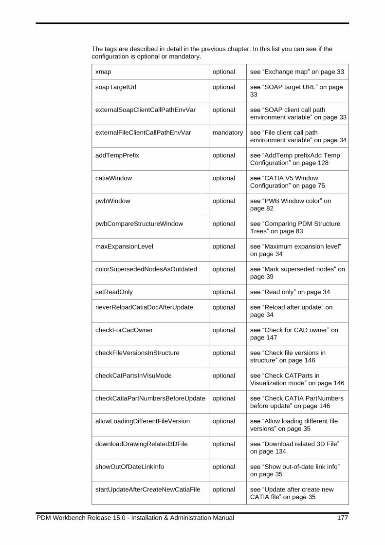
PDM Workbench Release 15.0 - Installation & Administration Manual 177
The tags are described in detail in the previous chapter. In this list you can see if the configuration is optional or mandatory.
xmap optional see “Exchange map” on page 33
soapTargetUrl optional see “SOAP target URL” on page 33
externalSoapClientCallPathEnvVar optional see “SOAP client call path environment variable” on page 33
externalFileClientCallPathEnvVar mandatory see “File client call path environment variable” on page 34
addTempPrefix optional see “AddTemp prefixAdd Temp Configuration” on page 128
catiaWindow optional see “CATIA V5 Window Configuration” on page 75
pwbWindow optional see “PWB Window color” on page 82
pwbCompareStructureWindow optional see “Comparing PDM Structure Trees” on page 83
maxExpansionLevel optional see “Maximum expansion level” on page 34
colorSupersededNodesAsOutdated optional see “Mark superseded nodes” on page 39
setReadOnly optional see “Read only” on page 34
neverReloadCatiaDocAfterUpdate optional see “Reload after update” on page 34
checkForCadOwner optional see “Check for CAD owner” on page 147
checkFileVersionsInStructure optional see “Check file versions in structure” on page 146
checkCatPartsInVisuMode optional see “Check CATParts in Visualization mode” on page 146
checkCatiaPartNumbersBeforeUpdate optional see “Check CATIA PartNumbers before update” on page 146
allowLoadingDifferentFileVersion optional see “Allow loading different file versions” on page 35
downloadDrawingRelated3DFile optional see “Download related 3D File” on page 134
showOutOfDateLinkInfo optional see “Show out-of-date link info” on page 35
startUpdateAfterCreateNewCatiaFile optional see “Update after create new CATIA file” on page 35

178 PDM Workbench Release 15.0 - Installation & Administration Manual
uploadChangedFilesAtSyncFailure optional see “Upload changed files at sync failure” on page 35
checkAuthoringToolVersion optional see “Check for CAD document CATIA release at PDM update” on page 147
createThumbnailwithWindows optional see “Create thumbnails by CATIA” on page 109
allowBrokenLinkAtNewProduct optional see “Optional check for broken links at update” on page 147
displayCustomQueryButtons optional see “Display custom query buttons” on page 47
requiredDialogAttributes optional see “Required attributes” on page 36
queryDialogIsModal optional see “Modal dialog” on page 47
checkIfNoQueryAttrsFilled optional see “Check if no query attribute filled” on page 47
showDisplayStringInQueryListView optional see “Display string in query list view” on page 47
maximumDescriptionAttributeLength optional see “Maximum description attribute length” on page 36
showDataSourceNlsValues optional see “Show data source NLS values” on page 36
showCreateVersionAtUpdate optional see “Create version button” on page 54
defaultCreateVersionAtUpdateValue optional see “Default create version value” on page 54
queryDialogDimensions optional see “Configuring the size of the Query dialog” on page 46
duplicateStructureDialog optional see “Duplicate Structure Configuration” on page 70 and 71
duplicateStructure optional see “Context action “Duplicate Structure”” on page 69
duplicateStructureRequest optional see “Duplicate Structure Configuration” on page 71
showReconnectAtUpdate optional see “Reconnect at Update” on page 157
showUnlockAfterUpdate optional see “Unlock after Save” on page 54
showCreatePartsAtUpdate optional see “Show create parts” on page 55

PDM Workbench Release 15.0 - Installation & Administration Manual 179
defaultCreatePartsAtUpdateValue optional see “Default create parts value” on page 55
showCreateDialogsMultiColumn optional See “Show create dialogs multi column” on page 51
renameExistingExMapFilesAtLoad optional see “Rename existing files in exchange map” on page 36
duplicateRelatedDrawings optional
see “134
showLoadWithLinkInQuery optional see “Automatically loading CATDrawings or linked CATParts” on page 48
showLoadWithDrawingInQuery optional see “Automatically loading CATDrawings or linked CATParts” on page 48
removeToolbarIcons optional see “Toolbar Configuration” on page 40
filter3dRepTypes optional see “Additional Rep Types” on page 137
catiaEnvironment optional see “Customer-Specific Environment” on page 40
autoLoginOnSessionExpired optional see “Auto login on session expired” on page 36
sessionSettings optional see “Session settings” on page 36
installedLanguages mandatory see “Language settings” on page 38
dateFormat mandatory see “Date format” on page 38
lastModificationDateAttribute mandatory see “Last modification date attribute” on page 39
standardPartUserDefPropAttribute optional see “Standard Part functionality for BOM Part Structure Data Model” on page 96
partClasses optional see “Part classes” on page 39
standardPartFiles optional see “Standard Part Functionality” on page 96
boundingBoxAttributes optional see “Bounding box definition” on page 131
catiaNodeBehaviorDefinitions optional see “Configurable CATIA Components Support” on page 152

180 PDM Workbench Release 15.0 - Installation & Administration Manual
templateFiles optional see “Management of CATIA Templates” on page 103
updateCatiaUserDefinedProperties optional see “CATIA user defined attributes” on page 125
updateCatiaLinksInPdm optional see “Link Support” on page 134 and “Basic Multi-Model Link Support” on page 135
attrsModifiableAtRevise optional see “Modifiable attributes” on page 67
expandStructureForRevise optional see “Expand structure” on page 68
“object”: 1 - n
This tag contains the definition of a PDM object class which can be used (queried, created, etc.) by the user.
The definition of PDM object classes, their corresponding dialogs and the actions that can be performed on them are described in the chapter PDM Objects.
“relation”: 1 - n
This tag contains the definition of PDM relation classes that can be accessed (expanded, created, etc.) by the user.
The definition of PDM relation classes, their corresponding dialogs and the actions that can be performed on them are described in the chapter PDM Relations.
“attribute”: 0 - n
The definition of PDM attributes that are referenced in dialogs.
Attributes and dialog forms are explained in the chapter PDM Attributes and Form Attributes.
“pwbAttribute”: 0 - n
The definition of attributes that do not correspond directly to PDM attributes of PDM objects.
Attributes and dialog forms are explained in the chapter PDM Attributes and Form Attributes.
“dataSource”: 0 - n
Data sources contain attribute values. By assigning data sources to attributes default values for these attributes can be defined.
Data sources are explained in the chapter Data Sources.
PDM Attributes and Form Attributes
Every PDM attribute that is displayed in a dialog form should be defined in an attribute tag.
The attribute definition contains the following attributes:

PDM Workbench Release 15.0 - Installation & Administration Manual 181
▪ “name” Mandatory, must correspond to the PDM attribute's name.
▪ “displayName” Mandatory. As described in “NLS Support for Display Names” the NLS string for the “displayName” XML attribute is defined in the CATNls file specific to the PDM system and the customization.
▪ “dataSource” Optional. The data source includes the possible values for this attribute.
▪ “isFileName” Optional. If is set to “true” the value of the corresponding input file name is checked about illegal2 characters when creating a file.
▪ “isPartNumber” Optional.
▪ “autoName” Optional.
▪ “isDerived” Optional.
Example:
<attribute name="name" displayName="NLS_Name" isFileName="true"
isPartNumber="true" autoName="true" />
<attribute name="current" displayName="NLS_current"
dataSource="LifeCycleStates" />
<attribute name="revision" displayName="NLS_Revision" />
A form definition contains form attributes which reference the previously defined PDM attribute.
The form attribute definitions contain the following attributes:
▪ “name” Mandatory, must correspond to the PDM attribute's name.
▪ “displayName” Optional. As described in “NLS Support for Display Names” the NLS string for the “displayName” XML attribute is defined in the CATNls file specific to the PDM system and the customization. If not defined here the display name of the “attribute” tag will be used.
▪ “mode” Possible values are “output” (read-only), “update” (can be modified), or “select” (e.g. for combo boxes).
Default is “output”.
▪ “visibleLength” Optional, the length of the text editor widget in characters.
▪ “allowedLength” Optional, the length of the value that can be inserted in the text editor widget in characters.
▪ “required” “true” or “false”. If “true”, then a value must be set.
Default is “false”.
▪ “widgetType” Possible values are “SingleLineEditor”, “MultiLineEditor”, “ComboBox”, “SingleCheckBox”, “CheckBoxes”, “RadioButtons”, “SingleSelectorList”, “MultiSelectorList”, “NameValueList”, “Date”.
2 Filenames must not contain control characters, non-printable characters and any of the following characters: *?:;\/<>|

182 PDM Workbench Release 15.0 - Installation & Administration Manual
Default is “SingleLineEditor”.
▪ “embeddedObjAttr” Optional. If the PDM attribute refers to a different PDM attribute in a contained object attribute, then this XML attribute's value contains that object attribute's name.
▪ “embeddedAttribute” Optional. The name of the PDM attribute of the embedded object. If “embeddedObjAttr” is set, then “embeddedAttribute” must be set, too.
▪ “dataSource” Optional. The value defines the link to a data source that is more special than the linked data source in the <attribute> tag.
▪ “listViewRelevant” “true” or “false”. If “true”, then the attribute will appear in the query list view.
This attribute should only be added to “Query” forms. Please refer to the PDM Workbench User Manual for more information.
Default is “false”.
▪ “sort” Possible values are “true” or “false”. If “true”, then the attribute can be sorted in the query result window.
▪ “displayOnly” Possible values are “true” or “false”. If “true”, then the display value of the value of the data source will be used.
▪ “entryAllowed” Possible values are “true” or “false”. If “true”, then the user can enter a text additional to the attached data source.
Example:
<form name="Query">
<formAttribute name="name" widgetType="SingleLineEditor"
mode="update" visibleLength="15" required="false"
listViewRelevant="true" />
Form definitions generally refer to classes of PDM objects (query form, properties form, etc.). The definition of PDM object classes is described in chapter PDM Objects.
Description of the Widget Types
There are nine different widget types available to build up dialogs with. All widget types except “SingleLineEditor”, “MultiLineEditor” and one mode of “NameValueList” can only be used on attributes that have certain kinds of Data Sources attached. Data Sources are a container of a limited set of values.
The detailed explanation of Data Sources you can find in chapter Data Sources.
SingleLineEditor Supports “update” and “output” mode. Can be used for attributes with no data source attached and also for attributes with data sources of type “SingleValue”.
Picture 190: Single Line Editor Widget, update mode
Picture 191: Single Line Editor Widget, output mode

PDM Workbench Release 15.0 - Installation & Administration Manual 183
MultiLineEditor Supports “update” and “output” mode. Can be used for attributes with no data source attached and also for attributes with data sources of type “ValueList”.
Picture 192: Multi Line Editor Widget, update mode
ComboBox Supports “select” and “output” mode. This widget type can only be used for attributes with data sources of type “ValueList”, “BooleanValueList” or “invokeMessage” if this message returns a set of values.
Picture 193: Combo Box Widget, select mode
SingleCheckBox Supports “select” and “output” mode. Needs an attribute with a data source of type “BooleanValueList”. This widget should be used only for required attributes or for attributes that are only displayed, already set to a value and cannot be updated.
Picture 194: Single Check Box Widget, select mode
CheckBoxes Supports “select” and “output” mode. Possible for attributes with data sources which contain several values (type “ValueList”, “BooleanValueList” or “invokeMessage”) and where the user can select more than one value.
Picture 195: Check Boxes Widget, select mode
RadioButtons Supports “select” and “output” mode. Possible for attributes with a data source of type “ValueList”, “BooleanValueList” or “invokeMessage” where only one value can be selected at one time. They should be used for required attributes only, because one value has always to be selected.

184 PDM Workbench Release 15.0 - Installation & Administration Manual
Picture 196: Radio Buttons Widget, select mode
SingleSelectorList Supports “select” and “output” mode. It represents a list with one column where one item is selectable. It can be used for all attributes with attached data sources of type “ValueList”, “BooleanValueList” or “invokeMessage”.
Picture 197: Single Selector List Widget, select mode
MultiSelectorList Supports “select” and “output” mode. It represents a list with one column where several items are selectable. (The multi-selector list looks like the single-selector list, except that more than one item of the list can be selected.) It can be used for all attributes with attached data sources of type “ValueList”, “BooleanValueList” or “invokeMessage”.
NameValueList Supports “select”, “update” and “output” mode. It represents a list with two columns (e.g. for name value sets)
→ when working in update mode the widget type can be used for all attributes within the Schema file (no data source needed). The user can change every single column item (columns can be empty).
→ when working in select mode the widget type can only be used for attributes with data sources of type “NameValueList” attached. (widget acts as a filter then)
Login Form
This tag contains a description of the “Login” form. It defines the attributes needed for logging in to the PDM system. Generally it contains the attributes “login name”, “password”, and “database” at least, though other attributes like “group” can be defined if it is necessary for the PDM system.
Example:
<form name="Login" info="ShowOnlyLoginData">
<frame displayName="NLS_UserData">
<pwbFormAttribute name="PWBLoginUser" widgetType="ComboBox"
mode="update" visibleLength="10" required="true"
entryAllowed="true" dataSource="UserNames" />
<pwbFormAttribute name="PWBLoginPassword"
widgetType="SingleLineEditor" mode="update"
visibleLength="10" required="false" />
<formAttribute name="LoginDatabase" widgetType="ComboBox"
mode="update" visibleLength="10" required="true"
entryAllowed="false" />
</frame>
</form>
The XML tags inside the frame tag describe how the attributes “user” and “password” are displayed in the login dialog.

PDM Workbench Release 15.0 - Installation & Administration Manual 185
Mandatory.
PDM Objects
XML tags object define PDM object classes that can be used in the PDM Workbench application. They represent the subset of objects defined within the PDM system which are needed in a PDM-CAD integration.
An object XML tag contains the following attributes:
▪ “name” The internal PDM class name.
▪ “displayName” The class name that is shown to the user.
▪ “icon” The icon that represents the class in the PDM window and the list window.
Example:
<object name="/Part/Assembly" displayName="NLS_Assembly" icon="Aras_Part">
For the icon to be displayed correctly in the PDM window a bitmap file with the name of the icon (in this example “Aras_Part.bmp”) must exist in the subdirectory “resources\graphic\icons\normal” of the CATIA V5 directory (e.g. “intel_a” on Windows 32 Bit CATIA installation, and “win_b64” on Windows 64 Bit CATIA installation).
The list view window needs a bitmap file with the file name (icon name) + “16x16.bmp”, in this example “Aras_Part16x16.bmp”.
As described in “NLS Support for Display Names” the NLS string for the XML attribute displayName is defined in the CATNls file specific to the PDM system and the customization.
Description of PDM Objects
The tag description defines which of the attributes of the class should be displayed beside the icon. In this example, these are the attributes “item_number”, “major_rev”, “generation”, “name”, and “state”.
Example:
<description>
<descAttribute name="item_number" />
<descAttribute name="major_rev" />
<descAttribute name="generation" />
<descAttribute name="name" />
<descAttribute name="state" />
</description>
Picture 198: PDM Node in PWB window

186 PDM Workbench Release 15.0 - Installation & Administration Manual
Tooltip of PDM Objects
The tag tooltipAttribute defines which string has to be shown as tooltip for the object. The value can be the name of an attribute of the object. If this value is empty, then the description defined in the chapter above will be used.
Example:
<tooltipAttribute name="description" />
The attribute “description” has the value “Test”.
Picture 199: Tooltip of PDM Node in PWB window
Actions on PDM Objects
Actions that can be performed with PDM objects have to be defined in the Schema file. There are two kinds of actions: So-called toolbar actions, which are started by clicking on an icon in the PDM Workbench toolbar, and context actions, which are started by right-clicking on the node and selecting one of the context menu items.
Toolbar actions are defined with an “action” tag. The action “Query” can be defined on any object type.
Example:
<!-- * all PWB toolbar actions permitted for this object * -->
<action name="Query" />
If, for instance, the action “Query” is defined for the object type “/Part/Assembly”, then, when the user clicks on the “Query” toolbar icon, the type “Assembly” (display name) is included in the query dialog list, otherwise it is not.
Picture 200: Select PDM object type in “PDM Query” dialog

PDM Workbench Release 15.0 - Installation & Administration Manual 187
Context Actions
Context actions are declared similarly to toolbar actions. For context actions, the tag “contextAction” is used.
Example:
<!-- * all PWB context actions permitted for this object * -->
<contextAction name="CheckIn" usedIn="PdmWindow|QueryDialog" />
<contextAction name="CheckOut" usedIn="PdmWindow|QueryDialog" />
<contextAction name="CheckInAll" usedIn="PdmWindow|QueryDialog" />
<contextAction name="CheckOutAll" usedIn="PdmWindow|QueryDialog" />
<contextAction name="Highlight" usedIn="PdmWindow" />
The attribute “usedIn” defines where the context action is shown. The attribute value “PdmWindow” activates the action in the PDM window. The attribute value “QueryDialog” activates the action in the result list view of the query dialog. These two attribute values can be combined with the pipe “|”.
If a certain context action is defined for a PDM object class in the Schema file, then the corresponding context menu entry for object nodes of that class exists.

188 PDM Workbench Release 15.0 - Installation & Administration Manual
Picture 201: Context actions for the type /Part/Assembly - Example
Some things to keep in mind regarding the definition of context actions:
If the context action “Unlock” (CheckIn) is defined, then the dialog forms “CheckInNew” and “CheckIn” must also be defined.
If the context action “Lock” (CheckOut) is defined, then the dialog form “CheckOut” must also be defined.
The context action “Load” (LoadStructure) should only be defined on part objects.
The following context actions are available:
Context action name Description
Properties see “Context action “Properties”” on page 148

PDM Workbench Release 15.0 - Installation & Administration Manual 189
CheckIn see “Context action “Unlock”” on page 148
CheckOut see “Context action “Lock”” on page 148
CheckInAll see “Context action “Unlock all”” on page 148
CheckOutAll see “Context action “Lock all” on page 149
Duplicate see “Context action “Duplicate”” on page 149
DuplicateStructure see “Duplicate Structure Configuration” on page 69
DuplicateDelete see “Context action “Duplicate-Delete”” on page 149
DuplicateSupersede see “Context action “Duplicate-Supersede”” on page 149
Insert see “Context action “Insert PDM Node”” on page 149
Replace see “Context action “Replace Node”” on page 150
Expand see “Context action “Expand”” on page 85
MultipleExpand see “Context action “Expand Multiple Levels”” on page 85
CustomExpand see “Context action “Custom Expand”” on page 86
DeExpand see “Context action “De-Expand”” on page 86
MultipleExpandWithBomChildren see “Context action “Expand Multiple Levels including Bom Children”” on page 87
CompareStructure see “Comparing PDM Structure Trees” on page 83
Promote see “Context action “Promote”” on page 94
Revise see “Context action “Revise”” on page 67
Execute see “Context action “Execute”” on page 150
UpdateSubCmpRels see “Context action “Update structure relations”” on page 150
UpdateParentCmpRel see “Context action “Update parent relation”” on page 150
LoadStructure see “Context action “Load”” on page 129
LoadStructureCurrent see “Context action “Load (Current)”” on page 130
LoadInContext see “Context action “Load in Context”” on page 130
LoadWithLinks see “Context action “Load with Links”” on page 130
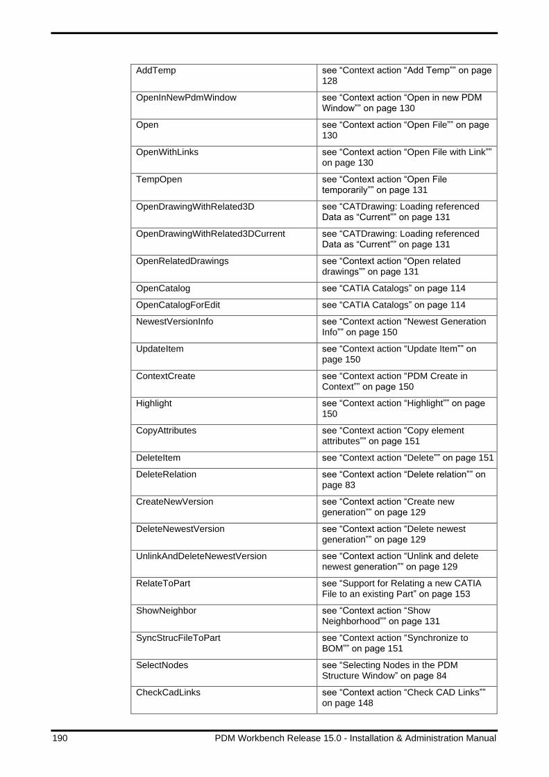
190 PDM Workbench Release 15.0 - Installation & Administration Manual
AddTemp see “Context action “Add Temp”” on page 128
OpenInNewPdmWindow see “Context action “Open in new PDM Window”” on page 130
Open see “Context action “Open File”” on page 130
OpenWithLinks see “Context action “Open File with Link”” on page 130
TempOpen see “Context action “Open File temporarily”” on page 131
OpenDrawingWithRelated3D see “CATDrawing: Loading referenced Data as “Current”” on page 131
OpenDrawingWithRelated3DCurrent see “CATDrawing: Loading referenced Data as “Current”” on page 131
OpenRelatedDrawings see “Context action “Open related drawings”” on page 131
OpenCatalog see “CATIA Catalogs” on page 114
OpenCatalogForEdit see “CATIA Catalogs” on page 114
NewestVersionInfo see “Context action “Newest Generation Info”” on page 150
UpdateItem see “Context action “Update Item”” on page 150
ContextCreate see “Context action “PDM Create in Context”” on page 150
Highlight see “Context action “Highlight”” on page 150
CopyAttributes see “Context action “Copy element attributes”” on page 151
DeleteItem see “Context action “Delete”” on page 151
DeleteRelation see “Context action “Delete relation”” on page 83
CreateNewVersion see “Context action “Create new generation”” on page 129
DeleteNewestVersion see “Context action “Delete newest generation”” on page 129
UnlinkAndDeleteNewestVersion see “Context action “Unlink and delete newest generation”” on page 129
RelateToPart see “Support for Relating a new CATIA File to an existing Part” on page 153
ShowNeighbor see “Context action “Show Neighborhood”” on page 131
SyncStrucFileToPart see “Context action “Synchronize to BOM”” on page 151
SelectNodes see “Selecting Nodes in the PDM Structure Window” on page 84
CheckCadLinks see “Context action “Check CAD Links”” on page 148

PDM Workbench Release 15.0 - Installation & Administration Manual 191
SetConfigInfoOnRelations see “Setting Configuration Information on Structure Relations” on page 162
Disabling context menu items in the CATIA structure window
In the corresponding “contextAction” definition the XML attribute “removeFromCatiaWindow” needs to be set to “true”:
<contextAction name="CheckIn" usedIn="PdmWindow|QueryDialog"
removeFromCatiaWindow="true" />
If that is done the corresponding context action will not be available in the CATIA window anymore. It may still be available as a context menu in the PDM structure window or as a context menu in the query dialog result list.
PDM Object Forms
The following forms can be defined for an object class:
“Query”, “Properties”, “UpdateItem”, “CheckInNew”, “CheckIn”, “CheckOut”
The “CheckIn” and “CheckOut” forms do not have to contain any attributes, they just need to be defined.
Example:
<form name="Query">
<formAttribute name="item_number" widgetType="SingleLineEditor"
mode="update" visibleLength="15" required="false"
listViewRelevant="true" />
<formAttribute name="major_rev" widgetType="SingleLineEditor"
mode="update" visibleLength="15" required="false"
listViewRelevant="true" />
<formAttribute name="generation" widgetType="SingleLineEditor"
mode="update" visibleLength="15" required="false"
listViewRelevant="true" />
<formAttribute name="name" widgetType="SingleLineEditor" mode="update"
visibleLength="15" required="false"
listViewRelevant="true" />
<formAttribute name="state" widgetType="SingleLineEditor" mode="update"
visibleLength="15" required="false"
listViewRelevant="true" />
<formAttribute name="unit" widgetType="ComboBox" mode="update"
visibleLength="15" required="false" />
<formAttribute name="make_buy" widgetType="ComboBox" mode="update"
visibleLength="15" required="false" />
<formAttribute name="description" widgetType="MultiLineEditor"
mode="update" visibleLength="15" required="false"
listViewRelevant="true" />
<formAttribute name="created_on" widgetType="SingleLineEditor"
mode="update" visibleLength="15" required="false"
listViewRelevant="true" />
<formAttribute name="modified_on" widgetType="SingleLineEditor"
mode="update" visibleLength="15" required="false"
listViewRelevant="true" />
</form>

192 PDM Workbench Release 15.0 - Installation & Administration Manual
PDM Relations
XML tags relation define PDM relation classes that can be used in the PDM Workbench application. They represent the subset of the relations defined in the PDM system that are needed in PDM-CAD integration.
As with the “object” XML tags, a “relation” XML tag contains the following attributes:
▪ “name” The internal PDM class name.
▪ “displayName” The class name that is shown to the user.
▪ “icon” The icon that represents the class in the PDM window and the list window.
▪ “createAllowed” Defines whether relations of this class can be created by the user. Relations are created by copying and pasting object nodes. If “createAllowed” is “true”, then, at paste, the relation class is included in the list of applicable relations, otherwise it is not. Please refer to the PDM Workbench User Manual for more information.
▪ “expandAllowed” Defines if it is allowed to expand this relation class explicitly in the context action “Expand”.
Example:
<relation name="Part BOM" displayName="NLS_PartBOM"
icon="Aras_Relation" createAllowed="true"
expandAllowed="true">
As for the PDM object classes, a bitmap file for the icon must exist in the CATIA icon subdirectory (“IconName.bmp” and “IconName16x16.bmp”).
As described in “NLS Support for Display Names” the NLS string for the “displayName” XML attribute is defined in the CATNls file specific to the PDM system and the customization.
Description of PDM Relations
As with PDM object definitions, the description tag defines which of the attributes of the class should be displayed beside the icon.
In this example the attributes “Class”, “major_rev”, and “generation” are defined as the description.
Example:
<description>
<descAttribute name="Class" />
<descAttribute name="major_rev" />
<descAttribute name="generation" />
</description>
“Relationship” tags
The tags leftToRightRelationship and rightToLeftRelationship define the relationships for the two sides of the relation. They contain the following XML attributes:
▪ “name” The internal PDM relationship name.
▪ “displayName” The relationship name that is shown to the user.

PDM Workbench Release 15.0 - Installation & Administration Manual 193
▪ “multipleExpand” If “multipleExpand” is “true”, then the relationship appears in the “Expand Multiple Levels” context menu, otherwise it does not. For this the context action “Expand Multiple Levels” must be defined on the PDM object. The default value is “false”.
Example:
The Aras relation “Part BOM” has the relationships “Part BOM_LeftToRight” (display name is “Uses Part BOM”) and “Part BOM_RightToLeft” (display name is “Is Used in Part BOM”).
<leftToRightRelationship name="Part BOM_LeftToRight"
displayName="NLS_PartBOM_LeftToRight"
multipleExpand="true" />
<rightToLeftRelationship name="Part BOM_RightToLeft"
displayName="NLS_PartBOM_RightToLeft"
multipleExpand="true" />
The text that describes a relation icon is the display name of the expanded relationship (“Part BOM” in this example) as well as the parameters defined in the “description” XML tag in parentheses “Class”, “major_rev”, and “generation” in this example).
Picture 202: Relation icon with relationship and description attribute
The display of a relationship name in the PDM tree can be switched off by defining the XML attribute “showNameInPdmTree” with the value “false” for a relationship definition:
<relation name="/CAD Structure/Structure"
displayName="NLS_CADStructure_Structure"
icon="Aras_Relation"
createAllowed="true" expandAllowed="true" info="AsSaved">
...
<leftToRightRelationship
name="/CAD Structure/Structure_LeftToRight"
displayName="NLS_CADStructure_Structure_LeftToRight"
multipleExpand="true"
showNameInPdmTree="false" />
<rightToLeftRelationship
name="/CAD Structure/Structure_RightToLeft"
displayName="NLS_CADStructure_Structure_RightToLeft"
multipleExpand="true" />
“Left and Right Object” Classes
The tags leftObject and rightObject define which object classes are valid for this relation.

194 PDM Workbench Release 15.0 - Installation & Administration Manual
In the following example the relation is between CATIA parts:
<leftObject name="/Part/Assembly" />
<rightObject name="/Part/Assembly" />
<rightObject name="/Part/Component" />
PDM Relation Forms
The following forms can be defined for a relation class:
“Properties”, “UpdateItem”, “Create”
The definition of the dialog forms for relations is similar to the definition of the dialog forms for objects.
Example:
<form name="UpdateItem">
<formAttribute name="reference_designator"
widgetType="SingleLineEditor" mode="update"
visibleLength="15" />
</form>
Data Sources
Data sources describe a static set of values that are already known when writing the Schema file. The set of these values will never change during the lifetime of the PDM Workbench.
Data Source “Value” tag
The value tag of static data sources contains the following XML tags:
▪ “name” The PDM name of the attribute.
▪ “displayName” The dialog display name of the attribute.
▪ “booleanValue” “true” or “false” to assign the correct value to the attribute names (this tag is only used for type “BooleanValueList”).
▪ “valueName” The PDM name of the value attribute (this tag is only used for type “NameValueList”).
▪ “displayValue” The dialog display name of the value attribute (this tag is only used for type “NameValueList”).
Static data sources can be of type:
SingleValue: the data source contains only one static element.
Example:
<dataSource name="Autoname" type="SingleValue">
<value name="autoname" displayName="NLS_Autoname" />
</dataSource>
ValueList: the data source contains a set of static value elements.
Example:
<dataSource name="LifeCycleStates" type="ValueList">
<value name="Preliminary" displayName="NLS_Preliminary" />

PDM Workbench Release 15.0 - Installation & Administration Manual 195
<value name="Review" displayName="NLS_Review" />
<value name="Approve" displayName="NLS_Approve" />
<value name="Released" displayName="NLS_Released" />
</dataSource>
Starting with Aras Innovator 12 SP8 there is a new feature "Inactive List Values". This feature allows the Aras Innovator administrator to inactivate List values going forward, while retaining the values as set on existing data. In Aras Innovator web client, starting in SP8, the List dropdown (and type-ahead) knows to omit any inactive values when setting new values, in a form or in a grid. When using a List dropdown (and type-ahead) for searching, the inactive values still appear.
In the PWBSchema file, list values in a data source of type “ValueList” can have the XML attribute “pdmInfo”. If this attribute has the value “InactiveListValue” the list entry is removed from dialogs which update an item. It is still present in other dialogs, like the query dialog. The default value is “ActiveListValue”.
Example:
<dataSource name="Unit" type="ValueList">
<value name="EA" displayName="NLS_EA" />
<value name="IN" displayName="NLS_IN"/>
<value name="FT" displayName="NLS_FT" pdmInfo="InactiveListValue" />
<value name="MM" displayName="NLS_MM"/>
<value name="CM" displayName="NLS_CM"/>
<value name="M" displayName="NLS_M"/>
</dataSource>
BooleanValueList: the data source contains exactly the value pair “true” and “false”.
Example:
<dataSource name="PlusOrMinus" type="BooleanValueList">
<value name="+" displayName="NLS_ValueSetPlus" booleanValue="true" />
<value name="-" displayName="NLS_ValueSetMinus" booleanValue="false" />
</dataSource>
NameValueList: the data source contains a list of name-value pairs.
Example:
<dataSource name="Test" type="NameValueList">
<value name="test1" displayName="NLS_test1" valueName="test1_value"
displayValue="NLS_test1_value" />
<value name="test2" displayName="NLS_test2" valueName="test2_value"
displayValue="NLS_test2_value" />
</dataSource>
Complete example of using a data source tag:
The attribute “CheckedOut” can be assigned exactly to “true” or “false”. Within the dialog this will be expressed by showing a “+” or a “-“ sign. Therefore we define a data source called “PlusOrMinus” and attach this container to the attribute description.
<attribute name="CheckedOut" displayName="NLS_CheckedOut"
dataSource="PlusOrMinus" />
<dataSource name="PlusOrMinus" type="BooleanValueList">

196 PDM Workbench Release 15.0 - Installation & Administration Manual
<value name="+" displayName="NLS_ValueSetPlus" booleanValue="true" />
<value name="-" displayName="NLS_ValueSetMinus" booleanValue="false" />
</dataSource>

PDM Workbench Release 15.0 - Installation & Administration Manual 197
CHAPTER 9
Troubleshooting This chapter lists error conditions and describes possible sources of such failures and how to solve them.
Type or Namespace “ArasUtil” could not be found …
Picture 203: Name space could not be found
Please replace calls of the class “ArasUtil” with calls to “PwbServerAddin.PwbServerApi”.
The usage of the class “ArasUtil” in custom server methods is now allowed anymore and has to be replaced with calls to “PwbServerAddin.PwbServerApi”.
Locking CAD Documents in CATIA fails when the Conversion Server is installed.
In some cases locking CAD documents in CATIA fails with this server stack trace:
PdmObject.PerformAction (Lock)
ArasUtil.AddOwner -> LockStatus:'0'
ArasUtil.AddOwner -> caught exception:'An item with the same key has
already been added.'
at System.Collections.Generic.Dictionary`2.Insert(TKey key, TValue
value, Boolean add)
at
System.Linq.Enumerable.ToDictionary[TSource,TKey,TElement](IEnumerable`1
source, Func`2 keySelector, Func`2 elementSelector, IEqualityComparer`1
comparer)

198 PDM Workbench Release 15.0 - Installation & Administration Manual
at Aras.Server.Core.FileContainerItemsOnAfterUpdate.Main(XmlDocument
inDom, XmlDocument outDom, Object eventData) in
E:\Builds\Innovator_RELS11-0-SP11\6812-RELS11-0-
SP11\Innovator.git\CompilableCode\Core\InternalMethods\Files\FileContainer
ItemsOnAfterUpdate.cs:line 67
If that happens please create the server setting “EnableFileCloneCreation” and set it to the value “false”. That should fix the issue.
Conversion Tasks fail for updated or new CAD files from PDM Workbench
The Aras 3D CAD to PDF Conversion may fail after Update from PDM Workbench. In this case please check the “Aras 3D CAD to PDF Conversion” Rule:
Picture 204: “Aras 3D CAD to PDF Conversion” Rule
Edit the Rule and uncheck all checkboxes for “Lock Dependency” in the Task Event Templates Tab.
Picture 205: “Uncheck Lock Dependencies Aras 3D CAD to PDF Conversion” Rule