PROJECT FINAL REPORT - CORDIS
42
Eco-design and Validation of In-Wheel Concept for Electric Vehicles Project acronym: EUNICE Grant agreement no.: 285688 Call: FP7-2011-GC-ELECTROCHEMICAL-STORAGE 22/12/2015 1 Version 1.0 PROJECT FINAL REPORT Grant Agreement number: 285688 Project acronym: EUNICE Project title: Eco-design and Validation of In-Wheel Concept for Electric Vehicles Funding Scheme: Large-scale integrating collaborative project Period covered: from 01.09.2012 to 30.08.2015 Project coordinator name, title and organisation: Alberto Peña AUTOMOTIVE unit responsible Fundación Tecnalia Research & Innovation Tel: +34 607 22 74 82 Fax: +34 901 70 60 09 E-mail: [email protected] Project website address: www.eunice-project.eu
-
Upload
khangminh22 -
Category
Documents
-
view
1 -
download
0
Transcript of PROJECT FINAL REPORT - CORDIS
Eco-design and Validation of In-Wheel Concept for Electric Vehicles
Project acronym: EUNICE Grant agreement no.: 285688
Call: FP7-2011-GC-ELECTROCHEMICAL-STORAGE
22/12/2015 1 Version 1.0
PROJECT FINAL REPORT
Grant Agreement number: 285688
Project acronym: EUNICE
Project title: Eco-design and Validation of In-Wheel Concept for Electric Vehicles
Funding Scheme: Large-scale integrating collaborative project
Period covered: from 01.09.2012 to 30.08.2015
Project coordinator name, title and organisation:
Alberto Peña
AUTOMOTIVE unit responsible
Fundación Tecnalia Research & Innovation
Tel: +34 607 22 74 82
Fax: +34 901 70 60 09
E-mail: [email protected]
Project website address: www.eunice-project.eu
Eco-design and Validation of In-Wheel Concept for Electric Vehicles
Project acronym: EUNICE Grant agreement no.: 285688
Call: FP7-2011-GC-ELECTROCHEMICAL-STORAGE
22/12/2015 2 Version 1.0
4.1 Final publishable summary report
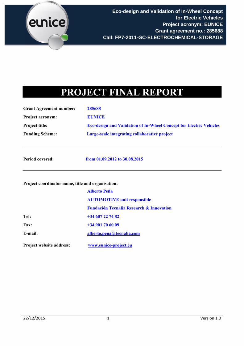
A. Executive Summary Eunice project main goal is to demonstrate the concept of motor in wheel system for passenger car segment, which allows maximum design freedom for new generation of electric vehicles. The project clustered a series of expert partners, each one with deep knowledge of specific domain, and having specific “state of the art” technologies which will provide a synergic effect when combined to come up with an innovative and functional design.
Figure 1: Context of Eunice project, implementation on mass production EV´s
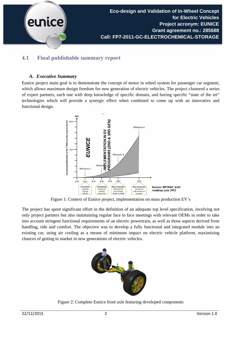
The project has spent significant effort in the definition of an adequate top level specification, involving not only project partners but also maintaining regular face to face meetings with relevant OEMs in order to take into account stringent functional requirements of an electric powertrain, as well as those aspects derived from handling, ride and comfort. The objective was to develop a fully functional and integrated module into an existing car, using air cooling as a means of minimum impact on electric vehicle platform, maximizing chances of getting to market in new generations of electric vehicles.
Figure 2: Complete Eunice front axle featuring developed components
Eco-design and Validation of In-Wheel Concept for Electric Vehicles
Project acronym: EUNICE Grant agreement no.: 285688
Call: FP7-2011-GC-ELECTROCHEMICAL-STORAGE
22/12/2015 3 Version 1.0
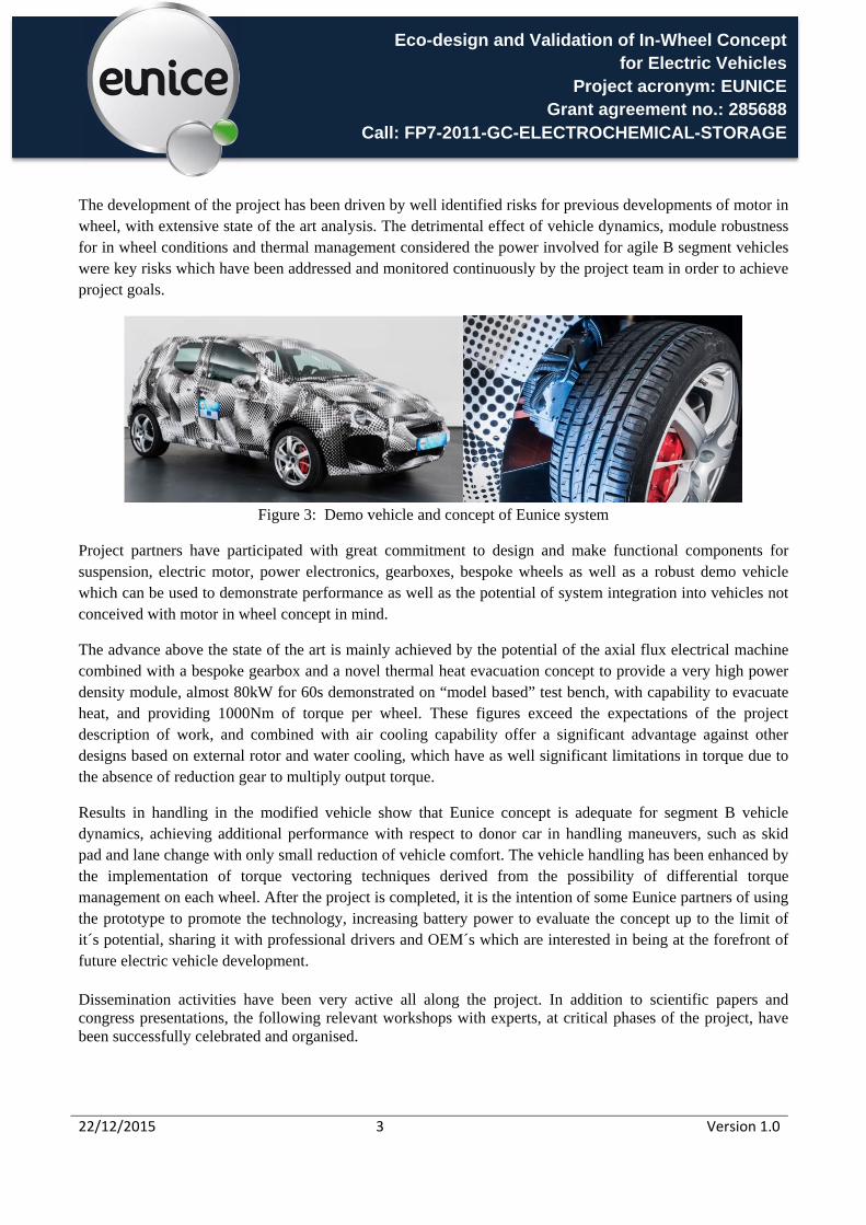
The development of the project has been driven by well identified risks for previous developments of motor in wheel, with extensive state of the art analysis. The detrimental effect of vehicle dynamics, module robustness for in wheel conditions and thermal management considered the power involved for agile B segment vehicles were key risks which have been addressed and monitored continuously by the project team in order to achieve project goals.
Figure 3: Demo vehicle and concept of Eunice system
Project partners have participated with great commitment to design and make functional components for suspension, electric motor, power electronics, gearboxes, bespoke wheels as well as a robust demo vehicle which can be used to demonstrate performance as well as the potential of system integration into vehicles not conceived with motor in wheel concept in mind.
The advance above the state of the art is mainly achieved by the potential of the axial flux electrical machine combined with a bespoke gearbox and a novel thermal heat evacuation concept to provide a very high power density module, almost 80kW for 60s demonstrated on “model based” test bench, with capability to evacuate heat, and providing 1000Nm of torque per wheel. These figures exceed the expectations of the project description of work, and combined with air cooling capability offer a significant advantage against other designs based on external rotor and water cooling, which have as well significant limitations in torque due to the absence of reduction gear to multiply output torque.
Results in handling in the modified vehicle show that Eunice concept is adequate for segment B vehicle dynamics, achieving additional performance with respect to donor car in handling maneuvers, such as skid pad and lane change with only small reduction of vehicle comfort. The vehicle handling has been enhanced by the implementation of torque vectoring techniques derived from the possibility of differential torque management on each wheel. After the project is completed, it is the intention of some Eunice partners of using the prototype to promote the technology, increasing battery power to evaluate the concept up to the limit of it´s potential, sharing it with professional drivers and OEM´s which are interested in being at the forefront of future electric vehicle development.
Dissemination activities have been very active all along the project. In addition to scientific papers and congress presentations, the following relevant workshops with experts, at critical phases of the project, have been successfully celebrated and organised.
Eco-design and Validation of In-Wheel Concept for Electric Vehicles
Project acronym: EUNICE Grant agreement no.: 285688
Call: FP7-2011-GC-ELECTROCHEMICAL-STORAGE
22/12/2015 4 Version 1.0
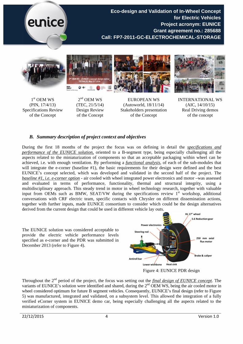
1st OEM WS (PIN, 17/4/13)
Specifications Review of the Concept
2nd OEM WS (TEC, 21/5/14) Design Review of the Concept
EUROPEAN WS (Autoworld, 18/11/14)
Stakeholders presentation of the Concept
INTERNATIONAL WS (AIC, 14/10/15)
Real Driving demos of the concept
B. Summary description of project context and objectives
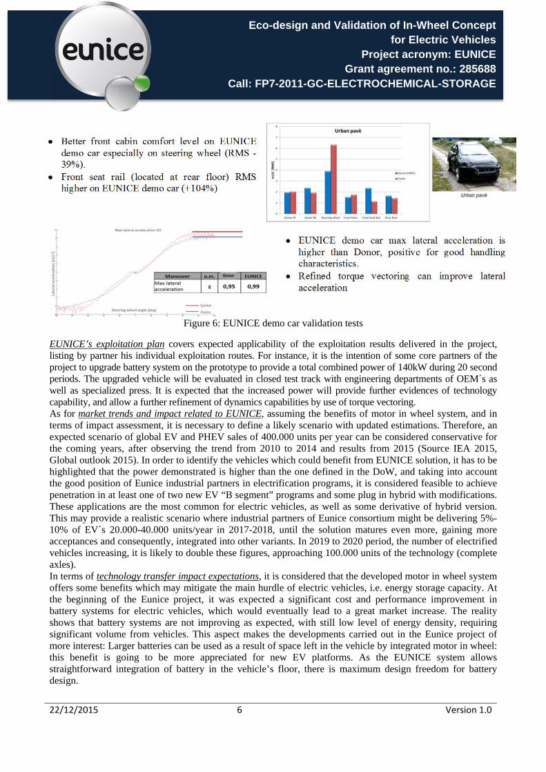
During the first 18 months of the project the focus was on defining in detail the specifications and performance of the EUNICE solution, oriented to a B-segment type, being especially challenging all the aspects related to the miniaturization of components so that an acceptable packaging within wheel can be achieved, i.e. with enough ventilation. By performing a functional analysis, of each of the sub-modules that will integrate the e-corner (baseline #1), the basic requirements for their design were defined and the best EUNICE’s concept selected, which was developed and validated in the second half of the project. The baseline #1, i.e. e-corner option - air cooled with wheel integrated power electronics and motor –was assessed and evaluated in terms of performance, functionality, thermal and structural integrity, using a multidisciplinary approach. This steady trend in motor in wheel technology research, together with valuable input from OEMs such as BMW, SEAT/VW during the specifications review 1st workshop, additional conversations with CRF electric team, specific contacts with Chrysler on different dissemination actions, together with further inputs, made EUNICE consortium to consider which could be the design alternatives derived from the current design that could be used in different vehicle lay outs. The EUNICE solution was considered acceptable to provide the electric vehicle performance levels specified as e-corner and the PDR was submitted in December 2013 (refer to Figure 4).
Figure 4: EUNICE PDR design
Throughout the 2nd period of the project, the focus was setting out the final design of EUNICE concept. The variants of EUNICE’s solution were identified and shared, during the 2nd OEM WS, being the air cooled motor in wheel considered optimum for future B segment vehicles. Consequently, EUNICE’s final design (refer to Figure 5) was manufactured, integrated and validated, on a subsystem level. This allowed the integration of a fully verified eCorner system in EUNICE demo car, being especially challenging all the aspects related to the miniaturization of components.

Eco-design and Validation of In-Wheel Concept for Electric Vehicles
Project acronym: EUNICE Grant agreement no.: 285688
Call: FP7-2011-GC-ELECTROCHEMICAL-STORAGE
22/12/2015 5 Version 1.0
Figure 5: EUNICE validated solution As suggested during the 2nd OEM WS, in addition to EUNICE DoW’s scope and under WP2 RTD activities, the EUNICE Torque Vectoring ECU has been developed, based on an algorithm which was conceived following an alternative approach to conventional closed-loop yaw-rate control algorithms. The concept consists in basing on the current centripetal acceleration target estimation as main torque-vectoring criteria. This is calculated basing on a estimation of the ideal (target) centripetal acceleration force that should correspond to the steering wheel position (from which the ideal radius is calculated) and the linear speed, which indicates how “strong” the curve is, and therefore how strong the torque vectoring should be. Additional compensation factors depending on other vehicle's variables are also involved in the algorithm. It has been implemented on a high-performance system-on-chip embedded platform, a Xilinx Zynq 7020, and it was programmed to provide an as transparent as possible integration into the existing EUNICE demo car powertrain. Under EUNICE demo car validation tests, it has been demonstrated physically that its vehicle dynamics performance is comparable to the one of the correspondent donor car. On the other hand, when integrating the Torque Vectoring ECU in EUNICE demo car, CAN communication issues were detected, thus it was finally validated with satisfactory results using DYNACAR®. Enhanced design areas to be improved have been clearly identified and corrective actions for production have been suggested, based on the validation results.
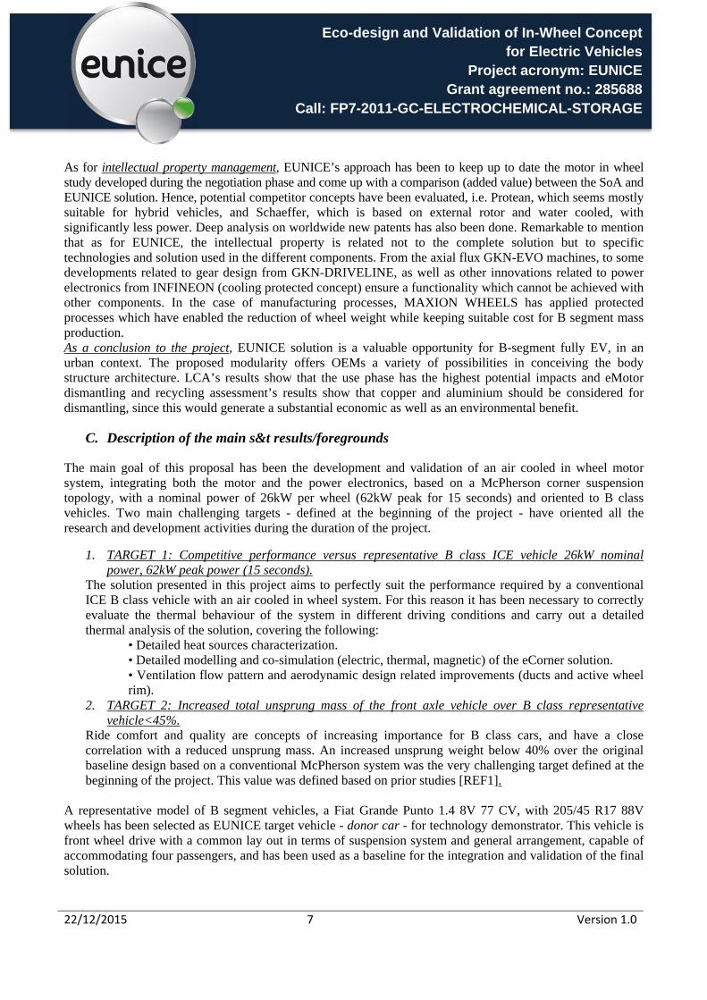
Better front cabin comfort level on EUNICE demo car especially on steering wheel (RMS -30%).
Rear floor RMS values are higher on EUNICE demo car (+32%) due to worse condition from rear domes.
Eco-design and Validation of In-Wheel Concept for Electric Vehicles
Project acronym: EUNICE Grant agreement no.: 285688
Call: FP7-2011-GC-ELECTROCHEMICAL-STORAGE
22/12/2015 6 Version 1.0
Better front cabin comfort level on EUNICE
demo car especially on steering wheel (RMS -39%).
Front seat rail (located at rear floor) RMS higher on EUNICE demo car (+104%)
EUNICE demo car max lateral acceleration is
higher than Donor, positive for good handling characteristics.
Refined torque vectoring can improve lateral acceleration
Figure 6: EUNICE demo car validation tests
EUNICE’s exploitation plan covers expected applicability of the exploitation results delivered in the project, listing by partner his individual exploitation routes. For instance, it is the intention of some core partners of the project to upgrade battery system on the prototype to provide a total combined power of 140kW during 20 second periods. The upgraded vehicle will be evaluated in closed test track with engineering departments of OEM´s as well as specialized press. It is expected that the increased power will provide further evidences of technology capability, and allow a further refinement of dynamics capabilities by use of torque vectoring. As for market trends and impact related to EUNICE, assuming the benefits of motor in wheel system, and in terms of impact assessment, it is necessary to define a likely scenario with updated estimations. Therefore, an expected scenario of global EV and PHEV sales of 400.000 units per year can be considered conservative for the coming years, after observing the trend from 2010 to 2014 and results from 2015 (Source IEA 2015, Global outlook 2015). In order to identify the vehicles which could benefit from EUNICE solution, it has to be highlighted that the power demonstrated is higher than the one defined in the DoW, and taking into account the good position of Eunice industrial partners in electrification programs, it is considered feasible to achieve penetration in at least one of two new EV “B segment” programs and some plug in hybrid with modifications. These applications are the most common for electric vehicles, as well as some derivative of hybrid version. This may provide a realistic scenario where industrial partners of Eunice consortium might be delivering 5%-10% of EV´s 20.000-40.000 units/year in 2017-2018, until the solution matures even more, gaining more acceptances and consequently, integrated into other variants. In 2019 to 2020 period, the number of electrified vehicles increasing, it is likely to double these figures, approaching 100.000 units of the technology (complete axles). In terms of technology transfer impact expectations, it is considered that the developed motor in wheel system offers some benefits which may mitigate the main hurdle of electric vehicles, i.e. energy storage capacity. At the beginning of the Eunice project, it was expected a significant cost and performance improvement in battery systems for electric vehicles, which would eventually lead to a great market increase. The reality shows that battery systems are not improving as expected, with still low level of energy density, requiring significant volume from vehicles. This aspect makes the developments carried out in the Eunice project of more interest: Larger batteries can be used as a result of space left in the vehicle by integrated motor in wheel: this benefit is going to be more appreciated for new EV platforms. As the EUNICE system allows straightforward integration of battery in the vehicle’s floor, there is maximum design freedom for battery design.
Eco-design and Validation of In-Wheel Concept for Electric Vehicles
Project acronym: EUNICE Grant agreement no.: 285688
Call: FP7-2011-GC-ELECTROCHEMICAL-STORAGE
22/12/2015 7 Version 1.0
As for intellectual property management, EUNICE’s approach has been to keep up to date the motor in wheel study developed during the negotiation phase and come up with a comparison (added value) between the SoA and EUNICE solution. Hence, potential competitor concepts have been evaluated, i.e. Protean, which seems mostly suitable for hybrid vehicles, and Schaeffer, which is based on external rotor and water cooled, with significantly less power. Deep analysis on worldwide new patents has also been done. Remarkable to mention that as for EUNICE, the intellectual property is related not to the complete solution but to specific technologies and solution used in the different components. From the axial flux GKN-EVO machines, to some developments related to gear design from GKN-DRIVELINE, as well as other innovations related to power electronics from INFINEON (cooling protected concept) ensure a functionality which cannot be achieved with other components. In the case of manufacturing processes, MAXION WHEELS has applied protected processes which have enabled the reduction of wheel weight while keeping suitable cost for B segment mass production. As a conclusion to the project, EUNICE solution is a valuable opportunity for B-segment fully EV, in an urban context. The proposed modularity offers OEMs a variety of possibilities in conceiving the body structure architecture. LCA’s results show that the use phase has the highest potential impacts and eMotor dismantling and recycling assessment’s results show that copper and aluminium should be considered for dismantling, since this would generate a substantial economic as well as an environmental benefit.
C. Description of the main s&t results/foregrounds
The main goal of this proposal has been the development and validation of an air cooled in wheel motor system, integrating both the motor and the power electronics, based on a McPherson corner suspension topology, with a nominal power of 26kW per wheel (62kW peak for 15 seconds) and oriented to B class vehicles. Two main challenging targets - defined at the beginning of the project - have oriented all the research and development activities during the duration of the project.
1. TARGET 1: Competitive performance versus representative B class ICE vehicle 26kW nominal power, 62kW peak power (15 seconds).
The solution presented in this project aims to perfectly suit the performance required by a conventional ICE B class vehicle with an air cooled in wheel system. For this reason it has been necessary to correctly evaluate the thermal behaviour of the system in different driving conditions and carry out a detailed thermal analysis of the solution, covering the following:
• Detailed heat sources characterization. • Detailed modelling and co-simulation (electric, thermal, magnetic) of the eCorner solution. • Ventilation flow pattern and aerodynamic design related improvements (ducts and active wheel rim).
2. TARGET 2: Increased total unsprung mass of the front axle vehicle over B class representative vehicle<45%.
Ride comfort and quality are concepts of increasing importance for B class cars, and have a close correlation with a reduced unsprung mass. An increased unsprung weight below 40% over the original baseline design based on a conventional McPherson system was the very challenging target defined at the beginning of the project. This value was defined based on prior studies [REF1].
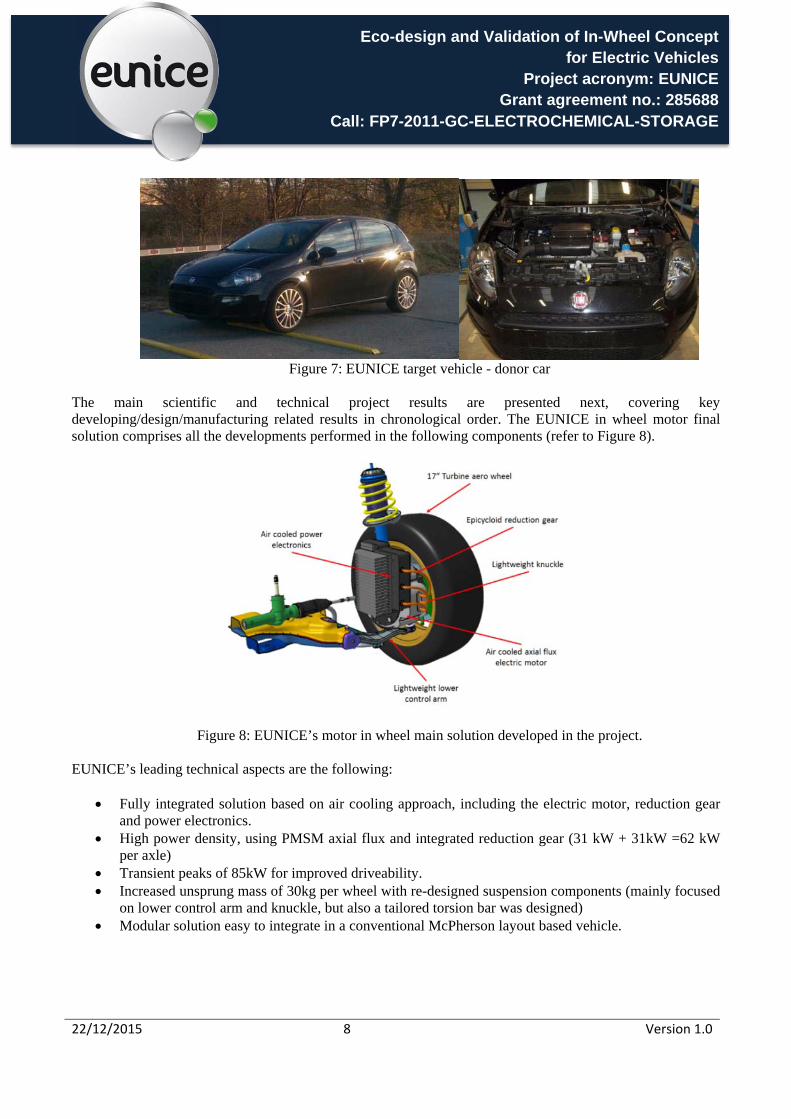
A representative model of B segment vehicles, a Fiat Grande Punto 1.4 8V 77 CV, with 205/45 R17 88V wheels has been selected as EUNICE target vehicle - donor car - for technology demonstrator. This vehicle is front wheel drive with a common lay out in terms of suspension system and general arrangement, capable of accommodating four passengers, and has been used as a baseline for the integration and validation of the final solution.
Eco-design and Validation of In-Wheel Concept for Electric Vehicles
Project acronym: EUNICE Grant agreement no.: 285688
Call: FP7-2011-GC-ELECTROCHEMICAL-STORAGE
22/12/2015 8 Version 1.0
Figure 7: EUNICE target vehicle - donor car
The main scientific and technical project results are presented next, covering key developing/design/manufacturing related results in chronological order. The EUNICE in wheel motor final solution comprises all the developments performed in the following components (refer to Figure 8).
Figure 8: EUNICE’s motor in wheel main solution developed in the project. EUNICE’s leading technical aspects are the following:
Fully integrated solution based on air cooling approach, including the electric motor, reduction gear and power electronics.
High power density, using PMSM axial flux and integrated reduction gear (31 kW + 31kW =62 kW per axle)
Transient peaks of 85kW for improved driveability. Increased unsprung mass of 30kg per wheel with re-designed suspension components (mainly focused
on lower control arm and knuckle, but also a tailored torsion bar was designed) Modular solution easy to integrate in a conventional McPherson layout based vehicle.

Eco-design and Validation of In-Wheel Concept for Electric Vehicles
Project acronym: EUNICE Grant agreement no.: 285688
Call: FP7-2011-GC-ELECTROCHEMICAL-STORAGE
22/12/2015 9 Version 1.0
C1 Electric and electronic components
C11 Electric motor and power electronics EUNICE’s specifications in terms of motor torque speed requirements are presented in Figure 9. The points representing the ARTEMIS based duty cycle used for the project are under the expected electric motor characteristics in nominal conditions. This is a positive condition for the motor as it is feasible to deliver all the torque most of the time without high thermal overheating requirement, in long period driving conditions. Additional torque margin (limited in time) for faster accelerations or especial driving conditions (gradient capability) is also available.
Figure 9: EUNICE’s vehicle torque vs speed requirements
Figure 10 presents the motor general characteristics considered for EUNICE. These values were used as the initial data for the internal dimensioning, i.e. stator, windings, rotor and magnets, of the electric motor design.
Figure 10: EUNICE’s electric motor general features
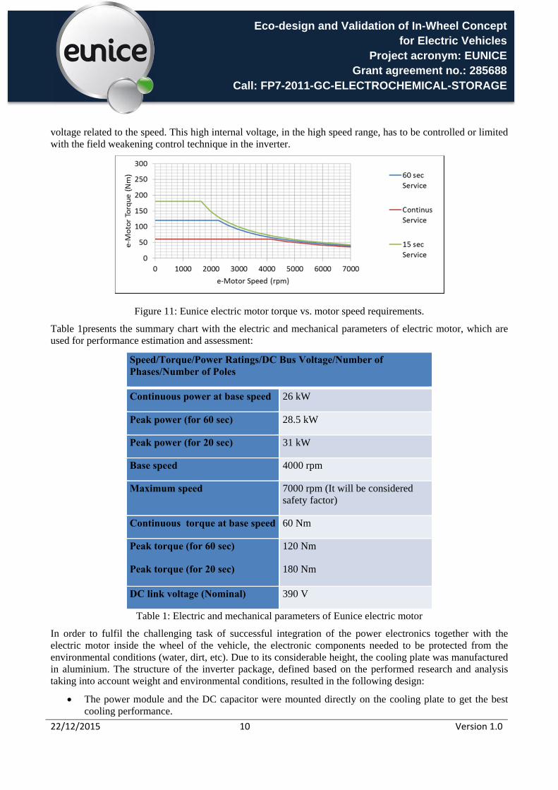
The torque speed characteristics (Figure 11) considered for the electric motor are separated in a torque constant area (up to the base speed) and the power speed constant (from the base speed up to the maximum). Permanent magnets synchronous motors, due to the internal magnet excitation, show a linear back-EMF
Eco-design and Validation of In-Wheel Concept for Electric Vehicles
Project acronym: EUNICE Grant agreement no.: 285688
Call: FP7-2011-GC-ELECTROCHEMICAL-STORAGE
22/12/2015 10 Version 1.0
voltage related to the speed. This high internal voltage, in the high speed range, has to be controlled or limited with the field weakening control technique in the inverter.
Figure 11: Eunice electric motor torque vs. motor speed requirements.
Table 1presents the summary chart with the electric and mechanical parameters of electric motor, which are used for performance estimation and assessment:
Speed/Torque/Power Ratings/DC Bus Voltage/Number of Phases/Number of Poles
Continuous power at base speed 26 kW
Peak power (for 60 sec) 28.5 kW
Peak power (for 20 sec) 31 kW
Base speed 4000 rpm
Maximum speed 7000 rpm (It will be considered safety factor)
Continuous torque at base speed 60 Nm
Peak torque (for 60 sec)
Peak torque (for 20 sec) 120 Nm
180 Nm
DC link voltage (Nominal) 390 V
Table 1: Electric and mechanical parameters of Eunice electric motor
In order to fulfil the challenging task of successful integration of the power electronics together with the electric motor inside the wheel of the vehicle, the electronic components needed to be protected from the environmental conditions (water, dirt, etc). Due to its considerable height, the cooling plate was manufactured in aluminium. The structure of the inverter package, defined based on the performed research and analysis taking into account weight and environmental conditions, resulted in the following design:
The power module and the DC capacitor were mounted directly on the cooling plate to get the best cooling performance.
Eco-design and Validation of In-Wheel Concept for Electric Vehicles
Project acronym: EUNICE Grant agreement no.: 285688
Call: FP7-2011-GC-ELECTROCHEMICAL-STORAGE
22/12/2015 11 Version 1.0
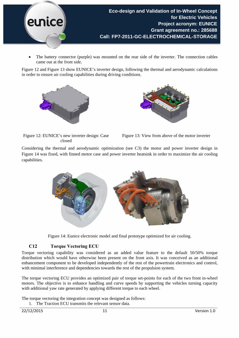
The battery connector (purple) was mounted on the rear side of the inverter. The connection cables came out at the front side.
Figure 12 and Figure 13 show EUNICE’s inverter design, following the thermal and aerodynamic calculations in order to ensure air cooling capabilities during driving conditions.
Figure 12: EUNICE’s new inverter design: Case closed
Figure 13: View from above of the motor inverter
Considering the thermal and aerodynamic optimization (see C3) the motor and power inverter design in Figure 14 was fixed, with finned motor case and power inverter heatsink in order to maximize the air cooling capabilities.
Figure 14: Eunice electronic model and final prototype optimized for air cooling.
C12 Torque Vectoring ECU Torque vectoring capability was considered as an added value feature to the default 50/50% torque distribution which would have otherwise been present on the front axis. It was conceived as an additional enhancement component to be developed independently of the rest of the powertrain electronics and control, with minimal interference and dependencies towards the rest of the propulsion system.
The torque vectoring ECU provides an optimized pair of torque set-points for each of the two front in-wheel motors. The objective is to enhance handling and curve speeds by supporting the vehicles turning capacity with additional yaw rate generated by applying different torque to each wheel.
The torque vectoring the integration concept was designed as follows:
1. The Traction ECU transmits the relevant sensor data.
Eco-design and Validation of In-Wheel Concept for Electric Vehicles
Project acronym: EUNICE Grant agreement no.: 285688
Call: FP7-2011-GC-ELECTROCHEMICAL-STORAGE
22/12/2015 12 Version 1.0
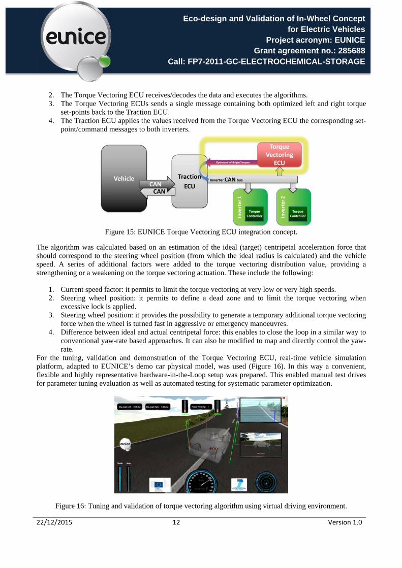
2. The Torque Vectoring ECU receives/decodes the data and executes the algorithms. 3. The Torque Vectoring ECUs sends a single message containing both optimized left and right torque
set-points back to the Traction ECU. 4. The Traction ECU applies the values received from the Torque Vectoring ECU the corresponding set-
point/command messages to both inverters.
Figure 15: EUNICE Torque Vectoring ECU integration concept.
The algorithm was calculated based on an estimation of the ideal (target) centripetal acceleration force that should correspond to the steering wheel position (from which the ideal radius is calculated) and the vehicle speed. A series of additional factors were added to the torque vectoring distribution value, providing a strengthening or a weakening on the torque vectoring actuation. These include the following:
1. Current speed factor: it permits to limit the torque vectoring at very low or very high speeds. 2. Steering wheel position: it permits to define a dead zone and to limit the torque vectoring when
excessive lock is applied. 3. Steering wheel position: it provides the possibility to generate a temporary additional torque vectoring
force when the wheel is turned fast in aggressive or emergency manoeuvres. 4. Difference between ideal and actual centripetal force: this enables to close the loop in a similar way to
conventional yaw-rate based approaches. It can also be modified to map and directly control the yaw-rate.
For the tuning, validation and demonstration of the Torque Vectoring ECU, real-time vehicle simulation platform, adapted to EUNICE’s demo car physical model, was used (Figure 16). In this way a convenient, flexible and highly representative hardware-in-the-Loop setup was prepared. This enabled manual test drives for parameter tuning evaluation as well as automated testing for systematic parameter optimization.
Figure 16: Tuning and validation of torque vectoring algorithm using virtual driving environment.

Eco-design and Validation of In-Wheel Concept for Electric Vehicles
Project acronym: EUNICE Grant agreement no.: 285688
Call: FP7-2011-GC-ELECTROCHEMICAL-STORAGE
22/12/2015 13 Version 1.0
C2 Mechanical components The design development of EUNICE suspension components was performed using all the design criteria normally adopted by the OEM’s in the standard development of suspension components, and trying to maintain the original kinematics of the donor vehicle.
Specific and detailed design was performed for lower control arm, knuckle and torsion bar, and the rest of the suspension components were modified adequately to fulfil all the performance requirements.
The functional analysis performed during the design of the suspension mechanical components is summarized in the following list.
Elasto-kinematic analysis
Vehicle handling and comfort simulation
Vertical loads durability and misuse validation
Longitudinal loads durability and misuse validation
Lateral loads durability and misuse validation
Using this design guide, all the vehicle and suspension driveability performances were checked, followed by the design and the calculations of all the suspension components according with the durability and misuse targets (Figure 17).
Figure 17: Example of misuse analysis for the knuckle and lower control arm suspension parts.
Due to space restrictions in the EUNICE in-wheel solution, new knuckle, control arm and stabilizer bar were designed following the automotive standards. In Figure 18, the solution adopted for the knuckle is shown. Due to the weight restrictions only the aluminium material was considered for the knuckle.
Weight: 4,27 kg
Material: Aluminium AlSi7Mg Alloy (Low Pressure Die Casting process technology).

Eco-design and Validation of In-Wheel Concept for Electric Vehicles
Project acronym: EUNICE Grant agreement no.: 285688
Call: FP7-2011-GC-ELECTROCHEMICAL-STORAGE
22/12/2015 14 Version 1.0
Figure 18: Eunice suspension knuckle CAD model and final prototype manufactured in aluminium with low pressure die casting.
For the control arm three different materials / technologies were evaluated, and are presented in Table 2 with their respective main parameter values. Finally ADI cast iron was selected, due to the better weight/strength ratio obtained (Figure 19).
Material / Process / Weight σ Yield [MPa] σ UTS [MPa] ε [%]
Cast Iron 40-30-15 / Casting process technology / 3,60 kg
295 390 15
ADI / Austempered ductile iron 900-8 (Casting + heat threating process technology) / 2,80 kg
600 900 7
Aluminium AlSi7Mg Alloy / Low pressure die casting process technology / 2,20 kg
220 270 6
Table 2: Control arm with material, process and main characteristics
Figure 19: Eunice suspension control arm CAD model and final prototype manufactured in cast iron with ADI heat threating process.
Eco-design and Validation of In-Wheel Concept for Electric Vehicles
Project acronym: EUNICE Grant agreement no.: 285688
Call: FP7-2011-GC-ELECTROCHEMICAL-STORAGE
22/12/2015 15 Version 1.0
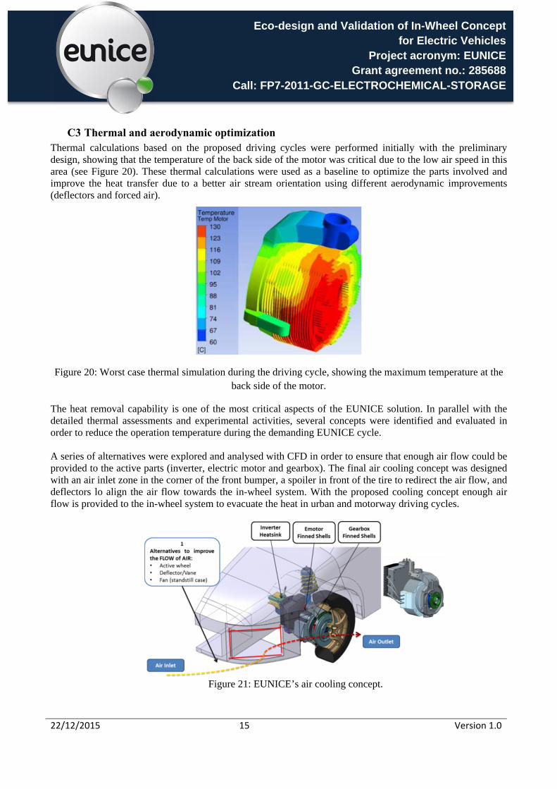
C3 Thermal and aerodynamic optimization Thermal calculations based on the proposed driving cycles were performed initially with the preliminary design, showing that the temperature of the back side of the motor was critical due to the low air speed in this area (see Figure 20). These thermal calculations were used as a baseline to optimize the parts involved and improve the heat transfer due to a better air stream orientation using different aerodynamic improvements (deflectors and forced air).
Figure 20: Worst case thermal simulation during the driving cycle, showing the maximum temperature at the back side of the motor.
The heat removal capability is one of the most critical aspects of the EUNICE solution. In parallel with the detailed thermal assessments and experimental activities, several concepts were identified and evaluated in order to reduce the operation temperature during the demanding EUNICE cycle. A series of alternatives were explored and analysed with CFD in order to ensure that enough air flow could be provided to the active parts (inverter, electric motor and gearbox). The final air cooling concept was designed with an air inlet zone in the corner of the front bumper, a spoiler in front of the tire to redirect the air flow, and deflectors lo align the air flow towards the in-wheel system. With the proposed cooling concept enough air flow is provided to the in-wheel system to evacuate the heat in urban and motorway driving cycles.
Figure 21: EUNICE’s air cooling concept.
Eco-design and Validation of In-Wheel Concept for Electric Vehicles
Project acronym: EUNICE Grant agreement no.: 285688
Call: FP7-2011-GC-ELECTROCHEMICAL-STORAGE
22/12/2015 16 Version 1.0
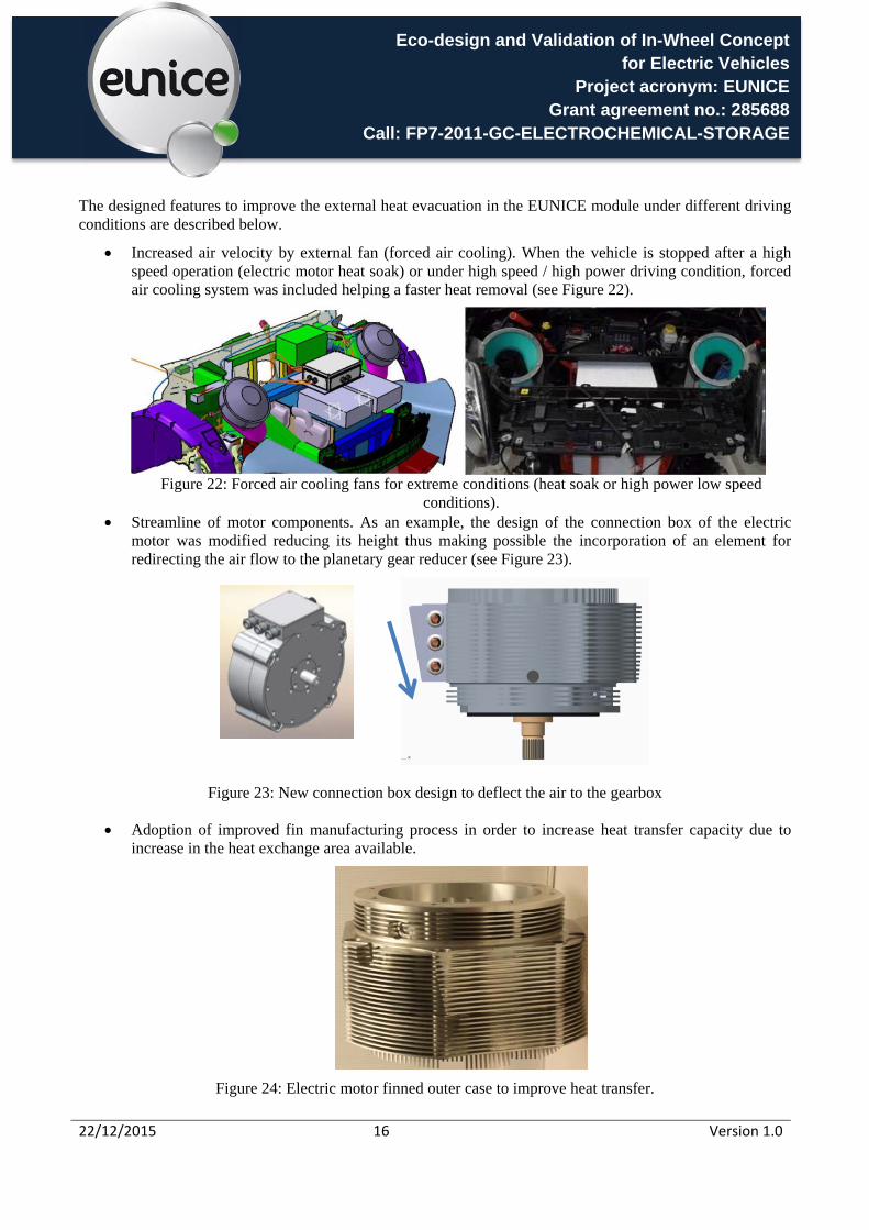
The designed features to improve the external heat evacuation in the EUNICE module under different driving conditions are described below.
Increased air velocity by external fan (forced air cooling). When the vehicle is stopped after a high speed operation (electric motor heat soak) or under high speed / high power driving condition, forced air cooling system was included helping a faster heat removal (see Figure 22).
Figure 22: Forced air cooling fans for extreme conditions (heat soak or high power low speed
conditions). Streamline of motor components. As an example, the design of the connection box of the electric
motor was modified reducing its height thus making possible the incorporation of an element for redirecting the air flow to the planetary gear reducer (see Figure 23).
Figure 23: New connection box design to deflect the air to the gearbox
Adoption of improved fin manufacturing process in order to increase heat transfer capacity due to increase in the heat exchange area available.
Figure 24: Electric motor finned outer case to improve heat transfer.
Eco-design and Validation of In-Wheel Concept for Electric Vehicles
Project acronym: EUNICE Grant agreement no.: 285688
Call: FP7-2011-GC-ELECTROCHEMICAL-STORAGE
22/12/2015 17 Version 1.0
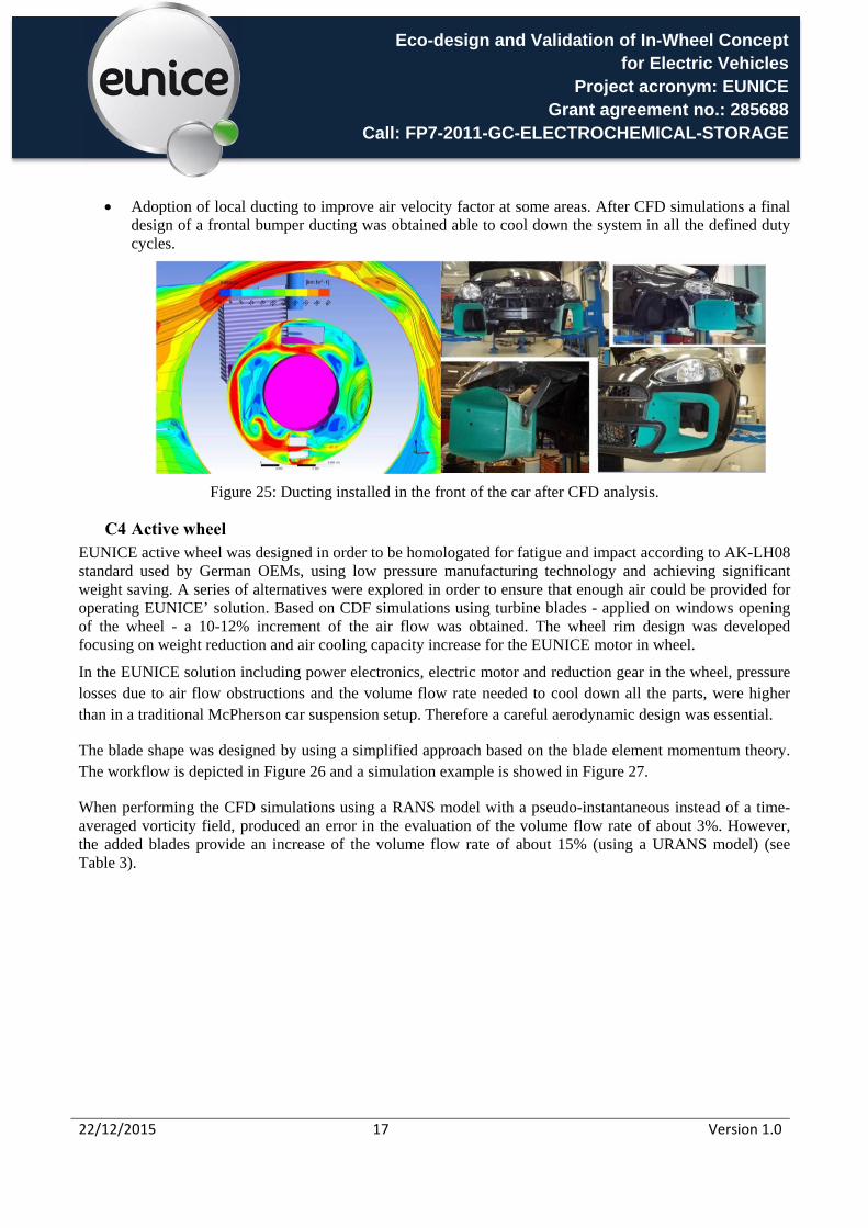
Adoption of local ducting to improve air velocity factor at some areas. After CFD simulations a final design of a frontal bumper ducting was obtained able to cool down the system in all the defined duty cycles.
Figure 25: Ducting installed in the front of the car after CFD analysis.
C4 Active wheel EUNICE active wheel was designed in order to be homologated for fatigue and impact according to AK-LH08 standard used by German OEMs, using low pressure manufacturing technology and achieving significant weight saving. A series of alternatives were explored in order to ensure that enough air could be provided for operating EUNICE’ solution. Based on CDF simulations using turbine blades - applied on windows opening of the wheel - a 10-12% increment of the air flow was obtained. The wheel rim design was developed focusing on weight reduction and air cooling capacity increase for the EUNICE motor in wheel.
In the EUNICE solution including power electronics, electric motor and reduction gear in the wheel, pressure losses due to air flow obstructions and the volume flow rate needed to cool down all the parts, were higher than in a traditional McPherson car suspension setup. Therefore a careful aerodynamic design was essential.
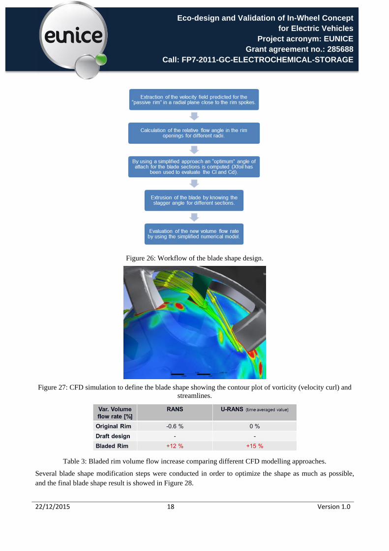
The blade shape was designed by using a simplified approach based on the blade element momentum theory. The workflow is depicted in Figure 26 and a simulation example is showed in Figure 27.
When performing the CFD simulations using a RANS model with a pseudo-instantaneous instead of a time-averaged vorticity field, produced an error in the evaluation of the volume flow rate of about 3%. However, the added blades provide an increase of the volume flow rate of about 15% (using a URANS model) (see Table 3).
Eco-design and Validation of In-Wheel Concept for Electric Vehicles
Project acronym: EUNICE Grant agreement no.: 285688
Call: FP7-2011-GC-ELECTROCHEMICAL-STORAGE
22/12/2015 18 Version 1.0
Figure 26: Workflow of the blade shape design.
Figure 27: CFD simulation to define the blade shape showing the contour plot of vorticity (velocity curl) and streamlines.
Table 3: Bladed rim volume flow increase comparing different CFD modelling approaches.
Several blade shape modification steps were conducted in order to optimize the shape as much as possible, and the final blade shape result is showed in Figure 28.

Eco-design and Validation of In-Wheel Concept for Electric Vehicles
Project acronym: EUNICE Grant agreement no.: 285688
Call: FP7-2011-GC-ELECTROCHEMICAL-STORAGE
22/12/2015 19 Version 1.0
Figure 28: CDR Rim (grey) and new blade design (green)
The turbine blade final design is fixed to the wheel using screws, and was manufactured by using rapid prototyping technology using DURAFORM GF material. The choice of selective laser sintering and glass filled polyamide material was done due to requirement for good mechanical stiffness and elevate temperature resistance (Figure 29).
Figure 29: Turbine blade fixed on wheel
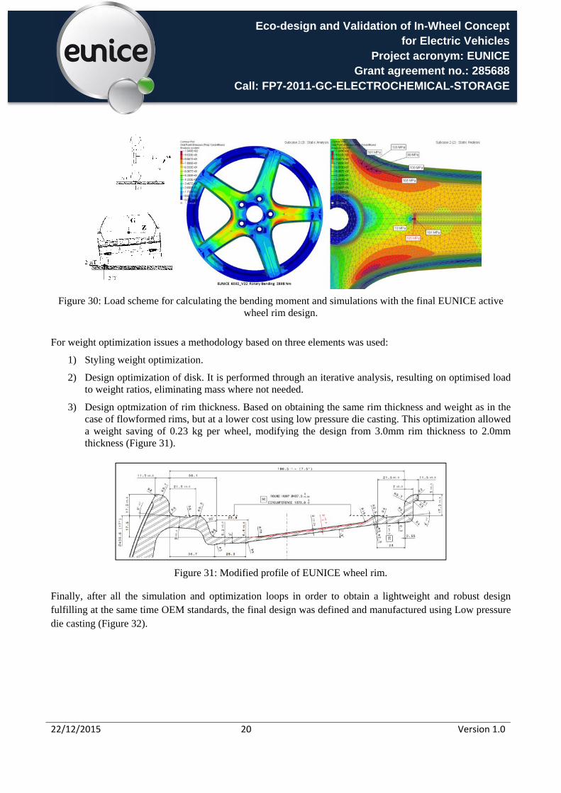
The design and development of the lightweight wheel rim was made according to AK-LH 08 standard. A bending moment of 2898Nm was applied with the aim of checking that the requirement of 200.000 cycles without cracks was fulfilled.
Eco-design and Validation of In-Wheel Concept for Electric Vehicles
Project acronym: EUNICE Grant agreement no.: 285688
Call: FP7-2011-GC-ELECTROCHEMICAL-STORAGE
22/12/2015 20 Version 1.0
Figure 30: Load scheme for calculating the bending moment and simulations with the final EUNICE active wheel rim design.
For weight optimization issues a methodology based on three elements was used:
1) Styling weight optimization.
2) Design optimization of disk. It is performed through an iterative analysis, resulting on optimised load to weight ratios, eliminating mass where not needed.
3) Design optmization of rim thickness. Based on obtaining the same rim thickness and weight as in the case of flowformed rims, but at a lower cost using low pressure die casting. This optimization allowed a weight saving of 0.23 kg per wheel, modifying the design from 3.0mm rim thickness to 2.0mm thickness (Figure 31).
Figure 31: Modified profile of EUNICE wheel rim.
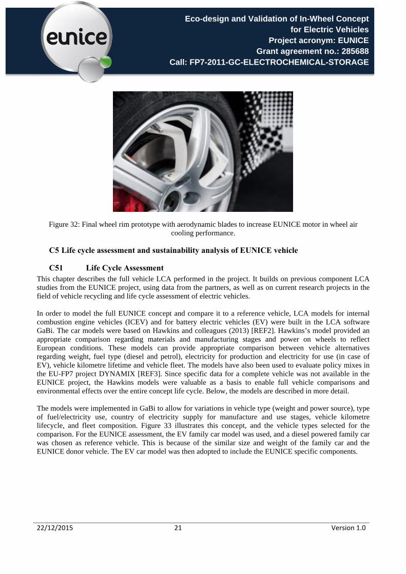
Finally, after all the simulation and optimization loops in order to obtain a lightweight and robust design fulfilling at the same time OEM standards, the final design was defined and manufactured using Low pressure die casting (Figure 32).
Eco-design and Validation of In-Wheel Concept for Electric Vehicles
Project acronym: EUNICE Grant agreement no.: 285688
Call: FP7-2011-GC-ELECTROCHEMICAL-STORAGE
22/12/2015 21 Version 1.0
Figure 32: Final wheel rim prototype with aerodynamic blades to increase EUNICE motor in wheel air cooling performance.
C5 Life cycle assessment and sustainability analysis of EUNICE vehicle
C51 Life Cycle Assessment This chapter describes the full vehicle LCA performed in the project. It builds on previous component LCA studies from the EUNICE project, using data from the partners, as well as on current research projects in the field of vehicle recycling and life cycle assessment of electric vehicles. In order to model the full EUNICE concept and compare it to a reference vehicle, LCA models for internal combustion engine vehicles (ICEV) and for battery electric vehicles (EV) were built in the LCA software GaBi. The car models were based on Hawkins and colleagues (2013) [REF2]. Hawkins’s model provided an appropriate comparison regarding materials and manufacturing stages and power on wheels to reflect European conditions. These models can provide appropriate comparison between vehicle alternatives regarding weight, fuel type (diesel and petrol), electricity for production and electricity for use (in case of EV), vehicle kilometre lifetime and vehicle fleet. The models have also been used to evaluate policy mixes in the EU-FP7 project DYNAMIX [REF3]. Since specific data for a complete vehicle was not available in the EUNICE project, the Hawkins models were valuable as a basis to enable full vehicle comparisons and environmental effects over the entire concept life cycle. Below, the models are described in more detail. The models were implemented in GaBi to allow for variations in vehicle type (weight and power source), type of fuel/electricity use, country of electricity supply for manufacture and use stages, vehicle kilometre lifecycle, and fleet composition. Figure 33 illustrates this concept, and the vehicle types selected for the comparison. For the EUNICE assessment, the EV family car model was used, and a diesel powered family car was chosen as reference vehicle. This is because of the similar size and weight of the family car and the EUNICE donor vehicle. The EV car model was then adopted to include the EUNICE specific components.

Eco-design and Validation of In-Wheel Concept for Electric Vehicles
Project acronym: EUNICE Grant agreement no.: 285688
Call: FP7-2011-GC-ELECTROCHEMICAL-STORAGE
22/12/2015 22 Version 1.0
Figure 33: Vehicle types, lifecycle impacts and possible parameters variations. The overall material composition of the reference vehicle and the EUNICE concept do not differ significantly, as seen in Figure 34 and Figure 35. The EUNICE concept has less steel and iron than the reference vehicle, but more aluminium, slightly more copper and larger battery (the Li-ion battery pack).
Figure 34: Material composition of the reference vehicle
Figure 35: Material breakdown EUNICE concept
Figure 36 below summarizes the results for the different environmental impact categories for EUNICE vehicle in the base case scenario (160.000 km use case, 10 years).

Eco-design and Validation of In-Wheel Concept for Electric Vehicles
Project acronym: EUNICE Grant agreement no.: 285688
Call: FP7-2011-GC-ELECTROCHEMICAL-STORAGE
22/12/2015 23 Version 1.0
Figure 36: EUNICE motor in wheel concept environmental impacts.
The results from the LCA are largely in line with previous studies of vehicles, in the sense that the use phase is dominating most impact categories. This is due to the relatively long life of vehicles, and the impacts associated with production of fuel and electricity. Exceptions from this pattern are the results for resource depletion potential and stratospheric ozone depletion potential, where the production phase has a larger impact. It should be noted that differences in the level of detail in LCA models for part production may play a role here, since the EUNICE specific part models are based on data from the project while the replaced reference vehicle part models are based on literature data. The EUNICE concept has a lower total environmental impact in all categories except the particulate matter emissions and the stratospheric ozone depletion potential. Particulate emissions in the EUNICE use phase are dominated by electricity production, but maintenance of the vehicle also contributes by almost a third of the total emissions, due to the fact that it includes replacement and disposal of one battery. If maintenance would not be included for any of the vehicles, the EUNICE concept would have lower total particulate emissions than the reference vehicle. The potential climate impact is particularly lower for EUNICE, but as seen in the sensitivity analysis, these results are strongly depending on how the electricity for the use phase is produced. In the same way that a cleaner electricity mix lowers the EUNICE total GWP, the production of electricity from coal has the potential to outweigh the benefits of lower direct emissions in the use phase. In a wider systems perspective, it is important to consider how an increased electricity demand for transportation purposes would influence the total production in the European system.
C52 Life Cycle Sustainability Analysis Life Cycle Sustainability Analysis (LCSA) was conducted to evaluate the EUNICE solution components and manufacturing processes on the individual product level, product category level, and societal level, with respect to the economic, environmental and social implications relevant for the EUNICE motor in wheel based concept. Based on the range of BEV penetration in the literature data summary in Table 4, the following three scenarios for BEV market shares are outlined for the study (Table 5). The characteristics of the scenarios are inspired by the DYNAMIX project [REF3]. The scenarios provide snapshot images of what the new sales in

Eco-design and Validation of In-Wheel Concept for Electric Vehicles
Project acronym: EUNICE Grant agreement no.: 285688
Call: FP7-2011-GC-ELECTROCHEMICAL-STORAGE
22/12/2015 24 Version 1.0
the small car segment would look like in 2020, 2030 and 2040 respectively. In 2013, there were 13 196 000 vehicles in EU28, whereof 90% (11.9 million) passenger cars [REF4]. The market share for small vehicles, where EUNICE would be included, was about 25% of the fleet in 2013 [REF4]. For simplicity, it was assumed that the market share of BEV in the small car segment is the same as in the total fleet.
Study 2010 2014 2015 2018 2020 2022 2025 2030
AEA 2009 Optimistic - 0 - 2%
10%
Pessimistic - 0 - 0.5%
2%
JRC 2010 Optimistic - - - - 2.9%
29%
Pessimistic - - - - 0.5%
1.9%
CE Delft 2011 Optimistic 0
0%
2%
13% 22%
Most realistic 0
0.%
1%
5% 11%
Table 4: Summary of literature on BEV scenarios.
Scenario 2020 BEV share 2030 BEV share 2040 BEV share
No change 0.2% 0.2% 0.2%
Slow development 0.5% 3% 10%
Optimistic 1% 10% 25%
Table 5: BEV market shares for the three EUNICE background scenarios.
The market penetration of new technologies like EUNICE does not only affect the environment through, for example, climate emissions. It also has an effect on social and economic development. The EUNICE concept can potentially have important impacts on, for example, the following sustainability aspects:
Environmental aspects: Emission levels from cars on EU level (including assumptions for electricity production) such as CO2, particles and NOX, congestion and noise levels in cities.
Economic aspects: Job opportunities and GDP (construction/retrofitting of electric vehicles, battery production, charging infrastructure, technology export)
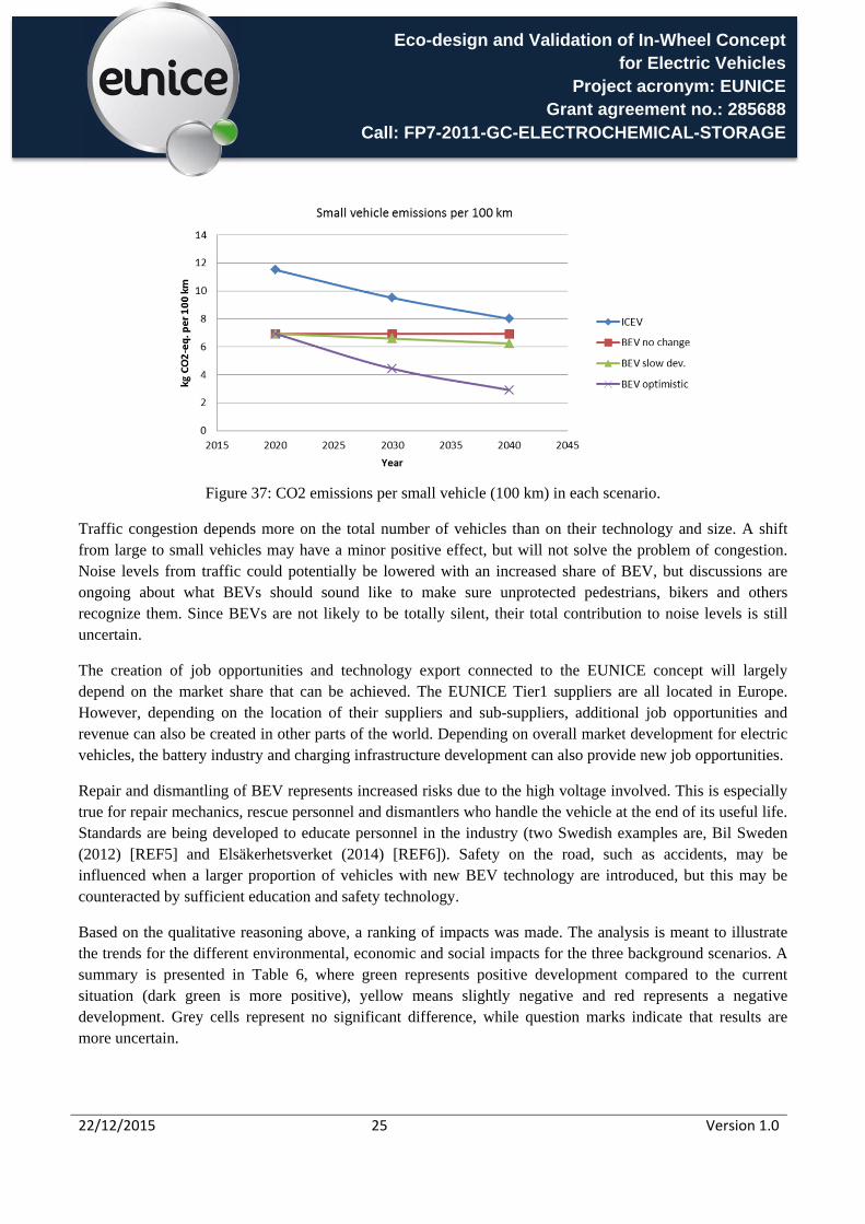
Social aspects: Road safety and work environment risks. Direct emissions from electric vehicles are much lower than from conventional ICE vehicles and a larger proportion of BEV would have a positive impact on climate emissions (see example for small vehicles in Figure 37). Driven by legislation, the emission levels for ICEV will also decrease, regardless of the BEV development. Together with the decreasing total fleet size and a larger proportion of small vehicles in the “slow development” and “optimistic” scenarios, this will lead to a decrease in total fleet climate impact. Based on the results from the LCA comparison, total particulate emissions could increase depending on battery development. The emissions associated with battery disposal are not likely to be concentrated to city centers, where health problems related to traffic emissions are most prominent.
Eco-design and Validation of In-Wheel Concept for Electric Vehicles
Project acronym: EUNICE Grant agreement no.: 285688
Call: FP7-2011-GC-ELECTROCHEMICAL-STORAGE
22/12/2015 25 Version 1.0
Figure 37: CO2 emissions per small vehicle (100 km) in each scenario.
Traffic congestion depends more on the total number of vehicles than on their technology and size. A shift from large to small vehicles may have a minor positive effect, but will not solve the problem of congestion. Noise levels from traffic could potentially be lowered with an increased share of BEV, but discussions are ongoing about what BEVs should sound like to make sure unprotected pedestrians, bikers and others recognize them. Since BEVs are not likely to be totally silent, their total contribution to noise levels is still uncertain.
The creation of job opportunities and technology export connected to the EUNICE concept will largely depend on the market share that can be achieved. The EUNICE Tier1 suppliers are all located in Europe. However, depending on the location of their suppliers and sub-suppliers, additional job opportunities and revenue can also be created in other parts of the world. Depending on overall market development for electric vehicles, the battery industry and charging infrastructure development can also provide new job opportunities.
Repair and dismantling of BEV represents increased risks due to the high voltage involved. This is especially true for repair mechanics, rescue personnel and dismantlers who handle the vehicle at the end of its useful life. Standards are being developed to educate personnel in the industry (two Swedish examples are, Bil Sweden (2012) [REF5] and Elsäkerhetsverket (2014) [REF6]). Safety on the road, such as accidents, may be influenced when a larger proportion of vehicles with new BEV technology are introduced, but this may be counteracted by sufficient education and safety technology.
Based on the qualitative reasoning above, a ranking of impacts was made. The analysis is meant to illustrate the trends for the different environmental, economic and social impacts for the three background scenarios. A summary is presented in Table 6, where green represents positive development compared to the current situation (dark green is more positive), yellow means slightly negative and red represents a negative development. Grey cells represent no significant difference, while question marks indicate that results are more uncertain.

Eco-design and Validation of In-Wheel Concept for Electric Vehicles
Project acronym: EUNICE Grant agreement no.: 285688
Call: FP7-2011-GC-ELECTROCHEMICAL-STORAGE
22/12/2015 26 Version 1.0
Table 6: Summary of LCSA results.
C6 Donor car modifications and assembly of the EUNICE in wheel motor system The integration of the EUNICE in wheel system, the battery and the other features were developed starting from the donor vehicle and considering the main project constraints associated to the following aspects:
EUNICE in wheel system dimensions. Front/Rear weight distribution respect to donor car. Cooling needs. Battery position (engine compartment).
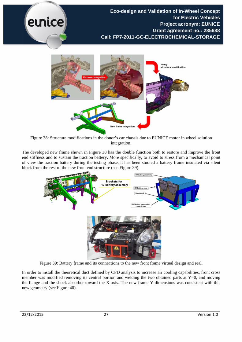
The project constraints implied unforeseen series of significant modifications on the original body in white structure; as a consequence the front end was redesigned defining a new structural frame, which follows the same functionality but with slightly narrow distance between front longitudinal chassis beams of the donor car structure. This modification was required due to the size of power inverters considering the fin size for effective air cooling of the solution. A summary of the modifications is described in the following Figure 38.
Societal impact type EUNICE background scenario
No change Slow development Optimistic
Short term climate impact, fleet level Long term climate impact, fleet level
Traffic noise levels in cities ? ?
Particulate emissions ? ?
City congestion
Job opportunities in the EU BEV industry
Job opportunities in the EU car industry
Job opportunities outside the EU ?
Export of BEV technology ?
Road safety ? ?
Work environment risk
Eco-design and Validation of In-Wheel Concept for Electric Vehicles
Project acronym: EUNICE Grant agreement no.: 285688
Call: FP7-2011-GC-ELECTROCHEMICAL-STORAGE
22/12/2015 27 Version 1.0
Figure 38: Structure modifications in the donor’s car chassis due to EUNICE motor in wheel solution
integration.
The developed new frame shown in Figure 38 has the double function both to restore and improve the front end stiffness and to sustain the traction battery. More specifically, to avoid to stress from a mechanical point of view the traction battery during the testing phase, it has been studied a battery frame insulated via silent block from the rest of the new front end structure (see Figure 39).
Figure 39: Battery frame and its connections to the new front frame virtual design and real.
In order to install the theoretical duct defined by CFD analysis to increase air cooling capabilities, front cross member was modified removing its central portion and welding the two obtained parts at Y=0, and moving the flange and the shock absorber toward the X axis. The new frame Y-dimensions was consistent with this new geometry (see Figure 40).

Eco-design and Validation of In-Wheel Concept for Electric Vehicles
Project acronym: EUNICE Grant agreement no.: 285688
Call: FP7-2011-GC-ELECTROCHEMICAL-STORAGE
22/12/2015 28 Version 1.0
Figure 40: Structural modification due to cooling area requested
As result, the donor and demo front end appear consistently different, as shown in Figure 41.
Figure 41: Final structural differences between donor and demo
Finally all the new designed suspension and powertrain components were installed in the car suspension subframe, and subsequently in the modified donor vehicle (see Figure 42)
Figure 42: Final EUNICE in wheel system integration in donor car.
Eco-design and Validation of In-Wheel Concept for Electric Vehicles
Project acronym: EUNICE Grant agreement no.: 285688
Call: FP7-2011-GC-ELECTROCHEMICAL-STORAGE
22/12/2015 29 Version 1.0
C7 EUNICE in wheel solution powertrain concept validation and summary of vehicle dynamic results
This chapter presents the powertrain prototype validation activities, followed by final results regarding the ride, comfort and handling validation tests on EUNICE demo car with fully integrated motor in wheel system.
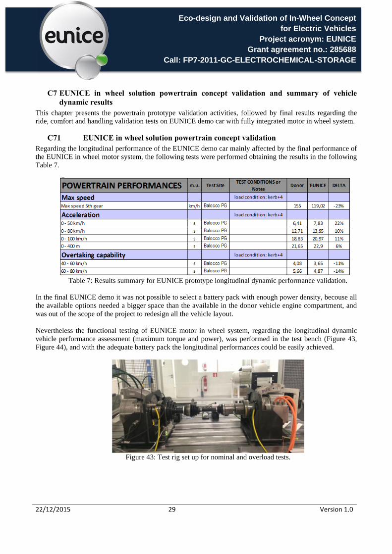
C71 EUNICE in wheel solution powertrain concept validation Regarding the longitudinal performance of the EUNICE demo car mainly affected by the final performance of the EUNICE in wheel motor system, the following tests were performed obtaining the results in the following Table 7.
Table 7: Results summary for EUNICE prototype longitudinal dynamic performance validation.
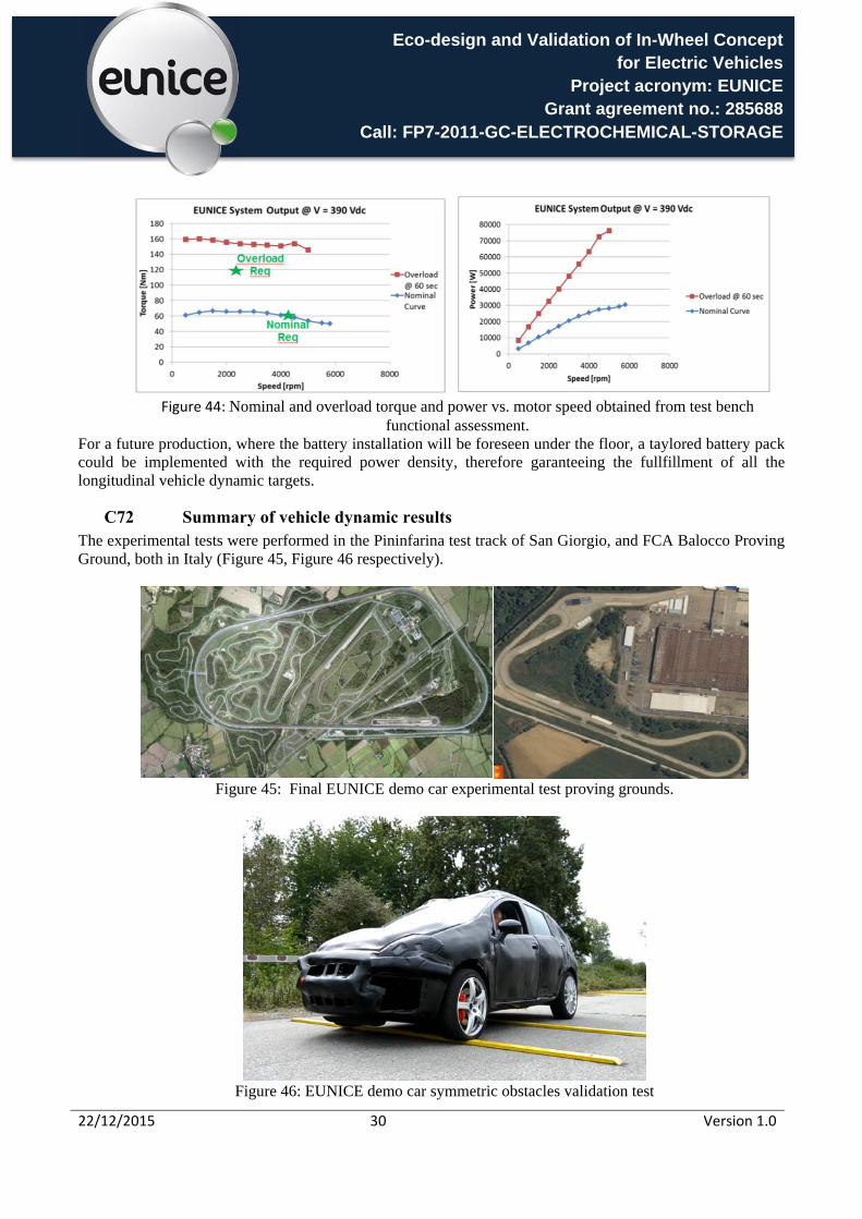
In the final EUNICE demo it was not possible to select a battery pack with enough power density, becouse all the available options needed a bigger space than the available in the donor vehicle engine compartment, and was out of the scope of the project to redesign all the vehicle layout.
Nevertheless the functional testing of EUNICE motor in wheel system, regarding the longitudinal dynamic vehicle performance assessment (maximum torque and power), was performed in the test bench (Figure 43, Figure 44), and with the adequate battery pack the longitudinal performances could be easily achieved.
Figure 43: Test rig set up for nominal and overload tests.
Eco-design and Validation of In-Wheel Concept for Electric Vehicles
Project acronym: EUNICE Grant agreement no.: 285688
Call: FP7-2011-GC-ELECTROCHEMICAL-STORAGE
22/12/2015 30 Version 1.0
Figure 44: Nominal and overload torque and power vs. motor speed obtained from test bench
functional assessment. For a future production, where the battery installation will be foreseen under the floor, a taylored battery pack could be implemented with the required power density, therefore garanteeing the fullfillment of all the longitudinal vehicle dynamic targets.
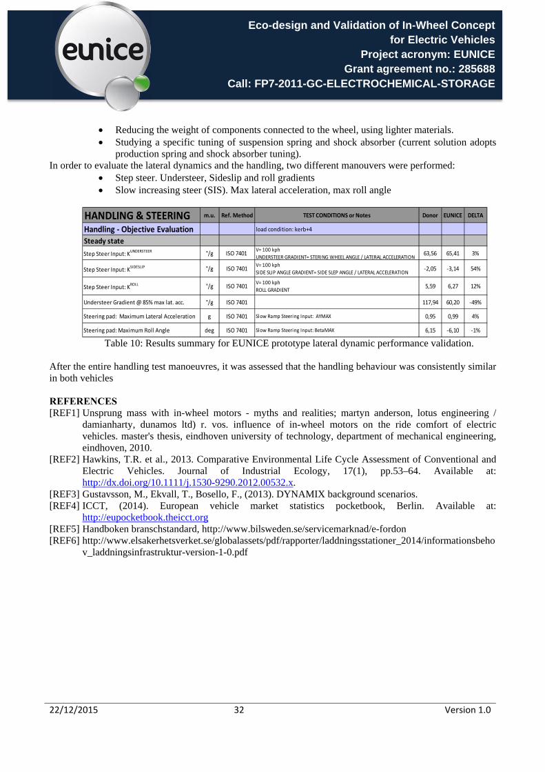
C72 Summary of vehicle dynamic results The experimental tests were performed in the Pininfarina test track of San Giorgio, and FCA Balocco Proving Ground, both in Italy (Figure 45, Figure 46 respectively).
Figure 45: Final EUNICE demo car experimental test proving grounds.
Figure 46: EUNICE demo car symmetric obstacles validation test

Eco-design and Validation of In-Wheel Concept for Electric Vehicles
Project acronym: EUNICE Grant agreement no.: 285688
Call: FP7-2011-GC-ELECTROCHEMICAL-STORAGE
22/12/2015 31 Version 1.0
Regarding the ride and comfort characterization of the EUNICE demo car, the following tests were performed.
N° Path Speed [km/h]
Lenght [m]
1 Urban pavè 40 80
2 Smooth Road 60 300
3 Symmetric Obstacles
30 40
4 Asymmetric
Rails 30 40
5 Asymmetric
Obstacles 30 60
Table 8: EUNICE ride and comfort test manoeuvres.
Table 9 lists a summary of all the results from the ride and comfort comparison is showed. Each measure was repeated 3 times, and Power based Averages of spectra were calculated to obtain a single spectrum for each test, through LMS software. The values were ISO weighted RMS [m/s2] with frequency spectra of range [0.5-80 Hz].
Table 9: Results summary for EUNICE prototype ride and comfort test manoeuvres.
After all the ride and comfort testing, as theoretically foreseen physical tests confirmed that Eunice demo ride and comfort is in general slightly worse than donor car without motor in wheel system, due to the presence of higher unsprung mass.
To improve ride and comfort characteristics, suggested Eunice future solution could consist in the following improvements:
Removing the power inverter (weight: 8.3 kg/wheel) from the wheel, allocating it into engine compartment, behind the radiator grille area.
RIDE COMFORT m.u.Ref.
MethodTest Site TEST CONDITIONS or Notes Donor EUNICE DELTA
Ride Comfort ‐ Objective evaluation load condition: kerb+4
Urban pavè 40 km/h steering wheel m/s2 PF PF S.Giorgio ISO WEIGHTED RMS (equivalent XYZ) 6,35 3,90 ‐39%
Urban pavè 40 km/h front floor m/s2 PF PF S.Giorgio ISO WEIGHTED RMS (equivalent XYZ) 1,76 1,53 ‐13%
Urban pavè 40 km/h front seat rail m/s2 PF PF S.Giorgio ISO WEIGHTED RMS (equivalent XYZ) 1,15 2,35 104%
Urban pavè 40 km/h rear floor m/s2 PF PF S.Giorgio ISO WEIGHTED RMS (equivalent XYZ) 1,45 1,65 14%
Smooth road 60 km/h steering wheel m/s2 PF PF S.Giorgio ISO WEIGHTED RMS (equivalent XYZ) 1,96 2,30 17%
Smooth road 60 km/h front floor m/s2 PF PF S.Giorgio ISO WEIGHTED RMS (equivalent XYZ) 0,59 0,66 12%
Smooth road 60 km/h front seat rail m/s2 PF PF S.Giorgio ISO WEIGHTED RMS (equivalent XYZ) 0,58 0,59 2%
Smooth road 60 km/h rear floor m/s2 PF PF S.Giorgio ISO WEIGHTED RMS (equivalent XYZ) 0,61 0,72 18%
Symmetric obstacle 30 km/h steering wheel m/s2 PF PF S.Giorgio ISO WEIGHTED RMS (equivalent XYZ) 8,12 5,66 ‐30%
Symmetric obstacle 30 km/h front floor m/s2 PF PF S.Giorgio ISO WEIGHTED RMS (equivalent XYZ) 2,40 2,21 ‐8%
Symmetric obstacle 30 km/h front seat rail m/s2 PF PF S.Giorgio ISO WEIGHTED RMS (equivalent XYZ) 2,21 2,83 28%
Symmetric obstacle 30 km/h rear floor m/s2 PF PF S.Giorgio ISO WEIGHTED RMS (equivalent XYZ) 1,92 2,54 32%
Asymmetric rails 30 km/h steering wheel m/s2 PF PF S.Giorgio ISO WEIGHTED RMS (equivalent XYZ) 3,21 3,66 14%
Asymmetric rails 30 km/h front floor m/s2 PF PF S.Giorgio ISO WEIGHTED RMS (equivalent XYZ) 0,96 1,24 29%
Asymmetric rails 30 km/h front seat rail m/s2 PF PF S.Giorgio ISO WEIGHTED RMS (equivalent XYZ) 0,89 1,85 108%
Asymmetric rails 30 km/h rear floor m/s2 PF PF S.Giorgio ISO WEIGHTED RMS (equivalent XYZ) 0,92 1,28 39%
Asymmetric obstacle 30 km/h steering wheel m/s2 PF PF S.Giorgio ISO WEIGHTED RMS (equivalent XYZ) 4,43 7,05 59%
Asymmetric obstacle 30 km/h front floor m/s2 PF PF S.Giorgio ISO WEIGHTED RMS (equivalent XYZ) 1,59 1,84 16%
Asymmetric obstacle 30 km/h front seat rail m/s2 PF PF S.Giorgio ISO WEIGHTED RMS (equivalent XYZ) 1,40 1,51 8%
Asymmetric obstacle 30 km/h rear floor m/s2 PF PF S.Giorgio ISO WEIGHTED RMS (equivalent XYZ) 1,49 2,10 41%
Eco-design and Validation of In-Wheel Concept for Electric Vehicles
Project acronym: EUNICE Grant agreement no.: 285688
Call: FP7-2011-GC-ELECTROCHEMICAL-STORAGE
22/12/2015 32 Version 1.0
Reducing the weight of components connected to the wheel, using lighter materials. Studying a specific tuning of suspension spring and shock absorber (current solution adopts
production spring and shock absorber tuning). In order to evaluate the lateral dynamics and the handling, two different manouvers were performed:
Step steer. Understeer, Sideslip and roll gradients Slow increasing steer (SIS). Max lateral acceleration, max roll angle
Table 10: Results summary for EUNICE prototype lateral dynamic performance validation.
After the entire handling test manoeuvres, it was assessed that the handling behaviour was consistently similar in both vehicles
REFERENCES [REF1] Unsprung mass with in-wheel motors - myths and realities; martyn anderson, lotus engineering /
damianharty, dunamos ltd) r. vos. influence of in-wheel motors on the ride comfort of electric vehicles. master's thesis, eindhoven university of technology, department of mechanical engineering, eindhoven, 2010.
[REF2] Hawkins, T.R. et al., 2013. Comparative Environmental Life Cycle Assessment of Conventional and Electric Vehicles. Journal of Industrial Ecology, 17(1), pp.53–64. Available at: http://dx.doi.org/10.1111/j.1530-9290.2012.00532.x.
[REF3] Gustavsson, M., Ekvall, T., Bosello, F., (2013). DYNAMIX background scenarios. [REF4] ICCT, (2014). European vehicle market statistics pocketbook, Berlin. Available at:
http://eupocketbook.theicct.org [REF5] Handboken branschstandard, http://www.bilsweden.se/servicemarknad/e-fordon [REF6] http://www.elsakerhetsverket.se/globalassets/pdf/rapporter/laddningsstationer_2014/informationsbeho
v_laddningsinfrastruktur-version-1-0.pdf
HANDLING & STEERING m.u. Ref. Method TEST CONDITIONS or Notes Donor EUNICE DELTA
Handling ‐ Objective Evaluation load condition: kerb+4
Steady state
Step Steer Input: KUNDERSTEER °/g ISO 7401
V= 100 kph
UNDERSTEER GRADIENT= STERING WHEEL ANGLE / LATERAL ACCELERATION63,56 65,41 3%
Step Steer Input: KSIDESLIP °/g ISO 7401
V= 100 kph
SIDE SLIP ANGLE GRADIENT= SIDE SLEP ANGLE / LATERAL ACCELERATION‐2,05 ‐3,14 54%
Step Steer Input: KROLL °/g ISO 7401
V= 100 kph
ROLL GRADIENT5,59 6,27 12%
Understeer Gradient @ 85% max lat. acc. °/g ISO 7401 117,94 60,20 ‐49%
Steering pad: Maximum Lateral Acceleration g ISO 7401 Slow Ramp Steering Input: AYMAX 0,95 0,99 4%
Steering pad: Maximum Roll Angle deg ISO 7401 Slow Ramp Steering Input: BetaMAX 6,15 ‐6,10 ‐1%

Eco-design and Validation of In-Wheel Concept for Electric Vehicles
Project acronym: EUNICE Grant agreement no.: 285688
Call: FP7-2011-GC-ELECTROCHEMICAL-STORAGE
22/12/2015 33 Version 1.0
D. Potential impact
During the development of EUNICE project, the majority of the industrial partners have been involved in developments related to vehicle electrification. It has to be pointed out the launch of vehicles such as the Porsche 918 and BMW i8, where GKN DRIVELINE is in charge of developments of advanced transmission systems, with significant recognition and awards, such as PACE awards 2015 (refer to Figure 47).
Figure 47: PACE awards 2015 GKN DRIVELINE for 2 speed gearbox eAxle on the BMW i8 hybrid supercar.
Other partners like INFINEON and MAGNETI MARELLI have had activity in new electrified vehicles. According to insideevs.com webpage, yearly EV sales have increased rapidly during the development of EUNICE
project. MAGNETI MARELLI has been involved in the development of new electric urban vehicle Fiat 500e, and GKN DRIVELINE has provided transmission and driveline components for this application (refer to Figure
48)
Figure 48: Fiat 500 electric, where EUNICE partners MM and GKN DRIVELINE involved (as TIER1)
The involvement in electric vehicle programs from Eunice partners will enable the dissemination of project achievements with industry, offering the motor in wheel system as a viable solution for electric and hybrid vehicles. It has to be noted as well that development activity related to electrification has increased as well
demanding more and more engineering resources.
Eco-design and Validation of In-Wheel Concept for Electric Vehicles
Project acronym: EUNICE Grant agreement no.: 285688
Call: FP7-2011-GC-ELECTROCHEMICAL-STORAGE
22/12/2015 34 Version 1.0
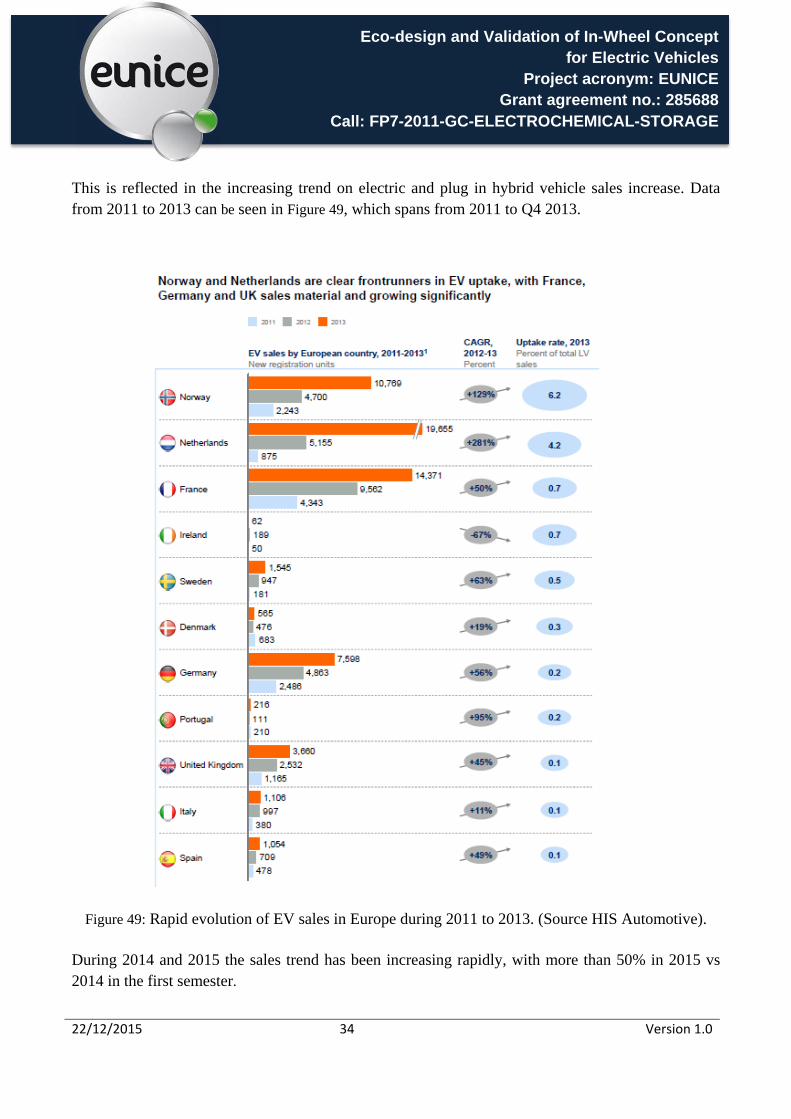
This is reflected in the increasing trend on electric and plug in hybrid vehicle sales increase. Data from 2011 to 2013 can be seen in Figure 49, which spans from 2011 to Q4 2013.
Figure 49: Rapid evolution of EV sales in Europe during 2011 to 2013. (Source HIS Automotive).
During 2014 and 2015 the sales trend has been increasing rapidly, with more than 50% in 2015 vs 2014 in the first semester.

Eco-design and Validation of In-Wheel Concept for Electric Vehicles
Project acronym: EUNICE Grant agreement no.: 285688
Call: FP7-2011-GC-ELECTROCHEMICAL-STORAGE
22/12/2015 35 Version 1.0
Figure 50: EV sales in first semester 2014 vs 2015. (source Renault)
Another important factor is that during 2015 at least 15 PHEV have been introduced in the market, according to EV obsession web page (www.evobsession.com), which clearly shows activity on development of such vehicles.
In this context, of EV growth on sales as well as new emerging programs, and considering the raise in costs related to ICE meeting the emission targets, the opportunity of a proven motor in wheel concept developed within the Eunice project, can be in a good position to be implemented in new electrification programs. It also has to be taken into account the evolution of PHEV and EV´s at global level, with number of units manufactured approaching 400.000 units according to 2015 reports from IEA (International Energy Agency)
Figure 51: Global PHEV and BEV sales evolution (Source IEA 2015, Global outlook 2015)
Eco-design and Validation of In-Wheel Concept for Electric Vehicles
Project acronym: EUNICE Grant agreement no.: 285688
Call: FP7-2011-GC-ELECTROCHEMICAL-STORAGE
22/12/2015 36 Version 1.0
In order to maximize the exploitation possibilities, the project has considered the valuable inputs from invited OEMs - during the two workshops developed throughout the project execution - not only aligning the Eunice design to B segment, as initially planned, but also taking into account variations for application on different platforms. The variants of the Eunice solution have then been identified and shared with OEM´s, being the air cooled motor in wheel considered optimum for future B segment vehicles equipped with such technology. An important conclusion is that the integration of the power inverter into the wheel is not so relevant, especially taking into account the small space required for state of the art inverters. This fact is relevant as there is no need to modify elements on the front part of body in white when implementing the solution to existing platforms. In parallel, in terms of market penetration, beneficial facts for accelerating the demand of affordable electrified vehicles should be considered, such as the increase in vehicle sales from 2014 and 2015 and the increasing costs for ICE exhaust after treatment systems to cope with more stringent standards.
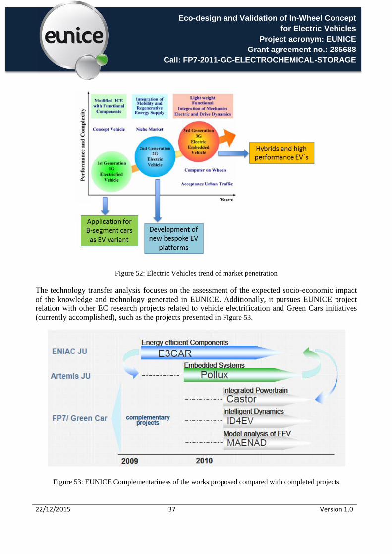
As for the future scenario on EUNICE’s solution applications, trends of market penetration of EV – as detailed in Figure 52– have been taken into account, in order to conclude that EUNICE’s concept can be used in several vehicle platforms.
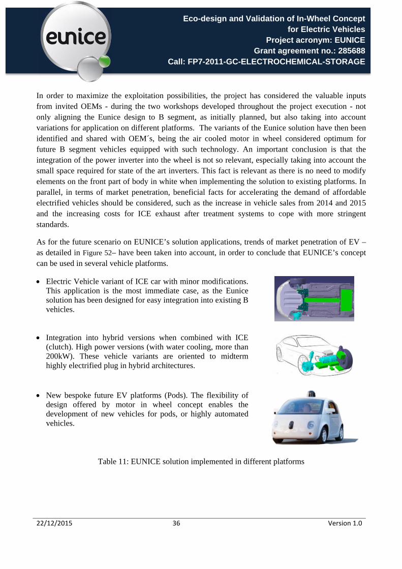
Electric Vehicle variant of ICE car with minor modifications. This application is the most immediate case, as the Eunice solution has been designed for easy integration into existing B vehicles.
Integration into hybrid versions when combined with ICE (clutch). High power versions (with water cooling, more than 200kW). These vehicle variants are oriented to midterm highly electrified plug in hybrid architectures.
New bespoke future EV platforms (Pods). The flexibility of design offered by motor in wheel concept enables the development of new vehicles for pods, or highly automated vehicles.
Table 11: EUNICE solution implemented in different platforms
Eco-design and Validation of In-Wheel Concept for Electric Vehicles
Project acronym: EUNICE Grant agreement no.: 285688
Call: FP7-2011-GC-ELECTROCHEMICAL-STORAGE
22/12/2015 37 Version 1.0
Figure 52: Electric Vehicles trend of market penetration
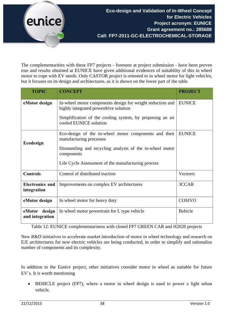
The technology transfer analysis focuses on the assessment of the expected socio-economic impact of the knowledge and technology generated in EUNICE. Additionally, it pursues EUNICE project relation with other EC research projects related to vehicle electrification and Green Cars initiatives (currently accomplished), such as the projects presented in Figure 53.
Figure 53: EUNICE Complementariness of the works proposed compared with completed projects
Eco-design and Validation of In-Wheel Concept for Electric Vehicles
Project acronym: EUNICE Grant agreement no.: 285688
Call: FP7-2011-GC-ELECTROCHEMICAL-STORAGE
22/12/2015 38 Version 1.0
The complementarities with these FP7 projects - foreseen at project submission - have been proven true and results obtained at EUNICE have given additional evidences of suitability of this in wheel motor to cope with EV needs. Only CASTOR project is oriented to in wheel motor for light vehicles, but it focuses on its design and architectures. as it is shown on the lower part of the table
TOPIC CONCEPT PROJECT
eMotor design In-wheel motor components design for weight reduction and highly integrated powerdrive solution
Simplification of the cooling system, by proposing an air cooled EUNICE solution
EUNICE
Ecodesign
Eco-design of the in-wheel motor components and their manufacturing processes
Dismantling and recycling analysis of the in-wheel motor components
Life Cycle Assessment of the manufacturing process
EUNICE
Controls Control of distributed traction Vectorrc
Electronics and integration
Improvements on complex EV architectures 3CCAR
eMotor design In wheel motor for heavy duty COSIVO
eMotor design and integration
In wheel motor powertrain for L type vehicle Behicle
Table 12: EUNICE complementariness with closed FP7 GREEN CAR and H2020 projects
New R&D initiatives to accelerate market introduction of motor in wheel technology and research on E/E architectures for new electric vehicles are being conducted, in order to simplify and rationalize number of components and its complexity.
In addition to the Eunice project, other initiatives consider motor in wheel as suitable for future EV´s. It is worth mentioning
BEHICLE project (FP7), where a motor in wheel design is used to power a light urban vehicle.
Eco-design and Validation of In-Wheel Concept for Electric Vehicles
Project acronym: EUNICE Grant agreement no.: 285688
Call: FP7-2011-GC-ELECTROCHEMICAL-STORAGE
22/12/2015 39 Version 1.0
COSIVO (FP7), which deals with EVs too and has finished at the same time as EUNICE project. It is more oriented to commercial vehicle applications. (https://www.tu-chemnitz.de/etit/le/anzeige_de/Press%20release%20COSIVU%20kick-off.pdf)
In order to quantify EUNICE’s impact of the technology transfer on electrification market, the main benefits of the technology, demonstrated on the project development, have to be considered:
Modularity and ease of integration, leaving additional space to OEM for energy storage, occupants, etc.
Demonstrated performance for B segment vehicle Good dynamic behaviour
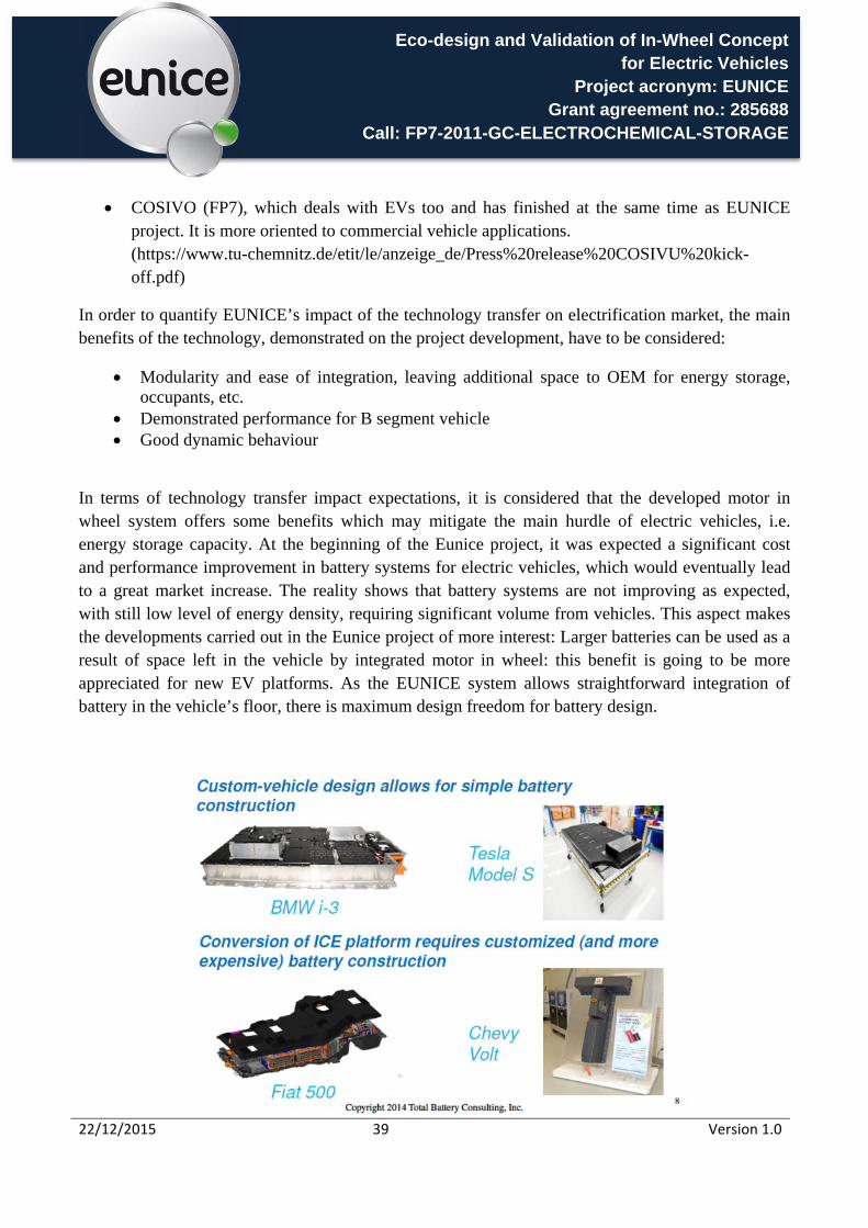
In terms of technology transfer impact expectations, it is considered that the developed motor in wheel system offers some benefits which may mitigate the main hurdle of electric vehicles, i.e. energy storage capacity. At the beginning of the Eunice project, it was expected a significant cost and performance improvement in battery systems for electric vehicles, which would eventually lead to a great market increase. The reality shows that battery systems are not improving as expected, with still low level of energy density, requiring significant volume from vehicles. This aspect makes the developments carried out in the Eunice project of more interest: Larger batteries can be used as a result of space left in the vehicle by integrated motor in wheel: this benefit is going to be more appreciated for new EV platforms. As the EUNICE system allows straightforward integration of battery in the vehicle’s floor, there is maximum design freedom for battery design.
Eco-design and Validation of In-Wheel Concept for Electric Vehicles
Project acronym: EUNICE Grant agreement no.: 285688
Call: FP7-2011-GC-ELECTROCHEMICAL-STORAGE
22/12/2015 40 Version 1.0
Figure 54: Typical battery shapes governed by vehicle components and systems restrictions (source Total Battery Consulting)
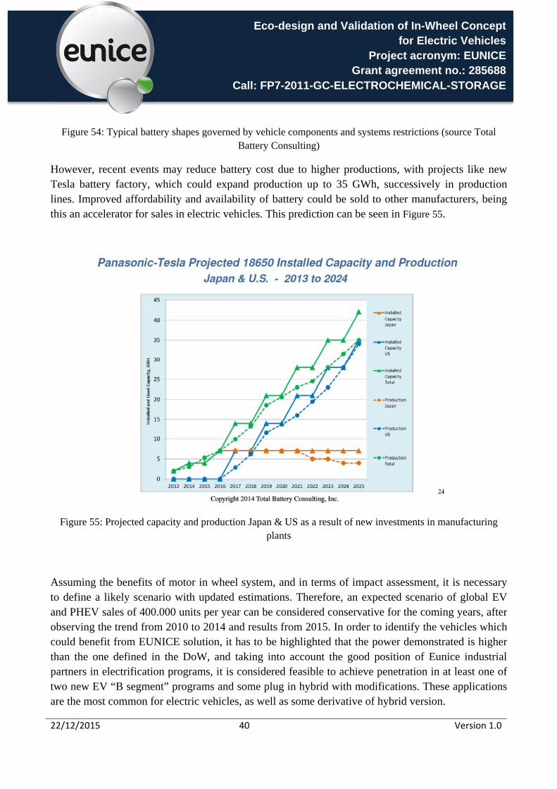
However, recent events may reduce battery cost due to higher productions, with projects like new Tesla battery factory, which could expand production up to 35 GWh, successively in production lines. Improved affordability and availability of battery could be sold to other manufacturers, being this an accelerator for sales in electric vehicles. This prediction can be seen in Figure 55.
Figure 55: Projected capacity and production Japan & US as a result of new investments in manufacturing plants
Assuming the benefits of motor in wheel system, and in terms of impact assessment, it is necessary to define a likely scenario with updated estimations. Therefore, an expected scenario of global EV and PHEV sales of 400.000 units per year can be considered conservative for the coming years, after observing the trend from 2010 to 2014 and results from 2015. In order to identify the vehicles which could benefit from EUNICE solution, it has to be highlighted that the power demonstrated is higher than the one defined in the DoW, and taking into account the good position of Eunice industrial partners in electrification programs, it is considered feasible to achieve penetration in at least one of two new EV “B segment” programs and some plug in hybrid with modifications. These applications are the most common for electric vehicles, as well as some derivative of hybrid version.

Eco-design and Validation of In-Wheel Concept for Electric Vehicles
Project acronym: EUNICE Grant agreement no.: 285688
Call: FP7-2011-GC-ELECTROCHEMICAL-STORAGE
22/12/2015 41 Version 1.0
This may provide a realistic scenario where industrial partners of Eunice consortium might be delivering 5%-10% of EV´s 20.000-40.000 units/year in 2017-2018, until the solution matures even more, gaining more acceptances and consequently, integrated into other variants. In 2019 to 2020 period, the number of electrified vehicles increasing, it is likely to double these figures, approaching 100.000 units of the technology (complete axles).
Figure 56: Types of PHEV´s sold in Europe S1 2015: Developed motor in wheel technology could be applied for power and performance requirements to more than 50% of production. (Combined 100kW peak power assumed, as demonstrated by technology)
Within the PHEV vehicles sold in Europe in 2015, an exercise of potential implementation of Eunice design has been completed. The Eunice solution in different variants, can be used in vehicles similar to Nissan Leaf, Renault Zoe, Volkswagen E-Golf, BMW I 3, Renault Kangoo ZR, Mercedes B class Electric, Kia Soul, and applied in hybrids like Volvo V60 and Volkswagen GTE accounting for 40.000 vehicles from a total of 75.600 sold in Europe 2015 so far (Q3 2015)
This forecast, although considered not aggressive, could be complemented by implementation on new generation POD vehicles, aiming at urban transport autonomous applications, where the benefits of in wheel motor developed in EUNICE solution could be even more valuable.

Eco-design and Validation of In-Wheel Concept for Electric Vehicles
Project acronym: EUNICE Grant agreement no.: 285688
Call: FP7-2011-GC-ELECTROCHEMICAL-STORAGE
22/12/2015 42 Version 1.0
Project coordinator name, title and organisation: Mr. Alberto Peña AUTOMOTIVE unit responsible, FUNDACIÓN TECNALIA RESEARCH & INNOVATION Tel: +34 607 22 74 82 E-mail: [email protected] Project website address www.eunice-project.eu EUNICE list of beneficiaries:
Participant Legal Name Short Name Organisation Type Country Logo Fundación TECNALIA Research & Innovation
TECNALIA RESEARCH CENTRE Spain
Pininfarina S.p.A PIN INDUSTRY END USER Italy
Sistemi Sospensioni Spa MM INDUTRY Italy
Fundacion CIE I+D+I CIE NON PROFIT ORGANISATION
Spain
Industrias Puigjaner S.A. DENN SME Spain
Ivl Svenska Miljoeinstitutet Ab IVL RESEARCH CENTRE Sweden Infineon Technologies Ag INFN INDUSTRY Germany
Automotive Intelligence Center AIC
NON PROFIT ORGANISATION
Spain
AIT Austrian Institute of Technology GmbH
AIT RESEARCH CENTRE Austria
Maxion Wheels HL INDUSTRY Italy
GKN EVO eDrive Systems GKN EVO INDUSTRY United Kingdom
European Association of Automotive Suppliers
CLEPA NON PROFIT ORGANISATION
Belgium
GKN DRIVELINE Zumaia,S.A. GKN DRIVELINE
INDUSTRY Spain