Bio Fuel Oil - Upgrading by Hot Filtration and Novel ... - CORDIS
49
Energy JOR3-CT98-0253 15 February 2001/ys Bio fuel oil - Upgrading by hot filtration and novel physical methods 1 Bio Fuel Oil - Upgrading by Hot Filtration and Novel Physical Methods Solantausta, Y., Gust, S., Hogan, E., Massoli, P., Sipilä, K. VTT Energy (co-ordinator) Fortum Oyj CANMET Istituto Motori - CNR Contract JOR3-CT98-0253 PUBLISHABLE FINAL REPORT October 1 1998 to September 30 2000 Research funded in part by THE EUROPEAN COMMISSION in the framework of the Non Nuclear Energy Programme JOULE III
-
Upload
khangminh22 -
Category
Documents
-
view
1 -
download
0
Transcript of Bio Fuel Oil - Upgrading by Hot Filtration and Novel ... - CORDIS

Energy JOR3-CT98-025315 February 2001/ys Bio fuel oil - Upgrading by hot filtration and novel physical methods
1
Bio Fuel Oil - Upgrading by Hot Filtration and NovelPhysical Methods
Solantausta, Y., Gust, S., Hogan, E., Massoli, P., Sipilä, K.
VTT Energy (co-ordinator)Fortum OyjCANMET
Istituto Motori - CNR
Contract JOR3-CT98-0253
PUBLISHABLE FINAL REPORTOctober 1 1998 to September 30 2000
Research funded in part byTHE EUROPEAN COMMISSION
in the framework of theNon Nuclear Energy Programme
JOULE III

Energy JOR3-CT98-025315 February 2001/ys Bio fuel oil - Upgrading by hot filtration and novel physical methods
2
ABSTRACT
The primary objective of the R&D project was to support demonstration of a bioenergyscheme, where bio fuel oil (BFO) is employed as boiler or engine power plant fuel. At thisstage quality improvement of the BFO is technically the critical factor related to pyrolysisliquid production. The principal technologies studied were hot filtration of pyrolysisvapours coupled to a pyrolyser, and preparation of microemulsion from BFO. The firstaims in reducing solids content and alkali metals in BFO. The second aims in enabling useof BFO in existing equipment (small boilers, diesel engines) without major modifications.Related to BFO utilisation, experimental work in full-scale boilers and laboratory scale wasperformed. Basic data concerning use of BFO as power plant Diesel engines was generated.Markets for BFO were analysed.
Total of 5.8 tonnes of pyrolysis liquid was produced for utilisation tests and for qualityimprovement work within this project from forest residues and pine sawdust, which areconsidered industrially relevant feedstocks. Hot vapour filtration is a very efficient methodto remove particles from the pyrolysis vapours and to improve the quality of the productliquid. The most critical parameters are filtration temperature, face velocity and particulateloading. Microemulsion technology, which would make it possible to use BFO and mineraloil mixtures in existing heat and power generating systems without major modifications,was also developed. The most influential process variable in emulsion preparation issurfactant concentration. EHS (environment, health and safety) aspects were alsoconsidered. In order to assure customers that a product is safe for shipping, storage and use,the health and safety aspects of a product must be evaluated.
Basic combustion data related to BFO utilisation in boilers and Diesel engine wasgenerated in laboratory scale. The combustion fundamentals of droplets composed of purepyrolysis oil, as well as of BFO-based emulsions and mixtures were examined.Experiments were performed at both ambient and high-pressure. Eight different fuels wereexamined for a total of about five hundred tests. The combustion of carbonaceous residualsfrom all samples was diffusion limited. Use of BFO in medium scale heating boilers wasdeveloped. Performance and emissions of CO, NOx, and particulates were measured in twoindustrial boilers (200 and 500 kW) modified for the purpose. Based on earlier and thecurrent boiler combustion tests it is concluded that BFO can be effectively combusted usingproperly modified simple and relatively inexpensive pressure atomisation equipment andemissions reduced to acceptable levels. In order to assess the current limitations to the useof BFO in a light-duty Diesel engine, a series of tests were carried out with a stock single-cylinder, without any modification and/or pre-treatment of the fuel. Reliable operation wasrecorded with BFO-Diglyme blends, with a BFO content up to 37.5% in volume. Micro-emulsions of BFO in No.2 Diesel were also used.
Based on the market analysis, it is obvious that the replacement of light fuel oils willgive more economic incentives than replacing heavy fuel oils.

Energy JOR3-CT98-025315 February 2001/ys Bio fuel oil - Upgrading by hot filtration and novel physical methods
3
TABLE OF CONTENTS
ABSTRACT................................................................................................................................................ 1
TABLE OF CONTENTS........................................................................................................................... 3
PARTNERSHIP ......................................................................................................................................... 4
COORDINATION......................................................................................................................................... 4
1. OBJECTIVES OF THE PROJECT ..................................................................................................... 5
2. SCIENTIFIC AND TECHNICAL DESCRIPTION OF THE PROJECT ........................................ 9
2.1 TASKS AND METHODS......................................................................................................................... 92.2 RESULTS........................................................................................................................................... 14
2.2.1 Hot filtration for pyrolysis vapours (task 1) ........................................................................... 142.2.2 Microemulsions (task 2)........................................................................................................... 162.2.3 BFO production (task 3)......................................................................................................... 182.2.4 BFO quality (task 1, 2 and 3) .................................................................................................. 222.2.5 Handling and storage of BFO, and heath and safety issues related to BFO (task 4).............. 272.2.6. Fundamental behaviour of BFO in combustion (task 5) ........................................................ 302.2.7 Medium size boiler tests (task 6).............................................................................................. 332.2.8 Engine tests (task 7)................................................................................................................. 352.2.9 Market opportunities for bio fuel oil (task 8)........................................................................... 38
3. CONCLUSIONS................................................................................................................................... 42
3.1 APPLICATIONS .................................................................................................................................. 423.2 TASKS............................................................................................................................................... 42
3.2.1 Task 1....................................................................................................................................... 423.2.2 Task 2....................................................................................................................................... 423.2.3 Task 3....................................................................................................................................... 433.2.4 Task 4....................................................................................................................................... 433.2.5 Task 5....................................................................................................................................... 443.2.6 Task 6....................................................................................................................................... 443.2.7 Task 7....................................................................................................................................... 453.2.8 Task 8....................................................................................................................................... 46
4. EXPLOITATION................................................................................................................................. 47
5. PHOTOGRAPH................................................................................................................................... 48

Energy JOR3-CT98-025315 February 2001/ys Bio fuel oil - Upgrading by hot filtration and novel physical methods
4
PARTNERSHIP
COORDINATIONVTT EnergyKai SipiläYrjö SolantaustaPO Box 1601FIN-02044 VTT, EspooFINLANDFax +358-9-460 [email protected]
Fortum OySteven GustP.O. Box 31006101 PorvooFINLANDFax +358 10 452 [email protected]
CANMET, Alternative Energy DivisionEd Hogan580 Booth StreetOttawa, Ontario K1A 0E4CANADAFax +1-613-996 [email protected]
Istituto Motori - C.N.R.Patrizio MassoliViale Marconi 880125 NapoliITALYFax +39-081-239 [email protected]
USF Schumacher Umwelt- und Trenntechnik GmbHSteffen HeidenreichP.O.Box 1562, Zur Flugelau 70D-74555 CrailsheimBaden-WurttembergGermanyFax +49-7951-302 [email protected]

Energy JOR3-CT98-025315 February 2001/ys Bio fuel oil - Upgrading by hot filtration and novel physical methods
5
1. OBJECTIVES OF THE PROJECT
The primary objective of the R&D project is to support demonstration of a bioenergyscheme, where bio fuel oil (BFO) is employed as boiler or engine power plant fuel. BFOhas potential in becoming a competitive bioenergy alternative in these markets.
A successful introduction of a new liquid fuel on the energy market will be very difficultbecause of the low quality of the present BFOs. At this stage quality improvement of theBFO is technically the critical factor.
The market has to be approached in stages. The approach is illustrated in Figure 1.1.The first stage preferably has to be a single heavy fuel oil (HFO) boiler, where BFO isused. Both production and utilisation should preferably be within one organisation. Oncethe technical problems have been overcome, it will be possible gradually to widen themarket to eventual projected end-users, boilers and diesel power plants.
Fluidized-Bed Boiler
FastPyrolysis
HFOBoiler
CHPDiesels
LFOBoiler
FlastPyrolysis
First phaseElectricity & heat (steam, district heat, cooling)
Second phaseElectricity, heat, and bfo for one boiler
Third phaseElectricity, heat, and bfo for boilers and power plants
Fluidized-Bed Boiler
Fluidized-Bed Boiler
Market Introduction of BFO
Figure 1.1 Market introduction of BFO
BFO may be envisioned to replace either light (LFO) or heavy fuel oil (HFO). Typicallythese oils are used as boiler and diesel power plant fuels. European prices for LFO andHFO are presented in Figures 1.2 and 1.3.

Energy JOR3-CT98-025315 February 2001/ys Bio fuel oil - Upgrading by hot filtration and novel physical methods
6
Fortum (a partner) and Birka Energi (a co-funding partner) are both considering utilisingthe technology as part of their future plans. These companies have estimated that there maybe industrial opportunities in Europe, in which BFO may be viable.
Light Fuel Oil in Prices in EUAugust 15, 2000
VAT Included
Aus
tria
Bel
gium
Den
mar
k
Ger
man
y Fi
nlan
d Fr
ance
Gre
ece
Gre
at B
ritai
n
Irel
and
Italy
Lu
xem
bour
g
Net
herla
nds
Portu
gal
Swed
en
Spai
n
0
20
40
60
80
100
ECU
/MW
h
taxed
untaxed
Figure 1.2. LFO prices in Europe/1/
Heavy Fuel Oil in Prices in EUAugust 15, 2000
VAT Included
Aus
tria
Bel
gium
Den
mar
k
Ger
man
y
Finl
and
Fran
ce
Gre
ece
Gre
at B
ritai
n
Irel
and
Italy
Luxe
mbo
urg
Net
herla
nds
Portu
gal
Swed
en
Spai
n
0
10
20
30
40
50
ECU
/MW
h
taxed
untaxed
Figure 1.3. HFO prices in Europe/1/
Energy JOR3-CT98-025315 February 2001/ys Bio fuel oil - Upgrading by hot filtration and novel physical methods
7
BFO has been proposed also as a diesel power plant (DPP) fuel. There is very littleexperience of the application, and technical uncertainties with this concept areconsiderable.
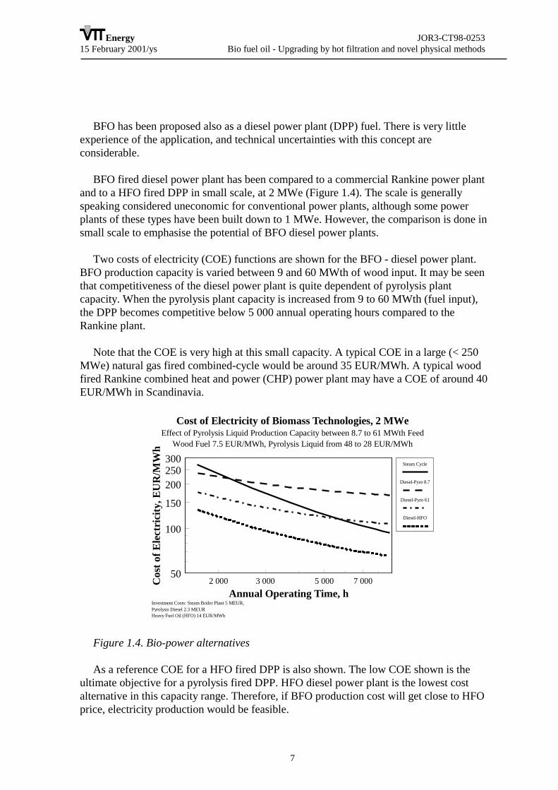
BFO fired diesel power plant has been compared to a commercial Rankine power plantand to a HFO fired DPP in small scale, at 2 MWe (Figure 1.4). The scale is generallyspeaking considered uneconomic for conventional power plants, although some powerplants of these types have been built down to 1 MWe. However, the comparison is done insmall scale to emphasise the potential of BFO diesel power plants.
Two costs of electricity (COE) functions are shown for the BFO - diesel power plant.BFO production capacity is varied between 9 and 60 MWth of wood input. It may be seenthat competitiveness of the diesel power plant is quite dependent of pyrolysis plantcapacity. When the pyrolysis plant capacity is increased from 9 to 60 MWth (fuel input),the DPP becomes competitive below 5 000 annual operating hours compared to theRankine plant.
Note that the COE is very high at this small capacity. A typical COE in a large (< 250MWe) natural gas fired combined-cycle would be around 35 EUR/MWh. A typical woodfired Rankine combined heat and power (CHP) power plant may have a COE of around 40EUR/MWh in Scandinavia.
Cost of Electricity of Biomass Technologies, 2 MWeEffect of Pyrolysis Liquid Production Capacity between 8.7 to 61 MWth Feed
Wood Fuel 7.5 EUR/MWh, Pyrolysis Liquid from 48 to 28 EUR/MWh
Investment Costs: Steam Boiler Plant 5 MEUR, Pyrolysis Diesel 2.3 MEURHeavy Fuel Oil (HFO) 14 EUR/MWh
2 000 3 000 5 000 7 00050
100
150
200250300
Annual Operating Time, h
Cos
t of E
lect
rici
ty, E
UR
/MW
h
Steam Cycle
Diesel-Pyro 8.7
Diesel-Pyro 61
Diesel-HFO
Figure 1.4. Bio-power alternatives
As a reference COE for a HFO fired DPP is also shown. The low COE shown is theultimate objective for a pyrolysis fired DPP. HFO diesel power plant is the lowest costalternative in this capacity range. Therefore, if BFO production cost will get close to HFOprice, electricity production would be feasible.

Energy JOR3-CT98-025315 February 2001/ys Bio fuel oil - Upgrading by hot filtration and novel physical methods
8
Following objectives for the R&D project have been defined:• To increase the market value of BFO by improving BFO quality as fuel• To improve the utilisation of BFO in power plants and boilers.
These objectives are pursued in several tasks. Following technical objectives have beendefined for the project:• To develop hot vapour filtration at process development unit (PDU) scale to remove
solids from BFO. The present solid content of 0.5 to 2 wt% will be reduced to <0.1wt%.
• To develop microemulsion technology, which would make it possible to use BFO andmineral oil mixtures in existing equipment without major modifications. Threeemulsions will be manufactured and characterised in laboratory analysis.
• To maximise organic yield by varying key process parameters (temperature, residencetime) for pyrolysis of three feedstocks (forest residues, pine sawdust, and straw).
• To develop bio fuel oil handling and storage procedures, and to study the health andsafety issues related to industrial use of BFO.
• Four BFO and derivatives will be employed in laboratory scale equipment tocharacterise their fundamental combustion behaviour.
• To develop use of BFO in medium scale heating boilers. Performance and emissions ofCO, NOx, and particulates will be measured for two BFO in a 200 kW boiler.
• To support the development of a BFO as power plant engine fuel by generating basicengine performance and emission data.
• To determine the competitiveness of BFO as heating oil in Finland and Sweden.

Energy JOR3-CT98-025315 February 2001/ys Bio fuel oil - Upgrading by hot filtration and novel physical methods
9
2. SCIENTIFIC AND TECHNICAL DESCRIPTION OFTHE PROJECT
2.1 TASKS AND METHODS
The objectives listed in the previous section were pursued in following tasks:• Hot filtration for pyrolysis vapours (task 1)• Microemulsions (task 2)• BFO production and quality (task 3)• Handling and storage of BFO, and heath and safety issues related to BFO (task 4)• Fundamental behaviour of BFO in combustion (task 5)• Medium size boiler tests (task 6)• Engine tests (task 7)• Market opportunities for bio fuel oil (task 8)• Co-ordination (task 9)
Project structure is shown in Figure 2.1.
Production Applications
Markets8
VTT, Fortum
Hot filtering1
VTT, Scumacher
Microemulsions2
CanMet, VTT
Oil prod. optimisation3
VTT
Handling, health & safety 4
Fortum, VTTCombustion fundamentals 5
Istituto Motori
Medium size boilers6
Fortum
Engine tests7
Istituto MotoriCo-ordination
9
VTT
Figure 2.1. Project organisation and task participants
The project has been successful in all tasks carried out. The tasks of the project werecarried out within the planned schedule with minor exceptions.
In task 1, hot vapour filtration of pyrolysis vapours (HVF) was carried out as planned.Two long-term test runs in the bench-scale unit (Figure 2.2) were carried out, and the

Energy JOR3-CT98-025315 February 2001/ys Bio fuel oil - Upgrading by hot filtration and novel physical methods
10
necessary data for scale-up was generated. Design of a slipstream HVF system was carriedout, and the equipment (including a scrubber with pumps and heat exchangers, HVF vessel,necessary piping and instrumentation) was installed (Figure 2.2). Note that the investmentcosts were paid outside the current project. The HVF system was operated integrated to theProcess Development Unit (PDU), which is described related to task 3.
Pulse nitrogen
Process gasafter the1st cyclone
Hot gas filter Oil condenser
Hot gas filteredwood oil
Clean gas to recycle blower
HOT GAS FILTRATION SIDE STREAM
Figure 2.2. HVF integrated to the PDU (not shown)
In task 2, several different microemulsion samples were prepared (Figure 2.3) andanalysed. Some of the samples were also used in utilisation tests. The task was carried outas planned.
Figure 2.3. Bench-scale emulsifier
Energy JOR3-CT98-025315 February 2001/ys Bio fuel oil - Upgrading by hot filtration and novel physical methods
11
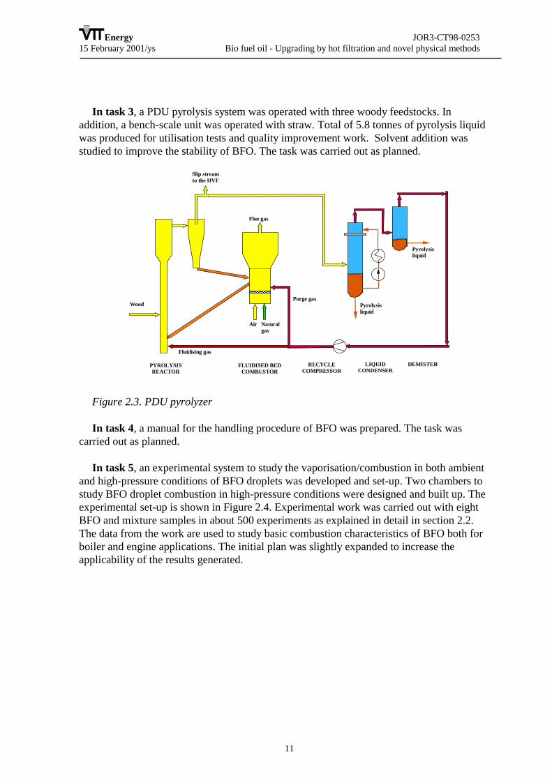
In task 3, a PDU pyrolysis system was operated with three woody feedstocks. Inaddition, a bench-scale unit was operated with straw. Total of 5.8 tonnes of pyrolysis liquidwas produced for utilisation tests and quality improvement work. Solvent addition wasstudied to improve the stability of BFO. The task was carried out as planned.
FLUIDISED BEDCOMBUSTOR
Wood
Pyrolysisliquid
Air Natural gas
Purge gas
Fluidising gas
Flue gas
PYROLYSISREACTOR
LIQUIDCONDENSER
DEMISTER
Slip streamto the HVF
Pyrolysisliquid
RECYCLECOMPRESSOR
Figure 2.3. PDU pyrolyzer
In task 4, a manual for the handling procedure of BFO was prepared. The task wascarried out as planned.
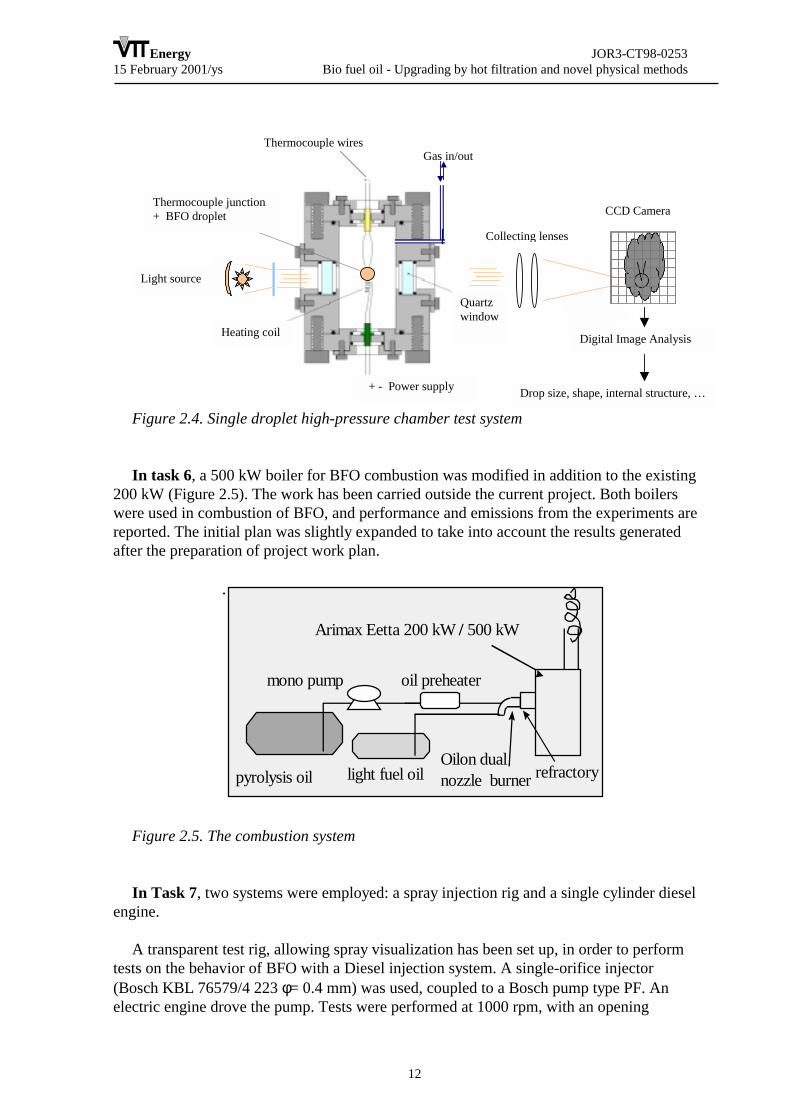
In task 5, an experimental system to study the vaporisation/combustion in both ambientand high-pressure conditions of BFO droplets was developed and set-up. Two chambers tostudy BFO droplet combustion in high-pressure conditions were designed and built up. Theexperimental set-up is shown in Figure 2.4. Experimental work was carried out with eightBFO and mixture samples in about 500 experiments as explained in detail in section 2.2.The data from the work are used to study basic combustion characteristics of BFO both forboiler and engine applications. The initial plan was slightly expanded to increase theapplicability of the results generated.
Energy JOR3-CT98-025315 February 2001/ys Bio fuel oil - Upgrading by hot filtration and novel physical methods
12
CCD Camera
+ - Power supply
Quartzwindow
Heating coil
Light source
Thermocouple junction+ BFO droplet
Digital Image Analysis
Drop size, shape, internal structure, …
Collecting lenses
Gas in/outThermocouple wires
Figure 2.4. Single droplet high-pressure chamber test system
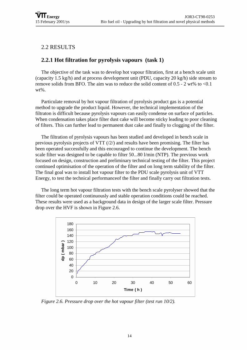
In task 6, a 500 kW boiler for BFO combustion was modified in addition to the existing200 kW (Figure 2.5). The work has been carried outside the current project. Both boilerswere used in combustion of BFO, and performance and emissions from the experiments arereported. The initial plan was slightly expanded to take into account the results generatedafter the preparation of project work plan.
.
pyrolysis oil light fuel oil
Arimax Eetta 200 kW / 500 kW
Oilon dualnozzle burner
mono pump
refractory
oil preheater
Figure 2.5. The combustion system
In Task 7, two systems were employed: a spray injection rig and a single cylinder dieselengine.
A transparent test rig, allowing spray visualization has been set up, in order to performtests on the behavior of BFO with a Diesel injection system. A single-orifice injector(Bosch KBL 76579/4 223 φ= 0.4 mm) was used, coupled to a Bosch pump type PF. Anelectric engine drove the pump. Tests were performed at 1000 rpm, with an opening

Energy JOR3-CT98-025315 February 2001/ys Bio fuel oil - Upgrading by hot filtration and novel physical methods
13
pressure of the nozzle of 200 bar. Further injection trials included a 4-holes injector (BoschKBEL 108 P 25, φ=0.28 mm).
A high-speed digital imaging system (Motionscope by Redlake) has been used forrecording the spray evolution in time. Typical speed was 4000 frames per second, with anexposure time of 50 µs per frame. Spatial resolution was 100×98 pixel. A cw Ar+ laser hasbeen used as the light source, allowing the most effective and versatile handling of theillumination.
The spray, injected in the transparent test rig, was visualized with back-illumination:this optical set-up essentially allowed appreciating the extension of liquid part of the spray,together with some characteristic parameters (e.g. the break-up length or the spray coneangle).
The engine used for the tests is a production Ruggerini RP170 single-cylinder enginewith a displacement of 747 cm3 (bore = 100 mm, stroke = 95 mm, compression ratio =18:1). The injection system consists of a Bosch pump type P and a Bosch nozzle (modelDLL 160SA570W5L, 4 holes, Φ = 0.28 mm, 160°). This engine has been previouslycharacterized in terms of internal fluid dynamics by LDV measurement. While basically astock engine, multiple accesses are provided in the cylinder head for the visualization ofinjection and combustion events. A fast sampling valve allows additional sampling ofspecies. Standard analyzers were used for exhaust gas analysis: a FID for HC, achemiluminescent analyzer for NOx, and a NDIR analyzer for CO.
Tests have been carried out with blends of Pine Oil and Diglyme (12.5%, 25%, 37.5%and 50% in volume of BFO). The sample used for the blends was the pyrolysis oilproduced at VTT PDU from Finnish Pine (see Table 2). Two different emulsions with 30%(in weight) BFO in No. 2 Diesel Fuel were supplied by CANMET and tested accordingly.A Hydrotreated Diesel (HDT) fuel was used as a reference.
The task was carried out as planned.
The task 8. Heavy fuel oil (HFO) markets in Sweden and light fuel oil (LFO) marketsin Finland and Sweden give good market potential to initiate production. The options to thecustomer, who wishes to switch to a renewable fuel, is investments of 1 - 10 M FIM forsolid combustion system, or 30-500 k FIM for BFO modification to an existing system.Although there are remaining technical uncertainties, the system, where BFO is used,appears intersting for many users. The task was carried out as planned.
Task 9, co-ordination, has been carried out as planned. Five project meetings were held.
Energy JOR3-CT98-025315 February 2001/ys Bio fuel oil - Upgrading by hot filtration and novel physical methods
14
2.2 RESULTS
2.2.1 Hot filtration for pyrolysis vapours (task 1)
The objective of the task was to develop hot vapour filtration, first at a bench scale unit(capacity 1.5 kg/h) and at process development unit (PDU, capacity 20 kg/h) side stream toremove solids from BFO. The aim was to reduce the solid content of 0.5 - 2 wt% to <0.1wt%.
Particulate removal by hot vapour filtration of pyrolysis product gas is a potentialmethod to upgrade the product liquid. However, the technical implementation of thefiltraton is difficult because pyrolysis vapours can easily condense on surface of particles.When condensation takes place filter dust cake will become sticky leading to poor cleaningof filters. This can further lead to permanent dust cake and finally to clogging of the filter.
The filtration of pyrolysis vapours has been studied and developed in bench scale inprevious pyrolysis projects of VTT (/2/) and results have been promising. The filter hasbeen operated successfully and this encouraged to continue the development. The benchscale filter was designed to be capable to filter 50...80 l/min (NTP). The previous workfocused on design, construction and preliminary technical testing of the filter. This projectcontinued optimisation of the operation of the filter and on long term stability of the filter.The final goal was to install hot vapour filter to the PDU scale pyrolysis unit of VTTEnergy, to test the technical performanceof the filter and finally carry out filtration tests.
The long term hot vapour filtration tests with the bench scale pyrolyser showed that thefilter could be operated continuously and stable operation conditions could be reached.These results were used as a background data in design of the larger scale filter. Pressuredrop over the HVF is shown in Figure 2.6.
020406080
100120140160180
0 10 20 30 40 50 60
Time ( h )
dp (
mba
r )
Figure 2.6. Pressure drop over the hot vapour filter (test run 10/2).
Energy JOR3-CT98-025315 February 2001/ys Bio fuel oil - Upgrading by hot filtration and novel physical methods
15
The next step was to design and construct the PDU scale filtration system to beconnected to PDU scale pyrolyser. The filter was designed to be installed to slip stream ofthe pyrolyser. The slip stream installation required reliable and stable gas flow controlsystem. This was arranged by constructing a separate scrubber after the filter. Scrubber wasfollowed by continuously operating gas low measurement and control system.
The filter unit for PDU scale pyrolyser was constructed simultaneously with gasscrubbing and gas flow control system. The basic design of the filter was the same as wasused in bench scale tests. It was designed to be capable to handle 150-500 ln/min ( 30...100% of the total gas flow of the pyrolyser). The principal aim was to use the filter for a 30 %slipstream, around 150 l/min.
The filter was equipped with three one-meter long, ceramic, candle filter elements. Filterelements were selected and delivered by USF Schumacher. The filter unit was equippedwith electrical heating to compensate heat losses.
Initial experiments were carried out with a 170 l/min slipstream. As the pressure dropincreased continuously, tests were carried out with full gas flow of about 450 l/min.However, the both tests with 100 % gas flow lead to very similar result than with 30…50% gas flow: efficient solids removal but inefficient filter cleaning (filter dust detachment).
After detailed evaluation of the results the conclusion was that reasons for continuouslyincreasing pressure drop in those two different cases (30…50 % and 100 % gas flowentering into the filter) were most probably different. It was also very evident that in thecase of 30…50 % gas flow the particulate loading was not representative (compared tototal gas flow).
Based on these conclusions the next tests were planned based on about 30…40 % gasflow. In addition, a special attention was focused on correct particulate loading of the gasentering the filter. Gas flow was adjusted to 150 l/min to limit the surface velocity. Filterwas operated at 515oC. Pyrolyser was fueled by forest residue derived fuel.
Filter operated as designed: pressure drop of the filter increased linearly as long as thepulse cleaning was done. Pulse cleaning was capable to detach filter dust cake and dustcake was removed from the bottom of the filter vessel. Some partial self-detachment wasalso detected (some part of the dust was felt into the bottom of the filter vessel without anypulse cleaning of the filters). The pressure drop of the filter is presented in Figure 2.7.
It was demonstrated that hot vapour filtration is very efficient method to removeparticles from the pyrolysis vapours and to improve the quality of the product liquid. Theextremely low solid content of the product liquid is reported in Tables 2.4 and 2.5.However, the successful implementation of the filtration requires optimised filtrationconditions.
USF Scuhmacher examined the filters after the tests. The filters were in good condition,and no irreversible phenomena had taken place. Report of the analysis is attached asAppendix 8 to this report.

Energy JOR3-CT98-025315 February 2001/ys Bio fuel oil - Upgrading by hot filtration and novel physical methods
16
The most critical parameters are filtration temperature, face velocity and particulateloading. The particle size distribution also plays important role in successful design of thefiltration process. When filtration conditions are favourable a good filtration performancecan be met. This includes not only the efficient particulate removal but also efficientdetachment of dust cake from the filter surfaces by high pressure pulsing and dischargingthe dust from filter vessel. Hot vapour filtration of pyrolysis vapours was also demonstratedsuccessfully in PDU scale.
PDU17 dpHVF
0
0.5
1
1.5
2
2.5
3
3.5
4
4.5
03-1
4-00
20:
00:0
0.00
0
03-1
4-00
20:
20:0
0.00
0
03-1
4-00
20:
40:0
0.00
0
03-1
4-00
21:
00:0
0.00
0
03-1
4-00
21:
20:0
0.00
0
03-1
4-00
21:
40:0
0.00
0
03-1
4-00
22:
00:0
0.00
0
03-1
4-00
22:
20:0
0.00
0
03-1
4-00
22:
40:0
0.00
0
03-1
4-00
23:
00:0
0.00
0
03-1
4-00
23:
20:0
0.00
0
03-1
4-00
23:
40:0
0.00
0
03-1
5-00
00:
00:0
0.00
0
03-1
5-00
00:
20:0
0.00
0
03-1
5-00
00:
40:0
0.00
0
03-1
5-00
01:
00:0
0.00
0
03-1
5-00
01:
20:0
0.00
0
03-1
5-00
01:
40:0
0.00
0
dP k
Pa
Figure 2.7. Pressure drop of the filter (PDU 17).
2.2.2 Microemulsions (task 2)
The objective was to develop microemulsion technology, which would make it possibleto use BFO and mineral oil mixtures in existing heat and power generating systems withoutmajor modifications. Three emulsions were to be manufactured by CETC (CANMETEnergy Technology Centre) and characterised in laboratory analysis.
If stable bio-oil in diesel emulsions could be produced acidity and viscosity problemswould be mitigated. Also physical properties of emulsions would be closer to that of thecontinuous phase (diesel in this case) than that of bio-oil itself, and the negative effects ofash and char in bio-oil would be less because of dilution by diesel. In addition, low NOxemission could be expected. When 5-15 vol% water was emulsified into seed-oil bio-fuel,NOx and soot emissions were reduced in a series of engine tests. These were explained byimproved atomization possibly through microexplosion and lower combustion-chambertemperature /3/. Because bio-oil has a high water content, similar advantages could beexpected from bio-oil in diesel emulsions.
CANMET Energy Technology Centre (CETC) established that stable emulsions couldbe prepared from pyrolysis derived bio-oil and regular diesel fuel using appropriate
Energy JOR3-CT98-025315 February 2001/ys Bio fuel oil - Upgrading by hot filtration and novel physical methods
17
surfactants /4/. Emulsions so produced are extremely stable depending on surfactantconcentrations. The emulsified products are referred to as BDMs for bio-oil diesel mixturesin this report.
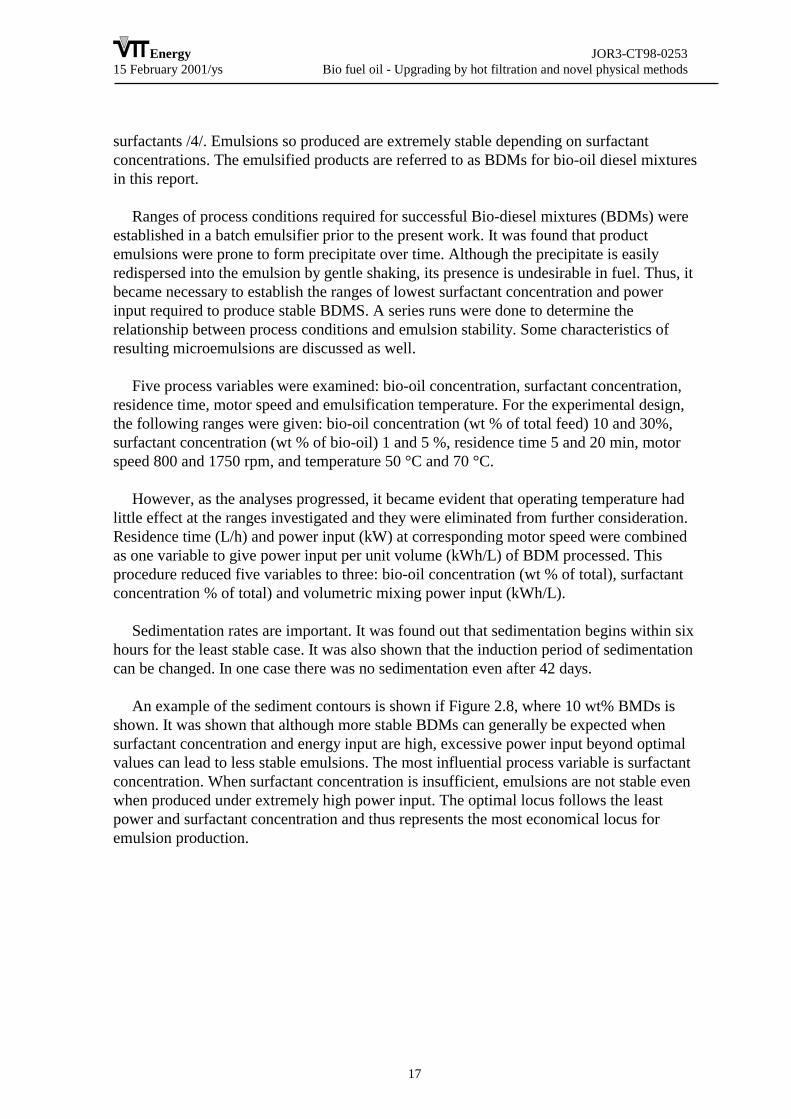
Ranges of process conditions required for successful Bio-diesel mixtures (BDMs) wereestablished in a batch emulsifier prior to the present work. It was found that productemulsions were prone to form precipitate over time. Although the precipitate is easilyredispersed into the emulsion by gentle shaking, its presence is undesirable in fuel. Thus, itbecame necessary to establish the ranges of lowest surfactant concentration and powerinput required to produce stable BDMS. A series runs were done to determine therelationship between process conditions and emulsion stability. Some characteristics ofresulting microemulsions are discussed as well.
Five process variables were examined: bio-oil concentration, surfactant concentration,residence time, motor speed and emulsification temperature. For the experimental design,the following ranges were given: bio-oil concentration (wt % of total feed) 10 and 30%,surfactant concentration (wt % of bio-oil) 1 and 5 %, residence time 5 and 20 min, motorspeed 800 and 1750 rpm, and temperature 50 °C and 70 °C.
However, as the analyses progressed, it became evident that operating temperature hadlittle effect at the ranges investigated and they were eliminated from further consideration.Residence time (L/h) and power input (kW) at corresponding motor speed were combinedas one variable to give power input per unit volume (kWh/L) of BDM processed. Thisprocedure reduced five variables to three: bio-oil concentration (wt % of total), surfactantconcentration % of total) and volumetric mixing power input (kWh/L).
Sedimentation rates are important. It was found out that sedimentation begins within sixhours for the least stable case. It was also shown that the induction period of sedimentationcan be changed. In one case there was no sedimentation even after 42 days.
An example of the sediment contours is shown if Figure 2.8, where 10 wt% BMDs isshown. It was shown that although more stable BDMs can generally be expected whensurfactant concentration and energy input are high, excessive power input beyond optimalvalues can lead to less stable emulsions. The most influential process variable is surfactantconcentration. When surfactant concentration is insufficient, emulsions are not stable evenwhen produced under extremely high power input. The optimal locus follows the leastpower and surfactant concentration and thus represents the most economical locus foremulsion production.

Energy JOR3-CT98-025315 February 2001/ys Bio fuel oil - Upgrading by hot filtration and novel physical methods
18
Figure 2.8. Sediment contours for 10 % BDMs
The principal conclusions were:
Bio-oils in diesel emulsion fuels were produced and their stability investigated. Resultswere analyzed using a statistical model. A quadratic response surface model agrees wellwith experimental results. Dominant parameters are bio-oil and surfactant concentrationsand power input, and there are optimal loci for different bio-oil concentrations thatminimize the final costs of emulsified products.
Fuel properties such as cetane number, viscosity and corrosion were characterized.Ensyn pyrolytic oil had a cetane number of 20.6±1.3. Usually it is not easy to determine thecetane number of pyrolytic bio-oil due to its poor combustion characteristics. However,when emulsions were formed it was possible to do so by linear interpolation. The viscosityof emulsified fuels was best described by Einstein's equation for dilute solid dispersions.
2.2.3 BFO production (task 3)
The objective is to determine optimum values for key process parameters (temperature,residence time) for pyrolysis of three feedstocks (forest residues, pine sawdust, and straw).The organic yield is maximised using optimum parameters. The organic yield is expectedto be above 65 wt% for pine sawdust without the hot vapour filter (HVF). Both the PDUand laboratory scale (150 g/h) units are used for this task.
Pyrolysis liquid or bio fuel oil (BFO) has been estimated to be the lowest cost liquidbiofuel /5/. The estimated production costs have to be further decreased, its quality has to

Energy JOR3-CT98-025315 February 2001/ys Bio fuel oil - Upgrading by hot filtration and novel physical methods
19
be improved, and the production of a homogenous liquid has to be demonstratedindustrially, before BFO is a marketable product.
Woody biomasses (forest residues, pine sawdust) are considered industrially relevantfeedstocks for potential BFO production in Scandinavia. Wood samples were pyrolysedwithin this task to produce pyrolysis liquid for utilisation tests (tasks 5, 6, and 7 within thisproject) and for quality improvement work (tasks 2 and 3).
It has been shown earlier /6/ that fast pyrolysis of straw, and the subsequent use of thepyrolysis liquid as a diesel power plant fuel, is economically attractive in Denmark. As partof a work, which aims in developing technologies for this opportunity, fast pyrolysis testsin a laboratory scale pyrolyzer with straw were carried out.
A summary of the tests being reported is shown in Table 2.1. The hot filter was operatedpart time during runs 13, 15, 16, 17, and 18. Other tests provided liquid for utilisation testsand product improvement work.
Table 2.1. Summary of experiments 10-18, FR = Forest residue
Time Feedstock Production kgPDU10 Dec 1998 Pine 1 535PDU11 Mar 1999 Pine 2 1036PDU12 Jun 1999 Pine 3 707PDU13 Sept 1999 FR 95 422PDU15 Dec 1999 FR 95 158PDU16 Feb 2000 FR 95 1212PDU17 Mar 2000 FR 95 793PDU18 May 2000 FR 2 906
A summary of yields, when wood fuels are used is shown in Tables 2.2 and 2.3. Notethat both organic and pyrolysis water yields are calculated for dry feedstock. The yields arealso shown in Figure 2.9. The yields are calculated based on weighted overall mass yieldsduring runs. The amounts produced in the runs range between 540 and 1210 kg.
Table 2.2. Liquid yields based on dry feed, pine feedstock
PDU10 PDU11 PDU12Organic yield wt% 66.9 63.2 59.2Pyrolysis water wt% 10.5 8.9 11.1Liquid yield wt% 77.4 72.1 70.3

Energy JOR3-CT98-025315 February 2001/ys Bio fuel oil - Upgrading by hot filtration and novel physical methods
20
Table 2.3. Liquid yields based on dry feed, forest residue feedstock
PDU16 PDU17 PDU18Organic yield wt% 46.3 49.5 43.1Pyrolysis water wt% 12.7 14.7 12.6Liquid yield wt% 59.0 64.2 55.7
Pyrolysis yields
30
40
50
60
70
80
Run Number
Yie
ld w
t%
Pyr. water 10.5 8.9 11.1 12.7 14.7 12.6
Organics 66.9 63.2 59.2 46.3 49.5 43.1
10 11 12 16 17 18
Figure 2.9 Liquid yields based on dry feed, wood feedstock
The effect of ash content of wood feed on the organic liquid yield is shown in Figure2.10. The yield is based on the mass of the whole liquid produced, and it ranges between530 - 1210 kg. The decrease in the yield of organic liquid is clear, as the ash content of thefeed is increased. The result is also important because although process parameters werevaried during runs, ash content appears to explain much of the variation.

Energy JOR3-CT98-025315 February 2001/ys Bio fuel oil - Upgrading by hot filtration and novel physical methods
21
Yield of organics, feed moisture 3-4 wt%
R 2 = 0. 9852
40
45
50
55
60
65
70
0 0.5 1 1.5 2 2.5 3 3.5 4
Ash wt%
Org
anic
s wt%
Figure 2.10. Organic liquid yield as a function of feed ash content
The effect of moisture on the organic liquid yield using pine feed is shown in Figure2.11. A potential explanation for this feature is a decreasing heat flow into the organicmatrix, because more water has to be evaporated before pyrolysis may proceed. The resulthas considerable practical consequences. If the correlation presented is valid also for largerfacilities, a quite dry material must be used for pyrolysis to reach a high organic yield. Analternative would be to use an even smaller particle size to improve heat transfer. However,this may be even more expensive than drying the feed to low moisture content.
Yield of organics, pine feed
R 2 = 0. 9999
5052545658606264666870
1.0 2.0 3.0 4.0 5.0 6.0 7.0
Feed moisture wt%
Org
anic
s wt%
Figure 2.11. Organic liquid yield as a function of feed moisture content
Danish straw samples were converted in the laboratory pyrolyzer. It should be noted thatthe yield data is not directly comparable to the PDU data given above. Because of different

Energy JOR3-CT98-025315 February 2001/ys Bio fuel oil - Upgrading by hot filtration and novel physical methods
22
scale, solvents are used in the laboratory unit to determine liquid yield. The feed particlesize is also considerably smaller. Finally, the reactor types used in this task are alsodifferent. Among other, these factors contribute to differences between the two systems.
Organic liquid yield as a function of reaction temperature is shown for straw in Figure2.12. Four different straw samples have been converted. The correlations are shown for twodifferent samples: one with natural ash composition and one that has been water washed toreduce the amount of alkali metals. Removing a large fraction of alkali metals (80 % ofpotassium in the "washed" sample) increases the yield of organic liquid considerably.
Straw Pyrolysis, Organic Liquid YieldFour Straw Samples
420 440 460 480 500 520 540 56035
40
45
50
55
Temperature C
Mas
s Y
ield
Bas
ed o
n dm
wt%
Washed
Natural
Straw 9
Straw 11
Figure 2.12. Organic liquid yield in straw pyrolysis
Conclusions from the task are summarised:
All the objectives of the task were met. Total of 5.8 tonnes of pyrolysis liquid wasproduced for utilisation tests and quality improvement work. It was found that a relativelyhigh reaction temperature of 530 °C produced the highest liquid yield in the PDU unit,when forest residue fuel was used as feedstock. In the bench scale unit the maximum liquidyield for straw was around 480 °C. The residence time was not varied. A shorter residencetime than the present 2 seconds in the PDU might have been more favourable. However, itcould not be shortened because of excessive carry over of fines to the liquid, if reactor gasvelocity would further have been increased. The organic liquid yield was 66 wt%, when adry (2 wt% moisture) pine feed was used. Finally, the unit PDU unit was operatedsuccessfully in a steady-state mode to enable hot filter operation.
2.2.4 BFO quality (task 1, 2 and 3)
Energy JOR3-CT98-025315 February 2001/ys Bio fuel oil - Upgrading by hot filtration and novel physical methods
23
Biomass pyrolysis liquid product may be used as a fuel oil substitute. Combustion testsperformed using different scale burners (for example, task 6) and internal combustionengines and gas turbines have demonstrated that the oils could be burnt efficiently instandard or slightly modified equipment. These tests also identified several challenges inpyrolysis liquid applications resulting from their properties.
Pyrolysis liquids are typically dark-brown organic liquids. The physical properties of theoils as well as methods for their measurements are described in several publications (forexample /7/, more references in an appendix to this report). These properties result fromthe chemical composition of the oils, which is significantly different from that ofpetroleum-derived fuels.
The thermal cracking of pyrolysis vapors during hot filtration, although reducing the oilyield, has a beneficial impact on the oil quality /for example, 8/. It causes size reduction ofoligomeric chains, which not only affects the oil viscosity but its combustion chemistry aswell. Diesel engine tests performed on crude and hot-filtered oils show a substantialincrease in burning rate and a lower ignition delay for the latter. The main reason for thisimprovement in combustion quality is thought to be the structural change expressed as thelower average molecular weight.
Polar solvents have been used for many years to homogenize and to reduce viscosity ofpyrolysis liquids /9, 10/. The addition of solvents, especially methanol, also shows asignificant effect on oil stabilization. The rate of viscosity increase for the oil with 10 wt%of methanol is almost 20 times less than for the oil without additives /11/. It is postulatedthat solvent addition can impact the oil viscosity by three mechanisms:
1. physical dilution without affecting the chemical reaction rates;2. reducing the reaction rate by molecular dilution or by changing the oil
microstructure;3. chemical reactions between the solvent and the oil components that prevent further
chain growth.
The chemical reactions that can occur between the pyrolysis liquid and methanol orethanol are esterification and acetalization. Though thermodynamically non-favored, theycan proceed to a significant extent if appropriate conditions are applied. In such a case, inaddition to the decrease in viscosity and in aging rate, they also lead to other desirablechanges like reduced acidity, improved volatility and heating value, and better miscibilitywith diesel fuels. Considering the simplicity, the low cost of some solvents (methanol) andtheir beneficial effects on the oil properties, this method seems to be the most practicalapproach to pyrolysis liquid quality upgrading.
Pyrolysis liquids are not miscible with hydrocarbon fuels, but they can be emulsifiedwith diesel oil with the aid of surfactants. A process for producing stable micro-emulsions,with 5 - 30% of pyrolysis liquid in diesel has been developed at CANMET EnergyTechnology Centre (task 2). These emulsions are less corrosive and have showedpromising ignition characteristics.
PDU pine pyrolysis liquids have been good-quality single-phase liquids (Table 2.4).Solids content is typically 0.1 - 0.3 wt%, when the particle size of the feed is below 3 mm.

Energy JOR3-CT98-025315 February 2001/ys Bio fuel oil - Upgrading by hot filtration and novel physical methods
24
Lower solids contents, 0.02 - 0.1 wt%, in PDU runs 4 - 6 have been obtained for a smallerparticle size. Ash content is typically 0.2 - 0.3 wt-% with 10 - 30 ppm K+Na. Watercontent varies with feedstock moisture from 16.3 (feedstock moisture 3.3 wt-%) to 21.4wt% (feedstock moisture 5.8 wt%). Density, heating value and viscosity vary also with thewater content.
Table 2.4. Fuel oil analyses of PDU pine liquids.
PDU4 PDU5 PDU6 PDU7 PDU8 PDU10 PDU11 PDU11 PDU12 PDU13 PDU13KS
Solids, wt-% (abt. 1 µm) ethanol 0.03 0.02 0.11 0.20 0.25 0.29 0.35 0.06 0.14 0.02 methanol:CH3Cl, 1:1pH 2.4 2.3 2.3 2.6 2.6 2.5 2.6Water, wt-% (ASTM D 1744) 17.0 20.4 19.6 19.8 21.4 15.7 16.3 16.6 21.3 21.4 25.4Viscosity , cSt (ASTM D 445)40°C 35 3650°C 28 16 24 28 21 29 32 31 23 9Density (15°C), kg/dm3 (ASTM D 4052) 1.24 1.23 1.23 1.24 1.22 1.24 1.24 1.23 1.19Heating value (HHV), MJ/kg (DIN 51900) 18.7 17.3 18.5 17.9 17.8 19.0 19.1 18.2 17.2Lower heating value (LHV), MJ/kg 17.2 15.8 16.3 17.6 17.7 16.6 15.6Ash, wt-% (EN 7) 0.03 0.02 0.02 0.02 0.03 0.03 0.018CHN, wt-% (ASTM D5373-93)C 45.7 42.8 43.5 46.7 46.6 44.9 41.6H 7 7.1 7.10 6.7 6.7 7.4 7.5N < 0,1 <0.1 < 0.1 0.1 0.1 < 0,1 < 0,1Alkali metals, mg/kg Na 6.1 4.1 K 16 6.5 Mg 5.4 15 Ca 23 49Cl, mg/kgS, mg/kgConradson carbon, wt-% (ASTM D 189) 16 14 17Flash point, °C (ASTM D 93)Pour point, °C (ASTM D 97) -19 -24
The feedstock for PDU16-20 experiments was forest residue. A large amount ofextractives in bark and needles in the feed yielded two distinct oil phases (chemicalcomposition in Figure 2.13). Physical properties are shown in Table 2.5.
The surface phase (30 - 40 vol% of the whole liquid product) contained most of theextractives. This surface phase was of wax-like foamy material its polarity (low in oxygen)being much lower than that of the bottom phase. The main compound classes in the surfacephase were fatty acids, resin acids, resin and fatty alcohols, sterols, and phenolicsubstances. Because of high amount of neutral substances the water content and the amountof water-soluble compounds are low.
The bottom phase (60 - 70 vol%) resembles a typical softwood pyrolysis liquid. Thedifferences to other softwood oils are higher water and ash contents and the presence of asmall amount of extractives. Alkali metals in ash act as catalystsin pyrolysis producinghigh water content. In addition, the surface phase rejects water to the bottom phase.
Table 2.5. Physical properties of forest residue liquids.

Energy JOR3-CT98-025315 February 2001/ys Bio fuel oil - Upgrading by hot filtration and novel physical methods
25
PDU16 PDU17 PDU18 PDU18 hot-filtered PDU37/0017F
top bottom top bottom bottom top bottom top bottom top bottomSolids, wt-% (abt. 1 µm) ethanol 2.7 0.1 methanol:CH3Cl, 1:1 0.0 1.1 0.1 0.0 0.0 0.8 0.1pH 3.1 3.1 3.3 3.2 3.2 3.4 3.4 3.3 3.2 3.52 3.35Water, wt-% (ASTM D 1744) 27.0 24.6 13.8 27.7 29.4 13.1 31.4 12.1 32.9 13.0 30.9Viscosity , cSt (ASTM D 445)20°C 16 16 26 26 3340°C 153 18 17 191 11 12Density (15°C), kg/dm3 (ASTM D 4052) 1.190 1.205 1.206 1.126 1.184 1.136 1.183 1.175Heating value (HHV), MJ/kg (DIN 51900 16.7 17.6 27.0 16.4 17.8 27.8 16.3 25.9 15.3 25.5Lower heating value (LHV), MJ/kg 15.1 16.0 25.3 14.7 16.2 26.1 24.1 13.6 23.9Ash, wt-% (EN 7) 0.3 0.2 0.4 0.2 0.3 0.1 0.2 0.2 0.1CHN, wt-% (ASTM D5373-93)C 40.4 42.5 59.9 40.1 38.8 57.3 36.2 57.7 36.2 57.6H 7.5 7.6 7.8 7.5 7.5 7.8 8.0 8.0 7.9 7.7N 0.3 0.2 0.2 <0.1 0.4 0.3 0.3 0.3 0.3 0.3Alkali metals, mg/kg Na 10 10 5.2 41 7 27 19 15 K 95 98 130 86 85 30 75 88 Mg 130 140 150 36 74 16 91 65 Ca 630 540 630 430 400 240 390 360Cl, mg/kg <100 <100S, mg/kg 290 310Conradson carbon, wt-% (ASTM D 189) 17.5Flash point, °C (ASTM D 93) 45 42 40 50Pour point, °C (ASTM D 97) -15 -12
Composition of whole oils PAP 60/99
Bottom phase Surface phase0
20
40
60
80
100
Frac
tiona
tion
of w
hole
oils
, %
Volatile compoundsAlcoholsVolatile AcidsDiethylether-solublesWaterDiethylether-insolublesWater-insolubles
Figure 2.13. Chemical composition of the bottom and surface phases of forest residueliquid. Fractionation is based on water and solvent extractions.
The main differences between pine and straw liquids are:
Energy JOR3-CT98-025315 February 2001/ys Bio fuel oil - Upgrading by hot filtration and novel physical methods
26
• Water yield is higher for straw because a higher amount of alkali metals catalyzeswater formation reactions. The water yield is a function of alkali metal content in thefeedstock.
• Straw yields in a smaller water-insoluble fraction due to a smaller amount of ligninin the feedstock.
• Straw produces more acids because of its composition. The proportion of acetic acidis larger for straw liquid than for pine liquid.
• Straw pyrolysis liquid contains more methanol, aldehydes and ketones than pinepyrolysis liquid.
The main differences between pine and forest residue liquids are:• Liquids produced from forest residue are multi-phase containing an extractive-rich
upper layer.• Extractives in forest residue liquid demand a more powerful solvent than alcohol. A
mixture of a polar and neutral solvent is needed for solids determination.• The bottom phase of forest residue liquid is very similar to that of pine liquid except
of a small concentration of extractives and higher water content.• Forest residue contains more ash, and alkali metals produces a high water yield.
Alkali metals may be also cause the higher reactivity of forest residue liquid.• Needles in forest residue produce high nitrogen content of the liquid.
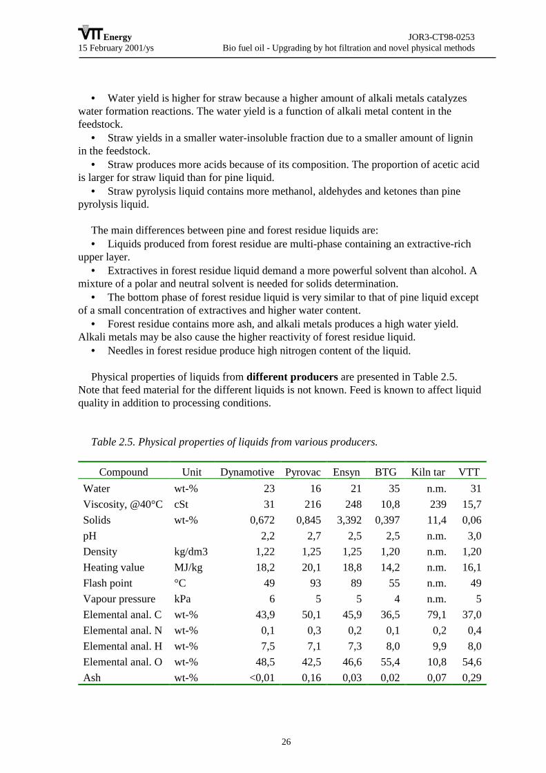
Physical properties of liquids from different producers are presented in Table 2.5.Note that feed material for the different liquids is not known. Feed is known to affect liquidquality in addition to processing conditions.
Table 2.5. Physical properties of liquids from various producers.
Compound Unit Dynamotive Pyrovac Ensyn BTG Kiln tar VTTWater wt-% 23 16 21 35 n.m. 31Viscosity, @40°C cSt 31 216 248 10,8 239 15,7Solids wt-% 0,672 0,845 3,392 0,397 11,4 0,06pH 2,2 2,7 2,5 2,5 n.m. 3,0Density kg/dm3 1,22 1,25 1,25 1,20 n.m. 1,20Heating value MJ/kg 18,2 20,1 18,8 14,2 n.m. 16,1Flash point °C 49 93 89 55 n.m. 49Vapour pressure kPa 6 5 5 4 n.m. 5Elemental anal. C wt-% 43,9 50,1 45,9 36,5 79,1 37,0Elemental anal. N wt-% 0,1 0,3 0,2 0,1 0,2 0,4Elemental anal. H wt-% 7,5 7,1 7,3 8,0 9,9 8,0Elemental anal. O wt-% 48,5 42,5 46,6 55,4 10,8 54,6Ash wt-% <0,01 0,16 0,03 0,02 0,07 0,29

Energy JOR3-CT98-025315 February 2001/ys Bio fuel oil - Upgrading by hot filtration and novel physical methods
27
The hot-filtration study (task 1) was focused on technical operation of the filter.Hence, no systematic study on the quality of oil was carried out. However, hot-filtrationchanges the oil quality as follows: increase in water, decrease in solids. Due to the highwater content of the oil the stability test could not be carried out.
Emulsion samples from pine pyrolysis liquids were all in two phases. However, simpleshaking of the emulsion can remix them. These emulsions were not true microemulsionsbecause of a clear appearance of droplets above 1 µm size. In addition, emulsions lookedunhomogenous. Samples from forest residue oil were the most stable microemulsions everanalysed. The droplet size of the whole sample is below 1 µm and the emulsion is insingle-phase at least for 6 months storage.
The following conclusions can be drawn:• Stability of pine pyrolysis liquids can be improved by adding water, methanol, or a
mixture of these solvents.• Liquids produced from forest residue are multi-phase containing an extractive-rich
upper layer. The surface phase is high in extractives and solids and low in water, oxygen,and polar compounds. The bottom phase of forest residue liquid is very similar to that ofpine liquid except of a small concentration of extractives and higher water content.
• Forest residue containing more ash, and alkali metals produces a high water yield.Alkali metals may be also cause the higher reactivity of forest residue liquid.
• Forest residue liquids are more reactive than pine pyrolysis liquids. The reactivity ishighest during the first month.
• Needles in forest residue produce high nitrogen content of the liquid.• Straw is high in alkali metals which causes high water yield. The chemical
composition of straw yield also to higher amount of acids, especially acetic acid, andhigher amount of methanol, aldehydes and ketones than pine pyrolysis liquid.
• Hot-filtration increases the water content and decreases the solids content of theliquid.
• Forest residue liquid yields in a stable microemulsion with light fuel oil. 2.2.5 Handling and storage of BFO, and heath and safety issues related
to BFO (task 4)
The objective is to develop bio fuel oil handling and storage procedures for industrialapplications, and to study the health and safety issues related to industrial use of BFO.
The work in this task concentrated on the following subtasks:• Material Safety Data Sheet (MSDS): To determine chemical and physical-chemical
characteristics of BFO to produce MSDS• Other clearances concerning toxicology, ecotoxicology, handling, storage and
product• Exposures and emissions

Energy JOR3-CT98-025315 February 2001/ys Bio fuel oil - Upgrading by hot filtration and novel physical methods
28
The work started from determining the chemical and physical-chemical characteristicsof BFO. Because properties of BFO differ from those for fossil oil, not all standardprocedures developed for fossil oil could be used. In this work methods suitable for BFOtested at VTT by Oasmaa et al. /7/ and some methods for fossil oil were used. This workgave information and data to determine MSDS for BFO. Based on previous informationfeedstock, process conditions and processing of BFO determine mainly the properties ofBFO. That is why content of various components and physical characteristics of BFObetween different BFO producers varies a lot and sometimes between production lots ofone producer.
The analysed BFOs that were made with fast pyrolysis method were compared to kiln-burned pine tar that is made by slow pyrolysis method. This was done to describe thedifference between these two products and also to help in categorising BFO product. Kiln-burned pine tar has CAS and EINECS categories but for BFO they have not been defined.
BFO of different producers were analysed giving special attention to toxic, mutagenicand/or carcinogenic compounds (Table 2.6).
Table 2.6. Summary of the quantitative results of chemical characteristics
Compound Unit Dyna-motive
Pyrovac Ensyn BTG kilntar
VTT
C1-C6 acids wt-% 4,2 4,4 6,5 6,4 0,4 5,1Aldehydes and ketones wt-% 2,5 1,5 1,2 2,2 0,1 1,3Phenols wt-% 4,9 5,2 1,8 3,3 4,7 2,8EPA-PAHs mg/kg 8 28 330 3 1030 2VOC/monoaromatics mg/kg 680 10 510 90 1860 200VOC/2-methyl-2-butenal
mg/kg 100 <10 40 70 <10 70
VOC/furane mg/kg 110 20 10 60 50 40
Acidity of BFOAs can be seen from Table 2.6 the total amount of detected C1-C6-acids as benzyl
derivative from water phase show that BFO has some 5 wt-% acidic compounds. pHmeasurements in Table 2.5 show that BFO has strong acidic property while pH is 2-3.Authorities are more interested about the total acidity than single components.
Aldehydes and ketones of BFOThe total amount of detected aldehydes and ketones was below 5 wt-%. Amount of
carcinogenic compounds like formaldehyde and acetaldehyde varied in measured samplesbetween 0,01-0,84 wt-%.
Energy JOR3-CT98-025315 February 2001/ys Bio fuel oil - Upgrading by hot filtration and novel physical methods
29
PhenolsThe total amount of detected phenols was below 6 wt-%. Variation between BFO
produced by different producers exists. This may be due to use of different feedstock andprocess conditions.
EPA-PAH compoundsMost interesting results were measured in case of polyaromatic hydrocarbons. As can be
seen from the table, the concentration of PAHs is a function of use of different feedstockand process conditions. As a reference kiln-burned pine tar has 500 times greater valuescompared to VTT’s BFO. This is due to fast pyrolysis that apparently reduces formation ofPAHs.
VOC compoundsThe amount of volatile organic compounds varied as can be seen from table x. The
variation can be interpreted to be due to different process conditions. Pyrovac’s vacuumprocess seems to decrease the amount of volatile components.
EHS (environment, health and safety) aspects were also considered. In order to assurecustomers that a product is safe for shipping, storage and use, the health and safety aspectsof a product must be evaluated. Much of this information can be obtained from productsMSDS (material safety data sheet). This is required for all products which are sold inEurope together with its’ EINECS (European Index of Existing Chemical Substances)number. Unfortunately the EINECS numbers for existing products do not reflect the exactnature of this new fast pyrolysis product.
Exposure measurements were also carried out in connection to a boiler test with 500kW BFO burner used for half day test period. Burning temperature is about 800-900°C.Consumption of isopropyl alcohol that is used for cleaning of equipment is about 0,1-5l/day. BFO made by VTT was pumped from 100 l barrels to burner. Also LFO was used asa support fuel in the beginning and end of test periods.
Summary of the results: Concentrations of hydrocarbons were low. Isopropyl hadconcentrations of 3-12 ppm that is 6% of the limit. Of aromatic hydrocarbons benzeneconcentrations were < 0,1 ppm that is less than 2% of limit, toluene and ethyl benzeneconcentrations < 0,1 ppm that is less than 1% of limit and xylene concentrations < 1 ppmthat is less than 1% of limit.
Concentrations of PAH compounds were relative small. Concentrations ofbenzo(a)pyrene in fixed test points were <0,01 µg/m3 that is less than 1% of limit.Naphthalene was the only compound that could be detected over limit of identification 0,6µg/m3 that is less than 1% of limit.
In boiler use of BFO temporary measured concentrations of carbon monoxide and NOxwere less than the limit of identification < 2 ppm for CO and < 0,5 ppm for NO+NO2. Theconcentration of CO2 was 0,01%.
• As a summary it can be said that the measured contaminant concentrations were small.

Energy JOR3-CT98-025315 February 2001/ys Bio fuel oil - Upgrading by hot filtration and novel physical methods
30
• During the measurements in the boiler room atmosphere could be detected a strongsmell of tar and smoke was irritating. That’s why one must take care of enoughventilation in the boiler room and site specific ventilation must be arranged.
• Disposable gloves that are used in handling BFO must be thick and they must bechanged frequently.
• More measurements must be done to get more statistical information. Far goingconclusions can not be made after one measurement day.
Materials. Because of acidity (pH 2-3) of pyrolysis liquids following recommendationsfor materials are suggested:• Plastics or AISI 316 for storage• Plastics, copper and its alloys (no abrasion), AISI 316 for piping applications• AISI 316 or better acid-resistant steel for process equipment
Due to instability and reactivity of pyrolysis liquids following storage conditions arerecommended:• Air-free plastic or stainless steel containers• Storage temperature 15 °C, but at least below 25 °C• Constant slow propeller stirring
Following is recommended for handling:• Air should be avoided• Heating above 60 °C should be avoided• Heating between 40-60 °C should be minimised to a few hours• Hot surfaces has to be avoided
For poor-quality pyrolysis liquids following is suggested:• Homogenising of the liquid with simultaneous addition of 5-10 wt-% methanol. A 1-2
wt-% addition of formic acid for homogenisation is not adequate.• Slow constant propeller-type mixing provided during the storage.
2.2.6. Fundamental behaviour of BFO in combustion (task 5)
The objective of task 5 was to highlight, in a lab scale environment, the combustionfundamentals of droplets composed of pure pyrolysis oil, as well as of BFO-basedemulsions and mixtures. As the utilisation of such fuels was foreseen in boilers and inDiesel engines, attention had to be given to the problem of formation and behaviour ofunburned solid material, in order to avoid intolerable particulate emissions and operationalproblems.
The specific objectives of the task were:
1) Description of the thermal behaviour (heating, vaporisation and combustionfeatures) of BFO and BFO derived fuel droplets at normal and high pressure conditions;

Energy JOR3-CT98-025315 February 2001/ys Bio fuel oil - Upgrading by hot filtration and novel physical methods
31
2) Study of the physical and chemical phenomena undergone by droplets (swelling,liquid phase pyrolysis inside droplet);
3) Study of the formation of carbonaceous residuals.
Two single-droplet combustion chambers were developed to study evaporation-combustion of single droplets up to 100 bar. Droplets composed of different fuels weresuspended to a thermocouple or to a quartz fibre. Quartz windows permitted the opticalaccess to the chambers. Both laser and halogen light sources were used to illuminatedroplets during vaporisation, before ignition. The thermal behaviour exhibited by dropletswas followed by means of high-speed digital imaging. About two thousands of frames werecollected for each test. The acquisition velocity ranged between 400 and 4000 frames/s.
Eight different fuels were examined for a total of about five hundred tests. Experimentswere carried out on a pure pine pyrolysis oil, two emulsions of forest residue oil (10% and30%) in #2 diesel oil, an emulsion of 30% of pine oil in #2 diesel oil, a mixture of pine oil(30%) in diglyme. Reference tests were carried out on commercial Italian Diesel oil, ondiglyme and on hexadecane. Diglyme was chosen for the good ignition property (cetanenumber 110-130) and for the very low sooting tendency; n-hexadecane (or "cetane") wastested because it is used in the standard procedures to evaluate ignition characteristics ofDiesel engine fuels. The pressure ranged between 1 and 60 bar, the size of dropletsbetween 400 µm and 1100 µm.
All fuels were easy to ignite at normal and high pressure. In the investigatedexperimental conditions, the environment temperature had a significant influence on theignition delay: this was due mainly to the relevance of the physics of the process (heatingand vaporisation of the fuel) respect to the chemistry in the pre-ignition phase. Also theinfluence of different heating rates on combustion phenomenology was investigated. Themain effect resulted on droplet evaporation rate and swelling phenomena. The temperatureof the chamber and the heating ramp influenced instead only marginally after-ignitionprocesses.
Increasing the pressure, the swelling phenomena - typical of pure pyrolysis oils -exhibited a reduced intensity and completely disappeared at pressures higher than 20 bar.Mixture and emulsion droplets showed less marked swelling at normal pressure and thephenomenon completely disappeared already at 10 bar. However, strong bubbling andfoaming were observed. The temporal sequence heating-swelling-vaporisation/bubbling/foaming-ignition was strongly dependent on the properties of the"carrier" fuel used in the preparation of the mixture or emulsions.

Energy JOR3-CT98-025315 February 2001/ys Bio fuel oil - Upgrading by hot filtration and novel physical methods
32
sw = Dmax/D0
0 20 40 60Pressure, bar
0.8
1.2
1.6
2
2.4
Swel
ling
Fact
or425
563802 524
438555
953
645
928744 836 552802
552
D0 Dma
Figure 2.14. Swelling factor vs pressure for pur pine pyrolysis oil droplet
After ignition, both mixture and emulsions droplets underwent a diameter reduction thatcould be approximated with a D2 law. Some difficulties arose for pure oil droplets due tothe strong swelling that prevented a correct determination of the drop diameter. Thedroplets burning time (normalised respect to the drop diameter) decreased with pressure forall the samples. The liquid burning rate was around 1 mm2/sec at normal pressure,increased to about 1.5 mm2/sec at 12 bar and to 2 mm2/sec at 45 bar.
All the samples, even if to a different extent, evidenced liquid-phase pyrolysis and theformation of a cenosphere during the last part of the liquid combustion. However, theformation of a solid residual, peculiar of pure oil droplets, was reduced in the case ofemulsions and mixtures. Interesting enough, these samples gave rise to a smaller solidresidual respect to what could be expected from the BFO content in the parent droplet. Thiswas due to the different combustion properties of emulsions and mixtures when comparedto pure BFOs. The other main parameter influencing cenosphere formation was, of course,the BFO quality and composition. The synergy between BFO quality and combustionproperties can result in very surprising effects: in practice no solid residual was formed bythe emulsion made with 30% pine oil in #2 diesel oil.
The pressure also played a role in the structure and shape of the residual since it forcedthe droplet/cenosphere surface in opposite direction respect to the internal pressuregenerated by the liquid vaporised in the droplet interior. At intermediate pressures, around10 bar, the balancing between these forces produced "cocoon" shaped cenospheres whenpure BFO was used. Pressure had a minor influence on cenosphere formation whenemulsions and mixtures were used. This could be explained by considering their lowcontent of oil and, hence, of "swelling" agent. An increase of the residual size with pressurewas observed at 45 bar for the samples containing the higher oil concentration.
In the examined experimental conditions, the combustion of residuals from all sampleswas diffusion limited. The cenosphere burning rate was, hence, determined essentially bythe particle surface extension.

Energy JOR3-CT98-025315 February 2001/ys Bio fuel oil - Upgrading by hot filtration and novel physical methods
33
2.2.7 Medium size boiler tests (task 6)
The objective is to develop use of BFO in medium scale heating boilers. Performanceand emissions of CO, NOx, and particulates were be measured for BFO in 200 and 500 kWboilers.
The existing burner equipment that is normally used with light fuel oils has beenoptimized with a much higher heating value fuel than pyrolysis liquid (roughly double). Thismeans that to achieve an adequate fuel / air mixtures and velocities, much less air is requiredfor combustion. This causes the flame to expand in size and to extend to the end of thecombustion chamber. It was observed that this type of flame is such that internal heating isnot adequate to combust particulates and high molecular tars which increases emissions. Inaddition, since pyrolysis viscosity is higher than light fuel oils, a higher pressure is usedwhich leads to drop blow through and higher particulate emissions.
The pyrolysis liquids produced at VTT from pine sawdust with water concentrations lessthan 24% gave a more stable flame in the 200 kW boiler. The 30% water content pyrolysisliquid produced from forestry residues could not be combusted cleanly in the 200 kW boilersystem with the existing equipment but was found to give a good flame in the larger 500 kWboiler. Upon further comparison of the 200 kW and 500 kW burners that were used in thisproject it was noted that both use the same dimensions for the burner retention head. Thismeans that for the larger loads in the larger boiler the relative velocities adjacent to the burnerretention head are much greater giving a much better fuel / air mixture and a more stable andhotter flame.
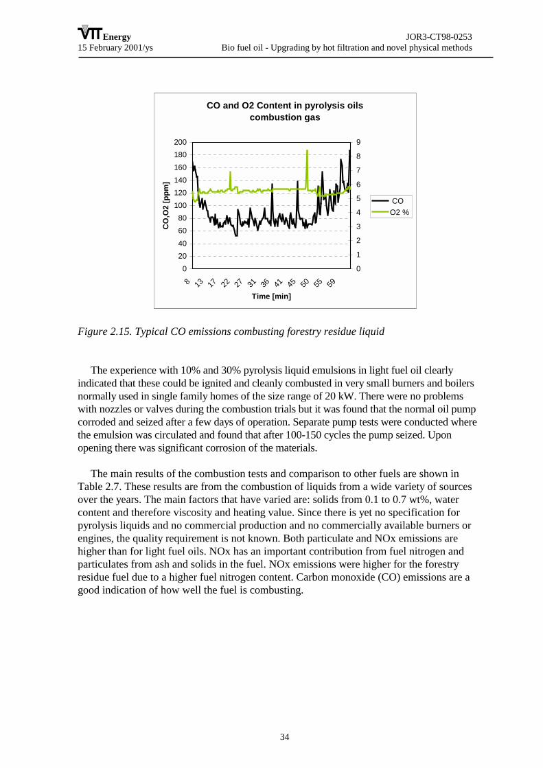
From both a viscosity standpoint and a solids standpoint, both the forestry residue and pinesawdust fuels produced by VTT Energy were of sufficiently good quality to be combustedcleanly in light fuel oil boilers. The only notable emissions that are higher than for light fueloils is that of particulates and tars. It is believed that once a burner is designed specifically forpyrolysis liquids, it will be possible to reduce further these emissions and combust these fuelscleanly in this size class. From a combustion standpoint, the most important emission iscarbon monoxide (CO) which is shown in Figure 2.15 for the forestry residue sample fromVTT. Carbon monoxide is an intermediate combustion product between the fuel itself and thefinal combustion product carbon dioxide. The lower the carbon monoxide, the more completethe combustion. The value shown in Figure 2,15 illustrates that the pyrolysis liquid wascombusting cleanly in the system.
Energy JOR3-CT98-025315 February 2001/ys Bio fuel oil - Upgrading by hot filtration and novel physical methods
34
CO and O2 Content in pyrolysis oils combustion gas
020406080
100120140160180200
8 13 17 22 27 31 36 41 45 50 55 59
Time [min]
CO
,O2
[ppm
]
0
1
2
3
4
5
6
7
8
9
COO2 %
Figure 2.15. Typical CO emissions combusting forestry residue liquid
The experience with 10% and 30% pyrolysis liquid emulsions in light fuel oil clearlyindicated that these could be ignited and cleanly combusted in very small burners and boilersnormally used in single family homes of the size range of 20 kW. There were no problemswith nozzles or valves during the combustion trials but it was found that the normal oil pumpcorroded and seized after a few days of operation. Separate pump tests were conducted wherethe emulsion was circulated and found that after 100-150 cycles the pump seized. Uponopening there was significant corrosion of the materials.
The main results of the combustion tests and comparison to other fuels are shown inTable 2.7. These results are from the combustion of liquids from a wide variety of sourcesover the years. The main factors that have varied are: solids from 0.1 to 0.7 wt%, watercontent and therefore viscosity and heating value. Since there is yet no specification forpyrolysis liquids and no commercial production and no commercially available burners orengines, the quality requirement is not known. Both particulate and NOx emissions arehigher than for light fuel oils. NOx has an important contribution from fuel nitrogen andparticulates from ash and solids in the fuel. NOx emissions were higher for the forestryresidue fuel due to a higher fuel nitrogen content. Carbon monoxide (CO) emissions are agood indication of how well the fuel is combusting.

Energy JOR3-CT98-025315 February 2001/ys Bio fuel oil - Upgrading by hot filtration and novel physical methods
35
Table 2.7. Pyrolysis liquid properties, emissions and comparison to other fuels
Medium lightfuel oil
Fast pyrolysisliquid
Woodchips
Heavy fuel oil
Viscosity cSt 30 oC 50 oC
94
300....10070...10
600180
Solids - 0.7 … 0.01 <0.05Ash wt% <0.010 0.1...0.01 2...4 0.03Sulfur wt% 0.15 0 0 1Nitrogen wt% 0 0.03....0.1 0.1...0.2 0.3Typical emissions CO (ppm) NOx (ppm) particulates(Bach.) g/Nm3
15-3080-1200.2 - 1
30-100120-180
2 - 550-100
500-600080-160
+tars, PAH100-200
5-30200-400
1-450-200
2.2.8 Engine tests (task 7)
The objective is to support the development of a BFO as power plant engine fuel bygenerating basic engine performance and emission data. The specific objectives of the taskwere:
• The description of spray injection, formation and ignition;• Evaluation of engine performance;• The analysis of emissions of an engine fueled with BFO;• Study of residuals in the combustion chamber.
The proposed work was innovative in the following points:
• Use of high-speed visualization techniques to characterize the behavior of commercialDiesel engine injectors with BFO;
• A systematic investigation of the performance of a commercial DI Diesel engine fueledwith BFO.
The values of the break-up length and the cone angle with the single orifice nozzle werealways smaller for BFO, if compared to Diesel fuel. The same trend was observed with thefour-hole nozzle. In this case, in order to visualize the sprays exiting from the nozzle, awhite shield was placed just behind the nozzle tip: this optical arrangement determined thesimultaneous visualization of the spray and of its shadow on the underlying screen.
Fully developed spray patterns for Diesel and BFO fuels were compared on a larger fieldof view. The BFO spray is characterized by a good degree of atomization as evidenced bythe strong similarity with diesel fuel sprays. However, Diesel fuel spray shows a widercone angle and greater break-up length; this can be arguably attributed to the higher valueof BFO viscosity respect to diesel fuel (more than one order of magnitude).

Energy JOR3-CT98-025315 February 2001/ys Bio fuel oil - Upgrading by hot filtration and novel physical methods
36
During the visualization tests, no wear or clogging of the injector was recorded.Anyway, an endurance test was specifically performed on the pump-injector system, inorder to check the system in the long run. The 4-holes injector was used. After a totalrunning time of 26 minutes at 1500 rpm, the joint between the electric motor and the PF-type pump failed. The pump was disassembled, revealing no trace of wearing in theplunger-barrel assembly, nor in the delivery valve. The joint failure was apparently due toan increased resistance offered by the pump, to be likely attributed to an overheating of thedriving cam. No clear indications exist that the inconvenience must be attributed to the useof BFO. No major obstacles could therefore be anticipated to the tests on the engine: thefuel delivery system resulted suited to the direct use of BFO, showing no trace of abnormaldegradation and hence no need for modifications.
In the engine tests, the cylinder pressure for blends with an increasing percentage inBFO are reported. Steady running was recorded for periods of nearly an hour. 37.5% (involume) was the maximum amount of BFO allowing for a stable operation. Typical rate ofheat release for 12.5%, 25% and 37.5% BFO blends in Diglyme are shown in Figure 2.16.If compared to the Diesel behavior, they show a steeper rise and a slightly narrower peak ofpremixed combustion, followed by a diffusive phase, which gets more marked as long asthe amount of BFO decreases. Cylinder pressure data for two different BFO-emulsions(prepared from BFO produced by Dynamotive and VTT) is also reported. Both curvespresent a typical shape characterized by an abrupt increase of the pressure and a higherpeak, coherent with the poorer self-ignition properties of the emulsions. This is confirmedby the much longer ignition delays, as inferred from the needle lift data. The rate of heatrelease better allows to appreciate the sudden, essentially premixed combustion,particularly evident in the case of Dynamotive-Diesel emulsions.
-5 0 5 10 15 20 25 30 35 40crank angle, deg
0
5
10
15
Rat
e of
Hea
t Rel
ease
, %/d
eg
Diesel (HDT)12.5% VTT oil - Diglyme25% VTT oil - Diglyme37.5% VTT oil - Diglyme
Figure 2.16. Heat release rate for BFO-Diglyme blends and Diesel fuel

Energy JOR3-CT98-025315 February 2001/ys Bio fuel oil - Upgrading by hot filtration and novel physical methods
37
The specific fuel consumption, in g/kWh is reported. The obtained results are scaledwith the different Heating Value of the base compounds: the amount of fuel necessary todeliver the same power output with BFO-Diglyme blends got larger increasing thepercentage of BFO. The two BFO-Diesel emulsions present a different value ofconsumption, even if the amount of BFO is the same: this effect must be likely ascribed tothe different parent BFO.
The NOx emissions from the BFO-Diglyme mixtures were systematically lower thanboth the reference Diesel (HDT) and pure Diglyme, and their values seem to get lower,increasing the BFO amount. HC emissions are much lower than Diesel fuel, of the sameorder of magnitude than pure Diglyme: increasing the BFO beyond 25%, the HC emissionsrise, suggesting there is a trade-off between chemical and physical effects: the atomizationcharacteristics become probably less suitable for an effective combustion. The COemissions are noticeably higher than those of pure Diglyme and of the same order ofmagnitude of Diesel fuel: they decrease with the self-ignition characteristics, as expected.The results obtained with the two emulsions must be compared to those of Diesel fuel:while the HC level is similar, the Dynamotive Oil-based emulsion show a very high peakof NOx emissions, coherent with the peculiar combustion behavior, as evidenced by therate of heat release.
The ignition delay was evaluated as the time lag between the start of the needle lift andthe start of combustion (inferred from the heat release data). The ignition delay increaseswith the BFO concentration in Diglyme blends. The two emulsions show an even longerdelay. By means of a Reference Fuel Correlation, previously obtained, the Cetane Numberwas evaluated from the Ignition Delay. Reporting the CN as a function of the BFOconcentration in BFO-Diglyme blends, a trend can be estimated, allowing evaluating theCN number of pure BFO. Its value turns out being about -10.
Note that the Cetane Number is a conventional way to characterize the ignition qualityof a diesel fuel. The CN scale is defined through blends of two reference fuels, Cetane andheptamethylnonane, having CN of 100 and 15 respectively. Some fuels can exhibit an auto-ignition quality even better than pure Cetane. An example are some oxygenates, as theirCN is greater than 100. This is to emphasise that the CN scale has no strictly physicalmeaning. BFO has a negative (or zero) value, which has the following meaning:
a) It is an indication of extremely poor auto-ignition quality (as opposed to someliterature references): as a pure fuel, it should not self-ignite in a series Diesel fuel.
b) The suggested value was obtained by extrapolation from a series of blends withincreasing content of BFO: the so-called 'blending method'.
c) Being obtained this way, this CN value can find its use in the evaluation of the CN ofa blend (or emulsion), as the weighed average of the components' CN. As a matter of fact,IM used it to independently check the CN of BFO-Diesel emulsions with good agreementto CANMET specs.
Energy JOR3-CT98-025315 February 2001/ys Bio fuel oil - Upgrading by hot filtration and novel physical methods
38
Engine durability can seriously impair BFO application. Special attention was paid tothe fuel delivery components, as their degradation is likely to have consequences on theperformance and the emissions. Typically no decrease in performance was appreciatedduring each run (lasting ~1 hour), nevertheless the injector was always took down forinspection, at the end of each test. The needle was always within tolerance, some darkeningin color being occasionally noticed; injector blocking was recorded only with 50% (vol.)BFO blend.
Some deposit build-up on the outer nozzle tip was observed after running the enginewith BFO-Diglyme blends. Apart from the build-up of residuals on the outer surface, theinjector was still functional. After an attempt to run on a 50% blend, the needle was sealedin its seat and two of the four holes were blocked. This inconvenience was practicallyabsent with micro-emulsions of BFO in No. 2 Diesel.
The engine head and the fuel pump were thoroughly inspected at the end of the wholeseries of tests (extending over several running hours). Both the cylinder wall and the pistontop were in good conditions, traces of BFO residuals being located on the exhaust valveseat. The plunger and ducts of fuel pump were functional, with no trace of erosion orcorrosion.
2.2.9 Market opportunities for bio fuel oil (task 8)
The objective is to determine the competitiveness of BFO as heating oil in Finland andSweden.
The main markets for BFO are either as a light fuel oil (LFO) or heavy fuel oil (HFO)replacement. LFO is use almost exclusively for heating due its’ high price whereas HFO isused both for heating purposes and as a fuel for combined heat and power applications.Other applications such as co-firing with other fuels in power boilers is also technicallypossible, but it is believed that solid biomass will be used here.
The price of LFO and HFO in selected European countries is show in Fig. 2-14. And ascan be seen in Figure 2.17, the non-taxed price for LFO is for the most part 50% higherthan for HFO. In addition, depending on the country, taxes on LFO tend to much higher.This gives added incentive to develop solutions for the combustion of pyrolysis liquid at asmaller scale than that of heavy fuel oils. Thus the intermediate size boiler range for thestudies at Fortum has been chosen.

Energy JOR3-CT98-025315 February 2001/ys Bio fuel oil - Upgrading by hot filtration and novel physical methods
39
Consumer Prices 15.9.2000
0.000.100.200.300.400.500.600.700.800.901.00
LFO Ita
ly
HFO Italy
LFO G
erman
y
HFO Germ
any
LFO Finl
and
HFO Finlan
d
LFO Swed
en
HFO Swed
en
LFO D
enmark
HFO Den
mark
Euro
/litr
e
taxref. price + retail
Figure 2.17. Consumer price of heating fuels in selected European countries
The effect of the fluctuation in crude oil prices is shown in Figure 2.18 on LFO (gas oil)and LSHFO (low sulphur heavy fuel oil). One can see a tripling in the international marketprices for LFO and HFO over the past 2 years. These increase in prices illustrate thevulnerability European countries are to the effect of crude oil prices and give addedincentive to search for solutions for alternatives.
Unfortunately these fluctuations also illustrate the problems in developing alternativesto crude oil based products since the profitability in making investments in alternativeenergy technologies can greatly vary if the selling price of the alternative is tied to the priceof petroleum products
Based on the market analysis presented here, it is obvious that the replacement of lightfuel oils will give more economic incentives.
In addition, there will be increased demand for these renewable energy products due tovarious government incentive programmes which will assist in market introduction by acombination of tax credits on the fuel, investment assistance for BFO production and use.

Energy JOR3-CT98-025315 February 2001/ys Bio fuel oil - Upgrading by hot filtration and novel physical methods
40
Figure 2.18. Market prices for LFO (gas oil) and low sulphur HFO (LSHFO)
The adverse properties of BFO as fuel are well known. Hot vapour filtration (HVF) hasbeen identified as one alternative to improve BFO fuel quality. Product cost/value ratio isdefined to study improvement of BFO quality. In effect this ratio expresses, how manytimes more expensive BFO is to commercial alternives.
Using the current assumptions about performance of BFO production (a "generic"pyrolysis), BFO replacing heavy fuel oil (HFO) would be 1.6 to 1.8 times more expensivethan HFO in Skandinavia. A hot filtered BFO would be about 1.1 to 1.4 times moreexpensive than light fuel oil (LFO), Figure 2.19. Therefore it is concluded that HVF, iftechnically feasible, would improve the competitiveness of BFO. It may also be seen thatbecause of different feedstock and fuel oil cost, the competitiveness of HVF appearsdifferent in these two countries.
Further improvements through the integration of pyrolysis to a boiler plant have beenestimated to lower BFO production cost further.
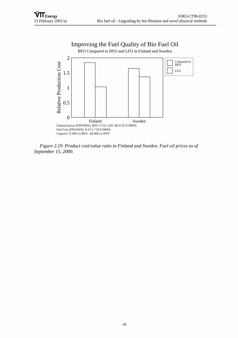
Energy JOR3-CT98-025315 February 2001/ys Bio fuel oil - Upgrading by hot filtration and novel physical methods
41
Improving the Fuel Quality of Bio Fuel OilBFO Compared to HFO and LFO in Finland and Sweden
Untaxed prices (FIN/SWE): HFO 17/22, LFO 38/33 ECU/MWhFuel Cost (FIN/SWE): 8.3/11.7 ECU/MWh Capacity 72 000 t/a BFO - 68 000 t/a HVF
Finland Sweden0
0.5
1
1.5
2R
elat
ive
Prod
uctio
n Co
st Compared toHFO
LFO
Figure 2.19. Product cost/value ratio in Finland and Sweden. Fuel oil prices as ofSeptember 15, 2000.
Energy JOR3-CT98-025315 February 2001/ys Bio fuel oil - Upgrading by hot filtration and novel physical methods
42
3. CONCLUSIONS
3.1 APPLICATIONS
The work aims in developing two applications for a new liquid fuel, bio fuel oil (BFO),or pyrolysis liquid. The two principal applications are BFO use as a boiler fuel and BFOuse as a diesel engine power plant fuel.
Replacing of both heavy and light fuel oils in boilers is considered, although it is likelythat the first alternative is only applicable in some rare circumstances. Replacing LFO inheating is emphasised, as this application may be feasible in medium term (withinapproximately 2-3 years). Experimental work in full-scale boilers was performed. UsingBFO as power plant fuel is technically less developed. Therefore valuable basic dataconcerning use of BFO in engine power plants was generated. It is believed that the engineapplication will take longer to commercialise than the boiler application.
Only energy uses of BFO are considered in this project. Although other applications (forexample, feedstock for the production of chemicals) exist, it is believed that these areusually quite case specific.
3.2 TASKS
3.2.1 Task 1
Hot vapour filtration is very efficient method to remove particles from the pyrolysisvapours and to improve the quality of the product liquid. However, the successfulimplementation of the filtration requires optimised filtration conditions.
The most critical parameters are filtration temperature, face velocity and particulateloading. The particle size distribution also plays important role in successful design of thefiltration process. When filtration conditions are favourable a good filtration performancecan be met. This includes not only the efficient particulate removal but also efficientdetachment of dust cake from the filter surfaces by high pressure pulsing and dischargingthe dust from filter vessel. Hot vapour filtration of pyrolysis vapours was demonstratedsuccessfully in PDU scale.
3.2.2 Task 2
Bio-oils in diesel emulsion fuels were produced and their stability investigated. Resultswere analyzed using a statistical model. A quadratic response surface model agrees wellwith experimental results. Dominant parameters are bio-oil and surfactant concentrationsand power input, and there are optimal loci for different bio-oil concentrations thatminimize the final costs of emulsified products.

Energy JOR3-CT98-025315 February 2001/ys Bio fuel oil - Upgrading by hot filtration and novel physical methods
43
Fuel properties such as cetane number, viscosity and corrosion were characterized.Ensyn pyrolytic oil had a cetane number of 20.6±1.3. Usually it is not easy to determine thecetane number of pyrolytic bio-oil due to its poor combustion characteristics. However,when emulsions were formed it was possible to do so by linear interpolation. The viscosityof emulsified fuels was best described by Einstein's equation for dilute solid dispersions.
3.2.3 Task 3
All the objectives of the task were met. Total of 5.8 tonnes of pyrolysis liquid wasproduced for utilisation tests and quality improvement work. It was found that a relativelyhigh reaction temperature of 530 °C produced the highest liquid yield in the PDU unit,when forest residue fuel was used as feedstock. In the bench scale unit the maximum liquidyield for straw was around 480 °C. The residence time was not varied. A shorter residencetime than the present 2 seconds in the PDU might have been more favourable. However, itcould not be shortened because of excessive carry over of fines to the liquid, if reactor gasvelocity would have further been increased. The organic liquid yield was 66 wt%, when adry (2 wt% moisture) pine feed was used. Finally, the unit PDU unit was operatedsuccessfully in a steady-state mode to enable hot filter operation.
3.2.4 Task 4
Materials. Because of acidity (pH 2-3) of pyrolysis liquids following recommendationsfor materials are suggested:• Plastics or AISI 316 for storage• Plastics, copper and its alloys (no abrasion), AISI 316 for piping applications• AISI 316 or better acid-resistant steel for process equipment
Due to instability and reactivity of pyrolysis liquids following storage conditions arerecommended:• Air-free plastic or stainless steel containers• Storage temperature 15 °C, but at least below 25 °C• Constant slow propeller stirring
Following is recommended for handling:• Air should be avoided• Heating above 60 °C should be avoided• Heating between 40-60 °C should be minimised to a few hours• Hot surfaces has to be avoided
For poor-quality pyrolysis liquids following is suggested:• Homogenising of the liquid with simultaneous addition of 5-10 wt-% methanol. A 1-2
wt-% addition of formic acid for homogenisation is not adequate.• Slow constant propeller-type mixing provided during the storage.

Energy JOR3-CT98-025315 February 2001/ys Bio fuel oil - Upgrading by hot filtration and novel physical methods
44
3.2.5 Task 5
The combustion fundamentals of BFO and BFO derived fuels (emulsions and mixture)were characterised at both normal and high-pressure conditions and the peculiar featuresidentified. Two single-droplet combustion chambers were developed and a maximumpressure of 60 bar was reached. Droplets were suspended to a thermocouple or to a quartzfibre. The thermal behaviour exhibited by droplets was followed by means of high-speeddigital shadowgraphy.
A database relative to heating, swelling, vaporisation, liquid burning, cenosphereformation and burning processes was formed and all the relevant parameters wererecognised and correlated with the fuels properties.
The main results obtained in the Task activity are summarised in the following.• All the fuels were easy to ignite at normal and high pressure.• The swelling phenomenon reduced its intensity with pressure: it completely
disappeared at pressures higher than 10 and 20 bar for emulsions/mixture fuels and purepyrolysis oil, respectively.
• The diameter of emulsion and mixtures droplet decreased during burning with aD2 law.
• The liquid burning rate was around 1 mm2/sec at normal pressure, increased toabout 1.5 mm2/sec at 12 bar and to 2 mm2/sec at 45 bar very similarly to commercial lightdiesel oil.
• Mixture and emulsions formed carbonaceous residual at different extent and withdifferent morphology and internal structure. This influenced the solid burning rate. Thedominant parameters in the formation of solid residuals were the oil quality, theenvironment pressure, and the thermal level achieved by droplets before cenosphereformation.
The most significant result has been the observation that one of the emulsions, theemulsion composed by 30% of hot filtered pine oil in #2 Diesel oil, gave no carbonaceousresiduals in all the conditions tested. Moreover, this emulsion exhibited a generalbehaviour very similar to a commercial diesel oil. These two observations demonstrate thata cautious combination of oil quality and fuel technologies could open the way for animmediate and successful utilisation of BFO in furnaces and Diesel engines.
3.2.6 Task 6
Based on earlier and the current boiler combustion tests it is concluded that BFO can beeffectively combusted using properly modified simple and relatively inexpensive pressureatomisation equipment and emissions reduced to acceptable levels with a combination ofoptimisation of combustion conditions and good quality fuels. The major modifications thatwere employed within this work to existing commercial equipment was an acid resistantpump, an oil preheater with low surface temperatures, a refractory lined pre-chamber betweenthe burner and boiler, air operated valves and a computer based control system. These werefound to be required in order to optimize combustion conditions and to pump and atomize

Energy JOR3-CT98-025315 February 2001/ys Bio fuel oil - Upgrading by hot filtration and novel physical methods
45
this fuel. These modifications would increase the cost of a typical system by about 50% andwould not be practical in a commercial system. These modifications can though be used by aburner manufacturer to build a platform for a prototype system that could be used for fieldtrials.
From both a viscosity standpoint and a solids standpoint, both the forestry residue and pinesawdust fuels produced by VTT Energy were of sufficiently good quality to be combustedcleanly in light fuel oil boilers. The only notable emissions that are higher than for light fueloils is that of particulates and tars. It is believed that once a burner is designed specifically forpyrolysis liquids, it will be possible to reduce futher these emissions and combust these fuelscleanly in this size class.
The experience with 10% and 30% pyrolysis liquid emulsions in light fuel oil clearlyindicated that these could be ignited and cleanly combusted in small burners and boilersnormally used in single family homes of the size range of 20 kW. It was therefore concludedthat a new, acid resistant pump would be needed for the emulsions. This pump developmentwas not included in the original work plan and will require further investigations. It is furtherbelieved that long term tests will show that the normal in-line oil preheater with surfacetemperatures of 120-150 C will also need to be replaced with emulsions due to slow tarring ofthe surfaces.
3.2.7 Task 7
The performance of a commercial DI Diesel injection system with Bio Fuel Oil wascharacterized by means of high-speed imaging. The BFO spray was injected in atransparent test rig, and its time evolution visualized with back illumination: this allowedappreciating the extension of the liquid part of the spray, as well as some characteristicparameters. BFO spray showed good atomization quality, even if the break-up length andthe cone angle were smaller than Diesel fuel. These effects, likely due to the greaterviscosity of BFO, were observed both with a single-hole and with a four-hole injector.
The injection tests confirmed the possibility of using a standard Diesel fuel supplysystem with BFO, as the performance and the efficiency weren't substantially impaired.
In order to assess the current limitations to the use of BFO in a light-duty D.I. Dieselengine, a series of tests were carried out with a stock single-cylinder, without anymodification and/or pre-treatment of the fuel. The physical-chemical properties of Bio FuelOil, which would preclude its direct application in a production Diesel engine, weresmoothed by blending it with Diglyme. Blends with increasing percentage of BFO inDiglyme were tested, together with two different micro-emulsions of BFO in No.2 Dieselfuel. The main results can be summarized as follows.
• Reliable operation was recorded with BFO-Diglyme blends, with a BFO content up to37.5% in volume. Micro-emulsions of BFO in No.2 Diesel exhibited a peculiarcombustion behavior, with a sharp peak of heat release rate.
• Much lower HC and NOx levels than Diesel fuel characterized BFO-Diglyme blends,CO levels being comparable. The emission profile of micro-emulsions didn’t feature
Energy JOR3-CT98-025315 February 2001/ys Bio fuel oil - Upgrading by hot filtration and novel physical methods
46
appreciable deviation from Diesel fuel, other than the peak of NOx recorded with theDynamotive oil emulsion.
• The fuel consumption scaled with the heating value of the samples, being higher forBFO-Diglyme blends.
• Ignition Delays of BFO-Diglyme blends increased with the BFO content. Using aReference Fuel Correlation, the cetane number of pure BFO was estimated by means ofthe blending method.
• The critical components of the engine experienced no relevant trouble, after severalrunning hours.
3.2.8 Task 8
The international market prices for LFO and HFO have tripled over the past 2 years.These increase in prices illustrate the vulnerability European countries are to the effect ofcrude oil prices and give added incentive to search for solutions for alternatives.
Unfortunately these fluctuations also illustrate the problems in developing alternativesto crude oil based products since the profitability in making investments in alternativeenergy technologies can greatly vary if the selling price of the alternative is tied to the priceof petroleum products.
Based on the market analysis presented here, it is obvious that the replacement of lightfuel oils will give more economic incentives.
In addition, there will be increased demand for these renewable energy products due tovarious government incentive programmes which will assist in market introduction by acombination of tax credits on the fuel, investment assistance for BFO production and use.
Energy JOR3-CT98-025315 February 2001/ys Bio fuel oil - Upgrading by hot filtration and novel physical methods
47
4. EXPLOITATION
Implementation in its’ broadest sense refers to commercial exploitation and in the caseof pyrolysis liquids for fuels, this has not yet happened. The technology, depending on theapplication, is at the demonstration stage where a number of pilot plants are producingliquids in order to further develop applications. Developers of pyrolysis technologies whohave been continually attempting to demonstrate their technology for the past ten years buthave not yet been successful in scaling up to this scale. Therefore the only implementationthat this project could possibly contribute to is the demonstration of specific solutions toparts of the overall fuel chain. Here it is also important to differentiate between what istechnically feasible and what is economically feasible. Since the VTT PDU unit that wasused in this project to produce the liquid samples and since the cost of emulsions that wereproduced is not known, comments referring to implementation or exploitation here aremore of a technical nature.
Hot filtration of pyrolysis vapors is ready for scale-up and longer-term tests. Obviouslythe technology can only be exploited integrated to a pyrolyser, and therefore the utilizationof this process may only be done as part of an overall development effort. Preparation ofemulsions from BFO requires also further R&D before exploitation. Basic combustion testsand tests in a single-cylinder engine revealed interesting interactions between mixtures andemulsions of BFO, and points out towards new research topics. The work carried out wasnovel, and in addition to demonstration efforts of BFO combustion, the results will beuseful also in related scientific research projects.
In the use of BFO in medium size boilers, the work has shown that there are no majorproblems with igniting and combusting pyrolysis liquids produced used in this project. Thesamples from pine sawdust with low solids and low moisture (<25%) content gave a morestable flame than the products from forestry residues that had high moisture content (30%).The main concerns are in long-term durability of combustion components, in tar andparticulate emissions, and in tar and char deposits in the burner retention head, nozzles,valves and pumps. There also remain questions regarding long-term storage and mixing ofliquids with changes in fuel properties. In the case of pyrolysis / mineral oil emulsions,combustion of these was successful in smaller boilers than the pure pyrolysis liquid. Here itwas however noted that the normal pump used with these burners was corroded and wouldhave to be replaced with a more suitable pump.
Therefore in order to implement and exploit the results of this study, a cooperationproject with a burner manufacturer must be initiated in which the technical solutions tothese areas is assessed and appropriate technologies developed and constructed. Sincethere is not yet any production in Scandinavia, there is currently little incentive by burnermanufacturers to develop these burners. The implementation of this work will thereforerequire that the pyrolysis liquid manufacturers work together with burner manufacturers.

Energy JOR3-CT98-025315 February 2001/ys Bio fuel oil - Upgrading by hot filtration and novel physical methods
48
5. PHOTOGRAPH

Energy JOR3-CT98-025315 February 2001/ys Bio fuel oil - Upgrading by hot filtration and novel physical methods
49
6. REFERENCES
1 http://www.oil.fi/
2 JOR3-CT95-0025 final report, VTT Energy April 1999.
3 Crookes, R.J., Kiannejad, F. and Nazha, M.A.A. "Seed-oil bio-fuel of low Centanenumber: the effect of water emulsification of diesel-engine operation and emissions", J. ofInstitute of Energy, 68 (1995) pp. 142-151.
4 Ikura, M., Mirmiran, S., Stanciulescu, M. and Sawatzky, H. "Pyrolysis liquid-in-dieseloil microemulsions", US patent 5,820640 (1998).
5 IEA Bioenergy Technoeconomic assessesments 1982-1994.
6 Markworth, N., Techno-economic assessment of production and application,Denmark. SK-Power/Elkraft. Espoo 1997, EU AIR2-CT94-1162, VTT Energy.
7 Oasmaa, A.; Leppämäki, E.; Koponen, P.; Levander, J.; Tapola, E., PhysicalCaracterisation of Biomass-based Pyrolysis Liquids. Application of Standard fuel oilAnalyses. Espoo 1997, Technical Research Centre of Finland.
8 Diebold, J.P.; Scahil, J.W.; Czernik, S.; Phillips, SD.; Feik, C.J., Progress inproduction of Hot-Gas Filtered Biocrude Oil. In Proceedings of the Second EC/CanadaWorkshop on Thermal Biomass Processing, Bridgwater, A.V., Hogan, E., Eds., CPLScientific Information Services, Ltd., Newbury, 1996, pp. 66-81.
9 Polk, M.B. and Phingbodhippakkiya, M., Development of Methods for theStabilization of Pyrolytic Oils, EPA-600/2-81-201, September 1981.
10 Casanova, J., Comparative Study of Various Physical and Chemical Aspects ofPyrolysis Pyrolysis liquids Versus Conventional Fuels Regarding Their Use in Engines, InProceeding of Specialist Workshop on Biomass Pyrolysis liquid Properties andCombustion, Estes Park, CO, Sept. 26-28 1994, NREL CP-430-7215, pp. 343-354.
11 Diebold, J.P. and Czernik, S., Additives to Lower and Stabilize the Viscosity ofPyrolysis liquids during Storage, Energy & Fuels, 1997, 11, 1081-1091.