
FIRST-Nuclides - CORDIS - europa.eu
244
DELIVERABLE (D-N°:5.2) 1 st Annual Workshop Proceedings Author(s): Bernhard Kienzler, Volker Metz, Lara Duro, Alba Valls Reporting period: e.g. 01/01/12 – 31/06/13 Date of issue of this report: 01/03/13 Start date of project: 01/01/12 Duration: 36 Months Project co-funded by the European Commission under the Seventh Euratom Framework Programme for Nuclear Research &Training Activities (2007-2011) Dissemination Level PU Public X RE Restricted to a group specified by the partners of the FIRST-Nuclides project CO Confidential, only for partners of the FIRST-Nuclides project FIRST-Nuclides (Contract Number: 295722)
-
Upload
khangminh22 -
Category
Documents
-
view
0 -
download
0
Transcript of FIRST-Nuclides - CORDIS - europa.eu

DELIVERABLE (D-N°:5.2)
1st Annual Workshop Proceedings
Author(s): Bernhard Kienzler, Volker Metz, Lara Duro, Alba Valls
Reporting period: e.g. 01/01/12 – 31/06/13
Date of issue of this report: 01/03/13
Start date of project: 01/01/12 Duration: 36 Months
Project co-funded by the European Commission under the Seventh Euratom Framework Programme for Nuclear
Research &Training Activities (2007-2011)
Dissemination Level
PU Public X
RE Restricted to a group specified by the partners of the FIRST-Nuclides project
CO Confidential, only for partners of the FIRST-Nuclides project
FIRST-Nuclides (Contract Number: 295722)

(D-N°:5.2) – 1st Annual Workshop Proceedings
Dissemination level: PU
Date of issue of this report: 01/03/13
2
DISTRIBUTION LIST
Name Number of copies Comments
Mr. Christophe Davies
(European Commission)
All consortium members and
European Commission
One electronic copy
submitted via participant
portal
One electronic copy available
on the restricted area and the
public part of the FIRST-
Nuclides webportal

KIT ScIenTIfIc RepoRTS 7639
1st Annual Workshop Proceedings of the Collaborative Project “Fast / Instant Release of Safety Relevant Radionuclides from Spent Nuclear Fuel” (7th EC FP CP FIRST-Nuclides)
Budapest 09 – 11 october 2012
Bernhard Kienzler, Volker Metz, Lara Duro, Alba Valls(eds.)
1st A
nn
ual
Wo
rksh
op
pro
ceed
ing
s o
f th
e c
olla
bo
rati
ve p
roje
ct
“fas
t / In
stan
t R
elea
se o
f Sa
fety
Rel
evan
t R
adio
nu
clid
es f
rom
Sp
ent
nu
clea
r fu
el”
B
ern
har
d K
ien
zler
, Vo
lker
Met
z,
Lara
Du
ro, A
lba
Val
ls (
eds.
)


Bernhard Kienzler, Volker Metz, Lara Duro, Alba Valls (eds.)
1st Annual Workshop Proceedings of the Collaborative Project “Fast / Instant Release of Safety Relevant Radionuclides from Spent Nuclear Fuel” (7th EC FP CP FIRST-Nuclides)
Budapest 09 - 11 October 2012

Karlsruhe Institute of Technology
KIT SCIENTIFIC REPORTS 7639

1st Annual Workshop Proceedings of the Collaborative Project “Fast / Instant Release of Safety Relevant Radionuclides from Spent Nuclear Fuel” (7th EC FP CP FIRST-Nuclides)
Budapest 09 - 11 October 2012
Bernhard KienzlerVolker MetzLara DuroAlba Valls (eds.)

Report-Nr. KIT-SR 7639
This report is printed in black and white. The report showing the original colours in several photos, tables, figures and logos can be downloaded from the homepage of KIT Scientific Publishing.
Karlsruher Institut für Technologie (KIT)Institut für Nucleare Entsorgung
Amphos 21 Consulting S. L. Passeig de Garcia i Faria, 49 – 51, 10 – 1a
Impressum
Karlsruher Institut für Technologie (KIT)KIT Scientific PublishingStraße am Forum 2D-76131 Karlsruhewww.ksp.kit.edu
KIT – Universität des Landes Baden-Württemberg und nationales Forschungszentrum in der Helmholtz-Gemeinschaft
KIT Scientific Publishing 2013Print on Demand
ISBN 978-3-86644-980-0
Diese Veröffentlichung ist im Internet unter folgender Creative Commons-Lizenz publiziert: http://creativecommons.org/licenses/by-nc-nd/3.0/de/

FOREWORD
The present document is the proceedings of the 1st Annual Workshop (AW) of the EURATOM FP7
Collaborative Project FIRST-Nuclides (Fast / Instant Release of Safety Relevant Radionuclides from Spent
Nuclear Fuel). The electronic version of these proceedings is also available in the webpage of the project
(http://www.firstnuclides.eu/). The workshop was hosted by MTA-EK and held in Budapest (Hungary) 9th – 11th
October 2012. The project started in January 2012 and has three years duration. It has 10 beneficiaries and 11
associated groups. All of them have participated in the 1st AW as well as external interested groups.
The proceedings serve several purposes. The key purpose is to document and make available to a broad
scientific community the outcome of the FIRST-Nuclides project. For this reason, a considerable part of the
project activity reporting is done through the proceedings, together with the outcome of scientific-technical
contributions and Topical Sessions on different topics of interest for the development of the project. In the
1st AW of FIRST-Nuclides, the topical session focused on the characteristics and modelling of spent nuclear
fuel. Additional purposes of the proceedings are to ensure on-going documentation of the project outcome,
promote systematic scientific-technical development throughout the project and to allow thorough review of the
project progress.
All Scientific and Technical papers submitted for the proceedings have been reviewed by the EUG (End-User-
Group). The EUG is a group specifically set up within the project in order to represent the interest of the end
users to the project and their needs. To this aim, the composition of the EUG includes organisations representing
national waste management or national regulatory interests and competence.
The proceedings give only very brief information about the project structure and the different activities around
the project. More information about the project can be found in detail under http://www.firstnuclides.eu/.
Thanks are due to all those who submitted Scientific and Technical contributions for review and, especially, the
workpackage leaders who provided the summary of the different workpackages for publication in these
proceedings. We also want to give a special thanks to the reviewers, members of the EUG, whose effort and
hard work reflect their commitment and dedication to the project and ensure a proper direction of the research
within the project programme.


Table of Contents
THE PROJECT ..................................................................................................................................................... 1
1ST ANNUAL WORKSHOP ................................................................................................................................. 5
Objectives ............................................................................................................................................ 5 RTD sessions ....................................................................................................................................... 5 Poster presentations ............................................................................................................................. 8 Topical session .................................................................................................................................... 8 Additional presentations ...................................................................................................................... 8 Structure of the proceedings ................................................................................................................ 9
WP OVERVIEW ................................................................................................................................................. 11
S + T CONTRIBUTIONS ................................................................................................................................... 27
POSTERS ........................................................................................................................................................... 207
TOPICAL SESSIONS ....................................................................................................................................... 211
PRESENTATIONS BY ASSOCIATED GROUPS ........................................................................................ 223


THE PROJECT
The EURATOM FP7 Collaborative Project “Fast / Instant Release of Safety Relevant Radionuclides
from Spent Nuclear Fuel (CP FIRST-Nuclides)” started in January 1, 2012 and extends over 3 years.
The European nuclear waste management organisations contributing to the Technology Platform
“Implementing Geological Disposal (IGD-TP)” considered the fast / instant release of safety relevant
radionuclides from high burn-up spent nuclear fuel as one of the key topics in the deployment plan.
For this reason, the CP FIRST-Nuclides deals with understanding the behaviour of high burn-up
uranium oxide (UO2) spent nuclear fuels in deep geological repositories.
The fast / instant release of radionuclides from spent nuclear fuel was investigated in a series of
previous European projects (such as SFS (Poinssot et al., 2005; Johnson et al., 2004) NF-PRO
(Sneyers, 2008) and MICADO (Grambow et al., 2010)). In addition, there were several studies mainly
of the French research programs that investigated and quantified the rapid release (Ferry et al., 2008;
Lovera et al., 2003; Johnson et al., 2004, 2005). However, several important issues are still open and
consequently, the CP FIRST-Nuclides aims on covering this deficiency of knowledge, determining, for
example, the “instant release fraction (IRF)” values of iodine, chlorine, carbon and selenium that are
still largely unknown.
Fuel elements from different Light Water Reactors (LWRs), with different enrichments, burn-up and
average power rates need to be disposed of in Europe. This waste type represents one of the sources
for the release of radionuclides after loss of integrity of a disposed canister. The quantification of time-
dependent release of radionuclides from spent high burn-up UO2 fuel is required for safety analyses.
The first release fraction consists of radionuclides in gaseous form, and those showing a high solubility
in groundwater.
LWRs use conventional oxide fuels with initial enrichments of up to 5 wt.% 235U for reaching average
burn-up of 60 GWd/tHM. During the use of UO2 in a reactor, a significantly higher burn-up takes
place at the rim of the fuel pellets. The physico-chemical properties of the fuel are further complicated
by additions of gadolinium oxide and/or chromium oxide, which is used for criticality control or to
adjust the UO2 grain sizes for minimizing fission gas release (FGR). Moreover, the fission products of
uranium cause expansion in the UO2 crystal structure leading to disturbances of the fuel matrix. The
chemical stability of the fission products oxides in the UO2 matrix, can be classified into different
groups: (i) the rare earth elements and Y, Zr, Ba and Sr, whose oxides form either solid solutions with
UO2 or single phase precipitates; (ii) Mo, Cs and Rb, which are either oxidized or not, depending on

THE PROJECT 1st AW Proceedings - 7th EC FP - FIRST-Nuclides
2
the O/U ratio; and (iii) elements like Ru, with unstable oxides which form metallic precipitates within
the UO2.
The CP is organized in six workpackages (WP): WP1, “Samples and tools” deals with the selection,
characterization and preparation of the materials to be studied and the set-up of experimental and
organisational tools. In this sense, one of the essential requirements of the project is that typical and
sufficiently well characterized spent nuclear fuel is being used for the experiments and modelling
studies. WP2 covers the “Gas release and rim and grain boundary diffusion experiments” and WP3
addresses “Dissolution based release studies”. This includes determining the chemical form of released
radionuclides, fission gases, 135Cs, 129I, 14C, 79Se, 99Tc and 126Sn. WP4 “Modelling” deals with
modelling of release/retention processes of fission products in the spent fuel structure. Special
attention is attributed to fission product migration along the grain boundaries, the effects of fractures in
the pellets and of holes/fractures in the cladding. The modelling work within FIRST-Nuclides will help
to clarify which geometric scales dominate the fast/instant release.
WP5 “Knowledge, reporting and training” is responsible for the knowledge management generated
within the project, the state-of-the-art report, the general reporting, keeping the documentation up-to-
date and organizing training measures. The management of the Collaborative Project is included in
WP6.
The project is implemented by a Consortium with ten beneficiaries (Karlsruher Institut fuer
Technologie (KIT) Germany, Amphos 21 Consulting S.L. (AMPHOS21) Spain, Joint Research Centre
– Institute for Transuranium Elements (JRC-ITU) European Commission, Forschungszentrum Juelich
GmbH (JÜLICH) Germany, Paul Scherer Institut (PSI) Switzerland, Studiecentrum voor Kernenergie
(SCK•CEN) Belgium, Centre National de la recherche scientifique (CNRS) France, Fundacio Centre
Technologic (CTM) Spain, Magyar Tudományos Akadémia Energiatudományi Kutatóközpont (MTA-
EK) Hungary, and Studsvik Nuclear AB (STUDSVIK) Sweden). The Coordination Team consists of
KIT (Coordinator) and AMPHOS21 (Coordination Secretariat) which are responsible for project
management, knowledge management, documentation, dissemination and training. Their
responsibilities include further the coordination of the project work and activities, communication
between the Project Consortium and the European Commission, monitoring the use of resources and
transferring financial resources, communication between different project beneficiaries and bodies,
documentation of the project outcome and its dissemination and communication to interested parties.
Several organisations from France (Commissariat à l'énergie atomique et aux énergies alternatives,
CEA), USA (Los Alamos Natonal Laboratory, SANDIA National Laboratories), UK (Nuclear

1st AW Proceedings - 7th EC FP - FIRST-Nuclides THE PROJECT
3
Decommissioning Authority (NDA, Center for Nuclear Engineering of the Imperial College London),
National Nuclear Laboratory (NNL) and a consortium coordinated by the University Cambridge),
Finland (Posiva Oy, Teollisuuden Voima (TVO)), Spain (CIEMAT) and Germany (Gesellschaft für
Anlagen- und Reaktorsicherheit (GRS) mbH) contribute to the project without any funding as
Associated Groups (AG). These groups have particular interest in the exchange of information. Finally,
a group of six implementation and regulatory oriented organizations (SKB (Sweden), NAGRA
(Switzerland), ONDRAF/NIRAS (Belgium), ANDRA (France), BfS (Germany), ENRESA (Spain)
participate as an “End-User Group (EUG)”. This group ensures that end-user interests (waste
management organisations and one regulator) are reflected in the project work reviewing the project
work and the scientific-technical outcome.
References
Ferry C., Piron J.P., Poulesquen A., Poinssot C. (2008) Radionuclides release from the spent fuel
under disposal conditions: Re-Evaluation of the Instant Release Fraction. MRS Proceedings, 1107,
447.
Grambow, B., Bruno, J., Duro, L., Merino, J., Tamayo, A., Martin, C., Pepin, G., Schumacher, S.,
Smidt, O., Ferry, C., Jegou, C., Quiñones, J., Iglesias, E., Villagra, N.R., Nieto, J.M., Martínez-
Esparza, A., Loida, A., Metz, V., Kienzler, B., Bracke, G., Pellegrini, D., Mathieu, G., Wasselin-
Trupin, V., Serres, C., Wegen, D., Jonsson, M., Johnson, L., Lemmens, K., Liu, J., Spahiu, K.,
Ekeroth, E., Casas, I., de Pablo, J., Watson, C., Robinson, P., Hodgkinson, D. (2010) Final Report of
the Project MICADO: Model uncertainty for the mechanism of dissolution od spent fuel in nuclear
waste repository.
Johnson L., Ferry C., Poinssot C., Lovera P. (2005) Spent fuel radionuclide source-term model for
assessing spent fuel performance in geological disposal. Part I: Assessment of the instant release
fraction. Journal of Nuclear Materials, 346, 56-65.
Johnson, L., Poinssot, C., Ferry, C., Lovera, P. (2004) Estimates of the instant release fraction for UO2
and MOX fuel at t=0. Report of the SFS Project of the 5th Euratom Framework Program.
Lovera P., Férry C., Poinssot C., Johnson L. (2003) Synthesis report on the relevant diffusion
coefficients of fission products and helium in spent nuclear fuelCEA Report, CEA-R-6039.

THE PROJECT 1st AW Proceedings - 7th EC FP - FIRST-Nuclides
4
Poinssot, C., Ferry, C., Kelm, M., Granbow, B., Martínez, A., Johnson, L., Andriambolona, Z., Bruno,
J., Cachoir, C., Cavendon, J.M., Christensen, H., Corbel, C., Jégou, C., Lemmens, K., Loida, A.,
Lovera, P., Miserque, F., de Pablo, J., Poulesquen, A., Quiñones, J., Rondinella, V., Spahiu, K.,
Wegen, D.H. (2005) Spent fuel stability under repository conditions – Final report of the European
SFS Project.
Sneyers, A. (2008) Understanding and Physical and Numerical Modelling of the Key Processes in the
Near Field and their Coupling for Different Host Rocks and Repository Strategies NF-PRO Project.

1st
ANNUAL WORKSHOP
The 1st Annual Project Workshop of the FIRST-Nuclides project was held in Budapest (Hungary) 9th –
11th October 2012. The workshop was hosted by MTA-EK. There were 44 attendees at the workshop,
representing beneficiaries, associated groups, the End-User Group and project external organizations.
The workshop was organized in three days of oral presentations of results obtained within the project
and a topical session on characteristics and modelling of spent nuclear fuel.
Objectives
The Workshop combines different activities and meetings with the following objectives:
• Informing about the scientific progress. Plenary sessions are used for giving overviews by the
workpackage leaders and communicating detailed results and planned activities by the
beneficiaries.
• Informing about the administrative status.
• Informing/agreeing upon forthcoming reporting.
• Discussing various topics of interest for the consortium.
• Agreeing upon the forthcoming work program.
Emphasis was on scientific-technical topics with administrative issues kept to the minimum necessary.
RTD sessions
The workshop included plenary sessions where the results from the different workpackages were
presented. Next to an overview of the achievements within the respective WP, scientific highlights
were presented. The following presentations were given within the project.
WP1 session
• V. Metz. Overview of Activities within WP1 “Samples and Tools”
• V. Metz, A. Loida, E. González-Robles, E. Bohnert, B. Kienzler. Characterization of
irradiated PWR UOX fuel (50.4 GWd/tHM burn-up) used for leaching experiments.
Contribution of KIT-INE to WP1 “Samples and Tools”
• D.H. Wegen, D. Papaioannou, R. Nasyrow, R. Gretter. Non-destructive analysis of a PWR
fuel segment with a burn-up of 50.4 GWd/tHM

1ST ANNUAL WORKSHOP 1st AW Proceedings - 7th EC FP - FIRST-Nuclides
6
• H. Curtius. HTR spent fuel - selected material for FIRST-Nuclides-
• A. Froideval Zumbiehl, E. Curti, I. Günther-Leopold. WP1: Selection and description of
spent fuel samples selected for PSI studies in frame of the FIRST Nuclides project
• K. Govers, M. Verwerft, W. Van Renterghem, K. Lemmens, T. Mennecart, C. Cachoir,
L. Adriaensen, A. Dobney, M. Gysemans. Characterisation of SCK·CEN fuel samples used
for leach tests in FIRST-Nuclides
• J. Vandenborre. Radiolytic corrosion of grain boundaries onto the UO2 TRISO particle
surface: WP1 - Solid characterization and irradiation cell development
• R. Sureda, J. de Pablo, I. Casas, F. Clarens, D. Serrano-Purroy, P. Carbol, J.P. Glatz,
D. Papaioannou, V. Rondinella. SNF selected for the FIRST Nuclides WP1
• Z. Hózer, E. Slonszki. Characterisation of spent VVER-440 fuel (WP1)
• O. Roth. Sample Selection and Characterization at Studsvik
WP2 session
• D.H. Wegen. WP2: Fission Gas Release and Rim and Grain Boundary Diffusion
• D.H. Wegen, D. Papaioannou, W. de Weerd. Sampling and Measurement of Fission Gas
from Spent Nuclear Fuel
• E. Bohnert, E. González-Robles, M. Herm, B. Kienzler, M. Lagos, V. Metz. Determination
of Gaseous Fission and Activation Products Released from 50.4 GWd/t PWR Fuel –
Contribution of KIT-INE to WP2
• O. Roth. Preparations and experimental start-up at Studsvik WP2
• P. Carbol, I. Marchetti. Oxygen and Water Diffusion into 42 GWd/tHM UO2 Fuel under
Reducing Conditions
• H. Curtius. HTR Spent Fuel -Microstructure and Radionuclide Inventory-
• J. Vandenborre, A. Traboulsi, G. Blain, J. Barbet, M. Fattahi. Radiolytic Corrosion of Grain
Boundaries onto the UO2 TRISO Particle Surface: WP2 – First in situ RAMAN tests under
He2+ irradiation
WP3 session
• K. Lemmens. Introduction : overview of activities within WP3
• Z. Hózer, E. Slonszki. Evaluation of activity concentation data measured at Paks NPP

1st AW Proceedings - 7th EC FP - FIRST-Nuclides 1ST ANNUAL WORKSHOP
7
• D. Serrano-Purroy, L. Aldave de las Heras, J. P. Glatz, R. Sureda, F. Clarens, J. de Pablo,
I. Casas. Overview of activities. Experimental set-up
• O. Roth, J. Low, A. Puranen, D. Cui, C. Askeljung. Preparations and experimental start-up
at Studsvik WP3
• E. González-Robles, E. Bohnert, A. Loida, N. Müller, V. Metz and B. Kienzler.
Characterization of 50.4 GWd/t PWR fuel and set-up of dissolution experiments
• Th. Mennecart, K. Lemmens, K. Govers, L. Adriaensen, C. Cachoir, A. Dobney,
M. Gysemans, W. Van Renterghem, M. Verwerft. Concept of leach tests for the
experimental determination of IRF radionuclides from Belgian high-burnup spent nuclear
fuel in “FIRST-Nuclides”
• I. Günther-Leopold, E. Curti, A. Froideval Zumbiehl. XRF/XAS feasibility study for
radionuclides determination in spent fuel samples
WP4 session
• J. de Pablo. WP4 – Overview of activities
• M. Pękala, A. Idiart, L. Duro, O. Riba. Modelling of SF Saturation with Water (Approach,
Preliminary Results and Potential Implications)
• B. Kienzler, C. Bube, V. Metz, E. González-Robles Corrales. Modelling of boundary and
initial conditions for upscaling migration / retention processes of fission products in the
spent nuclear fuel structure
• I. Casas, A. Espriu, D. Serrano-Purroy, A. Martínez-Esparza, J. de Pablo. IRF modelling
from high burn-up spent fuel leaching batch and dynamic leaching experiments
WP5 session
• A. Valls. Status and overview of WP5
• E. González-Robles, V. Metz, B. Kienzler, O. Riba, A. Valls, L. Duro. State of the art
(WP5: Deliverable 5.1)

1ST ANNUAL WORKSHOP 1st AW Proceedings - 7th EC FP - FIRST-Nuclides
8
Poster presentations
The following posters were presented during the 1st Annual Workshop:
• B. Kienzler, V. Metz, L. Duro, A. Valls, V. Montoya. Generic Poster of FIRST-Nuclides
project
• E. González-Robles, B. Kienzler, V. Metz, A. Valls, O. Riba, L. Duro. State of the art of
the Fast/Instant Release Fraction
Topical session
The Topical Sessions aim at covering the key areas along with the project. In these proceedings,
topical sessions held in the kick-off meeting are also included. Those topical sessions focused on
characterization and modelling of the spent nuclear fuel behaviour under repository conditions.
Presentations within this topic were the following:
• O. Beneš. Thermodynamics of Fission Products in spent nuclear fuel
• C. Gebhardt, W. Goll. Characteristics of Spent Nuclear Fuel
• D. Serrano-Purroy, J. P. Glatz. Impact of the irradiation history of nuclear fuels on the
corrosion behaviour in a disposal environment
• P. Van Uffelen. The potential of TRANSURANUS for source term calculations of spent
fuel
Additional presentations
Additional presentations were given on a topic of general interest, especially the context of the present
project within the EURATOM FP7 program on geologic disposal. These presentations were given by
the associated group. Additional presentations given during the kick-off meeting are also are also
included.
• D. Hambley. Long term behaviour of spent AGR fuel in repository
• A. Meleshyn, J. Wolf, U. Noseck, G. Bracke. Source term modelling for spent fuel
elements in performance assessment
• D. Reed. Applicability of Past Spent Fuel Research in the US to a Salt-Based HLW
Repository

1st AW Proceedings - 7th EC FP - FIRST-Nuclides 1ST ANNUAL WORKSHOP
9
• D. C. Sassani. Brief Overview of Used Fuel Degradation & Radionuclide Mobilization
Activities within the Used Fuel Disposition Campaign
Structure of the proceedings
The proceedings are divided into the following sections:
• WP activity overviews
• Individual Scientific and Technical Contributions, containing reviewed scientific and
technical manuscripts
• Posters presented in the 1st Annual Workshop
• Contribution of external experts presenting issues of interest for the project within the
Topical Sessions
• Additional presentations given by members of the associated group
All the scientific-technical contributions submitted were reviewed by the EUG members (End-User-
Group).


WP OVERVIEW


OVERVIEW WP1: SAMPLES AND TOOLS
Volker Metz
Karlsruher Institut fuer Technologie (KIT), DE
Introduction
The first workpackage deals with selection, characterization and preparation of appropriate spent
nuclear fuels samples and set-up of tools for handling and transportation of the highly radioactive
material. The overall objectives of WP1 are:
Provision documentation of available experimental and theoretical data on high burn-up spent
nuclear fuel (HBU-SNF) material;
selection of those HBU-SNF samples for subsequent experimental investigations, where key
parameters regarding fuel history and irradiation characteristics are sufficiently known and
publication of these parameters is permitted;
preparation of selected HBU-SNF samples for subsequent structural and chemical
characterisation as well as experimental investigations within WP2 and WP3.
Six months after the start of the project, available experimental and theoretical data were documented
in Deliverable 1.1 (Metz et al., 2012a). In these Proceedings of the 1st Annual Workshop, new results
of the characterisation of selected samples and activities related to the sample preparations are
reported.
Since the activities within WP1 are a prerequisite for further experimental investigations within CP
FIRST-Nuclides, all experimentally working Beneficiaries contribute to this workpackage.
Achievements
KIT provided a spent nuclear fuel rod segment with an average discharge burnup of 50.4 GWd/tHM,
which was transported to JRC-ITU for characterisation, gas sampling, cutting and sampling of fuel
pellets. Characteristics of the fuel rod segment are described in Metz et al. (2012b). They compared
values of the average burnup and the initial 235U enrichment of the HBU-SNF samples selected by KIT
and the other Beneficiaries and to respective values of fuel assemblies irradiated BWR and PWR fuels
reported by the NEA Nuclear Science Committee (2006). The 50.4 GWd/tHM fuel rod segment was
inspected visually for defects and a -scan of the segment was recorded by JRC-ITU (Wegen et al.,

OVERVIEW WP1 1st AW Proceedings - 7th EC FP - FIRST-Nuclides
14
2012a). Furthermore, the JRC-ITU team determined the oxide thickness along the segment’s cladding,
punctured the segment for gas sampling and prepared pellet-sized samples by dry cutting (Wegen et al.,
2012b; Wegen et al., 2012c). The oxide thickness data are in good agreement with results of the -
scanning (Wegen et al., 2012b). Gas analyses were conducted within workpackage 2 of FIRST-
Nuclides, and results are given by González-Robles et al. (2012). Some of the pellet-sized samples are
provided by JRC-ITU to KIT for dissolution-based experiments, other pellet-sized samples of the fuel
rod segment are used for further post irradiation examinations by JRC-ITU (Wegen et al., 2012b).
Curtius and Bosbach (2012) report manufacturing data and irradiation characteristics as well as
radionuclide inventories of five UO2 TRISO fuel pebbles irradiated in the Petten High Flux Reactor. A
burnup of about 107 GWd/tHM was calculated for the end of the irradiation. Coated particles were
isolated from the pebbles and transported to JÜLICH for scanning electron microscope examinations
and dissolution-based experiments. For dissolution-based experiments and spectroscopic studies, PSI
selected two HBU UO2 fuel rods and one HBU mixed oxide fuel rod having burn-ups in the range of
57.5 to 63 GWd/tHM. For each of the selected fuel rods one suitable fuel segment was selected and a
segment cutting plan was compiled. Manufacturing and operational data of the fuel rods, cutting plans,
and the set-up of their leach experiments are described by Günther-Leopold et al. (2012). SCK•CEN
studies a fuel rod with an average discharge burnup of 51 GWd/tHM. Govers et al. (2012) presents the
characteristics of the fuel rod that will be used for dissolution-based experiments. Details on the fuel
manufacturing, irradiation history, calculated isotopic inventory and the temporal inventory evolution
are given. Based on the -scanning of the fuel rod, a segment cutting plan was developed (Govers et al.,
2012). CNRS selected non-irradiated UO2 TRISO particles for studies on the corrosion at UO2 grain
boundaries under cyclotron radiation. Vandenborre et al. (2012) reports on scanning electron
microscope examinations and geometric properties of the studied TRISO particles. Set-up of analytical
tools and first in situ tests were performed within workpackage 2 of FIRST-Nuclides, and details are
given by Vandenborre et al. (2012). MTA-EK compiles characterisitic data on damaged VVER-440
fuel stored in the spent fuel storage pool of the Paks-2 power plant since an incident in April 2003.
Hózer and Slonszki (2012) present design and operational characteristics data of these spent VVER-
440 fuel rods. Details are given about the post-incident history, calculations of power history and
burnup dependent parameters (e.g., linear power, fuel temperature, gap width). A summary on the
radionuclide inventories of 30 damaged fuel assemblies and the radionuclide inventory of a leaking
fuel assembly is given by Hózer and Slonszki (2012). STUDSVIK selected six HBU UO2 fuel rods
having burn-ups in the range of 50.2 to 70.2 GWd/tHM for dissolution-based experiments. Roth and
Puranen (2012) summarize the process of selecting the HBU-SNF samples and preparations made for

1st AW Proceedings - 7th EC FP - FIRST-Nuclides OVERVIEW WP1
15
the start of the experiments. Characteristics of the fuel rods are reported in Metz et al. (2012a). Based
on -scanning of the fuel rods, segment cutting plans were developed; an exemplary -scan and cutting
plan is shown by Roth and Puranen (2012).
References
Curtius, H. and Bosbach, D. (2012) HTR spent fuel - selected material for FIRST.Nuclides. 7th EC FP
– FIRST-Nuclides 1st Annual Workshop Proceedings (Budapest, Hungary).
González-Robles, E., Bohnert, E., Loida, A., Müller, N., Lagos, M., Metz, V., Kienzler, B. (2012)
Fission gas measurements and description of leaching experiments with of KIT’s irradiated PWR fuel
rod segment (50.4 GWd/tHM). 7th EC FP – FIRST-Nuclides 1st Annual Workshop Proceedings
(Budapest, Hungary).
Govers, K., Verwerft, M., Van Renterghem, W., Lemmens, K., Mennecart, T., Cachoir, C.,
Adriaensen, L., Dobney, A., Gysemans, M. (2012) Characterization of SCKCEN fuel samples used
for leach tests in FIRST-Nuclides. 7th EC FP – FIRST-Nuclides 1st Annual Workshop Proceedings
(Budapest, Hungary).
Günther-Leopold, I., Linder, H., Froideval Zumbiehl, A., Curti, E. (2012) Selection of high burn-up
fuel samples for leach experiments and spectroscopical studies at PSI. 7th EC FP – FIRST-Nuclides 1st
Annual Workshop Proceedings (Budapest, Hungary).
Hózer, Z. and Slonszki, E. (2012) Characterisation of spent VVER-440 fuel to be used in the FIRST-
Nuclides project. 7th EC FP – FIRST-Nuclides 1st Annual Workshop Proceedings (Budapest,
Hungary).
Metz, V., Bohnert, E., Bube, C., González-Robles, E., Kienzler, B., Loida, A., Müller, N., Carbol, P.,
Glatz, J. P., Nasyrow, R., Papaioannou, D., Rondinella, V. V., Serrano Purroy, D., Wegen, D., Curtius,
H., Klinkenberg, H., Günther-Leopold, I., Cachoir, C., Lemmens, K., Mennecart, T., Vandenborre, J.,
Casas, I., Clarens, F., de Pablo, J., Sureda Pastor, R., Hózer, Z., Slonszki, E., Ekeroth, E., Roth, O.
(2012a) Fast / Instant Release of Safety Relevant Radionuclides from Spent Nuclear Fuel (FIRST-
Nuclides): Characterisation of spent nuclear fuel samples to be used in FIRST-Nuclides – relevance of
samples for the Safety Case. FIRST-Nuclides Deliverable D1.1.
OVERVIEW WP1 1st AW Proceedings - 7th EC FP - FIRST-Nuclides
16
Metz, V., Loida, A., González-Robles, E., Bohnert, E., Kienzler, B. (2012b) Characterization of
irradiated PWR UOX fuel (50.4 GWd/tHM) used for leaching experiments. 7th EC FP – FIRST-
Nuclides 1st Annual Workshop Proceedings (Budapest, Hungary).
NEA (2006) Very High Burn-ups in Light Water Reactors. OECD Nuclear Energy Agency, NEA
publication 6224, ISBN 92-64-02303-8.
Roth, O. and Puranen, A. (2012) Selection of materials, preparations and experimental set-up. 7th EC
FP – FIRST-Nuclides 1st Annual Workshop Proceedings (Budapest, Hungary).
Vandenborre, J., Traboulsi, A., Blain, G., Fattahi, M. (2012) Radiolytic corrosion of grain boundaries
onto the UO2 TRiso particle surface. 7th EC FP – FIRST-Nuclides 1st Annual Workshop Proceedings
(Budapest, Hungary).
Wegen, D.H., Papaioannou, D., Nasyrow, R., Rondinella, V.V., Glatz, J.P. (2012a) Non-destructive
analysis of a PWR fuel segment with a burn-up of 50.4 GWd/tHM – Part I: Visual examination and -
scanning. 7th EC FP – FIRST-Nuclides 1st Annual Workshop Proceedings (Budapest, Hungary).
Wegen, D.H., Papaioannou, D., Nasyrow, R., Rondinella, V.V., Glatz, J.P. (2012b) Non-destructive
analysis of a PWR fuel segment with a burn-up of 50.4 GWd/tHM – Part II: Defect determination. 7th
EC FP – FIRST-Nuclides 1st Annual Workshop Proceedings (Budapest, Hungary).
Wegen, D.H., Papaioannou, D., Gretter, R., Nasyrow, R., Rondinella, V.V., Glatz, J.P. (2012c)
Preparation of samples for IRF investigations and post Irradiation examinations from 50.4 GWd/tHM
PWR fuel. 7th EC FP – FIRST-Nuclides 1st Annual Workshop Proceedings (Budapest, Hungary).
OVERVIEW WP2: GAS RELEASE + RIM AND GRAIN BOUNDARY DIFFUSION
Detlef Wegen
Joint Research Centre – Institute for Transuranium Elements (JRC-ITU), European Comission
Introduction
Workpackage 2 (WP2) consists of two main components. In the first component “Experimental
determination of fission gas release” the focus is on the quantification of fission gases and fission gas
release in high burn-up (HBU) UO2 spent nuclear fuels (SNF). Fission gas sampled in the plenum of a
fuel rod will be analysed as well as the grain boundary inventory and the cross sectional distribution of
fission gases and volatile fission products.
The second component “Rim and grain boundary diffusion” deals with investigations on oxygen
diffusion in spent UO2-fuel. The examination diffusion effects will result in the quantification of water
penetration into the grain structures and subsequent corrosion/diffusion phenomena. Furthermore,
investigations on irradiated and unirradiated fuel kernels separated from high temperature reactor
(HTR) fuel are planned which are complementary to those on light water reactor (LWR) fuel.
The following five institutions are collaborating in WP2.
The Joint Research Centre – Institute for Transuranium Elements (JRC-ITU) is the leading
organization for WP2. In the first project year the fission gas release from a spent fuel rod owned by
KIT will be measured. The determination of the inventory of fission gas and fission products in grain
boundaries are foreseen for the second and third project year.
The investigation of diffusion effects will start in the first project year with the characterisation and
preparation of spent fuel samples, which will be used for corrosion experiments in H218O water at
room temperature during the second project year. In the last year the 18O/16O depth profiles will be
determined to quantify the oxygen diffusion in SNF.
The Karlsruher Institut für Technologie (KIT) will in the first project year analyse fission and
activation products in the gas phase from a punctured fuel rod segment. The development, testing and
implementation of analytical methods for fission and activation products will be carried out in project
year one and two. Leaching experiments in which gas and solution analyses are foreseen will be
started in the first year and last until project month 33.

OVERVIEW WP2 1st AW Proceedings - 7th EC FP - FIRST-Nuclides
18
Studsvik Nuclear AB (STUDSVIK) will in the frame of WP2, investigate the radial fission gas and
volatile fission product distribution (Xe, I, and Cs) by Laser-Ablation Mass Spectroscopy (LA-MS) on
HBU PWR and BWR SNF.
Forschungszentrum Jülich GmbH (JÜLICH) is working on spent high temperature reactor fuel (HTR).
The radionuclide inventory in the fuel kernel and in the coatings as well as the microstructure and the
elemental distribution will be analysed before leaching in the first half of the project. Investigations of
the microstructure and of the elemental distribution of the fuel kernel and of the coatings will be
performed before (first half of the project) and after leaching (second half of the project). Within the
first half of the project the radionuclide inventory in the fuel kernel and in the coatings will be
determined and compared to calculated values as well. After cracking of the tight coatings the fission
gas release fraction will be measured in the first 18 months. Then static leaching experiments with the
separated fuel kernels and coatings will start in year two in order to determine the fast instant
radionuclide release fraction.
Unirradiated tristructural-isotropic (TRISO) fuel particles are investigated by the Centre National de la
Recherche Scientifique (CNRS) at the ARRONAX cyclotron under He2+-beam irradiation in the dose
rate range of 0 - 100 Gy/min. The corrosion of UO2 TRISO particles is investigated in view of grain
boundary effects and secondary phase formation and the influence of hydrogen. The experiments will
be started in the beginning of the second project year with studies on the role of grain boundaries
followed by investigations under hydrogen and under varying dose rates.
Achievements
After six month experimental work programme the outcome is coined by preparatory work, testing of
new experimental set-ups and characterisation of materials and samples.
JRC-ITU has done fission gas sampling and analysis from a PWR fuel rod owned by KIT (Wegen et
al., 2012). The total amount of gas, the gas pressure in the rod and the free volume was determined.
The gas samples were shared with KIT for further analyses.
The gas composition was determined by KIT using a quadrupole mass spectrometer with batch inlet
system (Bonhert et al., 2012). A method to determine 14C in gas and aqueous solutions by liquid
scintillation counting is under development.
STUDSVIK has planned laser ablation studies on a BWR and on a PWR UOX fuel (Roth, 2012).

1st AW Proceedings - 7th EC FP - FIRST-Nuclides OVERVIEW WP2
19
JRC-ITU has started the preparation of the oxygen/water diffusion study (Carbol and Marchetti, 2012).
The spent fuel was selected and the transfer of ownership is on-going. ITU's shielded SIMS has been
prepared for measurements on spent fuel fragments (holder, procedures etc.). 18O-labelled water
(>98 at.% H218O) was purchased. This was difficult because the amount is limited and most of the
produced 18O is needed for the production of 18F, which is widely used in PET (positron emission
tomography).
JÜLICH has started to analyse the microstructure and elemental distribution before leaching as well as
the radionuclide inventory in the fuel kernel and in the coatings (Curtius et al., 2012). The surface of
the fuel kernel shows large grains and the metallic precipitates appear as hexagonal platelets. The
elements Cs, O, U, Mo, Xe, Zr, and Tc were identified whereas higher amounts of the volatile
elements Cs and Xe were detected in the surrounding buffer. Furthermore, the elements Am, Pu, Cm,
U, Eu, Ce, Sr, Tc, and Pr were found quantitatively within the kernel while Cs behaved differently.
About 95% of the activity was found in the coatings.
CNRS has in WP2 set-up the analytical tools. First in situ tests were carried out. UO2 solid was
immersed in ultra pure water and irradiated at the ARRONAX facility with a He2+ beam. During
irradiation first Raman spectra were measured in situ (Vandenborre et al., 2012).
References
Bohnert, E., Gonzáles-Robles, E., Herm, M., Kienzler, B., Lagos, M., Metz, V. (2012) Determination
of Gaseous Fission and Activation Products Released from 50.4 GWd/t PWR Fuel. Presentation.
7th EC FP – FIRST-Nuclides, 1st Annual Workshop (Budapest, Hungary).
Carbol, P. and Marchetti, I. (2012) Oxygen and Water Diffusion into 42 GWd/tHM UO2 Fuel Under
Reducing Conditions. Presentation. 7th EC FP – FIRST-Nuclides, 1st Annual Workshop (Budapest,
Hungary).
Curtius, H., Müller, E., Müskes, H. W., Klinkenberg, M., Bosbach, D. (2012) HTR Spent Fuel -
Microstructure and Radionuclide Inventory-. 7th EC FP – FIRST-Nuclides, 1st Annual Workshop
(Budapest, Hungary).
Roth O. (2012) Preparations and Experimental Start-up at Studsvik WP2. Presentation. 7th EC FP –
FIRST-Nuclides, 1st Annual Workshop (Budapest, Hungary).

OVERVIEW WP2 1st AW Proceedings - 7th EC FP - FIRST-Nuclides
20
Vandenborre, J., Traboulsi, A., Blain, G., Barbet, J., Fattahi, M. (2012) Radiolytic Corrosion of Grain
Boundaries onto the UO2 TRISO Particle Surface. 7th EC FP – FIRST-Nuclides, 1st Annual Workshop
(Budapest, Hungary).
Wegen, D.H., Papaioannou, D., De Weerd, W., Rondinella, V.V., Glatz, J.P. (2012) Fission Gas
Release Measurement on 50.4 GWd/tHM PWR Fuel. 7th EC FP – FIRST-Nuclides, 1st Annual
Workshop (Budapest, Hungary).

OVERVIEW WP3: DISSOLUTION BASED RELEASE
Karel Lemmens
Studiecentrum voor Kernenergie (SCK-CEN), BE
The overall objective of WP3 is the quantification of the fast release of radionuclides by means of
leach tests with spent nuclear fuel, and – to the extent possible – the determination of their chemical
speciation. Such leach tests are performed by INE, PSI, Studsvik, SCK•CEN, ITU and CTM. The
experiments are done with PWR fuels having a burnup in the range of 45 to 70 MWd/kgHM, with BWR
fuels of 50-60 MWd/kgHM, and a MOX fuel of 63 MWd/kgHM (average burnups).
The radionuclides that are susceptible to fast release are situated in various compartments of the fuels,
i.e. in the gap between the fuel and the cladding, in the large fissures, in the grain boundaries, and in
the cladding. Hence, the release to be expected in the leach tests depends on the physical preparation
of the fuel samples from the fuel rods. The most complete information can be obtained by exposing
different fuel compartments to the leachant. The programme therefore foresees tests with cladded fuel
segments (segments cut from the fuel rods, a few mm to 2.5 cm long, exposed to the leachant on the
top and bottom surface, but radially covered by the cladding), with fuel fragments (not covered by the
cladding), and with fuel powder (maximum grain boundary exposure). For some fuels, fragments and
powder from the centre and the periphery of the fuel are tested separately. In other leach tests, the
cladding is separated from the fuel fragments, and the cladding with the adhering fuel residues is
leached together with the fragments. In still other experiments, the cladding with the adhering fuel
residues is leached separately (without the fuel fragments). Lastly, the cladding can be leached after
removal of the fuel residues, to determine the specific release from the cladding.
The radionuclide release measured in the leach tests depends to some extent on the leach test
conditions, i.e. the composition of the leachant and the atmosphere. To reduce the related effects and
to ease the intercomparison of the results, most tests are done in a harmonized solution of
19 mM NaCl + 1 mM NaHCO3. The atmosphere under which the tests are performed is mostly
oxidizing, but the oxidation is limited by closure of the leach vessels. One laboratory uses a reducing
atmosphere (argon with hydrogen gas). During the leach test, the composition of the leachant is
verified at different time intervals. The last sampling is foreseen 12 months after the start of the
experiments, but in some cases (particularly with fuel powder) the sampling will be stopped after
40-60 days.

OVERVIEW WP3 1st AW Proceedings - 7th EC FP - FIRST-Nuclides
22
The exact experimental setup of the leach tests is different for the various laboratories. Some
laboratories replace the solution completely at the sampling intervals, other laboratories take only
small samples. The equipment and procedures are not standardized.
The radiochemical analyses always include the Cs and I isotopes, which are well known for their fast
release and which show a similar behaviour as the fission gasses. Much attention is given also to 79Se
and 14C, i.e. isotopes for which the release and speciation is poorly understood. Special efforts are
done to lower the detection limit for 79Se. One laboratory plans specific surface analyses to determine
the Se distribution on a µm-scale and to determine the oxidation state of the Se in the fuel. Another
laboratory foresees specific analytical treatments to distinguish organic from anorganic 14C. Other
isotopes are measured as well, e.g. 90Sr and U isotopes, which allow to estimate the fuel oxidation
before and during the leach tests. One laboratory also intends to measure the released gasses (Kr, Xe,
H2, O2).
As a complement to the leach tests performed on fuel samples under controlled laboratory conditions,
the leaching behaviour of damaged and leaking VVER fuels is studied. These fuel rods have been
stored since 2003 (damaged fuel) and 2009 (leaking fuel) in pools with a pH 4 and 7, containing
15-21 g/kg boric acid.
The leach tests are currently in the preparation phase. Radionuclide release measurements are therefore
not yet available. The papers hereafter describe the experimental setup and analyses planned by the
various laboratories contributing to WP3.

OVERVIEW WP4: MODELLING
Joan de Pablo
Fundació Centre Technologic (CTM), ES
Objectives
The objectives of WP4 cover initial speciation of fission products in LWR fuel, and multi-scale
modelling of the migration / retention processes of fission products in the HBU spent fuel, in the
cladding, and the estimation of the fission product total release through the spent fuel rod.
On the other hand, a semi-empirical model will be developed to predict fission product release to water
from gap, grain boundaries and grains.
Introduction
In this project, the following parts of the fuel will be taken into account (see Table 1)
Table 1: Radionuclides and Part of the Fuel considered in FIRST-Nuclides
GAP Fission gases, volatiles (129I, 137Cs, 135Cs, 36Cl, 79Se, 126Sn*). Also 14C (non-
volatile but partially segregated)
GRAIN
BOUNDARY
Fission gases, volatiles (129I, 137Cs,135Cs, 36Cl, 79Se, 126Sn*), segregated metals
(99Tc, 107Pd)
RIM Fission gases, volatiles (129I, 137Cs,135Cs, 36Cl, 79Se, 126Sn*), Sr
* more relevant for MOX
Besides, the dissolution of the matrix will also be considered to differentiate radionuclide release from
the grains.
In two recent papers, Serrano-Purroy et al. (2012) and Roudil et al. (2007), IRF were determined at
two different times, 10 and 60 days respectively. In both cases, the release of selected radionuclides
followed after more than one year but a lower rate. Therefore, IRF should be probably correlated to the
instant that water contacts the gap and grain boundaries and not with time, thus the time needed for
pellet saturation is one of the important parameters. In this context, it is important to assess the water
saturation time.

OVERVIEW WP4 1st AW Proceedings - 7th EC FP - FIRST-Nuclides
24
Modeling
1) Radionuclide Characteristics in the Fuel
KIT performed for a rod segment the calculation of the burn-up and decay history by using web-
KORIGEN.
Temperature history and the calculation of the rim zone burn-up and thickness as well as the rim
porosity.
2) Water saturation of the fuel
AMPHOS 21 assessed the saturation time of SNF under conditions representative of a deep
underground repository and laboratory.
3) Modeling of radionuclide release to water
UPC-CTM is developing a semi-empirical model is based on the experimental fitting by using three
different first-order kinetic equations corresponding to different parts of the fuel: gap, cracks, external
or internal grain boundaries, rim structure, and finally grains (matrix).
References
Roudil, D., Jégou, C., Broudic, V., Muzeau, B., Peuget, S., Deschanels, X. (2007) Gap and grain
boundaries inventories from pressurized water reactor spent fuels. Journal of Nuclear Materials, 362,
411-415.
Serrano-Purroy, D., Clarens, F., González-Robles, E., Glatz, J.P., Wegen, D.H., de Pablo, J., Casas, I.,
Giménez, J., Martínez-Esparza, A. (2012) Instant release fraction and matrix release of high burn-up
UO2 spent nuclear fuel: Effect of high burn-up structure and leaching solution composition. Journal of
Nuclear Materials, 247, 249-258.

OVERVIEW WP5: KNOWLEDGE, REPORTING AND TRAINING
Alba Valls
Amphos 21 Consulting S.L. (AMPHOS21), ES
Work package 5 (WP5) of the FIRST-Nuclides project is focused on knowledge management and
knowledge dissemination, reporting and training. The objectives of this WP are (i) to provide access to
all scientific-technical results for all interested parties, (ii) to elaborate a state of the art report and (iii)
to organize, within the project, training and education for the next generation of spent nuclear fuel
specialists.
Several dissemination activities are foreseen along the project. They are mainly centered on making
accessible all the information related with the project to the interest parties such as the beneficiaries of
the project itself or the scientific community. The dissemination is done via various channels:
newsletters, presentations, posters, project webpage, annual workshops, proceedings, etc. The webpage
of the project consists on a public site where all the information of the organization and objectives of
the project are available as well as the public deliverables produced along the project life. The
information/reports are periodically updated and all the uploaded material will be available for 5 years
after the end of the project. In addition, an intranet is created for the members of the FIRST-Nuclides
with the aim of facilitating the communication between the members of the project consortium.
The first version of the State of the art report is already published (Kienzler et al., 2012) and it is
available at the project website (http://www.firstnuclides.eu/). This report is divided in two parts, the
first one presents basic information of spent fuel, such as the characterization of nuclear fuel,
irradiation and temperature induced processes in UO2 during its use in reactors, and disposal concepts
for spent nuclear fuel in different countries. In the second part of the report, the state of the art on fast
release fraction is documented by a summary of results obtained from more than 100 published
experiments using different samples, experimental techniques, and duration of the experiments. The
State of the Art report will be regularly updated with respect to the advances achieved within the
project.
Three different training measures are planned during the FIRST-Nuclides project:
(i) organizing invited lectures within the annual workshops, given by external experts
regarding issues of interest in the frame of FIRST-Nuclides. In the 1st Annual Workshop,

OVERVIEW WP5 1st AW Proceedings - 7th EC FP - FIRST-Nuclides
26
staff from AREVA was invited to give a presentation on ‘Characteristics of Spent Nuclear
Fuel’;
(ii) organizing training on the job through mobility measures between partners. Training
mobility measures are offered to the project beneficiaries and to organizations from the EU
and Switzerland. These measures are not open to third countries even in the Associated
Group.
(iii) organizing training courses. KIT-INE will provide for a training course in summer 2013, on
hot cells work to improve the handling and waste management techniques and to boost the
safety awareness of scientific. Attendants will receive practical training as well as script of
the course.
During the second year of the project, it is foreseen to edit the second newsletter and to organize the
second annual workshop. An update of the State of the Art report will be delivered.
References
Kienzler, B., Metz, V., González-Robles, E., Montoya, V., Valls, A., Duro, L. (2012) State-of-the-Art
and Rationale for Experimental Investigation. Deliverable 5.1. FIRST-Nuclides project.

S + T CONTRIBUTIONS


IRF MODELLING FROM HIGH BURN-UP SPENT FUEL LEACHING EXPERIMENTS
IGNASI CASAS, ALEXANDRA ESPRIU, DANIEL SERRANO-PURROY, AURORA MARTÍNEZ-ESPARZA, JOAN DE PABLO ........................................................................................................................................ 31
SELECTION AND CHARACTERISATION OF HTR FUEL
HILDE CURTIUS, EMIL MÜLLER , HANS WALTER MÜSKES, MARTINA KLINKENBERG, DIRK BOSBACH .. 41
A COMBINED XRF / XAS STUDY OF SOME INSTANT RELEASE FRACTION RADIONUCLIDES IN HIGH BURN-UP UO2 SPENT NUCLEAR FUEL
A. FROIDEVAL ZUMBIEHL, E. CURTI, I. GÜNTHER-LEOPOLD ................................................................... 53
FISSION GAS MEASUREMENTS AND DESCRIPTION OF LEACHING EXPERIMENTS WITH OF KIT’S IRRADIATED PWR FUEL ROD SEGMENT (50.4 GWD/THM)
ERNESTO GONZÁLEZ-ROBLES, ELKE BOHNERT, ANDREAS LOIDA, NIKOLAUS MÜLLER, VOLKER METZ, BERNHARD KIENZLER. ............................................................................................................................. 61
CHARACTERIZATION OF SCKCEN FUEL SAMPLES USED FOR LEACH TESTS IN FIRST-NUCLIDES
KEVIN GOVERS, MARC VERWERFT, WOUTER VAN RENTERGHEM, KAREL LEMMENS, THIERRY MENNECART, CHRISTELLE CACHOIR, LESLEY ADRIAENSEN, ANDREW DOBNEY, MIREILLE GYSEMANS .............................................................................................................................. 71
SELECTION OF HIGH BURN-UP FUEL SAMPLES FOR LEACH EXPERIMENTS AND SPECTROSCOPICAL STUDIES AT PSI
INES GÜNTHER-LEOPOLD, HANS-PETER LINDER, ANNICK FROIDEVAL ZUMBIEHL, ENZO CURTI ............ 79
CHARACTERISATION OF SPENT VVER-440 FUEL TO BE USED IN THE FIRST-NUCLIDES PROJECT
ZOLTÁN HÓZER, EMESE SLONSZKI .......................................................................................................... 87
MODELLING OF BOUNDARY AND INITIAL CONDITIONS FOR UPSCALING MIGRATION / RETENTION PROCESSES OF FISSION PRODUCTS IN THE SPENT NUCLEAR FUEL STRUCTURE
BERNHARD KIENZLER, CHRISTIANE BUBE, ERNESTO GONZÁLEZ-ROBLES CORRALES, VOLKER METZ ....................................................................................................................................... 103
CONCEPT OF LEACH TESTS FOR THE EXPERIMENTAL DETERMINATION OF IRF RADIONUCLIDES FROM BELGIAN HIGH-BURNUP SPENT NUCLEAR FUEL IN FIRST-NUCLIDES
THIERRY MENNECART, KAREL LEMMENS, KEVIN GOVERS, ADRIAENSEN LESLEY, CHRISTELLE CACHOIR DOBNEY ANDREW, GYSEMANS MIREILLE, VAN RENTERGHEM WOUTER, VERWERFT MARC ................ 111
CHARACTERIZATION OF IRRADIATED PWR UOX FUEL (50.4 GWD/THM) USED FOR LEACHING EXPERIMENTS
VOLKER METZ, ANDREAS LOIDA, ERNESTO GONZÁLEZ-ROBLES, ELKE BOHNERT, BERNHARD KIENZLER ............................................................................................................................ 117

MODELLING OF SPENT FUEL SATURATION WITH WATER – APPROACH, PRELIMINARY RESULTS AND POTENTIAL IMPLICATIONS
MAREK PĘKALA, ANDRÉS IDIART , LARA DURO, OLGA RIBA ............................................................... 125
MODELLING OF SPENT FUEL SATURATION WITH WATER –SELECTION OF MATERIALS, PREPARATIONS AND EXPERIMENTAL SET-UP
OLIVIA ROTH AND ANDERS PURANEN ................................................................................................... 137
WP3. DISSOLUTION BASED RELEASE JOINT CONTRIBUTION ITU-CTM
DANIEL SERRANO-PURROY, LAURA ALDAVE DE LAS HERAS, JEAN PAUL GLATZ, VINCENZO V. RONDINELLA, FREDERIC CLARENS, JOAN DE PABLO, IGNASI CASAS, ROSA SUREDA ...... 145
PREVIOUS INVESTIGATIONS ON THE INSTANT RELEASE FRACTION AND GENERAL DESCRIPTION OF THE PROJECT
ALBA VALLS, OLGA RIBA, LARA DURO, ERNESTO GONZÁLEZ-ROBLES CORRALES, BERNHARD KIENZLER, VOLKER METZ ................................................................................................. 153
RADIOLYTIC CORROSION OF GRAIN BOUNDARIES ONTO THE UO2 TRISO PARTICLE SURFACE
JOHAN VANDENBORRE, ALI TRABOULSI, GUILLAUME BLAIN, JACQUES BARBET, MASSOUD FATTAHI ............................................................................................................................... 161
NON-DESTRUCTIVE ANALYSIS OF A PWR FUEL SEGMENT WITH A BURN-UP OF 50.4
GWD/THM – PART I: VISUAL EXAMINATION AND -SCANNING
DETLEF H. WEGEN, DIMITRIOS PAPAIOANNOU, RAMIL NASYROW, VINCENZO V. RONDINELLA, JEAN-PAUL GLATZ ................................................................................................................................ 173
NON-DESTRUCTIVE ANALYSIS OF A PWR FUEL SEGMENT WITH A BURN-UP OF 50.4 GWD/THM – PART II: DEFECT DETERMINATION
DETLEF H. WEGEN, DIMITRIOS PAPAIOANNOU, RAMIL NASYROW, VINCENZO V. RONDINELLA, JEAN-PAUL GLATZ ................................................................................................................................ 183
PREPARATION OF SAMPLES FOR IRF INVESTIGATIONS AND POST IRRADIATION EXAMINATIONS FROM 50.4 GWD/THM PWR FUEL
DETLEF H. WEGEN, DIMITRIOS PAPAIOANNOU, RALF GRETTER, RAMIL NASYROW, VINCENZO V. RONDINELLA, JEAN-PAUL GLATZ ................................................................................... 193
FISSION GAS RELEASE MEASUREMENT ON ONE 50.4 GWD/THM PWR FUEL SEGMENT
DETLEF H. WEGEN, DIMITRIOS PAPAIOANNOU, WIM DE WEERD, VINCENZO V. RONDINELLA, JEAN-PAUL GLATZ ................................................................................................................................ 201

IRF MODELLING FROM HIGH BURN-UP SPENT FUEL LEACHING EXPERIMENTS
Ignasi Casas1*, Alexandra Espriu1, Daniel Serrano-Purroy3, Aurora Martínez-Esparza4, Joan de Pablo1,2
1 Universitat Politècnica de Catalunya Barcelona Tech (UPC) 2 Fundació Centre Technologic (CTM), ES
3 Joint Research Centre – Institute for Transuranium Elements (JRC-ITU), European Comission 4 ENRESA, ES
* Corresponding author: [email protected]
Abstract
This work focuses on the Instant Release Fraction modeling of several leaching experiments
performed with a High Burn-up Spent Fuel of 60 MWd/kgU. Experimental results from powder
samples from different parts of the fuel and cladded fuel (CS) segment samples were evaluated. Data
were obtained by using different experimental devices, both batch (static) and continuous flow system
(dynamic).
Uranium, technetium and cesium release have been studied by using a kinetic model which consists of
three functions for first order kinetics representing different parts of the fuel. A good fit has been
obtained in all the cases.
Introduction
Instant Release Fraction (IRF) refers to the fraction of the inventory of relevant radionuclides (RN)
that may be rapidly released from the fuel after a failure of canister. From a theoretical point of view,
soluble radionuclides outside of the UO2-matrix will be released immediately rsp. intaneously when
water is in contact with the failed canister. Different assessments of the RN percentage corresponding
to this IRF have been proposed from different authors. A good discussion of this can be found in
Johnson et al. (2004) where for high burn-up (HBU) fuels the estimation of best and pessimistic values
differed by more than 50%. It is pointed out in the same report that the contribution from gap and grain
boundary to the IRF is also unclear.

Casas et al. 1st AW Proceedings - 7th EC FP - FIRST-Nuclides
32
These inconsistencies promoted important experimental programs on IRF from High Burn-up Fuel. It
started with the NF-PRO project (Clarens et al., 2007) and is followed with the present FIRST-
Nuclides project.
To obtain information about the location of the different RN’s, powders from the center and the
periphery of the fuel and cladded segments were leached in different media (González-Robles, 2011).
A recent paper (Serrano-Purroy et al., 2012) discussed the contribution from external and internal grain
boundaries to identify the RN release, taking into account leaching experiments. In the same sense,
Roudil et al. (2007) discussed the contribution of the gap and grain boundaries to the IRF.
In these experiments, it is necessary to define the duration of the leaching to determine the IRF.
Nowadays this time is selected somewhat arbitrarily, in the works commented above, Serrano-Purroy
et al. used 10 days to determine the IRF while Roudil et al. established 60 days. In both works, the
total release of selected radionuclides after more than one year of leaching time showed a lower rate. It
is questioned if this lower release rate is related to the possibility of the water to contact grain
boundaries or to ability of water to dissolve the matrix.
In this work, data of theleaching experiments performed with a HBU fuel (González-Robles, 2011;
Serrano-Purroy et al., 2012) will be used for applying a semi-empirical model to determine the
contribution of the different parts of the fuel to the IRF.
1. Conceptual model
The conceptual model for SNF dissolution is developing as a sum of different fuel parts. The
dissolution of each different phase is considered as first order kinetics.
∑ , ∞ 1 eq. 1
The main parameters are mRN(t) which means the total measured cumulative moles dissolved of the
correspondent fission product at a time t, mRN,i∞ which means the total moles present for the specified
dissolving phase of the fission product and ki is the kinetic constant for the dissolution of that phase.
The model has a number of implicit assumptions and limitations. We assume the homogeneity of the
different samples; in the case of powders this means that every single particle has the same size,

1st AW Proceedings - 7th EC FP - FIRST-Nuclides Casas et al.
33
composition and radionuclide distribution. In the case of cladded fuel samples, it is assumed that the
fuel surface is regular.
The model considers also matrix dissolution, since its dissolution rate will be the rate as the different
radionuclides located inside the matrix will release.
2. Samples
The characteristics and preparation of the spent fuel samples that we have used in the model exercise
are given in detail elsewhere (González-Robles, 2011). A summary of these characteristics is given in
Tables 1 and 2. Two different powders were used, one from the periphery (called “out”) and another
from the center of the pellet (called “core”). CS refers to cladded segment.
Table 1: Characteristics of the Spent Fuel
Fuel 60BU
Reactor type PWR BU (MWd/kgU) 60
Length cycle (days) 352 235U enrichment (weight %) 3.95 Number of irradiation cycles 5
End of irradiation March 2001 Fission Gas Release (%) 15
Table 2: Physical characterization of powder and segmented samples
Sample denomination
Size
60BU-CORE 68 ± 15 μm 60BU-OUT 82 ± 8 μm 60BU-CS Length: 12.7mm
Diameter: 10.7mm Weight: 8.9647 g
Table 3 shows the leaching experiments that have been modeled in the present work.

Casas et al. 1st AW Proceedings - 7th EC FP - FIRST-Nuclides
34
Table 3: Powder and segmented samples used in the modeling exercise. In all cases the modeled radionuclides are the same: U, Cs and Tc
SAMPLE EXPERIMENT Powder (OUT) Static
Dynamic Powder (CORE) Static
Dynamic Pellet Static
3. Results and discussion
Two radionuclides, Cesium and Technetium (in addition to Uranium), have been chosen for this
preliminary modeling. Cesium due to its known high release and Technetium because there are some
doubts if this element has a significant contribution to IRF. Technetium is present in fuel as insoluble
alloy (Johnson et al., 2004). Although its release is very small, it is segregated significantly to grain
boundaries. Besides, Uranium is also modeled for determining the release associated to the matrix
dissolution.
In Figure 1, cumulative moles of the three radionuclides for powder out-sample by using a dynamic
system (see Serrano-Purroy et al., 2011) are shown as a function of time. At the beginning, the three
elements show a rather similar behavior, with a fast initial release. After this initial period, the rate of
release decreases for the three radionuclides, although Uranium and Technetium slow down more
significantly than Cesium.
Figure 1: U, Cs and Tc cumulative moles vs. time for powder out-samples in a dynamic system
1.00E‐10
1.00E‐09
1.00E‐08
1.00E‐07
1.00E‐06
1.00E‐05
0.00 50.00 100.00 150.00 200.00 250.00 300.00
Cu
mu
lati
ve m
oles
Time (Days)
U exp
Cs exp
Tc exp

1st AW Proceedings - 7th EC FP - FIRST-Nuclides Casas et al.
35
In all the experiments and for the three elements it was possible to fit the experimental data to an
expression with three different kinetic constants corresponding to different parts of the fuel:
, ∞ 1 , ∞ 1 , ∞ 1 eq. 2
The expression eq. 2 is the proposed model to predict the release of any radionuclide. It is necessary to
determine the following six parameters: mRN,1∞, mRN,2∞, mRN,3∞, k1, k2 and k3. Though, since the total
mass of a certain radionuclide is known from the inventory, then mRN,3∞ is deduced from mRN,1∞ and
mRN,2∞.
First of all, the Uranium results were modeled in order to find k3, since this constant should correspond
to the matrix dissolution kinetic constant. Then, Cesium and Technetium were modeled taking the
same value for k3, assuming that it would correspond to the fraction of each radionuclide released from
the matrix assuming congruent dissolution.
In Figures 2, 3, and 4 experimental data obtained for the three radionuclides from static tests with
powder OUT and CORE samples are presented together with the mRN(t) values obtained from the
fitting of equation eq. 2. As it is observed a fairly good fitting is always obtained.
Figure 5 shows Cesium data obtained from the static experiment with the cladded segment. In this
Figure the three contributions of equation eq. 2 are presented together with the total mRN(t) values.
A summary of the fitting parameters obtained for the whole set of experiments studied is summarized
in Table 4.
Figure 2: Uranium fitting from static experiments
‐5.0E‐06
3.5E‐19
5.0E‐06
1.0E‐05
1.5E‐05
2.0E‐05
2.5E‐05
3.0E‐05
3.5E‐05
0 20 40 60 80 100 120
Cumulative m
oles
Time (days)
U out experimental U out fitting U core experimental U core fitting

Casas et al. 1st AW Proceedings - 7th EC FP - FIRST-Nuclides
36
Figure 3: Cesium fitting from static experiments
Figure 4: Technetium fitting from static experiments
‐1E‐07
7E‐21
1E‐07
2E‐07
3E‐07
4E‐07
5E‐07
6E‐07
0 20 40 60 80 100 120
Cumulative m
oles
Time (days)
Cs out experimental Cs out fitting
Cs core experimental Cs core fitting
0E+00
1E‐08
2E‐08
3E‐08
4E‐08
5E‐08
6E‐08
7E‐08
8E‐08
9E‐08
1E‐07
0 20 40 60 80 100 120
Cumulative m
oles
Time (days)Tc out experimental Tc out fittingTc core experimental Tc core fitting

1st AW Proceedings - 7th EC FP - FIRST-Nuclides Casas et al.
37
Figure 5: Cesium fitting from static experiments using a cladded fuel segment
In the case of uranium, the initial release (m1+m2) is attributed to the dissolution of either oxidized
layers and/or fine particles resulting from the drilling process. This initial release is almost negligible
in the cladded fuel segment sample.
In powder samples, Cesium initial release (m1+m2) can be attributed to grain boundaries. Roughly, for
the presented data, Cesium releases vary from 5 to 15%. The k3 values for Uranium and Cesium are
similar indicating a congruent dissolution at the end of the experiments.
Table 4: Fitting parameters of expression eq. 2 for the experiments modeled in this work
Exp. Sample Nuclide m1
(%) m2
(%) m3
(%) k1
(d-1) k2
(d-1) k3
(d-1)
Static
Powder-OUT
U 0.80 0.21 98.99 1.07 0.06 6.00E-07 Cs 4.32 0.48 95.19 2.57 0.07 6.00E-07 Tc 0.89 0.31 98.80 2.21 0.04 6.00E-07
Powder-CORE
U 2.66 0.48 96.85 3.00 0.02 6.00E-05 Cs 4.92 5.62 89.45 3.00 5.00·10-3 6.00E-05 Tc 1.83 0.4 97.77 2.00 0.01 6.00E-05
Dynamic
Powder-OUT
U 0.10 0.03 99.9 1.00 7.00.10-2
2.30E-06
Cs 0.50 12.4 87.1 6.00 8.00.10-4
2.50E-06 Tc 0.02 0.19 97.79 3.50 0.30 2.10E-06
Powder-CORE
U 0.19 0.05 99.76 2.00 0.04 6.50E-06
Cs 0.50 15.6 83.9 4.00 4.1·10-3 6.50E-06
Tc 0.08 0.12 99.8 3.00 0.03 6.50E-05
0.0E+00
2.0E‐06
4.0E‐06
6.0E‐06
8.0E‐06
1.0E‐05
1.2E‐05
0 50 100 150 200 250
Nuclide (mol Cs)
Time (days)
Cs exp Cs model Model 1 Model 2 Model 3
Casas et al. 1st AW Proceedings - 7th EC FP - FIRST-Nuclides
38
Exp. Sample Nuclide m1
(%) m2
(%) m3
(%) k1
(d-1) k2
(d-1) k3
(d-1)
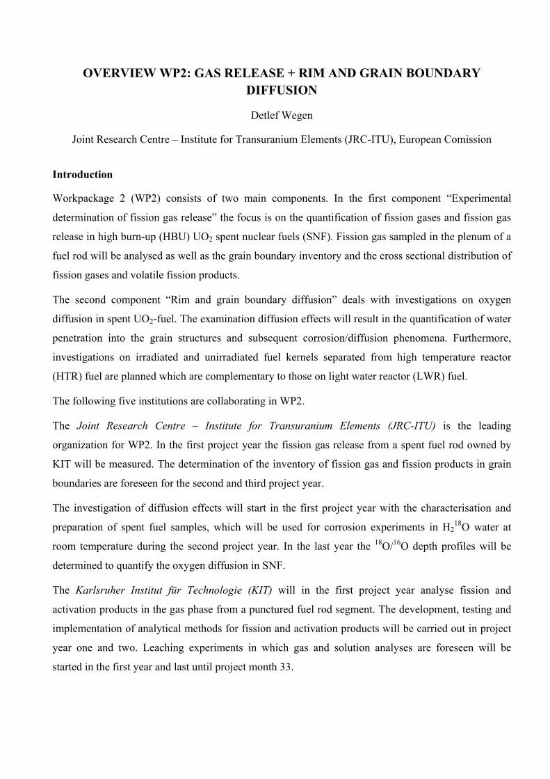
Static Pellet U 0.007 0.005 99.99 0.63 1.45·10-3 3.00E-09 Cs 3.91 2.33 93.76 9.64 0.88 1.23E-05 Tc 0.02 0.004 99.98 5.08 0.25 1.66E-06
As seen in Table 4, a different behavior is observed for the cladded fuel segment sample: m1 might be
the contribution from the gap and cracks, while m2 could be due to grain boundary dissolution. On the
other hand, it is observed that k3 is much higher for Cesium than for Uranium, indicating that in this
experiment both elements are not congruently dissolved at the end of the experimental time.
Uranium and Technetium release are similar in all the samples, but k3 values differ in several
experiments. This fact would indicate that dissolution is not congruent and it could indicate the
Technetium segregation to grain boundaries.
Conclusions and Future work
This work is a preliminary attempt to model IRF experimental data taking into account radionuclide
location: gap, grain boundary, internal grain boundary and matrix, as well as the high burn-up
structure.
The model is conceptually based on the contribution of different phases dissolving simultaneously, and
allows to present hypothesis of the source terms of each radionuclide.
Several sets of experiments have been successfully modeled, which is giving confidence that the
overall release of the radionuclides can be fitted adequately.
This kind of modeling is planned to be applied in the future to the experimental data generated in the
First-Nuclides project.
Acknowledgement
The research leading to these results has received funding from the European Union's European
Atomic Energy Community's (Euratom) Seventh Framework Programme FP7/2007-2011 under grant
agreement n° 295722 (FIRST-Nuclides project).

1st AW Proceedings - 7th EC FP - FIRST-Nuclides Casas et al.
39
References
Clarens, F., Serrano-Purroy, D., Martínez- Esparza, A., Glatz, J-P., de Pablo, J., Wegen, D.,
Christiansen, B., Casas, I., González-Robles, E., Gago, J.A. (2007) RN fractional release of spent fuel
as a function of burn-up: Effect of RIM. 6th EC FP – NF-PRO, 4th Annual Workshop, (Brusels
Belgium).
González-Robles, E. (2011) Study of Radionuclide Release in commercials UO2 Spent Nuclear Fuels.
Effect of Burn-up and High Burn-up Structure. PhD Thesis, UPC-Barcelona Tech.
Johnson, L., C. Ferry, C. Poinssot, P. Lovera (2004) Estimates of the Instant Release Fraction for UO2
and MOX fuels at t=0. Nagra Technical Report 04-08.
Roudil, D., Jégou, C., Broudic, V., Muzeau, B., Peuget, S., Deschanels, X (2007) Gap and grain
boundaries inventories from pressurized water reactors spent fuels. Journal of Nuclear Materials, 362,
411-415.
Serrano-Purroy, D., Clarens, F., González-Robles, E., Glatz, J., Wegen, D., de Pablo, J., Casas, I.,
Giménez, J., Martínez-Esparza, A. (2012) Instant release fraction and matrix release of high burn-up
UO2 spent nuclear fuel: Effect of high burn-up structure and leaching solution comosition. Journal of
Nuclear Materials, 427, 249-258.


SELECTION AND CHARACTERISATION OF HTR FUEL
Hilde Curtius*, Emil Müller , Hans Walter Müskes, Martina Klinkenberg, Dirk Bosbach
Forschungszentrum Juelich GmbH (JÜLICH), DE
* Corresponding author: [email protected]
Abstract
Spent UO2 fuel samples produced for High Temperature Reactors (HTR) are used by Jülich within the
project FIRST-Nuclides. After grinding and polishing of the miniature fuel element (the so-called
coated particle) the obtained polished specimen was investigated with ESEM (Environmental scanning
electron microscope) in order to gain information of the microstructure. Big pores and metallic islands
are visible. An elemental mapping was performed and the elements Cs, Xe, Mo, Zr, U, O, Si and C
were identified clearly. As expected the volatile elements Cs and Xe are mainly detected in the
surrounding porous carbon layer, the so-called buffer.
ESEM investigation was performed with the fuel kernel itself. Big grains but small pores are visible at
the periphery. The metallic islands form hexagonal platelets and contain the elements Zr, Tc, Mo.
The activities of nuclides of Cs, Eu, Ce, Ru, Sb, Rh, Pr and Am in a coated particle were determined
by gamma spectrometric measurement. The measured values agree with the calculated values. A
selective cracking process and a separation step were developed to distinguish clearly between the
elemental distribution within the fuel kernel and the coatings. The fuel kernel and the coatings were
leached respectively dissolved and the solutions obtained were analysed. The elements Am, Pu, Cm,
U, Eu, Ce, Sr, Tc, and Pr are located quantitatively within the kernel. The activity distribution of the
element Cs is extremely different. About 95% of the activity of Cs was detected in the coatings. Due to
the low oxygen potential of the fuel-kernel and considering carbon oxidation during irradiation ternary
Cs compounds are not stable and the only stable phase for Cs is gaseous. In this chemical form Cs was
released from the fuel-kernel to the coatings.
Introduction
Five fuel pebbles from the German production AVR GLE-4/2 were used at the High Flux Reactor in
Petten and an experiment was performed which was called HFR-EU1bis. The irradiation started on

Curtius et al. 1st AW Proceedings - 7th EC FP - FIRST-Nuclides
42
9 September 2004. After 249 full effective power days the experiment was terminated on 18 October
2005. For the pebble HFR-EU1bis/2 a burn-up of 10.2 % FIMA was determined. More experimental
details are given in the following section “Selection of material”. Coated Particles drilled out from the
pebble HFR-EU1bis/2 will be used in WP2.
WP2 focus on four topics:
1. The microstructure (grain boundaries, morphology, metallic islands, pore size and gas bubbles)
before and after leaching.
2. Elemental mapping will go along with these investigations.
3. The determination of the radionuclide inventory by wet chemistry and other analytic tools. The
experimental data obtained will be compared to the calculated radionuclide inventory.
4. The characterisation of the fission gas fraction and of the fast/instant release fraction of volatile
radionuclides after contact with groundwater represents the main working goals.
Preliminary results of the four topics, microstructure, elemental mapping, radionuclide inventory and
radionuclide distribution between coatings and fuel kernel are presented at the first annual workshop.
1. Selection of material
At the High Flux Reactor in Petten the experiment HFR-EU1bis was performed (Fütterer et al., 2006)
using five fuel pebbles from the German production AVR GLE-4/2.
These fuel pebbles had a diameter of 60 mm and mainly consist of graphite. Each fuel pebble
contained about 9560 so called TRISO coated particles with 502-micron diameter UO2 kernels, having
16.76 235U wt% enrichment; coating thickness were approximately 92, 40, 35 and 40 micron for
porous carbon buffer, inner dense pyrocarbon layer (IPyC), silicon carbide (SiC) and outer dense
pyrocarbon layer (oPyC). A fuel pebble represents a fuel element whereas a coated particle can be
regarded as a “miniature fuel element” of about 1 mm in diameter. In Figure 1 a fuel element (pebble)
and a TRISO coated particle are illustrated.

1st AW Procee
Figure 1: D
One pebbl
determined
Table 1: Ma
From the f
transported
edings - 7th EC
Design of a fue
le irradiate
d. The main
ain irradiation
fuel element
d to the Fors
C FP - FIRST-N
el element an
d in Petten
n data are su
n data for the
Nuclide
Enrichme
Irradiation
Reactor cy
Irradiation
Thermal f
Fast fluen
Central te
of pebbles
Power den
FIMA:
t named HF
schungszen
Nuclides
nd a TRISO co
n was calle
ummarized i
e pebble HFR
nt
n at:
ycles:
n:
fluences:
nces:
emperature
s:
nsity:
FR-EU1bis/
ntrum Jülich
43
oated fuel pa
ed HFR-EU
in (Fütterer
R-EU1bis/2
Bq/mg
16.76 w
High F
10
249.55
2.23 x
3.98 x
1250 °C
30 W/c
10.2 %
/2 the TRIS
h in Decemb
rticle
U1bis/2 an
et al., 2008
U
wt% 235U
lux Reactor
(efpds)
1025 m-2
1025 m-2
C
cm3
, (95.57 GW
SO coated p
ber 2011.
d a burn-u
8) and in Ta
r Petten
Wd/t)
articles wer
up of 10.2%
able 1.
re isolated b
Curtius e
% FIMA w
by drilling a
et al.
was
and

Cur
W
pe
2.
A
va
pe
wa
res
Fig
Th
(E
A
ga
bo
du
ma
rtius et al.
ith the OCT
riod of 174
Microstru
TRISO co
acuum. Afte
rformed usi
as performe
sin is shown
gure 1: TRIS
he prepared
SEM).
FEI Quant
aseous large
oundaries, p
ue to the z-c
apping was
TUPOS cod
9 days (Tab
ucture inve
ated particl
er 48 h a gr
ing sandpap
ed with sand
n.
SO coated fue
d sample w
a 200 FEG
e field Sec
porosity). Th
contrast (ato
performed
de the activ
ble 2).
estigations
le was emb
rinding and
per (SiC typ
dpaper (SiC
l particle emb
was then in
G instrument
condary Ele
he back Sca
omic numbe
(detection l
vities of the
of the spen
bedded in a
d polishing
pe, 35 µm a
C-type, 5 µm
bedded in res
nvestigated
t was used.
ectron-detec
attered Elec
er of the ele
limit 0.1 wt
44
e main radio
nt fuel samp
a resin (Ar
process wa
and 22 µm)
m). In Figu
sin
with an en
. The instru
ctor was u
ctron-Detec
ements). Wi
t%).
1st AW
onuclides w
ple and elem
raldit DBF
as performe
). As last st
re 1 the po
nvironmenta
ument is eq
sed to cha
tor was use
ith the Apo
W Proceedings -
were calcula
mental map
CH and A
d. The wet
tep a wet po
lished spec
al scanning
quipped with
aracterize th
ed to obtain
llo X Drift
- 7th EC FP - F
ated after a
pping
Aradur HY
t grinding p
olishing of
cimen embe
g electron m
th three det
he morphol
n chemical i
detector th
FIRST-Nuclides
cool-down
951) under
process was
the sample
dded in the
microscope
tectors. The
logy (grain
information
e elemental
s
n
r
s
e
e
e
e
n
n
l

1st AW Procee
In Figure
step was p
maximum
would get
irradiation
Figure 2: Po
The UO2 s
many meta
edings - 7th EC
2 the SEM
erformed ti
diameter (
lost. Clear
period the p
olished TRIS
surface of th
allic inclusio
C FP - FIRST-N
photo of th
ill the UO2
500 µm) w
rly the three
porous carb
SO coated fuel
he polished
ons (green c
Nuclides
he polished
kernel was
was not per
e tight coat
bon layer of
l particle
d specimen
circles) are
45
d irradiated
350 µm in
rformed bec
tings are vi
f the CP was
itself is cov
visible (Fig
TRISO coa
diameter. F
cause it cou
isible. Due
s pressed an
vered with
gure 3).
ated particle
Further grin
uld be poss
to the pres
nd a gap did
big pores (u
e is shown.
nding and po
sible that th
ssure build
d formed.
(up to 20 µm
Curtius e
The polish
olishing to
he fuel ker
up during
m in size) a
et al.
ing
the
rnel
the
and

Cur
Fig
Re
spo
hig
vo
we
Be
the
co
Th
ho
cle
34
me
ele
rtius et al.
gure 3: View
esults from
ots. In the r
gh accumul
olatility. In t
ere identifie
esides the p
e fuel kern
nstructed sa
he coatings
older and an
early (Figur
4.30 wt%, O
etallic islan
emental map
of the UO2 s
the elemen
red and blu
lation of th
the yellow
ed clearly.
polished spe
nel itself. A
ample devi
were colle
nalysed by S
re 4). The
O 6.79 wt%
nds as hexag
pping revea
surface cover
ntal mappin
ue area (reg
he fission g
area (whol
ecimen inve
A crack proc
ice. It was p
cted in a 2
SEM techni
elemental m
, Zr 0.79wt
gonal platle
al the presen
red with pores
ng did indic
ion of the b
gas Xe and
e surface o
estigations w
cess was st
possible to
20 ml polye
ique. Large
mapping rev
t%, Mo 4.8
ets (average
nce of Mo 2
46
s and metallic
cate the pre
buffer respe
the elemen
of the kerne
were focuse
tarted using
separate th
ethylene via
grains (up
vealed the
2 wt%, Tc
size aprox
20.35 wt% ,
1st AW
c islands
esence of M
ectively reg
nt Cs was
el) the elem
ed on the m
g a modifie
he coatings
al. The fuel
to 112 µm)
presence of
2.02wt%, U
imately 3 µ
Zr 3.12 wt
W Proceedings -
Mo up to 8.
gion betwee
determined
ments C, O,
microstructu
ed microme
from the f
l kernel wa
) and grain
f the follow
U 48.29 wt%
µm) are visi
% and Tc 5
- 7th EC FP - F
.4 wt% in t
en kernel an
d indicating
Si, U, Zr,
ure of the p
eter screw
fuel kernel
as sticked o
boundaries
wing main e
%, Cs 1.24
ible (Figure
5.13 wt%.
FIRST-Nuclides
these green
nd buffer) a
g their high
Mo and Cs
periphery of
and a self-
selecticely.
on a sample
s are visible
elements: C
wt%. Nice
e 5) and an
s
n
a
h
s
f
-
.
e
e
C
e
n

1st AW Procee
At the per
hexagonal
Figure 4: Vi
Figure 5: Vi
edings - 7th EC
riphery of
platelets ar
View of the UO
View of the UO
C FP - FIRST-N
the fuel ke
re detected a
O2 fuel kerne
O2 fuel kerne
Nuclides
ernel large
as well.
l
el periphery w
47
grains and
with the metal
d small por
llic precipitat
res exist. M
tes as hexago
Many metal
onal platelets
Curtius e
llic islands
et al.
as

Curtius et al. 1st AW Proceedings - 7th EC FP - FIRST-Nuclides
48
3. Radionuclide inventory
3.2 Gamma measurement of an irradiated coated particle
The radionuclide inventory was calculated with the OCTOPUS code (Fütterer et al., 2008) after a cool-
down period of 1749 days after end of irradiation on 18th October 2005. In Table 1 the main
radioisotopes and their activities for a coated particle (CP) are summarized. In order to compare these
calculated values to measured values a gamma spectrometric measurement was performed. The
irradiated TRISO coated particle was placed in a polyethylene tube, closed and the measurement was
started. Two different detectors were attached to the gamma spectrometer; a HPGe detector type PGC
2018, Bias: 2500 V positive and a low energy germanium (LEGe) detector. The measure time was
86,400 sec. The sample has a distance to the HPGe detector of 60 cm and 50 cm to the LEGe detector.
For determination of the radionuclide activities the software Gamma-W version 2.44 was used. The
uncertainties of the values obtained are in the range between 10 to 13%.
The measured activities agree with the calculated values quite well (Table 2).
3.3 Determination of radionuclide activities by wet chemistry and different analytic tools
After the gamma spectrometric measurement of the CP (coated particle) a crack process was started
using a modified micrometer screw and a self-constructed sample device. It was possible to separate
the coatings from the fuel kernel selectively. The coatings were placed in a 20 ml polyethylene vial.
Then 10 ml Thorex reagenz (mixture of 13 M HNO3, 0.05 M HF and 0.1 M Al(NO3)3 x 9 H2O) was
added and leaching was performed for 7 days. The isolated fuel kernel was placed in a 20 ml
polyethylene vial and dissolved completely in 10 ml Thorex reagenz.
Both sample solutions were used for further analytical steps in oder to compare the calculated values to
the measured activities and to gain informations about the elemental distribution between coatings and
fuel kernel.
First the activity of tritium in the chemical form as HTO was determined. From each sample solution
100 µl were diluted with 9.9 ml water and a subboil process (70°C) was performed. The condensate
was collected and 1 ml was used for the β-measurement, performed with a Liquid Scintillation Counter
(LSC, TRICARB 2200 A, Packard). Results are summarized in Table 1 and indicate that only small
activities (about 3.2%) of tritium as HTO are only present in the kernel. The main activity of tritium is
expected in the gas fraction. Another β-measurement using 0.1 ml from each sample solution was

1st AW Proceedings - 7th EC FP - FIRST-Nuclides Curtius et al.
49
performed and the activity of 241Pu was determined. 241Pu is quantitatively present in the kernel
(Table 1) and was not detected in the coatings (detection limit: 0.1 Bq/sample).
Then 1 ml from each sample solution was filled in a polyethylene vial and a γ-measurement was
performed (HPGe detector type PGC 2018, Bias:2500 V positiv, counting time: 86,400 s, software:
Gamma-W Version: 2.44: using 152Eu as standard solution with the same geometry, distance 15 cm).
The uncertanties of the measured activities are in the range between 5% (high values) to 20% (low
values). The radiosotopes 144Pr, 144Cer, 154Eu and 155Eu were identified and detected quantitatively in
the kernel, but only about 5% of the activity of Cs was detected. Within the coatings the activity of Cs
was determined to be about 95%. Under the conditions of irradiation a very low oxygen potential was
present (taken carbon oxidation into account as well). Under this condition Cs does not form stable
ternary compounds and the only stable phase is the gaseous one. A high release of Cs from the fuel
kernel to the coatings took place (Barrachin et al., 2011).
Besides Cs the radioisotope 90Sr strongly contributes to the activity of the sample. The activity of 90Sr
was determined after the following selective separation steps; 1 ml of each sample solution was diluted
with 0.67 ml of a 1 M HNO3 solution. Then 1 ml of this solution was used to quantify the 90Sr activity.
A colum (6 ml in volume) was filled with a suspension of 1 g resin (Sr-Resin, Eichrom-Company) in 5
ml of a 2 M HNO3 solution. The colum was washed two times with 5 ml of a 2 M HNO3 solution and
then 5 ml of a 8 M HNO3 solution was added. Afterwards the sample solution was added to the
column. The sample vial was rinsed with 1 ml of a 8 M HNO3 solution and this solution was added to
the colum as well. Then a washing step with 10 ml of a 8 M HNO3solution was performed. The
washing solution was collected. After the washing steps 90Sr was eluated by using
10 ml of a 0.05 M HNO3 solution. Immediatly 1 ml of the eluat was used for the β-measurement. The
main activity ( 95 ± 2%) of Sr was detected in the kernel.
Then the activity of technetium was determined. First the washing solution of the Sr partition process
was evaporated. The obtained residue was dissolved in a 2 M HNO3 solution (about 2 ml) and then
used as sample soltuion for the Tc stripping. A colum (6 ml in volume) was filled with a suspension of
1 g Tc-Resin (TEVA-Resin, Eichrom-Company) in 5 ml of a 2 M HNO3 solution. The colum was
washed two times with 5 ml of a 2 M HNO3 solution. Then the sample solution was added. Washing
steps were performed with 10 ml of a 2 M HNO3 solution. After the washing process Tc was eluated
with 10 ml of a 8 M HNO3 solution. The eluate was evaporated and the residue was dissolved in 1 ml
of a 2 M HNO3 solution and the activity of Tc was determined by LSC. Tc is quantitatively present in
the kernel.

Curtius et al. 1st AW Proceedings - 7th EC FP - FIRST-Nuclides
50
An alpha-spectrometer (Octete, company Ortec, PIPS-detector (planar implanted passivated silicon))
was used to analyze the activities of the radionuclides U, Pu, Am, Np and Cm. 0.1 ml from both
samples solutions were vaporized directly on metal disks and the measurement was performed for
250,000 sec. The results indicate that with these radionuclides are completely present in the kernel
(Table 2). The activity for Np was below the detection limit.
Table 2: Radionuclide activities for a coated particle (CP) (uranium mass of 0.60476 mg) calculated with the OCTOPUS code (date: august 2010), measured activities ** for the coatings and for the fuel kernel from the sample solutions (date august 2012) and measured activities for the intact CP* by γ-measurement (date august 2012).
Nuclide Bq/CP Bq/kernel ** Bq/coatings** Bq/CP* 3H 2.37E+04 6.84E+02 n.d. n.d.
90Sr 4.11E+06 3.18E+06 0.17E+06 90Y 4.11E+06 3.18E+06 0.17E+06 99Tc 9.86E+02 1.31E+03 0.97E+01
106Ru 2.34E+06 1.33E+05 7.28E+04 3.10E+05 125Sb 3.95E+05 1.52E+04 3.54E+02 8.10E+04 134Cs 1.51E+06 2.58E+04 0.80E+06 0.84E+06 137Cs 6.47E+06 4.00E+05 6.36E+06 6.56E+06 144Pr 2.06E+06 0.35E+06 1.46E+03 0.37E+06
144Cer 2.05E+06 0.36E+06 1.18E+03 0.31E+06 154Eu 2.23E+05 1.14E+05 2.85E+02 1.20E+05 155Eu 1.22E+05 4.67E+04 1.52E+02 0.49E+05 234U 1.42E+02 1.82E+02 n.d. 235U 2.95E+00 n.d. n.d. 236U 2.59E+01 3.33E+01 n.d.
237Np 1.48E+01 n.d. n.d. 238Pu 5.75E+04 7.03E+04 2.45E+02 239Pu 1.37E+04 1.09E+04 1.41E+01 240Pu 1.69E+04 1.35E+04 1.55E+01 241Pu 4.39E+06 2.47E+06 n.d.
241Am 3.91E+04 3.11E+04 1.05E+02 2.15E+04 244Cm 1.20E+04 0.90E+04 1.33E+01
n.d. : not detected

1st AW Proceedings - 7th EC FP - FIRST-Nuclides Curtius et al.
51
Conclusions and Future work
Within the project First Nuclides UO2TRISO coated particles are used as spent fuel samples. ESEM
investigations were performed to obtain information of the microstructure and of the elemental
distribution. Big pores, large grains and metallic precipitates are visible in a polished specimen. The
elements Cs, O, U, Mo, Xe, Zr and Si were identified whereas higher amounts of the volatile elements
Cs and Xe were detected in the surrounding buffer. The periphery of an isolated fuel kernel revealed
big grains and small pores. The metallic islands appear as hexagonal platelets and the elements Mo, Zr
and Tc were identified clearly.
The activities of the elements Cs, Eu, Ce, Ru, Sb, Rh, Pr and Am of a coated particle were determined
by γ-spectroscopy and agree with the calculated values.
A selective cracking, separation and dissolution/leaching step was performed to distinguish clearly
between the elements in the fuel kernel and in the coatings. Then the radionuclides were identified by
different analytical tools and their activities were determined.
The elements Am, Pu, Cm, U, Eu, Ce, Sr, Tc, and Pr are located quantitatively within the kernel
according to the results. The element Cs is different. About 95% of the activity was found in the
coatings. During irradiation a very low oxygen potential developed and under this condition Cs is only
stable in atomic form in the gas phase. In this chemical form Cs the drastic release of Cs from the fuel
kernel can be explained.
In future work the fission gas released during the crack process will be analysed. Further on in the
beginning of 2013 isolated fuel kernels will be leached under oxic and anoxic/reducing conditions.
Acknowledgement
Special thanks to Dr. Eric Mauerhofer and Norman Liek for the gamma- and alpha measurements.
The research leading to these results has received funding from the European Union's European
Atomic Energy Community's (Euratom) Seventh Framework Programme FP7/2007-2011 under grant
agreement n° 295722 (FIRST-Nuclides project).

Curtius et al. 1st AW Proceedings - 7th EC FP - FIRST-Nuclides
52
References
Barrachin, M., Dubourg, R., de Groot, S., Kissane, M. P., Bakker, K. (2011) Fission-product behaviour
in irradiated TRISO-coated particles: Results of the HFR-EU-1bis experiment and their interpretation.
Journal of Nuclear Materials, 415, 104-116.
Fütterer, M. A., Berg, G., Toscano, E., Bakker, K. (2006) Irradiation results of AVR fuel pebbles at
increased temperature and burn-up in the HFR Petten. 3rd International Topical Meeting on High
Temperature Reactor Technology, (Johannesburg, South Africa), B00000035.
Fütterer, M.A., Berg, G., Marmier, A., Toscano, E., Freis, D., Bakker, de Groot, S. (2008) Results of
AVR fuel pebble irradiation at increased temperature and burn-up in the HFR Petten. Nuclear
Engineering and Design, 238, 2877-2885.

A COMBINED XRF / XAS STUDY OF SOME INSTANT RELEASE FRACTION RADIONUCLIDES IN HIGH BURN-UP UO2 SPENT NUCLEAR FUEL
Annick Froideval Zumbiehl*, Enzo Curti, Ines Günther-Leopold
Paul Scherrer Institut (PSI), CH
* Corresponding author: [email protected]
Abstract
A combined X-ray fluorescence (XRF) and X-ray absorption spectroscopy (XAS) study of some
relevant instant release fraction radionuclides - such as Se, Cs, and I - is proposed to be conducted on
high burn-up UO2 spent nuclear fuel in order to gain insight into the redox state and the microscopic
distribution patterns of these radionuclides. This report mainly focuses on the description of the
experimental methodology.
Introduction
In the safety case for high-level radioactive waste repositories, aqueous corrosion of the waste plays a
central role, since it determines the source term of radionuclide release to the environment. The direct
disposal of irradiated nuclear fuel is an option adopted in many countries, implying that radionuclide
release studies from spent UO2 and MOX fuel are critical for the safety case. One of the major issues
to be resolved is the reliable determination of the so-called “Instant Release Fraction” (IRF) i.e. the
cumulative inventory fraction of segregated easily soluble nuclides (129I, 135Cs, 36Cl, 79Se, 14C, 99Tc)
which is released within weeks/months on contact with aqueous solutions. This initial phase is
followed by slow radionuclide release following the dissolution of the UO2/PuO2 lattice (“matrix
dissolution”).
In the present study, we propose to gain insight into the chemical speciation and microscopic
distribution patterns of some relevant IRF radionuclides such as Se, Cs and I, present in high burn-up
UO2 spent nuclear fuel. An analytical approach based on the combined use of synchrotron-based
techniques such as X-ray absorption spectroscopy (XAS) and X-ray fluorescence (XRF) will thus be
conducted on such radioactive nuclear material. The spectroscopic characterization (both on the
microscopic and on the macroscopic scale) of selected IRF nuclides within the spent fuel matrix may

Froideval Zumbiehl et al. 1st AW Proceedings - 7th EC FP - FIRST-Nuclides
54
greatly help in understanding the mechanisms of fast initial release in aqueous solutions. We will
particularly focus on Se, since this is the least known among the IRF nuclides. For instance, in recent
experiments it was not possible to detect Se by ICP-MS in the leaching solution after interaction
between spent nuclear fuel and aqueous solution, implying a leached inventory fraction of less than
0.22% (Johnson et al., 2012). Such results would be understandable if Se is present as (insoluble)
reduced species (Se0 or Se–II) in the pristine spent fuel and would not undergo oxidation to soluble
oxidized species (SeIV or SeVI) during the leaching process. Therefore, one of the main goals of the
proposed X-ray spectroscopic study will be the determination of the oxidation state of Se in the
selected spent fuel samples before and after aqueous leaching.
Materials
Two classes of materials are foreseen to be investigated in a first step of the experimental study:
(i) a high burn-up (~75 GWd/t, 9 cycles) UO2 spent nuclear fuel irradiated in the Leibstadt
nuclear plant (KKL),
(ii) several non-irradiated UO2 reference materials containing simultaneously Se, Cs and I in
amounts covering the concentration ranges expected in spent fuel.
The above mentioned fuel sample was selected for the feasibility study since the samples chosen for
the FIRST-Nuclides leach experiments are not yet prepared in the hot cells of PSI (the work is
scheduled for 2013) whereas a subsample of this rod is easily accessible due to earlier investigations in
the frame of other post irradiation examination programs. Although the burn-up of this fuel is slightly
higher than the samples envisaged for the leach experiments (57 – 64 GWd/t), a successful
investigation of the 9 cycles-UO2 fuel would give important insight into the Se redox state and would
prove the depicted analytical concept.
It is foreseen to prepare the high burn-up UO2 spent nuclear fuel from KKL by using the peeling test
method described in Degueldre et al. (2011). This method consists of polishing a section of the fuel
segment by successively using silicon carbide and sand abrasive papers. The freed micro-particles of
fuel are then removed from the surface of the fuel section and collected by pressing the fuel section on
a piece of adhesive Kapton tape (see Figure 1). The peeling preparation method has the advantage to
allow reducing the spent fuel sample to a size which limits the sample activity below 100 LA1 allowed
at the microXAS beamline. A Kapton tape subsample with a total activity below the 100 LA limit will
1 LA stands for the Swiss licensing limit, specified in Annex 3 Column 10 of the “Strahlenschutzgesetz, March, 22nd, 1991”

1st AW Procee
then be p
campaign.
Figure 1: P2011)
The UO2 r
Se, Cs and
well as in h
nuclear fue
Figure 2: Tcalculated unds.iaea.orgconsidered f
edings - 7th EC
prepared for
Picture of a M
reference m
d I (approx.
high burn-u
el from reac
Total Se conusing the fissg/relnsd/vchafor the XAS/X
C FP - FIRST-N
r investiga
MOX fuel segm
materials (na
10 ppm, 10
up spent fue
ctors operate
ncentrations sion yields ofrt/) assuming
XRF feasibility
1
1
1
1
1
Se
to
tal (
mg
/kg
init
ial U
O2)
Nuclides
tion at the
ment cross se
atural or dep
00 ppm, and
el. Figure 2
ed with 235U
induced by ff all relevantg an energy oty study.
0
20
40
60
80
100
120
140
160
180
0 10 20
55
e microXA
ection prepar
pleted U) w
d 1000 ppm
2 shows the
U and therm
fission of 2
t Se isotopes of 200 MeV/f
0 30 40 50
Burnup [G
S beamline
red by the pee
will be prepa
m) in order to
e estimated t
mal neutrons
235U by thermgiven in the
fission. The r
0 60 70 80
GWd/tiU]
e during an
eling method
ared with di
o cover the
total Se con
s.
mal neutronse IAEA interared point cor
0 90 100
Froide
an “active”
(taken from
different con
range expe
ncentrations
s as a functactive databarresponds to
eval Zumbiehl e
measurem
Degueldre et
ncentrations
ected in low
s in UO2 sp
tion of burn-ase (http://wwthe KKL sam
et al.
ment
t al.
s of
w as
pent
-up, ww-
mple

Froideval Zumbiehl et al. 1st AW Proceedings - 7th EC FP - FIRST-Nuclides
56
Experimental approach
The spectroscopic characterization (both on the microscopic and on the macroscopic scale) of selected
IRF nuclides within the spent fuel matrix is proposed to be investigated by using synchrotron-based
techniques such as (micro-)X-ray fluorescence spectroscopy (micro-XRF) and micro-X-ray absorption
spectroscopy (micro-XAS). Particular attention has been paid to choose suitable beamlines in terms of
technical capabilities and allowance for active samples. The INE-beamline (ANKA synchrotron
facility, KIT, Eggenstein-Leopoldshafen, Germany) and the microXAS beamline (SLS, Villigen PSI,
Switzerland) were found to meet the necessary requirements for carrying out measurements on
radioactive samples. However, they differ in the technical specifications:
(i) The range of photon energies delivered at the INE-beamline would allow collecting XANES
spectra at the Se K-edge, as well as at the Cs L1-edge and the I L1- and I L2-edges; in contrast, the
microXAS beamline has a more restricted energy range allowing measurements to be made only at the
Se K-edge.
(ii) The micro-focusing capabilities of the microXAS beamline are excellent (with a size of the
beam at the sample surface in the order of ~ 11 m2) making it the beamline of choice to collect
spectroscopic information with a spatial resolution in the low micrometer level.
(iii) The primary photon intensity at the microXAS beamline is about a factor 100 larger than at
the ANKA beamline.
(iv) ANKA has much higher activity limits, which would in principle allow the preparation of
larger (and thus more representative) UO2 spent fuel samples with a continuous surface.
Thanks to a past successful study performed at the microXAS beamline (SLS) on the characterization
of plutonium-uranium mixed oxide by coupling micro-X-ray diffraction and absorption investigations
(Degueldre et al., 2011), we believe that a similar synchrotron-based analytical approach could be
conducted on a high burn-up spent UO2 fuel sample (see Table 1). However, measuring IRF nuclides
in a heavy spent fuel matrix is more challenging than only recording U and Pu absorption spectra.
Specifically, the low concentrations in the 100 - 4000 ppm range and lower beam energies involved
(E<13 keV) will limit the number of excitable atoms.
These potential difficulties were the main reason for the decision taken to use non-irradiated UO2
reference materials for a feasibility study. They will be used in preliminary measurements for verifying
the detection limits for I, Cs and Se measurements in real spent fuel samples. Afterwards, micro- and
bulk-XANES spectra are foreseen to be recorded at the Se K-edge on the high burn-up UO2 fuel

1st AW Proceedings - 7th EC FP - FIRST-Nuclides Froideval Zumbiehl et al.
57
sample. Such absorption spectra are expected to allow determining the redox state distribution of Se in
the spent fuel sample with a spatial resolution close to few micrometers. This information is important
to understand where, in the spent fuel texture, selenium is present as immobile Se(-II), Se(0) or mobile
Se(IV), Se(VI) species contributing to the IRF. Knowledge of the redox state is expected to yield basic
information on the mobility of these nuclides. For instance, selenium is known to be immobile in the
reduced states Se(-II) and Se(0), whereas it becomes easily soluble upon oxidation to Se(IV), Se(VI)
(Scheinost and Charlet, 2008). A proposal for beamtime request at the microXAS beamline will be
submitted by Sept. 15, 2012.
Moreover, a beamtime proposal has been submitted to ANKA in the frame of the call n°20 (beamtime
campaign: Oct. 2012 - March 2013) in order to obtain access to the INE beamline. The proposed
experiment aims at investigating, on a microscopic (micrometer) scale, by means of XAS/XRF: (i) the
distribution of IRF nuclides (Cs, I, Se) within the spent fuel texture, specifically whether I, Cs and Se
are enriched in the porous rim of high burn-up spent fuel grains; (ii) the redox state and atomic
coordination environment of Se through bulk via if possible) micro-EXAFS (if possible); (iii) the
redox state of Se and I via micro-XANES measurements which will yield important information on the
mobility of these nuclides. Unfortunately, beamtime could not be allocated in spite of the excellent
scientific judgment of the proposal. Nevertheless, thanks to the common scientific interest, INE has
agreed to provide – if possible within the very restricted beamtime currently available – “in-house”
access to the INE beamline. This beamtime would be devoted to the aforementioned feasibility
XAS/XRF study with UO2 reference materials aiming at determining the detection limits of Se, Cs, I in
UO2. Depending on the time schedule of the INE beamline, two options have been offered to us: (i) the
allocation of two days of beamtime within the “in-house” beamtime pool or (ii) occasional test
measurements depending on the time schedule of the beamline (see Table 1).

Froideval Zumbiehl et al. 1st AW Proceedings - 7th EC FP - FIRST-Nuclides
58
Table 1: Synchrotron-based methodology proposed to be conducted at the Swiss Light Source (SLS, Villigen PSI, Switzerland) and/or at the ANKA facility (Eggenstein-Leopoldshafen, Germany) in order to investigate relevant IRF nuclides in high burn-up UO2 spent fuel and in non-irradiated UO2 reference samples containing Se mixed with Cs and I
S a m p l e s f o r e s e e n to be i n v e s t i g a t e d:
T e c h n i q u e s
high burn-up UO2 spent fuel (from KKL nuclear plant)
UO2 reference samples containing Se
mixed with Cs and Ia
(micro-)XRF
Accessible elements and their corresponding emission lines: Se-K1,2
I-L1,2
Cs-L1, Cs-L1
Se-K1,2
Se-K1,2
I-L1,2
Cs-L1, Cs-L1
(micro-)XANES
A b s o r p t i o n e d g e s: Se-K, Cs-L1
I-L1, I-L2
Se-K Se-K Cs-L1
I-L1, I-L2 Beamline (facility) INE (ANKA) microXAS (SLS) INE (ANKA)
Sample UO2 spent fuel UO2 spent fuel UO2- reference samples (feasibility study)
Status of the beamtime request
submitted, but not accepted (on waiting list)
to be submitted (by Sept. 15)
“in-house” INE beamtime, or, test measurements
Note: a The selenium, caesium and iodine concentrations will be approx. 10, 100, and 1000 ppm.
Conclusions
An analytical approach based on the combined use of the (micro-)XRF and the (micro-)XAS
synchrotron methods is proposed to be applied to a high burn-up UO2 spent fuel in order to gain
insights into the redox state and the microscopic distribution patterns of some relevant IRF
radionuclides such as Se, Cs and I, present in the nuclear material.
Acknowledgements
Acknowledgments are due to J. Rothe, K. Dardenne (ANKA, KIT-INE) for their scientific interest in
this project and for their technical and scientific advices in order to prepare a possible measurement
campaign at the INE beamline (ANKA). D. Grolimund and C. Borca from the microXAS beamline
(SLS, PSI) are also thanked for their scientific interest and their willingness to collaborate on this
project. M. Martin and A. Bullemer (AHL/PSI) are thanked for the provision and for the preparation of
the high burn-up UO2 spent nuclear fuel. The support of the group «Isotope and elemental analysis»
(AHL/PSI) in preparation of the references samples is also thanked. Bernhard Kienzler (KIT-INE) is

1st AW Proceedings - 7th EC FP - FIRST-Nuclides Froideval Zumbiehl et al.
59
greatly acknowledged for helpful discussions and his precious advice to carry out a preliminary
feasibility study at ANKA with low-activity material.
The research leading to these results has received funding from the European Union's European
Atomic Energy Community's (Euratom) Seventh Framework Programme FP7/2007-2011 under grant
agreement n° 295722 (FIRST-Nuclides project).
References
Degueldre, C., Martin, M., Kuri, G., Grolimund, D., Borca, C. (2011) Plutonium-uranium mixed oxide
characterizations by coupling micro-X-ray diffraction and absorption investigations. Journal of
Nuclear Materials, 416, 142-150.
Johnson, L., Günther-Leopold, I., Kobler Waldis, J., Linder, H. P., Low, J., Cui, D., Ekeroth, E.,
Spahiu, K., Evins, L. Z. (2012) Rapid aqueous release of fission products from LWR fuel:
Experimental results and correlations with fission gas release. Journal of Nuclear Materials, 420, 54-
62.
Scheinost, A. and Charlet, L. (2008) Selenite Reduction by Mackinawite, Magnetite and Siderite: XAS
Characterization of Nanosized Redox Products. Environmental Science and Technology, 42, 1984-
1989.


FISSION GAS MEASUREMENTS AND DESCRIPTION OF LEACHING EXPERIMENTS WITH OF KIT’S IRRADIATED PWR FUEL ROD SEGMENT
(50.4 GWD/THM)
Ernesto González-Robles*, Elke Bohnert, Andreas Loida, Nikolaus Müller, Volker Metz, Bernhard Kienzler.
Karlsruher Institute fuer Technology (KIT), DE
* Corresponding author: [email protected]
Abstract
The study of the instant release fraction requires a better knowledge of the fission gas release and the
radionuclide release during leaching experiments. In the present communication we explain the
methodology to measure the fission gas release from a fuel rod puncturing test and, the instant release
fraction from leaching experiments with samples from the same fuel rod segment. Additionally, a
complete description of the materials, conditions and analytical methods that will be used during the
leaching experiment is given. Results of the gas analyses from the puncturing test are presented.
1. Introduction
The disposal in deep bedrock repositories is considered as the preferred option for the management of
spent nuclear fuel, SNF, in many countries (Johnson and Shoesmith, 1988; Shoesmith, 2000; Bruno
and Ewing, 2007). The aim is to permanently and safely dispose of the radioactive material so that it is
isolated from the biosphere for an appropriate length of time. A multi-barrier system is interposed
between the SNF and the environment considering the SNF itself as the first technical barrier. In safety
assessments for disposal of spent nuclear fuel (SNF) in deep underground repository, failure of
canisters and loss of the integrity of fuel rods is considered in the long term. Some of the radionuclides
within the SNF material will be directly exposed to water contact after the barrier failure. Assessing
the performance of SNF in a potential future geological disposal system requires the understanding and
quantification of the radionuclide release.
The release of the radionuclides into water will be constituted by two main processes (Johnsson et al.,
2005; Poinssot et al., 2005): i) short term release of the so-called instant release fraction (IRF); ii) long
term release dominated by the dissolution of the UO2 grains, which is referred as matrix contribution.

González-Robles et al. 1st AW Proceedings - 7th EC FP - FIRST-Nuclides
62
The IRF is due to the segregation of a part of the radionuclide inventory to the gap interface between
the cladding and the pellet, the fractures as well as to grain boundaries. The radionuclides that will be
segregated are: fission gases (Kr and Xe), volatiles elements (129I, 137Cs, 135Cs, 36Cl and 79Se) and
segregated metals (99Tc and 126Sn) (Johnson et al., 2004). The degree of segregation of the various
radionuclides is highly dependent on in-reactor fuel operating parameters such as linear power rating,
fuel temperature, burn-up, ramping processes, and interim storage time. In the case of the fission gases,
the gas release occurs by diffusion to grain boundaries, grain growth accompanied by grain boundary
sweeping, gas bubble interlinkage and intersection of gas bubbles by cracks in the fuel (Johnson and
Shoesmith, 1988).The fission gas release is more correlated to the linear heat rating, which is also
correlated to fuel temperature, than to the burn-up of the SNF (Kamikura, 1992, Johnson et al., 2004).
The conditions during irradiation ensure that linear heat ratings are kept low and the fission gas release
is minimised. The radionuclides located in the gap interface will be released after some weeks,
whereas a complete release of the radionuclides segregated in the grain boundaries will take several
months or even years.
During the last decade three European projects, SFS (Poinssot et al., 2005), NF-PRO (Grambow et al.,
2008) and MICADO (Grambow et al., 2010) were carried out, in which, the IRF concept was revised
and redefined as the radionuclide inventory located within microstructures with low confinement
properties: fuel plenum, gap zone, fracture surfaces, the rim zone with high burn-ups structures and
grain boundaries (Grambow et al., 2010).
The present work aims to analyse gases (in particular fission gases) released into the plenum of the
fuel rod, and the development of an experimental procedure to measure the radionuclides that
constitute the IRF during the performance of leaching experiments.
2. Materials, methods and results
2.1 Investigated 50.4 GWd/tHM PWR fuel rod segment
For the experimental studies, KIT-INE provided a HBU-SNF rod segment which had been irradiated
during four cycles in the PWR Gösgen (KKG), Switzerland, and discharged in May 1989. During
reactor operation an average burn-up of 50.4 GWd/tHM was achieved. Characteristic data of the studied
segment N0204 of the KKG-BS fuel rod SBS1108 are given by Metz et al. (2012) and Wegen et al.
(2012).

1st AW Proceedings - 7th EC FP - FIRST-Nuclides González-Robles et al.
63
2.2 Gas analysis
Prior to the start of the leaching experiments, the fuel rod segment was carried to ITU for two
purposes: i) characterization of the fuel rod segment (by means of non-destructive analyses in the first
year of the FIRST-Nuclides project) and a puncturing to estimate the amount of fission gases present
in the fuel rod segment; ii) the preparation of pellet-sized SNF samples.
2.2.1 Experimental procedure
Once the puncturing of the fuel rod segment was performed at ITU, the pressure was measured and
gases were collected in stainless steel single-ended miniature sampling cylinders. The SS-4CS-TW-50
Swagelok gas sampling cylinders were characterised by a volume of 50 ml, a length of 159 mm, an
outer diameter for tube fitting of 9.5 mm and an inner diameter for tube socket weld connection of
6.4 mm (Figure 1). The volume of the tubes is known and the total amount of gas could be calculated.
The cylinders were carried back to KIT-INE, where the gases were analysed by means of a quadrupole
gas mass spectrometer (gas MS). The gas MS (GAM400, In Process Instruments, Bremen, Germany)
was equipped with a Faraday and SEV detector and a batch inlet system (Figure 1). The batch-type
gas inlet system was optimised for low gas sample consumption. Within the gas dosage and inlet
system, the total gas pressure was controlled at four successive positions. It applied three different
expansion-volumes to charge relatively low gas contents in the desired pressure range. Ten scans of
each gas sample were measured, using the SEV-detector, and the mean value was taken. Calibration of
the gas MS analysis was performed in the same pressure range as the respective range for analyses of
the sample aliquots.
Figure 1: a) Image of GAM400 quadrupole gas mass spectrometer b) Image of a stainless steel single-ended miniature sampling cylinder used to collect gas samples
b
)
a
)

González-Robles et al. 1st AW Proceedings - 7th EC FP - FIRST-Nuclides
64
2.2.2 Results
Table 1 presents the average values of gases measured in the samples taken from the puncturing test of
the 50.4 GWd/tHM fuel rod segment. O2 and N2 contents in the gas composition (0.31 and 1.3 vol.%,
respectively) are related to air contamination during the sampling of the cylinders. The gas released
from the plenum of the punctured fuel rod segment contains a measurable content of CO2. In the past,
similar CO2 contents were observed in various fuel rod puncturing tests performed by some of the
FIRST-Nuclides project partners, i.e. ITU, PSI, SCK-CEN and Studsvik. The measured contents of Kr
and Xe will be compared to their calculated total inventory in the 50.4 GWd/tHM fuel rod segment, in
order to determine the percentage of the fission gas released into the plenum.
Table 1: Concentration of gases and absolute gas volumes sampled during the puncturing test of the 50.4 GWd/tHM fuel rod segment
Gas Concentration
(vol.%) Volume
(cm3) Ar 0.28 0.40
CO2 0.13 0.18 N2 1.3 1.87 O2 0.31 0.44 Kr 1.5 2.1 Xe 18 26 He 78 111
2.2.3 Leaching experiments
Three leaching experiments with samples of the 50.4 GWd/tHM fuel rod segment are foreseen to be
conducted under anoxic conditions. The samples will be: one cladded segment (as a pellet) and two
decladded SNF fragments. The experiments will be carried out in Ti-lined VA autoclaves (total
volume 250 ml; Figure 2), with two valves in the lid to allow sampling of gases and of solutions
during the experiment. A 10 mM NaCl + 1 mM NaHCO3 solution is chosen as leachant, and the
anoxic conditions will be achieved by application of a H2 + Ar reducing atmosphere within the
autoclaves ( 37 bar Ar +3 bar H2).

1st AW Procee
Figure 2: Im
At the beg
described b
solution w
solution al
release. Th
2.2.4 Gas
In parallel
sampled. T
gases, H2
positioned
using the q
edings - 7th EC
mage of a Ti-l
ginning of th
before. At t
will be comp
liquots will
he leachant w
s sampling p
to the sam
The main in
and O2. F
inside the
quadropole g
C FP - FIRST-N
lined VA auto
he experime
the end of e
pletely renew
l be sample
will not be
procedure
mpling of s
nterest is in
Figure 3 sh
shielded bo
gas MS sys
Nuclides
oclave inside
ents two wa
each wash c
wed. In the
ed at differ
replenished
olution aliq
the release
hows the s
ox-line of K
tem describ
65
the shielded
ashing cycl
cycle, aliqu
e following
rent time i
d during this
quots, the g
e of the fiss
system requ
KIT-INE. A
bed above.
box-line of K
es will be p
ots will be
static phase
intervals to
s static phas
gas phase o
sion gases,
uired to co
Analyses of
KIT-INE
performed w
sampled fo
e of the lea
determine
se.
of the autoc
Kr and Xe,
ollect the g
f the gas sa
Gon
with the sam
or further an
aching expe
the kinetic
claves will
, as well as
gases from
amples will
nzález-Robles e
me leachant
nalysis and
riments, sm
cs of the I
be frequen
the radioly
the autocla
be perform
et al.
t as
the
mall
IRF
ntly
ytic
ave
med

González-Robles et al. 1st AW Proceedings - 7th EC FP - FIRST-Nuclides
66
Figure 3: Images of the gas sampling system that will be using during the leaching experiments. a) Image of the interior of the shielded box-line of KIT-INE, showing the Titanium valves and stainless steel tubings, which connect the autoclave to the out of the hot cell. b) Image of out part of the hot cell, showing the connection between the autoclave (coming from the previous figure) and the sample cylinder used to collect the gases.
2.2.5 Aqueous sampling procedure
The aqueous solution will be analysed to determine the specific activity of 134Cs, 135Cs, 137Cs, 90Sr, 241Pu, 129I, 79Se, 14C, 36Cl, 238Pu, 239Pu, 240Pu, 238U, 99Tc, 237Np. Following analysis methods will be
applied:
γ-spectrometry for concentration measurements of 134Cs, 137Cs. The separation of these
radionuclides from the original solution is described in Grambow et al. (1996). Afterwards the
analysis is performed by means of Ge-detectors (EGC-15-185-R and GX3018, Canberra
Industries Inc, Meriden, USA).
Liquid scintillation counting (LSC) using a Packard Tri-Carb 3110TR Low activity scintillation
analyser (Perkin Elmer INC, Waltham, USA) to quantify: 90Sr, 241Pu, 14C. Solution aliquots
will be homogenised with a LSC-Cocktail (Ultima Gold XR, Packard) before measurement.
α-spectrometry will be used to determine the amount of 238Pu, 239Pu, 240Pu using a analysis
chamber with a S100 field channel analysator (238Pu, 239/240Pu) and passivated implanted planar
silicon (PIPS) detectors (Canberra 74/01, Canberra Industries Inc, Meriden, USA) which
combine high resolution and low backgrounds in a rugged alpha detector with active areas up
to 1200 mm2. It integrates into one package a stainless steel vacuum chamber for low
backgrounds and ease of cleaning, a vacuum gauge, detector bias supply, preamp/amplifier,
pulser, discriminator, counter, and digital display. A stainless steel shelf and sample holder are
b) a)

1st AW Proceedings - 7th EC FP - FIRST-Nuclides González-Robles et al.
67
included for reproducible detector/sample spacing, which is user selectable from 1 to 49 mm, in
4 mm increments
Inductively coupled plasma mass spectrometer (ELAN 6100, Perkin Elmer Inc, Waltham,
USA) to measure the concentrations of 79Se, 238U, 99Tc, 237Np.
3. Summary and future work
KIT-INE provided a 50.4 GWd/tHM fuel rod segment in the ownership of KIT-INE, where all data and
findings can be published without restrictions. This HBU-SNF was transported to ITU for
characterisation, gas sampling, cutting and sampling of fuel pellets. Gas samples and fuel pellets were
returned to KIT for further investigations. Results of the measured fission gas contents will be
compared to their theoretical total inventory in order to estimate the percentage of fission gas that was
released into the plenum of the fuel rod segment. The analytical method for the gas measurements will
also be applied to fission gases obtained during dissolution based experiments.
KIT-INE will perform three static leaching experiments with a pellet-sized cladded segment and two
decladded SNF fragments. These experiments will be conducted under reducing conditions in
autoclaves performing regular sampling of gases and solutions. The methodology that will be followed
during the performance of the leaching experiment is explained in the present communication. Within
the following months the leaching experiments will be started.
Acknowledgements
The authors would like to thank our colleagues at JRC-ITU, in particular to R. Gretter, Ramil
Nasyrow, Dimitrios Papaioannou, Wim de Weerd and Detlef Wegen for performing the puncturing
test of the 50.4 GWd/tHM PWR fuel segment, as well as for non-destructive analyses, cutting the
segment and further activities related to the characterization of the samples.
The research leading to these results has received funding from the European Union's European
Atomic Energy Community's (Euratom) Seventh Framework Programme FP7/2007-2011 under grant
agreement n° 295722 (FIRST-Nuclides project).

González-Robles et al. 1st AW Proceedings - 7th EC FP - FIRST-Nuclides
68
References
Bruno, J. and Ewing, R.C. (2006) Spent nuclear fuel. Elements, 2, 343-349.
Grambow, B., Loida, A., Dressler, P., Geckeis, H., Gago, J., Casas, I., de Pablo, J., Gimenez, J.,
Torrero M.E. (1996) Long-term safety of radioactive waste disposal: Chemical reaction of fabricates
and high burn-up spent UO2 fuel with saline brines. Final report FZKA 5702 Forschungszentrum,
Karlsruhe, Germany.
Grambow, B., Lemmens, K., Minet, Y., Poinssot, C., Spahiu, K., Bosbach, D., Cachoir, C., Casas, I.,
Clarens, F., Christiansen, B., de Pablo, J., Ferry, C., Giménez, J., Gin, S., Glatz, J.P., Gago, J. A.,
Gonzalez Robles, E., Hyatt, N. C., Iglesias, E., Kienzler, B., Luckscheiter, B., Martinez-Esparza, A.,
Metz, V., Ödegaard-Jensen, A., Ollila, K., Quiñones, J., Rey, A., Ribet, S., Rondinella, V. V.,
Skarnemark, G., Wegen, D. H., Serrano-Purroy, D., Wiss, T. (2008) Final Synthesis Report for NF-
PRO: “Understanding and Physical and Numerical Modelling of the Key Processes in the Near-Field
and their Coupling for Different Host Rocks and Repository Strategies”. RTD Component 1:
Dissolution and release from the waste matrix. F16W-CT-2003-02389. European Commission,
Brussels, Belgium.
Grambow, B., Bruno, J., Duro, L., Merino, J., Tamayo, A., Martin, C., Pepin, G., Schumacher, S.,
Smidt, O., Ferry, C., Jegou, C., Quiñones, J., Iglesias, E., Rodríguez-Villagra, N., Nieto, J. M.,
Martinez-Esparza, A., Loida, A., Metz, V., Kienzler, B., Bracke, G., Pellegrini, G., Mathieu, G.,
Wasselin-Trupin, V., Serres, C., Wegen, D., Jonsson, M., Johnson, L., Lemmens, K., Liu, J.,
Spahiu, K., Ekeroth, E., Casas, I., de Pablo, J., Watson, C., Robinson, P., Hodgkinson, D. (2010)
MICADO, Model uncertainty for the mechanism of dissolution of spent fuel in nuclear waste
repository. Final activity report. European Commission, Brussels, Belgium.
Johnson, L. and Shoesmith, D.W. (1988) Spent Fuel in Radioactive Waste Forms for the Future.
W. Lutze and R.C. Ewing, Eds. (North-Holland, Amsterdam), 635-698.
Johnson, L., Ferry, C., Poinssot, C., Lovera, P. (2004) Estimates of the Instant Release Fraction for
UO2 and MOX fuels at t=0. Nagra Technical Report 04-08.
Kamikura, K. (1992) FP gas release behaviour of High Burn-up MOX fuel for Thermal Reactors.
Proceedings of Technical Committee Meeting on Fission Gas release and Fuel Rod Chemistry Related
to Extended Burnup. IAEA-TEDOC-697.

1st AW Proceedings - 7th EC FP - FIRST-Nuclides González-Robles et al.
69
Metz, V., Loida, A., González-Robles, E., Bohnert, E., Kienzler, B. (2012) Characterization of
irradiated PWR UOX fuel (50.4 GWd/tHM) used for leaching experiments. Proceedings of 7th EC FP –
FIRST-Nuclides 1st Annual Workshop (Budapest, Hungary).
Poinssot, C., Ferry, C., Kelm, M., Grambow, B., Martínez Esparza, A., Johnson, L., Andriambololona,
Z., Bruno, J., Cachoir, C., Cavedon, J. M., Christensen, H., Corbel, C., Jegou, C., Lemmens, K.,
Loida, A., Lovera, P., Miserque, F., De Pablo, J., Poulesquen, A., Quiñones, J., Rondinella, V. V.,
Spahiu, K. and Wegen, D. (2005) Final report of the European project Spent Fuel Stability under
repository conditions. CEA Report, CEA-R-6093.
Shoesmith, D.W. (2000) Fuel corrosion process under waste disposals. Journal of Nuclear Materials,
282, 1-31.
Shoesmith, D.W. (2007) Used Fuel and Uranium dissolution studies - A review. NWMO Technical
Report, NWMO-TR-2007-03.
Wegen, D.H., Papaioannou, D., Nasyrow, R., Gretter, R., de Weerd, W. (2012) Non-destructive
analysis of segment N0204 of the spent fuel pin SBS1108 (in prep.).


CHARACTERIZATION OF SCKCEN FUEL SAMPLES USED FOR LEACH TESTS IN FIRST-NUCLIDES
Kevin Govers*, Marc Verwerft, Wouter Van Renterghem, Karel Lemmens, Thierry Mennecart, Christelle Cachoir, Lesley Adriaensen, Andrew Dobney, Mireille Gysemans
Studiecentrum voor Kernenergie (SKN-CEN), BE
* Corresponding author: [email protected]
Abstract
In the framework of the FIRST-Nuclides program, SCK•CEN will conduct leaching experiments on a
PWR UOX fuel, taken from the Belgian Tihange 1 reactor, with a rod average burnup of
50 MWd/kgHM in order to determine the rapid release of some of the most critical radionuclides.
Considering the influence of the irradiation parameters on the actual location of fission products at the
beginning of the leaching test, the interpretation of the experimental results highly relies on a good
characterization of the fuel samples. This article will deal with the characterization of the fuel rod and
samples that will be used for the leach tests performed at SCK•CEN.
Introduction
As one of the partners of FIRST-Nuclides with a hot-cell infrastructure and the required analytical
laboratories, SCK•CEN will perform leach tests on spent fuel samples with a relatively high burn-up.
For this purpose, a fuel rod was selected from the spent fuel stock available at SCK•CEN for which the
characteristics are known and can be made public.
In the past, several fuel rods irradiated under high duty conditions in Tihange 1 PWR reactor, have
been extracted from their assembly to perform post-irradiation experiments at SCK•CEN laboratories.
These fuel rods and relevant results of the previous post-irradiation examination (PIE) campaign are
available for further research. These fuel rods are therefore good candidates for correlating leach tests
measurements to FGR results.
The present article provides the characteristics of the fuel rod that will be used for the leach tests at
SCK•CEN (Mennecart, et al., 2012). It is a PWR UOX fuel from the Belgian Tihange 1 reactor
irradiated about 12 years ago during cycles 20 and 21 up to an average burnup of about 50 MWd/kgHM.
Govers et al. 1st AW Proceedings - 7th EC FP - FIRST-Nuclides
72
We show the scheme according to which the samples will be cut for further characterization and for
the leach tests. Detailed irradiation data are not available yet and will be reported at a later stage. In the
meantime pellet average isotopic composition has been estimated based on the calculated burnup.
Fuel rod characteristics
Fuel rod history
The Tihange 1 NPP, located in Belgium, is a PWR reactor loaded with 15×15 fuel assemblies usually
operated at an elevated linear power. Two fuel rods located at symmetrical positions (D05 and E12) in
the assembly have been extracted from assembly FT1X57 for non-destructive and destructive analyses
in the SCK•CEN laboratories (Sannen and Pathoens, 2003). Fuel rod D05 has been selected for use in
FIRST-Nuclides and will be further characterized in this paper.
Details about the power history at rod and sample level will be reconstructed by the operator during
the first phase of the FIRST-Nuclides project, based on reactor power history and power distribution
mapping of the core. At present, generic data are available: the final rod-average burnup, estimated as
50.0 MWd/kgHM for rod D05, was achieved in two cycles of 18 months each. The intermediate burnup
was about 28.1 MWd/kgHM.
Rod fabrication data
The geometry of assembly FT1X57 consists of a 15×15 array of fuel rods with 21 unfuelled locations
(guide tubes) for potential insertion of control rods or instrumentation. The cladding material is M5.
Nominal data about the fuel rod design can be found in Table 1. Batch data relative to rod dimensions
and fuel composition are reported in Table 2.

1st AW Proceedings - 7th EC FP - FIRST-Nuclides Govers et al.
73
Table 1: Nominal (design) data – rod D05, fuel assembly FT1X57
Assembly type AFA 2G Assembly geometry 15 × 15 # of fuel rods per assembly 204 Rod pitch (mm) 14.3 Fuel Type UO2 Enrichment (nominal) (% U235/Utot) 4.25 Density (nominal) (% TD) 96 Average grain size (µm) 10 Cladding Type M5 recrystallized Composition
Nb (wt.%)
Fe (wt.%)
O (wt.%)
Zr (wt.%)
Nominal M5 0.8 – 1.2 0.015 – 0.06 0.09 – 0.12
balance
External diameter (mm) 10.720 Thickness (mm) 0.618 Internal diameter (mm) 9.484
Cutting scheme definition
Fuel rods D05 and E12 were cut, after non-destructive tests, into four segments of about 1 m length
each. The samples for the leach tests will be taken from the second segment (from the bottom) of rod
D05, internally referred to as FT1X57-D05/R4. The burnup profile between the end of the first span up
to the end of the fifth span is indeed relatively constant, as shown by the γ-activity measurement (see
Figure 1), except close to grid locations. Activity peaks are observed at regular intervals in the central
zone, indicating volatile product migration to colder zones at inter-pellet locations. A large
contribution to the signal originates from Cs isotopes. There is, however, no indication of major
redistribution of volatile fission products along the fuel rod, which would be characterized by a slightly
depleted signal at the centre and higher activity in the bottom and top parts.
The samples to be used for the leach tests will consist of two pellets. The samples are cut from mid-
pellet to mid-pellet in order to keep a representative inventory of the volatile elements that relocate at
pellet-pellet interfaces. Two other samples are taken for fuel characterization. The first one is used for
radiochemical analysis (RCA) of the fission product and actinides inventory; enabling the average
pellet burnup to be determined. The second one is used for optical microscopy (OM) and

Govers et al. 1st AW Proceedings - 7th EC FP - FIRST-Nuclides
74
determination of the local element composition by electron-probe micro-analysis (EPMA). An
additional spare sample is also foreseen. The proposed cutting scheme is illustrated in Figure 2. Signal
peaks, regularly spaced by about 11.8 mm, were exploited to identify pellet-pellet interfaces. The
samples are located in the flat γ-activity zone, far enough away from the grid locations. Although the
axial burnup is expected to be homogeneous over the sampling zone, leach test samples are proposed
to be flanked by the sample used for burnup determination by RCA and the sample used for OM /
EPMA. The spare sample is located the closest to the third grid location, next to the OM / EPMA
sample.
Table 2: Batch data – rod D05
Fuel rod Rod total length (mm) 3861.9 Active fuel stack length (mm) 3634.9 Plenum length (mm) 205.1 Diametrical pellet-clad gap (µm) 190 He filling pressure (bar) 20 Fuel characteristics Material UO2 Density (% TD) Mass metal/oxide (gU / gUO2)
96.44 88.13
U isotopic composition 234U / Utot (wt%) 0.038 235U / Utot (wt%) 4.251 236U / Utot (wt%) 0.001 238U / Utot (wt%) 95.71 Impurities / additives Not available yet Pellet dimensions Diameter (mm) 9.294 Length (mm) 11.15 Dish
Depth (mm)
Spherical radius (mm)
0.34 16.70
Chamfer
Height (mm)
Width (mm)
0.20 0.57

1st AW Procee
Figure 1: Gguide for throd length is
Figure 2: experimentsAn additiona
Estimated
Although t
is still app
edings - 7th EC
Gross-γ scanne eye) clearlys characterist
Proposed cu. One sampleal spare samp
d isotopic in
the detailed
roximate, fu
C FP - FIRST-N
ning of rod Dy identifies thtic of high bu
utting scheme will be usedple is current
nventory
d power hist
fuel compos
Nuclides
D05. Measurehe activity dr
urnup fuel.
me of segmed for burnup tly being cons
tory has not
sition can b
75
ements were arop due to su
ent FT1X57-Ddeterminatiosidered.
t yet been p
be estimated
acquired everupport grids.
D05/R4. Thron and anothe
provided by
d using robu
ry 0.5 mm usThe flat activ
ree samples er one for op
y the reactor
ust tools. Th
sing a collimaivity profile o
are intendeptical microsc
r operator a
he followin
Govers e
ator. The lineover most of f
ed for leachcopy and EPM
and the burn
ng results ha
et al.
e (a fuel
hing MA.
nup
ave

Gov
be
co
15
int
A
18
be
Th
the
stu
rod
co
Figpow
vers et al.
en derived
mpiled cros
lattice. V
terpolation o
simplified,
8 months cy
tween both
he power le
e burnup af
udy. Two bu
d average b
des reflect i
gure 3: Simpwer. Addition
using the O
ss-section li
Variations i
of the librar
constant, p
ycles of the
cycles and
vel has bee
fter 10 year
urnup level
burnup and s
isotopic pro
plified power nal calculatio
ORIGEN-AR
ibraries for
in fuel com
ry data.
ower histor
selected hig
a storage ti
en varied (s
rs storage, w
ls are highli
sample burn
oduction and
history for thons will be pe
RP module
several LW
mposition,
ry has been
gh duty fuel
ime of 10 ye
ee Figure 3
which is re
ighted in Fi
nup. One sh
d decay but
he various buerformed once
76
available in
WR fuel ass
burnup an
postulated o
l rods. A sh
ears after th
3) to exami
epresentativ
igure 4 and
hould keep i
t do not mod
urnup cases. e the detailed
1st AW
n SCALE 6
embly desig
nd moderato
over 2 cycle
hutdown per
he irradiatio
ine the sens
e of the sp
d Figure 5
in mind tha
del fission p
We have assd power histor
W Proceedings -
.1 (ORNL,
gns, among
or density
es of 500 da
riod of 50 d
n.
sitivity of th
ecimen con
correspond
t values cal
product redi
umed 2 cyclery is availabl
- 7th EC FP - F
2011). It co
g which the
are handle
ays each, re
days has bee
he fuel com
nsidered in
ding respect
lculated wit
istribution (
es of 500 dayle.
FIRST-Nuclides
ontains pre-
PWR 15 ×
ed through
eflecting the
en assumed
mposition to
the present
ively to the
th neutronic
(migration).
ys at constant
s
-
×
h
e
d
o
t
e
c
.
t

1st AW Procee
Figure 4: Aapproximate
Figure 5: R
evolution wi
burnups.
edings - 7th EC
Actinide invene rod and sam
Relevant (in
ith disposal b
C FP - FIRST-N
ntory evolutiomple burnups
terms of the
burnup, after
Nuclides
on with dispo.
e leaching te
r 10 years of
77
osal burnup,
est experime
f decay. Verti
after 10 yea
ents) long- a
ical arrows i
rs of decay.
and medium-l
indicate the a
Vertical arro
lived radiois
approximate
Govers e
ows indicate
sotope invent
rod and sam
et al.
the
tory
mple

Govers et al. 1st AW Proceedings - 7th EC FP - FIRST-Nuclides
78
Conclusions and Future work
This article summarizes the fabrication data currently available for dissemination amongst First-
Nuclides partners. It will be complemented later by the detailed power history of the rod (i.e. including
axial profile) for which calculations by the plant operator should become available in the coming
weeks. Further characterization of the sample will be made using optical microscopy, radiochemical
analysis and electron-probe microanalysis.
Acknowledgement
The authors wish to thank Areva (fuel manufacturer), Electrabel (plant operator) and Tractebel
(engineering office, support to operator) for providing agreement to use the fuel for additional
research.
The research leading to these results has received funding from the European Union's European
Atomic Energy Community's (Euratom) Seventh Framework Programme FP7/2007-2011 under grant
agreement n° 295722 (FIRST-Nuclides project).
References
Mennecart, T., Lemmens, K., Govers, K., Adriaensen, L., Cachoir, C., Dobney, A. (2012) Concept of
leach test for the experimental determination of IRF radionuclides from Belgian high burnup spent
nuclear fuel in First-Nuclides. Budapest, Hungary.
ORNL. (2011) Scale: A Comprehensive Modeling and Simulation Suite for Nuclear Safety Analysis
and Design. Available from Radiation Safety InformationComputational Center at Oak Ridge National
Laboratory as CCC-785.
Sannen, L., and Parthoens, Y. (2003) R-3788 - Framatome – Tihange 1: Assembly FT1X57 – Rods
E12 and D05 – Non-destructive evaluation, Puncture, H2 analysis. Mol, Belgium: SCK-CEN.

SELECTION OF HIGH BURN-UP FUEL SAMPLES FOR LEACH EXPERIMENTS AND SPECTROSCOPICAL STUDIES AT PSI
Ines Günther-Leopold*, Hans-Peter Linder, Annick Froideval Zumbiehl, Enzo Curti
Paul Scherrer Institut (PSI), CH
* Corresponding author: [email protected]
Abstract
The selection of suitable high burn-up spent nuclear fuel samples available in the Hot Laboratory of
the Paul Scherrer Institut (PSI) that will be used for leach experiments and XRF/XAS studies to
investigate the instant release fraction (IRF) and the redox state of relevant radionuclides in the frame
of the FIRST Nuclides project is described in this report. The data required for the characterization of
fuel and cladding were collected and compiled.
Introduction
WP3 “Dissolution based release” of the FIRST Nuclides project targets the quantification of the fast
release of gaseous and non-gaseous activation and fission products into the aqueous phase during spent
nuclear fuel leach tests. The present report describes the characteristics of the high burn-up fuel
samples selected for leach experiments foreseen to be carried out in the Hot Laboratory of PSI.
The experiments will cover high burn-up UO2 and mixed oxide (MOX) spent nuclear fuels from
boiling water reactor (BWR) and pressurized water reactor (PWR) having burn-up in the range of 57 to
64 GWd/tHM. Special emphasis will be given to the determination of IRF values of Cs, I, Se and 14C as
well as to the Se redox state. The results from these leaching experiments on fuel samples with and
without cladding, as well as cladding fragments alone, should help gaining insight into the contribution
of the cladding material onto the 14C IRF values.
Characteristics of the selected fuel samples
PSI is able to perform leach experiments on maximum nine fuel samples in parallel in the “Dissolution
box” of the Hot Laboratory. The test matrix was defined by selecting three samples (cladded fuel,

Günther-Leopold et al. 1st AW Proceedings - 7th EC FP - FIRST-Nuclides
80
cladding and fuel fragments) from an UO2 fuel rod irradiated in the Leibstadt BWR (KKL), as well as
six samples (cladded fuel, fuel fragments, cladding with and without fuel residues) from the Gösgen
PWR (KKG), of which four originate from an UO2 fuel rod and two from a MOX fuel rod. In addition
to a previously published study (Johnson et al., 2012) fuel fragments and cladding of this MOX fuel
rod will be leached separately in order to complete the available data set for this material.
The information given is this paper is also compiled within the Deliverable 1.1 (“Characterisation of
spent nuclear fuel samples to be used in FIRST-Nuclides – relevance of samples for the Safety Case”,
issued June 2012).

1st AW Proceedings - 7th EC FP - FIRST-Nuclides Günther-Leopold et al.
81
High burn-up UO2 fuel from BWR
Details on the selected UO2 BWR fuel rod from KKL are given in Table 1.
Table 1: Characterisation data of the UO2 BWR fuel selected for PSI investigations
Data category Parameter
Reactor Leibstadt NPP, Switzerland Boiling Water Reactor
Fuel assembly design information
10 x 10 Lattice SVEA96 Optima, fuel assembly AIA003, rod position H6, Node 4
Assembly / cladding material compositon
Zircaloy-2, designation LK3/L
Fuel rod data Fission gas release: 2.26% Rod length as fabricated: 4146.6 Rod length after irradiation: 4163.3 Internal rod pre-pressure: 7 bar
Fuel material (pellet) data UO2, initial enrichment: 3.9% 235U Pellet diameter (as fabricated): 8.77 ± 0.013 mm Pellet length: 10.7 ± 0.8 mm Density (spec) 10.52 ± 0.19 g/cm3 Density as fabricated 10.48 – 10.54 g/cm3 Grain size 6 ≤ x ≤ 25 μm
Fuel sample data Sample position 455 mm to 520 mm from BEP Cladding sample data Zircaloy-2 with liner, designation LK3/L
Cladding outer diameter: 10.30 ± 0.04 mm Cladding inner diameter: 8.94 ± 0.04 mm Liner Thickness 70 ± 40 μm
Irradiation data Rod average burnup: 57.5 GWd/tU, exp. determined local burnup: 6.1% FIMA
Number of cycles: 7 Date of loading: August 1998 Date of unloading: April 2005 Duration of irradiation: 2400 days Average linear power: ~ 160 W/cm Max. linear power: 270 W/cm

Günther-Leopold et al. 1st AW Proceedings - 7th EC FP - FIRST-Nuclides
82
High burn-up UO2 fuel from PWR
Details on the selected UO2 PWR fuel rod from KKG are given in Table 2.
Table 2: Characterisation data of the UO2 PWR fuel selected for PSI investigations
Data category Parameter
Reactor Gösgen NPP, Switzerland PWR
Fuel assembly design information
KKG-14B-4021-01-0129 Lattice geometry: 15x15, 48 assemblies with 20 control rods/assembly Fuel rod diameter: 10.765 mm Fuel rod diameter after irradiation: 10.697 mm
Assembly / cladding material composition
Zircaloy 4, DX HPA4 (0.6Sn)
Fuel rod data Test rod Fission gas release: 13.2%, 51.5 bar Internal rod pre-pressure: 22 bar Rod length as fabricated: 3860 mm Rod length after irradiation: 3879 mm Active length: 3550 mm
Fuel material (pellet) data UO2, initial enrichment: 4.3% 235U Fuel density (as fabricated): 10.45 g/cm3
Fuel sample data Sample position 2620 mm to 2695 mm from BEP Cladding sample data Cladding outer diameter: 10.75 ± 0.05 mm
Cladding inner diameter: max. 9.45 mm Max. Oxide: 36 µm
Irradiation data Rod average burnup: 62.2 GWd/tU, exp. determined local burnup: to be performed
Number of cycles: 4 Date of loading: 28.7.1999 Date of unloading: 28.6.2003 Duration of irradiation: 1324.43 days

1st AW Proceedings - 7th EC FP - FIRST-Nuclides Günther-Leopold et al.
83
High burn-up MOX fuel from PWR
Details on the selected MOX PWR fuel rod from KKG are given in Table 3.
Table 3: Characterisation data of the MOX PWR fuel selected for PSI investigations
Data category Parameter
Reactor Gösgen NPP LPWR
Fuel assembly design information
KKG-13-5024-10-676 Lattice geometry: 15x15 48 assemblies with 20 control rods/assembly Fuel rod diameter: 10.76 mm (measured) Fuel rod diameter after irradiation: 10.736 mm
Assembly / cladding material composition
Duplex ELS0.8b
Fuel rod data Test rod Fission gas release: 26.7%, 76.4 bar Internal rod pre-pressure: 22 bar Rod length as fabricated: 3859.0 mm Rod length after irradiation: 3886.1 mm Active length: 3550 mm
Fuel material (pellet) data MOX, initial enrichment: 5.5% Pufiss Fuel density (as fabricated): 10.45 ± 0.15 g/cm3 Fuel density after irradiation: 9.903 g/cm3 Pellet diameter (as fabricated): 9.13 ± 0.013 mm
Fuel sample data Sample position 2030 mm to 2070 mm from BEP Cladding sample data Cladding outer diameter: 10.75 ± 0.05 mm
Cladding inner diameter: 9.30 ± 0.04 mm Max. Oxid: 36 µm
Irradiation data Rod average burnup: 63.0 GWd/tU, exp. determined local burnup: 7.3% FIMA
Number of cycles: 4 Date of loading: 30.06.1997 Date of unloading: 07.07.2001 Duration of irradiation: 1368 days Average linear power: 306 W/cm (average fuel rod power in 4 cycles) Max. linear power: approx. 430 W/cm
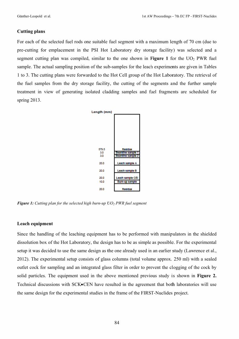
Gün
Cu
Fo
pre
seg
sam
1 t
the
tre
spr
Fig
Le
Sin
dis
set
20
ou
sol
Te
the
nther-Leopold
utting plan
or each of th
e-cutting fo
gment cutti
mple. The a
to 3. The cu
e fuel samp
eatment in
ring 2013.
gure 1: Cuttin
each equipm
nce the han
ssolution bo
tup it was d
012). The ex
utlet cock fo
lid particles
echnical dis
e same desig
et al.
s
he selected
or emplace
ing plan wa
actual samp
utting plans
ples from t
view of g
ng plan for th
ment
ndling of th
ox of the Ho
decided to u
xperimental
or sampling
s. The equi
scussions w
gn for the e
fuel rods o
ment in th
as compiled
pling positio
were forwa
the dry stor
enerating i
he selected hi
he leaching
ot Laborato
se the same
l setup cons
g and an int
ipment use
with SCKC
experimenta
ne suitable
he PSI Hot
d, similar t
on of the sub
arded to the
rage facility
solated cla
igh burn-up U
equipment
ry, the desi
e design as t
sists of glas
egrated glas
d in the ab
EN have re
al studies in
84
fuel segme
Laboratory
to the one
b-samples f
e Hot Cell g
y, the cutti
adding samp
UO2 PWR fue
has to be p
ign has to b
the one alre
ss columns
ss filter in o
bove mentio
esulted in th
the frame o
1st AW
ent with a m
y dry stora
shown in F
for the leach
group of the
ng of the s
ples and fu
el segment
performed w
e as simple
eady used in
(total volum
order to pre
oned previo
he agreeme
of the FIRST
W Proceedings -
maximum le
age facility
Figure 1 fo
h experimen
e Hot Labor
segments an
uel fragmen
with manipu
as possible
n an earlier s
me approx.
event the cl
ous study i
ent that both
T-Nuclides
- 7th EC FP - F
ength of 70
y) was sele
or the UO2
nts are give
ratory. The
and the furt
nts are sch
ulators in th
e. For the ex
study (Lawr
250 ml) wi
logging of t
s shown in
h laboratori
project.
FIRST-Nuclides
cm (due to
cted and a
PWR fuel
en in Tables
retrieval of
ther sample
heduled for
he shielded
xperimental
rence et al.,
ith a sealed
the cock by
n Figure 2.
ies will use
s
o
a
l
s
f
e
r
d
l
,
d
y
.
e

1st AW Procee
The glass
manufactur
Figure 2: As
Acknowle
The suppo
acknowled
sample pre
microXAS
The resear
Atomic En
agreement
Reference
Johnson, L
Spahiu, K.
Experimen
62.
edings - 7th EC
componen
red in-hous
ssembly of fiv
dgement
rt and recom
dged. The au
eparations fo
S (SLS, PSI)
rch leading
ergy Comm
t n° 295722
es
L., Günther
, Evins, L.Z
ntal results a
C FP - FIRST-N
ts for the
se. The expe
ve glass colum
mmendation
uthors thank
for the propo
) beamlines
g to these r
munity's (Eu
(FIRST-Nu
r-Leopold,
Z. (2012) Ra
and correla
Nuclides
leach equip
erimental se
mns with pist
ns of L. Joh
k M. Martin
osed measu
.
results has
uratom) Sev
uclides proje
I., Kolber
apid aqueou
ations with f
85
pment are
etup will be
tons designed
hnson (Nag
n (AHL/PSI
urement cam
received f
venth Frame
ect).
Waldis, J.,
us release o
fission gas
already ord
manufactur
d and used for
gra) concern
I) for techni
mpaigns at th
funding from
ework Prog
, Linder, H
f fission pro
release. Jou
dered, whe
red till end
r earlier PSI
ning the sam
ical and sci
he INE (AN
m the Euro
gramme FP
H.P., Low,
oducts from
urnal of Nu
Gün
ereas the pi
of 2012.
leaching exp
mple selecti
ientific advi
NKA, KIT,
opean Unio
P7/2007-201
J., Cui, D.
m high burn-
uclear Mate
nther-Leopold e
istons will
eriments
ion are grea
ices in view
Germany) a
on's Europe
11 under gr
, Ekeroth,
-up LWR fu
erials, 420, 5
et al.
be
atly
w of
and
ean
rant
E.,
uel:
54-


CHARACTERISATION OF SPENT VVER-440 FUEL TO BE USED IN THE FIRST-NUCLIDES PROJECT
Zoltán Hózer*, Emese Slonszki
Magyar Tudományos Akademia Energiatudományi Kutatóközpont (MTA EK), HU
* Corresponding author: [email protected]
Abstract
Dissolution rates of different isotopes from VVER fuel will be determined in the FIRST-Nuclides
project based on activity measurements at the Paks NPP. The present report summarizes the design and
operational characteristics of fuel that were stored in the given periods in the spent fuel storage pool of
the power plant. The isotope inventories are also included in order to facilitate the calculation of
fractional release rates.
Introduction
In the framework of the FIRST-Nuclides project the MTA Centre for Energy Research will produce
fuel dissolution data on VVER fuel. There were two series of measurements at the Paks NPP that can
be used for the evaluation of fuel dissolution in wet environment:
a) In 2003 thirty fuel assemblies were damaged at the power plant during a cleaning tank incident.
The integrity of fuel cladding was lost and most of the fuel pellets had direct contact with the
coolant. The damaged fuel was stored in a special service area of the spent fuel storage pool for
almost four years. During this period the activity concentration was regularly measured. Using
the measured data the dissolution rates of different isotopes can be calculated.
b) In 2009 a leaking fuel assembly was identified at the NPP. The assembly was removed from
the reactor core and the placed in the spent fuel storage pool. The power plant decided to
launch a special measurement programme for the investigation of activity release from the
leaking fuel rod in wet storage conditions. The measured data allows us to produce dissolution
rates for these conditions, too.

Hózer et al. 1st AW Proceedings - 7th EC FP - FIRST-Nuclides
88
As a first step of analyses the fuel assemblies have to be characterised. In the present report the main
geometrical, design and operational data will be summarised for both damaged and leaking VVER–
440 fuel assemblies.
1. Characterisation of damaged fuel
On 10 April 2003 severe damage of fuel assemblies took place during an incident at Unit 2 of Paks
Nuclear Power Plant in Hungary (Hózer et al., 2010; NEA/CSNI/R, 2008; Slonszki et al., 2010; Hózer
et al., 2009). The assemblies were being cleaned in a special tank below the water level of the spent
fuel storage pool in order to remove crud buildup. That afternoon, the chemical cleaning of assemblies
was completed and the fuel rods were being cooled by circulation of storage pool water. The first sign
of fuel failure was the detection of some fission gases released from the cleaning tank during that
evening. The cleaning tank cover locks were released after midnight and this operation was followed
by a sudden increase in activity concentrations. The visual inspection revealed that all 30 fuel
assemblies were severely damaged. The first evaluation of the event showed that the severe fuel
damage happened due to inadequate coolant circulation within the cleaning tank.
The damaged fuel assemblies were removed from the cleaning tank in 2006 and are stored in special
canisters in the spent fuel storage pool of the Paks NPP.
Following several discussions between expert from different countries and international organisations
the OECD–IAEA Paks Fuel Project was proposed.
The Project will focus on the numerical simulation of the most important aspects of the incident. A
database necessary for the code calculations was collected. This data is available for the FIRST-
Nuclides project.
1.1. Design characteristics of VVER-440
The fuel assembly data were collected from open literature (Solonin et al., 1997). The main data is
listed below. The list includes both working and follower type VVER-440 assemblies. Both types can
be found among the damaged assemblies.
Length of (working) fuel assembly 3217 mm
Length of (follower) fuel assembly 3200 mm
Shroud material Zr 2,5%Nb
Cladding material Zr 1%Nb

1st AW Proceedings - 7th EC FP - FIRST-Nuclides Hózer et al.
89
Number of fuel rods 126
Fuel assembly key size 144 mm
Lattice pitch 12.2 mm
Fuel rod length 2550 mm
Fuel column length (working assembly) 2420 mm
Fuel column length (follower assembly) 2320 mm
Outer cladding diameter 9.15 mm
Cladding thickness 0.65 mm
Pellet diameter 7.57 mm
Central hole diameter 1.2-1.8 mm
Pellet-cladding gap 0.15-0.26 mm
Pellet shape chamfered
Pellet height 9-12 mm
Pellet density 10.4-10.8 g/cm3
Pellet densification max. 0.4%
Helium pressure 0.5 MPa
Free fuel element volume 15 cm3
Number of spacer grids 10
Some material properties of E110 (Zr1%Nb) cladding material has collected from open literature
(Smirnov et al., 1997).
Cladding yield strength at 20 oC 400-420 MPa
Cladding yield strength at 350 oC 180-190 MPa
Cladding ultimate strength at 20 oC 430-450 MPa
Cladding ultimate strength at 350 oC 200-210 MPa
Cladding uniform elongation at 20 oC 10%
Cladding uniform elongation at 350 oC 15%
Cladding total elongation at 20 oC 34-38%
Cladding total elongation at 350 oC 42-47%
Irradiated cladding yield strength at 20 oC 500-580 MPa
Irradiated cladding yield strength at 350 oC 340-370 MPa
Irradiated cladding ultimate strength at 20 oC 460-510 MPa

Hózer et al. 1st AW Proceedings - 7th EC FP - FIRST-Nuclides
90
Irradiated cladding ultimate strength at 350 oC 305-335 MPa
Irradiated cladding uniform elongation at 20 oC 2-5%
Irradiated cladding uniform elongation at 350 oC 4-6%
Irradiated cladding total elongation at 20 oC 14-24%
Radiated cladding total elongation at 350 oC 18-24%
Number of perforations at the bottom of the shroud (working assemblies) 12
Number of perforations at the top of the shroud (working assemblies) 12
Diameter of perforations 9 mm
1.2. Operational data of damaged fuel assemblies
The operational data of fuel assemblies has been collected in order provide burnup specific data for
each fuel assembly that was cleaned in the cleaning tank. Such data are necessary for the definition of
initial fuel state (before start of cleaning operation).
This part of database collection included several calculations, which were based on real fuel cycles of
each assembly.
The power histories of fuel assemblies are included in the database, so participants can carry out their
own calculations (e.g. with fuel behaviour codes) if they consider it necessary.
Operational data for Unit 2 and cycles 16-19 were provided by the Paks NPP. They included:
load map of archives for cycle 16 describing the burnup distribution at the beginning of cycle,
power distributions and histories for cycles 16-19,
refuelling matrices between 16-19 cycles.
The burnup distribution in 10 axial nodes for each assembly was calculated using the GLOBUSKA
module of the KARATE programme system (Hegedűs et al., 2002).
The decay heat of each node of each assembly was calculated using power distribution and considering
the storage time between reactor shutdown and the incident. The ORIGEN and TIBSO codes were
applied for this purpose. The reactor-physics calculations were performed at the Reactor Analysis
Department of the Atomic Energy Research Institute, Budapest.
The fuel assemblies with similar power histories and of the same type (follower or working) were
grouped into 6 groups and only one representative assembly was calculated for each group. Later all

1st AW Proceedings - 7th EC FP - FIRST-Nuclides Hózer et al.
91
fuel assemblies were assigned to their given values. This approach was applied in the following
calculations, too.
The assemblies groups are listed below with the factory No.:
1. assembly group (1.-6.): 60465, 60466, 60467, 60468, 60469, 60470 (standard assemblies
with 10.8 MWd/kgU burnup)
2. assembly group (7.-11.): 53906, 53873, 53994, 53930, 53878 (standard assemblies with 26.7
MWd/kgU burnup)
3. assembly group (12.): 57033(follower assembly with 10.1 MWd/kgU burnup)
4. assembly group (13.-18.): 58734, 59741, 59738, 59742, 59743, 59739 (follower assemblies
with 21.1 MWd/kgU burnup)
5. assembly group (19.-24.): 61039, 61040, 61040, 61042, 61043, 61046 (follower assemblies
with 13.3 MWd/kgU burnup)
6. assembly group (25.-30.): 61048, 61049, 61050, 60577, 60575, 60576 (follower assemblies
with 13.1 MWd/kgU burnup)
The burnup dependent parameters of each assembly were determined using the reactor-physics data
and fresh fuel parameters with the TRANSURANUS (Lassmann, 1992) code, where slice 1
correspondes to node 10. We used for our calculation averaged data on geometries. Table 1 the data
on geometries are summarized. Please note that some differences may exist between these data (used
for the present calculations) and the fuel data published in open literature (and given in previous
chapter).
Table 2 contains the main parameters of fuel assemblies at the end of cycle 19. The maximum value of
calculated parameters and the minimum gap size, furthermore the calculated rod internal pressure at
20 oC, 60 oC and 260 oC are presented.
The calculated cladding axial deformation, fractional fission gas release, gap width, linear heat rate,
pressure in the rod, tangential creep strain, fuel temperature, average fuel temperature, cladding
tangential stress and the power history and profile of all assemblies are shown in for assembly No.7
(53906) in Figure 1 as an example.

Hózer et al. 1st AW Proceedings - 7th EC FP - FIRST-Nuclides
92
Table 1: Geometrical parameters of fresh assemblies
Table 2: Collected values of assemblies at the end of cycle 19
ParameterAssembly
No. 12
Assemblies
No. 7-11
Assemblies
No. 13-18
Assemblies
No. 19-24
Assemblies
No. 25-30
Assemblies
No. 1-6
Friction coefficient between fuel and cladding: static friction 8.00E-01 8.00E-01 8.00E-01 8.00E-01 8.00E-01 8.00E-01
Friction coefficient between fuel and cladding: sliding friction 8.00E-01 8.00E-01 8.00E-01 8.00E-01 8.00E-01 8.00E-01
Height of axial slice 1-10 [mm] 2.32E+02 2.42E+02 2.32E+02 2.32E+02 2.32E+02 2.42E+02
Height of axial slice 11 [mm] 9.00E+01 9.00E+01 9.00E+01 9.00E+01 9.00E+01 9.00E+01
Inner fuel radius [mm] 7.25E-01 7.25E-01 7.25E-01 7.25E-01 7.25E-01 7.25E-01
Outer fuel radius [mm] 3.78E+00 3.78E+00 3.78E+00 3.78E+00 3.78E+00 3.78E+00
Inner cladding radius [mm] 3.88E+00 3.88E+00 3.88E+00 3.88E+00 3.88E+00 3.88E+00
Outer cladding radius [mm] 4.55E+00 4.55E+00 4.55E+00 4.55E+00 4.55E+00 4.55E+00
Surface roughness fuel [mm] 1.80E-03 1.80E-03 1.80E-03 1.80E-03 1.80E-03 1.80E-03
Surface roughness clad [mm] 1.00E-03 1.00E-03 1.00E-03 1.00E-03 1.00E-03 1.00E-03
Fillgas pressure [MPa] 6.00E-01 6.00E-01 6.00E-01 6.00E-01 6.00E-01 6.00E-01
Fillgas temperature [oC] 2.00E+01 2.00E+01 2.00E+01 2.00E+01 2.00E+01 2.00E+01
Upper plenum volume (maximum) [mm3] 4.26E+03 4.26E+03 4.26E+03 4.26E+03 4.26E+03 4.26E+03
Gap volume (maximum) [mm3] 5.73E+03 5.97E+03 5.73E+03 5.73E+03 5.73E+03 5.97E+03
Volume of central void (maximum) [mm3] 3.83E+03 4.00E+03 3.83E+03 3.83E+03 3.83E+03 4.00E+03
Total free volume [mm3] 1.38E+04 1.42E+04 1.38E+04 1.38E+04 1.38E+04 1.42E+04
Friction coefficient between fuel and cladding: static friction 8.00E-01 8.00E-01 8.00E-01 8.00E-01 8.00E-01 8.00E-01
ParameterAssemblies
No. 7-11
Assemblies
No. 13-18
Assembly
No. 12
Assemblies
No. 19-24
Assemblies
No. 25-30
Assemblies
No. 1-6
Max. claddingaxial deformation [mm] 7.62E+00 6.95E+00 5.61E+00 6.32E+00 6.26E+00 5.79E+00
Max. burnup [MWd/kgU] 3.14E+01 2.74E+01 1.61E+01 1.61E+01 1.59E+01 1.26E+01
Average burnup [MWd/kgU] 2.65E+01 2.19E+01 1.04E+01 1.38E+01 1.36E+01 1.07E+01
Max. fractional fission gas release [%] 1.76E-03 1.53E-03 9.38E-04 8.92E-04 8.80E-04 6.92E-04
Min. gap size [] 3.89E+00 4.47E+00 2.26E+01 2.50E+01 2.57E+01 3.63E+01
Max. linear heat rate [W/mm] 2.19E+01 2.06E+01 2.24E+01 2.28E+01 2.21E+01 1.75E+01
Max. pressure in the rod [MPa] 2.05E+00 1.92E+00 1.76E+00 1.76E+00 1.75E+00 1.60E+00
Rod internal pressure at 20 oC [MPa] 7.43E-01 7.09E-01 6.41E-01 6.53E-01 6.51E-01 6.28E-01
Rod internal pressure at 60 oC [MPa] 8.46E-01 8.06E-01 7.29E-01 7.42E-01 7.40E-01 7.15E-01
Rod internal pressure at 260 oC [MPa] 1.38E+00 1.32E+00 1.19E+00 1.21E+00 1.20E+00 1.16E+00
Cladding tangential creep strain [%] -3.81E-01 -3.14E-01 -1.49E-01 -2.59E-01 -2.49E-01 -1.53E-01
Max. fuel temperature [oC] 9.10E+02 9.12E+02 9.76E+02 9.87E+02 9.64E+02 8.06E+02
Max. average fuel temperature [oC] 6.90E+02 7.17E+02 7.55E+02 7.62E+02 7.48E+02 6.51E+02

1st AW Proceedings - 7th EC FP - FIRST-Nuclides Hózer et al.
93
-2
0
2
4
6
8
10
0 5 10 15 20 25 30
Burnup (MWd/kgU)
Cla
ddin
g a
xial
de
form
atio
n (m
m)
Assembly No.7
0
0.0005
0.0010
0.0015
0.0020
0 5 10 15 20 25 30
Burnup (MWd/kgU)
Fra
ctio
nal f
issi
on g
as r
elea
se (
%)
Assembly No.7
0
10
20
30
40
50
60
70
80
0 5 10 15 20 25 30
10 slice9 slice8 slice7 slice6 slice5 slice4 slice3 slice2 slice1 slice
Burnup (MWd/kgU)
Ga
p w
idth
(m
)
Assembly No.7
0
5
10
15
20
25
0 5 10 15 20 25 30
10 slice9 slice8 slice7 slice6 slice5 slice4 slice3 slice2 slice1 slice
Burnup (MWd/kgU)
Lin
ear
hea
t ra
te (
W/m
m)
Assembly No.7
0.5
1.0
1.5
2.0
2.5
0 5 10 15 20 25 30
Burnup (MWd/kgU)
Pre
ssur
e in
the
rod
(M
Pa)
Assembly No.7
-0.4
-0.3
-0.2
-0.1
0
0.1
0 5 10 15 20 25 30
Burnup (MWd/kgU)
Cla
ddin
g t
ange
ntia
l cre
ep s
tra
in (
%)
Assembly No.7

Hózer et al. 1st AW Proceedings - 7th EC FP - FIRST-Nuclides
94
Figure 1: Representation of the calculated burnup dependent parameters, power history and profile for assembly No. 7.
1.3. Isotope inventory
The isotope inventory of the 30 assemblies was calculated using the ORIGENARP module of the
SCALE4.4a program system. The calculations yielded the concentrations and activities of isotopes for
the six assembly groups. The data was assigned to the each fuel assembly.
The typical material composition was considered in the calculations with following isotopes and
elements: 234U, 235U, 236U, 238U, Hf, Nb, Sn, Zr. The calculations were done with 44 energy groups
gamma and neutron spectrum directory from time of shutdown of Unit 2 of Paks NPP for the next
calculated calendar days: 0 (day of shutdown), 3, 10, 13 (day of incident), 30, 60, 120, 240, 365 and
760. The database includes 138 isotopes in the above 10 times for each assembly.
0
100
200
300
400
500
600
700
800
900
1000
0 5 10 15 20 25 30
10 slice9 slice8 slice7 slice6 slice5 slice4 slice3 slice2 slice1 slice
Burnup (MWd/kgU)
Max
imu
m f
uel t
empe
ratu
re (
oC
)
Assembly No.7
0
100
200
300
400
500
600
700
800
0 5 10 15 20 25 30
10 slice9 slice8 slice7 slice6 slice5 slice4 slice3 slice2 slice1 slice
Burnup (MWd/kgU)
Ave
rag
e fu
el t
emp
era
ture
(o C
)
Assembly No.7
-82
-80
-78
-76
-74
-72
-70
0 5 10 15 20 25 30
10 slice9 slice8 slice6 slice5 slice4 slice3 slice2 slice1 slice
Burnup (MWd/kgU)
Cla
dd
ing
ta
nge
ntia
l str
ess
(MP
a)
Assembly No.7
0
2
4
6
8
10
12
14
16
18
0.00E+00 5.00E+03 1.00E+04 1.50E+04 2.00E+04 2.50E+04
Time [hour]
Lin
ear
pow
er o
f as
sem
bly
No.
7
[kW
/m]
0
0.2
0.4
0.6
0.8
1
1.2
1.4
Pow
er p
rofi
le o
f as
sem
bly
No.
7
linear power
node 10
node 5
node 1
1st AW Proceedings - 7th EC FP - FIRST-Nuclides Hózer et al.
95
The data of 6 assemblies were used to characterise the assemblies (e.g. fission product content). It
could be seem that the order of activities of assemblies were very close to each other after shutdown.
The calculations were carried out at the Reactorphysics Department of Paks NPP. The total activities
of 30 assemblies is shown in Table 3.
The total activity of assemblies and assemblies groups after shutdown were determined by 3 main
groups like light elements (activated structural materials of assemblies – assembly claddings, spacer
grids, rod claddings), actinides and fission products.
The light elements are monotonous decreasing in time and their activity was significant part of the
total activity of assembly at the time of the incident. These elements are 91Zr, 92Zr, 94Zr, 96Zr, 93Nb, 119Sn, 120Sn.
The activity of actinides is important in all examined periods compared to total activity of calculated
assemblies. It includes the 234U, 235U, 236U, 238U, 237Np, 235Np, 239Pu, 240Pu, 241Pu, 242Pu, 241Am, 243Am, 242Cm, 244Cm. The release of these elements with all probability can be taken place only if they
dissolve from pellets.
Activity of fission products are decreasing in time and their contribution to the total activity is
important only at the beginning period after the incident. Their activities will converge to a saturation
value, which represents a considerable part of the release at the incident.
2. Characterisation of the 70873 leaking fuel assembly
The No. 70873 fresh follower fuel assembly was loaded into position No. 33 of cycle 22 of Unit 4 at
the Paks NPP. The enrichment of U was 3,82%. The design characteristics of this assembly are the
same as that of damaged fuel described in chapter 1.1.
2.1. Operational data of leaking fuel assembly
The operational history of the assembly was provided by the power plant.
The assembly was operated for one year and was removed from the core during the refueling period.
For this reason the assembly reached only 14 MWd/kgU burnup.
According to the analyses of primary coolant activities, this assembly had only one single leaking fuel
rod, the other 125 rods were intact.

Hózer et al. 1st AW Proceedings - 7th EC FP - FIRST-Nuclides
96
Table 3: Isotope inventory of 30 damaged fuel assemblies at the reactor shutdown
Isotope Activity [Bq] Isotope Activity [Bq] Isotope Activity [Bq] 239Np 2,30E+18 131I 1,23E+17 127Te 8,90E+15
133I 2,61E+17 88Rb 1,06E+17 133mXe 8,05E+15 133Xe 2,51E+17 131Te 1,06E+17 241Pu 7,67E+15
135I 2,47E+17 105Ru 1,05E+17 137Cs 7,22E+15 140La 2,45E+17 88Kr 1,04E+17 129mTe 7,11E+15 99Mo 2,37E+17 91mY 1,03E+17 137Ba 6,90E+15 140Ba 2,35E+17 105Rh 9,78E+16 90Y 6,53E+15 95Zr 2,33E+17 147Nd 8,55E+16 90Sr 5,90E+15 95Nb 2,30E+17 135Xe 7,44E+16 134Cs 5,75E+15 97Nb 2,25E+17 237U 7,12E+16 111mAg 5,09E+15 97Zr 2,23E+17 149Pm 6,36E+16 111Pd 5,08E+15
141Ce 2,16E+17 135mXe 5,17E+16 111Ag 5,04E+15 141La 2,15E+17 129Sb 3,78E+16 136Cs 3,08E+15
97mNb 2,12E+17 106Rh 3,73E+16 242Am 2,48E+15 99mTc 2,09E+17 85mKr 3,66E+16 244Am 1,71E+15 143Ce 2,06E+17 129Te 3,58E+16 242Cm 9,69E+14 143Pr 2,00E+17 106Ru 3,20E+16 125Sb 5,77E+14 92Y 1,86E+17 153Sm 3,07E+16 181Hf 4,86E+14 92Sr 1,85E+17 105mRh 2,99E+16 154Eu 2,33E+14 91Y 1,83E+17 109Pd 2,89E+16 155Eu 1,22E+14 132I 1,81E+17 131mTe 2,25E+16 110mAg 1,09E+14
132Te 1,78E+17 151Pm 2,22E+16 122Sb 8,19E+13 91Sr 1,78E+17 83Br 1,70E+16 180mHf 4,37E+13
103Ru 1,72E+17 83mKr 1,70E+16 239Pu 3,62E+13 103mRh 1,72E+17 147Pm 1,69E+16 124Sb 3,35E+13
89Sr 1,46E+17 238Np 1,65E+16 3H 3,18E+13 145Pr 1,39E+17 148Pm 1,49E+16 240Pu 3,06E+13 93Y 1,38E+17 156Eu 9,60E+15 244Cm 2,30E+13
144Pr 1,25E+17 243Pu 9,30E+15 175Hf 1,88E+13 144Ce 1,23E+17 127Sb 9,20E+15 242Am 4,68E+12

1st AW Proceedings - 7th EC FP - FIRST-Nuclides Hózer et al.
97
The power of axial nodes of the assembly was calculated using the power normalized power
distribution and the power of assembly. The power of axial nodes of assembly was divided by 126
(total number of fuel rods) and by the length of nodes that determined the linear heat rate of one rod.
The FUROM code (Kulacsy, 2011) was applied for the calculation of the coolant temperature from the
inlet temperature of core for each axial nodes. The fast neutron flux was determined by the FUROM,
too. The initial data for FUROM calculations are given in Table 4.
Table 4: Technological parameters of fuel rod used in the calculations
Parameter Value of parameter
inner fuel radius [mm] 0.675
outer fuel radius [mm] 3.7925
surface roughness fuel [μm] 2
inner cladding radius [mm] 3.88
outer cladding radius [mm] 4.55
surface roughness clad [μm] 1
active length of rod [m] 2.36
enrichment [%] 3.82
Relative density of fresh fuel [-] 0.962
relative density after densification [-] 0.97
fuel grain size [μm] 14
He fillgas pressure [bar] 6
plenum volume [cm3] 8.5
coolant inlet temperature [ºC] 266
Figure 2 shows the linear heat rate versus time for each of axial nodes. While the power of some
nodes increased, some others decreased, but the total power of rods in the follower assembly decreased
during the cycle.

Hó
Fig
2.2
Th
Un
Fig
zer et al.
gure 2: Linea
2. Isotope
he 70873 as
nit 4 operate
gure 3: Reac
ar heat rate of
inventory o
sembly con
ed for near n
tor paramete
of 39 axial no
of 70873 ass
ntained 114,
nominal po
ers of cycle 22
des of rod ve
sembly
837 kg U,
wer (1485 M
2 of Unit 4
98
ersus time
from which
MW) after t
1st AW
h the mass o
the third eff
W Proceedings -
of 235U was
fective day (
- 7th EC FP - F
s 4,405 kg. C
(Figure 3).
FIRST-Nuclides
Cycle 22 of
s
f

1st AW Proceedings - 7th EC FP - FIRST-Nuclides Hózer et al.
99
Cycle 22 of Unit 4 was 319,95 effective operational days based on measured data. The cycle started at
30.05.2008 and finished at 24.04.2009. Calculated burnup of 70873 assembly was 14,137 MWd/kgU,
so the calculated power was 5,097 MW. The isotope inventory of 70873 assembly during the operation
and the storage was calculated based on these data by ORIGEN-ARP 5.01 program (Table 5.). The
time steps in the calculations were: 0.3, 1, 3, 10, 30, 90, 150, 250, 300, 319.95 during the operation and
1, 3, 10, 30, 90, 150, 250, 350, 400, 450 during the storage.
Table 5: Isotope inventory of one fuel rod in the leaking 70873 fuel assembly at the reactor shutdown
Isotope Mass [g] Activity [Bq]239Np 8,31 5,67E+14 140La 0,47 7,86E+13
95Zr 11,77 7,40E+13 95Nb 6,35 7,31E+13
141Ce 8,12 6,80E+13 99Mo 0,42 5,88E+13
99mTc 0,04 5,32E+13 103Ru 5,54 5,24E+13
89Sr 5,49 4,69E+13 144Ce 36,38 3,41E+13 97Nb 0,00 2,73E+13 97Zr 0,05 2,72E+13
106Ru 7,74 7,61E+12 137Cs 62,21 1,59E+12
90Sr 32,14 1,30E+12 134Cs 2,82 1,08E+12 136Cs 0,04 8,06E+11 125Sb 0,37 1,12E+11
242Cm 0,08 7,74E+10 154Eu 0,51 3,74E+10 239Pu 552,90 2,48E+10 155Eu 0,16 2,35E+10
110mAg 0,01 1,77E+10 240Pu 97,59 1,61E+10
3H 0,00 1,12E+10 122Sb 0,00 9,68E+09 124Sb 0,00 7,67E+09
244Cm 0,04 1,04E+09 241Am 0,62 6,25E+08

Hózer et al. 1st AW Proceedings - 7th EC FP - FIRST-Nuclides
100
3. Conclusions
The main characteristics of the damaged and leaking fuel VVER-440 fuel assemblies have been
collected. The fuel damage took place in an incident after reactor shutdown, while the leaking fuel
was detected during normal operation.
There were no special examination of the fresh fuel assemblies before loading them into the reactor
core, for this reason factory data are used to characterise the fuel. The operational parameters were
derived using power histories of from the NPP. The calculations were carried out with fuel behavior
codes FUROM and TRANSURANUS.
The isotope inventories were determined using the real power histories of each fuel assembly for
almost one thousand isotopes. For future evaluation only the long lived isotopes will be used. The
inventory is important for the determination of fractional releases.
30 fuel assembly were stored in the same pool when fuel was damaged. The activity release resulted
from all assemblies. The calculation of dissolution rates should use some averaged values.
From the leaking fuel assembly only one out of 126 fuel rods was in contact with water, but the
leaking rod was not identified. The averaged values from this assembly can be used for the
characterization of a source rod and for the evaluation of activity data from this type of assembly.
Aknowledgement
The research leading to these results has received funding from the European Union's European
Atomic Energy Community's (Euratom) Seventh Framework Programme FP7/2007-2011 under grant
agreement n° 295722 (FIRST-Nuclides project).
References
Hegedűs C., Hegyi G., Hordósy G., Keresztúri A., Makai M., Maráczy C., Telbisz F., Temesvári E.,
Vértes P. (2002) The KARATE Program System. PHYSOR 2002.
Hózer, Z., Szabó, E., Pintér, T., Baracska Varjú I., Bujtás, T., Farkas, G., Vajda, N. (2009) Activity
release from damaged fuel during the Paks-2 cleaning tank incident in the spent fuel storage pool.
Journal of Nuclear Materials, 392, 90-94.
Hózer, Z., Aszódi, A., Barnak, M., Boros, I., Fogel, M., Guillard, V., Győri, Cs., Hegyi, G.,
Horváth, G. L., Nagy, I., Junninen, P., Kobzar, V., Légrádi, G., Molnár, A., Pietarinen, K.,

1st AW Proceedings - 7th EC FP - FIRST-Nuclides Hózer et al.
101
Perneczky, L., Makihara, Y., Matejovic, P., Perez-Feró, E., Slonszki, E., Tóth, I., Trambauer, K.,
Tricot, N., Trosztel, I., Verpoorten, J., Vitanza, C., Voltchek, A., Wagner, K. C., Zvonarev, Y. (2010)
Numerical analyses of an ex-core fuel incident: Results of the OECD-IAEA Paks Fuel Project. Nuclear
Engineering and Design, 240, 538-549.
Kulacsy, K. (2011) Fuel behaviour calculations with version 2.0 of the code FUROM, 9th International
Conference on VVER Fuel Performance Proceedings, Modelling and Experimental Support.
Lassmann, K. (1992). TRANSURANUS: a fuel rod analysis code ready for use. Journal of Nuclear
Materials, 188, 295-302.
NEA/CSNI/R (2008)2. OECD-IAEA Paks Fuel Project Final Report.
Slonszki, E., Hózer, Z., Pintér, T., Baracska Varjú, I. (2010) Activity release from the damaged spent
VVER-fuel during long-term wet storage. Radiochimica Acta, 98, 231-236.
Solonin, M., Bibilashvili, Y., Loltoukhovsky, A., Medvedev, A., Novikov, V., Nikishov, A.,
Nikulina, A., Sokolov, N., Sokolov, F., Lunin, G., Proselkov, V., Panyushkin, A., Tsiboulia, V.,
Afanasiev, V., Rozhkov, V., Enin, A., Samoylov, O., Vasilchenko, I., Tsikanov, V., Golovanov, V.,
Ovchinikov, V., Smirnov, V., Smirnov, A. (1997) VVER Fuel Performance and Material Development
for Extended Burnup in Russia. Proc. Second Int. Seminar on VVER Fuel Performance, Modelling
and Experimental Support.
Smirnov V., Smirnov V., Kanashov B., Kuzmin V., Bibilashvili Y., Novikov V., Enin A., Rozhkov V.,
Tzibulya V., Bek E. (1997) Behaviour of VVER-440 and VVER-1000 in a Burnup Range of 20-48
MWd/kgU. 2nd International Seminar on VVER Fuel Performance Proceedings, Modelling and
Experimental Support.


MODELLING OF BOUNDARY AND INITIAL CONDITIONS FOR UPSCALING MIGRATION / RETENTION PROCESSES OF FISSION
PRODUCTS IN THE SPENT NUCLEAR FUEL STRUCTURE
Bernhard Kienzler*, Christiane Bube, Ernesto González-Robles Corrales, Volker Metz
Karlsruher Institute fuer Technology (KIT), DE
* Corresponding author: [email protected]
Abstract
To prepare the modelling studies on the initial speciation of fission and activation products of low
concentrations in high burn-up LWR fuel, important initial and boundary conditions were derived.
These include the burn-up history and decay of fission products, temperatures during irradiation in the
reactor and during storage in the laboratory, properties of the rim structure, such as thickness, rim
burn-up, xenon concentrations and porosity.
Introduction
In safety assessments for disposal of spent nuclear fuel in deep underground repository, failure of
canisters and loss of the integrity of fuel rods is considered in the long term. Some of the radionuclides
within the spent fuel material will be directly exposed to water contact after the barrier failure. The
modelling studies performed at KIT aim on the speciation of activation and fission products of low
concentrations in high burn-up LWR fuel before contact to water. This information is a prerequisite for
a multi-scale modelling of the migration / retention processes of activation and fission products in the
spent nuclear fuel, in the cladding, and for estimation of the fission product total release. In order to
develop and apply such models for scale-up of release processes from the micro-scale level to the fuel-
rod scale, boundary and initial conditions are required. In this context KIT is going to calculate the
initial speciation of radionuclides of the instant / fast release fraction as function of irradiation history,
temperature and other critical parameters of the 50.4 GWd/tHM PWR fuel, used in experimental studies
at KIT.

Kienzler et al. 1st AW Proceedings - 7th EC FP - FIRST-Nuclides
104
Following calculations were performed to provide for the initial and boundary conditions:
Calculation of the burn-up and decay history using the webKorigen software package
(Nucleonica GmbH, 2011).
Calculation of the rim zone burn-up
Calculation of the rim zone thickness
Calculation of the porosity
Characteristic data of the KIT fuel
The studied 50.4 GWd/tHM PWR Gösgen fuel consists of pure UO2, fabricated by Kraftwerk Union
AG using the NIKUSI process (Stratton, 1991). The fuel rod was irradiated in the PWR Gösgen
(KKG), Switzerland. The data given in Table 1 characterize the studied N0204 KKG-BS fuel rod
segment and are used for the modelling.
Table 1: Characteristic data of the fuel rod segment N0204 KKG-BS studied by KIT
Property Value
initial enrichment: 3.8% 235U
pellet diameter: 9.3 mm
pellet density 10.41 g/cm3
rod diameter: 10.75 ± 0.05 mm
zircaloy wall thickness: 0.725 mm
initial radial gap: 0.17 mm
number of cycles: 4
average burn-up: 50.4 GWd/tHM
av. linear power: 260 W/cm
max. linear power: 340 W/cm
discharge date: 27. May 1989
duration of irradiation 1226 days
storage time 23 years

1st AW Proceedings - 7th EC FP - FIRST-Nuclides Kienzler et al.
105
Fission Product Inventories
The fissions per initial metal atom (FIMA) provide a measure for the burn-up of spent nuclear fuel.
There are various approaches to calculate FIMA. In the present study the approach of (Nakahara et al.,
1990) was applied, which is described in equation (1):
FIMA %
∙∙γ
∙γ
eq.1
U, Pu, 148Nd denote the molar fractions of the respective radioelements / radionuclides, 148 denotes the
fission yield for the mass 148. All these isotopes decay to the stable isotope 148Nd. Based on an
effective energy release of 205.4 MeV per fission, the burn-up (GWd/tHM) is then obtained by
multiplying the FIMA (%) by the conversion factor 9.60.
Calculations of the burn-up and the decay history of the 50.4 GWd/tHM PWR Gösgen fuel were
performed using the webKorigen software package (Nucleonica GmbH, 2011). The code was applied
via the web portal www.nucleonica.net. Input parameters were the initial enrichment, the final average
burn-up, the number of reactor cycles and the decay time. The output included activities, amount of
radionuclides (in gram and mol) and decay heat per radionuclide and selected decay time. More
options were available, but these were not relevant for the present modelling study.
Boundary conditions for the temperature history of the 50.4 GWd/tHM fuel rod segment
The central temperature of a fuel rod was calculated according to following equations:
T = QR2/(4) eq.2
or alternatively
T = linear power rate /(4) eq.3
where Q denotes the heat production rate, R the radius of the fuel rod and the heat conductivity. The
heat conductivity varies as a function of the burn-up between 5 W m-1 K-1 for fresh UO2 fuel and
2.5 W m-1 K-1 for irradiated fuel (Lucuta et al., 1996). Using equations (2) and (3) and the data of the
50.4 GWd/tHM PWR Gösgen fuel (Table 1), T values in the range of 827 to 1000 K were calculated.
The coolant’s temperature in the Gösgen PWR was 325°C. Therefore, the maximal temperature during
irradiation of the studied N0204 KKG-BS fuel rod segment was estimated to be above 1300°C.

Kienzler et al. 1st AW Proceedings - 7th EC FP - FIRST-Nuclides
106
Up to present, the fuel rod segment was stored over a period of 23 years. The radiooactive decay
reduced the heat production rate to 9.39·10-4 W/g corresponding to 9.77·10-4 W/cm3. The heat rate was
controlled by inserting the N0204 KKG-BS fuel rod segment into a thermal insulation package and
measuring the temperature at the surface of the rod segment. Measurements and calculations
correspond well, under the assumption that 82% of the total decay heat remained in the rod segment.
The result shows that not only the total calculated / decay heat, but also 40 % of the decay heat
remains in the UO2 matrix. The heat development in the insulated rod was simulated using the
FLEXPDE code; data for heat capacity of UO2 fuel was taken from IAEA TECDOC-949 (IAEA,
1997).
Calculated rim zone burn-up and thickness of the 50.4 GWd/tHM fuel
Properties of the rim zone were analyzed by many authors, e.g. (Bremier et al., 2002; Koo et al., 2001;
Manzel and Walker, 2000; Matzke and Spino, 1997; Roudil et al., 2009; Spino et al., 1996; Une et al.,
1992). Koo et al. (2001) reviewed published literature with respect to the effect of burn-up on the rim
thickness and on the fission gas content. Based on the analysis of these data, the mean local burn-up
within the entire rim region is estimated to be 1.33 times the average pellet burn-up. This finding is
consistent with local neodymium profile measurements. The best fit was represented by eq. 4,
Rt = 3.55 BUR - 185 eq.4
where Rt is the rim thickness (µm) and BUR is the rim burn-up (GWd/tHM). A pessimistic function that
bounds all the data is also given in (Koo et al., 2001) by
Rt = 5.28 BUR - 178 eq.5
However, use of the latter expression suggests that significant rim thicknesses exist even in fuels with
burn-ups in the range of 30 GWd/tHM. Since this seems completely inconsistent with microstructural
studies, a revised expression was developed, given by Johnson (Johnson et al., 2005):
Rt = 5.44 BUR - 281 eq.6
Using the data of the 50.4 GWd/tHM PWR fuel, following results were obtained:
Rim zone burn-up: 67.0 GWd/tHM
Rim zone thickness: 83.7 µm

1st AW Proceedings - 7th EC FP - FIRST-Nuclides Kienzler et al.
107
Calculated Xenon concentrations in the rim zone of a 50.4 GWd/tHM fuel pellet
Koo (Koo et al., 2001) quoted an expression derived by Lassmann et al. (1995) for calculating the concentration of fission gas (Xe) in the rim zone.
∙ eq.7
where c denotes the Xe production rate (wt% per unit burn-up (1.46·10-2 wt.% per GWd/tHM), a denotes a fitting constant (0.0584, BUrim is the rim burn-up and BU0
rim is the threshold burn-up for rim formation (30 GWd/tHM). The Xe present in rim pores is calculated by
Xepores = c BUrim-Xem eq.8
For the 50.4 GWd/tHM PWR Gösgen fuel, following results were calculated:
Xenon in the matrix of rim Xe 0.026 wt.%
Xe in the rim pores Xepores 0.953 wt.%
The result shows that almost the complete Xe inventory of the rim is located in pores.
Calculated rim porosity of the 50.4 GWd/tHM fuel
The thermal conductivity of UO2 fuel has been investigated since many years, as it represents the most
important property influencing the fuel operating temperature, and in turn affecting directly fuel
performance and behaviour, particularly its fission-gas release and swelling. Therefore, the factors
influencing the thermal conductivity have been analyzed. Very important in this context is the porosity
of the UO2 matrix (Lucuta et al., 1996). Spino (Spino et al., 1996) investigated the rim microstructure
in PWR fuels in the burn-up range 40 to 67 GWd/tHM and provided for tabulated data on burn-up,
radial position and measured porosity, and pore sizes in 2D and 3D. Spino also presented an equation
allowing the calculations of the burn-up – porosity relation:
Porosity = (burn-up - BUo) d1 + exp(-d2+d3r/r0) eq. 9
BUo, d1, d2, d3 denote fit parameters, r the radius and r0 represents the maximum pellet radius. BUo is
the lowest burn-up for which eq.9 is valid. The data of (Spino et al., 1996) and eq.9 were used to fit
their data in order to obtain the following values for the d1, d2, d3 fit parameters.
BUo 22 GWd/tHM
d1 1.2310-1

Kienzler et al. 1st AW Proceedings - 7th EC FP - FIRST-Nuclides
108
d2 37
d3 39.6
Using these fit parameters, for 50.4 GWd/tHM PWR Gösgen fuel following data were obtained:
Rim porosity (r/r0 = 0.9): 3.8 %
Rim porosity (r/r0 = 1): 17.0 %
average rim porosity (0.9r/r01): 6.2 %
Outlook
For modelling the speciation of activation and fission products, information on different available
databases was compiled. This included the HSC Chemistry 7.0 software program for process flow-
sheet simulation, which contains specific calculation modules and twelve databases together with
extensive thermo-chemical, heat transfer and mineralogical data.
Furthermore, the MTDATA base is considered, which provides for a very extensive thermodynamic
database for oxide systems. The MTDATA base is available via the web portal
http://resource.npl.co.uk/mtdata/NPLOxideDatabase.htm. It includes full coverage of Zr and partial
data for U oxides. However, this database contains only limited data for fission products. Since further
development of MTDATA is integrated in a European project with Rudy Konings (JRC-ITU,
Karlsruhe) on data for nuclear fuels and their interaction, data for most of the fission products will be
acquired in future.
Another promising option for modelling the speciation of activation and fission products is the GEMS
code and database developed by D. Kulik (PSI, Villigen). GEMS is applicable for thermodynamic
modelling of aquatic (geo)chemical systems by Gibbs Energy Minimization and is available via the
web portal http://gems.web.psi.ch/.
Acknowledgement
The research leading to these results has received funding from the European Union's European
Atomic Energy Community's (Euratom) Seventh Framework Programme FP7/2007-2011 under grant
agreement n° 295722 (FIRST-Nuclides project).

1st AW Proceedings - 7th EC FP - FIRST-Nuclides Kienzler et al.
109
References
Bremier, S., Walker, C. T., Manzel, R. (2002) Fission gas release and fuel swelling at burn-ups higher
than 50 MWd/kgU. Fission Gas Behaviour in Water Reactor Fuels, Seminar Proceedings, 93-106.
IAEA (1997) Thermophysical properties of materials for water cooled reactors. IAEA TECDOC - 949.
Johnson, L., Ferry, C., Poinssot, C., Lovera, P. (2005) Spent fuel radionuclide source-term model for
assessing spent fuel performance in geological disposal. Part I: Assessment of the instant release
fraction. Journal of Nuclear Materials, 346, 56-65.
Koo, Y.H., Lee, B.H., Cheon, J.S., Sohn, D.S. (2001) Pore pressure and swelling in the rim region of
LWR high burnup UO2 fuel. Journal of Nuclear Materials, 295, 213-20.
Lassman, K., Walker, C.T., van de Laar, J., Lindström, F. (1995) Modelling the high burnup UO2
structure in LWR fuel. Journal of Nuclear Materials, 226, 1-8.
Lucuta, P. G., Matzke, H., Hastings, I. J. (1996) A pragmatic approach to modelling thermal
conductivity of irradiated UO2 fuel: Review and recommendations. Journal of Nuclear Materials, 232,
166-80.
Manzel, R. and Walker, C.T. (2000) High burnup fuel microstructure and its effect on fuel rod
performance. ANS International Topical Meeting on Light Water Reactor Fuel Performance (Park
City, Utah, April 10-13, 2000).
Matzke, H. and Spino, J. (1997) Formation of the rim structure in high burnup fuel. Journal of Nuclear
Materials, 248, 170-79.
Nakahara, Y., Suzuki, T., Gunji, K., Kohno, N., Sonobe, T., Ohnuki, M., Itoh, M., Takano, H., Adachi,
T. (1990) Actinide and Fission Productnuclides Accumulated in PWR Spent Fuels. OECD-NEA
Information Exchange Programme on Actinide and Fission Product Separation and Transmutation
First Meeting, (Mite, Japan, 6-8 November 1990).
Nucleonica GmbH (2011) Nucleonica Nuclear Science Portal www.nucleonica.com, Version 3.0.11
[online text].
Roudila, D., Jegoua, C., Broudica, V., Tribeta, M. (2009) Rim instant release radionuclide inventory
from French high burnup spent UOX fuel. MRS Proceedings, 1193, 627.
Spino, J., Vennix, K., Coquerelle, M. (1996) Detailed characterisation of the rim microstructure in
PWR fuels in the burn-up range 40–67 GWd/tM. Journal of Nuclear Materials, 231, 179-90.

Kienzler et al. 1st AW Proceedings - 7th EC FP - FIRST-Nuclides
110
Stratton, R.W. (1991) A comparative irradiation test of UO2 sphere-pac and pellet fuel in the Goesgen
PWR. Int. Topical Meeting on LWR Fuel Performance, 174-83.
Une, K., Nogita, K., Kashibe, S., Imamura, M. (1992) Microstructural change and its influence on
fission gas release in high burnup UO2 fuel. Journal of Nuclear Materials, 188, 65-72.

CONCEPT OF LEACH TESTS FOR THE EXPERIMENTAL DETERMINATION OF IRF RADIONUCLIDES FROM BELGIAN HIGH-
BURNUP SPENT NUCLEAR FUEL IN FIRST-NUCLIDES
Thierry Mennecart, Karel Lemmens, Kevin Govers, Adriaensen Lesley, Christelle Cachoir, Dobney Andrew, Gysemans Mireille, Van Renterghem Wouter, Verwerft Marc
Studicentrum voor Kernenergie (SCK-CEN), BE
* Corresponding author: [email protected]
Abstract
In the framework of the FIRST-Nuclides program, SCK•CEN will conduct leaching experiments on a
PWR UOX fuel, taken from the Belgian Tihange 1 reactor, with an rod average burnup of 50
MWd/kgHM in order to determine the rapid release of some of the most critical radionuclides. The main
experimental parameters have been defined, i.e. the type of fuel, the number of tests and the sample
preparation, the experimental setup, the leach test conditions (medium, atmosphere), the sampling
scheme and the surface and solution analyses. Preparations are on-going, with the start of leach tests
planned for early 2013. The average pellet burnup of the samples tested will be determined
analytically, together with a detailed characterization of the microstructure.
Introduction
As one of the partners of FIRST-Nuclides with a hot-cell infrastructure and the required analytical
laboratories, SCK•CEN will perform leach tests on spent fuel samples with a relatively high burn-up.
For this purpose, a fuel rod was selected from the spent fuel stock available at SCK•CEN for which the
characteristics are known and can be made public.
The selected fuel samples originate from a PWR UOX fuel from the Belgian Tihange 1 reactor with an
average burnup of 50 MWd/kgHM. More information about this fuel is given in the paper from
SCK•CEN's contribution to WP1 of FIRST-Nuclides (Govers et al., 2012).
The results obtained from leach tests depend on how the fuel samples are prepared before leaching
commences. Cladded fuel segments and decladded fuel fragments, or fragments from the centre or the
periphery of the pellet will exhibit different leaching behaviours. A combination of differently

Mennecart et al. 1st AW Proceedings - 7th EC FP - FIRST-Nuclides
112
prepared samples provides the most complete information, but for budgetary reasons, the number of
tests with different samples has been limited to two at SCK•CEN.
In the following sections, we describe the sample preparation, the sample pre-test characterization, the
experimental setup, the leachate composition and the solution analyses, before ending with our
conclusions and future work. The details of the methods presented may have to be changed if
difficulties occur when they are applied.
Sample preparation
Two fuel segments, about 2.5 cm long, including one whole and two half pellets, will be taken from
the central part of the fuel rod (Govers et al., 2012), and prepared as samples for leach testing.
As agreed with the other partners in WP3, every participating laboratory should perform at least one
test with an intact cladded fuel segment. So the first segment will be used as it is after cutting, without
any further treatment. For a second test, the cladding will be cut open longitudinally on opposite sides
of the fuel segment. The two cladding halves with the attached fuel will be separated from each other
by applying force with a simple tool (e.g. screwdriver). The fuel attached to the cladding halves will
not be detached. The leach test will be done with the two cladding halves, the attached fuel, and the
fuel fragments that may come loose during the sample preparation, all in one leach vessel.
A third, adjacent segment will be cut in order to determine the burnup by means of radiochemical
analysis.
A fourth, shorter segment, will be cut for the microstructural characterization of the fuel before
leaching. That same sample will also be analysed by electron-probe microanalysis (EPMA) to
determine the local concentration of various elements.
Sample pre-test characterization
Although fabrication data and detailed irradiation history will be available for the project, a cross-
check between these estimations and experimental observations of the state of the irradiated fuel is
needed in order to reduce uncertainties on e.g. available free surfaces for leaching and on fission
product inventory and location at the end of the irradiation. Good agreement between experiments and
theoretical models for the behaviour of "observable" fission products would allow us to make firm
hypotheses about the location of the few isotopes for which the experimental sensitivity is too low.

1st AW Proceedings - 7th EC FP - FIRST-Nuclides Mennecart et al.
113
Burnup analyses
The average pellet burnup will be determined by radiochemical analysis (RCA) of a small fuel
segment (equivalent of 2 pellets) cut in the vicinity of the test samples. The proposed cutting scheme
specifies a cutting from mid-pellet to mid-pellet in order to keep a relevant inventory of Cs, bearing in
mind the relocation of Cs to the pellet-pellet interface observed upon γ-scanning. The burnup
determination is based on the measurement of various burnup indicators, mainly Nd isotopes, by
TIMS, and confirmed by 137Cs and 144Ce, using γ-spectrometry. Other relevant isotopes in terms of the
fast / instant release fraction will also be measured, within the range permitted by the technique.
Microstructure analysis
A segment (1 pellet height, cut from mid-pellet to mid-pellet) of the rod fuel will be examined using
different surface analysis techniques. After polishing, optical microscopy and Scanning Electron
Microscopy (SEM) will be used to observe the surface state and the different zones before the leach
test. This will provide information about the microstructure of the fuel, such as e.g. the cracking
pattern or the radial extent of the high burnup structure zone. Inspection of the outer part of the pellet
will determine whether contact was established between the pellet and the cladding, and the extent of
the interaction layer. A Telatom 3 optical microscope and a JEOL JSM-6310 SEM are installed inside
a hot cell and licensed for the analysis of irradiated fuel pellets.
Electron-probe microanalysis
That very same sample used for microstructure analysis will also be subjected to electron-probe
microanalysis (EPMA). A CAMECA SX-100R instrument, installed inside a hot cell, is available at
SCK•CEN. The instrument has four shielded spectrometers and can analyse all elements from C to
Cm. The shielding of the spectrometers protects the detectors from the direct radiation of the sample
and allows the analysis of radioactive samples. The EPMA technique enables the quantitative
determination of the local concentration of selected elements with a detection limit up to 100 ppm.
Contrary to the radiochemical burnup analysis, which provides isotopic information, EPMA concerns
only the elemental content. It can, however, sample much smaller zones (typically of the order of
hundreds of micrometers) and provide local information. The radial distribution of Xe, Cs and Nd
(together with U and Pu) will be measured using this technique. Local inventory in a grain is also
possible and would indicate the extent of depletion of some elements close to grain boundaries. These
measurements will be performed directly inside the hot cell.

Me
Ex
Th
Sin
ins
of
wa
tha
bu
wi
ox
gla
on
po
de
Th
sec
fill
Figof P
ennecart et al.
xperimenta
he experime
nce SCK•C
side a hot c
the various
as chosen (F
at fits tight
ubbling with
ill be little o
xidation by
ass tube, a g
n the piston
oint depends
sired height
hree paralle
cond unit w
led only wit
gure 1: ExpePSI]
al setup
ents will be
CEN did not
ell, our exp
s setups emp
Figure 1).
tly in the g
h Ar, the air
or no furthe
atmospheri
glass frit pr
is sufficien
s on the num
t.
el leach test
will contain a
th the leach
erimental setu
performed
t, at the star
perimental s
ployed by th
It consist o
glass tube.
r in the hea
er exchange
ic oxygen s
revents the l
nt to force t
mber and he
ts will be c
a partially d
hate, as a bla
up used by PS
inside a hot
rt of FIRST
setup was se
he other par
f glass tube
After fillin
dspace is pu
e between th
should be li
loss of spen
the solution
eight of the
conducted:
decladded s
ank test to e
SI for the leac
114
t cell under
T-Nuclides,
elected by c
rtners. Fina
es, used as l
ng the tube
ushed out b
he solution
imited duri
nt fuel fragm
n through th
perforation
one leach
ample (see
estimate the
ching of the s
1st AW
an air atmo
possess lea
comparing t
ally the setup
leaching ves
with the l
by the piston
in the vess
ng the leac
ments durin
he frit. The
ns in the me
unit will c
'sample pre
e cross conta
spent fuel, an
W Proceedings -
osphere.
aching equip
the advanta
p used at PS
ssels, each e
leachant pre
n via an ov
sel and the a
ching test. A
ng sampling
sample vol
etal rod that
contain an i
eparation'), a
amination.
d applied als
- 7th EC FP - F
pment suita
ages and dis
SI for simil
equipped w
eviously de
verflow. Be
air in the ho
At the botto
g. A modera
lume at eac
t fixes the p
intact fuel
and a third
so at SCK•CE
FIRST-Nuclides
able for use
sadvantages
ar purposes
with a piston
eaerated by
ecause there
ot cell, fuel
om of each
ate pressure
ch sampling
piston at the
segment, a
unit will be
EN [Courtesy
s
e
s
s
n
y
e
l
h
e
g
e
a
e
y

1st AW Proceedings - 7th EC FP - FIRST-Nuclides Mennecart et al.
115
Leachate composition
The leachate composition can have an influence on the leaching behaviour of specific radionuclides, if
their release is solubility controlled. Leachants of different pH can thus result in different leaching or
different stability in solution of the leached components (e.g. 14C in carbonate form can volatilize if the
pH is too low). In the case of redox sensitive radionuclides, such as Se and Tc, the redox potential of
the medium is even more important. The oxidation of the fuel will cause a faster release of
radionuclides from the fuel matrix, and may increase the solubility of Se and Tc, if they are originally
present in reduced form.
To eliminate the uncertainty linked to the use of different leachates when the tests with different fuels
are compared, there is agreement within WP3 to use a standard leachant, consisting of 19 mM NaCl +
1 mM NaHCO3. The pH of this solution is around 7.4. No pH buffer will be added to the solution,
because important pH changes are not expected.
Solution analyses
All leaching vessels will be sampled simultaneously at four different points in time, the final sampling
being planned for one year after the start of the tests.
Only the most relevant radionuclides will be measured, using either mass-spectrometry or
radioanalytical techniques.
The concentration of 238U will be used to estimate the dissolution rate of the fuel and will be measured
by means of ICP-MS.
ICP-MS will permit the determination of the concentrations of 93Zr, 129I, 135Cs, 137Cs, 99Tc, 107Pd and 126Sn releases into solution during the dissolution of the fuel. Some of these radionuclides (especially 107Pd, 129Sn and 99Tc) may have concentrations close to the detection limit.
The concentrations of 59Ni, 94Nb and 137Cs will be measured by γ- or X-ray-spectrometry. The
concentrations of 14C, 63Ni and 90Sr will be determined using liquid scintillation counting (LSC).
In some cases, prior to the analyses, a separation will be required to avoid interference with others
radionuclides. This will be the case for 14C, 59Ni, 63Ni, 94Nb and 90Sr.

Mennecart et al. 1st AW Proceedings - 7th EC FP - FIRST-Nuclides
116
Although the measurement of the 14C-, 59Ni-, 63Ni- and 94Nb-content of waste matrices is performed
routinely at SCK•CEN, their analysis in a spent fuel and/or in leachates thereof has not previously
been performed at SCK•CEN. An evaluation and optimization of existing methodologies will have to
be performed.
Analyses of 79Se are not planned.
Conclusions and Future work
The main parameters of the experiments to be performed by SCK•CEN have been fixed. The
equipment for the leaching experiments has been ordered and should be delivered before the end of
2012. In the meantime, the accessory equipment is being prepared, including for the longitudinal
cutting, and the analytical scheme is being worked out in detail. The cutting of the fuel segments is
planned for the end of 2012 or January 2013, depending on the exact availability of the cutting
equipment and hot cell.
The leaching tests are expected to start in the first months of 2013, such that the analytical results from
the last sample (after one year) will be available mid-2014. The first analytical results will be available
in the course of 2013. The average pellet burnup analysis is planned in parallel in 2013.
Acknowledgement
The research leading to these results has received funding from the European Union's European
Atomic Energy Community's (Euratom) Seventh Framework Programme FP7/2007-2011 under grant
agreement n° 295722 (FIRST-Nuclides project).
This work was performed as part of the programme of the Belgian Agency for Radioactive Waste and
Enriched Fissile Materials (NIRAS/ONDRAF) on the geological disposal of high level/long-lived
radioactive waste. The authors gratefully acknowledge the technical support from Ben Gielen and the
analytical service of the SCK•CEN as well as AREVA, Electrabel and Tractebel for the data related to
the fuel rod.
References
Govers, K., Verwerft, M., Lemmens K. (2012) Characterization of SCK•CEN fuel samples used for
leaching test experiments in the framework of FIRST-Nuclides. 7th EC FP – FIRST-Nuclides 1st
Annual Workshop Proceedings.

CHARACTERIZATION OF IRRADIATED PWR UOX FUEL (50.4 GWD/THM) USED FOR LEACHING EXPERIMENTS
Volker Metz*, Andreas Loida, Ernesto González-Robles, Elke Bohnert, Bernhard Kienzler
Karlsruher Institute of Technology (KIT), DE
* Corresponding author: [email protected]
Abstract
A high burn-up UOX fuel, discharged from the KKG pressurized water reactor (PWR Gösgen,
Switzerland) was chosen for leaching experiments, which will be conducted at KIT-INE to determine
the instant / fast release fraction of safety relevant radionuclides. The studied fuel rod segment
achieved an average burn-up of 50.4 GWd/tHM and a maximal linear power of 340 W/cm during
reactor operation. Besides the burn-up and linear power rate, the instant / fast release fraction of the
spent nuclear fuel depends on various parameters related to the manufacturing and irradiation history,
which are documented in the present communication. Characteristics of the selected spent nuclear fuel
sample are compared to characteristics of other high burn-up fuels studied within the FIRST-Nuclides
project.
Introduction
In safety assessments for disposal of spent nuclear fuel (SNF) in deep underground repository, failure
of canisters and loss of the integrity of fuel rods is considered in the long term. Some of the
radionuclides within the SNF material will be directly exposed to water contact after the barrier failure.
Experimental studies performed at KIT-INE aim on the fast / instant release of activation and fission
products from a high burn-up (HBU) fuel upon contact with water. This information is a prerequisite
for a reliable assessment of the migration / retention processes of activation and fission products in the
spent nuclear fuel, in the cladding, and for estimation of the fast / instant release fraction (IRF). The
IRF depends on critical characteristics of the SNF such as manufacturing process, burn-up history and
fuel temperature history and storage time.
For the experimental and theoretical studies within the FIRST-Nuclides project, KIT-INE provides a
HBU-SNF rod segment in the ownership of KIT, where all data and findings can be published without

Me
res
an
ach
ma
ch
pe
pe
bu
po
Th
ch
ch
an
20
fue
Figlin
etz et al.
strictions. T
nd discharge
hieved. Ch
anufacturing
aracterizatio
llet and cla
llet dimens
urn-up, the
ower rate.
he selected
aracterisatio
aracterisatio
nd KIT-INE
012, respecti
el pellets w
gure 1: 50.4 e of KIT-INE
The fuel rod
ed in May
haracteristic
g, fuel ass
on covers t
adding. The
sions, densit
irradiation
d fuel rod
on, gas sam
on and gas
(Wegen et
ively). Afte
ere returned
GWd/tHM PWE before transp
d was irradi
1989. Dur
c data of
sembly des
the compos
e informati
ty and spec
time and th
segment (
mpling, cutt
sampling, c
al., 2012a;
er puncturin
d to KIT-IN
WR fuel rod ssport to JRC-I
iated during
ring reactor
the KKG
sign and ir
sition, cladd
ion regardin
cifics of the
he number
(Figure 1)
ting and sa
conducted in
Wegen et a
ng and succ
NE for furthe
segment afterITU
118
g four cycle
r operation
fuel samp
rradiation h
ding thickne
ng the fuel
e production
of cycles a
) was tran
ampling of
n the follow
al., 2012b;
essive cutti
er investiga
r removal fro
1st AW
es in the PW
an average
ple were c
history. Wi
ess and the
l material c
n process. T
as well as t
nsported to
fuel pellet
wing weeks
Wegen et a
ing of the fu
ations.
m the lead sh
W Proceedings -
WR Gösgen
e burn-up o
ollected, d
ith respect
initial radi
comprises t
The irradiat
the maximu
JRC-ITU
s. Results o
, are given
al., 2012c; G
uel rod segm
hield storage
- 7th EC FP - F
n (KKG), S
of 50.4 GW
dealing wit
to the cla
ial gap wid
the initial e
tion history
um and ave
in March
of the non-
in reports o
González-R
ment, gas s
e tube at the s
FIRST-Nuclides
Switzerland,
Wd/tHM was
h the fuel
adding, the
dth between
enrichment,
y covers the
erage linear
h 2012 for
-destructive
of JRC-ITU
obles et al.,
amples and
shielded box-
s
,
s
l
e
n
,
e
r
r
e
U
,
d
-

1st AW Proceedings - 7th EC FP - FIRST-Nuclides Metz et al.
119
Characteristics of the selected 50.4 GWd/tHM PWR fuel
The data given in Table 1 characterize the studied segment N0204 of the KKG-BS fuel rod SBS1108.
The studied HBU-SNF consists of pure UO2, fabricated by Kraftwerk Union AG using the NIKUSI
sintering process (Stratton et al., 1991). NIKUSI is a short-term fast sintering process under controlled
oxidizing condition at a temperature (< 1300 °C) below the temperature range of conventional UO2
pellet sintering processes (Kutty et al., 2004). Stratton et al. (1991) reported an UO2 stoichiometry of
U/O = 2.002. Generally, the fuel pellets of the segment had been initially enriched with 3.8% 235U.
Two pellets adjacent to the upper and lower isolation pellets were made of Unat (Figure 2). The
cladding material is Zircaloy-4 (DX ESL 0.8) with an external and internal diameter of 10.75 0.05
mm and about 9.3 mm, respectively; the wall thickness is specified as 0.725 mm (Kernkraftwerk
Gösgen, 2010; Stratton et al., 1991).
The lattice geometry of the fuel assembly consisted of a 15×15 array of fuel rods. 205 of the 225
positions per assembly were occupied with fuel rods, the 20 remaining positions were available for
control rods (Kernkraftwerk Gösgen, 2010). The final rod-average burn-up was estimated as 50.4
GWd/tHM for the fuel rod SBS1108, which had been achieved in four cycles of 1226 days total
irradiation duration. A rim zone burn-up of 67.0 GWd/tHM and a maximal temperature during
irradiation above 1300 °C was estimated based on the data of Table 1 (Kienzler et al., 2012). The
average and maximal linear power was calculated as 260 and 340 W/cm, respectively.

Metz et al. 1st AW Proceedings - 7th EC FP - FIRST-Nuclides
120
Table 1: Characteristic data of 50.4 GWd/tHM fuel rod segment discharged from PWR Gösgen
Data category Information category
Parameter
Reactor essential PWR Gösgen, Switzerland
light water coolant
Fuel assembly design information
essential Lattice geometry: 15x15 48 assemblies with 20 control rods per assembly
External fuel rod diameter: 10.75 0.05 mm
Fuel rod # SBS 1108, Segment N 0204
Fuel rod data essential Test fuel rod
Internal rod pre-pressure: 21.5 1 bar He
Fuel material data essential UO2 fuel, initial enrichment 3.8% 235U, Unat, resp.
O/U = 2.002; fuel fabrication without additives
Pellet dimensions: = 9.2 mm, height = 11 mm
Calculated radionuclide inventory given in Grambow et al. (2000)
Fuel density (as fabricated): 10.41 g/cm3
supplemental Measured radionuclide inventory given in Grambow et al. (2000)
Cladding data essential Zircaloy-4, DX ESL 0.8 Wall thickness: 0.725 mm Initial radial gap fuel / cladding: <0.17 mm
Irradiation data essential Calculated burn-up: 50.4 GWd/tHM Number of cycles: 4 Average linear power: 260 W/cm Maximal linear power: 340 W/cm
Discharge: 27. May 1989 Irradiation duration: 1226 days
Comparison of selected 50.4 GWd/tHM PWR fuel to other HBU-SNF samples
In a recent report regarding the characterisation of 13 spent nuclear fuel samples to be used in the
FIRST-Nuclides project, it was shown that these HBU-SNF samples were irradiated at a wide range of
operational conditions (Metz et al., 2012). The initial 235U enrichment versus the average discharge
burn-up of the selected fuel rods are compared to average values for irradiated BWR and PWR fuel
assemblies reported by the NEA (2006). As shown in Figure 3, most of the high burn-up fuels selected
for investigations in the project FIRST-Nuclides are on or close to trend-lines for present high burn-up
fuels. The data point of the PWR Gösgen fuel rod segment plots on the trend line of PWR fuel with

1st AW Procee
4-batch-ref
and BWR
the selected
up fuels wh
Figure 2: Sc
the total --rinserted ima
Summary
KIT-INE p
findings ca
of 13 HBU
to be dispo
are docum
characteriz
characteriz
edings - 7th EC
fuelling sch
fuels select
d 13 HBU-S
hich need to
chematic cro
rate and the aage is taken fr
and Futur
provides a
an be publis
U-SNF samp
osed of in E
mented in the
zation, gas
zation, of
C FP - FIRST-N
heme and is
ed for studi
SNF sample
o be dispose
ss section of
activities of 13
from Wegen e
re work
spent nucl
shed withou
ples, consid
European re
e present co
sampling,
the leachin
Nuclides
characteriz
ies within F
es leads to t
ed of in Eur
f the Gösgen 537Cs and 60Cot al. (2012a).
ear fuel rod
ut restriction
ered as repr
epositories.
ommunicati
cutting and
ng behavio
121
zed by a rela
FIRST-Nucl
the conclusi
ropean repo
50.4 GWd/tHM
o along the se
d segment
ns The studi
resentative t
Data on the
ion. The fue
d sampling
our, studie
atively low
ides. At the
ion that the
ositories (Me
M fuel rod seg
egment. The
in the own
ied 50.4 GW
to some ext
e fuel rod m
el rod segm
of fuel pel
ed in prev
burn-up com
e present sta
se samples
etz et al., 20
gment and --scan was m
nership of K
Wd/tHM PW
tent to high
manufacturin
ment was tra
llets. Result
ious exper
mpared to t
ate, the char
are relevan
012).
-scan of the s
measured by J
KIT, where
WR fuel belo
burn-up SN
ng and irrad
ansported to
lts of the n
rimental se
Metz e
the other PW
racterisation
t to high bu
segment show
JRC-ITU and
e all data a
ongs to a gro
NF which ne
diation histo
o JRC-ITU
non-destruct
eries, will
et al.
WR
n of
urn-
wing
d the
and
oup
eed
ory
for
tive
be

Me
do
the
de
FigNupro
Ac
Th
Na
de
fur
(O
Th
Ato
ag
etz et al.
ocumented a
e FIRST-Nu
termine fas
gure 3: Initiuclear Sciencoject, are sho
cknowledge
he authors
asyrow, Di
structive an
rther activit
ONDRAF-N
he research
omic Energ
greement n°
and interpre
uclides proj
t / instant re
ial 235U enricce Committeeown as stars.
ements
would like
imitrios Pap
nalysis of th
ties related
NIRAS) and
h leading to
gy Commun
295722 (FI
eted to comp
ject, pellets
elease fracti
chment versue, 2006). DatThe data poin
to thank o
paioannou,
he 50.4 GW
d to the cha
Lawrence J
o these resu
nity's (Eurat
IRST-Nuclid
plete the av
s of the fue
ion under re
us discharge ta of selectednt of the 50.4
our colleag
Wim de
Wd/tHM PW
aracterizatio
Johnson (NA
ults has re
tom) Sevent
des project)
122
vailable data
el rod segm
educing con
e burn-ups avd BWR and P4 GWd/tHM PW
gues at JRC
Weerd and
WR fuel segm
on of the sa
AGRA) are
eceived fund
th Framewo
).
1st AW
a-set for the
ment will be
nditions.
veraged per PWR fuel rodWR fuel is den
C-ITU, in p
d Detlef W
ment as we
amples. Th
e gratefully
ding from
ork Program
W Proceedings -
studied fue
used in lea
fuel assemblds, to be usenoted by an o
particular to
Wegen for
ll as for cu
e reviews b
acknowledg
the Europe
mme FP7/2
- 7th EC FP - F
el rod segm
aching exp
lies (modifieed in the FIRopen star.
o Ralf Gre
performing
utting the se
by Daniele
ged.
ean Union's
2007-2011 u
FIRST-Nuclides
ment. Within
eriments to
ed after NEARST-Nuclides
etter, Ramil
g the non-
egment and
Boulanger
s European
under grant
s
n
o
A s
l
-
d
r
n
t

1st AW Proceedings - 7th EC FP - FIRST-Nuclides Metz et al.
123
References
González-Robles, E., Bohnert, E., Loida, A., Müller, N., Lagos, M., Metz, V., Kienzler, B. (2012)
Fission gas measurements and description of leaching experiments with of KIT’s irradiated PWR fuel
rod segment (50.4 GWd/tHM). 7th EC FP – FIRST-Nuclides 1st Annual Workshop Proceedings
(Budapest, Hungary).
Grambow, B., Loida, A., Martínez-Esparza, A., Díaz-Arocas, P., de Pablo, J., Paul, J.-L., Marx, G.,
Glatz, J.-P., Lemmens, K., Ollila, K., and Christensen, H. (2000) Long-term safety of radioactive
waste disposal: source term for performance assessment of spent fuel as a waste form. Final report.
Source term for performance assesment of spent fuel as a waste form. European Commission, Nuclear
Science and Technology Series. Forschungszentrum Karlsruhe Wissenschaftliche Berichte, FZKA
6420.
Kernkraftwerk Gösgen (2010) Technik und Betrieb – Technische Hauptdaten. Kernkraftwerk Gösgen-
Däniken AG, Däniken (Solothurn, Switzerland).
Kienzler, B., Bube, C., González-Robles, E., Metz, V. (2012) Modelling of boundary conditions for
upscaling migration / retention processes of fission products in the spent nuclear fuel structure. 7th EC
FP – FIRST-Nuclides 1st Annual Workshop Proceedings (Budapest, Hungary).
Kutty, T.R.G., Hegde, P.V., Khan, K.B., Jarvis, T., Sengupta, A.K., Majumdar, S., Kamath, H.S.
(2004) Characterization and densification studies on ThO2–UO2 pellets derived from ThO2 and U3O8
powders. Journal of Nuclear Materials, 335, 462-470.
Metz, V., Bohnert, E., Bube, C., González-Robles, E., Kienzler, B., Loida, A., Müller, N., Carbol, P.,
Glatz, J. P., Nasyrow, R., Papaioannou, D., Rondinella, V. V., Serrano Purroy, D., Wegen, D.,
Curtius, H., Klinkenberg, H., Günther-Leopold, I., Cachoir, C., Lemmens, K., Mennecart, T.,
Vandenborre, J., Casas, I., Clarens, F., de Pablo, J., Sureda Pastor, R., Hózer, Z., Slonszki, E.,
Ekeroth, E., Roth, O. (2012) Fast / Instant Release of Safety Relevant Radionuclides from Spent
Nuclear Fuel (FIRST-Nuclides): Characterisation of spent nuclear fuel samples to be used in FIRST-
Nuclides – relevance of samples for the Safety Case. Deliverable No 1.1. European Commission,
Brussels.
NEA (2006) Very High Burn-ups in Light Water Reactors. OECD Nuclear Energy Agency, NEA
publication no. 6224, ISBN 92-64-02303-8.
Stratton, R.W., Botta, F., Hofer, R., Ledergerber, G., Ingold, F., Ott, C., Reindl, J., Zwicky, H.U.,
Bodmer, R., Schlemmer, F. (1991) A comparative irradiation test of UO2 sphere-pac and pellet fuel in

Metz et al. 1st AW Proceedings - 7th EC FP - FIRST-Nuclides
124
the Goesgen PWR. International Topical Meeting on LWR Fuel Performance “Fuel for the
90’s”(Avignon, France), p. 174-83.
Wegen, D.H., Papaioannou, D., Nasyrow, R., Rondinella, V.V., Glatz, J.P. (2012a) Non-destructive
analysis of a PWR fuel segment with a burn-up of 50.4 GWd/tHM – Part I: Visual examination and -
scanning. 7th EC FP – FIRST-Nuclides 1st Annual Workshop Proceedings (Budapest, Hungary).
Wegen, D.H., Papaioannou, D., Nasyrow, R., Rondinella, V.V., Glatz, J.P. (2012b) Non-destructive
analysis of a PWR fuel segment with a burn-up of 50.4 GWd/tHM – Part II: Defect determination. 7th
EC FP – FIRST-Nuclides 1st Annual Workshop Proceedings (Budapest, Hungary).
Wegen, D.H., Papaioannou, D., Gretter, R., Nasyrow, R., Rondinella, V.V., Glatz, J.P. (2012c)
Preparation of samples for IRF investigations and Post Irradiation examinations from 50.4 GWd/tHM
PWR fuel. 7th EC FP – FIRST-Nuclides 1st Annual Workshop Proceedings (Budapest, Hungary).

MODELLING OF SPENT FUEL SATURATION WITH WATER – APPROACH, PRELIMINARY RESULTS AND POTENTIAL IMPLICATIONS
Marek Pękala*, Andrés Idiart , Lara Duro, Olga Riba
Amphos 21 Consulting S.L. (AMPHOS21), ES
* Corresponding author: [email protected]
Introduction
Disposal in a deep underground repository is currently considered by several countries as the preferred
option for the long-term management of spent nuclear fuel (SNF). For regulatory reasons the safety of
such a disposal facility must be demonstrated quantitatively through Performance Assessment (PA)
calculations. One of the factors that have the potential to significantly influence the results of PA is the
radionuclide release rate from the waste upon contact with groundwater. In current PA calculations the
radionuclide release from the SNF is typically represented by a two-stage process: (i) an instantaneous
release of a fraction of the inventory immediately upon contact with water (the instant release fraction
– IRF), followed by (ii) a relatively slow release rate of the inventory confined in the SNF matrix over
a long period of time. PA calculations indicate that instant release is important for the overall safety
assessment of the facility, but there are significant uncertainties about the nature of this phenomenon
and how it should be represented in PA. The First Nuclides project has been initiated with the aim to
provide better, both conceptual and quantitative, understanding of the processes involved in the instant
release of radionuclides from SNF.
In the context of IRF, the knowledge of the rate of SNF saturation with water is key as the release of
some radionuclides is conditioned upon wetting of the grain surfaces of the fuel by water. Therefore,
the instant release rate of these radionuclides depends, among others, on the rate of SNF saturation
with water. An improved understanding of the rate of saturation with water will help to elucidate
radionuclide instant release both under repository conditions and with regard to laboratory experiments
conducted on the SNF under near-room conditions.
Pękala et al. 1st AW Proceedings - 7th EC FP - FIRST-Nuclides
126
Conceptual Approach
Background and Motivation
Under repository conditions water saturation of the SNF would be contingent upon breaching of the
surrounding cladding, which provides a water-tight barrier. This could happen as a result of a number
of physico-chemical processes (Rothman, 1984; Pescatore et al., 1989). Depending on the gas pressure
within the intact fuel rod, a local failure (e.g. a pin-hole or a small crack) of the cladding under fully
saturated conditions in the near-field could allow water ingress into the rod (if the hydrostatic pressure
is higher than the gas pressure in the rod) until the gas pressure within the rod established equilibrium
with the hydrostatic pressure. The amount of water flowing into the rod (and therefore the SNF portion
directly exposed to water) would depend on the initial gas pressure in the rod and on the hydrostatic
pressure (which under fully saturated conditions is a function of the repository depth). Should the
initial gas pressure be above the hydrostatic pressure, after the excess gas has escaped the rod, direct
water inflow into the rod would be prevented due to pressure equilibration between the inside and
outside of the rod. From a conceptual viewpoint, modelling of SNF water saturation under the above-
described scenarios would require a dual-phase (coupled water-gas flow) approach, where the two
partial differential equations (PDE) describing the flow of the two phases are coupled and solved
simultaneously. Such an approach poses a significant computational challenge, therefore as a first
attempt a simplifying assumption was made according to which the cladding had undergone extensive
damage allowing all gas contained within the fuel rod to escape. This approach eliminates the need to
account for the coupled behaviour of the gas in the system. Consequently, a computationally simpler
approach for unsaturated water flow described by the Richards equation could be used, which relies on
the assumption that gas has sufficiently low viscosity to allow it to move (as it is replaced by water)
without significant pressure build-up (Pinder and Celia, 2006). Therefore, in this approach it is
assumed that there is no gas pressure gradient. This model represents therefore a worst-case scenario,
whereby groundwater can contact the entire external surface of the SNF pellet stack within the rod. It
is further assumed, that the process of water saturation of the entire SNF pellet stack can be adequately
approximated by the saturation of a single pellet. Therefore, the calculation results represent the
saturation with water of a single SNF pellet. This approach has the additional benefit that it resembles
saturation of a single uncladded SNF pellet under laboratory conditions (if account is taken of the
appropriately lower boundary water pressure values, which are near atmospheric). Hence, the results of
these calculations may be useful in elucidating the results of radionuclide release rate studies
conducted under laboratory conditions.

1st AW Procee
Interconne
Fluid satur
the fluid. I
diffusion a
al., 2010).
“porosity”
pellet rim
to be non-
suffer a v
reactor (e.g
pellet and
patterns) d
of burn-up
cracks are
therefore th
Conceptua
For model
burn-up co
of complet
Figure 1: Thdiameter = 8
edings - 7th EC
ected Pellet
ration of a m
It has been
along bound
However,
is inaccessi
as a result o
-connected,
arying deg
g. Faya, 19
the resultin
depends on t
p (Oguma, 1
assumed to
he only path
alisation of t
lling purpos
onditions (a
tely impervi
The Reference8.19 mm).
C FP - FIRST-N
Voidage Av
medium is t
suggested t
daries of ind
as a first
ible to liqui
of recrystal
and therefo
ree of crac
981). This is
ng different
the reactor
1983; Willi
o provide co
hways inclu
the Pellet
ses an idea
around 60 kW
ious matrix
e Pellet with i
Nuclides
vailable for
he process
that, during
dividual UO
approximat
id water. Al
lization pro
fore were ex
cking due t
s due to a s
tial expansi
operating c
ford, 1984)
ontinuous p
uded in the m
alised Refer
W/m) was d
(i.e. zero in
idealised crac
127
r Saturation
of filling up
the saturati
O2 grains co
tion, in this
lthough a si
ocesses duri
xcluded fro
to thermo-m
sharp therm
ion. The de
conditions a
). In the wa
passage (con
model.
rence Pellet
defined (Fi
nterconnect
ck pattern. P
with Water
p of interco
ion with wa
mposing th
s work it h
gnificant in
ing irradiati
om the mod
mechanical
mal gradient
egree of cra
and can be s
ater saturati
nnected “po
t representin
igure 1). It
ed porosity)
ellet dimensio
r
nnected voi
ater of SNF
e fuel pellet
has been as
ncrease of po
ion in the re
del (Spino e
constraints
that is esta
acking (aper
somewhat c
on calculati
orosity”) to
ng relativel
was assume
) and is cros
ons are in mi
ids within t
F, very slow
et may occur
ssumed that
orosity occu
eactor, thes
et al., 1996
s while irra
ablished rad
rture geome
correlated w
ions presen
inflowing
ly high line
ed that the
ss-cut by cr
illimetres (he
Pękala e
he medium
w water vapo
r (Marchett
t this (matr
urs in the SN
e are assum
6). Fuel pell
adiated in
dially within
etry and cra
with the deg
nted here, o
water, and
ear power a
pellet consi
racks.
eight = 13.5 m
et al.
m by
our
ti et
rix)
NF
med
lets
the
n a
ack
gree
nly
are
and
ists
mm,

Pękala et al. 1st AW Proceedings - 7th EC FP - FIRST-Nuclides
128
The crack characteristics of the Reference Pellet were defined based on literature relating mean pellet
crack aperture (20 µm) and crack pattern (regularly distributed cracks: 3 axial, 3 radial and 1
circumferential) with power applied to rod in the reactor (Oguma, 1983; Williford, 1984). Thereafter,
the saturation with water of these cracks was modelled as saturation of a network of discrete cracks. It
was further assumed that the pellet is at room temperature, therefore no heat transfer or high
temperature effects are accounted for.
In addition to the Reference Pellet calculations (water saturating major cracks), another set of
calculations was carried out to test the influence of sub-micrometre scale cracks (present within sectors
of the pellet bounded by the major cracks). 1D calculations over a reference distance of 1 mm were
performed assuming an arbitrarily small (due to lack of reliable data) mean fracture aperture of 0.1 µm
and employing the concept of porous-equivalent medium (which assumes that the cracks are
sufficiently small and well-connected so as to be adequately approximated by a porous medium). Also
the interconnected voidage for these calculations was assumed to be 0.1 (where by voidage is meant
the ratio of volume of void space within the pellet and the total volume of the pellet).
The rationale for splitting the calculations into two separate models of different scales was based on
the expected distinct time-scales required for the saturation of the major and small crack systems
(which was expected to be much faster in case of the larger cracks).
Mathematical Description of Saturation with Water
The modelled process is variably-saturated flow of water in cracks. The simplest mathematical model
for such a problem is based on the Richards equation (Bear and Cheng, 2010), which constitutes an
extension of the empirical Darcy’s Law to unsaturated conditions. Although originally developed to
model variably-saturated flow in soils, the Richards approach has been further extended to other
porous and fractured materials (Finsterle, 2000; Liu and Bodvarsson, 2001). The Richards equation is
a PDE that can be solved for water (moisture) pressure (or equivalently for water content) as a function
of time and space. The solution of the Richards equation must however be conducted simultaneously
with a coupled set of constitutive algebraic equations describing water retention and relative
permeability properties of the medium. In this study the commonly used van Genuchten model (van
Genuchten, 1980) is used in conjunction with the Richards flow equation. In the model, the
dependence of permeability on the degree of water saturation results in significant non-linearity,
especially at low water content (dry) conditions, which may render the problem numerically difficult
(instability and convergence problems – Forsyth et al., 1995).

1st AW Proceedings - 7th EC FP - FIRST-Nuclides Pękala et al.
129
Parameterisation of the Model
Two parameters (n and α) are required for the van Genuchten model. These are typically derived from
laboratory water saturation experiments. However, to the authors’ knowledge, this data is not available
for SNF. Therefore, retention curves for the pellet were estimated based on a model derived from
statistical considerations of the cracks apertures (Fredlund and Xing, 1994; Zhang and Fredlund,
2003). The retention curve was calculated assuming a mean value of crack aperture (20 µm for the
Reference Pellet calculations and 0.1 µm for the small-scale cracks calculations), a relative standard
deviation of the apertures (50% and 100%) and assuming that the crack apertures follow a log-normal
distribution. No data is available on the relative standard deviations for SNF crack apertures, therefore
intermediate values from the study of Keller (1997) on fracture statistics from rock cores were used as
first approximations. The van Genuchten parameters were then fitted to the retention curves by means
of non-linear optimisation. The interconnected voidage in the Reference Pellet (volume of fractures
over bulk volume, 0.02) was estimated from the assumed mean fracture aperture and the fracture
geometry. In the case of the small-scale cracks calculations, an arbitrary value of 0.1 was assumed for
their porosity. The saturated permeability was estimated according to the cubic law, which relates the
permeability with the cube of the aperture (Marsily, 1986). Zero compressibility for the fractures was
assumed. The residual water content was also assumed to be zero.
Numerical Implementation
The model was implemented in the finite element code Comsol Multiphysics using the Fracture Flow
Interface (for the Reference Pellet) and the Richards Interface (for the sub-micrometre scale crack
apertures – porous-equivalent approach). The Fracture Flow Interface was modified by manually
implementing a storage-retention term and the van Genuchten constitutive equations so as to account
for variably-saturated flow within the fractures. The pressure is the state variable of the model. The
finite element mesh (consisting of 10,500 triangular elements) used in calculations for the Reference
Pellet is shown in Figure 2. Mesh-independence of the solution was verified by running select
calculations with a refined mesh of 50,000 elements. In the case of sub-micrometre cracks,
calculations were carried out using 1D geometry over a reference distance of 1 mm discretised by 1000
elements, and with the cracks represented as an effective porous medium (Richards Interface).
MUMPS direct solver was used to solve the set of linear algebraic equations resulting from problem
discretisation, while the solution was progressed in time using the BDF solver. Linear finite elements
were used and gravity effects were ignored.

Pęk
Fig
Ca
Bo
Th
(co
am
hy
wa
Ini
Th
we
co
kala et al.
gure 2: The f
alculation C
oundary Con
he prelimin
orrespondin
mbient cond
ydrostatic pr
as applied to
itial Condit
he initially d
ere tested:
rresponding
finite element
Cases and R
nditions
nary calcu
ng to 5 cm
ditions (i. e
ressures at
o all externa
tions
dry conditio
1‰ and 0.
g to about 1
t mesh of the R
Results
ulation eff
m water colu
e. water sa
repository d
al crack bou
ons in the pe
.1‰. An ex
‰ water sa
Reference Pe
forts presen
umn), whic
aturation of
depth (e.g.
undaries, as
ellet were re
xample of
aturation is s
130
ellet. Dimensi
nted below
ch may be
f an uncla
400-500 m
s shown in F
epresented
the initial
shown in F
1st AW
ions are in m
w focused
thought of
dded pellet
m). The bou
Figure 3.
by a low w
and bounda
igure 3.
W Proceedings -
illimetres.
d on low
f as repres
t in a beak
ndary press
ater saturati
ary state of
- 7th EC FP - F
boundary
entative of
ker), in co
sure (consta
tion degree;
f the Refer
FIRST-Nuclides
pressures
f laboratory
ontrast with
ant in time)
two values
rence Pellet
s
s
y
h
)
s
t

1st AW Procee
Figure 3: EColours repcm water ccorresponds
Calculatio
Two calcul
of intercon
cracks (Ca
and Case 2
Table 1: Prfracture aperetention, Incorresponds
edings - 7th EC
Example of thpresent degreecolumn) is aps to just below
n Cases
lation cases
nnected disc
ase 2). Preli
2 calculation
reliminary reerture 20 µmnitial S – inits to a 5 cm wa
C FP - FIRST-N
he initial ande of saturatiopplied the exw 1‰ water s
s were consi
crete fractur
iminary resu
ns, respectiv
esults for Casm). RSD – retial degree ofater column (
RSD (%)
50
100
Nuclides
d boundary con with waterxternal edgessaturation. Pe
idered: (Ta
res (Case 1)
ults of these
vely.
se 1: approxelative Standaf water satura(near atmosph
131
conditions appr (fraction of
es of cracks ellet dimensio
able 1) satur
), and (Tab
e calculatio
imate time toard Deviatio
ration of the fheric conditio
Initial S =
1 second
1 minute
plied to the Rf unity). Boun(full water s
ons are in mi
ration of the
le 2) satura
ons are show
o full water son of fracturefracture systeons).
1‰
d
e
Reference Pendary water psaturation). llimetres.
e Reference
ation of a ne
wn in Table
saturation ine aperture asem (initial co
Initial S =
1 min
2 hou
ellet in a typpressure (corThe initial s
e Pellet thro
etwork of su
es 1 and 2
n the Referenssumed in caondition). Bo
= 0.1‰
nute
ur
Pękala e
ical calculatirresponding tsuction press
ugh a netwo
ub-microme
for the Cas
nce Pellet (malculating waundary press
et al.
ion. to 5 sure
ork
etre
e 1
ean ater sure

Pękala et al. 1st AW Proceedings - 7th EC FP - FIRST-Nuclides
132
Table 2: Preliminary results for Case 2: approximate time to full water saturation of the sub-micrometre scale fractures (mean aperture 0.1 µm) over a distance of 1 mm. RSD – relative Standard Deviation of fracture aperture assumed in calculating water retention curve, Initial S – initial degree of water saturation of the fracture system (initial condition). Boundary pressure corresponds to a 5 cm water column (near atmospheric conditions).
RSD (%) Initial S = 1‰ Initial S = 0.1‰
50 5 second 1 minute
100 2 hour 1 year
Discussion
Main Uncertainties in the Model
The results presented are preliminary and are underpinned by a number of important assumptions,
which in the absence of literature or experimental data had to be made. Therefore, the water saturation
times presented should be regarded with a degree of caution.
On a conceptual level, although the proposed approach has been applied to variably-saturated flow in
fractured rocks (Finsterle, 2000; Liu and Bodvarsson, 2001), there exists some concern as to the
validity of applying retention parameters derived from bulk scale properties to flow within individual,
discrete cracks. This could be particularly the case if the extent of cracks is large relative to the
modelled domain (the pellet). To circumvent this problem it is argued that retention properties of the
pellet result predominantly from variation of crack apertures on a microscopic scale within individual
cracks (rather than from the presence of cracks characterised by different, but relatively constant,
apertures).
Considerable uncertainty exists regarding the parameterisation of the model. In particular, as the water
retention curve of the pellet has not been determined experimentally and had to be approximated using
geometric considerations, the resulting van Genuchten fitting parameters depend crucially on the crack
network statistics. This information however is scarce and, to a large extent, had to be assumed. Two
crack parameters are of special importance: the mean aperture and the standard deviation of the
apertures. The latter parameter is especially important for the performance of the model (the calculated
water saturation time) as can be seen from the results shown in Tables 1 and 2. Moreover, the initial
degree of dryness (which defines the initial suction pressure in the crack network) has an important
impact on the calculated time to full saturation with water. For example, if the initial degree of water
saturation was much lower, the calculated saturation times would increase.

1st AW Proceedings - 7th EC FP - FIRST-Nuclides Pękala et al.
133
Potential Implications
Due to the presence of cracks in the pellet of distinctly different apertures we expect that the water
saturation of the SNF pellet will proceed in two stages. First the larger cracks will be saturated
relatively quickly (possibly in a matter of minutes to hours) followed by saturation with water of the
smaller (sub-micrometre) cracks, which may be a much longer process (operating over a time scale of
many days to months). If any additional voids (aside cracks) were thought to participate in the
saturation process (such as grain boundaries) this would make the saturation time significantly longer
(perhaps on the scale of many years) depending on their hydraulic properties. Such a two-stage water
saturation regime could have implications for the interpretation of SNF leaching experiments. In such
experiments it has been observed that radionuclide release proceeds in two distinct phases: (i) a rapid
release phase (over a period of minutes and hours) followed by (ii) an extended period of radionuclide
release at a much slower rate (over periods of at least several hundreds of days – e.g. González-Robles
(2011)). This pattern has been explained by distinct fuel dissolution rates operating during the two
phases (González-Robles, 2011). However, the two-stage water saturation process described above
could also exert a similar effect on the radionuclide release rate. The two mechanisms (dissolution and
surface wetting) could be complementary. This hypothesis will be studied in more detail with the
model developed in this work.
Conclusions and Future Work
Conclusions
A preliminary model for simulating the saturation with water of a single SF pellet has been proposed
and tested. The pellet was conceptualised to be composed of a completely impervious matrix (with no
interconnected porosity) cross-cut by a network of interconnected fractures. The fractures are idealised
to belong to two separate populations differing in their mean aperture (20 µm and 0.1 µm). Saturation
with water proceeds through the cracks network due to water pressure gradient. The Richards approach
to modelling variably-saturated flow within the crack was employed and the model was implemented
in Comsol Multiphysics. Although considerable uncertainties remain regarding the parameterisation of
the model (particularly with respect to the water retention properties of the pellet) preliminary results
indicate that (under near atmospheric conditions) the larger cracks would saturate relatively quickly
(within hours at most), while the smaller cracks may take much longer to become fully saturated
(months to years). This may have implications for the interpretation of laboratory SNF leaching
experiments on radionuclide release.

Pękala et al. 1st AW Proceedings - 7th EC FP - FIRST-Nuclides
134
On-going and Future Work
This work is under active development. It is expected that the uncertainties currently present in the
model and affecting the results will be reduced as more experimental data becomes available. Using
the current approach it is straightforward to include the effect of presence of partial cladding on the SF
pellet (by adjusting the boundary conditions) as may be the case in some laboratory experiments.
Similarly, extrapolation to repository conditions (of the water saturation of a single uncladded pellet)
would pose no significant difficulty. An extension of the model to include the entire rod under
repository conditions is possible but would cause a significant increase in the complexity of the model
(dual-phase coupled flow of gas and water).
An alternative and more detailed approach to modelling variably-saturated flow in cracks could be
based on the work of Or and Tuller (2000) who developed a model for surface liquid retention on
rough fracture surfaces due to adsorptive and capillary forces. This approach however would require
detailed knowledge on the crack surface geometry. Such information could be obtained, for example,
by means of X-Ray Computer Tomography (CT).
Acknowledgement
The research leading to these results has received funding from the European Union's European
Atomic Energy Community's (Euratom) Seventh Framework Programme FP7/2007-2011 under grant
agreement n° 295722 (FIRST-Nuclides project).
References
Bear, J. and Cheng, A. H-D. (2010) Modelling groundwater flow and contaminant transport. Theory
and Applications of Transport in Porous Media Volume 23. Springer Science+Business Media B.V.
Faya, S. C. S. (1981) A survey on fuel pellet and healing phenomena in reactor operation. Instituto de
Pesquisas Energéticas e Nucleares, Centro de Engenharia Nuclear, Report OUTUBRO/1981.
Finsterle, S. (2000) Using the continuum approach to model unsaturated flow in fractured rock. Water
Research Resources, 36, 2055-2066.
Forsyth, P. A., Wu, Y. S., Preuss, K. (1995) Robust numerical methods for saturated-unsaturated flow
with dry initial conditions in heterogenous media. Advances in Water Resources, 18, 25-38.
Fredlund, D. G. and Xing, A. (1994) Equations for the soil-water characteristic curve. Canadian
Geotechnical Journal, 31, 521-532.
1st AW Proceedings - 7th EC FP - FIRST-Nuclides Pękala et al.
135
van Genuchten, M. Th. (1980) A closed-form equation for predicting the hydraulic conductivity of
unsaturated soils. Soil Science Society of America Journal, 44, 892–898.
Gonzáles-Robles Corrales, E. (2011) Study of radionuclide reléase in comercial UO2 spent nuclear
fuels. Effect of burn-up and high burn-up structure. Ph. D. Thesis, Universitat Politècnica de
Catalunya.
Keller, A. A. (1997) High resolution CAT imaging of fractures in consolidated materials. International
Journal of Rock Mechanics and Mining Sciences, 34, 358.
Liu, H-H. and Bodvarsson, G. S. (2001) Constitutive relations for unsaturated flow in a fracture
network. Journal of Hydrology, 252, 116-125.
Marchetti, I., Belloni, F., Himbert, J., Carbol, P., Fanghänel, Th. (2010) 2010 Spent Nuclear Fuel
Workshop presentation. Barcelona, 3 November 2010.
de Marsily, G. (1986) Quantitative Hydrogeology. Academic Press, San Diego.
Oguma, M. (1983) Cracking and relocation behaviour of nuclear fuel pellets during rise to power.
Nuclear Engineering and Design, 76, 35.
Or, D. and Tuller, M. (2000) Flow in unsaturated fractured porous media: Hydraulic conductivity of
rough surfaces. Water Resources Research, 36, 1165-1177.
Pescatore, C., Cowgill, M. G., Sullivan, T. M. (1989) Zircaloy cladding performance under spent fuel
disposal conditions. Brookhaven National Laboratory, Progress Report BNL-52235.
Pinder, G. F. and Celia, M. A. (2006) Subsurface Hydrology. John Wiley & Sons, Inc.
Rothman, A. J. (1984) Potential corrosión and degradation mechanisms of zircaloy cladding on spent
nuclear fuel in a tuff repository. Lawrance Livermore National Laboratory, UCID-20172.
Spino, J., Vennix, K., Coquerelle, M. (1996) Detailed characterisation of the rim microstructure in
PWR fuels in the burn-up range 40-67 GWd/tM. Journal of Nuclear Materials, 231, 179-190.
Tokunaga, T. K. and Wan, J. (1997) Water film flow along fracture surfaces of porous rock. Water
Resources Research, 33, 1357-1367.
Willford, R. E. (1984) A cracked-fuel constitutive equation. Nuclear Technology, 67, 208.
Zhang, L. and Fredlund, D. G. (2003) Characteristics of water retention curves for unsaturated
fractured rocks. Second Asian Conference on Unsaturated Soils, UNSAT-ASIA 2003, Osaka, Japan.


MODELLING OF SPENT FUEL SATURATION WITH WATER –SELECTION OF MATERIALS, PREPARATIONS AND EXPERIMENTAL SET-UP
Olivia Roth*and Anders Puranen
Studsvik Nuclear AB (STUDSVIK), SE
* Corresponding author: [email protected]
Abstract
This paper describes the selection of six high burn-up SNF samples for leaching experiments and laser
ablation studies and the preparations made for the start of the experiments as well as the start-up of two
leaching experiments and laser ablation studies.
The main focus of the investigations is to explore the effects of additives and dopants on the
fast/instant release of fission products such as Cs and I. Experiments will also be performed to
investigate the feasibility of measuring fast/instant release of Se and 14C.
Furthermore, laser ablation experiments will be performed to study the radial distribution of I, Xe and
Cs and to explore any correlation to the fission gas release (FGR) and instant release leach rates of the
corresponding fuel samples.
Introduction
This paper describes ongoing efforts at Studsvik Nuclear AB within the EURATOM FP7
Collaborative Project ”Fast / Instant Release of Safety Relevant Radionuclides from Spent Nuclear
Fuel (CP FIRST-Nuclides)”.
The aim with the project is to study the fraction of fission and activation products that is fast/instantly
released from spent nuclear fuel upon contact with aqueous media. The fraction consists of readily
soluble phases in the gap between fuel and cladding, cracks and grain boundaries. Some of these
fission and activation products have a long half-life and are for this reason important for the safety
assessment of deep repositories for spent nuclear fuel.
At the Studsvik Hot Cell laboratory, spent fuel leaching studies have been conducted since around
1980. During 1990-1996 a comprehensive research program was initiated aiming at mapping the most

Roth et al. 1st AW Proceedings - 7th EC FP - FIRST-Nuclides
138
important parameters influencing the stability of spent nuclear fuel in water (Forsyth, 1997). Since
then the program has been extended with leaching experiments of high burn-up fuel and instant release
experiments (Johnson et al., 2011; Zwicky et al., 2011).
In these previous experiments, standard UO2 fuel has been used. Today new fuel types with additives
and dopants are taken into use in commercial reactors. The additives and dopants effects properties
such as grain size and fission gas release which in turn may affect the instant release behavior of the
fuel. The main objective of this study is to investigate how these changes in the fuel matrix affect the
instant release process.
Sample selection and preparation
The main focus of the investigation is to explore the effects of additives and dopants on the fast/instant
release of fission products such as Cs and I. For this reason six high burn-up fuels were chosen for the
studies. The selected fuels are listed in Table 1.
Table 1: Fuels selected for investigation at Studsvik
Sample name Reactor type Fuel type FGR
[%]
Calculated BU (rod average) [MWd/kgU]
D07 BWR Std UO2 ~1.6 50.2
L04 BWR Std UO2 ~3.1 54.8
5A2 BWR Std UO2 ~2.4 57.1
C1 BWR Al/Cr doped UO2 ~1.4 59.1
VG81 PWR Gd doped UO2 ~2.2 54.4
AM2K12 PWR Std UO2 ~4.9 70.2
The fuels have previously been characterized by measuring the fission gas release (FGR). The method
for FGR measurements is described in section 1.1. The calculated burn-up (average) for the rods are
provided from the core calculations of the power stations that irradiated the rods. All samples will
undergo gamma scanning (either gross gamma scan or digital gamma scan) before experimental start-
up. The method for this is described in section 1.2.

1st AW Proceedings - 7th EC FP - FIRST-Nuclides Roth et al.
139
Method for analysis of fission gas release 1.1
The fission gas release was measured by puncturing the rods at the plenum, collecting the internal gas
in a standard volume and determining the pressure. Samples of the gas were collected and analysed by
mass spectrometry.
The total internal free volume of the rod was determined by the backfill method, using argon at
constant pressure. The amount of released gas was calculated from the puncturing pressure and the
volume of the puncturing system and from the gas composition.
Using the UO2 content of the rod, the average burn-up of the rod and fission yields of Xe and Kr
(interpolated from standard calculations with the Origen code) the amount of generated fission gas can
be determined.
The fission gas release (i.e. fraction of released gas relative to generated gas) was obtained from the
measured amount of released Xe and Kr isotopes, and the predicted amount of generated Xe and Kr.
Method for gamma scanning 1.2
Gamma scanning is performed by moving the sample past a Ge detector with a 0.5 mm collimator. The
signal from the detector can be recorded in analog or digital mode. Analog recording of the signal
gives the total energy detected as a function of the axial position on the rod i.e. the gross gamma
spectrum. Digital recording records the energy from each nuclide separately and a spectrum for each
nuclide is given.
The gamma spectra gives information on the positions of pellet-pellet interfaces as well as the burn-up
profile. By scanning a reference sample with known burn-up in sequence with the sample, the local
burn-up of the sample can be calculated from the digitally recorded 137Cs signal.
Spent fuel leaching studies
Sample preparation 2.1
Spent fuel leaching studies are performed using samples from 6 different fuel rods. Before the start of
the leaching experiment each fuel segment is gamma scanned to identify pellet-pellet interfaces,
thereafter samples are cut from the segment. The samples are cut at mid-pellet positions as shown in
Figure 1. Each sample consists of approximately 2 fuel pellets including cladding.

Rot
Fig
Th
Th
co
cau
tog
In
an
ex
gra
co
eff
Ex
Th
cla
co
in
th et al.
gure 1: Schem
he samples a
he fuel segm
nsisting of
uses the fue
gether with
a next step
nd leaching t
pose the gr
ains. This
mbining th
fects (from
xperimental
he leaching
added fuel s
ntains 200 m
a ‘basket’
matic picture
are leached
ments are w
fuel fragme
el fragment
the claddin
p the leachi
technique d
rain bounda
would idea
he grinding
the friction
Setup 2.2
experiment
segments an
ml leaching
made of pla
e of leaching s
as cladded
weighed bef
ents + sepa
ts to detach
ng (and any
ing of powd
described by
aries by grin
ally make
and leachin
of grinding
ts are perfor
nd fuel fragm
g solution (1
atinum wire
sample positi
fuel segme
fore the sta
arated cladd
h from the c
remaining f
dered specim
y (Stroes-G
nding the fu
the entire
ng into one
g) can be mi
rmed in a H
ments + sep
10 mM NaC
e. Fuel frag
140
ion relative to
ents, fuel fra
art of the le
ding, the cla
cladding. T
fuel still stic
mens will b
ascoyne et
fuel down t
grain boun
e wet grind
inimized.
Hot Cell at th
parated clad
Cl + 2 mM
gments + se
1st AW
o gamma spec
agments + s
eaching exp
adding is cu
The fuel frag
cking to the
be performe
al., 1995). T
o the same
ndary inven
ding step su
he Studsvik
dding is per
NaHCO3).
eparated cla
W Proceedings -
ctrum
eparated cla
periments. T
ut vertically
gments are
e inside of th
ed using a
The objectiv
size range
ntory availa
urface oxid
k Hot Cell la
formed in g
Cladded fue
adding are p
- 7th EC FP - F
adding or fu
To obtain t
y and bent o
collected a
he cladding
simultaneou
ve of this m
as the indi
able for le
dation and t
aboratory. L
glass flasks.
el segments
placed in gl
FIRST-Nuclides
uel powder.
the samples
open which
and leached
g).
us grinding
method is to
ividual fuel
aching. By
temperature
Leaching of
. Each flask
s are placed
lass baskets
s
.
s
h
d
g
o
l
y
e
f
k
d
s

1st AW Procee
with filter
experiment
The leachin
at every sa
leaching tim
freshly ma
leaching fl
fraction of
the results
In August
of leaching
evaluation
Figure 2: Gimmersed in
edings - 7th EC
bottom. Th
ts are perfo
ng is perfor
ampling int
me of 365 d
ade leaching
lasks and an
f the fuel inv
of the prior
2012, the le
g solutions (
. Figure 2 s
General pictun leaching sol
C FP - FIRST-N
he baskets a
rmed under
rmed in a cu
terval. Afte
d), the stopc
g solution.
nalysed by I
ventory up t
r samplings
eaching of t
(1 day and
shows the g
ures of leachlution
Nuclides
are attached
r aerated, sta
umulative w
er 1 d, 7 d
cock and fu
Samples of
ICP-MS and
to a given l
.
two fuel sam
7 days) hav
eneral proc
hing experime
141
d to stop coc
agnant cond
way in which
d, 21 d, 63
uel basket is
f the old le
d gamma an
leaching tim
mples (clad
ve been succ
cedure for th
ents a) cladd
cks and imm
ditions (no s
h the leachi
d, 92 d an
transferred
eaching solu
nalysis (137C
me the analy
dded fuel seg
cessfully pe
he leaching
ded fuel in P
mersed in th
stirring).
ing solution
nd 182 d (r
d to a new le
utions are w
Cs). In orde
ysed concen
gments) wa
erformed. T
experiment
Pt-basket, b)
he leaching
n is complet
resulting in
eaching flas
withdrawn
er to calcula
ntrations are
as started. T
The analysed
ts.
Pt-basket w
Roth e
g solution. T
tely exchang
n a cumulat
sk containin
from the us
ate the leach
e thus added
Two exchang
d data is un
with cladded f
et al.
The
ged
tive
ng a
sed
hed
d to
ges
der
fuel

Roth et al. 1st AW Proceedings - 7th EC FP - FIRST-Nuclides
142
As mentioned above, leaching of powdered specimens will be performed using a simultaneous
grinding and leaching technique described by (Stroes-Gascoyne et al., 1995).
For this purpose a rotary pestle and mortal mill will be used. Using this mill, powders with a final
grain size of 10-20 µm should be achieved. Approximately 1 g of fuel will be grinded and
simultaneously leached in 100 ml leaching solution (10 mM NaCl + 2 mM NaHCO3).
Before the start of the combined leaching and grinding experiment the grinding method will be tested
by grinding fuel in different time intervals and evaluate the achieved grain size by sieving and SEM
analysis.
The cladding from the powdered fuel sample will be leached separately using the same experimental
set up as for fuel fragments + separated cladding with contact periods 1 day and 7 days.
All aqueous samples from the leaching studies are removed from the hot cell and transported to the
chemistry laboratory where the samples are centrifuged (and filtered if necessary in the case of
powdered samples) and analysed for Cs and I with ICP-MS.
A method for analysis of Se and 14C will be tested. Se analysis will be performed using hydride
generation ICP-MS. If convincing Se isotopic ratios consistent with a fissiogenic origin are obtained,
efforts to determine the Se speciation in the leaching solution will also be made (by control of the Se
redox state and hydride generation or by chromatography). Preliminary results on the first leaching
samples analysed by ICP-MS indicate fissiogenic 82Se levels close to the detection limit (without
modifications for specific analysis of Se). Analysis of 14C will be performed using a method with
liquid scintillation.
Laser ablation
Laser ablation will be used to study the radial distribution of I, Xe and Cs. Taking the circular
geometry of the fuel cross section into account the average fuel content can also be obtained from the
data. The results will be used to investigate any correlation to the FGR, and to the instant release rates
of the corresponding fuel samples. The samples to be studied are cross sections (transversal cut,
perpendicular to the axial direction of the rod) from a standard UO2 fuel and an Al/Cr-additive fuel
(5A2 and C1 in Table 1). The sample preparation is underway with the laser ablation cross sections to
be analysed taken at mid pellet position from a neighbour pellet to the fuel sample for the leaching
investigation.

1st AW Procee
The ablatio
ablation ch
cell is injec
(ICP-MS),
length of <
20 Hz. For
Figure 3: Th
Optimisati
(Pearce et
results of t
analysis an
Future wo
The study
one experi
of Se and 1
Further eff
available to
2 The laser is m
edings - 7th EC
on equipme
hamber that
cted into a P
installed in
< 4 ns. The
r scans acro
he laser abla
on and cali
al., 1997).
this method
nd the result
ork
will continu
ment using 14C will con
fforts will b
o the projec
mounted on a m
C FP - FIRST-N
ent consists
is housed i
Perkin Elm
n a glove bo
spot size ca
ss a fuel pe
tion hot cell a
ibration of
For investi
d have been
ts of theoret
ue with thre
the simulta
ntinue and th
be made to
ct (such as m
motorized X-Y-
Nuclides
of a New-W
n a hot cell
mer Elan 610
ox. The abla
an be varied
llet cross se
and the samp
the system
igations of s
n shown to
tical calcula
ee leaching
aneous grin
he laser abla
make mor
microscopy
Z stage with <
143
Wave UP-2
(Figure 3)
00 DRC II I
ating laser o
d between 5
ection line s
ple transfer ca
m is perform
spent fuel t
be in good
ations (Gran
experiment
nding leachi
ation exper
re data from
results). If
1 µm resolution
213 floating
). The transp
Inductively
operates at a
-160 µm w
speeds of 10
ask
med by abla
the data is n
d agreement
nfors et al.,
ts using fuel
ing method.
iments will
m previous
necessary, s
n
g2 Nd:YAG
port gas (He
Coupled Pl
a wavelengt
ith an ablati
0-30 µm/s ar
ation on SR
normalized
t with deter
2012).
l fragments
The testing
be finalized
characteriz
such data w
laser in con
e or Ar) fro
lasma Mass
th of 213 nm
tion frequen
are common
RM NIST g
as fraction
rminations
+ separated
g of method
d.
zations of
will be produ
Roth e
nnection to
m the ablat
s Spectrome
m with a pu
ncy between
nly employe
glass standa
ns of 238U. T
by dissolut
d cladding a
ds for analy
the spent f
uced.
et al.
an
ion
eter
ulse
n 1-
ed.
ards
The
ion
and
ysis
fuel

Roth et al. 1st AW Proceedings - 7th EC FP - FIRST-Nuclides
144
Acknowledgement
This project is funded by The Swedish Nuclear Fuel and Waste Management Co. (SKB) , Posiva Oy
and the European Union's European Atomic Energy Community's (Euratom) Seventh Framework
Programme FP7/2007-2011 under grant agreement n° 295722 (FIRST-Nuclides project).
References
Forsyth, R. (1997) The SKB Spent Fuel Corrosion Program – An evaluation of results from the
experimental program performed in the Studsvik Hot Cell Laboratory. Skb Technical Report SKB TR
97-25.
Granfors, M., Puranen, A., Zwicky, H-U. (2012) Radial profiling and isotopic inventory analysis of
irradiated nuclear fuel using laser ablation ICP-MS. Proc. Top Fuel 2012. In press.
Johnson, L., Günther-Leopold, I., Kobler, Waldis, J., Linder, H.P., Low, J., Cui, D., Ekeroth, E.,
Spahiu, K., Evins, L.Z. (2011) Rapid aqueous release of fission products from high burn-up LWR fuel:
Experimental results and correlations with fission gas release. Journal of Nuclear Materials, 420,
54-62.
Pearce, N., Perkins, W., Westgate, J., Gorton, M., Jackson, S., Neal, C., Chenery, S. (1997)
A Compilation of New and Published Major and Trace Element Data for NIST SRM 610 and NIST
SRM 612 Glass Reference Materials. The Journal of Geostandards and Geoanalyses. 21, 115-144.
Stroes-Gascoyne, S., Moir, D.L., Kolar, M., Porth, R.J., McConnell, J.L., Kerr, A.H. (1995)
Measurement of gap and grain-boundary inventories of 129I in used CANDU fuels. MRS Proceedings,
353, 625-631.
Zwicky, H-U., Low, J., Ekeroth, E. (2011) Corrosion studies with high burnup light water reactor fuel;
Release of nucllides into simulated groundwater during accumulated contact time of up to two years.
SKB Technical Report SKB TR-11-03.

WP3. DISSOLUTION BASED RELEASE JOINT CONTRIBUTION ITU-CTM
Daniel Serrano-Purroy1*, Laura Aldave de las Heras1, Jean Paul Glatz1, Vincenzo V. Rondinella1, Frederic Clarens2, Joan de Pablo2, Ignasi Casas3, Rosa Sureda2
1 Joint Research Centre – Institute for Transuranium Elements (JRC-ITU), European Comission 2 Funadaió Centre Technologic (CTM), ES
3 Universitat Politècnica de Catalunya · Barcelona Tech (UPC), ES
* Corresponding author: [email protected]
Abstract
A summary of the work to be carried out at ITU in the frame of WP3 by ITU and CTM as well as an
updated work program are reported. In addition some effort was dedicated to the development of an
improved method of ICPMS Sr determination and preliminary results are also reported. The study of
Sr, although being a short-living radionuclide and therefore not important for IRF, is an aspect of
special interest due to some contradictory literature findings. Although it has been traditionally
considered as matrix release indicator recent experimental work carried out at ITU has shown that Sr
dissolves faster than the matrix. In order to clarify this statement a more precise evaluation method is
being developed in the frame of this project. Similar methodologies will also be applied for other
radionuclides of interest like Se.
Dissolution based fast radionuclide release
In the following months several corrosion experiments will be carried out at ITU by dedicated ITU and
CTM personnel. The aim of these experiments is the determination of the IRF of commercial spent
UO2 nuclear fuels. Different samples will be used, see WP1, and the experiments will be carried out
using cladded segments and two different powder fuel fractions: one prepared from the centre of the
pellet (CORE) and another one from the fuel pellet periphery (OUT), enriched with the so-called High
Burn-Up Structure (HBS).

Serrano-Purroy et al. 1st AW Proceedings - 7th EC FP - FIRST-Nuclides
146
1. Experimental set-up
1.1. Powder samples
Approximately 0.25 g of SNF powder will be placed in in 50 ml borosilicate glass test tubes of
(150 x 25) mm with plastic screw cap (Schütt Labortechnik GmbH, Göttingen, Germany) with 50 ml
of the selected leaching solution. The tubes will be placed on a rotator stirrer to avoid concentration
gradients. The rotator stirrer is made in polymethacrylate over a stainless steel framework, using an
electrical motor with a nominal speed of 30 rpm; enough to ensure that the SNF is kept in suspension
and to assure a perfect contact with the solution.
The experiments will be performed in air equilibrated solutions. To minimize the possibility of
uranium saturation and secondary phase formation the solution will be completely replenished after
each sampling. All aliquots taken will be acidified with 1M HNO3 and measured by a sector field ICP-
MS (Inductively Coupled Plasma Mass Spectrometry) (Thermo Element2, Thermo Electron
Corporation, Germany). If other measuring methodologies, for example for iodine or selenium, are
developed during the course of the project, they will also be applied.
The pH, Eh and temperature will be measured at given intervals with an Orion 525A+ pH-meter and a
gel pH Triode L/M, (9107BN, Thermo-Electron, USA) and platinum Redox electrodes, (97-78-00,
Thermo-Electron, USA). The pH electrode will be calibrated with commercial pH buffer solutions
(METLER TOLEDO Inc., USA; pH 4.01 (Ref. 501307069), pH 7.00 (Ref.51302047), pH 9.21
(Ref. 51302070)). Commercial pH 7.00 buffer solution will be used to calibrate the redox electrode.
1.2. Cladded segments
Samples of approximately 2 mm of cladded segment will be placed in a (50 ± 1) ml flask with 50 ml of
the selected leaching solution in equilibrium with air leaving a head space gas of about 10 ml. The
solution will be shaken daily to avoid the build up of concentration gradients in the liquid phase.
Samples will be hanged in a Pt wire in order to facilitate de sampling. Again, solution will be
completely replenished after each sampling.
Sampling treatment will be the same as the one explained in section 1.1.1.
1.3. Leaching solution
The selected leaching solution will be 19 mM NaCl + 1.0 mM NaHCO3.

1st AW Proceedings - 7th EC FP - FIRST-Nuclides Serrano-Purroy et al.
147
1.4. Solution analysis results
The total released or cumulative moles in solution for element i, mols(i), will be calculated considering
the total amount of radionuclide removed in each sampling (Equation 1):
i)(n,mols )(mols ∑ sample
ni
0
eq. 1
where molssample (n,i) correspond to the moles in solution before each complete replenishment n (mols).
The Fraction of Inventory of an element i released in the Aqueous Phase (FIAPi) will be given by
Eq. 2.
iSNF
aqi
SNFi,
aqi,i H m
V c
m
mFIAP ==
eq. 2
where mi,aq is the mass of element i in the aqueous phase (g), mi,SNF the mass of element i in the SNF
sample (g), mSNF the mass of SNF used in the experiment (g), Hi corresponds to the fraction of
inventory for the nuclide i (g/g), ci is the concentration of element i in solution (gi/ml) and Vaq is the
volume of solution (ml).
The Fractional Release Rate for an element i (FRRi) in d-1 will be given by Eq. 3:
t
FIAPFRR i
i
eq. 3
where t is the time (d).
The Fractional Release for an element i Normalised to the total Surface area (FNSi) will be:
S
FIAPFNS i
i eq. 4
where S is the total surface area (m2).
And the Fractional Release Normalised to Uranium for an element i (FNUi) is given by Eq. 5.
U
ii FIAP
FIAPFNU
eq. 5
where FIAPi and FIAPU are the FIAP of element i and Uranium, respectively.
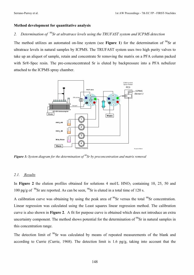
Serrano-Purroy et al. 1st AW Proceedings - 7th EC FP - FIRST-Nuclides
148
Method development for quantitative analysis
2. Determination of 90Sr at ultratrace levels using the TRUFAST system and ICPMS detection
The method utilizes an automated on-line system (see Figure 1) for the determination of 90Sr at
ultratrace levels in natural samples by ICPMS. The TRUFAST system uses two high purity valves to
take up an aliquot of sample, retain and concentrate Sr removing the matrix on a PFA column packed
with Sr®-Spec resin. The pre-conconcentrated Sr is eluted by backpressure into a PFA nebulizer
attached to the ICPMS spray chamber.
1
3
4Waste
Miliq Water
HN O3 4M
2
HN O3 4M
250 µl loop
6
54
3
21
6
5
43
21
V1
WasteWaste
SC-DX Autosamp ler
ICPMS
PC3
Element 2
C hilled cyclonicSpray chamber
ESI Micro Per ipump
Vacuum
©Laura Aldave
FA ST valve
Figure 1: System diagram for the determination of 90Sr by preconcentration and matrix removal
2.1. Results
In Figure 2 the elution profiles obtained for solutions 4 mol/L HNO3 containing 10, 25, 50 and
100 pg/g of 90Sr are reported. As can be seen, 90Sr is eluted in a total time of 120 s.
A calibration curve was obtaining by using the peak area of 90Sr versus the total 90Sr concentration.
Linear regression was calculated using the Least squares linear regression method. The calibration
curve is also shown in Figure 2. A fit for purpose curve is obtained which does not introduce an extra
uncertainty component. The method shows potential for the determination of 90Sr in natural samples in
this concentration range.
The detection limit of 90Sr was calculated by means of repeated measurements of the blank and
according to Currie (Currie, 1968). The detection limit is 1.6 pg/g, taking into account that the

1st AW Proceedings - 7th EC FP - FIRST-Nuclides Serrano-Purroy et al.
149
injection volume is 250 µl that represents an absolute amount of 0.25 pg (5 Bq) of 90Sr. The precision
of the method, based on the relative standard deviation of the peak area calculated on the basis of three
repetitions is always less than 2% in this concentration range.
However, the detection limit, accuracy and precision of 90Sr determination by ICPMS are mainly
affected by the occurrence of isobaric atomic and molecular ions at m/z = 90 (see Table 1). Moreover,
the peak tailing of the highly abundant 88Sr isotope, the concentration of natural strontium in the
sample is usually in the low µg/g range, will also disturbs the 90Sr determination.
Figure 2: Elution Chromatograms of solutions containing 10, 25, 50 and 100 pg/g of 90Sr
Table 1: Possible interferences for 90Sr and required mass resolution
Nuclide Molecular ions Required mass resolution (m/Δm) 90Sr 180W2
+ 1370 180Hf2
+ 1372 58Ni16O2
+ 2315 74Ge16O+ 10765 52Cr38Ar+ 19987 50V40Ar+ 49894 54Fe36Ar+ 155548 50Ti40Ar+ 158287 90Zr+ 29877
-4 0 0
-2 0 0
0
2 0 0
4 0 0
6 0 0
8 0 0
1 0 0 0
1 2 0 0
1 4 0 0
1 6 0 0
0 5 0 1 0 0 1 5 0 2 0 0
T im e ( s e c )
Inte
ns
ity
m
ass
90
(c
ps
)
1 0
2 5
5 0
1 0 0
S r -9 0 C a lib ra ti o n y = 3 8 2 , 6 2 x
R 2 = 0 , 9 9 9 9
0
5 0 0 0
1 0 0 0 0
1 5 0 0 0
2 0 0 0 0
2 5 0 0 0
3 0 0 0 0
3 5 0 0 0
4 0 0 0 0
4 5 0 0 0
0 2 0 4 0 6 0 8 0 1 0 0 1 2 0
S r- 9 0 p g g - 1
Pe
ak
Are
a

Serrano-Purroy et al. 1st AW Proceedings - 7th EC FP - FIRST-Nuclides
150
Artificial ground waters samples adjusted to 4 mol/L HNO3 were prepared and analysed in order to
determine the impact of possible interferences in the m/z 90 due to the presence in the water of the
elements described in Table 1. Two series of samples were prepared with and without natural
strontium, in order to study both the interferences formation and the peak tailing of 88Sr on m/z 90. The
concentration of natural strontium in the artificial ground water samples used was between 2 to
6 ng/g. However, concentrations up to 150 ng/g are possible in natural waters. Figure 3 shows that the
peak tailing of the 88Sr isotope is not disturbing the peak area of 90Sr when the concentration of Sr is
around 5 ng/g.
Figure 3: Elution Chromatograms of artificial ground waters with a concentration of 5 ng/g of natural strontium
Further studies are ongoing to determine the lowest natural Sr concentration that increases the
background signal in the peak area of 90Sr. Operating the ICPMS in medium resolution could remove
the peak tailing of 88Sr on the m/z 90, reducing, however sensitivity and increasing the detection limits
of 90Sr.
2.2. Conclusions
The TRUFAST system offers easy and efficient determination of low pg/g levels of 90Sr in natural
water. Moreover, with its automated and versatile sample uptake and introduction capabilities, reduces
sample preparation time while achieving good detection limits.
Sample 1 (Ti, V, Cr, Fe,Ge, Zr, Sr)
-100
0
100
200
300
400
500
600
700
800
900
0 20 40 60 80 100 120 140 160 180 200
Time (sec)
Inte
nsity (cps) blank
sample 1_a
sample 1_b
sample 1_c
50 pg/g

1st AW Proceedings - 7th EC FP - FIRST-Nuclides Serrano-Purroy et al.
151
Applicability of the TRUFAST system for the analysis of leachates of spent fuel in ground water has
been preliminary studied. In Table 2 are summarized the total inventory of Sr isotopes in a UO2 fuel.
With a burn-up of 40 GWd/tHM irradiated in a PWR with 4 cycles of 1 year and a cooling time of 4
years. In addition, the concentrations of some elements affecting the quantitative determination of 90Sr
and the theoretical concentration of Sr released in ground water using the IRF of Cera et al. (2000) are
also shown.
Table 2: Spent fuel total theoretical inventory and Sr concentrations released using IRF estimates3 for strontium and potential interfering elements
Nuclide µg/g fuel1 fuel dissolution2
µg/g % released 3 µg/g in leachates
90Sr 147.5 2.95 3 0.0885 88Sr 102.5 2.05 3 0.0615 90Zr 23.5 0.47 90Y 0.0375 7.5E-04
74Ge 0.015 3.0E-04 89Sr 1.35E-08 2.7E-10 3 8.1E-12
1 UO2 fuel. Burnup 40 GWd/tHM irradiated in a PWR, 4 cycles of 1 year. Cooling time 4 years.
2 Dissolution of a small sample 0.25 g. Final volume 50 ml
3 Cera et al. (2003)
Considering the analytical figures of the TRUFAST system coupled to ICPMS and the values
summarised in Table 2, it is clear that the method developed can be applied for the determination of Sr
in leachates of spent fuel in ground water. In spite of the presence of some elements interfering at m/z
90, those elements are not retained in the column and have no impact on the quantitative determination
of 90Sr. The influence of the abundance sensitivity of 88Sr will only depend of the total concentration of
natural Sr in the ground water used for the leaching experiments. Indeed, the concentration of 88Sr in
the spent fuel is of the same order of magnitude as 90Sr.

Serrano-Purroy et al. 1st AW Proceedings - 7th EC FP - FIRST-Nuclides
152
Updated Work Program
Acknowledgement
The research leading to these results has received funding from the European Union's European
Atomic Energy Community's (Euratom) Seventh Framework Programme FP7/2007-2011 under grant
agreement n° 295722 (FIRST-Nuclides project).
References
Cera, E., Merino, J., Bruno, J., Clarens, F., Giménez, J., de Pablo, J., Martínez-Esparza, A. (2003)
ENRESA 2003. AGP arcilla. Modelo de alteración del combustible nuclear gastado. Enviros.
Currie, L.A. (1968) Limits for quantitative detection and quantitative determination. Analitical
Chemistry, 40, 586.
ID Task Nam e
1 Workpackage 3 (Dissolution based release)2 D3.1 Dissolution fast/instant release studies3 Experiments with segments4 Experiments whith powder5 SEM6 Knudsen Cell7 Data treatment8 Method development for quantitative analysis9 Sr10 Se11 I12 Deliverables13 Contribution to D3.114 Contribution to D3.115 Contribution to D3.1
Qtr 1 Qtr 2 Qtr 3 Qtr 4 Qtr 1 Qtr 2 Qtr 3 Qtr 4 Qtr 1 Qtr 2 Qtr 3 Qtr 42012 2013 2014
PREVIOUS INVESTIGATIONS ON THE INSTANT RELEASE FRACTION AND GENERAL DESCRIPTION OF THE PROJECT
Alba Valls1*, Olga Riba1, Lara Duro1, Ernesto González-Robles Corrales2, Bernhard Kienzler2, Volker Metz2
1 Amphos 21 Consulting S.L. (SP) 2 Karlsruhe Institute of Technology (KIT), Institut für Nukleare Entsorgung (INE) (DE)
* Corresponding author: [email protected]
Abstract
The State-of-the-Art report on fast / instant release of activation and fission products from spent
nuclear fuel is documented by a summary of results obtained from more than 100 published
experiments. All authors refer to a definition of the fast / instant release as a fraction of the inventory
of some segregated radionuclides that may be rapidly released from the fuel and fuel assembly
materials at the time of canister breaching. In the context of safety analysis, the time of mobilization of
this fraction can be considered as an instantaneous release of some radionuclides at the containment
failure time, even when the real release occurs during few weeks, months or years.
Introduction
The Collaborative Project “Fast / Instant Release of Safety Relevant Radionuclides from Spent
Nuclear Fuel (FIRST-Nuclides)” contributes to the progress towards implementing of geological
disposal in line with the Vision Report and the Strategic Research Agenda (SRA) of the
“Implementing Geological Disposal – Technology Platform (IGD-TP)”. It falls within the 7th
Framework Programme Topic Fission-2011-1.1.1. FIRST-Nuclides project started in January 2012 and
extends over three years.
The consortium consists of 10 beneficiaries, six of which can provide with experimental facilities
having specialized installations and equipment for working with highly radioactive materials and the
other four are organizations having specific knowledge. 8 institutions havejoined the project as
associated groups and the end-user group is created by 6 members.

Valls et al. 1st AW Proceedings - 7th EC FP - FIRST-Nuclides
154
The fast / instant release fraction of radionuclides from spent fuel was investigated in the frame of
national research programmes and in previous European projects: SFS (Poinssot et al., 2005; Johnson
et al., 2004), NF-PRO (Sneyers, 2008) and MICADO (Grambow et al., 2010). There are still some
remaining open issues derived from these investigations. Actually during the MICADO project, the
following information was described as missing:
‐ Understanding of the distribution of fission gas release (FGR) and deriving more realistic
relationships between FGR and release of various fission products.
‐ Relationships between the FGR and iodine release for LWR fuel.
‐ Quantification and modelling of long-term retention of fission products on grain boundaries.
‐ Quantification of the IRF for high burn-up fuel.
‐ Chemical speciation of the relevant elements especially chemical form of 14C.
Objectives of FIRST-Nuclides
The objectives of FIRST-Nuclides are defined considering the outcomes of the previous European
projects and publications. Thus, the main objective of the present collaborative project is to improve
the understanding of the fast / instant release of radionuclides from high bur-up spent UO2 fuels from
LWRs in geological repositories.
The overall objectives of CP FIRST-Nuclides are the following:
‐ To provide for improved data for the fast/instant release fraction for high burn-up spent
UO2 fuel
‐ To establish correlations between the experimental FGR and the fast/instant release of non-
gaseous fission products, in particular 129I, 79Se and 135Cs
‐ To reduce uncertainties with respect to the fast/instant release of 129I and 14C
‐ To determine the chemical form of the relevant elements in order to evaluate retention
processes
Description of the fuel
The spent nuclear fuel of interest in the investigations of FIRST-Nuclides project is UO2 fuel with a
burn-up of around 60GWd/tHM. The selected fuels, representative for present PWRs and BWR, have
grain sizes of 10-20 µm, densities of 10.0-10.8 g/cm3 and pore sizes in the range of 5 to 80 µm.

1st AW Proceedings - 7th EC FP - FIRST-Nuclides Valls et al.
155
In the following table, the characteristics of the fuel that will be used in the FIRST-Nuclides
investigations are detailed.
Table 1. Fuel data under investigation from PWR and BWR
PWR BWR
Discharge (manufacturer)
1989 -2008 (AREVA)
2005 – 2008
(AREVA/Westinghouse)
Cladding
Material
Diameter
Thickness (mm)
Zry-4-M5
9.50 - 10.75
0.62 - 0.73
Zyr 2
9.84 - 10.2
Pellet
Enrichment(%)
Grain size (µm)
Density (g/cm3)
2.8 - 4.3
5 - 40
10.41
3.5 - 4.25 %
6 - 25
10.52
Irradiation BU (GWd/t)
Cycles
45 - 70.2
2 - 14
50.2 – 59.1
5 - 7
Linear Power Average (W/cm) 186 - 306 160 -200
FGR (%) 4.9 – 26.7 1.4 – 3.1
Structural and chemical processes in nuclear fuel
The Fast /Instant release fraction is highly affected by processes occurring in the fuel pellet during the
irradiation period and its storage, determining both the micro and macrostructure of the spent fuel rod.
Once the water reaches the spent fuel pellet, the proportion of radionuclide release will be influenced
by their location in the pellet and their chemical form.
During the irradiation period, the pellet suffers several structural changes:
‐ Macroscopic fragmentation of the pellet (in ~15 fragments) due to steep thermal gradients
developed under irradiation and because of low thermal conductivity (Ferry et al., 2006).
During irradiation the pellet temperature can be as high as 1700°C at the center of the pellet,

Valls et al. 1st AW Proceedings - 7th EC FP - FIRST-Nuclides
156
decreasing to about 400°C (regulatory guidance limit (NRC, 2003)) at its rim or outer
boundary.
‐ Decrease of pellet/cladding gap as a result of retention of fission products in the fuel matrix
that causes swelling of the fuel pellet. The volume gap for pellet is ~ 0.07 cm3 and this can be
reduced down to 0.01 cm3 with BU = 40 MWd/kgU and even disappear for BU > 47 MWd/kgU
causing pellet-clad mechanical interaction (PCMI) (Forsyth, 1997).
‐ Radial zonation of the pellet with the formation of a rim structure due to higher local BU for
average pellet BU > 40MWd/KgU with thickness from ~40 to ~250 µm (Martínez-Esparza et
al., 2009). Due to the greater amount of fission products and defects generated in the pellet rim,
a recristallization process takes place resulting in an structure with smaller grain sizes (0.1 to
0.5 µm), high porosity (15%) and smaller lattice parameter making the structure fairly resistant
to fracturing despite the high porosity (Spino and Papaioannou, 2008).
‐ Longitudinal zonation due to heterogeneous burn up along the rod presenting lower BU at the
endings of the rod (Dehaudt et al., 2000).
The chemical stability of the fission products in equilibrium with UO2±x, can be classified into four
main groups (Kleykamp, 1985):
‐ Elements soluble in the spent fuel matrix including actinides, lanthanides, rare earth elements
and elements forming soluble oxides, such as Zr, Nb, Sr.
‐ Elements forming insoluble oxides in the matrix: Rb, Cs, Ba, Zr, Nb, Mo, Te.
‐ Fission products that form metallic precipitates: Mo, Tc, Ru, Rh, Pd, Ag, Cd, In, Sn, Sb, Te.
‐ Fission gases (Kr, Xe, He) and volatile fission products (I, Br, Rb, Cs, Te)
The distribution of fission products in the spent fuel rod is determined by the radiological inventory
and by the structural changes. In terms of fast/instant release fraction, it is important to know those
radionuclides incompatible with the matrix and located in the gap and grain. Experimental
determinations show that fission gases, volatile fission products and other fission products such as Mo,
Tc and Sr are mainly in these areas. Thus, when water contacts these radionuclides they will be rapidly
released.
Investigations on fast/instant release fraction
Data obtained from different leaching experiments with spent fuel (UO2 and MOX) performed during
the last 30 years are compiled in the FIRST-Nuclides deliverable D5.1 (Kienzler et al., 2012).

1st AW Proceedings - 7th EC FP - FIRST-Nuclides Valls et al.
157
Initially, investigations on fast/instant release fraction were done with spent nuclear fuel with a
maximum burn up of around 50 GWd/tU . It has been observed that the average burn up of SNFs used
in those studies is progressively increasing with time (Figure 1). Last investigations have been
performed mainly using SNF with burn up higher than 45 GWd/tU.
Figure 1: Spent fuel burn up used in leaching experiments during the last 30 years
About 100 experiments have been compiled in the review and most of them have been done with PWR
spent fuels with burn up between 41 and 50 GWd/tU (Figure 2). There is relatively less measurements
of fast/instant release for MOX spent fuel. All these experimental data have been reported in 30
different publications. Therefore, the scarcity of data concerning high burn up fuel highlights the need
to study these fuels currently being discharged from nuclear power stations.
0
10
20
30
40
50
60
70
80
1985 1990 1995 2000 2005 2010 2015
Bu
rn U
p (
GW
d/t
HM
)
year
PWR
BWR
MOX

Valls et al. 1st AW Proceedings - 7th EC FP - FIRST-Nuclides
158
Figure 2: Number of experiments performed with different SNF and BU
Radionuclides considered in that review exercise are rubidium, caesium, strontium, iodine,
molybdenum and technetium. In the following figure (Figure 3), it is represented the amount of
measurements reported in the reviewed publications for each radionuclide taking into account if the
measurement stands for the release from the gap or from the grain boundaries (gb).
Figure 3: Number of measurements of IRF of different radionuclides from the gap and the grain
boundaries (gb)
0
5
10
15
20
25
30
35
11-20 21-30 31-40 41-50 51-60 61-70 >70
Nº
of e
xper
imen
ts
Burn up ranges (GWd/tU)
PWR
BWR
MOX
0
10
20
30
40
50
60
gap gb gap gb gap gb gap gb gap gb gap gb
Rb Cs Sr I Mo Tc
Nº
of m
easu
rem
ents
PWR
BWR
MOX

1st AW Proceedings - 7th EC FP - FIRST-Nuclides Valls et al.
159
Figure 3 shows that most of measurements are focused on the release of caesium from the gap
although several experiments have measured the instant release of strontium from both the gap and
grain boundaries. As most of the studies have been performed with PWR spent fuels, IRF data are also
mostly for this kind of fuels. Only few data of IRF are obtained from MOX spent fuels.
Conclusions
Significant improvements in the understanding of the performance of spent fuel under repository
conditions have taken place. However, most of the published data on fast/instant release fractions
relates to fuel with burn-up values below 45 GWd/tU. Over the next years the average burn-up will
increase, reaching average values of about 60 GWd/tU. For that reason, FIRST-Nuclides focus on
improving the understanding of the fast/instant release of radionuclides from high burn-up spent fuels.
Further steps consist on update the present database with data produced in the FIRST-Nuclide project
to improve the database of IRF for fission and activation products and to correlate fission gas release
measurements with other fission products considered to be low confined in the spent fuel matrix
Aknowledgements
The research leading to these results has received funding from the European Union's European
Atomic Energy Community's (Euratom) Seventh Framework Programme FP7/2007-2011 under grant
agreement n° 295722 (FIRST-Nuclides project).
References
Kienzler, B., Metz, V., González-Robles, E., Montoya, V., Valls, A., Duro L. (2012) State of the art
report. Deliverable D5.1 of the FIRST-Nuclides Project.
Dehaudt, P., Dubois, S., Maguin, J.C., Huet, F., Pelletier, M., Lacroix, B., Pasquet, B., Guérin, Y.,
Hourdequin, N., Salot, R., Desgranges, L., Delette, G., Struzik, C. (2000) Le combustible nucléaire et
son état physico-chimique à la sortie des réacteurs. CEA report, CEA-R-5923.
Ferry, C., Poinssot, C., Cappelaere, C., Desgranges, L., Jegou, C., Miserque, F., Piron, J.P., Roudil, D.,
Gras, J.M. (2006) Specific outcomes of the research on the spent fuel long-term evolution in interim
dry storage and deep geological disposal. Journal of Nuclear Materials, 352, 246-253.

Valls et al. 1st AW Proceedings - 7th EC FP - FIRST-Nuclides
160
Forsyth, R. (1997) An evaluation of results from the experimental programme performed in the
Studsvik Hot Cell Laboratory. The SKB Spent Fuel Corrosion Programme. SKB Technical Report,
TR-97-25.
Grambow, B., Bruno, J., Duro, L., Merino, J., Tamayo, A., Martin, C., Pepin, G., Schumacher, S.,
Smidt, O., Ferry, C., Jegou, C., Quiñones, J., Iglesias, E., Villagra, N.R., Nieto, J.M.,
Martínez-Esparza, A., Loida, A., Metz, V., Kienzler, B., Bracke, G., Pellegrini, D., Mathieu, G.,
Wasselin-Trupin, V., Serres, C., Wegen, D., Jonsson, M., Johnson, L., Lemmens, K., Liu, J.,
Spahiu, K., Ekeroth, E., Casas, I., d. Pablo, J., Watson, C., Robinson, P., Hodgkinson, D. (2010) Final
Report of the Project MICADO: Model uncertainty for the mechanism of dissolution od spent fuel in
nuclear waste repository.
Johnson, L., Poinssot, C., Ferry, C., Lovera, P. (2004) Estimates of the instant release fraction for UO2
and MOX fuel at t=0. A Report of the Spent Fuel Stability (SFS) Project.
Kleykamp, H. (1985) The chemical state of the fission products in oxide fuels. Journal of Nuclear
Materials, 131, 221-246.
Martínez-Esparza, A., Clarens, F., Gonzalez-Robles, E., Gimenez, F.J., Casas, I., De Pablo, J.,
Serrano, D., Wegen, D., Glatz, J.P. (2009) Effect of burn-up and high burn-up structure on spent
nuclear fuel alteration. ENRESA publicación técnica 04-2009.
NRC (2003) NRC ISG-11. Interim Staff Guidance – 11, Rev. 3.
Poinssot, C., Ferry, C., Kelm, M., Granbow, B., Martínez, A., Johnson, L., Andriambolona, Z.,
Bruno, J., Cachoir, C., Cavendon, J.M., Christensen, H., Corbel, C., Jégou, C., Lemmens, K.,
Loida, A., Lovera, P., Miserque, F., de Pablo, J., Poulesquen, A., Quiñones, J., Rondinella, V.,
Spahiu, K., Wegen, D.H. (2005) Spent fuel stability under repository conditions. Final report of the
European (SFS) project.
Sneyers, A. (2008) Understanding and Physical and Numerical Modelling of the Key Processes in the
Near Field and their Coupling for Different Host Rocks and Repository Strategies. Report of the NF-
PRO project.
Spino, J. and Papaioannou, D. (2008) Lattice contraction in the rim zone as controlled by
recrystallization: Additional evidence. Journal of Nuclear Materials, 372, 416-420.

RADIOLYTIC CORROSION OF GRAIN BOUNDARIES ONTO THE UO2 TRISO PARTICLE SURFACE
Johan Vandenborre1*, Ali Traboulsi1, Guillaume Blain1, Jacques Barbet2, Massoud Fattahi1
1 Centre National de la Recherche Sientifique (CNRS), FR 2 Cyclotron ARRONAX, FR
* Corresponding author: [email protected].
Abstract
This work is dealing with the understanding of the corrosion mechanisms at solid/solution interface
and taking into account for the 4He2+ ions irradiation effects on these mechanisms. These corrosion and 4He2+ ions radiolysis phenomena append at solid/solution interface and will be studied at a µmetric
scale by the Raman spectroscopy. Moreover, a 4He2+ ions irradiation affects a small low volume and
allows us to control the irradiated area (solution, solid or interface). For the solid, the chemical species
induced by 4He2+ ions radiolysis of water are reactive and are involved in classical corrosion
mechanisms of UO2. Moreover, we want to study the impact of the 4He2+ ions radiolysis of water
layers physisorbed into the surface onto corrosion mechanisms. That is the reason why we want to use
a local irradiation, allowed by the 4He2+ ions ion beam provided by the ARRONAX cyclotron (E =
64.7 MeV). In this work an experimental apparatus will be performed in order to characterize
solid/solution interface at µmetric scale by Raman spectroscopy under 4He2+ ions irradiation provided
by the cyclotron ARRONAX facility. The leaching experiments under irradiation will be performed
for a short time in order to study the parameters during the fast instant release step. The grain
boundaries effect will be studied by the comparison between one TRISO particles set (solids with
grain boundaries) and one TRISO particles set previously washed by one acid solution (solid without
grain boundaries). The role of H2 will be studied by the comparison between experiments under Ar or
Ar/H2 atmosphere. The dose rate range will be between 0 and 100 Gy/min by using the alpha ion beam
which let us control the dose set down into the sample. For all these experiments, measurements will
be performed by the in situ Raman spectroscopy during the irradiation in order to follow the
formation/consumption of the secondary phases formed onto the solid. The SEM will be performed in
order to characterize the grain boundaries and the secondary phases formed by the leaching/irradiation
experiments. The µGC is used to measure the PH2 into the irradiation cell to follow the

Vandenborre et al. 1st AW Proceedings - 7th EC FP - FIRST-Nuclides
162
production/consumption of this gaseous species formed by the water radiolysis and consumed by the
leaching process.
Introduction
This paper deals with the radiolytic corrosion at the UO2 surface. We study the impact of the water
radiolysis on the corrosion of the grain boundaries (GB) detected at the TRISO particle surface.
Moreover, the H2 influence onto the corrosion is studied. In more details, the conditions of these
experiments are described below:
UO2 TRISO particle natural: This work deals with the impact of the GB present at the UO2 TRISO
particle surface. We want to study the effect of the GB onto the dissolution (It has been already
shown that for ThO2 TRISO particles it is the GB which control the solubility (Vandenborre et al.,
2010). Moreover, information provided on the GB impact on the UO2 TRISO particle dissolution
can be relevant for the instant release fraction because IRF is linked to the GB phase onto the Spent
Fuel surface.
Pure water irradiated: We want to study the effect of the radiolysis, classically induced by the high
burn-up spent UO2 fuel, by an external alpha beam with a large scale of dose rate (between 0 and
100 Gy/min) in order to study the radiolytic dissolution of UO2 and its secondary phases.
Moreover, the dose rate of about 25 Gy/min corresponds to the dose rate delivered by the high
burn-up spent UO2 fuel (Grambow et al., 2010). Then, we study the solid surface dissolution by the
water radiolysis coming not from the high burn-up spent UO2 fuel but by a controlled alpha beam.
This alpha beam is controlled for the dose rate, the localisation of the 30 µm layer irradiated (in
water, onto the surface, into the GB…) in order to determine the impact of this localisation onto the
IRF. Moreover, the water radiolysis produces molecular species such as H2O2 which play a non
negligible role into the UO2 corrosion mechanism as described in the literatura (Corbel et al., 2001;
Ekeroth et al., 2006; Jégou et al., 2005; Jonsson et al., 2004; Roth and Jonsson, 2008; Suzuki et al.,
2006).
H2 effect: This is studied either induced by the water radiolysis or initially merged in the system
during the dissolution of the GB. In fact, we are able to measure the H2 produced or consumed by
the radiolysis/dissolution mechanisms and to bring information onto the reactivity of the IRF vs.
the H2, in particular at 0.02 M (=0.16 bar) corresponding to experimental conditions performed in
previous European Projects (MICADO, SFS). Moreover, the H2 quantity implied during the
dissolution of GB phases can be measured.

1st AW Proceedings - 7th EC FP - FIRST-Nuclides Vandenborre et al.
163
UO2 secondary phases characterization and evolution can be followed by in situ Raman
spectroscopy. The kinetics (from a few minutes to a few days) of formation/consumption of the
secondary phases onto the UO2 surface (with a localization at the GB by µ-Raman technique) give
data onto the formation/consumption of the instant release fractions. Raman experiments have been
successfully performed onto the UO2 surface with good results for the determination of schoepite
and studtite phases at the UO2 surface as described in the literatura (Amme et al., 2002; Biwer et
al., 1990; Carbol et al., 2005; Corbel et al., 2006; Eary and Cathles, 1983; Hanson et al., 2005; He
and Shoesmith, 2010; Sattonnay et al., 2001).
Also, this work can answer to the GB formation, depletion, evolution, reactivity vs. alpha external dose
rate, [H2] at the UO2 surface for the FIRST-Nuclides Project. Moreover, it seems relevant for the
retention process to know the secondary phases formation/depletion by the radiolytic chemical
reactions and the effect of H2 onto these phases.
Material and Methods
Samples
UO2 TRISO particles are purchased by Pr. Fachinger from FZJ and the synthesis detailed in (Brähler et
al., 2012) with, in particular, a calcination step which was performed at 1600°C for UO2
crystallization. Physico-mechanical characterization and first solubility tests have been performed
(Bros et al., 2006; Grambow et al., 2008; Titov et al., 2004).
Solid analysis is performed by SEM (scanning electron microscopy, JEOL 5800 SV with a 15 kV
voltage) and the SEM samples were covered by a Pt layer in order to improve electron conduction and
increase the picture resolution. Mechanical separation of C-layers from the UO2 spheres is performed
in order to analyse the sphere (Figure 2). Table 1 shows the properties of the UO2 spheres after the
separation step. Moreover, we have checked by EDX that the chemical composition of the sphere
surface is only UO2.

.
spheres with
M picture of UO
rties determin
hing batch e
tion in unde
aining 15 ml
GB phases
different C-la
O2 TRISO pa
ned for the U
Sphere
Diamete
Weight
Density
GeometrArea (m
experiments
ersaturated
l of a 0.1 m
s.
ayers from (B
rticle after th
UO2 sphere
er (mm)
(mg)
(g/cm3)
ric Surface m2/g)
were perfo
conditions.
ol/L HCl so
164
Brähler et al.,
he separation
UO2(
0.50
0.76
10.96
1.05E
ormed expo
A HDPE (
olution unde
1st AW
, 2012)
n step, Left: C
cr)
6
E-3
sing unirrad
(High Dens
er continuou
W Proceedings -
C-Layers, Righ
diated UO2
ity poly-eth
us stirring d
- 7th EC FP - F
ht: UO2 sphe
TRISO par
hylene) reac
during 15 da
FIRST-Nuclides
ere
rticles to an
ction vessel
ays in order
s
n
l
r

1st AW Proceedings - 7th EC FP - FIRST-Nuclides Vandenborre et al.
165
Irradiation experiments
4He2+ ions irradiations are provided by the ARRONAX cyclotron facility (Saint-Herblain, France) onto
a vertical beam-line. Experiments are carried out within the ARRONAX cyclotron at 64.7 MeV. The
intensity of the particles beam, measured on an internal Faraday cup located one meter upstream, is
maintained at 70 nA. The uncertainty of that current measurement is about 10%. Fricke dosimetry
(Fricke and Hart,1996) is used in this study in order to determine the dose deposited into the samples.
This method is based on the oxidation of Fe2+ to Fe3+ by the species produced by the water radiolysis
reactions. The concentration of ferric ions is monitored by UV-Vis measurements at 304 nm (ε = 2197
L.mol−1.cm−1, 298 K) with a spectrophotometer CARY4000 (VARIAN). These measurements are
carried out on samplings few minutes after irradiation. Super Fricke solutions are prepared by
dissolving the desired quantity of Mohr’s salt ([Fe2+] = 10 mmol/L) and NaCl (1 mmol/L) in aerated
aqueous 0.4 mol/L H2SO4 solutions. All reagents are analytical grade or equivalent. NaCl is added in
order to avoid any organic impurities. The irradiation time is a few minutes for ARRONAX
experiments. The dose rates were measured at 7500 Gy/min during irradiation in the ARRONAX
facility using the ferric ion radiolytic yield extrapolated from the literature (Costa et al., 2012) (G(Fe3+)
= 5.0 10-7 mol/J for E = 5.0 MeV and G(Fe3+) = 11.7 10-7 mol/J for E = 64.7 MeV).
At the ARRONAX cyclotron, 2 ml of solution is introduced into the irradiation cell. Due to the small
penetration depth of 4He2+ ions in water, the irradiated volume fraction is small.
In situ Raman experiments
The Raman system is purchased from the HORIBA Jobin-Yvon Company. Raman spectra are
recorded with an iHR550 spectrometer equipped with two optic fibers (diameter = 100 µm, length = 20
m). The detector is a charged coupled device (CCD) cooled by Peltier effect (203 K). Raman spectra
are excited with a laser beam at 632.8 nm emitted by a He/Ne Laser. The laser beam is weakly focused
on samples with a diameter of about 1 mm and a power of about 14 mW for a working distance of 40
mm on the sample and an acquisition time of 2 minutes. The Raman backscattering is collected
through an objective system and dispersed by 1200 groves/mm gratings to obtain 5 cm-1 spectral
resolution for Raman stokes spectra excited at 632.8 nm. The wavenumber accuracy was checked and
considered better than 0.5 cm-1.
With the Raman spectroscopic device (laser excitation and back scattering Raman) described before, in
situ experiments have been performed onto the solid samples in contact with ultrapure water. Figure 3
displays the device installed onto the 4He2+ beam line. The 4He2+ ions beam is provided by the
ARRONAX cyclotron facility with E = 64.7 MeV. The average length of the 4He2+ particle for this

Van
en
co
2 m
sol
irr
co
FigAR
Re
1.
1.1
Fir
irr
Ho
irr
Mo
Ch
the
hy
ndenborre et al
nergy is dete
de (Ziegler
ml, with a s
lution and
radiation, th
rrosion and
gure 3: LeftRRONAX faci
esults
WP1 Resu
1 Irradiat
rst test exp
radiation ce
owever, we
radiation, th
oreover, w
hromatograp
e uranium
ydrogen prod
.
ermined at
et al., 2010
solid/4He2+-
not onto th
his work can
d the direct i
ft: In situ Raility vertical b
ults
tion cell dev
periments o
ell, which p
e are devel
he solid by
with the ce
phy (See Fi
speciation
duced or co
about 2.5 m
0). Thus, w
beam distan
he solid sur
n be devote
irradiation c
aman spectrbeam line, Rig
velopment
of in situ R
permits ana
loping a n
the Raman
ell we will
igure 5). T
at the surf
onsumed by
mm in the
e could hav
nce of 5 mm
rface. So, w
ed to study
consequence
oscopic devight: Zoom at
Raman analy
alysis of th
new version
spectroscop
l be able
This comple
face, in the
the chemic
166
ultrapure w
ve checked
m, the 4He2+
with this in
the effect o
es onto the
ice experimethe UO2 TRI
ysis have b
he surface
n in order
py and the
to measure
ete analytic
e solution
cal system.
1st AW
water solutio
experiment+ ions irradi
situ experi
of the water
solid surfac
ent under 4HISO particle s
been perfor
with Rama
to analyze
solution by
e the hydr
system wil
during the
W Proceedings -
on by the S
tally that fo
ation direct
imental dev
r radiolysis
ce.
He2+ ions besurface with U
rmed with
an spectrosc
e respective
y the UV-V
rogen in th
ll be useful
irradiation
- 7th EC FP - F
SRIM 2008
or a volume
t effects occ
vice experim
species on
eam irradiatiUO2(cr) and
a first vers
copy (See
ely, during
VIS spectrop
the system
l in order to
n and to m
FIRST-Nuclides
simulation
solution of
cur onto the
ment under
to the solid
ion onto theGB phases
sion of our
Figure 4).
g the alpha
photometry.
by µ-Gas
o determine
measure the
s
n
f
e
r
d
e
r
.
a
.
s
e
e

1st AW Procee
Figure 4: Ledevice exper
Figure 5: Lspectroscopi
1.2 SEM
A pre-wash
GB. By thi
UO2 TRIS
particle su
Figure 7).
edings - 7th EC
eft: Irradiatioriment under
Left: New meic cell
M pictures
hing experi
is way, we w
O particle.
urfaces were
C FP - FIRST-N
on cell with H4He2+ ions be
easurement c
ment has be
will determ
First SEM
e analyzed
Nuclides
H2 bubbles pream irradiati
cell with UV
een perform
mine the imp
pictures an
before and
167
roduced by thion onto the A
V-VIS probe,
med in order
pact of the G
nalysis were
d after the
he water radioARRONAX fa
Right: Schem
r to study U
GB onto the
performed
pre-washin
olysis, Right:acility vertica
matic picture
UO2 TRISO
e radiolytic d
onto two s
ng step (Re
: In situ Ramaal beam line
e of the new
particle wit
dissolution
samples. Th
espectively
Vandenborre e
an spectrosco
w In situ Ram
th and with
process of
he UO2 TRI
Figure 6 a
et al.
opic
man
out
the
SO
and

Van
Fig
Fig
Fro
wa
gra
Th
GB
2.
Th
8.
typ
too
are
spe
Sie
ndenborre et al
gure 6: SEM
gure 7: SEM
om these p
ashing proc
ains, with G
he next step
B(I), from th
WP2 Res
he spectra o
The spectr
pical fundam
o low to per
e not yet ab
ectra are at
egel, 1973;
.
M pictures of th
M pictures of th
ictures, the
cess involve
GB too, occu
of this wor
he solid sin
ults
f the first te
ra have bee
mental UO
rmit determ
le to detect
800-870 cm
Sobry, 197
he UO2 TRISO
he UO2 TRISO
e grain size
es a dissolu
ur at the UO
rk is to anal
ntering, and
ests of in sit
en monitore
stretch Ram
mining of the
accurately
m-1 (Amme
73). That is
O particle BE
O particle AF
average ca
ution of the
O2 surface w
lyze, by µ-R
GB(II), from
tu Raman ex
ed versus th
man band a
e evolution
the UO2 sec
et al., 2002
the reason
168
EFORE the p
FTER the pre
an be determ
C-layers re
with a lower
Raman spec
m the pre-w
xperiment u
he irradiatio
at 443 cm-1
of the Ram
condary ph
2; Aubriet e
why, in the
1st AW
pre-washing s
e-washing step
mined abou
emained at
r grain size
ctroscopy, th
washing pro
under alpha
on time (1 t
of the UO
man spectra v
ases such as
et al., 2006;
e next step
W Proceedings -
tep
p
ut 15 5 µm
the UO2 su
average.
he surface w
cess.
irradiation
to 6 min).
O2. Neverthe
versus the i
s shoepite o
Biwer et a
of this task
- 7th EC FP - F
m. Moreov
urface. Mor
with UO2(cr
were shown
We can rec
eless, the se
irradiation t
or studite in
al., 1990; H
k, we will in
FIRST-Nuclides
ver, the pre-
reover, new
r) grain and
n in Figure
cognize the
ensitivity is
time. So we
n the Raman
oekstra and
nstall a new
s
-
w
d
e
e
s
e
n
d
w

1st AW Procee
powerful L
our experim
Figure 8: Rirradiation t
Conclusio
The future
A c
UV
Imp
LA
hig
A H
the
rad
Fin
TR
this
edings - 7th EC
LASER with
mental devi
Raman spectrtime of 6 min
ns and Fut
works plan
complete Ur
V-VIS Spect
provement
ASER (532
gher spatial
Hydrogen im
atmosphere
diolytic corr
nally, after
RISO particl
s work is th
C FP - FIRST-N
h a higher e
ice.
ra of the UO
ture work
nned for this
ranium spec
trophotome
of the Ram
nm), a hig
scale for the
mpact study
e in the irra
osion proce
the FIRST
le in order t
e first step o
Nuclides
excitation w
O2 TRISO pa
s task:
ciation durin
try and at th
man detectio
gher time re
e discrimina
y onto the r
adiation cell
ess.
-Nuclides P
to study a m
of the comp
169
wavelength o
article, Left:
ng the radio
he solid sur
on in order t
esolution fo
ation betwe
radiolytic co
l in order to
Project, the
more realisti
plete study.
of 532 nm i
For irradia
olytic corros
face by Ram
to increase
or the mech
een the UO2
orrosion by
o determine
e same syst
ic system cl
in order to i
ation times fr
sion respect
man analysi
the sensitiv
hanisms kin
(cr) grain an
the control
the part of
tem will be
lose to the S
increase the
from 1 to 5 m
tively into t
is.
vity by a gr
netics deter
and the GB a
l and the m
f H2 which o
e used into
Spent Nucle
Vandenborre e
e sensitivity
min, Right: F
the solution
reen excitat
rmination a
analysis.
measurement
occurs into
o an Irradia
ear Fuel. Th
et al.
y of
For
n by
tion
at a
t of
the
ated
hus

Vandenborre et al. 1st AW Proceedings - 7th EC FP - FIRST-Nuclides
170
Acknowledgement
We acknowledge B. Humbert and J.Y. Mevellec from the IMN laboratory for support in Raman
measurements and N. Stephant for SEM measurements. The authors acknowledge ARRONAX staff
for the efficient performing of irradiation runs onto the cyclotron facility.
The research leading to these results has received funding from the European Union's European
Atomic Energy Community's (Euratom) Seventh Framework Programme FP7/2007-2011 under grant
agreement n° 295722 (FIRST-Nuclides project).
References
Amme, M., Renker, B., Schmid, B., Feth, M.P., Bertagnolli, H., Döbelin, W. (2002) Raman
microspectrometric identification of corrosion products formed on UO2 nuclear fuel during leaching
experiments. Journal of Nuclear Materials, 306, 202-212.
Aubriet, H., Humbert, B., Perdicakis, M. (2006) Interaction of U(VI) with pyrite galena and their
mixtures a theoretical and multitechnique approach. Radiochimica Acta, 94, 657-663.
Biwer, B.M., Ebert, W.L., Bates, J.K. (1990) The Raman spectra of several uranyl-containing minerals
using a microprobe. Journal of Nuclear Materials, 175, 188-193.
Brähler, G., Hartung, M., Fachinger, J., Grosse, K.H., Seemann, R. (2012) Improvements in the
fabrication of HTR fuel elements. Nuclear Engineering and Design, 251, 239-243.
Bros, P., Mouliney, M.H., Millington, D., Sneyers, A., Fachinger, J., Vervondern, K., Roudil, D.,
Cellier, F., Abram, T.J. (2006) Raphael project- HTR specific waste characterization programme.
Proceedings HTR2006: 3rd International Topical Meeting on High Temperature Reactor Technology,
B00000162.
Carbol, P., Cobos-Sabate, J., Glatz, J.P., Ronchi, C., Rondinella, V., Wegen, D.H., Wiss, T., Loida, A.,
Metz, V., Kienzler, B., Spahiu, K., Grambow, B., Quinones, J., Martinez Esparza Valiente, A. (2005)
The effect of dissolved hydrogen on the dissolution of 233U doped UO2(s), high burn-up spent fuel and
MOX fuel, in: Co, S.N.F.a.W.M. (Ed.), Report. SFS EU-Project, Stockholm.
Corbel, C., Sattonnay, G., Guilbert, S., Garrido, F., Barthe, M.F., Jegou, C. (2006) Addition versus
radiolytic production effects of hydrogen peroxide on aqueous corrosion of UO2. Journal of Nuclear
Materials, 348, 1-17.

1st AW Proceedings - 7th EC FP - FIRST-Nuclides Vandenborre et al.
171
Corbel, C., Sattonnay, G., Lucchini, J.-F., Ardois, C., Barthe, M.-F., Huet, F., Dehaudt, P., Hickel, B.,
Jegou, C. (2001) Increase of the uranium release at an UO2/H2O interface under He2+ ion beam
irradiation. Nuclear Instruments and Methods in Physics Research Section B: Beam Interactions with
Materials and Atoms, 179, 225-229.
Costa, C., Vandenborre, J., Crumière, F., Blain, G., Essehli, R., Fattahi, M. (2012) Chemical
Dosimetry during alpha irradiation: A specific system for UV-Vis in situ measurement. American
Journal of Analytical Chemistry, 3, 6-11.
Eary, L. and Cathles, L. (1983) A kinetic model of UO2 dissolution in acid, H2O2 solutions that
includes uranium peroxide hydrate precipitation. Metallurgical and Materials Transactions B, 14, 325-
334.
Ekeroth, E., Roth, O., Jonsson, M. (2006) The relative impact of radiolysis products in radiation
induced oxidative dissolution of UO2. Journal of Nuclear Materials, 355, 38-46.
Fricke, H. and Hart, E.J. (1966) Chemical dosimetry, Radiation Dosimetry. Attix F.H. et Roesch W.C,
New York, USA.
Grambow, B., Abdelouas, A., Guittonneau, F., Vandenborre, J., Fachinger, J., von Lensa, W., Bros, P.,
Roudil, D., Perko, J., Marivoet, J., Sneyers, A., Millington, D., Cellier, F. (2008) The Backend of the
Fuel Cycle of HTR/VHTR Reactors. ASME Conference Proceedings, 649-657.
Grambow, B., Bruno, J., Duro, L., Merino, J., Tamayo, A., Martin, C., Pepin, G., Schumacher, S.,
Smidt, O., Ferry, C., Jegou, C., Quinoñes, J., Iglesias, E., Rodriguez Villagra, N., Nieto, J.M.,
Martinez-Esparza, A., Loida, A., Metz, V., Kienzler, B., Bracke, G., Pellegrini, D., Mathieu, G.,
Wasselin-Trupin, V., Serres, C., Wegen, D., Jonsson, M., Johnson, L., Lemmens, K., Liu, J.,
Spahiu, K., Ekeroth, E., Casas, I., De Pablo, J., Watson, C., Robinson, P., Hodgkinson, D. (2010) Final
Activity Report : Project MICADO Model for Uncertainty for the mechanism of dissolution of spent
fuel in nuclear waste repository in: Commission, E. (Ed.), Report.
Hanson, B., McNamara, B., Buck, E., Friese, J., Jenson, E., Krupka, K., Arey, B. (2005) Corrosion of
commercial spent nuclear fuel.1. Formation of studtite and metastudtite. Radiochimica Acta, 93, 159-
168.
He, H. and Shoesmith, D. (2010) Raman spectroscopic studies of defect structures and phase transition
in hyper-stoichiometric UO2+x. Physical Chemistry Chemical Physics, 12, 8108-8117.

Vandenborre et al. 1st AW Proceedings - 7th EC FP - FIRST-Nuclides
172
Hoekstra, H.R. and Siegel, S. (1973) The uranium trioxide-water system. Journal of Inorganic and
Nuclear Chemistry, 35, 761-779.
Hoekstra, H.R. and Siegel, S. (1973) The uranium trioxide-water system. Journal of Inorganic and
Nuclear Chemistry, 35, 761-779.
Jégou, C., Muzeau, B., Broudic, V., Peuget, S., Poulesquen, A., Roudil, D., Corbel, C. (2005) Effect of
external g irradiation on dissolution of the spent UO2 fuel matrix. Journal of Nuclear Materials, 341,
62-82.
Jonsson, M., Ekeroth, E., Roth, O. (2004) Dissolution of UO2 by one and two electron oxidants. MRS
Proceedings, 807, 77-82.
Roth, O. and Jonsson, M. (2008) Oxidation of UO2(s) in aqueous solution. Central European Journal of
Chemistry, 6, 1-14.
Sattonnay, G., Ardois, C., Corbel, C., Lucchini, J.F., Barthe, M.F., Garrido, F., Gosset, D. (2001)
-radiolysis effects on UO2 alteration in water. Journal of Nuclear Materials, 288, 11-19.
Sobry, R. (1973) Etude des "uranates" hydrates--II: Examen des proprietes vibrationnelles des uranates
hydrates de cations bivalents. Journal of Inorganic and Nuclear Chemistry, 35, 2753-2768.
Suzuki, T., Abdelouas, A., Grambow, B., Mennecart, T., Blondiaux, G. (2006) Oxidation and
dissolution rates of UO2(s) in carbonate-rich solutions under external a irradiation and initially
reducing conditions. Radiochimica Acta, 94, 567-573.
Titov, M.M., Fachinger, J., Bukaemskiy, A.A. (2004) Investigation of physico-mechanical properties
of ceramic oxide kernels for nuclear applications. Journal of Nuclear Materials, 328, 21-30.
Vandenborre, J., Grambow, B., Abdelouas, A. (2010) Discrepancies in Thorium Oxide Solubility
Values: Study of Attachment/Detachment Processes at the Solid/Solution Interface. Inorganic
Chemistry, 49, 8736-8748.
Ziegler, J.F., Ziegler, M.D., Biersack, J.P. (2010) SRIM The stopping and range of ions in matter
(2010) Nuclear Instruments and Methods in Physics Research Section B: Beam Interactions with
Materials and Atoms, 268, 1818-1823.
NON-DESTRUCTIVE ANALYSIS OF A PWR FUEL SEGMENT WITH A BURN-UP OF 50.4 GWD/THM – PART I: VISUAL EXAMINATION AND
-SCANNING
Detlef H. Wegen *, Dimitrios Papaioannou, Ramil Nasyrow, Vincenzo V. Rondinella, Jean-Paul Glatz
Joint Research Centre – Institute for Transuranium Elements (JRC-ITU), European Comission
* Corresponding author: [email protected]
Abstract
Non-destructive analysis is an essential set of analyses for validation of the fuel rod safety and
provides a valuable basis of information to plan and implement successful sampling. In a first step the
pin was inspected visually for defects. These results were complemented by -spectrometric
measurements along the fuel pin. This provided first information about the actual pellet positions in the
pin and the burn-up axial profile.
Introduction
During reactor operation a fuel rod is exposed to conditions which lead to complex alterations in the
fuel, but also in the cladding material. Heat and fission products (FP) are produced by nuclear fission
in the fuel. Due to the high temperature the cladding can creep and the generated FP cause a swelling
of the fuel (Olander, 1976; Franklin et al., 1983). New isotopes are created by neutron activation not
only in the fuel but, also in the structural materials. Hydrogen and irradiation can cause embrittlement
of the cladding (Bertolinoa et al., 2002; Daum et al., 2001). As a consequence of these solicitations
defects can be generated in the rod. The first step in analysis of spent fuel rods is the non-destructive
testing (NDT). NDT is an essential set of analyses that allows to consistently acquire reliable data
needed for validation of the safety and efficient performance of the fuel rod in pile and to provide a
valuable basis of information to plan and implement successful destructive post irradiation
examination (PIE) (Papaionnau et al., 2012) In the following, the NDT performed on a PWR (Gösgen,
Switzerland) UOX fuel segment with a burn-up of 50.4 GWd/tHM is described. Details of the
irradiation are given in (Metz et al., 2012). The examinations have been carried out in the hot cells of
JRC-ITU (Wegen et al., 2012a).

We
Vi
Th
ab
me
Pr
Th
ma
vid
is
ind
to
Ph
Th
Fig
Th
lar
egen et al.
isual Exam
he aim is t
normalities
eans of a CC
rocedure of
he fuel rod i
andrel centr
deo camera
recorded an
dicating the
each other.
hotographs
he engraved
gure 1: Macr
he optical e
rge defects,
mination
to examine
. Visual ex
CD colour c
f the examina
is put horiz
ring. With a
at a focal l
nd character
e correspond
d label of the
rograph show
examination
but helical
the state
xamination
camera insta
ation
zontally on
a known spe
length of ca
ristic zones
ding axial p
e pin segme
wing the label
n of the seg
l tracks arou
of the oute
of outer cla
alled in a ho
the metrolo
eed (2.494 m
a. 20 cm. A
of normal
position. Th
ent was chec
l of segment N
gment at the
und the pin.
174
er cladding
adding surf
ot cell.
ogy bench a
mm/s) the fu
digital vide
or abnorma
his procedur
cked by opt
N0204
e three posi
. These trac
1st AW
g surface an
face of irra
and pushed
fuel rod is tr
eo film of th
al states are
re is repeate
tical examin
itions (0°, 1
cks have be
W Proceedings -
nd to detec
diated fuel
at a defined
ranslated in
he complete
e reported in
ed along 3 a
nation (Figu
120°, 240°)
en formed b
- 7th EC FP - F
ct possible
rods is per
d depth into
front of a C
e length of t
n an examin
axes generat
ure 1).
) (Figure 2
before the a
FIRST-Nuclides
defects or
rformed by
o the fixing
CCD digital
the fuel rod
nation form
tors at 120°
) shows no
actual NDT
s
r
y
g
l
d
m
°
o
T

1st AW Procee
analysis at
longitudina
Figure 2: Mpositions. (a)
In the cen
cladding lo
sharp. The
spiral track
single pictu
Gamma S
The record
qualitative
distribution
the
an e
the
The fuel r
collimator
edings - 7th EC
t ITU. One
al scratches
Montage of 4a) as recorded
ntre of the
ooks brighte
e rod thus s
k and the sli
ures (perspe
canning
ding of the γ
ly and qua
n of -emitt
observation
estimation o
estimation
rod is tran
aperture is
C FP - FIRST-N
can assum
s were most
6 single pictd inside the h
segment, a
er than at th
eems to be
ight change
ective displa
γ-ray emissi
antitatively
ters from irr
n of volatile
of the fuel’s
of the pow
nslated duri
1.2 mm.
Nuclides
me that they
likely form
ures extractehot cell; (b) w
t the positi
he bottom an
less oxidis
e of the colo
acement and
ion spectrum
analysed.
radiated fue
e fission pro
s average bu
er experienc
ng the me
175
y origin fro
med during t
ed from threewith colour co
ion corresp
nd top end.
sed at the to
our intensity
d slightly in
m along the
The overa
el rod. This t
oduct migra
urn up and
ced by the r
asurement
om analyses
the removal
e digital videorrection.
onding to t
The bound
op and bott
y is an artef
nhomogene
e axis of a f
all purpose
technique e
ation (for in
rod during a
in front a
s performed
of the pin f
eo films show
the location
dary betwee
tom end. Th
fact resulting
ous illumin
fuel rod allo
is the det
nables:
stance Cs),
a power tran
collimator
d at the rea
from the bu
wing segment
n of the fu
en these area
he slight di
g from the m
nation).
ows fission
termination
nsient.
r and a Ge
Wegene
actor site. T
undle.
t N0204 at th
uel pellets,
as is relativ
stortion of
montage of
products to
n of the ax
e-detector;
et al.
The
hree
the
vely
the
f 46
o be
xial
the

Wegen et al. 1st AW Proceedings - 7th EC FP - FIRST-Nuclides
176
Analyses of a fixed energy range corresponding to a particular emission energy are associated with a
nuclide (for example the 661.6 keV line for 137Cs) for its qualitative and quantitative determination.
The impulses provided by the Ge-counter are analysed simultaneously
by a multi channel spectrometer,
by a rate meter provided with an analogue output proportional to the counting rate of the
detector.
Experimental Procedure
Background
Before or after each measurement, keeping exactly the same conditions, the background spectrum is
obtained and the total γ-ray intensity is counted. These are subtracted from the raw data for the rod to
calculate the real (net) pin data.
Energy Calibration
The -spectroscopy system is calibrated using 137Cs and 152Eu sources at the beginning of each
measurement series or when a measurement parameter is changed (e.g. amplification gain,
displacement of the detector, use of other collimator aperture). Three known energy lines (for instance
the 152Eu lines at 344, 778 and 1408 keV) covering the whole range are measured and put on the graph
“measured vs. reference” peak positions. If the standard deviation of the linear regression does not
exceed 2 keV, the calibration is accepted. Otherwise the calibration is repeated.
Efficiency Calibration
The efficiency calibration is carried out with a known, certified source 137Cs with homogeneous
surface activity distribution, with same form, geometry and similar chemical composition (to guarantee
identical absorption effects) as the fuel pin. The quantitative determination of the isotope is performed
after subtracting the background signal.

1st AW Proceedings - 7th EC FP - FIRST-Nuclides Wegenet al.
177
Control of measurements
Before the measurement of a fuel rod, it is necessary to control the following measuring conditions:
i) Reproducibility of the data acquisition system using a calibrated 137Cs-source (with activity
of 1.113·109 Bq).
ii) Preliminary identification of the spectrum peaks and expected intensity, so that no overflow
of the detection system takes place during the measurement. The γ-counting rate should not
exceed 15,000 counts/sec. If necessary, the counting rate can be attenuated.
The measurements cover the energy range 50 to 2200 keV.
Procedure of the measurement
The fuel rod is placed horizontally on the metrology bench and pushed at a defined depth in the fixing
mandrel centring. The fuel rod is translated during the measurement in front of the collimator (with
aperture of 1.2 mm) and the Ge-detector. The impulses generated by the detector’s Ge crystal are
treated simultaneously:
- by a multi-channel spectrometer for nuclide identification. The γ-spectrum is obtained for 150 s
time intervals and corresponds to a pin length of 5 mm.
- by a rate meter. Here it is measured the total γ-ray intensity for the complete wavelength range to
determine the axial distribution of γ-emitters. The length-relevant resolution of the measurement
depends on the collimator aperture. The analogue output of the rate meter is measured
continuously with a multi-meter; an ADC changes this output to digital and the signal is also
recorded on the hard disk of a computer. The scanning rate of the digital signal was one value per
second and the translation speed of the fuel rod 2 mm/min. The modifying factor of the rate meter
is 3000 with an analogue output range from 05 V.
For every isotope choice the axial distribution of the corresponding activity is recorded on the hard
disk of a computer.
During the measurement no changes in the cell environment that could affect the γ-background level
are permitted.
Laser length measurement is carried out in parallel with a precision of 0.01 mm and the
reproducibility of 0.05 mm.

We
Ex
Th
ve
ma
co
10
dis
can
no
the
Ne
ma
of
To
Th
co
Fig
egen et al.
xperimental
he measured
ry low. It sh
arks the star
nstant indic
00 mm. Sma
shed ends w
n migrate to
ot or only to
e fuel pellet
ear the top
arks the pos
the 60Co-ac
owards the t
he compari
rresponds to
gure 3: -sca
Results
d total -sca
hows highe
rt of the enr
cating a hom
all sharp dr
where the sp
o these loca
o a small am
ts. The peak
end the rat
sition of the
ctivity resu
top end plug
son with t
o the fuel st
an of segment
an rate (Figu
er values at
riched UO2-
mogeneous
rops in this
pecific activ
ations and i
mount occur
ks can be us
te drops at t
e second ins
ulting from
g the -rate
the optical
tack positio
t N0204 show
ure 3) in the
the position
-pellet stack
burn-up di
s region ar
vity and ther
ncrease the
rred here th
sed for posit
the position
ulation pell
the neutron
levels out.
picture of
ns and leng
wing the total
178
e region of
n of the firs
k. Along thi
istribution a
re seen at t
refore also t
e specific ac
hat was not
tion analysi
n of the sec
let. Then the
n activation
f the segm
gth.
-rate and th
1st AW
the bottom
t natural UO
is stack the
along the st
the pellet/pe
the -rate ar
ctivity at the
enough to r
is of single f
cond natura
e total -rate
n of cobalt a
ment shows
he activities of
W Proceedings -
end (plug a
O2-pellet. T137Cs activi
ack, with a
ellet interfa
re lower. Vo
e pellet/pell
reach the sp
fuel pellets.
l UO2-pelle
e increases
as compone
s that the
f 137Cs and 60
- 7th EC FP - F
and insulatio
The next sha
ity remains
a small decr
aces. The p
olatile fissio
let interface
pecific activ
.
et. The follo
because of
ent of the s
brighter ar
0Co along the
FIRST-Nuclides
on pellet) is
arp increase
remarkably
rease below
pellets have
on products
es. This has
vity level of
owing drop
an increase
teel spring.
rea exactly
e segment
s
s
e
y
w
e
s
s
f
p
e
.
y

1st AW Proceedings - 7th EC FP - FIRST-Nuclides Wegenet al.
179
A detailed analysis of the -scan rate was carried out and provided length data of the pellets after
irradiation. They are summarised in Table 1. The average pellet length (mean peak distance) was
11.3 mm for the “natural” UO2 and 11.5 mm for the “enriched” UO2.
The fuel properties are given by Metz et al. (Metz et al., 2012). The pellet length before irradiation can
be estimated from the length of the fuel stack plus the length of the isolation pellets which is given
with (439 ± 0.5) mm in the technical drawing of this fuel rod segment by the fuel manufacturer. The
length of the bottom side isolation pellet is given with 3 mm. We assumed an uncertainty of 0.5 mm.
The length of the top end isolation pellet (iso1) is adjusted so that the total length of (439 ± 0.5) mm is
obtained. The length of iso1 is (4.9 ± 0.5) mm (see Table 1) and a total fuel stack length of
(431.1 ± 0.9) mm is deduced. There are 38 pellets in the stack i.e. an average length of 11.3 mm per
pellet before irradiation. Assuming the same length for natural and enriched pellets, the enriched fuel
stack length is (408 ± 1) mm.

Wegen et al. 1st AW Proceedings - 7th EC FP - FIRST-Nuclides
180
Table 1: Determination of pellet positions of segment N0204 from -scanning data
calculated results:number of gaps found: 39number of pellets (enriched U): 36number of pellets (natural U): 2
total fuel stack length: 435.0 mmenriched U fuel stack length: 412.4 mmmean peak distance(PD) enriched U: 11.5 mmmean peak distance(PD) natural U: 11.3 mm
description position(bot end=0) distancemm mm
pin top end 538.3 2.81st data point measured at pin top end 535.5 10.0
spring 525.5 69.2iso1 (measured REFERENCE POINT) 456.3 4.9
fuel stack top end 451.4 ---natural UO2 II 440.0 11.3
enriched UO2 36 428.9 11.235 417.5 11.434 405.9 11.633 394.7 11.332 383.0 11.631 371.5 11.530 359.9 11.729 348.5 11.328 337.1 11.427 325.6 11.626 314.3 11.325 303.0 11.324 291.3 11.623 279.7 11.622 268.3 11.421 256.9 11.420 245.3 11.619 233.7 11.618 222.2 11.517 210.9 11.316 199.4 11.515 187.9 11.514 176.1 11.813 165.0 11.112 153.6 11.411 142.1 11.610 130.7 11.49 119.3 11.48 107.6 11.67 96.1 11.56 84.7 11.45 73.3 11.54 61.9 11.43 50.3 11.62 38.9 11.41 27.7 11.2
natural UO2 I 16.4 11.3fuel stack bottom end 16.4 ---

1st AW Proceedings - 7th EC FP - FIRST-Nuclides Wegenet al.
181
For PWR fuel rods with a burn-up of 50.4 GWd/tHM the expected volume swelling is in the range of
3.0 to 3.5% considering a volume swelling rate between 0.06 and 0.07 %/GWd/tHM (Guérin, 1999).
The linear fuel swelling calculated from the “enriched” UO2 fuel stack lengths before and after
irradiation (Table 1) is (1 ± 0.2)% or expressed as volume swelling (3.0 ± 0.7)%, which matches the
expectation. The natural UO2 fuel pellets remain in the range of ±0.2 mm unchanged.
Conclusions and Future work
Visual inspection of the fuel segment has shown no larger defects, but some helicoidal and
longitudinal scratches on the cladding. At the positions of the fuel pellets, a colour change is visible in
the cladding, which can be attributed to increased cladding oxidation in this area. -scanning has
shown a homogeneous burn-up along the pin with a very small decrease towards the bottom end.
Furthermore, the positions and the number of fuel pellets as well as the spring in the plenum were
determined.
Further examinations of this segment are described in (Wegen et al., 2012b).
Acknowledgement
The research leading to these results has received funding from the European Union's European
Atomic Energy Community's (Euratom) Seventh Framework Programme FP7/2007-2011 under grant
agreement n° 295722 (FIRST-Nuclides project).
References
Bertolinoa, G., Meyera, G., Perez Ipinab, J. (2002) Degradation of the mechanical properties of
Zircaloy-4 due to hydrogen embrittlement. Journal of Alloys and Compounds, 330–332, 408-413.
Daum, R.S., Majumdar, S., Bates, D.W., Motta, A.T., Koss, D.A., Billone, M.C. (2001) On the
Embrittlement of Zircaloy-4 Under RIA-Relevant Conditions. Zirconium in the Nuclear Industry:
Thirteenth International Symposium, Annecy, France, June 10-14, 2001, ASTM Special Technical
Publication 1423.
Franklin, D.G., Lucas, G.E., Bement, A.L. (1983) Creep of zirconium alloys in nuclear reactors.
ASTM special technical publication 815, Baltimore, United States.

Wegen et al. 1st AW Proceedings - 7th EC FP - FIRST-Nuclides
182
Guérin Y. (1999) In-Reactor Behaviour of Fuel Materials, in: Bailly, H., Ménessier, D., Prunier, C.
(eds.), The Nuclear Fuel of Pressurized Water Reactors and Fast Reactors. Commissariat à l'Énergie
Atomique (CEA).
Metz, V., Loida, A., González-Robles, E., Bohnert, E., Kienzler, B. (2012) Characterization of
irradiated PWR UOX fuel (50.4GWd/tHM) used for leaching experiments. 7th EC FP – FIRST-Nuclides
1st Annual Workshop Proceedings (Budapest, Hungary).
Olander, D.R. (1976) Fundamental aspects of nuclear reactor fuel elements. California Univ. Technical
Report TID-26711-P1, Berkeley, United States.
Papaioannou, D., Nasyrow, R., De Weerd, W., Bottomley, D., Rondinella, V.V. (2012) Non-
destructive examinations of irradiated fuel rods at the ITU hot cells. 2012 Hotlab conference, 24-27
September 2012, Marcoule, France.
Wegen, D.H., Papaioannou, D., Nasyrow, R., Gretter, R., de Weerd, W. (2012) Non-destructive testing
of segment N0204 of the spent fuel pin SBS1108 - Contribution to WP1 of the collaborative project
FIRST Nuclides. JRC75272, European Atomic Energy Community, Karlsruhe, Germany.
Wegen, D.H., Papaioannou, D., Nasyrow, R., Rondinella, V.V., Glatz, J.P. (2012) Non-destructive
analysis of a PWR fuel segment with a burn-up of 50.4 GWd/tHM – Part II: Defect determination. 7th
EC FP – FIRST-Nuclides 1st Annual Workshop Proceedings (Budapest, Hungary).

NON-DESTRUCTIVE ANALYSIS OF A PWR FUEL SEGMENT WITH A BURN-UP OF 50.4 GWD/THM – PART II: DEFECT DETERMINATION
Detlef H. Wegen*, Dimitrios Papaioannou, Ramil Nasyrow, Vincenzo V. Rondinella, Jean-Paul Glatz
Joint Research Centre – Institute for Transuranium Elements (JRC-ITU), European Comission
* Corresponding author: [email protected]
Abstract
The fuel segment is examined for deformations and other defects of the cladding. The oxide thickness
along the segment’s cladding is determined and it is shown that the results are in good agreement with
-scanning data. Assumptions about the temperature profile along the segment are derived.
Introduction
As pointed out elsewhere (Papaioannou et al., 2012) non-destructive testing (NDT) is an essential set
of analyses that allows to consistently acquire reliable data needed for validation of the safety and
efficient performance of the fuel rod in pile and to provide a valuable basis of information to plan and
implement successful destructive post irradiation examination (PIE). During reactor operation a fuel
rod is exposed to conditions which lead to complex alterations in the fuel, but also in the cladding
material. Heat and fission products (FP) are produced by nuclear fission in the fuel. Due to the high
temperature the cladding can creep and the generated FP cause a swelling of the fuel (Olander, 1976;
Franklin et al., 1983). Hydrogen and irradiation can cause embrittlement of the cladding (Bertolinoa et
al., 2002; Daum et al., 2001). As a consequence of these solicitations defects can be generated in the
rod. In the following, the defect determination performed on one of five segments of a segmented
PWR (Gösgen, Switzerland) UOX fuel rod with a burn-up of 50.4 GWd/tHM is described. The fuel
stack consists of 36 “enriched” UO2-pellets plus one natural UO2 pellet at top and bottom end (Wegen
et al., 2012b). Details of the irradiation are given in (Metz et al., 2012).The examinations have been
carried out in the hot cells of JRC-ITU (Wegen et al., 2012a).

Wegen et al. 1st AW Proceedings - 7th EC FP - FIRST-Nuclides
184
Profilometry
Profilometry is used to quantify the combined effects of cladding creep and fuel swelling as well as the
evaluation of rod ovalization and detection of any geometrical anomaly. The measurements are
generally made using inductive transducers following calibration on certified standards in the diameter
range of interest.
For this purpose the fuel rod is put horizontally on the metrology bench and pushed at a defined depth
into the fixing mandrel centring. The fuel rod is simultaneously translated and rotated during the
measurement and crossed through the knife edge contacts of the LVDT (linear variable differential
transformer) gauge. Following parameters are used:
Spiral rotation: 2 mm advance per rotation
Translation speed: 1000 mm per hour
Measurement precision: 3 µm
Complementary this measurement was repeated two times without rotation with the same translation
speed, the angular position of the knife edge were changed by 90 degrees to one another.
The outputs of the LVDT gauge (diameter measurement) are recorded continuously via data logger on
the connected computer and stored in electronic media. Scanning rate of the data logger was one value
per 0.25 s.
Reference standards with diameter similar to the nominal value (10.5, 10.6, 10.67, 10.70, 10.75, 10.8
and 10.85 mm) were used for the calibration of the LVDT gauge.
Laser length measurement is carried out parallel to profilometry, defect and oxide thickness
determination with a precision of 0.01 mm and the reproducibility of 0.05 mm.
Results of the examination
The measured diameter of the segment and the pellet positions are shown in Figure 1a. A creep down
of the zircaloy cladding is visible. An overview about in-reactor creep of zirconium alloys is given in
(Adamson et al., 2009). The diameter before irradiation was 10.75 mm the measured average diameter
along the fuel stack is about 10.71 mm. The mean diameter is smaller at the fuel stack ends than in the
middle of the stack (Table 1). The measured curve shows a periodical change of the diameter along
the fuel stack. The positions of the maxima of the averaged diameter curve (average of 80 data points)
match very well with the positions of the pellet/pellet interfaces obtained from -scanning. The minima
are always located at the centre of a pellet (Table 1). The difference between minimal and maximal

1st AW Proceedings - 7th EC FP - FIRST-Nuclides Wegen et al.
185
diameter is along the stack of the originally enriched UO2 pellets in the range of 13 to 20 µm. At the
position of the natural UO2 pellets the average cladding diameter decreases about 20 to 30 µm. The
profiles along the fuel stack of the average minimal and of the maximal diameter reach a maximum
250 to 350 mm from the bottom end of the segment. Here the diameter is 25 to 30 µm larger compared
to the positions of the first and last "enriched" UO2 pellets. The segment shows a slight ovalization.
Defect Determination
Eddy current examinations are carried out to detect defects present in the cladding, such as cracks,
variable thickness, corrosion, etc. Geometrical or structural heterogeneities in the cladding (crack,
corrosion, etc.) modify the eddy current path. These variations of the eddy current generated in the
examined part by the alternating field of a coil are assessed.
Experimental procedure
The fuel rod is put horizontally on a metrology bench and pushed at a defined depth in the fixing
mandrel centring. The fuel rod is translated during the measurement at a speed of 100 mm/min and
moved through an encircling coil. The standard coil frequency of 300 kHz can be preferably adjusted
depending on the depth of the detected defect.
The measurement is calibrated using standards of the same material under examination with following
pre-set defects:
1, 2, 4 holes of 1 mm diameter
internal groove 0.1 mm thick
outer groove 0.1 mm thick
swelling 0.1 mm
A calibration is made before each measurement (Figure 1a).
As can be seen are the phase shift of the X- and Y-signals (see Lissajous pattern in Figure 1a) affected
by the type of the simple standard defects while the amplitude gives information about the defect size.
The defect length can be derived from the position of the minima and maxima of the signals along the
tube length. The characterisation of “natural” defects from measured data is complex (Auld and
Moulder, 1999).

We
Th
acq
Re
Fig
Fig
me
wi
pro
of
en
(F
sum
ob
in
acc
Ou
Hi
(no
vic
egen et al.
he X- and Y
quired and
esults
gure 1: Eddy
gure 2b sh
easurement
ith the pell
ofilometry i
the encircl
nds than in
igure 1b).
mmarized i
btained from
agreement
curacy of th
uter Oxide
igh frequen
onmagnetic
cinity of a f
Y-outputs o
stored via d
y current Lissa
hows the m
no larger d
let/pellet in
investigatio
ing coil is n
the centre.
In general t
in Table 1.
m -scanning
with the pr
he ridge stan
Layer Thi
ncy eddy cu
c/ferromagn
ferromagnet
of the encir
data logger i
ajous pattern
easured edd
defects could
nterfaces. T
ons because
not maintai
In the Lis
the results f
The defect
g and profil
rofilometry
ndard of (14
ickness
urrent meas
netic, insula
tic material
cling coil (
in a comput
n of (a) standa
dy current,
d be detecte
This effect
e the relatio
ined constan
ssajous patt
fit with thos
t locations d
lometry. Th
data taking
40 ± 60) µm
surements a
ator/conduc
. The densi
186
(test signal
ter file.
ard defects an
the total -
ed. A small
reflects th
onship betw
nt (IAEA, 2
tern no oth
se obtained
determined
he measured
into accoun
m.
are suitable
ctor). The
ity of force
1st AW
equals X-
nd (b) measu
-scanning a
periodical
he small ch
ween the seg
2011). It is
er defects t
from -sca
from eddy
d diameter
nt an uncert
to determi
magnetic f
lines in the
W Proceedings -
plus Y-outp
red along the
nd the pell
change is v
hange in d
gments diam
less pronou
than a serie
anning and p
current tes
differences
tainty of ~4
ine coating/
force lines
e material v
- 7th EC FP - F
puts) are co
e fuel stack
let positions
visible which
diameter fou
meter and th
unced at the
es of ridge
profilometry
sting match
along the p
40% resultin
/substrate a
are modif
varies with t
FIRST-Nuclides
ontinuously
s. From the
h correlates
und in the
he diameter
e fuel stack
s is visible
y. They are
h with those
pin are also
ng from the
associations
fied in the
the distance
s
y
e
s
e
r
k
e
e
e
o
e
s
e
e

1st AW Proceedings - 7th EC FP - FIRST-Nuclides Wegen et al.
187
of the probe from the ferromagnetic material. This effect is used to measure the layer thickness at the
surface of fuel rods after calibration with tubes, identical in geometry and nature to the rod cladding.
Procedure of the measurement
The fuel rod is put horizontally on a metrology bench and pushed at a defined depth in the fixing
mandrel centring. The fuel rod is simultaneously translated and rotated during the measurement, which
is carried out by means of eddy current using a punctual coil unit touching the outer surface of the
cladding.
Spiral rotation: 5 mm advance per rotation
Translation speed: 20 mm per minute
Scanning rate of the data logging was one value per second.
The measuring system is calibrated using standards consisting of oxidized rods of the same material
under examination. The thickness of the standard’s oxide layer is certified by the manufacturer
(AREVA-NP).
Calibration control is carried out before each fuel rod examination. The precision of the translation is
± 0.05 mm/metre and ± 5° for the rotation. The precision of the oxide layer thickness measurement is
± 2 µm.
The outputs of the eddy current coil (outer oxide layer thickness) and axial position are continuously
acquired by a PC.
Results of the oxide thickness measurement
The measured oxide profile is given together with the total -scanning and the pictures of the segment
in Figure 2c. The oxide profile matches with the optical appearance of the pin. Thicker oxide (35 to
45 µm) is found in the light grey zone of the pin while at the darker grey zones at both ends the
thickness is below 17 µm. The maximal thickness is found on the pin between 250 and 350 mm from
the bottom end.
Temperature is beside exposure time, water chemistry, neutron flux and others a main parameter
controlling the oxide growth (Garzarolli and Garzarolli, 2012). Looking at the measured oxide profile
it can be assumed that despite a relatively constant burn-up (Wegen et al., 2012b) the temperature at
the cladding surface was lower towards both ends of the pin.

We
Fig
pel(c)
Co
ND
ex
egen et al.
gure 2: Resu
llet positions. Outer oxide
onclusions
DT has been
amined seg
lts of NDT. (a
. (b) Defect dlayer thickne
and Future
n successfu
gment N020
(a) Diameter
determinationess along seg
e work
ully carried o
04 shows no
and mean dia
n via eddy cugment N0204.
out on a PW
o major defe
188
ameter (rotat
urrent measur
WR UOX fu
fects. Ridges
1st AW
ted) along seg
rement. -sca
uel rod with
s were iden
W Proceedings -
gment N0204
n and pellet p
h a burn-up
ntified with p
- 7th EC FP - F
4 together wit
positions are
of 50.4 GW
profilometr
FIRST-Nuclides
th -scan and
e also shown.
Wd/tHM. The
ry and eddy
s
d
e
y

1st AW Proceedings - 7th EC FP - FIRST-Nuclides Wegen et al.
189
current testing at the pellet/pellet gap locations. The obtained results are in good agreement with those
obtained from -scanning (Wegen et al., 2012b).
The measured oxide thickness profile matches well with the visual nature of the outer cladding
(Wegen et al., 2012b). Despite a homogeneous burn-up it seems that the maximum temperature of the
cladding water interface was between 250 and 350 mm from the bottom end of the segment. This is
supported by slight variations measured with profilometry and eddy current in the same zone.
Table 1: Comparison of -scanning (Wegen et al., 2012a; Wegen et al., 2012b), profilometry and eddy current data
The results achieved by NDT were used for the preparation of samples for further destructive
examinations at JRC-ITU and IRF determinations at KIT-INE (Wegen et al., 2012c).
description
Y-scanning:pellet gap position ¹
profilometry:max.
diameter position ¹
mean diameter rotated (max)
calculated mean diameter difference
Y-scanning:pellet centre
position ¹
profilometry:min. diameter
position ¹mean diameter rotated (min)
eddy current defect position ¹
eddy current diameter difference
mm mm mm µm mm mm mm mm µm
fuel stack top end 451.4 451.4 10.683 ² 452.5 17 ²natural UO2 II 440.0 440.2 10.713 23 ² 445.7 445.8 10.682 ² 441.4 15 ²
enriched UO2 36 428.9 429.7 10.714 13 434.5 436.9 10.699 430.0 1435 417.5 417.9 10.718 14 423.2 423.2 10.705 418.4 1434 405.9 406.0 10.724 18 411.7 412.4 10.704 406.4 1233 394.7 395.3 10.721 14 400.3 400.5 10.707 395.5 1332 383.0 383.6 10.722 16 388.8 388.9 10.708 383.9 1631 371.5 371.7 10.724 17 377.3 377.2 10.706 371.8 1230 359.9 359.9 10.726 17 365.7 366.2 10.708 360.8 1429 348.5 349.2 10.727 17 354.2 354.4 10.710 349.1 1328 337.1 337.4 10.726 15 342.8 342.8 10.711 337.7 1027 325.6 325.6 10.724 14 331.3 331.9 10.711 326.3 1426 314.3 314.8 10.731 20 319.9 320.2 10.709 315.0 1325 303.0 303.0 10.729 18 308.6 308.5 10.714 303.2 1324 291.3 292.1 10.729 19 297.1 297.5 10.708 291.8 1323 279.7 280.4 10.729 19 285.5 285.7 10.710 280.2 1422 268.3 268.6 10.728 20 274.0 274.0 10.709 268.9 1321 256.9 256.8 10.724 16 262.6 263.2 10.706 257.0 1020 245.3 245.9 10.725 18 251.1 251.5 10.708 245.5 1319 233.7 234.2 10.723 18 239.5 239.7 10.706 233.6 1318 222.2 222.5 10.726 19 228.0 228.0 10.705 222.4 1117 210.9 210.7 10.725 17 216.6 216.8 10.710 211.1 1216 199.4 199.9 10.722 17 205.2 205.3 10.706 199.3 1015 187.9 188.1 10.721 17 193.7 193.6 10.705 188.1 914 176.1 176.2 10.719 16 182.0 182.7 10.703 176.2 1513 165.0 164.8 10.722 19 170.6 171.0 10.701 164.7 1412 153.6 153.7 10.724 19 159.3 159.3 10.703 153.2 1311 142.1 141.9 10.725 20 147.9 148.3 10.705 141.9 1410 130.7 130.0 10.721 17 136.4 136.5 10.703 130.4 129 119.3 118.7 10.717 15 125.0 125.0 10.704 118.5 138 107.6 106.6 10.720 21 113.5 113.1 10.699 106.9 147 96.1 96.6 10.717 18 101.9 102.1 10.699 95.7 126 84.7 84.4 10.713 17 90.4 90.1 10.699 84.4 165 73.3 72.4 10.713 22 79.0 78.8 10.693 72.7 154 61.9 60.5 10.708 19 67.6 67.9 10.691 60.6 163 50.3 50.0 10.703 13 56.1 55.9 10.688 49.6 122 38.9 37.7 10.705 14 44.6 44.0 10.693 38.3 91 27.7 27.7 10.703 27 ² 33.3 33.2 10.690 28.5 11 ²
natural UO2 I 16.4 15.7 10.672 ² 22.0 22.2 10.662 ² 15.9 92 ²fuel stack bottom end 16.4average value(1…36) 10.721 17 10.704 13
¹ ) Positions relative to the bottom end of the segment ² ) Not included in average value
Wegen et al. 1st AW Proceedings - 7th EC FP - FIRST-Nuclides
190
Acknowledgement
The research leading to these results has received funding from the European Union's European
Atomic Energy Community's (Euratom) Seventh Framework Programme FP7/2007-2011 under grant
agreement n° 295722 (FIRST-Nuclides project).
References
Adamson, R., Garzarolli, F., Patterson, C. (2009) In-Reactor Creep of Zirconium Alloys. Advanced
Nuclear Technology International, Skultuna, Sweden.
Auld, A. and Moulder, J.C. (1999) Review of Advances in Quantitative Eddy Current Nondestructive
Evaluation. Journal of Nondestructive Evaluation, 18, 3-36.
Bertolinoa, G., Meyera, G., Perez Ipinab, J. (2002) Degradation of the mechanical properties of
Zircaloy-4 due to hydrogen embrittlement. Journal of Alloys and Compounds, 330–332, 408–413.
Daum, R. S., Majumdar, S., W. Bates, D., Motta, A. T., Koss, D. A., Billone, M. C. (2001) On the
Embrittlement of Zircaloy-4 Under RIA-Relevant Conditions. Zirconium in the Nuclear Industry:
Thirteenth International Symposium, Annecy, France, June 10-14, 2001, ASTM Special Technical
Publication 1423.
Franklin, D.G., Lucas, G.E., Bement, A.L. (1983) Creep of zirconium alloys in nuclear reactors.
ASTM special technical publication 815, Baltimore, United States.
Garzarolli F. and Garzarolli M. (2012) PWR Zr Alloy Cladding Water Side Corrosion. Advanced
Nuclear Technology International, Mölnlycke, Sweden.
International Atomic Energy Agency (2011) Eddy Current Testing at Level 2: Manual for the Syllabi
Contained IAEA-TECDOC-628/Rev. 2 ‘Training Guidelines for Non-Destructive Testing
Techniques’.
Metz, V., Loida, A., González-Robles, E., Bohnert, E., Kienzler, B. (2012) Characterization of
irradiated PWR UOX fuel (50.4GWd/tHM) used for leaching experiments. 7th EC FP – FIRST-Nuclides
1st Annual Workshop Proceedings (Budapest, Hungary).
Olander, D.R. (1976) Fundamental aspects of nuclear reactor fuel elements. California Univ. Technical
Report TID-26711-P1, Berkeley, United States.

1st AW Proceedings - 7th EC FP - FIRST-Nuclides Wegen et al.
191
Papaioannou, D., Nasyrow, R., De Weerd, W., Bottomley, D., Rondinella, V. V. (2012) Non-
destructive examinations of irradiated fuel rods at the ITU hot cells. 2012 Hotlab conference
(Marcoule, France).
Wegen, D.H., Papaioannou, D., Nasyrow, R., Gretter, R., de Weerd, W. (2012) Non-destructive testing
of segment N0204 of the spent fuel pin SBS1108 - Contribution to WP1 of the collaborative project
FIRST Nuclides. JRC75272, European Atomic Energy Community, Karlsruhe, Germany.
Wegen, D.H., Papaioannou, D., Nasyrow, R., Rondinella, V.V., Glatz, J.-P. (2012) Non-destructive
analysis of a PWR fuel segment with a burn-up of 50.4 GWd/tHM – Part I: Visual inspection and -
scanning. 7th EC FP – FIRST-Nuclides 1st Annual Workshop Proceedings (Budapest, Hungary).
Wegen, D.H., Papaioannou, D., Gretter, R., Nasyrow, R., Rondinella, V.V., Glatz, J.-P. (2012)
Preparation of samples for IRF investigations and post irradiation examinations from 50.4 GWd/tHM
PWR fuel. 7th EC FP – FIRST-Nuclides 1st Annual Workshop Proceedings (Budapest, Hungary).


PREPARATION OF SAMPLES FOR IRF INVESTIGATIONS AND POST IRRADIATION EXAMINATIONS FROM 50.4 GWd/tHM PWR FUEL
Detlef H. Wegen*, Dimitrios Papaioannou, Ralf Gretter, Ramil Nasyrow, Vincenzo V. Rondinella, Jean-Paul Glatz
Joint Research Centre – Institute for Transuranium Elements (JRC-ITU), European Comission
* Corresponding author: [email protected]
Abstract
Samples for leaching experiments at KIT-INE have been prepared from a PWR fuel segment at the hot
cell facility of JRC-ITU. The specimens were carefully examined and some features relevant for future
investigations were identified.
Introduction
The aim was to prepare samples for leaching experiments at KIT-INE from a PWR fuel segment with
a burn-up of 50.4 GWd/tHM (Metz et al., 2012). For this purpose it was envisaged to cut whole pellets
with cladding from the segment. Of special interest were natural UO2 pellets located at the top and
bottom end of the fuel stack (first and last pellet of the fuel stack). Ideally, the segment was to be cut at
the positions of the pellet/pellet gaps formed by the pellets dishings.
Experimental procedure
The sample preparation was carried out after non-destructive testing of the pin (Wegen et al., 2012a;
Wegen et al., 2012b) in the hot cells of ITU (under nitrogen atmosphere with a typical oxygen contents
< 1%). A cutting machine equipped with a diamond wafering blade (Buehler Isomet ® series 15HC)
was used for the sectioning of the segment. The dry cutting was performed slowly without any cooling
liquid.
To find the exact positions of the pellet/pellet gaps a reference must be found. Therefore, the top end
of the segment containing the spring was cut-off approximately 10 mm before the isolation pellet at the
top end. Then the length of the top end section was measured as well as the distance from the cut to the

We
iso
ref
Th
cu
Fig
egen et al.
olation pelle
ference poin
he lengths o
utting positio
gure 1: Cuttin
et inside the
nt consideri
of the specim
ons relative
ng plan of seg
e cladding.
ing a cut wi
mens were
to the -sca
gment N0204
The positio
dth of 0.4 m
measured a
an were calc
4
194
ons for all th
mm and fixe
and a pictur
culated (Fig
1st AW
he cuttings
ed in a cuttin
e of each cu
gure 2).
W Proceedings -
needed wer
ng plan (see
ut was taken
- 7th EC FP - F
re calculate
e Figure 1)
en. From the
FIRST-Nuclides
ed from this
.
ese data the
s
s
e

1st AW Proceedings - 7th EC FP - FIRST-Nuclides Wegen et al.
195
Figure 2: -scan of segment N0204 showing pellet-pellet interfaces (blue) and cut positions (red). For illustration a sketch of the fuel segment is also included (I and II: “natural”UO2; 1, 2,…,36: enriched UO2).
Description of the specimen
The samples were designated in the sequence of their preparation (1 to 7). To distinguish between top
and bottom side the specimens were marked with a small notch in the cladding. Specimens 1 to 5 were
marked at the top side while specimen 6 and 7 were marked at the bottom side. The cut positions
relative to the -scan and the appearance of the samples are shown in Figure 3 and Figure 4.
Specimen 1
Specimen 1 was cut exactly at the pellet/pellet gap. Parts of the pellet dishing can be seen on the top
and bottom side of the sample. Referring to Figure 2 it contains the “natural” UO2 pellet II.
Specimen 2
This specimen contains the last enriched UO2 pellet 36 from the bottom end (Figure 2). The top side
shows parts of the dishing while at the bottom side the cut is tight at the dishing and it is cut-off.
0E+00
1E+06
2E+06
3E+06
4E+06
0 50 100 150 200 250 300 350 400 450 500
length / mm
cou
nt
rate
/ s
-1
Y-rate
smoothed Y-rate
pellet gap
cut position
bottom end
I 1 2 3 4 5 10 15 20 25 30 35 II

We
Sp
Th
bu
pe
Fig
egen et al.
pecimen 3
he photograp
ut at the bot
llet.
gure 3: Cut p
ph from the
ttom side th
positions in re
e top side of
he cut goes
elation to -sc
f the enriche
through th
can and phot
196
ed pellet 35
he pellet an
tographs of sa
1st AW
5 (Figure 2)
d therefore
amples 1 to 5
W Proceedings -
) shows a ne
the dishing
5
- 7th EC FP - F
early compl
g is remove
FIRST-Nuclides
lete dishing
ed from the
s
g
e

1st AW Procee
Figure 4: C
Specimen 4
Comparing
side both s
of pellet 35
edings - 7th EC
Cut positions i
4
g the cut po
showing no
5 including
C FP - FIRST-N
in relation to
ositions and
dishing lea
g the comple
Nuclides
-scan and p
d -scanning
ads to the co
ete pellet/pe
197
photographs o
g data, and
onclusion th
ellet gap an
of samples 6 a
d looking at
hat specime
nd at the bo
and 7
the photog
en 4 contain
ttom end ~
graphs of to
ns at its top
~8.3 mm of
Wegen e
op and bott
p end ~1.5 m
the top end
et al.
om
mm
d of

We
pe
fis
Sp
Sp
of
Sp
Th
tho
Th
0.4
of
giv
pe
Pr
Sp
rem
cu
ins
Fig
egen et al.
llet 34 (Fig
ssion produc
pecimen 5
pecimen 5 is
pellet 34 an
pecimen 6 an
hese specim
ose of the p
he lengths o
4 mm a tota
pellet I is
ves rise to t
llet 1. This
reparation
pecimen 1, 3
main at ITU
ut and separ
side the hot
gure 5: Load
gure 2). Th
ct inventory
s foreseen f
nd ~2 mm o
nd 7
mens are attr
pellet/pellet
of the samp
al length for
listed with
the assumpt
finding has
for transpo
3, 4 and 7
U for further
rated by alu
cell with ar
ding of sample
his sample
y in the hidd
for longitud
of pellet 32.
ributed to th
gaps obtain
ples (Figure
r both of 11
11.3 mm w
tion that the
s to be taken
ort
were forese
r examinatio
uminum pla
rgon. The tr
es in transpor
is very spe
den gap near
dinal ceramo
he “natural”
ned from -s
e 1) are 5.8
1.5 mm is o
which is 0.2
e top end o
n into accou
een to be tr
ons. For the
ates as show
ransport of
rt container (
198
ecial for le
ar the top en
mography of
” UO2 pelle
scanning bu
8 and 5.3 m
obtained. In
2 mm short
f specimen
unt planning
ransported b
e transport,
wn in Figur
samples to
(schematic)
1st AW
eaching exp
nd of specim
f the whole
et I (Figure
ut on the ph
mm respecti
Table 1 in
ter than the
6 could co
g future exa
back to KIT
the samples
re 5. Before
KIT-INE ha
W Proceedings -
periments b
men 4.
pellet 33. It
e 2). The cu
otographs n
vely. Consi
n (Wegen et
e distance b
ntain a sma
minations.
T-INE while
s were place
e closure th
as taken pla
- 7th EC FP - F
because of t
It contains a
ut position
no dishing c
idering a cu
t al., 2012a)
between the
all part of th
e specimen
ed in a steel
he capsule w
ace in July 2
FIRST-Nuclides
the volatile
also ~3 mm
match with
can be seen.
ut width of
) the length
e cuts. This
he enriched
n 2, 5 and 6
l capsule as
was purged
2012.
s
e
m
h
.
f
h
s
d
6
s
d

1st AW Proceedings - 7th EC FP - FIRST-Nuclides Wegen et al.
199
Conclusions and Future work
A reference point was successfully fixed after the cut-off of the segments top end which enables
together with the total -scan of the segment an exact determination of the cut positions. This
information together with photographs taken from the various cuts made a further characterisation of
the specimen possible and some possible; specific features to be taken into account for future
investigations were identified.
The specimen 2, 5 and 6 are foreseen for further destructive analyses e.g. ceramography etc.
Acknowledgement
The research leading to these results has received funding from the European Union's European
Atomic Energy Community's (Euratom) Seventh Framework Programme FP7/2007-2011 under grant
agreement n° 295722 (FIRST-Nuclides project).
References
Metz, V., Loida A., González-Robles, E., Bohnert, E., Kienzler, B. (2012) Characterization of
irradiated PWR UOX fuel (50.4GWd/tHM) used for leaching experiments. 7th EC FP – FIRST-Nuclides
1st Annual Workshop Proceedings (Budapest, Hungary).
Wegen, D.H., Papaioannou, D., Nasyrow, R., Rondinella, V.V., Glatz, J.-P. (2012) Non-destructive
analysis of a PWR fuel segment with a burn-up of 50.4 GWd/tHM, 7th EC FP – FIRST-Nuclides 1st
Annual Workshop Proceedings (Budapest, Hungary).
Wegen, D.H., Papaioannou, D., Nasyrow, Gretter, R., de Weerd, W. (2012) Non-destructive testing of
segment N0204 of the spent fuel pin SBS1108 - Contribution to WP1 of the collaborative project
FIRST Nuclides. JRC75272, European Atomic Energy Community, Karlsruhe, Germany.


FISSION GAS RELEASE MEASUREMENT ON ONE 50.4 GWd/tHM PWR FUEL SEGMENT
Detlef H. Wegen*, Dimitrios Papaioannou, Wim De Weerd, Vincenzo V. Rondinella, Jean-Paul Glatz
Joint Research Centre – Institute for Transuranium Elements (JRC-ITU), European Comission
* Corresponding author: [email protected]
Abstract
Fission gas release measurements have been performed on one of five short UOX fuel segments of a
segmented PWR fuel rod with a burn-up of 50.4 GWd/tHM at the hot cell facilities of JRC-ITU. The
free volume and the normal fission gas volume were determined while the isotopic composition could
not be obtained.
Introduction
The determination of fission gas release to the plenum of a fuel pin as well as the isotopic composition
of the gas and the measurement of the free volume of the fuel rod is important to evaluate the overall
fuel rod behaviour during irradiation. Furthermore, it plays an important role in the context of final
waste storage to estimate the instant release fraction (IRF) of volatile fission products at times when
the waste after a canister failure comes in contact with groundwater (Carbol et al., 2012).
The measurement device in operation developed at JRC-ITU consists of two main parts: i) the
puncturing device installed inside a hot cell consisting of a drilling machine, a system of standard
volumes and calibrated pressure gauges (Figure 1); ii) a quadrupole mass spectrometer installed
outside the hot cell (Figure 2).
Experimental
The measurement procedure is as described in (Hoffmann et al., 2005) and in (Papaioannou et al.,
2012).
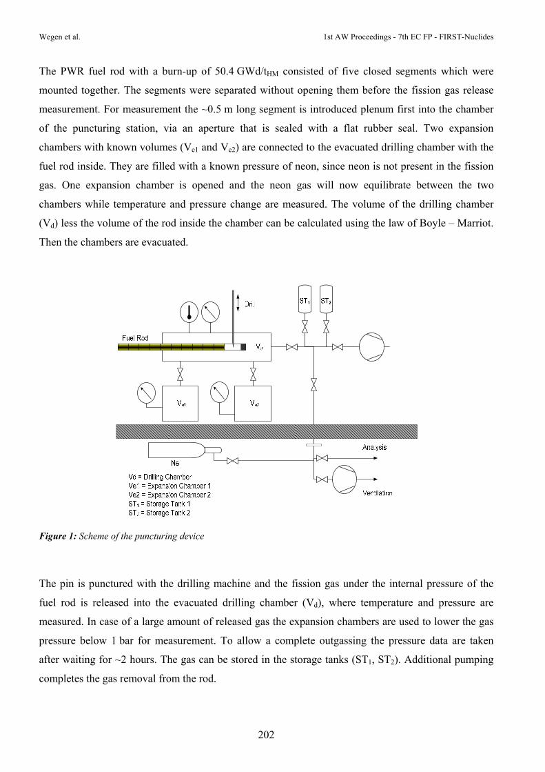
Wegen et al. 1st AW Proceedings - 7th EC FP - FIRST-Nuclides
202
The PWR fuel rod with a burn-up of 50.4 GWd/tHM consisted of five closed segments which were
mounted together. The segments were separated without opening them before the fission gas release
measurement. For measurement the ~0.5 m long segment is introduced plenum first into the chamber
of the puncturing station, via an aperture that is sealed with a flat rubber seal. Two expansion
chambers with known volumes (Ve1 and Ve2) are connected to the evacuated drilling chamber with the
fuel rod inside. They are filled with a known pressure of neon, since neon is not present in the fission
gas. One expansion chamber is opened and the neon gas will now equilibrate between the two
chambers while temperature and pressure change are measured. The volume of the drilling chamber
(Vd) less the volume of the rod inside the chamber can be calculated using the law of Boyle – Marriot.
Then the chambers are evacuated.
Figure 1: Scheme of the puncturing device
The pin is punctured with the drilling machine and the fission gas under the internal pressure of the
fuel rod is released into the evacuated drilling chamber (Vd), where temperature and pressure are
measured. In case of a large amount of released gas the expansion chambers are used to lower the gas
pressure below 1 bar for measurement. To allow a complete outgassing the pressure data are taken
after waiting for ~2 hours. The gas can be stored in the storage tanks (ST1, ST2). Additional pumping
completes the gas removal from the rod.

1st AW Procee
The mass
concentrati
fission gas
purging. Th
fed into the
gas.
To determ
volumes (V
The neon
punctured
volume the
For the fiss
Gösgen (M
For this pu
be attached
without pro
Figure 2: Si
edings - 7th EC
spectromet
ion level as
s, it is used
hen the line
e quadrupol
mine the fre
Ve1, Ve2) to
will now e
rod. By me
e free gas vo
sion gas rel
Metz et al.,
urpose a gas
d to the sam
oblems.
implified sche
C FP - FIRST-N
ter is calibr
s close as p
as purge ga
es are evacu
le mass spe
e gas volum
o the purged
equilibrate b
eans of the p
olume of th
ease determ
2012) it wa
s sampling
mpling outle
eme of the fis
Nuclides
rated using
possible to
as to clean t
uated to app
ctrometer in
me of the r
d and evacu
between the
pressure dro
e rod is calc
mination of t
as foreseen
outlet was
et to collect
sion gas samp
203
g gas stand
the expect
the lines aft
proximately
n order to d
rod, neon i
uated drillin
e two cham
op of the ch
culated.
the PWR fu
to share th
installed ou
a gas samp
mpling station
ards with k
ted concentr
fter calibrati
3 mbar and
determine th
is released
ng chamber
mbers and a
hamber and
uel rod SBS
he gas samp
utside the h
ple. The mod
installed out
known com
ration. Sinc
ion in three
d the gas fro
he isotopic c
from the p
r with the p
also fill the
the prior m
S 1108, Segm
ple between
ot cell (Fig
dified syste
tside the hot c
mposition o
ce neon is
cycles of e
om the drilli
composition
pre-pressuriz
punctured ro
e free gas v
measured dri
ment N 020
n KIT-INE
gure 2). A g
em was teste
cell
Wegen e
f Xe, Kr a
not present
evacuation a
ing chambe
n of the fiss
zed expans
od still insi
volume of
illing chamb
04 irradiated
and JRC-IT
gas mouse c
ed and work
et al.
at a
t in
and
r is
ion
ion
ide.
the
ber
d at
TU.
can
ked

Wegen et al. 1st AW Proceedings - 7th EC FP - FIRST-Nuclides
204
Results
The measurement was carried out in the second half of May 2012. The results of the pressure and
volume determinations are summarized in Table 1 and in (Wegen et al., 2012). Because of the short
length of the segment (~0.5 m) the fission gas volume was small compared to a normal LWR rod with
a length of ~4 m. From the totally available 147 cm3 fission gas three batches were sampled in gas
mice before composition determination and transferred to KIT-INE for further analysis.
Table 1: Results of the fission gas release measurements at ITU. The volumes given are referred to a temperature of To = 273.15 K and a pressure of po = 1013.25 mbar.
At JRC-ITU the composition of the remaining gas was measured by mass spectrometry. Careful data
analysis and cross checking of the results showed that the results obtained were not significant. The
reasons for this are most probably technical problems triggered by a too small amount of available
fission gas.
More reliable results concerning the gas composition should be obtainable by mass spectrometry
analysis of the gas sample sent to KIT-INE (Bohnert et al., 2012).
Conclusions
The fission gas volume and the free volume of the fuel segment investigated were determined
successfully. The sampled gas was shared between KIT-INE and JRC-ITU. Because the amount of
available gas was too small the determination of the isotopic composition was not possible using the
setup installed in ITU.
Date: 22.5.12 Temperature: 22 °C
Operator: W.W. Leak Rate: 3.02E-03 mbar·L·s-1
Reactor: KKGg Pin No.: 07-63/07-47 SBS 1108//G09/G09
IRRADIATION DATA:
Average Burn-up: 50.4 GWd/t(U)
RESULTS:
Free volume of the pin: 4.2 cm3
Pressure before puncturing: 37.2 bar
Normal gas volume: 142 cm3

1st AW Proceedings - 7th EC FP - FIRST-Nuclides Wegen et al.
205
Acknowledgement
The research leading to these results has received funding from the European Union's European
Atomic Energy Community's (Euratom) Seventh Framework Programme FP7/2007-2011 under grant
agreement n° 295722 (FIRST-Nuclides project).
References
Bohnert, E., González-Robles, E., Herm, M., Kienzler, B., Lagos, M., Metz, V. (2012) Determination
of Gaseous Fission and Activation Products Released from 50.4 GWd/t PWR Fuel. 7th EC FP –
FIRST-Nuclides 1st Annual Workshop Proceedings (Budapest, Hungary).
Carbol, P., Wegen, D.H., Wiss, T., Fors, P. (2012) Spent Fuel as Waste Material. R.J.M. Konings,
(ed.) Comprehensive Nuclear Materials, 5, 389-420.
Hoffmann, P.B., de Weerd, W., Toscano, E.H. (2005) Post-irradiation examination of high burnup
BWR fuel rods: Techniques and results, Jahrestagung Kerntechnik 2005, 10-12 May 2005, Nürnberg,
Germany.
Metz, V., Loida, A., González-Robles, E., Bohnert, E., Kienzler, B. (2012) Characterization of
irradiated PWR UOX fuel (50.4GWd/tHM) used for leaching experiments, 7th EC FP – FIRST-Nuclides
1st Annual Workshop Proceedings (Budapest, Hungary).
Papaioannou, D., Nasyrow, R., De Weerd, W., Bottomley, D., Rondinella, V. V. (2012) Non-
destructive examinations of irradiated fuel rods at the ITU hot cells, 2012 Hotlab conference
(Marcoule, France).
Wegen, D.H., Papaioannou, D., Nasyrow, R., Gretter, R., de Weerd, W. (2012) Non-destructive testing
of segment N0204 of the spent fuel pin SBS1108 - Contribution to WP1 of the collaborative project
FIRST Nuclides. JRC75272, European Atomic Energy Community, Karlsruhe, Germany.


POSTERS

POSTERS
208
1st AWW Proceedings -- 7th EC FP - FFIRST-Nuclidess

1st AW Proceeedings - 7th ECC FP - FIRST-NNuclides
209
POSTEERS


TOPICAL SESSIONS


THERMODYNAMICS OF FISSION PRODUCTS IN SPENT NUCLEAR FUEL3
Ondřej Beneš
Joint Research Centre – Institute for Transuranium Elements (JRC-ITU), European Comission
The behaviour of spent nuclear fuel (SNF) as well as the fast release of safety relevant radionuclides
are controlled by various phases formed under the conditions during the use of the fuel in a nuclear
power plant. Important parameters are (i) the temperature, (ii) the composition of the fuel and (iii) the
oxygen potential of oxide-fuel. In an ideal case, the thermodynamics should be able to describe the
behaviour of SNF. As basis for understanding the behaviour of fission products (FP) in the fuel, the
phase diagrams of the binary systems “U-O” and “U-Pu” as well as the ternary system “U-Pu-O” were
discussed. For fresh nuclear fuel (U-Pu-O system), the phase diagrams are well elaborated, but that is
not case for the complex system SNF, in which all FPs are present. A full description of phase
diagrams including all FPs of interest is not available. Presently, the primary interest is on the volatile
FPs and their solid/gas equilibrium.
Thermodynamics provide information on the chemical state of FPs which influences the physical
properties of the fuel itself, such as thermal conductivity, melting temperature, deformations, and
swelling as well as determine the physico-chemical properties of the FP mainly their volatility and
solubility in water. Temperature and the oxygen potential of the fuel (determined by O/M ration in
UO2) are the key parameters with respect to thermodynamics. However, kinetics especially diffusion
processes of the FPs is another driving force for the phase formation. As example, the Cs – I system
was discussed in details and thermodynamic considerations were compared to Knudsen cell
experiments. According to thermodynamics, CsI is the stable compound at T = 900K, however, the
temperature varies by more than 500 K over the radius of a fuel pin in a nuclear power plant.
The chemical state of a series of FPs was given including metal precipitates, molybdenum, zirconium,
and iodine. The stable form of iodine is CsI, but due to kinetic reasons I or I2 can also be formed.
Reaction sites where CsI can be formed are bubbles and microstructures in the UO2 matrix. At low
burn-up (<5 GWd/t), such structures are not available, therefore the formation of CsI is not likely. The
generation of other iodides is also possible such ZrI4 or MoI4. Due to the excess of caesium in
comparison to iodine (Cs/I ~ 10), it is expected that almost all iodine will be in the form of CsI located
at grain boundaries, cracks and/or fission gas bubbles. Remaining caesium reacts with zirconium,
3 Abstract summarized by the coordination team

Beneš 1st AW Proceedings - 7th EC FP - FIRST-Nuclides
214
forming Cs2MoO4 as stable Cs phase. Cs does not react with UO2 forming uranate phases, such as
Cs2UO4, instead it reacts with ZrO2: 2 Cs (s) + ZrO2(s) + 0.5 O2(g) Cs2ZrO3(s).
This compound is in equilibrium with Cs2MoO4. Neither of these compounds is volatile. At oxygen
potentials below -440 kJ/mol, tellurium reacts with Cs molybdate forming Cs2Te(s) and free oxygen
according to Te(l) + Cs2MoO4(s) Cs2Te(s) + O2(g) + MoO2(s).
Rare earth elements are highly soluble in the solid UO2 matrix, forming UO2-R2O3 solid solutions.
Significant deformation of the UO2 crystals are not observed by the presence of R2O3. Both FPs Ba
and Sr are present in an oxidized form reacting either with UO2 or ZrO2 to give BaZrO3 and SrZrO3
which is found as a solid solution (Ba,Sr)ZrO3. Above 1000 K, BaUO3 is formed, but no SrUO3. Sr is
found in so called “grey phase“ consisting of (Ba,Sr)(U,Pu,Zr)O3 solid solution. At oxygen potentials
above 400 kJ/mol and in the presence of MoO2, BaMoO4 becomes stable.

CHARACTERISTICS OF SPENT NUCLEAR FUEL
Christoph Gebhardt and Wolfgang Goll
AREVA FUEL Business Unit (FDM-G), FR
The talk provided information on management of UO2 fuel for Pressurized Water Reactor (PWR) and
Boiling Water Reactor (BWR) fuels, including neutron‐physical aspects which are basis of an optimal
usage of the fuel. The distribution of spent nuclear fuel in relation to their burn‐up ‐ as reported by the
utilities ‐ was presented, as well as the histories of the bundle power for some reactors. These bundle
powers depend on the reactor operation and on the number of cycles. The radial and axial burn‐up
distribution was demonstrated for a modern 18x18 fuel assembly with 60 MWd/kgU average burn‐up.
In this context the pellet centerline temperatures as a function of the rod’s linear heat rate and the
temperature of the coolant were discussed for BWR and PWR fuel elements.
The fuel pellet manufacturing processes and typical inventories of additives and impurities of fuel
pellets were explained. Special attention was given to the typical Al (~100 ppm) and Cr (~800 ppm)
contents in the fuel pellets. In the following discussion it was questioned whether trivalent Al and Cr
might interact with trivalent actinides under repository conditions. With respect to the cladding, typical
PWR and BWR fuel rod cladding materials were described and their irradiation induced alterations in
regard to corrosion and hydrogen uptake was quantified. It was shown that an increase in burn‐up
causes both an increase in hydrogen incorporation and an extension of the Zircaloy oxide thickness.
The lecture included the corrosion relevant compositions of PWR and BWR cladding alloys and the
behaviour of modern cladding materials such as M5, where the component Sn is replaced by Nb which
shows significantly lower corrosion rates under the temperature regime of reactors. In this material,
also the hydrogen uptake is lower.
Furthermore, defect mechanisms under interim and final storage were discussed. During handling,
transport, discharge operations and interim storage it is required that systematic failures of fuel rods
will not occur and the mechanical integrity of the fuel assembly structure is retained. Systematic
cladding failures can be avoided by limiting stress and strain of the material. If defective fuel rods are
present, these rods need special treatment and/or confinement.

Gebhardt et al. 1st AW Proceedings - 7th EC FP - FIRST-Nuclides
216
Under disposal conditions, temperatures and, hence, stresses are further reduced excluding systematic
failure. Defects under thermal creep conditions are limited to small cracks leading to a prompt loss of
rod inner pressure. In the long term, effects from He production, delayed hydride cracking and other
post‐irradiation processe may become relevant.

IMPACT OF THE IRRADIATION HISTORY OF NUCLEAR FUELS ON THE CORROSION BEHAVIOUR IN A DISPOSAL ENVIRONMENT
Dani Serrano-Purroy and Jean-Paul Glatz
Joint Research Centre – Institute for Transuranium Elements (JRC-ITU), European Comission
Nuclear fuel becomes a very heterogeneous material during irradiation both from a structural and from
a compositional point of view. The degree of heterogeneity due essentially to a very high temperature
gradient (e.g. 1000°C in the pellet centre , 500°C at the fuel periphery corresponding to a distance of
app. 5 mm) increases with burn-up and linear power. For MOX produced by a master mix blend
technique (MIMAS), Pu-rich (25% Pu) agglomerates up to150 µm diameter are present already before
irradiation.
Also the composition, i.e. the content of higher actinides formed by neutron capture and the fission
product content increases with burn-up. Furthermore the fission events are taking place more and more
at the fuel pellet periphery, where Pu formed by neutron capture of 238U takes over from 235U as fissile
material. Higher actinides, essentially Pu, Np, Am and Cm are produced in always higher amounts as
the burn-up increases. For MOX where Pu is the fissile material from the beginning the built-up of
higher actinides is even more significant (almost 10 times more compared to UO2 at the same burn-
up). Depending on their thermophysical properties, the fission products migrate in the thermal gradient
to the fuel grain boundaries or for the most volatile elements like fission gases Xe, Kr but also Cs or I
to the fuel periphery and depending on the irradiation conditions a more or less important part of these
elements are even found in the fuel pin plenum after irradiation.
Detailed post irradiation examination using optical, scanning or transmission electron microscopy,
electron microprobe analysis, Knudsen cell, gamma scanning but also chemical analysis, allow to
characterise the fuel changes during irradiation. Among others the development of thermal cracks,
porosity, radiation defects due to strong radiation are identified. The grain subdivision at the fuel
pellet periphery (RIM effect) or the precipitation of 5 metal (Ru, Rh, Pd, Mo, Tc) particles' at the grain
boundaries is being observed.
It was shown that the irradiation history and here first of all the linear power reached in the fuel, is the
dominating cause of the above mentioned phenomena, e.g. fuels run at high linear power, even if the
burn-up is moderate, show very high release of volatiles to the fuel rod plenum.

Serrano-Purroy et al. 1st AW Proceedings - 7th EC FP - FIRST-Nuclides
218
It is obvious that all these modification affect the fuel corrosion behaviour in a repository in the
situation of failure of all retention barriers, i.e. when the fuel gets in contact with ground water.
Especially the instant release fraction, i.e. the release of highly soluble elements (Cs. I, Se, Te, Rb…)
with a large part of the inventory transported to the fuel periphery during irradiation, can considerably
depend on the fuel irradiation history.

THE POTENTIAL OF THE TRANSURANUS CODE FOR SOURCE TERM CALCULATION OF SPENT NUCLEAR FUEL
Paul Van Uffelen
Joint Research Centre – Institute for Transuranium Elements (JRC-ITU), European Comission
TRANSURANUS is a computer program for the thermal and mechanical analysis of fuel rods during
various operating conditions, generally referred to as a fuel performance code. Emphasis lies on
assessing both the temperature and the stress levels in a fuel pin, since they are linked to the crucial
safety criteria, set by the regulators, to be fulfilled during the entire in-pile lifetime of the fuel rod. The
code has been transmitted to various industrial partners, research organisations, as well as, safety
authorities and universities across Europe. The corresponding know-how is also being transferred via
international summer schools, training courses and workshops organised by JRC-ITU, as well as,
advanced courses at several universities within the European Union.
The TRANSURANUS code solves the equations for the radial heat transfer, the radial displacement
along with the stress distribution in both the fuel and the surrounding cladding, and describes the
fission product behaviour as a function of time. The equations embody the following phenomena:
Thermal performance: heat conduction, radiation and convection;
Mechanical performance: elastic deformation, creep, densification, thermal expansion, pellet
cracking and relocation, swelling;
Actinide behaviour: depletion and build-up of main U, Np, Pu, Am and Cm nuclides, impact on
the radial power profile;
Fission product behaviour of Xe, Kr, Cs, Nd, and He
The lecture will treat the main equations and the associated limitations with the focus on fission
product behaviour. More precisely, the following mechanisms will be considered in greater detail:
recoil, knock-out & sputtering, lattice diffusion, trapping, irradiation re-solution, thermal re-solution,
thermal diffusion, grain boundary diffusion, grain boundary sweeping, bubble migration, bubble
interconnection and sublimation or vaporisation. For each of these mechanisms, a brief description will
be provided along with a discussion of its domain of application. Following a description of the main
relevant mechanisms, the various models for fission gas release and swelling in the open literature will
be reviewed, including those which have been implemented in the TRANSURANUS code.

Van Uffelen 1st AW Proceedings - 7th EC FP - FIRST-Nuclides
220
Once the behaviour of the fuel rod is computed in each axial slice, they are coupled in the code via
balance equations for stresses and gas composition. For this reason standard fuel performance codes
are so-called 1.5 D codes, while 2D (3D) codes solve the equations (for heat removal and stresses)
simultaneously in two (three) dimensions.
The TRANSURANUS code has a clearly defined mechanical–mathematical framework, in which new
material properties and models can easily be incorporated. The code has a comprehensive material data
bank for oxide, mixed oxide, carbide and nitride fuels, Zircaloy and steel claddings and several
different coolants (water, sodium, potassium, lead, bismuth). Besides its flexibility for fuel rod design,
the code can deal with a wide range of different situations, with time scales from milliseconds to years.
Hence, TRANSURANUS can be used as a single code system for simulating both long-term
irradiations under normal operating conditions as well as transient tests. In this way the code can be
applied to a fuel pin segment from a commercial fuel rod that is re-irradiated in an experimental
reactor after instrumentation, like in the Halden Boiling Water Reactor. The 'restart' mode allows
simulating re-fabricated fuel rods, i.e. where the fill gas has been completely changed.
TRANSURANUS also allows simulating cladding tubes without fuel submitted to heating burst tests
in out-of-pile conditions. Finally, thanks to the restart option, the code has also occasionally been used
to simulate storage conditions. Nevertheless, this requires the appropriate material properties for such
conditions to be implemented, such as the expression for cladding creep in the temperature range of
interest.
Once the main models of the code have been presented, the verification and validation procedure of
the code will be outlined and illustrated. More precisely, the verification of models in a stand-alone
environment on the basis of either analytical or more complex and accurate numerical solutions
obtained by means of more-dimensional finite element solutions will be presented. In a second step,
the validation relies on experimental data, when available, such as, the local thermal conductivity of
nuclear fuel as a function of burn-up and temperature, the radial concentrations of fission products
measured after irradiation by means of electron probe micro-analysis or secondary ion mass
spectrometry, or cladding tube diameters after burst tests that correspond to conditions during a loss of
coolants accident. The final step of the code validation consists of a comparison against integral
experimental data, as well as a comparison with other code predictions. Excellent opportunities for
benchmark exercises like FUMEX-III are organised by the IAEA, or the LOCA benchmark organised
by the OECD-NEA.

1st AW Proceedings - 7th EC FP - FIRST-Nuclides Van Uffelen
221
The widely used mechanistic approach described above leads, in many cases, to discrepancies between
theoretical predictions and experimental evidence because some of the physical processes are of
stochastic nature., The mechanistic approach has therefore been augmented by statistical analyses that
apply basic probabilistic methods, such as the Monte Carlo method, in order to better understand
uncertainties and their consequences.
A combination of a restart and Monte Carlo statistics may be used to perform a probabilistic analysis
only after the restart. This option may thus also be helpful for the analysis a long base irradiation of a
fuel rod in a reactor followed by the simulation of the same rod during a transient or long term storage.


PRESENTATIONS BY ASSOCIATED GROUPS


LONG TERM BEHAVIOUR OF SPENT AGR FUEL IN REPOSITORY
David Hambley
Spent Fuel Management and Disposal, Fuel Cycle Solutions, National Nuclear Laboratory (NNL), UK
Background
The majority of nuclear power production in the UK is from Advanced Gas-Cooled Reactors. The
spent fuel from these reactors is currently being reprocessed, however the reprocessing facility is due
to close within the next 10 years and it is anticipated that future arisings will be sent to a geological
disposal facility towards the end of this century. The siting and development of a geological disposal
facility is under way and incorporates spent fuel.
AGR Fuel
The AGR and its fuel are unique to the UK. Whilst the fuel in both AGR and most LWRs is uranium
dioxide, there are many significant differences:
AGR fuel pellets are annual, whilst in LWR systems the pellets are solid,
the fuel cladding is stainless steel (20/25/Nb), whereas most power reactor system use zirconium
alloy cladding;
the cladding temperature in operation is higher, up to 825°C, but peak fuel temperatures and radial
temperature gradients are similar;
differences in the neutron spectrum leads to a lower rim/average Pu profile.
the coolant in AGRs is carbon dioxide, which produces some deposition of carbon on the fuel pin
surfaces, this is substantially different from the ‘crud’ formed on LWR fuel pins and can lead to
much higher fission gas release in a small proportion of the fuel pins.
The peak fuel element burn-up is currently around 40 GWd/teU, which is somewhat lower than many
LWRs and is unlikely to exceed 45 GWd/teU.
Current Programme
The UK Nuclear Decommissioning Agency are interested in investigating whether the differences
between AGR and LWR fuel result is significantly difference fuel behaviour under repository

Hambley 1st AW Proceedings - 7th EC FP - FIRST-Nuclides
226
conditions. This programme is being conducted via 6 PhDs at Cambridge University, Lancaster
University and Imperial College.
Inactive simulants of active FPs have been incorporated into SIMfuel replicating species at 100 years
cooling, which have been charaterised with optical and SEM microscopy and X-ray diffraction. All
key phases have been identified and anlyses are continuing. This will be followed by annealing at
300˚C and 825˚C to compare effects on FP distrobutions with LWR fuels.
Modelling of the fission product distribution in AGR UO2 at elevated temperatures is currently under
way to be followed by modelling of radiation damage in U secondary mineral phases and solubility of
FPs.
Work is underway to induce radiation damage in SIMfuel samples and examine the effects of the
damage on dissolution behaviour.
Two separate investigations are underway into UO2 corrosion. They are investigating the effects of
cladding and cladding corrosion products on dissolution and whether a fenton cycle could be initiated.
Other aspects include investigation of the formation and stability of UO2 secondary phases on UO2 and
their impact on corrosion.
Finally the radiation stability of secondary phases (particularly for alpha recoil damage) will be
examined using XRD and 17O MASNMR, this will be followed by examination of the actinide
substitution process: i.e. solid solubility and possible partitioning of Np or Pu.

SOURCE TERM MODELLING FOR SPENT FUEL ELEMENTS IN PERFORMANCE ASSESSMENT
Artur Meleshyn1, Jens Wolf1, Ulrich Noseck1, Guido Bracke2
Gesellschaft für Anlagen- und Reaktorsicherheit (GRS) mbH, DE 1 Brunswick, Germany
2 Cologne, Germany
Integrated performance assessment models of deep geological repositories for high-level radioactive
waste (HLW) and spent nuclear fuel include a source term which describes the release of radionuclides
from HLW or spent fuel elements (SFE) from failed containers into the contacting aqueous solution.
The chemical release rate depends on time (kinetics), solubility of radionuclides in the solution
(thermodynamics), and temperature. The general source term can be represented in the form:
XiXci rtAtntA )()()( , , where nc(t) is the fraction of the failed containers at time t, AX.i(t) is the
inventory of radionuclide i in component X at time t, and rX is the chemical release rate for component
X. GRS currently utilizes two databases to model the source term with respect to the definition of the
components and their characteristic release rates and, correspondingly, the relative inventories of
radionuclides in the components.
In the project Scientific Basis for the Assessment of the Long-Term Safety of Repositories, four SFE-
components are currently defined: Zircaloy, structural parts, fuel matrix, and instant release fraction
(IRF) with the characteristic isotope-independent release rates of 0.0036, 0.002, 1.0·10-6, and 1.0 a−1,
respectively. In comparison to the previously used SPA source term with only three SFE components
(Lührmann et al., 2012) this source term results in significant changes in the calculated effective dose
rate. The degree of these changes indicates also a strong dependence on the applied solubility limits,
which were assumed for the geochemical environment of a repository, as well as on relative
inventories of dose-determining radionuclides 36Cl, 129I, 135Cs, 226Ra, 233U, and 237Np in the
components of SFE.
Only three SFE-components were defined in the Preliminary Safety Analysis of Gorleben site:
Zircaloy (including tubes and structural materials), fuel matrix, and IRF with the characteristic isotope-
independent release rates of 0.00003, 0.00365, and 1.0 a−1, respectively (Larue et al., 2012). The IRF
of fission gas, 14C, 36Cl, 90Sr, 99Tc, 107Pd, 129I, 135Cs, and 137Cs is provided for burn-ups of 41, 48, 60,
75 GWd/tHM. Solubility limits in highly-saline brines are provided for Zr, Tc, Sm, Th, U, Np, Pu, and
Am and were derived from experimental and analogue studies (Kienzler et al., 2012). Solubility data

Meleshyn et al. 1st AW Proceedings - 7th EC FP - FIRST-Nuclides
228
for other elements with radionuclides is not available. This is considered presently to be unimportant
for performance assessment calculations (Larue et al., 2012).
The source term used in performance assessment calculations acts directly on effective dose rate and
performance indicators (e.g., radiotoxicity flux from repository compartments) of a repository. These
safety and performance indicators can be used to assess the effect of high burn-up fuel on selected
scenarios. GRS can contribute to the outcome of FIRST-Nuclides project by performance assessment
calculations for generic repositories for HLW/SF in rock salt and claystone applying an improved
source term using parameters for high burn-up SFE provided or derived from data by the beneficiaries
of FIRST-Nuclides.
References
Kienzler, B., Altmaier, M., Bube, C., Metz, V. (2012) Radionuclide Source Term for HLW Glass,
Spent Nuclear Fuel, and Compacted Hulls and End Pieces (CSD-C Waste), KIT-SR 7624, Karlsruhe,.
Larue et al. (2012) Analysis of radiological consequences, Report, Draft.
Lührmann, L., Noseck, U., Storck, R. (2000) Spent Fuel Performance Assessment (SPA) for a
Hypothetical Repository in Crystalline Formations in Germany. GRS mbH, GRS-154, Braunschweig.

APPLICABILITY OF PAST SPENT FUEL RESEARCH IN THE US TO ASALT-BASED HLW REPOSITORY
Donald T. Reed
Earth and Environmental Sciences Division, Los Alamos National Laboratory (LANL), US
A summary of spent fuel interaction studies in the US will be provided and evaluated in the context of
the likely safety case for a potential salt-based HLW US repository. Past spent fuel studies were
focused on basaltic groundwater interactions performed at Pacific Northwest Laboratory in support of
the Basalt Waste Isolation and drip tests that were specific to the proposed Yucca Mountain site. These
data, although appropriate for their respective safety cases do not directly address the special
considerations possible in a low-probability brine inundation scenario where high ionic strengths,
temperatures and irradiated high-chloride brine predominate. An assessment of how the data in hand
can be used and the need for future experiments that address the range of options being considered in
the US will be presented. The current status of the repository programs in the US will also be given.


OVERVIEW OF USED FUEL DEGRADATION & RADIONUCLIDE MOBILIZATION ACTIVITIES WITHIN THE USED FUEL DISPOSITION
CAMPAIGN
David C. Sassani
Sandia National Laboratories, Department 6225, Advanced Systems Analysis, US
The disposition of used nuclear fuel (UNF) and high level waste (HLW) is fundamental to the nuclear
fuel cycle in the USA. There is a need to develop strategies for managing radioactive wastes from any
fuel cycle. Following institutions are involved in the Used Fuel Degradation & Radionuclide
Mobilization Activities: U.S. Department of Energy (DOE), Office of Nuclear Energy (NE)
established the Used Fuel Disposition Campaign (UFDC) as part of its Fuel Cycle Technology (FCT)
program. The activities include modeling and experimental work at the collaborating National
Laboratories Sandia National Laboratories (SNL), Pacific Northwest National Laboratory (PNNL),
Argonne National Laboratory (ANL).
The used fuel degradation and radionuclide mobilization model concepts includes the fast release
fraction (or instant release) inventory that includes fission products located in the fuel gap, the plenum
regions (fission gases), accessible grain boundaries/pellet fractures. The matrix degradation inventory
that covers the matrix itself and fission products located in the inaccessible grain boundaries/pellet
fractures, the matrix as solid solution or dissolved within the grain structure, the noble metal particles
(which undergo their own degradation rate once exposed) and focuses on the major rate limiting
processes (e.g., radiolysis, matrix degradation, noble metal particle degradation). In future, coupling
with physical degradation of cladding and mechanical evolution of degrading fuel is foreseen.

ISBN 978-3-86644-980-0 9 783866 449800
ISBN 978-3-86644-980-0
1st A
nn
ual
Wo
rksh
op
Pro
ceed
ing
s o
f th
e C
olla
bo
rati
ve P
roje
ct
“Fas
t / In
stan
t R
elea
se o
f Sa
fety
Rel
evan
t R
adio
nu
clid
es f
rom
Sp
ent
Nu
clea
r Fu
el”
B
ern
har
d K
ien
zler
, Vo
lker
Met
z,
Lara
Du
ro, A
lba
Val
ls (
eds.
)