Counterbalance Valves Catalog - Sauer Bibus
46
-
Upload
khangminh22 -
Category
Documents
-
view
4 -
download
0
Transcript of Counterbalance Valves Catalog - Sauer Bibus


CB - Counterbalance Valves
Counterbalance Valves Catalog
CB - 2 11141716 • Rev CA • August 2015
* Flow ratings are based on a pressure drop of 22 bar [319 psi] unless otherwise noted. They are for comparison purposes only.
Quick Reference
Quick Reference
Atmospheric Vent Model No. Cavity Description Flow* Pressure Page
1
2
3
ATM.
CB10-AV SDC10-3S Counterbalance Valve, Atmospheric Vent, Pilot Port 3
60 l/min[16 US gal/min]
350 bar[5075 psi]
CB - 14
Atmospheric Vent Model No. Cavity Description Flow* Pressure PageVCB06-CN NCS06/3 Counterbalance Valve,
Atmospheric Vent, Pilot Port 1
60 l/min[16 US gal/min]
350 bar[5075 psi]
CB - 16
VCB12-CN NCS12/3 140 l/min[37 US gal/min]
350 bar[5075 psi]
CB - 18
Hydraulic Vent Model No. Cavity Description Flow* Pressure PageVCB06-EN NCS06/3 Counterbalance Valve,
Hydraulic Vent, Pilot Port 160 l/min[16 US gal/min]
350 bar[5075 psi]
CB - 20
VCB12-EN NCS12/3 140 l/min[37 US gal/min]
350 bar[5075 psi]
CB - 22
Dual Counterbalance Model No. Cavity Description Flow* Pressure Page
C1 C2
V2V1
CP448-2 CIB Dual Counterbalance Valve, Hydraulic Vent,Catalog HIC
20 l/min[5 US gal/min]
350 bar[5075 psi]
CB - 24
VCB06-EN-DL CIB 60 l/min [16 gal/min]
350 bar [5075 psi]
CB - 26
DCB10-HV CIB 60 l/min[16 US gal/min]
350 bar[5075 psi]
CB - 28
CP441-2 CIB 115 l/min[30 US gal/min]
350 bar[5075 psi]
CB - 30
VCB12-EN-DL CIB 140 l/min[37 US gal/min]
350 bar[5075 psi]
CB - 32
DCB20-HV CIB 266 l/min[70 US gal/min]
345 bar[5000 psi]
CB - 34
Dual Counterbalance Model No. Cavity Description Flow* Pressure Page
C1 C2
V2V1
ATM. ATM.
VCB06-CN-DL CIB Dual Counterbalance Valve, Atmospheric Vent,Catalog HIC, Nose to Nose
60 l/min[16 US gal/min]
350 bar[5075 psi]
CB - 36
DCB10-AV CIB 60 l/min[16 US gal/min]
350 bar[5075 psi]
CB - 38
VCB12-CN-DL CIB 140 l/min[37 US gal/min]
350 bar[5075 psi]
CB - 40
Hydraulic Vent Model No. Cavity Description Flow* Pressure PageCP448-1 CP08-3L Counterbalance Valve,
Hydraulic Vent, Pilot Port 3
20 l/min[5 US gal/min]
350 bar[5075 psi]
CB - 6
CB10-HV SDC10-3S 60 l/min[16 US gal/min]
350 bar[5075 psi]
CB - 8
CP441-1 CP12-3S 115 l/min[30 US gal/min]
350 bar[5075 psi]
CB - 10
CB20-HV CP20-3S 266 l/min[70 US gal/min ]
345 bar[5000 psi]
CB - 12
1
2
3

CB -
Coun
terb
alan
ce V
alve
s
Counterbalance Valves Catalog
CB - 311141716 • Rev CA • August 2015
Application Notes
App
licat
ion
Not
es
Counterbalance valves
A counterbalance valve provides several functions:
· Free flow in one direction.· Leak-free load holding.· Protection against hydraulic line failure.· Protection against pressure shocks caused by external forces or overrunning loads· Cavitation-free motion control to match speed to pump flow when a load could
cause loss of control of an actuator (cylinder or motor).· Smooth, modulated motion control when the directional valve is suddenly closed.
COUNTERBALANCEVALVES
Motion control valves, also referred to as load holding valves, are used to control the motion of a load in the following ways:
· Prevent a load from dropping in case of hose or tube failure.· Prevent a load from drifting caused by directional control valve spool leakage.· Provide smooth, modulated motion when the load is in a lowering or run-away mode.· Provide smooth, modulated motion when the directional control valve is suddenly
closed.There are two basic types of motion control valves:
· Pilot-operated, or pilot-to-open check valves will satisfy the first two of the above requirements.
· Counterbalance valves will satisfy all four of the above requirements.
MOTION CONTROL VALVES
Hydraulic Vent Model No. Cavity Description Flow* Page
C1 C2
TV1 V2
DCB10-MC CIB Dual Counterbalance Valve,With Makeup Checks, Catalog HIC
57 l/min[15 US gal/min]
350 bar[5075 psi]
CB - 42
DCB12-MC CIB 95 l/min[25 US gal/min]
350 bar[5075 psi]
CB - 44

CB - Counterbalance Valves
Counterbalance Valves Catalog
CB - 4 11141716 • Rev CA • August 2015
Application Notes
Application N
otes
Counterbalance valves will positively hold a pressurized load and will control the motion of the load based on application of a pressure signal to the pilot port. Counterbalance valves are available as individual cartridges or standard cartridge-in-body (CIB) packages.
1
2 3P103 055
Individual cartridge counterbalance valve
A typical circuit application for a counterbalance valve contains a pump, directional control valve, and an actuator. Without a counterbalance valve the load will drift down due to spool leakage if the directional control valve is centered with the load raised. Additionally there is no protection against the load dropping in the event of hydraulic line failure.
Circuit without a counterbalance valve
W
P103 121
Circuit with a counterbalance valve
W
P103 122
Adding a counterbalance valve controls motion and provides protection against hose or tube failure. In this circuit, moving the directional control valve to the left causes the cylinder to extend, raising the load with free flow going through the check valve portion of the counterbalance valve. When the directional control valve is centered, the counterbalance valve will prevent leakage and lock the load in position. Moving the directional control valve to the right sends flow/pressure to the rod end of the cylinder. This pressure also acts to pilot open the counterbalance valve and allows the load to be lowered. Should the load cause the cylinder to run away from the pump, pilot pressure to the counterbalance valve will decrease and the counterbalance valve will modulate to match the cylinder speed to the pump flow.
COUNTERBALANCEVALVES(continued)

CB -
Coun
terb
alan
ce V
alve
s
Counterbalance Valves Catalog
CB - 511141716 • Rev CA • August 2015
Application Notes
App
licat
ion
Not
es
The pressure required to pilot open the counterbalance valve can be calculated as follows:
P = (Ps • Ab) - W (load retracts cylinder) (Ab • R) + Ar
P = (Ps • Ar) - W (load extends cylinder) (Ar • R) + Ab
W = LoadPs = Counterbalance valve relief setting; see below for more informationAb = Cylinder bore areaAr = Cylinder bore area-Cylinder rod areaR = Counterbalance valve pilot ratio; see below for more information
Note that these equations are idealized and do not consider any backpressure in the circuit, which is additive to the pressure required to pilot open the check valve.
Some additional guidelines for counterbalance valve applications:
· Specify the counterbalance valve relief setting high enough to stop any motion (flow) at the maximum expected actuator pressure. Generally it is recommended to use a setting of 1.3 multiplied by the maximum load pressure.
· Use low pilot ratios (3:1 and 4.5:1) for applications where loads may vary widely. Low pilot ratios require higher pilot pressure and are less efficient but provide stable, precise control for varying loads.
· Use high pilot ratios (8:1 and 10:1) for applications where loads are relatively constant. High pilot ratio valves require lower pilot pressure, have faster response, and are more efficient, but lack stability and precision in response to varying loads.
· Do not oversize counterbalance valves. There is no pressure drop operating limit for counterbalance valves and in fact some pressure drop is required to maintain valve operation.
· Locate counterbalance valves at or near the actuator to provide maximum load holding protection in the event of hydraulic line failure.
· Do not use counterbalance valves with closed-center directional control valves. Pressure trapped between the directional control valve and the actuator can pilot the counterbalance valve open and result in undesired load motion.
· Do not use counterbalance valves with tandem-center directional control valves. Backpressure in the system can prevent the counterbalance valve from opening.
Do not Do notDo
COUNTERBALANCEVALVES(continued)

CB - Counterbalance Valves
Counterbalance Valves Catalog
CB - 6 11141716 • Rev CA • August 2015
OPERATION
APPLICATIONS
PERFORMANCE
SPECIFICATIONS SCHEMATIC
1
2
3
This 3-ported, externally piloted counterbalance valve is 8-size, cartridge style, low leakage with hydraulic vent. The check section allows free flow from the directional valve (port 2) to the load (port 1), while normally blocking flow from port 1 to port 2. Reverse flow is blocked until pilot pressure is applied at port 3. When the load pressure at port 1 rises above the pressure setting, the relief valve is activated and pressure is relieved from port 1 to port 2.
Rated pressure 350 bar [5075 psi]*Rated flow at 22 bar (319 psi)
20 l/min [5 US gal/min]
Leakage 10 drops/min @ 70% of crack pressure
Weight 0.16 kg [0.36 lb]Pilot ratio 3:1, 4.5:1, 8:1Cavity CP08-3L
* 350 bar with steel housing 210 bar with aluminum housing
CP448-1Hydraulic Vent
Single counterbalance valves are normally used when the load is unidirectional, such as aerial lifts, cranes, or winches. In load holding applications, they can be used as hose-break valves when installed close to or in an actuator. Dual valves can be used for controlling loads bi-directionally in motor applications, or for cylinders going over center.
154 SUS (33 cSt) hyd. oil @ 100° F (38° C)
5
0
73
psi bar
Pre
ssu
re d
rop
4L/minFlow
1.1US gal/min
10
15
20
25
30
145
218
290
363
435
8 12 16 20
2.1 3.2 4.2 5.3
8.0:1
4.5:1
3.0:1
piloted open 1 2free flow 2 1
CP448-1

CB -
Coun
terb
alan
ce V
alve
s
Counterbalance Valves Catalog
CB - 711141716 • Rev CA • August 2015
EXAMPLE CIRCUITS
ORDERING INFORMATION
DIMENSIONS
Load Holding - Single Actuator
Load Holding - Double Actuator
CP448-1
CP448-1CP448-1 CP44
8-1
mm [in]
45.7[1.80]
52.1[2.05]
max.
3/4-16 UNF
turn ccw to increasepressure settingturn cw to reducepressure setting
1
2 3
h 0.875 in34-41 N.m[25-30 lbf.ft]
t
3/16 in
Hydraulic VentCP448-1

CB - Counterbalance Valves
Counterbalance Valves Catalog
CB - 8 11141716 • Rev CA • August 2015
OPERATION
APPLICATIONS
SPECIFICATIONS
PERFORMANCE
SCHEMATIC
1
2
3
CB10-HV : Counterbalance valve, 10-size, hydraulic vent. This valve is 3-ported, externally piloted and low leakage. The check section allows free flow from the directional valve (port 2) to the load (port 1), while normally blocking flow from port 1 to port 2. Reverse flow is blocked until pilot pressure is applied at port 3. When the load pressure at port 1 rises above the pressure setting, the intergral relief valve is activated and pressure is relieved from port 1 to port 2.
Rated pressure 350 bar [5075 psi]*Rated flow at 22 bar (319 psi
60 l/min [16 US gal/min]
Leakage 10 drops/min @ 70% of crack pressure
Weight 0.22 kg [0.47 lb]Pilot ratio 3:1, 4.5:1, 10:1Cavity SDC10-3S
* 350 bar with steel housing 210 bar with aluminum housing
CB10-HVHydraulic Vent
Single counterbalance valves are normally used when the load is unidirectional, such as aerial lifts, cranes, or winches. In load holding applications, they can be used as hose-break valves when installed near or within an actuator. Dual valves can be used for controlling loads bi-directionally in motor applications, or for cylinders going over center.
100
200
300
10 20 30 40 50 60 l/min
5
10
15
20
25
bar
15 US gal/min
psi
0
12963
26 cSt [121 SUS] hyd.oil at 50°C [122°F]
Pilot open
Free flow
CB10-HV

CB -
Coun
terb
alan
ce V
alve
s
Counterbalance Valves Catalog
CB - 9
mm [in]
11141716 • Rev CA • August 2015
DIMENSIONS
EXAMPLE CIRCUITS
ORDERING INFORMATION
Load Holding - Single Actuator
Counterbalance- Double Actuator
CB10-HVCB10-HV
CB10-HV
CB10
-HV
46.3[1.82]
36.4[1.43]
4[0.16]
Ø2
1.2
[Ø0
.83
]
2
1
37/8-14 UNF-2A27mm
17mm16 - 20 Nm [12-15 lbf*ft]
45 - 50 Nm [33-37 lbf*ft]
Type F:Tamper ResistantType E: External Adjustment
4mm
Turn ccw to increasepressure settingTurn cw to reducepressure setting
Hydraulic VentCB10-HV

CB - Counterbalance Valves
Counterbalance Valves Catalog
CB - 10 11141716 • Rev CA • August 2015
OPERATION
APPLICATIONS
SPECIFICATIONS
PERFORMANCE
SCHEMATIC
154 SUS (33 cSt) hyd. oil @ 100° F (38° C)
5
0
73
psi bar
Pre
ssu
re d
rop
40L/minFlow
10.6US gal/min
10
15
20
25
30
145
218
290
363
435
80 120 160 200
21.1 31.7 42.3 52.8
free flow
pilot open
1
2
3
This 3-ported, externally piloted unit is a 12-size cartridge style, low leakage counterbalance valve with hydraulic vent. The check section allows free flow from the directional valve (port 2) to the load (port 1), while normally blocking flow from port 1 to port 2. Reverse flow is blocked until pilot pressure is applied at port 3. When the load pressure at port 1 rises above the pressure setting, the integral relief valve is activated and pressure is relieved from port 1 to port 2.
Rated pressure 350 bar [5075 psi]*Rated flow at 22 bar (319 psi )
115 l/min [30 US gal/min]
Leakage 10 drops/min @ 70% of crack pressure
Weight 0.22 kg [0.48 lb]Pilot ratio 3:1, 4.5:1, 10:1Cavity CP12-3S
* 350 bar with steel housing 210 bar with aluminum housing
CP441-1Hydraulic Vent
Single counterbalance valves are normally used when the load is unidirectional, such as aerial lifts, cranes, or winches. In load holding applications, they can be used as hose-break valves when installed near or within an actuator. Dual valves can be used for controlling loads bi-directionally in motor applications, or for cylinders going over center.
CP441-1

CB -
Coun
terb
alan
ce V
alve
s
Counterbalance Valves Catalog
CB - 11
mm [in]
11141716 • Rev CA • August 2015
DIMENSIONS
EXAMPLE CIRCUITS
ORDERING INFORMATION
Load Holding - Single Actuator
Counterbalance- Double Actuator
CP441-1 CP441-1
CP441-1
CP44
1-1
55.9[2.20]
41.1[1.62]
1-1/16-12 UN
turn ccw to increasepressure settingturn cw to reducepressure setting
1
2 3
ht
1.25 in68-75 N.m[50-55 lbf.ft]
4mm
Hydraulic VentCP441-1

CB - Counterbalance Valves
Counterbalance Valves Catalog
CB - 12 11141716 • Rev CA • August 2015
OPERATION
APPLICATIONS
SPECIFICATIONS
PERFORMANCE
SCHEMATIC
CB20-HV : Counterbalance valve, 20-size, hydraulic vent. This is a 3-ported, externally piloted, cartridge style, low leakage unit. The check section allows free flow from the directional valve (port 2) to the load (port 1), while normally blocking flow from port 1 to port 2. Reverse flow is blocked until pilot pressure is applied at port 3. When the load pressure at port 1 rises above the pressure setting, the integral relief valve is activated and pressure is relieved from port 1 to port 2.
Rated pressure 345 bar [5000 psi]*Rated flow at 22 bar (319 psi )
266 l/min [70 US gal/min]
Leakage 10 drops/min @ 70% of crack pressure
Weight 1.22 kg [2.69 lb]Pilot ratio 3:1, 4.5:1, 10:1Cavity CP20-3SP20-3S
* 345 bar with steel housing 210 bar with aluminum housing
CB20-HVHydraulic Vent
Single counterbalance valves are normally used when the load is unidirectional, such as aerial lifts, cranes, or winches. In load holding applications, they can be used as hose-break valves when installed near or within an actuator. Dual valves can be used for controlling loads bi-directionally in motor applications, or for cylinders going over center.
1
2
3
CB20-HV

CB -
Coun
terb
alan
ce V
alve
s
Counterbalance Valves Catalog
CB - 13
mm [in]
11141716 • Rev CA • August 2015
DIMENSIONS
EXAMPLE CIRCUITS
ORDERING INFORMATIONCB
20-H
V
Hydraulic VentCB20-HV
Load Holding - Single Actuator
Load Holding - Double Actuator
CB20-HV
CB20-HV CB20-HV

CB - Counterbalance Valves
Counterbalance Valves Catalog
CB - 14 11141716 • Rev CA • August 2015
OPERATION
APPLICATIONS
SCHEMATICSPECIFICATIONS
PERFORMANCE
1
2
3
ATM.
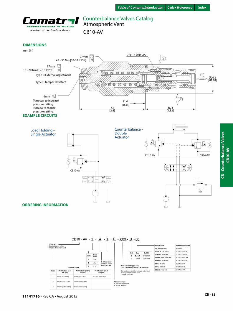
CB10-AV : Counterbalance valve, 10-size, atmospheric vent. This is a 3- ported, externally piloted, cartridge style, low leakage unit. The check section allows free flow from the directional valve (port 2) to the load (port 1). Reverse flow is blocked until pilot pressure is applied at port 3. When the pressure at port 1 rises above the pressure setting, the integral relief valve is activated and vents the area behind the pilot piston.
Rated pressure 350 bar [5075 psi]*
Rated flow at 22 bar (319 psi )
60 l/min [16 US gal/min]
Leakage 10 drops/min @ 70% of crack pressure
Weight 0.27 kg [0.60 lb]Pilot ratio 3:1, 4.5:1, 10:1Cavity SDC10-3S
* 350 bar with steel housing 210 bar with aluminum housing
CB10-AVAtmospheric Vent
Atmospheric vented valves are applied when it is not practical to connect a separate vent line to the tank. Use a single counterbalance valves when the load is unidirectional, such as aerial lifts, cranes, or winches. In load holding applications, they can be used as hose-break valves when installed near or within an actuator. Dual valves can be used for controlling loads bi-directionally in motor applications, or for cylinders going over center.
100
200
300
10 20 30 40 50 60 l/min
5
10
15
20
25
bar
15 US gal/min
psi
0
12963
26 cSt [121 SUS] hyd.oil at 50°C [122°F]
Pilot open
Free flow
CB10-AV
CB -
Coun
terb
alan
ce V
alve
s
Counterbalance Valves Catalog
CB - 15
mm [in]
11141716 • Rev CA • August 2015
EXAMPLE CIRCUITS
DIMENSIONS
ORDERING INFORMATION
CB10
-AV
Ø26.5[Ø1.04]
46.3[1.82]
11.6[0.46]
61[2.4]
1
37/8-14 UNF-2A
2
45 - 50 Nm [33-37 lbf*ft]27mm
Type E: External Adjustment
Type F:Tamper Resistant
17mm16 - 20 Nm [12-15 lbf*ft]
Turn ccw to increasepressure settingTurn cw to reducepressure setting
4mm
Atmospheric VentCB10-AV
CB10-AV
CB10-AV CB10-AV
Load Holding - Single Actuator
Counterbalance - Double Actuator

CB - Counterbalance Valves
Counterbalance Valves Catalog
CB - 16 11141716 • Rev CA • August 2015
OPERATION
APPLICATIONS
SPECIFICATIONSSCHEMATIC
PERFORMANCE
This counterbalance valve is a 6-size metric, 3-ported, externally piloted low leakage, cartridge style valve with atmospheric vent. The check section allows free flow from the directional valve (port 2) to the load (port 3), while normally blocking flow from port 3 to port 2. Reverse flow is blocked until pilot pressure is applied at port 1. When the pressure at port 3 rises above the pressure setting, the integral relief valve is activated and vents the area behind the pilot piston.
Rated pressure 350 bar [5075 psi]*Rated flow at 22 bar (319 psi )
60 l/min [16 US gal/min]
Leakage 10 drops/min @ at 70% of crack pressure
Weight 0.29 kg [0.65 lb]Pilot ratio 4.1:1, 7.1:1Cavity NCS06/3
* 350 bar with steel housing 210 bar with aluminum housing
VCB06-CNAtmospheric Vent
Atmospheric vented valves are applied when it is not practical to connect a separate vent line to the tank. Use a single counterbalance valve when the load is unidirectional, such as aerial lifts, cranes, or winches. In load holding applications, they are suitable as hose-break valves when installed near or within an actuator. Dual cartridges can be used for controlling loads bi-directionally in motor applications, or for cylinders going over center. Since this valve is piloted at port 1, no cross port drilling is required when dual cartridges are mounted nose to nose in an HIC.
VCB06-CN

CB -
Coun
terb
alan
ce V
alve
s
Counterbalance Valves Catalog
CB - 17
mm [in]
11141716 • Rev CA • August 2015
DIMENSIONS
EXAMPLE CIRCUITS
ORDERINGINFORMATION
VCB06-CN
VCB06-CN VCB06-CN
Load Holding - Single Actuator
Counterbalance with Pressure Limiting
VCB
06-C
N
Atmospheric VentVCB06-CN
turn cw to increasepressure settingturn ccw to decreasepressure setting

CB - Counterbalance Valves
Counterbalance Valves Catalog
CB - 18 11141716 • Rev CA • August 2015
OPERATION
APPLICATIONS
SPECIFICATIONSSCHEMATIC
PERFORMANCE
This counterbalance valve is a 12 size metric, 3-ported, externally piloted low leakage, cartridge style valve with atmospheric vent. The check section allows free flow from the directional valve (port 2) to the load (port 3), while normally blocking flow from port 3 to port 2. Reverse flow is blocked until pilot pressure is applied at port 1. When the pressure at port 3 rises above the pressure setting, the integral relief valve is activated and vents the area behind the pilot piston.
Rated pressure 350 bar [5075 psi]*
Rated flow at 22 bar (319 psi )
140 l/min [37 US gal/min]
Weight 0.93 kg [2.05 lb]Pilot ratio 4.7:1, 5.9:1, 6.9:1Cavity NCS12/3
* 350 bar with steel housing 210 bar with aluminum housing
VCB12-CNAtmospheric Vent
Atmospheric vented valves are applied when it is not practical to connect a separate vent line to the tank. Use a single counterbalance valve when the load is unidirectional, such as aerial lifts, cranes, or winches. In load holding applications, they are suitable for use as hose-break valves when installed near or within an actuator. Dual cartridges can be used for controlling loads bi-directionally in motor applications, or for cylinders going over center. Since this valve is piloted at port 1, no cross port drilling is required when dual cartridges are mounted nose to nose in an HIC.
35 70 105 140
10 20 30
l/min0
5
10
15
20
0
50
100
150
200
250
psi bar
US gal/min
3 2
32
Pressure drop26 cSt [125 SUS] hyd.oil @ 20° C[68°F]
VCB12-CN

CB -
Coun
terb
alan
ce V
alve
s
Counterbalance Valves Catalog
CB - 19
mm [in]
11141716 • Rev CA • August 2015
DIMENSIONS
EXAMPLE CIRCUITS
ORDERING INFORMATION
VCB
12-C
N
10mm
128Max
17mm13-17 Nm [9-12 lbf*ft]
[2.6]
[0.63]16
66
23
[Ø1.
48]
Ø37
.51
65-70 Nm [47-52 lbf*ft]38mm
M 33x2
turn cw to increasepressure settingturn ccw to decreasepressure setting
Atmospheric VentVCB12-CN
VCB12-CN
VCB12-CN
VCB12-CN
Load Holding - Single Actuator
Load Holding - Double Actuator

CB - Counterbalance Valves
Counterbalance Valves Catalog
CB - 20 11141716 • Rev CA • August 2015
OPERATION
APPLICATIONS
SPECIFICATIONSSCHEMATIC
PERFORMANCE
The VCB06-EN is a cartridge style, 6-size metric counterbalance valve with hydraulic vent. This valve is 3- ported, externally piloted and low leakage. The check section allows free flow from the directional valve (port 2) to the load (port 3). Reverse flow is blocked until pilot pressure is applied at port 1. When the load pressure at port 3 rises above the pressure setting, the integral relief valve is activated and pressure is relieved from port 3 to port 2.
Rated pressure 350 bar [5075 psi]*Rated flow at 22 bar (319 psi )
60 l/min [16 US gal/min]
Leakage 10 drops/min @ at 70% of crack pressure
Weight 0.21 kg [0.47 lb]Pilot ratio 4.1:1, 7.1:1Cavity NCS06/3
* 350 bar with steel housing 210 bar with aluminum housing
VCB06-ENHydraulic Vent
Single counterbalance valves are normally used when the load is unidirectional, such as aerial lifts, cranes, or winches. In load holding applications, they can be used as hose-break valves when installed near or within an actuator. Dual cartridges can be used for controlling loads bi-directionally in motor applications, or for cylinders going over center. Since this valve is piloted at port 1, no cross port drilling is required when dual cartridges are mounted nose to nose in an HIC.
VCB06-EN

CB -
Coun
terb
alan
ce V
alve
s
Counterbalance Valves Catalog
CB - 21
mm [in]
11141716 • Rev CA • August 2015
DIMENSIONS
EXAMPLE CIRCUITS
ORDERING INFORMATION
VCB06-EN
VCB06-EN
VCB06-EN
Load Holding - Single Actuator
Counterbalance - Double Actuator
VCB
06-E
N
Hydraulic VentVCB06-EN
turn cw to increasepressure settingturn ccw to decreasepressure setting

CB - Counterbalance Valves
Counterbalance Valves Catalog
CB - 22
35 70 105 140
10 20 30
l/min0
5
10
15
20
0
50
100
150
200
250
psi bar
US gal/min
Pressure drop26 cSt [125 SUS] hyd.oil @ 20° C[68°F]
11141716 • Rev CA • August 2015
OPERATION
APPLICATIONS
SPECIFICATIONS SCHEMATIC
PERFORMANCE
The VCB12-EN is a cartridge style, 12-size metric counterbalance valve with hydraulic vent. This valve is 3- ported, externally piloted and low leakage. The check section allows free flow from the directional valve (port 2) to the load (port 3). Reverse flow is blocked until pilot pressure is applied at port 1. When the load pressure at port 3 rises above the pressure setting, the integral relief valve is activated and pressure is relieved from port 3 to port 2.
Rated pressure 350 bar [5075 psi]*Rated flow at 22 bar (319 psi )
140 l/min [37 US gal/min]
Leakage 10 drops/min @ at 70% of crack pressure
Weight 0.7 kg [1.58 lb]Pilot ratio 4.7:1, 5.9:1. 6.9:1Cavity NCS12/3
* 350 bar with steel housing 210 bar with aluminum housing
VCB12-ENHydraulic Vent
Single counterbalance valves are normally used when the load is unidirectional, such as aerial lifts, cranes, or winches. In load holding applications, they can be used as hose-break valves when installed near or within an actuator. Dual cartridges can be used for controlling loads bi-directionally in motor applications, or for cylinders going over center. Since this valve is piloted at port 1, no cross port drilling is required when dual cartridges are mounted nose to nose in an HIC. V
CB12-EN

CB -
Coun
terb
alan
ce V
alve
s
Counterbalance Valves Catalog
CB - 23
mm [in]
11141716 • Rev CA • August 2015
DIMENSIONS
EXAMPLE CIRCUITS
ORDERING INFORMATION
M 33x2
turn cw to increasepressure settingturn ccw to decreasepressure setting
VCB12-EN
VCB12-EN VCB12-EN
VCB
12-E
N
Hydraulic VentVCB12-EN
Counterbalance- Double Actuator
Load Holding - Single Actuator

CB - Counterbalance Valves
Counterbalance Valves Catalog
CB - 24 11141716 • Rev CA • August 2015
OPERATION
APPLICATIONS
SPECIFICATIONS SCHEMATIC
PERFORMANCE
This dual valve, internally piloted HIC is a low leakage counterbalance assembly with hydraulic vent. The CP448-2 uses two CP448-1 8-size cartridges and allows free flow from the V ports to the C ports and blocks flow in the reverse direction until the relief setting is reached, or until adequate pilot pressure has been applied to the opposite V port.
Rated pressure 350 bar [5075 psi]*Rated flow at 22 bar (319 psi )
20 l/min [5 US gal/min]
Weight 0.78 kg [1.72 lb]Pilot ratio 3:1, 4.5:1, 8:1Cavity CIB
* 350 bar with steel housing 210 bar with aluminum housing
CP448-2Dual Counterbalance - Hydraulic Vent
Dual counterbalance HIC’s are used for controlling loads in bidirectional motion such as wheel motor applications or for cylinders going over center. They are also suitable for use on the boom and dipper cylinder on an excavator.
154 SUS (33 cSt) hyd. oil @ 100° F (38° C)
5
0
73
psi bar
Pre
ssu
re d
rop
4L/minFlow
1.1US gal/min
10
15
20
25
30
145
218
290
363
435
8 12 16 20
2.1 3.2 4.2 5.3
8.0:1
4.5:1
3.0:1
piloted open 1 2free flow 2 1
CP448-2

CB -
Coun
terb
alan
ce V
alve
s
Counterbalance Valves Catalog
CB - 25
mm [in]
11141716 • Rev CA • August 2015
DIMENSIONS
EXAMPLE CIRCUITS
ORDERING INFORMATIONCP
448-
2
31.75[1.25]
C 1C 2
16.00[0.63]
30.99[1.22]
57.91[2.28]
88.90[3.50]
79.50[3.13]
9.65[0.38]
63.50[2.50]
8.38[0.33]
31.75[1.25]
16.00[0.63]
turn ccw to increasepressure setting
turn cw to decreasepressure setting
Dual Counterbalance - Hydraulic VentCP448-2
Bi-directional Motion Control
Bi-directional Load Holding
CP448-2 CP448-2

CB - Counterbalance Valves
Counterbalance Valves Catalog
CB - 26 11141716 • Rev CA • August 2015
OPERATION
APPLICATIONS
SPECIFICATIONS SCHEMATIC
PERFORMANCE
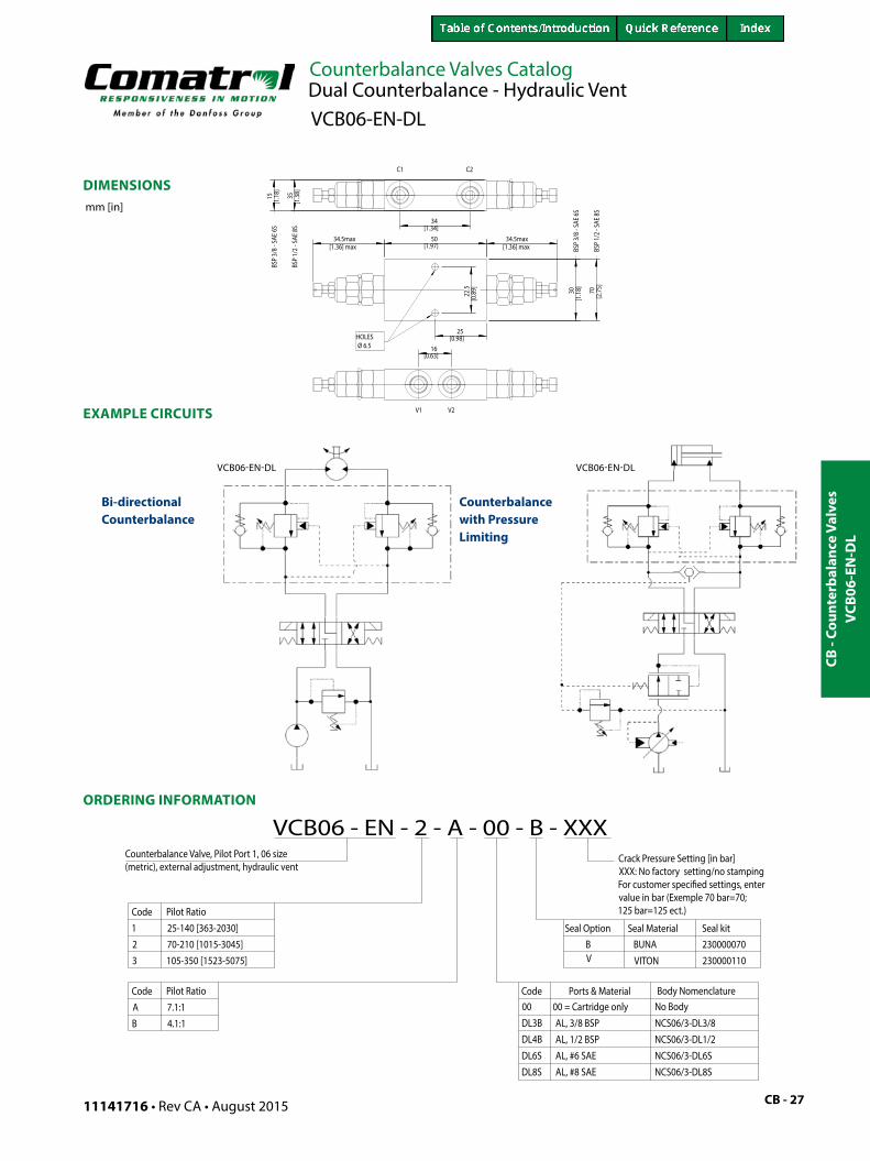
This is a dual counterbalance HIC, 6-size metric, hydraulically vented, internally-piloted, low leakage, with a nose to nose design. The VCB06-EN-DL allows free flow from the V ports to the C ports and blocks flow in the reverse direction until the relief setting is reached, or until adequate pilot pressure has been applied to the opposite V port.
Rated pressure 350 bar [5075 psi]*
Rated flow at 22 bar (319 psi )
60 l/min [16 US gal/min]
Leakage 10 drops/min @ at 70% of crack pressure
Weight 1.02 kg [2.25 lb]Pilot ratio 4.1:1, 7.1:1Cavity CIB
* 350 bar with steel housing 210 bar with aluminum housing
VCB06-EN-DLDual Counterbalance - Hydraulic Vent
Use dual counterbalance HIC’s for controlling loads in bidirectional motion such as wheel motor applications or for cylinders going over center. They are also suitable for use on the boom and dipper cylinder on an excavator. excavators.
VCB06-EN
-DL
CB -
Coun
terb
alan
ce V
alve
s
Counterbalance Valves Catalog
CB - 27
mm [in]
15
30
35
70
[1.34]
[1.97]
[1.1
8]
[2.7
5]
[1.1
8]
[1.3
8]
34
34.5max 34.5max 50
16
22.5
25[0.98]
[0.63]
[1.36] max[1.36] max
[0.8
9]
HOLES Ø 6.5
C1 C2
V2V1
BSP
3/8
- SAE
6S
BSP
1/2
- SAE
8S
BSP
1/2
- SAE
8S
BSP
3/8
- SAE
6S
11141716 • Rev CA • August 2015
DIMENSIONS
EXAMPLE CIRCUITS
ORDERING INFORMATION
VCB06-EN-DL VCB06-EN-DL
AL, #8 SAE
230000070230000110
Counterbalance Valve, Pilot Port 1, 06 size (metric), external adjustment, hydraulic vent
VCB06 - EN - 2 - A - 00 - B - XXX
Code00 = Cartridge onlyAL, 3/8 BSPAL, 1/2 BSP
No Body
NCS06/3-DL3/8NCS06/3-DL1/2NCS06/3-DL6SNCS06/3-DL8S
Ports & MaterialAB
Body NomenclatureCode00DL3BDL4B
DL8S
VB
VITON
BUNASeal kitSeal MaterialSeal Option
Pilot Ratio7.1:14.1:1
70-210 [1015-3045]25-140 [363-2030]Pilot Ratio
21Code
3 105-350 [1523-5075]
Crack Pressure Setting [in bar]XXX: No factory setting/no stampingFor customer speci�ed settings, enter value in bar (Exemple 70 bar=70;125 bar=125 ect.)
DL6S AL, #6 SAE
Bi-directional Counterbalance
Counterbalance with Pressure Limiting
VCB
06-E
N-D
L
Dual Counterbalance - Hydraulic VentVCB06-EN-DL

CB - Counterbalance Valves
Counterbalance Valves Catalog
CB - 28 11141716 • Rev CA • August 2015
OPERATION
APPLICATIONS
SPECIFICATIONS SCHEMATIC
PERFORMANCE
EXAMPLE CIRCUIT
DCB10-HV: Dual counterbalance HIC, 10-size, hydraulic vent. This is an internally piloted, low leakage assembly. The DCB10-HV uses 2 CB10-HV 10-size cartridges and allows free flow from the V port to the C ports and blocks flow in the reverse direction until the relief setting is reached, or until adequate pilot pressure has been applied to the opposite V port.
Rated pressure 350 bar [5075 psi]*
Rated flow at 22 bar (319 psi )
60 l/min [16 US gal/min]
Leakage 10 drops/min @ at 70% of crack pressure
Weight 0.90 kg [1.98 lb]Pilot ratio 3.0:1, 4.5:1, 10.0:1Cavity CIB
* 350 bar with steel housing 210 bar with aluminum housing
DCB10-HVDual Counterbalance - Hydraulic Vent
Dual counterbalance HIC’s are used for controlling loads in bidirectional motion such as wheel motor applications or for cylinders going over center. They are also suitable for use on the boom and dipper cylinder on an excavator.
100
200
300
10 20 30 40 50 60 l/min
5
10
15
20
25
bar
15 US gal/min
psi
0
12963
26 cSt [121 SUS] hyd.oil at 50°C [122°F]
Pilot open
Free flow
DCB10-HV
Bi-directional Motor Control
DCB10-H
V

CB -
Coun
terb
alan
ce V
alve
s
Counterbalance Valves Catalog
CB - 29
mm [in]
11141716 • Rev CA • August 2015
DIMENSIONS
ORDERING INFORMATION
DCB
10-H
V
Bottom View
100.00 [3.94]
70.00 [2.76]
DIAM 6.5 [0.26]
BSPPort
BSPPort
BSPPort
17.5 [0.69]
33 [1.30]
67 [2.64]
15 [0.59]70 [2.76]
15 [0.59]
20 [0.79]
38 [1.50]
35.00 [1.38]
BSPPort
17.5 [0.69]
38 [1.50]
35.00 [1.38]
BSP Ported - (Body Only)
Dual Counterbalance - Hydraulic VentDCB10-HV

CB - Counterbalance Valves
Counterbalance Valves Catalog
CB - 30 11141716 • Rev CA • August 2015
OPERATION
APPLICATIONS
SPECIFICATIONS SCHEMATIC
PERFORMANCE
This dual counterbalance, internally piloted catalog HIC is a low leakage assembly with hydraulic vent. This HIC uses 2 CP441-1 12-size cartridges and allows free flow from the V port to the C ports and blocks flow in the reverse direction until the relief setting is reached, or until adequate pilot pressure has been applied to the opposite V port.
Rated pressure 350 bar [5075 psi]*
Rated flow at 22 bar (319 psi )
115 l/min [30 US gal/min]
Weight 1.26 kg [2.77 lb]Pilot ratio 3:1, 4.5:1, 10:1Cavity CIB
* 350 bar with steel housing 210 bar with aluminum housing
CP441-2Dual Counterbalance - Hydraulic Vent
Dual counterbalance HIC’s are used for controlling loads in bidirectional motion such as wheel motor applications or for cylinders going over center. They are also suitable for use on the boom and dipper cylinder on an excavator.
154 SUS (33 cSt) hyd. oil @ 100° F (38° C)
5
0
73
psi bar
Pre
ssu
r e d
rop
40L/minFlow
10.6US gal/min
10
15
20
25
30
145
218
290
363
435
80 120
21.1 31.7
free flow
pilot open
CP441-2

CB -
Coun
terb
alan
ce V
alve
s
Counterbalance Valves Catalog
CB - 31
mm [in]
11141716 • Rev CA • August 2015
DIMENSIONS
EXAMPLE CIRCUITS
ORDERING INFORMATION
CP44
1-2
Turn ccw to increasepressure settingTurn cw to reducepressure setting
22.4[0.88]
50.8[2.00]
88.9[3.50]
129.3[5.09]
19.1[0.75]
82.6[3.25]
101.6[4.00]
12.7[0.50]127.0
[5.00]
44.5[1.75]
38.1[1.50]19.1
[0.75]
10.4[0.41] C2 C1
V2
V1 Bottom view
Bottom view
Dual Counterbalance - Hydraulic VentCP441-2
Bi-directional Motor Control
Bi-directional Load Control
CP441-2 CP441-2

CB - Counterbalance Valves
Counterbalance Valves Catalog
CB - 32
35 70 105 140
10 20 30
l/min0
5
10
15
20
0
50
100
150
200
250
psi bar
US gal/min
Pressure drop26 cSt [125 SUS] hyd.oil @ 20° C[68°F]
11141716 • Rev CA • August 2015
OPERATION
APPLICATIONS
SPECIFICATIONS SCHEMATIC
PERFORMANCE
The VCB12-EN-DL is a dual counterbalance HIC, 12-size metric, hydraulically vented, internally-piloted, low leakage, with a nose to nose design. This catalog HIC allows free flow from the V ports to the C ports and blocks flow in the reverse direction until the relief setting is reached, or until adequate pilot pressure has been applied to the opposite V port.
Rated pressure 350 bar [5075 psi]*
Rated flow at 22 bar (319 psi )
140 l/min [37 US gal/min]
Leakage 10 drops/min @ at 70% of crack pressure
Weight 2.54 kg [5.60 lb]Pilot ratio 4.7:1, 5.9:1, 6.9:1Cavity CIB
* 350 bar with steel housing 210 bar with aluminum housing
VCB12-EN-DLDual Counterbalance - Hydraulic Vent
Use dual counterbalance HIC’s for controlling loads in bidirectional motion such as wheel motor applications or for cylinders going over center. They are also suitable for use on the boom and dipper cylinder on an excavator.
VCB12-EN
-DL

CB -
Coun
terb
alan
ce V
alve
s
Counterbalance Valves Catalog
CB - 33
mm [in]
turn cw to increasepressure settingturn ccw to decreasepressure setting
11141716 • Rev CA • August 2015
DIMENSIONS
EXAMPLE CIRCUITS
ORDERING INFORMATION
VCB12-EN-DL
VCB12-EN-DL
VCB
12-E
N-D
L
Dual Counterbalance - Hydraulic VentVCB12-EN-DL
Bi-directional Motion Control
Counterbalance with Pressure Limiting

CB - Counterbalance Valves
Counterbalance Valves Catalog
CB - 34 11141716 • Rev CA • August 2015
OPERATION
APPLICATIONS
SPECIFICATIONS SCHEMATIC
PERFORMANCE
DCB20-HV: Dual counterbalance HIC, 20-size, hydraulic vent. This HIC is low leakage and internally piloted. The DCB20-HV uses 2 CB20-HV 20-size cartridges and allows free flow from the V port to the C ports and blocks flow in the reverse direction until the relief setting is reached, or until adequate pilot pressure has been applied to the opposite V port.
Rated pressure 350 bar [5075psi]*Rated flow at 22 bar (319 psi )
266 l/min [70 US gal/min]
Leakage 10 drops/min @ at 70% of crack pressure
Weight Aluminum 5.59 kg [12.59 lb]Ductile 10.68 kg [23.55 lb]
Pilot ratio 3.0:1, 4.5:1, 10.0:1Cavity CIB
* 350 bar with steel housing 210 bar with aluminum housing
DCB20-HVDual Counterbalance - Hydraulic Vent
Use dual counterbalance HIC’s for controlling loads in bidirectional motion such as wheel motor applications or for cylinders going over center. They are also suitable for use on the boom and dipper cylinder on an excavator.
DCB20-H
V

CB -
Coun
terb
alan
ce V
alve
s
Counterbalance Valves Catalog
CB - 35
mm [in]
11141716 • Rev CA • August 2015
DIMENSIONS
EXAMPLE CIRCUITS
ORDERING INFORMATION
Counterbalance with Pressure Limiting
Bi-directional Counterbalance DCB20-HVDCB20-HV
DCB
20-H
V
Dual Counterbalance - Hydraulic VentDCB20-HV
turn ccw to increasepresure setting
turn cw to decreasepressure setting

CB - Counterbalance Valves
Counterbalance Valves Catalog
CB - 36 11141716 • Rev CA • August 2015
OPERATION
APPLICATIONS
SPECIFICATIONS SCHEMATIC
PERFORMANCE
The VCB06-CN-DL is a dual counterbalance HIC, 6-size metric, nose to nose design with atmoshperic vent. This catalog HIC allows free flow from the V ports to the C ports and blocks flow in the reverse direction until the relief setting is reached, or until adequate pilot pressure has been applied to the opposite V port.
Rated pressure 350 bar [5075 psi]*
Rated flow at 22 bar [319 psi]
60 l/min [16 US gal/min]
Leakage 10 drops/min @ at 70% of crack pressure
Weight 0.96 kg [2.15 lb]Pilot ratio 4.1:1, 7.1:1Cavity CIB
* 350 bar with steel housing 210 bar with aluminum housing
VCB06-CN-DL
Dual Counterbalance - Atmospheric Vent
Atmospherically vented HIC’s are applied when it is not practical to connect a separate vent line to the tank. Use dual counterbalance HIC’s for controlling loads in bidirectional motion such as wheel motor applications or for cylinders going over center.
VCB06-CN
-DL

CB -
Coun
terb
alan
ce V
alve
s
Counterbalance Valves Catalog
CB - 37
mm [in]
turn cw to increasepressure settingturn ccw to decreasepressure setting
Bi-directional Motion Control
Counterbalance - Double Actuator
VCB06-CN-DL VCB06-CN-DL
11141716 • Rev CA • August 2015
DIMENSIONS
EXAMPLE CIRCUITS
ORDERING INFORMATION
VCB
06-C
N-D
L
Dual Counterbalance - Atmospheric VentVCB06-CN-DL

CB - Counterbalance Valves
Counterbalance Valves Catalog
CB - 38 11141716 • Rev CA • August 2015
OPERATION
APPLICATIONS
SPECIFICATIONS SCHEMATIC
PERFORMANCE
EXAMPLE CIRCUITS
DCB10-AV
DCB10-AV : Dual counterbalance HIC, 10-size, atmopheric vent. This HIC is low leakage and internally piloted. The DCB10-AV uses 2 CB10-AV 10-size cartridges and allows free flow from the V port to the C ports and blocks flow in the reverse direction until the relief setting is reached, or until adequate pilot pressure has been applied to the opposite V port.
Rated pressure 350 bar [5075 psi]*Rated flow at 22 bar (319 psi )
60 l/min [16 US gal/min]
Leakage 10 drops/min @ at 70% of crack pressure
Weight 0.90 kg [1.98 lb]Pilot ratio 3.0:1, 4.5:1, 10.0:1Cavity CIB
* 350 bar with steel housing 210 bar with aluminum housing
DCB10-AVDual Counterbalance - Atmospheric Vent
Atmospheric vented valves are applied when it is not practical to connect a separate vent line to the tank. Use dual counterbalance HIC’s for controlling loads in bidirectional motion such as wheel motor applications or for cylinders going over center. They are also suitable for use on the boom and dipper cylinder on an excavator.
Bi-directional Motor Control
100
200
300
10 20 30 40 50 60 l/min
5
10
15
20
25
bar
15 US gal/min
psi
0
12963
26 cSt [121 SUS] hyd.oil at 50°C [122°F]
Pilot open
Free flow
DCB10-AV

CB -
Coun
terb
alan
ce V
alve
s
Counterbalance Valves Catalog
CB - 39
mm [in]
11141716 • Rev CA • August 2015
DIMENSIONS
ORDERING INFORMATION
DCB
10-A
V
Bottom View
100.00 [3.94]
70.00 [2.76]
DIAM 6.5 [0.26]
BSPPort
BSPPort
BSPPort
17.5 [0.69]
33 [1.30]
67 [2.64]
15 [0.59]70 [2.76]
15 [0.59]
20 [0.79]
38 [1.50]
35.00 [1.38]
BSPPort
17.5 [0.69]
38 [1.50]
35.00 [1.38]
BSP Ported - (Body Only)
Cross-sectional view SAE - Ported
Dual Counterbalance - Atmospheric VentDCB10-AV

CB - Counterbalance Valves
Counterbalance Valves Catalog
CB - 40 11141716 • Rev CA • August 2015
OPERATION
APPLICATIONS
SPECIFICATIONS SCHEMATIC
PERFORMANCE
The VCB12-CN-DL is a dual counterbalance HIC, 12-size metric, nose to nose design with atmoshperic vent. This catalog HIC allows free flow from the V ports to the C ports and blocks flow in the reverse direction until the relief setting is reached, or until adequate pilot pressure has been applied to the opposite V port.
VCB12-CN-DLDual Counterbalance - Atmospheric Vent
Atmospherically vented valves are applied when it is not practical to connect a separate vent line to the tank. Use dual counterbalance HIC’s for controlling loads in bidirectional motion such as wheel motor applications or for cylinders going over center.
Rated pressure 350 bar [5075 psi]*
Rated flow at 22 bar (319 psi )
140 l/min [37 US gal/min]
Weight 2.92 kg [6.45 lb]Pilot ratio 4.7:1, 5.9:1, 6.9:1Cavity CIB
* 350 bar with steel housing 210 bar with aluminum housing
35 70 105 140
10 20 30
l/min0
5
10
15
20
0
50
100
150
200
250
psi bar
US gal/min
3 2
32
Pressure drop26 cSt [125 SUS] hyd.oil @ 20° C[68°F]
VCB12-CN
-DL

CB -
Coun
terb
alan
ce V
alve
s
Counterbalance Valves Catalog
CB - 41
mm [in]
turn cw to increasepressure settingturn ccw to decreasepressure setting
11141716 • Rev CA • August 2015
DIMENSIONS
EXAMPLE CIRCUITS
ORDERING INFORMATION
VCB
12-C
N-D
L
Dual Counterbalance - Atmospheric VentVCB12-CN-DL
Bi-directional Motion Control
Counterbalance - Double Actuator
VCB12-CN-DL VCB12-CN-DL

CB - Counterbalance Valves
Counterbalance Valves Catalog
CB - 42 11141716 • Rev CA • August 2015
OPERATION
APPLICATIONS
SPECIFICATIONS SCHEMATIC
PERFORMANCE
DCB10-MCDual Counterbalance - w/ Makeup Checks, Catalog HIC
C1 C2
TV1 V2
Rated pressure 350 bar [5075 psi]*
Rated flow at 22 bar (319 psi )
57 l/min [15 US gal/min]
Weight 2.39 kg [5.27 lb], Aluminum5.04 kg [11.11 lb], Ductile
Pilot ratio 3.0:1, 4.5:1, 10.0:1Cavity CIB
Dual counterbalance HIC, 10-size, hydraulic vent with make-up checks. This is an internally piloted, low leakage assembly. The DCB10-MC uses two CB10-HV cartridges and four CP100-3 check valves, allowing free flow from the V port to the C ports and blocks flow in the reverse direction until the relief setting is reached, or until adequate pilot pressure has been applied to the opposite V port. Connect the T port to a tank line to allow for make-up flow into the circuit.
Dual counterbalance HIC’s are used for controlling loads in bidirectional motion such as wheel motor applications or for cylinders going over center. They are also suitable for use on the boom and dipper cylinder on an excavator. When make-up feature is needed, connect ‘T’ port to reservoir or charge system. This allows the load to be smoothly controlled with minimum energy loss. If load tries to run ahead of pump, pilot pressure will decrease and the relief section will throttle or close to prevent runaway. The T port is also useful in cylinder applications where directional valves (specifically proportional valves) are sensitive to flow intensification of powering the rod side. The DCB10-MC diverts flow directly to tank and bypasses the directional valve. This HIC technically replaces the 1EEC11-01.
DCB10-M
C

CB -
Coun
terb
alan
ce V
alve
s
Counterbalance Valves Catalog
CB - 4311141716 • Rev CA • August 2015
DIMENSIONS
EXAMPLE CIRCUITS
ORDERING INFORMATION
DCB10-MCDual Counterbalance - w/ Makeup Checks, Catalog HIC
DCB
10-M
C

CB - Counterbalance Valves
Counterbalance Valves Catalog
CB - 44 11141716 • Rev CA • August 2015
OPERATION
APPLICATIONS
SPECIFICATIONS SCHEMATIC
PERFORMANCE
DCB12-MCDual Counterbalance - w/ Makeup Checks, Catalog HIC
Rated pressure210 bar [3045 psi], Aluminum350 bar [5075 psi], Ductile
Rated flow at 22 bar (319 psi )
95 l/min [25 US gal/min]
Weight 3.13 kg [6.90 lbs], Aluminum6.98 kg [15.39 lbs], Ductile
Pilot ratio 3.0:1, 4.5:1, 10.0:1Cavity CIB
C1 C2
TV1 V2
Dual counterbalance HIC, 12-size, hydraulic vent with make-up checks. This is an internally piloted, low leakage assembly. The DCB12-MC uses two CP441-1 cartridges and four CP100-3 check valves, allowing free flow from the V port to the C ports and blocks flow in the reverse direction until the relief setting is reached, or until adequate pilot pressure has been applied to the opposite V port. Connect the T port to a tank line to allow for make-up flow into the circuit.
Dual counterbalance HIC’s are used for controlling loads in bidirectional motion such as wheel motor applications or for cylinders going over center. They are also suitable for use on the boom and dipper cylinder on an excavator. When make-up feature is needed, connect ‘T’ port to reservoir or charge system. This allows the load to be smoothly controlled with minimum energy loss. If load tries to run ahead of pump, pilot pressure will decrease and the relief section will throttle or close to prevent runaway. The T port is also useful in cylinder applications where directional valves (specifically proportional valves) are sensitive to flow intensification of powering the rod side. The DCB12-MC diverts flow directly to tank and bypasses the directional valve. This HIC technically replaces the 1EEC12-01.
DCB12-M
C

CB -
Coun
terb
alan
ce V
alve
s
Counterbalance Valves Catalog
CB - 4511141716 • Rev CA • August 2015
DIMENSIONS
ORDERING INFORMATION
EXAMPLE CIRCUITS
Dual Counterbalance - w/ Makeup Checks, Catalog HICDCB12-MC
DCB
12-M
C

CB - Counterbalance Valves
Counterbalance Valves Catalog
CB - 46 11141716 • Rev CA • August 2015
Notes
Notes