GWSeries - BIBUS Romicon BV
11
Descriptions GW Working fluid Compressed air Max. working pressure MPa 1.0 (≈150 psi, 10 bar) Negative pressure kPa -100 (≈-15 psi, -1 bar) *2 Ambient temperature °C -10 (14°F) to 60 (140°F) (no freezing) Tube used Soft nylon tube (F-15**) Urethane tube (U-95**, NU-**) *1 Fitting GW Series ● Port size: M 3 to R1/2, φ4 to φ12 ● Compatible tube O.D.: φ3.2 to φ12 *1: Body is copper alloy (electroless nickel plated) for single straight, single straight (round), female straight, female bulkhead, bulkhead and bulkhead female connector. *2: Equivalent to UL94 standards V-0 *3: Standard push ring color: white, ozone-proof specifications P11: blue, clean-room specifications P70: pink, P74: orange, P80: light blue. (When flame retardant is added, the hue will be lighter.) Note: Sales unit is 10 pcs./bag. *1: Refer to page 814 for tube dimensions, ambient temperature and working pressure. *2: Use a urethane tube (U-95**/NU-**) together with an insert ring at vacuum pressure. * Refer to the model No. on the dimensions page (pages 740 to 749) for the model No. combination. Internal structure and parts list How to order 45 8 6 L GW Specifications A B C E D Shape S Straight L Elbow T Tee TR Tetrapod Y Y tee FY FY WY Double Y CR Cross P Plug C Cap M For tightening fitting MF Manifold Compatible tube O.D. 3 φ3.2 4 φ4 6 φ6 8 φ8 10 φ10 12 φ12 16 φ16 44 φ4/φ4 46 φ4/φ6 48 φ4/φ8 64 φ6/φ4 66 φ6/φ6 68 φ6/φ8 610 φ6/φ10 86 φ8/φ6 88 φ8/φ8 810 φ8/φ10 812 φ8/φ12 108 φ10/φ8 1010 φ10/φ10 1012 φ10/φ12 1210 φ12/φ10 1212 φ12/φ12 Port size M3 M3×0.5 M5 M5×0.8 6 R1/8 8 R1/4 10 R3/8 15 R1/2 0 No thread 4P Plug for φ4 6P Plug for φ6 8P Plug for φ8 10P Plug for φ10 12P Plug for φ12 B Blanking plug C C type plug L L type plug Y Y type plug Other combinations L Long T Turn D D type X Bulkhead S Round shape M Female E Bulkhead female W Double 2T 2-port turn 45 Single 45° Option Blank None P6 CU/PTFE free specs No. Part name Material 1 Body *1 Copper alloy (electroless nickeling treatment) Polybutylene terephthalate (flame-resistant resin *2) 2 Packing Nitrile rubber 3 Chuck holder Polyetherimide 4 Chuck Stainless steel 5 Push ring *3 Polybutylene terephthalate (flame-resistant resin *2) 6 Outer ring Copper alloy (electroless nickeling treatment) 7 Drive-in nipple Copper alloy (electroless nickeling treatment) P11 ……………… GW Ozone-proof specifications (Ending Page 9) P80 ……………… ……………… GW GW Clean-room specifications (Catalog No. CB-033SA) P7* A B C D E 4 7 5 6 1 2 3 F.R.L F (Filtr) R (Reg) L (Lub) PresSW Shutoff SlowStart FlmResistFR Oil-ProhR MedPresFR No Cu/ PTFE FRL Outdrs FR F.R.L (Related) CompFRL LgFRL PrecsR VacF/R Clean FR ElecPneuR AirBoost SpdContr Silncr CheckV/ other Jnt/tube AirUnt PrecsCompn Mech/ ElecPresSw ContactSW AirSens PresSW Cool AirFloSens/ Contr WaterRtSens TotAirSys (Total Air) TotAirSys (Gamma) RefrDry DesicDry HiPolymDry MainFiltr Dischrg etc Ending 739
-
Upload
khangminh22 -
Category
Documents
-
view
1 -
download
0
Transcript of GWSeries - BIBUS Romicon BV

Descriptions GWWorking fluid Compressed airMax. working pressure MPa 1.0 (≈150 psi, 10 bar)Negative pressure kPa -100 (≈-15 psi, -1 bar) *2Ambient temperature °C -10 (14°F) to 60 (140°F) (no freezing)
Tube usedSoft nylon tube (F-15**)
Urethane tube (U-95**, NU-**) *1
Fitting
GW Series● Port size: M 3 to R1/2, φ4 to φ12● Compatible tube O.D.: φ3.2 to φ12
*1: Body is copper alloy (electroless nickel plated) for single straight, single straight (round), female straight, female bulkhead, bulkhead and bulkhead female connector.
*2: Equivalent to UL94 standards V-0*3: Standard push ring color: white, ozone-proof specifications P11: blue,
clean-room specifications P70: pink, P74: orange, P80: light blue. (When flame retardant is added, the hue will be lighter.)
Note: Sales unit is 10 pcs./bag.
*1: Refer to page 814 for tube dimensions, ambient temperature and working pressure.*2: Use a urethane tube (U-95**/NU-**) together with an insert ring at vacuum pressure.
* Refer to the model No. on the dimensions page (pages 740 to 749) for the model No. combination.
Internal structure and parts list
How to order
4586LGW
Specifications
A B C ED
ShapeS StraightL ElbowT Tee
TR TetrapodY Y tee
FY FYWY Double YCR CrossP PlugC CapM For tightening fitting
MF Manifold
Compatible tube O.D.3 φ3.24 φ46 φ68 φ810 φ1012 φ1216 φ1644 φ4/φ446 φ4/φ648 φ4/φ864 φ6/φ466 φ6/φ668 φ6/φ8610 φ6/φ1086 φ8/φ688 φ8/φ8810 φ8/φ10812 φ8/φ12108 φ10/φ81010 φ10/φ101012 φ10/φ121210 φ12/φ101212 φ12/φ12
Port sizeM3 M3×0.5M5 M5×0.86 R1/88 R1/410 R3/815 R1/20 No thread
4P Plug for φ46P Plug for φ68P Plug for φ810P Plug for φ1012P Plug for φ12B Blanking plugC C type plugL L type plugY Y type plug
Other combinationsL LongT TurnD D typeX BulkheadS Round shapeM FemaleE Bulkhead femaleW Double2T 2-port turn45 Single 45°
OptionBlank None
P6 CU/PTFE free specs
No. Part name Material
1 Body *1Copper alloy (electroless nickeling treatment)
Polybutylene terephthalate (flame-resistant resin *2)
2 Packing Nitrile rubber
3 Chuck holder Polyetherimide
4 Chuck Stainless steel
5 Push ring *3 Polybutylene terephthalate (flame-resistant resin *2)
6 Outer ring Copper alloy (electroless nickeling treatment)
7 Drive-in nipple Copper alloy (electroless nickeling treatment)
P11………………GW
Ozone-proof specifications (Ending Page 9)
P80
………………
………………
GW
GW
Clean-room specifications (Catalog No. CB-033SA)
P7*
A B C D E
4
7
56
1 2 3
F.R.L
F (Filtr)
R (Reg)
L (Lub)
PresSW
Shutoff
SlowStart
FlmResistFR
Oil-ProhR
MedPresFRNo Cu/PTFE FRL
Outdrs FRF.R.L (Related)
CompFRL
LgFRL
PrecsR
VacF/R
Clean FR
ElecPneuR
AirBoost
SpdContr
SilncrCheckV/ other
Jnt/tube
AirUnt
PrecsCompnMech/ElecPresSw
ContactSW
AirSensPresSW CoolAirFloSens/Contr
WaterRtSensTotAirSys (Total Air)TotAirSys (Gamma)
RefrDry
DesicDry
HiPolymDry
MainFiltrDischrg etc
Ending
739
GW Series
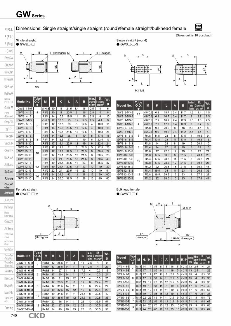
● GWS□-□-E● GWS□-□-MBulkhead femaleFemale straight
Dimensions: Single straight/single straight (round)/female straight/bulkhead female
● GWS□-□-S● GWS□-□Single straight (round)Single straight
Model No.Tube O.D.
φM H K L A B
Min. bore size
Eff. X-sectional area mm2
Wt. g
GWS 4-M54
M5×0.8 10 11 21.5 3.4 16 2.5 4 6GWS 4- 6 R1/8 10 11 20.5 8 16 2.5 4 8GWS 4- 8 R1/4 14 15.8 19.5 11 16 2.5 4 15GWS 6-M5
6
M5×0.8 12 13.5 23 3.4 17.5 2.5 4.4 9GWS 6- 6 R1/8 12 13.5 23 8 17.5 4 10.3 11GWS 6- 8 R1/4 14 15.8 23.5 11 17.5 4 10.3 18GWS 6-10 R3/8 17 19.1 21.5 12 17.5 4 10.3 26GWS 8- 6
8R1/8 14 15.8 28 8 19 5 17.5 18
GWS 8- 8 R1/4 14 15.8 27 11 19 6 22.4 17GWS 8-10 R3/8 17 19.1 22.5 12 19 6 22.4 24GWS10- 6
10
R1/8 17 19.1 31 8 21.5 5 17.5 26GWS10- 8 R1/4 17 19.1 32.5 11 21.5 8 30.5 22GWS10-10 R3/8 17 19.1 28.5 12 21.5 8 30.5 26GWS10-15 R1/2 22 24 26.5 15 21.5 8 30.5 49GWS12- 8
12R1/4 19 21.4 35.5 11 23 8 35.5 37
GWS12-10 R3/8 19 21.4 30.5 12 23 10 40 32GWS12-15 R1/2 22 24 29.5 15 23 10 40 51GWS16-10
16R3/8 24 26.5 42 12 28 12 90 60
GWS16-15 R1/2 24 26.5 37.5 15 28 13 90 66
Model No.Tube O.D.
φM K L A B
Hex head hole
diameter
Eff. X-sectional area mm2
Wt. g
GWS 3-M3-S3.2
M3×0.5 6.9 15.7 2.4 11.7 1.5 1.4 1.5GWS 3-M5-S M5×0.8 6.9 16.7 3.4 11.7 2 2.7 2.5GWS 4-M3-S
4M3×0.5 7.9 16.9 2.4 12.9 1.5 1.6 2.5
GWS 4-M5-S M5×0.8 7.9 17.9 3.4 12.9 2 2.7 3GWS 4- 6-S R1/8 9.8 20.5 8 16 2.5 4.1 8GWS 6-M5-S
6M5×0.8 9.9 19.2 3.4 14.2 2.5 4.4 4
GWS 6- 6-S R1/8 11.8 23 8 17.5 4 10.6 9GWS 6- 8-S R1/4 13.8 23 11 17.5 4 10.6 15GWS 8- 6-S
8R1/8 14 28 8 19 5 20.4 15
GWS 8- 8-S R1/4 14 27 11 19 6 22 15GWS 8-10-S R3/8 17 22.5 12 19 6 22 21GWS10- 6-S
10
R1/8 17.5 30.5 8 21.5 5 20.1 26GWS10- 8-S R1/4 17.5 28.5 11 21.5 6 26.3 21GWS10-10-S R3/8 17.5 28.5 12 21.5 8 30.1 27GWS10-15-S R1/2 22 26.5 15 21.5 8 30.1 46GWS12- 8-S
12R1/4 19.5 34 11 23 6 26.3 33
GWS12-10-S R3/8 19.5 29.5 12 23 8 37.9 28GWS12-15-S R1/2 22 28.5 15 23 8 37.9 47
Model No.Tube O.D.
φM H L ℓ A B
Min. bore size
Eff. X-sectional area mm2
Wt. g
GWS 4- 6-M4
Rc1/8 12 25.5 11 8 16 2.5 4 9GWS 4- 8-M Rc1/4 17 28.5 14 11 16 2.5 4 23GWS 6- 6-M
6Rc1/8 14 27 11 8 17.5 4 10.3 16
GWS 6- 8-M Rc1/4 17 30 14 11 17.5 4 10.3 24GWS 6-10-M Rc3/8 19 31 15 12 17.5 4 10.3 25GWS 8- 6-M
8Rc1/8 17 28.5 11 8 19 6 22.4 26
GWS 8- 8-M Rc1/4 17 31.5 14 11 19 6 22.4 27GWS 8-10-M Rc3/8 19 32.5 15 12 19 6 22.4 29GWS10- 8-M
10Rc1/4 19 34.5 14 11 21.5 8 30.5 42
GWS10-10-M Rc3/8 19 35.5 15 12 21.5 8 30.5 35GWS12- 8-M
12Rc1/4 22 36 14 11 23 10 35.5 57
GWS12-10-M Rc3/8 22 37 15 12 23 10 35.5 53GWS12-15-M Rc1/2 24 40 18 15 23 10 35.5 56
Model No.
Tube O.D.
φM H1 H2 L ℓ A B E M×P Mounting
holeφMin. bore size
Eff. X-sectional area mm2
Wt. g
GWS 4- 6-E4
Rc1/8 14 14 25.5 11 8 16 5 M12×1 13 2.5 4 21GWS 4- 8-E Rc1/4 17 14 28.5 14 11 16 5 M12×1 13 2.5 4 28GWS 6- 6-E
6Rc1/8 17 17 27 11 8 17.5 5 M14×1 15 4 10.3 33
GWS 6- 8-E Rc1/4 17 17 30 14 11 17.5 5 M14×1 15 4 10.3 33GWS 6-10-E Rc3/8 19 17 31.5 15 12 17.5 5 M14×1 15 4 10.3 35GWS 8- 6-E
8Rc1/8 19 19 28.5 11 8 19 6 M16×1 17 6 22.4 42
GWS 8- 8-E Rc1/4 19 19 31.5 14 11 19 6 M16×1 17 6 22.4 56GWS 8-10-E Rc3/8 19 19 32.5 15 12 19 6 M16×1 17 6 22.4 38GWS10- 8-E
10Rc1/4 22 23 34.5 14 11 21.5 9 M20×1 21 8 30.5 73
GWS10-10-E Rc3/8 22 23 35.5 15 12 21.5 9 M20×1 21 8 30.5 68GWS12-10-E
12Rc3/8 24 26 37.5 15 12 23 10 M22×1 23 9 35.5 88
GWS12-15-E Rc1/2 24 26 40.5 18 15 23 10 M22×1 23 9 35.5 82
[Sales unit is 10 pcs./bag]
M H (Hexagon)H (Hexagon)
φKφK
LA
M5
B M
LA
BMM
φK
AL
A
M3, M5
BB
L
φK
M× PM
H2 (Hexagon)
H1 (Hexagon)
A B
E (max)
M
H (Hexagon) L
A B
L
F.R.L
F (Filtr)
R (Reg)
L (Lub)
PresSW
Shutoff
SlowStart
FlmResistFR
Oil-ProhR
MedPresFRNo Cu/PTFE FRL
Outdrs FRF.R.L (Related)
CompFRL
LgFRL
PrecsR
VacF/R
Clean FR
ElecPneuR
AirBoost
SpdContr
SilncrCheckV/ other
Jnt/tube
AirUnt
PrecsCompnMech/ElecPresSw
ContactSW
AirSensPresSW CoolAirFloSens/Contr
WaterRtSensTotAirSys (Total Air)TotAirSys (Gamma)
RefrDry
DesicDry
HiPolymDry
MainFiltrDischrg etc
Ending
740
GW SeriesDimensions
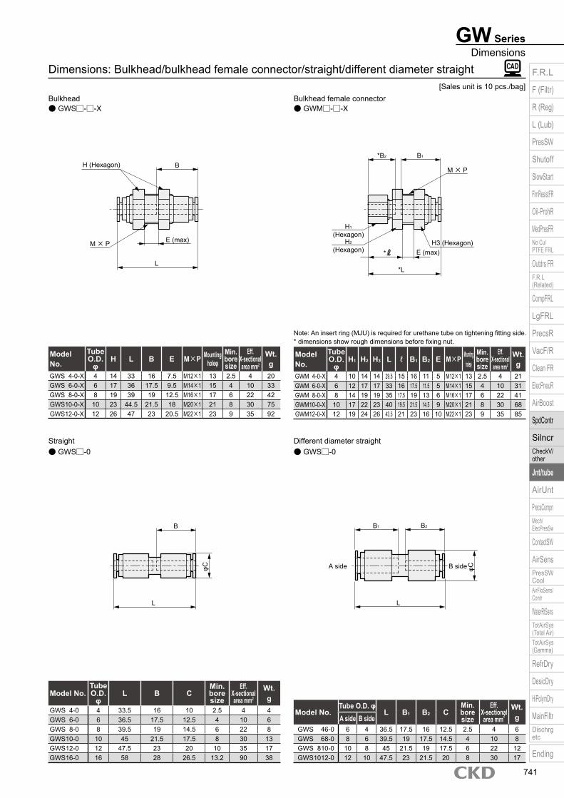
● GWS□-0● GWS□-0Different diameter straightStraight
Note: An insert ring (MJU) is required for urethane tube on tightening fitting side.* dimensions show rough dimensions before fixing nut.
Dimensions: Bulkhead/bulkhead female connector/straight/different diameter straight
● GWM□-□-X● GWS□-□-XBulkhead female connectorBulkhead
Model No.
Tube O.D.
φH L B E M×P Mounting
holeφMin. bore size
Eff. X-sectional area mm2
Wt. g
GWS 4-0-X 4 14 33 16 7.5 M12×1 13 2.5 4 20GWS 6-0-X 6 17 36 17.5 9.5 M14×1 15 4 10 33GWS 8-0-X 8 19 39 19 12.5 M16×1 17 6 22 42GWS10-0-X 10 23 44.5 21.5 18 M20×1 21 8 30 75GWS12-0-X 12 26 47 23 20.5 M22×1 23 9 35 92
Model No.
Tube O.D.
φH1 H2 H3 L ℓ B1 B2 E M×P Mounting
holeφMin. bore size
Eff. X-sectional area mm2
Wt. g
GWM 4-0-X 4 10 14 14 29.5 15 16 11 5 M12×1 13 2.5 4 21GWM 6-0-X 6 12 17 17 33 16 17.5 11.5 5 M14×1 15 4 10 31GWM 8-0-X 8 14 19 19 35 17.5 19 13 6 M16×1 17 6 22 41GWM10-0-X 10 17 22 23 40 19.5 21.5 14.5 9 M20×1 21 8 30 68GWM12-0-X 12 19 24 26 43.5 21 23 16 10 M22×1 23 9 35 85
Model No.Tube O.D.
φL B C
Min. bore size
Eff. X-sectional area mm2
Wt. g
GWS 4-0 4 33.5 16 10 2.5 4 4GWS 6-0 6 36.5 17.5 12.5 4 10 6GWS 8-0 8 39.5 19 14.5 6 22 8GWS10-0 10 45 21.5 17.5 8 30 13GWS12-0 12 47.5 23 20 10 35 17GWS16-0 16 58 28 26.5 13.2 90 38
Model No.Tube O.D. φ
L B1 B2 CMin. bore size
Eff. X-sectional area mm2
Wt. gA side B side
GWS 46-0 6 4 36.5 17.5 16 12.5 2.5 4 6GWS 68-0 8 6 39.5 19 17.5 14.5 4 10 8GWS 810-0 10 8 45 21.5 19 17.5 6 22 12GWS1012-0 12 10 47.5 23 21.5 20 8 30 17
[Sales unit is 10 pcs./bag]
M× P
H (Hexagon)
E (max)
L
B
H3 (Hexagon)
M× P
H2 (Hexagon)
H1 (Hexagon)
E (max)*
*L
*B2 B1
φC
L
B
A side B side φC
L
B1 B2
F.R.L
F (Filtr)
R (Reg)
L (Lub)
PresSW
Shutoff
SlowStart
FlmResistFR
Oil-ProhR
MedPresFRNo Cu/PTFE FRL
Outdrs FRF.R.L (Related)
CompFRL
LgFRL
PrecsR
VacF/R
Clean FR
ElecPneuR
AirBoost
SpdContr
SilncrCheckV/ other
Jnt/tube
AirUnt
PrecsCompnMech/ElecPresSw
ContactSW
AirSensPresSW CoolAirFloSens/Contr
WaterRtSensTotAirSys (Total Air)TotAirSys (Gamma)
RefrDry
DesicDry
HiPolymDry
MainFiltrDischrg etc
Ending
741
GW Series
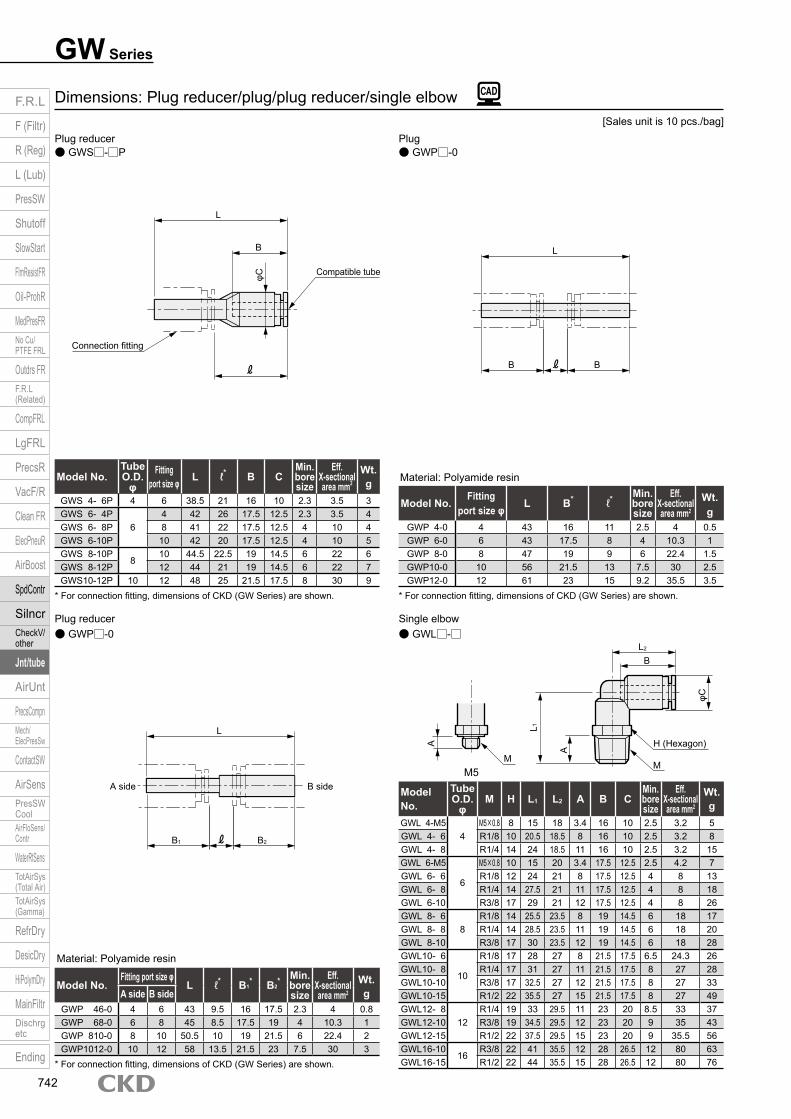
Material: Polyamide resin
* For connection fitting, dimensions of CKD (GW Series) are shown.
Material: Polyamide resin
* For connection fitting, dimensions of CKD (GW Series) are shown.
* For connection fitting, dimensions of CKD (GW Series) are shown.
● GWL□-□● GWP□-0Single elbowPlug reducer
Dimensions: Plug reducer/plug/plug reducer/single elbow
● GWP□-0● GWS□-□PPlugPlug reducer
Model No.Tube O.D.
φFitting
port size φ L ℓ* B CMin. bore size
Eff. X-sectional area mm2
Wt. g
GWS 4- 6P 4 6 38.5 21 16 10 2.3 3.5 3GWS 6- 4P
64 42 26 17.5 12.5 2.3 3.5 4
GWS 6- 8P 8 41 22 17.5 12.5 4 10 4GWS 6-10P 10 42 20 17.5 12.5 4 10 5GWS 8-10P
810 44.5 22.5 19 14.5 6 22 6
GWS 8-12P 12 44 21 19 14.5 6 22 7GWS10-12P 10 12 48 25 21.5 17.5 8 30 9
Model No. Fitting port size φ L B* ℓ* Min.
bore size
Eff. X-sectional area mm2
Wt. g
GWP 4-0 4 43 16 11 2.5 4 0.5GWP 6-0 6 43 17.5 8 4 10.3 1GWP 8-0 8 47 19 9 6 22.4 1.5GWP10-0 10 56 21.5 13 7.5 30 2.5GWP12-0 12 61 23 15 9.2 35.5 3.5
Model No.Fitting port size φ
L ℓ* B1* B2
* Min. bore size
Eff. X-sectional area mm2
Wt. gA side B side
GWP 46-0 4 6 43 9.5 16 17.5 2.3 4 0.8GWP 68-0 6 8 45 8.5 17.5 19 4 10.3 1GWP 810-0 8 10 50.5 10 19 21.5 6 22.4 2GWP1012-0 10 12 58 13.5 21.5 23 7.5 30 3
Model No.
Tube O.D.
φM H L1 L2 A B C
Min. bore size
Eff. X-sectional area mm2
Wt. g
GWL 4-M54
M5×0.8 8 15 18 3.4 16 10 2.5 3.2 5GWL 4- 6 R1/8 10 20.5 18.5 8 16 10 2.5 3.2 8GWL 4- 8 R1/4 14 24 18.5 11 16 10 2.5 3.2 15GWL 6-M5
6
M5×0.8 10 15 20 3.4 17.5 12.5 2.5 4.2 7GWL 6- 6 R1/8 12 24 21 8 17.5 12.5 4 8 13GWL 6- 8 R1/4 14 27.5 21 11 17.5 12.5 4 8 18GWL 6-10 R3/8 17 29 21 12 17.5 12.5 4 8 26GWL 8- 6
8R1/8 14 25.5 23.5 8 19 14.5 6 18 17
GWL 8- 8 R1/4 14 28.5 23.5 11 19 14.5 6 18 20GWL 8-10 R3/8 17 30 23.5 12 19 14.5 6 18 28GWL10- 6
10
R1/8 17 28 27 8 21.5 17.5 6.5 24.3 26GWL10- 8 R1/4 17 31 27 11 21.5 17.5 8 27 28GWL10-10 R3/8 17 32.5 27 12 21.5 17.5 8 27 33GWL10-15 R1/2 22 35.5 27 15 21.5 17.5 8 27 49GWL12- 8
12R1/4 19 33 29.5 11 23 20 8.5 33 37
GWL12-10 R3/8 19 34.5 29.5 12 23 20 9 35 43GWL12-15 R1/2 22 37.5 29.5 15 23 20 9 35.5 56GWL16-10
16R3/8 22 41 35.5 12 28 26.5 12 80 63
GWL16-15 R1/2 22 44 35.5 15 28 26.5 12 80 76
[Sales unit is 10 pcs./bag]
φC
L
Connection fitting
Compatible tube
B
B B
L
A side B side
B1 B2
L
M5M
M
H (Hexagon)
L1
A
A
φC
L2
B
F.R.L
F (Filtr)
R (Reg)
L (Lub)
PresSW
Shutoff
SlowStart
FlmResistFR
Oil-ProhR
MedPresFRNo Cu/PTFE FRL
Outdrs FRF.R.L (Related)
CompFRL
LgFRL
PrecsR
VacF/R
Clean FR
ElecPneuR
AirBoost
SpdContr
SilncrCheckV/ other
Jnt/tube
AirUnt
PrecsCompnMech/ElecPresSw
ContactSW
AirSensPresSW CoolAirFloSens/Contr
WaterRtSensTotAirSys (Total Air)TotAirSys (Gamma)
RefrDry
DesicDry
HiPolymDry
MainFiltrDischrg etc
Ending
742
GW SeriesDimensions
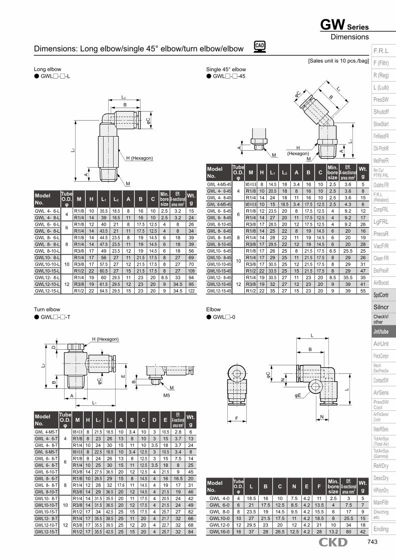
● GWL□-0● GWL□-□-TElbowTurn elbow
Dimensions: Long elbow/single 45° elbow/turn elbow/elbow
● GWL□-□-45● GWL□-□-LSingle 45° elbowLong elbow
Model No.
Tube O.D.
φM H L1 L2 A B C
Min. bore size
Eff. X-sectional area mm2
Wt. g
GWL 4- 6-L4
R1/8 10 35.5 18.5 8 16 10 2.5 3.2 15GWL 4- 8-L R1/4 14 39 18.5 11 16 10 2.5 3.2 24GWL 6- 6-L
6R1/8 12 40 21 8 17.5 12.5 4 8 26
GWL 6- 8-L R1/4 14 43.5 21 11 17.5 12.5 4 8 34GWL 8- 6-L
8R1/8 14 44.5 23.5 8 19 14.5 6 18 39
GWL 8- 8-L R1/4 14 47.5 23.5 11 19 14.5 6 18 39GWL 8-10-L R3/8 17 49 23.5 12 19 14.5 6 18 56GWL10- 8-L
10R1/4 17 56 27 11 21.5 17.5 8 27 69
GWL10-10-L R3/8 17 57.5 27 12 21.5 17.5 8 27 70GWL10-15-L R1/2 22 60.5 27 15 21.5 17.5 8 27 109GWL12- 8-L
12R1/4 19 60 29.5 11 23 20 8.5 33 94
GWL12-10-L R3/8 19 61.5 29.5 12 23 20 9 34.5 95GWL12-15-L R1/2 22 64.5 29.5 15 23 20 9 34.5 122
Model No.
Tube O.D.
φM H L1 L2 A B C
Min. bore size
Eff. X-sectional area mm2
Wt. g
GWL 4-M5-454
M5×0.8 8 14.5 18 3.4 16 10 2.5 3.6 5GWL 4- 6-45 R1/8 10 20.5 18 8 16 10 2.5 3.6 8GWL 4- 8-45 R1/4 14 24 18 11 16 10 2.5 3.6 15GWL 6-M5-45
6
M5×0.8 10 15 18.5 3.4 17.5 12.5 2.5 4.3 6GWL 6- 6-45 R1/8 12 23.5 20 8 17.5 12.5 4 9.2 12GWL 6- 8-45 R1/4 14 27 20 11 17.5 12.5 4 9.2 17GWL 6-10-45 R3/8 17 28.5 20 12 17.5 12.5 4 9.2 26GWL 8- 6-45
8R1/8 14 25 22 8 19 14.5 6 20 16
GWL 8- 8-45 R1/4 14 28 22 11 19 14.5 6 20 19GWL 8-10-45 R3/8 17 29.5 22 12 19 14.5 6 20 28GWL10- 6-45
10
R1/8 17 26 25 8 21.5 17.5 6.5 25.5 25GWL10- 8-45 R1/4 17 29 25 11 21.5 17.5 8 29 26GWL10-10-45 R3/8 17 30.5 25 12 21.5 17.5 8 29 31GWL10-15-45 R1/2 22 33.5 25 15 21.5 17.5 8 29 47GWL12- 8-45
12R1/4 19 30.5 27 11 23 20 8.5 35.5 35
GWL12-10-45 R3/8 19 32 27 12 23 20 9 39 41GWL12-15-45 R1/2 22 35 27 15 23 20 9 39 55
Model No.
Tube O.D.
φM H L1 L2 A B C D E
Eff. X-sectional area mm2
Wt. g
GWL 4-M5-T4
M5×0.8 8 21.5 18.5 10 3.4 10 3 10.5 2.8 6GWL 4- 6-T R1/8 8 23 26 13 8 10 3 15 3.7 13GWL 4- 8-T R1/4 10 24 30 15 11 10 3.5 18 3.7 24GWL 6-M5-T
6
M5×0.8 8 22.5 18.5 10 3.4 12.5 3 10.5 3.4 8GWL 6- 6-T R1/8 8 24 26 13 8 12.5 3 15 7.5 14GWL 6- 8-T R1/4 10 25 30 15 11 12.5 3.5 18 8 25GWL 6-10-T R3/8 14 27.5 36.5 20 12 12.5 4 21.5 9 45GWL 8- 6-T
8R1/8 10 26.5 29 15 8 14.5 4 16 16.5 20
GWL 8- 8-T R1/4 12 28 32 17.6 11 14.5 4 19 17 31GWL 8-10-T R3/8 14 29 36.5 20 12 14.5 4 21.5 19 46GWL10- 8-T
10R1/4 14 31.5 35.5 20 11 17.5 4 20.5 24 42
GWL10-10-T R3/8 14 31.5 36.5 20 12 17.5 4 21.5 24 49GWL10-15-T R1/2 17 34 42.5 25 15 17.5 4 25.7 27 82GWL12- 8-T
12R1/4 17 35.5 38.5 25 11 20 4 21.7 32 66
GWL12-10-T R3/8 17 35.5 39.5 25 12 20 4 22.7 32 68GWL12-15-T R1/2 17 35.5 42.5 25 15 20 4 25.7 32 84
Model No.
Tube O.D.
φL B C N E F
Min. bore size
Eff. X-sectional area mm2
Wt. g
GWL 4-0 4 18.5 16 10 7.5 4.2 11 2.5 3 5GWL 6-0 6 21 17.5 12.5 8.5 4.2 13.5 4 7.5 7GWL 8-0 8 23.5 19 14.5 9.5 4.2 15.5 6 17 9GWL10-0 10 27 21.5 17.5 11 4.2 18.5 8 25.5 15GWL12-0 12 29.5 23 20 12 4.2 21 10 34 18GWL16-0 16 37 28 26.5 12.5 4.2 28 13.2 80 42
[Sales unit is 10 pcs./bag]
L 1
A
φC
L2
M
H (Hexagon)
B
A H(Hexagon)
MM
φC
A
L 1
L2
B
M5
B
H (Hexagon)
M
φCBD
E
L2
AL1
φE
φC
N
L
L
N
B
F
F.R.L
F (Filtr)
R (Reg)
L (Lub)
PresSW
Shutoff
SlowStart
FlmResistFR
Oil-ProhR
MedPresFRNo Cu/PTFE FRL
Outdrs FRF.R.L (Related)
CompFRL
LgFRL
PrecsR
VacF/R
Clean FR
ElecPneuR
AirBoost
SpdContr
SilncrCheckV/ other
Jnt/tube
AirUnt
PrecsCompnMech/ElecPresSw
ContactSW
AirSensPresSW CoolAirFloSens/Contr
WaterRtSensTotAirSys (Total Air)TotAirSys (Gamma)
RefrDry
DesicDry
HiPolymDry
MainFiltrDischrg etc
Ending
743
GW Series
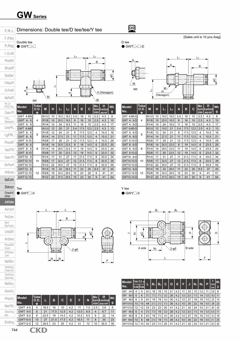
● GWY□-0● GWT□-0Y teeTee
Dimensions: Double tee/D tee/tee/Y tee
● GWT□-□-D● GWT□-□D teeDouble tee
Model No.
Tube O.D.
φM H L1 L2 A B C
Min. bore size
Eff. X-sectional area mm2
Wt. g
GWT 4-M54
M5×0.8 10 16.5 18.5 3.4 16 10 2.5 4.3 8GWT 4- 6 R1/8 10 20.5 18.5 8 16 10 2.5 4.3 10GWT 4- 8 R1/4 14 24 18.5 11 16 10 2.5 4.3 17GWT 6-M5
6
M5×0.8 12 20 21 3.4 17.5 12.5 2.5 4.3 13GWT 6- 6 R1/8 12 24 21 8 17.5 12.5 4 10.5 16GWT 6- 8 R1/4 14 27.5 21 11 17.5 12.5 4 10.5 21GWT 6-10 R3/8 17 29 21 12 17.5 12.5 4 10.5 29GWT 8- 6
8R1/8 14 25.5 23.5 8 19 14.5 6 23.5 20
GWT 8- 8 R1/4 14 28.5 23.5 11 19 14.5 6 23.5 24GWT 8-10 R3/8 17 30 23.5 12 19 14.5 6 23.5 32GWT10- 8
10R1/4 17 31 27 11 21.5 17.5 8 33.5 34
GWT10-10 R3/8 17 32.5 27 12 21.5 17.5 8 33.5 39GWT10-15 R1/2 22 35.5 27 15 21.5 17.5 8 33.5 55GWT12- 8
12R1/4 19 33 29.5 11 23 20 8.5 37 45
GWT12-10 R3/8 19 34.5 29.5 12 23 20 9 41 51GWT12-15 R1/2 22 37.5 29.5 15 23 20 9 41 64
Model No.
Tube O.D.
φM H L1 L2 A B C
Min. bore size
Eff. X-sectional area mm2
Wt. g
GWT 4-M5-D4
M5×0.8 10 16.5 18.5 3.4 16 10 2.5 4.3 8GWT 4- 6-D R1/8 10 20.5 18.5 8 16 10 2.5 4.3 10GWT 4- 8-D R1/4 14 24 18.5 11 16 10 2.5 4.3 17GWT 6-M5-D
6
M5×0.8 12 19.5 21 3.4 17.5 12.5 2.5 4.3 13GWT 6- 6-D R1/8 12 24 21 8 17.5 12.5 4 10.5 16GWT 6- 8-D R1/4 14 27.5 21 11 17.5 12.5 4 10.5 21GWT 6-10-D R3/8 17 29 21 12 17.5 12.5 4 10.5 29GWT 8- 6-D
8R1/8 14 25.5 23.5 8 19 14.5 6 23.5 20
GWT 8- 8-D R1/4 14 28.5 23.5 11 19 14.5 6 23.5 24GWT 8-10-D R3/8 17 30 23.5 12 19 14.5 6 23.5 32GWT10- 8-D
10R1/4 17 31 27 11 21.5 17.5 8 33.5 34
GWT10-10-D R3/8 17 32.5 27 12 21.5 17.5 8 33.5 39GWT10-15-D R1/2 22 35.5 27 15 21.5 17.5 8 33.5 55GWT12- 8-D
12R1/4 19 33 29.5 11 23 20 8.5 37 45
GWT12-10-D R3/8 19 34.5 29.5 12 23 20 9 41 51GWT12-15-D R1/2 22 37.5 29.5 15 23 20 9 41 64
Model No.
Tube O.D.
φL B C E F N
Min. bore size
Eff. X-sectional area mm2
Wt. g
GWT 4-0 4 18.5 16 10 4.2 11 7.5 2.5 3.6 8GWT 6-0 6 21 17.5 12.5 4.2 13.5 8.5 4 9.7 11GWT 8-0 8 23.5 19 14.5 4.2 15.5 9.5 6 22 14GWT10-0 10 27 21.5 17.5 4.2 18.5 11 8 30 23GWT12-0 12 29.5 23 20 4.2 21 12 10 35.5 30
Model No.
Tube O.D. φL B1 B2 C D E F J N1 N2 P
Eff. X-sectional area mm2
Wt. gA side B side
GWY 44-0 4 4 34.5 16 16 10 21 4.2 11 23 15 12.5 11 3.6 8GWY 66-0 6 6 37.5 17.5 17.5 12.5 26 4.2 13.5 25.5 17.5 14 13.5 10.5 11GWY 88-0 8 8 40.5 19 19 14.5 30 4.2 15.5 27 19 15 15.5 23 14GWY1010-0 10 10 48 21.5 21.5 17.5 36 4.2 18.5 30 22 18 18.5 38 23GWY1212-0 12 12 53 23 23 20 41 4.2 21 32 24 19.5 21 50 30GWY 64-0 6 4 37.5 17.5 16 12.5 26 4.2 13.5 25.5 17.5 14 13.5 5.4 11GWY 86-0 8 6 40.5 19 17.5 14.5 30 4.2 15.5 27 19 15 15.5 14.3 16GWY 108-0 10 8 48 21.5 19 17.5 36 4.2 18.5 30 22 18 18.5 21.1 20GWY1210-0 12 10 53 23 21.5 20 41 4.2 21 32 24 19.5 21 35.5 30
[Sales unit is 10 pcs./bag]
A
A
H(Hexagon)
MM
L2
L1
A
A
φC
φC
L1 L2
B
L2 L2
MM
H (Hexagon)
B
M5
M5
B sideA side
L L
B
L
2-φE2-φE
N
φC
F
J N1
φC
P D
B1 B2
L
N2
FNN
F.R.L
F (Filtr)
R (Reg)
L (Lub)
PresSW
Shutoff
SlowStart
FlmResistFR
Oil-ProhR
MedPresFRNo Cu/PTFE FRL
Outdrs FRF.R.L (Related)
CompFRL
LgFRL
PrecsR
VacF/R
Clean FR
ElecPneuR
AirBoost
SpdContr
SilncrCheckV/ other
Jnt/tube
AirUnt
PrecsCompnMech/ElecPresSw
ContactSW
AirSensPresSW CoolAirFloSens/Contr
WaterRtSensTotAirSys (Total Air)TotAirSys (Gamma)
RefrDry
DesicDry
HiPolymDry
MainFiltrDischrg etc
Ending
744

GW SeriesDimensions
● GWL□-□-2T ● GWTR□-□Tetrapod (with R)2-port turn elbow
Dimensions: Double Y tee/cross/2-port turn elbow/tetrapod (with R)
● GWCR□-0● GWY□-□CrossDouble Y tee
Model No.
Tube O.D.
φM H L A B D E F J P
Eff. X-sectional area mm2
Wt. g
GWY 4-M54
M5×0.8 12 38 3.4 16 21 4.2 11 23 11 4.5 12GWY 4- 6 R1/8 12 42 8 16 21 4.2 11 23 11 5.5 14GWY 4- 8 R1/4 14 45.5 11 16 21 4.2 11 23 11 5.5 19GWY 6-M5
6
M5×0.8 12 41 3.4 17.5 26 4.2 13.5 25.5 13.5 4.5 17GWY 6- 6 R1/8 14 46 8 17.5 26 4.2 13.5 25.5 13.5 17.5 19GWY 6- 8 R1/4 14 49 11 17.5 26 4.2 13.5 25.5 13.5 17.5 22GWY 6-10 R3/8 17 50.5 12 17.5 26 4.2 13.5 25.5 13.5 17.5 31GWY 8- 6
8R1/8 17 49 8 19 30 4.2 15.5 27 15.5 25.5 27
GWY 8- 8 R1/4 17 52 11 19 30 4.2 15.5 27 15.5 25.5 29GWY 8-10 R3/8 17 53.5 12 19 30 4.2 15.5 27 15.5 25.5 34GWY10- 8
10R1/4 19 59.5 11 21.5 36 4.2 18.5 30 18.5 35 42
GWY10-10 R3/8 19 61 12 21.5 36 4.2 18.5 30 18.5 38.5 48GWY10-15 R1/2 22 64 15 21.5 36 4.2 18.5 30 18.5 38 61GWY12- 8
12R1/4 22 64.5 11 23 41 4.2 21 32 21 37 51
GWY12-10 R3/8 22 66 12 23 41 4.2 21 32 21 37 57GWY12-15 R1/2 22 69 15 23 41 4.2 21 32 21 40.5 67
Model No.
Tube O.D.
φL B C E F N
Min. bore size
Eff. X-sectional area mm2
Wt. g
GWCR 8-0 8 24 19 14.5 4.2 15.5 9.5 6 22 19GWCR10-0 10 27.5 21.5 17.5 4.2 18.5 11 8 30.5 30GWCR12-0 12 30 23 20 4.2 21 12 10 35.9 39
Model No.
Tube O.D.
φM H L1 L2 A B C D O P
Eff. X-sectional area mm2
Wt. g
GWL 4-M5-2T 4 M5×0.8 8 21.5 18.5 3.4 16 10 3 21 11 3.6 9GWL 6- 6-2T 6 R1/8 8 24 26 8 17.5 12.5 3 26 13.5 8.5 18GWL 8- 8-2T 8 R1/4 12 28 32 11 19 14.5 4 30 15.5 19 36GWL10-10-2T 10 R3/8 14 31.5 36.5 12 21.5 17.5 4 36 18.5 26 54GWL12-15-2T 12 R1/2 17 35.5 42.5 15 23 20 4 41 21 34 90
Model No.
Tube O.D.
φM H L1 L2 A B C E F N
Min. bore size
Eff. X-sectional area mm2
Wt. g
GWTR 4-M54
M5×0.8 10 22.5 19 3.4 16 10 4.2 11 7.5 2.5 4.3 11GWTR 4- 6 R1/8 10 26.5 19 8 16 10 4.2 11 7.5 2.5 4.5 13GWTR 4- 8 R1/4 14 30 19 11 16 10 4.2 11 7.5 2.5 4.5 20GWTR 6-M5
6
M5×0.8 14 25 21.5 3.4 17.5 12.5 4.2 13.5 8.5 2.5 4.3 19GWTR 6- 6 R1/8 14 30 21.5 8 17.5 12.5 4.2 13.5 8.5 4 10.5 22GWTR 6- 8 R1/4 14 33 21.5 11 17.5 12.5 4.2 13.5 8.5 4 10.5 25GWTR 6-10 R3/8 17 34.5 21.5 12 17.5 12.5 4.2 13.5 8.5 4 10.5 33GWTR 8- 6
8R1/8 17 32.5 24 8 19 14.5 4.2 15.5 9.5 6 23.5 28
GWTR 8- 8 R1/4 17 35.5 24 11 19 14.5 4.2 15.5 9.5 6 23.5 33GWTR 8-10 R3/8 17 37 24 12 19 14.5 4.2 15.5 9.5 6 23.5 38GWTR10- 8
10R1/4 19 39.5 27.5 11 21.5 17.5 4.2 18.5 13 8 35.5 45
GWTR10-10 R3/8 19 41 27.5 12 21.5 17.5 4.2 18.5 13 8 35.5 52GWTR10-15 R1/2 22 44 27.5 15 21.5 17.5 4.2 18.5 13 8 35.5 65GWTR12- 8
12R1/4 22 41.5 30 11 23 20 4.2 21 14 8.5 37.5 60
GWTR12-10 R3/8 22 43 30 12 23 20 4.2 21 14 8.5 37.5 68GWTR12-15 R1/2 22 46 30 15 23 20 4.2 21 14 8.5 37.5 77
[Sales unit is 10 pcs./bag]
M5
φC
φC
J P D
NN
L
B
L
F
LL
L
F
2-φE
2-φEH (Hexagon)
M
M
A
A
B
M5
AA
H (Hexagon)
MM
M5
A
H (Hexagon)
M
M
AD
φCL 2
φE
B
N
BL 2
N
φC
L2L1
F
P
O
L1
F.R.L
F (Filtr)
R (Reg)
L (Lub)
PresSW
Shutoff
SlowStart
FlmResistFR
Oil-ProhR
MedPresFRNo Cu/PTFE FRL
Outdrs FRF.R.L (Related)
CompFRL
LgFRL
PrecsR
VacF/R
Clean FR
ElecPneuR
AirBoost
SpdContr
SilncrCheckV/ other
Jnt/tube
AirUnt
PrecsCompnMech/ElecPresSw
ContactSW
AirSensPresSW CoolAirFloSens/Contr
WaterRtSensTotAirSys (Total Air)TotAirSys (Gamma)
RefrDry
DesicDry
HiPolymDry
MainFiltrDischrg etc
Ending
745
GW Series
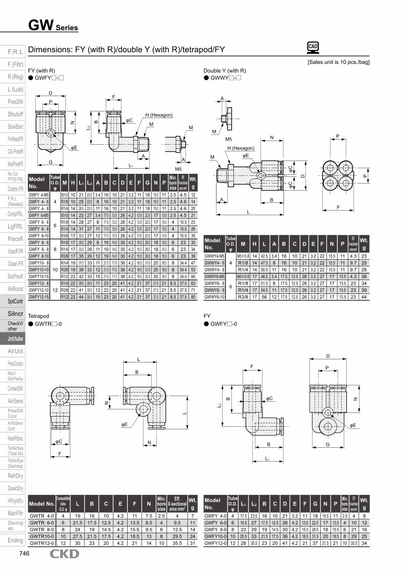
● GWFY□-0● GWTR□-0FYTetrapod
Dimensions: FY (with R)/double Y (with R)/tetrapod/FY
● GWWY□-□● GWFY□-□Double Y (with R)FY (with R)
Model No.
Tube O.D.
φM H L1 L2 A B C D E F G N P
Min. bore size
Eff. X-sectional area mm2
Wt. g
GWFY 4-M54
M5×0.8 10 21 23.5 3.4 16 10 21 3.2 11 18 15.5 11 2.5 4.5 12GWFY 4- 6 R1/8 10 25 23.5 8 16 10 21 3.2 11 18 15.5 11 2.5 4.6 14GWFY 4- 8 R1/4 14 28.5 23.5 11 16 10 21 3.2 11 18 15.5 11 2.5 4.6 20GWFY 6-M5
6
M5×0.8 14 23 27 3.4 17.5 12.5 26 4.2 13.5 22.5 17 13.5 2.5 4.5 21GWFY 6- 6 R1/8 14 28 27 8 17.5 12.5 26 4.2 13.5 22.5 17 13.5 4 10.5 23GWFY 6- 8 R1/4 14 31 27 11 17.5 12.5 26 4.2 13.5 22.5 17 13.5 4 10.5 26GWFY 6-10 R3/8 17 32.5 27 12 17.5 12.5 26 4.2 13.5 22.5 17 13.5 4 10.5 35GWFY 8- 6
8R1/8 17 30.5 29 8 19 14.5 30 4.2 15.5 26.5 18 15.5 6 23 30
GWFY 8- 8 R1/4 17 33.5 29 11 19 14.5 30 4.2 15.5 26.5 18 15.5 6 23 34GWFY 8-10 R3/8 17 35 29 12 19 14.5 30 4.2 15.5 26.5 18 15.5 6 23 39GWFY10- 8
10R1/4 19 37.5 33 11 21.5 17.5 36 4.2 18.5 31.5 20 18.5 8 34.4 47
GWFY10-10 R3/8 19 39 33 12 21.5 17.5 36 4.2 18.5 31.5 20 18.5 8 34.4 53GWFY10-15 R1/2 22 42 33 15 21.5 17.5 36 4.2 18.5 32.5 20 18.5 8 34.4 66GWFY12- 8
12R1/4 22 39.5 35.5 11 23 20 41 4.2 21 37 21.5 21 8.5 37.5 63
GWFY12-10 R3/8 22 41 35.5 12 23 20 41 4.2 21 37 21.5 21 8.5 37.5 71GWFY12-15 R1/2 22 44 35.5 15 23 20 41 4.2 21 37 21.5 21 8.5 37.5 80
Model No.
Tube O.D.
φM H L A B C D E F N P
Eff. X-sectional area mm2
Wt. g
GWWY4-M54
M5×0.8 14 42.5 3.4 16 10 21 3.2 22 15.5 11 4.3 23GWWY4- 6 R1/8 14 47.5 8 16 10 21 3.2 22 15.5 11 9.7 25GWWY4- 8 R1/4 14 50.5 11 16 10 21 3.2 22 15.5 11 9.7 28GWWY6-M5
6
M5×0.8 17 46.5 3.4 17.5 12.5 26 3.2 27 17 13.5 4.3 36GWWY6- 6 R1/8 17 51.5 8 17.5 12.5 26 3.2 27 17 13.5 23 34GWWY6- 8 R1/4 17 54.5 11 17.5 12.5 26 3.2 27 17 13.5 23 39GWWY6-10 R3/8 17 56 12 17.5 12.5 26 3.2 27 17 13.5 23 44
Model No.Compatible
tube O.D. φ
L B C E F NMin. bore size
Eff. X-sectional area mm2
Wt. g
GWTR 4-0 4 19 16 10 4.2 11 7.5 2.5 4 7GWTR 6-0 6 21.5 17.5 12.5 4.2 13.5 8.5 4 9.5 11GWTR 8-0 8 24 19 14.5 4.2 15.5 9.5 6 12.5 14GWTR10-0 10 27.5 21.5 17.5 4.2 18.5 13 8 29.5 24GWTR12-0 12 30 23 20 4.2 21 14 10 35.5 31
Model No.
Tube O.D.
φL1 L2 B C D E F G N P
Min. bore size
Eff. X-sectional area mm2
Wt. g
GWFY 4-0 4 17.5 23.5 16 10 21 3.2 11 18 15.5 11 2.5 4 8GWFY 6-0 6 19.5 27 17.5 12.5 26 4.2 13.5 22.5 17 13.5 4 10 12GWFY 8-0 8 22 29 19 14.5 30 4.2 15.5 26.5 18 15.5 6 21 16GWFY10-0 10 25.5 33 21.5 17.5 36 4.2 18.5 31.5 20 18.5 8 29 25GWFY12-0 12 28 35.5 23 20 41 4.2 21 37 21.5 21 10 35.5 34
[Sales unit is 10 pcs./bag]
M5
A
N P
P
φC
D
φC
N B
BA
FL
GL1
AA
φE H (Hexagon)
H (Hexagon)
M
M
MφC
P
DF
φE
M5
L2
M
B
φE
N
φE
N
F
B
L 2
N
G
L1
D
B
L
φC
F
φC
P
L
F.R.L
F (Filtr)
R (Reg)
L (Lub)
PresSW
Shutoff
SlowStart
FlmResistFR
Oil-ProhR
MedPresFRNo Cu/PTFE FRL
Outdrs FRF.R.L (Related)
CompFRL
LgFRL
PrecsR
VacF/R
Clean FR
ElecPneuR
AirBoost
SpdContr
SilncrCheckV/ other
Jnt/tube
AirUnt
PrecsCompnMech/ElecPresSw
ContactSW
AirSensPresSW CoolAirFloSens/Contr
WaterRtSensTotAirSys (Total Air)TotAirSys (Gamma)
RefrDry
DesicDry
HiPolymDry
MainFiltrDischrg etc
Ending
746
GW SeriesDimensions
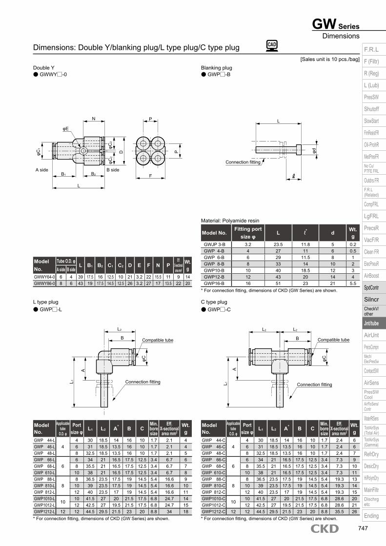
* For connection fitting, dimensions of CKD (GW Series) are shown. * For connection fitting, dimensions of CKD (GW Series) are shown.
Material: Polyamide resin
* For connection fitting, dimensions of CKD (GW Series) are shown.
Dimensions: Double Y/blanking plug/L type plug/C type plug
● GWP□-L
● GWWY□-0
● GWP□-CC type plugL type plug
● GWP□-BBlanking plugDouble Y
Model No.
Tube O.D. φL B1 B2 C1 C2 D E F N P
Eff. X-sectional area mm2
Wt. gA side B side
GWWY64-0 6 4 39 17.5 16 12.5 10 21 3.2 22 15.5 11 9 14GWWY86-0 8 6 43 19 17.5 14.5 12.5 26 3.2 27 17 13.5 22 20
Model No.Fitting port
size φL ℓ* d Wt.
gGWJP 3-B 3.2 23.5 11.8 5 0.2GWP 4-B 4 27 11 6 0.5GWP 6-B 6 29 11.5 8 1GWP 8-B 8 33 14 10 2GWP10-B 10 40 18.5 12 3GWP12-B 12 43 20 14 4GWP16-B 16 51 23 21 5.5
Model No.
Applicable tube
O.D. φ
Port size φ L1 L2 A* B C
Min. bore size
Eff. X-sectional area mm2
Wt. g
GWP 44-L4
4 30 18.5 14 16 10 1.7 2.1 4GWP 46-L 6 31 18.5 13.5 16 10 1.7 2.1 4GWP 48-L 8 32.5 18.5 13.5 16 10 1.7 2.1 5GWP 66-L
66 34 21 16.5 17.5 12.5 3.4 6.7 6
GWP 68-L 8 35.5 21 16.5 17.5 12.5 3.4 6.7 7GWP 610-L 10 38 21 16.5 17.5 12.5 3.4 6.7 8GWP 88-L
88 36.5 23.5 17.5 19 14.5 5.4 16.6 9
GWP 810-L 10 39 23.5 17.5 19 14.5 5.4 16.6 10GWP 812-L 12 40 23.5 17 19 14.5 5.4 16.6 11GWP1010-L
1010 41.5 27 20 21.5 17.5 6.8 24.7 14
GWP1012-L 12 42.5 27 19.5 21.5 17.5 6.8 24.7 15GWP1212-L 12 12 44.5 29.5 21.5 23 20 8.8 34 18
Model No.
Applicable tube
O.D. φ
Port size φ L1 L2 A* B C
Min. bore size
Eff. X-sectional area mm2
Wt. g
GWP 44-C4
4 30 18.5 14 16 10 1.7 2.4 6GWP 46-C 6 31 18.5 13.5 16 10 1.7 2.4 6GWP 48-C 8 32.5 18.5 13.5 16 10 1.7 2.4 7GWP 66-C
66 34 21 16.5 17.5 12.5 3.4 7.3 9
GWP 68-C 8 35.5 21 16.5 17.5 12.5 3.4 7.3 10GWP 610-C 10 38 21 16.5 17.5 12.5 3.4 7.3 11GWP 88-C
88 36.5 23.5 17.5 19 14.5 5.4 19.3 13
GWP 810-C 10 39 23.5 17.5 19 14.5 5.4 19.3 14GWP 812-C 12 40 23.5 17 19 14.5 5.4 19.3 15GWP1010-C
1010 41.5 27 20 21.5 17.5 6.8 28.6 20
GWP1012-C 12 42.5 27 19.5 21.5 17.5 6.8 28.6 21GWP1212-C 12 12 44.5 29.5 21.5 23 20 8.8 35.5 26
[Sales unit is 10 pcs./bag]
A side B side
L
B1 B2 F
P
φC2
φC1 φC
2
D P
N
φE
φd
Connection fitting
L
Connection fitting
Compatible tube
Connection fitting
Compatible tube
L 1
φC
A
φCL2 L2
B
A
L 1
B
L2
F.R.L
F (Filtr)
R (Reg)
L (Lub)
PresSW
Shutoff
SlowStart
FlmResistFR
Oil-ProhR
MedPresFRNo Cu/PTFE FRL
Outdrs FRF.R.L (Related)
CompFRL
LgFRL
PrecsR
VacF/R
Clean FR
ElecPneuR
AirBoost
SpdContr
SilncrCheckV/ other
Jnt/tube
AirUnt
PrecsCompnMech/ElecPresSw
ContactSW
AirSensPresSW CoolAirFloSens/Contr
WaterRtSensTotAirSys (Total Air)TotAirSys (Gamma)
RefrDry
DesicDry
HiPolymDry
MainFiltrDischrg etc
Ending
747
GW Series
* For connection fitting, dimensions of CKD (GW Series) are shown.
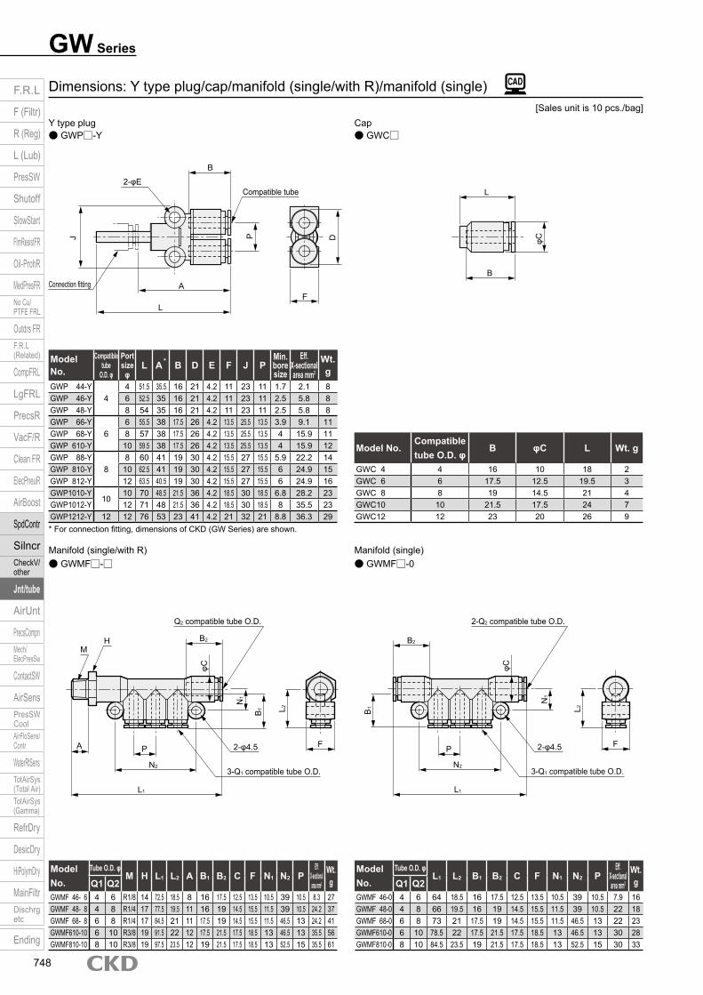
● GWMF□-0● GWMF□-□Manifold (single)Manifold (single/with R)
Dimensions: Y type plug/cap/manifold (single/with R)/manifold (single)
● GWC□● GWP□-YCapY type plug
Model No.
Compatible tube
O.D. φ
Port size
φL A B D E F J P
Min. bore size
Eff. X-sectional area mm2
Wt. g
GWP 44-Y4
4 51.5 35.5 16 21 4.2 11 23 11 1.7 2.1 8GWP 46-Y 6 52.5 35 16 21 4.2 11 23 11 2.5 5.8 8GWP 48-Y 8 54 35 16 21 4.2 11 23 11 2.5 5.8 8GWP 66-Y
66 55.5 38 17.5 26 4.2 13.5 25.5 13.5 3.9 9.1 11
GWP 68-Y 8 57 38 17.5 26 4.2 13.5 25.5 13.5 4 15.9 11GWP 610-Y 10 59.5 38 17.5 26 4.2 13.5 25.5 13.5 4 15.9 12GWP 88-Y
88 60 41 19 30 4.2 15.5 27 15.5 5.9 22.2 14
GWP 810-Y 10 62.5 41 19 30 4.2 15.5 27 15.5 6 24.9 15GWP 812-Y 12 63.5 40.5 19 30 4.2 15.5 27 15.5 6 24.9 16GWP1010-Y
1010 70 48.5 21.5 36 4.2 18.5 30 18.5 6.8 28.2 23
GWP1012-Y 12 71 48 21.5 36 4.2 18.5 30 18.5 8 35.5 23GWP1212-Y 12 12 76 53 23 41 4.2 21 32 21 8.8 36.3 29
Model No.Compatible tube O.D. φ
B φC L Wt. g
GWC 4 4 16 10 18 2GWC 6 6 17.5 12.5 19.5 3GWC 8 8 19 14.5 21 4GWC10 10 21.5 17.5 24 7GWC12 12 23 20 26 9
Model No.
Tube O.D. φM H L1 L2 A B1 B2 C F N1 N2 P
Eff. X-sectional area mm2
Wt. gQ1 Q2
GWMF 46- 6 4 6 R1/8 14 72.5 18.5 8 16 17.5 12.5 13.5 10.5 39 10.5 8.3 27GWMF 48- 8 4 8 R1/4 17 77.5 19.5 11 16 19 14.5 15.5 11.5 39 10.5 24.2 37GWMF 68- 8 6 8 R1/4 17 84.5 21 11 17.5 19 14.5 15.5 11.5 46.5 13 24.2 41GWMF610-10 6 10 R3/8 19 91.5 22 12 17.5 21.5 17.5 18.5 13 46.5 13 35.5 56GWMF810-10 8 10 R3/8 19 97.5 23.5 12 19 21.5 17.5 18.5 13 52.5 15 35.5 61
Model No.
Tube O.D. φL1 L2 B1 B2 C F N1 N2 P
Eff. X-sectional area mm2
Wt. gQ1 Q2
GWMF 46-0 4 6 64 18.5 16 17.5 12.5 13.5 10.5 39 10.5 7.9 16GWMF 48-0 4 8 66 19.5 16 19 14.5 15.5 11.5 39 10.5 22 18GWMF 68-0 6 8 73 21 17.5 19 14.5 15.5 11.5 46.5 13 22 23GWMF610-0 6 10 78.5 22 17.5 21.5 17.5 18.5 13 46.5 13 30 28GWMF810-0 8 10 84.5 23.5 19 21.5 17.5 18.5 13 52.5 15 30 33
*
[Sales unit is 10 pcs./bag]
Connection fitting
Compatible tube
L
AF
J DP
B
2-φE
φC
B
L
MH
B1
Q2 compatible tube O.D.
3-Q1 compatible tube O.D.
2-φ4.5
L 2
φC
B1
N1
B2
A P
L1
F
N2
2-Q2 compatible tube O.D.
3-Q1 compatible tube O.D.
2-φ4.5
L 2
N1
B2
P
L1
F
N2
φC
F.R.L
F (Filtr)
R (Reg)
L (Lub)
PresSW
Shutoff
SlowStart
FlmResistFR
Oil-ProhR
MedPresFRNo Cu/PTFE FRL
Outdrs FRF.R.L (Related)
CompFRL
LgFRL
PrecsR
VacF/R
Clean FR
ElecPneuR
AirBoost
SpdContr
SilncrCheckV/ other
Jnt/tube
AirUnt
PrecsCompnMech/ElecPresSw
ContactSW
AirSensPresSW CoolAirFloSens/Contr
WaterRtSensTotAirSys (Total Air)TotAirSys (Gamma)
RefrDry
DesicDry
HiPolymDry
MainFiltrDischrg etc
Ending
748
GW SeriesDimensions
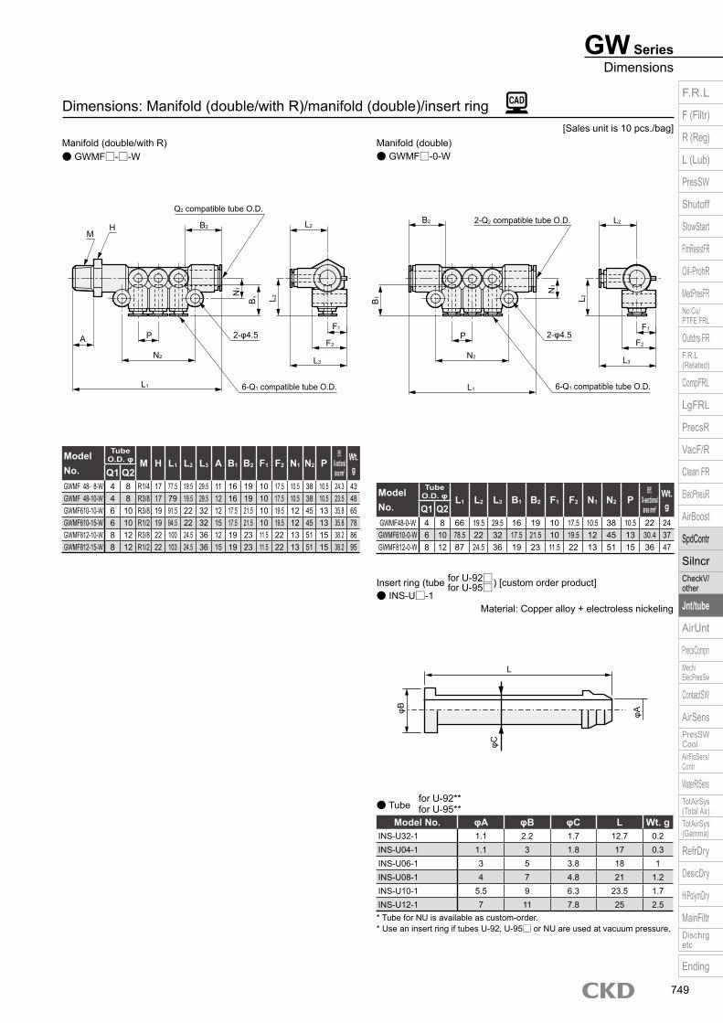
Material: Copper alloy + electroless nickeling
* Tube for NU is available as custom-order.* Use an insert ring if tubes U-92, U-95□ or NU are used at vacuum pressure.
for U-92**for U-95**● Tube
for U-92□ for U-95□
● INS-U□-1Insert ring (tube ) [custom order product]
Dimensions: Manifold (double/with R)/manifold (double)/insert ring
● GWMF□-0-W● GWMF□-□-WManifold (double)Manifold (double/with R)
Model No.
Tube O.D. φ M H L1 L2 L3 A B1 B2 F1 F2 N1 N2 P
Eff. X-sectional area mm2
Wt. gQ1 Q2
GWMF 48- 8-W 4 8 R1/4 17 77.5 19.5 29.5 11 16 19 10 17.5 10.5 38 10.5 24.3 43GWMF 48-10-W 4 8 R3/8 17 79 19.5 29.5 12 16 19 10 17.5 10.5 38 10.5 23.5 48GWMF610-10-W 6 10 R3/8 19 91.5 22 32 12 17.5 21.5 10 19.5 12 45 13 35.8 65GWMF610-15-W 6 10 R1/2 19 94.5 22 32 15 17.5 21.5 10 19.5 12 45 13 35.8 78GWMF812-10-W 8 12 R3/8 22 100 24.5 36 12 19 23 11.5 22 13 51 15 38.2 86GWMF812-15-W 8 12 R1/2 22 103 24.5 36 15 19 23 11.5 22 13 51 15 38.2 95
Model No.
Tube O.D. φ L1 L2 L3 B1 B2 F1 F2 N1 N2 P
Eff. X-sectional area mm2
Wt. gQ1 Q2
GWMF48-0-W 4 8 66 19.5 29.5 16 19 10 17.5 10.5 38 10.5 22 24GWMF610-0-W 6 10 78.5 22 32 17.5 21.5 10 19.5 12 45 13 30.4 37GWMF812-0-W 8 12 87 24.5 36 19 23 11.5 22 13 51 15 36 47
Model No. φA φB φC L Wt. gINS-U32-1 1.1 2.2 1.7 12.7 0.2INS-U04-1 1.1 3 1.8 17 0.3INS-U06-1 3 5 3.8 18 1INS-U08-1 4 7 4.8 21 1.2INS-U10-1 5.5 9 6.3 23.5 1.7INS-U12-1 7 11 7.8 25 2.5
[Sales unit is 10 pcs./bag]
2-Q2 compatible tube O.D.
6-Q1 compatible tube O.D.
2-φ4.5
L 2B1
N1
L2B2
P
L1
F1
L3
F2
N2
MH
Q2 compatible tube O.D.
6-Q1 compatible tube O.D.
2-φ4.5
L 2B1N
1
L2B2
A P
L1
F1
L3
F2
N2
L
φA
φC
φB
F.R.L
F (Filtr)
R (Reg)
L (Lub)
PresSW
Shutoff
SlowStart
FlmResistFR
Oil-ProhR
MedPresFRNo Cu/PTFE FRL
Outdrs FRF.R.L (Related)
CompFRL
LgFRL
PrecsR
VacF/R
Clean FR
ElecPneuR
AirBoost
SpdContr
SilncrCheckV/ other
Jnt/tube
AirUnt
PrecsCompnMech/ElecPresSw
ContactSW
AirSensPresSW CoolAirFloSens/Contr
WaterRtSensTotAirSys (Total Air)TotAirSys (Gamma)
RefrDry
DesicDry
HiPolymDry
MainFiltrDischrg etc
Ending
749