J300SERIES - Hiflex Automatiseringstechniek BV
144
HITACHI INVERTER J300SERIES INSTRUCTION MANUAL Three pllase input 400V class J300 E4: European version Hitachi, Ltd. NBsosx Tokyo Japan
-
Upload
khangminh22 -
Category
Documents
-
view
5 -
download
0
Transcript of J300SERIES - Hiflex Automatiseringstechniek BV
HITACHI INVERTER
J300SERIESINSTRUCTION MANUAL
Three pllase input 400V class
J300 E4: European version
Hitachi, Ltd. NBsosx
Tokyo Japan

)
SAFETYFor the Best Results with J300 Series inverter. read this manual and all of the wamins sisn attachedto the inverter carefully before installing and operating it, and ibllow the instrucrionsixaitly. Kcepthis manual handy for your quick rel'erence.
Delinitions and Symbols
A satety instruction (message) is given with a hazard alert symbol and a signal word;WARNING or CAUTION. Each signal word has the following meaning throughour this manual.
This symbol means haziudous high voltagc. lt used to call your attention toitems or operations that could bc dangerous to your and other personsoperating this equipment.Read these message and follow thesc inshuctions carefully.
This is the "Safety Alert Symbol.." This symbol is used to call your atten-tron to items or operations that could be dangerous to your or other personsoperating tbis equipment. Read these messages and follow these instruc-tions carefully.
, / l \./ ! \ WARNING WARNING
A "or'o,
NOTE
Indicates a potentially hazardous situarion which, ifnot avoided, can resultin serious injury or death.
CAUTIONIndicates a potentially hazardous situation which, if not avoided, can resultin minor to moderatc injury, or serious damage ofproduct.The mauers desc bed under f' CAUTtdfl may, if nor avoided, lead toserious results depending on the situation. Imponant matters ar:e describedin CAUTION (as well as WARNING), so be surc to obsene rhem.
NOTE: Notes indicate an area or subject of special merit, emphasizingeilher lhe producl . cdpabil t t ie. or uommon errors in operrtron or mainrenance.
/N nazanoous HrcH voLrAGE
Motor control equipment and electronic conrollcrs are connected to hazardous line voltages. Whenservicingdrives andelectronic controllers. therc mightbe exposedcomponents with cases orprotrusionsat or above ljne potenrial. Extreme care should be takcn to protect against shock.Stand on an insulating pad and make it a habit touse only one hand when checking components. Alwayswork with anotherperson in case anemergency occurs. Disconnect power before checking controllersor pedolming maintenance. Be sure equipmenl is properly grounded. Wear safety glasses wheneverworking on an electronic controllers or rotating electrical equipment.
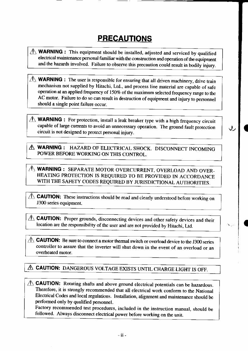
lA WlnltlC : This equipment shoutd be in\ta ed. adjusled and r"rui..Jb, ouJifiJ lI electrical maintenance personal familiar with the consFuction and operation of thiequipment I] and the hazards involved. Failure to observe rhis precaution coutd resuh in-S!1!!y-
l
,{\ WAFNING : The user is responsible for ensuring that all ddven machinery, dnve trainmechanism not supplied by Hitachi, Ltd., and process line material are caDable of safeoperation at an applied fr€quency of 1502. of the maximum selected frequency range to theAC motor. Failur€ to do so can result in destruction of equipment and injury to personnelshould a single point failure occur.
I A WanUHO : For proreclion. instau a leak breaker,yp" *;,t u tigf, f.";;;;;;lI capable ol large currents to avoid an unnecessary operation. The ground fault prorection I' circuil is nol designed lo protect pemonal iniurv. I
lA WARN|NG : HAZARD oF ELECTRIcAL sHocK. DlscoNNEcr rNcoMrNG 111
I powER BEFORE wORKlNc ONTHTS CONTROL.
I
| ,4r mnrtlc : sEpARATE MoroR ovERcuRRENr, ovERLoAD;ND otER- I] HEATTNC PROTECTION tS REQUTRED TO BE PROVTDED rN ACCORDANCE II
I l\ CAUTION: These instrucrions should be read and clearly un,t .rtood b.io* *-kinr - -l
' lI
J300 series equipment.
I l\ CAUftOlr Proper ground:.. disconnecting de\,ices and oth"r.uf.ty d"ui... *J,hJlI location are the responsibility of the user and are not provided by Hitachi, Ld.
I
i A CAtmOl: Be sule to connecr a motor thermal switch or ou"doud d"ui"" to th" J3m.".i""1I controller to assure that the iiverter will shut down in the event of an overload or an l
I] overheated motor.
I A cAUTtoN: DANcERous voLTAGE Exrsrs INTIL cHARcE LIG@
PRECAUTIONS
A CAUTION: Rotating shafts and above ground electrical potentials can be hazardous.Therefore, it is srongly rccommended that all elecrical work conform to the NationalElectrical Codes and local regulations. Installation, alignment and maintenance should beperformed only by qualified personnel.Factory recommended test prccedures, included in the instruction manual. should befollowed. Always disconnect electrical power before working on the unit.
a
I
Ju
- l t -

via low resistive path (< 0.lO)
event suitable protection must be
AAlarm connection may contain h^zardou$ live voltage even when inverter is disconnected.ln case ofremoving front cover for maintenance or inspection, confirm that incoming powerfor alarm connection is surely disconnected.
ZL CAUTION:Hazardous (main) teminals for any interconnection (motor, contact breaker, filter etc.)must be inaccessible in end in:,tallation.
I CAUTION:Connection to field wiring terminals must be reliably fixed having two independent meansof support. Using terminal with cable suppon (figure below), or cable gland, cable clampetc.
I cAUflON:A double pole disconnection device must be htred to the incoming mains supply clos€ tothe inverter. Additionally, a protEction device meeting IEC947- l/lEC947-3 must be fittedat this point (protection device data shown in page 5-8).
.A caunol:EMT filter is reouired for EMC directive .
The above instructions. together with any other requirements hiehlighted itr thismanual. must be complied with for cotrthued LVD compliance.
I.. WARNING This equipment has high leakage current and must be perminady hand wiredto eanh via two indiDendent cable.
A MoroRsa) Class I motor must be connected to prctective earthb) Any motor used must be of suitable rating.c) Motors may have hazardous moving parts, in this
Drovided.
,A CAUTION:This equipment should be installed in an enclosure meeting requirements of IP4X (seeEN60529). The end application must be in accordanc€ with BS EN6O2O4- I (with r€ference
I to manual page 4-1 and 4-2, the diagram measurements to be suitably amended).
- l l l -

The Date OperationManual No.No. Revision Contents oflssue
Revision History Table

TABLE OF CONTENTS
SAFETY PRECAUTIONS
Page
l - l
3 - 1
INSPECTION UPON UNPACKING
APPEARANCE AND NAMES OF PARTS
5
6.
1 .
8 .
9 .
l 0
l l

I. SAFETY PRECAUTIONS
L hslallation
a Be sure to install the unit on flame resistant material such as metal. ............. D. 4-lOtherwise. there is a danser offire.
a Be sure not to place anything inflammable in *re vicinity.Otherwise. there is a daneer of fire.
o Be sure not to let the foreign matter enter such as cut wire refuse,spatter from welding, iron refuse, wire, dust, etc.Otherwise, there is a danger of fire.
a Be sure to install it in a place which can bear the weight accordingthe specifications in tle text (4. Installation).Otherwise, it may fall and there is a danger of injury.
a Be sure to install the unit on a perpendicular wall which is not subject
Otherwise, it may fall and there is a danger of injury.a Be sure not to install and operate an inverter which is damaged or
parts ofwhich are missing.Otherwise, there is a danger of injury.
a Be sure to install it in a roorn which is not exposed to direct sunlightand is well ventilated. Avoid environments which tend to be high intemperature, high in humidity or to have dew condensation, as well asplaces with dust, conosive gas, explosive gas, inflammable gas,grinding-fluid mist, salt damage, etc.Otherwise, there is a danger of fire.
a Be sure that the wall surface is a nonflarnmable material. such as steelDlate.
Wiring
. . . . . . . . . . . . p . + l
. . . . . . . . . . . . p . +1
t o . . . . . . . . . . . P .4 -1
. . . . . . . . . . . . p .4 - l
. . . . . . . . . . . . p . + l
. . . . . . . . . . . . p .4 -1
. . . . . . . . . . . . p .4 -2
I caurroH
a
a WARNTNG
Be sure to ground the unit.Otherwise, there is a danger ofelectric shock and/or fire.Wiring work shail be caried out by electrical experts.Otherwise, there is a danger of elecffic shock and/or fire.Implement wiring afier checking that the power supply is off.It might incur electric shock and/or fire.After installing the main body, carry out wiring.Otherwise, there is a danger of electric shock and,i or injury.
p . 5 - l

CAUTION
Make sure that the inPut voltage is:
Three phase 380 to 415 v/50 Hz, 400 to 460 V/60 Hz
Be sure not to inPut a single phase to a 3 phase type'
Otherwise, therc is a danger of fire'
Be sure not to connect AC power supply to the output terminals
tu (T1), v (r2), w (r3).Otherwise, there is a danger of injury and/or fire'
Power supplY
Fasten the scrcws with the specified fastening torque Check so that
there is no loosening of screws.Otherwise, there is a danger of fire.
for usi
R (LI) , S \L2' . T Gl r : Three phase ]80rn4l5v'50 Hr4{Xl ro 460V/60 Hz
p. 5-2
p.5-2
Frequency inverters with CE-filters (RFl-filter) and screened motor
cables have a higher leakage current against enrth Especially in the
moment of switihing on this can cause unintentional triggerings of
earth leakage circuit breakers- Because of the rcctifier on the lnput
sirle of the inverter there is the possibility to stall the switch off
function through amounts of Dc-current' The following should be
observed:Only short time-invariant and pulse curent sensitive earth leitkage
circuit breakers with higher t gger curent should be used'
Other components should be secured with separate earth leakage
circuit breakers.
Earth leakage circuit breakers in front of an inverter are not an
absolute protection against direct touchlng'
a Besuretosel the fuse(s) (the samephaseasthe main power \upply)
in the operation circuit '
Otherwise, there is a danger of fire'
a As for motor leads, eanh leakage breakers and electromagnetic
contactots. be sure to use the equivalent ones with the specified
capacity (rated).Otherwise, there is a danger offire.
(11) (12) (Lr)R S T
(T1) (T2) (T3)

A cnunoHInput phase failure protection
( I ) J30O-E version inverter are provided with the phase failure protection on the powersupply.
(2) When a buzzer, lamp, noise filter or transformer is connected between the input powerterminals (L1, L2, L3) and input power fuses, input phase failure cannot be protected.
(Ll) (L2) (L3)
(Bad example)
(Good example)
Power supply

3. Contml and oPeration
A WARNTNG
a Be sure to tum on the input power supply after mounting the surface .' P 6-l
cover. While being energized. be sure nol lo remove lhe cover'
Otherwise, there is a danger of electric shock'
a Be sure not to op€rate the switches with wet hands p 6-l
Otherwise, thele is a danger of electric shock'
a While the inverter is energized, be sure not to touch the inverter " p 6-l
terminals ev€n during stoppage.Otherwise, there is a danger of electric shock'
a If the retry mode is selected, it may suddenly restart dudng the triP p 0- t
stop. Be sur€ not to approach the machine' (Be sure to design the
machine so rhat personnel safety will be secured even if it restans )
Otherwise, there is a danger of injury'
a Even if the power supply is cut for a short period of time, it may . p 6-l
r€start operation after the power supply is recovered if the operation
command is given lf it may incur danger to p€rsonnel, be sure to
make a circuit so that it will not Estart after power rccovery'
Otherwise, there is a danger of injury.
a The Stop Key is effective only whe. ihe function is set Be sure to p 6-l
prepare the Key separately from tbe emergency stop'
Otherwise, there is a danger of injury.
a After the op€ration command is given, if the alarrn reset is conducted' . .. " p 6- l
it will restart suddenly. Be sure to set the alarm reset after checking p 5-13
the oD€ration command is off.Otherwise, there is a danger of injury.
a Be sule not to touch the inside of the energized inverter or to put a bar .. .. p 6-l
into it.Otherwise, thee is a danger of electric shock and/or frre'
I When the power is tumed on when the running command is on' the
motor starts rctation alld it is dangerous Befor€ tuming lhe Power on'
confm that the running command is not on'
a When the Stop key function i$ ineffective, prcs$in8 the Stop key does
not cancel the stop and trip.Be surc to prcvide an emergency stop switch separately When lhe
operarion command destination is a digital op€rator, this selection es
ineffective.
P . 7 - l
'l-4

I caunoruRadiating fin and discharging resistor will have high temperature.Be sure not to touch them.Otherwise, there is a danger ofgetting bumed.
p .6-2
p .6-2
. . . . . . . . . . . . p . l0 1
. . . . . . . . . . . . p . 10- t
a Low to high speed opcration of the inverter can be easily set. Be surcto operate it after checking the tolerance ofthe motor and machine.Otherwise. there is a danger oI injury.
a If a motor is operated at a frequency higher than 60H2, be sure tocheck the speeds ofthe motor and the machine with eachmanufacturer, and after getting their consent, operate them.Otherwise, there is a danger of machine breakage.
o Check the following before iuld during the test run.Otherwise, there is a danger ofmachine breakage.. Was the shon-cut bar between +l and + connected?
Was the direction ofthe motor correct?Was the invener ripped during acceleration or deceleration?Were the rpm and frequency meter correct?Were there any abnormal motor vibrations or noise?
J , Maintenance, inspection and part replacement
i\ unrurNoAfter a lapsc of morc than 10 minutes after turning off the input power.uppl). pcdorm rhc meinlenance and inspection.Otherwise. there is a daneer ofelectric shock.
o Make sure that only qualified persons will pedorm maintenance,inspection and pan replacement. (Befbre starting the work, removemetallic objects f|om your person (wristwalch, br.rcelet, etc.)(Be sure to use tools protected with insulation.)Otherwise. there is a danger of electric shock and/or injury.
1!\ crurona When removing connecto$, never puli the wircs. (Wircs for cooling ... . . . . . . . . . p. l0-l
fan and thermal relay)Otherwise, there is a danger of tire due to wire breakage and/or injury.
, . , . , , . . , , . ' , p ,6-2
. . . . . . . . . . . . . p .6 -3
a
t - c

5, Others
7\ mnxneNever modify the unit.Otherwise, there is a danger of electric shock and/or injury'
aI caunor
Wilhsland voltaee aests and insulatioo r€sistance tesls (megger leslst -are -.executed before ihe units are shipped, so thsl thcrt is tro need to conducl lnese
tests before op€ration.
When conducting m€gger t€-sts as a part of daily inspection, be suT that tl:s€ lEistsarc onlv execuleA betw;en the main circuit and the ground' Do not execute megger
tesrs on the control circuit.
Remove the ZNR connecting b€t*een G(PE) to T(L3) terminal before conductingtie tests. ARer tests, be sure to anacb the ZNR again
a I)o not atisch or remove wlring or connectors wh€n ltower is applied' Also' tlo
not check signals during oPeratiotr.a Do not stoD;peration by switching off th€ electromagnetic contactors on the-
primsry oi s€condrry sid€s of lhe Inverter'
Earth
Tum ON and OFF(Cod exanple)
When there has been an instantaneous power failure, and-if an operation instruction
has betn siven, then tbe unil may restart operation after the power failure has,ended'
If there iia possibility thal such an occunence may harm humans' then Insuul an
;il;;;;;J[";-"d"or (Mso) on the power supplv side' so that the circuit does
not allow;ulomalic restarting afier the power supply recovers ll tne opuonal;;i,tJo.J;iil;ilJ'ano fie rer.v rul''ton hai'been selected' this will also cause
;;;;;!;;iil;;;h"n un op..otion intL.uction has been inPut' so please be
careful.
(L l ) (L2) rL l r r+1, t+ l l - , mlr ml m)
R B R S T P D P N U V W
ZNR
RB(Ll)R
tL2)s
(L3)T
(+ l )PD
{+)P N
CIl)U
cn) cr3) (PD)
i1'3)(T2)
1-6

/\ caurrorua Do not insert leading power factor capacitors or surge absorbers between the
output terminals ofthe inverter and the motor.
Surge absorber
(Lr)(L2Xh) r )(T2)(-n)Powd I-) R . S . T!upply
ing power facbr capacitor
o Be sure to ground the grounding terminal, @.a When inspecting the unit, after turning the power supply off be sure to wait
unitl the CHARGE lamp b€side the control terminal is offbefor€ opening thecover.
(lfthe lamp is lit or still flickering, then tlte intemal capacitor's rcsidual voltage isstill dangerous.)
. MOTOR TERMINAL SURGE VOLTAGE SUPPRESSION FILTER(FOR THE 4OO V CLASS)
In a system using an invener ofthe voltage control PWM system, a surge voltagecaused by the cable constants such as the cable length (especially when the distancebetween the motor and inverter is 10 m or more) and cabling method may occur atthe motoa terminal.A dedicated filter ofthe 4O0 V class for suppressing this surge voltage is available,Please order one.
. PROTECTION AGAINST NOISE INTERFERENCE FROM INI'ERTER
The inverter uses many semiconductor switching elements such as transistors andIGBTS. Thus, a radio set or measuring instrument located near the inverter issusceptible to noise interference.To protect the instruments ftom enoneous operation due to noise interference, theyshould be installed well apart from the inverter. lt is also effective to shield thewhole invener structure.Addition of an EMI filter on the input side of the inverter also reduces the effect ofnoise trom commercial power line on extemal devices.Note that extemal dispersion ofnoise from the power line can be minimiz€d byconnecting an EMI filter on the primary side of inverter.

A CAUTION
EMlflllcr
,!. 1EMI
complck\ Eround |ne shiel,l madcol mclal nleen 'nrlord Pdel c"wid as shon a wire as Possible
. EFFECTS OF DISTRIBUTOR LINES ON INVERTERS
In the cases below involving a general_purpose invefier' a large peak current flows
on the power supply side, someiimes destroying the convefier module Where such
sit.rations are foreseen, or the paired equipment must be highly reliable' install an AC
reactor between the power supply and the inverter'
(A) The unbalance factor of the power supply is 37o or higher'
(B) The power suPply capacity is at least l0 times greater than the inverter capac ity
(and the power supply capacity' 500 kVA or more)
(C) Abrupt power supply cbanges are expected'
Examples:(1) Several inverters are interconnected with a short bus'
(2) A thyristor convefier and an inverter are interconnected with a short bus'
(3) An installed Phase advance capacitor opens and closes'
tn cases (A), (B) or (C), we recommend installing an AC reactor of 37o (in-a voltage
drcp at rated cunent) with respect to the supply voltage on the power supply side-
a When occDrring an EEPROM efior ( fiffi )' be sure to conlirm the setting
value again.
a When setting b contact to the reverse command ([REV] terminal), the inverter
state automatically. Do not set to b contacL
In all the illustrations in this miulual, covers and safety devices iue occasionally
removed to describe the details. When the product is operated, male sure that the
covers and safety devices are placed as they were specified originally and operate
it according to the instruction manual.
GENERAL CAUTION
1-8

Before installation and wiring, be su.e to check the following:
. Make sure that therc was no damage during tansportation the unit.
. After unpacking the unit, make sure that the package contains one invener and oneoperation manual
. Make sure that the product is the one you ordered by checking the specifications label onthe front of the cover.
lnFltpowasupply, 'l+
rn&,.nd rr.q!..ct J+R.Ed inpotcure +Prod*iio. yd
INPUT OUTPUTr i ! I 5 l / r P l l i h r u r r r 3 0 1 6 , r y 1 P h
Drrr@wc
( (
f Ct" -*ot" is fu !h. r30o 055HFB1)
+ Ou9ut voltaS.- Ralcd outpot cuft.t+ Mdimnn applicNbl€ noror (4Pkw)+ Prduclion numb6
and felory conrol symbol
Contents of Snecifrcations Label
If you discover any problems, contact yout sales agent immediately.
Descriotion ot Inverter Model
J3m
TII
Series name
E4: Euopean version
Srucure typeF: with digilal op€rotor(Semi-clo6ed, open type)
Input voltageH: Thr€! phase 400V class
Applicable rnotor caFcity (4P.kW)055: 5.5kW 370: 37 kw0?5: 7.5kW 450: 45 kW110: 11kW 550: 55 kW150: 15 kW 750: 75 kW22it22kw q)0: mkw3m:30kW 1100: l10kW

3. APPEARANCE AND NAMES OF PARTS
\ames of Parts
Front cover
A set screw
Charge lamp(LED)
! .)ntrol circuitr.rminals
Case -_-_
.'t a'v(voigiot
opemtorMain circuitteminals
Wiringholes
Earth terminal
Blind cover

4. tN toN
l\ cAUloN
a Be sure to install the unit on flame resistant material such as metal.Otherwis€. there is a danser of flre.
Be sure not to place anything inflammable in *re vicinity.Otherwise, there is a danger of fire.
Be sure not to let the foreign matter enter such as cut wire rcfuse, spatter fiomwelding, iron refuse, wire, dust, etc.Otherwise, there is a danger of fire.
I Be sure to install it in a place which can bear the weight according to thespecifications in the text (4. Installation).Otherwise, it may fall and there is a danger of injury.
a Be sure to install the unit on a perpendicular wall which is not subject to vib.ation.Otherwise, it may fall imd there is a danger of injury.
o Be sure not to instali and operate an invener which is damaged or parts of which aremissing.Orher* ise. there i\ a danger of injury.
a Be sure to install it in a room which is not exposed to direct sunlight and is wellventilated. Avoid environments which tend to be high in temperature, high inhumidily or to have dew condensation, as well as places with dust, corrosive gas,explosive gas, inflammable gas, grinding-fluid mist, salt damage, etc.Otherwise. there is a danser offire.
4-1

For cooling purposes, be sure that the inverter is installed veftically ln addition' be sure that
it i. iip-ui"i iio- oiher components and walls' lf foreign matter is introduced into the
interio; of the inverter, this mty cause malfunctions, so male sure thal no torelgn matter carl
entef l[.
NOTE: Install rhc invencr venicallv.Do not install it on the floor or horizonlally'
NOTE l: The inverter should be installed in a locked enclosure that meets tho requrrements
in lP4X (see EN60529).
NOTE 2: When an inverter (055HF to l50HD is installed outside lul enclosure' the top ol
the inverter needs to be covered with the optional blind cover'
The hisher the ambient temperature inside the inverter' the shorter its life will be'
i ir tt"i n"n..utins unll is used near lhe invener' try lo krep i l a\ lar^awal as .possible.'Also. wh'en inslall ing lhe inverter in a bo\' be sure to carelully con, loer
ventilation and the dimenstonsFor EMC direcrive and Low Voltage directive, do not remove the front cover'
The end application must be in accordance with BS EN6020'l- 1'
Each of irwerters 220HF to I IOOHF must be installed in a locked enclosure'
NOTE 3:
NOTE 4:NOTE 5:NOTE 6:
+
I\ CAUTION
Be sure lhat the wall surface is a nonflammablematerial, such as steel Plate.
A Be "ure to check the ambient temperalure
Applicable modelPla!e (,f installttion
055 to 1l00HF(NOTE 6)
- l0 to 50'Cwithin the enclosurc
(NOTE l) -10 to 40'C
055 ro l50HF-10 to 40'C
Outside the enclosure(NOTE 2) -10 to 40'C
4-2
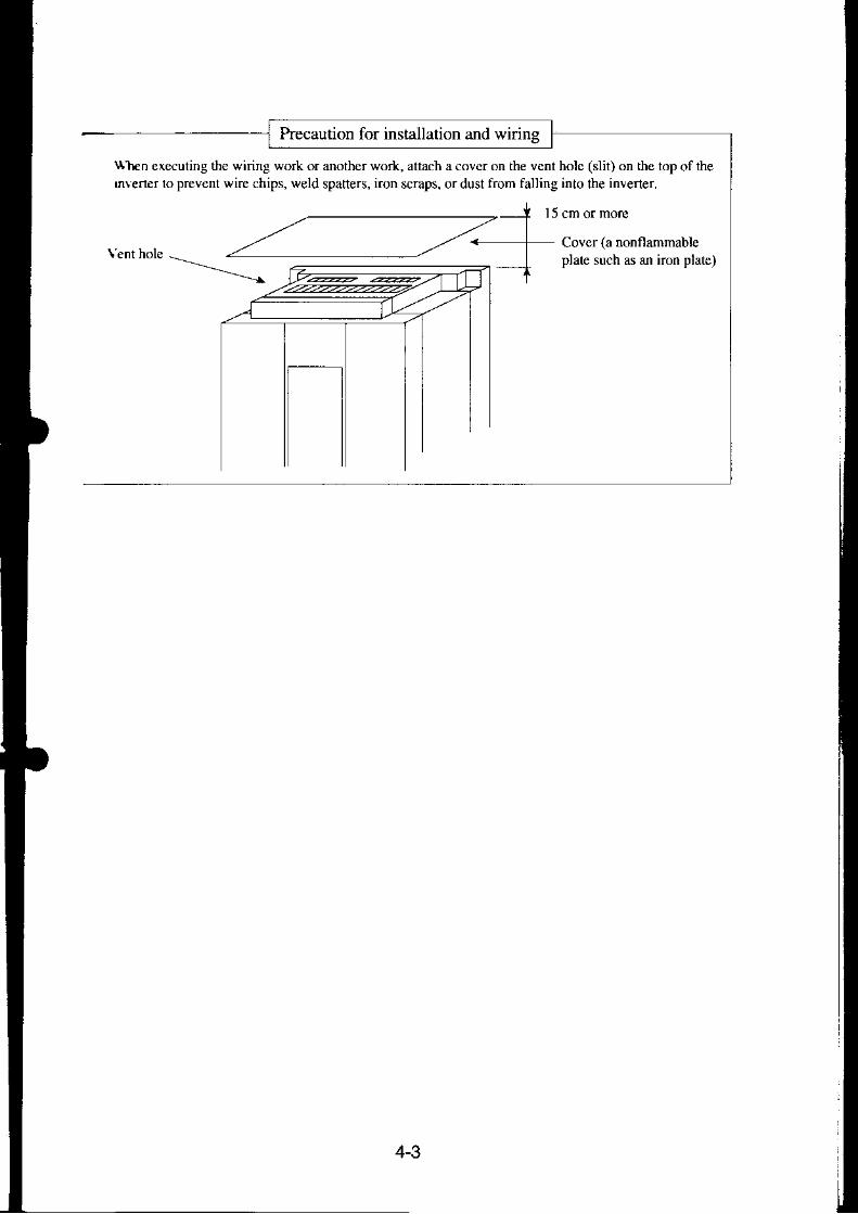
Precaution for installation and wirins
\\}En executing the wiring work or another work, altach a cover on the vcnt holc (slit) on the top of ihemlener lo prevent wire chips, weld spatters, iron scraps, or dust from falling into lhe inve(er.
I5 cm or more
Covcr (a nonflammableplate such as an iron plate)

I wanHrrucBe sure to ground the unit.Odterwise, there is a danger of electric shock and./or lue.Wiring work shall be caried out by electrical experts.Otierwise, there is a dange. ofelectric shock and./or fire.Implement wiring after checking that the power supply is off.It might incur electric shock ard./or fire.Afte! installing the main body, carry out wiring.Otherwise, there is a danger of electric shock and/or injury.
c - l

A caunouMake sure that the input voltage is:Three phase 380 to 415 V/50 Hz, 400 to 460 V/60 Hz
Be sure not to input a single phase to a 3 phase type.Otherwise, there is a danger offire.Be sure not to connect AC power supply to the output terminalstu (rl), v (r2), w (r3)1.Otherwise, there is a danger ofinjury and./or fire,
Note:R (Ll), s (L2), T (L3): Three phase 380 to 4l5V/50 Hz
4fi) to 460V/60 Hz
Power supply
Fasten the scrcws with the specified fastening torque. Check so that there is noloosening of screws.Otherwise, there is a danger of frre.Remarks for using earth leakaqe circuit breakers in the mains supDlv:Frcquency inverten with CE-filters (RFl-filter) and screened motor cables have ahigher lei*age current against earth. EspecialJy in the moment of switching on thiscan cause unintentional triggerings of earth leakage circuit breakers. Because of iherectifier on the input side of the invener there is the possibility to stall the switch-offfunction through amounts of DC-current. The following should be observed:
Only shon dme-invariant and pulse current-sensitive earth leakage circuitbreakers with higher trigger current should be used.Other components should be secured with separate earth leakage circuit breakers.Earth leakage circuit breakers in front of an inverter are not an absolute protectionagainst direct touching.
Be sure to set the fuse(s) (the same phase as the main power supply)in the ope.ation circuit.Otherwise, there is a danger of fire.As lbr motor leads, earth leakage breakers and electromagnetic contactors, be sure touse the equivalent ones with the specified capacity (rated).Otherwise, there is a danger of fire.
Double pole disconnection device must be fitted to the incoming mains supply closeto tne inverter. And protection device meeting IEC947-I/IEC947-3 must be fitted atthis point.
Connection to wiring terminal must be reliabily fixed with two means of support.
(Ll) (L2) (L3) (Tr) (r'2) (Tr)R S T U V W
5-2

The terminal board will be exposed when the front cover or terminal cover (220HF toI l00HD is removed. wire the inverter in this state.
Wiring the Power Supply and Motor
. The inverter will be damaged if the power supply is connected to the motor teminalsU(Tl), V(T2) and W(T3), so be sure not to make any mistakes.
. If multiple moton are to be connected, be sure to attach a tiermal relay to each motor.
NOTE 1: When changing the power supply of the motor between the invener and commer-cial power, be sure to install mechanically interlocked switches Mgl and Mg2.
flsre
NOTE 2: Install an eanh leakage breaker at the input of the invener. (Select an eanhleakage breaker whose sensitive current level is raised in high frequency range.)when the cable length between the invefter and motor is long (more than 10 m),the thermal relay may malfunction due to higher ha.rnonics. Thereibre, install anAC reactor on the output side of the invener or use a current sensor in place ofthe thermal relay.
1' 1't lPower supp
Tly
Braking Units
R (L I ) (T I ) Us (L? Irvener (r2)vT (L3) aT3) W
5-3

NOTE 3: Be sure that the specified grounding is carried oul Be-sure to separate the unit'sgrounding pole frbm those of otier heavy electrjc machinery' and avoid usingcommon grounolng poles.
lf multiple inverters are used, make sure that the grcunding connections do notcreaE a loop.
Proper grounding
1\ caurroruExtemal or remote over load protection required, if multiple motors to be connected'
Grounding boll(at lhe s'te)
54

Wiring ofControl Circuit TermiDah
SOURCE TYPE wiring(Factory settings for European version)
Input inielligcnt terminalFailure alarm
Failurc alarm
SINK TYPE wiring
oi ItInput intelligenr rerminal
NOTE l: When an outplt intelligent terminal is used, be sure to install a surge absorbingdiode in parallel with the relay (Ry). Otherwise, the surge volhStcreared wh;nthe relay (RY) goes ON or OFF may damage the output intelligent terminalclrcuit.
NOTE 2: Use a twisted and shielded wire for the signal line, and cut the shielded coveringas shown in the diagram below. Make sure that the length of the signal line is 2bmetefs or less.
5-5

No grounding nec€ssarY
FG (framc ground) of the invener
NOTE 3: When the frequency setting signal is tumed on and off with a contact, use a relaywhich will not cause contact malfunctions, even with the extremely weak cul-rcnts and voltages, such as clossbar twin contacts, etc.
NOTE 4: Use relays which do not have contact defects at 24 V DC, 3 mA for the otherte.minals.
NOTE 5: Separate the main circuit wiring from the relay control circuit wiring. If theymust cross, be sure that they cross at a right angle
"/
Do not short between the terminals H and L and between the terminals P24 andCM1 of the control circuit.
lnsulate lhe common terminal L for ftequency analog command input and thecommon terminal (COMMON) ofthe peripheral equipment such as thesequencer before starting use.
Connect
Insulate
Main circuit powcr line(R, S, T. U, v, W, P, RB, N, Ll , L2, L3, Tl , T2, Tl , +, - , etc.)
Right angte
Signat inpul line
Separatc by l 0
\FM. CM t. fLC. P24. F\t . 8. 7. b. 5. 4. 3. 2. L
,H, O. OI, L, CM2. 12, I I , ALO, ALl, AL2)
NOTE 6:
NOTE 7:
5-6

tJ Connection to the Programmable ControlleralEn lh€ intemal interfacc po\rer source is usedI T}|rs rs an example whcn the sink type transistor
.{Iput (open collector output) module of thei€ouencer rs connected
\ ' te Malc \ure of lhe shon-( i rcuir bar or wirebetween the terminals PLC and P24.
J300 scries
@ This is an example when rhe source typetransistor output (open collector output)module ofthe sequencer is connected
Nole: Male sure of rhe shon-crrcuir b, f or $ i ,<between the terminals CM1 and PLC.
YTS48 type output module(by Hitachi)
: when the extemal interface powcr source is usedI Thi. i \ an ernmple $hen rhe sink ( jpe rran\rsror
output (open collector oulput module ofthesequencer rs connect€d
Notc: Remove the short'circuit bar or wire betweenthe tenninals CMI and PLC or P24 and PLC.
@ This is an example when the source typetransistor output (open collector output)module ofthe sequencer is connected
Noie: Remove the short-circuit bar or wirc betweenthe terminals CM I and PLC or P24 and PLC.
J300
YTR48 type ourput module(by Hitachi)
YTS48 type output module(by Hitachi)
Nolc: Bc surc 1o turn the inverter on afler thc conrroller and external power sourcc(Otherwise, the dala in ihe inv€rter may be changed.)
: TR.lli lype outpul module- \ H i l J e h i )
5-7

Wiring Equipment, Options (EMI filter, etc.)
(400V class)
Power supply
R S T
InverterRA
(Tr) (T2) (Tl
Standard equipment
sigul
5.5 il00055HF EX50C(30A)H20
EX50C(30A)H20
l 1 EX50C(5OA) H25
l 5 J300.150HF EX608(604) H35
18.5it00.t20H! EX60B(60A) H50
22 H50
l 1 RXr00(r00A H80
t.t00.450HF H t00
55 RX225(175A H t25
Hl50
RX225(225AH200
0 H250
Fundlon
( A L l - ! n L )( A L I . I J H )
This pan js ukd rhen the unbalancc voltagc ratio is 3Eoormore and powersupply is 500 kvA ormore, and thercis a rapid change in rhe poversupply.It also jmproves the pover fa.ror.
reactor) (ZCL-A)
Using thc inveflermay cause noise on the peripheralequipncnl through thc powerlines.This pxn redu.es noise.
EMI fil1erfor
0FJ300-! ! ! )
This pan reduces common noise generated betweenrhe pnser .upply rnd rhe Er .dno. a, se l l a \ romdl nonc.Put i r in rhe pr imary \ ide nf inrener
NOTI 5
( R B I J J . ! )
'tl'is pul is used lbr appticrlions thar needs to increaser lc bmle .orq, e o l rhe in !ener q In t requenr l ) ' rm o land olfrnd to run high ineftia load.
This pan educes noile generated at the output of
(lr is posible to use for bolh irpur and output.)
(ACL L ! ! )(ACL H l t l )
Running motors with rhc invenergenentes vibntiongnratcr lhan ftar wlthcommercial powersupply-This pan insbllcd bctwccn fie invenerard motor reduces
wl en ,he crb le ler t rh r rseen rhe In\cac ' JnLl roror Flong, a countemeasule for a malfunction offte lemal

!iOTE 1: The applicable equipment is for a Hitachi stardard four pole squirrel-cage motor..'IOTE 2r Be sure to consider the capacity of lhe circuit bEaker to be used.NOTE 3: Be sure to use bigger wires for power lined if the distalce exceeds 20 m.NOTE 4: Be sure to use an grounding wire of 3.5 rnm? or more.NOTE 5: EMI filter is required for EMC directive but others are not for this purpose.
NOTE 6: Install an earth leakage bEaker meeting requir€ments of IEC94'1 -IIEC94'1 -3 atthe inDut.
(.) Use 1.25 nm: wire for tle alarn hignal lrie.classify the det€ctive current of lhe eaflh leakage br€aker depending on lhe totaldistancer b€tween th€ invener and the motor,
Detectiv€ cunent (mA)
lm m and less 30300 m and less lm6m m and less 2n
NOTE 7: When using CV wire and metal tube,the leakage current is around 30 mA/km.
NOTE E: The leakage cunent becomes eight timesbecause IV wires have a high dielectricconstant. Thereforc, use an one classlarger earth leakage breaker accordingto the left table.
5-9

5.5 Terminal( I ) Main circuit terninal
, , widlh
fcrcfrTerninal layoul Tvp€ wid|n
(mm,
-\S\\\ '- lntemal short c utbar
RB(RB)
R( 1 1 )
s(,2\
T(L3)
PD(+l)
P(+)
N( )
UCTI) (Tl) (Tl )
G €(PE)
055,075HF
S\) .-- hlemal qhoncircuit bar
R(L1)
S(L2\
T(L3)
PD(+l)
P N( )
U(rl) (rl) (rl)
Ge)(PE)
0l l . l50HF
lS\\\) --- Intemat sttmt circ it bar
(PE)R
(Ll)s
0,2)T
(L3)PD(+1)
P(+)
N U(rl) cr1) (rl) (PE)
220,370HF M6 17.5
450,550HF M8 23
N-I .-- Inremal shon circuit bar 750,9mHF M l 0
l c @l rpE)
R(Ll)
S(L2)
U(rl) (Tl) (Tl) (PE) IIMHF M l 0 44
Main cft.uit
Temioalsymbol Terminal d€scription Function
R€mv. dE inrdal shon ci(uit b& *hen
WAFMNG
An r.l|ps or mE |n.n loniffi.n rMiryan
otdi!., 6.c i, | &4s ol.tdnic slEt:
R . S , T
oD,0r),(u)Coonect the power supply
fl).(Ta,(n)Inverler ouQut
P , R , B(+).{RB)
E{temal regenerative Comect a r€generative resistor(option) NoTa)
P , N(+).( )
Extemal regenerativebraking unit
Connect a regenerative bmking unit(option)
G { + ) Ground Ground (connecl gounding to avoid
PD(+!)
Ext€mal choke coil Connect 3 cbote coil (DCL) farharnronica cunent r€duction
A\:,/ Cround at cas€ Ground (colmect Srourding to rvoid
NOTE: Only the 055HF and 075HF are €quipped wilh RB t€rminals and @ gound at cas€.
(2) CooEol circuit t€rminal
Tbe intelligent tO terminals I tro 8 and 11 and 12 are initializ€d as sho*n below at factory before shipmeot
FM cMl REV cr{l lc RS H OI L cMi RUN F A r l l A L 2
cMl 8 5 l 2 H L CM: l 2
$10

\OTE 1: Initial setting is b contact for European version.\OTE 2: Terminal RS can use only contact a (normally open). It cannot use contact b (normally closed).
C-ol crrcuil
Termioalsymbol Terminal de$ription and function
Standard s€tting ofintelligent terminal
Rema*s
FM Frequency monitor Dry contactClose: ON (run)OFn: OFF (stop)
Min. ON time:l2 ms or more
cMl Common for monitor
PLC Common tcrminal for the extemal powersource of the sequencer (PLC)
P24 Intemal power source for th€ frequencymonitor and intelligent input terminal
8 Intelligenr inpur rermrnal 8 REV Reverse op€ration
7 Intelligenr inpur rermrnal 7 CFI Multistage speed(Firsr stage)
In.elligent input terminal 6 cF2 Muhistage speed(Second stage)
5 InGllig€nt input terminal 5 CH1 2 stage accldec.
4 Intelligenr inpur rerminal 4 FRS Free run input signal(NOIE l)
3 Intelligenr inpur lerminal 3 JC Jogging
2 Intellig€nt inpua terminal 2 AT Current input selection
Intelligent inpur terminal I RS Reset iNoTD2)
H Power supply for frequency command IO VDC
o Voltage acquency command cs vDC (nMiel), 1}10 vDC
OI Current fiequency command
L Common for frequency command
CM2 Common for inrelIgcnr ourpur lerm,nal
l 2 lntelligent output signal 12 RIJN Run signal 27 \DC50 InA max
1 l Intelligent output signal l1 FAI Frequocy amval signal
ALO Nornul: AL0-ALI closeAbnormal, Power off:AL0-ALI open
Contact radng250 VAC 2.5 A (Resisror load)fMin 10o VAC
0.2A(cos6-0.4) i l0mA30 VDC 3.0 A (Resistor load)I5 VDC
0.7 A ([email protected]) \100 mA
A CAUTIONAlam connction may contain h&ardous lile voltage even when inverier is disconnected.In case of removing onl cover for maintenance or inspection, confim that incoming powertor alam conne.tion is surely disconnecred.
ALI
AL2
5-1 I

5.6 Control CircuitTerminals
Terrninal slmbol Tcrminal nomef M Analogi Output irequency, current, torque
Digital: Outpui frcqucncy x frcquency convened value(Set in lhe remote op€rator rnonjtor mode). max. pulse: 3.6 kHz
c M l Lummun lermrnal lor tne munltor lermmalPL( rntcmal mcnace common ( on'mon rermrnal lor |ne c\rcmdl po\rcr \^urcc .'l lhc \.quenierP24 Inpul rLgnal pu$er suurce lnlcmal power source lor tbe contact mput termrnal and Irequ€ncy
monitor terminal, 24 VDC.Common fbr the FW terminal and intellisent input terminals
Forward run/stop tcrminal
REV
CFI
Multiltage speed
swl Founh(l\r lsour.e rtP€)
sw2
CF2 sw2
cF3(\oTE 1)
sw3
JG Jng! ingLr( Draxrn! input !anar
5 t N rnrur lrzrLi , ,n ( \hrpnren' \ rJrr . dr l r ! r i , ry) inputSF-'I lhe outpul lrequencv setlrng. base and rnaxrmum lrcqucncrcs.
conrol method. notor constant. acceleration ordccclcralion timc,manual rorquc boosr sc(ing, and eleclronic thennal setling arechangcd in batch.
L H lwo stagc accclcr ron The acceleration or decelerition rimc or sclccrion oflwo sLagclccntion or deceleration is changed by tuming the contact ON
IRS the lnvcrtcr stops and lhc moror stops lree runFRS functions when the contact is opened. (Europcan !'crsion)
EXI t \ l e m c l r n p t \ lcrnrL tnt Inpur \ rgnal ( I h< ronta! r r \ L 'pen )USP Relta( prevenhon when the power ls turncd on m rhc RUN
state (lhe contact is open.)c5 Lommcrcral power source
switchinsswrtch srgnal lrom lhc commcrclal powcr source to rnvenerdnve (Note: wlen the terminal is uscd. a rrip is also conceled.)
5t'l l ennrnar sofiware locK lnc dlrlaor arr luncrtons excep! i(tr output rrequency setlnS 'slockcd. Scc 12 9 [F 25].
AnaroS InpuL Lonrnranu Analog rnput vojtag€-cunent swrtchng (wben thc contacl ls uN,cuncnl inpul signal lo OI L rs acrive.)
RS Inp or a larm srgnal rs rcrcL.UP Kemote control luncnon, wbcn the contac! r! tumed uN, the operatton ts accelerated-
(Avanablc only when the frequency command i! sent
Kemote conlrol runcIron, whcn thc contacl rs rumcd ON, the operatton ts decelerated.(Avaihble $e iiequenc] command is senr to the operator.)
5-12

Irynbol Terminal Barne D€s.riptontl irequency command power
lcrminal! lnrnal[atron or a voltage slgnal by an extemal command
is belween O and I 0 VDC (Switching from 0 to 5V is cxecutedby A48.) Wllen inputting 4 - 20 mA, tum thc input terminal aroN.
150rob2 m) hplr imF&r.250 K)InDliBrd4.s0kn
wl)ct a curenr is inputkd fron bdween OI and Lmd the value is 4 mA,dt oulpul f.equcncy nay 0.6 Hz. tf this 6cus, e1 a lalue nore $d rheiequemy which is ourpurcd by iA al nan hquetuye ing,
(NOTE3)
o f requency command termlnat(voltage command)
ol rrequency command termrnal
L irequency commano commortennmal
common &nnmal ior rntellrsent outDut termnalFrequency arrival signal When each oprator is used, and anival signal can be
outputed ar an oprional frcquency.Signal during rxn the transistor output is tumed ON during running.
(Outputted even during DC injection braking)O!er-rorque signal The tmnsistor output is tumcd ON when ahe torque is more
The sct value can b€ changed by the remore op€rator.Use this function only undcr thc sensorless vecror control.
Fauft alarm terminal
Nomal: ALO-AII closeAbnorrnal, Power offiAL0,ALI open
Contact rating250 VAC 2.5 A (Resistor load) Min loovac
0.2 A (Cos0-0.4) l0 mA30 VDC 3.0 A (Resistor load) 5VDC
0.7 A (coso:0.4) 100 mA
FAI
RUN
OTQ
A L I
AL2
NOTE 1: To set four or more multispeeds, use the CF3 terminal.
NOTE 2: When an inconvemience occurs in the above characteristics, adjust il usinglBlBDl una lFlEl. The .um of borh analog input signals is outputtedWhen selecting one ofanalog input current and voltage, make sure that the otheris not inputted.
)
5-13

SJ Terrninal Connection Diagram
Pow€r supply
Thee phasepower supply
*: Be surc to rcmove theintemal shon circuil bswhen using DC rea.tor.
Example forsouroe rypewiringRefer toPage 5-5.
l-o\--f-o\ iF-b-il-{-D-iF--r-i| ^_'* '
rle_ll - i .
- r t
Reg€nemtive rcsistor055,075HF: RB2, two each
Fault alarrn signal(Normal: Al-0 AL1 ON)
50011 !o 2 tll
Follow the timing shown as below
: GroundingMain circuitpower supPly
Oper-atiocommandOutput
{N0TE a)
NOM: Common terminal for each terminal is different.
Terminalnallle
FM F W , S t o l H, O, OI l l , t2
Command cMl P24 (CMl)'l L CM2*: CMI is for sink type wiring
f.equencyNumber ofrevolutions
NOTE 3: trvhen lhe operation cornmand is input firard the main circuit Dower is tumed ON.
NOTE 2: The regenerative .esistor has a tempemture sensor. NOIT 4:When it *orks, tum off power supply to the inve(ero set the deceleration tirre lonser,
and dir€ct stalt results and a tdp occurs.
Do not input the opemtion commandsimulEneously *hen the main circuitis iumed on.
Invener
(Tr) u(T2) V(T3) W
1
5-14

al 8€fore Starting Operation
Prior to the test run, check the following.
' a
O
a
,/I\ WARNING
Be sure to tum on the input power supply after mounting the surface cover. Whileb€ing energized, be sure not to remove the cover.Otherwise, there is a danger of electric shock.Be sure not to operate the switches with wet hands.Otherwise, there is a danger ofelectric shock.While the inve.ter is energized, be surc not to touch the inverter terminals evenounng stoppage.Otherwise, there is a danger of electric shock.If the rc-tlf mode is selected, it may suddenly restart during the trip stop. Be surenot to approach the machine. (Be sure to design the machine so that personnel safetywill be secured even if it restarts.)Otherwise, there is a danger of injury.
Even if the power supply is cut for a short period of time, it may restart operationafter the power supply is recovered if the operation command is given. If it mayincur danger to personnel, be sure to make a circuit so that it will not restart afterpower recovery.Otherwise, there is a danger of injury.The Stop Key is effective only when the function is set. Be sure to prepare the Keyseparately from the emergency stop.Otherwise, there is a danger of injury.After the operation command is given, if the alam reset is conducted, it will restarlsuddenly. Be sure to set the alarm rcset after checking the operation command is ofiOtherwise, there is a danger of injury.Be sure not to touch the inside ofthe energized inverter or to put a bar into it.Otherwise, there is a danser ofelectric shock and/or fire.
o - l

f caunoHa Radiating fin and discharging resistor will have high temperaturc. Be sure not to
touch them.Otherwise, there is a danger of getting burned.
a Low to high speed opention of fte inverter can be easily set. Be sure to operate itafter checking the tolerance ofthe motor and machine.Otherwise. lhere is a danger of injury.
a If a motor is operated at a frequency higher than 60H2, be sure to check the speeds ofthe motor and the machine with each manufacturer, and after getling their consent,operate them.Otherwise, there is a danger ofmachine breakage.
Note:
(1) Make sure that the power lines (input power supply R(Ll), S(L2) and T(L3), and outputterminals, U(Tl ), V(T2) and W(T3) are connected correctly.
(2) Mate sure that there are no mistakes in the signal line connections-
(3) Make sure that the inverter case (@) is grounded.
Make sure that terminals other than those specified are not grounded.
Make sure that the inverter is installed venically on a wall, and a nonflammable mate-rial such as a steel plate is used as a mounting surface.
Make sure that there are no short-circuits caused by stray pieces of wire, solderlessterminals or other objects left from widng work. Also, make sure that no tools havebeen left behind.
Make sure that the output wires are not short-circuited or grounded.
Make sure that there are no loose screws or terminals.
Make sure that the maximum frequency setting matches the machine specifications.
Be sure to refer to page l0 2 when conducting insulation resistttnce and withstandvoltase tests. Never test telminals other than those which are indicated.
(6)
(4)
(s)
('7)
(8)
(e)
6-2

a,! Test Run
Operating with digital operator:When setting frequency, run and stopwith digital operator.(The same way as remote operator(DOP) or copy with (DRW).)
Running from external command:When setting frequency, run and stopfrom extemal command (FW,RV Terminal.)The following shows run fromthe operation box (OPE-4MJ2,OPE-8MJ2)
I ceunonCheck the following before and during the test run.Otherwise, there is a dinger ofmachine breakage.. Was the short-cut bar between + 1 and r connected? (This check applies only
when dre DCL is not used.). Was the direction of the motor correct?. Was the inverter tripped during acceleration or deceleration?. Were the SPEED (rpm) and frequency meter correct?. Were there any abnormal motor vibrations or noise?
When overcurent tripping or overvoltage tripping occu$ during the test run,increase the acceleration time or deceleration time.
An example ofa general connection diagram is shown below.
Ph* ii
I ALo-AL]: ON
Sinii"L l ) (T t )U
LT.&,':
L L ) ( T r )
T(Lr) (T3
*: For source type wiring.
6-3

Operating with digital operator:
Procedure( I ) Tum on ELB to supply power to the invener. Make sure that ttre @ Lro on tle dlgitat
operator tums ON.
(2) hess the l_rffi key once to display lc/T-c|.
t3t ftess S of the digital operator four times to di"plal [f].
(4) Press the ffi key and then press the
p key to set l-lDDl . er"r. tn" | ,tLE"lkey to establish the data.
(5) Press the E key four times to display
FI-?r.(6) Press E of the digital operaton five
times to dispaly IFT-Z.
(7) Press the @ tey ana then ttre Ekey so as to increase to frequency or the
E key so as to decreaie the frequency.
(When the LlU or LVI key i\ pressedconlinuously. the frequency is changedcontinuously.)
-, i-'rlr l, . r------wnen rne I F-Nc I Key rs presseo. l!l__glis displayed.
(8) Check dre outpul frequemcy and rolalion
drrectron. when the a or El Key rs
pressed to display [f] and then the
ffi tey is pressed.lhe rolalron direc-
tion can be checked. lFI_l indicates
lorward rotalron and lr i I rndrcales
reverse rolalion. When fte rolalior, r n tdrreclron rs cnecKeo. pres5 lne | .jil� I
key. When the rotation direction cannotbe found, operate the equipment at a lowfrequency to check the rotation direction.
(9) Preisl rhe I Fri I f"y. The dequipmentstafts running.
F---.-*-;-ii{ I0) Press the lsio'.qc;-l kei. The equipment
decelerates and stops.
Runnign from external command:
(4) Press the ffi key and then press the
E key ro set flDl . r."., rn" f,ffilkey to establish the data.
(5) Press the @ key four times to display
|a-e.(6) Shofi the terminals FW and P24 (CMl*)
of the control teminal block.
(7) Apply a voltage between the terminals Oand L to start running.
(8) Open tie terminals FW and P24 (CM I *)of the control terminal block to stopdeceleration.
Symbols are indicated for SinkRefer to page 5-5.

The failure alarm signal is generated from the terminal ALo and ALl when a failurehappens. At this time the contents of the failure are displayed on the digital operator.
. Whether the alarm terminal output is to be tumed on or off during normal run can be
selected by the exlension fun"tion lEIFll
The alam output terminals at initial setting are as follows (1).
The alarm output terminals are valiable as follows 12; by setting lEIFil
. Contact specification
Marirnum Minirnun250 vAC 2.5 A,Rei isror loadr U.2 A \co\@-0.4) 10O VAC lOmA
30 VDC I.n A r Rc\r\ t . r load ' 0.7 A tcos@*O.4/ 5 VDC l0O rnA
Working voltage: Max. 50 V
Saving the alaim signaiWhen an alarm signal is outputted, the alarm signal data is stored even if the input poweris tumed off and the contents can be checked by tuming the power on once again. How-ever, when the input power is tumed off, the invener control power is also tumed ofi Asa result, when the power is tumed on next, the alam contact output is reset (deleted).Thercfore, when saving the alam contact output, let the extemal sequence receive andsave it and then tum off the inverter input power.
When the alarm contact output is set ON during normal run, a time delay occurs until thecontact is closed when the power is tumed on. Therefore, when using the alarm contactoutput, set a time delay of about 2 seconds when the power is tumed on.
( l ) Cl 'n tacr b (2) Contact a
&------t? J ]r-----r------- tA L 2 l a l r ] A m ]
AtGcnmme of@ alm
ta;Mlf P-*laFd;TaajALifAI I sh,us | |
b oN Nomar I cro\cd I oFn( nrEr -bNlAbnomlr f oFi--T-al;a-i^-r ' l oFF I I optn I crosd I
F-.�."9or;trT--t^.-,-lf foN TN",,"if_oF" f�cr*.d
-l
I a fdN TAffi*r-ra69J-_1-6r" -I toFFT
Tf_oF. -Tcr",.d I
6-5

A) Tum control terminal I on. (ln theinitialization at factory before ship-ment, intelligent input terminal I isallocated to the reset RS terminal.)
When the in{emal interface power sourceP24-CMI is used (Source type wiring)
sl Pr"r, l.f"o,;'l::,| on the digital
cM1 PLC P24
o o -
operator. (This is effective onlywhen an alarm occurs.)
C) Open lhe power receiving brealer ofthe inverter, and make surc that theCharge lalnp on the control boardgoes out. (See page 3-1.) Then,close the power r€ceiving breaker.When the intemal interface Dower source
P24-CM I is used (Sink typd wiring)
NOIE: When t-he control circuit terminal RS is used. never short-circuit RS-P24(CMl+) for four seconds or more. Otherwise. a communication erorR-ERROR COMM<z> may occur (Although the digital opemtor display is
[=]:=l , the inverter is normal). when the above error occun, open the RSte.minal and press the operator key.
*: For sink type widng

Th. slandard type digital operator is modified so as to.pe.ations. Data can be set simply.
be used easily by minimizing key
\rmes of Parts
FUNC (Function) keyTbis key is used for changingJommands. When pressing\ey after setting dala andpffamctcr, they arc automati-callymemoriz€d.
Monitor (LED display)This display shows frequency, motorcunent. motor revolution speed, andTrip history
POWER LampPower lamp of control
Up key, Down keyThcse kcys are used tochange data and increaseor decrease th€ frequency.
RUN keyThis key is used for starting. (Wlcnterminal mn is sclccled, this key does
sroz#sar teyThis key is used forstopping the motor or
(W}len eithcr opemtor or terminal is se-lected, ihis key works. If$eerrensionfunction is used, *ris tunction is void.)
ll\ wARNtNGThe STOP/RESET key wo*s only when a function is ser heparc an cmergency swirch separarely.Tbe use of the STOP/RESET kcy as an emergency swirch nmy causc an injury.
-j Operation Procedure(Example that the frequency is set and the equipment starts running)
)rsplay afierrrser is tumcd Press then k€y once.
tidrE lPress thellu]Jll key onceand set the frequency by usingthe
E andEkeys.
Press the Ekey five times.
is
w}len sclccrine de monit- ".".. E+;lmode. eress E! andE
-""1 FUN
The frequency which is
ser ty the ffi key is
to aisptuy lTT El.

7.J Key Description
EE Datadisllar I
Code display
UP/DOWN key_J
The key are used to select the code and change tlrc data. when
the f key is pressed once, the monitor mode lc{-? it disptay"a
first and then lFI_l , m-El , Ff,'ll , -- are one by one. Ifthe f key is pressed once agu;n *h"1 JFII9 is displayed, thedisplay is retumed to ldLll .If an optional code is selected when lFI79 is displayed and
tle ffi kel is pressed, the extension function mode can be se-
lected.
tnrr'l lvl l^l l=pfiElFUNCI
- t l IFUNC
F t l l E- { -Select lhe cxtension
lJ Zl.F-I7ll
H-[D - Fi I ll \crccn rrans,,ion
l f,t l rnun rcrl
fEF] tFunction keyl . . . This key allows the selection of commands and memorizes param-I FUNC |
_ ' - " t "a" .
-
when $is key is pressed once in rh" ,tut. of IJT-E . lFTTTl . trredata state is set. When the key is pressed once in the stateof ll!!!l , the extension functlon code selection state is set.
t i*lg I tEr€ II FLrNc I E F-l LIqNc l
FT,'ql -�����+> l,ql Tl -+ Fl sTl -------+ffDl
ffi sc.""n t'un";tlon
This key stiuls the run.The set value of F4 detemines a forward run or a reverse run.
ISTOP/RESET keyl . . . This key stops the run.When a trip occurs, this key becomes the reset key.
7-2

'J Explanation of Screen Display
. When the inverter is tumed on, the latest display appears. However, when the displayunit lbr data of the commands F2 to Fl4 is turned off, the commands (F2toF14)aredisplayed. (d10 and dl l excluded)
. Data during running in any function mode or extension function mode can be displayed.Even if data cannot be changed during running, data can be monitored.
. ln each of the funcrion modeslf!]1. lFTTl. Ffl. FTTI . ond lFTEl.,iurncan be changed even during running. In other function modes and extension functionmodes. dala cannot be set during running.
7-Z .lilFl -lJT-.fl .li-ElOr data display Thc display is left unchanged.
iFT-? FT-EI FTI ITT-EI fFT i li!.--l-.ql--"-IlCodc shilh cdn (hdnge dara durine runnrng - Data cdn be chanled
Hitl ***'"g'""i"g
ta."-l] F U N
Running stan
/ -.t

Transition ofEach Code
<Monitor mode>
Output frequency
Motor revolutionspeed monitor
Output cuarentmonitor
Frequency conve(€d
Trip modtor
Trip histo.ymoni(or
<Function mode>
Output frequencyseftrng
Running di.€ctronsetting
setting
Deceleration timesetting
Manual toaque boostsettingRun command,frequency command
Analog meteraqustment
Motor receivingvolrage
Extension functions€iting
Control method setting
Motor capacity s€tting
Motor poles setting
SD€€d control rcsponseconstant setting
Sta( frequency adjusunent
M&rimum frequencylirniEr seltingMinimum f.equencylimiter setiing
Jump frEquency setting 1
Jump frcquency s€tting 2
Jump ftequency setting 3
Canier frequency setting
Frequency cornnand samplinglcquency settng
Muttispe€d firstspeed se(lngMultisp€ed secondspeed setungMultispeed thirdspeed settlngElectronic &ermal leveladjustme tElectronic thermalcharacleristic selectronMotor pole number settingfor molor speed monitorExtemal frequency settingstaftExtemal frequency setting
Instantaneous restan
Dynarnic brfing usagelatiooptional arrival frequency
Optional anival frequency
Monitor signal selection
Frequency convertedvaluc setung
Analog input s€le€tion
Frequency€rrival signal
Restarting after FRSsignal selection
7-4
Reduced voltage softstan sehng
Running modeselectionJoqging frequencvsemngBa.se frequencyserrngMaximum frequencysetlingMatimum frequency
Selection of resetterminal performanceP gain s€tting of PIDfimcitonI gain s€lting of PID
D gain setting of PID
Selection of PIDfuncitonSetting mcthod ofPID
Setting of PIDreference value
Auto tuning setting
Motor dala selection
Ro-To option seleclion
Input lerminal setting I
lnput rerminal setting 2
Input terminal setting 3
tnput termianl s€tting 4
Input terminal setting 5
Inpot terminal setting 6
lnput terminal setting 7
Input terminal setting 8
Output tcrminal setting l1
output terminal setting I 2
Input rerminal a and b
Ootput terminal a and bconlact setting
. T f f E l .wnen melFUNCl xey ls Presseo once
to set the extension functron, the
screcn is changed to the extension
function code sele,ction scre€n,
When a code is selected from the
codes @ffi to @ and the
lTFl kev is oressed, the screen isIFUNCIchanged to the relevant extension
function settig screen,
lql-BlFIIIFT_?IHI JIIFTIt-r-- /-ll ,Yl ) l
FT_EIFIIFr-atFtSlwmlql-ttlFL,rl[ET_;II t t t J l
FtqWJIlFl,?qllHlt -11lnl -rF'lrt l t- nl
FIElFTJqHMFlfgwrqnwgqlwnlw&lil9ellwm
To extension funclion code setting
<Ertension function mode>
6qF1FIEE]WNwattwraltmEqlwgnWE 7tlwgaw1nw{ ilFEAW1'j-lFIE5lHlEJl'.i'FIE-IWiH=.lIEIT]l.T-lll , _ l L r l
nltrT*FlffiI | q lEl---F-ll l - l f l
lL l , -11
nlnrAfI-t--il[ L l , , l
w70llilEn

. The extensior functions shown on page 7-6 can be ser by the [@] ",,t"nrionfunction settins function.
Digital Operator Initialization List
( I ) Monitor mode, function mode. The standard set value ofeachcode number is displayed.
NOTE l: In the standard contiguration. four values fiom 0 fo 3 can be selected. When anoptional PC board is mounred, 16 values ftom 0 to 15 can be sclccted_ Rcfcr roF O
NOTE 2: For the 400 V class, one of 380, 400, 415. 440. and 460 car be selectcd.
Function nalne TypeMrxito/set value
Output fiequency monitor 0.0rl r.r9 r0.0-99.9 100-1m
Motor revolution speed 0.(x) 9.99/10.0 99.9/100 600
Outpur currcnt monitor 0.0 999
Frequency converted value 0.00 9.99, 10.0'99.91 I 0o.-999.100,9991 0-t39
Trip Monitor
Trip hislory monitor
Output liequency s€ft ing 0.00 9.99 tu u-99.9 t00.4110 o_00
Running dircction setting F r (rbs cril tun re\ rAe run) F
Acce leration time setting I 0.01-9.99, 10.(199.9, l0o 999 10.0
Deceleration omc sctling I 0 0t -9.9910.0 99.9/100 999 -r0.0
Mrnual torque boost lelling
Runn comrnand. frequency (x)- t5
NOTE ]
03
Analog rneter adjustment 00-250 t12
Moor rccciving voltage lEo 460NOl I l 2
.400
i i Extension luncton se ing A O A99]C O,C2I A O
7-5

() ) Extension function mode. Each function name and settable range to the extension function mode are shown.Set (he exlension function code to be changed by IFIJ-9.
SF.n onhr crr coNonr *njnr
Muimm'Exry|jnitd*ju
Fr*rv c{lmri !'@Lm fr@ry
Murrisd li6r iB.n *BirrMuliscn sid c! &dn!Mutiwn tnird sEn *df
1 7 Elcchnic tll|trl ch!@d!.ic stcdon
Mtu @k nuhb..did Id m6 @n lbiM
Frl@lrqE(ysn4rh
odiod divil fiwmY tor [email protected].
ODiidll eiYrl fiqEEv ao ldLnrid
FaE(ycolcn d lrlE ronr
2a F n6ry si'r iF.r orrd c6od
1 l
Fdn.@drurd/drdrEEry dind (GL hidl)
FqEy.'tmrd/d'q rqEq dhr (or L 'miD|l)
S.Lc.id dM hiE Ef@
PqinEdiEofPIDfirjb
I Fii kuia or PID turi@D -in dirErd PID 6mrid
0
S.uim or PID Ef.rE vdE
00
rl3, 5-9. I t. t6, 3,23 t33-233-23
3-233 2 3 2
3-23
tutbiu|:[dhmbtdit
NOTE l: Th€ trrost applicabl€ motor capacity of the inverter is se1.NOTE 2: The initial selting of each inverle. k adjusted when shipping from Ih€ work!.
7-6

Explanation of Modes
(l) Monitor mode contents
Output
Contenls rnd di\Ihy
The frequency outputted by the inverter is monirored.Thc display is as shown b€low.
T:T-:--=-l
l-l]l/ l/ '"t* ** *o"u
:T:---- [T: :l A freuuenc\ behveeno.Ol Hz' r ' l i i l i i i . 1 - i
- i I Jnd q qo H.7 is d i ,p rd lcd in un i r \
t2, | ; i ; i i to Lj L, ' L l eq.q Hz is di .played in unir '- - I | : � ] ] � � : � � r : ] ] ] ] . t , ' ,1 i t t ,
a I : - - = f t - - t A k e q u e n r ! b e r $ e e n I m H z a n d
l i l j / l ' " lL/ l l i / l oo u) i ' ai"pra.,,r i" ," 's or' ' - ' - l
I l - - l H z .
The rotational frequency convencd valuc of the frequency ourpurtcd by the inveneris displayed.(Note that the value is not the realrotational frequency ofthc nnnor.)
The convened value is displayed as shown bebw using 'roralional ficqucncy/ 10O."
ET=-:'Il l l l l , l D ; s D l a \ $ h e n s r o D o c dt tlt I I r
: - - - : _ : :
' l i l l i I . ' - , ; ' l ' J lH i l l
' r - - - - '| - f I- :l t:T=-:r_rl r '-> .,.t i l /n t_l LlLl l
L r l l < _ - ' l l . l _ t ' , ' _ _ . _
,qitl . - : - ' =, r , l i l i l l l _ l l l l
I ' r_r r_,] 'o ]t_i '_r ,_l
NoTE: Motor polc nunrbercan be set by lBlr_r5l.
Thc convened value is displayedin units of0.0l (l rprn).From I lo 999 rpm
The convened value is displayedin units of0. l (10 rpm).Fron 1000 ro 9990 rprn
Thc convened value is displayedin units of I (l0O rpm)-From l(Xxn to 6(X,ID rpm
The current outputted by the invefter is monitored. The display is as shown below.
t :T: : tt l t I t I| l t M
tlrtI r_1 . r_r
f r : : tI t l ' / t lI r , r r , l
il il /l I Acurrcnrbetween I0oA and 999 AIo I
-l -t -1 r\ dr\plxvcd In unirs L,r I A.
The ourput dhday accuact n abour i L0%Inveneroulputcumt llrMo.rrordisplaycunent: lvcRared cuftnl ofde lnvene. IR
- r 0 0 . 1 r 0 q
7-7

MonitorConlents and display
Frequency
The producl of thc valuc of lrequency convened value sening (A47) and that ofoutput frequency(d0) is displayed on the nonitor.
l '*?ElE![9]
I prsiFUNC
0.01o 9.99
10.00 to 99.99
t00.00 to 999.99
1000.00 to 9999.99
10000.00 o 39960.00
Trip
T.iphistor]
When a rip occurs. lhc cause of tlc rflp is dispt.rycd in ftis code.lhe . ontenr. ol Lhc larc. I rrp aJc dr,pla)eJ \r hene\ e' fie I lebllol ed( h r\ d,spld)cJ. [!!!]
As a general display.key is p.essed. the content
tr{Hr lFUNC
tRE lIFUNCI
I *-;E Ii F U N Ca
1,t I
Trip
t ! Il l t l
NOTE l: When there is no rip is d isp layed
NOTE 2: The above example ofthc volhgc bcrlvccn P(+) and N( ) rndicatcs 390 ro 399 V.
, ,o .o , , * " . ' n .A ; . - l ke \ i ' p ,e . .e . . , r ,e , . , , , io r . ru , . .i ! d 'sp layed.
Thc causes oflhe l3!r 1rip and lhe lisr rrip but onc rrc displalcdand thef#fi€ I key is prcsscd. rhc rip caule is displated.
FUNC
When tbe co rnand is displayed
NOTT I:
NO'l'It 2:
1"-",! lF U N C t - .
iwhen rhere is not a lnp hrsrory. i iHow to delete trip history dataScc page 7 14.
un t
Causc of the last trip
is d isp layed.
7-A

O Function mode
T A----:J
oedaT.ncy-t
M€inods for setring the output frequency are as follows:l. Digital operator ------ --- Refer to this setting.2. Control circuit terminal - - Refer to this settins.
(multisLage sp€f,d conunandt3. Extemal analog input --------- Referto page 6-2.
(0 to l0 V,0 to 5 V,4 to 20 mA)4. Remote op€rator Refer to the erplanalion ofeach remote operator.
(new tr?e, general purpose)5. Optional PCB Refer to each optional PCB operation.
(l) Sesing from the digital operator
FF;Ilr_tlL,,ul
A frequency belween 0.01 Hz and 9.99 Hz isset in unils of0.0l Hz.
A frequen€y between 10.0 Hz and 99.9 Hz isset in units of0.1 Hz.
A frequency between 100 Hz and ,ltn Hz isset in units of 1 Hz.
By innialiation, the nunhl'€ed cm bect up to thc third slag€. wh€n CF: isselbyreminrl allmalion (in 1nis case, inlelrigentinpur reminal 5 is rllcared), ul' ro the ?ln st gecM be sl (et by the exiension funcrion nodec4).Intelligent inpur rcminal allcation: C0 ro C?
- ) >
[ilr-llullr rl
ffi-T:--:l
l / lr ' l / lI t - - l
t 4 .tvt
t^ l- v t -
l - t * t ] � : .lFUNcl Inr l rd sel value
when fieE or E key is prcss€d continuously, rhe value is chansed continuously.
(2) Setting ftom the control circuit terminal (multisp€€d selling)The output frequency at the multisp€€d can be set as specified below. When the runningmode is the process stepping mode, switch it to the multistage speed mode by the remote opemlm.
@ Connect the multispeed lerminal for setting the frequency to P24.rThc relationshif heiween mulusficeds I to 7 and the controlcircuir 0ernunale is as
Ermtlc or tninal cdMtim
I 2 3 C t )ON
ONON ONON
ONONON ONOFF
@ set an optional output frequency using the El- Erct.
^ i e f t lQ) Press the Eql9l key once to sLore the ser outpul frequency.
NOTE 2: lFl Cl is displayed.
@ ness me [ rcy once. (Check whether the output frcquency, which is s et,is displayed.)
@ By repeating (1) to (4), the output frequency in rhe multispeed mode cao b€ s€t.
N0l E J: wheneler any data rs changed. be $re ro pr".. rhe ffi key belore srartng
lhe nel serung. Nole rhar when rhe 1.11f-l r, ;, *Gi,..,r. fie dara wirrnot De ser. lw!!l -
NOTE 4: wllen setting to over 120 Hz,.he chaneing over maximum frequency is necessal.Remote operator or copy unit must be used(w1Fn rie value is switched to 4O0 by F 30, an output frequency of up to 400 Hzcan be set.)
7-9

Set the motor direction.
ser the moror direcrion when running by pressins th"[ffi l*"r.NOTE: The serdng during run is impossible.
Runningdirection

-dContents aod display
L1lt_!t
- tiDc Id 2Ld.rr-- liDe Id 2
Thes€ comrnands set and disDlav Acc. time ) and Dec. time (
. ' ' - t a _tat | | t^'l
tnnEl - .Y r . . -- t rrEl- lFUNcl rljligi3lle lrurcllFl 6l-_-lll?,A-
- r + _l v l l l l v l-
* l -
. Acceleralion time 2 and deceleration tilne 2 are set when CHI is connected wi& P24.
. when a time of more than 1 ,000 seconds is set by the remote operator,is displayed oo the digital operator.
Selling range Period
0.01 to 9.99s Every 0.ols10.0 to 99.9s Every 0.ls100 to 999s EYery ls
; - , r ti l-i l- l
Vroual
rlling
S€i torque boost
. Motor torque can b€ adjusted to increase the output voltag€ when the s€ning torqueis not sufficient in V/F control, Pay attention not to cause lhe motor to bumout andan inve(er trip.
. Setting is eff€ctive only when V/F control is s€lect€d.
fTf,ElSetting method
Outputvoltage
I00%l v l l l l ^ l- i t -
ffi'1,'"lt"rffitl-t t-lt- -------+t t t Il
t l l
MITI^I Aho- * l
tTnWith the remote operator (DOP, DRW, HOP, or l{RW,pornr@in lhe |mque boosl graph can be changed withinde range of0% ro 50% wi$ r€sp€rt lo lhe baqe frequency.
0 5 10 25 50Hz6 1 2 3 0 6 0
(v-Boost F m.0% is setwith the remote operator.)
I
,l7-11

Runcommand-mcmethod
Fr€quency
ngmethod
Switching the run conm d and frequency command setting nodes
Set the run command and frequency command sending destinations. The srandard specificarionselection ranse is from 00 to 03.
lnitial value
Set valuc Run command b Frcqucncy command to
Digital operator Digital operator
Digital operalor T€rminal block
Terminal block Digital opcmtor
Terminal block Terminal block
Digitalop€rator Option 1
Optjon I Digital operator
Option I Oplion I
Digital op€raior Option 2
Option 2 Digital operator
Option 2 Option 2
Terminal biock Option 1
Option I Terminal block
Tcrminal bldk Option 2
Option 2 Tcrminal block
Option I Optjon 2
Opdon 2 Option I
Setting mcthod
t AtY l l t l c l
tpfiEL. Yr , |i*;tic ' ' r ' - rn ' t ' r rvarue lc , , r j . l
Ae-- t a I f f i\IOTEI:
NOTE2:
The run command and lrcquency cornmand sending dcstinalions can be set to anyofrhe terminal, operator, oplion l, and oprion 2. S€lect thc relevanr sei lalue.
Wh€n option I or oplion 2 is selected for 'Run command !o" and "Frequency commandto,'r lhc digital operator and terminal block cannot issue commands. Ser option Iorupl ion ) 'set!alue,@ f@ronl l foroperar ian ^r t rcquenc) (omrranrt .r?om the optionalPC b6;ft:
-
7 -12

Adjusl &e analog meter connectcd lo the trequency monitorlerminal. (Initial selting of lhe [FM ] terminal: Analog frequency moniror)W}l€n opcration starts. t/T output between FM and CMI terminals isproportional to dr output daia. Adjusr rhe mcler so that ir indicatesthe ma).imum poinl when the output r\ al rhe maxrmum.
tlDD
I
l 1- { t i r ing
' r.luge{rr ing
-ttr l
F-L'i
U]f&
NOTE l: This function is valid only whcn the analog moniror is used.(Frcqency monjtor, current moniror, torque moniror)
NOTE 2: The adjust€d value when lhe input t€rminal STN (initialization) is used isthe initial value.
Conrenls and display
. s€t the molorreceiving vottag". wh-,h"[SiEcltey is prcss€d once, rhe current ser va]ueof6€ rnotorrccciving voltage is displayed-
. Set $e receiving voiDgefrom the dala on $e lefr.
4oo v crass lJm FIEEI m.-3 BqA Fm
Sclccl the item ofeach exrension function. After sefting, the display is retumed io the codedisolay.Oiiti. a",u i' .nung"a. u" \ure ro pre\\ rhe
ffi t.r r,.ro,. ir.
l v a* v -Whcn fte data is chang€d.the display blinks.(Ser value srorage wajt siatc)
m-HslWhen lhc IFUNCI key is pressed, rhe display slopsblin]l(ing and the data is stored.
l^ l lv ll*;E I lv l i t tE
EUlq Initialvaluc E!!91lFfIB -'-----------f-rTTPl -ff
- . t | _a l v* -
wl1en adjuning the malog netei funhemor€, reFar thc @e openron_
Maximum level of analog meterFequency monibn (A63 maxinln nequency sening)cuftnl monllor (200% of invener ded cuden0Torquc monitor (2m% ot nrd rorqnc)
7-13

t I lt t l
Contents and display
Adjusl the analog meter connected to rhe lrequency monirortcrminal. (lnirial sening ofthe [FM] terrninal: Analog freqLiency moniror)When op€ration shrrs, rrT outpurbctween FM and CMI rerminals isproponional1() the output dara. Adjust tlre melerso fiat it indicaleslie ma\rmum pornl shen lhe oulput l\ rr rhe md\imum.
l a l i vl m c l
- l * - 6 u 1
[!!!q] Inirjal value Ltl^!]
NOTE l: This funcrjon is vatid only when the analog moniroris used.(Freqency monitor, currenl noniror, torque monitor)
NOTE 2: The adjusred value when the input terminat STN (inirialization) is used isthe inilial value.
I c M l
l ' PLC
wlen adjusting th€ ualog freler tunnemoie, Epcat 6e sme openrion.
- Maximurn t€vel of analos mcter __Fequency noniror: (A6:r ndimum iEqncncr snine)cudent nonitor (2m% of invenei ared cucnl) l
I Torquemonno. (200%ornredrorque)
. Set the motor rcceiving voUrr". *n"n ,n" ffi *ey is prcssed once, rhe curreni set vatueot the motorreceiving voltagc is displaycd-
. Set $e receiving vokagcfrorn rh€ data on the lefi.
4{ro v a"* IJIEE ETEDI Ffi5:l Em FIEZlIniiial vatue
E
Sclect $e item of each cxrension function. Aficr setting, $e display is retumed to the code
@Afrerdata is chansec, te sure !o press the ffi
r."r,o.n,r" u.
Code selection
(Set !alue (orage wair shlc)
Code sclection
+ IET---]
\ r I I A* -
rrlog
.tceiving
!.crng
Ertension
5€!ting
I
7 -13

(21
(3)
(4)
Retuning to the initialization (Stlte set at fsctory b€fore shipment)
When r€tuming the equipment to the initial state set at factory before shipment for some reason,follow the following procedure.
(1) Allocate STN (s€t value ffi ) to one of the input intelligent terminals.
tUs" EII to lEIl in the extension turction mode to set the intelligent terminals.)
lHowever, IEI-EI cannot be used sinc€ rcsetaing RS is initially set.)
Short-circuit the STN teminal and I (CMl*), then tum power off and on. (When the poweris tumed off, do not tum it on again until the CHARGE lamp of rhe logic PCB goes off.)
Keep the STN terminal op€n for mor€ than 6 seconds. (When keying, resetting, or tumingpower off is Ir€rformed within 6 seconds, the equipment may not be initialized.)
Tum the power off after more than 6 seconds. (When the power is tumed off within 6 seconds,the equipment may not be initialized.)
How to Delete Trip History Dab ( l?T7dl , and ATjl)
To delete tdp history data for some reason, follow the inshuctions shown below using the remoteoperator (DOP or HOP) or copy unit (DRW or HRW).
L Using the r€mot€ op€rator (DOP-OA) or copy unit (DRW-OA)
(l) Display brn TCN
(trip history count clear) or the function mode initial seG
mg lF:C ntf, .Move tle cursor to beneath the initial set values. Select CLR and store it.Tum the power off once and then tum it on. or close the r€set teminal RS-P24 (CM I *) forapprox. a second. By this, trip history data is deleted.When trip history is deleted, data of [F-38] is set to [CNT]. Trip counting restarts.
Using high-performance r€mote operalor (HOP-OJ) or high-p€rformance copy unit(HRw-OJ)
(l) Display IICNT 0: CNTI (trip history count clear) or tie function mode initial setting[2-l rNrT].
(2) Enter a count clearing value [0: CLR] from the lo-key pad.(3) Tum the power off once and Ihen tum it on. or close the reset ieminal RS-P24 (CMl*) for
approx. a second. By this, trip history data is deleted.(4) When trip history is delete4 data of [2-l INTT] is setto [CNT]. Trip counting rcstarts.
NOTE: Symbols * are indicated for Sink type wiring.
(21(3)
(4)
7-14

,-i, Erlension function mode contents
Conlents and display
IET DI;--- --+ l-T-?ll --, vtconuot(vc)Conrtan( rorqu€ chardclerisric.
l e * l TrFUNcr FJ I lal- [ -
|-T--n v/fconnol(vPll-1T- Redu.edrorquechuacteri.r ics.
- l l - I . S p o w e rEl ll r4l
t,tTT-7| v, fcontrol(vP2)
a- Rcdu(ed ro,que chardcrerisuc\.- l _ l . T p o w e rlv l I l^
t *TT-!l v/rconsol{\?3)'a- Reducedtorquechardcren.r,c,,
- l - 2 . 0 p o w e .v t a l- [ -
l-q Sensorless vector conFol (SLv)
_ | _tv l
ta l* [ -
-T-ql vccr,rr consol wirh .en.or I v2,NOTE : veL r^r c , ,nDol INV only
(Feedbalk board i\ nes€rrffy)
Set ihe conFol method. Select one of rhe following control codes.
t{r6E IEUIQI Inilial value
0
l zt , / lL z :
f
l t :| , / l
lr/ if0
Z2
0
Z0
Z
0
Sct the motor capacity and number of motor pol€s according 10 tle molor io be us€d.The maximum rating of t})e applicable +pole motor for each inverteris set inilialty. NOTE :
Motor capacity-Tr-m
t l r ;E I v l l l ^ ll r u r c l
- { l -----------+ l='lE7Tl
+ l ! : L J � 9 1
nFE - l t -rurc lV I lal
Ett!ul
tv t I ta l- l -fel.7t7tl
(Elopee letsioi)
. \lten ie ddrd dtr\ rr nd,hNL'. ot molor potes rhdrot rfe n@ror. ,...rta.,ory
fT_Fl chtueriircsmalno'b._ - oorJ Fed ornnqr fe rn$ , .e$
I nft Y I a rhe tor. p.rromM..,ru.IFUNc
- * l - norb .demo^hkd ' th€6tingofanotorued is row or
moE motoB are flnnin8.sel thn dala popcrl] dordingro rhc moror usd ifns Eting isnol the sne as the naxinum
- - lt t li-t I t l
=T------lt l l l lnl r l;I_li r l r - l. I - l
capacity,
5etting
7-15

Conlents and display
Speedcontrcl
setting
Set the respons€ sp€ed (ASR sysrem gain) between rhe inverter and motor. When increasingor decreasing the cunent molor response speed, adjust $e ASR sysren gain. Wlen the s€t value isdecreased. the responsc specd is increased, Wlren the set value is increased, the respons€ speed is
E,f?ldd A constant b€tween 0.Ul
F* and 9 99 rs ser in units of o ol
r-r- -l A constanlbctwe€n 10.0
Start
.djustment
Set the trcquency for srarling ourpur of the inverter.Set a frequency between 0.1 Hz and 9.99 Hz in unirs of0.0l Hz.
v la ll l * 6 E l v I H B ' EE!!!l Iniriat value IFUNc
f
When the stan frequency is incrcascd,the acceleration or dcccleration time is

h!o.lContents and display
t t Ia t l
trqlrncy
h&r
-;
f i n
Set the limits of frequency settine within rltelr9l Lilstarr frequency a justment range anmaximum lir4uency setting rang€- When a value beyond the limits is inputted from Ibe operaror,it will not b€ stored. Even if a value beyond the limits is inputted as extemal analog input, rhe setvalue will nol be chansed,
Maximumfr€quency limitcr
Minimumfrequency limiter
(4{n)
- OmDur teouencvhr l ra l va lue (oO Hz)
l t Ev t -
l l E
Setting example(When an upper limir of 45 Hz and a lowerlimit of 20 Hz are set)
Initial value
'- FEquency onnand(F SET)
NOTE: Setting conditions0 Hz or upperlimir > lowerlimitwhen U Hz rs ,cr. t}lc limrre^ will nor operalr
----=r / l- - l/ ,!4,ttt'- -rl
Jump
*riing I
Jump
i.tting 2
Jrmp
i€tting 3 l ^ .v t -
To avoid a resonance with the load, the frequencies at up to 3 points can bc jurnped- The senineorder and the execution order may bc changed.
The frequency equivalcnl 1o the jump frequ€ncy s€tting widlh (1 0.5 Hz) (Not€ I ) cannor be set asa jump frequcncy.
NOTE r : The jump frequency can be set by the renoG operalorNOTE 2 : As to lhe frequencies which are set by the Jump frequcncy setling function. the set
frequ€ncies are jumped but the output frequencies pass.
E(v)
tump fteque.cy 1: l0Hz.rump nequercy 2:30 HzJump lftqncncy 3: .15 HzJnmp liEqncncy aidrh: 0.5 Hz
I
7 -'17

Carrierfrequencys€tting
Set the switching frequency of fte power module.
| fl*E I NorE r, tlEEl!!!el Inirial value FUNc
NOTE l: The initial value of carrier frequencyvades wiah the invener capacity.
The value of carrier frequency is in effectin its permined mnge in VT modc whenthe VT mode is used either by the s€ttingI or setting 2 and when the second seling
Canier fRquency initial value
CT
055 to l50tlF
2!O HF
450 ro 550 HF
CT: Crnstdl lorqle V/F: VC, SLV. V2\.Tr Vriable brque V/F: VPl , VP2, vP3
Set thc frcquency commands (voltage frequency cornmand (O-L terminal signal), cunent frequencycommand (OI L terminal signal), and the number of samplings.
l-T*-fl rie n,mueroromptrng' n *r n
. lhc olrpo{ ftqucky btroms likcly ro
FfEl. Ine numoe,orgmohnqs r *r o s.* The E{ton rmhi.o;e\ lonser bdLrhc onlptrr tftquency beomes stabl€.
FrGqu€ncy
slmpliryfrequencysetting
t:T :tILfl l Jt , , t i i
t:T li l l t i rltll t 1t t - l
T:I-----lL' l LrlI r r / l
Multispeeds€tting I
Multispe€dsetting 2
Multisp€€dsetting 3
Set the output frequency of each multispccd speed. lvhen sctling fbur or morc speeds, rcfer to therem oi[p outrur frequency scnrng.
ExmDl€ of lne coftclion ftrhod for EunEd veGion
Exanple ol Mulispeed eting
(6) CF2
ON
OFF ON
ON ON
NOTE: wten using four or nore nnlrtteed coMds.u* rhe nnxisF€d temiml (CF3) a m inpnl leminal.
7 -14

b(tmnic-rErl
Uolor Pole
*tting
Contents and display
Sct the clectronic thermal level.motor in units of I (9.).
Set fte thennal levelin accordance \,vilh the raled current of rhc
x 100
l5enrng merhuri Fl t^lH;E V E;E
lMll Inidal value FUNC
FortncJ300 0f5HFE4 (Europ€s !c6io.). do not ler rheelecrronic rle'mttevet ro lll% or higber $hen vT(V/F VPl ,vP2,orVP3)nset . I fde leve l i sser roava ldcb . t *en1 l19 ; rnd l20+. r l re l ( i ron ic$emalielly may noi firctjon undcrd overload. sropping the J:lm wilh d ovcrcurrcmcmr nesege.
100 150 200
Sclccr ihc clccronic thermal charactcristics. Ser lhe rhermal characrerislics in accordance wirh$e klad to be used. For free sctling ofset value 2. rhe currcnt and lrequency can be serby each
Consranr torque charactersrcI Reduced rorque charadensdc
2 Fre serting(Cai b. scr by lhe .emore ope%ror)
; 3 0
o20 60 t20
Oulpul frcquency (Hz)
Set the pole numbcr of motor to conven output frcqucncy into moror rotation sp€ed on monitormoaeruncitonllfl.
2 . 4 6 , q t n t 2 , t , 1 , A . r . 2 0 . 1 4 . 1 2 . 1 6 . $fl-irll Ascrrins mcm^r |-;l I Al
l n ; F l v l H t EE!l!q Iniliat vatue FuNcl
ryt r lCJ l > l Y l lH c ' :- l A -lv l | ^
vT-T- -l
l 6 l
7 -19

Contents and display
Set lhe frequency for staning output for an extcmal frequency command (0 to 10 V.0 to 5 V,4 to 20 nA) and the frequcncy for €nding output. Wlten 0 Hz is set, this funcijon will bc canceled.
:
NOTD li The s$dard s.ting is 0 Hz.tn rhis cae. the scle.t€d V/fpar€m is nsed ior runnins.
NOTE 2: $rE4!@Cing lhe Vr|!4!gdaf@r A.16 ( {d )md A27 (e .d )aR *r. erdiun A 26 (\m) at'dTI)7 (en,l).
-
NorE 3: wh.; Tr2;l (skn) > Au1l (end)
Extemal lrequencysehngencl
Fl?ll sameasA26
n ser md de f€quency commandvalue is nininiTld (0 v or.1ma).the output tuquenct nal bcloweied rh& rhe valnc wnich isser bv fAT26 b !0 .1 to0 . lHz .The rc3sn istharir 6 iudpeJ rhardee is somc lrcquency dne tonois on thc signal line dd it nanomal opeBton.
NOTE r: The etlinC sno*n lefi n ahopo$rblc wid F1 of fie Etule
Inilial value
r--T-nlnLLrlI'-l[r4! 1
Externalfrequencys€ttingst3rt
Ext€rnalFrequencysetting end
Set the invcncr retry method when apower crror occurs.Selecr the set laluc of the rery me$od to be ueed.
Ini t ix l , ralue
NOTn l: wnd lhe bae fiequ.ncy is o.c ofth. tbllosine ones. fequ.tr.y narchrn! mat 'eian al0 HzUhcn the base irequency ii 60 H/: Dir.n at 40 Hz or leswhen rhe bde lrequency i\50 Hz: Dri!.n arl0 H7 or lessForoth.rpr..aurions.reierroChaprer l.'InidtMcousnopreshn'olAppendir l
NOTE2: Sin.c thc Erry mode is *lected.lhe equiOncm rcnans iot dps oiove(unent. ovcn-�ohale. or unde^ollaBe.ForundeBoltage, 16 redes (l7dr rijr) dc c\ccur.d.Fo. overcunent oro\enolrage.I tetrs (founh dp) are e:ecul.d.Donotu\e dis tuncrion for r .asc rhar a fallen subndteshouldt[ h.ld by the machine bmk. *hcn rhc moloris r de fre M mode.
Instanta-
sel€clion
rRestar t l
Alamr ourput afier tnpped
Frequ€ncy malching sian ar he tirneof rerta( ( Notc I )
0 Hz sran ar rhe time otresun
7-20

1 7 1r-r 'it-t I
brton
a!-icHhg
-r .rdo
r t
\rrivalopaionrlfrtquency
tiotr
lrrivaloplionallrequcncy
l1-l
BRD ON
Ser t}|e u\agc ratio (%, tor I00 seconds ot BRD.wlrcn tlrc BRD opemtion exceeds lhis se[ing,$e operation will be stopp€d.
NOIE l: Tbe inlemal BRD cimit is nol mmledin m inven€r orlEr thm tlE iyFs 055HF,
NOTE2: when 0 s el rhe BRD will nor Ir
NOTE l: Whe. T exa€ds the i€t value, d€ BRDwill be slopFd.
NOTE 4: Wbd mori.g d €it mal BRDmi!set
dre usae rario oft@ od reno"e {reintemd ard ertenal Esislm.
NOTf, 5r The inilial sttings of I lGl lmHF
NOIT 6: Cddirids wh.. usi.g tl'e errernalErisd aE shown in lh€ Dble.
Inverier requiring an ertemal .esistor
Model 055,075HFE
Extemal resistor RB2, two each in s€ries(70 obm or more)
Usage ratio Mar. l0 (%)
Built in resistor 80( )30wUsage mdo Mar. 1.5 (%)
( r l +12+r l )
NOTET: Tl s function mnor b€ usd ftr lh. invener wles I l0 to I I mHF which nav€ no built in BRD(dynoic bErino cinit.
Fn00l- l t -tv t l Ia l
l f i r F lLFUIlcl Initial value--------------+ [-TFl <- L_lufllfrFlE!!q n ir--l
Etual- t + -tvt
ta lI H f i E IE!!!q hitial valu€
) t t a tat l
E'EIlzulal
Wtren lFI99 frequency anival signal oulpul method 2 is sel€ct€d, an output signal is outputted
at an optiooal frequ€ncy. When frequency arrival signal output method I is selected, an output
signal is outputted ar an optional frequency or more. For acceleration lFlJ9 and decelemtion
lFlYEl, Oc rrequencr is set in units of0.l Hz (in units of 1 rL for 100 Htor more).
At rhe tine of aceleFlion. an ouiput sig'dirtum.dON in . rM8e fom tlE etfre4uencyn.5 Hz rn rh€ sa fieguemt +1.5 Hz. Al the
lime ofddel.Elion, d ouQut sig'al n $m€dON in. rdse fton $. sd frqu€my +O.5 Hzto dE slfiqleict 1,5 Hz.
WJ!]
0
7-21

Monitorsignelselection
Seleci the output monitors signal ar lhe control circuit terminal FM fromthe table indicated below.
setting method ff3 rnitiar v
trul Elll l4l m=4Eqlq ,, FUNCI
OutDut moniror sianal OuFut full scale value
EFrequency monitor@ffi uaximum frequencyCurrcnt rnonitor 200% of fte rated cunentTorque monitor 2m% of the nteJ lurque
NOIE: Us fie ollog lorq@ monito function only in the*nerlcs sbre. Under fte v/f conliol. e apt@trialcvalue is ouelned. fte a(u@y ir t0%
Analog lorquc moniror (Nore)
Digital output frequency monitor
Frequency
s€tting
Set a convened value for frequency converted value monitoring. Tbe product of lhis sening and dleouptut fRquency (dO) is displayed as the value for the frequ€ncy converted value nonitor (d3).
f.*1 tYlll A msetE!!q '' FUNCI
Inirial value
Analogrnpurselection
Sel $e ma\imum !ohage Io b€ supplied bcrwe€n the termrnal' 0 and L.
r-fEl trlll a fn=l[!-!E ' IFUNC
Initial Yalue
DCo TO lov
30 koTerminal connection example
Set valu€ Function
Max. 5 v inputI Max. l0 V jnput

Restarting.Rer FRS'ignal
Wlen selecaing tlte fr€quency arrival signal at thc output terminal, sclect the afrival signal outpu!method,
(Hz)
Sedng method
T*l lllj !!] rct€tEqlq ' LFUNCI
Flq9_--_+f[Di 'm5-3lnitial value
Set value Function
At the time of consranl speed arival
Optionally set frcquency or more
2 Only optionally set frequency
Set optional frcqucncics of sct valuc 1 and scl
"arue 2 uy lil-r'-Y ana Fil 5'L, .
NOTE l: The frequency anival signalcan be allocated only to oneof the in@lligent outpul |erminals.It cannot be outputted toan individual output leminalfbr acceleration and decelemtion.
NOTE 2: Selection of arrival signaloutputmeihod for relay option board (J RY)can be done by remote oprator andF 48 funcilon.
(Hz)
0
fl-Dl: At the tirne of constant
|-|--jl' Optionally set frequency
I SH7 nta al
T[e Only optionally setfrequcncy
speed arrival
s"tfl0[l *afTFl witrr rrre E ana E teys.
Setting mcthodInitial value
tlrrtl - lf -l runcl lv l l l - - * t - Initial value
Sclccr an operation afrer a free run srop.
7-23

R€ducedvoltagesoft starts€lting
Adjust reduced voltage stan.
fT Fjl nere n no re,lr< rolhee. nr ub
. incrased bur rbe moror &acrion tire is
5: The ctTcd of rhe Educed volrage is
The rusn cure.t n ndu.ed but lnenoror Eacbon line is DcEed.
Running
Select the running mode. Set the running mode ro be uscd.
- l t - hnd laruc
m 'l ^ [tfllSel lalue
0 Nomalrunningmodc
t Encrgy conservadon running mode
2 Fuzzy most suitable accclcrationand d€celcration modcInilial value
NOTEi when ihe tuzzy nos suirlble accelerarion dd d{elerarion m sel(ted md the toad incnia (notor shafrconlenion) is nore rhd about 20 rimes of tlal of lhe individual notor, ff overyohagc rip my e.ur.lfdis @cua. EFt rhe mode to rhc nomal MninA mde. Ioi olher pBaurions. refer to 'PFcaurions lortuzzy mon suMblc acccleErion dddecllerarion" of App€ndix L
Joggingfrequencys€rrrng
Ser the running command so as to bc inputred ro rhe terminal.
rser rl 5 rol UL- or!lil,.1-1. rSincejogging is a direct input operation and may be easily mpped, set rhe jogging frequency10 5 Hz or less.
Setting method Example of the connection methodfor Europcan vcrstunRefer ro Page 5-5
_ l + -tipqE I tYl I A fH6ElE!!9] I IFUNG
bcrwccn0.0l Hz ud0.09 Hz
' Operation tirning
SWJG
SwIw is tuned Ol_F
Nojo-ssins opcralon s ltrromed *hen rhe ser value k snalld lnm rhc nd tcqucncJ, FI3.
7-24

I
Contents and display
;FN.r L'll_ |-:T-:= I t lr-rlr'1")l- - l
Lsal.tquedcyctllng
frrquencyt mnS
Set lhe bas€ ftequency and marimum frequency-
Setting exampl€Scttin8 me0od
- l t _lTnEl tr l l lA fFrElLEUlal vl |-EU[A]
Initial value
tvt I t^ l- f l -I
60 Hz WfizI
(462) be frcquency (462) base frcque.cy; a{, t zdd (46l) mdinuh (A63) miimum rEquency:frequency: 60 Hz l2OHz
(400)
Wlen the frequency is set so thai the basefrequency is larger than the maiirnumfrequency, the bas€ frequency is forced 19151,to b€ made €qual to the marimumfr€quency at the start of running,
when a ftquency mE than the ba* rEquency 60 Hzis ued.lne rulo. h mt a gde.al purpok mtff buia special mrd. ThftfoE, th€ nuimum al'plicablemolor si valu€ is diffeEnlwhe. the kW display is tr sme,1he invertetcapeny may be incE&d-
Set the bae tuqu€ncy amordine 10 rhe specifiadonsof [E mro.. Wh€n rh€ b.se fequenct is er to lessthd 50 Hz, rh€ tubr may be $umed.
NOTD 2l
30 Hz 60 Hz l20Hz .|{|) HzI
-:T:---] t I | l lr-r l t ' l ' i I
\taximumfrequency!.1€cdon
Select 120 Hz or 400 Hz as the upper limit that can be se. in .he maximum frequency sening (A63).
f*tE I rniiial valuetFuNct t l-
M | t ^ l- f l -
-:T-:=l_tt l-ll II III II II-:T: -1r_llLl rl l t t l
FrequencycommandoutPutfrequ€ncyadjustiO-L, OI-L)
Adjust the relationship between the extemal frequency oonmand and th€ inverrer oulput frequency.: Voltage command (O,L)
: Cunent command (OI-L)This function is factory set to tie appropriate posilion. lfahis setting is changed unnecessarily, th€correct relationsbip between the ertemal ftequency command and output frequency is no longermainlained. This will result in poor control perfom nce. Adjust the setting oI this filnction onlywhen lhe output frequency dlfs not conform to the extemal command.Adjustment med'od
Voltage command:
Crmenl command:
Put voltage command ( lov of 5V) to O L lerminal, and adjust unitoutput lrequency comes to maximum.Put current command (4-20mH) to OI L terminal, and adjustoutput frequency comes to maximum.
unit
7-25,

Selectionof rcsetterminalperfor-
Possible to select a performance of a release timing of alarm signal when giving res€t signallrom [RS] terminal
Sel valuc
rl-A H";ei''� faa
ff-71 [*i]ir zzr
mnnrlLl u lt:T:---l
ltitl iL t - l
T:T:=
f/l1r'L i - - l
Propor-tional gains€tting
Inaeglalgarnsetting
Differentialgain setting
These luncuons drc u.ed ro set PID cunlrul operalion lains.l H l f U l p ' P r o p o n i o n a l r g a i n . l H Y l l t r t n r e g r a t r t Gain adiustins ranac
P 0.0 to5.0
I 0.0 to I5.0 s
D 0lo 100.0
sain, l l tLSC D (Dif ferenrial) gain
- t f -
ffi Eril affi
PID
selection
. This function is used to control rhe PID funcdons incorporated in $e inverter.
. This function is also used to selecl a feed-back signal input and set a magnification of the integralgain setting value.
. For details of PID control, refer to'Appendix 8 PID ConEol Functions".
- l f -
MEl I Af f i2
Initial value
Note l: Set "0" for the use ofa PID optional board.Note 2: Do not assign a feed-back signal input and an target frequency command
to the same terminal. Ifassisned. the PID funciion willbe disabled.
7-26

I
E€limh.li@
cdc-:- :-:l-! Ll-,|, - - ' - ' I
Trrget
.rting
tnte md'.rrg€t.Jue level!.tting
runings.rting
Votordatarelection
. This function is used to selcct a method to enrer the krger value for eiecuting each PID function.
- l { r -E'il trl ll A r*nEltFUNct vt lrulsl
Set value Performance
0 The trrget value dep€nds
on the @@ l"uel set 'ulu".
I The target value is set using
the IFT_9 frequ"n"y s"uingmethod.
NOTE l: Sct " 1" when a PID optional board (J-PI) is used.The value entered to the OS rerminal of J-PI is assumed as rhe targel value.
NOTD 2: The ta.rget value at ser "1" is GL OI L;nput'ignO. lFl ?l s€rring or mutdspeedsedns.
. This tunction is us€d 1(] set a larget valu€ level of PID controlling within 0 to 200%.
. This tunction is valid wten O is set ror @ffi .
If an analog voltage is entered as a feedbackvalue, lhe feedback voltag€ (0 to 10V)
-. - lt - conesponds lo this largel value le\ell_q!!^l |!l | | |4l lT*cl sening {0 ro 200%r. ln orlrer word\. 't
- lFUNcl -fl lFuNcl when sv is enrered as $e rarqer teedbacklFlEEEEEEEEEEEEEEEE�l_ -ffDl _____,Ega "J,;"f";;;.;;;;,dJ;;--
Initial value intemal target value, set lm% as thisintemal hrget value.
Select whethe. to siart auto tuning as well as a mode. When 1 c 2 is set, auto tuning is sbnedduring fi e first oFcration.
Fl97-ffa- f&n I rn'riut 'arueEUlq r^EI I E
Aulo luning is not !'erfonned.Normal measurement mode(The motor runs.)
Rl, R2, or L measurement mode(The motor does not run.)
Select the motor constani us€d for sensorless vectlm control (SLV),
_ t a _lTrE I [Zl ll AJ frre 1t_E!!gJ r I Lzulq
Set value Data us€d
0 Old Hilachi g€neral-purpose motof data
Ne* Hitachi generalpur[)o6e motor data("Th€ Mottr')
2 Auto tuning data
7-27

T:T:=L| |ULI
t i
I IL l - -
Ro.T-optionselection

Extensionfunction
Inputterminals€ttingI t o S
Cunlenrs and display
A terminal function is allocated to each of the inpul intelligenr rerminals I to 8. When using afunction other than the standad set funcrions or changing rh€ rerminat order, set rhe functionfor each terminal. The minimum inpur signal acceptance rime of the inpur intelligenr rerminals isabout 20 ms,
PCB rrminalarrayArrary of codes and intelligenr rerminals
Code Function name
c 0 Input lerminal setting I l 8C 1 Input aerminal seling 2 2 t 6C 2 Input terminal s€tring 3 l 5c 3 lnput terminal setting 4 4 l t
Input terminal sening 5 5 9c 5 Input terminal setring 6 6 2c 6 Input terminal settina 7 7C ' 7 Input terminal settinq 8 0
Seuing merhodT6;t-. Pre.. 'ne r:it] tey oncc for $e termindt code ro b€ \er.
. The s€t values of the rerminals which are sei ar prcsent are dhplay€d. Display lhe sel valueof$e terrninal to be uscd from the tundion lisr indjcated below by pressing lhe key Eand l9 and rrren oress rn" lpfit I k"". FUNC
. The display is retumed to the codc display and rhe rerminat funcdon is changed.
Enle! rhe ser value of lne ledinal ntuoc
ffiel robeu*dbypts$ingrrrreysEandE
ffi__ +[T,€l ____+ il-,tr] _|n-tSetins exanple: The RS (rs0 fundion is cnoged b de SFT (rrninal soIlw@ l6tr) tuncdon.
FRS
1 ) EXT ExtemalIrlp1 3 USP USP function
CS Commercial power source switrhingt 5 SFI Tcrminal software lock
AT Analog mpu loltlge/curmr swirhing
l 8 RS Reset
27 UP R€motc oFraron fundjon, mcelemrion
2l\ DWN Renore olErarion funcdon, dcccleation
Pr€cautions for terminal s€fting
. same rerminar, cannl'r be \er be,$ccn ETZ *a iITl.Wlen moving a rerminal name to anorher rcrminal, set another terminalwhich is nor !o beued at $e setting source before inpurting lhe set value ro rhe scrting desrination and rhenseleci thc tcrminal name which is to be set ai thc seuins destinadon.
FMCMIPLCP24
8,7
54l2
H
lnpul intelligent
Inpur lerminal function list
0 REVcF1 Muhiqp€ed I
2 CF2 Multisp€ed 23 CF3 Multisp€ed 35 Jogging
DB E\temal DC bratrng1 STN lnitiaLzatlon
SET 2nd funcdonC H I 2 stage accelention and dcccleralion
7-29

Rr,llt - t -
mOutputt€rminalsettingl l end 12
A terminal function is allocated to each of the ouFur intelligent terminals 1l and 12. W}len usinga function other than the standard set functions or changing tie terninal order, set the funcaion foreach terminal,
Arrary of codes and intclligcnr rcrminrls
Code Function name
cr0 Output terminal setting l1 l l 0
c t l Output terminal setting 12 t )
The setting method is the sameas rhat of tie inpul terminals
FITE'o F]ES]INOTE: The torque o1$e ovenorque signal can be sel by thc rcmolc operator. The initial
valu€s of mobring and regeneration are I 007, lorque. The ovenorque signal can be
used only under the sensorless vector control.
Setting nethod_ fEat .. P|es' 'l'el,:ir"c]rct dcc lbr thc rcrminal c^d. ro hr \et
. The set values ofthe terminals wbich are set ar present are displayed. Display thc scl valucof th€ terminal to be used from th€ funcrion list indicated below by pressing the key
and |El and rhen ore* rh" lrarr ] r"".. FUNCI '
. The display is retumed lo iie code display and ihe terminal function is changed.
Inpur rcrminal funLrron lr \ t
0 FAI Frequ€ncy arrival signalRUN Signalduring running
2 OTQ O!eforquc signal (Norc)
Enkr fie ser ralue orde Emral ndeto be sed by ersrc $e keys
E dd
E.
Precautions for terminal settins
- Same termrnah cannor be s€r berween L I iuland L I i , .when moving a t€rminal name to another terminal, set another terminal which is not to beu€d at the sening source before inputting th€ set value io the setting desdnation and thenselect lhe terminal name which is to be set at the settins destination.
t'*frtLFUNcI
tE;€ I
PCB terminal anay
7-30

;-;lrIq
lnput
. a n d b
.€tting
Outputterminala a n d b
s€rrrng
Conrents and display
The input intelligent t€rminals 4 to I can b€ changed individually to the a contact or b conbc!sp€cification. Select th€ setvalueby pressing $ekeys E *dE by combinins tbe contactsa and b with relerence to the bble indicated below.
fErample: uhen rhe str rdlue i , A: T Conrdcr a lnpur reminr\ 3. I II tconu(t b: Input terminals 4. 2. j
Seiting method
Selecr |ne conlad specfcaiion wirhrefeence to lhe hble indicated below.
In i t ia ls€t t ingI (llurop€an vers'on)
F E C,1 6 5 4 l 2 0
4 b b b b b
3 b b b b b b b b
2 b b b
b b b
a: Conl&r x spccitica!.n
b: conract b sp€ciication
Set the high
Input teminal a andb conlacts function list
The output inSenr lerminal I I and I2 and alarm output terminal can be changed idividualy io lhe:1conlact or b contacr specification. Select the setvalue by pressins the keys L4land Lt7I bycombining the contacts a and b wiih reference 10 the table indicated below.
fExampl€: when the setvalue isflfll:1etam outpur contact b ]t
- L Terninals I Lnd 12: conracl b,
Seuing method
Pes rhe E key r rimes
Imtial scning
,7 6 5 4 3 2
? =1 l b b b
12 b
b b b
O{lput teminals I | @d 12
r: Conracr a speci,icalion
b: Conracr b specificaron(Opened wbcn Fwer
\OTE: For dcr:rl' ̂ f fic Alafm tcrminrl. .ce pdge 6-5.
7-31

t
The J300 series inverters are equipped with prctection functions against overcurrent,overvoltage, and undervoltage which protect the inveder. If the protection functions areengaged, the output is shut down, motor runs free and holds that condition until it is reset.
Description Contents Display
A cunrent due lo the altemating cunent CT b€tween the power moduleand output terminal {U(Tl), V(I2), W(T3)} is delected.
Constantspeed EEN
d rdac LUr r cu rflows through the inverlcr and causes a fault- Therefore, when anabnormal current is detected bv the allemalins curent CT and it cxceeds
Dec, IEiDAa specified ralue, the output is cur oft (An abnormai current is alsodetected in the power module. Refer to E:[], GEl, ffi, and EIE1.)
Overload
\OTE I)
When a motor overload is det€cted by the elecaonic thermal function, the outputof the inverter is cul off. IEE9|
Braking When the braking time exceeds the satting by ESIA braking duty faclor. anovervoltage lhe output of the invener is cut oft ffifiql
OveNollage When the conve(er voltage exceeds a c€rtain level due to regeneralive energy fromthe motor, this proteclion function engages, and the output of invener is cut ofl tElD-l
EEPROM enor)roTE 2)
When the memory built in has problems due to noise or ex€essive temp€rature rise,rhis protective function engages, and the outputofinve(er is cut ofi EWA
L ndcrvoltageA decrease of the input voltage of an inverter results in improper function of thecontol circuit. 11 also Senerates motor h€al and causes low torque. Oulput iscut off when the input vohage gocs down lo lcss than 300 V to 320 V.
FAgl
CT earor Abnormalifv on builtin CT and the outou!ofthe inverter is cul off. lEIjdl
CPU error Malfunction or abnormalily on built-in CPU and the output of the invener is cutoff. lETr tl
trxtemal tripAn abnormality signal from extemal equipment cuts off the output of the inverter.(When extemal tiD function is sel€cted)
USP enorIt indicates an error when power is turned on while the invener is being run.(whcn USP tunction is s€lecled)
Ground laull The inverter is protected by detection of gound faults between the invener outputand the motor upon power on. There may be the possibility of power module failure. IET'qI
lnput overvollage
When the input voltage is higher than the specified value, it is detected 100 secondsafter power is tumed on and the output is cut oft However, when a volOge highermao approx,500 to 530 V (40O V class) is inputted, it is hiSher thsn the rated wlue of the partin use, so thal the part may not be protected and damaged,
ET79
power failure(NOTE 4)
Wlen an instantaneous flower failure for more than 15 ms occurs, the oulput is cutoft: Whcn the instantaneous power failure time is long, the fault signal is released.Note that when restart is s€l€cted, the equipment restans when the running tEl7dl
8-1

Description Contenh Displtt
Optional An error occurs in the opiional connecdon (connector, ctc.) Opt ion I IEI'?,Optinn 2 lET,dl
OptionalPCB enor
An cnor message outputt€d fron tI€ opdonalPCB NOTE 5 Option I IFTTd
Option 2 IE]FEPhase failure When a phase failure is dctcctcd on thc receiving side {R(Ll), S(L2), T(L3)}
of the invcrtcr, the output is cut off. (NOTE 3)
protectionThe deteclorwhich is built in the power module operates. Constanl sp€ed l c l - J t l
wnen me ouQur s'oe or lnresirictcd, a large cunent flows through the inverier and causcs a Deceleration afJ�J
fauh, Therefore. when a current in ihe Dower module or an
exceeds a specified v,rlue, thc oulpul is cul off. Slop EEqINOTE I:
NOTE 2:
Ifa nip occurs, prcss the RESET key or shori fte resel terminal RS P24 assigned as a controlcircui! terminal after a delay of l0 scconds.A lrip can b€ cleared by pressing the RESET ke) or shorting the reset terminal RS P24 assigncdas acontrolcircuir @rminal. Resetling ihc power supply cannot clear ,r rip. (To rcsct the power supply isto tum power off and tum it on again alrer ihe CHARGE lamp at lhe upperright comcr of the conirol PCboard go€s oft) Check ag.in wherher the set data is concct.Power oFF during noior dcceleration may cause an input phase failure €rror.Thc instantaneous ride-thru p€nod of l5ms may be shortcnd dcpending on tbe power supply voltage or load.When thc J FB is installed, an €nor is displayed for each factor as shown below.
Encoder line breal: lEl6-Zlovenpccd: lE 5 /Positioning crror: 16 5Athsrmlstor line blgl\:Ej6_!lr4otor overheat: lF 5 5Malfunction or banormality on built'in CPU of fte option: lE 6
'7
NOTE 3:NOTE,I:NOTE 5:
Other display
8-2

r . l Error Messages and Diagnosis
When the invener goes wrong, it operates as indicated below. Find the cause and takeconlerneasutes.
\OTD l: How to reselA: srop the inven€r. Then, connect th€ <Rs> and <P24> conrol terminals or p,."" *r" @ rcy on tr"
op€ate the circuit breaker and electromagnedc contactor (tum the power on again).Stop the inverter. Then, reset dle tiermal relay.
9-1
B :C:
Enor Messages and Diagnosis
Synptom
Cause
(erplanation
d
a
za
Check
E-
d_
a
Display on lheLCD of the
digitalopenlor
(drsplay on lhcLCD of the
a
E 0 1( O C . D r i v e )
oby the AC CT whilethe motor was runnrng
(o!ercurcnt dur'ngoperation)
Chcck whcihcr a load waschangedrapidly.
Do not change loadsrap'dly.
Check whcther thcrc is ashoncd oulput or groundhult.
Check whether the oueullines or molor is shoned.
E 0 2( o C . D e c e l )
oby the Ac cT during
Check whether the speedwas decrcased rapidly.
Set a longer dccclcration
Check whelher there is ashoned output or ground
Check wherher the ourputlines or molor is shoned.
E 0 3( O C . A c c e l )
oby the AC CT during
(overcunenr during
Check wheiher a load waschanged mp'dly.
Do nor changc loadsrapjdly.
Check whether there is ashoned ourput or groundfauh.
Check wherher lhe outpurlincs of molor is shorted.
Check whether the sranlrequenct is too high.
t wer the sran irequ€ncy.
Check whether the torqueboost is too high.
t wcr thc torque boost.
Check whether thc motor is Check lhe rnolor or loads.
E 0 5( O v e r . L )
o Ovcrloadcd invcner
ovcrload)
Chcck for an ovcrload.
Check wheiher theelcctronic ilcrmal l€vel isconect. (Check whether thel€Yel has been changed.)
Ser an appropriate level.

Syrnptor,
Cause
(explanationofmessage)
d
Chcck a"r",a-a-* Ia
a
F
s
Display on theLCD of the
digital operator
(display on theLCD of rhe
6:1
a
t r u o( O L . B R D )
o The regenerativebrdking time is longerby the lalue se1 byBRD9oED.
Check the braking resisbrusc rario set in ffi.
' S€t a longer deceledb,
. Set a larger operationdutycycre.
' s * M t o @ .
E 0 7( O v e r . V )
o Olervohage in de DCsmoothing circuit
Check whether ihe speedwas decreased npidly.
Set a longer deceleratimrirne.
Check whethcr the motorwas nrn from the load side.
Do nor usc conscculive
Check whe$er thcrc is aground iaull.
Check whcthcr the ouapurlines or molor is shoned.
E O B( E E P R O M )
o EEPROM cnor Check whcrher thcrc is alarge noise source near the
Mole the noise source
Check whelher the anbienrtempenture is too high.
Replace the cooling fan.
E 0 9( U n d e r . V )
o D€fective powersupply (insufficientvorngc)
Check whelher the voltage Check lhe power supply.
Check whether the MCB orMg has a poorcontact.
Replace th€ MCB of Mg.
Check whether l0 ormore
oulages wilhin 100 rnsoccuned in l0 minutes.
Check the powe. supply.
E 1 0(cr)
o CT cnor Chcck whcthcr lhc CT is Rcpair thc CT.
E t l( C P U )
o CPU crrof Chcck whclhcr lhcre is alargc noise source neaf the
Move lhe noise soufc€
Check whelher the inverteris defecdve.
Repah the inlerter.
E t z(EXTERNAL)
o Extemal trip Check wherher there was a Eliminate lhe eror from
t r t J( u s P )
o USPeror Check whether powef wr!tumed on while the invenerwa! running when the USP
Eliminnte the enor tiom
9-2

Symprom
\OTE l: The failures detecuble in $e powermodule are ovcrcuncnls, cxccssively hot main devices, and insufficienlvohages from the gate circuit power supply-
g_3
Cause
(explanationol message)
aaCheck
;
t
Display on rheLCD of the
digiral op€mlor
(djsplay on theLCD ol the
remole operalor)
a
E 1 4( G N D . F l t )
o Ground fault on ficoutput side of$e
Chelk tE viring betveen $einvener and motor and alsocheck dle notor fix a groundfault. (Usc a megger.)
Conect the portions havinea ground fault.
E 1 5( O V , S R C )
ovoluge
Check whether an
rcccivedduringan
. t wef thc vohage lobc
. Reduces fluctuations ofthe received voltage.
. Install an AC .eactor onfte input side.
E 1 6( I n s t . P - F )
opower oulage)
Check whe$er de vohage Reltore fte power supply
Check whe$er the MCB orMg har a pmr conbcl.
Replace the MCB or Mg.
E 1 7( N G . O P 1 )
ooplon I PC board
Check the conncctors and Rcpair $c defective
E 1 B( N G . O P 2 )
ooprion 2 rc borrd
Check the connecton and Rcpair lhc defective
E 1 9( o P 1 )
cl Dettcrivc option I PC Reier 10 the instruction
t r z u( o P 2 )
o Defeclive option-2 PC Rciir to the inslruction
E 2 4( P H . F a i 1 )
o Dclcctivc powersupply (mrssing phasc)
Check the power supplyconnections for abnotnal
Repair rhc abnonnal
Check whelher the MCB orMg has a poof contact.
Replace rhe MCB orMB.
E 3 1( P M . D r i v c )
c (NOTEI) Failurcderckd
Fmlure rise in lhe Mvener
Check whether a load waschanged tupidly.
Do nor change loadsnpidly.
Check whether there is ashoncd outpui or ground
Check whether the oulputlines ormotor is shoned-
E32( P M . D e c e l )
o (NOTI l) Failur. dcre!.r.d Check whethcr the spccdwas decrcascd rapjdly.
Scl a longcr dccclcnriondme.
Chcck whcthcr thcrc is ashoned ourput or ground
Check shether fte outputlines ormotor is shoned.

Symptom
Causc
0r messagcl
6
Check
o
I6
:t
Display on thcLCD of lhe
digiral opemtor
(display on fteLCD of the
6
t
E 3 3( P M . A c c e l )
o (NOTf, r) Check whether $e speed scr a longer accelention
Check qhether a load waschanged npjdty.
Do noL.hange loads rapidt.
shoridl ooD0t or glord taitCheck whe&er tne ouFutlines or molor is sbori€d.
Cbeck whelhcr de suil Lower th. stan frequency.
Ch€ck whether tbe torqueboost is too high.
Lowe. t'e torque boost.
Che{k wheher the notor is Check tbe motor or loads.
E 3 4( P M . E R R )
o (NOTE 1)
,r'ulule qhrle tlte molorvas stopping, or
installation is venical andthe wall is a nonllanmabl€wall such as an ron plat.
Checl rhc insHllation.
Cherk whetlEr $€ caoling fanis uming a,xl $e anbienr
Replace lhe cooling far.
check lhc intemal powersupply.
Repa; the intemal po*ersupply.
Cbeck d)e main devices.
E 6 0(oP | 0 )
E62( o P 1 2 )
o Ltfedive J-FB PC Refef ro he nanual suppliedwi$ 6e J'FB PC board.
E 6 4(oP 1 4 )
E 6 5(oP r 5 )
o Def€ctiv€ J-FB PC Rcfcr to the nanual suppliedwitl *r I-FB PC boad.
E67( o P 1 7 )
o Defertive I FB PC Refer ro $e manual suppljed*ih $e J-FB PC boad-
NOTE I : The failures detecrable in the powcr module are overcurrents, excessively hot main dcvices, and insufficientvoltages from thc gate circuit power supply.
9-4

Synptom
Cause
or messagel
a
d
Check Countermensurea
Display on theLCD of the
djgitaloperator
(display on rheLCD of the
a
o cCbeck whether the ft€rmalr€lay is set to an appropriate
Sel the themal 'elay to an
B Check whether lliere is asbo( or ground fault in tle
Remove fie shon or g.oundfauh.
Check whet'er de MCB Increase the MCB capaciry.
Check shelher the inveternodule or convener module
Repair fie invener module
l B Check for a power outage. Restorc the power supply lo
Check whether the McB or Replace tle MCB or Mg.
9-5

t Trouble shootins
Symptom
The
will not
Thc invenerourpursu(Tl), v(T2and w(T3)
supplyingvoltage,
.ls powcr being supplied 1o tcnninalsR(L1), S(L2) and T(L3)?It it is, thc POWER larnp should be on.
. Chcck tcrminals R(Ll). S(L2), T(L3), UOIIv(r2), and w(r3).
. Tum on thc power supply.
. k the display EEE ? . PressE E and check the conrcnr.Then press the rcsct ke].
. Is the operation insiruction RUN ON?
. Is lerininal FW (or REV) connected roterminal P24? .
. Sct to ON.
. Connecr lerminalP24 ro tcrminal Fw(or REV) on dlc pnnted,circuit board.(When thc tcrminal mode is sclccred.)
'Has the frequenc] sctterbeen tumcd on. . . t E + lb) Pulh'ng LFi jNc re) and rhcn
EEt.' '' Are lhc printed,circuit board te.minalsH, O and L connected tothc potent'ometrer? .
. Arc de lerninals connecred to theextemal ,nd intemal intcriace powe.sourcc tne termlnal modc is selecled?
. Push down keys and se!.
. When terminal mod€ is selectcd, connect th.polentromclcr 10 H, O, and L. and then set.
.In the case of thc imemal interface powersource. shon $e terminals P24 and PLC orCM1 and PLC.
.In the case of$e exlcmal interface powcrsource. tum thc PLC terminalon.
. Has RS/FRS been leil ONI . Contacr FRS.
ts trre moae rcy IFTB serting conecri. Read the cxplanation ofthe function modeonce asain. (Pagc 7 12) F9 frcqucncy/runcommanding neth0d
u(T1), v(T2)and w(T3)dre supplyingvolage.
The oplional
. Has thc motor s€ized oris the load toogreat?
. Rclcasc seizure or lighren thc bad.
. Tcst rhc mobr indep€ndendy.
. Are lhe remotc operator and cquipmcnlbody swrtchcd coonectly ?
. Is the sening ot' thc DIP s\'rtch on thcbick of the rcmotc opcra(tr corecl ?
. Check thc opcratn)n of the optional rcmoreopemlor. (cop) unu)
ffi 2: ON (Sane as VwA, JlO0)
Thc
of ihe
. Are !h€ conncctions ofoutput tcrminalsU(Tl) . V(T2) and w(l l ) concct?
.Is the phase scquence ofthe mororiorwdd or revcrsc in respecr to U(Tl).v(T2) and w(T3)l
. Makc thc conneclions according to the phasesequencc ofthe nrctor. (ln gcncral, fbrwardshould be in thc scquence: U(l l), V(T2)and w(T3).)
. Arc $e terminals on rhc printed-circuir . Shon the Fw terminal for lbrward rotation orthe intelligent inpul lcrminal 8 (rhe inrelligcnrinput terminal 8 is allocated to rxn conrmandREV by lnitialization at factory bcfbreshipmenr) fbr rcverse rotation to rhc P24teminal (Sourcc rype).

I
Symptom
. Afterchecking the wiring ofthe frequcncy setter, $e rpm srilldoes nol increase wh€n the setreris tumed.
. Replace the frequency setter
. Are terminals 7 and P24,lenninal 6and P24 ON (Source type)?
. Tum offterminal7 and 6. (When lhefrequenc-y and mulrisrage speed are fired ara grven rrequency. rhe speed potentlometerwill bc invalid.)
. Is the load too greal? . Decrcase the load,. when lhe load is roo areat. the limitmslirnLtlon will be ac !tteJ. so rharthe rotational spced will be low€r thantne sctlmg.
: I n c. Is the maximum frequency seuing
. Arc lhe number ofmotorpoles,lhc gcar mtio, and pullcy ratio con€ct?
- Check the speed-change ralio.
:.lc dala The data is
the initialser0ng.
. Thc STN terminal is tumed ON and thepowcr rs umeo on_
. The input terminals I to 5 are tumedON and then power is lumed on.
. Tum ihe STN tcrminal OFF.
.Input tie data again.
. Replace the logic PCB.
The data hasnot changed,
. Was the power tumed offwithour
ou,ntn, *" ffi kcy afier rhe dara
was changed with @p teys.
.lnput rhc dala and push th. ffi
rcl -*.
. The data is memorized upon power oftls thc dme from powcr OFF to ON less
. Take six s€conds or rnore when tuminq DowerOFF and ON after chrnging $e dala.
- -
Datacopied0y.|ne copy
.Is ihc power tumed off lbr five secondsor rnorc afier the display changedfiom REMT ro INv(HRW OJ)
. Copy again and tum the powerofTfivcscconds or more alier copying.
lle dala
-nangeo.s€tting can
changed.Run and
. The changc of rhe brminalmodc anddigilal operator mode were conect?
. Confirm the ctrange in |FIS setring mode.
The daia can
cnangeo.
' Is lhe input lcrminal SFT ON ?. Is lhe software lock mode set al MD2or MDI ?
. Tum ihc switch OFF.
Notc: If software lock is ON because ofuse wi$ an explosion pmof moror,do not release thc soflware locks.
9-7

Overload(ElectronicthermalF p )(Lowtrequency
. Is the IFT-EI torque boost too trigh ?
. Do the electronic thermal chamcteristicsmatch the set charact€rinics of the
. Decreas€ the torque boost.
. Reset the electronic thermal characteristtaand level.
. ls lhe input voltage high ?
.Is the equipment stopped with theinvener DC voltagc increased afiersudden deccleration ?
. Lower the input voltag€.
. Set a deceleration time which is alilde
.Increase the AVR set value above theinput voltage and lower the V gain bythe ratio.

ia.l Maintenance and Inspection Precautions
/\ wnnxrrucI Be sure to turn oft' the power supply during maintenance and inspection.a After the power supply has been tumed ofl you must always wait l0 minutes so that
DC bus capacitors can discharge then start maintenance and inspection after theCHARGE lamp on the printed-circuir board has gone out. (Immediarely after thelamp has gone out, there will be a residual voltage of about 50 V DC in the DC busintermediate circuit.)Perfbrm the work after the CHARGE lamp has sropped flickering.
a Make sure that only qualified persons will perform maintenance, inspection and partreplacement. (Before starting the work, remove metallic objects irom your person(wristwatch, bracelet, etc.)(Be sure to use tools protected with insulation.)Otherwise, there is a danger of electric shock and-/or injury.
A CAUTION
a When removing connecto$, never pull thc wires. (Wires for cooling fan and thermalrelay.)Otherwise, there is a danger of fire due to wiie breakage and/or injury.
. General precautions
Always keep the unit clean so that dust or other foreign matter does not enter the inverter.Take special care in regard to breaking lines and connection mistakes. Firmly connecttcminals and connectors. Keep electronic equipment away from moisture and oil. Dust,steel filings and other foreign matter can damage insulation, causing unexpected accidents. so take special care.
10.2 Inspection Items
(1) Daily inspection(2) Periodic inspection (Approximarely once a year)(3) Insulation resistance tests, vr'ithstand voltage tests
1 0 - 1
See l0-3.

Conduct these tests by short-circuiting the terminals as shown below, md by followingconditions described.
In regard to insulation resistance tests, measure the terminals below and the groundingat 500 VDC, and make sure that 5 MQ or grearer is indicated.
Do not perform the withstand voltage test. When it should be done,in regard to withstand voltage tests, supply the terminals below and the grounding with2000 VAC (4O0 V class) for one minute, and make sure that there are no abnormalities,
Do not conduct insulation resistance tests and withstand voltage tests for teminalsother than those indicated below.
Increase or decrease the applied voltage for the withstand voltage test slowly and tumtheequipment0Vagain.
Appliedvoltage
Remove the ZNR connecting betwcen G(PE) 1() T(L3) terminal betbre conducting rhetests. After tests, be sure to attach the ZNR again.
lnsulation Resistance Tests and Withstand Voltase Tests
(RB) (L1) (L2) (L3) (+ t ) (+ ) ( ) (T l ) (T : ) (T3)R A R S T P D P N U V W
Megohrn-merer
ZNR
RB( L l )R
(L2) (-3),I
( + 1 )PD
(+)P
( )N
(T1)U
(T2) ( l l ) (PE)(i
NOTE
NOTE 2:
Ifthe invener is uscd under high temperature and heavy load conditions. itsoperating life will be significantly reduced.
lfthe inverter has been stored for three years or more, apply thc following condr,tions.
Apply 807. of the rated voltage ofthe capacitor for t hour at normal lempera-ture,Increasc the voftage to 90% and apply it for I hour.Apply the rated voltage fbr 5 hours.
NOTE 3: Prccautions in handling printed circuit boards.When maintenance and inspection ofprinted circuit boards is necessary, be surcto follow the precautions below.
. Prevent damage caused by static electricity. Thc IGBT of the inverrer mod-ule, the MCUS and ICs on a printed-circuit board can be deslroyed by staticelectricity, so be sure to ground work benches, soldering irons. and yourselfbefore working on a printed-circuit board.
o
o
10-2

EE
E
6 !.? -
5 F -
(,
r + = x
i E : i -5 v - ; t r
< 3 P n e
: I a ;: r
c + 3 3 =; E - ! K g l E i - - -
E 9 ; : *nE 5{= : *E g - n - i . b n 9 X + . i r
z = a . . . . . i : 8 . . ?
€E
€6-
&E . E : i
i = E 4 * i6 : C F E i
: ! I : ; F a
lP t tPE i r E r :5. ? t v 6 : l t E - : o : : " @
; 1 r : 2 2 : l " i i 1 : ; !! : - 3 4 t 5 : = = i E 5 i e ^ = e: S E s t s ! : E : 3 P g P i 33 0 0
;\
o
sz
t a =a 1 !
O i d !
; : 9 F E - i
t i : E i ;. 9 8 ; = s U . ! F ;j 9 . : . : * ; * i n ;T i E E t B e i E d
9 r . &i 2 +
; F; . _ i
o
. 9 -; 5
€ !
E
o > a
10-3

A ! , -
- g a
fr
(.)E
z i oz z z
E
a8E
-
€5E.9
t!
a-
> l
i ' - ! .* ' 4d l i - >
b \ \
o \ \ \\
itE
zO ( , )
t v€
O
a a
t a
E
i i 68.€e.9.
" =
104

E E
q 2
z z
E
E o _
,-4
I
€ . 9r t
> 5S !.1d E
z z
g - o& E
z a
t
:t
u 5 > 5 ?o l Z g - : " = ;
: z - ^ ? e . F 4 35 s : E Er .E ; g .g3 : 3 9 E 6 ; ! ! :: A
E
\
o \ \ \
t r . i v 9 'q = i : t : E i =: t E t " a : 7 u
t$ala i4E:ai i€s ! ; ; *E;* i € F t . E i = i aa a
z a zz 4
i 9 i
+ h :- ! + Z
z z z
Et
o
o Q
E
. : E i : = ! 3
: E
, : ! o t o
10-5

10.3 Measurement Method for VO Voltage, Current, and Power
ured is the total effective value.
General measuring instruments for I/O voltage, current, and power are indicated below.voltage to be measured is the fundamental wave effective voltage and the Dower to be n
R(11
supply (L2)
Generals purpose v
Table 3 Parts to be measured
iiem Measunng instmment Rcmarks
Supply voltag€E l
Between R and S, S andT,TandR(ERXESXET)
Moving-iron typcvolme!er or rectifier{
-f-
Srpply currentI 1
R, s,T oRXIsXtr) * Moving-iron rype Total eff€crive
Supply power Bctween R and S, S andT ( W | l X W l 2 )
- Electrodlnamr! rlDe Total eflbctive
Supply power
Pfr
Calculate lhe supply power factor from lhe measurcd suppty vottage, Er,supply cunent I I and supply power w I .
pr,= -w, . toot%,, / I ,EL. I l
Outpul voltageEo
Between U and V, V and
(EUXEvXEw), Rectifier typc Total effcctive
value
IoU, V, w (hr)(Iv)(Iw) d Movios-iron type Total effcctive
Oulput power Between U and V, V
(WorXwo2)
Electronic tvDc Total effectivc
Outpui power
Pfo
Cal( ulale the oulpur puser la. Inr I r .m lhe output v^lrage L. L 'urpul curfcnt Innu outpur power w,
Pf^= :wo x toot%t" J3 .Eo.Io
NOTEI: Use a meter indicating a fundamental wave effective value fbr voltage, andmeters indicating total effective values for current and power.
NOTE 2: The inverter output waveform is a distorted wave, and low frequencys nuy causeerrors. However, the measuring instruments and methods indicated above pro-vide compiuatively accuratc values.
NOTE 3: A tester (general purpose) may not be suited often to measurement of a distorted10-6

Mearurenrent method for output voltage
Fundam€ntal wavc effetile value:
'lo-7

Item Description
400 V class
ud€l Name (T}!e) D55HF|075HF | | loHF I l50HF 22OHI llmHI l17nHF l450HF lr5OHF lT5OHIomHFl mHF
:alosure (NOTE l) Semienclosed type (IP20) Open type 0P00)
\ef volrage category II
i-ned AC input power supply (\) tbree-phase (3 wir$ ennh tuiral). 380 to 415 or 400 io 460 V*10%. 50 o.60 Hz+5%
irred output vollage (V) (NOTE 2) Three phase. J80 to 460 v (Conesponding ro lhe inpur voltager
leut frequency ranse (NOTE 3) 0.1 to ,100 Hz
Digital cornmand $.01% and analog command 1().1% for the maximumfrequency command
-:l'1tuency setring resolution Digital s€tting: 0.01 H/60 Hz, Analog sening: Maximum ftequency/1m0
. ullnge/frcquency characteristics V/f variable, high $an torque, standard stadng torque (constant torque,reduced torcue)
\rcelemtion/dccel€ration time 0.0 I to 3000 s€conds, acceleration and deceleration individua y set
)laning toque (NOTE 4) 150% or more ( I Hz)
3ra}-r 8
Dynamic brfing(NOTE 5)Feedback to capacitor
Aboui 20% About l0 to 15%
Dynamic braking usirgextemal rcgenemtive Braking r€sistor
optional Using eitemai BRD unit
DC injection braking Operared ar |}le DC hraldng frequency or by exr,emal inpul
lnpulirSnals
Frequencysetting
Dgital operator ser by Eandm
Exlenral signals2 W 500 O to 2 kO potentiometer, 0 0o 5 VDC (nominal),0 to l0 VDC (noninal) (input impedance 30 K)), 4 to 20 mA (nominal)(input imp€dance 250 O)
stop
Dgital aperatr IRUN|lSToFl(oniy tor torward run or reverse run, the runclion modeshould be swhched.)
External signalsFW (forwad run cotunand/stop
Inteligent input teminal
REV (rev€rs€ run command), FRS (fre€ run stop comnand), CFI to CF3(mulrisrage sp€ed s€tting), USP (USP firnction), JG (iogging command),CH1 (2-stage acceleration and deceleration), DB (external DB comnand),Rs(reset inpu0, STN (initialization), SFI (software l(rk), AT (current inputs€lection), CS (commercial power sourc€ switching), SET (2nd settings€leciion), EXT (€xtemal trip), UP (r€nole contsol, acceleration),DOWN (remote control. deceleration)
Outputsrgnals
Intelligent oulpul rerminal FAI (sp€en arrival signalr. RUN rsignal dunng runt.OTO{ovenorque signalt
Frequency monitoringAnalos output ftequency monitor (0 to l0 VDC, I mA tul scale), disitalfrequency signal by remote operator. analog curr€nt monitor, analog torque
1 1 - 1

Item Description
Inputvoltage 400 V class
Model Namc (Type) 055HF075HFIIOHFl50HF22OHF3OOHFl70tir 45OHI 55OHF750Hf )00Hrl l d
Fault alarm contacr (ALo-ALl) OFF when an invefter alarm occurs
Oiher charucteristics
AVR function, data batch setting, V/F chamctedstic swirching, curveacceleration and deceleration, upper and lower limiters, 8-stag€ sp€€d, startl rcquenc) l - ine Jiusmenr. t r ip hisrory mon||or{up ro$ree Imes stored).fuzzeleratiun md deceleration. auroruninp. er..
Overcurrcnl, overvoltage, undervoltage. elecrronic thcrmal, abnormalrcmpcrdturc. groundinB (unenr. o\erload |e,rncIon. crc.
Ceneralspccrfi
Vibrations (NOTE 6) 5.9 m/s2 (0.6c) lo - ss Hz 2.0 I I l r52 (0.2c) I0 - 55 Hz
Opcration lcation H€ight of 1000 m or less. indmrs (free ofcorrosive gas and dust)
Rcgel gray No. 1 (Munsell 9. I Y ?.4/0.6 sernigloss, cooling fan of aluninumsround color)
Optjons Rernote op€rator, copy unit, cable for digital operator, braking resistor, reactorforimproving powcr factor. noise filter for inverrer, fitiing forconduit rubeconn€ction, fixing forremoving cooling fins
Ert imared mass (kBl 7.5 7.5 l 3 13 2 l 36 36 70 '70 80
NOTE l: Protective structure is based upon JEMI030 1977.
NOTE 2: The output voltage will decrease if input voltage decreases.
NOTE 3: Confirm with the motor manufacturer the moto6 maximum rpm when uring c motorrunning at frequency higher than 50/60 Hz.
NOTE 4: When using the standard four pole motor. select the high starl torque (SLV) at the ratedvoltage. (For details, contact the dealer you purchased the product.)
NOTE 5: Torque will be reduced when the base frequency exceeds 50/60 Hz.The dynamic braking torque is about 607. for 055HF or about 50olo for 075HF whenthe 400 V class RB2 x 2 se es f70 O or more) is used.
NOTE 6; According to the test method shown is JIS C 0911 (1984)

t
ll,2 IndiYidualSpecilicationI ) European version (J300-: HFE4)
\OTE 1: The applicable motor is a Hitachi standard four-pole motor. When using another motor,make sure that the rated motor current does not exceed the rated inverter current.
\OTE 2: Applicable motor rating at variable torque is valid with the condition that output currentdoes not exceed the ruting at variable torque.
\OTE 3: When a V/F pattem (VPl, VP2, or VP3) for variable torque is selected IFI-Z for thedigital operator or F-04 for the remote opemtor), the setting data are automaticallychanged by the invener.
\OTE 4: CT: Constant torque.\OTE 5: VT: Variable torque.\OTE 6: Only 055HF to l50HF can be installed outside an enclosure. When they are installed
oulside a cabinet, the top of each irverter needs to be covered with the optional blindcover. Each of 220HF to I I 00HF must be i nstalled in an enclosure.
1 1 - 3
Item Descnption
lput voltage 400 V class
\lodcl Name (Type) 055HFO75HFIIOHFI5OHFzMHF 3OHF 37OHF45OHF55OHF75OHF9OOHFt l00HI
{pplicable_1o{or ratinglP, ma,r.,w/rP)\OTE 1)
Constant torque 55n.57.5^0 lt/15 t5t20 2v30 30/4037i5045/6055t5 75/100gt|il25I l0/50
Variable torque(NOTE 2)
7.5^0 l v l5 15t202Am l0/40 l715045i60 55t5 75/LU)wt25 110/503Anl
rrput380 V 8.6 10.5 15 2 l 32 38 49 59 72 98 1 1 6 r43
coostant4TX} V 9.0 1 l 16 22 l3 40 52 62 76 103 t22 150
460 V 10.4 t2.'l 18 38 46 60 72 88 l l 9 l,!0 t't3
Variabletorquc
380 V 10.5 l5 2 l t0 l9 49 58 7 l 96 6 143 r't 1
400 v 1 l 16 22 30 4 1 5 l 61 l 0 l 122 150 180
460 V 12.'l l 8 25 35 59 '70 86 I t 6 140 173 207
ialed input-unent (A)
Constant torque t7 2l l0 42 6-l 16 98 l l 7 t43 t94 229 282
(NOTE 3) 2l 30 42 57 '77 % l l 5 l 4 l t90 229 282 338
!{ared output-u(enl (A)
Constant torque 1 l l 6 2J 32 48 58 '75 90 l l 0 149 t76 2t1Variable rorque(NOTE 3) 16 23 2-l 44 59 88 t08 t46 t16 ) t 1 260
Constanl toque l 6 t2 l 0 -l -] _]
Variable torque(NOTE 3) 8 4 2 2 2
,)verload
,apacity
Constant torque 150%. for I minule
(NOTE 3) I l5%, for 30 sec
l;enerallempera
CT(NOTE4) -10 to 50"C
( lO to 40"C when the ioverte. isinstalled oubide an enclosure NOTE 6)
VT(NOTE s)
Clo to 4o'C when dle invener isinstalled ouBide m enclosE NOTE 6)
-10 to 40'C
Humidity 20 to 90% RH

( l )
(2)
l : .1 Connecting lhe remote operator
Be sure to tum the power supply off when connecting the connector.
High performance remole operalor (HOP)High performance copy unit (HRW)
Digital operator
Remote operator (DOP)Copy unit (DRw)
Insert the connector straight into the remote operator and invertet unitprinted-circuit board.
Tum on the power supply.
Make sure that the liquid crystal display of the remote operator is lit.
When the power supply of the inverter js tumed on, ps000.0-llofthe monitoring modewill be displayed. If, however, any ofthe following is displayed when the invener istumed off, they will be displayed when power is tumed on again.
. Frequency setting, multi speed setting or other frequency displays, motor rotationalspeed display, frequency conversion display, o. output cunent display.
\OTE: When conflicting data is ser, a waming IleRN.- will be displayed. For 6 secondsthereatier, do not perform the key operation, reset operation, running operation, powerOFF operation. (Otherwise, a communication error may occur in the operaror./

NOTE: See the operation manual of the remote operator for instructions.ln addition, see the following pages for details on its various functions. Set the diD-switches mounted on the backside ofthe remote operator and copy unit as below.
When tumed ON,read out is inhibited.
Ifpushine down ffi"RD LOCK" is displa
lnvalid
Set as below (When serting status do not malch model,the corect function can not bc atlain€d,)
SwitchModel 2
J30O series(Sane as VWA, J I 00) OFF ON
ffi rcrwitrrox,yed.

ll.2 Monitor mode
\lnnitor mode list when thc remote operator (DOP) and copy unit (DRw) arc used. \tonitor modc inrdal values and display contents
Inrtial display contcnts. initialization, and change rangcs irre disptayed'n the lablc indicated below.
Sening can be changeddunng op€rationSeting can nol be changedduring operationDisplay only
N :
\OTE l: The termrndloutput shen the JiSitrl output fr€quen.), moniror is set ar the l_M tcrminal of rhe controlcrrcurt rs the outpui trequenr\ frequen y converted value" The upper limit of ourpal is 3.6 kHz.
Display Djsplay corllcnt Idrial valu$
Frequency settingand outputlrequcncy
Multistage,speedseting and oulput frequency
0.0IIz Y (l ) displays the s€rting.(2) displays thc output.. : j is displayed
lnstructon is ON.
R: Reverse run
,/ \],-\ ,/ 1r ll\
TM 0.0 i , 0 oHz 0.0 H,
150000 0 0.0H2
0.0H2
350000.0 :, 0.0H2
0.0 Hz
Jogging frequencysctiing G0000.0, r 0.0H2 1.0 Hz Y ai 5 Hz or more.
Expansionnulljstage spccd
450000.0 . 0.0H2
750000 0 0.0H2
0.0IIz
. Valid whcn thc mulristagespeed tcm nal
. Tbe mukistasc sDccdarc displayedwh-enre rnput tcrmrnar rs
. For terninal settinA.relcr rr' l: l4 "lnpui
) scrting ACCL 00-10 00s 30.0s
setting D.LCI 0LB0 00s 10.0s
1Frequency scrting F.SEI SELECT REM TRM TRMiREM
N REM| Setting fnnr
TRM: Sesing fionl fle5 Opemri^n c0rnmrnJ T R SFLECT REM lRM,IRM/REM
oPrroP2 N
6RPM4P ORPM Synchronizcd speed
display
,7 Frequency con!cr1edvalue setting and
/ HzO7.0 0.00 1 . 0
The arithmelic vaiueby the frequency
displayed. (NOTE 1)'lhe (l) s.cuon dqandlon thc INv ra@d
The (2) sectiondjsplar-.s the rarc to thc
9 47.
IO
12-3

Dirytay Mon senioerange
RennrLs
lrequcnc) adjustllrenr V-Boost F 10.0% 10.0.i Y
t2 Oulput voltagegain adjustment V'Gain 100% l00qr Y
1 3Jogging frequency
Jogg,ng 1.00 Hz 1.0 IIz A lrip occurs easilyat 5 Hz or more.
l 1 adjusiment ADJ t72 t72
l 5Terminal inpur 1ERM LLLLLLLLL
_ F s - ? 5 l lLem,nd- ' 3 6 4 2
F;"*l ' '
r!
IIL
Monilornam€ l
^t -, t-tt
T;p monitor
f _
It - .
r f lp nrsrury mL'nrL i l r
L
I Conrenls of lasl
I
TDisplay coftent I Trip cause, contents
[^!\-nN ---?]l
] Nonnal strte
h'AR-N --E-'Fl
Frcquency seliins enor
tiRRl -l
| ,= ; : ; <Tr ip (ause l>LLru\r vv Lr \ v Tf ipcause
I I RRI 11.0 H/ I Ourrr I i qucnc) shen r r ppeJ
ERR-1 --utA
I I output cunent whcn uippcrt
T._ *-: ,- ]-"trage uerr een P u.l ' l uh.n
i ; ; , ; , . - ;* ; cumulalrre )ear ' dnJ m"n$'
ERRORCOUNT (]
-I E R R O R C O U \ | 2 5 T o l a l u i p c o u n r
]-nRt r--------_
[ERR, oLA;;ll i;I:t:,::"* >_ - - - ' -
ERR-, 5.o H'l j outpur iicqucncy when lrrppeo
[-nR, xr I A I ourpur . rncnr $hen r ' ,ppe.,
f - . : : \ . l t3ee berween P , l \$h{nr ,KKl 5bu.u vdc t f i tpcd
f- fcnmulJLr \ i \edr ' and nronrh,L ERR2 RUN 0Y 7D " lcn r ,pp. j
l l E R R 3 # l
i .....----------------------------_ I <TriD etuse .l>I E R R I F \ T E R \ A L l T , , ^ " , , . -
t . r . - " -
[nR1 00 Hrl uurpur i"equen(] sh.n,,,ptxu
[-RR-a--nt^ I ourpur , uncnr $hen ,,,pp(i
trR-R3 "'0.0 V,l, l \il,"ge berq(n P dnd \ shen
Cumular ive \eu ' and m, 'nrh 'LL3!1 8!I QLD | " hen r"pp"i
1 2 4
Rcmarks
when the equipnent isnomral, # is displayed.\xnen x v,|r. shnh i\larscrth.n thc uDDer or\n;,llcr ftan rhelawer
-
displaycd on a priorilybasrs when an alarm
Ovenoltagc trip
-"a,*r"t
Overcurenl rip fbr
t . -I Extemal tripLII
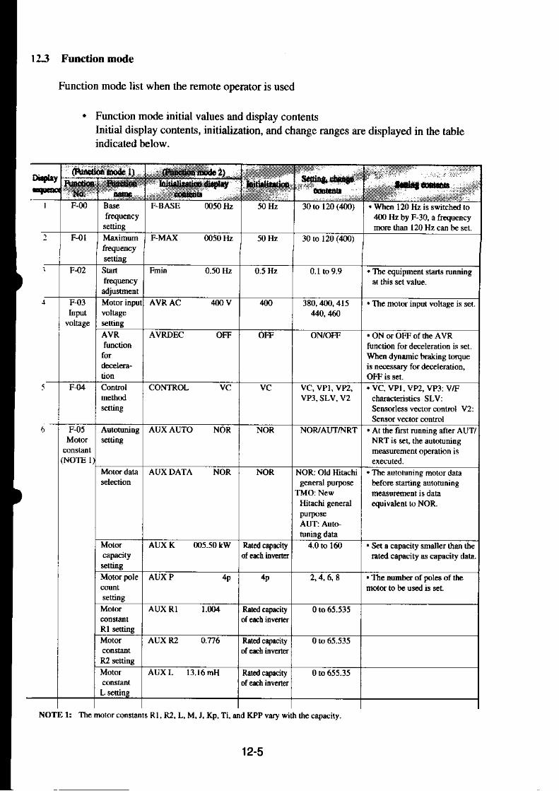
ll3 Function mode
Function mode list when the remote operator is used
. Function mode initial values and display contentsInitial display conterts, initialization, and change ranges are displayed in the tableindicated below.
Digbytd.donhd. l) , dd lid. t)
SEr : . . '
&sad*
6
F-m Basc F-BASE m50 Hz 50 Hz 30 ro 120 (400.) . When 120 Hz h Bwitch€d to40t lzbyF30,afrequef tymE thm 120 Hr can be ser
F4t FMAX m50 Hz 50 Hz 30 to 12, (4oo)
F42 Stan Fmin 0.50 Hz 0.5 Hz 0.1 to 9.9 . The €quipinent stan! ruming
F,03Itrput
AVRAC 400 V 100 3E0,,100.415444,4ffi
. The motor input volta8e is s.t.
AVRDEC OFF OFF ON/OFF . ON or OFF of the AVRtunction for deeleration is set.Wh€n dynnnic b6kir8 toqwis ressry fo. d.{el€mtion,OFF tu s!t.
F{4 CONTROL YC vc vc,vPl, yPz,vP3, SLV, V2
. VC, VPl, VP?, vP3: V1Fcharadqistics SLV:Sensod$s vector @ntrcl V2:Sensor vector @ntrcl
F-05
(NOTE I
s€l6ngAUXAUTO NOR NOR NOR/AUT/NRT ! At the fnl running ,ft€r AUT/
NRT i3 re! the autotunitrgmdurcment oFmdon is
AUXDATA NOR NOR NOR: Old Hitachi
TMO:NewHitachi general
. The lulotnning moror darabeforc starting aulotuning
equivalent to NOR.
AUXK 005.50 tW 4.0 to 1d) . Sa . capecity shaller than th€ratcd capacity as cepecity d!rr.
AUX P 4p 1p 2 , 1 , 6 , 8 ' Thc mrnh€. of poles of lhemotor to be us€d b sct.
Rl setting
AUX Rl t.{n4 0to65.535
R2 settin8
AUXR? O.n6 0to 65.535
Motor AUXL 13.16mH 0 to 655-15
NOTE l: The molor conslan$ Rl, R2, L, M, J, Kp, Ti, md KPP vary wirh rhe capaciry.
12-5


)
Didry(Fmdioi rmd.2)
lrf;lro.-
Ioitirriation dbpliy .-:. . a(nlldL .,..:..:,
F-OE Fsp F rxxn.0 Hz 0 H z 0 to 400.0 . The frequency at which theac.elemtion oFration hslopped remprdily is set.
F[p TIME m0 q 0 to 60.0 . Th€ time that rh€ accelemtionh sbpped €npotuily rl acenain fEquency durinS
l 0
l 2
F 0 9 PARAM REM REM REM/ .oP']w2(Option
The parBmeter setting commanding sou.c€ is selecled.REM (each op€.aroo,OPI (oplion I ), OP2 (option 2
F-totumin8
Running RUNMODE NOR NOR NOR/OEN/c,oD
NOR: NormalrunningOEN: Energyconsenarion
GOD: Fuzzy mmt suilablea@leation anddeeleration running
Reslaningafter FRS
RUNFRS Z5T Z5T fsTzsr fST: Resbn afte. frcquency
Z S T : 0 H z s t . nF-11 SPD I 0001).00 Hz 0 H z n to 120 0 (400) . The input terminal CFI h set
Multis|age
ctring
SPD 2 0001)-00 Hz OHz 0 to 120.0 (400) . The itrput terminal CF2 h set
Multislage SPD 3 U .00 Hz 0 H z 0lo 120.0(4O0) . The input terminakCFl mdCF2 are set md ukd.
Mulristage
setting
SPD 4 0000.00 Hz 0 H z 0 !o | 20.0 (400) . The input teminals CFI andCF3 m set dd us€d.
MultistaSp SPD 5 m00.m Hz OHz 0 to 120.0 (400) . Th€ input temiMls CFz ddCF3 @ et and l]s€d.
Multistage SPD 6 moo.00 Hz OHz 0 ro 120.0 (4m) . The input termimls CFI , CF2,and CF:l are s€t and used.
Mulftrage SPD 7 m0O.0O IIz OHz 0 to 120.0 (400) . Th€ iDput teminal CFI is o€t
12-7

1: l OFF
Functior , Furctiof, ldtidizs
ryq. , Iq.J .o'riF20 DC braking DCBSW
DC braking DCB KIND
b.akinS DCB F
. DC bnkingON: DC braking availibleOFF: DC braking unavailauc
. DC braking method seleclic.l
EDC: EdSe opention. The frequcncy at which the
DC brdking srafis is kt.
.]]tc DC bnking force ar sLr
' The DC bnking force ar slop
0 ro 600.0
. Thc DC b.aking rime at stop is
0ro 5.00 The output frequcicy is lowercdro the DC braking frcqucncylhe lree run rine duringcrc!ur ion or DC bmhng r \ r r .. The xllowable usage ratio of
tbc braking rcsislor lbr l0Oseconds is set. (NOTE l)
DCD
i nDC braking DCB \'.STA
0ux).5 H/ 0.5 llz
0
LVL LVL LVL'EtrC
O ro 4O0O Ht
0 t.. ,0
0 t o 2 0
{x);;;;;:
DC bnting DCB V STP
DC bnking DCB T-STA
DC br.rking DCB T-STP
DC brakjnq DCB STOP-T
. a9its'T!11F 2 l 001.59n
F 22 Allowable IPS TIME
allowable po$erfailu€usrSe tlme senrnS.rntio of Reclosing IPS WAIT
braking instanlancousresisnn poqs lailur
0.1ro 25 s . When an instantancous powcrhilurc dcuu, de allowabletine untilthc poscr liilure is
BRD q.ED
l 5
seconds Instmmeous IPS POWR ALM
l . 0 s . Thc *a i t ing t ime unr i l lhererunnlnS ian\ alc. a.inst.ni.neous power f!iluf edcu6 dnd is rccovcrcd is scr.
ZST: 0 IIz start retryF-l?: Rctry aftcr jrcqucnc)
RST] Rerunning stdn rerryO\]OFFotF Whcn an insilnlucou\ polcr
O N : T n p
CRT]SIJBiFRE
20 lo t20, .
0O 1.0 s
AI-Mis sct. poscr lailurc
TdpYledi{)i IPS'IRIP
t 6 Elecuonic E-THM CHAR CRT CRT
ALM]IiI?/RSlZST
OFF
et".,t.,ri.: e-rultt,eVel
. Elcdronic thcmal chaructcns-ti. sening CRT: Consllir
SUB: Reduced ro.que charac
IRE: Free charxcrerltict007
. Thc DC b.aking rime at stan it
1.59. 055-0?5HF\OTtr l: lnitial srliing ofusagc ratn)
12-8
I l0-1l00HF

(NOTE 3)
E,TH\rl F_l mOO Hz Rared capacit) ot 0 lo ,gl0 H2
t'equency (2)
E.THN4 A2 8.5A Ratcd capacity oi
t-rnt'l e: t--o a-nareu.npo.'ty or 0 ro 600.0 A
E.THM F3 7l Hz Raredcapacity of 0 ro 41]) tiz
50 lo 150.,
0.110 I1.0
t 1 ou".tou,t I Uldcr lhc sensorle$ lectdcontrol. an ovcrload is dctcctedflom botl the olerload rcstric-tion od lorqDe limiter. (NOTE 2)
When fte setdng i\ 31.0 in SLVor V2 conrrol mode. rheoverload resricrn)n hds no
F,24
F-25 S LOCK
J300 055 HFE4: 1226l,075 HFE4| l l3s.I l0 HFE4: I ll7.150 HFE4: I13" / .
Elen ifthe funcdon is ser roOFF. lhc olerl@d resri.rion isinvalid only lor rhe fiBtaccelerarion whcn thc lotua'!and reveBe run comnmd s
MDO- MD | : Tem inal soliwarelock (SFT)MD2, MD3:Soi$are l(rk(NOTE I )
OLOAD ACC ON ON: valid ior
MDI MDOlMD IMD2/MD3
IIOTE l: when MDo is set and the inpui terminal SFI is tumed ON. thc dara of all funclions is locked. whenMD2isset (slored). th€ data ofall ihc tirnctions is locked. During lo.king, no data cdn be changed. MDl. MD3can sel only thc outpul frequency.
\OTE 2: When VT (ViF - VPl, VP2, or vP3) is set for the Europcan version, the naximum allowable value ofOLOAD LEVEL is as shown b€low. Makc surc ihat value is not€xceeded. Values upto 1507. canbc sc!.when a level exceeding thc maxinrun allowable value is set, however. the aclual level rernains unchanged.
l1cfB'220 HFE4.122./a30O HFE4: 1187.3'7O HFE4. t25qc45O HFE4 t25Cc550 HFE:| 113./.
J1(n-150 HFE4: 121q.9OO HFEA 122'h
1l0O HFE4: 125'l.
\OTE3: Elcctronic ihcrmal chfacteristic free sctling currenr and frequency depends on ihc invcrter rating.
OLOAD LEVELI25C/.
OLOAD CONSTOI-O
12-9

12-10

NOTE l: When setting 20% or less, the error will incrEas€ (t 20% or noae).Therefore. set 20q, or morc.
Did|'-lEq
Cf4shd 0od. 1) (Fotroictrtr d.Al,rit.dtr-46 xllrl
cor&{ii:"IN F SAMP 8 E l t o E
25 F-32 ARV FTN CST CST CST/PAT/ANY CST: Output at constdt
PAT: Output of more than
ANY: ol put ofonly sel
ARV ACC 0.0H2 0Hz 0 to 400.0
ARVDEC 0.0 Hz 0Hz 0 Lo 400.0
)6 F-33
sAral(NOTE 1)
ov,TRQV 100% t$t% 0 to 25tl . During contrcl of SLVand V2: Power running
. Dnring @ntrol of VC
waming l€vel for power
. When 0 i3 ser Any siCnal
ov-TRQR 100% lffi% 0 to 250 . Duri!8 contol of SLVud Y2: Re8eftrative
. Dlring contml of vCmd VPI to VP3: No
. When O is set: Any sigml
21 F,34hrelliSe
InFrr INTM I RS RS rc*t RS md 17
lnpot IN-TM2 AT AT ud 17
Input
setting
IN-TM ] JC JG jossirs JGudlT
bput IN TM4 FRS FRS fe FRS ond 17
Input INTM5 CHI CHI 2 strS€ CHI md 17
12-'11


Seuir. rni.nt3
. The FM teminalmonibr
F,38Initiali-
Trip hist,rryi tNtT TCNT
Drbug
signal oumut is selcctcd-A F: Analog frequencl
D-F: Digiral fiequency. Trip counr dclerion selecrion
CNT: T.ip counting is
CLR:The trip counr is cleared.
. T1'c JiEiral openror tunoin8
CNT/CLR
ON/OFF . Debug modc scrtjngON orOFFOFF: Tl'e debug mqlc is
ON: The debug mode is tumed
Digil!l FWD FWD/REV
Sclection of INIT RESET ON ON ON/OFF ONr Alam relcac when rcser
OFF:Alam releak wher reset
t l F 3 9 O P P 0102: l pulk t021 25510 65515 Ellective with option bodd( l -FB)
OP MODE ASR ASR ASR/A?R
OP RO TO OFF
IN
OFFTON
Stop
Srop
OR POS IN]OUTIN Effective silh oplion boardO.FB)
5.0 Hz 0lo4OO Hz0U)5.0 H/Speed rrrjnS OR FCDiection ORTITRN
Ci'.pt"ri* I on I
FWDREV
iiro t(x)(Xi
FWD
0.00 s 0 to 9.99

No.l4 FB FB/REF Effcctilc wirh oprion board
(J.FB)
seuine NdmeBror PO ECR N Oo(xrl I to 9999
D;;nimro'l Po Ec,R-D 0000l I to 99x)90 ro 655J5
' Po FFwc 000.00
Position PO G 000.50rad/s 0.5 0 ro 100
35 F-42
l innl imi t
TRQ LIMIT REM REM REM/OP I/OP2 REM: Ea.h operatorPOI: Opt ion IPO2:Option 2
(Note l)l imi tMinus TRQ REv l50ti 150E 20 to 154. , RegenemrL\e molc
36 IN OI]T
P-lDhte"r PID Lvt
. value sctingO ta 2$c/.
Pgain srr ine PID PD P I . OO t,, r S,OISain sfting PID Ir 0l.0s
Dgain r in ! PrD D 00J.0 0 l o l mMrn r,. aselerion . PIpMopE Mry r l4!!
F:16 rmnsn;ssion COMSAU (IrOixl bts 60{JConmuni, speed
:100,600r l20O' Efrictilc with oprion board24{[/4i]00i9600/ (JcM)
t9200carion sclectionp'oteot Sration lseurng nunber
COM NUMBER l r o 1 2
COM LENCTH
Otr_ / OFFCOMPAR-SELI ON' ON ON/OFF
COM PAR SEL2 EvN EVN EVNTODD
Slop bir
serectlon
COM STOPBIT 2
20 to 150.1
NOTE Srnalle.levels oftorque linit and ovcrload restnction arc given rop priority and vlttid for any control mcthod
12-14

12-15

12.4 Protection function display list $hen ahe remole operalor is used
There are protection functions tbr overcurrent. oveNoltage. and undervoltage provided toprotect the inverter. When one ofthe functions is performed, the output is cut otT, and themotor is put into the free run state, .rnd the status is kept until the inverter is forced to reset.
ir4s! ,r-t-!--E D IEIU6
L U It u Jt u b OL.BRD
H-oiE O EEtrgETT'ItL). ! t CPU
C ) i C EXTERNAL
E I JE i'l
[FRR, aa-*-l
E t 5 ov.sRc
ET7]INC.OPt
E I B NC.OP2
(NOTE 2)
E t9IE)?DoP2
(\OTE ) t c'9C J i
E ] ?IE J I tfM4rllE l,lil_d
For error contents, see page 8-1.Other displays
L "glll_.ry"g:____tThis tr displated when an enor €cu$ hcts.en $. in!.ncr and rcmorc opcrarorwhen the STOP kel orootherk€l isplesed, ihe oneinaldisplar" appearwhen $e ongind dnplat dcs not apFar. rum the power oifdd $en on onceaerm. Ch(t *helher any conn(lo6 are l@se.
Irone ofde displals on lh€ left acuE shen the copy un,t is used ro read or copy,take the corespondina counlemeasure.lNV. RUN Sr.l tn. iunnrng.INV. TRIP hess lhe STOP key toElease rhedp..INV TYPE: The inlenertypc oithe cop, source i!dilleenl lion daroftnccoriJ_ dcn0alion, Lhe |ne 5aN rytr oilnvener ro rcad.r.opy
IR.ERRoR N" rRit--l
R EllglllvllPE lThe liJunh s*nch ol the DIP sulch on lhe bacl otlhe remote operarols ON.Wltn ftadingdata.nn lhe s*ilch OFF.
This indi.ares rhlr lne r$nmeous lorer failure esun aun.ron 1s bcing Friomcd.. RESTART 0sdnN incxccdtion.. ADTUSTT Frequencynrarchingn in execurion.
The supdy voluge i\loweed ro |ne unlietuohrge lerel wlen drsd^pla!apFaN, run thc po*cron onc. again.
The utulenolugc atier |Jle poqrr n rumeJ uft D dnpldyeJ
This is displaycd atur de aurotuninS measurcmenr is finished..TunineOK The mea$remnt reminates nomaily.. Tuning NC The measureftnt ra,ls.
NOTE l: Power OFF dudng motor deceleration may cause an input phase failure ellor.NOTE 2: Wlen the J-FB is inslalled, an error is display for each factor as shown below.
Digitaloperator DOP,DRw
OP-Op'lOP' IOP'114OP'lOP'-
Encoder line break:Overspeed:Positioning error:Thermistor line break:Motor overheat:Malfunction or abnormality on built-in CPU of the option:

12.5 Warning Error List
The following waming errors are displayed on the waming monitor in the monitor mode..Check the set value. When an attempt is made to set a value larger than the set range, the setvalue may be rewritten as shown below.
Warning error display Forced rewriting Description ourputRecoverymethod
Fma,\ > Fch Fmax * Fch Fch: Fr€qu€ncy for maximumfrequency swi&hing( 120, 100)
Fmax : Maximum fi€qu€ncyFrnini Start frequencyFb: Base trequencyFs: SetfrequencyFm: Multistage speed setting
Flw: LowerlimiterfiequencyFup: Uppcr limiter frequencyFp: Jump frequencyFes: Extemal set analog stan
frequencyFee: Exlemal s€t analog end
OFF
.e
9 ;
. c €
^o" t
E ;
2 Fb > Fmax Fb * Fma\
3 Fs > Fma,\ Fs * Fm&'(
4 Fm > Fma,\ Fm .� Fma{
5 Flw > Fmax Flw - Fmax
Fup > Fmax Fup * Fmax
,7Fes > Fma{ Fes .� Fmar
8 F€e > Fma\ Fee .� Fma\
9 Fs > Fup Fs . FuprrequencyJogging frequency
l 0 Fm > Fup Fm . Fup
I I Fmin > Fup Fmin - Fup
t2 Flw > Fs nw Fs
l 3 Flw Fm
t 1 Frnin > Fs Fmin - Fs
l 5 Fmin > Fm Fmin -- Fln
l 6 Fmin > Fj Fmin - Fj
t 1 Fnin > Flw Frnin - Flw
t 8 F p > F s Fs
l 9 F P > F j Fp Fj
20 F p > F m Fp Frn
12-17

12.6 Dimensions
Remote operator, copy unit
Dinens iona I dra*ins Gnnr m)
R.d.op.dor(DOP.OA) ..
r 'dli ingpedoiadondi'elD Mountlry p.rrordd diasran
MounriDg D.rr.ralion di!gr!n
+]SF&!j-l
are different in cable shapesdme as those for the Jl00.
NOTE 1: The cables for the VWS3A and VWA seriesfor the J300. The cables for the J300 are theonly cables, various cables are in stock.
from thoseTo change
rhtc op.ilror (HOP Or) -ecop! um(HRW.OJ) ! -
12-14

12.7 Copy Unit Function
When pressing any key or resetting the unit after tle | 6'$" I key is pressed, be sure to wait forat least six seconds. (Wlen any key is pressed. the Lrn-ir js reset. or rhe power js tumed offwithin six seconds, the data may not be copied.)
ffir
lE | -- lff l ElLtLrnlenerA c"p1-,r ljllll l_ffi]
Tum off the power supply toinvener A and remove the cable.Connect the cable to inverter B andtum on the power.Copy data stored in the copy unit iswritten to inverter B.Cut off the power supply to inverterB. ( * t )Perform the above processes from 3to 5 sequentially fbr inverters C andD. That is, the same process as atfor inverter B.
Connect the cable and pressthe remote key.Change the data of the invenerwith copy unit.
invefter A (lt is stored into the
2 to 6 lem"oy d9a ofthe copy unit).The following procedures are thesame those of the operation l.Change the data setting first.
l ' -F-qf lE Fl f , -= l : l . -nt_!9!lLE-!Lr]!:l |:: l= Dab.ldsc Ff
: : : r l f f r =^. Y [jj:]]] t4 ++r
t oD ) Ln i , I n \ e re r q
t r t l
l g - i : : ; ; l H lL{+r l: :3: I rrn InvenerA Copy unn
12-19

12.8 Data to be copied by the copy unit
Precautions for copyingThe copy units, DRW and HRW cannot copy some of pararneteis.For the details, see Appendir 7.
'12-20

\\hen inquiring about invener trouble, please be ready to inform the distributor where you:urchased your unit or following addrcss.
llitachi Europe Gmbh
Am seestem 18 (Euro-conter)40547 Dusseldorf, GermanyTEL: 0211 5283-0FAX: 021 I -5283-649
l) Type
:) Purchased date
3) Production No. (MFG. No.)
-l) Malfunctionsymptoms
lf the contents are unclear due to an old nameplate, give only the clear items. To rcduce the non.)peration time, it is recommended to stock a spare inverter.
Warranty
The warranty period under normal installation and handling conditions shall beone (l) year after the date of delivery. The wananty shall cover the repair ofonlythe inverter to be delivered.
I . Service in the following cases, even within the warranty period, shall be charged to the pur-chaser.
(a) Malfunction or damage caused by misoperation or remodelling or improper repair
(b) Malfunction or damage caused by a drop after purchase and transpofiation
(c) Malfunction or damage caused by fire, ea-rthquake, flood, thunderbolt, or othernatural calamities, pollution or abnomal voltage.
2. When service is required for the product at your worksite, all expenses associated with fieldrepair shall be charged to the purchaser.
3. Always keep it handy. Please do not loose it. We arc sorry but this manual can notre-issued.
13- 1

Appendix I Manual for New Functions
l. Autotuning
[Outline of the function]
This is a function for automatically setting the motor circuit constant necessary for thesensorless vector.When the autotuning function is performed by a motor which is designed according to JIS C4210 and then the sensorless vector is contolled, even a motor (Hitachi general purpose motor)whose constant is unknown at an output frequency of I Hz can generate a torque of 1507o.An Hitachi general purpose motor is given a constant which is a default value. Therefore, inevery case, the characteristics will be obtained without trouble. When the characteristicscannot be obtained, measure the motor circuit constant by the autotunins function.
(2) DC excnation (Tle mo1or d@s not rotate.)(l) The noror is accelenred "p ro 80% of the
base liequency and then decelerated andsropped. (The molor rotares-)
(4) The noto. is accelerated up lo 40% of the basefrequency dd rhen decelerated and sloppcd.
I (The motor rotrles.), (41) Measurcncnt(accele.arioddeceleration)
5 0 s e c o n d s - - - a - 4 0| 50 r< I0o seconds - - - a = 20: l0O t< Soosc.onds a - 10
Autorunirg suning ncthcl
(l) Before executing the autotuning function,make sure the following set values.O a) Base frequency
b) Motor capacityc) No. of motor polesSet the values according to a motorwhich uses a, b, and c.
@ Make sure that 0 Hz is not set. (When 0Hz is set, the autotuning function willnot be performed.)
@ Cancel all the DC braking settings.(DC braking is not set by initialization.)
@ Make an molor inpul vollage setting(F-03 AVR AC -) according to themotormting.
(2) D ve the motor for about 60 to 120 sec-onds. (During autotuning, the motor auto-matically runs in the order of (1) to (4)gi\en on lhe lefr and $e molorconslant ismeasured. Therefore, make sure beforestarting operation that no problems arecaused to the load to be connected duringthe automatic running frorr (1) to (4).)Example:When the base frequency is 120 Hz, themotor runs up to 8070 of the base frequencyin (3), that is, 96 Hz and then deceleratesand stops.
The status for using the autotuning data isset.
Running under sensorless vector control rsavailable.
Tum lhe aulotuning mdleON. (Note)
Tlm tbe Run command ON.
AtterDe measurement cnds, rhe motor is stopped-
Selecl $e confol ncthod. Selecr rhe motordara.
A-1

Autotuning start
lsetting methodl
(1) Digital operator
Initial display
Display the EE .of,*ur" .*irch and ser itto the data (01) for starting autotuning setting.
When the equipment starts running after thedata is s€t, the autotuning measurement rsexecuted.
F 05 motor constant setting is displayedDisplay the AUX AUTO screen and select AUTor NRT.
AutotuningNOR: Setting OFF and autotuning endAUT: Autotuning measurement start (Motor
rotates)NRT: Autotuning measurement start (Motor
does not rotates)
When th€ equipment starts running after thedata is set. the autoluning measurement isexecuted.
I lFl *zI lat
ta;R I@I
(2) R€mote op€rator
EEI
i -
E
F.Os AUX
AUX AUTO NOR
AUX AUTO AUT
FS005o.0 0.0H2
When the autoluning operation terminates, "Display at end" indicated on 44 page is displayed.When the autotuling operation temiantqs nomally, see lie "nuning method by autotming da€" indicatedon A-5 page.W}rcn the aul,ohining fails, set 'lnqtsrrlenrent start" once again and perform rerunning.
When lAl9Tlissetto I lUCl on $e digital operator or NRT is selected on the r€mote operator,aulo luning is performed in a mode in which the motor does not run (only AC excitation and DCexcilation are possible). Then, the value of motor constants Rl, R2, and L are measured.
Precautions1. When the autotuning function is execuied in the state that the DC braking is set, the accumte
motor constant will not be set. Cancel the DC braking the then start measur€ment.2. By the autotuning function, a capacity betrreen the applicable motor capacity and motor capac-
ity under one fmme can be set.3. When accelemtion or spe€ding up is not to be performed in lhe opemtion for accelerating up to
80% of the base frequency, lower the set value of manual torque boost.4, The autotuning measurement time is about 2 minutes or so, However, tie measufement time
may be increased depending on the load inertia. When the measurement time exceeds 5 minutes,press the STOP key so as to decrcase the set value of manual torque boost and enter the runcommano once agarn.
5. Be sure if motor is in standstill before you carry out an autotuning. Autotuoing data carried outwhen motor is still running may be not coffect.
6. Do nol intenupt an autotuning with power offor any stop command except emergency case. [tmay case data lose.In it is occurrcd, make an initialization aad reprogram what you need, and carryout autotuningag:'n
A-2

> 1 Command
2 Initial
3 Funclion
4 Option
(3) New remote operator
First hierarchy
Second hierarchy Y
> 1 Control
2 AcdDec
3 Run
4 Braking
Third hierarchy
Select "J Funclion" in rhe first hierarchy.
Select "l Control" in the second hierarchy.
Select 2 Motor" in the third hierarchy.
Change the content of " l Auto" from0:NOR to IrAUT in fie founh hierarchy.Wlen the data is changed, press thekey.
Mx,
) t un2 Motor
3 Carrier
MF*F]
rourth hierarchy V
) r nuro q:NoR(G2)
2 DATA Q:NOR(0-2)
tr:dE l
STOR
Y
) r nuro 1:AUTi0-2)
2 DATA Q:NORl0-2)
Monitor display
) r s
AC1
DCl
50.00H2
0.00H2
10.00s
10.00s
|+= b1when the [roN l(ey rs pressed to selectthe monitor mode :md the equipment startsrunning, the autotuning is executed.

Display when the autotuning terminates
[Display in the normal state]
When the autotuning terminates normally, the following is displayed. When one of the keys ispressed, the original screen is displayed.
.Digital operator
Normal terminatjon display
.Remote operator
.New remot€ operator
fT;-
[';r.-l
Normal i,erminalion display
lDisplay in the failure state]
. lf the autotuning is executed when the motor is not connected to the inverter, the following isdisplayed and the measurement is stopped. As a motor constant when the measurement fails, thelast value is set. When one of the keys is pressed, the original screen is displayed. When execut-ing the measurement once again, change the autotuning measurement setting to "Start" and enterthe lun command in the same way.
.Digital operator
OK I Function 3 OR FR
Abnormal terminalion display
NG Function 3 OR FR
fT l;l-�
l*-"r*l
Abnormal tcrmination display
When running the inverter using the autotuning data after the autotuning measurement lerminales,make settings by the method indicated on the next page.
.Remote operator
.New remote opelator
A4

Running method by autotuning data
When running the inverter using the autotuning data:1. A 0 : The control method is set at SLV (sensorless vector control).2. A-98: The motor data is set on the autotuning side by the software switch.
Make the above two settings.
NOTE: When no torque is outputted during the sensorless vector run after the above settings aremade, make the following settings. Increase the setvalue ofRl ofeach remote operator(moror constantr belore stcrting running.
lsetting methodl
(1) Digitaloperator l. S"l".t l-T-41 (sensorless vector conrrol) by
2.
rhe lA 0 0l conrrol method.0: Conslant lorque characteisticI: Reduced torque characteristic (L5 power)2: Reduced rorciue characreo.r 'c i t .7 bot^ er).r . RtLluced turque character isrrc r2.0 i roucr. l4: Sensorless vector controlSet the motor constant data to the data which is
I Al9 8 | meaiurcd b) lhe aulorunrng funcl tonusing the software switch.(Rcfer r , ' rhe lA98 | coftu are \q rrch of lhe op(rxl i , ,n
(When executing the second setting, change the
(2) Remote opcratorBy the ubor e tu o sett inp.. runnrng by theautotuning data is available.
F-04 CONTROL t . Sclect [SLV] (sensorlcss veclor control) byF-o,l control method.
EFl-l
i;Flx 2
rElElq
ItrE
QONTROL VC
CONTF]OL SLV
AUX DATA NOR
AUX DATA AUT
FS050.0 000.0 Hz
the
, [@ rnitiardisplay I
EEx4
VC: Consbnt torque characteristicVPI: Reduccd lorque chdacteristic (l.5 power)VP2: Reduccd torque characteristic (l.7 powcr./VP3: Reduccd lorque characteristic (2.0 power)SLV: Sensorless veclor cont.ol
2. Set the [AUT] autotuning data by moror dataseleclion of thc F-05 motor constant.
By the rbo \e t$o .e t t i nps . mnnrng b1 rh rauloluning data is available.
@14lInitial displal
EtMoNl
ExzE x z
A-5

1 Command
2 Init ial
3 Function
4 Option
(3) New remote operator
First hienrchy
Third hi€rarcby
Third hierarchy
) r v l2 Motor
3 Carrier
Fourth hiemrchy V
Selecl "S Function" in the first hierarchy.
Select "l Conhol" in the second hiertuchy.
Select "l V/f in the third hierarchy.
Change the content of "6 Mode" fromo:VC to 4:SLV in the fourth hierarchy.When the data is changed, press the
--;etf I
key. sToR
Mrz
Second hierarchy V
I Control
2 Acc/Dec
3 Run
4 Braking
5 A-Dec 1:ON(0-1)
) o tuooe Q:vc(0-5)
0."r. ,n" [#Kl key ro rerum ro rhe third
E t utrFeF]J STOR
IER-IRETN I
MfErR ll s E L l
MtrFiFII sToR I
) r v r2 Motor
3 Carrier
hierarchy and select "2 Motor"
Change the content of "0 NOR" from 0:NORto 2:AUT in the founh hierarchy.When the data is changed, press thekey.
When the monitor mode is selected, running by the autotuning data starts.
A-6
1 AUTO q:NOR(0-2)
> 2 DATA 2jAUT(0-2)

t
lNoTESl
* 1: Il fte desired characteristic cannot be obtained in a sensorless vector control oD€ration withauto tuning measured data, adjust the motor constant according to the detected symptom shown
(DOP, DRW, HOP, and HRW functions of the rcmote operaror are needed for this adjustment.)
Operadon Status Symptom AdJustment AdjustinS Item(DOPDRW Fundion No.)
Powerrunning When low fr€quency Increase the mobr constanr Rl in r€lation to tF-05 AUX RllGtatus with an (a fcw Hz) torque is auto tuning data step by step wirhin 1.2 rimes.accelerating torque) insuffi cienl
When $e sp€edlluctuation cc€ffi cient
lncrcasc the mobr constanr R2 in relaiion to IF-05 AUX R2lauto tuning data step by step within 1.2 times.
fluctuation c()efficientDccrcasc ihe motorconsranr R2 in relation ro lF-05 AUX R2laulo tuning data srep by step within 0.8 tincs.
Regeneradon W})en low frequency(status witb a (a few Hz) torquc isdecelerating torque) insuffi cicnt
i! Increasc the motor constant Rl in relationto aulo tuning data sr,ep by step within 1.2dmes-
lF,os AUX Rtl
?l Decrcas. the motor constanr M in relationto auto tuning data step by sGp wi$in 0.8
tF,Os AUX Ml
it Decreas€ the carri€r frcquency s€t value. tF.36 CARRIER](mfordigital
Combine the methods Q_r to ,3 above to adjust
r *2: If, when the sensorless vector is controlled, 2 frames or less maximum applicable motots aret operated. then the characteri\ l ic may not be sauslactory.
*3: No sensorless vector control opeaation is possible if plural motors are operated.
A-7

2. Energlr conservation running
loutline of the functionl
This is a function for automatically setting the output voltage corresponding to the load duringthe V/F control running and suppressing useless power.The function is effective for a load of reduced torque characteristics such as a fan and pump.
When the load of an inductionmotor is constant as shown in thedrawing on the right, there is avoltage at which the current isminimized. When the cunent isminimized, the power is alsominimized. The function auto-matically searches this voltage.
IPrecautions]
l� The output voltage is decreased so as to minimize the curent. The search limits arc thevoltase of toroue constant characteristic t507o.
2. The f'unction is performedunder comparatively slowconfol. Theretbre, when asudden load change (such asan impact load) occurs, themotoa may stall.
Range whcre ihe energyconservalion is effective
A-8

lSetting methodl
(l) Digital operator
Initial display
f.*lfMaNl
fier]|"T;:--l L FUNC
l ^ t " t l _
(2) Remote operator
tEl nt-
E
0:1 :2.
F-10 RUN
FUN MODE OEN
ES000.0 000.0 Hz
s"l""t l-T-Tl uy lalJ 9l runnins modeselection.Running mode selection
Normal runningEnergy conservation runningFuzzy most suitable acceleration anddeceleration running
When the running starts after the data is set, theenergy cons€ryation running is performed.
F-10 running mode selection is displayed.Display the RUN MODE screen and seiecr'oEN".
Running mode selectionNOR: Normal runningOEN: Energy conservation runningGOD: Fuzzy most suitable acceleration and
deceleration running
When the running starts after the data is set, theenergy conservation running is performed.
A-9

(3) New remote operator
First hierarchy
1 Command
2 Inilial
3 Funclion
4 Option
Second hiersrchy Y
EX,
L V L X 2
I jsr1 SEL ]
F/t
FEl^�]
trf=-ilEl] STF
Selecl '3 Functjon' in the f irst hierarchy.
Select "3 Run" in the second hier:uchy.
Select "2 Pattem" in the third hierarchy.
1 Control
2 AcdDec
3 Run
4 Braking
Third hierarchy
) t r."g.
2 Pattern
3 SPD
rounrr rrierarchy {
> 1 MODE o:NOR(0-2)
Y
> 1 MODE L:oEN(0-2)
Monitor display
) r s
AC1
DCl
50.00H2
0.00H2
10.00s
10.00s
Change the content of " l:MODE ' tiomo:NOR to I :OEN in the fourth hierarchyWhen the data is changed, press the i- lkey. L JE I
==-; t- E _ t
when the I MoX ] key is pressed to selectthe monitor mode and the equipment startsrunning. the fuzzy mosl suilable accelerationand deceleration running is executed.
A-10

3. Fuzzy most suitable acceleration and deceleration
loudine ofthe tunctionl
The fuzzy most suitable acceleration and deceleration function realizes acceleration and decel-eration characteristics using the inverter capability at its maximum under fuzzy conkol toeliminate troublesome setting of the acceleration and deceleration time.
The acceleration time is a time for acceleration at the current specified by the overload restriction constant.
The deceleration time is a time for decelerating so that the current does not exceed 150q, of thespecified one or the DC voltage in the inverteicircuit does not exceed 770 V.
The function sets the acceleration and deceleration time automatically in response to a changein the load or inerlia in real time.
IPrecautions]
1. This function is not suitable for a machine which requires a constant accelemtion anddeceleration time. The acceleration and deceleration time varies with the masnitude of theload or inenia.
2. When the inenia ofthe machine is morc than about 20 times of that of the motor shaft, atrip may occur.
3. The acceleration and deceleration time of the same motor always varies with a change ofthe culrent.
4. The fuzzy most suitable accelention and deceleration setting function is valid only underthe V/F control. ln the high start torque running mode (under the sensorless vecror con_trol), the normal runnine is oerformed-If the jogging running iiexecuted when the fuzzy most suitable acceleration and decelera-tion setting function is selected, the jogging operation cannot be performed due to thetuzzy control.
6. When the Ioad is more than the rated one, the deceleration time may be increased.7. When acceleration and deceleration (the cycle is 2 [s] or less) are repeated frequently, a
trip may occur.8. If an extemal braking unit is used, the motor cannot stop within the deceleratlon tlme set
with a braking resistor. In such a case, do not use the fuzzy acceleratior/decelerationruncnon.
5.
A-11

lPrinciplel
The acceleration and deceleration ratio or acceleration and deceleration are set in accordanccwith the fuzzy rule from the distance to the overload rcstriction level and the start slopes ofcurrent and voltase.
t
.9
E
Disuncc
Accelention ratio, accclcraliondelemiraliordeceleration mtio,de.eleEtion delenination
A-12

> 1 Command
2 Inil ial
3 Function )
4 Option
(3) New remote operator
First hierarchy
Seconrl hierarchy {
Third hierarchy
Monitordisplay
) r rreq.2 Pattern
3 SPD
Fourdr rrierarchy I
> 1 [,roDE gNoR(0-2)
V
> 1 |\4ODE 2:GODl0-2)
Select "3 Funcrion" in the first hierarchy
Select "3 Run" in the second hierarchy.
Select "2 Pattem" in the third hierarchy.
Change the content of" l:MODE'fromo:NOR to 2:COD in $e founh hierarchy.When the data is changed, press thel"y.
t ' E - 7When the I N.,tOtVl key is pressed to selectthe monitor mode and the equipment startsrunning.lhe fuzzy most suitable accelerationand deceleration running is executed.
Mx,
1 Control
2 Acc/Dec
3 Run
4 Braking
M " 2
trrEfiII sEL I
trI_EEII S T R I
) r s
AC1
DC1
0.00H2
0.00H2
10.00s
10.00s
A-14

t
Appendix 2 Instantaneous Power Failure Restart and Commercial Power Source Switching
l. lnstantaneous po\rer failure restarl
[Function Outline]
This function allows an invener operation to be selected according to the subject system asfollows when an instantaneous power failure occurs.. Retry mode: When FTP/RST/ZST is set at IPS POWR. Alarm mode: When ALM is set at IPS POWR. f matching: The rotation speed and fte phase are detected while the motor is on a free
mnning to restart the operation accordingly.
WARNING
a When the invefier stops due to a trip with retry mode selected, the motor restanssuddenly. Stand clear of the machine. Otherwise, you may be injured. (Design themachine in such a way that persons are protected against a restart of the machine.).
lsetting Methodl
.rt
Remote openror fF 221 Di8italopenior At insontaneous power tuilurc
IPS TIME 0,3 to 25.0 - Sct a! allowable inslanlaneouspower ftilure ime.
IPS WAIT 0.1 to lff).0 Set a wait rine afieran instdtaneous power failure/power rceontion in fic rctry modc or alter an eror.
ALM
-n"
RST
ZST
0 Tripping wilh u instanlaneous Trippingpower iailure wilhin the IPSTIME.If an opention commandis issued for an instanhneouspower hilu.e derecred our oflheIPS TIME, restan the operation(0 Hz thn)_
Tdpping Tripping
Thc inalching stops wirh aninsbntaneous power iailurederered wlthin $e IPS TIME.The invenertrips *ith aninsbntaneou! power iiiluredcrected out of the PIS TIME.
Tlte f
2 Thc inarching is renaned itrhe The tmarching isinsbntlncous powerfajlure is reslaned ilpowcr isq i rh, l rhc IPS l l l \ .4b. f tc rc \ rorcJ $ ' rh,n. l 'inlener rips ifthe insuntmcous The invener fipspowerfailue is nor wirhin the unless power is norIPS TIME. reslored eithin.los,
3 The invener is resllncd at 0 Hz Thc invcrbr is sonedif the insranrdeous power failure al 0 Hz if power istr wuhin lhe PIS TlMt. The FioFd $ithin 4Os.invene. trips ifthe instantaneous The invertef tripspowcrkilue js nor within the unles power hIPS TIME, rcstorcd within 4o".
IPS TRIP OFF
ON
No retry at an instantrneous polerfailurc and no trip!t Io* voitageduring the invener srop.
Rery or under vohagc trip is pcrlbmed during the'nvener srop or runnhg-
A-15
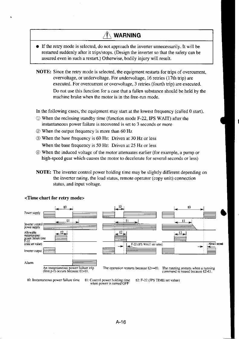
I unrurnor If the retry mode is selected, do not approach the inverter unnecessadly. It will be
restaned suddenly afier it trips/stops. (Design the invener so that the safety can beassured even in such a restart.) Otherwise, bodily injury will result.
NOTE: Since the retry mode is selected, the €quipment restarts for trips of overcurent,overvoltage, or undervoltage. For undervoltage, 16 retries (17th trip) areexecuted. For overcurent or overvoltage, 3 retries (fourth tdp) are executed.Do not use this function for a case that a fallen substance should be held bv themachine brake when the motor is in the free run mode.
ln the following cases, the equipment may start at the lowest ftequency (called 0 start).
O When the reclosing standby time (function mode F-22, IPS WAIT) after theinstantaneous power failure is recovered is set to 3 seconds or more
O When the output frequency is more than 60 Hz
O) When the base frequency is 60 Hz: Driven at 30 Hz or lessWben the base frequency is 50 Hz: Driven at 25 Hz or less
@ When the induced voltage of the motor attenuates earlier (for example, a pump orhigh-speed gear which causes the motor to decelerate for several seconds or less)
NOTE: The inverter control power holding time may be slightly different depending onthe inverter rating, the load status, remote operator (copy unit) connectionstatus, and input voltage.
<Time chart for retry mode>
An instanlaneous Dower failure riD(Inst.p D occurs tacausc t>to-
t o r l 0 ' n|.-:5r
+]+pows$PPry :r= r:
r2,l <qi ,_l?-l
( d a u q r \ r f l I F 2 2 t P s $ A , t e r , d t l r ,
The oDemlion rcstarts because t>-to. The runnins reshns when a runnin!connand ii issued be.au\e tltl
-
t0: Instaitaneous powerrairurc rime tr:conrror pows lllf:ffd$e
tr: F-rr 0Ps rlMEser varue)
A-16
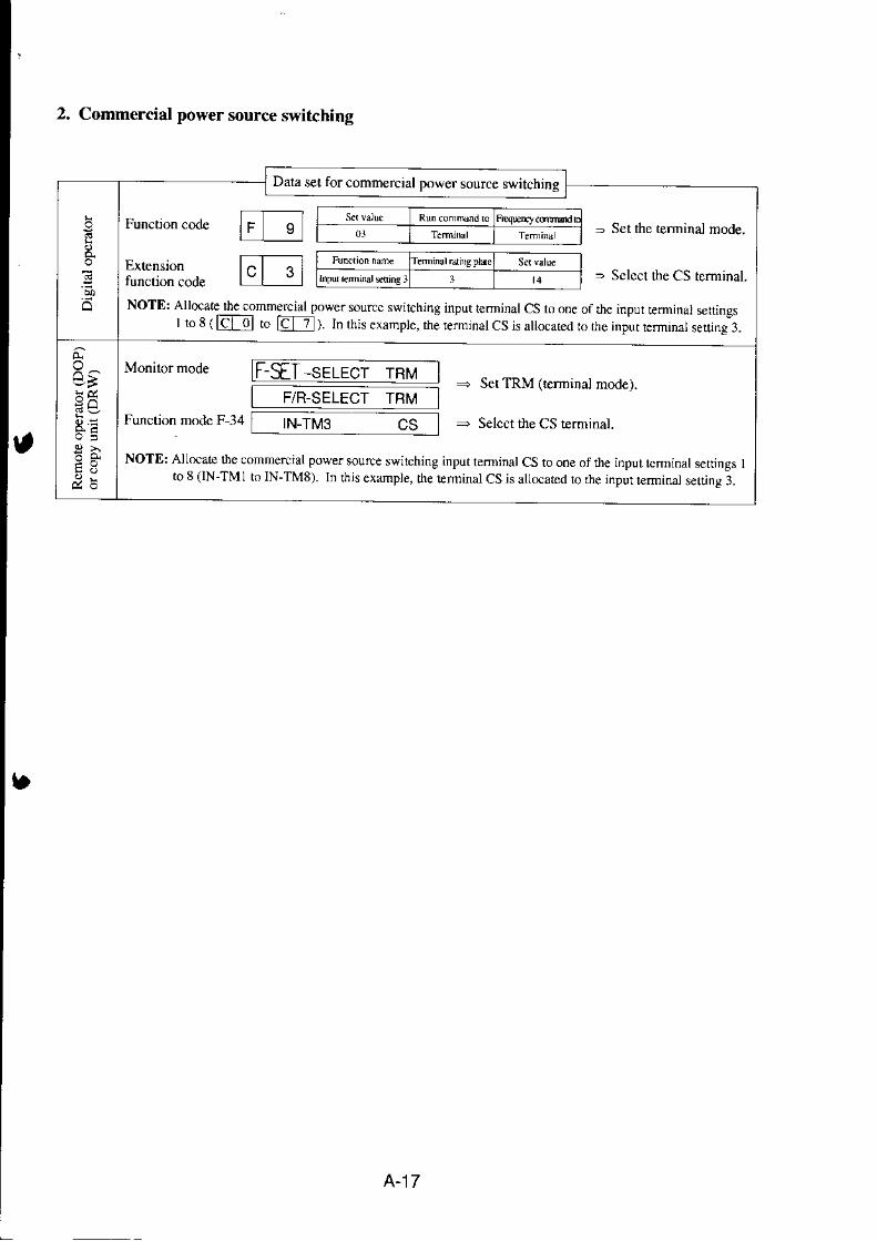
2. Commercial power source switching
Dala set for comm€rcral power source switching
NOTD: Allocate $e commercial power sourcc swilching input ledinatCS to one of rhc inpur leminatsemngsI ro 8 ( EtO to m). In this examptc, the ierminal CS is allocated ro the input lerminatseltrng I�
Extension
- sei rhe rerminal mode.
= Sclcct the CS terminal.
d , E
F-SET-serecr rnv
Function modc F 34
F/R-SELECT TF]M- Set TRM (lcrminal node).
- Selcct the CS rerminal.|N-TM3 CS
NOTE: A1l.,cate the commercial power source switching inputteminalCs toone of rhe inpul lcminalsetlings Ito 8 (lN -TM I to IN-TM8). In ihis example, the Erminal CS is suocarcd to rhe inpur leminal setling 3.
A-17

NOTE r: whcn the ELB dips duc lo r groDd-faul! lne commerial po*ersourc cirun *ill nol opedte. Theeloe, wheh a b&lup isneessdy, tlte a conncrial power source cncun from $e ELBC.
NOTE 2: U* weal cunent rlals tbr FwY, RvY, and CSY, Sep@te AC.elays fion DC relays. The abole scquence is a iefeence dn*ing
'4)\ 7
@@,41\ 7
...- serinebr limer2C- -
' f t . f m c : . l c n f l J l v . c | n r ^ r , . o n d - L F o r t u ) , o m " ! l - e n L h e r r r m e h a * \ o n J s o r n o R . 'IuYt oFi
Connection example diagram and timing for commercial power source switching running
Mgl and Mg2 interl(ling ne
A-18

Appendix 3 CaPacitor Life Cune
* The ambient temperature herein means tlte tempelature around th" tnu:1:l ^-
body. lf the inverter i' f'ou'"a in u p-"i' tft" u'rnbi"n' t"tp"tutu'e corresponds
to the temperature in the panel s within the rating, the capacitor life is
* Even when the ambient temperaNle I
:ffiJli;;;;i;ion is impeded due to bad installation conditions or dust'
5 6
Capacitor lilt (Year)
A-19

Appendix 4 Acceleration/Deceleration Curve Constants
This function can vary the cunature when the acceleration curve pattem (or deceleration curvepattem) is selected to S curve, U curve or RU (reverse U) curve in the function mode (F-06). If thcacceleration curve pattem or deceleration curve pattern is selected, the selected pattem applies toboth acceleration and deceleration.The larger number causes a greater curvafure.
CuIvepauem Acceleration Deceleration
S curve
Setfreq.
t
Decel. time -----)
Serfreq.
I
U curve
Set Serfrcq.
1frcq.
I
Decel
RUcurve
Setrfeq.
1 N\I \ Xl x t . - \
Deccl.limc >
+
A-20

Appendix 5 Multi-Motor Operation and Precautions for Operation
l E r c ; :1 4 4 ? � 1 2r : g : ; : :
9 l = ;
e i a 3-2
E E
.:q!
6 i a
E
, l
= ?
;9
9 q
P
E
. !
l:.5:IE
lr-
> :
-o (-- .--9 l = z, i | ? r 1, . ^ , i' - " l i =
g = l E - :6 r Z i to e ; d! ! ! - :
i 1 e l2 2 * l : l6 . ; a > , \ " eL E q -
a a - = - N6 0 ' - i < x
E , F i 6 ) = i ?5
- t - r : < o @' . )
.. \_,-
r A
! 1 \ 4
.9
c 9h 9> r :
a i i
r 3 6
oci
l a
o.
g
a E d
F E F
E? > .F 6
a t P
< t 9
z
I
t
A-21

r € ;; : P :
di
t F
i >
9 E
e
A P
} > . Y t r
E g I A U
' . > . i -9 Y 9 E
k F 9 ;
9 : E P lg e I I
B 3 E 5
F
z
n l cl l e E
r E l l ii j e t g
E ; . 4.zN l o l
d r . ! | q l
< r l a l Ri < -
F " X X+ z o x !
: 62
&,
ll.
z
A-22

z e = E
:EF ^E N
* - - l - l
E A
i - ^P a
Io
E
:
e> E
n ^ l
: . ra v
7-,
- L
.:
. : E
a : ; - ' d
X r i !- e - 1 ; 2
5 d
ll.
. !
; : !
- a . -: ! t
9 9 : 2
.E : =
E a
E ! 2
E
A { , o
.9
6
E.:i=
A
J
A-23

Appendix 6 Supplementaly Explanation ofthe Function Mode
. The explanation of the function mode is displayed on the DOP or DRW type of theremote operator.As for the operating methods with other remote opento$, refer to the conespond-ine table of the ooeraror disolav.
. Afrer data ir changed. be sure to push down rhe | ; i! | fel.Noda la i s r to red in $e in \enerbod) .
. Change data when the inverter is stopped. (except when the invener is stoppedduring trip, and stopped when ON between the reset terminal RS and P24.)
. In the function mode, the motor can not be st.fted running.Select the monitor mode beforehand.
It is possible to run lwo motors with onc jnvcner byswitching th€ controlcircuit terminal ISETI. Ttrchanging of the SET terminal can bc cxeculed onlywhen the ;nveri€r is stopped.
Function which can be set with the second function
lMonitor mod€l
L Output frequencysening
2. Acc€leration anddeceleration timeserdng (NOTE)(Funcrion mode)F-06Acceleration timcsettingF-07Dcccleration timeserrng
3. Manual lorquc boostsetting
lFunction model
1. F-00Basic frequencysetting
2. F-01Maxinum licqucncysettinS
3 . F 0 4Control me$od
4. F,05Motor constanr sctring
\OTE:
Wlen sclccling lhe second funclion.2-stage acccleraion and dccclcration time setting can not be sel andu,cd. whcn:c'r ing dnJ u, ing lhe )-nJge accclcfd onand deceleration rimc, sclcct the first function (whenISETI terminal is oFn.
Set the 2 stage accel. and decei. runct;on ot IT_g| 6
T lrtr ILr!!91
Ef_1l -Tf-gTr*ElL-L!!.gt
fr-E -a"3
l!,i-;1"";C
Setfing conlents
I. S€lling m€thod 1: Digiral operator
Ser LLIII in any nf r}'e inputFrminul!t - t n t , ^ t a 1 l
lsettins cxamplel
E
Setting me$od 2: Remob operator
Set the s€ttings LSETI in anv ofthc inpur rcrminals 1 ro8 .when using the high pcrfbrmancc rcmotc opcraror,input [8] SET with the ren key.
2. Function changing method
Aiter lhe input lerminal ofrhe setiing funclion codc.nd Stf are.hon,.rcuucd, tnc.cc^nd funcrronsetting can bc starrcd.\ \hcn rhc ,h^n LLicuir i \ r . . \e 'eJ. rhe fun( l ionrelums to thc origin.rl sctting (the firjl function).
3. Setting m€tbod ofeach function
Set same as the normal sctling.When checking the function modc, confirm rI withrhe tcminal slarus ON/OFF.
Inirialsettin8s which can be ser with thc sccond lmcrionis srme as the factory selrings.
A-24

Appendix 7 List for display and data read/copy with each operators
(l) Monitor modeN: Not Dossible
'>
*l Reprcsents an indjcaion for comrunding frequency from ihe oprionalpCB.
A-25
Moblorname H'J:,ilf B#:,#',ft*"" *. *ou*a*,o' J>*,"*.*u
No. w iDRwFrequcncy setting
First sening FS 0.00 Hz FS0000.0 0.0 Hz Y F2 0.00 Y YSecond \erfing FS 0.00 Hz FS0000.0 0.0 Hz Y F2 0.00 N
MLrlristage speed sctting ls 0.00 Hz 1s0ql).0 0.0 Hz y
75 0.0O Hz 7S00rC0.0 0.0 Hz
F2 0.00 Y N
Analog fiequency setting TM 0.rJ0 Hz TM 0.0 0.0H2 Y F2 0.00 N N(4J
Jogging fiequency setting JG 1.00 Hz JC 1.0 0.0H2 Y F2 1.00 Y Y
Oprion I frequency display Ol 0.10 Hz 0l 0.0 0.0H2 y pZ Orrc V N(6)
Option 2 frequency display 02 0.00 Hz 02 0.0 0.0 Hz*l {:J)
Y F2 0.00 Y N
Outpui frequcncy setting 0.00 Hz FS0000.0 0.0 Hz Y(3 )
d0 0.00
Acceleration lime scttingFirst seting ACI 30.00 s ACCI 0030.00 s Y F6 30.0 YSecond setting ACI 30.00 s ACCI 0010.00 s Y F 6 3 O . O Y N
2 slep accel€ration line setling AC2 15.00 s ACC2 00l5.UO s y F6 15.0 y NDcceleration iime setling
First seuing DCI 30.00 s DECI 0030.00 s Y F7 30.0 YSe(L,nd serring DCI 30.00 s DEC1 0030.00 s F"] 30.0 N
2-srep dccclcrauon trme scluns DC2 15.00 s DtCl onlr .Uo\ ) F l5.u y NMoior polc nurnb€r setting RPM l:4 pMotor rprn monito.ed ORPM
RPM 4P ORPI4 YA 2 5 4 Y0.00
ConYerted frequency setiing lHz L0
0.00/Hz 01.0 S.AA
( 15) (16)Y A47 I,OO Y YY d3 0.00Y d2 0-00 -
Con!ercd frequeney monrtorOutput current monitor lnl 0.0 AOulput cureni ratc monitor 0.0 q.
rrn 0.0 A 9!:LN
Torqu€ O 9. Torque 0% N -Manual torque hr(xt adJustmenr
First setingSecond sett'ng
1 1 V B o o s t c o d e < l ] > Y F 8 l l y y
ffiV-BoostV-Bo,rst
- - - - - - T - - -
F t0.oa/. N - Y NF 1 0 . 0 . / r N _ Y N
Manual torque boost frcquency
First selting V-Boon F 10.0 9. V-BoosrSecona 'cn'ng r e, 'o.r i to ' t l . \ -B-, '
Output vollage gain adJustment YV-Cain 100 9. V-cain ll)qo N Y1.00 Hz Jogging
172 ADJ
Joggjng frequency sefi ingAnalog meier adjusment
JoggingADJ
LtlJ Hzt 1 2
IY F r 0
1.00 Yt '72 Y
IN
Terminal input \trtus mnnrror TERM LLLLLLLLL TERM LLLLLLLLL N
# WARNAlarm display
First seuing WARN # N Y Nt - NSecond serting WARN # WARN # N - ' r = -

F db tlo 'ta dfil6' fr||l6d/dr^l&.Ait| I,d gru bts
Trio cause factor I ERRI # ERRI # Y d10 N N
Trip frequency I ERRI 0.0 Hz ERRI 0.0 Hz N N NTrip curent I ERRI O.OA ERRI O.O A Y d l 0 N NTrio time P N volrase I ERRI 0.0vdc ERRI 0.0 Vdc Y d t0 N N
Inlcgrated count I of caus€time runninq days
E R R I R O Y O D E R R I R O Y O D N N N
Intearat€d error count ERR COIJNT O ERR COUNT O N N N
Trip cause 2 ERR2 # ERR2 # Y d l l N NTrip frequency z ERR2 0.0 Hz ERR2 0.0 Hz N N NTriD currert 2 ERR2 O.O A ERR2 O.OA N N N
Trip time P-N volrage 2 ERR2 0.0 Vdc ERR2 0.0vdc N N NlntegEted count of erorlime running days
ERRzR OY OD E R R 2 R O Y O D N N N
Tnp cause l ERR3 ERR3 Y d l l N N
TriD frequency 3 ERR3 0.0 Hz ERR3 O,O HZ N N NTriD currenl 3 ERR3 O.O A ERR] O.OA N N N
Trip time P-N voltase 3 ERR3 0.0 Vdc ERR3 0.0vdc N N N
Integmted counl ofefiortime running days
ERR3 R OY OD ERR3 R OY OD N N N
(2) Function mode Y: PossibleN: Not possible
Dilplry i,ifi HOP' HRW DiloLy i,ltDOP, Dtw. f*ailr, rSdd{6e Ih.r.d/@y1r9* Dd. dit *., l{3' D.t dirplay AtraiduoNO Drlt mt_ *nl
I F-SSI l:REM F-SEr-SELECI REM
F9 0 Y
2 F/R l:Rru FA.SELECTREM
] PARM O. REM F-09 PARAM REM N Y Y2 I TCNI 0: Cl,tI F ] E INmCNT Cl.rI N
Debu! mode disDlav slecdon 2 DEBG O OFF IN]T DEBG OFF N N N
Digilal oFRtd olating diretid ] DOPE O Flf,D II..IIT DOPE RWD Y F4 Y
R*r perfonnaltce r.ldLioa 4RISEI 0: ON INII R'ESM ON Y m6 Y
Fint seurngSeMd s.ttin!
3 1 1 I F BASE 50gz F-BASE m50 Hz Y 462 50 Y YI F BASE 50 Hz F BASE 0050 Hz Y N2 50 Y N
Fi$t se6ing
Seond cidnS
2FMAX 50 tlz F{t F MAx 0050 Hz Y A63 50 Y2F-MAX 50Hz f-MAx m50 H2 A6l 50 Y N
I Fmin 0.5 Hz F{2 Fmin 0.50ltz Y 0_ 50 Y N
1 A A C 0 : m ) v AYR ACzOO V Y F l l 2m YAVR tulcnon ON/OFF duing 5 A,DFT O ON AVR DEC ON N Y Y
A-26
I

l -1 I 6 MODE O:VC
Auto runng setrng
Fi.stsedng
Motor polc nurnber rlecrio.Firsr !€ning
MotorcdnantRlsetingFi6rsedng
F.O5 AUX AUTO NOR
AUX DATA NORAI]X DATA
3 K 6J.50kW ALX K m50 kWALrX l\ 0050 tw
A2
AUX Rr 0.025 r
Firsrsning
AUXRI O,O25I
I A98
A98
N
NMotor conslanl R2 setdn8
Firsr r€rdng
Motor conshnt L srtingFilslerirg
Molorcostdt M seuingFiRl Rtdng
Ssond
Moror consknt Kp efiingFirst settine
ALX M 010.90 nH
AUX M 010.90 mfi
Motor connmr Ti setringFirsletring
Ssond seniig
I'loror cdnint Kpp scningFirsrserdnB
Saond rring
AUx i 0ll) 44 kn:ALX J 0(I.41 kgrnr
AUX Ko 2.00 A]
A3
2.00
AUX Kp 2.00l
AUX T'00100ms I I YNAUX Ti00l00Ds
AUX Kpp 001 .00AUX Kpp00l.0O
:l K615.50 kw
5 Rr 0.25t5 Rr 0.251
AUX R2 0.0 r94AUX R2 0.019,1
AUX L 001 29 mH7 L 3.29nH AUX L 0{l 29 mH
8 M .10.90 mH
8 M 30.90 mH
9 J 0.t4
6t o.r,1----i
a Kp 2.00
a Kp 2.00
bTi l00ms
b T-l m.,
c Kpp LC0
Carier fcquency setring 3-lJ ICARRY t6.0tHz F-:16 CARRIER t6.0kHz y Al0 16.0Accelefiton timc scning
Fi$tsfting: - _ .
ACCI 0030.00 s
ACCI 0J10.00 s
Acalenmd me cune paltcn setti I LINE 0r L
4GAIN 2
30.00 s30.00 s
2 4 2 15.00 s Y F6 t5.0ACC2 {n|5.00s
A-27

Dittloy wirh HoL rf,w Di'plry !i&00f, DRw Add Ilo. ridr diilrnaaitr Dih!',&rLayer hqdalay
'bo airptry ALtbilitr J|r:l DacN.!&l lDRwDcceleration lirc srtng
Fi$t srting
S4ond sening
l-2-2 I Dt 10.u0 s F{7 DEC r 0010.00 F7 :r0.0 YI Dl 30.00 s DEC I 0030.00 Y n 10.0 Y N2D2 ls.ms DEC 2 ml5.m Y n 1 5 0 Y N
Ddxkddon rrme tunep€uem *k(uon ] LINE (). L DECLINE L N YAc.eleridon/dceleration cuoe 4GAIN 2 DF-C OAIN 02 N
Acel€ralion lift stop frequcncy senin8 3 3 1 I F 0.0 Hz F-08 Fsp F 00(x).0 H/ N YAcc.lenlion time slop rime seting 2 TIME 0.0 s Fsp T IME 00.0 s N YMuft i-stcp Bp€f, d/pmess s€pping 3 3 2 F l 0
Olfmton nulc rlarion I MODE O. NOR RUN MODE NOR AJ9 0 Y N2 FRS l: ZST RUN FRS ZST A54 OI Y Y
lst speed of Multishge sp€ed J-l-3 I Sl 0.00llz F l l SPD I (lm.m flz At2 0.0 Y N252 0.00 H, SPD 2 qlm.00 llz
SPD 3 Um.00 HzSPD 4 00m.00 Ht
SPD 7 (xm.m Hz
Y A l l 0.0 Y Nld sp.ed of MulhraSe sped I Sl 0.mnz 0.0 Y N4th-7lh speed of Muliisag€ speed 4 5 4 0.00 Hz
0.mHz
F2 0.0 Y N
DC braljng type seleltion
DC bnting poser Pl4non
3.4-l ISW o:OFF
2 KIND t:LVL
l I 0 .5 t l7
4V STA ()
5 V S l P 0
6VSTA 0.0 s
? T-STP 0.0s
8 STOP-T 0.00 s
F 2 0 DCB SW OFF
DCB X]ND LVL
DCB FfiXt).sllz
IrB V STA (Xl
!N
N
1II
IIY
DC br*ing power eletion DCB V-S IT 00 Y
DC iraking tim Pl{rion
Guning tinE)
DC bn&ing lime eletion(stoppirg tim)
DCB V.STA0lI.0s N Y
D{8 T SIP OM,O S N
DC bmjinS nurpu OFF rimc adlusrmenl DCB STOP I0 m ! N YRegeneration bralinS Frling J42 I %ED 1.5% F?I BRD-flEDUil5c, Al8 1.5 YEletrodc thennal chanctedstis
3 5 1 I CHAR 1:SuB n3 EIHM CHAR SIJB Y AU I YI CIIAR l:StrB E.IIIM CHAR SUB Y AU I Y N
2LEVEL I{N% E.IIIM U\TL lM* Y A23 tm Y Y2 LE\'EL lqn E'IttMLIWI lm4 Y A].] t00 Y N
ElcLonic th€mal ch@cledstics
ftE seuing(cme value l)
l A t 1 5 . 8 4 E II{M AI I5,8 A N N
El6Eonic 0rmrl characteristiN I
rt setins (ttcquencl l)4 F l o H z E-ruM FlmHz N Y N
El@lrmic thernal chuacterislicsfte€ setli.g (cunenl v{lue 2)
5 A2 15.8 A E I l {M A215.EA N Y N
A-28

Dbplsr rlft HOP, HRw Dirpla,,L DOP, ttw Rr.dn I{o. rt&&blal,i Dr0i6ib6!ky!r DN, diipla, N('..:, tair dirplry $o ,h {RIN Df,W
El€cLonic $ernal chff aderisricsfre€ sening (tr€qu€ncy 2)
l -5- l 6 F 2 O H z F 2 l E THM F) MI HT N Y N
Elat dic themul chrnctcfisticstee seuing (cumit vrlue 3)
7 A3 24.0 A N N
Elect onic th€rnal chmcrerisricsfie€ seting (ftequeocy l)
8 Fll 1l Hl N Y
Ovsload Iin,t lcvel erung 3-5 2 1LE]',EL 125% F.24 0{-0AD trltl t25* N Y YOv€rload bmir onsranl rtllnS 2 CONST 1.0 OLOAD CONST l]I () N YOvsload lirnit selelioi durinS I ACC |ON OLOAD ACC ON N Y Y
Frequcncy lower linir.r e(ing l-5-3 I LIML 0-0 Hz F 2 6 UMn L mm0 Ht Y A5 0.0 Y YFrequercy uppq limiter scnitrg 2 LIMH 0.0 gz LIMIT H 00)0.0 Hz Y 0.0 YJuq, fi€qu€ncy (l) 3Fl 0.0 Hz ruMP Fl frXn0 fiz 0.0 Y Y,unp fteque.cy (2) JIMP N {TMO HZ
JUMP F:] OM.O H.
JUMPW 0.5H2
A8 0.0 Y YY 0.0 Y Y
Junp frequency vidrl ening 6WIDTtl0.5 Hz N YAllowable i.slrntaMus tine 3-5-4 I TIME I,()S F-22 IPS TIME l.0s NR@losiig st.nd by afrer inst{la.eous 2 WAIT 1.0 s I }SWAIT00l0s N Y Y
Inslallaftou8 pov€r tdlw rcsLin IPS POWR ALM 0 Y Y
Tnp s|fflo. duing slop under IPS TRIP OFF N
Md. tuquenqy sletion 1 5 5 I MAXF 0r 120 Hr F..t0 F MAX-L I2OH7 Y t20 YSofisare l@k *ietion 2 SLOCK l:MDl r-25 s,LiXK MDI NSTOP key validity sletior 3 S1OP l :ON F 2 8 STOP 5W ON N YRuming dne!ft n seleclion 4 !/R 2:FRE F.29 T/R SIV FRE N YRdes€ run prevention
Redoceil yolage sofi sun eltiig5IREV 0: OFF
6 RVS 6
F/R PREV OFP N
f/R RVS 6 45E Y NAralug inpul volugc selet|nn 1,6-1
l-o 2
l V l : 1 0
2 EXS 0.0H2
3 EXE 0.0 H7
F l t IN ANA IOV 448IN EXS lrtllO.0 Hz A26 0.0 YIN EXE m0.0 tlz Y 427 0.0 N
E temal frequency slan Ere s€Ll:ng 4EX% 0% IN EX%S 0('() % N NEiteral f.equency e.d .ale s.rrttrg 5 EX%E lm% IN EX%E IM% N Y NLrtmal frcquenc] cun poDl kning 6 LEVEL 0 Hz lN LEVEL 0 Hz N Y YFrequency coMd 6anpling 7 F-SAMP E
I PTN 1} CST
IN F.SAMP 8 Y Au 8 Y N
Anival sig.al ouFut pauern scl4tion l F-32 AIRV PIN CST Y 0 Y YArival fcqucrcy sttrry fn rceleratio0 ACC 0.0H2 ARvAcc0.0Hzi Y At9 0Adval ftqueicr srirS for dccelemtioi DEC 0.0 Hz ARV DEC O.O HZ Y 0 Y YOverlonue siqinl 6E Id Dlus rorcue l v l m % l l L 0v TRQ V 100 %l N NOv€norquc si8lrl 6te lor nins rorque R 100 % 0V-TRQR 100% N Y N
A-29

DtNtl4tdtl gOP, nRw Drotrr lla DoP. Dlrv ndtilr'i dtlc,e qirftdlcolt
ktlr trri&l|v .rs, M,4pl{rIN.TM I RS
ilFlbmtt N0. Ihl| Hnw ,1*t 6 l I-l lSiRS F,34 C O IE N
212 16:AT INTM2AT c l l6 N
3 t 3 5 J C IN IM 3IC c z 5 N
4l-4 ll:FRS IN 'IM 4 FRS c l l l Y N
5 t5 9.CHl IN.TM 5 CHI Y c 4 N
616 2:CF2 IN TM 6 CFz Y C 5 2 Y N
1l-1 l icFl IN TM 7 CFI Y C 6 Y N
8I8 0:REV IN TM E REV C 7 0 N
I.r'ur leminal I NONC sening 9l-OCl 0:NO IN,TM ()/C ! NO Y c20 m Y N
rerni.al 2 NO,NC setting r I OC2 0:NO IN TM CVC.2 NO N
Leminal 3 NONC \etuns b l-OC3 0:No N-ru ryC I NO Y N
InDUr hrminal4 NONC cI OC4 0:NO IN TM CVC4 NO Y N
oulDlt tefinind ll d 0 l 0 F A 1 OTII.TM I FAI cl0 0 Y N
ooaut Gdind 12 srti e0-2 L RUN otfl-ru 2 RUN cl l N
Alm oubut NONC attinr rLOCA l :NC OUT,ru Orc A NC Y c2l 04 Y N
Ourpul lerninal L I NO/NC setdng 80{Cl oNO OLII.TM()/f.1N0 Y N
ourpur terninal l2 No/Nc sning h GOC2 0: NO OUI-TM 0r!1.2 N0 N
3-64 I SEL 0:A F MONITOR A F 0 Y
llosl orEratiotr a1 OP I eno. I OPI l :STP F47 OP.ERRI STP N N
Hosr oper.tim ar OP2 emr 2 OP2 I:STP OP.ERR2 STP N N
Encod€ pulk Nnber setlrng +2 I ENC-P 1024 plr F 3 9 OP P 0l {t4 pule N Y N
2 MODE O ASR OP MODE ASR N Y N
3ROTO COFF oP RO m OrF Y 0 Y
Srop poGirid sning s*i|ch +l I POS 0:lN F40 OR POS IN N
2P 0 pls oR P ofilt) N Y N
I FC 5.0 Hz OR FC 0rc5.0 Hz N N
,ITURN 0:FWD OR TURN FWD N Y Y
Compleooo re8e eninB 5 LIMTI 5 pls oR L 0005 N N
Conpletion delay itme efting 6TW 0.0m OR TW 00.0 ns N N
Eledronic rd fning D{xiton $let$n I mRP 0: FB F-41 M ECRP FB N Y Y
Num€.rt{r ofeleLonic geit .atio 2 ECR.N I PO EGR.N (U)OI N Y N
Denonimtor of ekc|ronic 8d ratio . ]EGRD I PO EGR D m(nl N N
4FFWG 0.m PO rrwc m.oo N Y N
5c 0.50'd Po C m0.$ .ad/s N Y N
Tdque lirut€r eninS el€.tion +5 I LIMIT O IN F42 IRQ LffN IN N Y N
Pld( rorque liDier sertirg 2 FWD 150%'IRQ FWD I5() % N Y N
Minus torqw liniter settiig I REV 150% TRQ REY I5O % N Y N
PID target value ettint nEflod I I.SEL OIN F4l PID IN SEL IN 495 0 Y
2LVL 0.m c, PID LvL q10.0 {l Y A96 m0 Y N
P Sair sfting 3 P t.0 PIDP I .O Y 1.0 Y N
I gain settng 4 I L o s nDI Lms A9t 1.0 Y N
D gain sdting 5D 10.0 PID D 01m.0 Y A92 0.0 Y N
6 MODE 0: MDO PID MODE MDC Y 0 Y N
a
I
A-30

Dspldy w,rh HOP. HRW pisplay with DoF, DRw r@on Nu *'lh ,l's al oFlw I Dair Edcopv
Liyer D?E d,spray No- Datadisp'ay Dara HR1V DRWTransnission speed seledion
slltion nufr bcr sclcctron
Bit hngth seledioi
Pdit] ON/OFF shcrion
Odd,cvcn parjty scleclron
L7 coMBAtDffmh NCOM NUMBERO1 N -
;oMLENorHlT NC' '\IPARSLI O{ 'ICO]\IPAR SEUEY\ N _
COMSTOPBTT2 N
I BAIID | 6m bps 1 462 NUMBER I3 LENGTH O:84 P A R 1 l : O N
5 PAR 2 0:EVN
6 STOPBTT 0:2
Y NY N-fY
r'
Rela] output teminalRYA signalselecnon
Rcla) output tcminal RYB signalselectlon
Reh) oulput rcminal RYC sigorl
f 4IJ RELAYRYARUN N1 RYA 3:RUN
, RYB O{5N RELAY RYB CST ).l
RILAYRYCOI]I N
Ext nsjon luncnon seldng Sdliigonl! lbr dieital opehror Y F1,1vollagc comnaid adjusnicit Sening onll fordiliral op.rator Y All0 NCunenl connand rdjusnnent Senrg onl) lbr diSiml openrot Y A8] \ N
A-31

Appendix 8 PID Function
1. Function
The PID (hoportional, Integral, Difierential) control furtions can apply to controlling oftheair (water) amount ofa fan pump, etc., as well as controlling ofpressure within a fixed value.Set the reference signal according to the ftequency settirg method or the intemal level.Set the feed-back signal according to the analog voltage input (0 to 5V or 0 to lov) or analogcurrent input (4 to 20 mA).
[Wiring Sketch]
Reference0 t o l 0 V0 t o 5 V4 t o 2 0 m Aor Intemal level0 to 2007o
Feed-back Signal (0 to 5 V, 0 to l0 V, 4 to 20 mA)
PID Gain
If the response is not stabilized in a PID control operation, adjust the gains as follows accord-ing to the symptom ofthe inverter.. The change of controlled variable is slow even when thc target value is changed.
- Incrcase the P grin.. The change ofcontrolled variable is fast, but not stable.
Decrease the P gain.. It is difficult to make the ta-rget value match with the controlled variable.
- Decrease the I gain.. Both the target value an the conffolled va able are not stablc. They match after oscilla
uon,Increase the I gain.
. The response is slow cven when the P gain is increased.- Increase the D gain.
. The response is not stabilized due to oscillation even when the P gain is increased.- Decrease the D gain.
Sensor
Transducer
,
A-32
Irad (Fan Pump, etc.)

3. Data Seating Method
(l) Digital operator
Setti item SettingPID IN SEL IN The PID LVL set value is assumed as the ta.eet value.
OUT The tarSet value depends on the frequency setting method.PID LVL o Lo 2(nEaPID P 0 to 5.0PID I 0 to 15.0PID D 0 to 100.0PID MODE MDO
MDIMD'
]l
MD3-l
Built-in PID control OFFAn analog current input is used as the feed-back signal.An analog voltage input is used as the feed-back .signal.An analog current input is used as the feed-back signalt gain x 10.
MD4 An analog voltage input is used as the feed-back signal.I gain x 10.
Notes: . If the target value signal is to be entered to an external terminal. the sisnalshould nol hr assigned to the terminal u.ed b) rhe feed-back sipnal input. lfassigned, no PID operation is possibJe.The [PID LVL] value (0 to 200%) conesponds to 0 to lov of analog volFage input. ln other words, if the target value input of 5V is converted to anintemal level, set 100% for the [PID LVL].lf target values are to b€ entered with current (OI-L input), tum on the ATteminal.
A-33
neter to lflli-i lfl sll Fl ,ll Fl , j I lAlq;l [;I"q-' EIr-a of the extended runcironmode contents (7-26, 7-27).
(2) Remote operator