Conjugate free convection with surface radiation in open top cavity
10
Conjugate free convection with surface radiation in open top cavity Dwesh K. Singh a , S.N. Singh b,⇑ a HT Lab, Mechanical Engineering, ISM Dhanbad, Jharkhand 826004, India b Mechanical Engineering, ISM Dhanbad, Jharkhand 826004, India article info Article history: Received 31 January 2015 Received in revised form 8 April 2015 Accepted 8 May 2015 Keywords: Open cavity Volumetric heat generation Surface radiation Conjugate Convection abstract This paper reports the numerical study of two-dimensional, steady, incompressible, conjugate, laminar, natural convection with surface radiation in open top cavity having air as the intervening medium for dif- ferent locations of uniform volumetric heat generating source at the left wall. For surface radiation cal- culations, radiosity–irradiation formulation has been used, while the view factors required therein, are calculated using the Hottel’s Crossed-string method. The analysis has been done for a constant property of fluid, with the Boussinesq approximation assumed to be valid. The effects of the magnitude of heat source, location, the material and surface properties of the heat source on both heat transfer and fluid flow have been studied and discussed. An important contribution from the present work is to find the location of heat source for efficient cooling and it is found at the top of the left wall. Based on a large set of numerical data, correlations have been developed for maximum non-dimensional temperature of heat source for three different locations at the left wall. Ó 2015 Elsevier Ltd. All rights reserved. 1. Introduction Open cavities are encountered in various engineering systems, such as open cavity solar thermal receivers, uncovered flat plate solar collectors having rows of vertical strips, electronic chips, pas- sive systems, etc. The thermal performance of electronic packages containing a number of discrete heat sources has been studied extensively in the literature. The design problem in electronic packages is to maintain cooling of chips in an effective way to pre- vent overheating and hot spots. This is achieved generally by effec- tive cooling by natural convection, mixed convection, surface radiation and finally by better design. In the latter case, the objec- tive is to maximize heat transfer density so that the maximum temperature specified for safe operation of a chip is not exceeded. Thus, optimum placement of discrete heat source may be required. To date, many literature shows that there are numerous studies on heat transfer by natural convection numerical as well as experi- mental and by conjugate heat transfer. An excellent review of laminar natural convection has been presented by Ostrach [1]. Benchmark numerical solutions for natural convection in a square enclosure with two isothermal and two adiabatic walls have been obtained by de Vahl Davis and Jones [2]. Ho and Chang [3] studied the effect of aspect ratio for natural-convection heat transfer in a vertical rectangular enclosure with 2-dimensional discrete heating. Tou and Zhang [4] performed three-dimensional numerical simulation of natural convection in an inclined liquid-filled enclosure with an array of discrete heaters. Similarly, experimental studies have been performed using open cavities with an aspect ratio of one [5–8]. In the above literatures, only heat transfer by natural convection is considered, i.e. conduction and radiation are neglected. Theoretical conjugate heat transfer by natural convection and radiation has been studied in various other configurations. Balaji and Venkateshan [9] studied interaction of radiation with free convection in an open cavity. Dehghan and Behnia [10] studied both numerically and experimentally conjugate heat transfers in an open-top upright cavity having discrete heater and with the bottom side insulated. Gururaja Rao et al. [11] investigated for conjugate mixed convection with surface radiation from a vertical electronic board equipped with a movable flush-mounted discrete heat source and determined the best position for the heat source. Singh and Venkateshan [12] reported the results of numerical study of natural convection with surface radiation in side vented open cavities using mixed boundary condition for the opening above the right wall. Kuznetsov and Sheremet [13] per- formed a numerical study of two-dimensional transient natural convection in a rectangular enclosure having finite thickness heat-conducting walls. Martyushev and Sheremet [14,15] numeri- cally studied transient laminar natural convection with surface radiation in a square and cubical enclosure with heat-conducting http://dx.doi.org/10.1016/j.ijheatmasstransfer.2015.05.038 0017-9310/Ó 2015 Elsevier Ltd. All rights reserved. ⇑ Corresponding author. Tel.: +91 3262235491; fax: +91 3262296563. E-mail addresses: [email protected] (D.K. Singh), [email protected] (S.N. Singh). International Journal of Heat and Mass Transfer 89 (2015) 444–453 Contents lists available at ScienceDirect International Journal of Heat and Mass Transfer journal homepage: www.elsevier.com/locate/ijhmt
Transcript of Conjugate free convection with surface radiation in open top cavity

International Journal of Heat and Mass Transfer 89 (2015) 444–453
Contents lists available at ScienceDirect
International Journal of Heat and Mass Transfer
journal homepage: www.elsevier .com/locate / i jhmt
Conjugate free convection with surface radiation in open top cavity
http://dx.doi.org/10.1016/j.ijheatmasstransfer.2015.05.0380017-9310/� 2015 Elsevier Ltd. All rights reserved.
⇑ Corresponding author. Tel.: +91 3262235491; fax: +91 3262296563.E-mail addresses: [email protected] (D.K. Singh), [email protected]
(S.N. Singh).
Dwesh K. Singh a, S.N. Singh b,⇑a HT Lab, Mechanical Engineering, ISM Dhanbad, Jharkhand 826004, Indiab Mechanical Engineering, ISM Dhanbad, Jharkhand 826004, India
a r t i c l e i n f o
Article history:Received 31 January 2015Received in revised form 8 April 2015Accepted 8 May 2015
Keywords:Open cavityVolumetric heat generationSurface radiationConjugateConvection
a b s t r a c t
This paper reports the numerical study of two-dimensional, steady, incompressible, conjugate, laminar,natural convection with surface radiation in open top cavity having air as the intervening medium for dif-ferent locations of uniform volumetric heat generating source at the left wall. For surface radiation cal-culations, radiosity–irradiation formulation has been used, while the view factors required therein, arecalculated using the Hottel’s Crossed-string method. The analysis has been done for a constant propertyof fluid, with the Boussinesq approximation assumed to be valid. The effects of the magnitude of heatsource, location, the material and surface properties of the heat source on both heat transfer and fluidflow have been studied and discussed. An important contribution from the present work is to find thelocation of heat source for efficient cooling and it is found at the top of the left wall. Based on a largeset of numerical data, correlations have been developed for maximum non-dimensional temperatureof heat source for three different locations at the left wall.
� 2015 Elsevier Ltd. All rights reserved.
1. Introduction
Open cavities are encountered in various engineering systems,such as open cavity solar thermal receivers, uncovered flat platesolar collectors having rows of vertical strips, electronic chips, pas-sive systems, etc. The thermal performance of electronic packagescontaining a number of discrete heat sources has been studiedextensively in the literature. The design problem in electronicpackages is to maintain cooling of chips in an effective way to pre-vent overheating and hot spots. This is achieved generally by effec-tive cooling by natural convection, mixed convection, surfaceradiation and finally by better design. In the latter case, the objec-tive is to maximize heat transfer density so that the maximumtemperature specified for safe operation of a chip is not exceeded.Thus, optimum placement of discrete heat source may be required.To date, many literature shows that there are numerous studies onheat transfer by natural convection numerical as well as experi-mental and by conjugate heat transfer.
An excellent review of laminar natural convection has beenpresented by Ostrach [1]. Benchmark numerical solutions fornatural convection in a square enclosure with two isothermaland two adiabatic walls have been obtained by de Vahl Davisand Jones [2]. Ho and Chang [3] studied the effect of aspect ratio
for natural-convection heat transfer in a vertical rectangularenclosure with 2-dimensional discrete heating. Tou and Zhang[4] performed three-dimensional numerical simulation of naturalconvection in an inclined liquid-filled enclosure with an array ofdiscrete heaters. Similarly, experimental studies have beenperformed using open cavities with an aspect ratio of one [5–8].In the above literatures, only heat transfer by natural convectionis considered, i.e. conduction and radiation are neglected.
Theoretical conjugate heat transfer by natural convection andradiation has been studied in various other configurations. Balajiand Venkateshan [9] studied interaction of radiation with freeconvection in an open cavity. Dehghan and Behnia [10] studiedboth numerically and experimentally conjugate heat transfers inan open-top upright cavity having discrete heater and with thebottom side insulated. Gururaja Rao et al. [11] investigated forconjugate mixed convection with surface radiation from a verticalelectronic board equipped with a movable flush-mounteddiscrete heat source and determined the best position for theheat source. Singh and Venkateshan [12] reported the results ofnumerical study of natural convection with surface radiation inside vented open cavities using mixed boundary condition for theopening above the right wall. Kuznetsov and Sheremet [13] per-formed a numerical study of two-dimensional transient naturalconvection in a rectangular enclosure having finite thicknessheat-conducting walls. Martyushev and Sheremet [14,15] numeri-cally studied transient laminar natural convection with surfaceradiation in a square and cubical enclosure with heat-conducting
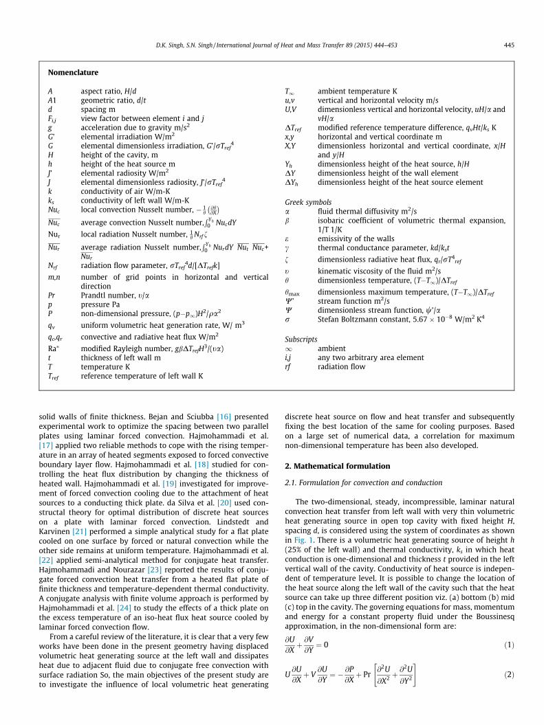
Nomenclature
A aspect ratio, H/dA1 geometric ratio, d/td spacing mFi,j view factor between element i and jg acceleration due to gravity m/s2
G’ elemental irradiation W/m2
G elemental dimensionless irradiation, G’/rTref4
H height of the cavity, mh height of the heat source mJ’ elemental radiosity W/m2
J elemental dimensionless radiosity, J’/rTref4
k conductivity of air W/m-Kks conductivity of left wall W/m-KNuc local convection Nusselt number, � 1
h@h@X
� �Nuc average convection Nusselt number,
R Yh0 NucdY
Nur local radiation Nusselt number, 1h Nrf f
Nur average radiation Nusselt number,R Yh
0 NurdY Nut Nuc+Nur
Nrf radiation flow parameter, rTref4d/[DTrefk]
m,n number of grid points in horizontal and verticaldirection
Pr Prandtl number, t/ap pressure PaP non-dimensional pressure, (p�p1)H2/qa2
qv uniform volumetric heat generation rate, W/ m3
qc,qr convective and radiative heat flux W/m2
Ra⁄ modified Rayleigh number, gbDTrefH3/(ta)
t thickness of left wall mT temperature KTref reference temperature of left wall K
T1 ambient temperature Ku,v vertical and horizontal velocity m/sU,V dimensionless vertical and horizontal velocity, uH/a and
vH/aDTref modified reference temperature difference, qvHt/ks Kx,y horizontal and vertical coordinate mX,Y dimensionless horizontal and vertical coordinate, x/H
and y/HYh dimensionless height of the heat source, h/HDY dimensionless height of the wall elementDYh dimensionless height of the heat source element
Greek symbolsa fluid thermal diffusivity m2/sb isobaric coefficient of volumetric thermal expansion,
1/T 1/Ke emissivity of the wallsc thermal conductance parameter, kd/kst
f dimensionless radiative heat flux, qr/rT4ref
t kinematic viscosity of the fluid m2/sh dimensionless temperature, (T�T1)/DTref
hmax dimensionless maximum temperature, (T�T1)/DTref
W’ stream function m2/sW dimensionless stream function, w’/ar Stefan Boltzmann constant, 5.67 � 10�8 W/m2 K4
Subscripts1 ambienti,j any two arbitrary area elementrf radiation flow
D.K. Singh, S.N. Singh / International Journal of Heat and Mass Transfer 89 (2015) 444–453 445
solid walls of finite thickness. Bejan and Sciubba [16] presentedexperimental work to optimize the spacing between two parallelplates using laminar forced convection. Hajmohammadi et al.[17] applied two reliable methods to cope with the rising temper-ature in an array of heated segments exposed to forced convectiveboundary layer flow. Hajmohammadi et al. [18] studied for con-trolling the heat flux distribution by changing the thickness ofheated wall. Hajmohammadi et al. [19] investigated for improve-ment of forced convection cooling due to the attachment of heatsources to a conducting thick plate. da Silva et al. [20] used con-structal theory for optimal distribution of discrete heat sourceson a plate with laminar forced convection. Lindstedt andKarvinen [21] performed a simple analytical study for a flat platecooled on one surface by forced or natural convection while theother side remains at uniform temperature. Hajmohammadi et al.[22] applied semi-analytical method for conjugate heat transfer.Hajmohammadi and Nourazar [23] reported the results of conju-gate forced convection heat transfer from a heated flat plate offinite thickness and temperature-dependent thermal conductivity.A conjugate analysis with finite volume approach is performed byHajmohammadi et al. [24] to study the effects of a thick plate onthe excess temperature of an iso-heat flux heat source cooled bylaminar forced convection flow.
From a careful review of the literature, it is clear that a very fewworks have been done in the present geometry having displacedvolumetric heat generating source at the left wall and dissipatesheat due to adjacent fluid due to conjugate free convection withsurface radiation So, the main objectives of the present study areto investigate the influence of local volumetric heat generating
discrete heat source on flow and heat transfer and subsequentlyfixing the best location of the same for cooling purposes. Basedon a large set of numerical data, a correlation for maximumnon-dimensional temperature has been also developed.
2. Mathematical formulation
2.1. Formulation for convection and conduction
The two-dimensional, steady, incompressible, laminar naturalconvection heat transfer from left wall with very thin volumetricheat generating source in open top cavity with fixed height H,spacing d, is considered using the system of coordinates as shownin Fig. 1. There is a volumetric heat generating source of height h(25% of the left wall) and thermal conductivity, ks in which heatconduction is one-dimensional and thickness t provided in the leftvertical wall of the cavity. Conductivity of heat source is indepen-dent of temperature level. It is possible to change the location ofthe heat source along the left wall of the cavity such that the heatsource can take up three different position viz. (a) bottom (b) mid(c) top in the cavity. The governing equations for mass, momentumand energy for a constant property fluid under the Boussinesqapproximation, in the non-dimensional form are:
@U@Xþ @V@Y¼ 0 ð1Þ
U@U@Xþ V
@U@Y¼ � @P
@Xþ Pr
@2U
@X2 þ@2U
@Y2
" #ð2Þ

ht
d
H
Y,V
X,U
Adiaba�c walls,qc +qr=0
gqvΔytΔY
Qrad
Qconv
Qcond, Y
Qcond, (Y+ΔY)
Differential element ofheat source
Fig. 1. Schematic of the Geometry.
446 D.K. Singh, S.N. Singh / International Journal of Heat and Mass Transfer 89 (2015) 444–453
U@V@Xþ V
@V@Y¼ � @P
@Yþ Pr
@2V
@X2 þ@2V
@Y2
" #þ Ra� Prh ð3Þ
U@h@Xþ V
@h@Y¼ @2h
@X2 þ@2h
@Y2 ð4Þ
The stream function is calculated from its definition as
U ¼ @w@Y
; V ¼ � @w@X
2.2. Temperature distribution along heat source at the left wall
Energy balance of conduction (Qcond), convection (Qconv) andradiation (Qrad) at the differential element of heat source providedon the left wall, which is shown, enlarged in the inset of Fig. 1,yields the following equation for the temperature distributionalong the heat source (except end points) at the left wall, in thenormalized form:
Q cond;y þ qvDyt ¼ Q cond;ðyþDyÞ þ Q conv þ Q rad
The above equation after normalization and subsequent simpli-fication leads to
@2h
@Y2 þ c@h@X
� �X¼0þ A1
A
� �� e
1� e
� �cNrf
TTref
� �4
� J
" #¼ 0 ð5Þ
For the elements at interface of the bottom and top ends of theheat source the equations for temperature variation has been sep-arately derived by making energy balance as below:
@h@Yþ c
DY2
@h@X
� �X¼0þ A1
ADY2� e
1� e
� �DY2
cNrfT
Tref
� �4
� J
" #¼ 0
ð6Þ
@h@Y� c
DY2
@h@X
� �X¼0� A1
ADY2þ e
1� e
� �DY2
cNrfT
Tref
� �4
� J
" #¼ 0
ð7Þ
2.3. Formulation for radiation
The radiosity-irradiation formulation is used to describe surfaceradiation. The walls are assumed diffuse and gray. For an area
element on a boundary of the cavity the non- dimensional radios-ity is given by the equation:
Ji ¼ eiTi
Th
� �4
þ ð1� eiÞXn
j¼1
Fij Jj i ¼ 1;2ðmþ n� 2Þ ð8Þ
The first term on the right-hand side represents the emissionterm and the second term is the reflected radiation. The summa-tion is over all the irradiation terms for that particular element.After all the radiosities are known, the irradiations are evaluatedand net radiant flux from each zone is calculated.
2.4. Boundary conditions
The velocity boundary conditions on the solid rigid walls arebased on the assumption that the trapped air does not sleep onthe walls. Temperature boundary condition at the top open sectionis based on flow condition. At the adiabatic bottom, right and restparts of the left wall convection and radiation balance each other(see Fig. 1). Hence
Bottom wall:
U ¼ 0; V ¼ 0 and@h@Y¼ Nrf ðJ � GÞ
Right wall:
U ¼ 0; V ¼ 0 and@h@X¼ Nrf ðJ � GÞ
Open top:
U ¼ 0;@V@Y¼ 0
@h@Y
� �out¼ 0; hin ¼ 0
Left wall:
U ¼ 0 and V ¼ 0
@h@X¼Nrf ðJ�GÞ for the non-heat source parts of the left wall:
3. Solution procedure
The governing Eqs. (1)–(4) are discretized by the finite volumemethod on a non-uniform staggered grid system using the SIMPLEalgorithm of Patankar [25] with first order UPWIND scheme forconvective - diffusive terms . The set of discretized equations werethen solved by a line-by-line procedure of the tri-diagonal matrixalgorithm (TDMA). In radiosity-irradiation equation view factorsare evaluated using Hottel’s crossed string method [26]. A com-puter code is developed under FORTRAN platform. As convergencecriteria, 10�3 is chosen for all dependent variables. Based on gridrefinement test, numbers of grid points are taken as 51 � 41.Results of grid refinement test are presented in the ensuingsection. A cosine and semi- cosine function have been chosen togenerate the non-uniform grids respectively along X and Y direc-tions. For derivative boundary conditions, three point formulaeusing second degree Lagrangian polynomial have been used.
4. Results and discussion
Table 1 shows the range of parameters considered in the pre-sent study. Thermal conductivity varies from 0.25 to 0.5 W/m-k.One example is epoxy glass (coated with Mylar) having thermal

Table 1Range of parameters.
Parameters Range
qv, W/m3 5 � 104–1 � 106
ks, W/m-K 0.25–0.50Ra⁄ 1 � 105–1 � 107
Nrf 17.11–58.758c 1.359–2.719e 0.05–0.85
D.K. Singh, S.N. Singh / International Journal of Heat and Mass Transfer 89 (2015) 444–453 447
conductivity 0.26 W/mk. Calculations have been made keeping inview the objective of evolving useful correlations for hmax.
0 1 2 3 42.5
5.0
7.5
10.0
12.5
15.0
17.5
20.0
22.5
25.0
Nu c
Y
ε=0ε=1
A=4
Fig. 2. Comparison of present work for e = 0; e = 1. Rayleigh number, Ra = 5 � 105.
Table 3Comparison of present work with Balaji and Venkateshan [9].
Nuc (Leading edge) Nuc (Trailingedge)
e = 0 e = 1 e = 0 e = 1
Balaji and Venkateshan [9] 23.75 16.40 6.95 7.05Present results 22.60 16.15 7.22 7.11Deviation (%) 5.08 1.54 3.88 0.85
4.1. Grid refinement test
To study the effect of grid size on the solution, a case withqv = 5 � 105 W/m3, Ra* = 2.307 � 106, A = 2, e = 0.8 andks = 0.5 W/m-K is considered, and the results are shown inTable 2. The present problem involves an interaction between freeconvection and surface radiation. Since the grid size affects thesetwo to different extents. It is necessary to look at the effect of gridsize on both the average convection and radiation Nusselt numberin order to decide the grid size. The grid sensitivity analysis is donein two parts – (a) ‘M’ fixed with varying ‘N’ and (b) ‘N’ fixed withvarying ‘M’ and optimum grid size is arrived at. Table 2(a) showswhen M is fixed, the differences in Nuc between the grids size of31 � 21 and 31 � 31 is 0.178% which is the lowest. However, thedifferences in Nur , Nut and hmax are the biggest. Also, 31 � 21 is arelatively coarse grid. The difference in Nur between the grids sizeof 31 � 51 and 31 � 61 is 0.240% which is the lowest. However, thedifferences in Nuc , Nut and hmax are comparatively higher than forother grids size. The difference in Nut between the grids size of31 � 41 and 31 � 51 is 0.025% which is the lowest and its Nuc ,Nur and hmax are comparatively smaller than others. Based on theseobservations N has been fixed as 41. Similarly, when N is fixedTable 2(b) shows that the difference in Nut between the grids sizeof 51 � 41 and 61 � 41 is 0.575% which is the lowest and Nuc;Nur
and hmax have a comparatively smaller value than others. Based onthese observations the M is taken as 51. Thus, the grid pattern usedin the present work is taken as 51 � 41.
Table 2aGrid refinement test M = 31, N varied.
M � N Nuc Nur Nut hmax %change
31 � 21 17.365 6.364 23.729 0.864 –31 � 31 17.396 6.082 23.479 0.855 0.17831 � 41 17.347 6.179 23.527 0.861 0.28131 � 51 17.305 6.227 23.533 0.859 0.24231 � 61 17.261 6.242 23.503 0.856 0.25431 � 71 17.202 6.261 23.463 0.852 0.342
Table 2bGrid refinement test N = 41, M varied.
M � N Nuc Nur Nut hmax %change
21 � 41 18.233 6.204 24.438 0.838 –31 � 41 17.347 6.179 23.527 0.861 4.85941 � 41 17.245 6.107 23.353 0.866 0.58851 � 41 17.221 6.294 23.511 0.856 0.13961 � 41 17.200 6.447 23.647 0.859 0.12271 � 41 17.161 6.714 23.875 0.851 0.227
4.2. Code validation
In order to validate the employed method and check the code,results for isothermal boundary condition at the left wall in anair-filled open top cavity of aspect ratio, A = 4, Rayleigh numberRa = 5 � 105, e = 0 and e = 1were obtained and compared with theBalaji and Venkateshan [9] in terms of local convection Nusseltnumber (Nuc). The convection Nusselt number distribution alongthe left wall for the two cases of emissivity is given in Fig 2.Since, the convection Nusselt number is locally distributed at theleft wall. Therefore, for quantitative comparison, maximum andminimum convection Nusselt number at the leading and trailingedge of right vertical wall is considered for the two values of emis-sivity as shown in Table 3. The comparison between the local
in Nuc %change in Nur %change in Nut %change in hmax
–4.431 1.054 1.0421.569 0.204 0.6960.771 0.025 0.2320.240 0.127 0.3490.303 0.170 0.467
in Nuc %change in Nur %change in Nut %change in hmax
–0.403 3.872 2.6711.165 0.739 0.5772.971 0.672 1.1552.373 0.575 0.3493.976 0.955 0.931

448 D.K. Singh, S.N. Singh / International Journal of Heat and Mass Transfer 89 (2015) 444–453
Nusselt numbers at the leading and trailing edge show the percent-age difference of 5.08% and 3.88% for e = 0 and 1.54% and 0.88% fore = 1. Thus, comparison results clearly show the good agreementbetween the Balaji and Venkateshan [9] results and those of thepresent study.
4.3. Typical results for open top cavity
Having validated the present code with previous results ofBalaji and Venkateshan [9], a detailed parametric study has beenundertaken. Typical results from this study are presented herefor open top cavity having discrete volumetric heat generationsource at different locations viz. (a) bottom position (b) midposition and (c) top position at the left wall of the cavity.
4.3.1. Flow patterns and isothermsDifferent locations of heat source on the left wall plays a deci-
sive role with regard to the flow pattern and heat transfer thatresides in the cavity. Fig. 3 shows the streamlines and isothermsfor the two values of emissivity, e = 0.05 and e = 0.85 withks = 0.25 W/m-K, qv = 1 � 105 W/m3 and Ra⁄ = 9.231 � 105.Considering the weak radiation case i.e. e = 0.05 when heat sourceis placed at the bottom of the left wall as shown in Fig. 3(a), ambi-ent air enters into the cavity up to the bottom wall. After heating ofair by the heat source placed at the bottom of the left wall, thesame start moving upward only along the left wall forming a singleloop circulation as it is confirmed by the corresponding isothermswhich show a thin boundary layer on the left wall. On placing theheat source at the bottom of the left wall for strong radiation i.e.e = 0.85 as shown in Fig. 3(b), the adiabatic walls of the cavityget heated due to intense surface radiation heat exchange asevidenced by the thermal boundary layer development. Thus, theair adjacent to the walls of the cavity is heated due to convectionheat transfer. As a result both the side walls are induced byup-flow forming two loop circulations as shown in Fig. 3(b).When heat source is placed at the mid of the left wall as shownin Fig. 3(a) for weak radiation i.e. e = 0.05, two zones of fluid circu-lation are observed in the contour of streamlines. In the first zone
Fig. 3. Streamline and isotherm for different location of the heat source (b
closer to the left wall the incoming ambient air comes down andturn around towards the open top of the cavity after taking heatfrom the source before reaching the bottom wall which is notheated due to weak radiation as it is confirmed by the correspond-ing isotherms. The trapped air is recirculated in the non-heatingzone near the bottom and right wall of the cavity as clearly shownin Figure. It is to be noted that as the emissivity increases frome = 0.05 to e = 0.85 as shown in Fig. 3(b) by placing the heat sourceat the mid of the left wall, flow patterns are almost similar exceptthe increment of the strength of second circulation due to convec-tion heat transfer from the adiabatic walls to the air. When heatsource is placed at the top of the left wall under weak radiationcase i.e. e = 0.05 as shown in Fig. 3(a), air inside the cavity formsa single loop flow pattern adjacent to the left wall due to theabsence of heat source at the bottom wall and weak radiation.Keeping the position of the heat source as earlier case for strongradiation (e = 0.85) as shown in Fig. 3(b), it results in the radiativeheating of adiabatic walls due to which both the side walls areinduced by up-flow forming two loops circulation as shown inFig. 3(b). Transition from single loop to double loop circulationtakes place at different values of emissivity and volumetric heatgeneration.
Effect of conductivity is studied by varying the conductivityof heat source as shown in Fig. 4 for different locations. Resultsare obtained for qv = 1 � 105, e = 0.5, Ra⁄ = 9.231 � 105 and4.615 � 105. For ks = 0.50 W/m-K as shown in Fig. 4(b), streamlines and isotherms exhibit similar trends of Fig. 4(a) forks = 0.25 W/m-K except for the case when heat source is at top ofleft wall. In the case when heat source is at top of the left wall asecondary vortex is developed at the bottom right corner.Conductive heat transfer increases on increasing the conductivityof heat source from ks = 0.25 W/m-K to ks = 0.50 W/m-K whichleads to decrement in temperature of heat source. Due to thisdecrement in temperature radiative heat flux from the heat sourcedecreases and results in the elimination of secondary vortex devel-oped due to radiative heating of adiabatic walls as shown inFig. 4(b). Increment in conductivity does not affect the intensityof stream function for the case when heat source is at the bottom
ottom, mid and top) arranged left to right at (a) e = 0.05 (b) e = 0.85.

Fig. 4. Streamline and isotherm for different location of the heat source (bottom, mid and top) arranged left to right at (a) ks = 0.25 W/m-K (b) ks = 0.50 W/m-K.
0.0 0.1 0.2 0.3 0.4 0.5
0.25
0.30
0.35
0.40
0.45
0.50
Dim
ensi
onle
ss te
mpe
ratu
re (θ
)
Yh
qv=1x10⁵, Ra*=9.231x10⁵
qv=1x10⁶, Ra*=9.231x10⁶
0.20
0.25
0.30
0.35
0.40
0.45
0.50
Yh
Dim
ensi
onle
ss te
mpe
ratu
re (
θ)
qv=1x10⁵,Ra*=9.231x10⁵
qv=1x10⁶,Ra*=9.231x10⁶
0.7 0.8 0.9 1.0 1.1 1.2 1.4 1.5 1.6 1.7 1.8 1.9 2.0
0.0
0.1
0.2
0.3
0.4
Yh
Dim
ensi
onle
ss te
mpe
ratu
re (
θ)
qv=1x10⁵,Ra*=9.231x10⁵
qv=1x10⁶,Ra*=9.231x10⁶
(a) (b) (c)Fig. 5. Variation of dimensionless temperature (h) along the heat source (a) Heat source at bottom position (b) Heat source at mid position (c) Heat source at top position.
D.K. Singh, S.N. Singh / International Journal of Heat and Mass Transfer 89 (2015) 444–453 449
of the left wall, whereas, the increment in conductivity fromks = 0.25 to ks = 0.50 W/m-K suppresses the intensity of streamfunction for the case when heat source is at mid and top of the leftwall. Changes in conductivity of heat source alters the temperaturedistribution inside the cavity for all the different locations of heatsource as shown in Figs. 4(a) and (b).
4.3.2. Variation of non-dimensional temperature with parameters (qv,e and c)
Fig. 5 shows the variation of non-dimensional temperaturealong the volumetric heat generating source for different locationsviz. (a) When heat source is placed at the bottom of the left wall (b)heat source is placed at the mid of the left wall and (c) heat sourceis placed at the top of the left wall. Results are presented for twodifferent values of qv and Ra⁄ as shown in figure with e = 0.5 andks = 0.25 W/m-K. Fig. 5 shows that for all the three different loca-tions non-dimensional temperature increases along the heatsource and reaches a maximum value at the end of the heat source.
Comparing among the three locations of heat source, sharpincrease of h is not found in the case when heat source is at bottomposition. From physical standpoint of view this is justified, becausebottom wall gets heated due to radiative heat flux emitted (e = 0.5)by the heat source and transfer heat convectively to the air. Also,from the Fig. 5(a)–(c), one can find that difference in minimumand maximum temperature within the heat source is greater whenheat source is at the top position and it is smaller for bottom posi-tion. So, it is observed that degree of increase in non-dimensionaltemperature within the heat source is smaller for bottom positionand larger for top position of left wall. Since reference temperatureTref and Ra⁄ increase with the increase in qv, which lead to increasein buoyancy force caused by temperature difference resulting inthe decrement of non-dimensional temperature as it is depictedin Fig. 5(a)–(c). The maximum non-dimensional temperature isobtained for the case when heat source is at the mid positionand it is smaller when heat source is at the top position of the leftwall where it is more exposed to ambient condition.

0.0
0.1
0.2
0.3
0.4D
imen
sion
less
tem
pera
ture
(θ)
Width of the cavity
at the bottom of the cavity at the mid of the cavity at the top of the cavity
0.0
0.1
0.2
0.3
0.4
Dim
ensi
onle
ss te
mpe
ratu
re (
θ)
Width of the cavity
at the bottom of the cavity at the mid of the cavity at the top of the cavity
0.0 0.2 0.4 0.6 0.8 1.0 0.0 0.2 0.4 0.6 0.8 1.0 0.0 0.2 0.4 0.6 0.8 1.0
0.0
0.1
0.2
0.3
0.4
Dim
ensi
onle
ss te
mpe
ratu
re (θ
)
Width of the cavity
at the bottom of the cavity at the mid of the cavity at the top of the cavity
(a) (b) (c)Fig. 6. Variation of dimensionless temperature (h) along the width of the cavity (a) Heat source at bottom position (b) Heat source at mid position (c) Heat source at topposition.
450 D.K. Singh, S.N. Singh / International Journal of Heat and Mass Transfer 89 (2015) 444–453
Fig. 6 shows non-dimensional local temperature distributionacross the width of the cavity for different locations of heatsource at three different section of the cavity. The parameters setis taken as Ra⁄ = 9.231 � 105, qv = 1 � 105 W/m3, e = 0.85 andks = 0.25 W/m-K. It can be seen that bottom wall is substantiallyheated because of radiation which is more pronounced in the casewhen heat source is at the bottom position as discussed earlier forFig. 5. Curves also show that for all the three different locations ofheat source at the left wall of cavity, maximum temperature is gen-erated at the left wall within the heat source and substantiallydecreases up to one-half of width of the cavity. It then again startincreasing up to the right wall due to the radiation exchange.Further when heat source is at bottom position, it is found thattemperature at the top of the left wall is lower than the centre ofthe left wall of the cavity which clearly shows that heat is carriedout by air from bottom section of the cavity but the same trend isnot shown in case when heat source is placed at the mid and top ofthe left wall. Because air after getting heat from the source startsmoving upward and escapes out of the cavity.
Fig. 7 shows the variation of hmax inside the cavity with emissiv-ity (e) for different values of heat generation (qv). As shown inFigs 7(a)–(c), ten different values of e and four different values ofqv are considered with conductivity ks = 0.25 W/m-K andRa⁄ = 1 � 105 for different locations viz. (a) bottom position (b)mid position and (c) top position. Figures show that for a particular
0.25
0.30
0.35
0.40
0.45
0.50
0.55
0.60
0.65
θ max
Emissivity (ε)
qv=5 X10⁴
qv=1 X10⁵
qv=5 X10⁵
qv=1 X10⁶
0.25
0.30
0.35
0.40
0.45
0.50
0.55
0.60
0.65
θ max
Emiss
0.0 0.2 0.4 0.6 0.8 1.00.0 0.2 0.4
(a) (b
Fig. 7. Variation of hmax with emissivity for different heat source position (a) Heat sourc
value of qv maximum non-dimensional temperature decreasessubstantially for all the three different locations of heat source atthe left wall of the cavity. For different values of qv and locationsof heat source, hmax undergoes a marked drop in its value as eincreases from 0.05 to 0.85. When heat source is at bottom andtop position degree of decrement in hmax is 21% as e changes from0.05 to 0.85 for qv = 5 � 104, 1 � 105 and 1 � 106 W/m3 whereas itis 20% for qv = 5 � 105 W/m3. For the mid position, hmax drops downby 25% for qv = 5 � 104 and 1 � 105 W/m3 which shows that effectof emissivity between the same limit is somewhat higher for thesetwo values of qv at this position. Whereas, for the same position thedecrement in hmax for qv/ = 5 � 105 W/m3 is 20% and forqv = 1 � 106 W/m3 degree of decrement in hmax is 22% are observed.
The effect of conductance (c) on hmax is plotted in Fig. 8 for sixdifferent values of c at four different values of volumetric heat gen-eration (qv) with e = 0.85 as shown in figures. From Fig. 8(a)–(c) fordifferent locations of heat source at the left wall, it is investigatedthat with increase in c, maximum non-dimensional temperaturehmax substantially decreases. It is to be noted, the case consideredhere when heat source is at bottom and mid position of the leftwall for e = 0.85, hmax decreases by 50% when c changes from1.359 to 2.719 for all the four different values of qv. In the samerange of c, however, in Fig 8(c) when heat source is located atthe top of the left wall reveals the decrement in hmax is about45% for qv = 5 � 104 and 1 � 105 W/m3 and the same decreases
ivity (ε)
qv=5 X10⁴
qv=1 X10⁵
qv=5 X10⁵
qv=1 X10⁶
0.6 0.8 1.0 0.0 0.2 0.4 0.6 0.8 1.00.25
0.30
0.35
0.40
0.45
0.50
0.55
0.60
θ max
Emissivity (ε)
qv=5 X10⁴
qv=1 X10⁵
qv=5 X10⁵
qv=1 X10⁶
) (c) e at bottom position (b) Heat source at mid position (c) Heat source at top position.

0.2
0.3
0.4
0.5
0.6
0.7
0.8
0.9
1.0θ m
ax
Conductance (γ)
qv=5 X10⁴
qv=1 X10⁵
qv=5 X10⁵
qv=1 X10⁶
0.3
0.4
0.5
0.6
0.7
0.8
0.9
1.0
θ max
Conductance (γ)
qv=5 X10⁴
qv=1 X10⁵
qv=5 X10⁵
qv=1 X10⁶
1.4 1.6 1.8 2.0 2.2 2.4 2.6 1.2 1.4 1.6 1.8 2.0 2.2 2.4 2.6 2.8 1.2 1.4 1.6 1.8 2.0 2.2 2.4 2.6 2.80.2
0.3
0.4
0.5
0.6
0.7
0.8
Conductance (γ)
θ max
qv=5 X10⁴
qv=1 X10⁵
qv=5 X10⁵
qv=1 X10⁶
(a) (b) (c)Fig. 8. Variation of hmax with conductance for different heat generating position (a)Heat source at bottom position (b) Heat source at mid position (c) Heat source at topposition.
10
15
20
25
30
35ε=0.1, qv=5x10⁴
ε=0.8, qv=5x10⁴
ε=0.1, qv=1x10⁶
ε=0.8, qv=1x10⁶
Yh
Loca
l Con
vect
ive
Nus
selt
num
ber
10121416182022242628303234 ε=0.1, qv=5x10⁴
ε=0.8, qv=5x10⁴
ε=0.1, qv=1x10⁶
ε=0.8, qv=1x10⁶
Yh
Loca
l Con
vect
ive
Nus
selt
num
ber
0.0 0.1 0.2 0.3 0.4 0.7 0.8 0.9 1.0 1.1 1.2 1.5 1.6 1.7 1.8 1.9
10
15
20
25
30
35
40
45ε=0.1, qv=5x10⁴
ε=0.8, qv=5x10⁴
ε=0.1, qv=1x10⁶
ε=0.8, qv=1x10⁶
Yh
Loca
l Con
vect
ive
Nus
selt
num
ber
(a) (b) (c)Fig. 9. Variation of local convective Nusselt number along the heat source (a) Heat source at bottom position (b) Heat source at mid position (c) Heat source at top position.
1
2
3
4
5
6
7
8
9
Loca
l Rad
iativ
e N
usse
lt nu
mbe
r
Yh
ε=0.1, qv=5x10⁴
ε=0.8, qv=5x10⁴
ε=0.1, qv=1x10⁶
ε=0.8, qv=1x10⁶
1
2
3
4
5
6
7
8
9
Yh
ε=0.1, qv=5x10⁴
ε=0.8, qv=5x10⁴
ε=0.1, qv=1x10⁶
ε=0.8, qv=1x10⁶
Loca
l Rad
iativ
e N
usse
lt nu
mbe
r
0
2
4
6
8
10
Loca
l Rad
iativ
e N
usse
lt nu
mbe
r
Yh
ε=0.1, qv=5x10⁴
ε=0.8, qv=5x10⁴
ε=0.1, qv=1x10⁶
ε=0.8, qv=1x10⁶
0.0 0.1 0.2 0.3 0.4 0.7 0.8 0.9 1.0 1.1 1.5 1.6 1.7 1.8 1.9
(a) (b) (c)Fig. 10. Variation of local radiative Nusselt number along the heat source (a) Heat source at bottom position (b) Heat source at mid position (c) Heat source at top position.
D.K. Singh, S.N. Singh / International Journal of Heat and Mass Transfer 89 (2015) 444–453 451
by 47% for qv = 5 � 105 and 1 � 106 W/m3. With this quantitativestudy it is investigated that the effect of c is more pronouncedfor the case when heat source is located at the bottom and midposition of the left wall inside the cavity.
4.3.3. Variation of local Nusselt numberVariation of local convective and radiative Nusselt number Nuc
and Nur along the heat source is shown in Figs. 9 and 10 for three
different position of heat source with various combinations of gov-erning parameters. Value of emissivity e and volumetric heat gen-eration qv (W/m3) are shown in figures and the correspondingmodified Rayleigh number is taken as Ra⁄ = 4.615 � 105 and9.231 � 106 and Ks = 0.25 W/m-K. For all the different position ofheat source, Fig. 9 shows that local convective Nusselt numberdecreases along the heat source with the exception when heatsource is at bottom position. At this position there is a considerable

-800
-600
-400
-200
0
200
400
600
800
Width of the cavity (X)
Dim
ensi
onle
ss v
ertiv
al v
eloc
ity
qv=1x10⁵,Ra*=1x10⁵
qv=1x10⁶,Ra*=1x10⁶
-600
-400
-200
0
200
400
600
800
Width of the cavity (X)D
imen
sion
less
ver
tival
vel
ocity
qv=1x10⁵,Ra*=1x10⁵
qv=1x10⁶,Ra*=1x10⁶
0.0 0.2 0.4 0.6 0.8 1.0 0.0 0.2 0.4 0.6 0.8 1.0 0.0 0.2 0.4 0.6 0.8 1.0
-400
-200
0
200
400
Width of the cavity (X)
Dim
ensi
onle
ss v
ertiv
al v
eloc
ity
qv=1x10⁵,Ra*=1x10⁵
qv=1x10⁶,Ra*=1x10⁶
(a) (b) (c) Fig. 11. Variation of dimensionless vertical velocity at the top of the cavity (a) Heat source at bottom position (b) Heat source at mid position (c) Heat source at top position.
452 D.K. Singh, S.N. Singh / International Journal of Heat and Mass Transfer 89 (2015) 444–453
difference among Nusselt number distribution at the bottom of theheat source. This is because of adiabatic condition of bottom wallas already discussed in Section 4.3.2. It can be seen from figuresthat increase in qv leads to the increment in local convectiveNusselt number distribution. Further, the higher value of surfaceemissivity causes a reduction of convective heat transfer fromthe heat source, but at the same time increases radiative heattransfer as shown in Fig. 10, because of intense surface radiationinterchange among the walls. From Fig 10 for local radiativeNusselt number distribution it is observed that radiative Nusseltnumber increases along the heat source. This increment can beexplained by the increment in non-dimensional temperature alongthe heat source which results in more radiative heat flux along theheat source. Effect of qv on radiative Nusselt number is studied fortwo different values. Since, radiation flow parameter (Nrf) is theincreasing function of qv, therefore heat transfer by radiationincreases with the increase in qv.
4.3.4. Variation of vertical velocityVariation of non-dimensional vertical velocity, V at the top sec-
tion across the width of the cavity is presented in Fig. 11. Resultsare depicted for two different values of qv and Ra⁄ as shown in fig-ure with ks = 0.25 W/m-K, e = 0.5. In the vertical velocity profilesshown in Fig. 11(a)–(c), for different locations of heat source, twopeaks are observed, longer one near the heated left wall and a sec-ond smaller one close to the right adiabatic wall which confirmtwo loop circulations and boundary layer development at the rightadiabatic vertical wall in presence of surface radiation as describedin the earlier Section 4.3.1. Radiation heat transfer from the leftwall heats both the right and bottom walls and under equilibriumthese two walls lose heat convectively to the air. Thus, there aretwo plumes leaving the cavity. In addition to the above, it is alsofound that maximum non dimensional velocity attained by theair is approximately same for the cases when heat source is at bot-tom and mid position. While for the case when heat source is at topposition, the maximum non dimensional vertical velocity is almosthalf for both the values of Ra⁄ and qv in comparison to the bottomand mid position of heat source. The possible reason for this causeis that air after heating at the top position instantly escapes outfrom the cavity and fresh ambient air re-enters into the cavitywhich disturb the flow coming out from the cavity.
5. Correlations
The range of parameters for which calculation have been doneare shown in Table 1. All the walls were assumed to be of the same
emissivity. Based on a large set of data, non- dimensional maxi-mum temperature, hmax for different locations are correlated as:
When heat source at the bottom of the left wall:
hmax ¼ 21:186ð1þ Ra�Þ�0:208ðNrf =ð1þ Nrf ÞÞ�0:303ð1þ eÞ�0:428ð1þ cÞ�0:794
When heat source at the mid of the left wall:
hmax ¼ 23:183ð1þ Ra�Þ�0:211ðNrf =ð1þ Nrf ÞÞ�0:078ð1þ eÞ�0:460ð1þ cÞ�0:798
When heat source at the top of the left wall:
hmax ¼ 9:116ð1þ Ra�Þ�0:161ðNrf =ð1þ Nrf ÞÞ�1:011ð1þ eÞ�0:367ð1þ cÞ�0:710
As the modified Rayleigh number Ra⁄ enhances heat transfer byconvection which decreases the maximum temperature hmax insidethe cavity, as it is confirmed by the negative exponent. The expo-nent of emissivity and conductance are negative which signify thathmax decreases with the increase in said parameters. In evolving theabove correlation, (1 + parameter) term has been used as the mostappropriate form , because in multi-mode heat transfer , even,when one mode is not considered or parameter set to zero, hmax
would be non-zero, as it still contains heat transfer by other modes.Minimum correlation coefficient of 0.996 and maximum standarderror of 2.19% indicates the goodness of fit.
6. Conclusions
Conjugate laminar natural convection with surface radiation ina two-dimensional open top cavity due to a volumetric heat gener-ating source for three different locations on the left vertical side-wall is numerically investigated. Main efforts are focused on thelocation of heat source at the left wall and the effect of indepen-dent variables on the fluid flow and heat transfer characteristics,and the following conclusions are obtained.
From design point of view for cooling of such type of system oneshould not ignore the location of heat source which plays a signif-icant role in natural convection heat transfer. The best possibleposition of heat source is found at the top of the left wall insidethe cavity. Surface radiation changes the basic flow physics andenhances the radiative heat transfer as a result of which heat trans-fer by convection decreases. So, ignoring of surface radiation is notfeasible for this kind of problem. Thermal conductance and volu-metric heat generation decrease the non-dimensional maximumtemperature. Volumetric heat generating rate enhances the con-vective and radiative heat transfer. Further, a useful correlationhas been developed for maximum non-dimensional temperature(hmax).

D.K. Singh, S.N. Singh / International Journal of Heat and Mass Transfer 89 (2015) 444–453 453
Conflicts of interest
None declared.
References
[1] S. Ostrach, Natural convection in enclosures, ASME J. Heat Transfer 110 (1988)1175–1190.
[2] G. de Vahl Davis, I.P. Jones, Natural convection in a square cavity – acomparison exercise, Int. J. Numer. Methods Fluids 3 (1983) 227–248.
[3] C.J. Ho, J.Y. Chang, A study of natural-convection heat transfer in a verticalrectangular enclosure with 2-dimensional discrete heating––effect of aspectratio, Int. J. Heat Mass Transfer 37 (1994) 917–925.
[4] S.K.W. Tou, X.F. Zhang, Three-dimensional numerical simulation of naturalconvection in an inclined liquid-filled enclosure with an array of discreteheaters, Int. J. Heat Mass Transfer 46 (2003) 127–138.
[5] V. Sernas, I. Kyriakides, Natural convection in an open cavity, proceedings ofthe seventh, Int. Heat Trans. Conf. Munich 2 (1982) 275–286.
[6] C.F. Hess, R.H. Henze, Experimental investigation of natural convection lossesfrom open cavities, J. Heat Transfer 106 (1984) 333–338.
[7] S.S. Cha, K.J. Choi, An interferometric investigation of open cavity naturalconvection heat transfer, Exp. Heat Transfer 2 (1989) 27–40.
[8] Y.L. Chan, C.L. Tien, Laminar natural convection in shallow open cavities, J. HeatTransfer 108 (1986) 305–309.
[9] C. Balaji, S.P. Venkateshan, Interaction of radiation with free convection in anopen cavity, Int. J. Heat Fluid Flow 15 (1994) 317–324.
[10] A.A. Dehghan, M. Behnia, Combined natural convection–conduction andradiation in a discretely heated open cavity, J. Heat Transfer 118 (1996) 56–64.
[11] Gururaja Rao, C. Balaji, S.P. Venkateshan, Conjugate mixed convection withsurface radiation from a vertical plate with a discrete heat source, ASME J. HeatTransfer 123 (2001) 698–702.
[12] S.N. Singh, S.P. Venkateshan, Numerical study of natural convection withsurface radiation in side-vented open cavities, Int. J. Therm. Sci. 43 (2004)865–876.
[13] G.V. Kuznetsov, M.A. Sheremet, Conjugate natural convection in an enclosurewith a heat source of constant heat transfer rate, Int. J. Heat Mass Transf. 54(2011) 260–268.
[14] S.G. Martyushev, M.A. Sheremet, Conjugate natural convection combined withsurface thermal radiation in an air filled cavity with internal heat source, Int. J.Therm. Sci. 76 (2014) 51–67.
[15] S.G. Martyushev, M.A. Sheremet, Conjugate natural convection combined withsurface thermal radiation in a three dimensional enclosure with a heat source,Int. J. Heat Mass Transfer 73 (2014) 340353.
[16] A. Bejan, E. Sciubba, The optimal spacing for parallel plates cooled by forcedconvection, Int. J. Heat Mass Transfer 35 (1992) 3259–3264.
[17] M.R. Hajmohammadi, M. Moulod, O.J. Shariatzadeh, S.S. Nourazar, Newmethods to cope with temperature elevations in heated segments of flatplates cooled by boundary layer flow, Therm. Sci. (2013). online first(00),pp.159–159.
[18] M.R. Hajmohammadi, A. Pouzesh, S. Poozesh, Controlling the heat fluxdistribution by changing the thickness of heated wall, J. Basic Appl. Sci. 2 (7)(2012) 7270–7275.
[19] M.R. Hajmohammadi, A. Campo, S.S. Nourazar, A.M. Ostad, Improvement offorced convection cooling due to the attachment of heat sources to aconducting thick plate, J. Heat Transfer Trans. ASME 135 (2013) 124504-1.
[20] A.K. da Silva, S. Lorente, A. Bejan, Optimal distribution of discrete heat sourceson a plate with laminar forced convection, Int. J. Heat Mass Transfer 47 (2004)2139–2148.
[21] M. Lindstedt, R. Karvinen, Conjugate heat transfer in a plate – One surface atconstant temperature and the other cooled by forced or natural convection,Int. J. Heat Mass Transfer 66 (2013) 489–495.
[22] M.R. Hajmohammadi, S.S. Nourazar, A.H. Manesh, Semi-analytical treatmentsof conjugate heat transfer, J. Mech. Eng. Sci. 227 (2012) 492–503.
[23] M.R. Hajmohammadi, S.S. Nourazar, Conjugate forced convection heat transferfrom a heated flat plate of finite thickness and temperature-dependentthermal conductivity, Heat Transfer Eng. 35 (2014) 863–874.
[24] M.R. Hajmohammadi, M. Moulod, O.J. Shariatzadeh, A. Campo, Effect of a thickplate on the excess temperature of iso-heat flux heat sources cooled bylaminar forced convection flow; conjugate analysis, Numer. Heat Transfer PartA 66 (2014) 205–216.
[25] S.V. Patankar, Numerical Heat Transfer and Fluid Flow, Hemisphere PublishingCorporation, New York, 1980.
[26] H.C. Hottel, A.S. Sarofim, Radiative Heat Transfer, McGraw-Hill, New York,1967.