Dynamic conjugate F-SHARP microscopy - Nature
8
Papadopoulos et al. Light: Science & Applications (2020)9:110 Official journal of the CIOMP 2047-7538 https://doi.org/10.1038/s41377-020-00348-x www.nature.com/lsa ARTICLE Open Access Dynamic conjugate F-SHARP microscopy Ioannis N. Papadopoulos 1 , Jean-Sebastien Jouhanneau 2 , Naoya Takahashi 3 , David Kaplan 3 , Matthew Larkum 3 , James Poulet 2 and Benjamin Judkewitz 1 Abstract Optical microscopy is an indispensable tool in biomedical sciences, but its reach in deep tissues is limited due to aberrations and scattering. This problem can be overcome by wavefront-shaping techniques, albeit at limited fields of view (FOVs). Inspired by astronomical imaging, conjugate wavefront shaping can lead to an increased field of view in microscopy, but this correction is limited to a set depth and cannot be dynamically adapted. Here, we present a conjugate wavefront-shaping scheme based on focus scanning holographic aberration probing (F-SHARP). We combine it with a compact implementation that can be readily adapted to a variety of commercial and home-built two-photon microscopes. We demonstrate the power of the method by imaging with high resolution over extended FOV (>80 μm) deeper than 400 μm inside a mouse brain through a thinned skull. Introduction Optical microscopy has been crucial for many impor- tant insights in biomedical research. However, when light travels through biological tissues, its interaction with cells and other structures causes scattering, which worsens with depth 1 . For this reason, conventional optical micro- scopy is typically limited to depths of a few hundred micrometres. Confocal and two-photon (2P) microscopy 2 can mitigate some of the scattering and enable an increased depth penetration by using only ballistic pho- tons for focusing. However, the exponential decay of ballistic light with imaging depth still limits these approaches to <100 μm for confocal microscopy, <1 mm for 2P microscopy and <2 mm for three-photon microscopy 1,3,4 . The interaction of light with inhomogeneous media has been studied under two different regimes. First, in the regime of optical aberrations, large-scale variations of the refractive index lead to a general mild deterioration of the imaging quality 5 . Second, as the spatial range of the refractive index inhomogeneities approaches the wave- length of light, the interaction is dominated by scattering 6 . In this case, illuminating a turbid medium with a coherent light source leads to the generation of a speckle pattern, in which the wavefront appears scrambled. Yet, information is not lost because there is a linear relationship between optical wavefronts at the input plane and the output plane of a scattering medium 7–11 . Thus, both aberrations and scattering can in principle be inverted and compensated for. Techniques based on this idea include modular adaptive optics 12–14 , wavefront sensing 15–17 , pupil seg- mentation techniques 18,19 and iterative optimization 20,21 . Most of these techniques are best suited for either the aberration or the scattering regime but not for both. To flexibly correct both scattering and aberrations in vivo, we recently developed a technique termed focus scanning holographic aberration probing (F-SHARP) 22 . F-SHARP measures the amplitude and phase of a point-spread function (PSF) inside a medium, which contains both high- and low-angle scattering information. Because F-SHARP is not limited to the refresh rate of the wavefront-shaping element, it enables the use of a high- pixel-count spatial light modulator (SLM) and allows cor- rection for a large (>1000) number of modes at high speeds. © The Author(s) 2020 Open Access This article is licensed under a Creative Commons Attribution 4.0 International License, which permits use, sharing, adaptation, distribution and reproduction in any medium or format, as long as you give appropriate credit to the original author(s) and the source, provide a link to the Creative Commons license, and indicate if changes were made. The images or other third party material in this article are included in the article’ s Creative Commons license, unless indicated otherwise in a credit line to the material. If material is not included in the article’s Creative Commons license and your intended use is not permitted by statutory regulation or exceeds the permitted use, you will need to obtain permission directly from the copyright holder. To view a copy of this license, visit http://creativecommons.org/licenses/by/4.0/. Correspondence: Benjamin Judkewitz ([email protected]) 1 Charité – Universitätsmedizin Berlin, Einstein Center for Neurosciences, NeuroCure Cluster of Excellence, Charitéplatz 1, 10117 Berlin, Germany 2 Max Delbrück Center for Molecular Medicine, Robert-Rössle-Str. 10, 13092 Berlin, Germany Full list of author information is available at the end of the article 1234567890():,; 1234567890():,; 1234567890():,; 1234567890():,;
-
Upload
khangminh22 -
Category
Documents
-
view
3 -
download
0
Transcript of Dynamic conjugate F-SHARP microscopy - Nature

Papadopoulos et al. Light: Science & Applications (2020) 9:110 Official journal of the CIOMP 2047-7538https://doi.org/10.1038/s41377-020-00348-x www.nature.com/lsa
ART ICLE Open Ac ce s s
Dynamic conjugate F-SHARP microscopyIoannis N. Papadopoulos1, Jean-Sebastien Jouhanneau2, Naoya Takahashi3, David Kaplan3, Matthew Larkum3,James Poulet2 and Benjamin Judkewitz 1
AbstractOptical microscopy is an indispensable tool in biomedical sciences, but its reach in deep tissues is limited due toaberrations and scattering. This problem can be overcome by wavefront-shaping techniques, albeit at limited fields ofview (FOVs). Inspired by astronomical imaging, conjugate wavefront shaping can lead to an increased field of view inmicroscopy, but this correction is limited to a set depth and cannot be dynamically adapted. Here, we present aconjugate wavefront-shaping scheme based on focus scanning holographic aberration probing (F-SHARP). Wecombine it with a compact implementation that can be readily adapted to a variety of commercial and home-builttwo-photon microscopes. We demonstrate the power of the method by imaging with high resolution over extendedFOV (>80 µm) deeper than 400 μm inside a mouse brain through a thinned skull.
IntroductionOptical microscopy has been crucial for many impor-
tant insights in biomedical research. However, when lighttravels through biological tissues, its interaction with cellsand other structures causes scattering, which worsenswith depth1. For this reason, conventional optical micro-scopy is typically limited to depths of a few hundredmicrometres. Confocal and two-photon (2P) microscopy2
can mitigate some of the scattering and enable anincreased depth penetration by using only ballistic pho-tons for focusing. However, the exponential decay ofballistic light with imaging depth still limits theseapproaches to <100 µm for confocal microscopy, <1 mmfor 2P microscopy and <2mm for three-photonmicroscopy1,3,4.The interaction of light with inhomogeneous media has
been studied under two different regimes. First, in theregime of optical aberrations, large-scale variations of the
refractive index lead to a general mild deterioration of theimaging quality5. Second, as the spatial range of therefractive index inhomogeneities approaches the wave-length of light, the interaction is dominated by scattering6.In this case, illuminating a turbid medium with a coherentlight source leads to the generation of a speckle pattern, inwhich the wavefront appears scrambled. Yet, informationis not lost because there is a linear relationship betweenoptical wavefronts at the input plane and the output planeof a scattering medium7–11. Thus, both aberrations andscattering can in principle be inverted and compensatedfor. Techniques based on this idea include modularadaptive optics12–14, wavefront sensing15–17, pupil seg-mentation techniques18,19 and iterative optimization20,21.Most of these techniques are best suited for either theaberration or the scattering regime but not for both. Toflexibly correct both scattering and aberrations in vivo, werecently developed a technique termed focus scanningholographic aberration probing (F-SHARP)22. F-SHARPmeasures the amplitude and phase of a point-spreadfunction (PSF) inside a medium, which contains bothhigh- and low-angle scattering information. BecauseF-SHARP is not limited to the refresh rate of thewavefront-shaping element, it enables the use of a high-pixel-count spatial light modulator (SLM) and allows cor-rection for a large (>1000) number of modes at high speeds.
© The Author(s) 2020OpenAccessThis article is licensedunder aCreativeCommonsAttribution 4.0 International License,whichpermits use, sharing, adaptation, distribution and reproductionin any medium or format, as long as you give appropriate credit to the original author(s) and the source, provide a link to the Creative Commons license, and indicate if
changesweremade. The images or other third partymaterial in this article are included in the article’s Creative Commons license, unless indicated otherwise in a credit line to thematerial. Ifmaterial is not included in the article’s Creative Commons license and your intended use is not permitted by statutory regulation or exceeds the permitted use, you will need to obtainpermission directly from the copyright holder. To view a copy of this license, visit http://creativecommons.org/licenses/by/4.0/.
Correspondence: Benjamin Judkewitz ([email protected])1Charité – Universitätsmedizin Berlin, Einstein Center for Neurosciences,NeuroCure Cluster of Excellence, Charitéplatz 1, 10117 Berlin, Germany2Max Delbrück Center for Molecular Medicine, Robert-Rössle-Str. 10, 13092Berlin, GermanyFull list of author information is available at the end of the article
1234
5678
90():,;
1234
5678
90():,;
1234567890():,;
1234
5678
90():,;

Despite many advances in wavefront shaping over thelast decade, it has still not become a widely used methodfor in vivo imaging in biomedical research. The reasonsfor this slow adoption are as follows: first, the limited FOVthat one can obtain with conventional wavefront shaping;second, the usually very complicated setups required forthe implementation of wavefront corrections on top of anonlinear microscope.The lateral range across which a correction pattern will
still lead to an increase in image quality (the correctedFOV) depends on the thickness and the scattering prop-erties of the sample. This lateral range is linked to thecorrelations that light exhibits when propagating throughinhomogeneous media23–27. These correlations, alsoknown as the “tilt/tilt” and “shift/shift” memory effect,have been combined with wavefront shaping28–31 toincrease the corrected fields of view, but in the case ofthick scattering media, the improvement was moderateand limited to a few µm.There are imaging scenarios in which a single dominant
scattering layer can be considered mostly responsible forthe deterioration of the image quality (e.g., imagingunderlying tissue through a thin, strongly scattering skullor imaging stars through the atmosphere). In these cases,one can increase the corrected FOV by directly imagingthe wavefront shaper onto this scattering layer (asopposed to the objective pupil, which is commonly done).This approach, termed conjugate adaptive optics, was firstapplied in astronomical imaging. Astronomers achievedan expansion of the corrected FOV by combining lensesand physically displacing the wavefront shaper within theoptical train of the system32–35. Conjugate adaptive opticshave also been applied to optical microscopy, where thewavefront shaper is translated within the optical path ofthe microscope36–38. This implementation of conjugateadaptive optics makes it difficult to quickly scan the focalplane across different imaging depths because it requiresphysical translation of the wavefront shaper.Here, we demonstrate a novel conjugate wavefront
compensation scheme in which the conjugation of thecorrection pattern against the dominant scattering layer isachieved by translating the correction pattern against theback aperture of the microscope objective. Such animplementation offers the benefit of versatile depth con-jugation without the need for moving the wavefront-shaping element within the optical path. Moreover, wepresent an implementation of conjugate F-SHARP in asingle optical module that can be attached to virtually anyhome-built or commercial nonlinear microscope. Weutilise this implementation of conjugate F-SHARP todeliver high-resolution images with an increased FOV andperform in vivo imaging through a thinned skull pre-paration in mouse lines with both sparse and denselabelling of cellular fluorescence.
PrincipleConjugate F-SHARP with a stationary wavefront shaperIn a raster scanning imaging system, a cone of light
emerges from the objective lens and converges towardsthe imaging plane to form the desired focus spot. If thesystem is telecentric, as in most modern microscopysystems, scanning the focus spot across the image planeresults in a lateral displacement of the light cone relativeto the object. If the focus is aberrated by a scattering layerin the sample, one can recruit any of the multiple adaptiveoptics techniques to calculate the corresponding wave-front pattern that will enhance the image quality. Thewavefront is modulated in such a way that when itencounters the scattering layer, it will undo the aberrat-ing/scattering effect and will lead to a sharp focus at thecentre of the imaging plane (Fig. 1a, left). The problemthat arises in this context is that in a pupil conjugateadaptive optics scheme, the shaped wavefront is scannedagainst the phase aberration together with the originallight cone, leading to an imperfect correction at positionsaway from the centre of the image (Fig. 1a, middle).One can overcome this problem by ensuring that the
compensating wavefront remains superimposed againstthe scattering layer, irrespective of the focus positionwithin the image plane36 (Fig. 1a, right). Mertz et al.36,Park et al.37 and Tao et al.38 have accomplished this byshaping the wavefront at a plane conjugate to the positionof the dominant scattering layer (Fig. 1b). This approach,termed conjugate adaptive optics, requires physicaltranslation of the wavefront shaper within the optical pathas the distance between the image plane and the scat-tering plane changes.The diffraction of a tight focused spot is quickly
dominated by far-field diffraction as it moves away fromthe focal plane39. Therefore, we can approximate therelationship between the wavefront at the imaging loca-tion and the wavefront at the plane of the scatteringmedium by means of a Fourier transform given that thescattering layer is at a certain distance away from theimage plane. Considering that the back aperture ofthe microscope objective (the pupil plane) is also linked tothe image plane via a Fourier transform, we conclude thefollowing: we can approximate a translation of thewavefront at the scattering layer plane by a translation atthe pupil plane. This insight offers an alternative imple-mentation of conjugate adaptive optics, where the con-stant superposition of the scattering compensatingwavefront is achieved by the scheme shown in Fig. 1c. Apair of X–Y tilting mirrors can be placed after thewavefront-shaping element at the Fourier plane of thepupil, such that the tilt of the mirrors leads to a transla-tion of the correction pattern. Thus, we can achieve avirtual conjugation of the wavefront shaper to differentdepths by controlling the displacement of the correction
Papadopoulos et al. Light: Science & Applications (2020) 9:110 Page 2 of 8

pattern relative to the back aperture of the microscopeobjective. A more detailed description of this principle,together with an analytic expression of the relationshipbetween the position of the scattering layer and the vol-tage control of the secondary mirrors, is given in theSupplementary material.
Modular implementation of F-SHARPAdaptive optics and wavefront correction hold much
promise for the study of deep tissues, but the adoption of
these techniques in biomedical research has been limitedby the complexity of their implementation. To overcomethis hurdle, we propose a modular and compact technicalimplementation of conjugate F-SHARP. The new moduleis versatile and adaptable to virtually any pre-existing 2Pmicroscope.The principle of F-SHARP microscopy is based on the
reconstruction of the amplitude and phase of the scat-tered E-field PSF inside the scattering medium. Theappropriate wavefront correction that leads to the
Intermediateimage plane
From femtosecondlaser
Wavefrontshaper (at
pupil plane)
Conjugatescanner
Pupil plane
Conjugate scanner
Scatterer placedsome distance fromthe imaging plane
Scattering layer
Tailored wavefront
The correction pattern isshifted relative to thescanned excitation matchingthe scattering layer
a
bIntermediateimage plane
Pupil plane
From femtosecondlaser
Intermediateimage plane
Lens Lens Lens Lens
Pupil planeSLM at conjugateplane of scatterer
Pupil plane
SLM at conjugateplane of scatterer
Intermediateimage planePupil plane
dws
c
Fig. 1 Pupil vs conjugate wavefront correction and z-scanless implementation. a In adaptive optics/scattering compensation scanningmicroscopy, a correction pattern is applied to the excitation beam, which undoes the scattering induced by the inhomogeneous medium betweenthe objective and the imaging plane (left). If the dominant scattering layer is positioned at a considerable distance away from the imaging planecompared with the wavelength, the correction pattern ends up getting scanned against the layer itself (middle). Although part of the information forthe compensation is still there, no efficient scattering compensation is achieved. We can compensate for this effect by descanning the correctionpattern against the scattering layer (right). b One approach to overcoming this problem is to directly image the wavefront shaper at the position ofthe dominant scattering layer between the imaging and the pupil plane. However, in this case, correcting for different distances of the scatteringlayer to the imaging plane requires the physical displacement of the wavefront shaper within the optical path. c Alternatively, we achieve the properconjugate wavefront correction by actively scanning the correction pattern against the pupil of the optical system by a 2D scanning mirrorintroduced in the intermediate imaging plane. Correcting for different distances between the scattering layer and the imaging plane is achieved bychanging the relative displacement of the correction pattern against the pupil aperture.
Papadopoulos et al. Light: Science & Applications (2020) 9:110 Page 3 of 8
compensation of aberrations and scattering is the com-plex conjugate of the Fourier transform of the recon-structed PSF at the image plane. We can separate themethod into three distinct core components: (1) awavefront-shaping element optically conjugated to theback focal plane of the microscope objective, (2) a sec-ondary scanning mechanism for scanning the aberratedweak beam against the strong beam and (3) a way tochange the relative phase between the two beams.For the implementation of conjugate scanning, we
included an extra pair of galvanometric mirrors placed atthe intermediate image plane to enable the transversetranslation of the SLM relative to the back aperture of themicroscope objective (Fig. 1c). A detailed description ofthe technical implementation of conjugate F-SHARP ispresented in the Supplementary material.
ResultsTo characterize conjugate F-SHARP and verify its
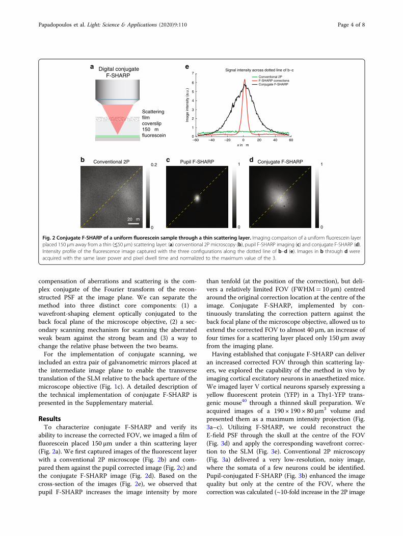
ability to increase the corrected FOV, we imaged a film offluorescein placed 150 μm under a thin scattering layer(Fig. 2a). We first captured images of the fluorescent layerwith a conventional 2P microscope (Fig. 2b) and com-pared them against the pupil corrected image (Fig. 2c) andthe conjugate F-SHARP image (Fig. 2d). Based on thecross-section of the images (Fig. 2e), we observed thatpupil F-SHARP increases the image intensity by more
than tenfold (at the position of the correction), but deli-vers a relatively limited FOV (FWHM= 10 μm) centredaround the original correction location at the centre of theimage. Conjugate F-SHARP, implemented by con-tinuously translating the correction pattern against theback focal plane of the microscope objective, allowed us toextend the corrected FOV to almost 40 μm, an increase offour times for a scattering layer placed only 150 μm awayfrom the imaging plane.Having established that conjugate F-SHARP can deliver
an increased corrected FOV through thin scattering lay-ers, we explored the capability of the method in vivo byimaging cortical excitatory neurons in anaesthetized mice.We imaged layer V cortical neurons sparsely expressing ayellow fluorescent protein (YFP) in a Thy1-YFP trans-genic mouse40 through a thinned skull preparation. Weacquired images of a 190 × 190 × 80 μm3 volume andpresented them as a maximum intensity projection (Fig.3a–c). Utilizing F-SHARP, we could reconstruct theE-field PSF through the skull at the centre of the FOV(Fig. 3d) and apply the corresponding wavefront correc-tion to the SLM (Fig. 3e). Conventional 2P microscopy(Fig. 3a) delivered a very low-resolution, noisy image,where the somata of a few neurons could be identified.Pupil-conjugated F-SHARP (Fig. 3b) enhanced the imagequality but only at the centre of the FOV, where thecorrection was calculated (~10-fold increase in the 2P image
a
x in µm
Conventional 2PF-SHARP correctionsConjugate F-SHARP
60–60 40–20–40 0 200
1
6
5
4
3
2
7
e
Imag
e in
tens
ity (
a.u.
)
Scatteringfilmcoverslip150 µmfluorescein
Digital conjugateF-SHARP
20 µm
b
0
0.2c
0
1d
0
1
Signal intensity across dotted line of b–c
Conjugate F-SHARPPupil F-SHARPConventional 2P
Fig. 2 Conjugate F-SHARP of a uniform fluorescein sample through a thin scattering layer. Imaging comparison of a uniform fluorescein layerplaced 150 μm away from a thin (≲50 µm) scattering layer: (a) conventional 2P microscopy (b), pupil F-SHARP imaging (c) and conjugate F-SHARP (d).Intensity profile of the fluorescence image captured with the three configurations along the dotted line of b–d (e). Images in b through d wereacquired with the same laser power and pixel dwell time and normalized to the maximum value of the 3.
Papadopoulos et al. Light: Science & Applications (2020) 9:110 Page 4 of 8

intensity). Conjugate F-SHARP, however (Fig. 3c), deliveredan enhanced image over an extended FOV of 80 μm(Fig. 3f), with similar enhancement to that of pupilF-SHARP.We also verified the capabilities of conjugate F-SHARP
to obtain high-quality 2P images from a mouse brain, inwhich neurons were densely labelled with a red fluor-escent protein, tdTomato. We imaged through the thin-ned skull of a Rbp4-Cre/Ai9 transgenic mouse in vivo. Wecaptured a volumetric imaging dataset with conventional2P microscopy, with pupil F-SHARP corrections andconjugate F-SHARP (Fig. 4). We present the maximumintensity projection along the three axes from the threeimaging modalities in Fig. 4a–c, respectively. We used themeasured E-field PSF at a location at the centre of theFOV (Fig. 4d) to reconstruct the corresponding phasemap that would cancel the scattering (Fig. 4e). Comparingthe three imaging modalities, we observe that the con-ventional 2P microscope fails to capture the morphologyof the neurons within the sample (Fig. 4a, f). PupilF-SHARP corrections deliver an increased resolution andimage intensity (an ~5-fold enhancement of the 2P signal
intensity), which was, however, limited only to the areaaround the location where the wavefront correction wascalculated (Fig. 4b, f). Employing conjugate F-SHARPallowed us to achieve an increased image intensity (~4.5-fold enhancement of the 2P signal intensity) and con-siderably better resolution across almost the entire FOValong the transverse as well as the longitudinal directions(Fig. 4c, f).
DiscussionWe introduced an approach for rapid and versatile
conjugate scattering compensation. We accomplished thisby translating the correction pattern against the backaperture of the microscope objective rather than byphysically moving the wavefront-shaping element withinthe optical path. We used the technique to image throughboth sparsely and densely expressing neurons within anintact mouse brain through a thinned skull preparation.We achieved an ~8-fold increase in the corrected FOV
(~80 μm FOV for conjugate F-SHARP) when imaging aThy1-YFP mouse at 470 μm deep inside the brain, with acorresponding ~10-fold enhancement of the 2P intensity.
Conventional 2P
5 µm
Pupil F-SHARP Conjugate F-SHARP
Y–ZX–Y
X–Z
Y–ZX–Y
X–Z
20 µmY–ZX–Y
X–Z
cba
fed
0
5
10
15
20
25
30Image intensity along profile (a.u.)
x in µm–100 –80 –60 –40 –20 0 20 40 60 80 100
Conjugate F-SHARPPupil F-SHARPConventional 2P
Fig. 3 Imaging through the thinned skull of a sparsely labelled THY1-YFP mouse 470 μm below the brain surface. Maximum intensityprojection of a 190 × 190 × 80 μm3 volume using conventional 2P (a), pupil F-SHARP (b) and conjugate F-SHARP (c). Images in a–c are presented onthe same colour scale and with a saturation corresponding to 0.5 of the maximum signal. The measured E-field PSF at the centre of the image (d) andthe corresponding correction pattern assigned to the wavefront shaper (e) demonstrate a PSF that is highly scattered (phase shown in pseudocolour, using a circular HSV colour map). The conjugate F-SHARP module allows us to increase both the signal intensity and the resolution over anextended FOV compared with conventional 2P and F-SHARP. The achieved FOV increases from 15 μm (pupil F-SHARP) to 80 μm (f).
Papadopoulos et al. Light: Science & Applications (2020) 9:110 Page 5 of 8
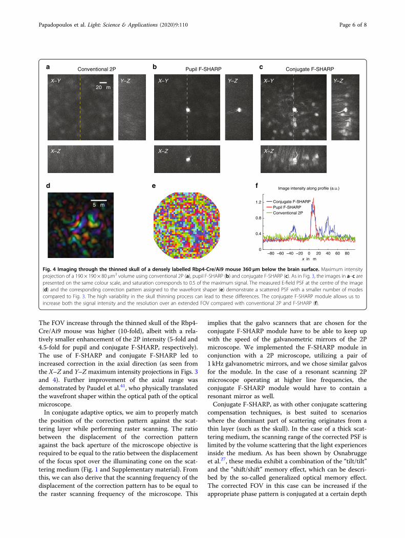
The FOV increase through the thinned skull of the Rbp4-Cre/Ai9 mouse was higher (10-fold), albeit with a rela-tively smaller enhancement of the 2P intensity (5-fold and4.5-fold for pupil and conjugate F-SHARP, respectively).The use of F-SHARP and conjugate F-SHARP led toincreased correction in the axial direction (as seen fromthe X–Z and Y–Zmaximum intensity projections in Figs. 3and 4). Further improvement of the axial range wasdemonstrated by Paudel et al.41, who physically translatedthe wavefront shaper within the optical path of the opticalmicroscope.In conjugate adaptive optics, we aim to properly match
the position of the correction pattern against the scat-tering layer while performing raster scanning. The ratiobetween the displacement of the correction patternagainst the back aperture of the microscope objective isrequired to be equal to the ratio between the displacementof the focus spot over the illuminating cone on the scat-tering medium (Fig. 1 and Supplementary material). Fromthis, we can also derive that the scanning frequency of thedisplacement of the correction pattern has to be equal tothe raster scanning frequency of the microscope. This
implies that the galvo scanners that are chosen for theconjugate F-SHARP module have to be able to keep upwith the speed of the galvanometric mirrors of the 2Pmicroscope. We implemented the F-SHARP module inconjunction with a 2P microscope, utilizing a pair of1 kHz galvanometric mirrors, and we chose similar galvosfor the module. In the case of a resonant scanning 2Pmicroscope operating at higher line frequencies, theconjugate F-SHARP module would have to contain aresonant mirror as well.Conjugate F-SHARP, as with other conjugate scattering
compensation techniques, is best suited to scenarioswhere the dominant part of scattering originates from athin layer (such as the skull). In the case of a thick scat-tering medium, the scanning range of the corrected PSF islimited by the volume scattering that the light experiencesinside the medium. As has been shown by Osnabruggeet al.27, these media exhibit a combination of the “tilt/tilt”and the “shift/shift” memory effect, which can be descri-bed by the so-called generalized optical memory effect.The corrected FOV in this case can be increased if theappropriate phase pattern is conjugated at a certain depth
Conjugate F-SHARP
20 µm
Conventional 2P
Conjugate F-SHARPPupil F-SHARPConventional 2P
Pupil F-SHARP
5 µm1.2
Image intensity along profile (a.u.)
0
0.8
0.4
–80 –60 –40 –20 0 20 40 60 80
cba
fed
Y–Z Y–Z Y–ZX–Y
X–Z X–Z X–Z
X–Y X–Y
x in µm
Fig. 4 Imaging through the thinned skull of a densely labelled Rbp4-Cre/Ai9 mouse 360 μm below the brain surface. Maximum intensityprojection of a 190 × 190 × 80 μm3 volume using conventional 2P (a), pupil F-SHARP (b) and conjugate F-SHARP (c). As in Fig. 3, the images in a–c arepresented on the same colour scale, and saturation corresponds to 0.5 of the maximum signal. The measured E-field PSF at the centre of the image(d) and the corresponding correction pattern assigned to the wavefront shaper (e) demonstrate a scattered PSF with a smaller number of modescompared to Fig. 3. The high variability in the skull thinning process can lead to these differences. The conjugate F-SHARP module allows us toincrease both the signal intensity and the resolution over an extended FOV compared with conventional 2P and F-SHARP (f).
Papadopoulos et al. Light: Science & Applications (2020) 9:110 Page 6 of 8
inside the thick scattering medium. Using conjugateF-SHARP, we can dynamically achieve the conjugation ofthe scattering compensating wavefront at any depth. Thetechnique can prove powerful for thick scattering mediaof varying thickness across the FOV.The use of phase-only liquid crystal SLMs for wavefront
shaping is usually linked with optical setups that exhibitdecreased power efficiency. Here, we presented the designand implementation of an optical system based on SLMwavefront corrections and F-SHARP similar to refer-ence22, where the optical implementation imposes mini-mal loss to the beam power due to the double passthrough a polarizing beam-splitter (Supplementarymaterial, Section 1). Moreover, minimizing the distancethat the separated beams travel independently (betweenthe beam-splitter and the SLM/MEMS mirror) greatlyincreases the phase stability of the system. At the sametime, a phase stepping scheme that relies on an electro-optic modulator can be driven at very fast rates. In theexperiments presented here, phase stepping was per-formed at every pixel of the acquired image. Fast phasestepping leads to better performance of the systembecause the rejection of laser fluctuation noise canenhance the accuracy of the reconstructed wavefront19.In summary, the combination of a versatile conjugation
scheme with a modular and adaptable design increasesthe reach of wavefront shaping and deep tissue micro-scopy to greater fields of view.
Materials and methodsSurgical proceduresAll experiments were performed according to protocols
approved by the Berlin Animal Ethics committee (Land-esamt für Gesundheit und Soziales, LAGeSo) and com-plied with the European animal welfare law.Five-week-old Thy1-YFP40 or Rbp4-Cre/Ai9 transgenic
mice were anaesthetized with 1.5% isoflurane and testedfor lack of tail pinch reflex. Their eyes were protected withointment (Visidic, Bausch+Lomb), and their body tem-perature was kept at 37 °C with a feedback sensor systemcomposed of a rectal temperature probe and a heating pad(DC Temperature controller, FHC). Surgical tools wereheat-sterilized using a glass bead steriliser (Steri 250,Keller, Fine Science Tools), and all surfaces were wipedwith a 70% ethanol solution prior to surgery. An incisionof ~1 cm was performed above the midline, and con-nective tissue was carefully removed to expose the skull.Further cleaning was performed using a microcurette(Fine Science Tools) to remove any remaining tissue onthe skull. The coordinates of the primary somatosensorycortex were marked, and the skull was washed thoroughlywith Ringer solution (in mM: 135 NaCl, 5 KCl, 5 HEPES,1.8 CaCl2 and 1 MgCl2). After drying the skull carefullyand avoiding the zone of interest, a needle (25G) was used
to mark the surface of the skull to increase the contactsurface with the glue and strengthen the bond with thelightweight metal head implant placed on the con-tralateral hemisphere of the zone of interest. Cyanoacry-late glue (Loctite 401) or UV-curing adhesive (OptiBond,Kerr) was applied to the exposed surface of the skull,avoiding the region of interest. Next, a recording chamberwas built from dental cement covering the head implantand going all around but not covering the imaging area.Before the dental cement dried completely, the walls ofthe recording chamber were carefully shaped and thenfilled with Ringer’s solution and thoroughly cleaned. Oncethe skull was dry, we used a drill head (500 µm diameter,Komet, Brassler) operated by a dental drill (Success 40,Osada) to thin the skull over the area of interest (square of3 mm × 3mm). The thinning process was carried out inshort drilling periods of 30 s followed by washing withRinger’s solution to remove bone dust and cool thethinned surface. This process was repeated until the bloodvessels were clearly visible, which corresponded to a finalbone thickness of ~50 µm42. Next, a small drop of cya-noacrylate glue was applied to the thinned skull to securea 3 mm× 3mm glass coverslip over the area for imaging.Finally, the skull was covered with Ringer’s solution, andthe mouse was transferred to the 2P setup.
Scattering filmFor the experiments presented in Fig. 2, we dissolved
fluorescein dye in water and deposited a small droplet ofthe fluorescent solution on a glass slide. We placed a #1glass coverslip (mean thickness of 150 μm) on top andsealed the sample. On top of the coverslip, we placed alayer of Parafilm with a thickness of 125 μm, using theParafilm as a scattering layer.
AcknowledgementsThe authors thank M. Hoffmann, T. Chaigne, C. Berlage and D. Di Battista forcritically reviewing the manuscript. We acknowledge funding by the GermanScience Foundation DFG (projects 326649520 and 327654276/SFB 1315) andthe Human Frontiers Science Programme. B.J. is a recipient of a Starting Grantby the European Research Council (ERC-2016-StG-714560) and the AlfriedKrupp Prize for Young University Teachers, awarded by the Alfried Krupp vonBohlen und Halbach-Stiftung.
Author details1Charité – Universitätsmedizin Berlin, Einstein Center for Neurosciences,NeuroCure Cluster of Excellence, Charitéplatz 1, 10117 Berlin, Germany. 2MaxDelbrück Center for Molecular Medicine, Robert-Rössle-Str. 10, 13092 Berlin,Germany. 3Institute for Biology, Humboldt University, Charitéplatz 1, 10117Berlin, Germany
Author contributionsB.J. and I.N.P. conceived and developed the idea. I.N.P. designed theexperiments with help from B.J. I.N.P. built the set-up and collected andanalysed the data. J.-S.J., D.K. and N.T. performed the mouse procedures undersupervision from J.P. and M.L. I.N.P. and B.J. wrote the manuscript. B.J.supervised the project.
Conflict of interestThe authors declare that they have no conflict of interest.
Papadopoulos et al. Light: Science & Applications (2020) 9:110 Page 7 of 8
Supplementary information is available for this paper at https://doi.org/10.1038/s41377-020-00348-x.
Received: 30 December 2019 Revised: 1 June 2020 Accepted: 15 June 2020
References1. Ntziachristos, V. Going deeper than microscopy: the optical imaging frontier in
biology. Nat. Methods 7, 603–614 (2010).2. Denk, W., Strickler, J. H. & Webb, W. W. Two-photon laser scanning fluores-
cence microscopy. Science 248, 73–76 (1990).3. Horton, N. G. et al. In vivo three-photon microscopy of subcortical structures
within an intact mouse brain. Nat. Photonics 7, 205–209 (2013).4. Ouzounov, D. G. et al. In vivo three-photon imaging of activity of GCaMP6-
labeled neurons deep in intact mouse brain. Nat. Methods 14, 388–390(2017).
5. Mahajan, V. N. Optical Imaging and Aberrations: Part I. Ray Geometrical Optics(SPIE Press, Bellingham, WA, 1998).
6. Goodman, J. W. Statistical Optics (Wiley, New York, 2000).7. Vellekoop, I. M. & Mosk, A. P. Focusing coherent light through opaque strongly
scattering media. Opt. Lett. 32, 2309–2311 (2007).8. Yaqoob, Z. et al. Optical phase conjugation for turbidity suppression in bio-
logical samples. Nat. Photonics 2, 110–115 (2008).9. Hsieh, C. L. et al. Digital phase conjugation of second harmonic radiation
emitted by nanoparticles in turbid media. Opt. Express 18, 12283–12290(2010).
10. Cui, M. & Yang, C. Implementation of a digital optical phase conjugationsystem and its application to study the robustness of turbidity suppression byphase conjugation. Opt. Express 18, 3444–3455 (2010).
11. Popoff, S. M. et al. Measuring the transmission matrix in optics: an approach tothe study and control of light propagation in disordered media. Phys. Rev. Lett.104, 100601 (2010).
12. Booth, M. J. et al. Adaptive aberration correction in a confocal microscope.Proc. Natl. Acad. Sci. USA 99, 5788–5792 (2002).
13. Neil, M. A. A. et al. Adaptive aberration correction in a two-photon microscope.J. Microsc. 200, 105–108 (2000).
14. Olivier, N., Débarre, D. & Beaurepaire, E. Dynamic aberration correction formultiharmonic microscopy. Opt. Lett. 34, 3145–3147 (2009).
15. Tao, X. D. et al. Adaptive optics confocal microscopy using direct wavefrontsensing. Opt. Lett. 36, 1062–1064 (2011).
16. Wang, K. et al. Rapid adaptive optical recovery of optimal resolution over largevolumes. Nat. Methods 11, 625–628 (2014).
17. Wang, K. et al. Direct wavefront sensing for high-resolution in vivo imaging inscattering tissue. Nat. Commun. 6, 7276 (2015).
18. Ji, N., Milkie, D. E. & Betzig, E. Adaptive optics via pupil segmentation forhigh-resolution imaging in biological tissues. Nat. Methods 7, 141–147(2010).
19. Wang, C. et al. Multiplexed aberration measurement for deep tissue imagingin vivo. Nat. Methods 11, 1037–1040 (2014).
20. Tang, J. Y., Germain, R. N. & Cui, M. Superpenetration optical microscopy byiterative multiphoton adaptive compensation technique. Proc. Natl. Acad. Sci.USA 109, 8434–8439 (2012).
21. Katz, O. et al. Noninvasive nonlinear focusing and imaging through stronglyscattering turbid layers. Optica 1, 170–174 (2014).
22. Papadopoulos, I. N. et al. Scattering compensation by focus scanning holo-graphic aberration probing (F-SHARP). Nat. Photonics 11, 116–123 (2017).
23. Freund, I., Rosenbluh, M. & Feng, S. C. Memory effects in propagation of opticalwaves through disordered media. Phys. Rev. Lett. 61, 2328–2331 (1988).
24. Feng, S. C. et al. Correlations and fluctuations of coherent wave transmissionthrough disordered media. Phys. Rev. Lett. 61, 834–837 (1988).
25. Schott, S. et al. Characterization of the angular memory effect of scattered lightin biological tissues. Opt. Express 23, 13505–13516 (2015).
26. Judkewitz, B. et al. Translation correlations in anisotropically scattering media.Nat. Phys. 11, 684–689 (2015).
27. Osnabrugge, G. et al. Generalized optical memory effect. Optica 4, 886–892(2017).
28. Hsieh, C. L. et al. Imaging through turbid layers by scanning the phase con-jugated second harmonic radiation from a nanoparticle. Opt. Express 18,20723–20731 (2010).
29. Vellekoop, I. M. & Aegerter, C. M. Scattered light fluorescence microscopy:imaging through turbid layers. Opt. Lett. 35, 1245–1247 (2010).
30. Bertolotti, J. et al. Non-invasive imaging through opaque scattering layers.Nature 491, 232–234 (2012).
31. Katz, O., Small, E. & Silberberg, Y. Looking around corners and through thinturbid layers in real time with scattered incoherent light. Nat. Photonics 6,549–553 (2012).
32. Beckers, J. M. Increasing the size of the isoplanatic patch with multiconjugateadaptive optics. Proceedings of European Southern Observatory Conference andWorkshop (European Southern Observatory, Garching, 1988).
33. Johnston, D. C. & Welsh, B. M. Analysis of multiconjugate adaptive optics. J.Optical Soc. Am. A 11, 394–408 (1994).
34. Ragazzoni, R., Marchetti, E. & Valente, G. Adaptive-optics corrections availablefor the whole sky. Nature 403, 54–56 (2000).
35. Tokovinin, A., Le Louarn, M. & Sarazin, M. Isoplanatism in a multiconjugateadaptive optics system. J. Optical Soc. Am. A 17, 1819–1827 (2000).
36. Mertz, J., Paudel, H. & Bifano, T. G. Field of view advantage of conjugateadaptive optics in microscopy applications. Appl. Opt. 54, 3498–3506 (2015).
37. Park, J. H., Sun, W. & Cui, M. High-resolution in vivo imaging of mouse brainthrough the intact skull. Proc. Natl Acad. Sci. USA 112, 9236–9241 (2015).
38. Tao, X. D. et al. Three-dimensional focusing through scattering media usingconjugate adaptive optics with remote focusing (CAORF). Opt. Express 25,10368–10383 (2017).
39. Goodman, J. W. Introduction to Fourier Optics 3rd edn (Roberts and CompanyPublishers, Greenwoood Village, 2005).
40. Feng, G. P. et al. Imaging neuronal subsets in transgenic mice expressingmultiple spectral variants of GFP. Neuron 28, 41–51 (2000).
41. Paudel, H. P. et al. Axial range of conjugate adaptive optics in two-photonmicroscopy. Opt. Express 23, 20849–20857 (2015).
42. Drew, P. J. et al. Chronic optical access through a polished and reinforcedthinned skull. Nat. Methods 7, 981–984 (2010).
Papadopoulos et al. Light: Science & Applications (2020) 9:110 Page 8 of 8