Configuration — QoS and IP Filtering for R and RS Modules
364
Nortel Ethernet Routing Switch 8600 Configuration — QoS and IP Filtering for R and RS Modules Release: 5.1 Document Revision: 03.02 www.nortel.com NN46205-507 .
-
Upload
khangminh22 -
Category
Documents
-
view
4 -
download
0
Transcript of Configuration — QoS and IP Filtering for R and RS Modules

Nortel Ethernet Routing Switch 8600
Configuration — QoS and IPFiltering for R and RS ModulesRelease: 5.1Document Revision: 03.02
www.nortel.com
NN46205-507.

Nortel Ethernet Routing Switch 8600Release: 5.1Publication: NN46205-507Document release date: 30 April 2009
Copyright © 2008-2009 Nortel NetworksAll Rights Reserved.
LEGAL NOTICE
While the information in this document is believed to be accurate and reliable, except as otherwise expresslyagreed to in writing, NORTEL PROVIDES THIS DOCUMENT "AS IS" WITHOUT WARRANTY OR CONDITIONOF ANY KIND, EITHER EXPRESS OR IMPLIED. The information and/or products described in this document aresubject to change without notice.
THE SOFTWARE DESCRIBED IN THIS DOCUMENT IS FURNISHED UNDER A LICENSE AGREEMENT ANDMAY BE USED ONLY IN ACCORDANCE WITH THE TERMS OF THAT LICENSE.
Nortel, the Nortel logo, and the Globemark are trademarks of Nortel Networks.
Ethereal is a trademark of Ethereal Inc.
Microsoft is a trademark of Microsoft Corp.
All other trademarks are the property of their respective owners.
ATTENTION
For information about the safety precautions, read "Safety messages" in this guide.
.

3.
ContentsSoftware license 9
New in this release 13Other changes 14Access control entry 14Basic DiffServ 14Customer service 14Default values 14Ingress and egress mapping tables 14
Introduction 15
QoS fundamentals 17Introduction to QoS 17QoS for R and Classic modules 18QoS and RS modules 20QoS and filters 21DiffServ networks 21
Packet classification, marking, and mapping 22PHB 24DiffServ and the Ethernet Routing Switch 8600 24QoS implementation 26DiffServ and non-IP traffic 27DiffServ configuration parameters 27Layer 2 and Layer 3 trusted and untrusted ports 29DiffServ and ACLs 37Queueing 38Egress queue packet assignment 52
Policing and shaping 60Token buckets and policing 61Policy-based policer versus shaper 62Policy-based traffic policing 63Port-based traffic policing 69Queue-based traffic shaping 70Port-based shaping 71
Nortel Ethernet Routing Switch 8600Configuration — QoS and IP Filtering for R and RS Modules
NN46205-507 03.0230 April 2009
Copyright © 2008-2009 Nortel Networks
.

4
Broadcast and multicast traffic bandwidth limiters 71QoS and MPLS 71QoS and VoIP 72
Traffic filtering fundamentals 75Overview 75Traffic filters for Classic and R series modules 76Deep packet pattern match filters 77R series module filters and packet layer traversal 77Access control templates 77
ACT attributes 78ACT patterns for offset filtering 78Predefined ACTs 81ACT configuration guidelines 83
Access control lists 84ACL priority 86
Access control entries 87ACE overview 87ACE actions 88ACE priority 88Common ACE uses and configurations 89Example: ACE TCP Established flag filter 91
Port mirroring, ACLs, and ACEs 92R modules and port mirroring 93RS modules and port mirroring 93
Traffic filter configuration 93ACL, ACT, and ACE configuration guidelines 94Nortel Secure Network Access 94
QoS and IP filter configuration 95
Basic DiffServ configuration using Device Manager 99Enabling DiffServ for a port 99Configuring Layer 3 trusted or untrusted ports 100Configuring Layer 2 trusted or untrusted ports 101Configuring the port QoS level 101Configuring the VLAN QoS level 101
Basic DiffServ configuration using the CLI 103Job aid 103Enabling DiffServ on a port 104Configuring Layer 3 trusted or untrusted ports 104Configuring Layer 2 trusted or untrusted ports 105Configuring the port QoS level 106Configuring the VLAN QoS level 106Configuring the QoS level for a MAC address 107
Nortel Ethernet Routing Switch 8600Configuration — QoS and IP Filtering for R and RS Modules
NN46205-507 03.0230 April 2009
Copyright © 2008-2009 Nortel Networks
.

5
Example of configuring a QoS level for a MAC address 108
Basic DiffServ configuration using the NNCLI 109Job aid 109Enabling DiffServ on a port 110Configuring Layer 3 trusted or untrusted ports 111Configuring Layer 2 trusted or untrusted ports 112Configuring the port QoS level 113Configuring the VLAN QoS level 114Configuring the QoS level for a MAC address 114
Example of setting a QoS level for a MAC address 116
QoS configuration using Device Manager 117Broadcast and multicast bandwidth limiting 117Configuring port-based shaping for R and RS modules 118Configuring port-based policing for RS modules 118Configuring a policy-based policer 118Configuring an egress queue set 119Configuring egress queue set queues 121Modifying an egress queue set or queue 122Modifying ingress MPLS to QoS mappings 123Modifying egress QoS to MPLS mappings 124
QoS configuration using the CLI 125Job aid 125Configuring broadcast and multicast bandwidth limiting 128Configuring the port-based shaper 129Configuring a port-based policer for RS modules 129Configuring a policy-based policer 130
Job aid 131Adding lanes to a policy-based policer 132Configuring an egress queue set 132
Example of configuring an egress queue set 135Job aid 135
Modifying an egress queue set 136Configuring an egress queue set queue 138
Example of configuring an egress queue set queue 139Job aid 140
Configuring ingress mappings 140Configuring egress mappings 142
QoS configuration using the NNCLI 145Job aid 145Configuring broadcast and multicast bandwidth limiting 147Configuring the port-based shaper 149Configuring a port-based policer for RS modules 150
Nortel Ethernet Routing Switch 8600Configuration — QoS and IP Filtering for R and RS Modules
NN46205-507 03.0230 April 2009
Copyright © 2008-2009 Nortel Networks
.
6
Configuring a policy-based policer 150Job aid 151
Configuring an egress queue set 152Job aid 153
Configuring an egress queue set queue 154Modifying an egress queue set or egress queue set queue 155Configuring ingress mappings 157Configuring egress mappings 158
Traffic filter configuration using Device Manager 161Traffic filter configuration procedures 161Configuring ACTs 162Adding a user-defined pattern 164Configuring an access control list 165
Traffic filter configuration using the CLI 169Traffic filter configuration using the CLI procedures 169Job aid 171Configuring an ACT 173Adding a user-defined pattern 175Configuring an ACL 177Configuring global and default actions for an ACL 178Associating VLANs with an ACL 179Associating ports with an ACL 180Viewing R and RS module filter configuration information 181
Job aid 182
Traffic filter configuration using the NNCLI 183Traffic filter configuration procedures 183Job aid 185Configuring an ACT 186Adding a user-defined pattern 188Configuring an ACL 189Configuring global and default actions for an ACL 190Associating VLANs with an ACL 191Associating ports with an ACL 192Viewing R and RS module filter configuration information 193
Job aid 193
Access control entry configuration using Device Manager 195Configuring ACEs 196Configuring ACE actions 199Modifying ACE parameters 200Configuring ACE ARP entries 200Viewing all ACE ARP entries for an ACL 202Configuring an ACE Ethernet source address 202
Nortel Ethernet Routing Switch 8600Configuration — QoS and IP Filtering for R and RS Modules
NN46205-507 03.0230 April 2009
Copyright © 2008-2009 Nortel Networks
.

7
Configuring an ACE Ethernet destination address 203Configuring an ACE LAN traffic type 204Configuring an ACE Ethernet VLAN tag priority 206Configuring an ACE Ethernet port 207Configuring an ACE Ethernet VLAN ID 209Viewing all ACE Ethernet entries for an ACL 210Configuring an ACE IP source address 211Configuring an ACE IP destination address 212Configuring an ACE IP DSCP 214Configuring an ACE IP protocol 215Configuring ACE IP options 216Configuring ACE IP fragmentation 217Viewing all ACE IP entries for an ACL 219Configuring an ACE TCP source port 220Configuring an ACE UDP source port 221Configuring an ACE TCP destination port 222Configuring an ACE UDP destination port 224Configuring an ACE ICMP message type 225Configuring an ACE TCP flag 226Viewing all ACE Protocol entries for an ACL 227Configuring an ACE Pattern 1 entry 228Configuring an ACE Pattern 2 entry 230Configuring an ACE Pattern 3 entry 231Viewing all ACE Advanced pattern entries for an ACL 232Configuring an ACE IPv6 source address 233Configuring an ACE IPv6 destination address 234Configuring an ACE IPv6 next header 235Viewing IPv6 attributes for an ACL 236
Access control entry configuration using the CLI 239Job aid 239Configuring ACEs 242Configuring ACE actions 244Configuring ACE debug actions 246
Example of configuring R module TxFilter mode mirroring 248Configuring ARP ACEs 248Configuring an Ethernet ACE 249
Example of configuring an Ethernet ACE 251Configuring an IP ACE 252
Example of configuring an IP ACE 254Configuring a protocol ACE 254
Example of configuring a protocol ACE 256Configuring a custom ACE 256
Example of configuring a custom ACE 258
Nortel Ethernet Routing Switch 8600Configuration — QoS and IP Filtering for R and RS Modules
NN46205-507 03.0230 April 2009
Copyright © 2008-2009 Nortel Networks
.

8
Configuring an IPv6 ACE 258Viewing ACL and ACE configuration data 259
Access control entry configuration using the NNCLI 261Job aid 261Configuring ACEs 263Configuring ACE actions 265
Example of configuring ACE actions 267Configuring ACE debug actions 267Configuring ARP ACEs 269Configuring an Ethernet ACE 270
Example of configuring an Ethernet ACE 272Configuring an IP ACE 272
Example of configuring an IP ACE 274Configuring a protocol ACE 274
Example of configuring a protocol ACE 276Configuring a custom ACE 276
Example of configuring a custom ACE 277Configuring an IPv6 ACE 277
Example of configuring an IPv6 ACE 279Viewing ACL and ACE configuration data 279
CLI configuration examples 281Delivering subrate IP service using policy-based policers 281Policing multiple flows using VLAN-based ACLs 283Mirroring using ACLs 287Asymmetric downlink and uplink using policy-based policers and port-based
shapers 288
Safety messages 291Notices 291
Attention notice 291Caution ESD notice 291Caution notice 292
Customer service 295Updated versions of documentation 295Getting help 295Express Routing Codes 295Additional information 296
Advanced filter examples 297ACE filters for secure networks 297
Egress queues and pages 349
Workaround for inVlan, srcIp ACL 351
Nortel Ethernet Routing Switch 8600Configuration — QoS and IP Filtering for R and RS Modules
NN46205-507 03.0230 April 2009
Copyright © 2008-2009 Nortel Networks
.

9.
Software licenseThis section contains the Nortel Networks software license.
Nortel Networks Inc. software license agreementThis Software License Agreement ("License Agreement") is betweenyou, the end-user ("Customer") and Nortel Networks Corporation andits subsidiaries and affiliates ("Nortel Networks"). PLEASE READ THEFOLLOWING CAREFULLY. YOU MUST ACCEPT THESE LICENSETERMS IN ORDER TO DOWNLOAD AND/OR USE THE SOFTWARE.USE OF THE SOFTWARE CONSTITUTES YOUR ACCEPTANCE OFTHIS LICENSE AGREEMENT. If you do not accept these terms andconditions, return the Software, unused and in the original shippingcontainer, within 30 days of purchase to obtain a credit for the fullpurchase price.
"Software" is owned or licensed by Nortel Networks, its parent or one ofits subsidiaries or affiliates, and is copyrighted and licensed, not sold.Software consists of machine-readable instructions, its components, data,audio-visual content (such as images, text, recordings or pictures) andrelated licensed materials including all whole or partial copies. NortelNetworks grants you a license to use the Software only in the countrywhere you acquired the Software. You obtain no rights other than thosegranted to you under this License Agreement. You are responsible for theselection of the Software and for the installation of, use of, and resultsobtained from the Software.
1. Licensed Use of Software. Nortel Networks grants Customer anonexclusive license to use a copy of the Software on only one machineat any one time or to the extent of the activation or authorized usage level,whichever is applicable. To the extent Software is furnished for use withdesignated hardware or Customer furnished equipment ("CFE"), Customeris granted a nonexclusive license to use Software only on such hardwareor CFE, as applicable. Software contains trade secrets and Customeragrees to treat Software as confidential information using the same careand discretion Customer uses with its own similar information that it doesnot wish to disclose, publish or disseminate. Customer will ensure thatanyone who uses the Software does so only in compliance with the terms
Nortel Ethernet Routing Switch 8600Configuration — QoS and IP Filtering for R and RS Modules
NN46205-507 03.0230 April 2009
Copyright © 2008-2009 Nortel Networks
.

10 Software license
of this Agreement. Customer shall not a) use, copy, modify, transferor distribute the Software except as expressly authorized; b) reverseassemble, reverse compile, reverse engineer or otherwise translate theSoftware; c) create derivative works or modifications unless expresslyauthorized; or d) sublicense, rent or lease the Software. Licensors ofintellectual property to Nortel Networks are beneficiaries of this provision.Upon termination or breach of the license by Customer or in the eventdesignated hardware or CFE is no longer in use, Customer will promptlyreturn the Software to Nortel Networks or certify its destruction. NortelNetworks may audit by remote polling or other reasonable means todetermine Customer’s Software activation or usage levels. If suppliers ofthird party software included in Software require Nortel Networks to includeadditional or different terms, Customer agrees to abide by such termsprovided by Nortel Networks with respect to such third party software.
2. Warranty. Except as may be otherwise expressly agreed to inwriting between Nortel Networks and Customer, Software is provided"AS IS" without any warranties (conditions) of any kind. NORTELNETWORKS DISCLAIMS ALL WARRANTIES (CONDITIONS) FOR THESOFTWARE, EITHER EXPRESS OR IMPLIED, INCLUDING, BUT NOTLIMITED TO THE IMPLIED WARRANTIES OF MERCHANTABILITY ANDFITNESS FOR A PARTICULAR PURPOSE AND ANY WARRANTY OFNON-INFRINGEMENT. Nortel Networks is not obligated to provide supportof any kind for the Software. Some jurisdictions do not allow exclusionof implied warranties, and, in such event, the above exclusions may notapply.
3. Limitation of Remedies. IN NO EVENT SHALL NORTELNETWORKS OR ITS AGENTS OR SUPPLIERS BE LIABLE FOR ANYOF THE FOLLOWING: a) DAMAGES BASED ON ANY THIRD PARTYCLAIM; b) LOSS OF, OR DAMAGE TO, CUSTOMER’S RECORDS,FILES OR DATA; OR c) DIRECT, INDIRECT, SPECIAL, INCIDENTAL,PUNITIVE, OR CONSEQUENTIAL DAMAGES (INCLUDING LOSTPROFITS OR SAVINGS), WHETHER IN CONTRACT, TORT OROTHERWISE (INCLUDING NEGLIGENCE) ARISING OUT OFYOUR USE OF THE SOFTWARE, EVEN IF NORTEL NETWORKS,ITS AGENTS OR SUPPLIERS HAVE BEEN ADVISED OF THEIRPOSSIBILITY. The forgoing limitations of remedies also apply to anydeveloper and/or supplier of the Software. Such developer and/or supplieris an intended beneficiary of this Section. Some jurisdictions do not allowthese limitations or exclusions and, in such event, they may not apply.
4. General
1. If Customer is the United States Government, the following paragraphshall apply: All Nortel Networks Software available under this LicenseAgreement is commercial computer software and commercial computer
Nortel Ethernet Routing Switch 8600Configuration — QoS and IP Filtering for R and RS Modules
NN46205-507 03.0230 April 2009
Copyright © 2008-2009 Nortel Networks
.

Nortel Networks Inc. software license agreement 11
software documentation and, in the event Software is licensed foror on behalf of the United States Government, the respective rightsto the software and software documentation are governed by NortelNetworks standard commercial license in accordance with U.S. FederalRegulations at 48 C.F.R. Sections 12.212 (for non-DoD entities) and48 C.F.R. 227.7202 (for DoD entities).
2. Customer may terminate the license at any time. Nortel Networksmay terminate the license if Customer fails to comply with the termsand conditions of this license. In either event, upon termination,Customer must either return the Software to Nortel Networks or certifyits destruction.
3. Customer is responsible for payment of any taxes, including personalproperty taxes, resulting from Customer’s use of the Software.Customer agrees to comply with all applicable laws including allapplicable export and import laws and regulations.
4. Neither party may bring an action, regardless of form, more than twoyears after the cause of the action arose.
5. The terms and conditions of this License Agreement form the completeand exclusive agreement between Customer and Nortel Networks.
6. This License Agreement is governed by the laws of the country inwhich Customer acquires the Software. If the Software is acquired inthe United States, then this License Agreement is governed by thelaws of the state of New York.
Nortel Ethernet Routing Switch 8600Configuration — QoS and IP Filtering for R and RS Modules
NN46205-507 03.0230 April 2009
Copyright © 2008-2009 Nortel Networks
.

12 Software license
Nortel Ethernet Routing Switch 8600Configuration — QoS and IP Filtering for R and RS Modules
NN46205-507 03.0230 April 2009
Copyright © 2008-2009 Nortel Networks
.

13.
New in this releaseSee the following sections for details about what’s new in Nortel EthernetRouting Switch 8600 Configuration — QoS and IP Filtering for R and RSModules (NN46205-507) for Release 5.1:
• “Other changes” (page 14)
Nortel Ethernet Routing Switch 8600Configuration — QoS and IP Filtering for R and RS Modules
NN46205-507 03.0230 April 2009
Copyright © 2008-2009 Nortel Networks
.

14 New in this release
Other changes
See the following sections for information about changes that are notfeature-related:
• “Access control entry” (page 14)
• “Basic DiffServ” (page 14)
• “Customer service” (page 14)
• “Default values” (page 14)
• “Ingress and egress mapping tables” (page 14)
Access control entryThe access control entry configuration procedures are moved to aseparate section. For more information, see the following sections:
• “Access control entry configuration using Device Manager” (page 195)
• “Access control entry configuration using the CLI” (page 239)
• “Access control entry configuration using the NNCLI” (page 261)
Basic DiffServThe basic DiffServ configuration task is moved to a separate section. Formore information, see the following sections:
• “Basic DiffServ configuration using Device Manager” (page 99)
• “Basic DiffServ configuration using the CLI” (page 103)
• “Basic DiffServ configuration using the NNCLI” (page 109)
Customer service“Customer service” (page 295) is added to the document.
Default valuesWhere appropriate, this document indicates the default value for acommand.
Ingress and egress mapping tables“Egress queue packet assignment” (page 52) includes updated tables fordefault ingress and egress mappings.
Nortel Ethernet Routing Switch 8600Configuration — QoS and IP Filtering for R and RS Modules
NN46205-507 03.0230 April 2009
Copyright © 2008-2009 Nortel Networks
.

15.
IntroductionThis document provides instructions to use the command line interface(CLI), the Nortel Command Line Interface (NNCLI), and Device Manager toconfigure Quality of Service (QoS) and filtering operations on the EthernetRouting Switch 8600.
Navigation• “QoS fundamentals” (page 17)
• “Traffic filtering fundamentals” (page 75)
• “QoS and IP filter configuration” (page 95)
• “Basic DiffServ configuration using Device Manager” (page 99)
• “Basic DiffServ configuration using the CLI” (page 103)
• “Basic DiffServ configuration using the NNCLI” (page 109)
• “QoS configuration using Device Manager” (page 117)
• “QoS configuration using the CLI” (page 125)
• “QoS configuration using the NNCLI” (page 145)
• “Traffic filter configuration using Device Manager” (page 161)
• “Traffic filter configuration using the CLI” (page 169)
• “Traffic filter configuration using the NNCLI” (page 183)
• “Access control entry configuration using Device Manager” (page 195)
• “Access control entry configuration using the CLI” (page 239)
• “Access control entry configuration using the NNCLI” (page 261)
• “CLI configuration examples” (page 281)
• “Safety messages” (page 291)
• “Customer service” (page 295)
• “Advanced filter examples” (page 297)
Nortel Ethernet Routing Switch 8600Configuration — QoS and IP Filtering for R and RS Modules
NN46205-507 03.0230 April 2009
Copyright © 2008-2009 Nortel Networks
.

16 Introduction
• “Egress queues and pages” (page 349)
• “Workaround for inVlan, srcIp ACL” (page 351)
Nortel Ethernet Routing Switch 8600Configuration — QoS and IP Filtering for R and RS Modules
NN46205-507 03.0230 April 2009
Copyright © 2008-2009 Nortel Networks
.

17.
QoS fundamentalsUse the information in this section to help you understand Quality ofService (QoS).
This section describes a range of features that you can use with theEthernet Routing Switch 8600 to allocate network resources to criticalapplications. You can configure your network to prioritize specific types oftraffic to ensure traffic receives the appropriate QoS level. Allocate priorityto protocol and application data depending on required parameters, forexample, minimum data rate or minimum time delay.
For information about how to use the command line interface (CLI), theNortel Command Line Interface (NNCLI), and Device Manager, seeNortel Ethernet Routing Switch 8600 Fundamentals — User Interfaces(NN46205-308) .
Navigation• “Introduction to QoS” (page 17)
• “QoS for R and Classic modules” (page 18)
• “QoS and RS modules” (page 20)
• “QoS and filters” (page 21)
• “DiffServ networks” (page 21)
• “QoS and MPLS” (page 71)
• “QoS and VoIP” (page 72)
Introduction to QoSQoS is the extent to which a service delivery meets user expectations.In a QoS-aware network, a user can expect the network to meet certainperformance levels. You specify these performance levels in terms ofservice availability, packet loss, packet delay, and packet delay variation.
Nortel Ethernet Routing Switch 8600Configuration — QoS and IP Filtering for R and RS Modules
NN46205-507 03.0230 April 2009
Copyright © 2008-2009 Nortel Networks
.
18 QoS fundamentals
By assigning QoS levels to traffic flows on your Local Area Network(LAN), you can allocate network resources where you need them most.For an effective QoS strategy, you must configure QoS functionality fromend-to-end in the network: across various devices, such as routers,switches, and end stations; across platforms and media; and across linklayers, such as an Ethernet.
The Ethernet Routing Switch 8600 supports QoS classification for both L2(802.1p bits) and L3 (Differentiated Services Code Point bits) parameters.Do not confuse the terminology L2 and L3 with Layer 2 (bridging) or Layer3 (routed) operation. L2 represents an association with Q-tags, of which802.1p bits is a portion. L3 represents an association with DifferentiatedServices Code Point (DSCP).
The Ethernet Routing Switch 8600 provides QoS functionality that candiffer for Layer 2 (bridged) and Layer 3 (routed) traffic flows. The EthernetRouting Switch 8600 can also assign QoS levels based on multiple criteriaincluding (but not limited to) Transport Control Protocol (TCP) or UserDatagram Protocol (UDP) ports used by an application.
To effectively use QoS functions in your network, you must perform thefollowing tasks:
• Identify traffic sources and types.
• Determine the required QoS parameters based on the traffic.
• Perform traffic management (QoS) operations based on the requiredparameters.
The Ethernet Routing Switch 8600 implements the QoS functionality for IPtraffic through a Differentiated Services (DiffServ) network architecture.
QoS for R and Classic modulesRelease 5.0 and later contains three QoS implementations:
• The pre-4.0 implementation that involves E and M modules (Classicmodules).
• Beginning with Release 4.0, an implementation that uses specificR module features and includes support for the 8630GBR, 8648GTR,8683XLR, and 8683XZR modules.
• Beginning with Release 5.0, an implementation for RS modules thatperforms all features of R modules, and offers advanced policingcapabilities. See “QoS and RS modules” (page 20) and “Port-basedtraffic policing” (page 69).
Nortel Ethernet Routing Switch 8600Configuration — QoS and IP Filtering for R and RS Modules
NN46205-507 03.0230 April 2009
Copyright © 2008-2009 Nortel Networks
.

QoS for R and Classic modules 19
You do not require R mode for many of the advanced QoS features of theR module implementation. However, you must enable R mode to enableFeedback Output Queueing (see “Feedback output queueing” (page 39)).
The following table shows the differences in the level of support for theClassic and Advanced QoS implementations.
In this table, E denotes enabled, D denotes disabled, and N/A denotesnot applicable. CLAS denotes Classic and ADV denotes advanced. 32K, 128 K, and 256 K denote the number of records in kilobytes supportedfor each mode.
Table 1Features supported for each operation mode for Classic and R series modules
Chassisconfiguration
Mode Moduletype
Features supported on modules
R M E QoS Filters Policing Shaping
Default(32 K)
— — E CLAS CLAS CLAS N/A
M (128 K) — E — CLAS CLAS CLAS N/A
Same-
module
chassisR (256 K) E — — ADV ADV ADV ADV
Default(32 K)
E E E CLAS(ADV on Rmodule);no FOQ
CLAS(ADV on Rmodule)
CLAS(ADV on Rmodule)
ADV on Rmodule
M (128 K) E E D CLAS(ADV on Rmodule);no FOQ
CLAS(ADV on Rmodule)
CLAS(ADV on Rmodule)
ADV on Rmodule
Mixed-
module
chassis
R (256 K) E D D ADV; FOQ ADV ADV ADV
A same-module configuration means the chassis contains the followingmodules:
• all R modules with the 8692 switch fabric/CPU (SF/CPU) module
• all Classic (E and M) modules with 8692 SF/CPU, or 8690 or 8691SF/CPU
A mixed-module configuration means the chassis contains Classicmodules and R modules with the 8692 SF/CPU.
In a mixed-module chassis configuration that operates in either Default orM mode, the following features are available only on R modules:
Nortel Ethernet Routing Switch 8600Configuration — QoS and IP Filtering for R and RS Modules
NN46205-507 03.0230 April 2009
Copyright © 2008-2009 Nortel Networks
.

20 QoS fundamentals
• advanced QoS with bandwidth reservation capabilities
• two-rate three-color-marker ingress policing
• port or queue-based egress shaping
• advanced ingress and egress Access Control Lists (ACL)
• Split MultiLink Trunking (SMLT) and InterSwitch Trunking (IST) on10 Gb/s ports
An all-R module chassis configuration that operates in R mode includes allthe features previously listed plus the following capabilities:
• Feedback Output Queueing (FOQ)
• high scaling; for more information, see the most recent EthernetRouting Switch 8600 release notes
If you enable R mode, the system disables E and M modules. If youenable M mode, and one or more modules in the chassis is an E module,the system disables E modules. This action protects the system forwardingdatabase from inconsistencies.
You can configure up to 128 MultiLink Trunking (MLT) groups, and up to8 Equal Cost Multipath (ECMP) routing paths. These features, like FOQ,are available only when the chassis contains only R modules, and youenable R mode.
Enhanced Operational mode increases virtual local area network (VLAN)MLT scalability. Use Enhanced Operational mode to provide up to 1980MLT VLANs. For more information about Enhanced Operational mode,VLANs, and VLAN scalability, see Nortel Ethernet Routing Switch 8600Configuration — VLANs and Spanning Tree (NN46205-517) .
R series modules support both ingress and egress filtering by using ACLs.Classic filters can filter only at ingress.
R modules use many features, such as FOQ, shaping, and policing,to implement QoS functionality. For more information about how QoSoperates on Classic modules, see Nortel Ethernet Routing Switch 8600Configuration — QoS and IP Filtering for Classic Modules (NN46205-508).
QoS and RS modulesRS module ports operate at up to 10 Gb/s. At high data rates, ensuringnetwork stability is critical. The switch cannot drop network control protocoltraffic. In addition, the switch must process high-priority traffic, such as
Nortel Ethernet Routing Switch 8600Configuration — QoS and IP Filtering for R and RS Modules
NN46205-507 03.0230 April 2009
Copyright © 2008-2009 Nortel Networks
.

DiffServ networks 21
VoIP traffic, even at the expense of lower-priority data traffic. To providesuch performance, the RS module performs frame classification andscheduling at the MAC layer (Layer 2).
You can oversubscribe RS modules on ingress. The Ethernet MediaAccess Controller data transport device operates such that the switchcontinues to forward protocol and other high-priority traffic duringcongestion. Each RS module port uses three ingress queues to handlepriority traffic if ingress oversubscription occurs.
RS modules support the same QoS features as R modules, and provideQoS functionality at the MAC layer by using port-based policers. For moreinformation, see “Port-based traffic policing” (page 69). R and RS modulesuse Advanced (ACL-based) filters.
RS modules use three strict-priority queues for each port. These queuesare ingress queues on the Ethernet Media Access Controller data transportdevice.
RS modules include the 8648GTRS, the 8612XLRS, the 8634XGRS, andthe 8648GBRS. The 8648GBRS, 8648GTRS, and 10/100/1000 Mb/sports of the 8634XGRS support eight queues for each egress port. The8612XLRS and the 10 Gb/s Ethernet ports of the 8634XGRS support upto 64 queues for each egress port.
QoS and filtersThe Ethernet Routing Switch 8600 has functions you can use to provideappropriate QoS levels to traffic for each customer, application, orpacket. These functions include egress-queue-set-based shapers,port-based shapers, DiffServ access or core port settings, policy-basedpolicers, and port-based policers. The Ethernet Routing Switch 8600also provides classic (E and M modules) and advanced (for R seriesmodules—ACL-based) filters. You need not use filters to provide QoS;however, filters help prioritize customer traffic. Filters also provideprotection by blocking unwanted traffic.
Policers apply at ingress; Classic or ACL-based filters and shapers applyat egress.
DiffServ networksDiffServ divides traffic into various classes (behavior aggregates) to giveeach class differentiated treatment.
Nortel Ethernet Routing Switch 8600Configuration — QoS and IP Filtering for R and RS Modules
NN46205-507 03.0230 April 2009
Copyright © 2008-2009 Nortel Networks
.

22 QoS fundamentals
A DiffServ network provides either end-to-end or intradomain QoSfunctionality by implementing classification and mapping functions atthe network boundary or access points. Within a core network, DiffServregulates packet behavior by this classification and mapping.
DiffServ, as defined by RFC 2475, provides QoS for aggregate traffic flows(as opposed to individual traffic flows, which use an Integrated Servicesarchitecture [IntServ—RFC 1633]). DiffServ provides QoS by using trafficmanagement and conditioning functions (packet classification, marking,policing, and shaping) on network edge devices, and by using Per-HopBehaviors (PHB), which includes queueing and dropping traffic on networkcore devices. The Ethernet Routing Switch can perform all these QoSfunctions. The order of DiffServ operations for a packet is as follows:
• packet classification: IEEE 802.1p, EXP-bit, and DSCP markingsclassify (map) the packet to the appropriate PHB and QoS level.
For more information, see “Packet classification, marking, andmapping” (page 22).
• policing: The switch rate-limits and colors packets; the switch drops orre-marks excessive traffic.
For more information, see “Policy-based traffic policing” (page 63)and“Port-based traffic policing” (page 69).
• re-marking: The switch can re-mark packets according to QoS actionsyou configure into the switch (internal QoS mappings).
For more information, see “Internal QoS level” (page 57).
• shaping: The Ethernet Routing Switch 8600 provides bothqueue-based and port-based shaping. Egress queue shaping providesshaping for each queue; port-based shaping shapes all outgoing trafficto a specific rate.
For more information, see “Queue-based traffic shaping” (page 70) and“Port-based shaping” (page 71).
Although you do not require filters for QoS operation, you can use filters toprovide traffic management actions.
For information about Classic filters, see Nortel Ethernet RoutingSwitch 8600 Configuration — QoS and IP Filtering for Classic Modules(NN46205-508) . For information about Advanced filters, see “Trafficfiltering fundamentals” (page 75).
Packet classification, marking, and mappingTraffic classification includes functions that examine a packet to determinefurther actions according to defined rules. Classification involvesidentifying flows so that the router can modify the packet contents or PHB,apply conditioning treatments to the packet, and determine how to forward
Nortel Ethernet Routing Switch 8600Configuration — QoS and IP Filtering for R and RS Modules
NN46205-507 03.0230 April 2009
Copyright © 2008-2009 Nortel Networks
.

DiffServ networks 23
the packet to the egress interface. Packet classification depends on theservice type of the packet and the point in the traffic management processwhere the classification occurs.
The device classifies traffic as it enters the DiffServ network, and assignsthe appropriate PHB based on the classification. To differentiate betweenclasses of service, the device marks the DiffServ (DS) parameter in theIP packet header, as defined in RFC 2474 and RFC 2475. The DSCPmarking defines the forwarding treatment of the packet at each networkhop. This marking (or classification) occurs at the edge of the DiffServdomain, and is based on the policy (or filter) associated with a microflow oraggregate flow.
You can configure the mapping of DSCP-to-forwarding behaviors andDSCP re-markings. Re-marking the DSCP resets the treatment of packetsbased on new network specifications or desired levels of service.
Layer 3 marking uses the DSCP parameter. Layer 2 (Ethernet) markinguses the 802.1p-bit parameter.
For Layer 2 packets, priority bits (or 802.1p bits) define the traffic priorityof the Ethernet packet. You can configure an interface to map DSCP,802.1p, or EXP bits to internal QoS levels on ingress. You can configurean interface to map internal QoS levels to DSCP, 802.1p, or EXP bits ategress. 802.1p bit mapping, which assesses the 802.1p bit and derives anappropriate DSCP, meets the Ethernet VLAN QoS requirements.
Within the network, a packet PHB associated with the DSCP determineshow a device forwards the packet to the next hop—if at all. Consequently,nodes can allocate buffer and bandwidth resources to each competingtraffic stream. The initial DSCP setting is based on network policies for thetype of service required. The objective of DSCP-to-NNSC mapping is totranslate the QoS characteristics defined by the packet DSCP marker toa Nortel Networks Service Class (NNSC). The DSCP-to-NNSC mappingoccurs at ingress. For each received packet, the mapping function assignsan NNSC.
The Ethernet Routing Switch maintains six mapping tables. These tablestranslate the ingress 802.1p-bit, EXP-bit, or DSCP markings to an internalQoS level, and then retranslate the internal QoS level to an egress DSCP,EXP-bit, or 802.1p-bit markings as follows:
• Ingress 802.1p-bit to QoS level
• Ingress DSCP to QoS level
• Ingress MultiProtocol Label Switching (MPLS) EXP-bit to QoS level
• QoS level to egress 802.1p-bit
Nortel Ethernet Routing Switch 8600Configuration — QoS and IP Filtering for R and RS Modules
NN46205-507 03.0230 April 2009
Copyright © 2008-2009 Nortel Networks
.

24 QoS fundamentals
• QoS level to egress DSCP
• QoS level to egress MPLS EXP-bit
For more information about mappings, see “Egress queue packetassignment” (page 52).
PHBWhen traffic enters the DiffServ network, packets enter a queue accordingto the marking, which determines the PHB of the packets. For example, ifthe system marks a video stream to receive the highest priority, it entersa high-priority queue. As these packets traverse the DiffServ network, thesystem forwards the video stream before other packets.
RFC 2597 and RFC 2598 define two standard PHBs: the AssuredForwarding PHB group and the Expedited Forwarding PHB group. TheEthernet Routing Switch 8600 also uses the Default (DF) and ClassSelector (CS) groups. Class Selector in a DiffServ network providesbackward compatibility with IP precedence.
Assured Forwarding PHB groupRFC 2597 describes the Assured Forwarding PHB group, which dividesdelivery of IP packets into four independent classes. The AssuredForwarding PHB group offers different levels of forwarding resources ineach DiffServ node. Within each Assured Forwarding PHB group, thesystem marks IP packets with one of three possible drop precedencevalues. During network congestion, the drop precedence of a packetdetermines the relative importance within the Assured Forwarding PHBgroup.
Expedited Forwarding PHB groupRFC 2598 describes the Expedited Forwarding PHB group as thePremium service: the best service the network can offer. ExpeditedForwarding PHB is a forwarding treatment for a DiffServ microflowwhen the transmission rate ensures that it is the highest priority and itexperiences no packet loss for in-profile traffic.
DiffServ and the Ethernet Routing Switch 8600The Ethernet Routing Switch 8600 implements a DiffServ architecture asdefined in RFC 2474 and RFC 2475. The IEEE 802.1p and the DSCPmarkings in virtual local area networks (VLAN) classify the packet tothe appropriate PHB and QoS level to provide Layer 2 and Layer 3 QoSfunctionality, respectively.
Nortel Ethernet Routing Switch 8600Configuration — QoS and IP Filtering for R and RS Modules
NN46205-507 03.0230 April 2009
Copyright © 2008-2009 Nortel Networks
.
DiffServ networks 25
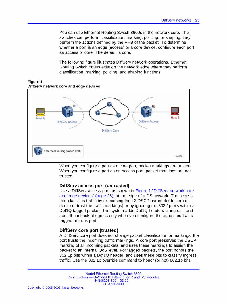
You can use Ethernet Routing Switch 8600s in the network core. Theswitches can perform classification, marking, policing, or shaping; theyperform the actions defined by the PHB of the packet. To determinewhether a port is an edge (access) or a core device, configure each portas access or core. The default is core.
The following figure illustrates DiffServ network operations. EthernetRouting Switch 8600s exist on the network edge where they performclassification, marking, policing, and shaping functions.
Figure 1DiffServ network core and edge devices
When you configure a port as a core port, packet markings are trusted.When you configure a port as an access port, packet markings are nottrusted.
DiffServ access port (untrusted)Use a DiffServ access port, as shown in Figure 1 "DiffServ network coreand edge devices" (page 25), at the edge of a DS network. The accessport classifies traffic by re-marking the L3 DSCP parameter to zero (itdoes not trust the traffic markings) or by ignoring the 802.1p bits within aDot1Q-tagged packet. The system adds Dot1Q headers at ingress, andadds them back at egress only when you configure the egress port as atagged or trunk port.
DiffServ core port (trusted)A DiffServ core port does not change packet classification or markings; theport trusts the incoming traffic markings. A core port preserves the DSCPmarking of all incoming packets, and uses these markings to assign thepacket to an internal QoS level. For tagged packets, the port honors the802.1p bits within a Dot1Q header, and uses these bits to classify ingresstraffic. Use the 802.1p override command to honor (or not) 802.1p bits.
Nortel Ethernet Routing Switch 8600Configuration — QoS and IP Filtering for R and RS Modules
NN46205-507 03.0230 April 2009
Copyright © 2008-2009 Nortel Networks
.

26 QoS fundamentals
QoS operations for IPv4 and IPv6 are the same. You can associate alltraffic with MAC, port, and VLAN QoS levels rather than with 802.1p bits orthe DSCP parameter.
QoS implementationThe following figure shows how the Ethernet Routing Switch 8600 providesQoS functionality. The order of operations is as follows:
• ingress classification of the packet
• mapping of ingress classification to an internal QoS value
• placement of the packet into an egress queue based on the internalQoS-to-egress queue mapping
• egress servicing of the packet by a scheduler
Figure 2Overview of Ethernet Routing Switch 8600 QoS operations
Ingress QoS configuration parameters determine traffic classification.Classification creates a mapping to an internal QoS level (0 to 7) thatmaps to an egress queue. The egress queue mapping determines theoutput packet DSCP, EXP-bit, or 802.1p markings. Whether a packet ispart of a Layer 2 (bridged) or a Layer 3 (routed) traffic flow can affect QoSoperations.
At ingress, you can modify traffic classification with filters (Access ControlLists—ACL); however, QoS deployment does not require the use of trafficfilters. You can use traffic filters to configure criteria to identify a microflow
Nortel Ethernet Routing Switch 8600Configuration — QoS and IP Filtering for R and RS Modules
NN46205-507 03.0230 April 2009
Copyright © 2008-2009 Nortel Networks
.

DiffServ networks 27
or an aggregate flow. The filters can match multiple parameters in the IPpacket and can assign actions that match the criteria you specify. Filtersoverride the standard ingress QoS or DiffServ operations.
Implement a DiffServ network on the Ethernet Routing Switch 8600 byconfiguring a port as trusted or untrusted.
DiffServ and non-IP trafficDiffServ applies only to IP packets. The system maps non-IP traffic to asource MAC, port, or VLAN QoS level. For R and RS module ports, thesystem first maps traffic to the MAC QoS level. With no MAC QoS levelsetting or match, the Ethernet Routing Switch 8600 chooses between portand VLAN QoS levels by selecting the highest QoS level setting. Normalegress QoS operation then occurs, although egress mapping tablesassociated with DSCP do not apply—DSCP is an IP-only parameter.
DiffServ configuration parametersYou can use a number of parameters to configure DiffServ and QoS. Allpackets receive QoS operation handling. The following sections describethese parameters using Device Manager terms.
In the following sections, do not confuse the terminology L2 and L3with Layer 2 (bridging) or Layer 3 (routed) operation. L2 represents anassociation with Q-tags, of which 802.1p bits is a portion. L3 representsan association with DSCP.
• “DiffServ—true or false” (page 27)
• “Layer3Trust—core or access” (page 28)
• “Layer2 8021p Override” (page 28)
• “Port-based QoS level” (page 28)
• “VLAN-based QoS level” (page 28)
DiffServ—true or falseYou can configure the DiffServ parameter to true or false; false is thedefault. This parameter works with the Layer3Trust parameter. TheDiffServ parameter is a global parameter that affects QoS L3 DSCPoperations.
If the DiffServ parameter is false (DiffServ disabled), the L3 DSCPparameter is not used for classification or modified. When the DiffServparameter is true, it activates the Layer3Trust parameter.
Nortel Ethernet Routing Switch 8600Configuration — QoS and IP Filtering for R and RS Modules
NN46205-507 03.0230 April 2009
Copyright © 2008-2009 Nortel Networks
.

28 QoS fundamentals
Layer3Trust—core or accessYou can configure the Layer3Trust parameter to core or access; coreis the default. Core configures the port to a trusted state and accessconfigures the port to an untrusted state
The DiffServ parameter determines the operation of this parameter. Theoperation depends on whether the port is tagged or untagged. Taggedpacket operation depends on the Layer2 8021p Override parameter(described next). If DiffServ is false, Layer3Trust has no effect; nomodification of the DSCP or TOS bits occurs. If DiffServ is true, the coreand access settings take affect as described in “DiffServ access port(untrusted)” (page 25) and “DiffServ core port (trusted)” (page 25).
Layer2 8021p OverrideYou can configure the Layer2 8021p Override parameter to true or false;false is the default.
This parameter primarily affects L2 tagged packet treatment, but can alsoaffect the treatment of the L3 DSCP parameter.
If Layer2 8021p Override is false, the port trusts the 802.1p-bit portion of aQ-tagged packet. The port trusts the 802.1p-bit marking regardless of theport setting (tagged or untagged); however, if the discard tagged packetsparameter (DiscardTaggedFrames) on an untagged port is true, the portdiscards the packet.
If Layer2 8021p Override is true, the port does not trust the 802.1p bitmarking. No re-marking occurs because the system strips 802.1p bits atingress. In this case, the QoS operation depends on other parameters,such as DiffServ and Layer3Trust settings, or the MAC, port, or VLAN QoSlevel.
Port-based QoS levelUse the port-based QoS level to configure the default QoS level for a port.You can configure the QoS level from 0 to 6 (level 7 is reserved for internalswitch use—network control traffic). The default value is 1.
For VoIP traffic, Nortel recommends that you use QoS level 6.
If you configure port QoS levels, Layer 2 and Layer 3 traffic from the sameport has the same QoS level.
VLAN-based QoS levelUse the VLAN-based QoS level to configure a default QoS level for aVLAN. You can configure a QoS level from 0 to 6 (level 7 is reserved forinternal switch use— network control traffic). The default value is 1.
Nortel Ethernet Routing Switch 8600Configuration — QoS and IP Filtering for R and RS Modules
NN46205-507 03.0230 April 2009
Copyright © 2008-2009 Nortel Networks
.

DiffServ networks 29
Use VLAN-based QoS levels to customize VLANs for traffic applications.For example, add a Voice VLAN to an edge switch to carry VoIP traffic.Then you can apply a QoS level to the Voice VLAN to ensure properhandling of time-sensitive VoIP traffic without using filters. For VoIP traffic,Nortel recommends that use you QoS level 6.
Layer 2 and Layer 3 trusted and untrusted portsThis section contains a series of traffic processing flowcharts. Theflowcharts show QoS operations that result from various configurationoptions. You can configure R series module ports as trusted oruntrusted at both Layer 2 (802.1p) or Layer 3 (DSCP) for ingresspacket classification. The following section describes the configurationcombinations:
• “Layer 2 untrusted and Layer 3 untrusted” (page 29)
• “Layer 2 untrusted and Layer 3 trusted” (page 31)
• “Layer 2 trusted and Layer 3 trusted” (page 33)
• “Layer 2 trusted and Layer 3 untrusted” (page 34)
The Ethernet Routing Switch 8600 provides eight internal QoS levels.These eight levels, numbered zero to seven, map to the egress queues(see “Ingress mappings and queues” (page 52)) through
• the MAC, port, or VLAN QoS level settings (also numbered zero toseven)
• the ingress 8021p to (internal) QoS mapping table
• the ingress DSCP to (internal) QoS mapping table
• the ingress MPLS EXP bit to (internal) QoS mapping table
If the default number of egress queues changes by using a custom queueset, you can alter the mapping tables as required.
The default number of queues for either the 8 max-queue-set or the 64max-queue-set is 8.
The following sections and flowcharts include no MPLS QoS operations.For information about MPLS actions, see “QoS and MPLS” (page 71).
Layer 2 untrusted and Layer 3 untrustedTo configure a port as Layer 2 untrusted and Layer 3 untrusted, assign thefollowing parameter values:
• DiffServ = true
• Layer3Trust = access
• Layer2 8021p Override = true
Nortel Ethernet Routing Switch 8600Configuration — QoS and IP Filtering for R and RS Modules
NN46205-507 03.0230 April 2009
Copyright © 2008-2009 Nortel Networks
.

30 QoS fundamentals
Use this configuration to classify packets through either MAC, port, orVLAN QoS levels. Use VLAN QoS for a VLAN that carries traffic fora single application. For example, directly connected voice traffic canuse VLAN QoS to give the same ingress classification to all packets (allingress packets are voice packets). You can use MAC-based QoS for allpackets from a single device. You can use a port-based QoS level for allpackets that enter a port within a VLAN, rather than a VLAN-based QoSlevel, which applies to all ports within the VLAN.
For details about Layer 2 untrusted, Layer 3 untrusted QoS operations,see Figure 3 "DiffServ access mode with 802.1p override enabled" (page31).
Nortel Ethernet Routing Switch 8600Configuration — QoS and IP Filtering for R and RS Modules
NN46205-507 03.0230 April 2009
Copyright © 2008-2009 Nortel Networks
.

DiffServ networks 31
Figure 3DiffServ access mode with 802.1p override enabled
Layer 2 untrusted and Layer 3 trustedTo configure a port as Layer 2 untrusted and Layer 3 trusted, assign thefollowing parameter values:
• DiffServ = true
• Layer3Trust = core
• Layer2 8021p Override = true
Nortel Ethernet Routing Switch 8600Configuration — QoS and IP Filtering for R and RS Modules
NN46205-507 03.0230 April 2009
Copyright © 2008-2009 Nortel Networks
.

32 QoS fundamentals
Use these configuration options to classify packet QoS through theDSCP parameter for all IP packets, whether tagged or untagged. Thisconfiguration is typical when another QoS or DiffServ-enabled andconfigured switch marks IP packets at the edge. These already markedpackets arrive L3 trusted, and the Ethernet Routing Switch 8600 continueswith the trust (DiffServ core port operation). For tagged packets, 802.1pbits are not examined. For non-IP packets, this configuration causesclassification by one of MAC, port, or VLAN QoS settings.
For details about Layer 2 untrusted, Layer 3 trusted QoS operations, seeFigure 4 "DiffServ core mode with 802.1p override enabled" (page 32).
Figure 4DiffServ core mode with 802.1p override enabled
Nortel Ethernet Routing Switch 8600Configuration — QoS and IP Filtering for R and RS Modules
NN46205-507 03.0230 April 2009
Copyright © 2008-2009 Nortel Networks
.
DiffServ networks 33
Layer 2 trusted and Layer 3 trustedTo configure a port as Layer 2 trusted and Layer 3 trusted, assign thefollowing parameter values:
• DiffServ = true
• Layer3Trust = core
• Layer2 8021p Override = false
Use these configuration options to classify packet QoS through 802.1pfor all IP tagged packets, and through DSCP for all untagged routed IPpackets. If the packet is non-IP or bridged IP, the system uses the MAC,port, or VLAN QoS level. This action is independent of tagged (trunk) oruntagged (access) port settings. An exception is an untagged port with aDiscardTaggedFrames parameter of true (nondefault); the port discardsthe packet rather than classifies it for QoS treatment.
For details about Layer 2 trusted, Layer 3 trusted QoS operations, seeFigure 5 "DiffServ core mode with 802.1p override disabled" (page 34).
Nortel Ethernet Routing Switch 8600Configuration — QoS and IP Filtering for R and RS Modules
NN46205-507 03.0230 April 2009
Copyright © 2008-2009 Nortel Networks
.

34 QoS fundamentals
Figure 5DiffServ core mode with 802.1p override disabled
Layer 2 trusted and Layer 3 untrustedTo configure a port as Layer 2 trusted and Layer 3 untrusted, assign thefollowing parameter values:
• DiffServ = True
• Layer3Trust = Access
• Layer2 8021p Override = false
Nortel Ethernet Routing Switch 8600Configuration — QoS and IP Filtering for R and RS Modules
NN46205-507 03.0230 April 2009
Copyright © 2008-2009 Nortel Networks
.

DiffServ networks 35
Use these configuration options to classify packet QoS through 802.1p forall tagged packets, and MAC, port, or VLAN QoS levels for all untaggedpackets. One MAC, port, or VLAN QoS level setting handles all untagged(IP or non-IP) packets. If the packet is an IP packet, the DSCP parameterbits are not modified or examined.
For details about Layer 2 trusted, Layer 3 untrusted QoS operations, seeFigure 6 "DiffServ access mode with 802.1p override disabled" (page 36).
Nortel Ethernet Routing Switch 8600Configuration — QoS and IP Filtering for R and RS Modules
NN46205-507 03.0230 April 2009
Copyright © 2008-2009 Nortel Networks
.

36 QoS fundamentals
Figure 6DiffServ access mode with 802.1p override disabled
DiffServ disabledIf you assign the DiffServ parameter the default of false (disabled), the L3DSCP parameter is ignored. For more information about QoS operationswhen DiffServ is false, see Figure 7 "DiffServ disabled" (page 37).
Nortel Ethernet Routing Switch 8600Configuration — QoS and IP Filtering for R and RS Modules
NN46205-507 03.0230 April 2009
Copyright © 2008-2009 Nortel Networks
.
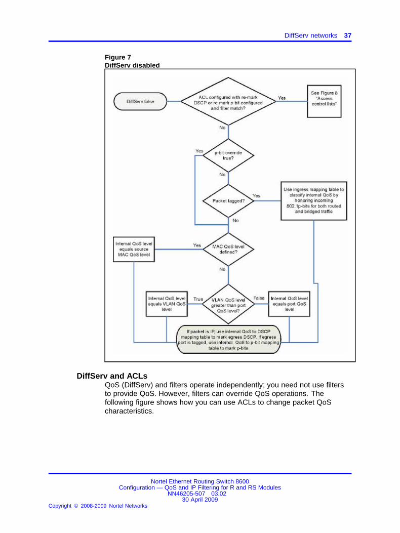
DiffServ networks 37
Figure 7DiffServ disabled
DiffServ and ACLsQoS (DiffServ) and filters operate independently; you need not use filtersto provide QoS. However, filters can override QoS operations. Thefollowing figure shows how you can use ACLs to change packet QoScharacteristics.
Nortel Ethernet Routing Switch 8600Configuration — QoS and IP Filtering for R and RS Modules
NN46205-507 03.0230 April 2009
Copyright © 2008-2009 Nortel Networks
.

38 QoS fundamentals
Figure 8Access control lists
QueueingQueuing is a congestion-avoidance function that prioritizes packet delivery.Queuing ensures discriminate packet discard during network congestionand can delay a packet in memory until the scheduled transmission.
You can use queuing to manage congestion. Queueing determines theorder in which an interface sends packets based on priorities assignedto those packets. Congestion management activities include the creationof queues, the assignment of packets to the queues based on packetclassification, and the scheduling of packets in a queue for transmission.
Nortel Ethernet Routing Switch 8600Configuration — QoS and IP Filtering for R and RS Modules
NN46205-507 03.0230 April 2009
Copyright © 2008-2009 Nortel Networks
.
DiffServ networks 39
When no congestion exists (periods of low traffic volume), an interfacesends packets after they arrive. During periods of transmission congestionat the outgoing interface, packets arrive faster than the interface cansend them. If you use congestion management features, packets thataccumulate at an interface form a queue until the interface can send them.The packets follow a transmission schedule according to the assignedpriority and the queuing mechanism configured for the interface. TheEthernet Routing Switch 8600 scheduler determines the order of packettransmission by controlling how queues are handled with respect to eachother.
Feedback output queueingThe FOQ mechanism helps the Ethernet Routing Switch 8600 avoid switchfabric congestion. The Ethernet Routing Switch 8600 monitors and reportscongestion for individual egress queues. The FOQ mechanism notifiesthe ingress ports of possible future switch fabric congestion. If an egressqueue becomes congested, FOQ restricts the packet flow to that queue.The switch fabric does not waste resources forwarding packets that willbe dropped.
FOQ avoids packet drops indiscriminate of QoS flows, which provides faircongestion management. Old switches base congestion managementon the Class of Service (CoS) and cannot distinguish offending trafficfrom correctly functioning traffic if they both have the same CoS level.Switches based on CoS congestion management also cannot distinguishoffending traffic from well-behaved traffic on the lane (fabric PID) level.Thus, in old systems, all queues of the same PID can suffer from packetdrops because of congestion. The switch uses FOQ for fine control overcongestion; it can manage congestion for each queue. In FOQ systems,congestion in an egress queue only affects that queue; it does not affectpackets destined for noncongested queues.
The Ethernet Routing Switch 8600 automatically uses FOQ after youenable R modeand, thus, does not support FOQ in a chassis with amixture of modules (R series modules and E or M modules).
Egress queue setsThe egress queue set is a logical bundle of configuration queues; it is atemplate that you use to apply the same queue configuration to a group(set) of ports available on multiple input and output (I/O) modules. All portsthat you add to an egress queue set use identical configuration queues.
Nortel Ethernet Routing Switch 8600Configuration — QoS and IP Filtering for R and RS Modules
NN46205-507 03.0230 April 2009
Copyright © 2008-2009 Nortel Networks
.

40 QoS fundamentals
You can use the following two templates to create an egress queue set:
• An eight-queue template: Configure up to eight queues on the8648GTR, the 8648GBRS, the 8648GTRS, and the 10/100/1000 Mb/sports of the 8634XGRS.
• A 64-queue template: Configure up to 64 queues on Gigabit and10 Gigabit R modules. These modules include the 8630GBR, the8683XLR, the 8683XZR, the 8612XLRS, and the 10 Gb/s Ethernetports of the 8634XGRS.
The Ethernet Routing Switch 8600 R modules can use up to 8 or 64queues, depending on the module type.
Classic modules (E and M modules) support exactly eight queues.You cannot configure the queue parameters. For more informationabout QoS for Classic modules, see Nortel Ethernet Routing Switch8600 Configuration — QoS and IP Filtering for Classic Modules(NN46205-508) .
Queues within the egress queue set use three queuing styles (see thefollowing figure):
• high-priority group
• balanced-queuing group
• low-priority group
Figure 9Queuing styles
For more information about queuing styles, see “Queuing styles” (page45).
Nortel Networks Service Class
Nortel Networks Service Classes (NNSC) define a standard architectureto provide end-to-end QoS on a range of Nortel Ethernet switching andvoice products. NNSCs function as default QoS policies built in to a
Nortel Ethernet Routing Switch 8600Configuration — QoS and IP Filtering for R and RS Modules
NN46205-507 03.0230 April 2009
Copyright © 2008-2009 Nortel Networks
.

DiffServ networks 41
product. The NNSCs incorporate the various QoS technologies to providea complete end-to-end QoS behavioral treatment. The Ethernet RoutingSwitch 8600 includes a built-in QoS implementation for NNSCs.
Default egress queue sets (NNSC templates)NNSCs provide default recommended settings and behaviors for queueson an output port. With the Ethernet Routing Switch 8600 R modules, youcan modify some of the default settings for each of these queues andcreate custom queues based on your specific needs.
The Ethernet Routing Switch 8600 includes the following two reserved andpreconfigured egress queue sets based on the NNSCs model:
• Egress queue set 1 (eight-queue template)—used for modules withmore than 10 ports for each lane.
• Egress queue set 2 (64-queue template)—used for modules with 10ports or less for each lane.
For information about modules and lanes, see the following table.
Table 2R series modules and lanes
Module Number of lanes
8612XLRS 3—each lane supports 4 XFP ports
8630GBR 3—each lane supports 10 SFP ports
8634XGRS 3—Lane 1 supports 4 RJ-45 ports and 12 SFPports; Lane 2 supports 4 RJ-45 and 12 SFP ports,and Lane 3 supports 2 XFP ports
8648GBRS 3—each lane supports 16 SFP ports
8648GTR 2—one lane supports ports 1 to 24; the othersupports ports 25 to 48
8648GTRS 2—one lane supports ports 1 to 24; the othersupports ports 25 to 48
8683XLR and 8683XZR 3—each lane supports 1 XFP port
The Ethernet Routing Switch 8600 includes eight preconfigured queues(corresponding to the eight NNSCs) on each port of an R seriesmodule. Figure 10 "Preconfigured egress queue set 1" (page 42) showsthe eight preconfigured queues of the eight-queue template. Figure11 "Preconfigured egress queue set 2" (page 42) shows the eightpreconfigured queues of the 64 queue template. You can also use the CLIcommand show qos config egress-queue-set to view the queuesets.
Nortel Ethernet Routing Switch 8600Configuration — QoS and IP Filtering for R and RS Modules
NN46205-507 03.0230 April 2009
Copyright © 2008-2009 Nortel Networks
.

42 QoS fundamentals
Figure 10Preconfigured egress queue set 1
Figure 11Preconfigured egress queue set 2
The Queue IDs (Qid) differ for Classic and R series (R and RS) modules.Classic modules support 8 queues numbered from 0 to 7, where 0 is thelowest priority and 7 is the highest priority. R series modules support64 queues, numbered from 0 to 63. The Ethernet Routing Switch 8600internal QoS mechanism maps QoS levels between Classic and R seriesmodule systems.
The eight predefined queues used in R series modules map to the eightqueues used in Classic (E and M module) systems. The eight Classicqueues include two high-priority, one low-priority, and five balancedqueues.
Nortel Ethernet Routing Switch 8600Configuration — QoS and IP Filtering for R and RS Modules
NN46205-507 03.0230 April 2009
Copyright © 2008-2009 Nortel Networks
.

DiffServ networks 43
The Ethernet Routing Switch 8600 R series modules support up to 8 or 64queues. You can use the eight preconfigured queues, or you can createcustom queues. On R series modules, you can configure the minimumrate, maximum rate, and maximum queue length parameters for thequeues.
The minimum rate parameter does not apply to the preconfigured high- orlow-priority queues. On the 64 queue set modules, you cannot change theminimum rate for queues 55, 62, and 63. On the eight queue set modules,you cannot change the minimum rate for queues 5, 6, and 7.
If you choose to use custom queues, adhere to the following guidelines:
• Nortel recommends that you always use at least eight queues foran R series module to avoid possible issues with the DSCP to QoSmappings.
• You must include at least one balanced queue in each set.
• You must have at least one high-priority queue to handle network orcritical traffic.
• Each set must include a balanced queue with a Qid of 0.
• You cannot configure the Qid; you can configure the number of queuesfor each queueing style. The switch automatically assigns the Qidbased on the number of each queueing style you choose.
For a VLAN traffic shaping configuration example using egress queue sets,see VLAN Traffic Shaping for ERS8600 Technical Brief (NN48500-557) ,available on the Nortel Technical Support Web site.
NNSC types in the egress queue setIn the NNSC domain, the egress queue set uses the following trafficclassifications:
• network control traffic (Critical or Network)
• subscriber traffic (Premium, Metal, or Standard)
Critical or Network NNSCThe switch uses the Critical or Network NNSC for traffic within a singleadministrative network domain. If such traffic does not get through, thenetwork cannot function. Examples of such types of traffic are heartbeatsbetween core network switches or routers. The Spanning Tree BridgeProtocol Data Units (BPDU) use the Critical NNSC to enter and exit theEthernet Routing Switch 8600. NNSCs include network control trafficpackets for OSPF, BGP, STP, and other protocols.
Nortel Ethernet Routing Switch 8600Configuration — QoS and IP Filtering for R and RS Modules
NN46205-507 03.0230 April 2009
Copyright © 2008-2009 Nortel Networks
.

44 QoS fundamentals
Premium NNSCThe switch uses the Premium NNSC for IP telephony services, andprovides the low latency and low jitter required to support the services.IP telephony services include Voice over IP (VoIP), voice signaling,Fax over IP (FoIP), and voice-band data services over IP (for example,analog modem). The switch can also use the Premium NNSC for CircuitEmulation Services over IP (CESoIP).
Metal NNSCsThe Platinum, Gold, Silver, and Bronze NNSCs are collectively referred toas the metal classes. The metal NNSCs provide a minimum bandwidthguarantee and are useful for variable bit rate or bursty types of traffic.Applications that use the metal NNSCs support mechanisms thatdynamically adjust their transmit rate and burst size based on congestion(packet loss) detected in the network.
Platinum NNSCThe switch uses the Platinum NNSC for applications that require lowlatency, for example, real-time services such as video conferencingand interactive gaming. Platinum NNSC traffic provides the low latencyrequired for interhuman (interactive) communications. The Platinum NNSCprovides a minimum bandwidth assurance for Assured Forwarding 41(AF41) and Class Selector 4 (CS4)-marked flows. When the networkexperiences congestion, DiffServ nodes use drop precedence to controlvariable bit rates that exceed the minimum assured bandwidth.
Gold NNSCThe switch uses the Gold NNSC for applications that require near-real-timeservice and are not as delay-sensitive as applications that use thePlatinum service. Such applications include streaming audio and video,video on demand, and surveillance video.
The Gold NNSC is based on the assumption that the source anddestination buffer traffic and, therefore, the traffic is less sensitive to delayand jitter. By default, the Gold NNSC provides a minimum bandwidthassurance for AF31, AF32, AF33, and CS3-marked flows. When thenetwork experiences congestion, DiffServ nodes use drop precedence tocontrol variable bit rates and burst sizes that exceed the minimum assuredbandwidth.
Silver NNSCThe switch uses the Silver NNSC for responsive (typically client- andserver-based) applications. Such applications include Systems NetworkArchitecture (SNA) terminals (for example, a PC or Automatic TellerMachine) to mainframe (host) transactions that use Data Link Switching
Nortel Ethernet Routing Switch 8600Configuration — QoS and IP Filtering for R and RS Modules
NN46205-507 03.0230 April 2009
Copyright © 2008-2009 Nortel Networks
.

DiffServ networks 45
(SNA over IP), Telnet sessions, Web-based ordering and credit cardprocessing, financial wire transfers, and Enterprise Resource Planningapplications.
Silver NNSC applications require a fast response and have asymmetricalbandwidth needs. The client sends a short message to the server and theserver responds with a much larger data flow to the client. For example,after a user clicks a hyperlink (that sends a few dozen bytes) on a Webpage, the Web browser loads a new Web page (that downloads kilobytesof data). The Silver NNSC provides a minimum bandwidth assurance forAF21- and CS2-marked flows.
The Silver NNSC favors short-lived, low-bandwidth TCP-based flows.During network congestion, DiffServ nodes use drop precedence tocontrol variable bit rates and burst sizes that exceed the minimum assuredbandwidth.
Bronze NNSCThe switch uses the Bronze NNSC for long-lived TCP-based flows,such as file transfers, e-mail, or noncritical Operation, Administration,and Maintenance (OAM) traffic. The Bronze NNSC provides a minimumbandwidth assurance for AF11- and CS1-marked flows. During networkcongestion, DiffServ nodes use drop precedence to control variable bitrates and burst sizes that exceed the minimum assured bandwidth. Nortelrecommends that you use the Bronze NNSC for noncritical OAM trafficwith the CS1 DSCP marking.
Standard NNSCThe switch uses the Standard NNSC for best-effort services. Nortel doesnot specify delay, loss, or jitter guarantees for this NNSC.
Queuing stylesThe Ethernet Routing Switch 8600 R modules can have up to 8 or 64queues for each port. The switch bundles queues together based onqueuing styles. The queue numbering order is as follows:
• high-priority queues
• low-priority queues
• balanced queues
High-priority queues have the highest priority. Queues that are membersof this group take precedence over the queues in all other queuing groups.The strict (high) priority group is always guaranteed service first and hasthe lowest latency among the groups. The queuing scheduler immediatelyhandles packets that enter the strict-priority queues to transmit thosepackets at the highest priority.
Nortel Ethernet Routing Switch 8600Configuration — QoS and IP Filtering for R and RS Modules
NN46205-507 03.0230 April 2009
Copyright © 2008-2009 Nortel Networks
.

46 QoS fundamentals
For 64 queue set queues, the strict-priority queues numbers start fromqueue index 63 and decrement. For 8 queue set queues, the strict-priorityqueues numbers start from queue index 7 and decrement. In Figure12 "High-priority queues 62 and 63" (page 46), queues 62 and 63 aremembers of a strict-priority group. The scheduler handles a packet thatenters queue 63 at the highest priority. After the scheduler transmitspackets in queue 63, it handles queue 62.
The scheduler handles queues within the high-priority queue group inpriority order. A higher queue number corresponds to a higher priority.
Figure 12High-priority queues 62 and 63
Queue 63 is reserved for Critical or Network Control traffic. For example,Spanning Tree BPDUs and topology updates are placed in queue 63.Queue 62 is the next highest priority queue and carries latency-sensitivesubscriber traffic. For example, VoIP and video conferencing applicationsuse Premium queue 62.
By default on trusted ports, incoming packets with 802.1p equal to 6, orDSCP markings of CS5 or Expedited Forwarding (EF), are placed in queue62 to ensure timely service.
You can configure the max-rate parameter to bind output traffic to thespecified limit. The switch either delays (if the buffer is not full) or dropstraffic that violates this limit; see Figure 13 "Queues bounded by max-rateparameter" (page 47)). By default, high-priority queues use a maximum
Nortel Ethernet Routing Switch 8600Configuration — QoS and IP Filtering for R and RS Modules
NN46205-507 03.0230 April 2009
Copyright © 2008-2009 Nortel Networks
.

DiffServ networks 47
rate based on the NNSC recommendations. Figure 10 "Preconfiguredegress queue set 1" (page 42) and Figure 11 "Preconfigured egress queueset 2" (page 42) show the default max-rate parameters. For high-priorityqueues, a non-100-percent maximum rate ensures that a malfunctioningclient application does not use the entire port bandwidth.
Figure 13Queues bounded by max-rate parameter
By default, high-priority queues use a max-rate based on NNSCrecommendations. In the default NNSC queuing template(egress-queue-set 2), high-priority queue 63 uses a max-rate of 5 percent,whereas queue 62 uses a max-rate of 50 percent.
Minimum rate values do not apply to high-priority queues. The followingtable shows examples of high-priority queues.
Table 3High-priority queues in the 64-queue template
Queue Name Description
Queue 63 Network Reserved for Critical or Network traffic
Queue 62 Subscriber Recommended for latency-sensitive subscribertraffic, for example, VoIP
You can increase the max-rate on high-priority queues (see the followingfigure).
Nortel Ethernet Routing Switch 8600Configuration — QoS and IP Filtering for R and RS Modules
NN46205-507 03.0230 April 2009
Copyright © 2008-2009 Nortel Networks
.

48 QoS fundamentals
Figure 14Increase in maximum rate on high-priority queues
The warning message that appears can occur when you modify the defaultmax-rate on high-priority queues. Because high-priority queues haveprecedence over balanced queues, you must follow this rule when youconfigure the max-rate on high-priority queues. The maximum rate mustbe less than or equal to the available bandwidth minus the total minimumrate for the balanced queues.
To increase the max-rate on high-priority queues, decrease the minimumrate on the balanced queues as shown in “Configuring an egress queueset” (page 119). Then, increase the max-rate as described in “Configuringan egress queue set” (page 119). The following figure shows thisconfiguration process.
Figure 15Decrease in minimum rate of balanced queues
Nortel Ethernet Routing Switch 8600Configuration — QoS and IP Filtering for R and RS Modules
NN46205-507 03.0230 April 2009
Copyright © 2008-2009 Nortel Networks
.

DiffServ networks 49
Low-priority queues have the lowest priority, with a minimum rate of 0.High-priority and balanced queues take precedence over low-priorityqueues. This queue corresponds to best-effort traffic.
A weighted fair queueing (WFQ) scheduler handles balanced queues. AWFQ scheduler handles queues in a round-robin fashion (each queue inturn), where each queue receives bandwidth in proportion to the weight.The minimum rate you configure for the queue determines the weight andservice time of the queue.
The minimum rate guarantees that the queues receive the configuredbandwidth. The min-rate is a promise to the subscriber that the queuereceives at least the percentage of bandwidth share configured for thatqueue. If no additional data exists on other queues, the rate on a queuecan increase to the max-rate configured for the queue. For example, ifyou configure a queue for a 10 percent minimum rate on a 1 Gb/s port,the scheduler guarantees that the queue receives a fair share of 100 Mb/sfrom the available output port bandwidth.
To guarantee minimum configured rates, the sum of minimum rates forbalanced queues and maximum rates for high-priority queues must notexceed 100 percent. Balanced queues permit oversubscription but do notguarantee minimum rates.
Minimum rates do not apply to high-priority groups. The switch handleshigh-priority traffic up to the max-rate limit. By default, minimum rates onbalanced queues are based on the NNSC recommendations; see Figure16 "Minimum rates on balanced queues" (page 50). For more information,see “Egress queue set minimum rate” (page 70).
Nortel Ethernet Routing Switch 8600Configuration — QoS and IP Filtering for R and RS Modules
NN46205-507 03.0230 April 2009
Copyright © 2008-2009 Nortel Networks
.

50 QoS fundamentals
Figure 16Minimum rates on balanced queues
You can configure the max-rate parameter to bind the output trafficto the specified limit. The system either delays (if the buffer is notfull) or drops traffic that violates this limit. By default, high-priorityqueues use a maximum rate based on the NNSC recommendations.Balanced and low-priority queues use a maximum rate of 100 percent.Figure 10 "Preconfigured egress queue set 1" (page 42) and Figure 11"Preconfigured egress queue set 2" (page 42) show the default max-rateparameters. For high-priority queues, a non-100-percent maximum rateensures that a malfunctioning client application does not use the entireport bandwidth.
You can modify the default max-rates on all queues. High-priority queueshave precedence over balanced queues, and balanced queues takeprecedence over low-priority queues. To guarantee that balanced queuesobtain the promised minimum rates, ensure that the maximum rate onhigh-priority queues is less than or equal to the available data rate minusthe total minimum rate for the balanced queues.
The minimum rate guarantees that the queue receives the configuredbandwidth. The min-rate is a promise to the subscriber that a queuereceives at least the percentage of bandwidth share configured for thatqueue. If no data to service exists on other queues, the rate on a queuecan increase to the max-rate configured on the queue.
For example, if you configure a balanced queue for a 10 percent min-rateon a 1 Gb/s port, the scheduler provides the queue with a fair share of atleast 100 Mb/s from the available output port bandwidth. Minimum rates
Nortel Ethernet Routing Switch 8600Configuration — QoS and IP Filtering for R and RS Modules
NN46205-507 03.0230 April 2009
Copyright © 2008-2009 Nortel Networks
.

DiffServ networks 51
do not apply to high-priority or low-priority queueing styles. Incominghigh-priority traffic is serviced at up to the max-rate limit. Low-priorityqueues always have a min-rate of 0; no guaranteed rates exist forlow-priority traffic. By default, minimum rates for balanced queues arebased on the NNSC recommendations, see Figure 10 "Preconfiguredegress queue set 1" (page 42) and Figure 11 "Preconfigured egress queueset 2" (page 42).
The Ethernet Routing Switch 8600 supports 32 000 memory pages(queues) for each forwarding lane. Each memory page is 512 bytes inlength, except the first page, which is 144 bytes in length. For informationabout modules and lanes, see Table 2 "R series modules and lanes" (page41).
You can change the default maximum queue length (max-q-length)parameter. However, such changes can cause an oversubscription ofavailable buffers, depending on module types and configurations. You canuse leftover queue lengths from some queues to increase the buffer sizeof other queues. Use the show port stats command to view port queuestatistics (see the following figure). Increase the max-q-length for any portwith a queue that shows a nonzero value in the dropped pages parameter.
The default max-q-length settings are based on real-world (generalized)traffic patterns, and the traffic patterns and queue usage for a specific usercan vary widely. Therefore, adjust the max-q-length parameter dependingupon user traffic patterns and queue configurations.
Nortel Ethernet Routing Switch 8600Configuration — QoS and IP Filtering for R and RS Modules
NN46205-507 03.0230 April 2009
Copyright © 2008-2009 Nortel Networks
.

52 QoS fundamentals
Figure 17show port stats egress-queues output
The utilization parameter is calculated for an individual port and for eachqueue.
For more information about QoS statistics, see Nortel Ethernet RoutingSwitch 8600 Performance Management (NN46205-704) .
Egress queue packet assignmentThe Ethernet Routing Switch 8600 assigns packets to egress (transmit)queues based on the ingress mappings and the internal QoS level.
Ingress mappings and queuesThe switch uses ingress maps to translate incoming packet QoS markingsto the internal QoS level. The switch classifies packets based on theinternal QoS level.
Ingress mappings are as follows:
• 802.1p to (internal) QoS level
• DSCP to (internal) QoS level
• EXP-bit to (internal) QoS level
The following tables show ingress mappings obtained using the CLIcommand show qos ingressmap. Table 5 "Default ingress 802.1p toQoS to egress queue mappings" (page 53) shows ingress IEEE 1p to QoSlevel mappings.
Nortel Ethernet Routing Switch 8600Configuration — QoS and IP Filtering for R and RS Modules
NN46205-507 03.0230 April 2009
Copyright © 2008-2009 Nortel Networks
.

DiffServ networks 53
Table 6 "Gigabit Ethernet default ingress DSCP to QoS to egress queuemapping" (page 54) shows DSCP to internal QoS-level mappings.
The following table shows MPLS EXP-bit mappings.
Table 4QoS ingress MPLS Exp bit to QoS-level map
MPLS Exp bit QoS level
0 0
1 1
2 2
3 3
4 4
5 5
6 6
7 7
The following tables describe default ingress and egress mappings.
Table 5Default ingress 802.1p to QoS to egress queue mappings
InternalQoS Egress queue PHB
Queue name(EgressQueue Set2)
Default 1premarkingonegress
NetworkServiceClass(NSC)
8queueports
64queueports
0 5 55 Custom Custom 1 Custom
1 4 4 CS0/DF Standard 0 Standard
2 3 3 CS1/AF11 Bronze 2 Bronze
3 2 2 CS2/AF21 Silver 3 Silver
4 1 1 CS3/AF31 Gold 4 Gold
5 0 0 CS4/AF41 Platinum 5 Platinum
6 6 62 CS5/EF Premium 6 Premium/EF
7 7 63 CS6/CS7 Network (orCritical)
7 Premium/EF
In the following table, TOS denotes Type of Service and Hex denoteshexadecimal.
Nortel Ethernet Routing Switch 8600Configuration — QoS and IP Filtering for R and RS Modules
NN46205-507 03.0230 April 2009
Copyright © 2008-2009 Nortel Networks
.

54 QoS fundamentals
Table 6Gigabit Ethernet default ingress DSCP to QoS to egress queue mapping
IngressInternalQoSlevel
PHBlevel
Queue name (EgressQueue Set 2)
DSCP DSCP(bin)
DSCP(Hex)
TOS
00 000000 00 00 1 CS0
00 000000 00 00 1 DF
01 000001 01 04 1 CS0
02 000010 02 08 1 CS0
03 000011 03 0C 1 CS0
04 000100 04 10 1 CS0
05 000101 05 14 1 CS0
06 000110 06 18 1 CS0
07 000111 07 1C 1 CS0
Custom
08 001000 08 20 2 CS1 Bronze
09 001001 09 24 1 CS0 Custom
10 001010 0A 28 2 AF11 Bronze
11 001011 0B 2C 1 CS0 Custom
12 001100 0C 30 2 CS1 Bronze
13 001101 0D 34 1 CS0 Custom
14 001110 0E 38 2 CS1 Bronze
15 001111 0F 3C 1 CS0 Custom
16 010000 10 40 3 CS2 Silver
17 010001 11 44 1 CS0 Custom
18 010010 12 48 3 AF21 Silver
19 010011 13 4C 1 CS0 Custom
20 010100 14 50 3 CS2 Silver
21 010101 15 54 1 CS0 Custom
22 010110 16 58 3 CS2 Silver
23 010111 17 5C 1 CS0 Custom
24 011000 18 60 4 CS3 Gold
25 011001 19 64 1 CS0 Custom
Nortel Ethernet Routing Switch 8600Configuration — QoS and IP Filtering for R and RS Modules
NN46205-507 03.0230 April 2009
Copyright © 2008-2009 Nortel Networks
.

DiffServ networks 55
Table 6Gigabit Ethernet default ingress DSCP to QoS to egress queue mapping (cont’d.)
IngressInternalQoSlevel
PHBlevel
Queue name (EgressQueue Set 2)
DSCP DSCP(bin)
DSCP(Hex)
TOS
26 011010 1A 68 4 AF31
27 011011 1B 6C 4 CS3
28 011100 1C 70 4 CS3
Gold
29 011101 1D 74 1 CS0 Custom
30 011110 1E 78 4 CS3 Gold
31 011111 1F 7C 1 CS0 Custom
32 100000 20 80 5 CS4 Platinum
33 100001 21 84 1 CS0 Custom
34 100010 22 88 5 AF41
35 100011 23 8C 5 CS4
36 100100 24 90 5 CS4
Platinum
37 100101 25 94 1 CS0 Custom
38 100110 26 98 5 CS4 Platinum
39 100111 27 9C 1 CS0 Custom
40 101000 28 A0 5 CS4 Platinum
41 101001 28 A4 5 CS4 Platinum
42 101010 2A A8 1 CS0
43 101011 2B AC 1 CS0
44 101100 2C B0 1 CS0
45 101101 2D B4 1 CS0
Custom
46 101110 2E B8 6 EF
47 101111 2F BC 6 CS5
Premium
48 110000 30 C0 7 CS6 Network (or Critical)
Nortel Ethernet Routing Switch 8600Configuration — QoS and IP Filtering for R and RS Modules
NN46205-507 03.0230 April 2009
Copyright © 2008-2009 Nortel Networks
.

56 QoS fundamentals
Table 6Gigabit Ethernet default ingress DSCP to QoS to egress queue mapping (cont’d.)
IngressInternalQoSlevel
PHBlevel
Queue name (EgressQueue Set 2)
DSCP DSCP(bin)
DSCP(Hex)
TOS
49 110001 31 C4 1 CS0
50 110010 32 C8 1 CS0
51 110011 33 CC 1 CS0
52 110100 34 D0 1 CS0
53 110101 35 D4 1 CS0
54 110110 36 D8 1 CS0
55 110111 37 DC 1 CS0
Custom
56 111000 38 E0 7 CS7 Network (or Critical)
57 111001 39 E4 1 CS0
58 111010 3A E8 1 CS0
59 111011 3B EC 1 CS0
60 111100 3C F0 1 CS0
61 111101 3D F4 1 CS0
62 111110 3E F8 1 CS0
63 111111 3F FC 1 CS0
Custom
The following table describes mappings for MPLS-based QoS.
Table 7Default ingress EXP-bit to QoS to egress queue mappings
EXP-bit Internal QoS Egress queue Queue name (Egress Queue Set 2)
0 0 55 Custom
1 1 4 Standard (or Default)
2 2 3 Bronze
3 3 2 Silver
4 4 1 Gold
5 5 0 Platinum
6 6 62 Premium
7 7 63 Network (or Critical)
Nortel Ethernet Routing Switch 8600Configuration — QoS and IP Filtering for R and RS Modules
NN46205-507 03.0230 April 2009
Copyright © 2008-2009 Nortel Networks
.

DiffServ networks 57
Internal QoS levelThe internal QoS level or effective QoS level is a key element in theEthernet Routing Switch 8600 QoS architecture. The internal QoS levelspecifies the kind of treatment a packet receives and the transmit queuefor the exit (egress) path. The Ethernet Routing Switch 8600 classifies andassigns an internal QoS level to every packet that enters the switch.
Internal QoS levels map to the transmit or egress queues on a port. Forexample, for an access port, the highest value among the port QoS level,VLAN QoS level, and MAC QoS level becomes the internal QoS level(effective QoS level). For Layer 3 trusted (core) ports, the switch honorsincoming DSCP and TOS bits. The ingress DSCP to QoS level mapdetermines the internal QoS level assignment. If you configure a MACQoS level on an untrusted port, it takes precedence over the VLAN QoSlevel and the port QoS level.
The following figure shows a Nortel i2002 VoIP phone that sends packetswith a 802.1p value of 6 on a trusted Layer 2 port. The 802.1p-to-QoSlevel ingress map determines the internal QoS level of the packet andplaces the packet in the appropriate queue using the QoS level to queuemapping table.
Nortel Ethernet Routing Switch 8600Configuration — QoS and IP Filtering for R and RS Modules
NN46205-507 03.0230 April 2009
Copyright © 2008-2009 Nortel Networks
.

58 QoS fundamentals
Figure 18Path from input port to queues
The internal QoS level maps to the transmit queues. The following tableshows the default mapping of internal QoS level to egress queue for theR and RS modules.
Table 8QoS level to queue mapping for each module
8683XLR, 8683XZR, 8630GBR,8612XLRS, and 10 Gb/s portsof the 8634XGRS
8648GTR, 8648GTRS,8648GBRS, and10/100/1000 Mb/s ports ofthe 8634XGRS
QoSlevel
Queue Queue
0 55 5
Nortel Ethernet Routing Switch 8600Configuration — QoS and IP Filtering for R and RS Modules
NN46205-507 03.0230 April 2009
Copyright © 2008-2009 Nortel Networks
.

DiffServ networks 59
Table 8QoS level to queue mapping for each module (cont’d.)
8683XLR, 8683XZR, 8630GBR,8612XLRS, and 10 Gb/s portsof the 8634XGRS
8648GTR, 8648GTRS,8648GBRS, and10/100/1000 Mb/s ports ofthe 8634XGRS
QoSlevel
Queue Queue
1 4 4
2 3 3
3 2 2
4 1 1
5 0 0
6 62 6
7 63 7
Egress queueing and modulesPackets that egress from R series module ports can originate from eitheranother R series module port or from a Classic module port.
Although packets exit from the egress forward processing module, theingress processor (the port processor of packet origin) determines theegress queue. The ingress forward processing module determines theegress queue ID based either on the packet DSCP or 802.1p markingsor through the filter or port, VLAN, or MAC QoS levels (see the followingtable).
Table 9Default QoS to egress queue mappings for each module
Internal QoS leveland NNSC
Ports with 8 queues foreach portqueue and style
Ports with 64 queues foreach portqueue and style
Classicqueue
0, Custom (besteffort)
5, Low priority 55, Low priority 0
1, Standard 4, Weighted 4, Weighted 1
2, Bronze 3, Weighted 3, Weighted 2
3, Silver 2, Weighted 2, Weighted 3
4, Gold 1, Weighted 1, Weighted 4
5, Platinum 0, Weighted 0, Weighted 6
6, Premium 6, High Priority 62, High Priority 5
7, Network 7, High Priority 63, High Priority 7
Nortel Ethernet Routing Switch 8600Configuration — QoS and IP Filtering for R and RS Modules
NN46205-507 03.0230 April 2009
Copyright © 2008-2009 Nortel Networks
.
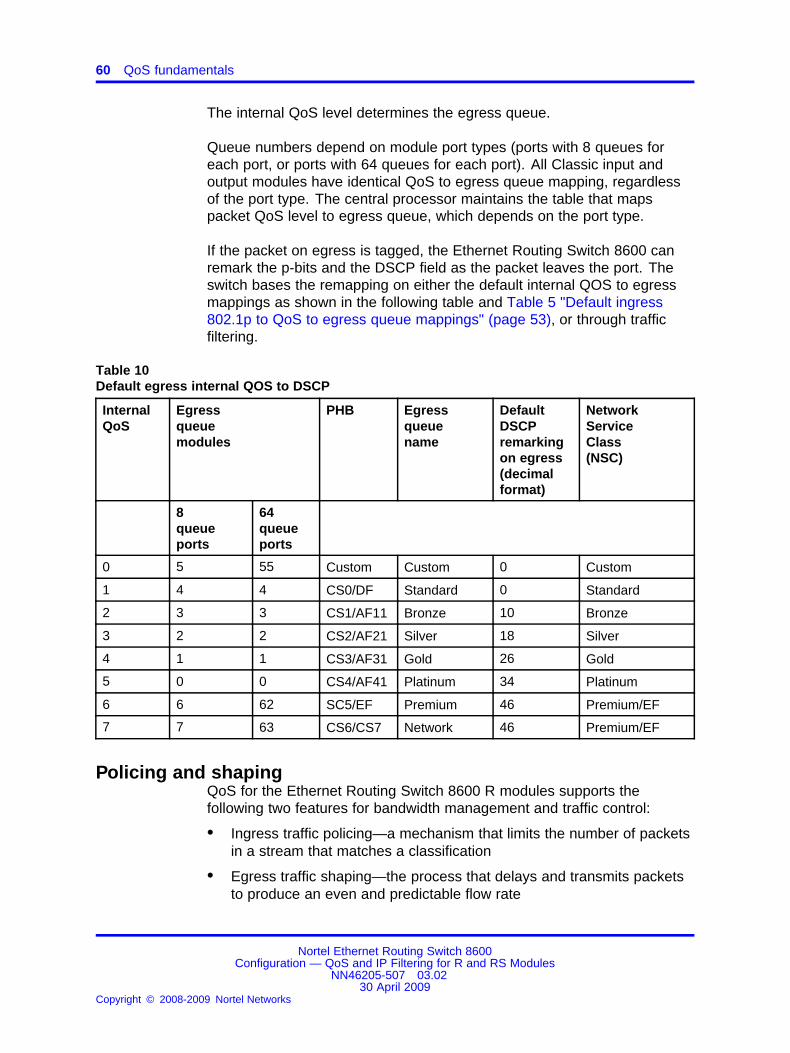
60 QoS fundamentals
The internal QoS level determines the egress queue.
Queue numbers depend on module port types (ports with 8 queues foreach port, or ports with 64 queues for each port). All Classic input andoutput modules have identical QoS to egress queue mapping, regardlessof the port type. The central processor maintains the table that mapspacket QoS level to egress queue, which depends on the port type.
If the packet on egress is tagged, the Ethernet Routing Switch 8600 canremark the p-bits and the DSCP field as the packet leaves the port. Theswitch bases the remapping on either the default internal QOS to egressmappings as shown in the following table and Table 5 "Default ingress802.1p to QoS to egress queue mappings" (page 53), or through trafficfiltering.
Table 10Default egress internal QOS to DSCP
InternalQoS
Egressqueuemodules
PHB Egressqueuename
DefaultDSCPremarkingon egress(decimalformat)
NetworkServiceClass(NSC)
8queueports
64queueports
0 5 55 Custom Custom 0 Custom
1 4 4 CS0/DF Standard 0 Standard
2 3 3 CS1/AF11 Bronze 10 Bronze
3 2 2 CS2/AF21 Silver 18 Silver
4 1 1 CS3/AF31 Gold 26 Gold
5 0 0 CS4/AF41 Platinum 34 Platinum
6 6 62 SC5/EF Premium 46 Premium/EF
7 7 63 CS6/CS7 Network 46 Premium/EF
Policing and shapingQoS for the Ethernet Routing Switch 8600 R modules supports thefollowing two features for bandwidth management and traffic control:
• Ingress traffic policing—a mechanism that limits the number of packetsin a stream that matches a classification
• Egress traffic shaping—the process that delays and transmits packetsto produce an even and predictable flow rate
Nortel Ethernet Routing Switch 8600Configuration — QoS and IP Filtering for R and RS Modules
NN46205-507 03.0230 April 2009
Copyright © 2008-2009 Nortel Networks
.

Policing and shaping 61
Each feature is important to deliver Differentiated Services (DiffServ) withina QoS network domain. Figure 19 "Basic policer and shaper behavior"(page 61) shows basic policing and shaping behavior.
Figure 19Basic policer and shaper behavior
Token buckets and policingTokens are a key concept in traffic control. A policer or shaper calculatesthe number of packets that pass and the data rate. Each packetcorresponds to a token, and the policer or shaper transmits or passes thepacket if the token is available (see Figure 20 "Token flow" (page 62)).
The token container is like a bucket. In this view, the bucket representsboth the number of tokens available for use instantaneously (the depthof the bucket) and the rate of token replenishment (how fast the bucketrefills). The following figure shows the flow of tokens.
Nortel Ethernet Routing Switch 8600Configuration — QoS and IP Filtering for R and RS Modules
NN46205-507 03.0230 April 2009
Copyright © 2008-2009 Nortel Networks
.

62 QoS fundamentals
Figure 20Token flow
In the Ethernet Routing Switch 8600, each policer has two token buckets.One token bucket is for the peak rate and the other is for the service rate.
A token bucket permits bursty traffic and binds it. A bursty flow can useseveral tokens to sent the bursty transmission through. Hosts can savetokens to transmit, but never more tokens than the bucket can hold. Whenthe bucket is full, the host discards the additional tokens. If no tokens areavailable, the sender must wait until one is available.
Policy-based policer versus shaperPolicy-based traffic policers and traffic shapers identify traffic by using apolicy (a contract). Traffic that conforms to this policy (a service contract)is guaranteed transmission, and nonconforming traffic is considered inviolation.
Policy-based policers and shapers differ in how they treat violations:
• Traffic shapers buffer and delay traffic that violates the contract.
If no tokens are available in the token bucket, the traffic shaperdelays packets until a token is available. Queueing buffers excessivepackets and shapes the flow when the source data rate is higher thanexpected. The Ethernet Routing Switch 8600 supports traffic shapingat the port level and for each transmit-queue (egress queue) level foroutgoing (egress) traffic.
Nortel Ethernet Routing Switch 8600Configuration — QoS and IP Filtering for R and RS Modules
NN46205-507 03.0230 April 2009
Copyright © 2008-2009 Nortel Networks
.
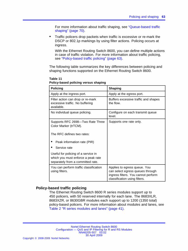
Policing and shaping 63
For more information about traffic shaping, see “Queue-based trafficshaping” (page 70).
• Traffic policers drop packets when traffic is excessive or re-mark theDSCP or 802.1p markings by using filter actions. Policing occurs atingress.
With the Ethernet Routing Switch 8600, you can define multiple actionsin case of traffic violation. For more information about traffic policing,see “Policy-based traffic policing” (page 63).
The following table summarizes the key differences between policing andshaping functions supported on the Ethernet Routing Switch 8600.
Table 11Policy-based policing versus shaping
Policing Shaping
Apply at the ingress port. Apply at the egress port.
Filter action can drop or re-markexcessive traffic. No bufferingavailable.
Buffers excessive traffic and shapesthe flow.
No individual queue policing. Configure on each transmit queuelevel.
Supports RFC 2698—Two Rate ThreeColor Marker (trTCM).
The RFC defines two rates:
• Peak information rate (PIR)
• Service rate
Useful for policing of a service inwhich you must enforce a peak rateseparately from a committed rate.
Supports one rate only.
You can perform traffic classificationusing filters.
Applies to egress queue. Youcan select egress queues throughingress filters. You cannot performclassification using filters.
Policy-based traffic policingThe Ethernet Routing Switch 8600 R series modules support up to450 policers, with 50 reserved internally for each lane. The 8683XLR,8683XZR, or 8630GBR modules each support up to 1200 (1350 total)policy-based policers. For more information about modules and lanes, seeTable 2 "R series modules and lanes" (page 41).
Nortel Ethernet Routing Switch 8600Configuration — QoS and IP Filtering for R and RS Modules
NN46205-507 03.0230 April 2009
Copyright © 2008-2009 Nortel Networks
.

64 QoS fundamentals
The switch supports the following options:
• service rate limiting
• peak Information Rate limiting
• three internal colors to which to re-mark packets
— red (discard right away)
— yellow (discard if the network is congested)
— green (forward)
• drop precedence during internal congestion
The switch supports ingress policing on port ACLs or VLAN ACLs. PortACLs apply to individual port-based policers that are members of individuallanes. VLAN ACLs apply to global policers that are members of all lanes.
Policy-based policing in the Ethernet Routing Switch 8600 offers threeprimary functions:
• rate limiting based on peak and service rates
• dropping packets in excess of the peak rate
• packet coloring as green, yellow, and red
Figure 21 "Layer 2 to Layer 7 ingress policing" (page 65) shows ingresspolicing operations. In this figure, the switch forwards packets classified asExpedited (E), colors them green, and does not drop a packet. The switchcolors packets classified as Assured Forwarding (AF) as green, yellow, orred. The switch drops red packets immediately and drops yellow packetsduring congestion.
Nortel Ethernet Routing Switch 8600Configuration — QoS and IP Filtering for R and RS Modules
NN46205-507 03.0230 April 2009
Copyright © 2008-2009 Nortel Networks
.

Policing and shaping 65
Figure 21Layer 2 to Layer 7 ingress policing
In the preceding figure, CI denotes committed information (or service) rate,and PI denotes peak information rate. For more information about packetcoloring, see “Two Rate Three Color Marking” (page 65).
Two Rate Three Color MarkingEthernet Routing Switch 8600 traffic policing supports RFC 2698 (TwoRate Three Color Marker—trTCM). The traffic policer meters a packetstream and marks packets either green, yellow, or red. The policer marksa packet red if it exceeds the peak rate. The policer marks a packet yellowif it exceeds the service rate, and green if it falls below that rate.
The policer assigns drop probabilities to packets in the red, yellow, andgreen zones. The switch is more likely to drop yellow packets duringcongestion than green packets.
The following figure shows that three color marking is useful for ingresspolicing of a service in which you must enforce a peak rate separately froma committed (service) rate.
Nortel Ethernet Routing Switch 8600Configuration — QoS and IP Filtering for R and RS Modules
NN46205-507 03.0230 April 2009
Copyright © 2008-2009 Nortel Networks
.
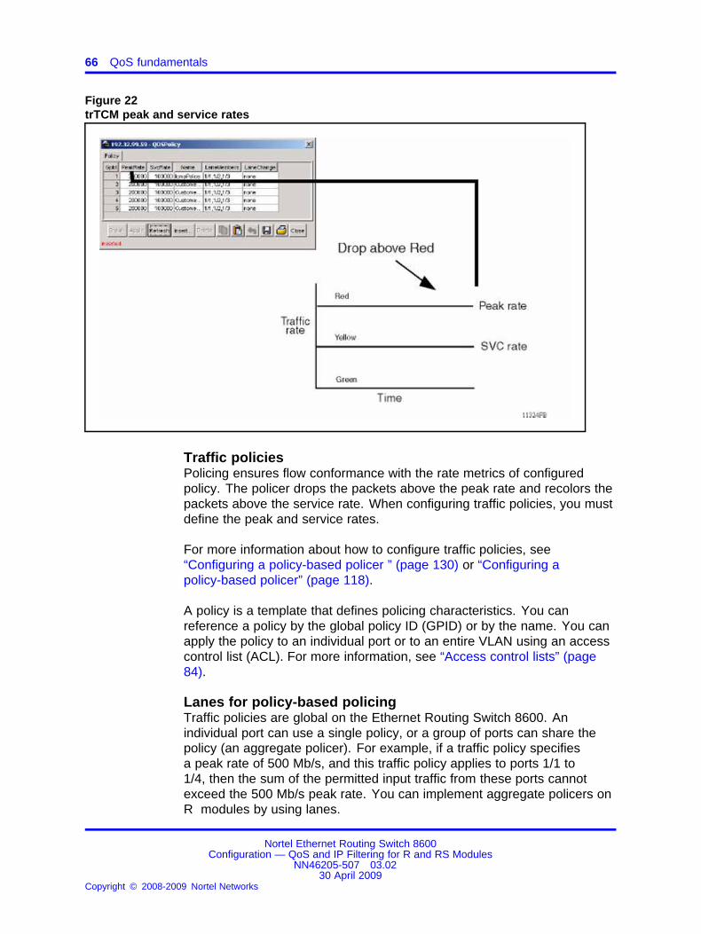
66 QoS fundamentals
Figure 22trTCM peak and service rates
Traffic policiesPolicing ensures flow conformance with the rate metrics of configuredpolicy. The policer drops the packets above the peak rate and recolors thepackets above the service rate. When configuring traffic policies, you mustdefine the peak and service rates.
For more information about how to configure traffic policies, see“Configuring a policy-based policer ” (page 130) or “Configuring apolicy-based policer” (page 118).
A policy is a template that defines policing characteristics. You canreference a policy by the global policy ID (GPID) or by the name. You canapply the policy to an individual port or to an entire VLAN using an accesscontrol list (ACL). For more information, see “Access control lists” (page84).
Lanes for policy-based policingTraffic policies are global on the Ethernet Routing Switch 8600. Anindividual port can use a single policy, or a group of ports can share thepolicy (an aggregate policer). For example, if a traffic policy specifiesa peak rate of 500 Mb/s, and this traffic policy applies to ports 1/1 to1/4, then the sum of the permitted input traffic from these ports cannotexceed the 500 Mb/s peak rate. You can implement aggregate policers onR modules by using lanes.
Nortel Ethernet Routing Switch 8600Configuration — QoS and IP Filtering for R and RS Modules
NN46205-507 03.0230 April 2009
Copyright © 2008-2009 Nortel Networks
.

Policing and shaping 67
The following figure shows three lanes on an 8630GBR module, eachconsisting of ten 1 Gb/s ports. You configure a traffic policy for one laneor multiple lanes. All members of the lane can use this policy. A policerrequires at least one configured lane to function. You must configure apolicer on a lane for a lane port to use it. You can configure up to 450policies (policers) for each lane.
Figure 238630GBR lanes
For more information about modules and lanes, see Table 2 "R seriesmodules and lanes" (page 41).
Policies and access control entriesYou must bind a policy with a filter (access control entry—ACE). The filterclassifies the packet from the input stream and applies the appropriatetraffic policy based on the flow classification criteria configured in the filter.The following figure shows the building blocks for traffic policing.
Nortel Ethernet Routing Switch 8600Configuration — QoS and IP Filtering for R and RS Modules
NN46205-507 03.0230 April 2009
Copyright © 2008-2009 Nortel Networks
.

68 QoS fundamentals
Figure 24QoS traffic policing configuration building blocks
Policy-based policing actionsThe following figure depicts policing actions. Packet coloring and dropactions depend on the peak and service rates. The policer drops packetstransmitted greater than the configured peak rate; the policer recolorspackets transmitted greater than the committed service rate.
Nortel Ethernet Routing Switch 8600Configuration — QoS and IP Filtering for R and RS Modules
NN46205-507 03.0230 April 2009
Copyright © 2008-2009 Nortel Networks
.

Policing and shaping 69
Figure 25Policing actions
Port-based traffic policingTo provide QoS functionality at the MAC layer, RS modules introduce aport-based policer. Port-based policing applies before the traffic reachesthe network processor. You can use both policy-based policers andport-based policers at the same time.
Port-based policing rate limits aggregate port traffic. For example, if thesystem includes a 10 Gb/s link, but the rest of the system cannot handle10 Gb/s traffic, you can use a port-based policer to rate limit to 5 Gb/s.The policer drops all traffic above 5 Gb/s.
Nortel Ethernet Routing Switch 8600Configuration — QoS and IP Filtering for R and RS Modules
NN46205-507 03.0230 April 2009
Copyright © 2008-2009 Nortel Networks
.

70 QoS fundamentals
Queue-based traffic shapingQueue-based shapers are sets of egress queues. Each port can haveonly one queue-based shaper. A queue-based shaper shapes all outgoingtraffic to the configured rate for that queue.
Shapers delay some or all packets in a traffic stream to bring the streaminto compliance with a traffic profile. Shaping limits the output bandwidthto meet the downstream requirement, which eliminates bottlenecks intopologies with data rate mismatches.
Shapers apply at egress after the packet traverses ingress filters orpolicers.
For egress queue sets, you can configure a minimum and a maximumrate.
Egress queue set minimum rateYou can configure a minimum rate for balanced or low-priority queues.The minimum rate is a promise to allocate that minimum bandwidthpercentage to the queue. If the output port is not congested and no morepackets to service exist in priority queues, each balanced or low-priorityqueue can use the available bandwidth up to line rate or the configuredmaximum rate. The minimum rate does not apply to high- and low-priorityqueues.
Egress queue set maximum rateYou can configure a maximum rate for queues in balanced, low-priorityand high-priority groups. The maximum rate limits the transmission of datahigher than the configured rate. Traffic that exceeds the max-rate limiteither buffers for the next time interval or is dropped if the buffer is full.
Traffic shaping statisticsEvery elementary egress queue uses two hardware counters. Thecounters are total pages and dropped pages.
Statistical precision makes it difficult to compare actual queue outputbecause statistics count pages. The first page is 144 bytes, all subsequentpages are 512 bytes. Packets of less than 144 (or 148, counting thepacket header extension) bytes appear as one page. Packets of sizesgreater than 144 bytes display a number of pages greater than the numberof frames.
A packet header extension (PHE) is used when a packet originates fromanother R or RS module (as opposed to from a Classic module).
Nortel Ethernet Routing Switch 8600Configuration — QoS and IP Filtering for R and RS Modules
NN46205-507 03.0230 April 2009
Copyright © 2008-2009 Nortel Networks
.

QoS and MPLS 71
For more information about the relationship between packet size andmemory pages used for egress queuing, see “Egress queues and pages”(page 349).
Port-based shapingThe port-based shaper rate limits the output traffic to the configured valuefor each port. By default, port-based shaping is disabled. The EthernetRouting Switch 8600 supports a minimum shaper rate of 1 Mb/s and amaximum of 10 Gb/s. The switch drops offending traffic.
Only R and RS modules support port-based shaping.
For configuration instructions, see “Configuring port-based shaping forR and RS modules” (page 118) (Device Manager), “Configuring theport-based shaper” (page 129) (CLI), and “Configuring the port-basedshaper” (page 149) (NNCLI).
Broadcast and multicast traffic bandwidth limitersR and RS modules support bandwidth limiters for ingress broadcast andmulticast traffic. The modules drop traffic that violates the bandwidth limit.
For configuration instructions, see “Configuring broadcast and multicastbandwidth limiting” (page 128) (CLI) and “Configuring broadcast andmulticast bandwidth limiting” (page 147) (NNCLI).
QoS and MPLSMPLS does not define new QoS architectures; MPLS QoS uses theDiffServ architecture defined for IP QoS.
IP DiffServ and MPLS DiffServ are similar in the following respects:
• both use classification, marking, policing, and shaping at the networkedge
• both use buffer management and packet scheduling mechanisms toimplement EF, AF, and Best-effort (BE) PHB
MPLS QoS differs from IP DiffServ because the DSCP parameter is notdirectly visible to MPLS Label Switch Routers (LSR), which forward basedon the EXP parameter. Make QoS information visible to LSRs by usingthe EXP parameter. The Ethernet Routing Switch 8600 uses ingressEXP bit to internal QoS and egress QoS to EXP bit mappings. The EXPbits map directly to the internal QoS level. Mappings take effect only onMPLS-enabled interfaces, and the switch trusts all MPLS interfaces.
Nortel Ethernet Routing Switch 8600Configuration — QoS and IP Filtering for R and RS Modules
NN46205-507 03.0230 April 2009
Copyright © 2008-2009 Nortel Networks
.

72 QoS fundamentals
The MPLS EXP bits in the label stack carry the packet QoS level betweenrouters. On ingress, the classification stage derives the PHB from the EXPparameter in the top label stack entry. On egress, the PHB maps to anEXP value. The router marks the EXP in the top label stack entry of thepacket before the packet enters a queue for transmission.
On the Ethernet Routing Switch 8600, you globally define EXP to PHBprofiles and PHB to EXP profiles (mappings) for the router.
The Ethernet Routing Switch supports setting EXP bits for both tunnel andservice labels based on either 802.1p or DSCP markings.
Only MPLS-enabled interfaces trust MPLS EXP bits . If a port on whichyou disable MPLS receives an MPLS frame to bridge, it does not trust theEXP markings. If an MPLS edge switch receives a standard IP packet togo out on an MPLS interface, the switch can mark the EXP bits. In thiscase, the internal QoS-to-EXP egress mappings configure the EXP bits ofthe packet.
For more information about MPLS, see Nortel Ethernet Routing Switch8600 Configuration — MPLS Services (NN46205-519) . You can view orconfigure EXP mappings using the CLI, NNCLI, or Device Manager.
QoS and VoIPVoice over Internet Protocol (VoIP) traffic requires low latency and jitter.To ensure the switch handles VoIP traffic appropriately, configure properQoS.
When you use the Ethernet Routing Switch 8600 as a core router, to treatVoIP traffic appropriately, configure ports as core ports (this is the defaultport setting). In this case, the switch trusts QoS markings applied to VoIPtraffic and does not re-mark QoS settings. However, if this configuration isnot sufficient, you can also apply filters, route policies, or re-mark traffic.
When you use the Ethernet Routing Switch 8600 as an edge router(access port, or untrusted), you must pay attention to how the switchmarks VoIP traffic. Because the Ethernet Routing Switch 8600 does notsupport Power over Ethernet (PoE), and the switch generally operates inthe network core, VoIP traffic is not a concern. If you use the EthernetRouting Switch 8600 as an edge device and you want to apply QoSto VoIP traffic, you can configure a specific VLAN (for example, aVoice VLAN) to apply a QoS level to VoIP traffic. In this case, Nortelrecommends that you assign the VLAN default QoS level to 6 (Premium).
Nortel Ethernet Routing Switch 8600Configuration — QoS and IP Filtering for R and RS Modules
NN46205-507 03.0230 April 2009
Copyright © 2008-2009 Nortel Networks
.

QoS and VoIP 73
For Release 5.0, the Ethernet Routing Switch 8600 supports a securitymechanism called Nortel Secure Network Access (NSNA). NSNA supportsthe use of special VoIP VLANs; for more information, see Nortel EthernetRouting Switch 8600 Security (NN46205-601) .
Nortel Ethernet Routing Switch 8600Configuration — QoS and IP Filtering for R and RS Modules
NN46205-507 03.0230 April 2009
Copyright © 2008-2009 Nortel Networks
.

74 QoS fundamentals
Nortel Ethernet Routing Switch 8600Configuration — QoS and IP Filtering for R and RS Modules
NN46205-507 03.0230 April 2009
Copyright © 2008-2009 Nortel Networks
.
75.
Traffic filtering fundamentalsTraffic filtering on the Ethernet Routing Switch 8600 is a mechanismto manage traffic by defining filtering conditions and associating theseconditions with specific actions. Filtering blocks unwanted traffic andprioritizes other traffic, which efficiently manages bandwidth and protectsyour network.
Navigation• “Overview” (page 75)
• “Traffic filters for Classic and R series modules” (page 76)
• “Deep packet pattern match filters” (page 77)
• “R series module filters and packet layer traversal” (page 77)
• “Access control templates” (page 77)
• “Access control lists” (page 84)
• “Access control entries” (page 87)
• “Port mirroring, ACLs, and ACEs” (page 92)
• “Traffic filter configuration” (page 93)
• “ACL, ACT, and ACE configuration guidelines” (page 94)
• “Nortel Secure Network Access” (page 94)
OverviewUsing traffic filters, you can reduce network congestion and control accessto network resources by blocking, forwarding, or prioritizing specified trafficon an interface.
The Ethernet Routing Switch 8600 can use traffic filtering for manypurposes. Filtering can provide security and can help ensure that alltraffic is treated according the Class of Service (COS) required by theapplication. The Ethernet Routing Switch can drop low-priority traffic undercongestion, police incoming traffic, and mark or drop nonconforming traffic.
Nortel Ethernet Routing Switch 8600Configuration — QoS and IP Filtering for R and RS Modules
NN46205-507 03.0230 April 2009
Copyright © 2008-2009 Nortel Networks
.

76 Traffic filtering fundamentals
The traffic class (internal to the switch), drop precedence, DSCP, EXP,and 802.1p bit markings define the COS. The switch supports DiffServmarking and re-marking using filters.
You need not use filters to provide QoS. Filters can override QoS packetoperations.
On R series modules, each port supports 8 or 64 hardware egressqueues, with control traffic (for example, spanning tree) assigned to thehighest priority queue. You can implement filters by using access controltemplates (ACT), access control entries (ACE), and access control lists(ACL).
Traffic filters for Classic and R series modulesThe Ethernet Routing Switch 8600 uses two traffic filteringimplementations:
• the pre-4.0 implementation that involves E and M modules (Classicmodules) to support Layer 3 and Layer 4 filtering.
• a filtering implementation that uses R series modules and ACLs tosupport ingress and egress Layer 2 through Layer 7 filtering.
Classic and R module filters can coexist in the same chassis. UseClassic commands to configure pre-4.0 filters that operate only onClassic modules, and use the 4.0 and later commands to configure filtersthat operate only on R modules. Nortel Ethernet Routing Switch 8600Configuration — QoS and IP Filtering for Classic Modules (NN46205-508)describes the Classic filtering commands, and this document describes theR module traffic filtering commands.
R module filters do not interoperate with Classic module filters. In amixed-mode chassis, Classic filters apply only to Classic modules, whileR module filters apply only to R modules. The Ethernet Routing Switch8600 software provides some configuration guidelines. For example,when you add virtual local area networks (VLAN) to an ACL, a messageindicates the filters apply only to the R module port members of that VLAN.When you add ports to an ACL, the switch ensures that the port belongsto an R module.
In R module traffic filtering, a filtering rule (an ACE) defines a pattern foundin a packet and the desired behavior for that packet. An ACL is a group ofACE filtering rules associated with a logical interface at ingress or egress.
As each packet enters an interface with an ACL, the interface scansmatching ACEs for that packet and applies the actions of those ACEsaccording to precedence.
Nortel Ethernet Routing Switch 8600Configuration — QoS and IP Filtering for R and RS Modules
NN46205-507 03.0230 April 2009
Copyright © 2008-2009 Nortel Networks
.

Access control templates 77
Filters operate in the same manner for R and RS modules. The onlydifference between R and RS module filter operations is port mirroring.See “RS modules and port mirroring” (page 93) and “R modules and portmirroring” (page 93).
Deep packet pattern match filtersThe Ethernet Routing Switch 8600 offers deep packet inspection to detectand block attacks that directly target applications and data that use thepacket payload. Using deep packet filters, the switch can identify thetraffic content and completely block, rate limit, or shape it, and can applyany filter rule to the packet. Deep packet pattern match filters rely onACL-based filters that operate based on matches of up to 80 bytes deep inthe packet. You can configure these filters at the bit level.
R series module filters and packet layer traversalThe Ethernet Routing Switch 8600 offers powerful and easy-to-use filters.R series module-based filters apply to packets regardless of the OSIlayer they traverse. Generally, the ACLs of other companies apply atrouting boundaries only; if a packet does traverse a Layer 3 boundary,the ACL does not apply. As a result, to provide filtering for each layer,other companies must either apply Layer 2 ACLs with Layer 3 ACLs, oruse private VLANs. Either option makes filter configurations crowdedand difficult to debug. Nortel R series module filters apply to the packetregardless of the Layer N operation that applies to the packet (switched orrouted).
Access control templatesAn ACT defines the selection of match fields for each ACL. R seriesmodule filters require an ACT. Before you add an ACE to an ACL, youmust first associate the ACL with an existing ACT.
Access control templates navigation
• “ACT attributes” (page 78)
• “ACT patterns for offset filtering” (page 78)
• “Predefined ACTs” (page 81)
• “ACT configuration guidelines” (page 83)
Nortel Ethernet Routing Switch 8600Configuration — QoS and IP Filtering for R and RS Modules
NN46205-507 03.0230 April 2009
Copyright © 2008-2009 Nortel Networks
.

78 Traffic filtering fundamentals
ACT attributesAn ACT defines a set of match fields, or attributes, for an ACL. TheEthernet Routing Switch 8600 supports the following attributes:
• ARP operation—If the packet is an ARP packet, this attribute matchesthe ARP operation (ARP request or ARP response). The supportedoperators for this attribute are none or operation.
• Ethernet—Specifies one of the following Ethernet attributes: none,source MAC, destination MAC, etherType, port, VLAN, or VLAN TagPriority.
• IP—Specifies one or more of the following IP attributes: none, sourceIP, destination IP, IP fragmentation flag, IP options, IP protocol type, orDSCP.
• IPv6—Specifies one or more of the following IPv6 attributes: none,source IPv6, destination IPv6, or nextHdr.
• Protocol—Specifies one or more of the following protocol attributes:none, TCP source port, UDP source port, TCP destination port, UDPdestination port, TCP flags, or ICMP message type.
ACT patterns for offset filteringAn ACT can contain pattern parameters used for offset filtering. To use anACT pattern, select the base; this specifies where to start the offset filter.Then select, in bits, the offset bit position and the offset length.
You can configure up to three ACT pattern attributes for each ACL. If yourequire more than three ACT pattern attributes, combine a port and aVLAN ACL type to support up to six ACT pattern attributes.
Although the pattern length for one ACT pattern can be up to 56 bits,combine two or three ACT patterns to filter a pattern length of greater than56 bits. For example, you can combine two ACT patterns to filter a patternof up to 112 bits in length.
The following table shows the available pattern options.
Table 12ACT pattern options
Field Description
Base A user-defined header for the ACEs of the ACL.
Item Description
etherBegin Beginning of the Ethernet packet.
macDstBegin Beginning of the MAC destination field in theEthernet packet header.
Nortel Ethernet Routing Switch 8600Configuration — QoS and IP Filtering for R and RS Modules
NN46205-507 03.0230 April 2009
Copyright © 2008-2009 Nortel Networks
.

Access control templates 79
Table 12ACT pattern options (cont’d.)
Field Description
macSrcBegin Beginning of the source MAC field in theEthernet packet header.
ethTypeLenBegin Beginning of the type and length field in theEthernet packet header.
arpBegin Beginning of the hardware address type fieldin the ARP packet.
ipHdrBegin Beginning of the IP packet header (versionfield).
ipOptionsBegin Beginning of the IP options field in the IPheader. This item is normally after the IPdestination address. If the packet does notinclude IP options (the header length isequal to 5), the filter does not apply. Thefilter applies only if the header length isgreater than 5.
ipPayloadBegin Located after the IP destination address. Ifthe packet includes IP options, it is after theIP options field, plus padding.
ipTosBegin Beginning of the TOS byte in the IP header.
ipProtoBegin Beginning of the IP type in the IP header(starting with the ninth byte).
ipSrcBegin Beginning of the source IP field in the IPheader.
ipDstBegin Beginning of the destination IP field in the IPheader.
tcpBegin Beginning of the TCP packet.
tcpSrcportBegin Beginning of the source port field in the TCPheader.
tcpDstportBegin Beginning of the destination port field in theTCP header.
tcpFlagsEnd End of the TCP flags field in the TCP header(beginning of the window field).
udpBegin Beginning of the UDP packet.
udpSrcportBegin Beginning of the source port field in the UDPheader.
udpDstportBegin Beginning of the destination port field in theUDP header.
etherEnd End of Ethernet header.
Nortel Ethernet Routing Switch 8600Configuration — QoS and IP Filtering for R and RS Modules
NN46205-507 03.0230 April 2009
Copyright © 2008-2009 Nortel Networks
.
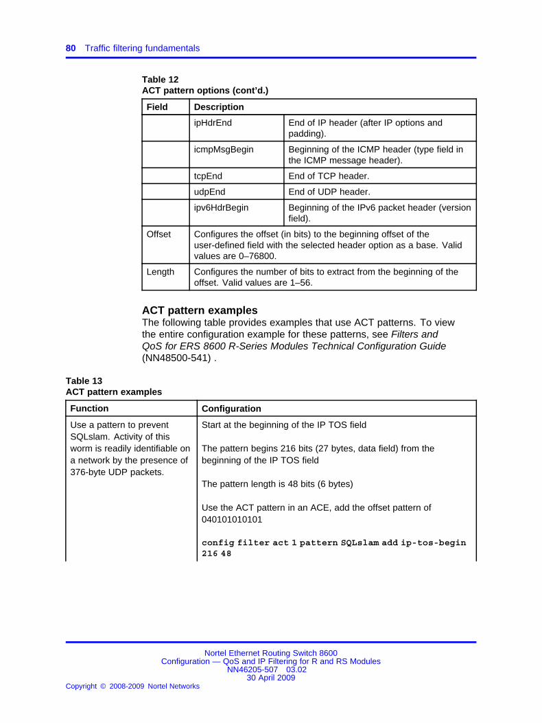
80 Traffic filtering fundamentals
Table 12ACT pattern options (cont’d.)
Field Description
ipHdrEnd End of IP header (after IP options andpadding).
icmpMsgBegin Beginning of the ICMP header (type field inthe ICMP message header).
tcpEnd End of TCP header.
udpEnd End of UDP header.
ipv6HdrBegin Beginning of the IPv6 packet header (versionfield).
Offset Configures the offset (in bits) to the beginning offset of theuser-defined field with the selected header option as a base. Validvalues are 0–76800.
Length Configures the number of bits to extract from the beginning of theoffset. Valid values are 1–56.
ACT pattern examplesThe following table provides examples that use ACT patterns. To viewthe entire configuration example for these patterns, see Filters andQoS for ERS 8600 R-Series Modules Technical Configuration Guide(NN48500-541) .
Table 13ACT pattern examples
Function Configuration
Use a pattern to preventSQLslam. Activity of thisworm is readily identifiable ona network by the presence of376-byte UDP packets.
Start at the beginning of the IP TOS field
The pattern begins 216 bits (27 bytes, data field) from thebeginning of the IP TOS field
The pattern length is 48 bits (6 bytes)
Use the ACT pattern in an ACE, add the offset pattern of040101010101
config filter act 1 pattern SQLslam add ip-tos-begin216 48
Nortel Ethernet Routing Switch 8600Configuration — QoS and IP Filtering for R and RS Modules
NN46205-507 03.0230 April 2009
Copyright © 2008-2009 Nortel Networks
.

Access control templates 81
Function Configuration
config filter acl 4 ace 1 advanced custom-filter1SQLslam eq 040101010101
Use a pattern to preventNachia attacks.
Start at the beginning of the IP TOS field
The pattern begins 224 bits (28 bytes) from the beginning of theIP TOS field
The pattern length is 24 bits (3 bytes)
Use the ACT pattern in an ACE, add the offset pattern of aaaaaa
config filter act 1 pattern Nachia add ip-tos-begin224 24
config filter acl 4 ace 2 advanced custom-filter2Nachia eq aaaaaa
Predefined ACTsYou can configure custom ACTs or you can choose from a list ofpredefined ACTs. The following figure shows the Ethernet Routing Switch8600 predefined ACTs viewed with Device Manager. The informationshown includes the ARP, Ethernet, Protocol, IPv6, and IP attributesassociated with each ACT.
Figure 26Predefined ACT list
Nortel Ethernet Routing Switch 8600Configuration — QoS and IP Filtering for R and RS Modules
NN46205-507 03.0230 April 2009
Copyright © 2008-2009 Nortel Networks
.

82 Traffic filtering fundamentals
Use a predefined ACT whenever possible. You can create your ownACTs; however, ensure that you include the minimum required parameterson which to filter. The more attributes on which you choose to filter, thelonger it takes the Ethernet Routing Switch 8600 to process incoming data.
The following table describes the action of each predefined ACT.
Table 14Predefined ACT actions
ACT ID ACT name Description
4081 NSNA Default ACT Filters on etherType, vlan, DestIp, IpProtoType,tcpDstPort, and udpDestPort. Used with NortelSecure Network Access.
4082 IP Media filters ACT Filters on Protocol attributes tcpSrcPort, udpSrcPort,tcpDstPort, and udpDstPort.
4083 Arp-Spoof_Layer_2 ACT Filters on packets with ARP information, and on theEthernet attribute dstMac. PreventsARP spoofing.
4084 Mac Src/Dst & ARP ACT Filters on packets with ARP information, and on theEthernet attributes dstMac and srcMac.
4085 Mac Src/Dst & IP ACT Filters on the Ethernet attributes dstMac andsrcMac, and on the IP attributes dstIp and ScrIp.
4086 IP Options ACT Filters on the IP attributes srcIp, dstIp, andipOptions.
4087 IP Fragmentation ACT Filters on the IP attributes srcIp, dstIp, andipFragFlag.
4088 DSCP ACT Filters on the IP attributes srcIp, dstIp, and dscp.
4089 UDP ACT Filters on the IP attributes srcIp, dstIp; and on theProtocol attributes udpSrcPort, udpDstPort.
4090 TCP ACT Filters on the IP attributes srcIp, dstIp; and on theProtocol attributes tcpSrcPort, tcpDstPort, tcpFlags.
4091 IP Sa/Da, Protocol ACT Filters on the IP attributes srcIp, dstIp, andipProtoType.
4092 IP Sa and Da ACT Filters on the IP attributes srcIp, and dstIp.
4093 Arp ACT Filters on packets with ARP information.
4094 Mac Src-Dst,Ether ACT Filters on packets with Ethernet attributes srcMac,dstMac, and etherType.
Nortel Ethernet Routing Switch 8600Configuration — QoS and IP Filtering for R and RS Modules
NN46205-507 03.0230 April 2009
Copyright © 2008-2009 Nortel Networks
.

Access control templates 83
Table 14Predefined ACT actions (cont’d.)
ACT ID ACT name Description
4095 Mac Src-Dst,Ether,Dot1pACT
Filters on packets with Ethernet attributes srcMac,dstMac, etherType, and vlanTagPrio.
4096 IP Ping-Snoop ACT Filters on the IP attributes: srcIp, dstIp and theprotocol attribute icmpMsgType. Used with the PingSnoop feature. For more information about PingSnoop, see Nortel Ethernet Routing Switch 8600Troubleshooting (NN46205-703) .
ACT configuration guidelinesACTs define the attributes and pattern information used in the ACEs of anACL. One or more ACLs can use an ACT. After you create the ACL usingan ACT, you cannot modify the ACT.
When you configure a new ACT, choose only the attributes you plan to usewhen you configure the ACEs. For each additional attribute you includein an ACT, the switch must perform an additional lookup. To enhanceperformance, keep the number of ACT attributes as small as possible. Forexample, if you plan to filter on source and destination IP addresses andDSCP, select only these IP attributes. The number of ACEs within an ACLdoes not affect performance.
The following list describes ACT guidelines:
• For pattern matching filters, the switch supports three patterns for eachACT.
• After you configure the ACT, you must activate it (Apply = true). Afteryou activate the ACT, you cannot modify it; you can only delete it.
• You can delete an ACT only when no ACLs use that ACT.
• The switch supports 4000 ACTs and 4000 ACLs.
• The switch reserves ACT and ACL IDs 4001 to 4096 forsystem-defined ACTs and ACLs. You can use these ACTs and ACLs,but you cannot modify them.
An ACT with an IPv6 attribute has a single ACL of type IPv6.
An ACT with only Ethernet attributes can include up to two ACLs. You canhave only one IPv4 and one IPv6 ACL.
Nortel Ethernet Routing Switch 8600Configuration — QoS and IP Filtering for R and RS Modules
NN46205-507 03.0230 April 2009
Copyright © 2008-2009 Nortel Networks
.

84 Traffic filtering fundamentals
Access control listsThe Ethernet Routing Switch 8600 R series modules use ACLs for filtering.An ACL comprises an ordered list of ACEs (filter rules). The ACEs providespecific actions, such as dropping packets within a specified IP range, ora specific UDP port or port range. For more details, see “Access controlentries” (page 87). When an ingress or egress packet meets the matchcriteria specified in one or more ACEs within an ACL, the correspondingaction occurs.
An ACL can contain multiple ACEs, which the ACL uses to control multipleflows. A packet can match attributes in more than one ACE. The actionsthat apply to the packet are the nonconflicting actions of the matchingACEs. The ACE priority resolves which action, among conflicting actions,applies.
The default action applies when no ACEs match a packet, while globalactions apply to all ACEs that match a packet. The default action is permit,and the default global action is none (no action). You can modify thedefault and global actions at any time.
ACL global actions include
• none
• mirror
• count
• mirror-count
• ipfix
• mirror-ipfix
• count-ipfix
• mirror-count-ipfix
In addition to the system-defined attributes, you can choose up to threepatterns to match against. You can match anywhere in the packet on theingress side, and anywhere within the first 144 bytes on the egress side.You can combine the three patterns, up to 7 bytes each, to form a 21-bytepattern match.
Four types of ACLs exist:
• Ingress port (inPort)
• Ingress VLAN (inVLAN)
When you use type inVlan, ports that you define under the ACL applythe filter to ingress packets on those ports.
Nortel Ethernet Routing Switch 8600Configuration — QoS and IP Filtering for R and RS Modules
NN46205-507 03.0230 April 2009
Copyright © 2008-2009 Nortel Networks
.

Access control lists 85
• Egress port (outPort)
• Egress VLAN (outVLAN)
When you use type outVlan, ports that you define under the ACL applythe filter to egress packets on those ports.
The ingress and egress VLAN ACLs apply to all the active port membersof that VLAN. By default, you create an ACL in the enabled state.
The Ethernet Routing Switch 8600 supports both port-based andVLAN-based ACLs. Depending on the configuration, you can apply theactions of both ACLs to a packet. In such cases, the port-based ACLactions have priority and apply first.
The Ethernet Routing Switch 8600 supports two default (or predefined)ACLs: the IP Media Filters ACL and the IP Ping-Snoop ACL. Theseoperate with ACTs of the same name.
The following figure shows the relationships between ACTs, ACEs, andACLs.
Figure 27ACT, ACE, and ACL relationships
Nortel Ethernet Routing Switch 8600Configuration — QoS and IP Filtering for R and RS Modules
NN46205-507 03.0230 April 2009
Copyright © 2008-2009 Nortel Networks
.

86 Traffic filtering fundamentals
ACL priorityYou can configure both port-based ACLs and VLAN-based ACLs. Nortelrecommends that you apply only one type of ACL to a packet; however,sometimes the actions of both port-based and VLAN-based ACLs mustapply to a packet. In this case, apply the port-based ACL actions first.Apply VLAN-based ACL actions only if the mode (permit or deny) is thesame as for the port-based ACL and if the VLAN-based ACL ACE actionsdo not overlap with the port-based ACL actions.
ACL priority examplesThe following examples demonstrate the resulting action based on theconfigured mode and actions:
Example 1
Port and VLAN-based ACL configuration:
• Port-based ACL—mode permit, any action
• VLAN-based ACL—mode deny, any action
The actions of the port-based ACL apply.
Example 2
Port and VLAN-based ACL configuration:
• Port-based ACL
ACE 1: mode permit, action police
• VLAN-based ACL
ACE 1: mode permit, action police
ACE 2: mode permit, action remark-dscp
The actions of the port-based ACL and the actions of ACE 2 of theVLAN-based ACL apply.
Example 3
Port and VLAN-based ACL configuration:
• Port-based ACL
ACE 1: mode permit, action police
• VLAN-based ACL
ACE 1: mode permit, actions police, remark-dscp
Nortel Ethernet Routing Switch 8600Configuration — QoS and IP Filtering for R and RS Modules
NN46205-507 03.0230 April 2009
Copyright © 2008-2009 Nortel Networks
.
Access control entries 87
The actions of the port-based ACL apply.
Access control entriesAccess control entries (ACE) provide the match criteria and rules forACL-based filters.
Access control entries navigation
• “ACE overview” (page 87)
• “ACE actions” (page 88)
• “ACE priority” (page 88)
• “Common ACE uses and configurations” (page 89)
• “Example: ACE TCP Established flag filter” (page 91)
ACE overviewAn ACE is one filter rule that makes up an ACL. A filter rule is a statementthat defines a pattern (found in a packet) and the desired behavior forpackets that carry the pattern. When the packets match an ACE rule, thespecified action occurs.
An ACE affects matching packets on all interfaces associated with thecontained ACL. As each packet enters an interface with an associatedACL, the interface scans the list for a pattern that matches the incomingpacket. A behavior rule associated with the pattern determines packettreatment.
If multiple ACEs in an ACL match a packet, you can choose a preferredACE by assigning precedence to the rule. The switch determinesprecedence by the ACE ID: the lower the ID number, the higher theprecedence. Behavior for a packet that meets the criteria specified bymore than one rule is derived from the highest precedence rule to ensuredeterministic behavior.
If you do not specify a value for an ACT attribute in the ACE, that attributevalue is treated as a wildcard. You can configure a maximum of 1000ACEs for each port for ingress and egress. The system supports amaximum of 10 000 ACEs.
When you disable the ACL, the ACL state affects the administrative stateof all ACEs within it.
Ethernet Routing Switch 8600 R modules limit the memory for statisticscounters. The system supports up to 1000 counters for ingress (dependingon the overlapping attribute values) and an equal number for egress.
Nortel Ethernet Routing Switch 8600Configuration — QoS and IP Filtering for R and RS Modules
NN46205-507 03.0230 April 2009
Copyright © 2008-2009 Nortel Networks
.

88 Traffic filtering fundamentals
ACE actionsYou must specify actions for ACEs. The following table shows a sample ofACL and ACE parameters and valid ingress and egress actions.
Table 15Ingress and egress ACL and ACE parameters
Ingress (port or VLAN-based)
Match criteria
MAC, p-bits, VLANtag, ARP, IP, DSCP,TCP, and UDP
Match pattern
base, offset, andlength
Action
Permit, deny, redirect to next hop,redirect to next hop IPv6, redirectto MLT index, remark 802.1p,remark DSCP, police, send toeqress queue
Egress (port or VLAN-based)
Match criteria
MAC, p-bits, VLANtag, ARP, IP, DSCP,TCP, and UDP
Match pattern
base, offset, andlength
Action
permit and deny
Priority
Based on ID (port-based ACL before VLAN-based ACL)
If a packet matches multiple ACEs, the Ethernet Routing Switch 8600applies the noncontradicting actions of all ACEs according to precedence(ACE ID). If you specify a stop-on-match flag, the switch stops at that ACE.
If the switch redirects a packet, it does not perform regular packetprocessing for the packet. The mirroring configuration, policerconfiguration, and egress queue ID configuration must occur outside thecontext of filtering.
ACE priorityIf a packet matches multiple ACEs in an ACL, the actions of the highestpriority ACE apply. The actions of the remaining ACEs apply only if themode is the same as the highest priority ACE, and if the actions do notoverlap with the highest priority ACE.
ACE priority examplesThe following examples demonstrate the action taken based on theconfigured mode and actions:
Example 1 ACE 1 and 2 configuration:
• ACE 1—mode permit, actions police
• ACE 2—mode deny, actions mirror
Nortel Ethernet Routing Switch 8600Configuration — QoS and IP Filtering for R and RS Modules
NN46205-507 03.0230 April 2009
Copyright © 2008-2009 Nortel Networks
.
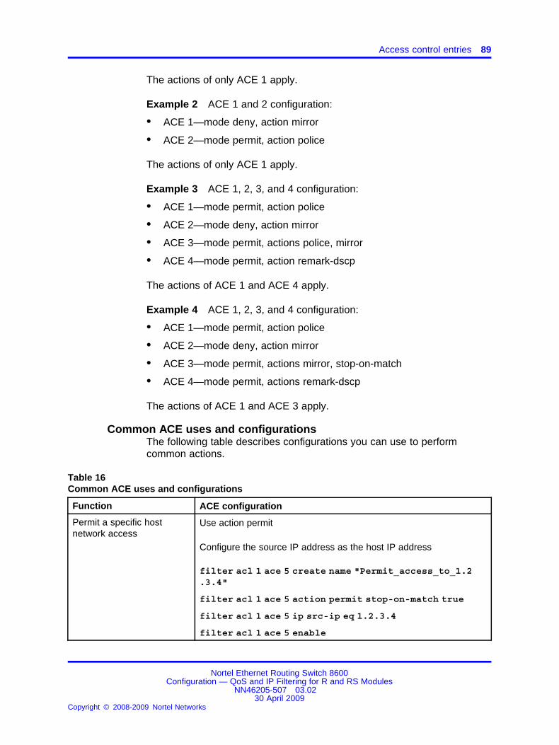
Access control entries 89
The actions of only ACE 1 apply.
Example 2 ACE 1 and 2 configuration:
• ACE 1—mode deny, action mirror
• ACE 2—mode permit, action police
The actions of only ACE 1 apply.
Example 3 ACE 1, 2, 3, and 4 configuration:
• ACE 1—mode permit, action police
• ACE 2—mode deny, action mirror
• ACE 3—mode permit, actions police, mirror
• ACE 4—mode permit, action remark-dscp
The actions of ACE 1 and ACE 4 apply.
Example 4 ACE 1, 2, 3, and 4 configuration:
• ACE 1—mode permit, action police
• ACE 2—mode deny, action mirror
• ACE 3—mode permit, actions mirror, stop-on-match
• ACE 4—mode permit, actions remark-dscp
The actions of ACE 1 and ACE 3 apply.
Common ACE uses and configurationsThe following table describes configurations you can use to performcommon actions.
Table 16Common ACE uses and configurations
Function ACE configuration
Permit a specific hostnetwork access
Use action permit
Configure the source IP address as the host IP address
filter acl 1 ace 5 create name "Permit_access_to_1.2.3.4"
filter acl 1 ace 5 action permit stop-on-match true
filter acl 1 ace 5 ip src-ip eq 1.2.3.4
filter acl 1 ace 5 enable
Nortel Ethernet Routing Switch 8600Configuration — QoS and IP Filtering for R and RS Modules
NN46205-507 03.0230 April 2009
Copyright © 2008-2009 Nortel Networks
.

90 Traffic filtering fundamentals
Table 16Common ACE uses and configurations (cont’d.)
Function ACE configuration
Deny a specific hostnetwork access
Use action deny
Configure the source IP address as the host IP address
filter acl 1 ace 5 create name "Deny_access_to_1.2.3.4"
filter acl 1 ace 5 action deny stop-on-match true
filter acl 1 ace 5 ip src-ip eq 1.2.3.4
filter acl 1 ace 5 enable
Permit a specific range ofhosts network access
• use action permit
• configure the source IP address as the range of host IPaddresses
filter acl 1 ace 5 create name "Permit_access_to_1.2.3.4-5.6.7.8"
filter acl 1 ace 5 action permit stop-on-match true
filter acl 1 ace 5 ip src-ip eq 1.2.3.4-5.6.7.8
filter acl 1 ace 5 enable
Deny Telnet traffic Use action deny
Configure the protocol as TCP and the TCP destination port as 23
filter acl 1 ace 5 create name "Deny_telnet"
filter acl 1 ace 5 action deny stop-on-match true
filter acl 1 ace 5 ip ip-protocol-type eq tcp
filter acl 1 ace 5 protocol tcp-dst-port eq 23
filter acl 1 ace 5 enable
Allow only internal networksto initiate a TCP session
Use the Established filter. See “Example: ACE TCP Established flagfilter” (page 91).
Deny FTP traffic Use action deny
Configure the protocol as TCP and the TCP destination port as 21
filter acl 1 ace 5 create name "Deny_ftp"
filter acl 1 ace 5 action deny stop-on-match true
filter acl 1 ace 5 ip ip-protocol-type eq tcp
Nortel Ethernet Routing Switch 8600Configuration — QoS and IP Filtering for R and RS Modules
NN46205-507 03.0230 April 2009
Copyright © 2008-2009 Nortel Networks
.

Access control entries 91
Table 16Common ACE uses and configurations (cont’d.)
Function ACE configuration
filter acl 1 ace 5 protocol tcp-dst-port eq 21
filter acl 1 ace 5 enable
Example: ACE TCP Established flag filterThe following ACE filter matches for the Established flag of TCP packets.This filter matches traffic after a TCP three-way handshake is complete.This usually occurs in the context of traffic between the Internet andservers.
The following Established flag filter matches and permits any packetwith a protocol type of TCP and looks for the TCP flags Reset (RST) orAcknowledgement (ACK).
Example 1:
filter acl 1 ace 5 create name "ESTABLISHED"filter acl 1 ace 5 action permit stop-on-match truefilter acl 1 ace 5 ip src-ip eq 1.6.172.0-1.6.172.255filter acl 1 ace 5 ip ip-protocol-type eq tcpfilter acl 1 ace 5 protocol tcp-dst-port ge 1023filter acl 1 ace 5 protocol tcp-flags match-any rst,ackfilter acl 1 ace 5 enable
Because most IP traffic uses port numbers less than 1023, any packetwith a destination port less than 1023, or with an unset ACK or RST bit,is denied. Therefore, when a host attempts to initiate a TCP connectionby sending the first TCP packet (without SYN or RST bit set) for a portnumber less than 1023, it is denied; the TCP session fails. The switchpermits any internally initiated TCP sessions because they have ACK orRST bits set for returning packets, and they use port numbers greater than1023.
Example 2:
filter acl 100 ace 10 create name "10_50_all_established"filter acl 100 ace 10 action permit stop-on-match truefilter acl 100 ace 10 debug count enablefilter acl 100 ace 10 ip dst-ip eq 10.50.0.0-10.50.255.255filter acl 100 ace 10 ip ip-protocol-type eq tcp,icmpfilter acl 100 ace 10 protocol tcp-src-port eq 21-22,80,443,3389filter acl 100 ace 10 protocol tcp-flags match-any rst,ackfilter acl 100 ace 10 enable
Nortel Ethernet Routing Switch 8600Configuration — QoS and IP Filtering for R and RS Modules
NN46205-507 03.0230 April 2009
Copyright © 2008-2009 Nortel Networks
.

92 Traffic filtering fundamentals
Port mirroring, ACLs, and ACEsUse port mirroring to monitor and analyze network traffic. Port mirroringsupports both ingress (incoming traffic) and egress (outgoing traffic) portmirroring. When you enable mirroring, the switch forwards the mirrored(source) port ingress or egress packets normally, and sends a copy of thepackets from the mirrored port to the mirroring (destination) port. You canobserve and analyze packet traffic at the mirroring port by using a networkanalyzer.
You can configure two mirroring functions: ACL and ACE-based mirroring,and individual port diagnostic mirroring, for which you need not configurefilters.
For R series modules, configure an ACL or an ACE to perform themirroring operation. To do so, you can configure the ACL global action tomirror, or you can configure the ACE debug action to mirror. If you use theglobal action, mirroring applies to all ACEs that match in an ACL.
You can use filters to reduce the amount of mirrored traffic. Apply anACL to the mirrored port in the egress, ingress, or both directions. Filtersforward traffic patterns that match the ACL or ACE with an action ofpermit to the destination and to the mirroring port. Filters do not forwardtraffic patterns that match an ACE with an action of drop (deny) to thedestination, but traffic still reaches the mirroring port. If you enable a portor VLAN filter, that filter is the mirroring filter.
You can specify more than one mirroring destination by using multipleACEs. Use each ACE to specify a different destination. The following tableidentifies the procedures to use to configure port mirroring.
Table 17Port mirroring procedures
For information about See
Configuring port mirroringusing Device Manager
“Configuring an access control list” (page165) and “Configuring ACEs” (page 196)
Configuring port mirroringusing the CLI
“Configuring global and default actions for anACL” (page 178) and “Configuring ACE debugactions” (page 246)
Configuring port mirroringusing the NNCLI
“Configuring global and default actions for anACL” (page 190) and “Configuring ACE debugactions” (page 267)
Configuration examples “Mirroring using ACLs” (page 287)
Port mirroring anddiagnostics
Nortel Ethernet Routing Switch 8600Troubleshooting (NN46205-704)
Nortel Ethernet Routing Switch 8600Configuration — QoS and IP Filtering for R and RS Modules
NN46205-507 03.0230 April 2009
Copyright © 2008-2009 Nortel Networks
.

Traffic filter configuration 93
R modules and port mirroringR modules support two port mirroring modes: receive (Rx) (ingress, thatis, inPort and inVLAN) and transmit (Tx) (egress, that is, outPort andoutVLAN).
In Rx mode, when you configure the ACE Debug or ACL Global options tomirror, use the ACE to configure the mirroring destination port.
In Tx mode, when you configure the ACE Debug or ACL Global optionsto mirror, use the Diagnostics parameter to configure the mirroringdestination. For example, in Device Manager, choose Edit, Diagnostics,Port Mirrors tab to select the destination ports.
RS modules and port mirroringRS modules offer enhanced port mirroring. Using RS modules, you canspecify a destination multilink trunking (MLT) group, a destination port orset of ports, or a destination VLAN.
RS modules support rxFilter and txFilter modes, but operate different fromR modules. As you do for R modules, you select the mode by configuringthe inPort, outPort, inVLAN, and outVLAN ACL parameters. You canglobally configure the mirroring action in an ACL, or for a specific ACEby using the ACE Debug actions. However, regardless of the ingress oregress mode, you configure the mirroring destination by using an ACE.
For more information about port mirroring, see Nortel Ethernet RoutingSwitch 8600 Troubleshooting (NN46205-703) .
Traffic filter configurationTraffic filtering is a mechanism that manages traffic by defining filteringconditions and associating these conditions with specific actions. Within aDiffServ network, use IP filtering to reassign QoS levels based on a rangeof filtering conditions.
The following steps summarize the filter configuration process:
1. Determine your desired match fields.
2. Use a predefined ACT that includes your desired match fields;otherwise, configure an ACT with your desired match fields.
3. Configure an ACL and associate it with the ACT.
4. Configure an ACE within the ACL.
5. Configure the desired precedence, traffic type, and action.
You determine the traffic type when you create either an ingress oregress ACL.
6. Modify the fields for the ACE.
Nortel Ethernet Routing Switch 8600Configuration — QoS and IP Filtering for R and RS Modules
NN46205-507 03.0230 April 2009
Copyright © 2008-2009 Nortel Networks
.

94 Traffic filtering fundamentals
ACL, ACT, and ACE configuration guidelinesACEs of type inVlan with an ACT that includes srcIp and with an ACLdefault action of deny require additional configuration to function properly.See “Workaround for inVlan, srcIp ACL” (page 351).
Alternatively, Nortel recommends that you create ACLs with a defaultaction of permit and with an ACE mode of deny. For deny and permitACLs or ACEs, the default action and the mode must be opposite for theACE (filter) to have meaning.
When you configure R series module filters, keep the following scalinglimits in mind.
Table 18ACT, ACE, ACL scaling
Parameter Maximum number
ACLs for each switch 4000
ACEs for each switch 4000
ACEs for each ACL 500
ACEs for each port 2000• 500 inPort
• 500 inVLAN
• 500 outPort
• 500 outVLAN
Nortel Secure Network AccessNortel Secure Network Access (NSNA) is a Nortel network access controlsolution where the edge devices (for example, the Ethernet Routing Switch8600) work in coordination with access controllers and policy servers toenforce security policy compliance on all endpoints (for example, PCs,laptops, IP phones) that access network computing resources. NSNAprovides network access only to compliant and trusted endpoint devicesand can restrict the access of noncompliant devices.
NSNA uses filters to restrict access. Nortel defines a preconfigured ACT,called NSNA Default ACT, for this purpose. For more information aboutfilters and NSNA, see Nortel Ethernet Routing Switch 8600 Security(NN46205-601) .
Nortel Ethernet Routing Switch 8600Configuration — QoS and IP Filtering for R and RS Modules
NN46205-507 03.0230 April 2009
Copyright © 2008-2009 Nortel Networks
.

95.
QoS and IP filter configurationConfigure Quality of Service (QoS) and IP filters to set up your network toprioritize specific types of traffic to ensure traffic receives the appropriateQoS level and to manage traffic by defining filtering conditions andassociating these conditions with specific actions.
QoS and IP filter configuration tasksThis work flow shows you the sequence of tasks you perform to configureQoS and IP filters on the Nortel Ethernet Routing Switch 8600. To link to atask, go to “QoS and IP filter configuration navigation” (page 96).
Nortel Ethernet Routing Switch 8600Configuration — QoS and IP Filtering for R and RS Modules
NN46205-507 03.0230 April 2009
Copyright © 2008-2009 Nortel Networks
.

96 QoS and IP filter configuration
Figure 28QoS and IP filter configuration tasks
QoS and IP filter configuration navigation• “Basic DiffServ configuration using Device Manager” (page 99)
• “Basic DiffServ configuration using the CLI” (page 103)
• “Basic DiffServ configuration using the NNCLI” (page 109)
• “QoS configuration using Device Manager” (page 117)
• “QoS configuration using the CLI” (page 125)
• “QoS configuration using the NNCLI” (page 145)
Nortel Ethernet Routing Switch 8600Configuration — QoS and IP Filtering for R and RS Modules
NN46205-507 03.0230 April 2009
Copyright © 2008-2009 Nortel Networks
.
QoS and IP filter configuration navigation 97
• “Traffic filter configuration using Device Manager” (page 161)
• “Traffic filter configuration using the CLI” (page 169)
• “Traffic filter configuration using the NNCLI” (page 183)
• “Access control entry configuration using Device Manager” (page 195)
• “Access control entry configuration using the CLI” (page 239)
• “Access control entry configuration using the NNCLI” (page 261)
Nortel Ethernet Routing Switch 8600Configuration — QoS and IP Filtering for R and RS Modules
NN46205-507 03.0230 April 2009
Copyright © 2008-2009 Nortel Networks
.

98 QoS and IP filter configuration
Nortel Ethernet Routing Switch 8600Configuration — QoS and IP Filtering for R and RS Modules
NN46205-507 03.0230 April 2009
Copyright © 2008-2009 Nortel Networks
.

99.
Basic DiffServ configuration usingDevice Manager
Use DiffServ to implement classification and mapping functions at thenetwork boundary or access points to regulate packet behavior. WithR series modules, you can configure a port as a trusted (core) or anuntrusted (access) port at both Layer 2 and Layer 3.
Basic DiffServ configuration navigation• “Enabling DiffServ for a port” (page 99)
• “Configuring Layer 3 trusted or untrusted ports” (page 100)
• “Configuring Layer 2 trusted or untrusted ports” (page 101)
• “Configuring the port QoS level” (page 101)
• “Configuring the VLAN QoS level” (page 101)
Enabling DiffServ for a portEnable DiffServ so that the switch provides DiffServ-based Quality ofService (QoS) on that port.
Procedure steps
Step Action
1 In Device Manager, choose QOS, Port QoS Config.
2 In the DiffServ column, double-click a row.
A list appears.
3 Select true.
4 Click Apply.
Nortel Ethernet Routing Switch 8600Configuration — QoS and IP Filtering for R and RS Modules
NN46205-507 03.0230 April 2009
Copyright © 2008-2009 Nortel Networks
.

100 Basic DiffServ configuration using Device Manager
You can also enable DiffServ on the Interface tab. Select a port,and click Edit, Port, General - GlobalRouter (vrf 0). ConfigureDiffServ to true.
--End--
Variable definitionsUse the data in the following table to help you configure QoS on a port.
Variable Value
Index Specifies an index value that uniquely identifies aport.
DiffServ Specifies whether DiffServ is enabled (true) ordisabled (false) on the port. The default is false.
Layer3Trust Configures the Layer 3 trusted port as an access orcore port. The default is core.
Layer2 Override 802.1p Specifies whether Layer 2 802.1p override isenabled (true) or disabled (false) on the port. Thedefault is false.
QosLevel Specifies the QoS level to use when the systemprocesses packets carried on this port. Valuesrange from level 0–6 (7 is reserved for networkcontrol traffic). The default is 1.
Configuring Layer 3 trusted or untrusted portsConfigure a port as trusted or untrusted to determine the Layer 3 QoSactions the switch performs. A trusted port honors incoming DSCPmarkings. An untrusted port overrides DSCP markings.
Procedure steps
Step Action
1 In Device Manager, choose QOS, Port QoS Config.
2 In the Layer3Trust column, double-click a row.
A list appears.
3 Select core (trusted) or access (untrusted) as the port setting.
4 Click Apply.
You can also configure Layer3Trust on the Interface tab. Selecta port, and click Edit, Port, General - GlobalRouter (vrf 0).
--End--
Nortel Ethernet Routing Switch 8600Configuration — QoS and IP Filtering for R and RS Modules
NN46205-507 03.0230 April 2009
Copyright © 2008-2009 Nortel Networks
.

Configuring the VLAN QoS level 101
Configuring Layer 2 trusted or untrusted portsConfigure a port as trusted or untrusted to determine the Layer 2 QoSactions the switch performs. A trusted port (override false) honorsincoming 802.1p bit markings. An untrusted port (override true) overrides802.1p bit markings.
Procedure steps
Step Action
1 In Device Manager, choose QOS, Port QoS Config.
2 In the Layer2 Override 8021p column, double-click a row.
A list appears.
3 To configure the port as a Layer 2 untrusted port, select true. Toconfigure it as a Layer 2 trusted port, select false.
By default, all ports are Layer 2 trusted (Layer2 Override 8021pis false).
4 Click Apply.
--End--
Configuring the port QoS levelUse the default port QoS level to assign a default QoS level for all traffic(providing the packet does not match an ACL to re-mark the packet).
Procedure steps
Step Action
1 In Device Manager, choose QOS, Port QoS Config.
2 Double-click a row in the QosLevel column, and select the newlevel.
3 Click Apply.
You can also configure the port QoS level on the Interface tab.Select a port, and click Edit, Port, General - GlobalRouter (vrf 0).Configure the QosLevel as required.
--End--
Configuring the VLAN QoS levelUse the default VLAN QoS level to assign a default QoS level for all traffic(providing the packet does not match an ACL to re-mark the packet).
Nortel Ethernet Routing Switch 8600Configuration — QoS and IP Filtering for R and RS Modules
NN46205-507 03.0230 April 2009
Copyright © 2008-2009 Nortel Networks
.

102 Basic DiffServ configuration using Device Manager
Prerequisites
• A configured VLAN exists. If you configure a new VLAN, you configurethe QoS level as part of that configuration.
Procedure steps
Step Action
1 In Device Manager, choose VLAN, VLANs - GlobalRouter (vrf0).
2 Click the Advanced tab.
3 Double-click a row in the QosLevel column, and select the level.
4 Click Apply.
--End--
Nortel Ethernet Routing Switch 8600Configuration — QoS and IP Filtering for R and RS Modules
NN46205-507 03.0230 April 2009
Copyright © 2008-2009 Nortel Networks
.

103.
Basic DiffServ configuration using theCLI
Use DiffServ to provide appropriate Quality of Service (QoS) to specifictraffic types.
Basic DiffServ configuration navigation• “Job aid” (page 103)
• “Enabling DiffServ on a port” (page 104)
• “Configuring Layer 3 trusted or untrusted ports” (page 104)
• “Configuring Layer 2 trusted or untrusted ports” (page 105)
• “Configuring the port QoS level” (page 106)
• “Configuring the VLAN QoS level” (page 106)
• “Configuring the QoS level for a MAC address” (page 107)
Job aidThe following roadmap lists some of the QoS commands and theparameters that you can use to perform the procedures in this section.
Table 19Roadmap of QoS CLI commands
Command Parameter
802.1p-override <enable|disable>
access-diffserv <true|false>
enable-diffserv true
config ethernet <port>
qos-level <0-6>
Nortel Ethernet Routing Switch 8600Configuration — QoS and IP Filtering for R and RS Modules
NN46205-507 03.0230 April 2009
Copyright © 2008-2009 Nortel Networks
.

104 Basic DiffServ configuration using the CLI
Table 19Roadmap of QoS CLI commands (cont’d.)
Command Parameter
fdb-static add <mac> port <value> qos<0-6>
fdb-entry qos-level <mac> status <value><0-6>
config vlan <vlan id>
qos-level <0-6>
Enabling DiffServ on a portEnable DiffServ so that the switch provides DiffServ-based QoS on a port.
Procedure steps
Step Action
1 Enable DiffServ:
config ethernet <port> enable-diffserv
--End--
Variable definitionsUse the data in the following table to use the config ethernet <ports>enable-diffserv <true|false> command.
Variable Value
enable-diffserv <true|false> True enables DiffServ for the port or portsselected. If true all other QoS parameter valuesand functions now take affect and apply. Iffalse, these parameters and settings do notapply. By default, enable-diffserv is false.
Configuring Layer 3 trusted or untrusted portsConfigure a port as trusted or untrusted to determine the Layer 3 QoSactions the switch performs. A trusted port honors incoming DSCPmarkings. An untrusted port overrides DSCP markings.
Prerequisites
• DiffServ is enabled.
Nortel Ethernet Routing Switch 8600Configuration — QoS and IP Filtering for R and RS Modules
NN46205-507 03.0230 April 2009
Copyright © 2008-2009 Nortel Networks
.

Configuring Layer 2 trusted or untrusted ports 105
Procedure steps
Step Action
1 Configure the port as Layer 3 trusted or untrusted:
config ethernet <port> access-diffserv <true|false>
--End--
Variable definitionsUse the data in the following table to use the config ethernet <port>command.
Variable Value
access-diffserv<true|false>
true specifies an access port and overridesincoming DSCP bits; false specifies a core portand honors and handles incoming DSCP bits. Thedefault is false.
The Device Manager field for this parameter is Layer3Trust. A CLI valueof true equals a value of access for Device Manger and CLI value of falseequals a value of core for Device Manager.
Configuring Layer 2 trusted or untrusted portsConfigure a port as trusted or untrusted to determine the Layer 2 QoSactions the switch performs. A trusted port (override disabled) honorsincoming 802.1p bit markings. An untrusted port (override enabled)overrides 802.1p bit markings.
Prerequisites
• DiffServ is enabled.
Procedure steps
Step Action
1 Configure the port as Layer 2 trusted or untrusted:
config ethernet <port> 802.1p-override <enable|disable>
--End--
Nortel Ethernet Routing Switch 8600Configuration — QoS and IP Filtering for R and RS Modules
NN46205-507 03.0230 April 2009
Copyright © 2008-2009 Nortel Networks
.
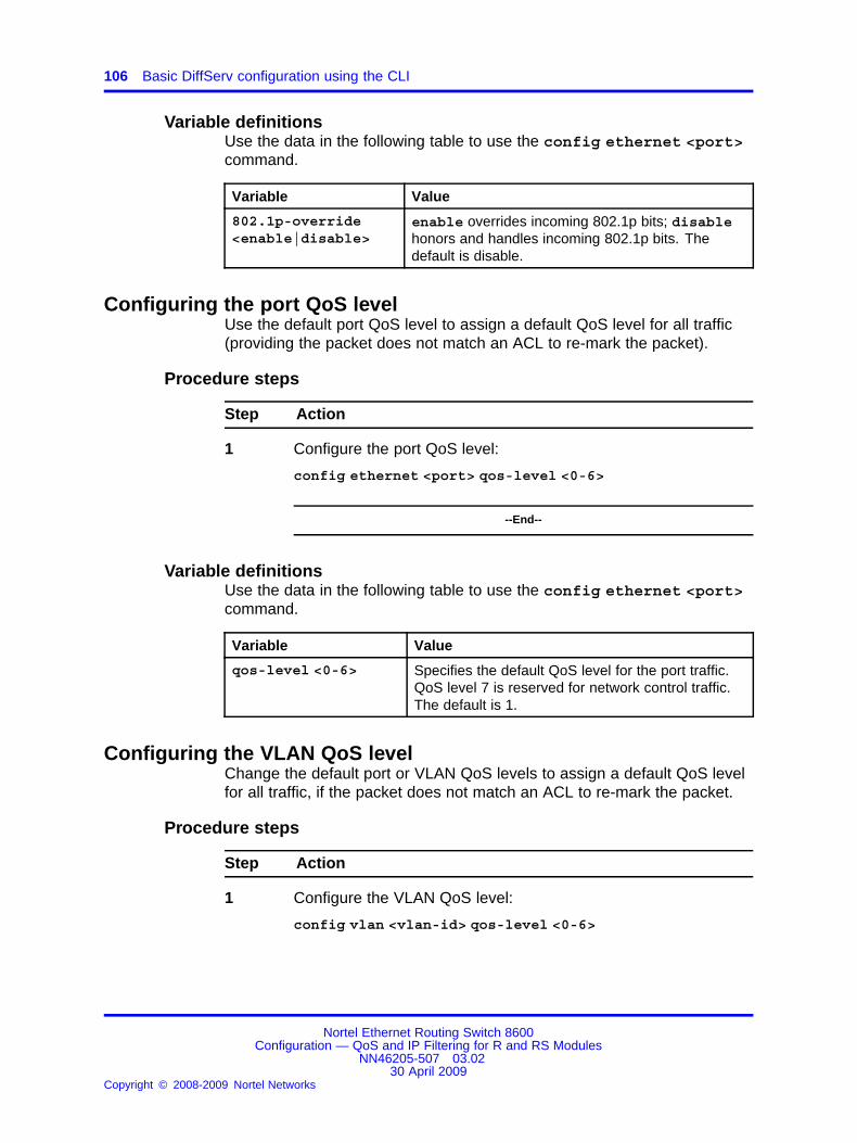
106 Basic DiffServ configuration using the CLI
Variable definitionsUse the data in the following table to use the config ethernet <port>command.
Variable Value
802.1p-override<enable|disable>
enable overrides incoming 802.1p bits; disablehonors and handles incoming 802.1p bits. Thedefault is disable.
Configuring the port QoS levelUse the default port QoS level to assign a default QoS level for all traffic(providing the packet does not match an ACL to re-mark the packet).
Procedure steps
Step Action
1 Configure the port QoS level:
config ethernet <port> qos-level <0-6>
--End--
Variable definitionsUse the data in the following table to use the config ethernet <port>command.
Variable Value
qos-level <0-6> Specifies the default QoS level for the port traffic.QoS level 7 is reserved for network control traffic.The default is 1.
Configuring the VLAN QoS levelChange the default port or VLAN QoS levels to assign a default QoS levelfor all traffic, if the packet does not match an ACL to re-mark the packet.
Procedure steps
Step Action
1 Configure the VLAN QoS level:
config vlan <vlan-id> qos-level <0-6>
Nortel Ethernet Routing Switch 8600Configuration — QoS and IP Filtering for R and RS Modules
NN46205-507 03.0230 April 2009
Copyright © 2008-2009 Nortel Networks
.

Configuring the QoS level for a MAC address 107
<vlan-id> specifies the VLAN ID (1 to 4094) for which tospecify the QoS level.
--End--
Variable definitionsUse the data in the following table to use the config vlan <vlan-id>command.
Variable Value
qos-level <0-6> Specifies the default QoS level for the VLAN traffic.QoS level 7 is reserved for network control traffic.The default is 1.
Configuring the QoS level for a MAC addressApply a QoS level to traffic from specific VLAN MAC addresses to providespecial QoS treatment to the packets or to modify the QoS level providingthe packet does not match an ACL to re-mark the packet.
Procedure steps
Step Action
1 Configure the source MAC QoS level for a dynamically learnedaddress:
config vlan <vlan id> fdb-entry qos-level <mac> status<value> <0-6>
2 Configure the source MAC QoS level for a static address:
config vlan <vlan id> fdb-static add <mac> port <value>qos <0-6>
--End--
Variable definitionsUse the data in the following table to use the fdb-entry command.
Variable Value
<mac> Specifies the MAC address in the format0x00:0x00:0x00:0x00:0x00:0x00
status <value> Specifies the forwarding database (FDB) status(other|invalid|learned|self|mgmt)
<0-6> Specifies the QoS level. The default is 1.
Use the data in the following table to use the fdb-static command.
Nortel Ethernet Routing Switch 8600Configuration — QoS and IP Filtering for R and RS Modules
NN46205-507 03.0230 April 2009
Copyright © 2008-2009 Nortel Networks
.

108 Basic DiffServ configuration using the CLI
Variable Value
add <mac> Adds or configures the source MAC QoS level to aVLAN bridge.
<mac> specifies the MAC address in the format0x00:0x00:0x00:0x00:0x00:0x00.
port <value> <value> specifies the port number
qos <0-6> <0-6> specifies the QoS level. The default is 1.
Example of configuring a QoS level for a MAC address
Procedure steps
Step Action
1 To change the source MAC QoS level to 2 for the MAC address00:00:00:00:01:0a on VLAN 2 through port 7/26, enter thefollowing command:
ERS-8610:5#config vlan 2 fdb-static add00:00:00:00:01:0a port 7/26 qos 2
--End--
Nortel Ethernet Routing Switch 8600Configuration — QoS and IP Filtering for R and RS Modules
NN46205-507 03.0230 April 2009
Copyright © 2008-2009 Nortel Networks
.

109.
Basic DiffServ configuration using theNNCLI
Use DiffServ to provide appropriate Quality of Service (QoS) to specifictraffic types.
Basic DiffServ configuration navigation• “Job aid” (page 109)
• “Enabling DiffServ on a port” (page 110)
• “Configuring Layer 3 trusted or untrusted ports” (page 111)
• “Configuring Layer 2 trusted or untrusted ports” (page 112)
• “Configuring the port QoS level” (page 113)
• “Configuring the VLAN QoS level” (page 114)
• “Configuring the QoS level for a MAC address” (page 114)
Job aidThe following roadmap lists some of the QoS commands and theparameters that you can use to perform the procedures in this section.
Table 20Roadmap of QoS NNCLI commands
Command Parameter
Global Configuration mode
vlan mac-address-entry <1-4094>qos-level <H.H.H> <0-6> status <other|invalid|learned|self|mgmt>
—
vlan mac-address-filter <1-4094><H.H.H> <portList> <0-6>
—
vlan mac-address-static <1-4094><H.H.H> <portList> qos <0-6>
—
Nortel Ethernet Routing Switch 8600Configuration — QoS and IP Filtering for R and RS Modules
NN46205-507 03.0230 April 2009
Copyright © 2008-2009 Nortel Networks
.

110 Basic DiffServ configuration using the NNCLI
Table 20Roadmap of QoS NNCLI commands (cont’d.)
Command Parameter
Interface Configuration mode
access-diffserv [port <portList>] [enable]
—
enable-diffserv [port <portList>] [enable]
—
802.1p-override [enable]qos
level [port <portList>] <0-6>
Enabling DiffServ on a portEnable DiffServ so that the switch provides DiffServ-based QoS on thatport.
Prerequisites
• Access Interface Configuration mode.
Procedure steps
Step Action
1 Enable DiffServ:
enable-diffserv [port <portList>] [enable]
--End--
Variable definitionsUse the data in the following table to use the enable-diffservcommand.
Variable Value
enable Enables DiffServ for the specified port. The defaultis disabled.To use the default configuration, use thedefault option in the command defaultenable-diffserv [enable]
Nortel Ethernet Routing Switch 8600Configuration — QoS and IP Filtering for R and RS Modules
NN46205-507 03.0230 April 2009
Copyright © 2008-2009 Nortel Networks
.

Configuring Layer 3 trusted or untrusted ports 111
Variable Value
To delete the current configuration, use the nooption in the commandno enable-diffserv[enable]
port <portList> Specifies the slot and port, or slot and port list.To delete the current configuration, use the nooption in the command no enable-diffserv[port <portList>]
Configuring Layer 3 trusted or untrusted portsConfigure a port as trusted or untrusted to determine the Layer 3 QoSactions the switch performs. A trusted port honors incoming DSCPmarkings. An untrusted port overrides DSCP markings.
Prerequisites
• Access Interface Configuration mode.
• DiffServ is enabled.
Procedure steps
Step Action
1 Configure the port as Layer 3 untrusted:
access-diffserv [port <portList>] [enable]
To configure the port as Layer 3 trusted, use the noaccess-diffserv enable command.
--End--
Variable definitionsUse the data in the following table to use the access-diffservcommands.
Nortel Ethernet Routing Switch 8600Configuration — QoS and IP Filtering for R and RS Modules
NN46205-507 03.0230 April 2009
Copyright © 2008-2009 Nortel Networks
.

112 Basic DiffServ configuration using the NNCLI
Variable Value
enable If enabled, specifies an access port and overridesincoming DSCP bits. If disabled, specifies a coreport and honors and handles incoming DSCP bits.The default is disabled.To use the default configuration, use thedefault option in the command defaultaccess-diffserv [enable]
To delete the current configuration, use the nooption in the commandno access-diffserv[enable]
port <portList> Specifies the slot and port, or slot and port list.To delete the current configuration, use the nooption in the command no access-diffserv[port <portList>]
Configuring Layer 2 trusted or untrusted portsConfigure a port as trusted or untrusted to determine the Layer 2 QoSactions the switch performs. A trusted port (override disabled) honorsincoming 802.1p bit markings. An untrusted port (override enabled)overrides 802.1p bit markings.
Prerequisites
• Access Interface Configuration mode.
• DiffServ is enabled.
Procedure steps
Step Action
1 Configure the port as Layer 2 untrusted:
qos 802.1p-override [enable]
To configure the port as Layer 2 trusted, use the no qos802.1p-override command.
--End--
Variable definitionsUse the data in the following table to youuse the qos 802.1p-overridecommand.
Nortel Ethernet Routing Switch 8600Configuration — QoS and IP Filtering for R and RS Modules
NN46205-507 03.0230 April 2009
Copyright © 2008-2009 Nortel Networks
.

Configuring the port QoS level 113
Variable Value
enable If you configure this variable, it overrides incoming802.1p bits; if you do not configure this variable,it honors and handles incoming 802.1p bits. Thedefault is disable (Layer 2 trusted).To use the default configuration, use thedefault option in the command default qos802.1p-override [enable]
To delete the current configuration, use the nooption in the commandno qos 802.1p-override[enable]
Configuring the port QoS levelUse the default port QoS level to assign a default QoS level for all traffic(providing the packet does not match an ACL that re-marks the packet).
Prerequisites
• Access Interface Configuration mode.
Procedure steps
Step Action
1 Configure the port QoS level:
qos level [port <portList>] <0-6>
--End--
Variable definitionsUse the data in the following table to use the qos level command.
Variable Value
<0-6> Specifies the default QoS level for the port traffic.QoS level 7 is reserved for network control traffic.The default is 1.To use the default configuration, use the defaultoption in the command default qos level
port <portList> Specifies the slot and port, or slot and port list.
Nortel Ethernet Routing Switch 8600Configuration — QoS and IP Filtering for R and RS Modules
NN46205-507 03.0230 April 2009
Copyright © 2008-2009 Nortel Networks
.

114 Basic DiffServ configuration using the NNCLI
Configuring the VLAN QoS levelYou can change the default port or VLAN QoS levels to assign a defaultQoS level for all traffic, providing the packet does not match an ACL thatre-marks the packet.
Prerequisites
• Access VLAN Interface Configuration mode.
• The VLAN exists.
Procedure steps
Step Action
1 Configure the VLAN level:
qos level <0-6>
--End--
Variable definitionsUse the data in the following table to use the qos level command.
Variable Value
<0-6> Specifies the default QoS level for the VLAN traffic.QoS level 7 is reserved for network control traffic.The default is 1.To use the default configuration, use the defaultoption in the commanddefault qos level
Configuring the QoS level for a MAC addressApply a QoS level to traffic from specific VLAN MAC addresses toprovide special QoS treatment to the packets and to modify the QoS levelproviding that the packet does not match an ACL that re-marks the packet.
For more information about the VLAN commands, see Nortel EthernetRouting Switch 8600 Configuration — VLANs and Spanning Tree(NN46205-517) .
Prerequisites
• Access Global Configuration mode.
• The VLAN exists.
Nortel Ethernet Routing Switch 8600Configuration — QoS and IP Filtering for R and RS Modules
NN46205-507 03.0230 April 2009
Copyright © 2008-2009 Nortel Networks
.

Configuring the QoS level for a MAC address 115
Procedure steps
Step Action
1 Configure the source MAC QoS level for a dynamically learnedaddress:
vlan mac-address-entry <1-4094> qos-level <H.H.H> <0-6>status <other|invalid|learned|self|mgmt>
2 Configure the source MAC QoS level for a bridge static address:
vlan mac-address-static <1-4094> <H.H.H> <portList> qos<0-6>
3 Configure the source MAC QoS level for a bridge filter address:
vlan mac-address-filter <1-4094> <H.H.H> <portList><0-6>
--End--
Variable definitionsUse the data in the following table to use the commands in this procedure.
Variable Value
<0-6> Specifies the QoS level. The default is 1.To use the default configuration, use the defaultoption in the command.
<1-4094> Specifies the VLAN ID.
<H.H.H> Specifies the MAC address in the format0x00:0x00:0x00:0x00:0x00:0x00
<portList> Specifies the slot and port, or slot and port list.
status <other|invalid|learned|self|mgmt>
Specifies the FDB status (other|invalid|learned|self|mgmt)
Nortel Ethernet Routing Switch 8600Configuration — QoS and IP Filtering for R and RS Modules
NN46205-507 03.0230 April 2009
Copyright © 2008-2009 Nortel Networks
.

116 Basic DiffServ configuration using the NNCLI
Example of setting a QoS level for a MAC address
Procedure steps
Step Action
1 To change the source MAC QoS level to 2 for the MAC address00:00:00:00:01:0a on VLAN 2 through port 7/26, enter thefollowing command:
ERS-8610:5#vlan mac-address-static 2 00:00:00:00:01:0a 7/26 qos 2
--End--
Nortel Ethernet Routing Switch 8600Configuration — QoS and IP Filtering for R and RS Modules
NN46205-507 03.0230 April 2009
Copyright © 2008-2009 Nortel Networks
.

117.
QoS configuration using DeviceManager
Configure Quality of Service (QoS) to allocate network resources whereyou need them most.
For information about statistics, see Nortel Ethernet Routing Switch 8600Performance Management (NN46205-704) .
Navigation• “Broadcast and multicast bandwidth limiting” (page 117)
• “Configuring port-based shaping for R and RS modules” (page 118)
• “Configuring port-based policing for RS modules” (page 118)
• “Configuring a policy-based policer” (page 118)
• “Configuring an egress queue set” (page 119)
• “Configuring egress queue set queues” (page 121)
• “Modifying an egress queue set or queue” (page 122)
• “Modifying ingress MPLS to QoS mappings” (page 123)
• “Modifying egress QoS to MPLS mappings” (page 124)
Broadcast and multicast bandwidth limitingUse broadcast and multicast bandwidth limiting to restrict the amount ofingress broadcast and multicast traffic on a port. The port drops traffic thatviolates the bandwidth limit.
You can configure broadcast and multicast bandwidth limiting only byusing the CLI or the NNCLI.
See “Configuring broadcast and multicast bandwidth limiting” (page 128).
Nortel Ethernet Routing Switch 8600Configuration — QoS and IP Filtering for R and RS Modules
NN46205-507 03.0230 April 2009
Copyright © 2008-2009 Nortel Networks
.

118 QoS configuration using Device Manager
Configuring port-based shaping for R and RS modulesUse egress port-based shaping to bind the maximum rate at which trafficleaves the port.
For information about how to configure queue-based shaping, see“Configuring egress queue set queues” (page 121).
Procedure steps
Step Action
1 From the Device Manager device view, select a port.
2 In Device Manager, choose Edit, Port, General - GlobalRouter(vrf 0).
3 From EgressRateLimitState, select enable.
4 From EgressRateLimit , enter an egress rate limit in kilobits persecond.
5 Click Apply.
--End--
Configuring port-based policing for RS modulesUse a port-based policer to bandwidth-limit ingress traffic. The systemdrops or re-marks violating traffic. Only RS modules support this policer.
Procedure steps
Step Action
1 In Device Manager, select a port.
2 In Device Manager, choose Edit, Port, General - GlobalRouter(vrf 0).
3 From IngressRateLimitState, select enable.
4 From IngressRateLimit , enter an ingress rate limit in kilobitsper second.
5 Click Apply.
--End--
Configuring a policy-based policerUse a QoS policy to configure peak and service policing rates for specificlane members. Use an Access Control Entry (ACE) to apply the policy totraffic.
Nortel Ethernet Routing Switch 8600Configuration — QoS and IP Filtering for R and RS Modules
NN46205-507 03.0230 April 2009
Copyright © 2008-2009 Nortel Networks
.

Configuring an egress queue set 119
Procedure steps
Step Action
1 In the Device Manager menu bar, choose QOS, Policy.
2 Click Insert.
3 Configure the name and ID as required.
4 Configure the peak and service rates and lane members.
The peak rate must be greater than or equal to the service rate.You can use the following variable definitions table to help youconfigure QoS policies.
5 Click Insert.
Configure a filter to use a policy by using the Police parameteras you configure an ACE.
6 To modify a value in the Policy tab, double-click the parameterto change. Change the value, and then click Apply.
7 To delete a policy, select a policy and click Delete.
--End--
Variable definitionsUse the data in the following table to configure a policy-based policer.
Variable Value
GpId Identifies a global policer (GP) ID value thatcorresponds to the local policer. Valid values rangefrom 1–16383.
PeakRate Identifies a local policer peak rate in kilobits persecond equal to the corresponding GP ID.
SvcRate Identifies a local policer service rate in kilobits persecond equal to the corresponding GP ID.
Name Specifies an administratively assigned name for thisglobal policer.
LaneMembers Specifies a port number for a set of lanes.
Configuring an egress queue setConfigure an egress queue set to apply the same egress queueconfiguration (a template) to a group (set) of ports.
ATTENTIONIf you add or modify an egress queue set, you must restart the switch.
Nortel Ethernet Routing Switch 8600Configuration — QoS and IP Filtering for R and RS Modules
NN46205-507 03.0230 April 2009
Copyright © 2008-2009 Nortel Networks
.

120 QoS configuration using Device Manager
Procedure steps
Step Action
1 In Device Manager, choose QOS, Egress Queue Set.
2 After the message about R and RS modules appears, click OK.
3 Click Insert.
4 Configure the ID or accept the default value.
5 Choose either an 8- or 64-queue template.
10/100/1000 Mb/s ports must use the eight-queue template.
6 Configure the number of balanced queues, high-priority queues,and low-priority queues.
Use the following variable definitions table to configure the queueset as required.
7 Configure the name and port members.
8 Click Apply.
9 Click Insert.
A message indicates that you must restart the switch to applythe changes. Restart the switch after you make all configurationchanges.
10 To delete an egress queue set, select the queue set to deleteand click Delete.
--End--
Variable definitionsUse the data in the following table to configure an egress queue set.
Variable Value
Id Specifies a value that uniquely identifies the egressqueue template.
MaxQueues Specifies the maximum number of queues in thistemplate, either 8 or 64. The default is 8.
BalancedQueues Specifies the total number of balanced queues inthis template. The range is 0–48.
HiPriQueues Specifies the total number of high-priority queues inthis template. The range is 0–64.
LoPriQueues Specifies the total number of low-priority queues inthis template. The range is 0–8.
Nortel Ethernet Routing Switch 8600Configuration — QoS and IP Filtering for R and RS Modules
NN46205-507 03.0230 April 2009
Copyright © 2008-2009 Nortel Networks
.

Configuring egress queue set queues 121
Variable Value
Name Specifies an administratively assigned name for thisegress queue template.
PortMembers Specifies the port members to add to the egressqueue template.
Apply Applies the egress queue template.
Configuring egress queue set queuesEstablish queue-based shapers on egress queue set queues. Egressqueue sets define the QoS treatment that traffic receives. Configure thequeue parameters to suit customer QoS requirements.
You can modify some egress queue set queue attributes (Name, MinRate,MaxRate, and MaxLength) for custom queues. You cannot modifyqueueing style. To modify queueing style, create a new egress queue setwith the desired queueing styles.
As you change the queue set queue parameters, do not use the Refreshbutton, or you erase your changes. Instead, after you make changes, clickApply, and then click Close.
Prerequisites
• An egress queue set exists.
ATTENTIONIf you modify an applied egress queue set queue, you must restart the switch.
ATTENTIONFor each Balanced queue, you must specify a desired minimum rate (min-rate)guarantee and a maximum-rate (max-rate) limit.
For Priority queues (either high or low priority), a minimum rate guarantee doesnot apply. Configure only a rate limit (max-rate).
The sum of minimum rate guarantees must be less than the port line rate minusthe sum of high-priority queue rate limits. If this condition is not met, minimumrates are not guaranteed.
Procedure steps
Step Action
1 In Device Manager, choose QOS, Egress Queue Set.
2 Select the queue set for which to configure queues, and clickQueue.
Nortel Ethernet Routing Switch 8600Configuration — QoS and IP Filtering for R and RS Modules
NN46205-507 03.0230 April 2009
Copyright © 2008-2009 Nortel Networks
.

122 QoS configuration using Device Manager
3 On the Queue tab, double-click a desired attribute and changethe attribute.
4 Click Apply to apply the desired attributes. Do not click Refresh.
5 If you modify an applied queue set, reapply the queue set, savethe configuration, and then restart the switch. You can use theRefresh button on the Egress Queue Set tab to see that Applyis false after you change the queue parameters.
--End--
Variable definitionsUse the data in the following table to configure queues.
Variable Value
Queue Set Id Specifies the ID of the queue set.
Qid Specifies the queue offset from the base queue forthis port. Valid values range from 0–63.
Name Specifies the Nortel Networks Service Class(NNSC) for this egress queue.
Style Specifies the egress queue style. Valid values are
• hipri (high priority)
• balanced
• lopri (low priority)
MinRate Specifies the egress queue minimum rateguarantee in Kb/s. Applies to balanced and lowpriority queues only.
MaxRate Specifies the egress queue maximum rate in Kb/s.
MaxLength (in pages) Specifies the maximum queue length.
Modifying an egress queue set or queueYou can modify some of the egress queue set parameters for customqueues.
ATTENTIONIf you modify an egress queue set, you must restart the switch.
Prerequisites
• An egress queue set exists.
Nortel Ethernet Routing Switch 8600Configuration — QoS and IP Filtering for R and RS Modules
NN46205-507 03.0230 April 2009
Copyright © 2008-2009 Nortel Networks
.

Modifying ingress MPLS to QoS mappings 123
Procedure steps
Step Action
1 In Device Manager, choose QOS, Egress Queue Set.
2 Change the Name or PortMember attributes as required.
To change an attribute, double-click the desired parameter, andchoose the new parameter from the list.
You can change no other Egress Queue Set parameter on thistab. If you must change other parameters, delete the queue set,and then create a new one.
3 Click Apply.
4 To change the queue parameters, select a queue set, and thenclick Queue.
5 You can modify any parameter that does not appear dimmed.After you make the changes, click Apply.
6 Reapply the queue set corresponding to this queue.
You can use the Refresh button on the Egress Queue Set tabto see that Apply is indeed false after you change the queueparameters.
7 To save the configuration, select Actions, SaveRuntimeConfigor Actions, SaveBootConfig.
8 To restart the switch, choose Edit, Chassis. On the System tab,in the ActionGroup4 section, select hardReset, and then clickApply.
--End--
Modifying ingress MPLS to QoS mappingsYou can modify the ingress Multiprotocol Label Switching (MPLS) to QoSmappings to change traffic priorities. However, Nortel recommends thatyou use the default mappings.
For information about modifying other mappings (802.1p and DSCP), seeNortel Ethernet Routing Switch 8600 Configuration — QoS and IP Filteringfor Classic Modules (NN46205-506) .
Procedure steps
Step Action
1 In Device Manager, choose QOS, Mapping Tables.
2 Click the Ingress MPLS Exp Bit to QoS tab.
Nortel Ethernet Routing Switch 8600Configuration — QoS and IP Filtering for R and RS Modules
NN46205-507 03.0230 April 2009
Copyright © 2008-2009 Nortel Networks
.

124 QoS configuration using Device Manager
3 Modify the QoS mappings as required.
4 Click Apply.
--End--
Variable definitionsUse the data in the following table to modify MPLS mappings.
Variable Value
MplsExp Specifies the MPLS Exp level. The range is 0–7.
Level Specifies the internal QoS level. The range is 0–7.
Modifying egress QoS to MPLS mappingsYou can modify the egress QoS to MPLS mappings to change trafficpriorities. However, Nortel recommends that you use the default mappings.
Procedure steps
Step Action
1 In Device Manager, choose QOS, Mapping Tables.
2 Click the Egress QoS to MPLS Exp Bit tab.
3 Modify the QoS mappings as required.
4 Click Apply.
--End--
Variable definitionsUse the data in the following table to modify MPLS mappings.
Variable Value
QosLevel Specifies the internal QoS level. The range is 0–7.
MplsExp Specifies the MPLS Exp level. The range is 0–7.
Nortel Ethernet Routing Switch 8600Configuration — QoS and IP Filtering for R and RS Modules
NN46205-507 03.0230 April 2009
Copyright © 2008-2009 Nortel Networks
.

125.
QoS configuration using the CLIUse the procedures in this section to configure Quality of Service (QoS) onyour Ethernet Routing Switch 8600.
For information about statistics, see Nortel Ethernet Routing Switch 8600Performance Management (NN46205-704) .
Navigation• “Job aid” (page 125)
• “Configuring broadcast and multicast bandwidth limiting” (page 128)
• “Configuring the port-based shaper” (page 129)
• “Configuring a port-based policer for RS modules” (page 129)
• “Configuring a policy-based policer ” (page 130)
• “Adding lanes to a policy-based policer ” (page 132)
• “Configuring an egress queue set ” (page 132)
• “Modifying an egress queue set ” (page 136)
• “Configuring an egress queue set queue” (page 138)
• “Configuring ingress mappings” (page 140)
• “Configuring egress mappings” (page 142)
Job aidThe following roadmap lists some of the QoS commands and theparameters that you can use to perform the procedures in this section.
Nortel Ethernet Routing Switch 8600Configuration — QoS and IP Filtering for R and RS Modules
NN46205-507 03.0230 April 2009
Copyright © 2008-2009 Nortel Networks
.

126 QoS configuration using the CLI
Table 21Roadmap of QoS CLI commands
Command Parameter
broadcast-bandwidth-limit <value>[<enable|disable>]
broadcast-rate-limit
Only for Classic modules. See Nortel EthernetRouting Switch 8600 Configuration — QoS and IPFiltering for Classic Modules (NN46205-508) .
multicast-bandwidth-limit <value>[<enable|disable>]
multicast-rate-limit
Only for Classic modules. See Nortel EthernetRouting Switch 8600 Configuration — QoS and IPFiltering for Classic Modules (NN46205-508) .
police <kbps> [<enable|disable>]
config ethernet <port>
shape <kbps> [<enable|disable>]
apply
create qmax <value> [balanced-queues<value>] [hipri-queues <value>][lopri-queues <value>] [name <value>]
delete
info
config qos egress-queue-set <id>
name <value>
add <ports>
info
config qos egress-queue-set <id>port
remove <ports>
info
name
config qos egress-queue-set <id>queue <qid>
set [min-rate <value>] [max-rate <value>][max-length <value>]
1p <level> <ieee1p>
ds <level> <dscp>
exp <level> <exp>
config qos egressmap
info
Nortel Ethernet Routing Switch 8600Configuration — QoS and IP Filtering for R and RS Modules
NN46205-507 03.0230 April 2009
Copyright © 2008-2009 Nortel Networks
.

Job aid 127
Table 21Roadmap of QoS CLI commands (cont’d.)
Command Parameter
1p <ieee1p> <level>
ds <dscp> <level>
exp <exp> <level>
config qos ingressmap
info
create peak-rate <value> svc-rate <value>[lanes <value>] [name <value>]
delete
info
modify peak-rate <value> svc-rate <value>
config qos policy <policy-id>
name <value>
add <lane-list>config qos policy <policy-id>lanes remove <lane-list>
[<ports>]
[queues <value>]
show port stats egress-queues
[verbose]
all
egress-queue-set <id> [queues]
show qos config egress-queue-set
port <ports>
show qos config eqmap <slot-number>
lane <lane-no>
all
port <ports>
show qos config policy
policy <policy-id>
1p [<level>]
ds [<level>]
show qos egressmap
exp
1p [<ieee1p>]
ds [<dscp>]
show qos ingressmap
exp
all [verbose]
egress-queue-set <id> [verbose]
show qos stats egress-queue-set
port <ports> [verbose]
Nortel Ethernet Routing Switch 8600Configuration — QoS and IP Filtering for R and RS Modules
NN46205-507 03.0230 April 2009
Copyright © 2008-2009 Nortel Networks
.
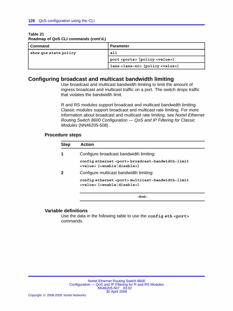
128 QoS configuration using the CLI
Table 21Roadmap of QoS CLI commands (cont’d.)
Command Parameter
all
port <ports> [policy <value>]
show qos stats policy
lane <lane-no> [policy <value>]
Configuring broadcast and multicast bandwidth limitingUse broadcast and multicast bandwidth limiting to limit the amount ofingress broadcast and multicast traffic on a port. The switch drops trafficthat violates the bandwidth limit.
R and RS modules support broadcast and multicast bandwidth limiting.Classic modules support broadcast and multicast rate limiting. For moreinformation about broadcast and multicast rate limiting, see Nortel EthernetRouting Switch 8600 Configuration — QoS and IP Filtering for ClassicModules (NN46205-508) .
Procedure steps
Step Action
1 Configure broadcast bandwidth limiting:
config ethernet <port> broadcast-bandwidth-limit<value> [<enable|disable>]
2 Configure multicast bandwidth limiting:
config ethernet <port> multicast-bandwidth-limit<value> [<enable|disable>]
--End--
Variable definitionsUse the data in the following table to use the config eth <port>commands.
Nortel Ethernet Routing Switch 8600Configuration — QoS and IP Filtering for R and RS Modules
NN46205-507 03.0230 April 2009
Copyright © 2008-2009 Nortel Networks
.

Configuring a port-based policer for RS modules 129
Variable Value
broadcast-bandwidth-limit <value>[<enable|disable>]
Specifies the bandwidth limit for broadcast trafficfrom 250–2147483647 Kb/s. <enable|disable>enables or disables bandwidth limiting. The defaultis disabled.
multicast-bandwidth-limit <value>[<enable|disable>]
Specifies the bandwidth limit for multicast trafficfrom 250–2147483647 Kb/s. <enable|disable>enables or disables bandwidth limiting. The defaultis disabled.
Configuring the port-based shaperUse port-based shaping to rate-limit all egress (outgoing) traffic to aspecific rate.
For information about configuring queue-based shaping, see “Configuringan egress queue set queue” (page 138).
Procedure steps
Step Action
1 Configure port-based shaping:
config ethernet <port> shape <kbps> [<enable|disable>]
--End--
Variable definitionsUse the information in the following table to use the command in thisprocedure.
Variable Value
<enable|disable> Enables or disables port-based shaping on the port.The default is disable.
<kbps> Configures the shaping rate from 1000–10000000Kb/s.
Configuring a port-based policer for RS modulesUse a port-based policer to bandwidth-limit incoming traffic. The systemdrops or re-marks violating traffic. Only RS modules support this policer.
Nortel Ethernet Routing Switch 8600Configuration — QoS and IP Filtering for R and RS Modules
NN46205-507 03.0230 April 2009
Copyright © 2008-2009 Nortel Networks
.

130 QoS configuration using the CLI
Procedure steps
Step Action
1 Configure the policing limit and enable or disable policing:
config ethernet <port> police <kbps> <enable|disable>
--End--
Variable definitionsUse the following variable definitions table to the commands in thisprocedure.
Variable Value
police <kbps> Specifies the ingress rate limit (policing limit) inkilobits per second. The range is 1000–10000000.
<enable|disable> Enables or disables policing (ingress-rate-limiting).The default is enable.
Configuring a policy-based policerUse a QoS policy to configure peak and service policing rates for specificlane members. Use an ACE to apply the policy to traffic.
Procedure steps
Step Action
1 Configure a policer (traffic policy):
config qos policy <policy-id> create peak-rate <value>svc-rate <value> [lanes <value>] [name <value>]
2 Ensure the configuration is correct:
show qos config policy policy <policy-id>
--End--
Variable definitionsUse the information in the following table to use the config qos policy<policy-id> command.
Nortel Ethernet Routing Switch 8600Configuration — QoS and IP Filtering for R and RS Modules
NN46205-507 03.0230 April 2009
Copyright © 2008-2009 Nortel Networks
.

Configuring a policy-based policer 131
Variable Value
create peak-rate<value> svc-rate<value> [lanes<value>] [name<value>]
Configures the following options:
• create peak-rate <value> specifies a peakrate value in kilobits per second for the policy.
• svc-rate <value> specifies a service ratevalue in kilobits per second for the policy.
• lanes <value> identifies a specific lane or alllanes to which the policy applies.
• name <value> specifies a service rate value inkilobits per second for the policy.
delete Deletes an existing policy. You cannot delete apolicy if an access control entry references thepolicy.
info Displays current setting information for the policy.
modify peak-rate<value> svc-rate<value>
Configures the following options:
• modify peak-rate <value> modifies a peakrate value in kilobits per second for the policy.
• svc-rate <value> modifies a service ratevalue in kilobits per second for the policy.
name <value> Modifies the name of the policer template.
Use the information in the following table to use the show qos configpolicy command.
Variable Value
all Displays all configured policing data.
lane <lane-no> Displays policing data by lane.
policy <policy-id> Displays policing data by policy ID.
port <ports> Displays policing data by port.
Job aidThe following table describes the headings in the show command output.
Table 22show qos config policy output
Field Description
PolicerID Specifies the policer ID number.
Name Specifies the name of the policer.
peak-rate Specifies a policer peak rate in Kb/s.
Nortel Ethernet Routing Switch 8600Configuration — QoS and IP Filtering for R and RS Modules
NN46205-507 03.0230 April 2009
Copyright © 2008-2009 Nortel Networks
.

132 QoS configuration using the CLI
Table 22show qos config policy output (cont’d.)
Field Description
svc-rate Specifies a local policer service rate in Kb/s.
lanes Specifies the lane numbers associated with thepolicy.
Adding lanes to a policy-based policerAdd or remove lanes from a policer so that the policer operates only onspecific lane members.
Prerequisites
• The policy exists.
Procedure steps
Step Action
1 Add lanes from an existing policer:
config qos policy <policy-id> lanes add <lane-list>
--End--
Variable definitionsUse the information in the following table to use the config qos policy<policy-id> lanes command.
Variable Value
add <lane-list> Adds lanes to an existing policer template.
remove <lane-list> Removes lanes from an existing policer template.
Configuring an egress queue setConfigure an egress queue set to apply the same egress queueconfiguration (a template) to a group (set) of ports.
ATTENTIONIf you add or modify an egress queue set, you must restart the switch.
Nortel Ethernet Routing Switch 8600Configuration — QoS and IP Filtering for R and RS Modules
NN46205-507 03.0230 April 2009
Copyright © 2008-2009 Nortel Networks
.

Configuring an egress queue set 133
Procedure steps
Step Action
1 Configure the egress queue set template:
config qos egress-queue-set <id> create qmax <value>[balanced-queues <value>] [hipri-queues <value>][lopri-queues <value>] [name <value>]
2 Associate ports with the egress queue set:
config qos egress-queue-set <id> port add <port>
The system verifies that the requested port types support thenumber of queues in the egress queue set. If you add newports to the template that you already applied, the system sendsadditional messages to the relevant module control processorsand configures the hardware accordingly.
3 Ensure the configuration is correct:
show qos config egress-queue-set egress-queue-set <id>
config qos egress-queue-set <id> info
4 To configure the egress queue set queues, configure the egressqueue set queues now, before you apply the egress queue set.
5 Apply the queue set:
config qos egress-queue-set <id> apply
6 After all configurations are complete, restart the switch.
boot
--End--
Variable definitionsUse the information in the following table to use the config qosegress-queue-set <id> command.
Variable Value
apply Applies the egress queue set when you issue thecommand. Otherwise, the operation is lost after youleave the current context.
When you create an egress queue set, applyoccurs when you issue the command. When youmodify a queue set, apply occurs after you save theconfiguration and boot the switch.
Nortel Ethernet Routing Switch 8600Configuration — QoS and IP Filtering for R and RS Modules
NN46205-507 03.0230 April 2009
Copyright © 2008-2009 Nortel Networks
.

134 QoS configuration using the CLI
Variable Value
create qmax <value>[balanced-queues<value>] [hipri-queues <value>][lopri-queues<value>] [name<value>]
Specifies the maximum number of queues, either8 or 64, as well as the number of balanced,high-priority, and low-priority queues in the egressqueue set. The sum of the number of queues forbalanced, high-priority (hipri), and low-priority (lopri)queues must be less than or equal to the qmax.
delete Deletes the egress queue set.
info Shows current queue set information.
name <value> Modifies the name of the egress queue settemplate.
Use the information in the following table to use the config qosegress-queue-set <id> port command.
Variable Value
add <ports> Specifies the list of ports to add to the existingegress queue set template. Use this commandto move a port from the default NNSC setup to adifferent egress queue set.
If you add ports to an applied template, the systemsends additional messages to the relevant modulecontrol processors and configures the hardwareaccordingly.
info Shows information about a queue portconfiguration.
remove <ports> Specifies the list of ports to remove from theexisting egress queue set template. Removingports from a specific egress queue set configuresthe NNSC default appropriate for the port type.
If you attempt to remove a port from the NNSCdefault template, a warning message appears andthe port stays with the default NNSC.
Use the following table to use the show qos config egress-queue-set command.
Variable Value
all Displays all configured egress queue set data.
egress-queue-set<id> [queues]
Displays egress queue set data identified by nameor specific ID.
port <ports> Displays egress queue set data by port.
Nortel Ethernet Routing Switch 8600Configuration — QoS and IP Filtering for R and RS Modules
NN46205-507 03.0230 April 2009
Copyright © 2008-2009 Nortel Networks
.

Configuring an egress queue set 135
Example of configuring an egress queue set
Procedure steps
Step Action
1 Configure the queue set:
ERS-8606:5# config qos egress-queue-set 49create qmax 64 balanced-queues 8 hipri-queues 8lopri-queues 8 name QueueSet49
2 Add ports:
ERS-8606:5#config qos egress-queue-set 49 port add2/1
3 Ensure the configuration is correct:
ERS-8606:5# show qos config egress-queue-setegress-queue-set 49
4 Apply the queue set:
ERS-8606:5#config qos egress-queue-set 49 apply
--End--
Job aidThe following table describes the headings in the show command output.
Table 23egress queue set show command output
Field Description
TemplateID Template ID.
Name Name of the queue set queue template.
Total Qs Total number of all queues.
BalQs Number of balanced queues.
Hi-priQs Number of high-priority queues.
lo-priQs Number of low-priority queues.
Ports Specifies the ports associated with the queue.
Nortel Ethernet Routing Switch 8600Configuration — QoS and IP Filtering for R and RS Modules
NN46205-507 03.0230 April 2009
Copyright © 2008-2009 Nortel Networks
.

136 QoS configuration using the CLI
Modifying an egress queue setConfigure an egress queue set to apply the same egress queueconfiguration (a template) to a group (set) of ports.
ATTENTIONIf you add or modify an egress queue set, you must restart the switch.
Procedure steps
Step Action
1 Modify the egress queue set template:
config qos egress-queue-set <id> create qmax <value>[balanced-queues <value>] [hipri-queues <value>][lopri-queues <value>] [name <value>]
2 Modify associated ports with the egress queue set:
config qos egress-queue-set <id> port add <port>
3 Ensure the configuration is correct:
show qos config egress-queue-set egress-queue-set <id>
config qos egress-queue-set <id> info
4 To configure the egress queue set queues, do so now, beforeyou apply the egress queue set.
5 Apply the queue set:
config qos egress-queue-set <id> apply
The following message appears:
WARNING: The egress-queue-set QoS change made will takeeffect only after the configuration is saved and thechassis is rebooted.
6 Save the configuration as required:
save config
save config standby config.cfg
save bootconfig
save bootconfig standby boot.cfg
7 Restart the switch:
boot -y
8 After the switch comes back online, ensure that the changeswere made:
Nortel Ethernet Routing Switch 8600Configuration — QoS and IP Filtering for R and RS Modules
NN46205-507 03.0230 April 2009
Copyright © 2008-2009 Nortel Networks
.

Modifying an egress queue set 137
config qos egress-queue-set <id> info
--End--
Variable definitionsUse the information in the following table to use the config qosegress-queue-set <id> command.
Variable Value
apply Applies the egress queue set. Apply occurs whenyou issue the command. Otherwise, the operationis lost after you leave the current context.
When you create an egress queue set, applyoccurs when you issue the command. When youmodify a queue set, apply occurs after you save theconfiguration and boot the switch.
create qmax <value>[balanced-queues<value>] [hipri-queues <value>][lopri-queues<value>] [name<value>]
Specifies the maximum number of queues, either8 or 64, as well as the number of balanced,high-priority, and low-priority queues in the egressqueue set. The sum of the number of queues forbalanced, high-priority (hipri), and low-priority (lopri)queues must be less than or equal to the qmax.
delete Deletes the egress queue set.
info Shows current queue set information.
name <value> Modifies the name of the egress queue settemplate.
Use the information in the following table to use the config qosegress-queue-set <id> port command.
Variable Value
add <ports> Specifies the list of ports to add to the existingegress queue set template. Use this commandto move a port from the default NNSC setup to adifferent egress queue set.
If you add ports to an applied template, the systemsends additional messages to the relevant modulecontrol processors and configures the hardwareaccordingly.
Nortel Ethernet Routing Switch 8600Configuration — QoS and IP Filtering for R and RS Modules
NN46205-507 03.0230 April 2009
Copyright © 2008-2009 Nortel Networks
.

138 QoS configuration using the CLI
Variable Value
info Shows information about a queue portconfiguration.
remove <ports> Specifies the list of ports to remove from theexisting egress queue set template. Removingports from a specific egress queue set configuresthe NNSC default appropriate for the port type.
If you attempt to remove a port from the NNSCdefault template, a warning message appears andthe port stays with the default NNSC.
Configuring an egress queue set queueConfigure an egress queue to customize shaping behavior. Basequeue-based shapers on egress queue set queues.
ATTENTIONFor each Balanced queue, you must specify a desired minimum rate (min-rate)guarantee and a maximum-rate (max-rate) limit.
For Priority queues (either high or low priority), a minimum rate guarantee doesnot apply. Configure only a rate limit (max-rate).
The sum of minimum rate guarantees must be less than the port line rate minusthe sum of high-priority queue rate limits. If this condition is not met, minimumrates are not guaranteed.
ATTENTIONIf you add or modify an egress queue set, you must restart the switch.
Prerequisites
• The egress queue set exists.
Procedure steps
Step Action
1 Configure an egress queue set queue:
config qos egress-queue-set <id> queue <qid> set[min-rate <value>] [max-rate <value>] [max-length<value>]
This action removes the associated egress queue set. <qid>identifies the queue ID, from 1 to 386.
2 Ensure the configuration is correct:
config qos egress-queue-set <id> queue <qid> info
Nortel Ethernet Routing Switch 8600Configuration — QoS and IP Filtering for R and RS Modules
NN46205-507 03.0230 April 2009
Copyright © 2008-2009 Nortel Networks
.

Configuring an egress queue set queue 139
show qos config egress-queue-set egress-queue-set 49queues
3 Apply the changes to the queue set:
config qos egress-queue-set <id> apply
If you modified an existing queue set, save the configuration, andthen restart the switch.
--End--
Variable definitionsUse the information in the following table to use the config qosegress-queue-set <id> queue <qid> command.
Variable Value
info Shows information about a queue configuration.
name Modifies the name of the egress queue.
set [min-rate<value>] [max-rate<value>] [max-length <value>]
Configures the following options:
• min-rate and max-rate—specify the line ratein percent to accommodate various port speedsin the same template. For example, if a 20percent rate applies to a 10 and a 1 Gb/s port;the result is a 2 Gb/s bandwidth allocation for 10Gb/s ports, and 200 Mb/s for 1 Gb/s ports. Themin-rate minimum is 1 percent and the max-ratemaximum is 100 percent.
• max-length—you can specify the limit to whicha queue can grow. The queue length doesnot imply that a queue has a fixed number ofbuffers. For example, a queue can grow to fullmemory size of 32 K buffers.
Example of configuring an egress queue set queue
Procedure steps
Step Action
1 Configure the egress queue set queue:
ERS-8606:5# config qos egress-queue-set 49 queue 3set max-rate 70
2 Ensure the configuration is correct:
Nortel Ethernet Routing Switch 8600Configuration — QoS and IP Filtering for R and RS Modules
NN46205-507 03.0230 April 2009
Copyright © 2008-2009 Nortel Networks
.

140 QoS configuration using the CLI
ERS-8606:5#show qos config egress-queue-setegress-queue-set 49 queues
3 Apply the queue set:
ERS-8606:5# config qos egress-queue-set 49 apply
4 Save the configuration:
ERS-8606:5#save config
ERS-8606:5#save bootconfig
5 Restart the switch:
ERS-8606:5#reboot -y
6 After the switch comes back online, verify that the egress queueset applies and is correct:
ERS-8606:5#config qos egress-queue-set 49 info
ERS-8606:5#config qos egress-queue-set 49 queue 3info
--End--
Job aidThe following table describes the headings in the show command output.
Table 24egress queue set queue show command output
Field Description
Qid Queue offset from the base queue.
Q-name Name of the queue.
Q-style Queuing style: low priority, high priority, or balanced.
min-rate Minimum guaranteed rate.
max-rate Maximum data rate.
max-q-length Maximum queue length.
Configuring ingress mappingsYou can modify the ingress mappings to change traffic priorities. However,Nortel recommends that you use the default mappings.
Procedure steps
Step Action
1 Configure MPLS to QoS ingress mappings:
config qos ingressmap exp <exp> <level>
Nortel Ethernet Routing Switch 8600Configuration — QoS and IP Filtering for R and RS Modules
NN46205-507 03.0230 April 2009
Copyright © 2008-2009 Nortel Networks
.

Configuring ingress mappings 141
2 Configure DSCP to QoS ingress mappings:
config qos ingressmap ds <dscp> <level>
3 Configure 802.1p bit to QoS ingress mappings:
config qos ingressmap 1p <ieee1p> <level>
4 Ensure the configuration is correct:
show qos ingressmap <1p|ds|exp> [<value>]
--End--
Variable definitionsUse the information in the following table to use the config qosingressmap command.
Variable Value
1p <ieee1p> <level> Maps the IEEE 802.1p bit to QoS level.
• <level> configures the QoS Level from 0–7.
• <ieee1p> configures the IEEE 1P as an indexfrom 0–7.
Each QoS level has a default IEEE 1P value:• level 0—1
• level 1—0
• level 2—2
• level 3—3
• level 4—4
• level 5—5
• level 6—6
• level 7—7
ds <dscp> <level> Maps the DS byte to QoS level.
• <level> configures the QoS level from 0–7.
• <dscp> configures the DiffServ Code Point(DSCP) as an index from 0–63.
exp <exp> <level> Maps the MPLS EXP bit to a QoS level with arange from 0–7.
info Displays information about the QoS ingressmappings.
Use the information in the following table to use the show qosingressmap command.
Nortel Ethernet Routing Switch 8600Configuration — QoS and IP Filtering for R and RS Modules
NN46205-507 03.0230 April 2009
Copyright © 2008-2009 Nortel Networks
.

142 QoS configuration using the CLI
Variable Value
1p [<ieee1p>] Shows the 802.1p bit to QoS ingress mappings.
ds [<dscp>] Shows the DSCP to QoS ingress mappings.
exp Shows the MPLS to QoS ingress mappings.
Configuring egress mappingsYou can modify the egress mappings to change traffic priorities. However,Nortel recommends that you use the default mappings.
Procedure steps
Step Action
1 Configure QoS to MPLS egress mappings:
config qos egressmap exp <level> <exp>
2 Configure QoS to DSCP egress mappings:
config qos egressmap ds <level> <dscp>
3 Configure QoS to 802.1p bit egress mappings:
config qos egressmap 1p <level> <ieee1p>
4 Ensure the configuration is correct:
show qos egressmap <1p|ds|exp> [<level>]
show qos config eqmap <slot-number>
--End--
Variable definitionsUse the information in the following table to use the config qosegressmap command.
Variable Value
1p <level> <ieee1p> Maps the Qos level to IEEE 802.1p priority.
• <level> configures the QoS level from 0–6.
• <ieee1p> configures the IEEE 802.1p priorityfrom 0–7.
Each QoS level has a default IEEE 1P value:• level 0—1
• level 1—0
• level 2—2
Nortel Ethernet Routing Switch 8600Configuration — QoS and IP Filtering for R and RS Modules
NN46205-507 03.0230 April 2009
Copyright © 2008-2009 Nortel Networks
.

Configuring egress mappings 143
Variable Value
• level 3—3
• level 4—4
• level 5—5
• level 6—6
• level 7—7
ds <level> <dscp> Maps the QoS level to DS byte.
• <level> configures the QoS level from 0–6.
• <dscp> configures the DiffServ Code Point(DSCP) as an index from 0–63.
exp <level> <exp> Maps the QoS level to MPLS EXP level. The rangefor each is 0–7.
info Displays information about the QoS egressmappings.
Use the information in the following table to use the show qos egressmapcommand.
Variable Value
1p [<level>] Shows the QoS to 802.1p bit egress mappings.
ds [<level>] Shows the QoS to DSCP egress mappings.
exp Shows the QoS to MPLS egress mappings.
Nortel Ethernet Routing Switch 8600Configuration — QoS and IP Filtering for R and RS Modules
NN46205-507 03.0230 April 2009
Copyright © 2008-2009 Nortel Networks
.

144 QoS configuration using the CLI
Nortel Ethernet Routing Switch 8600Configuration — QoS and IP Filtering for R and RS Modules
NN46205-507 03.0230 April 2009
Copyright © 2008-2009 Nortel Networks
.

145.
QoS configuration using the NNCLIUse the procedures in this section to configure Quality of Service (QoS) onthe Ethernet Routing Switch 8600.
For information about statistics, see Nortel Ethernet Routing Switch 8600Performance Management (NN46205-704) .
Navigation• “Job aid” (page 145)
• “Configuring broadcast and multicast bandwidth limiting” (page 147)
• “Configuring the port-based shaper” (page 149)
• “Configuring a port-based policer for RS modules” (page 150)
• “Configuring a policy-based policer ” (page 150)
• “Configuring an egress queue set” (page 152)
• “Configuring an egress queue set queue” (page 154)
• “Modifying an egress queue set or egress queue set queue” (page155)
• “Configuring ingress mappings” (page 157)
• “Configuring egress mappings” (page 158)
Job aidThe following roadmap lists some of the QoS commands and theparameters that you can use to perform the procedures in this section.
Table 25Roadmap of QoS NNCLI commands
Command Parameter
Privileged EXEC mode
Nortel Ethernet Routing Switch 8600Configuration — QoS and IP Filtering for R and RS Modules
NN46205-507 03.0230 April 2009
Copyright © 2008-2009 Nortel Networks
.

146 QoS configuration using the NNCLI
Table 25Roadmap of QoS NNCLI commands (cont’d.)
Command Parameter
qos apply egress-queue-set<1-386>
—
fastEthernet <portList>
GigabitEthernet <portList>
show qos 802.1p-override
vlan <1-4094>
<1-386> [queue <0-63>]show qos egress-queue-set
port <portList>
1p [<0-7>]
ds [<0-7>]
show qos egressmap
exp [<0-7>]
show qos eqmap <1-10> —
1p [<0-7>]
ds [<0-63>]
show qos ingressmap
exp [<0-7>]
interface fastEthernet <portList>show qos policer
interface gigabitEthernet <portList>
show qos policy-config[<0-16383>] [lane <WORD 1-128>][port <portList>]
—
show qos queue [<0-7>] —
interface fastEthernet <portList>
interface gigabitEthernet <portList>
show qos shaper
interface vlan <1-4094>
egress-queue-set [<1-386>] [interface-type <fastEthernet|gigabitEthernet><portList>] [detail]
show qos statistics
policy [<0-20000>] [lane <WORD 1-128>][port <portList>]
Global Configuration mode
<1-386> <portList>qos egress-queue-set
qmax <1-386> <8|64> [balanced-queues <0-48>] [hipri-queues <0-64>] [lopri-queues<0-8>] [name <WORD 0-32>]
Nortel Ethernet Routing Switch 8600Configuration — QoS and IP Filtering for R and RS Modules
NN46205-507 03.0230 April 2009
Copyright © 2008-2009 Nortel Networks
.

Configuring broadcast and multicast bandwidth limiting 147
Table 25Roadmap of QoS NNCLI commands (cont’d.)
Command Parameter
max-length <0-32760>
max-rate <0-100>
min-rate <0-100>
qos egress-queue-set queue<1-386> <0-63>
name <WORD 0-32>
1p <0-7> <0-7>
ds <0-7> <WORD 1-6>
qos egressmap
exp <0-7> <0-7>
1p <0-7> <0-7>
ds <0-63> <0-7>
qos ingressmap
exp <0-7> <0-7>
peak-rate <250-10000000> svc-rate<250-10000000>
lanes <WORD 1-128>
qos policy <1-16383>
name <WORD 1-32>
qos threshold <0–3> Only for Classic modules. See Nortel EthernetRouting Switch 8600 Configuration — QoS and IPFiltering for Classic Modules (NN46205-508) .
Interface Configuration mode
[port <portList>] broadcast <250-2147483647>
bandwidth-limit
[port <portList>] multicast <250-2147483647>
if-policer [port <portList>] police-rate<1000–10000000>
qos
if-shaper [port <portList>] shape-rate<1000–10000000>
rate-limit Only for Classic modules. See Nortel EthernetRouting Switch 8600 Configuration — QoS and IPFiltering for Classic Modules (NN46205-508) .
Configuring broadcast and multicast bandwidth limitingUse broadcast and multicast bandwidth limiting to restrict the amount ofingress broadcast and multicast traffic on a port. The switch drops trafficthat violates the bandwidth limit.
Nortel Ethernet Routing Switch 8600Configuration — QoS and IP Filtering for R and RS Modules
NN46205-507 03.0230 April 2009
Copyright © 2008-2009 Nortel Networks
.

148 QoS configuration using the NNCLI
R and RS modules support broadcast and multicast bandwidth limiting.Classic modules support broadcast and multicast rate limiting. For moreinformation about broadcast and multicast rate limiting, see Nortel EthernetRouting Switch 8600 Configuration — QoS and IP Filtering for ClassicModules (NN46205-508) .
Prerequisites
• Access Interface Configuration mode.
Procedure steps
Step Action
1 Configure broadcast bandwidth limiting:
bandwidth-limit [port <portList>] broadcast<250-2147483647>
2 Configure multicast bandwidth limiting:
bandwidth-limit [port <portList>] multicast<250-2147483647>
--End--
Variable definitionsUse the data in the following table to use the bandwidth-limitcommands.
Variable Value
broadcast <250-2147483647>
Specifies the bandwidth limit for broadcast trafficfrom 250–2147483647 Kb/s.To delete the current configuration, use the nooption in the command: no bandwidth-limit[port <portList>] broadcast
To use the default configuration, use thedefault option in the command: defaultbandwidth-limit broadcast.
The default is disabled.
Nortel Ethernet Routing Switch 8600Configuration — QoS and IP Filtering for R and RS Modules
NN46205-507 03.0230 April 2009
Copyright © 2008-2009 Nortel Networks
.

Configuring the port-based shaper 149
Variable Value
multicast <250-2147483647>
Specifies the bandwidth limit for multicast trafficfrom 250–2147483647 Kb/s.To delete the current configuration, use the nooption in the command: no bandwidth-limit[port <portList>] multicast
To use the default configuration, use thedefault option in the command: defaultbandwidth-limit multicast.
The default is disabled.
port <portList> Specifies the slot and port, or a list of slots andports.To delete the current configuration, use the nooption in the command: no bandwidth-limitport <portList>
To use the default configuration, use thedefault option in the command: defaultbandwidth-limit port <portList>
Configuring the port-based shaperUse port-based shaping to rate-limit all outgoing traffic to a specific rate.
For information about configuring queue-based shaping, see “Configuringan egress queue set queue” (page 138).
Prerequisites
• Access Interface Configuration mode.
Procedure steps
Step Action
1 Configure port-based shaping:
qos if-shaper [port <portList>] shape-rate<1000–10000000>
--End--
Variable definitionsUse the data in the following table to use the qos if-shaper command.
Nortel Ethernet Routing Switch 8600Configuration — QoS and IP Filtering for R and RS Modules
NN46205-507 03.0230 April 2009
Copyright © 2008-2009 Nortel Networks
.

150 QoS configuration using the NNCLI
Variable Value
port <portList> Specifies the slot and port, or slot and portlist.
shape-rate <1000-10000000>
Configures the shaping rate from 1000–10000000 Kb/s.
Configuring a port-based policer for RS modulesUse a port policer to bandwidth-limit incoming traffic. The switch drops orre-marks violating traffic. Only RS modules support this policer.
Prerequisites
• Access Interface Configuration mode.
Procedure steps
Step Action
1 Assign the policing limit:
qos if-policer [port <portList>] police-rate<1000–10000000>
--End--
Variable definitionsUse the data in the following table to use the qos if-policer command.
Variable Value
police-rate<1000–10000000>
Specifies the ingress rate limit (policing limit) inKb/s. The range is 1000–10000000.
port <portList> Specifies the slot and port or slot and portlist.
Configuring a policy-based policerUse a QoS policy to configure peak and service policing rates for specificlane members.
Prerequisites
• Access Global Configuration mode.
Nortel Ethernet Routing Switch 8600Configuration — QoS and IP Filtering for R and RS Modules
NN46205-507 03.0230 April 2009
Copyright © 2008-2009 Nortel Networks
.
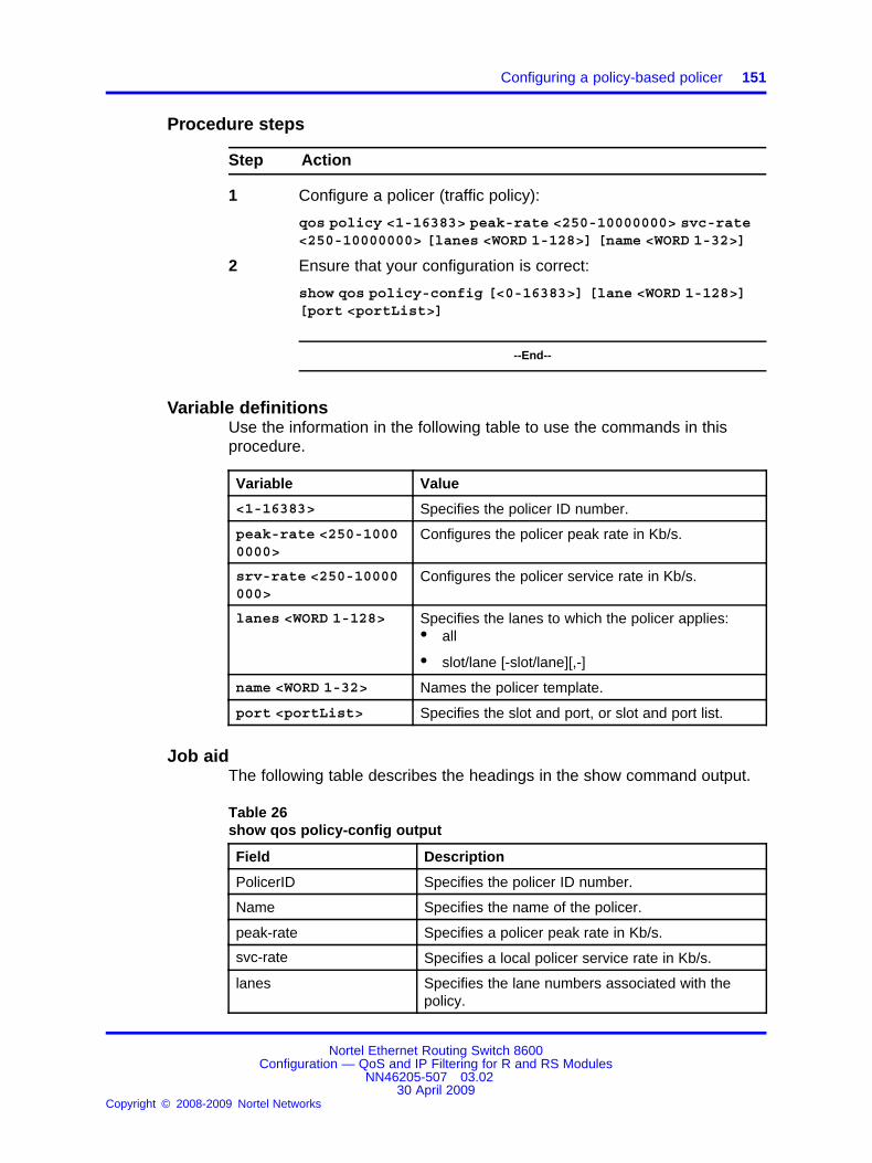
Configuring a policy-based policer 151
Procedure steps
Step Action
1 Configure a policer (traffic policy):
qos policy <1-16383> peak-rate <250-10000000> svc-rate<250-10000000> [lanes <WORD 1-128>] [name <WORD 1-32>]
2 Ensure that your configuration is correct:
show qos policy-config [<0-16383>] [lane <WORD 1-128>][port <portList>]
--End--
Variable definitionsUse the information in the following table to use the commands in thisprocedure.
Variable Value
<1-16383> Specifies the policer ID number.
peak-rate <250-10000000>
Configures the policer peak rate in Kb/s.
srv-rate <250-10000000>
Configures the policer service rate in Kb/s.
lanes <WORD 1-128> Specifies the lanes to which the policer applies:• all
• slot/lane [-slot/lane][,-]
name <WORD 1-32> Names the policer template.
port <portList> Specifies the slot and port, or slot and port list.
Job aidThe following table describes the headings in the show command output.
Table 26show qos policy-config output
Field Description
PolicerID Specifies the policer ID number.
Name Specifies the name of the policer.
peak-rate Specifies a policer peak rate in Kb/s.
svc-rate Specifies a local policer service rate in Kb/s.
lanes Specifies the lane numbers associated with thepolicy.
Nortel Ethernet Routing Switch 8600Configuration — QoS and IP Filtering for R and RS Modules
NN46205-507 03.0230 April 2009
Copyright © 2008-2009 Nortel Networks
.
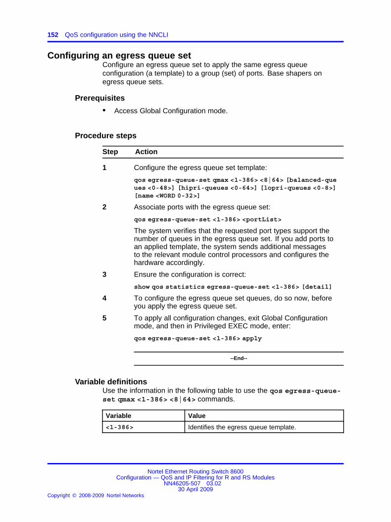
152 QoS configuration using the NNCLI
Configuring an egress queue setConfigure an egress queue set to apply the same egress queueconfiguration (a template) to a group (set) of ports. Base shapers onegress queue sets.
Prerequisites
• Access Global Configuration mode.
Procedure steps
Step Action
1 Configure the egress queue set template:
qos egress-queue-set qmax <1-386> <8|64> [balanced-queues <0-48>] [hipri-queues <0-64>] [lopri-queues <0-8>][name <WORD 0-32>]
2 Associate ports with the egress queue set:
qos egress-queue-set <1-386> <portList>
The system verifies that the requested port types support thenumber of queues in the egress queue set. If you add ports toan applied template, the system sends additional messagesto the relevant module control processors and configures thehardware accordingly.
3 Ensure the configuration is correct:
show qos statistics egress-queue-set <1-386> [detail]
4 To configure the egress queue set queues, do so now, beforeyou apply the egress queue set.
5 To apply all configuration changes, exit Global Configurationmode, and then in Privileged EXEC mode, enter:
qos egress-queue-set <1-386> apply
--End--
Variable definitionsUse the information in the following table to use the qos egress-queue-set qmax <1-386> <8|64> commands.
Variable Value
<1-386> Identifies the egress queue template.
Nortel Ethernet Routing Switch 8600Configuration — QoS and IP Filtering for R and RS Modules
NN46205-507 03.0230 April 2009
Copyright © 2008-2009 Nortel Networks
.

Configuring an egress queue set 153
Variable Value
apply Applies the egress queue set when you issue thecommand.
When you create an egress queue set, applyoccurs when you issue the command. When youmodify a queue set, apply occurs after you save theconfiguration and boot the switch.
This command is available only in Privileged EXECmode.
balanced-queues<0-48>
Specifies the maximum number of balanced queuesin the egress queue set.
hipri-queues <0-64> Specifies the maximum number of high-priorityqueues in the egress queue set.
lopri-queues <0-8> Specifies the maximum number of low-priorityqueues in the egress queue set.
name <WORD 0-32> Names the egress queue set template.
qmax <8|64> Specifies the maximum number of queues, either8 or 64. The sum of the number of queues forbalanced, hipri, and lopri queues must be less thanor equal to qmax.
Use the information in the following table to youuse the qosegress-queue-set <1-386> <portList> command.
Variable Value
<1-386> Identifies the egress queue set.
<portList> Specifies the list of ports.
To remove ports to an egress queue set, use thefollowing command:
no qos egress-queue-set <1-386><portList>
Job aidThe following table describes the headings in the show command output.
Table 27Description of terms in show command output
Field Description
Qid Queue offset from the base queue
Nortel Ethernet Routing Switch 8600Configuration — QoS and IP Filtering for R and RS Modules
NN46205-507 03.0230 April 2009
Copyright © 2008-2009 Nortel Networks
.

154 QoS configuration using the NNCLI
Table 27Description of terms in show command output (cont’d.)
Field Description
Q-name Name of the queue
Q-Style Queuing style: low priority; high priority; orbalanced
min-rate Minimum guaranteed rate
max-rate Maximum data rate
max-q-length Maximum queue length
TemplateID Template ID
Name Name of the template
Total Qs Total number of queues
BalQs Number of balanced queues
Hi-priQs Number of high-priority queues
lo-priQs Number of low-priority queues
Total pages Total pages offered to the queue
Dropped pages Total pages dropped by the queue
Utilization Percent of queue usage
Configuring an egress queue set queueConfigure an egress queue set queue to customize shaping behavior.
CAUTIONRisk of packet lossIf you modify an egress queue set queue, you must restart theswitch.
ATTENTIONFor each Balanced queue, you must specify a desired minimum rate (min-rate)guarantee and a maximum-rate (max-rate) limit.
For Priority queues (either high or low priority), a minimum rate guarantee doesnot apply. Configure only a rate limit (max-rate).
The sum of minimum rate guarantees must be less than the port line rate minusthe sum of high-priority queue rate limits. If this condition is not met, minimumrates are not guaranteed.
Prerequisites
• Access Global Configuration mode.
Nortel Ethernet Routing Switch 8600Configuration — QoS and IP Filtering for R and RS Modules
NN46205-507 03.0230 April 2009
Copyright © 2008-2009 Nortel Networks
.

Modifying an egress queue set or egress queue set queue 155
Procedure steps
Step Action
1 Configure the QoS egress queue set queue:
qos egress-queue-set queue <1-386> <0-63> [max-length<0-32760>] [max-rate <0-100>] [min-rate <0-100>] [name<WORD 0-32>]
2 To apply the changes to the queue set, exit Global Configurationmode, and then in Privileged EXEC mode, enter:
qos apply egress-queue-set <1-386>
If you modify an existing queue set, save the configuration, andthen restart the switch.
--End--
Variable definitionsUse the information in the following table to use the qos egress-queue-set queue commands.
Variable Value
<0-63> Identifies the queue.
<1-386> Identifies the egress queue template.
max-length<0-32760>
Specifies the limit to which a queue can grow. Thequeue length does not imply that a queue has afixed number of buffers. For example, a queue cangrow to full memory size of 32 K buffers.
max-rate <0-100> Specifies the maximum line rate in percent toaccommodate various port speeds in the sametemplate. The max-rate maximum is 100 percent.For example, if a 20 percent rate applies to a 10and 1 Gb/s Ethernet port, the result is a 2 Gb/sbandwidth allocation for 10 Gb/s Ethernet and 200Mb/s for a 1 Gb/s Ethernet port.
min-rate <0-100> Specifies the minimum line rate in percent toaccommodate various port speeds in the sametemplate.
name <WORD 0-32> Names the egress queue.
Modifying an egress queue set or egress queue set queueModify a queue set or queue to change shaping behavior.
Nortel Ethernet Routing Switch 8600Configuration — QoS and IP Filtering for R and RS Modules
NN46205-507 03.0230 April 2009
Copyright © 2008-2009 Nortel Networks
.

156 QoS configuration using the NNCLI
CAUTIONRisk of packet lossIf you modify an egress queue set, you must restart the switch.
Prerequisites
• Access Global Configuration mode.
Procedure steps
Step Action
1 After you apply a queue set, you can modify the queue min-rateand max-rate parameters:
qos egress-queue-set queue <1-386> <0-63> [max-length<0-32760>] [max-rate <0-100>] [min-rate <0-100>] [name<WORD 0-32>]
2 Modify associated ports with the egress queue set:
qos egress-queue-set <1-386> <portList>
Remove ports to an egress queue set:
no qos egress-queue-set <1-386> <portList>
3 You cannot modify other queue set parameters. If you requiredifferent queue set parameters, you must delete the queueset and configure another. If you attempt to change anotherparameter, the following message appears:
Error: Modification of NNSC Egress QSet values notallowed. Only Queue Min/Max rate modification allowed.
4 Ensure the configuration is correct:
show qos egress-queue-set [<1-386>] [detail]
5 To apply all configuration changes, exit Global Configurationmode, and then in Privileged EXEC mode, enter:
qos apply egress-queue-set <1-386>
The following message appears:
WARNING: The egress-queue-set QoS change made will takeeffect only after the configuration is saved and thechassis is rebooted.
6 Save the configuration as required:
save config
Nortel Ethernet Routing Switch 8600Configuration — QoS and IP Filtering for R and RS Modules
NN46205-507 03.0230 April 2009
Copyright © 2008-2009 Nortel Networks
.

Configuring ingress mappings 157
save config standby config.cfg
save bootconfig
save bootconfig standby boot.cfg
7 Restart the switch:
boot -y
8 Verify the changes:
show qos egress-queue-set [<1-386>]
--End--
Variable definitionsUse the information in the following table to use the commands in thisprocedure.
Variable Value
<1-386> Identifies the egress queue template.
Configuring ingress mappingsYou can modify the ingress mappings to change traffic priorities. However,Nortel recommends that you use the default mappings.
Prerequisites
• Access Global Configuration mode.
Procedure steps
Step Action
1 Configure MPLS to QoS ingress mappings:
qos ingressmap exp <0-7> <0-7>
2 Configure DSCP to QoS ingress mappings:
qos ingressmap ds <0-63> <0-7>
3 Configure 802.1p bit to QoS ingress mappings:
qos ingressmap 1p <0-7> <0-7>
4 Ensure the configuration is correct:
Nortel Ethernet Routing Switch 8600Configuration — QoS and IP Filtering for R and RS Modules
NN46205-507 03.0230 April 2009
Copyright © 2008-2009 Nortel Networks
.

158 QoS configuration using the NNCLI
show qos ingressmap
--End--
Variable definitionsUse the information in the following table to use the qos ingressmapcommands.
Variable Value
1p <0-7> <0-7> Maps the IEEE 802.1p bit to QoS level. Each QoSlevel has a default IEEE 1P value:• level 0—1
• level 1—0
• level 2—2
• level 3—3
• level 4—4
• level 5—5
• level 6—6
• level 7—7
To use the default configuration, use the defaultoption in the commanddefault qos ingressmap1p
ds <0-63> <0-7> Maps the DS byte to QoS level.
exp <0-7> <0-7> Maps the MPLS EXP bit to a QoS level. Eachoption has a range from 0–7.
Configuring egress mappingsYou can modify the egress mappings to change traffic priorities. However,Nortel recommends that you use the default mappings.
Prerequisites
• Access Global Configuration mode.
Procedure steps
Step Action
1 Configure QoS to MPLS egress mappings:
qos egressmap exp <0-7> <0-7>
Nortel Ethernet Routing Switch 8600Configuration — QoS and IP Filtering for R and RS Modules
NN46205-507 03.0230 April 2009
Copyright © 2008-2009 Nortel Networks
.

Configuring egress mappings 159
2 Configure QoS to DSCP egress mappings:
qos egressmap ds <0-7> <WORD 1-6>
3 Configure QoS to 802.1p bit egress mappings:
qos egressmap 1p <0-7> <0-7>
4 Ensure the configuration is correct:
show qos egressmap
--End--
Variable definitionsUse the information in the following table to use the qos egressmapcommands.
Variable Value
1p <0-7> <0-7> Maps the QoS level to IEEE 802.1p priority. EachQoS level has a default IEEE 1P value:• level 0—1
• level 1—0
• level 2—2
• level 3—3
• level 4—4
• level 5—5
• level 6—6
• level 7—7
To use the default configuration, use the defaultoption in the commanddefault qos ingressmap1p
ds <0-7> <WORD 1-6> Maps the QoS level to DS byte. You can specifythe DSCP in either hexadecimal, binary, or decimal.
exp <0-7> <0-7> Maps the QoS level to MPLS EXP level.
Nortel Ethernet Routing Switch 8600Configuration — QoS and IP Filtering for R and RS Modules
NN46205-507 03.0230 April 2009
Copyright © 2008-2009 Nortel Networks
.

160 QoS configuration using the NNCLI
Nortel Ethernet Routing Switch 8600Configuration — QoS and IP Filtering for R and RS Modules
NN46205-507 03.0230 April 2009
Copyright © 2008-2009 Nortel Networks
.

161.
Traffic filter configuration using DeviceManager
Use traffic filtering to provide security by blocking unwanted traffic andprioritizing other traffic.
For information about statistics, see Nortel Ethernet Routing Switch 8600Performance Management (NN46205-704) .
Traffic filter configuration proceduresThis task flow shows you the sequence of procedures you performto configure traffic filters. To link to any procedure, go to “Traffic filterconfiguration navigation” (page 161).
Figure 29Traffic filter configuration procedures
Traffic filter configuration navigation
• “Configuring ACTs” (page 162)
• “Adding a user-defined pattern” (page 164)
• “Configuring an access control list” (page 165)
Nortel Ethernet Routing Switch 8600Configuration — QoS and IP Filtering for R and RS Modules
NN46205-507 03.0230 April 2009
Copyright © 2008-2009 Nortel Networks
.

162 Traffic filter configuration using Device Manager
Configuring ACTsUse an access control template (ACT) to specify all possible match fieldsfor an access control list (ACL).
Prerequisites
• Add patterns before you activate the ACT (Apply = true).
Procedure steps
Step Action
1 In Device Manager, choose Security, Data Path, AdvancedFilters (ACE/ACLs).
A notification box appears that indicates you can configureadvanced filters for R and RS modules only.
2 Click OK.
3 To add a new ACT, click Insert.
4 Type an ActId or accept the default ACT ID.
5 Name the ACT.
6 Select the Address Resolution Protocol (ARP), Ethernet, IP,protocol, and IPv6 attributes you require.
7 Click Insert.
8 If you need to add a pattern, you must do so before you activatethe ACT.
9 On the ACT dialog box, change Apply to true to activate theACT you just configured.
After you configure Apply to true, you can no longer modify theACT. If you require different attributes or patterns, you mustdelete the ACT and create a new one.
10 To delete an ACT, select the ACT and click Delete.
You cannot delete an ACT if an ACL references it. You must firstdelete the ACL.
--End--
Variable definitionsUse the data in the following table to configure ACTs.
Variable Value
ActId Specifies a unique identifier for the ACT. The rangeis 1–4096.
Nortel Ethernet Routing Switch 8600Configuration — QoS and IP Filtering for R and RS Modules
NN46205-507 03.0230 April 2009
Copyright © 2008-2009 Nortel Networks
.
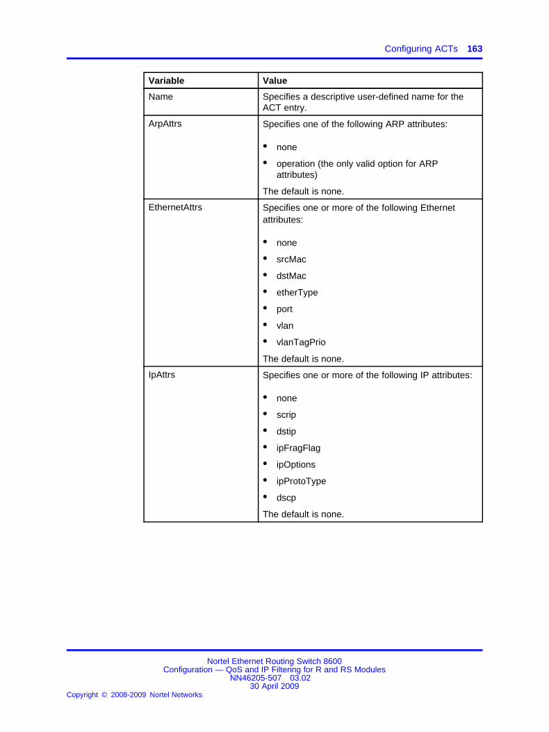
Configuring ACTs 163
Variable Value
Name Specifies a descriptive user-defined name for theACT entry.
ArpAttrs Specifies one of the following ARP attributes:
• none
• operation (the only valid option for ARPattributes)
The default is none.
EthernetAttrs Specifies one or more of the following Ethernetattributes:
• none
• srcMac
• dstMac
• etherType
• port
• vlan
• vlanTagPrio
The default is none.
IpAttrs Specifies one or more of the following IP attributes:
• none
• scrip
• dstip
• ipFragFlag
• ipOptions
• ipProtoType
• dscp
The default is none.
Nortel Ethernet Routing Switch 8600Configuration — QoS and IP Filtering for R and RS Modules
NN46205-507 03.0230 April 2009
Copyright © 2008-2009 Nortel Networks
.

164 Traffic filter configuration using Device Manager
Variable Value
ProtocolAttrs Specifies one or more of the following protocolattributes:
• none
• tcpSrcPort
• udpSrcPort
• tcpDstPort
• udpDstport
• tcpFlags
• icmpMsgFlags
The default is none.
Ipv6Attrs Specifies one or more of the following protocolattributes:
• none
• srcIpv6
• dstIpv6
• nextHdr
The default is none.
Apply Indicates whether the ACT applies.
Adding a user-defined patternAdd a user-defined pattern to which the filter can match. You canconfigure up to three patterns for each ACT.
You can insert a pattern only into an inactive ACT.
Prerequisites
• An ACT exists.
• You did not apply the ACT.
Procedure steps
Step Action
1 In Device Manager, choose Security, Data Path, AdvancedFilters (ACE/ACLs).
Nortel Ethernet Routing Switch 8600Configuration — QoS and IP Filtering for R and RS Modules
NN46205-507 03.0230 April 2009
Copyright © 2008-2009 Nortel Networks
.

Configuring an access control list 165
A message box appears that indicates you can configureadvanced filters for R and RS modules only.
2 Click OK.
3 On the ACT tab, select the ACT in which to insert a pattern.
4 Click Pattern.
5 Click Insert.
6 Configure the pattern, and then click Insert.
7 To activate the ACT, on the ACT tab, set Apply to true for theACT.
--End--
Variable definitionsUse the data in the following table to configure ACT patterns.
Variable Value
Name Specifies a descriptive user-defined name for the ACL pattern entry.
Specifies one of the following as the user-defined header for the ACEs of the ACL:(The default is none.)
Base
• none
• macSrcBegin
• ipHdrBegin
• ipTosBegin
• ipDstBegin
• tcpDstportBegin
• udpSrcportBegin
• ipHdrEnd
• updEnd
• etherBegin
• ethTypeLenBegin
• ipOptionsBegin
• ipProtoBegin
• tcpBegin
• tcpFlagsEnd
• udpDstportBegin
• icmpMsgBegin
• ipv6HdrBegin
• macDstBegin
• arpBegin
• ipPayloadBegin
• ipSrcBegin
• tcpSrcportBegin
• udpBegin
• etherEnd
• tcpEnd
Offset Configures the offset in bits to the beginning offset with the selected header optionas a base. Valid values are 0–76800. The default is 0.
Length Configures the number of bits to extract from the beginning of the offset. Validvalues are 1–56. The default is 1.
Configuring an access control listUse an ACL to specify an ordered list of ACEs, or filter rules. The ACEsprovide specific actions for the filter to perform.
Nortel Ethernet Routing Switch 8600Configuration — QoS and IP Filtering for R and RS Modules
NN46205-507 03.0230 April 2009
Copyright © 2008-2009 Nortel Networks
.

166 Traffic filter configuration using Device Manager
When you create an ACL with the type inVlan that uses an ACT basedon the source IP address, the ACL no longer works after the ARP agingtime elapses. This does not create a security breach. For a solution to thisissue, see “Workaround for inVlan, srcIp ACL” (page 351).
To modify an ACL parameter, double-click the parameter you wish tochange. Change the value, and then click Apply. You cannot changea parameter that appears dimmed; in this case, delete the ACL andconfigure a new one.
Prerequisites
• The ACT exists.
• You applied the ACT.
Procedure steps
Step Action
1 In Device Manager, choose Security, Data Path, AdvancedFilters (ACE/ACLs).
A message box appears that indicates you can configureadvanced filters for R and RS modules only.
2 Click OK.
3 Click the ACL tab.
4 Click Insert.
5 Type an ACL ID from 1 to 4096 or accept the default value.
6 Click the ActId browse (...) button to select an ACT ID.
7 Select an Act ID and click Ok.
8 Specify whether the ACL is VLAN or port-based, and whether itis ingress (in) or egress (out).
9 Specify a name for the ACL.
10 If the ACL is VLAN-based, click the VlanList ellipsis (...) andchoose a VLAN list.
11 If the ACL is port-based, select the PortList by clicking theellipsis (...).
12 Select the desired ports and then click Ok.
13 Configure the DefaultAction and the GlobalAction.
14 Enable or disable the State, as required.
15 Click Insert.
Nortel Ethernet Routing Switch 8600Configuration — QoS and IP Filtering for R and RS Modules
NN46205-507 03.0230 April 2009
Copyright © 2008-2009 Nortel Networks
.

Configuring an access control list 167
16 To delete an ACL, select the ACL and click Delete.
--End--
Use the data in the following table to configure an ACL.
Variable Value
AclId Specifies a unique identifier for the ACL from1–4096.
ActId Specifies a unique identifier for the ACT entry from1–4096.
Type Specifies whether the ACL is VLAN- or port-based.Valid options are
• inVlan
• outVlan
• inPort
• outPort
ATTENTIONThe inVlan and outVlan ACLs drop packets if youadd a VLAN after ACE creation. For VLAN-basedfilters, ensure the ACE uses R module slots,regardless of the VLAN port membership on aslot.
Name Specifies a descriptive user-defined name for theACL.
VlanList For inVlan and outVlan ACL types, specifies allVLANs associated with the ACL.
PortList For inPort and outPort ACL types, specifies theports associated with the ACL.
DefaultAction Specifies the action taken when no ACEs in theACL match. Valid options are deny and permit,with permit as the default. Deny means the systemdrops the packets; permit means the systemforwards packets.
Nortel Ethernet Routing Switch 8600Configuration — QoS and IP Filtering for R and RS Modules
NN46205-507 03.0230 April 2009
Copyright © 2008-2009 Nortel Networks
.
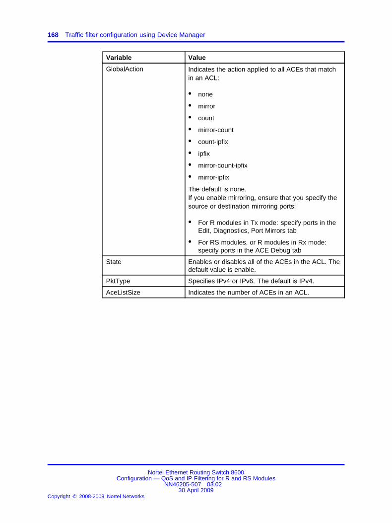
168 Traffic filter configuration using Device Manager
Variable Value
GlobalAction Indicates the action applied to all ACEs that matchin an ACL:
• none
• mirror
• count
• mirror-count
• count-ipfix
• ipfix
• mirror-count-ipfix
• mirror-ipfix
The default is none.If you enable mirroring, ensure that you specify thesource or destination mirroring ports:
• For R modules in Tx mode: specify ports in theEdit, Diagnostics, Port Mirrors tab
• For RS modules, or R modules in Rx mode:specify ports in the ACE Debug tab
State Enables or disables all of the ACEs in the ACL. Thedefault value is enable.
PktType Specifies IPv4 or IPv6. The default is IPv4.
AceListSize Indicates the number of ACEs in an ACL.
Nortel Ethernet Routing Switch 8600Configuration — QoS and IP Filtering for R and RS Modules
NN46205-507 03.0230 April 2009
Copyright © 2008-2009 Nortel Networks
.

169.
Traffic filter configuration using the CLIUse traffic filtering to block unwanted traffic or to prioritize desired traffic.
For information about statistics, see Nortel Ethernet Routing Switch 8600Performance Management (NN46205-704) .
Traffic filter configuration using the CLI proceduresThis task flow shows you the sequence of procedures you performto configure traffic filters. To link to a procedure, go to “Traffic filterconfiguration using the CLI navigation” (page 170).
Nortel Ethernet Routing Switch 8600Configuration — QoS and IP Filtering for R and RS Modules
NN46205-507 03.0230 April 2009
Copyright © 2008-2009 Nortel Networks
.

170 Traffic filter configuration using the CLI
Figure 30Traffic filter configuration using the CLI procedures
Traffic filter configuration using the CLI navigation
• “Job aid” (page 171)
• “Configuring an ACT” (page 173)
• “Adding a user-defined pattern” (page 175)
Nortel Ethernet Routing Switch 8600Configuration — QoS and IP Filtering for R and RS Modules
NN46205-507 03.0230 April 2009
Copyright © 2008-2009 Nortel Networks
.

Job aid 171
• “Configuring an ACL” (page 177)
• “Configuring global and default actions for an ACL” (page 178)
• “Associating VLANs with an ACL” (page 179)
• “Associating ports with an ACL” (page 180)
• “Viewing R and RS module filter configuration information” (page 181)
Job aidThe following roadmap lists traffic filter commands that you can use toperform the procedures in this section.
Table 28Roadmap of traffic filter CLI commands
Command Parameters
clear filter acl statistics default[<acl-id>]
—
clear filter acl statistics port[<acl-id>] [<acl-id> <ace-id>][<acl-id> <ace-id> <port-num>]
—
create <type> act <value> [pktType<value>] [name <value>]
delete
disable
enable
info
config filter acl <acl-id>
name <value>
<ports>
info
config filter acl <acl-id> port
remove <ports>
default-action <value>
global-action <value>
config filter acl <acl-id> set
info
add <vid> [<vid2-vid3>]
info
config filter acl <acl-id> vlan
remove <vid> [<vid2-vid3>]
Nortel Ethernet Routing Switch 8600Configuration — QoS and IP Filtering for R and RS Modules
NN46205-507 03.0230 April 2009
Copyright © 2008-2009 Nortel Networks
.
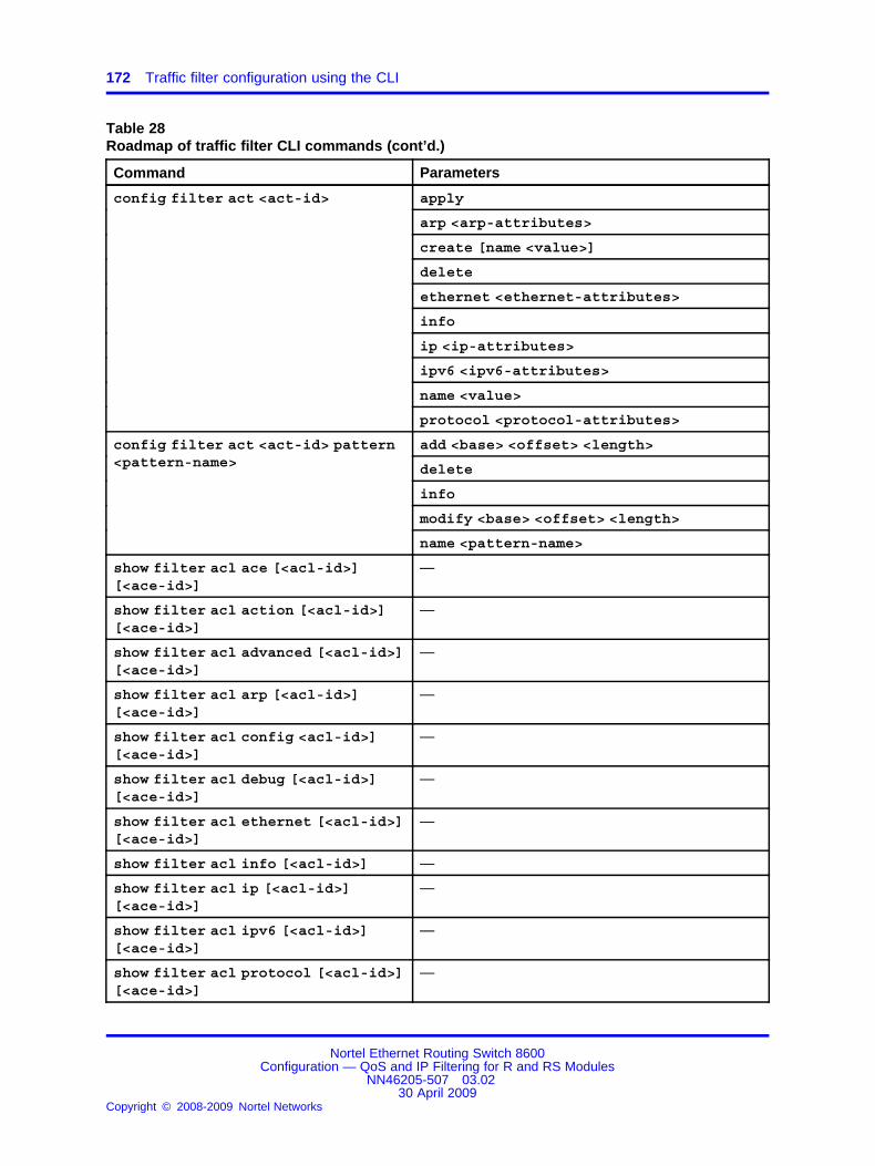
172 Traffic filter configuration using the CLI
Table 28Roadmap of traffic filter CLI commands (cont’d.)
Command Parameters
apply
arp <arp-attributes>
create [name <value>]
delete
ethernet <ethernet-attributes>
info
ip <ip-attributes>
ipv6 <ipv6-attributes>
name <value>
config filter act <act-id>
protocol <protocol-attributes>
add <base> <offset> <length>
delete
info
modify <base> <offset> <length>
config filter act <act-id> pattern<pattern-name>
name <pattern-name>
show filter acl ace [<acl-id>][<ace-id>]
—
show filter acl action [<acl-id>][<ace-id>]
—
show filter acl advanced [<acl-id>][<ace-id>]
—
show filter acl arp [<acl-id>][<ace-id>]
—
show filter acl config <acl-id>][<ace-id>]
—
show filter acl debug [<acl-id>][<ace-id>]
—
show filter acl ethernet [<acl-id>][<ace-id>]
—
show filter acl info [<acl-id>] —
show filter acl ip [<acl-id>][<ace-id>]
—
show filter acl ipv6 [<acl-id>][<ace-id>]
—
show filter acl protocol [<acl-id>][<ace-id>]
—
Nortel Ethernet Routing Switch 8600Configuration — QoS and IP Filtering for R and RS Modules
NN46205-507 03.0230 April 2009
Copyright © 2008-2009 Nortel Networks
.

Configuring an ACT 173
Table 28Roadmap of traffic filter CLI commands (cont’d.)
Command Parameters
show filter acl statistics default[<acl-id>]
—
show filter acl statistics port[<acl-id>] [<acl-id> <ace-id>][<acl-id> <ace-id> <port-num>]
—
show filter act [<act-id>] —
show config module filter [verbose][module <value>] [mode <value>]
—
show filter act-pattern [<act-id>] —
Configuring an ACTUse an access control template (ACT) to specify all possible match fieldsfor an access control list (ACL).
Prerequisites
• Add patterns before you activate the ACT (Apply = true).
Procedure steps
Step Action
1 Create the ACT:
config filter act <act-id> create [name <value>]
<act-id> specifies an ACT ID from 1 to 4096.
2 Configure the required ACT attributes: ARP, IP, IPv6, protocol,and Ethernet. You can specify Access Control Entry (ACE)attributes only for the attributes that you specify in the ACT.
3 To add a pattern, you must do so before you activate the ACT.
4 Ensure the configuration is correct:
show filter act [<act-id>]
5 Apply (commit) your changes:
config filter act <act-id> apply
After you issue the apply command, you can no longer modifythe ACT. If you require different attributes or patterns, you mustdelete the ACT and create a new one.
--End--
Nortel Ethernet Routing Switch 8600Configuration — QoS and IP Filtering for R and RS Modules
NN46205-507 03.0230 April 2009
Copyright © 2008-2009 Nortel Networks
.

174 Traffic filter configuration using the CLI
Variable definitionsUse the information in the following table to use the config filter act<act-id> command.
Variable Value
apply Applies or commits the ACT. After you issue theapply command, you can change the ACT onlyby deleting it and creating a new one if no ACLsare associated with the ACT.
arp <arp-attributes> Specifies the permitted ARP attributes for theACT. Separate the list of allowed attributes bycommas:
• none
• operation
If you select none, this action deletes the nodeand prevents you from selecting other attributes.
create [name <value>] Creates an ACT. The name <value> parameteris optional and specifies a descriptive name forthe ACT using 0–32 characters. If you do notenter a name, the switch generates a defaultname. The ACT ID acts as an index to the ACTtable. You can change the name at any time,even after you issue the apply command.
delete Deletes an ACT if no associated ACLs exist.
ip <ip-attributes> Specifies the permitted IP attributes for the ACT.You must separate the list of attributes commas.The list can include
• none
• srcIp, dstIp, ipFragFlag, ipOptions,ipProtoType, and dscp
If you select none, this action deletes the nodeand prevents you from selecting other attributes.The default is none.
Nortel Ethernet Routing Switch 8600Configuration — QoS and IP Filtering for R and RS Modules
NN46205-507 03.0230 April 2009
Copyright © 2008-2009 Nortel Networks
.

Adding a user-defined pattern 175
Variable Value
ethernet <ethernet-attributes>
Specifies the permitted Ethernet attributes forthe ACT. You must separate the list of attributescommas. The list can include
• none
• srcMac, dstMac, etherType, <port|vlan>, andvlanTagPrio
If you select none, this action deletes the nodeand prevents you from selecting other attributes.The default is none.
info Shows information about the ACTs.
ipv6 <ipv6-attributes>
Specifies the permitted IPv6 attributes. You mustseparate the list of attributes commas. The listcan include
• none
• srcIpv6, dstIpv6, and nextHdr
If you select none, this action deletes the nodeand prevents you from selecting other attributes.The default is none.
name <value> Specifies a name for the ACT using 0–32characters.
protocol <protocol-attributes>
Specifies the permitted protocol attributes forthe ACT. You must separate the list of attributescommas. The list can include
• none
• tcpSrcPort, udpSrcPort, tcpDstPort,udpDstPort, tcpFlags, and icmpMsgFlags
If you select none, this action deletes the nodeand prevents you from selecting other attributes.The default is none.
Adding a user-defined patternAdd a user-defined pattern to which the ACT can match.
You can insert a pattern into an ACT only if it is inactive (not applied). AnACT can have a maximum of three associated patterns.
Nortel Ethernet Routing Switch 8600Configuration — QoS and IP Filtering for R and RS Modules
NN46205-507 03.0230 April 2009
Copyright © 2008-2009 Nortel Networks
.

176 Traffic filter configuration using the CLI
Prerequisites
• An ACT exists.
• You did not apply the ACT.
Procedure steps
Step Action
1 Create a template for patterns within an ACT:
config filter act <act-id> pattern <pattern-name> add<base> <offset> <length>
2 Ensure the configuration is correct:
show filter act-pattern [<act-id>]
--End--
Variable definitionsUse the information in the following table to use the config filter act<act-id> pattern <pattern-name>command.
Variable Value
add <base> <offset><length>
Adds a template for patterns you create.
<base>—the base and the offset togetherdetermine the beginning of the pattern. Permittedvalues for the base include
• none
• ether-begin, mac-dst-begin, mac-srcbegin,ethTypeLen-begin, arp-begin, ip-hdr-begin,ip-options-begin, ip-payload-begin, ip-tos-begin,ip-proto-begin, ip-src-begin, ip-dst-begin,ipv6-hdr-begin, tcp-begin, tcp-srcport-begin,tcp-dstport-begin, tcp-flags-end, udp-begin,udp-srcport-begin, udp-dstport-begin, ether-end,ip-hdr-end, icmp-msg-begin, tcp-end, andudp-end
<offset> is the number of bits from the basewhere the pattern starts.
<length> is the length in bits, from 1–56, of theuser-defined field.
Nortel Ethernet Routing Switch 8600Configuration — QoS and IP Filtering for R and RS Modules
NN46205-507 03.0230 April 2009
Copyright © 2008-2009 Nortel Networks
.
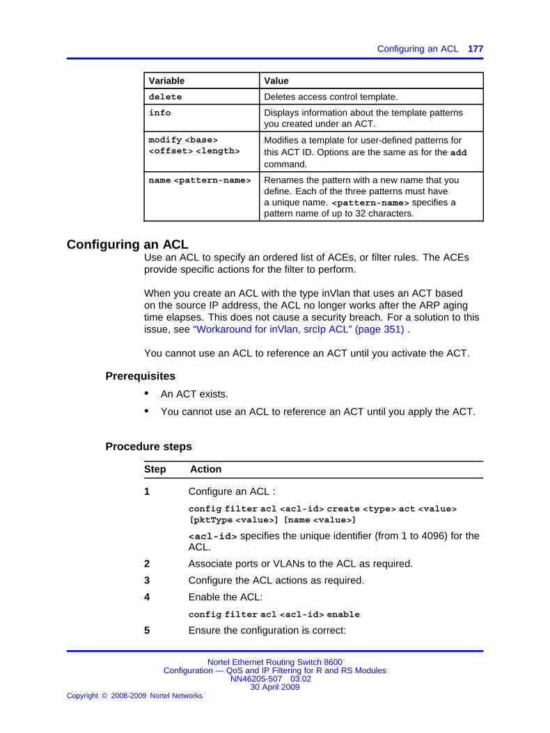
Configuring an ACL 177
Variable Value
delete Deletes access control template.
info Displays information about the template patternsyou created under an ACT.
modify <base><offset> <length>
Modifies a template for user-defined patterns forthis ACT ID. Options are the same as for the addcommand.
name <pattern-name> Renames the pattern with a new name that youdefine. Each of the three patterns must havea unique name. <pattern-name> specifies apattern name of up to 32 characters.
Configuring an ACLUse an ACL to specify an ordered list of ACEs, or filter rules. The ACEsprovide specific actions for the filter to perform.
When you create an ACL with the type inVlan that uses an ACT basedon the source IP address, the ACL no longer works after the ARP agingtime elapses. This does not cause a security breach. For a solution to thisissue, see “Workaround for inVlan, srcIp ACL” (page 351) .
You cannot use an ACL to reference an ACT until you activate the ACT.
Prerequisites
• An ACT exists.
• You cannot use an ACL to reference an ACT until you apply the ACT.
Procedure steps
Step Action
1 Configure an ACL :
config filter acl <acl-id> create <type> act <value>[pktType <value>] [name <value>]
<acl-id> specifies the unique identifier (from 1 to 4096) for theACL.
2 Associate ports or VLANs to the ACL as required.
3 Configure the ACL actions as required.
4 Enable the ACL:
config filter acl <acl-id> enable
5 Ensure the configuration is correct:
Nortel Ethernet Routing Switch 8600Configuration — QoS and IP Filtering for R and RS Modules
NN46205-507 03.0230 April 2009
Copyright © 2008-2009 Nortel Networks
.

178 Traffic filter configuration using the CLI
show filter acl info [<acl-id>]
--End--
Variable definitionsUse the information in the following table to use the config filter acl<acl-id> command.
Variable Value
create <type> act<value> [pktType<value>] [name<value>]
Creates an ACL only when you associate an ACTwith that ACL. Options include
• <type>—type of ACL: inVlan, outVlan, inPort,or outPort.
• act <value>—an ACT ID from 1–4096.
• pktType <value>—Layer 3 packet type (ipv4or ipv6)
• name <value>—an optional parameter thatspecifies a descriptive name for the ACL using0–32 characters.
delete Deletes an ACL.
Removes all VLANs or brouter ports under this ACLand deletes all ACEs. It does not delete the ACTs.
disable Disables the ACL state, and all associated ACEs.
enable Enables the ACL state, and all associated ACEs.
Enable is the default.
info Displays information related to the ACL.
name <value> Renames an ACL.
Configuring global and default actions for an ACLConfigure the default action to specify packet treatment when a packetdoes not match an ACE.
Configure the global action to specify packet treatment when a packetdoes match an ACE.
Prerequisites
• The ACL exists.
Nortel Ethernet Routing Switch 8600Configuration — QoS and IP Filtering for R and RS Modules
NN46205-507 03.0230 April 2009
Copyright © 2008-2009 Nortel Networks
.

Associating VLANs with an ACL 179
Procedure steps
Step Action
1 Configure the global action for an ACL:
config filter acl <acl-id> set global-action <value>
2 Configure the default action for an ACL:
config filter acl <acl-id> set default-action <value>
--End--
Variable definitionsUse the information in the following table to use the config filter acl<acl-id> set command.
Variable Value
default-action<value>
Specifies the default action to take when no ACEsmatch. Options include <deny|permit>. Thedefault is permit.
global-action<value>
The <value> parameter specifies the global actionfor matching ACEs:
• none
• mirror, count, mirror-count, ipfix, mirror-ipfix,count-ipfix, and mirror-count-ipfix
If you enable mirroring, ensure you specify thesource or destination mirroring ports:
• For R modules in Tx mode: use config diagmirror-by-port commands to specifymirroring ports.
• For RS modules, or R modules in Rx mode,use the config filter acl <acl-id>ace <ace-id> debug commands to specifymirroring ports.
info Displays the status of the global and default actions.
Associating VLANs with an ACLAssociate VLANs with, or remove VLANs from, an ACL so that filters applyor do not apply to VLAN traffic, respectively.
Nortel Ethernet Routing Switch 8600Configuration — QoS and IP Filtering for R and RS Modules
NN46205-507 03.0230 April 2009
Copyright © 2008-2009 Nortel Networks
.

180 Traffic filter configuration using the CLI
Prerequisites
• The ACL exists.
• The VLANs exist.
Procedure steps
Step Action
1 Associate VLANs with an ACL:
config filter acl <acl-id> vlan add <vid> [<vid2-vid3>]
2 Remove VLANs from an ACL:
config filter acl <acl-id> vlan remove <vid>[<vid2-vid3>]
--End--
Variable definitionsUse the information in the following table to use the config filter acl<acl-id> vlan command.
Variable Value
add <vid> [<vid2-vid3>]
Associates a VLAN or a VLAN list with an ACL. The<vid> parameter is a list of VLANs separated by acomma, or a range of VLANs specified from low tohigh [vlan-id - vlan-id].
info Displays the ACL VLAN status.
remove <vid>[<vid2-vid3>]
Removes a VLAN or VLAN list from an ACL. The<vid> parameter is a list of VLANs separated by acomma, or a range of VLANs specified from low tohigh [vlan-id to vlan-id].
Associating ports with an ACLAssociate ports with, or remove ports from, an ACL so that filters do or donot apply to port traffic, respectively.
Prerequisites
• The ACL exists.
Nortel Ethernet Routing Switch 8600Configuration — QoS and IP Filtering for R and RS Modules
NN46205-507 03.0230 April 2009
Copyright © 2008-2009 Nortel Networks
.

Viewing R and RS module filter configuration information 181
Procedure steps
Step Action
1 Associate ports with an ACL:
config filter acl <acl-id> port add <ports>
2 Remove ports from an ACL:
config filter acl <acl-id> port remove <ports>
--End--
Variable definitionsUse the information in the following table to use the config filter acl<acl-id> port command.
Variable Value
add <ports> Associates a port or a port list with an ACL. The<ports> parameter is a list of ports in the followingformat: [<slot/port>] or [<slot/port-slot/port>].
remove <ports> Removes a port or a port list from an ACL. The<ports> parameter is a list of ports in the followingformat: [<slot/port>] or [<slot/port-slot/port>].
info Displays the ACL port status.
Viewing R and RS module filter configuration informationYou can view configuration information for ACL-based filters.
Procedure steps
Step Action
1 View configuration information about R module filters:
show config module filter [verbose] [mode <value>]
--End--
Variable definitionsUse the information in the following table to use the show command.
Nortel Ethernet Routing Switch 8600Configuration — QoS and IP Filtering for R and RS Modules
NN46205-507 03.0230 April 2009
Copyright © 2008-2009 Nortel Networks
.

182 Traffic filter configuration using the CLI
Variable Value
mode <value> Shows filter configuration output in either CLIor NNCLI mode. <value> is cli or nncli.
verbose Shows detailed output.
Job aidThis section shows the show config module filter command output.
ERS-8606:5# show config module filterPreparing to Display Configuration... ## MON APR 14 11:05:31 2008 UTC# box type : ERS-8006# software version : REL4.2.0.0_B157# monitor version : 4.2.0.0/157# cli mode : 8600 CLI### Asic Info :# SlotNum|Name |CardType |MdaType |Parts Description## Slot 1 -- 0x00000001 0x00000000# Slot 2 -- 0x00000001 0x00000000# Slot 3 8630GBR 0x2432511e 0x00000000 RSP=25 CLUE=2 F2I=1 F2E=1FTMUX=17 CC= 3 FOQ=266 DPC=184 BMC=776 PIM=257 MAC=4# Slot 4 8648GTR 0x24220130 0x00000000 RSP=25 CLUE=2 F2I=1 F2E=1FTMUX=0 CC=3 FOQ=266 DPC=6 BMC=776 PIM=257 MAC=4# Slot 5 8692SF 0x200e0100 0x00000000 CPU: CPLD=19 MEZZ=4 SFM:OP=3 TMUX=2 SWIP=23 FAD=16 CF=28# Slot 6 -- 0x00000001 0x00000000 config## R-MODULE FILTER CONFIGURATION#filter act 1 create name "ACT-1ADV"filter act 1 ethernet srcMacfilter act 1 ip srcIpfilter act 1 protocol tcpSrcPortfilter act 1 apply filter act 2 create name "ACT-2AD VS"filter act 2 pattern kelie add ip-hdr-begin 0 1filter act 2 applyfilter acl 1 create inPort act 1filter acl 1 set global-action mirror-countfilter acl 1 ace 1 create name "Adv"filter acl 1 ace 1 action permit filter acl 1 ace 1 debugcopytoprimarycp enablefilter acl 2 create inPort act 2filter acl 2 ace 1 create name "KB"filter acl 2 ace 1 action permit remark-dot1p fivebackERS-8606:5#
Nortel Ethernet Routing Switch 8600Configuration — QoS and IP Filtering for R and RS Modules
NN46205-507 03.0230 April 2009
Copyright © 2008-2009 Nortel Networks
.

183.
Traffic filter configuration using theNNCLI
Use traffic filtering to block unwanted traffic or to prioritize desired traffic.
Traffic filter configuration proceduresThis task flow shows you the sequence of procedures you performto configure traffic filters. To link to a procedure, go to “Traffic filterconfiguration navigation” (page 184).
Nortel Ethernet Routing Switch 8600Configuration — QoS and IP Filtering for R and RS Modules
NN46205-507 03.0230 April 2009
Copyright © 2008-2009 Nortel Networks
.

184 Traffic filter configuration using the NNCLI
Figure 31Traffic filter configuration procedures
Traffic filter configuration navigation
• “Job aid” (page 185)
• “Configuring an ACT” (page 186)
• “Adding a user-defined pattern” (page 188)
Nortel Ethernet Routing Switch 8600Configuration — QoS and IP Filtering for R and RS Modules
NN46205-507 03.0230 April 2009
Copyright © 2008-2009 Nortel Networks
.

Job aid 185
• “Configuring an ACL” (page 189)
• “Configuring global and default actions for an ACL” (page 190)
• “Associating VLANs with an ACL” (page 191)
• “Associating ports with an ACL” (page 192)
• “Viewing R and RS module filter configuration information” (page 193)
Job aidThe following roadmap lists traffic filter commands that you can use toperform the procedures in this section.
Table 29Roadmap of traffic filter NNCLI commands
Command Parameters
Privileged EXEC mode
default [<1-4096>]clear filter acl statistics
port [<1-4096> [<1-1000> [<portList>]]]
<1-4096>
ace [<1-4096>] [<1-1000>]
action [<1-4096>] [<1-1000>]
advanced [<1-4096>] [<1-1000>]
arp [<1-4096>] [<1-1000>]
config [<1-4096>] [<1-1000>]
debug [<1-4096>] [<1-1000>]
ethernet [<1-4096>] [<1-1000>]
ip [<1-4096>] [<1-1000>]
ipv6 [<1-4096>] [<1-1000>]
protocol [<1-4096>] [<1-1000>]
statistics default [<1-4096>]
show filter acl
statistics port [<1-4096> [<1-1000>[<portList>]]]
show filter act [<1-4096>] —
show filter act-pattern[<1-4096>]
—
Global Configuration mode
Nortel Ethernet Routing Switch 8600Configuration — QoS and IP Filtering for R and RS Modules
NN46205-507 03.0230 April 2009
Copyright © 2008-2009 Nortel Networks
.

186 Traffic filter configuration using the NNCLI
Table 29Roadmap of traffic filter NNCLI commands (cont’d.)
Command Parameters
enable
name <WORD 0-32>
filter acl <1-4096>
type <inVlan|outVlan|inPort|outPort>act <1-4096> [pktType <ipv4|ipv6>] [name<WORD 0-32>]
filter acl port <1-4096><portList>
—
default-action <deny|permit>filter acl set <1-4096>
global-action <count|count-ipfix|ipfix|mirror|mirror-count|mirror-count-ipfix|mirror-ipfix>
filter acl vlan <1-4096> <1-4094> —
arp operation
ethernet <srcMac|dstMac|ethertype|<port|vlan>|vlanTagPrio>
ip <srcip|dstIp|ipFragFlag|ipOptions|ipProtoType|dscp>
ipv6 <srcipv6|dstIpv6|nextHdr>
name <WORD 0-32>
filter act <1-4096>
protocol <tcpSrcPort|udpSrcPort|tcpDstPort|udpDstPort|tcpFlags|icmpMsgType>
filter act pattern <1-4096> <WORD0-32> <base> <0-76800> <1-56>
—
filter apply act <1-4096> —
Configuring an ACTUse an access control template (ACT) to specify all possible match fieldsfor an access control list (ACL).
Prerequisites
• Enter Global Configuration mode.
• To add a pattern, the ACT must be inactive (Apply = false).
Nortel Ethernet Routing Switch 8600Configuration — QoS and IP Filtering for R and RS Modules
NN46205-507 03.0230 April 2009
Copyright © 2008-2009 Nortel Networks
.

Configuring an ACT 187
Procedure steps
Step Action
1 Create the ACT:
filter act <1-4096> [name <WORD 0-32>]
<1-4096> specifies an ACT ID from 1 to 4096.
2 Configure the required ACT attributes: ARP, IP, IPv6, protocol,and Ethernet. You can specify ACE attributes only for theattributes that you specify in the ACT.
3 Optionally, add a pattern.
4 Ensure the configuration is correct:
show filter act [<1-4096>]
5 Apply (commit) your changes:
filter apply act <1-4096>
After you issue the apply command, you cannot modify the ACT.If you require different attributes or patterns, you must delete theACT and create a new one.
--End--
Variable definitionsUse the information in the following table to use the filter act<1-4096> commands.
Variable Value
apply Applies or commits the ACT. After you issue theapply command, to change the ACT, you mustdelete it ( if no ACLs are associated with it) andrecreate it.
arp <operation> Specifies the permitted ARP attributes for theACT. The only option is operation.
ip <ip-attributes> Specifies the permitted IP attributes for the ACT.Separate the list of attributes by commas: srcIp,dstIp, ipFragFlag, ipOptions, ipProtoType, ordscp. The default is none.
To use the default configuration, use the defaultoption in the command: default filter act<1-4096> ip
Nortel Ethernet Routing Switch 8600Configuration — QoS and IP Filtering for R and RS Modules
NN46205-507 03.0230 April 2009
Copyright © 2008-2009 Nortel Networks
.

188 Traffic filter configuration using the NNCLI
Variable Value
ethernet <srcMac|dstMac|ethertype|<port|vlan>|vlanTagPrio>
Specifies the permitted Ethernet attributes for theACT. Separate the list of attributes by commas:srcMac, dstMac, etherType, <port|vlan>, orvlanTagPrio. The default is none.
To use the default configuration, use the defaultoption in the command: default filter act<1-4096> ethernet
ipv6 <srcipv6|dstIpv6|nextHdr>
Specifies the permitted IPv6 attributes. Separatethe list of allowed attributes by commas: srcIpv6,dstIpv6, or nextHdr.
name <WORD 0-32> Specifies an optional name for the ACT that uses0–32 characters. If you do not enter a name,the switch generates a default name. You canchange the name at any time, even after youissue the apply command.
protocol <tcpSrcPort|udpSrcPort|tcpDstPort|udpDstPort|tcpFlags|icmpMsgType>
Specifies the permitted protocol attributes for theACT. Separate the list of attributes by commas:tcpSrcPort, udpSrcPort, tcpDstPort, udpDstPort,tcpFlags, or icmpMsgFlags. The default is none.
To use the default configuration, use the defaultoption in the command: default filter act<1-4096> protocol
Adding a user-defined patternAdd a user-defined pattern to which the ACT can match. An ACT can havea maximum of three associated patterns.
Prerequisites
• You can insert a pattern into an ACT only if it is inactive.
• Enter Global Configuration mode.
Procedure steps
Step Action
1 Create a template for patterns within an ACT:
filter act pattern <1-4096> <WORD 0-32> <base> <0-76800><1-56>
2 Ensure the configuration is correct:
Nortel Ethernet Routing Switch 8600Configuration — QoS and IP Filtering for R and RS Modules
NN46205-507 03.0230 April 2009
Copyright © 2008-2009 Nortel Networks
.

Configuring an ACL 189
show filter act-pattern [<act-id>]
--End--
Variable definitionsUse the information in the following table to use the pattern commands.
Variable Value
<0-76800> The <0-76800> parameter specifies the offset:the number of bits from the base where the patternstarts.
<1-56> The <1-56> parameter specifies the length in bitsof the user-defined field from 1–56.
<base> The <base> parameter specifies the base.The base and the offset together determinethe beginning of the pattern. Permittedvalues for the base include ether-begin,mac-dst-begin, mac-srcbegin, ethTypeLen-begin,arp-begin, ip-hdr-begin, ip-options-begin,ip-payload-begin, ip-tos-begin, ip-proto-begin,ip-src-begin, ip-dst-begin, ipv6-hdr-begin, tcp-begin,tcp-srcport-begin, tcp-dstport-begin, tcp-flags-end,udp-begin, udp-srcport-begin, udp-dstport-begin,ether-end, ip-hdr-end, icmp-msg-begin, tcp-end, orudp-end.
<WORD 0-32> Names the pattern with a new name that youdefine. Each of the three patterns must have aunique name.
Configuring an ACLUse an ACL to specify an ordered list of ACEs, or filter rules. The ACEsprovide specific actions for the filter to perform.
When you create an ACL with the type inVlan that uses an ACT basedon the source IP address, the ACL no longer works after the ARP agingtime elapses. This does not cause a security breach. For a solution to thisissue, see “Workaround for inVlan, srcIp ACL” (page 351).
Prerequisites
• An ACT exists.
• You cannot use an ACL to reference an ACT until you apply the ACT.
• Enter Global Configuration mode.
Nortel Ethernet Routing Switch 8600Configuration — QoS and IP Filtering for R and RS Modules
NN46205-507 03.0230 April 2009
Copyright © 2008-2009 Nortel Networks
.

190 Traffic filter configuration using the NNCLI
Procedure steps
Step Action
1 Create and configure an ACL:
filter acl <1-4096> type <inVlan|outVlan|inPort|outPort> act <1-4096> [pktType <ipv4|ipv6>] [name <WORD 0-32>]
<1-4096> specifies a unique identifier (1 to 4096) for this ACL;act <1-4096> specifies an ACT ID from 1 to 4096.
2 Ensure the configuration is correct:
show filter acl info [<1-4096>]
3 Associate ports or VLANs to the ACL as required.
4 Configure the ACL actions as required.
5 Ensure that the ACL is enabled:
filter acl <1-4096> enable
--End--
Variable definitionsUse the information in the following table to use the filter acl<1-4096> command.
Variable Value
enable Enables the ACL state, and all associated ACEs.Enable is the default state.
name <WORD 0-32> Specifies an optional descriptive name for the ACL.
pktType <ipv4|ipv6> Specifies the IP version. The default is IPv4.
type <inVlan|outVlan|inPort|outPort>
Specifies the ACL type. inVlan and inPort areingress ACLs, and outVlan and outPort areegress ACLs.
Configuring global and default actions for an ACLConfigure the default packet treatment when a packet does not match anACE.
Configure the global packet treatment when a packet does match an ACE.
Prerequisites
• The ACL exists.
• Enter Global Configuration mode.
Nortel Ethernet Routing Switch 8600Configuration — QoS and IP Filtering for R and RS Modules
NN46205-507 03.0230 April 2009
Copyright © 2008-2009 Nortel Networks
.

Associating VLANs with an ACL 191
Procedure steps
Step Action
1 Configure the global action for an ACL:
filter acl set <1-4096> global-action <count|count-ipfix|ipfix|mirror|mirror-count|mirror-count-ipfix|mirror-ipfix>
2 Configure the default action for an ACL:
filter acl set <1-4096> default-action <permit|deny>
--End--
Variable definitionsUse the information in the following table to use the filter acl set<1-4096> commands.
Variable Value
default-action<deny|permit>
Specifies the default action to take when no ACEsmatch. Options include <deny|permit>. Thedefault is permit.
global-action <count|count-ipfix|ipfix|mirror|mirror-count|mirror-count-ipfix|mirror-ipfix>
Specifies the global action for matching ACEs:mirror, count, mirror-count, ipfix, mirror-ipfix,count-ipfix, or mirror-count-ipfix.If you enable mirroring, ensure you specify thesource or destination mirroring ports:
• For R modules in Tx mode, use mirror-by-port commands to specify mirroring ports.
• For RS modules, or R modules in Rx mode,use the filter acl ace debug commands tospecify mirroring ports.
The default is none. To use the defaultconfiguration, use the default option in thecommand default filter acl set <1-4096>global-action
Associating VLANs with an ACLAssociate VLANs with, or remove VLANs from, an ACL so that filters do ordo not apply to VLAN traffic, respectively.
Nortel Ethernet Routing Switch 8600Configuration — QoS and IP Filtering for R and RS Modules
NN46205-507 03.0230 April 2009
Copyright © 2008-2009 Nortel Networks
.

192 Traffic filter configuration using the NNCLI
Prerequisites
• The ACL exists.
• Enter Global Configuration mode.
Procedure steps
Step Action
1 Associate VLANs with an ACL:
filter acl vlan <1-4096> <1-4094>
2 Remove VLANs from an ACL:
no filter acl vlan <1-4096> <1-4094>
--End--
Variable definitionsUse the information in the following table to use the commands in thisprocedure.
Variable Value
<1-4096> Specifies an ACL ID from 1–4096.
<1-4094> Specifies the VLAN IDs from 1–4094.
Associating ports with an ACLAssociate ports with, or remove ports from, an ACL so that filters do or donot apply to port traffic, respectively.
Prerequisites
• The ACL exists.
• Enter Global Configuration mode.
Procedure steps
Step Action
1 Associate ports with an ACL:
filter acl port <1-4096> <portList>
2 Remove ports from an ACL:
Nortel Ethernet Routing Switch 8600Configuration — QoS and IP Filtering for R and RS Modules
NN46205-507 03.0230 April 2009
Copyright © 2008-2009 Nortel Networks
.

Viewing R and RS module filter configuration information 193
no filter acl port <1-4096> <portList>
--End--
Variable definitionsUse the information in the following table to use the commands in thisprocedure.
Variable Value
<1-4096> Specifies an ACL ID from 1–4096.
<portList> Specifies ports in one of the following formats:[<slot/port>] or [<slot/port-slot/port>].
Viewing R and RS module filter configuration informationView configuration information for ACL-based filters.
Procedure steps
Step Action
1 View configuration information about ACLs:
show filter acl
2 View configuration information about ACTs:
show filter act
3 View configuration information about ACT patterns:
show filter act-pattern
--End--
Variable definitionsUse the information in the following table to use the show command.
Variable Value
mode <value> Shows filter configuration output in either CLIor NNCLI mode. <value> is cli or nncli.
verbose Shows detailed output.
Job aidThis sections shows the show config module filter command output.
Nortel Ethernet Routing Switch 8600Configuration — QoS and IP Filtering for R and RS Modules
NN46205-507 03.0230 April 2009
Copyright © 2008-2009 Nortel Networks
.

194 Traffic filter configuration using the NNCLI
ERS-8606:5# show config module filterPreparing to Display Configuration... ## MON APR 14 11:05:31 2008 UTC# box type : ERS-8006# software version : REL4.2.0.0_B157# monitor version : 4.2.0.0/157# cli mode : 8600 CLI### Asic Info :# SlotNum|Name |CardType |MdaType |Parts Description## Slot 1 -- 0x00000001 0x00000000# Slot 2 -- 0x00000001 0x00000000# Slot 3 8630GBR 0x2432511e 0x00000000 RSP=25 CLUE=2 F2I=1 F2E=1FTMUX=17 CC= 3 FOQ=266 DPC=184 BMC=776 PIM=257 MAC=4# Slot 4 8648GTR 0x24220130 0x00000000 RSP=25 CLUE=2 F2I=1 F2E=1FTMUX=0 CC=3 FOQ=266 DPC=6 BMC=776 PIM=257 MAC=4# Slot 5 8692SF 0x200e0100 0x00000000 CPU: CPLD=19 MEZZ=4 SFM:OP=3 TMUX=2 SWIP=23 FAD=16 CF=28# Slot 6 -- 0x00000001 0x00000000 config## R-MODULE FILTER CONFIGURATION#filter act 1 create name "ACT-1ADV"filter act 1 ethernet srcMacfilter act 1 ip srcIpfilter act 1 protocol tcpSrcPortfilter act 1 apply filter act 2 create name "ACT-2AD VS"filter act 2 pattern kelie add ip-hdr-begin 0 1filter act 2 applyfilter acl 1 create inPort act 1filter acl 1 set global-action mirror-countfilter acl 1 ace 1 create name "Adv"filter acl 1 ace 1 action permit filter acl 1 ace 1 debugcopytoprimarycp enablefilter acl 2 create inPort act 2filter acl 2 ace 1 create name "KB"filter acl 2 ace 1 action permit remark-dot1p fivebackERS-8606:5#
Nortel Ethernet Routing Switch 8600Configuration — QoS and IP Filtering for R and RS Modules
NN46205-507 03.0230 April 2009
Copyright © 2008-2009 Nortel Networks
.

195.
Access control entry configurationusing Device Manager
Use an access control entry (ACE) to define a pattern (found in a packet)and the desired behavior for packets that carry the pattern.
ACEs of type inVlan with an ACT that includes srcIp and with an accesscontrol list (ACL) default action of deny, require additional configuration tofunction properly. See “Workaround for inVlan, srcIp ACL” (page 351).
Alternatively, Nortel recommends that you create ACLs with a defaultaction of permit, and with an ACE mode of deny. For deny or permit ACLsor ACEs, the default action and the mode must be opposite for the ACE(filter) to have meaning.
Access control entry configuration navigation• “Configuring ACEs” (page 196)
• “Configuring ACE actions” (page 199)
• “Modifying ACE parameters” (page 200)
• “Configuring ACE ARP entries” (page 200)
• “Viewing all ACE ARP entries for an ACL” (page 202)
• “Configuring an ACE Ethernet source address” (page 202)
• “Configuring an ACE Ethernet destination address” (page 203)
• “Configuring an ACE LAN traffic type” (page 204)
• “Configuring an ACE Ethernet VLAN tag priority” (page 206)
• “Configuring an ACE Ethernet port” (page 207)
• “Configuring an ACE Ethernet VLAN ID” (page 209)
• “Viewing all ACE Ethernet entries for an ACL” (page 210)
• “Configuring an ACE IP source address” (page 211)
• “Configuring an ACE IP destination address” (page 212)
Nortel Ethernet Routing Switch 8600Configuration — QoS and IP Filtering for R and RS Modules
NN46205-507 03.0230 April 2009
Copyright © 2008-2009 Nortel Networks
.

196 Access control entry configuration using Device Manager
• “Configuring an ACE IP DSCP” (page 214)
• “Configuring an ACE IP protocol” (page 215)
• “Configuring ACE IP options” (page 216)
• “Configuring ACE IP fragmentation” (page 217)
• “Viewing all ACE IP entries for an ACL” (page 219)
• “Configuring an ACE TCP source port” (page 220)
• “Configuring an ACE UDP source port” (page 221)
• “Configuring an ACE TCP destination port” (page 222)
• “Configuring an ACE UDP destination port” (page 224)
• “Configuring an ACE ICMP message type” (page 225)
• “Configuring an ACE TCP flag” (page 226)
• “Viewing all ACE Protocol entries for an ACL” (page 227)
• “Configuring an ACE Pattern 1 entry” (page 228)
• “Configuring an ACE Pattern 2 entry” (page 230)
• “Configuring an ACE Pattern 3 entry” (page 231)
• “Viewing all ACE Advanced pattern entries for an ACL” (page 232)
• “Configuring an ACE IPv6 source address” (page 233)
• “Configuring an ACE IPv6 destination address” (page 234)
• “Configuring an ACE IPv6 next header” (page 235)
• “Viewing IPv6 attributes for an ACL” (page 236)
Configuring ACEsUse an ACE to define filter actions, for example, re-marking the DSCP,or mirroring.
Prerequisites
• The ACL exists.
Procedure steps
Step Action
1 In Device Manager, choose Security, Data Path, AdvancedFilters (ACE/ACLs).
Nortel Ethernet Routing Switch 8600Configuration — QoS and IP Filtering for R and RS Modules
NN46205-507 03.0230 April 2009
Copyright © 2008-2009 Nortel Networks
.

Configuring ACEs 197
A message box appears that indicates you can configureadvanced filters for R or RS module hardware only.
2 Click OK.
3 Click the ACL tab.
4 Select the ACL to which to add an ACE.
5 Click ACE.
6 Click Insert.
7 Configure the ACE ID, or accept the default.
8 Name the ACE.
9 Choose the mode: deny (drop packets) or permit (forwardpackets).
CAUTIONRisk of packet lossIf not absolutely necessary, Nortel recommendsthat you do not select copyToPrimaryCp orcopyToSecondaryCp. If you select thecopyToPrimaryCp parameter, the switch sendspackets to the CP, which can overload it. You canuse the Packet Capture Tool (PCAP), rather thanselect the parameter copyToPrimaryCp.
10 Configure the ACE actions and flags as required.
11 Click Insert.
12 To enable the ACE, in the ACE Common tab, set AdminStateto enable, and click Apply.
13 To delete an ACE Common entry, select the entry and clickDelete.
--End--
Variable definitionsUse the data in the following table to configure ACE actions and flags.
Variable Value
AceId Specifies a unique identifier and priority for theACE.
AclId Specifies the ACL ID.
Name Specifies a descriptive user-defined name for theACE. The system automatically assigns a name ifyou do not type one.
Nortel Ethernet Routing Switch 8600Configuration — QoS and IP Filtering for R and RS Modules
NN46205-507 03.0230 April 2009
Copyright © 2008-2009 Nortel Networks
.
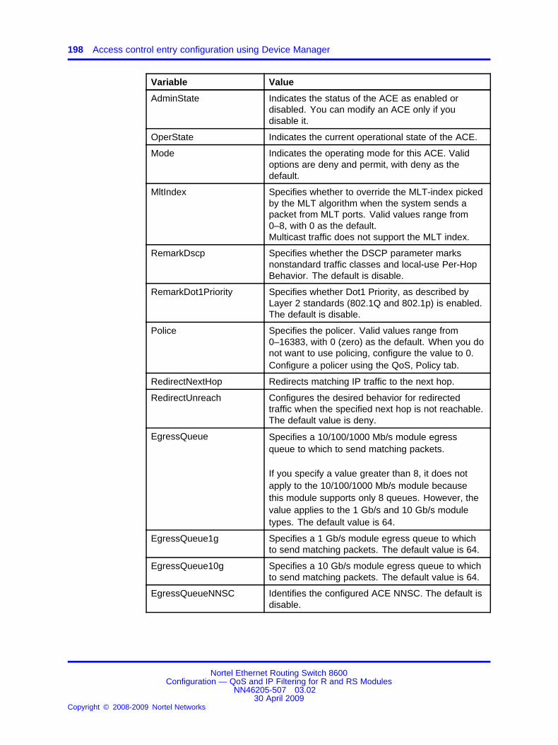
198 Access control entry configuration using Device Manager
Variable Value
AdminState Indicates the status of the ACE as enabled ordisabled. You can modify an ACE only if youdisable it.
OperState Indicates the current operational state of the ACE.
Mode Indicates the operating mode for this ACE. Validoptions are deny and permit, with deny as thedefault.
MltIndex Specifies whether to override the MLT-index pickedby the MLT algorithm when the system sends apacket from MLT ports. Valid values range from0–8, with 0 as the default.Multicast traffic does not support the MLT index.
RemarkDscp Specifies whether the DSCP parameter marksnonstandard traffic classes and local-use Per-HopBehavior. The default is disable.
RemarkDot1Priority Specifies whether Dot1 Priority, as described byLayer 2 standards (802.1Q and 802.1p) is enabled.The default is disable.
Police Specifies the policer. Valid values range from0–16383, with 0 (zero) as the default. When you donot want to use policing, configure the value to 0.Configure a policer using the QoS, Policy tab.
RedirectNextHop Redirects matching IP traffic to the next hop.
RedirectUnreach Configures the desired behavior for redirectedtraffic when the specified next hop is not reachable.The default value is deny.
EgressQueue Specifies a 10/100/1000 Mb/s module egressqueue to which to send matching packets.
If you specify a value greater than 8, it does notapply to the 10/100/1000 Mb/s module becausethis module supports only 8 queues. However, thevalue applies to the 1 Gb/s and 10 Gb/s moduletypes. The default value is 64.
EgressQueue1g Specifies a 1 Gb/s module egress queue to whichto send matching packets. The default value is 64.
EgressQueue10g Specifies a 10 Gb/s module egress queue to whichto send matching packets. The default value is 64.
EgressQueueNNSC Identifies the configured ACE NNSC. The default isdisable.
Nortel Ethernet Routing Switch 8600Configuration — QoS and IP Filtering for R and RS Modules
NN46205-507 03.0230 April 2009
Copyright © 2008-2009 Nortel Networks
.

Configuring ACE actions 199
Variable Value
StopOnMatch Enables or disables the stop-on-match option. Thisoption specifies whether to stop or continue after anACE matches the packet. When this ACE matches,the switch does not attempt a match on other ACEswith lower priority. The default is disable.
Flags Specifies one of the following flag values:
• none—No action (default value)
• count—Enables or disables counting if a packetmatches the ACE
• copyToPrimaryCp—Enables or disables thecopying of matching packets to the primary CP
• copyToSecondaryCp—Enables or disables thecopying of matching packets to the secondaryCP
• mirror—Enables or disables the mirroring ofmatching packets to an interface
If you enable mirroring, ensure that you alsoconfigure the appropriate parameters:
• For R and RS modules in Rx mode, and for RSmodules: DstPortList, DstVlanId, or DstMltId.
• For R modules in Tx mode: configure the Edit,Diagnostics, Port Mirrors tab.
DstPortList Specifies the ports to which to mirror traffic.
DstVlanId Specifies the VLAN to which to mirror traffic.
DstMltId Specifies the Multilink Trunking (MLT) group towhich to mirror traffic.
IpfixState Specifies whether IPFIX is enabled or disabled.The default is disable.
RedirectNextHopIpv6 Redirects matching IPv6 traffic to the next hop.
Configuring ACE actionsUse the Action/Debug tab to configure the actions of an ACE or to modifythe ACE. Actions determine the process that occurs when a packetmatches (or does not match) an ACE. Use debug actions (flags) to usefilters for troubleshooting and monitoring procedures.
Prerequisites
• The ACE exists.
Nortel Ethernet Routing Switch 8600Configuration — QoS and IP Filtering for R and RS Modules
NN46205-507 03.0230 April 2009
Copyright © 2008-2009 Nortel Networks
.

200 Access control entry configuration using Device Manager
Procedure steps
Step Action
1 In Device Manager, choose Security, Data Path, AdvancedFilters (ACE/ACLs).
A notification box appears that indicates you can configureadvanced filters for R and RS modules only.
2 Click OK.
3 Click the ACL tab.
4 Select the appropriate ACL on the ACL tab.
5 Click ACE.
6 Select an AceId.
7 Click Action/Debug.
8 Configure the actions as required, and then click Apply.
--End--
Modifying ACE parametersModify ACE parameters so that the filter uses different parameters.
Prerequisites
• The ACE exists.
Procedure steps
Step Action
1 Navigate to the ACE Common tab.
2 Except for the debug actions (flags), disable the AdminState ofthe ACE before you perform modifications.
3 Double-click the ACE parameter to change. Change theparameter as required.
4 Re-enable the AdminState if required, and then click Apply.
--End--
Configuring ACE ARP entriesUse ACE ARP entries so that the filter looks for ARP request or responsepackets.
Nortel Ethernet Routing Switch 8600Configuration — QoS and IP Filtering for R and RS Modules
NN46205-507 03.0230 April 2009
Copyright © 2008-2009 Nortel Networks
.

Configuring ACE ARP entries 201
Prerequisites
• The ACE exists.
• The ACL exists.
• The ACT has ARP attributes.
Procedure steps
Step Action
1 In Device Manager, choose Security, Data Path, AdvancedFilters (ACE/ACLs).
A message box appears that indicates you can configureadvanced filters for R and RS modules only.
2 Click OK.
3 Click the ACL tab.
4 Select a parameter for the appropriate ACL.
5 Click ACE.
6 Select a parameter for the appropriate ACE.
7 Click Arp.
8 Click Insert.
9 Select ARP request or response.
10 Click Insert.
--End--
Variable definitionsUse the data in the following table to configure ARP ACEs.
Variable Value
AclId Specifies the ACL index.
AceId Specifies the ACE index.
Type Specifies the ACE ARP operation. The onlyoption is operation.
Oper Specifies the operator for the ACE ARPoperation. The only valid option is eq (equal).
Value Specifies the ARP packet type. Valid optionsare arpRequest and arpResponse.
Nortel Ethernet Routing Switch 8600Configuration — QoS and IP Filtering for R and RS Modules
NN46205-507 03.0230 April 2009
Copyright © 2008-2009 Nortel Networks
.

202 Access control entry configuration using Device Manager
Viewing all ACE ARP entries for an ACLView all of the ACE ARP entries associated with an ACL.
Procedure steps
Step Action
1 In Device Manager, choose Security, Data Path, AdvancedFilters (ACE/ACLs).
A message box appears that indicates you can configureadvanced filters for R and RS modules only.
2 Click OK.
3 Click the ACL tab.
4 Select the appropriate ACL.
5 Click Arp.
The ACE ARP, ACL (x) dialog box appears showing all ARPentries.
6 To modify a parameter, double-click the parameter, select theoption, and click Apply.
--End--
Configuring an ACE Ethernet source addressUse ACE Ethernet source address entries so that the filter looks forspecific Ethernet source addresses.
Prerequisites
• The ACE exists.
• The ACL exists.
• The ACT has Ethernet srcMac attributes.
Procedure steps
Step Action
1 In Device Manager, choose Security, Data Path, AdvancedFilters (ACE/ACLs).
A message box appears that indicates you can configureadvanced filters for R and RS modules only.
2 Click OK.
3 Click the ACL tab.
Nortel Ethernet Routing Switch 8600Configuration — QoS and IP Filtering for R and RS Modules
NN46205-507 03.0230 April 2009
Copyright © 2008-2009 Nortel Networks
.

Configuring an ACE Ethernet destination address 203
4 Select the appropriate ACL.
5 Click ACE.
6 Select the appropriate ACE.
7 Click Eth.
8 Click Insert.
9 Specify the ACE Ethernet operation.
10 In the List dialog box, specify the Ethernet source address.
11 Click Insert.
--End--
Variable definitionsUse the data in the following table to configure Ethernet ACEs.
Variable Value
AclId Specifies the ACL index.
AceId Specifies the associated ACE index.
Oper Specifies the operators for the source MACaddress:
• eq—exact match
• ne—not equal
• le—less than or equal to
• ge—greater than or equal to
List Specifies the MAC address to match in thefollowing format:
• a single MAC address
• a range of MAC addresses
• a list of MAC addresses
Configuring an ACE Ethernet destination addressUse ACE Ethernet destination address entries so that the filter looks forspecific Ethernet destination addresses.
Nortel Ethernet Routing Switch 8600Configuration — QoS and IP Filtering for R and RS Modules
NN46205-507 03.0230 April 2009
Copyright © 2008-2009 Nortel Networks
.

204 Access control entry configuration using Device Manager
Prerequisites
• The ACE exists.
• The ACL exists.
• The ACT has Ethernet dstMac attributes.
Procedure steps
Step Action
1 In Device Manager, choose Security, Data Path, AdvancedFilters (ACE/ACLs).
A message box appears that indicates you can configure filtersfor R and RS modules only.
2 Click OK.
3 Click the ACL tab.
4 Select the appropriate ACL.
5 Click ACE.
6 On the ACE Common tab, select the appropriate ACE.
7 Click Eth.
8 Click the Destination Address tab.
9 Click Insert.
10 Specify the ACE Ethernet operation.
11 In the List box, specify the Ethernet destination address.
12 Click Insert.
--End--
Configuring an ACE LAN traffic typeUse ACE Ethernet type entries so that the filter looks for specific LANtraffic packets: IP, ARP, IPX-802.3, IPX-802.2, IPX-SNAP, IPX-Ethernet2,AppleTalk, Dec-Lat, Dec-Other, SNA-802.2, SNA-Ethernet2, NetBios,XNS, VINES, IPv6, rRAPR, and PPPoE.
Prerequisites
• The ACE exists.
• The ACL exists.
• The ACT has Ethernet etherType attributes.
Nortel Ethernet Routing Switch 8600Configuration — QoS and IP Filtering for R and RS Modules
NN46205-507 03.0230 April 2009
Copyright © 2008-2009 Nortel Networks
.

Configuring an ACE LAN traffic type 205
Procedure steps
Step Action
1 In Device Manager, choose Security, Data Path, AdvancedFilters (ACE/ACLs).
A message box appears that indicates you can configureadvanced filters for R and RS modules only.
2 Click OK.
3 Click the ACL tab.
4 Select the appropriate ACL.
5 Click ACE.
The ACE, ACL dialog box appears with the ACE Common tabdisplayed.
6 On the ACE Common tab, select the appropriate ACE.
7 Click Eth.
8 Click the Ethernet Type tab.
9 Click Insert.
The Ethernet, ACL, ACE, Insert Ethernet Type dialog boxappears.
10 Specify the operation type.
11 In the TypeList box, enter the Ethernet types. Specify values inthe following order, for example, ip, arp, rarp or 1, 2, 3–5.
12 Click Insert.
--End--
Variable definitionsUse the data in the following table to help you configure Ethernet ACEs.
Variable Value
AclId Specifies the ACL index.
AceId Specifies the associated ACE index.
Nortel Ethernet Routing Switch 8600Configuration — QoS and IP Filtering for R and RS Modules
NN46205-507 03.0230 April 2009
Copyright © 2008-2009 Nortel Networks
.

206 Access control entry configuration using Device Manager
Variable Value
TypeOper Identifies Ethernet type operators. Valid values are
• eq—exact match
• ne—not equal
TypeList Specifies the Ethernet type. Entries include: 0to 0xffff or ip, arp, ipx802.3, ipx802.2, ipxSnap,ipxEthernet2, appleTalk, decLat, decOther,sna802.2, snaEthernet2, netBios, xns, vines, ipv6,rarp, and PPPoE.
Configuring an ACE Ethernet VLAN tag priorityUse ACE Ethernet VLAN tag priority entries so that the filter looks forspecific VLAN tag priorities.
Prerequisites
• The ACE exists.
• The ACL exists.
• The ACT has Ethernet vlanTagPrio attributes.
Procedure steps
Step Action
1 In Device Manager, choose Security, Data Path, AdvancedFilters (ACE/ACLs).
A message box appears that indicates you can configureadvanced filters for R and RS modules only.
2 Click OK.
3 Click the ACL tab.
4 Select the appropriate ACL.
5 Click ACE.
6 On the ACE Common tab, select the appropriate ACE.
7 Click Eth.
8 Click the Vlan Tag Priority tab.
9 Click Insert.
10 Specify the operation type.
11 In the VlanTagPrio box, select the priority bits.
Nortel Ethernet Routing Switch 8600Configuration — QoS and IP Filtering for R and RS Modules
NN46205-507 03.0230 April 2009
Copyright © 2008-2009 Nortel Networks
.

Configuring an ACE Ethernet port 207
12 Click Insert.
--End--
Variable definitionsUse the data in the following table to configure tag priorities.
Variable Value
AclId Specifies the ACL index.
AceId Specifies the associated ACE index.
Oper Specifies the operators for the ACE Ethernet VLANtag priority:
• eq—exact match
• ne—not equal
VlanTagPrio Specifies the priority bits (3-bit field) from the802.1Q/p tag:
• zero
• one
• two
• three
• four
• five
• six
• seven
• undefined
Configuring an ACE Ethernet portUse ACE Ethernet port entries so that the filter looks for traffic on specificports. You can only insert an ACE Common Ethernet port for VLAN ACLtypes.
Prerequisites
• The ACE exists.
• The ACL exists.
• The ACT has Ethernet port attributes.
Nortel Ethernet Routing Switch 8600Configuration — QoS and IP Filtering for R and RS Modules
NN46205-507 03.0230 April 2009
Copyright © 2008-2009 Nortel Networks
.

208 Access control entry configuration using Device Manager
Procedure steps
Step Action
1 In Device Manager, choose Security, Data Path, AdvancedFilters (ACE/ACLs).
A message box appears that indicates you can configureadvanced filters for R and RS modules only.
2 Click OK.
3 Click the ACL tab.
4 Select the appropriate ACL.
5 Click ACE.
6 On the ACE Common tab, select the appropriate ACE.
7 Click Eth.
8 Click the Port tab.
9 Click Insert.
10 Specify the operation type.
11 Click the Port ellipses (...).
12 Choose the ports.
13 Click OK.
14 Click Insert.
--End--
Variable definitionsUse the data in the following table to configure ACE Ethernet ports.
Variable Value
AclId Specifies the ACL index.
AceId Specifies the associated ACE index.
Oper Specifies the operators for the ACE Ethernet port:
• eq—exact match
• ne—not equal
Port Specifies the port or port list on which to performa match.
Nortel Ethernet Routing Switch 8600Configuration — QoS and IP Filtering for R and RS Modules
NN46205-507 03.0230 April 2009
Copyright © 2008-2009 Nortel Networks
.
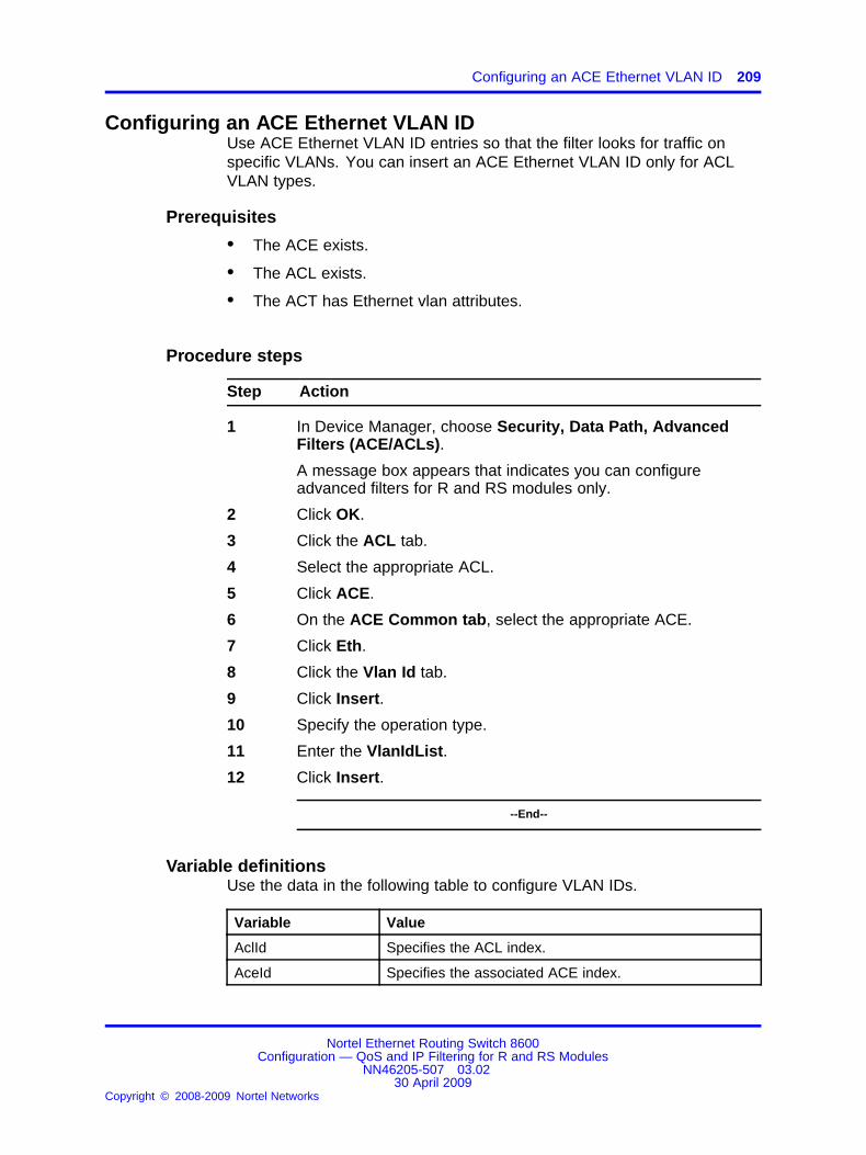
Configuring an ACE Ethernet VLAN ID 209
Configuring an ACE Ethernet VLAN IDUse ACE Ethernet VLAN ID entries so that the filter looks for traffic onspecific VLANs. You can insert an ACE Ethernet VLAN ID only for ACLVLAN types.
Prerequisites
• The ACE exists.
• The ACL exists.
• The ACT has Ethernet vlan attributes.
Procedure steps
Step Action
1 In Device Manager, choose Security, Data Path, AdvancedFilters (ACE/ACLs).
A message box appears that indicates you can configureadvanced filters for R and RS modules only.
2 Click OK.
3 Click the ACL tab.
4 Select the appropriate ACL.
5 Click ACE.
6 On the ACE Common tab, select the appropriate ACE.
7 Click Eth.
8 Click the Vlan Id tab.
9 Click Insert.
10 Specify the operation type.
11 Enter the VlanIdList.
12 Click Insert.
--End--
Variable definitionsUse the data in the following table to configure VLAN IDs.
Variable Value
AclId Specifies the ACL index.
AceId Specifies the associated ACE index.
Nortel Ethernet Routing Switch 8600Configuration — QoS and IP Filtering for R and RS Modules
NN46205-507 03.0230 April 2009
Copyright © 2008-2009 Nortel Networks
.

210 Access control entry configuration using Device Manager
Variable Value
Oper Specifies the operators for the ACE Ethernet VLAN ID:
• eq—exact match
• ne—not equal
VlanIdList Specifies the VLAN ID on which to perform a match.
Viewing all ACE Ethernet entries for an ACLView all of the ACE Ethernet entries associated with an ACL.
Procedure steps
Step Action
1 In Device Manager, choose Security, Data Path, AdvancedFilters (ACE/ACLs).
A message box appears that indicates you can configureadvanced filters for R and RS modules only.
2 Click OK.
3 Click the ACL tab.
4 Select the appropriate ACL.
5 Click Eth.
The ACE Ethernet, ACL (x) dialog box appears.
--End--
Variable definitionsUse the data in the following table to youconfigure ACEs.
Variable Value
AclId Specifies the ACL Ethernet index.
AceId Specifies the ACE Ethernet index.
SrcAddrList Specifies the list of Ethernet source addressesto match.
ScrAddrOper Specifies the operators for the ACE Ethernetsource MAC address.
DstAddrList Specifies the list of Ethernet destinationaddresses to match.
DstAddrOper Specifies the operators for the ACE Ethernetdestination MAC address.
Nortel Ethernet Routing Switch 8600Configuration — QoS and IP Filtering for R and RS Modules
NN46205-507 03.0230 April 2009
Copyright © 2008-2009 Nortel Networks
.

Configuring an ACE IP source address 211
Variable Value
EtherTypeList Specifies the EtherType value from theEthernet header. For example, ARP uses0x0806 and IP uses 0x0800.
Platform support determines the behavior for802.1Q/p tagged packets. The EtherType for802.1Q tagged frames is 0x8100.
The range is 0–65535 and supports listsand ranges of values. An invalid Ether-typeof 65536 indicates that you do not want theparameter in the match criteria.
EtherTypeOper Specifies the Ethernet type operators.
VlanTagPrio Specifies the priority bits (3-bit field) from the802.1Q/p tag.
VlanTagPrioOper Specifies the operators for the ACE EthernetVLAN tag priority.
Port Specifies the port number or port list to match.
PortOper Specifies the operator for the ACE Ethernetport.
VlanIdList Specifies the VLAN ID to match.
VlanIdOper Specifies the operator for the ACE EthernetVLAN ID.
Configuring an ACE IP source addressUse ACE IP source address entries to have the filter look for specificsource IP addresses.
Prerequisites
• The ACE exists.
• The ACL exists.
• The ACT has IP srcIp attributes.
Procedure steps
Step Action
1 In Device Manager, choose Security, Data Path, AdvancedFilters (ACE/ACLs).
Nortel Ethernet Routing Switch 8600Configuration — QoS and IP Filtering for R and RS Modules
NN46205-507 03.0230 April 2009
Copyright © 2008-2009 Nortel Networks
.

212 Access control entry configuration using Device Manager
A message box appears that indicates you can configureadvanced filters for R and RS modules only.
2 Click OK.
3 Click the ACL tab.
4 Select the appropriate ACL.
5 Click ACE.
6 On the ACE Common tab, select the appropriate ACE.
7 Click IP.
8 Click Insert.
9 Specify the operation type.
10 In the List box, enter the source IP address.
11 Click Insert.
--End--
Variable definitionsUse the data in the following table to configure IP source address ACEs.
Variable Value
AclId Specifies the ACL index.
AceId Specifies the associated ACE index.
Oper Specifies the operators for the ACE IP sourceaddress:
• eq—exact match
• ne—not equal
• le—less than or equal to
• ge—greater than or equal to
List Specifies the source IP address in the followingformat:
• a single IP address
• a range of IP addresses
• a list of IP addresses
Configuring an ACE IP destination addressUse ACE IP destination address entries to have the filter look for specificdestination IP addresses.
Nortel Ethernet Routing Switch 8600Configuration — QoS and IP Filtering for R and RS Modules
NN46205-507 03.0230 April 2009
Copyright © 2008-2009 Nortel Networks
.
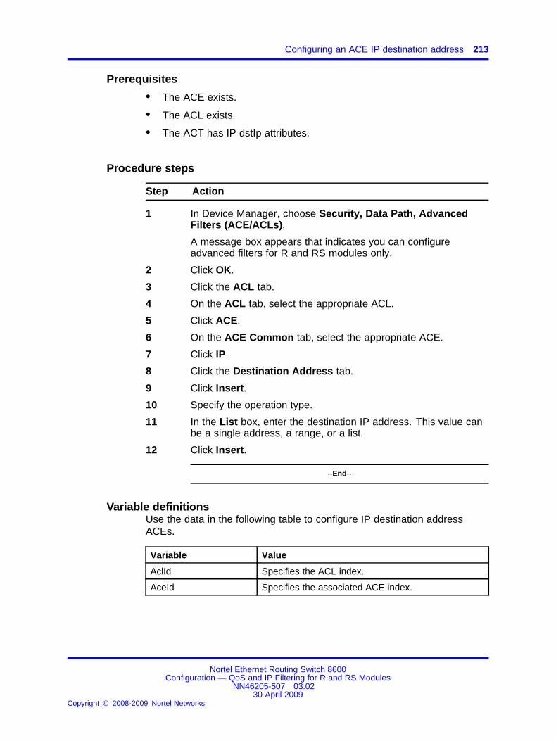
Configuring an ACE IP destination address 213
Prerequisites
• The ACE exists.
• The ACL exists.
• The ACT has IP dstIp attributes.
Procedure steps
Step Action
1 In Device Manager, choose Security, Data Path, AdvancedFilters (ACE/ACLs).
A message box appears that indicates you can configureadvanced filters for R and RS modules only.
2 Click OK.
3 Click the ACL tab.
4 On the ACL tab, select the appropriate ACL.
5 Click ACE.
6 On the ACE Common tab, select the appropriate ACE.
7 Click IP.
8 Click the Destination Address tab.
9 Click Insert.
10 Specify the operation type.
11 In the List box, enter the destination IP address. This value canbe a single address, a range, or a list.
12 Click Insert.
--End--
Variable definitionsUse the data in the following table to configure IP destination addressACEs.
Variable Value
AclId Specifies the ACL index.
AceId Specifies the associated ACE index.
Nortel Ethernet Routing Switch 8600Configuration — QoS and IP Filtering for R and RS Modules
NN46205-507 03.0230 April 2009
Copyright © 2008-2009 Nortel Networks
.

214 Access control entry configuration using Device Manager
Variable Value
Oper Specifies the operators for the ACE IP destinationaddress:
• eq—exact match
• ne—not equal
• le—less than or equal to
• ge—greater than or equal to
List Specifies the destination IP address in the followingformat:
• a single IP address
• a range of IP addresses
• a list of IP addresses
Configuring an ACE IP DSCPUse ACE IP DSCP entries to have the filter look for packets with specificDSCP markings.
Prerequisites
• The ACE exists.
• The ACL exists.
• The ACT has IP dscp attributes.
Procedure steps
Step Action
1 In Device Manager, choose Security, Data Path, AdvancedFilters (ACE/ACLs).
A message box appears that indicates you can configureadvanced filters for R and RS modules only.
2 Click OK.
3 Click the ACL tab.
4 On the ACL tab, select the appropriate ACL.
5 Click ACE.
6 On the ACE Common tab, select the appropriate ACE.
7 Click IP.
8 Click the DSCP tab.
Nortel Ethernet Routing Switch 8600Configuration — QoS and IP Filtering for R and RS Modules
NN46205-507 03.0230 April 2009
Copyright © 2008-2009 Nortel Networks
.

Configuring an ACE IP protocol 215
9 Click Insert.
10 Specify the operation type.
11 In the List box, enter the count for the DSCP values.
12 Click Insert.
--End--
Variable definitionsUse the data in the following table to configure IP DSCP ACEs.
Variable Value
AclId Specifies the ACL index.
AceId Specifies the associated ACE index.
Oper Specifies the operators for the ACE IP DSCP:
• eq—exact match
• ne—not equal
List Specifies a count for the number of discrete rangesentered for the DSCP values. Entries include 0–256,disable, phbcs0, phbcs1, phbaf11, phbaf12, phbaf13,phbcs2, phbaf21, phbaf22, phbaf23, phbcs3,phbaf31, phbaf32, phbaf33, phbcs4, phbaf41,phbaf42, phbaf43, phbcs5, phbcs6, phbef, andphbcs7.
Configuring an ACE IP protocolUse ACE IP protocol entries to have the filter look for packets of specificprotocols; for example, ICMP, TCP, UDP, IPSec-ESP, IPSec-AH, OSPF,VRRP, and SNMP.
Prerequisites
• The ACE exists.
• The ACL exists.
• The ACT has IP ipProtoType attributes.
Procedure steps
Step Action
1 In Device Manager, choose Security, Data Path, AdvancedFilters (ACE/ACLs).
Nortel Ethernet Routing Switch 8600Configuration — QoS and IP Filtering for R and RS Modules
NN46205-507 03.0230 April 2009
Copyright © 2008-2009 Nortel Networks
.

216 Access control entry configuration using Device Manager
A message box appears that indicates you can configureadvanced filters for R and RS modules only.
2 Click OK.
3 Click the ACL tab.
4 On the ACL tab, select the appropriate ACL.
5 Click ACE.
6 On the ACE Common tab, select the appropriate ACE.
7 Click IP.
8 Click the Protocol tab.
9 Click Insert.
10 Specify the operation type.
11 In the List box, enter the IP protocol type.
12 Click Insert.
--End--
Variable definitionsUse the data in the following table to configure protocol ACEs.
Variable Value
AclId Specifies the ACL index.
AceId Specifies the associated ACE index.
Oper Specifies the operators for the ACE IP protocol:
• eq—exact match
• ne—not equal
List Specifies the IP protocol type. Entries include 0–256,undefined, icmp, tcp, udp, ipsecesp, ipsecah, ospf,vrrp, and snmp.
Configuring ACE IP optionsUse ACE IP option entries to have the filter look for packets with an IPoption specified.
Prerequisites
• The ACE exists.
• The ACL exists.
• The ACT has IP ipOptions attributes.
Nortel Ethernet Routing Switch 8600Configuration — QoS and IP Filtering for R and RS Modules
NN46205-507 03.0230 April 2009
Copyright © 2008-2009 Nortel Networks
.

Configuring ACE IP fragmentation 217
Procedure steps
Step Action
1 In Device Manager, choose Security, Data Path, AdvancedFilters (ACE/ACLs).
A message box appears that indicates you can configureadvanced filters for R and RS modules only.
2 Click OK.
3 Click the ACL tab.
4 On the ACL tab, select the appropriate ACL.
5 Click ACE.
6 On the ACE Common tab, select the appropriate ACE.
7 Click IP.
8 Click the Options tab.
9 Click Insert.
10 Specify the logical operator.
Any is the only valid choice.
11 Click Insert.
--End--
Variable definitionsUse the data in the following table to configure IP option ACEs.
Variable Value
AclId Specifies the ACL index.
AceId Specifies the associated ACE index.
Oper Specifies the logical operator for the ACE IPoptions. Any is the only valid option.
Configuring ACE IP fragmentationUse ACE IP fragmentation entries to have the filter look for packets withthe fragmentation flag set.
Prerequisites
• The ACE exists.
• The ACL exists.
• The ACT has IP ipFragFlag attributes.
Nortel Ethernet Routing Switch 8600Configuration — QoS and IP Filtering for R and RS Modules
NN46205-507 03.0230 April 2009
Copyright © 2008-2009 Nortel Networks
.

218 Access control entry configuration using Device Manager
Procedure steps
Step Action
1 In Device Manager, choose Security, Data Path, AdvancedFilters (ACE/ACLs).
A message box appears that indicates you can configureadvanced filters for R and RS modules only.
2 Click OK.
3 Click the ACL tab.
4 Select the appropriate ACL.
5 Click ACE.
6 Select the appropriate ACE.
7 Click IP.
8 Click the Fragmentation tab.
9 Click Insert.
10 Specify the operator for IP fragmentation.
Eq is the only valid choice.
11 Specify the fragmentation bits to match from the IP header.
12 Click Insert.
--End--
Variable definitionsUse the data in the following table to configure fragmentation ACEs.
Variable Value
AclId Specifies the ACL index.
AceId Specifies the associated ACE index.
Oper Specifies the operators for ACE IP fragmentation.The only valid value is eq (equals).
Fragmentation Specifies the IP fragmentation bits to match from theIP header:
• noFragment
• anyFragment
• moreFragment
• lastFragment
The default is noFragment.
Nortel Ethernet Routing Switch 8600Configuration — QoS and IP Filtering for R and RS Modules
NN46205-507 03.0230 April 2009
Copyright © 2008-2009 Nortel Networks
.

Viewing all ACE IP entries for an ACL 219
Viewing all ACE IP entries for an ACLView all of the ACE IP entries associated with an ACL.
Procedure steps
Step Action
1 In Device Manager, choose Security, Data Path, AdvancedFilters (ACE/ACLs).
A message box appears that indicates you can configureadvanced filters for R and RS modules only.
2 Click OK.
3 Click the ACL tab.
4 Select the appropriate ACL.
5 Click IP.
The ACE IP, ACL (x) dialog box appears.
--End--
Variable definitionsUse the data in the following table to understand ACE parameters.
Variable Value
AclId Specifies the ACL IP index.
AceId Specifies the ACE IP index.
SrcAddrList Specifies the list of IP source addresses fromthe IP header to match.
ScrAddrOper Specifies the operators for the ACE IP sourceaddress.
DstAddrList Specifies the list of IP destination addressesfrom the IP header to match.
DstAddrOper Specifies the operators for the ACE IPdestination address.
DscpList Specifies how the 6-bit DSCP parameter fromthe TOS byte in the IPv4 header encodes PHBinformation following RFC 2474.
DscpOper Specifies the operators for the ACE IP DSCP.
ProtoList Specifies the IP protocol type from the IPheader to match. The range is 0–255.
ProtoOper Specifies the operators for the ACE IPprotocols.
Nortel Ethernet Routing Switch 8600Configuration — QoS and IP Filtering for R and RS Modules
NN46205-507 03.0230 April 2009
Copyright © 2008-2009 Nortel Networks
.

220 Access control entry configuration using Device Manager
Variable Value
Options Specifies the IP options to match from the IPheader.
OptionsOper Specifies the logical operator. Any is the onlyoption.
Fragmentation Specifies the IP fragmentation bits to matchfrom the IP header.
FragOper Specifies the operator for IP fragmentation.
Configuring an ACE TCP source portUse ACE TCP source port entries to have the filter look for packets witha specific TCP source port.
Prerequisites
• The ACE exists.
• The ACL exists.
• The ACT has protocol tcpSrcPort attributes.
Procedure steps
Step Action
1 In Device Manager, choose Security, Data Path, AdvancedFilters (ACE/ACLs).
A message box appears that indicates you can configureadvanced filters for R and RS modules only.
2 Click OK.
3 Click the ACL tab.
4 Select the appropriate ACL.
5 Click ACE.
6 Select the appropriate ACE.
7 Click Proto.
8 Click Insert.
9 Specify the operator for the TCP source port.
10 Specify the port number or port list to match.
11 Click Insert.
--End--
Nortel Ethernet Routing Switch 8600Configuration — QoS and IP Filtering for R and RS Modules
NN46205-507 03.0230 April 2009
Copyright © 2008-2009 Nortel Networks
.

Configuring an ACE UDP source port 221
Variable definitionsUse the data in the following table to configure TCP source port ACEs.
Variable Value
AclId Specifies the ACL index.
AceId Specifies the associated ACE index.
Oper Specifies the operators for the ACE protocol TCPsource port:
• eq—exact match
• ne—not equal
• le—less than or equal to
• ge—greater than or equal to
Port Specifies the port number in the following format:
• a single port number
• a range of port numbers
• a list of port numbers
Configuring an ACE UDP source portUse ACE UDP source port entries to have the filter look for packets witha specific UDP source port.
Prerequisites
• The ACE exists.
• The ACL exists.
• The ACT has protocol udpSrcPort attributes.
Procedure steps
Step Action
1 In Device Manager, choose Security, Data Path, AdvancedFilters (ACE/ACLs).
A message box appears that indicates you can configureadvanced filters for R and RS modules only.
2 Click OK.
3 Click the ACL tab.
4 Select the appropriate ACL.
Nortel Ethernet Routing Switch 8600Configuration — QoS and IP Filtering for R and RS Modules
NN46205-507 03.0230 April 2009
Copyright © 2008-2009 Nortel Networks
.

222 Access control entry configuration using Device Manager
5 When the ACE button becomes active, click it.
6 Select the appropriate ACE.
7 Click Proto.
8 Click the UDP Source Port tab.
9 Click Insert.
10 Specify the operator for the UDP source port.
11 Specify the port number or port list to match.
12 Click Insert.
--End--
Variable definitionsUse the data in the following table to configure UDP source port ACEs.
Variable Value
AclId Specifies the ACL index.
AceId Specifies the associated ACE index.
Oper Specifies the operators for the ACE protocol UDPsource port:
• eq—exact match
• ne—not equal
• le—less than or equal to
• ge—greater than or equal to
Port Specifies the port number in the following format:
• a single port number
• a range of port numbers
• a list of port numbers
Configuring an ACE TCP destination portUse ACE TCP destination port entries to have the filter look for packetswith a specific TCP destination port.
Prerequisites
• The ACE exists.
• The ACL exists.
• The ACT has protocol tcpDstPort attributes.
Nortel Ethernet Routing Switch 8600Configuration — QoS and IP Filtering for R and RS Modules
NN46205-507 03.0230 April 2009
Copyright © 2008-2009 Nortel Networks
.

Configuring an ACE TCP destination port 223
Procedure steps
Step Action
1 In Device Manager, choose Security, Data Path, AdvancedFilters (ACE/ACLs).
A message box appears that indicates you can configureadvanced filters for R and RS modules only.
2 Click OK.
3 Click the ACL tab.
4 Select the appropriate ACL.
5 Click ACE.
6 Select the appropriate ACE.
7 Click Proto.
8 Click the TCP Destination Port tab.
9 Click Insert.
10 Specify the operator for the TCP destination port.
11 Specify the port number or port list to match.
12 Click Insert.
--End--
Variable definitionsUse the data in the following table to configure TCP destination port ACEs.
Variable Value
AclId Specifies the ACL index.
AceId Specifies the associated ACE index.
Oper Specifies the operators for the ACE protocol TCPdestination port:
• eq—exact match
• ne—not equal
• le—less than or equal to
• ge—greater than or equal to
Port Specifies the port number. As noted at the bottomof the tab, potential entries include 0–65535, echo,ftpdata, ftpcontrol, ssh, telnet, dns, http, bgp, h.323,and undefined.
Nortel Ethernet Routing Switch 8600Configuration — QoS and IP Filtering for R and RS Modules
NN46205-507 03.0230 April 2009
Copyright © 2008-2009 Nortel Networks
.

224 Access control entry configuration using Device Manager
Configuring an ACE UDP destination portUse ACE UDP destination port entries to have the filter look for packetswith a specific TCP destination port.
Prerequisites
• The ACE exists.
• The ACL exists.
• The ACT has protocol udpDstPort attributes.
Procedure steps
Step Action
1 In Device Manager, choose Security, Data Path, AdvancedFilters (ACE/ACLs).
A message box appears that indicates you can configureadvanced filters for R and RS modules only.
2 Click OK.
3 Click the ACL tab.
4 Select the appropriate ACL.
5 Click ACE.
6 Select the appropriate ACE.
7 Click Proto.
8 Click the UDP Destination Port tab.
9 Click Insert.
10 Specify the operator for the UDP destination port.
11 Specify the port number or port list to match.
12 Click Insert.
--End--
Variable definitionsUse the data in the following table to configure UDP destination port ACEs.
Variable Value
AclId Specifies the ACL index.
AceId Specifies the associated ACE index.
Nortel Ethernet Routing Switch 8600Configuration — QoS and IP Filtering for R and RS Modules
NN46205-507 03.0230 April 2009
Copyright © 2008-2009 Nortel Networks
.

Configuring an ACE ICMP message type 225
Variable Value
Oper Specifies the operators for the ACE protocol UDPdestination port:
• eq—exact match
• ne—not equal
• le—less than or equal to
• ge—greater than or equal to
Port Specifies the port number. Entries include 0–65535,echo, dns, bootpServer, bootpClient, tftp, rip, rtp,rtcp, and undefined.
Configuring an ACE ICMP message typeUse ACE ICMP message type entries to have the filter look for packetsof a specific ICMP message type.
Prerequisites
• The ACE exists.
• The ACL exists.
• The ACT has protocol icmpMsgType attributes.
Procedure steps
Step Action
1 In Device Manager, choose Security, Data Path, AdvancedFilters (ACE/ACLs).
A message box appears that indicates you can configureadvanced filters for R and RS modules only.
2 Click OK.
3 Click the ACL tab.
4 Select the appropriate ACL.
5 Click ACE.
6 Select the appropriate ACE.
7 Click Proto.
8 Click the Icmp Msg Type tab.
9 Click Insert.
10 Specify the operator for the ICMP message type.
Nortel Ethernet Routing Switch 8600Configuration — QoS and IP Filtering for R and RS Modules
NN46205-507 03.0230 April 2009
Copyright © 2008-2009 Nortel Networks
.

226 Access control entry configuration using Device Manager
11 In the List box, specify the ICMP messages to match.
12 Click Insert.
--End--
Variable definitionsUse the data in the following table to help you configure ICMP ACEs.
Variable Value
AclId Specifies the ACL index.
AceId Specifies the associated ACE index.
Oper Specifies the operators for the ACE protocol ICMPmessage type:
• eq—exact match
• ne—not equal
Port Specifies the port number. Entries include 0–255,echoreply, destunreach, sourcequench, redirect,echo-request, routeradv, routerselect, time-exceeded,param-problem, timestamp-request, timestamp-reply,addressmask-request, addressmask-reply, andtraceroute.
Configuring an ACE TCP flagUse ACE TCP flag entries to have the filter look for packets with a specificTCP flag.
Prerequisites
• The ACE exists.
• The ACL exists.
• The ACT has protocol tcpFlags attributes.
Procedure steps
Step Action
1 In Device Manager, choose Security, Data Path, AdvancedFilters (ACE/ACLs).
A message box appears that indicates you can configureadvanced filters for R and RS modules only.
2 Click OK.
Nortel Ethernet Routing Switch 8600Configuration — QoS and IP Filtering for R and RS Modules
NN46205-507 03.0230 April 2009
Copyright © 2008-2009 Nortel Networks
.

Viewing all ACE Protocol entries for an ACL 227
3 Click the ACL tab.
4 Select the appropriate ACL.
5 Click ACE.
6 Select the appropriate ACE.
7 Click Proto.
8 Click the TCP Flags tab.
9 Click Insert.
10 Specify the operator for the TCP flags entry.
11 In the List box, specify the TCP flags to match.
12 Click Insert.
--End--
Variable definitionsUse the data in the following table to configure TCP flag ACEs.
Variable Value
AclId Specifies the ACL index.
AceId Specifies the associated ACE index.
Oper Specifies the operators for the ACE protocol TCP flagsentry:
• matchAny
• matchAll
List Specifies the TCP flags—none, fin (finish connection),syn (synchronize), rst (reset connection), push, ack(acknowledge), urg (urgent), and undefined.
Viewing all ACE Protocol entries for an ACLView all of the ACE Protocol entries associated with an ACL.
Procedure steps
Step Action
1 In Device Manager, choose Security, Data Path, AdvancedFilters (ACE/ACLs).
A message box appears that indicates you can configureadvanced filters for R and RS modules only.
2 Click OK.
Nortel Ethernet Routing Switch 8600Configuration — QoS and IP Filtering for R and RS Modules
NN46205-507 03.0230 April 2009
Copyright © 2008-2009 Nortel Networks
.

228 Access control entry configuration using Device Manager
3 Click the ACL tab.
4 Select the appropriate ACL.
5 Click Proto.
The ACE Protocol, ACL (x) dialog box appears.
--End--
Variable definitionsUse the data in the following table to understand the protocol parameters.
Variable Value
AclId Specifies the ACL protocol index.
AceId Specifies the ACE protocol index.
TcpSrcPort Specifies the port number or port list to match.
TcpSrcPortOper Specifies the operator for the ACE protocol TCPsource port.
UdpSrcPort Specifies the port number or port list to match.
UdpSrcPortOper Specifies the operator for the ACE protocol UDPsource port.
TcpDstPort Specifies port number or port list to match.
TcpDstPortOper Specifies the operator for the ACE protocol TCPdestination port.
UdpDstPort Specifies the port number or port list to match.
UdpDstPortOper Specifies the operator for the ACE protocol UDPdestination port.
IcmpMsgTypeList Specifies one or a list of ICMP messages to match.The valid range is 0–255 (reserved).
IcmpMsgTypeOper Specifies the operator for the ACE protocol ICMPmessage types.
TcpFlagsList Specifies one or a list of TCP flags to match. Thevalid range is 0–63.
TcpFlagsOper Specifies the operator for the ACE protocol TCPflags.
Configuring an ACE Pattern 1 entryConfigure an ACE pattern entry to have the filter look for a specific patternin a packet.
Nortel Ethernet Routing Switch 8600Configuration — QoS and IP Filtering for R and RS Modules
NN46205-507 03.0230 April 2009
Copyright © 2008-2009 Nortel Networks
.

Configuring an ACE Pattern 1 entry 229
Prerequisites
• The ACE exists.
• The ACL exists.
• The ACT has a pattern.
Procedure steps
Step Action
1 In Device Manager, choose Security, Data Path, AdvancedFilters (ACE/ACLs).
A message box appears that indicates you can configureadvanced filters for R and RS modules only.
2 Click OK.
3 Click the ACL tab.
4 On the ACL tab, select the appropriate ACL.
5 Click ACE.
6 Select the appropriate ACE.
7 Click Adv.
8 Click Insert.
9 Specify a name for the ACE pattern entry.
10 Specify the operators for the ACE pattern.
11 Assign the pattern value.
12 Click Insert.
--End--
Variable definitionsUse the data in the following table to configure ACE patterns.
Variable Value
AclId Specifies the ACL index.
AceId Specifies the associated ACE index.
Name Specifies a descriptive user-defined name for theACE pattern entry.
Nortel Ethernet Routing Switch 8600Configuration — QoS and IP Filtering for R and RS Modules
NN46205-507 03.0230 April 2009
Copyright © 2008-2009 Nortel Networks
.

230 Access control entry configuration using Device Manager
Variable Value
Oper Specifies the operators for the ACE pattern:
• eq—exact match
• le—less than or equal to
• ge—greater than or equal to
Value Configures the pattern value as a numeric string.The numeric value of each byte is encoded inone octet of the string. Unused bytes remain atthe trailing end of string. The Pattern Length fieldconfigures the number of bytes to extract from thisstring.
Configuring an ACE Pattern 2 entryConfigure an ACE pattern entry to have the filter look for a specific patternin a packet.
Prerequisites
• The ACE exists.
• The ACL exists.
• The ACT has two patterns.
Procedure steps
Step Action
1 In Device Manager, choose Security, Data Path, AdvancedFilters (ACE/ACLs).
A message box appears that indicates you can configureadvanced filters for R and RS modules only.
2 Click OK.
3 Click the ACL tab.
4 Select the appropriate ACL.
5 Click ACE.
6 Select the appropriate ACE.
7 Click Adv.
8 Click Pattern 2.
9 Click Insert.
10 Specify a name for the ACE pattern entry.
Nortel Ethernet Routing Switch 8600Configuration — QoS and IP Filtering for R and RS Modules
NN46205-507 03.0230 April 2009
Copyright © 2008-2009 Nortel Networks
.

Configuring an ACE Pattern 3 entry 231
11 Specify the operators for the ACE pattern.
12 Assign the pattern value.
13 Click Insert.
--End--
Configuring an ACE Pattern 3 entryConfigure an ACE pattern entry to have the filter look for a specific patternin a packet.
Prerequisites
• The ACE exists.
• The ACL exists.
• The ACT has three patterns.
Procedure steps
Step Action
1 In Device Manager, choose Security, Data Path, AdvancedFilters (ACE/ACLs).
A message box appears that indicates you can configureadvanced filters for R and RS modules only.
2 Click OK.
3 Click the ACL tab.
4 Select the appropriate ACL.
5 ClickACE.
6 Select the appropriate ACE.
7 ClickAdv.
8 Click Pattern 3.
9 Click Insert.
10 Specify a name for the ACE pattern entry.
11 Specify the operators for the ACE pattern.
12 Assign the pattern value.
13 Click Insert.
--End--
Nortel Ethernet Routing Switch 8600Configuration — QoS and IP Filtering for R and RS Modules
NN46205-507 03.0230 April 2009
Copyright © 2008-2009 Nortel Networks
.

232 Access control entry configuration using Device Manager
Viewing all ACE Advanced pattern entries for an ACLView all of the ACE Advanced entries associated with an ACL.
Procedure steps
Step Action
1 In Device Manager, choose Security, Data Path, AdvancedFilters (ACE/ACLs).
A message box appears that indicates you can configureadvanced filters for R and RS modules only.
2 Click OK.
3 Click the ACL tab.
4 Select the appropriate ACL.
5 Click Adv.
The ACE Advanced, ACL (x) dialog box appears.
--End--
Variable definitionsUse the data in the following table to configure ACEs.
Variable Value
AclId Specifies the ACL pattern index.
AceId Specifies the ACE pattern index.
Pattern1Name Specifies the name chosen by the administrator forthe ACE pattern 1 entry.
Pattern1Value Specifies the pattern 1 value as numeric string. Thenumeric value of each byte is encoded in one octetof the string. Unused bytes are left at the trailingend of string.
Pattern1Oper Specifies the operators for ACE pattern 1.
Pattern2Name Specifies the name chosen by the administrator forthe ACE pattern 2 entry.
Pattern2Value Specifies the pattern 2 value as a numeric string.
Pattern2Oper Specifies the operators for ACE pattern 2.
Pattern3Name Specifies the name chosen by the administrator forthe ACE pattern 3 entry.
Pattern3Value Specifies the pattern 3 value as a numeric string.
Pattern3Oper Specifies the operators for ACE pattern 3.
Nortel Ethernet Routing Switch 8600Configuration — QoS and IP Filtering for R and RS Modules
NN46205-507 03.0230 April 2009
Copyright © 2008-2009 Nortel Networks
.

Configuring an ACE IPv6 source address 233
Configuring an ACE IPv6 source addressConfigure an ACE IPv6 source address to have the filter look for a specificIPv6 source addresses.
Prerequisites
• The ACE exists.
• The ACL exists.
• The associated ACL packet type must be IPv6.
• The ACT has IPv6 attributes of srcIpv6.
Procedure steps
Step Action
1 In Device Manager, choose Security, Data Path, AdvancedFilters (ACE/ACLs).
A message box appears that indicates you can configureadvanced filters for R and RS modules only.
2 Click OK.
3 Click the ACL tab.
4 Select an IPv6 ACL.
5 ClickACE.
6 Select an ACE.
7 ClickIPv6.
8 Click Insert.
9 Specify the operation and the IPv6 address.
10 Click Insert.
--End--
Variable definitionsUse the data in the following table to configure IPv6 source or destinationaddress ACEs.
Variable Value
AclId Specifies the ACL ID.
AceId Specifies the ACE ID.
Nortel Ethernet Routing Switch 8600Configuration — QoS and IP Filtering for R and RS Modules
NN46205-507 03.0230 April 2009
Copyright © 2008-2009 Nortel Networks
.

234 Access control entry configuration using Device Manager
Variable Value
Oper Specifies the ACE operation. The only option is eq(equals).
List Specifies the IPv6 address—a binary string of16 octets in network byte-order. Enter a single IPv6address, a range of IPv6 addresses, or multipleIPv6 addresses.
Configuring an ACE IPv6 destination addressConfigure an ACE IPv6 destination address to have the filter look for aspecific IPv6 destination addresses.
The IPv6 parameters that you can configure depend on the ACTconfiguration.
Prerequisites
• The ACE exists.
• The ACL exists.
• The associated ACL packet type must be IPv6.
• The ACT has IPv6 attributes of dstIpv6.
Procedure steps
Step Action
1 In Device Manager, choose Security, Data Path, AdvancedFilters (ACE/ACLs).
A message box appears that indicates you can configureadvanced filters for R and RS modules only.
2 Click OK.
3 Click the ACL tab.
4 Select an IPv6 ACL.
5 Click ACE.
6 Select an ACE.
7 Click IPv6.
8 Click Insert.
9 Specify the operation and the Destination Address.
Nortel Ethernet Routing Switch 8600Configuration — QoS and IP Filtering for R and RS Modules
NN46205-507 03.0230 April 2009
Copyright © 2008-2009 Nortel Networks
.

Configuring an ACE IPv6 next header 235
10 Click Insert.
--End--
Configuring an ACE IPv6 next headerConfigure an ACE IPv6 next header to have the filter look for a packetswith the next header parameter assigned.
The IPv6 parameters that you can configure depend on the ACTconfiguration.
Prerequisites
• The ACE exists.
• The ACL exists.
• The associated ACL packet type must be IPv6.
• The ACT has IPv6 attributes of nxtHdr.
Procedure steps
Step Action
1 In Device Manager, choose Security, Data Path, AdvancedFilters (ACE/ACLs).
A message box appears that indicates you can configureadvanced filters for R and RS modules only.
2 Click OK.
3 Click the ACL tab.
4 Select an IPv6 ACL.
5 Click ACE.
6 Select an ACE.
7 Click IPv6.
8 Click Insert.
9 Specify the operation and the Next header parameters.
10 Click Insert.
--End--
Variable definitionsUse the data in the following table to configure IPv6 next header ACEs.
Nortel Ethernet Routing Switch 8600Configuration — QoS and IP Filtering for R and RS Modules
NN46205-507 03.0230 April 2009
Copyright © 2008-2009 Nortel Networks
.

236 Access control entry configuration using Device Manager
Variable Value
AclId Specifies the ACL ID.
AceId Specifies the ACE ID.
Oper Specifies the ACE operation. The optionsare eq (equal) or ne (not equal).
NxtHdr Specifies the next header: hop-by-hop,tcp, udp, routing, frag, ipsecESP, ipsecAh,icmpv6, noNxtHdr, undefined.
Viewing IPv6 attributes for an ACLView all of the ACE IPv6 entries associated with an ACL.
Procedure steps
Step Action
1 In Device Manager, choose Security, Data Path, AdvancedFilters (ACE/ACLs).
A message box appears that indicates you can configureadvanced filters for R and RS modules only.
2 Click OK.
3 Click the ACL tab.
4 Select a parameter of an IPv6 ACL.
5 Click IPv6.
--End--
Variable definitionsUse the data in the following table to understand IPv6 ACE parameters.
Variable Value
AclId Specifies the unique identifier for the ACL.
AceId Specifies the unique identifier for the ACE.
SrcAddrList Lists the source IPv6 addresses.
SrcAddrOper Specifies equal (eq) or not equal (ne) or any inrelation to the listed source addresses.
DstAddrList Lists the IPv6 destination addresses.
DstAddrOper Specifies equal (eq) or not equal (ne) or any inrelation to the listed source addresses.
Nortel Ethernet Routing Switch 8600Configuration — QoS and IP Filtering for R and RS Modules
NN46205-507 03.0230 April 2009
Copyright © 2008-2009 Nortel Networks
.

Viewing IPv6 attributes for an ACL 237
Variable Value
NxtHdrNxtHdr Displays the next header value.
NxtHdrOper Specifies equal (eq) or not equal (ne) or any inrelation to the listed source addresses.
Nortel Ethernet Routing Switch 8600Configuration — QoS and IP Filtering for R and RS Modules
NN46205-507 03.0230 April 2009
Copyright © 2008-2009 Nortel Networks
.
238 Access control entry configuration using Device Manager
Nortel Ethernet Routing Switch 8600Configuration — QoS and IP Filtering for R and RS Modules
NN46205-507 03.0230 April 2009
Copyright © 2008-2009 Nortel Networks
.

239.
Access control entry configurationusing the CLI
An access control entry (ACE) comprises an ordered list of traffic filteringrules.
Access control entry configuration navigation• “Job aid” (page 239)
• “Configuring ACEs” (page 242)
• “Configuring ACE actions” (page 244)
• “Configuring ACE debug actions” (page 246)
• “Configuring ARP ACEs” (page 248)
• “Configuring an Ethernet ACE” (page 249)
• “Configuring an IP ACE” (page 252)
• “Configuring a protocol ACE ” (page 254)
• “Configuring a custom ACE ” (page 256)
• “Configuring an IPv6 ACE” (page 258)
• “Viewing ACL and ACE configuration data” (page 259)
Job aidThe following roadmap lists traffic filter commands that you can use toperform the procedures in this section.
Table 30Roadmap of traffic filter CLI commands
Command Parameters
clear filter acl statistics port[<acl-id>] [<acl-id> <ace-id>][<acl-id> <ace-id> <port-num>]
–
Nortel Ethernet Routing Switch 8600Configuration — QoS and IP Filtering for R and RS Modules
NN46205-507 03.0230 April 2009
Copyright © 2008-2009 Nortel Networks
.

240 Access control entry configuration using the CLI
Table 30Roadmap of traffic filter CLI commands (cont’d.)
Command Parameters
action <mode> [mlt-index <value>][remark-dscp <value>] [remark-dot1p<value>] [police <value>] [redirect-next-hop <value>] [unreachable <value>][egress-queue <value>] [stop-on-match<value>] [egress-queue-nnsc <value>][ipfix <value>]
create [name <value>]
debug [count <value>] [copytoprimarycp<value>] [copytosecondarycp <value>][mirror <value>] [mirroring-dst-ports<value>] [mirroring-dst-vlan <value>][mirroring-dst-mlt <value>]
delete
disable
enable
info
config filter acl <acl-id> ace<ace-id>
name <value>
custom-filter1 <pattern1-name> <ace-op><value>
custom-filter2 <pattern2-name> <ace-op><value>
custom-filter3 <pattern3-name> <ace-op><value>
delete <pattern-attributes>
config filter acl <acl-id> ace<ace-id> advanced
info
delete <arp-attributes>
info
config filter acl <acl-id> ace<ace-id> arp
operation <ace-op> <arp-oper-type>
delete <ethernet-attributes>
dst-mac <ace-op> <dst-mac-list>
ether-type <ace-op> <ether-type>
info
port <ace-op> <ports>
src-mac <ace-op> <src-mac-list>
vlan-id <ace-op> <vid>
config filter acl <acl-id> ace<ace-id> ethernet
vlan-tag-prio <ace-op> <vlan-tag-prio>
Nortel Ethernet Routing Switch 8600Configuration — QoS and IP Filtering for R and RS Modules
NN46205-507 03.0230 April 2009
Copyright © 2008-2009 Nortel Networks
.

Job aid 241
Table 30Roadmap of traffic filter CLI commands (cont’d.)
Command Parameters
delete <ip-attributes>
dscp <ace-op> <dscp-list>
dst-ip <ace-op> <dst-ip-list>
info
ip-frag-flag <ace-op> <ip-frag-flag>
ip-options <ace-op>
ip-protocol-type <ace-op> <ip-protocol-type>
config filter acl <acl-id> ace<ace-id> ip
src-ip <ace-op> <src-ip-list>
delete <ipv6-attributes>
dst-ipv6 <ace-op> <dst-ipv6-list>
info
src-ipv6 <ace-op> <src-ipv6-list>
config filter acl <acl-id> ace<ace-id> ipv6
nxt-hdr <ace-op> <nxt-hdr>
delete <protocol-attributes>
icmp-msg-type <ace-op> <icmp-msg-type>
info
tcp-dst-port <ace-op> <tcp-portlist>
tcp-flags <ace-op> <tcp-flags>
tcp-src-port <ace-op> <tcp-portlist>
udp-dst-port <ace-op> <udp-portlist>
config filter acl <acl-id> ace<ace-id> protocol
udp-src-port <ace-op> <udp-portlist>
mirroring-dst-ports <port>
mirroring-dst-vlan <vid>
config filter acl <acl-id> ace<ace-id> remove-mirror-dst
mirroring-dst-mlt <mid>
show filter acl ace [<acl-id>][<ace-id>]
–
show filter acl action [<acl-id>][<ace-id>]
–
show filter acl advanced [<acl-id>][<ace-id>]
–
show filter acl arp [<acl-id>][<ace-id>]
–
show filter acl config <acl-id>][<ace-id>]
–
Nortel Ethernet Routing Switch 8600Configuration — QoS and IP Filtering for R and RS Modules
NN46205-507 03.0230 April 2009
Copyright © 2008-2009 Nortel Networks
.

242 Access control entry configuration using the CLI
Table 30Roadmap of traffic filter CLI commands (cont’d.)
Command Parameters
show filter acl debug [<acl-id>][<ace-id>]
–
show filter acl ethernet [<acl-id>][<ace-id>]
–
show filter acl ip [<acl-id>][<ace-id>]
–
show filter acl ipv6 [<acl-id>][<ace-id>]
–
show filter acl protocol [<acl-id>][<ace-id>]
–
show filter acl statistics port[<acl-id>] [<acl-id> <ace-id>][<acl-id> <ace-id> <port-num>]
–
Configuring ACEsUse an access control entry (ACE) to define a packet pattern and thedesired behavior for packets that carry the pattern.
ACEs of type inVlan with an ACT that includes srcIp, and with an ACLdefault action of deny, require additional configuration to function properly.See “Workaround for inVlan, srcIp ACL” (page 351) for the CLI commandsfor this special configuration.
Alternatively, Nortel recommends that you create ACLs with a defaultaction of permit, and with an ACE mode of deny. For deny and permitACLs and ACEs, the default action and the mode must be opposite for theACE (filter) to have meaning.
Prerequisites
• The ACL exists.
Procedure steps
Step Action
1 Create an ACE:
config filter acl <acl-id> ace <ace-id> create [name<value>]
2 Configure the action mode as deny or permit:
Nortel Ethernet Routing Switch 8600Configuration — QoS and IP Filtering for R and RS Modules
NN46205-507 03.0230 April 2009
Copyright © 2008-2009 Nortel Networks
.

Configuring ACEs 243
config filter acl <acl-id> ace <ace-id> action<deny|permit>
3 Configure actions as required.
4 Ensure the configuration is correct:
show filter acl ace [<acl-id>] [<ace-id>]
5 Enable the ACE:
config filter acl <acl-id> ace <ace-id> enable
--End--
Variable definitionsUse the information in the following table to use the config filter acl<acl-id> ace <ace-id> commands.
Variable Value
action <deny|permit> Updates desired action parameters for the ACE.
create [name <value>] Creates an Access Control Entry (ACE). The ACEID determines precedence (that is, the lower theID, the higher the precedence).
The name <value> parameter is optional andspecifies a descriptive name for the ACE using0–32 characters.
You can modify ACE attributes only after youdisable the ACE.
If you issue the same command several times,the new values overwrite the previous command.For example, if you enter the following commandsthe values you enter with the third commandoverwrite the first command:
config filter acl acl-2 ace ace-3 ipsrc-ip eq 1.1.1.1
config filter ac acl-2 ace-3 ip dst-ipeq 5.5.5.5
config filter acl acl-2 ace ace-3 ipsrc-ip eq 7.7.7.7
debug Updates desired debug parameters for accesscontrol entry.
delete Deletes an ACE.
Nortel Ethernet Routing Switch 8600Configuration — QoS and IP Filtering for R and RS Modules
NN46205-507 03.0230 April 2009
Copyright © 2008-2009 Nortel Networks
.

244 Access control entry configuration using the CLI
Variable Value
disable Disables an ACE within an ACL. The default isdisable.
enable Enables an ACE within an ACL. After you enablean ACE, if you need to make changes, you mustfirst disable it.
info Displays information related to the ACE.
name <value> Renames an ACE using a descriptive name from0–32 characters.
Configuring ACE actionsActions determine the process that occurs when a packet matches anACE.
Prerequisites
• The ACL exists.
• The ACE exists.
Procedure steps
Step Action
1 Configure ACE actions:
config filter acl <acl-id> ace <ace-id> action<deny|permit> [mlt-index <value>] [remark-dscp<value>] [remark-dot1p <value>] [police <value>][redirect-next-hop <value>] [unreachable <value>][egress-queue <value>] [stop-on-match <value>][egress-queue-nnsc <value>] [ipfix <value>]
2 Ensure the configuration is correct:
show filter acl action [<acl-id>] [<ace-id>]
--End--
Variable definitionsUse the information in the following table to use the config filter acl<acl-id> ace <ace-id> action <deny|permit> command.
Nortel Ethernet Routing Switch 8600Configuration — QoS and IP Filtering for R and RS Modules
NN46205-507 03.0230 April 2009
Copyright © 2008-2009 Nortel Networks
.
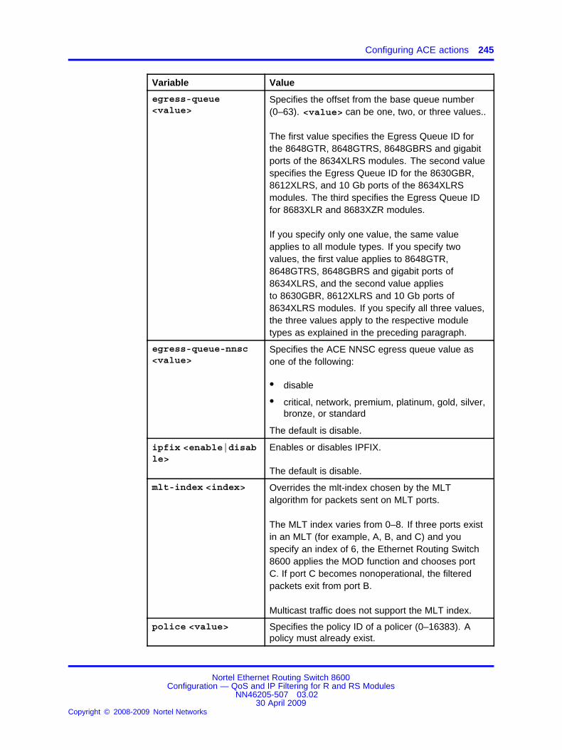
Configuring ACE actions 245
Variable Value
egress-queue<value>
Specifies the offset from the base queue number(0–63). <value> can be one, two, or three values..
The first value specifies the Egress Queue ID forthe 8648GTR, 8648GTRS, 8648GBRS and gigabitports of the 8634XLRS modules. The second valuespecifies the Egress Queue ID for the 8630GBR,8612XLRS, and 10 Gb ports of the 8634XLRSmodules. The third specifies the Egress Queue IDfor 8683XLR and 8683XZR modules.
If you specify only one value, the same valueapplies to all module types. If you specify twovalues, the first value applies to 8648GTR,8648GTRS, 8648GBRS and gigabit ports of8634XLRS, and the second value appliesto 8630GBR, 8612XLRS and 10 Gb ports of8634XLRS modules. If you specify all three values,the three values apply to the respective moduletypes as explained in the preceding paragraph.
egress-queue-nnsc<value>
Specifies the ACE NNSC egress queue value asone of the following:
• disable
• critical, network, premium, platinum, gold, silver,bronze, or standard
The default is disable.
ipfix <enable|disable>
Enables or disables IPFIX.
The default is disable.
mlt-index <index> Overrides the mlt-index chosen by the MLTalgorithm for packets sent on MLT ports.
The MLT index varies from 0–8. If three ports existin an MLT (for example, A, B, and C) and youspecify an index of 6, the Ethernet Routing Switch8600 applies the MOD function and chooses portC. If port C becomes nonoperational, the filteredpackets exit from port B.
Multicast traffic does not support the MLT index.
police <value> Specifies the policy ID of a policer (0–16383). Apolicy must already exist.
Nortel Ethernet Routing Switch 8600Configuration — QoS and IP Filtering for R and RS Modules
NN46205-507 03.0230 April 2009
Copyright © 2008-2009 Nortel Networks
.

246 Access control entry configuration using the CLI
Variable Value
redirect-next-hop<value>
Specifies the next-hop IP address for redirect mode(a.b.c.d).
If you specify a next-hop IPv6 address for redirectmode, enter 0.0.0.0 <IPv6 address>.
remark-dot1p<value>
Specifies the new 802.1 priority bit for matchingpackets:• disable
• zero, one, two, three, four, five, six, or seven
The default is disable.
remark-dscp <value> Specifies the new Per-Hop Behavior for matchingpackets:• disable
• phbcs0, phbcs1, phbaf11, phbaf12, phbaf13,phbcs2, phbaf21, phbaf22, phbaf23, phbcs3,phbaf31, phbaf32, phbaf33, phbcs4, phbaf41,phbaf42, phbaf43, phbcs5, phbef, phbcs6, andphbcs7
The default is disable.
stop-on-match<true|false>
Enables or disables the stop-on-match option. Thisoption specifies whether to stop or continue after anACE matches the packet. After this ACE matches,the switch does not attempt a match on other ACEswith lower priority. The default is false.
unreachable<deny|permit>
Denies or permits packet dropping when the nexthop is unreachable. The default is deny.
Configuring ACE debug actionsUse debug actions to use filters for troubleshooting or traffic monitoring.
CAUTIONRisk of packet lossNortel recommends that you do not select copyToPrimaryCpor copyToSecondaryCp. If you select the copyToPrimaryCpparameter, the switch sends packets to the CP, which canoverload it. You can use the Packet Capture Tool (PCAP),rather than using copyToPrimaryCp.
Prerequisites
• The ACL exists.
• The ACE exists.
Nortel Ethernet Routing Switch 8600Configuration — QoS and IP Filtering for R and RS Modules
NN46205-507 03.0230 April 2009
Copyright © 2008-2009 Nortel Networks
.

Configuring ACE debug actions 247
Procedure steps
Step Action
1 Configure debug actions for an ACE:
config filter acl <acl-id> ace <ace-id> debug [count<value>] [copytoprimarycp <value>] [copytosecondarycp<value>] [mirror <value>] [mirroring-dst-ports <value>][mirroring-dst-vlan <value>] [mirroring-dst-mlt<value>]
2 Ensure the configuration is correct:
show filter acl debug [<acl-id>] [<ace-id>]
--End--
Variable definitionsUse the information in the following table to use the config filter acl<acl-id> ace <ace-id> debug command.
Variable Value
count <enable|disable>
Enables or disables counting after a packetmatching the ACE is found. The default is disable.
copytoprimarycp<enable|disable>
Enables or disables the ability to copy matchingpackets to the primary (Master) CPU. The default isdisable.
copytosecondarycp<enable|disable>
Enables or disables the ability to copy matchingpackets to the secondary (Standby) CPU. Thedefault is disable.
mirror <enable|disable>
Enables or disables mirroring for the ACE.If you enable mirroring, ensure that you configurethe appropriate parameters:
• For R and RS modules in Rx mode, and for RSmodules, use mirroring-dst-ports, mirroring-dst-vlan, or mirroring-dst-mlt.
• For R modules in Tx mode, use the configdiag mirror-by-port commands to specifythe mirroring source or destination.
The default is disable.
mirroring-dst-ports<value>
Specifies the destination port or ports for mirroring.
Nortel Ethernet Routing Switch 8600Configuration — QoS and IP Filtering for R and RS Modules
NN46205-507 03.0230 April 2009
Copyright © 2008-2009 Nortel Networks
.

248 Access control entry configuration using the CLI
Variable Value
mirroring-dst-vlan<value>
Specifies the destination VLAN for mirroring.
mirroring-dst-mlt<value>
Specifies the destination MLT group for mirroring.
Example of configuring R module TxFilter mode mirroringThis configuration sends mirrored ICMP packets from port 2/1 to port 4/1.
Step Action
1 Configure ACT 3:
ERS8610:5# config filter act 3 create
ERS8610:5# config filter act 3 ipProtoType
ERS8610:5# config filter act 3 apply
2 Configure an outVLAN ACL that uses ACT 3 and VLAN 2:
ERS8610:5# config filter acl 21 create outVlan act 3
ERS8610:5# config filter acl 21 vlan add 2
3 Add ACE 21 with action of permit to mirror ICMP traffic:
ERS8610:5# config filter acl 21 ace 1 create nameicmp
ERS8610:5# config filter acl 21 ace 1 action permit
ERS8610:5# config filter acl 21 ace 1 ipip-protocol-type eq icmp
ERS8610:5# config filter acl 21 ace 1 debug mirrorenable
ERS8610:5# config filter acl 21 ace 1 enableERS8610:5#
4 Because this is an R module in txFilter mode, configure themirroring source and destination ports:
ERS8610:5# config diag mirror-by-port 1 createin-port 1/1 out-port 3/1 mode txFilter enable true
--End--
Configuring ARP ACEsUse ACE ARP entries to have the filter look for ARP requests orresponses.
Nortel Ethernet Routing Switch 8600Configuration — QoS and IP Filtering for R and RS Modules
NN46205-507 03.0230 April 2009
Copyright © 2008-2009 Nortel Networks
.

Configuring an Ethernet ACE 249
Prerequisites
• The ACE exists.
• The ACL exists.
• The ACT has ARP attributes.
Procedure steps
Step Action
1 To configure an ACE for ARP packets:
config filter acl <acl-id> ace <ace-id> arp operation<ace-op> <arp-oper-type>
2 Ensure the configuration is correct:
show filter acl arp [<acl-id>] [<ace-id>]
--End--
Variable definitionsUse the following table to use the config filter acl <acl-id> ace<ace-id> arp command.
Variable Value
delete <arp-attributes>
Deletes ARP attributes.
info Displays ARP status information for the ACE.
operation <ace-op><arp-oper-type>
Specifies the following:
• <ace-op> specifies an operator for a fieldmatch operation (eq).
• <arp-oper-type> specifies an operation type:arpRequest or arpResponse.
For ARP, only one attribute exists—operation.
Configuring an Ethernet ACEUse Ethernet ACEs to filter on Ethernet parameters.
Prerequisites
• The ACE exists.
• The ACL exists.
Nortel Ethernet Routing Switch 8600Configuration — QoS and IP Filtering for R and RS Modules
NN46205-507 03.0230 April 2009
Copyright © 2008-2009 Nortel Networks
.

250 Access control entry configuration using the CLI
• The ACT has Ethernet attributes.
• You can select a port or a VLAN ID, but not both.
Procedure steps
Step Action
1 Configure an ACE with Ethernet header attributes:
config filter acl <acl-id> ace <ace-id> ethernet
2 Ensure the configuration is correct:
show filter acl ethernet [<acl-id>] [<ace-id>]
--End--
Variable definitionsUse the following table to help you use the config filter acl<acl-id> ace <ace-id> ethernet command.
Variable Value
delete <ethernet-attributes>
Specifies Ethernet ACE attributes to delete. The<ethernet-attributes> parameter is a list ofEthernet attributes {<attr>,<attr>,<attr>-} where attris
• none
• srcMac, dstMac, etherType, <port|vlan>, orvlanTagPrio
You cannot select other attributes if you selectnone.
dst-mac <ace-op><dst-mac-list>
The <ace-op> parameter specifies an operator fora field match condition: eq, ne, le, ge.
The <dst-mac-list> parameter specifies a list ofdestination MAC addresses separated by a comma,or a range of MAC addresses specified from lowto high; for example, [a:b:c:d:e:f, (x:y:z:w:v:u-a:b:c:d:e:f)].
You cannot use an asterisk (*) after <ace-op>.
Nortel Ethernet Routing Switch 8600Configuration — QoS and IP Filtering for R and RS Modules
NN46205-507 03.0230 April 2009
Copyright © 2008-2009 Nortel Networks
.

Configuring an Ethernet ACE 251
Variable Value
ether-type <ace-op><ether-type>
The <ace-op> parameter specifies an operator fora field match condition: eq, ne.
The <ether-type> parameter specifies anether-type name or number:
• 0–65563
• ip, arp, ipx802dot3, ipx802dot2, ipxSnap,ipxEthernet2, appleTalk, decLat, decOther,sna802dot2, snaEthernet2, netBios, xns, vines,ipv6, rarp, or PPPoE.
info Displays Ethernet header status information for theACE.
port <ace-op><ports>
The <ace-op> parameter specifies an operator fora field match condition (eq).
The <ports> parameter specifies a port list[slot/port].
src-mac <ace-op><src-mac-list>
The <ace-op> parameter specifies an operator fora field match condition: eq, ne, le, ge.
The <src-mac-list> parameter specifies a listof source MAC addresses separated by a comma,or a range of MAC addresses specified from lowto high; for example, [a:b:c:d:e:f, (x:y:z:w:v:u-a:b:c:d:e:f)].
vlan-id <ace-op><vid>
The <ace-op> parameter specifies an operator fora field match condition (eq).
The <vid> parameter specifies a list of VLAN IDsfrom 0–4096.
vlan-tag-prio <ace-op> <vlan-tag-prio>
The <ace-op> parameter specifies an operator fora field match condition: eq, ne.
The <vlan-tag-prio> parameter specifies aVLAN tag priority from 0–7 or undefined.
Example of configuring an Ethernet ACE
Step Action
1 Specify a specific destination MAC address:
Nortel Ethernet Routing Switch 8600Configuration — QoS and IP Filtering for R and RS Modules
NN46205-507 03.0230 April 2009
Copyright © 2008-2009 Nortel Networks
.

252 Access control entry configuration using the CLI
ERS-8610:6# config filter acl 1 ace 12 ethernetdst-mac eq 08:00:69:02:01:FC
--End--
Configuring an IP ACEUse IP ACEs to filter on the source IP address, destination IP address,DiffServ Code Point (DSCP), protocol, IP options, and IP fragmentationparameters.
Prerequisites
• The ACE exists.
• The ACL exists.
• The ACT has IP attributes.
Procedure steps
Step Action
1 Configure an ACE with IP header attributes:
config filter acl <acl-id> ace <ace-id> ip
2 Ensure the configuration is correct:
show filter acl ip [<acl-id>] [<ace-id>]
--End--
Variable definitionsUse the following table to help you use the config filter acl<acl-id> ace <ace-id> ip command.
Variable Value
delete <ip-attributes>
Specifies a list of IP ACE attributes to delete:
• none
• srcIp, dstIp, ipFragFlag, ipOptions, ipProtoType,or dscp
You cannot select other attributes if you selectnone.
Nortel Ethernet Routing Switch 8600Configuration — QoS and IP Filtering for R and RS Modules
NN46205-507 03.0230 April 2009
Copyright © 2008-2009 Nortel Networks
.
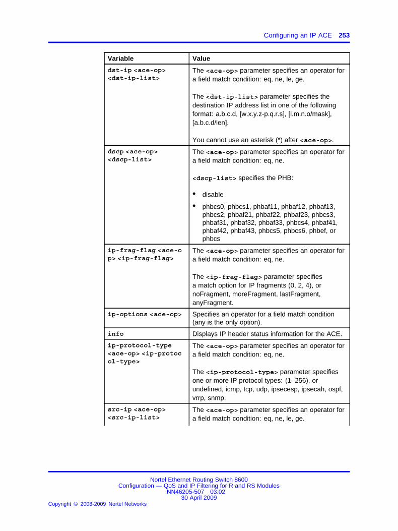
Configuring an IP ACE 253
Variable Value
dst-ip <ace-op><dst-ip-list>
The <ace-op> parameter specifies an operator fora field match condition: eq, ne, le, ge.
The <dst-ip-list> parameter specifies thedestination IP address list in one of the followingformat: a.b.c.d, [w.x.y.z-p.q.r.s], [l.m.n.o/mask],[a.b.c.d/len].
You cannot use an asterisk (*) after <ace-op>.
dscp <ace-op><dscp-list>
The <ace-op> parameter specifies an operator fora field match condition: eq, ne.
<dscp-list> specifies the PHB:
• disable
• phbcs0, phbcs1, phbaf11, phbaf12, phbaf13,phbcs2, phbaf21, phbaf22, phbaf23, phbcs3,phbaf31, phbaf32, phbaf33, phbcs4, phbaf41,phbaf42, phbaf43, phbcs5, phbcs6, phbef, orphbcs
ip-frag-flag <ace-op> <ip-frag-flag>
The <ace-op> parameter specifies an operator fora field match condition: eq, ne.
The <ip-frag-flag> parameter specifiesa match option for IP fragments (0, 2, 4), ornoFragment, moreFragment, lastFragment,anyFragment.
ip-options <ace-op> Specifies an operator for a field match condition(any is the only option).
info Displays IP header status information for the ACE.
ip-protocol-type<ace-op> <ip-protocol-type>
The <ace-op> parameter specifies an operator fora field match condition: eq, ne.
The <ip-protocol-type> parameter specifiesone or more IP protocol types: (1–256), orundefined, icmp, tcp, udp, ipsecesp, ipsecah, ospf,vrrp, snmp.
src-ip <ace-op><src-ip-list>
The <ace-op> parameter specifies an operator fora field match condition: eq, ne, le, ge.
Nortel Ethernet Routing Switch 8600Configuration — QoS and IP Filtering for R and RS Modules
NN46205-507 03.0230 April 2009
Copyright © 2008-2009 Nortel Networks
.

254 Access control entry configuration using the CLI
Variable Value
The <src-ip-list> parameter specifies asource IP address list in one of the followingformat: a.b.c.d, [w.x.y.z-p.q.r.s], [l.m.n.o/mask],[a.b.c.d/len].
Example of configuring an IP ACE
Step Action
1 Specify a destination IP address:
ERS-8610:6# config filter acl 1 ace 12 ip dst-ip eq131.205.3.4
--End--
Configuring a protocol ACEUse protocol ACEs to filter on the TCP source port, UDP source port, TCPdestination port, UDP destination port, ICMP message type, and TCPflags.
Prerequisites
• The ACE exists.
• The ACL exists.
• The ACT has protocol attributes.
Procedure steps
Step Action
1 Configure an ACE with protocol attributes:
config filter acl <acl-id> ace <ace-id> protocol
The tcp-flags and icmp-msg-type command options support lists.
2 Ensure the configuration is correct:
show filter acl protocol [<acl-id>] [<ace-id>]
--End--
Nortel Ethernet Routing Switch 8600Configuration — QoS and IP Filtering for R and RS Modules
NN46205-507 03.0230 April 2009
Copyright © 2008-2009 Nortel Networks
.

Configuring a protocol ACE 255
Variable definitionsUse the information in the following table to use the config filter acl<acl-id> ace <ace-id> protocol command.
Variable Value
delete <protocol-attributes>
Specifies protocol ACE attributes to delete
• none
• tcpSrcPort, udpSrcPort ,tcpDstPort, udpDstPort,tcpFlags, or icmpMsgType
You cannot select other attributes if you select none.
icmp-msg-type <ace-op> <icmp-msg-type>
The <ace-op> parameter specifies an operator fora field match condition: eq, ne.
The <icmp-msg-type> parameter specifiesone or more IP protocol types (0–255), orechoreply, destunreach, sourcequench,redirect, echo-request, routeradv, routerselect,time-exceeded, param-problem, timestamp-request,timestamp-reply, addressmask-request,addressmask-reply, or traceroute.
You cannot select an asterisk (*) after <ace-op>.
info Displays IP header status information for the ACE.
tcp-dst-port <ace-op> <tcp-portlist>
The <ace-op> parameter specifies an operator fora field match condition: eq, ne, le, ge. The defaultis eq (equals).
The <tcp-portlist> parameter specifies thedestination port for the TCP protocol: (0–65535), orecho, ftpdata, ftpcontrol, ssh, telnet, dns, http, bgp,hdot323, or undefined.
tcp-flags <ace-op><tcp-flags>
The <ace-op> parameter specifies an operator fora field match condition: matchAny, matchAll
<tcp-flags> specifies one or more TCP flags:none, fin, syn, rst, push, ack, urg, or undefined.
Nortel Ethernet Routing Switch 8600Configuration — QoS and IP Filtering for R and RS Modules
NN46205-507 03.0230 April 2009
Copyright © 2008-2009 Nortel Networks
.

256 Access control entry configuration using the CLI
Variable Value
tcp-src-port <ace-op> <tcp-portlist>
The <ace-op> parameter specifies an operator fora field match condition: eq, ne, le, ge. The defaultis eq (equals).
The <tcp-portlist> parameter specifies thedestination port for the TCP protocol (0–65535), orecho, dns, bootpServer, bootpClient, tftp, rip, rtp,rtcp, or undefined.
udp-dst-port <ace-op> <udp-portlist>
The <ace-op> parameter specifies an operator fora field match condition: eq, ne, le, ge. The defaultis eq.
The <udp-portlist> parameter specifies thedestination port for the UDP protocol (0–65535), orecho, dns, bootpServer, bootpClient, tftp, rip, rtp,rtcp, or undefined.
udp-src-port <ace-op> <udp-portlist>
The <ace-op> parameter specifies an operator fora field match condition: eq, ne, le, ge. The defaultis eq.
The <udp-portlist> parameter specifies thesource port for the UDP protocol (0–65535), orecho, dns, bootpServer, bootpClient, tftp, rip, rtp,rtcp, or undefined.
Example of configuring a protocol ACE
Step Action
1 Specify ICMP packets:
ERS-8610:6# config filter acl 1 ace 12 protocolicmp-msg-type eq destunreach
--End--
Configuring a custom ACEYou can use a custom ACE to define your own match patterns.
Prerequisites
• The ACE exists.
• The ACL exists.
• The ACT has pattern attributes.
Nortel Ethernet Routing Switch 8600Configuration — QoS and IP Filtering for R and RS Modules
NN46205-507 03.0230 April 2009
Copyright © 2008-2009 Nortel Networks
.

Configuring a custom ACE 257
Procedure steps
Step Action
1 Add an ACE for patterns that you define:
config filter acl <acl-id> ace <ace-id> advanced
2 Ensure that your configuration is correct:
show filter acl advanced [<acl-id>] [<ace-id>]
--End--
Variable definitionsUse the following table to use the config filter acl <acl-id> ace<ace-id> advanced command.
Variable Value
custom-filter1<pattern1-name><ace-op> <value>
Specifies the following information for customfilter 1:
• <pattern1-name>—a descriptive name forpattern 1 that uses 0–32 characters.
• <ace-op>—an operator for a field matchcondition (eq, le, ge). The ace-op ne does notapply to an ACE pattern.
• <value>—a hexadecimal number equal to thepattern template length.
custom-filter2<pattern2-name><ace-op> <value>
Specifies the following information for customfilter 2:
• <pattern2-name>—a descriptive name forpattern 2 that uses 0–32 characters.
• <ace-op>—an operator for a field matchcondition (eq, le, ge). The ace-op ne does notapply to an ACE pattern.
• <value>—a hexadecimal number equal to thepattern template length.
Nortel Ethernet Routing Switch 8600Configuration — QoS and IP Filtering for R and RS Modules
NN46205-507 03.0230 April 2009
Copyright © 2008-2009 Nortel Networks
.

258 Access control entry configuration using the CLI
Variable Value
custom-filter3<pattern3-name><ace-op> <value>
Specifies the following information for customfilter 3:
• <pattern3-name>—a descriptive name forpattern 3 that uses 0–32 characters.
• <ace-op>—an operator for a field matchcondition (eq, le, ge). The ace-op ne does notapply to an ACE pattern.
• <value>—a hexadecimal number equal to thepattern template length.
delete <pattern-attributes>
Deletes user-defined patterns for an ACE:
• none
• custom-filter1, custom-filter2, custom-filter3
info Displays user-defined pattern status information forthe ACE.
Example of configuring a custom ACE
Step Action
1 Add an ACE for patterns that you define:
ERS-8610:6# config filter acl 1 ace 12 advancedcustom-filter1 Pattern1 eq 0x12
--End--
Configuring an IPv6 ACEUse an IPv6 ACE to filter on IPv6 attributes.
Prerequisites
• The ACE exists.
• The ACL exists.
• The ACT has IPv6 attributes.
Procedure steps
Step Action
1 Add an ACE with IP header attributes:
Nortel Ethernet Routing Switch 8600Configuration — QoS and IP Filtering for R and RS Modules
NN46205-507 03.0230 April 2009
Copyright © 2008-2009 Nortel Networks
.

Viewing ACL and ACE configuration data 259
config filter acl <acl-id> ace <ace-id> ipv6
2 Ensure that your configuration is correct:
show filter acl ipv6 [<acl-id>] [<ace-id>]
--End--
Variable definitionsUse the information in the following table to use the config filter acl<acl-id> ace <ace-id> ipv6 command.
Variable Value
delete <ipv6-attributes>
Deletes the specified IPv6 ACE attributes.You cannot select other attributes if you selectnone.
dst-ipv6 <ace-op><dst-ipv6-list>
The <ace-op> parameter specifies an operator fora field match condition: eq, ne.
The <dst-ipv6-list> parameter specifies thelist of destination IPv6 addresses, separated bycommas.
You cannot select an asterisk (*) after <ace-op>.
info Displays the current level parameter settings andthe next level directories.
nxt-hdr <ace-op><nxt-hdr>
The <ace-op> parameter specifies an operator fora field match condition: eq, ne.
The <nxt-hdr> parameter specifies hop-by-hop,tcp, udp, routing, fragment, ipsecesp, ipsecah,icmpv6, noHdr, or undefined.
src-ipv6 <ace-op><src-ipv6-list>
The <ace-op> parameter specifies an operator fora field match condition: eq, ne.
The <src-ipv6-list> parameter specifies the listof source IPv6 addresses, separated by commas.
Viewing ACL and ACE configuration dataReview your configuration to ensure that it is correct.
Nortel Ethernet Routing Switch 8600Configuration — QoS and IP Filtering for R and RS Modules
NN46205-507 03.0230 April 2009
Copyright © 2008-2009 Nortel Networks
.

260 Access control entry configuration using the CLI
Procedure steps
Step Action
1 View a list of executed commands:
show filter acl config [<acl-id>] [<ace-id>]
--End--
Variable definitionsUse the information in the following table to use the show filter aclconfig command.
Variable Value
<ace-id> Specifies an ACE ID from 1–1000.
<acl-id> Specifies an ACL ID from 1–4096.
Nortel Ethernet Routing Switch 8600Configuration — QoS and IP Filtering for R and RS Modules
NN46205-507 03.0230 April 2009
Copyright © 2008-2009 Nortel Networks
.

261.
Access control entry configurationusing the NNCLI
Use an ACE to provide an ordered list of traffic filtering rules.
Access control entry configuration navigation• “Job aid” (page 261)
• “Configuring ACEs” (page 263)
• “Configuring ACE actions” (page 265)
• “Configuring ACE debug actions” (page 267)
• “Configuring ARP ACEs” (page 269)
• “Configuring an Ethernet ACE” (page 270)
• “Configuring an IP ACE” (page 272)
• “Configuring a protocol ACE” (page 274)
• “Configuring a custom ACE” (page 276)
• “Configuring an IPv6 ACE” (page 277)
• “Viewing ACL and ACE configuration data” (page 279)
Job aidThe following roadmap lists traffic filter commands that you can use toperform the procedures in this section.
Table 31Roadmap of traffic filter NNCLI commands
Command Parameters
Global Configuration mode
enablefilter acl ace <1-4096> <1-1000>
name <WORD 0-32>
Nortel Ethernet Routing Switch 8600Configuration — QoS and IP Filtering for R and RS Modules
NN46205-507 03.0230 April 2009
Copyright © 2008-2009 Nortel Networks
.

262 Access control entry configuration using the NNCLI
Table 31Roadmap of traffic filter NNCLI commands (cont’d.)
Command Parameters
egress-queue <0-64>
egress-queue-nnsc <bronze|critical|custom|gold|platimum|premium|silver|standard>
ipfix enable
mlt-index <0-8>
police <0-16383>
redirect-next-hop <WORD 1-15>
remark-dot1p <0-8>|zero|one|two|three|four|five|six|seven>
remark-dscp <0-256>|phbcs0|phbcs1|phbaf11|phbaf12|phbaf13|phbcs2|phbaf21|phbaf22|phbaf23|phbcs3|phbaf31|phbaf32|phbaf33|phbcs4|phbaf41|phbaf42|phbaf43|phbcs5|phbef|phbcs6|phbcs7>
stop-on-match enable
filter acl ace action <1-4096><1-1000> <deny|permit>
unreachable <deny|permit>
custom-filter1 <WORD 0-32> <eq|le|ge><WORD 1-1024>
custom-filter2 <WORD 0-32> <eq|le|ge><WORD 1-1024>
filter acl ace advanced <1-4096><1-1000>
custom-filter3 <WORD 0-32> <eq|le|ge><WORD 1-1024>
filter acl ace arp <1-4096><1-1000> operation eq <arprequest|arpresponse>
–
dst-mac <eq|ne|le|ge> <WORD 1-1024>
ether-type <eq|ne> <WORD 1-200>
port <eq> <portList>
src-mac <eq|ne|le|ge> <WORD 1-1024>
vlan-id <eq> <1..4094[,<1..4094>...]>
filter acl ace ethernet <1-4096><1-1000>
vlan-tag-prio <eq|ne> <0-7>
Nortel Ethernet Routing Switch 8600Configuration — QoS and IP Filtering for R and RS Modules
NN46205-507 03.0230 April 2009
Copyright © 2008-2009 Nortel Networks
.
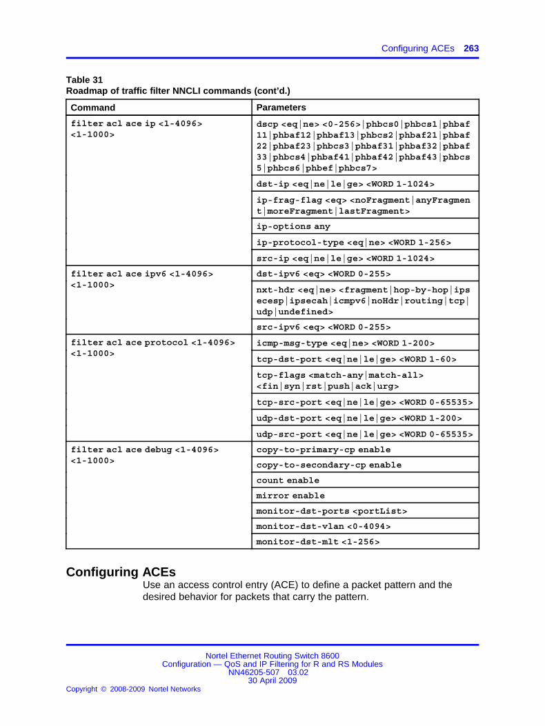
Configuring ACEs 263
Table 31Roadmap of traffic filter NNCLI commands (cont’d.)
Command Parameters
dscp <eq|ne> <0-256>|phbcs0|phbcs1|phbaf11|phbaf12|phbaf13|phbcs2|phbaf21|phbaf22|phbaf23|phbcs3|phbaf31|phbaf32|phbaf33|phbcs4|phbaf41|phbaf42|phbaf43|phbcs5|phbcs6|phbef|phbcs7>
dst-ip <eq|ne|le|ge> <WORD 1-1024>
ip-frag-flag <eq> <noFragment|anyFragment|moreFragment|lastFragment>
ip-options any
ip-protocol-type <eq|ne> <WORD 1-256>
filter acl ace ip <1-4096><1-1000>
src-ip <eq|ne|le|ge> <WORD 1-1024>
dst-ipv6 <eq> <WORD 0-255>
nxt-hdr <eq|ne> <fragment|hop-by-hop|ipsecesp|ipsecah|icmpv6|noHdr|routing|tcp|udp|undefined>
filter acl ace ipv6 <1-4096><1-1000>
src-ipv6 <eq> <WORD 0-255>
icmp-msg-type <eq|ne> <WORD 1-200>
tcp-dst-port <eq|ne|le|ge> <WORD 1-60>
tcp-flags <match-any|match-all><fin|syn|rst|push|ack|urg>
tcp-src-port <eq|ne|le|ge> <WORD 0-65535>
udp-dst-port <eq|ne|le|ge> <WORD 1-200>
filter acl ace protocol <1-4096><1-1000>
udp-src-port <eq|ne|le|ge> <WORD 0-65535>
copy-to-primary-cp enable
copy-to-secondary-cp enable
count enable
mirror enable
monitor-dst-ports <portList>
monitor-dst-vlan <0-4094>
filter acl ace debug <1-4096><1-1000>
monitor-dst-mlt <1-256>
Configuring ACEsUse an access control entry (ACE) to define a packet pattern and thedesired behavior for packets that carry the pattern.
Nortel Ethernet Routing Switch 8600Configuration — QoS and IP Filtering for R and RS Modules
NN46205-507 03.0230 April 2009
Copyright © 2008-2009 Nortel Networks
.
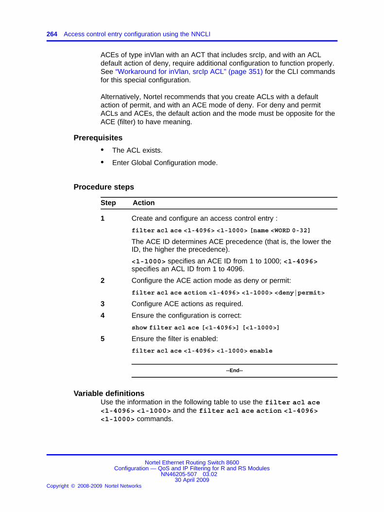
264 Access control entry configuration using the NNCLI
ACEs of type inVlan with an ACT that includes srcIp, and with an ACLdefault action of deny, require additional configuration to function properly.See “Workaround for inVlan, srcIp ACL” (page 351) for the CLI commandsfor this special configuration.
Alternatively, Nortel recommends that you create ACLs with a defaultaction of permit, and with an ACE mode of deny. For deny and permitACLs and ACEs, the default action and the mode must be opposite for theACE (filter) to have meaning.
Prerequisites
• The ACL exists.
• Enter Global Configuration mode.
Procedure steps
Step Action
1 Create and configure an access control entry :
filter acl ace <1-4096> <1-1000> [name <WORD 0-32]
The ACE ID determines ACE precedence (that is, the lower theID, the higher the precedence).
<1-1000> specifies an ACE ID from 1 to 1000; <1-4096>specifies an ACL ID from 1 to 4096.
2 Configure the ACE action mode as deny or permit:
filter acl ace action <1-4096> <1-1000> <deny|permit>
3 Configure ACE actions as required.
4 Ensure the configuration is correct:
show filter acl ace [<1-4096>] [<1-1000>]
5 Ensure the filter is enabled:
filter acl ace <1-4096> <1-1000> enable
--End--
Variable definitionsUse the information in the following table to use the filter acl ace<1-4096> <1-1000> and the filter acl ace action <1-4096><1-1000> commands.
Nortel Ethernet Routing Switch 8600Configuration — QoS and IP Filtering for R and RS Modules
NN46205-507 03.0230 April 2009
Copyright © 2008-2009 Nortel Networks
.

Configuring ACE actions 265
Variable Value
<deny|permit> Configures the action mode. The default is deny.
To use the default configuration, use the defaultoption in the command default filter acl aceaction <1-4096> <1-1000>
debug Updates desired debug parameters for ACEs.
enable Enables an ACE within an ACL.
After you enable an ACE, to make changes, firstdisable it.
name <WORD 0-32> Specifies an optional descriptive name for the ACEthat uses 0–32 characters.
Configuring ACE actionsActions determine the process that occurs when a packet matches anACE.
Prerequisites
• The ACE exists.
• Enter Global Configuration mode.
• To use a policer, a policy exists.
Procedure steps
Step Action
1 Configure ACE actions:
filter acl ace action <1-4096> <1-1000> <deny|permit>
2 Ensure the configuration is correct:
show filter acl action [<1-4096>] [<1-1000>]
--End--
Variable definitionsUse the information in the following table to use the filter acl aceaction <1-4096> <1-1000> <deny|permit> commands.
Nortel Ethernet Routing Switch 8600Configuration — QoS and IP Filtering for R and RS Modules
NN46205-507 03.0230 April 2009
Copyright © 2008-2009 Nortel Networks
.
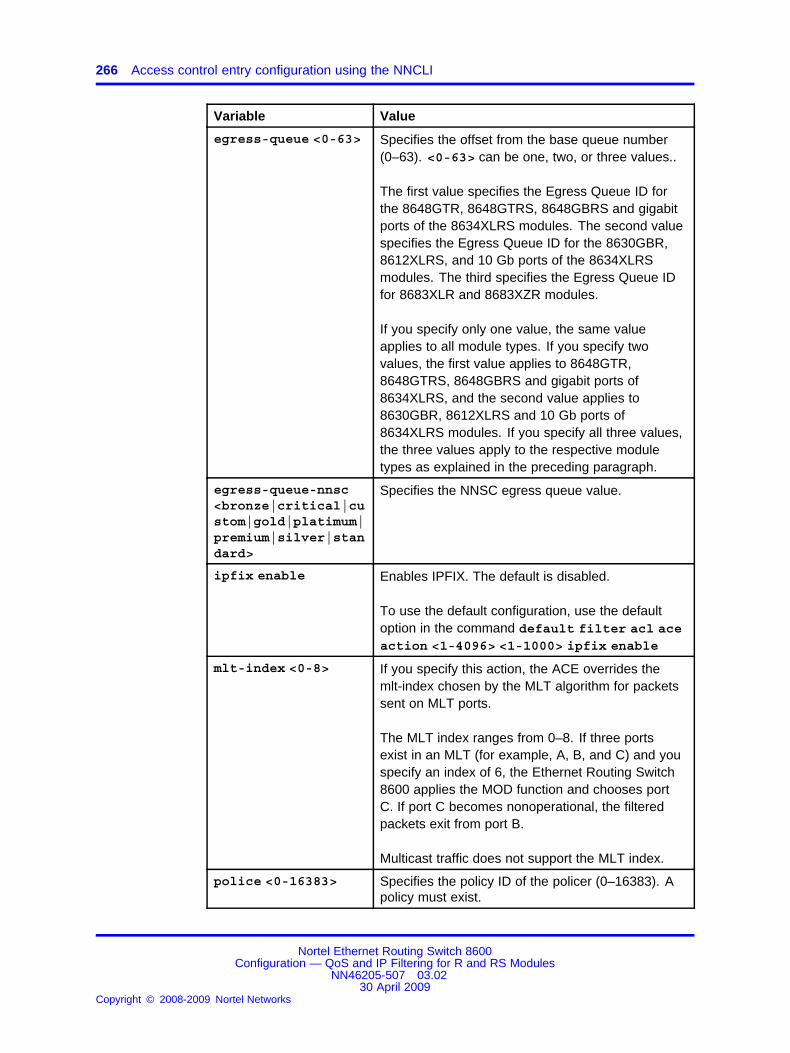
266 Access control entry configuration using the NNCLI
Variable Value
egress-queue <0-63> Specifies the offset from the base queue number(0–63). <0-63> can be one, two, or three values..
The first value specifies the Egress Queue ID forthe 8648GTR, 8648GTRS, 8648GBRS and gigabitports of the 8634XLRS modules. The second valuespecifies the Egress Queue ID for the 8630GBR,8612XLRS, and 10 Gb ports of the 8634XLRSmodules. The third specifies the Egress Queue IDfor 8683XLR and 8683XZR modules.
If you specify only one value, the same valueapplies to all module types. If you specify twovalues, the first value applies to 8648GTR,8648GTRS, 8648GBRS and gigabit ports of8634XLRS, and the second value applies to8630GBR, 8612XLRS and 10 Gb ports of8634XLRS modules. If you specify all three values,the three values apply to the respective moduletypes as explained in the preceding paragraph.
egress-queue-nnsc<bronze|critical|custom|gold|platimum|premium|silver|standard>
Specifies the NNSC egress queue value.
ipfix enable Enables IPFIX. The default is disabled.
To use the default configuration, use the defaultoption in the command default filter acl aceaction <1-4096> <1-1000> ipfix enable
mlt-index <0-8> If you specify this action, the ACE overrides themlt-index chosen by the MLT algorithm for packetssent on MLT ports.
The MLT index ranges from 0–8. If three portsexist in an MLT (for example, A, B, and C) and youspecify an index of 6, the Ethernet Routing Switch8600 applies the MOD function and chooses portC. If port C becomes nonoperational, the filteredpackets exit from port B.
Multicast traffic does not support the MLT index.
police <0-16383> Specifies the policy ID of the policer (0–16383). Apolicy must exist.
Nortel Ethernet Routing Switch 8600Configuration — QoS and IP Filtering for R and RS Modules
NN46205-507 03.0230 April 2009
Copyright © 2008-2009 Nortel Networks
.

Configuring ACE debug actions 267
Variable Value
redirect-next-hop<WORD 1-15>
Specifies the next-hop IP address for redirect mode(a.b.c.d).
If you specify the next-hop IPv6 address for redirectmode, enter 0.0.0.0 <IPv6 address>.
remark-dscp <WORD0-256>
Specifies the new Per-Hop Behavior for matchingpackets: phbcs0, phbcs1, phbaf11, phbaf12,phbaf13, phbcs2, phbaf21, phbaf22, phbaf23,phbcs3, phbaf31, phbaf32, phbaf33, phbcs4,phbaf41, phbaf42, phbaf43, phbcs5, phbef, phbcs6,phbcs7.
remark-dot1p <WORD0-256>
Specifies the new 802.1 priority bit for matchingpackets: zero, one, two, three, four, five, six, orseven.
stop-on-matchenable
Enables the stop-on-match option. This optionspecifies whether to stop or continue after an ACEmatches the packet. After this ACE matches, theswitch does not attempt a match on other ACEswith lower priority.
unreachable<deny|permit>
Denies or permits packet dropping when thenext-hop for the packet is unreachable. The defaultis deny.
To use the default configuration, use the defaultoption in the command default filter acl aceaction <1-4096> <1-1000> unreachable
Example of configuring ACE actions
Step Action
1 Configure actions:
ERS-8610:6#filter acl ace action 1 1 permit ipfixenable remark-dscp phbaf22
--End--
Configuring ACE debug actionsUse debug actions to use filters for troubleshooting or monitoringprocedures.
Nortel Ethernet Routing Switch 8600Configuration — QoS and IP Filtering for R and RS Modules
NN46205-507 03.0230 April 2009
Copyright © 2008-2009 Nortel Networks
.
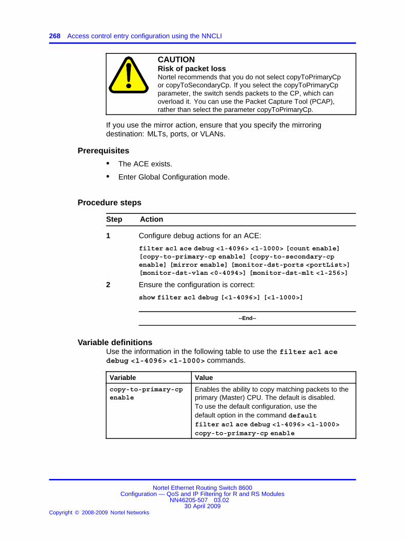
268 Access control entry configuration using the NNCLI
CAUTIONRisk of packet lossNortel recommends that you do not select copyToPrimaryCpor copyToSecondaryCp. If you select the copyToPrimaryCpparameter, the switch sends packets to the CP, which canoverload it. You can use the Packet Capture Tool (PCAP),rather than select the parameter copyToPrimaryCp.
If you use the mirror action, ensure that you specify the mirroringdestination: MLTs, ports, or VLANs.
Prerequisites
• The ACE exists.
• Enter Global Configuration mode.
Procedure steps
Step Action
1 Configure debug actions for an ACE:
filter acl ace debug <1-4096> <1-1000> [count enable][copy-to-primary-cp enable] [copy-to-secondary-cpenable] [mirror enable] [monitor-dst-ports <portList>][monitor-dst-vlan <0-4094>] [monitor-dst-mlt <1-256>]
2 Ensure the configuration is correct:
show filter acl debug [<1-4096>] [<1-1000>]
--End--
Variable definitionsUse the information in the following table to use the filter acl acedebug <1-4096> <1-1000> commands.
Variable Value
copy-to-primary-cpenable
Enables the ability to copy matching packets to theprimary (Master) CPU. The default is disabled.To use the default configuration, use thedefault option in the command defaultfilter acl ace debug <1-4096> <1-1000>copy-to-primary-cp enable
Nortel Ethernet Routing Switch 8600Configuration — QoS and IP Filtering for R and RS Modules
NN46205-507 03.0230 April 2009
Copyright © 2008-2009 Nortel Networks
.
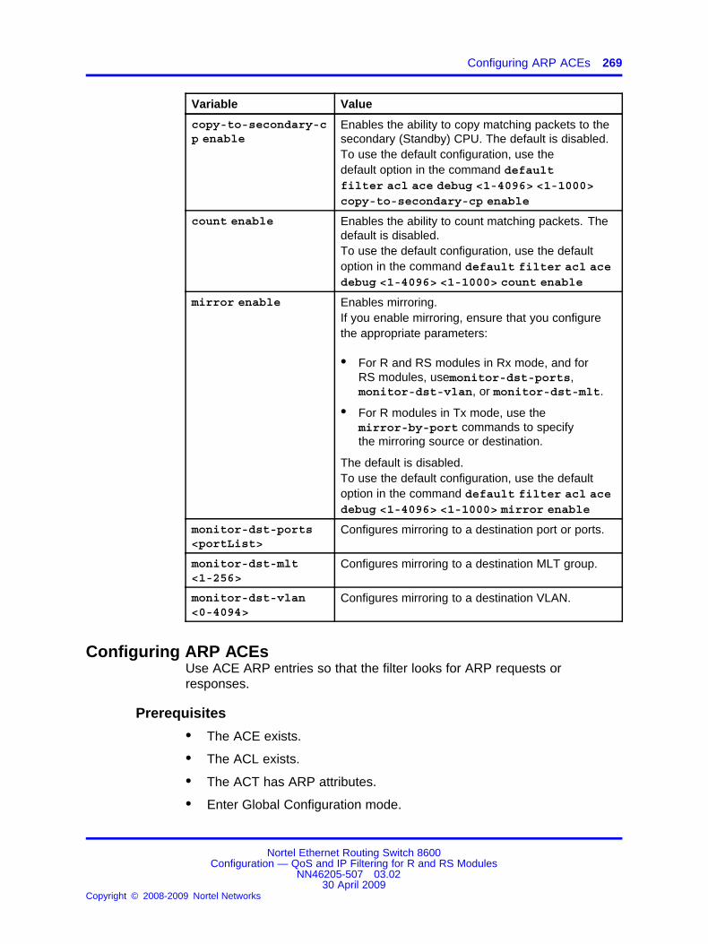
Configuring ARP ACEs 269
Variable Value
copy-to-secondary-cp enable
Enables the ability to copy matching packets to thesecondary (Standby) CPU. The default is disabled.To use the default configuration, use thedefault option in the command defaultfilter acl ace debug <1-4096> <1-1000>copy-to-secondary-cp enable
count enable Enables the ability to count matching packets. Thedefault is disabled.To use the default configuration, use the defaultoption in the command default filter acl acedebug <1-4096> <1-1000> count enable
mirror enable Enables mirroring.If you enable mirroring, ensure that you configurethe appropriate parameters:
• For R and RS modules in Rx mode, and forRS modules, usemonitor-dst-ports,monitor-dst-vlan, or monitor-dst-mlt.
• For R modules in Tx mode, use themirror-by-port commands to specifythe mirroring source or destination.
The default is disabled.To use the default configuration, use the defaultoption in the command default filter acl acedebug <1-4096> <1-1000> mirror enable
monitor-dst-ports<portList>
Configures mirroring to a destination port or ports.
monitor-dst-mlt<1-256>
Configures mirroring to a destination MLT group.
monitor-dst-vlan<0-4094>
Configures mirroring to a destination VLAN.
Configuring ARP ACEsUse ACE ARP entries so that the filter looks for ARP requests orresponses.
Prerequisites
• The ACE exists.
• The ACL exists.
• The ACT has ARP attributes.
• Enter Global Configuration mode.
Nortel Ethernet Routing Switch 8600Configuration — QoS and IP Filtering for R and RS Modules
NN46205-507 03.0230 April 2009
Copyright © 2008-2009 Nortel Networks
.
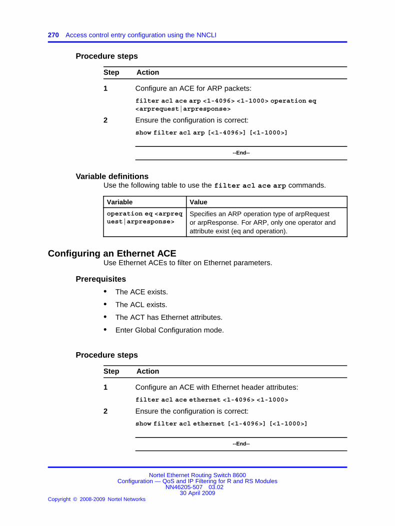
270 Access control entry configuration using the NNCLI
Procedure steps
Step Action
1 Configure an ACE for ARP packets:
filter acl ace arp <1-4096> <1-1000> operation eq<arprequest|arpresponse>
2 Ensure the configuration is correct:
show filter acl arp [<1-4096>] [<1-1000>]
--End--
Variable definitionsUse the following table to use the filter acl ace arp commands.
Variable Value
operation eq <arprequest|arpresponse>
Specifies an ARP operation type of arpRequestor arpResponse. For ARP, only one operator andattribute exist (eq and operation).
Configuring an Ethernet ACEUse Ethernet ACEs to filter on Ethernet parameters.
Prerequisites
• The ACE exists.
• The ACL exists.
• The ACT has Ethernet attributes.
• Enter Global Configuration mode.
Procedure steps
Step Action
1 Configure an ACE with Ethernet header attributes:
filter acl ace ethernet <1-4096> <1-1000>
2 Ensure the configuration is correct:
show filter acl ethernet [<1-4096>] [<1-1000>]
--End--
Nortel Ethernet Routing Switch 8600Configuration — QoS and IP Filtering for R and RS Modules
NN46205-507 03.0230 April 2009
Copyright © 2008-2009 Nortel Networks
.

Configuring an Ethernet ACE 271
Variable definitionsUse the following table to use the filter acl ace ethernet <1-4096><1-1000> commands.
Variable Value
dst-mac <eq|ne|le|ge> <WORD 1-1024>
The <eq|ne|le|ge> parameter specifies anoperator for a field match condition: equal to, notequal to, less than or equal to, greater than orequal to.
The <WORD 1-1024> parameter specifies alist of destination MAC addresses separatedby a comma, or a range of MAC addressesspecified from low to high; for example, [a:b:c:d:e:f,(x:y:z:w:v:u-a:b:c:d:e:f)].
ether-type <eq|ne><WORD 1-200>
The <eq|ne> parameter specifies an operator for afield match condition: equal to or not equal to.
The <WORD 1-200> parameter specifies anether-type name or number:
• 0–65563
• ip, arp, ipx802dot3, ipx802dot2, ipxSnap,ipxEthernet2, appleTalk, decLat, decOther,sna802dot2, snaEthernet2, netBios, xns, vines,ipv6, rarp, or PPPoE
port eq <portList> Specifies ports to which to match, where<portList> specifies the ports.
src-mac <eq|ne|le|ge> <WORD 1-1024>
The <eq|ne|le|ge> parameter specifies anoperator for a field match condition: equal to, notequal to, less than or equal to, greater than orequal to.
The <WORD 1-1024> parameter specifies a list ofsource MAC addresses separated by separatedby a comma, or a range of MAC addressesspecified from low to high; for example, [a:b:c:d:e:f,(x:y:z:w:v:u- a:b:c:d:e:f)].
vlan-id eq <1-4094> Specifies VLANs to match, where <1-4094>specifies the VLAN IDs.
vlan-tag-prio<eq|ne> <0-7>
The <eq|ne> parameter specifies an operator for afield match condition: equal to or not equal to.
The <vlan-tag-prio> parameter specifies aVLAN tag priority from 0–7 or undefined.
Nortel Ethernet Routing Switch 8600Configuration — QoS and IP Filtering for R and RS Modules
NN46205-507 03.0230 April 2009
Copyright © 2008-2009 Nortel Networks
.

272 Access control entry configuration using the NNCLI
Example of configuring an Ethernet ACE
Step Action
1 Specify a specific destination MAC address:
ERS-8610:6# filter acl ace ethernet 1 12 dst-mac eq08:00:69:02:01:FC
--End--
Configuring an IP ACEUse IP ACEs to filter on the source IP address, destination IP address,DiffServ Code Point (DSCP), protocol, IP options, and IP fragmentationparameters.
Prerequisites
• The ACE exists.
• The ACL exists.
• The ACT has IP attributes.
• Enter Global Configuration mode.
Procedure steps
Step Action
1 Configure an ACE with IP header attributes:
filter acl ace ip <1-4096> <1-1000>
2 Ensure the configuration is correct:
show filter acl ip [<1-4096>] [<1-1000>]
--End--
Variable definitionsUse the following table to use the filter acl ace ip <1-4096><1-1000> commands.
Nortel Ethernet Routing Switch 8600Configuration — QoS and IP Filtering for R and RS Modules
NN46205-507 03.0230 April 2009
Copyright © 2008-2009 Nortel Networks
.

Configuring an IP ACE 273
Variable Value
dst-ip <eq|ne|le|ge> <WORD 1-1024>
The <eq|ne|le|ge> parameter specifies anoperator for a field match condition: equal to, notequal to, less than or equal to, greater than or equalto.
The <WORD 1-1024> parameter specifies thedestination IP address list in one of the followingformats: a.b.c.d, [w.x.y.z-p.q.r.s], [l.m.n.o/mask],[a.b.c.d/len].
dscp <eq|ne> <WORD0-256>
The <eq|ne> parameter specifies an operator for afield match condition: equal to or not equal to.
The <WORD 0-256> parameter specifies the PHBname or DSCP value {0 to 256}, or phbcs0, phbcs1,phbaf11, phbaf12, phbaf13, phbcs2, phbaf21,phbaf22, phbaf23, phbcs3, phbaf31, phbaf32,phbaf33, phbcs4, phbaf41, phbaf42, phbaf43,phbcs5, phbcs6, phbef, or phbcs.
ip-frag-flag eq<noFragment|anyFragment|moreFragment|lastFragment>
The eq parameter specifies an operator for a fieldmatch condition: equal to.
The ip-frag-flag parameter specifies a matchoption for IP fragments (0, 2, or 4), or noFragment,anyFragment, moreFragment, lastFragment.
ip-options any Matches to an IP option. Any is the only option.
ip-protocol-type<eq|ne> <WORD 1-256>
The <eq|ne> parameter specifies an operator for afield match condition: equal to or not equal to.
The <WORD 1-256> parameter specifies one ormore IP protocol types: (1–256), or undefined,icmp, tcp, udp, ipsecesp, ipsecah, ospf, vrrp, snmp.
src-ip <eq|ne|le|ge> <WORD 1-1024>
The <eq|ne|le|ge> parameter specifies anoperator for a field match condition: equal to, notequal to, less than or equal to, greater than or equalto.
The <WORD 1-1024> parameter specifies a sourceIP address list in one of the following formats:a.b.c.d, [w.x.y.z-p.q.r.s], [l.m.n.o/mask], [a.b.c.d/len].
Nortel Ethernet Routing Switch 8600Configuration — QoS and IP Filtering for R and RS Modules
NN46205-507 03.0230 April 2009
Copyright © 2008-2009 Nortel Networks
.
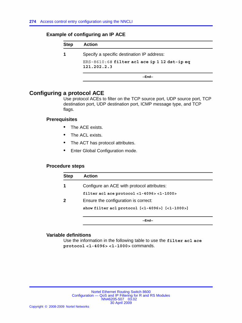
274 Access control entry configuration using the NNCLI
Example of configuring an IP ACE
Step Action
1 Specify a specific destination IP address:
ERS-8610:6# filter acl ace ip 1 12 dst-ip eq121.202.2.3
--End--
Configuring a protocol ACEUse protocol ACEs to filter on the TCP source port, UDP source port, TCPdestination port, UDP destination port, ICMP message type, and TCPflags.
Prerequisites
• The ACE exists.
• The ACL exists.
• The ACT has protocol attributes.
• Enter Global Configuration mode.
Procedure steps
Step Action
1 Configure an ACE with protocol attributes:
filter acl ace protocol <1-4096> <1-1000>
2 Ensure the configuration is correct:
show filter acl protocol [<1-4096>] [<1-1000>]
--End--
Variable definitionsUse the information in the following table to use the filter acl aceprotocol <1-4096> <1-1000> commands.
Nortel Ethernet Routing Switch 8600Configuration — QoS and IP Filtering for R and RS Modules
NN46205-507 03.0230 April 2009
Copyright © 2008-2009 Nortel Networks
.

Configuring a protocol ACE 275
Variable Value
icmp-msg-type<eq|ne> <WORD 1-200>
The <eq|ne> parameter specifies an operator for afield match condition: equal to or not equal to.
The <WORD 1-200> parameter specifiesone or more IP protocol types (0–255), orechoreply, destunreach, sourcequench,redirect, echo-request, routeradv, routerselect,time-exceeded, param-problem, timestamp-request,timestamp-reply, addressmask-request,addressmask-reply, or traceroute.
tcp-dst-port<eq|ne|le|ge> <WORD1-60>
The <eq|ne|le|ge> parameter specifies anoperator for a field match condition: equal to, notequal to, less than or equal to, greater than or equalto.
The <WORD 1-60> parameter specifies thedestination port for the TCP protocol: (0–65535), orecho, ftpdata, ftpcontrol, ssh, telnet, dns, http, bgp,hdot323, or undefined.
tcp-flags <match-any|match-all> <WORD>
Specifies matchAny or matchAll operators for a fieldmatch condition.
The <WORD> parameter specifies one or more TCPflags: none, fin, syn, rst, push, ack, urg, undefined.
The tcp-flags and icmp-msg-type command optionssupport lists.
tcp-src-port<eq|ne|le|ge> <WORD0-65535>
The <eq|ne|le|ge> parameter specifies anoperator for a field match condition: equal to, notequal to, less than or equal to, greater than or equalto.
The <WORD 0-65535> parameter specifies thedestination port for the TCP protocol (0–65535), orecho, dns, bootpServer, bootpClient, tftp, rip, rtp,rtcp, or undefined.
Nortel Ethernet Routing Switch 8600Configuration — QoS and IP Filtering for R and RS Modules
NN46205-507 03.0230 April 2009
Copyright © 2008-2009 Nortel Networks
.

276 Access control entry configuration using the NNCLI
Variable Value
udp-dst-port<eq|ne|le|ge> <WORD1-200>
The <eq|ne|le|ge> parameter specifies anoperator for a field match condition: equal to, notequal to, less than or equal to, greater than or equalto.
The <WORD 1-200> parameter specifies thedestination port for the UDP protocol (0–65535), orecho, dns, bootpServer, bootpClient, tftp, rip, rtp,rtcp, or undefined.
udp-src-port<eq|ne|le|ge> <WORD0-65535>
The <eq|ne|le|ge> parameter specifies anoperator for a field match condition: equal to, notequal to, less than or equal to, greater than or equalto.
The <WORD 0-65535> parameter specifies thesource port for the UDP protocol (0–65535), or [ ].
Example of configuring a protocol ACE
Step Action
1 Specify ICMP packets:
ERS-8610:6# filter acl ace protocol 1 12icmp-msg-type eq echo-request
--End--
Configuring a custom ACEYou can use a custom ACE to define your own match patterns.
Prerequisites
• The ACE exists.
• The ACL exists.
• The ACT has pattern attributes.
• Enter Global Configuration mode.
Procedure steps
Step Action
1 Add an ACE for patterns that you define:
Nortel Ethernet Routing Switch 8600Configuration — QoS and IP Filtering for R and RS Modules
NN46205-507 03.0230 April 2009
Copyright © 2008-2009 Nortel Networks
.

Configuring an IPv6 ACE 277
filter acl ace advanced <1-4096> <1-1000>
2 Ensure that your configuration is correct:
show filter acl advanced [<1-4096>] [<1-1000>]
--End--
Variable definitionsUse the following table to use the filter acl ace advanced <1-4096><1-1000> commands.
Variable Value
custom-filter1<WORD 0-32><eq|le|ge> <WORD1-1024>
Creates a custom filter 1:• <WORD 0-32> specifies a descriptive name for
the pattern that uses 0–32 characters.
• <eq|le|ge> specifies the operators equal to,less than or equal to, or greater than or equalto. The ace-op ne does not apply to an ACEpattern.
• <WORD 1-1024> specifies a hexadecimalnumber equal to the pattern template length.
custom-filter2<WORD 0-32><eq|le|ge> <WORD1-1024>
Creates custom filter 2.
custom-filter3<WORD 0-32><eq|le|ge> <WORD1-1024>
Creates custom filter 3.
Example of configuring a custom ACE
Step Action
1 Add an ACE for patterns that you define:
ERS-8610:6# filter acl ace advanced 1 12custom-filter1 PatternName eq 0x12
--End--
Configuring an IPv6 ACEUse an IPv6 ACE to filter on IPv6 attributes.
Nortel Ethernet Routing Switch 8600Configuration — QoS and IP Filtering for R and RS Modules
NN46205-507 03.0230 April 2009
Copyright © 2008-2009 Nortel Networks
.

278 Access control entry configuration using the NNCLI
Prerequisites
• The ACE exists.
• The ACL exists.
• The ACT has IPv6 attributes.
• Enter Global Configuration mode.
Procedure steps
Step Action
1 Add an ACE with IP header attributes:
filter acl ace ipv6 <1-4096> <1-1000>
2 Ensure that your configuration is correct:
show filter acl ipv6 [<1-4096>] [<1-1000>]
--End--
Variable definitionsUse the information in the following table to use the filter acl aceipv6 <1-4096> <1-1000> commands.
Variable Value
dst-ipv6 <eq> <WORD0-255>
The <eq|ne> parameter specifies an operator for afield match condition: equal to or not equal to.
The <WORD 0-255> parameter specifies alist of destination IPv6 addresses, separatedby commas. An example IPv6 address is3ffe:1900:4545:3:200:f8ff:fe21:67cf.
Nortel Ethernet Routing Switch 8600Configuration — QoS and IP Filtering for R and RS Modules
NN46205-507 03.0230 April 2009
Copyright © 2008-2009 Nortel Networks
.

Viewing ACL and ACE configuration data 279
Variable Value
nxt-hdr <eq|ne><nxt-hdr>
The <eq|ne> parameter specifies an operator for afield match condition: equal to or not equal to.
<nxt-hdr> specifies hop-by-hop, tcp, udp, routing,fragment, ipsecesp, ipsecah, icmpv6, noHdr, orundefined.
src-ipv6 <eq> <WORD0-255>
The <eq|ne> parameter specifies an operator for afield match condition: equal to or not equal to.
The <WORD 0-255> parameter specifiesa list of source IPv6 addresses, separatedby commas. An example IPv6 address is3ffe:1900:4545:3:200:f8ff:fe21:67cf.
Example of configuring an IPv6 ACE
Step Action
1 Add an ACE with IP header attributes:
ERS-8610:6# filter acl ace ipv6 1 12 dst-ipv6 eq3ffe:1900:4545:3:200:f8ff:fe21:67cf
--End--
Viewing ACL and ACE configuration dataReview your configuration to ensure that it is correct.
Prerequisites
• Enter Privileged EXEC mode.
Procedure steps
Step Action
1 View a list of executed commands:
show filter acl config [<1-4096>] [<1-1000>]
--End--
Nortel Ethernet Routing Switch 8600Configuration — QoS and IP Filtering for R and RS Modules
NN46205-507 03.0230 April 2009
Copyright © 2008-2009 Nortel Networks
.
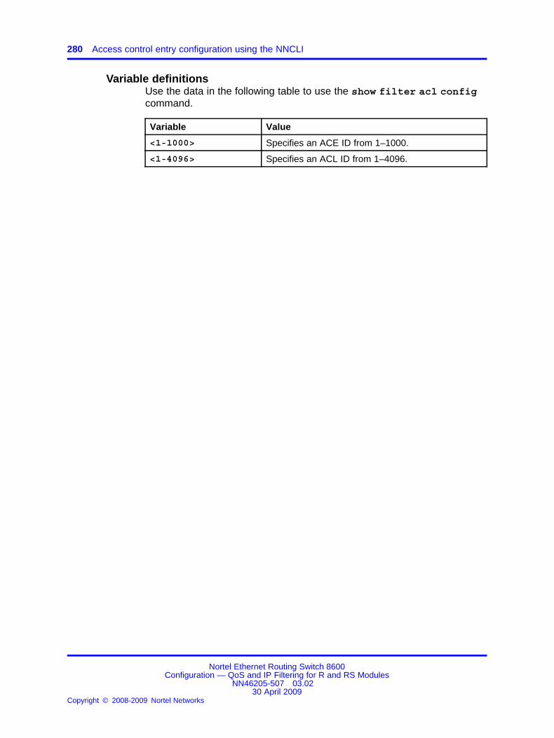
280 Access control entry configuration using the NNCLI
Variable definitionsUse the data in the following table to use the show filter acl configcommand.
Variable Value
<1-1000> Specifies an ACE ID from 1–1000.
<1-4096> Specifies an ACL ID from 1–4096.
Nortel Ethernet Routing Switch 8600Configuration — QoS and IP Filtering for R and RS Modules
NN46205-507 03.0230 April 2009
Copyright © 2008-2009 Nortel Networks
.
281.
CLI configuration examplesThis section provides configuration examples for common Quality ofService (QoS) and filtering tasks and includes the command line interface(CLI) commands you use to create the sample configurations.
For more information, see the configuration examples in Filters andQoS for ERS 8600 R-Series Modules Technical Configuration Guide(NN48500-541) . You can find this Technical Configuration Guide atwww.nortel.com/documentation. Choose Routers & Routing Switches, andthen Ethernet Routing Switch 8600.
Navigation• “Delivering subrate IP service using policy-based policers” (page 281)
• “Policing multiple flows using VLAN-based ACLs” (page 283)
• “Mirroring using ACLs” (page 287)
• “Asymmetric downlink and uplink using policy-based policers andport-based shapers” (page 288)
Delivering subrate IP service using policy-based policersThe example that follows shows how to provision subrate IP service. Agigabit link extends from an Ethernet Routing Switch 8600 to a client, seeFigure 32 "Subrate IP service delivery" (page 282). The configuration limitsclient throughput to 200 Mb/s. Traffic that exceeds the configured rate limitis dropped.
Nortel Ethernet Routing Switch 8600Configuration — QoS and IP Filtering for R and RS Modules
NN46205-507 03.0230 April 2009
Copyright © 2008-2009 Nortel Networks
.

282 CLI configuration examples
Figure 32Subrate IP service delivery
If you need additional bandwidth, you can increase the rate by performinga soft configuration on the Ethernet Routing Switch 8600. In thisconfiguration, IP traffic from a source affects the filter action policer that isbound to the policy.
The switch drops packets above the peak rate, and you can configure thepolicer on an individual lane basis as required.
Procedure steps
Step Action
1 Create a QoS traffic policy:
ERS-8606:5# config qos policy 1
ERS-8606:5# config qos policy 1 create peak rate200000 svc-rate 200000
ERS-8606:5/config/qos/policy/1# name ClientA
ERS-8606:5# info
Id : 1Status : Entry is createdName : "ClientA"
peak-rate : 200000svc-rate : 200000lanes : 2/1,2/2
2 Create an ACT:
ERS-8605:5# config filter act 1 create name"Source"ERS-8606:5# config filter act 1 ip srcipERS-8606:5# config filter act 1 apply
3 Create an ACL:
Nortel Ethernet Routing Switch 8600Configuration — QoS and IP Filtering for R and RS Modules
NN46205-507 03.0230 April 2009
Copyright © 2008-2009 Nortel Networks
.

Policing multiple flows using VLAN-based ACLs 283
ERS-8606:5# config filter acl 1 create inPort act 1name "Policer1"ERS-8606:5# config filter acl 1 port add 2/11,2/13
4 Create an ACE and bind it to the traffic policy:
ERS-8606:5# config filter acl 1 ace 1 createERS-8606:5# config filter acl 1 ace 1 action permitpolice 1ERS-8606:5# config filter acl 1 ace 1 ip scr-ip eq10.0.0.0-10.255.255.255ERS-8606:5# config filter acl 1 ace 1 enable
You can also configure the ACE in one line:
config filter acl 1 ace 1 create; action police 1; ipsrcr-ip eq 10.0.0.0-10.255.255.255; enable
--End--
Policing multiple flows using VLAN-based ACLsIn the following example, you classify incoming traffic at VLAN 100, seeFigure 33 "Multiple flow policing using VLAN-based ACLs" (page 284), andpolice different flows according to the peak and service rate requirementsshown in the following table.
Table 32Flow requirements
Traffic type Peak rate Service rate
Web HTTP 200 Mb/s 100 Mb/s
FTP file transfer 100 Mb/s 50 Mb/s
UDP RTP 80 Mb/s 60 Mb/s
Other TCP port 50 Mb/s 40 Mb/s
Nortel Ethernet Routing Switch 8600Configuration — QoS and IP Filtering for R and RS Modules
NN46205-507 03.0230 April 2009
Copyright © 2008-2009 Nortel Networks
.

284 CLI configuration examples
Figure 33Multiple flow policing using VLAN-based ACLs
Procedure steps
Step Action
1 Configure a WWW policy.
ERS-8606:5# config qos policy 11 create peak-rate200000 svc-rate 10000ERS-8606:5/config/qos/policy/11# lanes add1/1,1/2,1/3ERS-8606:5/config/qos/policy/11# name WWW
The name is optional. Use the optional lane parameter to applythe policy only to slot 1.
2 Display the policy configuration:
ERS-8606:5# show qos config policy policy 11
3 Configure a policy for File Transfer Protocol (FTP):
ERS-8605:5# config qos policy 12 create peak-rate100000 svc-rate 50000ERS-8606:5/config/qos/policy/12# lanes add1/1,1/2,1/3ERS-8606:5/config/qos/policy/12# name FTP
4 Display the policy configuration:
Nortel Ethernet Routing Switch 8600Configuration — QoS and IP Filtering for R and RS Modules
NN46205-507 03.0230 April 2009
Copyright © 2008-2009 Nortel Networks
.

Policing multiple flows using VLAN-based ACLs 285
ERS-8606:5/show/qos/config/policy/12# policy 12
5 Configure a policy for User Datagram Protocol (UDP):
ERS-8606:5# config qos policy 13 create peak-rate800000 svc-rate 60000ERS-8606:5/config/qos/policy/13# lanes add1/1,1/2,1/3ERS-8606:5/config/qos/policy/13# name UDP
6 Display the policy configuration:
ERS-8606:5/show/qos/config/policy/13# policy 13
7 Configure a policy for all other traffic:
ERS-8606:5# config qos policy 14 create peak-rate500000 svc-rate 40000ERS-8606:5/config/qos/policy/14# lanes add1/1,1/2,1/3ERS-8606:5/config/qos/policy/14# name Other
8 Display the policy configuration:
ERS-8606:5/show/qos/config/policy/13# policy 13
9 Create filters and bind them to policies. Create an ACT:
Nortel Ethernet Routing Switch 8600Configuration — QoS and IP Filtering for R and RS Modules
NN46205-507 03.0230 April 2009
Copyright © 2008-2009 Nortel Networks
.

286 CLI configuration examples
ERS-8606:5/config# filter act 100 create name"TCPIP"ERS-8606:5/config# filter act 100 ip scrip, dstipERS-8606:5/config# filter act 100 protocoltcpSrcPort,udpSrcPort,tcpDstPort,udpDstPortERS-8606:5/config# filter act 100 apply
10 Create an ACL:
ERS-8606:5/config# filter acl 100 create inVlan act100ERS-8606:5/config# filter acl 100 vlan add 100
11 Create an ACE. Classify HTTP and the binding policy:
ERS-8606:5/config# filter acl 100 ace 1 createERS-8606:5/config# filter acl 100 ace 1 actionpermit police 11ERS-8606:5/config# filter acl 100 ace 1 protocoltcp-dst-port eq httpERS-8606:5/config# filter acl 100 ace 1 enable
12 Classify FTP (control and data packets) and the binding policy:
ERS-8606:5/config# filter acl 100 ace 2 createERS-8606:5/config# filter acl 100 ace 2 actionpermit police 12ERS-8606:5/config# filter acl 100 ace 2 protocoltcp-dst-port eq ftpcontrolERS-8606:5/config# filter acl 100 ace 2 enableERS-8606:5/config# filter acl 100 ace 3 createERS-8606:5/config# filter acl 100 ace 3 actionpermit police 12ERS-8606:5/config# filter acl 100 ace 3 protocoltcp-dst-port eq ftpdataERS-8606:5/config# filter acl 100 ace 3 enable
13 Classify RTP and the binding policy:
ERS-8606:5/config# filter acl 100 ace 4 createERS-8606:5/config# filter acl 100 ace 4 actionpermit police 13ERS-8606:5/config# filter acl 100 ace 4 protocoludp-dst-port eq rtpERS-8606:5/config# filter acl 100 ace 4 enable
14 Configure the TCP port and binding policy:
ERS-8606:5/config# filter acl 100 ace 5 createERS-8606:5/config# filter acl 100 ace 5 actionpermit police 14ERS-8606:5/config# filter acl 100 ace 5 protocol
Nortel Ethernet Routing Switch 8600Configuration — QoS and IP Filtering for R and RS Modules
NN46205-507 03.0230 April 2009
Copyright © 2008-2009 Nortel Networks
.

Mirroring using ACLs 287
tcp-dst-port eq 0ERS-8606:5/config# filter acl 100 ace 5 enable
--End--
Mirroring using ACLsFor more information about port mirroring and remote port mirroring, seeNortel Ethernet Routing Switch 8600 Troubleshooting (NN46205-703) .
This configuration example shows how to perform the following tasks:
• Enable port mirroring (RxFilter mode) for a port on VLAN 220.
• Use port 3/48 as the monitoring port.
• Configure an ACL so that TCP traffic from ports 20 to 500, and ICMPframes are mirrored to the monitoring port; see Figure 34 "Switchconfiguration for port mirroring example" (page 287).
Figure 34Switch configuration for port mirroring example
Procedure steps
Step Action
1 Create a new ACT to filter on ICMP frames and TCP destinationports. Configure a new ACT with ID = 2:
ERS-8610:5# config filter act 2 create
2 Select the IP attributes of the IP protocol type:
ERS-8610:5# config filter act 2 ip ipProtoType
Nortel Ethernet Routing Switch 8600Configuration — QoS and IP Filtering for R and RS Modules
NN46205-507 03.0230 April 2009
Copyright © 2008-2009 Nortel Networks
.

288 CLI configuration examples
3 Select protocol attributes of TCP source port, TCP destinationport, and UDP destination port
ERS-8610:5# config filter act 2 protocol tcpDstPort
4 Enable ACT 2:
ERS-8610:5# config filter act 2 apply
5 Create ACL 1 with type ingress VLAN:
ERS-8610:5# config filter acl 1 create inVlan act 2
6 Add ingress VLAN of 220 to ACL 1:
ERS-8610:5# config filter acl 1 vlan add 220
7 Add ACE 1 with action of permit to mirror ICMP traffic:
ERS-8610:5# config filter acl 1 ace 1 create nameicmpERS-8610:5# config filter acl 1 ace 1 action permitERS-8610:5# config filter acl 1 ace 1 debug mirrorenable mirroring-dst-ports 3/48ERS-8610:5# config filter acl 1 ace 1 ipip-protocol-type eq icmpERS-8610:5# config filter acl 1 ace 1 enable
8 Add ACE 2 with action of permit to mirror TCP traffic with adestination port range from 20 to 500:
ERS-8610:5# config filter acl 1 ace 2 create nametcp_rangeERS-8610:5# config filter acl 1 ace 2 action permitERS-8610:5# config filter acl 1 ace 2 debug mirrorenable mirroring-dst-ports 3/48ERS-8610:5# config filter acl 1 ace 2 ipip-protocol-type eq tcpERS-8610:5# config filter acl 1 ace 2 protocoltcp-dst-port eq 20-500ERS-8610:5# config filter acl 1 ace 2 enable
--End--
Asymmetric downlink and uplink using policy-based policers andport-based shapers
The example that follows shows how to provision asymmetric downlink anduplink using the policer and a traffic shaper. A gigabit link extends from anEthernet Routing Switch 8600 to a client; see the following figure.
Nortel Ethernet Routing Switch 8600Configuration — QoS and IP Filtering for R and RS Modules
NN46205-507 03.0230 April 2009
Copyright © 2008-2009 Nortel Networks
.

Asymmetric downlink and uplink using policy-based policers and port-based shapers 289
Figure 35Asymmetric downlink and uplink
The client requirement is
• downlink of 400 Mb/s (shaped)
• uplink of 200 Mb/s (policed)
Procedure steps
Step Action
1 Configure the port shaper for downlinking by configuring theshaper for a 400 Mb/s rate:
ERS-8606:5# config ethernet 2/1 shape 400000 enable
2 Configure a QoS traffic policy:
ERS-8606:5# config qos policy 1 create peak-rate200000 svc-rate 200000 lanes 2/1,2/2
ERS-8606:5# config qos policy 1 name ClientA
3 Configure an ACT:
ERS-8606:5# config filter act 1 create name“SourceIP”
ERS-8606:5# config filter act 1 ip srcip
ERS-8606:5# config filter act 1 apply
4 Configure an ACL:
ERS-8606:5# config filter acl 1 create inPort act 1name “Policer1”
ERS-8606:5# config filter acl 1 port add 2/1
5 Configure an ACE and bind it to the traffic policy:
ERS-8606:5# config filter acl 1 ace 1 create
ERS-8606:5# config filter acl 1 ace 1 action permitpolicy 1
Nortel Ethernet Routing Switch 8600Configuration — QoS and IP Filtering for R and RS Modules
NN46205-507 03.0230 April 2009
Copyright © 2008-2009 Nortel Networks
.

290 CLI configuration examples
ERS-8606:5# config filter acl 1 ace 1 ip src-ip eq10.0.0.0-10.255.255.255
ERS-8606:5# config filter acl 1 ace 1 enable
--End--
Nortel Ethernet Routing Switch 8600Configuration — QoS and IP Filtering for R and RS Modules
NN46205-507 03.0230 April 2009
Copyright © 2008-2009 Nortel Networks
.
291.
Safety messagesThis section describes the various precautionary notices used in thisdocument. This section also contains precautionary notices that you mustread for safe operation of the Nortel Ethernet Routing Switch 8600.
NoticesNotice paragraphs alert you about issues that require your attention. Thefollowing sections describe the types of notices.
Attention notice
ATTENTIONAn attention notice provides important information regarding the installation andoperation of Nortel products.
Caution ESD notice
CAUTIONESDESD notices provide information about how to avoid dischargeof static electricity and subsequent damage to Nortel products.
CAUTIONESD (décharge électrostatique)La mention ESD fournit des informations sur les moyens deprévenir une décharge électrostatique et d’éviter d’endommagerles produits Nortel.
CAUTIONACHTUNG ESDESD-Hinweise bieten Information dazu, wie man dieEntladung von statischer Elektrizität und Folgeschäden anNortel-Produkten verhindert.
Nortel Ethernet Routing Switch 8600Configuration — QoS and IP Filtering for R and RS Modules
NN46205-507 03.0230 April 2009
Copyright © 2008-2009 Nortel Networks
.

292 Safety messages
CAUTIONPRECAUCIÓN ESD (Descarga electrostática)El aviso de ESD brinda información acerca de cómo evitaruna descarga de electricidad estática y el daño posterior a losproductos Nortel.
CAUTIONCUIDADO ESDOs avisos do ESD oferecem informações sobre como evitardescarga de eletricidade estática e os conseqüentes danos aosprodutos da Nortel.
CAUTIONATTENZIONE ESDLe indicazioni ESD forniscono informazioni per evitare scarichedi elettricità statica e i danni correlati per i prodotti Nortel.
Caution notice
CAUTIONCaution notices provide information about how to avoid possibleservice disruption or damage to Nortel products.
CAUTIONATTENTIONLa mention Attention fournit des informations sur les moyensde prévenir une perturbation possible du service et d’éviterd’endommager les produits Nortel.
CAUTIONACHTUNGAchtungshinweise bieten Informationen dazu, wie man möglicheDienstunterbrechungen oder Schäden an Nortel-Produktenverhindert.
CAUTIONPRECAUCIÓNLos avisos de Precaución brindan información acerca decómo evitar posibles interrupciones del servicio o el daño a losproductos Nortel.
CAUTIONCUIDADOOs avisos de cuidado oferecem informações sobre como evitarpossíveis interrupções do serviço ou danos aos produtos daNortel.
Nortel Ethernet Routing Switch 8600Configuration — QoS and IP Filtering for R and RS Modules
NN46205-507 03.0230 April 2009
Copyright © 2008-2009 Nortel Networks
.

Notices 293
CAUTIONATTENZIONELe indicazioni di attenzione forniscono informazioni per evitarepossibili interruzioni del servizio o danni ai prodotti Nortel.
Nortel Ethernet Routing Switch 8600Configuration — QoS and IP Filtering for R and RS Modules
NN46205-507 03.0230 April 2009
Copyright © 2008-2009 Nortel Networks
.

294 Safety messages
Nortel Ethernet Routing Switch 8600Configuration — QoS and IP Filtering for R and RS Modules
NN46205-507 03.0230 April 2009
Copyright © 2008-2009 Nortel Networks
.

295.
Customer serviceVisit the Nortel Web site to access the complete range of services andsupport that Nortel provides. Go to www.nortel.com, or go to one of thepages listed in the following sections.
Navigation• “Updated versions of documentation” (page 295)
• “Getting help” (page 295)
• “Express Routing Codes” (page 295)
• “Additional information” (page 296)
Updated versions of documentationYou can download and print the latest versions of Nortel Ethernet RoutingSwitch 8600 NTPs and Release Notes directly from the Internet atwww.nortel.com/documentation.
Getting helpIf you purchased a service contract for your Nortel product from adistributor or authorized reseller, contact the technical support staff for thatdistributor or reseller for assistance.
If you purchased a Nortel service program, you can get help bycontacting one of the Nortel Technical Solutions Centers found athttp://www.nortel.com/callus; or visit our Technical Support site athttp://www.nortel.com/support.
Express Routing CodesAn Express Routing Code (ERC) is available for many Nortel products andservices.
When you use an ERC, your call is routed to a technical support personwho specializes in supporting that particular product or service. To locatean ERC for a product or service, go to http://www.nortel.com/erc.
Nortel Ethernet Routing Switch 8600Configuration — QoS and IP Filtering for R and RS Modules
NN46205-507 03.0230 April 2009
Copyright © 2008-2009 Nortel Networks
.
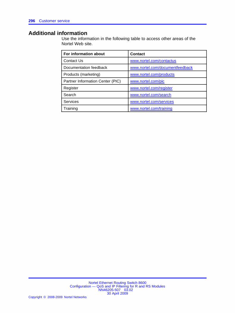
296 Customer service
Additional informationUse the information in the following table to access other areas of theNortel Web site.
For information about Contact
Contact Us www.nortel.com/contactus
Documentation feedback www.nortel.com/documentfeedback
Products (marketing) www.nortel.com/products
Partner Information Center (PIC) www.nortel.com/pic
Register www.nortel.com/register
Search www.nortel.com/search
Services www.nortel.com/services
Training www.nortel.com/training
Nortel Ethernet Routing Switch 8600Configuration — QoS and IP Filtering for R and RS Modules
NN46205-507 03.0230 April 2009
Copyright © 2008-2009 Nortel Networks
.

297.
AppendixAdvanced filter examples
This appendix gives a detailed Advanced filter configuration example.
ACE filters for secure networksThe following example shows filters configured for two Layer 2 switchedhosts and two Layer 3 routed hosts for an IP phone and computer VLANnetwork.
These filters apply after an analysis of the traffic types flowing on thenetwork. The filters provide security by permitting legitimate traffic anddenying (dropping) all other traffic. Filters redirect certain traffic to anotherIP address. Further, use IPFIX and counting for reporting and monitoring.The filters can also determine which traffic to permit on which parts of thenetwork.
The ACEs named DENY ANY or DENY ANY ANY are the cleanup filters.These filters drop traffic that does not match other ACEs.
Through the use of Ethereal, you determine that ACEs permit (this is notan exhaustive list) the following traffic types:
• DNS traffic
• ICMP traffic
• IGMP traffic
• VRRP traffic (in certain areas)
• BootStrap Protocol server and client traffic
• DHCP traffic
• NetBIOS traffic (in certain areas)
• TCP traffic with the Established flag set
• traffic with specific IP addresses
• Microsoft Operations Manager 2005 agent (MOM 2005) traffic
Nortel Ethernet Routing Switch 8600Configuration — QoS and IP Filtering for R and RS Modules
NN46205-507 03.0230 April 2009
Copyright © 2008-2009 Nortel Networks
.

298 Advanced filter examples
• HTTP, HTTP proxy, and HTTPS traffic
• remote desktop traffic
• ISAKMP and Internet Key Exchange (IKE) traffic
• SQL database system traffic
Other ACEs deny (drop) the following traffic types:
• VRRP traffic (in certain areas)
• NetBIOS traffic (UDP destination ports 137, 138)
• specific multicast traffic (UDP destination ports 61011, 64046)
• specific UDP traffic
• instant messaging traffic (UDP destination port 1900)
This section shows the filters configured for the first Layer 2 switched host.
#
# R-MODULE FILTER CONFIGURATION
#
filter act 1 create name "BUSINESS 1"
filter act 1 ip srcIp,dstIp,ipOptions,ipProtoType
filter act 1 protocol tcpSrcPort,udpSrcPort,tcpDstPort,udpDstPort,tcpFlags,icmpMsgType
filter act 1 apply
filter acl 1 create outPort act 1 name "VRRP_Drop"
filter acl 1 port add 4/24-4/25,8/37
filter acl 1 ace 1 create name "VRRP"
filter acl 1 ace 1 action deny stop-on-match true
filter acl 1 ace 1 debug count enable
filter acl 1 ace 1 ip ip-protocol-type eq vrrp
filter acl 1 ace 1 enable
filter acl 1 ace 2 create name "NetbIOS_Drop"
filter acl 1 ace 2 action deny stop-on-match true
filter acl 1 ace 2 debug count enable
filter acl 1 ace 2 ip ip-protocol-type eq udp
filter acl 1 ace 2 protocol udp-dst-port eq 137
filter acl 1 ace 2 enable
Nortel Ethernet Routing Switch 8600Configuration — QoS and IP Filtering for R and RS Modules
NN46205-507 03.0230 April 2009
Copyright © 2008-2009 Nortel Networks
.
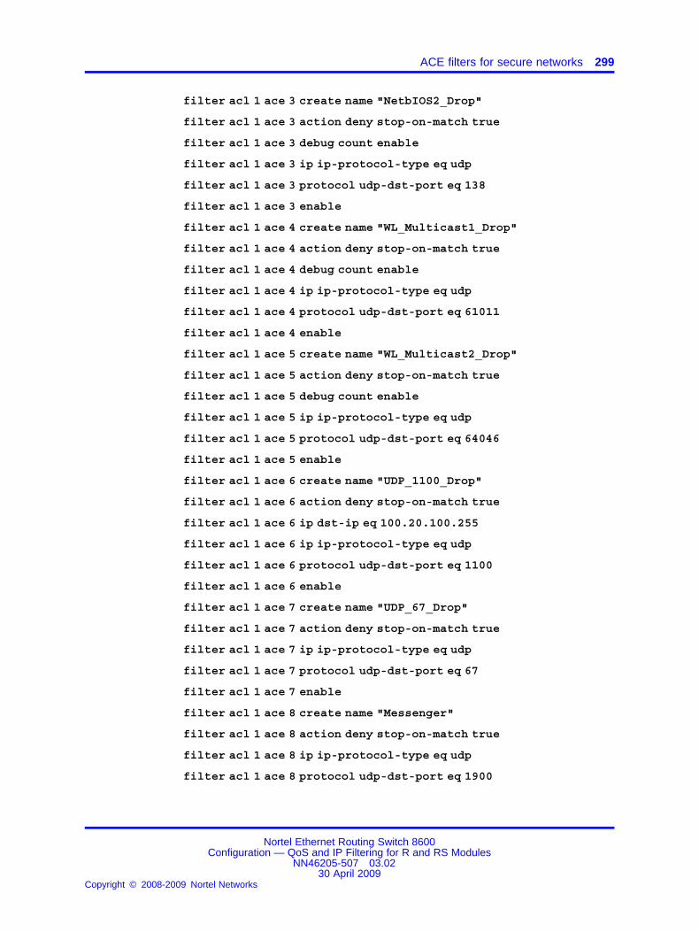
ACE filters for secure networks 299
filter acl 1 ace 3 create name "NetbIOS2_Drop"
filter acl 1 ace 3 action deny stop-on-match true
filter acl 1 ace 3 debug count enable
filter acl 1 ace 3 ip ip-protocol-type eq udp
filter acl 1 ace 3 protocol udp-dst-port eq 138
filter acl 1 ace 3 enable
filter acl 1 ace 4 create name "WL_Multicast1_Drop"
filter acl 1 ace 4 action deny stop-on-match true
filter acl 1 ace 4 debug count enable
filter acl 1 ace 4 ip ip-protocol-type eq udp
filter acl 1 ace 4 protocol udp-dst-port eq 61011
filter acl 1 ace 4 enable
filter acl 1 ace 5 create name "WL_Multicast2_Drop"
filter acl 1 ace 5 action deny stop-on-match true
filter acl 1 ace 5 debug count enable
filter acl 1 ace 5 ip ip-protocol-type eq udp
filter acl 1 ace 5 protocol udp-dst-port eq 64046
filter acl 1 ace 5 enable
filter acl 1 ace 6 create name "UDP_1100_Drop"
filter acl 1 ace 6 action deny stop-on-match true
filter acl 1 ace 6 ip dst-ip eq 100.20.100.255
filter acl 1 ace 6 ip ip-protocol-type eq udp
filter acl 1 ace 6 protocol udp-dst-port eq 1100
filter acl 1 ace 6 enable
filter acl 1 ace 7 create name "UDP_67_Drop"
filter acl 1 ace 7 action deny stop-on-match true
filter acl 1 ace 7 ip ip-protocol-type eq udp
filter acl 1 ace 7 protocol udp-dst-port eq 67
filter acl 1 ace 7 enable
filter acl 1 ace 8 create name "Messenger"
filter acl 1 ace 8 action deny stop-on-match true
filter acl 1 ace 8 ip ip-protocol-type eq udp
filter acl 1 ace 8 protocol udp-dst-port eq 1900
Nortel Ethernet Routing Switch 8600Configuration — QoS and IP Filtering for R and RS Modules
NN46205-507 03.0230 April 2009
Copyright © 2008-2009 Nortel Networks
.

300 Advanced filter examples
filter acl 1 ace 8 enable filter acl 20 create inVlan act 1 name"Symantec-Drop"
filter acl 20 vlan add 2
filter acl 20 ace 10 create name "Othello-drop"
filter acl 20 ace 10 action deny stop-on-match true
filter acl 20 ace 10 debug count enable
filter acl 20 ace 10 ip src-ip eq 100.20.2.47
filter acl 20 ace 10 ip ip-protocol-type eq tcp
filter acl 20 ace 10 protocol tcp-src-port eq 80
filter acl 20 ace 10 enable
filter acl 20 ace 15 create name "Macbeth-drop"
filter acl 20 ace 15 action deny stop-on-match true
filter acl 20 ace 15 debug count enable
filter acl 20 ace 15 ip src-ip eq 100.20.2.29
filter acl 20 ace 15 ip ip-protocol-type eq tcp
filter acl 20 ace 15 protocol tcp-src-port eq 80
filter acl 902 create inVlan act 1 name "ITD_REMOTE_in"
filter acl 902 vlan add 902 filter acl 902 disable
filter acl 902 ace 5 create name "ITD_TO_ITD"
filter acl 902 ace 5 action permit stop-on-match true
filter acl 902 ace 5 ip dst-ip eq 100.20.103.65-100.20.103.78
filter acl 902 ace 5 enable
filter acl 902 ace 10 create name "ICMP_PERMIT"
filter acl 902 ace 10 action permit stop-on-match true
filter acl 902 ace 10 ip ip-protocol-type eq icmp
filter acl 902 ace 10 enable
filter acl 902 ace 20 create name "IGMP_PERMIT"
filter acl 902 ace 20 action permit stop-on-match true
filter acl 902 ace 20 ip ip-protocol-type eq 2
filter acl 902 ace 20 enable
filter acl 902 ace 30 create name "VRRP_PERMIT"
filter acl 902 ace 30 action permit stop-on-match true
Nortel Ethernet Routing Switch 8600Configuration — QoS and IP Filtering for R and RS Modules
NN46205-507 03.0230 April 2009
Copyright © 2008-2009 Nortel Networks
.
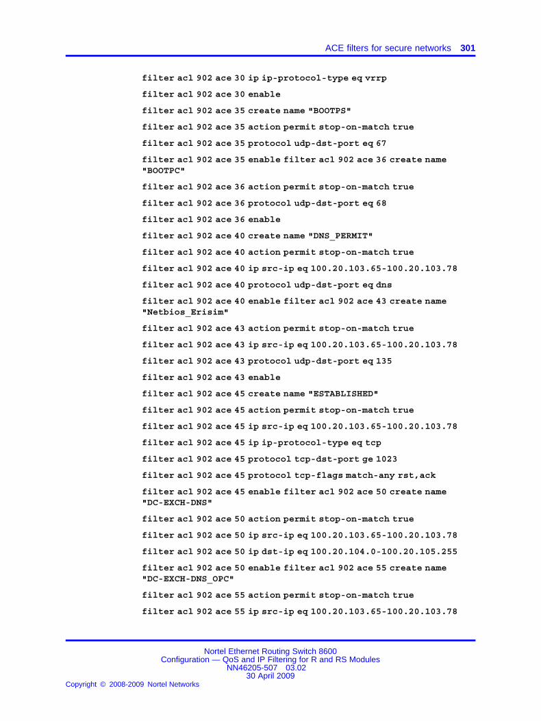
ACE filters for secure networks 301
filter acl 902 ace 30 ip ip-protocol-type eq vrrp
filter acl 902 ace 30 enable
filter acl 902 ace 35 create name "BOOTPS"
filter acl 902 ace 35 action permit stop-on-match true
filter acl 902 ace 35 protocol udp-dst-port eq 67
filter acl 902 ace 35 enable filter acl 902 ace 36 create name"BOOTPC"
filter acl 902 ace 36 action permit stop-on-match true
filter acl 902 ace 36 protocol udp-dst-port eq 68
filter acl 902 ace 36 enable
filter acl 902 ace 40 create name "DNS_PERMIT"
filter acl 902 ace 40 action permit stop-on-match true
filter acl 902 ace 40 ip src-ip eq 100.20.103.65-100.20.103.78
filter acl 902 ace 40 protocol udp-dst-port eq dns
filter acl 902 ace 40 enable filter acl 902 ace 43 create name"Netbios_Erisim"
filter acl 902 ace 43 action permit stop-on-match true
filter acl 902 ace 43 ip src-ip eq 100.20.103.65-100.20.103.78
filter acl 902 ace 43 protocol udp-dst-port eq 135
filter acl 902 ace 43 enable
filter acl 902 ace 45 create name "ESTABLISHED"
filter acl 902 ace 45 action permit stop-on-match true
filter acl 902 ace 45 ip src-ip eq 100.20.103.65-100.20.103.78
filter acl 902 ace 45 ip ip-protocol-type eq tcp
filter acl 902 ace 45 protocol tcp-dst-port ge 1023
filter acl 902 ace 45 protocol tcp-flags match-any rst,ack
filter acl 902 ace 45 enable filter acl 902 ace 50 create name"DC-EXCH-DNS"
filter acl 902 ace 50 action permit stop-on-match true
filter acl 902 ace 50 ip src-ip eq 100.20.103.65-100.20.103.78
filter acl 902 ace 50 ip dst-ip eq 100.20.104.0-100.20.105.255
filter acl 902 ace 50 enable filter acl 902 ace 55 create name"DC-EXCH-DNS_OPC"
filter acl 902 ace 55 action permit stop-on-match true
filter acl 902 ace 55 ip src-ip eq 100.20.103.65-100.20.103.78
Nortel Ethernet Routing Switch 8600Configuration — QoS and IP Filtering for R and RS Modules
NN46205-507 03.0230 April 2009
Copyright © 2008-2009 Nortel Networks
.

302 Advanced filter examples
filter acl 902 ace 55 ip dst-ip eq 100.6.105.0-100.6.105.15
filter acl 902 ace 55 enable filter acl 902 ace 60 create name"Filesharing_Erisim"
filter acl 902 ace 60 action permit stop-on-match true
filter acl 902 ace 60 ip src-ip eq 100.20.103.65-100.20.103.78
filter acl 902 ace 60 ip dst-ip eq 100.20.103.71-100.20.103.72
filter acl 902 ace 60 enable
filter acl 902 ace 65 create name "Filesharing_Erisim_Ek"
filter acl 902 ace 65 action permit stop-on-match true
filter acl 902 ace 65 ip src-ip eq 100.20.103.65-100.20.103.78
filter acl 902 ace 65 ip dst-ip eq 10.10.230.6
filter acl 902 ace 65 enable filter acl 902 ace 70 create name"IBPSQL_Erisim"
filter acl 902 ace 70 action permit stop-on-match true
filter acl 902 ace 70 ip src-ip eq 100.20.103.65-100.20.103.78
filter acl 902 ace 70 ip dst-ip eq 100.20.100.176
filter acl 902 ace 70 ip ip-protocol-type eq tcp
filter acl 902 ace 70 protocol tcp-dst-port eq 4450
filter acl 902 ace 70 enable
filter acl 902 ace 75 create name "CTI_Erisim"
filter acl 902 ace 75 action permit stop-on-match true
filter acl 902 ace 75 ip src-ip eq 100.20.103.65-100.20.103.78
filter acl 902 ace 75 ip dst-ip eq 100.6.100.161
filter acl 902 ace 75 ip ip-protocol-type eq tcp
filter acl 902 ace 75 protocol tcp-dst-port eq 1433
filter acl 902 ace 75 enable
filter acl 902 ace 80 create name "PVA_ERISIM"
filter acl 902 ace 80 action permit stop-on-match true
filter acl 902 ace 80 ip src-ip eq 100.20.103.65-100.20.103.78
filter acl 902 ace 80 ip dst-ip eq 100.6.100.138
filter acl 902 ace 80 ip ip-protocol-type eq tcp
filter acl 902 ace 80 protocol tcp-dst-port eq 1521
filter acl 902 ace 80 enable
filter acl 902 ace 85 create name "PWC_ERISIM"
filter acl 902 ace 85 action permit stop-on-match true
Nortel Ethernet Routing Switch 8600Configuration — QoS and IP Filtering for R and RS Modules
NN46205-507 03.0230 April 2009
Copyright © 2008-2009 Nortel Networks
.

ACE filters for secure networks 303
filter acl 902 ace 85 ip src-ip eq 100.20.103.65-100.20.103.78
filter acl 902 ace 85 ip dst-ip eq 100.6.100.113
filter acl 902 ace 85 ip ip-protocol-type eq tcp
filter acl 902 ace 85 protocol tcp-dst-port eq 1521
filter acl 902 ace 85 enable
filter acl 902 ace 90 create name "OASIS_ERISIM"
filter acl 902 ace 90 action permit stop-on-match true
filter acl 902 ace 90 ip src-ip eq 100.20.103.65-100.20.103.78
filter acl 902 ace 90 ip dst-ip eq 100.6.100.112
filter acl 902 ace 90 ip ip-protocol-type eq tcp
filter acl 902 ace 90 protocol tcp-dst-port eq 1521
filter acl 902 ace 90 enable
filter acl 902 ace 95 create name "AV-YAMA_YONETIM__9968"
filter acl 902 ace 95 action permit stop-on-match true
filter acl 902 ace 95 ip src-ip eq 100.20.103.65-100.20.103.78
filter acl 902 ace 95 ip ip-protocol-type eq tcp
filter acl 902 ace 95 protocol tcp-dst-port eq 9968
filter acl 902 ace 95 enable
filter acl 902 ace 100 create name "AV-YAMA_YONETIM_2967"
filter acl 902 ace 100 action permit stop-on-match true
filter acl 902 ace 100 ip src-ip eq 100.20.103.65-100.20.103.78
filter acl 902 ace 100 ip ip-protocol-type eq tcp
filter acl 902 ace 100 protocol tcp-dst-port eq 2967
filter acl 902 ace 100 enable
filter acl 902 ace 105 create name "AV-YAMA_YONETIM_UDP_2967"
filter acl 902 ace 105 action permit stop-on-match true
filter acl 902 ace 105 ip src-ip eq 100.20.103.65-100.20.103.78
filter acl 902 ace 105 ip ip-protocol-type eq udp
filter acl 902 ace 105 protocol udp-dst-port eq 2967
filter acl 902 ace 105 enable
filter acl 902 ace 108 create name "AV-YAMA_YONETIM_SOURCE_9968"
filter acl 902 ace 108 action permit stop-on-match true
filter acl 902 ace 108 ip src-ip eq 100.20.103.65-100.20.103.78
filter acl 902 ace 108 ip ip-protocol-type eq udp
Nortel Ethernet Routing Switch 8600Configuration — QoS and IP Filtering for R and RS Modules
NN46205-507 03.0230 April 2009
Copyright © 2008-2009 Nortel Networks
.

304 Advanced filter examples
filter acl 902 ace 108 protocol udp-src-port eq 9968
filter acl 902 ace 108 enable
filter acl 902 ace 110 create name "ALERT_MOM_SMS_ERISIM_TCP_1270"
filter acl 902 ace 110 action permit stop-on-match true
filter acl 902 ace 110 ip src-ip eq 100.20.103.65-100.20.103.78
filter acl 902 ace 110 ip dst-ip eq 100.6.140.10-100.6.140.11
filter acl 902 ace 110 ip ip-protocol-type eq tcp
filter acl 902 ace 110 protocol tcp-dst-port eq 1270
filter acl 902 ace 110 enable
filter acl 902 ace 120 create name "ALERT_MOM_SMS_ERISIM_UDP_1270"
filter acl 902 ace 120 action permit stop-on-match true
filter acl 902 ace 120 ip src-ip eq 100.20.103.65-100.20.103.78
filter acl 902 ace 120 ip dst-ip eq 100.6.140.10-100.6.140.11
filter acl 902 ace 120 ip ip-protocol-type eq udp
filter acl 902 ace 120 protocol udp-dst-port eq 1270
filter acl 902 ace 120 enable
filter acl 902 ace 130 create name "ALERT_MOM_SMS_ERISIM_HTTP"
filter acl 902 ace 130 action permit stop-on-match true
filter acl 902 ace 130 ip src-ip eq 100.20.103.65-100.20.103.78
filter acl 902 ace 130 ip dst-ip eq 100.6.140.13
filter acl 902 ace 130 ip ip-protocol-type eq tcp
filter acl 902 ace 130 protocol tcp-dst-port eq 80
filter acl 902 ace 130 enable
filter acl 902 ace 135 create name "ALERT_MOM_SMS_ERISIM_HTTP2"
filter acl 902 ace 135 action permit stop-on-match true
filter acl 902 ace 135 ip src-ip eq 100.20.103.65-100.20.103.78
filter acl 902 ace 135 ip dst-ip eq 100.6.106.92
filter acl 902 ace 135 ip ip-protocol-type eq tcp
filter acl 902 ace 135 protocol tcp-dst-port eq 80
filter acl 902 ace 135 enable
filter acl 902 ace 140 create name "ALERT_MOM_SMS_ERISIM_1521"
filter acl 902 ace 140 action permit stop-on-match true
filter acl 902 ace 140 ip src-ip eq 100.20.103.65-100.20.103.78
Nortel Ethernet Routing Switch 8600Configuration — QoS and IP Filtering for R and RS Modules
NN46205-507 03.0230 April 2009
Copyright © 2008-2009 Nortel Networks
.

ACE filters for secure networks 305
filter acl 902 ace 140 ip dst-ip eq 100.6.100.126
filter acl 902 ace 140 ip ip-protocol-type eq tcp
filter acl 902 ace 140 protocol tcp-dst-port eq 1521
filter acl 902 ace 140 enable
filter acl 902 ace 150 create name "ALERT_MOM_SMS_ERISIM_1521x"
filter acl 902 ace 150 action permit stop-on-match true
filter acl 902 ace 150 ip src-ip eq 100.20.103.65-100.20.103.78
filter acl 902 ace 150 ip dst-ip eq 100.20.100.47
filter acl 902 ace 150 ip ip-protocol-type eq tcp
filter acl 902 ace 150 protocol tcp-dst-port eq 1521
filter acl 902 ace 150 enable
filter acl 902 ace 155 create name "FULL_ERISIM"
filter acl 902 ace 155 action permit stop-on-match true
filter acl 902 ace 155 ip dst-ip eq 100.20.100.149
filter acl 902 ace 155 enable
filter acl 902 ace 160 create name "LOGLAMAK_ICIN"
filter acl 902 ace 160 action permit redirect-next-hop100.20.150.34 stop-on-match true
filter acl 902 ace 160 ip src-ip ge 0.0.0.0
filter acl 902 ace 170 create name "DENY_ANY_ANY"
filter acl 902 ace 170 action deny stop-on-match true
filter acl 902 ace 170 ip src-ip ge 0.0.0.0
filter acl 902 ace 170 ip dst-ip ge 0.0.0.0
filter acl 902 ace 170 enable
The following section provides details about the filter configuration for thesecond switched Layer 2 host.
#
# R-MODULE FILTER CONFIGURATION
#
filter act 1 create name "BUSINESS 1"
filter act 1 ip srcIp,dstIp,ipOptions,ipProtoType
filter act 1 protocol tcpSrcPort,udpSrcPort,tcpDstPort,udpDstPort,tcpFlags,icmpMsgType filter act 1 apply
filter acl 1 create outPort act 1 name "VRRP Drop"
Nortel Ethernet Routing Switch 8600Configuration — QoS and IP Filtering for R and RS Modules
NN46205-507 03.0230 April 2009
Copyright © 2008-2009 Nortel Networks
.

306 Advanced filter examples
filter acl 1 port add 4/24-4/25,8/37
filter acl 1 ace 1 create name "VRRP"
filter acl 1 ace 1 action deny stop-on-match true
filter acl 1 ace 1 ip ip-protocol-type eq vrrp
filter acl 1 ace 1 enable
filter acl 1 ace 2 create name "NetbIOS_Drop"
filter acl 1 ace 2 action deny stop-on-match true
filter acl 1 ace 2 ip ip-protocol-type eq udp
filter acl 1 ace 2 protocol udp-dst-port eq 137
filter acl 1 ace 2 enable
filter acl 1 ace 3 create name "NetbIOS2_Drop"
filter acl 1 ace 3 action deny stop-on-match true
filter acl 1 ace 3 ip ip-protocol-type eq udp
filter acl 1 ace 3 protocol udp-dst-port eq 138
filter acl 1 ace 3 enable filter acl 1 ace 4 create name"WL_Multicast1_Drop"
filter acl 1 ace 4 action deny stop-on-match true
filter acl 1 ace 4 ip ip-protocol-type eq udp
filter acl 1 ace 4 protocol udp-dst-port eq 61011
filter acl 1 ace 4 enable
filter acl 1 ace 5 create name "WL_Multicast2_Drop"
filter acl 1 ace 5 action deny stop-on-match true
filter acl 1 ace 5 ip ip-protocol-type eq udp
filter acl 1 ace 5 protocol udp-dst-port eq 64046
filter acl 1 ace 5 enable filter acl 20 create inVlan act 1 name"Symantec-Drop"
filter acl 20 vlan add 2
filter acl 20 ace 10 create name "Othello-drop"
filter acl 20 ace 10 action deny stop-on-match true
filter acl 20 ace 10 debug count enable
filter acl 20 ace 10 ip src-ip eq 100.20.2.47
filter acl 20 ace 10 ip ip-protocol-type eq tcp
filter acl 20 ace 10 protocol tcp-src-port eq 80
filter acl 20 ace 10 enable
filter acl 20 ace 15 create name "Macbeth-drop"
Nortel Ethernet Routing Switch 8600Configuration — QoS and IP Filtering for R and RS Modules
NN46205-507 03.0230 April 2009
Copyright © 2008-2009 Nortel Networks
.

ACE filters for secure networks 307
filter acl 20 ace 15 action deny stop-on-match true
filter acl 20 ace 15 debug count enable
filter acl 20 ace 15 ip src-ip eq 100.20.2.29
filter acl 20 ace 15 ip ip-protocol-type eq tcp
filter acl 20 ace 15 protocol tcp-src-port eq 80
filter acl 902 create inVlan act 1 name "ITD_REMOTE_in"
filter acl 902 vlan add 902 filter acl 902 disable
filter acl 902 ace 5 create name "ITD_TO_ITD"
filter acl 902 ace 5 action permit stop-on-match true
filter acl 902 ace 5 ip dst-ip eq 100.20.103.65-100.20.103.78
filter acl 902 ace 5 enable
filter acl 902 ace 10 create name "ICMP_PERMIT"
filter acl 902 ace 10 action permit stop-on-match true
filter acl 902 ace 10 ip ip-protocol-type eq icmp
filter acl 902 ace 10 enable
filter acl 902 ace 20 create name "IGMP_PERMIT"
filter acl 902 ace 20 action permit stop-on-match true
filter acl 902 ace 20 ip ip-protocol-type eq 2
filter acl 902 ace 20 enable filter acl 902 ace 30 create name"VRRP_PERMIT"
filter acl 902 ace 30 action permit stop-on-match true
filter acl 902 ace 30 ip ip-protocol-type eq vrrp
filter acl 902 ace 30 enable
filter acl 902 ace 35 create name "BOOTPS"
filter acl 902 ace 35 action permit stop-on-match true
filter acl 902 ace 35 protocol udp-dst-port eq 67
filter acl 902 ace 35 enable
filter acl 902 ace 36 create name "BOOTPC"
filter acl 902 ace 36 action permit stop-on-match true
filter acl 902 ace 36 protocol udp-dst-port eq 68
filter acl 902 ace 36 enable
filter acl 902 ace 40 create name "DNS_PERMIT"
filter acl 902 ace 40 action permit stop-on-match true
Nortel Ethernet Routing Switch 8600Configuration — QoS and IP Filtering for R and RS Modules
NN46205-507 03.0230 April 2009
Copyright © 2008-2009 Nortel Networks
.

308 Advanced filter examples
filter acl 902 ace 40 ip src-ip eq 100.20.103.65-100.20.103.78
filter acl 902 ace 40 protocol udp-dst-port eq dns
filter acl 902 ace 40 enable
filter acl 902 ace 43 create name "Netbios_Erisim"
filter acl 902 ace 43 action permit stop-on-match true
filter acl 902 ace 43 ip src-ip eq 100.20.103.65-100.20.103.78
filter acl 902 ace 43 protocol udp-dst-port eq 135
filter acl 902 ace 43 enable
filter acl 902 ace 45 create name "ESTABLISHED"
filter acl 902 ace 45 action permit stop-on-match true
filter acl 902 ace 45 ip src-ip eq 100.20.103.65-100.20.103.78
filter acl 902 ace 45 ip ip-protocol-type eq tcp
filter acl 902 ace 45 protocol tcp-dst-port ge 1023
filter acl 902 ace 45 protocol tcp-flags match-any rst,ack
filter acl 902 ace 45 enable
filter acl 902 ace 50 create name "DC-EXCH-DNS"
filter acl 902 ace 50 action permit stop-on-match true
filter acl 902 ace 50 ip src-ip eq 100.20.103.65-100.20.103.78
filter acl 902 ace 50 ip dst-ip eq 100.20.104.0-100.20.105.255
filter acl 902 ace 50 enable
filter acl 902 ace 55 create name "DC-EXCH-DNS_OPC"
filter acl 902 ace 55 action permit stop-on-match true
filter acl 902 ace 55 ip src-ip eq 100.20.103.65-100.20.103.78
filter acl 902 ace 55 ip dst-ip eq 100.6.105.0-100.6.105.15
filter acl 902 ace 55 enable
filter acl 902 ace 60 create name "Filesharing_Erisim"
filter acl 902 ace 60 action permit stop-on-match true
filter acl 902 ace 60 ip src-ip eq 100.20.103.65-100.20.103.78
filter acl 902 ace 60 ip dst-ip eq 100.20.103.71-100.20.103.72
filter acl 902 ace 60 enable
filter acl 902 ace 65 create name "Filesharing_Erisim_Ek"
filter acl 902 ace 65 action permit stop-on-match true
filter acl 902 ace 65 ip src-ip eq 100.20.103.65-100.20.103.78
filter acl 902 ace 65 ip dst-ip eq 10.10.230.6
Nortel Ethernet Routing Switch 8600Configuration — QoS and IP Filtering for R and RS Modules
NN46205-507 03.0230 April 2009
Copyright © 2008-2009 Nortel Networks
.
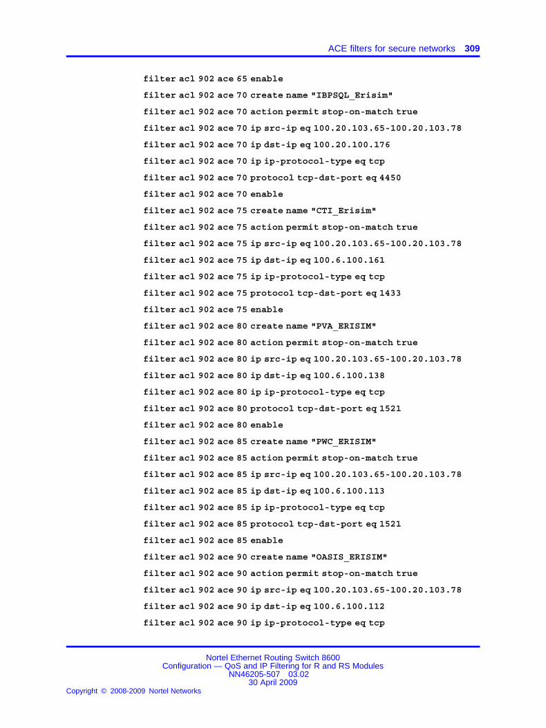
ACE filters for secure networks 309
filter acl 902 ace 65 enable
filter acl 902 ace 70 create name "IBPSQL_Erisim"
filter acl 902 ace 70 action permit stop-on-match true
filter acl 902 ace 70 ip src-ip eq 100.20.103.65-100.20.103.78
filter acl 902 ace 70 ip dst-ip eq 100.20.100.176
filter acl 902 ace 70 ip ip-protocol-type eq tcp
filter acl 902 ace 70 protocol tcp-dst-port eq 4450
filter acl 902 ace 70 enable
filter acl 902 ace 75 create name "CTI_Erisim"
filter acl 902 ace 75 action permit stop-on-match true
filter acl 902 ace 75 ip src-ip eq 100.20.103.65-100.20.103.78
filter acl 902 ace 75 ip dst-ip eq 100.6.100.161
filter acl 902 ace 75 ip ip-protocol-type eq tcp
filter acl 902 ace 75 protocol tcp-dst-port eq 1433
filter acl 902 ace 75 enable
filter acl 902 ace 80 create name "PVA_ERISIM"
filter acl 902 ace 80 action permit stop-on-match true
filter acl 902 ace 80 ip src-ip eq 100.20.103.65-100.20.103.78
filter acl 902 ace 80 ip dst-ip eq 100.6.100.138
filter acl 902 ace 80 ip ip-protocol-type eq tcp
filter acl 902 ace 80 protocol tcp-dst-port eq 1521
filter acl 902 ace 80 enable
filter acl 902 ace 85 create name "PWC_ERISIM"
filter acl 902 ace 85 action permit stop-on-match true
filter acl 902 ace 85 ip src-ip eq 100.20.103.65-100.20.103.78
filter acl 902 ace 85 ip dst-ip eq 100.6.100.113
filter acl 902 ace 85 ip ip-protocol-type eq tcp
filter acl 902 ace 85 protocol tcp-dst-port eq 1521
filter acl 902 ace 85 enable
filter acl 902 ace 90 create name "OASIS_ERISIM"
filter acl 902 ace 90 action permit stop-on-match true
filter acl 902 ace 90 ip src-ip eq 100.20.103.65-100.20.103.78
filter acl 902 ace 90 ip dst-ip eq 100.6.100.112
filter acl 902 ace 90 ip ip-protocol-type eq tcp
Nortel Ethernet Routing Switch 8600Configuration — QoS and IP Filtering for R and RS Modules
NN46205-507 03.0230 April 2009
Copyright © 2008-2009 Nortel Networks
.

310 Advanced filter examples
filter acl 902 ace 90 protocol tcp-dst-port eq 1521
filter acl 902 ace 90 enable
filter acl 902 ace 95 create name "AV-YAMA_YONETIM__9968"
filter acl 902 ace 95 action permit stop-on-match true
filter acl 902 ace 95 ip src-ip eq 100.20.103.65-100.20.103.78
filter acl 902 ace 95 ip ip-protocol-type eq tcp
filter acl 902 ace 95 protocol tcp-dst-port eq 9968
filter acl 902 ace 95 enable
filter acl 902 ace 100 create name "AV-YAMA_YONETIM_2967"
filter acl 902 ace 100 action permit stop-on-match true
filter acl 902 ace 100 ip src-ip eq 100.20.103.65-100.20.103.78
filter acl 902 ace 100 ip ip-protocol-type eq tcp
filter acl 902 ace 100 protocol tcp-dst-port eq 2967
filter acl 902 ace 100 enable
filter acl 902 ace 105 create name "AV-YAMA_YONETIM_UDP_2967"
filter acl 902 ace 105 action permit stop-on-match true
filter acl 902 ace 105 ip src-ip eq 100.20.103.65-100.20.103.78
filter acl 902 ace 105 ip ip-protocol-type eq udp
filter acl 902 ace 105 protocol udp-dst-port eq 2967
filter acl 902 ace 105 enable
filter acl 902 ace 108 create name "AV-YAMA_YONETIM_SOURCE_9968"
filter acl 902 ace 108 action permit stop-on-match true
filter acl 902 ace 108 ip src-ip eq 100.20.103.65-100.20.103.78
filter acl 902 ace 108 ip ip-protocol-type eq udp
filter acl 902 ace 108 protocol udp-src-port eq 9968
filter acl 902 ace 108 enable
filter acl 902 ace 110 create name "ALERT_MOM_SMS_ERISIM_TCP_1270"
filter acl 902 ace 110 action permit stop-on-match true
filter acl 902 ace 110 ip src-ip eq 100.20.103.65-100.20.103.78
filter acl 902 ace 110 ip dst-ip eq 100.6.140.10-100.6.140.11
filter acl 902 ace 110 ip ip-protocol-type eq tcp
filter acl 902 ace 110 protocol tcp-dst-port eq 1270
filter acl 902 ace 110 enable
Nortel Ethernet Routing Switch 8600Configuration — QoS and IP Filtering for R and RS Modules
NN46205-507 03.0230 April 2009
Copyright © 2008-2009 Nortel Networks
.

ACE filters for secure networks 311
filter acl 902 ace 120 create name "ALERT_MOM_SMS_ERISIM_UDP_1270"
filter acl 902 ace 120 action permit stop-on-match true
filter acl 902 ace 120 ip src-ip eq 100.20.103.65-100.20.103.78
filter acl 902 ace 120 ip dst-ip eq 100.6.140.10-100.6.140.11
filter acl 902 ace 120 ip ip-protocol-type eq udp
filter acl 902 ace 120 protocol udp-dst-port eq 1270
filter acl 902 ace 120 enable
filter acl 902 ace 130 create name "ALERT_MOM_SMS_ERISIM_HTTP"
filter acl 902 ace 130 action permit stop-on-match true
filter acl 902 ace 130 ip src-ip eq 100.20.103.65-100.20.103.78
filter acl 902 ace 130 ip dst-ip eq 100.6.140.13
filter acl 902 ace 130 ip ip-protocol-type eq tcp
filter acl 902 ace 130 protocol tcp-dst-port eq 80
filter acl 902 ace 130 enable
filter acl 902 ace 135 create name "ALERT_MOM_SMS_ERISIM_HTTP2"
filter acl 902 ace 135 action permit stop-on-match true
filter acl 902 ace 135 ip src-ip eq 100.20.103.65-100.20.103.78
filter acl 902 ace 135 ip dst-ip eq 100.6.106.92
filter acl 902 ace 135 ip ip-protocol-type eq tcp
filter acl 902 ace 135 protocol tcp-dst-port eq 80
filter acl 902 ace 135 enable
filter acl 902 ace 140 create name "ALERT_MOM_SMS_ERISIM_1521"
filter acl 902 ace 140 action permit stop-on-match true
filter acl 902 ace 140 ip src-ip eq 100.20.103.65-100.20.103.78
filter acl 902 ace 140 ip dst-ip eq 100.6.100.126
filter acl 902 ace 140 ip ip-protocol-type eq tcp
filter acl 902 ace 140 protocol tcp-dst-port eq 1521
filter acl 902 ace 140 enable
filter acl 902 ace 150 create name "ALERT_MOM_SMS_ERISIM_1521x"
filter acl 902 ace 150 action permit stop-on-match true
filter acl 902 ace 150 ip src-ip eq 100.20.103.65-100.20.103.78
filter acl 902 ace 150 ip dst-ip eq 100.20.100.47
filter acl 902 ace 150 ip ip-protocol-type eq tcp
Nortel Ethernet Routing Switch 8600Configuration — QoS and IP Filtering for R and RS Modules
NN46205-507 03.0230 April 2009
Copyright © 2008-2009 Nortel Networks
.

312 Advanced filter examples
filter acl 902 ace 150 protocol tcp-dst-port eq 1521
filter acl 902 ace 150 enable
filter acl 902 ace 155 create name "FULL_ERISIM"
filter acl 902 ace 155 action permit stop-on-match true
filter acl 902 ace 155 ip dst-ip eq 100.20.100.149
filter acl 902 ace 155 enable
filter acl 902 ace 160 create name "LOGLAMAK_ICIN"
filter acl 902 ace 160 action permit redirect-next-hop100.20.150.34 stop-on-match true
filter acl 902 ace 160 ip src-ip ge 0.0.0.0
filter acl 902 ace 170 create name "DENY_ANY_ANY"
filter acl 902 ace 170 action deny stop-on-match true
filter acl 902 ace 170 ip src-ip ge 0.0.0.0
filter acl 902 ace 170 ip dst-ip ge 0.0.0.0
filter acl 902 ace 170 enable
The following section provides details about the filter configuration for thefirst core Layer 3 host.
#
# R-MODULE FILTER CONFIGURATION
#
filter act 1 create name "BUSINESS 1"
filter act 1 ip srcIp,dstIp,ipOptions,ipProtoType
filter act 1 protocol tcpSrcPort,udpSrcPort,tcpDstPort,udpDstPort,tcpFlags,icmpMsgType
filter act 1 apply
filter acl 1 create outPort act 1 name "VRRP_Drop_ACL"
filter acl 1 port add 4/46
filter acl 1 ace 1 create name "Vrrp"
filter acl 1 ace 1 action deny stop-on-match true
filter acl 1 ace 1 ip ip-protocol-type eq vrrp
filter acl 1 ace 1 enable
filter acl 171 create inVlan act 1 name "TOPLANTI_VE_EGITIM_ACL"
filter acl 171 vlan add 171
Nortel Ethernet Routing Switch 8600Configuration — QoS and IP Filtering for R and RS Modules
NN46205-507 03.0230 April 2009
Copyright © 2008-2009 Nortel Networks
.

ACE filters for secure networks 313
filter acl 171 disable filter acl 171 ace 10 create name"ICMP_PERMIT"
filter acl 171 ace 10 action permit stop-on-match true
filter acl 171 ace 10 ip ip-protocol-type eq icmp
filter acl 171 ace 10 enable
filter acl 171 ace 20 create name "IGMP_PERMIT"
filter acl 171 ace 20 action permit stop-on-match true
filter acl 171 ace 20 ip ip-protocol-type eq 2
filter acl 171 ace 20 enable
filter acl 171 ace 30 create name "VRRP_PERMIT"
filter acl 171 ace 30 action permit stop-on-match true
filter acl 171 ace 30 ip ip-protocol-type eq vrrp
filter acl 171 ace 30 enable
filter acl 171 ace 40 create name "DNS_PERMIT"
filter acl 171 ace 40 action permit stop-on-match true
filter acl 171 ace 40 ip src-ip eq 100.20.171.0-100.20.171.255
filter acl 171 ace 40 ip dst-ip eq 100.20.104.0-100.20.104.255
filter acl 171 ace 40 protocol udp-dst-port eq dns
filter acl 171 ace 40 enable
filter acl 171 ace 50 create name "ESTABLISHED"
filter acl 171 ace 50 action permit stop-on-match true
filter acl 171 ace 50 ip src-ip eq 100.6.172.0-100.6.172.255
filter acl 171 ace 50 ip ip-protocol-type eq tcp
filter acl 171 ace 50 protocol tcp-dst-port ge 1023
filter acl 171 ace 50 protocol tcp-flags match-any rst,ack
filter acl 171 ace 50 enable
filter acl 171 ace 60 create name "DHCP_PERMIT"
filter acl 171 ace 60 action permit stop-on-match true
filter acl 171 ace 60 protocol udp-dst-port eq bootpServer
filter acl 171 ace 60 enable
filter acl 171 ace 80 create name "DC_DNS_EXC_PERMIT"
filter acl 171 ace 80 action permit stop-on-match true
filter acl 171 ace 80 ip src-ip eq 100.20.172.0-100.20.172.255
filter acl 171 ace 80 ip dst-ip eq 100.20.104.0-100.20.105.255
Nortel Ethernet Routing Switch 8600Configuration — QoS and IP Filtering for R and RS Modules
NN46205-507 03.0230 April 2009
Copyright © 2008-2009 Nortel Networks
.

314 Advanced filter examples
filter acl 171 ace 80 enable
filter acl 171 ace 90 create name "HTTP_PERMIT"
filter acl 171 ace 90 action permit stop-on-match true
filter acl 171 ace 90 ip src-ip eq 100.20.172.0-100.20.172.255
filter acl 171 ace 90 protocol tcp-dst-port eq 80
filter acl 171 ace 90 enable
filter acl 171 ace 100 create name "HTTPS_PERMIT"
filter acl 171 ace 100 action permit stop-on-match true
filter acl 171 ace 100 ip src-ip eq 100.20.172.0-100.20.172.255
filter acl 171 ace 100 protocol tcp-dst-port eq 443
filter acl 171 ace 100 enable
filter acl 171 ace 110 create name "PROXY_8080_PERMIT"
filter acl 171 ace 110 action permit stop-on-match true
filter acl 171 ace 110 ip src-ip eq 100.20.172.0-100.20.172.255
filter acl 171 ace 110 ip dst-ip eq 100.20.189.0-100.20.189.255
filter acl 171 ace 110 protocol tcp-dst-port eq 8080
filter acl 171 ace 110 enable
filter acl 171 ace 120 create name "CITRIX_Conn"
filter acl 171 ace 120 action permit stop-on-match true
filter acl 171 ace 120 protocol tcp-dst-port eq 1494
filter acl 171 ace 120 protocol udp-dst-port eq 1604
filter acl 171 ace 120 enable
filter acl 171 ace 130 create name "PWC_VPN_ERISIM"
filter acl 171 ace 130 action permit stop-on-match true
filter acl 171 ace 130 ip src-ip eq 100.20.172.0-100.20.172.255
filter acl 171 ace 130 protocol tcp-dst-port eq 11160
filter acl 171 ace 130 enable
filter acl 171 ace 140 create name "Microsoft_FileSharing_PERMIT"
filter acl 171 ace 140 action permit stop-on-match true
filter acl 171 ace 140 debug count enable
filter acl 171 ace 140 protocol tcp-dst-port eq 135-139
filter acl 171 ace 140 protocol udp-dst-port eq 135-139
filter acl 171 ace 140 enable
Nortel Ethernet Routing Switch 8600Configuration — QoS and IP Filtering for R and RS Modules
NN46205-507 03.0230 April 2009
Copyright © 2008-2009 Nortel Networks
.

ACE filters for secure networks 315
filter acl 171 ace 150 create name "Microsoft_FileSharing_PERMIT"
filter acl 171 ace 150 action permit stop-on-match true
filter acl 171 ace 150 debug count enable
filter acl 171 ace 150 protocol tcp-dst-port eq 445
filter acl 171 ace 150 protocol udp-dst-port eq 445
filter acl 171 ace 150 enable
filter acl 172 create inVlan act 1 name "MISAFIR_ACL"
filter acl 172 vlan add 172
filter acl 172 disable
filter acl 172 ace 5 create name "Misafir_to_Misafir"
filter acl 172 ace 5 action permit stop-on-match true
filter acl 172 ace 5 ip dst-ip eq 100.20.172.0-100.20.172.255
filter acl 172 ace 5 enable
filter acl 172 ace 10 create name "ICMP_PERMIT"
filter acl 172 ace 10 action permit stop-on-match true
filter acl 172 ace 10 ip ip-protocol-type eq icmp
filter acl 172 ace 10 enable
filter acl 172 ace 20 create name "IGMP_PERMIT"
filter acl 172 ace 20 action permit stop-on-match true
filter acl 172 ace 20 ip ip-protocol-type eq 2
filter acl 172 ace 20 enable
filter acl 172 ace 30 create name "VRRP_PERMIT"
filter acl 172 ace 30 action permit stop-on-match true
filter acl 172 ace 30 ip ip-protocol-type eq vrrp
filter acl 172 ace 30 enable
filter acl 172 ace 40 create name "DNS_PERMIT"
filter acl 172 ace 40 action permit stop-on-match true
filter acl 172 ace 40 ip src-ip eq 100.20.172.0-100.20.172.255
filter acl 172 ace 40 ip dst-ip eq 100.20.104.0-100.20.104.255
filter acl 172 ace 40 protocol udp-dst-port eq dnsfilter acl 172 ace 40 enable
filter acl 172 ace 50 create name "ESTABLISHED"
filter acl 172 ace 50 action permit stop-on-match true
Nortel Ethernet Routing Switch 8600Configuration — QoS and IP Filtering for R and RS Modules
NN46205-507 03.0230 April 2009
Copyright © 2008-2009 Nortel Networks
.

316 Advanced filter examples
filter acl 172 ace 50 ip src-ip eq 100.20.172.0-100.20.172.255
filter acl 172 ace 50 ip ip-protocol-type eq tcp
filter acl 172 ace 50 protocol tcp-dst-port ge 1023
filter acl 172 ace 50 protocol tcp-flags match-any rst,ack
filter acl 172 ace 50 enable
filter acl 172 ace 60 create name "DHCP_PERMIT"
filter acl 172 ace 60 action permit stop-on-match true
filter acl 172 ace 60 protocol udp-dst-port eq bootpServer
filter acl 172 ace 60 enable
filter acl 172 ace 80 create name "DC_DNS_EXC_PERMIT"
filter acl 172 ace 80 action permit stop-on-match true
filter acl 172 ace 80 ip src-ip eq 100.20.172.0-100.20.172.255
filter acl 172 ace 80 ip dst-ip eq 100.20.104.0-100.20.105.255
filter acl 172 ace 80 enable
filter acl 172 ace 90 create name "HTTP_PERMIT"
filter acl 172 ace 90 action permit stop-on-match true
filter acl 172 ace 90 ip src-ip eq 100.20.172.0-100.20.172.255
filter acl 172 ace 90 ip ip-protocol-type eq tcp
filter acl 172 ace 90 protocol tcp-dst-port eq 80
filter acl 172 ace 90 enable
filter acl 172 ace 100 create name "HTTPS_PERMIT"
filter acl 172 ace 100 action permit stop-on-match true
filter acl 172 ace 100 ip src-ip eq 100.20.172.0-100.20.172.255
filter acl 172 ace 100 ip ip-protocol-type eq tcp
filter acl 172 ace 100 protocol tcp-dst-port eq 443
filter acl 172 ace 100 enable
filter acl 172 ace 105 create name "REMDESKTOP_PERMIT"
filter acl 172 ace 105 action permit stop-on-match true
filter acl 172 ace 105 ip src-ip eq 100.20.172.0-100.20.172.255
filter acl 172 ace 105 ip ip-protocol-type eq tcp
filter acl 172 ace 105 protocol tcp-dst-port eq 3389
filter acl 172 ace 105 enable
filter acl 172 ace 106 create name "NORKOM_PERMIT"
filter acl 172 ace 106 action permit stop-on-match true
Nortel Ethernet Routing Switch 8600Configuration — QoS and IP Filtering for R and RS Modules
NN46205-507 03.0230 April 2009
Copyright © 2008-2009 Nortel Networks
.
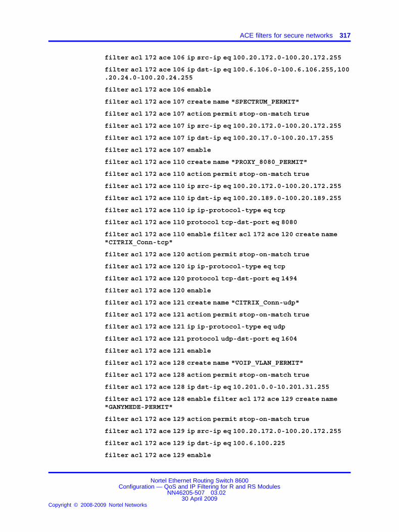
ACE filters for secure networks 317
filter acl 172 ace 106 ip src-ip eq 100.20.172.0-100.20.172.255
filter acl 172 ace 106 ip dst-ip eq 100.6.106.0-100.6.106.255,100.20.24.0-100.20.24.255
filter acl 172 ace 106 enable
filter acl 172 ace 107 create name "SPECTRUM_PERMIT"
filter acl 172 ace 107 action permit stop-on-match true
filter acl 172 ace 107 ip src-ip eq 100.20.172.0-100.20.172.255
filter acl 172 ace 107 ip dst-ip eq 100.20.17.0-100.20.17.255
filter acl 172 ace 107 enable
filter acl 172 ace 110 create name "PROXY_8080_PERMIT"
filter acl 172 ace 110 action permit stop-on-match true
filter acl 172 ace 110 ip src-ip eq 100.20.172.0-100.20.172.255
filter acl 172 ace 110 ip dst-ip eq 100.20.189.0-100.20.189.255
filter acl 172 ace 110 ip ip-protocol-type eq tcp
filter acl 172 ace 110 protocol tcp-dst-port eq 8080
filter acl 172 ace 110 enable filter acl 172 ace 120 create name"CITRIX_Conn-tcp"
filter acl 172 ace 120 action permit stop-on-match true
filter acl 172 ace 120 ip ip-protocol-type eq tcp
filter acl 172 ace 120 protocol tcp-dst-port eq 1494
filter acl 172 ace 120 enable
filter acl 172 ace 121 create name "CITRIX_Conn-udp"
filter acl 172 ace 121 action permit stop-on-match true
filter acl 172 ace 121 ip ip-protocol-type eq udp
filter acl 172 ace 121 protocol udp-dst-port eq 1604
filter acl 172 ace 121 enable
filter acl 172 ace 128 create name "VOIP_VLAN_PERMIT"
filter acl 172 ace 128 action permit stop-on-match true
filter acl 172 ace 128 ip dst-ip eq 10.201.0.0-10.201.31.255
filter acl 172 ace 128 enable filter acl 172 ace 129 create name"GANYMEDE-PERMIT"
filter acl 172 ace 129 action permit stop-on-match true
filter acl 172 ace 129 ip src-ip eq 100.20.172.0-100.20.172.255
filter acl 172 ace 129 ip dst-ip eq 100.6.100.225
filter acl 172 ace 129 enable
Nortel Ethernet Routing Switch 8600Configuration — QoS and IP Filtering for R and RS Modules
NN46205-507 03.0230 April 2009
Copyright © 2008-2009 Nortel Networks
.

318 Advanced filter examples
filter acl 172 ace 130 create name "PWC_VPN_ERISIM"
filter acl 172 ace 130 action permit stop-on-match true
filter acl 172 ace 130 ip src-ip eq 100.20.172.0-100.20.172.255
filter acl 172 ace 130 ip ip-protocol-type eq tcp
filter acl 172 ace 130 protocol tcp-dst-port eq 11160
filter acl 172 ace 130 enable
filter acl 172 ace 131 create name "ISAKMP"
filter acl 172 ace 131 action permit stop-on-match true
filter acl 172 ace 131 ip ip-protocol-type eq udp
filter acl 172 ace 131 protocol udp-dst-port eq 500
filter acl 172 ace 131 enable
filter acl 172 ace 132 create name "ESP"
filter acl 172 ace 132 action permit stop-on-match true
filter acl 172 ace 132 ip ip-protocol-type eq 50
filter acl 172 ace 132 enable
filter acl 172 ace 133 create name "LOGLAMAK_ICIN"
filter acl 172 ace 133 action permit redirect-next-hop100.20.150.34 stop-on-match true ipfix enable
filter acl 172 ace 133 debug count enable
filter acl 172 ace 133 ip src-ip ge 0.0.0.0
filter acl 172 ace 140 create name "DENY_ANY_ANY"
filter acl 172 ace 140 action deny stop-on-match true
filter acl 172 ace 140 debug count enable
filter acl 172 ace 140 ip src-ip ge 0.0.0.0
filter acl 172 ace 140 ip dst-ip ge 0.0.0.0
filter acl 172 ace 140 enable
filter acl 802 create inVlan act 1 name "NICE-CLS_ACL-in"
filter acl 802 vlan add 802
filter acl 802 disable
filter acl 802 ace 1 create name "NICE_to_NICE"
filter acl 802 ace 1 action permit stop-on-match true
filter acl 802 ace 1 ip dst-ip eq 100.20.174.32-100.20.174.63
filter acl 802 ace 1 enable
filter acl 802 ace 10 create name "ICMP_PERMIT"
Nortel Ethernet Routing Switch 8600Configuration — QoS and IP Filtering for R and RS Modules
NN46205-507 03.0230 April 2009
Copyright © 2008-2009 Nortel Networks
.

ACE filters for secure networks 319
filter acl 802 ace 10 action permit stop-on-match true
filter acl 802 ace 10 ip ip-protocol-type eq icmp
filter acl 802 ace 10 enable
filter acl 802 ace 20 create name "IGMP_PERMIT"
filter acl 802 ace 20 action permit stop-on-match true
filter acl 802 ace 20 ip ip-protocol-type eq 2
filter acl 802 ace 20 enable filter acl 802 ace 30 create name"VRRP_PERMIT"
filter acl 802 ace 30 action permit stop-on-match true
filter acl 802 ace 30 ip ip-protocol-type eq vrrp
filter acl 802 ace 30 enable
filter acl 802 ace 40 create name "DNS_PERMIT"
filter acl 802 ace 40 action permit stop-on-match true
filter acl 802 ace 40 ip src-ip eq 100.20.174.32-100.20.174.63
filter acl 802 ace 40 ip dst-ip eq 100.20.104.0-100.20.104.255
filter acl 802 ace 40 protocol udp-dst-port eq dns
filter acl 802 ace 40 enable
filter acl 802 ace 45 create name "DC-EXCH-DNS"
filter acl 802 ace 45 action permit stop-on-match true
filter acl 802 ace 45 ip dst-ip eq 100.20.104.0-100.20.105.255
filter acl 802 ace 45 enable
filter acl 802 ace 50 create name "ESTABLISHED"
filter acl 802 ace 50 action permit stop-on-match true
filter acl 802 ace 50 ip src-ip eq 100.20.174.32-100.20.174.63
filter acl 802 ace 50 ip ip-protocol-type eq tcp
filter acl 802 ace 50 protocol tcp-dst-port ge 1023
filter acl 802 ace 50 protocol tcp-flags match-any rst,ack
filter acl 802 ace 50 enable
filter acl 802 ace 51 create name "UDP_Permit"
filter acl 802 ace 51 action permit stop-on-match true
filter acl 802 ace 51 ip ip-protocol-type eq udp
filter acl 802 ace 51 enable
filter acl 802 ace 60 create name "NICE_Logging"
filter acl 802 ace 60 action permit stop-on-match true
Nortel Ethernet Routing Switch 8600Configuration — QoS and IP Filtering for R and RS Modules
NN46205-507 03.0230 April 2009
Copyright © 2008-2009 Nortel Networks
.

320 Advanced filter examples
filter acl 802 ace 60 ip src-ip eq 100.20.174.32-100.20.174.63
filter acl 802 ace 60 ip ip-protocol-type eq tcp
filter acl 802 ace 60 protocol tcp-dst-port eq 2011
filter acl 802 ace 60 enable
filter acl 802 ace 65 create name "RTS_Conn"
filter acl 802 ace 65 action permit stop-on-match true
filter acl 802 ace 65 ip dst-ip eq 100.20.152.20
filter acl 802 ace 65 enable
filter acl 802 ace 70 create name "CTI_Conn"
filter acl 802 ace 70 action permit stop-on-match true
filter acl 802 ace 70 ip src-ip eq 100.20.174.32-100.20.174.63
filter acl 802 ace 70 ip ip-protocol-type eq tcp
filter acl 802 ace 70 protocol tcp-dst-port eq 3750
filter acl 802 ace 70 enable
filter acl 802 ace 90 create name "LOGLAMA"
filter acl 802 ace 90 action permit redirect-next-hop100.20.150.217 stop-on-match true
filter acl 802 ace 90 debug count enable
filter acl 802 ace 90 ip src-ip ge 0.0.0.0
filter acl 802 ace 100 create name "DENY_ANY"
filter acl 802 ace 100 action deny stop-on-match true
filter acl 802 ace 100 debug count enable
filter acl 802 ace 100 ip src-ip ge 0.0.0.0
filter acl 802 ace 100 ip dst-ip ge 0.0.0.0
filter acl 802 ace 100 enable
filter acl 804 create inVlan act 1 name "BASIM_LIMITED-in"
filter acl 804 vlan add 804
filter acl 804 ace 5 create name "Basim_to_Basim"
filter acl 804 ace 5 action permit stop-on-match true
filter acl 804 ace 5 ip dst-ip eq 100.20.174.96-100.20.174.127
filter acl 804 ace 5 enable
filter acl 804 ace 10 create name "ICMP_PERMIT"
filter acl 804 ace 10 action permit stop-on-match true
Nortel Ethernet Routing Switch 8600Configuration — QoS and IP Filtering for R and RS Modules
NN46205-507 03.0230 April 2009
Copyright © 2008-2009 Nortel Networks
.
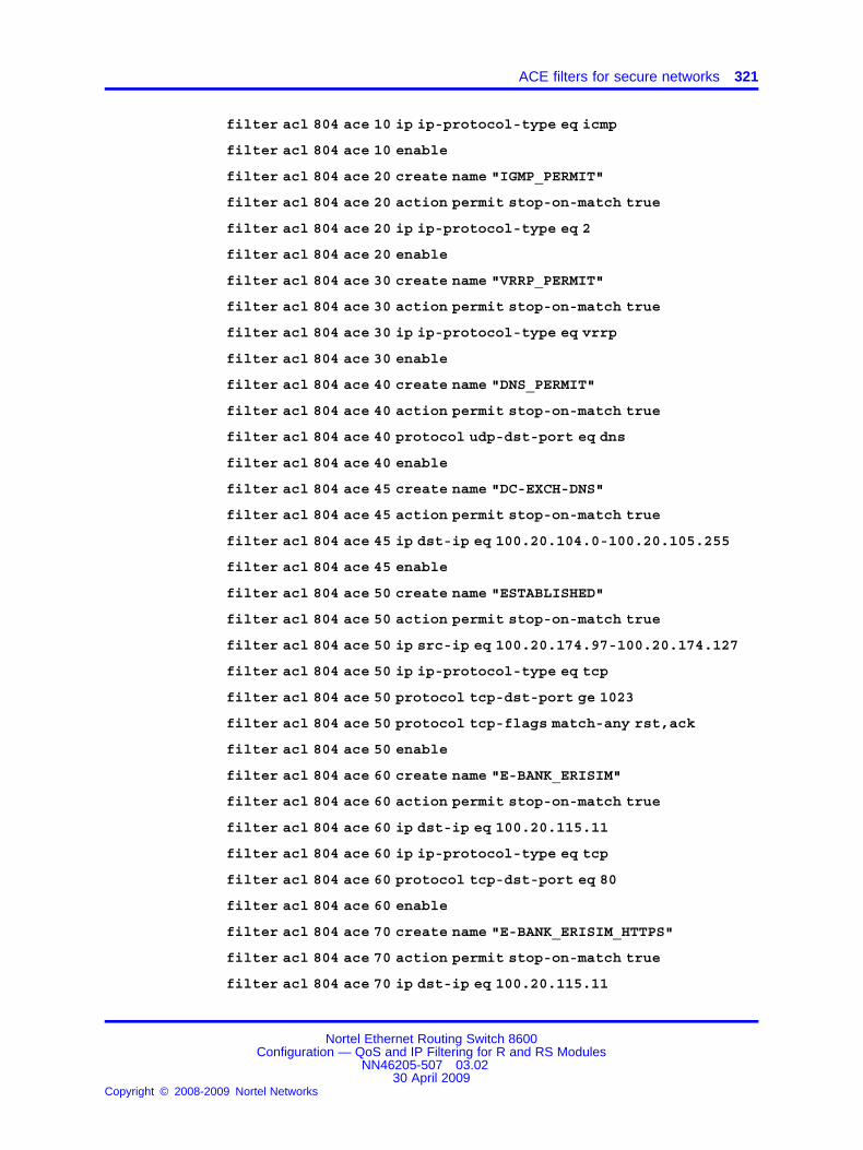
ACE filters for secure networks 321
filter acl 804 ace 10 ip ip-protocol-type eq icmp
filter acl 804 ace 10 enable
filter acl 804 ace 20 create name "IGMP_PERMIT"
filter acl 804 ace 20 action permit stop-on-match true
filter acl 804 ace 20 ip ip-protocol-type eq 2
filter acl 804 ace 20 enable
filter acl 804 ace 30 create name "VRRP_PERMIT"
filter acl 804 ace 30 action permit stop-on-match true
filter acl 804 ace 30 ip ip-protocol-type eq vrrp
filter acl 804 ace 30 enable
filter acl 804 ace 40 create name "DNS_PERMIT"
filter acl 804 ace 40 action permit stop-on-match true
filter acl 804 ace 40 protocol udp-dst-port eq dns
filter acl 804 ace 40 enable
filter acl 804 ace 45 create name "DC-EXCH-DNS"
filter acl 804 ace 45 action permit stop-on-match true
filter acl 804 ace 45 ip dst-ip eq 100.20.104.0-100.20.105.255
filter acl 804 ace 45 enable
filter acl 804 ace 50 create name "ESTABLISHED"
filter acl 804 ace 50 action permit stop-on-match true
filter acl 804 ace 50 ip src-ip eq 100.20.174.97-100.20.174.127
filter acl 804 ace 50 ip ip-protocol-type eq tcp
filter acl 804 ace 50 protocol tcp-dst-port ge 1023
filter acl 804 ace 50 protocol tcp-flags match-any rst,ack
filter acl 804 ace 50 enable
filter acl 804 ace 60 create name "E-BANK_ERISIM"
filter acl 804 ace 60 action permit stop-on-match true
filter acl 804 ace 60 ip dst-ip eq 100.20.115.11
filter acl 804 ace 60 ip ip-protocol-type eq tcp
filter acl 804 ace 60 protocol tcp-dst-port eq 80
filter acl 804 ace 60 enable
filter acl 804 ace 70 create name "E-BANK_ERISIM_HTTPS"
filter acl 804 ace 70 action permit stop-on-match true
filter acl 804 ace 70 ip dst-ip eq 100.20.115.11
Nortel Ethernet Routing Switch 8600Configuration — QoS and IP Filtering for R and RS Modules
NN46205-507 03.0230 April 2009
Copyright © 2008-2009 Nortel Networks
.

322 Advanced filter examples
filter acl 804 ace 70 ip ip-protocol-type eq tcp
filter acl 804 ace 70 protocol tcp-dst-port eq 443
filter acl 804 ace 70 enable
filter acl 804 ace 80 create name "FRED_Erisim"
filter acl 804 ace 80 action permit stop-on-match true
filter acl 804 ace 80 ip dst-ip eq 100.20.100.145
filter acl 804 ace 80 enable
filter acl 804 ace 81 create name "BARNEY_Erisim"
filter acl 804 ace 81 action permit stop-on-match true
filter acl 804 ace 81 ip dst-ip eq 100.20.100.151
filter acl 804 ace 81 enable
filter acl 804 ace 90 create name "BUFFY_ERISIM"
filter acl 804 ace 90 action permit stop-on-match true
filter acl 804 ace 90 ip dst-ip eq 100.20.100.77
filter acl 804 ace 90 ip ip-protocol-type eq tcp
filter acl 804 ace 90 protocol tcp-dst-port eq 1433
filter acl 804 ace 90 enable
filter acl 804 ace 100 create name "ROMTest_ERISIM"
filter acl 804 ace 100 action permit stop-on-match true
filter acl 804 ace 100 ip dst-ip eq 100.20.24.77
filter acl 804 ace 100 ip ip-protocol-type eq tcp
filter acl 804 ace 100 protocol tcp-dst-port eq 1433
filter acl 804 ace 100 enable
filter acl 804 ace 101 create name "Mrksql-t0_ERISIM"
filter acl 804 ace 101 action permit stop-on-match true
filter acl 804 ace 101 ip dst-ip eq 100.20.20.77
filter acl 804 ace 101 ip ip-protocol-type eq tcp
filter acl 804 ace 101 protocol tcp-dst-port eq 1433
filter acl 804 ace 101 enable
filter acl 804 ace 110 create name "ROSETTA_ERISIM"
filter acl 804 ace 110 action permit stop-on-match true
filter acl 804 ace 110 ip dst-ip eq 172.17.1.100
filter acl 804 ace 110 enable
filter acl 804 ace 120 create name "PLAST_ERISIM"
Nortel Ethernet Routing Switch 8600Configuration — QoS and IP Filtering for R and RS Modules
NN46205-507 03.0230 April 2009
Copyright © 2008-2009 Nortel Networks
.

ACE filters for secure networks 323
filter acl 804 ace 120 action permit stop-on-match true
filter acl 804 ace 120 ip dst-ip eq 212.57.7.20
filter acl 804 ace 120 enable
filter acl 804 ace 130 create name "AV-Yama_YONETIM_2967"
filter acl 804 ace 130 action permit stop-on-match true
filter acl 804 ace 130 ip ip-protocol-type eq tcp
filter acl 804 ace 130 protocol tcp-dst-port eq 2967
filter acl 804 ace 130 enable
filter acl 804 ace 140 create name "AV-Yama_YONETIM_9968"
filter acl 804 ace 140 action permit stop-on-match true
filter acl 804 ace 140 ip ip-protocol-type eq tcp
filter acl 804 ace 140 protocol tcp-dst-port eq 9968
filter acl 804 ace 140 enable
filter acl 804 ace 150 create name "AV-Yama_YONETIM_UDP_2967"
filter acl 804 ace 150 action permit stop-on-match true
filter acl 804 ace 150 ip ip-protocol-type eq udp
filter acl 804 ace 150 protocol udp-dst-port eq 2967
filter acl 804 ace 150 enable
filter acl 804 ace 160 create name "AV-Yama_YONETIM_UDP_9968"
filter acl 804 ace 160 action permit stop-on-match true
filter acl 804 ace 160 ip ip-protocol-type eq udp
filter acl 804 ace 160 protocol udp-dst-port eq 9968
filter acl 804 ace 160 enable
filter acl 804 ace 170 create name "AV-Yama_YONETIM_UDP_Source"
filter acl 804 ace 170 action permit stop-on-match true
filter acl 804 ace 170 ip ip-protocol-type eq udp
filter acl 804 ace 170 protocol udp-src-port eq 9968
filter acl 804 ace 170 enable
filter acl 804 ace 210 create name "PROXY_ERISIM_EK"
filter acl 804 ace 210 action permit stop-on-match true
filter acl 804 ace 210 ip dst-ip eq 100.20.189.0-100.20.189.255
filter acl 804 ace 210 ip ip-protocol-type eq tcp
filter acl 804 ace 210 protocol tcp-dst-port eq 8080
filter acl 804 ace 210 enable
Nortel Ethernet Routing Switch 8600Configuration — QoS and IP Filtering for R and RS Modules
NN46205-507 03.0230 April 2009
Copyright © 2008-2009 Nortel Networks
.

324 Advanced filter examples
filter acl 804 ace 220 create name "LOGLAMA"
filter acl 804 ace 220 action permit redirect-next-hop100.20.150.217 stop-on-match true
filter acl 804 ace 220 debug count enable
filter acl 804 ace 220 ip src-ip ge 0.0.0.0
filter acl 804 ace 230 create name "DENY_ANY"
filter acl 804 ace 230 action deny stop-on-match true
filter acl 804 ace 230 debug count enable
filter acl 804 ace 230 ip src-ip ge 0.0.0.0
filter acl 804 ace 230 ip dst-ip ge 0.0.0.0
filter acl 804 ace 230 enable
filter acl 805 create inVlan act 1 name "SBS-Remote"
filter acl 805 vlan add 805
filter acl 805 ace 5 create name "SBS-to-SBS"
filter acl 805 ace 5 action permit stop-on-match true
filter acl 805 ace 5 ip dst-ip eq 100.20.174.128-100.20.174.135
filter acl 805 ace enable
filter acl 805 ace 10 create name "ICMP_PERMIT"
filter acl 805 ace 10 action permit stop-on-match true
filter acl 805 ace 10 ip ip-protocol-type eq icmp
filter acl 805 ace 10 enable
filter acl 805 ace 20 create name "IGMP_PERMIT"
filter acl 805 ace 20 action permit stop-on-match true
filter acl 805 ace 20 ip ip-protocol-type eq 2
filter acl 805 ace 20 enable
filter acl 805 ace 30 create name "VRRP_PERMIT"
filter acl 805 ace 30 action permit stop-on-match true
filter acl 805 ace 30 ip ip-protocol-type eq vrrp
filter acl 805 ace 30 enable
filter acl 805 ace 40 create name "DNS_PERMIT"
filter acl 805 ace 40 action permit stop-on-match true
filter acl 805 ace 40 protocol udp-dst-port eq 53
filter acl 805 ace 40 enable
Nortel Ethernet Routing Switch 8600Configuration — QoS and IP Filtering for R and RS Modules
NN46205-507 03.0230 April 2009
Copyright © 2008-2009 Nortel Networks
.

ACE filters for secure networks 325
filter acl 805 ace 50 create name "ESTABLISHED"
filter acl 805 ace 50 action permit stop-on-match true
filter acl 805 ace 50 ip src-ip eq 100.20.174.128-100.20.174.134
filter acl 805 ace 50 ip ip-protocol-type eq tcp
filter acl 805 ace 50 protocol tcp-dst-port ge 1023
filter acl 805 ace 50 protocol tcp-flags match-any rst,ack
filter acl 805 ace 50 enable
filter acl 805 ace 80 create name "DC_DNS_EXCH_PERMIT"
filter acl 805 ace 80 action permit stop-on-match true
filter acl 805 ace 80 ip dst-ip eq 100.20.104.0-100.20.105.255
filter acl 805 ace 80 enable
filter acl 805 ace 90 create name "HTTP_PERMIT"
filter acl 805 ace 90 action permit stop-on-match true
filter acl 805 ace 90 ip ip-protocol-type eq tcp
filter acl 805 ace 90 protocol tcp-dst-port eq 80
filter acl 805 ace 90 enable
filter acl 805 ace 100 create name "HTTPS_PERMIT"
filter acl 805 ace 100 action permit stop-on-match true
filter acl 805 ace 100 ip ip-protocol-type eq tcp
filter acl 805 ace 100 protocol tcp-dst-port eq 443
filter acl 805 ace 100 enable
filter acl 805 ace 105 create name "REMDESKTOP_PERMIT"
filter acl 805 ace 105 action permit stop-on-match true
filter acl 805 ace 105 ip ip-protocol-type eq tcp
filter acl 805 ace 105 protocol tcp-dst-port eq 3389
filter acl 805 ace 105 enable
filter acl 805 ace 110 create name "PROXY_8080_PERMIT"
filter acl 805 ace 110 action permit stop-on-match true
filter acl 805 ace 110 ip dst-ip eq 100.20.189.0-100.20.189.255
filter acl 805 ace 110 ip ip-protocol-type eq tcp
filter acl 805 ace 110 protocol tcp-dst-port eq 8080
filter acl 805 ace 110 enable
filter acl 805 ace 120 create name "DAMEWARE_PERMIT" filter acl805 ace 120 action permit
Nortel Ethernet Routing Switch 8600Configuration — QoS and IP Filtering for R and RS Modules
NN46205-507 03.0230 April 2009
Copyright © 2008-2009 Nortel Networks
.
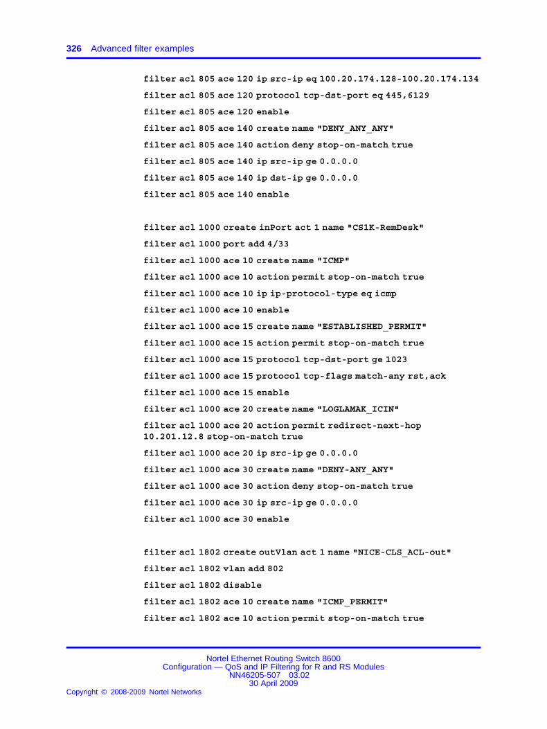
326 Advanced filter examples
filter acl 805 ace 120 ip src-ip eq 100.20.174.128-100.20.174.134
filter acl 805 ace 120 protocol tcp-dst-port eq 445,6129
filter acl 805 ace 120 enable
filter acl 805 ace 140 create name "DENY_ANY_ANY"
filter acl 805 ace 140 action deny stop-on-match true
filter acl 805 ace 140 ip src-ip ge 0.0.0.0
filter acl 805 ace 140 ip dst-ip ge 0.0.0.0
filter acl 805 ace 140 enable
filter acl 1000 create inPort act 1 name "CS1K-RemDesk"
filter acl 1000 port add 4/33
filter acl 1000 ace 10 create name "ICMP"
filter acl 1000 ace 10 action permit stop-on-match true
filter acl 1000 ace 10 ip ip-protocol-type eq icmp
filter acl 1000 ace 10 enable
filter acl 1000 ace 15 create name "ESTABLISHED_PERMIT"
filter acl 1000 ace 15 action permit stop-on-match true
filter acl 1000 ace 15 protocol tcp-dst-port ge 1023
filter acl 1000 ace 15 protocol tcp-flags match-any rst,ack
filter acl 1000 ace 15 enable
filter acl 1000 ace 20 create name "LOGLAMAK_ICIN"
filter acl 1000 ace 20 action permit redirect-next-hop10.201.12.8 stop-on-match true
filter acl 1000 ace 20 ip src-ip ge 0.0.0.0
filter acl 1000 ace 30 create name "DENY-ANY_ANY"
filter acl 1000 ace 30 action deny stop-on-match true
filter acl 1000 ace 30 ip src-ip ge 0.0.0.0
filter acl 1000 ace 30 enable
filter acl 1802 create outVlan act 1 name "NICE-CLS_ACL-out"
filter acl 1802 vlan add 802
filter acl 1802 disable
filter acl 1802 ace 10 create name "ICMP_PERMIT"
filter acl 1802 ace 10 action permit stop-on-match true
Nortel Ethernet Routing Switch 8600Configuration — QoS and IP Filtering for R and RS Modules
NN46205-507 03.0230 April 2009
Copyright © 2008-2009 Nortel Networks
.

ACE filters for secure networks 327
filter acl 1802 ace 10 ip ip-protocol-type eq icmp
filter acl 1802 ace 10 enable
filter acl 1802 ace 20 create name "IGMP_PERMIT"
filter acl 1802 ace 20 action permit stop-on-match true
filter acl 1802 ace 20 ip ip-protocol-type eq 2
filter acl 1802 ace 20 enable
filter acl 1802 ace 30 create name "VRRP_PERMIT"
filter acl 1802 ace 30 action permit stop-on-match true
filter acl 1802 ace 30 ip ip-protocol-type eq vrrp
filter acl 1802 ace 30 enable
filter acl 1802 ace 51 create name "UDP_Permit"
filter acl 1802 ace 51 action permit stop-on-match true
filter acl 1802 ace 51 ip ip-protocol-type eq udp
filter acl 1802 ace 51 enable
filter acl 1802 ace 60 create name "NICE_Logging"
filter acl 1802 ace 60 action permit stop-on-match true
filter acl 1802 ace 60 ip src-ip eq 100.20.174.32-100.20.174.63
filter acl 1802 ace 60 protocol tcp-dst-port eq 2011
filter acl 1802 ace 60 enable
filter acl 1802 ace 65 create name "RTS_Conn"
filter acl 1802 ace 65 action permit stop-on-match true
filter acl 1802 ace 100 create name "DENY_ANY"
filter acl 1802 ace 100 action deny stop-on-match true
filter acl 1802 ace 100 ip src-ip ge 0.0.0.0
filter acl 1802 ace 100 ip dst-ip ge 0.0.0.0
filter acl 1802 ace 100 enable
filter acl 1804 create outVlan act 1 name "BASIM_LIMITED-out"
filter acl 1804 vlan add 804
filter acl 1804 ace 5 create name "BASIM_to_BASIM"
filter acl 1804 ace 5 action permit stop-on-match true
filter acl 1804 ace 5 ip src-ip eq 100.20.174.96-100.20.174.127
filter acl 1804 ace 5 enable
filter acl 1804 ace 10 create name "ICMP_PERMIT"
Nortel Ethernet Routing Switch 8600Configuration — QoS and IP Filtering for R and RS Modules
NN46205-507 03.0230 April 2009
Copyright © 2008-2009 Nortel Networks
.

328 Advanced filter examples
filter acl 1804 ace 10 action permit stop-on-match true
filter acl 1804 ace 10 ip ip-protocol-type eq icmp
filter acl 1804 ace 10 enable
filter acl 1804 ace 20 create name "IGMP_PERMIT"
filter acl 1804 ace 20 action permit stop-on-match true
filter acl 1804 ace 20 ip ip-protocol-type eq 2
filter acl 1804 ace 20 enable
filter acl 1804 ace 30 create name "VRRP_PERMIT"
filter acl 1804 ace 30 action permit stop-on-match true
filter acl 1804 ace 30 ip ip-protocol-type eq vrrp
filter acl 1804 ace 30 enable
filter acl 1804 ace 40 create name "DNS_PERMIT"
filter acl 1804 ace 40 action permit stop-on-match true
filter acl 1804 ace 40 protocol udp-src-port eq 53
filter acl 1804 ace 40 enable
filter acl 1804 ace 45 create name "DC-EXCH-DNS"
filter acl 1804 ace 45 action permit stop-on-match true
filter acl 1804 ace 45 ip src-ip eq 100.20.104.0-100.20.105.255
filter acl 1804 ace 45 enable
filter acl 1804 ace 50 create name "ESTABLISHED"
filter acl 1804 ace 50 action permit stop-on-match true
filter acl 1804 ace 50 ip dst-ip eq 100.20.174.97-100.20.174.127
filter acl 1804 ace 50 ip ip-protocol-type eq tcp
filter acl 1804 ace 50 protocol tcp-dst-port ge 1023
filter acl 1804 ace 50 protocol tcp-flags match-any rst,ack
filter acl 1804 ace 50 enable
filter acl 1804 ace 80 create name "PWC_ERISIM"
filter acl 1804 ace 80 action permit stop-on-match true
filter acl 1804 ace 80 ip src-ip eq 100.20.100.145
filter acl 1804 ace 80 enable
filter acl 1804 ace 110 create name "ROSETTA_ERISIM"
filter acl 1804 ace 110 action permit stop-on-match true
filter acl 1804 ace 110 ip src-ip eq 172.17.1.100
filter acl 1804 ace 110 enable
Nortel Ethernet Routing Switch 8600Configuration — QoS and IP Filtering for R and RS Modules
NN46205-507 03.0230 April 2009
Copyright © 2008-2009 Nortel Networks
.

ACE filters for secure networks 329
filter acl 1804 ace 120 create name "PLAST_ERISIM"
filter acl 1804 ace 120 action permit stop-on-match true
filter acl 1804 ace 120 ip src-ip eq 212.57.7.20
filter acl 1804 ace 120 enable
filter acl 1804 ace 130 create name "AV-Yama_YONETIM_9968"
filter acl 1804 ace 130 action permit stop-on-match true
filter acl 1804 ace 130 ip ip-protocol-type eq tcp
filter acl 1804 ace 130 protocol tcp-dst-port eq 9968
filter acl 1804 ace 130 enable
filter acl 1804 ace 140 create name "AV-Yama_YONETIM_2967"
filter acl 1804 ace 140 action permit stop-on-match true
filter acl 1804 ace 140 ip ip-protocol-type eq tcp
filter acl 1804 ace 140 protocol tcp-dst-port eq 2967
filter acl 1804 ace 140 enable
filter acl 1804 ace 150 create name "AV-Yama_YONETIM_UDP_9968"
filter acl 1804 ace 150 action permit stop-on-match true
filter acl 1804 ace 150 ip ip-protocol-type eq udp
filter acl 1804 ace 150 protocol udp-dst-port eq 9968
filter acl 1804 ace 150 enable
filter acl 1804 ace 160 create name "AV-Yama_YONETIM_UDP_2967"
filter acl 1804 ace 160 action permit stop-on-match true
filter acl 1804 acl 160 ip ip-protocol-type eq udp
filter acl 1804 ace 160 protocol udp-dst-port eq 2967
filter acl 1804 ace 160 enable
filter acl 1804 ace 180 create name "SUNUCU_YONETIM"
filter acl 1804 ace 180 action permit stop-on-match true
filter acl 1804 ace 180 ip src-ip eq 100.20.150.80-100.20.150.95
filter acl 1804 ace 180 ip ip-protocol-type eq tcp
filter acl 1804 ace 180 protocol tcp-dst-port eq 3389
filter acl 1804 ace 180 enable
filter acl 1804 ace 200 create name "OTOMIZE_DEBIT_CARD_OPS"
filter acl 1804 ace 200 action permit stop-on-match true
filter acl 1804 ace 200 ip src-ip eq 100.20.114.0-100.20.114.255
filter acl 1804 ace 200 ip ip-protocol-type eq tcp
Nortel Ethernet Routing Switch 8600Configuration — QoS and IP Filtering for R and RS Modules
NN46205-507 03.0230 April 2009
Copyright © 2008-2009 Nortel Networks
.

330 Advanced filter examples
filter acl 1804 ace 200 protocol tcp-dst-port eq 445
filter acl 1804 ace 200 enable
filter acl 1804 ace 210 create name "OTOMIZE_DEBIT_CARD_OPS"
filter acl 1804 ace 210 action permit stop-on-match true
filter acl 1804 ace 210 ip src-ip eq 100.20.24.0-100.20.24.255
filter acl 1804 ace 210 ip ip-protocol-type eq tcp
filter acl 1804 ace 210 protocol tcp-dst-port eq 445
filter acl 1804 ace 210 enable
filter acl 1804 ace 220 create name "LOGLAMA"
filter acl 1804 ace 220 action permit
filter acl 1804 ace 220 debug count enable
filter acl 1804 ace 220 ip src-ip ge 0.0.0.0
filter acl 1804 ace 220 enable
filter acl 1804 ace 230 create name "DENY_ANY"
filter acl 1804 ace 230 action deny stop-on-match true
filter acl 1804 ace 230 debug count enable
filter acl 1804 ace 230 ip src-ip ge 0.0.0.0
filter acl 1804 ace 230 ip dst-ip ge 0.0.0.0
filter acl 1804 ace 230 enable
The following section provides details about the filter configuration for thesecond core Layer 3 host
#
# R-MODULE FILTER CONFIGURATION
#
filter act 1 create name "BUSINESS 1"
filter act 1 ip srcIp,dstIp,ipOptions,ipProtoType
filter act 1 protocol tcpSrcPort,udpSrcPort,tcpDstPort,udpDstPort,tcpFlags,icmpMsgType
filter act 1 apply filter acl 1 create outPort act 1 name"VRRP_Drop_ACL"
filter acl 1 port add 4/46
filter acl 1 ace 1 create name "Vrrp"filter acl 1 ace 1 action deny stop-on-match true
filter acl 1 ace 1 debug count enable
filter acl 1 ace 1 ip ip-protocol-type eq vrrp
Nortel Ethernet Routing Switch 8600Configuration — QoS and IP Filtering for R and RS Modules
NN46205-507 03.0230 April 2009
Copyright © 2008-2009 Nortel Networks
.

ACE filters for secure networks 331
filter acl 1 ace 1 enable
filter acl 171 create inVlan act 1 name "TOPLANTI_VE_EGITIM_ACL"
filter acl 171 vlan add 171
filter acl 171 disable
filter acl 171 ace 10 create name "ICMP_PERMIT"
filter acl 171 ace 10 action permit stop-on-match true
filter acl 171 ace 10 ip ip-protocol-type eq icmp
filter acl 171 ace 10 enable filter acl 171 ace 20 create name"IGMP_PERMIT"
filter acl 171 ace 20 action permit stop-on-match true
filter acl 171 ace 20 ip ip-protocol-type eq 2
filter acl 171 ace 20 enable
filter acl 171 ace 30 create name "VRRP_PERMIT"
filter acl 171 ace 30 action permit stop-on-match true
filter acl 171 ace 30 ip ip-protocol-type eq vrrp
filter acl 171 ace 30 enable
filter acl 171 ace 40 create name "DNS_PERMIT"
filter acl 171 ace 40 action permit stop-on-match true
filter acl 171 ace 40 ip src-ip eq 100.20.171.0-100.20.171.255
filter acl 171 ace 40 ip dst-ip eq 100.20.104.0-100.20.104.255
filter acl 171 ace 40 protocol udp-dst-port eq dns
filter acl 171 ace 40 enable
filter acl 171 ace 50 create name "ESTABLISHED"
filter acl 171 ace 50 action permit stop-on-match true
filter acl 171 ace 50 ip src-ip eq 100.6.172.0-100.6.172.255
filter acl 171 ace 50 ip ip-protocol-type eq tcp
filter acl 171 ace 50 protocol tcp-dst-port ge 1023
filter acl 171 ace 50 protocol tcp-flags match-any rst,ack
filter acl 171 ace 50 enable
filter acl 171 ace 60 create name "DHCP_PERMIT"
filter acl 171 ace 60 action permit stop-on-match true
filter acl 171 ace 60 protocol udp-dst-port eq bootpServer
filter acl 171 ace 60 enable
Nortel Ethernet Routing Switch 8600Configuration — QoS and IP Filtering for R and RS Modules
NN46205-507 03.0230 April 2009
Copyright © 2008-2009 Nortel Networks
.

332 Advanced filter examples
filter acl 171 ace 80 create name "DC_DNS_EXC_PERMIT"
filter acl 171 ace 80 action permit stop-on-match true
filter acl 171 ace 80 ip src-ip eq 100.20.172.0-100.20.172.255
filter acl 171 ace 80 ip dst-ip eq 100.20.104.0-100.20.105.255
filter acl 171 ace 80 enable filter acl 171 ace 90 create name"HTTP_PERMIT"
filter acl 171 ace 90 action permit stop-on-match true
filter acl 171 ace 90 ip src-ip eq 100.20.172.0-100.20.172.255
filter acl 171 ace 90 protocol tcp-dst-port eq 80
filter acl 171 ace 90 enable
filter acl 171 ace 100 create name "HTTPS_PERMIT"
filter acl 171 ace 100 action permit stop-on-match true
filter acl 171 ace 100 ip src-ip eq 100.20.172.0-100.20.172.255
filter acl 171 ace 100 protocol tcp-dst-port eq 443
filter acl 171 ace 100 enable
filter acl 171 ace 110 create name "PROXY_8080_PERMIT"
filter acl 171 ace 110 action permit stop-on-match true
filter acl 171 ace 110 ip src-ip eq 100.20.172.0-100.20.172.255
filter acl 171 ace 110 ip dst-ip eq 100.20.189.0-100.20.189.255
filter acl 171 ace 110 protocol tcp-dst-port eq 8080
filter acl 171 ace 110 enable
filter acl 171 ace 120 create name "CITRIX_Conn"
filter acl 171 ace 120 action permit stop-on-match true
filter acl 171 ace 120 protocol tcp-dst-port eq 1494
filter acl 171 ace 120 protocol udp-dst-port eq 1604
filter acl 171 ace 120 enable
filter acl 171 ace 130 create name "PWC_VPN_ERISIM"
filter acl 171 ace 130 action permit stop-on-match true
filter acl 171 ace 130 ip src-ip eq 100.20.172.0-100.20.172.255
filter acl 171 ace 130 protocol tcp-dst-port eq 11160
filter acl 171 ace 130 enable
filter acl 171 ace 140 create name "Microsoft_FileSharing_PERMIT"
filter acl 171 ace 140 action permit stop-on-match true
filter acl 171 ace 140 debug count enable
Nortel Ethernet Routing Switch 8600Configuration — QoS and IP Filtering for R and RS Modules
NN46205-507 03.0230 April 2009
Copyright © 2008-2009 Nortel Networks
.

ACE filters for secure networks 333
filter acl 171 ace 140 protocol tcp-dst-port eq 135-139
filter acl 171 ace 140 protocol udp-dst-port eq 135-139
filter acl 171 ace 140 enable
filter acl 171 ace 150 create name "Microsoft_FileSharing_PERMIT"
filter acl 171 ace 150 action permit stop-on-match true
filter acl 171 ace 150 debug count enable
filter acl 171 ace 150 protocol tcp-dst-port eq 445
filter acl 171 ace 150 protocol udp-dst-port eq 445
filter acl 171 ace 150 enable
filter acl 172 create inVlan act 1 name "MISAFIR_ACL"
filter acl 172 vlan add 172
filter acl 172 disable
filter acl 172 ace 5 create name "Misafir_to_Misafir"
filter acl 172 ace 5 action permit stop-on-match true
filter acl 172 ace 5 ip dst-ip eq 100.20.172.0-100.20.172.255
filter acl 172 ace 5 enable
filter acl 172 ace 10 create name "ICMP_PERMIT"
filter acl 172 ace 10 action permit stop-on-match true
filter acl 172 ace 10 ip ip-protocol-type eq icmp
filter acl 172 ace 10 enable
filter acl 172 ace 20 create name "IGMP_PERMIT"
filter acl 172 ace 20 action permit stop-on-match true
filter acl 172 ace 20 ip ip-protocol-type eq 2
filter acl 172 ace 20 enable
filter acl 172 ace 30 create name "VRRP_PERMIT"
filter acl 172 ace 30 action permit stop-on-match true
filter acl 172 ace 30 ip ip-protocol-type eq vrrp
filter acl 172 ace 30 enable
filter acl 172 ace 40 create name "DNS_PERMIT"
filter acl 172 ace 40 action permit stop-on-match true
filter acl 172 ace 40 ip src-ip eq 100.20.172.0-100.20.172.255
filter acl 172 ace 40 ip dst-ip eq 100.20.104.0-100.20.104.255
Nortel Ethernet Routing Switch 8600Configuration — QoS and IP Filtering for R and RS Modules
NN46205-507 03.0230 April 2009
Copyright © 2008-2009 Nortel Networks
.
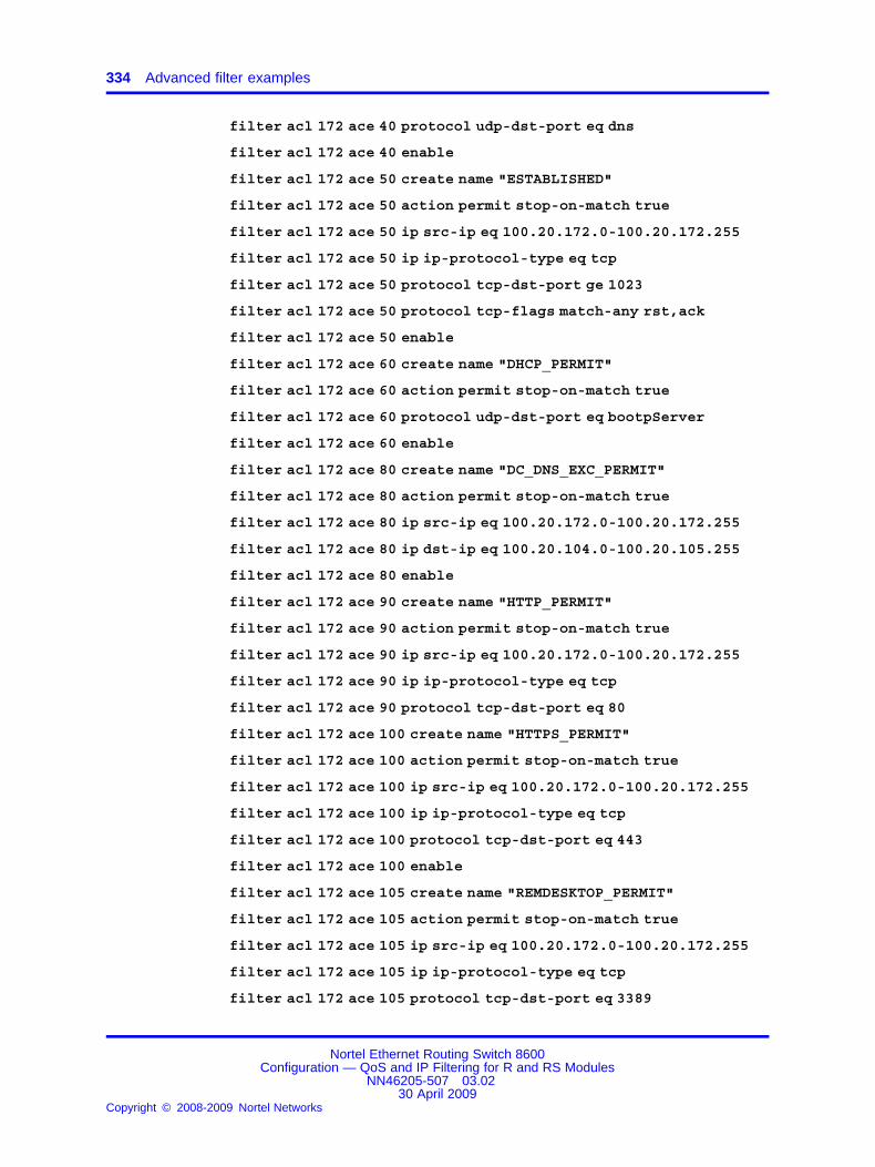
334 Advanced filter examples
filter acl 172 ace 40 protocol udp-dst-port eq dns
filter acl 172 ace 40 enable
filter acl 172 ace 50 create name "ESTABLISHED"
filter acl 172 ace 50 action permit stop-on-match true
filter acl 172 ace 50 ip src-ip eq 100.20.172.0-100.20.172.255
filter acl 172 ace 50 ip ip-protocol-type eq tcp
filter acl 172 ace 50 protocol tcp-dst-port ge 1023
filter acl 172 ace 50 protocol tcp-flags match-any rst,ack
filter acl 172 ace 50 enable
filter acl 172 ace 60 create name "DHCP_PERMIT"
filter acl 172 ace 60 action permit stop-on-match true
filter acl 172 ace 60 protocol udp-dst-port eq bootpServer
filter acl 172 ace 60 enable
filter acl 172 ace 80 create name "DC_DNS_EXC_PERMIT"
filter acl 172 ace 80 action permit stop-on-match true
filter acl 172 ace 80 ip src-ip eq 100.20.172.0-100.20.172.255
filter acl 172 ace 80 ip dst-ip eq 100.20.104.0-100.20.105.255
filter acl 172 ace 80 enable
filter acl 172 ace 90 create name "HTTP_PERMIT"
filter acl 172 ace 90 action permit stop-on-match true
filter acl 172 ace 90 ip src-ip eq 100.20.172.0-100.20.172.255
filter acl 172 ace 90 ip ip-protocol-type eq tcp
filter acl 172 ace 90 protocol tcp-dst-port eq 80
filter acl 172 ace 100 create name "HTTPS_PERMIT"
filter acl 172 ace 100 action permit stop-on-match true
filter acl 172 ace 100 ip src-ip eq 100.20.172.0-100.20.172.255
filter acl 172 ace 100 ip ip-protocol-type eq tcp
filter acl 172 ace 100 protocol tcp-dst-port eq 443
filter acl 172 ace 100 enable
filter acl 172 ace 105 create name "REMDESKTOP_PERMIT"
filter acl 172 ace 105 action permit stop-on-match true
filter acl 172 ace 105 ip src-ip eq 100.20.172.0-100.20.172.255
filter acl 172 ace 105 ip ip-protocol-type eq tcp
filter acl 172 ace 105 protocol tcp-dst-port eq 3389
Nortel Ethernet Routing Switch 8600Configuration — QoS and IP Filtering for R and RS Modules
NN46205-507 03.0230 April 2009
Copyright © 2008-2009 Nortel Networks
.

ACE filters for secure networks 335
filter acl 172 ace 105 enable
filter acl 172 ace 106 create name "NORKOM_PERMIT"
filter acl 172 ace 106 action permit stop-on-match true
filter acl 172 ace 106 ip src-ip eq 100.20.172.0-100.20.172.255
filter acl 172 ace 106 ip dst-ip eq 100.6.106.0-100.6.106.255,100.20.24.0-100.20.24.255
filter acl 172 ace 106 enable
filter acl 172 ace 107 create name "SPECTRUM_PERMIT"
filter acl 172 ace 107 action permit stop-on-match true
filter acl 172 ace 107 ip src-ip eq 100.20.172.0-100.20.172.255
filter acl 172 ace 107 ip dst-ip eq 100.20.17.0-100.20.17.255
filter acl 172 ace 107 enable
filter acl 172 ace 110 create name "PROXY_8080_PERMIT"
filter acl 172 ace 110 action permit stop-on-match true
filter acl 172 ace 110 ip src-ip eq 100.20.172.0-100.20.172.255
filter acl 172 ace 110 ip dst-ip eq 100.20.189.0-100.20.189.255
filter acl 172 ace 110 ip ip-protocol-type eq tcp
filter acl 172 ace 110 protocol tcp-dst-port eq 8080
filter acl 172 ace 110 enable
filter acl 172 ace 120 create name "CITRIX_Conn-tcp"
filter acl 172 ace 120 action permit stop-on-match true
filter acl 172 ace 120 ip ip-protocol-type eq tcp
filter acl 172 ace 120 protocol tcp-dst-port eq 1494
filter acl 172 ace 120 enable
filter acl 172 ace 121 create name "CITRIX_Conn-udp"
filter acl 172 ace 121 action permit stop-on-match true
filter acl 172 ace 121 ip ip-protocol-type eq udp
filter acl 172 ace 121 protocol udp-dst-port eq 1604
filter acl 172 ace 121 enable
filter acl 172 ace 128 create name "VOIP_VLAN_PERMIT"
filter acl 172 ace 128 action permit stop-on-match true
filter acl 172 ace 128 ip src-ip eq 100.20.172.0-100.20.172.255
filter acl 172 ace 128 ip dst-ip eq 10.201.0.0-10.201.31.255
filter acl 172 ace 128 enable
Nortel Ethernet Routing Switch 8600Configuration — QoS and IP Filtering for R and RS Modules
NN46205-507 03.0230 April 2009
Copyright © 2008-2009 Nortel Networks
.
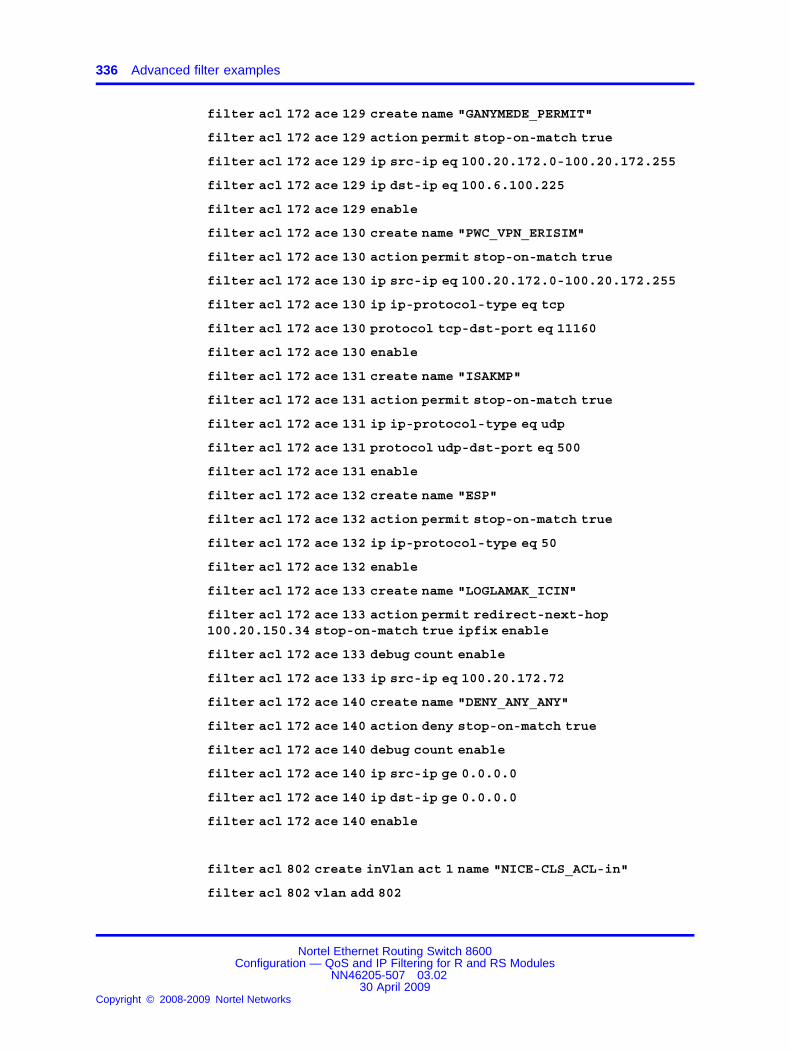
336 Advanced filter examples
filter acl 172 ace 129 create name "GANYMEDE_PERMIT"
filter acl 172 ace 129 action permit stop-on-match true
filter acl 172 ace 129 ip src-ip eq 100.20.172.0-100.20.172.255
filter acl 172 ace 129 ip dst-ip eq 100.6.100.225
filter acl 172 ace 129 enable
filter acl 172 ace 130 create name "PWC_VPN_ERISIM"
filter acl 172 ace 130 action permit stop-on-match true
filter acl 172 ace 130 ip src-ip eq 100.20.172.0-100.20.172.255
filter acl 172 ace 130 ip ip-protocol-type eq tcp
filter acl 172 ace 130 protocol tcp-dst-port eq 11160
filter acl 172 ace 130 enable
filter acl 172 ace 131 create name "ISAKMP"
filter acl 172 ace 131 action permit stop-on-match true
filter acl 172 ace 131 ip ip-protocol-type eq udp
filter acl 172 ace 131 protocol udp-dst-port eq 500
filter acl 172 ace 131 enable
filter acl 172 ace 132 create name "ESP"
filter acl 172 ace 132 action permit stop-on-match true
filter acl 172 ace 132 ip ip-protocol-type eq 50
filter acl 172 ace 132 enable
filter acl 172 ace 133 create name "LOGLAMAK_ICIN"
filter acl 172 ace 133 action permit redirect-next-hop100.20.150.34 stop-on-match true ipfix enable
filter acl 172 ace 133 debug count enable
filter acl 172 ace 133 ip src-ip eq 100.20.172.72
filter acl 172 ace 140 create name "DENY_ANY_ANY"
filter acl 172 ace 140 action deny stop-on-match true
filter acl 172 ace 140 debug count enable
filter acl 172 ace 140 ip src-ip ge 0.0.0.0
filter acl 172 ace 140 ip dst-ip ge 0.0.0.0
filter acl 172 ace 140 enable
filter acl 802 create inVlan act 1 name "NICE-CLS_ACL-in"
filter acl 802 vlan add 802
Nortel Ethernet Routing Switch 8600Configuration — QoS and IP Filtering for R and RS Modules
NN46205-507 03.0230 April 2009
Copyright © 2008-2009 Nortel Networks
.

ACE filters for secure networks 337
filter acl 802 disable
filter acl 802 ace 1 create name "NICE_to_NICE"
filter acl 802 ace 1 action permit stop-on-match true
filter acl 802 ace 1 ip dst-ip eq 100.20.174.32-100.20.174.63
filter acl 802 ace 1 enable
filter acl 802 ace 10 create name "ICMP_PERMIT"
filter acl 802 ace 10 action permit stop-on-match true
filter acl 802 ace 10 ip ip-protocol-type eq icmp
filter acl 802 ace 10 enable filter acl 802 ace 20 create name"IGMP_PERMIT"
filter acl 802 ace 20 action permit stop-on-match true
filter acl 802 ace 20 ip ip-protocol-type eq 2
filter acl 802 ace 20 enable
filter acl 802 ace 30 create name "VRRP_PERMIT"
filter acl 802 ace 30 action permit stop-on-match true
filter acl 802 ace 30 ip ip-protocol-type eq vrrp
filter acl 802 ace 30 enable
filter acl 802 ace 40 create name "DNS_PERMIT"
filter acl 802 ace 40 action permit stop-on-match true
filter acl 802 ace 40 ip src-ip eq 100.20.174.32-100.20.174.63
filter acl 802 ace 40 ip dst-ip eq 100.20.104.0-100.20.104.255
filter acl 802 ace 40 protocol udp-dst-port eq dns
filter acl 802 ace 40 enable
filter acl 802 ace 45 create name "DC-EXCH-DNS"
filter acl 802 ace 45 action permit stop-on-match true
filter acl 802 ace 45 ip dst-ip eq 100.20.104.0-100.20.105.255
filter acl 802 ace 45 enable
filter acl 802 ace 50 create name "ESTABLISHED"
filter acl 802 ace 50 action permit stop-on-match true
filter acl 802 ace 50 ip src-ip eq 100.20.174.32-100.20.174.63
filter acl 802 ace 50 ip ip-protocol-type eq tcp
filter acl 802 ace 50 protocol tcp-dst-port ge 1023
filter acl 802 ace 50 protocol tcp-flags match-any rst,ack
filter acl 802 ace 50 enable
Nortel Ethernet Routing Switch 8600Configuration — QoS and IP Filtering for R and RS Modules
NN46205-507 03.0230 April 2009
Copyright © 2008-2009 Nortel Networks
.
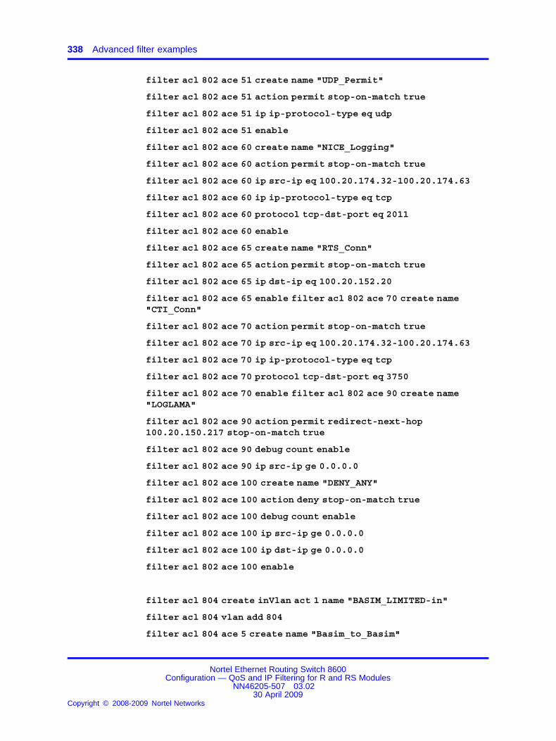
338 Advanced filter examples
filter acl 802 ace 51 create name "UDP_Permit"
filter acl 802 ace 51 action permit stop-on-match true
filter acl 802 ace 51 ip ip-protocol-type eq udp
filter acl 802 ace 51 enable
filter acl 802 ace 60 create name "NICE_Logging"
filter acl 802 ace 60 action permit stop-on-match true
filter acl 802 ace 60 ip src-ip eq 100.20.174.32-100.20.174.63
filter acl 802 ace 60 ip ip-protocol-type eq tcp
filter acl 802 ace 60 protocol tcp-dst-port eq 2011
filter acl 802 ace 60 enable
filter acl 802 ace 65 create name "RTS_Conn"
filter acl 802 ace 65 action permit stop-on-match true
filter acl 802 ace 65 ip dst-ip eq 100.20.152.20
filter acl 802 ace 65 enable filter acl 802 ace 70 create name"CTI_Conn"
filter acl 802 ace 70 action permit stop-on-match true
filter acl 802 ace 70 ip src-ip eq 100.20.174.32-100.20.174.63
filter acl 802 ace 70 ip ip-protocol-type eq tcp
filter acl 802 ace 70 protocol tcp-dst-port eq 3750
filter acl 802 ace 70 enable filter acl 802 ace 90 create name"LOGLAMA"
filter acl 802 ace 90 action permit redirect-next-hop100.20.150.217 stop-on-match true
filter acl 802 ace 90 debug count enable
filter acl 802 ace 90 ip src-ip ge 0.0.0.0
filter acl 802 ace 100 create name "DENY_ANY"
filter acl 802 ace 100 action deny stop-on-match true
filter acl 802 ace 100 debug count enable
filter acl 802 ace 100 ip src-ip ge 0.0.0.0
filter acl 802 ace 100 ip dst-ip ge 0.0.0.0
filter acl 802 ace 100 enable
filter acl 804 create inVlan act 1 name "BASIM_LIMITED-in"
filter acl 804 vlan add 804
filter acl 804 ace 5 create name "Basim_to_Basim"
Nortel Ethernet Routing Switch 8600Configuration — QoS and IP Filtering for R and RS Modules
NN46205-507 03.0230 April 2009
Copyright © 2008-2009 Nortel Networks
.

ACE filters for secure networks 339
filter acl 804 ace 5 action permit stop-on-match true
filter acl 804 ace 5 ip dst-ip eq 100.20.174.96-100.20.174.127
filter acl 804 ace 5 enable
filter acl 804 ace 10 create name "ICMP_PERMIT"
filter acl 804 ace 10 action permit stop-on-match true
filter acl 804 ace 10 ip ip-protocol-type eq icmp
filter acl 804 ace 10 enable
filter acl 804 ace 20 create name "IGMP_PERMIT"
filter acl 804 ace 20 action permit stop-on-match true
filter acl 804 ace 20 ip ip-protocol-type eq 2
filter acl 804 ace 20 enable
filter acl 804 ace 30 create name "VRRP_PERMIT"
filter acl 804 ace 30 action permit stop-on-match true
filter acl 804 ace 30 ip ip-protocol-type eq vrrp
filter acl 804 ace 30 enable
filter acl 804 ace 40 create name "DNS_PERMIT"
filter acl 804 ace 40 action permit stop-on-match true
filter acl 804 ace 40 protocol udp-dst-port eq dns
filter acl 804 ace 40 enable
filter acl 804 ace 45 create name "DC-EXCH-DNS"
filter acl 804 ace 45 action permit stop-on-match true
filter acl 804 ace 45 ip dst-ip eq 100.20.104.0-100.20.105.255
filter acl 804 ace 45 enable
filter acl 804 ace 50 create name "ESTABLISHED"
filter acl 804 ace 50 action permit stop-on-match true
filter acl 804 ace 50 ip src-ip eq 100.20.174.97-100.20.174.127
filter acl 804 ace 50 ip ip-protocol-type eq tcp
filter acl 804 ace 50 protocol tcp-dst-port ge 1023
filter acl 804 ace 50 protocol tcp-flags match-any rst,ack
filter acl 804 ace 50 enable
filter acl 804 ace 60 create name "E-BANK_ERISIM"
filter acl 804 ace 60 action permit stop-on-match true
filter acl 804 ace 60 ip dst-ip eq 100.20.115.11
filter acl 804 ace 60 ip ip-protocol-type eq tcp
Nortel Ethernet Routing Switch 8600Configuration — QoS and IP Filtering for R and RS Modules
NN46205-507 03.0230 April 2009
Copyright © 2008-2009 Nortel Networks
.

340 Advanced filter examples
filter acl 804 ace 60 protocol tcp-dst-port eq 80
filter acl 804 ace 60 enable
filter acl 804 ace 70 create name "E-BANK_ERISIM_HTTPS"
filter acl 804 ace 70 action permit stop-on-match true
filter acl 804 ace 70 ip dst-ip eq 100.20.115.11
filter acl 804 ace 70 ip ip-protocol-type eq tcp
filter acl 804 ace 70 protocol tcp-dst-port eq 443
filter acl 804 ace 70 enable
filter acl 804 ace 80 create name "FRED_Erisim"
filter acl 804 ace 80 action permit stop-on-match true
filter acl 804 ace 80 ip dst-ip eq 100.20.100.145
filter acl 804 ace 80 enable
filter acl 804 ace 81 create name "BARNEY_Erisim"
filter acl 804 ace 81 action permit stop-on-match true
filter acl 804 ace 81 ip dst-ip eq 100.20.100.151
filter acl 804 ace 81 enable
filter acl 804 ace 90 create name "BUFFY_ERISIM"
filter acl 804 ace 90 action permit stop-on-match true
filter acl 804 ace 90 ip dst-ip eq 100.20.100.77
filter acl 804 ace 90 ip ip-protocol-type eq tcp
filter acl 804 ace 90 protocol tcp-dst-port eq 1433
filter acl 804 ace 90 enable
filter acl 804 ace 100 create name "ROMTest_ERISIM"
filter acl 804 ace 100 action permit stop-on-match true
filter acl 804 ace 100 ip dst-ip eq 100.20.24.77
filter acl 804 ace 100 ip ip-protocol-type eq tcp
filter acl 804 ace 100 protocol tcp-dst-port eq 1433
filter acl 804 ace 100 enable
filter acl 804 ace 101 create name "Mrksql-t0_ERISIM"
filter acl 804 ace 101 action permit stop-on-match true
filter acl 804 ace 101 ip dst-ip eq 100.20.20.77
filter acl 804 ace 101 ip ip-protocol-type eq tcp
filter acl 804 ace 101 protocol tcp-dst-port eq 1433
Nortel Ethernet Routing Switch 8600Configuration — QoS and IP Filtering for R and RS Modules
NN46205-507 03.0230 April 2009
Copyright © 2008-2009 Nortel Networks
.

ACE filters for secure networks 341
filter acl 804 ace 101 enable filter acl 804 ace 110 create name"ROSETTA_ERISIM"
filter acl 804 ace 110 action permit stop-on-match true
filter acl 804 ace 110 ip dst-ip eq 172.17.1.100
filter acl 804 ace 110 enable
filter acl 804 ace 120 create name "PLAST_ERISIM"
filter acl 804 ace 120 action permit stop-on-match true
filter acl 804 ace 120 ip dst-ip eq 212.57.7.20
filter acl 804 ace 120 enable
filter acl 804 ace 130 create name "AV-Yama_YONETIM_2967"
filter acl 804 ace 130 action permit stop-on-match true
filter acl 804 ace 130 ip ip-protocol-type eq tcp
filter acl 804 ace 130 protocol tcp-dst-port eq 2967
filter acl 804 ace 130 enable
filter acl 804 ace 140 create name "AV-Yama_YONETIM_9968"
filter acl 804 ace 140 action permit stop-on-match true
filter acl 804 ace 140 ip ip-protocol-type eq tcp
filter acl 804 ace 140 protocol tcp-dst-port eq 9968
filter acl 804 ace 140 enable
filter acl 804 ace 150 create name "AV-Yama_YONETIM_UDP_2967"
filter acl 804 ace 150 action permit stop-on-match true
filter acl 804 ace 150 ip ip-protocol-type eq udp
filter acl 804 ace 150 protocol udp-dst-port eq 2967
filter acl 804 ace 150 enable
filter acl 804 ace 160 create name "AV-Yama_YONETIM_UDP_9968"
filter acl 804 ace 160 action permit stop-on-match true
filter acl 804 ace 160 ip ip-protocol-type eq udp
filter acl 804 ace 160 protocol udp-dst-port eq 9968
filter acl 804 ace 160 enable
filter acl 804 ace 170 create name "AV-Yama_YONETIM_UDP_Source"
filter acl 804 ace 170 action permit stop-on-match true
filter acl 804 ace 170 ip ip-protocol-type eq udp
filter acl 804 ace 170 protocol udp-src-port eq 9968
filter acl 804 ace 170 enable
Nortel Ethernet Routing Switch 8600Configuration — QoS and IP Filtering for R and RS Modules
NN46205-507 03.0230 April 2009
Copyright © 2008-2009 Nortel Networks
.

342 Advanced filter examples
filter acl 804 ace 210 create name "PROXY_ERISIM_EK"
filter acl 804 ace 210 action permit stop-on-match true
filter acl 804 ace 210 ip dst-ip eq 100.20.189.0-100.20.189.255
filter acl 804 ace 210 ip ip-protocol-type eq tcp
filter acl 804 ace 210 protocol tcp-dst-port eq 8080
filter acl 804 ace 210 enable
filter acl 804 ace 220 create name "LOGLAMA"
filter acl 804 ace 220 action permit redirect-next-hop100.20.150.217 stop-on-match true
filter acl 804 ace 220 debug count enable
filter acl 804 ace 220 ip src-ip ge 0.0.0.0
filter acl 804 ace 230 create name "DENY_ANY"
filter acl 804 ace 230 action deny stop-on-match true
filter acl 804 ace 230 debug count enable
filter acl 804 ace 230 ip src-ip ge 0.0.0.0
filter acl 804 ace 230 ip dst-ip ge 0.0.0.0
filter acl 804 ace 230 enable
filter acl 805 create inVlan act 1 name "SBS_Remote"
filter acl 805 vlan add 805
filter acl 805 ace 5 create name "SBS-to-SBS"
filter acl 805 ace 5 action permit stop-on-match true
filter acl 805 ace 5 ip dst-ip eq 100.20.174.128-100.20.174.135
filter acl 805 ace 5 enable
filter acl 805 ace 10 create name "ICMP_PERMIT"
filter acl 805 ace 10 action permit stop-on-match true
filter acl 805 ace 10 ip ip-protocol-type eq icmp
filter acl 805 ace 10 enable
filter acl 805 ace 20 create name "IGMP_PERMIT"
filter acl 805 ace 20 action permit stop-on-match true
filter acl 805 ace 20 ip ip-protocol-type eq 2
filter acl 805 ace 20 enable
filter acl 805 ace 30 create name "VRRP_PERMIT"
filter acl 805 ace 30 action permit stop-on-match true
Nortel Ethernet Routing Switch 8600Configuration — QoS and IP Filtering for R and RS Modules
NN46205-507 03.0230 April 2009
Copyright © 2008-2009 Nortel Networks
.

ACE filters for secure networks 343
filter acl 805 ace 30 ip ip-protocol-type eq vrrp
filter acl 805 ace 30 enable
filter acl 805 ace 40 create name "DNS_PERMIT"
filter acl 805 ace 40 action permit stop-on-match true
filter acl 805 ace 40 protocol udp-dst-port eq 53
filter acl 805 ace 40 enable filter acl 805 ace 50 create name"ESTABLISHED"
filter acl 805 ace 50 action permit stop-on-match true
filter acl 805 ace 50 ip src-ip eq 100.20.174.128-100.20.174.134
filter acl 805 ace 50 ip ip-protocol-type eq tcp
filter acl 805 ace 50 protocol tcp-dst-port ge 1023
filter acl 805 ace 50 protocol tcp-flags match-any rst,ack
filter acl 805 ace 50 enable
filter acl 805 ace 80 create name "DC_DNS_EXCH_PERMIT"
filter acl 805 ace 80 action permit stop-on-match true
filter acl 805 ace 80 ip dst-ip eq 100.20.104.0-100.20.105.255
filter acl 805 ace 80 enable
filter acl 805 ace 90 create name "HTTP_PERMIT"
filter acl 805 ace 90 action permit stop-on-match true
filter acl 805 ace 90 ip ip-protocol-type eq tcp
filter acl 805 ace 90 protocol tcp-dst-port eq 80
filter acl 805 ace 90 enable
filter acl 805 ace 100 create name "HTTPS_PERMIT"
filter acl 805 ace 100 action permit stop-on-match true
filter acl 805 ace 100 ip ip-protocol-type eq tcp
filter acl 805 ace 100 protocol tcp-dst-port eq 443
filter acl 805 ace 100 enable
filter acl 805 ace 105 create name "REMDESKTOP_PERMIT"
filter acl 805 ace 105 action permit stop-on-match true
filter acl 805 ace 105 ip ip-protocol-type eq tcp
filter acl 805 ace 105 protocol tcp-dst-port eq 3389
filter acl 805 ace 105 enable
filter acl 805 ace 110 create name "PROXY_8080_PERMIT"
filter acl 805 ace 110 action permit stop-on-match true
Nortel Ethernet Routing Switch 8600Configuration — QoS and IP Filtering for R and RS Modules
NN46205-507 03.0230 April 2009
Copyright © 2008-2009 Nortel Networks
.

344 Advanced filter examples
filter acl 805 ace 110 ip dst-ip eq 100.20.189.0-100.20.189.255
filter acl 805 ace 110 ip ip-protocol-type eq tcp
filter acl 805 ace 110 protocol tcp-dst-port eq 8080
filter acl 805 ace 110 enable
filter acl 805 ace 120 create name "DAMEWARE_PERMIT"
filter acl 805 ace 120 action permit
filter acl 805 ace 120 ip src-ip eq 100.20.174.128-100.20.174.134
filter acl 805 ace 120 protocol tcp-dst-port eq 445,6129
filter acl 805 ace 120 enable
filter acl 805 ace 140 create name "DENY_ANY_ANY"
filter acl 805 ace 140 action deny stop-on-match true
filter acl 805 ace 140 ip src-ip ge 0.0.0.0
filter acl 805 ace 140 ip dst-ip ge 0.0.0.0
filter acl 805 ace 140 enable
filter acl 1802 create outVlan act 1 name "NICE-CLS_ACL-out"
filter acl 1802 vlan add 802
filter acl 1802 disable filter acl 1802 ace 10 create name"ICMP_PERMIT"
filter acl 1802 ace 10 action permit stop-on-match true
filter acl 1802 ace 10 ip ip-protocol-type eq icmp
filter acl 1802 ace 10 enable
filter acl 1802 ace 20 create name "IGMP_PERMIT"
filter acl 1802 ace 20 action permit stop-on-match true
filter acl 1802 ace 20 ip ip-protocol-type eq 2
filter acl 1802 ace 20 enable filter acl 1802 ace 30 create name"VRRP_PERMIT"
filter acl 1802 ace 30 action permit stop-on-match true
filter acl 1802 ace 30 ip ip-protocol-type eq vrrp
filter acl 1802 ace 30 enable
filter acl 1802 ace 51 create name "UDP_Permit"
filter acl 1802 ace 51 action permit stop-on-match true
filter acl 1802 ace 51 ip ip-protocol-type eq udp
filter acl 1802 ace 51 enable
filter acl 1802 ace 60 create name "NICE_Logging"
Nortel Ethernet Routing Switch 8600Configuration — QoS and IP Filtering for R and RS Modules
NN46205-507 03.0230 April 2009
Copyright © 2008-2009 Nortel Networks
.

ACE filters for secure networks 345
filter acl 1802 ace 60 action permit stop-on-match true
filter acl 1802 ace 60 ip src-ip eq 100.20.174.32-100.20.174.63
filter acl 1802 ace 60 protocol tcp-dst-port eq 2011
filter acl 1802 ace 60 enable
filter acl 1802 ace 100 create name "DENY_ANY"
filter acl 1802 ace 100 action deny stop-on-match true
filter acl 1802 ace 100 ip src-ip ge 0.0.0.0
filter acl 1802 ace 100 ip dst-ip ge 0.0.0.0
filter acl 1802 ace 100 enable
filter acl 1804 create outVlan act 1 name "BASIM_LIMITED-out"
filter acl 1804 vlan add 804
filter acl 1804 ace 5 create name "BASIM-to-BASIM"
filter acl 1804 ace 5 action permit stop-on-match true
filter acl 1804 ace 5 ip src-ip eq 100.20.174.96-100.20.174.127
filter acl 1804 ace 5 ip dst-ip eq 100.20.174.96-100.20.174.127
filter acl 1804 ace 5 enable
filter acl 1804 ace 10 create name "ICMP_PERMIT"
filter acl 1804 ace 10 action permit stop-on-match true
filter acl 1804 ace 10 ip ip-protocol-type eq icmp
filter acl 1804 ace 10 enable
filter acl 1804 ace 20 create name "IGMP_PERMIT"
filter acl 1804 ace 20 action permit stop-on-match true
filter acl 1804 ace 20 ip ip-protocol-type eq 2
filter acl 1804 ace 20 enable
filter acl 1804 ace 30 create name "VRRP_PERMIT"
filter acl 1804 ace 30 action permit stop-on-match true
filter acl 1804 ace 30 ip ip-protocol-type eq vrrp
filter acl 1804 ace 30 enable
filter acl 1804 ace 40 create name "DNS_PERMIT"
filter acl 1804 ace 40 action permit stop-on-match true
filter acl 1804 ace 40 protocol udp-src-port eq 53
filter acl 1804 ace 40 enable
filter acl 1804 ace 45 create name "DC-EXCH-DNS"
filter acl 1804 ace 45 action permit stop-on-match true
Nortel Ethernet Routing Switch 8600Configuration — QoS and IP Filtering for R and RS Modules
NN46205-507 03.0230 April 2009
Copyright © 2008-2009 Nortel Networks
.

346 Advanced filter examples
filter acl 1804 ace 45 ip src-ip eq 100.20.104.0-100.20.105.255
filter acl 1804 ace 45 enable filter acl 1804 ace 50 create name"ESTABLISHED"
filter acl 1804 ace 50 action permit stop-on-match true
filter acl 1804 ace 50 ip dst-ip eq 100.20.174.97-100.20.174.127
filter acl 1804 ace 50 ip ip-protocol-type eq tcp
filter acl 1804 ace 50 protocol tcp-dst-port ge 1023
filter acl 1804 ace 50 protocol tcp-flags match-any rst,ack
filter acl 1804 ace 50 enable
filter acl 1804 ace 80 create name "PWC_ERISIM"
filter acl 1804 ace 80 action permit stop-on-match true
filter acl 1804 ace 80 ip src-ip eq 100.20.100.145
filter acl 1804 ace 80 enable
filter acl 1804 ace 110 create name "ROSETTA_ERISIM"
filter acl 1804 ace 110 action permit stop-on-match true
filter acl 1804 ace 110 ip src-ip eq 172.17.1.100
filter acl 1804 ace 110 enable
filter acl 1804 ace 120 create name "PLAST_ERISIM"
filter acl 1804 ace 120 action permit stop-on-match true
filter acl 1804 ace 120 ip src-ip eq 212.57.7.20
filter acl 1804 ace 120 enable
filter acl 1804 ace 130 create name "AV-Yama_YONETIM_9968"
filter acl 1804 ace 130 action permit stop-on-match true
filter acl 1804 ace 130 ip ip-protocol-type eq tcp
filter acl 1804 ace 130 protocol tcp-dst-port eq 9968
filter acl 1804 ace 130 enable
filter acl 1804 ace 140 create name "AV-Yama_YONETIM_2967"
filter acl 1804 ace 140 action permit stop-on-match true
filter acl 1804 ace 140 ip ip-protocol-type eq tcp
filter acl 1804 ace 140 protocol tcp-dst-port eq 2967
filter acl 1804 ace 140 enable
filter acl 1804 ace 150 create name "AV-Yama_YONETIM_UDP_9968"
filter acl 1804 ace 150 action permit stop-on-match true
filter acl 1804 ace 150 ip ip-protocol-type eq udp
Nortel Ethernet Routing Switch 8600Configuration — QoS and IP Filtering for R and RS Modules
NN46205-507 03.0230 April 2009
Copyright © 2008-2009 Nortel Networks
.

ACE filters for secure networks 347
filter acl 1804 ace 150 protocol udp-dst-port eq 9968
filter acl 1804 ace 150 enable filter acl 1804 ace 160 create name"AV-Yama_YONETIM_UDP_2967"
filter acl 1804 ace 160 action permit stop-on-match true
filter acl 1804 ace 160 ip ip-protocol-type eq udp
filter acl 1804 ace 160 protocol udp-dst-port eq 2967
filter acl 1804 ace 160 enable filter acl 1804 ace 180 create name"SUNUCU_YONETIM"
filter acl 1804 ace 180 action permit stop-on-match true
filter acl 1804 ace 180 ip src-ip eq 100.20.150.80-100.20.150.95
filter acl 1804 ace 180 ip ip-protocol-type eq tcp
filter acl 1804 ace 180 protocol tcp-dst-port eq 3389
filter acl 1804 ace 180 enable
filter acl 1804 ace 200 create name "OTOMIZE_DEBIT_CARD_OPS"
filter acl 1804 ace 200 action permit stop-on-match true
filter acl 1804 ace 200 ip src-ip eq 100.20.114.0-100.20.114.255
filter acl 1804 ace 200 ip ip-protocol-type eq tcp
filter acl 1804 ace 200 protocol tcp-dst-port eq 445
filter acl 1804 ace 200 enable
filter acl 1804 ace 210 create name "OTOMIZE_DEBIT_CARD_OPS"
filter acl 1804 ace 210 action permit stop-on-match true
filter acl 1804 ace 210 ip src-ip eq 100.20.24.0-100.20.24.255
filter acl 1804 ace 210 ip ip-protocol-type eq tcp
filter acl 1804 ace 210 protocol tcp-dst-port eq 445
filter acl 1804 ace 210 enable
filter acl 1804 ace 230 create name "DENY_ANY"
filter acl 1804 ace 230 action deny stop-on-match true
filter acl 1804 ace 230 debug count enable
filter acl 1804 ace 230 ip src-ip ge 0.0.0.0
filter acl 1804 ace 230 ip dst-ip ge 0.0.0.0
filter acl 1804 ace 230 enable
Nortel Ethernet Routing Switch 8600Configuration — QoS and IP Filtering for R and RS Modules
NN46205-507 03.0230 April 2009
Copyright © 2008-2009 Nortel Networks
.

348 Advanced filter examples
Nortel Ethernet Routing Switch 8600Configuration — QoS and IP Filtering for R and RS Modules
NN46205-507 03.0230 April 2009
Copyright © 2008-2009 Nortel Networks
.

349.
AppendixEgress queues and pages
The following tables describes the relationship between pages and packetsfor the Ethernet Routing Switch 8600 egress queues. In these tables, BPdenotes backplane. The first table shows information for data for packetsthat do not use a PHE (that is, packets from Classic modules). The secondtable describes pages using packets that use a PHE (that is, packets fromR or RS modules).
Table 33Cell breaks, back breaks, and back page usage without PHE
Start End Cells BP packetbytes
BP usage BP count
Last pagebytes
Breakcount
1 72 1 0
73 148 2 0
149 224 3 1 76 5 80 1 5 80 148
225 300 4 77 152 85 160 1 85 160 0
301 376 5 153 228 165 240 1 165 240 0
377 452 6 229 304 245 360 1 245 360 0
453 528 7 305 380 325 400 1 325 400 0
529 604 8 381 456 405 480 1 405 480 0
605 680 9 457 532 485 560 2 -27 48 632
681 756 10 533 608 565 640 2 53 128 0
757 832 11 609 684 645 720 2 133 208 0
833 908 12 685 760 725 800 2 213 288 0
909 984 13 761 836 805 880 2 293 368 0
985 1060 14 837 912 885 960 2 373 448 0
1061 1136 15 913 988 965 1040 3 -59 16 1120
... ... ... ... ... ... ... ... ... ... ...
11777 11852 156 11629 11704 12245 12320 25 -43 32 11820
Nortel Ethernet Routing Switch 8600Configuration — QoS and IP Filtering for R and RS Modules
NN46205-507 03.0230 April 2009
Copyright © 2008-2009 Nortel Networks
.

350 Egress queues and pages
Table 34Cell breaks, back breaks, and back page usage with PHE
Start End Cells BP packetbytes
BP usage BP count
Last pagebytes
Breakcount
1 68 1 0
69 144 2 0
145 220 3 1 76 5 80 1 5 80 144
221 296 4 77 152 85 160 1 85 160 0
297 372 5 153 228 165 240 1 165 240 0
373 448 6 229 304 245 320 1 245 320 0
449 524 7 305 380 325 400 1 325 400 0
525 600 8 381 456 405 480 1 405 480 0
601 676 9 457 532 485 560 2 -27 48 628
677 752 10 533 608 565 640 2 53 128 0
753 828 11 609 684 645 720 2 133 208 0
829 904 12 685 760 725 800 2 213 288 0
905 980 13 761 836 805 880 2 293 368 0
981 1056 14 837 912 885 960 2 373 448 0
1057 1132 15 913 988 965 1040 3 -59 16 1116
... ... ... ... ... ... ... ... ... ... ...
11773 11848 156 11629 11704 12245 12320 25 -43 32 11816
Nortel Ethernet Routing Switch 8600Configuration — QoS and IP Filtering for R and RS Modules
NN46205-507 03.0230 April 2009
Copyright © 2008-2009 Nortel Networks
.

351.
AppendixWorkaround for inVlan, srcIp ACL
When you create an ACL with the type inVlan that uses an ACT based onthe source IP address, the ACL no longer works after the ARP aging timeelapses. This does not cause a security breach.
To ensure the ACL operates correctly, you can add an additional ACL ACEthat permits all ARP requests.
The following procedure shows how to create an ACE to solve this issue.Create a VLAN, an inVlan ACT, and an ACL. Then, create two ACEs;the key step is to create the ARP request ACE, which solves the ACLoperation issue.
Procedure steps
Step Action
1 Create the VLAN:
ERS8610:5#vlan 3000 create byport 1 color 5
ERS8610:5#vlan 3000 ports add 2/1-2/48
ERS8610:5#vlan 3000 ip create 172.30.0.252/24
ERS8610:5#vlan 3000 ip vrrp 5 address 172.30.0.254
ERS8610:5#vlan 3000 ip vrrp 5 backup-master enable
ERS8610:5#vlan 3000 ip vrrp 5 enable
2 Create the ACT and ACL:
ERS8610:5#filter act 1 create name "test-ACT-1"
ERS8610:5#filter act 1 ip srcIp
ERS8610:5#filter act 1 arp operation
ERS8610:5#filter act 1 apply
Nortel Ethernet Routing Switch 8600Configuration — QoS and IP Filtering for R and RS Modules
NN46205-507 03.0230 April 2009
Copyright © 2008-2009 Nortel Networks
.

352 Workaround for inVlan, srcIp ACL
ERS8610:5#filter acl 1 create inVlan act 1 name"test-ACL-1"
ERS8610:5#filter acl 1 set default-action deny
ERS8610:5#filter acl 1 vlan add 3000
3 Create the ACEs:
These ACEs filter based on the source IP addresses of172.30.0.100, 172.30.0.252, and 172.30.0.254 and permit ARPrequests. The key part of this workaround is to configure theACE to permit ARP requests. Ensure that the ACE you add topermit ARP requests uses a unique ACE ID.
ERS8610:5#filter acl 1 ace 1 create name "arp"
ERS8610:5#filter acl 1 ace 1 action permit
ERS8610:5#filter acl 1 ace 1 arp operation eqarprequest
ERS8610:5#filter acl 1 ace 1 enable
ERS8610:5#filter acl 1 ace 2 create name ip
ERS8610:5#filter acl 1 ace 2 action permit
ERS8610:5#filter acl 1 ace 2 ip src-ip eq172.30.0.100
ERS8610:5#filter acl 1 ace 2 enable
ERS8610:5#filter acl 1 ace 3 create name ip2
ERS8610:5#filter acl 1 ace 3 action permit
ERS8610:5#filter acl 1 ace 3 ip src-ip eq172.30.0.252
ERS8610:5#filter acl 1 ace 3 enable
ERS8610:5#filter acl 1 ace 4 create name ip3
ERS8610:5#filter acl 1 ace 4 action permit
ERS8610:5#filter acl 1 ace 4 ip src-ip eq172.30.0.254
Nortel Ethernet Routing Switch 8600Configuration — QoS and IP Filtering for R and RS Modules
NN46205-507 03.0230 April 2009
Copyright © 2008-2009 Nortel Networks
.

Procedure steps 353
ERS8610:5#filter acl 1 ace 4 enable
--End--
Nortel Ethernet Routing Switch 8600Configuration — QoS and IP Filtering for R and RS Modules
NN46205-507 03.0230 April 2009
Copyright © 2008-2009 Nortel Networks
.

354 Workaround for inVlan, srcIp ACL
Nortel Ethernet Routing Switch 8600Configuration — QoS and IP Filtering for R and RS Modules
NN46205-507 03.0230 April 2009
Copyright © 2008-2009 Nortel Networks
.

355.
Index
64-queue template 408-queue template 40802.1p bit to QoS ingress mappings
configuring using the CLI 140configuring using the NNCLI 157
8612XLRS 21, 40, 588630GBR 18, 40, 63, 678634XGRS 21, 40, 588648GBRS 21, 40, 588648GTR 18, 408648GTRS 21, 40, 588683XLR 18, 40, 638683XZR 18, 40, 638690 SF/CPU 198691 SF/CPU 198692 SF/CPU 19
AACE 76, 87
actions 88configuration considerations 87configuring a custom ACE using the
CLI 256configuring actions using Device
Manager 199configuring actions using the CLI 244configuring actions using the NNCLI 265configuring ARP entries using Device
Manager 200configuring ARP entries using the
CLI 248configuring ARP entries using the
NNCLI 269configuring custom entries using the
NNCLI 276configuring custom pattern using
Device Manager 228
configuring debug actions using theCLI 246
configuring debug actions using theNNCLI 267
configuring Ethernet destinationaddress using Device Manager 203
configuring Ethernet entries using theCLI 249
configuring Ethernet entries using theNNCLI 270
configuring Ethernet LAN traffic typeusing Device Manager 204
configuring Ethernet port usingDevice Manager 207
configuring Ethernet source addressusing Device Manager 202
configuring Ethernet VLAN ID usingDevice Manager 209
configuring Ethernet VLAN tagpriority using Device Manager 206
configuring ICMP message typeusing Device Manager 225
configuring IP destination addressusing Device Manager 212
configuring IP DSCP using DeviceManager 214
configuring IP entries using the CLI 252configuring IP entries using the
NNCLI 272configuring IP fragmentation using
Device Manager 217configuring IP options using Device
Manager 216configuring IP protocol using Device
Manager 215configuring IP source address using
Device Manager 211
Nortel Ethernet Routing Switch 8600Configuration — QoS and IP Filtering for R and RS Modules
NN46205-507 03.0230 April 2009
Copyright © 2008-2009 Nortel Networks
.

356
configuring IPv6 destination addressusing Device Manager 234
configuring IPv6 entries 277configuring IPv6 entries using the
CLI 258configuring IPv6 next header using
Device Manager 235configuring IPv6 source address
using Device Manager 233configuring protocol entries using the
CLI 254configuring protocol entries using the
NNCLI 274configuring TCP destination port
using Device Manager 222configuring TCP flag using Device
Manager 226configuring TCP source port using
Device Manager 220configuring UDP destination port
using Device Manager 224configuring UDP source port using
Device Manager 221configuring using Device Manager 196configuring using the CLI 242configuring using the NNCLI 263established flag filter example 91modifying using Device Manager 200policy 67port mirroring 92priority 88viewing ACE ARP entries for an ACL
using Device Manager 202viewing ACE Ethernet entries for an
ACL using Device Manager 210viewing ACE IP entries for an ACL
using Device Manager 219viewing ACE IPv6 attributes for an
ACL using Device Manager 236viewing ACE Protocol entries for an
ACL using Device Manager 227viewing ACL and ACE configuration
data using the CLI 259viewing ACL and ACE configuration
data using the NNCLI 279AceListSize 168ACL 64, 84
associating ports with an ACL usingthe NNCLI 192
associating ports with, using the CLI 180
associating VLANs with an ACLusing the NNCLI 191
associating VLANs with, using theCLI 179
configuring actions using the CLI 178configuring actions using the NNCLI 190configuring using Device Manager 165configuring using the CLI 177configuring using the NNCLI 189default actions 84global actions 84port and VLAN-based ACLs 85port mirroring 92priority 86
AclId 167ACT 77
adding a user-defined pattern usingthe CLI 175
adding a user-defined pattern usingthe NNCLI 188
adding patterns using DeviceManager 164
attributes 78configuration considerations 83configuring using Device Manager 162configuring using the CLI 173configuring using the NNCLI 186pattern 78predefined 81
ActId 162, 167AdminState 198AF 24Apply 121ARP spoofing 82ArpAttrs 163
BBalancedQueues 120Base 165broadcast and multicast bandwidth
limitingconfiguring using Device Manager 117configuring using the CLI 128configuring using the NNCLI 147
Bronze NNSC 45
CClassic modules 18classification 22, 26
Nortel Ethernet Routing Switch 8600Configuration — QoS and IP Filtering for R and RS Modules
NN46205-507 03.0230 April 2009
Copyright © 2008-2009 Nortel Networks
.

357
coloring 64copy to primary CPU 199, 246, 267copy to secondary CPU 199, 246, 267count packets 199, 246, 267Critical NNSC 43CS 24custom queue set 41
DDefault mode 19DefaultAction 167DF 24DiffServ 21, 100
access ports 25assured forwarding 24configuring Layer 2 trusted or
untrusted ports using DeviceManager 101
configuring Layer 2 trusted oruntrusted ports using the CLI 105
configuring Layer 2 trusted oruntrusted ports using theNNCLI 112
configuring Layer 3 trusted oruntrusted ports using DeviceManager 100
configuring Layer 3 trusted oruntrusted ports using the CLI 104
configuring Layer 3 trusted oruntrusted ports using theNNCLI 111
configuring the port QoS level usingDevice Manager 101
configuring the port QoS level usingthe CLI 106
configuring the port QoS level usingthe NNCLI 113
configuring the VLAN QoS levelusing Device Manager 101
configuring the VLAN QoS levelusing the CLI 106
configuring the VLAN QoS levelusing the NNCLI 114
core ports 25drop precedence 24DS codepoint (DSCP) 22DS parameter 23enabling using Device Manager 99enabling using the CLI 104enabling using the NNCLI 110
expedited forwarding 24implementation 24MPLS 71packet classification, marking,
mapping 22PHB 24
DiffServ—true or false 27DSCP to QoS ingress mappings
configuring using the CLI 140configuring using the NNCLI 157
DscpList 219DscpOper 219DstAddrList 210, 219, 236DstAddrOper 210, 219, 236DstMltId 199DstPortList 199DstVlanId 199
EEF 24egress queue mappings
Classic module to R series module 60R and RS modules 59
egress queue set 3964-queue template 41configuring a queue using the CLI 138configuring using Device Manager 119configuring using the CLI 132configuring using the NNCLI 152default 41eight-queue template 41modifying using Device Manager 122modifying using the CLI 136modifying using the NNCLI 155
egress queue set queueconfiguring using Device Manager 121configuring using the NNCLI 154
egress rate limiting, configuring usingDevice Manager 118
EgressQueue 198EgressQueue10g 198EgressQueue1g 198EgressQueueNNSC 198Enhanced Operation mode 20established flag filter
ACE example 91EthernetAttrs 163EtherTypeList 211EtherTypeOper 211EXP-bit 23, 26, 71
Nortel Ethernet Routing Switch 8600Configuration — QoS and IP Filtering for R and RS Modules
NN46205-507 03.0230 April 2009
Copyright © 2008-2009 Nortel Networks
.

358
Ffeedback output queueing 39filter
Classic module 76introduction 75offset 78R module 76RS module 77
filter configurationviewing using the CLI 181viewing using the NNCLI 193
filters and QoS 21Flags 199flowchart
DeffServ and ACL 37DiffServ disabled 36Layer 2 trusted and Layer 3 trusted 33Layer 2 trusted and Layer 3 untrusted 34Layer 2 untrusted and Layer 3 trusted 31Layer 2 untrusted and Layer 3
untrusted 29policing actions 68trusted and untrusted QoS actions 29
FOQ 39Fragmentation 218, 220FragOper 220
GGlobalAction 168Gold NNSC 44GpId 119
HHiPriQueues 120
IIcmpMsgTypeList 228IcmpMsgTypeOper 228Id 120Index 100ingress mapping 52internal QoS level 57introduction to QoS 17IntServ 22IpAttrs 163ipfix 84, 168, 179, 191, 245IpfixState 199
IPv6 26, 78, 80–81, 83, 162, 168,175, 188, 204, 246, 258, 267, 277
redirect next hop 199Ipv6Attrs 164
Llane
ACLs 64CoS 39egress queue sets 41policers 63policy-based policing 66queue length 51
LaneMembers 119Layer2 8021p Override 28Layer2 Override 8021p 100Layer3Trust 28, 100Length 165Level 124List 203, 212, 214–216, 227, 234LoPriQueues 120
MM mode 19MAC layer QoS 20max-rate 47max-rate parameter 46MaxLength (in pages) 122MaxQueues 120MaxRate 122memory page 70Metal NNSC 44minimum rate 43, 48MinRate 122mirroring 92, 199, 246MltIndex 198Mode 198MPLS 71
modifying egress QoS to MPLSEXP bit mappings using DeviceManager 124
modifying ingress MPLS EXP-bit toQoS mappings using DeviceManager 123
QoS mappings 23trusted QoS markings 72
MPLS and DiffServ 71MPLS to QoS ingress mappings
configuring using the CLI 140
Nortel Ethernet Routing Switch 8600Configuration — QoS and IP Filtering for R and RS Modules
NN46205-507 03.0230 April 2009
Copyright © 2008-2009 Nortel Networks
.

359
configuring using the NNCLI 157MplsExp 124
NName 119, 121–122, 163, 165, 167, 229Network NNSC 43NNSC 23, 43non-IP traffic 27Nortel Networks Service Classes 40NSNA 94
ACT 82NxtHdr 236NxtHdrNxtHdr 237NxtHdrOper 237
OOffset 165Oper 201, 203, 207–208, 210, 212,
214–218, 221–223, 225–227,230, 234, 236
OperState 198Options 220OptionsOper 220
Ppage 70Pattern1Name 232Pattern1Oper 232Pattern1Value 232Pattern2Name 232Pattern2Oper 232Pattern2Value 232Pattern3Name 232Pattern3Oper 232Pattern3Value 232peak rate 62PeakRate 119PHB 24Ping-Snoop 83PktType 168Platinum NNSC 44Police 198policer 61
adding lanes to a policy-basedpolicer using the CLI 132
configuring a policy-based policerusing Device Manager 118
configuring a policy-based policerusing the CLI 130
configuring policy-based policerusing the NNCLI 150
configuring port-based policer usingthe CLI 129
configuring port-based policer usingthe NNCLI 150
configuring port-based policing usingDevice Manager 118
policy-based 63policy-based policer and ACL
configuration example 283policy-based policer configuration
example 281, 288port-based 21, 69
policer vs shaper 62policer, aggregate 66policing 22, 60policy 62, 66
ACE 67configuring a policy-based policer
using Device Manager 118Port 211, 221–223, 225–226port mirroring 92, 168, 179, 199, 267
ACL ACE configuration example 287example of configuring R module
TxFilter mode mirroring 248port mirroring: configuring ACL
ACE mirroring using DeviceManager 197
port mirroring: configuring ACL ACEmirroring using NNCLI 269
port mirroring: configuring ACL globalmirroring using CLI 179
port mirroring: configuring ACLglobal mirroring using DeviceManager 166
port mirroring: configuring ACL globalmirroring using NNCLI 191
Port QoS Config dialog box 100Port-level QoS 28PortList 167PortMembers 121PortOper 211predefined queue sets 41Premium NNSC 44ProtocolAttrs 164ProtoList 219ProtoOper 219
Nortel Ethernet Routing Switch 8600Configuration — QoS and IP Filtering for R and RS Modules
NN46205-507 03.0230 April 2009
Copyright © 2008-2009 Nortel Networks
.

360
QQID 122QoS
intradomain 21introduction 17
QoS and filters 21QoS CLI commands 103, 125QoS level for specific MAC addresses
configuring using the CLI 107configuring using the NNCLI 114
QoS NNCLI commands 109, 145QoS to 802.1p bit egress mappings
configuring using the CLI 142configuring using the NNCLI 158
QoS to DSCP egress mappingsconfiguring using the CLI 142configuring using the NNCLI 158
QoS to MPLS egress mappingsconfiguring using the CLI 142configuring using the NNCLI 158
QosLevel 100, 124QOSPolicy dialog box 119queue
balanced 49high-priority 45low-priority 49max-rate 50maximum queue length 51min-rate 50
Queue ID 42Queue Set Id 122queue shaper
maximum rate configuration 70minimum rate configuration 70
queueing style 40queuing 38queuing style 45
RR mode 19–20
FOQ 39R module 18rate limiting 64re-marking 22RedirectNextHop 198RedirectNextHopIpv6 199RedirectUnreach 198RemarkDot1Priority 198RemarkDscp 198roadmap of QoS CLI commands 103, 125
roadmap of QoS NNCLIcommands 109, 145
roadmap of traffic filter CLIcommands 171, 239
RS module 20
Sscheduling 26, 39ScrAddrOper 210, 219service rate 62shaper 61
configuring port-based shaper usingDevice Manager 118
configuring port-based shaper usingthe CLI 129
configuring port-based shaper usingthe NNCLI 149
port-based 71port-based shaper configuration
example 288queue-based 70statistics 70
shaping 22, 60, 70Silver NNSC 44SMLT 20SrcAddrList 210, 219, 236SrcAddrOper 236Standard NNSC 45State 168StopOnMatch 199strict-priority 45Style 122SvcRate 119
TTcpDstPort 228TcpDstPortOper 228TcpFlagsList 228TcpFlagsOper 228TcpSrcPort 228TcpSrcPortOper 228token bucket 61traffic filter
CLI commands 171, 239traffic filtering
configuration steps 93R module and Classic filter
interoperability 76traffic violation 62
Nortel Ethernet Routing Switch 8600Configuration — QoS and IP Filtering for R and RS Modules
NN46205-507 03.0230 April 2009
Copyright © 2008-2009 Nortel Networks
.

361
trTCM 63, 65Type 167, 201TypeList 206TypeOper 206
UUdpDstPort 228UdpDstPortOper 228UdpSrcPort 228UdpSrcPortOper 228untagged 28, 33
VValue 201, 230viewing ACE Advanced entries for an
ACL 232VLAN-level QoS 28VlanIdList 210–211VlanIdOper 211VlanList 167VlanTagPrio 207, 211VlanTagPrioOper 211VoIP 28–29, 44, 46–47, 57, 72
Wweighted fair queueing 49
Nortel Ethernet Routing Switch 8600Configuration — QoS and IP Filtering for R and RS Modules
NN46205-507 03.0230 April 2009
Copyright © 2008-2009 Nortel Networks
.

362
Nortel Ethernet Routing Switch 8600Configuration — QoS and IP Filtering for R and RS Modules
NN46205-507 03.0230 April 2009
Copyright © 2008-2009 Nortel Networks
.


Nortel Ethernet Routing Switch 8600
Configuration — QoS and IP Filtering for R and RS ModulesCopyright © 2008-2009 Nortel NetworksAll Rights Reserved.
Release: 5.1Publication: NN46205-507Document revision: 03.02Document release date: 30 April 2009
To provide feedback or to report a problem in this document, go to www.nortel.com/documentfeedback.
www.nortel.comLEGAL NOTICE
While the information in this document is believed to be accurate and reliable, except as otherwise expressly agreed to in writing,NORTEL PROVIDES THIS DOCUMENT "AS IS" WITHOUT WARRANTY OR CONDITION OF ANY KIND, EITHER EXPRESSOR IMPLIED. The information and/or products described in this document are subject to change without notice.
THE SOFTWARE DESCRIBED IN THIS DOCUMENT IS FURNISHED UNDER A LICENSE AGREEMENT AND MAY BE USEDONLY IN ACCORDANCE WITH THE TERMS OF THAT LICENSE.
Nortel, the Nortel logo, and the Globemark are trademarks of Nortel Networks.
Ethereal is a trademark of Ethereal Inc.
Microsoft is a trademark of Microsoft Corp.
All other trademarks are the property of their respective owners.
ATTENTION
For information about the safety precautions, read "Safety messages" in this guide.