
Wireless industrial sensor networks: Framework for QoS assessment and QoS management
13
Wireless industrial sensor networks: Framework for QoS assessment and QoS management Ivan Howitt, a Wayne W. Manges, b Phani Teja Kuruganti, b Glenn Allgood, c José A. Gutierrez, d James M. Conrad a a ECE Department, University of North Carolina at Charlotte, Charlotte, North Carolina 28223, USA b Extreme Measurement Communications Center, Oak Ridge National Laboratory, Oak Ridge, Tennessee 37831, USA c Computational Science and Engineering Division, Oak Ridge National Laboratory, Oak Ridge, Tennessee 37831, USA d Embedded Systems and Communications-Eaton Corporation, Milwaukee, Wisconsin 53216, USA Received 10 May 2005; accepted 11 December 2005 Abstract This paper presents a framework that addresses Quality of Service QoS for industrial wireless sensor networks as a real-time measurable set of parameters within the context of feedback control, thereby facilitating QoS management. This framework is based on examining the interaction between the industrial control processes and the wireless network. Control theory is used to evaluate the impact of the control/communication interaction, providing a methodology for defining, measuring, and quantifying QoS requirements. An example is presented illustrating the wireless industrial sensor network WISN QoS management framework for providing dynamic QoS control within WISN. The example focuses on WISN operating in a time-varying RF interference environment in order to manage application-driven QoS latency constraints. © 2006 ISA—The Instrumentation, Systems, and Automation Society. Keywords: Quality of service; Wireless; Industrial networks; Interference 1. Introduction Global competition and dwindling natural re- sources are spurring industries’ search for technol- ogy innovations to improve process efficiencies that can enhance quality and increase productivity. Innovations are sought to achieve higher levels of availability, reliability, and maintainability for pro- duction equipment and production processes. In addition, to facilitate these goals, plant supervisors and production managers require timely situation awareness and understanding concerning aggre- gate production measures down to variations in individual machine performance. The recent technology boom in ad hoc wireless networking is opening new opportunities for the vision of self-configuring, self-healing, and robust industrial wireless networks. This new vision ex- tends wireless technology’s utility well beyond its frequent deployment as a point-to-point link within the industrial environment. The challenge in achieving this new vision is maintaining Qual- ity of Service QoS requirements. Assessment and management of QoS needs to occur, allowing the network to adapt to changes in the RF, infor- mation, and operational environments. The capac- ity to adapt is paramount to maintaining the re- quired operational performance. Proprietary solutions that attempt to address this issue often require elaborate installation planning and rigor- ous maintenance schedules. This expenditure of effort hinders the scalability that wireless commu- nications provide. Wireless communications is poised to support ISA Transactions ® Volume 45, Number 3, July 2006, pages 347–359 0019-0578/2006/$ - see front matter © 2006 ISA—The Instrumentation, Systems, and Automation Society.
-
Upload
independent -
Category
Documents
-
view
0 -
download
0
Transcript of Wireless industrial sensor networks: Framework for QoS assessment and QoS management

Wireless industrial sensor networks: Framework for QoSassessment and QoS management
Ivan Howitt,a Wayne W. Manges,b Phani Teja Kuruganti,b Glenn Allgood,c
José A. Gutierrez,d James M. Conrada
aECE Department, University of North Carolina at Charlotte, Charlotte, North Carolina 28223, USAbExtreme Measurement Communications Center, Oak Ridge National Laboratory, Oak Ridge, Tennessee 37831, USA
cComputational Science and Engineering Division, Oak Ridge National Laboratory, Oak Ridge, Tennessee 37831, USAdEmbedded Systems and Communications-Eaton Corporation, Milwaukee, Wisconsin 53216, USA
�Received 10 May 2005; accepted 11 December 2005�
Abstract
This paper presents a framework that addresses Quality of Service �QoS� for industrial wireless sensor networks asa real-time measurable set of parameters within the context of feedback control, thereby facilitating QoS management.This framework is based on examining the interaction between the industrial control processes and the wirelessnetwork. Control theory is used to evaluate the impact of the control/communication interaction, providing amethodology for defining, measuring, and quantifying QoS requirements. An example is presented illustrating thewireless industrial sensor network �WISN� QoS management framework for providing dynamic QoS control withinWISN. The example focuses on WISN operating in a time-varying RF interference environment in order to manageapplication-driven QoS latency constraints. © 2006 ISA—The Instrumentation, Systems, and Automation Society.
Keywords: Quality of service; Wireless; Industrial networks; Interference
1. Introduction
Global competition and dwindling natural re-sources are spurring industries’ search for technol-ogy innovations to improve process efficienciesthat can enhance quality and increase productivity.Innovations are sought to achieve higher levels ofavailability, reliability, and maintainability for pro-duction equipment and production processes. Inaddition, to facilitate these goals, plant supervisorsand production managers require timely situationawareness and understanding concerning aggre-gate production measures down to variations inindividual machine performance.
The recent technology boom in ad hoc wirelessnetworking is opening new opportunities for thevision of self-configuring, self-healing, and robust
industrial wireless networks. This new vision ex-tends wireless technology’s utility well beyond itsfrequent deployment as a point-to-point linkwithin the industrial environment. The challengein achieving this new vision is maintaining Qual-ity of Service �QoS� requirements. Assessmentand management of QoS needs to occur, allowingthe network to adapt to changes in the RF, infor-mation, and operational environments. The capac-ity to adapt is paramount to maintaining the re-quired operational performance. Proprietarysolutions that attempt to address this issue oftenrequire elaborate installation planning and rigor-ous maintenance schedules. This expenditure ofeffort hinders the scalability that wireless commu-nications provide.
Wireless communications is poised to support
ISA Transactions®Volume 45, Number 3, July 2006, pages 347–359
0019-0578/2006/$ - see front matter © 2006 ISA—The Instrumentation, Systems, and Automation Society.

technical innovations in the industrial community,with widespread use of wireless sensors forecastedto improve manufacturing production and energyefficiency by 10% to 18% and reduce emissionsby 25% �1�. With this incentive, the Department ofEnergy’s �DOE� Industrial Technologies Programsponsored a workshop �1� to provide a forum fortechnology end users and suppliers to help the in-dustries accelerate the adoption of wireless sys-tems for process measurement and control, i.e.,wireless industrial sensor networks �WISN�. Thismeeting was also the kick-off meeting for theWireless Industrial Networking Alliance �WINA��2�.
The use of wireless technology within the indus-try has been actively explored over the past tenyears �3,4�. The challenge continues to be the factthat success occurs at the intersection of the fourengineering and information technology disci-plines defined in the name: Wireless, Industrial,Sensor, and Networks. Solutions require the com-bination of expertise from each of these areas:
• Industrial expertise providing application do-main knowledge,
• Sensor expertise required to understand issuesassociated with calibration, drift, digitization,sampling, and transducer phenomena,
• Wireless device and radio frequency �RF� envi-ronment expertise addressing issues of technol-ogy suitability, electromagnetic compatibility,and electromagnetic interference �EMI� issuesassociated with industrial environments,
• Network expertise addressing the need forcomplex hierarchical network architectures in-volving thousands to tens of thousands of wire-less sensor nodes, which support a multiplicityof industrial applications.
In line with the WINA charter, as illustrated inTable 1, the WINA technical committee has under-taken the development of a quality of service�QoS� design and assessment framework forWISN. The goal of this activity is to assist thewireless communication supplier and the end usercommunity with achieving a successful solution.This paper details the WISN QoS framework. InSection 2, an overview of the framework is pre-sented. In Section 3, the characteristics of an in-dustrial RF environment are reviewed and in Sec-tion 4, a method for characterizing the QoSrequirements in the context of industrial applica-
tions is presented. In Section 5, monitoring andmaintaining QoS within the WISN is addressed,and conclusions are presented in Section 6.
2. Overview
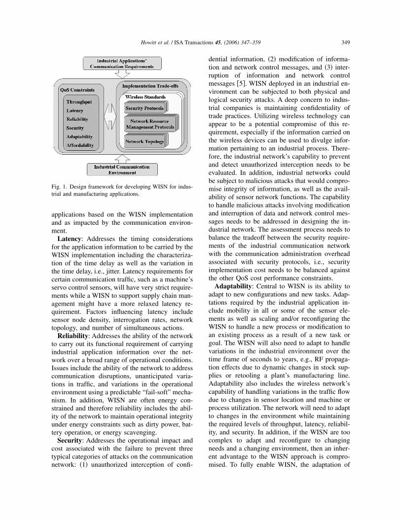
The formulation of a WISN solution for a spe-cific industrial application will need to address thewireless communication design in the context ofthe application as well as in the context of theapplication’s environment, e.g., RF industrial en-vironment. To address these challenges, a designframework for developing WISN is proposed asillustrated in Fig. 1. A measure of effectiveness�MOEs�, in this case QoS, provides a means forevaluating the overall effectiveness �i.e., trade-offanalysis� of a proposed wireless communicationdesign. Correspondingly, measures of perfor-mances �MOPs�—throughput, latency, reliability,security, adaptability, and affordability—representthe aggregate properties that define QoS. TheMOPs/MOEs are based on mapping functionalneeds onto operational requirements and definingmeasurable and quantifiable parameters. A con-struct for assessing QoS in terms of the notionalrelationship between controls and communicationsis presented in Section 4. A brief overview of is-sues associated with industrial RF environment ispresented in Section 3. Details concerning QoSand its associated MOPs are as follows:
Throughput: Addresses the ability of the net-work to carry the offered traffic by the industrial
Table 1WINA charter �2�.
Wireless technology and wireless networking systemshold great promise to help U.S. industry use energy andmaterials more efficiently, lower systems andinfrastructure costs, lower production costs, and increaseproductivity. Although major advances in both price andperformance have occurred in wireless networking, itsacceptance in the industrial sectors has been slow. WINAfocuses on four activities to accelerate the adoption ofwireless technology in the industrial sector.Activity 1: Identify, characterize, recommend, and
certify appropriate wireless technologiesActivity 2: Promote effective standards, regulations,
and practicesActivity 3: Focus on customer requirementsActivity 4: Quantify and communicate the benefits and
potential impacts of wireless technologies.
348 Howitt et al. / ISA Transactions 45, (2006) 347–359
applications based on the WISN implementationand as impacted by the communication environ-ment.
Latency: Addresses the timing considerationsfor the application information to be carried by theWISN implementation including the characteriza-tion of the time delay as well as the variation inthe time delay, i.e., jitter. Latency requirements forcertain communication traffic, such as a machine’sservo control sensors, will have very strict require-ments while a WISN to support supply chain man-agement might have a more relaxed latency re-quirement. Factors influencing latency includesensor node density, interrogation rates, networktopology, and number of simultaneous actions.
Reliability: Addresses the ability of the networkto carry out its functional requirement of carryingindustrial application information over the net-work over a broad range of operational conditions.Issues include the ability of the network to addresscommunication disruptions, unanticipated varia-tions in traffic, and variations in the operationalenvironment using a predictable “fail-soft” mecha-nism. In addition, WISN are often energy con-strained and therefore reliability includes the abil-ity of the network to maintain operational integrityunder energy constraints such as dirty power, bat-tery operation, or energy scavenging.
Security: Addresses the operational impact andcost associated with the failure to prevent threetypical categories of attacks on the communicationnetwork: �1� unauthorized interception of confi-
dential information, �2� modification of informa-tion and network control messages, and �3� inter-ruption of information and network controlmessages �5�. WISN deployed in an industrial en-vironment can be subjected to both physical andlogical security attacks. A deep concern to indus-trial companies is maintaining confidentiality oftrade practices. Utilizing wireless technology canappear to be a potential compromise of this re-quirement, especially if the information carried onthe wireless devices can be used to divulge infor-mation pertaining to an industrial process. There-fore, the industrial network’s capability to preventand detect unauthorized interception needs to beevaluated. In addition, industrial networks couldbe subject to malicious attacks that would compro-mise integrity of information, as well as the avail-ability of sensor network functions. The capabilityto handle malicious attacks involving modificationand interruption of data and network control mes-sages needs to be addressed in designing the in-dustrial network. The assessment process needs tobalance the tradeoff between the security require-ments of the industrial communication networkwith the communication administration overheadassociated with security protocols, i.e., securityimplementation cost needs to be balanced againstthe other QoS cost performance constraints.
Adaptability: Central to WISN is its ability toadapt to new configurations and new tasks. Adap-tations required by the industrial application in-clude mobility in all or some of the sensor ele-ments as well as scaling and/or reconfiguring theWISN to handle a new process or modification toan existing process as a result of a new task orgoal. The WISN will also need to adapt to handlevariations in the industrial environment over thetime frame of seconds to years, e.g., RF propaga-tion effects due to dynamic changes in stock sup-plies or retooling a plant’s manufacturing line.Adaptability also includes the wireless network’scapability of handling variations in the traffic flowdue to changes in sensor location and machine orprocess utilization. The network will need to adaptto changes in the environment while maintainingthe required levels of throughput, latency, reliabil-ity, and security. In addition, if the WISN are toocomplex to adapt and reconfigure to changingneeds and a changing environment, then an inher-ent advantage to the WISN approach is compro-mised. To fully enable WISN, the adaptation of
Fig. 1. Design framework for developing WISN for indus-trial and manufacturing applications.
349Howitt et al. / ISA Transactions 45, (2006) 347–359

the wireless network should be transparent to theend user.
Within the industrial environment, adaptabilityis one true advantage of wireless over wired net-works. Directly interconnecting all neighboringnodes with wiring is too complex and cost-prohibitive. WISN, however, provide low cost andredundant connectivity that can be exploited in thenetwork layer to optimize routing for current con-ditions.
Affordability: Once functionality, operability,and utility are addressed, there will be a need toassess affordability. Affordability in this contextincludes cost of ownership �packaging require-ments, modifications, maintainability, etc.�, imple-mentation costs, replacement and logistics costs,and training and servicing costs as well as the per-unit costs.
3. Wireless industrial environment
Advances in wireless communications over thepast several decades can be attributed, in part, toincorporating the evolving comprehension of theRF channel characteristics into the communicationsystem design. By understanding the RF environ-ment within the industrial environment, the net-work design process and the ability to assess thedesign can be enhanced. In order to characterizethe industrial network’s RF environment, the radiosignal propagation and RF interference sourcesneed to be understood. In the industrial network,the interference sources are comprised of environ-mental noise sources such as certain machines orindustrial processes as well as unintentional inter-ference from other collocated wireless devices. Inaddition, intentionally interference sources may beintroduced to create network vulnerability.
3.1. RF signal propagation
Extensive work is reported in the literature oncharacterizing the radio propagation in indoor en-vironments including industrial sites �6,7�. Under-standing the RF signal propagation is essential fordesigning the WISN to achieve and maintain theQoS constraints.
The reliability of the communication link be-tween a transmitter �Tx� and receiver �Rx� is de-pendent on the environment as well as the wirelessdevices used. As an example, the IEEE 802.11bWLAN specifies a frame error rate of less than 8%
for a received signal of −80 dBm �decibels refer-enced to a milliwatt�. The reliability of a link willdirectly impact the latency and throughput QoSconstraints. The RF signal propagation character-istics will also impact security and adaptabilityQoS constraints. As an example, from a securitypoint of view, understanding the RF signal propa-gation provides insight into the locations at whichWISN communication system can be compro-mised by either intercepted data or malicious at-tacks.
Due to underlying electromagnetic propagationmechanisms, RF signal propagation has a naturaldichotomy for characterizing its behavior: large-scale propagation and multipath fading. Based onan extensive measurement campaign made in fivefactories conducted by Rappaport �7�, large-scalepropagation for WISN is well modeled by a log-normal shadowing model,
PR�d� = EIRP + GR + 10n log10� �
4�d�
+ X� �dBm� , �1�
where PR�d� is the received power in dBm at adistance of d from the transmitter, EIRP is thetransmitter’s effective isotropic radiated power indBm, GR is the receiver’s antenna gain �dB� in thedirection of the signal propagation, n is the pathloss exponent, � is the wavelength of the carrier,and X� is a zero mean normal distributed randomvariable �RV� with standard deviation �. Since X�
is zero mean, the sum of the first three terms inEq. �1� represents the expected value of PR�d� andthe received power is inversely proportional to thelog of the distance where n is the proportionalityconstant. The RV X� models the variations in thereceived signal strength due to the variations in theobstructions between the transmitter and receiver,i.e., walls, inventory storage racks, and machinery.In �7�, based on a least-square error fit to the entireensemble of data collected from the factories, n=2.2 and �=7.9 dB. For individual measurementcampaigns, typical values of n ranged from 1.8 to2.8 and � ranged from 4 to 10 dB. Fig. 2 illus-trates the received signal power as a function ofdistance based on n=2.2 and �=7.9 dB, and us-ing typical values for IEEE 802.11b operating at2.4 GHz �EIRP=20 dBm, GR=0 dB�. In the fig-ure, the shaded region represents plus and minusone sigma about the mean. Since X� is normal
350 Howitt et al. / ISA Transactions 45, (2006) 347–359

distribution in dB, the likelihood of the receivedsignal occurring within the shaded region for agiven distance is 68%.
Multipath fading is another important consider-ation when characterizing the industrial environ-ment’s RF signal propagation. Multipath fading iscaused by multiple reflections of the transmittedsignal arriving at the receiver. These reflectionsrepresent different wave fronts that have traveledthrough different paths and therefore are time de-layed and phase shifted versions of the originaltransmission. The received signal is the vectorsum of these signals. Different methods can beemployed to counter the effects of multipath fad-ing. One of the most straightforward methods is touse a received signal fade margin when determin-ing the coverage range for a transmitted signal.The required fade margin can be on the order of30 dB in an obstructed environment. This wouldimply using −50 dBm as the receiver sensitivityfor the WLAN. The impact of the industrial envi-ronment on the reliable coverage range is substan-tial, as illustrated in Fig. 2.
3.2. RF interference
RF interference occurs when the detection of thedesired signal is corrupted by another signal at theintended receiver �8�. Based on current unlicensed�UL� band wireless protocols, data are transmittedbased on packet transmissions. A corrupted packetis detected at the receiver and a retransmission is
often initiated. The impact of a corrupted signalwill be dependent on the data stream affected andthe underlying application. In order for the desiredsignal to be corrupted, the interference signal mustoccur at the same time, frequency, and with suffi-cient power. There are two potential unintentionalinterference sources within the WISN: �1� wirelesscommunication networks operating in the samefrequency band whose operations are uncoordi-nated, �2� industrial equipment which produces RFharmonics within the communications network’sfrequency band.
Since the wireless technologies being consid-ered for the WISN operate in the UL bands, thepotential for interference exists between variouswireless networks operating adjacent to each otheror between the various hierarchical communica-tion layers that are implemented using differentwireless technologies. Methods for evaluating anddesigning networks that decrease the likelihood ofinterference between UL band wireless technolo-gies are presented in �8�.
Certain machine tools are potential sources ofinterference unique to the industrial environment.These interference sources include arc welders,power electronics, and induction motors. Anec-dotal evidence indicates these sources of interfer-ence may be of concern, even though limited em-pirical data from the literature would suggestotherwise. In �7�, interference from industrialnoise sources is indicated to be insignificant for
Fig. 2. Received signal power vs distance based on typical values for WLAN operating in a typical industrial environment.
351Howitt et al. / ISA Transactions 45, (2006) 347–359

communication systems operating above 1 or1.6 GHz when measurements were made at dis-tances in excess of four meters from the noisesources. In order to ensure the reliability of thenetwork operation, more details are required onthe characteristics of these interference sourcesand their impact on QoS. This is especially truefor WISN, where wireless devices may operatewithin a meter or less of interference sources.
RF interference can also be from intentional in-terference sources, which can take on differentlevels of sophistication, from denial of service at-tacks to intentional spoofing. A general discussionconcerning intentional interference and cyber at-tacks goes beyond the scope of this paper.
4. Assessing QoS requirements: Interactionbetween controls and communications
Determining the QoS constraints for the WISNcan be a daunting task. The application domainexperts often do not understand the terminologyand concerns of the wireless communications &networking experts and vice versa. In addition, thedegree of reliability required by the communica-tion network based on the industrial application isoften not well understood or characterized. Bothof these issues can be addressed by evaluating theWISN QoS requirements within the context of anindustrial controls problem and examining the in-teraction principles between the two. The ap-proach can be applied to a wide array of industrialapplications and is directly applicable to industrialcontrol processes in which the WISN is used tosupport sensing and/or actuator componentswithin the processes. It is also applicable for
WISNs used to support supply chain managementthat can also be viewed as a control process.
4.1. Interrelationship between process control &communications
The performance of communication links canhave a major impact on process control systems.The relationship between the control and commu-nications is illustrated in Fig. 3. The dotted lineencompasses a notional model of a process controlloop. The outer loop denotes the role of a commu-nication network in ordering system stability. Theloops contain the typical elements of a feedbackcontrol system where L is the target load, P & Cdenote the process and respective control, and H1
is the feedback transfer function. In this notionalconstruct H2 represents the transfer function of thewireless communication network used for processand information feedback. The purpose of the con-trol system is to effectively manage and controlthe system variables �i.e., line frequency� in thepresence of a highly variable and nondeterministicload. To achieve this, the response behavior ofeach system block should be accurately known orpredictable. The existence of the wireless commu-nication network introduces new terms in the sta-bility equation. The behavior of the communica-tion network and its impact on a stable system’soperation needs to be understood and quantified togenerate the bounded limits for the system’s stablestate operation.
The transfer function of the inner control loop,i.e., the existing process control loop, can be de-rived as
Fig. 3. A typical block diagram illustrating interrelationship between process control and wireless communication network ina feedback loop.
352 Howitt et al. / ISA Transactions 45, (2006) 347–359

�1�s��2�s�
=C�s�P�s�
1 + H1�s�C�s�P�s�, �2�
where �1�s� and �2�s� are the output and input ofthe process control loop, respectively. The transferfunction of the entire system is
�2�s�I�s�
=L�s�C�s�P�s�
1 + H1�s�C�s�P�s� + H2�s�L�s�C�s�P�s�.
�3�
The communications network introduces a newterm in the stability equation: H2LCP. This termrepresents the cross-coupling between the processcontrol inner loop and the communication networkand indicates the complexity of the interdepen-dence between the process control and communi-cation.
Clearly the communications infrastructure mustsupport the real-time transactions occurring at alllevels in the control architecture. The conse-quences of communication problems like unpre-dictable latencies, excessive drops in throughput atcritical times, and link flooding due to intentionaland unintentional intervention from “outsiders”coupled with load uncertainties will affect theoverall system stability and must be evaluatedagainst the “ideal” performance. The scale and thecriticality of the network demands for a priori er-ror estimates between the intrinsic or quoted QoSand the actual perceived QoS need to be studiedand understood. Since the communication infra-structure overlaid is a measurement and controlnetwork, end-to-end performance guarantees to di-rectly affect the control system stability.
4.2. Example problem: Variability in wirelessnetwork latency
A first-order feedback control system is used todemonstrate the effect of latency in the feedbackloop. Fig. 4�a� shows the transfer function of thefeedback control loop described in Fig. 3. Theouter loop �WISN� is the wireless industrial com-munication network. A transport delay of 0.01 s isintroduced in the inner feedback loop. The vari-able parameter is the communication latency inthe outer loop. Figs. 4�b�–4�d� show the outputbehavior for zero latency, fixed latency, and ran-domly variable latency, respectively. This shows
the effect on system stability as the communica-tion network model progresses from being predict-able to highly variable.
5. Wireless industrial network QoS: A controlsparadigm
5.1. Overview
As presented in the previous sections, if an in-dustrial site incorporates a wireless network forindustrial processing, the application requirementswill define the network’s QoS constraints. QoShas often been perceived as a quoted parameter ofa particular network, but not as a real-time mea-surable or quantifiable parameter. Work has beenconducted on defining the QoS for individual ar-chitectural layers, but less attention has been spenton a framework for ensuring that the application’srequired QoS constraints are being satisfied. If thenetwork is responsive, intelligent enough to under-stand the QoS requirements of the application, andable to adaptively adjust accordingly, then the usercan be assured a certain QoS performance level ismaintained within the bounds of operational per-formance requirements. This can be done by de-veloping methodologies to measure and quantifythe parameters affecting the QoS and providethem as feedback to the application using the net-work. This is vital in developing next-generationnetworks for industrial control and monitoring ap-plications.
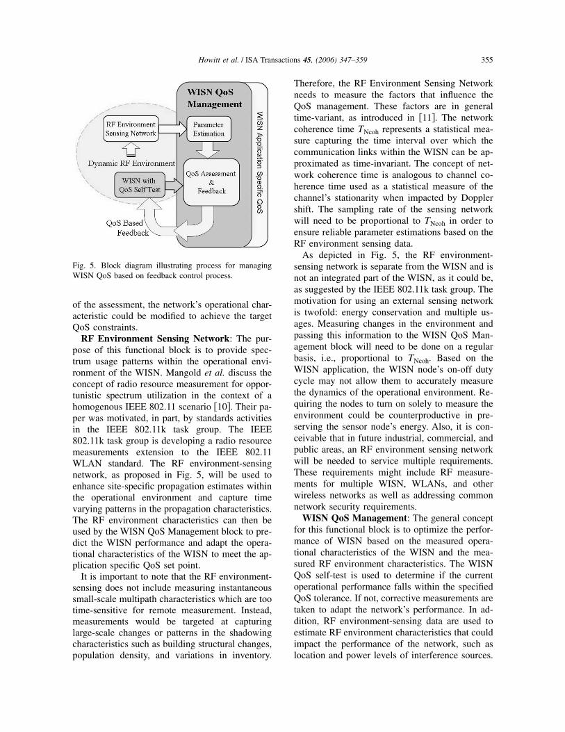
The approach presented is similar in scope tothe approach presented by Li and Nahrstedt forapplication-aware QoS adaptation �9�. Fig. 5 pre-sents a block diagram representing a generalframework for assessing and dynamically manag-ing, i.e., controlling, the WISN in order to drivethe observable QoS performance to the applicationdefined target QoS. The figure illustrates both themajor functional components and the informationflow to accomplish the QoS management frame-work. The major functional blocks described are:
• WISN with QoS Self Test,• RF Environment Sensing Network, and• WISN QoS Management.
WISN with QoS Self-Test: The WISN areimplemented to perform a set of applicationswhich may change over time and which have de-fined QoS constraints. The WISN are comprisedof hardware/software that enables specific capa-
353Howitt et al. / ISA Transactions 45, (2006) 347–359

bilities, i.e., operational frequency bands, fre-quency agility, power control, routing algorithms�for multihop networks�, and scheduling algo-rithms. In addition, the WISN operate within a dy-namic RF environment comprising time varyingco-channel interference sources and time varyingRF propagation characteristic such as multipath.
Even if the WISN nodes are at fixed locations,dynamics in the environment will significantly im-pact the RF propagation characteristics. By incor-porating a QoS self-test within the WISN, theWISN management functional block can readilytest the observable QoS parameters and assess thenetworks performance. Depending on the outcome
Fig. 4. Example illustrating the effect of variability in wireless communication network latency on the overall process control:�a� Block diagram of control process with wireless sensor network in feedback loop; �b� WISN is modeled as ideal, nolatency; �c� WISN is modeled with fixed latency; �d� WISN is modeled with variable latency where variability is based on auniform distribution.
354 Howitt et al. / ISA Transactions 45, (2006) 347–359
of the assessment, the network’s operational char-acteristic could be modified to achieve the targetQoS constraints.
RF Environment Sensing Network: The pur-pose of this functional block is to provide spec-trum usage patterns within the operational envi-ronment of the WISN. Mangold et al. discuss theconcept of radio resource measurement for oppor-tunistic spectrum utilization in the context of ahomogenous IEEE 802.11 scenario �10�. Their pa-per was motivated, in part, by standards activitiesin the IEEE 802.11k task group. The IEEE802.11k task group is developing a radio resourcemeasurements extension to the IEEE 802.11WLAN standard. The RF environment-sensingnetwork, as proposed in Fig. 5, will be used toenhance site-specific propagation estimates withinthe operational environment and capture timevarying patterns in the propagation characteristics.The RF environment characteristics can then beused by the WISN QoS Management block to pre-dict the WISN performance and adapt the opera-tional characteristics of the WISN to meet the ap-plication specific QoS set point.
It is important to note that the RF environment-sensing does not include measuring instantaneoussmall-scale multipath characteristics which are tootime-sensitive for remote measurement. Instead,measurements would be targeted at capturinglarge-scale changes or patterns in the shadowingcharacteristics such as building structural changes,population density, and variations in inventory.
Therefore, the RF Environment Sensing Networkneeds to measure the factors that influence theQoS management. These factors are in generaltime-variant, as introduced in �11�. The networkcoherence time TNcoh represents a statistical mea-sure capturing the time interval over which thecommunication links within the WISN can be ap-proximated as time-invariant. The concept of net-work coherence time is analogous to channel co-herence time used as a statistical measure of thechannel’s stationarity when impacted by Dopplershift. The sampling rate of the sensing networkwill need to be proportional to TNcoh in order toensure reliable parameter estimations based on theRF environment sensing data.
As depicted in Fig. 5, the RF environment-sensing network is separate from the WISN and isnot an integrated part of the WISN, as it could be,as suggested by the IEEE 802.11k task group. Themotivation for using an external sensing networkis twofold: energy conservation and multiple us-ages. Measuring changes in the environment andpassing this information to the WISN QoS Man-agement block will need to be done on a regularbasis, i.e., proportional to TNcoh. Based on theWISN application, the WISN node’s on-off dutycycle may not allow them to accurately measurethe dynamics of the operational environment. Re-quiring the nodes to turn on solely to measure theenvironment could be counterproductive in pre-serving the sensor node’s energy. Also, it is con-ceivable that in future industrial, commercial, andpublic areas, an RF environment sensing networkwill be needed to service multiple requirements.These requirements might include RF measure-ments for multiple WISN, WLANs, and otherwireless networks as well as addressing commonnetwork security requirements.
WISN QoS Management: The general conceptfor this functional block is to optimize the perfor-mance of WISN based on the measured opera-tional characteristics of the WISN and the mea-sured RF environment characteristics. The WISNQoS self-test is used to determine if the currentoperational performance falls within the specifiedQoS tolerance. If not, corrective measurements aretaken to adapt the network’s performance. In ad-dition, RF environment-sensing data are used toestimate RF environment characteristics that couldimpact the performance of the network, such aslocation and power levels of interference sources.
Fig. 5. Block diagram illustrating process for managingWISN QoS based on feedback control process.
355Howitt et al. / ISA Transactions 45, (2006) 347–359
This characterization can then be used to predictperformance impact on the WISN, and the WISNcan apply corrective measures to prevent the QoSfrom falling below the desired tolerance levels.
As depicted in Fig. 5, optimization could beconducted at a central location and the operationalchanges are downloaded to the network. An im-portant constraint for this functional block is thatupdating the WISN needs to be cost-effective, e.g.,if the sensor nodes in the WISN are energy-constrained, then the energy cost required for up-dating the network needs to be less than the en-ergy savings obtained by the performanceimprovement achieved by the update. Even thoughthe WISN QoS Management is depicted as a cen-tralized process, a distributed version of the pro-cess is not precluded and could provide a moreefficient approach for certain WISN implementa-tions.
5.2. Example WISN QoS management in aninterference environment
The following example illustrates the WISNQoS Management strategy for providing dynamicQoS control within WISN. The example focuseson WISN operating in a time varying RF interfer-ence environment. The goal of the example is toillustrate the interaction between wireless tech-nologies, RF environment, application based QoSrequirement, and the QoS management.
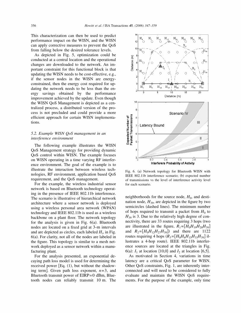
For the example, the wireless industrial sensornetwork is based on Bluetooth technology operat-ing in the presence of IEEE 802.11b interference.The scenario is illustrative of hierarchical networkarchitecture where a sensor network is deployedusing a wireless personal area network �WPAN�technology and IEEE 802.11b is used as a wirelessbackbone on a plant floor. The network topologyfor the analysis is given in Fig. 6�a�. Bluetoothnodes are located on a fixed grid at 3-m intervalsand are depicted as circles, each labeled Hi, in Fig.6�a�. For clarity, not all of the nodes are labeled inthe figure. This topology is similar to a mesh net-work deployed as a sensor network within a manu-facturing plant.
For the analysis presented, an exponential de-caying path loss model is used for determining thereceived power �Eq. �1�, but without the shadow-ing term�. Given path loss exponent, n=3, andBluetooth transmit power of EIRP=0 dBm, Blue-tooth nodes can reliably transmit 10 m. The
neighborhoods for the source node, H0, and desti-nation node, H39, are depicted in the figure by twosemicircles �dashed lines�. The minimum numberof hops required to transmit a packet from H0 toH39 is 3. Due to the relatively high degree of con-nectivity, there are 33 routes requiring 3 hops �twoare illustrated in the figure, R1= �H0H19H20H39�and R2= �H0H12H27H39�� and there are 1122routes requiring 4 hops �R3= �H0H6H15H33H39� il-lustrates a 4-hop route�. IEEE 802.11b interfer-ence sources are located at the triangles in Fig.6�a�: I1 at location �10,0� and I2 at location �6,5�.
As motivated in Section 4, variations in timelatency are a critical QoS parameter for WISN.Other QoS constraints, Fig. 1, are inherently inter-connected and will need to be considered to fullyevaluate and maintain the WISN QoS require-ments. For the purpose of the example, only time
Fig. 6. �a� Network topology for Bluetooth WISN withIEEE 802.11b interference scenario; �b� expected numberof transmissions vs the level of interference activity levelfor each scenario.
356 Howitt et al. / ISA Transactions 45, (2006) 347–359

latency will be considered where the latency isbased on the time required to multihop the controlmessage from H0 to H39. Due to the time varyingcharacteristics of the interference sources, differ-ent routes through the network will provide im-proved end-to-end QoS performance, i.e., reducedlatency and reduced variability in the latency. Toillustrate, four scenarios are considered whereeach scenario examines a different number of in-terference sources. The scenarios are defined asfollows:
• Scenario I: One IEEE 802.11b interferencesource at I1,
• Scenario II: Two IEEE 802.11b interferencesources—one at I1 and one at I2,
• Scenario III: Three IEEE 802.11b interferencesources—two at I1 and one at I2,
• Scenario IV: Four IEEE 802.11b interferencesources—three at I1 and one at I2.
For Scenarios II through IV, the interferencesource at I1 is representative of an IEEE 802.11baccess point with multiple transceivers operatingin different frequency bands and utilizing a com-mon antenna. Independence is assumed betweenthe multiple interference sources.
The latency in transmitting the control messageis directly related to the expected number of re-transmissions required for the message to be suc-
cessfully transmitted over a given route, N̄Tx�Ri�.As an example for R1,
N̄Tx�R1� = N̄Tx�H0,H19� + N̄Tx�H19,H20�
+ N̄Tx�H20,H39� , �4�
where N̄Tx�Hi ,Hj� is the expected number oftransmissions to successfully transmit a messagefrom node Hi to node Hj. Due to interference,each hop is susceptible to requiring one or moreretransmissions. The likelihood of retransmissionis based on the collision probability, i.e., the prob-ability the Bluetooth packet will need to be re-transmitted due to IEEE 802.11b interference �12�.For the purposes of this discussion, a key param-eter in determining the collision probability is thelikelihood an interference source is active, Pr�Ak�.The probability of activity for the interferencesources would be monitored by the rfenvironment-sensing network and used to estab-lish a QoS management policy to be used by the
WISN. The details concerning how the QoS man-agement policy would be implemented are beyondthe scope of the current discussion.
The impact on the WISN transmission latencywas evaluated to illustrate the utility of QoS man-
agement. For each scenario, N̄Tx�Ri� was evaluatedfor all possible routes Ri of hop length three andfour. For each scenario, the probability of activitywas varied in order to examine the effect of inter-ference on the number of transmissions. In orderto simplify the display of the results, all interfer-ence sources are at the same level of activity,Pr�A�=Pr�Ak�∀k. Results are depicted in Fig.6�b�, where the graphs represent the spread in theexpected number of packet transmissions requiredto multihop a single packet from the source to thesink. For the majority of the scenarios and inter-ference levels, route R1 is the worst 3-hop route,the one requiring the maximum number of ex-pected retransmissions and therefore the greatestlatency. The reason for this is the interferencesources located at I1 cause Bluetooth transmis-sions from H0 to H19 to be susceptible to colli-sions and, therefore, a higher retransmission rate.In addition, the Bluetooth transmissions from H19to H20 are also susceptible to collisions, but at alower rate. For Scenario I, the lowest latency routeis R2, and for Scenario II, the lowest latency routechanges from R2 to �H0H9H20H39�. This is due tothe introduction of the interference source at I2. Asthe number of interference sources increases at lo-cation I1, the lowest latency route changes from a3-hop to a 4-hop route, i.e., R3.
For the purpose of the example, the expectednumber of packet transmissions should be lessthan six, shown in Fig. 6�b�. The latency bound isobtained by considering the impact of the varia-tion of the communication latency in conjunctionwith the effect on the process control governed bythe industrial application, presented in Section 4.Therefore, given that the RF environment-sensingnetwork detects activity from a single interfererlocated at I1, the WISN should operate within theQoS tolerance without intervention from theWISN QoS Management. This prediction is sub-stantiated by running a QoS self-test within theWISN to verify the self-test results are consistentwith the predicted time latency results estimatedby the WISN QoS Management. At the other ex-treme, if Scenario IV is detected then, based onthe estimated interference activity levels, certain
357Howitt et al. / ISA Transactions 45, (2006) 347–359

routes within the WISN should be eliminated fromconsideration in order to ensure the required QoS.Given Scenario IV with activity levels in access of60% would require additional intervention. Thiscould be handled by establishing an activity usagepolicy within the IEEE 802.11b network or, if thisis not feasible, additional measures would need tobe taken within the WISN network to improve thelatency.
6. Conclusions
Wireless communications is poised to supporttechnical innovations in the industrial communitywith the widespread use of wireless sensors pro-viding economic benefits to industrial end users.In addition to this, societal benefits will evolvethrough reduced emissions and energy consump-tion. In order to facilitate the wireless communi-cation supplier and end user community in achiev-ing a successful WISN solution, an integratedframework is presented for designing the WISN.As detailed above, the framework can be summa-rized by three essential components:
QoS Definition: QoS is the central measure ofeffectiveness in both the design evaluation in de-veloping the WISN solution and the maintenanceof the implemented WISN. A broad definition isapplied in defining the MOPs used in characteriz-ing the QoS requirements: throughput, latency, re-liability, security, adaptability, and affordability.These MOPs can then be used to define measur-able and quantifiable parameters based on map-ping functional needs onto operational require-ments.
QoS Assessment: A framework for definingmeasurable and quantifiable parameters for theQoS provides both a context for application do-main and communication experts to address theQoS requirements as well as a method for estimat-ing these requirements. As presented in this ar-ticle, control theory can provide such a frameworkin which the interdependence between the indus-trial control process and communication networkcan be evaluated and bounds on the communica-tion requirements can be established.
QoS Management: The time varying and harshcharacteristics of the industrial RF environment inconjunction with the need to maintain the QoSrequirements established for the industrial applica-tion dictates the need for a control’s paradigm forQoS management. As presented in this article, the
paradigm involves a feedback loop based on theWISN QoS self-test to actively manage the QoS.Due to the nature of the industrial RF environmentand the network coherence time, the WISN self-test data are augmented with an external RFenvironment-sensing network. The RF environ-ment characteristics can then be used by the WISNQoS Management block to predict the WISN per-formance and adapt the operational characteristicsof the WISN to meet the application specific QoSset point.
References
�1� Industrial Wireless Technology for the 21st Century.U.S. DOE Office of Energy Efficiency and RenewableEnergy, http://www.oit.doe.gov/sens_cont/pdfs/wireless_technology.pdf, December 2002.
�2� Wireless Industrial Networking Alliance �WINA�.http://www.wina.org.
�3� Weaver, A. C., Survey of industrial information tech-nology. Proceedings of IECON’01, 2001, pp. 2056–2061.
�4� Wiberg, P.-A. and Bilstrup, U., Wireless technology inindustry—Applications and user scenarios. Proc. ofETFA, 2001, pp. 123–131.
�5� Perrig, A., Stankovic, J., and Wagner, D., Security inwireless sensor networks. Commun. ACM 47�6�,53–57 �2004�.
�6� Kjesbu, S. and Brunsvik, T., Radio wave propagationin industrial environments. Proc. of IECON, 2000, 4,pp. 2425–2430.
�7� Rappaport, T., Characterization of UHF multipath ra-dio channels in factory buildings. IEEE Trans. Anten-nas Propag. 37, 1058–1069 �1989�.
�8� Howitt, I., WLAN and WPAN Coexistence in ULBand. IEEE Trans. Veh. Technol. 50, 1114–1124�2001�.
�9� Li, B. and Nahrstedt, K., A control-based middlewareframework for quality of service adaptations. IEEE J.Sel. Areas Commun. 17�9�, 1632–1650 �1999�.
�10� Mangold, S., Zhong, Z., Challapali, K., and Chou, C.T., Spectrum agile radio: Radio resource measure-ments for opportunistic spectrum usage. Proc. ofGlobComm 04, pp. 3467–3471.
�11� Landry, R., Grace, K., and Saidi, A., On the designand management of heterogeneous networks: Apredictability-based perspective. IEEE Commun. Mag.42�11�, 80–87 �2004�.
�12� Howitt, I., Bluetooth performance in the presence of802.11b WLAN. IEEE Trans. Veh. Technol. 51, 1640–1651 �2002�.
358 Howitt et al. / ISA Transactions 45, (2006) 347–359

Ivan Howitt Dr. Howitt receivedthe BEE and MSEE from GeorgiaInstitute of Technology in 1982and 1990, respectively, and thePh.D. degree in electrical engi-neering from University of Cali-fornia, Davis in 1995. He hasworked as a Research Engineerwith Georgia Tech Research Insti-tute, a Visiting Assistant Professorat Virginia Tech, and an AssistantProfessor at the University ofWisconsin, Milwaukee. In 2002,he joined the Department of Elec-
trical & Computer Engineering, University of North Carolina atCharlotte as an Associate Professor. His research interests includeinteroperability issues facing UL band wireless services, methodsfor mitigating interference, and approaches for optimizing wirelessnetwork performance.
Wayne W. Manges Mr. Mangescurrently directs the U.S. Depart-ment of Energy’s Industrial Wire-less Program at ORNL focusingon the needs of the hard industriesfrom DOE’s Industrial Technolo-gies Program. With 28 years atOak Ridge National Lab, Wayneworks extensively with steel, pa-per, and other industries to bringrobust, wireless technology totheir markets. He has been de-clared a visionary for his earlyviews on wireless applications
and has published and presented papers around the world and con-tinues as a contributing editor for Sensors Magazine. He holdsdegrees from California University of Pennsylvania, University ofPittsburgh, Rensselaer Polytechnic Institute, and University ofTennessee.
Phani Teja Kuruganti Mr. Kuru-ganti received his MS degree inElectrical Engineering from theUniversity of Tennessee, Knox-ville in 2003, and a BE in Elec-tronics and Communication Engi-neering from Osmania University,Hyderabad in 2001. He is now aresearch engineer at Oak RidgeNational Laboratory, Oak Ridge,TN. His current research interestsare industrial wireless communi-cations, collaborative signal andinformation processing in sensor
networks, and large scale hi-fidelity modeling and simulation.
Glenn O. Allgood Dr. Allgood isa Distinguished Researcher atOak Ridge National Laboratoryand is a member of the Modelingand Simulation Group in theComputational Science and Engi-neering Division. He has over35 years experience in technologyapplication and R&D that coversprivate industry, the military, aca-demia, and the U.S. Government.He has over 125 articles, papers,and publication in areas such asfinite element modeling, human
factors, advance control, wireless systems, and cognition and com-plex systems, and has over 10 patents and invention disclosures.His current research interests are R&D economics and the study ofcomplex systems and their emergent behaviors.
José A. Gutierrez Dr. Gutierrezis the Technology Manager of theEmbedded Systems and Commu-nications Department of the Inno-vation Center at Eaton Corp. Hisscientific focus is in the field ofembedded systems and wirelessnetworking design for commer-cial and industrial applications.He is the chief technical editor ofthe IEEE 802.15.4 standard andformer Program Manager of theZigbee Alliance. In addition, he isa member of the board of direc-
tors and technical chairman of the Wireless Industrial NetworkAlliance. Dr. Gutierrez has over 20 publications related to embed-ded wireless networking, artificial intelligence, automatic control,and robotic vision, including a book on low-rate wireless personalarea networks.
James M. Conrad Dr. Conrad re-ceived his bachelor’s degree incomputer science from the Uni-versity of Illinois, Urbana, and hismaster’s and doctorate degrees incomputer engineering from NorthCarolina State University. He iscurrently an associate professor atthe University of North Carolinaat Charlotte. He has served as anassistant professor at the Univer-sity of Arkansas and as an instruc-tor at North Carolina State Uni-versity. He has also worked at
IBM and Ericsson/Sony Ericsson. He is the author of numerousbooks, book chapters, journal articles, and conference papers in theareas of robotics, embedded systems, and wirelesscommunications.
359Howitt et al. / ISA Transactions 45, (2006) 347–359