Dynamic Power Management in Wireless Sensor Networks
11
1518 IEEE SENSORS JOURNAL, VOL. 12, NO. 5, MAY 2012 Dynamic Power Management in Wireless Sensor Networks: State-of-the-Art Waltenegus Dargie, Member, IEEE Abstract—In the last few years, interest in wireless sensor net- works has increased considerably. These networks can be useful for a large number of applications, including habitat monitoring, structural health monitoring, pipeline monitoring, transportation, precision agriculture, supply chain management, and many more. Typically, a wireless sensor network consists of a large number of simple nodes which operate with exhaustible batteries, unattended. Manual replacement or recharging the batteries is not an easy or desirable task. Hence, how energy is utilized by the various hard- ware subsystems of individual nodes directly affects the scope and usefulness of the entire network. This paper provides a comprehen- sive assessment of state-of-the-art of dynamic power management (DPM) in wireless sensor networks. It investigates aspects of power dissipation in a node and analyses the strength and limitations of selective switching, dynamic frequency, and voltage scaling. Index Terms—Clock gating, dynamic frequency scaling, dy- namic power management, dynamic voltage scaling, embedded systems, power gating, selective switching, wireless sensor net- works. I. INTRODUCTION W IRELESS sensor networks are one of the technolo- gies that are gaining a considerable attention. They have been deployed to monitor the activities of animals and plants whose behavioural patterns or distributions can easily be affected by human presence [19]; to inspect the structural integrity of bridges and buildings [18], [33] as well as of pipelines [26]; to capture the presence and extent of active volcanoes [32]. Likewise, in precision agriculture, they have been used to monitor soil moisture, radiation, pH, and humidity [7], [6]. Other applications include healthcare [29] and supply chain management [20]. Typically, a wireless sensor network consists of a large number of nodes each of which integrates one or more sensors, a processing subsystem and a short range transceiver. The nodes are capable of organizing themselves to establish and maintain a network and carry out reliable sensing. However, when considered individually, each node is a simple device; the components that make up its subsystems are commonplace, off-the-shelf components. Ideally, the network should have a Manuscript received May 03, 2011; revised September 28, 2011; accepted October 18, 2011. Date of publication October 28, 2011; date of current version April 13, 2012. The associate editor coordinating the review of this paper and approving it for publication was Prof. Tianhong Cui. The author is with the Chair of Computer Networks, Faculty of Computer Science, Technical University of Dresden, 01062 Dresden, Germany (e-mail: [email protected]). Color versions of one or more of the figures in this paper are available online at http://ieeexplore.ieee.org. Digital Object Identifier 10.1109/JSEN.2011.2174149 long life and operate unattended, but several factors put a limit to the energy source: 1) Considering the complexity of the task for which they are deployed – namely, sensing, processing, and communica- tion –, the nodes are very small in size to accommodate high capacity batteries. 2) Given the size of the network and its deployment setting, manually replacing or recharging batteries on a periodic basis is a formidable challenge. 3) Whereas research is being conducted to employ renewable energy and self-recharging mechanisms, still the size of presently available nodes makes the task difficult. 4) The failure of a few number of nodes may fragment the entire network prematurely. The problem of power consumption has been addressed in two different ways in the literature. In the first, a large number of energy-efficient communication protocols – most significantly, MAC, routing and self-organization protocols – that take the peculiarities of wireless sensor networks into ac- count have been proposed. In the second, local dynamic power management (DPM) strategies are developed to recognize and minimize the impact of wasteful and inefficient activities within an individual node. Wasteful and inefficient activities can be accidental side-ef- fects or results of non-optimal software and hardware config- urations. For example field observations revealed that some nodes exhausted their batteries prematurely because of unex- pected overhearing of traffic that caused the communication subsystem to become active for a time longer than originally anticipated [17]. Similarly, some nodes exhausted their batteries prematurely because they aimlessly attempted to establish links with a network that has become no longer accessible to them. Most of the time, however, inefficient power consumption re- sults due to not-optimal configurations in hardware and soft- ware components. For example, a considerable amount of power can be dissipated in an idle processing or communication sub- system. Similarly, a receiver that aimlessly receives packets that are not destined to it; or overhears while neighboring nodes communicate with each other consumes a significant amount of power. A local DPM strategy ensures that such wasteful activities are avoided and power is consumed frugally. Ideally, it provides each subsystem of a node with the amount of power that is suf- ficient enough to carry out a task at hand. When there is no task to be processed or executed, it forces the subsystem to operate at the most economical power mode or turns it off altogether. There has been a considerable interest in the past, and as a consequence, a significant body of work, in dynamic power management, particularly, in the context of embedded systems. But wireless sensor networks bring their own challenges and 1530-437X/$26.00 © 2011 IEEE
Transcript of Dynamic Power Management in Wireless Sensor Networks

1518 IEEE SENSORS JOURNAL, VOL. 12, NO. 5, MAY 2012
Dynamic Power Management in Wireless SensorNetworks: State-of-the-Art
Waltenegus Dargie, Member, IEEE
Abstract—In the last few years, interest in wireless sensor net-works has increased considerably. These networks can be usefulfor a large number of applications, including habitat monitoring,structural health monitoring, pipeline monitoring, transportation,precision agriculture, supply chain management, and many more.Typically, a wireless sensor network consists of a large number ofsimple nodes which operate with exhaustible batteries, unattended.Manual replacement or recharging the batteries is not an easy ordesirable task. Hence, how energy is utilized by the various hard-ware subsystems of individual nodes directly affects the scope andusefulness of the entire network. This paper provides a comprehen-sive assessment of state-of-the-art of dynamic power management(DPM) in wireless sensor networks. It investigates aspects of powerdissipation in a node and analyses the strength and limitations ofselective switching, dynamic frequency, and voltage scaling.
Index Terms—Clock gating, dynamic frequency scaling, dy-namic power management, dynamic voltage scaling, embeddedsystems, power gating, selective switching, wireless sensor net-works.
I. INTRODUCTION
W IRELESS sensor networks are one of the technolo-gies that are gaining a considerable attention. They
have been deployed to monitor the activities of animals andplants whose behavioural patterns or distributions can easilybe affected by human presence [19]; to inspect the structuralintegrity of bridges and buildings [18], [33] as well as ofpipelines [26]; to capture the presence and extent of activevolcanoes [32]. Likewise, in precision agriculture, they havebeen used to monitor soil moisture, radiation, pH, and humidity[7], [6]. Other applications include healthcare [29] and supplychain management [20].
Typically, a wireless sensor network consists of a largenumber of nodes each of which integrates one or more sensors,a processing subsystem and a short range transceiver. Thenodes are capable of organizing themselves to establish andmaintain a network and carry out reliable sensing. However,when considered individually, each node is a simple device;the components that make up its subsystems are commonplace,off-the-shelf components. Ideally, the network should have a
Manuscript received May 03, 2011; revised September 28, 2011; acceptedOctober 18, 2011. Date of publication October 28, 2011; date of current versionApril 13, 2012. The associate editor coordinating the review of this paper andapproving it for publication was Prof. Tianhong Cui.
The author is with the Chair of Computer Networks, Faculty of ComputerScience, Technical University of Dresden, 01062 Dresden, Germany (e-mail:[email protected]).
Color versions of one or more of the figures in this paper are available onlineat http://ieeexplore.ieee.org.
Digital Object Identifier 10.1109/JSEN.2011.2174149
long life and operate unattended, but several factors put a limitto the energy source:
1) Considering the complexity of the task for which they aredeployed – namely, sensing, processing, and communica-tion –, the nodes are very small in size to accommodatehigh capacity batteries.
2) Given the size of the network and its deployment setting,manually replacing or recharging batteries on a periodicbasis is a formidable challenge.
3) Whereas research is being conducted to employ renewableenergy and self-recharging mechanisms, still the size ofpresently available nodes makes the task difficult.
4) The failure of a few number of nodes may fragment theentire network prematurely.
The problem of power consumption has been addressedin two different ways in the literature. In the first, a largenumber of energy-efficient communication protocols – mostsignificantly, MAC, routing and self-organization protocols –that take the peculiarities of wireless sensor networks into ac-count have been proposed. In the second, local dynamic powermanagement (DPM) strategies are developed to recognize andminimize the impact of wasteful and inefficient activities withinan individual node.
Wasteful and inefficient activities can be accidental side-ef-fects or results of non-optimal software and hardware config-urations. For example field observations revealed that somenodes exhausted their batteries prematurely because of unex-pected overhearing of traffic that caused the communicationsubsystem to become active for a time longer than originallyanticipated [17]. Similarly, some nodes exhausted their batteriesprematurely because they aimlessly attempted to establish linkswith a network that has become no longer accessible to them.
Most of the time, however, inefficient power consumption re-sults due to not-optimal configurations in hardware and soft-ware components. For example, a considerable amount of powercan be dissipated in an idle processing or communication sub-system. Similarly, a receiver that aimlessly receives packets thatare not destined to it; or overhears while neighboring nodescommunicate with each other consumes a significant amount ofpower.
A local DPM strategy ensures that such wasteful activitiesare avoided and power is consumed frugally. Ideally, it provideseach subsystem of a node with the amount of power that is suf-ficient enough to carry out a task at hand. When there is no taskto be processed or executed, it forces the subsystem to operateat the most economical power mode or turns it off altogether.
There has been a considerable interest in the past, and asa consequence, a significant body of work, in dynamic powermanagement, particularly, in the context of embedded systems.But wireless sensor networks bring their own challenges and
1530-437X/$26.00 © 2011 IEEE

DARGIE: DYNAMIC POWER MANAGEMENT IN WIRELESS SENSOR NETWORKS: STATE-OF-THE-ART 1519
Fig. 1. A partial view of the system architecture of a wireless sensor node. The components with gold background are those to which DPM can be applied.
peculiarities into the research field. To begin with, unlike em-bedded systems, which function, by and large, stand-alone, noindividual node is of interest in and of itself. Secondly, a localdecision made by a node can have a global impact. This paper at-tempts to provide a comprehensive insight into aspects of DPMin wireless sensor networks. It presents the challenges, the re-sults that are achieved so far, and some outstanding research is-sues in need of attention.
The remaining part of the paper is organized as follows: InSection II, sources of power dissipation in a wireless sensornode are discussed in detail. In Section III, different DPMstrategies and their side-effects are presented. In Section IV, aconceptual architecture for a DPM is discussed. In Section V,hardware and software prototype implementations of dynamicpower management systems in wireless sensor networks arediscussed. Finally, in Section VI, some outstanding researchissues are discussed and concluding remarks are given.
II. POWER DISSIPATIONS
Power in a sensor node can be inefficiently dissipated for var-ious reasons. Fig. 1 shows four of the main subsystems of a wire-less sensor node, namely, the sensing, memory, processor andcommunication subsystems. Different types of communicationinterfaces (serial buses) interconnect these subsystems, but themost frequently used are the serial peripheral interface (SPI) andthe inter-integrated circuit ( ). A SPI bus is useful for highspeed communication (for example, between the communica-tion and processing subsystems), whereas the half-duplexis suitable for low speed communication (mostly between theADCs of the sensing subsystem and the processing subsystem).
A. Processor Subsystem
At the very low-level, undesirable power dissipation occursdue to various intrinsic leakage components in the CMOS tran-sistors. Some of these are weak inversion, drain-induced bar-rier lowering, gate-induced drain leakage, and gate oxide tun-neling [23]. Finding the right balance between the various tran-sistor design parameters is a formidable challenge; despite re-markable achievements in semi-conductor technologies, there
TABLE INOMINAL CURRENT DRAW OF THE
ATMEGA128L MICROCONTROLLER
are still lossy components. A related source of power dissipa-tion (known as dynamic dissipation power) is the charging anddischarging of load capacitances [2]. This power is quadrati-cally proportional to the DC supply voltage and linearly pro-portional to the operating frequency.1 While decreasing the biasvoltage reduces the dynamic power dissipation, there is a sideeffect to it, however, as it also means that the threshold voltage –the voltage required to turn on the transistor – should also be re-duced, which, in turn, results in a significant amount of leakagecurrent.
Most existing processing subsystems employ microcon-trollers, notably Intel’s StrongARM and Atmel’s AVR. Thesemicrocontrollers enable some of their internal componentsto be turned-off completely when they are idle. For examplethe ATmega128L microcontroller provides six different con-figurations, each of which has a different power dissipationprofile: idle, ADC noise reduction, power save, power down,standby and extended standby. The idle mode stops the CPUwhile allowing the SRAM, Timer/Counters, SPI port and theinterrupt system to continue functioning. The ADC NoiseReduction mode stops the CPU and all I/O modules, exceptthe asynchronous timer and the ADC. The aim is to minimizeswitching noise during ADC conversions. In Power save mode,the asynchronous timer continues to run, allowing the user tomaintain a timer base; the remaining components of the device
1This knowledge is the basis for dynamic frequency and voltage scaling, tobe discussed in Section III-B.
1520 IEEE SENSORS JOURNAL, VOL. 12, NO. 5, MAY 2012
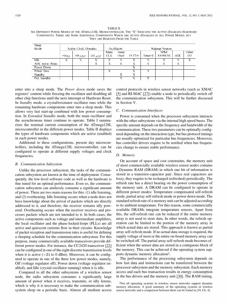
TABLE IISIX DIFFERENT POWER MODES OF THE ATMEGA128L MICROCONTROLLER. THE “X” INDICATES THE ACTIVE (ENABLED) HARDWARE
COMPONENTS. THERE ARE SOME ADDITIONAL COMPONENTS WHICH ARE ACTIVE (ENABLED) IN ALL POWER MODES, BUT
THEY ARE REMOVED FROM THE TABLE
enter into a sleep mode. The Power down mode saves theregisters’ content while freezing the oscillator and disabling allother chip functions until the next interrupt or Hardware Reset.In Standby mode, a crystal/resonator oscillator runs while theremaining hardware components enter into a sleep mode. Thisallows very fast start-up combined with low power consump-tion. In Extended Standby mode, both the main oscillator andthe asynchronous timer continue to operate. Table I summa-rizes the nominal current consumption of the ATmega128Lmicrocontroller in the different power modes. Table II displaysthe types of hardware components which are active (enabled)in each power modes.
Additional to these configurations, present day microcon-trollers, including the ATmega128L microcontroller, can beconfigured to operate at different supply voltages and clockfrequencies.
B. Communication Subsystem
Unlike the processor subsystem, the tasks of the communi-cation subsystem are known at the time of deployment. Conse-quently, the low-level software code as well as the hardware isfine tuned for an optimal performance. Even so, the communi-cation subsystem can aimlessly consume a significant amountof power. There are two main reasons for this: (1) idle listening,and (2) overhearing. Idle listening occurs when a node does nothave knowledge about the arrival of packets which are directlyaddressed to it, and therefore, the receiver remains idly pow-ered. Overhearing occurs when the receiver receives and pro-cesses packets which are not intended to it. In both cases, theactive components such as voltage and intermediate amplifiers,the local oscillator and the phase-locked-loops (PLLs) are allactive and quiescent currents flow in their circuits. Knowledgeof packet reception and transmission rates is useful for defininga sleeping schedule for the communication subsystem. For thispurpose, many commercially available transceivers provide dif-ferent power modes. For instance, the CC2420 transceiver [22]can be configured in one of the eight discrete transmission levelswhen it is active ( to 0 dBm). Moreover, it can be config-ured to operate in one of the three low power modes, namely,Off (voltage regulator off), Power down (voltage regulator en-abled), and Idle (crystal oscillator running) when it is idle.
Compared to all the other subsystems of a wireless sensornode, the radio subsystem consumes a significantly largeamount of power when it receives, transmits, or idly listens,which is why it is necessary to make the communication sub-system sleep on a periodic basis. Almost all medium access
control protocols in wireless sensor networks (such as XMAC[5] and RI-MAC [27]) enable a node to periodically switch offthe communication subsystem. This will be further discussedin Section V.
C. Communication Interfaces
Power is consumed when the processor subsystem interactswith the other subsystems via the internal high speed buses. Thespecific amount depends on the frequency and bandwidth of thecommunication. These two parameters can be optimally config-ured depending on the interaction type, but bus protocol timingsare usually optimized for particular bus frequencies. Moreover,bus controller drivers require to be notified when bus frequen-cies change to ensure stable performance.
D. Memory
On account of space and cost constraints, the memory unitof most commercially available wireless sensor nodes containsa Dynamic RAM (DRAM) in which one bit of information isstored in a transistor-capacitor pair. Since real capacitors arelossy, they require to be recharged (refreshed) periodically. Therefresh rate has a direct bearing on the power consumption ofthe memory unit. A DRAM can be configured to operate indifferent power modes: Temperature compensated self-refreshmode, partial array self-refresh mode or power down mode. Thestandard refresh rate of a memory unit can be adjusted accordingto its ambient temperature. For this reason, some commerciallyavailable DRAMs integrate temperature sensors. Apart fromthis, the self-refresh rate can be reduced if the entire memoryarray is not used to store data. In other words, the refresh op-eration can be limited to the portion of the memory array inwhich actual data are stored. This approach is known as partialarray self-refresh mode. If no actual data storage is required, thesupply voltage of most or the entire on-board memory array canbe switched off. The partial array self-refresh mode becomes ef-ficient when the sensor data are stored in a contiguous block ofthe memory. This can be achieved if the operating system sup-ports dynamic memory allocation2.
The performance of the processing subsystem depends onhow fast data and instructions can be transferred between theprocessor subsystem and the memory subsystem. Each memoryaccess and each bus transaction results in energy consumptionin the bus drivers and the memory unit [30]. The RAM timing,
2Not all operating systems in wireless sensor networks support dynamicmemory allocation. A good summary of the operating systems in wirelesssensor networks and a comparison between them can be found in [10, Ch. 4].

DARGIE: DYNAMIC POWER MANAGEMENT IN WIRELESS SENSOR NETWORKS: STATE-OF-THE-ART 1521
TABLE IIIPARAMETERS OF RAM TIMING
another parameter that influences the power consumption of thememory unit, refers to the latency associated with accessing thememory unit. Before a processor subsystem accesses a partic-ular cell in a memory, it should first determine the particularrow or bank and then activate it with a row access strobe (RAS)signal. Once a row is activated, it can be accessed until the dataare exhausted. The time required to activate a row in a memoryis , which is relatively small but could impact the system’sstability if set incorrectly. A memory cell is activated through acolumn access strobe (CAS). The delay between the activationof a memory cell and the writing of data into or reading of datafrom the cell is given as – it is called RAS to CAS delay.This time can be short or long, depending on how the memory isaccessed. If it is accessed sequentially, it is insignificant, but, ifthe memory is accessed in a random fashion, the current activerow must first be deactivated before a new row is activated, inwhich case, the latency can be considerable.
The delay between the CAS signal and the availability of validdata on the data bus is called CAS Latency. Low CAS latencymeans high performance but also high power consumption. Thetime required to terminate one row access and begin the next rowaccess is . In conjunction with , the time (or clock cy-cles) required to switch banks (rows) and select the next cell forreading, writing, or refreshing is expressed as . Theduration of time required between the active and precharge com-mands is called . It is a measure of how long the processormust wait before the next memory access begins. Table III sum-marizes the quantities that express RAM timing.
Besides how memory is accessed, several decode and mul-tiplex (switching) stages have to be passed through the bus tomove data from the memory unit to the processing subsystemand vice versa [30]. The dynamic power consumption of thememory unit depends on the rate at which the decoding and mul-tiplexing operations take place.
E. Power Subsystem
The power subsystem supplies DC voltage to all the othersubsystems and consists of a battery and a DC-DC converter,among other things. The DC-DC converter is responsible forproviding the right amount of supply voltage to each individualhardware component by transforming the main DC supplyvoltage into a suitable level. The transformation can be astep-down (buck), a step-up (boost), or an inversion (flyback)process, depending on the requirements of the individual
Fig. 2. A DC-DC converter consisting of a supply voltage, a switching circuit,a filter circuit and a load resistance.
subsystems. The transformation process has its own powerconsumption, even though this is a small amount.
1) Batteries: Batteries are specified by a rated current ca-pacity, , expressed in Ampere-Hour. This quantity describesthe maximum amount of energy that can be withdrawn from abattery under a specified discharge rate and temperature. Mostportable batteries are rated at , which means a 1000 mAhbattery provides 1000 mA for one hour, if it is discharged at arate of . Ideally, the same battery can discharge at a rate of
, providing 500 mA for two hours; and at , 2000 mA for30 minutes and so on. is often referred to as a one-hour dis-charge. Likewise, a would be a two-hour discharge and a
a ten-hour discharge.In reality, batteries perform at a rate below the prescribed rate.
Often, the Peukert Equation [11] is applied to quantify the ca-pacity offset.
(1)
where is the Peukert Capacity expressed in Ampere-Hours;is the discharge current in Ampere; is a dimensionless constantthat refers to the internal resistance of the battery (known asthe Peukert constant). This value indicates how well a batteryperforms under continuous heavy currents. A value close to 1indicates that the battery performs well; the higher the number,the more capacity is lost when the battery is discharged at highcurrents. is determined empirically. For example, for lead acidbatteries, the number is typically between 1.3 and 1.4. Finally,
is the discharge time expressed in hours.Drawing current at a rate greater than the discharge rate re-
sults in a current consumption rate higher than the rate of dif-fusion of the active elements in the electrolyte. If this processsustains for a long time, the electrodes run out of active mate-rial even though the electrolyte has not yet completely exhaustedthe active material. This situation can be overcome by intermit-tently drawing current from the battery.
2) DC-DC Converter: The DC-DC converter transforms onevoltage level into another voltage level. It is the equivalent of anAC voltage transformer. The main problem with a DC-DC con-verter is its conversion efficiency. A typical DC-DC converterconsists of a power supply, a switching circuit, a filter circuitand a load resistor. Fig. 2 illustrates the basic circuit structureof a DC-DC converter.
As can be seen in the figure, the circuit consists of a single-pole, double-throw (SPDT) switch that is connected to a DCsupply voltage, . Considering the inductor, , as a short cir-cuit and the capacitor, , as an open circuit for the DC supplyvoltage, the output voltage of the switch, , equals to

1522 IEEE SENSORS JOURNAL, VOL. 12, NO. 5, MAY 2012
Fig. 3. Output voltage of the switching circuit of a DC-DC converter.
when the switch is in position 1 and 0 when it is in position 2.Varying the position of the switch at a frequency, , yields aperiodically varying square wave, , that has a period
.can be expressed by a duty cycle , which describes
the fraction of time that the switch is in position 1, such that. The output voltage of the switching circuit is
displayed in Fig. 3.A DC-DC converter is realized by employing active
switching components, such as diodes or power MOSFETs.Typically, the switching frequencies range from 1 kHz to 1MHz,depending on the speed of the semiconductor devices. Usingthe inverse Fourier transformation, the DC component of( ) is described as:
(2)
which is the average value of .In other words, the integral value represents the area under the
waveform of Fig. 3 for a single period, or the height of mul-tiplied by the time . It can be seen that the switching circuitreduces the DC component of the supply voltage by a factor thatequals to the duty cycle, . Since holds,holds as well.
Ideally the switching circuit should not consume power. Inpractice, however, due to the presence of an internal capacitiveload, there is some power dissipation. As a result, the efficiencyof the switching circuit is between 70 and 90%.
In addition to the desired DC voltage, contains undesir-able harmonics of the switching frequency, . These harmonicsmust be removed so that the converter’s output voltage isessentially equal to the DC component . For this pur-pose, a DC-DC converter employs a lowpass filter. In Fig. 2, afirst-order low-pass filter is connected to the switching cir-cuit. The filter’s cut-off frequency is given by:
(3)
The cut-off frequency, , should be sufficiently less than theswitching frequency, , so that only the DC component ofis allowed to pass to the next stage. Once again, in an idealfilter, there is no power dissipation in the passive components.In practice, however, there is some dissipation.
The DC-DC converter produces a DC output voltage whosemagnitude can be controlled by the duty cycle, , using circuitelements that (ideally) do not dissipate power. The conversion
ratio, , is defined as the ratio of the DC output voltage,, to the DC input voltage, , under a steady-state condition:
(4)
For the buck converter shown in Fig. 2, .
III. DYNAMIC POWER MANAGEMENT
There are two basic premises for implementing DPM in wire-less sensor networks: (1) Wireless sensor networks are predom-inantly event driven and the events occur infrequently; and (2)nodes experience non-uniform workload. Hence, the main goalof a DPM strategy is to identify idle and underutilized hard-ware components and adapt their power requirements accord-ingly. This entails determining the type and timing of the powertransition based on the system’s history, workload, and perfor-mance constraints [24]. Power transitions can take place by se-lectively switching off/on hardware components or through dy-namic frequency and voltage scaling [3]. The former is some-times referred to as power gating [4] while the latter as clockgating [9], [34].
A. Selective Switching
In Section II, it has been shown that some of the hardwarecomponents of a wireless sensor node can be configuredto operate at different power modes, depending on theirpresent and anticipated workload. The decision for a par-ticular power mode should take the cost of power transitionand the associated latency into account. There are severalfactors which influence these costs. For instance, the processorsubsystem has to save and load context (state) informationduring power mode switching; the communication subsystemhas to start up and synchronize some devices before actualtransmission and reception begin – the frequency synthe-sizer’s phase-locked loop (PLL) of the widely used ChipconCC2420 transceiver requires 192 to lock up. Similarly,switching the StrongARM-1100 microcontroller from an ac-tive mode ( ) toan idle mode ( ) takes 10whereas a transition from an active mode to a sleep mode( ) requires 90 . To bringthe same processor from an idle mode to an active mode willtake 10 whereas from a sleep mode to an active mode willtake 160 [3]. For a DRAM, transition from an active mode( ) to a nap mode (powerconsumption = 3 mW) saves a significant amount of power, butbringing the memory unit back to the active state during dataaccess can incur a transition cost of 165 mW and a delay of120ns [14].
In a wireless sensor network, the interesting phenomena tobe captured (for example, a leakage in a pipeline, a fracture ina structure, or a pestilence in a farm) cannot be modeled as de-terministic events. Otherwise there would be no need for settingup a monitoring sentinel. Therefore, estimation of the arrival ofevents in the network should be probabilistic. The associateduncertainty forces a trade-off to be made between energy effi-ciency and the potential to miss vital events.
1) Transition Costs: Consider a hardware component insidea node that operates in just two different power modes – i.e., on

DARGIE: DYNAMIC POWER MANAGEMENT IN WIRELESS SENSOR NETWORKS: STATE-OF-THE-ART 1523
or sleep. For simplicity, the transition from on to sleep does nothave an associated power cost, but the reverse transition (fromsleep to on) results in power and delay costs. These costs arejustified, if the energy that can be saved in the sleep state is alarge amount. It is useful to quantify these costs and set up atransition threshold.
Let denote the minimum time the hardware compo-nent stays in a sleep state; the power consumed during this timeis ; the transition time is ; the power consumedduring the transition is ; and the power consumed in anon state is . Hence:
(5)Therefore, is justified if [8]:
(6)
Equations (5) and (6) can easily be generalized to describedistinct operational power modes, in which case a transition
from any state (signifying a higher operational power mode)to (signifying a lower operational power mode) resulting areverse transition time . Hence, the transition is justified if(7) is satisfied.
(7)
where is the duration of the subsystem in state .The equations above assume that the transition cost from a
higher power mode (on) to a lower power mode (off) is negli-gible. If this is not the case, the energy that can be saved througha power transition (from state to state , ) is expressedas:
(8)
If the transition from state to state costs the same amountof power and time delay as the transition from state to state(a symmetric transition cost), (8) can be expressed as:
(9)
Obviously, the transition is justified if . This canbe achieved in three different ways, namely, by:
1) increasing the gap between and ;2) increasing the duration of state , ; and,3) decreasing the transition times, and .Algorithm: Consider a wireless sensor node that consists of
an ATmega128L microcontroller, a CC2420 transceiver, and aDRAM memory unit. The different power modes of the indi-vidual components are summarized in Fig. 4. A DPM based onthe Selective Switching technique can have at least
different operation points: .A transition from to has always an associated power anddelay cost.
Fig. 4. Power configuration space of a wireless sensor node.
Fig. 5. An example realisation of a DMP (selective switching) as a part of afirst-in-first-out (FIFO) scheduler.
The task of the DPM is, therefore, to observe the activity(workload) of each hardware component for a set period of timeand estimate the task arrival rate in the future. Based on this es-timation, the optimal power mode and the associated transitiontime is computed for each hardware component. Then, the ag-gregate transition time is calculated to determine the appropriateoperation point of the node.
One way of implementing the DPM is as a part of an en-ergy-aware scheduler, since the scheduler has complete knowl-edge of the tasks that should be executed and the type of hard-ware resources they require. Moreover, schedulers inherentlydefine queues for scheduling tasks (no task will be lost evenwhen a hardware component is sleeping or is switched off) and,therefore, the DPM implementation does not require a modifi-cation of the scheduler’s architecture.
Fig. 5 displays an example DPM realisation as a part of an en-ergy-aware FIFO scheduler. Based on knowledge of each man-ageable hardware component, , the DPM de-fines a minimum dwell time ( ) for each component to re-main in the state , operating at operating power , using (6)or one similar to it. The DPM periodically examines the task ar-rival rate at each component ( ) and estimates the average time( ) between two consecutive tasks until the next observationtime. Alternatively, can be the average latency for devicethat can be tolerated by the application. Once is obtained,the DPM grades (bonuses) each operating point if .

1524 IEEE SENSORS JOURNAL, VOL. 12, NO. 5, MAY 2012
Fig. 6. A processor subsystem operating at its peak performance (solid line). The power consumption of the processor can be improved by applying either fre-quency (above) or voltage (below) scaling (indicated by the dash lines). As can be seen, a scaling process results in a delay in execution time. Ideally, this latencyis still below the time set by the scheduler when no voltage or frequency scaling is applied, but in reality, it is greater than this limit. This is the cost of scaling andits significance is application-dependent.
Finally, the operating point that obtains the highest grading willbe selected as the next operating point.
In our example, there are different operating pointsand manageable hardware components.
B. Dynamic Scaling
Dynamic voltage scaling (DVS) and dynamic frequencyscaling (DFS) are complimentary to Selective Switching.These two approaches aim at adapting the performance of theprocessor core (as well as the memory unit and the internalcommunication interfaces) when the node is active.
Most of the time, the tasks scheduled by the operating system(runtime environment) do not require the processor to executeat its peak capacity. Rather, some tasks are completed aheadof their deadline and the processor enters into a low-leakageidle mode for the remaining time. As illustrated by Fig. 6, eventhough the two tasks are completed ahead of their schedule, theprocessor runs still at peak frequency and supply voltage, whichis wasteful.
With DVS and DFS, the supply voltage and clock frequencyof some of the subsystems of a wireless node are scaled downaccording to the present and anticipated workload, so that each
task is stretched to its planned schedule. While reduction in theoperation frequency results in a linear energy saving, reductionin the supply voltage results in quadratic saving. However, thereduction in magnitude in both cases cannot take place arbi-trarily; only specific discrete amounts are permitted to ensure astable operation. Moreover, the reduction cannot take place end-lessly. For example, the minimum operating voltage for CMOSlogic to function under a stable condition was first derived bySwanson and Meindl [28] and is expressed as follows:
(10)
where is the surface state capacitance per unit area; isthe gate-oxide capacitance per unit area; and is the channeldepletion region capacitance per unit area.
Unlike Selective Switching, there are two types of costs withdynamic scaling. Firstly, power supplies require a finite amountof time to settle to the new operating voltage; the delay beinga function of the load on the supply voltage. During this time,some hardware components (in some cases, the processor sub-system itself), should be halted and isolated to avoid unreliableoperation. This requires an external hardware. Secondly, due to

DARGIE: DYNAMIC POWER MANAGEMENT IN WIRELESS SENSOR NETWORKS: STATE-OF-THE-ART 1525
TABLE IVFILTER COEFFICIENTS FOR TASK ARRIVAL RATE ESTIMATION
the capacitive load inside the CMOS circuitry, power transitiondoes not take place at once. The switching delay can be approx-imated by the following equation:
(11)
where is the source capacitance; is the supply voltage atthe drain; and is the drain saturation current. Accordingto Sinha and Chandrakasan, the relationship between the energycost, the operation frequency and the supply voltage [25] can beexpressed as follows:
(12)
where, is the average switching capacitance per cycle;is the sampling period; is the operating frequency
at supply voltage; is the normalized processing rate( ); and , where is thethreshold voltage.
Dynamic voltage and frequency scaling require stable clockgenerator and DC-DC converter, which imply development cost.
C. Task Scheduling
As mentioned earlier, the estimation of the task arrival rate atthe scheduler and the anticipated workload of the different sub-systems are crucial preconditions for a DPM technique. Sinhaand Chandrakasan [25] investigate several types of filters as es-timation techniques. These filters take the past tasks at thescheduler – tasks that are executed to the end in a First In FirstOut (FIFO) scheduler – into account and estimate the workloadof the processor for the next observation period:
(13)
The filter’s coefficients in (13) can have different complexity,depending on the type of filter chosen. For a moving average fil-ters, all filter coefficients have the same values, whereas for anExponential Weighted Average filter, the coefficients of recentworkloads have more significance than previous workloads. ForLeast Mean Square filters, the values of the filter coefficientsare set based on the difference between the estimated and actualworkloads of past observations. The coefficients of the differentfilters are summarized in Table IV. Experiment results show thatlarge values of do not necessarily correspond to more accu-rate estimation [25]. Moreover, Least Mean Square filters aremore reliable than other, but they are also more complex andcomputational intensive.
A complementary approach is to estimate the workload ofeach hardware resource during a specified observation time andestimate the future workload independently. This is particularlyuseful for Selective Switching. Merkel and Bellosa propose a“task activity vector ” (TAV) as a part of the runtime contextof a task [21]. The vector has a dimension that is equal to thenumber of hardware components which support dynamic powermanagement. Each component of the vector denotes the degreeof utilization of a corresponding hardware component when thetask is executed. The idea is to provide the scheduler with de-tailed information regarding the resource requirement of eachtask. Hardware event counters can be employed to determine thefrequency and duration of hardware access by each task [16].This way, the scheduler is able to determine the right type ofpower adaptation for each hardware component. The side effectof this approach is its disregard of dependency between the dif-ferent hardware components.
IV. CONCEPTUAL ARCHITECTURE
The implementation of a DPM technique should address threeessential concerns:
1) How much is the net power that can be gained by a DPMtechnique? How much is the extra computational overheadthat should be introduced?
2) Should the technique be centralized or distributed?3) If it is a centralized approach, which of the subsystems of
a wireless sensor node should be responsible for the task?A typical DPM technique monitors the activities of in-
dividual subsystems and makes decisions pertaining to thesuitable operational power modes. Since this process consumescertain amount of power and requires additional resources, itcan be justified if the net power gain is significantly large.
The decision whether a DPM technique should be central ordistributed depends on several factors. One advantage of a cen-tralized approach is that it is possible to achieve a global view ofthe power consumption of the node. On the other hand, a globaltechnique can add a significant computational load on the sub-system that undertakes the management. A distributed approachscales well by authorizing individual subsystems to carry outlocal power management strategies. The problem with this ap-proach is that local strategies may contradict with global goals.Given the relative simplicity of a wireless sensor node and thequantifiable tasks that should be processed, most existing powermanagement strategies are based on centralized solutions.
A. Architectural Overview
Though the aim of a DPM technique is to optimize the powerconsumption of a node, it should not affect the system’s sta-bility. Furthermore, the application requirements in terms of thequality of sensed data and latency should be satisfied. Fortu-nately, in most realistic situations, a wireless sensor network isdeployed with a specific task in mind. This task does not change,or it changes gradually. Knowledge of the sensing task, the de-ployment setting and the network density simplifies the work-load estimation. This is summarized by Fig. 7.

1526 IEEE SENSORS JOURNAL, VOL. 12, NO. 5, MAY 2012
Fig. 7. Factors affecting a DPM technique.
Fig. 8. A DPM technique modelled as a state machine.
A DPM technique will take several factors into account, in-cluding the system’s hardware architecture and the various op-eration modes of individual hardware components; the avail-able resources (CPU workload and memory) to carry out var-ious computations pertaining to the management task; the en-ergy reserve of the node as well as the current discharge rateand the load of the supply voltage; and the application’s qualityof service requirements. Once the workload of the node and thepower modes of the different subsystems for the next observa-tion period are estimated, the DPM technique may reconfigurethe hardware components, reschedule tasks, and adjust biasingvoltages and the frequency of clock generators, which is whythe arrows in Fig. 7 indicate in both direction.
The process can be understood as a circular process con-sisting of three basic operations: workload and energy mon-itoring, power mode estimation and adaptation and task(re)scheduling. The energy consumption of the differenthardware components should be monitored to determine thedeviation between the approximated and the actual energyconsumption of the node. This will be useful to adjust the filtercoefficients of the task arrival estimation filter. The circularprocess is illustrated in Fig. 8.
V. IMPLEMENTATION
Decisions with regard to the implementation of the dynamicpower management architecture entail the choice betweenSelective Switching of hardware components and DynamicVoltage and Frequency Scaling. Whereas the former can be
Fig. 9. A partial view of a hardware realisation of dynamic voltage and fre-quency scaling.
realised with a software component that collaborates with theoperating system or runtime environment (scheduler), the lattermay require an external hardware component, depending onthe sensitivity of the processing subsystem. There are mainlythree reasons for this:
1) During voltage scaling, most practical power supplies re-quire a certain amount of time to settle to the new voltagelevel. This time depends on the load on the supply voltagebus.
2) When voltage and frequency scaling are applied, theprocessor subsystem may not operate reliably and shouldtherefore be halted during the transition.
3) A change in the operating frequency of a CPU may affectthe operation of internal phase-locked loops (PLLs), whichmay mean reprogramming the PLLs. In fact, this limits therange of frequencies that can be supported by a dynamicfrequency scaling.
Fig. 9 displays the Lattice Semiconductor Corporation hard-ware subsystem that supports dynamic frequency and voltagescaling. The subsystem consists of the supply voltage (whichoutputs two different voltage levels, depending on whether theMOSFET transistor connected to the DC supply voltage is onor off), a clock generator (which outputs 20 different clock fre-quencies), and the power controller (POWER1208P1) whichprovides all the logic for frequency and voltage scaling func-tions. The controller receives instructions (from the processorsubsystem) through the four pins at the left side. The subsystemdecouples the effect of voltage and frequency transitions fromthe processing subsystem and provides stable inputs to it. Oneof the side effects of employing an external hardware subsystemfor a DPM is the additional space requirement.
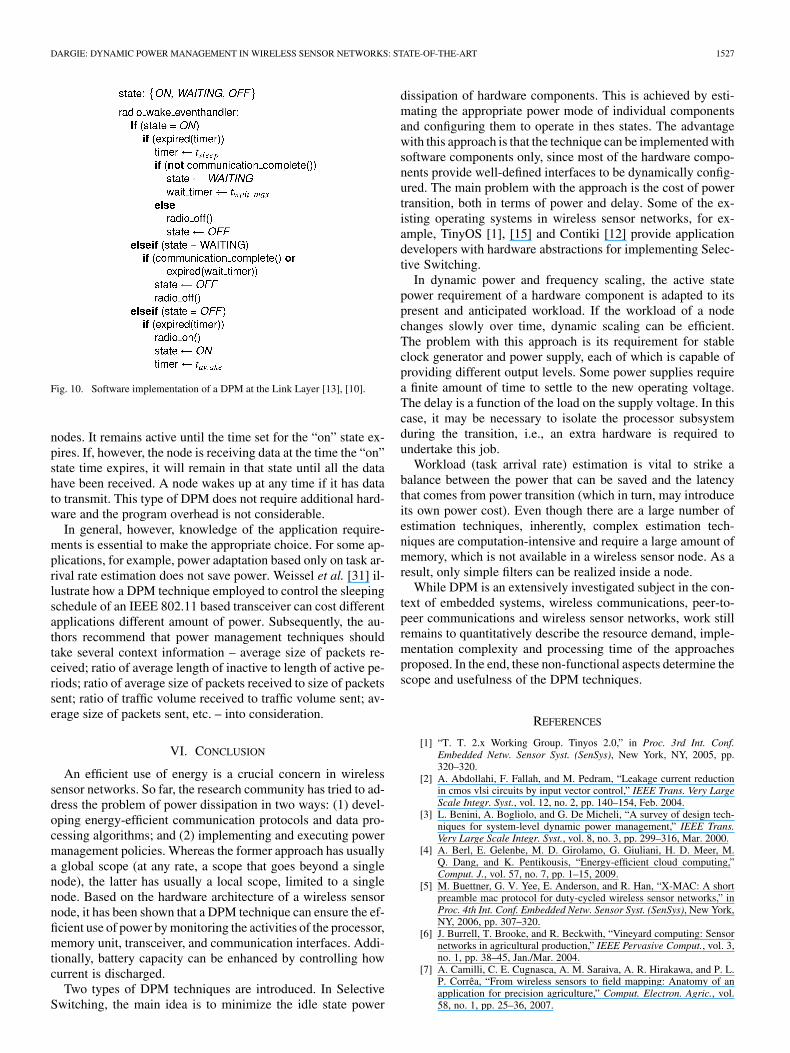
Almost all Medium Access Control (MAC) protocols in wire-less sensor network support periodic sleeping of the communi-cation subsystem of a node to frugally utilise power (therebyavoiding idle listening and overhearing). These protocols definea duty cycle, , which is lessthan 10%. The duty cycle depends on the data traffic within thenetwork and the maximum end-to-end delay in packet delivery.Fig. 10 displays a software realisation of a DPM based on peri-odic sleeping. The link layer defines three radio states, namely,on (active), off (sleep), and waiting states. If the communica-tion subsystem is in the “on” states, it participates in multi-hopcommunications by forwarding packets to and from neighbour
DARGIE: DYNAMIC POWER MANAGEMENT IN WIRELESS SENSOR NETWORKS: STATE-OF-THE-ART 1527
Fig. 10. Software implementation of a DPM at the Link Layer [13], [10].
nodes. It remains active until the time set for the “on” state ex-pires. If, however, the node is receiving data at the time the “on”state time expires, it will remain in that state until all the datahave been received. A node wakes up at any time if it has datato transmit. This type of DPM does not require additional hard-ware and the program overhead is not considerable.
In general, however, knowledge of the application require-ments is essential to make the appropriate choice. For some ap-plications, for example, power adaptation based only on task ar-rival rate estimation does not save power. Weissel et al. [31] il-lustrate how a DPM technique employed to control the sleepingschedule of an IEEE 802.11 based transceiver can cost differentapplications different amount of power. Subsequently, the au-thors recommend that power management techniques shouldtake several context information – average size of packets re-ceived; ratio of average length of inactive to length of active pe-riods; ratio of average size of packets received to size of packetssent; ratio of traffic volume received to traffic volume sent; av-erage size of packets sent, etc. – into consideration.
VI. CONCLUSION
An efficient use of energy is a crucial concern in wirelesssensor networks. So far, the research community has tried to ad-dress the problem of power dissipation in two ways: (1) devel-oping energy-efficient communication protocols and data pro-cessing algorithms; and (2) implementing and executing powermanagement policies. Whereas the former approach has usuallya global scope (at any rate, a scope that goes beyond a singlenode), the latter has usually a local scope, limited to a singlenode. Based on the hardware architecture of a wireless sensornode, it has been shown that a DPM technique can ensure the ef-ficient use of power by monitoring the activities of the processor,memory unit, transceiver, and communication interfaces. Addi-tionally, battery capacity can be enhanced by controlling howcurrent is discharged.
Two types of DPM techniques are introduced. In SelectiveSwitching, the main idea is to minimize the idle state power
dissipation of hardware components. This is achieved by esti-mating the appropriate power mode of individual componentsand configuring them to operate in thes states. The advantagewith this approach is that the technique can be implemented withsoftware components only, since most of the hardware compo-nents provide well-defined interfaces to be dynamically config-ured. The main problem with the approach is the cost of powertransition, both in terms of power and delay. Some of the ex-isting operating systems in wireless sensor networks, for ex-ample, TinyOS [1], [15] and Contiki [12] provide applicationdevelopers with hardware abstractions for implementing Selec-tive Switching.
In dynamic power and frequency scaling, the active statepower requirement of a hardware component is adapted to itspresent and anticipated workload. If the workload of a nodechanges slowly over time, dynamic scaling can be efficient.The problem with this approach is its requirement for stableclock generator and power supply, each of which is capable ofproviding different output levels. Some power supplies requirea finite amount of time to settle to the new operating voltage.The delay is a function of the load on the supply voltage. In thiscase, it may be necessary to isolate the processor subsystemduring the transition, i.e., an extra hardware is required toundertake this job.
Workload (task arrival rate) estimation is vital to strike abalance between the power that can be saved and the latencythat comes from power transition (which in turn, may introduceits own power cost). Even though there are a large number ofestimation techniques, inherently, complex estimation tech-niques are computation-intensive and require a large amount ofmemory, which is not available in a wireless sensor node. As aresult, only simple filters can be realized inside a node.
While DPM is an extensively investigated subject in the con-text of embedded systems, wireless communications, peer-to-peer communications and wireless sensor networks, work stillremains to quantitatively describe the resource demand, imple-mentation complexity and processing time of the approachesproposed. In the end, these non-functional aspects determine thescope and usefulness of the DPM techniques.
REFERENCES
[1] “T. T. 2.x Working Group. Tinyos 2.0,” in Proc. 3rd Int. Conf.Embedded Netw. Sensor Syst. (SenSys), New York, NY, 2005, pp.320–320.
[2] A. Abdollahi, F. Fallah, and M. Pedram, “Leakage current reductionin cmos vlsi circuits by input vector control,” IEEE Trans. Very LargeScale Integr. Syst., vol. 12, no. 2, pp. 140–154, Feb. 2004.
[3] L. Benini, A. Bogliolo, and G. De Micheli, “A survey of design tech-niques for system-level dynamic power management,” IEEE Trans.Very Large Scale Integr. Syst., vol. 8, no. 3, pp. 299–316, Mar. 2000.
[4] A. Berl, E. Gelenbe, M. D. Girolamo, G. Giuliani, H. D. Meer, M.Q. Dang, and K. Pentikousis, “Energy-efficient cloud computing,”Comput. J., vol. 57, no. 7, pp. 1–15, 2009.
[5] M. Buettner, G. V. Yee, E. Anderson, and R. Han, “X-MAC: A shortpreamble mac protocol for duty-cycled wireless sensor networks,” inProc. 4th Int. Conf. Embedded Netw. Sensor Syst. (SenSys), New York,NY, 2006, pp. 307–320.
[6] J. Burrell, T. Brooke, and R. Beckwith, “Vineyard computing: Sensornetworks in agricultural production,” IEEE Pervasive Comput., vol. 3,no. 1, pp. 38–45, Jan./Mar. 2004.
[7] A. Camilli, C. E. Cugnasca, A. M. Saraiva, A. R. Hirakawa, and P. L.P. Corrêa, “From wireless sensors to field mapping: Anatomy of anapplication for precision agriculture,” Comput. Electron. Agric., vol.58, no. 1, pp. 25–36, 2007.

1528 IEEE SENSORS JOURNAL, VOL. 12, NO. 5, MAY 2012
[8] C. Chiasserini and R. Rao, “Improving energy saving in wireless sys-tems by using dynamic power management,” IEEE Trans. WirelessCommun., vol. 2, no. 5, pp. 1090–1100, Sep. 2003.
[9] K. Choi, R. Soma, and M. Pedram, “Dynamic voltage and frequencyscaling based on workload decomposition,” in Proc. Int. Symp. LowPower Electron. Design (ISLPED), New York, NY, 2004, pp. 174–179.
[10] W. Dargie and C. Poellabauer, Fundamentals of Wireless Sensor Net-works: Theory and Practice, 1 ed. New York: Wiley, 2010.
[11] D. Doerffel and S. A. Sharkh, “A critical review of using the peukertequation for determining the remaining capacity of lead-acid andlithium-ion batteries,” J. Power Sources, vol. 155, no. 2, pp. 395–400,2006.
[12] A. Dunkels, B. Gronvall, and T. Voigt, “Contiki – A lightweight andflexible operating system for tiny networked sensors,” in Proc. 29thAnnu. IEEE Int. Conf. Local Comput. Netw. (LCN ), Washington, DC,2004, pp. 455–462.
[13] A. Dunkels, O. Schmidt, T. Voigt, and M. Ali, “Protothreads: Simpli-fying event-driven programming of memory-constrained embeddedsystems,” in Proc. 4th Int. Conf. Embedded Netw. Sensor Syst.(SenSys), New York, NY, 2006, pp. 29–42.
[14] X. Fan, C. Ellis, and A. Lebeck, “Memory controller policies for drampower management,” in : Proc. Int. Symp. Low Power Electron. Design(ISLPED), New York, NY, 2001, pp. 129–134.
[15] J. Hill, R. Szewczyk, A. Woo, S. Hollar, D. Culler, and K. Pister,“System architecture directions for networked sensors,” in Proc.9th Int. Conf. Archit. Support Program. Languages Oper. Syst. (AS-PLOS-IX), New York, NY, 2000, pp. 93–104.
[16] C. Isci and M. Martonosi, “Runtime power monitoring in high-endprocessors: Methodology and empirical data,” in Proc. 36th Annu.IEEE/ACM Int. Symp. Microarchit. (MICRO), Washington, DC, 2003,p. 93.
[17] X. Jiang, J. Taneja, J. Ortiz, A. Tavakoli, P. Dutta, J. Jeong, D. Culler,P. Levis, and S. Shenker, “An architecture for energy management inwireless sensor networks,” SIGBED Rev., vol. 4, no. 3, pp. 31–36, 2007.
[18] S. Kim, S. Pakzad, D. Culler, J. Demmel, G. Fenves, S. Glaser, and M.Turon, “Health monitoring of civil infrastructures using wireless sensornetworks,” in Proc. 6th Int. Conf. Inf. Process. Sensor Netw. (IPSN),New York, NY, 2007, pp. 254–263.
[19] A. Mainwaring, D. Culler, J. Polastre, R. Szewczyk, and J. Anderson,“Wireless sensor networks for habitat monitoring,” in Proc. ACM Int.Workshop Wireless Sensor Netw. Appl. (WSNA), 2002, pp. 88–97.
[20] M. Malinowski, M. Moskwa, M. Feldmeier, M. Laibowitz, and J. A.Paradiso, “Cargonet: A low-cost micropower sensor node exploitingquasi-passive wakeup for adaptive asychronous monitoring of excep-tional events,” in Proc. 5th Int. Conf. Embedded Netw. Sensor Syst.(SenSys), New York, NY, 2007, pp. 145–159.
[21] A. Merkel and F. Bellosa, “Task activity vectors: A new metric fortemperature-aware scheduling,” in Proc. 3rd ACM SIGOPS/EuroSysEur. Conf. Comput. Syst., New York, NY, 2008, pp. 1–12.
[22] J. Polastre, R. Szewczyk, and D. Culler, “Telos: Enabling ultra-lowpower wireless research,” in Proc. 4th Int. Symp. Inf. Process. SensorNetw. (IPSN), Piscataway, NJ, 2005, pp. 364–369.
[23] K. Roy and S. Mukhopadhyay, “Leakage current mechanisms andleakage reduction techniques in deep-submicrometer cmos circuits,”Proc. IEEE, vol. 91, no. 2, pp. 305–327, Feb. 2003.
[24] T. Simunic, L. Benini, A. Acquaviva, P. Glynn, and G. De Micheli,“Dynamic voltage scaling and power management for portable sys-tems,” in Proc. 38th Annu. Design Automat. Conf. (DAC ), New York,NY, 2001, pp. 524–529.
[25] A. Sinha and A. Chandrakasan, “Dynamic power management in wire-less sensor networks,” IEEE Des. Test Comput., vol. 18, no. 2, pp.62–74, Mar./Apr. 2001.
[26] I. Stoianov, L. Nachman, S. Madden, and T. Tokmouline, “Pipenet: Awireless sensor network for pipeline monitoring,” in Proc. 6th Int. Conf.Inf. Process. Sensor Netw. (IPSN), New York, NY, 2007, pp. 264–273.
[27] Y. Sun, O. Gurewitz, and D. B. Johnson, “RI-MAC: A receiver-initi-ated asynchronous duty cycle mac protocol for dynamic traffic loadsin wireless sensor networks,” in Proc. 6th ACM Conf. Embedded Netw.Sensor Syst., 2008, pp. 1–14.
[28] R. Swanson and J. Meindl, “Ion-implanted complementary mos tran-sistors in low-voltage circuits,” IEEE J. Solid-State Circuits, vol. 7, no.2, pp. 146–153, 1972.
[29] U. Varshney, “Pervasive healthcare and wireless health monitoring,”Mob. Netw. Appl., vol. 12, no. 2–3, pp. 113–127, 2007.
[30] A. Weissel and F. Bellosa, “Process cruise control: Event-driven clockscaling for dynamic power management,” in Proc. Int. Conf. Com-pilers, Archit., Synthesis Embedded Syst. (CASES), New York, NY,2002, pp. 238–246.
[31] A. Weissel, M. Faerber, and F. Bellosa, “Application characterizationfor wireless network power management,” in Proc. Int. Conf. Archit.Comput. Syst. (ARCS), 2004, pp. 231–245.
[32] G. Werner-Allen, K. Lorincz, M. Welsh, O. Marcillo, J. Johnson, M.Ruiz, and J. Lees, “Deploying a wireless sensor network on an activevolcano,” IEEE Internet Comput., vol. 10, no. 2, pp. 18–25, Mar./Apr.2006.
[33] N. Xu, S. Rangwala, K. K. Chintalapudi, D. Ganesan, A. Broad, R.Govindan, and D. Estrin, “A wireless sensor network for structuralmonitoring,” in Proc. 2nd Int. Conf. Embedded Netw. Sensor Syst., NewYork, NY, 2004, pp. 13–24.
[34] Y.-W. Yang and K. S.-M. Li, “Temperature-aware dynamic frequencyand voltage scaling for reliability and yield enhancement,” in Proc. AsiaSouth Pacific Design Autom. Conf. (ASP-DAC), Piscataway, NJ, 2009,pp. 49–54.
Waltenegus Dargie (M’08) received the B.Sc.degree in electrical engineering from the NazarethTechnical College, Ethiopia, in 1997, and theM.Sc. degree from the Technical University ofKaiserslautern, Germany, in 2002, both in electricalengineering, and the Ph.D. degree in computer en-gineering from the Technical University of Dresden,Germany, in 2006.
He was a Researcher at the Department of Elec-trical Engineering and Computer Science, Universityof Kassel, Germany, from 2002 to 2005, and also at
the Fraunhofer Institute of Experimental Software Engineering, Kaiserslautern,Germany, from 2002 to 2003. He is currently an Associate Professor at the Tech-nical University of Dresden, Germany. His research interests include wirelessnetworks, wireless sensor networks, and digital signal processing.