SECURING WIRELESS SENSOR AND VEHICULAR ...
190
HAL Id: tel-01199395 https://tel.archives-ouvertes.fr/tel-01199395 Submitted on 15 Sep 2015 HAL is a multi-disciplinary open access archive for the deposit and dissemination of sci- entific research documents, whether they are pub- lished or not. The documents may come from teaching and research institutions in France or abroad, or from public or private research centers. L’archive ouverte pluridisciplinaire HAL, est destinée au dépôt et à la diffusion de documents scientifiques de niveau recherche, publiés ou non, émanant des établissements d’enseignement et de recherche français ou étrangers, des laboratoires publics ou privés. Securing wireless sensor and vehicular networks Wafa Ben Jaballah To cite this version: Wafa Ben Jaballah. Securing wireless sensor and vehicular networks. Networking and Internet Archi- tecture [cs.NI]. Université de Bordeaux, 2014. English. NNT : 2014BORD0013. tel-01199395
-
Upload
khangminh22 -
Category
Documents
-
view
1 -
download
0
Transcript of SECURING WIRELESS SENSOR AND VEHICULAR ...

HAL Id: tel-01199395https://tel.archives-ouvertes.fr/tel-01199395
Submitted on 15 Sep 2015
HAL is a multi-disciplinary open accessarchive for the deposit and dissemination of sci-entific research documents, whether they are pub-lished or not. The documents may come fromteaching and research institutions in France orabroad, or from public or private research centers.
L’archive ouverte pluridisciplinaire HAL, estdestinée au dépôt et à la diffusion de documentsscientifiques de niveau recherche, publiés ou non,émanant des établissements d’enseignement et derecherche français ou étrangers, des laboratoirespublics ou privés.
Securing wireless sensor and vehicular networksWafa Ben Jaballah
To cite this version:Wafa Ben Jaballah. Securing wireless sensor and vehicular networks. Networking and Internet Archi-tecture [cs.NI]. Université de Bordeaux, 2014. English. �NNT : 2014BORD0013�. �tel-01199395�
THÈSE
PRÉSENTÉE À
L´ UNIVERSITÉ DE BORDEAUX
ÉCOLE DOCTORALE EN MATHÉMATIQUES ET INFORMATIQUE
par
Wafa Ben Jaballah
Pour obtenir le grade de DOCTEUR
Université de Bordeaux, France
SPÉCIALITÉ : INFORMATIQUE
SECURING WIRELESS SENSORAND VEHICULAR NETWORKS
SOUTENUE LE : 08 Janvier 2014
Devant le Jury de Thèse :
Mauro ContiFrederic CuppensFrancine KriefMaryline LaurentMohamed MosbahHabib Youssef
Président du jury, Université de PadoueRapporteur, Telecom BretagneExaminateur, Institut Polytechnique de Bordeaux Rapporteur, Telecom SudParisDirecteur de thèse, Institut Polytechnique de Bordeaux Directeur de thèse, Université de Sousse

ii

iii
To the memory of my beloved mother,to the love of my family,and to the love of the other people to whom I did not dedicate enough time.

iv
© Copyright byWafa Ben Jaballah
2014

v
“We must have perseverence and above all confidence in ourselves. We must believe thatwe are gifted for something and that this thing must be attained.”
–Marie Curie–

vi
TABLE OF CONTENTS
Page
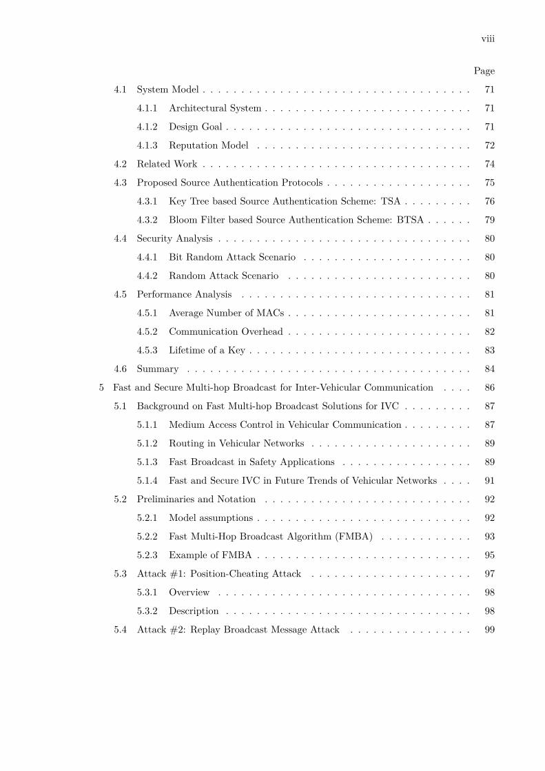
List of Tables . . . . . . . . . . . . . . . . . . . . . . . . . . . . . . . . . . . . . . . . xii
List of Figures . . . . . . . . . . . . . . . . . . . . . . . . . . . . . . . . . . . . . . xiii
ABSTRACT . . . . . . . . . . . . . . . . . . . . . . . . . . . . . . . . . . . . . . . xvii
1 Introduction . . . . . . . . . . . . . . . . . . . . . . . . . . . . . . . . . . . . . . . 1
1.1 Wireless Sensor Networks and Vehicular Communications . . . . . . . . . . 1
1.1.1 Wireless Sensor Networks . . . . . . . . . . . . . . . . . . . . . . . . 2
1.1.2 Vehicular Communications . . . . . . . . . . . . . . . . . . . . . . . 3
1.2 Security Requirements and Related Issues . . . . . . . . . . . . . . . . . . . 5
1.3 Attacks . . . . . . . . . . . . . . . . . . . . . . . . . . . . . . . . . . . . . . 7
1.4 Defensive Measures . . . . . . . . . . . . . . . . . . . . . . . . . . . . . . . . 9
1.5 Main Contributions . . . . . . . . . . . . . . . . . . . . . . . . . . . . . . . . 13
1.6 Dissertation Outline . . . . . . . . . . . . . . . . . . . . . . . . . . . . . . . 14
2 Key Disclosure based Source Authentication . . . . . . . . . . . . . . . . . . . . . 16
2.1 Notation and Preliminaries . . . . . . . . . . . . . . . . . . . . . . . . . . . 16
2.1.1 Notation . . . . . . . . . . . . . . . . . . . . . . . . . . . . . . . . . . 16
2.1.2 Preliminaries . . . . . . . . . . . . . . . . . . . . . . . . . . . . . . . 18
2.2 Related Work . . . . . . . . . . . . . . . . . . . . . . . . . . . . . . . . . . . 19
2.2.1 Overview of µTESLA . . . . . . . . . . . . . . . . . . . . . . . . . . 22
2.2.2 Overview of Multi-level µTESLA: ML-µTESLA . . . . . . . . . . . . 24
2.2.3 Staggered Authentication . . . . . . . . . . . . . . . . . . . . . . . . 27
2.3 System Model . . . . . . . . . . . . . . . . . . . . . . . . . . . . . . . . . . . 28

vii
Page
2.3.1 Architectural System . . . . . . . . . . . . . . . . . . . . . . . . . . . 28
2.3.2 Adversary Model . . . . . . . . . . . . . . . . . . . . . . . . . . . . . 28
2.3.3 Design Goals . . . . . . . . . . . . . . . . . . . . . . . . . . . . . . . 28
2.4 Our Advanced Schemes . . . . . . . . . . . . . . . . . . . . . . . . . . . . . 29
2.4.1 Staggered Multi-level-µTESLA . . . . . . . . . . . . . . . . . . . . . 29
2.4.2 Bloom Filter Multi-level-µTESLA . . . . . . . . . . . . . . . . . . . 31
2.5 Formal Validation . . . . . . . . . . . . . . . . . . . . . . . . . . . . . . . . 33
2.5.1 Overview of AVISPA . . . . . . . . . . . . . . . . . . . . . . . . . . . 33
2.5.2 Multi-level-µTESLA . . . . . . . . . . . . . . . . . . . . . . . . . . . 34
2.5.3 Staggered Multi-level-µTESLA . . . . . . . . . . . . . . . . . . . . . 39
2.5.4 Bloom Filter Multi-level-µTESLA . . . . . . . . . . . . . . . . . . . 40
2.5.5 Security Analysis . . . . . . . . . . . . . . . . . . . . . . . . . . . . . 41
2.6 Performance Evaluation . . . . . . . . . . . . . . . . . . . . . . . . . . . . . 43
2.6.1 Prototype Implementation . . . . . . . . . . . . . . . . . . . . . . . . 43
2.6.2 Simulation Setup . . . . . . . . . . . . . . . . . . . . . . . . . . . . . 45
2.6.3 Results . . . . . . . . . . . . . . . . . . . . . . . . . . . . . . . . . . 46
2.7 Summary . . . . . . . . . . . . . . . . . . . . . . . . . . . . . . . . . . . . . 51
3 Delayed Authentication Compromise . . . . . . . . . . . . . . . . . . . . . . . . . 53
3.1 Related Work . . . . . . . . . . . . . . . . . . . . . . . . . . . . . . . . . . . 54
3.2 Notation and Background . . . . . . . . . . . . . . . . . . . . . . . . . . . . 55
3.2.1 Notation . . . . . . . . . . . . . . . . . . . . . . . . . . . . . . . . . . 55
3.2.2 Background . . . . . . . . . . . . . . . . . . . . . . . . . . . . . . . . 56
3.3 Limitations and Attacks for the State of the Art . . . . . . . . . . . . . . . 60
3.4 Our proposal: MASS . . . . . . . . . . . . . . . . . . . . . . . . . . . . . . . 61
3.4.1 Overview . . . . . . . . . . . . . . . . . . . . . . . . . . . . . . . . . 61
3.4.2 Description . . . . . . . . . . . . . . . . . . . . . . . . . . . . . . . . 61
3.5 Security Analysis . . . . . . . . . . . . . . . . . . . . . . . . . . . . . . . . . 63
3.6 Performance Comparison . . . . . . . . . . . . . . . . . . . . . . . . . . . . 65
3.7 Conclusion . . . . . . . . . . . . . . . . . . . . . . . . . . . . . . . . . . . . 68
4 Secure Group Communications . . . . . . . . . . . . . . . . . . . . . . . . . . . . 70
viii
Page
4.1 System Model . . . . . . . . . . . . . . . . . . . . . . . . . . . . . . . . . . . 71
4.1.1 Architectural System . . . . . . . . . . . . . . . . . . . . . . . . . . . 71
4.1.2 Design Goal . . . . . . . . . . . . . . . . . . . . . . . . . . . . . . . . 71
4.1.3 Reputation Model . . . . . . . . . . . . . . . . . . . . . . . . . . . . 72
4.2 Related Work . . . . . . . . . . . . . . . . . . . . . . . . . . . . . . . . . . . 74
4.3 Proposed Source Authentication Protocols . . . . . . . . . . . . . . . . . . . 75
4.3.1 Key Tree based Source Authentication Scheme: TSA . . . . . . . . . 76
4.3.2 Bloom Filter based Source Authentication Scheme: BTSA . . . . . . 79
4.4 Security Analysis . . . . . . . . . . . . . . . . . . . . . . . . . . . . . . . . . 80
4.4.1 Bit Random Attack Scenario . . . . . . . . . . . . . . . . . . . . . . 80
4.4.2 Random Attack Scenario . . . . . . . . . . . . . . . . . . . . . . . . 80
4.5 Performance Analysis . . . . . . . . . . . . . . . . . . . . . . . . . . . . . . 81
4.5.1 Average Number of MACs . . . . . . . . . . . . . . . . . . . . . . . . 81
4.5.2 Communication Overhead . . . . . . . . . . . . . . . . . . . . . . . . 82
4.5.3 Lifetime of a Key . . . . . . . . . . . . . . . . . . . . . . . . . . . . . 83
4.6 Summary . . . . . . . . . . . . . . . . . . . . . . . . . . . . . . . . . . . . . 84
5 Fast and Secure Multi-hop Broadcast for Inter-Vehicular Communication . . . . 86
5.1 Background on Fast Multi-hop Broadcast Solutions for IVC . . . . . . . . . 87
5.1.1 Medium Access Control in Vehicular Communication . . . . . . . . . 87
5.1.2 Routing in Vehicular Networks . . . . . . . . . . . . . . . . . . . . . 89
5.1.3 Fast Broadcast in Safety Applications . . . . . . . . . . . . . . . . . 89
5.1.4 Fast and Secure IVC in Future Trends of Vehicular Networks . . . . 91
5.2 Preliminaries and Notation . . . . . . . . . . . . . . . . . . . . . . . . . . . 92
5.2.1 Model assumptions . . . . . . . . . . . . . . . . . . . . . . . . . . . . 92
5.2.2 Fast Multi-Hop Broadcast Algorithm (FMBA) . . . . . . . . . . . . 93
5.2.3 Example of FMBA . . . . . . . . . . . . . . . . . . . . . . . . . . . . 95
5.3 Attack #1: Position-Cheating Attack . . . . . . . . . . . . . . . . . . . . . 97
5.3.1 Overview . . . . . . . . . . . . . . . . . . . . . . . . . . . . . . . . . 98
5.3.2 Description . . . . . . . . . . . . . . . . . . . . . . . . . . . . . . . . 98
5.4 Attack #2: Replay Broadcast Message Attack . . . . . . . . . . . . . . . . 99

ix
Page
5.4.1 Overview . . . . . . . . . . . . . . . . . . . . . . . . . . . . . . . . . 99
5.4.2 Description . . . . . . . . . . . . . . . . . . . . . . . . . . . . . . . 100
5.5 Attack #3: Interrupting Forwarding Attack . . . . . . . . . . . . . . . . . 100
5.5.1 Overview . . . . . . . . . . . . . . . . . . . . . . . . . . . . . . . . 101
5.5.2 Description . . . . . . . . . . . . . . . . . . . . . . . . . . . . . . . 102
5.6 Solution to Attack #1: False Position Detection . . . . . . . . . . . . . . 102
5.6.1 State of the Art Solutions for False Position Detection . . . . . . . 102
5.6.2 Overview of the Proposed Cheating Position Detection . . . . . . . 104
5.6.3 Description of the Proposed Cheating Position Detection . . . . . 109
5.7 Solution to Attack #2: Anti-Replay Protection . . . . . . . . . . . . . . . 115
5.7.1 State of the Art Solutions of Anti-Replay Protection . . . . . . . . 116
5.7.2 Overview of our Proposed Solution . . . . . . . . . . . . . . . . . . 116
5.7.3 Description . . . . . . . . . . . . . . . . . . . . . . . . . . . . . . . 117
5.8 Solution to Attack #3: Interrupting Forwarding Attack Detection . . . . 119
5.8.1 State of the Art Solutions of Detecting Misbehaving Forwarders . 119
5.8.2 Overview . . . . . . . . . . . . . . . . . . . . . . . . . . . . . . . . 120
5.8.3 Description . . . . . . . . . . . . . . . . . . . . . . . . . . . . . . . 121
5.9 FS-MBA . . . . . . . . . . . . . . . . . . . . . . . . . . . . . . . . . . . . . 123
5.9.1 Security Overhead . . . . . . . . . . . . . . . . . . . . . . . . . . . 124
5.10 Performance Evaluation . . . . . . . . . . . . . . . . . . . . . . . . . . . . 125
5.10.1 Simulation Environment . . . . . . . . . . . . . . . . . . . . . . . . 126
5.10.2 Simulations Outcomes . . . . . . . . . . . . . . . . . . . . . . . . . 127
5.11 Summary . . . . . . . . . . . . . . . . . . . . . . . . . . . . . . . . . . . . 138
6 Conclusion . . . . . . . . . . . . . . . . . . . . . . . . . . . . . . . . . . . . . . . 142
6.1 Contributions . . . . . . . . . . . . . . . . . . . . . . . . . . . . . . . . . . 142
6.2 Future Direction . . . . . . . . . . . . . . . . . . . . . . . . . . . . . . . . 143
Bibliography . . . . . . . . . . . . . . . . . . . . . . . . . . . . . . . . . . . . . . . 146

x

xi
List of Tables
2.1 Overview of some state of the art key disclosure schemes in WSNs. . . . . . . 22
3.1 Delayed Authentication Compromise: Notation . . . . . . . . . . . . . . . . . . 55
3.2 Overheads of TASS, PTASS, and MASS . . . . . . . . . . . . . . . . . . . . . . 66
5.1 Fast and Secure Multi-hop Broadcast for IVC: Notation . . . . . . . . . . . . . 92
5.2 FS-MBA Overhead . . . . . . . . . . . . . . . . . . . . . . . . . . . . . . . . . 125
5.3 Configuration Parameters . . . . . . . . . . . . . . . . . . . . . . . . . . . . . 126

xii
List of Figures
2.1 A Bloom Filter with n = 4, m = 16 and k = 3 . . . . . . . . . . . . . . . . . . 19
2.2 An example of a One Way Key Chain . . . . . . . . . . . . . . . . . . . . . . . 19
2.3 µTESLA Scheme . . . . . . . . . . . . . . . . . . . . . . . . . . . . . . . . . . . 23
2.4 An example of two level key chain mechanism (n0 = 3, and n1 = 3) . . . . . . 26
2.5 SML-µTESLA: An example of execution . . . . . . . . . . . . . . . . . . . . . . 31
2.6 Mapping d MACs into a Bloom filter Vector . . . . . . . . . . . . . . . . . . . . 33
2.7 A scheme of state machine interpretation . . . . . . . . . . . . . . . . . . . . . 37
2.8 Role receiver: Arrival of a data packet . . . . . . . . . . . . . . . . . . . . . . . 39
2.9 Loss of Packets . . . . . . . . . . . . . . . . . . . . . . . . . . . . . . . . . . . . 39
2.10 Transmission of a data packet (SML-µTESLA) . . . . . . . . . . . . . . . . . . 41
2.11 Our Application Architecture . . . . . . . . . . . . . . . . . . . . . . . . . . . . 44
2.12 Authentication Probability . . . . . . . . . . . . . . . . . . . . . . . . . . . . . 47
2.13 Authentication Probability versus attack rate and duration using TelosB motes 47
2.14 Authentication Delay . . . . . . . . . . . . . . . . . . . . . . . . . . . . . . . . . 48
2.15 Average Number of Forged Packets in Multi-level-µTESLA using TelosB motes 48
2.16 Delay of Forged Packets in the Buffer . . . . . . . . . . . . . . . . . . . . . . . 49
2.17 Delay of Forged and Authenticated Packets in Staggered Multi-Level µTESLA 50
2.18 Delay of Forged and Authenticated Packets in Multi-level µTESLA . . . . . . . 50
3.1 Merkle Winternitz signature scheme to sign m bits . . . . . . . . . . . . . . . . 57
3.2 TASS Direct Acyclic Graph (t = 4) . . . . . . . . . . . . . . . . . . . . . . . . . 59

xiii
3.3 MASS Direct Acyclic Graph (t = 4) . . . . . . . . . . . . . . . . . . . . . . . . 62
3.4 MASS: Drop and Switch Command Attack Detection . . . . . . . . . . . . . . 64
3.5 Average Transmission Overhead for an Authenticated Message . . . . . . . . . 67
3.6 Average Authentication Overhead for a Message . . . . . . . . . . . . . . . . . 67
4.1 Architectural Model . . . . . . . . . . . . . . . . . . . . . . . . . . . . . . . . . 72
4.2 Key Tree Generation by a source S . . . . . . . . . . . . . . . . . . . . . . . . . 77
4.3 Energy Consumption in Communication . . . . . . . . . . . . . . . . . . . . . . 83
5.1 Contention window versus distance . . . . . . . . . . . . . . . . . . . . . . . . . 95
5.2 Example of a fast broadcast algorithm . . . . . . . . . . . . . . . . . . . . . . . 97
5.3 Impact of distance cheating on the waiting time . . . . . . . . . . . . . . . . . . 98
5.4 Example of enforcing non cooperation attack . . . . . . . . . . . . . . . . . . 100
5.5 Impact of a malicious forwarder node . . . . . . . . . . . . . . . . . . . . . . 101
5.6 Degrading performance attack executed by n malicious vehicles . . . . . . . . 102
5.7 Scenario 1 - Case 1 . . . . . . . . . . . . . . . . . . . . . . . . . . . . . . . . . 105
5.8 Scenario 1 - Case 2 . . . . . . . . . . . . . . . . . . . . . . . . . . . . . . . . . 106
5.9 Scenario 1 - Case 3 . . . . . . . . . . . . . . . . . . . . . . . . . . . . . . . . . 106
5.10 Scenario 1: Verifier waiting time versus distance . . . . . . . . . . . . . . . . 107
5.11 Scenario 2: Verifier waiting time versus distance . . . . . . . . . . . . . . . . 108
5.12 Scenario 3: Verifier waiting time versus distance . . . . . . . . . . . . . . . . 109
5.13 Verifier waiting time versus distance . . . . . . . . . . . . . . . . . . . . . . . 109
5.14 Neighbor structure . . . . . . . . . . . . . . . . . . . . . . . . . . . . . . . . . 110
5.15 Indirect neighbors structure . . . . . . . . . . . . . . . . . . . . . . . . . . . . 110
5.16 A modified structure of Hello message . . . . . . . . . . . . . . . . . . . . . . 111
5.17 Falsing list neighbors . . . . . . . . . . . . . . . . . . . . . . . . . . . . . . . . 115
5.18 Modified broadcast message . . . . . . . . . . . . . . . . . . . . . . . . . . . . 117
5.19 Stored Table . . . . . . . . . . . . . . . . . . . . . . . . . . . . . . . . . . . . 117
5.20 Example of non propagation of broadcast message . . . . . . . . . . . . . . . 122
5.21 FMBA under attacks: Average Number of Slots . . . . . . . . . . . . . . . . . 130

xiv
5.22 FMBA and FS-MBA under attacks: Average Number of Slots . . . . . . . . . 131
5.23 FMBA: Retransmissions/Collisions . . . . . . . . . . . . . . . . . . . . . . . . 131
5.24 FMBA under Attack #1: Estimated transmission range . . . . . . . . . . . . 133
5.25 FS-MBA under Attack #1: Estimated transmission range . . . . . . . . . . . 133
5.26 FMBA under Attack #1: Average of declared distance by the attacker . . . . 134
5.27 FMBA under Attack #1: Average Number of Hops . . . . . . . . . . . . . . . 135
5.28 FMBA under Attack #2: Average Number of slots . . . . . . . . . . . . . . . 136
5.29 FMBA under Attack #2: Percentage of Message Propagation to the end of theplatoon . . . . . . . . . . . . . . . . . . . . . . . . . . . . . . . . . . . . . . . 137
5.30 FMBA under Attack#3 with a Random Position of Malicious node: Percentageof Message Propagation . . . . . . . . . . . . . . . . . . . . . . . . . . . . . . 138
5.31 FMBA under Attack #3 with Malicious Node at the End of the TransmissionRange of the First Sender: Percentage of Message Propagation . . . . . . . . 138

xv

xvi
ABSTRACT
Wireless sensor and vehicular networks play an important role in critical military andcivil applications, and pervade our daily life. However, security concerns constitute a po-tential stumbling block to the impeding wide deployment of sensor networks and vehicu-lar communications. This dissertation studies communication security for Wireless SensorNetworks (WSNs), and vehicular communication. To this aim, we address four importantaspects. The first study addresses broadcast authentication in WSNs. We focus on keydisclosure based schemes. We demonstrate that key disclosure delay induces an authenti-cation delay, which could lead to a memory DoS attack. We then propose two broadcastauthentication protocols for WSNs, which overcome the security vulnerability of existingsolutions. The proposed schemes guarantee the efficient management of receiver’s buffer,by employing a staggered authentication mechanism, and a Bloom filter data structure toreduce the communication overhead. We also validate our protocols under the AVISPAmodel checking tool, and we evaluate them with experiments under TinyOS. Our findingsare that these protocols provide source authentication service while respecting the WSNconstraints.
The second study addresses the storage issue in WSNs, in particular the Delayed Authen-tication Compromise attack (DAC). We first demonstrate that recently proposed schemes,which also address the DAC issue are vulnerable to two kinds of attacks: switch com-mand attack (where an adversary pretends to “switch” two messages over time), and dropcommand attack (where an adversary just pretends to “hide” a message sent from thebroadcaster). As a countermeasure against these attacks, we propose a new solution forbroadcast authentication. Our analysis shows that our solution is effective in detecting bothswitch command and drop command attack, and—at the same time—is more efficient (interms of both communication and computation) than the state of the art solutions.
In the third study, we address key management security in WSNs. We present novelsymmetric-key-based authentication schemes which exhibit low computation and communi-cation authentication overhead. Our schemes are built upon the integration of a reputationmechanism, a Bloom filter, and a key binary tree for the distribution and updating of the au-

xvii
thentication keys. Our schemes are lightweight and efficient with respect to communicationand energy overhead.
The fourth study addresses security in vehicular communications. We focus on fast multihop broadcast applications. We analyze the security threats of state of the art vehicularbased safety applications. We demonstrate that these schemes are vulnerable to the posi-tion cheating attack, the replay broadcast message attack, and the interrupting forwardingattack. Then, we propose countermeasures for these threats. We hence propose a completesolution which is both fast and secure in broadcasting safety related messages: Fast andSecure Multi-hop Broadcast Algorithm (FS-MBA). Finally, we confirm the efficiency andfeasibility of our proposals using an extensive set of simulations under NS-2 Simulator.
Keywords: Source Authentication in WSNs, Security, Secure Vehicular Communica-tions, Key management, Attacks.

xviii

xix
RESUME
Les Réseaux de Capteurs Sans Fils (RCSFs) et les réseaux véhiculaires sont de plusen plus répandus, et déployés dans des domaines d’applications variés tels que la santé,la surveillance environmentale, les applications d’alerte d’accident, et les applications mili-taires. Cependant, ces réseaux peuvent être sujets à des attaques, ce qui empêche leur util-isation à grande échelle. Cette thèse étudie la sécurité des communications pour les réseauxde capteurs sans fils, et les communications inter-véhiculaires. Dans ce but, nous abordonsquatre aspects importants. La première étude porte sur l’authentification des messagesdiffusés dans les réseaux de capteurs. Nous nous concentrons sur les principaux schémas àbase de divulgation de clés d’authentification. Nous démontrons que le délai de divulgationde clé induit un délai d’authentification, ce qui pourrait conduire à une attaque de mémoirede déni de service. Nous proposons ensuite deux protocoles d’authentification de la sourcedans les RCSFs, pour surmonter la vulnérabilité des solutions existantes. Les schémas pro-posés garantissent la gestion efficace de la mémoire tampon du récepteur, en utilisant unmécanisme d’authentification par niveau, et une structure de Filtre de Bloom afin de ré-duire le coût de communication. Ensuite, nous validons nos protocoles en utilisant l’outilde vérification AVISPA, et nous les évaluons avec des expérimentations dans l’environmentTinyOS. Nous confirmons que ces protocoles fournissent un service d’authentification de lasource tout en respectant les contraintes de RCSFs.
La seconde étude porte sur le problème de stockage au niveau des capteurs. Nous con-sidérons en particulier l’attaque d’authentification différée “Delayed Authentication Com-promise” (DAC) dans les RCSFs, qui permet à un attaquant d’utiliser une clé déjà divulguéepour signer d’autres messages. Nous montrons d’abord que les systèmes récemment pro-posés qui sont résistants également à l’attaque DAC sont vulnérables aussi à deux typesd’attaques: attaque de permutation de commandes (où un adversaire prétend “permuter”deux messages au fil du temps), et l’attaque de rejet de commandes (où un adversaire semble“cacher” un message envoyé par la station de base). Nous proposons ensuite une nouvellesolution d’authentification. Notre analyse montre que notre solution est efficace pour dé-tecter à la fois l’attaque de permutation de commandes et l’attaque de rejet de commandes,— et en même temps — est plus efficace (en termes de communication et de calcul) que lessolutions existantes.
xx
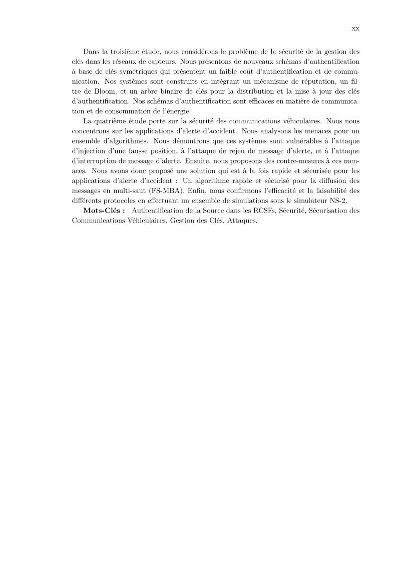
Dans la troisième étude, nous considérons le problème de la sécurité de la gestion desclés dans les réseaux de capteurs. Nous présentons de nouveaux schémas d’authentificationà base de clés symétriques qui présentent un faible coût d’authentification et de commu-nication. Nos systèmes sont construits en intégrant un mécanisme de réputation, un fil-tre de Bloom, et un arbre binaire de clés pour la distribution et la mise à jour des clésd’authentification. Nos schémas d’authentification sont efficaces en matière de communica-tion et de consommation de l’énergie.
La quatrième étude porte sur la sécurité des communications véhiculaires. Nous nousconcentrons sur les applications d’alerte d’accident. Nous analysons les menaces pour unensemble d’algorithmes. Nous démontrons que ces systèmes sont vulnérables à l’attaqued’injection d’une fausse position, à l’attaque de rejeu de message d’alerte, et à l’attaqued’interruption de message d’alerte. Ensuite, nous proposons des contre-mesures à ces men-aces. Nous avons donc proposé une solution qui est à la fois rapide et sécurisée pour lesapplications d’alerte d’accident : Un algorithme rapide et sécurisé pour la diffusion desmessages en multi-saut (FS-MBA). Enfin, nous confirmons l’efficacité et la faisabilité desdifférents protocoles en effectuant un ensemble de simulations sous le simulateur NS-2.
Mots-Clés : Authentification de la Source dans les RCSFs, Sécurité, Sécurisation desCommunications Véhiculaires, Gestion des Clés, Attaques.

xxi

xxii
RESUME DETAILLE
Au cours des dernières décennies, il y a eu une croissance importante dans le domainede l’informatique ubiquitaire et omniprésente. En particulier, l’informatique ubiquitairevise à rendre “plusieurs ordinateurs disponibles dans l’environnement physique, mais aussitransparents pour l’utilisateur” [1]. Pendant cette période, les récents progrès des systèmesélectro-mécaniques, de la communication sans fil et de l’électronique numérique ont facilitéla production de petits appareils performants et pas chers, tels que les téléphones intel-ligents, les PDA, les systèmes d’identification par radiofréquence (RFID), les Réseaux deCapteurs Sans Fils (RCSFs), et de nombreuses autres technologies. Ces appareils mobilessont capables d’effectuer diverses opérations complexes sans perdre de vue les besoins desutilisateurs. Les appareils sont utilisés dans de grandes variétés d’applications telles que lasurveillance de la santé, les systèmes de diagnositc, les alarmes de sécurité, la communicationvéhiculaire et la surveillance de l’environnement.
Dans de nombreux scénarios d’application, la sécurité est un besoin essentiel. Dans cettethèse, on se focalise sur la sécurité des communications dans les réseaux de capteurs sansfils (RCSFs), et les communications inter-véhiculaires. Nous allons mettre l’accent sur lesexigences en sécurité pour ces deux types de technologies, et par la suite nous allons aborderles différentes motivations qui permettent de sécuriser les RCSFs et les communicationsinter-véhiculaires.Authentification de la source L’authentification de la source des messages de diffusiond’une station de base à des capteurs est le paradigme le plus commun dans les réseaux decapteurs sans fil. Cette authentification est trés importante, car elle permet à la station debase de diffuser des requêtes et des messages aux capteurs et d’exploiter ainsi efficacementle réseau de capteurs sans fil. L’authentification permet aux récepteurs de vérifier que lesmessages reçus proviennent de la source prétendue, et n’ont pas été modifiés en cours deroute. Le problème devient plus complexe dans le cas où d’autres récepteurs de donnéessont non fiables, et où les paquets perdus ne sont pas retransmis. L’authentification de lasource des messages diffusés est donc l’un des services de sécurité les plus importants dansces réseaux [2–8].
Un réseau de capteurs peut être déployé dans des environnements hostiles où il y ades attaques malveillantes. Dans une telle situation, la sécurité devient une des préoc-

xxiii
cupations majeures. En tant que service de sécurité fondamental, l’authentification de lasource des messages diffusés permet à un expéditeur de diffuser des données critiques et/oudes commandes de noeuds de capteurs d’une manière authentifiée. Par exemple un at-taquant est incapable d’intercepter un message de l’expéditeur [9–15]. Toutefois, en raisondes contraintes de ressources sur les noeuds de capteurs, les techniques d’authentificationtraditionnelles telles que les signatures numériques basées sur des clés publiques ne sontpas souhaitables. Dans [16], les auteurs ont développé µTESLA pour l’authentificationde la source des messages diffusés dans les réseaux de capteurs basée sur la cryptographiesymétrique, ce qui élimine la dépendance à la cryptographie à clé publique. Plusieurs sché-mas à base du protocole µTESLA ont été proposés pour étendre la capacité de protocoleµTESLA [4–7, 17]. Malgré ces progrès récents, plusieurs questions ne sont toujours pascorrectement traitées.
• Authentification Immédiate des Messages. Les schémas à base de µTESLAsouffrent d’un retard d’authentification, en raison du retard de divulgation de la cléd’authentification. Ce processus se réfère à une asymétrie temporelle, où la clé estsecrète au niveau de la station de base, et elle sera divulguée après certains intervallesde temps (délai de divulgation), rendant ainsi la clé publique. Dans ce scénario, lestravaux dans [7, 18] prouvent que ces mécanismes sont vulnérables contre certainesattaques comme celles de déni de service.
• Résistance aux Attaques de Déni de Service (DoS). Un attaquant peut lancerles attaques DoS sur les messages pour surcharger la mémoire tampon, et il ex-ploite le délai d’authentification des messages pour intercepter des paquets de don-nées. Bien que plusieurs solutions aient été proposées dans [7], celles-ci utilisent unebande passante importante ou bien nécessitent d’importantes ressources au niveau del’expéditeur (en utilisant par exemple les énigmes cryptographiques) [19].
• Coût de Communication. Comme les capteurs ont des ressources limitées, le coûtde communication est crucial. Ainsi, pour concevoir un système d’authentificationefficace dans ces réseaux, le coût de communication doit être réduit.
L’Attaque de Délai d’Authentification Les schémas d’authentification qui se basentsur les mécanismes de µTESLA entraînent une vulnérabilité qui peut conduire à une attaqueappelée ”Delayed Authentication Compromise”(DAC). Considérons le scénario suivant: lerécepteur doit identifier les messages reçus, de telle sorte que l’attaquant ne puisse pasmodifier successivement les messages. Les mécanismes à base de divulgation de clé, ou bienà base de µTESLA ne sont pas candidats à être utilisés dans un tel scénario. En effet,dès que la clé est divulguée, l’attaquant peut utiliser cette clé pour modifier les messagesenregistrés. Dans [18], ce processus d’attaque désigne l’attaque DAC. L’adversaire peututiliser une clé déjà divulguée pour signer par exemple la commande “ouvrir une porte”, etl’enregistrer dans la mémoire d’un actionneur compromis. Une fois que la porte est ouverte,il sera difficile de prouver avec certitude ce qui a été compromis. Si la station de base estdéclarée honnête, alors nous pouvons affirmer que le noeud est malveillant, mais si la station
xxiv
de base elle-même peut être compromise, alors il n’est pas possible de déterminer qui estle malveillant, le noeud ou la station de base. Afin de contrer ces attaques du DAC, lesauteurs dans [18] proposent trois algorithmes appelés PASS, TASS et PTASS. Cependant,plusieurs questions ne sont toujours pas correctement traitées.
• Attaque de Suppression de Commande. Un noeud malveillant peut facilementsupprimer/rejeter une commande transmise par la station de base. Un noeud récep-teur ne pourra pas détecter si la station de base n’a pas envoyé une commande, oubien si la commande a été supprimée par un noeud malveillant.
• Attaque de Permutation de Commande. Les protocoles (TASS et PTASS) sontégalement vulnérables à l’attaque de permutation de commande qui vise à changerl’ordre des messages envoyés par la station de base. Prenons le scénario où la station debase doit envoyer la commande “initialiser” suivie par la commande “fermer la porte”,tandis que l’attaquant souhaite ouvrir la porte. En utilisant TASS et PTASS, le noeudmalveillant est capable de changer l’ordre des commandes, poussant le récepteur àexécuter la commande “fermer la porte”, puis d’exécuter la commande “initialiser”,ce qui va rouvrir la porte.
• Authentification Immédiate des Messages. En utilisant le protocole TASS, lerécepteur doit attendre la fin d’un intervalle de temps afin d’authentifier les mes-sages reçus. Cela peut conduire également à des attaques DoS. PTASS propose unmoyen d’envoyer des messages de haute priorité qui sont immédiatement authentifiés.Toutefois, cette fonctionnalité engendre une augmentation de la communication et dela transmission.
Dans de nombreuses applications, il est important de protéger les communications entreles noeuds de capteurs pour maintenir l’authentification, la confidentialité et l’intégrité.
En particulier, les efforts de recherche pertinents ont abordé la technique de clé degroupe afin de localiser le calcul, et aussi pour diminuer les coûts de communication dansles réseaux de capteurs sans fil [20]. La technique à base d’un arbre de clés est utilisée poursécuriser les communications de groupe. Plusieurs techniques de gestion sécurisée de cléde groupe ont été proposées pour sécuriser les communications multicast [21, 22]. Dans unsystème de gestion de clé de groupe typique [23], il y a un tiers de confiance, dit centre dedistribution de clés (KDC). Cette entité unique et fiable est responsable de la générationet de la distribution de clés aux membres de groupe. Dans [21], les auteurs proposent unsystème de gestion de clés de groupe se basant sur une hiérarchie des clés topologiques. Ilgénère un arbre de clés en se référant à la topologie de réseau de capteurs. Dans [24, 25],les auteurs proposent un polynôme de degré t avec le terme constant du polynôme étantla clé secrète, en calculant t termes distincts du polynôme et les stockant. Dans [26], lesauteurs ont conçu un système utilisant un arbre de clé pour gérer les membres du groupe.Par ailleurs, dans [26], la technique de clé de groupe repose sur une refonte de systèmede groupe centralisé basé sur l’arbre logique de clés dans les réseaux de capteurs. Cettetechnique n’est pas pratique pour les réseaux de capteurs, puisqu’elle utilise des opérationscomplexes.

xxv
Bien que de nombreux travaux dans [9,11] aient proposé des mécanismes d’authentificationde la source dans les réseaux de capteurs sans fil, le problème est toujours difficile puisqu’ilfaut réaliser un compromis entre la sécurité et les ressources de calcul limitées.
Sécurité des communications inter-véhiculaires On s’intéresse dans cette thèse à lasécurité des communications entre véhicules. En effet, la communication entre véhiculesest parmi les applications les plus prometteuses [27, 28]. De nombreuses applications sontpossibles, en particulier, les systèmes d’alerte de dangers.
En résumé, plusieurs algorithmes de diffusion multi-sauts ont été proposés. Ces algo-rithmes partagent généralement un ensemble de propriétés, se situant dans une même classede solutions. Malheureusement, ils ont tous été développés sans tenir compte des aspects desécurité. La sécurité est un problème fondamental, qui ne devrait pas être négligé [29]. Eneffet, les attaquants pourraient exécuter des actions malveillantes pour injecter des faussesinformations ou de fausses alarmes.
Contributions Les principales contributions de cette thèse se résument comme suit.
• Contribution 1 : Authentification de la source des messages diffusés dansles RCSFs. Nous identifions le problème de l’authentification de la source des mes-sages diffusés dans les RCSFs. Nous détectons une vulnérabilité de sécurité pour lesprotocoles à base de clé symétrique qui se basent sur µTESLA. Cette vulnérabilitépourrait conduire à une attaque de déni de service affectant la mémoire des capteurs.Nous proposons ensuite plusieurs schémas à clé symétrique permettant de limiter lesimpacts de cette attaque. Nous atteignons notre objectif en intégrant plusieurs tech-niques telles que le mécanisme d’authentification par niveau afin de réduire le nombrede paquets forgés dans le tampon de récepteur. Nous concevons un système basé surun filtre de Bloom qui permet de concevoir un protocole avec un coût de communi-cation faible. Nous validons formellement nos solutions de sécurité, et nous évaluonsleurs performances sous le simulateur TOSSIM. Cette contribution est présentée dansle Chapitre 2.
• Contribution 2 : Authentification différée dans les RCSFs. Tout d’abord, nousmontrons que les protocoles existants qui sont résistants à l’attaque DAC sont soumisà deux attaques possibles : l’attaque de rejet/suppression de commandes, et l’attaquede permutation de commandes. Deuxièmement, nous proposons une nouvelle solutionqui est résistante à l’attaque DAC, à l’attaque de rejet/suppression et à l’attaque depermutation de commandes. En plus, notre solution est plus efficace par rapport àl’état de l’art, ce qui permet également l’authentification immédiate des messages.Cette contribution est bien détaillée dans le Chapitre 3.
• Contribution 3 : Communications du Groupe dans les RCSFs. Le problèmede la fourniture de l’authentification de la source dans les RCSFs a été un obstaclepour leur déploiement à grande échelle. Nous présentons un schéma basé sur une clé

xxvi
symétrique ayant un faible coût de calcul et de communication. Nos systèmes sontconstruits en intégrant un mécanisme de réputation, un filtre de Bloom, et un arbrebinaire de clés pour la distribution et la mise à jour des clés d’authentification. Nosschémas sont efficaces en matière de communication et de consommation d’énergie.Cette contribution est décrite dans le Chapitre 4.
• Contribution 4 : Sécurité des communications entre véhicules. Nous analysonsla sécurité d’un algorithme représentant la diffusion rapide multi-saut (FMBA) [30,31]comme un état de l’art des applications de sécurité basées sur les communications en-tre véhicules. Nous proposons des contre-mesures pour gérer les menaces de sécurité.En particulier, nous nous concentrons sur l’une des principales menaces: la possibilitéd’attaquer le protocole pour entraver son fonctionnement. Nous identifions les prob-lèmes et proposons des contre-mesures possibles. Les solutions proposées et identifiéespour FMBA peuvent être également adaptées à d’autres protocoles/algorithmes, ap-partenant à la même catégorie générale d’applications. Cette contribution est biendétaillée dans le Chapitre 5.

xxvii

CHAPTER 1
Introduction
Over the last few decades there have been tremendous developments in the area of per-vasive and ubiquitous computing. In particular, the ubiquitous computing aims to make“many computers available throughout the physical environment, but making them effec-tively invisible to the user” [1]. During this era, recent advances in Micro Electro MechanicalSystems (MEMS), in wireless communication and in digital electronic made it possible toproduce small, cheap and “smart” devices such as smart-phones, PDAs, Radio FrequencyIDentification systems (RFID), Wireless Sensor Networks (WSNs), and many other tech-nologies. These portable devices are capable of performing various complex operationswhile keeping in view the needs of users. These devices are being used in wide varieties ofapplications such as health monitoring, diagnostic systems, safety alarms, vehicular com-munication, and environment monitoring.
Moreover, annually, road crashes result in almost 120000 fatalities and 2.4 million in-juries in the European Region [32]. Road traffic injuries represent the leading cause of deathamong adolescents and young adults [33], and the economic burden of road crashes is asmuch as 3% of gross domestic product. Nevertheless, many effective preventive strategiesexist [32]. Therefore there is potential to take up the challenge and reduce the burden ofroad traffic injuries. The basic approach consists of using advanced technologies that canprevent vehicles from being involved in accidents. In this direction, one of the most promis-ing techniques is based on the use of inter vehicular communication (IVC) [27,28,34]. Manyapplications are possible in this context, yet local danger warning systems remain the mostprominent ones. Secure communication is a crucial aspect that must not be overlooked.Indeed, attackers might run malicious actions to inject false information or alarm, thusrendering ineffective the safety application [35–41].
In this thesis, we focus on the security issues of Wireless Sensor Networks and vehicularcommunications [42–44], introduced in the following section.
1.1 Wireless Sensor Networks and Vehicular Communications
In the following, we present Wireless Sensor Networks as well as their specific constraints.
1 1 1

1.1 WIRELESS SENSOR NETWORKS AND VEHICULAR COMMUNICATIONS Chapter 2 Key Disclosure based Source Authentication
1.1.1 Wireless Sensor Networks
In this thesis, a sensor device is a small device that is able to sense environmental data(sound, light, temperature, etc.). The device is also able to communicate with other sensornodes in its communication range and compute the sensed/received data. A set of thesesensor devices deployed in a given area constitutes a network with no pre-established archi-tecture, also called Wireless Sensor Network (WSN). The usefulness of this type of networkcomes from the collaboration of a big amount of nodes. In a WSN hundreds or thousandsof nodes are usually deployed in a large area where they can sense data, compute andcommunicate the collected data in a very efficient and distributed way. Sensor nodes aredifferent compared to other traditional wireless devices, they do not communicate directlywith a Base Station (BS)- a device that does not have the limitations of a sensor node-but mainly with other sensor nodes. The sensed data are locally computed and forwardedto the BS. WSN applications are in different fields: building surveillance, battlefield moni-toring, fire prevention, and so on. Most WSN applications require security (confidentiality,integrity, authenticity, and availability) as a fundamental building block. If we consider aWSN deployed in order to detect an area, e.g, for the detection of poisonous gas that couldpotentially be released during a concert or a big sport event. In this scenario, if the networkis not secure we could have worse damages. In order to develop useful security mechanisms,it is necessary to know and understand the constraints of WSNs first. In the following, wepresent the challenges specific to WSNs.
Challenges The following features (resource constraints, unreliable communication, net-work constraints, and vulnerability to novel attacks) make it particularly challenging toprotect communication security in WSNs.
• Resource Constraints. In WSNs, the nodes are battery-powered, thus they onlyhave a limited energy supply. This again requires the security design to be efficient re-garding both communication and computation overheads. In most cases, sensors onlyhave very limited memory, which further narrows down the security design choices.All these resource constraints require that the security design can only be efficientand lightweight; otherwise it will not be practical for WSNs.
• Unreliable Communication. Unreliable communication is another threat to sensorsecurity. The security of the network relies heavily on a defined protocol, which inturn depends on communication.
– Unreliable Transfer. Normally the packet-based routing of the sensor networkis connection less and thus inherently unreliable. Packets may get damaged dueto channel errors or dropped at highly congested nodes. The result is lost ormissing packets. Furthermore, the unreliable wireless communication channelalso results in damaged packets. A higher channel error rate also forces thesoftware developer to devote resources to error handling. More importantly, if
2 2 2

1.1 WIRELESS SENSOR NETWORKS AND VEHICULAR COMMUNICATIONS Chapter 2 Key Disclosure based Source Authentication
the protocol lacks the appropriate error handling it is possible to lose criticalsecurity packets. This may include, for example, a cryptographic key.
– Conflicts. Even if the channel is reliable, the communication may still be un-reliable. This is due to the broadcast nature of the wireless sensor network. Ifpackets meet in the middle of transfer, conflicts will occur and the transfer itselfwill fail. In a high density sensor network, this can be a major problem. Moredetails about the effect of wireless communication can be found at [45].
– Latency. Multi-hop routing, network congestion, and node processing can leadto greater latency in the network, thus making it difficult to achieve synchroniza-tion among sensor nodes. The synchronization issues can be critical to sensorsecurity where the security mechanism relies on critical event reports and cryp-tographic key distribution. Real-time communication issues in wireless sensornetworks are discussed in [46].
• Network Constraints. Wireless networks use wireless open channels, therefore anadversary can easily eavesdrop on all the network communications, as well as arbi-trarily injecting messages and launching jamming attacks at different network layers.This means that the security design has to take into account both passive and activeattacks. Wireless Sensor Networks are distributed in nature, therefore centralizedsecurity solutions cannot be an option. This also means that these environmentsare vulnerable to various DoS attacks. WSNs in particular are often very large inscale, which in turn imposes scalability requirements on the security design of WSNapplications.
• Malicious attacks. WSNs are prone to several kinds of novel attacks as stated inSection 1.3. For instance, an adversary could inject some bogus information in thenetwork and let the honest nodes believe that it is an authentic participant in thenetwork, thereby acquiring all the information traversed in the network.
In the following, we present vehicular communications systems and some major challengesspecific to this technology.
1.1.2 Vehicular Communications
Vehicles will be equipped with novel computing, communications, and sensing capabili-ties. These will increase and support a number of applications that enhance the transporta-tion safety and efficiency. A key aspect of vehicular communications systems is to expandthe time horizon of information relevant to driving safety. Based on their own sensing andon information received from nearby peers and Road-Side-Units (RSUs), vehicles can an-ticipate, detect, and avoid dangerous situations. For example, messages about accidents,timely notifications about upcoming lane changes, and alerts about unsafely approachingvehicles, can be highly beneficial. Interconnected vehicles not only collect information aboutthemselves and their environment, but they also exchange this information in real time with
3 3 3

1.1 WIRELESS SENSOR NETWORKS AND VEHICULAR COMMUNICATIONS Chapter 2 Key Disclosure based Source Authentication
other vehicles. Security is a fundamental problem in this context which should not be over-looked [29]. Indeed, attackers might run malicious actions to inject false information oralarm, thus rendering ineffective the safety application [35–41]. In the following, we discusssome major constraints of vehicular communications that could affect security.
Challenges The user requirements, the operational conditions, and constraints on ve-hicular communication systems make security a hard problem [47]. The most significantchallenges specific to the vehicular communications range from network volatility, to liabilityand privacy, delay-sensitive applications, and heterogeneity.
• Network Volatility. Let us consider two vehicles traveling on the highway thatmay remain for a limited period of time, within a few wireless hops, or within theirtransceiver range. This means that vehicular networks lack the relatively long-livedcontext. As a result, password-based establishment of secure channels, gradual de-velopment of trust by using a circle of trust, or secure communication only with ahandful of endpoints, may be not practical for securing vehicular communication.
• Heterogeneity. Security solutions should retain flexibility, efficiency, and operabil-ity. Vehicular communication technologies as well as their supported applications arevarious and heterogeneous. Nodes are possibly equipped with external devices as Ge-ographical Positioning Service (GPS), digital audio, or cellular transceivers. A securesolution should be inter operable.
• Delay-Sensitive Applications. Safety applications impose strict deadlines for mes-sage delivery and are time-sensitive. Security design must take these constraints intoconsideration. Protocols should be lightweight and robust to denial of service (DoS)attacks. An adversary can generate a high volume of bogus information and consumesresources, which could result in message delay.
• Liability vs. Privacy. Vehicular communication is envisioned as an excellent op-portunity to obtain hard-to-refute data that can assist legal investigation, (e.g., in caraccidents). The identification of the vehicles as sources of messages should be possibleand without ambiguity. Moreover, informations related to coordinates, time intervals,and associated vehicles, should be possible to extract.
• Scalability. An important challenge is the scale of the network, which is roughly abillion of vehicles around the world. This makes the design to provide cryptographickeys a challenge, taking into account that there are also various authorities governingtransportation systems. Moreover, the security scheme should take into account theexistence of collisions or retransmissions when the vehicle density increases.
All the malicious attacks, and the specific features interleaved together, impose manychallenging requirements for the security design in WSNs and vehicular communications.Sophisticated techniques and careful design are demanded to balance among all these com-peting and sometimes even conflicting requirements as desired by the WSN applications orvehicular applications.
4 4 4

1.2 SECURITY REQUIREMENTS AND RELATED ISSUES Chapter 2 Key Disclosure based Source Authentication
In the following, we report an overview of security issues in Wireless Sensor Networksand vehicular communications [42–44]. In particular, Section 1.2 presents the typical secu-rity requirements under the context of WSNs and vehicular communications. Section 1.3describes the main attacks in WSNs and vehicular communications. Section 1.4 presentssome of the main defensive measures. Section 1.5 presents the contributions of our work.The following chapters of this thesis provide a deeper discussion of some aspects presentedin these sections.
1.2 Security Requirements and Related Issues
In the following, we report the major security requirements and related issues for WSNsand vehicular communications [42–44,48].
Confidentiality Data confidentiality is an important issue in network security. Con-fidentiality ensures that the content of the message being transferred is never disclosedto unauthorized entities. Network transmission of sensitive information, such as militaryinformation, requires confidentiality.
When we focus on sensor networks, the confidentiality relates to the following:
• In many applications nodes communicate highly sensitive data, e.g., key distribution,therefore it is important to build a secure channel in a wireless sensor network.
• A sensor network should not leak sensor readings to its neighbors.
• To protect against traffic analysis, public sensor information such as sensor identitiesand public keys, should be encrypted.
To achieve confidentiality, a standard approach is to encrypt the data with a secret key thatis only intended for a receiver to possess.
Authenticity Authenticity enables a node to make sure the identities of its communi-cating entities. Thus, an adversary could not masquerade another entity, and disseminateforged messages [44]. An adversary can inject additional packets. So the receiver needs toensure that the data originates from the correct source. Moreover, the authentication ser-vice is necessary for many administrative tasks (e.g., network reprogramming or controllingsensor node duty cycle). Message authentication is crucial for many applications in sensornetworks and vehicular communications. Data authentication can be achieved through apurely symmetric mechanism in case of two-party communication. In this case, the senderand the receiver share a common secret key to compute the Message Authentication Code(MAC) of all communicated data. In a multicast scenario, this approach is not feasible.Thus some approaches have been proposed in WSNs. Adrian Perrig et al. propose a keychain distribution system called µTESLA [13,49]. The basic idea of µTESLA is to use a keychain to generate and disclose authentication keys. Moreover, in µTESLA, initially beforethe authentication of broadcast messages, some initial information must be unicast to each
5 5 5

1.2 SECURITY REQUIREMENTS AND RELATED ISSUES Chapter 2 Key Disclosure based Source Authentication
sensor node. Liu and Ning [5] propose Multi-level-µTESLA that broadcasts the key chaincommitments rather than using µTESLA’s unicasting technique.
Integrity Integrity ensures that a message being transferred is never corrupted or mod-ified by an adversary without being detected. An adversary may be unable to steal infor-mation with the implementation of confidentiality. However, this does not mean the datais safe. In fact, the adversary can change the data. For instance, a malicious node may addsome fragments or manipulate the data within a packet, and this new packet can then betransmitted to the original receiver. Data loss or damage can even occur also due to harshcommunication environment, and without the presence of a malicious node. Thus, integrityensures that any received data has not been altered in transit.
Data Freshness Data freshness means that the data is recent, and that it ensures thatno old messages have been replayed. Even when confidentiality and integrity services areprovided, we need to ensure the freshness of each message. For instance, shared-key ap-proaches need data freshness, and the keys should be changed over time. As it takes timefor the new shared keys to be propagated to the entire network, an adversary can use areplay attack. Thus, it is easy to disrupt the normal behavior of the node, when the nodeis not aware of the new key change time. A standard approach to solve this problem is toadd a nonce, or another time-related counter, to ensure data freshness.
Availability Availability ensures the survivability of network services despite denial ofservice (DoS) attacks [7]. A DoS attack could be launched at any layer of the network andcould be of various forms. At the network layer, an adversary could disrupt the routingprotocol and disconnect the network. At the application layer, an adversary may bring downhigh-level services such as network broadcast and multicast. Despite the importance and thespread of WSNs and vehicular communications, providing satisfactory security protectionhas never been an easy task. This is because WSNs not only suffer from various maliciousattacks; but also are subject to many resource and network constraints as compared totraditional wireless networks.
In a WSN environment, adjusting traditional encryption algorithms to fit within thenetwork will introduce some extra costs [7]. To this aim, some approaches modify the codeto reuse as much code as possible. Other approaches make use of additional communicationto achieve the same goal. Some approaches force strict limitations on the data access, orpropose a central point scheme to simplify the algorithm. However, these approaches arenot feasible in WSNs and weaken the availability of a sensor network. The first reason isthat additional computation consumes additional energy, and the data will be no longeravailable when the battery of the sensor is depleted. The second reason is that additionalcommunication also consumes more energy. A third reason is that a single point of failurewill be introduced if using the centralized scheme. This threatens the availability of thenetwork and motivates the research on security.
6 6 6

1.3 ATTACKS Chapter 2 Key Disclosure based Source Authentication
Time Synchronization Most wireless network applications, often require a scalable timesynchronization service enabling data consistency and coordination [50]. In sensor networkapplications, in order to conserve power, an individual sensor’s radio may be turned offfor periods of time. In [51], the authors propose a flooding time synchronization proto-col (FTSP), especially tailored for applications, requiring stringent precision on resourcelimited wireless platforms. The FTSP protocol uses periodic flooding of synchronizationmessages. It is based on using MAC-layer time-stamping and comprehensive error compen-sation including clock skew estimation. The first version of the protocol FTSP was firstimplemented on the Berkley Mica2 platform, and then on TelosB motes [52].
Self Organization Self Organizing a network with specific assignment of roles and tasksto the devices based on their wireless connectivity or sensing characteristics is an impor-tant problem [53]. Self organization involves abstracting the communicating entities into aneasily controllable network infrastructure. Cluster or connected dominating set, tree, grid,or mesh based organizations are typical. For example, in a sensor network, the dynamicsof the whole network inhibits the idea of pre-installation of a shared key between the basestation and all sensor nodes [54]. Thus, the nodes must self-organize to conduct key man-agement and build a trust relation among them. In the context of symmetric encryptiontechniques [54, 55], several random key pre-distribution schemes have been devised. More-over, in the context of public-key distribution, several public-key cryptography techniqueshave been proposed. Self organization is very necessary since when this service is lackingin a network, the damage resulting from an attack may be devastating.
1.3 Attacks
In this section, we give an overview of some attacks on wireless sensor networks, andvehicular communications.
Attacks on Wireless Sensor Networks Sensor networks are particularly vulnerable toseveral types of attacks. Attacks can be performed in a variety of ways ranging from denialof service to delayed authentication compromise, physical attacks, sybil attacks, wormholeattacks, and so on. In the following, we present some major attacks on WSNs, that couldalso be applied to vehicular communications.
• Denial of Service Attacks.
A standard attack is simply to jam a node or a set of nodes. Jamming consists in thiscase to the transmission of a radio signal that interferes with the radio frequenciesbeing used by the network [56]. There are two forms of jamming a network: Constantjamming and Intermittent jamming. The former (Constant jamming) involves thecomplete jamming of the entire network. No messages are able to be sent or received.In Intermittent jamming, nodes are able to exchange periodically but not consistently.
7 7 7

1.3 ATTACKS Chapter 2 Key Disclosure based Source Authentication
This can have an impact on the sensor network when exchanged messages betweennodes are time sensitive [56].Denial of service attacks assume a particular importance in wireless sensor networks,where it is not possible to afford the computational overhead necessary in implement-ing many of the typical defensive strategies of traditional computing. Attacks can bemade on the link layer itself. For instance, an attacker may simply intentionally vio-late the communication protocol, e.g., ZigBee [57], or IEEE 801.11b (Wi-Fi) protocol,and then transmit messages continually in an attempt to generate collisions. Thus,the collisions would require the retransmission of any packet affected by the collision.Using this technique, an attacker can easily deplete a node’s power supply by doingmany retransmissions.The routing layer is also susceptible to DoS attacks. A node can take advantage of amulti hop network by simply refusing to route messages constantly or intermittently.In the transport layer, the malicious node can opt to flooding. Flooding can beas simple as sending many connection requests to a susceptible node. In this case,resources must be allocated to handle the connection request. As a result, the node’sresources will be exhausted. Finally, a denial of service attack can be performedagainst the specific application level protocol.We address the DoS attack in Chapter 2, and we demonstrate that authenticationdelay in µTESLA based schemes could lead to a memory DoS attack. In Chapter 5,we address also this kind of attack when analyzing the security threats to a state ofthe art multi-hop broadcast algorithm for vehicular communications.
• Delayed Authentication Compromise Attack. In order to present the delayedauthentication compromise attack, let us consider the scenario when the receiver needsto log the received messages, in such a way that an attacker cannot successivelymodify the messages. Key disclosure based schemes (µTESLA based schemes) arenot candidates to be used in such scenario. Indeed, as soon as the key is disclosed,the attacker may use that key to modify the logged messages. In [18], this attackprocess refers to Delayed Authentication Compromise (DAC) attack. The adversarymay use an already disclosed key to sign for instance the command “open the valve”,and save it in the memory of a compromised actuator. Once noticed that the valve hasbeen opened, it will be difficult to prove with certainty who has been compromised.If the base station is trusted, we can state that the node is cheating; however if thebase station itself can be compromised, then it is not possible to determine who ischeating, the node or the base station. We present the DAC attack in Chapter 3, andwe demonstrate that several issues are still not properly addressed.
Attacks on Vehicular Communications The major attacks on vehicular communi-cations could be classified into Bogus Information, Cheating Positioning information, IDdisclosure of other vehicles, Denial of Service, and Masquerade [39]. In the following wepresent a brief overview of these attacks.
8 8 8

1.4 DEFENSIVE MEASURES Chapter 2 Key Disclosure based Source Authentication
• Bogus information. One or several legitimate members of the network send outfalse information to misguide other vehicles about traffic conditions. In order to copewith such misbehavior, the received data from a given source should be verified bycorrelating and comparing them with those received from other sources.
• Cheating on positioning information. Injection of a false position by a maliciousvehicle pretending to be at a claimed position.
• ID disclosure of other vehicles. This is to track their location. A global entitycan monitor trajectories of targeted vehicles and use this data for many purposes, wecould take the example of some car rental companies that track their own cars.
• Denial of Service. Wood and Stankovic define the denial of service attack as “anyevent that diminishes or eliminates a network’s capacity to perform its expected func-tion” [56]. The attacker may want to bring down the Inter-Vehicular Communication(IVC) or even cause an accident. Example of attacks include channel jamming andaggressive injection of dummy messages.
• Masquerade. The attacker claims to be another vehicle by using false identities.
In Chapter 5, we study a state of the art algorithm for vehicular safety, and we demonstrateits vulnerability to different attacks.
1.4 Defensive Measures
A set of security primitives should be included to solve the security problems, and im-prove the robustness and reliability of the network. In order to create secure communicationchannels, a set of cryptographic primitives is needed; and the security credentials used bythose primitives must be distributed using key management systems [62]. Moreover, addi-tional services such as trust management and self-healing should exist [63, 64]. They canhelp to protect the core protocols of the network: routing, time synchronization, and aggre-gation. Finally other aspects such as distributed computing, secure location, secure mobilebase station location need to be protected, if included inside a sensor network.
In this section, we describe some of the main security defensive measures ranging fromkey establishment, which lays the foundation for different security aspects, to more specificmeasures.
Key Establishment One security aspect that deserves an important attention in net-works is the area of key management [65–69]. In traditional networks, key establishment isdone using public-key protocols such as the Diffie-Helman protocol [70]. Most of the tradi-tional techniques, however, are unsuitable in low power devices. Wireless sensor networksare unique in this aspect due to their size, mobility, and computational/power constraints.This, coupled with the typical operational constraints of WSNs, makes secure key man-agement an absolute necessity in most wireless sensor network designs. The problem with
9 9 9

1.4 DEFENSIVE MEASURES Chapter 2 Key Disclosure based Source Authentication
asymmetric cryptography in WSNs, is that it is typically too computationally intensive forthe individual nodes in a sensor network. Different researchers show that it is feasible toimplement asymmetric cryptography, with the right selection of algorithms [44,71–73]. Twoof the most used techniques to implement public-key cryptosystems are RSA and EllipticCurve Cryptography (ECC) [74]. In [73], Malan et al. demonstrate a working implementa-tion of Diffie-Hellman based on the Elliptic Curve Discrete Logarithm Problem.
Despite the actual use of implementation of asymmetric cryptography on sensor devices,symmetric cryptography induces low computational complexity compared to asymmetriccryptography. Symmetric cryptography based schemes use a single shared key known onlybetween the two communicating parties. One major shortcoming of symmetric cryptographyis the key exchange problem: Two communicating hosts must somehow know the shared keybefore they can communicate securely. One case is that all nodes share the same master key,thus when a node is compromised, all the communications are also compromised. A secondcase, when all the pair of nodes share a different symmetric key. As a result, each node has tostore a huge amount of keys. Different approaches of random key pre-distribution schemeshave also been proposed to resolve the problems related to these two cases [23,54,69,75,76].
Relevant research efforts addressed the group key technique in order to localize compu-tation, and also to decrease communication overhead in wireless sensor networks [20], forexample in situational awareness, border protection, asset tracking, and digital battlefield.Key tree structure is considered in previous literature to secure group communications.Several secure group key management techniques have been proposed to support securemulticast [21, 22]. In a typical group key management scheme [23], there is a trusted thirdparty, known as Key Distribution Center (KDC). This single trusted entity is responsible forgenerating and distributing keys securely to the group members. In [21], authors proposea group key management scheme called Topological Key Hierarchy (TKH). It generatesa key tree by using the sensor network topology with consideration of subtree-based keytree separation and wireless multicast advantage. In [26], the authors conceived a schemeusing a key tree to manage group members. Their technique reposes on a centralized grouprekeying scheme, and it is based on logical key tree. Their scheme is based on a groupkey management, that is not practical in sensor networks since it uses complex operations.Although many works in [9,11] discussed source authentication in wireless sensor networks,and especially group key for secure group communications, the problem is still challengingbecause we have to manage the trade-off between acceptable levels of security and, con-serving scarce resources, in particular energy needed for network operations. We focus onChapter 2 on key disclosure based schemes for source authentication service. In Chapter 4,we present security protocols based on group key management.
Defending Against DoS Attacks One strategy in defending against the classic jammingattack is to identify the jammed part of the network and effectively route around theunavailable portion. Wood and Stankovic [56] describe a two-phase approach where thenodes along the perimeter of the jammed region report their status to their neighbors whothen collaboratively define the jammed region and simply route around it. At the MAC
10 10 10
1.4 DEFENSIVE MEASURES Chapter 2 Key Disclosure based Source Authentication
layer, nodes might use a MAC admission control that is rate limiting to handle jamming.The network will ignore those requests designed to exhaust the power supply of a node.However, this is not fool-proof as the network must be able to handle any legitimately largetraffic volume. A sending node can send the message along multiple paths to increase thelikelihood that the message will eventually arrive at its destination. This has the advantageof effectively dealing with nodes that may not be malicious, but rather may have simplyfailed as it does not rely on a single node to route its messages.
In the transport layer, in order to resolve the flooding denial of service attack, authorsin [77] propose a mechanism that uses client puzzles. The aim is to discern a node’scommitment to make the connection by using some of their own resources. Aura et al. [77]suggest that a server should force a client to commit its own resources first. This strategywould likely be effective as long as the client has computational resources comparable tothose of the server.
In Chapter 2, we address the memory DoS attack in WSNs. Then, we propose a newand secure broadcast authentication scheme. Our proposal uses a staggered authenticationmechanism applied to WSNs. We address also three types of attacks in vehicular commu-nications in Chapter 5, that could be classified as a Denial of Service attacks. We proposeefficient countermeasures to mitigate the impact of these three attacks in Chapter 5.
Defending Against the Delayed Authentication Compromise Attack In orderto be resilient against DAC attacks, the authors in [18] propose three algorithms calledPartially Accountable Signature Scheme (PASS), Totally Accountable Signature Scheme(TASS), and Prioritized Totally Accountable Signature Scheme (PTASS). PASS works onlyin particular cases, while TASS and PTASS are more widely applicable. In fact, the mainidea behind these two protocols is as follows. The time is divided in intervals. Moreover,the protocols associate the authentication key both to the time interval and to the messagecontent. The base station builds a Direct Acyclic Graph (DAG) composed by a MerkleTree and several Merkle-Winternitz Signatures [78]. When the base station wants to send acommand, it sends several nodes of this DAG, in such a way to create a one time signatureof the command. The receivers can authenticate the signature, but an attacker cannot usethis signature to authenticate other messages. We address the problem of DAC attack inChapter 3, and propose an efficient and secure scheme that is also resistant to this kind ofattack.
Defending Against the Position Cheating Attack in Vehicular CommunicationsAccurate information on position is crucial for IVC based vehicular safety applications. Tothis aim, detection mechanisms have been proposed in this context to recognize nodes cheat-ing about their location [79–84]. Position verification approaches can be grouped into twomain categories [79,85]: infrastructure based and infrastructure-less based approaches. Theapproaches using infrastructure based solutions use special hardware dedicated infrastruc-ture to verify the position of other vehicles. In the infrastructure-less approaches, solutionsuse parameter based and model based approaches.
11 11 11

1.4 DEFENSIVE MEASURES Chapter 2 Key Disclosure based Source Authentication
We address position cheating detection in vehicular communications in Chapter 5. Wepropose a new cheating position detection mechanism based on collaboration of vehicles.
Secure Broadcast Authentication Broadcast authentication from a sink or base sta-tion to sensors is the most common paradigm in Wireless Sensor Networks and of great im-portance, as it enables the base station to disseminate queries and messages to the sensorsand thus efficiently operate the wireless sensor network. Broadcast authentication enablesreceivers to verify that received messages originated with the claimed source, and were notmodified en-route. The problem becomes more complex in common settings, where otherreceivers of the data are untrusted, and where lost packets are not retransmitted. Broadcastauthentication is hence one of the most important security services in such networks [2–8].
As a fundamental security service, broadcast authentication enables a sender to broad-cast critical data and/or commands to sensor nodes in an authenticated way such that anattacker is unable to forge any message from the sender [9–15]. However, due to the re-source constraints on sensor nodes, traditional broadcast authentication techniques such aspublic key based digital signatures are not desirable. Perrig et al. developed µTESLA forbroadcast authentication in sensor networks based on symmetric cryptography [16], whichremoves the dependence on public key cryptography. Several multi-level µTESLA schemeshave been proposed to extend the capability of the original µTESLA protocol [4–7]. InChapter 2, we detail secure broadcast authentication service in Wireless Sensor Networks,and especially based on µTESLA schemes. Despite the recent advances, we show in Chapter2, that several issues are still not properly addressed in WSNs.
• Immediate message authentication. µTESLA based schemes suffer from authen-tication delay, due to the delay of the disclosure of the authentication key. Thisprocess refers to temporal asymmetry, where the key is secret at the base station,and it will be disclosed after some time intervals (disclosure delay), and thus the keywill be public. In this scenario, researches in [7, 18] prove that this kind of schemesare vulnerable against some attacks as DoS attacks [7], and Delay AuthenticationCompromise attack [18].
• Resistance to DoS attacks. An attacker may launch DoS attacks by floodinga target node with messages to overload its buffers, and to exploit the message au-thentication delay to forge data packets. Though several solutions have been proposedin [7], they either use substantial bandwidth or require significant resources at senders(cryptographic puzzles) [19].
• Low communication overhead. As devices are resource constrained, the commu-nication overhead is of great importance. Thus, to devise an efficient secure broadcastauthentication scheme in these networks, this overhead should be minimized.
12 12 12

1.5 MAIN CONTRIBUTIONS Chapter 2 Key Disclosure based Source Authentication
1.5 Main Contributions
The main contributions of this thesis are summarized as follows.
• Contribution 1: Broadcast Authentication in WSNs. We identify the problemof broadcast authentication in WSNs and point out a serious security vulnerabilityto the symmetric-key based µTESLA-like schemes, that could lead to a memory DoSattack. We then propose several symmetric key based schemes to address the proposedproblem with minimized computational and communication costs. We achieve our goalby integrating several buildings blocks such as the staggered authentication mechanismin order to reduce the number of forged packets in the receiver’s buffer, and to allowthe scheme to be more resistant. We devise a Bloom filter based scheme that allows alow communication overhead. We also analyze the performance and security resiliencyof the proposed schemes. This contribution is discussed in Chapter 2.
• Contribution 2: Delayed Authentication Compromise in WSNs. First, weshow that existing protocols that are resilient to DAC attack (TASS and PTASS)are subject to two possible attacks that we refer to as the drop command attackand the switch command attack. Second, we propose a new solution that is resilientagainst the DAC, the drop command attack and the switch command attack, andwhen compared to the state of the art solution is even more efficient, allowing alsoimmediate message authentication. This contribution is discussed in Chapter 3.
• Contribution 3: Secure Group Communications in WSNs. The problemof providing source authentication in Wireless Sensor Networks (WSNs) has beena roadblock to their large scale deployment, and is still in its infancy. We presentnovel symmetric-key-based authentication schemes which exhibit low computation andcommunication authentication overhead. Our schemes are built upon the integrationof a reputation mechanism, a Bloom filter, and a key binary tree for the distributionand updating of the authentication keys. Our schemes are lightweight and efficientwith respect to communication and energy overhead. This contribution is discussedin Chapter 4.
• Contribution 4: Securing Vehicular Safety Application. We analyze the se-curity of a representative algorithm Fast Multi-hop Broadcast Algorithm (FMBA)[30, 31] for state of the art IVC based safety applications, and propose countermea-sures to handle the security threats. In particular, we focus on one of the main threatsto safety application: the possibility to attack the protocol to impede its useful ser-vice. We focus especially on FMBA as it embodies both a state of the art solution andis a representative example of the IVC based vehicular safety applications class. In-deed, we identify the problems and propose possible countermeasures. The proposedsolutions identified for FMBA can be adapted also to other protocols/algorithms, be-longing to the same general class of applications. This contribution is discussed inChapter 5.
13 13 13

1.6 DISSERTATION OUTLINE Chapter 2 Key Disclosure based Source Authentication
1.6 Dissertation Outline
The organization of this dissertation is as follows. Chapter 2 presents key disclosurebased broadcast authentication schemes. In Section 2.1, we introduce the notation and thebackground of the cryptographic mechanisms to be used. Section 2.2 presents the relatedwork. In Section 2.3, we present the system model, adversary model, and design goals.Then, in Section 2.4, we propose two advanced schemes and detail the underlying designlogic. Section 2.5 analyses the security of the proposed scheme using the AVISPA modelchecking tool. In Section 2.6, we evaluate the performance of the proposed schemes. InSection 2.7, we summarize the chapter.
Chapter 3 discusses delayed authentication compromise attack in WSNs. In Section 3.1,we discuss the related work. Section 3.2 presents the notation and background. In Section3.3, we discuss the limitations and attacks for the state of the art. In Section 3.4, we proposeour secure solution MASS. Sections 3.5 and 3.6 are the security and performance analysisof the proposed schemes, respectively. We summarize the chapter in Section 3.7.
Chapter 4 discusses efficient authentication schemes for group communications. Section4.1 presents the system model. Section 4.2 is the related work. Section 4.3 details theproposed protocols. Section 4.4 presents the detailed security analysis, followed by theperformance analysis in Section 4.5. In Section 4.6, we summarize the chapter.
Chapter 5 presents a secure and fast broadcast scheme for vehicular communications.Section 5.1 presents a background on fast multi-hop broadcast solutions for inter vehicularcommunication, and evaluates the related work in respect of these goals. Section 5.2 is thenotation and preliminaries. Sections 5.3, 5.4 and 5.5 discuss the vulnerability of FMBA tothree attacks: position cheating attack, replay broadcast message attack, and interruptingforwarding attack, respectively. Sections 5.6, 5.7, and 5.8 propose three countermeasures tothe three attacks. Section 5.9 describes the secure proposal. Section 5.10 reports the sim-ulation results of FMBA, FMBA under attacks, and FS-MBA. We give the summarizationin Section 5.11.
Chapter 6 concludes the dissertation and offers some directions for future work that canbe followed to continue researching the exposed problems.
14 14 14

15 15 15

CHAPTER 2
Key Disclosure based SourceAuthentication
In this chapter, we focus on key disclosure based source authentication schemes in WSNs.We demonstrate that key disclosure delay induces an authentication delay. For instance,a malicious node runs a memory denial of service attack, that leads to overload the bufferof the device, and then enforces the device to drop authenticated packets. False packetswill remain in the receiver’s buffer until the reception of the authenticated key. In orderto mitigate this problem, we propose efficient schemes resistant to this kind of attack inWSNs. First, we propose a staggered Multi-level µTESLA called SML-µTESLA. Then, wecome up with an approach based on Bloom Filter called BML-µTESLA protocol. We alsovalidate the three key disclosure based schemes under the AVISPA model checking tool [97].We evaluate SML-µTESLA and ML-µTESLA within the TinyOS operating system [98],TOSSIM and PowerTossim-Z simulators [99]. Our findings are that these protocols providevery good source authentication service while respecting the WSN constraints.
2.1 Notation and Preliminaries
In this section, we present the notation used throughout this chapter and some prelim-inary notions.
2.1.1 Notation
We use the following notation:
• S: Sender
• R: Receiver
• I: Intruder
16 16 16

2.1 NOTATION AND PRELIMINARIES Chapter 2 Key Disclosure based Source Authentication
• Ti: The ith time interval corresponding to the generation of the ith key of a high levelkey chain
• Ti,j : The time interval corresponding to the ith high level key and the jth low levelkey
• t0: The start time
• Time: The current Time
• Mi,j : The jth message in time interval Ti
• M′ : A primed variable M ′ always means the new value of M
• M1.M2: Message M1 concatenated with message M2
• CDM : Commitment Distribution Message
• inv: Inverse of a key. Given a public key returns private key
• MAC: Message Authentication Code
• Hash: Message authentication code function
• d: The disclosure key delay
• S → R: M ; Message M sent from S to R
• Ki,j : The authenticated key of the ith low level chain in the jth time interval
• Ki: The authenticated key corresponding to the high level chain in time interval Ti
• Ki,0: The first key of the ith low level chain or the first key commitment of the ith
low level chain
• n1: The number of keys in the low level key chain
• n0: The number of keys in the high level key chain
• Iknowledge: Intruder Knowledge
• Mk: Message encrypted with key k
• Kprevc1: Set initially to the first key of the high level chain, and then it indicates thecurrent key
• Kprev2: The value of the disclosed key in the received packet
• Kpublished: The disclosed key
• Kprev: It indicates the previous key, set initially to the first key of the low level keychain
17 17 17

2.1 NOTATION AND PRELIMINARIES Chapter 2 Key Disclosure based Source Authentication
• act1 /\ act2: This operator indicates in HLPSL language that these two actions act1and act2 are operated simultaneously
• PRF : Pseudo Random Function
• d: The disclosure key delay. It is represented on terms of number of time intervals.
2.1.2 Preliminaries
In the following, we give a brief overview of the Bloom Filter data structure, and thekey chain.
Bloom Filter A Bloom filter is a space-efficient data structure for representing a set.This structure is used in order to test membership queries. In order to represent a setE = e1, e2, ..., en of n elements, a Bloom vector B of m bits can be used. The m bits areinitially all set to 0. Moreover, this structure needs k independent hash functions h1,..., hk.These k hash functions range between 0 and m− 1, and each element is mapped to [0, ...,m − 1]. For each element e in E, the bits hi(e) are set to 1 for 1 ≤ i ≤ k. In order toverify if an item e is in E, we test whether all bits hi(e) are set to 1. If yes, e is assumedto be a member of E. If not, e is not a member of E. A Bloom filter may suggest that anelement e is in E even though it is not [100]. Figure 2.1 illustrates an example of BloomFilter insertion. To query the membership of an item e′ within E, the bits at indices hi(e′)(1 ≤ i ≤ k) are checked. If any of them is 0, then certainly e′ 6∈ E. Otherwise, if all the bitsare set to ‘1’, e′ ∈ E with high probability. There is a possibility of error which arises due tothe hashing collision that makes the elements in E collectively causing indices hi(e′) beingset to 1 even if e′ 6∈ E. This is called a false positive. Note that there is no false negativein the Bloom Filter membership verification. The probability of a false positive [100] fprobis then approximated to:
fprob = (1− e−k×n
m )k
Key chain and its Application in Resource Constrained Networks One way keychain is a cryptographic primitive. The first use of this technique was for one time passwords[101]. This primitive is used in S/KEY one time password system [102]. After that, one-waychains are also used in many other applications. Figure 2.2 illustrates the generation of aone-way chain. In order to generate this chain, we randomly pick the last element of thechain, and we generate the chain by repeatedly applying a one way function f . Finally, v0is a commitment to the entire one-way chain, and we can verify any element of the chainthrough v0. For example, in order to verify that an element vi is indeed the element withindex i of the hash chain, we check that f i(vi) = v0. We reveal the elements of the chain inthis order v0, v1, v2, and vn. The storage of this chain could be done in two manners. Thefirst one is to create it all at one and store each element of the chain. The second manner
18 18 18

2.2 RELATED WORK Chapter 2 Key Disclosure based Source Authentication
e1 e2 e3 e4
h1(e1)
h2(e1)
h3(e1)
h1(e2) h2(e2) h3(e2)
. . .
1 0 1 0 0 1 0 0 0 1 0 0 0 0 0 1
bit 0 bit 15
Figure 2.1. – A Bloom Filter with n = 4, m = 16 and k = 3
Generation
Use/Reveal
f(vn)f(v
n-1)
v0
vn-2
vn-1
vn
f(v1)
v1
f(v2)
...
Figure 2.2. – An example of a One Way Key Chain
is to store the current key vi, and compute any other key on demand. An hybrid approachwas proposed to reduce the storage with a small computation penalty. The authors in [103]devise a storage efficient mechanism for one way chains. In fact, a one way chain with Nelements only requires log(N) storage and log(N) computation to access an element.
2.2 Related Work
Security concerns constitute a potential stumbling block to the impeding wide deploy-ment of sensor networks. Providing source authentication service in such networks is of
19 19 19

2.2 RELATED WORK Chapter 2 Key Disclosure based Source Authentication
great importance. In fact, this security service enables a receiver of a message to confirmwhether the message is from the pretended source. Source authentication has been recentlysuggested as an effective security service, and considerable research has been done on provid-ing source authentication in WSNs [9–15,104]. Source authentication protocols presented inthe literature have described different methods of carrying the authentication informationof a message. In fact, the proposed solutions could be classified into two categories.
The first category is the signature based schemes [3, 105–109], which requires the useof asymmetric cryptographic primitives and pairing operations [110]. Public Key Cryptog-raphy (PKC) such as Elliptic Curve Cryptography (ECC) has been proposed for solvingthe problem of source authentication in WSNs. ECC is attractive for constrained wire-less devices because the smaller keys result in memory, bandwidth, and computationalsavings [104]. A well-known key exchange algorithm for ECC is the Elliptic Curve Diffie-Hellman (ECDH) algorithm and ECC-based signatures can be generated and verified withthe Elliptic Curve Digital Signature Algorithm (ECC-160) [111]. However, optimized sig-natures based on ECC and Identity schemes [106,112] suffer from high energy consumptionas well as significant communication and computation costs. In fact, these schemes requiretwo time consuming operations that are the point multiplication and pairing operation.The pairing operation has been used for securing resource-constrained sensor networks butit seems to be one of the most expensive operations in terms of computational complexityand memory requirements [113, 114]. Many Identity (ID) based signatures [106] requireweil pairing [114] or tate pairing [113] computation which leads to a high computation costand thus to a high level energy consumption. ECC based ID-Signature does not requirepairing computations and uses only the ECC operations. Bellare-Namprempre-Neven sig-nature (BNN-IDS) is further adapted to wireless sensor networks, and it needs three pointmultiplications for signature verification [115]. Further, Elliptic Curve Digital SignatureAlgorithm (ECDSA) [116] offers a moderate computation cost since it requires two pointmultiplications in order to verify signature. Thus, even though many optimized signatureschemes are efficient, they are still unsuitable for most sensor network architectures. Onthe other hand, while signing each data packet provides good source authentication; it hashigh overhead, both in terms of time (to sign and verify), and in terms of bandwidth. Thiskind of solutions could be easily exploited for example by a malicious node to enforce thedevice doing highly cost false signature verifications, leading to computation Denial of Ser-vice attack. In particular, the battery of the device will be depleted in a very short timeinterval.
The second category of solutions is the symmetric key based schemes [5, 11, 13, 117,118]. In particular, time asymmetry based schemes are good alternative to provide sourceauthentication of messages in these constrained networks. µTESLA [13] is the first solutionbased on key disclosure delay in WSNs. This protocol requires symmetric cryptographicprimitives and it is an adaptation to the TESLA protocol [49]. It requires a one way hashchain in order to generate authentication keys [49]. µTESLA uses one MAC attached toeach packet which is generated by a new key disclosed at a later point in time. On receiptof such a message, a recipient stores the packet, waits for the disclosure of the key and
20 20 20

2.2 RELATED WORK Chapter 2 Key Disclosure based Source Authentication
verifies its validity. If this verification fails, the packet is discarded. Moreover, µTESLAsends the key chain commitments, starting time, and duration of each time interval, usingunicast, which is not scalable in large sensor networks. Furthermore, µTESLA suffers fromauthentication delay which is a vulnerability to many DoS attacks which over consumesscarce energy resources.
In order to enhance the scalability of µTESLA, multi-level µTESLA was proposed [5].It consists of a multi-level key chain in order to be applied in a large WSN. Each chain in ahigher level is used to authenticate the commitment (the first key) of the lower level, and thelowest level is used to authenticate the message. Multi- level key chains are used to extendthe lifetime of authenticated broadcast [5]. Like µTESLA, multi-level µTESLA suffers fromauthentication delay of the data packets. In order to support a large number of broadcastsenders, Merkle Tree-µTESLA [119] uses Merkle Tree using µTESLA instances as buildingblocks [120]. Though Merkle Tree-µTESLA is scalable in terms of senders, the revocationand addition of new senders is very hard since it needs the update of the Merkle Tree.Another approach uses compressed Bloom filter in order to authenticate the parameters ofinstances of µTESLA and supports many senders [121].
In [122], the authors use symmetric cryptography to build a batch broadcast authen-tication and present their protocol BABRA (Batch Broadcast Authentication). In fact, abatch is a burst of sequenced packets. Since BABRA eliminates the use of key chain, thekeys are independent. Therefore, when the batch key is lost, BABRA requires mechanismsthat provide resilience to the key loss; which is easily provided in µTESLA based schemes.
MultiMAC [123] is a broadcast source authentication mechanism based on multiplemessage authentication codes. It proposes a deterministic combinatorial key distributionscheme that provides source authentication service. MultiMAC offers the immediate au-thentication scheme. However, it suffers from the communication overhead per packet sincea packet has to concatenate multiple message authentication codes, and also raises somescalability concerns.
Hence, we can summarize that the key problem of the µTESLA based protocols is relatedto the authentication delay. Real time applications suffer from this authentication delay,and also if we consider a malicious node in the network, it can exploit the authenticationdelay of the received messages, to forge messages, and broadcast them, thus leading to adenial of service attack that affects the memory of the device.
Many approaches were proposed in order to reduce this delay. For instance, the authorsin [124] have proposed the immediate authentication mechanism in TESLA. A hash imageof the content of each packet is concatenated in an earlier packet. However, this mechanismis not efficient since the source has to have a unique sending rate. Moreover, when a packetis lost, it cannot be immediately authenticated.
Another approach was proposed in [4] aiming to authenticate immediately the packetsand not to wait for d time intervals. Note that d represents the key disclosure delay.This approach consists of using a message specific puzzle. This message is obtained byappending the µTESLA packet which is in fact a weak authentication mechanism. Theadded information consists of a hash value of a puzzle key and the initial µTESLA packet.
21 21 21
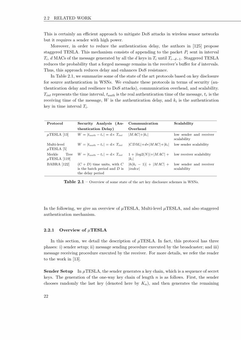
2.2 RELATED WORK Chapter 2 Key Disclosure based Source Authentication
This is certainly an efficient approach to mitigate DoS attacks in wireless sensor networksbut it requires a sender with high power.
Moreover, in order to reduce the authentication delay, the authors in [125] proposestaggered TESLA. This mechanism consists of appending to the packet Pi sent in intervalTi, dMACs of the message generated by all the d keys in Ti until Ti−d−1. Staggered TESLAreduces the probability that a forged message remains in the receiver’s buffer for d intervals.Thus, this approach reduces delay and enhances DoS resistance.
In Table 2.1, we summarize some of the state of the art protocols based on key disclosurefor source authentication in WSNs. We evaluate these protocols in terms of security (au-thentication delay and resilience to DoS attacks), communication overhead, and scalability.Tint represents the time interval, tauth is the real authentication time of the message, tr is thereceiving time of the message, W is the authentication delay, and ki is the authenticationkey in time interval Ti.
Protocol Security Analysis (Au-thentication Delay)
CommunicationOverhead
Scalability
µTESLA [13] W = |tauth − tr| = d× Tint |MAC|+|ki| low sender and receiverscalability
Multi-levelµTESLA [5]
W = |tauth − tr| = d× Tint |CDMi|+d∗|MAC|+|ki| low sender scalability
Merkle TreeµTESLA [119]
W = |tauth − tr| = d× Tint 1 + |log2(N)|+|MAC| +|ki|
low receiver scalability
BABRA [122] (C + D) time units, with Cis the batch period and D isthe delay period
|h(ki − 1)| + |MAC| +|index|
low sender and receiverscalability
Table 2.1 – Overview of some state of the art key disclosure schemes in WSNs.
In the following, we give an overview of µTESLA, Multi-level µTESLA, and also staggeredauthentication mechanism.
2.2.1 Overview of µTESLA
In this section, we detail the description of µTESLA. In fact, this protocol has threephases: i) sender setup; ii) message sending procedure executed by the broadcaster; and iii)message receiving procedure executed by the receiver. For more details, we refer the readerto the work in [13].
Sender Setup In µTESLA, the sender generates a key chain, which is a sequence of secretkeys. The generation of the one-way key chain of length n is as follows. First, the senderchooses randomly the last key (denoted here by Kn), and then generates the remaining
22 22 22
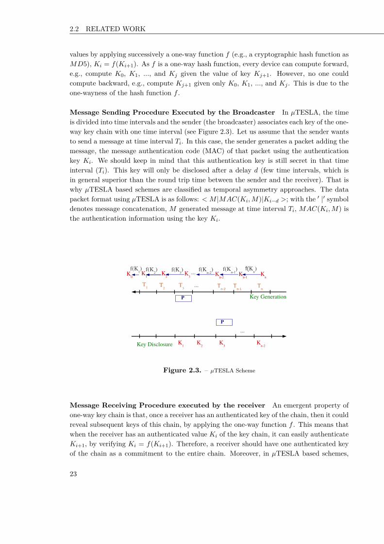
2.2 RELATED WORK Chapter 2 Key Disclosure based Source Authentication
values by applying successively a one-way function f (e.g., a cryptographic hash function asMD5), Ki = f(Ki+1). As f is a one-way hash function, every device can compute forward,e.g., compute K0, K1, ..., and Kj given the value of key Kj+1. However, no one couldcompute backward, e.g., compute Kj+1 given only K0, K1, ..., and Kj . This is due to theone-wayness of the hash function f .
Message Sending Procedure Executed by the Broadcaster In µTESLA, the timeis divided into time intervals and the sender (the broadcaster) associates each key of the one-way key chain with one time interval (see Figure 2.3). Let us assume that the sender wantsto send a message at time interval Ti. In this case, the sender generates a packet adding themessage, the message authentication code (MAC) of that packet using the authenticationkey Ki. We should keep in mind that this authentication key is still secret in that timeinterval (Ti). This key will only be disclosed after a delay d (few time intervals, which isin general superior than the round trip time between the sender and the receiver). That iswhy µTESLA based schemes are classified as temporal asymmetry approaches. The datapacket format using µTESLA is as follows: < M |MAC(Ki,M)|Ki−d >; with the ′ |′ symboldenotes message concatenation, M generated message at time interval Ti, MAC(Ki,M) isthe authentication information using the key Ki.
Key Generation
Key Disclosure
T1 T
2 Tn-1
Tn
K1
K2 K
n-2K
n-1K
n
P
f(Kn)f(K
n-1)f(K
2)
...
f(Kn-2
)...
Tn-2
T3
K3
f(K3)
...P
K1
K2
Kn-2
K3
K0
f(K1)
Figure 2.3. – µTESLA Scheme
Message Receiving Procedure executed by the receiver An emergent property ofone-way key chain is that, once a receiver has an authenticated key of the chain, then it couldreveal subsequent keys of this chain, by applying the one-way function f . This means thatwhen the receiver has an authenticated value Ki of the key chain, it can easily authenticateKi+1, by verifying Ki = f(Ki+1). Therefore, a receiver should have one authenticated keyof the chain as a commitment to the entire chain. Moreover, in µTESLA based schemes,
23 23 23

2.2 RELATED WORK Chapter 2 Key Disclosure based Source Authentication
nodes should be loosely synchronized. Initially, all nodes know the key disclosure scheduleof keys of the one way key chain.
Authenticating broadcast packets When a receiver receives the packets, it needs toensure that the packet could not be spoofed by an adversary. To verify this condition, thereceiver should check for each incoming packet that the sender did not yet disclose the keywhich corresponds to the packet, which means that no adversary could have forged thepackets. In order to verify this security condition, sender and receivers should be looselysynchronized, and that the key disclosure delay is known by all the participants in thenetwork (sender and receivers).
When a receiver receives an incoming broadcast packet in time interval Ti, it checks thefollowing security condition: Tc+δ−T0
Tint< Ti+d, where Tc is the local time when the packet
is received, T0 is the start time of the first time interval, Tint is the duration of each timeinterval, δ is the maximum clock difference between the sender and itself, d is the disclosurekey delay. Moreover, d is represented in terms of number of time intervals. For instance,when the node receives a broadcast packet in time interval T3 (i = 3), and d= 2. It has tocheck whether Tc+δ−T0
Tint< 3+2. In the case when the packet verifies the security condition,
the receiver will store it in its buffer. The receiver could verify this packet only whenreceiving the corresponding key. If the security condition is violated, which means that thepacket had an unusually long delay, thus the receiver drops the packet since an adversarymight have altered it. When receiving a key Ki of a previous time interval, the receiververifies its authenticity by checking whether this key matches the last authenticated storedkey Kj , by verifying Ki = f |j−i|(Kj). If the check is successful, the new key Ki is authenticand the receiver can authenticate all packets that were sent within the time intervals Ti toTj . The receiver also stores the key Ki instead of key Kj .
µTESLA is an extension to TESLA. The only difference between these two protocols isin their key chain commitment distribution schemes. TESLA uses asymmetric cryptographyto boostrap new receivers, which is impractical for resource constrained devices due to itshigh computation and storage overheads. µTESLA depends on symmetric cryptographywith the master key, shared between the sender and each receiver, to bootstrap the newreceivers individually. In this scheme, the receiver first sends a request to the sender, andthen the sender replies with a packet containing the current time Tc for time synchronization,a key Ki of one way key chain used in a past interval, the start time of the time intervalTi, the duration Tint of each time interval and the disclosure delay d.
2.2.2 Overview of Multi-level µTESLA: ML-µTESLA
Multi-level µTESLA [5] (ML-µTESLA) is a source authentication protocol, based onmulti-level key chains. It is an extended version of µTESLA. However, in µTESLA, thereis a difficulty to distribute the key chain commitments to a large number of sensor nodes.In particular, the method of bootstrapping new receivers in µTESLA does not scale to alarge WSN. In [5], the authors claim that there is a mismatch between the unicast-based
24 24 24

2.2 RELATED WORK Chapter 2 Key Disclosure based Source Authentication
distribution of key chain commitments and the authentication key of broadcast messagesin µTESLA. The transmission of the initial parameters is based on unicast, however thetechnique is intended for broadcast authentication. The goal of Multi-level µTESLA is toenhance the scalability of µTESLA, so that it could be applied to large WSNs.
In the following, we first detail the mechanism of multi-level-key chain. Then, we discussthe steps of execution of the protocol that are: the setup phase, the sending message phase,and the receiving message phase.
Multi-level key chain The concept of Multi-level key chain has been first introducedby [5]. As µTESLA uses a unicast transmission to send the initialization parameters (forbootstrapping new receivers), this concept is not viable when dealing with broadcast trans-mission [13]. To mitigate this problem, the authors in [5] use multi-level key chain todistribute the commitment of one-way chain.
Setup Phase In the setup phase, the sender/broadcaster generates a multi-level keychain. This chain is a set of one-way key chain with different levels.
The low level key chains are intended for authenticating broadcast messages, while thehigh level key chain is used to distribute and authenticate commitments (first key) of thelow-level key chains. The high level key chain uses a long enough interval to divide thetime line into equal time intervals, so that it cover the lifetime of a sensor network, withouthaving too many keys. The low level key chains have short enough intervals.
The lifetime of a sensor network is divided into n0 (long) intervals. In Figure 2.4, n0 = 3.The high level key chain has four elements K3, K2, K1, and K0, which are generated byrandomly picking K3 and computing Ki = f(Ki+1) for i = 0, 1, .., n0 − 1, where f isa pseudo-random function. The key Ki is associated with each time interval Ti. Thedisclosure of the authentication key Ki is disclosed in time interval Ti+1 since the high leveltime interval is usually very long compared to the network delay and clock discrepancies.As in µTESLA, the security condition to check whether the base station has disclosed thekey Ki when a sensor node receives a message authenticated with key Ki at time Ti is asfollows: Tc+δ−T0
Tint< Ti+d; where Tc is the local time when the packet is received, Ti is the
ith time interval, T0 is the start time of the first time interval, Tint is the duration of eachtime interval, δ is the maximum clock difference between the sender and itself, and d is thekey disclosure delay. In case of high level key chains, the disclosure delay is represented interms of number of high level time intervals. In general, the high level key is disclosed inthe next time interval, since the high level time interval is usually very long compared tothe network delay and clock discrepancies (d = 1). For instance, let us assume a scenariowhere a packet is received at T3 (the third time interval), the local time of the receiver isTc, and having received the values of δ, T0, Tint, and d. In this case, the security conditionis as follows: Tc+δ−T0
Tint< 3+1.
Each time interval Ti is further divided into n1 (short) time intervals of equal duration,denoted as Ti,1, Ti,2, ..., and Ti,n1. The base station generates a low level key chain foreach time interval Ti by randomly picking Ki,n1 and computing the remaining keys by
25 25 25

2.2 RELATED WORK Chapter 2 Key Disclosure based Source Authentication
T1,1 T
3,1
Time
T1,2
T1,3
T2,1
T2,2
T2,3 T
3,2T
3,3
K1,2
K1,3 K
2,1 K2,2
K2,3
K3,1
K3,2
K3,3
T1 T2T3
K1 K2 K3
K1,0
K1,1
K2,0 K
3,0
ff
f01 f01
f1f1f1f1f1f1
f1f1f1
fK0
Figure 2.4. – An example of two level key chain mechanism (n0 = 3, and n1 = 3)
applying a pseudo-random function f1. The keyKi,j is intended for authenticating messagesbroadcasted during the time interval Ti,j . The starting time of the key chain < Ki,0 > ispredetermined at Ti,j . The disclosure delay for the low level key chains can be determinedin the same way as in µTESLA. We assume that all the low-level key chains use the samedisclosure delay d. In case of low level key chains, d is represented on terms of number of lowlevel time intervals. When d = 3, it means that the low level key will be disclosed after threelow level time intervals. When sensor nodes are initialized, their clocks are synchronizedwith the base station.
In addition, the base station distributes to the sensor nodes the following parameters:the starting time, the commitment K0 for the high-level key chain, the duration Tint ofeach low-level time interval, the duration of each high level time interval, the disclosuredelay for the low-level key chains, and the maximum clock discrepancy between the basestation and the sensor nodes throughout the lifetime of the sensor network. In order for thesensor nodes to use a low level key chain during the time interval Ti, they must authenticatethe commitment (first key of the chain) Ki,0 before the start time of Ti. To achieve thisgoal, the base station broadcasts a commitment distribution message, denoted as CDM i,during each time interval Ti, with CDM i = i|Ki+2,0|MAC(K ′i , i|Ki+2,0)|Ki−1 where the′ |′ symbol denotes message concatenation, and K
′i is derived from key Ki with a pseudo
random function other than f and f1. Thus, to use a low-level key chain during Ti, thebase station needs to generate the key chain during Ti−2, and distribute Ki,0 in CDM i−2.
In particular, instead of choosing each key Ki,n1 randomly, each Ki,n1 is derived from ahigh-level Ki+1 (which is used to be in the next high-level time interval) through anotherpseudo-random function f01. That is Ki,n1 = f01(Ki+1).
26 26 26

2.2 RELATED WORK Chapter 2 Key Disclosure based Source Authentication
Message Sending Procedure Executed by the Broadcaster Let us consider that thebase station needs to send a data packet at time interval Ti,j . The format of the data packetis as follows: P = level_number|index|M |MAC(Ki,j ,M)|Ki,j−d (2) where level_numberrepresents the level of the hash chain, index is the index of the packet, M is the messagegenerated at time interval Ti,j , Ki,j−d represents the key corresponding to time intervalTi,j−d, and d represents the key disclosure delay for low level key chains.
Message Authenticating Procedure Executed by the Broadcaster When receiv-ing a CDM packet, the receiver does the following operations: (i) first, it needs to beensure that the packet could not be spoofed by an adversary. To verify this condition, thereceiver should check for each CDM packet that the sender did not disclose the key; ii)second, it should verify the authenticity of the received key by comparing it to the laststored authenticated key; and iii) third, if the check is successful, the new key is authenticand the receiver can authenticate CDM packets.
When receiving a data packet, the receiver does the following operations: i) first, itchecks whether the sender did not disclose the received authentication key (as in µTESLA);ii) second, it verifies the authenticity of the received (disclosed key) by comparing it to thelast stored key; and iii) third, if the key is authenticated, then the new key could be usedto authenticate received data packets.
2.2.3 Staggered Authentication
Staggered authentication was first proposed in [125] to deal with reducing delay asso-ciated with multicast authentication. The goal of this approach is to make the usage ofreceiver-side buffers more efficient, and nodes more resilient to buffer overflow denial ofservice attacks. The mechanism is applied to TESLA scheme, and employs several messageauthentication codes (MACs) that correspond to authentication keys that are staggered intime. The added MACs provide partial authentication, and the complete authentication isdone when all the MACs added to the packet are correct.
To broadcast message Mj in interval Ti, the sender constructs packet Pj . In fact, apacket Pj used in TESLA has the following format:
Pj = Mj |MAC(Ki,Mj)|Ki−d
with Mj is a message generated at time interval Ti, Ki−d is a key seed disclosed, thatcorresponds to time interval Ti−d. This key will be used to authenticate packets that aresent at time interval Ti−d, and d is the disclosure delay.
Using a staggered authentication mechanism, the modified jth data packet generated inTi is constructed as follows:
Pj =Mj |MAC(Ki,Mj)|MAC(Ki−1,Mj)|MAC(Ki−2,Mj)|...|MAC(Ki−d−1,Mj)|Ki−d
27 27 27

2.3 SYSTEM MODEL Chapter 2 Key Disclosure based Source Authentication
with Ki−d is a key disclosed at time interval Ti. In this scheme, the sender adds d messageauthentication codes to the message. On receiving a packet, the node will start authenticat-ing the packet and not to wait for d time intervals in order to confirm whether the packetis correct or not. The partial authentication allows the receiver to remove the incorrectpackets as soon as possible (after verifying at each time interval whether the correspondingMAC is correct or not). In fact, adding d MACs to the packet, will allow the receiverto authenticate partially if the corresponding MAC (using the disclosed key at that timeinterval) is correct or not. If it is not correct, the packet will be removed from the receiver’sbuffer, otherwise, the packet has a high probability to be an authenticated packet. Thereceiver can confirm that the received packet is authenticated until the verification of allthe added MACs, and when receiving the final disclosed key Ki.
2.3 System Model
In this section, we present the architectural system, the adversary model, as well asdesign goals.
2.3.1 Architectural System
We consider a large spatially distributed sensor network, consisting of one Base Stationand a large number of sensor nodes. The sensor nodes are resource-constrained with respectto memory space, computation capability, bandwidth, and power supply. The Base Stationis assumed to be more powerful than sensor nodes in terms of computation and communica-tion capabilities. The Base Station broadcasts queries or commands through sensor nodes,and expects replies that reflect the latest information or measurements. We also assumethat the WSN is loosely synchronized and that the Base Station is always trustworthy butthe sensor nodes are subject to compromise.
2.3.2 Adversary Model
We focus on Denial of Service (DoS) attacks such as bogus message flooding, aimingat exhausting constrained network resources. We assume that the adversary is able tocompromise a limited number of sensor nodes i.e., the adversary cannot compromise anunlimited number of sensor nodes.
2.3.3 Design Goals
Our primary security goal is that all messages broadcast by the base station are authen-ticated, so that the bogus ones inserted by the compromised sensor nodes can be efficientlyrejected. We also focus on minimizing the overhead of the security design.
28 28 28

2.4 OUR ADVANCED SCHEMES Chapter 2 Key Disclosure based Source Authentication
2.4 Our Advanced Schemes
Key disclosure based schemes have a major pitfall which is the authentication delay.This could be exploited by an attacker to handle various attacks, especially Denial of Ser-vice attacks in these constrained devices. Analyzing the impact of this dreadful attack onWSNs, we aim to reduce the authentication delay, and therefore reducing the forged delayin the receiver’s buffer. In this section, we present our proposed schemes. The first schemecalled staggered Multi-level-µTESLA consists on using the mechanism of staggered authen-tication in the Internet, and applying it to a protocol for Wireless Sensor Networks. Thesecond scheme enhances our first proposal by using a Bloom filter, in order to reduce thecommunication overhead of all the packets.
2.4.1 Staggered Multi-level-µTESLA
The aim of our proposal is to reduce the delay of forged packets in the receiver’s bufferin WSNs. In the following, we present a brief overview and a detailed description of ourproposal.
Overview
Deploying key disclosure delay based schemes in the resource constrained devices asWSNs is of great importance. However, the delay induced by these schemes could beexploited by an attacker to handle various attacks, especially Denial of Service attacks,and to lead to buffer overflow in these devices. In order to mitigate against these attacks,we refer to the principle of partial authentication and apply it to the resource constraineddevices. To this aim, we focus on applying this principle to Multi-level µTESLA, which is ascalable source authentication protocol in WSNs. Our proposal is called Staggered Multi-level µTESLA (SML-µTESLA). As Multi-level µTESLA, this scheme consists of splittingthe transmission time into equal length intervals and generating an authentication keycorresponding to packets sent in a given time interval. This authentication key is derivedusing a publicly available one-way function. Staggered Multi-level µTESLA is based onMACs from successive Multi-level µTESLA keys. Many adversaries will not be able toforge all the MACs constructed as opposed to the single-MAC-based scheme.
Description
In the following, we describe the set up phase, the transmission phase, as well as theverification phase of staggered Multi-level µTESLA.
Set Up Phase As Multi-level-µTESLA, the base station sends the initialization parame-ters to all the receivers in a secure channel after establishing the multi-level key chains: start
29 29 29

2.4 OUR ADVANCED SCHEMES Chapter 2 Key Disclosure based Source Authentication
time, number of high level time intervals, number of low level time intervals, the first keyof the high level chain, the first key of the low level chain, the disclosure delay of low levelkey chains, the disclosure delay of high level key chains (which is here one time interval),and the maximum clock discrepancy.
Transmission Phase When the base station needs to send a packet at time interval Ti,j ,it needs to create a data packet P as follows.P = level_number|index|M |MAC(Ki,j ,M)|MAC(Ki,j−1,M)| MAC(Ki,j−2,M)| ...|MAC(Ki,j−d−1,M)|Ki,j−dThe sender adds d message authentication codes to the message. Each message authenti-cation code will be authenticated at each time interval (when receiving the correspondingauthenticated key). Let us assume that the sender sends the packet P in time interval Ti,j .In order to authenticate this packet, the sender adds d message authentication codes usingthe following keys Ki,j , Ki,j−1,..., and Ki,j−d−1. When receiving this packet, the receiverwill buffer it. At time interval Ti,j+1, the receiver will receive the disclosed key Ki,j−d−1from another packet that discloses this information. Using the keyKi,j−d−1, the receiver canauthenticate the packet P with doing a partial authentication to verify the correspondingmessage authentication code (MAC(ki,j−d−1,M)). Then, if the verification does not hold(which means the packet is not correct), the receiver will remove the received authenticatedpacket in that time interval. Otherwise, the packet will still in the receiver’s buffer until thereception of another disclosed key that serves to authenticate the other message authenti-cation code. The complete authentication of the packet will be done until the reception ofthe disclosed key Ki,j . In that time, the receiver can confirm whether the packet is corrector not. This method will reduce the number of forged packets in the resource constraineddevices.
In SML-µTESLA, the receiver does not have to wait for d time intervals in order tostart authenticating packets. In fact, the receiver can use any received keys to begin theauthentication process and can thus promptly remove bogus packets. Hence, the numberof forged packets in the receiver’s buffer is decreased and the scheme is more resistant toDoS attacks.
The following Figure 2.5 represents an example of SML-µTESLA mechanism betweenthe sender and the receiver. In fact, the receiver does not have to wait for three timeintervals (in this example, d = 3) to start authenticating packets (packet P2,3 in Figure2.5). The receiver can use a received key in a time interval to start the authenticationprocess, and can thus promptly remove P2,3 if it is a bogus packet.
SML-µTESLA is efficient since it is based on symmetric cryptography. Thus, the ad-ditional computation and communication requirements introduced by the extra MACs willnot cause significant performance degradation. When it receives a packet, the receiver putsthe packet at the head of the queue, and degrades the packet to lower layers as additionalkeys arrive and the corresponding MACs are verified. If the verification fails, the packet isdropped from the queue. When the final key involved arrives and the corresponding MACis verified, then complete authentication is achieved.
30 30 30

2.4 OUR ADVANCED SCHEMES Chapter 2 Key Disclosure based Source Authentication
Key Generation
T2
Key Disclosure
T2,1
K2,1K2,2 K2,3 K2,4 K2,5
P2,3
P2,3
P2,3
f
T2,2 T2,3 T2,4 T2,5
K2,1K2,2 K2,3
f f f
Level 1Level 2
Level 3
K2,0f
...
...
Figure 2.5. – SML-µTESLA: An example of execution
2.4.2 Bloom Filter Multi-level-µTESLA
Our second proposal consists on devising a protocol that offers low cost, by using aBloom filter data structure to map the multiple message authentication codes.
Overview
In SML-µTESLA, a data packet generated in Ti,j is constructed as follows:P = level_number|index|M |MAC(Ki,j ,M)|MAC(Ki,j−1,M)|MAC(Ki,j−2,M)|..|MAC(Ki,j−d−1,M)|Ki,j−dThus, the sender uses multiple message authentication codes in order to have a more resis-tant scheme to DoS attacks. In order to enhance the performance of our scheme, we use aBloom Filter vector.
Description
Our second proposal is called BML-µTESLA, which is an extension of Staggered Multi-level µTESLA. The major goal of BML-µTESLA is to reduce the communication overhead.In fact, in time interval Ti,j , the sender generates d message authentication codes for eachdata packet, and constructs the set E. For each data packet, we have:
E = < MAC(Ki,j ,M),MAC(Ki,j−1,M), .., MAC(Ki,j−d−1,M) >We have to map the elements of E (each with |MAC| bytes) to an m-bit vector B
with B = b0, b1, ..., bm. Therefore, we have m < d × |MAC| to reduce the filter size and
31 31 31

2.4 OUR ADVANCED SCHEMES Chapter 2 Key Disclosure based Source Authentication
m > k × d to have a small probability of a false positive [126]. Note that k represents thenumber of hash functions used in the Bloom filter. These k hash functions are known byevery node as well as by the base station. For the sake of clearness, let us assume that theset of d MACs is denoted as follows: < MAC1,MAC2,MAC3, ...,MACd >. Initially, allthe bits of the Bloom Filter B are initialized to ‘0’. After that, the Base station fills theBloom Filter as follows: For each item (MAC) on E, if there exists hl(MAC) = i, then theith bit of B is set to ‘1’, (bi = 1).
In our case, we used a space-efficient Bloom filter [126] which is a randomized datastructure often used to represent a group of elements (d MACs) with a small false positiverate. That is, the Bloom filter saves space at the cost of representing a slightly larger group,than the original group of elements.
Choice of the Parameters of the Bloom Filter Given the number d of MACs gen-erated and concatenated in one packet, and the storage space of m bits for a single Bloomfilter, the minimum probability of a false positive [100,126] fprob that can be achieved is
fprob = (0.6185)( md
)
The probability of a false positive decreases as the fraction md increases. If we take for
example m = 16 bits, k = 3 and d = 3, then the minimum probability of a false positive isfprob = 0.077. To send a data packet P during a time interval Ti,j , the sender generates dMACs which are then mapped to a Bloom filter vector bi,j . The data packet correspondingto a message M in time interval Ti,j is then constructed as follows:
P = level_number|index|M |bi,j |Ki,j−d
Figure 2.6 illustrates how d MACs of each data packet are mapped into a Bloom Filtervector using k hash functions.
On receiving the data packet, the receiver tries to do the following operations:
• verify if the number of ‘1’ bits is less than or equal to d × k bits in the vector. If itis not, the packet is dropped; else the receiver computes the message authenticationcode MAC ′ with the correspondent key.
• verify if the computed message authentication code is in the Bloom filter bi,j . Infact, for each hash function hi (with 1 ≤ i≤ k) used in the Bloom filter, it verifies ifhi(MAC ′) is between 0 and m−1. If all the corresponding bits in the vector are set toone, then the packet is assumed to be partially authenticated. The packet is degradedto the lower levels of the buffer until all the correspondent MACs are verified, whenreceiving the corresponding keys in further packets as in SML-µTESLA. Else, theverification fails and the packet is dropped.
Our solution BML-µTESLA inherits the efficiency and security of SML-µTESLA. Inparticular, it inherits the resistance to packet loss. Further, the forged packets have a high
32 32 32

2.5 FORMAL VALIDATION Chapter 2 Key Disclosure based Source Authentication
Mi,j
MAC1
MAC2
MACd
Ki-d
Mi,j
1
0
1
.
1
.
Ki-d
m-bit vector
d*|MAC| h1(*)
h2(*)
h3(*)
..
..
..h
k(*) ...
Figure 2.6. – Mapping d MACs into a Bloom filter Vector
probability to be dropped before the expiration of the authentication delay. Furthermore,our protocol reduces the communication cost and the total energy overhead by using aBloom filter.
In the following section, we present the model checking tool AVISPA, that we use forverifying the three protocols (ML-µTESLA, SML-µTESLA, and BML-µTESLA).
2.5 Formal Validation
Formal validation tools are used in order to show the safety of a protocol. To this aim,there are many formal validation tools that are proposed in the literature [127–131]. We aimto formally verify and model ML-µTESLA, SML-µTESLA, and BML-µTESLA using theAVISPA model-checking tool and HLPSL language [97,131]. We show that those protocolscan safely be used for source authentication. We also demonstrate that those three protocolsexhibit also some attack problems which are hard to eliminate. A security protocol mustfulfill authentication, confidentiality, integrity, and non-repudiation, etc. Errors revealedafter deployment could appear to be catastrophic. Thus, validation before implementationis crucial. Validation requires the development of many formal methods to investigate prosand cons of any protocol.
2.5.1 Overview of AVISPA
We used the AVISPA toolbox which is devoted to the verification of security protocols.In fact, AVISPA was used earlier to verify WSNs. In [132], the authors analyze the TinySecauthentication protocol with AVISPA. They report a man-in-the-middle attack for pairwise-key establishment.
AVISPA provides a High-Level Formal Specification Language (HLPSL) [97] for spec-ifying protocols and verifying their security properties. Once the model of the protocol is
33 33 33

2.5 FORMAL VALIDATION Chapter 2 Key Disclosure based Source Authentication
specified, AVISPA translates it into an Intermediate Format (IF). This intermediate for-mat consists on the input of many back-ends that are integrated into AVISPA: SATMC(SAT- based Model-Checker), OFMC (On the-Fly-Model-Checker), Cl-Atse (Constraint-Logic-based Attack Searcher) and TA4SP (Tree Automata based on Automatic Approxi-mations for the Analysis of Security Protocols).
In order to specify a protocol in AVISPA, we present two kinds of roles: basic rolesand composed roles. A basic role describes participant initial knowledge, the initial state,the set of transitions and events of each participant. On the other hand, composed rolesdescribe protocol sessions. Several intruder models are implemented and each model has itsspecificities. The intruder is modeled by the channels over which the communication takesplaces. The Dolev-Yao intruder model is the strongest possible model of the capabilitiesof an intruder which preserves the properties of encryption. In fact, the intruder can readall transmitted messages, re-direct messages, and also block messages. If it receives anencrypted message and has knowledge of the appropriate key, it can learn the contents ofthe message. The Over-the-air intruder model uses Over-the- air channels which deliver themessage to the intruder and to the recipient at the same time. It is possible for the intruderto send messages. However, in this communication model, the intruder cannot performman-in-the- middle or a protocol on- the-fly attacks. We use the Dolev-Yao Intruder modelsince it is adequate to evaluate the correctness of our protocols.
2.5.2 Multi-level-µTESLA
We formally verify the state of the art protocol Multi-level-µTESLA, and we presenthow we model it using HLPSL language in AVISPA model checking tool.
Model Description
We implement a simple network consisting of three nodes: the sender, the receiver, andthe intruder. The sender broadcasts data packets and CDM packets. Each node is modeledas an independent process, broadcasting or receiving according to the protocol.
We model the broadcast of messages as sending a copy of every message simultaneouslyon each channel. We highlight the fact that all messages in AVISPA are passed through theattacker regardless of channel definitions. It is crucial to be able to prove that ML-µTESLAprotocol has the desired source authentication property. In order to model the system, wehave to model its components using the high level formal language HLPSL.
For ML-µTESLA, the system is composed by the network, the adversary and by theprotocol itself. In fact, the analysis starts by specifying the models used for the network,for the adversary and for ML-µTESLA protocol. Having established this formal framework,one can specify the security property source authentication required for ML-µTESLA. Afterestablishing the objectives, the model allows the proving or the disproving of the validity ofthe source authentication property for ML-µTESLA. We cannot specify the exact topology
34 34 34

2.5 FORMAL VALIDATION Chapter 2 Key Disclosure based Source Authentication
of the network. In fact, the model checker will generate all the possible combinations ofsource node-destination node pairs. Verification will be made over all the possible topologiesthat can be built with the specified number of nodes.
Given that our state space needs be finite, we set a limit on the number of packetsthat can be broadcast during one session. One packet is transmitted in each time interval.Obviously, this assumption does not affect the analysis since attacks do not depend onthe number of broadcast packets. Moreover, due to the fact that AVISPA does not offerarithmetic semantics, we have modeled the increase of the counter by representing a functiontick, such as tick(0) represents 1, tick(tick(0)) represents 2 and so on.
Moreover, the current model assumes the possibility of gaps, i.e. the receiver may missa message. We send artificial time ticks to keep the sender synchronized with the receiver.The current model does not include the possibility of messages being delayed, i.e. beingreceived in a later time interval because AVISPA does not handle a clock. How long it takesfrom sending to receiving a message depends on the value of a delay and the actions theintruder performs.
In our validation model, we assume that ML-µTESLA uses some cryptographic primi-tives including MAC values (hash) and Pseudo-Random Functions (f , f1, f01). Note thatthe MAC is computed by a message authentication code function that takes as input a mes-sage and a secret key, whereas Pseudo-Random Functions (PRFs) provide commitmentsto keys. S and R know PRFs and the message authentication code function to be used inthe session.
We also assume that the participants are initially synchronized: R knows the disclosureschedule of the keys, and S sends packets at regular intervals that are agreed with R duringthe synchronization process. Our model of ML-µTESLA uses a role environment whichincludes the two agents S and R, the local variables as hash functions, the channels, thepublic key, and the function tick which is used in order to calculate the number of keys,time intervals, the intruder knowledge, and also combined sessions. ML-µTesla protocolinvolves two participants: a sender (S) and a receiver (R). In this scheme, we make thefollowing assumptions:
• S and R communicate through an unreliable channel that is under complete controlof an intruder (I).
• While specifying the environment (i.e., defining a set of local states, a set of actions,a protocol), we assume that S has all the information it needs to prepare a packet.
• Moreover, we assume that I has all the information needed to prepare well-formedpackets.
• We consider a Dolev-Yao intruder who controls the channel and who is able to encryptand decrypt messages if he or she has the appropriate key.
• We assume that the intruder sends (resends and fakes) well-formed packets only i.e.,any packet contains a message body, a key, and appropriate MAC values.
35 35 35
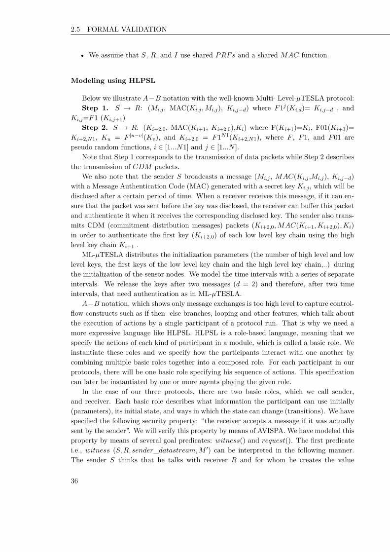
2.5 FORMAL VALIDATION Chapter 2 Key Disclosure based Source Authentication
• We assume that S, R, and I use shared PRFs and a shared MAC function.
Modeling using HLPSL
Below we illustrate A−B notation with the well-known Multi- Level-µTESLA protocol:Step 1. S → R: (Mi,j , MAC(Ki,j ,Mi,j), Ki,j−d) where F1j(Ki,d)= Ki,j−d , and
Ki,j=F1 (Ki,j+1)Step 2. S → R: (Ki+2,0, MAC(Ki+1, Ki+2,0),Ki) where F(Ki+1)=Ki, F01(Ki+3)=
Ki+2,N1, Ku = F |u−v|(Kv), and Ki+2,0 = F1N1(Ki+2,N1), where F , F1, and F01 arepseudo random functions, i ∈ [1...N1] and j ∈ [1...N ].
Note that Step 1 corresponds to the transmission of data packets while Step 2 describesthe transmission of CDM packets.
We also note that the sender S broadcasts a message (Mi,j , MAC(Ki,j ,Mi,j), Ki,j−d)with a Message Authentication Code (MAC) generated with a secret key Ki,j , which will bedisclosed after a certain period of time. When a receiver receives this message, if it can en-sure that the packet was sent before the key was disclosed, the receiver can buffer this packetand authenticate it when it receives the corresponding disclosed key. The sender also trans-mits CDM (commitment distribution messages) packets (Ki+2,0,MAC(Ki+1,Ki+2,0),Ki)in order to authenticate the first key (Ki+2,0) of each low level key chain using the highlevel key chain Ki+1 .
ML-µTESLA distributes the initialization parameters (the number of high level and lowlevel keys, the first keys of the low level key chain and the high level key chain,..) duringthe initialization of the sensor nodes. We model the time intervals with a series of separateintervals. We release the keys after two messages (d = 2) and therefore, after two timeintervals, that need authentication as in ML-µTESLA.
A−B notation, which shows only message exchanges is too high level to capture control-flow constructs such as if-then- else branches, looping and other features, which talk aboutthe execution of actions by a single participant of a protocol run. That is why we need amore expressive language like HLPSL. HLPSL is a role-based language, meaning that wespecify the actions of each kind of participant in a module, which is called a basic role. Weinstantiate these roles and we specify how the participants interact with one another bycombining multiple basic roles together into a composed role. For each participant in ourprotocols, there will be one basic role specifying his sequence of actions. This specificationcan later be instantiated by one or more agents playing the given role.
In the case of our three protocols, there are two basic roles, which we call sender,and receiver. Each basic role describes what information the participant can use initially(parameters), its initial state, and ways in which the state can change (transitions). We havespecified the following security property: “the receiver accepts a message if it was actuallysent by the sender”. We will verify this property by means of AVISPA. We have modeled thisproperty by means of several goal predicates: witness() and request(). The first predicatei.e., witness (S,R, sender_datastream,M ′) can be interpreted in the following manner.The sender S thinks that he talks with receiver R and for whom he creates the value
36 36 36

2.5 FORMAL VALIDATION Chapter 2 Key Disclosure based Source Authentication
M′ with the purpose sender_datastream. The request (R,S, Sender_datastream,M ′)
specification can be interpreted as follows: the receiver R thinks that he talks with senderS who sent him the value M ′ with the purpose sender_datastream. The protocol goalsare declared in the goal section.
Note that in our model, we use state machines to present how we specified some actionsand events in our three source authentication protocols. Circles represent states and linesindicate transitions or events. A transition consists of a trigger, or precondition, and anaction to be performed when the trigger event occurs. This is illustrated in Figure 2.7. If thesystem is, for example, in state S1 and when some events occur, then it will be a transitionto state S2 and some actions will be executed. Actions and events are implemented usingHLPSL language.
Figure 2.7. – A scheme of state machine interpretation
The initialization phase has to be secured. The sender generates the number of keys inthe high level chain and the number of keys in the low level chain. Thus, when the systemis in state 0 and we receive an event RCV (start), then the system moves to state 1 andexecutes the following actions:
• update the current time, i.e. the start time,
• generate the number of keys for each key chain: N and N1,
• generate the first key of each key chain,
• transmit the initialization parameters.
We note that this intruder model cannot break cryptography, thus, if the intruder doesnot know the key, it cannot forge or modify the message. The intruder knowledge is definedin the environment role as follows.
role environment() def=const s, r: agent,
37 37 37

2.5 FORMAL VALIDATION Chapter 2 Key Disclosure based Source Authentication
sr, ir, sync: channel (dy),hash_: hash_func,f, f1, f01: hash_func,KS: public_key,tick: text -> text,t_0, loss: textintruder_knowledge = {s, r, hash_, loss, f, f1, f01, t_0}compositionsession(s, r, sr, sync, f, f1, f01, KS)end rolesr, ir, and sync are channels that are dominated by a Dolev-Yao intruder model (channel(dy)). When an intruder could execute an action, it needs to add session(i, r, ir, sync, f,f1, f01, KS) in the role environment.
We have used two level key chains: one high level key chain and four low level keychains. Each low level key chain has three keys and each low level key will be generated inthe correspondent low level time interval. Knowing the last key of the high level key chain,we can compute the first key of this chain by applying pseudo random functions. Moreover,the multi-level key chain offers the possibility to compute the first key of the first low levelkey chain using pseudo-random functions
We can assume that the role of the initialization parameters is very crucial to determinethe safety of our protocols. In order to transmit a data packet, the sender generates amessage M using the operator new(), then it sends M , the message authentication code:(hash_(K ′,M ′)) and the disclosed key: (F1(F1(K ′))).
In what follows, we describe some actions and local states indicating the reception ofa new packet (data packet or CDM packet), the buffering of a verified packet, and also,the authentication of a buffered packet. The loss of packet is also modeled and thereforethe update of buffering keys. In Figure 2.8, we model the receiver side when a data packetarrives (using HLPSL). In fact, the system is in state 4, and when a data packet is received(RCV (M1′.Hash′.K_published′)), and the current time is inferior to N time intervals(Time/ = N), then the system moves to state 5, and we assign the value of the publishedkey in the data packet to Kprev2. Kprev2 indicates the presumed published key.
In Figure 2.9, we specify the case when a data packet is lost. In fact, when the followingconditions are satisfied: (the Time is inferior to N and the node receives RCV (loss)), thenthe receiver updates a variable gap indicating that there is effectively a loss of packet, andthe authentication of the buffered packets could be done by the reception of another packetin the future. We have to remember that all the authentication keys are generated from akey chain using a pseudo random function. That is why when a packet is lost, the schemeis still resistant to packet loss, i.e., authentication continues even when there are packetlosses.
We note that the intruder knowledge has a major impact on finding out whether thereis an attack or not. In our model, we insert a maximum of knowledge: the agents, the hashfunction, the pseudo random functions, etc.
38 38 38
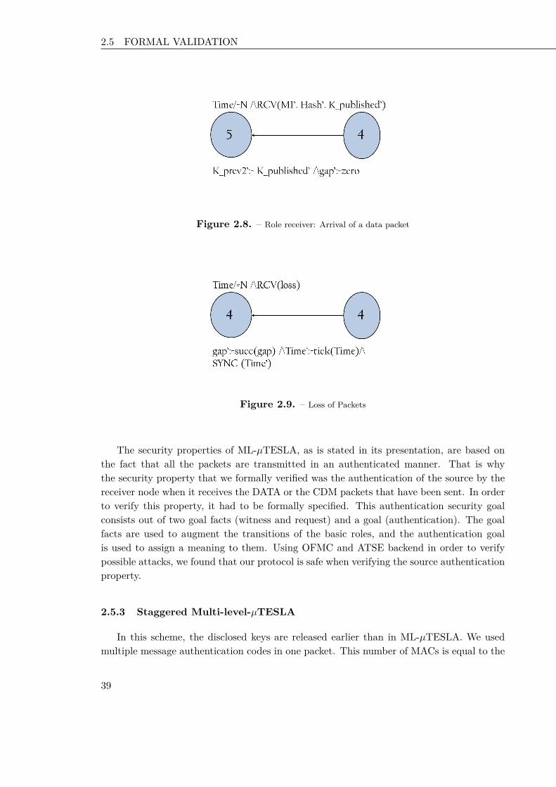
2.5 FORMAL VALIDATION Chapter 2 Key Disclosure based Source Authentication
Figure 2.8. – Role receiver: Arrival of a data packet
Figure 2.9. – Loss of Packets
The security properties of ML-µTESLA, as is stated in its presentation, are based onthe fact that all the packets are transmitted in an authenticated manner. That is whythe security property that we formally verified was the authentication of the source by thereceiver node when it receives the DATA or the CDM packets that have been sent. In orderto verify this property, it had to be formally specified. This authentication security goalconsists out of two goal facts (witness and request) and a goal (authentication). The goalfacts are used to augment the transitions of the basic roles, and the authentication goalis used to assign a meaning to them. Using OFMC and ATSE backend in order to verifypossible attacks, we found that our protocol is safe when verifying the source authenticationproperty.
2.5.3 Staggered Multi-level-µTESLA
In this scheme, the disclosed keys are released earlier than in ML-µTESLA. We usedmultiple message authentication codes in one packet. This number of MACs is equal to the
39 39 39

2.5 FORMAL VALIDATION Chapter 2 Key Disclosure based Source Authentication
key disclosure delay. If for example, the key disclosure delay is three time intervals, thenSML-µTESLA packet has three MACs. Our protocol is also initially synchronized then theinitialization parameters are transmitted in a secure manner or pre-loaded in the senderand the receiver.
The following scenario describes the A-B Model:Step 1. S → R :< Mi,j ,MAC(Ki,j ,Mi,j),
MAC(Ki,j+1,Mi,j), ..,MAC(Ki,j−d+1,Mi,j),Ki,j−d > where F1d(ki,d) = Ki,j−d,and Ki,j=F1(Ki,j+1).
Step 2. S → R :< Ki+2,0,MAC(Ki+1,Ki+2,0),Ki >
where F (Ki+1) = Ki,and Ki+2,0 = F1N1(Ki+2,N1),F01(Ki+3) = Ki+2,N1, and Ku = F |u−v|(Kv)where F , F1, F01 are pseudo random functions, i ∈ [1...N1] and j ∈ [1...N ].
As in ML-µTESLA, we define the environment role, the agents, the intruder model andthe intruder knowledge. We adopt the same validation model as described in ML-µTESLA.
We indicate that the previous simulation scenarios done in ML-µTESLA could be ap-plied to SML-µTESLA in HLPSL and we have obtained the same results as the previousprotocol. In fact, in order to transmit a data packet, as described in Figure 2.10, the sendergenerates a new message M ′ using new(), then concatenates, with the message M ′ , twomessage authentication codes (using hash_(K ′ ,M ′),hash_(K_prev′ ,M ′)), and the dis-closed key F1(F1(K ′)). In this scenario, we use two message authentication codes becausethe key disclosure delay is two time intervals. K_prev′ represents the previous key and ifwe generate a packet for transmission, then K_prev is updated by the value of the authen-tication key in this time interval. Thus, in the following time interval, this key will be usedto generate a message authentication code. The sender uses more than just key to constructMACs during time interval Ti, such as K_prev. Thus many potential adversaries will notbe able to forge the MACs constructed using K_prev, K.
Upon accepting a message as valid, the receiver executes the request function. Thisfunction tests that the identity of the supposed sender and the value itself are the sameas the ones specified in the corresponding witness function. If not, then the attacker hasmanaged to successfully forge a packet. The specified model of SML-µTESLA allows theproving of the validity of the source authentication property.
2.5.4 Bloom Filter Multi-level-µTESLA
Bloom filter based scheme (BML-µTESLA) consists of an enhanced version of SML-µTESLA. In fact, this latter uses multiple message authentication codes increasing thecommunication cost. It is possible to reduce this cost by using a Bloom filter data structure.This, in turn, will reduce the energy consumption.
We specify the Bloom filter based scheme as follows:
40 40 40

2.5 FORMAL VALIDATION Chapter 2 Key Disclosure based Source Authentication
Figure 2.10. – Transmission of a data packet (SML-µTESLA)
Step 1. S ← R: (Mi,j , bi,j , Ki,j−d) where bi,j is a Bloom filter generated in time intervalTi,j and maps the following items that was integrated in a data packet in SML-µTESLA:MAC(Ki,j ,Mi,j), MAC(Ki,j+1,Mi,j),..., MAC(Ki,j−d+1,Mi,j).
Step 2. S ← R: (Ki+2,0,MAC(Ki+1,Ki+2,0),Ki) where F (Ki+1) = Ki, Ki+2,0 =F1N1(Ki+2,N1), F01(Ki+3) = Ki+2,N1, where F , F1, F01 are pseudo random functions,i ∈ [1...N1] and j ∈ [1...N ].
The initialization parameters are transmitted from the sender to the receiver. Then, thesender computes for each packet the corresponding Bloom filter, transmits the message, theBloom filter, and the disclosed key using the following specification
SND(M ′.F ilter′.F1(F1(K ′)))
where Filter is a set of nat (natural) representing the Bloom filter, and the disclosed key isF1(F1(K ′)). The receiver must first verify that the disclosed key is safe by comparing itto the latest buffered key. Once this key is verified, then it will be buffered.
We represent the Bloom filter data structure as a set of “0”s and “1”s in HLPSL language.Recall that the model checking tool does not support arithmetic operations. We set thevalue of the key disclosure delay to two time intervals, as in ML-µTESLA. The receiverfirst creates two message authentication codes. These two MACs are mapped using threeindependent hash functions H1, H2, and H3.
2.5.5 Security Analysis
We have specified our protocols using HLPSL language and AVISPA tools. In order todetect attacks like replay, parallel sessions, and DoS attacks, we used ATSE backend whichdetects possible attacks and gives a trace.
• Replay Attacks. Replay attacks consist on playing back previously transmittedmessages by the intruder to sabotage a protocol session. Replay attacks take place
41 41 41

2.5 FORMAL VALIDATION Chapter 2 Key Disclosure based Source Authentication
when the intruder redirects eavesdropped or altered messages within one or moreinterleaved protocol session(s). These attacks could be detected using the optionsession compilation in OFMC backend of AVISPA. OFMC detects the replay attackeven without the second parallel session between the sender and the receiver. This isbecause it first simulates a run of the whole system and in a second run, it lets theintruder takes advantage of the knowledge learn in the first run. The formal analysisthat we conducted confirms that our protocols are safe with regards to replay attacks.
• Type Flaw Attacks. A type flaw attack happens generally when the receiver of amessage accepts that message as valid, but imposes a different interpretation on thebit sequence than the participant who created it. These attacks can be optionallycombined with a message interception in order to prevent reception of interceptedmessage by its recipient such as to perform a type flaw based message replay. The in-truder triggers a type flaw attack after having altered an eavesdropped message basedon intruder knowledge, thus resulting in another message. Our models of the threesource authentication protocols resist to this type of attack since AVISPA (OFMCand ATSE backends) does not indicate any flaw attack trace.
• Parallel Session Attacks. This kind of attack takes place by subsequent interleavingreplays among protocol sessions, in which the intruder manipulates protocol partici-pants in multiple roles, in order to subvert the protocol’s goals. Parallel sessions can bespecified in HLPSL, but they may lead to replay attacks and may be used in sequenceones. In AVISPA, we try to detect this attack by applying parallel sessions having thesame parameters as the following example: session(s, r, sr, sync, f, f1, f01,KS) /\session(s, r, sr, sync, f, f1, f01,KS).Where s and r are agents, sr and sync represent the channels which are dominatedby a Dolev-Yao Intruder model. f ,f1 and f01 are hash functions and KS is a publickey. AVISPA did not detect a parallel session attack.
• DoS Attacks. It takes place anytime after the occurrence of some action representinga transmission of a message taken by the intruder, or after the transmission of an en-crypted message where the intruder knows the encrypted key. Based on Iknowledge,the intruder alters messages and transmits them. The intruder performs an integrityviolation attack of the received message. In fact, we assume that the intruder concate-nates some bogus data. The intruder then performs the transmission of this alteredmessage many times representing many distinct requests. An intruder can transmitmany bogus packets to an authentic receiver leading to a DoS attack. We found thatML-µTESLA can encounter DoS attacks on data packets and CDM packets.
We note that the absence of an attack with AVISPA gives a measure of confidence; howeverit is not a proof of protocol security since AVISPA and alike impose a bound on the roleinstances to get decidability.
To spoof an individual ML-µTESLA packet to a single receiver, an attacker must suc-cessfully forge the authenticator designated for that receiver in the packet and all subsequent
42 42 42

2.6 PERFORMANCE EVALUATION Chapter 2 Key Disclosure based Source Authentication
confirmations of validity. The probability of successfully forging a single secure MAC tag ofb bits in length is 2−b. In SML-µTESLA the probability of forging the authenticator whichconsists of d MACs will be 2−(d×b).
2.6 Performance Evaluation
We show that SML-µTESLA satisfies the following requirements: low memory overhead,low energy consumption, low authentication delay. We further compare SML-µTESLA andML-µTESLA, and show that SML-µTESLA outperforms ML-µTESLA in several ways. Inorder to evaluate our schemes, we implement the two schemes on TinyOS using TOSSIMsimulator. The experiments are done using TelosB motes.
2.6.1 Prototype Implementation
The TelosB motes [52] used in our experiments, run TinyOS operating system version2.1 and support NesC as a programming language [98]. A TelosB mote is of the size oftwo AA batteries. It has an IEEE 802.15.4/ZigBee compliant RF transceiver, allowingradio communication in the frequency range 2.4 to 2.4835 GHz (a globally compatible ISMband), and a bit rate of 250 kbps data rate. It is based on the TI MSP430 microcontroller.The MSP430 incorporates 8 MHz, 16 bit RISC CPU, 48 K bytes flash memory (ROM),and 10 K bytes RAM.
TinyOS is written in NesC, a C-based language that provides support for the TinyOScomponent and concurrency model. Each component can correspond to a hardware element(led, timer, ADC, etc.) and can be reused in different applications. An application is com-posed by a set of components linked together to achieve a fixed goal. The implementationof a component is done by defining a set of commands, events, and tasks.
Figure 2.11 depicts the components and the interfaces of our schemes. They are com-posed of a set of components linked together. MainC is a major component that is exe-cuted first in any TinyOS application. Basically, our implementation uses several Timerinterfaces (provided by a Timer component) for handling message transmission. TimerMil-liC is the standard millisecond timer abstraction. In order to enable sending and receiv-ing messages, our scheme uses the AMSenderC, AMReceiverC, MMTESLAReceiverC, andMMTESLASenderC components that provide interfaces Packet, AMPacket, RadioSend,RadioReceive, Primitive and Buffer. This code reuse in TinyOS saves code space in ROMas well as data space in RAM because less variables and cipher contexts have to be de-fined. AMSender is a virtualized abstraction. That is, each AMSender can handle a singleoutgoing packet. Every hardware platform defines a component ActiveMessageC, whichthe basic packet components (AMSenderC, AMReceiverC, etc.) wire to. Generally, Ac-tiveMessageC is just a configuration that renames a particular radio chips active messagelayer. In addition, our application uses a linear feed shift register random number generator(RandomLFSR) component to generate pseudo-random numbers needed by key chains. An
43 43 43

2.6 PERFORMANCE EVALUATION Chapter 2 Key Disclosure based Source Authentication
application can change what the default random number generator is by defining its ownRandomC, which maps to a different algorithm. As block cipher, we have chosen the RC5component to provide both encryption and authentication. RC5 as a symmetric key cipherfor this system has already been implemented and tested. The LedsC component actuallyturns the LEDs on and off, during testing. LedsC is useful for debugging, but in deploymentit is a significant energy cost and usually replaced with NoLedsC.
TimerMilliC
SimpleBufferCSecPrimitiveC
LedsC
AMReceiverC
AMSenderC
ActiveMessageC
RandomLfsrC
MainC
MMTESLAReceiverC
CBCMacC
RC5C
MMTESLASenderC
MMTESLAAttackerC
SourceAuthenticationC
BootTimer
RadioReceive
RadioSend
RadioControlRandom
Receiver Primitive MAC
Primitive
Primitive
Leds
Attacker
Sender
BlockCipher/BlockCipherInfo
Figure 2.11. – Our Application Architecture
However, one of the major constraints on implementing the two schemes on a sensorplatform is the small available payload size of packets. The standard packet payload islimited to 29 bytes under TinyOS.
In ML-µTESLA scheme, it is easy to send all the amount of data using 29 bytes. But, inSML-µTESLA scheme, it is difficult to send all the amount of data using a 29 bytes packet,then we have to modify the application Makefile using “TOSH_DATA_LENGTH =100′′ in order to have a packet with maximum 100 bytes, since in 802.15.4 the packetdoes not exceed 128 bytes of data length. We employed timers that fire every 100 ms inour simulations since this provides sufficient spacing for TOSSIM while still allowing formaximum channel utilization.
We notice that TinyOS has memory constraints. In fact, it allows for static memoryallocation, in order to cope with the severe hardware constraints of sensor nodes. This makes
44 44 44

2.6 PERFORMANCE EVALUATION Chapter 2 Key Disclosure based Source Authentication
it very space and time efficient because there is no need for maintaining an additional datastructure to manage the dynamic heap. In other words, this allows using the entire RAM forstoring information. However, all variables and their sizes have to be known at compile timewhich makes working with dynamic data structures as linked lists or hash maps, impossible.
Moreover, some applications may need more memory since the amount of available RAMis not sufficient, probably just temporarily, than the node offers. In this case, EEPROM(also called flash) might be used. EEPROM is mostly larger than the RAM but reading fromit and writing to it are operations needing a lot of time and energy. Thus, these memoryconstraints lead us to optimize the use of global variables that take a lot of memory space.We make pointers to them to reduce them, when it is necessary to use them.
We use TelosB motes in order to test and validate our protocols. However, the TelosBmotes need synchronization since the implemented protocols have the requirement of node’ssynchronization. In order to limit this constraint, we use the flooding time synchronizationprotocol [51] because it is very efficient compared to other synchronized protocols and ithad been tested also in TelosB motes. We had run experiments on 10 TelosB motes, withone malicious mote, and 9 honest motes.
2.6.2 Simulation Setup
We run our simulations with the TOSSIM simulator [98]. TOSSIM is actually a dis-crete event emulator designed specifically for TinyOS applications. We also evaluate theaverage node energy consumption overhead needed to authenticate the source of a trans-mitted packet. To achieve this goal, we used PowerTOSSIM-Z simulator [99]. It is basedon TinyOS and TOSSIM. PowerTOSSIM-Z makes use of the TinyOS and TOSSIM com-ponent model to instrument hardware state transitions for the purpose of tracking powerconsumption. Simulated hardware components (radio, sensors, LEDs, etc.) make calls tothe PowerState module, which emits power state transition messages for each component.These messages can be combined with a power model to generate detailed power consump-tion data or visualizations. Our evaluation is focused on the broadcast of data packets.In our experiments, we use a sender, an attacker, and a receiver component. We adopt asetting as follows. The ML-µTESLA key disclosure delay is 3 time intervals, the duration ofeach ML-µTESLA time interval is 100 ms, and each ML-µTESLA key chain consists of 600keys. Thus, the duration of each ML-µTESLA instance is 60 seconds. We assume there are200 ML-µTESLA instances, which cover up to 200 minutes in time. We also assume thateach hash value, cryptographic key or MAC value is 8 bytes long. The ML-µTESLA datapacket format contains a sender ID (2 bytes), a key chain index (2 bytes), a fragment index(1 byte), and one hash value (8 bytes). As a result, the packet payload size is 29 bytes.
According to the implementation we obtained, each CDM and Data message in multi-level scheme also contains 29 bytes payload. We assume 3 CDM buffers at each receiver forthe two schemes. We set initially the data packet rate from the sender as 100 data packetsper minute, and allocate 3 buffers for data packets at each sensor node. To investigate theauthentication probability under DoS attacks and communication failures, we assume the
45 45 45

2.6 PERFORMANCE EVALUATION Chapter 2 Key Disclosure based Source Authentication
attacker sends 100 forged data packets per minute. We also assume the channel loss rate is0.5. In our simulation scenarios, we define the attack rate as the number of forged packetsper min. To improve the accuracy of our results, we repeated the experiments at least 50times.
2.6.3 Results
In this section, we present the outcome of the two authentication protocols.
Authentication Probability
The authentication probability is the fraction of the authenticated packets receiveddivided by the number of received packets. The Figure 2.12 reports the authenticationprobability. This is shown for the two protocols. The x-axis of Figure 2.12 indicatesthe buffer capacity of the receiver that is taken into consideration while the y-axis showsthe corresponding authentication probability of the messages. In fact, the authenticationprobability increases slowly when the buffer capacity is increased. When we assume thesame buffer capacity, with varying the attack rate (number of forged packets per min), theauthentication probability increases when the attack rate increases.
It is interesting to note that for ML-µTESLA, the authentication probability increaseswhen we decrease the attack rate. Moreover it also increases when increasing the buffercapacity. We can see that the two schemes always have a higher authentication rate whenthe buffer capacity increases. The reason is that, a sensor node is able to authenticate anybuffered message once it receives a later disclosed key, since different key chains are linkedtogether. Though in the ML-µTESLA scheme, lower-level ML-µTESLA key chains are alsolinked to the higher-level ones, a sensor node may have to wait for a long time to recoveran authentication key from the higher-level key chain when the corresponding lower-levelkey chain commitment is lost due to severe DoS attacks or channel losses. During this timeperiod, most of previous buffered data packets are already dropped.
It is straightforward to prove that ML-µTESLA scheme has to allocate a large bufferto achieve certain authentication probability when there are severe DoS attacks, whilethe staggered authentication can achieve higher authentication probability without anyadditional buffer. Figure 2.12 also shows the behaviour of SML-µTESLA corresponds tothat of an ideal protocol. The reason is that in this scheme, a sensor node can verify a datapacket immediately and when receiving any disclosed key on the later time interval, whilein the ML-µTESLA scheme, a sensor node has to wait for a while before authenticatingdata messages.
Figure 2.13 shows the behavior of ML-µTESLA when we run it on TelosB motes. Thex-axis indicates the duration of an attack, while the y-axis shows the corresponding au-thentication probability of the messages, with varying the attack rate. The authenticationprobability increases slowly when the duration of the attack is low.
46 46 46

2.6 PERFORMANCE EVALUATION Chapter 2 Key Disclosure based Source Authentication
0
0.2
0.4
0.6
0.8
1
10 20 30 40 50 60 70 80 90 100
Au
then
ticati
on
Pro
bab
ilit
y
Buffer Capacity
Attack rate = 360, multi-level-microTESLAAttack rate = 360, staggered multi-level-microTESLA
Attack rate = 120, multi-level-microTESLAAttack rate = 120, staggered multi-level-microTESLA
Attack rate = 40, multi-level-microTESLAAttack rate = 40, staggered multi-level-microTESLA
Figure 2.12. – Authentication Probability
0
0.2
0.4
0.6
0.8
1
60 45 30 15 5 2 1 0
Au
then
ticati
on
Pro
bab
ilit
y
Attack Duration (min)
Attack rate = 60Attack rate = 30Attack rate = 20
Figure 2.13. – Authentication Probability versus attack rate and duration using TelosB motes
Authentication Delay
To measure the average time for computing the authentication delay, we use SysTime,a TinyOS component that provides a 32-bit system time based on the available hardwareclock. The average time to compute authentication delay (the delay of authenticated packetminus the delay of received packet) is throughly the same. This metric varies by varying theloss rate. As it shows in Figure 2.14, the authentication delay increases when the loss rateincreases too. In fact, when the loss rate = 20%, then the authentication delay is 500 ms.Moreover, this delay increases for loss rate = 80%, the authentication delay is 1500 ms.
47 47 47

2.6 PERFORMANCE EVALUATION Chapter 2 Key Disclosure based Source Authentication
0
5
10
15
20
25
30
10 20 30 40 50 60 70 80 90
Au
then
ticati
on
Dela
y (
x 1
00 m
s)
Loss Rate
Multi-level-microTESLAStaggered Multi-level-microTESLA
Figure 2.14. – Authentication Delay
Forged Packets
Figure 2.15 reports the average number of forged packets with varying the attack rateusing experiments on TelosB motes. We could see that the average number of forged packetsincreased when the capabilities of the malicious node becomes stronger. When the durationof attack = 40 min, then the average number of forged packets is superior than 1200 (whenattack rate = 60), however it is less than the half when attack rate = 20.
0
200
400
600
800
1000
1200
60 45 30 15 5 2 1
Avera
ge N
um
ber
of
Fo
rged
Packets
Attack Duration (min)
Attack rate = 20Attack rate = 30Attack rate = 60
Figure 2.15. – Average Number of Forged Packets in Multi-level-µTESLA using TelosB motes
48 48 48

2.6 PERFORMANCE EVALUATION Chapter 2 Key Disclosure based Source Authentication
Figure 2.16 reports the average delay of forged packets with varying the loss rate. Wecould see that the delay of forged packets is much lower than the authentication delay. Thiscould be explained by the fact that in staggered authentication, forged packets are quicklydropped and deleted.
0
5
10
15
20
25
30
10 20 30 40 50 60 70 80 90
Dela
y o
f F
org
ed
Packets
(x 1
00 m
s)
Loss Rate
Staggered Multi-level-microTESLAMulti-level-microTESLA
Figure 2.16. – Delay of Forged Packets in the Buffer
In ML-µTESLA, the delay of forged packets is thoroughly the same as the authenticationdelay. This could be explained by the fact that in staggered authentication, forged packetsare quickly dropped and deleted, since received packets are only authenticated after dtime intervals (in our experiments, d = 3). In Figure 2.17 the delay of forged packets inthe receiver’s buffer varies with the loss rate. Furthermore, we remark that in staggeredauthentication scheme, it allows a small delay of forged packets since these packets does notwait for the disclosure of one key. In this scheme, the delay of forged packets is between(1.5 × 100 ms) and (2 × 100 ms). This also demonstrates that forged packets in theSML-µTESLA are quickly removed from the receiver’s buffer.
Figure 2.17 represents the delay of forged and authenticated packets in staggered auten-tication. Forged packets remain a small time in the receiver’s buffer, while the authenticatedpackets, they are only authenticated after receiving the three authentication keys, since thedisclosure authenticated key is three time intervals.
Figure 2.18 represents ML-µTESLA when varying the delay of forged and authenticatedpackets. In fact, these two delays are throughly the same because forged and authenticatedpackets have to wait for receiving the three keys. For a loss rate = 10 %, the delay is lessthan (5 × 100 ms) in ML-µTESLA.
49 49 49

2.6 PERFORMANCE EVALUATION Chapter 2 Key Disclosure based Source Authentication
0
5
10
15
20
25
30
10 20 30 40 50 60 70 80 90
Dela
y o
f P
ackets
(x 1
00 m
s)
Loss Rate
Delay of Forged PacketsAuthentication Delay
Figure 2.17. – Delay of Forged and Authenticated Packets in Staggered Multi-Level µTESLA
0
5
10
15
20
25
30
10 20 30 40 50 60 70 80 90
Dela
y o
f P
ackets
(x 1
00 m
s)
Loss Rate
Delay of Forged PacketsAuthentication delay
Figure 2.18. – Delay of Forged and Authenticated Packets in Multi-level µTESLA
Memory Requirements
In order to evaluate the memory space requirements among nodes, our implementationof ML-µTESLA in TelosB occupied approximately 2666 (bytes) in RAM and 24786 (bytes)in ROM, representing 25% of the available ROM and 50% of the RAM. SML-µTESLAoccupied approximately 3318 (bytes) in RAM and 25962 (bytes) in ROM. The increase ofthe RAM in the second scheme is due to the staggered mechanism, and the access to thereceiver’s buffer for each time interval.
50 50 50

2.7 SUMMARY Chapter 2 Key Disclosure based Source Authentication
Energy Overhead
The commercially available platforms such as the MicaZ are limited to 48KB of programmemory and 10 KB of RAM [133]. They are alimented with double AA batteries that offerenergy of 2850 mAh alimented by a 3 v power. Thus a sensor node provides an initialtotal energy of 30780 joule. The energy overhead introduced by these two applications is248818 mj for the first scheme and 248927 mj for the second scheme, which is negligibleregarding the total energy of a mote (< 1%). These values correspond to a data rate of 100data packets per minute and an attack rate of 60 data packets per minute. Therefore, theproposed source authentication solution is very efficient and suits well the severe constraintsof sensor nodes. Such efficiency is necessary for any security solution in wireless sensordevices. Energy is the scarcest resource. Thus, we underline that every protocol designedfor sensor nodes must be evaluated in terms of power consumption to be validated. Wedemonstrate with our techniques that security systems can become an integral part ofpractical sensor networks.
2.7 Summary
In this chapter, we present and justify a few of the basic requirements that an ideal proto-col for key disclosure delay based source authentication protocol should have. We highlightthat a major pitfall of these schemes is the authentication delay between the reception ofthe packet and its real authentication. In particular, we propose two source authenticationschemes. We presented a formal approach to the security analysis of Multi-Level-µTESLA,and our two proposed schemes by means of a model checking tool namely, AVISPA. Theoutput shows that the three protocols are safe in terms of source authentication. We alsofound that modeling time with AVISPA is not a trivial task since AVISPA does not handle aclock, and we must experiment many session scenarios in order to test the different attacks.
We have also done extensive simulations to show the efficiency of SML-µTESLA. More-over, we indicate that the overhead of such protocols should be small. Performance compar-isons show that SML-µTESLA exhibits better results in terms of authentication probability,energy overhead, and resilience to DoS attack. We are interested in the development of amore accurate intruder model that takes into account the particular features of wirelesssensor network.
In this chapter, we focus on memory Denial of Service attacks on broadcast authenti-cation, and in particular in µTESLA based schemes. If we consider the scenario when thereceiver needs to log the received messages, in such a way that a malicious node cannotsuccessively modify the messages, µTESLA based schemes are not candidates, to be usedin such scenario. Indeed, as soon as the key is disclosed, the attacker may use that key tomodify the logged messages. This kind of attack refers to the Delayed Authentication Com-promise attack. The next chapter provides a secure mechanism to deal with the delayedauthentication compromise attack in key disclosure based schemes in WSNs.
51 51 51

52 52 52

CHAPTER 3
Delayed AuthenticationCompromise
The previous chapter looked at the broadcast authentication service in key disclosure basedschemes. We present that several broadcast authentication solutions have been developedfor resource constrained devices, and we focus especially on a security vulnerability thatcould lead to a denial of service attack. We then propose several solutions to mitigatethis problem. In this chapter, we demonstrate that these solutions are not effective whenthe received messages (and its associated receiving time) have to be stored, and used in asubsequent moment as a proof—a common scenario when receiving devices are unattendedfor most of the time. We first demonstrate that recently proposed schemes that also addressthe storage issue are vulnerable to two kinds of attacks: switch command attack (where anadversary pretends to “switch” two messages over time), and drop command attack (wherean adversary just pretends to “hide" a message sent from the broadcaster). We then proposea new solution for broadcast authentication: MASS. Our analysis shows that our solutionis effective in detecting both switch command and drop command attack, and—at the sametime—is more efficient (in terms of both communication and computation) than the stateof the art solutions.
The rest of the chapter is organized as follows. In Section 3.1, we give a brief overviewof state of the art in broadcast authentication. We present the background in Section 3.2.We discuss the limitations and the weaknesses of two state of the art protocols to cope withtwo important attacks: switch command attack, and drop command attack in Section 3.3.In Section 3.4 we detail our solution MASS, where we explain the set-up, the transmissionand the verification phase of the scheme. We analyze the security of our proposal in Section3.5. We discuss the overhead of MASS and compare it with state of the art protocols inSection 3.6. Finally, Section 3.7 reports some concluding remarks.
53 53 53

3.1 RELATED WORK Chapter 2 Key Disclosure based Source Authentication
3.1 Related Work
In [19, 134, 135], the authors present different ways to enhance the broadcast authenti-cation service either by using cryptographic puzzles, or multi-level one chains to improvethe scalability of µTESLA (to deal with large Wireless Sensor Networks). Let us considerthe scenario when the receiver needs to log the received messages, in such a way that anattacker cannot successively modify the messages. Key disclosure based schemes are notcandidates, to be used in such scenario. Indeed, as soon as the key is disclosed, the attackermay use that key to modify the logged messages. In [18], this attack process refers to De-layed Authentication Compromise (DAC) attack. In the DAC attack, the adversary mayuse an already disclosed key to sign for instance the command “open the valve”, and save itin the memory of a compromised actuator. By using a key disclosure delay based scheme,the adversary can physically force the door, use an already disclosed key to generate a fakemessage requiring to open the door, and store it in the memory of the actuator. Oncenoticed that the valve has been opened, it will be difficult to prove with certainty who hasbeen compromised. If the base station is trusted, we can state that the node is cheating;however if the base station itself can be compromised, then it is not possible to determinewho is cheating, the node or the base station.
In order to be resilient against DAC attacks, the authors in [18] propose three algo-rithms called Partially Accountable Signature Scheme (PASS), Totally Accountable Sig-nature Scheme (TASS), and Prioritized Totally Accountable Signature Scheme (PTASS).PASS works only in particular cases (so we will not focus on it), while TASS and PTASSare more widely applicable. The main idea behind these two protocols is that the time isis divided in time intervals, and we associate the authentication key both to the time in-terval and to the message content. The base station builds a Direct Acyclic Graph (DAG)composed by a Merkle Tree and several Merkle-Winternitz Signatures [78] (we will give ageneral overview of these two notions on Section 3.2). When the base station wants to senda command, it sends several nodes of this DAG, in such a way to create a one time signatureof the command. The receivers can authenticate the signature, but an attacker cannot usethis signature to authenticate other messages. Further details about TASS and PTASS aregiven in Section 3.2.2. However, it is important to highlight the difference between thesetwo protocols. While TASS does not provide immediate authentication of the messages,PTASS does allow two levels of message priorities: low and high priority messages. Theauthentication of high priority messages comes with a transmission overhead, but thesemessages can be immediately authenticated by the receiver.
In the literature, several other protocols have been proposed for the broadcast authen-tication. In the following, we will review the most important one-time signature schemesthat are relevant for our work. One-time signature schemes are signature schemes based onone way functions [136]. Unfortunately, using a single key pair a one-time signature schemecan be used to sign few messages only. This is due to the disclosure of information thatshortly after signing a few messages can be used by an attacker. Despite this limitation,one-time signature schemes are advantageous because of their speed. Since they are based
54 54 54

3.2 NOTATION AND BACKGROUND Chapter 2 Key Disclosure based Source Authentication
on one way functions, their computation cost is quite low when compared with that ofasymmetric primitives. In [137], a one-time signature scheme for broadcast authenticationtailored towards peer-to-peer systems has been proposed. It overcomes the restrictions oftraditional approaches based on signature schemes like RSA in terms of delays, signaturesize, and computational complexity. However, it is subject to DAC attacks. Motivatedby the application of signatures to stream and broadcast authentication, Perrig proposeda one-time signature scheme called BiBa [138]. The protocol is robust to packet loss, butit suffers from DAC attacks. Hash to Obtain Random Subset (HORS) scheme is an im-provement of BiBa that decreases the time needed to sign and verify messages while alsoreducing the key and signature sizes [139]. It is computationally efficient, requiring a singlehash function evaluation to generate the signature and a few hash function evaluations forverification. Due to the large public key size (usually 10 to 20K bytes), HORS does notsuite resource constrained devices [140]. Furthermore, in both BiBa and HORS, securitydecreases as the number of messages that are signed in a time interval increases.
In the following, we present the notation and some notions relative to the Merkle Treeand Merkle-Winternitz Signature.
3.2 Notation and Background
In this section, we present the notation used in this chapter. We also present an overviewof TASS and PTASS protocols that are resistant against the delayed authentication com-promise attack [18].
3.2.1 Notation
We summarize the notation used in this chapter in Table 3.1.
Symbol Definitiont Number of time intervalsc Maximum number of different commands
that the base station can sendm Maximum number of commands that the
base station can send in a time intervalkpriv_j Private key of the time interval jsj
k,l Command signature used in time intervalj, with 1 ≤ k ≤ m and 1 ≤ l ≤ c
zjk,l Checksum node used in time interval j,
with 1 ≤ k ≤ m and 1 ≤ l ≤ cF Hash function
Table 3.1 – Delayed Authentication Compromise: Notation
55 55 55

3.2 NOTATION AND BACKGROUND Chapter 2 Key Disclosure based Source Authentication
3.2.2 Background
The protocols that we are going to introduce rely on Merkle Trees (also called HashTrees) and Merkle-Winternitz Signatures.
Merkle-Tree
A Merkle Tree is a tree-based data structure generally used for authentication purposes.We will use binary trees, however our schemes can be easily adapted to use trees that haveany ariety. The value of each inner node of the tree is the result of a hash function thatreceives in input the concatenation of the values of its children. For a leaf v of the MerkleTree, the co-path of v is defined as the set of siblings of the vertices that lead on the pathfrom v up to the root. We will use a cryptographic hash function such as SHA-1 for ourpurposes [141].
Merkle-Winternitz Signatures
Merkle-Winternitz signatures [78] rely on one-way functions to build a Direct AcyclicGraph to encode a signature. This scheme is efficient when it is used to sign low entropymessages. An edge between two nodes v1 → v2 represents an application of the one-wayfunction, in other words: v2 = F (v1), where F represents the one way function. If a node hasmultiple incoming edges, then its value will be equal to the hash value of the concatenationof all its predecessor nodes. Figure 3.1 shows an example of a Merkle-Winternitz signaturegraph. The signer selects a private key kpriv and uses a Pseudo Random Function (PRF )to calculate sm and z1. Then, it uses the one-way function to calculate the other values.Finally, the public key kpub is computed by hashing s1 and zm; that is: kpub = F (s1‖zm).The public key is distributed to the receivers in a secure way. The left chain is calledsignature chain, while the simple Merkle Winternitz signature scheme to sign m bits rightone is the checksum chain and it is used to prevent forgeries. In our scenario, each node ofthe signature chain will represent a command, or a message, that the sender may sign. Tosign the command i, where 1 ≤ i ≤ m, the signer sends the values si and zi as a signature. Toverify the signature, the receiver calculates the key kpub = F (F i(si)Fm−i(zi)), and comparesit with the public key of the signer: if it matches the signature is correct. Since the indicesof the checksum chain run in direction opposite to the signature chain, an adversary thatwants to forge a signature has to invert at least one one-way function.
The Merkle-Winternitz scheme is a secure one-time signature, but does not scale well tosign a large number of bits. However, it is worth noticing that more than two chains can beused, where each one can encode some number of bits of the signature. For example, onecould encode an 8 bit number by using four chains of length 4 to encode two bits in eachchain. Furthermore, the number of checksum chain can be further reduced as explained byMerkle [78]. It has to be considered that to sign 128 different commands, instead of two
56 56 56

3.2 NOTATION AND BACKGROUND Chapter 2 Key Disclosure based Source Authentication
chains (signature and checksum) with 128 values, we would only need one signature chainwith 16 values, one signature chain with 8 values, and one checksum chain with 22 values.Note that this mechanism can be used to reduce the number of hash function evaluationsthat are required to authenticate a message.
Kpriv
Kpub
S1
S2
Sm-1
Sm
Zm
Zm-1
Z2
Z1
Figure 3.1. – Merkle Winternitz signature scheme to sign m bits
Totally Accountable Signature Scheme (TASS)
In order to be resilient against Delay Authentication Compromise (DAC) attacks, theauthors in [18] propose TASS algorithm. The main idea in TASS is to relate the authenti-cation key to the time interval and also to the message content. Thus, the adversary hasto figure out what value of key it has to use to forge packets. The base station executes a
57 57 57

3.2 NOTATION AND BACKGROUND Chapter 2 Key Disclosure based Source Authentication
certain number of operations in the setup phase of the algorithm, and then builds a DirectAcyclic Graph (DAG), which is a Merkle Tree [78] and a set of hash chains. First, the basestation selects randomly t private values kpriv_1, . . . , kpriv_t, one for each time interval. Foreach private value kpriv_i in a time interval, it uses a Pseudo Random Function (PRF) togenerate m values si1,c, . . . , sim,c, and m values zi1,1, . . . , zim,1. Then, the base station startsfrom the values si1,c, . . . , sim,c and zi1,1, . . . , z
im,1, to generate 2m hash chains. Each hash
chain contains c+ 1 items. The last element of each chain represents the leading node. Tocompute the authentication key ki in that time interval, the base station uses the hashedvalue of the 2m leading nodes.
ki ← F (F (si1,1)‖ . . . ‖F (sim,1)‖F (zi1,c), . . . , F (zim,c)).
Then, the base station selects randomly t values of checksum nodes zi, with 1 ≤ i ≤ t. Thevalues k1, . . . , kt and z1, . . . , zt are the leaves of the Merkle Tree. After the creation of theMerkle tree, the base station signs the root and sends it to the receivers.
For each time interval, the base station broadcasts the co-path of ki (see Figure 3.2).Then, it will be able to send at most m authenticated messages during the time interval.When it wants to send a command, the base station sends a tuple composed by three values:the index of the command that it wants to send, one hash value selected among the nodessij,l, and one hash value selected among the nodes zij,l, with 1 ≤ j ≤ m and 1 ≤ l ≤ c.In particular, j indicates that it is sending the jth command in that time interval, and l
specifies which command the base station wants to send. At the end of the time interval,the base station sends the values of leading nodes of non used chains. The two used chainsare sij,l, and zij,l. On the receiver side, the sensor receiving the message < j, sij,l, zij,l >,will store it on its buffer until the expiration of the time interval, and the base stationtransmits the hash values of the first nodes of the not used chains. In that moment, it canauthenticate the buffered messages by executing some operations:
• It rebuilds the hash chains up to recover the leading node of each chain, that isF (si1,1), . . . ‖F (sim,1), F (zi1,c), . . . , F (zim,c).
• By knowing all the values of these nodes, it can compute ki = F (F (si1,1)‖ . . . ‖F (sim,1)‖F (zi1,c), . . . , F (zim,c)).
• It authenticates ki by using its co-path up to the root. If the computed root matchesthe one verified at the beginning of the session, then all the messages are correct andtherefore authenticated.
Figure 3.2 illustrates the DAG created by TASS in the Set up phase, for four timeintervals. This DAG represents a Merkle tree of eight leaves, and a set of 2m hash chains.For each time interval, the authentication key is computed using the values of the leadingnodes.
58 58 58

3.2 NOTATION AND BACKGROUND Chapter 2 Key Disclosure based Source Authentication
Sm-1,c
z1,1
z1,c
kpriv_1
S2,c
S1,c
z2,c
k1
z1
Root
k4 z
4
1
1 1 1
S1,1
1
S2,1
1
Sm,c
1
1
1
zm,1
zm-1,1z
2,1
zm-1,c z
m,cS
m-1,1
1
Sm,1
1 1
1 1 11
Figure 3.2. – TASS Direct Acyclic Graph (t = 4)
PTASS
In TASS scheme, the receiver proceeds to authenticate a message after the reception ofthe leading nodes of not used chains, at the end of the time interval. In order to resolve thislimitation, the authors in [18] propose PTASS. The main goal of PTASS is to authenticateimmediately the messages, with using different levels of priorities of messages. In particular,when the base station needs to transmit low priority messages, their authentication can bedelayed until the end of the time interval as in TASS. However, when the base stationtransmits high priority messages, these messages should be immediately authenticated. Inorder to provide immediate authentication, the base station extends the DAG used byTASS, by adding one more layer. In particular, a new Merkle tree is added between theleading nodes of the hash chains and the authentication keys ki, for 1 ≤ i ≤ t (t is thenumber of time intervals). It is straightforward to note that the overhead of creation of
59 59 59

3.3 LIMITATIONS AND ATTACKS FOR THE STATE OF THE ART Chapter 2 Key Disclosure based Source Authentication
the DAG on PTASS is much higher than the overhead needed to create the DAG of TASS.When transmitting a message, the behavior of the base station depends on the priority ofthe message. If the message has low priority there is no change with respect to TASS. If ithas high priority, the base station will send two nodes of the Merkle Winternitz hash chains(one for the key chain and the other for the checksum chain), together with the hash valuesbelonging to the co-path that are needed to immediately authenticate the key of that timeinterval. It is interesting to note, that the transmission and authentication cost added byPTASS is not negligible.
In the following section, we give the limitations and attacks for the state of the art.
3.3 Limitations and Attacks for the State of the Art
TASS and PTASS are the only protocols suitable for constrained devices such as sensorsand actuators, and that are resilient against the DAC attack [18]. However, these protocolsare subject to two attacks that we refer to as the drop command and the switch commandattack.
Drop Command Attack In the drop command attack scenario, the adversary may dropcommands that are sent from the base station. Let us assume that the base station wantsto update the code of the sensor, and sends a command “reset”. In TASS and PTASS, areceiver that does not receive a command, will infer that there is no command transmissionby the base station. Thus, in this scenario, the sensor will not execute the command “reset”,and it will never notice that a message has been dropped.
Switch Command Attack TASS and PTASS are also vulnerable to the switch commandattack that aims at switching the order of the messages sent by the base station. For the sakeof clarity, we describe the switch command attack by illustrating an example of commands.Let us consider the following scenario, where the base station needs to send the command“reset” followed by the command “close the valve”, while the attacker wants to open thevalve. In TASS and PTASS, the malicious node is able to switch the order of the commands,pushing the receiver to execute the command “close the valve”, and then to execute thecommand “reset”, that will reopen the valve.
Authentication Delay and Efficiency Limitations In TASS scheme, the receiver hasto wait the end of a time interval in order to authenticate the received messages. This maylead also to DOS attacks. PTASS overcomes this drawback by providing a way to send highpriority messages that are immediately authenticated. However, this feature comes withan increase of the communication and the transmission overhead. We evaluate and analyzethe performances of PTASS in Section 3.6.
In the following section, we propose and detail our secure solution.
60 60 60

3.4 OUR PROPOSAL: MASS Chapter 2 Key Disclosure based Source Authentication
3.4 Our proposal: MASS
Our solution MASS improves both the security and the efficiency of the two state ofthe art schemes TASS and PTASS. In particular, it adds resiliency to the drop commandattack and to the switch command attack. Furthermore, MASS provides the immediateauthentication as in PTASS, while requiring the same authentication and transmissionoverhead of TASS. In the following, we present an overview and successively a detaileddescription of our proposal.
3.4.1 Overview
In MASS, the base station builds a DAG composed by a Merkle tree and several hashchains (see Figure 3.3). The base station has a finite set of c different commands that canbroadcast to the receivers. The session is divided in t time intervals, and in each timeinterval a maximum of m messages can be sent by the base station. At the beginning ofthe protocol, the root of the DAG is securely transferred to the receivers. Then, when thebase station needs to send a command, it also sends a particular set of nodes belongingto the DAG. The receivers use this set of nodes to compute the root of the DAG, andthey authenticate the message only if the computed root is equal to the one that has beenreceived at the beginning of the protocol. This is mainly the same approach used in TASS,but the DAG used in our protocol is slightly different. The novelty is in the way thedifferent hash chains are tied one to each other. Indeed, the nodes highlighted in Figure 3.3as “Verification Nodes” are used to avoid switching of the order of the hash chains. Furtherdetails are given in the following about the “Verification Nodes” and leading nodes that aretied in MASS in a novel manner, compared to TASS and PTASS.
3.4.2 Description
The protocol is composed by three main phases. The first phase is the initialization orthe set up phase executed by the base station. The second phase consists on the messagetransmission. The third phase is the verification of the received message.
Set-up Phase
In the set-up phase, the base station builds the DAG depicted in Figure 3.3 by randomlyselecting t private keys kpriv_1, . . . , kpriv_t. At the end of this phase, the root of the DAGis securely transferred to the receivers. Note that each node with a solid ingoing arrowrepresented in Figure 3.3 is computed as the hash of the concatenation of its children.
The creation of the DAG works as follows. For each private value kpriv_i, the base sta-tion uses a Pseudo Random Function (PRF) to generate m signature values si1,c, . . . , sim,c,and m control values zi1,1, . . . , zim,1. Each value sik,l, for 1 ≤ k ≤ m and 1 ≤ l ≤ c is a
61 61 61

3.4 OUR PROPOSAL: MASS Chapter 2 Key Disclosure based Source Authentication
Sm-1,c z
1,1
z1,c
kpriv_1
S2,c
S1,c
z2,c
k1 1
Root
k4 4
1
1 1 1
S1,1
1
S2,1
1
Sm,c
1
1
1
zm,1
zm-1,1z
2,1
zm-1,c
zm,c
Sm-1,1
1S
m,1
1 1
1 1 1 1
...
Merkle Tree
Verification NodesLeading Nodes
Figure 3.3. – MASS Direct Acyclic Graph (t = 4)
command that can be signed by the base station, while zik,l are used as checksum nodes.Starting from the values si1,c, . . . , sim,c and zi1,1, . . . , zim,1, the base station derives 2m hashchains, each one counting c + 1 items. We will refer to the last generated item of a hashchain as the leading node of the chain. From the leading nodes, the base station generates anew set of nodes called verification nodes. It adds a new constraint on how the verificationnodes are generated (see Figure 3.3). More formally, the set of the 2m leading nodes is asfollows:< F c(si1,c), F c(si2,c), . . . , F c(sim,c), F c(zi1,1), F c(zi2,1), . . . , F c(zim,1) >.The set of 2m verification nodes is as follows:< F (F c(si1,c)), F (F c(si2,c)‖F (F c(si1,c))), ..., F (F c(sim,c)‖ F (F c(sim−1,c))),F (F c(zi1,1)), F (F c(zi2,1)‖F (F c(zi1,1))), ..., F (F c(zim,1)‖F (F c(zim−1,1))) >. The authentica-
62 62 62

3.5 SECURITY ANALYSIS Chapter 2 Key Disclosure based Source Authentication
tion key ki is then computed by hashing the concatenation of the values of the verificationnodes.
By repeating this process for each private value kpriv_i, the base station calculates theset of authentication keys ki, for 1 ≤ i ≤ t. It then associates a counter value i to eachauthentication key ki. This value is a sequential number that indicates the time interval.Finally, the base station uses the t key values and t counter values to build the Merkletree highlighted in Figure 3.3. We consider four time intervals, and we show only hashchains regarding K1 (see Figure 3.3). The resulting DAG (Direct Acyclic Graph) is thecombination of a Merkle tree and a set of hash chains.
Transmission Phase
At the beginning of each time interval ti, the base station sends the values of the leadingnodes of that time interval and also the co-path of the authentication key ki. When receivingthese values, the receivers can calculate the verification nodes, and finally the root of theMerkle tree. They have to verify that the root is equal to the one received in the set-upphase. If so, the leading nodes are successively used to authenticate the messages receivedduring that time interval.
When the base station wants to send a command, it sends a tuple composed by threevalues: the index of the command that it wants to send, one hash value selected amongthe nodes sij,l, and one hash value selected among the nodes zij,l, with 1 ≤ j ≤ m and1 ≤ l ≤ c. In particular, j indicates that it is the jth command sent in that time interval,and l specifies the precise command it wants to send.
Verification Phase
MASS allows immediate authentication. Indeed, the sensor receiving the tuple < l,sij,l, zij,l > can authenticate it soon after the reception. The receiver node executes someoperations as follows:
• It generates the value of the two leading nodes (of the used chains) corresponding tothe received message < l, sij,l, zij,l >.
• It checks that the two leading nodes correspond to those sent by the base station atthe beginning of the time interval. If so, the message is authenticated.
3.5 Security Analysis
The security of MASS relies on the one-wayness of the hash function F . Indeed, itcan be shown that an adversary that wants to forge a signature has to invert at least oneone-way function. In this section, we discuss the robustness of MASS against two differentattacks: the drop command attack and the switch command attack.
63 63 63

3.5 SECURITY ANALYSIS Chapter 2 Key Disclosure based Source Authentication
Figure 3.4 illustrates the set of hash chains, the leading nodes, and the verification nodesassociated to the first time interval. At the beginning of the time interval, the receiver willuse the leading nodes to prove if a received message is correct or not. We represent alsoan example of useful commands (“Close”, “Open”, “Check”, and “Reset”) as well as thespecial command “NULL” added by MASS.
Sm-1,c
z1,1
z1,c
kpriv_1
S2,c
S1,c
z2,c
k1
1
1 1 1
S1,1
1
S2,1
1
Sm,c
1
1
1
zm,1z
m-1,1z
2,1
zm-1,c z
m,cSm-1,1
1
Sm,1
1 1
1 1 1 1
Reset
Check
Open
Close
NULL
Reset
Check
Open
Close
Exa
mp
le o
f u
sefu
l Co
mm
and
s
Sp
ecia
l Co
mm
and
ad
ded
by
MA
SS
Exam
ple o
f usefu
l Co
mm
and
s
Sp
ecial Co
mm
and
a dd
ed b
y MA
SS
Switch Switch
Drop Command Attack
NULL
... ...
Figure 3.4. – MASS: Drop and Switch Command Attack Detection
Drop Command Attack In order to detect the drop command attack, MASS has aspecial command “NULL” which is used to explicitly communicate that no active commandis sent (see Figure 3.4). Let us consider that the base station in time interval ti does notneed to send any command. In this case, the base station sends a “NULL” command. Anode receiving this special command will infer that there is no command transmission atthat point in time. If a receiver did not receive any command (i.e., not even the specialcommand “NULL”), then it detects that a command was dropped. In brief, MASS detectsthe drop command attack thanks to its explicitly use of a “NULL” command.
Switch Command Attack In order to resolve the weaknesses of TASS and PTASSagainst the switch command attack, MASS uses the leading nodes to authenticate themessages received during a time interval, as described in the transmission and verificationphase (see Section 3.4.2).
Let us consider a scenario depicted in Figure 3.4, where the base station needs to sendthe command “reset” followed by the command “close the valve” to all the receivers. The
64 64 64
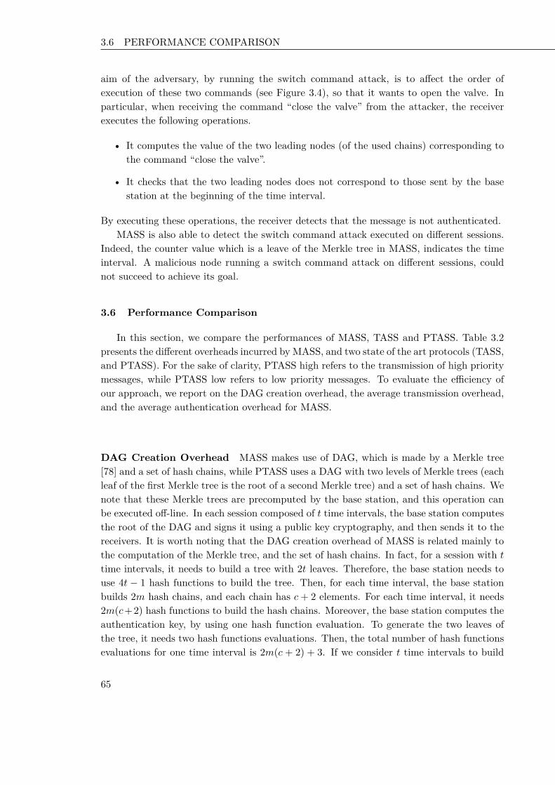
3.6 PERFORMANCE COMPARISON Chapter 2 Key Disclosure based Source Authentication
aim of the adversary, by running the switch command attack, is to affect the order ofexecution of these two commands (see Figure 3.4), so that it wants to open the valve. Inparticular, when receiving the command “close the valve” from the attacker, the receiverexecutes the following operations.
• It computes the value of the two leading nodes (of the used chains) corresponding tothe command “close the valve”.
• It checks that the two leading nodes does not correspond to those sent by the basestation at the beginning of the time interval.
By executing these operations, the receiver detects that the message is not authenticated.MASS is also able to detect the switch command attack executed on different sessions.
Indeed, the counter value which is a leave of the Merkle tree in MASS, indicates the timeinterval. A malicious node running a switch command attack on different sessions, couldnot succeed to achieve its goal.
3.6 Performance Comparison
In this section, we compare the performances of MASS, TASS and PTASS. Table 3.2presents the different overheads incurred by MASS, and two state of the art protocols (TASS,and PTASS). For the sake of clarity, PTASS high refers to the transmission of high prioritymessages, while PTASS low refers to low priority messages. To evaluate the efficiency ofour approach, we report on the DAG creation overhead, the average transmission overhead,and the average authentication overhead for MASS.
DAG Creation Overhead MASS makes use of DAG, which is made by a Merkle tree[78] and a set of hash chains, while PTASS uses a DAG with two levels of Merkle trees (eachleaf of the first Merkle tree is the root of a second Merkle tree) and a set of hash chains. Wenote that these Merkle trees are precomputed by the base station, and this operation canbe executed off-line. In each session composed of t time intervals, the base station computesthe root of the DAG and signs it using a public key cryptography, and then sends it to thereceivers. It is worth noting that the DAG creation overhead of MASS is related mainly tothe computation of the Merkle tree, and the set of hash chains. In fact, for a session with ttime intervals, it needs to build a tree with 2t leaves. Therefore, the base station needs touse 4t − 1 hash functions to build the tree. Then, for each time interval, the base stationbuilds 2m hash chains, and each chain has c+ 2 elements. For each time interval, it needs2m(c+2) hash functions to build the hash chains. Moreover, the base station computes theauthentication key, by using one hash function evaluation. To generate the two leaves ofthe tree, it needs two hash functions evaluations. Then, the total number of hash functionsevaluations for one time interval is 2m(c + 2) + 3. If we consider t time intervals to build
65 65 65

3.6 PERFORMANCE COMPARISON Chapter 2 Key Disclosure based Source Authentication
Protocol Priority Off-line DAGCreation Over-head (Number ofHash Functions)
Average Trans-mission Over-head for anAuthenticatedMessage (Num-ber of HashValues)
Average Authenti-cation Overhead fora Message (Numberof Hash Functions)
TASS n/a t(2m(c+ 1) + 7)− 1 log(2t)m
log(2t)+3m + c+ 1
PTASS Low 2mt(c+ 3) + 5t− 1 log(2t)m
log(2t)+3m +c+1+log(m)
High 2mt(c+ 3) + 5t− 1 log(2t)m + log(m) log(2t)+3
m +c+1+log(m)MASS n/a t(2m(c + 2) + 7) − 1 log(2t)
m + 2 log(2t)+3m + c + 3
Table 3.2 – Overheads of TASS, PTASS, and MASS
the tree, then the base station needs t(2m(c+ 2) + 3) + 4t− 1 hash functions. In total, thecreation of DAG on our proposal needs t(2m(c+ 2) + 7)− 1 hash functions evaluations.
Average Transmission Overhead The transmission overhead is an important metricthat should be taken into account when dealing with resource constrained devices. Thisoverhead depends on the DAG that is used, and it represents the number of hash values thatthe base station adds within the message. Indeed, in each time interval, the transmissionoverhead to authenticate the key of a time interval is equal to log(2t). Before messagetransmission, the base station sends the 2m leading nodes. In total, the average transmissionoverhead for MASS is equal to log(2t)
m + 2 hash values.Figure 3.5 reports the average transmission overhead for an authenticated message, while
varying the number of messages m and time intervals t. When the number of messagesincreases, MASS achieves better performances compared to PTASS high. It is worth notingthat the number of hash values are smaller than PTASS high. In particular, MASS performsbetter than PTASS when m is higher than 4 messages per interval.
Average Authentication Overhead To authenticate a message, the receiver has tocompute several hash functions. Considering that m messages at most can be sent in eachtime interval, the receiver in our proposal has to compute the number of hash functionevaluations to authenticate a message. Indeed, at the beginning of the time interval, thereceiver needs to compute the root of the Merkle tree by performing log(2t) number of hashfunctions evaluations. The number of hash functions to compute the verification nodesfrom the leading nodes is 2m. The computation of the key based on the verification nodes,requires one hash function evaluation. Moreover, the computation of the two leaves ofthe Merkle tree needs two hash functions evaluations. Thus, at the beginning of the timeinterval, the receiver node has to compute 2m+3 hash functions. Moreover, for each receivedmessage, the receiver has to compute the value of the leading nodes of the used chains. Thiscomputation requires c + 1 hash functions. In total, MASS requires log(2t)+3
m + c + 3 hashfunctions evaluations.
66 66 66

3.6 PERFORMANCE COMPARISON Chapter 2 Key Disclosure based Source Authentication
2000
4000
6000
8000
10000
12000 10 20
30 40
50 60
70 80
90 100
0
2
4
6
8
10
12
Nu
mb
er o
f H
as
h V
alu
es
TASS, PTASS LowMASS
PTASS High
t
m
Nu
mb
er o
f H
as
h V
alu
es
Figure 3.5. – Average Transmission Overhead for an Authenticated Message
In order to assess the average authentication overhead for a message, we varied thenumber of messages and commands. In Figure 3.6(a), we report this overhead while varyingthe number of messages m, and fixing the number of commands c = 5. It is straightforwardto note that the number of hash functions increases slightly when m increases. MASSrequires less number of hash functions evaluations compared to PTASS. Moreover, in Figure3.6(b), we report the average authentication overhead when c = 128. It is interesting tonote that for PTASS, the average authentication overhead increases. However, MASS haslower overhead compared to PTASS, even when increasing the number of commands andmessages.
0
2000
4000
6000
8000
10000
12000 10 20
30 40
50 60
70 80
90 100
20
40
60
80
100
120
140
Nu
mb
er o
f H
ash
Fu
ncti
on
s
TASSMASS
PTASS
t
m
Nu
mb
er o
f H
ash
Fu
ncti
on
s
(a) c=5
2000
4000
6000
8000
10000
12000 10 20
30 40
50 60
70 80
90 100
128
130
132
134
136
138
140
142
144
146
Nu
mb
er o
f H
ash
Fu
ncti
on
s
TASSMASS
PTASS
t
m
Nu
mb
er o
f H
ash
Fu
ncti
on
s
(b) c=128
Figure 3.6. – Average Authentication Overhead for a Message
67 67 67

3.7 CONCLUSION Chapter 2 Key Disclosure based Source Authentication
3.7 Conclusion
We presented in this chapter how current broadcast authentication protocols, that areresilient to Delay Compromise Attack, introduce vulnerabilities. An adversary can actuallyexploit these vulnerabilities to perform the drop command attack, as well as the switchcommand attack. We come up with a solution MASS, that allows a receiver to detectthese two attacks, with an efficient manner. Moreover, the design of our proposal providesimmediate message authentication. We analytically compared MASS with the state-of-the-art solutions (TASS, and PTASS) and proved that the overhead introduced by MASS islow, even for a high rate of messages and commands. The analysis of MASS shows itsfeasibility in the resource constrained devices compared to PTASS. Moreover, the featuresof MASS make it efficient for real time applications.
As observed in this chapter, one of the most vexing problem for broadcast authenticationin WSNs is the delayed authentication compromise attack. In order to provide sourceauthentication in key disclosure based schemes, the concept of key management is temporalasymmetry. Many researches focused on key management and distribution [142, 143] inorder to establish authentication keys: pairwise, cluster, and groups keys. It has beenproven that group key schemes [25] are more energy efficient than individual schemes dueto the low communication overhead. Group key based schemes are used in order to beaware of the overall situation, troops in combat missions report their status and share theobserved data. To this aim, in the next chapter, we will focus on group communications, inorder to build lightweight source authentication mechanisms in Wireless Sensor Networks.We propose a key management mechanism for the efficient, and rapid adoption of a newauthentication key, by a group of one-hop communicating sensor nodes.
68 68 68

69 69 69

CHAPTER 4
Secure Group Communications
In the previous chapters of this thesis, we consider two attacks on key disclosure basedschemes: memory denial of service attack, and delayed authentication compromise attack.In this chapter, we present novel symmetric-key-based authentication schemes which exhibitlow computation and communication authentication overhead. Our schemes are built uponthe integration of a reputation mechanism, a Bloom filter, and a key binary tree for thedistribution and updating of the authentication keys. Analytical evaluation of the proposedauthentication schemes shows that the estimated average number of concatenated messageauthentication code in a packet from time 0 till time t is 4pt, with p is the probability thata key is corrupted.
Our contribution in this chapter is threefold.
1. We propose a key management mechanism for the efficient, and rapid adoption ofa new authentication key, by a group of one-hop communicating sensor nodes. Themember nodes are arranged according to a binary tree overlay topology, whose root isthe communication source (see Figure 4.1). The efficiency of the proposed mechanismis due to the fact that it provides low communication overhead compared to commu-nicating with individual keys. Furthermore, our proposed scheme is rapid since theupdate of the authentication group key is done by adopting the key binary tree.
2. The group key is vulnerable against many malicious attacks. In order to alleviateagainst these attacks and reduce their impact, we first focus on proposing a reputationgenerator in each node. This generator evaluates the reputation value of the nodes.Once a malicious node (which has a low reputation value) is detected, it will bediscarded and isolated from the communication process.
3. End to End authentication is ensured via a series of a hop by hop authentication onthe path from the source to group members. At each hop, communication between anode and its immediate neighbors is authenticated, with a selected group key from aset arranged according to a binary tree (see Figure 4.1).
This chapter presents a family of source authentication schemes in wireless sensor net-works. In the first scheme, we present a key binary Tree based Source Authentication
70 70 70

4.1 SYSTEM MODEL Chapter 2 Key Disclosure based Source Authentication
scheme called TSA, which updates keys based on the reputation of nodes, and it preventsthe compromised nodes from understanding the communications between non-compromisednodes. Furthermore, we present a second scheme called BTSA that is based on a Bloomfilter data structure to reduce communication overhead. Extensive analysis are conductedto evaluate the proposed schemes, and the results show that these schemes can achieve agood level of security, and significantly improve the effectiveness of source authenticationservice.
4.1 System Model
We present in the following our architecture system, our design goal and the reputationmodel.
4.1.1 Architectural System
We consider a wireless sensor network which consists of a large number of sensors (seeFigure 4.1). These nodes are limited in power supply, bandwidth, and computational capa-bility.
We refer the reader to figure 4.1 that describes different steps of the communicationprocess using multi-hop communication. At each hop (or at each step of the communica-tion), a communicating source transmits messages to their direct neighbors. In step (1), weconsider that node (S1) is the communicating source, and in this case, (S1) creates its ownkey tree (KT 1). S1 uses the different pairwise keys between S1 and its n1 direct neighbors(S2, S3, .., Sn1) to create KT 1. At first, S1 authenticates its messages using the group keykgrS1,1. If the reputation mechanism detects that a node or a key is suspicious, then thegroup key will be updated, it will be kgrS1,1−1 and kgrS1,1−2. In fact kgrS1,1−1 is usedto authenticate messages transmitted from S1 to the set of nodes (S2, S3, .., Sn1
2), and
kgrS1,1−2 is used to authenticate messages transmitted from S1 to the set of nodes (Sn12 +1,
.., .., Sn1). Our reputation generator will be further described in section 4.1.3. In step(i), we consider that node (Si) is the communicating source. Si creates its own key tree(KT i) to select its authentication key. KT i uses the different pairwise keys between Si andits ni direct neighbors (Si1, Si2,.., Sini). At first, Si authenticates its messages using thegroup key kgrSi,1. If a suspicious node is detected, then the group key will be kgrSi,1−1 andkgrSi,1−2.
4.1.2 Design Goal
We focus on evaluating the energy consumption of our proposed two protocols TSAand BTSA. Moreover, we evaluate the communication, the computation and the memoryoverhead of the different schemes. We analyze the security of BTSA against bit and randomattack.
71 71 71

4.1 SYSTEM MODEL Chapter 2 Key Disclosure based Source Authentication
Figure 4.1. – Architectural Model
4.1.3 Reputation Model
The reputation model provides a mechanism to detect malicious nodes, and offers somedegree of prevention mechanism. In order to compute the confidence of nodes, the reputationmodel differentiates nodes as malicious or honest.
State of the art. Detection of Malicious Nodes in WSNs
Amisbehavior is related to the detection of false messages, which means that transmittedpackets are not authenticated. The way for detecting this kind of misbehavior is usingeither reputation-based mechanisms or credit-based mechanisms. However, credit basedmechanisms are incentive mechanisms which encourage nodes to forward packets, and to notbe selfish ( [144], [145], [146]). Our concern is to detect misbehaving nodes that authenticatefalsely the packet. In fact, the key could be compromised, or the sender/receiver could alsobe compromised. Thus, reputation based mechanisms seem to be more attractive to ourproblem. The reputation concept refers to the perception that a node has of another’sintention and norms. Reputation is a tool that allows nodes to cooperate and to do acertain service. In other words, a node could be assigned a reputation value determinedby its neighbors. Based on the reputation value, a node could be chosen for a service ornot (for example it can forward or transmit packets). A node which has a low reputation
72 72 72

4.1 SYSTEM MODEL Chapter 2 Key Disclosure based Source Authentication
value risks to be discarded and isolated from the network. A relevant corpus of research inreputation based mechanisms has been presented in [147], [148]. CONFIDANT [147] usesa reputation based system in order to isolate misbehaving nodes. CONFIDANT and ourreputation mechanism have the same objectives, however they differ in some points. Ourmetrics for computing a node reputation, take into account the node historical reputationwhich helps to be more fair in calculating a node reputation. Moreover, our metrics takeinto account the recommendation of all intermediate honest nodes in order to compute thereputation value between two nodes that they don’t have a direct communication betweenthem during a time window. We use the recommendations not only from direct neighbors,but from two-hop neighbors, in order to be resilient against collaborative malicious nodes.
A New Reputation-based Mechanism to Detect Malicious Nodes in WSNs
In order to detect suspicious nodes, we used a reputation based mechanism. Eachnode in the network has a reputation generator. This generator regroups a monitoringmodule that detects misbehavior, and a reputation module that collects and evaluates thereputation value of a given node. In order to make the proposed scheme resilient againstcollaborative attacks, we refer to two-hop neighbors in order to use their reputation values.The reputation value between two nodes A and B is represented by rep(A,B), which meansnode A evaluates the reputation of node B. We assume that 0 <= rep(A,B) <= 1. In theinitialization step, all nodes have the same reputation value equal to 1 (1 is the maximumvalue). The reputation value concerns the number of authenticated messages divided bythe number of received messages.
rep(A,B) = #authenticated#received . (4.1)
Moreover, each node stores a reputation table having this structure:< Node_id,Reputation_value, list_neighbors >, where Node_id is the direct neigh-bor node, Reputation_value is the reputation value corresponding to the node Node_id,list_neighbors is the list of neighbors of Node_id. list_neighbors has the following struc-ture < Node_id,Reputation_value >.
We suppose that there are two nodes A and B. We consider two scenarios to computerep(A,B). In the first scenario, we suppose that there is a direct communication betweenthe two nodes. Thus rep(A,B) is computed as follows (Equation 4.2).
rep(A,B) = (1− α)× reptable(A,B)+ α× repcur(A,B). (4.2)
where α is a value between 0 and 1. The computed value of rep(A,B) has two parts:the first part designs the previous stored table of rep(A,B) in the stored table of A. Thesecond part denotes the current reputation value of node B. We take into account thehistorical reputation value of a node. In the second scenario, we suppose that there is nodirect communication between the nodes A and B, then node A will check the different
73 73 73

4.2 RELATED WORK Chapter 2 Key Disclosure based Source Authentication
intermediate nodes in its stored table to evaluate the reputation of node B. Assume thatnodes C, D, and E have a direct communication between A and B. Only C and D have areputation value that it is superior than a threshold T . In this case, the reputation valuebetween A and B, is the sum of the different reputation values collected by the nodes Cand D. In general, this reputation value is computed using the following Equation 4.3,where Ninter_nodes is the number of nodes that their reputation value exceeds a certainThreshold T .
rep(A,B) =∑
i∈Ninter_nodesrep(A,Ni)× rep(Ni,B)
Ninter_nodes . (4.3)
If rep(A,B) is superior than T , we could confirm that B is not suspicious, else B is amalicious node.
4.2 Related Work
Many security-critical applications depend on key management processes to operate.When a node is compromised, these applications demand a high level of fault tolerance. Thisis a challenging problem since there are many stringent requirements for key management,and the resources available to implement such processes are very constrained in wirelesssensor networks. Key management and key distribution are primordial steps to providesource authentication service. The research community has revealed a relevant corpus ofwork on the key management and source authentication in WSNs [23, 69, 75, 76]. Groupkey based schemes are energy efficient due to the low communication overhead [25, 149].However, when a node in the group is compromised, the communication with other nodeswill be eavesdropped, and then the group key is compromised.
A primary challenge in providing source authentication service in WSNs, consists onmanaging the trade-off, between providing acceptable levels of security, and conservingscarce resources [48, 75, 76], in particular energy, needed for network operations. Severalsolutions have thereafter been proposed to address key management, and key distribution inwireless sensor networks [75], [76]. In particular, relevant research efforts have addressed thegroup key technique in order to localize computation, and also to decrease communicationoverhead in wireless sensor networks. Key tree structure is considered in previous literatureto secure group communications. Several secure group key management techniques havebeen proposed to support secure multicast [21, 150]. We use grouping to tackle with theprocess of combining a set of sensor nodes having similar properties as it was consideredin [25], for example in situational awareness, border protection, asset tracking, and digitalbattlefield. In a typical group key management scheme, there is a trusted third party, knownas Key Distribution Center (KDC). This single trusted entity is responsible for generatingand distributing keys securely to the group members. In [21], authors propose a group keymanagement scheme called Topological Key Hierarchy (TKH). It generates a key tree byusing the sensor network topology with consideration of subtree-based key tree separation
74 74 74

4.3 PROPOSED SOURCE AUTHENTICATION PROTOCOLS Chapter 2 Key Disclosure based Source Authentication
and wireless multicast advantage. In [24, 25], they propose a t degree polynomial with theconstant term of the polynomial being the secret key. It computes t distinct shares of thepolynomial and stores them at the users. To compute the group key, (t + 1) shares of thepolynomial are required and this (t + 1)th share is sent as an activating share by the KDC.In [26], the authors conceived a scheme using a key tree to manage group members. Theirgroup key technique reposes on a centralized group rekeying scheme based on logical keytree for WSNs. Their scheme is based on a group key management, that is not practicalin sensor networks since it uses complex operations. Furthermore, the authors in [151]proposed a group rekeying scheme for filtering false data in sensor networks.
Several works presented the problem of group key management in secure group com-munications, the rekeying cost when an element (a member of a group) leaves or joins agroup. Nevertheless, none of them have studied the detection of a malicious member, andits impact on the group key mechanism. We present a simple key tree based scheme totransmit authenticated messages, and enforce it with a reputation based mechanism in or-der to detect malicious nodes. Thus, our mechanism discard/isolate the suspicious nodes(or suspicious keys) from the communication process.
4.3 Proposed Source Authentication Protocols
We assume the existence of a key establishment protocol in wireless sensor network[54,152]. This protocol can help every pair of sensor nodes to setup a secret key to protecttheir communication. Moreover, we assume that each local source does a mapping betweenthe physical address for their one hop neighbors, and a logical address assignement. Infact, the communication source assigns logical addresses in an ascending order (see Figure4.2). Furthermore, our proposed reputation model presented in Section 4.1.3 is used toevaluate and classify the reputation of nodes. This reputation evaluation has a role to warnthe different local sources, for a possible compromise of authentication keys. Along thischapter, a node x neighborhood refers to the nodes that are only one hop away from nodex. We use the following notation:
• S and R are principals, i.e. the communicating nodes.
• IDS denotes the sensor identifier of node S.
• MK is the encryption of message M with key K.
• m is the bloom filter’s size.
• Hash is a hash function.
• MAC(M,K) denotes the computation of the message authentication code of messageM with key K.
• KS−R denotes the secret pairwise key shared between S and R.
75 75 75

4.3 PROPOSED SOURCE AUTHENTICATION PROTOCOLS Chapter 2 Key Disclosure based Source Authentication
• n_neigh is the number of neighbors.
• e is the number of nodes in the low level group.
• g is the number of low level groups.
• L denotes the height of the binary tree.
• l(k) designs the level of the key K in the binary tree.
4.3.1 Key Tree based Source Authentication Scheme: TSA
In this section, we present our basic key tree scheme called TSA. In fact, a simple andeffective way to authenticate broadcast messages is to use group keys. We assume that eachsource can add multiple Message Authentication Codes (MACs) into a broadcast message.TSA consists of three steps: initialization (key tree generation), message transmission, andgroup key updating.
Initialization Phase
Each source node S creates a key binary tree (see figure 4.2), based on the number of itsneighbors and on the size of each low level group. A low level group refers to a leaf in thekey binary tree. Let e be the number of elements in a low level group, and nneigh representsthe number of neighbors of the source. There are g = nneigh
|e| low-level groups. There isa trade off between security and communication when choosing the value of g or e. Thegroup keys are organized in a binary tree for height log2(g). If we have a tree of height L,S first transmits the first key (the root of the tree) Kgr. At each step of the protocol, thesource refers to this key binary tree. In fact, in order to authenticate a broadcast message,S should use a group key shared among it and its neighbor nodes. As a result, an adversarywill not be able to forge messages without compromising the group key.
Figure 4.2 presents an example of a key tree generated by a source S, which has neighborspresented by 1 to 16. These neighbors are divided into four groups. Each group contains 4nodes. Kgr is the first level key, and it is used to authenticate messages for neighbors 1 to16. Kgr1 is a second level key used to authenticate packets transmitted to neighbors 1 to8. In this initialization phase, the local source generates the first key. In fact, it chooses arandom value of q (Algorithm 1, line 2). Furthermore, the source S generates the first levelauthentication key (Kgr) using q random pairwise keys (Algorithm 1, line 3). In the nextstep, the group key is distributed to group members through unicast (line 4 and line 5). Areceiver Ri decrypts the received message using its pairwise key.
76 76 76

4.3 PROPOSED SOURCE AUTHENTICATION PROTOCOLS Chapter 2 Key Disclosure based Source Authentication
Figure 4.2. – Key Tree Generation by a source S
Algorithm 1: Initialization phase executed by a source SInput: IDS : Identity of a source S,1|neighS | : the neighbors of S,Hash: hash function,Ri: neighbor of source S with i ∈ [1...|neighS |],KS,Ri : the pairwise key between S and Ri ;S chooses a random value q with q ∈ [1...|neighS |] ;2Kgr ← Hash(KS,R1||KS,R2||....||KS,Rq ||IDS) ;3for all i ∈ [1...|neighS |] ;4transmit < (Kgr)KS−Ri
>;5EndFor ;6
Transmission Phase
In this phase, we present the sending message procedure as well as the receiving messageprocedure. The process at the source side is shown in Algorithm 2. The source uses thecurrent authentication group keys to generate the corresponding message (Algorithm 2,line 2 and line 3), then sends the message. Each receiver performs the verification steps asfollows: First, when receiving the packet, the receiver computes the corresponding messageauthentication code, compares the computed value to the retrieved one, if both are equalthen the packet is declared authentic. Otherwise, it is considered as not authentic. In thesending message procedure, the source S uses its current authentication keys. For example,we could consider the scenario that the authentication group key is the first key which isdenoted in figure 4.2 as Kgr. Then, the transmitted packet will be < M,MAC(M,Kgr) >.
77 77 77

4.3 PROPOSED SOURCE AUTHENTICATION PROTOCOLS Chapter 2 Key Disclosure based Source Authentication
The receiver verifies the current message. If the verification succeeds, then the message willbe transmitted, else it will be dropped.
Algorithm 2: Sending message procedure executed by a source SInput: M : the transmitted message,1Kgr1,....Kgr2,...Kgrn: n current authentication group keys;MAC: message authentication code algorithm;KS,Ri : pairwise key between the source S and its neighbor Ri;For each current authentication group key Kgri ;2Generate MAC(M,Kgri);3EndFor4transmit < M , MAC(M , Kgr1),MAC(M , Kgr2), ..MAC(M , Kgrn) >;
Updating Authentication Keys Phase
Source authentication needs the participation of confident nodes. In our scheme, weassume that after computing the reputation value of its neighbors, the node mentions itsconfident nodes, and suspicious nodes. Algorithm 3 depicts the updating process executedby a source S. If rep(S,Ri) < T (T is a threshold), then it means that the member Ri hasa low reputation value, and that the authentication group key K is suspicious. S proceedsto add it in its suspicious nodes, and updates the group key without using the pairwise keybetween S and Ri. Moreover, if rep(Ri, S) < T , and that n1 nodes in the neighborhoodof S confirm this state, they will send a report to S that they will not receive any messagefrom it, and that the key K could be suspicious. Thus, S will update its group key. Ifthe key K is suspicious, S checks if the level number of the key l(K) < L (Algorithm 3,line 2) then it will use the two keys corresponding to the two child nodes of key K (line5, line 6) in order to replace key K. S splits the level l(K) group defined by K into twosmaller groups to isolate compromised neighbors. We could consider the following scenariowhen the key Kgr (see figure 4.2) is detected as compromised; in this case L = 3 and(l(Kgr) = 1) < 3, S uses the two second level keys Kgr1 and Kgr2. We suppose that keyKgr1 is computed using q pairwise keys among the set of pairwise keys {KS,1, ....,KS,8}.Then, S hashes these q keys together with IDS using the hash function Hash. In Section5, we will evaluate the value of the parameter q. The resulting value is Kgr which is theauthentication group key for neighbors 1 to 8. The source proceeds to the same operationsto compute the second key Kgr2, which is computed using q pairwise keys among the setof pairwise keys {KS,9, ....,KS,16}. Then, S hashes these q keys together with IDS usingthe hash function Hash. The resulting value Kgr2 is the authentication group key forneighbors 9 to 16. If one of these keys is detected as compromised, the source will use itstwo children keys. Then, S transmits the new authentication keys to the presumed receiversand authenticates its messages as follows: < M,MAC(Kgr1,M),MAC(Kgr2,M) >. Thereceiver will authenticate the received message and if it succeeds, it will be transmitted,else it will be rejected. The process of rekeying continues until we achieve the last level of
78 78 78

4.3 PROPOSED SOURCE AUTHENTICATION PROTOCOLS Chapter 2 Key Disclosure based Source Authentication
the tree. If the last level key group is also suspicious, S uses the pairwise keys of the nodes.For example, in figure 4.2, if we consider that the key Kgr2−1 is suspicious, in this case thesource will update it by using its pairwise keys KS−9, KS−10, KS−11, KS−12.
Algorithm 3: Updating authentication group key executed by a local source SInput: M1, received_msg: the received data,1KS,R: the pairwise key between the source S and the receiver R;KS,Ri1 , KS,Ri2 , KS,Rj1 , KS,Rj2 : pairwise keys;Kgri
: the current authentication group key to authenticate messages for receiver R;MAC: message authentication code algorithm;Received_report_message ();if l(K) < L then2
K1, K2 ← use_two_child_nodes_key(K);3Choose q random_pairwise_keys;4with (q <number of nodes in each current group) ;K1 ← Hash(KS,Ri1 , , ...,KS,Rj1 ) ;5K2 ← Hash(KS,Ri2 , , ...,KS,Rj2 ) ;6transmit_encrypted_keys(K1, K2);7
else8use_pairwise_keys_nodes_group();9
4.3.2 Bloom Filter based Source Authentication Scheme: BTSA
We remark that when the number of compromised nodes increases, the number of usedauthentication group keys increases too. Thus, the communication overhead rises up. Inorder to reduce this overhead, we refer to a Bloom filter data structure. In fact, in thissection, we present the Bloom filter based scheme which consists on combining the basickey tree scheme and a Bloom filter structure. The major variations of bloom filters includecompressed bloom filters, counter bloom filters, and space-code bloom filters [126]. Com-pressed bloom filters can improve performance in terms of bandwidth saving, when bloomfilters are passed on as messages, however it consumes more energy than the standard one.Counter bloom filters deal mainly with the element detection operation of bloom filters.Space-code bloom filters and their variations are suitable for representing static sets, whosesize can be estimated before design and deployment.
In our case, we used a space-efficient bloom filter which is a randomized data structureoften used to represent a group of elements (in our case n MACs) with a small false positiverate. That is, the Bloom filter saves space at the cost of representing a slightly larger group,than the original group of elements. It uses d hash functions. The message size exchanged insensor networks should be minimized, in order to be resilient against wireless channel errorsand to save energies. The size of a Bloom filter is therefore limited, resulting in high falsepositive rates. Message authentication codes {MAC1,MAC2, ...MACn} are represented inthe Bloom filter bi. Their values are hashed d times using d different hash functions, andthe resulting values are mapped into d bit positions of an m-bit Bloom filter. Note thatit is possible for a hashed value to be mapped into an already marked bit position. The
79 79 79

4.4 SECURITY ANALYSIS Chapter 2 Key Disclosure based Source Authentication
Bloom filter maintains this collision as “1” without change to reduce space. The sender sidetransmits the following packet: < Mi, bi > where bi is the correspondent Bloom filter of themessage Mi. On receiving the data packet, the receiver tries to do the following operations:
• verify if the number of “1” bits is less than or equal to n× d bits in the vector. If itis not, the packet is dropped otherwise, the receiver computes the message authenti-cation code MAC with the correspondent key.
• verify if the computed message authentication code is in the Bloom filter bi. In fact,for each hash function hi (with 1 < i < d) used in the Bloom filter, it verifies if hi(MAC’) is between 0 and m− 1. If all the corresponding bits in the vector are set to“1”, then the packet is assumed to be authenticated. Else, the verification fails andthe packet is dropped.
An element (message authentication code value) which is not a legitimate element ofthe set could falsely succeed in the Bloom filter verification and therefore a false positive ofan element occurs.
4.4 Security Analysis
In this section, we analyze the security of our proposed schemes against some attacks:the bit random attack, and the random attack.
4.4.1 Bit Random Attack Scenario
In this attack scenario, we consider the case that an adversary generates a false Bloomfilter of m-bit size (all initialized to “0”) in Bloom filter based scheme. Then, the adversarycan choose randomly n×d bit positions in the vector and mark them as “1”. This probabilityis computed as follows (
m
nd
)(12
)nd(12
)m−nd=(m
nd
)(12
)m. (4.4)
Therefore the probability that a Bloom filter is falsely authenticated after using d hashfunctions will be
fprRbBF =((
m
nd
)(12
)m)d. (4.5)
4.4.2 Random Attack Scenario
This scenario refers to an adversary that randomly generates a false Bloom filter vectorof m-bit size. In fact, it randomly marks “1” in n × d bit positions. As it is known by
80 80 80

4.5 PERFORMANCE ANALYSIS Chapter 2 Key Disclosure based Source Authentication
the source and its neighbors, a Bloom filter cannot exceed n× d “1”s. Then, the maliciousnode marks as many bits as possible up to n × d bits. Thus, in this case, at a certain bitposition, the probability that a bit is marked as “1” is n×d
m . Therefore, the probability thatthis Bloom filter is falsely authenticated even after verification using d hash functions isfprRBF .
fprRBF =(nd
m
)d. (4.6)
4.5 Performance Analysis
We evaluate our proposed schemes using metrics: average number of MACs, the commu-nication overhead, and the computation overhead. Both security and performance factorshave to be considered when using our proposed source authentication schemes.
4.5.1 Average Number of MACs
In this section, we study the key tree based authentication protocol under the followingassumption: each key is corrupted with probability p > 0 (and thus not corrupted withprobability q = 1− p). We assume also that L, the desired height of the tree is given. Forany t > 0, we denote by Xt the number of concatenated MACs from time 0 till time t.Then, Xt is a random variable, and it is easy to see that 1 ≤ Xt ≤ 2L. However, one cando a probabilistic analysis of this random variable to obtain its average value. Indeed, wehave the following lemma :
Lemma 4.5.1 If we denote by E (Xt) the expected value of the random variable Xt, then :
E (Xt) = 4pt. (4.7)
Proof For any t > 1, assuming known the value of Xt, one can compute the probabilityfor Xt+1 to be equal to a given value using the following relation : ∀i, j > 0,
Pr (Xt+1 = i | Xt = j) =
q2 if i = j
2pq if i = j + 2p2 if j = i+ 40 otherwise.
Hence, we derive the expected value of Xt+1 given the value of Xt :
E (Xt+1 | Xt) = q2Xt + 2pq (Xt + 2) + p2 (Xt + 4)= Xt + 4pq + 4p2
= Xt + 4p. (4.8)
81 81 81

4.5 PERFORMANCE ANALYSIS Chapter 2 Key Disclosure based Source Authentication
Now, we define the new random variable Yt as: Yt = Xt − 4pt for any t > 0. Then :
E (Yt+1 | Xt) = E (Xt+1 | Xt)− 4p (t+ 1)= Xt − 4pt= Yt. (4.9)
Thus, the sequence Yt is martingale with respect to the sequence Xt and hence :
E (Yt+1) = E (E (Yt+1 | Xt))= E (Yt) = E (Yt) = 0. (4.10)
Hence E (Xt) = E (Yt) + 4pt = 4pt. Which ends the proof.
Fixing the probability p, it is clearly that E(Xt) is a linear function.
4.5.2 Communication Overhead
In this section, we present the communication overhead related to the two schemes. Achipcon CC1000 radio used in Crossbow MICA2DOT motes consumes 28.6 and 59.2 µJ
to receive and transmit one byte, respectively, at an effective data rate of 12.4Kb/s [111].Moreover, we assume a packet size of 36 bytes, 29 bytes for the payload and 7 bytes for thepreamble as suggested in TinyOS [153].
If we use the key tree approach without a Bloom filter, the data packet includes data(8 bytes), n MACs with each MAC (8 bytes). Message is then (8 + 8×n) bytes. Therefore,there should be (7×1×x+8+8×n) bytes for transmission (including 7-byte preamble perpacket, x is the number of packets to transmit 8 + 8×n bytes). Hence, the hop-wise energyconsumption of message transmission is (7 × 1 × x + 8 + 8 × n) × 59.2 × 10⁻⁶mJ . Then,the energy consumption of message reception is (7 × 1 × x + 8 + 8 × n) × 28.6 × 10⁻⁶mJ .When we used a Bloom filter, message (1) is (8 + m) bytes. Therefore, there should be(7× 1× y + 8 +m) bytes for transmission (y is the number of packets to transmit 8 + m
bytes). Hence, the hop-wise energy consumption of message transmission is (7×1× y+ 8 +m)×59.2×10⁻⁶mJ . Then, the energy consumption of message reception is (7×1×y+8+m)× 28.6× 10⁻⁶mJ . For each broadcast message, every sensor node should retransmit themessage once and receive w0 times the same message where w0 denotes the node density ofsensor nodes within an area equal to the transmission range of sensor nodes. We note Was the network size. Also, we note E1 the total energy consumption in communication forthe Bloom filter based scheme. We have
E1 =W [(7× 1× y + 8 +m)× 59.2× 10⁻⁶ +(7× 1× y + 8 +m)× 28.610−6w0].
82 82 82
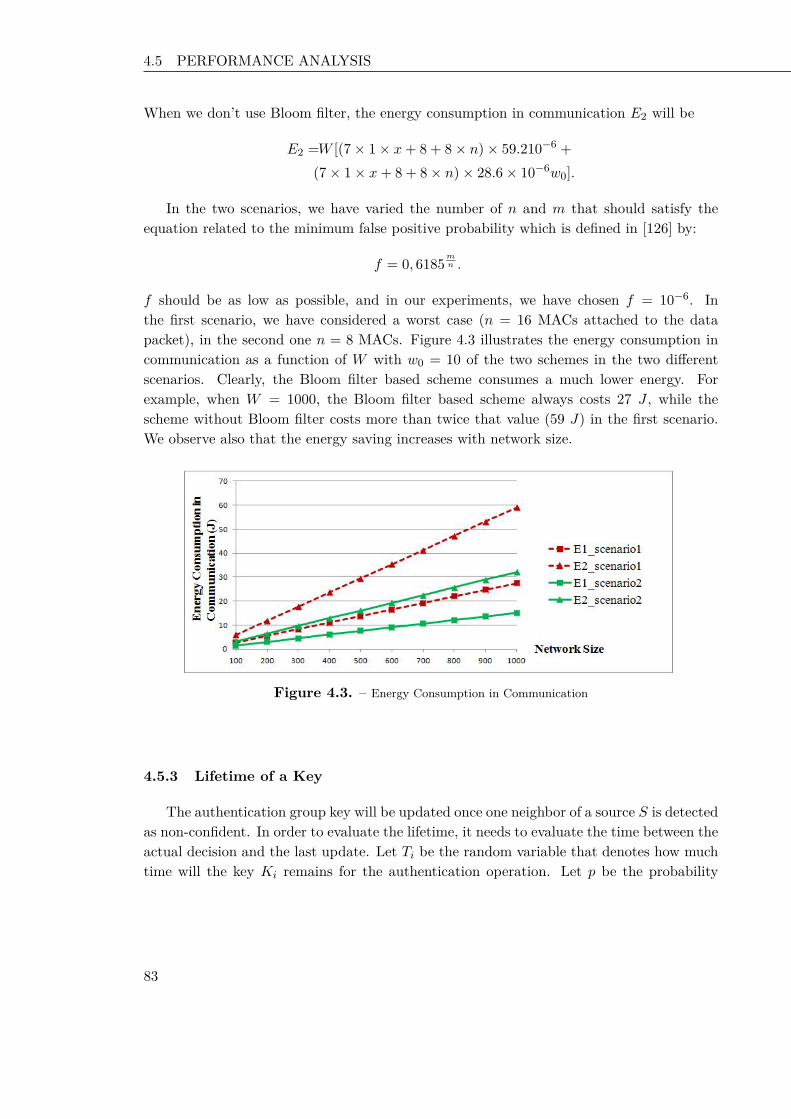
4.5 PERFORMANCE ANALYSIS Chapter 2 Key Disclosure based Source Authentication
When we don’t use Bloom filter, the energy consumption in communication E2 will be
E2 =W [(7× 1× x+ 8 + 8× n)× 59.210−6 +(7× 1× x+ 8 + 8× n)× 28.6× 10⁻⁶w0].
In the two scenarios, we have varied the number of n and m that should satisfy theequation related to the minimum false positive probability which is defined in [126] by:
f = 0, 6185mn .
f should be as low as possible, and in our experiments, we have chosen f = 10−6. Inthe first scenario, we have considered a worst case (n = 16 MACs attached to the datapacket), in the second one n = 8 MACs. Figure 4.3 illustrates the energy consumption incommunication as a function of W with w0 = 10 of the two schemes in the two differentscenarios. Clearly, the Bloom filter based scheme consumes a much lower energy. Forexample, when W = 1000, the Bloom filter based scheme always costs 27 J , while thescheme without Bloom filter costs more than twice that value (59 J) in the first scenario.We observe also that the energy saving increases with network size.
Figure 4.3. – Energy Consumption in Communication
4.5.3 Lifetime of a Key
The authentication group key will be updated once one neighbor of a source S is detectedas non-confident. In order to evaluate the lifetime, it needs to evaluate the time between theactual decision and the last update. Let Ti be the random variable that denotes how muchtime will the key Ki remains for the authentication operation. Let p be the probability
83 83 83

4.6 SUMMARY Chapter 2 Key Disclosure based Source Authentication
that the key is corrupted, t is a time parameter, and ε is a parameter used to control theprobability that the key is renewed.
Pr [Tki <= t] = 1− qt = 1− (1− p)t (4.11)
Pr [Ti <= t] = 1− qt = 1− (1− p)t (4.12)
If we want to compute the probability that Ti do not exceed t
Pr [Ti < t] <= ε. (4.13)
Pr [Ti < t] = 1− (1− p)t (4.14)
This implies that(1− ε) <= (1− p)t.
When applying the Logarithm, we have
t >= ln (1− ε)ln (1− p) (4.15)
Pr
[Ti <
ln (1− ε)ln (1− p)
]<= ε (4.16)
4.6 Summary
Source authentication is in its infancy in Wireless Sensor Networks which are featuredwith resource constraints and deployed in strategic areas. To address this problem, we haveproposed a family of source authentication schemes which rely on a key tree to update theauthentication group key in order to prevent the compromised nodes from understandingthe communications between non compromised ones. The performances of the schemes havebeen analyzed mathematically, confirming its effectiveness.
In the previous three chapters, we studied the security and in particular source au-thentication service in Wireless Sensor Networks. In the next chapter, we will focus onsecuring alert message applications in vehicular communications. Our aim is to devise se-cure solutions for fast multi-hop schemes. We analyze the security threats for fast broadcastsolutions, and then we come up with a secure solution to mitigate the impact of some attackson a vehicular safety application.
84 84 84

85 85 85

CHAPTER 5
Fast and Secure Multi-hopBroadcast for Inter-VehicularCommunication
In the previous three chapters, we focus on security issues in Wireless Sensor Networks,and provide efficient solutions for authentication service in these constrained networks. Asvehicular communications have attracted a lot of attention in the recent decades due tothe need of a safe driving or entertainment, we focus on this chapter on security issues ina vehicular safety application. Inter-Vehicular Communication (IVC) is amongst the mostpromising and challenging applications of Vehicular Ad-hoc Networks (VANETs) [27, 28].Many applications are possible in this context, yet local danger warning systems remainthe most prominent ones. Clearly, the effectiveness of safety related application is based onthe reliability of broadcast information. Therefore, secure communication in this context isa crucial aspect that must not be overlooked.
To discuss attacks to IVC based safety applications, we consider a state of the artprotocol which is representative of this class of applications: the Fast Multi-hop BroadcastAlgorithm (FMBA) [30]. Through FMBA algorithm, we analyze the security threats tostate of the art IVC based safety applications also proposing countermeasures for thesethreats. We hence propose a solution which is both fast and secure in broadcasting safetyrelated messages: Fast and Secure Multi-hop Broadcast Algorithm (FS-MBA).
This chapter is organized as follows. The next section reviews main work and backgroundrelated to the security issues of IVC. Section 5.2 discusses the functioning of the case studyalgorithm (FMBA). Sections 5.3, 5.4, and 5.5 detail possible attacks, whereas respectivesolutions are presented in Sections 5.6, 5.7, and 5.8. Section 5.9 wraps up the solutions ina single algorithm (FS-MBA). Section 5.10 discusses some performance issues. Finally, inSection 5.11 conclusions are drawn.
86 86 86

5.1 BACKGROUND ON FAST MULTI-HOP BROADCAST SOLUTIONS FOR IVC Chapter 2 Key Disclosure based Source Authentication
5.1 Background on Fast Multi-hop Broadcast Solutions for IVC
Inter-Vehicular Communication (IVC) is an important component of the intelligenttransportation system [27, 154–157]. It enables a driver (or her/his vehicle) to commu-nicate in a multi-hop fashion with other drivers located out of the radio range. As a result,information gathered from IVC can foster road safety and transportation efficiency. Ben-efiting from the large capacities (in terms of both space and power) of vehicles, the nodesof these networks can have long transmission ranges and unlimited lifetimes. Main IVCapplications can be categorized into three classes [158], which are as follows:
• Information and warning functions: Dissemination of road information (includingaccidents, road congestion, etc.) to remote vehicles.
• Communication based longitudinal control: Exploiting the “look through" capabilityof IVC to help avoiding accidents.
• Co-operative assistance system: Coordinating vehicles at critical points such as blindcrossing (a crossing without light control) and highway entries.
Most of the safety related applications, including state of the art ones, share propertiesthat put them into the same class of solutions: IVC based vehicular safety applications[30,31,158–161]. These common properties are as follows:
1. Communication is generally vehicle-to-vehicle (V2V), without infrastructure.
2. Vehicles exchange messages containing their position, direction, speed and possibledangers.
3. Broadcast messages have to be propagated as quickly as possible within a certain areaof interest, even through multi-hop forwarding.
4. Specific algorithms are employed to choose as few forwarders as possible over themulti-hop path to fasten the propagation of alert messages.
5. Vehicles’ information such as position, direction, speed and transmission range is usedto feed the forwarder selection algorithm.
For a clearer understanding of the subject, in the remaining part of this section we discussbackground information about general medium access control (Section 5.1.1), and generalrouting in vehicular communication (Section 5.1.2), fast broadcast solutions in safety relatedIVC applications in Section 5.1.3, and security issues in recent research trends related tovehicular networks (Section 5.1.4).
5.1.1 Medium Access Control in Vehicular Communication
A wide range of project activities have initiated around the world in order to improvevehicular communication networks. IEEE 802.11 task group p developed an amendment to
87 87 87

5.1 BACKGROUND ON FAST MULTI-HOP BROADCAST SOLUTIONS FOR IVC Chapter 2 Key Disclosure based Source Authentication
the 802.11 standard in order to enhance the 802.11 to support vehicular ad hoc networks(VANETs). This standard is known as 802.11 p, it defines physical and medium accesscontrol layers of VANETs. In addition, the IEEE 1609 working group defined IEEE 1609protocol family which developed higher layer specification based on 802.11 p. This protocolconsists of four documents: IEEE 1609.1, IEEE 1609.2, IEEE 1609.3, and IEEE 1609.4.IEEE 1609 protocol family and 802.11 p together are called Wireless Access for VehicularEnvironments (WAVE) standard. This system architecture is used for automotive wirelesscommunications [162]. Due to the characteristics of VANET and limited bandwidth, pe-riodic broadcast messages can consume the entire available bandwidth. Furthermore; theemergency messages need to be disseminated quickly and efficiently. Consequently, there isa need to prioritise important and time-critical messages and use quality of services.
The IEEE 802.11 p medium access control layer implements a priority scheme in asimilar way to IEEE 802.11 e EDCA (Enhanced Distributed Channel Access) function.The IEEE 802.11 p medium access control layer is based on multichannel operation ofWAVE architecture and 802.11 e EDCA. EDCA mechanism defines four different accesscategories (AC) for each channel. The access categories are indicated by AC0-AC3, andeach of them has an independent queue [163]. The EDCA mechanism provides prioritizationby assigning different contention parameters to each access category. AC3 has the highestpriority to access medium, whereas AC0 has the lowest priority. Each frame is categorizedinto different access categories, depending on the importance of the message. In IEEE802.11 p MAC layer, there are six service channels and one control channel and each ofthem has four different access categories.
IEEE 802.11 p uses a medium access control protocol that is based on a Carrier SenseMultiple Access protocol with Collision Avoidance (CSMA/CA). Due to the fact that bea-cons in VANETs may be sent several times per second [164] and vehicular density can varygreatly (and become large during traffic jams), it is expected that the channel may becomecongested [165], resulting in a deterioration of the cooperative awareness and hence theperformance of the Intelligent Transportation Systems (ITS) applications. When a nodetries to access the medium and finds the channel busy, it chooses a random backoff timefrom the interval [0, CW ] and delays the medium access for the duration of backoff. CWrepresents the contention window size. If no acknowledgement is received (e.g. a collisionoccurs) the CW size is doubled and the process starts over.
Several works evaluate the impact of different CW settings on the performance of802.11 p. CW is initialised to CWmin and doubled after a failed transmission (e.g. thesender has not received an acknowledgement within a certain timeout) up to CWmax. Asa result, a transmission can be attempted multiple times up to a retry limit, after whichthe transmitting node gives up. In [163,166], the authors study the performance of 802.11 punicast transmissions for the AC defined by 802.11 p’s Enhanced Distributed Channel Ac-cess (EDCA). In [166], the authors study two CW adaptation mechanisms in a vehicularto infrastructure setting after identifying that static CW settings do not perform optimalunder the dynamically changing vehicular environment.
88 88 88

5.1 BACKGROUND ON FAST MULTI-HOP BROADCAST SOLUTIONS FOR IVC Chapter 2 Key Disclosure based Source Authentication
5.1.2 Routing in Vehicular Networks
To enhance the safety of drivers and provide a comfortable driving environment, mes-sages with different purposes need to be exchanged among vehicles through IVC. However,due to high mobility, efficient routing represents a crucial technical challenge in vehicularcommunications, thus attracting the attention of researchers all around the world proposinginnovative solutions [167–169].
The design of efficient routing protocols for vehicular communications requires particularattention for its highly dynamic topology. In general, topology routing protocols use link’sstate within the network to transmit the packet from source to destination, whereas thisapproach would fail in presence of highly variable connectivity among nodes due to theirmobility. As vehicular communication can deal with a large number of vehicles but also withinterest for local information, geographic routing may embody an efficient approach [167].Routing based on geographic location exploits nodes’ knowledge about their position andtheir neighbors’ position, obtained through services like global positioning system (GPS).In this kind of routing, the vehicle does not maintain any routing table or exchange anylink state information with neighbor nodes. In fact, geographic routing protocols takeforwarding decisions based on the geographical position of the destination of a packet. Aforwarder vehicle must know only its own position, the position of the destination, andthe positions of its one-hop neighbors. Geographic routing protocols are not required tomaintain explicit routes, thus scaling well even with dynamic networks and representing aninteresting approach for vehicular communications.
5.1.3 Fast Broadcast in Safety Applications
In IVC systems, several applications require multi-hop broadcast to inform vehicles(and drivers) about road data, delivery announcements, traffic congestion, proximity withother vehicles, accidents and even entertainment related information for passengers [30,31, 158–161, 170]. The simplest broadcasting mechanism is flooding, where messages arere-broadcast by each node that receives them. Although very simple, yet this techniquemay lead to high message collision probability and data redundancy, thus resulting ratherinefficient in terms of radio resource usage and message delivery time.
When a message is disseminated to receivers beyond the transmission range, the multi-hopping could be used. However, multi-hop broadcast can consume a significant amount ofwireless resources for unnecessary retransmissions. These facts are important motivationsfor many works focused on efficient multi-hop message broadcast in VANETs; as high mo-bility and high number of nodes make multi-hop broadcast significantly more challengingin a VANET environment.
The broadcast delivery time represents one of the main issues of IVC. Indeed, it hasbeen proven that this characteristic is strictly related to both the number of relays of themessages (hops) and the network congestion [30, 159, 161, 171–176]. In [171], the demand-driven transmission (DDT) protocol adjusts the timing of rebroadcast packets such that
89 89 89

5.1 BACKGROUND ON FAST MULTI-HOP BROADCAST SOLUTIONS FOR IVC Chapter 2 Key Disclosure based Source Authentication
the vehicle farthest away from the source node retransmits earlier than the other nodes. Adhoc multi-hop broadcast and urban multi-hop broadcast are proposed in [161] for vehicularnetworks. These protocols are designed to address the broadcast storm, hidden node, andreliability problems in multi-hop broadcast. Sender nodes try to select the farthest node inthe broadcast direction, to assign the function of forwarding and acknowledging the packetwithout any a prior topology information. That is, senders select the farthest node withoutknowing the identification (ID) or position of their neighbors. FMBA [30] aims at reducingthe number of hops traversed by a message, in order to minimize the propagation delay of amessage. Vehicles in a car platoon dynamically estimate their transmission range and exploitthis information to efficiently propagate a broadcast message with as few transmissions aspossible. In essence, the farthest vehicle in the transmission range of a message sender orforwarder will be statistically privileged in becoming the next (and only) forwarder. In [159],authors have enhanced the fast broadcast algorithm using heterogeneous transmission range.Unlike [30], the authors select the forwarder of the message as the vehicle which transmissionspans farther, not the farthest vehicle in the transmission range of the sender.
In summary, several multi-hop broadcast algorithms have been proposed. These al-gorithms generally share a set of properties, thus falling into a single class of solutions.Unfortunately, they have all been developed without security in mind, whereas security is afundamental problem in this context which should not be overlooked [29]. Indeed, attackersmight run malicious actions to inject false information or alarm, thus rendering ineffectivethe safety application [35–41].
More in detail, the authors in [39] classify the attacks on vehicular communications into:
• Bogus information. One or several legitimate members of the network send outfalse information to misguide other vehicles about traffic conditions. In order to copewith such misbehavior, the received data from a given source should be verified bycorrelating and comparing them with those received from other sources.
• Cheating on positioning information. Injection of a false position by a maliciousvehicle pretending to be at a claimed position.
• ID disclosure of other vehicles. This is to track their location. A global entitycan monitor trajectories of targeted vehicles and use this data for many purposes, wecould take the example of some car rental companies that track their own cars.
• Denial of Service. The attacker may want to bring down the IVC or even causean accident. Example of attacks include channel jamming and aggressive injection ofdummy messages.
• Masquerade. The attacker claims to be another vehicle by using false identities.
In this work, we analyze the security of a representative algorithm for state of the artIVC based safety applications, and propose countermeasures to handle the security threats.In particular, we focus on one of the main threats to safety application: the possibility toattack the protocol to impede its useful service. For ease of exposition, but without loss of
90 90 90

5.1 BACKGROUND ON FAST MULTI-HOP BROADCAST SOLUTIONS FOR IVC Chapter 2 Key Disclosure based Source Authentication
generality, we focus especially on FMBA as it embodies both a state of the art solution anda representative example of the IVC based vehicular safety applications class possessing allthe five properties mentioned in Section I. Indeed, problems and possible countermeasuresidentified for FMBA can be adapted also to other protocols/algorithms, belonging to thesame general class of applications sharing the aforementioned set of properties.
5.1.4 Fast and Secure IVC in Future Trends of Vehicular Networks
For completeness, we present in this subsection a brief discussion on fast and securemessage transmission considering research trends in vehicular networks.
Vehicles are an important source of computing and sensing resources for drivers. Theseresources are increasingly under-utilized. The idea of vehicular clouds comes in handy tosolve this problem [177, 178]. In fact, the aim of this technology is to let vehicles shareresources such as computational power, storage and Internet connectivity. Security issuesencountered in vehicular clouds are very specific [178]; the high mobility and position infor-mation of vehicles make the problem very novel and challenging. In addition, the attackersare physically moving from place to place as vehicles are mobile nodes. Compared to a staticnetwork, it is much harder to locate the attackers. Moreover, in vehicular cloud, attackersand their targets may be physically colocated on one machine. For instance, an attackercan obtain confidential information and tampering with the integrity of information andthe availability of resources.
Named Data Networking (NDN) is a newly proposed architecture for the future Internetthat replaces IP end-to-end communication model with a request/reply model to retrievedata by application data names directly; distributed caching among participating nodesis exploited to this aim. This technology has been recently proposed also for vehicularnetworks [179]. Even if few works have recently shed light on significant privacy issues forNDN [180], and shown the feasibility of DoS attacks that may render caching and routinginoperative [181, 182], a comprehensive analysis of security issues and related solutionsfor vehicular networks is still lacking. Furthermore, we also highlight the possibility ofleveraging FM radio channels for (malicious) IVC communication, as recently shown in [183],for Android car radio devices.
Finally, security offered in infrastructure based multicast or broadcast, such as in WiMaxand other similar wireless technologies (e.g., [184]), could be considered for employment evenin vehicular networks. Furthermore, several solutions are focused on broadcast based onstatic network with pre-established shared secrets between nodes and the base station, thusintroducing delays. Unfortunately, the peculiar size, mobility, and connectivity of vehicularnetworks make the aforementioned solutions not suitable for this context. Furthermore,road safety related applications are strictly based on geographic locality and on real timeresponse, thus achieving higher efficiency levels when based on Vehicle-to-Vehicle commu-nication, rather than resorting on centralized approaches.
91 91 91

5.2 PRELIMINARIES AND NOTATION Chapter 2 Key Disclosure based Source Authentication
5.2 Preliminaries and Notation
In this section we present the notation (summarized in Table 5.1) and assumptionsused in this chapter. Furthermore, we describe in details FMBA, the case study chosen torepresent IVC based vehicular safety applications.
Symbol DefinitionCMBR Current Maximum Back RangeCMFR Current Maximum Front RangeLMBR Latest-Turn Maximum Back RangeLMFR Latest-Turn Maximum Front RangeMaxRange How far the transmission is expected to go back-
ward before the signal becomes too weak to beintelligible
d Distance between two vehiclesCW Contention WindowCWMax Maximum Contention WindowCWMin Minimum Contention WindowHello Hello message transmitted by a vehicle in the es-
timation phase to update the transmission rangedrm Declared transmission range in theHellomessageP The prover vehicleV The verifier vehicleR The geographical region
Table 5.1 – Fast and Secure Multi-hop Broadcast for IVC: Notation
It is worth noting that FMBA is designed to speed up multi-hop broadcast both front-ward and backward. However, for the sake of clarity, in this work we refer only to the casewhere alert messages have to be sent only backward, with respect to the vehicular travelingdirection (the frontward case is just specular).
5.2.1 Model assumptions
To simplify the discussion we have made the following assumptions about the generalmodel we are considering:
• We suppose that at most one malicious vehicle is on the network since, we want toevaluate the impact of one malicious vehicle on degrading the performances of thenetwork.
• There are no obstacles and no buildings in the road.
92 92 92
5.2 PRELIMINARIES AND NOTATION Chapter 2 Key Disclosure based Source Authentication
• The hearing communication range is symmetric. It means that if a vehicle V hears avehicle P , then we assume that P can also hear V .
• We suppose that there are N vehicles arranged in the platoon. A platoon can belooked at as a collection of nodes/vehicles connected by a wireless local area network(LAN), and are engaged in following each other longitudinally.
• A vehicle V does not know its transmission range.
• The verifier node V communicates directly with the verified node P .
• Each vehicle knows its own location, for instance, using GPS that provides accurateinformation about time and position.
• All the vehicles belong to a Public Key Infrastructure [185, 186]; i.e., each vehiclehas a public/private pair of keys and a unique identity certified by a CertificationAuthority. We assume that the certification authority corresponds to the governmentagency responsible to assign license plates: a vehicle can be used only if it is providedwith a unique license plate, a PKI certificate associated to its plate ID, and thepublic key of the Certification Authority. We assume that certificate revocation listsare updated at given time interval (e.g., daily) by the vehicle and stored in a localmemory1.
• The power and computational resources are supposed largely adequate for our appli-cation’s requirements.
• The network is loosely time synchronized.
5.2.2 Fast Multi-Hop Broadcast Algorithm (FMBA)
The aim of the Fast Multi-Hop Broadcast Algorithm (FMBA) is to reduce the timerequired by a message to propagate from the source to the farthest vehicle in a certainarea of interest [30]. To achieve this goal, FMBA exploits a distributed mechanism for theestimation of the communication range of vehicles. These communication range estimationsare obtained by exchanging a number of Hello messages among the vehicles, and are thenused to reduce the number of hops an alert message has to traverse to cover a certain areaof interest. This leads to a decrease in the number of transmissions as well as the timerequired by a broadcast message to reach all the cars following the sender within a certaindistance.
This scheme is composed by two phases: the estimation phase, and the broadcast phase.The former is continuously active and is meant to provide each vehicle with an up-to-dateestimation of its transmission range. Instead, the latter one is performed only when amessage has to be broadcast to all vehicles in the sender’s area of interest.1Please note that the list of revoked ID for all passenger vehicles in USA could fit in some 1GB storage.
93 93 93
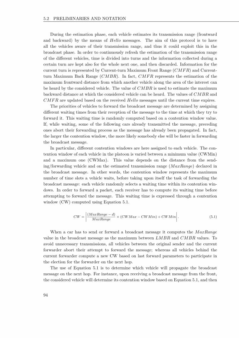
5.2 PRELIMINARIES AND NOTATION Chapter 2 Key Disclosure based Source Authentication
During the estimation phase, each vehicle estimates its transmission range (frontwardand backward) by the means of Hello messages. The aim of this protocol is to haveall the vehicles aware of their transmission range, and thus it could exploit this in thebroadcast phase. In order to continuously refresh the estimation of the transmission rangeof the different vehicles, time is divided into turns and the information collected during acertain turn are kept also for the whole next one, and then discarded. Information for thecurrent turn is represented by Current-turn Maximum Front Range (CMFR) and Current-turn Maximum Back Range (CMBR). In fact, CMFR represents the estimation of themaximum frontward distance from which another vehicle along the area of the interest canbe heard by the considered vehicle. The value of CMBR is used to estimate the maximumbackward distance at which the considered vehicle can be heard. The values of CMBR andCMFR are updated based on the received Hello messages until the current time expires.
The priorities of vehicles to forward the broadcast message are determined by assigningdifferent waiting times from their reception of the message to the time at which they try toforward it. This waiting time is randomly computed based on a contention window value.If, while waiting, some of the following cars already transmitted the message, precedingones abort their forwarding process as the message has already been propagated. In fact,the larger the contention window, the more likely somebody else will be faster in forwardingthe broadcast message.
In particular, different contention windows are here assigned to each vehicle. The con-tention window of each vehicle in the platoon is varied between a minimum value (CWMin)and a maximum one (CWMax). This value depends on the distance from the send-ing/forwarding vehicle and on the estimated transmission range (MaxRange) declared inthe broadcast message. In other words, the contention window represents the maximumnumber of time slots a vehicle waits, before taking upon itself the task of forwarding thebroadcast message: each vehicle randomly selects a waiting time within its contention win-dows. In order to forward a packet, each receiver has to compute its waiting time beforeattempting to forward the message. This waiting time is expressed through a contentionwindow (CW) computed using Equation 5.1.
CW =∣∣∣∣ (MaxRange− d)
MaxRange× (CWMax− CWMin) + CWMin
∣∣∣∣ . (5.1)
When a car has to send or forward a broadcast message it computes the MaxRange
value in the broadcast message as the maximum between LMBR and CMBR values. Toavoid unnecessary transmissions, all vehicles between the original sender and the currentforwarder abort their attempt to forward the message; whereas all vehicles behind thecurrent forwarder compute a new CW based on last forward parameters to participate inthe election for the forwarder on the next hop.
The use of Equation 5.1 is to determine which vehicle will propagate the broadcastmessage on the next hop. For instance, upon receiving a broadcast message from the front,the considered vehicle will determine its contention window based on Equation 5.1, and then
94 94 94

5.2 PRELIMINARIES AND NOTATION Chapter 2 Key Disclosure based Source Authentication
computes a random waiting time based on it. If, while waiting, the same message has beenheard again coming from behind, the message has already propagated from the consideredvehicle that can hence stop trying to forward it: somebody else already did it. Conversely,if the same broadcast message is heard from frontward, this means that a preceding vehiclehas already forwarded it. The procedure has to be restarted with the new parametersincluded in the newly heard broadcast message. If the waiting time expires without havingheard any other vehicle forwarding the same message, then considered vehicle broadcastsit including the estimated transmission range. If the broadcast fail, a backoff mechanism isutilized to compute the next transmission time.
In Figure 5.1, we present the CW of a vehicle V versus the position of different vehicles.Vehicles compute their CW through Equation 5.1. The farther a vehicle is from the sourceof a broadcast message, the smaller its CW results.
Figure 5.1. – Contention window versus distance
The waiting time is a value computed randomly within CW. Thus, as presented in Figure5.1, if we assume distances among vehicles as d(D,V ) ≥ d(C, V ) ≥ d(B, V ) ≥ d(A, V ),then the expectation of vehicles’ CWs generated by FMBA results CW (D) ≤ CW (C) ≤CW (B) ≤ CW (A). Therefore, in the considered example D has the highest probability tobecome the next forwarder of the message transmitted by vehicle V , since its waiting timeis randomly chosen within the smallest CW among those assigned by FMBA to vehicles A,B, C, and D. This leads to a general reduction of the number of hops and time needed bya broadcast message to traverse its area of interest.
5.2.3 Example of FMBA
Since our analysis is based on the FMBA case study, in this section we present anexample of execution of this algorithm. To help the readers, the example is presented inFigure 3.
We first suppose to have an initial state (Figure 5.2(a)), where all cars have initialvalues CMFR = CMBR = 300m; whereas the actual transmission range of each vehicleis 1000m. We consider a 2000m portion of road and we suppose that car F sends the
95 95 95

5.2 PRELIMINARIES AND NOTATION Chapter 2 Key Disclosure based Source Authentication
first Hello message (Figure 5.2(b)) broadcasting its CMFR (i.e., 300m). This value isused by cars in front of car F to update their CMBR values and by cars following carF to update their CMFR values. The value of CMBR (respectively CMFR) of eachvehicle receiving the broadcast Hello message is updated with the maximum among: i) thebroadcast CMFR value; ii) the previous value of CMBR (respectively CMFR), and iii)the distance from car F . The rationale of this is that CMFR represents how far a messagewas heard coming from the front of the car. Thus, when received in a broadcast message,this value is used to compute how far following vehicles are able to hear a message comingfrom their front. The value of CMFR can hence be one of the parameters to determinethe CMBR, which corresponds to the backward maximum transmission range (that willbe declared when transmitting an alert message). Similar but reversed considerations couldbe made if we considered the frontward direction for alert message propagation.
In Figure 5.2(c), car D sends a second Hello message broadcasting a CMFR of 300m sothat vehicles in D’s transmission range can update their CMBR and CMFR as explained.Then, car G sends the third Hello message (Figure 5.2(d)).
In the next step (Figure 5.2(e)), car C has to broadcast an alert message. We canremark that the algorithm has modified C’s CMFR and CMBR. The broadcast messageissued by car C includes in its MaxRange field the latest CMBR value. We remark thatthe maximum transmission range, estimated by car C, after only three Hello messages is900m over an actual one of 1000m. Cars following C and hearing the broadcast messagecan then compute their CW through Equation 5.1 so as to have a forwarder, possibly closeto the end of C’s backward transmission range.
96 96 96

5.3 ATTACK #1: POSITION-CHEATING ATTACK Chapter 2 Key Disclosure based Source Authentication
(a) Initial state
(b) First Hello message
(c) Second Hello message
(d) Third Hello message
(e) Broadcast message
Figure 5.2. – Example of a fast broadcast algorithm
5.3 Attack #1: Position-Cheating Attack
In this section, we present a position cheating attack. This attack is mainly linked toproperties 2), 4), and 5) mentioned in Section I and its goal is to induce delay by increasingthe CW of honest vehicles.
97 97 97

5.3 ATTACK #1: POSITION-CHEATING ATTACK Chapter 2 Key Disclosure based Source Authentication
5.3.1 Overview
A malicious node could announce in a Hello message a false position being more distantthan the real one. Then, honest nodes eventually receiving an alert broadcast messagewill compute unnecessarily large CWs, thus slowing down the forwarding process. For easeof presentation, Figure 5.3 depicts the impact of this attack reporting the CWs of somevehicles depending on their distance from the original sender/forwarder (vehicle V ) of thealert message.
In particular, as the CW of each vehicle is computed through Equation 5.1, withoutthe malicious vehicle the CW function should vary as shown by the continuous line in theFigure 5.3 (from its maximum in correspondence of vehicle V to its minimum at the endof the transmission range which is assumed to be close to vehicle D). Instead, if during theestimation phase, a malicious vehicle within V ’s transmission range sent a Hello messageto declare a fake position corresponding to M’ in the Figure 5.3, the transmission rangeestimation of vehicle V would be wrongly computed as the distance from V toM’, instead ofthe distance from V to D. This leads vehicles A, B, C and D to wrongly compute their CWswith higher values. In fact, those nodes will consider the minimum CW in correspondenceof position of M’, as shown by the dotted line in Figure 5.3.
This simple, yet effective attack, modifies the computation of CW, increasing in averagethe contention period of each node before any forwarding transmission can take place, henceslowing down the transmission of the alert message.
Figure 5.3. – Impact of distance cheating on the waiting time
5.3.2 Description
In this section, we present Algorithm 4 executed by a malicious vehicle M . In fact, itcheats about its claimed position, declaring a false position (Algorithm 4, line 2). Then, Mbroadcasts its Hello message (Algorithm 4, line 3) indicating its claimed position.
98 98 98

5.4 ATTACK #2: REPLAY BROADCAST MESSAGE ATTACK Chapter 2 Key Disclosure based Source Authentication
Algorithm 4: Position-Cheating attack executed by a malicious vehicle MInput: real_position: (Real position of M);1claimed_position: (Claimed position of M);vehicle_ID: ID of the vehicle M ;drm: declared max range of M ;Hello msg: Hello message generated by M ;claimed_position > real_position;2M → ∗: Hello msg = < vehicle_ID, claimed_position, drm > ;3
5.4 Attack #2: Replay Broadcast Message Attack
In this section, we present the replay broadcast message attack which has the aim toenforce honest nodes to not collaborate and not forward the packets. This attack is mainlylinked to properties 1), 2), and 3) mentioned in Section I. In particular, the adversary repeatsthe transmission of the same message, enforcing other vehicles to not forward packets.
5.4.1 Overview
In this scenario, we consider an honest node which broadcasts a message to all thereceivers in its transmission range. We suppose that the adversary intercepts the broadcastmessage and rebroadcasts it without waiting. First, we remark that all the nodes thatreceive this same broadcast message from the front, the attacker push them to restart thebroadcast procedure (as explained in the forwarding procedure of a broadcast message).Second, all the nodes that receive this message from the back, stop trying to forward thismessage. In fact, according to the FMBA, the messages has been already propagated overthe considered vehicles, and these vehicles will exit the forwarding procedure. The adversarycould repeat broadcasting the same message, pushing the nodes to not forward the packet,by just restarting at each time the broadcast process.
In more details, let us consider the scenario depicted in Figure 5.4(a). The honest car(C) forwards its messages. In this attack scenario, we suppose that the vehicle (M) ismalicious and does not wait for the expiration of its time interval; it sends the messageimmediately. When receiving the message, vehicles which are behind M (car F in Figure5.4(b)) restart the broadcast process, whereas nodes which are in front of M (cars D andE in Figure 5.4(b)) will exit the forwarding process.
To summarize this attack, a malicious node M could do some operations:
1. M does not modify the message but just broadcasts it.
• Nodes which are behind M restart the forwarding process, thus wasting time.
• Nodes which are in front of M exit the forwarding process.
No one could forward the packet if the adversary repeats every message sent by theforwarder or the sender vehicle.
99 99 99

5.5 ATTACK #3: INTERRUPTING FORWARDING ATTACK Chapter 2 Key Disclosure based Source Authentication
(a) Step 1
(b) Step 2
Figure 5.4. – Example of enforcing non cooperation attack
2. M modifies the broadcast message and forwards it with a high MaxRange so as togenerate slow forwarding hops with vehicles employing unnecessarily high CW values.
3. M forwards the message with a low MaxRange in order to increase the probabilitythat more than one vehicle will simultaneously attempt to forward the message, thusresulting in transmission collision and hence in forwarding delay.
5.4.2 Description
In this section, we present the Algorithm 5 executed by the malicious vehicle M . Infact, a source S broadcasts a message (line 2) and the malicious vehicle M retransmits itwithout waiting (line 4).
Algorithm 5: Enforcing non cooperation attack executed by the malicious vehicleMInput S: the sender of the message;1broadcast msg: the broadcast message of S;S →*: broadcast msg;2M intercepts the broadcast msg and does not wait for the expiration of its waiting time;3M → *: broadcast msg;4
5.5 Attack #3: Interrupting Forwarding Attack
The goal of this attack is to degrade the network performances by impeding alert messagerelaying. This attack is mainly linked to properties 1), 3), and 4) mentioned previously.
100 100 100
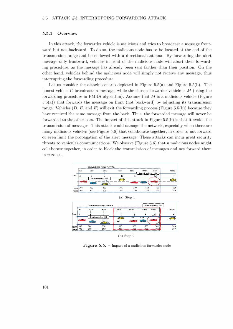
5.5 ATTACK #3: INTERRUPTING FORWARDING ATTACK Chapter 2 Key Disclosure based Source Authentication
5.5.1 Overview
In this attack, the forwarder vehicle is malicious and tries to broadcast a message front-ward but not backward. To do so, the malicious node has to be located at the end of thetransmission range and be endowed with a directional antenna. By forwarding the alertmessage only frontward, vehicles in front of the malicious node will abort their forward-ing procedure, as the message has already been sent farther than their position. On theother hand, vehicles behind the malicious node will simply not receive any message, thusinterrupting the forwarding procedure.
Let us consider the attack scenario depicted in Figure 5.5(a) and Figure 5.5(b). Thehonest vehicle C broadcasts a message, while the chosen forwarder vehicle is M (using theforwarding procedure in FMBA algorithm). Assume that M is a malicious vehicle (Figure5.5(a)) that forwards the message on front (not backward) by adjusting its transmissionrange. Vehicles (D, E, and F ) will exit the forwarding process (Figure 5.5(b)) because theyhave received the same message from the back. Thus, the forwarded message will never beforwarded to the other cars. The impact of this attack in Figure 5.5(b) is that it avoids thetransmission of messages. This attack could damage the network, especially when there aremany malicious vehicles (see Figure 5.6) that collaborate together, in order to not forwardor even limit the propagation of the alert message. These attacks can incur great securitythreats to vehicular communications. We observe (Figure 5.6) that n malicious nodes mightcollaborate together, in order to block the transmission of messages and not forward themin n zones.
(a) Step 1
(b) Step 2
Figure 5.5. – Impact of a malicious forwarder node
101 101 101

5.6 SOLUTION TO ATTACK #1: FALSE POSITION DETECTION Chapter 2 Key Disclosure based Source Authentication
Figure 5.6. – Degrading performance attack executed by n malicious vehicles
5.5.2 Description
The malicious forwarder executes the following algorithm in order to stop the propa-gation of the alert message in the network. A broadcasts a message (Algorithm 6, line 2).The malicious vehicle intercepts it and transmits it to the vehicles in front of it (Algorithm6, line 4). This attack disrupts the packet transmission process and blocks the transmissionof the broadcast message.
Algorithm 6: Degrading performance attack executed by a malicious forwarder ve-hicle MInput: broadcast msg : the broadcast message;1A: the sender of the broadcast message;A→ ∗: broadcast msg;2// M is the forwarder of the message;3M → front vehicles of M : broadcast msg;4
5.6 Solution to Attack #1: False Position Detection
Position dissemination is crucial for the fast broadcast algorithm [30]. Thus, forged posi-tion information has severe impact regarding the performance and security of the algorithm.We propose a detection mechanism that is able of recognizing nodes cheating about theirposition. Unlike other proposals described in the literature ( [79], [80], [81]), our detectionmechanism does not rely on additional hardware. Instead, our solution uses collaborativeneighbors. We present an overview and a detailed description of our false position detectionmechanism.
5.6.1 State of the Art Solutions for False Position Detection
Accurate information on position is crucial for IVC based vehicular safety applications.To this aim, detection mechanisms have been proposed in this context to recognize nodes
102 102 102

5.6 SOLUTION TO ATTACK #1: FALSE POSITION DETECTION Chapter 2 Key Disclosure based Source Authentication
cheating about their location [79–84]. Position verification approaches can be grouped intotwo main categories [79,85]: infrastructure based and infrastructure-less based approaches.
Infrastructure based Solutions
This approach uses special hardware dedicated infrastructure to verify the position ofother vehicles. The solutions in [79] use multiple sensors to monitor and calculate trustvalues for position information. There are two classes of position verification sensors: au-tonomous and cooperating sensors. In fact, autonomous sensors work autonomously oneach node and contribute their results to the overall trust ratings of neighbors. Cooperat-ing sensors use the information exchange between the neighbors to verify positions.
In [80], the authors propose a specific use of infrastructure called “verifiable multilater-ation”, employing three or more Road Side Units (RSUs). These RSUs send a synchronizedchallenge-response message to a vehicle. Then, the verification of its position is based onthe consistency in response time calculation, to verify an announced location of a vehicle.Authors in [80] also exploit an history of movement of vehicles to detect forged data.
The solution in [81] uses verifiers at special locations. These verifiers define an acceptabledistance between each others. The verification procedure then works as follows. First, theprover P sends a beacon containing its position. Then a verifier V replies with a challenge(a message) via radio. After receiving the challenge, P has to answer via ultrasound.The verifier computes the time required to receive the response (according to the definedacceptable distance for V ). Then, P is approved to be within the region R of the verifier.This solution needs specific infrastructure: the verifiers. More specifically, these verifiersattempt to verify location claims for region R that are “near” V . Clearly, verifier nodes areassumed to be trusted and using secure communication among themselves.
An approach in [83] achieves position verification based on reception of beacons. First,the verifier nodes are divided in acceptors and rejectors. The acceptor nodes are distributedin the region R which is to be controlled. Verifier nodes could decide whether a vehicle isin a region R or not. In this approach, verifier nodes (acceptors and rejectors) are placedon distinct places, and are temporally synchronized among each other. If a vehicle P wantsto prove its position (P wants to verify if it is in region R or not), it sends a beacon. Asverifiers are placed in a region R, then the first verifier which receives the beacon coulddecide whether the position of P is acceptable or not. In fact, if the signal of P first reachesa rejector, then P is not in region R. Otherwise, if the first reached verifier is an acceptor,then P is approved to be in region R.
In [84], the proposed solution depends on two directional antennas. Each vehicle pe-riodically sends a message containing its location together with its own two lists of frontand back neighbors. A vehicle will decide on the relative positions of its one-hop neighborsbased on the messages it receives.
103 103 103

5.6 SOLUTION TO ATTACK #1: FALSE POSITION DETECTION Chapter 2 Key Disclosure based Source Authentication
Infrastructure-less Approaches
Infrastructure-less approaches could be classified on parameter based and model basedapproaches [79].
• Parameter based approaches. Vehicles check whether a claimed node’s positionis within a degree of accuracy from the actual one. This check is based on acceptablevalues of some network and traffic parameters, such as i) packet’s timestamps con-sistency with current time; ii) acceptance range which assumes that no neighbor isfurther than the maximum transmission range. This approach assumes that the trans-mission range is fixed. The solution in [187] proposes distance bounding of vehicle’spositions also involving verifiers and provers. This approach mainly detects distanceenlarging fabrication. The verifier chooses the best common neighbor between thesender and him. This neighbor will give an estimated location of the prover. If thatestimated location is not within a certain error distance of both verifier and neighbor,the verifier considers the node as malicious.
• Model based approaches. These solutions compare the regular behavior of thesystem and current actions to identify anomalies that could indicate malicious be-haviors [188]. Each node periodically broadcasts its database containing informationabout observed nodes. When a broadcast is received, the contents are merged intothe receiving node’s database. Each node periodically examines events in its databasesearching for the scenario with the least number of malicious nodes. The disadvantageof this category of solutions is that a big search space of possible scenarios is neededto ensure efficacy.
5.6.2 Overview of the Proposed Cheating Position Detection
For the sake of clarity, we present in this section some false position attacks, distin-guishing among them depending on the claimed position and the real position of the ver-ified vehicle. The main participants are the verifier vehicle V , the prover vehicle M andthe other vehicles in the road. M claims a position in the Hello message. The verifiervehicle V uses information, collected by collaborative vehicles, to decide whether M is acheater or not. We elaborated three scenarios to deal with the false position attacks. Thefirst scenario considers that there is at most one malicious vehicle in the road. The secondscenario assumes that there is one malicious vehicle (either the prover vehicle M or one ofthe reporting vehicles). The third scenario assumes that the overhearing capabilities of thevehicles are asymmetric.
104 104 104

5.6 SOLUTION TO ATTACK #1: FALSE POSITION DETECTION Chapter 2 Key Disclosure based Source Authentication
Scenario 1
In this attack scenario, we consider that there is at most one malicious vehicle. M couldbe either a malicious vehicle or an honest one. We distinguish three cases based on the realposition and the claimed position of M .
A report is a message sent by a vehicle, to indicate that it does hear another vehiclemessage or not. In the first case, as presented in Figure 5.7(a), M claimed a position M ′
that is not included in the actual transmission range of the verifier V . Vehicle V collectsinformation from neighbor vehicles in order to decide whether the claimed position of Mis fake or not. The notation used to indicate whether a vehicle is hearing or not messageM is reported in Figure 5.7(c). This legend is also applied to the other following figures.In Figure 5.7(b), the reports of the vehicles demonstrate that only A, B and C have heardthe node M . Based on this reported information, the verifier V can determine that M ischeating about its position.
(a) Case 1: Claimed position is not under the transmission range of theverifier
(b) Results of vehicles’ reports
(c) Legend
Figure 5.7. – Scenario 1 - Case 1
In Figure 5.8(a), we discuss the second case. In this case, the claimed position of M(position M ′) is in the communication range of the verifier V . Vehicles A, B, and C reporttheir information about their neighbors (Figure 5.8(b)). These reports confirm that theconsidered vehicles (A, B, and C) received M ’s message, whereas vehicles D, E, F , G, andH did not hear it. Based on the collected information, the verifier node decides that thereceived information is consistent.
Considering the third case, as depicted in Figure 5.9(a), the verifier V is located betweenthe real position and the claimed position ofM . The verifier, in the third case, could confirmthat the reported information is consistent. Thus, M might be successfully cheating; yet,
105 105 105

5.6 SOLUTION TO ATTACK #1: FALSE POSITION DETECTION Chapter 2 Key Disclosure based Source Authentication
(a) Case 2: Claimed position and real position are within the transmis-sion range of the verifier
(b) Results of vehicles’ reports
Figure 5.8. – Scenario 1 - Case 2
the impact of this false location does not lead to successfully modify the CW of V as theclaimed position is between the positions of F and G, thus not affecting the computationof the maximum transmission range (Figure 5.9(b)).
(a) Real position and claimed position are on the transmission range ofV
(b) Results of vehicles’ reports
Figure 5.9. – Scenario 1 - Case 3
We could summarize these cases in Figure 5.10, which represents V ’s CW as a functionof the distance of the different neighbors. In fact, the CW is divided into three regionsbased on the different collected reports and position of vehicles. Let us consider the threeregions denoted by (R1), (R2), and (R3). Region (R1) represents the regular CW values(represented by the continuous line) of the vehicle V without an attack. Furthermore, ifM ’s claimed position exceeds C’s position (for example the positionM ′R2), this informationcould have an effect on the waiting time of other vehicles (A, B, C); until the claimed
106 106 106

5.6 SOLUTION TO ATTACK #1: FALSE POSITION DETECTION Chapter 2 Key Disclosure based Source Authentication
position of the prover reaches the position of D (represented by the dotted line). If theclaimed position of M exceeds D, in this situation the attack is detected. Region (R2) islimited by the positions of C and D, then a claimed position of M in this Region (R2) hasa small effect on V ’s CW. Region (R3) represents the position of vehicles superior than theposition of D. Vehicles D, E, F , G, and H are in Region (R3). If a malicious vehicle claimsto be in Region (R3) (for example M ′R3 in Figure 5.10), it will be detected by V becausemost of the vehicles in this region report the non overhearing of M . Thus, the verifier Vwill detect M as a cheater.
To summarize, if the vehicle M claims a position in Region (R1), the verifier V foundthat: (i) the reported information is consistent, (ii) M could be cheating, and (iii) even ifit cheats, there is no effect on V . In the second case, we consider that vehicle M claims aposition in the Region (R2). Thus, the verifier V proceeds to the following assumptions:(i) the reports of the observed nodes are consistent, (ii) V could not detect whether M ischeating or not, and (iii) the claimed position of M , situated between the positions of Cand D, changes the diagram and has an effect on V . In Region (R3) in Figure 5.10, theproverM claims a position located in this region. In this case, V decides thatM is cheatingbased on the received reports of vehicles.
Figure 5.10. – Scenario 1: Verifier waiting time versus distance
Scenario 2
In this attack scenario, we consider that the malicious vehicle could be at most eitherMor one of the reporting vehicles. Let us focus on Figure 5.11. We split the regions into fourparts: (R1), (R2), (R3) and (R4). (R1) includes the vehicles A, B, and C that they hearthe message, and could be in the transmission range of the verifier V . R1 represents theregular CW values of the vehicle V without an attack (represented by the continuous line).The region (R2) represents the region between the last vehicle that heard the message andthe first vehicle that did not hear the message. Region (R3) is the area including the firstvehicle that did not hear the message, and the second vehicle that did not hear also themessage. Region (R4) is the area including the vehicles that did not hear the message.
107 107 107

5.6 SOLUTION TO ATTACK #1: FALSE POSITION DETECTION Chapter 2 Key Disclosure based Source Authentication
We consider that one of the reporting vehicles (B) is in Region (R1). The reporter (B)claims that it does not hear M , however it should normally heard the message. Thus, theverifier V could detect B as the only cheating vehicle because we assumed that there isone malicious node. A vehicle located in Region (R2) (for example the vehicle D) declaresthat it does not hear M . In this case, neither M nor the reporting vehicle (D) are detectedas malicious. Vehicle V could not determine whether one of them is cheating or not. Ifthe reporting vehicle is located in Region (R3), it does not hear the vehicle M . Thus, theverifier V considered that one of the two vehicles is cheating either M or the reportingvehicle. In another situation, let us consider that the reporting vehicle (G) is located inRegion (R4), it transmits a report indicating that it does not hear M . Thus, the verifier Vconsiders that M is the malicious vehicle.
Figure 5.11. – Scenario 2: Verifier waiting time versus distance
Scenario 3
We consider in this scenario asymmetric overhearing capabilities: even if a vehicle V canreceive messages from M , the reverse could not be true. In this case, we consider Figure5.12(a) in which V hears M , and M does not hear V . In Figure 5.12(b), we represent thereports of vehicles about their ability to receive messages from M . In fact, A, B, F , G, andH do not hear M . Moreover C, D, and E have heard the message of the prover M . Thehearing capabilities of the vehicles are not the same. M does not hear V and also A and Bdo not hear M ’s message.
Vehicle V decides whether M is a cheater or not based on the received claimed positionin the three regions (Figure 5.13). In fact, if the prover M claims to be in Region (R3), itsclaimed position (M ′R3) will be detected as false. If M claims to be in Region (R2), theannouncement of this location (M ′R2) has an effect on the diagram of the verifier. However,M could not be detected as malicious. Finally we also consider the case where M claims tobe in Region (R1) (for example in position M ′R1). Thus, V could not detect M as cheatingnode, but the announcement of the location of M has no negative impact on the waitingtime of V .
108 108 108

5.6 SOLUTION TO ATTACK #1: FALSE POSITION DETECTION Chapter 2 Key Disclosure based Source Authentication
(a) Asymmetric hearing capabilities
(b) Results of vehicles’ reports
Figure 5.12. – Scenario 3: Verifier waiting time versus distance
Figure 5.13. – Verifier waiting time versus distance
5.6.3 Description of the Proposed Cheating Position Detection
In this section, we describe our proposed position verification scheme. Our solutionrequires no infrastructure but only distributed messages exchanged between nodes to de-tect the malicious nodes. In fact, we discuss how the information of the vehicles could bepropagated to other vehicles, in order to have a complete and a local observation. First, wediscuss the structure of the transmitted message, and the timing of forwarding or transmit-ting the information. Second, these data could be collected from direct neighbors (in casenodes communicate directly) or from multi-hop neighbors (in case of indirect or asymmetriccommunication) between vehicles. Yet, we should limit the multi-hop propagation of thisinformation within a limited region. Collected information should be recent and limited tothe participating nodes. Third, in order to guarantee the authenticity of messages, nodesproceed to an authentication mechanism. To do this, we propose to transmit the informationof vehicles in a modified Hello message. We present the sending and receiving procedureof Hello message. After receiving the different reports (the modified Hello messages) from
109 109 109

5.6 SOLUTION TO ATTACK #1: FALSE POSITION DETECTION Chapter 2 Key Disclosure based Source Authentication
vehicles, each verifier executes locally a position verification procedure. Then, the verifiervehicle could detect whether the claimed position of a vehicle M is false or not.
Structure of the Modified Hello Message
In order to have the position of the vehicles and their neighbors, we propose to includethese data into the Hello message instead of using additional structures. The first reasonsupporting this choice is that the Hello message is transmitted by a vehicle in each timeinterval (between 100 ms and 300 ms). A second reason is that the sender of the Hello mes-sage is chosen randomly. A third reason is to reduce the communication overhead and notgenerate another structure or another type of message. The modifiedHellomessage includesthe vehicle_id, the vehicle_position, declared_max_range, timestamp, list_neighborswhich is the list of two hop neighbors, and a signature generated by the sender private key.We refer the reader to Figure 5.14, in which we present an element (neighbor) in the list ofneighbors. This list is constructed by a set of elements of type Neighbor. Then, we clarifyin each element of type Neighbor its vehicle_id, vehicle_position, and a list of indirectneighbors. In fact, a list of indirect neighbors is composed by a set of elements of typeIndirect Neighbor. Each Indirect Neighbor (see Figure 5.15) is a structure which includesits vehicle_id, vehicle_position, declared_max_range, and timestamp. Moreover, thepacket in Figure 5.16 contains a signature of this information by the sender private key.The Figure 5.16 illustrates the structure of the modified Hello message.
Figure 5.14. – Neighbor structure
Figure 5.15. – Indirect neighbors structure
110 110 110

5.6 SOLUTION TO ATTACK #1: FALSE POSITION DETECTION Chapter 2 Key Disclosure based Source Authentication
Figure 5.16. – A modified structure of Hello message
Sending Hello Message Procedure
We focus on the Hello message sending procedure (Algorithm 7). In every turn, eachvehicle determines a random waiting time (lines 1 and 2). After this waiting time, if neitherother transmission is heard nor collision happened (line 6), it proceeds with transmitting aHello message. This Hello message includes vehicle_ID (line 7), the timestamp (line 9),the vehicle_position (line 8), the declared_max_range (line 10), the list of neighbors andtheir two hop neighbors: list_neigh_S (line 11). Furthermore, the sender uses its privatekey to generate a signature to the message (line 12), then it transmits the message (line13).
Algorithm 7: Sending Hello message algorithm (executed by vehicle X)Input: list_neighbors: list of neighbors of V ,1vehicle_X: the identity of the sender X,position_X: the sender position,current_T ime_X: current time of the sender,LMFR, CMFR, list_neigh_X: the list of neighbors of X,KX
private: private key of the sender S,H: hash function;Output: Hello message ;2For each turn ;3sending_time := random(turn_size);4wait (sending_time);5if not (heard_Hello_msg() or heard_collision()) then6
Hello_msg.vehicle_ID:= vehicle_X;7Hello_msg.vehicle_position:= position_X;8Hello_msg.timestamp:= current_T ime_X;9Hello_msg.declared_max_range:= max(LMFR,CMFR);10Hello_msg.list_neighbor:= list_neigh_X;11Hello_msg.signature:= KX
private12(H(Hello_msg.vehicle_ID, Hello_msg.vehicle_position, Hello_msg.timestamp,Hello_msg.declared_max_range, Hello_msg.list_neighbor)) ;transmit (Hello_msg);13
EndFor14
111 111 111

5.6 SOLUTION TO ATTACK #1: FALSE POSITION DETECTION Chapter 2 Key Disclosure based Source Authentication
Receiving Hello Message Procedure
The Hello message receiving procedure is depicted in Algorithm 8. In particular,a vehicle receiving a Hello message in line 2, generates the public key (line 3) usingf(sender_id_X) where f is a hash function. In line 4 of Algorithm 8, the receiver verifiesthe signature ofHellomessage. Then, it checks for the freshness of message (line 6). Indeed,it could be an old message transmitted to the vehicles. This check is performed verifying thecoherence between the time inserted in the message by the claiming vehicle (the sender of theHello message) and the current time of the receiver. Then, for each message that passes theprevious checks, the receiver vehicle extracts the information (sender_id_X). The receiverchecks whether this is the first received Hello message carrying the sender_id_X. Then,the receiver simply stores (sender_id_X, sender_position_X, declared_max_range,timestamp, list_neighbor_X) to its list of neighbors (algorithm 8, line 9). Then, the re-ceiver determines its own position (line 12), extracts from theHellomessage the sender_position(line 12), and the included estimation of the maximum transmission range (line 11), anddetermines the distance between itself and the sender (line 13). If the Hello message isreceived from ahead, the value of CMFR is updated (lines 14 and 15), otherwise CMBR isupdated (lines 16 and 17). In both cases, the new value is obtained as the maximum amongthe old one, the distance between the considered vehicle and the Hello message sender, andthe sender’s transmission range estimation provided by the Hello message.
Position Verification Procedure
After receiving reports (Hello messages) from other vehicles, a vehicle V could decidewhether the claimed position announced by a vehicle is correct or not. In Algorithm 9,we present the position verification algorithm executed by a vehicle V . In fact, V collectsN reports (Algorithm 9, line 3). For each received report, it checks whether the claimedvehicle M is in the list of neighbors of these vehicles. Based on this information, V coulddecide if the claimed position is in a certain Region. If the claimed position is in Region(R1) (line 9), then the vehicle could be a malicious one, but this has no negative effect onV . Otherwise, if the claimed position is in Region (R2) (line 12), then the position of Mhas an effect on V , and M is classified as suspicious. Finally, if the claimed position is inRegion (R3) (line 15), M is detected as a cheater. If there is at most one malicious node,we refer to the case 1 of scenario 1. If there is one malicious vehicle in the road (M or oneof the reporting vehicle), then we refer to the scenario 2.
The Utility of the Timestamp and the Vehicle Position in the Modified Hello
message
In this section, we present the utility of some received transmitted information and theirrole in preventing the propagation of the adversary’s message. We consider the scenario
112 112 112
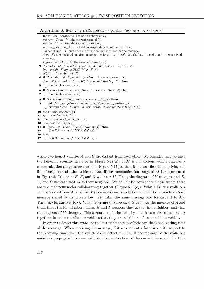
5.6 SOLUTION TO ATTACK #1: FALSE POSITION DETECTION Chapter 2 Key Disclosure based Source Authentication
Algorithm 8: Receiving Hello message algorithm (executed by vehicle V )Input: list_neighbors: list of neighbors of V ,1current_T ime_V : the current time of V ,sender_id_X: the identity of the sender,sender_position_X: the field corresponding to sender position,currentT ime_X: current time of the sender included in the message,drm_X: the declared maximum range received, list_neigh_X: the list of neighbors in the receivedmessage,signedHelloMsg_X: the received signature ;< sender_id_X, sender_position_X, currentT ime_X, drm_X,2list_neigh_X, signedHelloMsg_X > ;KP ub
X ← f(sender_id_X);3if H(sender_id_X, sender_position_X, currentT ime_X,4drm_X, list_neigh_X) 6= KP ub
X (signedHelloMsg_X) thenhandle this exception ;5
if IsNotCoherent (current_time_X, current_time_V ) then6handle this exception ;7
if IsNotPresent (list_neighbors, sender_id_X) then8add(list_neighbors,< sender_id_X, sender_position_X,9currentT ime_X, drm_X, list_neigh_X, signedHelloMsg_X >) ;
mp := my_position() ;10sp := sender_position ;11drm := declared_max_range ;12d := distance(mp, sp) ;13if (received_from_front(Hello_msg)) then14
CMFR := max(CMFR, d, drm) ;15else16
CMBR := max(CMBR, d, drm) ;17
where two honest vehicles A and G are distant from each other. We consider that we havethe following scenario depicted in Figure 5.17(a). If M is a malicious vehicle and has acommunication range as presented in Figure 5.17(a), then it has no effect in modifying thelist of neighbors of other vehicles. But, if the communication range of M is as presentedin Figure 5.17(b) then E, F , and G will hear M . Thus, the diagram of V changes, and E,F , and G indicate that M is their neighbor. We could also consider the case where thereare two malicious nodes collaborating together (Figure 5.17(c)). Vehicle M1 is a maliciousvehicle located near A, whereas M2 is a malicious vehicle located near G. A sends a Hellomessage signed by its private key. M1 takes the same message and forwards it to M2.Then, M2 forwards it to G. When receiving this message, G will hear the message of A andthink that A is its neighbor. Then, E and F suppose that M1 is their neighbor, and thusthe diagram of V changes. This scenario could be used by malicious nodes collaboratingtogether, in order to influence vehicles that they are neighbors of one malicious vehicle.
In order to detect this attack or to limit its impact, a vehicle can check the sending timeof the message. When receiving the message, if it was sent at a late time with respect tothe receiving time, then the vehicle could detect it. Even if the message of the maliciousnode has propagated to some vehicles, the verification of the current time and the time
113 113 113

5.6 SOLUTION TO ATTACK #1: FALSE POSITION DETECTION Chapter 2 Key Disclosure based Source Authentication
Algorithm 9: Position verification algorithm (executed by vehicle V )Input: V : the verifier node executes the verification algorithm1M : the vehicle for which V wants to verify its claimed positionM1,...MN : N messages collected by VClaimed_position of MMi =< sender_i, sender_position_i, timestamp_X,drm_X, list_neigh_i >;Output: State of M is malicious or suspicious;2//i is the sender of the report Mi3For all i ∈ 1, ...Ndoextract (list_neigh_i) from the report Mi;if M ∈ list_neigh_i then4
i hears M ;5else6
i does not hear M ;7
End For.8V sets its CW with respect to the different information;if claimed_position ∈ Region (R1) of V then9
M is not detected as malicious and the claiming distance has no effect on V ;10else11
if claimed_position ∈ Region (R2) of V then12M is not detected and has an effect on V ;13
else14if claimed_position ∈ Region (R3) of V then15
M is detected as malicious;16
included in the message could prevent the forwarding of this message. In fact, based ontime, the vehicle can limit the propagation of the message (the malicious vehicle tries toforward it, in order to convince other vehicles that they are neighbors of V ). At a certaintime, a vehicle can detect that it is a late message (because forwarding takes time). Thevehicle could use also the position information of the sender of the message. Thus, if theposition of the sender is too distant from the receiver, then the received information is notconsistent and the verifier can detect the malicious vehicle.
114 114 114
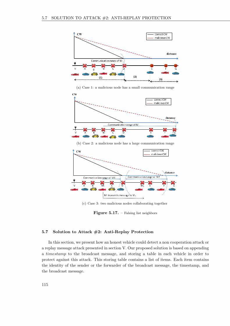
5.7 SOLUTION TO ATTACK #2: ANTI-REPLAY PROTECTION Chapter 2 Key Disclosure based Source Authentication
(a) Case 1: a malicious node has a small communication range
(b) Case 2: a malicious node has a large communication range
(c) Case 3: two malicious nodes collaborating together
Figure 5.17. – Falsing list neighbors
5.7 Solution to Attack #2: Anti-Replay Protection
In this section, we present how an honest vehicle could detect a non cooperation attack ora replay message attack presented in section V. Our proposed solution is based on appendinga timestamp to the broadcast message, and storing a table in each vehicle in order toprotect against this attack. This storing table contains a list of items. Each item containsthe identity of the sender or the forwarder of the broadcast message, the timestamp, andthe broadcast message.
115 115 115

5.7 SOLUTION TO ATTACK #2: ANTI-REPLAY PROTECTION Chapter 2 Key Disclosure based Source Authentication
5.7.1 State of the Art Solutions of Anti-Replay Protection
Anti-replay protection allows a receiving node to identify replayed messages and discardthem to guarantee of weak or sequential freshness. IPSec, for example, uses an incrementingcounter included with each packet to ensure sequential freshness [189]. IPSec’s slidingwindow allows for out-of-order packet arrival; as long as packets arrive in order, or withinthe sliding window, they are accepted regardless of the time interval between packets. Amore strict guarantee is strong freshness, which ensures that a message was sent withina certain, usually short, preceding time period. Strong freshness can be provided in twoways: either via a challenge or response sequence, usually involving a nonce value, or usinga timestamp that is added to the packet during transmission and compared by the receiverwith the global clock. All of these anti-replay techniques require traffic authentication sothat counter values and timestamps cannot be modified without detection.
One of the proposed anti-replay mechanism is included in the SPINS protocol for wirelesssensor networks [16]. In this mechanism, weak freshness is a byproduct of CTR-modeencryption. A monotonically increasing counter is used as a nonce value by encryptingoutgoing packets, and this counter is also used as an anti-replay counter.
Timestamps are a practical alternative for anti-replay support in VANETs. Timestampsrequire that nodes maintain fine grained synchronization, and that all nodes synchronizewith a global clock. Synchronization in vehicular communication is not a problem as vehiclescould use the GPS clock information. Thus, in our approach to prevent this kind of replayattacks, we use timestamps.
5.7.2 Overview of our Proposed Solution
Let us assume the malicious node received a broadcast message, and then transmittedthis message, without waiting for the expiration of any contention avoidance delay. Inthis case, the nodes receiving this broadcast message from their front restart the broadcastprocedure. At the same time, nodes receiving the message from their back abort theirmessage forwarding procedure, since the message has been already propagated over themalong the direction of propagation.
In order to detect this malicious behavior, each sender of the broadcast message shouldindicate in the transmitted broadcast message a timestamp. Then, the broadcast messageincludes a vehicle_id, aMaxRange, a timestamp (indicating the current forwarding time).Furthermore, each vehicle maintains a stored table in which it indicates in each line of thetable the following fields: vehicle_id, a timestamp, and a broadcast message. Using thesestored information, the vehicle could detect if it received the same message from its frontvehicles, in a short period. The message will not be taken into consideration as it is areplayed message.
116 116 116

5.7 SOLUTION TO ATTACK #2: ANTI-REPLAY PROTECTION Chapter 2 Key Disclosure based Source Authentication
5.7.3 Description
In this section, we provide a detailed description of our proposed solution to detectmalicious vehicles based on message exchange. To this aim, we discuss the structure of thebroadcast message and the need for a stored table to detect replayed messages. Furthermore,in order to guarantee the authenticity of messages, nodes proceed to an authenticationmechanism. To do this, we propose to transmit the timestamp in the broadcast message, andto store in each vehicle a table containing the last previous transmitted broadcast messages.We present the sending and the receiving procedure of a broadcast message. After receivingthe broadcast message from a forwarder vehicle, a receiver of the message executes locallya verification procedure. Then, this vehicle could detect whether the transmitted messageis a replayed message or not. The verifier vehicle uses the information stored in its tableand the forwarding time to determine if it is a replayed broadcast message or not.
Broadcast Message and Stored Table
Figure 5.18 and Figure 5.19 describe the structure of the broadcast message, as well asthe stored table in each vehicle.
When receiving a broadcast message, the vehicle should verify whether it is a freshmessage or not. In the latter case, it drops the message. Therefore, the structure of themodified broadcast message includes a timestamp added by the sender.
Figure 5.18. – Modified broadcast mes-sage Figure 5.19. – Stored Table
Sending Broadcast Message Procedure
A vehicle sending the broadcast message proceeds as follows. With the help of Algo-rithm 10, we explain our scheme’s behavior during the procedure for sending broadcastmessages. Each vehicle proceeds with transmitting a broadcast message; this broadcastmessage includes the vehicle_ID (line 2), the MaxRange (line 3), the timestamp (line 4),and the data (line 5). Furthermore, the sender uses its private key to generate a signaturefor the message (line 6), before broadcasting it (line 7).
117 117 117

5.7 SOLUTION TO ATTACK #2: ANTI-REPLAY PROTECTION Chapter 2 Key Disclosure based Source Authentication
Algorithm 10: Sending broadcast Message algorithm (executed by a vehicle X)Input: broadcast msg : the broadcast message;1vehicle_Id_X: vehicle ID of the sender X;MaxRange_X: MaxRange of vehicle X;timestamp_X: timestamp or current time of vehicle X;data_X: generated data;Kpriv_X: private key of sender X ;vehicle_ID ← vehicle_Id_X;2MaxRange←MaxRange_X;3timestamp← timestamp_X;4data← data_X;5signature←6{vehicle_Id_X,MaxRange_X, timestamp_X, data_X} _Kpriv_X ;broadcast msg ←7〈vehicle_ID,MaxRange, timestamp, data, signature〉;
Receiving Broadcast Message Procedure
The broadcast message receiving procedure is presented in Algorithm 11. In particular,a vehicle receiving a broadcast message (line 2), checks for the freshness of message (line4). This check is performed by verifying the coherence between the timestamp, includedin the message, by the claiming vehicle (the sender of the broadcast message) and thereceiver’s current time. In line 7 of Algorithm 11, the receiver verifies the signature of thebroadcast message. Then, it checks whether the received broadcast message had alreadybeen transmitted before, using its stored table (verified_stored_table()). If the messageis received for the first time, then the vehicle simply stores (vehicle_id_X, timestamp_X,broadcast msg) in its stored table which is the role of add_message_to_stored_table()(line 10). Otherwise, the broadcast msg is a replayed message, and thus it will be dropped(line 12).
118 118 118

5.8 SOLUTION TO ATTACK #3: INTERRUPTING FORWARDING ATTACK DETECTION Chapter 2 Key Disclosure based Source Authentication
Algorithm 11: Receiving broadcast message algorithm (executed by a vehicle V )Input: broadcast msg: the received broadcast message;1f : hash function;broadcast msg =2〈vehicle_Id_X,_, timestamp_X,Data_X,Signature_X〉;Kpub_X = f(vehicle_Id_X) ;3if not (verified_timestamp(current_time, timestamp_X)) then4
V drops the message;5else6
if verified_signature() then7if verified_stored_table() then8
accept_message();9add_message_to_stored_table() ;10
else11drop packet;12handle exception();13
else14drop packet;15handle exception();16
5.8 Solution to Attack #3: Interrupting Forwarding Attack Detection
To detect malicious vehicles attempting to jeopardize FMBA by impeding the propa-gation of an alert message, we propose a mechanism that detects when vehicles along theroad have not received the message. Our solution requires a vehicle acting as a verifier(as described in Section 5.8.2 and 5.8.3). Each forwarder vehicle should give a proof ofrelaying the broadcast message. Please note that we do not need any specific mechanism toelect the verifier, since any node can act as such (in fact, messages for the verifier are notintended for any specific receiver). We can just assume that any node in the area will alsoact as verifier. Of course a verifier which is a malicious node would not report any problem,even if an attack is detected. However, to detect the attack and take further actions (e.g.,rebroadcast the blocked message) it is enough that at least one non compromised verifierdetects the attack. In the following, we present an overview of the security scheme as wellas a description of it.
5.8.1 State of the Art Solutions of Detecting Misbehaving Forwarders
Malicious vehicles are compromised vehicles that are willing to put an effort to introducesome damage. Hence malicious nodes are different from selfish ones, since selfish just donot want to use their resources for the sake of protocol’s success. Many studies enhance thecooperation between vehicles and incentive them to forward messages. Major contributionsin incentive cooperation in multi-hop communications use either reputation based schemes( [147], [190], and [191]) or credit based schemes [192], or hybrid schemes [193]. We underlinethat the type of attack that we described, in section VI, deals with malicious behavior of
119 119 119

5.8 SOLUTION TO ATTACK #3: INTERRUPTING FORWARDING ATTACK DETECTION Chapter 2 Key Disclosure based Source Authentication
nodes, not selfishness. In fact, the malicious node tries to transmit packets only frontwardand not backward, in order to stop the propagation of the message. Many efforts ( [147],[190], and [191]) have been done to detect misbehaving nodes that do not forward thepackets. We classify these works on reputation based schemes and credit based schemes.
Reputation based Mechanisms
The reputation of a node increases when it carries out correctly the task of forwardingthe packets. The main problem of the reputation based mechanisms is that they work inthe inefficient promiscuous mode [194]. Once a node’s reputation degrades to a threshold,the node is identified as dishonest or selfish. In [195], a watchdog and a path-rater areimplemented in each node. The watchdog overhears the medium to detect whether thenext-hop node forwards the packets or not. The path-rater module chooses the path thatavoids selfish nodes based on the watchdog’s notifications. The major disadvantage of thisscheme is that it incurs extra loads on the honest nodes. In [196], it is shown that thereputation based mechanisms punish the selfish nodes at the expense of decreasing thethroughput of cooperative ones.
Credit based Mechanisms
In the credit based mechanisms, the cooperative nodes earn credits in order to relaypackets generated from other nodes, and spend them to relay packets. In Nuglets [197], atamper proof device is installed on each node, thus it allows nodes to store their creditsand secure their operations. However, this is not secure and realistic because they assumethat the device can not be tampered. In [144], the authors propose SIP, in which thedestination node sends a payment receipt to the sender which issues a REWARD packet.The REWARD packet increments the credit counters stored in the intermediate nodes. Thedisadvantage of this scheme is that each packet needs three trips between the source anddestination nodes.
The credit based schemes proposed in the literature, to detect misbehaving or selfishnodes could not be applied to our specific problem, since malicious nodes could forward onlyon one direction (frontward) and not backward. The goal of the compromised nodes is tostop the propagation of the alert message, thus it could induce damages and accidents. Theapproach we propose, is based on the fact that each forwarder node has to sent a proof ofreceipt to a verifier node. The receipt message includes information that helps the verifiernode to detect the misbehavior of the node.
5.8.2 Overview
The kind of attacks that we described, in section VIII, deals with malicious behavior ofnodes, not selfishness. In fact, the malicious node tries to transmit packets only frontward
120 120 120

5.8 SOLUTION TO ATTACK #3: INTERRUPTING FORWARDING ATTACK DETECTION Chapter 2 Key Disclosure based Source Authentication
and not backward (by adjusting its transmission range). The aim of this malicious vehicleis to stop the propagation of the message. To prevent this attack, neighbor nodes have tocollaborate together to confirm whether this node is misleading or not. Therefore, we haveto define a strategy able to confirm that backward neighbors have not received the message.To reclaim this, each forwarder vehicle should transmit a receipt message to a verifier node,indicating that its message was relayed. The verification will be done by a verifier node ableto use its knowledge of the vehicles on the road, to decide whether there are some maliciousvehicles, that are trying to impede the correct propagation of the broadcast message.
In the following, we discuss the structure of the receipt message, as well as the trans-mission of this message by the forwarder nodes, and the verification operation done by theverifier node. The attack is more specific to FMBA, and different from what was studiedin the literature [192], [193].
To simplify our presentation, we refer the reader to Figure 5.20(a) in which we have thevehicle A sending a broadcast message (represented by m1), which forwards this messageto the forwarder vehicle D. Then, D transmits the broadcast message (m2) to the receiversin its communication range. As a consequence, M is chosen as a forwarder when applyingthe forwarding procedure in FMBA. Unfortunately, M is a malicious vehicle and thanksto a directional antenna tries to send messages only frontward (broadcast message (m3)).The goal of M is to stop the propagation of the broadcast message, by blocking vehicles inthe front from forwarding the alert message, while backward vehicles (G, H, I, and J) willnever receive the alert message (see Figure 5.20(b)).
5.8.3 Description
In this section, we detail the transmission of a receipt message by a forwarder vehicle,as well as the verification performed by the verifier node.
Receipt Message
In order to send a proof of packet relay, the forwarder vehicle has to create a receiptmessage. In fact, forwarders contact the verifier node at least once during each time in-terval to send their receipts. After forwarding a broadcast message, the forwarder sendsto the verifier node a receipt message containing the vehicle_id, the vehicle_position, thetimestamp, and a signature generated by the forwarder private key. We refer the readerto Figure 5.20(c), in which we present an example of receipt messages generated by a for-warder. The verifier node collects authenticated receipts (containing the vehicleidentity,timestamp, and the receiptmessage), and performs some verifications to detect possiblemalicious forwarders trying to stop the propagation of the broadcast message.
121 121 121

5.8 SOLUTION TO ATTACK #3: INTERRUPTING FORWARDING ATTACK DETECTION Chapter 2 Key Disclosure based Source Authentication
(a) Step 1: Transmitting Broadcast messages
(b) Step 2: Results of overhearing messages
(c) Step 3: Sending receipt messages
Figure 5.20. – Example of non propagation of broadcast message detection
Sending Receipt Message Procedure Executed by a Forwarder Vehicle
A vehicle sending the receipt message proceeds as described by Algorithm 12. Focusingon the receipt message sending procedure, each forwarder transmits a receipt message afterrelaying a broadcast message. This receipt message includes the vehicle_ID (line 5) andthe timestamp (line 6). Furthermore, the sender uses its private key to generate a signatureto the message (line 9) before transmitting it (line 10).
Algorithm 12: Sending receipt message algorithm (executed by a vehicle X)Input: receipt msg : the receipt message;1A→ ∗: broadcast msg;vehicle_id_X: the vehicle Id of X;2timestamp_X: the timestamp of X;3K_priv_X: the private key of X;4vehicle_ID ← vehicle_id_X ;5timestamp← timestamp_X ;6signature← {vehicle_ID, timestamp} _Kpriv_X ;7//generating the receipt message8receipt_message← 〈vehicle_ID, timestamp, signature〉 ;9transmit (vehicle_ID, timestamp, signature);10
122 122 122

5.9 FS-MBA Chapter 2 Key Disclosure based Source Authentication
Receiving Receipt Message Procedure Executed by a Verifier Node
The receipt message receiving procedure executed by a verifier node is depicted in Al-gorithm 13. In particular, a vehicle receiving a broadcast message (line 2) generates thepublic key (line 6) using f(vehicle_id_X) with f is a hash function. In line 10 of Algorithm12, the receiver verifies the signature of the receipt message; then, for each message thatpasses the previous checks, the receiver vehicle extracts the information (vehicle_id_X)and (timestamp_X), and stores (vehicle_id_X, timestamp_X, signature_X) (line 13).At this point, the verifier node can verify using the different collected receipts whether thereis a propagation of the broadcast message or not, since it knows the position of the differentvehicles. If the information carried by the last forwarder vehicle is not consistent with thedispersion of vehicles on the road, this means there are neighbors that have not received thebroadcast message. In this case, the verifier can detect that one of the forwarder vehiclesis malicious, as it does not forward packets backward.
Algorithm 13: Receiving receipt message algorithm (executed by a vehicle V )Input: receipt msg: the receipt message of vehicle X;1vehicle_id_X: the received vehicle Id ;timestamp_X: the received timestamp;2signature_X: the received signature ;3K_pub: public key;4receipt_message← 〈vehicle_ID_X, timestamp_X, signature_X〉 ;5K_pub← f(vehicle_id_X) ;6if not (verified_timestamp(current_time, timestamp_X)) then7
V drops the message;8else9
if verified_signature() then10if verified_consistency then11
accept_message();12Add_message_to_stored_table() ;13
else14handle exception;15
else16drop packet;17
5.9 FS-MBA
In this section, we present FS-MBA, i.e., a global view of the solutions in the previoussections. In the remainder of this section, we provide a security overhead analysis for theFS-MBA algorithm (Section 5.9.1).
To make a global view of our secure solution, Algorithm 14 illustrates the merge of thealgorithms presented before (to tackle different type of attacks).
In particular, upon receiving a message (Algorithm 14, line 2), a vehicle does the fol-lowing checks. First, the receiver checks whether the message is a Hello message (line 3).
123 123 123

5.9 FS-MBA Chapter 2 Key Disclosure based Source Authentication
Algorithm 14: FS-MBAInput: type_message: the type of the received message, i.e Hello message, or broadcast message or1receipt message;msg: the received message;2if 〈 type_message== Hello message〉 then3
Receiving Hello message algorithm (Algorithm 8) ;4Position verification algorithm (Algorithm 9);5
else6if 〈 type_message == broadcast message〉 then7
Receiving broadcast message algorithm (Algorithm 11);8else9
Receiving receipt message algorithm (Algorithm 13);10
If this condition holds, the vehicle verifies the presence of the cheating position attack (line5). If the received message is a broadcast message (check done in line 7), the vehicle verifieswhether there is a replay broadcast message attack. The verification is done by executingAlgorithm 11. Finally, if the message is a receipt (check done in line 9), the node verifieswhether there is an interrupting forwarding attack (line 10), by running Algorithm 13.
5.9.1 Security Overhead
Security always comes at a price, which translates into processing, bandwidth and stor-age overhead. Securing FMBA also costs some additional communication and computationoverhead, due to the generation and the verification of packet signatures. Moreover, vehiclessend information (e.g., position) very frequently. Each Hello message has to be signed andsent to all vehicles in the communication range. In Figure 5.2, we summarize the commu-nication, the computation and the storage overhead experienced by a vehicle X for eachmessage. In Table 5.2, we denote the size (in terms of bytes) of a field S by ‖S‖. We denoteby sign the signature of the message, sign_gen_op represents the signature generationoperation, and sign_verif_op is the signature verification operation. Let N1 (N2) be thenumber of direct (indirect) neighbors (see Section 5.6.3) for a vehicle X. Let V_id be thevehicle identity, and V_pos indicates the vehicle position.
124 124 124

5.10 PERFORMANCE EVALUATION Chapter 2 Key Disclosure based Source Authentication
Overhead
Com
mun
ication per Hello msg
(send./rec.)‖timestamp‖+‖sign‖
+N1 (V_id+V_pos+drm +‖timestamp‖+N2(‖V_id‖+‖V_pos‖+‖drm‖+‖timestamp‖))
per broadcast msg(send./rec.)
‖timestamp‖+‖sign‖
per receipt msg(send./rec.)
‖receipt_msg‖Com
p. per each msg (send.) sign_gen_opper each msg (rec.) sign_verif_op
Storage per Hello msg
(send./rec.)-
per broadcast msg(send./rec.)
‖broadcast_msg‖
per receipt msg(send./rec.)
‖receipt_msg‖
Table 5.2 – FS-MBA Overhead
5.10 Performance Evaluation
We carried out an extensive experimental study to test FMBA under the three differentattacks (Attack #1, Attack #2, and Attack #3). The main tool utilized for our experimentsis the well known NS-2 simulator (version ns-2.29) [198]. We use the Wireless model two-rayground reflection, the type of road is highway with multiple lanes, and vehicle’s speed isbetween 70− 140 km/h. The contention window parameters are CWMin = 32 slots, andCWMax = 1024 slots. The number of slots for CWMin and CWMax is inspired by thestandard IEEE 802.11. A small time slot value could result in increasing the number ofcollisions, with a lack of reliability on delivering messages. According to the experimentsin [31], a time slot of 200 µs provides both a fast and reliable broadcast message delivery.The idle time before Hello message generation is 100 ms. The application message sizeis 200 Bytes, and Hello message size is 50 B. If no alert message happens, there is atransmission of Hello messages. Our configuration parameters are summarized in Table5.3. We should mention that, in our evaluated scenarios, the malicious node is randomlypositioned within the transmission range of the first sender.
125 125 125

5.10 PERFORMANCE EVALUATION Chapter 2 Key Disclosure based Source Authentication
Parameter ValueArea of Interest 7 TRHello message size 50 BBroadcast messagesize
200 B
Idle time 100 msCWMin 32 slotsCWMax 1024 slotsVehicle speed 70− 140 km/hSlot time 200 µsSimulation time 40 sNumber of simulations 100
Table 5.3 – Configuration Parameters
5.10.1 Simulation Environment
To provide a clear and general analysis of the proposed schemes, not affected by theimplementation details of any particular wireless technology (e.g., 802.11 b/g/p or others),we used a discrete progression of the time based on slots to represent all the time relatedvariables (such as MAC layer contention windows, random waiting, and time intervals). Weimplement and evaluate the performances of three protocols: the original FMBA; FMBAwith different attacks; and FS-MBA. We carried out an extensive set of scenarios, and foreach of them we run more than 100 simulations averaging their outcomes to produce chart.For each scenario, we use three different transmission ranges TR = 300 m, TR = 650 m,and TR = 1000 m to show how our systems scale. The choice of focusing on 300 m and1000 m of transmission range comes straightforward from the IEEE 802.11 p draft, whichindicates these two values as the boundaries for a highway scenario [199]. We choose alsothe value of TR = 650 m as an intermediate value between TR = 300 m and TR = 1000 m.
In the original FMBA, every vehicle in the platoon computes a random waiting timewithin the contention window before forwarding the message. The adopted contentionwindow is initially set to CWMin and follows a general back off mechanism by which itsvalue doubles every time a transmission attempt results in a collision and decreases linearlywith every successful transmission. We let the simulation run for 37 seconds, after which thefirst vehicle in the platoon generated an alert message. We compare the various schemes, weanalyze their ability in quickly forwarding the messages to all interested vehicles: FMBA,FMBA with attacks, and FS-MBA. For each attack, we are interested in evaluating someperformance metrics. In the first attack Attack #1, we focus on the following metrics: theaverage number of slots waiten before transmitting a message, the number of hops requiredto broadcast the alert message, the estimated transmission range of the sender and the firstforwarder of the message, the rate of collisions, and the claimed position of the attacker. Inthe second and the third attack (Attack #2 and Attack #3), we focus on the average numberof slots waiten before transmitting a message, and the percentage of message propagation.
126 126 126

5.10 PERFORMANCE EVALUATION Chapter 2 Key Disclosure based Source Authentication
FMBA uses a low transmission rate since it generates an alert message only when anabnormal behavior happens. Thus, the overhead due to Hello messages employed by ourprotocols is very limited, i.e., less than 1 Kb/s within a transmission range area. Thealert message has to be propagated from a certain vehicle to all following vehicles in anarea of interest of 7 × TR. We choose 7 × TR as there is no point in transmitting aninstantaneous alarm farther. However, we could set a larger (or smaller) area-of-interest ifit is more appropriate. The number of vehicles per Km of (multi-lane) road varies from 25to 400, representing different density levels; the factual range TR is variable (TR = 300 m,TR = 650 m, and TR = 1000 m). Our first assumption is that for all the different scenarios,the malicious node is on the first hop, which means that the attacker is on the transmissionrange of the first sender.
5.10.2 Simulations Outcomes
In the following, we present the performances of our protocols under several scenar-ios. We evaluate FMBA under Attack#1, and we evaluate our position cheating detectionattack. We carried out several scenarios to evaluate the impact of Attack #2 on the perfor-mances of FMBA. Finally, we implement and evaluate the impact of Attack #3 on FMBAprotocol.
Attack#1
We focus on evaluating the performances of FMBA under different scenarios related tothe position cheating attack. We compared the various schemes using different transmissionranges of 300 m, 650 m and 1000 m, respectively.
In our evaluation, we consider ten different scenarios:
• FMBA without attacks;
• FMBA with a false position cheating of 1.5 TR;
• FMBA with a false position cheating of 3 TR;
• FMBA with a false random position cheating between 0 and 6 TR;
• FMBA with a false position cheating of 5 TR;
• FS-MBA without attacks;
• FS-MBA with a false position cheating of 1.5 TR;
• FS-MBA with a false position cheating of 3 TR;
• FS-MBA with a false random position cheating between 0 and 6 TR; and
• FS-MBA with a false position cheating of 5 TR
127 127 127
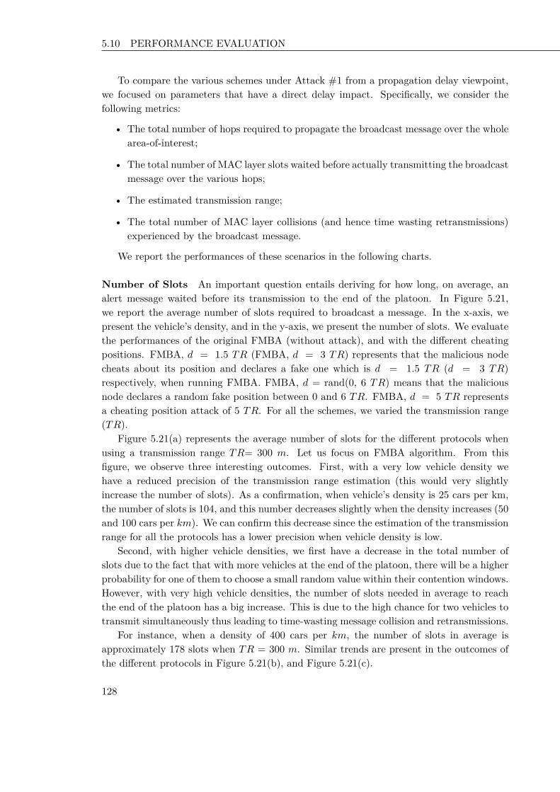
5.10 PERFORMANCE EVALUATION Chapter 2 Key Disclosure based Source Authentication
To compare the various schemes under Attack #1 from a propagation delay viewpoint,we focused on parameters that have a direct delay impact. Specifically, we consider thefollowing metrics:
• The total number of hops required to propagate the broadcast message over the wholearea-of-interest;
• The total number of MAC layer slots waited before actually transmitting the broadcastmessage over the various hops;
• The estimated transmission range;
• The total number of MAC layer collisions (and hence time wasting retransmissions)experienced by the broadcast message.
We report the performances of these scenarios in the following charts.
Number of Slots An important question entails deriving for how long, on average, analert message waited before its transmission to the end of the platoon. In Figure 5.21,we report the average number of slots required to broadcast a message. In the x-axis, wepresent the vehicle’s density, and in the y-axis, we present the number of slots. We evaluatethe performances of the original FMBA (without attack), and with the different cheatingpositions. FMBA, d = 1.5 TR (FMBA, d = 3 TR) represents that the malicious nodecheats about its position and declares a fake one which is d = 1.5 TR (d = 3 TR)respectively, when running FMBA. FMBA, d = rand(0, 6 TR) means that the maliciousnode declares a random fake position between 0 and 6 TR. FMBA, d = 5 TR representsa cheating position attack of 5 TR. For all the schemes, we varied the transmission range(TR).
Figure 5.21(a) represents the average number of slots for the different protocols whenusing a transmission range TR= 300 m. Let us focus on FMBA algorithm. From thisfigure, we observe three interesting outcomes. First, with a very low vehicle density wehave a reduced precision of the transmission range estimation (this would very slightlyincrease the number of slots). As a confirmation, when vehicle’s density is 25 cars per km,the number of slots is 104, and this number decreases slightly when the density increases (50and 100 cars per km). We can confirm this decrease since the estimation of the transmissionrange for all the protocols has a lower precision when vehicle density is low.
Second, with higher vehicle densities, we first have a decrease in the total number ofslots due to the fact that with more vehicles at the end of the platoon, there will be a higherprobability for one of them to choose a small random value within their contention windows.However, with very high vehicle densities, the number of slots needed in average to reachthe end of the platoon has a big increase. This is due to the high chance for two vehicles totransmit simultaneously thus leading to time-wasting message collision and retransmissions.
For instance, when a density of 400 cars per km, the number of slots in average isapproximately 178 slots when TR = 300 m. Similar trends are present in the outcomes ofthe different protocols in Figure 5.21(b), and Figure 5.21(c).
128 128 128

5.10 PERFORMANCE EVALUATION Chapter 2 Key Disclosure based Source Authentication
Let us focus on the impact of the four attacks on FMBA when the malicious node cheatsabout its position (d = 1.5 TR, d = 3 TR, d = rand(0, 6 TR), and d = 5 TR). First, whenan attacker runs a position cheating of 1.5 TR, we see the degradation of the performancesof FMBA is negligible (no more than few slots). For example, in Figure 5.21(a), whenthe vehicle’s density is 25 vehicles per km, the protocol FMBA with a position cheating ofd = 1.5 TR has approximately the same number of slots as FMBA without attack (106 slotsin average when vehicle density is 25 in Figure 5.21(a)). Thus, the attacker that claims afalse position d = 1.5 TR, has a negligible impact on increasing the average number of slots.
It is clear that the performances of FMBA degrades when an attacker declares a falseposition very distant from its real position. For example, FMBA with a position cheatingof d = 5 TR has the worst impact among the evaluated scenarios. In this case, the mali-cious node increases more as compared to an attack with d = 1.5 TR. As a consequence,the transmission of the alert message gets delayed more, as compared to an attack withd = 1.5 TR. For instance, in Figure 5.21(c), when the vehicle’s density is 25, the maliciousnode with a cheating position of d = 5 TR delays the transmission more than 60 slots,compared to FMBA without attack. Another interesting point, is that the performances ofthe attacker are almost the same when dealing with a fixed false position of d = 3 TR, andd = rand(0, 6 TR). The explanation to this is that even the attack is in average the same,however the impact of choosing values less than 3 TR decreases the number of slots.
An interesting point lies in understanding the correlation between the average numberof slots for different transmission ranges. From Figure 5.21, we notice that the number ofslots required to transmit a message with a transmission range TR = 1000 m is less than theprotocols using a transmission range of TR = 300 m or TR = 650 m. For instance, Figure5.21(b) needs less slots to transmit the alert message since it uses a transmission range ofTR = 650m, compared to the plotted protocols in Figure 5.21(a) using a TR = 300 m.For example, when the density is 25 vehicles per km, FMBA under TR =650 m needs inaverage 80 slots. However, when using FMBA under TR = 300 m, the message needs morethan 104 slots to be propagated. From these figures, we can confirm that having a hightransmission range helps in quickly transmitting an alert message.
We investigate on evaluating the average number of slots waited using FS-MBA. Let usfocus on Figure 5.22. For all the different transmission ranges (TR = 300 m, TR = 650 m,and TR = 1000 m), FS-MBA achieves lower transmission delays compared to FMBA underattack #1. This could be interpreted by the fact that FS-MBA uses a complete view basedon local observations of vehicles, and each node is a verifier of a claim.
Let us focus on the impact of the percentage of retransmissions/collisions on the averagenumber of hops. Figure 5.23 shows the percentage of collisions in function of the vehicledensity. In Figure 5.23, the x-axis represents the vehicle density, and the y-axis representsthe percentage of collisions. We see that the percentage of collisions is low for a low vehicledensity. This percentage increases slightly when the density of vehicles increases. In fact,when we increase the vehicle’s density too much, then this increases the possibility for twoor more vehicles to randomly choose the same smallest number of slots, thus resulting incollisions and retransmissions.
129 129 129

5.10 PERFORMANCE EVALUATION Chapter 2 Key Disclosure based Source Authentication
0
200
400
600
800
1000
1200
1400
25 50 100 200 300 400
slo
ts
Cars per Km
Without AttackFMBA, d=1.5*TR
FMBA, d=3*TRFMBA, d= rand(0, 6*TR)
FMBA, d=5*TR
(a) TR = 300 m
0
200
400
600
800
1000
1200
1400
25 50 100 200 300 400
slo
ts
Cars per Km
Without AttackFMBA, d=1.5*TR
FMBA, d=3*TRFMBA, d= rand(0, 6*TR)
FMBA, d=5*TR
(b) TR = 650 m
0
200
400
600
800
1000
1200
1400
25 50 100 200 300 400
slo
ts
Cars per Km
FMBA, Without AttackFMBA, d=1.5*TR
FMBA, d=3*TR FMBA, d= rand(0, 6*TR)
FMBA, d=5*TR
(c) TR = 1000 m
Figure 5.21. – FMBA under attacks: Average Number of Slots
Another interesting point from Figure 5.23 is that fixing a vehicle density, the numberof retransmissions that occured when the transmission range is 1000 m is higher, comparedto the two scenarios, i.e., when TR = 650 m or TR = 300 m. We see that when weincrease the transmission range, and we have the same density of vehicles, there is a higherpossibility that more than two nodes randomly choose the same smallest number of slots,thus generating collisions. For TR = 1000 m, and with a high density of 400 vehicles perkilometer, the percentage of retransmissions is superior than 40%. However, for the samedensity, and having TR = 300m, the percentage of collisions is less than 22%. The resultsin Figure 5.23 confirm our findings on increasing the number of slots in Figure 5.21, for ahigh vehicle density. In fact, the increase of slots when vehicle density is 200 cars per km,300 cars per km, and 400 cars per km, for all the scenarios with TR smaller than 1000 mand 650 m is due to the increase of the number of retransmissions.
Estimated Transmission Range We study the impact of the false position cheatingattack, on the estimation of the transmission range of the vehicles. Using a wrong transmis-sion range parameter (i.e., distance) has consequences on propagation delays (the numberof slots). In Figure 5.24, we report the estimated transmission range for both the sender of
130 130 130
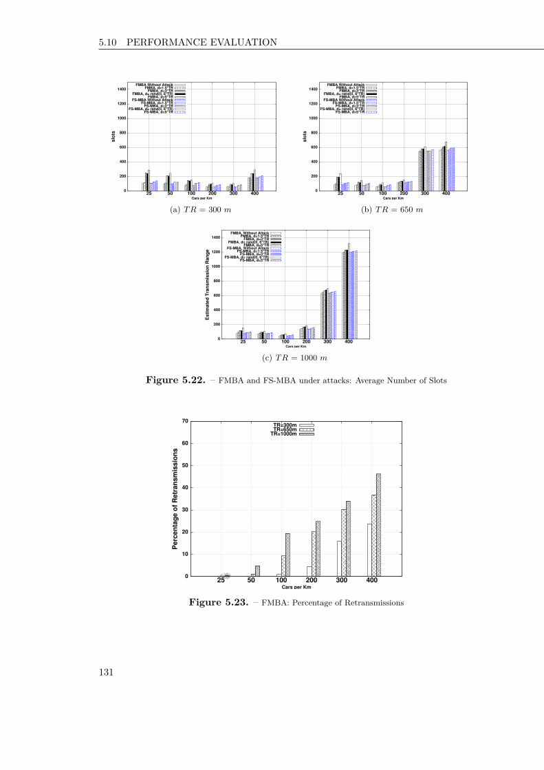
5.10 PERFORMANCE EVALUATION Chapter 2 Key Disclosure based Source Authentication
0
200
400
600
800
1000
1200
1400
25 50 100 200 300 400
slo
ts
Cars per Km
FMBA Without AttackFMBA, d=1.5*TR
FMBA, d=3*TRFMBA, d= rand(0, 6*TR)
FMBA, d=5*TRFS-MBA Without Attack
FS-MBA, d=1.5*TRFS-MBA, d=3*TR
FS-MBA, d= rand(0, 6*TR)FS-MBA, d=5*TR
(a) TR = 300 m
0
200
400
600
800
1000
1200
1400
25 50 100 200 300 400
slo
ts
Cars per Km
FMBA Without AttackFMBA, d=1.5*TR
FMBA, d=3*TRFMBA, d= rand(0, 6*TR)
FMBA, d=5*TRFS-MBA Without Attack
FS-MBA, d=1.5*TRFS-MBA, d=3*TR
FS-MBA, d= rand(0, 6*TR)FS-MBA, d=5*TR
(b) TR = 650 m
0
200
400
600
800
1000
1200
1400
25 50 100 200 300 400
Esti
mate
d T
ran
sm
issio
n R
an
ge
Cars per Km
FMBA, Without AttackFMBA, d=1.5*TR
FMBA, d=3*TR FMBA, d= rand(0, 6*TR)
FMBA, d=5*TRFS-MBA, Without Attack
FS-MBA, d=1.5*TRFS-MBA, d=3*TR
FS-MBA, d= rand(0, 6*TR)FS-MBA, d=5*TR
(c) TR = 1000 m
Figure 5.22. – FMBA and FS-MBA under attacks: Average Number of Slots
0
10
20
30
40
50
60
70
25 50 100 200 300 400
Perc
en
tag
e o
f R
etr
an
sm
issio
ns
Cars per Km
TR=300mTR=650m
TR=1000m
Figure 5.23. – FMBA: Percentage of Retransmissions
131 131 131

5.10 PERFORMANCE EVALUATION Chapter 2 Key Disclosure based Source Authentication
the message and the first forwarder of the message. In the x-axis, we represent the vehicles’density, and the y-axis is the estimated transmission range.
In particular, when an attack happens, the estimated transmission range is larger thanthe non attacked scheme. Obviously, the cheating attack with d = 1.5 TR has almost thesame estimation of the transmission range as FMBA without attacks (a negligible differ-ence). Moreover, we note that when the cheating position is higher than the real position,then the estimated transmission range is large. For instance, the estimated transmissionrange is large when the cheating position is 5 TR. Furthermore, the two protocols underattacks (FMBA, d = 3 TR and FMBA, d = rand(0, 6 TR)) have approximately the sameestimated transmission range.
An interesting point in Figure 5.24 is the position of the forwarder of the message,that it was affected by the attack. The difference between the sender and the forwarderof the message is approximately around 150 m, 300 m and 500 m for the protocols undertransmission range TR = 300m, TR = 650m, and TR = 1000m respectively. For moredetails, we refer the reader to the following figures (Figure 5.24(a), Figure 5.24(b), andFigure 5.24(c)). The property that emerges from these charts, is that the first forwarderis not at the end of the transmission range. This is because the estimation is made notby the first vehicle (the sender) but by the first forwarder (which should be at the endof the transmission range), but in case of the attack all vehicles will use high contentionwindows, thus providing all receiving nodes more or less the same probability to becomethe next forwarder. This means that the next forwarder will be in average at the middleof the transmission range which is the difference between the values in the sender and thefirst forwarder in the charts (see Figure 5.24(a), Figure 5.24(b), and Figure 5.24(c)).
In Figure 5.25, we report the estimated transmission range of the source and the firstforwarder of the message, using FS-MBA under Attack #1. We want to evaluate the impactof the position cheating attack on our solution FS-MBA. For all the different cheatingpositions, vehicles have approximately a good estimation of the transmission range.
Declared Attacked Distance In our simulations, the malicious node cheats about itsposition, by claiming either a fixed position or random position. We considered a scenariowhere the attacker declares a random position between 0 and 6 TR. In Figure 5.26, we reportthe average of the declared distance by the attacker when running the random attack. It isworth noting that the average of declared distance does not depend on the vehicle density.
Number of Hops We study the average number of hops that a broadcast message expe-riences before covering the whole considered portion of road. In Figure 5.27, we report thenumber of hops. In particular, let us consider the scenario where the actual transmissionrange is 300 m (see Figure 5.27(a)). The x-axis represents the vehicle density and the y-axisshows the number of hops. It is interesting to note that the impact of the cheating positionin this scenario does not affect the number of hops. The explanation to this is that weevaluated our protocols using one malicious vehicle, thus the attack affects approximatelyone hop. It is worth noting that, for TR = 300 m, the number of hops varies slightly when
132 132 132

5.10 PERFORMANCE EVALUATION Chapter 2 Key Disclosure based Source Authentication
0
1000
2000
3000
4000
5000
6000
25 50 100 200 300 400
Esti
mate
d T
ran
sm
issio
n R
an
ge
Cars per Km
Source, Without attackSource, d=1.5*TR
Source, d=3*TRSource, d= rand(0, 6*TR)
Source, d=5*TR
First Forwarder Without AttackFirst Forwarder, d=1.5*TR
First Forwarder, d=3*TRFirst Forwarder, d= rand(0, 6*TR)
First Forwarder, d=5*TR
(a) TR = 300 m
0
1000
2000
3000
4000
5000
6000
25 50 100 200 300 400
Esti
mate
d T
ran
sm
issio
n R
an
ge
Cars per Km
Source, Without attackSource, d=1.5*TR
Source, d=3*TRSource, d= rand(0, 6*TR)
Source, d=5*TR
First Forwarder Without AttackFirst Forwarder, d=1.5*TR
First Forwarder, d=3*TRFirst Forwarder, d= rand(0, 6*TR)
First Forwarder, d=5*TR
(b) TR = 650 m
0
1000
2000
3000
4000
5000
6000
25 50 100 200 300 400
Esti
mate
d T
ran
sm
issio
n R
an
ge
Cars per Km
Source, Without attackSource, d=1.5*TR
Source, d=3*TRSource, d= rand(0, 6*TR)
Source, d=5*TR
First Forwarder Without AttackFirst Forwarder, d=1.5*TR
First Forwarder, d=3*TRFirst Forwarder, d= rand(0, 6*TR)
First Forwarder, d=5*TR
(c) TR = 1000 m
Figure 5.24. – FMBA under Attack #1: Estimated transmission range
0
500
1000
1500
2000
25 50 100 200 300 400
Esti
mate
d T
ran
sm
issio
n R
an
ge
Cars per Km
Source, Without attackSource, d=1.5*TR
Source, d=3*TRSource, d= rand(0, 6*TR)
Source, d=5*TR
First Forwarder Without AttackFirst Forwarder, d=1.5*TR
First Forwarder, d=3*TRFirst Forwarder, d= rand(0, 6*TR)
First Forwarder, d=5*TR
(a) TR = 300 m
0
500
1000
1500
2000
25 50 100 200 300 400
Esti
mate
d T
ran
sm
issio
n R
an
ge
Cars per Km
Source, Without attackSource, d=1.5*TR
Source, d=3*TRSource, d= rand(0, 6*TR)
Source, d=5*TR
First Forwarder Without AttackFirst Forwarder, d=1.5*TR
First Forwarder, d=3*TRFirst Forwarder, d= rand(0, 6*TR)
First Forwarder, d=5*TR
(b) TR = 650 m
Figure 5.25. – FS-MBA under Attack #1: Estimated transmission range
augmenting the vehicle density. Let us focus on Figure 5.27(c). In this case, the number ofhops increases when the density is more than 300 cars per km and higher. This happensthanks to the fact that the election of the next forwarder depends on vehicle’s positions
133 133 133
5.10 PERFORMANCE EVALUATION Chapter 2 Key Disclosure based Source Authentication
0
500
1000
1500
2000
2500
3000
3500
25 50 100 200 300 400
Decla
red
Ran
do
m D
ista
nce
Cars per Km
TR=300mTR=650m
TR=1000m
Figure 5.26. – FMBA under Attack #1: Average of declared distance by the attacker
within the sender’s transmission range, and also chosen randomly. We should remind thatthe election of the forwarder on the broadcast phase of FMBA depends on the value of thecomputed waiting time of each receiver. For a high vehicle density, the forwarder is not allthe time at the end of the transmission range, thus the number of hops increases.
Attack #2: Replay Broadcast Message
We evaluate the performances of FMBA under Attack #2. In this attack scenario,the malicious node does not wait for the expiration of its time interval, it broadcasts themessage, and keeps sending the same message. The aim of the attacker is either to blockthe message, and not allow the forwarding of the alert message, or to delay the messagetransmission.
Number of Slots We study the impact of Attack #2 on the average number of slotsrequired before forwarding the broadcast message. In Figure 5.28, we present the vehiclesdensity in the x-axis, and in the y-axis, we present the average number of slots.
As expected, with a high broadcast rate, the number of slots increases, since the attackerdelays the transmission of the alert message, and keeps sending the same message. In fact,vehicles which are on front of the malicious node will exit the forwarding process, andvehicles which are on back of the malicious node will restart the broadcast process, thusincreasing the delay of the message transmission. From the different charts (Figure 5.28(a),Figure 5.28(b), and Figure 5.28(c)), we can confirm that increasing the broadcast rate ofthe alert message, this would delay the transmission of the packet, or the broadcast messagewill be postponed, and did not achieve the last vehicle in the platoon.
134 134 134

5.10 PERFORMANCE EVALUATION Chapter 2 Key Disclosure based Source Authentication
0
2
4
6
8
10
12
14
25 50 100 200 300 400
Ho
ps
Cars per Km
Without attackd=1.5*TR
d=3*TRd= rand(0, 6*TR)
d=5*TR
(a) TR = 300 m
0
2
4
6
8
10
12
14
25 50 100 200 300 400
Ho
ps
Cars per Km
Without attackd=1.5*TR
d=3*TRd= rand(0, 6*TR)
d=5*TR
(b) TR = 650 m
0
2
4
6
8
10
12
14
25 50 100 200 300 400
Ho
ps
Cars per Km
Without attackd=1.5*TR
d=3*TRd= rand(0, 6*TR)
d=5*TR
(c) TR = 1000 m
Figure 5.27. – FMBA under Attack #1: Average Number of Hops
With varying the density of vehicles, and the rebroadcast rate, we consider that for alow rebroadcast rate, the number of slots increases slightly (see Figure 5.28). When therebroadcast rate is 105 packets per second, then the average number of slots increases. FromFigure 5.28(a), we see that for a low vehicle density (for example 25), the attack has moreimpact on increasing the number of slots compared to vehicles with high density. Thiscould be interpreted that with more vehicles, there is a higher possibility that the messagepropagates to the end of the platoon.
Percentage of Message Propagation We investigate on studying the impact of At-tack #2 on the percentage of message propagation. We report the percentage of messagepropagation using FMBA, and FMBA under Attack #2 in Figure 5.29. In the x-axis, wepresent the density of vehicles, and in the y-axis, we present the percentage of messagepropagation. We evaluate FMBA under two different broadcast rates (rate = 102 pack-ets per second, and rate = 105 packets per second), and for different transmission ranges(TR=300 m, TR=650 m, and TR=1000 m). The percentage of message propagation in-creases when the rebroadcast rate decreases (see Figure 5.29). From Figure 5.29, we noticethat with a high vehicle density, the percentage of message propagation for all the schemes
135 135 135

5.10 PERFORMANCE EVALUATION Chapter 2 Key Disclosure based Source Authentication
0
200
400
600
800
1000
1200
1400
1600
25 50 100 200 300 400
slo
ts
Cars per Km
Without AttackFMBA, rate=10^2Pkt/sFMBA, rate=10^5 Pkt/s
(a) TR = 300 m
0
200
400
600
800
1000
1200
1400
1600
25 50 100 200 300 400
slo
ts
Cars per Km
Without AttackFMBA, rate=10^2Pkt/sFMBA, rate=10^5 Pkt/s
(b) TR = 650 m
0
200
400
600
800
1000
1200
1400
1600
25 50 100 200 300 400
slo
ts
Cars per Km
Without AttackFMBA, rate=10^2Pkt/sFMBA, rate=10^5 Pkt/s
(c) TR = 1000 m
Figure 5.28. – FMBA under Attack #2: Average Number of slots required to propagate a messageto the end of the platoon
under different transmission ranges, has a high value. In fact, there is a higher probabilityto find a forwarder of a message when the vehicle density increases. For a low vehicle density(25 vehicles per kilometer), the message propagation is about 80%, when the rebroadcastrate is 105 packets per second, and TR=300 m.
Another interesting point is that, with a low transmission range (TR = 300 m), thepercentage of message propagation is lower compared to the protocols using a transmissionrange TR = 650 m, or TR = 1000 m. For instance, with a density of 25 vehicles per km,the percentage of message propagation is about 81% (89%), for TR=300 m (TR=1000 m)respectively.
Attack#3: Interrupting Forwarding Attack
In order to evaluate the performances of FMBA under Attack#3, we consider twoscenarios. In the first scenario, the malicious node is at a random position between the
136 136 136

5.10 PERFORMANCE EVALUATION Chapter 2 Key Disclosure based Source Authentication
0
20
40
60
80
100
120
140
25 50 100 200 300 400
Perc
en
tag
e o
f m
essag
e p
rop
ag
ati
on
Cars per Km
FMBA, Without Attack, TR=300mFMBA, rate=10^2Pkt/sFMBA, rate=10^5 Pkt/s
FMBA, Without Attack, TR=650mFMBA, rate=10^2Pkt/s, TR=650m
FMBA, rate=10^5 Pkt/s, TR=650mFMBA, Without Attack, TR=1000mFMBA, rate=10^2Pkt/s, TR=1000mFMBA, rate=10^5 Pkt/s, TR=1000m
Figure 5.29. – FMBA under Attack #2: Percentage of Message Propagation to the end of theplatoon
first sender of the message and the end of the transmission of this sender. In the secondscenario, the malicious node is at the end of the transmission range.
In these scenarios, we evaluate the percentage of message propagation. We note thatin the second scenario, the forwarder selection is the same as the original FMBA, however,the first forwarder of the message will behave maliciously and runs Attack #3.
From Figure 5.30, we notice that the percentage of message propagation is high. Forinstance, for a density of 25 cars per km, the percentage of message propagation is more than80% for FMBA under different transmission ranges. In fact, when the density of vehiclesincreases, there is a high probability that the message reaches the end of the platoon. Thiscould be explained by the fact that increasing the vehicle’s density, there is a forwarder ofthe message.
In Figure 5.31, we report the scenario where the malicious node should be the firstforwarder of the message. In order to implement this scenario, we assume that the maliciousnode is at the end of the transmission range. In this case, we notice that the attacker didblock the transmission of the alert message with different percentages. In Figure 5.31, themessage propagation of FMBA under Attack#3 is approximately 23% with a TR =300 m,and with a density of 25 cars per km. This confirms our findings that when an attacker isat the end of the transmission range of the sender, then it has a higher possibility to blockthe transmission of the packet.
137 137 137

5.11 SUMMARY Chapter 2 Key Disclosure based Source Authentication
0
20
40
60
80
100
120
25 50 100 200 300 400
Perc
en
tag
e o
f m
essag
e p
rop
ag
ati
on
Cars per Km
FMBA under ATTACK#3: Percentage of Message Propagation under different TR
FMBA, Without Attack, TR=300mFMBA, With Attack, TR=300m
FMBA, Without Attack, TR=650m FMBA, With Attack, TR=650m
FMBA, Without Attack, TR=1000mFMBA, With Attack, TR=1000m
Figure 5.30. – FMBA under Attack#3 with a Random Position of Malicious node: Percentage ofMessage Propagation
0
20
40
60
80
100
120
25 50 100 200 300 400
Perc
en
tag
e o
f m
essag
e p
rop
ag
ati
on
Cars per Km
FMBA under ATTACK#3: Percentage of Message Propagation under different TR
FMBA, Without Attack, TR=300mFMBA, With Attack, TR=300m
FMBA, Without Attack, TR=650m FMBA, With Attack, TR=650m
FMBA, Without Attack, TR=1000mFMBA, With Attack, TR=1000m
Figure 5.31. – FMBA under Attack #3 with Malicious Node at the End of the Transmission Rangeof the First Sender: Percentage of Message Propagation
5.11 Summary
The main goal of Inter Vehicular Communications (IVC) consists in increasing people’ssafety by exchanging warning messages between vehicles. This chapter scratches the surfaceof what is promising to be a new and fertile area of research in IVC security. We haveelaborated on security issues in IVC considering a general class of applications based onmulti-hop broadcast; yet, without loss of generality, we have chosen a representative case
138 138 138

5.11 SUMMARY Chapter 2 Key Disclosure based Source Authentication
study for this class, FMBA, to concretely discuss issues and possible solutions. In thiscontext, we have provided an overview of the different attacks and security weaknesses, alsoproposing possible countermeasures.
139 139 139

140 140 140

141 141 141

CHAPTER 6
Conclusion
The number of areas and problems to which Wireless Sensor Networks and vehicular com-munications are applied continuously, grow while known and unknown threats affect thesetechnologies. Researchers are called to address the design of efficient protocols that aresecure against possible attacks. This chapter summarizes the contributions of the researchpresented in this dissertation over the previous state of the art and suggests directions forfuture work.
6.1 Contributions
This dissertation studies communication security in WSNs with respect to three im-portant aspects: broadcast/multicast security, attacks on broadcast authentication, securegroup communications, and secure and fast multi hop broadcast applications.
• Broadcast Authentication. We identified the problem of broadcast authentication inWSNs and pointed out a serious security vulnerability inherent to the symmetric-key based µTESLA-like schemes [5, 13, 49, 119, 121]. We then proposed several keydisclosure based schemes to address the proposed problem with resistance to DoSattack, and with minimized computational and communication costs. We achievedour goal by integrating several cryptographic building blocks, such as the Bloom filter,and the staggered authentication in an innovative manner. We also analyzed both theperformance and security resilience of the proposed schemes. Our research on thistopic appears in [200–205].
• Delayed Authentication Compromise. To address the delayed authentication com-promise attack in broadcast authentication schemes, we first presented two state ofthe art protocols that are inherently demanded by WSNs. We then demonstratethat these protocols are vulnerable to two kind of attacks: drop command attack,and switch command attack. Our proposal advances the current state-of-the art byenabling immediate message authentication with low overhead. The efficiency and se-
142 142 142

6.2 FUTURE DIRECTION Chapter 2 Key Disclosure based Source Authentication
curity properties of MASS were justified through analysis. Our research in this topicappears in [206].
• Secure Group Communications. Although many works in [9, 11] discussed sourceauthentication in wireless sensor networks, and especially group key for secure groupcommunications, the problem is still challenging because we have to manage the trade-off between acceptable levels of security and, conserving scarce resources, in particularenergy needed for network operations. Our proposal in this topic appears in [207,208].
• Secure Vehicular Communications. The main goal of Inter Vehicular Communications(IVC) consists in increasing people’s safety by exchanging warning messages betweenvehicles. We have elaborated on security issues in IVC considering a general class ofapplications based on multi-hop broadcast; yet, without loss of generality, we havechosen a representative case study for this class, FMBA, to concretely discuss issuesand possible solutions. We have provided an overview of the different attacks andsecurity weaknesses, also proposing possible countermeasures. Our proposal on thistopic appears in [209–211].
6.2 Future Direction
In this section, we briefly mention areas of future work based on our thesis. We outlinesix directions as follows.
• Secure Vehicular Communications. In this dissertation, we focused on securing in-formation for fast broadcast applications used to alert messages. We will extend ourschemes to secure more applications related to vehicular communications. Moreover,we will extend our work using different malicious nodes under different positions.Furthermore, a good direction is to validate formally our proposals, and evaluate thebehavior of the malicious node.
• Broadcast Authentication. We will extend our proposal MASS using a thoroughassessment with real devices, to confirm the efficiency of our solution. Moreover,we will extend the behavior of the attackers in memory DoS attacks to evaluatethe performances of Staggered multi-level-µTESLA, and Bloom Filter multi-level-µTESLA. Furthermore, we will focus on the formal verification of our schemes.
• Secure Data Aggregation. In many applications, the raw information sensed by indi-vidual sensors should be aggregated for the purpose of reducing the communicationcost and energy expenditure in data collection. In this dissertation, we did not takein consideration the secure data aggregation, however in order to preserve the privacyand to know the identification of the intermediate nodes in the path, a mechanismof authentication should be established. We will focus on building a new mechanismthat deal about this issue.
143 143 143

6.2 FUTURE DIRECTION Chapter 2 Key Disclosure based Source Authentication
• Privacy-aware Security Services. Data and network communication privacy can be abig concern in many applications. As WSNs and vehicular networks are envisioned tobecome more and more pervasive, privacy-aware security services should be furtherdeveloped. Privacy must be achieved in the sense that device/user-related informationshould be protected.
• We aim to design a reference security architecture for vehicular safety applications,with a set of coherent and complete assumptions.
• Finally, we aim to investigate specific security problems in heterogeneous WSNs.
144 144 144

145 145 145

146
Bibliography
[1] M. Weiser, “Some computer science issues in ubiquitous computing,” Communicationsof the ACM, vol. 36, jul 1993.
[2] X. Cao, W. Kou, L. Dang, and B. Zhao, “IMBAS: Identity-based multi-user broadcastauthentication in wireless sensor networks,” Journal of Computer Communications,vol. 31, pp. 659–667, 2008.
[3] X. Fan and G. Gong, “Accelerating signature-based broadcast authentication for wire-less sensor networks,” Journal of Ad Hoc networks, vol. 10, pp. 723–736, 2012.
[4] P. Ning, D. Liu, and W. Du, “Mitigating DoS Attacks against Broadcast Authentica-tion in Sensor Networks,” MSP.
[5] D. Liu and P. Ning, “Multi-Level µTESLA: Broadcast Authentication for DistributedSensor Networks,” ACM Transactions in Embedded Computing Systems (TECS),vol. 3, pp. 800–836, Nov. 2004.
[6] K. Xiong, R. Wang, W. Du, and P. Ning, “Containing bogus packet insertion at-tacks for broadcast authentication in sensor networks,” ACM Transactions on SensorNetworks Journal (TOSN), vol. 8, jul 2012.
[7] Q. Dong, D. Liu, and P. Ning, “Providing DoS resistance for signature-based broad-cast authentication in sensor networks,” ACM Transactions on Embedded ComputingSystems Journal (TECS), vol. 12, pp. 1–12, mar 2013.
[8] R. D. Pietro, C. Soriente, A. Spognardi, and G. Tsudik, “Collaborative authentica-tion in unattended WSNs,” Proceedings of the second ACM conference on Wirelessnetwork security WiSec, pp. 237–244, 2009.
[9] T. Kavitha and D. Sridharan, “Security Vulnerabilities In Wireless Sensor Networks:A Survey,” Journal of Information Assurance and Security, vol. 5, pp. 31–44, 2010.
[10] I. Krontiris and T. Dimitriou, “Scatter – secure code authentication for efficient re-programming in wireless sensor networks,” International Journal of Sensor Networks,vol. 10, pp. 14–24, 2011.

147
[11] O. D. Mohatara, A. F. Sabatera, and J. M. Sierrab, “A light-weight authenticationscheme for wireless sensor networks,” Journal of Ad hoc networks, vol. 9, pp. 727–735,July 2011.
[12] A. K. Das, P. Sharma, S. Chatterjee, and J. K. Sing, “A dynamic password-based userauthentication scheme for hierarchical wireless sensor networks,” Journal of Networkand Computer Applications, vol. 35, pp. 1646–1656, sep 2012.
[13] A. Perrig, R. Szewczyk, D. Culler, V. Wen, and D. Tygar, “Spins: Security protocolsfor sensor networks,” in Proc. Seventh Annual International Conference on MobileComputing and Networks, 2002.
[14] B. Wu, J. Wu, E. B. Fernandez, M. Ilyas, and S. Magliveras, “Secure and efficientkey management in mobile ad hoc networks,” Journal of Network and ComputerApplications, vol. 30, pp. 937–954, august 2007.
[15] M. Chorzempa, J.-M. Park, and M. Eltoweissy, “Key management for long-lived sen-sor networks in hostile environments,” Computer Communications, vol. 30, no. 9,pp. 1964–1979, 2007.
[16] A. Perrig, R. Szewczyk, J. D. Tygar, V. Wen, and D. E. Culler, “SPINS: Securityprotocols for sensor networks,” Wireless Networks, vol. 8, pp. 521–534, Sept. 2002.
[17] K. Ren, S. Yu, W. Lou, and Y. Zhang, “Multi-user broadcast in wireless sensornetworks,” IEEE Transactions on Vehicular Technology, vol. 58, pp. 4554–4564, oct2009.
[18] R. Di Pietro, F. Martinelli, and N. V. Verde, “Broadcast Authentication for ResourceConstrained Devices: A Major Pitfall and Some Solutions,” in IEEE SRDS, pp. 213–218, oct 2012.
[19] P. Schaller, S. Čapkun, and D. Basin, “BAP: Broadcast Authentication Using Crypto-graphic Puzzles,” Applied Cryptography and Network Security, vol. 4521, pp. 401–419,2007.
[20] Y. Kim, A. Perrig, and G. Tsudik, “Group Key Agreement Efficient in Communica-tion,” IEEE Transactions on Computers, vol. 53, 2004.
[21] J.-H. Son, J.-S. Lee, and S.-W. Seo, “Topological Key Hierarchy for Energy-EfficientGroup Key Management in Wireless Sensor Networks,” Journal of Wireless PersonalCommunications, vol. 52, no. 2, pp. 359–382, 2010.
[22] Y. Kim, A. Perrig, and G. Tsudik, “Tree-based group key agreement,” ACM Trans-actions on Information and System Security (TISSEC), vol. 7, pp. 60–96, feb 2004.
[23] Y. Amir, Y. Kim, C. Nita-rotaru, J. Schultz, J. Stanton, and G. Tsudik, “Securegroup communication using robust contributory key agreement,” IEEE Transactionson Parallel and Distributed Systems, vol. 15, pp. 468–480, 2004.

148
[24] A. M. Eskicioglu and M. R. Eskicioglu, “Multicast Security Using Key Graphs andSecret Sharing,” in Proceedings of the Joint International Conference on WirelessLANs and Home Networks (ICWLHN 2002) and Networking (ICN 2002), pp. 228–241, 2002.
[25] Y. Wang and B. Ramamurthy, “Group Rekeying Schemes for Secure Group Commu-nication in Wireless Sensor Networks,” in Proc. IEEE International Conference onCommunications, pp. 3419–3424, 2007.
[26] M. Tubaishat, J. Yin, B. Panja, and S. Madria, “A secure hierarchical model forsensor network,” vol. 33, pp. 7–13, 2004.
[27] M. L. Sichitiu and M. Kihl, “Inter-vehicle communication systems: a survey,” IEEECommunications Surveys & Tutorials, vol. 10, no. 2, pp. 88–105, 2008.
[28] C. Wu and Y. Liu, “Queuing network Modeling of Driver Workload and Performance,”IEEE Transactions on Intelligent Transportation Systems, vol. 8, no. 3, pp. 528–537,2007.
[29] P. Papadimitratos, L. Buttyan, T. Holcze, E. Schoch, J. Freudiger, M. Raya, Z. Ma,F. Kargl, A. Kung, and J.-P. Hubaux, “Secure vehicular communication systems:design and architectures,” IEEE Communications Magazine, vol. 46, pp. 100–109,Nov. 2008.
[30] C. E. Palazzi, S. Ferretti, M. Roccetti, G. Pau, and M. Gerla, “How Do You QuicklyChoreograph Inter-Vehicular Communications? A Fast Vehicle-to-Vehicle Multi-HopBroadcast Algorithm, Explained,” in IEEE CCNC, jan 2007.
[31] C. E. Palazzi, M. Roccetti, and S. Ferretti, “An Intervehicular Communication Ar-chitecture for Safety and Entertainment,” IEEE Transactions on Intelligent Trans-portation Systems, vol. 11, pp. 90–99, Mar. 2010.
[32] http://ec.europa.eu/transport/roadsafety/specialist/statistics/.
[33] “http://www.who.int/en/.”
[34] S. Biswas, R. Tatchikou, and F. Dion, “Vehicle-to-vehicle wireless communicationprotocols for enhancing highway traffic safety,” IEEE Communications Magazine,vol. 44, pp. 74–82, jan 2006.
[35] A. Weimerskirch, J. J. Haas, Y.-C. Hu, and K. P. Laberteaux, VANET: VehicularApplications and Inter-Networking Technologies Kenneth P Laberteaux, ch. 9 :DataSecurity in Vehicular Communication Networks. Chichester, UK: John Wiley & Sons„Nov. 2009.
[36] L. Zhang, Q. Wu, A. Solanas, and J. Domingo-Ferrer, “A Scalable Robust Authentica-tion Protocol for Secure Vehicular Communications,” IEEE Transactions on VehicularTechnology, vol. 59, pp. 1606–1617, May 2010.

149
[37] B. Mishra, P. Nayak, S. Behera, and D. Jena, “Security in vehicular adhoc networks:a survey,” in ICCCS, feb 2011.
[38] G. Calandriello, P. Papadimitratos, J. P. Hubaux, and A. Lioy, “On the Performanceof Secure Vehicular Communication Systems,” IEEE Transactions on Dependable andSecure Computing, vol. 8, pp. 898–912, 2011.
[39] M. Raya and J.-P. Hubaux, “The security of vehicular ad hoc networks,” in ACMSASN, nov 2005.
[40] A. Aijaz, B. Bochow, F. Dötzer, A. Festag, M. Gerlach, R. Kroh, and T. Leinmüller,“Attacks on Inter Vehicle Communication Systems - an Analysis,” in Workshop onIntelligent Transportation, Mar. 2006.
[41] Q. Wu, J. Domingo-Ferrer, and U. Gonzalez-Nicolas, “Balanced Trustworthiness,Safety and Privacy in Vehicle-to-Vehicle Communications,” IEEE Transactions onVehicular Technology, vol. 59, pp. 559–573, Mar. 2010.
[42] H. Hartenstein and K. Laberteaux, “A tutorial survey on vehicular ad hoc networks,” IEEE Communications Magazine, vol. 46, pp. 164–171, jun 2008.
[43] J. Guo, J. Baugh, and S. Wang, “A Group Signature Based Secure and Privacy-Preserving Vehicular Communication Framework ,” 2007 Mobile Networking for Ve-hicular Environments , pp. 103–108, may 2007.
[44] C. Zhang, X. Lin, R. Lu, and P.-H. Ho, “ An Efficient Message AuthenticationScheme for Vehicular Communications ,” IEEE Transactions on Vehicular Technol-ogy, vol. 5704, pp. 3357–3368, nov 2008.
[45] I. F. Akyildiz, W. Su, Y. Sankarasubramaniam, and E. Cayirci, “Wireless sensornetworks: a survey,” Computer Networks, vol. 10, pp. 393–422, 2002.
[46] J. Stankovic, T. Abdelzaher, C. Lu, L. Sha, and J. Hou, “Real-time commu- nicationand coordination in embedded sensor networks ,” pp. 1002–1022, 2003.
[47] Y. Jiang, M. Shi, X. Shen, and C. Lin, “BAT: A robust signature scheme for ve-hicular networks using Binary Authentication Tree,” IEEE Transactions on WirelessCommunications, vol. 8, pp. 1974–1983, apr 2009.
[48] Y. Zhou, Y. Fang, and Y. Zhang, “Securing wireless sensor networks: a survey,” IEEECommunications Surveys and Tutorials, vol. 10, pp. 6–28, 2008.
[49] A. Perrig, R. Canetti, B. Briscoe, J. Tygar, and D. X. Song, “Tesla: multicast sourceauthentication,” in Internet Draft, Internet Engineering Task Force, 2000.
[50] J. Elson and K. Romer, “Wireless sensor networks: a new regime for time synchro-nization,” ACM SIGCOMM Computer Communication Review, vol. 33, pp. 149–154,jan 2003.

150
[51] M. Maroti, B. Kusy, G. Simon, and A. Ledeczi, “The flooding time synchronisationprotocol,” in 2nd international conference on Embedded networked sensor systems,pp. 39–49, Nov. 2004.
[52] http://www.willow.co.uk/html/telosbmoteplatform.html.
[53] K. Sohrabi, J. Gao, V. Ailawadhi, and G. J. Pottie, “ Protocols for self-organizationof a wireless sensor network ,” IEEE Personal Communications, vol. 7, pp. 16–27, oct2000.
[54] L. Eschenauer and V. D. Gligor, “A key-management scheme for distributed sensornetworks ,” Proceedings of the 9th ACM conference on Computer and Communica-tions Security , pp. 41–47, 2002.
[55] D. Liu and N. Peng, “Efficient distribution of key chain commitments for broadcastauthentication in distributed sensor networks,” vol. 3 of Proc. of NDSS, pp. 263–276,feb 2003.
[56] A. D. Wood and J. A. Stankovic, “ Denial of service in sensor networks ,” Computer,vol. 35, pp. 54–62, oct 2002.
[57] “http://www.zigbee.org/.”
[58] J. Newsome, E. Shi, D. Song, and A. Perrig, “The sybil attack in sensor networks:analysis & defenses,” in Proceedings of the 3rd international symposium on Infor-mation processing in sensor networks, (New York, NY, USA), pp. 259–268, ACM,2004.
[59] J. R. Douceur, “The sybil attack,” in Revised Papers from the First InternationalWorkshop on Peer-to-Peer Systems, (London, UK), pp. 251–260, Springer-Verlag,2002.
[60] C. Bekara, M. Laurent-maknavicius, and K. Bekara, “SAPC: A Secure AggregationProtocol for Cluster-Based Wireless Sensor Networks ,” Mobile Ad-Hoc and SensorNetworks MSN, pp. 784–798, 2007.
[61] S. Madden, M. Franklin, J. Hellerstein, and W. Hong, “TAG : a Tiny AGgregationService for Ad-Hoc Sensor Networks,” SIGOPS Oper. Syst. Rev., vol. 36, no. SI,pp. 131–146, 2002.
[62] S. Jarecki, J. Kim, and G. Tsudik, “Flexible Robust Group Key Agreement,” IEEETransactions on Parallel and Distributed Systems, vol. 22, pp. 879–886, may 2011.
[63] R. Di Pietro, D. Ma, C. Soriente, and G. Tsudik, “Self-healing in unattended wirelesssensor networks,” ACM Transactions on Sensor Networks (TOSN), vol. 9, nov 2012.
151
[64] Y. Jianga, C. Lin, M. Sh, and X. S. Shen, “Self-healing group key distribution withtime-limited node revocation for wireless sensor networks,” Ad Hoc Networks, vol. 5,pp. 14–23, jan 2007.
[65] A. Shikfa, M. Önen, and R. Molva, “Local key management in opportunistic net-works,” International Journal of Communication Networks and Distributed Systems(IJCNDS), vol. 9, no. 1, 2012.
[66] X. Du, Y. Xiao, M. Guizani, and H.-H. Che, “An effective key management schemefor heterogeneous sensor networks,” Ad Hoc Networks, vol. 5, pp. 24–34, jan 2007.
[67] W. Du, J. Deng, Y. S. Han, P. K. Varshney, J. Katz, and A. Khalili, “A pairwise keypredistribution scheme for wireless sensor networks,” ACM Transactions on Informa-tion and System Security (TISSEC), vol. 8, pp. 228–258, may 2005.
[68] G. YANG, C. ming RONG, C. VEIGNER, J. tao WANG, and H. bing CHENG,“Identity-based key agreement and encryption for wireless sensor networks,” TheJournal of China Universities of Posts and Telecommunications, vol. 13, pp. 54–60,dec 2006.
[69] Y. Zhang, W. Liu, W. Lou, and Y. Fang, “Securing sensor networks with location-based keys ,” IEEE WCNC , pp. 1909–1914, mar 2005.
[70] W. Diffie and M. E. Hellman, “New directions in cryptography,” IEEE Transactionson Information Theory, vol. 22, pp. 644–654, nov 1976.
[71] R. Watro, D. Kong, S. fen Cuti, C. Gardiner, C. Lynn, and P. Kruus, “TinyPK:securing sensor networks with public key technology,” Proceedings of the 2nd ACMworkshop on Security of ad hoc and sensor networks , SASN’04, pp. 59–64, 2004.
[72] N. Gura, A. Patel, W. Arvinderpal, H. Eberle, and S. C. Shantz, “Comparing El-liptic Curve Cryptography and RSA on 8-bit CPUs,” Cryptographic Hardware andEmbedded Systems, pp. 119–132, 2004.
[73] D. J. Malan, M. Welsh, and M. D. Smith, “A Public-Key Infrastructure for KeyDistribution in TinyOS Based on Elliptic Curve Cryptography,” pp. 71–80, 2004.
[74] A. Seshadri, A. Perrig, L. V. Doorn, and P. Kholsa, “SWATT: softWare-based at-testation for embedded devices,” In Proceedings of the 2004 IEEE Symposium onSecurity and Privacy , pp. 272–282, may 2004.
[75] M. A. S. Jr, P. S. Barreto, C. B. Margi, and T. C. Carvalho, “A survey on key man-agement mechanisms for distributed Wireless Sensor Networks,” Journal of ComputerNetworks, vol. 54, pp. 2591–2612, Oct. 2010.
[76] J. Zhang and V. Varadharajan, “Wireless sensor network keymanagement survey andtaxonomy,” Journal of Network and Computer Applications, vol. 33, pp. 63–75, Mar.2010.

152
[77] T. Aura, P. Nikander, and J. Leiwo, “DOS-resistant authentication with client puz-zles,” in Revised Papers from the 8th International Workshop on Security Protocols,(London, UK), pp. 170–177, Springer, 2001.
[78] R. Merkle, “A digital signature based on a conventional encryption function,” inCRYPTO, pp. 369–378, 1988.
[79] T. Leinmüller, C. Maihöfer, E. Schoch, and F. Kargl, “Improved security in geographicad hoc routing through autonomous position verification,” in VANET workshop, 2006.
[80] J.-P. Hubaux, S. Capkun, and J. Luo, “The security and privacy of smart vehicles,”IEEE Security & Privacy, vol. 2, pp. 49–55, May 2004.
[81] N. Sastry, S. Umesh, and D. Wagner, “Secure verification of location claims,” in WiSE, 2003.
[82] G. Yan, S. Olariu, and M. C. Weigle, “Providing vanet security through active positiondetection,” Journal of Computer Communications, vol. 31, pp. 2883–2897, July 2008.
[83] A. Vora and M. Nesterenko, “Secure Location Verification Using Radio Broadcast,”IEEE Transactions on Dependable and Secure Computing, vol. 3, Oct. 2006.
[84] Z. Ren, W. Li, and Q. Yang, “Location Verification for VANETs Routing,” in IEEEWIMOB, Oct. 2009.
[85] T. Leinmüller, E. Schoch, and F. Kargl, “Position Verification Approaches for Vehic-ular Ad Hoc Networks,” IEEE Wireless Communication Magazine, vol. 13, pp. 16–21,Oct. 2006.
[86] C. Karlof and D. Wagner, “Secure routing in wireless sensor networks: Attacks andcountermeasures,” in Proceedings of the First IEEE International Workshop on SensorNetwork Protocols and Applications, vol. 1, pp. 113——127, Elsevier, Sept. 2003.
[87] P. Papadimitratos and Z. Haas, “Secure routing for mobile ad hoc networks,” in SCSCommunication Networks and Distributed Systems Modeling and Simulation Confer-ence (CNDS 2002), vol. 31, pp. 1–13, Citeseer, 2002.
[88] F. Nait-Abdessalem, “Detecting and avoiding wormhole attacks in wireless ad hocnetworks,” IEEE Communications Magazine, pp. 127–133, apr 2008.
[89] W. Wang and B. Bhargava, “Visualization of wormholes in sensor networks,” Pro-ceedings of the 3rd ACM workshop on Wireless security (WiSe’04), pp. 51–60, 2004.
[90] Q. Zhang, P. Wang, D. S. Reevers, and P. Ning, “Defending against sybil attacks insensor networks,” 25 th International Conference on Distributed Computing SystemsWorkshops, pp. 185–191, jun 2005.

153
[91] Z. Yan, P. Zhang, and T. Virtanen, “Trust Evaluation based Security Solution inAd hoc Networks,” In Proceedings of the Seventh Nordic Workshop on Security ITSystems (NordSec 2003) , 2003.
[92] S. Tanachaiwiwat, P. Dave, R. Bhindwale, and A. Helmy, “Location-centric isolationof misbehavior and trust routing in energy-constrained sensor networks ,” In IEEEWorkshop on Energy-Efficient Wireless Communications (EWCN), in conjunctionwith IEEE IPCCC’04, pp. 14–17, 2004.
[93] Z. Liang and W. Shi, “Enforcing cooperative resource sharing in untrusted peer-to-peer environment,” ACM Journal of Mobile Networks and Applications (MONET)special, vol. 10, 2005.
[94] Z. Liang and W. Shi, “Pet: A personalized trust model with reputation and riskevalua- tion for p2p resource sharing ,” In Proceedings of the 38th Annual HawaiiInternational Conference on System Sciences, 2005.
[95] Y. Lu, K. Li, W. Zhou, and P. Li, “Trust mechanisms in wireless sensor networks:Attack analysis and countermeasures,” Elsevier Journal of Network and ComputerApplications, vol. 35, pp. 867–880, may 2012.
[96] S. Ganeriwal, L. K. Balzano, and M. B. Srivastava, “Reputation-based frameworkfor high integrity sensor networks,” ACM Transactions on Sensor Networks (TOSN),vol. 4, may 2008.
[97] A. Armando, D. Basin, Y. Boichut, Y. Chevalier, L. Compagna, J. Cuellar, P. H.Drielsma, P. C. Heam, J. Mantovani, S. Modersheim, D. von Oheimb, M. Rusinow-itch, J. Santiago, M. Turu, L. Vigano, and L. Vigneron, “The AVISPA Tool for theAutomated Validation of Internet Security Protocols and Applications,” in Proceed-ing of the 17th International Conference on Computer Aided Verification (CAV’05),vol. 3576 of LNCS, Springer, 2005.
[98] P. Levis, N. Lee, M. Welsh, and D. Culler, “TOSSIM: Accurate and Scalable Simu-lation of Entire TinyOS Applications,” in First ACM Conference on Embedded Net-worked Sensor Systems Sensys, Nov. 2003.
[99] E. Perla, R. S. Carbajo, M. Huggard, and C. M.Goldrick, “PowerTossim Z: realisticenergy modeling for wireless sensor network envrionments,” in 3nd ACM workshopon Performance monitoring and measurement of heterogeneous wireless and wirednetworks, pp. 35–42, Oct. 2008.
[100] M. Mitzenmacher, “Compressed Bloom Filters,” IEEE/ACM Transactions on Net-works, vol. 10, pp. 613–620, Oct. 2000.
[101] L. Lamport, “Password authentication with insecure communication,” Communica-tions of the ACM, vol. 24, pp. 770–772, nov 1981.

154
[102] N. Haller, “The S/KEY One-Time Password System,” In Proceedings of the InternetSociety Symposium on Network and Distributed Systems, pp. 151–157, 1994.
[103] M. Jakobsson, “Fractal hash sequence representation and traversal ,” IEEE Interna-tional Symposium on Information Theory, p. 437, 2002.
[104] C. Karlof, N. Sastry, and D. Wagner, “TinySec: a link layer security architecturefor wireless sensor networks,” in Proceedings of the 2nd international conference onEmbedded networked sensor systems, pp. 162–175, ACM, 2004.
[105] S. Y. Chang, Y. H. Lin, H. M. Sun, and M. E. Wu, “Practical RSA signature schemebased on periodical rekeying for wireless sensor networks,” ACM Transactions onSensor Networks (TOSN), vol. 8, Mar. 2012.
[106] F. Hess, “Efficient identity based signature schemes based on pairings,” inProc.SAC,St.John’s, (Newfoundland,Canada), 2002.
[107] Z. Yu, Y. Wei, B. Ramkumar, and Y. Guan, “An Efficient Signature-Based Scheme forSecuring Network Coding Against Pollution Attacks,” in Proc. the 27th Conferenceon Computer Communications INFOCOMM, pp. 1409–1417, 2008.
[108] C. Zhang, R. Lu, X. Lin, P. Ho, and X. Shen, “An Efficient Identity-Based BatchVerification Scheme for Vehicular Sensor Networks,” in Proc. the 27th Conference onComputer Communications INFOCOMM, pp. 246–250, 2008.
[109] G. Gaubatz, J.-P. Kaps, E. Ozturk, and B. Sunar, “State of the art in ultra-low powerpublic key cryptography for wireless sensor networks ,” pp. 146–150, 2005.
[110] A. Liu and P. Ning, “ TinyECC: A Configurable Library for Elliptic Curve Cryptog-raphy in Wireless Sensor Networks ,” IPSN, pp. 245–256, apr 2008.
[111] A. Wander, N. Gura, H. Eberle, V. Gupta, and S. Shantz, “Energy analysis of publickey cryptography on small wireless devices,” in Proc. Percom Conf., 2008.
[112] T. Cheneau, A. Boudguiga, and M. Laurent, “Significantly improved performances ofthe cryptographically generated addresses thanks to ECC and GPGPU,” Computers& Security, vol. 29, pp. 419–431, jan 2010.
[113] G. M. Bertoni, L. Chen, P. Fragneto, K. A. Harrison, and G. Pelosi, “Computing tatepairing on smartcards,” 2005.
[114] V. Miller, “Short programs for functions on curves,” 1986.
[115] R. W. Zhu, G. Yang, and D. S. Wong, “An Efficient Identity-based key exchangeprotocol with KGS forward secrecy for low-power devices,” Theoretical ComputerScience, vol. 378, pp. 198–207, 2007.
155
[116] D. Johnson and A. M. Vanstone, “The Elliptic Curve Digital Signature Algorithm(ECDSA),” International Journal of Information Security, vol. 1, no. 1, pp. 36–63,2001.
[117] T. Kwon and J. Hong, “Secure and Efficient Broadcast Authentication in WirelessSensor Networks,” IEEE Transactions on Computers, vol. 59, pp. 1120–1133, Aug.2010.
[118] X. Zhang, H. Heys, and C. Li, “Energy efficiency of symmetric key cryptographic algo-rithms in wireless sensor networks,” in Communications (QBSC), 2010 25th BiennialSymposium on, pp. 168–172, IEEE, 2010.
[119] D. Liu, P. Ning, S. Zhu, and S. Jajodia, “Practical Broadcast Authentication in SensorNetworks,” The second Annual International Conference on Mobile and UbiquitousSystems: Networks and Services MobiQuitous, pp. 118–129, July 2005.
[120] R. C. Merkle, “Protocols for Public Key Cryptosystems,” IEEE Symposium on Secu-rity and Privacy, 1980.
[121] Y.-S. Chen, I.-L. Lin, C.-L. Lei, and Y.-H. Liao, “Broadcast Authentication in Sensornetworks Using Compressed Bloom Filters,” Distributed Computing in Sensor Sys-tems, vol. 5067, 2008.
[122] Y. Zhou and Y. Fang, “BABRA: Batch-based Broadcast Authentication in WirelessSensor Networks,” GlobeCom, Nov. 2006.
[123] T. Wu, Y. Cui, B. Kusy, A. Ledeczi, J. Sallai, N. Skirvin, J. Werner, and Y. Xue,“A fast and Efficient Source Authentication Solution for Broadcasting in WirelessSensor Networks,” IFIP, IEEE Proceeding of New Technologies, Mobility and Secu-rity,NTMS, May 2007.
[124] A. Perrig, R. Canetti, D. Song, and J.D.Tygar, “Efficient and Secure Source Authen-tication for Multicast,” Network and Distributed System Security Symposium, NDSS,2001.
[125] Q. Li and W. Trappe, “Reducing Delay and enhancing DoS resistance attacks in mul-ticast authentication through multigrade security,” ACM Transactions in EmbeddedComputing Systems (TECS), vol. 1, pp. 190–204, June 2006.
[126] Y. Matsumoto, H. Hazeyama, and Y. Kadobayashi, “Adaptive Bloom Filter: A spaceEfficient Counting Algorithm for Unpredictable Network Traffic,” Journal EICE -Transactions on Information and Systems, vol. E91-D, May 2008.
[127] S. Gritzalis, D. Spinellis, and P. Georgiadis, “Security Protocols over Open Networksand Distributed Systems: Formal Methods for their analysis, design, and verification,”Journal of Computer Communications, vol. 22, pp. 697–709, May 1999.
156
[128] D. Dolev and A. C. Yao, “On the Security of Public Key Protocols,” IEEE Transac-tions on Information Theory, vol. 29, mar 1983.
[129] L. Bozga, Y. Lakhnech, and M. Périn, “Hermes, a Tool verifying secrecy propertiesof unbounded security protocols,” 15th International Conference on Computer AidedVerification (CAV’03), July 2003.
[130] M. Burrows, M. Abadi, and oger Needham, “A Logic of Authentication,” ACM Trans-actions on Computer Systems (TOCS), vol. 8, pp. 18–36, Feb. 1990.
[131] E. Clarke, E. Grumberg, and D. A. Peled, Model checking. 2000.
[132] L. Tobarra, D. Cazorla, F. Cuartero, G. Diaz, and E. Cambronero, “Model CheckingWireless Sensor Networks Security Protocols: TinySec+LEAP+TinyPK,” First IFIPInternational Conference on Wireless Sensor and Actor Networks (WSAN’07), pp. 95–106, 2007.
[133] “Crossbow technology inc., www.xbow.com,”
[134] D. Liu, P. Ning, S. Zhu, and S. Jajodia, “Practical broadcast authentication in sensornetworks,” in MOBIQUITOUS, pp. 118–132, 2005.
[135] A. Norouzi, A. Abhari, and T. Yang, “Enhancing broadcast authentication in sensornetworks ,” in 14th Communications and Networking Symposium , pp. 125–132, 2011.
[136] L. Lamport, “Constructing digital signatures from a one-way function,” in SRI Inter-national Computer Science Laboratory, no. October, 1979.
[137] R. Meier and R. Wattenhofer, “ALPS: Authenticating Live Peer-to-Peer Streams,” inProceedings of the 27th Annual IEEE International Symposium on Reliable DistributedSystems (SRDS), Naples, Italy, 2008.
[138] A. Perrig, “The BiBa one-time signature and broadcast authentication protocol,” inProceedings of the 8th ACM conference on Computer and Communications Security,pp. 28–37, ACM, 2001.
[139] L. Reyzin and N. Reyzin, “Better than BiBa: Short one-time signatures with fastsigning and verifying,” in Information Security and Privacy, pp. 1–47, Springer, 2002.
[140] S.-M. Chang, S. Shieh, W. W. Lin, and C.-M. Hsieh, “An efficient broadcast authenti-cation scheme in wireless sensor networks,” Proceedings of the 2006 ACM Symposiumon Information, computer and communications security - ASIACCS ’06, p. 311, 2006.
[141] NIST, “FIPS 180-2: Secure hash standard,” tech. rep., 2002.
[142] M. Wena, Y. F. Zhengb, W. J. Ye, K. F. Chenb, and W. D. Qiub, “A key managementprotocol with robust continuity for sensor networks,” Journal of Computer Standardsand Interfaces, vol. 31, pp. 642–647, 2009.

157
[143] S. L. Keoh, E. Lupu, and M. Sloman, “Securing body sensor networks: Sensor asso-ciation and key management,” in Proc. IEEE International Conference on PervasiveComputing and Communications PerCom, pp. 1–6, Mar. 2009.
[144] Y. Zhang, W. Lou, W. Liu, and Y. Fang, “A Secure Incentive Protocol for Mobile AdHoc Networks,” Wireless Networks, vol. 13, pp. 569–582, Oct. 2007.
[145] J. Pan, L. Cai, X. S. Shen, and J. W. Mark, “Identity-Based Secure Collaboration inWireless Ad Hoc Networks,” Computer Networks (Elsevier), vol. 51, no. 3, pp. 853–865, 2007.
[146] M. M. E. A. Mahmoud and S. Shen, “Credit-Based Mechanism Protecting Multi-Hop Wireless Networks from Rational and Irrational Packet Drop,” in IEEE GlobalTelecommunications Conference (GLOBECOM 2010), 2010, pp. 1–5, Dec. 2010.
[147] S. Buchegger and J.-Y. L. Boudec, “Performance analysis of the CONFIDANT pro-tocol,” in Proc. of ACM MobiHoc 2002, pp. 226–236, ACM, June 2002.
[148] P. Mukerjee and S. Sen, “Comparing Reputation Schemes for detecting maliciousnodes in sensor networks,” The computer Journal, vol. 54, no. 3, pp. 482–489, 2011.
[149] Y. Amir, Y. Kim, C. Nita-Rotaru, and G. Tsudik, “On the performance of groupkey agreement protocols,” ACM Transactions on Information and System Security(TISSEC), vol. 7, pp. 457–488, aug 2004.
[150] Z. Yu and Y. Guan, “A robust group-based key management scheme for wireless sensornetworks ,” IEEE Wireless Communications and Networking Conference, pp. 1915–1920, 2005.
[151] W. Zhang and G. Cao, “Group rekeying for filtering false data in sensor networks: apredistribution and local collaboration-based approach,” in IEEE INFOCOM, 2005.
[152] J. Deng, “A pairwise key pre-distribution scheme for wireless sensor networks,” inProceedings of the 10th ACM conference on Computer and communication security- CCS ’03, vol. V, (New York, New York, USA), p. 42, The University of NorthCarolina at Greensboro, 2005.
[153] J. Hill, R. Szewczyk, A. Woo, S. Hollar, D. E. Culler, and K. S. J. Pister, “Systemarchitecture directions for networked sensors,” in Internet Draft, Internet EngineeringTask Force, pp. 93–104, 2000.
[154] L. Li, J. Song, F.-Y. Wang, W. Niehsen, and N. Zheng, “New Developments andResearch Trends for Intelligent Vehicles,” IEEE Intelligent Systems, vol. 20, no. 4,pp. 10–14, 2005.

158
[155] G. Karagiannis, O. Altintas, E. Ekici, G. Heijenk, B. Jarupan, K. Lin, and T. Weil,“Vehicular Networking: A Survey and Tutorial on Requirements, Architectures, Chal-lenges, Standards and Solutions,” IEEE Communications Surveys & Tutorials, vol. 13,no. 4, pp. 584–616, 2011.
[156] F. Qu, F.-Y. Wang, and L. Yang, “Intelligent transportation spaces: Vehicles, Traf-fic, Communications, and BeyondLiuqing Yang,” IEEE Communications Magazine,vol. 48, pp. 136–142, Nov. 2010.
[157] T. L. Willke, P. Tientrakool, and N. F. Maxemchuk, “A survey of Inter-Vehicle Com-munication Protocols and Their Applications,” IEEE Communications Surveys &Tutorials, vol. 11, no. 2, 2009.
[158] J. Luo and J.-P. Hubaux, A Survey of Research in Inter-Vehicle Communications.Embedded Security in Cars –Securing Current and Future Automotive IT Applica-tions, Springer-Verlag, 2005.
[159] A. Amoroso, M. Ciaschini, and M. Roccetti, “The farther relay and oracle for VANET.preliminary results,” in IEEE WICON, 2008.
[160] M. D. Felice, A. Ghandour, H. Hartail, and L. Bononi, “Enhancing the performanceof safety applications in IEEE 802.11p/WAVE Vehicular Networks,” in IEEE WOW-MOM, June 2012.
[161] G. Korkmaz, E. Ekici, F. Ozguner, and U. Ozguner, “Urban multi-hop broadcastprotocols for inter-vehicle communication systems,” in ACM Workshop VANET, oct2007.
[162] R. A. Uzcátegui and G. Acosta-Marum, “Wave: A tutorial,” IEEE CommunicationsMagazine, may 2009.
[163] Performance Evaluation of the IEEE 802.11p WAVE Communication Standard, IEEEVehicular Technology Conference, VTC-2007 Fall., sep 2007.
[164] “Etsi tr 102 638 v1.1.1: Intelligent transport systems (its); vehicular communications;basic set of applications; definitions,” tech. rep., 2009.
[165] M. van Eenennaam, W. K. Wolterink, G. Karagiannis, and G. Heijenk, “Exploringthe solution space of beaconing in vanets.,” IEEE Vehicular Networking Conference,VNC2009, oct 2009.
[166] Y. Wang, A. Ahmed, B. Krishnamachari, and K. Psounis, “Ieee 802.11p performanceevaluation and protocol enhancement,” IEEE International Conference on VehicularElectronics and Safety, ICVES 2008., pp. 317–322, sep 2008.
[167] F. Li and Y. Wang, “Routing in vehicular ad hoc networks: A survey,” IEEE VehicularTechnology Magazine,, vol. 2, pp. 12–22, jun 2007.

159
[168] Y.-W. LIN, Y.-S. CHEN, and S.-L. LEE, “Routing Protocols in Vehicular Ad HocNetworks: A Survey and Future Perspectives,” Journal of Information Science andEngineering, vol. 26, pp. 913–932, 2010.
[169] F. Qu, F.-Y. Wang, and L. Yang, “Intelligent transportation spaces: vehicles, traffic,communications, and beyond.,” IEEE Communications Magazine, vol. 48, no. 11,pp. 136–142, 2010.
[170] A. Broggi, P. Cerri, S. Ghidoni, P. Grisleri, and H. G. Jung, “A New Approach to Ur-ban Pedestrian Detection for Automatic Braking,” IEEE Transactions on IntelligentTransportation Systems, vol. 10, no. 4, pp. 594–605, 2009.
[171] M.-T. Sun, W.-C. Feng, K. Fujimura, T.-H. Lai, H. Okada, and K. Fujimura, “GPS-Based Message Broadcasting for Inter-vehicle Communication,” in ICPP, aug 2000.
[172] M. Roccetti and G. Marfia, “Modeling and Experimenting with Vehicular Congestionfor Distributed Advanced Traveler Information Systems,” Computer Performance En-gineering Lecture Notes in Computer Science, vol. 6432/2010, pp. 1–16, 2010.
[173] N. Ravi, S. Smaldone, L. Iftode, and M. Gerla, “Lane Reservation for Highways(Position Paper),” in IEEE ITSC, 2007.
[174] C. E. Palazzi, M. Roccetti, S. Ferretti, G. Pau, and M. Gerla, “Online Gameson Wheels: Fast Game Event Delivery in Vehicular Ad-hoc Networks,” in IEEEV2VCOM, June 2007.
[175] M. Fazio, C. E. Palazzi, S. Das, and M. Gerla, “Facilitating Real-time Applicationsin VANETs through Fast Address Auto-configuration,” in IEEE CCNC , 2007.
[176] T.-S. Dao, K. Y. K. Leung, C. M. Clark, and J. P. Huissoon, “Markov-Based LanePositioning Using Intervehicle Communication,” IEEE Transactions on IntelligentTransportation Systems, vol. 8, pp. 641–650, Dec. 2007.
[177] S. Basagni, M. Conti, S. Giordano, and I. Stojmenovic, The Next Paradigm Shift:From Vehicular Networks to Vehicular Clouds, pp. 645–700. Wiley-IEEE Press, 2013.
[178] G. Yan, D. Wen, S. Olariu, and M. C. Weigle, “Security Challenges in VehicularCloud Computing,” IEEE Transactions on Intelligent Transportation Systems, vol. 14,pp. 284–294, mar 2013.
[179] L. Wang, R. Wakikawa, R. Kuntz, R. Vuyyuru, and L. Zhang, “Data Naming inVehicle-to-Vehicle Communications,” in IEEE INFOCOM/NOMEN, apr 2012.
[180] G. Acs, M. Conti, P. Gasti, C. Ghali, and G. Tsudik, “Cache Privacy in Named-DataNetworking,” in IEEE ICDCS, jul 2013.

160
[181] F. Angius, C. Westphal, J. Wei, M. Gerla, and G. Pau, “Prefix Hopping: EfficientMany-To-Many Communication Support in Information Centric Networks,” in IEEEINFOCOM/NOMEN, apr 2013.
[182] A. Compagno, M. Conti, P. Gasti, and G. Tsudik, “Poseidon: Mitigating In-terest Flooding DDoS Attacks in Named Data Networking,” arXiv preprintarXiv:1303.4823, 2013.
[183] E. Fernandes, B. Crispo, and M. Conti, “FM 99.9, Radio Virus: Exploiting FM RadioBroadcasts for Malware Deployment,” IEEE Transactions on Information Forensicsand Security, vol. PP, no. 99, pp. 1–1, 2013.
[184] G. Kambourakis, E. Konstantinou, and S. Gritzalis, “Revisiting WiMAX MBS secu-rity,” Journal Computers and Mathematics with Applications, vol. 60, pp. 217–223,2010.
[185] W. Diffie and M. E. Hellman, “New directions in cryptography,” IEEE Transactionson Information Theory, vol. 22, no. 6, pp. 644–654, 1976.
[186] R. L. Rivest, A. Shamir, and L. Adleman, “A method for obtaining digital signaturesand public-key cryptosystems,” In ACM Communications Magazine, vol. 21, pp. 120–126, Feb. 1978.
[187] J.-H. Song, V. W. Wong, and V. C. Leung, “Secure Location Verification for VehicularAd-Hoc Networks,” in IEEE GLOBECOM, 2008.
[188] P. Golle, D. Greene, and J. Staddon, “Detecting and Correcting Malicious Data inVANETs,” in ACM Vanet Workshop, oct 2004.
[189] S. Kent and R. Atkinson, “Security Architecture for the Internet Protocol,” IETFRFC 2401, Nov. 1998.
[190] P. Michiardi and R. Molva, “CORE: A collaborative reputation mechanism to enforcenode cooperation in mobile ad hoc networks,” in IFIP CMS MANET, Sept. 2002.
[191] Q. He, D. Wu, and P. Kholsa, “A secure incentive architecture for ad hoc networks:Research Articles,” Journal in Wireless Communications and Mobile Computing -Wireless Network Security, pp. 333–346, May 2006.
[192] A. Weyland, T. Staub, and T. Braun, “Comparison of motivation-based cooperationmechanisms for hybrid wireless networks,” Journal of Computer Communications,vol. 24, pp. 2661–2670, Aug. 2006.
[193] M. E. Mahmoud and X. S. Shen, “Stimulating cooperation in multi-hop wirelessnetworks using cheating detection system,” in INFOCOM, apr 2010.

161
[194] L. M. Feeney, “An Energy-Consumption Model for Performance Analysis of RoutingProtocols for Mobile Ad Hoc Networks,” Mobile Networks and Applications, vol. 3,no. 6, pp. 239–249, 2001.
[195] S. Marti, T. J. Giuli, K. Lai, and M. Baker, “Mitigating routing misbehavior in mobilead hoc networks,” in ACM MobiCom, aug 2000.
[196] J. J. Jaramillo and R. Srikant, “DARWIN: Distributed and Adaptive Reputationmechanism for Wireless ad-hoc Networks,” in ACM MobiCom , Sept. 2007.
[197] L. Buttyan and J.-P. Hubaux, “Stimulating Cooperation in Self-Organizing MobileAd Hoc Networks,” Mobile Networks and Applications, vol. 8, pp. 579–592, Oct. 2003.
[198] Q. Chen, D. Jiang, V. Taliwal, and L. Delgrossi, “IEEE 802.11 based Vehicular Com-munication Simulation Design for NS-2 ,” VANET, 2006.
[199] “Dedicated Short Range Communications (DSRC) Home. [Online]. Available:http://www.leearmstrong.com/dsrc/dsrchomeset.htm .”.
[200] W. B. Jaballah, H. Youssef, and A. Meddeb, “Efficient Signature schemes in WirelessSensor Networks,” SenSornet (Poster), pp. 1–2, dec 2010.
[201] W. Ben Jaballah, A. Meddeb, and H. Youssef, “An efficient source authenticationscheme in wireless sensor networks,” in ACS/IEEE International Conference on Com-puter Systems and Applications- AICCSA 2010, May 2010.
[202] A Survey on Source Authentication Protocols in Wireless Sensor Networks, Interna-tional Symposium on Distance Education and Networks, dec 2010.
[203] W. B. Jaballah, M. Mosbah, H. Youssef, O. Ly, and A. Meddeb, “Modeling SourceAuthentication Protocols in Wireless Sensor Networks Using HLPSL,” IEEE Interna-tional Conference on Network and Information Systems Security, pp. 1–9, may 2011.
[204] W. Ben Jaballah, M. Mosbah, and H. Youssef, “Performance Evaluation of KeyDisclosure Delay Based Schemes in Wireless Sensor Networks,” in IEEE PER-COM/PERSENS, mar 2013.
[205] W. B. Jaballah, M. Mosbah, and H. Youssef, “Key Disclosure Delay based Schemes inWireless Sensor Networks,” Elsevier Journal of Network and Computer Applications,2013. under review.
[206] W. B. Jaballah, M. Conti, R. D. Pietro, M. Mosbah, and N. V. Verde, “MASS:An Efficient and Secure Broadcast Authentication Scheme for Resource ConstrainedDevices,” International Conference on Risks and Security of Internet and Systems ,pp. 1–10, oct 2013.
BIBLIOGRAPHY Chapter 2 Key Disclosure based Source Authentication
[207] W. B. Jaballah, M. Mosbah, H. Youssef, and A. Zemmari, “Lightweight Source Au-thentication Mechanisms in Wireless Sensor Networks,” 27th International Conferenceon Advances Information Networking and Applications, pp. 598–605, mar 2013.
[208] W. B. Jaballah, M. Mosbah, H. Youssef, and A. Zemmari, “Lightweight secure groupcommunications for resource constrained devices,” International Journal of Space-Based and Situated Computing IJSSC (under review), 2014.
[209] W. B. Jaballah, M. Conti, M. Mosbah, and C. E. Palazzi, “Secure Verification ofLocation Claims on a Vehicular Safety Application,” International Conference onComputer Communications and Networks, pp. 1–8, jul 2013.
[210] W. B. Jaballah, M. Conti, M. Mosbah, and C. E. Palazzi, “A secure alert messagingsystem for safe driving,” Elsevier Computer Communications ComCom, 2013. underreview.
[211] W. B. Jaballah, M. Conti, M. Mosbah, and C. E. Palazzi, “Fast and Secure Multi-hop Broadcast Solutions for Inter-Vehicular Communication,” IEEE Transactions onIntelligent Transportation Systems, aug 2013.
162 162 162