Virtual Induction Loops Based on Cooperative Vehicular Communications
10
Sensors 2013, 13, 1467-1476; doi:10.3390/s130201467 OPEN ACCESS sensors ISSN 1424-8220 www.mdpi.com/journal/sensors Article Virtual Induction Loops Based on Cooperative Vehicular Communications Marco Gramaglia 1,2 , Carlos J. Bernardos 2, * and Maria Calderon 2 1 Institute IMDEA Networks, Avenida del Mar Mediterraneo 22, 28918 Leganes (Madrid), Spain; E-Mail: [email protected] 2 Department of Telematics Engineering, Universidad Carlos III de Madrid, Avda. Universidad, 30, 28911 Leganes (Madrid), Spain; E-Mail: [email protected] * Author to whom correspondence should be addressed; E-Mail: [email protected]; Tel.: +34-91-624-6236; Fax: +34-91-624-8749. Received: 19 November 2012; in revised form: 19 December 2012 / Accepted: 14 January 2013 / Published: 24 January 2013 Abstract: Induction loop detectors have become the most utilized sensors in traffic management systems. The gathered traffic data is used to improve traffic efficiency (i.e., warning users about congested areas or planning new infrastructures). Despite their usefulness, their deployment and maintenance costs are expensive. Vehicular networks are an emerging technology that can support novel strategies for ubiquitous and more cost-effective traffic data gathering. In this article, we propose and evaluate VIL (Virtual Induction Loop), a simple and lightweight traffic monitoring system based on cooperative vehicular communications. The proposed solution has been experimentally evaluated through simulation using real vehicular traces. Keywords: vehicular communications; V2I; I2V; traffic monitoring 1. Introduction Every day, while we commute from home to work or from home to school, we likely traverse several detectors located along the roadsides that record our transit. Traffic data collected by these fixed sensors is used by public transport authorities (i.e., city/regional/state) to improve traffic efficiency by, for example, warning users about accidents or congested areas, or planning new infrastructures. All this
-
Upload
independent -
Category
Documents
-
view
2 -
download
0
Transcript of Virtual Induction Loops Based on Cooperative Vehicular Communications

Sensors2013, 13, 1467-1476; doi:10.3390/s130201467OPEN ACCESS
sensorsISSN 1424-8220
www.mdpi.com/journal/sensors
Article
Virtual Induction Loops Based on Cooperative VehicularCommunications
Marco Gramaglia 1,2, Carlos J. Bernardos 2,* and Maria Calderon 2
1 Institute IMDEA Networks, Avenida del Mar Mediterraneo 22,28918 Leganes (Madrid), Spain;
E-Mail: [email protected] Department of Telematics Engineering, Universidad CarlosIII de Madrid, Avda. Universidad, 30,
28911 Leganes (Madrid), Spain; E-Mail: [email protected]
* Author to whom correspondence should be addressed; E-Mail:[email protected];
Tel.: +34-91-624-6236; Fax: +34-91-624-8749.
Received: 19 November 2012; in revised form: 19 December 2012 / Accepted: 14 January 2013 /
Published: 24 January 2013
Abstract: Induction loop detectors have become the most utilized sensors in traffic
management systems. The gathered traffic data is used to improve traffic efficiency
(i.e., warning users about congested areas or planning new infrastructures). Despite their
usefulness, their deployment and maintenance costs are expensive. Vehicular networks
are an emerging technology that can support novel strategies for ubiquitous and more
cost-effective traffic data gathering. In this article, we propose and evaluate VIL (Virtual
Induction Loop), a simple and lightweight traffic monitoring system based on cooperative
vehicular communications. The proposed solution has been experimentally evaluated
through simulation using real vehicular traces.
Keywords: vehicular communications; V2I; I2V; traffic monitoring
1. Introduction
Every day, while we commute from home to work or from home to school, we likely traverse several
detectors located along the roadsides that record our transit. Traffic data collected by these fixed sensors
is used by public transport authorities (i.e., city/regional/state) to improve traffic efficiency by, for
example, warning users about accidents or congested areas,or planning new infrastructures. All this
Sensors2013, 13 1468
collected traffic data is processed by a central unit, which may decide to inform drivers about a potential
event of interest.
The most common and reliable technology used to collect traffic data are induction loops [1]. These
loops are embedded in roadways in a square formation that generates a magnetic field. Magnetic loops
count the number of vehicles and collect some information for each vehicle traversing the loop, such as
the instant of time, speed, lane and type of vehicle. This technology has been widely deployed all over
the world in the last decades. However, the deployment and maintenance costs of the induction loops
(ILs) are expensive [2].
Another existing monitoring technique is the use of video cameras. At the beginning cameras were
only used for remote surveillance, but with the relatively recent improvements in image recognition
and data analysis, video cameras are also currently being used to monitor road traffic load and state.
Each vehicle is uniquely identified by its license plate number and then tracked over a defined stretch of
the road. Although the use of image recognition tools can mimic the outcome obtained by induction
loops [3], this still requires the deployment of specialized fixed-infrastructure (i.e., camera posts).
Moreover, video cameras might not properly operate at nightor in severe weather conditions (e.g., fog,
heavy rain or snow).
Vehicular networks based on short-range wireless communications are a new paradigm widely
investigated nowadays to develop novel innovative Intelligent Transportation Systems (ITS) for safety
and traffic efficiency. One-hop wireless communications among vehicles and, between vehicles and
infrastructure nodes, enable the design of cooperative systems that can support novel decentralized
strategies for ubiquitous and more cost-effective traffic data gathering.
In this context, this article proposes and evaluates VIL (Virtual Induction Loop), a simple traffic
monitoring system based on cooperative vehicular communications. The basic idea behind VIL is to
define virtual loops whose position is advertised by roadside units (RSUs) along the road. Vehicles,
which are supposed to be equipped with Global Positioning System (GPS) receivers, monitor when they
are traversing one of these virtual loops and store their state at that moment (e.g., time, speed and, lane).
As soon as the vehicle gets close to an RSU, it delivers this recorded information to the RSU, which in
turn collects information related to several vehicles and VILs and sends it to the central ITS station.
The resulting advantages from the deployment of VIL are manifold. More roads than those currently
equipped with a monitoring infrastructure (mainly induction loops) could be easily observed without
requiring additional costs (i.e., nowadays only major urban cities can afford deploying andmaintaining
a monitoring infrastructure). VIL is a flexible and simple solution that incurs low communication
overhead. VIL service is easily deployed using Context-Aware Messages (CAM) [4], standardized by
the European Telecommunications Standards Institute (ETSI) to improve safety and traffic efficiency
in roads. Furthermore, other foreseen ITS services may share the same communication infrastructure
(e.g., pollution management).
The rest of this article is organized as follows. A brief review of ITS ETSI standardization is presented
in Section 2. In Section 3 we detail our proposal, which is experimentally evaluated using a trace-driven
simulator in Section 4, before concluding in Section 5.

Sensors2013, 13 1469
2. Background
The ETSI Technical Committee for Intelligent Transport Systems ETSI TC ITS [5] is currently
developing a set of protocols and algorithms that define a harmonized communication system for
European ITS applications. Different types of ITS stations(e.g., vehicles) are defined [6], which have
the capability of communicating between them using different access technologies. In particular, the
IEEE 802.11p [7] at the 5.9 GHz band, an amendment to the 802.11 protocol especially tailored for
vehicular networking, is one of these access technologies.
Vehicles can communicate with each other or with fixed roadside ITS stations (also called Roadside
Units, RSUs) installed along roads. The roadside units, which are likely to be deployed uniformly
along roads (e.g., using SOS posts), are usually connected to a wired network infrastructure (e.g., the
Internet) and have a wireless interface to communicate withvehicles. Through the continuous exchange
of messages between vehicles (Vehicle-to-Vehicle or V2V communications), and between vehicles and
infrastructure nodes (Vehicle-to-Infrastructure or V2I communications), real-time information about
current road traffic conditions can be cooperatively collected and shared.
According to ETSI standards, ITS stations, vehicles and RSUs periodically broadcast secure
Cooperative Awareness Messages (CAM) [4] to neighboring ITS stations that are located within a
single hop distance. CAMs are distributed using 802.11p andprovide information of presence, positions
as well as basic state of communicating ITS stations (e.g., current acceleration, occupancy of the vehicle,
current heading of the vehicle, ...). The periodic exchangeof CAMs helps ITS stations to support higher
layer protocols and cooperative applications, including road safety and traffic efficiency applications.
3. VIL Operation
A virtual induction loop (VIL) is a virtual line playing the same role as a legacy magnetic induction
loop (IL). In this way, VIL service gathers real time information of the vehicles traversing this
virtual line.
VIL is a traffic efficiency service that makes use of existing secure CAM messages sent by RSUs and
vehicles [4]. The full operation is shown in Figure1. First, the ingress RSU announces in its CAM
messages the positions of the virtual induction loops present in the stretch of road under its influence.
These CAM messages also include information on the identities of the egress RSUs, that is, the nearest
RSUs the vehicle may find in its way, after traversing the virtual loops in this stretch, depending on the
vehicle’s trajectory (see Figure1(a)). It is important to highlight two details: first, each stretch can not
only have several egress RSUs, but also several ingress RSUs(i.e., announcing the same virtual loops);
second, an RSU may play the role of egress RSUs for a stretch and the role of ingress RSUs for the
next stretch.
On the other hand, GPS devices are now cheap enough to be included in vehicles configurations,
as part of the on-board computer system. They supply two valuable pieces of information: the current
position and the current time in Universal Time Coordinated(UTC) form. From these two variables, it
is straightforward to calculate the current speed as well.

Sensors2013, 13 1470
Figure 1. VIL operation.
(a) Theingress RSUannounces the virtual loop (b) Vehicles record their sample
(c) Vehicles send gathered data to anegress RSU
Thus, for each announced virtual loop a vehicle encounters during its transit within the monitored
stretch (see Figure1(b)), it records its state when traversing the virtual loop (e.g., timestamp, speed,
lane,etc.).
At some point, the vehicle becomes aware of being within the radio coverage of an egressRSU
upon the reception of a CAM message broadcast by the egressRSU(i.e., the CAM message includes
the identity of this egressRSU). From that moment on, and while being in the RSU’s coverage area,
CAM messages sent by the vehicle also include the information gathered when it traversed each of the
virtual loops in the last stretch (see Figure1(c)). In addition to the basic information (e.g., timestamp
and speed), the vehicles can also upload another useful datasuch as the lane or their characteristics
(e.g., traffic control centers often want to know the percentage of heavy lorries). Theegress RSUs
send the data gathered to the traffic control center. Once there, the information on traffic conditions is
elaborated and eventually redistributed to drivers.
3.1. Impact of Technology Penetration Rate
Section4 provides an evaluation of our solution, showing no significant differences between the data
collected by using real induction loops and the one obtainedfrom our virtual induction loop solution.

Sensors2013, 13 1471
So far, we have presented our solution assuming an ideal penetration rate situation, meaning that every
vehicle on the road is equipped with a VIL-enabled ETSI TC ITSdevice. However, virtual induction
loops can be deployed even in non-ideal scenarios in which not all the vehicles are VIL-enabled or have
any communication capabilities.
If VIL is operated in a scenario where not all the vehicles participate in the virtual sensing, the
estimated information will deviate from the real one. In order to correct this behavior, VIL can use
a reference factor accounting for the ratio of vehicles thatare VIL-enabled over the total of vehicles
traversing a particular region. This can be easily achievedby using real induction loops that are already
deployed to obtain reference values of the number of vehicles using a road, and then crossing that
information with the number of VIL-enabled vehicles measured by a virtual induction loop placed at the
same position of the real loop, as shown in Figure2. Since the number of real induction loops is lower
than the intended number of virtual loops, the reference value is obtained by averaging the information
gathered from closest neighboring loops (e.g., loops located in the same city or the same metropolitan
area). The time granularity used to estimate this referencefactor can also be adjusted depending on the
road characteristics. A similar correction factor, takinginto account market penetration statistics, was
also proposed by Bauzaet al. in [8].
Figure 2. Reference factor estimation.
It is worth noting that even with lower penetration rates, VIL can provide an equivalent service to real
induction loops, but as the number of VIL-equipped vehiclesincreases, VIL could also be used to enable
more complex services, such as traffic congestion prediction.
Sensors2013, 13 1472
4. Evaluation
We evaluated our proposal by simulation. To achieve realistic results we built our software using the
Veins framework [9] for OMNeT++ [10]. Veins [11] is an advanced vehicular communication simulator
that couples realistic wireless features with the microscopic mobility simulator SUMO [12].
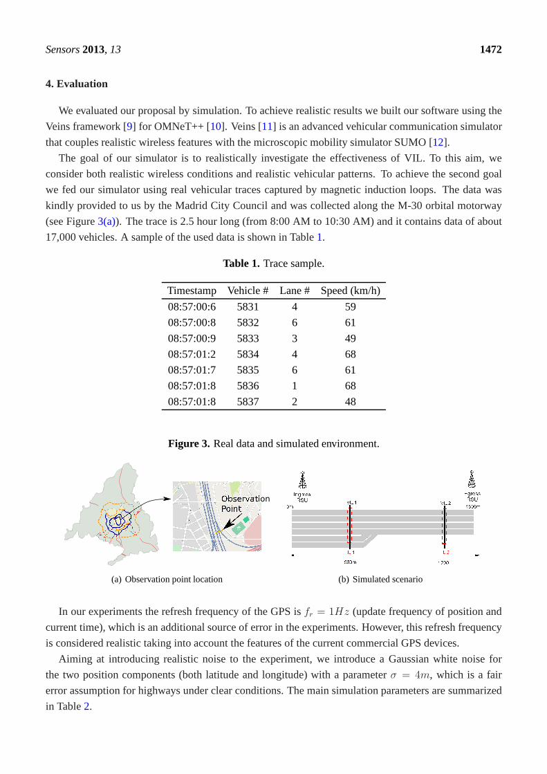
The goal of our simulator is to realistically investigate the effectiveness of VIL. To this aim, we
consider both realistic wireless conditions and realisticvehicular patterns. To achieve the second goal
we fed our simulator using real vehicular traces captured bymagnetic induction loops. The data was
kindly provided to us by the Madrid City Council and was collected along the M-30 orbital motorway
(see Figure3(a)). The trace is 2.5 hour long (from 8:00 AM to 10:30 AM) and it contains data of about
17,000 vehicles. A sample of the used data is shown in Table1.
Table 1. Trace sample.
Timestamp Vehicle # Lane # Speed (km/h)
08:57:00:6 5831 4 59
08:57:00:8 5832 6 61
08:57:00:9 5833 3 49
08:57:01:2 5834 4 68
08:57:01:7 5835 6 61
08:57:01:8 5836 1 68
08:57:01:8 5837 2 48
Figure 3. Real data and simulated environment.
Observation
(a) Observation point location (b) Simulated scenario
In our experiments the refresh frequency of the GPS isfr = 1Hz (update frequency of position and
current time), which is an additional source of error in the experiments. However, this refresh frequency
is considered realistic taking into account the features ofthe current commercial GPS devices.
Aiming at introducing realistic noise to the experiment, weintroduce a Gaussian white noise for
the two position components (both latitude and longitude) with a parameterσ = 4m, which is a fair
error assumption for highways under clear conditions. The main simulation parameters are summarized
in Table2.

Sensors2013, 13 1473
Table 2. Simulation settings.
Simulation framework OMNeT++, Veins and SUMO
Wireless Device 802.11g @ 6 Mb/s
Channel Model Pathloss with channel fading
Monitored stretch length (m) 1500
VIL positions (from theingress RSU) (m) 500, 1000
CAM frequency (s) uniform (0.75,1.25)
The monitored stretch is 1,500 m long and it is a 6-lane singlecarriageway road, composed by 4 main
lanes and 2 acceleration lanes. In the stretch there are one ingressRSUs, one egressRSUsand two virtual
loops (see Figure3(b)).
For the first 500 m, where the first VIL is placed, vehicles’ speed is forced to be close (±2.5 m/s)
to the departure one, then vehicles are allowed to increase their speed, up to 130 km/h. Figures4, 5
and6 depict the obtained simulation results. As it is typically done, the vehicular metrics—flow and
average speed—are summarized into coarser bins, in our caseone-minute sized. In Figures4 and5,
we compare the flow and the mean speed obtained by VIL at the egress RSU with the real ones from
the vehicular traces obtained with real induction loops. Itcan be noticed that despite inaccuracy in
latitude and longitude, and the errors introduced by the refresh frequency, the gap between the two curves
is almost negligible. Figure6 shows the cumulative distribution function (CDF) of the difference (in
absolute value) between the real crossing timestamps and the ones measured by the VIL system. As it can
be observed, almost all the crossing timestamps obtained byVIL fall into ±0.8 s of difference with the
real ones.
Figure 4. Vehicular flow.
0
50
100
150
200
250
0 20 40 60 80 100 120 140 160
Veh
icle
Flo
w [v
eh/m
in]
Time [min]
VIL 1VIL 2
IL 1IL 2

Sensors2013, 13 1474
Figure 5. Average speed.
30
40
50
60
70
80
90
100
110
120
130
0 20 40 60 80 100 120 140 160
Veh
icle
Spe
ed [k
m/h
]
Time [min]
VIL 1VIL 2
IL 1IL 2
Figure 6. Crossing timestamps error.
0
0.1
0.2
0.3
0.4
0.5
0.6
0.7
0.8
0.9
1
0 0.2 0.4 0.6 0.8 1 1.2
CD
F
Time Difference [s]
Timestamp error VIL 1Timestamp error VIL 2
A relevant parameter to be taken into account is the control overhead that the system introduces over
the air. Due to the use of existing CAMs, no new messages are introduced by VIL system. However, the
size of CAM messages is increased with the VIL information. In particular, CAMs broadcast by ingress
RSU include the location of the virtual loops in the area under their influence (8 bytes per virtual loop)
and the identity of the nearest egress RSUs (8 bytes per RSU).Considering the case of a CAM message
that announces 3 virtual loops and 5 egress RSUs, the total increase in the CAM message size is 64 bytes.
As for the CAM messages sent by the vehicles when they are in the coverage area of an egress RSU, the
size of these CAMs is increased by 6 bytes (the timestamp fieldaccounts for 4 additional bytes, and the
speed one for 2 more bytes) for each virtual loop the vehicle has crossed. Therefore, the increase in the
CAM message size can be considered to be of negligible impact.
Sensors2013, 13 1475
5. Conclusions
Keeping the traffic conditions monitored is a crucial task intraffic management systems. Traditional
solutions, based on the use of magnetic induction loops, arewidely deployed, even though they incur high
installation and maintenance costs. In this article we propose a simple approach based on cooperative
vehicular communications that allows scalable monitoringwithout incurring high installation costs.
Simulation results show that both the introduced error compared with the legacy methodologies and
the wireless overhead are negligible. Even in initial deployment scenarios, where not every vehicle
is VIL-enabled, our solution can be used as a suitable replacement of legacy monitoring systems.
Moreover, VIL enables a configurable level of granularity, providing a higher data resolution just when
and where it is needed.
Acknowledgements
This work has been partially funded by the Spanish MICINN through the QUARTET project
(TIN2009-13992-C02-01) and the I-MOVING project (TEC2010-18907). The authors would like to
acknowledge the Madrid city council for kindly providing uswith the empirical traces used in this work.
References
1. Anderson, R.L. Electromagnetic loop vehicle detectors.IEEE Trans. Veh. Technol.1970, 19,
23–30.
2. Leduc, G. Road Traffic Data: Collection Methods and Applications; JRC 47967; European
Commission: Seville, Spain, 2008.
3. Viarani, E. Extraction of Traffic Information from Images atDEIS. In Proceedings of the 10th
International Conference on Image Analysis and Processing, Venice, Italy, 27–29 September
1999; pp. 1073–1076.
4. Intelligent Transport Systems (ITS); Vehicular Communications; Basic Set of Applications; Part 2:
Specification of Cooperative Awareness Basic Service; European Telecommunications Standards
Institute: Sophia Antipolis Cedex, France, 2011.
5. Terms of Reference for Technical Committee (TC) Intelligent Transport Systems (ITS). Available
online: http://portal.etsi.org/its/itstor.asp (accessed on 22 January 2013).
6. Intelligent Transport Systems (ITS); Communications Architecture; European Telecommunications
Standards Institute: Sophia Antipolis Cedex, France, 2009.
7. Jiang, D.; Delgrossi, L. IEEE 802.11p: Towards an International Standard for Wireless Access in
Vehicular Environments. InProceedings of the IEEE Vehicular Technology Conference, Singapore,
11–14 May 2008; pp. 2036–2040.
8. Bauza, R.; Gozalvez, J. Traffic congestion detection in large-scale scenarios using vehicle-to-
vehicle communications.J. Netw. Comput. Appl.2012, in press.
9. Veins–Vehicles in Network Simulation. Available online: http://veins.car2x.org/ (accessed on 22
January 2013).
10. OMNeT++. Available online: http://www.omnetpp.org/ (accessed on 22 January 2013).

Sensors2013, 13 1476
11. Sommer, C.; German, R.; Dressler, F. Bidirectionally coupled network and road traffic simulation
for improved IVC analysis.IEEE Trans. Mob. Comput.2011, 10, 3–15.
12. SUMO Simulation of Urban MObility. Available online: http://sumo.sourceforge.net/ (accessed
on 22 January 2013).
c© 2013 by the authors; licensee MDPI, Basel, Switzerland. This article is an open access article
distributed under the terms and conditions of the Creative Commons Attribution license
(http://creativecommons.org/licenses/by/3.0/).