Combining X-ray microtomography with computer simulation for analysis of granular and porous...
19
Particuology 8 (2010) 81–99 Contents lists available at ScienceDirect Particuology journal homepage: www.elsevier.com/locate/partic Invited review Combining X-ray microtomography with computer simulation for analysis of granular and porous materials Roberto Moreno-Atanasio, Richard A. Williams ∗ , Xiaodong Jia Institute of Particle Science and Engineering, School of Process, Environmental and Materials Engineering, University of Leeds, Leeds LS2 9JT, UK article info Article history: Received 30 July 2009 Accepted 13 January 2010 Keywords: X-ray microtomography Granular flow Computer modelling Lattice Boltzmann method Discrete element method abstract The use of X-ray microtomographic (XMT) methods in analysing particulate systems has expanded rapidly in recent years with the availability of affordable desk-top apparatus. This review presents a summary of the major applications in which computer simulations are explicitly coupled with XMT in the area of granular and porous materials. We envisage two main ways of establishing the coupling between both techniques, based on the transference or exchange of information by using physical or geometrical parameters (i.e. a parametric link through fitting to a process model) or through the direct use of 3D XMT digital images (i.e. comparing image pixels and features directly). Examples of coupled applications are shown for the study of transport properties of rocks, particle packing, mechanical loading and sintering. Often, the link between XMT and computer simulations is based on visual comparisons and we conclude that the use of quantitative parameters such as the number of interparticle contacts, force networks or granule shape to link both techniques is still underrepresented in the literature. Strategies to provide a more robust and quantitative approach to optimise the information obtained from such tomography analyses are proposed. © 2010 Chinese Society of Particuology and Institute of Process Engineering, Chinese Academy of Sciences. Published by Elsevier B.V. All rights reserved. 1. Background X-ray microtomography (XMT) is a non-invasive and non- destructive imaging technique that is able to obtain a 3D image of a scanned sample from a series of X-ray shadow images which in tomographic terminology are often called projections. This tech- nique is based on the absorption dependency of X-rays on material density and atomic number (Sukop et al., 2008). The ability of XMT to Image 3D structures in a non-invasive way has made the use and application of XMT extremely popular across several disciplines including physics, materials science, medicine, mineral processing and powder technology (Fu, Dutt, et al., 2006; Jia, Gan, Williams, & Rhodes, 2007; Kong & Lannutti, 2000; Lin & Miller, 2000; Philippe & Bideau, 2001; Sukop et al., 2008; Wang, Zhang, Bengough, & Crawford, 2005). In addition, the use of higher energy X-ray syn- chrotron radiation sources has in turn stimulated the use of XMT due to its numerous advantages with respect to conventional X- ray sources, by allowing applications to areas such as sintering of Abbreviations: DEM, discrete (distinct) element method; LBM, lattice Boltzmann method; MC, Monte Carlo simulation; RWS, random walk simulation; VoF, volume of fluid method; XMT, X-ray microtomography. ∗ Corresponding author. E-mail address: [email protected] (R.A. Williams). metal powders (Lame, Bellet, Di Michiel, & Bouvard, 2004; Tiseanu, Craciunescu, Aldica, & Groza, 2005). Higher beam intensity and a higher degree of collimation with respect to conventional sources along with the polarisation of the X-ray synchrotron radiation allow a much better focus and image contrast when synchrotron radi- ation sources are used. Synchrotron radiation also presents the great advantage that the range of wavelengths is narrower (higher monochromaticity) than the range produced by conventional X- ray sources and therefore beam hardening effects are significantly smaller. In conventional devices, X-rays are produced by the deceler- ation of electrons against a target (usually tungsten or copper). The kinetic energy of the electrons is lost in the form of X-rays by “braking” or “deceleration” radiation which produces a con- tinuum radiation with a maximum cut-off value. This process is usually called Bremsstrahlung. In cases in which the material under study has a high X-ray absorption coefficient synchrotron radiation sources are more suitable than conventional devices. In contrast to Bremsstrahlung which is due to a tangential accelera- tion, synchrotron radiation is produced by centripetal acceleration due to the presence of a magnetic field that curves the trajec- tory of the electrons. Typical X-ray energy values used by both conventional devices and synchrotron accelerators are less than 150 keV, although this limit depends on the specific device and on the requirements of the application. 1674-2001/$ – see front matter © 2010 Chinese Society of Particuology and Institute of Process Engineering, Chinese Academy of Sciences. Published by Elsevier B.V. All rights reserved. doi:10.1016/j.partic.2010.01.001
-
Upload
newcastle-au -
Category
Documents
-
view
0 -
download
0
Transcript of Combining X-ray microtomography with computer simulation for analysis of granular and porous...

I
Cg
RI
a
ARA
KXGCLD
1
doindtaiaR&Ccdr
mo
1d
Particuology 8 (2010) 81–99
Contents lists available at ScienceDirect
Particuology
journa l homepage: www.e lsev ier .com/ locate /par t ic
nvited review
ombining X-ray microtomography with computer simulation for analysis ofranular and porous materials
oberto Moreno-Atanasio, Richard A. Williams ∗, Xiaodong Jianstitute of Particle Science and Engineering, School of Process, Environmental and Materials Engineering, University of Leeds, Leeds LS2 9JT, UK
r t i c l e i n f o
rticle history:eceived 30 July 2009ccepted 13 January 2010
eywords:-ray microtomographyranular flowomputer modellingattice Boltzmann methodiscrete element method
a b s t r a c t
The use of X-ray microtomographic (XMT) methods in analysing particulate systems has expanded rapidlyin recent years with the availability of affordable desk-top apparatus. This review presents a summaryof the major applications in which computer simulations are explicitly coupled with XMT in the areaof granular and porous materials. We envisage two main ways of establishing the coupling betweenboth techniques, based on the transference or exchange of information by using physical or geometricalparameters (i.e. a parametric link through fitting to a process model) or through the direct use of 3D XMTdigital images (i.e. comparing image pixels and features directly). Examples of coupled applications areshown for the study of transport properties of rocks, particle packing, mechanical loading and sintering.Often, the link between XMT and computer simulations is based on visual comparisons and we concludethat the use of quantitative parameters such as the number of interparticle contacts, force networks orgranule shape to link both techniques is still underrepresented in the literature. Strategies to provide
a more robust and quantitative approach to optimise the information obtained from such tomographyanalyses are proposed.ciety
mChaaagmrs
aTb
© 2010 Chinese So
. Background
X-ray microtomography (XMT) is a non-invasive and non-estructive imaging technique that is able to obtain a 3D imagef a scanned sample from a series of X-ray shadow images whichn tomographic terminology are often called projections. This tech-ique is based on the absorption dependency of X-rays on materialensity and atomic number (Sukop et al., 2008). The ability of XMTo Image 3D structures in a non-invasive way has made the use andpplication of XMT extremely popular across several disciplinesncluding physics, materials science, medicine, mineral processingnd powder technology (Fu, Dutt, et al., 2006; Jia, Gan, Williams, &hodes, 2007; Kong & Lannutti, 2000; Lin & Miller, 2000; PhilippeBideau, 2001; Sukop et al., 2008; Wang, Zhang, Bengough, &
rawford, 2005). In addition, the use of higher energy X-ray syn-hrotron radiation sources has in turn stimulated the use of XMTue to its numerous advantages with respect to conventional X-ay sources, by allowing applications to areas such as sintering of
Abbreviations: DEM, discrete (distinct) element method; LBM, lattice Boltzmannethod; MC, Monte Carlo simulation; RWS, random walk simulation; VoF, volume
f fluid method; XMT, X-ray microtomography.∗ Corresponding author.
E-mail address: [email protected] (R.A. Williams).
tiurctdtc1t
674-2001/$ – see front matter © 2010 Chinese Society of Particuology and Institute of Process Eoi:10.1016/j.partic.2010.01.001
of Particuology and Institute of Process Engineering, Chinese Academy ofSciences. Published by Elsevier B.V. All rights reserved.
etal powders (Lame, Bellet, Di Michiel, & Bouvard, 2004; Tiseanu,raciunescu, Aldica, & Groza, 2005). Higher beam intensity and aigher degree of collimation with respect to conventional sourceslong with the polarisation of the X-ray synchrotron radiation allowmuch better focus and image contrast when synchrotron radi-
tion sources are used. Synchrotron radiation also presents thereat advantage that the range of wavelengths is narrower (higheronochromaticity) than the range produced by conventional X-
ay sources and therefore beam hardening effects are significantlymaller.
In conventional devices, X-rays are produced by the deceler-tion of electrons against a target (usually tungsten or copper).he kinetic energy of the electrons is lost in the form of X-raysy “braking” or “deceleration” radiation which produces a con-inuum radiation with a maximum cut-off value. This processs usually called Bremsstrahlung. In cases in which the materialnder study has a high X-ray absorption coefficient synchrotronadiation sources are more suitable than conventional devices. Inontrast to Bremsstrahlung which is due to a tangential accelera-ion, synchrotron radiation is produced by centripetal acceleration
ue to the presence of a magnetic field that curves the trajec-ory of the electrons. Typical X-ray energy values used by bothonventional devices and synchrotron accelerators are less than50 keV, although this limit depends on the specific device and onhe requirements of the application.ngineering, Chinese Academy of Sciences. Published by Elsevier B.V. All rights reserved.

82 R. Moreno-Atanasio et al. / Part
(mria
I
wctc
�
wa
al(ooiato
at(acCAvb2
atuaaN
ocdti&
tsstasewctttCDfit
ltm
•
•
•
ftimsfitcJ&advt
ms
Fig. 1. Schematic diagram of a XMT scanning device.
When X-rays pass through matter, the amount of X-ray photonsor beam intensity) absorbed by different materials depends on the
aterial density, �, atomic number, Z, and beam energy, E. Theelationship between the emerging, I, and the incident, I0, beamntensities for a given energy of X-rays, after having passed throughsample of differential thickness, ds, is given by:
= I0 exp
∫(−�(s, E) ds, (1)
here � is the absorption coefficient of the sample. The absorptionoefficient at any given point depends on the spatial distribution ofhe different materials. For a single material the absorption coeffi-ient can be written as:
(E) = �
(a + bZ3.8
E3.2
), (2)
here a is a parameter with a weak dependency on the energy, E,nd b is a constant (Sukop et al., 2008).
X-ray tomography devices consist primarily of an X-ray sourcend a detector as schematically shown in Fig. 1. In early and somearge devices, the X-ray source, which produces an X-ray cone beamLin & Miller, 2001), rotates simultaneously with the detector inrder to obtain multiple 2D projections. However, most desktopr lab-scale devices are now based on the rotation of the samplenstead of the synchronous rotation of the source and detector. Atll moments during the rotation process, the sample should be con-ained within the cone beam to obtain a 3D reconstructed image,r else a special correction procedure has to be applied.
The X-ray photons that have not been absorbed by the samplere collected by the detector. The detector is usually a scintillator,hat converts X-rays into visible light, coupled with a photodiodearray of diodes) that converts light into current. This current isnalysed by a computer which creates a digital image. Sophisti-ated variations of this system using optical fibres combined withCD detectors can also be found (Schena, Santoro, & Favretto, 2007).lternatively, the detector can be an image intensifier that con-erts X-rays into visible light and a digital image is further obtainedy means of coupling with a CCD camera (Jenneson & Gundogdu,006).
The 3D reconstruction procedure is based on a pixel-basedpproach in which the 3D image is directly reconstructed using a fil-
ered back projection algorithm (Orlov, Morgan, & Cheng, 2006). Bysing a pixel-based approach there is no need to make assumptionsbout the shapes of the objects as needed when simple geometriesre reconstructed using a parametric-model approach (Kiss, Rodek,agy, Kuba, & Balasko, 2005; West, Jia, & Williams, 2000). First, thepd
mr
icuology 8 (2010) 81–99
riginal data are filtered in the frequency domain after having beenonverted using Fourier transforms. Then, after reconverting theata to the real domain, a back projection algorithm is applied tohe filtered data in order to obtain the 3D digitised tomographicmage of the sample (Russ, 2007; Scott & Williams, 1995; Williams
Beck, 1995).The quality of the final image is subjected to errors and limi-
ations of the reconstruction algorithms. For instance, the use ofquared pixels is intrinsically inaccurate for representing irregularhapes. The finite size of the pixels also limits the degree of detail ofhe image. In addition, in order to use a back projection algorithmnd a Fourier transform in an accurate way an infinite number oflices would be needed. A small number of slices would originaterrors in the Fourier transform. The characteristics of the filterould definitely influence the final reconstruction since signifi-
ant pixels may be removed by the filtering process. Furthermore,he use of a cone beam projection requires that the beam posi-ion should be accurately defined since misalignments of the X-rayube may produce errors in the reconstructed image (Sueseenak,hanwimalueang, Narkbuekaew, Chitsakul, & Pintavirooj, 2006).espite the importance of the influence of these limitations on thenal reconstructed images, this topic is not commonly discussed inhe literature addressing XMT applications.
Nevertheless, the main disadvantages that XMT presents are theimitations in spatial and temporal resolution and the lack of con-rast between phases having similar attenuation coefficients. The
ain limitations of XMT are:
Spatial resolution and sample size. Spatial resolution is deter-mined by the detector resolution and the focal spot size (typically0.5–5 �m). Often, the highest resolution is obtained at theexpense of a small sample size or a small scanned area.Temporal resolution and scan time. XMT requires that the struc-ture of the sample remains unchanged during the scan (typically30–120 min). This limits XMTs ability to look at fast dynamicbehaviour.Image contrast. XMT distinguishes components of different mate-rials by their differences in absorption coefficients. If a samplecontains components of similar attenuation (absorption) coeffi-cients, XMT cannot provide sufficient information.
The spatial image resolution depends mainly on two factors, theocal spot size (area of the target that is struck by electrons) andhe detector resolution. Depending on whether the focal spot sizes in the range of micrometres or nanometres the device is named
icrofocus or nanofocus (Daneke & Schanklies, 2004). The focalpot limits the resolution of the image to a typical value of half theocal spot size. The maximum resolution of current XMT devicess a few hundred of nanometres and therefore, the applicationo nanoparticulate systems is limited since individual nanoparti-les cannot be visualised (Gundogdu, Jenneson, & Tuzun, 2007;enneson & Gundogdu, 2006; Jenneson, Luggar, Morton, Gundogdu,
Tuzun, 2004). Fig. 2 shows nanoparticle aggregates before andfter fluidisation using a high spatial resolution X-ray tomographyevice (Gundogdu et al., 2007). The individual particles cannot beisualised. However, the presence of agglomerates is clear due tohe large agglomerate sizes (Gundogdu et al., 2007).
Nevertheless, the design of a new X-ray tomography device withultiple guns allow the application of X-ray tomography to the
tudy of multiphase flows since the device operates at 50 frames
er second (Luggar, Morton, Jenneson, & Key, 2001). This tool willrastically extend the range of applications of XMT.The size limitation may have a direct consequence on deter-ination of the bulk properties of the sample. A small scanned
egion may not be representative of the full sample and therefore

R. Moreno-Atanasio et al. / Part
Fig. 2. Imaging of nanopowder agglomerate before (left hand side) and after (righthand side) fluidisation. (With kind permission from Springer Science + BusinessMedia: Journal of Nanoparticle Research, Nano particle fluidisation in model 2Dap
tmsmJ
(actsoetDaetrsneab4rpuRer
prmstXntXt
teLnira(tat&auswteP
tiaJ2WBScbIbtManaii
aauecuanmSV(M&
tpttsimulated by computer simulations.
The aim of this review is to highlight the potential of coupling
nd 3D beds using high speed X-ray imaging and microtomography, Vol. 9, 2007,p. 215–223, Gundogdu, Jenneson, & Tuzun, Fig. 9.)
he predicted bulk properties may differs from those of the wholeaterial. In this case these statistical errors may be minimised by
canning different areas across the samples and averaging the esti-ated values of the bulk properties of the sample (Selomulya, Tran,
ia, & Williams, 2006).The limitation in temporal resolution is due to the exposure time
typically in a few hundred or more milliseconds) needed to obtainsingle projection and to the necessity of acquiring multiple (typi-ally hundreds to a couple of thousands) projections to reconstructhe 3D image. The time required to image a voxel increases as theize of the voxel decreases due to the statistical spatial distributionf photons (Wildenschild et al., 2002). Therefore, a decrease in thexposure time would produce blurry images with a lack of defini-ion of fine detail and poor contrast between the different materials.epending on the absorption coefficient of the different materialsnd the resolution and contrast of the image that is desired, thexposure time or, in turn, the total number of photons that strikehe sample, needs to be increased. Due to the large amount of timeequired to scan a 3D sample the application of XMT to dynamictates is limited since either the spatial or the temporal resolutioneeds to be changed in order to capture details in a rapidly changingnvironment. This is the case reported by Gundogdu et al. (2007)nd He and Kantzas (2005) who have applied XMT to a fluidiseded reactor. In the first case a temporal resolution with a value of0 ms was used which allowed a clear observation of agglomerationegions. In the second case the resolution was 490 �m and the noiseroduced by the rapid movement of the particles was removedsing a mathematical algorithm in order to produce a clear image.eal-time X-ray tomography as a technology does exist (Luggart al., 2001) but is too expensive and too restrictive for routineesearch use.
The similarity between attenuation coefficients of differenthases may produce a lack of contrast between the different mate-ials in the samples. This problem is very typical in the analysis ofultiphase flows. In these cases, the fluids are doped with other
ubstances in such a way that the viscosity and surface tension ofhe fluids remain basically unaltered whilst the capacity to absorb-rays changes and the contrast between phases increases sig-ificantly (Coles et al., 1998; Sukop et al., 2008). However, this
echnique is not so directly applicable to solids. Data fusion ofMT data with results from Raman or IR based chemical imagingechniques provides a way forward.
bpi
icuology 8 (2010) 81–99 83
Other limitations or problems that appear with XMT are relatedo the appearance of artifacts in the images. Artifacts have differ-nt origins which have been investigated in the literature (Vidal,étang, Peix, & Cloetens, 2005). The main ones are beam hardening,oise artifacts, ring artifacts and motion artifacts. Beam hardening
s due to a stronger attenuation of low energy X-ray in the spectrum,esulting in a homogeneous mass appearing denser at the bound-ry than in the centre, giving rise to the so-called cupped effectKrumm, Kasperl, & Franz, 2008). Ring artifacts, as indicated byheir name, manifest as a set of concentric rings in the images andre due to a different sensitivity of a given pixel within the detec-or with respect to the neighbouring pixels (Raven, 1998; Sijbers
Postnovz, 2004). Motion artifacts are blurring within the imagesnd are due to the movement of objects within the scanned vol-me being imaged (He & Kantzas, 2005). Despite the severity ofome of these artifacts, with due caution current computer soft-are is often able to remove them partially or totally by filtering
he images and using special algorithms that correct bad pixels orliminate the noise from the image (Krumm et al., 2008; Sijbers &ostnovz, 2004).
Applications of X-ray microtomography (XMT) in the litera-ure in different scientific or industrial fields are numerous. Fornstance: mechanical properties (Busignies et al., 2006; Mueth etl., 2000); colloidal deposition during filtration (Li, Lin, Miller, &ohnson, 2006); analysis of granule structures (Ansari & Stepánek,006b); mixing and segregation (Jia, Caulkin, Fairweather, &illiams, 2007; Yang & Fu, 2004) porous media (Betson, Barker,
arnes, Atkinson, & Jupe, 2004; Nakashima & Watanabe, 2002;panne et al., 1994; Wong, 1999) pore structure analysis of filterakes (Lin & Miller, 2001); visualisation of catalyst thickness aroundubbles during fluidisation (Kai, Misawa, Takahashi, Tiseanu, &
chikawa, 2005); analysis of the mixing of solids in a double conelender using marker particles (Chester et al., 1999) and determina-ion of moisture content during drying of sludge (Leonard, Blacher,
archot, Pirard, & Crine, 2003). Some reviews on specific industrialpplications such as analysis of voidage in mineral processing tech-ology (Lin, Miller, & Cortes, 1992; Miller, Lin, & Cortes, 1990) orpplications in hydrology (Wildenschild et al., 2002) can be foundn the literature. A general literature review addressing advancesn X-ray tomography applied to materials is given by Stock (2008).
The combination of XMT and computer simulations was initi-ted in the 1990s when X-ray microtomography started to be useds a way of obtaining detailed material structure that could besed in computer simulations (Olson & Rothman, 1997; Spannet al., 1994). However, since the early 2000s, the use of XMT inonjunction with computer simulations has become more pop-lar. Combinations of both techniques can be found in differentpplications such as in the analysis of fluid flow through a porousetwork (Lin & Miller, 2004; Sukop et al., 2008); permeability oficrostructures (Lu, Landis, & Keane, 2006; Selomulya et al., 2006;
panne et al., 1994); hydraulic properties (Karpyn & Piri, 2007;ogel, Tölke, Schulz, Krafczyk, & Roth, 2005); dissolution of tablets
Jia & Williams, 2006, 2007) and granule compression (Golchert,oreno, Ghadiri, & Litster, 2004; Golchert, Moreno, Ghadiri, Litster,Williams, 2004).The combination of XMT with computer simulations also offers
he possibility of investigating different physical and industrialroblems in a complementary manner. This is achieved by charac-erising structural changes through the use of XMT and comparinghem to the predictions of the different physical models that are
oth techniques illustrating examples in the area of granular andorous materials. The review starts by discussing the different ways
n which X-ray microtomography and computer simulation can be

8 / Part
lccawoptt
2
tdlca(X
msXdatXAri2pfiMWmrt
totmt
ctobpat(opfCti2bio
(auaaTt
ub
Fs
4 R. Moreno-Atanasio et al.
inked (Section 2). This section is followed by a review of the appli-ations in which XMT and computer simulations have been usedonjunctly to study the behaviour of granular and porous materi-ls (Section 3). The focus of Section 3 will be centred on the way inhich the link between both techniques has been established and
n the characteristics of the physical system under study. The finalart of the review describes and discusses the different parametershat offer a great potential to establish a robust link between bothechniques (Section 4).
. Linking XMT with computer simulations
The link between XMT and computer simulations is carried outhrough the exchange and comparison of structural informationerived from both techniques. Different ways to establish such a
ink can be envisaged (Fig. 3) and they may be restricted by theomputer simulation method used to couple both techniques. Theyre based on the use of parameters obtained from the XMT imagesparametric link) and on the direct use of XMT images to compareMT with simulations.
The parametric approach enables quantification of differentodel-based properties. The parametric link between XMT and
imulations can be carried out in different ways depending on ifMT is used to set up a simulation (input) (Fig. 3, route 1a) or to vali-ate its results (output) (Fig. 3, route 1b). A combination of both canlso be used. The first route (1a) would involve the use of parame-ers, such as particle positions, shapes and radii, as obtained fromMT data, as input for the simulations (Wang, Park, & Fu, 2007).comparison of the output parameters from the simulations with
esults from any other experimental techniques may be used to val-date the simulation results (Golchert, Moreno, Ghadiri, & Litster,004). In the second route (1b), we can directly compare the outputarameters from the simulations with their counterparts obtainedrom XMT data. This way of linking XMT with computer simulationss commonly used to predict final packing of granular beds (Lin &
iller, 2000), for instance. A similar methodology is reported byest et al. (2000) in the case of flow and particle concentration zoneodelling and imaging a hydrocyclone flow using different tomog-
aphy methods. West et al. (2000) used two parameters describinghe radial concentration profile inside the hydrocyclone separa-
Tilpt
ig. 3. Illustrative diagram of the main ways to link XMT and computer simulations.imulations. Dashed arrows indicate complementary ways of linking both techniques. Do
icuology 8 (2010) 81–99
or as filtering parameters. The values for these parameters werebtained from tomography data (i.e. unreconstructed). Visualisa-ion of the concentration could be obtained through the parametric
odel or independently by applying a reconstruction model toomography data.
The imaging link can also be used in two different ways as in thease of the parametric link (Fig. 3). The first one (route 2a) involveshe use of the XMT digital image as an input for the simulations, inrder to determine the geometry and boundary conditions neededy the computer models. Computer simulations are then used toredict any physical property of the system. A typical case is thenalysis of material permeability and tortuosity as these proper-ies strongly depend on the specific structure that is being analysedHarting, Venturoli, & Coveney, 2004; Lin & Miller, 2004). This typef link provides an accurate way for predicting realistic physicalroperties by reducing the statistical variation due to slightly dif-erent initial conditions (Jia, Gopinathan, Williams, Eberhardt, &larke, 2001). Occasionally a comparison of the computer simula-ion predictions with other experimental techniques is performedn order to validate the computer models. The second way (routeb) of using an image is to produce a qualitative visual comparisonetween the computer simulation output and XMT images, as for
nstance, visualising the shape of agglomerates and the distributionf components in a tablet (Rajniak et al., 2007).
Combinations of parametric and imaging links are also possibledashed arrows in Fig. 3) although there are relatively few exampless yet in the published literature. For instance, a combination of these of the initial digital images for the computer simulations anddirect comparison of structural parameters determined by XMT
nd computer simulations can be carried out (Sukop et al., 2008).his combination produces the most accurate way of linking thesewo techniques in order to fully investigate a physical process.
The main limitations of the coupling of XMT and computer sim-lations are influenced by the inherent limitations of XMT andy the limitations of the specific computer simulation techniques.
herefore, careful consideration of the errors arising from the lim-tations in XMT and computer simulations is needed. The mainimitations or sources of error are spatial resolution, size of the sam-le, temporal resolution, image contrast and the specific nature ofhe simulations.The continuous arrows indicate the primary way of linking XMT and computertted arrows indicate an inflow of information needed to set up the simulations.

/ Part
•
•
•
•
•
a(tarpotp
dJgbsvbodtoa&easdep
stf(cpi
LoFmmeMtb
isi
3s
oitstlstpsitwpt
3m
apctdmgcoaigut2iht
mm
R. Moreno-Atanasio et al.
Spatial resolution. The limit in spatial resolution of XMT influ-ences those details (e.g. small pores or particles) smaller than thevoxel size which cannot be reproduced by computer simulations.Therefore, differences between the values of bulk properties pre-dicted by the simulations and those determined experimentallymay appear.Size of the sample or the scan region. The values of parametersobtained from a small scanned region which is in turn used insimulations may not be representative of the macroscopic sampleand therefore differences between the predictions of computersimulations and the behaviour of the real material may alsoappear.Temporal resolution. XMT cannot capture fast changing dynamicstates. Therefore, the coupling between XMT and simulationsis often restricted to the transference of information prior tobeginning the simulations (simulation set up) or at the end ofsimulations (comparison of the final state). The comparison ofdynamic states is not easily feasible.Image contrast. A precise separation between different objectsor different phases is needed in order to accurately transfer theinformation into computer simulations or for predicting the finalstage of the system.Nature of the computer simulations. Some computer simulationtechniques are not able to deal with irregular contours or parti-cles and therefore XMT cannot be coupled with these simulationtechniques except if simplifications are made.
A low spatial resolution of the XMT image would result fromlow detector resolution or a low relative sample magnification
ratio of the distance between the detector and the X-ray source tohe distance between the sample and the detector). Details whichre smaller than the resolution size, such as small pores, cannot beesolved. Therefore, the calculation of any physical or geometricalarameter is strongly linked to the spatial resolution and contrastf the image (Gualda & Rivers, 2006; Stock, 2008) and errors inhe estimation of parameters such as volumes, surface areas anderimeters (Nakashima & Watanabe, 2002) may appear.
With regards to XMT the accuracy of the digital representation isirectly related to the resolution and contrast of the image (Zeidan,
ia, & Williams, 2007). Errors originated in the estimation of someeometrical parameters due to the digitisation process have alsoeen discussed in the literature (Zeidan et al., 2007). A 3D digiti-ation process represents real bodies with a set of cubical grids,oxels, with different grey levels. The voxels are considered toelong to the body if their level of grey passes a certain thresh-ld value according to the histogram of grey levels. The process ofetermining the threshold that separates different materials fromhe background is called segmentation. The selection of thresh-ld(s) is somewhat arbitrary and therefore could incur errors byssigning voxels to the inappropriate phase or body (NakashimaWatanabe, 2002). In addition, a poor contrast could make vox-
ls that belong to the sample, especially to its boundaries, possessvery low grey level and therefore they could be wrongly con-
idered as background in the segmentation process. In addition,etermination of radii or positions can only be achieved with anrror equal to the voxel size. Therefore, a clear identification of thearticle contour is needed.
Finally, since computer models are simplified versions of realystems this may incur limitations in the link between simula-ions and XMT. For instance, irregular particle shapes, as obtained
rom XMT, are often considered as individual spherical particlesGolchert, Moreno, Ghadiri, Litster, et al., 2004) or to be made up oflusters of spherical particles (Wang et al., 2007) within the com-uter models. These simplifications may produce a drastic changen porosities or mechanical behaviour (Golchert, Moreno, Ghadiri, &
&tuma
icuology 8 (2010) 81–99 85
itster, 2004) and therefore there is a need to reduce these sourcesf error by using the exact particle shape (Jia & Williams, 2001).urthermore, errors in the predicted values of physical parametersay also appear due to the fact that the scanned microscopic regionay not be representative of the whole macroscopic sample (Bentz
t al., 2000; Selomulya et al., 2006). For instance Discrete Elementethod cannot handle properly the use of irregular particles and
he use of digital softwares would be more appropriate to study theehaviour of non-spherical particles.
Limitations and errors originating from the models implicitlymmersed in the way in which XMT and simulations are linked arecarcely discussed in the literature despite their possible influencen the final computer simulation predictions.
. Combined applications of XMT and computerimulations
The combined use of XMT and computer simulations is basedn the capacity of the tomographic technique to obtain 3D detailednformation of the spatial distribution of materials. This informa-ion can be used to setup the boundary conditions in the computerimulations, to analyse either changes of shape or morphology oro determine physical parameters which are directly or indirectlyinked to changes in the structural properties of the material. Aummary of the main applications that have utilised the combina-ion of XMT and computer simulations to study the behaviour oforous or granular materials will be provided in the following sub-ections. Selected examples found in the literature can been seenn Table 1 indicating the application, material and parameters usedo link XMT and computer simulations and appropriate referencedork. The description of the materials, systems and main linkingarameters used by the computer simulations are included in theext for each reported case in the following subsections.
.1. Fluid flow and transport properties in porous and granularedia
One of the largest areas of application of XMT is the study andnalysis of fluid flow and transport properties in porous media. Aorous medium is a solid material permeated by a network of inter-onnected pores. The solid material is usually called the matrix andhe pores are called voids. Pores can be filled with gas or liquidepending on the environment or application. Examples of porousedia can be found in many science and engineering fields such as
eology (rocks), biology (sponges) and chemical engineering (filterakes). The passage of fluid through these materials depends notnly on the fluid properties but on the pore network which is usu-lly extremely irregular and difficult to characterise. When XMTs combined with computer simulations it is possible to investi-ate the fluid flow and material properties in an accurate way bysing realistic material structures and therefore avoiding uncer-ainties created by an unknown initial structure (Jia & Williams,006). However, the important caveat is that the resolution of the
maging method must be compatible with the minimum effectiveydraulic pore size in order to obtain accurate predictions of theransport properties of materials.
The most common computer simulation method used to deter-ine fluid flow and analyse transport properties through porousedia is the Lattice Boltzmann Method (LBM) (Succi, 2001; Sukop
Thorne, 2006). LBM may be regarded as a digital equivalent of theraditional Computational Fluid Dynamics (CFD). Typically, LBMses the digital information obtained from the XMT of the realaterial, usually a filter cake, a rock or simply a bed of particles,
s an input for the simulations. This suitability of the coupling of

86 R. Moreno-Atanasio et al. / Particuology 8 (2010) 81–99
Table 1Examples of coupling XMT with computer simulations.
Application Material Simulation XMT-simulation link Reference
Fluid saturations Sand, oil and water LBM Input structure andvisual observations
Sukop et al. (2008)
Fluid flow pattern Foam LBM Input structure Jia and Williams (2006)Fluid pattern Sandstone Input structure. Fluid
concentration withheight. Visualcomparison
Coles et al. (1998)
Flow pattern during drying process Alumina extrudates VoF Height of the liquidphase volume fraction
Kohout, Grof, et al. (2006)
Permeability of porous materials Bentheimer sandstone,water, oil
LBM Input structure Harting et al. (2004)
Permeability of filter cakes Glass beads LBM Input structure Selomulya et al. (2006)Permeability of filter cakes Iron ore LBM Input structure Lin and Miller (2004)Porosity of filter cakes Unspecified MC Porosity versus height Lin and Miller (2000)Permeability of flocs and sediments Glass beads LBM Input structure Selomulya et al. (2005)Permeability and tortuosity of porous
materialsGlass beads LBM Input structure Wang et al. (2005)
Permeability, tortuosity and packing ofporous materials
Lava RWS Input structure. Nakashima and Kamiya (2007)
Permeability and tortuosity of porousmaterials
Glass beads RWS Transport properties bytracking iondisplacement
Nakashima and Watanabe (2002)
Permeability and tortuosity of porousmaterials
Sandstone RWS Comparison withmedical CT
Nakashima et al. (2004)
Permeability Bricks LBM Input structure Bentz et al. (2000)Granule formation Mannitol + HPC DEM Comparison of
morphologyRajniak et al. (2007)
Granule dissolution Sugar cubes + NaCl VoF Comparison of granulesstructures
Ansari and Stepánek (2006a)
Granule dissolution rate Aspirin LBM. Input structure Jia and Williams (2007)Granule compression Glass beads DEM Input structure Golchert (2003)Bed compression Glass beads DEM Structure input. Pair
correlation functionFu, Elliott, et al. (2006)
Bed compression by vertical oscillations Glass beads MC Volume distribution ofpores duringcompaction
Richard et al. (2003)
Densification during bed compression Alumina granules DEM Shape of compactioncurves
Kong and Lannutti (2000)
Bed structure Glass mono, glass polyand MCC
DEM Input structure. Paircorrelation function
Fu, Dutt, et al. (2006)
Bed structure, packing Industrial powders Digital model Comparison of porosityand structure betweenreal and simulated
Jia, Gan, et al. (2007) and Jia, Caulkin,et al. (2007)
Bed structure-coordination number and Glass beads Optimization method Homogeneity and Al-Raoush and Alsaleh (2007)
t(
pswGdb
fitm
3
stocb
t22Xes
tWtbut
li
packing distributionSintering Iron powder DEMSintering Glass MC
hese two techniques has been discussed by Videla, Lin, and Miller2008).
Sukop and Thorne (2006) described a method originally pro-osed by Dardis and McCloskey (1998) to deal with greyscaletructures using LBM. Usually, structure input to LBM is binary,here a voxel is either completely solid or completely empty.reyscale (a value between 0 and 1) allows sub-pixel structuraletails, such as sub-pixel pores and smooth edges that would haveeen lost during binarisation, to be at least partially accounted for.
The review of this topic has been subdivided into two parts. Therst will be focused on the applications that study fluid profiles andhe second part will focus on the analysis of transport properties of
aterials, namely permeability and tortuosity.
.1.1. Fluid profilesOne of the pioneering pieces of work using an XMT-computer
imulation approach in the study of fluid profiles analyses the dis-ributions of two fluids in a sandstone sample proceeding from anil leg reservoir using an imaging link (Coles et al., 1998). Theiroupling was based on the use of the XMT scanned structure as theoundary condition for LBM simulations (Fig. 3, route 2a) and on
aL
qm
isotropyInput structure Vagnon et al. (2006)Neck growth Bordere et al. (2004)
he visual comparison of the computed fluid distribution withinD slices with XMT images from the real system (Fig. 3, routeb). Although no parameters were used to link simulations andMT, the qualitative good agreement between both techniques wasnough to demonstrate the potential of a combined use of XMT andimulations.
Applications based on the ‘imaging link’ have also demonstratedheir usefulness in the study of single flow in porous media (Jia &
illiams, 2006) by predicting the regions of higher velocity withinhe sample. The coupling between XMT and simulations presentedy these authors was carried out by scanning a piece of foam andsing the solid profile of the foam as the boundary conditions forheir LBM computer simulations (Fig. 3, route 1a).
A clear example of single flow in porous media using an ‘imagingink’, demonstrating the capability of using LBM coupled with XMTs shown in Fig. 4 (Videla et al., 2008). Fig. 4 shows the 3D image of
packed bed of limestone particles and the simulated flow usingBM within 2D slices.The study of oil and water distribution within a bed made of
uartz sand grains using a combination of the imaging and para-etric links reported by Sukop et al. (2008) has shown one of the

R. Moreno-Atanasio et al. / Particuology 8 (2010) 81–99 87
F showw , & MiB 28, Co
mtwapseb
f(2iuoaKmU(llftabcd
up
t2c
3
ipuio2c&
flapcs
p(ic(
ig. 4. Top, a 3D XMT image of a packed particle bed (1000 �m × 1400 �m). A and Bas published in Journal of the Chinese Institute of Chemical Engineers, Videla, Linoltzmann method for the calculation of permeability from XMT images, pp. 117–1
ost robust ways of coupling XMT with computer simulations. Inhis study the initial structure is transferred into the computer soft-are (route 1a). In addition, they compared the distribution of oil
nd water by comparing the relative content of each fluid plane bylane (route 1b) and the visual distribution of the two phases withinpecific pores (route 2b). The comparison between simulations andxperiments was excellent demonstrating the full potential andenefits of using a coupled XMT-computer simulation approach.
Combination of the imaging and parametric links can also beound in the study of drying processes. Kohout, Grof, and Stepánek2006) (a brief description of their work was provided by Stock,008) compared the experimental liquid phase morphology dur-
ng drying of cylindrical alumina for two cases corresponding tontreated (hydrophilic) and silanised alumina (neutral). Detailsf the use of 3D tomographic images of the sample as a bound-ry condition in the LBM computer simulations were given byohout, Grof, et al. (2006) (route 2a). Details of the simulationethodology can be found in Kohout, Collier, and Stepánek (2006).nder vacuum conditions (150 mbar) for the untreated material
first case) the formation of a cavity (without the presence ofiquid) inside the extrudate was perfectly reproduced by the simu-ations (route 2b). The comparison of the quantitative liquid profileor silanised particles (second case) dried under vacuum condi-ions was also excellent (route 1b). However, this agreement waschieved by choosing a contact angle of 60◦ which produced theest fit between simulations and experiments demonstrating the
apability of the XMT-computer simulations combination to vali-ate computer models.Many other pieces of work can be found in the literature thatse the combination of simulations and XMT to investigate flowrofiles within porous media. However, most of them are restricted
bwmcw
the simulated porous flow at slice 64 (A) and 128 (B) in the ZY planes. (This articleller, Vol. 39, Simulation of saturated fluid flow in packed particle beds—The latticepyright Elsevier.)
o the use of XMT as an input for the simulations (Fig. 3, routea) without making use of the full potential that is offered by aombination of XMT and computer simulations as described above.
.1.2. Transport properties in porous mediaDirectly related to studies of fluid flow profiles in porous media
s the necessity to characterise the pore network and thus the trans-ort properties of solid porous materials. This characterisation issually carried out by quantifying parameters such as permeabil-
ty and tortuosity with the former usually calculated using Darcy’sr Kozeny–Carman equations (Lin & Miller, 2004; Selomulya et al.,006) and the latter using the ratio between the diffusion coeffi-ients of particles in the porous material and in water (NakashimaWatanabe, 2002).Applications in the area of chemical engineering studying the
ow through filter cakes, particulate beds and flocculated materi-ls and in the areas of hydrology and geology studying the transportroperties of rocks are very frequent in the literature. These appli-ations are mainly aiming to study the relationship between poretructures and transport properties.
The analysis of the relationship between pore structures andermeability in filter cakes has been reported by Lin and Miller2004) amongst others. These authors determined the permeabil-ty of two filter cakes whose structure had been inputted into theomputer simulations based on LBM (Lin & Miller, 2000, 2001)Fig. 3, route 2a, imaging link). The computer model was validated
y comparing the predicted transport properties of cubic arraysith theoretical models and published data. Therefore, the esti-ated permeabilities obtained for the reconstructed images of ironakes (∼10−8 cm2) were assumed to be realistic and no comparisonith real experiments was performed.

88 R. Moreno-Atanasio et al. / Part
Fig. 5. Simulations of a digitised XMT section from 10 g/L specimen, identifyinginternal high pressure regions. (Reproduced with permission from IChemE, Fig. 4 ofCiI
pta2ssc(eiw
iJnrXec0uotpscepi
aBs
rovwGtncmt(
tc(SpsnsrsiNilpus(ts
oXtopmm
bacpoop
btl&euow(
tbeds, filter cakes and rocks) with the help of XMT. XMT has been
. Selomulya, X. Jia and R.A. Williams, Direct prediction of structure and permeabil-ty of flocculated structures and sediments using 3D tomographic imaging. TransChemE, Part A. Chemical Engineering Research and Design, 83, pp. 844–852.)
Selomulya et al. (2006) also presented a study of the transportroperties of filter cakes in which the XMT digital images wereransferred into two different LBM software packages, Powderflownd Digiflow, in order to perform the simulations (Fig. 3, routea). The authors minimised the errors originating from statisticaltructural variations across a filter cake made of glass beads bycanning six different areas across the sample and averaging theomputer simulation results. The simulated relative permeabilitiesk/r2) were calculated according to Darcy’s law (Eq. (2) in Selomulyat al., 2006) and were within the same order of magnitude (10−3)n experiments and simulations implying that the microstructures
ere representative of the whole sample (Selomulya et al., 2006).The study of the relationship between porosity and permeabil-
ty has also been carried out for flocculated structures (Selomulya,ia, & Williams, 2005; Williams, Selomulya, & Jia, 2005). The combi-ation of XMT and simulations was based on an imaging link (Fig. 3,oute 2a) in which the digital image obtained by a SkyScan 1072MT was transferred into a digital software package. Two differ-nt types of aggregates made of polydisperse silica (22 �m) werereated corresponding to two different concentrations of particles,.5 and 10 g/L and iron chloride/Magnafloc 155 and Zetag 154 weresed as flocculating agents (Selomulya et al., 2004). The predictionsf the computer simulations showed that the most porous struc-ure was also the most permeable. In addition, the LBM simulationsredicted the areas of larger fluid pressure within the sediments ashown in Fig. 5. Therefore trends such as sediment compressibilityould be identified. Although these results were not compared withxperiments, they suggested that computer simulations are able toroduce outputs with reasonable physical significance when real-
stic structures are input into the simulations.
The analysis of the transport properties of construction materi-ls has also received certain attention in the literature. For instance,entz et al. (2000) presented the study of the permeability of twoamples made of lime silica or clinker bricks using synchrotron
mftw
icuology 8 (2010) 81–99
adiation. The link was based on the transference of the structuref the sample into the computer simulations (Fig. 3, route 2a). Thealue of permeabilities obtained from the computer simulations,hich were based on Stokes equation (Schwartz, Martys, Bentz,arboczi, & Torquato, 1993), were around three times larger than
hose obtained by experiments based on vapour diffusivity tech-iques (Quenard, Xu, Künzel, Bentz, & Martys, 1998). The authorsonsidered that the discrepancy between simulation and experi-ents could be due to a small scan region, although they considered
hat other possible sources of errors such as a low pixel resolution6.65 �m per pixel) may have influenced the final results.
However, the most common types of applications are found inhe area of hydrology and geology where an extensive literaturean be found. The study presented by Nakashima and Watanabe2002) provided an exhaustive comparison between Random Walkimulations (RWS), XMT and other experimental results in theredictions of transport properties using glass beads as a modelystem. In order to obtain such a level of comparison a combi-ation of imaging and parametric link was used. The sample wascanned using XMT (Fig. 3, route 2a) but the tortuosity of the mate-ial was determined using a computed tomography (CT) medicalcanner (Fig. 3, route 1b). The RWS overestimated the permeabil-ty and tortuosity of the material obtained from the experiments.akashima and Watanabe (2002) attributed this difference to lim-
tations in the applications of Kozeny–Carman equations and to aow resolution of the CT images which could not detect the smallerores. However, in later work, Wang et al. (2005), using LBM sim-lations, obtained a similar value of permeability for exactly theame bed used in the experiments by Nakashima and Watanabe2002). This is a typical case in which limitations in the computa-ional models alongside limitations in the XMT resolution originatemall differences in the results.
Nakashima et al. (2004) studied the permeability and tortuosityf porous sandstone by random walk simulations as obtained from-ray computed tomography (Fig. 3, route 2a). The results for tor-
uosity obtained by simulations were five times greater than thosebtained by diffusion tracking on X-ray CT. However, the final com-uted permeability compared relatively well with conventionalethods (Fig. 3, route 1b). The details about their tomographyethodology were extensively described by Nakashima (2000).The determination of the permeability of Bentheimer sandstone
y simulating a mixture of water and oil was reported by Harting etl. (2004). The structure was transferred into the LBM software. Noomparison with experimental data was performed. Such a com-arison would have made an interesting contribution to the topicf transport properties since it would have provided a validationf the computer model in the prediction of multiphase transportroperties of fluid mixtures.
Several other good examples can be found in the literature com-ining XMT with computer simulations, especially LBM, in ordero study the permeability of the materials. Some of them usedava samples (Nakashima & Kamiya, 2007) or sandstone (Martys
Chen, 1996; Martys & Hagedorn, 2002) and others made a gen-ral study of the relationship between structure and permeabilitysing the Kozeny–Carman equation (Jia, Xu, & Williams, 2005). Inther cases, some model systems such as food (pasta particles)ere used to demonstrate the potential of combining XMT and LBM
Gopinathan, Fairwather, Jia, & Williams, 2003).Computer simulations have been able to successfully predict
he transport properties of different materials (such as granular
ainly used to determine the initial material structure and there-ore to avoid the influence of an unknown microscopic structure onhe transport properties. Nevertheless, future research in this areaill benefit from combined studies of computer simulations and

/ Part
Xlp
3
tstmitsei
c2ltawricuwSmssato
ieaf1XcpFcetnpwe
3
wcshrdpid
oatootTfusiapbt
auWtkdccdwfhs
setSvo
3
rsta&dflsaaltacgtitS
R. Moreno-Atanasio et al.
MT in order to establish empirical relationships that accuratelyink the geometry of pore networks and the macroscopic transportroperties of materials.
.2. Granule formation
Granule formation is a process with strong relevance to indus-ry (Iveson, Litster, Hapgood, & Ennis, 2001). It is important totudy the formation of granules as it is necessary to improvehe efficiency of the formation process and the final physical or
echanical properties of granules. XMT has been applied by itselfn this field on several occasions (Bouwman et al., 2005) sincehis technique shows a great potential to characterise granuletructure and to link it to the granule formation process. How-ver, the combined use of XMT and computer simulations is stillncipient.
The main contributions to the field are given by Stepánek andoworkers in the study of granule morphology (Rajniak et al.,007; Stepánek & Ansari, 2005). These authors used an imaging
ink (Fig. 3, route 2b) based on the visual comparison betweenhe real experimental granule morphology as obtained from XMTnd the morphology predicted by computer simulations. The studyas presented for granules with different porosities which cor-
espond to different values in the concentration of binders. Thenfluence of binder concentration on the granulation of pharma-eutical excipients (irregular mannitol particles of around 120 �m)sing a fluid bed granulator was studied. The granules, whose sizesere less than 600 �m, were scanned using an XMT scanner, model
ky-Scan-1072 (Rajniak et al., 2007). The porosities were deter-ined from the XMT images. The lower the porosity the more
pherical the granules were. The primary particles used in theimulations (Stepánek & Ansari, 2005) had the same morphologys the mannitol particles. Therefore, the authors concluded thathe virtual granules seemed to be realistic models of the physicalnes.
The lack of combined work of XMT and computer simulationsn this area offers a great potential for future applications and anxcellent opportunity to study not only granulation (Bouwman etl., 2005) but also other processes by which particles come togetherorming new structures as in the case of flocculation (Gregory,997; MacFarlane, Bremmell, & Addai-Mensah, 2006). In addition,MT can complement extensive computer simulation studies byomparing virtual granules with possible experimental counter-arts (Moreno & Ghadiri, 2003; Samimi, Moreno, & Ghadiri, 2004).urthermore, a link between the specific granule formation pro-ess and the final structure can be better understood by producingxhaustive comparisons between simulations and experiments inerms of shape, size, morphology, packing fraction and coordi-ation number. Such studies, if carried out in the future, wouldrovide a solid framework to further relate aggregation processesith granule structure, mechanical strength and dissolution prop-
rties.
.3. Granule dissolution
Granules are usually made of different components, some ofhich are active ingredients that need to be released as in the
ase of pharmaceutical tablets (Jia & Williams, 2007). The change intructure during dissolution is an important feature to study and itas been a focus for XMT since this technique can assist in the accu-
ate determination of the influence of the spatial distribution of theifferent components on the dissolution process. Therefore, com-uter simulations seem an ideal tool to complement the structuralnformation provided by XMT with the prediction of the kinetics ofissolution and disintegration of tablets.
XDvm
icuology 8 (2010) 81–99 89
Ansari and Stepánek (2006a) studied the dissolution behaviourf granules made of two components (suglets and sodium chloride)nd linked their structure obtained from XMT with their dissolu-ion behaviour. Simulated granules were made of a binary mixturef particles distributed in different proportions and in various partsf the granules. The XMT structures were qualitatively compared tohe structure of the computer simulated granules (Fig. 3, route 2b).he tendency in the dissolution rate as determined by the volumeraction of the second component with time was the same in sim-lations and experiments and strongly depended on the relativepatial distribution of components within the tablet. The compar-son between simulations and experiments was purely qualitativend did produce differences in the time scales of the dissolutionrocess. A more accurate validation of the simulation would haveeen possible by scanning the real granule structures and usinghem directly in the computer simulations (Fig. 3, route 2a).
An LBM computational study of the kinetics of dissolution ofn aspirin tablet whose structure was obtained from XMT andsed in simulations (Fig. 3, route 2a) has been reported (Jia &illiams, 2007). In order to simulate the concentration distribution
he convection–diffusion equation was used. The drug dissolutioninetics was controlled by the Noyes–Whitney equation. Particleisintegration was also considered and simulated as a diffusive pro-ess using a random walk algorithm. The fractional release of eachomponent indicates that the kinetics of dissolution is faster whenisintegration at the microscopic level takes place. Although XMTas only used to determine the initial granule structure and not
or validating the simulations, their computational methodologyad been previously validated by comparing it with theoreticallyolved models.
The combined use of XMT and computer simulations is stillcarce in the analysis of the dissolution behaviour of granules. How-ver, detailed morphological analysis of structures using XMT andheir comparison with computer simulations is already feasible.uch an approach would be a useful tool to link the influence of indi-idual parameters (size or shape) with the dissolution behaviourf tablets.
.4. Mechanical loading of granules and granular beds
The mechanical behaviour of granules and other granular mate-ials under different loading conditions (quasi-static compression,hear, impact) has been extensively studied in the literature due tohe complex nature of the process and its importance in industrialpplications (Makse, Gland, Johnson, & Schwartz, 2004; PhilippeBideau, 2001). From the behaviour of granular materials under
ifferent loading conditions we can gather information aboutowability and granular flow (Corwin, 2008), or resistance to colli-ion during handling and transport, amongst others properties. Inddition, the behaviour of granular materials at the macroscopicnd microscopic levels greatly depends on the bulk packing andocal arrangement of particles respectively. This is due to the facthat the external load is propagated following a highly irregularnd anisotropic path determined by the network of interparticleontacts (Luding, 2005). Therefore, the study of the behaviour ofranules and particulate beds is a field in which the combina-ion of XMT and computer simulations could provide very valuablenformation by linking between spatial particle distribution, con-act networks and mechanical strength (Rahmanian, Ghadiri, Jia, &
ˇtepánek, 2009; Richard et al., 2003).
One of the most suitable simulation techniques to couple withMT in the study of mechanical properties of granular materials isistinct Element Method (DEM). DEM considers particles as indi-idual entities with physical and geometrical properties (elasticodulus, density, particle size distribution and different shapes).

9 / Part
Igu
cawaiou((iuwtLauwatousttNtb
otddBtmeniut
octmbwpItabds
aatC(t
aatdslisfTst
tcldiwmtus
3
baSTXsme
son(agpodiftntgRtot
aGpp
0 R. Moreno-Atanasio et al.
n order to provide a direct correlation between external load andranular behaviour realistic contact deformation models should besed in the simulations (Gilabert, Roux, & Castellanos, 2007).
The study of individual particle properties on the mechanicalompression of granules is still an open field. However, a smallmount of work makes use of the potential of combining XMTith computer simulations. Golchert, Moreno, Ghadiri, Litster, et
l. (2004) and Golchert, Moreno, Ghadiri, and Litster (2004) stud-ed the influence of the structure of granules made of glass beadsf 100 �m in diameter on the compressive behaviour of the gran-le using XMT and DEM. Golchert, Moreno, Ghadiri, Litster, et al.2004), Golchert, Moreno, Ghadiri, and Litster (2004) and Golchert2003) determined particle sizes and positions from the XMTmages and this information was used to create the computer sim-lated granule (Fig. 3, route 1a). A real granule formation processas not carried out but a simple input of information from XMT into
he computer simulations was made. Golchert, Moreno, Ghadiri,itster, et al. (2004) showed that the visual similarity between DEMnd XMT images was very good despite the irregularity of the gran-le morphology and the irregular shapes of the primary particleshich could not be reproduced by the DEM software used by the
uthors. The mechanical strength of the irregular granule showedhat granule strength was extremely sensitive to granule morphol-gy. Golchert (2003) also observed that the computer simulationsnderestimated the time scale of the process and the compres-ive force required to produce the failure of the granule. It is likelyhat the simplification of particle shape would have played a cer-ain role in the differences between simulation and experiments.evertheless, this work provided a benchmark to further explore
he relationship between single particle properties and granuleehaviour.
The combined application of XMT and simulations to the studyf particulate beds under compression is a more common topichan the analysis of granules. As suggested by Stock (2008) theisplacement of marker particles in powder beds allows theetermination of the field displacement. For instance, Fu, Elliott,entham, Hancock, & Cameron (2006) used marker particles inhe study of the compressive behaviour of a bed of sugar particles
ixed with some glass particles. They observed that the mark-rs at the bottom of the bed were displaced less than the markersear the top of the bed. The authors stated that their results were
n agreement with computer simulation results by other authorssing Finite Element Method (FEM) (Wu et al., 2005) and thereforehe comparison was purely qualitative.
Kong and Lannutti (2000) used marker particles in the studyf densification of layers in a bed of alumina granules under fastompression. XMT was used to obtain an image of the density ofhe bed showing that densification of the layers appeared near the
oving wall followed by a propagation of stresses to the rest of theed. The computer simulations based on DEM showed that thereas some tendency in the increase of relative bed density withressure as shown by the experimental results (Fig. 3, route 2b).
n addition, a visual comparison of XMT and DEM showed that forhe case in which the height of the bed was smaller than the width,characteristic U-shaped region of high density was present. Thisehaviour was due to the transmission of stresses through the wallue to the presence of wall friction and was well reproduced by theimulations.
The compression process of a bed of powders can also be char-cterised by the decrease in local porosity as shown by Richard et
l. (2003). These authors compared the experimental results withhe published computer simulation results based on using Montearlo simulations (Philippe & Bideau, 2001) using a parametric linkFig. 3, route 1b). Glass bead particles (200–400 �m) were con-ained in a cylinder of 8 mm in diameter filled to a height of 8 cmsb2ef
icuology 8 (2010) 81–99
nd were subjected to vertical oscillations (70 Hz) and maximumccelerations of 0.95, 1.6 and 3.0 times gravity. The pore volume dis-ribution for medium and large pores was fitted to an exponentialecay function. These authors observed that large pores were veryensitive to vertical accelerations while small pores seemed to beess dependent on this parameter. The simulations also showed thensensitivity of the small pore volume distribution to the compres-ion process and that the decay of the medium and large size poresollowed an exponential function as shown by the experiments.his case is a clear example of the link between XMT and computerimulation and how both techniques can be used in a complemen-ary manner to investigate granular compression of beds.
The work reported here shows good qualitative and quantita-ive agreements between simulations and experiments and that theombination of XMT with computer simulations provides an excel-ent tool to investigate the behaviour of granular materials underifferent loading conditions. Nevertheless, more rigorous compar-
sons can be carried out especially with the help of marker particleshich could be easily used to compare specific particle displace-ents in simulations and experiments. Other parameters such as
he distribution of contact forces could also be easily comparedsing XMT and computer simulations and in this way provide atrong link between both techniques.
.5. Particle packing
One of the most extensively reported applications of XMT cane found in the area of particle packing although XMT has notlways been used in conjunction with computer simulations (Aste,aadatftart, & Senden, 2005; Vladisavljevic et al., 2007; Zhang,hompson, Reed, & Beenken, 2006). However, the combined use ofMT and computer simulations allows a direct and easy compari-on and validation of the particle packing predictions by computerodels (Fu, Elliott, Bentham, Hancock, & Cameron, 2006; Fu, Dutt,
t al., 2006; Jia, Gan, et al., 2007).The most typical way to create a particulate bed is based on the
edimentation of particles by gravity. However, this methodologyffers little control of the final packing fraction and coordinationumber of the system. Following this procedure Fu, Elliott, et al.2006) and Fu, Dutt, et al. (2006) compared the final simulatednd real packing of different batches containing monodisperselass spheres, polydisperse glass spheres and irregular polydis-erse microcrystalline cellulose particles (Fig. 3, route 2b). Bybtaining different cross sections from the XMT the particle sizeistribution was obtained, compared to SEM results and inputted
nto DEM simulations. For the glass spheres a good agreement wasound between the experimentally measured and simulation whenhe radial distribution function (RDF) was compared, but this wasot the case for the cellulose particles. The reason was attributedo the fact that the cellulose particles were not as spherical as thelass ones and this irregular shape caused that the first peak of theDF to be lower and broader than the real one. This work shows aypical case in which limitations in the computer models are therigin of the differences between the data obtained from XMT andhe predicted simulation data.
In contrast to the work of Fu, Dutt, et al. (2006) and Fu, Elliott, etl. (2006) the sphericity of particles did not pose a problem for Jia,an, et al. (2007) who studied the predicted packing of irregulararticles by using the real particle shape as an input for the com-uter simulations (Fig. 3, route 2a). Therefore, the link between
imulation and experiments presented by these authors is a com-ination of parametric and imaging link (Fig. 3, route 1b and routea respectively). Jia, Gan, et al. (2007) tested eight batches of differ-nt materials and scanned between 59 and 175 individual particlesrom each batch. The digital images were used as inputs for the dig-
/ Part
ipitftopm
pMftte
abwgWpwtmivtza0tsr
pastsl
3
ccctrtbaHhcus
Xcmop
atnufidcsses
gMeoktt
usa
4s
ebat&t(iaXmppa22es2
aio
4
Mbwpt
R. Moreno-Atanasio et al.
tal software DigiPac (Fig. 3, route 2a). Assuming that the scannedarticles were representative of all particles in the bulk they stud-
ed the simulation predictions for each powder. A comparison ofhe packing obtained experimentally and by simulations was per-ormed (Fig. 3, route 1b). Their results indicate a difference of lesshan 6% between simulations and experiments. This methodol-gy offers the possibility of presenting rigorous studies of particleacking specially to investigate the relationship between particleorphology and packing (e.g., Caulkin et al., 2009).The comparison of the bulk packing of a filter cake with the
redictions of Monte Carlo simulations was reported by Lin andiller (2000). The comparison was based on the curve of the sur-
ace porosity of a filter cake as defined by the ratio between void andotal cross sectional areas of the 2D slices, versus height. Althoughhe comparison was purely qualitative it was clearly seen thatxperiments and simulations followed the same tendency.
A sophisticated algorithm able to produce particulate beds withspecific value of coordination number and packing fraction distri-ution has been developed (Al-Raoush & Alsaleh, 2007). The resultsere compared to the values obtained from XMT for a bed made of
lass beads (400–600 �m) as previously studied by Al-Raoush andillson (2005). The method is based on a sequential addition of
articles and the minimisation of the distance between sphereshilst they are subjected to the condition of a given coordina-
ion number. The algorithm was tested for packing structures ofonodisperse and polydisperse spheres and the simulated pack-
ng densities were less than 0.3% and 0.2% different from the realalues respectively. The isotropy was also tested by determininghe projections of all pairs of contacting spheres along the x, y anddirections. The differences in the mean values of the projectionslong the axis between simulations and experiments were less than.3% in all cases. This work is probably one of the most exhaus-ive comparisons of the packing predictions obtained by computerimulations and experiments and it would be an excellent point ofeference for future analysis of packing of particles.
The study of packing structures offers very rigorous com-arisons between XMT and computer simulations. However, thepplication of a combined XMT-simulation methodology to thetudy of packing of irregular particles is still incipient. This is dueo the limitations of most computer codes to simulate arbitraryhapes that could be compared to the XMT images of real particu-ate systems.
.6. Sintering of particles
Another possible field for combined applications of XMT andomputer simulations is found in the analysis of microstructuralhanges during sintering of metal powders. Sintering is a typi-al process in powder metallurgy. Metal powders are thermicallyreated in order to obtain a continuous solid with a high mechanicalesistance. During sintering the pore sizes and shapes and pore dis-ribution of the material change, due to the development of a necketween particles. These changes make XMT the most appropri-te tool to investigate the changes in morphology of the system.owever, due to the metallic nature of materials and thereforeigh X-ray absorption, synchrotron radiation is more suitable thanonventional X-ray sources (Tiseanu et al., 2005) and combinedsed of computer simulations and XMT experiments is scarce whentudying sintering.
A couple of pieces of work deserve attention as examples of
MT studies that have been linked to computer simulations in thease of sintering. Vagnon et al. (2006) have used XMT in order toonitor the evolution of pore sizes and shapes during sinteringf iron powder compacts containing other elements such as cop-er, molybdenum and nickel amongst others. They observed that
afisMa
icuology 8 (2010) 81–99 91
lthough the total number of pores was reduced during sinteringhe number of ellipsoidal pores decreased more drastically than theumber of circular ones. Although no direct comparison with sim-lation results was presented, the authors commented that theirndings could easily be compared qualitatively with previous pre-ictions of densification predicted by discrete models applied toopper powders (Parhami & McMeeking, 1998) and Monte Carloimulations (Braginsky, Tikare, & Olevsky, 2005) especially on poreize reduction during sintering. Comments on the work of Vagnont al. (2006) about the influence of the sintering process on thehape of pores can be found elsewhere (Stock, 2008).
In the case of Bordere, Bernard, Gendron, and Heintz (2004) neckrowth evolution during glass sintering was monitored using XMT.onte Carlo simulations were performed using the physical prop-
rties of glass and the simulations were based on the minimisationf surface energies as well as elastic energies. The neck growthinetics were extracted from the XMT images and compared tohe computer simulations finding a good agreement between bothechniques.
It should be expected that in the following years the combinedse of XMT and computer simulations in this area will increaseince these techniques offer the possibility of monitoring and char-cterising detailed structural changes of materials during sintering.
. Descriptive parameters used by XMT and computerimulations
The link between XMT and computer simulations is alwaysstablished through the exchange of structural informationetween both techniques. Sometimes XMT images are digitalisednd imported into the computer simulations to be used as ini-ial structure parameters (Ansari & Stepánek, 2006a, 2006b; Lin
Miller, 2004; Zeidan et al., 2007). In other cases a visual qualita-ive comparison is the link between simulations and experimentsRajniak et al., 2007). However, the most interesting cases are thosen which the quantification of geometrical parameters that char-cterise the structural properties of the systems is used to linkMT with computer simulations (Sukop et al., 2008). In these casesicroscopic properties such as particle displacements and local
ore distributions, or macroscopic properties such as volumetricacking or relative fluid contents, are used to compare simulationsnd experiments. The extraction of quantitative parameters fromD or 3D images is carried out by stereology (Baddeley & Jensen,005). Stereology was traditionally focused on obtaining 3D param-ters from 2D slices. However, at present stereology also applies theame concepts indifferently to 1D, 2D or 3D (Baddeley & Jensen,005).
A brief review of some of the most important parameters thatre obtained from XMT which can be used by computer simulationss presented in the following section. In Table 2 we show a summaryf these parameters with the corresponding referenced work.
.1. Particle shape
Some computer simulation techniques such as Distinct Elementethod (DEM) require the specification of particle sizes and shapes
ased on geometrical parameters. Therefore, irregular particlesith arbitrary shapes need to be simplified in such a way that thehysical (moments of inertia) and geometrical parameters (charac-eristic length) that describe the particles in the simulations remain
s close as possible to the properties of the real particles. The simpli-cation and description of particle shapes has also been extensivelytudied in the area of powder technology (Garboczi, 2002; Lin &iller, 2005; Taylor, Garboczi, Erdogan, & Fowler, 2006; Wang etl., 2007). In addition, such simplifications of particle shape would

92 R. Moreno-Atanasio et al. / Particuology 8 (2010) 81–99
Table 2Descriptive parameters used to link tomography data with computer simulations.
Parameter Description Reference
Particle shape Shape characterisation Wang et al. (2007), Al-Raoush (2007), and Lin andMiller (2005)
Ellipsoidal simplification Wang et al. (2007)Spheroidal simplification Golchert, Moreno, Ghadiri, and Litster (2004) and
Golchert, Moreno, Ghadiri, Litster, et al. (2004)Grid models Sukop et al. (2008) and Jia and Williams (2006)
Surface area Surface area between different phases Kohout, Grof, et al. (2006)Ratio of area to volume (comparison for different materials) Lin and Miller (2005)Ratio of area to volume (correction factors due to digitalisation) Nakashima and Watanabe (2002)Distinguishing between solids and pores Nakashima and Watanabe (2002)
Porosity Size effect of the XMT scanned area Selomulya et al. (2006)Porosity versus height (theoretical model) Suzuki et al. (2005)Porosity versus height Selomulya et al. (2005) and Lin and Miller (2000)Radial density of the bulk material Busignies et al. (2006)Pore network structure and pore geometrical properties Al-Raoush and Willson (2005)Pore diameter Vladisavljevic et al. (2005) and Farber et al. (2003)Local void ratio Al-Raoush (2007)
Coordination number and contact network Contact histogram (influence of particle shape) Al-Raoush (2007)Number of contacts versus topological distance Al-Raoush (2007)
Correlation functions Radial distribution function Zhang et al. (2006), Fu, Elliott, et al. (2006), Fu, Dutt,et al. (2006), Richard et al. (2003), and Seidler et al.(2000)
Spherical harmonics for angular correlations Zhang et al. (2006)
rrt
tamfmw(
torqtoecuna
ibsmteboimocob
Aferafinsbreakage can be easily simulated by changing the relative positionsor radii of the spheres and by producing a division of the cluster.This algorithm is incorporated into some DEM commercial soft-ware. However, Fig. 6(b) clearly shows that more realistic resultscan be achieved by allowing the overlap of the individual spheres
Particle displacements
Phase profiles
equire that macroscopic properties such as packing fraction alsoemain as close as possible to their real values in order to avoid thathe physical predictions of the simulations become unrealistic.
One of the most common ways of simplifying particle shape iso consider irregular particles as ellipsoids. For instance, Wang etl. (2007) applied this technique to the study of irregular particlesade of limestone and sandstone, whose shapes were obtained
rom XMT. These ellipsoids are characterised by having the sameass and principal moments of inertia as the original particleshich can be described in terms of a spherical harmonic expansion
Garboczi, 2002; Taylor et al., 2006).Wang et al. (2007) showed that by applying the volume of
he equivalent ellipsoids it was revealed that the ellipsoid volumeverestimated the real particle volumes despite the fact that theeconstructed images of limestone and sandstone were reproducedualitatively well by the equivalent ellipsoidal simulation. Never-heless, the application of this methodology to the combined usef XMT and simulation work is extremely useful since it allows anasy manipulation of irregular particles without making computerodes very complex. Detailed descriptions of several algorithmssed to describe different particle shape properties (such as round-ess and moments of inertia) are also given by Al-Raoush (2007)nd Lin and Miller (2005).
Another way of using XMT images to simplify particle shapesn such a way that they can be easily handled by simulations, isased on the clumping of spheres method (Wang et al., 2007). Fig. 6hows two schematic representations of the clumping of spheresethod in which the tomographic image of a sugar particle is used
o create a computational equivalent particle. Fig. 6(a) depicts thequivalent particle using the non-overlapping technique describedy Wang et al. (2007). Fig. 6(b) presents the alternative methodf clumping the spheres by allowing them to overlap. As shownn Fig. 6(a), the shape and volume of the final computed particle
ay still be very different from the real one due to the presencef pores between the clumped spheres unlike the real object. Thelumping of spheres is achieved by means of an algorithm basedn the detection of the radius and position of the largest possi-le sphere enclosed within the voxels that represent one particle.
Ftipc
Fu, Dutt, et al. (2006), Yang and Fu (2004), and Kongand Lannutti (2000)Sukop et al. (2008) and Leonard et al. (2005)
fter selecting the largest possible sphere the procedure is repeatedor the remaining voxels within the original particle that are notnclosed by the largest sphere. The iterations continue until a goodeproduction of the original particle is achieved or the spheres ares small as the resolution of the image (voxel size). Therefore, thenal structure is made of clusters of spheres which in principle doot show a relative motion between them (Wang et al., 2007). Thisystem presents the advantage that plastic deformation or particle
ig. 6. (a) Illustration of the clumping of spheres method with no overlapping par-icles. The left hand side is the tomographic image of a sugar particle. The centralmage corresponds to the actual clumping method. The right hand side is the sim-lification of particle shape used by computer simulation. (b) Illustration of thelumping of spheres method with overlapping particles.

R. Moreno-Atanasio et al. / Part
F
aFeor
rpt(pn(sH
neMtc
isn2iop
uloeatgui
4
s
ep2licat
Xebmdlati
tbtmowfootpiepi(
cpenvpmc
4
iXaoapvgrl
ig. 7. Bed reconstruction using real particle shapes as obtained from XMT scans.
nd therefore avoiding the interstitial artificial pores that appear inig. 6(a). Nevertheless, this method may be computationally veryxpensive depending on the irregularity of the real particle andn the desired degree of accuracy of the simulated particle that isequired.
The work of Abou-Chakra, Baxter, and Tuzun (2004) simplifieseal particle shapes using the concept of circularity applied to 2Drojections of 3D particles. Circularity was defined as the ratio ofhe perimeter of a circle having the same area as the projected area2D) of a real particle (3D) to the perimeter of the correspondingrojection. Depending on the circularity along the three coordi-ate axes the particles were simplified to different 3D geometriesAbou-Chakra et al., 2004). They applied their technique to theimplification of electronic images captured through a microscope.owever, this technique could be directly applied to XMT images.
Other authors opted for more simple solutions and ignored theon-sphericity of particles if the particle shape was not stronglylongated (Golchert, Moreno, Ghadiri, & Litster, 2004; Golchert,oreno, Ghadiri, Litster, et al., 2004). In this case particle cen-
res and radii can be obtained directly from XMT and their use inomputer simulation software is straight forward.
However, the most effective way to use realistic particle shapess to directly input the XMT digitalised image into the computerimulations. This is typically the case for LBM and other grid tech-iques (Caulkin, Jia, Fairweather, & Williams, 2008; Jia & Williams,006; Sukop et al., 2008). This way of handling particle shape is
nvaluable for studying porous materials. Fig. 7 shows an examplef bed reconstruction using the exact shape from the individualarticles as obtained from XMT.
Many of the parameters described in this section have not beensed so far in the combined application of XMT and computer simu-
ations. However, simplification of irregular particles into ellipsoidsr other geometrical structures (cubes, cylinders, oblates) wouldnable intermediate methods between purely spherical particlesnd grid models to be used by computer simulation codes. In addi-ion, the application of the parameters described in this section toranule structural characterisation with a further link to the gran-lation process is still fairly unexplored and would constitute an
mportant topic of research in industry and academia.
.2. Surface area
The analysis of surface area as a way to characterise particlehapes (Lin & Miller, 2005) is very commonly found in the lit-
o
stf
icuology 8 (2010) 81–99 93
rature and it can be very useful to directly link XMT with thehysical properties predicted by simulations (Kohout, Grof, et al.,006; Nakashima & Watanabe, 2002). Nevertheless, the main prob-
em is that the estimation of surface area in a three-dimensionalmage can be extremely complicated due to the digitisation pro-ess. A review of different methods to determine this parameternd a new contact area calculation algorithm has been reported inhe literature (Thompson, 2007).
Amongst other applications, the estimation of surface area fromMT has been linked to the fluid phase distribution Kohout, Grof,t al. (2006). These authors have shown that the contact angleetween solid and liquid phases during a drying process in porousaterials has a direct relationship with the surface area between
ifferent phases (gas and liquid). According to these authors theargest and smallest contact angles exhibit the largest interfacialreas due to the formation of curved menisci. Intermediate con-act angles produced lower interfacial areas due the flatness of thenterface.
Other applications involve the study of the ratio of surface areao volume (A/V) of pores in a porous material. Surface area cane estimated directly from the area of the faces of the voxels inhe boundary between two phases. However, this method overesti-
ates the surface area by a factor of 1.5 due to the spherical shapesf the solid particles (Nakashima & Watanabe, 2002). This factorould be different for more complex geometries. This conversion
actor was also applied to the estimated surface to volume ratiobtained from random walk simulations (RWS). In RWS the ratiof surface to volume of the pores can be obtained from the slope ofhe curve of the tortuosity (ratio of the diffusion coefficients in thearticle bed and in water) versus time. RWS and digitally scanned
mages from XMT were in good agreement with the experimentallystimated surface to volume ratio according to the expression givenreviously by Latour, Mitra, Kleinberg, and Sotak (1993) where �
s the porosity and d the particle diameter in the form:
S
V
)ratio
= 61 − �
d�(3)
One possible future application of the calculation of surface areaould be to establish a link between the contact areas betweenarticles as obtained from XMT and the level of compression andlasticity of the materials. Nevertheless, this application wouldeed the contact area between particles to be larger than the size ofoxels. Such an application could be used in conjunction with theredictions of computer simulations to validate contact mechanicsodels and to complement studies in the area of granule and bed
ompression.
.3. Bulk porosity, porosity distribution and structures of pores
Porosity (or alternatively packing) and the distribution of poros-ty in a sample is probably the most common parameter used to linkMT and computer simulations. The importance of this parameterrises from its influence on the mechanical and physical behaviourf materials, such as mechanical strength, flowability, or perme-bility. Therefore, an accurate comparison between the porosityredicted in simulations and the values obtained from XMT isital to validate the computer methodology and further investi-ate the physical properties of granular materials. Some of the workeported in this section has not been used in conjunction with simu-ations but it has been included here since it provides the possibility
f linking XMT and computer methodologies in future work.The analysis of the bulk or local porosity of the samples poseseveral problems: the scanned areas may not be representative ofhe whole macroscopic system, the identification algorithm for dif-erentiation between space (pores) and matter may be inaccurate

9 / Part
attroutcoww
tTbtoottae
ocSp(ppbTcacwsrttFSotdptttd
asflfthtsw
ano
(caDioauihiaiata
lschsShep
lpTei
4
auatnaccsfoD(s
coRXcschi
4 R. Moreno-Atanasio et al.
nd finally the resolution of the XMT image may be smaller thanhe pore size. Therefore, different XMT scans from different parts ofhe sample should be considered in order to be able to obtain a rep-esentative value of porosity that can be compared to bulk porosityf the full sample. In this line the work by Selomulya et al. (2005)sed up to six scans from different regions of a filter cake in ordero obtain a reasonable value of bulk porosity of the material thatould be compared with the porosity of the real sample. The valuesf porosities obtained by two different commercial computer codesere slightly smaller than the experimental ones but neverthelessithin the margins of error.
The calculation of porosity is directly influenced by the segmen-ation process as discussed by Nakashima and Watanabe (2002).hese authors determined the porosity of a scanned sample of glasseads to be 0.37 by conventional methods (ratio of the volume ofhe sample to its mass). However, from XMT images a porosityf 0.34 was obtained. The difficulty appears from the fact that inrder to count the number of voxels corresponding to solid par-icles a threshold limit in the grey scale should be obtained fromhe XMT histogram. They therefore set this threshold limit in suchway that a reasonable compromise between the histogram and
xperimental results could be achieved.One of the most common ways of characterising the porosity
f materials, apart from the determination of the bulk porosity,onsists of analysing the porosity of the sample versus height (e.g.elomulya et al., 2005, applied to sediments). However, the com-arison with similar predictions of computer simulations is scarcee.g. Lin & Miller, 2000, applied to filter cakes; Xu et al., 2008, toacked columns). An interesting study regarding the analysis oforosity distribution with height within a cylindrical vessel haseen carried out by Suzuki, Tsuchitani, Limura, and Hirota (2005).hese authors were able to fit the curve of the porosity withinross sections with height to a damped oscillation. The amplitudend damping factor decreased with the increase in the particle toylinder ratio. They also showed that the fluctuations decreasedith the use of binary mixtures in which the maximum particle
ize did not exceed 1.6 times the smallest particle size. Largeratios of particle sizes may have changed these results due tohe percolation of the smaller particles through the network ofhe larger ones. Similar effects have also been shown by Caulkin,airweather, Jia, Gopinathan, and Williams (2006). In a later paperuzuki, Shinmura, Iimura, and Hirota (2008) applied their method-logy to the study of porosity distribution as a function of distanceo the side walls of cylindrical containers. The curves of porosityistribution versus distance to the cylindrical wall normalised toarticle size for different monodisperse systems were also fittedo damped oscillations. The amplitude showed little sensitivity tohe diameter of the cylinder for the range of cases studied whilsthe damping factor quickly increased with the cylinder to particleiameter ratio.
Another way of quantifying packing is based on determining thectual density of the material as a function of the distance to theymmetry axis of the samples (cylindrical compacts in this case)or different heights (Busignies et al., 2006). This parameter wasinked to the level of compression in the systems for twelve dif-erent compacts and it was shown that the differences betweenhe maximum, minimum and mean densities of the materials wereigher for more compressed tablets. This parameter was also usedo monitor the densification of the tablets during uniaxial compres-ion and to highlight the heterogeneity of the porosity distribution,
ith the level of compaction.The characterisation of the porosity of samples can also bechieved by analysing the pore network structure in terms of theumber of pore bodies, pore throats and the coordination numberf pores. Such a study was carried out by Al-Raoush and Willson
ai2oe
icuology 8 (2010) 81–99
2005) using synchrotron X-ray microtomography. These authorsonsidered eight different systems mainly made of glass beadslthough some of the samples were made of natural marine sand.espite the fact that the macroscopic value of porosity was sim-
lar for all the samples (0.37–0.43) the differences in the numberf pores, body pore sizes and pore coordination number reachedlmost 50%. According to the authors, these results indicated theniqueness of the pore-space morphology for each sample. More
mportantly these authors compared their results using low andigh resolution XMT images and concluded that in order to min-
mise the errors in the estimation of these parameters (e.g. numbernd coordination number of pores) a good resolution is needed. Thiss one of the most detailed pieces of work in the literature whichnalyses pore properties. In addition, a summary of the applica-ions of imaging techniques for the analysis of porous media withspecial focus on X-ray and MRI was also presented.
Other applications of XMT, in which no comparison with simu-ation results have been performed, have determined parametersuch as the average pore diameter and the number of pores perross sectional area. These parameters as extracted, from XMT,ave been compared with the results obtained from mercury intru-ion porosimetry (Farber, Tardos, & Michaels, 2003; Vladisavljevic,himizu, & Nakashima, 2005). Another parameter, local void ratio,as been used in the literature as a tool to understand the influ-nce of the angularity of the sample on the random packing of thearticles (Al-Raoush, 2007).
There are many possible ways and parameters (e.g. bulk andocal void ratio, density profile with distance, number and size ofores) that can be used to characterise the porosity of granular beds.hese parameters are not mutually exclusive but they complementach other and can be easily extracted from computer simulationsn order to provide a rigorous comparison with XMT.
.4. Characterisation of the contact network
The characterisation of the contact network of granular materi-ls is important in order to understand how the material behavesnder an external applied force. The most common way of char-cterising the network of contacts within a granular material iso determine the coordination number of the system. The coordi-ation number is defined as the number of contacts per particlend provides macroscopic information about the structure of theontact network within a granular material. The influence of theoordination number on the macroscopic behaviour of a system isuch that granules with the same value of packing fraction but dif-erent coordination number can show a completely different modef failure (Mishra & Thornton, 2001). Indeed one of the reasons whyEM simulations cannot reproduce the behaviour of real powders
of non-spherical particles) is because contact networks from idealpherical and real irregular particle beds are very different.
A contact network can be characterised not only by the totaloordination number of the assembly but also by the local valuesf the number of contacts. The use of a contact histogram helped Al-aoush (2007) to study the effect of the angularity of the samples.MT images of sand were used in the process and the results wereompared to an equivalent simulated granular bed made purely ofpherical particles. The contact histogram curve for spherical parti-les (simulation) was more skewed and reached a maximum valueigher than that of the curve for irregular particles (XMT exper-
ments), clearly influenced by the sphericity of the particles. In
ddition, this study by Al-Raoush was complemented by count-ng the number of contacts versus topological distance (Al-Raoush,007). Topological distance was defined as the distance in termsf neighbour distance. Therefore, a distance equal to one consid-red the first set of neighbours in contact with the initial particle,
/ Particuology 8 (2010) 81–99 95
abTtcastaobfasia
mtbLnbputmbs
4
ftab
g
wavatptbfm
bhuepilioIasws
Fig. 8. Tomographic image of a particulate bed made of glass ballotini after a projec-tird
tiaSstlafstirf
4
nbtue
ie(btcadam
nstcs
R. Moreno-Atanasio et al.
distance equal to two corresponded to the second set of neigh-ours and the contacts with the first set of neighbours was counted.his procedure was repeated for every particle in the system andhe final average was obtained. A typical curve of number of theontacts versus topological distance shows a minimum value attopological distance equal to one, where the minimum repre-
ents the average coordination number, and a maximum value athe average topological distance from any particle to the bound-ry of the system. This comparison between simulations and databtained from XMT showed that the maximum value of the num-er of contacts for the bed of spherical particles was higher thanor irregular particles, an indication of a stronger contact networks directly influenced by the lack of angularity (a variation of thistudy considers the use of the number of particles versus topolog-cal distance instead of number of contacts as reported by Aste etl. (2005)).
The determination of the coordination number in granularedia is also a typical subject in stereology and algorithms for
he extraction of this parameter from digital images and cane easily found in the literature (Jouannot-Chesney, Jernot, &antuejoul, 2006). However, the estimation of the coordinationumber and the characterisation of the contact network have noteen extensively studied in engineering applications, despite thesearameters being key to the understanding the behaviour of gran-lar materials under different loading conditions. Cases such ashe impact of agglomerates when the agglomerates do not show
acroscopic damage but suffer from breakage of contacts coulde very well studied by using a combination of XMT and computerimulations, due to the non-invasive behaviour of these techniques.
.5. Radial and angular correlation functions for particles
Another common way of comparing the structures obtainedrom simulations with those from experiments is carried out usinghe radial distribution function (RDF), g(r). The RDF gives the prob-bility of finding two particles at a given distance, r. The RDF cane expressed as:
(r) = n(r)�(V(r + �r) − V(r))
, (4)
here n(r) is the number of particles in a shell of thickness, �r,nd � is the mean particle density (number of particles per unitolume). This function shows a first peak that coincides with theverage distance between particles. Therefore, the RDF can be usedo explore the influence of particle shape on the local packing ofarticles as shown by Fu, Dutt, et al. (2006). These authors observedhat the first peak of the RDF was broader and lower for a simulateded made of spherical particles as compared to the XMT resultsrom the same bed which was originally made of slightly irregular
icrocrystalline cellulose.The information provided by the RDF can be well complemented
y the use of spherical harmonics (Zhang et al., 2006). Sphericalarmonics are functions that show maximum and minimum val-es depending on the relative orientation of the particles. Zhangt al. (2006) studied the orientation and distribution of cylindricalarticles which were made of an external layer of polymer and an
nner aluminium core. Oscillations in the RDF extended through aonger distance in densely packed states and were quickly dampedn the loosely packed states. This fact was attributed to the presencef large disordered structures when the system was loosely packed.
n addition, the authors observed the formation of an orthogonallignment of the cylinders as the packing density increased by usingpherical harmonics and they demonstrated that this alignmentas originated at the wall and was very strong for densely packedtructures.
ocwuf
ile (larger sphere) has impacted against the bed. One marker particle made of plastics shown as a dark particle due to the difference in X-ray absorption capacity withespect to the glass particles. The projectile was made of steel and its penetrationepth can be used as a parameter for comparison with computer simulation.
Many other examples of the use of the radial distribution func-ion can be found in the literature (Torquato, 2002). These examplesnclude the study of bed compression (Richard et al., 2003), char-cterisation of packing structure (Jia, Golchert, & Williams, 2005;eidler et al., 2000) and the analysis of the influence of particlehape (Al-Raoush, 2007). However, the use of spherical harmonicso analyse the packing of disordered structures made of irregu-ar particles is still very scarce in combined applications of XMTnd computer simulations. In addition, RDF and spherical harmonicunctions as obtained from XMT could be used in the study ofegregation processes as a way to determine the degree of separa-ion of different materials. These two parameters provide extensivenformation that allows the corroboration of computer simulationesults of irregular packed particles with the information obtainedrom XMT.
.6. Particle displacements
The determination of particle displacements is a common tech-ique used in XMT to visualise changes in the structure of a granulared. A typical case is bed compression. Although in most cases thisechnique has not been used in conjunction with computer sim-lations it offers a very direct way of comparing simulations andxperiments.
Examples of the application of the use of marker particlesnclude: Fu, Elliott, et al. (2006) who used glass particles as mark-rs in a bed of suglet particles during compression and Yang and Fu2004) who studied the compressive behaviour of microcellulosey marking some of the particles with lead (high X-ray absorp-ion) and therefore monitoring the behaviour of the bed duringompaction and during mixing in a V-blender. This technique haslso been used by other authors such as Chester et al. (1999) in aouble-cone blender but using molybdenum. In the work of Kongnd Lannutti (2000) tungsten particles were used as markers toonitor bed compression.Nevertheless, the observation of particle displacements does
ot necessarily need the introduction of marker particles in theystem since any particle that could easily be differentiated fromhe rest of the particles due to a different size or shape could beonsidered as a marker. This consideration would depend on thepecific type of problem. For instance, Fig. 8 shows the penetration
f a projectile within a particulate bed in which a marker particlean also be observed. In this case penetration depth of the projectileould be a suitable parameter to compare XMT and computer sim-lation predictions since the projectile can be easily differentiatedrom the rest of the particles.
9 / Part
susabit
4
tfldtvXcosasbiflPobce
fiIna
tc&twgtmaadfah
oladca
5
pmr
tp
gcotcmduttaseoccbwsptbiaio
nmMMeultwpmo
stbacodc(tM
itpod
6 R. Moreno-Atanasio et al.
The full potential of the use of marker particles will only behown when a direct comparison between XMT and computer sim-lations of the initial and final particle positions (after compression,hear, mixing or any type of granular flow) is carried out. In order tochieve such a comparison the initial system configuration shoulde scanned and be used in the simulations. Then, the final states
n experiments and simulations could be easily compared by usinghe particle displacements.
.7. Phase profiles
The term ‘phase profiles’ in the context of this review referso the separation of surfaces or the proportion between differentuids or different solid materials. The topic of phase profiles has airect application to the analysis of fluid distribution patterns (Sec-ion 3.1). The possibility of analysing phase profiles is based on thearious ways in which different liquids or liquids and gas absorb-rays. However, in some cases different fluids may show the sameapacity to absorb X-rays. In these cases, the fluids are doped withther substances in such a way that the viscosity and surface ten-ion of the fluids remain basically unaltered whilst the capacity tobsorb X-ray changes by increasing the contrast between phasesignificantly (Sukop et al., 2008). Once a good contrast of phases haseen achieved, the comparison with computer simulation results
s often performed by quantifying the relative proportion of eachuid at the bulk level, within 2D slices and within specific pores.otassium iodide and diiododecane were added to the water andil phases, respectively, in order to enhance the contrast betweenoth phases in the case of Sukop et al. (2008). Nevertheless, theomparison based on the visual similarities of flow profiles is alsoxtremely common (Coles et al., 1998).
Stock (2008) has provided a deep review of the use of phase pro-les with applications to materials, including biological materials.
n addition, Stock (2008) has discussed in detail the methodologyeeded to set up the distinction between phases and the problemsrising due to low contrast between two different materials.
The term ‘phase profile’ could be more widely used than just inhe sense of a fluid profile. For instance the work by Leonard andoworkers (Leonard et al., 2003; Leonard, Blacher, Marchot, Pirard,Crine, 2004, 2005) would have been excellent candidates to use
he technique of phase profiles in order to establish a comparisonith computer simulations. Leonard et al. (2003) used the average
rey levels in concentric rings as determined from the distance tohe external wall of cylindrical sludge as a way to determine the
oisture content during a drying process. In the case of Leonard etl. (2004) and Leonard et al. (2005) the total volume of the samples well as the crack ratio (crack area to cross sectional area) wereetermined directly from the binary images of the slices obtainedrom XMT. The crack ratios versus moisture content were fitted totheoretical model. In the same way computer simulation wouldave been a very suitable technique to describe this phenomenon.
The use of this parameter is not widespread and there are greatpportunities to apply this technique in combination with simu-ations to analyse fluid flow distribution problems. Other types ofpplications could be in the area of mixing and segregation of pow-ers where the distribution of different materials (which could beonsidered as different phases) can be monitored in the same ways the fluid flow profiles within porous materials.
. Summary and conclusions
The review demonstrates the potential to derive a more com-rehensive understanding of the behaviour of porous and granularaterials through the combined application of X-ray microtomog-
aphy and computer simulations. The methods are complementary
l
con
icuology 8 (2010) 81–99
o each other in the spatial and temporal information eachrovides.
The usefulness of these two techniques in the area of porous andranular materials arises from the difficulty in predicting the spe-ific physical behaviour of materials a priori due to the presencef complex geometrical structures. For instance, it is known thathe mechanical behaviour of granular materials is sensitive to theontact network and that porous material properties such as per-eability are directly influenced by the pore network. XMT aids the
etermination of the initial structure of the material by avoidingncertainties of unknown microscopic configurations of the sys-em and facilitates the work of computer simulation in predictinghe behaviour of systems. Therefore, combined applications of XMTnd computer simulations are numerous in these areas especially intudies of transport properties and packing of granular beds. How-ver, the combined application of XMT and simulations to the studyf the mechanical strength of materials is still incipient and in otherases is extremely scarce as shown in the study of sintering pro-esses. Topics that are still relatively unexplored and that wouldenefit from a combined analysis of the evolution of contact net-orks and aggregate structures could include analysis of the impact
trength of granules, segregation, flocculation and flowability ofowders. Furthermore, there are no studies in the areas of applica-ions presented here that systematically address the relationshipetween structure and physical properties of single particles. For
nstance, a systematic study of the relationships between cohesionnd packing for irregular shaped particles would be easily feasiblef XMT and computer simulations are used in conjunction with eachther.
XMT has been linked to the main computer simulation tech-iques used in the area of behaviour of porous and granularaterials such as Lattice Boltzmann Method, Distinct Elementethod, Finite Element Method, Random Walk simulations andonte Carlo simulations. These combinations have not been fully
xploited due to the fact that most of the published work has onlysed XMT as a way to set up the boundary conditions in the simu-
ations or to establish a purely visual comparison between bothechniques. Nevertheless, an increasing proportion of publishedork makes complete use of the combination of XMT and com-uter simulations in two ways: as a means to set up the computerodel and as a means to validate and compare with the predictions
f the simulations.XMT is better used with grid simulation models such as LBM
ince a total and direct transference of information between theomographic digital image and the state of the simulation grid cane achieved. The use of XMT with other simulation techniqueslways implies the loss of information from XMT since simplifi-ations of the real irregular particle shapes into spheres or clusterf spheres needs to be done. In future it may be more suitable toevelop new simulation techniques that combine grid models (dis-rete model), to describe the particle shape, with non-grid modelscontinuum model), to describe the dynamics of the system, similaro the case in which Finite Element Method and Discrete Element
ethod have been combined.The main difficulty in coupling XMT with computer simulations
s the limitations in XMT in predicting dynamic states. Therefore,he link between these two techniques is carried out by exchanginghysical or geometrical parameters at the beginning and the endf the computer simulations. Nevertheless, as shown here XMT ofynamic states can be reproduced by decreasing the spatial reso-
ution during the scan process.The main parameters used to link both techniques are: parti-
le shape, surface area of pores, solids, or interfaces, comparisonf packing at the macroscopic or microscopic levels, coordinationumber, pair correlation functions, contact networks, positions of

/ Part
sevwsattoaw
pdptaobs
cumtlXsNctt
lsmmnttt
A
pi(
R
A
A
A
A
A
A
A
B
B
B
B
B
B
B
C
C
C
C
C
C
D
D
F
F
F
G
G
G
G
G
G
G
G
G
R. Moreno-Atanasio et al.
pecific particles and phase distributions within the system. How-ver, the majority of published work has only used bulk and localalues of packing fractions within the samples to compare XMTith computer simulations, despite the fact that other parameters,
uch as contact networks or particle displacements, could be justs important as packing in order to compare, predict or understandhe physical behaviour of these systems. The use of other parame-ers such as fractal and multifractal exponents, shapes of granulesr topological descriptions of surfaces are still fairly unexplorednd in the future could constitute new ways of combining XMTith computer simulations.
Differences in the values of parameters may appear when com-uter simulation predictions and XMT data are compared. Theseifferences may arise from shortcomings or errors in the com-uter simulation or experimental models. Both errors arising fromhe digitalisation model and from physical models are scarcelyddressed in the literature. A discussion of such errors is needed inrder to improve the amount and accuracy of information that cane exchanged between both techniques. This is an area requiringystematic research.
In summary, this review has highlighted the benefits of using theombination of XMT and computer simulations and has tried to setp a benchmark to investigate the behaviour of porous and granularaterials. The increasing volume of research in this area suggests
hat the combination of these techniques in the area of granu-ar and porous media is in rapid expansion and the link betweenMT and computer simulations is evolving from a mere compari-on of visual images to the comparison of quantitative parameters.evertheless, in order to strengthen the link between XMT andomputer simulations future studies will need to produce exhaus-ive and quantitative parametric comparisons between these twoechniques.
For instance, applications in which simulation and XMT data areinked could be greatly benefited from developments in the area oftereology using new algorithms that extract quantitative infor-ation that describes material structure at the microscopic andacroscopic level. The powerful tool that is at hand by the combi-
ation of these techniques could enable the full understanding ofhe link between structural and physical properties and thus allowhe design of structured and smart granular materials that respondo specific functionalities.
cknowledgements
We would like to acknowledge the EPSRC for the financial sup-ort of this work (Grant EP/D031257/1) and the contribution of
llustrations from Prof. U. Tuzun (University of Surrey), Prof. C. LinUniversity of Utah) and Dr C. Selomulya (Monash University).
eferences
bou-Chakra, H., Baxter, J., & Tuzun, U. (2004). Three-dimensional particle shapedescriptors for computer simulation of non-spherical particulate assemblies.Advanced Powder Technology, 15, 63–77.
l-Raoush, R. (2007). Microstructure characterization of granular materials. PhysicaA: Statistical Mechanics and its Applications, 377, 545–558.
l-Raoush, R., & Alsaleh, M. (2007). Simulation of random packing of polydisperseparticles. Powder Technololgy, 176, 47–55.
l-Raoush, R., & Willson, C. S. (2005). Extraction of physically realistic pore net-work properties from three-dimensional synchrotron X-ray microtomographyimages of unconsolidated porous media systems. Journal of Hydrology, 300,44–64.
nsari, M. A., & Stepánek, F. (2006a). Design of granule structure: Computational
methods and experimental realization. AIChE Journal, 52, 3762–3774.nsari, M. A., & Stepánek, F. (2006b). Formation of hollow core granules by fluidbed in situ melt granulation: Modelling and experiments. International Journalof Pharmaceutics, 321, 108–116.
ste, T., Saadatfar, M., & Senden, T. J. (2005). Geometrical structure of disorderedsphere packings. Physical Review E, 71, 061302.
H
H
icuology 8 (2010) 81–99 97
addeley, A., & Jensen, E. B. V. (2005). Stereology for statisticians. London: Chapmanand Hall/CRC.
entz, D. P., Quenard, D. A., Kunzel, H. M., Baruchel, J., Peyrin, F., Martys, N. S., et al.(2000). Microstructure and transport properties of porous building materials.II. Three-dimensional X-ray tomographic studies. Materials and Structures, 33,147–153.
etson, M., Barker, J., Barnes, P., Atkinson, T., & Jupe, A. (2004). Porosity imaging inporous media using synchrotron tomographic techniques. Transport in PorousMedia, 57, 203–214.
ordere, S., Bernard, D., Gendron, D., & Heintz, J. M. (2004). Characterisation ofelementary sintering processes using Monte Carlo simulation and X-ray com-puted microtomography. In A. A. Mammoli, & C. A. Brebbia (Eds.), Computationalmethods in materials characterization (pp. 23–32). Southampton: WIT Press.
ouwman, A. M., Henstra, M. J., Westerman, D., Chung, J. T., Zhang, Z., Ingram, A., etal. (2005). The effect of the amount of binder liquid on the granulation mech-anisms and structure of microcrystalline cellulose granules prepared by highshear granulation. International Journal of Pharmaceutics, 290, 129–136.
raginsky, M., Tikare, V., & Olevsky, E. (2005). Numerical simulation of solid statesintering. International Journal of Solids and Structures, 42, 621–636.
usignies, V., Leclerc, B., Porion, P., Evesque, P., Couarraze, G., & Tchoreloff, P. (2006).Quantitative measurements of localized density variations in cylindrical tabletsusing X-ray microtomography. European Journal of Pharmaceutics and Biophar-maceutics, 64, 38–50.
aulkin, R., Fairweather, M., Jia, X., Gopinathan, N., & Williams, R. A. (2006). Aninvestigation of packed columns using a digital packing algorithm. Computersand Chemical Engineering, 30, 1178–1188.
aulkin, R., Jia, X., Fairweather, M., & Williams, R. A. (2008). Lattice approaches topacked column simulations. Particuology, 6, 404–411.
aulkin, R., Jia, X., Xu, C., Fairweather, M., Williams, R. A., Stitt, H., et al. (2009). Sim-ulations of structures in packed columns and validation by X-ray tomography.Industrial and Engineering Chemistry Research, 48, 202–213.
hester, A. W., Kowalski, J. A., Coles, M. E., Muegge, E. L., Muzzio, F. J., & Brone,D. (1999). Mixing dynamics in catalyst impregnation in double-cone blenders.Powder Technology, 102, 85–94.
oles, M. E., Hazlett, R. D., Spanne, P., Soll, W. E., Muegge, E. L., & Jones, K. W. (1998).Pore level imaging of fluid transport using synchrotron X-ray microtomography.Journal of Petroleum Science and Engineering, 19, 55–63.
orwin, E. I. (2008). Granular flow in a rapidly rotated system with fixed walls.Physical Review E, 77, 031308.
aneke, N., & Schanklies, B. (2004, October). From microfocus to nanofocus X-rayinspection. OnBoard Technology, 42–44.
ardis, O., & McCloskey, J. (1998). Lattice Boltzmann scheme with real numberedsolid density for the simulation of flow in porous media. Physical Review E, 57,4834–4837.
arber, L., Tardos, G., & Michaels, N. J. (2003). Use of X-ray tomography to study theporosity and morphology of granules. Powder Technology, 132, 57–63.
u, X., Elliott, J. A., Bentham, A. C., Hancock, B. C., & Cameron, R. E. (2006). Appli-cation of X-ray microtomography and image processing to the investigationof a compacted granular system. Particle & Particle System Characterization, 23,229–236.
u, X., Dutt, M., Bentham, A. C., Hancock, B. C., Cameron, R. E., & Elliott, J. A. (2006).Investigation of particle packing in model pharmaceutical powders using X-ray microtomography and discrete element method. Powder Technology, 167,134–140.
arboczi, E. J. (2002). Three-dimensional mathematical analysis of particle shapeusing X-ray tomography and spherical harmonics: Application to aggregatesused in concrete. Cement and Concrete Research, 32, 1621–1638.
ilabert, F. A., Roux, J. N., & Castellanos, A. (2007). Computer simulation of modelcohesive powders: Influence of assembling procedure and contact laws on lowconsolidation states. Physical Review E, 75, 011303.
olchert, D. J. (2003). Application of X-ray microtomography to DEM simulationsof agglomerate breakage. Unpublished doctoral dissertation. The University ofQueensland, Australia.
olchert, D. J., Moreno, R., Ghadiri, M., & Litster, J. (2004). Effect of granule morphol-ogy on breakage behaviour during compression. Powder Technology, 143–144,84–96.
olchert, D. J., Moreno, R., Ghadiri, M., Litster, J., & Williams, R. (2004). Applicationof X-ray microtomography to numerical simulations of agglomerate breakageby distinct element method. Advanced Powder Technology, 15, 447–457.
opinathan, N., Fairweather, M., Jia, X., & Williams, R. A. (2003, September). Compu-tational modelling of packed bed systems. In The 3rd world congress on industrialprocess tomography Banff, Canada, (pp. 601–606).
regory, J. (1997). The density of particle aggregates. Water Science and Technology,36, 1–13.
ualda, G. A. R., & Rivers, M. (2006). Quantitative 3D petrography using X-raytomography: Application to Bishop Tuff pumice clasts. Journal of Volcanologyand Geothermal Research, 154, 48–62.
undogdu, O., Jenneson, P. M., & Tuzun, U. (2007). Nano particle fluidisation in model2D and 3D beds using high speed X-ray imaging and microtomography. Journal
of Nanoparticle Research, 9, 215–233.arting, J., Venturoli, M., & Coveney, P. V. (2004). Large-scale grid enabled latticeBoltzmann simulations of complex fluid flow in porous media and under shear.Philosophical Transactions of the Royal Society of London A, 362, 1703–1722.
e, Z.-X., & Kantzas, A. (2005, September). Comparison of the behaviour of glassbeads and Polyethylene fluidized beds through flow visualization with X-ray
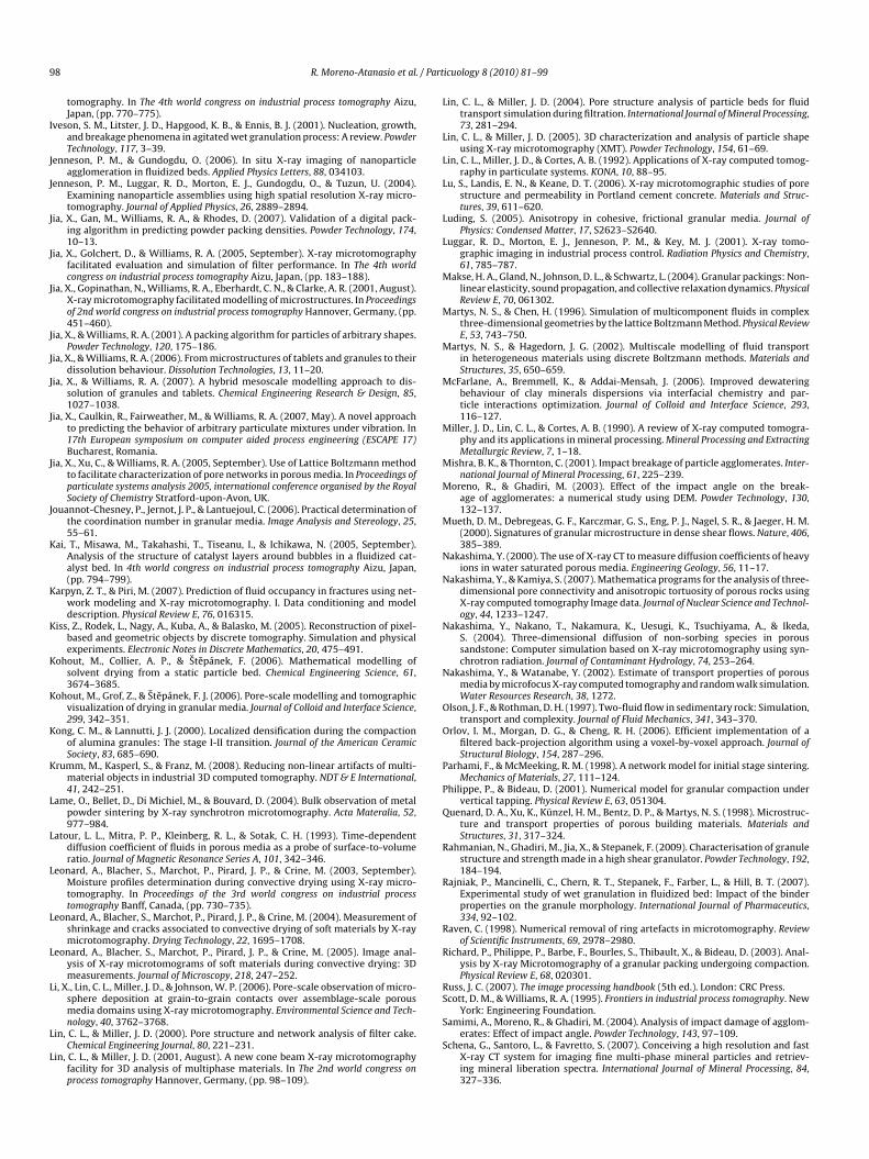
9 / Part
I
J
J
J
J
J
J
J
J
J
J
J
K
K
K
K
K
K
K
L
L
L
L
L
L
L
L
L
L
L
L
L
L
M
M
M
M
M
M
M
M
N
N
N
N
O
O
P
P
Q
R
R
R
R
RS
8 R. Moreno-Atanasio et al.
tomography. In The 4th world congress on industrial process tomography Aizu,Japan, (pp. 770–775).
veson, S. M., Litster, J. D., Hapgood, K. B., & Ennis, B. J. (2001). Nucleation, growth,and breakage phenomena in agitated wet granulation process: A review. PowderTechnology, 117, 3–39.
enneson, P. M., & Gundogdu, O. (2006). In situ X-ray imaging of nanoparticleagglomeration in fluidized beds. Applied Physics Letters, 88, 034103.
enneson, P. M., Luggar, R. D., Morton, E. J., Gundogdu, O., & Tuzun, U. (2004).Examining nanoparticle assemblies using high spatial resolution X-ray micro-tomography. Journal of Applied Physics, 26, 2889–2894.
ia, X., Gan, M., Williams, R. A., & Rhodes, D. (2007). Validation of a digital pack-ing algorithm in predicting powder packing densities. Powder Technology, 174,10–13.
ia, X., Golchert, D., & Williams, R. A. (2005, September). X-ray microtomographyfacilitated evaluation and simulation of filter performance. In The 4th worldcongress on industrial process tomography Aizu, Japan, (pp. 183–188).
ia, X., Gopinathan, N., Williams, R. A., Eberhardt, C. N., & Clarke, A. R. (2001, August).X-ray microtomography facilitated modelling of microstructures. In Proceedingsof 2nd world congress on industrial process tomography Hannover, Germany, (pp.451–460).
ia, X., & Williams, R. A. (2001). A packing algorithm for particles of arbitrary shapes.Powder Technology, 120, 175–186.
ia, X., & Williams, R. A. (2006). From microstructures of tablets and granules to theirdissolution behaviour. Dissolution Technologies, 13, 11–20.
ia, X., & Williams, R. A. (2007). A hybrid mesoscale modelling approach to dis-solution of granules and tablets. Chemical Engineering Research & Design, 85,1027–1038.
ia, X., Caulkin, R., Fairweather, M., & Williams, R. A. (2007, May). A novel approachto predicting the behavior of arbitrary particulate mixtures under vibration. In17th European symposium on computer aided process engineering (ESCAPE 17)Bucharest, Romania.
ia, X., Xu, C., & Williams, R. A. (2005, September). Use of Lattice Boltzmann methodto facilitate characterization of pore networks in porous media. In Proceedings ofparticulate systems analysis 2005, international conference organised by the RoyalSociety of Chemistry Stratford-upon-Avon, UK.
ouannot-Chesney, P., Jernot, J. P., & Lantuejoul, C. (2006). Practical determination ofthe coordination number in granular media. Image Analysis and Stereology, 25,55–61.
ai, T., Misawa, M., Takahashi, T., Tiseanu, I., & Ichikawa, N. (2005, September).Analysis of the structure of catalyst layers around bubbles in a fluidized cat-alyst bed. In 4th world congress on industrial process tomography Aizu, Japan,(pp. 794–799).
arpyn, Z. T., & Piri, M. (2007). Prediction of fluid occupancy in fractures using net-work modeling and X-ray microtomography. I. Data conditioning and modeldescription. Physical Review E, 76, 016315.
iss, Z., Rodek, L., Nagy, A., Kuba, A., & Balasko, M. (2005). Reconstruction of pixel-based and geometric objects by discrete tomography. Simulation and physicalexperiments. Electronic Notes in Discrete Mathematics, 20, 475–491.
ohout, M., Collier, A. P., & Stepánek, F. (2006). Mathematical modelling ofsolvent drying from a static particle bed. Chemical Engineering Science, 61,3674–3685.
ohout, M., Grof, Z., & Stepánek, F. J. (2006). Pore-scale modelling and tomographicvisualization of drying in granular media. Journal of Colloid and Interface Science,299, 342–351.
ong, C. M., & Lannutti, J. J. (2000). Localized densification during the compactionof alumina granules: The stage I-II transition. Journal of the American CeramicSociety, 83, 685–690.
rumm, M., Kasperl, S., & Franz, M. (2008). Reducing non-linear artifacts of multi-material objects in industrial 3D computed tomography. NDT & E International,41, 242–251.
ame, O., Bellet, D., Di Michiel, M., & Bouvard, D. (2004). Bulk observation of metalpowder sintering by X-ray synchrotron microtomography. Acta Materalia, 52,977–984.
atour, L. L., Mitra, P. P., Kleinberg, R. L., & Sotak, C. H. (1993). Time-dependentdiffusion coefficient of fluids in porous media as a probe of surface-to-volumeratio. Journal of Magnetic Resonance Series A, 101, 342–346.
eonard, A., Blacher, S., Marchot, P., Pirard, J. P., & Crine, M. (2003, September).Moisture profiles determination during convective drying using X-ray micro-tomography. In Proceedings of the 3rd world congress on industrial processtomography Banff, Canada, (pp. 730–735).
eonard, A., Blacher, S., Marchot, P., Pirard, J. P., & Crine, M. (2004). Measurement ofshrinkage and cracks associated to convective drying of soft materials by X-raymicrotomography. Drying Technology, 22, 1695–1708.
eonard, A., Blacher, S., Marchot, P., Pirard, J. P., & Crine, M. (2005). Image anal-ysis of X-ray microtomograms of soft materials during convective drying: 3Dmeasurements. Journal of Microscopy, 218, 247–252.
i, X., Lin, C. L., Miller, J. D., & Johnson, W. P. (2006). Pore-scale observation of micro-sphere deposition at grain-to-grain contacts over assemblage-scale porousmedia domains using X-ray microtomography. Environmental Science and Tech-
nology, 40, 3762–3768.in, C. L., & Miller, J. D. (2000). Pore structure and network analysis of filter cake.Chemical Engineering Journal, 80, 221–231.
in, C. L., & Miller, J. D. (2001, August). A new cone beam X-ray microtomographyfacility for 3D analysis of multiphase materials. In The 2nd world congress onprocess tomography Hannover, Germany, (pp. 98–109).
S
S
icuology 8 (2010) 81–99
in, C. L., & Miller, J. D. (2004). Pore structure analysis of particle beds for fluidtransport simulation during filtration. International Journal of Mineral Processing,73, 281–294.
in, C. L., & Miller, J. D. (2005). 3D characterization and analysis of particle shapeusing X-ray microtomography (XMT). Powder Technology, 154, 61–69.
in, C. L., Miller, J. D., & Cortes, A. B. (1992). Applications of X-ray computed tomog-raphy in particulate systems. KONA, 10, 88–95.
u, S., Landis, E. N., & Keane, D. T. (2006). X-ray microtomographic studies of porestructure and permeability in Portland cement concrete. Materials and Struc-tures, 39, 611–620.
uding, S. (2005). Anisotropy in cohesive, frictional granular media. Journal ofPhysics: Condensed Matter, 17, S2623–S2640.
uggar, R. D., Morton, E. J., Jenneson, P. M., & Key, M. J. (2001). X-ray tomo-graphic imaging in industrial process control. Radiation Physics and Chemistry,61, 785–787.
akse, H. A., Gland, N., Johnson, D. L., & Schwartz, L. (2004). Granular packings: Non-linear elasticity, sound propagation, and collective relaxation dynamics. PhysicalReview E, 70, 061302.
artys, N. S., & Chen, H. (1996). Simulation of multicomponent fluids in complexthree-dimensional geometries by the lattice Boltzmann Method. Physical ReviewE, 53, 743–750.
artys, N. S., & Hagedorn, J. G. (2002). Multiscale modelling of fluid transportin heterogeneous materials using discrete Boltzmann methods. Materials andStructures, 35, 650–659.
cFarlane, A., Bremmell, K., & Addai-Mensah, J. (2006). Improved dewateringbehaviour of clay minerals dispersions via interfacial chemistry and par-ticle interactions optimization. Journal of Colloid and Interface Science, 293,116–127.
iller, J. D., Lin, C. L., & Cortes, A. B. (1990). A review of X-ray computed tomogra-phy and its applications in mineral processing. Mineral Processing and ExtractingMetallurgic Review, 7, 1–18.
ishra, B. K., & Thornton, C. (2001). Impact breakage of particle agglomerates. Inter-national Journal of Mineral Processing, 61, 225–239.
oreno, R., & Ghadiri, M. (2003). Effect of the impact angle on the break-age of agglomerates: a numerical study using DEM. Powder Technology, 130,132–137.
ueth, D. M., Debregeas, G. F., Karczmar, G. S., Eng, P. J., Nagel, S. R., & Jaeger, H. M.(2000). Signatures of granular microstructure in dense shear flows. Nature, 406,385–389.
akashima, Y. (2000). The use of X-ray CT to measure diffusion coefficients of heavyions in water saturated porous media. Engineering Geology, 56, 11–17.
akashima, Y., & Kamiya, S. (2007). Mathematica programs for the analysis of three-dimensional pore connectivity and anisotropic tortuosity of porous rocks usingX-ray computed tomography Image data. Journal of Nuclear Science and Technol-ogy, 44, 1233–1247.
akashima, Y., Nakano, T., Nakamura, K., Uesugi, K., Tsuchiyama, A., & Ikeda,S. (2004). Three-dimensional diffusion of non-sorbing species in poroussandstone: Computer simulation based on X-ray microtomography using syn-chrotron radiation. Journal of Contaminant Hydrology, 74, 253–264.
akashima, Y., & Watanabe, Y. (2002). Estimate of transport properties of porousmedia by microfocus X-ray computed tomography and random walk simulation.Water Resources Research, 38, 1272.
lson, J. F., & Rothman, D. H. (1997). Two-fluid flow in sedimentary rock: Simulation,transport and complexity. Journal of Fluid Mechanics, 341, 343–370.
rlov, I. M., Morgan, D. G., & Cheng, R. H. (2006). Efficient implementation of afiltered back-projection algorithm using a voxel-by-voxel approach. Journal ofStructural Biology, 154, 287–296.
arhami, F., & McMeeking, R. M. (1998). A network model for initial stage sintering.Mechanics of Materials, 27, 111–124.
hilippe, P., & Bideau, D. (2001). Numerical model for granular compaction undervertical tapping. Physical Review E, 63, 051304.
uenard, D. A., Xu, K., Künzel, H. M., Bentz, D. P., & Martys, N. S. (1998). Microstruc-ture and transport properties of porous building materials. Materials andStructures, 31, 317–324.
ahmanian, N., Ghadiri, M., Jia, X., & Stepanek, F. (2009). Characterisation of granulestructure and strength made in a high shear granulator. Powder Technology, 192,184–194.
ajniak, P., Mancinelli, C., Chern, R. T., Stepanek, F., Farber, L., & Hill, B. T. (2007).Experimental study of wet granulation in fluidized bed: Impact of the binderproperties on the granule morphology. International Journal of Pharmaceutics,334, 92–102.
aven, C. (1998). Numerical removal of ring artefacts in microtomography. Reviewof Scientific Instruments, 69, 2978–2980.
ichard, P., Philippe, P., Barbe, F., Bourles, S., Thibault, X., & Bideau, D. (2003). Anal-ysis by X-ray Microtomography of a granular packing undergoing compaction.Physical Review E, 68, 020301.
uss, J. C. (2007). The image processing handbook (5th ed.). London: CRC Press.cott, D. M., & Williams, R. A. (1995). Frontiers in industrial process tomography. New
York: Engineering Foundation.
amimi, A., Moreno, R., & Ghadiri, M. (2004). Analysis of impact damage of agglom-erates: Effect of impact angle. Powder Technology, 143, 97–109.chena, G., Santoro, L., & Favretto, S. (2007). Conceiving a high resolution and fast
X-ray CT system for imaging fine multi-phase mineral particles and retriev-ing mineral liberation spectra. International Journal of Mineral Processing, 84,327–336.
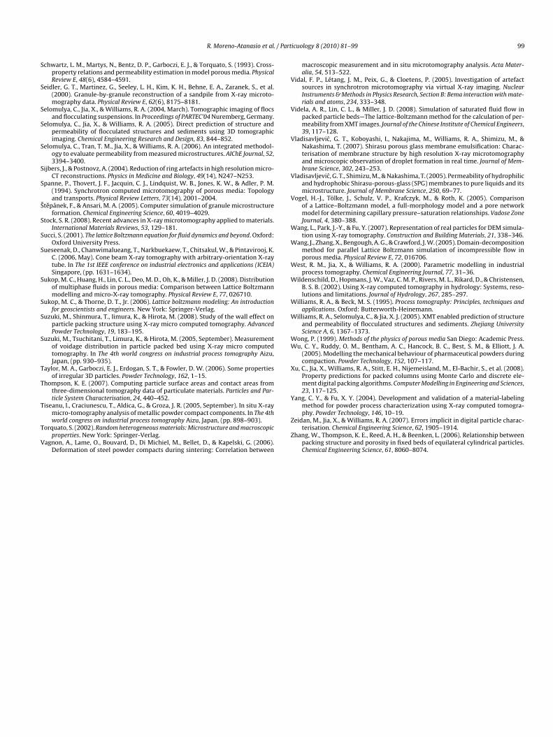
/ Part
S
S
S
S
S
S
S
S
S
S
S
S
S
S
S
T
T
T
T
V
V
V
V
V
V
W
W
W
W
W
W
WW
X
Y
R. Moreno-Atanasio et al.
chwartz, L. M., Martys, N., Bentz, D. P., Garboczi, E. J., & Torquato, S. (1993). Cross-property relations and permeability estimation in model porous media. PhysicalReview E, 48(6), 4584–4591.
eidler, G. T., Martinez, G., Seeley, L. H., Kim, K. H., Behne, E. A., Zaranek, S., et al.(2000). Granule-by-granule reconstruction of a sandpile from X-ray microto-mography data. Physical Review E, 62(6), 8175–8181.
elomulya, C., Jia, X., & Williams, R. A. (2004, March). Tomographic imaging of flocsand flocculating suspensions. In Proceedings of PARTEC’04 Nuremberg, Germany.
elomulya, C., Jia, X., & Williams, R. A. (2005). Direct prediction of structure andpermeability of flocculated structures and sediments using 3D tomographicimaging. Chemical Engineering Research and Design, 83, 844–852.
elomulya, C., Tran, T. M., Jia, X., & Williams, R. A. (2006). An integrated methodol-ogy to evaluate permeability from measured microstructures. AIChE Journal, 52,3394–3400.
ijbers, J., & Postnovz, A. (2004). Reduction of ring artefacts in high resolution micro-CT reconstructions. Physics in Medicine and Biology, 49(14), N247–N253.
panne, P., Thovert, J. F., Jacquin, C. J., Lindquist, W. B., Jones, K. W., & Adler, P. M.(1994). Synchrotron computed microtomography of porous media: Topologyand transports. Physical Review Letters, 73(14), 2001–2004.
ˇtepánek, F., & Ansari, M. A. (2005). Computer simulation of granule microstructureformation. Chemical Engineering Science, 60, 4019–4029.
tock, S. R. (2008). Recent advances in X-ray microtomography applied to materials.International Materials Reviews, 53, 129–181.
ucci, S. (2001). The lattice Boltzmann equation for fluid dynamics and beyond. Oxford:Oxford University Press.
ueseenak, D., Chanwimalueang, T., Narkbuekaew, T., Chitsakul, W., & Pintavirooj, K.C. (2006, May). Cone beam X-ray tomography with arbitrary-orientation X-raytube. In The 1st IEEE conference on industrial electronics and applications (ICEIA)Singapore, (pp. 1631–1634).
ukop, M. C., Huang, H., Lin, C. L., Deo, M. D., Oh, K., & Miller, J. D. (2008). Distributionof multiphase fluids in porous media: Comparison between Lattice Boltzmannmodelling and micro-X-ray tomography. Physical Review E, 77, 026710.
ukop, M. C., & Thorne, D. T., Jr. (2006). Lattice boltzmann modeling: An introductionfor geoscientists and engineers. New York: Springer-Verlag.
uzuki, M., Shinmura, T., Iimura, K., & Hirota, M. (2008). Study of the wall effect onparticle packing structure using X-ray micro computed tomography. AdvancedPowder Technology, 19, 183–195.
uzuki, M., Tsuchitani, T., Limura, K., & Hirota, M. (2005, September). Measurementof voidage distribution in particle packed bed using X-ray micro computedtomography. In The 4th world congress on industrial process tomography Aizu,Japan, (pp. 930–935).
aylor, M. A., Garboczi, E. J., Erdogan, S. T., & Fowler, D. W. (2006). Some propertiesof irregular 3D particles. Powder Technology, 162, 1–15.
hompson, K. E. (2007). Computing particle surface areas and contact areas fromthree-dimensional tomography data of particulate materials. Particles and Par-ticle System Characterisation, 24, 440–452.
iseanu, I., Craciunescu, T., Aldica, G., & Groza, J. R. (2005, September). In situ X-ray
micro-tomography analysis of metallic powder compact components. In The 4thworld congress on industrial process tomography Aizu, Japan, (pp. 898–903).orquato, S. (2002). Random heterogeneous materials: Microstructure and macroscopicproperties. New York: Springer-Verlag.
agnon, A., Lame, O., Bouvard, D., Di Michiel, M., Bellet, D., & Kapelski, G. (2006).Deformation of steel powder compacts during sintering: Correlation between
Z
Z
icuology 8 (2010) 81–99 99
macroscopic measurement and in situ microtomography analysis. Acta Mater-alia, 54, 513–522.
idal, F. P., Létang, J. M., Peix, G., & Cloetens, P. (2005). Investigation of artefactsources in synchrotron microtomography via virtual X-ray imaging. NuclearInstruments & Methods in Physics Research, Section B: Bema interaction with mate-rials and atoms, 234, 333–348.
idela, A. R., Lin, C. L., & Miller, J. D. (2008). Simulation of saturated fluid flow inpacked particle beds—The lattice-Boltzmann method for the calculation of per-meability from XMT images. Journal of the Chinese Institute of Chemical Engineers,39, 117–128.
ladisavljevic, G. T., Koboyashi, I., Nakajima, M., Williams, R. A., Shimizu, M., &Nakashima, T. (2007). Shirasu porous glass membrane emulsification: Charac-terisation of membrane structure by high resolution X-ray microtomographyand microscopic observation of droplet formation in real time. Journal of Mem-brane Science, 302, 243–253.
ladisavljevic, G. T., Shimizu, M., & Nakashima, T. (2005). Permeability of hydrophilicand hydrophobic Shirasu-porous-glass (SPG) membranes to pure liquids and itsmicrostructure. Journal of Membrane Science, 250, 69–77.
ogel, H.-J., Tölke, J., Schulz, V. P., Krafczyk, M., & Roth, K. (2005). Comparisonof a Lattice–Boltzmann model, a full-morphology model and a pore networkmodel for determining capillary pressure–saturation relationships. Vadose ZoneJournal, 4, 380–388.
ang, L., Park, J.-Y., & Fu, Y. (2007). Representation of real particles for DEM simula-tion using X-ray tomography. Construction and Building Materials, 21, 338–346.
ang, J., Zhang, X., Bengough, A. G., & Crawford, J. W. (2005). Domain-decompositionmethod for parallel Lattice Boltzmann simulation of incompressible flow inporous media. Physical Review E, 72, 016706.
est, R. M., Jia, X., & Williams, R. A. (2000). Parametric modelling in industrialprocess tomography. Chemical Engineering Journal, 77, 31–36.
ildenschild, D., Hopmans, J. W., Vaz, C. M. P., Rivers, M. L., Rikard, D., & Christensen,B. S. B. (2002). Using X-ray computed tomography in hydrology: Systems, reso-lutions and limitations. Journal of Hydrology, 267, 285–297.
illiams, R. A., & Beck, M. S. (1995). Process tomography: Principles, techniques andapplications. Oxford: Butterworth-Heinemann.
illiams, R. A., Selomulya, C., & Jia, X. J. (2005). XMT enabled prediction of structureand permeability of flocculated structures and sediments. Zhejiang UniversityScience A, 6, 1367–1373.
ong, P. (1999). Methods of the physics of porous media San Diego: Academic Press.u, C. Y., Ruddy, O. M., Bentham, A. C., Hancock, B. C., Best, S. M., & Elliott, J. A.
(2005). Modelling the mechanical behaviour of pharmaceutical powders duringcompaction. Powder Technology, 152, 107–117.
u, C., Jia, X., Williams, R. A., Stitt, E. H., Nijemeisland, M., El-Bachir, S., et al. (2008).Property predictions for packed columns using Monte Carlo and discrete ele-ment digital packing algorithms. Computer Modelling in Engineering and Sciences,23, 117–125.
ang, C. Y., & Fu, X. Y. (2004). Development and validation of a material-labelingmethod for powder process characterization using X-ray computed tomogra-
phy. Powder Technology, 146, 10–19.eidan, M., Jia, X., & Williams, R. A. (2007). Errors implicit in digital particle charac-terisation. Chemical Engineering Science, 62, 1905–1914.
hang, W., Thompson, K. E., Reed, A. H., & Beenken, L. (2006). Relationship betweenpacking structure and porosity in fixed beds of equilateral cylindrical particles.Chemical Engineering Science, 61, 8060–8074.