Three Dimensional Computerized Microtomography in the Analysis of Sculpture
11
SCANNING VOL. 30, 16–26 (2008) Wiley Periodicals, Inc. Three Dimensional Computerized Microtomography in the Analysis of Sculpture AURELIA BADDE 1 and BERNHARD ILLERHAUS 2 1 Freelance sculpture restorer at the Alte Nationalgalerie, Staatliche Museen zu Berlin (SMB), Bodestr. 1-3, 10178 Berlin, Germany 2 Federal Institute for Materials Research and Testing (BAM); Division VIII.3, Radiology, Zerst¨ orungsfreie Pr¨ ufung; Radiologische Verfahren, Richard-Willst¨ atter-Str. 11, 12478 Berlin, Germany Summary: The Alte Nationalgalerie, Staatliche Museen zu Berlin (SMB) and the Federal Institute for Materials Research and Testing (BAM) tested the accomplishment of the three dimensional computerized microtomography (3D-µCT)—a new flat panel detec- tor computerized tomography (CT) system at the BAM with extended energy range, with high voltage X-ray tubes (330 and 225 kV), with micrometer focal spot size and micrometer resolution and enlarged object size (up to 70 cm diameter)—for examining plaster statues. The high spatial and density resolution of the tomo- graph enable detailed insights into the individual work processes of the investigated cast plaster statues. While initiated in support of the conservation process, com- puted tomography (CT) analysis has assisted in reveal- ing relative chronologies within the series of the cast works of art, thus serving as a valuable tool in the art-historical appraisal of the oeuvres. The image-processing systems visualize the voids and cracks within and the cuts through the original cast works. Internal structures, armoring, sculptural rework- ing as well as restorative interventions are virtually reconstructed. The authors are currently employing the 3D-µCT systems at the BAM into the detection of defects in Carrara marble sculpture. Microcracks, fractures, and material flaws are visualized at spatial resolution down to 10 µm. Computerized reconstruction of ultrasound tomography is verified by analyzing correlations in the results obtained from the complementary application of these two non-destructive testing (NDT) methods of diagnosis. SCANNING 30: 16–26, 2008. 2008 Wiley Periodicals, Inc. Address for reprints: Dr. Bernhard Illerhaus, Federal Institute for Materials Research and Testing, Division VIII.3, Radiology, Richard-Willst¨ atter-Str. 11, 12478 Berlin, Germany e-mail: [email protected] Received 13 May 2007; Accepted with revision 29 October 2007 Key words: cast plaster statues, three dimensional microtomography, Carrara marble sculpture, condition assessment, visualization, internal structures, material flaws, ultrasound computed tomography, correlation, validation Introduction The use of X-ray CT for the nondestructive exam- ination of archaeological and cultural objects is per- haps most extensively documented on Egyptian mum- mies, where the investigations profit from the wide spread of medical CT-scanners and the similarity of the objects (Reyman, 1983; Leveque, 1987; Drenkhahn and Germer, 1991; Hughes et al ., 1993; Melville, 1995; Hughes, 1996; Stengele and Beck, 1999; Hunt, 2001; Kiple et al ., 2001; Spaabæk, 2002; Gostner et al ., 2004; Zollikofer et al ., 2005). There is however a vari- ety of other materials of artistic and cultural value that has been examined with X-ray CT over the past decades (Cheng et al ., 1988; D’Aversa et al ., 1992; Hering, 1994; Illerhaus et al ., 1994a,b; Cesareo et al ., 1999; Ghysels, 2003). A number of collaborations between the BAM and the SMB have allowed detailed three- dimensional assessment and documentation of sculp- tures and archaeological artifacts in their state of preser- vation and have provided the opportunity to inves- tigate into their respective manufacture and materi- ality (Goebbels et al ., 1994; Goebbels et al ., 1997; Heilmeyer, 1994; Wildung, 1994; Maish et al ., 2002; Badde and Illerhaus, 2004; de Caso et al ., 2004; Badde and Illerhaus, 2005; Thompson and Illerhaus, 2005). For inorganic archaeological objects, like ancient Greek bronze statues, only specialized tomographs, for which the costs are high and the availability is low, were able to give satisfactory results (Maish et al ., 2002). In the last years, the development of flat panel detectors and new high voltage X-ray tubes with micrometer spot
-
Upload
independent -
Category
Documents
-
view
1 -
download
0
Transcript of Three Dimensional Computerized Microtomography in the Analysis of Sculpture
SCANNING VOL. 30, 16–26 (2008) Wiley Periodicals, Inc.
Three Dimensional Computerized Microtomography in the Analysis ofSculpture
AURELIA BADDE1 and BERNHARD ILLERHAUS2
1 Freelance sculpture restorer at the Alte Nationalgalerie, Staatliche Museen zu Berlin (SMB), Bodestr. 1-3, 10178Berlin, Germany
2 Federal Institute for Materials Research and Testing (BAM); Division VIII.3, Radiology, Zerstorungsfreie Prufung;Radiologische Verfahren, Richard-Willstatter-Str. 11, 12478 Berlin, Germany
Summary: The Alte Nationalgalerie, StaatlicheMuseen zu Berlin (SMB) and the Federal Institutefor Materials Research and Testing (BAM) tested theaccomplishment of the three dimensional computerizedmicrotomography (3D-µCT)—a new flat panel detec-tor computerized tomography (CT) system at the BAMwith extended energy range, with high voltage X-raytubes (330 and 225 kV), with micrometer focal spotsize and micrometer resolution and enlarged object size(up to 70 cm diameter)—for examining plaster statues.
The high spatial and density resolution of the tomo-graph enable detailed insights into the individual workprocesses of the investigated cast plaster statues. Whileinitiated in support of the conservation process, com-puted tomography (CT) analysis has assisted in reveal-ing relative chronologies within the series of the castworks of art, thus serving as a valuable tool in theart-historical appraisal of the oeuvres.
The image-processing systems visualize the voidsand cracks within and the cuts through the original castworks. Internal structures, armoring, sculptural rework-ing as well as restorative interventions are virtuallyreconstructed.
The authors are currently employing the 3D-µCTsystems at the BAM into the detection of defects inCarrara marble sculpture. Microcracks, fractures, andmaterial flaws are visualized at spatial resolution downto 10 µm. Computerized reconstruction of ultrasoundtomography is verified by analyzing correlations in theresults obtained from the complementary applicationof these two non-destructive testing (NDT) methodsof diagnosis. SCANNING 30: 16–26, 2008. 2008Wiley Periodicals, Inc.
Address for reprints: Dr. Bernhard Illerhaus, Federal Institutefor Materials Research and Testing, Division VIII.3, Radiology,Richard-Willstatter-Str. 11, 12478 Berlin, Germanye-mail: [email protected]
Received 13 May 2007; Accepted with revision29 October 2007
Key words: cast plaster statues, three dimensionalmicrotomography, Carrara marble sculpture, conditionassessment, visualization, internal structures, materialflaws, ultrasound computed tomography, correlation,validation
Introduction
The use of X-ray CT for the nondestructive exam-ination of archaeological and cultural objects is per-haps most extensively documented on Egyptian mum-mies, where the investigations profit from the widespread of medical CT-scanners and the similarity ofthe objects (Reyman, 1983; Leveque, 1987; Drenkhahnand Germer, 1991; Hughes et al ., 1993; Melville, 1995;Hughes, 1996; Stengele and Beck, 1999; Hunt, 2001;Kiple et al ., 2001; Spaabæk, 2002; Gostner et al .,2004; Zollikofer et al ., 2005). There is however a vari-ety of other materials of artistic and cultural value thathas been examined with X-ray CT over the past decades(Cheng et al ., 1988; D’Aversa et al ., 1992; Hering,1994; Illerhaus et al ., 1994a,b; Cesareo et al ., 1999;Ghysels, 2003). A number of collaborations betweenthe BAM and the SMB have allowed detailed three-dimensional assessment and documentation of sculp-tures and archaeological artifacts in their state of preser-vation and have provided the opportunity to inves-tigate into their respective manufacture and materi-ality (Goebbels et al ., 1994; Goebbels et al ., 1997;Heilmeyer, 1994; Wildung, 1994; Maish et al ., 2002;Badde and Illerhaus, 2004; de Caso et al ., 2004; Baddeand Illerhaus, 2005; Thompson and Illerhaus, 2005).For inorganic archaeological objects, like ancient Greekbronze statues, only specialized tomographs, for whichthe costs are high and the availability is low, were ableto give satisfactory results (Maish et al ., 2002). In thelast years, the development of flat panel detectors andnew high voltage X-ray tubes with micrometer spot
A. Badde, B. Illerhaus: 3D-µCT in the analysis of sculpture 17
size widened the range of possible investigation tar-gets: scanning time has become fast and affordable.A joint project of the Alte Nationalgalerie and theBAM in Berlin tested the accomplishment of the 3D-µCT (a new CT system with extended energy rangeand enlarged object size, but still allowing microme-ter resolution) for examining 19th century cast plasterstatues, Christian Daniel Rauchs Model for the Goethe-Schiller-Monument for Weimar from 1848 and HonoreDaumiers Ratapoil from 1851 (Badde and Illerhaus,2004; de Caso et al ., 2004; Badde and Illerhaus, 2005).The high spatial and density resolution of the usedtomograph enables insights into the individual workprocesses of the investigated cast statues.
The focus of ongoing investigations is crack andmicrofissure detection in a late 19th century Carraramarble sculpture. The high density of marble proves tobe a demanding task for analysis with X-ray CT. Therequired resolution of the detector is in the order of20 µm. This can be reached by using a special type ofsingle crystal scintillator. The intended scan of objectdiameters of 15 cm and over will exact an image sizeof 10,0002 × 100 pixels. Comparative analysis withultrasound-CT (together with Frank Weise and StephanPirskawetz of the BAM1) on microfissured and frac-tured Carrara marble samples will validate results ofultrasound measurements in the damaged area of thesculpture.
Three Dimensional ComputerizedMicrotomography
Computerized X-ray tomography measures the linearabsorption coefficient of the investigated material ineach point of the region of interest. The coefficientis dependant on the incident X-ray energy and onthe atomic number of the material. In most cases, itcan be regarded as linear correlating to the specificdensity. In conventional (medical) systems tomogramsare measured slice by slice. In more modern types, theobject to be measured is moved constantly, allowingthe slices to generate a continuous volume. In the caseof 3D CT, the detector no longer consists of a row ofdetectors but of a square field with an array of detectorelements.
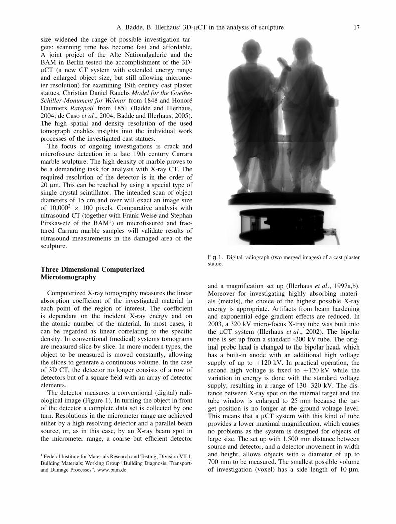
The detector measures a conventional (digital) radi-ological image (Figure 1). In turning the object in frontof the detector a complete data set is collected by oneturn. Resolutions in the micrometer range are achievedeither by a high resolving detector and a parallel beamsource, or, as in this case, by an X-ray beam spot inthe micrometer range, a coarse but efficient detector
1 Federal Institute for Materials Research and Testing; Division VII.1,Building Materials; Working Group “Building Diagnosis; Transport-and Damage Processes”, www.bam.de.
Fig 1. Digital radiograph (two merged images) of a cast plasterstatue.
and a magnification set up (Illerhaus et al ., 1997a,b).Moreover for investigating highly absorbing materi-als (metals), the choice of the highest possible X-rayenergy is appropriate. Artifacts from beam hardeningand exponential edge gradient effects are reduced. In2003, a 320 kV micro-focus X-tray tube was built intothe µCT system (Illerhaus et al ., 2002). The bipolartube is set up from a standard -200 kV tube. The orig-inal probe head is changed to the bipolar head, whichhas a built-in anode with an additional high voltagesupply of up to +120 kV. In practical operation, thesecond high voltage is fixed to +120 kV while thevariation in energy is done with the standard voltagesupply, resulting in a range of 130–320 kV. The dis-tance between X-ray spot on the internal target and thetube window is enlarged to 25 mm because the tar-get position is no longer at the ground voltage level.This means that a µCT system with this kind of tubeprovides a lower maximal magnification, which causesno problems as the system is designed for objects oflarge size. The set up with 1,500 mm distance betweensource and detector, and a detector movement in widthand height, allows objects with a diameter of up to700 mm to be measured. The smallest possible volumeof investigation (voxel) has a side length of 10 µm.
18 SCANNING Vol. 30, 1 (2008)
The spot size of the X-ray tube given for standardconditions at 90 kV is 10 µm, which is the same asa standard tube. With a two dimensional detector it isno longer possible to discriminate the scattered radia-tion released either by the object or the detector. Theaccumulated raw images therefore have to be carefullycorrected to yield an undisturbed CT image after back-projection (Illerhaus et al ., 1997, 2004). In all cases theback-projection is done with the well-known Feldkampalgorithm (Feldkamp et al ., 1984).
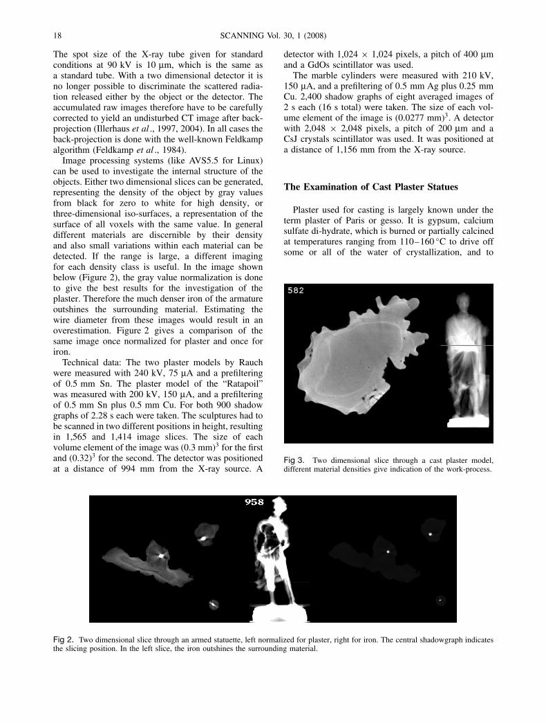
Image processing systems (like AVS5.5 for Linux)can be used to investigate the internal structure of theobjects. Either two dimensional slices can be generated,representing the density of the object by gray valuesfrom black for zero to white for high density, orthree-dimensional iso-surfaces, a representation of thesurface of all voxels with the same value. In generaldifferent materials are discernible by their densityand also small variations within each material can bedetected. If the range is large, a different imagingfor each density class is useful. In the image shownbelow (Figure 2), the gray value normalization is doneto give the best results for the investigation of theplaster. Therefore the much denser iron of the armatureoutshines the surrounding material. Estimating thewire diameter from these images would result in anoverestimation. Figure 2 gives a comparison of thesame image once normalized for plaster and once foriron.
Technical data: The two plaster models by Rauchwere measured with 240 kV, 75 µA and a prefilteringof 0.5 mm Sn. The plaster model of the “Ratapoil”was measured with 200 kV, 150 µA, and a prefilteringof 0.5 mm Sn plus 0.5 mm Cu. For both 900 shadowgraphs of 2.28 s each were taken. The sculptures had tobe scanned in two different positions in height, resultingin 1,565 and 1,414 image slices. The size of eachvolume element of the image was (0.3 mm)3 for the firstand (0.32)3 for the second. The detector was positionedat a distance of 994 mm from the X-ray source. A
detector with 1,024 × 1,024 pixels, a pitch of 400 µmand a GdOs scintillator was used.
The marble cylinders were measured with 210 kV,150 µA, and a prefiltering of 0.5 mm Ag plus 0.25 mmCu. 2,400 shadow graphs of eight averaged images of2 s each (16 s total) were taken. The size of each vol-ume element of the image is (0.0277 mm)3. A detectorwith 2,048 × 2,048 pixels, a pitch of 200 µm and aCsJ crystals scintillator was used. It was positioned ata distance of 1,156 mm from the X-ray source.
The Examination of Cast Plaster Statues
Plaster used for casting is largely known under theterm plaster of Paris or gesso. It is gypsum, calciumsulfate di-hydrate, which is burned or partially calcinedat temperatures ranging from 110–160 ◦C to drive offsome or all of the water of crystallization, and to
Fig 3. Two dimensional slice through a cast plaster model,different material densities give indication of the work-process.
Fig 2. Two dimensional slice through an armed statuette, left normalized for plaster, right for iron. The central shadowgraph indicatesthe slicing position. In the left slice, the iron outshines the surrounding material.
A. Badde, B. Illerhaus: 3D-µCT in the analysis of sculpture 19
receive calcium sulfate hemi-hydrate, respectively an-hydrite. When mixed, these fine powders are stablein air, but readily combine with water to form afine paste that quickly sets to a solid, calcium sulfatedi-hydrate. While setting, it generates heat and mayexpand slightly. Setting can be accelerated, for instanceby adding small amounts of salts or retarded by theaddition of organic materials. The addition of organicmedia, such as casein or oils will also render thishighly hygroscopic material less soluble in water andmore resistant to the epidermic penetration of dirt byhumidity transportation. Coatings of oil, shellac, milk,and polychromy on cast plaster surfaces also servethis purpose. However the reception of this materialis restricted to the interior. Plaster of Paris has longbeen used for casting in interior decoration as wellas for sculpture and sculpture models. Its use for castsculpture models is widespread and can be traced toEgyptian antiquity (Wildung, 1992).
Cast plaster dries with different densities dependingon the surrounding media. Liquid plaster filled into alubricated casting mould will acquire a surface bound-ary of high density, once set. The second and thirdcast layers into the still moist form will dry to a lowerdensity. Later additions of plaster, due to sculpturalreworking and restorative measures, will also have dis-cernible densities. With CT the density in each volumeelement can be measured. Cast material is clearly dis-tinguishable from later applied pasted material as iseach cast material layer or its layer boundary. In theCT images these boundaries are visible as brighter ordarker streaks within the cast material. Internal lacunaedue to casting mode, due to cracks or cuts stemmingeither from modification or restoration, are also wellrepresented (Figure 3). With 3D-µCT, the total bodyof a sculpture can be scanned to a high spatial res-olution. Cracks within and cuts through the originalcast become visible along with internal structures andarmoring.
The 19th century sculptural art is distinguished by theproduction of series, being the series of a figure molded,cast and hewn in different materials. The sculpturalprocess will more often than not involve the makingof a model in soft pliable material, such as is clay orwax, in reduced dimensions. The model is subsequentlycast in plaster. The thus produced plaster model can bemanipulated as creative development evolves.
It can be used as a model for reproductional purposes,for the casting of a bronze series or as a model forenlargement in scale and as a pointing model for itstransfer to stone. When the clay or wax model is notconserved, the plaster model will be the closest sourceof the creative sculptural sketch.
It is of art-historical interest to discern an orderwithin a plaster series of work. A chronology of thework process, from a creative idea to its realization,is made possible by examination of the object at
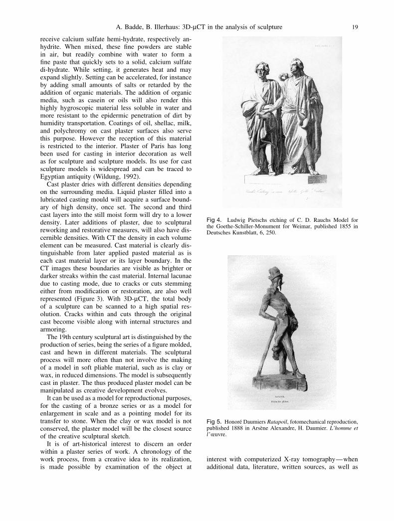
Fig 4. Ludwig Pietschs etching of C. D. Rauchs Model forthe Goethe-Schiller-Monument for Weimar, published 1855 inDeutsches Kunstblatt, 6, 250.
Fig 5. Honore Daumiers Ratapoil, fotomechanical reproduction,published 1888 in Arsene Alexandre, H. Daumier. L’homme etl ’œuvre.
interest with computerized X-ray tomography—whenadditional data, literature, written sources, as well as
20 SCANNING Vol. 30, 1 (2008)
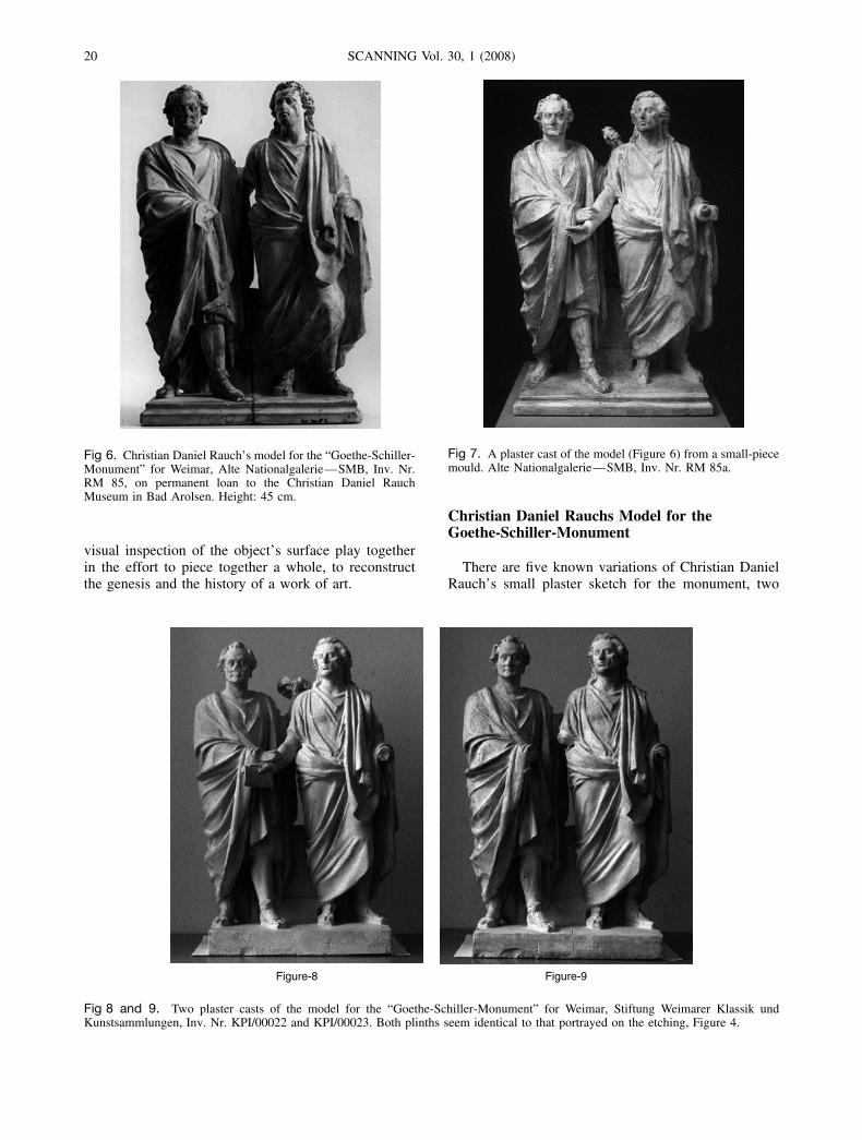
Fig 6. Christian Daniel Rauch’s model for the “Goethe-Schiller-Monument” for Weimar, Alte Nationalgalerie—SMB, Inv. Nr.RM 85, on permanent loan to the Christian Daniel RauchMuseum in Bad Arolsen. Height: 45 cm.
visual inspection of the object’s surface play togetherin the effort to piece together a whole, to reconstructthe genesis and the history of a work of art.
Fig 7. A plaster cast of the model (Figure 6) from a small-piecemould. Alte Nationalgalerie—SMB, Inv. Nr. RM 85a.
Christian Daniel Rauchs Model for theGoethe-Schiller-Monument
There are five known variations of Christian DanielRauch’s small plaster sketch for the monument, two
Figure-8 Figure-9
Fig 8 and 9. Two plaster casts of the model for the “Goethe-Schiller-Monument” for Weimar, Stiftung Weimarer Klassik undKunstsammlungen, Inv. Nr. KPI/00022 and KPI/00023. Both plinths seem identical to that portrayed on the etching, Figure 4.

A. Badde, B. Illerhaus: 3D-µCT in the analysis of sculpture 21
Fig 10. A shadowgraph of Schiller the figure on the right of Figure 6, with virtual 2D slices through the figure. Armature and cuts areeasily discernable. The different densities of the plaster give indication to reworking, filling, and additions as well as to casting mode.
in Weimar and three in Berlin (Figures 6, 7, 8, and9)). The other plaster variant that is not depictedhere, is preserved in the Stadtmuseum Berlin (Brehmet al ., 2003, catalogue nr. 347). Their respective stateof preservation reveals a fair amount of the originalvolume as it was presented to the general public in anetching in 1855 (Figure 4).
However the models vary. The bearings of arms andhands, legs and feet, of the attributes scroll and/or lau-rel wreath, details in the modeling of the robes differas well as the proximity of the two figures and thedesign of the plinths (Figures 7 and 8). The model thatis preserved in two parts (Figure 6) was reworked andmanipulated to a great extent. This plaster was appar-ently used more than once as a casting model. Cutsat the extremities, at the altar and the plinth are evi-dent, as are the reassemblies. The extent of the sculp-tural reworking of surfaces and also of the structuralmodifications to the plaster became traceable by threedimensional X-ray analysis (Figure 10). Examining thetwo exemplars of the Alte Nationalgalerie with 3D-µCThas also permitted thoughts on establishing a relativechronology within those editions known (Badde andIllerhaus, 2004).
Christian Daniel Rauch completed his model for theGoethe-Schiller-Monument for Weimar on August 22,1849 and had it cast in plaster. He sent the plaster modelfrom Berlin to Weimar at the request of the Grand DukeCarl Alexander of Saxony-Weimar. It was to arrive intime for the centenary celebrations of Goethe’s birthdaythat was held in Weimar a few days later, on August28, 1849.
The idea of the installation of a double monumentto the two German poets at a central site in Weimarhad already been formed in 1827. By 1835, Rauch hadbeen assigned to deliver the main idea for a life-sizebronze sculpture.
The written sources bear evidence that the first plas-ter model sent to Weimar in 1849 was soon returned toRauch, who proceeded to develop his design. Rauch’sletters disclose the difficulties he faced positioningthese two national idols side by side on one pedestal.They also depict his growing unease with the direc-tives that came from the main contractor of the venture,Ludwig I., King of Bavaria. Ultimately the discrep-ancies of opinion on the question of attire, whetherancient or coeval clothing would befit these icons, led
Rauch to pass this contract on to his student and friend,Ernst Rietschel. While the latter’ “Goethe-Schiller-Denkmal”, is situated in front of the “Nationalthe-ater” in Weimar, is one of the better known sculptureswithin Germany, Rauch apparently never relinquishedhis design. At 79 years of age, in 1857, he stated in hiswill to effect his sketch in marble, or, at least, as a cor-rected, larger plaster model (Eggers and Eggers, 1887).
A Cast of a Statue by Honore Daumier
Honore Daumiers sculpture “Ratapoil” is well rep-resented in leading museums and in private collectionsthroughout the world. The wide reception of this oeu-vre is due to a series of bronze reproductions, cast inthe late 19th century, in the early twenties and in thesixties of the 20th century.
Daumier formed the original model in clay in 1851and had it cast in plaster. According to written tradition,the artist repressed this plaster cast during the followingdecades because of its highly political implication.
The Alte Nationalgalerie and the BAM analyzed aplaster model of this sculpture, which is in a privatecollection (Figure 11). The main question behind theinvestigation was that of originality of this exemplar(de Caso et al ., 2004).
Prior research on the Ratapoil cast had establishedit as a so-called surmoulage, which is a cast takenfrom a cast, the latter being a plaster or a bronze. Thenumerous seam lines, which cover the surface of thisplaster statuette clearly mark it as a cast from a smallpiece mould. The CT examination revealed the internalarmature within the plaster as well as the differentsequences in casting and insertion of the armature(Figures 12–17).
The investigation of this plaster model led to its com-parison to the plaster model preserved at the Albright-Knox Art Gallery in Buffalo, N.Y. The two sur-faces were examined and contrasted. Radiographic andXeroradiographic analysis was carried through at theArt Conservation Dept., Buffalo State College, permit-ting comparison of structural properties. Contrasting thevisual evidence of the internal structures gave valuableindications for assessing the creational process as wellas the individual object history, as evidenced in cuts, re-attachments and armature, fillings and reconstructions.
22 SCANNING Vol. 30, 1 (2008)
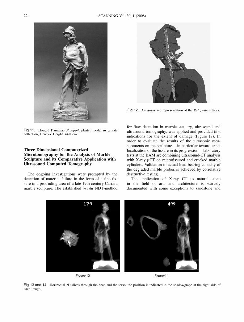
Fig 11. Honore Daumiers Ratapoil, plaster model in privatecollection, Geneva. Height: 44.8 cm.
Three Dimensional ComputerizedMicrotomography for the Analysis of MarbleSculpture and its Comparative Application withUltrasound Computed Tomography
The ongoing investigations were prompted by thedetection of material failure in the form of a fine fis-sure in a protruding area of a late 19th century Carraramarble sculpture. The established in situ NDT-method
Fig 12. An isosurface representation of the Ratapoil-surfaces.
for flaw detection in marble statuary, ultrasound andultrasound tomography, was applied and provided firstindications for the extent of damage (Figure 18). Inorder to evaluate the results of the ultrasonic mea-surements on the sculpture—in particular toward exactlocalization of the fissure in its progression—laboratorytests at the BAM are combining ultrasound-CT analysiswith X-ray µCT on microfissured and cracked marblecylinders. Validation to actual load-bearing capacity ofthe degraded marble probes is achieved by correlativedestructive testing.
The application of X-ray CT to natural stonein the field of arts and architecture is scarcelydocumented with some exceptions to sandstone and
Figure-13 Figure-14
Fig 13 and 14. Horizontal 2D slices through the head and the torso, the position is indicated in the shadowgraph at the right side ofeach image.

A. Badde, B. Illerhaus: 3D-µCT in the analysis of sculpture 23
Fig 15. A shadowgraph of the lower part of the statue, thearmature is reproduced clearly.
marble (Queisser, 1986; De Cleene, 1995; Jacobs et al .,1995), however its applicaton is quite common in theanalysis of drilling-cores (Dietrich et al ., 2000). Theneed for very highly resolved images for the deter-mination of material flaws in a size order of severalµm demands a detector that covers the whole objectdiameter in size with a resolution fine enough to detecthairline cracks in marble. The grain size of Carraramarble needs to be taken into consideration, which
lies in the range of 100—300 µm. The targeted detec-tor size is 10,000 by 100 pixels. The size in heightis limited otherwise the data set would overload anycomputer: for a 10,000 pixel wide image at least 7,000views over 180 degrees have to be taken. Such a highresolution is achievable nowadays for laboratory CTswith micro-focus X-ray tubes and object diameters upto 50 mm (Figures 18c and 19). But the evaluation ofan in situ X-ray µCT application raises high demands.In the case of our investigation, the diameter to bescanned is 15 cm. In addition, measuring position dur-ing in situ application must be free in space in anyposition. Thus the use of open micro-focus tubes is notrecommended, especially as the tube voltage should behigher than it is presently, but the mobility greater. Theuse of specially designed small bipolar tubes with thincables is required. Whereas any kind of available X-raytube may be used (micro-focus X-ray tubes are quiteheavy and big) in a laboratory environment, a mobileinspection system for an in situ application on marblesculpture will request a special small and lightweighttube with a high enough energy to penetrate the object(thickness).
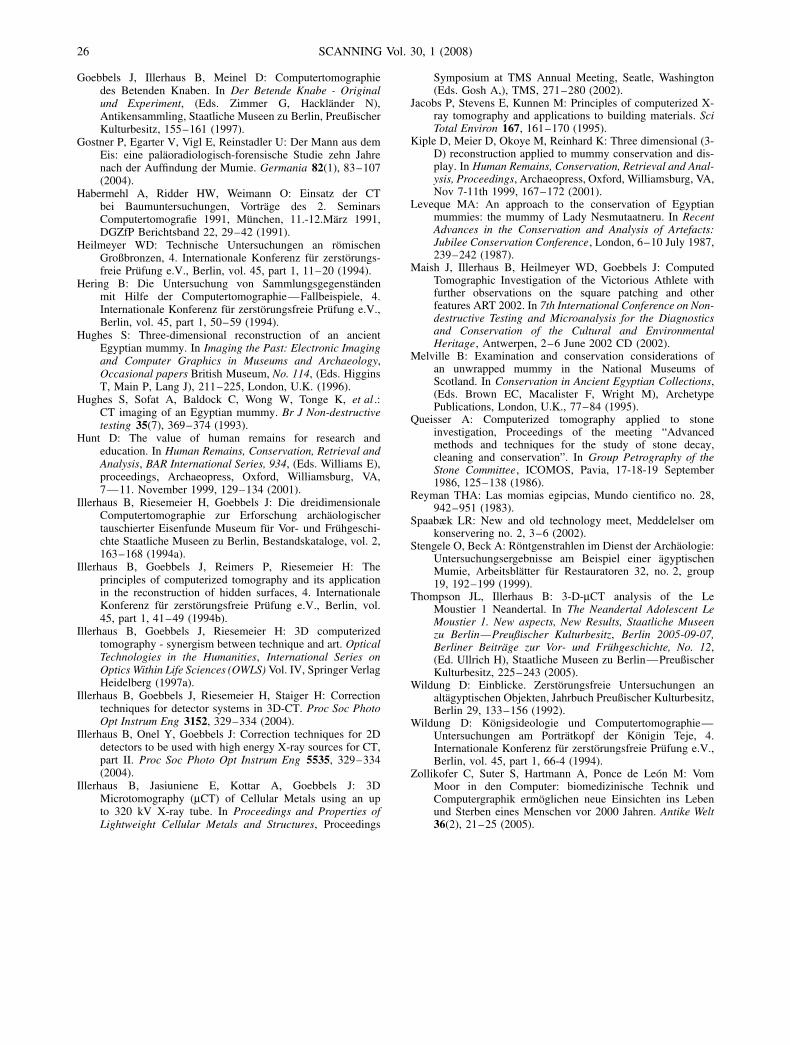
The first practical evaluation of an in situ applicationof X-ray µ-CT is being carried out with one of thefirst mobile CTs, constructed in 1980s, in order toinvestigate the stability of trees (Habermehl et al .,1991). In a first step this scanner was reconditionedat the BAM with a modern flat panel detector and a160 kV mini-focus X-ray tube (Figure 20). A matrixof 10233 pixels of ∼0.3 mm is possible.
Figure-16 Figure-17
Fig 16 and 17. Vertical 2D slices through two different directions of the Ratapoil 2D.
24 SCANNING Vol. 30, 1 (2008)
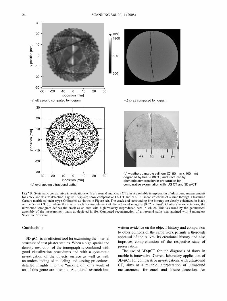
(a) ultrasound computed tomogram (c) x-ray computed tomogram
(b) overlapping ultrasound paths
-30 -20 -10 0 10 20 30x-position [mm]
-30
0
-10
-20
10
20
30
y-po
sitio
n [m
m]
300
1300
800
vp [m/s]
-30 -20 -10 0 10 20 30x-position [mm]
-30
0
-10
-20
10
20
30
y-po
sitio
n [m
m]
(d) weathered marble cylinder (Ø: 50 mm x 100 mm)degraded by heat (600 °C) and fractured bydiametric compression in preparation forcomparative examination with US CT and 3D µ-CT.
Fig 18. Systematic comparative investigations with ultrasound and X-ray CT aim at a reliable interpretation of ultrasound measurementsfor crack and fissure detection. Figure 18(a)–(c) show comparative US CT and 3D-µCT reconstructions of a slice through a fracturedCarrara marble cylinder (type Ordinario) as shown in Figure (d). The crack and surrounding fine fissures are clearly evidenced in blackon the X-ray CT (c), where the size of each volume element of the achieved image is (0.0277 mm)3. Contrary to expectations, theultrasound tomogram defines the crack as an area with high velocity (reproduced here in white). This is caused by the geometricalassembly of the measurement paths as depicted in (b). Computed reconstruction of ultrasound paths was attained with SandmeiersScientific Software.
Conclusions
3D-µCT is an efficient tool for examining the internalstructure of cast plaster statues. When a high spatial anddensity resolution of the tomograph is combined withgood visualization procedures and with a systematicinvestigation of the objects surface as well as withan understanding of modeling and casting procedures,detailed insights into the “making of” of a work ofart of this genre are possible. Additional research into
written evidence on the objects history and comparisonto other editions of the same work permits a thoroughappraisal of the œuvre, its creational history and alsoimproves comprehension of the respective state ofpreservation.
The use of 3D-µCT for the diagnosis of flaws inmarble is innovative. Current laboratory application of3D-µCT for comparative investigations with ultrasoundCT, aims at a reliable interpretation of ultrasoundmeasurements for crack and fissure detection. An
A. Badde, B. Illerhaus: 3D-µCT in the analysis of sculpture 25
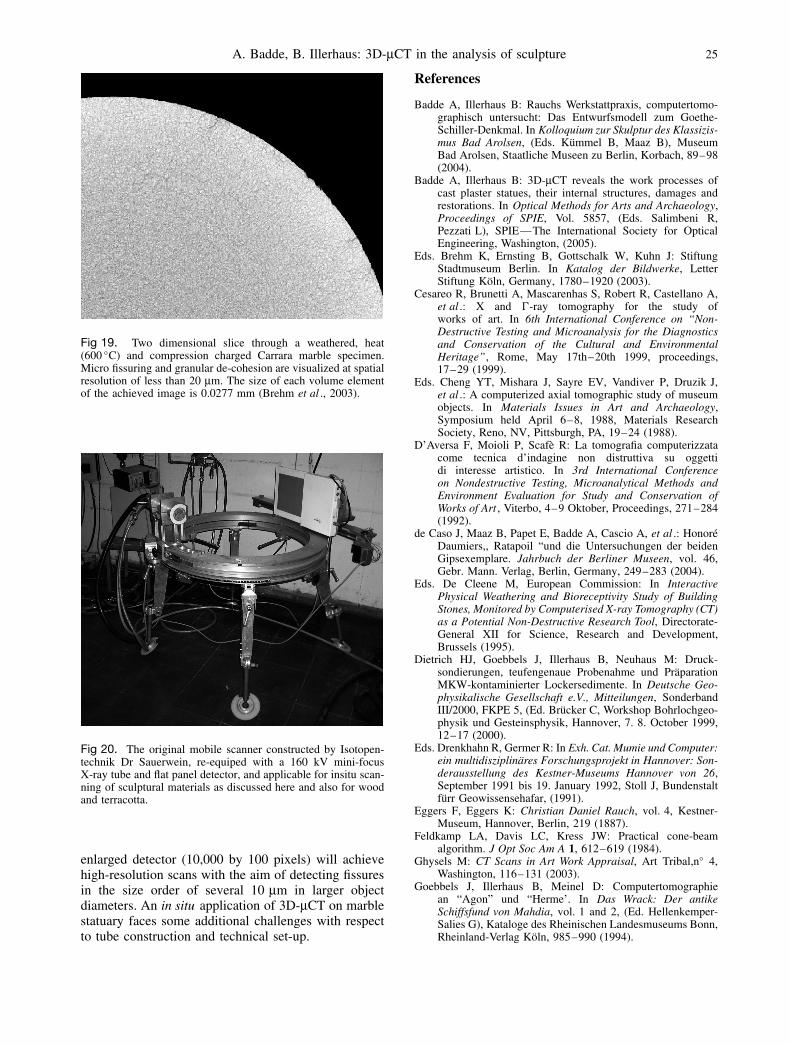
Fig 19. Two dimensional slice through a weathered, heat(600 ◦C) and compression charged Carrara marble specimen.Micro fissuring and granular de-cohesion are visualized at spatialresolution of less than 20 µm. The size of each volume elementof the achieved image is 0.0277 mm (Brehm et al ., 2003).
Fig 20. The original mobile scanner constructed by Isotopen-technik Dr Sauerwein, re-equiped with a 160 kV mini-focusX-ray tube and flat panel detector, and applicable for insitu scan-ning of sculptural materials as discussed here and also for woodand terracotta.
enlarged detector (10,000 by 100 pixels) will achievehigh-resolution scans with the aim of detecting fissuresin the size order of several 10 µm in larger objectdiameters. An in situ application of 3D-µCT on marblestatuary faces some additional challenges with respectto tube construction and technical set-up.
References
Badde A, Illerhaus B: Rauchs Werkstattpraxis, computertomo-graphisch untersucht: Das Entwurfsmodell zum Goethe-Schiller-Denkmal. In Kolloquium zur Skulptur des Klassizis-mus Bad Arolsen, (Eds. Kummel B, Maaz B), MuseumBad Arolsen, Staatliche Museen zu Berlin, Korbach, 89–98(2004).
Badde A, Illerhaus B: 3D-µCT reveals the work processes ofcast plaster statues, their internal structures, damages andrestorations. In Optical Methods for Arts and Archaeology,Proceedings of SPIE, Vol. 5857, (Eds. Salimbeni R,Pezzati L), SPIE—The International Society for OpticalEngineering, Washington, (2005).
Eds. Brehm K, Ernsting B, Gottschalk W, Kuhn J: StiftungStadtmuseum Berlin. In Katalog der Bildwerke, LetterStiftung Koln, Germany, 1780–1920 (2003).
Cesareo R, Brunetti A, Mascarenhas S, Robert R, Castellano A,et al .: X and �-ray tomography for the study ofworks of art. In 6th International Conference on “Non-Destructive Testing and Microanalysis for the Diagnosticsand Conservation of the Cultural and EnvironmentalHeritage”, Rome, May 17th–20th 1999, proceedings,17–29 (1999).
Eds. Cheng YT, Mishara J, Sayre EV, Vandiver P, Druzik J,et al .: A computerized axial tomographic study of museumobjects. In Materials Issues in Art and Archaeology,Symposium held April 6–8, 1988, Materials ResearchSociety, Reno, NV, Pittsburgh, PA, 19–24 (1988).
D’Aversa F, Moioli P, Scafe R: La tomografia computerizzatacome tecnica d’indagine non distruttiva su oggettidi interesse artistico. In 3rd International Conferenceon Nondestructive Testing, Microanalytical Methods andEnvironment Evaluation for Study and Conservation ofWorks of Art , Viterbo, 4–9 Oktober, Proceedings, 271–284(1992).
de Caso J, Maaz B, Papet E, Badde A, Cascio A, et al .: HonoreDaumiers,, Ratapoil “und die Untersuchungen der beidenGipsexemplare. Jahrbuch der Berliner Museen, vol. 46,Gebr. Mann. Verlag, Berlin, Germany, 249–283 (2004).
Eds. De Cleene M, European Commission: In InteractivePhysical Weathering and Bioreceptivity Study of BuildingStones, Monitored by Computerised X-ray Tomography (CT)as a Potential Non-Destructive Research Tool, Directorate-General XII for Science, Research and Development,Brussels (1995).
Dietrich HJ, Goebbels J, Illerhaus B, Neuhaus M: Druck-sondierungen, teufengenaue Probenahme und PraparationMKW-kontaminierter Lockersedimente. In Deutsche Geo-physikalische Gesellschaft e.V., Mitteilungen, SonderbandIII/2000, FKPE 5, (Ed. Brucker C, Workshop Bohrlochgeo-physik und Gesteinsphysik, Hannover, 7. 8. October 1999,12–17 (2000).
Eds. Drenkhahn R, Germer R: In Exh. Cat. Mumie und Computer:ein multidisziplinares Forschungsprojekt in Hannover: Son-derausstellung des Kestner-Museums Hannover von 26,September 1991 bis 19. January 1992, Stoll J, Bundenstaltfurr Geowissensehafar, (1991).
Eggers F, Eggers K: Christian Daniel Rauch, vol. 4, Kestner-Museum, Hannover, Berlin, 219 (1887).
Feldkamp LA, Davis LC, Kress JW: Practical cone-beamalgorithm. J Opt Soc Am A 1, 612–619 (1984).
Ghysels M: CT Scans in Art Work Appraisal, Art Tribal,n◦ 4,Washington, 116–131 (2003).
Goebbels J, Illerhaus B, Meinel D: Computertomographiean “Agon” und “Herme’. In Das Wrack: Der antikeSchiffsfund von Mahdia, vol. 1 and 2, (Ed. Hellenkemper-Salies G), Kataloge des Rheinischen Landesmuseums Bonn,Rheinland-Verlag Koln, 985–990 (1994).
26 SCANNING Vol. 30, 1 (2008)
Goebbels J, Illerhaus B, Meinel D: Computertomographiedes Betenden Knaben. In Der Betende Knabe - Originalund Experiment, (Eds. Zimmer G, Hacklander N),Antikensammling, Staatliche Museen zu Berlin, PreußischerKulturbesitz, 155–161 (1997).
Gostner P, Egarter V, Vigl E, Reinstadler U: Der Mann aus demEis: eine palaoradiologisch-forensische Studie zehn Jahrenach der Auffindung der Mumie. Germania 82(1), 83–107(2004).
Habermehl A, Ridder HW, Weimann O: Einsatz der CTbei Baumuntersuchungen, Vortrage des 2. SeminarsComputertomografie 1991, Munchen, 11.-12.Marz 1991,DGZfP Berichtsband 22, 29–42 (1991).
Heilmeyer WD: Technische Untersuchungen an romischenGroßbronzen, 4. Internationale Konferenz fur zerstorungs-freie Prufung e.V., Berlin, vol. 45, part 1, 11–20 (1994).
Hering B: Die Untersuchung von Sammlungsgegenstandenmit Hilfe der Computertomographie—Fallbeispiele, 4.Internationale Konferenz fur zerstorungsfreie Prufung e.V.,Berlin, vol. 45, part 1, 50–59 (1994).
Hughes S: Three-dimensional reconstruction of an ancientEgyptian mummy. In Imaging the Past: Electronic Imagingand Computer Graphics in Museums and Archaeology,Occasional papers British Museum, No. 114, (Eds. HigginsT, Main P, Lang J), 211–225, London, U.K. (1996).
Hughes S, Sofat A, Baldock C, Wong W, Tonge K, et al .:CT imaging of an Egyptian mummy. Br J Non-destructivetesting 35(7), 369–374 (1993).
Hunt D: The value of human remains for research andeducation. In Human Remains, Conservation, Retrieval andAnalysis, BAR International Series, 934, (Eds. Williams E),proceedings, Archaeopress, Oxford, Williamsburg, VA,7—11. November 1999, 129–134 (2001).
Illerhaus B, Riesemeier H, Goebbels J: Die dreidimensionaleComputertomographie zur Erforschung archaologischertauschierter Eisenfunde Museum fur Vor- und Fruhgeschi-chte Staatliche Museen zu Berlin, Bestandskataloge, vol. 2,163–168 (1994a).
Illerhaus B, Goebbels J, Reimers P, Riesemeier H: Theprinciples of computerized tomography and its applicationin the reconstruction of hidden surfaces, 4. InternationaleKonferenz fur zerstorungsfreie Prufung e.V., Berlin, vol.45, part 1, 41–49 (1994b).
Illerhaus B, Goebbels J, Riesemeier H: 3D computerizedtomography - synergism between technique and art. OpticalTechnologies in the Humanities, International Series onOptics Within Life Sciences (OWLS) Vol. IV, Springer VerlagHeidelberg (1997a).
Illerhaus B, Goebbels J, Riesemeier H, Staiger H: Correctiontechniques for detector systems in 3D-CT. Proc Soc PhotoOpt Instrum Eng 3152, 329–334 (2004).
Illerhaus B, Onel Y, Goebbels J: Correction techniques for 2Ddetectors to be used with high energy X-ray sources for CT,part II. Proc Soc Photo Opt Instrum Eng 5535, 329–334(2004).
Illerhaus B, Jasiuniene E, Kottar A, Goebbels J: 3DMicrotomography (µCT) of Cellular Metals using an upto 320 kV X-ray tube. In Proceedings and Properties ofLightweight Cellular Metals and Structures, Proceedings
Symposium at TMS Annual Meeting, Seatle, Washington(Eds. Gosh A,), TMS, 271–280 (2002).
Jacobs P, Stevens E, Kunnen M: Principles of computerized X-ray tomography and applications to building materials. SciTotal Environ 167, 161–170 (1995).
Kiple D, Meier D, Okoye M, Reinhard K: Three dimensional (3-D) reconstruction applied to mummy conservation and dis-play. In Human Remains, Conservation, Retrieval and Anal-ysis, Proceedings, Archaeopress, Oxford, Williamsburg, VA,Nov 7-11th 1999, 167–172 (2001).
Leveque MA: An approach to the conservation of Egyptianmummies: the mummy of Lady Nesmutaatneru. In RecentAdvances in the Conservation and Analysis of Artefacts:Jubilee Conservation Conference, London, 6–10 July 1987,239–242 (1987).
Maish J, Illerhaus B, Heilmeyer WD, Goebbels J: ComputedTomographic Investigation of the Victorious Athlete withfurther observations on the square patching and otherfeatures ART 2002. In 7th International Conference on Non-destructive Testing and Microanalysis for the Diagnosticsand Conservation of the Cultural and EnvironmentalHeritage, Antwerpen, 2–6 June 2002 CD (2002).
Melville B: Examination and conservation considerations ofan unwrapped mummy in the National Museums ofScotland. In Conservation in Ancient Egyptian Collections,(Eds. Brown EC, Macalister F, Wright M), ArchetypePublications, London, U.K., 77–84 (1995).
Queisser A: Computerized tomography applied to stoneinvestigation, Proceedings of the meeting “Advancedmethods and techniques for the study of stone decay,cleaning and conservation”. In Group Petrography of theStone Committee, ICOMOS, Pavia, 17-18-19 September1986, 125–138 (1986).
Reyman THA: Las momias egipcias, Mundo cientifico no. 28,942–951 (1983).
Spaabæk LR: New and old technology meet, Meddelelser omkonservering no. 2, 3–6 (2002).
Stengele O, Beck A: Rontgenstrahlen im Dienst der Archaologie:Untersuchungsergebnisse am Beispiel einer agyptischenMumie, Arbeitsblatter fur Restauratoren 32, no. 2, group19, 192–199 (1999).
Thompson JL, Illerhaus B: 3-D-µCT analysis of the LeMoustier 1 Neandertal. In The Neandertal Adolescent LeMoustier 1. New aspects, New Results, Staatliche Museenzu Berlin—Preußischer Kulturbesitz, Berlin 2005-09-07,Berliner Beitrage zur Vor- und Fruhgeschichte, No. 12,(Ed. Ullrich H), Staatliche Museen zu Berlin—PreußischerKulturbesitz, 225–243 (2005).
Wildung D: Einblicke. Zerstorungsfreie Untersuchungen analtagyptischen Objekten, Jahrbuch Preußischer Kulturbesitz,Berlin 29, 133–156 (1992).
Wildung D: Konigsideologie und Computertomographie—Untersuchungen am Portratkopf der Konigin Teje, 4.Internationale Konferenz fur zerstorungsfreie Prufung e.V.,Berlin, vol. 45, part 1, 66-4 (1994).
Zollikofer C, Suter S, Hartmann A, Ponce de Leon M: VomMoor in den Computer: biomedizinische Technik undComputergraphik ermoglichen neue Einsichten ins Lebenund Sterben eines Menschen vor 2000 Jahren. Antike Welt36(2), 21–25 (2005).