
Classification of Solid Oxide Fuel Cells - MDPI
22
Nanomaterials 2022, 12, 1059. https://doi.org/10.3390/nano12071059 www.mdpi.com/journal/nanomaterials Review Classification of Solid Oxide Fuel Cells Kairat A. Kuterbekov 1,2 , Alexey V. Nikonov 3, *, Kenzhebatyr Zh. Bekmyrza 1,2, *, Nikita B. Pavzderin 3 , Asset M. Kabyshev 1,2, *, Marzhan M. Kubenova 1,2 , Gaukhar D. Kabdrakhimova 1,2 and Nursultan Aidarbekov 1,2 1 Faculty of Physics and Technical Sciences, L.N. Gumilyov Eurasian National University, Nur-Sultan 010008, Kazakhstan; [email protected] (K.A.K.); [email protected] (M.M.K.); [email protected] (G.D.K.); [email protected] (N.A.) 2 Republican Public Association “Physical and Technical Society”, Nur-Sultan 010008, Kazakhstan 3 Institute of Electrophysics, Ural Branch, Russian Academy of Sciences, Yekaterinburg 620016, Russia; [email protected] * Correspondence: [email protected] (A.V.N.); [email protected] (K.Z.B.); [email protected] (A.M.K.) Abstract: Solid oxide fuel cells (SOFC) are promising, environmentally friendly energy sources. Many works are devoted to the study of materials, individual aspects of SOFC operation, and the development of devices based on them. However, there is no work covering the entire spectrum of SOFC concepts and designs. In the present review, an attempt is made to collect and structure all types of SOFC that exist today. Structural features of each type of SOFC have been described, and their advantages and disadvantages have been identified. A comparison of the designs showed that among the well-studied dual-chamber SOFC with oxygen-ion conducting electrolyte, the anode- supported design is the most suitable for operation at temperatures below 800 °C. Other SOFC types that are promising for low-temperature operation are SOFC with proton-conducting electrolyte and electrolyte-free fuel cells. However, these recently developed technologies are still far from com- mercialization and require further research and development. Keywords: solid oxide fuel cell; electrolyte-free fuel cells; proton-conducting electrolyte SOFC; single-chamber SOFC; direct-flame SOFC; microtubular SOFC 1. Introduction The growing global energy demand coupled with the need to reduce emissions of environmentally harmful greenhouse gases have resulted in the search for new clean al- ternative energy sources. In this regard, fuel cells are attracting great attention. These are efficient and silent electrochemical devices that directly convert the chemical energy of a fuel into electrical energy without the limitations of the Carnot cycle. There are several types of fuel cells: alkaline fuel cells (AFC), phosphoric acid fuel cells (PAFC), molten carbonate fuel cells (MCFC), proton exchange membrane fuel cells (PEMFC), and solid oxide fuel cells (SOFC) [1]. The high operating temperature of SOFC (400–1000 °C) gives them certain advantages over other types of fuel cells. SOFC can use a wide range of hy- drocarbons as fuel. Catalysts based on noble metals (for example, Pt) are not required for SOFC operation. Waste heat can be reused by cogeneration, which increases the overall efficiency of the system based on SOFC up to 90% [2]. In addition, all SOFC components are made of hard materials; therefore, they are not limited to plane geometry and can be shaped to any form. Intensive research of SOFC has been going on for three decades. During this time, many electrolyte and electrode materials have been studied, and a large number of SOFC configurations have been proposed and implemented. The first works [3,4] in which the SOFC classification was considered divided the fuel cells according to their geometry. Subsequently, the initial classification was complicated [5,6], and the division of the cells Citation: Kuterbekov, K.A.; Nikonov, A.V.; Bekmyrza, K.Z.; Pavzderin, N.B.; Kabyshev, A.M.; Kubenova, M.M.; Kabdrakhimova, G.D.; Aidarbekov, N. Classification of Solid Oxide Fuel Cells. Nanomaterials 2022, 12, 1059. https:// doi.org/10.3390/nano12071059 Academic Editor: Sergio Brutti Received: 26 January 2022 Accepted: 18 March 2022 Published: 24 March 2022 Publisher’s Note: MDPI stays neu- tral with regard to jurisdictional claims in published maps and institu- tional affiliations. Copyright: © 2022 by the authors. Li- censee MDPI, Basel, Switzerland. This article is an open access article distributed under the terms and con- ditions of the Creative Commons At- tribution (CC BY) license (https://cre- ativecommons.org/licenses/by/4.0/).
-
Upload
khangminh22 -
Category
Documents
-
view
1 -
download
0
Transcript of Classification of Solid Oxide Fuel Cells - MDPI

Nanomaterials 2022, 12, 1059. https://doi.org/10.3390/nano12071059 www.mdpi.com/journal/nanomaterials
Review
Classification of Solid Oxide Fuel Cells
Kairat A. Kuterbekov 1,2, Alexey V. Nikonov 3,*, Kenzhebatyr Zh. Bekmyrza 1,2,*, Nikita B. Pavzderin 3,
Asset M. Kabyshev 1,2,*, Marzhan M. Kubenova 1,2, Gaukhar D. Kabdrakhimova 1,2 and Nursultan Aidarbekov 1,2
1 Faculty of Physics and Technical Sciences, L.N. Gumilyov Eurasian National University,
Nur-Sultan 010008, Kazakhstan; [email protected] (K.A.K.); [email protected] (M.M.K.);
[email protected] (G.D.K.); [email protected] (N.A.) 2 Republican Public Association “Physical and Technical Society”, Nur-Sultan 010008, Kazakhstan 3 Institute of Electrophysics, Ural Branch, Russian Academy of Sciences, Yekaterinburg 620016, Russia;
* Correspondence: [email protected] (A.V.N.); [email protected] (K.Z.B.);
[email protected] (A.M.K.)
Abstract: Solid oxide fuel cells (SOFC) are promising, environmentally friendly energy sources.
Many works are devoted to the study of materials, individual aspects of SOFC operation, and the
development of devices based on them. However, there is no work covering the entire spectrum of
SOFC concepts and designs. In the present review, an attempt is made to collect and structure all
types of SOFC that exist today. Structural features of each type of SOFC have been described, and
their advantages and disadvantages have been identified. A comparison of the designs showed that
among the well-studied dual-chamber SOFC with oxygen-ion conducting electrolyte, the anode-
supported design is the most suitable for operation at temperatures below 800 °C. Other SOFC types
that are promising for low-temperature operation are SOFC with proton-conducting electrolyte and
electrolyte-free fuel cells. However, these recently developed technologies are still far from com-
mercialization and require further research and development.
Keywords: solid oxide fuel cell; electrolyte-free fuel cells; proton-conducting electrolyte SOFC;
single-chamber SOFC; direct-flame SOFC; microtubular SOFC
1. Introduction
The growing global energy demand coupled with the need to reduce emissions of
environmentally harmful greenhouse gases have resulted in the search for new clean al-
ternative energy sources. In this regard, fuel cells are attracting great attention. These are
efficient and silent electrochemical devices that directly convert the chemical energy of a
fuel into electrical energy without the limitations of the Carnot cycle. There are several
types of fuel cells: alkaline fuel cells (AFC), phosphoric acid fuel cells (PAFC), molten
carbonate fuel cells (MCFC), proton exchange membrane fuel cells (PEMFC), and solid
oxide fuel cells (SOFC) [1]. The high operating temperature of SOFC (400–1000 °C) gives
them certain advantages over other types of fuel cells. SOFC can use a wide range of hy-
drocarbons as fuel. Catalysts based on noble metals (for example, Pt) are not required for
SOFC operation. Waste heat can be reused by cogeneration, which increases the overall
efficiency of the system based on SOFC up to 90% [2]. In addition, all SOFC components
are made of hard materials; therefore, they are not limited to plane geometry and can be
shaped to any form.
Intensive research of SOFC has been going on for three decades. During this time,
many electrolyte and electrode materials have been studied, and a large number of SOFC
configurations have been proposed and implemented. The first works [3,4] in which the
SOFC classification was considered divided the fuel cells according to their geometry.
Subsequently, the initial classification was complicated [5,6], and the division of the cells
Citation: Kuterbekov, K.A.;
Nikonov, A.V.; Bekmyrza, K.Z.;
Pavzderin, N.B.; Kabyshev, A.M.;
Kubenova, M.M.; Kabdrakhimova,
G.D.; Aidarbekov, N. Classification
of Solid Oxide Fuel Cells.
Nanomaterials 2022, 12, 1059. https://
doi.org/10.3390/nano12071059
Academic Editor: Sergio Brutti
Received: 26 January 2022
Accepted: 18 March 2022
Published: 24 March 2022
Publisher’s Note: MDPI stays neu-
tral with regard to jurisdictional
claims in published maps and institu-
tional affiliations.
Copyright: © 2022 by the authors. Li-
censee MDPI, Basel, Switzerland.
This article is an open access article
distributed under the terms and con-
ditions of the Creative Commons At-
tribution (CC BY) license (https://cre-
ativecommons.org/licenses/by/4.0/).
Nanomaterials 2022, 12, 1059 2 of 22
into groups began to be carried out according to several criteria: temperature, form, sup-
porting component, etc. However, a number of concepts such as single-chamber SOFC [7]
and electrolyte-free fuel cell [8] are not considered in [5,6]. Although the standard criteria
are applicable for these concepts, new division parameters must be introduced to correctly
and unambiguously describe all SOFC designs. The expansion of the existing classifica-
tion will make it possible to order the data on the features of each SOFC type and facilitate
orientation in their diversity. In addition, the systematization of SOFC designs will help
to identify unused versions and possibly indicate ways to solve technological problems
by combining or adopting approaches used in different SOFC configurations.
In the presented work, we tried to collect all currently existing types of SOFC and
highlight their advantages and disadvantages.
2. Classification of SOFC
The SOFC classification will be carried out according to several criteria: presence/ab-
sence of electrolyte, gas spaces separation, operating temperature, support types, and cell
design. Individual fuel cells but not stacks will be used as the subject of classification,
although it should be recognized that in many cases the advantages and disadvantages of
a particular design are manifested precisely when cells are assembled into a stack.
2.1. Classification according to the Presence/Absence of Electrolyte
It is considered that the conventional SOFC structure is a three-layer one consisting
of porous electrode layers (anode and cathode) separated by a dense electrolyte layer.
However, in the last decade, electrolyte-free fuel cells (EFFC) have been developed. Some-
times, they are also called electrolyte-layer-free fuel cells, single-component fuel cells
(SCFC), or non-electrolyte separator fuel cells (NEFC).
Three-layer solid oxide fuel cells (TL-SOFC) are divided into two large classes ac-
cording to the type of charge carrier in the electrolyte: oxygen ions or protons. SOFC with
oxygen-ion-conducting electrolyte are the most developed and have reached the commer-
cialization stage. Usually, the abbreviation SOFC means exactly this type of fuel cell, and
it is used without any reservations, but sometimes, when compared with other variants,
the oxygen-ion-conducting electrolyte SOFCs are designated O-SOFC [9]. SOFC with pro-
ton-conducting electrolyte, which are marked in the literature as H-SOFC or PCFC [9,10],
were mentioned already in [4], but their intensive development has been observed only
in the last decade.
In O-SOFC (Figure 1a), oxygen ions move through the electrolyte from the cathode
to the anode under the influence of the oxygen chemical potential gradient. To ensure
continuous migration of O2− across the electrolyte, the oxygen on the cathode side must
enter the electrolyte lattice from the gas phase, leave the electrolyte lattice on the anode
side, and react with fuel. The cathodic reaction of converting O2 to O2−, known as oxygen
reduction, involves the absorption of electrons, whereas electrons, H2O, and CO2 form at
the anode when hydrogen or hydrocarbon fuel interacts with O2− supplied by the electro-
lyte. (Figure 1 shows only hydrogen for simplicity). The electrons released in the fuel ox-
idation reaction through an external load move to the cathode to participate in the oxygen
reduction reaction, thereby generating an electric current.
The open-circuit voltage (OCV) of the fuel cell (when there is no current through the
external load) depends on the gradient of the oxygen chemical potential from the cathode
and anode sides, and the temperature and pressure in the system [11]. Fuel cell OCV is
around 1.1 V at 900 °C with air as oxidant and hydrogen as fuel. When a current is passed,
the voltage at the terminals of the fuel cell drops due to its internal resistance, which is the
sum of ohmic, polarization, and concentration losses. The voltage on a load can be ex-
pressed as:
conci
iOCV RIEU (1)

Nanomaterials 2022, 12, 1059 3 of 22
where I is the current, Ri is the ohmic resistance of the SOFC components, η is the voltage
associated with polarization losses (overpotential), and ηconc is the voltage due to concen-
tration losses. The electrolyte layer makes the main contribution to ohmic losses, since its
conductivity is 2–3 orders of magnitude lower than that of electrode materials [4]. Polari-
zation losses (or polarization resistance) are determined by the processes of current for-
mation at the three phase boundary (electrolyte–electrode–gas), which depend on many
parameters, such as composition, structure, physicochemical properties of the electrolyte
and electrode materials, temperature, and oxygen partial pressure; in addition, they are
largely determined by the morphology of the three phase boundary, which, in turn, is set
by the prehistory and methods of making electrodes [12]. Concentration losses arise as a
result of a change in the reagent concentration in the reaction zone due to the difficulty in
delivering reagents (O2 and fuel) to the reaction site and the removal of reaction products
(H2O, CO2) through a porous electrode. Concentration losses are small when high porosity
and small thickness of the electrodes. The internal resistance of the SOFC should be min-
imized as much as possible to achieve high specific power.
Most often, oxide materials with a fluorite structure such as Y2O3 or Sc2O3 stabilized
ZrO2 (YSZ or ScSZ, respectively), and Gd2O3- or Sm2O3-doped CeO2 (GDC or SmDC, re-
spectively) are used as electrolytes for O-SOFC [13–15]. In the overwhelming majority of
cases, a composite based on Ni is used as an anode material [16–18], and the most com-
monly cathode materials of O-SOFC are La1-xSrxMnO3 (LSM) [19] and La1-xSrxCo1-yFeyO3
(LSCF) [20]. At the same time, extensive research isbeing conducted to find new electrode
materials [6,21–25]. Another area of research that has the prospect of improving SOFC
performances is the creation of nanostructures [26,27]. In particular, the introduction of
nanosized dense layers with mixed ion-electron conductivity at the cathode–electrolyte
interface can significantly reduce the polarization resistance [28,29]. Nanostructuring of
electrodes also results in an increase in their catalytic activity and allows the direct use of
hydrocarbon fuels [30–33].
A single SOFC is not suitable for practical use due to its low OCV; therefore, individ-
ual cells are connected in a stack to generate a sufficiently high voltage and power. The
connection is made using a component called interconnect, which must possess purely
electronic conductivity (without oxygen-ion conductivity). The interconnect makes con-
tribution to the internal resistance of the SOFC stack and is an important component to-
gether with the anode, cathode, and electrolyte. Consequently, the development of inter-
connections is also given much attention [6,34,35].
Figure 1. Scheme of operation of (a) oxygen-ion conducting electrolyte SOFC (O-SOFC), (b) proton-
conducting electrolyte SOFC (H-SOFC), (c) double-layer fuel cells (DLFC), and (d) single-layer fuel
cells (SLFC).
The operation principle of proton-conducting electrolyte SOFC (Figure 1b) is similar
to the one of O-SOFC. The difference is that when the fuel is oxidized at the anode, H+
enters the electrolyte lattice, and after transferring through the electrolyte, it takes part in
the oxygen reduction reaction with the formation of water. It is believed that the formation
of water on the cathode side is the advantage of H-SOFC, since, in this case, there is no

Nanomaterials 2022, 12, 1059 4 of 22
fuel dilution at the anode. In addition, proton-conducting materials such as SrCeO3, Ba-
ZrO3, and BaCeO3 exhibit higher conductivity than that of YSZ or GDC at temperatures
of 350–600 °C due to the relatively low activation energy of proton migration in solid ox-
ides [36,37]. Thus, H-SOFC must have a higher power than O-SOFC at low temperatures.
However, the properties of the electrolytes and electrodes still have to be improved to
completely implement this concept. The main issues associated with the development of
proton-conducting electrolytes are to increase chemical stability (prevent interaction with
CO2 and H2O), improve sinterability, and suppress electronic conductivity [38,39]. The
greatest hopes for a decrease in polarization losses in H-SOFC are pinned on the develop-
ment of a cathode material with mixed oxygen-ion-proton-electron triple conductivity
[40]. Presently, H-SOFC research is being conducted at the laboratory level with hydrogen
as a fuel [38,39].
Electrolyte-free fuel cells can be divided into two classes according to the number of
layers of dissimilar materials used to them fabrication: double-layer fuel cells (DLFC) and
single-layer fuel cells (SLFC).
The DLFC concept (Figure 1c) was proposed by B. Zhu’s group in [41] and developed
in [42]. These are the only publications that we were able to find on this construction.
DLFCs are formed from two materials with mixed oxygen-ion and electronic conductivity
of n- or p-type. In Ref. [41], the anode and cathode layers were formed from composites
to achieve the desired properties of materials. The p-n junction formed at the interface
between the two materials prevents the transfer of electrons through the structure of the
fuel cell and, in fact, acts as an electrolyte layer with oxygen-ionic conduction in the TL-
SOFC.
The SLFC idea was proposed in [43] in 2000. It was based on the assumption that one
material can perform the functions of all SOFC components (anode, electrolyte, cathode)
due to different types of conductivity at different oxygen partial pressures. The concep-
tion was tested on La0.9Sr0.1InO3-δ, which has oxygen ionic conductivity, but at the same
time, has p-type conductivity in an oxidizing atmosphere and n-type in a reducing atmos-
phere. The specific power of Pt/La0.9Sr0.1InO3-δ/Pt cell at 800 °C was 3 mW∙cm−2. B. Zhu et
al. changed the approach to the formation of SLFC functional layer by making it a porous
nanocomposite from materials with oxygen-ionic and semiconducting conduction (Figure
1d) [41,44]. To date, various two- and more-phase composites from materials with differ-
ent conductivity types have been used for SLFC fabrication. A review of the materials can
be found in [8,45]. In particular, ceria–carbonate electrolytes possess H+ and O2− conduc-
tion [41,46]; therefore, in Figure 1d the formation of H2O on the cathode side is shown.
The development of SLFC has been going on for ten years, but the operation principle
is still not entirely clear. Two main mechanisms have been proposed to explain the effect
of blocking the electron flow through the SLFC functional layer [47–49]. The first mecha-
nism consists of the formation of a p-n bulk heterojunction in the center of the composite
layer due to the fact that, when exposed to hydrogen and air, electrons and holes concen-
tration zones appear near the fuel and oxidizing current collectors, respectively [47]. The
second mechanism is associated with the formation of a Schottky junction between the
semiconductor component of the functional layer and the metal current collector on the
SLFC anode side [48]. In addition, the role of metal current collectors, which are most
often made of Ni and Ag, remains unclear. Do they only serve to transport electrons or
also function as electrodes in the SLFC? Nevertheless, it should be recognized that the
elimination of the electrolyte layer from the fuel cell design gives the EFFC the following
advantages over the conventional three-layer SOFC: (1) ease of manufacture, since only
one layer needs to be formed, and (2) the problems of thermomechanical matching of the
components are excluded. The developers also declare that polarization losses are re-
duced because there is no fixed electrode–electrolyte interface. Comparison of the charac-
teristics of SLFC and TL-SOFC made from the same materials indicates that a single-layer
structure has similar or even little higher specific power values than a three-layer struc-
ture [41,46,48].

Nanomaterials 2022, 12, 1059 5 of 22
A comparison of features of SOFC designs with different electrolytes and without
ones is presented in Table 1.
Table 1. Features of O-SOFC, H-SOFC, and FEFC.
SOFC Type Advantages Disadvantages
O-SOFC
Well-studied
There are industrial devices
Potential for internal reforming
Complexity of fabrication
Limited selection of materials
Low conductivity electrolyte
High operating temperatures result in higher
thermomechanical stresses and more significant
degradation
H-SOFC
Higher conductive electrolyte
Low operating temperatures suggest less
thermomechanical stress and less degradation
No fuel dilution with reaction products (H2O)
More research on electrolyte and electrode
materials are required
Complexity of fabrication
Internal reforming is questionable
DLFC
Simplicity of fabrication
The problem of thermomechanical matching of
cell materials is alleviated
Wide selection of materials
Poorly studied
No internal reforming
SLFC
Simplicity of fabrication
No problem with thermomechanical matching of
cell materials
Wide selection of materials
Poorly studied
Internal reforming is questionable
2.2. Classification according to the Gas Spaces Separation
SOFC can be divided into three groups according to the criterion of supply of gas
reagents: dual-chamber SOFC (DC-SOFC); single-chamber SOFC (SC-SOFC), which are
also called “one-chamber”, “mixed-fuels”, or “mixed-reactant”; and no-chamber solid ox-
ide fuel cells, which are most often called direct-flame SOFC (DF-SOFC) or flame fuel cells
(FFC) (Figure 2).
Figure 2. Schematics of (a) dual-chamber SOFC, (b) single-chamber SOFC, and (c) no-chamber
SOFC.
In DC-SOFC, the reactants are separated: the oxidant is fed to the cathode, and the
fuel is fed to the anode without any mixing (Figure 2a). The operation principle of this
configuration was discussed in detail above. It is only recalled that the electromotive force
arises by the gradient of the oxygen partial pressure between the separate electrode cham-
bers. Dual-chamber SOFC are considered to the conventional design, and the abbreviation
SOFC usually denotes separate-reactant solid oxide fuel cells.
In SC-SOFC, a mixture of fuel and oxidizer is fed into the working chamber (Figure
2b) [50]. In this case, the operation principle is based on the selectivity of the electrodes

Nanomaterials 2022, 12, 1059 6 of 22
for the respective reactions. The anode must be electrochemically active for fuel oxidation
and inert to oxidant reduction, and the cathode must exhibit selective oxygen reduction
and inertness to fuel. The open circuit voltage in SC-SOFC depends on both the electro-
catalytic activity and the selectivity of the electrodes. Specific designs of fuel cells can be
implemented because there is no need to hermetically isolate the electrodes from each
other: SC-SOFC with coplanar electrodes or single-face SC-SOFC and fully porous SOFC
(FP-SOFC) or all porous SOFC (Figure 3). In the design with coplanar electrodes (Figure
3a), the electrodes are formed on the same side of the electrolyte, which simplifies the
fabrication of SC-SOFC, increases its thermomechanical stability, and allows the for-
mation of several elements at once [51]. In FP-SOFC (Figure 3b,c), the electrolyte layer
between the electrodes is porous, which makes the construction cheaper due to low elec-
trolyte sintering temperatures [7]. However, a significant drawback of the specific SC-
SOFC designs is the low specific power amounting to 1–40 mW∙cm−2 at 750 °C [7,52,53].
Only in [54] was a specific power higher than 200 mW∙cm−2 at 750 °C obtained for FP-
SOFC. Moreover, in SOFC with coplanar electrodes, a strong degradation of characteris-
tics is observed [7].
Figure 3. Schematics of (a) SC-SOFC with coplanar electrodes and fully porous SOFC in (b) flow-by
and (c) flow-through configuration.
In a mixed-reactant design proposed by M. Horiuchi et al. [55], the fuel cell is placed
directly above the burning flame (Figure 2c). The anode is close to the fuel-rich flame, and
the cathode has access to ambient air. In this case, the flame provides the fuel cell with
heat, carries out the reforming of carbon-hydrogen fuel, and sets the difference in the ox-
ygen partial pressure between the two electrodes by consuming oxygen at the anode. The
operation principle of the DF-SOFC is close to the operation principle of the SC-SOFC
since gas separation is not required. However, requirements for the selectivity of the cat-
alysts are reduced because the DF-SOFC electrodes are placed in different atmospheres.
The mixed-reactant fuel cells (SC-SOFC and DF-SOFC) have several advantages over
DC-SOFC [7,56], especially for small devices. The absence of the need to separate gas
spaces results in increased thermomechanical stability and a simpler and compact design
both of the fuel cell and the gas manifold. This, in turn, makes the fabrication of a single
cell, and its collection in the stack is easier, whereas the formation of necessary effective
sealing at high temperatures for separate-reactant SOFC is a challenge [57,58]. Moreover,
the rigid connection of the cell to other stack components can result in mechanical stress
and even breakage. Another advantage of mixed-reactant SOFC over DC-SOFC is the abil-
ity to maintain the operating temperature without the need to supply additional heat from
outside. Herewith, DF-SOFC have a number of other advantages: the ability to use almost
any hydrocarbon fuel, including gases, liquids, and solids, quick start-up, and the prob-
lem of the porous electrodes coking is less serious than that in SC-SOFC.
On the other hand, mixed-reactant SOFC have serious drawbacks that impede their
practical use [7,56]. Electrode selectivity plays a key role in the functioning of SC-SOFC.
However, fully selective materials have not been found yet. In particular, all SOFC cath-
ode materials catalyze methane oxidation [59]. Due to parasitic reactions occurring at the
electrodes, SC-SOFCs have a low electrical efficiency (~1%), as well as a low level of fuel

Nanomaterials 2022, 12, 1059 7 of 22
utilization (about 10%) [7]. However, it has recently been shown that the use of a nano-
composite consisting of materials with different functions as a cathode can significantly
increase its selectivity and thereby increase the efficiency of the entire SC-SOFC [60]. The
electrical efficiency of DF-SOFC is even lower (0.45% [61]), which is associated not so
much with the electrode selectivity but with the fact that the fuel is consumed in the com-
bustion reaction. In addition, the significant material stresses arising from thermal load
associated with placing the cell near an open flame are a particular problem for DF-SOFC.
The use of an air/fuel mixture in SC-SOFC is a risk of ignition and/or explosion. Therefore,
in SC-SOFC, hydrogen is not used, and most often, methane is used as a fuel. The separate-
reactant SOFC are much safer and have significantly higher electrical efficiency (up to 60%
[62]) and a level of fuel utilization (about 80% [62]). Apparently, precisely this huge dif-
ference in the efficiency, as well as the immaturity of the technology, are the reason why
the mixed-reactant SOFC are not even mentioned in the classifications proposed in [3–6].
Table 2 summarizes the advantages and disadvantages of DC-SOFC, SC-SOFC, and
DF-SOFC.
Table 2. Features of DC-SOFC, SC-SOFC, and DF-SOFC.
SOFC Type Advantages Disadvantages
DC-SOFC
Well-studied
There are industrial devices
High efficiency
High level of fuel utilization
Fire and explosion safety
Complexity of fabrication
Matching of thermal expansion of cell materials
are required
Slow start up
SC-SOFC
Simplicity of fabrication
Simplified use of hydrocarbons as fuel
High resistance to thermomechanical stress
More selective electrodes are required
Low efficiency
Low level of fuel utilization
Flammable and explosive
Coking of electrodes
DF-SOFC
Simplicity of fabrication
Simplified use of hydrocarbons as fuel
Potential for quick start up
More selective electrodes are required
Low efficiency
Low level of fuel utilization
High thermomechanical stress
Coking of electrodes
Currently, DF-SOFC are fabricated based on oxygen-ion-conducting electrolytes [56].
To make SC-SOFC, oxygen-ion conducting electrolytes are also used in most cases [7], but
there are single works on the use of proton conducting electrolytes (for example, [63,64]).
It is obvious that EFFC operation in the condition of mixed reactants is impossible unless
the current collectors possess selectivity to various reactions.
At the end of this section, it is worth mentioning the so-called flame-assisted fuel cells
or flame fuel cells (FFC) [65–67]. This concept implies two devices integrated with each
other: the combustion system and the SOFC itself. The premixed combustion system
avoids complete oxidation of the fuel with excess air, which is present in conventional DF-
SOFC. As a result, more fuel enters the SOFC anode for electrochemical power generation.
Herewith, the air is separately supplied to the fuel cell cathode. Thus, from the point of
view of classification, the SOFC operates in a dual-chamber mode. The FFC concept allows
the use of a hydrocarbon fuel without any catalysts. However, the efficiency and level of
fuel utilization of the FFC are low, although higher than those of the DF-SOFC. The high-
est electrical efficiency of 6% and fuel utilization coefficient of 23% of FFC have been
achieved in [68].

Nanomaterials 2022, 12, 1059 8 of 22
2.3. Classification according to Operating Temperature
The first SOFC operated at temperatures of 900–1000 °C [3]. High operating temper-
atures ensured a low internal resistance of the fuel cell due to the high conductivity of the
electrolyte and a high rate of electrode reactions and, accordingly, high specific power as
well as the possibility of internal reforming of hydrocarbon fuel. However, high operating
temperatures also cause a number of problems related to sealing, the morphological sta-
bility of electrodes, the chemical stability of cell components, and the heat resistance of
accessories. These problems result in a high cost of cells and a reduction in their lifetime.
Therefore, a strategy to reduce the operating temperatures of SOFC was adopted. Lower
operating temperatures allow the use of new materials (in particular, steel interconnects
[34]), reduce the SOFC cost, reduce degradation, and implement faster start-up.
At the present time, SOFC are usually divided into high-, medium-, and low-temper-
ature categories. However, there is still no consensus on temperature ranges. In works
[69–71] SOFC are divided only by medium temperature (500–750 °C) and high tempera-
ture (above 750 °C). The authors of [72] consider that the definitions of “low-temperature”
and “medium-temperature” are a synonyms, and 800 °C is the upper limit of this temper-
ature range. The majority of researchers dividing SOFCs into three temperature classes
also define 800 °C as the boundary of medium–high temperatures [6,73–75]. Herewith, the
boundary between low and medium temperatures varies: in [6,74] and [73,75], 650 and
600 °C are marked, respectively. It should be noted that, usually, the physical reasons for
choosing a particular temperature as the range boundary are not explicitly indicated,
which, most likely, is the reason for the differences.
The temperature of 800 °C between high- and medium-temperature ranges, accepted
by most authors, implies the upper limit of the expediency of using steel interconnects for
the stack manufacture [34]. In Ref. [70], it was proposed to make the possibility of imple-
menting internal reforming of methane as a criterion for determining the lower operating
temperature of SOFC. The authors of [70] decided that 500 °C is the lowest temperature
at which methane internal reforming can occur on a suitable catalyst (catalyst was not
specified), although it was recognized that this temperature is controversial. In a recent
review [76], it was shown that methane internal reforming at the most common Ni-based
anode can occur only at temperatures above 600 °C. Therefore, we propose to set the tem-
perature of 600 °C as the boundary of the medium- and low-temperature region, thereby
dividing SOFC into cells that can directly use methane as fuel and cells that require exter-
nal reforming. Thus, in this work, SOFC operating in temperature ranges above 800 °C,
from 600 to 800 °C, and below 600 °C are considered high-, medium-, and low-tempera-
ture SOFC, respectively.
The above arguments for lowering the operating temperature generally refer to well-
studied separate-reactant O-SOFC. Alternative designs of SLFC, DLFC and H-SOFC have
also been developed to reduce operating temperatures. H-SOFC have higher specific pow-
ers in the low-temperature region than those of O-SOFC due to more conductive electro-
lytes. The temperature range of H-SOFC research is 450–750 °C, and the maximum specific
power of H-SOFC at 700 °C reaches ~ 1000 mW∙cm−2 [77,78]. The maximum temperature
of SLFC testing also did not exceed 750 °C, and the obtained maximum specific powers at
550 °C varied in a wide range, from 200 to 1000 mW∙cm−2 [45]. DLFC studies were carried
out at temperatures of about 550 °C, and the maximum specific powers were 560 and 280
mW∙cm−2 [41,42].
The development of mixed-reactant SOFC was aimed at simplifying the design and
did not imply a decrease in operating temperature. The operating temperatures of SC-
SOFC vary from 300 to 950 °C [7], and ones of DF-SOFC vary from 400 to 850 °C [79–81].
The data on the maximum specific power of SC-SOFC and DF-SOFC presented in the lit-
erature have a significant scatter from tens to several hundred mW∙cm−2. Their compari-
son is difficult since the power of mixed-reactant SOFC depends on not only the operating
temperature, structure, and materials of the fuel cell, but also on the type of hydrocarbon
fuel and the fuel–oxidizer ratio.

Nanomaterials 2022, 12, 1059 9 of 22
2.4. Classification according to Support Types
SOFC according to supporting component are usually divided into two large groups:
self-supporting and external-supporting [5]. In a self-supporting SOFC, one of the com-
ponents of the fuel cell (electrolyte, anode, or cathode) is the supporting element. In exter-
nal-supporting SOFC, the supporting element is a porous inert substrate or a metal inter-
connect. Note that, due to the inherent feature of the design, the supporting substrate of
the SC-SOFC can be gas-tight. SOFC schemes with different supporting components are
shown in Figure 4.
Figure 4. Different types of cell support architectures for SOFC.
The advantages and disadvantages of SOFC with different supporting components
are presented in Table 3 [5].
Table 3. Features of SOFC with the different supporting components.
SOFC Type Advantages Disadvantages
Self-supporting
ES SOFC
Relatively strong structural support from dense
electrolyte
Less susceptible to failure due to anode
reoxidation (Ni/YSZ anode) and cathode
reduction (LSM cathode)
Higher resistance due to low electrolyte
conductivity
Higher operating temperatures required to
minimize electrolyte ohmic losses
AS SOFC
Highly conductive anode
Lower operating temperature via use of thin
electrolytes
Potential anode reoxidation
Mass transport limitation due to thick anodes
CS SOFC
No oxidation issues but potential cathode
reduction
Lower operating temperature via use of thin
electrolyte
Lower conductivity
Mass transport limitation due to thick cathodes
External-supporting
SS SOFC
Thin cell components for lower operating
temperature
Potential for use of non-cell material for support
to improve properties
Increased complexity due to addition of new
materials
Possibility of formation of discontinuous layers
on a porous substrate
MS SOFC
Thin cell components for lower operating
temperature
Stronger structures from metallic interconnects
Interconnect oxidation
Flowfield design limitation due to cell support
requirement
The supporting component in the overwhelming majority of the first SOFC was an
electrolyte, and its thickness was about 0.2 mm [3,4]. The electrolyte-supported (ES) struc-
ture has relatively high strength and therefore has a low probability of mechanical failure,
including due to re-oxidation of cermet anode based on Ni. However, the supporting elec-
trolyte layer makes a significant contribution to the internal resistance of the SOFC. Since
the conductivity of electrolytes has an exponential dependence on temperature [13], op-
Nanomaterials 2022, 12, 1059 10 of 22
erating temperatures above 800 °C are required to achieve high specific power. Neverthe-
less, even now, the electrolyte supported design is popular among SOFC manufacturers
[82–84].
The above-described tendency towards a decrease of the SOFC operating tempera-
ture resulted in the need to reduce the electrolyte thickness and transfer the function of
the mechanical support to another component. The most widespread at present is the an-
ode-supported (AS) structure of SOFC [85–89], which allows achieving high specific
power at temperatures below 800 °C due to the thin electrolyte layer and high conductiv-
ity of the Ni-based anode [18]. In addition, this design is cheaper, because the NiO cost is
lower than that of electrolyte and cathode materials. However, a significant drawback of
the AS design is the possibility of anode re-oxidation, which is accompanied by a volume
change of nickel by 41% [16] that can cause mechanical stresses and cell failure. Another
problem of electrode supported designs is the limitation of the transfer of gas reagents
through the thick, porous layer to the three-phase boundary, which can degrade the char-
acteristics of the cell. In the anode supported structure, this problem is less acute than in
the cathode supported (CS) one due to the already mentioned volumetric change of nickel
during reduction. Moreover, the conductivity of cathode materials is lower than that of
cermet anodes [90], which results in larger internal losses and, accordingly, to a lower
specific power of CS SOFC in comparison with AS SOFC. The advantages of the cathode-
supported structure include the phase stability of the supporting element (no oxidation–
reduction cycles) and low ohmic losses on a thin electrolyte layer. CS SOFCs are not
widely used, although this design was used to create the first kW-class generators devel-
oped by Simence/Westinghose [91]. It should be noted that the operating temperatures of
industrial generators based on CS SOFC were above 900 °C.
The inert substrate-supported (SS) design allows the formation of thin electrolyte and
electrode layers. This has to assistant in reducing the operating temperature and reaching
of the high specific power of SOFC. Herewith, the supporting substrate can be made of a
cheap material that is not usually used in the SOFC. In addition, the supporting substrate
can be used as a carrier for a catalyst, allowing the conversion of hydrocarbon fuel into
syngas [92]. On the other hand, the introduction of additional material into the SOFC com-
position increases the complexity of its design and manufacturing technology. Disconti-
nuity of thin functional layers, which is very likely when they are formed on a porous
substrate, can result in fuel cell failure. Despite these issues, industrial plants based on SS
SOFC have been implemented [93,94] with operating temperatures above 900 °C.
The metal-supported (MS) design is attracting interest because of not only the low
operating temperatures and potentially high specific power obtained by thin functional
layers but also the high strength and electronic conductivity of the supporting component.
However, the development of a technology of MS SOFC fabrication is not an easy task. A
high sintering temperature is required for the formation of ceramic materials, while the
metal substrate must not be overheated. Other serious problems of this design are the
corrosion of the metal substrate under the SOFC operating conditions and the complexity
in sealing operations. Advances in the development of interconnect supported SOFC are
presented in [95,96]. The target operating temperatures of the MS SOFC are below 800 °C,
but there are data on their testing at 850 °C [95].
The overwhelming majority of studies of H-SOFC are carried out on cells having an
anode supported construction, which allows obtaining the highest power [39,78,97,98].
Only a few works were performed on cells with a supporting electrolyte [99] and support-
ing metal [100,101]. All studies of FEFC are currently performed on button cells, which
can conditionally be classified as an electrolyte-supported design since the functional
layer has a thickness of about 0.5-1 mm. The electrolyte- and anode-supported designs are
manly used for DF-SOFC fabrication. A comparison of these two designs carried out in
[79] showed that the maximum specific power of AS DF-SOFC (~ 475 mW∙cm−2) is almost
four times higher than that of ES DF-SOFC (~ 121 mW∙cm−2). However, there are a few
works are devoted to the development of metal supported DF-SOFC [81,102]. In Ref. [81],

Nanomaterials 2022, 12, 1059 11 of 22
the peak specific power of 633 mW cm−2 was achieved on laboratory samples of MS DF-
SOFC, whereas the specific power of the stack prototype tested on a commercial camping
stove reached only 156 mW cm−2 [102], which is close to the one of ES DF-SOFC. Mostly,
electrolytes and anodes are used as supporting components in SC-SOFC too [7,60,103–
105]. In the single work [106] devoted to cathode-supported SC-SOFC, the peak specific
power of only 9 mW∙cm−2 was obtained, whereas in AS SC-SOFC, power values of the
order of 200–400 mW∙cm−2 are achieved [104,105]. A recent numerical simulation [107] has
shown that the characteristics of a cathode-supported SC-SOFC should be less than those
of an anode-supported SC-SOFC due to the difficulty of oxygen passing through the cath-
ode layer to the reaction zone. The attempt of SC-SOFC forming on supporting dense sub-
strates of MgO and stainless steel, which can be considered a supporting interconnect,
was made in [108]. However, the internal resistance of the cells was very high. A numeri-
cal estimate of the residence time of the gas mixture in the cell has demonstrated that a
structure with a supporting dense substrate for SC-SOFC is impractical [59]. No works
describing SC-SOFC with a supporting porous substrate were found.
2.5. Classification according to Cell Design
Different geometric shapes of SOFC will be considered at the example of dual-cham-
ber O-SOFC, since this group of fuel cells has the largest number of design options. Dis-
cussion of forms of other SOFC types will be carried out based on O-SOFC designs.
In accordance with the design, SOFC can be divided into planar, tubular, flat-tubular,
and monolithic (Figure 5).
Figure 5. Schematics of (a) planar, (b) tubular, (c) flat-tube, and (d) monolithic SOFC.
The planar design (Figure 5a) is the most common due to the ease of manufacturing
cells and assembling them in a stack, relatively low cost, and high specific volumetric
power achieved by close packing of cells and low ohmic losses on interconnects. The dis-
advantages of the planar design are the difficulty in forming a hermetic seal between the
anode and cathode chambers at stack assembly, as well as low resistance to thermal stress.
An anode is most often the supporting elements of planar SOFC, but an electrolyte is also
a common support. Examples of commercial applications of AS and ES planar SOFC are
presented in [70,83]. Planar SOFC with supporting metal are also used in kW class gener-
ators [109], whereas the research and development of CS and SS planar cells are carried
out at the laboratory level (see, for example, [110,111]).
The tubular SOFC design (Figure 5b) ranks second in popularity [112], although the
first stacks were assembled on tubular cells [3,4]. Its advantages include ease of sealing,
as well as higher mechanical strength and higher resistance to thermal stress due to the
symmetric circular geometry. On the other hand, tubular SOFC have a lower specific vol-
umetric power than planar cells due to less dense packing and larger internal losses asso-
ciated with long paths of connecting cells in a stack. Moreover, the manufacturing process
of the tubular cells is more expensive. Today, as well as for the planar cells, the supporting
anode design is the most widespread architecture of tubular SOFC [88], having displaced
the cathode-supported design from the leading position. Although, as already mentioned,
the first large stacks were assembled on tubular CS SOFC [91]. The tubular design with

Nanomaterials 2022, 12, 1059 12 of 22
supporting porous substrate has also been commercially implemented [94], whereas there
are few works on ES and IS tubular cells [113,114].
The flat-tube SOFC design (Figure 5c) is essentially a hybrid of planar and tubular
ones and it is elaborated to combine the advantages of both SOFC types. In flat-tube SOFC,
the sealing is carried out more easily than in a planar design, and the simplicity of assem-
bling cells to a stack is preserved. At the same time, the specific volumetric power of the
flat-tube design is higher than that of a tubular one, whereas high resistance to thermal
stress is continued. However, the manufacture of flat-tube SOFC should be more compli-
cated and expensive than of planar cells. As the supporting element for a flat-tube design,
a cathode (we consider the DELTA design as flat-tube one) [91], an anode [115,116], and
a porous substrate [117] are used. A detailed description of materials, fabrication methods,
and characteristics of flat-tube SOFC can be found in a recent review [118].
The scheme of a monolithic SOFC design is shown in Figure 5d. It is necessary to
clarify that, in works [4,5], where the classification by design was performed jointly for
cells and stacks, the term “monolithic design” has a different meaning than in [3]. In Ref.
[3], it was believed that the basis of a monolithic fuel cell is a supporting electrolyte with
a system of gas channels on the walls of which electrodes are applied (Figure 5d). The
electrodes of adjacent channels have opposite signs; therefore, such a monolithic SOFC
can be considered a stack of parallel-connected cells. In Refs. [4,5], a monolithic design
was meant as a stack assembled from several series-connected corrugated cells that
formed gas channels (Figure 6a). In this work, we will adhere to the terminology of [3],
since cells and not stacks are classified. In addition, the so-called honeycomb SOFC (Fig-
ure 6b) [119,120], which are often distinguished by a special design [75], correspond to the
taken definition of a monolithic design. The monolithic design advantages are high ther-
momechanical strength and a quite high specific volumetric power. However, this design
is troublesome to manufacture and has difficulties in sealing and organizing current col-
lectors. Perhaps this is the reason for the small number of works devoted to monolithic
SOFC. All investigated monolithic SOFCs had a self-supporting structure, with a support-
ing electrolyte [119,121], a cathode [120], and an anode [122]. A metal interconnect can be
used as a supporting element for a monolithic SOFC, but this will further complicate the
fabrication. Applying a supporting porous substrate is apparently impossible without
changing the concept of a monolithic SOFC, since the internal contact between adjacent
channels will be broken.
Figure 6. Schematics of (a) monolithic stack and (b) cathode-supported honeycomb SOFC.
Table 4 summarizes the advantages and disadvantages of the four main SOFC de-
signs.
Among planar and tubular SOFC, microplanar and microtubular SOFC are distin-
guished, the development of which was carried out with an eye to mobile applications.
The accentuation of these designs into separate groups is associated not only with the size
of the fuel cells but with the features that arise when the size is reduced.

Nanomaterials 2022, 12, 1059 13 of 22
Table 4. Features of the different SOFC designs.
SOFC Type Advantages Disadvantages
Planar High power density
Simplicity of stack assembly
Low resistivity of thermomechanical stress
Difficulties with sealing
Tubular The resistivity of thermomechanical stress
Sealing is simpler than that of planar SOFC
Low power density
High internal resistance
Flat-tube The resistivity of thermomechanical stress
Simplicity of stack assembly
Complexity of fabrication of single cell
High internal resistance
Monolithic
Sufficiently high power density
High thermomechanical strength
High durability
Complexity of fabrication
Difficulties with the formation of the current
contacts
Difficulties with sealing
At the initial development stage of the concept of microplanar SOFC, these cells were
usually called simply micro-SOFC [123], whereas now, they are commonly marked to as
thin-film SOFC (TF-SOFC) [124,125]. In FT-SOFC, in contrast to large planar cells, the elec-
trolyte layer thickness does not exceed 1 μm, which makes it possible to greatly reduce
the operating temperature. The small electrolyte thickness is achieved due to the fact that
the electrochemical part of the TF-SOFC is formed on the supporting substrate (Figure 7).
There are two configurations of TF-SOFC: free-standing (Figure 7a) and porous substrate
supported (Figure 7b).
Figure 7. Schematics of (a) free-standing FT-SOFC and (b) porous substrate supported FT-SOFC.
In free-standing TF-SOFC, an anode–electrolyte–cathode structure is formed over a
hole in an inert material substrate (such as a silicon wafer). The main advantage of this
structure is the use of very thin electrolytes with a thickness of tens of nanometres [125–
127] that allows a reduction in the operating temperatures of TF-SOFCs to 300–500 °C. The
highest peak power of free-standing TF-SOFCs of 1.3 W∙cm−2 at 450 °C [126] was achieved
due to the combined effect of using a 60 nm-thick electrolyte and an increased effective
area formed due to the three-dimensional architecture of the cell. However, in most
works, the peak power is very modest, averaging 200–400 mW∙cm–2 [123,125]. In addition,
free-standing TF-SOFC have a number of disadvantages: the warping of films during fab-
rication can result in to cracking; the low mechanical strength of the cathode–electrolyte–
anode structure; the small active area of a single cell; manufacturing complexity; and the
problem of scaling. Apparently, these drawbacks mean that this type of SOFC is practi-
cally not being developed now, although the work [128] proposes a manufacturing
method of free-standing metal-supported TF-SOFC. Unfortunately, the cell characteristics
are not given.
The fabrication of porous substrate supported TF-SOFCs is much simpler than that
of free-standing TF-SOFC and consists of the serial formation of electrode and electrolyte
layers on a substrate. The main technical issue at porous substrate supported TF-SOFC
fabrication is to avoid the formation of defects in thin functional layers when they are
deposited on a rough surface of the substrate. Therefore, material of the substrate is usu-
ally either a NiO-based composite, the porosity of which is formed/increased upon nickel
reduction [123,125,129,130], or nanostructured anodized aluminum oxide (AAO)

Nanomaterials 2022, 12, 1059 14 of 22
[123,125,131]. There are a number of works devoted to the development of metal sup-
ported TF-SOFC [132,133]. The values of specific power of porous substrate supported TF-
SOFCs vary greatly in the literature, since the cells differ not only in the thickness of the
electrolyte but also in the electrode materials. Most often, Pt is used as an electrode due to
its low operating temperatures [123,127]. However, the development of nanostructured
electrodes allows to abandon noble metals and achieve high SOFC characteristics [134–
136]. The peak power of ~2.5 W∙cm−2 at 650 °C was achieved with a AAO-supported Ni-
YSZ | YSZ | GDC | LSCF-YSZ cell with a thickness of about 4 μm [135].
From a classification point of view, a free-standing TF-SOFC is SS SOFC design and
a porous substrate supported TF-SOFC can be AS, SS, and MS SOFC depending on the
substrate material.
Microtubular SOFC are tubular cells, the outer diameter of which is less than 3 mm.
This results in a higher specific volumetric power of the stack and a significant increase in
thermal shock resistance [137,138]. Increased thermomechanical characteristics of micro-
tubular SOFC ensure quick start-up and high resistance to thermal cycling. The disad-
vantages of microtubular SOFC are mainly related to their being assembled in a stack: 1)
construction issues at the organization of the current collection and connecting individual
cells with each other [139] and 2) sealing of the stack [140]. Nevertheless, in the last decade,
microtubular SOFC, due to their advantages, have attracted more attention than standard
tubular cells [112,138]. The most common supporting element for microtubular SOFC as
well as for tubular cells is an anode [141,142]. Microtubular SOFC with other supporting
elements are also researched but there are much fewer works [143–146]. In addition, nano-
tube SOFC with an outer diameter of less than 500 nm have been fabricated; however, the
obtained specific power was very low (1.3 μW∙cm−2 at 550 °C) [147].
Currently, almost all studies of mixed-reactant fuel cells (DF-SOFC and SC-SOFC)
have been carried out on button cells. There are only a few works on the use of microtubes
to investigate SOFC in a single-chamber regime [148]. H-SOFCs are also studied mainly
in the form of button cells [38,39]; however, there are several works to obtain sufficiently
large anode supported planar cells [149,150]. In addition, AS H-SOFC were fabricated in
tubular [151,152], thin film [153], and microtubular [78,154,155] designs.
3. Systematization of SOFC
Figure 8 shows a summary scheme of all types of SOFC realized to date. It should be
emphasized that the previously considered SOFC divisions are equal, and the presented
scheme does not have a strict hierarchical structure. The established dominance of the
attributes by which the division was made is rather arbitrary, but we hope that this
scheme clearly reflects the current state of developments in the SOFC field. The difference
between the “button cell” and “planar SOFC” icons is the size of the cells. “Button cell”
denotes small samples used in laboratory research, and “planar SOFC” denotes a large
planar cell (linear dimension of several cm) suitable for making stacks. It can be seen that
EFFC, mixed-reactant O-SOFC, and H-SOFC are still at the development stage, whereas
dual-chamber O-SOFC are already used to manufacture industrial generators. Unfortu-
nately, it is impossible to reflect in the scheme the number of works devoted to a particular
type of SOFC design and, consequently, its demand. Single works concern DLFC [41,42],
single-chamber H-SOFC [63,64], ES and MS H-SOFC [99,100] and CS O-SOFC
[91,110,120,144], whereas the fabrication and testing of ES and AS O-SOFC is described in
thousands of works. The temperature range for each type of SOFC in the scheme covers
all data presented in the literature. On the one hand, this shows the temperature borders
within which a certain SOFC type can function. On the other hand, this does not give a
representation of the optimal operating temperature of this SOFC type. For example, the
upper border of the SLFC operating range was set at 750 °C in accordance with [46], alt-
hough studies of the characteristics of SLFC have mainly been carried out at 550 °C. Nev-
ertheless, Figure 8 shows that the most well-developed O-SOFC used industrial genera-
tors operate at temperatures of 800 °C and above. Only AS O-SOFC stacks operate at lower
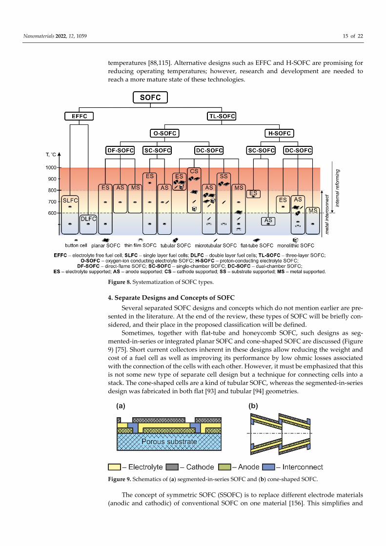
Nanomaterials 2022, 12, 1059 15 of 22
temperatures [88,115]. Alternative designs such as EFFC and H-SOFC are promising for
reducing operating temperatures; however, research and development are needed to
reach a more mature state of these technologies.
Figure 8. Systematization of SOFC types.
4. Separate Designs and Concepts of SOFC
Several separated SOFC designs and concepts which do not mention earlier are pre-
sented in the literature. At the end of the review, these types of SOFC will be briefly con-
sidered, and their place in the proposed classification will be defined.
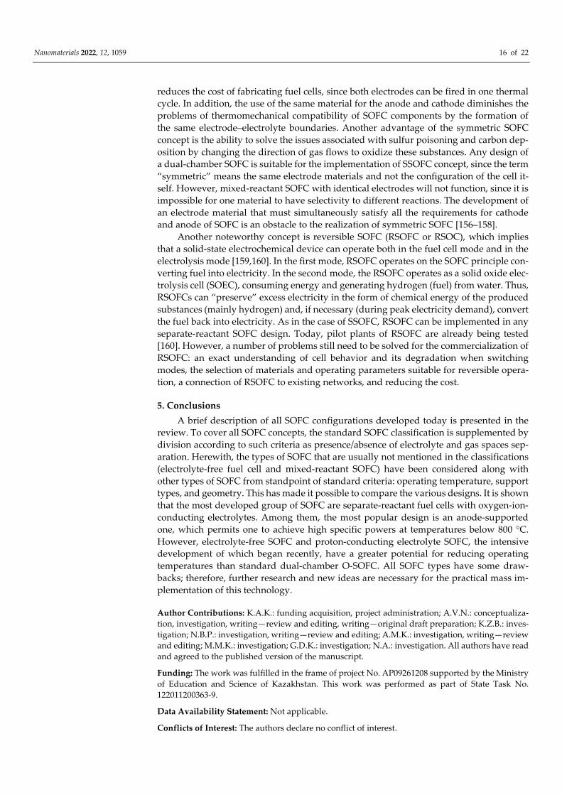
Sometimes, together with flat-tube and honeycomb SOFC, such designs as seg-
mented-in-series or integrated planar SOFC and cone-shaped SOFC are discussed (Figure
9) [75]. Short current collectors inherent in these designs allow reducing the weight and
cost of a fuel cell as well as improving its performance by low ohmic losses associated
with the connection of the cells with each other. However, it must be emphasized that this
is not some new type of separate cell design but a technique for connecting cells into a
stack. The cone-shaped cells are a kind of tubular SOFC, whereas the segmented-in-series
design was fabricated in both flat [93] and tubular [94] geometries.
Figure 9. Schematics of (a) segmented-in-series SOFC and (b) cone-shaped SOFC.
The concept of symmetric SOFC (SSOFC) is to replace different electrode materials
(anodic and cathodic) of conventional SOFC on one material [156]. This simplifies and
Nanomaterials 2022, 12, 1059 16 of 22
reduces the cost of fabricating fuel cells, since both electrodes can be fired in one thermal
cycle. In addition, the use of the same material for the anode and cathode diminishes the
problems of thermomechanical compatibility of SOFC components by the formation of
the same electrode–electrolyte boundaries. Another advantage of the symmetric SOFC
concept is the ability to solve the issues associated with sulfur poisoning and carbon dep-
osition by changing the direction of gas flows to oxidize these substances. Any design of
a dual-chamber SOFC is suitable for the implementation of SSOFC concept, since the term
“symmetric” means the same electrode materials and not the configuration of the cell it-
self. However, mixed-reactant SOFC with identical electrodes will not function, since it is
impossible for one material to have selectivity to different reactions. The development of
an electrode material that must simultaneously satisfy all the requirements for cathode
and anode of SOFC is an obstacle to the realization of symmetric SOFC [156–158].
Another noteworthy concept is reversible SOFC (RSOFC or RSOC), which implies
that a solid-state electrochemical device can operate both in the fuel cell mode and in the
electrolysis mode [159,160]. In the first mode, RSOFC operates on the SOFC principle con-
verting fuel into electricity. In the second mode, the RSOFC operates as a solid oxide elec-
trolysis cell (SOEC), consuming energy and generating hydrogen (fuel) from water. Thus,
RSOFCs can “preserve” excess electricity in the form of chemical energy of the produced
substances (mainly hydrogen) and, if necessary (during peak electricity demand), convert
the fuel back into electricity. As in the case of SSOFC, RSOFC can be implemented in any
separate-reactant SOFC design. Today, pilot plants of RSOFC are already being tested
[160]. However, a number of problems still need to be solved for the commercialization of
RSOFC: an exact understanding of cell behavior and its degradation when switching
modes, the selection of materials and operating parameters suitable for reversible opera-
tion, a connection of RSOFC to existing networks, and reducing the cost.
5. Conclusions
A brief description of all SOFC configurations developed today is presented in the
review. To cover all SOFC concepts, the standard SOFC classification is supplemented by
division according to such criteria as presence/absence of electrolyte and gas spaces sep-
aration. Herewith, the types of SOFC that are usually not mentioned in the classifications
(electrolyte-free fuel cell and mixed-reactant SOFC) have been considered along with
other types of SOFC from standpoint of standard criteria: operating temperature, support
types, and geometry. This has made it possible to compare the various designs. It is shown
that the most developed group of SOFC are separate-reactant fuel cells with oxygen-ion-
conducting electrolytes. Among them, the most popular design is an anode-supported
one, which permits one to achieve high specific powers at temperatures below 800 °C.
However, electrolyte-free SOFC and proton-conducting electrolyte SOFC, the intensive
development of which began recently, have a greater potential for reducing operating
temperatures than standard dual-chamber O-SOFC. All SOFC types have some draw-
backs; therefore, further research and new ideas are necessary for the practical mass im-
plementation of this technology.
Author Contributions: K.A.K.: funding acquisition, project administration; A.V.N.: conceptualiza-
tion, investigation, writing—review and editing, writing—original draft preparation; K.Z.B.: inves-
tigation; N.B.P.: investigation, writing—review and editing; A.M.K.: investigation, writing—review
and editing; M.M.K.: investigation; G.D.K.: investigation; N.A.: investigation. All authors have read
and agreed to the published version of the manuscript.
Funding: The work was fulfilled in the frame of project No. AP09261208 supported by the Ministry
of Education and Science of Kazakhstan. This work was performed as part of State Task No.
122011200363-9.
Data Availability Statement: Not applicable.
Conflicts of Interest: The authors declare no conflict of interest.

Nanomaterials 2022, 12, 1059 17 of 22
References
1. Kirubakaran, A.; Jain, S.; Nema, R.N. A review on fuel cell technologies and power electronic interface. Renew. Sust. Energ. Rev.
2009, 13, 2430–2440. https://doi.org/10.1016/j.rser.2009.04.004.
2. Ramadhani, F.; Hussain, M.A.; Mokhlis, H. A comprehensive review and technical guideline for optimal design and operations
of fuel cell-based cogeneration systems. Processes 2019, 7, 950. https://doi.org/10.3390/pr7120950.
3. Perfil’ev, M.V.; Demin, A.K.; Kuzin, B.L.; Lipilin, A.S. Vysokotemperaturnyj Jelektroliz Gazov; Nauka: Moscow, Russia, 1988; 232p,
ISBN 5-02-001399-4.
4. Minh, N.Q. Ceramic fuel cells. J. Am. Ceram. Soc. 1993, 76, 563–588. https://doi.org/10.1111/j.1151-2916.1993.tb03645.x.
5. Minh, N.Q. Solid oxide fuel cell technology—Features and applications. Solid State Ion. 2004, 174, 271–277.
https://doi.org/10.1016/j.ssi.2004.07.042.
6. Solid Oxide Fuel Cells: From Materials to System Modeling; Ni, M., Zhao, T.S., Eds.; UK RSC Publishing: Cambridge, UK, 2013;
523p. https://doi.org/10.1039/9781849737777-FP001.
7. Kuhn, M.; Napporn, T.W. Single-chamber solid oxide fuel cell technology–from its origins to today’s state of the art. Energies
2010, 3, 57–134. https://doi.org/10.3390/en3010057.
8. Zhu, B.; Raza, R.; Fan, L.; Sun, C. (Eds.) Solid Oxide Fuel Cells: From Electrolyte-Based to Electrolyte-Free Devices; Wiley-VCH:
Weinheim, Germany, 2020; 488p, ISBN: 978-3-527-81278-3.
9. Bello, I.T.; Zhai, S.; Zhao, S.; Li, Z.; Yu, N.; Ni, M. Scientometric review of proton-conducting solid oxide fuel cells. Int. J. Hydrogen
Energy 2021, 46, 37406–37428. https://doi.org/10.1016/j.ijhydene.2021.09.061.
10. Hossain, S.; Abdalla, A.M.; Jamain, S.N.B.; Zaini, J.H.; Azad, A.K. A review on proton conducting electrolytes for clean energy
and intermediate temperature-solid oxide fuel cells. Renew. Sust. Energ. Rev. 2017, 79, 750–764.
https://doi.org/10.1016/j.rser.2017.05.147.
11. Singhal, S.C.; Kendall, K. (Eds.); High Temperature Solid Oxide Fuel Cells: Fundamentals, Design and Applications; Elsevier Ltd.:
Oxford, UK, 2003; 405p, ISBN 1856173879.
12. Kan, W.H.; Samson, A.J.; Thangadurai, V. Trends in electrode development for next generation solid oxide fuel cells. J. Mater.
Chem. A 2016, 4, 17913–17932. https://doi.org/10.1039/C6TA06757C.
13. Fergus, J.W. Electrolytes for solid oxide fuel cells. J. Power Sources 2006, 162, 30–40.
https://doi.org/10.1016/j.jpowsour.2006.06.062.
14. Liu, T.; Zhang, X.; Wang, X.; Yu, J.; Li, L. A review of zirconia-based solid electrolytes. Ionics 2016, 22, 2249–2262.
https://doi.org/10.1007/s11581-016-1880-1.
15. Jaiswal, N.; Tanwar, K.; Suman, R.; Kumar, D.; Upadhyay, S.; Parkash, O. A brief review on ceria based solid electrolytes for
solid oxide fuel cells. J. Alloys Compd. 2019, 781, 984–1005. https://doi.org/10.1016/j.jallcom.2018.12.015.
16. Prakash, B.S.; Kumar, S.S.; Aruna, S.T. Properties and development of Ni/YSZ as an anode material in solid oxide fuel cell: A
review. Renew. Sust. Energ. Rev. 2014, 36, 149–179. https://doi.org/10.1016/j.rser.2014.04.043.
17. Ng, K.H.; Rahman, H.A.; Somalu, M.R. Review: Enhancement of composite anode materials for low-temperature solid oxide
fuels. Int. J. Hydrogen Energy 2019, 44, 30692–30704. doi:/10.1016/j.ijhydene.2018.11.137.
18. Liu, Y.; Shao, Z.; Mori, T.; Jiang, S.P. Development of nickel based cermet anode materials in solid oxide fuel cells—Now and
future. Mater. Rep. Energy 2021, 1, 100003. https://doi.org/10.1016/j.matre.2020.11.002.
19. Jiang, S.P. Development of lanthanum strontium manganite perovskite cathode materials of solid oxide fuel cells: A review. J.
Mater. Sci. 2008, 43, 6799–6833. https://doi.org/10.1007/s10853-008-2966-6.
20. Jiang, S.P. Development of lanthanum strontium cobalt ferrite perovskite electrodes of solid oxide fuel cells—A review. Int. J.
Hydrogen Energy 2019, 44, 7448–7493. https://doi.org/10.1016/j.ijhydene.2019.01.212.
21. Curia, M.; Silva, E.R.; Furtado, J.G.M.; Ferraz, H.C.; Secchi, A.R. Anodes for SOFC: Review of material selection, interface and
electrochemical phenomena. Quim. Nova 2021, 44, 86–97. https://doi.org/10.21577/0100-4042.20170652.
22. Chen, Y.; Zhou, W.; Ding, D.; Liu, M.; Ciucci, F.; Tade, M.; Shao, Z. Advances in cathode materials for solid oxide fuel cells:
Complex oxides without alkaline earth metal elements. Adv. Energy Mater. 2015, 5, 1500537.
https://doi.org/10.1002/aenm.201500537.
23. Jacobs, R.; Mayeshiba, T.; Booske, J.; Morgan, D. Material discovery and design principles for stable, high activity perovskite
cathodes for solid oxide fuel cells. Adv. Energy Mater. 2018, 8, 1702708. https://doi.org/10.1002/aenm.201702708.
24. Ding, P.; Li, W.; Zhao, H.; Wu, C.; Zhao, L.; Dong, B.; Wang, S. Review on Ruddlesden–Popper perovskites as cathode for solid
oxide fuel cells. J. Phys. Mater. 2021, 4, 022002. https://doi.org/10.1088/2515-7639/abe392.
25. Ahmad, M.Z.; Ahmad, S.H.; Chen, R.S.; Ismail, A.F.; Hazan, R.; Baharuddin, N.A. Review on recent advancement in cathode
material for lower and intermediate temperature solid oxide fuel cells application. Int. J. Hydrogen Energy 2021, 47, 1103–1120.
26. Fan, L.; Zhu, B.; Su, P.-C.; He, C. Nanomaterials and technologies for low temperature solid oxide fuel cells: Recent advances,
challenges and opportunities. Nano Energy 2018, 45, 148–176.
27. Jo, S.; Sharma, B.; Park, D.-H.; Myung, J. Materials and nano-structural processes for use in solid oxide fuel cells: A review. J.
Korean Ceram. Soc. 2020, 57, 135–151.
28. Janga, I.; Kima, S.; Kima, C.; Yoon, H.; Song, T. Enhancement of oxygen reduction reaction through coating a nano-web-
structured La0.6Sr0.4Co0.2Fe0.8O3-δ thin-film as a cathode/electrolyte interfacial layer for lowering the operating temperature of
solid oxide fuel cells. J. Power Sources 2018, 392, 123–128.

Nanomaterials 2022, 12, 1059 18 of 22
29. Pavzderin, N.B.; Solovyev, A.A.; Nikonov, A.V.; Shipilova, A.V.; Rabotkin, S.V.; Semenov, V.A.; Grenaderov, A.S.; Oskomov,
K.V. Formation of a dense La(Sr)Fe(Ga)O3 interlayer at the electrolyte/porous cathode interface by magnetron sputtering and
its effect on the cathode characteristics. Russ. J. Electrochem. 2021, 57, 519–525.
30. Develos-Bagarinao, K.; de Vero, J.; Kishimoto, H.; Ishiyama, T.; Yamaji, K.; Horita, T.; Yokokawa, H. Multilayered LSC and
GDC: An approach for designing cathode materials with superior oxygen exchange properties for solid oxide fuel cells. Nano
Energy 2018, 52, 369–380.
31. Zhang, Y.; Xu, N.; Fan, H.; Han, M. La0.6Sr0.4Co0.2Fe0.8O3-δ nanoparticles modified Ni-based anode for direct methane-fueled
SOFCs. Energy Procedia 2019, 158, 2250–2255.
32. Pei, K.; Zhou, Y.; Xu, K.; He, Z.; Chen, Y.; Zhang, W.; Yoo, S.; Zhao, B.; Yuan, W.; Liu, M.; et al. Enhanced Cr-tolerance of an
SOFC cathode by an efficient electro-catalyst coating. Nano Energy 2020, 72, 104704.
33. Venancio, S.A.; Sarruf, B.J.M.; Gomes, G.G.; de Miranda, P.E.V. Multifunctional macroporous solid oxide fuel cell anode with
active nanosized ceramic electrocatalyst. Int. J. Hydrogen Energy 2020, 45, 5501–5511.
34. Wu, J.; Liu, X.J. Recent development of SOFC metallic interconnect. Mater. Sci. Technol. 2010, 26, 293–305.
https://doi.org/10.1016/S1005-0302(10)60049-7.
35. Mah, J.C.W.; Muchtar, A.; Somalu, M.R.; Ghazali, M.J. Metallic interconnects for solid oxide fuel cell: A review on protective
coating and deposition techniques. Int. J. Hydrogen Energy 2017, 42, 9219–9229. https://doi.org/10.1016/j.ijhydene.2016.03.195.
36. Fabbri, E.; Pergolesi, D.; Traversa, E. Materials challenges toward proton-conducting oxide fuel cells: A critical review. Chem.
Soc. Rev. 2010, 39, 4355–4369. https://doi.org/10.1039/B902343G.
37. Meng, Y.; Gao, J.; Zhao, Z.; Amoroso, J.; Tong, J.; Brinkman, K.S. Review: Recent progress in low-temperature proton-conducting
ceramics. J. Mater. Sci. 2019, 54, 9291–9312.
38. Singh, B.; Ghosh, S.; Aich, S.; Roy, B. Low temperature solid oxide electrolytes (LT-SOE): A review. J. Power Sources 2017, 339,
103–135. https://doi.org/10.1016/j.jpowsour.2016.11.019.
39. Zhang, W.; Hu, Y.H. Progress in proton-conducting oxides as electrolytes for low-temperature solid oxide fuel cells: From
materials to devices. Energy Sci. Eng. 2021, 9, 984–1011. https://doi.org/10.1002/ese3.886.
40. Yang, G.; Su, C.; Shi, H.; Zhu, Y.; Song, Y.; Zhou, W.; Shao, Z. Toward reducing the operation temperature of solid oxide fuel
cells: Our past 15 years of efforts in cathode development. Energy Fuels 2020, 34, 15169–15194.
https://doi.org/10.1021/acs.energyfuels.0c01887.
41. Zhu, B.; Raza, R.; Qin, H.; Liu, Q.; Fan, L. Fuel cells based on electrolyte and non-electrolyte separators. Energy Environ. Sci. 2011,
4, 2986–2992. https://doi.org/10.1039/c1ee01202a.
42. Wang, G.; Wu, X.; Cai, Y.; Ji, Y.; Yaqub, A.; Zhu, B. Design, fabrication and characterization of a double layer solid oxide fuel
cell (DLFC). J. Power Sources 2016, 332, 8–15. https://doi.org/10.1016/j.jpowsour.2016.09.011.
43. He, H.P.; Huang, X.J.; Chen, L.Q. A practice of single layer solid oxide fuel cell. Ionics 2000, 6, 64–69.
https://doi.org/10.1007/BF02375548.
44. Zhu, B.; Ma, Y.; Wang, X.; Raza, R.; Qin, H.; Fan, L. A fuel cell with a single component functioning simultaneously as the
electrodes and electrolyte. Electrochem. Commun. 2011, 13, 225–227. https://doi.org/10.1016/j.elecom.2010.12.019.
45. Hu, E.; Jiang, Z.; Fan, L.; Singh, M.; Wang, F.; Raza, R.; Sajid, M.; Wang, J.; Kim, J.S.; Zhu, B. Junction and energy band on novel
semiconductor-based fuel cells. iScience 2021, 24, 102191. https://doi.org/10.1016/j.isci.2021.102191.
46. Dong, X.; Tian, L.; Li, J.; Zhao, Y.; Tian, Y.; Li, Y. Single-layer fuel cell based on a composite of Ce0.8Sm0.2O2−�–Na2CO3 and a
mixed ionic and electronic conductor Sr2Fe1.5Mo0.5O6−�. J. Power Sources 2014, 249, 270–276.
https://doi.org/10.1016/j.jpowsour.2013.10.045.
47. Zhu, B.; Lund, P.; Raza, R.; Patakangas, J.; Huang, Q.-A.; Fan, L.; Singh, M. A new energy conversion technology based on nano-
redox and nano-device processes. Nano Energy 2013, 2, 1179–1185. https://doi.org/10.1016/j.nanoen.2013.05.001.
48. Zhu, B.; Lund, P.D.; Raza, R.; Ma, Y.; Fan, L.; Afzal, M.; Patakangas, J.; He, Y.; Zhao, Y.; Tan, W.; et al. Schottky junction effect
on high performance fuel cells based on nanocomposite materials. Adv. Energy Mater. 2015, 5, 1401895.
https://doi.org/10.1002/aenm.201401895.
49. Zhu, B.; Mi, Y.; Xia, C.; Wang, B.; Kim, J.-S.; Lund, P.; Li, T. A nanoscale perspective on solid oxide and semiconductor membrane
fuel cells: Materials and technology. Energy Mater. 2021, 1, 100002.
50. Yano, M.; Tomita, A.; Sano, M.; Hibino, T. Recent advances in single-chamber solid oxide fuel cells: A review. Solid State Ion.
2007, 177, 3351–3359. https://doi.org/10.1016/j.ssi.2006.10.014.
51. Jacques-Bedard, X.; Napporn, T.W.; Roberge, R.; Meunier, M. Coplanar electrodes design for a single-chamber SOFC. J.
Electrochem. Soc. 2007, 154, B305–B309. https://doi.org/10.1149/1.2424421.
52. Kamvar, M.; Ghassemi, M.; Rezaei, M. Effect of catalyst layer configuration on single chamber solid oxide fuel cell performance.
Appl. Therm. Eng. 2016, 100, 98–104. https://doi.org/10.1016/j.applthermaleng.2016.01.128.
53. Guo, Y.; Bessaa, M.; Aguado, S.; Steil, M.C.; Rembelski, D.; Rieu, M.; Viricelle, J.-P.; Benameur, N.; Guizard, C.; Tardivat, C.; et
al., An all porous solid oxide fuel cell (SOFC): A bridging technology between dual and single chamber SOFCs. Energy Environ.
Sci. 2013, 6, 2119–2123. https://doi.org/10.1039/c3ee40131f.
54. Guo, Y.M.; Largiller, G.; Guizard, C.; Tardivat, C.; Farrusseng, D. Coke-free operation of an all porous solid oxide fuel cell (AP-
SOFC) used as an O2 supply device. J. Mater. Chem. A 2015, 3, 2684–2689. https://doi.org/10.1039/c4ta05009f.
55. Horiuchi, M.; Suganuma, S.; Watanabe, M. Electrochemical power generation directly from combustion flame of gases, liquids,
and solids. J. Electrochem. Soc. 2004, 151, A1402–A1405. https://doi.org/10.1149/1.1778168.

Nanomaterials 2022, 12, 1059 19 of 22
56. Shi, Y.; Cai, N.; Cao, T.; Zhang, J. (Eds.) High-Temperature Electrochemical Energy Conversion and Storage: Fundamentals and
Applications; CRC Press: London, UK, 2018; 223p, ISBN 9780367889838.
57. Mahapatra, M.K.; Lu, K. Glass-based seals for solid oxide fuel and electrolyzer cells—A review. Mater. Sci. Eng. R. Rep. 2010, 67,
65–85. https://doi.org/10.1016/j.mser.2009.12.002.
58. Singh, K.; Walia, T. Review on silicate and borosilicate-based glass sealants and their interaction with components of solid oxide
fuel cell. Int. J. Energy Res. 2021, 45, 20559–20582.
59. Riess, I.J. On the single chamber solid oxide fuel cells. Power Sources 2008, 175, 325–337, 2008.
https://doi.org/10.1016/j.jpowsour.2007.09.041.
60. Bedon, A.; Viricelle, J.P.; Rieu, M.; Mascotto, S.; Glisenti, A. Single chamber Solid Oxide Fuel Cells selective electrodes: A real
chance with brownmillerite-based nanocomposites. Int. J. Hydrogen Energy. 2021, 46, 14735–14747.
61. Vogler, M.; Barzan, D.; Kronemayer, H.; Schulz, C.; Horiuchi, M.; Suganuma, S.; Tokutake, Y.; Warnatz, J.; Bessler, W.G. Direct-
flame solid-oxide fuel cell (DFFC): A thermally self-sustained, air self- breathing, hydrocarbon-operated SOFC System in a
simple, no-chamber setup. ECS Trans. 2007, 7, 555–564. https://doi.org/10.1149/1.2729136.
62. Behling, N.H. Fuel cells. In Current Technology Challenges and Future Research Needs; Elsevier: Amsterdam, The Netherlnds, 2013;
685p. https://doi.org/10.1016/C2011-0-04424-1.
63. van Rij, L.N.; Le, J.; van Landschoot, R.C.; Schoonman, J.A. A novel Ni-CERMET electrode based on a proton conducting
electrolyte. J. Mater. Sci. 2001, 36, 1069–1076. https://doi.org/10.1023/A:1004805103420.
64. Fabbri, E.; D’Epifanio, A.; Sanna, S.; Bartolomeo, E.D.; Balestrino, G.; Licoccia, S.; Traversa, E. A novel single chamber solid
oxide fuel cell based on chemically stable thin films of Y-doped BaZrO3 proton conducting electrolyte. Energy Environ. Sci. 2010,
3, 618–621. https://doi.org/10.1039/c001316a.
65. Wang, K.; Milcarek, R.J.; Zeng, P.; Ahn, J. Flame-assisted fuel cells running methane. Int. J. Hydrogen Energy 2015, 40, 4659–4665.
66. Milcarek, R.J.; Wang, K.; Falkenstein-Smith, R.L.; Ahn, J. Micro-tubular flame-assisted fuel cells for micro-combined heat and
power systems. J. Power Sources 2016, 306, 148–151.
67. Milcarek, R.J.; Ahn, J. Micro-tubular flame-assisted fuel cells running methane, propane and butane: On soot, efficiency and
power density. Energy 2019, 169, 776–782.
68. Wang, Y.; Shi, Y.; Cao, T.; Zeng, H.; Cai, N.; Ye, X.; Wang, S. A flame fuel cell stack powered by a porous media combustor. Int.
J. Hydrogen Energy 2018, 43, 22595–22603.
69. Steele, B.C.H. Material science and engineering: The enabling technology for the commercialisation of fuel cell systems. J. Mater.
Sci. 2001, 36, 1053–1068. https://doi.org/10.1023/A:1004853019349.
70. Brett, D.J.L.; Atkinson, A.; Brandon, N.P.; Skinner, S.J. Intermediate temperature solid oxide fuel cells. Chem. Soc. Rev. 2008, 37,
1568–1578. https://doi.org/10.1039/b612060c.
71. Kaur, G. (Ed.) Intermediate Temperature Solid Oxide Fuel Cells; Elsevier: Amsterdam, The Netherlnds, 2020; 516p.
https://doi.org/10.1016/B978-0-12-817445-6.00001-6.
72. Ferrari, M.L.; Damo, U.M.; Turan, A.; Sanchez, D. Hybrid Systems Based on Solid Oxide Fuel Cells; Wiley: Hoboken, NJ, USA, 2017;
325p. https://doi.org/10.1002/9781119039044.
73. Weber, A.; Ivers-Tiffee, E.J. Materials and concepts for solid oxide fuel cells (SOFCs) in stationary and mobile applications.
Power Sour. 2004, 127, 273–283. https://doi.org/10.1016/j.jpowsour.2003.09.024.
74. Wachsman, E.D.; Lee, K.T. Lowering the temperature of solid oxide fuel cells. Science 2011, 334, 935–939.
https://doi.org/10.1126/science.1204090.
75. Timurkutluk, B.; Timurkutluk, C.; Mat, M.D.; Kaplan, Y. A review on cell/stack designs for high performance solid oxide fuel
cells. Renew. Sustain. Energy Rev. 2016, 56, 1101–1121. https://doi.org/10.1016/j.rser.2015.12.034.
76. Qiu, P.; Sun, S.; Yang, X.; Chen, F.; Xiong, C.; Jia, L.; Li, J. A review on anode on-cell catalyst reforming layer for direct methane
solid oxide fuel cells. Int. J. Hydrogen Energy 2021, 46, 25208–25224. https://doi.org/10.1016/j.ijhydene.2021.05.040.
77. Duan, C.; Tong, J.; Shang, M.; Nikodemski, S.; Sanders, M.; Ricote, S.; Almansoori, A.; O’Hayre, R. Readily processed protonic
ceramic fuel cells with high performance at low temperatures. Science 2015, 349, 1321–1326.
https://doi.org/10.1126/science.aab3987.
78. Chen, C.; Dong, Y.; Li, L.; Wang, Z.; Liu, M.; Rainwater, B.H.; Bai, Y. Electrochemical properties of micro-tubular intermediate
temperature solid oxide fuel cell with novel asymmetric structure based on BaZr0.1Ce0.7Y0.1Yb0.1O3-δ proton conducting
electrolyte. Int. J. Hydrogen Energy 2019, 44, 16887–16897. https://doi.org/10.1016/j.ijhydene.2019.04.264.
79. Wang, K.; Zeng, P.; Ahn, J. High performance direct flame fuel cell using a propane flame. Proc. Combust. Inst. 2011, 33, 3431–
3437. https://doi.org/10.1016/j.proci.2010.07.047.
80. Wang, Y.; Sun, L.; Luo, L.; Wu, Y.; Liu, L.; Shi, J. The study of portable direct-flame solid oxide fuel cell (DF-SOFC) stack with
butane fuel. J. Fuel Chem. Technol. 2014, 42, 1135–1139. https://doi.org/10.1016/S1872-5813(14)60045-1.
81. Tucker, M.C.; Ying, A.S. Metal-supported solid oxide fuel cells operated in direct-flame configuration. Int. J. Hydrogen Energy
2017, 42, 24426–24434.
82. Mai, A.; Iwanschitz, B.; Weissen, U.; Denzler, R.; Haberstock, D.; Nerlich, V.; Sfeir, J.; Schuler, A. Status of Hexis SOFC stack
development and the Galileo 1000 N micro-CHP system. ECS Trans. 2009, 25, 149–158. https://doi.org/10.1149/1.3205520.
83. Singh, A.; Ghuman, J.S.; Kumar, R. Bloom Energy for producing electricity. Int. J. Power Syst. Oper. Energy Manag. 2014, 4, 3.
https://doi.org/10.47893/IJPSOEM.2014.1111.

Nanomaterials 2022, 12, 1059 20 of 22
84. Kwon, Y.; Han, Y.J. Fabrication of electrolyte-supported solid oxide fuel cells using a tape casting process. Ceram. Soc. Jpn. 2020,
128, 310–316. https://doi.org/10.2109/jcersj2.20006.
85. Williams, M.C.; Strakey, J.P.; Surdoval, W.A.; Wilson, L.C. Solid oxide fuel cell technology development in the U.S. Solid State
Ion. 2006, 177, 2039–2044. https://doi.org/10.1016/j.ssi.2006.02.051.
86. McConnell, V.P.; Versa Power’s SOFC could scale to MW for SECA, and work in transport hybrids. Fuel Cells Bull. 2007, 2007,
12–16. doi:0.1016/S1464-2859(07)70368-1.
87. Yoo, Y.-S.; Lee, T.; Choi, J.H.; Park, T.-S.; Oh, J.-M.; Kim, C.-Y. Fabrication and demonstration of 1kW class SOFC stack and
system for residential power generation application. J. Fuel Cell Sci. Technol. 2009, 6, 021008. https://doi.org/10.1115/1.2971129.
88. Santori, G.; Brunetti, E.; Polonara, F. Experimental characterization of an anode-supported tubular SOFC generator fueled with
hydrogen, including a principal component analysis and a multi-linear regression. Int. J. Hydrogen Energy 2011, 36, 8435–8449.
https://doi.org/10.1016/j.ijhydene.2011.04.036.
89. Harboe, S.; Schreiber, A.; Margaritis, N.; Blum, L.; Guillon, O.; Menzler, N.H. Manufacturing cost model for planar 5 kWel SOFC
stacks at Forschungszentrum Julich. Int. J. Hydrogen Energy 2020, 45, 8015–8030. https://doi.org/10.1016/j.ijhydene.2020.01.082.
90. Tsipis, E.V.; Kharton, V.V. Electrode materials and reaction mechanisms in solid oxide fuel cells: A brief review. II.
Electrochemical behavior vs. materials science aspects. J. Solid State Electrochem. 2008, 12, 1367–1391.
https://doi.org/10.1007/s10008-008-0611-6.
91. Huang, K.; Singhal, S.C. Cathode-supported tubular solid oxide fuel cell technology: A critical review. J. Power Sources 2013,
237, 84–97. https://doi.org/10.1016/j.jpowsour.2013.03.001.
92. Zhao, K.; Kim, B.-H.; Du, Y.; Xu, Q.; Ahn, B.-G. Ceria catalyst for inert-substrate supported tubular solid oxide fuel cells running
on methane fuel. J. Power Sources 2016, 314, 10–17. https://doi.org/10.1016/j.jpowsour.2016.02.079.
93. Gardner, F.J.; Day, M.J.; Brandon, N.P.; Pashley, M.N.; Cassidy, M. SOFC technology development at Rolls-Royce. J. Power
Sources 2000, 86, 122–129. https://doi.org/10.1016/S0378-7753(99)00428-0.
94. Kobayashi, Y.; Ando, Y.; Kabata, T.; Nishiura, M.; Tomida, K.; Matake, N. Extremely high-efficiency thermal power system-
solid oxide fuel cell (SOFC) triple combined-cycle system. Mitsubishi Heavy Ind. Tech. Rev. 2011, 48, 9–15.
95. Krishnan, V.V. Recent developments in metal-supported solid oxide fuel cells. Wiley Interdiscip. Rev. Energy Environ. 2017, 6,
e246. https://doi.org/10.1002/wene.246.
96. Tucker, M.C. Progress in metal-supported solid oxide electrolysis cells: A review. Int. J. Hydrogen Energy 2020, 45, 24203–24218.
https://doi.org/10.1016/j.ijhydene.2020.06.300.
97. Sun, W.; Liu, M.; Liu, W.; Chemically stable yttrium and tin co-doped barium zirconate electrolyte for next generation high
performance proton-conducting solid oxide fuel cells. Adv. Energy Mater. 2013, 3, 1041–1050.
https://doi.org/10.1002/aenm.201201062.
98. Azad, A.K.; Abdalla, A.M.; Afif, A.; Azad, A.; Afroze, S.; Idris, A.C.; Park, J.-Y.; Saqib, M.; Radenahmad, N.; Hossain, S.; et al.
Improved mechanical strength, proton conductivity and power density in an ‘all-protonic’ ceramic fuel cell at intermediate
temperature. Sci. Rep. 2021, 11, 19382.
99. Hwang, S.H.; Kim, S.K.; Nam, J.T.; Park, J.S. Fabrication of an electrolyte-supported protonic ceramic fuel cell with nano-sized
powders of Ni-composite anode. Int. J. Hydrogen Energy 2021, 46, 1076–1084. https://doi.org/10.1016/j.ijhydene.2020.09.172.
100. Stange, M.; Stefan, E.; Denonville, C.; Larring, Y.; Rørvik, P.M.; Haugsrud, R. Development of novel metal-supported proton
ceramic electrolyser cell with thin film BZY15-Ni electrode and BZY15 electrolyte. Int. J. Hydrogen Energy 2017, 42, 13454–13462.
https://doi.org/10.1016/j.ijhydene.2017.03.028.
101. Wang, R.; Byrne, C.; Tucker, M.C. Assessment of co-sintering as a fabrication approach for metal-supported proton-conducting
solid oxide cells. Solid State Ion. 2019, 332, 25–33.
102. Tucker, M.C. Personal power using metal-supported solid oxide fuel cells operated in a camping stove flame. Int. J. Hydrogen
Energy. 2018, 43, 8991–8998.
103. Sayan, Y.; Venkatesan, V.; Guk, E.; Wu, H.; Kim, J.-S. Single-step fabrication of an anode supported planar single-chamber solid
oxide fuel cell. Int. J. Appl. Ceram. Technol. 2018, 15, 1375–1387.
104. Tian, Y.; Lü, Z.; Wang, Z.; Wei, B.; Guo, X.; Wu, P. Effect of the angle between gas flow direction and electrode on single-chamber
SOFC stacks. J. Solid State Electr. 2019, 23, 1651–1657.
105. Tian, Y.; Wu, P.; Zhang, X.; Guo, X.; Ding, L. Performance of a linear array solid oxide fuel cell micro-stack operated in single-
chamber conditions. Ionics 2020, 26, 6217–6224.
106. Choi, I.; Kim, J.-S.; Venkatesan, V.; Ranaweera, M. Fabrication and evaluation of a novel wavy single chamber solid oxide fuel
cell via in-situ monitoring of curvature evolution. Appl. Energy 2017, 195, 1038–1046.
107. Kamvar, M.; Ghassemi, M.; Steinberger-Wilckens, R. The numerical investigation of a planar single chamber solid oxide fuel
cell performance with a focus on the support types. Int. J. Hydrogen Energy 2020, 45, 7077–7087.
108. Raz, S.; Jak, M.J.G.; Schoonman, J.; Riess, I. Supported mixed-gas fuel cells. Solid State Ion. 2002, 149, 335–341.
https://doi.org/10.1016/S0167-2738(02)00402-2.
109. Udomsilp, D.; Rechberger, J.; Neubauer, R.; Bischof, C. Metal-supported solid oxide fuel cells with exceptionally high power
density for range extender systems. Cell Rep. Phys. Sci. 2020, 1, 100072. https://doi.org/10.1016/j.xcrp.2020.100072.
110. Liu, T.; Lin, J.; Liu, T.; Wu, H.; Xia, C.; Chen, C.; Zhan, Z. Tailoring the pore structure of cathode supports for improving. J.
Electroceram. 2018, 40, 138–143. https://doi.org/10.1007/s10832-018-0112-7.

Nanomaterials 2022, 12, 1059 21 of 22
111. Ji, S.; Cho, G.Y.; Yu, W.; Su, P.C.; Lee, M.H.; Cha, S.W. Plasma-enhanced atomic layer deposition of nanoscale yttria-stabilized
zirconia electrolyte for solid oxide fuel cells with porous substrate. ACS Appl. Mater. Interfaces 2015, 7, 2998−3002.
https://doi.org/10.1021/am508710s.
112. Li, G.; Gou, Y.; Qiao, J.; Sun, W.; Wang, Z.; Sun, K. Recent progress of tubular solid oxide fuel cell: From materials to applications.
J. Power Sources 2020, 477, 228693. https://doi.org/10.1016/j.jpowsour.2020.228693.
113. Ivanov, V.V.; Lipilin, A.S.; Kotov, Y.A.; Khrustov, V.R.; Shkerin, S.N.; Paranin, S.N.; Spirin, A.V.; Kaygorodov, A.S. Formation
of a thin-layer electrolyte for SOFC by magnetic pulse compaction of tapes cast of nanopowders. J. Power Sources 2006, 159, 605–
612. https://doi.org/10.1016/j.jpowsour.2005.11.039.
114. Han, Z.; Yang, Z.; Han, M. Fabrication of metal-supported tubular solid oxide fuel cell by phase-inversion method and in situ
reduction. Int. J. Hydrogen Energy 2016, 41, 10935–10941. doi:0.1016/j.ijhydene.2016.04.253.
115. Lim, T.H.; Park, J.L.; Lee, S.B.; Park, S.J.; Song, R.H.; Shin, D.R. Fabrication and operation of a 1 kW class anode-supported flat
tubular SOFC stack. Int. J. Hydrogen Energy 2010, 35, 9687–9692. https://doi.org/10.1016/j.ijhydene.2010.06.052.
116. Park, S.; Sammes, N.M.; Song, K.H.; Kim, T.; Chung, J.S. Monolithic flat tubular types of solid oxide fuel cells with integrated
electrode and gas channels. Int. J. Hydrogen Energy 2017, 42, 1154–1160. https://doi.org/10.1016/j.ijhydene.2016.08.212.
117. Mushtaq, U.; Kim, D.W.; Yun, U.J.; Lee, J.W.; Lee, S.B.; Park, S.J.; Song, R.H.; Kim, G.; Lim, T.H. Effect of cathode geometry on
the electrochemical performance of flat tubular segmented-in-series (SIS) solid oxide fuel cell. Int. J. Hydrogen Energy 2015, 40,
6207–6215. https://doi.org/10.1016/j.ijhydene.2015.03.040.
118. Khan, M.Z.; Iltaf, A.; Ishfaq, H.A.; Khan, F.N.; Tanveer, W.H.; Song, R.H.; Mehran, M.T.; Saleem, M.; Hussain, A.; Masaud, Z.
Flat-tubular solid oxide fuel cells and stacks: A review. J. Asian Ceram. Soc. 2021, 9, 745–770.
https://doi.org/10.1080/21870764.2021.1920135.
119. Zha, S.; Zhang, Y.; Liu, M. Functionally graded cathodes fabricated by sol-gel/slurry coating for honeycomb SOFCs. Solid State
Ionics 2005, 176, 25–31. https://doi.org/10.1016/j.ssi.2004.07.010.
120. Yamaguchi, T.; Shimizu, S.; Suzuki, T.; Fujishiro, Y.; Awano, M. Fabrication and evaluation of a novel cathode-supported
honeycomb SOFC stack. Mater. Lett. 2009, 63, 2577–2580. https://doi.org/10.1016/j.matlet.2009.09.009.
121. Ruiz-Morales, J.C.; Marrero-Lopez, D.; Pena-Martinez, J.; Canales-Vazquez, J.; Road, J.J.; Segarrad, M.; Savvina, S.N.; Núnez, P.
Performance of a novel type of electrolyte-supported solid oxide fuel cell with honeycomb structure. J. Power Sources 2010, 195,
516–521. https://doi.org/10.1016/j.jpowsour.2009.08.017.
122. Ikeda, S.; Nakajima, H.; Kitahara, T. Enhancement of fuel transfer in anode-supported honeycomb solid oxide fuel cells. J. Phys.
Conf. Ser. 2016, 745, 032082. doi:0.1088/1742-6596/745/3/032082.
123. Evans, A.; Bieberle-Hutter, A.; Rupp, J.L.M.; Gauckler, L.J. Review on microfabricated micro-solid oxide fuel cell membranes. J.
Power Sources 2009, 194, 119–129. https://doi.org/10.1016/j.jpowsour.2009.03.048.
124. Lee, Y.H.; Chang, I.; Cho, G.Y.; Park, J.; Yu, W.; Tanveer, W.H.; Cha, S.W. Thin film solid oxide fuel cells operating below 600 °C:
A Review. Int. J. Precis. Eng. Manuf-Green Technol. 2018, 5, 441–453.
125. Baek, J.D.; Chang, I.; Su. P.C. Thin-film solid oxide fuel cells. In Materials for Energy, 1st ed.; Zhang, S., Ed.; CRC Press: Boca
Raton, FL, USA, 2021; pp. 239-283.
126. An, J.; Kim, Y.-B.; Gür, T.M.; Park, J.; Prinz, F.B. 3-D nanostructured bilayer solid oxide fuel cell with 1.3 W/cm2 at 450 °C. Nano
Lett. 2013, 13, 4551–4555.
127. Baek, J.D.; Liu, K.Y.; Su, P.C. A functional micro-solid oxide fuel cell with 10 nm-thick freestanding electrolyte. J. Mater. Chem.
A 2017, 5, 18414–18419. https://doi.org/10.1039/C7TA05245F.
128. Wells, M.P.; Lovett, A.J.; Chalklen, T.; Baiutti, F.; Tarancón, A.; Wang, X.; Ding, J.; Wang, H.; Kar-Narayan, S.; Acosta, M.; et al.
Route to high-performance micro-solid oxide fuel cells on metallic substrates. ACS Appl. Mater. Interfaces 2021, 13, 4117−4125.
129. Kang, S.; Su, P.C.; Park, Y.I.; Saito, Y.; Prinz, F.B. Thin-film solid oxide fuel cells on porous nickel substrates with multistage
nanohole array. J. Electrochem. Soc. 2006, 153, A554–A559. https://doi.org/10.1149/1.2164769.
130. Kang, S.; Lee, J.; Cho, G.Y.; Kim, Y.; Lee, S.; Cha, S.W.; Bae, J. Scalable fabrication process of thin-film solid oxide fuel cells with
an anode functional layer design and a sputtered electrolyte. Int. J. Hydrogen Energy 2020, 45, 33980–33992.
131. Cho, G.Y.; Yu, W.; Lee, Y.H.; Lee, Y.; Tanveer, W.H.; Kim, Y.; Lee, S.; Cha, S.W.; Effects of nanoscale PEALD YSZ interlayer for
AAO based thin film solid oxide fuel cells. Int. J. Precis. Eng. Manuf-Green Technol. 2020, 7, 423–430.
132. Kim, K.J.; Park, B.H.; Kim, S.J.; Lee, Y.; Bae, H.; Choi, G.M. Micro solid oxide fuel cell fabricated on porous stainless steel: A new
strategy for enhanced thermal cycling ability. Sci. Rep. 2016, 6, 22443.
133. Reolon, R.P.; Sanna, S.; Xu, Y.; Lee, I.; Bergmann, C.P.; Prydsa, N.; Esposito, V. Effects of accelerated degradation on metal
supported thin film-based solid oxide fuel cells. J. Mater. Chem. A 2018, 6, 7887–7896.
134. Lee, M.S.; Lee, S.; Jeong, W.; Ryu, S.; Yu, W.; Lee, Y.H.; Cho, G.Y.; Cha, S.W. Nanoporous nickel thin film anode optimization
for low-temperature solid oxide fuel cells. Int. J. Hydrogen Energy 2021, 46, 36445–36453.
135. Yu, W.; Lim, Y.; Lee, S.; Pandiyan, A.; Cho, G.; Cha, S.W. Low-temperature, high-performance thin-film solid oxide fuel cells
with tailored nano-column structures of a sputtered Ni anode. J. Mater. Chem. A, 2020, 41, 21668–21679.
136. Lee, Y.H.; Ren, H.; Wu, E.A.; Fullerton, E.E.; Meng, Y.S.; Minh, N.Q. All-sputtered, superior power density thin-film solid oxide
fuel cells with a novel nanofibrous ceramic cathode. Nano Lett. 2020, 20, 2943−2949.
137. Kendall, K. Progress in microtubular solid oxide fuel cells. Int. J. Appl. Ceram. Technol. 2010, 7, 1–9. https://doi.org/10.1111/j.1744-
7402.2008.02350.x.

Nanomaterials 2022, 12, 1059 22 of 22
138. Zhang, X.; Jin, Y.; Li, D.; Xiong, Y. A review on recent advances in micro-tubular solid oxide fuel cells. J. Power Sources 2021, 506,
230135. https://doi.org/10.1016/j.jpowsour.2021.230135.
139. Howe, K.S.; Thompson, G.J.; Kendall, K. Micro-tubular solid oxide fuel cells and stacks. J. Power Sources 2011, 196, 1677–1686.
https://doi.org/10.1016/j.jpowsour.2010.09.043.
140. Lawlor, V.; Griesser, S.; Buchinger, G.; Olabi, A.G.; Cordiner, S.; Meissner, D. Review of the micro-tubular solid oxide fuel cell
Part I. Stack design issues and research activities. J. Power Sources 2009, 193, 387–399.
https://doi.org/10.1016/j.jpowsour.2009.02.085.
141. Jamil, S.M.; Othman, M.H.D.; Rahman, M.A.; Jaafar, J.; Ismail, A.F. Anode supported micro-tubular SOFC fabricated with mixed
particle size electrolyte via phase-inversion technique. Int. J. Hydrogen Energy 2017, 42, 9188–9201.
https://doi.org/10.1016/j.ijhydene.2016.05.016.
142. Nikonov, A.V.; Spirin, A.V.; Lipilin, A.S.; Khrustov, V.R.; Paranin, S.N. Fabrication of microtubular solid oxide fuel cells by film
compaction and co-sintering. Russ. J. Electrochem. 2018, 54, 547–553. https://doi.org/10.1134/S1023193518060149.
143. Hsieh, W.S.; Lin, P.; Wang, S.F. Characteristics of electrolyte supported micro-tubular solid oxide fuel cells with GDC-ScSZ
bilayer electrolyte. Int. J. Hydrogen Energy 2014, 39, 17267–17274. https://doi.org/10.1016/j.ijhydene.2014.08.060.
144. Meng, X.; Yang, N.; Gong, X.; Yin, Y.; Ma, Z.-F.; Tan, X.; Shao, Z.; Liu, S. Novel cathode-supported hollow fibers for light weight
micro-tubular solid oxide fuel cells with an active cathode functional layer. J. Mater. Chem. A 2015, 3, 1017–1022.
https://doi.org/10.1039/C4TA04635H.
145. Sumi, H.; Shimada, H.; Yamaguchi, Y.; Yamaguchi, T. Effect of anode thickness on polarization resistance for metal-supported
microtubular solid oxide fuel cells. J. Electrochem. Soc. 2017, 164, F243–F247. https://doi.org/10.1149/2.0431704jes.
146. Hedayat, N.; Panthi, D.; Du, Y. Inert substrate-supported microtubular solid oxide fuel cells based on highly porous ceramic by
low-temperature co-sintering. Ceram. Int. 2019, 45, 579–587. https://doi.org/10.1016/j.ceramint.2018.09.211.
147. Motoyama, M.; Chao, C.C.; An, J.; Jung, H.J.; Gur, T.M.; Prinz, F.B. Nanotubular array solid oxide fuel cell. ACS Nano 2014, 8,
340–351. https://doi.org/10.1021/nn4042305.
148. Akhtar, N.; Decent, S.P.; Loghin, D.; Kendall, K. Mixed-reactant, micro-tubular solid oxide fuel cells: An experimental study. J.
Power Sources 2009, 193, 39–48. https://doi.org/10.1016/j.jpowsour.2009.01.032.
149. An, H.; Lee, H.-W.; Kim, B.-K.; Son, J.-W.; Yoon, K.J.; Kim, H.; Shin, D.; Ji, H.-I.; Lee, J.-H. A 5×5 cm2 protonic ceramic fuel cell
with a power density of 1.3 W cm–2 at 600 °C. Nat. Energy 2018, 3, 870–875. https://doi.org/10.1038/s41560-018-0230-0.
150. Chen, X.; Zhang, H.; Li, Y.; Xing, J.; Zhang, Z.; Ding, X.; Zhang, B.; Zhou, J.; Wang, S. Fabrication and performance of anode-
supported proton conducting solid oxide fuel cells based on BaZr0.1Ce0.7Y0.1Yb0.1O3-δ electrolyte by multi-layer aqueous-based
co-tape casting. J. Power Sources 2021, 506, 229922. https://doi.org/10.1016/j.jpowsour.2021.229922.
151. Zhu, L.; O'Hayre, R.; Sullivan, N.P. High performance tubular protonic ceramic fuel cells via highly-scalable extrusion process.
Int. J. Hydrogen Energy 2021, 46, 27784–27792. https://doi.org/10.1016/j.ijhydene.2021.06.018.
152. Hanifi, A.R.; Sandhu, N.K.; Etsell, T.H.; Luo, J.L.; Sarkar, P. Fabrication and characterization of a tubular ceramic fuel cell based
on BaZr0.1Ce0.7Y0.1Yb0.1O3-d proton conducting electrolyte. J. Power Sources 2017, 341, 264–269.
https://doi.org/10.1016/j.jpowsour.2016.12.010.
153. Li, Y.; Wang, S.; Su, P.-C. Proton-conducting micro-solid oxide fuel cells with improved cathode reactions by a nanoscale thin
film gadolinium-doped ceria interlayer. Sci. Rep. 2016, 6, 22369.
154. Ren, C.; Wang, S.; Liu, T.; Lin, Y.; Chen, F. Fabrication of microtubular solid oxide fuel cells using sulfur-free polymer binder
via a phase inversion method. J. Power Sources 2015, 290, 1–7. https://doi.org/10.1016/j.jpowsour.2015.04.057.
155. Chen, C.; Dong, Y.; Li, L.; Wang, Z.; Liu, M.; Rainwater, B.H.; Bai, Y. High performance of anode supported
BaZr0.1Ce0.7Y0.1Yb0.1O3-δ proton-conducting electrolyte micro-tubular cells with asymmetric structure for IT-SOFCs. J. Electroanal.
Chem. 2019, 844, 49–57.
156. Ruiz-Morales, J.C.; Marrero-Lopez, D.; Canales-Vazquez, J.; Irvine, J.T.S. Symmetric and reversible solid oxide fuel cells. RSC
Adv. 2011, 1, 1403–1414. https://doi.org/10.1039/C1RA00284H.
157. Su, C.; Wang, W.; Liu, M.; Tade, M.O.; Shao, Z. Progress and prospects in symmetrical solid oxide fuel cells with two identical
electrodes. Adv. Energy Mater. 2015, 5, 1500188. https://doi.org/10.1002/aenm.201500188.
158. Zhao, Z.; Qi, H.; Tang, S.; Zhang, C.; Wang, X.; Cheng, M.; Shao, Z. A highly active and stable hybrid oxygen electrode for
reversible solid oxide cells. Int. J. Hydrogen Energy. 2021, 46, 36012–36022.
159. Mogensen, M.B.; Chen, M.; Frandsen, H.L.; Graves, C.; Hansen, J.B.; Hansen, K.V.; Hauch, A.; Jacobsen, T.; Jensen, S.H.; Skafte,
T.L.; Sun, X. Reversible solid-oxide cells for clean and sustainable energy. Clean Energy 2019, 3, 175–201.
https://doi.org/10.1093/ce/zkz023.
160. Bianchi, F.R.; Bosio, B. Operating principles, performance and technology readiness level of reversible solid oxide cells.
Sustainability 2021, 13, 4777. https://doi.org/10.3390/su13094777.